springs controlled by distributed cooperative system
TRANSCRIPT

energies
Article
Regulation Performance of Multiple DC ElectricSprings Controlled by DistributedCooperative System
Daojun Zha 1,† , Qingsong Wang 1,†, Ming Cheng 1,* , Fujin Deng 1 and Giuseppe Buja 2
1 School of Electrical Engineering, Southeast University, Nanjing 210096, China2 Department of Industrial Engineering, University of Padova, 35131 Padova, Italy* Correspondence: [email protected]; Tel.: +86-25-8279-4152† These authors contributed equally to this work.
Received: 4 August 2019; Accepted: 3 September 2019; Published: 5 September 2019
Abstract: DC electric springs (DCESs) have been recently developed to improve the voltage stabilityof a DC microgrid. A lately proposed DCES topology is comprised of a DC/DC three port converter(TPC), a bi-directional buck-boost converter (BBC) and a battery, and is arranged as follows: The TPCinput port is fed by a renewable energy source (RES) whilst the two TPC output ports supply anon-critical load (NCL) and a critical load (CL) separately; in turn, BBC together with the batteryconstitutes the DCES energy storage unit (ESU) and is connected in parallel to CL. In this paper, a setof DCESs with such a topology and with their CLs connected to a common DC bus is considered.The control of the DCESs is built up around a distributed cooperative system having two controllevels, namely primary and secondary, each of them endowed with algorithms committed to specifictasks. The structure of the control levels is explicated and their parameters are designed. The controlsystem is applied to a DCES set taken as a study-case and tested by simulation. The results of thetests show the excellent performance of the control system in both regulating the CL DC bus voltageand keeping the state-of-charge of the battery within predefined limits.
Keywords: DC microgrid; DC electric spring; distributed cooperative control; adaptive droop control;consensus algorithm
1. Introduction
As a demand-response technique, the electric spring (ES) has been proposed initially in [1] toensure the stabilization of the supply voltage of loads when the grid power fluctuates, which todayis more frequent than in the past since the grid power is mostly or entirely generated by renewableenergy sources (RESs). Based on the ES concept, two types of equipment have been developed:One is named the AC electric spring (ACES) [2,3] and is intended to stabilize the supply voltage ofAC appliances; the other one is named the DC electric spring (DCES) [4,5] and is intended for DCappliances. ACESs have been investigated first and actually many topologies and control strategiesare available for their implementation [2,6].
Instead, there is much to explore on DCESs as the research interests on this topic date back onlya few years. The overall system with the photovoltaic (PV) systems, fuel cells, and batteries thatare inherently of a DC nature can be fully integrated in the DC form without any DC/AC or AC/DCconverters, which contribute to a higher efficiency and reliability [7]. However, similar to the ACgrids, there are also some drawbacks in the DC microgrid due to the intermittent RES, such as thepower imbalance among the power sources and load, the bus voltage instability, and fluctuation.Existing solutions include the line-regulating converter [8], control for the coordinating the demands
Energies 2019, 12, 3422; doi:10.3390/en12183422 www.mdpi.com/journal/energies

Energies 2019, 12, 3422 2 of 17
and supplies [9], and droop control strategies [10]. However, these solutions commonly suffer fromadditional communication system or poor regulation performances. Considering the deficiencies ofthe DC power system with the RES, the concept of a DC electric spring is firstly proposed in [11],for the regulation of the bus voltage and power in a DC microgrid.
According to the ES concept, the loads of a DC microgrid are sorted into critical loads (CLs)and non-critical loads (NCLs). According to the sorting terminology, CLs are critical with respectto the supply voltage in the sense that they require a well-stabilized voltage to operate correctly,while NCLs do not require it. In order to stabilize the CL voltage, the DCES transfers some of the gridpower fluctuations from the DC microgrid to NCLs, and forces the remaining power fluctuations to beborne by a DCES-embedded battery, thus enabling fast and flexible energy storage with a reducedbattery usage.
There are two kinds of existing versions of the topology of the DCES [4,5], which can be sequencedas DCES-1 and DCES-2. The configuration of DCES-1 is the same as the original version of ACES.Since the low-pass filter inside the ACES has a big volume, the power density of such circuit is prettylow. In contrary, DCES-2 is realized by pure DC/DC converters to avoid the disadvantage introduced bythe filter with a big volume. However, there are three different power converters inside it, which leadsto a more complex control and lower reliability.
To avoid these disadvantages, an improved DCES topology has been proposed lately [12],which circumvents the inconvenience of the series connection of the NCL and ES. Moreover, in theproposed DCES, the CL and NCL are isolated from each other and are both in parallel with the DC bus,which is consistent with the traditional connection type in power systems.
The topology is comprised of a DC/DC three-port converter (TPC) [13] and an energy storageunit (ESU). The TPC input port is fed by RES (or by a RES-prevalent grid), whilst the two outputports supply the NCL and CL separately. The ESU, in turn, is connected in parallel to the CL andis comprised of a bi-directional buck-boost converter (BBC) [14] and a battery; its task is to ensurethe stabilization of the CL supply voltage while keeping the state-of-charge of the battery withinpredetermined limits. Hereafter, this DCES topology is referred to as a CL-paralleled (CLP)-ESU.
This paper focuses on DCESs and is aimed at investigating the regulation performance of a set oftopology-novel DCESs when they are controlled by means of a distributed cooperative system.
Cooperative control systems of a multi-stage appliance can be classified into three categories,denoted as centralized, decentralized, and distributed [15]. A centralized system necessitates ofcommunication between a central controller and the local controllers to control an appliance.A decentralized system dispenses from a central controller and the local controllers operate onthe basis of information that they are able to find individually, like the droop control for a powersystem; as a counterpart, it may not be effective in the full and/or optimal utilization of the resources ofthe appliance [16]. A distributed system also dispenses from a central controller, but is different from adecentralized system, in which the local controllers exchange information with the other controllersthrough a communication network to control the appliance.
A distributed cooperative control proposed in [17], including the voltage and current controller,is based on a consensus algorithm [18], which refers to all components reaching a certain commonagreement after the distributed control. In [19], the distributed cooperative control is used to establisha primary/secondary control framework for the DC microgrid. The V-I droop mechanism in [19] isused in the primary control for enabling a decentralized coordination of distributed energy resources.Moreover, the consensus algorithm is used in the secondary control for the DC-bus voltage regulatingand battery state-of-charge (SOC) balancing. The distributed cooperative control applied in the seriesand shunt DCESs is proposed in [20], whilst the primary and secondary control can achieve an averageDC-bus voltage consensus and SOC balance among the different DCESs.
In this paper, a distributed cooperative system is developed to control a set of multiple DCESswith a CLP-ESU topology [12]. The system has two control levels, primary and secondary, whose jointaction allows the concurrent achievement of the following objectives: Local voltage stabilization,

Energies 2019, 12, 3422 3 of 17
local power allocation, consensus on the DC bus voltage of the CL of each DCES, and consensus of thestate-of-charge (SOC) of the battery of each DCES. The system level with the primary control is of adecentralized type and includes the phased-shift control of TPC ports, the decoupling voltage controlof CLs, the adaptive droop settling of CLs, and the charging and discharging control of the batteries.In turn, the system level with the secondary control is of a distributed type and includes the voltagecontrol of the CL DC buses and the SOC control of the batteries.
In short, the organization of the paper is as follows. Section 2 reviews the topology and operationof DCES utilized in the paper. Section 3 illustrates the distributed cooperative system arranged for thecontrol of multiple DCESs. Section 4 shows the steady state analysis of the proposed control method.Section 5 presents the simulations carried on a study case of multiple DCESs and discusses the results.Section 6 concludes the paper.
2. DCES Topology and Operation
This paper utilizes DCESs with the CLP-ESU topology drawn within the dashed line of Figure 1.The photovoltaic (PV) array, NCL and CL are connected to the ports of the TPC, which is essentially atwo-output DC/DC converter isolated by means of a high frequency transformer and equipped with afull AC/DC bridge at each port. The battery is used for voltage regulation, and is paralleled to the CLDC bus through the BBC, which can be thought of as a version of the boost DC/DC converter, modifiedto support the bi-directional power flow. Compared to the existing DCES ones, the CLP-ESU topologykeeps the supply of the CL and NCL isolated from each other. This circuital layout is compliant with thetraditional way of connecting loads with different requirements in a power system [12]. More broadly,it can be envisaged that each output port in the figure supplies a distinct DC bus with connecting asmany CLs and NCLs as per the DCES sizing power.
Energies 2019, 12, x FOR PEER REVIEW 3 of 17
control of CLs, the adaptive droop settling of CLs, and the charging and discharging control of the batteries. In turn, the system level with the secondary control is of a distributed type and includes the voltage control of the CL DC buses and the SOC control of the batteries.
In short, the organization of the paper is as follows. Section 2 reviews the topology and operation of DCES utilized in the paper. Section 3 illustrates the distributed cooperative system arranged for the control of multiple DCESs. Section 4 shows the steady state analysis of the proposed control method. Section 5 presents the simulations carried on a study case of multiple DCESs and discusses the results. Section 6 concludes the paper.
2. DCES Topology and Operation
This paper utilizes DCESs with the CLP-ESU topology drawn within the dashed line of Figure 1. The photovoltaic (PV) array, NCL and CL are connected to the ports of the TPC, which is essentially a two-output DC/DC converter isolated by means of a high frequency transformer and equipped with a full AC/DC bridge at each port. The battery is used for voltage regulation, and is paralleled to the CL DC bus through the BBC, which can be thought of as a version of the boost DC/DC converter, modified to support the bi-directional power flow. Compared to the existing DCES ones, the CLP-ESU topology keeps the supply of the CL and NCL isolated from each other. This circuital layout is compliant with the traditional way of connecting loads with different requirements in a power system [12]. More broadly, it can be envisaged that each output port in the figure supplies a distinct DC bus with connecting as many CLs and NCLs as per the DCES sizing power.
The typical operating modes of the DCES are three, designated as the battery-balancing mode, battery-discharging mode, and battery-charging mode.
In the battery-balancing mode (mode 1), the power delivered by the RES is enough to supply CL at the specified value. The RES power fluctuations are forced by the ESU to flow almost entirely from the RES to the NCL, whilst the remaining small part of them flows into the battery to keep the CL voltage stabilized.
In the battery-discharging mode (mode 2), the RES power is in-sufficient to supply CL at the rated value even if the NCL voltage is adjusted to consume less power than the rated one. In this mode, the battery discharges to provide the deficit of power to the CL.
At the battery-charging mode (mode 3), the RES power exceeds the power consumption of CL even if the NCL voltage is adjusted to consume more power than the rated one. In this mode, the battery is charged and stores the excess of power.
The structure of multiple DCESs in a DC microgrid is schematized in Figure 2. The figure shows that the CL DC buses (henceforth briefly referred to as the DC buses) of each DCES are connected to each other by transmission lines, whose resistances are denoted with RL1, RL2, RL3, and RL4. The link of the four DCESs together forms a typical DC microgrid.
i1VIN
VNC
C1
IIN
v1
C2i2v2
v3 i3C3 Port
III
RNC
L1
L2
L3
VCRC
N1
N2
N3
C4
L1
iL
Q1
Q2
DCES
PortI
PortII
Three PortTransforme
rT1
BBC
DC/DC TPC
PV array
NCL
CLBoostBuck
VbBattery
Bus IC
Figure 1. Critical load paralleled-energy storage unit (CLP-ESU) topology of the DC electricspring (DCES).
The typical operating modes of the DCES are three, designated as the battery-balancing mode,battery-discharging mode, and battery-charging mode.
In the battery-balancing mode (mode 1), the power delivered by the RES is enough to supply CLat the specified value. The RES power fluctuations are forced by the ESU to flow almost entirely fromthe RES to the NCL, whilst the remaining small part of them flows into the battery to keep the CLvoltage stabilized.

Energies 2019, 12, 3422 4 of 17
In the battery-discharging mode (mode 2), the RES power is in-sufficient to supply CL at the ratedvalue even if the NCL voltage is adjusted to consume less power than the rated one. In this mode,the battery discharges to provide the deficit of power to the CL.
At the battery-charging mode (mode 3), the RES power exceeds the power consumption of CLeven if the NCL voltage is adjusted to consume more power than the rated one. In this mode, the batteryis charged and stores the excess of power.
The structure of multiple DCESs in a DC microgrid is schematized in Figure 2. The figure showsthat the CL DC buses (henceforth briefly referred to as the DC buses) of each DCES are connected toeach other by transmission lines, whose resistances are denoted with RL1, RL2, RL3, and RL4. The linkof the four DCESs together forms a typical DC microgrid.
Energies 2019, 12, x FOR PEER REVIEW 4 of 17
Figure 1. Critical load paralleled-energy storage unit (CLP-ESU) topology of the DC electric spring (DCES).
RL1
RL4
RL2
RL3
PV array 3
NCL3
TPC4
PV array4
NCL4
IIN3 IIN4
TPC2
PV array 2
NCL2
IIN2
TPC3
PV array 1
NCL1
IIN1
TPC1
CL3
VC3
CL1
VC1
BBC3
Battery3
BBC4
Battery4
CL4
VC4
CL2
VC2BBC1
Battery1
BBC2
Battery2
Figure 2. Structure of multiple DCESs.
3. Distributed Cooperative Control
3.1. Primary Control
The primary control, also named the local voltage control, provides the independent voltage control of each DCES. It exerts into two control actions, namely the TPC control and BBC control. As shown by the scheme in Figure 3, the TPC control regulates the power flow from the RES to the CL and NCL by changing the phase-shift angle, whilst the BBC control aims for a power regulation of the CL.
Phase shift
Drive Signal
Input power control
Critical load voltage
Phase shift
Bridge II
Bridge III
Bridge I
Non-critical load
Critical load BBCPCC
For power regulation
φ12
φ13
Figure 3. The proposed primary control of the DCES.
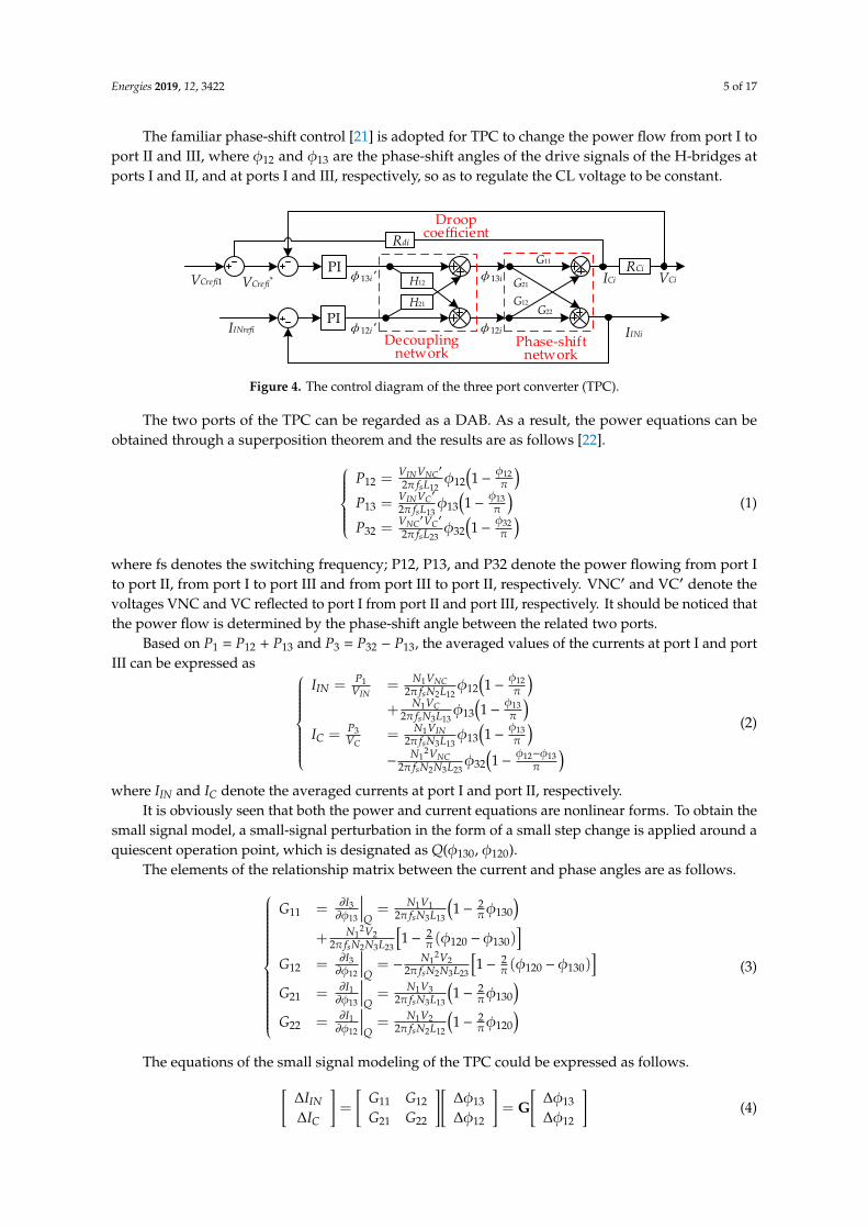
The TPC control encompasses three actions: Phase-shift control, decoupling network, and adaptive droop adjustment, as drawn in the diagram of Figure 4 for the ith DCES.
The familiar phase-shift control [21] is adopted for TPC to change the power flow from port I to port II and III, where ϕ12 and ϕ13 are the phase-shift angles of the drive signals of the H-bridges at ports I and II, and at ports I and III, respectively, so as to regulate the CL voltage to be constant.
Figure 2. Structure of multiple DCESs.
3. Distributed Cooperative Control
3.1. Primary Control
The primary control, also named the local voltage control, provides the independent voltagecontrol of each DCES. It exerts into two control actions, namely the TPC control and BBC control.As shown by the scheme in Figure 3, the TPC control regulates the power flow from the RES to the CLand NCL by changing the phase-shift angle, whilst the BBC control aims for a power regulation ofthe CL.
Energies 2019, 12, x FOR PEER REVIEW 4 of 17
Figure 1. Critical load paralleled-energy storage unit (CLP-ESU) topology of the DC electric spring (DCES).
RL1
RL4
RL2
RL3
PV array 3
NCL3
TPC4
PV array4
NCL4
IIN3 IIN4
TPC2
PV array 2
NCL2
IIN2
TPC3
PV array 1
NCL1
IIN1
TPC1
CL3
VC3
CL1
VC1
BBC3
Battery3
BBC4
Battery4
CL4
VC4
CL2
VC2BBC1
Battery1
BBC2
Battery2
Figure 2. Structure of multiple DCESs.
3. Distributed Cooperative Control
3.1. Primary Control
The primary control, also named the local voltage control, provides the independent voltage control of each DCES. It exerts into two control actions, namely the TPC control and BBC control. As shown by the scheme in Figure 3, the TPC control regulates the power flow from the RES to the CL and NCL by changing the phase-shift angle, whilst the BBC control aims for a power regulation of the CL.
Phase shift
Drive Signal
Input power control
Critical load voltage
Phase shift
Bridge II
Bridge III
Bridge I
Non-critical load
Critical load BBCPCC
For power regulation
φ12
φ13
Figure 3. The proposed primary control of the DCES.
The TPC control encompasses three actions: Phase-shift control, decoupling network, and adaptive droop adjustment, as drawn in the diagram of Figure 4 for the ith DCES.
The familiar phase-shift control [21] is adopted for TPC to change the power flow from port I to port II and III, where ϕ12 and ϕ13 are the phase-shift angles of the drive signals of the H-bridges at ports I and II, and at ports I and III, respectively, so as to regulate the CL voltage to be constant.
Figure 3. The proposed primary control of the DCES.
The TPC control encompasses three actions: Phase-shift control, decoupling network, and adaptivedroop adjustment, as drawn in the diagram of Figure 4 for the ith DCES.
Energies 2019, 12, 3422 5 of 17
The familiar phase-shift control [21] is adopted for TPC to change the power flow from port I toport II and III, where φ12 and φ13 are the phase-shift angles of the drive signals of the H-bridges atports I and II, and at ports I and III, respectively, so as to regulate the CL voltage to be constant.Energies 2019, 12, x FOR PEER REVIEW 5 of 17
PI
PI
Rdi
VCrefi1
IINrefi φ12i
φ13i
IINi
RCiVCiICiVCrefi* H12
H21
Decouplingnetwork
Droop coefficient
Phase-shiftnetwork
φ12i'
φ13i'G12
G21
G11
G22
Figure 4. The control diagram of the three port converter (TPC).
The two ports of the TPC can be regarded as a DAB. As a result, the power equations can be obtained through a superposition theorem and the results are as follows [22].
−=
−=
−=
πφφ
π
πφφ
π
πφφ
π
3232
2332
1313
1313
1212
1212
12
''
12
'
12
'
LfVVP
LfVVP
LfVVP
s
CNC
s
CIN
s
NCIN
(1)
where fs denotes the switching frequency; P12, P13, and P32 denote the power flowing from port I to port II, from port I to port III and from port III to port II, respectively. VNC′ and VC′ denote the voltages VNC and VC reflected to port I from port II and port III, respectively. It should be noticed that the power flow is determined by the phase-shift angle between the related two ports.
Based on P1 = P12 + P13 and P3 = P32 − P13, the averaged values of the currents at port I and port III can be expressed as
−
−−
−==
−+
−==
πφφφ
π
πφφ
π
πφφ
π
πφφ
π
131232
2332
21
1313
133
13
1313
133
1
1212
122
11
12
12
12
12
LNNfVN
LNfVN
VPI
LNfVN
LNfVN
VPI
s
NC
s
IN
CC
s
C
s
NC
ININ
(2)
where IIN and IC denote the averaged currents at port I and port II, respectively. It is obviously seen that both the power and current equations are nonlinear forms. To obtain
the small signal model, a small-signal perturbation in the form of a small step change is applied around a quiescent operation point, which is designated as Q(ϕ130, ϕ120).
The elements of the relationship matrix between the current and phase angles are as follows.
Figure 4. The control diagram of the three port converter (TPC).
The two ports of the TPC can be regarded as a DAB. As a result, the power equations can beobtained through a superposition theorem and the results are as follows [22].
P12 =VINVNC
′
2π fsL12φ12
(1− φ12
π
)P13 =
VINVC′
2π fsL13φ13
(1− φ13
π
)P32 =
VNC′VC
′
2π fsL23φ32
(1− φ32
π
) (1)
where fs denotes the switching frequency; P12, P13, and P32 denote the power flowing from port Ito port II, from port I to port III and from port III to port II, respectively. VNC′ and VC′ denote thevoltages VNC and VC reflected to port I from port II and port III, respectively. It should be noticed thatthe power flow is determined by the phase-shift angle between the related two ports.
Based on P1 = P12 + P13 and P3 = P32 − P13, the averaged values of the currents at port I and portIII can be expressed as
IIN = P1VIN
=N1VNC
2π fsN2L12φ12
(1− φ12
π
)+
N1VC2π fsN3L13
φ13(1− φ13
π
)IC = P3
VC= N1VIN
2π fsN3L13φ13
(1− φ13
π
)−
N12VNC
2π fsN2N3L23φ32
(1− φ12−φ13
π
) (2)
where IIN and IC denote the averaged currents at port I and port II, respectively.It is obviously seen that both the power and current equations are nonlinear forms. To obtain the
small signal model, a small-signal perturbation in the form of a small step change is applied around aquiescent operation point, which is designated as Q(φ130, φ120).
The elements of the relationship matrix between the current and phase angles are as follows.
G11 = ∂I3∂φ13
∣∣∣∣Q= N1V1
2π fsN3L13
(1− 2
πφ130)
+ N12V2
2π fsN2N3L23
[1− 2
π (φ120 −φ130)]
G12 = ∂I3∂φ12
∣∣∣∣Q= − N1
2V22π fsN2N3L23
[1− 2
π (φ120 −φ130)]
G21 = ∂I1∂φ13
∣∣∣∣Q= N1V3
2π fsN3L13
(1− 2
πφ130)
G22 = ∂I1∂φ12
∣∣∣∣Q= N1V2
2π fsN2L12
(1− 2
πφ120)
(3)
The equations of the small signal modeling of the TPC could be expressed as follows.[∆IIN
∆IC
]=
[G11 G12
G21 G22
][∆φ13
∆φ12
]= G
[∆φ13
∆φ12
](4)

Energies 2019, 12, 3422 6 of 17
where ∆IIN, ∆IC, ∆φ13, and ∆φ12 are the small-signal perturbation of IIN, IC, φ13, and φ12, respectively.
G =
[G11 G12
G21 G22
](5)
In Figure 4, since the CL voltage VC = ICRC and input port current IIN are influenced by bothφ12 and φ13, a decoupling network is inserted in the TPC control [23] to eliminate the cross influenceof the phase angles on the control of VC and IIN. A decoupling matrix H is designed to make GH adiagonal matrix to ensure one output is determined by one control input independently. As a result,two equations could be obtained as follows:
∆φ12′G21 + ∆φ12
′H21G22 = 0∆φ13
′G12 + ∆φ13′H12G11 = 0
(6)
where ∆φ13’ and ∆φ12’ are the small-signal perturbation of the virtual phase-shift angle derived from∆φ13 and ∆φ12 in the decoupling control.
Therefore, H can be derived and simplified as
H =
[1 H21
H12 1
]=
[1 −G12/G11
−G21/G22 1
](7)
In the control system, there are two control loops, the output voltage loop is designed for port IIIand the input current loop is related to port I. After the design of the decoupling network, it can beassumed that there are no interactions between these loops.
More details about the phase-shift control and decoupling control of DCES with the CLP-ESUtopology can be found in [12].
The third action of the TPC control is the adaptive droop [24] adjustment based on the consensusalgorithm, which is firstly utilized in the proposed primary TPC control compared to the existingliterature [25]. It is utilized to establish the individual power allocation for each DCES by changingthe virtual equivalent resistance Rdi (droop coefficient) in the diagram of Figure 4. The modified CLvoltage reference V∗Cre f i of the ith DCES is obtained by
V∗Cre f i = VCre f i1 −RdiICi (8)
where ICi and Rdi is the CL current and droop coefficient of the ith DCES, respectively. VCrefi1 is thevoltage reference generated by the secondary voltage control, as explained later on.
Thus, the voltage droop can be adjusted to comply with the different load conditions of the DCESs.The adjustment is obtained by updating the droop coefficient Rdi as follows:
Rdi = Rd0 − δRdi (9)
where, Rd0 is the initial droop coefficient, and δRdi is its correction term. The calculation of this term isbased on the consensus algorithm.
The principle of an average consensus algorithm is explicated in [18]. Let xi be the state variableof node i in a system, and let node i communicate with its neighboring node j under a communicationweight aij, the system is in consensus only when all the state variables are equal to each other. To reachthe consensus situation, the state variable xi is updated at time t by
.xi(t) =
n∑j=1
ai j(x j(t) − xi(t)), i = 1, 2, · · · , n (10)

Energies 2019, 12, 3422 7 of 17
where the dot over xi denotes the updated value of xi. The communication weight aij is a positivequantity that indicates if there is an exchange of information from node j to i and how much valued isthe information. Specifically, aij > 0 means that there is communication between nodes j to i, whilst aij= 0 means there is no communication; moreover, a large value of aij indicates that node j has a highdegree of influence on the update of the state variable of node i.
The final result of a consensus algorithm is that the state variables of each nodes approach theaverage of the initial values of all the nodes.
limt→∞
xi(t) =1n
n∑i=1
xi(0), i = 1, 2, · · · , n (11)
Based on the consensus algorithm, the correction term δRdi is carried in four steps: (i) Comparisonof current ICi of ith CL to that of jth CL neighbor, (ii) weighting of the current difference (ICj − ICi) withweight aij, (iii) summation of the weighted current differences of the N neighbors, and iv) entering ofthe summation into a PI controller [24].
δRdi = kPIi
N∑j=1
ai j(ICj − ICi) + kIIi
∫ N∑j=1
ai j(ICj − ICi)dt (12)
As a result, the update of Rd affects the output current and, hence, the output power of each DCES.The BBC control for the ith DCES has the diagram in Figure 5, where the voltage reference
VCerfi2 is generated by the secondary SOC control. It is worthy to note right now that, in general,VCerfi1 and VCerfi2 are different since they are generated respectively by the secondary voltage and SOCcontrols. The reference VCrefi1 is used to control the TPC and regulate the power consumption of NCL,while the reference VCrefi2 is used to change the operation mode of BBC and regulate the power ofthe battery. The switching signals of the BBC switches Q1 and Q2 are delivered by two logic ANDelements triggered by the output of a PI controller through the PWM generator and the outputs oftwo comparators.
The operation of the BBC control is as follows. When voltage VCi of ith CL DC-bus is higherthan a predefined value of the reference (e.g., VCi > 1.01VCrefi2), BBC enters into the buck mode,and DCES operates in the battery-charging mode. When VCi is lower than a predefined value ofthe reference (e.g., VCi < 0.99VCrefi2), BBC enters into the boost mode, and the DCES operates in thebattery-discharging mode. When VCi is in between 0.99VCrefi2 and 1.01VCrefi2, the two sides of BBC areisolated from each other, and the DCES operates in the battery-balancing mode.Energies 2019, 12, x FOR PEER REVIEW 8 of 17
VCi
PIcontroller
1%AND
comp
comp
-1%AND
Q1
Q2
VCrefi2 PWM generator
Figure 5. The charging and discharging control of BBC.
3.2. Secondary Control
The secondary control provides for generating the updated local values of references VCrefi1 and VCrefi2 for the two actions of the primary control. The diagram of the secondary control for ith DCES, drawn in Figure 6, underlines the two updating paths and the usage of two controls, one in the updating path of the CL DC-bus voltage, and the other one in that of the battery SOC. The operation of the secondary control relies on the average consensus algorithms.
=
−−−
N
jCiCjij VVa
1
)(
VCref
PICjV
−
=
−N
jijij SSa
1
)( PI
Voltage control
SOC controlVCrefi2
VC CiV−∫
Sj δ2i
δ1i
VCrefi1
Figure 6. The proposed secondary control of the DCES.
Returning to the diagram of Figure 6, the voltage control updates the average voltage 𝑉 of ith CL DC bus, by processing the local voltage measurement VCi and the neighbors’ average voltage 𝑉 [26] through a consensus algorithm. It is expressed by
tVVaVVn
jCjCiijCiCi d)(
1
___
=
−−= (13)
After comparison of 𝑉 to the global voltage reference VCref of the CL DC-bus voltage of the microgrid, the error term is processed by a PI controller, as formulated in (8), to generate a correction term δ1i for the voltage reference VCerfi1 of the TPC control of ith DCES.
tVVkVVk CiCrefIUiCiCrefPUii d)()(__
1 −+−=δ (14)
where the kPUi and kIUi are the proportional and integral coefficients of the voltage control. In agreement with (14), the correction term δ1i is higher when the average voltage 𝑉 greatly deviates from reference VCref. As shown by (15), this fact enforces reference VCrefi1 of the TPC control so as to realize the consensus of 𝑉 and VCref, which means that the average CL DC-bus voltage are regulated very close to the rated value [20].
11 iCrefCrefi VV δ+= (15)
Figure 5. The charging and discharging control of BBC.
3.2. Secondary Control
The secondary control provides for generating the updated local values of references VCrefi1 andVCrefi2 for the two actions of the primary control. The diagram of the secondary control for ith DCES,drawn in Figure 6, underlines the two updating paths and the usage of two controls, one in the

Energies 2019, 12, 3422 8 of 17
updating path of the CL DC-bus voltage, and the other one in that of the battery SOC. The operation ofthe secondary control relies on the average consensus algorithms.
Energies 2019, 12, x FOR PEER REVIEW 8 of 17
VCi
PIcontroller
1%AND
comp
comp
-1%AND
Q1
Q2
VCrefi2 PWM generator
Figure 5. The charging and discharging control of BBC.
3.2. Secondary Control
The secondary control provides for generating the updated local values of references VCrefi1 and VCrefi2 for the two actions of the primary control. The diagram of the secondary control for ith DCES, drawn in Figure 6, underlines the two updating paths and the usage of two controls, one in the updating path of the CL DC-bus voltage, and the other one in that of the battery SOC. The operation of the secondary control relies on the average consensus algorithms.
=
−−−
N
jCiCjij VVa
1
)(
VCref
PICjV
−
=
−N
jijij SSa
1
)( PI
Voltage control
SOC controlVCrefi2
VC CiV−∫
Sj δ2i
δ1i
VCrefi1
Figure 6. The proposed secondary control of the DCES.
Returning to the diagram of Figure 6, the voltage control updates the average voltage 𝑉 of ith CL DC bus, by processing the local voltage measurement VCi and the neighbors’ average voltage 𝑉 [26] through a consensus algorithm. It is expressed by
tVVaVVn
jCjCiijCiCi d)(
1
___
=
−−= (13)
After comparison of 𝑉 to the global voltage reference VCref of the CL DC-bus voltage of the microgrid, the error term is processed by a PI controller, as formulated in (8), to generate a correction term δ1i for the voltage reference VCerfi1 of the TPC control of ith DCES.
tVVkVVk CiCrefIUiCiCrefPUii d)()(__
1 −+−=δ (14)
where the kPUi and kIUi are the proportional and integral coefficients of the voltage control. In agreement with (14), the correction term δ1i is higher when the average voltage 𝑉 greatly deviates from reference VCref. As shown by (15), this fact enforces reference VCrefi1 of the TPC control so as to realize the consensus of 𝑉 and VCref, which means that the average CL DC-bus voltage are regulated very close to the rated value [20].
11 iCrefCrefi VV δ+= (15)
Figure 6. The proposed secondary control of the DCES.
Returning to the diagram of Figure 6, the voltage control updates the average voltage VCi of ith CLDC bus, by processing the local voltage measurement VCi and the neighbors’ average voltage VCj [26]through a consensus algorithm. It is expressed by
VCi = VCi −
∫ n∑j=1
ai j(VCi −VCj)dt (13)
After comparison of VCi to the global voltage reference VCref of the CL DC-bus voltage of themicrogrid, the error term is processed by a PI controller, as formulated in (8), to generate a correctionterm δ1i for the voltage reference VCerfi1 of the TPC control of ith DCES.
δ1i = kPUi(VCre f −VCi) + kIUi
∫(VCre f −VCi)dt (14)
where the kPUi and kIUi are the proportional and integral coefficients of the voltage control. In agreementwith (14), the correction term δ1i is higher when the average voltage VCi greatly deviates from referenceVCref. As shown by (15), this fact enforces reference VCrefi1 of the TPC control so as to realize theconsensus of VCi and VCref, which means that the average CL DC-bus voltage are regulated very closeto the rated value [20].
VCre f i1 = VCre f + δi1 (15)
To realize the consensus of the SOC of the batteries in a multiple DCES, the SOC control of Figure 6compels batteries with a high SOC to discharge faster and those with low SOC to charge faster. For thispurpose, the following local state variable Si is defined for the SOC of the battery of ith DCES [19]:
Si =Pbi
CiFSOCi=
VbiibiCiFSOCi
(16)
where Pbi indicates the power flow at the battery terminals (marked as negative during charging andpositive during discharging), SOCi is the SOC of the battery of ith DCES, and FSOCi is a function ofSOCi defined as
FSOCi =
SOCi − SOCL, Pbi > 0SOCH − SOCi, Pbi < 0
(17)
where SOCL and SOCH are respectively the lower and upper limits of SOCi, which are selected as 0.2and 0.8 in this paper.

Energies 2019, 12, 3422 9 of 17
By help of a consensus algorithm, the updated value of Si is processed by a PI controller,as formulated in (18), to generate a correction term δ2i for the voltage reference VCerfi2 of the BBCcontrol of ith DCES.
δ2i = kPSi
N∑j=1
ai j(S j − Si) + kISi
∫ N∑j=1
ai j(S j − Si)dt (18)
where the kPSi and kISi indicate the proportional and integral coefficient of the SOC control.Similar to the update of the voltage reference VCerfi1, a correction term δ2i becomes higher when Si
greatly deviates from the neighboring Sj. As shown by (19), this fact enforces reference VCrefi2 of theBBC control and, together with it, the charging or discharging process of the batteries so as to realizethe consensus of SOCi and SOCj.
VCre f i2 = VCre f + δi2 (19)
The structure of the distributed cooperative system arranged for the control of multiple DCESs isillustrated by the block diagram in Figure 7. The diagram highlights that the system has two controllevels, including the primary control and secondary control. Compared to the existing distributedcooperative control [27], the voltage references of the TPC and BBC controls that are located in theprimary control level, are generated respectively by the voltage and SOC controls that are locatedin the secondary control level. It means that the TPC and BBC can be controlled independently,which contributes to a reduced battery usage and releases the burden of the battery.
Energies 2019, 12, x FOR PEER REVIEW 9 of 17
To realize the consensus of the SOC of the batteries in a multiple DCES, the SOC control of Figure 6 compels batteries with a high SOC to discharge faster and those with low SOC to charge faster. For this purpose, the following local state variable Si is defined for the SOC of the battery of ith DCES [19]:
SOCii
bibi
SOCii
bii FC
iVFCP
S == (16)
where Pbi indicates the power flow at the battery terminals (marked as negative during charging and positive during discharging), SOCi is the SOC of the battery of ith DCES, and FSOCi is a function of SOCi defined as
<−>−
=0,0,
biiH
biLiSOCi PSOCSOC
PSOCSOCF (17)
where SOCL and SOCH are respectively the lower and upper limits of SOCi, which are selected as 0.2 and 0.8 in this paper.
By help of a consensus algorithm, the updated value of Si is processed by a PI controller, as formulated in (18), to generate a correction term δ2i for the voltage reference VCerfi2 of the BBC control of ith DCES.
tSSakSSakN
jijijISi
N
jijijPSii d)()(
112
==
−+−=δ (18)
where the kPSi and kISi indicate the proportional and integral coefficient of the SOC control. Similar to the update of the voltage reference VCerfi1, a correction term δ2i becomes higher when
Si greatly deviates from the neighboring Sj. As shown by (19), this fact enforces reference VCrefi2 of the BBC control and, together with it, the charging or discharging process of the batteries so as to realize the consensus of SOCi and SOCj.
22 iCrefCrefi VV δ+= (19)
The structure of the distributed cooperative system arranged for the control of multiple DCESs is illustrated by the block diagram in Figure 7. The diagram highlights that the system has two control levels, including the primary control and secondary control. Compared to the existing distributed cooperative control [27], the voltage references of the TPC and BBC controls that are located in the primary control level, are generated respectively by the voltage and SOC controls that are located in the secondary control level. It means that the TPC and BBC can be controlled independently, which contributes to a reduced battery usage and releases the burden of the battery.
TPC control• phase-shift control• decoupling control• adaptive droop control
BBC control• discharging and charg-
ing control
SOC controlVoltage control
Secondary control
Primary Control Figure 7. Structure of the proposed distributed cooperative control.
4. Steady State Analysis
In this section, the steady state analysis of the distributed cooperative control is carried out to prove the consensus of the CL average voltage and battery SOC.
Figure 7. Structure of the proposed distributed cooperative control.
4. Steady State Analysis
In this section, the steady state analysis of the distributed cooperative control is carried out toprove the consensus of the CL average voltage and battery SOC.
4.1. Consensus of the CL Average Voltage
By differentiating (13),
dVCi = dVCi −
n∑j=1
ai j(VCi −VCj) (20)
The global observer dynamic can be formulated as
dVC = dVC − LVC (21)
where L = D − A, in which D = diagn∑
j=1ai j, A = [ai j] ∈ Rn×n, VC = [VC1, VC2, · · · , VCn]
T and
VC = [VC1, VC2, · · · , VCn]T
is the CL DC-bus voltage vector and CL average voltage vector, respectively.Since VC(0) = VC(0), (21) can be written in the frequency domain as
VsC = s(sI + L)−1Vs
C = HVsC (22)

Energies 2019, 12, 3422 10 of 17
where VsC and Vs
C are the form in frequency domain of VC and VC.The correction term in (14) can be written in the frequency domain as
δ1 = GU(VCref −VsC) (23)
where VCref is the Laplace transform of the reference voltage vector, and lims→0
sVCref = VCre f 1n in which
1n is a column vector with all elements equal to 1 [27]. GU = diagGUi, in which
GUi = kPUi +kIUi
s(24)
combining (8) and (15), then write it in the frequency domain by substituting (22) and (23)
V∗Cref = VCref1 − ICRd = VCref + GU(VCref −HVsC) − ICRd (25)
where Rd = diagRdiis the droop coefficient matrix, and IC is the Laplace transform of the CL currentvector [IC1, IC2, · · · , ICn]
T
Thus, the dynamic behavior of the CL DC bus voltage with a closed-loop voltage regulator can beexpressed as
VsC = GC1V∗Cref (26)
where GC1 = diagGC1i is the transfer function matrix, in which GC1i is the closed-loop transferfunction of the ith TPC of DCES, and can be simplified as an inertial element
lims→0
GC1 = In (27)
where In is a n-order unit matrix.The CL current matrix IC can be obtained by the admittance matrix Y of the DCESs
IC = YVsC (28)
By substituting (26) and (28) into (25), the dynamic behavior of the CL DC bus voltage can bewritten as
VsC = (In + GC1GUH + GC1RdY)−1
×GC1(I + GU)VCref (29)
The steady state of the CL DC bus voltage can be obtained as
VssC = lim
s→0sVs
C = lims→0
[s(sIn + sGC1GUH + sGC1RdY)−1× sGC1(In + GU)VCref] (30)
Based on the definition of GU, it can be obtained as
lims→0
sGU = KIU (31)
Therefore,QVss
C= lim
s→0sHVs
C = (KIU)−1×KIUVCre f 1n = VCre f 1n (32)
where Q = lims→0
H is the n × n matrix with all the elements equal to 1/n. So, the steady state of the CL
average voltage can be written asVss
C = QVssC = Vcre f 1n (33)
Equation (33) implies that the CL average voltage will all reach consensus in the steady stateat VCref.

Energies 2019, 12, 3422 11 of 17
4.2. Consensus of the Battery SOC
The correction term in (18) can be written in the frequency domain as
δ1 = GSLS (34)
where S is the Laplace transform vector of the state variable in (16).By substituting (34), (19) can be written in the frequency domain
VCref2 = VCref + GSLS (35)
Similar to (26),Vs
C = GC2VCref2 (36)
where GC2 = diagGC2i is the transfer function matrix, in which GCi is the closed-loop transfer functionof the ith BBC of DCES, and can be simplified as an inertial element.
lims→0
GC1 = In (37)
Therefore, S can be written as
S = (GC2GSL)−1× (Vs
C −GC2VCref) (38)
Based on the definition of GS, it can be obtained as
lims→0
sGS = KIS (39)
The form of the state variable S in the frequency domain is Ss, and its steady state can beobtained as
Sss = lims→0
sSs = lims→0
[s(sGC2GSL)−1× (sVs
C − sGC2VCref)] (40)
Therefore, QSss can be written as
QSss = lims→0
sHS = lims→0
[sH(sGC2GSL)−1× (sVs
C − sGC2VCref)]
= lims→0
[s(KISL)−1× (In −Q)VCre f 1n)
= 0n
(41)
It can be seen that Sss is the eigenvector of Q associated with the eigenvalue zero, which ensuresthe state variable Si consensus. [27] According to the property of the Laplace matrix [28], the finalconsensus values can be obtained as
Sss = Sss1n (42)
where Sss is the positive real value to which all the state variables Si will be converged.Equations (33) and (42) shows that the average bus voltage and battery SOC will all reach
consensus in the steady state.
5. Simulation Results
Simulations are performed in the MATLAB/Simulink (2017a, MathWorks, Natick, MA, USA) tovalidate the performance of the proposed distributed cooperative control for the multiple DCESs.Table 1 reports the parameters of the study case utilized for simulation. To simplify the controllerdesign, the communication weights are set to one. To verify the proposed distributed cooperativecontrol, the resistance combinations of the CL and the NCL for the four DCESs are different from each

Energies 2019, 12, 3422 12 of 17
other. Moreover, the droop coefficients of the four DCESs are also different according to the differentoutput power.
Table 1. Parameters for simulations.
Parameter Values
Input Voltage (VIN) 50 VGlobal voltage reference of CL (VCref) 120 V
Communication weights (aij) 1
Resistance of the CL (RC) RC1, RC3 120 ΩRC2, RC4 150 Ω
Resistance of the NCL (RNC) RNC1, RNC2 40 ΩRNC3, RNC4 60 Ω
Initial droop coefficient (Rd0) Rd0 1
The performance of the primary control and distributed cooperative control is discussed indetail as follows including the steady state, converter failure, communication weight variation,and load variation.
5.1. Steady State
This case validates the distributed cooperative control when the DCESs are at a steady state,by comparing the performance of the droop control and consensus control. The simulation resultsof the primary control and distributed cooperative control of this multiple DCESs are shownin Figures 8 and 9, respectively.
Energies 2019, 12, x FOR PEER REVIEW 12 of 17
It can be seen that Sss is the eigenvector of Q associated with the eigenvalue zero, which ensures the state variable Si consensus. [27] According to the property of the Laplace matrix [28], the final consensus values can be obtained as
nss 1S ssS= (42)
where Sss is the positive real value to which all the state variables Si will be converged. Equations (33) and (42) shows that the average bus voltage and battery SOC will all reach
consensus in the steady state.
5. Simulation Results
Simulations are performed in the MATLAB/Simulink (2017a, MathWorks, Natick, MA, USA) to validate the performance of the proposed distributed cooperative control for the multiple DCESs. Table 1 reports the parameters of the study case utilized for simulation. To simplify the controller design, the communication weights are set to one. To verify the proposed distributed cooperative control, the resistance combinations of the CL and the NCL for the four DCESs are different from each other. Moreover, the droop coefficients of the four DCESs are also different according to the different output power.
Table 1. Parameters for simulations.
Parameter Values Input Voltage (VIN) 50 V
Global voltage reference of CL (VCref) 120 V Communication weights (aij) 1
Resistance of the CL (RC) RC1, RC3 120 Ω RC2, RC4 150 Ω
Resistance of the NCL (RNC) RNC1, RNC2 40 Ω RNC3, RNC4 60 Ω
Initial droop coefficient (Rd0) Rd0 1
The performance of the primary control and distributed cooperative control is discussed in detail as follows including the steady state, converter failure, communication weight variation, and load variation.
5.1. Steady State
This case validates the distributed cooperative control when the DCESs are at a steady state, by comparing the performance of the droop control and consensus control. The simulation results of the primary control and distributed cooperative control of this multiple DCESs are shown in Figure 8 and Figure 9, respectively.
(a) (b)
Figure 8. Only with the primary control of multiple DCESs: (a) DC-bus voltage; (b) battery SOC.
In Figure 8, with only the primary control, the CL DC bus voltage is regulated to 119.2 V butdeviates from the reference value of 120 V because of the droop gains and power allocation. The SOCsof the four batteries, whose initial value SOC0 are different from each other, are still in difference afterthe discharging. In Figure 9, the distributed cooperative control is simulated. It can be seen that the CLDC bus voltages between the four DCESs are in consensus and the average value is regulated to therated value, owing to the secondary voltage control. However, the CL DC bus voltage of the individualDCES may differ from the rated value. Moreover, the SOCs eventually converge toward consensusthanks to the fact that the secondary SOC control forces the batteries with a high SOC to be dischargedfaster and meanwhile the batteries with a low SOC to be charged faster.

Energies 2019, 12, 3422 13 of 17
Energies 2019, 12, x FOR PEER REVIEW 13 of 17
Figure 8. Only with the primary control of multiple DCESs: (a) DC-bus voltage; (b) battery SOC.
(a) (b)
Figure 9. Distributed cooperative control of multiple DCESs: (a) DC-bus voltage; (b) battery SOC.
In Figure 8, with only the primary control, the CL DC bus voltage is regulated to 119.2 V but deviates from the reference value of 120 V because of the droop gains and power allocation. The SOCs of the four batteries, whose initial value SOC0 are different from each other, are still in difference after the discharging. In Figure 9, the distributed cooperative control is simulated. It can be seen that the CL DC bus voltages between the four DCESs are in consensus and the average value is regulated to the rated value, owing to the secondary voltage control. However, the CL DC bus voltage of the individual DCES may differ from the rated value. Moreover, the SOCs eventually converge toward consensus thanks to the fact that the secondary SOC control forces the batteries with a high SOC to be discharged faster and meanwhile the batteries with a low SOC to be charged faster.
5.2. Converter Failure
This case illustrates the performance of the proposed control in the case of one converter failure. One DCES failure means that the output power of the DCES is zero. This happens when the DCES is shorted or broken, such as the short-circuit of the power switches and the open-circuit of the three-winding transformers. It is studied in this case to analyze the emergency performance of the proposed distributed cooperative control compared to the primary control. In this case, the output power of DCES1 reduces to zero at 0.1 s. The remaining DCESs carry out the power sharing by exchanging the SOC information with neighbors. In Figure 10, the four DC-bus voltages all deviate much from the rated value after the failure. In Figure 11, although the bus voltage of the DCESs cannot be regulated to a common value, with the distributed cooperative control, the average value of the remaining three DC-bus voltages are regulated close to the rated value if ignoring the small DC-bus voltage drop of DCES1. Moreover, the control can drive the four battery SOCs to consensus and balance.
Figure 9. Distributed cooperative control of multiple DCESs: (a) DC-bus voltage; (b) battery SOC.
5.2. Converter Failure
This case illustrates the performance of the proposed control in the case of one converter failure.One DCES failure means that the output power of the DCES is zero. This happens when the DCESis shorted or broken, such as the short-circuit of the power switches and the open-circuit of thethree-winding transformers. It is studied in this case to analyze the emergency performance of theproposed distributed cooperative control compared to the primary control. In this case, the outputpower of DCES1 reduces to zero at 0.1 s. The remaining DCESs carry out the power sharing byexchanging the SOC information with neighbors. In Figure 10, the four DC-bus voltages all deviatemuch from the rated value after the failure. In Figure 11, although the bus voltage of the DCESscannot be regulated to a common value, with the distributed cooperative control, the average valueof the remaining three DC-bus voltages are regulated close to the rated value if ignoring the smallDC-bus voltage drop of DCES1. Moreover, the control can drive the four battery SOCs to consensusand balance.
Energies 2019, 12, x FOR PEER REVIEW 14 of 18
(a) (b)
Figure 10. Only with the primary control when failure at 0.1s of DCES1: (a) DC-bus voltage; (b) battery SOC.
(a) (b)
Figure 11. Distributed cooperative control when failure at 0.1 s of DCES1: (a) DC-bus voltage; (b) battery SOC.
5.3. Communication Weight Variation
In this case, the effect of the communication weight on the speed of the system convergence is investigated. It can be seen from Equations (13), (14), and (18) that the communication weight aij affects the correction term δ1i and δ2i, which will affect the voltage reference. To simplify the controller design, in Figure 9 and Figure 12, the communication weights aij are set to one for normal impact levels and five for high impact levels, respectively.
Figure 10. Only with the primary control when failure at 0.1 s of DCES1: (a) DC-bus voltage;(b) battery SOC.

Energies 2019, 12, 3422 14 of 17
Energies 2019, 12, x FOR PEER REVIEW 14 of 17
(a) (b)
Figure 10. Only with the primary control when failure at 0.1s of DCES1: (a) DC-bus voltage; (b) battery SOC.
(a) (b)
Figure 11. Distributed cooperative control when failure at 0.1 s of DCES1: (a) DC-bus voltage; (b) battery SOC.
5.3. Communication Weight Variation
In this case, the effect of the communication weight on the speed of the system convergence is investigated. It can be seen from Equations (13), (14), and (18) that the communication weight aij affects the correction term δ1i and δ2i, which will affect the voltage reference. To simplify the controller design, in Figure 9 and Figure 12, the communication weights aij are set to one for normal impact levels and five for high impact levels, respectively.
(a) (b)
Figure 12. Distributed cooperative control when communication weights aij = 5: (a) DC-bus voltage; (b) battery SOC.
It can be seen in Figure 12a that the average CL DC-bus voltages reach the rated value for about 0.07 s regardless of the value of communication weight aij. Therefore, the communication weight has a weak impact on the convergence speed of the CL DC-bus voltage. However, in Figure 12b, the SOCs reach the consensus state faster with a larger aij. It can be concluded that a larger communication weight contributes to a faster convergence speed of SOC.
5.4. Load Variation
Figure 11. Distributed cooperative control when failure at 0.1 s of DCES1: (a) DC-bus voltage;(b) battery SOC.
5.3. Communication Weight Variation
In this case, the effect of the communication weight on the speed of the system convergence isinvestigated. It can be seen from Equations (13), (14), and (18) that the communication weight aij affectsthe correction term δ1i and δ2i, which will affect the voltage reference. To simplify the controller design,in Figures 9 and 12, the communication weights aij are set to one for normal impact levels and five forhigh impact levels, respectively.
Energies 2019, 12, x FOR PEER REVIEW 14 of 17
(a) (b)
Figure 10. Only with the primary control when failure at 0.1s of DCES1: (a) DC-bus voltage; (b) battery SOC.
(a) (b)
Figure 11. Distributed cooperative control when failure at 0.1 s of DCES1: (a) DC-bus voltage; (b) battery SOC.
5.3. Communication Weight Variation
In this case, the effect of the communication weight on the speed of the system convergence is investigated. It can be seen from Equations (13), (14), and (18) that the communication weight aij affects the correction term δ1i and δ2i, which will affect the voltage reference. To simplify the controller design, in Figure 9 and Figure 12, the communication weights aij are set to one for normal impact levels and five for high impact levels, respectively.
(a) (b)
Figure 12. Distributed cooperative control when communication weights aij = 5: (a) DC-bus voltage; (b) battery SOC.
It can be seen in Figure 12a that the average CL DC-bus voltages reach the rated value for about 0.07 s regardless of the value of communication weight aij. Therefore, the communication weight has a weak impact on the convergence speed of the CL DC-bus voltage. However, in Figure 12b, the SOCs reach the consensus state faster with a larger aij. It can be concluded that a larger communication weight contributes to a faster convergence speed of SOC.
5.4. Load Variation
Figure 12. Distributed cooperative control when communication weights aij = 5: (a) DC-bus voltage;(b) battery SOC.
It can be seen in Figure 12a that the average CL DC-bus voltages reach the rated value for about0.07 s regardless of the value of communication weight aij. Therefore, the communication weight has aweak impact on the convergence speed of the CL DC-bus voltage. However, in Figure 12b, the SOCsreach the consensus state faster with a larger aij. It can be concluded that a larger communicationweight contributes to a faster convergence speed of SOC.
5.4. Load Variation
This section discusses the performance of the proposed distributed cooperative control comparedto the primary control in the case of one load variation. The CL of DCES1 changes from 120 Ω to 80 Ωat 0.1 s.

Energies 2019, 12, 3422 15 of 17
It can be seen in Figure 13 that the four DC-bus voltages deviated from the rated value especiallyafter the load variation at 0.1 s. Moreover, the four SOCs are still different from each other. However,in Figure 14, with the distributed cooperative control, the four DC-bus voltages are in consensus,the average bus voltage can be regulated close to the rated value and four battery SOCs reach theconsensus state although the load variation is at 0.1 s. This study indicates the good performance ofthe proposed control method when the CL load varies.
Energies 2019, 12, x FOR PEER REVIEW 15 of 17
This section discusses the performance of the proposed distributed cooperative control compared to the primary control in the case of one load variation. The CL of DCES1 changes from 120 Ω to 80 Ω at 0.1 s.
It can be seen in Figure 13 that the four DC-bus voltages deviated from the rated value especially after the load variation at 0.1 s. Moreover, the four SOCs are still different from each other. However, in Figure 14, with the distributed cooperative control, the four DC-bus voltages are in consensus, the average bus voltage can be regulated close to the rated value and four battery SOCs reach the consensus state although the load variation is at 0.1 s. This study indicates the good performance of the proposed control method when the CL load varies.
(a) (b)
Figure 13. Primary control when the load variation is at 0.1 s of DCES1: (a) DC-bus voltage; (b) battery SOC.
(a) (b)
Figure 14. Distributed cooperative control when the load variation is at 0.1 s of DCES1: (a) DC-bus voltage; (b) battery SOC.
6. Conclusions
A distributed cooperative control is proposed for multiple DC electric springs with the recently proposed topology in this paper. The novel DCES, which is composed of the DC/DC three port converter, bi-directional buck-boost converter, and battery system, can realize electrical isolation between the CL and the NCL and can also realize the traditional paralleled connection way of the electrical loads. The proposed distributed cooperative control composed of the primary control and the secondary control, can be used to realize the local voltage stability, power allocation of multiple DCESs and the consensus of DC-bus voltages and battery SOCs among multiple DCESs. The primary control is made up of the phased-shift control, decoupling control, adaptive droop control, and charging/discharging control. Furthermore, the secondary control consists of the voltage control and
Figure 13. Primary control when the load variation is at 0.1 s of DCES1: (a) DC-bus voltage;(b) battery SOC.
Energies 2019, 12, x FOR PEER REVIEW 15 of 17
This section discusses the performance of the proposed distributed cooperative control compared to the primary control in the case of one load variation. The CL of DCES1 changes from 120 Ω to 80 Ω at 0.1 s.
It can be seen in Figure 13 that the four DC-bus voltages deviated from the rated value especially after the load variation at 0.1 s. Moreover, the four SOCs are still different from each other. However, in Figure 14, with the distributed cooperative control, the four DC-bus voltages are in consensus, the average bus voltage can be regulated close to the rated value and four battery SOCs reach the consensus state although the load variation is at 0.1 s. This study indicates the good performance of the proposed control method when the CL load varies.
(a) (b)
Figure 13. Primary control when the load variation is at 0.1 s of DCES1: (a) DC-bus voltage; (b) battery SOC.
(a) (b)
Figure 14. Distributed cooperative control when the load variation is at 0.1 s of DCES1: (a) DC-bus voltage; (b) battery SOC.
6. Conclusions
A distributed cooperative control is proposed for multiple DC electric springs with the recently proposed topology in this paper. The novel DCES, which is composed of the DC/DC three port converter, bi-directional buck-boost converter, and battery system, can realize electrical isolation between the CL and the NCL and can also realize the traditional paralleled connection way of the electrical loads. The proposed distributed cooperative control composed of the primary control and the secondary control, can be used to realize the local voltage stability, power allocation of multiple DCESs and the consensus of DC-bus voltages and battery SOCs among multiple DCESs. The primary control is made up of the phased-shift control, decoupling control, adaptive droop control, and charging/discharging control. Furthermore, the secondary control consists of the voltage control and
Figure 14. Distributed cooperative control when the load variation is at 0.1 s of DCES1: (a) DC-busvoltage; (b) battery SOC.
6. Conclusions
A distributed cooperative control is proposed for multiple DC electric springs with the recentlyproposed topology in this paper. The novel DCES, which is composed of the DC/DC three portconverter, bi-directional buck-boost converter, and battery system, can realize electrical isolationbetween the CL and the NCL and can also realize the traditional paralleled connection way of theelectrical loads. The proposed distributed cooperative control composed of the primary controland the secondary control, can be used to realize the local voltage stability, power allocation ofmultiple DCESs and the consensus of DC-bus voltages and battery SOCs among multiple DCESs.The primary control is made up of the phased-shift control, decoupling control, adaptive droop control,and charging/discharging control. Furthermore, the secondary control consists of the voltage control

Energies 2019, 12, 3422 16 of 17
and SOC control. The proposed distributed cooperative control applied in multiple DCESs with therecently proposed topologies has been validated by the simulation results.
Author Contributions: Conceptualization, D.Z., Q.W. and M.C.; methodology, Q.W.; software, D.Z.; validation,D.Z., Q.W.; formal analysis, F.D.; investigation, D.Z.; resources, Q.W.; data curation, Q.W.; writing—original draftpreparation, D.Z.; writing—review and editing, D.Z., Q.W., G.B.; visualization, F.D.; supervision, M.C.; projectadministration, Q.W.; funding acquisition, Q.W.
Funding: This work was supported by the Natural Science Foundation of Jiangsu Province under projectBK20170675, and by the National Natural Science Foundation of China under project 51877040.
Conflicts of Interest: The authors declare no conflict of interest.
References
1. Hui, S.Y.; Lee, C.K.; Wu, F.F. Electric springs—A new smart grid technology. IEEE Trans. Smart Grid 2012, 3,1552–1561. [CrossRef]
2. Wang, Q.; Cheng, M.; Jiang, Y.; Zuo, W.; Buja, G. A Simple Active and Reactive Power Control for Applicationsof Single-Phase Electric Springs. IEEE Trans. Ind. Electron. 2018, 65, 6291–6300. [CrossRef]
3. Wang, Q.; Cheng, M.; Chen, Z. Steady-state analysis of electric springs with a novel δ control. IEEE Trans.Power Electron. 2015, 30, 7159–7169. [CrossRef]
4. Mok, K.; Wang, M.; Tan, S.; Hui, S.Y.R. DC electric springs—A technology for stabilizing DC powerdistribution systems. IEEE Trans. Power Electron. 2017, 32, 1088–1105. [CrossRef]
5. Wang, Q.; Cheng, M.; Jiang, Y.; Chen, Z.; Deng, F.; Wang, Z. DC electric springs with DC/DC converters.In Proceedings of the IEEE International Power Electronics and Motion Control Conference, Hefei, China,28 September 2016; pp. 3268–3273.
6. Wang, M.; Yang, T.; Tan, S.; Hui, S.Y. Hybrid Electric Springs for Grid-Tied Power Control and StorageReduction in AC Microgrids. IEEE Trans. Power Electron. 2019, 34, 3214–3225. [CrossRef]
7. Kakigano, H.; Miura, Y.; Ise, T. Distribution Voltage Control for DC Microgrids Using Fuzzy Control andGain-Scheduling Technique. IEEE Trans. Power Electron. 2013, 28, 2246–2258. [CrossRef]
8. Ahmadi, R.; Ferdowsi, M. Improving the Performance of a Line Regulating Converter in aConverter-Dominated DC Microgrid System. IEEE Trans. Smart Grid 2014, 5, 2553–2563. [CrossRef]
9. Huang, P.; Liu, P.; Xiao, W.; El Moursi, M.S. A Novel Droop-Based Average Voltage Sharing Control Strategyfor DC Microgrids. IEEE Trans. Smart Grid 2015, 6, 1096–1106. [CrossRef]
10. Rouzbehi, K.; Miranian, A.; Luna, A.; Rodriguez, P. DC Voltage Control and Power Sharing in MultiterminalDC Grids Based on Optimal DC Power Flow and Voltage-Droop Strategy. IEEE J. Emerg. Sel. Top. PowerElectron. 2014, 2, 1171–1180. [CrossRef]
11. Mok, K.; Wang, M.; Tan, S.; Hui, S. DC electric springs—An emerging technology for DC grids. In Proceedingsof the IEEE Applied Power Electronics Conference and Exposition, Charlotte, NC, USA, 15–19 March 2015;pp. 684–690.
12. Wang, Q.; Zha, D.; Deng, F.; Cheng, M.; Buja, G. A topology of DC electric springs for DC householdapplications. IET Power Electron. 2019, 12, 1241–1248. [CrossRef]
13. Phattanasak, M.; Gavagsaz-Ghoachani, R.; Martin, J.; Nahid-Mobarakeh, B.; Pierfederici, S.; Davat, B.Control of a hybrid energy source comprising a fuel cell and two storage devices using isolated three-portbidirectional DC–DC converters. IEEE Trans. Ind. Appl. 2015, 51, 491–497. [CrossRef]
14. Bahrami, H.; Farhangi, S.; Iman-Eini, H.; Adib, E. A new interleaved coupled-inductor nonisolatedsoft-switching bidirectional DC/DC converter with high voltage gain ratio. IEEE Trans. Ind. Electron. 2018,65, 5529–5538. [CrossRef]
15. Xu, Y.; Zhang, W.; Hug, G.; Kar, S.; Li, Z. Cooperative control of distributed energy storage systems in amicrogrid. IEEE Trans. Smart Grid 2015, 6, 238–248. [CrossRef]
16. Mokhtari, G.; Nourbakhsh, G.; Ghosh, A. Smart coordination of energy storage units (ESUs) for voltage andloading management in distribution networks. IEEE Trans. Power Syst. 2013, 28, 4812–4820. [CrossRef]
17. Zhang, X.; Dong, M.; Ou, J. A distributed cooperative control strategy based on consensus algorithm in DCmicrogrid. In Proceedings of the IEEE Conference on Industrial Electronics and Applications, Wuhan, China,31 May–2 June 2018; pp. 243–248.

Energies 2019, 12, 3422 17 of 17
18. Olfati-Saber, R.; Fax, J.A.; Murray, R.M. Consensus and cooperation in networked multi-agent systems.Proc. IEEE USA 2007, 95, 215–233. [CrossRef]
19. Golsorkhi, M.S.; Shafiee, Q.; Lu, D.D.; Guerrero, J.M. A distributed control framework for integratedphotovoltaic-battery-based islanded microgrids. IEEE Trans. Smart Grid 2017, 8, 2837–2848. [CrossRef]
20. Chen, X.; Shi, M.; Sun, H.; Li, Y.; He, H. Distributed cooperative control and stability analysis of multiple DCelectric springs in a dc microgrid. IEEE Trans. Ind. Electron. 2018, 65, 5611–5622. [CrossRef]
21. Zhang, J.; Wu, H.; Qin, X.; Xing, Y. PWM plus secondary-side phase-shift controlled soft-switching full-bridgethree-port converter for renewable power systems. IEEE Trans. Ind. Electron. 2015, 62, 7061–7072. [CrossRef]
22. Samir, H.; Subhashish, B.; Chandan, C. A novel control principle for a high frequency transformer basedmultiport converter for integration of renewable energy sources. In Proceedings of the IEEE IndustrialElectronics Society. Annual. Conference, Vienna, Austria, 10–13 November 2013; pp. 7984–7989.
23. Wang, W.; Wang, P.; Ma, T.; Liu, H.; Wu, H. A simple decoupling control method for isolated three-portbidirectional converter in low-voltage DC microgrids. In Proceedings of the IEEE Energy ConversionCongress and Exposition, Montreal, QC, Canada, 20–24 September 2015; pp. 3192–3196.
24. Nasirian, V.; Davoudi, A.; Lewis, F.L.; Guerrero, J.M. Distributed adaptive droop control for dc distributionsystems. IEEE Trans. Energy Convers. 2014, 29, 944–956. [CrossRef]
25. Kim, S.Y.; Song, H.; Nam, K. Idling port isolation control of three-port bidirectional converter for EVs.IEEE Trans. Power Electron. 2012, 27, 2495–2506. [CrossRef]
26. Nasirian, V.; Moayedi, S.; Davoudi, A.; Lewis, F.L. Distributed cooperative control of DC microgrids.IEEE Trans. Power Electron. 2015, 30, 2288–2303. [CrossRef]
27. Chen, X.; Shi, M.; Zhou, J.; Chen, Y.; Zuo, W.; Wen, J.; He, H. Distributed cooperative control of multiplehybrid energy storage systems in a DC microgrid using consensus protocol. IEEE Trans. Ind. Electron. 2019, 1.[CrossRef]
28. Olfati-Saber, R.; Murray, R.M. Consensus problems in networks of agents with switching topology andtime-delays. IEEE Trans. Autom. Control 2004, 49, 1520–1533. [CrossRef]
© 2019 by the authors. Licensee MDPI, Basel, Switzerland. This article is an open accessarticle distributed under the terms and conditions of the Creative Commons Attribution(CC BY) license (http://creativecommons.org/licenses/by/4.0/).