srz instruction manual - rkc instrument inc. · 2018-01-25 · srz instruction manual module type...
TRANSCRIPT

RKC INSTRUMENT INC.
SRZ
Instruction Manual
Module Type Controller
IMS01T04-E6

Modbus is a registered trademark of Schneider Electric. Company names and product names used in this manual are the trademarks or registered trademarks of
the respective companies.

IMS01T04-E6 i-1
Thank you for purchasing this RKC product. In order to achieve maximum performance and ensure proper operation of the instrument, carefully read all the instructions in this manual. Please place the manual in a convenient location for easy reference.
SYMBOLS
: This mark indicates that all precautions should be taken for safe usage.
: This mark indicates important information on installation, handling and operating procedures.
: This mark indicates supplemental information on installation, handling and operating procedures.
: This mark indicates where additional information may be located.
To prevent injury to persons, damage to the instrument and the equipment, a suitable external protection device shall be required.
All wiring must be completed before power is turned on to prevent electric shock, fire or damage to the instrument and the equipment.
This instrument must be used in accordance with the specifications to prevent fire or damage to the instrument and the equipment.
This instrument is not intended for use in locations subject to flammable or explosive gases.
Do not touch high-voltage connections such as power supply terminals, etc. to avoid electric shock.
RKC is not responsible if this instrument is repaired, modified or disassembled by other than factory-approved personnel. Malfunction may occur and warranty is void under these conditions.
: This mark indicates precautions that must be taken if there is danger of electric shock, fire, etc., which could result in loss of life or injury.
: This mark indicates that if these precautions and operating procedures are not taken, damage to the instrument may result.
WARNING!
CAUTION
WARNING
!

IMS01T04-E6 i-2
This product is intended for use with industrial machines, test and measuring equipment. (It is not designed for use with medical equipment and nuclear energy plant.)
This is a Class A instrument. In a domestic environment, this instrument may cause radio interference, in which case the user may be required to take additional measures.
This instrument is protected from electric shock by reinforced insulation. Provide reinforced insulation between the wire for the input signal and the wires for instrument power supply, source of power and loads.
Be sure to provide an appropriate surge control circuit respectively for the following: - If input/output or signal lines within the building are longer than 30 meters. - If input/output or signal lines leave the building, regardless the length.
This instrument is designed for installation in an enclosed instrumentation panel. All high-voltage connections such as power supply terminals must be enclosed in the instrumentation panel to avoid electric shock to operating personnel.
All precautions described in this manual should be taken to avoid damage to the instrument or equipment.
If the equipment is used in a manner not specified by the manufacturer, the protection provided by the equipment may be impaired.
All wiring must be in accordance with local codes and regulations. All wiring must be completed before power is turned on to prevent electric shock, instrument
failure, or incorrect action. The power must be turned off before repairing work for input break and output failure including replacement of sensor, contactor or SSR, and all wiring must be completed before power is turned on again.
To prevent instrument damage as a result of failure, protect the power line and the input/output lines from high currents with a suitable overcurrent protection device with adequate breaking capacity such as a fuse, circuit breaker, etc.
A malfunction in this product may occasionally make control operations impossible or prevent alarm outputs, resulting in a possible hazard. Take appropriate measures in the end use to prevent hazards in the event of malfunction.
Prevent metal fragments or lead wire scraps from falling inside instrument case to avoid electric shock, fire or malfunction.
Tighten each terminal screw to the specified torque found in the manual to avoid electric shock, fire or malfunction.
For proper operation of this instrument, provide adequate ventilation for heat dissipation. Do not connect wires to unused terminals as this will interfere with proper operation of the
instrument. Turn off the power supply before cleaning the instrument. Do not use a volatile solvent such as paint thinner to clean the instrument. Deformation or
discoloration may occur. Use a soft, dry cloth to remove stains from the instrument. To avoid damage to the instrument display, do not rub with an abrasive material or push the
front panel with a hard object.
NOTICE This manual assumes that the reader has a fundamental knowledge of the principles of electricity,
process control, computer technology and communications. The figures, diagrams and numeric values used in this manual are only for explanation purpose. RKC is not responsible for any damage or injury that is caused as a result of using this instrument,
instrument failure or indirect damage. RKC is not responsible for any damage and/or injury resulting from the use of instruments made by
imitating this instrument. Periodic maintenance is required for safe and proper operation of this instrument. Some components
have a limited service life, or characteristics that change over time. Every effort has been made to ensure accuracy of all information contained herein. RKC makes no
warranty, expressed or implied, with respect to the accuracy of the information. The information in this manual is subject to change without prior notice.
No portion of this document may be reprinted, modified, copied, transmitted, digitized, stored, processed or retrieved through any mechanical, electronic, optical or other means without prior written approval from RKC.
CAUTION

IMS01T04-E6 i-3
CONTENTS
Page
1. OUTLINE ........................................................................... 1-1
1.1 Features ...................................................................................................... 1-2
1.2 Checking the Product .................................................................................. 1-3 1.2.1 Z-TIO module .......................................................................................................... 1-3 1.2.2 Z-DIO module .......................................................................................................... 1-3 1.2.3 Optional (sold separately) ....................................................................................... 1-3
1.3 Model Code................................................................................................. 1-4 1.3.1 Z-TIO module .......................................................................................................... 1-4 1.3.2 Z-DIO module .......................................................................................................... 1-7
1.4 Parts Description ......................................................................................... 1-9 1.4.1 Z-TIO module .......................................................................................................... 1-9 1.4.2 Z-DIO module ........................................................................................................ 1-11
2. SETTING PROCEDURE TO OPERATION ....................... 2-1
3. MOUNTING ........................................................................ 3-1
3.1 Mounting Cautions ........................................................................................ 3-2
3.2 Dimensions ................................................................................................... 3-4
3.3 Important Points When Joining Modules ...................................................... 3-5
3.4 DIN Rail Mounting and Removing ................................................................ 3-6
3.5 Panel Mounting ............................................................................................. 3-8
4. WIRING ............................................................................. 4-1
4.1 Wiring Cautions ............................................................................................ 4-2
4.2 Connecting Precautions ............................................................................... 4-4
4.3 Terminal Configuration ................................................................................. 4-5 4.3.1 Z-TIO module .......................................................................................................... 4-5 4.3.2 Z-DIO module ....................................................................................................... 4-10
4.4 Connection to Host Computer .................................................................... 4-12
4.5 Installation of Termination Resistor ............................................................ 4-17
4.6 Connections for Loader Communication .................................................... 4-19
5. SETTINGS BEFORE OPERATION ................................... 5-1 5.1 Module Address Setting ............................................................................... 5-2
5.2 Protocol Selections and Communication Speed Setting ............................... 5-3
5.3 Operating Precautions .................................................................................. 5-4
5.4 Communication Requirements ..................................................................... 5-5

IMS01T04-E6 i-4
Page
6. RKC COMMUNICATION ................................................... 6-1
6.1 Polling ........................................................................................................... 6-2 6.1.1 Polling procedures .................................................................................................. 6-2 6.1.2 Polling procedures example .................................................................................... 6-7
6.2 Selecting ....................................................................................................... 6-8 6.2.1 Selecting procedures .............................................................................................. 6-8 6.2.2 Selecting procedures example .............................................................................. 6-11
6.3 Communication Data Structure ................................................................... 6-12
6.4 Communication Data List............................................................................ 6-13 6.4.1 Reference to communication data list ................................................................... 6-13 6.4.2 Communication data of Z-TIO module .................................................................. 6-14 6.4.3 Communication data of Z-DIO module .................................................................. 6-30
7. MODBUS............................................................................ 7-1
7.1 Communication Protocol............................................................................... 7-2 7.1.1 Message format ...................................................................................................... 7-2 7.1.2 Function code ......................................................................................................... 7-3 7.1.3 Communication mode ............................................................................................. 7-3 7.1.4 Slave responses ..................................................................................................... 7-4 7.1.5 Calculating CRC-16 ................................................................................................ 7-5
7.2 Register Read and Write .............................................................................. 7-8 7.2.1 Read holding registers [03H] ................................................................................. 7-8 7.2.2 Preset single register [06H] ................................................................................... 7-9 7.2.3 Diagnostics (Loopback test) [08H] ....................................................................... 7-10 7.2.4 Preset multiple registers [10H] ............................................................................ 7-11
7.3 Data Processing Precautions ..................................................................... 7-12
7.4 How to Use Memory Area Data .................................................................. 7-13
7.5 How to Use Data Mapping .......................................................................... 7-17
7.6 Communication Data List............................................................................ 7-18 7.6.1 Reference to communication data list ................................................................... 7-18 7.6.2 Communication data of Z-TIO module .................................................................. 7-19 7.6.3 Communication data of Z-DIO module .................................................................. 7-39 7.6.4 Memory area data address (Z-TIO)....................................................................... 7-42 7.6.5 Data mapping address (Z-TIO, Z-DIO) .................................................................. 7-44

IMS01T04-E6 i-5
Page
8. COMMUNICATION DATA DESCRIPTION ....................... 8-1
8.1 Reference to Communication Data Contents ............................................... 8-2
8.2 Communication Data of Z-TIO Module ......................................................... 8-3 8.2.1 Normal setting data items ....................................................................................... 8-3 8.2.2 Engineering setting data items .............................................................................. 8-61
8.3 Communication Data of Z-DIO Module ..................................................... 8-143 8.3.1 Normal setting data items ................................................................................... 8-143 8.3.2 Engineering setting data items ............................................................................ 8-154
9. TROUBLESHOOTING ....................................................... 9-1
10. SPECIFICATIONS ......................................................... 10-1
10.1 Z-TIO module ........................................................................................... 10-2
10.2 Z-DIO module ......................................................................................... 10-16
11. APPENDIX ..................................................................... 11-1
11.1 ASCII 7-bit Code Table ............................................................................. 11-2
11.2 Current Transformer (CT) Dimensions ..................................................... 11-3
11.3 Cover ........................................................................................................ 11-4
11.4 Block Diagram of Logic Output Selection Function ................................... 11-6
11.5 Peak Current Suppression Function ......................................................... 11-7
11.6 Example of Using DI/DO........................................................................... 11-9
11.7 Example of Using Unused Heat/Cool Control Channel Inputs ................ 11-12
INDEX .................................................................................... A-1

i-6 IMS01T04-E6
MEMO

OUTLINE
IMS01T04-E6 1-1
1.1 Features ........................................................................................... 1-2
1.2 Checking the Product ....................................................................... 1-3 1.2.1 Z-TIO module ............................................................................................ 1-3 1.2.2 Z-DIO module ............................................................................................ 1-3 1.2.3 Optional (sold separately) .......................................................................... 1-3
1.3 Model Code ...................................................................................... 1-4 1.3.1 Z-TIO module ............................................................................................ 1-4 1.3.2 Z-DIO module ............................................................................................ 1-7
1.4 Parts Description ............................................................................. 1-9 1.4.1 Z-TIO module ............................................................................................ 1-9 1.4.2 Z-DIO module .......................................................................................... 1-11

1. OUTLINE
1-2 IMS01T04-E6
1.1 Features
This chapter describes features, package contents and model code, etc. The module type controller has the following features: Module type controller SRZ interfaces with the host computer via Modbus or RKC communication protocols. The SRZ sets all of the data items via communication (The communication interface used for both protocols is RS-485.). Therefore before operation, it is necessary to set value of each data item via communication. Common to both Z-TIO and Z-DIO module
A user can select RKC communication or Modbus.
When each module is connected, the power and communication lines are connected internally within the modules, and thus it is only necessary to wire one module to the power terminal and communication terminal; there is no need to individually wire each module to the terminals. This reduces the amount of wiring needed.
Compact size Terminal type: depth 85 mm, Connector type: depth 79 mm
Z-TIO module (Z-TIO-A, Z-TIO-B)
The Z-TIO module is a temperature control module equipped with either two or four control channels.
The measured input is a universal input that supports thermocouple input, resistance temperature sensor input, voltage input, current input, and feedback resistance input.
The input type can be specified separately for each channel, and different input types can be combined.
Output types are relay contact output, voltage pulse output, voltage output, current output, open collector output, and triac output. Output types are specified when the order is placed, and a different output type can be specified for each channel.
4CH Z-TIO module can have 4 CT (current transformer) inputs.
Up to 16 Z-TIO modules can be connected. [The maximum number of SRZ modules (including other function modules) on the same communication line is 31.]
Z-DIO module (Z-DIO-A)
The Z-DIO module is an event input/output module equipped with digital inputs and outputs (DI8 points /DO8 points).
DI signal assignment enables switching of various mode states and memory areas of the Z-TIO module.
DO signal assignment enables output of the event result of the Z-TIO module to the event output (DO), and output of the DO manual output state of the Z-DIO module.
Up to 16 Z-DIO modules can be connected. [The maximum number of SRZ modules (including other function modules) on the same communication line is 31.]
For reference purposes, the Modbus protocol identifies the host computer as master, each module of SRZ as slave.
For details of the Z-CT module, refer to Z-CT Instruction Manual (IMS01T21-E).

1. OUTLINE
IMS01T04-E6 1-3
1.2 Checking the Product
Before using this product, check each of the following:
Model code Check that there are no scratches or breakage in external appearance (case, front panel, or terminal, etc.) Check that all of the items delivered are complete. (Refer to below)
If any of the products are missing, damaged, or if your manual is incomplete, please contact RKC sales office or the agent.
1.2.1 Z-TIO module
Description Q’TY Remarks
Z-TIO-A module or Z-TIO-B module 1
Z-TIO Instruction Manual [For Host communication] (IMS01T01-E)
1 Enclosed with instrument
Z-TIO Host Communication Quick Instruction Manual [For Host communication] (IMS01T02-E)
1 Enclosed with instrument
Joint connector cover KSRZ-517A 2 Enclosed with instrument
Power terminal cover KSRZ-518A(1) 1 Enclosed with instrument
SRZ Instruction Manual (IMS01T04-E6)
1 This manual (sold separately) * * This manual can be downloaded from the official RKC website:
http://www.rkcinst.com/english/manual_load.htm
1.2.2 Z-DIO module
Description Q’TY Remarks
Z-DIO module 1
Z-DIO module Instruction Manual (IMS01T03-E)
1 Enclosed with instrument
Joint connector cover KSRZ-517A 2 Enclosed with instrument
Power terminal cover KSRZ-518A(1) 1 Enclosed with instrument
SRZ Instruction Manual (IMS01T04-E6)
1 This manual (sold separately) * * This manual can be downloaded from the official RKC website:
http://www.rkcinst.com/english/manual_load.htm
1.2.3 Optional (sold separately) Description Q’TY Remarks
End plate DEP-01 2
Connector SRZP-01 (front screw type) 2 For the connector type module
Connector SRZP-02 (side screw type) 2 For the connector type module
CT cable W-BW-03-1000 1 For CT input connector (cable length: 1 m)
CT cable W-BW-03-2000 1 For CT input connector (cable length: 2 m)
CT cable W-BW-03-3000 1 For CT input connector (cable length: 3 m)
Current transformer CTL-6-P-N 1 0.0 to 30.0 A
Current transformer CTL-12-S56-10L-N 1 0.0 to 100.0 A
Terminal cover KSRZ-510A(1) 1 For the terminal type module

1. OUTLINE
1-4 IMS01T04-E6
1.3 Model Code
Check that the product received is correctly specified by referring to the following model code list: If the product is not identical to the specifications, please contact RKC sales office or the agent.
1.3.1 Z-TIO module
Suffix code
Z-TIO-A □ □ □ □ □ / □ □ □ □□□/Y (1) (2) (3) (4) (5) (6) (7) (8) (9) (10)
Z-TIO-B □ □ □ / □ N □ □ □□□/Y (1) (2) (3) (6) (7) (8) (9) (10)
Suffix code Specifications Hardware coding only Quick start code1
(1) (2) (3) (4) (5) (6) (7) (8) (9) (10)
Wiring type Terminal type T
Connector type C
Relay contact output M
Voltage pulse output V
Output1 (OUT1) Voltage output, Current output (Refer to Output Code Table)
Triac output T
Open collector output D
Relay contact output M
Voltage pulse output V
Output2 (OUT2) Voltage output, Current output (Refer to Output Code Table)
Triac output T
Open collector output D
Relay contact output M
Output3 (OUT3) Voltage pulse output V
[Z-TIO-A type only] Voltage output, Current output (Refer to Output Code Table)
Triac output T
Open collector output D
Relay contact output M
Output4 (OUT4) Voltage pulse output V
[Z-TIO-A type only] Voltage output, Current output (Refer to Output Code Table)
Triac output T
Open collector output D
Current transformer (CT) input
None N
CT (4 points) [4-channel type], CT (2 points) [2-channel type] A
No quick start code (Configured to factory default) N
Quick start code Specify quick start code 1 1
Specify quick start code 1 and 2 2
Control Method (all channel common) [Quick start code 1]
Quick start code 1 is not specified No code
PID control with AT (Reverse action) F
PID control with AT (Direct action) D
Heat/Cool PID control with AT 1 G
Heat/Cool PID control with AT (for Extruder [air cooling]) 1 A
Heat/Cool PID control with AT (for Extruder [water cooling]) 1 W
Position proportioning PID control without FBR 2 Z
Measured input and Range (all channel common) [Quick start code 1]
Quick start code 1 is not specified No code
Refer to range code table.
Instrument specification Version symbol /Y
1 Z-TIO-A type: CH2 and CH4 only accept Measured value (PV) monitor and event action. Z-TIO-B type: CH2 only accepts Measured value (PV) monitor and event action. 2 Z-TIO-A type: Inputs of CH2 and CH4 can be used as FBR input. Z-TIO-B type: Input of CH2 can be used as FBR input.
4-channel type:
2-channel type:

1. OUTLINE
IMS01T04-E6 1-5
Output Code Table
Output type Code Output type Code
Voltage output (0 to 1 V DC) 3 Voltage output (1 to 5 V DC) 6
Voltage output (0 to 5 V DC) 4 Current output (0 to 20 mA DC) 7
Voltage output (0 to 10 V DC) 5 Current output (4 to 20 mA DC) 8
Range Code Table
[Thermocouple (TC) input, RTD input] [Voltage input, Current input]
Type Code Range (Input span) Code Range (Input span) Type Code Range (Input span)
K02 0 to 400 C KA1 0 to 800 F 0 to 10 mV DC 101
K04 0 to 800 C KA2 0 to 1600 F 0 to 100 mV DC 201 Programmable range
K41 200 to 1372 C KC7 328 to 2501 F 0 to 1 V DC 301 19999 to 19999
K K09 0.0 to 400.0 C KA4 0.0 to 800.0 F 0 to 5 V DC 401 [The decimal point position is selectable]
K10 0.0 to 800.0 C 0 to 10 V DC 501 (Factory set value: 0.0 to 100.0)
K35 200.0 to 400.0 C 1 to 5 V DC 601
K40 200.0 to 800.0 C 0 to 20 mA DC 701
K42 200.0 to 1372.0 C 4 to 20 mA DC 801
J02 0 to 400 C JA1 0 to 800 F
J04 0 to 800 C JA2 0 to 1600 F
J15 200 to 1200 C JB9 328 to 2192 F
J J08 0.0 to 400.0 C JB6 0.0 to 800.0 F
J09 0.0 to 800.0 C
J27 200.0 to 400.0 C
J32 200.0 to 800.0 C
J29 200.0 to 1200.0 C
T T19 200.0 to 400.0 C TC5 328 to 752 F
TC6 0.0 to 752.0 F
E E20 200.0 to 1000.0 C EB2 0.0 to 800.0 F
EB1 328 to 1832 F
S S06 50 to 1768 C SA7 58 to 3214 F
R R07 50 to 1768 C RA7 58 to 3214 F
B B03 0 to 1800 C BB1 32 to 3272 F
N N07 200 to 1372 C NA8 328 to 2502 F
PLII A02 0 to 1390 C AA2 0 to 2534 F
W5Re/W26Re W03 0 to 2300 C WB1 32 to 4208 F
Pt100 D21 200.0 to 200.0 C DC6 328.0 to 752.0 F
D35 200.0 to 850.0 C DD2 328 to 1562 F
JPt100 P31 200.0 to 649.0 C PC6 328.0 to 752.0 F
PD2 328 to 1200 F

1. OUTLINE
IMS01T04-E6 1-6
Quick start code 2 (Initial setting code)
Quick start code 2 tells the factory to ship with each parameter preset to the values detailed as specified by the customer. Quick start code is not necessarily specified when ordering, unless the preset is requested. These parameters are software selectable items and can be re-programmed in the field via the manual.
□ □ □ □-□ □
(1) (2) (3) (4) (5) (6)
Specifications Quick start code 2 (Initial setting code)
(1) (2) (3) (4) (5) (6)
Event function 1 (EV1) 1 None N
Event function 1 (Refer to Event type code table)
Event function 2 (EV2) 1 None N
Event function 2 (Refer to Event type code table)
Event function 3 (EV3) 1 None N
Event function 3 (Refer to Event type code table)
Temperature rise completion 6
Event function 4 (EV4) 1 None N
Event function 4 (Refer to Event type code table)
Control loop break alarm (LBA) 5
None N
CT type 2 CTL-6-P-N P
CTL-12-S56-10L-N S
Communication protocol RKC communication (ANSI X3.28-1976) 1
Modbus 2
1 If it is desired to specify the deviation action between channels or the deviation using local SV, the settings must be configured by the customer. (Engineering setting data) 2 The CT assignment and Heater break alarm (HBA) type must be configured by the customer. (Engineering setting data)
Event type code table
Code Type Code Type Code Type
A Deviation high H Process high V SV high
B Deviation low J Process low W SV low
C Deviation high/low K Process high with hold action 1 MV high [heat-side]
D Band L Process low with hold action 2 MV low [heat-side]
E Deviation high with hold action Q Deviation high with re-hold action 3 MV high [cool-side]
F Deviation low with hold action R Deviation low with re-hold action 4 MV low [cool-side]
G Deviation high/low with hold action T Deviation high/low with re-hold action

1. OUTLINE
IMS01T04-E6 1-7
1.3.2 Z-DIO module Z-DIO-A □-□ □/□-□□□□□□□
(1) (2) (3) (4) (5) (6) (7) (8)
Suffix code Specifications Hardware coding only Quick start code1
(1) (2) (3) (4) (5) (6) (7) (8)
Wiring type Terminal type T
Connector type C
Digital input (DI) None N 8 points A
None N Digital output (DO) Relay contact output (8 points) M Open collector output (8 points) D
Quick start code No quick start code (Configured to factory default) N (DI/DO assignments) Specify quick start code 1 1
DI signal assignments Quick start code 1 is not specified No code (DI1 to DI8) None N [Quick start code 1] Refer to DI assignment code table.
DO signal assignments Quick start code 1 is not specified No code (DO1 to DO4) None N [Quick start code 1] Refer to DO assignment code table.
DO signal assignments Quick start code 1 is not specified No code
(DO5 to DO8) None N [Quick start code 1] Refer to DO assignment code table. Communication protocol RKC communication (ANSI X3.28) 1 Modbus 2
DI assignment code table Code DI1 DI2 DI3 DI4 DI5 DI6 DI7 DI8
00 No assignment01
Memory area transfer (1 to 8) 1
AUTO/MAN 02 REM/LOC 03 Interlock release EDS start signal 104 Soak stop 05 RUN/STOP 06 REM/LOC 07 AUTO/MAN EDS start signal 108 Operation mode 3 Soak stop 09 RUN/STOP 10 EDS start signal 111 REM/LOC Soak stop 12 RUN/STOP 13 Area set 2
EDS start signal 1 Soak stop
14 RUN/STOP
15 Soak stop 16 EDS start signal 117 REM/LOC Soak stop 18 Interlock release AUTO/MAN RUN/STOP 19
EDS start signal 1 Soak stop
20 RUN/STOP
21 Soak stop 22
EDS start signal 1 Soak stop
23 AUTO/MAN REM/LOC 24
Soak stop RUN/STOP
25 REM/LOC EDS start signal 1 26 Memory area
transfer (1, 2) 1 Area set 2 Interlock release RUN/STOP AUTO/MAN REM/LOC Operation mode 3
27 Memory area transfer (1 to 8) 1 Area set 2 Operation mode 3 EDS start signal 1 EDS start signal 228 Memory area
transfer (1, 2) 1 Area set 2
Interlock release RUN/STOP AUTO/MAN REM/LOC 29 EDS start signal 1 EDS start signal 2 Operation mode 3
RUN/STOP: RUN/STOP transfer (Contact closed: RUN) AUTO/MAN: Auto/Manual transfer (Contact closed: Manual mode) REM/LOC: Remote/Local transfer (Contact closed: Remote mode) Interlock release (Interlock release when rising edge is detected) EDS start signal 1 (EDS start signal ON when rising edge is detected [for disturbance 1]) EDS start signal 2 (EDS start signal ON when rising edge is detected [for disturbance 2]) Soak stop (Contact closed: Soak stop)
1 Memory area transfer (:Contact open : Contact closed)
Memory area number 1 2 3 4 5 6 7 8
DI1 DI2 DI3
2 Area set becomes invalid prior to factory shipment. 3 Operation mode transfer (:Contact open : Contact closed)
Operation mode Unused Monitor Monitor Event function Control
DI5 (DI7) DI6 (DI8)
Continued on the next page.
Contact closed
Contact open
250 ms or more
DI signal will become valid at rising edge after the closed contact is held for 250 ms.
(Rising edge)

1. OUTLINE
IMS01T04-E6 1-8
Continued from the previous page. DO assignment code table [DO1 to DO4]
Code DO1 DO2 DO3 DO4
00 No assignment
01 DO1 manual output DO2 manual output DO3 manual output DO4 manual output
02 Event 1 comprehensive output 1 Event 2 comprehensive output 2 Event 3 comprehensive output 3 Event 4 comprehensive output 4
03 Event 1 (CH1) Event 2 (CH1) Event 3 (CH1) Event 4 (CH1)
04 Event 1 (CH2) Event 2 (CH2) Event 3 (CH2) Event 4 (CH2)
05 Event 1 (CH3) Event 2 (CH3) Event 3 (CH3) Event 4 (CH3)
06 Event 1 (CH4) Event 2 (CH4) Event 3 (CH4) Event 4 (CH4)
07 Event 1 (CH1) Event 1 (CH2) Event 1 (CH3) Event 1 (CH4)
08 Event 2 (CH1) Event 2 (CH2) Event 2 (CH3) Event 2 (CH4)
09 Event 3 (CH1) Event 3 (CH2) Event 3 (CH3) Event 3 (CH4)
10 Event 4 (CH1) Event 4 (CH2) Event 4 (CH3) Event 4 (CH4)
11 HBA (CH1) of Z-TIO module HBA (CH2) of Z-TIO module HBA (CH3) of Z-TIO module HBA (CH4) of Z-TIO module
12 Burnout status (CH1) Burnout status (CH2) Burnout status (CH3) Burnout status (CH4)
13 Temperature rise completion 5 HBA comprehensive output 6 Burnout state comprehensive output 7 DO4 manual output
1 Logical OR of Event 1 (ch1 to ch4) 2 Logical OR of Event 2 (ch1 to ch4) 3 Logical OR of Event 3 (ch1 to ch4) 4 Logical OR of Event 4 (ch1 to ch4) 5 Temperature rise completion status (ON when temperature rise completion occurs for all channels for which event 3 is set to temperature rise completion.) 6 The following signals are output depending on the setting of the DO signal assignment module address. ・Logical OR of HBA (ch1 to ch4) of Z-TIO module ・Logical OR of HBA (ch1 to ch12) of Z-CT module ・Logical OR of HBA (ch1 to ch4) of Z-TIO module and HBA (ch1 to ch12) of Z-CT module 7 Logical OR of burnout state (ch1 to ch4)
[DO5 to DO8]
Code DO5 DO6 DO7 DO8
00 No assignment
01 DO5 manual output DO6 manual output DO7 manual output DO8 manual output
02 Event 1 comprehensive output 1 Event 2 comprehensive output 2 Event 3 comprehensive output 3 Event 4 comprehensive output 4
03 Event 1 (CH1) Event 2 (CH1) Event 3 (CH1) Event 4 (CH1)
04 Event 1 (CH2) Event 2 (CH2) Event 3 (CH2) Event 4 (CH2)
05 Event 1 (CH3) Event 2 (CH3) Event 3 (CH3) Event 4 (CH3)
06 Event 1 (CH4) Event 2 (CH4) Event 3 (CH4) Event 4 (CH4)
07 Event 1 (CH1) Event 1 (CH2) Event 1 (CH3) Event 1 (CH4)
08 Event 2 (CH1) Event 2 (CH2) Event 2 (CH3) Event 2 (CH4)
09 Event 3 (CH1) Event 3 (CH2) Event 3 (CH3) Event 3 (CH4)
10 Event 4 (CH1) Event 4 (CH2) Event 4 (CH3) Event 4 (CH4)
11 HBA (CH1) of Z-TIO module HBA (CH2) of Z-TIO module HBA (CH3) of Z-TIO module HBA (CH4) of Z-TIO module
12 Burnout status (CH1) Burnout status (CH2) Burnout status (CH3) Burnout status (CH4)
13 Temperature rise completion 5 HBA comprehensive output 6 Burnout state comprehensive output 7 DO8 manual output
1 Logical OR of Event 1 (ch1 to ch4) 2 Logical OR of Event 2 (ch1 to ch4) 3 Logical OR of Event 3 (ch1 to ch4) 4 Logical OR of Event 4 (ch1 to ch4) 5 Temperature rise completion status (ON when temperature rise completion occurs for all channels for which event 3 is set to temperature rise completion.) 6 The following signals are output depending on the setting of the DO signal assignment module address. ・Logical OR of HBA (ch1 to ch4) of Z-TIO module ・Logical OR of HBA (ch1 to ch12) of Z-CT module ・Logical OR of HBA (ch1 to ch4) of Z-TIO module and HBA (ch1 to ch12) of Z-CT module 7 Logical OR of burnout state (ch1 to ch4)
For details of the Z-CT module, refer to Z-CT Instruction Manual (IMS01T21-E).

1. OUTLINE
IMS01T04-E6 1-9
1.4 Parts Description
1.4.1 Z-TIO module
Module mainframe <Terminal type>
* The 2-channel type does not have neither an input select switch (for CH3) and nor an input select switch (for CH4).
<Connector type>
** The 2-channel type does not have neither an input select switch (for CH3) and nor an input select switch (for CH4). Indication lamps FAIL/RUN [Green or Red] When normal (RUN): A green lamp is on
Self-diagnostic error (FAIL): A green lamp flashes
Instrument abnormality (FAIL): A red lamp is on
RX/TX [Green] During data send and receive: A green lamp turns on Switches Address setting switch Sets the Z-TIO module address.
(Refer to P. 5-2.)
DIP switch Sets the communication speed, data bit configuration, and communication protocol. (Refer to P. 5-3.)
Input select switch Selector switch for the measured input type. (Refer to P. 8-70.)
Input select switch*(for CH3)
Input select switch*(for CH4)
DIP switch
Input selectswitch (for CH1)
Input selectswitch (for CH2)
(Right side) (Left side)
CT1
CT2
LOAD
ER
CT4
CT3 TIO
FAIL/ UNR
RX/TX
0
21345
98 7 6
CA B D EF 0
21345
98 7 6
CA B DEF
CT1
CT2
R NU/LIAF
RX/TX
TIO
(Z-TIO-AT: 4-channel type)
Loader communication connector
Indication lamps
Address setting
switch
CT Input connector (Optional)
Input/Output terminals
(Z-TIO-BT: 2-channel type)
CN
1
CN
3
CN
2
CN
4
0
21345
98 7 6
CA B D EF
CT1
CT2CT3
CT4 TIO
FAIL/ UNR
RX/TX
LOAD
ER
TIO
CN1
CN3
CN2
CN4
0
21345
98 7 6
CA B DEF
CT1
CT2
R NU/LIAF
RX/TX
LOAD
ER
Loader communication connector
Indication lamps
Address setting
switch
CT Input connector (Optional)
Input/Output connector
DIP switch
Input selectswitch (for CH1)
Input selectswitch (for CH2)
(Right side)
Input select switch **(for CH3)
Input select switch **(for CH4)
(Left side)
(Z-TIO-BC: 2-channel type)(Z-TIO-AC: 4-channel type)

1. OUTLINE
IMS01T04-E6 1-10
Base
Mounting bracket Used to fix the module on DIN rails andalso to fix each module joined together.
(Base: Rear)
Mounting holes (M3 screw)
Holes for screws to fix the base to a panel, etc. Customer must provide the M3 screws.
Power supply terminals
Supply power to only one of the joinedmodules, and all of the joined modules willreceive power. (Refer to 4.1 Wiring Cautions)
Used to mechanically and electrically connect each module.
Joint connector
Communication terminals (RS-485)
Connect communication wires to only one ofthe joined modules, and all of the joinedmodules will communicate.
(Base: Front)
Base
(Right side)
(Z-TIO-A: Terminal type)
(Right side)
(Z-TIO-A: Connector type)
Base

1. OUTLINE
IMS01T04-E6 1-11
1.4.2 Z-DIO module
Module mainframe
Indication lamps FAIL/RUN [Green or Red] When normal (RUN): A green lamp is on
Self-diagnostic error (FAIL): A green lamp flashes
Instrument abnormality (FAIL): A red lamp is on
RX/TX [Green] During data send and receive: A green lamp turns on Switches
Address setting switch Sets the Z-DIO module address. (Refer to P. 5-2.)
DIP switch Sets the communication speed, data bit configuration, and communication protocol. (Refer to P. 5-3.)
Terminal configurations of the base are the same as the base of Z-TIO module. (Refer to P. 1-10)
DIP switch LOAD
ER
IN OUTDIO
FAIL/ UNR
RX/TX
0
21345
98 7 6
CA B D EF
<Terminal type>
Digital input terminals
Loader communication connector
Indication lamps
Address setting switch
Base
Digital output terminals
(Right side)
CN
1
CN
3
CN
2
CN
4
021345
98 7 6
CA B D EF
FAIL/ UNR
RX/TX
LOAD
ER
IN OUTDIO
DIP switch
Base
<Connector type>
Digital input connector
Digital output connector
Loader communication connector
Indication lamps
Address setting switch
(Right side)

IMS01T04-E6 1-12
MEMO

SETTINGPROCEDURE TO
OPERATION
IMS01T04-E6 2-1
1.1 ******** .............................................................................................. 1-2
1.2 ******* ................................................................................................ 1-3
1.3 ****** ................................................................................................. 1-4
1.4 *********** .......................................................................................... 1-5 1.4.1 ***** ........................................................................................................... 1-6 1.4.2 ******** ....................................................................................................... 1-7

2. SETTING PROCEDURE TO OPERATION
2-2 IMS01T04-E6
Conduct necessary setting before operation according to the procedure described below.
Execute it after turning off a power supply of the SRZ unit.
Processing of the host computer side
Preparation of communication program
Power-OFF
Turn on the power of the host computer and SRZ.
Processing of the SRZ side
Setting of communication relation
Communication speed setting
Data bit configuration
Communication protocol selection
Set the host computer and SRZ in always the same value.
Module address setting
Refer to 5.2 Protocol Selectionsand Communication Speed Setting (P. 5-3).
Refer to 5.1 Module Address Setting (P. 5-2).
Communication line connection
Refer to 4. WIRING (P. 4-1).
Power-ON
Communication program start
Execute it after turning on a power supply of the host computer.
Execute it after turning off a power supply of the host computer.
Set the Input scale high/low, Input range decimal point position, Control type, Event type etc.
Before setting operation data items, always set initial setting data items so as to satisfythe specification used.
For engineering setting data items, refer to following pages.
Z-TIO module: 8.2.2 Engineering setting data items (P. 8-61) Z-DIO module: 8.3.2 Engineering setting data items (P. 8-153)
Setting of Engineering setting data
Setting of communication relation
Communication speed setting Data bit configuration Communication protocol selection Communication port setting
A

2. SETTING PROCEDURE TO OPERATION
IMS01T04-E6 2-3
Set the control RUN/STOP transfer to the “RUN.”
Operation start
Setting of Normal setting data
Set parameters in Normal setting of data.
Control RUN
Control action type?
A
Position proportioning PID control
Adjustment of the valve position PID control or Heat/Cool PID control
For details, refer to P. 8-118.
For normal setting data items, refer to following pages.
Z-TIO module: 8.2.1 Normal setting data items (P. 8-3) Z-DIO module: 8.3.1 Normal setting data items (P. 8-143)

2-4 IMS01T04-E6
MEMO

MOUNTING
IMS01T04-E6 3-1
3.1 Mounting Cautions ........................................................................... 3-2
3.2 Dimensions ....................................................................................... 3-4
3.3 Important Points When Joining Modules .......................................... 3-5
3.4 DIN Rail Mounting and Removing .................................................... 3-6
3.5 Panel Mounting ................................................................................ 3-8

3. MOUNTING
3-2 IMS01T04-E6
3.1 Mounting Cautions
This chapter describes installation environment, mounting cautions, dimensions and mounting procedures.
(1) This instrument is intended to be used under the following environmental conditions.
(IEC 61010-1) [OVERVOLTAGE CATEGORY II, POLLUTION DEGREE 2]
(2) Use this instrument within the following environment conditions: Allowable ambient temperature: 10 to 50 C Allowable ambient humidity: 5 to 95 %RH
(Absolute humidity: MAX.W.C 29.3 g/m3 dry air at 101.3 kPa) Installation environment conditions: Indoor use
Altitude up to 2000 m
(3) Avoid the following conditions when selecting the mounting location: Rapid changes in ambient temperature which may cause condensation. Corrosive or inflammable gases. Direct vibration or shock to the mainframe. Water, oil, chemicals, vapor or steam splashes. Excessive dust, salt or iron particles. Excessive induction noise, static electricity, magnetic fields or noise. Direct air flow from an air conditioner. Exposure to direct sunlight. Excessive heat accumulation. (4) Mount this instrument in the panel considering the following conditions: Provide adequate ventilation space so that heat does not build up. Do not mount this instrument directly above equipment that generates large amount of heat (heaters,
transformers, semi-conductor functional devices, large-wattage resistors). If the ambient temperature rises above 50 C, cool this instrument with a forced air fan, cooler, etc.
Cooled air should not blow directly on this instrument. In order to improve safety and the immunity to withstand noise, mount this instrument as far away as
possible from high voltage equipment, power lines, and rotating machinery. High voltage equipment: Do not mount within the same panel. Power lines: Separate at least 200 mm Rotating machinery: Separate as far as possible
Space required between each module vertically When the module is mounted on the panel, allow a minimum of 50 mm at the top and bottom of the module to attach the module to the mainframe.
To prevent electric shock or instrument failure, always turn off the power before mounting or removing the instrument.
WARNING!
50 mm or more

3. MOUNTING
IMS01T04-E6 3-3
Depth for connector mount type module (Connector type) Space for connectors and cables must be considered when installing.
76.9 mm Approx. 50 mm
Connector (Plug)
Mounting the joint connector cover
It is recommended to use a plastic cover on the connector on both sides of the mounted modules for protection of connectors.
Joint connector cover (Standard equipment) Parts code Ordering code Q’ty
KSRZ-517A 00433384 2 Joint connector cover
Installing direction of SRZ unit Mount the SRZ unit in the direction specified as shown below.
Top
Bottom
(5) If this instrument is permanently connected to equipment, it is important to include a switch or circuit-breaker into the installation. This should be in close proximity to the equipment and within easy reach of the operator. It should be marked as the disconnecting device for the equipment.

3. MOUNTING
3-4 IMS01T04-E6
3.2 Dimensions
Terminal type module Connector type module
Connector type (sold separately): SRZP-01 [Front-screw type]
76.9 2.9
100
5
99
2.9
100
5
76.9
89.7
Connector type (sold separately): SRZP-02 [Side-screw type]
Z-TIO-AT: 4-channel type
30 6.7
Z-TIO-BT: 2-channel type
30 6.785
100
5
(Unit: mm)
(Unit: mm)
30 6.7
Z-TIO-BC: 2-channel type
30 6.7
Z-TIO-AC: 4-channel type

3. MOUNTING
IMS01T04-E6 3-5
3.3 Important Points When Joining Modules
When joining the Z-TIO and Z-DIO modules, note the following: The maximum number of joined T-TIO-A/B modules that can be connected to one host computer is 16.
SRZ unit
Example 1: When joining only Z-TIO-A modules
(Up to 16 modules)
SRZ unit
Example 2: When joining only Z-TIO-B modules
(Up to 16 modules)
SRZ unit
Example 3: When joining Z-TIO-A and Z-TIO-B modules
(Combination of 16 modules or less)
Up to 16 Z-DIO modules can be connected.
Z-DIO modules are used in combination with Z-TIO modules.
The maximum number of SRZ modules (including other function modules) on the same communication line is 31. Therefore, when 16 Z-TIO modules areconnected, up to 15 Z-DIO modules can be connected.
When Joining Z-TIO-A and Z-DIO modules
SRZ unit
15 Z-TIO-A modules 16 Z-DIO modules
SRZ unit
16 Z-TIO-A modules 15 Z-DIO modules
Z-TIO-A/B modules can also be combined with Z-TIO-C/D modules set for “host communication.”
[However, the total number of joined Z-TIO modules must not exceed the maximum (16).]
Z-TIO-A or Z-TIO-B modules(10 modules)
SRZ unit
Host computer
Z-TIO-C or Z-TIO-D modules*(6 modules)
* Temperature control module (for PLC communication)
Refer to the following manuals for connecting other modules. Z-TIO-C/D: Temperature Control Module [for PLC Communication] Z-TIO Instruction Manual (IMS01T10-E) Z-TIO-E/F: Temperature Control Module [for PLC Communication] Z-TIO-E/Z-TIO-F Installation Manual (IMS01T17- E). Z-CT: Current Transformer Input Module Z-CT Instruction Manual (IMS01T16-E). Z-COM: Communication Extension Module Z-COM Installation Manual (IMS01T05- E).

3. MOUNTING
3-6 IMS01T04-E6
3.4 DIN Rail Mounting and Removing
Mounting procedures
1. Pull down the mounting bracket at the bottom of the module (A). Attach the hooks on the top of the module to the DIN rail and push the lower section into place on the DIN rail (B).
2. Slide the mounting bracket up to secure the module to the DIN rail (C).
(B) Push
Mountingbracket
DIN rail
(A) Pull down (C) Locked
3. Mount the modules on the DIN rail. Slide the modules until the modules are closely joined together
and the joint connectors are securely connected.
Joint connector
(Front view of module mainframe)
4. Push in the mounting brackets to lock the modules together and fix to the DIN rail.
(Rear view of base)
Push in all of the mounting brackets.
Mountingbracket
State where each module is locked.

3. MOUNTING
IMS01T04-E6 3-7
5. Connect the required number of function modules.
6. Install a plastic cover on the connector on both sides of the mounted modules for protection of connectors.
Joint connector cover
To firmly fix the modules, use end plates on both sides of the mounted modules.
End plate Parts code Ordering code Q’ty
DEP-01 00434944 2
End plate (sold separately)
End plate (sold separately)
*
Removal procedures
1. Pull down a mounting bracket with a slotted screwdriver (A).
2. Lift the module from bottom, and take it off (B).
(A) Pull down
(B) Lift and take off

3. MOUNTING
3-8 IMS01T04-E6
3.5 Panel Mounting
Mounting procedures
1. Refer to the mounting dimensions below when selecting the location.
(Unit: mm) (30) 300.2
38
70 0
.2
100
M3
Recommended screw: M3 10
Mounting dimensions
Base
Recommended tightening torque: 0.3 N・m (3 kgf・cm)
2. Remove the base from the module (B) while the lock is pressed (A). (Fig. 1)
(B)
Fig. 1: Removing the base
Lock
(Bottom of the module mainframe)
(A)
3. Join bases. Then, lock them by pushing in the mounting brackets.
Refer to the 3.4 DIN Rail Mounting and Removing (P. 3-6).
4. Fix the base to its mounting position using M3 screws. Customer must provide the screws.
5. Mount the module on the base. (Fig. 2)
Fig. 2: Mounting the module mainframe
(Base)
(Top of the module mainframe)

WIRING
IMS01T04-E6 4-1
4.1 Wiring Cautions ................................................................................ 4-2
4.2 Connecting Precautions ................................................................... 4-4
4.3 Terminal Configuration ..................................................................... 4-5 4.3.1 Z-TIO module ............................................................................................ 4-5 4.3.2 Z-DIO module .......................................................................................... 4-10
4.4 Connection to Host Computer ........................................................ 4-12
4.5 Installation of Termination Resistor ................................................ 4-17
4.6 Connections for Loader Communication ........................................ 4-19

4. WIRING
4-2 IMS01T04-E6
4.1 Wiring Cautions
This chapter describes wiring cautions, wiring layout and wiring of terminals.
For thermocouple input, use the appropriate compensation wire.
For RTD input, use low resistance lead wire with no difference in resistance between the three lead wires (3-wire system).
Signal connected to Voltage input and Current input shall be low voltage defined as “SELV” circuit per IEC 60950-1.
To avoid noise induction, keep input/output signal wires away from instrument power line, load lines and power lines of other electric equipment.
If there is electrical noise in the vicinity of the instrument that could affect operation, use a noise filter.
Shorten the distance between the twisted power supply wire pitches to achieve the most effective noise reduction.
Always install the noise filter on a grounded panel. Minimize the wiring distance between the noise filter output and the instrument power supply terminals to achieve the most effective noise reduction.
Do not connect fuses or switches to the noise filter output wiring as this will reduce the effectiveness of the noise filter.
Allow approximately 8 seconds for contact output when the instrument is turned on. Use a delay relay when the output line is used for an external interlock circuit.
Power supply wiring must be twisted and have a low voltage drop.
For an instrument with 24 V power supply input, supply power from a “SELV” circuit defined as IEC 60950-1.
A suitable power supply should be considered in end-use equipment. The power supply must be in compliance with a limited-energy circuits (maximum available current of 8 A).
Supply the power to only one of the joined modules. When power is supplied to any one of the joined modules, all of the joined modules will receive power.
Select the power capacity which is appropriate for the total power consumption of all joined modules and the initial current surge when the power is turned on.
Power consumption (at maximum load): 140 mA max. (at 24 V DC) [Z-TIO module (4CH type)] 80 mA max. (at 24 V DC) [Z-TIO module (2CH type)] 70 mA max. (at 24 V DC) [Z-DIO module] Rush current: 10 A or less
For the terminal type module, use the specified solderless terminals. Only these specified solderless terminals can be used due to the insulation between the terminals.
Screw Size: M3 7 (with 5.8 5.8 square washer) Recommended tightening torque: 0.4 N・m (4 kgf・cm) Applicable wire: Solid/Twisted wire of 0.25 to 1.65 mm2 Specified solderless terminals: Manufactured by J.S.T MFG CO., LTD. Circular terminal with isolation V1.25MS3 (M3 screw, width 5.5 mm, hole diameter 3.2 mm)
Make sure that during field wiring parts of conductors cannot come into contact with adjacent conductive parts.
5.5 MAX
3.2 MIN
5.6 mm
9.0 mm
3.2
To prevent electric shock or instrument failure, do not turn on the power until all wiring is completed. Make sure that the wiring is correct before applying power to the instrument.
WARNING!

4. WIRING
IMS01T04-E6 4-3
When tightening a screw of the instrument, make sure to fit the screwdriver properly into the screw head mounted tilted or flat as shown in the right figure. Tightening the screw with excessive torque may damage the screw thread.
For the connector type module, use the following our connector (plug) [sold separately].
Connector type: SRZP-01 (Front-screw type) SRZP-02 (Side-screw type) Screw size: M2.5 Recommended tightening torque: 0.43 to 0.50 N・m (4.3 to 5.0 kgf・cm) Used cable specifications: Lead wire type: Solid (AWG 28 [cross-section: 0.081 mm2] to 12 [cross-section: 3.309 mm2]) or Twisted wire (AWG 30 [cross-section: 0.051 mm2] to 12 [cross-section: 3.309 mm2]) Stripping length: 9 to 10 mm (SRZP-01), 7 to 8 mm (SRZP-02)
For isolated device input/output blocks, refer to the following:
: Isolated : Not isolated
Z-TIO module
Power supply Output 1 (OUT1) 1, 2
Measured input (CH1) Output 2 (OUT2) 1, 2
Measured input (CH2) Measured input (CH3)
Output 3 (OUT3) 1, 2 Measured input (CH4)
Communication Output 4 (OUT4) 1, 2
1 When all outputs are continuous output (current output, voltage output) or voltage pulse output, there is no need for isolation between outputs. There is also no need for isolation between each output and the power supply, and no need for isolation between each output and communication.
2 When the output type is relay contact output or triac output, isolation is required between this output and other blocks (power supply, communication, and output).
Z-DIO module
Power supply Digital output 1 (DO1)
Digital input 1 (DI1) Digital output 2 (DO2)Digital input 2 (DI2) Digital output 3 (DO3)Digital input 3 (DI3) Digital output 4 (DO4)Digital input 4 (DI4) Digital input 5 (DI5) Digital input 6 (DI6) Digital output 5 (DO5)Digital input 7 (DI7) Digital output 6 (DO6)Digital input 8 (DI8) Digital output 7 (DO7)
Communication Digital output 8 (DO8)
Tilted terminal Flat terminal
9 to 10 mm
(SRZP-01)
7 to 8 mm
(SRZP-02)

4. WIRING
4-4 IMS01T04-E6
4.2 Connecting Precautions
Connect connectors correctly in the right position. If it is forcibly pushed in with pins in the wrong
positions, the pins may be bent resulting in instrument failure.
When connecting or disconnecting the connectors, do not force it too far to right and left or up and down, but move it on the straight. Otherwise, the connector pins may be bent, causing instrument failure.
When disconnecting a connector, hold it by the connector itself. Disconnecting connectors by yanking on their cables can cause breakdowns.
To prevent malfunction, never touch the contact section of a connector with bare hands or with hands soiled with oil or the like.
To prevent damage to cables, do not bend cables over with excessive force.
To prevent electric shock or instrument failure, turn off the power before connecting or disconnecting the instrument and peripheral equipment.
WARNING!

4. WIRING
IMS01T04-E6 4-5
4.3 Terminal Configuration
4.3.1 Z-TIO module
Input/Output terminals
<Terminal type module>
Z-TIO-AT 4-channel type <4-channel type only>
Thermocouple input
TC
RTD input
RTD A
B
B
Voltage/Current input
IN
Relay contact output
NO
OUT3
Triac output
Triac
OUT3
Voltage pulse/ Current/Voltage
output
OUT3
Open collector output
OUT3
CH3
Relay contact output
NO
OUT4
Triac output
Triac
OUT4
Voltage pulse/ Current/Voltage
output
OUT4
Open collector output
OUT4
CH4
Thermocouple input
TC
RTD input
RTDA
B
B
Voltage/Current input
IN
Feedback resistance input
22
23
22
21
22
21
25
24
25
24
25
24
25
24
30
29
30
29
30
29
30
29
27
26
28
27
26
27
26
21
O
W
C
28
27
26
<Common to both 2-channel/4-channel types>
CH1
CH2
Relay contactoutput
NO
OUT1
Triac output
Triac
OUT1
Voltage pulse/ Current/Voltage
output
OUT1
Open collector output
Relay contactoutput
NO
OUT2
Triac output
Triac
OUT2
Voltage pulse/ Current/Voltage
output
OUT2
Open collector output
Thermocoupleinput
RTD input Voltage/Currentinput
12
11
12
11
12
11
12
OUT1 11
17
16
17
16
17
16
17
OUT2 16
Thermocoupleinput
Voltage/Currentinput
RTD input Feedback resistance input
RTD
B
B
A
TC
IN
RTD
B
B
A
C
W
O
20
19
18
TC
15
14
15
14
13
15
14IN
20
19
20
19
20
19
18
Z-TIO-AT 4-channel type
Z-TIO-BT 2-channel type
Tilted terminalFlat terminal CAUTION
CH1
CH2

4. WIRING
IMS01T04-E6 4-6
<Connecter type module>
<4-channel type only>Thermocouple
input
TC2
1
RTD input
RTD A
B
B
3
2
1
Voltage/Current input
IN
2
1
Relay contactoutput
NO
OUT3
5
4
Triac output
Triac
OUT3
5
4
Voltage pulse/Current/Voltage
output
OUT3
5
4
Open collector output
OUT3
5
4
CH3
Relay contactoutput
NO
OUT4
5
4
Triac output
Triac
OUT4
5
4
Voltage pulse/Current/Voltage
output
OUT4
5
4
Open collector output
OUT4
5
4
CH4
Thermocouple input
TC2
1
RTD input
RTDA
B
B
3
2
1
Voltage/Current input
IN
2
1
Feedback resistance input
O
W
C
3
2
1
Z-TIO-AC 4-channel type
Z-TIO-BC 2-channel type <Common to both 2-channel/4-channel types>
Thermocouple input
TC
1
2
RTD input
1
2
3 RTD
B
B
A
Voltage/Current input
1
2IN
Relay contact output
NO
OUT1
4
5
Triac output
Triac
OUT1
4
5
Voltage pulse/ Current/Voltage
output
OUT1
4
5
Open collector output
4
OUT1 5
Relay contact output
NO
OUT2
4
5
Triac output
Triac
OUT2
4
5
Voltage pulse/ Current/Voltage
output
OUT2
4
5
Open collector output
4
OUT2 5
Thermocouple input
TC1
2
RTD input Voltage/Current input
IN
1
2
Feedback resistance input
C
W
O
1
2
3
1
2
3 RTD
B
B
A
CH1
CH2
CH1
CH2
Z-TIO-AC 4-channel type

4. WIRING
IMS01T04-E6 4-7
Input/output configurations by control specifications
Control type
CH1 output terminal (OUT1)
CH2 output terminal (OUT2)
CH3 output terminal (OUT3)
CH4 output terminal (OUT4)
CH1 input terminal (Input1)
CH2 input terminal (Input2)
CH3 input terminal (Input3)
CH4 input terminal (Input4)
2-channel type
module
PID control Control output (CH1)
Control output(CH2)
Sensor input(CH1)
Sensor input (CH2)
Heat/Cool PID control Heat-side
output (CH1)
Cool-side output (CH1)
Sensor input(CH1)
*
Position proportioning PID control
Open-side output (CH1)
Cool-side output (CH1)
Sensor input(CH1)
FBR input (CH1)
4-channel type
module
PID control Control output (CH1)
Control output(CH2)
Control output(CH3)
Control output(CH4)
Sensor input(CH1)
Sensor input (CH2)
Sensor input (CH3)
Sensor input(CH4)
Heat/Cool PID control Heat-side
output (CH1)
Cool-side output (CH1)
Heat-side output (CH3)
Cool-side output (CH3)
Sensor input(CH1)
* Sensor input (CH2)
*
Position proportioning PID control
Open-side output (CH1)
Cool-side output (CH1)
Open-side output (CH3)
Cool-side output (CH3)
Sensor input(CH1)
FBR input (CH1)
Sensor input (CH3)
FBR input (CH3)
PID control+ Heat/Cool PID control
Control output (CH1)
Control output(CH2)
Heat-side output (CH3)
Cool-side output (CH3)
Sensor input(CH1)
Sensor input (CH2)
Sensor input (CH3)
*
PID control+ Position proportioning PID control
Control output (CH1)
Control output(CH2)
Open-side output (CH3)
Cool-side output (CH3)
Sensor input(CH1)
Sensor input (CH2)
Sensor input (CH3)
FBR input (CH3)
Heat/Cool PID control +PID control
Heat-side output (CH1)
Cool-side output (CH1)
Control output(CH3)
Control output(CH4)
Sensor input(CH1)
* Sensor input (CH3)
Sensor input(CH4)
Heat/Cool PID control+ Position proportioning PID control
Heat-side output (CH1)
Cool-side output (CH1)
Open-side output (CH3)
Cool-side output (CH3)
Sensor input(CH1)
* Sensor input (CH3)
FBR input (CH3)
Position proportioning PID control+ PID control
Open-side output (CH1)
Cool-side output (CH1)
Control output(CH3)
Control output(CH4)
Sensor input(CH1)
FBR input (CH1)
Sensor input (CH3)
Sensor input(CH4)
Position proportioning PID control+ Heat/Cool PID control
Open-side output (CH1)
Cool-side output (CH1)
Heat-side output (CH3)
Cool-side output (CH3)
Sensor input(CH1)
FBR input (CH1)
Sensor input (CH3)
*
* Only the Measured value (PV) monitor and event action are possible.
“CH” numbers in parentheses indicate the control channel number of the module.
CH1 output terminals (OUT1)
CH2 output terminals (OUT2)
CH3 output terminals (OUT3)
CH4 output terminals (OUT4)
CH1 input terminals (Input1)
CH2 input terminals (Input2)
CH4 input terminals (Input4)
CH3 input terminals (Input3)
CH1 output terminals (OUT1)
CH2 output terminals (OUT2)
CH3 output terminals (OUT3)
CH1 input terminals (Input1)
CH2 input terminals (Input2)
CH4 input terminals (Input4)
CH4 output terminals (OUT4)
CH3 input terminals (Input3)

4. WIRING
IMS01T04-E6 4-8
Power supply terminals, Communication terminals (Common to both terminal and connector type module)
Connecting to the base terminals As an example, the method of connecting to the power terminals (terminal numbers 1 and 2) is shown below.
1. Remove the module mainframe to which the power wiring will be connected.
Remove the mainframe.
Module mainframe
2. Attach the solderless terminals to the power terminals with a Phillips head screwdriver.
! Prior to conducting the wiring, always turn OFF the power.
1 2
1 2
DC 24 V
+
Power supply terminals
2 1 (Base)
Solderless terminals
()(+)
3 4 5
3. Return the module mainframe to the base. This completes the wiring work.
Return the module mainframe to the base.
Connections to the communication terminals (terminal numbers 3 to 5) are made in the same way.
3 4 5
2 1 Power supply terminals
1
2
Description
24 V DC ()
24 V DC ()
Terminal No.
Communication terminals (RS-485)
Terminal No.
3
4
5
Description
T/R (A)
T/R (B)
SG

4. WIRING
IMS01T04-E6 4-9
CT input connector (Optional)
1 2
3 4
4 3
2 1
Pin No. Description
1
2 CT4 (CH4)
3
4 CT3 (CH3)
Pin No. Description
1
2 CT2 (CH2)
3
4 CT1 (CH1)
For the CT input, use the following our CT cable (with socket) and current transformer (CT). [sold separately]
Cable type: W-BW-03- (: Standard cable length [unit: mm])
1000: 1m, 2000: 2 m, 3000: 3 m
Current transformer (CT): CTL-6-P-N (0.0 to 30.0 A) or CTL-12-S56-10L-N (0.0 to 100.0 A)
[Solderless terminal] Blue: CT1 (Pin No. 3, 4), CT3 (Pin No. 3, 4) Yellow: CT2 (Pin No. 1, 2), CT4 (Pin No. 1, 2)

4. WIRING
IMS01T04-E6 4-10
4.3.2 Z-DIO module
Digital input (DI1 to DI8)
<Terminal type module> <Connecter type module>
* An external power supply of 24 V DC is required for the voltage contact input.
Voltage contact input
DI1
COM
COM
24 V DC
DI4
DI5
DI8
Circuit configuration of digital input
CN3
Pin No. Description
1 DI4
2 DI3
3 DI2
4 DI1
5 COM
CN4
Pin No. Description
1 DI8
2 DI7
3 DI6
4 DI5
5 COM
Voltage contact input
Voltage contact input * *
23
22
21
25
24
28
27
26
30
29
COM
DI4
DI3
DI2
DI1
COM
DI8
DI7
DI6
DI5
Flat terminal Tilted terminal
CAUTION

4. WIRING
IMS01T04-E6 4-11
Digital output (DO1 to DO8)
<Terminal type module> <Connecter type module>
* An external power supply of 12 to 24 V DC is required for the open collector output.
Relay contact output
DO1
DO4
Load
COM
Load
DO5
DO8
Load
Load
COM
Open collector output
COM
DO1
12 to 24 V DC
DO4
Load
COM
Load
DO5
DO8
Load
Load
Circuit configuration of digital output
Power supply terminals, Communication terminals
(Common to both terminal and connector type module)
Terminal configurations of the base are the same as the base of Z-TIO module. (Refer to P. 4-8)
CN1
Pin No. Description
5 COM
4 DO1
3 DO2
2 DO3
1 DO4
CN2
Pin No. Description
5 COM
4 DO5
3 DO6
2 DO7
1 DO8
Relay contact output/ Open collector output *
Relay contact output
Open collector output *
COM
DO1
DO2
DO3
DO4
NO
NO
NO
NO
COM
DO5
DO6
DO7
DO8
NO
NO
NO
NO
COM
DO1
DO2
DO3
DO4
COM
DO5
DO6
DO7
DO8
13
12
11
15
14
18
17
16
20
19
13
12
11
15
14
18
17
16
20
19
Flat terminal Tilted terminal
CAUTION

4. WIRING
4-12 IMS01T04-E6
4.4 Connection to Host Computer
Configurations that can be connected to a host computer
Examples of configurations of SRZ units that can be connected to a host computer are shown below.
“SRZ unit” refers to a unit consisting of only Z-TIO modules, or a unit in which Z-TIO modules are connected to several other function modules (Z-DIO, Z-CT and Z-COM).
When two or more Z-TIO module are connected
Up to 16 Z-TIO modules can be connected. When two or more Z-DIO module are connected to Z-TIO modules
Up to 16 Z-DIO modules can be connected. The maximum number of SRZ modules (Z-TIO, Z-CT and Z-COM) on the same communication line is 31.
Function modules (Z-TIO, Z-DIO, Z-CT and Z-COM) connected inside the same unit can be placed in any position.
For the procedure for connecting modules, refer to 3. WIRING (P. 3-1).
For the module address settings, refer to 5. SETTINGS BEFORE OPERATION (P. 5-1).
Host computer (master) RS-485
SRZ unit (slave)
0 Module address (Slave address)
Termination resistor
1 152
Z-TIO module
Internal communication line(RS-485)
Power supply (24 V DC)
To prevent electric shock or instrument failure, turn off the power before connecting or disconnecting the instrument and peripheral equipment.
WARNING!
Host computer (master) RS-485
SRZ unit (slave)
15 3016 17
Termination resistor
0 1
Z-TIO module Z-DIO module
Internal communication line (RS-485)
Power supply (24 V DC)
Module address (Slave address)

4. WIRING
IMS01T04-E6 4-13
When two or more SRZ units are connected (distributed arrangement)
Regardless of the number of units, a maximum of 16 SRZ Z-TIO modules and a maximum of 16 SRZ Z-DIO modules can be connected respectively. However, the maximum number of SRZ modules that can be connected overall, including other function modules (Z-DIO, Z-CT and Z-COM), is 31.
Function modules (Z-TIO, Z-DIO, Z-CT and Z-COM) connected inside the same unit can be placed in any position.
Host computer (master)
RS-485
RS-485
0 1 2 3 4 5
SRZ unit (slave)
Module address (Slave address)
16 17 18
Z-TIO module Z-DIO module
Internal communication line (RS-485)
Terminationresistor
Power supply (24 V DC)
6 7 8 9 10 11
SRZ unit (slave)
19 20 21
Z-TIO module Z-DIO module
Power supply (24 V DC)
12 13 14 15 22 23
Z-DIO module
SRZ unit (salve)
Z-TIO module
Power supply (24 V DC) RS-485
Module address (Slave address)
Module address (Slave address)
Internal communication line (RS-485)
Internal communication line (RS-485)

4. WIRING
IMS01T04-E6 4-14
Terminal number and signal details
Terminal No. Signal name Symbol
3 Send data/Receive data T/R (A)
4 Send data/Receive data T/R (B)
5 Signal ground SG
Wiring figure
Connection to the RS-485 port of the host computer (master) Host computer (Master)
RS-485
Pair wireSRZ unit
R SG
T/R (B)
T/R (A)
Z-TIO module (Slave)
SG 5
T/R (A) 3
4 T/R (B)
SG 5
T/R (A) 3
4 T/R (B)R
()
()
()
()
()
()
Z-TIO module (Slave)
Shielded twisted pair wire Connected by
the internal communication line
R: Termination resistor (Example: 120 1/2 W) If communication errors occur frequently due to the operation environment or the communication distance, connect termination resistors.
Up to 16 Z-TIO modules can be connected.
The maximum number of SRZ modules (including other function modules) on the same communication line is 31.
The cable and termination resistors must be provided by the customer.
The above figure shows an example of connecting of Z-TIO modules. However, this figure is also used even when the Z-DIO module is connected instead of the Z-TIO module.
For installation method of termination resistor of the SRZ side, refer to 4.5 Installation of Termination Resistor (P. 4-17).
(Base)
3 4 5
The maximum number of SRZ modules (Z-DIO, Z-CT and Z-COM) on the same communication line is 31.

4. WIRING
IMS01T04-E6 4-15
Connection to the RS-232C port of the host computer (master)
A RS-232C/RS-485 converter is required.
Host computer (Master)
RS-485 Pair wire
R
SG
T/R (B)
T/R (A)
SG 5
R
T/R (A) 3
4 T/R (B) RS-232C
SG 5
T/R (A) 3
4 T/R (B)
()
()
()
()
Z-TIO module (Slave)
Z-TIO module (Slave)
SRZ unit
Shielded twisted pair wire
Connected bythe internal communication line
RS-232C/RS-485 converter
Up to 16 Z-TIO modules can be connected.
The maximum number of SRZ modules (including other function modules) on the same communication line is 31.
R: Termination resistor (Example: 120 1/2 W) If communication errors occur frequently due to the operation environment or the communication distance, connect termination resistors.
When the host computer (master) uses Windows 95 or higher, use a RS-232C/RS-485 converter with an automatic send/receive transfer function. Recommended RS-232C/RS-485 converter: CD485, CD485/Vmanufactured by Data Link, Inc. or equivalent
The cable and termination resistors must be provided by the customer.
The above figure shows an example of connecting of Z-TIO modules. However, this figure is also used even when the Z-DIO module is connected instead of the Z-TIO module.
For installation method of termination resistor of the SRZ side, refer to 4.5 Installation of Termination Resistor (P. 4-17).
The maximum number of SRZ modules (Z-DIO, Z-CT and Z-COM) on the same communication line is 31.

4. WIRING
IMS01T04-E6 4-16
Connection to the USB of the host computer (master)
When the host computer (OS: Windows 98SE or higher) is corresponding to the USB connector, our communication converter COM-K (sold separately) can be used.
RS-485
SG 5
T/R (A) 3
4 T/R (B)
5
1 SG
3 T/R(B)
2 T/R (A)
4Unused
SG 5
T/R (A) 3
4 T/R (B)R
()
()
()
()
Z-TIO module (Slave)
Z-TIO module (Slave)
SRZ unit Host computer (Master)
Pair wire
Shielded twisted pair wire
Connected bythe internal communication line
USB communication converter COM-K *
Connected to USB port of a personal computer
USB cable(COM-K accessory)
Connected to USB connector
R: Termination resistor (Example: 120 1/2 W) If communication errors occur frequently due to the operation environment or the communication distance, connect termination resistors.
* The termination resistor is built into the COM-K.
Up to 16 Z-TIO modules can be connected.
The maximum number of SRZ modules (including other function modules) on the same communication line is 31.
For the COM-K, refer to COM-K Instruction Manual (IMR01Z01-E).
The cable and termination resistors must be provided by the customer.
The above figure shows an example of connecting of Z-TIO modules. However, this figure is also used even when the Z-DIO module is connected instead of the Z-TIO module.
For installation method of termination resistor of the SRZ side, refer to 4.5 Installation of Termination Resistor (P. 4-17).
The maximum number of SRZ modules (Z-DIO, Z-CT and Z-COM) on the same communication line is 31.

4. WIRING
IMS01T04-E6 4-17
4.5 Installation of Termination Resistor
When connecting termination resistors to each end of the RS-485 communication line, follow the procedure below to connect the resistor to the SRZ end.
For the termination resistor on the host computer side, connect it so as to satisfy the host computer used.
Mounting position
Connect a termination resistor between the communication terminals (No. 3 and 4) of the module at the end of the communication line from the host computer. When two or more Z-TIO module are connected When two or more Z-DIO module are connected to Z-TIO module
(Base)
3 4 5
SGT/R(A) T/R(B)
Termination resistor (Example: 120 1/2 W)
To host computer
Recommended tightening torque: 0.4 N・m (4 kgf・cm)
Host computer (master) RS-485
SRZ unit (slave)
Z-TIO module
Connect the termination resistor to this module.
Internal communication line(RS-485)
Termination resistor
Host computer (master) RS-485
SRZ unit (slave)
Z-TIO module
Connect the terminationresistor to this module.
Z-DIO module
Internal communication line (RS-485)
Termination resistor

4. WIRING
IMS01T04-E6 4-18
When two or more SRZ units are connected (distributed arrangement)
RS-485
RS-485
Termination resistor
Host computer (master)
SRZ unit (Slave)
Z-TIO module Z-DIO module
SRZ unit (Slave)
Z-TIO module Z-DIO module
RS-485
Z-TIO module
SRZ unit (Slave)
Internal communication line (RS-485)
Internal communication line (RS-485)
Connect the termination resistor to this module.
Internal communication line (RS-485)
Z-DIO module

4. WIRING
IMS01T04-E6 4-19
4.6 Connections for Loader Communication
Each function module (Z-TIO, Z-DIO) is equipped standard with a Loader communication connector.
The module Loader communication connector, our COM-K USB communication converter (sold separately) 1, and a personal computer can be connected with the appropriate cables, and our communication tool (WinUCI-SRZ, PROTEM2) 2 can be installed on the computer, to enable data management monitoring and settings from the computer.
The only data that can be communicated by Loader communication is data of a module that is connected by a Loader communication cable. (Data of other joined modules cannot be communicated.) 1 A loader communication cable (optional) is required for the connection to the Loader communication connector on the
module. USB communication converter COM-K-1 (with Loader communication cable [cable length: 1 m]) 2 The communication tool (WinUCI-SRZ, PROTEM2) can be downloaded from the official RKC website:
http://www.rkcinst.com/.
USB communication converter COM-K
USB cable (COM-K accessory)
Connected to loader communication connector of the module
Connected to USB port of a personal computer
Loader communication cable (W-BV-01) [Option]
Connected to loader communication connecter
Connected to USB connecter
Loader communication connecter
Communication tool (WinUCI-SRZ, PROTEM2) Software operation environment: WinUCI-SRZ: Windows 2000 or higher PROTEM2: Windows XP (Service Pack 2) or higher (PROTEM2 needs Microsoft .NET Framework 4.0 or later)
Communication port of host computer
USB port: Based on USB Ver. 2.0 Communication settings on the computer (Values other than the communication port are fixed.)
Communication speed: 38400 bps Start bit: 1 Data bit: 8 Parity bit: Without Stop bit: 1
The module address for Loader communication is fixed at “0.” The setting of the address setting switch is disregarded.
Personal computer
Do not unplug the USB cable while the power to the instrument is ON.
The Loader port is only for parameter setup.
The Loader communication corresponds to the RKC communication protocol “Based on ANSI X3.28-1976 subcategories 2.5 and B1.”
For the COM-K, refer to the COM-K Instruction Manual (IMR01Z01-E).

4-20 IMS01T04-E6
MEMO

SETTINGSBEFORE
OPERATION
IMS01T04-E6 5-1
5.1 Module Address Setting ................................................................... 5-2
5.2 Protocol Selections and Communication Speed Setting ................... 5-3
5.3 Operating Precautions ...................................................................... 5-4
5.4 Communication Requirements ......................................................... 5-5

5. SETTINGS BEFORE OPERATION
5-2 IMS01T04-E6
5.1 Module Address Setting
Set communication setting before mounting and wiring of the Z-TIO module.
Do not separate the module mainframe from the base with the power turned on. If so, instrument failure may result.
Address setting switches
Set an address for the module using a small blade screwdriver. When using two or more modules, set the desired address to each module.
To avoid problems or malfunction, do not duplicate an address on the same communication line.
Address setting switch Setting range: 0 to F [0 to 15: Decimal number] Factory set value: 0
Module address number of each module:
RKC communication Modbus
Z-TIO module
0 to 15: Decimal number 1 to 16: Decimal number
The value obtained by adding “1” to the set address corresponds to the address used for the actual program.
Z-DIO module
16 to 31: Decimal number
The value obtained by adding “16” to the set address corresponds to the address used for the actual program.
17 to 32: Decimal number
The value obtained by adding “17” to the set address corresponds to the address used for the actual program.
To prevent electric shock or instrument failure, always turn off the power before setting the switch.
To prevent electric shock or instrument failure, never touch any section other than those instructed in this manual.
WARNING!
CAUTION

5. SETTINGS BEFORE OPERATION
IMS01T04-E6 5-3
5.2 Protocol Selections and Communication Speed Setting
Use the DIP switch on the right side of module to select communication speed, data bit, configuration and protocol. The data changes become valid when the power is turned on again or when changed to RUN/STOP.
When two or more modules (Z-TIO, Z-DIO) are connected on the same communication line, the DIP switch settings (switch 1 to 8) of all modules must be the same. Otherwise the module may fail or malfunction.
DIP switch
ON OFF
12
34
56
78
ON
Module mainframe
Right side view
Z-TIO module
Z-DIO module
(The above figure is for the terminal type. However, the switch positions are the same for the connector type.)
1 2 Communication speed
OFF OFF 4800 bps
ON OFF 9600 bps
OFF ON 19200 bps
ON ON 38400 bps
Factory set value: 19200 bps
3 4 5 Data bit configuration
OFF OFF OFF Data 7-bit, without parity, Stop 1-bit *
OFF ON OFF Data 7-bit, Even parity, Stop 1-bit *
ON ON OFF Data 7-bit, Odd parity, Stop 1-bit *
OFF OFF ON Data 8-bit, without parity, Stop 1-bit
OFF ON ON Data 8-bit, Even parity, Stop 1-bit
ON ON ON Data 8-bit, Odd parity, Stop 1-bit
ON OFF OFF Do not set this one
ON OFF ON
Factory set value: Data 8-bit, without parity, stop 1-bit
* When the Modbus communication protocol is selected, this setting becomes invalid.
6 Protocol
OFF RKC communication
ON Modbus
Factory set value: RKC communication
Switch No. 7 and 8 must be always OFF. Do not set to ON.
Setting range of Modbus
Setting range of RKC communication

5. SETTINGS BEFORE OPERATION
5-4 IMS01T04-E6
5.3 Operating Precautions
Check the following items before starting operation, then turn on the power. Power ON When first powered on, the unit starts with the operation mode set to “Control” and the RUN/STOP switch set to STOP (control is stopped) (FAIL/RUN display lamp: lights green). When the RUN/STOP switch is switched from STOP to RUN, operation begins. [Factory set value: STOP] Action at input error If the input signal wiring is disconnected or short-circuited (RTD input and Feedback resistance input only), the instrument determines that burnout has occurred.
Burnout direction Upscale: Thermocouple 1, RTD input (at input break), Feedback resistance input (at input break), Voltage (low) input 1 Downscale: Thermocouple 1, RTD input (at short-circuited), Feedback resistance input
(at short-circuited), Voltage (low) input, Voltage (high) input 2, Current input 2 1 For the thermocouple input or the voltage (low) input, upscale or downscale can be selected by
Engineering mode. (Factory set value: Upscale) 2 For the voltage (high) input or the current input, the display becomes indefinite (display of about
zero value).
Output at input error Control output: According to the contents set by “Action (high/low) at input error” Event output: According to the contents set by “Event action at input error” Checking the each parameter The settings for the SV and all parameters should be appropriate for the controlled system.
There are parameters in Engineering setting which can not be changed when the controller is in RUN mode. Change the RUN/STOP mode from RUN to STOP when a change for the parameters in Engineering setting is necessary.
For details of the each parameter, refer to 8. COMMUNICATION DATA DESCRIPTION (P. 8-1).
Operation when power failure A power failure of 4 ms or less will not affect the control action. When a power failure of more than 4 ms occurs the instrument assumes that the power has been turned off. When the power returns, the operation of instrument will be re-starts in accordance with the content selected by Hot/Cold start.
For details of Hot/Cold start, refer to Hot/Cold start (P. 8-92). Event hold action The event action is activated when the power is turned on or when transferred from STOP mode to RUN
mode.
The event re-hold action is activated when not only the SV is changed, but also the power is turned on or when transferred from STOP mode to RUN mode.

5. SETTINGS BEFORE OPERATION
IMS01T04-E6 5-5
5.4 Communication Requirements
Processing times during data send/receive
When the host computer is using either the polling or selecting procedure for communication, the following processing times are required for controller to send data: - Response wait time after controller sends BCC in polling procedure - Response wait time after controller sends ACK or NAK in selecting procedure
RKC communication (Polling procedure)
Procedure details Time
Response send time after controller receives ENQ 50 ms max.
Response send time after controller receives ACK 50 ms max.
Response send time after controller receives NAK 50 ms max.
Response send time after controller sends BCC 2 ms max.
RKC communication (Selecting procedure)
Procedure details Time
Response send time after controller receives BCC 50 ms max.
Response wait time after controller sends ACK 2 ms max.
Response wait time after controller sends NAK 2 ms max.
Modbus
Procedure details Time
Read holding registers [03H] Response send time after the slave receives the query message
50 ms max.
Preset single register [06H] Response send time after the slave receives the query message
30 ms max.
Diagnostics (loopback test) [08H] Response send time after the slave receives the query message
30 ms max.
Preset multiple registers [10H] Response send time after the slave receives the query message
100 ms max.

5. SETTINGS BEFORE OPERATION
IMS01T04-E6 5-6
RS-485 (2-wire system) send/receive timing
RS-485 communication is conducted through two wires, therefore the transmission and reception of data requires precise timing. Polling procedure
a: Response send time after the controller receives [ENQ] + Interval time b: Response send time after the controller sends BCC c: Response send time after the controller receives [ACK] + Interval time or Response send time after the controller receives [NAK] + Interval time
- - - - - or
Host computer
b c a
- - - - -
N A K
A C K
ENQ
STX
BCC
EOT
SRZ
Send data (Possible/Impossible)
Possible
Impossible
Sending status
Send data (Possible/Impossible)
Possible
Impossible
Sending status
Selecting procedure
a: Response send time after the controller receives BCC + Interval time b: Response wait time after the controller sends ACK or Response wait time after the controller sends NAK
ba
- - - - -STX
BCC
orNAK
ACK
Host computer
SRZ
Send data (Possible/Impossible)
Possible
Impossible
Sending status
Send data (Possible/Impossible)
Possible
Impossible
Sending status
To switch the host computer from transmission to reception, send data must be on line.
The following processing times are required for the controller to process data. - In Polling procedure, Response wait time after the controller sends BCC - In Selecting procedure, Response wait time after the controller sends ACK or NAK
Fail-safe
A transmission error may occur with the transmission line disconnected, shorted or set to the high-impedance state. In order to prevent the above error, it is recommended that the fail-safe function be provided on the receiver side of the host computer. The fail-safe function can prevent a framing error from its occurrence by making the receiver output stable to the MARK (1) when the transmission line is in the high-impedance state.

RKC COMMUNICATION
IMS01T04-E6 6-1
6.1 Polling .............................................................................................. 6-2 6.1.1 Polling procedures .................................................................................... 6-2 6.1.2 Polling procedures example ...................................................................... 6-7
6.2 Selecting........................................................................................... 6-8 6.2.1 Selecting procedures ................................................................................ 6-8 6.2.2 Selecting procedures example ................................................................ 6-11
6.3 Communication Data Structure ...................................................... 6-12
6.4 Communication Data List ............................................................... 6-13 6.4.1 Reference to communication data list ..................................................... 6-13 6.4.2 Communication data of Z-TIO module .................................................... 6-14 6.4.3 Communication data of Z-DIO module.................................................... 6-30

6. RKC COMMUNICATION
6-2 IMS01T04-E6
6.1 Polling
RKC communication uses the Polling/Selecting method to establish a data link. The basic procedure is followed ANSI X3.28-1976 subcategories 2.5 and B1 basic mode data transmission control procedure (Fast selecting is the selecting method used in SRZ). The Polling/Selecting procedures are a centralized control method where the host computer controls the
entire process. The host computer initiates all communication so the controller responds according to queries and commands from the host.
The code use in communication is 7-bit ASCII code including transmission control characters.
Transmission control characters used in SRZ: EOT (04H), ENQ (05H), ACK (06H), NAK (15H), STX (02H), ETB (17H), ETX (03H) ( ): Hexadecimal
Data send/receive state can be monitored by using our communication tool (WinUCI-SRZ, PROTEM2). The communication tool (WinUCI-SRZ, PROTEM2) can be downloaded from the official RKC website: http://www.rkcinst.com/.
6.1.1 Polling procedures
Polling is the action where the host computer requests one of the connected SRZ to transmit data. An example of the polling procedure is shown below:
SRZ send SRZ send
ID: Identifier
Host computer send
Host computer send
[ Data ] or [ BCC ][ ID ]
(5)
(3)
(4)
(9)
(7)
(10)
Host computer send
No response
Noresponse
Indefinite
Time out
(8)
(6)
ENQ
EOT
EOT
STX
ETB
ETX
EOT
ACK N
AK
E O T
(1) (2)
[Address] [ ] [ ID ]
Memory area number When polling
the data corresponding
to the memory area

6. RKC COMMUNICATION
IMS01T04-E6 6-3
(1) Data link initialization
Host computer sends EOT to the controllers to initiate data link before polling sequence.
(2) Data sent from host computer - Polling sequence
The host computer sends the polling sequence in the following two types of formats: Format in which no Memory area number is specified, and
Format in which the Memory area number is specified.
When no Memory area number is specified
To be sent in this format for any identifier not corresponding to the memory area. When the Memory area number is specified
To be sent in this format for any identifier corresponding to the memory area.
1. Address (2 digits) This data is a module address of the SRZ for polled and must be the same as the module address set value in item 5.1 Module Address Setting (P. 5-2).
The polling address which transmitted a message once becomes effective so long as data link is not initialized by transmit and receive of EOT.
2. Memory area number (2 digits)
This is the identifier to specify the Memory area number. It is expressed by K1 to K8 to each Memory area number (from 1 to 8). If the Memory area number is assigned with K0, this represents that Control area is specified.
The memory area now used for control is called Control area.
If the Memory area number is not specified when polling the identifier corresponding to the memory area, this represents that the Control area is specified.
If any identifier not corresponding to the memory area is assigned with a Memory area number, this Memory area number is ignored.
IdentifierAddress
Example:
ENQ 1M0 1
4. 3. 1.
ENQ
4.3. 2. 1.
Memoryarea
number
Identifier Address
ENQK
Example:
ENQ S 1 1 K0 1

6. RKC COMMUNICATION
IMS01T04-E6 6-4
3. Identifier (2 digits) The identifier specifies the type of data that is requested from the SRZ. Always attach the ENQ code to the end of the identifier.
Refer to 6.4 Communication Data List (P. 6-13). 4. ENQ
The ENQ is the transmission control character that indicates the end of the polling sequence. The host computer then must wait for a response from the SRZ.
(3) Data sent from the SRZ
If the polling sequence is received correctly, the SRZ sends data in the following format:
If the length of send data (from STX to BCC) exceeds 136 bytes, it is divided into blocks by ETB. In this case, the succeeding divided data is sent after STX.
1. STX
STX is the transmission control character which indicates the start of the text transmission (identifier and data).
2. Identifier (2 digits)
The identifier indicates the type of data (measured value, status and set value) sent to the host computer.
Refer to 6.4 Communication Data List (P. 6-13).
3. Data Data which is indicated by an identifier of this instrument, consisting of channel numbers, data, etc. Each channel number and data are delimited by a space (20H). The data and the next channel number are delimited by a comma (2CH).
Channel number: 2-digit ASCII code, not zero-suppressed. Channels without channel numbers
may exist depending on the type of identifier.
Data: ASCII code, zero-suppressed with spaces (20H). The number of digits varies depending on the type of identifier.
Identifier Data BCCETBSTX
3.2. 6.4.1.
Identifier Data BCCETXSTX
3.2. 6.5.1. or

6. RKC COMMUNICATION
IMS01T04-E6 6-5
Memory area soak time monitor and Area soak time become the following data:
When data range is 0 hour 00 minute to 99 hours 59 minutes: Data range is 0:00 to 99:59, punctuation of time unit is expressed in colon “: (3AH).”
When data range is 0 minute 00 second to 199 minutes 59 seconds: Data range is 0:00 to 199:59, punctuation of time unit is expressed in colon “: (3AH).”
4. ETB
Transmission control character indicating the end of the block.
5. ETX Transmission control character indicating the end of the text.
6. BCC
BCC (Block Check Character) detects error by using horizontal parity (even number). Calculation method of BCC: Exclusive OR all data and characters from STX through ETB or ETX, not including STX.
Example:
STX M 1 0 1 1 5 0 . 0 ETX BCC
4DH 31H 30H 31H 20H 20H 31H 35H 30H 2EH 30H 03H
BCC = 4DH 31H 30H 31H 20H 20H 31H 35H 30H 2EH 30H 03H = 54H ( : Exclusive OR) Value of BCC becomes 54H
(4) EOT send (Ending data transmission from the SRZ)
In the following cases, the SRZ sends EOT to terminate the data link: When the specified identifier is invalid When there is an error in the data format When all the data has been sent
(5) No response from the SRZ
The SRZ will not respond if the polling address is not received correctly. It may be necessary for the host computer to take corrective action such as a time-out.
Hexadecimal numbers

6. RKC COMMUNICATION
IMS01T04-E6 6-6
(6) ACK (Acknowledgment)
An acknowledgment ACK is sent by the host computer when data received is correct. When the SRZ receives ACK from the host computer, the SRZ will send any remaining data of the next identifier without additional action from the host computer. When ACK was sent in succession for Z-TIO module, identifier data item down to “Communication
switch for logic” in the communication identifier list are sent.
When ACK was sent in succession for Z-DIO module, identifier data item down to “DO minimum ON/OFF time of proportioning cycle” in the communication identifier list are sent.
When host computer determines to terminate the data link, EOT is sent from the host computer.
(7) NAK (Negative acknowledge)
If the host computer does not receive correct data from the SRZ, it sends a negative acknowledgment NAK to the SRZ. The SRZ will re-send the same data when NAK is received. This cycle will go on continuously until either recovery is achieved or the data link is corrected at the host computer.
(8) No response from host computer
When the host computer does not respond within approximately three seconds after the SRZ sends data, the SRZ sends EOT to terminate the data link (time-out time: about 3 seconds).
(9) Indefinite response from host computer
The SRZ sends EOT to terminate the data link when the host computer response is indefinite.
(10) EOT (Data link termination)
The host computer sends EOT message when it is necessary to suspend communication with the SRZ or to terminate the data link due lack of response from the SRZ.

6. RKC COMMUNICATION
IMS01T04-E6 6-7
6.1.2 Polling procedure example (when the host computer requests data) Normal transmission
E O T
0
1
K
1
S
1
E N Q
A C K
04H 30H 31H 4BH 31H 53H 31H 05H 06H S
T X
S
1 0 1 4 0 0 . 0
E T X
B C C
02H 53H 31H 30H 31H 20H 20H 20H 34H 30H 30H 2EH 30H 03H
EOT
04H S
T X
P
1
0
1
E T X
BCC
02H 50H 31H 30H 31H 20H 03H 48H
Error transmission
E O T
0
1
K
1
S
1
E N Q
N A K
04H 30H 31H 4BH 31H 53H 31H 05H 15H
S
T X
S
1 0 1 4 0 0 . 0
E T X
B C C
02H 53H 31H 30H 31H 20H 20H 20H 34H 30H 30H 2EH 30H 03H
EOT
04H S
T X
S
1
0
1
E T X
BCC
02H 53H 31H 30H 31H 20H 03H
*1 Host computer send
SRZ resend
SRZ send
Data Channel No.Identifier
Address Memory area
number
Identifier
Host computer send Host computer send
Continue to *1
Error data
Continue to *1
*1
Host computer send Host computer send
SRZ send
Data Channel No.Identifier
Host computer send
SRZ send
Address Memory area
number
Identifier
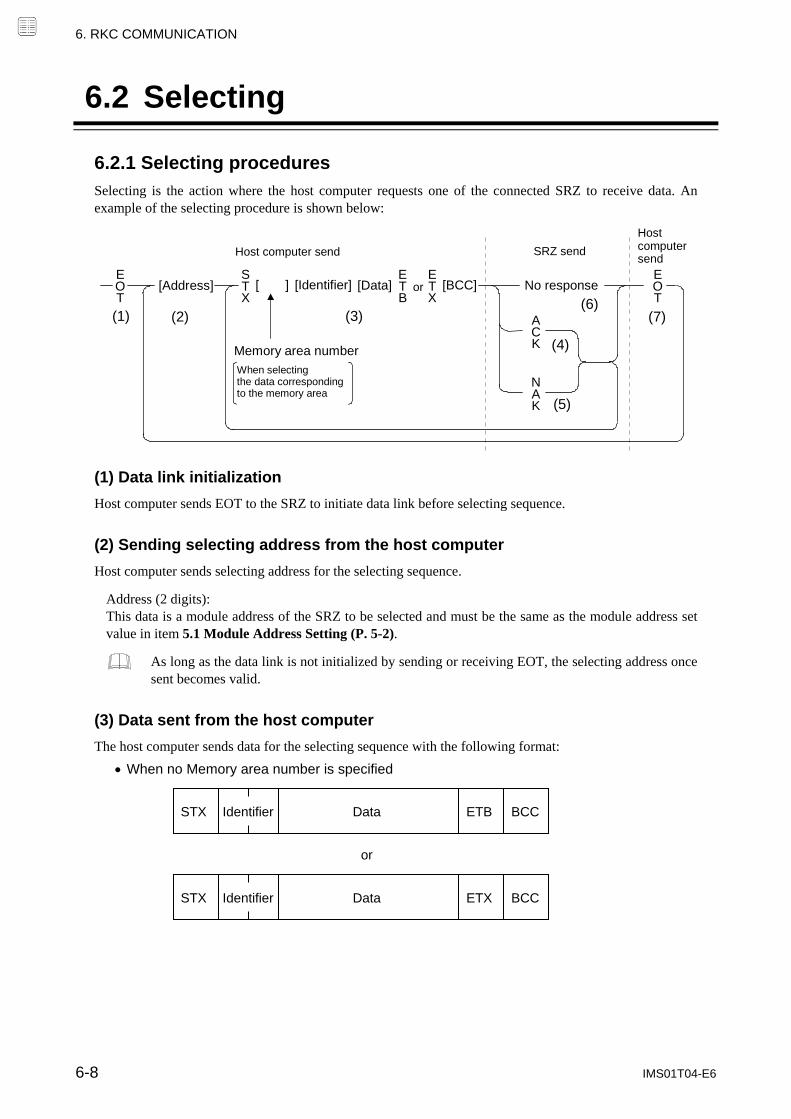
6. RKC COMMUNICATION
6-8 IMS01T04-E6
6.2 Selecting
6.2.1 Selecting procedures
Selecting is the action where the host computer requests one of the connected SRZ to receive data. An example of the selecting procedure is shown below: Host
computer send
[ ]
SRZ send Host computer send
[Data] [BCC]
(1) (2)
(5)
(3)
(4)
(6) [Address]
(7)
orEOT
EOT
STX
ETB
ETX
ACK
NAK
[Identifier]
Memory area number
When selecting the data corresponding to the memory area
No response
(1) Data link initialization
Host computer sends EOT to the SRZ to initiate data link before selecting sequence.
(2) Sending selecting address from the host computer
Host computer sends selecting address for the selecting sequence.
Address (2 digits): This data is a module address of the SRZ to be selected and must be the same as the module address set value in item 5.1 Module Address Setting (P. 5-2).
As long as the data link is not initialized by sending or receiving EOT, the selecting address once sent becomes valid.
(3) Data sent from the host computer
The host computer sends data for the selecting sequence with the following format:
When no Memory area number is specified
Identifier Data BCCETBSTX
Identifier Data BCCETXSTX
or

6. RKC COMMUNICATION
IMS01T04-E6 6-9
When the Memory area number is specified
For the STX, Memory area number, Identifier, Data, ETB, ETX and BCC, refer to 6.1 Polling (P. 6-2).
If the length of send data (from STX to BCC) exceeds 136 bytes, it is divided into blocks by ETB. In this case, the succeeding divided data is sent after STX.
Area soak time set data as the following:
When data range is 0 hour 00 minute to 99 hours 59 minutes: Data range is 0:00 to 99:59, punctuation of time unit is expressed in colon “: (3AH).”
When data range is 0 minute 00 second to 199 minutes 59 seconds: Data range is 0:00 to 199.59, punctuation of time unit is expressed in colon “: (3AH).”
In addition to above, when minute and second data are set in more than 60, become as the following:
Example: 1:65 (1 hour 65 minutes) → 2:05 (2 hours 05 minutes) 0:65 (0 minute 65 seconds) → 1:05 (1 minute 05 seconds)
About numerical data:
The data that receipt of letter is possible Data with numbers below the decimal point omitted or zero-suppressed data can be received.
(Number of digits: Within 7 digits)
<Example> When data send with 001.5, 01.5, 1.5, 1.50, 1.500 at the time of 1.5, SRZ can receive a data.
When the host computer sends data with decimal point to item of without decimal point, the SRZ
receives a message with the value that cut off below the decimal point.
<Example> When setting range is 0 to 200, the SRZ receives as a following.
Send data 0.5 100.5
Receive data 0 100 The SRZ receives value in accordance with decided place after the decimal point. The value below
the decided place after the decimal point is cut off.
<Example> When setting range is 10.00 to 10.00, the controller receives as a following.
Send data .5 .058 .05 0
Receive data 0.50 0.05 0.05 0.00
Data BCC ETBSTX
Data BCC ETXSTX
or
Identifier
Identifier
Memory area
number
Memory area
number

6. RKC COMMUNICATION
IMS01T04-E6 6-10
The data that receipt of letter is impossible The SRZ sends NAK when received a following data.
Plus sign and the data that gained plus sing
Only minus sign (there is no figure)
. Only minus sign and decimal point (period)
(4) ACK (Acknowledgment)
An acknowledgment ACK is sent by the SRZ when data received is correct. When the host computer receives ACK from the SRZ, the host computer will send any remaining data. If there is no more data to be sent to the SRZ, the host computer sends EOT to terminate the data link.
(5) NAK (Negative acknowledge)
If the SRZ does not receive correct data from the host computer, it sends a negative acknowledgment NAK to the host computer. Corrections, such as re-send, must be made at the host computer. The SRZ will send NAK in the following cases:
When an error occurs on communication the line (parity, framing error, etc.)
When a BCC check error occurs
When the specified identifier is invalid
When receive data exceeds the setting range
When receive data is the identifier of RO (read only)
(6) No response from SRZ
The SRZ does not respond when it can not receive the selecting address, STX, ETB, ETX or BCC.
(7) EOT (Data link termination)
The host computer sends EOT when there is no more data to be sent from the host computer or there is no response from the SRZ.

6. RKC COMMUNICATION
IMS01T04-E6 6-11
6.2.2 Selecting procedure example (when the host computer sends data) Normal transmission
E O T
0
1
S T X
K
1
S
1
0
1 4 0 0 . 0
ETX
BCC
04H 30H 31H 02H 4BH 31H 53H 31H 30H 31H 20H 20H 20H 34H 30H 30H 2EH 30H 03H A
C K
06H
S T X
P 1
0
1
ETX
BCC
EOT
02H 50H 31H 30H 31H 20H 03H 04H A
CK
06H
Error transmission
E O T
0
1
S T X
K
1
S
1
0
1 4 0 0 . 0
ETX
BCC
04H 30H 31H 02H 4BH 31H 53H 31H 30H 31H 20H 20H 20H 34H 30H 30H 2EH 30H 03H N
A K
15H
S T X
K 1
S
1
0
1
ETX
BCC
EOT
02H 4BH 31H 53H 31H 30H 31H 20H 03H 04H A
CK
06H
Host computer send Host computer send
Host computer send
SRZ send
SRZ send
*1
Continue to *1
Data Channel No. Identifier Address Memory area
number
*1 Host computer sendHost computer resend
SRZ send
Host computer send
SRZ send
Error data
Continue to *1
Data Channel No.Identifier Address Memory area
number

6. RKC COMMUNICATION
6-12 IMS01T04-E6
6.3 Communication Data Structure
Data description (Transmission/Receive data structure)
STX
ETX
BCC
Part of the data above is shown below. Data for each channel
Data length 7 digits
0
1
1 0 0 . 0 , 0 2
...
Data length 1 digit
0
1
,
0 2
* To select data corresponding to a memory area, specify the number of the appropriate memory area. If a Memory area number is specified for data that does not correspond to a memory area, the specification will be invalid.
Data for each module address (Without channel)
Data length 7 digits Data length 1 digit
Data length 32 digits (Model code) Data length 8 digits (ROM version)
I
D
...
V R ...
........................................................................................................
Data
Comma Space
DataData Identifier Channel No.
Channel No.
Space
Memory area number *
Identifier Data Identifier Data
Identifier Data Identifier Data
Identifier
CommaSpace
DataDataChannel No.
Channel No.
Memory area number *
Space
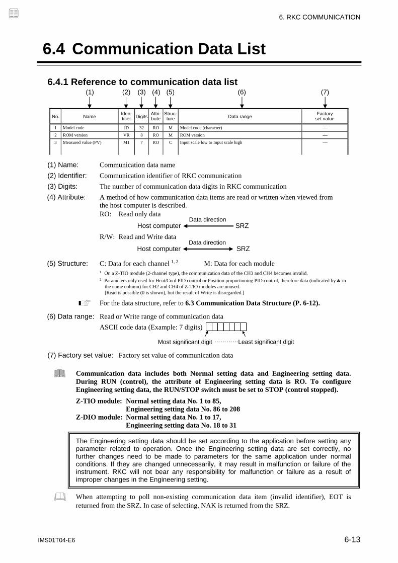
6. RKC COMMUNICATION
IMS01T04-E6 6-13
6.4 Communication Data List
6.4.1 Reference to communication data list
No. Name Iden- tifier Digits
Attri- bute
Struc-ture Data range
Factory set value
1 Model code ID 32 RO M Model code (character)
2 ROM version VR 8 RO M ROM version
3 Measured value (PV) M1 7 RO C Input scale low to Input scale high
(1) Name: Communication data name
(2) Identifier: Communication identifier of RKC communication
(3) Digits: The number of communication data digits in RKC communication
(4) Attribute: A method of how communication data items are read or written when viewed from the host computer is described.
RO: Read only data
R/W: Read and Write data
(5) Structure: C: Data for each channel 1, 2 M: Data for each module
1 On a Z-TIO module (2-channel type), the communication data of the CH3 and CH4 becomes invalid. 2 Parameters only used for Heat/Cool PID control or Position proportioning PID control, therefore data (indicated by in
the name column) for CH2 and CH4 of Z-TIO modules are unused. [Read is possible (0 is shown), but the result of Write is disregarded.]
For the data structure, refer to 6.3 Communication Data Structure (P. 6-12). (6) Data range: Read or Write range of communication data
ASCII code data (Example: 7 digits)
(7) Factory set value: Factory set value of communication data
Communication data includes both Normal setting data and Engineering setting data. During RUN (control), the attribute of Engineering setting data is RO. To configure Engineering setting data, the RUN/STOP switch must be set to STOP (control stopped).
Z-TIO module: Normal setting data No. 1 to 85, Engineering setting data No. 86 to 208 Z-DIO module: Normal setting data No. 1 to 17, Engineering setting data No. 18 to 31
The Engineering setting data should be set according to the application before setting any parameter related to operation. Once the Engineering setting data are set correctly, no further changes need to be made to parameters for the same application under normal conditions. If they are changed unnecessarily, it may result in malfunction or failure of the instrument. RKC will not bear any responsibility for malfunction or failure as a result of improper changes in the Engineering setting.
When attempting to poll non-existing communication data item (invalid identifier), EOT is returned from the SRZ. In case of selecting, NAK is returned from the SRZ.
Most significant digit Least significant digit …………
(1) (2) (3) (4) (5) (6) (7)
Host computerData direction
SRZ
Host computerData direction
SRZ

6. RKC COMMUNICATION
6-14 IMS01T04-E6
6.4.2 Communication data of Z-TIO module
No. Name Iden- tifier Digits
Attri-bute
Struc-ture Data range
Factory set value
1 Model code ID 32 RO M Model code (character)
2 ROM version VR 8 RO M ROM version
3 Measured value (PV) M1 7 RO C Input scale low to Input scale high Varies with the setting of the decimal point position.
4 Comprehensive event state AJ 7 RO C Least significant digit: Event 1 2nd digit: Event 2 3rd digit: Event 3 4th digit: Event 4 5th digit: Heater break alarm (HBA) 6th digit: Temperature rise completion Most significant digit: Burnout
Data 0: OFF 1: ON
5 Operation mode state monitor
L0 7 RO C Least significant digit: Control STOP 2nd digit: Control RUN 3rd digit: Manual mode 4th digit: Remote mode 5th digit to Most significant digit: Unused Data 0: OFF 1: ON
6 Error code ER 7 RO M 1: Adjustment data error 2: Data back-up error 4: A/D conversion error 32: Logic output data error If two or more errors occur simultaneously, the total summation of these error codes is displayed.
7 Manipulated output value (MV) monitor [heat-side]
O1 7 RO C PID control or Heat/Cool PID control: 5.0 to +105.0 %
Position proportioning PID control with feedback resistance (FBR) input: FBR input value is displayed. 0.0 to 100.0 %
8 Manipulated output value (MV) monitor [cool-side]
O2 7 RO C 5.0 to +105.0 %
9 Current transformer (CT) input value monitor
M3 7 RO C CTL-6-P-N: 0.0 to 30.0 A CTL-12-S56-10L-N: 0.0 to 100.0 A
10 Set value (SV) monitor MS 7 RO C Setting limiter low to Setting limiter high Varies with the setting of the decimal point position.
11 Remote setting (RS) input value monitor
S2 7 RO C Setting limiter low to Setting limiter high Varies with the setting of the decimal point position.
12 Burnout state monitor B1 1 RO C 0: OFF 1: ON
13 Event 1 state monitor AA 1 RO C 0: OFF 1: ON If the Event 3 type is Temperature rise completion, check the Temperature rise completion state in the Comprehensive event state (Identifier: AJ). (The Event 3 state monitor does not turn ON.)
14 Event 2 state monitor AB 1 RO C
15 Event 3 state monitor AC 1 RO C
16 Event 4 state monitor AD 1 RO C
17 Heater break alarm (HBA) state monitor
AE 1 RO C 0: OFF 1: ON
18 Output state monitor Q1 7 RO M Least significant digit: OUT1 2nd digit: OUT2 3rd digit: OUT3 4th digit: OUT4 5th digit to Most significant digit: Unused
Data 0: OFF 1: ON
Valid only for time-proportional control output.
Parameters only used for Heat/Cool PID control or Position proportioning PID control, therefore data for CH2 and CH4 of Z-TIO modules are unused.
Continued on the next page.

6. RKC COMMUNICATION
IMS01T04-E6 6-15
Continued from the previous page.
No. Name Iden- tifier Digits
Attri-bute
Struc-ture Data range
Factory set value
19 Memory area soak time monitor
TR 7 RO C 0 minutes 00 seconds to 199 minutes 59 seconds: 0:00 to 199:59 (min:sec)
0 hours 00 minutes to 99 hours 59 minutes: 0:00 to 99:59 (hrs:min) Data range of Area soak time can be selected on the Soak time unit.
20 Integrated operating time monitor
UT 7 RO M 0 to 19999 hours
21 Holding peak value ambient temperature monitor
Hp 7 RO C 10.0 to +100.0 C (14.0 to 212.0 F)
22 Backup memory state monitor
EM 1 RO M 0: The content of the backup memory does not coincide with that of the RAM.
1: The content of the backup memory coincides with that of the RAM.
23 Logic output monitor 1 ED 7 RO M Least significant digit: Logic output 1 2nt digit: Logic output 2 3rd digit: Logic output 3 4th digit: Logic output 4 5th digit to Most significant digit: Unused Data 0: OFF 1: ON
24 Logic output monitor 2 EE 7 RO M Least significant digit: Logic output 5 2nt digit: Logic output 6 3rd digit: Logic output 7 4th digit: Logic output 8 5th digit to Most significant digit: Unused Data 0: OFF 1: ON
25 PID/AT transfer G1 1 R/W C 0: PID control 1: Autotuning (AT) When the Autotuning (AT) is finished, the control will automatically returns to 0: PID control.
0
26 Auto/Manual transfer J1 1 R/W C 0: Auto mode 1: Manual mode
0
27 Remote/Local transfer C1 1 R/W C 0: Local mode 1: Remote mode When performing remote control by Remote setting input and also performing Cascade control and Ratio setting, transfer to the Remote mode.
0
28 RUN/STOP transfer SR 1 R/W M 0: STOP (Control stop) 1: RUN (Control start)
0
29 Memory area transfer ZA 7 R/W C 1 to 8 1
30 Interlock release AR 1 R/W C 0: Normal state 1: Interlock release execution
0
31 Event 1 set value (EV1) ★ A1 7 R/W C Deviation action, Deviation action between channels, Temperature rise completion range: Input span to +Input span Varies with the setting of the decimal point position.
Process action, SV action: Input scale low to Input scale high Varies with the setting of the decimal point position.
MV action: 5.0 to +105.0 % If the Event type corresponds to “0: None,” set to RO (Only reading data is possible). When Temperature rise completion is selected at Event 3 action type. If Event 4 corresponds to “9: Control loop break alarm (LBA),” the Event 4 set value becomes RO (Only reading data is possible).
50 (50.0)
32 Event 2 set value (EV2) ★ A2 7 R/W C 50 (50.0)
33 Event 3 set value (EV3) ★ A3 7 R/W C 50 (50.0)
34 Event 4 set value (EV4) ★ A4 7 R/W C 50 (50.0)
35 Control loop break alarm (LBA) time ★
A5 7 R/W C 0 to 7200 seconds (0: Unused)
480
★ Parameters which can be used in multi-memory area function Continued on the next page.

6. RKC COMMUNICATION
6-16 IMS01T04-E6
Continued from the previous page.
No. Name Iden- tifier Digits
Attri-bute
Struc-ture Data range
Factory set value
36 LBA deadband ★ N1 7 R/W C 0 to Input span Varies with the setting of the decimal point position.
0 (0.0)
37 Set value (SV) ★ S1 7 R/W C Setting limiter low to Setting limiter high Varies with the setting of the decimal point position.
TC/RTD: 0 (0.0)V/I: 0.0
38 Proportional band [heat-side] ★
P1 7 R/W C TC/RTD inputs: 0 to Input span (Unit: C [F]) Varies with the setting of the decimal point position.
Voltage (V)/Current (I) inputs: 0.0 to 1000.0 % of input span
0 (0.0): ON/OFF action (ON/OFF action for both heat and cool actions in case of a Heat/Cool PID control type.)
TC/RTD: 30 (30.0)
V/I: 30.0
39 Integral time [heat-side] ★
I1 7 R/W C PID control or Heat/Cool PID control: 0 to 3600 seconds or 0.0 to 1999.9 seconds (0, 0.0: PD action)
Position proportioning PID control: 1 to 3600 seconds or 0.1 to 1999.9 seconds
Varies with the setting of the Integral/Derivative time decimal point position selection.
240
40 Derivative time [heat-side] ★
D1 7 R/W C 0 to 3600 seconds or 0.0 to 1999.9 seconds (0, 0.0: PI action) Varies with the setting of the Integral/Derivative time decimal point position selection.
60
41 Control response parameter ★
CA 1 R/W C 0: Slow 1: Medium 2: Fast When the P or PD action is selected, this setting becomes invalid.
PID control, Position
proportioning PID control: 0Heat/Cool PID
control: 2
42 Proportional band [cool-side] ★
P2 7 R/W C TC/RTD inputs: 1 (0.1) to Input span (Unit: C [F]) Varies with the setting of the decimal point position.
Voltage (V)/Current (I) inputs: 0.1 to 1000.0 % of input span If control is other than Heat/Cool PID control, set to RO (Only reading data is possible).
TC/RTD: 30 (30.0)
V/I: 30.0
43 Integral time [cool-side] ★
I2 7 R/W C 0 to 3600 seconds or 0.0 to 1999.9 seconds (0, 0.0: PD action) Varies with the setting of the Integral/Derivative time decimal point position selection.
If control is other than Heat/Cool PID control, set to RO (Only reading data is possible).
240
44 Derivative time [cool-side] ★
D2 7 R/W C 0 to 3600 seconds or 0.0 to 1999.9 seconds (0, 0.0: PI action) Varies with the setting of the Integral/Derivative time decimal point position selection.
If control is other than Heat/Cool PID control, set to RO (Only reading data is possible).
60
45 Overlap/Deadband ★ V1 7 R/W C TC/RTD inputs: Input span to +Input span (Unit:C [F]) Varies with the setting of the decimal point position.
Voltage (V)/Current (I) inputs: 100.0 to +100.0 % of input span
Minus () setting results in Overlap.
However, the overlapping range is within the proportional range.
If control is other than Heat/Cool PID control, set to RO (Only reading data is possible).
0 (0.0)
★ Parameters which can be used in multi-memory area function
Parameters only used for Heat/Cool PID control or Position proportioning PID control, therefore data for CH2 and CH4 of Z-TIO modules are unused.
Continued on the next page.

6. RKC COMMUNICATION
IMS01T04-E6 6-17
Continued from the previous page.
No. Name Iden- tifier Digits
Attri-bute
Struc-ture Data range
Factory set value
46 Manual reset ★ MR 7 R/W C 100.0 to +100.0 %
If the Integral function is valid, set to RO (Only reading data is possible).
When Integral action (heating or cooling side) is zero, manual reset value is added to the control output.
0.0
47 Setting change rate limiter (up) ★
HH 7 R/W C 0 to Input span/unit time * 0: Unused Varies with the setting of the decimal point position. * Unit time: 60 seconds (factory set value)
0 (0.0)
48 Setting change rate limiter (down) ★
HL 7 R/W C 0 (0.0)
49 Area soak time ★ TM 7 R/W C 0 minutes 00 seconds to 199 minutes 59 seconds: 0:00 to 199:59 (min:sec)
0 hours 00 minutes to 99 hours 59 minutes: 0:00 to 99:59 (hrs:min)
Data range of Area soak time can be selected on the Soak time unit.
0:00
50 Link area number ★ LP 7 R/W C 0 to 8 (0: No link)
0
51 Heater break alarm (HBA) set value
A7 7 R/W C When CT is CTL-6-P-N: 0.0 to 30.0 A (0.0: Not used)
When CT is CTL-12-S56-10L-N: 0.0 to 100.0 A (0.0: Not used)
If there is no Current transformer (CT) or CT is assigned to “0: None,” set to RO (Only reading data is possible).
0.0
52 Heater break determination point
NE 7 R/W C 0.0 to 100.0 % of HBA set value (0.0: Heater break determination is invalid)
If there is no Current transformer (CT) or CT is assigned to “0: None,” set to RO (Only reading data is possible).
If Heater break alarm (HBA) corresponds to “0: Type A,” set to RO (Only reading data is possible).
30.0
53 Heater melting determination point
NF 7 R/W C 0.0 to 100.0 % of HBA set value (0.0: Heater melting determination is invalid)
If there is no Current transformer (CT) or CT is assigned to “0: None,” set to RO (Only reading data is possible).
If Heater break alarm (HBA) corresponds to “0: Type A,” set to RO (Only reading data is possible).
30.0
54 PV bias PB 7 R/W C Input span to +Input span Varies with the setting of the decimal point position.
0 (0.0)
55 PV digital filter F1 7 R/W C 0.0 to 100.0 seconds (0.0: Unused)
0.0
56 PV ratio PR 7 R/W C 0.500 to 1.500 1.000
57 PV low input cut-off DP 7 R/W C 0.00 to 25.00 % of input span
If the Square root extraction corresponds to “0: Unused,” set to RO (Only reading data is possible).
0.00
58 RS bias * RB 7 R/W C Input span to +Input span Varies with the setting of the decimal point position.
0 (0.0)
59 RS digital filter * F2 7 R/W C 0.0 to 100.0 seconds (0.0: Unused)
0.0
60 RS ratio * RR 7 R/W C 0.001 to 9.999 1.000
61 Output distribution selection
DV 1 R/W C 0: Control output 1: Distribution output
0
* Data on RS bias, RS ratio and RS digital filter is that in Cascade control or Ratio setting.
★ Parameters which can be used in multi-memory area function
Parameters only used for Heat/Cool PID control or Position proportioning PID control, therefore data for CH2 and CH4 of Z-TIO modules are unused.
Continued on the next page.

6. RKC COMMUNICATION
6-18 IMS01T04-E6
Continued from the previous page.
No. Name Iden- tifier Digits
Attri-bute
Struc-ture Data range
Factory set value
62 Output distribution bias DW 7 R/W C 100.0 to 100.0 % 0.0
63 Output distribution ratio DQ 7 R/W C 9.999 to 9.999 1.000
64 Proportional cycle time T0 7 R/W C 0.1 to 100.0 seconds
This item becomes RO (Only reading data is possible) for the Voltage/Current output specification.
This parameter is valid when “0: control output” has been selected at No. 95 “Output assignment.”
Relay contact output: 20.0
Voltage pulse output, Triac output and
Open collector output: 2.0
65 Minimum ON/OFF time of proportioning cycle
VI 7 R/W C 0 to 1000 ms
This item becomes RO (Only reading data is possible) for the Voltage/Current output specification.
0
66 Manual manipulated output value
ON 7 R/W C PID control: Output limiter low to Output limiter high
Heat/Cool PID control: Cool-side output limiter (high) to Heat-side output limiter (high)
Position proportioning PID control: When there is Feedback resistance (FBR) input and it does not break: Output limiter low to Output limiter high
When there is no Feedback resistance (FBR) input or the Feedback resistance (FBR) input is disconnected: 0: Close-side output OFF, Open-side output OFF 1: Close-side output ON, Open-side output OFF 2: Close-side output OFF, Open-side output ON
0.0
67 Area soak time stop function
RV 1 R/W C 0: No function 1: Event 1 2: Event 2 3: Event 3 4: Event 4
0
68 EDS mode (for disturbance 1)
NG 1 R/W C 0: No function 1: EDS function mode 2: Learning mode 3: Tuning mode
EDS function: External disturbance suppression function
0
69 EDS mode (for disturbance 2)
NX 1 R/W C 0
70 EDS value 1 (for disturbance 1)
NI 7 R/W C 100.0 to 100.0 % 0.0
71 EDS value 1 (for disturbance 2)
NJ 7 R/W C 0.0
72 EDS value 2 (for disturbance 1)
NK 7 R/W C 100.0 to 100.0 % 0.0
73 EDS value 2 (for disturbance 2)
NM 7 R/W C 0.0
74 EDS transfer time (for disturbance 1)
NN 7 R/W C 0 to 3600 seconds or 0.0 to 1999.9 seconds 0
75 EDS transfer time (for disturbance 2)
NO 7 R/W C 0
76 EDS action time (for disturbance 1)
NQ 7 R/W C 1 to 3600 seconds 600
77 EDS action time (for disturbance 2)
NL 7 R/W C 600
78 EDS action wait time (for disturbance 1)
NR 7 R/W C 0.0 to 600.0 seconds 0.0
79 EDS action wait time (for disturbance 2)
NY 7 R/W C 0.0
Parameters only used for Heat/Cool PID control or Position proportioning PID control, therefore data for CH2 and CH4 of Z-TIO modules are unused.
Continued on the next page.

6. RKC COMMUNICATION
IMS01T04-E6 6-19
Continued from the previous page.
No. Name Iden- tifier Digits
Attri-bute
Struc-ture Data range
Factory set value
80 EDS value learning times NT 7 R/W C 0 to 10 times (0: No learning mode)
1
81 EDS start signal NU 1 R/W C 0: EDS start signal OFF 1: EDS start signal ON (for disturbance 1) 2: EDS start signal ON (for disturbance 2)
0
82 Operation mode EI 1 R/W C 0: Unused 1: Monitor 2: Monitor Event function 3: Control
3
83 Startup tuning (ST) ST 1 R/W C 0: ST unused 1: Execute once * 2: Execute always * When the Startup tuning (ST) is finished, the setting will
automatically returns to “0: ST unused.”
The Startup tuning (ST) function is activated according to the ST start condition selected. If control is Position proportioning PID control, set to RO (Only reading data is possible).
0
84 Automatic temperature rise learning
Y8 1 R/W C 0: Unused 1: Learning * * When the automatic temperature rise learning is finished,
the setting will automatically returns to “0: Unused.”
0
85 Communication switch for logic
EF 7 R/W M Least significant digit: Communication switch 1 2nd digit: Communication switch 2 3rd digit: Communication switch 3 4th digit: Communication switch 4 5th digit to Most significant digit: Unused
Data 0: OFF 1: ON
0
Set data No. 86 or later are for engineering setting [Writable in the STOP mode]
86 Input type XI 7 R/W C 0: TC input K 1: TC input J 2: TC input R 3: TC input S 4: TC input B 5: TC input E 6: TC input N 7: TC input T 8: TC input W5Re/W26Re 9: TC input PLII 12: RTD input Pt100 13: RTD input JPt100 14: Current input 0 to 20 mA DC 15: Current input 4 to 20 mA DC 16: Voltage (high) input 0 to 10 V DC 17: Voltage (high) input 0 to 5 V DC 18: Voltage (high) input 1 to 5 V DC 19: Voltage (low) input 0 to 1 V DC 20: Voltage (low) input 0 to 100 mV DC 21: Voltage (low) input 0 to 10 mV DC 22: Feedback resistance input 100 to 150 23: Feedback resistance input 151 to 6 k
If changed to Voltage (high) input from TC/RTD/Current/Voltage (low)/Feedback resistance input, select the hardware by the input selector switch at the side of the module. (Refer to P. 8-70)
Based on model code
When not specifying: 0
Continued on the next page.

6. RKC COMMUNICATION
6-20 IMS01T04-E6
Continued from the previous page.
No. Name Iden- tifier Digits
Attri-bute
Struc-ture Data range
Factory set value
87 Display unit PU 7 R/W C 0: C 1: F
Use to select the temperature unit for Thermocouple (TC) and RTD inputs.
Based on model code When not
specifying: 0
88 Decimal point position XU 7 R/W C 0: No decimal place 1: One decimal place 2: Two decimal places 3: Three decimal places 4: Four decimal places
TC input: K, J, T, E Only 0 or 1 can be set. R, S, B, N, PLII, W5Re/W26Re Only 0 can be set. RTD input: Only 0 or 1 can be set. V/I inputs: From 0 to 4 can be set.
Based on model code
If input range
code is not specified: 1
89 Input scale high XV 7 R/W C TC/RTD inputs: Input scale low to Maximum value of the selected input range
Voltage (V)/Current (I) inputs: 19999 to +19999 (However, a span is 20000 or less.)
Varies with the setting of the decimal point position.
TC/RTD: Maximum value of the selected
input range
V/I: 100.0
If input range code is not
specified: 1372.0
90 Input scale low XW 7 R/W C TC/RTD inputs: Minimum value of the selected input range to Input scale high
Voltage (V)/Current (I) inputs: 19999 to +19999 (However, a span is 20000 or less.)
Varies with the setting of the decimal point position.
TC/RTD: Minimum value of the selected
input range
V/I: 0.0
If input range code is not
specified: 200.0
91 Input error determination point (high)
AV 7 R/W C Input error determination point (low) to (Input range high 5 % of input span)
Varies with the setting of the decimal point position.
Input range high (5 % of input
span)
92 Input error determination point (low)
AW 7 R/W C (Input range low 5 % of input span) to Input error determination point (high)
Varies with the setting of the decimal point position.
Input range low (5 % of input
span)
93 Burnout direction BS 1 R/W C 0: Upscale 1: Downscale
Valid only when the TC input and Voltage (low) input are selected.
0
94 Square root extraction XH 1 R/W C 0: Unused 1: Used
0
95 Output assignment (Logic output selection function)
E0 1 R/W C 0: Control output 1: Logic output result 2: FAIL output
0
96 Energized/De-energized
(Logic output selection function)
NA 1 R/W C 0: Energized 1: De-energized
0
Continued on the next page.

6. RKC COMMUNICATION
IMS01T04-E6 6-21
Continued from the previous page.
No. Name Iden- tifier Digits
Attri-bute
Struc-ture Data range
Factory set value
97 Event 1 type XA 7 R/W C 0: None 1: Deviation high (Using SV monitor value) 1 2: Deviation low (Using SV monitor value) 1 3: Deviation high/low (Using SV monitor value) 1 4: Band (Using SV monitor value) 1 5: Process high 1 6: Process low 1 7: SV high 8: SV low 9: Unused 10: MV high [heat-side] 1, 2 11: MV low [heat-side] 1, 2 12: MV high [cool-side] 1 13: MV low [cool-side] 1
14: Deviation high (Using local SV) 1 15: Deviation low (Using local SV) 1 16: Deviation high/low (Using local SV) 1 17: Band (Using local SV) 1 18: Deviation between channels high 1 19: Deviation between channels low 1 20: Deviation between channels high/low 1 21: Deviation between channels band 1 1 Event hold action is available. 2 If there is Feedback resistance (FBR) input in Position
proportioning PID control, set to the Feedback resistance (FBR) input value.
Based on model code
When not
specifying: 0
98 Event 1 channel setting FA 1 R/W C 1: Channel 1 2: Channel 2 3: Channel 3 4: Channel 4 This function is valid when “Deviation between channels” is selected.
1
99 Event 1 hold action WA 1 R/W C 0: OFF 1: Hold action ON (when power turned on; when transferred from STOP to RUN) 2: Re-hold action ON (when power turned on; when transferred from STOP to RUN; SV changed)
This function is valid when input value, deviation or manipulated value action has been selected.
In case of a deviation action, this function is not available while in Remote mode and while Setting changing rate limiter is working.
Based on model code
When not
specifying: 0
100 Event 1 interlock LF 1 R/W C 0: Unused 1: Used
0
101 Event 1 differential gap HA 7 R/W C Deviation, Process, Set value, or Deviation action between channels: 0 to Input span (Unit: C [F]) Varies with the setting of the decimal point position.
MV: 0.0 to 110.0 %
: 1 (1.0) : 1.0
102 Event 1 delay timer TD 7 R/W C 0 to 18000 seconds 0
103 Force ON of Event 1 action OA 7 R/W C Least significant digit: Event output turned on at input error occurrence
2nd digit: Event output turned on in Manual mode 3rd digit: Event output turned on during the
Autotuning (AT) function is being executed
4th digit: Event output turned on during the Setting change rate limiter is being operated
5th digit to Most significant digit: Unused
Data 0: Invalid 1: Valid
0
Continued on the next page.

6. RKC COMMUNICATION
6-22 IMS01T04-E6
Continued from the previous page.
No. Name Iden- tifier Digits
Attri-bute
Struc-ture Data range
Factory set value
104 Event 2 type XB 7 R/W C 0: None 1: Deviation high (Using SV monitor value) 1 2: Deviation low (Using SV monitor value) 1 3: Deviation high/low (Using SV monitor value) 1 4: Band (Using SV monitor value) 1 5: Process high 1 6: Process low 1 7: SV high 8: SV low 9: Unused 10: MV high [heat-side] 1, 2 11: MV low [heat-side] 1, 2 12: MV high [cool-side] 1 13: MV low [cool-side] 1 14: Deviation high (Using local SV) 1 15: Deviation low (Using local SV) 1 16: Deviation high/low (Using local SV) 1 17: Band (Using local SV) 1 18: Deviation between channels high 1 19: Deviation between channels low 1 20: Deviation between channels high/low 1 21: Deviation between channels band 1 1 Event hold action is available. 2 If there is Feedback resistance (FBR) input in Position
proportioning PID control, set to the Feedback resistance (FBR) input value.
Based on model code
When not
specifying: 0
105 Event 2 channel setting FB 1 R/W C 1: Channel 1 2: Channel 2 3: Channel 3 4: Channel 4 This function is valid when “Deviation between channels” is selected.
1
106 Event 2 hold action WB 1 R/W C 0: OFF 1: Hold action ON (when power turned on; when transferred from STOP to RUN) 2: Re-hold action ON (when power turned on; when transferred from STOP to RUN; SV changed)
This function is valid when input value, deviation or manipulated value action has been selected.
In case of a deviation action, this function is not available while in Remote mode and while Setting changing rate limiter is working.
Based on model code
When not
specifying: 0
107 Event 2 interlock LG 1 R/W C 0: Unused 1: Used
0
108 Event 2 differential gap HB 7 R/W C Deviation, Process, Set value, or Deviation action between channels: 0 to Input span (Unit: C [F]) Varies with the setting of the decimal point position.
MV: 0.0 to 110.0 %
: 1 (1.0) : 1.0
109 Event 2 delay timer TG 7 R/W C 0 to 18000 seconds 0
110 Force ON of Event 2 action OB 7 R/W C Least significant digit: Event output turned on at input error occurrence
2nd digit: Event output turned on in Manual mode 3rd digit: Event output turned on during the
Autotuning (AT) function is being executed
4th digit: Event output turned on during the Setting change rate limiter is being operated
5th digit to Most significant digit: Unused
Data 0: Invalid 1: Valid
0
Continued on the next page.

6. RKC COMMUNICATION
IMS01T04-E6 6-23
Continued from the previous page.
No. Name Iden- tifier Digits
Attri-bute
Struc-ture Data range
Factory set value
111 Event 3 type XC 7 R/W C 0: None 1: Deviation high (Using SV monitor value) 1 2: Deviation low (Using SV monitor value) 1 3: Deviation high/low (Using SV monitor value) 1 4: Band (Using SV monitor value) 1 5: Process high 1 6: Process low 1 7: SV high 8: SV low 9: Temperature rise completion 10: MV high [heat-side] 1, 2 11: MV low [heat-side] 1, 2 12: MV high [cool-side] 1 13: MV low [cool-side] 1
14: Deviation high (Using local SV) 1 15: Deviation low (Using local SV) 1 16: Deviation high/low (Using local SV) 1 17: Band (Using local SV) 1 18: Deviation between channels high 1 19: Deviation between channels low 1 20: Deviation between channels high/low 1 21: Deviation between channels band 1 1 Event hold action is available. 2 If there is Feedback resistance (FBR) input in Position
proportioning PID control, set to the Feedback resistance (FBR) input value.
Based on model code
When not
specifying: 0
112 Event 3 channel setting FC 1 R/W C 1: Channel 1 2: Channel 2 3: Channel 3 4: Channel 4
This function is valid when “Deviation between channels” is selected.
1
113 Event 3 hold action WC 1 R/W C 0: OFF 1: Hold action ON (when power turned on; when transferred from STOP to RUN) 2: Re-hold action ON (when power turned on; when transferred from STOP to RUN; SV changed) This function is valid when input value, deviation or manipulated value action has been selected. In case of a deviation action, this function is not available while in Remote mode and while Setting changing rate limiter is working.
Based on model code
When not
specifying: 0
114 Event 3 interlock LH 1 R/W C 0: Unused 1: Used
0
115 Event 3 differential gap HC 7 R/W C Deviation, Process, Set value, Deviation action between channels or Temperature rise completion: 0 to Input span (Unit: C [F]) Varies with the setting of the decimal point position.
MV: 0.0 to 110.0 %
: 1 (1.0) : 1.0
116 Event 3 delay timer TE 7 R/W C 0 to 18000 seconds If Event 3 corresponds to “9: Temperature rise completion,” the Event 3 delay timer becomes the Temperature rise completion soak time.
0
117 Force ON of Event 3 action OC 7 R/W C Least significant digit: Event output turned on at input error occurrence
2nd digit: Event output turned on in Manual mode 3rd digit: Event output turned on during the
Autotuning (AT) function is being executed
4th digit: Event output turned on during the Setting change rate limiter is being operated
5th digit to Most significant digit: Unused
Data 0: Invalid 1: Valid
0
Continued on the next page.

6. RKC COMMUNICATION
6-24 IMS01T04-E6
Continued from the previous page.
No. Name Iden- tifier Digits
Attri-bute
Struc-ture Data range
Factory set value
118 Event 4 type XD 7 R/W C 0: None 1: Deviation high (Using SV monitor value) 1 2: Deviation low (Using SV monitor value) 1 3: Deviation high/low (Using SV monitor value) 1 4: Band (Using SV monitor value) 1 5: Process high 1 6: Process low 1 7: SV high 8: SV low 9: Control loop break alarm (LBA) 10: MV high [heat-side] 1, 2 11: MV low [heat-side] 1, 2 12: MV high [cool-side] 1 13: MV low [cool-side] 1
14: Deviation high (Using local SV) 1 15: Deviation low (Using local SV) 1 16: Deviation high/low (Using local SV) 1 17: Band (Using local SV) 1 18: Deviation between channels high 1 19: Deviation between channels low 1 20: Deviation between channels high/low 1 21: Deviation between channels band 1 1 Event hold action is available. 2 If there is Feedback resistance (FBR) input in Position
proportioning PID control, set to the Feedback resistance (FBR) input value.
Based on model code
When not
specifying: 0
119 Event 4 channel setting FD 1 R/W C 1: Channel 1 2: Channel 2 3: Channel 3 4: Channel 4 This function is valid when “Deviation between channels” is selected.
1
120 Event 4 hold action WD 1 R/W C 0: OFF 1: Hold action ON (when power turned on; when transferred from STOP to RUN) 2: Re-hold action ON (when power turned on; when transferred from STOP to RUN; SV changed) This function is valid when input value, deviation or manipulated value action has been selected. In case of a deviation action, this function is not available while in Remote mode and while Setting changing rate limiter is working.
Based on model code
When not
specifying: 0
121 Event 4 interlock LI 1 R/W C 0: Unused 1: Used
0
122 Event 4 differential gap HD 7 R/W C Deviation, Process, Set value, or Deviation action between channels: 0 to Input span (Unit: C [F]) Varies with the setting of the decimal point position.
MV: 0.0 to 110.0 % Becomes invalid when the Event 4 type corresponds to “9: Control loop break alarm (LBA).”
: 1 (1.0) : 1.0
123 Event 4 delay timer TF 7 R/W C 0 to 18000 seconds 0
124 Force ON of Event 4 action OD 7 R/W C Least significant digit: Event output turned on at input error occurrence
2nd digit: Event output turned on in Manual mode 3rd digit: Event output turned on during the
Autotuning (AT) function is being executed
4th digit: Event output turned on during the Setting change rate limiter is being operated
5th digit to Most significant digit: Unused
Data 0: Invalid 1: Valid Becomes invalid when the Event 4 type corresponds to “9: Control loop break alarm (LBA).”
0
Continued on the next page.

6. RKC COMMUNICATION
IMS01T04-E6 6-25
Continued from the previous page.
No. Name Iden- tifier Digits
Attri-bute
Struc-ture Data range
Factory set value
125 CT ratio XS 7 R/W C 0 to 9999 CTL-6-P-N: 800 CTL-12-S56-10L
-N: 1000
126 CT assignment ZF 1 R/W C 0: None 3: OUT3 1: OUT1 4: OUT4 2: OUT2
CH1: 1 CH2: 2 CH3: 4 CH4: 4
127 Heater break alarm (HBA) type
ND 1 R/W C 0: Heater break alarm (HBA) type A (Time-proportional control output) 1: Heater break alarm (HBA) type B (Continuous control output) Time-proportional control output:
Relay, Voltage pulse, Triac, or Open collector output Continuous control output:
Voltage/Current continuous output
Set value is based on the Output
type specified at ordering.
128 Number of heater break alarm (HBA) delay times
DH 7 R/W C 0 to 255 times 5
129 Hot/Cold start XN 1 R/W C 0: Hot start 1 1: Hot start 2 2: Cold start
0
130 Start determination point SX 7 R/W C 0 to Input span (The unit is the same as input value.) 0: Action depending on the Hot/Cold start selection Varies with the setting of the decimal point position.
Based on specification
131 SV tracking XL 1 R/W C 0: Unused 1: Used
1
132 MV transfer function [Action taken when changed to Manual mode from Auto mode]
OT 1 R/W C 0: MV in Auto mode is used. [Balanceless-bumpless function] 1: MV in previous Manual mode is used.
0
133 Control action XE 1 R/W C 0: Brilliant II PID control (Direct action) 1: Brilliant II PID control (Reverse action) 2: Brilliant II Heat/Cool PID control [Water cooling type] 3: Brilliant II Heat/Cool PID control [Air cooling type] 4: Brilliant II Heat/Cool PID control [Cooling gain linear type] 5: Brilliant II Position proportioning PID control
Odd channel: From 0 to 5 can be set. Even channel: Only 0 or 1 can be set. *
* In Heat/Cool PID control and Position proportioning PID control, control action is not performed. Only PV monitor and event action is performed.
Based on model code
When not specifying: 1
134 Integral/Derivative time decimal point position
PK 1 R/W C 0: 1 second setting (No decimal place) 1: 0.1 seconds setting (One decimal place)
0
135 Derivative action KA 1 R/W C 0: Measured value derivative 1: Deviation derivative
0
136 Undershoot suppression factor
KB 7 R/W C 0.000 to 1.000 Water cooling: 0.100
Air cooling: 0.250
Cooling gain linear type:
1.000
137 Derivative gain DG 7 R/W C 0.1 to 10.0 6.0
138 ON/OFF action differential gap (upper)
IV 7 R/W C TC/RTD inputs: 0 to Input span (Unit: C [F]) Varies with the setting of the decimal point position.
Voltage (V)/Current (I) inputs: 0.0 to 100.0 % of input span
TC/RTD: 1 (1.0)
V/I: 0.1
139 ON/OFF action differential gap (lower)
IW 7 R/W C TC/RTD: 1 (1.0)
V/I: 0.1
Parameters only used for Heat/Cool PID control or Position proportioning PID control, therefore data for CH2 and CH4 of Z-TIO modules are unused.
Continued on the next page.

6. RKC COMMUNICATION
6-26 IMS01T04-E6
Continued from the previous page.
No. Name Iden- tifier Digits
Attri-bute
Struc-ture Data range
Factory set value
140 Action (high) at input error
WH 1 R/W C 0: Normal control 1: Manipulated output value at input error
0
141 Action (low) at input error
WL 1 R/W C 0
142 Manipulated output value at input error
OE 7 R/W C 105.0 to 105.0 %
Actual output values become those restricted by the output limiter.
Position proportioning PID control: If there is no Feedback resistance (FBR) input or the Feedback resistance (FBR) input is disconnected, an action taken when abnormal is in accordance with the value action setting during STOP.
0.0
143 Manipulated output value at STOP mode [heat-side]
OF 7 R/W C 5.0 to 105.0 % Position proportioning PID control: Only when there is Feedback resistance (FBR) input and it does not break, the Manipulated output value [heat-side] at STOP is output.
5.0
144 Manipulated output value at STOP mode [cool-side]
OG 7 R/W C 5.0
145 Output change rate limiter (up) [heat-side]
PH 7 R/W C 0.0 to 100.0 % of manipulated output /seconds (0.0: OFF)
Becomes invalid when in Position proportioning PID control.
0.0
146 Output change rate limiter (down) [heat-side]
PL 7 R/W C 0.0
147 Output limiter high [heat-side]
OH 7 R/W C Output limiter low to 105.0 % Position proportioning control: Becomes valid only when there is Feedback resistance (FBR) input and it does not break.
105.0
148 Output limiter low [heat-side]
OL 7 R/W C 5.0 % to Output limiter high Position proportioning PID control: Becomes valid only when there is Feedback resistance (FBR) input and it does not break.
5.0
149 Output change rate limiter (up) [cool-side]
PX 7 R/W C 0.0 to 100.0 % of manipulated output /seconds (0.0: OFF)
Becomes invalid when in Position proportioning PID control.
0.0
150 Output change rate limiter (down) [cool-side]
PY 7 R/W C 0.0
151 Output limiter high [cool-side]
OX 7 R/W C Output limiter low [cool-side] to 105.0 % 105.0
152 Output limiter low [cool-side]
OY 7 R/W C 5.0 % to Output limiter high [cool-side] 5.0
153 AT bias GB 7 R/W C Input span to +Input span
Varies with the setting of the decimal point position.
0 (0.0)
154 AT cycles G3 1 R/W C 0: 1.5 cycles 1: 2.0 cycles 2: 2.5 cycles 3: 3.0 cycles
1
155 Output value with AT turned on
OP 7 R/W C Output value with AT turned off to 105.0 % Actual output values become those restricted by the output limiter. Position proportioning PID control: Becomes valid only when there is Feedback resistance (FBR) input and it does not break (high limit of feedback resistance input at AT).
105.0
156 Output value with AT turned off
OQ 7 R/W C 105.0 % to Output value with AT turned on Actual output values become those restricted by the output limiter. Position proportioning PID control: Becomes valid only when there is Feedback resistance (FBR) input and it does not break (low limit of feedback resistance input at AT).
105.0
Parameters only used for Heat/Cool PID control or Position proportioning PID control, therefore data for CH2 and CH4 of Z-TIO modules are unused.
Continued on the next page.

6. RKC COMMUNICATION
IMS01T04-E6 6-27
Continued from the previous page.
No. Name Iden- tifier Digits
Attri-bute
Struc-ture Data range
Factory set value
157 AT differential gap time GH 7 R/W C 0.0 to 50.0 seconds 10.0
158 Proportional band adjusting factor [heat-side]
KC 7 R/W C 0.01 to 10.00 times 1.00
159 Integral time adjusting factor [heat-side]
KD 7 R/W C 0.01 to 10.00 times 1.00
160 Derivative time adjusting factor [heat-side]
KE 7 R/W C 0.01 to 10.00 times 1.00
161 Proportional band adjusting factor [cool-side]
KF 7 R/W C 0.01 to 10.00 times 1.00
162 Integral time adjusting factor [cool-side]
KG 7 R/W C 0.01 to 10.00 times 1.00
163 Derivative time adjusting factor [cool-side]
KH 7 R/W C 0.01 to 10.00 times 1.00
164 Proportional band limiter (high) [heat-side]
P6 7 R/W C TC/RTD inputs: 0 to Input span (Unit: C [F]) Varies with the setting of the decimal point position.
Voltage (V)/Current (I) inputs: 0.0 to 1000.0 % of input span 0 (0.0): ON/OFF action (ON/OFF action for both heat and cool actions in case of a Heat/Cool PID control type.)
TC/RTD: Input span
V/I: 1000.0
165 Proportional band limiter (low) [heat-side]
P7 7 R/W C TC/RTD: 0 (0.0)
V/I: 0.0
166 Integral time limiter (high) [heat-side]
I6 7 R/W C PID control or Heat/Cool PID control: 0 to 3600 seconds or 0.0 to 1999.9 seconds
Position proportioning PID control: 1 to 3600 seconds or 0.1 to 1999.9 seconds
Varies with the setting of the Integral/Derivative time decimal point position selection.
3600
167 Integral time limiter (low) [heat-side]
I7 7 R/W C PID control, Heat/Cool PID
control: 0 Position
proportioning PID control: 1
168 Derivative time limiter (high) [heat-side]
D6 7 R/W C 0 to 3600 seconds or 0.0 to 1999.9 seconds
Varies with the setting of the Integral/Derivative time decimal point position selection.
3600
169 Derivative time limiter (low) [heat-side]
D7 7 R/W C 0
170 Proportional band limiter (high) [cool-side]
P8 7 R/W C TC/RTD inputs: 1 (0.1) to Input span (Unit: C [F])
Varies with the setting of the decimal point position.
Voltage (V)/Current (I) inputs: 0.1 to 1000.0 % of input span
TC/RTD: Input span
V/I: 1000.0
171 Proportional band limiter (low) [cool-side]
P9 7 R/W C TC/RTD: 1 (0.1)
V/I: 0.1
172 Integral time limiter (high) [cool-side]
I8 7 R/W C 0 to 3600 seconds or 0.0 to 1999.9 seconds
Varies with the setting of the Integral/Derivative time decimal point position selection.
If control is other than Heat/Cool PID control, set to RO (Only reading data is possible).
3600
173 Integral time limiter (low) [cool-side]
I9 7 R/W C 0
174 Derivative time limiter (high) [cool-side]
D8 7 R/W C 0 to 3600 seconds or 0.0 to 1999.9 seconds
Varies with the setting of the Integral/Derivative time decimal point position selection.
If control is other than Heat/Cool PID control, set to RO (Only reading data is possible).
3600
175 Derivative time limiter (low) [cool-side]
D9 7 R/W C 0
176 Open/Close output neutral zone
V2 7 R/W C 0.1 to 10.0 % of output 2.0
Parameters only used for Heat/Cool PID control or Position proportioning PID control, therefore data for CH2 and CH4 of Z-TIO modules are unused.
Continued on the next page.

6. RKC COMMUNICATION
6-28 IMS01T04-E6
Continued from the previous page.
No. Name Iden- tifier Digits
Attri-bute
Struc-ture Data range
Factory set value
177 Action at feedback resistance (FBR) input error
SY 1 R/W C 0: Action depending on the valve action at STOP 1: Control action continued
0
178 Feedback adjustment FV 1 R/W C 0: Adjustment end 1: During adjustment on the open-side 2: During adjustment on the close-side
179 Control motor time TN 7 R/W C 5 to 1000 seconds 10
180 Integrated output limiter OI 7 R/W C 0.0 to 200.0 % of control motor time (0.0: OFF)
Becomes invalid when there is Feedback resistance (FBR) input.
150.0
181 Valve action at STOP VS 1 R/W C 0: Close-side output OFF, Open-side output OFF 1: Close-side output ON, Open-side output OFF 2: Close-side output OFF, Open-side output ON
Becomes valid when there is no Feedback resistance (FBR) input or the Feedback resistance (FBR) input is disconnected.
0
182 ST proportional band adjusting factor
KI 7 R/W C 0.01 to 10.00 times 1.00
183 ST integral time adjusting factor
KJ 7 R/W C 0.01 to 10.00 times 1.00
184 ST derivative time adjusting factor
KK 7 R/W C 0.01 to 10.00 times 1.00
185 ST start condition SU 1 R/W C 0: Activate the Startup tuning (ST) function when the power is turned on; when transferred from STOP to RUN; or when the Set value (SV) is changed.
1: Activate the Startup tuning (ST) function when the power is turned on; or when transferred from STOP to RUN.
2: Activate the Startup tuning (ST) function when the Set value (SV) is changed.
0
186 Automatic temperature rise group
Y7 7 R/W C 0 to 16 (0: Automatic temperature rise function OFF)
0
187 Automatic temperature rise dead time
RT 7 R/W C 0.1 to 1999.9 seconds 10.0
188 Automatic temperature rise gradient data
R2 7 R/W C 1 (0.1) to Input span/minutes
Varies with the setting of the decimal point position. 1 (1.0)
189 EDS transfer time decimal point position
NS 1 R/W C 0: 1 second setting (No decimal place) 1: 0.1 seconds setting (One decimal place)
0
190 Output average processing time for EDS
NV 7 R/W C 0.1 to 200.0 seconds 1.0
191 Responsive action trigger point for EDS
NW 7 R/W C 0 to Input span Varies with the setting of the decimal point position.
TC/RTD: 1 (1.0)
V/I: 1.0
192 Setting change rate limiter unit time
HU 7 R/W C 1 to 3600 seconds 60
193 Soak time unit RU 1 R/W C 0: 0:00 to 99:59 (hrs:min) [0 hours 00 minutes to 99 hours 59 minutes] 1: 0:00 to 199:59 (min:sec) [0 minutes 00 seconds to 199 minutes 59 seconds] Set the data range of Memory area soak time monitor and Area soak time.
1
194 Setting limiter high SH 7 R/W C Setting limiter low to Input scale high
Varies with the setting of the decimal point position.
Input scale high
195 Setting limiter low SL 7 R/W C Input scale low to Setting limiter high
Varies with the setting of the decimal point position.
Input scale low
Parameters only used for Heat/Cool PID control or Position proportioning PID control, therefore data for CH2 and CH4 of Z-TIO modules are unused.
Continued on the next page.

6. RKC COMMUNICATION
IMS01T04-E6 6-29
Continued from the previous page.
No. Name Iden- tifier Digits
Attri-bute
Struc-ture Data range
Factory set value
196 PV transfer function
TS 1 R/W C 0: Unused 1: Used
0
197 Operation mode assignment 1 (Logic output selection function)
Logic output 1 to 4
EA 7 R/W C 0: No assignment 1: Operation mode (Monitor/Control) 2: Operation mode (Monitor Event function/Control) 3: Auto/Manual 4: Remote/Local 5: Unused (Do not set this one)
0
198 Operation mode assignment 2 (Logic output selection function)
Logic output 5 to 8
EB 7 R/W C 0: No assignment 1: Operation mode (Monitor/Control) 2: Operation mode (Monitor Event function/Control) 3: Auto/Manual 4: Remote/Local 5: Unused (Do not set this one)
0
199 SV select function KM 1 R/W C 0: Remote SV function 1: Cascade control function 2: Ratio setting function 3: Cascade control 2 function
0
200 Remote SV function master channel module address
MC 7 R/W C 1 (Master channel is selected from itself)
0 to 99 (Master channel is selected from other modules)
1
201 Remote SV function master channel selection
MN 7 R/W C 1 to 99 1
202 Output distribution master channel module address
DY 7 R/W C 1 (Master channel is selected from itself)
0 to 99 (Master channel is selected from other modules)
1
203 Output distribution master channel selection
DZ 7 R/W C 1 to 99 1
204 Address of interacting modules
RL 7 R/W C 1 (Interact with its own module address)
0 to 99 (Interact with the addresses of other modules) 1
205 Channel selection of interacting modules
RM 7 R/W C 1 to 99
Becomes valid when the selected module is “Z-TIO module.”
1
206 Selection switch of interacting modules
RN 7 R/W C Least significant digit: Memory area number 2nd digit: Operation mode 3rd digit: Auto/Manual 4th digit: Remote/Local 5th digit EDS start signal 6th digit Interlock release Most significant digit: Suspension of area soak time
Data 0: No interaction 1: Interact with other channels
0
207 Control RUN/STOP holding setting
X1 1 R/W M 0: Not holding (STOP start) 1: Holding (RUN/STOP hold)
1
208 Interval time ZX 7 R/W M 0 to 250 ms 10

6. RKC COMMUNICATION
6-30 IMS01T04-E6
6.4.3 Communication data of Z-DIO module
No. Name Iden- tifier Digits
Attri-bute
Struc-ture Data range
Factory set value
1 Model code
ID 32 RO M Model code (character)
2 ROM version
VR 8 RO M ROM version
3 Digital input (DI) state 1 L1 7 RO M Least significant digit: DI1 2nd digit: DI2 3rd digit: DI3 4th digit: DI4 5th digit to Most significant digit: Unused
Data 0: Contact open 1: Contact closed
4 Digital input (DI) state 2 L6 7 RO M Least significant digit: DI5 2nd digit: DI6 3rd digit: DI7 4th digit: DI8 5th digit to Most significant digit: Unused
Data 0: Contact open 1: Contact closed
5 Digital output (DO) state 1 Q2 7 RO M Least significant digit: DO1 2nd digit: DO2 3rd digit: DO3 4th digit: DO4 5th digit to Most significant digit: Unused
Data 0: OFF 1: ON
6 Digital output (DO) state 2 Q3 7 RO M Least significant digit: DO5 2nd digit: DO6 3rd digit: DO7 4th digit: DO8 5th digit to Most significant digit: Unused
Data 0: OFF 1: ON
7 Error code
ER 7 RO M 2: Data back-up error
8 Integrated operating time monitor
UT 7 RO M 0 to 19999 hours
9 Backup memory state monitor
EM 1 RO M 0: The content of the backup memory does not coincide with that of the RAM. 1: The content of the backup memory coincides with that of the RAM.
10 RUN/STOP transfer SR 1 R/W M 0: STOP (Control stop) 1: RUN (Control start)
0
11 DO manual output 1 Q4 7 R/W M Least significant digit: DO1 manual output 2nd digit: DO2 manual output 3rd digit: DO3 manual output 4th digit: DO4 manual output 5th digit to Most significant digit: Unused
Data 0: OFF 1: ON
0
12 DO manual output 2 Q5 7 R/W M Least significant digit: DO5 manual output 2nd digit: DO6 manual output 3rd digit: DO7 manual output 4th digit: DO8 manual output 5th digit to Most significant digit: Unused
Data 0: OFF 1: ON
0
13 DO output distribution selection
DO 1 R/W C 0: DO output 1: Distribution output
0
14 DO output distribution bias
O8 7 R/W C 100.0 to 100.0 % 0.0
Continued on the next page.

6. RKC COMMUNICATION
IMS01T04-E6 6-31
Continued from the previous page.
No. Name Iden- tifier Digits
Attri-bute
Struc-ture Data range
Factory set value
15 DO output distribution ratio
O9 7 R/W C 9.999 to 9.999 1.000
16 DO proportional cycle time V0 7 R/W C 0.1 to 100.0 seconds Relay contact output: 20.0
Open collector output: 2.0
17 DO minimum ON/OFF time of proportioning cycle
VJ 7 R/W C 0 to 1000 ms 0
Set data No. 18 or later are for engineering setting [Writable in the STOP mode]
18 DI function assignment H2 7 R/W M 0 to 29
(Refer to page 8-154) Depends on model code When not
specifying: 0
19 Memory area setting signal E1 1 R/W M 0: Valid 1: Invalid
1
20 DO signal assignment module address 1
LQ 7 R/W M 1, 0 to 99
When “1” is selected, all of the signals of the same type (except temperature rise completion and DO manual output value) are OR-operated and produced as outputs from DO.
1
21 DO signal assignment module address 2
LR 7 R/W M 1, 0 to 99
When “1” is selected, all of the signals of the same type (except temperature rise completion and DO manual output value) are OR-operated and produced as outputs from DO.
1
22 DO output assignment 1 [DO1 to DO4]
LT 7 R/W M 0 to 13 (Refer to page 8-158)
Depends on model code When not
specifying: 0
23 DO output assignment 2 [DO5 to DO8]
LX 7 R/W M 0 to 13 (Refer to page 8-158)
Depends on model code When not
specifying: 0
24 DO energized/de-energized NB 1 R/W C 0: Energized 1: De-energized
0
25 DO output distribution master channel module address
DD 7 R/W C 1 (Master channel is selected from itself)
0 to 99 (Master channel is selected from other modules)
1
26 DO output distribution master channel selection
DJ 7 R/W C 1 to 99 1
27 DO manipulated output value (MV) at STOP mode
OJ 7 R/W C 5.0 to 105.0 % 5.0
28 DO output limiter (high)
D3 7 R/W C DO output limiter (low) to 105.0 % 105.0
29 DO output limiter (low)
D4 7 R/W C 5.0 % to DO output limiter (high) 5.0
30 Control RUN/STOP holding setting
X1 1 R/W M 0: Not holding (STOP start) 1: Holding (RUN/STOP hold)
1
31 Interval time
ZX 7 R/W M 0 to 250 ms 10

6-32 IMS01T04-E6
MEMO

MODBUS
IMS01T04-E6 7-1
7.1 Communication Protocol .................................................................. 7-2 7.1.1 Message format ........................................................................................ 7-2 7.1.2 Function code ........................................................................................... 7-3 7.1.3 Communication mode ............................................................................... 7-3 7.1.4 Slave responses ....................................................................................... 7-4 7.1.5 Calculating CRC-16 .................................................................................. 7-5
7.2 Register Read and Write .................................................................. 7-8 7.2.1 Read holding registers [03H] ................................................................... 7-8 7.2.2 Preset single register [06H] ..................................................................... 7-9 7.2.3 Diagnostics (Loopback test) [08H] ........................................................ 7-10 7.2.4 Preset multiple registers [10H] .............................................................. 7-11
7.3 Data Processing Precautions ......................................................... 7-12
7.4 How to Use Memory Area Data ...................................................... 7-13
7.5 How to Use Data Mapping .............................................................. 7-17
7.6 Communication Data List ............................................................... 7-18 7.6.1 Reference to communication data list ..................................................... 7-18 7.6.2 Communication data of Z-TIO module .................................................... 7-19 7.6.3 Communication data of Z-DIO module.................................................... 7-39 7.6.4 Memory area data address (Z-TIO) ......................................................... 7-42 7.6.5 Data mapping address (Z-TIO, Z-DIO) .................................................... 7-44

7. MODBUS
7-2 IMS01T04-E6
7.1 Communication Protocol
The master controls communication between master and slave. A typical message consists of a request (query message) sent from the master followed by an answer (response message) from the slave (SRZ). When master begins data transmission, a set of data is sent to the slave in a fixed sequence. When it is received, the slave decodes it, takes the necessary action, and returns data to the master.
Data send/receive state can be monitored by using our communication tool (PROTEM2). The communication tool (PROTEM2) can be downloaded from the official RKC website: http://www.rkcinst.com/.
7.1.1 Message format
The message consists of four parts: slave address, function code, data, and error check code which are always transmitted in the same sequence. Slave address
The slave address is a number from 0 to F manually set at the module address setting switch located at the front of the function module (Z-TIO, Z-DIO, Z-CT and Z-COM).
For details, refer to 5.1 Module Address Setting (P. 5-2). Although all connected slave units receive the query message sent from the master, only the slave with the slave address coinciding with the query message will accept the message.
Function code
The function codes are the instructions set at the master and sent to the slave describing the action to be
executed. The function codes are included when the slave responds to the master.
For details, refer to 7.1.2 Function code (P. 7-3).
Data
The data to execute the function specified by the function code is sent to the slave and corresponding data returned to the master from the slave.
For details, refer to 7.2 Register Read and Write (P. 7-8), 7.3 Data Processing Precautions (P. 7-12) and 7.6 Communication Data List (P. 7-18).
Error check
An error checking code (CRC-16: Cyclic Redundancy Check) is used to detect an error in the signal transmission.
For details, refer to 7.1.5 Calculating CRC-16 (P. 7-5).
Slave address
Function code
Data
Error check CRC-16
Message format

7. MODBUS
IMS01T04-E6 7-3
7.1.2 Function code
Function code contents
Function code (Hexadecimal)
Function Contents
03H Read holding registers Measured value, control output value, current transformer input measured value, Event status, etc.
06H Preset single register Set value, PID constants, event set value, etc.
08H Diagnostics (loopback test) Loopback test
10H Preset multiple registers Set value, PID constants, event set value, etc.
Message length of each function (Unit: byte)
Function code Function
Query message Response message
(Hexadecimal) Min Max Min Max
03H Read holding registers 8 8 7 255
06H Preset single register 8 8 8 8
08H Diagnostics (loopback test) 8 8 8 8
10H Preset multiple registers 11 255 8 8
7.1.3 Communication mode
Signal transmission between the master and slaves is conducted in Remote Terminal Unit (RTU) mode.
Items Contents
Data bit length 8-bit (Binary)
Start mark of message Unused
End mark of message Unused
Message length Refer to 7.1.2 Function code
Data time interval Less than 24-bit time *
Error check CRC-16 (Cyclic Redundancy Check)
* When sending a command message from the master, set intervals of data configuring one message to time shorter than the 24-bit
time. If time intervals become time longer than the 24-bit time the relevant slave assumes that message sending from the master is
terminated to deform the message format. As a result, the slave does not make a response.

7. MODBUS
IMS01T04-E6 7-4
7.1.4 Slave responses
(1) Normal response
In the response message of the Read Holding Registers, the slave returns the read out data and the number of data items with the same slave address and function code as the query message.
In the response message of the Preset Single Register, the slave returns the same message as the query message.
In the response message of the Diagnostics (Loopback test), the slave returns the same message as the query message.
In the response message of the Preset Multiple Registers, the slave returns the slave address, the function code, starting number, and number of holding registers in the multi-query message.
(2) Defective message response
If the query message from the master is defective, except for transmission error, the slave returns the error response message without any action.
If the self-diagnostic function of the slave detects an error, the slave will return an error response message to all query messages.
The function code of each error response message is obtained by adding 80H to the function code of the query message.
Error code Contents
1 Function code error (An unsupported function code was specified)
2 When the mismatched address is specified.
3 When the specified number of data items in the query message exceeds the maximum number of data items available
When the data written exceeds the setting range
4 Self-diagnostic error response
(3) No response
The slave ignores the query message and does not respond when:
The slave address in the query message does not coincide with any slave address settings.
The CRC code of the master does not coincide with that of the slave.
Transmission error such as overrun, framing, parity and etc., is found in the query message.
Data time interval in the query message from the master exceeds 24-bit time.
Slave address
Function code
Error code
Error check CRC-16
Error response message

7. MODBUS
IMS01T04-E6 7-5
7.1.5 Calculating CRC-16
The Cyclic Redundancy Check (CRC) is a 2 byte (16-bit) error check code. After constructing the data message, not including start, stop, or parity bit, the master calculates a CRC code and appends this to the end of the message. The slave will calculate a CRC code from the received message, and compare it with the CRC code from the master. If they do not match, a communication error has occurred and the slave does not respond. The CRC code is formed in the following sequence:
1. Load FFFFH to a 16-bit CRC register.
2. Exclusive OR () the first byte (8 bits) of the message with the CRC register. Return the result to the CRC register.
3. Shift the CRC register 1 bit to the right.
4. If the carry flag is 1, exclusive OR the CRC register with A001 hex and return the result to the CRC register. If the carry flag is 0, repeat step 3.
5. Repeat step 3 and 4 until there have been 8 shifts.
6. Exclusive OR the next byte (8 bits) of the message with the CRC register.
7. Repeat step 3 through 6 for all bytes of the message (except the CRC).
8. The CRC register contains the 2 byte CRC error code. When they are appended to the message, the low-order byte is appended first, followed by the high-order byte.

7. MODBUS
IMS01T04-E6 7-6
The flow chart of CRC-16
START
FFFFH CRC Register
0 n
Shift CRC Register 1 bit to the right
Carry flag is 1 No
Yes
CRC Register A001H CRC Register
n + 1 n
No
Yes
n 7
No
Yes
Is message complete ?
END
CRC Register next byte of the message CRC Register
Reverse with high-order byte and low-order byte of CRC register
The symbol indicates an exclusive OR operation. The symbol for the number of data bits is n.

7. MODBUS
IMS01T04-E6 7-7
Example of a CRC calculation in the ‘C’ language
This routine assumes that the data types ‘uint16’ and ‘uint8’ exists. Theses are unsigned 16-bit integer (usually an ‘unsigned short int’ for most compiler types) and unsigned 8-bit integer (unsigned char). ‘z_p’ is a pointer to a Modbus message, and ‘z_messaage_length’ is its length, excluding the CRC. Note that the Modbus message will probably contain NULL characters and so normal C string handling techniques will not work. uint16 calculate_crc(byte *z_p, unit16 z_message_length) /* CRC runs cyclic Redundancy Check Algorithm on input z_p */ /* Returns value of 16 bit CRC after completion and */ /* always adds 2 crc bytes to message */ /* returns 0 if incoming message has correct CRC */ {
uint16 CRC= 0xffff; uint16 next; uint16 carry; uint16 n; uint8 crch, crcl; while (z_messaage_length--) {
next = (uint16) *z_p; CRC ^= next; for (n = 0; n < 8; n++) {
carry = CRC & 1; CRC >>= 1; if (carry) {
CRC ^= 0xA001; }
} z_p++;
} crch = CRC / 256; crcl = CRC % 256 z_p [z_messaage_length++] = crcl; z_p [z_messaage_length] = crch; return CRC;
}

7. MODBUS
7-8 IMS01T04-E6
7.2 Register Read and Write
7.2.1 Read holding registers [03H]
The query message specifies the starting register address and quantity of registers to be read. The contents of the holding registers are entered in the response message as data, divided into two parts: the high-order 8-bit and the low-order 8-bit, arranged in the order of the register numbers.
Example: The contents of the four holding registers from 0000H to 0003H are the read out from slave
address 2. Query message
Slave address 02HFunction code 03HStarting No. High 00H
Low 00H
Quantity High 00H Low 04HCRC-16 High 44H Low 3AH
Normal response message
Slave address 02HFunction code 03HNumber of data 08HFirst holding register contents High 01H
Low 24H
Next holding register contents High 01H
Low 1BH
Next holding register contents High 01H
Low 2BH
Next holding register contents High 01H
Low 22H
CRC-16 High AAH Low F3H
Error response message
Slave address 02H80H Function code 83HError code 03HCRC-16 High F1H Low 31H
First holding register address
The setting must be between 1 (0001H) and 125 (007DH).
Number of holding registers 2
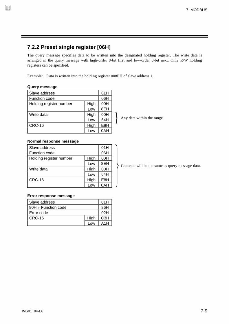
7. MODBUS
IMS01T04-E6 7-9
7.2.2 Preset single register [06H]
The query message specifies data to be written into the designated holding register. The write data is arranged in the query message with high-order 8-bit first and low-order 8-bit next. Only R/W holding registers can be specified.
Example: Data is written into the holding register 008EH of slave address 1.
Query message
Slave address 01HFunction code 06HHolding register number High 00H Low 8EHWrite data High 00H Low 64HCRC-16 High E8H Low 0AH
Normal response message
Slave address 01HFunction code 06HHolding register number High 00H Low 8EHWrite data High 00H Low 64HCRC-16 High E8H Low 0AH
Error response message
Slave address 01H80H Function code 86HError code 02HCRC-16 High C3H Low A1H
Any data within the range
Contents will be the same as query message data.

7. MODBUS
IMS01T04-E6 7-10
7.2.3 Diagnostics (Loopback test) [08H]
The master’s query message will be returned as the response message from the slave. This function checks the communication system between the master and slave.
Example: Loopback test for slave address 1 Query message
Slave address 01HFunction code 08HTest code High 00H Low 00HData High 1FH Low 34HCRC-16 High E9H Low ECH
Normal response message
Slave address 01HFunction code 08HTest code High 00H Low 00HData High 1FH Low 34HCRC-16 High E9H Low ECH
Error response message
Slave address 01H80H Function code 88HError code 03HCRC-16 High 06H Low 01H
Test code must be set to 00.
Contents will be the same as query message data.
Any pertinent data

7. MODBUS
IMS01T04-E6 7-11
7.2.4 Preset multiple registers [10H]
The query message specifies the starting register address and quantity of registers to be written. The write data is arranged in the query message with high-order 8-bit first and low-order 8-bit next. Only R/W holding registers can be specified.
Example: Data is written into the two holding registers from 008EH to 008FH of slave address 1.
Query message
Slave address 01HFunction code 10HStarting number High 00H Low 8EHQuantity High 00H Low 02HNumber of data 04HData to first register High 00H Low 64H
Data to next register High 00H Low 64H
CRC-16 High 3AH Low 77H
Normal response message
Slave address 01HFunction code 10HStarting number High 00H Low 8EHQuantity High 00H Low 02HCRC-16 High 21H Low E3H
Error response message
Slave address 01H80H Function code 90HError code 02HCRC-16 High CDH Low C1H
First holding register address
The setting must be between 1 (0001H) and 123 (007BH).
Number of holding registers 2
Any pertinent data

7. MODBUS
7-12 IMS01T04-E6
7.3 Data Processing Precautions
The numeric range of data used in Modbus protocol is 0000H to FFFFH. Only the set value within the setting range is effective.
FFFFH represents 1. The Modbus protocol does not recognize data with decimal points during communication.
Example1: When Heater break alarm (HBA) set value is 20.0 A, 20.0 is processed as 200, 200 = 00C8H
Heater break alarm (HBA) High 00H
set value Low C8H
Example2: When Set value (SV) is 20.0 C, 20.0 is processed as 200, 200 = 0000H 00C8H FF38H
Set value (SV) High FFH
Low 38H
In this communication, the variables that memory area includes handles different address with for
Control area and for setting area.
If data (holding register) exceeding the accessible address range is accessed, an error response message is returned.
Read data of unused item is a default value.
Any attempt to write to an unused item is not processed as an error. Data can not be written into an unused item.
If an error (data range error or address error) is detected in the data writing process, an error is returned. Writing is aborted at and after the addresses where an error occurred. After having completed the setting, check to see if the data was properly written.
An attribute of the item for functions which are not in the controller is RO (read only). If read action to this item is performed, the read data will be “0.” If write action to this item is performed, no error message is indicated and no data is written.
For details, refer to 7.6 Communication Data List (P. 7-18). Commands should be sent at time intervals of 24 bits after the master receives the response message.

7. MODBUS
IMS01T04-E6 7-13
7.4 How to Use Memory Area Data
Memory area function can store up to 8 individual sets of SVs and parameters. One of the areas is used for control, and the currently selected area is Control area. Memory area data can be used to check and change settings that belong to memory areas other than the Control area. Reading and writing of memory area data is performed by channel. Read and write of memory area data
If any Memory area number to perform data read and write is specified by the Setting memory area number (0500H to 0503H), data corresponding to the specified memory area number is called up to the register addresses from 0504H to 0553H. By using these register addresses from 0504H to 0553H, it becomes possible to read and write data in any memory area.
Register address CH1 CH2 CH3 CH4
Setting memory area number 0500H 0501H 0502H 0503H Register address to specify memory area Event 1 set value (EV1) 0504H 0505H 0506H 0507H Event 2 set value (EV2) 0508H 0509H 050AH 050BH Event 3 set value (EV3) 050CH 050DH 050EH 050FH Event 4 set value (EV4) 0510H 0511H 0512H 0513H Control loop break alarm (LBA) time 0514H 0515H 0516H 0517H LBA deadband 0518H 0519H 051AH 051BH Set value (SV) 051CH 051DH 051EH 051FH Proportional band [heat-side] 0520H 0521H 0522H 0523H Integral time [heat-side] 0524H 0525H 0526H 0527H Derivative time [heat-side] 0528H 0529H 052AH 052BH Register address of memory area data Control response parameter 052CH 052DH 052EH 052FH Proportional band [cool-side] 0530H 0531H 0532H 0533H Integral time [cool-side] 0534H 0535H 0536H 0537H Derivative time [cool-side] 0538H 0539H 053AH 053BH Overlap/Deadband 053CH 053DH 053EH 053FH Manual reset 0540H 0541H 0542H 0543H Setting change rate limiter (up) 0544H 0545H 0546H 0547H Setting change rate limiter (down) 0548H 0549H 054AH 054BH Area soak time 054CH 054DH 054EH 054FH Link area number 0550H 0551H 0552H 0553H
For the Memory area data list, refer to the 7.6.4 Memory area data address (P. 7-42).
Event 1 set value (EV1) (0504H) Event 2 set value (EV2) (0508H) Event 3 set value (EV3) (050CH) Event 4 set value (EV4) (0510H) Control loop break alarm (LBA) time (0514H) LBA deadband (0518H) Set value (SV) (0501C) Proportional band [heat-side] (0520H) Integral time [heat-side] (0524H) Derivative time [heat-side] (0528H) Control response parameter (052CH) Proportional band [cool-side] (0530H) Integral time [cool-side] (0534H) Derivative time [cool-side] (0538H) Overlap/Deadband (053CH) Manual reset (0540H) Setting change rate limiter (up) (0544H) Setting change rate limiter (down) (0548H) Area soak time (054CH) Link area number (0550H)
A memory area number which data is read/written is written to the register address, 0500H (for CH1).
Data corresponding to a specified memory area number is called up to the CH1 register addresses.
Memory area 8
Memory area 2
Memory area 1
CH1
Memory area 8
Memory area 2
Memory area 1
CH4

7. MODBUS
IMS01T04-E6 7-14
[Example 1] When data on the Event 1 set value in Memory area 2 of CH1 is read
1. The Memory area number, “2” is written to the CH1 Setting memory area number (0500H). Data in Memory area 2 is called up to the CH1 register addresses.
CH1 register addresses
Setting memory area number 0500H 2 Memory area number “2” Event 1 set value (EV1) 0504H 50 Event 2 set value (EV2) 0508H Event 3 set value (EV3) 050CH Event 4 set value (EV4) 0510H Control loop break alarm (LBA) time 0514H LBA deadband 0518H Set value (SV) 051CH Proportional band [heat-side] 0520H Integral time [heat-side] 0524H Derivative time [heat-side] 0528H The data of memory area 2 is loaded into these register addresses. Control response parameter 052CH Proportional band [cool-side] 0530H Integral time [cool-side] 0534H Derivative time [cool-side] 0538H Overlap/Deadband 053CH Manual reset 0540H Setting change rate limiter (up) 0544H Setting change rate limiter (down) 0548H Area soak time 054CH Link area number 0550H
2. Data “50” on Event 1 set values (0504H) is read.
[Example 2] When the Set value (SV) in Memory area 3 of CH1 is changed to 200
1. The Memory area number, “3” is written to the CH1 Setting memory area number (0500H). Data in Memory area 3 is called up to the CH1 register addresses.
CH1 register addresses
Setting memory area number 0500H 3 Memory area number “3” Event 1 set value (EV1) 0504H Event 2 set value (EV2) 0508H Event 3 set value (EV3) 050CH Event 4 set value (EV4) 0510H Control loop break alarm (LBA) time 0514H LBA deadband 0518H Set value (SV) 051CH 150 Proportional band [heat-side] 0520H Integral time [heat-side] 0524H Derivative time [heat-side] 0528H The data of memory area 3 is loaded into these register addresses. Control response parameter 052CH Proportional band [cool-side] 0530H Integral time [cool-side] 0534H Derivative time [cool-side] 0538H Overlap/Deadband 053CH Manual reset 0540H Setting change rate limiter (up) 0544H Setting change rate limiter (down) 0548H Area soak time 054CH Link area number 0550H
2. “200” is written to the Set value (SV) (051CH).

7. MODBUS
IMS01T04-E6 7-15
Control area transfer
Any memory area used for control is specified by the Memory area transfer (006EH to 0071H). The area (0076H to 00C5H) now used for control is called Control area.
The Memory area number (Control area) can be changed at either RUN or STOP.
Register address CH1 CH2 CH3 CH4
Memory area transfer 006EH 006FH 0070H 0071H Register address to specify Control area Event 1 set value (EV1) 0076H 0077H 0078H 0079H Event 2 set value (EV2) 007AH 007BH 007CH 007DH Event 3 set value (EV3) 007EH 007FH 0080H 0081H Event 4 set value (EV4) 0082H 0083H 0084H 0085H Control loop break alarm (LBA) time 0086H 0087H 0088H 0089H LBA deadband 008AH 008BH 008CH 008DH Set value (SV) 008EH 008FH 0090H 0091H Proportional band [heat-side] 0092H 0093H 0094H 0095H Integral time [heat-side] 0096H 0097H 0098H 0099H Derivative time [heat-side] 009AH 009BH 009CH 009DH Register address of memory area data Control response parameter 009EH 009FH 00A0H 00A1H Proportional band [cool-side] 00A2H 00A3H 00A4H 00A5H Integral time [cool-side] 00A6H 00A7H 00A8H 00A9H Derivative time [cool-side] 00AAH 00ABH 00ACH 00ADH Overlap/Deadband 00AEH 00AFH 00B0H 00B1H Manual reset 00B2H 00B3H 00B4H 00B5H Setting change rate limiter (up) 00B6H 00B7H 00B8H 00B9H Setting change rate limiter (down) 00BAH 00BBH 00BCH 00BDH Area soak time 00BEH 00BFH 00C0H 00C1H Link area number 00C2H 00C3H 00C4H 00C5H
Any memory area number used for control is written to the register address, 006EH (for CH1).
-Control area- Event 1 set value (EV1) (0076H) Event 2 set value (EV2) (007AH) Event 3 set value (EV3) (007EH) Event 4 set value (EV4) (0082H) Control loop break alarm (LBA) time (0086H) LBA deadband (008AH) Set value (SV) (008EH) Proportional band [heat-side] (0092H) Integral time [heat-side] (0096H) Derivative time [heat-side] (0096A) Control response parameter (009EH) Proportional band [cool-side] (00A2H) Integral time [cool-side] (00A6H) Derivative time [cool-side] (00AAH) Overlap/Deadband (00AEH) Manual reset (00B2H) Setting change rate limiter (up) (00B6H) Setting change rate limiter (down) (00BAH) Area soak time (00BEH) Link area number (00C2H)
Data corresponding to a specified Memory area number is called up to the CH1 register addresses.
Memory area 8
Memory area 2
Memory area 1
CH1
Memory area 8
Memory area 2
Memory area 1
CH4

7. MODBUS
IMS01T04-E6 7-16
[Example] When performing control by calling up data in Memory area 3 of CH1
1. The Memory area number, “3” is written to the Memory area transfer (006EH). Data in Memory area 3 is called up to the CH1 register addresses.
CH1 register addresses
Memory area transfer 006EH 3 Memory area number, “3” Event 1 set value (EV1) 0076H Event 2 set value (EV2) 007AH Event 3 set value (EV3) 007EH Event 4 set value (EV4) 0082H Control loop break alarm (LBA) time 0086H LBA deadband 008AH Set value (SV) 008EH Proportional band [heat-side] 0092H Integral time [heat-side] 0096H Derivative time [heat-side] 009AH The data of memory area 3 is loaded into these register addresses. Control response parameter 009EH Proportional band [cool-side] 00A2H Integral time [cool-side] 00A6H Derivative time [cool-side] 00AAH Overlap/Deadband 00AEH Manual reset 00B2H Setting change rate limiter (up) 00B6H Setting change rate limiter (down) 00BAH Area soak time 00BEH Link area number 00C2H
2. Control of CH1 is performed by using data in the register addresses.
If the Memory area transfer (006EH to 0071H) and the Setting memory area number (0500H to 0503H) are set to the same Memory area number, the respective data can be synchronized.
Values in the Control areas (0076H to 00C5H) become the same as those in the memory areas (0504H to 0553H).
If data in the Control area is changed, data in the memory area is also changed. If data in the memory area is changed, data in the Control area is also changed.

7. MODBUS
IMS01T04-E6 7-17
7.5 How to Use Data Mapping
When this communication method is used, 16 types of data (mapping data) can be specified as desired for the Z-TIO and Z-DIO modules, and read/write can be performed continuously.
Z-TIO module Z-DIO module
Register address to specify mapping data 1000H to 100FH 1000H to 100FH
Register address to actually read/write data 1500H to 150FH 1500H to 150FH
Register address of data which can be mapped Refer to 7.6.2 Communication data of Z-TIO module (P. 7-19).
Refer to 7.6.3 Communication data of Z-DIO module (P. 7-39).
For the data mapping address list, refer to the 7.6.5 Data mapping address (P. 7-44). [Example] Mapping the CH1 data “Measured value (PV), Manipulated output value (MV) monitor [heat-side], Event 1 state monitor, Event 2 state monitor” of a Z-TIO module to register addresses 1500H to 1503H.
For data mapping Mapping data
Name Register address
Name Register address (CH1)
HEX DEC HEX DEC
Register address setting 1 Read/write address: 1500H
1000 4096 Measured value (PV) 0000 0
Register address setting 2 Read/write address: 1501H
1001 4097 Manipulated output value (MV) monitor [heat-side]
000D 13
Register address setting 3 Read/write address: 1502H
1002 4098 Event 1 state monitor 0025 37
Register address setting 4 Read/write address: 1503H
1003 4099 Event 2 state monitor 0029 41
1. The register address, “0000H” of the Measured value (PV) to be mapped is written to register address setting 1 (1000H).
2. The register address, “000DH” of the Manipulated output value (MV) monitor [heat-side] to be mapped is written to register address setting 2 (1001H).
3. The register address, “0025H” of the Event 1 state monitor to be mapped is written to register address setting 3 (1002H).
4. The register address, “0029H” of the Event 2 state monitor to be mapped is written to register address setting 4 (1003H).
5. The assignment of the register addresses from 1500H to 1503H from/to which data is actually read/written becomes as follows.
Register address
Name HEX DEC
1500 5376 Measured value (PV) 1501 5377 Manipulated output value (MV) monitor [heat-side]
1502 5378 Event 1 state monitor
1503 5379 Event 2 state monitor
Write
High-speed communication is performed by reading or writing data in the consecutive register addresses from 1500H to 1503H.

7. MODBUS
7-18 IMS01T04-E6
7.6 Communication Data List
7.6.1 Reference to communication data list
No. Name Chan-
nel
Resister address Attri-bute
Struc-ture
Data range Factory
set value HEX DEC
1 Measured value (PV) CH1 CH2 CH3 CH4
0000 0001 0002 0003
0 1 2 3
RO C Input scale low to Input scale high Varies with the setting of the decimal point position.
2 Comprehensive event CH1 0004 4 RO C Bit data
(1) Name: Communication data name (2) Channel: Channel numbers of each Z-TIO and Z-DIO module (3) Register address: Register addresses of each channel (HEX: Hexadecimal DEC: Decimal)
With respect to the following communication data of the Z-TIO module, the register addresses of the indicated channels are non-used areas. 2-channel type module: Register addresses of the CH3 and CH4 Heat/Cool PID control and Position proportioning PID control: Register addresses of the CH2 and CH4 * Cool-only communication data of Heat/Cool PID control: Register addresses of the CH2 and CH4 *
* Communication data with a mark in the name column. (4) Attribute: A method of how communication data items are read or written when viewed from the
host computer is described RO: Read only data
R/W: Read and write data
(5) Structure: C: Data for each channel M: Data for each module (6) Data range: Read or write range of communication data
Bit 15 Bit 0…………….……………………
16-bit data (bit image)
(7) Factory set value: Factory set value of communication data
Communication data includes both Normal setting data and Engineering setting data. During RUN (control), the attribute of Engineering setting data is RO. To configure Engineering setting data, the RUN/STOP switch must be set to STOP (control stopped).
Z-TIO module: Normal setting data No. 1 to 83, Engineering setting data No. 85 to 207 Z-DIO module: Normal setting data No. 1 to 13, Engineering setting data No. 15 to 28
The Engineering setting data should be set according to the application before setting any parameter related to operation. Once the Engineering setting data are set correctly, no further changes need to be made to parameters for the same application under normal conditions. If they are changed unnecessarily, it may result in malfunction or failure of the instrument. RKC will not bear any responsibility for malfunction or failure as a result of improper changes in the Engineering setting.
An attribute of the item for functions which are not in the controller is RO (read only). If read action to this item is performed, the read data will be “0.” If write action to this item is performed, no error message is indicated and no data is written.
(1) (2) (3) (4) (5) (6)
(7)
Host computerData direction
SRZ
Host computerData direction
SRZ

7. MODBUS
IMS01T04-E6 7-19
7.6.2 Communication data of Z-TIO module
No. Name Chan-
nel Register address Attri-
buteStruc-ture
Data range Factory
set valueHEX DEC
1 Measured value (PV) CH1 CH2 CH3 CH4
0000 0001 0002 0003
0 1 2 3
RO C Input scale low to Input scale high Varies with the setting of the decimal point position.
2 Comprehensive event state
CH1 CH2 CH3 CH4
0004 0005 0006 0007
4 5 6 7
RO C Bit data Bit 0: Event 1 Bit 1: Event 2 Bit 2: Event 3 Bit 3: Event 4 Bit 4: Heater break alarm (HBA) Bit 5: Temperature rise completion Bit 6: Burnout Bit 7 to Bit 15: Unused Data 0: OFF 1: ON
[Decimal number: 0 to 127]
3 Operation mode state monitor
CH1 CH2 CH3 CH4
0008 0009 000A 000B
8 9 10 11
RO C Bit data Bit 0: Control STOP Bit 1: Control RUN Bit 2: Manual mode Bit 3: Remote mode Bit 4 to Bit 15: Unused Data 0: OFF 1: ON
[Decimal number: 0 to 15]
4 Error code 000C 12 RO M Bit data Bit 0: Adjustment data error Bit 1: Data back-up error Bit 2: A/D conversion error Bit 3: Unused Bit 4: Unused Bit 5: Logic output data error Bit 6 to Bit 15: Unused Data 0: OFF 1: ON [Decimal number: 0 to 63]
If two or more errors occur simultaneously, the total summation of these error codes is displayed.
5 Manipulated output value (MV) monitor [heat-side]
CH1 CH2 CH3 CH4
000D 000E 000F 0010
13 14 15 16
RO C PID control or Heat/Cool PID control: 5.0 to 105.0 %
Position proportioning PID control with feedback resistance (FBR) input: 0.0 to 100.0 %
6 Manipulated output value (MV) monitor [cool-side]
CH1 Unused CH3
Unused
0011 Unused 0013
Unused
17 Unused
19 Unused
RO C 5.0 to 105.0 %
7 Current transformer (CT) input value monitor
CH1 CH2 CH3 CH4
0015 0016 0017 0018
21 22 23 24
RO C CTL-6-P-N: 0.0 to 30.0 A CTL-12-S56-10L-N: 0.0 to 100.0 A
8 Set value (SV) monitor CH1 CH2 CH3 CH4
0019 001A 001B 001C
25 26 27 28
RO C Setting limiter low to Setting limiter high Varies with the setting of the decimal point position.
9 Remote setting (RS) input value monitor
CH1 CH2 CH3 CH4
001D 001E 001F 0020
29 30 31 32
RO C Setting limiter low to Setting limiter high Varies with the setting of the decimal point position.
Parameters only used for Heat/Cool PID control or Position proportioning PID control, therefore data for CH2 and CH4 of Z-TIO modules are unused.
Continued on the next page.

7. MODBUS
7-20 IMS01T04-E6
Continued from the previous page.
No. Name Chan-
nel Register address Attri-
buteStruc-ture
Data range Factory
set valueHEX DEC
10 Burnout state monitor CH1 CH2 CH3 CH4
0021 0022 0023 0024
33 34 35 36
RO C 0: OFF 1: ON
11 Event 1 state monitor CH1 CH2 CH3 CH4
0025 0026 0027 0028
37 38 39 40
RO C 0: OFF 1: ON If the Event 3 type is Temperature rise completion, check the Temperature rise completion state in the Comprehensive event state (Identifier: AJ). (The Event 3 state monitor does not turn ON.)
12 Event 2 state monitor CH1 CH2 CH3 CH4
0029 002A 002B 002C
41 42 43 44
RO C
13 Event 3 state monitor CH1 CH2 CH3 CH4
002D 002E 002F 0030
45 46 47 48
RO C
14 Event 4 state monitor CH1 CH2 CH3 CH4
0031 0032 0033 0034
49 50 51 52
RO C
15 Heater break alarm (HBA) state monitor
CH1 CH2 CH3 CH4
0035 0036 0037 0038
53 54 55 56
RO C 0: OFF 1: ON
16 Output state monitor 0039 57 RO M Bit data Bit 0: OUT1 Bit 1: OUT2 Bit 2: OUT3 Bit 3: OUT4 Bit 4 to Bit 15: Unused Data 0: OFF 1: ON [Decimal number: 0 to 15]
Valid only for time-proportional control output.
17 Memory area soak time monitor
CH1 CH2 CH3 CH4
003A 003B 003C 003D
58 59 60 61
RO C 0 minutes 00 seconds to 199 minutes 59 seconds: 0 to 11999 seconds
0 hours 00 minutes to 99 hours 59 minutes: 0 to 5999 minutes
Data range of Area soak time can be selected on the Soak time unit.
18 Integrated operating time monitor
003E 62 RO M 0 to 19999 hours
19 Holding peak value ambient temperature monitor
CH1 CH2 CH3 CH4
003F 0040 0041 0042
63 64 65 66
RO C 10.0 to 100.0 C (14.0 to 212.0 F)
20 Backup memory state monitor
0043 67 RO M 0: The content of the backup memory does not coincide with that of the RAM.
1: The content of the backup memory coincides with that of the RAM.
21 Logic output monitor 0044 68 RO M Bit data Bit 0: Logic output 1 Bit 1: Logic output 2 Bit 2: Logic output 3 Bit 3: Logic output 4 Bit 4: Logic output 5 Bit 5: Logic output 6 Bit 6: Logic output 7 Bit 7: Logic output 8 Bit 8 to Bit 15: Unused Data 0: OFF 1: ON
[Decimal number: 0 to 255]
Continued on the next page.
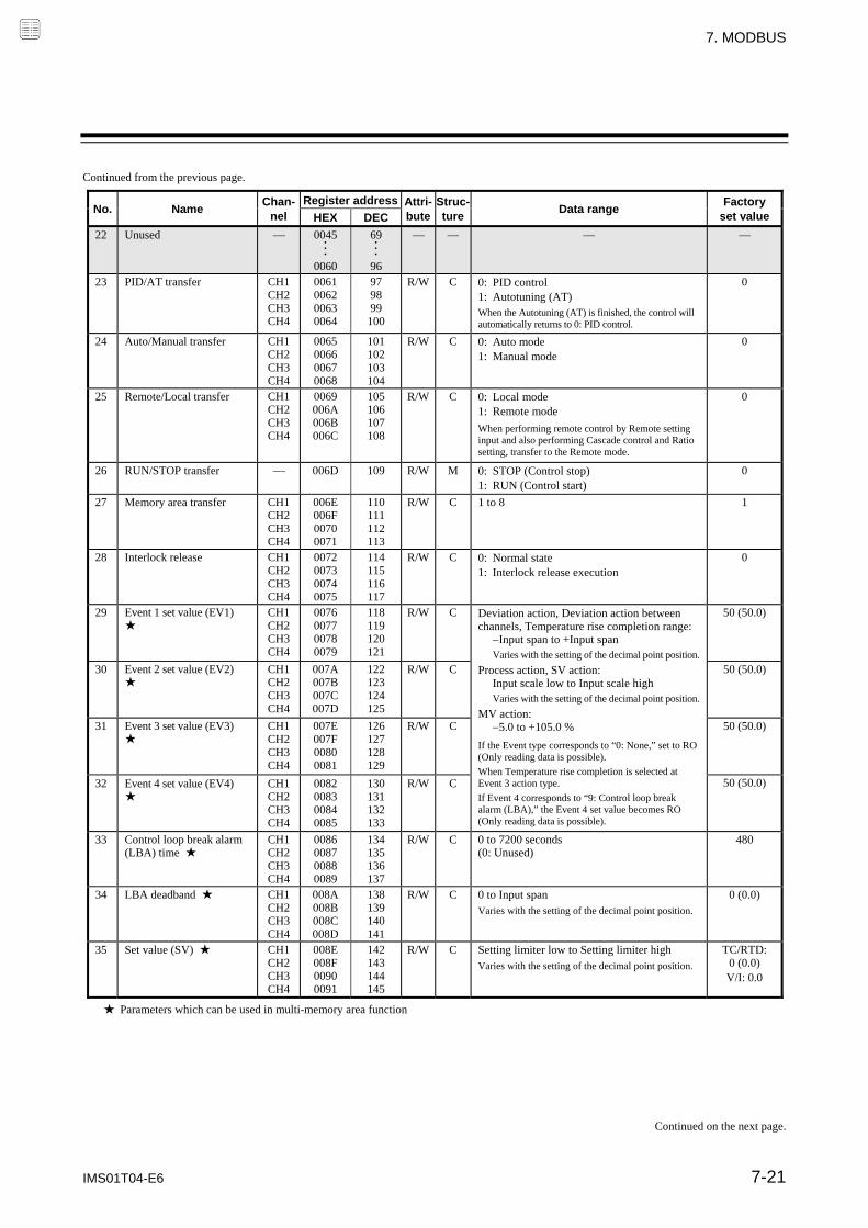
7. MODBUS
IMS01T04-E6 7-21
Continued from the previous page.
No. Name Chan-
nel Register address Attri-
buteStruc-ture
Data range Factory
set valueHEX DEC
22
Unused 0045 ・ ・ ・
0060
69 ・ ・ ・ 96
23 PID/AT transfer CH1 CH2 CH3 CH4
0061 0062 0063 0064
97 98 99
100
R/W C 0: PID control 1: Autotuning (AT) When the Autotuning (AT) is finished, the control will automatically returns to 0: PID control.
0
24 Auto/Manual transfer CH1 CH2 CH3 CH4
0065 0066 0067 0068
101 102 103 104
R/W C 0: Auto mode 1: Manual mode
0
25 Remote/Local transfer CH1 CH2 CH3 CH4
0069 006A 006B 006C
105 106 107 108
R/W C 0: Local mode 1: Remote mode
When performing remote control by Remote setting input and also performing Cascade control and Ratio setting, transfer to the Remote mode.
0
26 RUN/STOP transfer 006D 109 R/W M 0: STOP (Control stop) 1: RUN (Control start)
0
27 Memory area transfer CH1 CH2 CH3 CH4
006E 006F 0070 0071
110 111 112 113
R/W C 1 to 8 1
28 Interlock release CH1 CH2 CH3 CH4
0072 0073 0074 0075
114 115 116 117
R/W C 0: Normal state 1: Interlock release execution
0
29 Event 1 set value (EV1) ★
CH1 CH2 CH3 CH4
0076 0077 0078 0079
118 119 120 121
R/W C Deviation action, Deviation action between channels, Temperature rise completion range: Input span to +Input span Varies with the setting of the decimal point position. Process action, SV action: Input scale low to Input scale high Varies with the setting of the decimal point position. MV action: 5.0 to +105.0 %
If the Event type corresponds to “0: None,” set to RO (Only reading data is possible).
When Temperature rise completion is selected at Event 3 action type.
If Event 4 corresponds to “9: Control loop break alarm (LBA),” the Event 4 set value becomes RO (Only reading data is possible).
50 (50.0)
30 Event 2 set value (EV2) ★
CH1 CH2 CH3 CH4
007A 007B 007C 007D
122 123 124 125
R/W C 50 (50.0)
31 Event 3 set value (EV3) ★
CH1 CH2 CH3 CH4
007E 007F 0080 0081
126 127 128 129
R/W C 50 (50.0)
32 Event 4 set value (EV4) ★
CH1 CH2 CH3 CH4
0082 0083 0084 0085
130 131 132 133
R/W C 50 (50.0)
33 Control loop break alarm (LBA) time ★
CH1 CH2 CH3 CH4
0086 0087 0088 0089
134 135 136 137
R/W C 0 to 7200 seconds (0: Unused)
480
34 LBA deadband ★ CH1 CH2 CH3 CH4
008A 008B 008C 008D
138 139 140 141
R/W C 0 to Input span Varies with the setting of the decimal point position.
0 (0.0)
35 Set value (SV) ★ CH1 CH2 CH3 CH4
008E 008F 0090 0091
142 143 144 145
R/W C Setting limiter low to Setting limiter high Varies with the setting of the decimal point position.
TC/RTD: 0 (0.0) V/I: 0.0
★ Parameters which can be used in multi-memory area function
Continued on the next page.

7. MODBUS
7-22 IMS01T04-E6
Continued from the previous page.
No. Name Chan-
nel Register address Attri-
buteStruc-ture
Data range Factory
set valueHEX DEC
36 Proportional band [heat-side] ★
CH1 CH2 CH3 CH4
0092 0093 0094 0095
146 147 148 149
R/W C TC/RTD inputs: 0 to Input span (Unit: C [F])
Varies with the setting of the decimal point position.
Voltage (V)/Current (I) inputs: 0.0 to 1000.0 % of input span
0 (0.0): ON/OFF action (ON/OFF action for both heat and cool actions in case of a Heat/Cool PID control type.)
TC/RTD: 30 (30.0) V/I: 30.0
37 Integral time [heat-side] ★
CH1 CH2 CH3 CH4
0096 0097 0098 0099
150 151 152 153
R/W C PID control or heat/cool PID control: 0 to 3600 seconds or 0.0 to 1999.9 seconds (0, 0.0: PD action)
Position proportioning PID control: 1 to 3600 seconds or 0.1 to 1999.9 seconds Varies with the setting of the Integral/Derivative time decimal point position selection.
240
38 Derivative time [heat-side] ★
CH1 CH2 CH3 CH4
009A 009B 009C 009D
154 155 156 157
R/W C 0 to 3600 seconds or 0.0 to 1999.9 seconds (0, 0.0: PI action) Varies with the setting of the Integral/Derivative time decimal point position selection.
60
39 Control response parameter ★
CH1 CH2 CH3 CH4
009E 009F 00A0 00A1
158 159 160 161
R/W C 0: Slow 1: Medium 2: Fast
When the P or PD action is selected, this setting becomes invalid.
PID control, Position
proportioning PID control: 0
Heat/Cool PID control: 2
40 Proportional band [cool-side] ★
CH1 Unused CH3
Unused
00A2 Unused 00A4 Unused
162 Unused
164 Unused
R/W C TC/RTD inputs: 1 (0.1) to Input span (Unit: C [F])
Varies with the setting of the decimal point position.
Voltage (V)/Current (I) inputs: 0.1 to 1000.0 % of input span If control is other than Heat/Cool PID control, set to RO (Only reading data is possible).
TC/RTD: 30 (30.0) V/I: 30.0
41 Integral time [cool-side] ★
CH1 Unused CH3
Unused
00A6 Unused 00A8 Unused
166 Unused
168 Unused
R/W C 0 to 3600 seconds or 0.0 to 1999.9 seconds (0, 0.0: PD action) Varies with the setting of the Integral/Derivative time decimal point position selection.
If control is other than Heat/Cool PID control, set to RO (Only reading data is possible).
240
42 Derivative time [cool-side] ★
CH1 Unused CH3
Unused
00AA Unused 00AC Unused
170 Unused
172 Unused
R/W C 0 to 3600 seconds or 0.0 to 1999.9 seconds (0, 0.0: PI action) Varies with the setting of the Integral/Derivative time decimal point position selection.
If control is other than Heat/Cool PID control, set to RO (Only reading data is possible).
60
43 Overlap/Deadband ★ CH1 CH2 CH3 CH4
00AE 00AF 00B0 00B1
174 175 176 177
R/W C TC/RTD inputs: Input span to +Input span (Unit:C [F])
Varies with the setting of the decimal point position. Voltage (V)/Current (I) inputs: 100.0 to +100.0 % of input span Minus () setting results in Overlap.
However, the overlapping range is within the proportional range.
If control is other than Heat/Cool PID control, set to RO (Only reading data is possible).
0 (0.0)
★ Parameters which can be used in multi-memory area function
Parameters only used for Heat/Cool PID control or Position proportioning PID control, therefore data for CH2 and CH4 of Z-TIO modules are unused.
Continued on the next page.

7. MODBUS
IMS01T04-E6 7-23
Continued from the previous page.
No. Name Chan-
nel Register address Attri-
buteStruc-ture
Data range Factory
set valueHEX DEC
44 Manual reset ★
CH1 CH2 CH3 CH4
00B2 00B3 00B4 00B5
178 179 180 181
R/W C 100.0 to +100.0 %
If the Integral function is valid, set to RO (Only reading data is possible).
When Integral action (heating or cooling side) is zero, manual reset value is added to the control output.
0.0
45 Setting change rate limiter (up) ★
CH1 CH2 CH3 CH4
00B6 00B7 00B8 00B9
182 183 184 185
R/W C 0 to Input span/unit time * 0: Unused Varies with the setting of the decimal point position.
0 (0.0)
46 Setting change rate limiter (down) ★
CH1 CH2 CH3 CH4
00BA 00BB 00BC 00BD
186 187 188 189
R/W C * Unit time: 60 seconds (factory set value) 0 (0.0)
47 Area soak time ★ CH1 CH2 CH3 CH4
00BE 00BF 00C0 00C1
190 191 192 193
R/W C 0 minutes 00 seconds to 199 minutes 59 seconds: 0 to 11999 seconds
0 hours 00 minutes to 99 hours 59 minutes: 0 to 5999 minuts Data range of Area soak time can be selected on the Soak time unit.
0
48 Link area number ★ CH1 CH2 CH3 CH4
00C2 00C3 00C4 00C5
194 195 196 197
R/W C 0 to 8 (0: No link)
0
49 Heater break alarm (HBA) set value
CH1 CH2 CH3 CH4
00C6 00C7 00C8 00C9
198 199 200 201
R/W C When CT is CTL-6-P-N: 0.0 to 30.0 A (0.0: Not used)
When CT is CTL-12-S56-10L-N: 0.0 to 100.0 A (0.0: Not used) If there is no Current transformer (CT) or CT is assigned to “0: None,” set to RO (Only reading data is possible).
0.0
50 Heater break determination point
CH1 CH2 CH3 CH4
00CA 00CB 00CC 00CD
202 203 204 205
R/W C 0.0 to 100.0 % of HBA set value (0.0: Heater break determination is invalid)
If there is no Current transformer (CT) or CT is assigned to “0: None,” set to RO (Only reading data is possible).
If Heater break alarm (HBA) corresponds to “0: Type A,” set to RO (Only reading data is possible).
30.0
51 Heater melting determination point
CH1 CH2 CH3 CH4
00CE 00CF 00D0 00D1
206 207 208 209
R/W C 0.0 to 100.0 % of HBA set value (0.0: Heater melting determination is invalid)
If there is no Current transformer (CT) or CT is assigned to “0: None,” set to RO (Only reading data is possible).
If Heater break alarm (HBA) corresponds to “0: Type A,” set to RO (Only reading data is possible).
30.0
52 PV bias CH1 CH2 CH3 CH4
00D2 00D3 00D4 00D5
210 211 212 213
R/W C Input span to +Input span Varies with the setting of the decimal point position.
0 (0.0)
53 PV digital filter CH1 CH2 CH3 CH4
00D6 00D7 00D8 00D9
214 215 216 217
R/W C 0.0 to 100.0 seconds (0.0: Unused)
0.0
54 PV ratio CH1 CH2 CH3 CH4
00DA 00DB 00DC 00DD
218 219 220 221
R/W C 0.500 to 1.500 1.000
55 PV low input cut-off CH1 CH2 CH3 CH4
00DE 00DF 00E0 00E1
222 223 224 225
R/W C 0.00 to 25.00 % of input span
If the Square root extraction corresponds to “0: Unused,” set to RO (Only reading data is possible).
0.00
★ Parameters which can be used in multi-memory area function
Continued on the next page.

7. MODBUS
7-24 IMS01T04-E6
Continued from the previous page.
No. Name Chan-
nel Register address Attri-
buteStruc-ture
Data range Factory
set valueHEX DEC
56 RS bias *
CH1 CH2 CH3 CH4
00E2 00E3 00E4 00E5
226 227 228 229
R/W C Input span to +Input span Varies with the setting of the decimal point position.
0 (0.0)
57 RS digital filter *
CH1 CH2 CH3 CH4
00E6 00E7 00E8 00E9
230 231 232 233
R/W C 0.0 to 100.0 seconds (0.0: Unused)
0.0
58 RS ratio *
CH1 CH2 CH3 CH4
00EA 00EB 00EC 00ED
234 235 236 237
R/W C 0.001 to 9.999 1.000
59 Output distribution selection
CH1 CH2 CH3 CH4
00EE 00EF 00F0 00F1
238 239 240 241
R/W C 0: Control output 1: Distribution output
0
60 Output distribution bias CH1 CH2 CH3 CH4
00F2 00F3 00F4 00F5
242 243 244 245
R/W C 100.0 to 100.0 % 0.0
61 Output distribution ratio CH1 CH2 CH3 CH4
00F6 00F7 00F8 00F9
246 247 248 249
R/W C 9.999 to 9.999 1.000
62 Proportional cycle time CH1 CH2 CH3 CH4
00FA 00FB 00FC 00FD
250 251 252 253
R/W C 0.1 to 100.0 seconds
This item becomes RO (Only reading data is possible) for the Voltage/Current output specification.
This parameter is valid when “0: control output” has been selected at No. 94 “Output assignment.”
Relay contact output: 20.0
Voltage pulse output, Triac output and
Open collector output: 2.0
63 Minimum ON/OFF time of proportioning cycle
CH1 CH2 CH3 CH4
00FE 00FF 0100 0101
254 255 256 257
R/W C 0 to 1000 ms
This item becomes RO (Only reading data is possible) for the Voltage/Current output specification.
0
64 Manual manipulated output value
CH1 CH2 CH3 CH4
0102 0103 0104 0105
258 259 260 261
R/W C PID control: Output limiter low to Output limiter high
Heat/Cool PID control: Cool-side output limiter (high) to Heat-side output limiter (high)
Position proportioning PID control: When there is Feedback resistance (FBR) input and it does not break: Output limiter low to Output limiter high
When there is no Feedback resistance (FBR) input or the Feedback resistance (FBR) input is disconnected: 0: Close-side output OFF, Open-side output OFF 1: Close-side output ON, Open-side output OFF 2: Close-side output OFF, Open-side output ON
0.0
65 Area soak time stop function
CH1 CH2 CH3 CH4
0106 0107 0108 0109
262 263 264 265
R/W C 0: No function 1: Event 1 2: Event 2 3: Event 3 4: Event 4
0
* Data on RS bias, RS ratio and RS digital filter is that in Cascade control or Ratio setting.
Parameters only used for Heat/Cool PID control or Position proportioning PID control, therefore data for CH2 and CH4 of Z-TIO modules are unused.
Continued on the next page.

7. MODBUS
IMS01T04-E6 7-25
Continued from the previous page.
No. Name Chan-
nel Register address Attri-
buteStruc-ture
Data range Factory
set valueHEX DEC
66 EDS mode (for disturbance 1)
CH1 CH2 CH3 CH4
010A 010B 010C 010D
266 267 268 269
R/W C 0: No function 1: EDS function mode 2: Learning mode 3: Tuning mode EDS function: External disturbance suppression function
0
67 EDS mode (for disturbance 2)
CH1 CH2 CH3 CH4
010E 010F 0110 0111
270 271 272 273
R/W C 0
68 EDS value 1 (for disturbance 1)
CH1 CH2 CH3 CH4
0112 0113 0114 0115
274 275 276 277
R/W C 100.0 to 100.0 % 0.0
69 EDS value 1 (for disturbance 2)
CH1 CH2 CH3 CH4
0116 0117 0118 0119
278 279 280 281
R/W C 0.0
70 EDS value 2 (for disturbance 1)
CH1 CH2 CH3 CH4
011A 011B 011C 011D
282 283 284 285
R/W C 100.0 to 100.0 % 0.0
71 EDS value 2 (for disturbance 2)
CH1 CH2 CH3 CH4
011E 011F 0120 0121
286 287 288 289
R/W C 0.0
72 EDS transfer time (for disturbance 1)
CH1 CH2 CH3 CH4
0122 0123 0124 0125
290 291 292 293
R/W C 0 to 3600 seconds or 0.0 to 1999.9 seconds 0
73 EDS transfer time (for disturbance 2)
CH1 CH2 CH3 CH4
0126 0127 0128 0129
294 295 296 297
R/W C 0
74 EDS action time (for disturbance 1)
CH1 CH2 CH3 CH4
012A 012B 012C 012D
298 299 300 301
R/W C 1 to 3600 seconds 600
75 EDS action time (for disturbance 2)
CH1 CH2 CH3 CH4
012E 012F 0130 0131
302 303 304 305
R/W C 600
76 EDS action wait time (for disturbance 1)
CH1 CH2 CH3 CH4
0132 0133 0134 0135
306 307 308 309
R/W C 0.0 to 600.0 seconds 0.0
77 EDS action wait time (for disturbance 2)
CH1 CH2 CH3 CH4
0136 0137 0138 0139
310 311 312 313
R/W C 0.0
78 EDS value learning times CH1 CH2 CH3 CH4
013A 013B 013C 013D
314 315 316 317
R/W C 0 to 10 times (0: No learning mode)
1
79 EDS start signal CH1 CH2 CH3 CH4
013E 013F 0140 0141
318 319 320 321
R/W C 0: EDS start signal OFF 1: EDS start signal ON (for disturbance 1) 2: EDS start signal ON (for disturbance 2)
0
80 Operation mode CH1 CH2 CH3 CH4
0142 0143 0144 0145
322 323 324 325
R/W C 0: Unused 1: Monitor 2: Monitor Event function 3: Control
3
Continued on the next page.

7. MODBUS
7-26 IMS01T04-E6
Continued from the previous page.
No. Name Chan-
nel Register address Attri-
buteStruc-ture
Data range Factory
set valueHEX DEC
81 Startup tuning (ST) CH1 CH2 CH3 CH4
0146 0147 0148 0149
326 327 328 329
R/W C 0: ST unused 1: Execute once * 2: Execute always * When the Startup tuning is finished, the setting will
automatically returns to “0: ST unused.” The Startup tuning (ST) function is activated according to the ST start condition selected. If control is Position proportioning PID control, set to RO (Only reading data is possible).
0
82 Automatic temperature rise learning
CH1 CH2 CH3 CH4
014A 014B 014C 014D
330 331 332 333
R/W C 0: Unused 1: Learning * * When the automatic temperature rise learning is
finished, the setting will automatically returns to “0: Unused.”
0
83 Communication switch for logic
014E 334 R/W M Bit data Bit 0: Communication switch 1 Bit 1: Communication switch 2 Bit 2: Communication switch 3 Bit 3: Communication switch 4 Bit 4 to Bit 15: Unused Data 0: OFF 1: ON [Decimal number: 0 to 15]
0
84 Unused 014F ・ ・ ・
0175
335 ・ ・ ・
373
Set data No. 85 or later are for engineering setting [Writable in the STOP mode]
85 Input type CH1 CH2 CH3 CH4
0176 0177 0178 0179
374 375 376 377
R/W C 0: TC input K 1: TC input J 2: TC input R 3: TC input S 4: TC input B 5: TC input E 6: TC input N 7: TC input T 8: TC input W5Re/W26Re 9: TC input PLII 12: RTD input Pt100 13: RTD input JPt100 14: Current input 0 to 20 mA DC 15: Current input 4 to 20 mA DC 16: Voltage (high) input 0 to 10 V DC 17: Voltage (high) input 0 to 5 V DC 18: Voltage (high) input 1 to 5 V DC 19: Voltage (low) input 0 to 1 V DC 20: Voltage (low) input 0 to 100 mV DC 21: Voltage (low) input 0 to 10 mV DC 22: Feedback resistance input 100 to 150 23: Feedback resistance input 151 to 6 k If changed to Voltage (high) input from TC/RTD/Current/Voltage (low)/Feedback resistance input, select the hardware by the input selector switch at the side of the module. (Refer to P. 8-70)
Based on model code
When not specifying: 0
86 Display unit CH1 CH2 CH3 CH4
017A 017B 017C 017D
378 379 380 381
R/W C 0: C 1: F Use to select the temperature unit for Thermocouple (TC) and RTD inputs.
Based on model codeWhen not
specifying: 0
Continued on the next page.

7. MODBUS
IMS01T04-E6 7-27
Continued from the previous page.
No. Name Chan-
nel Register address Attri-
buteStruc-ture
Data range Factory
set valueHEX DEC
87 Decimal point position CH1 CH2 CH3 CH4
017E 017F 0180 0181
382 383 384 385
R/W C 0: No decimal place 1: One decimal place 2: Two decimal places 3: Three decimal places 4: Four decimal places
TC input: K, J, T, E: Only 0 or 1 can be set. R, S, B, N, PLII, W5Re/W26Re: Only 0 can be set. RTD input: Only 0 or 1 can be set. V/I inputs: From 0 to 4 can be set.
Based on model code
If input range
code is not specified:
1
88 Input scale high CH1 CH2 CH3 CH4
0182 0183 0184 0185
386 387 388 389
R/W C TC/RTD inputs: Input scale low to Maximum value of the selected input range
Voltage (V)/Current (I) inputs: 19999 to 19999 (However, a span is 20000 or less.)
Varies with the setting of the decimal point position.
TC/RTD: Maximum
value of the selected input
range
V/I: 100.0
If input range code is not specified: 1372.0
89 Input scale low CH1 CH2 CH3 CH4
0186 0187 0188 0189
390 391 392 393
R/W C TC/RTD inputs: Minimum value of the selected input range to Input scale high
Voltage (V)/Current (I) inputs: 19999 to 19999 (However, a span is 20000 or less.)
Varies with the setting of the decimal point position.
TC/RTD: Minimum
value of the selected input
range
V/I: 0.0
If input range code is not specified: 200.0
90 Input error determination point (high)
CH1 CH2 CH3 CH4
018A 018B 018C 018D
394 395 396 397
R/W C Input error determination point (low) to (Input range high 5 % of input span)
Varies with the setting of the decimal point position.
Input range high (5 %
of input span)
91 Input error determination point (low)
CH1 CH2 CH3 CH4
018E 018F 0190 0191
398 399 400 401
R/W C (Input range low 5 % of input span) to Input error determination point (high)
Varies with the setting of the decimal point position.
Input range low (5 %
of input span)
92 Burnout direction CH1 CH2 CH3 CH4
0192 0193 0194 0195
402 403 404 405
R/W C 0: Upscale 1: Downscale
Valid only when the TC input and Voltage (low) input are selected.
0
93 Square root extraction CH1 CH2 CH3 CH4
0196 0197 0198 0199
406 407 408 409
R/W C 0: Unused 1: Used
0
94 Output assignment (Logic output selection function)
CH1 CH2 CH3 CH4
019A 019B 019C 019D
410 411 412 413
R/W C 0: Control output 1: Logic output result 2: FAIL output
0
95 Energized/De-energized (Logic output selection function)
CH1 CH2 CH3 CH4
019E 019F 01A0 01A1
414 415 416 417
R/W C 0: Energized 1: De-energized
0
Continued on the next page.

7. MODBUS
7-28 IMS01T04-E6
Continued from the previous page.
No. Name Chan-
nel Register address Attri-
buteStruc-ture
Data range Factory
set valueHEX DEC
96 Event 1 type CH1 CH2 CH3 CH4
01A2 01A3 01A4 01A5
418 419 420 421
R/W C 0: None 1: Deviation high (Using SV monitor value) 1 2: Deviation low (Using SV monitor value) 1 3: Deviation high/low (Using SV monitor value) 1 4: Band (Using SV monitor value) 1 5: Process high 1 6: Process low 1 7: SV high 8: SV low 9: Unused 10: MV high [heat-side] 1, 2 11: MV low [heat-side] 1, 2 12: MV high [cool-side] 1 13: MV low [cool-side] 1
14: Deviation high (Using local SV) 1 15: Deviation low (Using local SV) 1 16: Deviation high/low (Using local SV) 1 17: Band (Using local SV) 1 18: Deviation between channels high 1 19: Deviation between channels low 1 20: Deviation between channels high/low 1 21: Deviation between channels band 1 1 Event hold action is available. 2 If there is Feedback resistance (FBR) input in
Position proportioning PID control, set to the Feedback resistance (FBR) input value.
Based on model code
When not
specifying: 0
97 Event 1 channel setting CH1 CH2 CH3 CH4
01A6 01A7 01A8 01A9
422 423 424 425
R/W C 1: Channel 1 2: Channel 2 3: Channel 3 4: Channel 4 This function is valid when “Deviation between channels” is selected.
1
98 Event 1 hold action CH1 CH2 CH3 CH4
01AA 01AB 01AC 01AD
426 427 428 429
R/W C 0: OFF 1: Hold action ON (when power turned on; when transferred from STOP to RUN) 2: Re-hold action ON (when power turned on; when transferred from STOP to RUN; SV changed) This function is valid when input value, deviation or manipulated value action has been selected. In case of a deviation action, this function is not available while in Remote mode and while setting changing rate limiter is working.
Based on model code
When not
specifying: 0
99 Event 1 interlock CH1 CH2 CH3 CH4
01AE 01AF 01B0 01B1
430 431 432 433
R/W C 0: Unused 1: Used
0
100 Event 1 differential gap CH1 CH2 CH3 CH4
01B2 01B3 01B4 01B5
434 435 436 437
R/W C Deviation, Process, Set value, or Deviation action between channels: 0 to Input span (Unit: C [F]) Varies with the setting of the decimal point position.
MV: 0.0 to 110.0 %
: 1 (1.0) : 1.0
101 Event 1 delay timer CH1 CH2 CH3 CH4
01B6 01B7 01B8 01B9
438 439 440 441
R/W C 0 to 18000 seconds 0
102 Force ON of Event 1 action CH1 CH2 CH3 CH4
01BA 01BB 01BC 01BD
442 443 444 445
R/W C Bit data Bit 0: Event output turned on at input error occurrence Bit 1: Event output turned on in Manual mode Bit 2: Event output turned on during the Autotuning (AT) function is being executed Bit 3: Event output turned on during the Setting change rate limiter is being operated Bit 4 to Bit b15: Unused Data 0: Invalid 1: Valid [Decimal number: 0 to 15]
0
Continued on the next page.

7. MODBUS
IMS01T04-E6 7-29
Continued from the previous page.
No. Name Chan-
nel Register address Attri-
buteStruc-ture
Data range Factory
set valueHEX DEC
103 Event 2 type CH1 CH2 CH3 CH4
01BE 01BF 01C0 01C1
446 447 448 449
R/W C 0: None 1: Deviation high (Using SV monitor value) 1 2: Deviation low (Using SV monitor value) 1 3: Deviation high/low (Using SV monitor value) 1 4: Band (Using SV monitor value) 1 5: Process high 1 6: Process low 1 7: SV high 8: SV low 9: Unused 10: MV high [heat-side] 1, 2 11: MV low [heat-side] 1, 2 12: MV high [cool-side] 1 13: MV low [cool-side] 1 14: Deviation high (Using local SV value) 1 15: Deviation low (Using local SV value) 1 16: Deviation high/low (Using local SV value) 1 17: Band (Using local SV value) 1 18: Deviation between channels high 1 19: Deviation between channels low 1 20: Deviation between channels high/low 1 21: Deviation between channels band 1 1 Event hold action is available. 2 If there is Feedback resistance (FBR) input in
Position proportioning PID control, set to the Feedback resistance (FBR) input value.
Based on model code
When not
specifying: 0
104 Event 2 channel setting CH1 CH2 CH3 CH4
01C2 01C3 01C4 01C5
450 451 452 453
R/W C 1: Channel 1 2: Channel 2 3: Channel 3 4: Channel 4 This function is valid when “Deviation between channels” is selected.
1
105 Event 2 hold action CH1 CH2 CH3 CH4
01C6 01C7 01C8 01C9
454 455 456 457
R/W C 0: OFF 1: Hold action ON (when power turned on; when transferred from STOP to RUN) 2: Re-hold action ON (when power turned on; when transferred from STOP to RUN; SV changed)
This function is valid when input value, deviation or manipulated value action has been selected. In case of a deviation action, this function is not available while in Remote mode and while Setting changing rate limiter is working.
Based on model code
When not
specifying: 0
106 Event 2 interlock CH1 CH2 CH3 CH4
01CA 01CB 01CC 01CD
458 459 460 461
R/W C 0: Unused 1: Used
0
107 Event 2 differential gap CH1 CH2 CH3 CH4
01CE 01CF 01D0 01D1
462 463 464 465
R/W C Deviation, Process, Set value, or Deviation action between channels: 0 to Input span (Unit: C [F]) Varies with the setting of the decimal point position.
MV: 0.0 to 110.0 %
: 1 (1.0) : 1.0
108 Event 2 delay timer CH1 CH2 CH3 CH4
01D2 01D3 01D4 01D5
466 467 468 469
R/W C 0 to 18000 seconds 0
109 Force ON of Event 2 action CH1 CH2 CH3 CH4
01D6 01D7 01D8 01D9
470 471 472 473
R/W C Bit data Bit 0: Event output turned on at input error occurrence Bit 1: Event output turned on in Manual mode Bit 2: Event output turned on during the Autotuning (AT) function is being executed Bit 3: Event output turned on during the Setting change rate limiter is being operated Bit 4 to Bit b15: Unused Data 0: Invalid 1: Valid [Decimal number: 0 to 15]
0
Continued on the next page.

7. MODBUS
7-30 IMS01T04-E6
Continued from the previous page.
No. Name Chan-
nel Register address Attri-
buteStruc-ture
Data range Factory
set valueHEX DEC
110 Event 3 type CH1 CH2 CH3 CH4
01DA 01DB 01DC 01DD
474 475 476 477
R/W C 0: None 1: Deviation high (Using SV monitor value) 1 2: Deviation low (Using SV monitor value) 1 3: Deviation high/low (Using SV monitor value) 1 4: Band (Using SV monitor value) 1 5: Process high 1 6: Process low 1 7: SV high 8: SV low 9: Temperature rise completion 10: MV high [heat-side] 1, 2 11: MV low [heat-side] 1, 2 12: MV high [cool-side] 1 13: MV low [cool-side] 1 14: Deviation high (Using local SV value) 1 15: Deviation low (Using local SV value) 1 16: Deviation high/low (Using local SV value) 1 17: Band (Using local SV value) 1 18: Deviation between channels high 1 19: Deviation between channels low 1 20: Deviation between channels high/low 1 21: Deviation between channels band 1 1 Event hold action is available. 2 If there is Feedback resistance (FBR) input in
Position proportioning PID control, set to the Feedback resistance (FBR) input value.
Based on model code
When not
specifying: 0
111 Event 3 channel setting CH1 CH2 CH3 CH4
01DE 01DF 01E0 01E1
478 479 480 481
R/W C 1: Channel 1 2: Channel 2 3: Channel 3 4: Channel 4 This function is valid when “Deviation between channels” is selected.
1
112 Event 3 hold action CH1 CH2 CH3 CH4
01E2 01E3 01E4 01E5
482 483 484 485
R/W C 0: OFF 1: Hold action ON (when power turned on; when transferred from STOP to RUN) 2: Re-hold action ON (when power turned on; when transferred from STOP to RUN; SV changed) This function is valid when input value, deviation or manipulated value action has been selected. In case of a deviation action, this function is not available while in Remote mode and while Setting changing rate limiter is working.
Based on model code
When not
specifying: 0
113 Event 3 interlock CH1 CH2 CH3 CH4
01E6 01E7 01E8 01E9
486 487 488 489
R/W C 0: Unused 1: Used
0
114 Event 3 differential gap CH1 CH2 CH3 CH4
01EA 01EB 01EC 01ED
490 491 492 493
R/W C Deviation, Process, Set value, Deviation action between channels, or Temperature rise completion: 0 to Input span (Unit: C [F]) Varies with the setting of the decimal point position.
MV: 0.0 to 110.0 %
: 1 (1.0) : 1.0
115 Event 3 delay timer CH1 CH2 CH3 CH4
01EE 01EF 01F0 01F1
494 495 496 497
R/W C 0 to 18000 seconds If Event 3 corresponds to “9: Temperature rise completion,” the Event 3 delay timer becomes the temperature rise completion soak time.
0
116 Force ON of Event 3 action CH1 CH2 CH3 CH4
01F2 01F3 01F4 01F5
498 499 500 501
R/W C Bit data Bit 0: Event output turned on at input error occurrence Bit 1: Event output turned on in Manual mode Bit 2: Event output turned on during the Autotuning (AT) function is being executed Bit 3: Event output turned on during the Setting change rate limiter is being operated Bit 4 to Bit b15: Unused Data 0: Invalid 1: Valid [Decimal number: 0 to 15]
0
Continued on the next page.

7. MODBUS
IMS01T04-E6 7-31
Continued from the previous page.
No. Name Chan-
nel Register address Attri-
buteStruc-ture
Data range Factory
set valueHEX DEC
117 Event 4 type CH1 CH2 CH3 CH4
01F6 01F7 01F8 01F9
502 503 504 505
R/W C 0: None 1: Deviation high (Using SV monitor value) 1 2: Deviation low (Using SV monitor value) 1 3: Deviation high/low (Using SV monitor value) 1 4: Band (Using SV monitor value) 1 5: Process high 1 6: Process low 1 7: SV high 8: SV low 9: Control loop break alarm (LBA) 10: MV high [heat-side] 1, 2 11: MV low [heat-side] 1, 2 12: MV high [cool-side] 1 13: MV low [cool-side] 1 14: Deviation high (Using local SV value) 1 15: Deviation low (Using local SV value) 1 16: Deviation high/low (Using local SV value) 1 17: Band (Using local SV value) 1 18: Deviation between channels high 1 19: Deviation between channels low 1 20: Deviation between channels high/low 1 21: Deviation between channels band 1 1 Event hold action is available. 2 If there is Feedback resistance (FBR) input in
Position proportioning PID control, set to the Feedback resistance (FBR) input value.
Based on model code
When not
specifying: 0
118 Event 4 channel setting CH1 CH2 CH3 CH4
01FA 01FB 01FC 01FD
506 507 508 509
R/W C 1: Channel 1 2: Channel 2 3: Channel 3 4: Channel 4 This function is valid when “Deviation between channels” is selected.
1
119 Event 4 hold action CH1 CH2 CH3 CH4
01FE 01FF 0200 0201
510 511 512 513
R/W C 0: OFF 1: Hold action ON (when power turned on; when transferred from STOP to RUN) 2: Re-hold action ON (when power turned on; when transferred from STOP to RUN; SV changed) This function is valid when input value, deviation or manipulated value action has been selected. In case of a deviation action, this function is not available while in Remote mode and while Setting changing rate limiter is working.
Based on model code
When not
specifying: 0
120 Event 4 interlock CH1 CH2 CH3 CH4
0202 0203 0204 0205
514 515 516 517
R/W C 0: Unused 1: Used
0
121 Event 4 differential gap CH1 CH2 CH3 CH4
0206 0207 0208 0209
518 519 520 521
R/W C Deviation, Process, Set value, or Deviation action between channels: 0 to Input span (Unit: C [F]) Varies with the setting of the decimal point position.
MV: 0.0 to 110.0 % Becomes invalid when the Event 4 type corresponds to “9: Control loop break alarm (LBA).”
: 1 (1.0) : 1.0
122 Event 4 delay timer CH1 CH2 CH3 CH4
020A 020B 020C 020D
522 523 524 525
R/W C 0 to 18000 seconds 0
123 Force ON of Event 4 action CH1 CH2 CH3 CH4
020E 020F 0210 0211
526 527 528 529
R/W C Bit data Bit 0: Event output turned on at input error occurrence Bit 1: Event output turned on in Manual mode Bit 2: Event output turned on during the Autotuning (AT) function is being executed Bit 3: Event output turned on during the Setting change rate limiter is being operated Bit 4 to Bit b15: Unused Data 0: Invalid 1: Valid [Decimal number: 0 to 15] Becomes invalid when the Event 4 type corresponds to “9: Control loop break alarm (LBA).”
0
Continued on the next page.

7. MODBUS
7-32 IMS01T04-E6
Continued from the previous page.
No. Name Chan-
nel Register address Attri-
buteStruc-ture
Data range Factory
set value HEX DEC
124 CT ratio CH1 CH2 CH3 CH4
0212 0213 0214 0215
530 531 532 533
R/W C 0 to 9999 CTL-6-P-N:800
CTL-12-S56-10L-N: 1000
125 CT assignment CH1 CH2 CH3 CH4
0216 0217 0218 0219
534 535 536 537
R/W C 0: None 3: OUT3 1: OUT1 4: OUT4 2: OUT2
CH1: 1 CH2: 2 CH3: 3 CH4: 4
126 Heater break alarm (HBA) type
CH1 CH2 CH3 CH4
021A 021B 021C 021D
538 539 540 541
R/W C 0: Heater break alarm (HBA) type A (Time-proportional control output) 1: Heater break alarm (HBA) type B (Continuous control output) Time-proportional control output:
Relay, Voltage pulse, Triac, or Open collector output
Continuous control output: Voltage/Current continuous output
Set value is based on the Output type specified at ordering.
127 Number of heater break alarm (HBA) delay times
CH1 CH2 CH3 CH4
021E 021F 0220 0221
542 543 544 545
R/W C 0 to 255 times 5
128 Hot/Cold start CH1 CH2 CH3 CH4
0222 0223 0224 0225
546 547 548 549
R/W C 0: Hot start 1 1: Hot start 2 2: Cold start
0
129 Start determination point CH1 CH2 CH3 CH4
0226 0227 0228 0229
550 551 552 553
R/W C 0 to Input span (The unit is the same as input value.) 0: Action depending on the Hot/Cold start selection Varies with the setting of the decimal point position.
Based on specification
130 SV tracking CH1 CH2 CH3 CH4
022A 022B 022C 022D
554 555 556 557
R/W C 0: Unused 1: Used
1
131 MV transfer function [Action taken when changed to Manual mode from Auto mode]
CH1 CH2 CH3 CH4
022E 022F 0230 0231
558 559 560 561
R/W C 0: MV in Auto mode is used. [Balanceless-bumpless function]
1: MV in previous Manual mode is used.
0
132 Control action CH1 CH2 CH3 CH4
0232 0233 0234 0235
562 563 564 565
R/W C 0: Brilliant II PID control (Direct action) 1: Brilliant II PID control (Reverse action) 2: Brilliant II Heat/Cool PID control [Water cooling type] 3: Brilliant II Heat/Cool PID control [Air cooling type] 4: Brilliant II Heat/Cool PID control [Cooling gain linear type] 5: Brilliant II Position proportioning PID control Odd channel: From 0 to 5 can be set. Even channel: Only 0 or 1 can be set. *
* In Heat/Cool PID control and Position proportioning PID control, control action is not performed. Only PV monitor and event action is performed.
Based on model code
When not
specifying: 1
133 Integral/Derivative time decimal point position
CH1 CH2 CH3 CH4
0236 0237 0238 0239
566 567 568 569
R/W C 0: 1 second setting (No decimal place) 1: 0.1 seconds setting (One decimal place)
0
134 Derivative action CH1 CH2 CH3 CH4
023A 023B 023C 023D
570 571 572 573
R/W C 0: Measured value derivative 1: Deviation derivative
0
Parameters only used for Heat/Cool PID control or Position proportioning PID control, therefore data for CH2 and CH4 of Z-TIO modules are unused.
Continued on the next page.

7. MODBUS
IMS01T04-E6 7-33
Continued from the previous page.
No. Name Chan-
nel Register address Attri-
buteStruc-ture
Data range Factory
set valueHEX DEC
135 Undershoot suppression factor
CH1 Unused CH3
Unused
023E Unused 0240
Unused
574 Unused
576 Unused
R/W C 0.000 to 1.000 Water cooling: 0.100
Air cooling: 0.250
Cooling gain linear type:
1.000
136 Derivative gain CH1 CH2 CH3 CH4
0242 0243 0244 0245
578 579 580 581
R/W C 0.1 to 10.0 6.0
137 ON/OFF action differential gap (upper)
CH1 CH2 CH3 CH4
0246 0247 0248 0249
582 583 584 585
R/W C TC/RTD inputs: 0 to Input span (Unit: C [F]) Varies with the setting of the decimal point position.
Voltage (V)/Current (I) inputs: 0.0 to 100.0 % of input span
TC/RTD: 1 (1.0) V/I: 0.1
138 ON/OFF action differential gap (lower)
CH1 CH2 CH3 CH4
024A 024B 024C 024D
586 587 588 589
R/W C TC/RTD: 1 (1.0) V/I: 0.1
139 Action (high) at input error
CH1 CH2 CH3 CH4
024E 024F 0250 0251
590 591 592 293
R/W C 0: Normal control 1: Manipulated output value at input error
0
140 Action (low) at input error
CH1 CH2 CH3 CH4
0252 0253 0254 0255
594 595 596 597
R/W C 0
141 Manipulated output value at input error
CH1 CH2 CH3 CH4
0256 0257 0258 0259
598 599 600 601
R/W C 105.0 to 105.0 %
Actual output values become those restricted by the output limiter.
Position proportioning PID control: If there is no Feedback resistance (FBR) input or the Feedback resistance (FBR) input is disconnected, an action taken when abnormal is in accordance with the value action setting during STOP.
0.0
142 Manipulated output value at STOP mode [heat-side]
CH1 CH2 CH3 CH4
025A 025B 025C 025D
602 603 604 605
R/W C 5.0 to 105.0 %
Position proportioning PID control: Only when there is Feedback resistance (FBR) input and it does not break, the Manipulated output value [heat-side] at STOP is output.
5.0
143 Manipulated output value at STOP mode [cool-side]
CH1 Unused CH3
Unused
025E Unused 0260
Unused
606 Unused 608
Unused
R/W C 5.0
144 Output change rate limiter (up) [heat-side]
CH1 CH2 CH3 CH4
0262 0263 0264 0265
610 611 612 613
R/W C 0.0 to 100.0 % of manipulated output /seconds (0.0: OFF)
Becomes invalid when in Position proportioning PID control.
0.0
145 Output change rate limiter (down) [heat-side]
CH1 CH2 CH3 CH4
0266 0267 0268 0269
614 615 616 617
R/W C 0.0
146 Output limiter high [heat-side]
CH1 CH2 CH3 CH4
026A 026B 026C 026D
618 619 620 621
R/W C Output limiter low to 105.0 %
Position proportioning PID control: Becomes valid only when there is Feedback resistance (FBR) input and it does not break.
105.0
147 Output limiter low [heat-side]
CH1 CH2 CH3 CH4
026E 026F 0270 0271
622 623 624 625
R/W C 5.0 % to Output limiter high Position proportioning PID control: Becomes valid only when there is Feedback resistance (FBR) input and it does not break.
5.0
148 Output change rate limiter (up) [cool-side]
CH1 Unused CH3
Unused
0272 Unused 0274
Unused
626 Unused
628 Unused
R/W C 0.0 to 100.0 % of manipulated output /seconds (0.0: OFF) Becomes invalid when in Position proportioning PID control.
0.0
Parameters only used for Heat/Cool PID control or Position proportioning PID control, therefore data for CH2 and CH4 of Z-TIO modules are unused.
Continued on the next page.

7. MODBUS
7-34 IMS01T04-E6
Continued from the previous page.
No. Name Chan-
nel Register address Attri-
buteStruc-ture
Data range Factory
set valueHEX DEC
149 Output change rate limiter (down) [cool-side]
CH1 Unused CH3
Unused
0276 Unused 0278
Unused
630 Unused
632 Unused
R/W C 0.0 to 100.0 % of manipulated output /seconds (0.0: OFF) Becomes invalid when in Position proportioning PID control.
0.0
150 Output limiter high [cool-side]
CH1 Unused CH3
Unused
027A Unused 027C Unused
634 Unused
636 Unused
R/W C Output limiter low [cool-side] to 105.0 % 105.0
151 Output limiter low [cool-side]
CH1 Unused CH3
Unused
027E Unused 0280
Unused
638 Unused
640 Unused
R/W C 5.0 % to Output limiter high [cool-side] 5.0
152 AT bias CH1 CH2 CH3 CH4
0282 0283 0284 0285
642 643 644 645
R/W C Input span to +Input span
Varies with the setting of the decimal point position.
0 (0.0)
153 AT cycles CH1 CH2 CH3 CH4
0286 0287 0288 0289
646 647 648 649
R/W C 0: 1.5 cycles 1: 2.0 cycles 2: 2.5 cycles 3: 3.0 cycles
1
154 Output value with AT turned on
CH1 CH2 CH3 CH4
028A 028B 028C 028D
650 651 652 653
R/W C Output value with AT turned off to 105.0 % Actual output values become those restricted by the output limiter.
Position proportioning PID control: Becomes valid only when there is Feedback resistance (FBR) input and it does not break (high limit of feedback resistance input at AT).
105.0
155 Output value with AT turned off
CH1 CH2 CH3 CH4
028E 028F 0290 0291
654 655 656 657
R/W C 105.0 % to Output value with AT turned on Actual output values become those restricted by the output limiter.
Position proportioning PID control: Becomes valid only when there is Feedback resistance (FBR) input and it does not break (low limit of feedback resistance input at AT).
105.0
156 AT differential gap time
CH1 CH2 CH3 CH4
0292 0293 0294 0295
658 659 660 661
R/W C 0.0 to 50.0 seconds 10.0
157 Proportional band adjusting factor [heat-side]
CH1 CH2 CH3 CH4
0296 0297 0298 0299
662 663 664 665
R/W C 0.01 to 10.00 times 1.00
158 Integral time adjusting factor [heat-side]
CH1 CH2 CH3 CH4
029A 029B 029C 029D
666 667 668 669
R/W C 0.01 to 10.00 times 1.00
159 Derivative time adjusting factor [heat-side]
CH1 CH2 CH3 CH4
029E 029F 02A0 02A1
670 671 672 673
R/W C 0.01 to 10.00 times 1.00
160 Proportional band adjusting factor [cool-side]
CH1 Unused CH3
Unused
02A2 Unused 02A4 Unused
674 Unused
676 Unused
R/W C 0.01 to 10.00 times 1.00
161 Integral time adjusting factor [cool-side]
CH1 Unused CH3
Unused
02A6 Unused 02A8 Unused
678 Unused
680 Unused
R/W C 0.01 to 10.00 times 1.00
162 Derivative time adjusting factor [cool-side]
CH1 Unused CH3
Unused
02AA Unused 02AC Unused
682 Unused
684 Unused
R/W C 0.01 to 10.00 times 1.00
Parameters only used for Heat/Cool PID control or Position proportioning PID control, therefore data for CH2 and CH4 of Z-TIO modules are unused.
Continued on the next page.

7. MODBUS
IMS01T04-E6 7-35
Continued from the previous page.
No. Name Chan-
nel Register address Attri-
buteStruc-ture
Data range Factory
set valueHEX DEC
163 Proportional band limiter (high) [heat-side]
CH1 CH2 CH3 CH4
02AE 02AF 02B0 02B1
686 687 688 689
R/W C TC/RTD inputs: 0 to Input span (Unit: C [F])
Varies with the setting of the decimal point position.
Voltage (V)/Current (I) inputs: 0.0 to 1000.0 % of input span 0 (0.0): ON/OFF action (ON/OFF action for both heat and cool actions in case of a Heat/Cool PID control type.)
TC/RTD: Input span
V/I: 1000.0
164 Proportional band limiter (low) [heat-side]
CH1 CH2 CH3 CH4
02B2 02B3 02B4 02B5
690 691 692 693
R/W C TC/RTD: 0 (0.0)
V/I: 0.0
165 Integral time limiter (high) [heat-side]
CH1 CH2 CH3 CH4
02B6 02B7 02B8 02B9
694 695 696 697
R/W C PID control or Heat/Cool PID control: 0 to 3600 seconds or 0.0 to 1999.9 seconds
Position proportioning PID control: 1 to 3600 seconds or 0.1 to 1999.9 seconds
Varies with the setting of the Integral/Derivative time decimal point position selection.
3600
166 Integral time limiter (low) [heat-side]
CH1 CH2 CH3 CH4
02BA 02BB 02BC 02BD
698 699 700 701
R/W C PID control, Heat/Cool PID
control: 0 Position
proportioning PID control: 1
167 Derivative time limiter (high) [heat-side]
CH1 CH2 CH3 CH4
02BE 02BF 02C0 02C1
702 703 704 705
R/W C 0 to 3600 seconds or 0.0 to 1999.9 seconds
Varies with the setting of the Integral/Derivative time decimal point position selection.
3600
168 Derivative time limiter (low) [heat-side]
CH1 CH2 CH3 CH4
02C2 02C3 02C4 02C5
706 707 708 709
R/W C 0
169 Proportional band limiter (high) [cool-side]
CH1 Unused CH3
Unused
02C6 Unused 02C8 Unused
710 Unused
712 Unused
R/W C TC/RTD inputs: 1 (0.1) to Input span (Unit: C [F])
Varies with the setting of the decimal point position.
Voltage (V)/Current (I) inputs: 0.1 to 1000.0 % of input span
TC/RTD: Input span
V/I: 1000.0
170 Proportional band limiter (low) [cool-side]
CH1 Unused CH3
Unused
02CA Unused 02CC Unused
714 Unused
716 Unused
R/W C TC/RTD: 1 (0.1)
V/I: 0.1
171 Integral time limiter (high) [cool-side]
CH1 Unused CH3
Unused
02CE Unused 02D0 Unused
718 Unused
720 Unused
R/W C 0 to 3600 seconds or 0.0 to 1999.9 seconds
Varies with the setting of the Integral/Derivative time decimal point position selection.
If control is other than Heat/Cool PID control, set to RO (Only reading data is possible).
3600
172 Integral time limiter (low) [cool-side]
CH1 Unused CH3
Unused
02D2 Unused 02D4 Unused
722 Unused
724 Unused
R/W C 0
173 Derivative time limiter (high) [cool-side]
CH1 Unused CH3
Unused
02D6 Unused 02D8 Unused
726 Unused
728 Unused
R/W C 0 to 3600 seconds or 0.0 to 1999.9 seconds
Varies with the setting of the Integral/Derivative time decimal point position selection.
If control is other than Heat/Cool PID control, set to RO (Only reading data is possible).
3600
174 Derivative time limiter (low) [cool-side]
CH1 Unused CH3
Unused
02DA Unused 02DC Unused
730 Unused
732 Unused
R/W C 0
175 Open/Close output neutral zone
CH1 Unused CH3
Unused
02DE Unused 02E0 Unused
734 Unused
736 Unused
R/W C 0.1 to 10.0 % of output 2.0
176 Action at feedback resistance (FBR) input error
CH1 Unused CH3
Unused
02E2 Unused 02E4 Unused
738 Unused
740 Unused
R/W C 0: Action depending on the valve action at STOP 1: Control action continued
0
177 Feedback adjustment CH1 Unused CH3
Unused
02E6 Unused 02E8 Unused
742 Unused
744 Unused
R/W C 0: Adjustment end 1: During adjustment on the open-side 2: During adjustment on the close-side
Parameters only used for Heat/Cool PID control or Position proportioning PID control, therefore data for CH2 and CH4 of Z-TIO modules are unused.
Continued on the next page.

7. MODBUS
7-36 IMS01T04-E6
Continued from the previous page.
No. Name Chan-
nel Register address Attri-
buteStruc-ture
Data range Factory
set valueHEX DEC
178 Control motor time CH1 Unused CH3
Unused
02EA Unused 02EC Unused
746 Unused
748 Unused
R/W C 5 to 1000 seconds 10
179 Integrated output limiter
CH1 Unused CH3
Unused
02EE Unused 02F0
Unused
750 Unused
752 Unused
R/W C 0.0 to 200.0 % of control motor time (0.0: OFF)
Becomes invalid when there is Feedback resistance (FBR) input
150.0
180 Valve action at STOP
CH1 Unused CH3
Unused
02F2 Unused 02F4
Unused
754 Unused
756 Unused
R/W C 0: Close-side output OFF, Open-side output OFF 1: Close-side output ON, Open-side output OFF 2: Close-side output OFF, Open-side output ON
Becomes valid when there is no Feedback resistance (FBR) input or the Feedback resistance (FBR) input is disconnected.
0
181 ST proportional band adjusting factor
CH1 CH2 CH3 CH4
02F6 02F7 02F8 02F9
758 759 760 761
R/W C 0.01 to 10.00 times 1.00
182 ST integral time adjusting factor
CH1 CH2 CH3 CH4
02FA 02FB 02FC 02FD
762 763 764 765
R/W C 0.01 to 10.00 times 1.00
183 ST derivative time adjusting factor
CH1 CH2 CH3 CH4
02FE 02FF 0300 0301
766 767 768 769
R/W C 0.01 to 10.00 times 1.00
184 ST start condition
CH1 CH2 CH3 CH4
0302 0303 0304 0305
770 771 772 773
R/W C 0: Activate the Startup tuning (ST) function when the power is turned on; when transferred from STOP to RUN; or when the Set value (SV) is changed.
1: Activate the Startup tuning (ST) function when the power is turned on; or when transferred from STOP to RUN.
2: Activate the Startup tuning (ST) function when the Set value (SV) is changed.
0
185 Automatic temperature rise group
CH1 CH2 CH3 CH4
0306 0307 0308 0309
774 775 776 777
R/W C 0 to 16 (0: Automatic temperature rise function OFF)
0
186 Automatic temperature rise dead time
CH1 CH2 CH3 CH4
030A 030B 030C 030D
778 779 780 781
R/W C 0.1 to 1999.9 seconds 10.0
187 Automatic temperature rise gradient data
CH1 CH2 CH3 CH4
030E 030F 0310 0311
782 783 784 785
R/W C 1 (0.1) to Input span/minutes Varies with the setting of the decimal point position.
1 (1.0)
188 EDS transfer time decimal point position
CH1 CH2 CH3 CH4
0312 0313 0314 0315
786 787 788 789
R/W C 0: 1 second setting (No decimal place) 1: 0.1 seconds setting (One decimal place)
0
189 Output average processing time for EDS
CH1 CH2 CH3 CH4
0316 0317 0318 0319
790 791 792 793
R/W C 0.1 to 200.0 seconds 1.0
190 Responsive action trigger point for EDS
CH1 CH2 CH3 CH4
031A 031B 031C 031D
794 795 796 797
R/W C 0 to Input span
Varies with the setting of the decimal point position.
TC/RTD: 1 (1.0)
V/I: 1.0
Parameters only used for Heat/Cool PID control or position proportioning control, therefore data for CH2 and CH4 of Z-TIO modules are unused.
Continued on the next page.

7. MODBUS
IMS01T04-E6 7-37
Continued from the previous page.
No. Name Chan-
nel Register address Attri-
buteStruc-ture
Data range Factory
set valueHEX DEC
191 Setting change rate limiter unit time
CH1 CH2 CH3 CH4
031E 031F 0320 0321
798 799 800 801
R/W C 1 to 3600 seconds 60
192 Soak time unit CH1 CH2 CH3 CH4
0322 0323 0324 0325
802 803 804 805
R/W C 0: 0 to 5999 minutes [0 hours 00 minutes to 99 hours 59 minutes]
1: 0 to 11999 seconds [0 minutes 00 seconds to 199 minutes 59 seconds]
Set the data range of Memory area soak time monitor and Area soak time.
1
193 Setting limiter high CH1 CH2 CH3 CH4
0326 0327 0328 0329
806 807 808 809
R/W C Setting limiter low to Input scale high Varies with the setting of the decimal point position.
Input scale high
194 Setting limiter low CH1 CH2 CH3 CH4
032A 032B 032C 032D
810 811 812 813
R/W C Input scale low to Setting limiter high Varies with the setting of the decimal point position.
Input scale low
195 PV transfer function CH1 CH2 CH3 CH4
032E 032F 0330 0331
814 815 816 817
R/W C 0: Unused 1: Used
0
196 Operation mode assignment 1 (Logic output selection function) Logic output 1 to 4
CH1 CH2 CH3 CH4
0332 0333 0334 0335
818 819 820 821
R/W C 0: No assignment 1: Operation mode (Monitor/Control) 2: Operation mode (Monitor Event function/Control) 3: Auto/Manual 4: Remote/Local 5: Unused (Do not set this one)
0
197 Operation mode assignment 2 (Logic output selection function) Logic output 5 to 8
CH1 CH2 CH3 CH4
0336 0337 0338 0339
822 823 824 825
R/W C 0: No assignment 1: Operation mode (Monitor/Control) 2: Operation mode (Monitor Event function/Control) 3: Auto/Manual 4: Remote/Local 5: Unused (Do not set this one)
0
198 SV select function CH1 CH2 CH3 CH4
033A 033B 033C 033D
826 827 828 829
R/W C 0: Remote SV function 1: Cascade control function 2: Ratio setting function 3: Cascade control 2 function
0
199 Remote SV function master channel module address
CH1 CH2 CH3 CH4
033E 033F 0340 0341
830 831 832 833
R/W C 1 (Master channel is selected from itself)
0 to 99 (Master channel is selected from other modules)
1
200 Remote SV function master channel selection
CH1 CH2 CH3 CH4
0342 0343 0344 0345
834 835 836 837
R/W C 1 to 99 1
201 Output distribution master channel module address
CH1 CH2 CH3 CH4
0346 0347 0348 0349
838 839 840 841
R/W C 1 (Master channel is selected from itself)
0 to 99 (Master channel is selected from other modules)
1
202 Output distribution master channel selection
CH1 CH2 CH3 CH4
034A 034B 034C 034D
842 843 844 845
R/W C 1 to 99 1
Continued on the next page.

7. MODBUS
7-38 IMS01T04-E6
Continued from the previous page.
No. Name Chan-
nel Register address Attri-
buteStruc-ture
Data range Factory
set valueHEX DEC
203 Address of interacting modules
CH1 CH2 CH3 CH4
034E 034F 0350 0351
846 847 848 849
R/W C 1 (Interact with its own module address)
0 to 99 (Interact with the addresses of other modules)
1
204 Channel selection of interacting modules
CH1 CH2 CH3 CH4
0352 0353 0354 0355
850 851 852 853
R/W C 1 to 99
Becomes valid when the selected module is “Z-TIO module.”
1
205 Selection switch of interacting modules
CH1 CH2 CH3 CH4
0356 0357 0358 0359
854 855 856 857
R/W C Bit data Bit 0: Memory area number Bit 1: Operation mode Bit 2: Auto/Manual Bit 3: Remote/Local Bit 4: EDS start signal Bit 5: Interlock release Bit 6: Suspension of area soak time Bit 7 to Bit 15: Unused Data 0: No interaction 1: Interact with other channels
[Decimal number: 0 to 127]
0
206 Control RUN/STOP holding setting
035A 858 R/W M 0: Not holding (STOP start) 1: Holding (RUN/STOP hold)
1
207 Interval time 035B 859 R/W M 0 to 250 ms 10

7. MODBUS
IMS01T04-E6 7-39
7.6.3 Communication data of Z-DIO module
No. Name Chan-
nel Register address Attri-
buteStruc-ture
Data range Factory
set valueHEX DEC
1 Digital input (DI) state 0000 0 RO M Bit data Bit 0: DI1 Bit 1: DI2 Bit 2: DI3 Bit 3: DI4 Bit 4: DI5 Bit 5: DI6 Bit 6: DI7 Bit 7: DI8 Bit 8 to Bit 15: Unused Data 0: Contact open 1: Contact closed [Decimal number: 0 to 255]
2 Digital output (DO) state 0001 1 RO M Bit data Bit 0: DO1 Bit 1: DO2 Bit 2: DO3 Bit 3: DO4 Bit 4: DO5 Bit 5: DO6 Bit 6: DO7 Bit 7: DO8 Bit 8 to Bit 15: Unused Data 0: OFF 1: ON [Decimal number: 0 to 255]
3 Error code 0002 2 RO M Bit data Bit 1: Data back-up error Bit 0, Bit 2 to Bit 15: Unused Data 0: OFF 1: ON [Decimal number: 0 to 2]
4 Integrated operating time monitor
0003 3 RO M 0 to 19999 hours
5 Backup memory state monitor
0004 4 RO M 0: The content of the backup memory does not coincide with that of the RAM. 1: The content of the backup memory coincides with that of the RAM.
6 Unused 0005 ・ ・ ・
0045
5 ・ ・ ・ 69
7 RUN/STOP transfer 0046 70 R/W M 0: STOP (Control stop) 1: RUN (Control start)
0
8 DO manual output 0047 71 R/W M Bit data Bit 0: DO1 manual output Bit 1: DO2 manual output Bit 2: DO3 manual output Bit 3: DO4 manual output Bit 4: DO5 manual output Bit 5: DO6 manual output Bit 6: DO7 manual output Bit 7: DO8 manual output Bit 8 to Bit 15: Unused Data 0: OFF 1: ON [Decimal number: 0 to 255]
0
Continued on the next page.

7. MODBUS
7-40 IMS01T04-E6
Continued from the previous page.
No. Name Chan-
nel Register address Attri-
buteStruc-ture
Data range Factory
set valueHEX DEC
9 DO output distribution selection
CH1 CH2 CH3 CH4 CH5 CH6 CH7 CH8
0048 0049 004A 004B 004C 004D 004E 004F
72 73 74 75 76 77 78 79
R/W C 0: DO output 1: Distribution output
0
10 DO output distribution bias
CH1 CH2 CH3 CH4 CH5 CH6 CH7 CH8
0050 0051 0052 0053 0054 0055 0056 0057
80 81 82 83 84 85 86 87
R/W C 100.0 to 100.0 % 0.0
11 DO output distribution ratio
CH1 CH2 CH3 CH4 CH5 CH6 CH7 CH8
0058 0059 005A 005B 005C 005D 005E 005F
88 89 90 91 92 93 94 95
R/W C 9.999 to 9.999 1.000
12 DO proportional cycle time
CH1 CH2 CH3 CH4 CH5 CH6 CH7 CH8
0060 0061 0062 0063 0064 0065 0066 0067
96 97 98 99
100 101 102 103
R/W C 0.1 to 100.0 seconds Relay contact output: 20.0
Open collector
output: 2.0
13 DO minimum ON/OFF time of proportioning cycle
CH1 CH2 CH3 CH4 CH5 CH6 CH7 CH8
0068 0069 006A 006B 006C 006D 006E 006F
104 105 106 107 108 109 110 111
R/W C 0 to 1000 ms 0
14 Unused 0070 ・ ・ ・
00A3
112 ・ ・ ・
163
Set data No. 15 or later are for engineering setting [Writable in the STOP mode]
15 DI function assignment 00A4 164 R/W M 0 to 29 (Refer to page 8-154)
Based on model codeWhen not
specifying: 0
16 Memory area setting signal
00A5 165 R/W M 0: Valid 1: Invalid
1
17 DO signal assignment module address 1 [DO1 to DO4]
00A6 166 R/W M 1, 0 to 99
When “1” is selected, all of the signals of the same type (except temperature rise completion and DO manual output value) are OR-operated and produced as outputs from DO.
1
18 DO signal assignment module address 2 [DO5 to DO8]
00A7 167 R/W M 1, 0 to 99
When “1” is selected, all of the signals of the same type (except temperature rise completion and DO manual output value) are OR-operated and produced as outputs from DO.
1
Continued on the next page.

7. MODBUS
IMS01T04-E6 7-41
Continued from the previous page.
No. Name Chan-
nel Register address Attri-
buteStruc-ture
Data range Factory
set valueHEX DEC
19 DO output assignment 1 [DO1 to DO4]
00A8 168 R/W M 0 to 13 (Refer to page 8-158)
Based on model codeWhen not
specifying: 0
20 DO output assignment 2 [DO5 to DO8]
00A9 169 R/W M 0 to 13 (Refer to page 8-158)
Based on model codeWhen not
specifying: 0
21 DO energized/de-energized CH1 CH2 CH3 CH4 CH5 CH6 CH7 CH8
00AA 00AB 00AC 00AD 00AE 00AF 00B0 00B1
170 171 172 173 174 175 176 177
R/W C 0: Energized 1: De-energized
0
22 DO output distribution master channel module address
CH1 CH2 CH3 CH4 CH5 CH6 CH7 CH8
00B2 00B3 00B4 00B5 00B6 00B7 00B8 00B9
178 179 180 181 182 183 184 185
R/W C 1 (Master channel is selected from itself)
0 to 99 (Master channel is selected from other modules)
1
23 DO output distribution master channel selection
CH1 CH2 CH3 CH4 CH5 CH6 CH7 CH8
00BA 00BB 00BC 00BD 00BE 00BF 00C0 00C1
186 187 188 189 190 191 192 193
R/W C 1 to 99 1
24 DO manipulated output value (MV) at STOP mode
CH1 CH2 CH3 CH4 CH5 CH6 CH7 CH8
00C2 00C3 00C4 00C5 00C6 00C7 00C8 00C9
194 195 196 197 198 199 200 201
R/W C 5.0 to 105.0 % 5.0
25 DO output limiter (high) CH1 CH2 CH3 CH4 CH5 CH6 CH7 CH8
00CA 00CB 00CC 00CD 00CE 00CF 00D0 00D1
202 203 204 205 206 207 208 209
R/W C DO output limiter (low) to 105.0 % 105.0
26 DO output limiter (low) CH1 CH2 CH3 CH4 CH5 CH6 CH7 CH8
00D2 00D3 00D4 00D5 00D6 00D7 00D8 00D9
210 211 212 213 214 215 216 217
R/W C 5.0 % to DO output limiter (high) 5.0
27 Control RUN/STOP holding setting
00DA 218 R/W M 0: Not holding (STOP start) 1: Holding (RUN/STOP hold)
1
28 Interval time 00DB 219 R/W M 0 to 250 ms 10

7. MODBUS
7-42 IMS01T04-E6
7.6.4 Memory area data address (Z-TIO)
The register addresses, 0500H to 0553H are used for checking and changing each set value belonging to the memory area.
No. Name Chan-
nel Register address Attri-
buteStruc-ture
Data range Factory
set valueHEX DEC
1 Setting memory area number
CH1 CH2 CH3 CH4
0500 0501 0502 0503
1280 1281 1282 1283
R/W C 1 to 8 1
2 Event 1 set value (EV1) CH1 CH2 CH3 CH4
0504 0505 0506 0507
1284 1285 1286 1287
R/W C Deviation action, Deviation action between channels, Temperatue rise completion range: Input span to +Input span Varies with the setting of the decimal point position.
Process action, SV action: Input scale low to Input scale high Varies with the setting of the decimal point position.
MV action: 5.0 to 105.0 %
50 (50.0)
3 Event 2 set value (EV2) CH1 CH2 CH3 CH4
0508 0509 050A 050B
1288 1289 1290 1291
R/W C 50 (50.0)
4 Event 3 set value (EV3) CH1 CH2 CH3 CH4
050C 050D 050E 050F
1292 1293 1294 1295
R/W C 50 (50.0)
5 Event 4 set value (EV4) CH1 CH2 CH3 CH4
0510 0511 0512 0513
1296 1297 1298 1299
R/W C 50 (50.0)
6 Control loop break alarm (LBA) time
CH1 CH2 CH3 CH4
0514 0515 0516 0517
1300 1301 1302 1303
R/W C 0 to 7200 seconds (0: Unused)
480
7 LBA deadband CH1 CH2 CH3 CH4
0518 0519 051A 051B
1304 1305 1306 1307
R/W C 0 to Input span
Varies with the setting of the decimal point position.
0 (0.0)
8 Set value (SV) CH1 CH2 CH3 CH4
051C 051D 051E 051F
1308 1309 1310 1311
R/W C Setting limiter low to Setting limiter high
Varies with the setting of the decimal point position.
TC/RTD: 0 (0.0) V/I: 0.0
9 Proportional band [heat-side]
CH1 CH2 CH3 CH4
0520 0521 0522 0523
1312 1313 1314 1315
R/W C TC/RTD inputs: 0 to Input span (Unit: C [F]) Varies with the setting of the decimal point position.
Voltage (V)/Current (I) inputs: 0.0 to 1000.0 % of input span
0 (0.0): ON/OFF action (ON/OFF action for both heat and cool actions in case of a Heat/Cool PID control type.)
TC/RTD: 30 (30.0) V/I: 30.0
10 Integral time [heat-side] CH1 CH2 CH3 CH4
0524 0525 0526 0527
1316 1317 1318 1319
R/W C PID control or Heat/Cool PID control: 0 to 3600 seconds or 0.0 to 1999.9 seconds (0, 0.0: PD action) Position proportioning PID control: 1 to 3600 seconds or 0.1 to 1999.9 seconds Varies with the setting of the Integral/Derivative time decimal point position selection.
240
11 Derivative time [heat-side]
CH1 CH2 CH3 CH4
0528 0529 052A 052B
1320 1321 1322 1323
R/W C 0 to 3600 seconds or 0.0 to 1999.9 seconds (0, 0.0: PI action) Varies with the setting of the Integral/Derivative time decimal point position selection.
60
12 Control response parameter
CH1 CH2 CH3 CH4
052C 052D 052E 052F
1324 1325 1326 1327
R/W C 0: Slow 1: Medium 2: Fast
When the P or PD action is selected, this setting becomes invalid.
PID control, Position
proportioning PID control: 0
Heat/Cool PID control: 2
Continued on the next page.

7. MODBUS
IMS01T04-E6 7-43
Continued from the previous page.
No. Name Chan-
nel Register address Attri-
buteStruc-ture
Data range Factory
set valueHEX DEC
13 Proportional band [cool-side]
CH1 CH2 CH3 CH4
0530 0531 0532 0533
1328 1329 1330 1331
R/W C TC/RTD inputs: 1 (0.1) to Input span (Unit: C [F]) Varies with the setting of the decimal point position. Voltage (V)/Current (I) inputs: 0.1 to 1000.0 % of input span If control is other than Heat/Cool PID control, set to RO (Only reading data is possible).
TC/RTD: 30 (30.0) V/I: 30.0
14 Integral time [cool-side] CH1 CH2 CH3 CH4
0534 0535 0536 0357
1332 1333 1334 1335
R/W C 0 to 3600 seconds or 0.0 to 1999.9 seconds (0, 0.0: PD action) Varies with the setting of the Integral/Derivative time decimal point position selection.
If control is other than Heat/Cool PID control, set to RO (Only reading data is possible).
240
15 Derivative time [cool-side]
CH1 CH2 CH3 CH4
0538 0539 053A 053B
1336 1337 1338 1339
R/W C 0 to 3600 seconds or 0.0 to 1999.9 seconds (0, 0.0: PI action) Varies with the setting of the Integral/Derivative time decimal point position selection.
If control is other than Heat/Cool PID control, set to RO (Only reading data is possible).
60
16 Overlap/Deadband CH1 CH2 CH3 CH4
053C 053D 053E 053F
1340 1341 1342 1343
R/W C TC/RTD inputs: Input span to +Input span (Unit:C [F]) Varies with the setting of the decimal point position.
Voltage (V)/Current (I) inputs: 100.0 to 100.0 % of input span Minus () setting results in Overlap.
However, the overlapping range is within the proportional range.
If control is other than Heat/Cool PID control, set to RO (Only reading data is possible).
0 (0.0)
17 Manual reset
CH1 CH2 CH3 CH4
0540 0541 0542 0543
1344 1345 1346 1347
R/W C 100.0 to 100.0 % If the Integral function is valid, set to RO (Only reading data is possible).
When Integral action (heating or cooling side) is zero, manual reset value is added to the control output.
0.0
18 Setting change rate limiter (up)
CH1 CH2 CH3 CH4
0544 0545 0546 0547
1348 1349 1350 1351
R/W C 0 to Input span/unit time * 0: Unused Varies with the setting of the decimal point position.
0 (0.0)
19 Setting change rate limiter (down)
CH1 CH2 CH3 CH4
0548 0549 054A 054B
1352 1353 1354 1355
R/W C * Unit time: 60 seconds (factory set value) 0 (0.0)
20 Area soak time CH1 CH2 CH3 CH4
054C 054D 054E 054F
1356 1357 1358 1359
R/W C 0 minutes 00 seconds to 199 minutes 59 seconds: 0 to 11999 seconds
0 hours 00 minutes to 99 hours 59 minutes: 0 to 5999 minutes
Data range of Area soak time can be selected on the Soak time unit.
0
21 Link area number CH1 CH2 CH3 CH4
0550 0551 0552 0553
1360 1361 1362 1363
R/W C 0 to 8 (0: No link)
0

7. MODBUS
7-44 IMS01T04-E6
7.6.5 Data mapping address (Z-TIO, Z-DIO)
Register address for data mapping
No. Name Register address Number
of data items
Attri-bute
Data range Factory
set valueHEX DEC
1 Register address setting 1 Read/write address: 1500H
1000 4096 1 R/W Decimal: 1 to 4095 (1: No mapping)
Hexadecimal: FFFFH to 0FFFH (FFFFH: No mapping)
Set the register address of data to be assigned to 1500H to 150FH.
1
2 Register address setting 2 Read/write address: 1501H
1001 4097 1 R/W 1
3 Register address setting 3 Read/write address: 1502H
1002 4098 1 R/W 1
4 Register address setting 4 Read/write address: 1503H
1003 4099 1 R/W 1
5 Register address setting 5 Read/write address: 1504H
1004 4100 1 R/W 1
6 Register address setting 6 Read/write address: 1505H
1005 4101 1 R/W 1
7 Register address setting 7 Read/write address: 1506H
1006 4102 1 R/W 1
8 Register address setting 8 Read/write address: 1507H
1007 4103 1 R/W 1
9 Register address setting 9 Read/write address: 1508H
1008 4104 1 R/W 1
10 Register address setting 10 Read/write address: 1509H
1009 4105 1 R/W 1
11 Register address setting 11 Read/write address: 150AH
100A 4106 1 R/W 1
12 Register address setting 12 Read/write address: 150BH
100B 4107 1 R/W 1
13 Register address setting 13 Read/write address: 150CH
100C 4108 1 R/W 1
14 Register address setting 14 Read/write address: 150DH
100D 4109 1 R/W 1
15 Register address setting 15 Read/write address: 150EH
100E 4110 1 R/W 1
16 Register address setting 16 Read/write address: 150FH
100F 4111 1 R/W 1

7. MODBUS
IMS01T04-E6 7-45
Register address for data read/writes
No. Name Register address Number
of data items
Attri-bute
Data range Factory
set valueHEX DEC
1 Data specified by register address setting 1 (1000H)
1500 5376 1
Differs depending on data specified.
2 Data specified by register address setting 2 (1001H)
1501 5377 1
3 Data specified by register address setting 3 (1002H)
1502 5378 1
4 Data specified by register address setting 4 (1003H)
1503 5379 1
5 Data specified by register address setting 5 (1004H)
1504 5380 1
6 Data specified by register address setting 6 (1005H)
1505 5381 1
7 Data specified by register address setting 7 (1006H)
1506 5382 1
8 Data specified by register address setting 8 (1007H)
1507 5383 1
9 Data specified by register address setting 9 (1008H)
1508 5384 1
10 Data specified by register address setting 10 (1009H)
1509 5385 1
11 Data specified by register address setting 11 (100AH)
150A 5386 1
12 Data specified by register address setting 12 (100BH)
150B 5387 1
13 Data specified by register address setting 13 (100CH)
150C 5388 1
14 Data specified by register address setting 14 (100DH)
150D 5389 1
15 Data specified by register address setting 15 (100EH)
150E 5390 1
16 Data specified by register address setting 16 (100FH)
150F 5391 1

7-46 IMS01T04-E6
MEMO

COMMUNICATIONDATA
DESCRIPTION
IMS01T04-E6 8-1
8.1 Reference to Communication Data Contents ................................... 8-2
8.2 Communication Data of Z-TIO Module ............................................. 8-3 8.2.1 Normal setting data items ......................................................................... 8-3 8.2.2 Engineering setting data items ................................................................ 8-61
8.3 Communication Data of Z-DIO Module ........................................ 8-143 8.3.1 Normal setting data items ..................................................................... 8-143 8.3.2 Engineering setting data items .............................................................. 8-154

8. COMMUNICATION DATA DESCRIPTION
8-2 IMS01T04-E6
8.1 Reference to Communication Data Contents
(1) Name: Communication data name
(2) RKC communication identifier: Communication identifier of RKC communication
(3) Modbus register address: Modbus communication data register addresses of each channel
These register addresses are written using both of hexadecimal and decimal (in parentheses) numbers.
(4) Description: A short description of the communication data item
(5) Attribute: A method of how communication data items are read or written when viewed from the host computer is described.
RO: Read only data
R/W: Read and Write data
(6) Digits: The number of communication data digits in RKC communication
(7) Number of data: The number of communication data in Modbus Number of each channel data: 4 (Z-TIO), 8 (Z-DIO) Number of each module data: 1 (Common to both Z-TIO and Z-DIO module)
(8) Data range: Read or Write range of communication data
(9) Factory set value: Factory set value of communication data
(10) Related parameters: A name and a page of relational items
There is item including the functional description.
SRZHost computer Data direction
SRZHost computer Data direction
Set value (SV) [Local set value (SV)]
RKC communicationidentifier
S1
Modbus register address
ch1: 008EH (142) ch3: 0090H (144)ch2: 008FH (143) ch4: 0091H (145)
Set value (SV) is desired value of the control.
Attribute: R/W
Digits: 7 digits
Number of data: 4 (Data of each channel)
Data range: Setting limiter low to Setting limiter high (Varies with the setting of the decimal point position.)
Factory set value: TC/RTD inputs: 0 (0.0) Voltage (V)/Current (I) inputs: 0.0 Related parameters: Input type (P. 8-69), Setting limiter (high/low) (P. 8-125)
(1) (2) (3)
(4)
(5)
(6)
(7)
(8)
(9)
(10)

8. COMMUNICATION DATA DESCRIPTION
IMS01T04-E6 8-3
8.2 Communication Data of Z-TIO Module
8.2.1 Normal setting data items
Model code RKC communicationidentifier
ID
Modbus register address
This value is the type identifier code of the Z-TIO module.
Attribute: RO Digits: 32 digits Number of data: 1 (Data of each module) Data range: Depends on model code Factory set value: ROM version RKC communication
identifier VR
Modbus register address
This value is a version of the ROM loaded on the Z-TIO module.
Attribute: RO Digits: 8 digits Number of data: 1 (Data of each module) Data range: The version of loading software Factory set value: Measured value (PV) RKC communication
identifier M1
Modbus register address
ch1: 0000H (0) ch3: 0002H (2) ch2: 0001H (1) ch4: 0003H (3)
Measured value (PV) is an input value of the Z-TIO module. There are thermocouple input (TC), resistance temperature detector input (RTD), voltage input (V), current input (I) and feedback resistance input.
Attribute: RO Digits: 7 digits Number of data: 4 (Data of each channel) Data range: Input scale low to Input scale high (Varies with the setting of the decimal point position.) Factory set value:

8. COMMUNICATION DATA DESCRIPTION
IMS01T04-E6 8-4
Comprehensive event state RKC communication
identifier AJ
Modbus register address
ch1: 0004H (4) ch3: 0006H (6) ch2: 0005H (5) ch4: 0007H (7)
Each event state such as Event 1 to Event 4, Heater break alarm, Temperature rise completion or Burnout is expressed in bit data items.
Attribute: RO Digits: 7 digits Number of data: 4 (Data of each channel) Data range: RKC communication: ASCII code data The event state is assigned as a digit image in ASCII code data of 7 digits.
ASCII code data of 7 digits:
Most significant digit ············ Least significant digit Data: 0: OFF 1: ON
Modbus: 0 to 127 (bit data) The event state is assigned as a bit image in binary numbers. Bit image: 0000000000000000
Bit 15 ······················ Bit 0
Bit data: 0: OFF 1: ON
Factory set value: Related parameters: Event set value (EV) (P. 8-20), Heater break alarm (HBA) set value (P. 8-32), Heater break determination point (P. 8-34), Heater melting determination point (P. 8-34), Burnout direction (P. 8-74), Event type (P. 8-77), Event hold action (P. 8-81), Event interlock (P. 8-83), Event differential gap (P. 8-84), Event delay timer (P. 8-85), CT ratio (P. 8-89), CT assignment (P. 8-89), Heater break alarm (HBA) type (P. 8-90), Number of heater break alarm (HBA) delay times (P. 8-91)
If the Event 3 type (P. 8-77) is temperature rise completion, check the temperature rise completion state in the comprehensive event state. The Event 3 state monitor (P. 8-9) does not turn ON.
Bit 0: Event 1 Bit 1: Event 2 Bit 2: Event 3 Bit 3: Event 4 Bit 4: Heater break alarm (HBA) Bit 5: Temperature rise completionBit 6: Burnout Bit 7 to Bit 15: Unused
Least significant digit: Event 1 2nd digit: Event 2 3rd digit: Event 3 4th digit: Event 4 5th digit: Heater break alarm (HBA) 6th digit: Temperature rise completion Most significant digit: Burnout

8. COMMUNICATION DATA DESCRIPTION
IMS01T04-E6 8-5
Operation mode state monitor RKC communication
identifier L0
Modbus register address
ch1: 0008H (8) ch3: 000AH (10) ch2: 0009H (9) ch4: 000BH (11)
Each operation mode state of the Z-TIO module is expressed in bit data items.
Attribute: RO Digits: 7 digits Number of data: 4 (Data of each channel) Data range: RKC communication: ASCII code data The operation mode state is assigned as a digit image in ASCII code data of 7 digits.
ASCII code data of 7 digits:
Most significant digit ············ Least significant digit Data: 0: OFF 1: ON
Modbus: 0 to 15 (bit data) The operation mode state is assigned as a bit image in binary numbers. Bit image: 0000000000000000
Bit 15 ····················· Bit 0 Bit data: 0: OFF 1: ON
Factory set value:
Related parameters: Auto/Manual transfer (P. 8-16), Remote/Local transfer (P. 8-17), RUN/STOP transfer (P. 8-17), Operation mode (P. 8-52)
When the Operation mode (P. 8-52) is “0: Unused,” all operation mode state monitor data is “0: OFF.”
Bit 0: Control STOP Bit 1: Control RUN Bit 2: Manual mode Bit 3: Remote mode Bit 4 to Bit 15: Unused
Least significant digit: Control STOP 2nd digit: Control RUN 3rd digit: Manual mode 4th digit: Remote mode 5th digit to Most significant digit: Unused

8. COMMUNICATION DATA DESCRIPTION
IMS01T04-E6 8-6
Error code RKC communication
identifier ER
Modbus register address
000CH (12)
Each error state of the Z-TIO module is expressed in bit data items.
Attribute: RO Digits: 7 digits Number of data: 1 (Data of each module) Data range: 0 to 63 (bit data)
The error state is assigned as a bit image in binary numbers. However, send data from the SRZ be changed to decimal ASCII code from the bit image in binary numbers for RKC communication. Bit image: 0000000000000000
Bit 15 ····················· Bit 0 Bit data: 0: OFF 1: ON
Factory set value: Manipulated output value (MV) monitor [heat-side]
RKC communicationidentifier
O1
Modbus register address
ch1: 000DH (13) ch3: 000FH (15) ch2: 000EH (14) ch4: 0010H (16)
Heat-side output value for PID control or Heat/Cool PID control. When Feedback resistance (FBR) input is used in Position proportioning PID control, the Feedback resistance (FBR) input value is monitored.
Attribute: RO Digits: 7 digits Number of data: 4 (Data of each channel) Data range: PID control or Heat/Cool PID control: 5.0 to 105.0 % When Feedback resistance (FBR) input is used in Position proportioning PID control: 0.0 to 100.0 %
Factory set value: Related parameters:
When there is Feedback resistance (FBR) input and the Feedback resistance (FBR) is not connected, over-scale will occur and cause a burnout state.
Bit 0: Adjustment data error Bit 1: Data back-up error Bit 2: A/D conversion error Bit 3: Unused Bit 4: Unused Bit 5: Logic output data error Bit 6 to Bit 15: Unused

8. COMMUNICATION DATA DESCRIPTION
IMS01T04-E6 8-7
Manipulated output value (MV) monitor [cool-side]
RKC communication identifier
O2
Modbus register address
ch1: 0011H (17) ch3: 0013H (19) ch2: Unused ch4: Unused
Cool-side output value of Heat/Cool PID control.
Attribute: RO Digits: 7 digits Number of data: 4 (Data of each channel) Data range: 5.0 to 105.0 % Factory set value: Related parameters: Manual manipulated output value (P. 8-42), Output limiter (high/low) (P. 8-107)
The manipulated output value on the cool-side is valid only during Heat/Cool PID control. Current transformer (CT) input value monitor
RKC communicationidentifier
M3
Modbus register address
ch1: 0015H (21) ch3: 0017H (23) ch2: 0016H (22) ch4: 0018H (24)
This item is Current transformer input value to use by a Heater break alarm (HBA) function.
Attribute: RO Digits: 7 digits Number of data: 4 (Data of each channel) Data range: CTL-6-P-N: 0.0 to 30.0 A CTL-12-S56-10L-N: 0.0 to 100.0 A Factory set value: Related parameters: Heater break alarm (HBA) state monitor (P. 8-9),
Heater break alarm (HBA) set value (P. 8-32), CT ratio (P. 8-89), CT assignment (P. 8-89), Number of heater break alarm (HBA) delay times (P. 8-91)
Set value (SV) monitor RKC communication
identifier MS
Modbus register address
ch1: 0019H (25) ch3: 001BH (27)ch2: 001AH (26) ch4: 001CH (28)
This value is a monitor of the Set value (SV) that is a desired value for control.
Attribute: RO Digits: 7 digits Number of data: 4 (Data of each channel) Data range: Setting limiter low to Setting limiter high (Varies with the setting of the decimal point position.) Factory set value: Related parameters: Input type (P. 8-69), Decimal point position (P. 8-71)

8. COMMUNICATION DATA DESCRIPTION
IMS01T04-E6 8-8
Remote setting (RS) input value monitor RKC communication
identifier S2
Modbus register address
ch1: 001DH (29) ch3: 001FH (31) ch2: 001EH (30) ch4: 0020H (32)
Input value used in Remote mode. Monitors the SV selected by the remote SV selection function.
Attribute: RO Digits: 7 digits Number of data: 4 (Data of each channel) Data range: Setting limiter low to Setting limiter high (Varies with the setting of the decimal point position.) Factory set value: Related parameters: RS bias (P. 8-36), RS ratio (P. 8-37), RS digital filter (P. 8-37), SV select function (P. 8-127), Remote SV function master channel module address (P. 8-133), Remote SV function master channel selection (P. 8-134) Burnout state monitor RKC communication
identifier B1
Modbus register address
ch1: 0021H (33) ch3: 0023H (35) ch2: 0022H (34) ch4: 0024H (36)
Monitor a state in input break.
Attribute: RO Digits: 1 digit Number of data: 4 (Data of each channel) Data range: 0: OFF 1: ON Factory set value: Related parameters: Burnout direction (P. 8-74)

8. COMMUNICATION DATA DESCRIPTION
IMS01T04-E6 8-9
Event 1 state monitor RKC communication
identifier AA
Modbus register address
ch1: 0025H (37) ch3: 0027H (39) ch2: 0026H (38) ch4: 0028H (40)
Event 2 state monitor RKC communication identifier
AB
Modbus register address
ch1: 0029H (41) ch3: 002BH (43) ch2: 002AH (42) ch4: 002CH (44)
Event 3 state monitor RKC communication identifier
AC
Modbus register address
ch1: 002DH (45) ch3: 002FH (47) ch2: 002EH (46) ch4: 0030H (48)
Event 4 state monitor RKC communication identifier
AD
Modbus register address
ch1: 0031H (49) ch3: 0033H (51) ch2: 0032H (50) ch4: 0034H (52)
Monitor an ON/OFF state of the event.
Attribute: RO Digits: 1 digit Number of data: 4 (Data of each channel) Data range: 0: OFF 1: ON Factory set value: Related parameters: Event set value (P. 8-20), Event type (P. 8-77), Event channel setting (P. 8-80),
Event hold action (P. 8-81), Event interlock (P. 8-83), Event differential gap (P. 8-84), Event delay timer (P. 8-85)
If the Event 3 type (P. 8-77) is temperature rise completion, check the temperature rise completion state in the comprehensive event state (P. 8-4). (The Event 3 state monitor does not turn ON.)
Heater break alarm (HBA) state monitor RKC communication
identifier AE
Modbus register address
ch1: 0035H (53) ch3: 0037H (55) ch2: 0036H (54) ch4: 0038H (56)
Monitor a state of Heater break alarm.
Attribute: RO Digits: 1 digit Number of data: 4 (Data of each channel) Data range: 0: OFF 1: ON Factory set value: Related parameters: Current transformer (CT) input value monitor (P. 8-7),
Heater break alarm (HBA) set value (P. 8-32), CT ratio (P. 8-89), CT assignment (P. 8-89), Number of heater break alarm (HBA) delay times (P. 8-91)
Heater break alarm function cannot be used when control output is Voltage/Current output.

8. COMMUNICATION DATA DESCRIPTION
IMS01T04-E6 8-10
Output state monitor RKC communication
identifier Q1
Modbus register address
0039H (57)
ON/OFF state of output (OUT1 to OUT4) is expressed as a bit image in decimal number.
Attribute: RO Digits: 7 digits Number of data: 1 (Data of each module) Data range: RKC communication: ASCII code data The output state is assigned as a digit image in ASCII code data of 7 digits.
ASCII code data of 7 digits:
Most significant digit ············ Least significant digit Data: 0: OFF 1: ON
Modbus: 0 to 15 (bit data) The output state is assigned as a bit image in binary numbers. Bit image: 0000000000000000
Bit 15 ······················· Bit 0
Bit data: 0: OFF 1: ON
Factory set value: Related parameters: Output assignment (P. 8-75)
When the output type is control output, this is only effective when time proportional output is used.
Bit 0: OUT1 Bit 1: OUT2 Bit 2: OUT3 Bit 3: OUT4 Bit 4 to Bit 15: Unused
Least significant digit: OUT1 2nd digit: OUT2 3rd digit: OUT3 4th digit: OUT4 5th digit to Most significant digit: Unused

8. COMMUNICATION DATA DESCRIPTION
IMS01T04-E6 8-11
Memory area soak time monitor RKC communication
identifier TR
Modbus register address
ch1: 003AH (58) ch3: 003CH (60) ch2: 003BH (59) ch4: 003DH (61)
Monitors the time elapsed for memory area operation (soak time) when ramp/soak control by using Multi-memory area is performed.
Attribute: RO Digits: 7 digits Number of data: 4 (Data of each channel) Data range: 0 minutes 00 seconds to 199 minutes 59 seconds or
0 hours 00 minutes to 99 hours 59 minutes [RKC communication]
0 minutes 00 seconds to 199 minutes 59 seconds: 0:00 to 199:59 (min:sec) 0 hours 00 minutes to 99 hours 59 minutes: 0:00 to 99:59 (hrs:min)
[Modbus] 0 minutes 00 seconds to 199 minutes 59 seconds: 0 to 11999 seconds 0 hours 00 minutes to 99 hours 59 minutes: 0 to 5999 minutes
Factory set value: Related parameters: Area soak time (P. 8-30), Link area number (P. 8-31), Soak time unit (P. 8-124)
As the Area soak time for the memory area linked last becomes invalid, no Area soak time is monitored.
Example of the simple Ramp/Soak control:
Memory area 2
Memory area 1
Memory area 3
Memory area 4
Memory area 5
Time
Measured value (PV)
Area soak time
Setting change rate limiter
Link area number

8. COMMUNICATION DATA DESCRIPTION
IMS01T04-E6 8-12
Integrated operating time monitor RKC communication
identifier UT
Modbus register address
003EH (62)
This value is an integrated operating time of the Z-TIO module.
Attribute: RO Digits: 7 digits Number of data: 1 (Data of each module) Data range: 0 to 19999 hours Factory set value: Holding peak value ambient temperature monitor
RKC communication identifier
Hp
Modbus register address
ch1: 003FH (63) ch3: 0041H (65) ch2: 0040H (64) ch4: 0042H (66)
This value is a maximum ambient temperature on the terminal board of the module.
Attribute: RO Digits: 7 digits Number of data: 4 (Data of each channel) Data range: 10.0 to 100.0 C (14.0 to 212.0 F) Factory set value: Backup memory state monitor RKC communication
identifier EM
Modbus register address
0043H (67)
The contents of the RAM and those of the FRAM can be checked.
Attribute: RO Digits: 1 digit Number of data: 1 (Data of each module) Data range: 0: The content of the backup memory does not coincide with that of the RAM. 1: The content of the backup memory coincides with that of the RAM. Factory set value:

8. COMMUNICATION DATA DESCRIPTION
IMS01T04-E6 8-13
Logic output monitor 1 RKC communication
identifier ED
Logic output monitor 2 RKC communication identifier
EE
Logic output monitor Modbus register address
0044H (68)
Each logic output state of the Z-TIO module is expressed in bit data items.
Attribute: RO Digits: 7 digits Number of data: 1 (Data of each module) Data range: RKC communication: ASCII code data The logic output state is assigned as a digit image in ASCII code data of 7 digits.
ASCII code data of 7 digits:
Most significant digit ············ Least significant digit Data: 0: OFF 1: ON
Modbus: 0 to 255 (bit data) The logic output state is assigned as a bit image in binary numbers. Bit image: 0000000000000000
Bit 15 ····················· Bit 0 Bit data: 0: OFF 1: ON
Factory set value: Related parameters: Communication switch for logic (P. 8-60), Output assignment (P. 8-75), Operation mode assignment (P. 8-126)
Bit 0: Logic output 1 Bit 1: Logic output 2 Bit 2: Logic output 3 Bit 3: Logic output 4 Bit 4: Logic output 5 Bit 5: Logic output 6 Bit 6: Logic output 7 Bit 7: Logic output 8 Bit 8 to Bit 15: Unused
[Logic output monitor 2]
Least significant digit: Logic output 5 2nd digit: Logic output 6 3rd digit: Logic output 7 4th digit: Logic output 8 5th digit to Most significant digit: Unused
[Logic output monitor 1]
Least significant digit: Logic output 1 2nd digit: Logic output 2 3rd digit: Logic output 3 4th digit: Logic output 4 5th digit to Most significant digit: Unused

8. COMMUNICATION DATA DESCRIPTION
IMS01T04-E6 8-14
PID/AT transfer RKC communication
identifier G1
Modbus register address
ch1: 0061H (97) ch3: 0063H (99) ch2: 0062H (98) ch4: 0064H (100)
Activation or deactivation of the Autotuning (AT) function is selected.
Attribute: R/W Digits: 1 digit Number of data: 4 (Data of each channel) Data range: 0: PID control 1: Autotuning (AT) Factory set value: 0 Related parameters: AT bias (P. 8-108), AT cycles (P. 8-109), Output value with AT turned on (P. 8-110),
Output value with AT turned off (P. 8-110), AT differential gap time (P. 8-111), Proportional band limiter (high/low) [heat-side/cool-side] (P. 8-112), Integral time limiter (high/low) [heat-side/cool-side] (P. 8-112), Derivative time limiter (high/low) [heat-side/cool-side] (P. 8-113), Proportional band adjusting factor [heat-side/cool-side] (P. 8-113, P. 8-115), Integral time adjusting factor [heat-side/cool-side] (P. 8-114, P. 8-116), Derivative time adjusting factor [heat-side/cool-side] (P. 8-115, P. 8-116)
Autotuning (AT): The Autotuning (AT) function automatically measures, computes and sets the optimum PID values. The Autotuning (AT) can be used for PID control (Direct action/Reverse action), Heat/cool PID control, and Position proportioning PID control. When the Autotuning (AT) is finished, the control will automatically returns to 0: PID control.
Caution for using the Autotuning (AT)
When a temperature change (UP and/or Down) is 1 C or less per minute during Autotuning (AT), Autotuning (AT) may not be finished normally. In that case, adjust the PID values manually. Manual setting of PID values may also be necessary if the set value is around the ambient temperature or is close to the maximum temperature achieved by the load.
If the output change rate limiter is set, the optimum PID values may not be computed by Autotuning (AT).
When the cascade control is activated, the AT function cannot be turned on. Requirements for Autotuning (AT) start
Start the Autotuning (AT) when all following conditions are satisfied: The Autotuning (AT) function can start from any state after power on, during a rise in temperature or in stable control.
Operation state
RUN/STOP transfer RUN
PID/AT transfer PID control
Auto/Manual transfer Auto mode
Remote/Local transfer Local mode
Parameter setting Output limiter high 0.1 %, Output limiter low 99.9 %
Input value state The Measured value (PV) is not underscale or over-scale.
Input error determination point (high) Measured value (PV) Input error determination point (low)
Operation mode [Identifier: EI] (P. 8-52) Control
Continued on the next page.
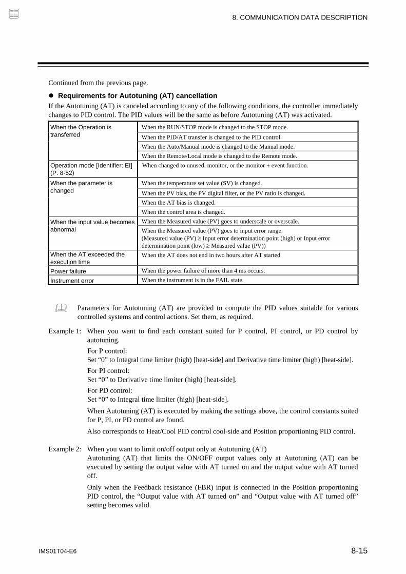
8. COMMUNICATION DATA DESCRIPTION
IMS01T04-E6 8-15
Continued from the previous page.
Requirements for Autotuning (AT) cancellation
If the Autotuning (AT) is canceled according to any of the following conditions, the controller immediately changes to PID control. The PID values will be the same as before Autotuning (AT) was activated.
When the Operation is transferred
When the RUN/STOP mode is changed to the STOP mode.
When the PID/AT transfer is changed to the PID control.
When the Auto/Manual mode is changed to the Manual mode.
When the Remote/Local mode is changed to the Remote mode.
Operation mode [Identifier: EI] (P. 8-52)
When changed to unused, monitor, or the monitor + event function.
When the parameter is changed
When the temperature set value (SV) is changed.
When the PV bias, the PV digital filter, or the PV ratio is changed.
When the AT bias is changed.
When the control area is changed.
When the input value becomes abnormal
When the Measured value (PV) goes to underscale or overscale.
When the Measured value (PV) goes to input error range. (Measured value (PV) Input error determination point (high) or Input error determination point (low) Measured value (PV))
When the AT exceeded the execution time
When the AT does not end in two hours after AT started
Power failure When the power failure of more than 4 ms occurs.
Instrument error When the instrument is in the FAIL state.
Parameters for Autotuning (AT) are provided to compute the PID values suitable for various controlled systems and control actions. Set them, as required.
Example 1: When you want to find each constant suited for P control, PI control, or PD control by
autotuning.
For P control: Set “0” to Integral time limiter (high) [heat-side] and Derivative time limiter (high) [heat-side].
For PI control: Set “0” to Derivative time limiter (high) [heat-side].
For PD control: Set “0” to Integral time limiter (high) [heat-side].
When Autotuning (AT) is executed by making the settings above, the control constants suited for P, PI, or PD control are found.
Also corresponds to Heat/Cool PID control cool-side and Position proportioning PID control. Example 2: When you want to limit on/off output only at Autotuning (AT)
Autotuning (AT) that limits the ON/OFF output values only at Autotuning (AT) can be executed by setting the output value with AT turned on and the output value with AT turned off.
Only when the Feedback resistance (FBR) input is connected in the Position proportioning PID control, the “Output value with AT turned on” and “Output value with AT turned off” setting becomes valid.

8. COMMUNICATION DATA DESCRIPTION
IMS01T04-E6 8-16
Auto/Manual transfer RKC communication
identifier J1
Modbus register address
ch1: 0065H (101) ch3: 0067H (103)ch2: 0066H (102) ch4: 0068H (104)
Use to transfer the Auto mode or Manual mode.
Auto mode: Automatic control is performed. Manual mode: The manipulated output value can be manually changed.
Attribute: R/W Digits: 1 digit Number of data: 4 (Data of each channel) Data range: 0: Auto mode 1: Manual mode Factory set value: 0 Related parameters: Operation mode state monitor (P. 8-5), MV transfer function (P. 8-95) PV transfer function (P. 8-125) Function: The manipulated output value when changed to the Manual mode from the Auto
mode differs depending on the MV transfer function (P. 8-95) setting. The MV transfer function enables the selection of whether a balanceless and bumpless transfer is made or a previous manipulated output value is used.
Balanceless-bumpless function This function is used to prevent overload caused by the Manipulated output value (MV) suddenly changing when Auto mode is transferred to Manual mode and vice versa.
Manipulated output value (MV)
Auto mode Auto modeManual mode
Time
(a) (b) (c)
(a) Transfer from Auto mode to Manual mode. When the mode is transferred to Manual mode, the manipulated output value used in Auto mode will be used as the manual output value in Manual mode.
(b) The manipulated output value is changed (Manual mode function).
(c) Transfer from Manual mode to Auto mode. When the mode is transferred to Auto mode, the controller starts PID control based on the MV used in Manual mode.
Link Z-TIO module and Z-DIO module to switch Auto/Manual by using Digital input (DI). For details, refer to following items: Address of interacting modules (P. 8-137) Selection switch of interacting modules (P. 8-138) DI function assignment (P. 8-154) of Z-DIO module
Regardless of whether the mode is Auto mode or Manual mode, the ON/OFF action remains effective.

8. COMMUNICATION DATA DESCRIPTION
IMS01T04-E6 8-17
Remote/Local transfer RKC communication
identifier C1
Modbus register address
ch1: 0069H (105) ch3: 006BH (107)ch2: 006AH (106) ch4: 006CH (108)
Use to transfer the Remote mode or Local mode.
Local mode: Control is performed at the local set value (SV). Remote mode: Control is performed with a remote setting (RS) input value.
Attribute: R/W Digits: 1 digit Number of data: 4 (Data of each channel) Data range: 0: Local mode 1: Remote mode Factory set value: 0 Related parameters: Operation mode state monitor (P. 8-5), SV tracking (P. 8-94)
When the ratio setting is selected with the SV selection function or cascade control is performed, the adjustment gauge on the slave must be switched to Remote mode.
Link Z-TIO module and Z-DIO module to switch Remote/Local by using Digital input (DI). For details, refer to following items: Address of interacting modules (P. 8-137) Selection switch of interacting modules (P. 8-138) DI function assignment (P. 8-154) of Z-DIO module
RUN/STOP transfer RKC communication
identifier SR
Modbus register address
006DH (109)
Use to transfer the RUN (control RUN) or STOP (control STOP).
Attribute: R/W Digits: 1 digit Number of data: 1 (Data of each module) Data range: 0: Control STOP 1: Control RUN Factory set value: 0 Related parameters: Operation mode state monitor (P. 8-5), Operation mode (P. 8-52), Control RUN/STOP holding setting (P. 8-141)
When used together with RKC panel mounted controllers (HA400/900, FB400/900, etc.), be careful that the numbers of indicating “RUN/STOP” of this instrument are opposite from those of the above controllers (0: Control RUN, 1: Control STOP).
Switch RUN/STOP by using Digital input (DI) of Z-DIO module. All modules connected to the Z-DIO transfer RUN/STOP at the same time. For details, refer to DI function assignment (P. 8-154) of Z-DIO module

8. COMMUNICATION DATA DESCRIPTION
IMS01T04-E6 8-18
Memory area transfer RKC communication
identifier ZA
Modbus register address
ch1: 006EH (110) ch3: 0070H (112)ch2: 006FH (111) ch4: 0071H (113)
This item selects the memory area (Control area) to use for control.
Attribute: R/W Digits: 7 digits Number of data: 4 (Data of each channel) Data range: 1 to 8 Factory set value: 1 Multi-memory area function Multi-memory area function can store up to 8 individual sets of SVs and parameters in Parameter setting mode.* One of the areas is used for control, and the currently selected area is Control area. If the set values are stored in divided memory areas for each work process, it is possible to collectively call up all of these set values necessary for the process simply by changing the corresponding memory area numbers. * On the SRZ, up to eight areas can be stored per channel.
Working process 1 Working process 2 Working process 8
Memory area 1
Set value (SV) Event 1 set value (EV1) Event 2 set value (EV2) Event 3 set value (EV3) Event 4 set value (EV4) Control loop break alarm (LBA) time LBA deadband Proportional band [heat-side] Integral time [heat-side] Derivative time [heat-side] Control response parameter Proportional band [cool-side] Integral time [cool-side] Derivative time [cool-side] Overlap/Deadband Manual reset Setting change rate limiter (up) Setting change rate limiter (down) Area soak time Link area number
Memory area 2
Set value (SV) Event 1 set value (EV1) Event 2 set value (EV2) Event 3 set value (EV3) Event 4 set value (EV4) Control loop break alarm (LBA) time LBA deadband Proportional band [heat-side] Integral time [heat-side] Derivative time [heat-side] Control response parameter Proportional band [cool-side] Integral time [cool-side] Derivative time [cool-side] Overlap/Deadband Manual reset Setting change rate limiter (up) Setting change rate limiter (down) Area soak time Link area number
Memory area 8
Set value (SV) Event 1 set value (EV1) Event 2 set value (EV2) Event 3 set value (EV3) Event 4 set value (EV4) Control loop break alarm (LBA) time LBA deadband Proportional band [heat-side] Integral time [heat-side] Derivative time [heat-side] Control response parameter Proportional band [cool-side] Integral time [cool-side] Derivative time [cool-side] Overlap/Deadband Manual reset Setting change rate limiter (up) Setting change rate limiter (down) Area soak time Link area number
Memory area 8 is used as the control area
In addition, it is possible to perform Ramp/Soak control by linking each memory area. It is possible to perform Ramp/Soak control of up to sixteen segments (eight steps) per channel.
Step 1
(Area 1)
Step 2
(Area 2)
Step 3
(Area 3)
Step 4
(Area 4)
Step 5
(Area 5)
Step 6
(Area 6)
Step 7
(Area 7)
Step 8
(Area 8)
Setting change rate limiter (up)
Link area number
Area soak time
1 segment
Link Z-TIO module and Z-DIO module to switch Memory area by using Digital input (DI). For details, refer to following items: Address of interacting modules (P. 8-137) Selection switch of interacting modules (P. 8-138) DI function assignment (P. 8-154) of Z-DIO module Memory area setting signal (P. 8-156)

8. COMMUNICATION DATA DESCRIPTION
IMS01T04-E6 8-19
Interlock release RKC communication
identifier AR
Modbus register address
ch1: 0072H (114) ch3: 0074H (116) ch2: 0073H (115) ch4: 0075H (117)
The event state is turned OFF when the event ON state is continued by the event interlock function.
Attribute: R/W Digits: 1 digit Number of data: 4 (Data of each channel) Data range: 0: Normal state 1: Interlock release execution Related parameters: Event interlock (P. 8-83) Factory set value: 0 Function: The following example shows how the event interlock is released.
Event set value
Set value (SV)
Event state
Event interlockrelease input OFF
OFF
OFF
OFF ON
ON
Measured value (PV)
Not turned OFF as the event interlock continues.
Turned OFF as the event interlock is released.
Event type: Deviation high [Example]
ON OFF
Invalid when the measured value (PV) is in the event ON zone.
To enable the interlock function, the interlock item of Event 1 to Event 4 must be set to “1: Used.”
Link Z-TIO module and Z-DIO module to release Interlock by using Digital input (DI). For details, refer to following items: Address of interacting modules (P. 8-137) Selection switch of interacting modules (P. 8-138) DI function assignment (P. 8-154) of Z-DIO module

8. COMMUNICATION DATA DESCRIPTION
IMS01T04-E6 8-20
Event 1 set value (EV1) RKC communication
identifier A1
Modbus register address
ch1: 0076H (118) ch3: 0078H (120)ch2: 0077H (119) ch4: 0079H (121)
Event 2 set value (EV2) RKC communication identifier
A2
Modbus register address
ch1: 007AH (122) ch3: 007CH (124)ch2: 007BH (123) ch4: 007DH (125)
Event 3 set value (EV3) RKC communication identifier
A3
Modbus register address
ch1: 007EH (126) ch3: 0080H (128)ch2: 007FH (127) ch4: 0081H (129)
Event 4 set value (EV4) RKC communication identifier
A4
Modbus register address
ch1: 0082H (130) ch3: 0084H (132)ch2: 0083H (131) ch4: 0085H (133)
EV1 through EV4 are set values of the event action.
Attribute: R/W Digits: 7 digits Number of data: 4 (Data of each channel) Data range: Deviation action 1 and Deviation action between channels 1:
Input span to Input span (Varies with the setting of the decimal point position.) Process action 2 and SV action 2: Input scale low to Input scale high (Varies with the setting of the decimal point position.) MV action (heat-side, cool-side) 2: 5.0 to 105.0 % Temperature rise completion range (Event 3 only) 3: Input span to Input span (Varies with the setting of the decimal point position.) 1 Deviation high, Deviation low, Deviation high/low, Band 2 high, low 3 When temperature rise completion is selected for the Event 3 type.
Factory set valu-E60 (50.0) Related parameters: Event type (P. 8-77), Event hold action (P. 8-81),
Event differential gap (P. 8-84), Event delay timer (P. 8-85), Force ON of Event action (P. 8-87)
When “9: Temperature rise completion” is selected for the Event 3 type, the Event 3 setting will be the range for determining temperature rise completion. For information on the temperature rise completion function, refer to Event type (P. 8-77). When “9: Control loop break alarm (LBA)” is selected for the Event 4 type, the Event 4 setting will be RO.

8. COMMUNICATION DATA DESCRIPTION
IMS01T04-E6 8-21
Control loop break alarm (LBA) time RKC communication
identifier A5
Modbus register address
ch1: 0086H (134) ch3: 0088H (136)ch2: 0087H (135) ch4: 0089H (137)
The LBA time sets the time required for the LBA function to determine there is a loop failure. When the LBA is output (under alarm status), the LBA function still monitors the Measured value (PV) variation at an interval of the LBA time.
Attribute: R/W Digits: 7 digits Number of data: 4 (Data of each channel) Data range: 0 to 7200 seconds (0: Unused) Related parameters: LBA deadband (P. 8-22), Event 4 type (P. 8-77) Factory set value: 480 Function: The Control loop break alarm (LBA) function is used to detect a load (heater) break
or a failure in the external actuator (power controller, magnet relay, etc.), or a failure in the control loop caused by an input (sensor) break. The LBA function is activated when control output reaches 0 % (low limit with output limit function) or 100 % (high limit with output limit function). LBA monitors variation of the Measured value (PV) for the length of LBA time. When the LBA time has elapsed and the PV is still within the alarm determination range, the LBA will be ON.
[Alarm action] LBA determination range: TC/RTD inputs: 2 C [F] (fixed) Voltage/Current inputs: 0.2 % of input span (fixed)
Heat control When the output reaches 0 %
(low limit with output limit function) When the output exceeds 100 % (high limit with output limit function)
For reverse action
When the LBA time has passed and the PV has not fallen below the alarm determination range, the alarm will be turned on.
When the LBA time has passed and the PV has not risen beyond the alarm determination range, the alarm will be turned on.
For direct action
When the LBA time has passed and the PV has not risen beyond the alarm determination range, the alarm will be turned on.
When the LBA time has passed and the PV has not risen beyond the alarm determination range, the alarm will be turned on.
If the Autotuning function is used, the LBA time is automatically set twice as large as the Integral time. The LBA setting time will not be changed even if the Integral time is changed.
If the LBA function detects an error occurring in the control loop, but cannot specify the location, a check of the control loop in order. The LBA function does not detect a location which causes alarm status. If LBA alarm is ON, check each device or wiring of the control loop.
When AT function is activated, the controller is in STOP mode, the control type is Heat/Cool PID control, the LBA time is set to 0 or the LBA function is not assigned to Event 4, the LBA function is not activated.
If the LBA setting time does not match the controlled object requirements, the LBA setting time should be lengthened. If setting time is not correct, the LBA will malfunction by turning on or off at inappropriate time or not turning on at all.
While the LBA is ON (under alarm status), the following conditions cancel the alarm status and LBA will be OFF. The Measured value (PV) rises beyond (or falls below) the LBA determination range within the
LBA time. The Measured value (PV) enters within the LBA deadband.

8. COMMUNICATION DATA DESCRIPTION
IMS01T04-E6 8-22
LBA deadband RKC communication
identifier N1
Modbus register address
ch1: 008AH (138) ch3: 008CH (140)ch2: 008BH (139) ch4: 008DH (141)
Control loop break alarm (LBA) deadband gives a neutral zone to prevent the Control loop break alarm (LBA) from malfunctioning caused by disturbance.
Attribute: R/W Digits: 7 digits Number of data: 4 (Data of each channel) Data range: 0 to Input span (Varies with the setting of the decimal point position.) Related parameters: Control loop break alarm (LBA) time (P. 8-21), Event 4 type (P. 8-77) Factory set value: 0 (0.0) Function: The LBA may malfunction due to external disturbance from outside even when the
control does not have any problem. To prevent malfunctioning due to external disturbance, LBA deadband (LBD) sets a neutral zone in which LBA is not activated. When the Measured value (PV) is within the LBD area, LBA will not be activated. If the LBD setting is not correct, the LBA will not work correctly.
LBD differential gap
Alarm area Alarm area Non-alarm areaA B
Set value (SV) LBD set value Low High
LBD differential gap: TC/RTD inputs: 0.8 C [F] Voltage/Current inputs: 0.8 % of input span
If the LBA function detects an error occurring in the control loop, but cannot specify the location, a check of the control loop in order. The LBA function does not detect a location which causes alarm status. If LBA alarm is ON, check each device or wiring of the control loop.
When AT function is activated, the controller is in STOP mode, the control type is Heat/Cool PID control, the LBA time is set to 0 or the LBA function is not assigned to Event 4, the LBA function is not activated.
If the LBA setting time does not match the controlled object requirements, the LBA setting time should be lengthened. If setting time is not correct, the LBA will malfunction by turning on or off at inappropriate time or not turning on at all.
While the LBA is ON (under alarm status), the following conditions cancel the alarm status and LBA will be OFF. The Measured value (PV) rises beyond (or falls below) the LBA determination range within the
LBA time. The Measured value (PV) enters within the LBA deadband.
A: During temperature rise: Alarm area During temperature fall: Non-alarm area B: During temperature rise: Non-alarm area During temperature fall: Alarm area

8. COMMUNICATION DATA DESCRIPTION
IMS01T04-E6 8-23
Set value (SV) [Local set value (SV)]
RKC communication identifier
S1
Modbus register address
ch1: 008EH (142) ch3: 0090H (144)ch2: 008FH (143) ch4: 0091H (145)
Set value (SV) is desired value of the control.
Attribute: R/W Digits: 7 digits Number of data: 4 (Data of each channel) Data range: Setting limiter low to Setting limiter high (Varies with the setting of the decimal point position.) Factory set value: TC/RTD inputs: 0 (0.0) Voltage (V)/Current (I) inputs: 0.0 Related parameters: Input type (P. 8-69), Setting limiter (high/low) (P. 8-125) Proportional band [heat-side] RKC communication
identifier P1
Modbus register address
ch1: 0092H (146) ch3: 0094H (148)ch2: 0093H (147) ch4: 0095H (149)
Proportional band [cool-side] RKC communication identifier
P2
Modbus register address
ch1: 00A2H (162) ch3: 00A4H (164)ch2: Unused ch4: Unused
Use to set the Proportional band of the P, PI, PD and PID control.
Attribute: R/W Digits: 7 digits Number of data: 4 (Data of each channel) Data range: Proportional band [heat-side]:
- TC/RTD inputs: 0 to Input span (Unit: C [F]) (Varies with the setting of the decimal point position.) - Voltage (V)/Current (I) inputs: 0.0 to 1000.0 % of input span 0 (0.0): ON/OFF action (Heat/Cool PID control: heat-side and cool-side are both ON/OFF action)
Regardless of whether the mode is Auto mode or Manual mode, the ON/OFF action remains effective.
Proportional band [cool-side]: - TC/RTD inputs: 1 (0.1) to Input span (Unit: C [F]) (Varies with the setting of the decimal point position.) - Voltage (V)/Current (I) inputs: 0.1 to 1000.0 % of input span
Factory set value: Proportional band [heat-side]: - TC/RTD inputs: 30 (30.0) - Voltage (V)/Current (I) inputs: 30.0
Proportional band [cool-side]: - TC/RTD inputs: 30 (30.0) - Voltage (V)/Current (I) inputs: 30.0
Related parameters: Overlap/Deadband (P. 8-27), Decimal point position (P. 8-71), Control action (P. 8-95), ON/OFF action differential gap (upper/lower) (P. 8-102)
Continued on the next page.

8. COMMUNICATION DATA DESCRIPTION
IMS01T04-E6 8-24
Continued from the previous page. Function: In Heat/Cool PID control, only one module enables heat and cool control. For
example, this is effective when cool control is required in extruder cylinder temperature control.
Manipulated output (MV)
100 %
0 %
Heat-side output
Proportional band[heat-side]
Cool-side output
Set value (SV)
OL DB DB: Deadband
Temperature
Proportional band[cool-side]
OL: Overlap
The Proportional band [cool-side] is valid only during Heat/Cool PID control. Integral time [heat-side] RKC communication
identifier I1
Modbus register address
ch1: 0096H (150) ch3: 0098H (152)ch2: 0097H (151) ch4: 0099H (153)
Integral time [cool-side] RKC communication identifier
I2
Modbus register address
ch1: 00A6H (166) ch3: 00A8H (168)ch2: Unused ch4: Unused
Integral action is to eliminate offset between Set value (SV) and Measured value (PV) by proportional action. The degree of Integral action is set by time in seconds.
Attribute: R/W Digits: 7 digits Number of data: 4 (Data of each channel) Data range: Integral time [heat-side]
- PID control or Heat/Cool PID control: 0 to 3600 seconds or 0.0 to 1999.9 seconds 0 (0.0): Integral time OFF (PD action) - Position proportioning PID control: 1 to 3600 seconds or 0.1 to 1999.9 seconds Integral time [cool-side] 0 to 3600 seconds or 0.0 to 1999.9 seconds 0 (0.0): Integral time OFF (PD action)
Factory set value: Integral time [heat-side]: 240 Integral time [cool-side]: 240
Related parameters: Control action (P. 8-95), Integral/Derivative time decimal point position (P. 8-100)
The integral time [cool-side] is valid only during Heat/Cool PID control.
When the heat-side or cool-side integral time is set to zero for Heat/Cool PID control, PD action will take place for both heat-side and cool-side.

8. COMMUNICATION DATA DESCRIPTION
IMS01T04-E6 8-25
Derivative time [heat-side] RKC communication
identifier D1
Modbus register address
ch1: 009AH (154) ch3: 009CH (156)ch2: 009BH (155) ch4: 009DH (157)
Derivative time [cool-side] RKC communication identifier
D2
Modbus register address
ch1: 00AAH (170) ch3: 00ACH (172)ch2: Unused ch4: Unused
Derivative action is to prevent rippling and make control stable by monitoring output change. The degree of Derivative action is set by time in seconds.
Attribute: R/W Digits: 7 digits Number of data: 4 (Data of each channel) Data range: Derivative time [heat-side]: 0 to 3600 seconds or 0.0 to 1999.9 seconds 0 (0.0): Derivative time OFF (PI action) Derivative time [cool-side]: 0 to 3600 seconds or 0.0 to 1999.9 seconds Derivative time [cool-side]: 0 (0.0): Derivative time OFF (PI action) Factory set value: Derivative time [heat-side]: 60 Derivative time [cool-side]: 60 Related parameters: Control action (P. 8-95), Integral/Derivative time decimal point position (P. 8-100), Derivative gain (P. 8-101)
The derivative time [cool-side] is valid only during Heat/Cool PID control.

8. COMMUNICATION DATA DESCRIPTION
IMS01T04-E6 8-26
Control response parameter RKC communication
identifier CA
Modbus register address
ch1: 009EH (158) ch3: 00A0H (160)ch2: 009FH (159) ch4: 00A1H (161)
The control response for the Set value (SV) change can be selected among Slow, Medium, and Fast.
Attribute: R/W Digits: 1 digit Number of data: 4 (Data of each channel) Data range: 0: Slow 1: Medium 2: Fast Factory set value: PID control, Position proportioning PID control: 0
Heat/Cool PID control: 2 Related parameters: Control action (P. 8-95) Function: The control response for the Set value (SV) change can be selected among Slow,
Medium, and Fast. If a fast response is required, Fast is chosen. Fast may cause overshoot. If overshoot is critical, Slow is chosen.
Fast Selected when rise time needs to be shortened (operation needs to started fast). However in this case, slight overshooting may not be avoided.
Medium Middle between “Fast” and “Slow.” Overshooting when set to “Medium” becomes less than that when set to “Fast.”
Slow Selected when no overshooting is allowed. Used when material may be deteriorated if the temperature becomes higher that the set value.
Measured value (PV)
Set value (SV)
Change
Set value (SV) change point Time
Fast
Medium
Slow
Set value (SV)
When the P or PD action is selected, this setting becomes invalid.

8. COMMUNICATION DATA DESCRIPTION
IMS01T04-E6 8-27
Overlap/Deadband RKC communication
identifier V1
Modbus register address
ch1: 00AEH (174) ch3: 00B0H (176)ch2: 00AFH (175) ch4: 00B1H (177)
This is the overlapped range of proportional bands (on the heat and cool sides) or the deadband range when Heat/Cool PID control is performed.
Attribute: R/W Digits: 7 digits Number of data: 4 (Data of each channel) Data range: TC/RTD inputs: Input span to +Input span (Unit: C [F])
(Varies with the setting of the decimal point position.) Voltage (V)/Current (I) inputs: 100.0 to +100.0 % of Input span
Factory set value: TC/RTD inputs: 0 (0.0) Voltage (V)/Current (I) inputs: 0.0
Related parameters: Proportional band [heat-side/cool-side] (P. 8-23), Control action (P. 8-95) Function: Overlap (OL):
Range in which the Proportional band [heat-side] and the Proportional band [cool-side] are overlapped. If a Measured value (PV) is within the overlapped range, manipulated output values (heat-side and cool-side) may be simultaneously output.
Deadband (DB): This is a control dead zone existing between the Proportional band [heat-side] and the Proportional band [cool-side]. If a Measured value (PV) is within the deadband range, neither the manipulated output value (heat-side) nor the manipulated output value (cool-side) is output.
When Measured value (PV) is in Deadband, Manipulated output may be produced by setting Output limiter (low) to 0.1 % or more.
Manipulated output value (MV)
100 %
0 %
Heat-side output value
Proportional band[heat-side]
Cool-side output value
Set value (SV)
OL DB DB: Deadband
Temperature
If set to minus (), the proportional band (on the cool side) overlaps with the proportional band (on the heat side).
Proportional band[cool-side]
OL: Overlap
Minus () setting results is overlap. However, the overlapping range is limited to the Proportional band [heat-side] set range or the Proportional band [cool-side] set range, whichever is smaller.

8. COMMUNICATION DATA DESCRIPTION
IMS01T04-E6 8-28
Manual reset RKC communication
identifier MR
Modbus register address
ch1: 00B2H (178) ch3: 00B4H (180)ch2: 00B3H (179) ch4: 00B5H (181)
In order to eliminate the offset occurring in Proportional (P) control, the manipulated output value is manually corrected.
When the Manual reset is set to the plus (+) side: The manipulated output value under the stable condition increases by the Manual reset value. When the Manual reset is set to the minus () side: The manipulated output value under the stable condition decreases by the Manual reset value.
Attribute: R/W When the integral function is enabled, the Manual reset is RO.
Digits: 7 digits Number of data: 4 (Data of each channel) Data range: 100.0 to +100.0 % Factory set value: 0.0 Related parameters: Integral time [heat-side/cool-side] (P. 8-24) Function: This is the function used to manually correct the offset when in Proportional (P)
control or PD control. Offset means the deviation of the actual when the manipulated output value
becomes stabilized (stable state). If the manual reset value varies, the manipulated output value also changes.
Set value (SV)
Offset
Measured value (PV)
Temperature
Time
Measured value (PV)
Offset
Manual reset is set.
To enable the Manual reset function, either Integral time [heat-side] or Integral time [cool-side] must be set to zero.

8. COMMUNICATION DATA DESCRIPTION
IMS01T04-E6 8-29
Setting change rate limiter (up) RKC communication
identifier HH
Modbus register address
ch1: 00B6H (182) ch3: 00B8H (184)ch2: 00B7H (183) ch4: 00B9H (185)
Setting change rate limiter (down) RKC communication identifier
HL
Modbus register address
ch1: 00BAH (186) ch3: 00BCH (188)ch2: 00BBH (187) ch4: 00BDH (189)
This function is to allow the Set value (SV) to be automatically changed at specific rates when a new Set value (SV).
Attribute: R/W Digits: 7 digits Number of data: 4 (Data of each channel) Data range: 0 to Input span/unit time * 0: Unused (Varies with the setting of the decimal point position.) * Unit time: 60 seconds (Factory set value) Factory set value: Setting change rate limiter (up): 0 (0.0) Setting change rate limiter (down): 0 (0.0) Related parameters: Setting change rate limiter unit time (P. 8-124) : Setting change rate limiter This function is to allow the Set value (SV) to be automatically changed at specific rates when a new Set value (SV). Setting change rate limiter (up) is used when the SV is changed to a higher SV. Setting change rate limiter (down) is used when the SV is changed to a lower SV. [Application examples of setting change rate limiter]
SV
Decrease gradually
at specific rate
SV [After changing]
SV [Before changing]
Changing the set value
Time
Decreasing the SV to a lower value
Increase gradually
at specific rate
Changing the set value
SV [After changing]
SV [Before changing]
Time
Increasing the SV to a higher value
SV
When the setting change rate limiter is used, the SV will also ramp up or ramp down by the function at power-on and operation mode change from STOP to RUN.
If the Autotuning (AT) function is activated while the SV is ramping up or ramping down by the setting change rate limiter, AT will starts after the SV finishes ramp-up or ramp-down by the limiter, and the controller is in PID control mode until AT starts.
When the value of setting change rate limiter is changed during normal operation, the ramp-up or ramp-down rate will be changed unless the SV already has finished ramp-up or ramp-down by the function.
If the rate of setting change limiter is set to any value other than “0: Unused,” the event re-hold action to be taken by a Set value (SV) change becomes invalid.

8. COMMUNICATION DATA DESCRIPTION
IMS01T04-E6 8-30
Area soak time RKC communication
identifier TM
Modbus register address
ch1: 00BEH (190) ch3: 00C0H (192)ch2: 00BFH (191) ch4: 00C1H (193)
This is the time required until transferred to the Link area number when performing Ramp/Soak control.
Attribute: R/W Digits: 7 digits Number of data: 4 (Data of each channel) Data range: RKC communication:
0 minutes 00 seconds to 199 minutes 59 seconds: 0:00 to 199:59 (min:sec) 0 hours 00 minutes to 99 hours 59 minutes: 0:00 to 99:59 (hrs:min)
Modbus: 0 minutes 00 seconds to 199 minutes 59 seconds: 0 to 11999 seconds 0 hours 00 minutes to 99 hours 59 minutes: 0 to 5999 minutes
Factory set value: RKC communication: 0:00 Modbus: 0
Related parameters: Soak time unit (P. 8-124) Function: Area soak time is used for Ramp/Soak control function in conjunction with Link
area number and Setting change rate limiter (up/down).
[Application examples of Area soak time]
Measured value (PV)
Set value (SV) of memory area 1
Memory area 1
Area soak time ofmemory area 1
Setting change rate limiter (up)of memory area1
Area soak time ofmemory area 2
Setting change rate limiter(up) of memory area 2
Time
Set value (SV) of memory area 2
Memory area 2
The Area soak time for the memory area linked last becomes invalid to continue the state of the Set value (SV) reached.
Time required while the Setting change rate limiter is being operated is not included in the Area soak time.
The Area soak time can be changed during normal operation with Ramp/Soak control function, but Read the following example carefully how the time change affects Ramp/Soak control time. For example, the Memory area which has 5-minute soak time is executed. When 3 minutes passed, the Area soak time is changed from 5 minutes to 10 minutes. The remaining time of the currently executed Memory area is computed as follows. (The new soak time 10 minutes) – (lapsed time 3 minutes) = (remaining time 7 minutes) The old soak time does not have any effect on remaining time.
Area soak time: 5 minutes
Area soak time is changed 10 minutes.
Measured value (PV)
Set value (SV) of memory area 1
Present set value (SV)
Time
Operationstart: 3 minutes
Time of remaining operating hour:
7 minutes
Changing

8. COMMUNICATION DATA DESCRIPTION
IMS01T04-E6 8-31
Link area number RKC communication
identifie LP
Modbus register address
ch1: 00C2H (194) ch3: 00C4H (196)ch2: 00C3H (195) ch4: 00C5H (197)
Memory area numbers for linking the corresponding memory areas are set when Ramp/Soak control is performed.
Attribute: R/W Digits: 7 digits Number of data: 4 (Data of each channel) Data range: 0 to 8 (0: No link) Factory set value: 0 Function: Link area number is used for Ramp/Soak control function in conjunction with Area
soak time and Setting change rate limiter (up/down).
Area soak time of memory area 1
Area soak time ofmemory area 2
Setting change rate limiter (down) of memory area 3
Area soak time of memory area 3
Measured value (PV)
Set value (SV) of memory area 2
Set value (SV) of memory area 1
Set value (SV) of memory area 3
Present set value (SV)
TimeMemory area 2 Memory area 3 Memory area 1
Setting change rate limiter (up) of memory area 2
Setting change rate limiter (up) of memory area 1
The area soak time for the memory area linked last becomes invalid to continue the state of the Set value (SV) reached.

8. COMMUNICATION DATA DESCRIPTION
IMS01T04-E6 8-32
Heater break alarm (HBA) set value RKC communication
identifier A7
Modbus register address
ch1: 00C6H (198) ch3: 00C8H (200)ch2: 00C7H (199) ch4: 00C9H (201)
HBA is to set the set values for the Heater break alarm (HBA) function. The HBA function detects a fault in the heating circuit by monitoring the current flowing through the load by a dedicated Current transformer (CT).
For type “A” HBA, - Set the set value to approximately 85 % of the maximum reading of the CT input. - Set the set value to a slightly smaller value to prevent a false alarm if the power supply may become
unstable. - When more than one heater is connected in parallel, it may be necessary to increase the HBA set value to
detect a single heater failure.
For type “B” HBA, Set the set value to the maximum CT input value. This will be the current when the control is at 100 % control output. The set value is used to compute the width of a non-alarm range.
Attribute: R/W Digits: 7 digits Number of data: 4 (Data of each channel) Data range: When the CT type is CTL-6-P-N: 0.0 to 30.0 A (0.0: Not used)
When the CT type is CTL-12-S56-10L-N: 0.0 to 100.0 A (0.0: Not used) Factory set value: 0.0 Related parameters: Comprehensive event state (P. 8-4),
Current transformer (CT) input value monitor (P. 8-7), Heater break alarm (HBA) state monitor (P. 8-9), Heater break determination point (P. 8-34), Heater melting determination point (P. 8-34), CT ratio (P. 8-89), CT assignment (P. 8-89), Heater break alarm (HBA) type (P. 8-90), Number of heater break alarm (HBA) delay times (P. 8-91)
Function: < Heater break alarm (HBA) type A > Heater break alarm (HBA) type A can be used with time-proportional control output (Relay, Voltage pulse, or Triac output). The HBA function monitors the current flowing through the load by a dedicated Current transformer (CT), compares the measured value with the HBA set values, and detects a fault in the heating circuit. Low or No current flow (Heater break, malfunction of the control device, etc.): When the control output is ON and the CT input value is equal to or less than the heater break determination point for the preset number of consecutive sampling cycles, an alarm is activated. However, heater break alarm does not action when control output ON time is 0.1 second or less. Over current or short-circuit: When the control output is OFF and the CT input value is equal to or greater than the heater break determination point for the preset number of consecutive sampling cycles, an alarm is activated. However, heater break alarm does not action when control output OFF time is 0.1 second or less.
Continued on the next page.

8. COMMUNICATION DATA DESCRIPTION
IMS01T04-E6 8-33
Continued from the previous page. < Heater break alarm (HBA) type B > Heater Break Alarm (HBA) type B can be used with continuous control output (Voltage/Current continuous output). The HBA function assumes that the heater current value is proportional* to the control output value of the controller, otherwise viewed as the Manipulated variable (MV), and compare it with the CT input value to detect a fault in the heating or cooling circuit.
* It is assumed that the current value flowing through the load is at maximum when the control output from the controller is 100 %, and the minimum current value flowing through the load is zero (0) when the control output from the controller is 0 %.
Low or No current flow (Heater break, malfunction of the control device, etc.) The alarm determination point (Low) is computed as follows: [Non-alarm range (Low) width] = (Heater break determination point) (HBA set value) [Alarm determination point (Low)] = [(HBA set value) (MV)] – [Non-alarm range (Low) width)] When the CT input value is equal to or less than the Heater break determination point for the preset number of consecutive sampling cycles, an alarm status is produced. Over current or short-circuit The alarm determination point (High) is computed as follows: (Non-alarm range (High) width) = (Heater melting determination point) (HBA set value) (Alarm determination point (High)) = ((HBA set value) (MV)) + (Non-alarm range (High) width) When the CT input value is equal to or greater than the Heater melting determination point for the preset number of consecutive sampling cycles, an alarm status is produced.
Computed heater current value (Proportional to voltage squared)
Alarm range ofLow current/ No current
Alarm range ofOver current/Short-circuit
Current value of heater used (squared)
Manipulated output value of controller
Non-alarm range (High) for heater melting determination
100 [%]
0 [%]
0 [A]
Maximum current value (squared)
Non-alarm range (Low) for heater break determination
Heater break determination point
(0.0 to 100.0 % of maximum current)
Heater melting determination point
(0.0 to 100.0 % of maximum current)
The current factory set values of the Heater break determination point and the Heater melting determination point are set to 30.0 %. If any of the following conditions exists, set them to a slightly larger value to prevent a false alarm. Heater current values is not proportional to the control output in Phase control. There is difference on control output accuracy between the controller and the operating
unit (SCR Power Controller). There is a delay on control output between the controller and the operating unit (SCR
Power Controller).
Factory set value of Heater break alarm (HBA) varies with the control output type of CT assignment. Factory set value (CT assignment of CH1: OUT1) of Heater break alarm (HBA) type: OUT1 output type: Time-proportional control output *: Type A Continuous control output *: Type B
* Time-proportional control output: Relay contact, Voltage pulse, Triac or Open collector output Continuous control output: Voltage/Current continuous output

8. COMMUNICATION DATA DESCRIPTION
IMS01T04-E6 8-34
Heater break determination point RKC communication
identifier NE
Modbus register address
ch1: 00CAH (202) ch3: 00CCH (204)ch2: 00CBH (203) ch4: 00CDH (205)
Set the Heater break determination point for the Heater break alarm (HBA) type B.
Attribute: R/W Digits: 7 digits Number of data: 4 (Data of each channel) Data range: 0.0 to 100.0 % of HBA set value
(0.0: Heater break determination is invalid) Factory set value: 30.0 Related parameters: Comprehensive event state (P. 8-4),
Heater break alarm (HBA) state monitor (P. 8-9), Heater break alarm (HBA) set value (P. 8-32), Heater melting determination point (P. 8-34), CT assignment (P. 8-89), Heater break alarm (HBA) type (P. 8-90), Number of heater break alarm (HBA) delay times (P. 8-91)
Function: Refer to Heater break alarm (HBA) set value (P. 8-32). Heater melting determination point RKC communication
identifier NF
Modbus register address
ch1: 00CEH (206) ch3: 00D0H (208)ch2: 00CFH (207) ch4: 00D1H (209)
Set the Heater melting determination point for the Heater break alarm (HBA) type B.
Attribute: R/W Digits: 7 digits Number of data: 4 (Data of each channel) Data range: 0.0 to 100.0 % of HBA set value (0.0: Heater melting determination is invalid) Factory set value: 30.0 Related parameters: Comprehensive event state (P. 8-4),
Heater break alarm (HBA) state monitor (P. 8-9), Heater break alarm (HBA) set value (P. 8-32), Heater break determination point (P. 8-34), CT assignment (P. 8-89), Heater break alarm (HBA) type (P. 8-90), Number of heater break alarm (HBA) delay times (P. 8-91)
Function: Refer to Heater break alarm (HBA) set value (P. 8-32)

8. COMMUNICATION DATA DESCRIPTION
IMS01T04-E6 8-35
PV bias RKC communication
identifier PB
Modbus register address
ch1: 00D2H (210) ch3: 00D4H (212)ch2: 00D3H (211) ch4: 00D5H (213)
PV bias adds bias to the Measured value (PV). The PV bias is used to compensate the individual variations of the sensors or correct the difference between the Measured value (PV) of other instruments.
Attribute: R/W Digits: 7 digits Number of data: 4 (Data of each channel) Data range: Input span to +Input span (Varies with the setting of the decimal point position.) Factory set value: 0 (0.0) PV digital filter RKC communication
identifier F1
Modbus register address
ch1: 00D6H (214) ch3: 00D8H (216)ch2: 00D7H (215) ch4: 00D9H (217)
This item is the time of the first-order lag filter to eliminate noise against the measured input.
Attribute: R/W Digits: 7 digits Number of data: 4 (Data of each channel) Data range: 0.0 to 100.0 seconds (0.0: Unused) Factory set value: 0.0 PV ratio RKC communication
identifier PR
Modbus register address
ch1: 00DAH (218) ch3: 00DCH (220)ch2: 00DBH (219) ch4: 00DDH (221)
PV ratio is a multiplier to be applied to the Measured value (PV). The PV ratio is used to compensate the individual variations of the sensors or correct the difference between the Measured value (PV) of other instruments.
Attribute: R/W Digits: 7 digits Number of data: 4 (Data of each channel) Data range: 0.500 to 1.500 Factory set value: 1.000

8. COMMUNICATION DATA DESCRIPTION
IMS01T04-E6 8-36
PV low input cut-off RKC communication
identifier DP
Modbus register address
ch1: 00DEH (222) ch3: 00E0H (224)ch2: 00DFH (223) ch4: 00E1H (225)
PV low input cut-off is used with Square root extraction function. The measured value less than the PV low input cut-off is ignored to prevent control disturbance caused by input variation at low measured value range.
Attribute: R/W When square root extraction is “0: Unused,” the PV low input cut-off will be RO.
Digits: 7 digits Number of data: 4 (Data of each channel) Data range: 0.00 to 25.00 % of input span Factory set value: 0.00 Related parameters: Square root extraction (P. 8-74) Function: When input signal square root extraction is used for in flow control, etc., the square
root extraction result varies widely at the low measured value range. The measured value less than the PV low input cut-off is ignored to compute control output in order to prevent control disturbance caused by input variation at low measured value range.
100 %
70.7 %
50 %
Output
Input100 % 50 %25 %
When set value of the PV low input cut-off is 15 %
0 %
When set value of the PV low input cut-off is 0 %
RS bias RKC communication
identifier RB
Modbus register address
ch1: 00E2H (226) ch3: 00E4H (228)ch2: 00E3H (227) ch4: 00E5H (229)
RS bias adds bias to the Remote setting (RS) input value.
Attribute: R/W Digits: 7 digits Number of data: 4 (Data of each channel) Data range: Input span to +Input span (Varies with the setting of the decimal point position.) Factory set value: 0 (0.0) Related parameters: Remote/Local transfer (P. 8-17), SV select function (P. 8-127),
Remote SV function master channel module address (P. 8-133), Remote SV function master channel selection (P. 8-134)
When the cascade control is selected, this is used as the cascade bias. When the ratio setting is selected, this is used as the ratio setting bias.

8. COMMUNICATION DATA DESCRIPTION
IMS01T04-E6 8-37
RS digital filter RKC communication
identifier F2
Modbus register address
ch1: 00E6H (230) ch3: 00E8H (232)ch2: 00E7H (231) ch4: 00E9H (233)
This item is the time of the first-order lag filter to eliminate noise against the Remote setting input.
Attribute: R/W Digits: 7 digits Number of data: 4 (Data of each channel) Data range: 0.0 to 100.0 seconds (0.0: Unused) Factory set value: 0.0 Related parameters: Remote/Local transfer (P. 8-17), SV select function (P. 8-127),
Remote SV function master channel module address (P. 8-133), Remote SV function master channel selection (P. 8-134)
When the cascade control is selected, this is used as the cascade digital filter. When the ratio setting is selected, this is used as the ratio setting digital filter.
RS ratio RKC communication
identifier RR
Modbus register address
ch1: 00EAH (234) ch3: 00ECH (236)ch2: 00EBH (235) ch4: 00EDH (237)
RS ratio is a multiplier to be applied to the Remote setting (RS) input value.
Attribute: R/W Digits: 7 digits Number of data: 4 (Data of each channel) Data range: 0.001 to 9.999 Factory set value: 1.000 Related parameters: Remote/Local transfer (P. 8-17), SV select function (P. 8-127),
Remote SV function master channel module address (P. 8-133), Remote SV function master channel selection (P. 8-134)
When the cascade control is selected, this is used as the cascade ratio. When the ratio setting is selected, this is used as the ratio setting ratio.

8. COMMUNICATION DATA DESCRIPTION
IMS01T04-E6 8-38
Output distribution selection RKC communication
identifier DV
Modbus register address
ch1: 00EEH (238) ch3: 00F0H (240)ch2: 00EFH (239) ch4: 00F1H (241)
Select whether or not the manipulated output value of the specified master channel is output from slave channels.
Attribute: R/W Digits: 1 digit Number of data: 4 (Data of each channel) Data range: 0: Control output (master channel) 1: Distribution output (slave channel) Factory set value: 0 Related parameters: Output distribution bias (P. 8-40), Output distribution ratio (P. 8-40),
Output distribution master channel module address (P. 8-133), Output distribution master channel selection (P. 8-136)
Function: The output distribution function outputs the manipulated output value computed for the master channel as a manipulated output value from slave channels. Bias and ratio computations can also be applied to the manipulated output value computed for the master channel before it is output from the slave channels.
Number of output distribution channels: 187 channels maximum (excluding the master channel) [When Z-DIO module: 16 modules, Z-TIO module 4CH type: 15 modules]
Master channel
Z-TIO module
Sensor input
Setting change rate limiter
PID computation
Output limiter
Output
Capture the output value
Output distribution bias
Output limiter
Output Manipulated output value of master channel
Manipulated output value of slave channel
Manipulated output value of master channel
Output distribution ratio
Communication
Slave channel
(Internal communication)
Capture the output value
DO output distribution bias
DO output limiter
Output
Manipulated output value of slave channel
DO output distribution ratio
Slave channel
Communication
Manipulated output value of master channel
Z-DIO module *
* Distribution output from Z-DIO module becomes open collector output or relay contact output.
The manipulated output values of the master channel and slave channels are each output within the limit of the output limiter.
The output distribution function only functions within modules that are connected together (SRZ unit).
Continued on the next page.

8. COMMUNICATION DATA DESCRIPTION
IMS01T04-E6 8-39
Continued from the previous page. Operation flow Example: Using two Z-TIO modules (4CH type)
Master/Slave: Master/Slave Module address CH Input Output
Master channel (Heater 2)
Module address 0 CH1 Sensor input Control output
Slave channel (Heater 1)
Module address 0 CH3 Distribution output
Slave channel (Heater 3)
Module address 1 CH1 Distribution output
Setting: Module address 0 Module address 1
Setting items CH1 (Master)
CH3 (Slave)
CH1 (Slave)
Output distribution master channel module address
1 or 0 0 (Set module address 0)
Output distribution master channel selection
1 (Set CH1)
1 (Set CH1)
Output distribution selection
0 (Control output)
1 (Distribution output)
1 (Distribution output)
Output distribution bias Set as needed
Output distribution ratio Set as needed
Module address 0
Module address 1
11
12
11
12
14
15
24
25
TC
CH1
Heater 1 Heater 2 Heater 3
SSR SSR SSR
CH1
CH3 CH1
Hot plate
1. Set the Output distribution master channel module address
2. Select the Output distribution master channel
In the slave channel, set the module address number of the module that includes the channel to be specified as the master.
Output distribution master channel module address (P. 8-135): 1 (Master channel is selected from itself) 0 to 99 (Master channel is selected from other modules)
In the slave channel, select the channel number that will be the master in the master channel module. This setting is not required in the master channel.
Output distribution master channel selection (P. 8-136): 1 to 99
3. Output distribution selection
Set “0: Control output” in the master channel.
Set “1: Distribution output” in the slave channel.
4. Control start
5. Adjust the Output distribution bias
In each slave, set the bias (P. 8-40) and ratio (P. 8-40) for the manipulated output value from the master. Select these settings as needed based on the actual operation state.
6. Adjust the Output distribution ratio

8. COMMUNICATION DATA DESCRIPTION
IMS01T04-E6 8-40
Output distribution bias RKC communication
identifier DW
Modbus register address
ch1: 00F2H (242) ch3: 00F4H (244)ch2: 00F3H (243) ch4: 00F5H (245)
The bias which is added to the manipulated output value of the master channel that is distributed to slave channels and output.
Attribute: R/W Digits: 7 digits Number of data: 4 (Data of each channel) Data range: 100.0 to 100.0 % Factory set value: 0.0 Related parameters: Output distribution selection (P. 8-38), Output distribution ratio (P. 8-40),
Output distribution master channel module address (P. 8-135), Output distribution master channel selection (P. 8-136)
Output distribution ratio RKC communication
identifier DQ
Modbus register address
ch1: 00F6H (246) ch3: 00F8H (248)ch2: 00F7H (247) ch4: 00F9H (249)
The ratio (magnification) which is applied to the manipulated output value of the master channel that is distributed to slave channels and output.
Attribute: R/W Digits: 7 digits Number of data: 4 (Data of each channel) Data range: 9.999 to 9.999 Factory set value: 1.000 Related parameters: Output distribution selection (P. 8-38), Output distribution bias (P. 8-40),
Output distribution master channel module address (P. 8-135), Output distribution master channel selection (P. 8-136)
Proportional cycle time RKC communication
identifier T0
Modbus register address
ch1: 00FAH (250) ch3: 00FCH (252)ch2: 00FBH (251) ch4: 00FDH (253)
Proportional cycle time is to set control cycle time for time based control output such as Voltage pulse for SSR, Triac, Relay and Open-collector output.
Attribute: R/W Digits: 7 digits Number of data: 4 (Data of each channel) Data range: 0.1 to 100.0 seconds Factory set value: Relay contact output: 20.0 Voltage pulse output (V), Triac output (T) and Open-collector output (D): 2.0 Related parameters: Output assignment (P. 8-75)
To set the Proportioning cycle, “0: Control output” must be set in the output assignment item.
The Proportional cycle time becomes invalid when the Voltage/Current output is selected.

8. COMMUNICATION DATA DESCRIPTION
IMS01T04-E6 8-41
Minimum ON/OFF time of proportioning cycle
RKC communication identifier
VI
Modbus register address
ch1: 00FEH (254) ch3: 0100H (256)ch2: 00FFH (255) ch4: 0101H (257)
This is the minimum ON/OFF time of the time proportioning cycle.
Attribute: R/W Digits: 7 digits Number of data: 4 (Data of each channel) Data range: 0 to 1000 ms Factory set value: 0 Related parameters: Proportional cycle time (P. 8-40), Output assignment (P. 8-75) Function: The minimum ON/OFF time of the proportioning cycle is used to prevent output
ON or OFF when the output is greater than 0 % or less than 100 %. This is useful when you wish to establish a minimum ON/OFF time to prolong the life of the relay.
Example 1: Setting of Minimum ON/OFF time of proportioning cycle Computed output
More than 0 % (Around 0 %)
Computed output
ON
OFF
* When a long minimum ON/OFF time is required for the relay, set a time longer than that time.
ON
OFF Actual output
ON
OFF
Computed output
ON
OFF Actual output
Setting of Minimum ON/OFF time
ON
OFF
DO proportioning cycle time
(ON time)
*
Less than 100 % (Around 100 %)
Setting of Minimum ON/OFF time
ON
OFF (OFF time)
DO proportioning cycle time
*
Example 2: Setting of Minimum ON/OFF time of proportioning cycle Computed output More than 0 % (Around 0 %)
Computed output
ON
OFF
* When a long minimum ON/OFF time is required for the relay, set a time longer than that time.
ON
OFF Actual output
ON
OFF
Computed output
ON
OFF Actual output
Setting of Minimum ON/OFF time
ON
OFF
DO proportioning cycle time
(ON time)
*
Less than 100 % (Around 100 %)
Setting of Minimum ON/OFF time
ON
OFF (OFF time)
DO proportioning cycle time
*
The minimum ON/OFF time of the proportioning cycle becomes invalid when the Voltage/Current output is selected.
Operation will not take place if “Proportional cycle time Minimum ON/OFF time of proportioning cycle.”

8. COMMUNICATION DATA DESCRIPTION
IMS01T04-E6 8-42
Manual manipulated output value RKC communication
identifier ON
Modbus register address
ch1: 0102H (258) ch3: 0104H (260)ch2: 0103H (259) ch4: 0105H (261)
Use to set the output value in the Manual control.
Attribute: R/W Digits: 7 digits Number of data: 4 (Data of each channel) Data range: PID control: Output limiter low to Output limiter high Heat/cool PID control: Cool-side output limiter (high) to
Heat-side output limiter (high) Position proportioning PID control:
- When there is Feedback resistance (FBR) input and no Feedback resistance (FBR) input is disconnected: Output limiter low to Output limiter high
- When there is no Feedback resistance (FBR) input or the Feedback resistance (FBR) input is disconnected: 0: Close-side output OFF, Open-side output OFF 1: Close-side output ON, Open-side output OFF 2: Close-side output OFF, Open-side output ON
Factory set value: 0.0 Related parameters: Output limiter (high/low) (P. 8-107)
If Position proportional PID control is changed from “Feedback resistance (FBR) input” to “No FBR input,” both open-side output and close-side output will turn OFF.
If an input disconnection occurs when “Feedback resistance (FBR) input” is used, the manual manipulated output value will start from the state “0 (close-side output OFF, open-side output OFF).”
Following recovery from an input disconnection when “Feedback resistance (FBR) input” is used, the manual manipulated output value will be bumped to the current feedback resistance value. The output of the ON/OFF action in the Manual mode is as follows.
・When Manual manipulated output value Output limiter (low) (or 0.0 % or less) → Output limiter (low)
・When Manual manipulated output value Output limiter (low) (or 0.0 % or less) → Output limiter (high)

8. COMMUNICATION DATA DESCRIPTION
IMS01T04-E6 8-43
Area soak time stop function RKC communication
identifier RV
Modbus register address
ch1: 0106H (262) ch3: 0108H (264)ch2: 0107H (263) ch4: 0109H (265)
Select the event for which the Area soak time is to be stopped when an event state occurs.
Attribute: R/W Digits: 1 digit Number of data: 4 (Data of each channel) Data range: 0: No function 1: Event 1 2: Event 2 3: Event 3 4: Event 4 Factory set value: 0 Related parameters: Area soak time (P. 8-30) Function: The Area soak time stop function stops the Area soak time count when an event
state occurs at the specified event output during soak operation. When the event state is cleared, the area soak time count stop is canceled and soak operation resumes from the state immediately prior to the stop.
Measured value (PV)
Set value (SV) of Memory area 1
Area soak time of Memory area 1: 10 minutes Area soak time stop function: 1 (Event 1)
Time
Present set value (SV)
Event 1 state occurs
Soak operation (3 minutes)
Area soak timestop
(2 minutes)
Event 1 state cleared
Soak operation resumes (Remaining operation time is
7 minutes)
Example:

8. COMMUNICATION DATA DESCRIPTION
IMS01T04-E6 8-44
EDS mode (for disturbance 1) RKC communication
identifier NG
Modbus register address
ch1: 010AH (266) ch3: 010CH (268)ch2: 010BH (267) ch4: 010DH (269)
EDS mode (for disturbance 2) RKC communication identifier
NX
Modbus register address
ch1: 010EH (270) ch3: 0110H (272)ch2: 010FH (271) ch4: 0111H (273)
Select the mode of the EDS function (External disturbance suppression function).
Attribute: R/W Digits: 1 digit Number of data: 4 (Data of each channel) Data range: 0: No function 1: EDS function mode 2: Learning mode 3: Tuning mode Factory set value: EDS mode (for disturbance 1): 0 EDS mode (for disturbance 2): 0 Related parameters: EDS value 1 (P. 8-48), EDS value 2 (P. 8-48), EDS transfer time (P. 8-49),
EDS action time (P. 8-49), EDS action wait time (P. 8-50), EDS value learning times (P. 8-50), EDS start signal (P. 8-51)
Function: When an external disturbance that affects control occurs, the EDS function corrects and minimizes the effect of the disturbance before the effect (such as disturbance of the temperature) appears. The EDS function has three modes (tuning, learning, and EDS function). After tuning and learning are performed, control by the EDS function (EDS control) can be performed.
If EDS control is performed in cases where the disturbance generation timing is known in a temperature control sequence generating inevitable disturbances, temperature control after disturbance generation becomes more stable.
(1) First, the EDS start signal is received and then the signal obtained by adding the EDS value 1 to the Manipulated output (MV) is output.
(2) The signal obtained by adding the EDS value 2 to the Manipulated output (MV) is output when the EDS transfer time elapses after EDS start.
(3) The EDS output value added is reset when the EDS action time elapses after EDS start or a new EDS start signal is generated to make processing so that no output may vary.
Two parameters (for disturbance 1, for disturbance 2) are available to enable responses to two different types of disturbances.
Continued on the next page.
EDS start signal
Set value (SV)
EDS action time
EDS transfer time
Measured value (PV): Only PID control
Measured value (PV): PID EDS control
EDS value 1EDS value 2
EDS value
MV (high)
MV (low) (1) (2) (3)
EDS action schematic diagram

8. COMMUNICATION DATA DESCRIPTION
IMS01T04-E6 8-45
Continued from the previous page.
For the EDS action time, set the approximate time for a single disturbance response to converge. This time will be automatically computed when tuning is performed, and will be the action time of the EDS control. In addition, EDS action wait time is set as wait time until the action is actually taken after the EDS start signal is received.
There is two types of EDS start signal: input via communication and input by Digital input (DI). For DI, the Z-DIO module is required.
Tuning mode/Learning mode/EDS function mode
If EDS control is performed for the first time or the Set value (SV) or PID constants are changed even when EDS control is already performed, execute tuning and learning.
Avoid generating the next disturbance until disturbances generated when the EDS start signal is input converge and then stabilize (until the EDS action time elapses) while tuning and learning are being executed.
Tuning mode: If the tuning is executed, the EDS transfer time, the EDS value 1, the EDS value 2, and EDS action time are automatically computed and then set. Learning mode: If the learning is executed, the EDS transfer time, the EDS value 1, and the EDS value 2 computed by the above tuning are revised to more appropriate values.
Set the number of learning times beforehand. EDS function mode: When the EDS function is executed, EDS control is performed using the EDS transfer time, EDS value 1, and EDS value 2, which were computed and set by executing tuning and learning. Requirements for performing
Control action should be set to PID or PI control. Input should not be abnormal (not exceed the input error determination point). The Set value (SV) must not have changed.
(even if a setting change rate limiter is set, the SV must not have changed in accordance with the change rate)
The settings of EDS value 1 and EDS value 2 must be other than “0.0.” The EDS mode selection must not be “0: No function.”
The output change rate limiter should be set. The desired result of disturbance rejection may not be obtained.
The EDS function does not support Heat/Cool PID control or Position proportioning PID control.
Continued on the next page.

8. COMMUNICATION DATA DESCRIPTION
IMS01T04-E6 8-46
Continued from the previous page. Requirements for normal end and suspending
[Normal end] When the EDS action time elapses after EDS control starts following EDS start signal input.
When a new EDS start signal is input (in this case, EDS control is re-started within the same sampling period or after a lapse of the EDS action wait time).
[Requirements for suspending]
When EDS mode selection, EDS value 1, EDS value 2, EDS transfer time or EDS action wait time is changed.
When Set value (SV), Proportional band, Integral time or Derivative time is changed. When the requirements for taking action are not satisfied any more.
No control is suspended even if the EDS action time is changed during EDS control. The changed EDS action time becomes valid when the next EDS start signal is input.
Operating Procedure for EDS function
The procedure for performing EDS control is described in the following on the assumption that the disturbance generation timing is known. If tuning and learning have already been executed, you may start from item 5.
Continued on the next page.
1. Setting of set value (SV) and PID constants
2. Setting of EDS control related parameters
3. Tuning execution
4. Learning execution
5. EDS control execution
Set the Set value (SV) and PID constants before performing EDS control. When computing the PID constants, the Autotuning (AT) function may be activated.
Set the EDS action wait time (P. 8-50) and number of learning times (P. 8-50).
If the EDS start signal is input at the disturbance generation timing after the tuning ends (EDS mode selection: learning mode), the first learning starts using the EDS transfer time, the EDS value 1 and the EDS value 2 computed by that tuning.
After a lapse of the EDS action time, the learning ends. In addition, if the number of learning times preset reaches, EDS mode selection is automatically turned to the “1: EDS function mode” to start preparing EDS control. The EDS transfer time, the EDS value 1 and the EDS value 2 are revised when the next EDS start signal is input.
If the EDS start signal is input at the disturbance generation timing after the learning ends (EDS mode: EDS function mode) or the “1: EDS function mode” is set by EDS mode selection, EDS control reflecting the last learning result starts.
If the EDS start signal (P. 8-51) is input at the disturbance generation timing after the “3: Tuning mode” is selected in EDS mode selection, the tuning action starts being taken.
The EDS action time (P. 8-49) is automatically computed and set.
The tuning ends when the computed EDS action time elapses and thus the EDS transfer time (P. 8-49), EDS value 1(P. 8-48), and EDS value 2 (P. 8-48) are automatically computed and then set. In addition, EDS mode selection is automatically turned to the “2: Learning mode” to start of preparing the learning.

8. COMMUNICATION DATA DESCRIPTION
IMS01T04-E6 8-47
Continued from the previous page. Example: EDS action selection when the number of learning times is set at 3 (When there is one disturbance pattern)
If it is impossible to satisfy a control response to the last learning result, the learning can be continued. In this case, if the EDS start signal is input at the disturbance generation timing with EDS mode selection turned to the “2: Learning mode” again, the learning re-starts. Also change the number of learning times before the EDS start signal is input, if necessary.
If it needs to end the learning before arriving at the number of learning times, turn EDS mode selection to the “1: EDS function mode” before inputting the next EDS start signal. In this case, the learning result computed before being turned to the “1: EDS function mode” becomes valid.
If the EDS output value is not automatically computed only once after the instrument power is turned on, the instrument is set to the “3: Tuning mode” by the first EDS start signal even with EDS mode selection turned to the “2: Learning mode” to start executing the tuning.
A: EDS mode selection automatically turns from “3: Tuning mode” to the “2: Learning mode.” B: EDS mode selection automatically turns from “2: Learning mode” to the “1: EDS function mode.”
EDS start signal
SV
EDS mode selection
EDS start signal EDS start signal EDS start signal EDS start signal EDS start signal
Tuning The first time learning
The second time learning
The third time learning EDS control EDS control
Control PID PID EDS
tuning result PID EDS
learning result 1
PID EDS learning result
2
PID EDS learning result
3
PID EDS learning result
3
Tuning result Learning result 1 Learning result 2 Learning result 3 Setting of EDS value
A B

8. COMMUNICATION DATA DESCRIPTION
IMS01T04-E6 8-48
EDS value 1 (for disturbance 1) RKC communication
identifier NI
Modbus register address
ch1: 0112H (274) ch3: 0114H (276)ch2: 0113H (275) ch4: 0115H (277)
EDS value 1 (for disturbance 2) RKC communication identifier
NJ
Modbus register address
ch1: 0116H (278) ch3: 0118H (280)ch2: 0117H (279) ch4: 0119H (281)
This setting is used to suppress temperature changes in the Measured value (PV) due to external disturbances.
Attribute: R/W
Digits: 7 digits
Number of data: 4 (Data of each channel)
Data range: 100.0 to 100.0 %
Factory set value: EDS value 1 (for disturbance 1): 0.0 EDS value 1 (for disturbance 2): 0.0
Related parameters: EDS mode (P. 8-44), EDS value 2 (P. 8-48), EDS transfer time (P. 8-49), EDS action time (P. 8-49), EDS action wait time (P. 8-50), EDS value learning times (P. 8-50), EDS start signal (P. 8-51)
Function: For the EDS function, refer to EDS mode (P. 8-44). EDS value 2 (for disturbance 1) RKC communication
identifier NK
Modbus register address
ch1: 011AH (282) ch3: 011CH (284)ch2: 011BH (283) ch4: 011DH (285)
EDS value 2 (for disturbance 2) RKC communication identifier
NM
Modbus register address
ch1: 011EH (286) ch3: 0120H (288)ch2: 011FH (287) ch4: 0121H (289)
This setting is used to suppress overshooting and undershooting of the measured value (PV) due to rebounding.
Attribute: R/W
Digits: 7 digits
Number of data: 4 (Data of each channel)
Data range: 100.0 to 100.0 %
Factory set value: EDS value 2 (for disturbance 1): 0.0 EDS value 2 (for disturbance 2): 0.0
Related parameters: EDS mode (P. 8-44), EDS value 1 (P. 8-48), EDS transfer time (P. 8-49), EDS action time (P. 8-49), EDS action wait time (P. 8-50), EDS value learning times (P. 8-50), EDS start signal (P. 8-51)
Function: For the EDS function, refer to EDS mode (P. 8-44).

8. COMMUNICATION DATA DESCRIPTION
IMS01T04-E6 8-49
EDS transfer time (for disturbance 1) RKC communication
identifier NN
Modbus register address
ch1: 0122H (290) ch3: 0124H (292)ch2: 0123H (291) ch4: 0125H (293)
EDS transfer time (for disturbance 2) RKC communication identifier
NO
Modbus register address
ch1: 0126H (294) ch3: 0128H (296)ch2: 0127H (295) ch4: 0129H (297)
This sets the time for transfer between EDS value 1 and EDS value 2. This time is used to attain a balance between suppressing temperature changes due to external disturbances and suppressing rebounding.
Attribute: R/W
Digits: 7 digits
Number of data: 4 (Data of each channel)
Data range: 0 to 3600 seconds or 0.0 to 1999.9 seconds
Factory set value: EDS transfer time (for disturbance 1): 0 EDS transfer time (for disturbance 2): 0
Related parameters: EDS mode (P. 8-44), EDS value 1 (P. 8-48), EDS value 2 (P. 8-48), EDS action time (P. 8-49), EDS action wait time (P. 8-50), EDS value learning times (P. 8-50), EDS start signal (P. 8-51)
Function: For the EDS function, refer to EDS mode (P. 8-44). EDS action time (for disturbance 1) RKC communication
identifier NQ
Modbus register address
ch1: 012AH (298) ch3: 012CH (300)ch2: 012BH (299) ch4: 012DH (301)
EDS action time (for disturbance 2) RKC communication identifier
NL
Modbus register address
ch1: 012EH (302) ch3: 0130H (304)ch2: 012FH (303) ch4: 0131H (305)
For the EDS action time, set the approximate time for a single disturbance response to converge. This time will be automatically computed when tuning is performed, and will be the action time of the EDS control.
Attribute: R/W
Digits: 7 digits
Number of data: 4 (Data of each channel)
Data range: 1 to 3600 seconds
Factory set value: EDS action time (for disturbance 1): 600 EDS action time (for disturbance 2): 600
Related parameters: EDS mode (P. 8-44), EDS value 1 (P. 8-48), EDS value 2 (P. 8-48), EDS transfer time (P. 8-49), EDS action wait time (P. 8-50), EDS value learning times (P. 8-50), EDS start signal (P. 8-51)
Function: For the EDS function, refer to EDS mode (P. 8-44).

8. COMMUNICATION DATA DESCRIPTION
IMS01T04-E6 8-50
EDS action wait time (for disturbance 1) RKC communication
identifier NR
Modbus register address
ch1: 0132H (306) ch3: 0134H (308)ch2: 0133H (307) ch4: 0135H (309)
EDS action wait time (for disturbance 2) RKC communication identifier
NY
Modbus register address
ch1: 0136H (310) ch3: 0138H (312)ch2: 0137H (311) ch4: 0139H (313)
Set the wait time until action is actually started following the reception of an EDS start signal.
Attribute: R/W
Digits: 7 digits
Number of data: 4 (Data of each channel)
Data range: 0.0 to 600.0 seconds
Factory set value: EDS action wait time (for disturbance 1): 0.0 EDS action wait time (for disturbance 2): 0.0
Related parameters: EDS mode (P. 8-44), EDS value 1 (P. 8-48), EDS value 2 (P. 8-48), EDS transfer time (P. 8-49), EDS action wait time (P. 8-49), EDS value learning times (P. 8-50), EDS start signal (P. 8-51)
Function: For the EDS function, refer to EDS mode (P. 8-44). EDS value learning times
RKC communication identifier
NT
Modbus register address
ch1: 013AH (314) ch3: 013CH (316)ch2: 013BH (315) ch4: 013DH (317)
Set the number of learning times when “Learning mode” is selected in ESD mode selection.
Attribute: R/W
Digits: 7 digits
Number of data: 4 (Data of each channel)
Data range: 0 to 10 times (0: No learning mode)
Factory set value: 1
Related parameters: EDS mode (P. 8-44), EDS value 1 (P. 8-48), EDS value 2 (P. 8-48), EDS transfer time (P. 8-49), EDS action time (P. 8-49), EDS action wait time (P. 8-50), EDS start signal (P. 8-51)
Function: For the EDS function, refer to EDS mode (P. 8-44).
If the number of learning times is set to “0,” the mode will automatically change to EDS function mode when tuning mode ends.
Tuning mode EDS function mode Learning mode
When the number oflearning times is setto other than “0.”
(Automatically) (Automatically)
When the number of learning times is set to “0.”
(Automatically)

8. COMMUNICATION DATA DESCRIPTION
IMS01T04-E6 8-51
EDS start signal RKC communication
identifier NU
Modbus register address
ch1: 013EH (318) ch3: 0140H (320)ch2: 013FH (319) ch4: 0141H (321)
This is the input signal to start or end the mode (tuning, learning, and EDS function) of EDS mode selection.
Attribute: R/W
Digits: 1 digit
Number of data: 4 (Data of each channel)
Data range: 0: EDS start signal OFF 1: EDS start signal ON (for disturbance 1) 2: EDS start signal ON (for disturbance 2)
Factory set value: 0
Related parameters: EDS mode (P. 8-44), EDS value 1 (P. 8-48), EDS value 2 (P. 8-48), EDS transfer time (P. 8-49), EDS action time (P. 8-49), EDS action wait time (P. 8-50), EDS value learning times (P. 8-50)
Function: For the EDS function, refer to EDS mode (P. 8-44).
Automatically returns to “0: EDS start signal OFF” after the EDS start signal is turned ON.
When the EDS start signal is input a second time during EDS control (when the EDS start signal is “0”), EDS control resumes.
If you wish to execute EDS start signal input using a Digital input (DI) signal, a Z-DIO module is necessary (P. 8-154).
When EDS start signal input is executed using the DI signal of a Z-DIO module, EDS start signal ON (for disturbance 1) and EDS start signal ON (for disturbance 2) can be input simultaneously. However, in this case, EDS control for disturbance 1 is given priority.
EDS start signal
Set value (SV)
EDS action time
Measured value (PV)
EDS value 1EDS value 2
EDS start signal
Forced end of previous EDS action time
EDS action time

8. COMMUNICATION DATA DESCRIPTION
IMS01T04-E6 8-52
Operation mode
RKC communication identifier
EI
Modbus register address
ch1: 0142H (322) ch3: 0144H (324)ch2: 0143H (323) ch4: 0145H (325)
This mode is used to select “unused,” “monitor,” “monitor event function,” or “control” for each channel.
Attribute: R/W Digits: 1 digit Number of data: 4 (Data of each channel) Data range: 0: Unused (Neither monitor nor control is performed) 1: Monitor (Only data monitor is performed) 2: Monitor Event function (Data monitor and event action [temperature rise completion, including LBA] are performed) 3: Control (Control is performed) Factory set value: 3 Related parameters: Operation mode state monitor (P. 8-5), RUN/STOP transfer (P. 8-17),
Control RUN/STOP holding setting (P. 8-141) Instrument action states in each operation mode from the RUN/STOP state:
Operation Mode
Unused Monitor Monitor Event
function Control
RUN state
Monitor (measured value) “0” is displayed Measured value
Event action Event function disabled 1 Event function enabled Output terminal (when control output is selected) 2 Output of 5 % Manipulated output value at STOP mode Control output value
Output terminal (when logic output is selected) 3 Depends on logic output result
Output terminal (when FAIL output is selected) 4 Depends on FAIL result
STOP state
Monitor (measured value) “0” is displayed Measured value
Event action Event function disabled 1 Output terminal (when control output is selected) 2 Output of 5 % Manipulated output value at STOP mode
Output terminal (when logic output is selected) 3 Logic output result: OFF
Output terminal (when FAIL output is selected) 4 Depends on FAIL result
1 If this instrument action state occurs when event interlock is ON, the interlock will be canceled. 2 When the output type is relay contact output, voltage pulse output, triac output, or open collector output, the output is limited to the
range 0 to 100 %. 3 When the output type is voltage output or current output, logic output is disabled. 4 When the output type is voltage output or current output, FAIL output is disabled.
Instrument action states depending on the operation mode and RUN/STOP switching: Operation Mode RUN/STOP State
Monitor Event function state STOP ↓
RUN
Event function* Action according to the selection in “Event Hold Action” (P. 8-81).
Control state
Event function* Action according to the selection in “Event Hold Action” (P. 8-81).
Control Action according to the settings in “Control RUN/STOP Hold Setting” (P. 8-141), “Hot/Cold Start” (P. 8-92), and “Start Determination Point” (P. 8-93).
Unused or Monitor ↓
Monitor Event function
RUN state
Event function* Action according to the selection in “Event Hold Action” (P. 8-81).
Unused or Monitor ↓
Control
Event function* Action according to the selection in “Event Hold Action” (P. 8-81).
Control Same action as when power is turned on.
Monitor Event function ↓
Control Control Same action as when power is turned on.
* Excluding the SV high, SV low, and control loop break alarm (LBA).
Link Z-TIO module and Z-DIO module to switch Operation mode by using Digital input (DI). For details, refer to Address of interacting modules (P. 8-137), Selection switch of interacting modules (P. 8-138) and DI function assignment (P. 8-154) of Z-DIO module.

8. COMMUNICATION DATA DESCRIPTION
IMS01T04-E6 8-53
Startup tuning (ST) RKC communication
identifier ST
Modbus register address
ch1: 0146H (326) ch3: 0148H (328)ch2: 0147H (327) ch4: 0149H (329)
Use to set the number of execution times of Startup tuning (ST).
Attribute: R/W Digits: 7 digits Number of data: 1 (Data of each channel) Data range: 0: ST unused 1: Execute once 2: Execute always Factory set value: 0 Related parameters: ST proportional band adjusting factor (P. 8-120), ST derivative time adjusting factor
(P. 8-120), ST integral time adjusting factor (P. 8-120), ST start condition (P. 8-120), Proportional band limiter (high/low) [heat-side] (P. 8-113), Integral time limiter (high/low) [heat-side] (P. 8-114), Derivative time limiter (high/low) [heat-side] (P. 8-115)
Function: Startup tuning (ST) is a function which automatically computes and sets the PID values from the response characteristics of the controlled system at power ON, transfer from STOP to RUN, and Set value (SV) change. As simple autotuning, the PID values can be found in a short time without
disturbing controllability for controlled systems with slow response at power ON. For controlled systems which require different PID values for each temperature
setting, the PID values can be found for each Set value (SV) change. Timing of activating the Startup tuning (ST) can be selected from among the
following three types. Activate the Startup tuning (ST) function when the power is turned on; when
transferred from STOP to RUN; or when the Set value (SV) is changed. Activate the Startup tuning (ST) function when the power is turned on; or when
transferred from STOP to RUN. Activate the Startup tuning (ST) function when the Set value (SV) is changed.
Power is turned on or control is changed to RUN from STOP.
Set value (SV)
Startup tuning (ST) is turned on.
Activate the Startup tuning (ST) function when the power is turned on; or when transferred from STOP to RUN.
Set value (SV) is changed.
Set value (SV)
Startup tuning (ST) is turned on.
Activate the Startup tuning (ST) function when the Set value (SV) is changed.
Set value (SV) is changed.
Set value (SV)
Startup tuning (ST) is turned on.
Activate the Startup tuning (ST) function when the power is turned on; when transferred from STOP to RUN; or when the Set value (SV) is changed.
Set value (SV) after being changed
Power is turned on or control is changed to RUN from STOP.
Set value (SV) after being changed
Startup tuning (ST) function does not correspond to the Heat/Cool PID control (only in the temperature fall direction) and the Position proportioning PID control. If startup tuning ends normally, the LBA time is automatically set twice as large as the Integral time.
If the setting is set to “1: Execute once”: When the Startup tuning is finished, the setting will automatically returns to “0: ST unused.”
Continued on the next page.

8. COMMUNICATION DATA DESCRIPTION
IMS01T04-E6 8-54
Continued from the previous page.
Caution for using the Startup tuning (ST) For Startup tuning (ST) at power ON or transfer from STOP to RUN, always set the heater power to ON
simultaneously with the start of tuning or before the start of tuning. Start Startup tuning (ST) in the state in which the temperature differential of the Measured value (PV)
and Set value (SV) at the start of Startup tuning (ST) is twice the proportional band, or greater. If in Heat/Cool PID control, start activating the Startup tuning (ST) function under the condition of “Set
value (SV) > Measured value (PV).” Only the PID values on the heat-side are automatically computed but no PID values on the cool-side are changed. Execute the Autotuning (AT) function to the PID valued on the cool-side.
When the manipulated output may be limited by the output limiter setting, the optimum PID values may not be computed by Startup tuning (ST).
When setting the output change rate limiter, the optimum PID values may not be computed by Startup tuning (ST).
When setting the setting change rate limiter, the optimum PID values are not obtained even when Startup tuning (ST) is executed at Set value (SV) change.
Requirements for Startup tuning (ST) start
Start the Startup tuning (ST) when all following conditions are satisfied:
Operation state
RUN/STOP transfer RUN
PID/AT transfer PID control
Auto/Manual transfer Auto mode
Remote/Local transfer Local mode
Parameter setting Operation mode is set to “Control.”
Startup tuning (ST) is set to ON. (Execute once, Execute always)
Output limiter high 0.1 %, Output limiter low 99.9 %
Input value state The measured value (PV) is not underscale or overscale.
Input error determination point (high) Measured value (PV) Input error determination point (low)
At Startup tuning (ST) at setting change, the Measured value (PV) shall be stabilized.
Set value (SV) > Measured value (PV) (Heat/Cool PID control)
Output value state At startup, output is changed and saturated at the Output limiter high or the Output limiter low.
Requirements for Startup tuning (ST) cancellation If the Startup tuning (ST) is canceled according to any of the following conditions, the controller immediately changes to PID control. The PID values will be the same as before ST was activated.
When the parameter is changed
When Startup tuning (ST) is set to OFF
When the PV bias, the PV digital filter, or the PV ratio is changed.
When Operation mode is set to other than “Control.”
When the Operation is transferred
When the RUN/STOP mode is changed to the STOP mode.
When the Autotuning (AT) is activated.
When the Auto/Manual mode is changed to the Manual mode.
When the Remote/Local mode is changed to the Remote mode.
When the input value becomes abnormal
When the Measured value (PV) goes to underscale or overscale.
When the Measured value (PV) goes to input error range. (Measured value (PV) Input error determination point (high) or Input error determination point (low) Measured value (PV))
When the ST exceeded the execution time
When the ST does not end in hundred minutes after ST started
Power failure When the power failure of more than 4 ms occurs.
Instrument error When the instrument is in the FAIL state.
Continued on the next page.

8. COMMUNICATION DATA DESCRIPTION
IMS01T04-E6 8-55
Continued from the previous page.
Procedure for using the Startup tuning (ST)
The setting procedure when executing Startup tuning (ST) only one time at power ON is shown below as a setting example.
When Startup tuning (ST) is executed with power ON or control is switched from STOP to RUN as the start condition, the starting action will be “Hot start 2” regardless of the setting of Hot/Cold Start (P. 8-92).
When Startup tuning (ST) was interrupted, the setting does not change to “0: ST unused.” Startup tuning (ST) starts when the restart conditions are satisfied.
As the parameters for Startup tuning (ST) function, there are “ST proportional band adjusting factor,” “ST integral time adjusting factor,” and “ST derivative time adjusting factor” in Engineering setting data. However, use the same setting as the factory set values (1.00 times).
Example: When set the proportional band adjusting factor Proportional band (P)
Computed proportional band Proportional band adjusting factor (0.01 to 10.00 times)
1. Set the start condition
2. Set the execution method
3. Start the Startup tuning (ST)
In “ST start condition” (P. 8-120) in the engineering setting data, set “At power ON (either 0 or 1)” as the Startup tuning (ST) start condition.
ST start condition: 0: Activate the Startup tuning (ST) function when the power is turned on; when transferred
from STOP to RUN; or when the Set value (SV) is changed. 1: Activate the Startup tuning (ST) function when the power is turned on; or when
transferred from STOP to RUN. 2: Activate the Startup tuning (ST) function when the Set value (SV) is changed.
In “Startup tuning (ST)” in the normal setting data, set “1: Execute once.”
Turn off the power once and turn it on again. The Startup tuning (ST) will automatically start. When the calculation and setting of PID values is completed, the Startup tuning (ST) setting will automatically returns to “0: ST unused.”

8. COMMUNICATION DATA DESCRIPTION
IMS01T04-E6 8-56
Automatic temperature rise learning RKC communication
identifier Y8
Modbus register address
ch1: 014AH (330) ch3: 014CH (332)ch2: 014BH (331) ch4: 014DH (333)
Use to select Use/Unuse of the Automatic temperature rise learning function.
Attribute: R/W Digits: 1 digit Number of data: 4 (Data of each channel) Data range: 0: Unused 1: Learning Factory set value: 0 Related parameters: Automatic temperature rise group (P. 8-121), Automatic temperature rise dead time
(P. 8-121), Automatic temperature rise gradient data (P. 8-122) Function: Automatic temperature rise learning is used to obtain the “Automatic temperature
rise dead time” and “Automatic temperature rise gradient data” that are required to perform automatic temperature rise. When “1: Learning” is set and control is switched from STOP to RUN, learning starts. When “Automatic temperature rise dead time” and “Automatic temperature rise gradient data” are obtained, automatic temperature rise learning ends.
When in Heat/Cool PID control, automatic temperature rise learning is only in the temperature rise direction. Automatic temperature rise learning can be executed even when the automatic temperature rise group (P. 8-121) is set to “0: Automatic temperature rise function OFF.” However, temperature rise by the automatic temperature rise function at the next startup is not possible. In this case, the measured values (PV) separately rise toward their set values, and thus the temperature rise completion times are not the same.
When starting automatic temperature rise learning, start with a temperature difference between the Measured value (PV) and Set value (SV) of more than twice the proportional band.
Requirements for automatic temperature rise learning start Automatic temperature rise learning can be executed when all the following conditions are satisfied.
Operation state
RUN/STOP transfer RUN PID/AT transfer PID control Auto/Manual transfer Auto mode Remote/Local transfer Local mode
Parameter setting
Operation mode (P. 8-52) Control Automatic temp. rise learning 1 (Learning) Output limiter value Output limiter high 0.1 %, Output limiter low 99.9 %
Input value state The Measured value (PV) is not underscale or overscale. Input error determination point (high) Measured value (PV) Input error determination point (low)
The Measured value (PV) is stable. Set value (SV) Measured value (PV) [Heat/Cool PID control] Output value state At startup, output is changed and saturated at the Output limiter high or the Output limiter low. *
* When the setting change rate limiter is enabled, there is a concern that the output state when automatic temperature rise learning is started will not saturate to the output limiter. In this case, the start condition for automatic temperature rise learning cannot be met.
Requirements for automatic temperature rise learning cancellation If any of the following states occur, automatic temperature rise learning is immediately stopped. In this case, automatic temperature rise learning remains set to “1: Learning.”
When the parameter is changed The automatic temperature rise learning setting is changed to “0: No function.” When the PV bias, the PV digital filter, or the PV ratio is changed. When Operation mode is set to other than “Control.”
When the Operation is transferred When the RUN/STOP mode is changed to the STOP mode.
When the Auto/Manual mode is changed to the Manual mode. When the Remote/Local mode is changed to the Remote mode.
When the input value becomes abnormal
When the Measured value (PV) goes to underscale or overscale. When the Measured value (PV) goes to input error range. (Measured value (PV) Input error determination point (high) or Input error determination point (low) Measured value (PV))
The execution time for automatic temperature rise learning is exceeded.
Automatic temperature rise learning does not end after approximately 100 minutes has elapsed following the start of automatic temperature rise learning.
Power failure When the power failure of more than 4 ms occurs. Instrument error When the instrument is in the FAIL state.

8. COMMUNICATION DATA DESCRIPTION
IMS01T04-E6 8-57
Automatic temperature rise function (with learning function): Treating channels that have the same group number specification as one group, the automatic temperature rise function synchronizes the temperature rise of the other channels in the group to the channel that requires the most time for the Measured value (PV) to reach the Set value (SV). By using the automatic temperature rise function to balance the temperature rise, uniform temperature control without any local burning or partial thermal expansion of the controlled system is possible. Also, if started by turning on (1: Learning) the automatic temperature rise learning function, the data needed by automatic temperature rise can be automatically computed and automatic temperature rise is possible from the next starting.
Since internal communication has a time lag (250 ms) in data transmission, when using it in a fast response control system, take this time lag into consideration.
The maximum number of connectable Z-TIO modules at internal communication is 16, without regard to the number of groups.
The automatic temperature rise function can be used for a group of channels within connected modules (SRZ unit), or within a single module.
Example: Multi-point temperature control using two Z-TIO modules (2-channel type) When Z-TIO module 1 (CH1, CH2) and Z-TIO module 2 (CH1, CH2) are started without using the
automatic temperature rise function (Automatic temperature rise group: “0” setting), the measured values (PV) separately rise toward their set values (SV1 to 4). As a result, each completes the temperature rise at a different time.
When the system is started using the automatic temperature rise function after Z-TIO module 1 (CH1, CH2) and Z-TIO module 2 (CH1, CH2) are set to the same group number and automatic temperature rise learning is executed, the temperature rise of Z-TIO module 1 (CH1, CH2) [slave] and Z-TIO module 2 (CH1) [slave] are synchronized to the temperature rise of Z-TIO module 2 (CH2) [master], which requires the most time in the group for the measured value (PV) to reach the set value (SV). As a result, Z-TIO module 1 (CH1, CH2) and Z-TIO module 2 (CH1, CH2) complete the temperature rise simultaneously.
SV1
SV2
SV3
SV4
No. 1 PV *
No. 2 PV *
No. 3 PV *
No. 4 PV *
SV1
SV2
SV3
SV4
No. 1 PV * No. 2 PV *
No. 3 PV *
No. 4 PV * TimeTime
* No. 1 PV: The PV of CH1 of Z-TIO module 1 No. 3 PV: The PV of CH1 of Z-TIO module 2
No. 2 PV: The PV of CH2 of Z-TIO module 1 No. 4 PV: The PV of CH2 of Z-TIO module 2
Temperature Temperature
Temperature rise start
No. 1 to 4 completetemperature rise atthe same time
When automatic temperature rise not executed When automatic temperature rise executed
No.1Temp. rise completion
No.2 Temp. rise completion
No.3Temp. risecompletion
No.4Temp. risecompletion
Temperaturerise start
Continued on the next page.
Z-TIO module 1
CH1 (Group No. 1)
CH2 (Group No. 1)
Z-TIO module 2
CH1 (Group No. 1)
CH2 (Group No. 1)
Internal communication

8. COMMUNICATION DATA DESCRIPTION
IMS01T04-E6 8-58
Continued from the previous page.
Requirements for automatic temperature rise start When all the channels in a group satisfy the following conditions, automatic temperature rise is executed.
Operation state
RUN/STOP transfer RUN 1
PID/AT transfer PID control
Auto/Manual transfer Auto mode
Parameter setting
Operation mode (P. 8-52) Control 1
Control action PID control (reverse action or direct action)
Heat/Cool PID control (air cooling, water cooling, cooling gain linear type) 2
Automatic temperature rise group Other than 0
Automatic temperature rise learning 0 (Unused)
Input value state
The Measured value (PV) is not Underscale or Overscale.
No burn out (input break or short circuit)
Input error determination point (high) Measured value (PV) Input error determination point (low)
Reverse action and Heat/Cool PID control (air cooling, water cooling, cooling gain linear type) 2: Set value (SV) Measured value (PV) at start of automatic temperature rise
Direct action: Set value (SV) Measured value (PV) at start of automatic temperature rise
1 [RUN] (in RUN/STOP tansfer) and [Control] (in Operation mode) are absolute requirements for automatic temperature rise. The automatic temperature rise function is suspended if any one channel in the group does not satisfy this requirement. As soon as this requirement is satisfied, the automatic temperature rise is started. If any condition other than [RUN] and [Control] is not satisfied, the channel where the condition is not matched is controlled in normal mode without executing the automatic temperature rise, and the automatic temperature rise is executed in other channels.
2 When in Heat/Cool PID control, an automatic temperature rise only in the temperature rise direction is enabled.
Requirements for automatic temperature rise cancellation When an abort condition is established for the master:
Automatic temperature rise of all the channels in the group immediately stops and switches to normal control.
When an abort condition is established for the slaves: The automatic temperature rise is aborted at the channel where the abort condition is established and normal control is started. Other channels continue the automatic temperature rise.
When the automatic temperature rise is started, the channel which takes the longest time for the Measured value (PV) to reach the Set value (SV) of all the channels in the group automatically becomes the master.
Operation state
RUN/STOP transfer When the RUN/STOP mode is changed to the STOP mode.
PID/AT transfer When the Autotuning (AT) is activated.
Auto/Manual transfer When the Auto/Manual mode is changed to the Manual mode.
Parameter setting When the proportional band is set to 0. (When the control type is changed to ON/OFF control)
When Operation mode is set to other than “Control.”
Input value state
When the Measured value (PV) goes to underscale or overscale.
When the burnout occurs (input break or short circuit)
When the Measured value (PV) goes to input error range. (Measured value (PV) Input error determination point (high) or Input error determination point (low) Measured value (PV))
Power failure When the power failure of more than 4 ms occurs.
Instrument error When the instrument is in the FAIL state.
Other The module unit has been inserted/removed.
Continued on the next page.

8. COMMUNICATION DATA DESCRIPTION
IMS01T04-E6 8-59
Continued from the previous page.
Procedure for using the automatic temperature rise function
1. Set the Automatic temperature rise group
2. Automatic temperature rise learning ON
3. Control stop
For each Z-TIO module channel, set an automatic temperature rise group number in “Automatic temperature rise group” (P. 8-121) in the engineering setting data.
Automatic temperature rise group: 0 to 16 (0: Automatic temperature rise function OFF)
For each Z-TIO module channel, set automatic temperature rise learning ON/OFF in “Automatic temperature rise learning” (P. 8-56) in the normal setting data.
Automatic temperature rise learning: 0 (Unused) [Factory set value] 1 (Learning)
Since the automatic temperature rise learning function is performed, stop control and wait until the heater cools. The automatic temperature rise learning function calculates the automatic temperature rise dead time and automatic temperature rise gradient data from the state of the measured value (PV) at startup.
4. Control start Check that the heater is cold and then start control.
5. Automatic temperature rise learning start
When control starts, automatic temperature rise starts simultaneously.
6. Automatic temperature rise learning ends
When the automatic temperature rise dead time and automatic temperature rise gradient data are calculated, automatic temperature rise learning ends. When the automatic temperature rise learning is finished, the setting of automatic temperature rise learning will automatically returns to “0: Unused.”
7. Automatic temperature rise effective from next startup
Automatic temperature rise can be executed from the next startup by using the calculated automatic temperature rise dead time and automatic temperature rise gradient data.
When the group number is set to “0,” that channel does not perform automatic temperature rise.
When the automatic temperature rise group and other set values were changed, execute automatic temperature rise learning again.
When automatic temperature rise learning is not established, the automatictemperature rise learning remains “1: Learning.”
Au
tom
atic
te
mp
erat
ure
ris
e le
arn
ing
A
uto
ma
tic
te
mp
era
ture
ris
e

8. COMMUNICATION DATA DESCRIPTION
IMS01T04-E6 8-60
Communication switch for logic RKC communication
identifier EF
Modbus register address
014EH (334)
ON/OFF signal that applies the signal of event information occurring in the higher system as input to a logic computation result (logic output).
Attribute: R/W Digits: 7 digits Number of data: 1 (Data of each module) Data range: RKC communication: ASCII code data Communication switch for logic is assigned as a digit image in ASCII code data of 7 digits.
ASCII code data of 7 digits:
Most significant digit ············ Least significant digit Data: 0: OFF 1: ON
Modbus: 0 to 15 (bit data) Communication switch for logic is assigned as a bit image in binary numbers. Bit image: 0000000000000000
Bit 15 ····················· Bit 0 Bit data: 0: OFF 1: ON
Factory set value: 0 Related parameters: Logic output monitor (P. 8-13), Output assignment (P. 8-75),
Operation mode assignment (P. 8-126)
Example: Applying an event signal from a host computer to logic switch 1
For a block diagram of the logic output selection function, refer to 11. APPENDIX (P. 11-6).
Host computer
Z-TIO module
Communication (Signal: 0 or 1)
<Logic output 2 to 4> Same as Logic output 1
<論理出力 1>
・・・・
CH1
Event 1 Event 2 Event 3 Event 4 HBA1 Communication SW1 (0: OFF 1: ON)
Control output 1
FAIL output 1
Output terminal1
(Output assignment)
Logic output 1
CH4
Event 1 Event 2 Event 3 Event 4 HBA4 Communication SW4 (0: OFF 1: ON)
0
1
2
・・・・・・
Energized/De-energized
<Logic output 1>
Bit 0: Communication switch 1 Bit 1: Communication switch 2 Bit 2: Communication switch 3 Bit 3: Communication switch 4 Bit 4 to Bit 15: Unused
[Communication switch for logic]
Least significant digit: Communication switch 1 2nd digit: Communication switch 2 3rd digit: Communication switch 3 4th digit: Communication switch 4 5th digit to Most significant digit: Unused

8. COMMUNICATION DATA DESCRIPTION
IMS01T04-E6 8-61
8.2.2 Engineering setting data items Setting procedure of Engineering setting data items When RUN/STOP switching (RKC communication identifier: RS, Modbus register address: 006DH) is set to “0: STOP (control stop),” Engineering setting data can be configured.
During RUN (control), the attribute of the Engineering setting data is RO (read only).
Precaution against parameter change If the following parameters are changed, related settings will also change.
Before changing a parameter, be sure to make a record of all the settings (Normal setting data and Engineering setting data). After changing a parameter, be sure to check all the settings (Normal setting data and Engineering setting data).
When the Input type or the Display unit parameter is changed When the input type is changed, all the setting in the following table will be changed. When the display unit is changed, the settings which has or mark will be changed. Reset the settings to the values that you wish to use. Input type (RKC communication identifier: XI, Modbus address: 0176H to 0179H) Display unit (RKC communication identifier: PU, Modbus address: 017AH to 017DH)
Items that are initialized: Data type Items Default value
Engineering setting data
Decimal point position TC/RTD inputs: 0 * Voltage (V)/Current (I) inputs: 1
Input scale high TC/RTD inputs: Maximum value of the selected input range Voltage (V)/Current (I) inputs: 100.0
Input scale low TC/RTD inputs: Minimum value of the selected input range Voltage (V)/Current (I) inputs: 0.0
Input error determination point (high) TC/RTD inputs: Input range high (5 % of Input span)
Voltage (V)/Current (I) inputs: +105.0 Input error determination point (low) TC/RTD inputs:
Input range low (5 % of Input span) Voltage (V)/Current (I) inputs: 5.0
Parameters to be initialized when display unit is changed. * When the Decimal point position before the Input type change is one to four decimal places, it becomes “1” after the Input
type change.
Continued on the next page.
The Engineering setting data should be set according to the application before setting any parameter related to operation. Once the Engineering setting data are set correctly, those data are not necessary to be changed for the same application under normal conditions. If they are changed unnecessarily, it may result in malfunction or failure of the instrument. RKC will not bear any responsibility for malfunction or failure as a result of improper changes in the Engineering setting.
WARNING!

8. COMMUNICATION DATA DESCRIPTION
IMS01T04-E6 8-62
Continued from the previous page.
Data type Items Default value
Engineering Burnout direction 0: Upscale
setting data Event 1 channel setting 1 (Channel 1)
Event 2 channel setting
Event 3 channel setting Event 4 channel setting
Event 1 hold action 0 (OFF)
Event 2 hold action
Event 3 hold action
Event 4 hold action Event 1 interlock 0 (Unused)
Event 2 interlock Event 3 interlock Event 4 interlock Event 1 differential gap TC/RTD inputs: 1 C [F]
Event 2 differential gap Voltage (V)/Current (I) inputs:
Event 3 differential gap 1 digit (Varies with the setting of the decimal point position)
Event 4 differential gap MV: 1.0 %
Event 1 delay timer 0.0 seconds
Event 2 delay timer
Event 3 delay timer
Event 4 delay timer
Force ON of Event 1 action 0000
Force ON of Event 2 action
Force ON of Event 3 action
Force ON of Event 4 action
Start determination point Value equivalent to 3 % of input span
ON/OFF action differential gap (upper) TC/RTD inputs: 1 C [F]
ON/OFF action differential gap (lower) Voltage (V)/Current (I) inputs: 0.1 % of input span
AT bias 0
Proportional band limiter (high) [heat-side]
TC/RTD inputs: Input span Voltage (V)/Current (I) inputs: 1000.0 % of input span
Proportional band limiter (low) [heat-side]
TC/RTD inputs: 0 C [F] Voltage (V)/Current (I) inputs: 0.0 % of input span
Integral time limiter (high) [heat-side]
1 second setting (No decimal place): 3600 seconds 0.1 seconds setting (One decimal place): 1999.9 seconds
Integral time limiter (low) [heat-side]
1 second setting (No decimal place): 0 seconds 0.1 seconds setting (One decimal place): 0.0 seconds
Derivative time limiter (high) [heat-side]
1 second setting (No decimal place): 3600 seconds 0.1 seconds setting (One decimal place): 1999.9 seconds
Derivative time limiter (low) [heat-side] 1 second setting (No decimal place): 0 seconds 0.1 seconds setting (One decimal place): 0.0 seconds
Proportional band limiter (high) [cool-side]
TC/RTD inputs: Input span Voltage (V)/Current (I) inputs: 1000.0 % of input span
Proportional band limiter (low) [cool-side]
TC/RTD inputs: 1 C [F] Voltage (V)/Current (I) inputs: 0.1 % of input span
Integral time limiter (high) [cool-side]
1 second setting (No decimal place): 3600 seconds 0.1 seconds setting (One decimal place): 1999.9 seconds
: Parameters to be initialized when display unit is changed.
Continued on the next page.

8. COMMUNICATION DATA DESCRIPTION
IMS01T04-E6 8-63
Continued from the previous page.
Data type Items Default value
Engineering setting data
Integral time limiter (low) [cool-side]
1 second setting (No decimal place): 0 seconds 0.1 seconds setting (One decimal place): 0.0 seconds
Derivative time limiter (high) [cool-side]
1 second setting (No decimal place): 3600 seconds 0.1 seconds setting (One decimal place): 1999.9 seconds
Derivative time limiter (low) [cool-side]
1 second setting (No decimal place): 0 seconds 0.1 seconds setting (One decimal place): 0.0 seconds
Setting limiter high Input scale high
Setting limiter low Input scale low
Responsive action trigger point for EDS
TC/RTD inputs: 1 C [F] Voltage (V)/Current (I) inputs: 1.0 %
Normal setting Event 1 set value (EV1) 50
data Event 2 set value (EV2) Event 3 set value (EV3) Event 4 set value (EV4)
Control loop break alarm (LBA) time 480 seconds
LBA deadband 0
Set value (SV) TC/RTD inputs: 0 C [F] Voltage (V)/Current (I) inputs: 0.0
Proportional band [heat-side] TC/RTD inputs: 30 C [F] Voltage (V)/Current (I) inputs: 30.0 % of input span
Integral time [heat-side] 240 seconds
Derivative time [heat-side] 60 seconds
Control response parameter PID control: 0 (Slow) Heat/Cool PID control: 2 (Fast)
Proportional band [cool-side] TC/RTD inputs: 30 C [F] Voltage (V)/Current (I) inputs: 30.0 % of input span
Integral time [cool-side] 240 seconds
Derivative time [cool-side] 60 seconds
Overlap/Deadband TC/RTD inputs: 0 C [F] Voltage (V)/Current (I) inputs: 0.0 % of input span
Setting change rate limiter (up) 0 (0.0)
Setting change rate limiter (down) 0 (0.0)
PV bias 0
PV ratio 1.000
RS bias 0
RS ratio 1.000
: Parameters to be initialized when display unit is changed.
: Parameters to be rounded when display unit is changed.
Items processed by limiter processing:
Data type Items
Engineering setting data
Automatic temperature rise gradient data
: Parameters to be rounded when display unit is changed.

8. COMMUNICATION DATA DESCRIPTION
IMS01T04-E6 8-64
When an Event type parameter is changed
When an event type setting is changed, the corresponding event settings will be initialized. Reset these settings to the values that you wish to use.
Event 1 type (RKC communication identifier: XA, Modbus address: 01A2H to 01A5H) Event 2 type (RKC communication identifier: XB, Modbus address: 01BEH to 01C1H) Event 3 type (RKC communication identifier: XC, Modbus address: 01DAH to 01DDH) Event 4 type (RKC communication identifier: XD, Modbus address: 01F6H to 01F9H)
Data type Items Default value
Engineering Event 1 hold action 0 (OFF)
setting data Event 2 hold action
items Event 3 hold action 1
Event 4 hold action 2
Event 1 interlock 0 (Unused)
Event 2 interlock
Event 3 interlock 1
Event 4 interlock 2
Event 1 differential gap TC/RTD inputs: 1 C [F]
Event 2 differential gap Voltage (V)/Current (I) inputs:
Event 3 differential gap 1 1 digit (Varies with the setting of the decimal point position)
Event 4 differential gap 2 MV: 1.0 %
Event 1 delay timer 0.0 seconds
Event 2 delay timer
Event 3 delay timer 1
Event 4 delay timer 2
Force ON of Event 1 action 0000
Force ON of Event 2 action
Force ON of Event 3 action 1
Force ON of Event 4 action 2
Normal setting Event 1 set value (EV1) 50
data items Event 2 set value (EV2)
Event 3 set value (EV3) 1
Event 4 set value (EV4) 2
Control loop break alarm (LBA) time 3 480 seconds
LBA deadband 3 0
1 Except when the event 3 type is “Temperature rise completion.” 2 Except when the event 4 type is “Control loop break alarm (LBA).” 3 When the event 4 type is changed to “Control loop break alarm (LBA).”

8. COMMUNICATION DATA DESCRIPTION
IMS01T04-E6 8-65
When the Control action parameter is changed
When the control action setting (RKC communication identifier: XE, Modbus address: 0232H to 0235H) is changed, the settings in the following table will be changed. Reset the settings to the values that you wish to use. Items that are initialized:
Data type Items Default value
Engineering setting data
Undershoot suppression factor Heat/Cool PID control [Water cooling]: 0.100
Heat/Cool PID control [Air cooling]: 0.250
Heat/Cool PID control [Cooling gain linear type]: 1.000
Normal setting data
Control response parameter When changed from Heat/Cool PID control to PID control or Position proportioning PID control: 0 (Slow)
When changed from PID control or Position proportioning PID control to Heat/Cool PID control: 2 (Fast)
Manual manipulated output value When changed from Heat/Cool PID control or PID control to Position proportioning PID control (without Feedback resistance input): 0
When changed from Heat/Cool PID control or PID control to Feedback resistance input burnout in Position proportioning PID control (with Feedback resistance input): 0
Items processed by limiter processing:
Data type Items
Engineering setting data
Integral time limiter (high) [heat-side] *
Integral time limiter (low) [heat-side] *
Normal setting data
Integral time *
* When changed from PID control or Heat/Cool PID control to Position proportioning PID control, the setting range is
processed by limiter processing.

8. COMMUNICATION DATA DESCRIPTION
IMS01T04-E6 8-66
When the Decimal point position parameter is changed
When the input decimal point position is changed (RKC communication identifier: XU, Modbus address: 017EH to 0181H), the decimal point positions of the settings in the following table are automatically converted. However, in some cases, the change of decimal point position may also change the set value. Where this occurs, reset the value to the value that you wish to use.
Data type Items
Engineering Input scale high ON/OFF action differential gap (lower) 2
setting data Input scale low AT bias
Input error determination point (high) Proportional band limiter (high) [heat-side] 2
Input error determination point (low) Proportional band limiter (low) [heat-side] 2
Event 1 differential gap 1 Proportional band limiter (high) [cool-side] 2
Event 2 differential gap 1 Proportional band limiter (low) [cool-side] 2
Event 3 differential gap 1 Setting limiter high
Event 4 differential gap 1 Setting limiter low
Start determination point Automatic temperature rise gradient data
ON/OFF action differential gap (upper) 2 Responsive action trigger point for EDS
Normal setting Measured value (PV) Set value (SV)
data SV monitor Proportional band [heat-side] 2
Remote setting (RS) input value monitor Proportional band [cool-side] 2
Event 1 set value (EV1) 1 Overlap/Deadband 2
Event 2 set value (EV2) 1 Setting change rate limiter (up)
Event 3 set value (EV3) 1 Setting change rate limiter (down)
Event 4 set value (EV4) 1 PV bias
LBA deadband RS bias
1 Only for deviation, process, or set value. 2. Only for thermocouple (TC) or RTD inputs. When the Input scale high limit/low limit parameter is changed
When the high limit or low limit of the input scale is changed, the settings in the following table will be changed. Reset the settings to the values that you wish to use.
Input scale high (RKC communication identifier: XV, Modbus address: 0182H to 0185H) Input scale low (RKC communication identifier: XW, Modbus address: 0186H to 0189H) Items that are initialized:
Data type Items Default value
Engineering Input error determination point (high) Input range high (5 % of Input span)
setting data Input error determination point (low) Input range low (5 % of Input span)
Setting limiter (high) Input scale high
Setting limiter (low) Input scale low
Continued on the next page.

8. COMMUNICATION DATA DESCRIPTION
IMS01T04-E6 8-67
Continued from the previous page.
Items processed by limiter processing:
Data type Items
Engineering Event 1 differential gap 1 AT bias
setting data Event 2 differential gap 1 Proportional band limiter (high) [heat-side] 2
Event 3 differential gap 1 Proportional band limiter (low) [heat-side] 2
Event 4 differential gap 1 Proportional band limiter (high) [cool-side] 2
Start determination point Proportional band limiter (low) [cool-side] 2
ON/OFF action differential gap (upper) 2 Automatic temperature rise gradient data
ON/OFF action differential gap (lower) 2 Responsive action trigger point for EDS
Normal setting Event 1 set value (EV1) 1 Proportional band [cool-side] 2
data items Event 2 set value (EV2) 1 Overlap/Deadband 2
Event 3 set value (EV3) 1 Setting change rate limiter (up)
Event 4 set value (EV4) 1 Setting change rate limiter (down)
LBA deadband PV bias
Set value (SV) RS bias
Proportional band [heat-side] 2
1 Only for deviation, process, or set value. 2. Only for thermocouple (TC) or RTD inputs. When the CT assignment parameter is changed
When the CT assignment is changed (RKC communication identifier: ZF, Modbus address: 0216H to 0219H), the setting in the following table will be changed. Heater break alarm (HBA) type varies from the control output type assigned by CT assignment.
Data type Items
Engineering setting data Heater break alarm (HBA) type
When the Integral/Derivative time decimal point position parameter is changed
When the Integral/Derivative time decimal point position is changed (RKC communication identifier: PK, Modbus address: 0236H to 0239H), the decimal point positions of the settings in the following table are automatically converted. However, in some cases, the change of decimal point position may also change the set value. Where this occurs, reset the value to the value that you wish to use.
Data type Items
Engineering Integral time limiter (high) [heat-side] Integral time limiter (high) [cool-side]
setting data Integral time limiter (low) [heat-side] Integral time limiter (low) [cool-side]
Derivative time limiter (high) [heat-side] Derivative time limiter (high) [cool-side]
Derivative time limiter (low) [heat-side] Derivative time limiter (low) [cool-side]
Normal setting Integral time [heat-side] Integral time [cool-side]
data Derivative time [heat-side] Derivative time [cool-side]

8. COMMUNICATION DATA DESCRIPTION
IMS01T04-E6 8-68
When the EDS transfer time decimal point position parameter is changed
When the EDS transfer time decimal point position is changed (RKC communication identifier: NS, Modbus address: 0312H to 0315H), the decimal point positions of the settings in the following table are automatically converted. However, in some cases, the change of decimal point position may also change the set value. Where this occurs, reset the value to the value that you wish to use.
Data type Items
Engineering setting data EDS transfer time (for disturbance 1)
EDS transfer time (for disturbance 2)
When the Output limiter high limit/low limit parameter is changed
When the high limit or low limit of the output limiter is changed, the settings in the following table will be changed (be processed by the limiter).
Output limiter (high) [heat-side] (RKC communication identifier: OH, Modbus address: 026AH to 026DH) Output limiter (low) [heat-side] (RKC communication identifier: OL, Modbus address: 026EH to 0271H) Output limiter (high) [cool-side] (RKC communication identifier: OX, Modbus address: 027AH, 027CH) Output limiter (low) [cool-side] (RKC communication identifier: OY, Modbus address: 027EH, 0270H)
Data type Items
Normal setting data Manual manipulated output value
When the Ssoak time unit high limit/low limit parameter is changed
When the soak time unit (RKC communication identifier: RU, Modbus address: 0322H to 0325H) is changed, the settings in the following table will be changed (be processed by the limiter).
Data type Items
Normal setting data Area soak time
When the Setting limiter high limit/low limit parameter is changed
When the high limit or low limit of the setting limiter is changed, the settings in the following table will be changed (be processed by the limiter).
Setting limiter (high) (RKC communication identifier: SH, Modbus address: 0326H to 0329H) Setting limiter (low) (RKC communication identifier: SL, Modbus address: 032AH to 032DH)
Data type Items
Normal setting data Set value (SV)

8. COMMUNICATION DATA DESCRIPTION
IMS01T04-E6 8-69
Data explanation
Input type RKC communication
identifier XI
Modbus register address
ch1: 0176H (374) ch3: 0178H (376)ch2: 0177H (375) ch4: 0179H (377)
Input type number is a number to indicate an input type.
Attribute: R/W
Digits: 7 digits
Number of data: 4 (Data of each channel)
Data range: 0 to 23
A measured input is a universal input but requires hardware selection (of a voltage (low) or (high) input group). The input select switch enables hardware selection. (Refer to next page.)
Data range Hardware Factory set value
0: TC input K 1: TC input J 2: TC input R 3: TC input S 4: TC input B 5: TC input E 6: TC input N 7: TC input T 8: TC input W5Re/W26Re 9: TC input PLII 12: RTD input Pt100 13: RTD input JPt100 14: Current input 0 to 20 mA DC 15: Current input 4 to 20 mA DC 19: Voltage (low) input 0 to 1 V DC 20: Voltage (low) input 0 to 100 mV DC 21: Voltage (low) input 0 to 10 mV DC 22: Feedback resistance input 100 to 150 23: Feedback resistance input 151 to 6 k
Voltage (low) input group
Based on model code When not specifying:
0
16: Voltage (high) input 0 to 10 V DC 17: Voltage (high) input 0 to 5 V DC 18: Voltage (high) input 1 to 5 V DC
Voltage (high) input group
Do not set to any number (including 10 and 11) which is not described in the input range table above. This may cause malfunctioning.
As the decimal point position, input scale high and input scale low are initialized if the input type is changed, it is necessary to conduct the re-setting. A value of “equivalent to 3 % of input span” is automatically set at the start determination point. For the parameters which will be initialized if the input type is changed, refer to Precaution against parameter change (P. 8-61).
Related parameters: Decimal point position (P. 8-71), Input scale high/low (P. 8-71)
Continued on the next page.

8. COMMUNICATION DATA DESCRIPTION
IMS01T04-E6 8-70
Continued from the previous page. Hardware selection The voltage (low) or (high) input group is selected by the Input select switch at the side of the module. Turn the measured value input switch by a small screwdriver.
Input select switch (For CH1)
Input select switch (For CH2)
Input select switch (For CH3)
Input select switch (For CH4)
Input select switch (For CH3 and CH4)
Voltage (high) input group
Voltage (low) input group
Input select switch (For CH1 and CH2)
Voltage (low) input group
Voltage (high) input group
Z-TIO module (Terminal type)
* The switch position is the same on the Z-TIO module (connector type).
(Left side) (Right side)
Display unit RKC communication
identifier PU
Modbus register address
ch1: 017AH (378) ch3: 017CH (380)ch2: 017BH (379) ch4: 017DH (381)
Use to select the temperature unit for Thermocouple (TC) and RTD inputs.
Attribute: R/W
Digits: 7 digits
Number of data: 4 (Data of each channel)
Data range: 0: C 1: F
Factory set value: Based on model code When not specifying: 0
The invalidity in case of the Voltage (V)/Current (I) inputs.

8. COMMUNICATION DATA DESCRIPTION
IMS01T04-E6 8-71
Decimal point position RKC communication
identifier XU
Modbus register address
ch1: 017EH (382) ch3: 0180H (384)ch2: 017FH (383) ch4: 0181H (385)
Use to select the Decimal point position of the input range.
Attribute: R/W Digits: 7 digits Number of data: 4 (Data of each channel) Data range: 0: No decimal place 2: Two decimal places 4: Four decimal places
1: One decimal place 3: Three decimal places TC input: K, J, T, E: Only 0 or 1 can be set.
Other than the above: Only 0 can be set. RTD input: Only 0 or 1 can be set.
Voltage (V)/Current (I) inputs: From 0 to 4 can be set. Factory set value: Based on model code If input range code is not specified: 1 Related parameters: Proportional band [heat-side/cool-side] (P. 8-23), Input type (P. 8-69), Input scale
high/low (P. 8-71), Automatic temperature rise gradient data (P. 8-122), Responsive action trigger point for EDS (P. 8-123)
Input scale high RKC communication
identifier XV
Modbus register address
ch1: 0182H (386) ch3: 0184H (388)ch2: 0183H (387) ch4: 0185H (389)
Input scale low RKC communication identifier
XW
Modbus register address
ch1: 0186H (390) ch3: 0188H (392)ch2: 0187H (391) ch4: 0189H (393)
Use to set the high limit and low limit of the input scale range.
Attribute: R/W Digits: 7 digits Number of data: 4 (Data of each channel) Data range:
[Input scale high] TC/RTD inputs: Input scale low to Maximum value of the selected input range Voltage (V)/Current (I) inputs: 19999 to 19999 [However, a span is 20000 or less.] (Varies with the setting of the decimal point position.) [Input scale low] TC/RTD inputs: Minimum value of the selected input range to
Input scale high Voltage (V)/Current (I) inputs: 19999 to 19999 [However, a span is 20000 or less.] (Varies with the setting of the decimal point position.)
Factory set value: [Input scale high] TC/RTD inputs: Maximum value of the selected input range Voltage (V)/Current (I) inputs: 100.0 If input range code is not specified: 1372.0
[Input scale low] TC/RTD inputs: Minimum value of the selected input range Voltage (V)/Current (I) inputs: 0.0 If input range code is not specified: 200.0
Related parameters: Input type (P. 8-69), Decimal point position (P. 8-71) When a Voltage (V)/Current (I) input type is selected, the input scale high limit can be set lower than the input scale low limit. (Input scale high limit < Input scale low limit)
Continued on the next page.

8. COMMUNICATION DATA DESCRIPTION
IMS01T04-E6 8-72
Continued from the previous page. Function: The input range can be changed for temperature input.
For Voltage (V)/Current (I) input, display scaling can be made in the range of 19999 to 19999.
Example [temperature input]: When the range of 200.0 to +1372.0 C for thermocouple
Type K is changed to 0.0 to 400.0 C Maximum value of the
selected input range +1372.0 C
Input range
Input scale low 0.0 C Input scale high 400.0 C
Input span 400.0 C
Input span 1572.0 C
Minimum value of the selected input range
200.0 C
Example [Voltage (V)/Current (I) inputs]:
When the input scale is changed to “0.0 to 50.0” from “0.0 to 100.0” at a voltage input of 1 to 5 V DC
Input scale low 0.0
When the voltage input is 1 V: Measured value (PV) is the “0.0.”When the voltage input is 5 V: Measured value (PV) is the “100.0.”
Voltage input 1 V
Input scale high100.0
Voltage input 5 V
Input scale low 0.0
When the voltage input is 1 V: Measured value (PV) is the “0.0.”When the voltage input is 5 V: Measured value (PV) is the “50.0.”
Voltage input 1 V
Input scale high50.0
Voltage input 5 V
Scale change
Input range table
Input type Data range Hardware
TC input K 200.0 to 1372.0 C (328 to 2501 F, 0.0 to 800.0 F)
J 200.0 to 1200.0 C (328 to 2192 F, 0.0 to 800.0 F)
T 200.0 to 400.0 C (328 to 752 F, 0.0 to 752.0 F)
S 50 to 1768 C (58 to 3214F)
R 50 to 1768 C (58 to 3214F)
E 200.0 to 1000.0 C (328 to 1832 F, 0.0 to 800.0 F)
B 0 to 1800 C (0 to 3272 F)
N 0 to 1300 C (0 to 2372 F) Voltage (low)
PLII 0 to 1390 C (0 to 2534 F) input group
W5Re/W26Re 0 to 2300 C (0 to 4208 F)
RTD input Pt100 200.0 to 850.0 C (328 to 1562 F, 328.0 to 752.0 F)
JPt100 200.0 to 640.0 C (328 to 1184 F, 328.0 to 752.0 F)
Feedback resistance input 100 to 6 k (Standard 135 )
Current input 0 to 20 mA DC
4 to 20 mA DC
Voltage (low) 0 to 1 V DC Programmable range
input 0 to 100 mV DC 19999 to 19999
0 to 10 mV DC (The decimal point position of the input range is selectable.)
Voltage (high) 0 to 10 V DC Voltage (high) input 0 to 5 V DC input group
1 to 5 V DC
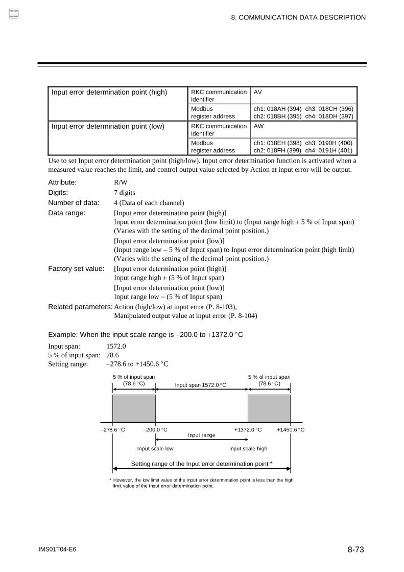
8. COMMUNICATION DATA DESCRIPTION
IMS01T04-E6 8-73
Input error determination point (high) RKC communication
identifier AV
Modbus register address
ch1: 018AH (394) ch3: 018CH (396)ch2: 018BH (395) ch4: 018DH (397)
Input error determination point (low) RKC communication identifier
AW
Modbus register address
ch1: 018EH (398) ch3: 0190H (400)ch2: 018FH (399) ch4: 0191H (401)
Use to set Input error determination point (high/low). Input error determination function is activated when a measured value reaches the limit, and control output value selected by Action at input error will be output.
Attribute: R/W
Digits: 7 digits
Number of data: 4 (Data of each channel)
Data range: [Input error determination point (high)] Input error determination point (low limit) to (Input range high 5 % of Input span) (Varies with the setting of the decimal point position.)
[Input error determination point (low)] (Input range low 5 % of Input span) to Input error determination point (high limit) (Varies with the setting of the decimal point position.)
Factory set value: [Input error determination point (high)] Input range high (5 % of Input span)
[Input error determination point (low)] Input range low (5 % of Input span)
Related parameters: Action (high/low) at input error (P. 8-103), Manipulated output value at input error (P. 8-104)
Example: When the input scale range is 200.0 to 1372.0 C
Input span: 1572.0 5 % of input span: 78.6 Setting range: 278.6 to +1450.6 C
200.0 C
5 % of input span (78.6 C)
5 % of input span (78.6 C) Input span 1572.0 C
278.6 C +1372.0 C +1450.6 C Input range
Input scale low Input scale high
Setting range of the Input error determination point *
* However, the low limit value of the Input error determination point is less than the high limit value of the Input error determination point.

8. COMMUNICATION DATA DESCRIPTION
IMS01T04-E6 8-74
Burnout direction RKC communication
identifier BS
Modbus register address
ch1: 0192H (402) ch3: 0194H (404)ch2: 0193H (403) ch4: 0195H (405)
Use to select Burnout direction in input break. When input break is detected by the module, the measured value go either Upscale or Downscale according to the Burnout direction setting.
Attribute: R/W
Digits: 1 digit
Number of data: 4 (Data of each channel)
Data range: 0: Upscale 1: Downscale
Factory set value: 0
The Burnout direction setting is effective only for Thermocouple input and Voltage (low) input.
For the following types of input, the action when an input break occurs is fixed, regardless of the Burnout direction setting. RTD input: Upscale Voltage (high) input: Downscale (display of about 0 V) Current input: Downscale (display of about 0 mA) Feedback resistance input: Upscale
Square root extraction RKC communication
identifier XH
Modbus register address
ch1: 0196H (406) ch3: 0198H (408)ch2: 0197H (407) ch4: 0199H (409)
Use to select use/unuse of the Square root extraction for the measured value.
Attribute: R/W
Digits: 1 digit
Number of data: 4 (Data of each channel)
Data range: 0: Unused 1: Used
Factory set value: 0
Related parameters: PV low input cut-off (P. 8-36)
Function: The controller can receive the input signal directly from a differential pressure type flow transmitter by using Square root extraction function without using a square root extractor.

8. COMMUNICATION DATA DESCRIPTION
IMS01T04-E6 8-75
Output assignment (Logic output selection function)
RKC communication identifier
E0
Modbus register address
ch1: 019AH (410) ch3: 019CH (412)ch2: 019BH (411) ch4: 019DH (413)
This is used to assign the output function (control output, logic output result and FAIL output) for the output 1 (OUT1) to output 4 (OUT4).
Attribute: R/W
Digits: 1 digit
Number of data: 4 (Data of each channel)
Data range: 0: Control output 1: Logic output result 2: FAIL output
Factory set value: 4-CH type module 2-CH type module Output 1 (OUT1): 0 Output 1 (OUT1): 0 Output 2 (OUT2): 0 * Output 2 (OUT2): 0 Output 3 (OUT3): 0 Output 4 (OUT4): 0 *
* Disabled for Heat/Cool PID control and Position proportioning PID control
Related parameters: Energized/De-energized (P. 8-76), Event type (P. 8-87), Heater break alarm (HBA) set value (P.8-32), Communication switch for logic (P. 8-60)
: Valid : Invalid
Output assignment
Output type
Relay contact Voltage pulse Voltage output Current output Triac Open-collector
0 (Control output)
1 (Logic output resulet)
2 (FAIL output)
For the block diagram of Logic output selection function, refer to 11. APPENDIX (P. 11-6).
[Relation between output assignment and output type]

8. COMMUNICATION DATA DESCRIPTION
IMS01T04-E6 8-76
Energized/De-energized (Logic output selection function)
RKC communication identifier
NA
Modbus register address
ch1: 019EH (414) ch3: 01A0H (416)ch2: 019FH (415) ch4: 01A1H (417)
Energized/De-energized can be selected for any of outputs 1 (OUT1) to 4 (OUT4) that have an output function (logic output result) assigned.
Attribute: R/W
Digits: 1 digit
Number of data: 4 (Data of each channel)
Data range: 0: Energized 1: De-energized
Factory set value: 0
Related parameters: Output assignment (P. 8-75), Event type (P. 8-77), Heater break alarm (HBA) set value (P.8-32), Communication switch for logic (P. 8-60)
Function: Action of Energized/De-energized
Energized/De-energized setting
Output state of OUT1 to4
Non-event state Event state
Energized Event output OFF Event output ON
De-energized Event output ON Event output OFF
Example: Relay contact output Energized: Relay contact is closed under the event or alarm state. De-energized: Relay contact opens under the event or alarm state.
Diagram for explaining operation (At power-ON)
Energized
Non-event state Event state
De- energized
Non-event state Event state
In the following cases, the selection is fixed at de-energized.
An output that has an output assignment of “0: Control output” FAIL alarm (normal: contacts closed, error: contacts open)
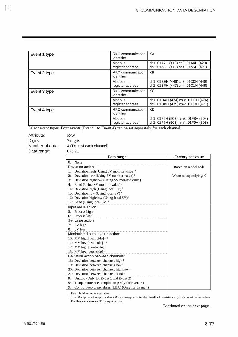
8. COMMUNICATION DATA DESCRIPTION
IMS01T04-E6 8-77
Event 1 type RKC communication
identifier XA
Modbus register address
ch1: 01A2H (418) ch3: 01A4H (420)ch2: 01A3H (419) ch4: 01A5H (421)
Event 2 type RKC communication identifier
XB
Modbus register address
ch1: 01BEH (446) ch3: 01C0H (448)ch2: 01BFH (447) ch4: 01C1H (449)
Event 3 type RKC communication identifier
XC
Modbus register address
ch1: 01DAH (474) ch3: 01DCH (476)ch2: 01DBH (475) ch4: 01DDH (477)
Event 4 type RKC communication identifier
XD
Modbus register address
ch1: 01F6H (502) ch3: 01F8H (504)ch2: 01F7H (503) ch4: 01F9H (505)
Select event types. Four events (Event 1 to Event 4) can be set separately for each channel.
Attribute: R/W Digits: 7 digits Number of data: 4 (Data of each channel) Data range: 0 to 21
Data range Factory set value
0: None Deviation action: 1: Deviation high (Using SV monitor value) 1 2: Deviation low (Using SV monitor value) 1 3: Deviation high/low (Using SV monitor value) 1 4: Band (Using SV monitor value) 1
14: Deviation high (Using local SV) 1 15: Deviation low (Using local SV) 1 16: Deviation high/low (Using local SV) 1 17: Band (Using local SV) 1
Based on model code
When not specifying: 0
Input value action: 5: Process high 1 6: Process low 1
Set value action: 7: SV high 8: SV low
Manipulated output value action: 10: MV high [heat-side] 1, 2 11: MV low [heat-side] 1, 2 12: MV high [cool-side] 1 13: MV low [cool-side] 1
Deviation action between channels: 18: Deviation between channels high 1 19: Deviation between channels low 1 20: Deviation between channels high/low 1 21: Deviation between channels band 1
9: Unused (Only for Event 1 and Event 2) 9: Temperature rise completion (Only for Event 3) 9: Control loop break alarm (LBA) (Only for Event 4)
1 Event hold action is available. 2 The Manipulated output value (MV) corresponds to the Feedback resistance (FBR) input value when
Feedback resistance (FBR) input is used.
Continued on the next page.

8. COMMUNICATION DATA DESCRIPTION
IMS01T04-E6 8-78
Continued from the previous page. Related parameters: Comprehensive event state (P. 8-4), Event state monitor (P. 8-9),
Event set value (P. 8-20), Output assignment (P. 8-75), Event interlock (P. 8-83), Event differential gap (P. 8-84), Event delay timer (P. 8-85)
Funtion:
Event function Diagrams of the event action type are shown in the following.
1: Deviation high (using SV monitor value), 14: Deviation high (using Local SV value)
(Event set value is greater than 0.) (Event set value is less than 0.)
2: Deviation low (using SV monitor value), 15: Deviation low (using Local SV value)
(Event set value is greater than 0.) (Event set value is less than 0.)
3: Deviation high/low (using SV monitor value) 4: Band (using SV monitor value)
5: Process high 6: Process low
7: SV high: 8: SV low:
10: MV high [heat-side] 12: MV high [cool-side]
11: MV low [heat-side] 13: MV low [cool-side]
( : Set value (SV) : Event set value ☆: Event differential gap)
16: Deviation high/low (using Local SV value) 17: Band (using Local SV value)
ON: Event action turned on, OFF: Event action turned off
Deviation action: When the deviation (PV – SV) reaches the event set value, event ON occurs.
Input value action: When the measured value (PV) reaches the event set value, event ON occurs.
Set value action: When the set value (SV) reaches the event set value, event ON occurs.
Manipulated output value action: When the manipulated output value (MV) reaches the event set value, event ON occurs.
Deviation action between channels: When the deviation between different channels (PV – PV of comparison channel) reaches the event set value, event ON occurs.
18: Deviation between channels high (Same action as "Deviation high")
19: Deviation between channels low (Same action as "Deviation low")
20: Deviation between channels high/low (Same action as "Deviation high/low")
21: Deviation between channels band (Same action as "Band")
OFF ON PV
Low High
☆
ON OFF PV
Low High
☆
OFF ON OFF PV
Low High
☆ ☆
ON OFF PV
Low High
☆
ON OFF SV
Low High
☆
ON OFF MV
Low High
☆
OFF ON PV
Low High
☆
ON OFF ON PV
Low High
☆ ☆
OFF ON SV
Low High
☆
OFF ON MV
Low High
☆
OFF ON Low High
PV☆
ON OFF PV
Low High
☆
Continued on the next page.

8. COMMUNICATION DATA DESCRIPTION
IMS01T04-E6 8-79
Continued from the previous page. Temperature rise completion function During the sampling of temperature input, when the Measured value (PV) comes within the temperature rise completion range, the temperature rise completion will occur.
PV1
PV2Sampling period
Previous sampling The time sampling
Set value (SV)Temperature rise completion
*
* The temperature rise completion range is set using the Event 3 set value.
The action of temperature rise completion is the same as “17: Band (using local SV).” If the Measured value (PV) is outside the temperature rise completion range even after temperature rise completion, temperature rise completion OFF will be indicated in the Comprehensive event state (P. 8-4). If you wish to maintain temperature rise completion ON in the Comprehensive event state (P. 8-4) even when the measured value is outside the temperature rise completion range, set the Event 3 interlock (P. 8-83) to “1” (Used). When temperature rise completion is not set as the Event 3 type, temperature rise completion of the Comprehensive event state is “0: OFF” in the STOP state, and “1: ON” in the RUN state. If the Event 3 type is temperature rise completion, check the temperature rise completion state in the Comprehensive event state. (The Event 3 state monitor (P. 8-9) does not turn ON.)
Control loop break alarm (LBA) function
For LBA function, refer to Control loop break alarm (LBA) time (P. 8-21).

8. COMMUNICATION DATA DESCRIPTION
IMS01T04-E6 8-80
Event 1 channel setting RKC communication
identifier FA
Modbus register address
ch1: 01A6H (422) ch3: 01A8H (424)ch2: 01A7H (423) ch4: 01A9H (425)
Event 2 channel setting RKC communication identifier
FB
Modbus register address
ch1: 01C2H (450) ch3: 01C4H (452)ch2: 01C3H (451) ch4: 01C5H (453)
Event 3 channel setting RKC communication identifier
FC
Modbus register address
ch1: 01DEH (478) ch3: 01E0H (480)ch2: 01DFH (479) ch4: 01E1H (481)
Event 4 channel setting RKC communication identifier
FD
Modbus register address
ch1: 01FAH (506) ch3: 01FCH (508)ch2: 01FBH (507) ch4: 01FDH (509)
Select the channel number for “PV of comparison channel” when “Deviation between channels” is selected for the event action type.
Attribute: R/W
Digits: 1 digit
Number of data: 4 (Data of each channel)
Data range: 1: Channel 1 2: Channel 2 3: Channel 3 4: Channel 4
Factory set value: 1
Related parameters: Event type (P. 8-77)

8. COMMUNICATION DATA DESCRIPTION
IMS01T04-E6 8-81
Event 1 hold action RKC communication
identifier WA
Modbus register address
ch1: 01AAH (426) ch3: 01ACH (428)ch2: 01ABH (427) ch4: 01ADH (429)
Event 2 hold action RKC communication identifier
WB
Modbus register address
ch1: 01C6H (454) ch3: 01C8H (456)ch2: 01C7H (455) ch4: 01C9H (457)
Event 3 hold action RKC communication identifier
WC
Modbus register address
ch1: 01E2H (482) ch3: 01E4H (484)ch2: 01E3H (483) ch4: 01E5H (485)
Event 4 hold action RKC communication identifier
WD
Modbus register address
ch1: 01FEH (510) ch3: 0200H (512)ch2: 01FFH (511) ch4: 0201H (513)
Use to set an event hold action for the Event.
Attribute: R/W
Digits: 1 digit
Number of data: 4 (Data of each channel)
Data range: 0 to 2
Data range Factory set value
0: OFF 1: Hold action ON (Only hold action) Validate the hold action when the power is turned on. Validate the hold action when transferred from STOP (control
STOP) to RUN (control RUN). 2: Re-hold action ON (hold and re-hold actions) Validate the hold action when the power is turned on. Validate the hold action when transferred from STOP (control
STOP) to RUN (control RUN). Validate the re-hold action when the Set value (SV) is
changed. However, if the rate of setting change limiter is set to any function other than “OFF (Unused)” or in the remote mode, the re-hold action becomes invalid.
Based on model code
When not specifying: 0
When high alarm with Hold/Re-hold action is used for Event function, alarm does not turn on while Hold action is in operation. Use in combination with a high alarm without Hold action in order to prevent overheating which may occur by failure of control devices, such as welding of relays.
The hold action is effective when Process, Deviation, or Manipulated output value action is selected for the Event type.
Related parameters: Comprehensive event state (P. 8-4), Event state monitor (P. 8-9), Event set value (P. 8-20), Event type (P. 8-77), Event interlock (P. 8-83), Event differential gap (P. 8-84), Event delay timer (P. 8-85)

8. COMMUNICATION DATA DESCRIPTION
IMS01T04-E6 8-82
Function:
Hold action When hold action is ON, the Event action is suppressed at start-up or STOP to RUN until the Measured value (PV) has entered the non-event range. [With hold action] [Without hold action]
ONON Event status
Time
Deviation
Hold action area
Measured value (PV) Measured value (PV)
Event set value
Set value (SV)
OFF
Time
Deviation
Measured value (PV)
Event set value
Set value (SV)
ON Event status OFF
Measured value (PV)
Re-hold action When re-hold action is ON, the Event action is also suppressed at the control set value change until the Measured value (PV) has entered the non-event range.
Action condition 1: Hold action ON (Only hold action)
2: Re-hold action ON (Hold and re-hold actions)
When the power is turned on Hold action Hold action
When transferred from STOP (control STOP) to RUN (control RUN)
Hold action Hold action
When the Set value (SV) is changed Without hold and re-hold actions
Re-hold action
The re-hold action is invalid for any of the following. However, the hold action is valid. When Setting change rate limiter other than “0 (Unused)” are set. When Remote/Local transfer is the remote mode.
Example: When Event 1 type is the deviation low
When re-hold action is OFF and event output type is deviation, the event output is produced due to the set value change. The re-hold action suppresses the alarm output until the Measured value (PV) has entered the non-event range again.
Event area
Measured value (PV)
Before the change of set value
The change of set valueSet valueEvent set value
Event area After the change of set value
Measured value (PV)
Set value Event set value

8. COMMUNICATION DATA DESCRIPTION
IMS01T04-E6 8-83
Event 1 interlock RKC communication
identifier LF
Modbus register address
ch1: 01AEH (430) ch3: 01B0H (432)ch2: 01AFH (431) ch4: 01B1H (433)
Event 2 interlock RKC communication identifier
LG
Modbus register address
ch1: 01CAH (458) ch3: 01CCH (460)ch2: 01CBH (459) ch4: 01CDH (461)
Event 3 interlock RKC communication identifier
LH
Modbus register address
ch1: 01E6H (486) ch3: 01E8H (488)ch2: 01E7H (487) ch4: 01E9H (489)
Event 4 interlock RKC communication identifier
LI
Modbus register address
ch1: 0202H (514) ch3: 0204H (516)ch2: 0203H (515) ch4: 0205H (517)
Use to select the interlock function for the Event.
Attribute: R/W
Digits: 1 digit
Number of data: 4 (Data of each channel)
Data range: 0: Unused 1: Used
Factory set value: 0
Related parameters: Comprehensive event state (P. 8-4), Event state monitor (P. 8-9), Event set value (P. 8-20), Event type (P. 8-77), Event differential gap (P. 8-84), Event delay timer (P. 8-85), Force ON of Event action (P. 8-87)
Function: The event interlock function is used to hold the event state even if the measured value (PV) is out of the event area after its entry into the area once.
Example: When the event interlock function is used for deviation high
Event set value
Set value (SV)
Event status OFF ON
Measured value (PV)
Time
Event interlock
Deviation
Measured value (PV)
[Without Event hold action]

8. COMMUNICATION DATA DESCRIPTION
IMS01T04-E6 8-84
Event 1 differential gap RKC communication
identifier HA
Modbus register address
ch1: 01B2H (434) ch3: 01B4H (436)ch2: 01B3H (435) ch4: 01B5H (437)
Event 2 differential gap RKC communication identifier
HB
Modbus register address
ch1: 01CEH (462) ch3: 01D0H (464)ch2: 01CFH (463) ch4: 01D1H (465)
Event 3 differential gap RKC communication identifier
HC
Modbus register address
ch1: 01EAH (490) ch3: 01ECH (492)ch2: 01EBH (491) ch4: 01EDH (493)
Event 4 differential gap RKC communication identifier
HD
Modbus register address
ch1: 0206H (518) ch3: 0208H (520)ch2: 0207H (519) ch4: 0209H (521)
Use to set a differential gap of the Event.
Attribute: R/W Digits: 7 digits Number of data: 4 (Data of each channel) Data range: Deviation, process, set value, Deviation action between channels, or
Temperature rise completion (Only for Event 3): 0 to Input span (Unit: C [F]) (Varies with the setting of the decimal point position.) MV: 0.0 to 110.0 %
Factory set value: Deviation, Process, Set value, Deviation action between channels, or Temperature rise completion (Only for Event 3):
TC/RTD inputs: 1 (1.0) Voltage (V)/Current (I) inputs: 1.0
MV: 1.0 Related parameters: Comprehensive event state (P. 8-9), Event state monitor (P. 8-9),
Event set value (P. 8-20), Event type (P. 8-77), Event interlock (P. 8-83), Event delay timer (P. 8-85), Force ON of Event action (P. 8-87)
Function: It prevents chattering of event output due to the Measured value (PV) fluctuation around the event set value.
Differential gap
Measured value (PV)
Event set value
ON OFF OFF Event status
Time
Measured value (PV)
Process high
Differential gap
Measured value (PV)
Event setvalue
ON OFF OFF Event status
Time
Measured value (PV)
Process low When the event 4 type is “9: Control loop break alarm (LBA),” the event 4 differential gap setting is not effective.

8. COMMUNICATION DATA DESCRIPTION
IMS01T04-E6 8-85
Event 1 delay timer RKC communication
identifier TD
Modbus register address
ch1: 01B6H (438) ch3: 01B8H (440)ch2: 01B7H (439) ch4: 01B9H (441)
Event 2 delay timer RKC communication identifier
TG
Modbus register address
ch1: 01D2H (466) ch3: 01D4H (468)ch2: 01D3H (467) ch4: 01D5H (469)
Event 3 delay timer RKC communication identifier
TE
Modbus register address
ch1: 01EEH (494) ch3: 01F0H (496)ch2: 01EFH (495) ch4: 01F1H (497)
Event 4 delay timer RKC communication identifier
TF
Modbus register address
ch1: 020AH (522) ch3: 020CH (524)ch2: 020BH (523) ch4: 020DH (525)
Event delay timer is to set an output delay time for event outputs.
Attribute: R/W
Digits: 7 digits
Number of data: 4 (Data of each channel)
Data range: 0 to 18000 seconds
Factory set value: 0
Related parameters: Comprehensive event state (P. 8-4), Event state monitor (P. 8-9), Event set value (P. 8-20), Event type (P. 8-77), Event interlock (P. 8-83), Event differential gap (P. 8-84), Force ON of Event action (P. 8-87)
Function: When an event condition becomes ON status, the output is suppressed until the Delay Timer set time elapses. After the time is up, if the event output is still ON status, the output will be produced.
Example: When the setting of Event 1 delay timer is 50 seconds
Event state
Set value (SV)
Event 1 set value
Measured value (PV)
Event 1 delay timer (50 seconds)
Event 1 output ON
Event 1 output OFF
Non-event state
Event 1 delay timer (50 seconds)
Continued on the next page.

8. COMMUNICATION DATA DESCRIPTION
IMS01T04-E6 8-86
Continued from the previous page.
The event delay timer is also activated for the following cases. When set to the event state simultaneously with power turned on. When set to the event state simultaneously with control changed to RUN (control start) from
STOP (control stop).
In the event wait state, no event output is turned on even after the event delay timer preset time has elapsed.
The event delay timer is reset for the following cases. When power failure occurs while the event delay timer is being activated. When control is changed to STOP (control stop) from RUN (control start) while the event
delay timer is being activated.
When the Event 3 type is “9: Temperature rise completion,” the Event 3 delay timer will be the Temperature rise completion soak time *. * Temperature rise completion soak time: The time until the temperature rise is complete after the Measured value (PV) enters
the temperature rise completion zone.
Temperature rise completion zone
Temperature rise completion Temperature rise start
Temperature rise completion
soak time Measured value (PV)
Set value (SV)

8. COMMUNICATION DATA DESCRIPTION
IMS01T04-E6 8-87
Force ON of Event 1 action RKC communication
identifier OA
Modbus register address
ch1: 01BAH (442) ch3: 01BCH (444)ch2: 01BBH (443) ch4: 01BDH (445)
Force ON of Event 2 action RKC communication identifier
OB
Modbus register address
ch1: 01D6H (470) ch3: 01D8H (472)ch2: 01D7H (471) ch4: 01D9H (473)
Force ON of Event 3 action RKC communication identifier
OC
Modbus register address
ch1: 01F2H (498) ch3: 01F4H (500)ch2: 01F3H (499) ch4: 01F5H (501)
Force ON of Event 4 action RKC communication identifier
OD
Modbus register address
ch1: 020EH (526) ch3: 0210H (528)ch2: 020FH (527) ch4: 0211H (529)
Select the operation state that is output (force ON) as the event action.
Attribute: R/W Digits: 7 digits Number of data: 4 (Data of each channel) Data range: RKC communication: ASCII code data The event action is assigned as a digit image in ASCII code data of 7 digits.
ASCII code data of 7 digits:
Most significant digit ············ Least significant digit Data: 0: Invalid 1: Valid Modbus: 0 to 15 (bit data) The event action is assigned as a bit image in binary numbers.
Bit image: 0000000000000000
Bit 15 ······················ Bit 0 Bit data: 0: Invalid 1: Valid
Factory set value: 0
Related parameters: Input error determination point (high/low) (P. 8-73), Action (high/low) at input error (P. 8-103)
This setting is not effective when the event type is “0: None.”
The Force ON of Event 4 action is not effective when the Event 4 type corresponds to “9: Control loop break alarm (LBA).”
Continued on the next page.
Least significant digit: Event output turned on at input error occurrence 2nd digit: Event output turned on in Manual mode 3rd digit: Event output turned on during the Autotuning (AT) function is being executed 4th digit: Event output turned on during the Setting change rate limiter is being operated 5th to Most significant digit: Unused
Bit 0: Event output turned on at input error occurrence Bit 1: Event output turned on in Manual mode Bit 2: Event output turned on during the Autotuning (AT) function is being executedBit 3: Event output turned on during the Setting change rate limiter is being operated Bit 4 to Bit 15: Unused

8. COMMUNICATION DATA DESCRIPTION
IMS01T04-E6 8-88
Continued from the previous page.
Example: When “0: Event output turned on at input error occurrence” is selected Input range: 0 to 400 C Input error determination point (high): 300 C Input error determination point (low): 50 C
Action area at input error Action area at input error
Differential gap (0.1 % of input span)
Input error determination point (high)
0 C 50 C 300 C 400 C
Input scale range
Forcibly turned on (1: Valid)
Normal processing (0: Invalid)
Forcibly turned on (1: Valid)
Normal processing (0: Invalid)
Select one of these
Input error determination point (low)
Select one of these
“0: Invalid”: The event output is produced depending on the selected event action status. “1: Valid”: The event output is forcibly turned on regardless of the event action status.

8. COMMUNICATION DATA DESCRIPTION
IMS01T04-E6 8-89
CT ratio RKC communication
identifier XS
Modbus register address
ch1: 0212H (530) ch3: 0214H (532)ch2: 0213H (531) ch4: 0215H (533)
Use to set the number of turns (ratio) of the current transformer that is used with the Heater break alarm (HBA).
Attribute: R/W Digits: 7 digits Number of data: 4 (Data of each channel) Data range: 0 to 9999 Factory set value: CTL-6-P-N: 800
CTL-12-S56-10L-N: 1000 Related parameters: Comprehensive event state (P. 8-4),
Heater break alarm (HBA) state monitor (P. 8-9), Heater break alarm (HBA) set value (P. 8-32), Heater break determination point (P. 8-34), Heater melting determination point (P. 8-34), CT assignment (P. 8-89), Heater break alarm (HBA) type (P. 8-90)
CT assignment RKC communication
identifier ZF
Modbus register address
ch1: 0216H (534) ch3: 0218H (536)ch2: 0217H (535) ch4: 0219H (537)
Use to assign the Heater break alarm (HBA) function to an output.
Attribute: R/W Digits: 1 digit Number of data: 4 (Data of each channel) Data range: 0: None 3: OUT3
1: OUT1 4: OUT4 2: OUT2
Factory set value: CH1: 1 CH3: 3 CH2: 2 CH4: 4
Related parameters: Comprehensive event state (P. 8-4), Heater break alarm (HBA) state monitor (P. 8-9), Heater break alarm (HBA) set value (P. 8-32), Heater break determination point (P. 8-34), Heater melting determination point (P. 8-34), CT ratio (P. 8-89), Heater break alarm (HBA) type (P. 8-90)
It is possible to detect three-phase heater breaks by assigning the same output number to the outputs for CT determination.
1 2
3 4
4 3
2 1
Pin No. Description
1
2 CT4 (CH4)
3
4 CT3 (CH3)
Pin No. Description
1
2 CT2 (CH2)
3
4 CT1 (CH1)
For example, on a module with four CT inputs like that above, three-phase heater breaks can be detected by assigning the same output number to CT1 and CT2, and CT3 and CT4 respectively.

8. COMMUNICATION DATA DESCRIPTION
IMS01T04-E6 8-90
Heater break alarm (HBA) type RKC communication
identifier ND
Modbus register address
ch1: 021AH (538) ch3: 021CH (540)ch2: 021BH (539) ch4: 021DH (541)
Use to select the Heater break alarm (HBA) type.
Attribute: R/W
Digits: 1 digit
Number of data: 4 (Data of each channel)
Data range: 0: Heater break alarm (HBA) type A [Time-proportional control output]
1: Heater break alarm (HBA) type B [Continuous control output]
Factory set value: Set value is based on the Output type specified at ordering.
Related parameters: Comprehensive event state (P. 8-4), Heater break alarm (HBA) state monitor (P. 8-9), Heater break alarm (HBA) set value (P. 8-32), Heater break determination point (P. 8-34), Heater melting determination point (P. 8-34), CT ratio (P. 8-89), CT assignment (P. 8-89)
Function: Heater break alarm (HBA) type A:
Heater break alarm (HBA) type A can be used with time-proportional control output (Relay, Voltage pulse, or Triac output).
The HBA function monitors the current flowing through the load by a dedicated Current transformer (CT), compares the measured value with the HBA set values, and detects a fault in the heating circuit.
Heater break alarm (HBA) type B:
Heater Break Alarm (HBA) type B can be used with continuous control output (Voltage/Current continuous output).
The HBA function assumes that the heater current value is proportional * to the control output value of the controller, otherwise viewed as the manipulated variable (MV), and compare it with the CT input value to detect a fault in the heating or cooling circuit.
* It is assumed that the current value flowing through the load is at maximum when the control output from the controller is 100 %, and the minimum current value flowing through the load is zero (0) when the control output from the controller is 0 %.
When changing the value of CT assignment, the type of Heater break alarm (HBA) automatically changes.
CT assignment HBA Type
1 to 4 (OUT1 to 4)
Type A (for time-proportional control output) or Type B (for continuous control output)
0: None Same as value before the change
Example: OUT1: Relay contact output, OUT2: Voltage/Current continuous output
When changing the value of CT assignment from OUT1 to OUT2, the type of Heater break alarm (HBA) automatically changes from Type A to B.

8. COMMUNICATION DATA DESCRIPTION
IMS01T04-E6 8-91
Number of heater break alarm (HBA) delay times
RKC communication identifier
DH
Modbus register address
ch1: 021EH (542) ch3: 0220H (544)ch2: 021FH (543) ch4: 0221H (545)
To prevent producing a false alarm, the alarm function waits to produce an alarm status until the measured CT input value is in an alarm range for the preset number of consecutive sampling cycles.
Attribute: R/W
Digits: 7 digits
Number of data: 4 (Data of each channel)
Data range: 0 to 255 times
Factory set value: 5
Related parameters: Comprehensive event state (P. 8-4), Current transformer (CT) input value monitor (P. 8-7), Heater break alarm (HBA) state monitor (P. 8-9), Heater break alarm (HBA) set value (P. 8-9), Heater break determination point (P. 8-34), Heater melting determination point (P. 8-34), CT ratio (P. 8-89), CT assignment (P. 8-89)
Function: Heater break alarm (HBA) delay time Number of delay times Sampling time (Sampling time: 500 ms)
Example: When the number of delay times is 5 times: HBA delay time 5 times 500 ms 2500 ms 2.5 seconds
HBA state
ON
OFF
HBA ON state
HBA ON
HBA delay time
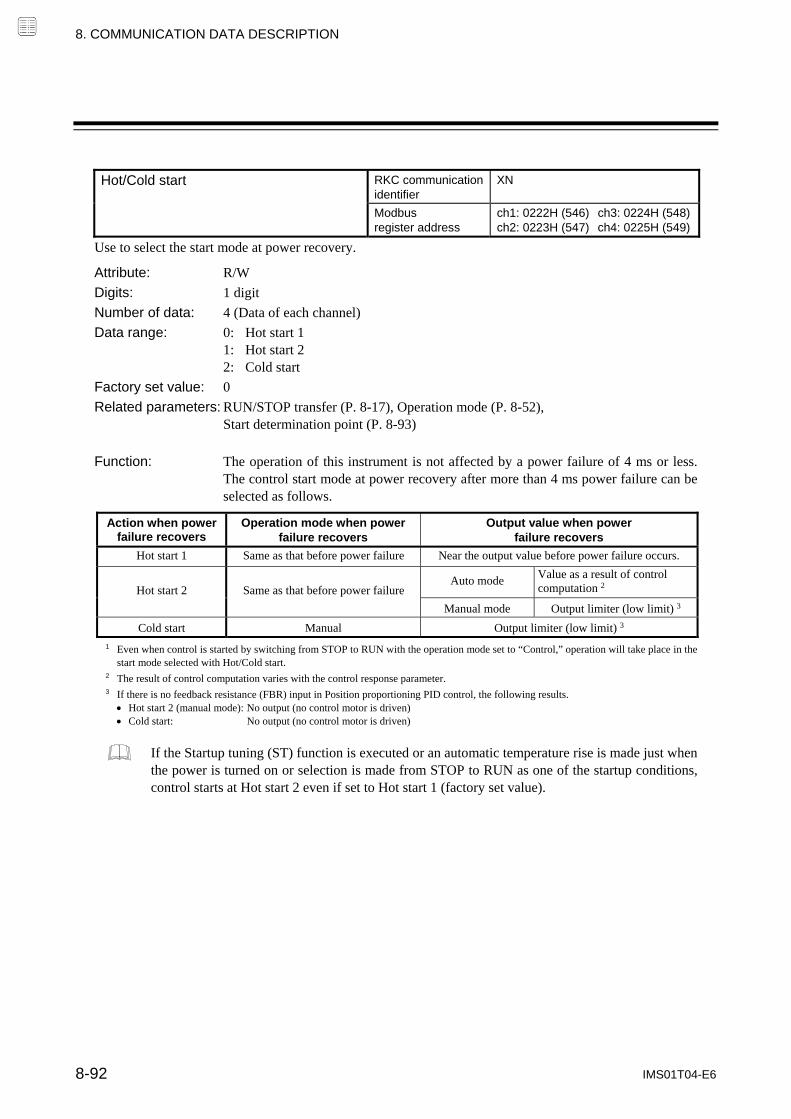
8. COMMUNICATION DATA DESCRIPTION
IMS01T04-E6 8-92
Hot/Cold start RKC communication
identifier XN
Modbus register address
ch1: 0222H (546) ch3: 0224H (548)ch2: 0223H (547) ch4: 0225H (549)
Use to select the start mode at power recovery.
Attribute: R/W
Digits: 1 digit
Number of data: 4 (Data of each channel)
Data range: 0: Hot start 1 1: Hot start 2 2: Cold start
Factory set value: 0
Related parameters: RUN/STOP transfer (P. 8-17), Operation mode (P. 8-52), Start determination point (P. 8-93)
Function: The operation of this instrument is not affected by a power failure of 4 ms or less. The control start mode at power recovery after more than 4 ms power failure can be selected as follows.
Action when power failure recovers
Operation mode when power failure recovers
Output value when power failure recovers
Hot start 1 Same as that before power failure Near the output value before power failure occurs.
Hot start 2 Same as that before power failure Auto mode Value as a result of control
computation 2
Manual mode Output limiter (low limit) 3
Cold start Manual Output limiter (low limit) 3
1 Even when control is started by switching from STOP to RUN with the operation mode set to “Control,” operation will take place in the start mode selected with Hot/Cold start.
2 The result of control computation varies with the control response parameter. 3 If there is no feedback resistance (FBR) input in Position proportioning PID control, the following results. Hot start 2 (manual mode): No output (no control motor is driven) Cold start: No output (no control motor is driven)
If the Startup tuning (ST) function is executed or an automatic temperature rise is made just when the power is turned on or selection is made from STOP to RUN as one of the startup conditions, control starts at Hot start 2 even if set to Hot start 1 (factory set value).

8. COMMUNICATION DATA DESCRIPTION
IMS01T04-E6 8-93
Start determination point RKC communication
identifier SX
Modbus register address
ch1: 0226H (550) ch3: 0228H (552)ch2: 0227H (551) ch4: 0229H (553)
Determination point always set to Hot start 1 when recovered from power failure. The Start determination point becomes the deviation setting from the Set value (SV).
Attribute: R/W
Digits: 7 digits
Number of data: 4 (Data of each channel)
Data range: 0 to Input span (The unit is the same as input value.) 0: Action depending on the Hot/Cold start selection (Varies with the setting of the decimal point position.)
Factory set value: Based on specification (value equivalent to 3% of input span)
Related parameters: RUN/STOP transfer (P. 8-17), Hot/Cold start (P. 8-92)
Function: The start state is determined according to the Measured value (PV) level [deviation from set value] at power recovery.
When a Measured value (PV) is between the determination points on the (plus) and (minus) sides, always started from “Hot start 1” when recovered.
When a Measured value (PV) is out of the determination points or the Start determination point is set at “0,” operation starts from any start state selected by Hot/Cold start.
Start determination point
(minus side) Start determination point
(plus side)
Start determination point setting Set value (SV)
Hot start 1 Hot start 1, Hot start 2, Cold start
Low High
Hot start 1, Hot start 2, Cold start

8. COMMUNICATION DATA DESCRIPTION
IMS01T04-E6 8-94
SV tracking RKC communication
identifier XL
Modbus register address
ch1: 022AH (554) ch3: 022CH (556)ch2: 022BH (555) ch4: 022DH (557)
To select Use/Unuse of SV tracking.
Attribute: R/W
Digits: 1 digit
Number of data: 4 (Data of each channel)
Data range: 0: Unused 1: Used
Factory set value: 1
Related parameters: Remote/Local transfer (P. 8-17)
Function: With SV Tracking function, when Remote/Local mode is transferred from Remote to Local, the set value used in Remote mode before the mode transfer will be kept using in Local mode to prevent rapid set value change.
Operation mode: Local Remote Local
Set value used Local set value Remote set value Local set value
SV tracking used Local set value Remote set value Local set value Remote set value Local set value Remote set value
SV tracking unused Local set value Remote set value Local set value Remote set value Local set value Remote set value
Time (t)
Set value (SV)
Remote set value
Remote/Local transferred point
(SV tracking used)
Local set value
Time (t)
Set value (SV)
Remote/Local transferred point
(SV tracking unused)
Remote set value
Local set value

8. COMMUNICATION DATA DESCRIPTION
IMS01T04-E6 8-95
MV transfer function
[Action taken when changed to Manual mode from Auto mode]
RKC communication identifier
OT
Modbus register address
ch1: 022EH (558) ch3: 0230H (560)ch2: 022FH (559) ch4: 0231H (561)
The manipulated output value used for manual control is selected when the operation mode in changed to the Manual mode from the Automatic mode.
Attribute: R/W Digits: 1 digit Number of data: 4 (Data of each channel) Data range: 0: Manipulated output value (MV) in Auto mode is used.
[Balanceless/Bumpless function] 1: Manipulated output value (MV) in previous Manual mode is used. Factory set value: 0 Related parameters: Auto/Manual transfer (P. 8-16) Function: For the Balanceless/Bumpless function, refer to Auto/Manual transfer (P. 8-16).
Control action RKC communication
identifier XE
Modbus register address
ch1: 0232H (562) ch3: 0234H (564)ch2: 0233H (563) ch4: 0235H (565)
Use to select the control action type.
Attribute: R/W
Digits: 1 digit
Number of data: 4 (Data of each channel)
Data range: 0: Brilliant II PID control (Direct action) 1: Brilliant II PID control (Reverse action) 2: Brilliant II Heat/Cool PID control [Water cooling] 3: Brilliant II Heat/Cool PID control [Air cooling] 4: Brilliant II Heat/Cool PID control [Cooling gain linear type] 5: Brilliant II Position proportioning PID control
[Data ranges by module type] : Selectable
Z-TIO module Set value
0 1 2 3 4 5
4-channel type
2-channel type
CH1
CH2 * Not selectable
CH3
CH4 * Not selectable
* Even channel (CH2, CH4): In Heat/Cool PID control and Position proportioning PID control, control action is not performed. Only PV monitor and event action is performed.
Factory set value: Based on model code
When not specifying: 1
Continued on the next page.

8. COMMUNICATION DATA DESCRIPTION
IMS01T04-E6 8-96
Continued from the previous page.
Function: PID control (direct action) The Manipulated output value (MV) increases as the Measured value (PV) increases. This action is used generally for cool control.
PID control (reverse action) The Manipulated output value (MV) decreases as the Measured value (PV) increases. This action is used generally for heat control.
MV MV
Direct action PV PV
Reverse action Heat/Cool PID control In Heat/Cool PID control, only one controller enables heat and cool control. For example, this is effective when cool control is required in extruder cylinder temperature control.
Water cooling/Air cooling: The algorithm assuming plastic molding machine Heat/Cool PID control is employed. Even in equipment provided with a cooling mechanism having nonlinear characteristics, it responds quickly to attain the characteristic responding to the set value with small overshooting.
Cooling gain linear type: The algorithm assuming applications without nonlinear cooling capability is employed.
Manipulated output value (MV)
100 %
0 %
Manipulated output value (MV) [heat-side]
Proportional band[heat-side]
Set value (SV)
OL DB DB: Deadband
Temperature
Proportional band[cool-side]
OL: Overlap
Manipulated output value (MV) [cool-side]
The input/output configuration for Heat/Cool PID control using a 4-channel module is shown below. There is no CH3 and CH4 when a 2-channel module is used.
Sensor input 2 Out
put 1
O
utpu
t 2
Out
put 3
O
utpu
t 4
Inpu
t 1
Inp
ut 2
Inpu
t 3
Inpu
t 4
CH1
CH2
CH3
CH4
Sensor input 2 heat-side output
Sensor input 2 cool-side output
Sensor input 1
Sensor input 1 heat-side output
Sensor input 1 cool-side output
Continued on the next page.

8. COMMUNICATION DATA DESCRIPTION
IMS01T04-E6 8-97
Continued from the previous page. Position proportioning PID control Position proportioning PID control converts the control output value of the controller into the corresponding signal to control a motor driven valve (control motor) and then performs temperature control of a controlled object by regulating fluid flow.
Position proportional PID control without Feedback resistance is used on this instrument, and control is possible without Feedback resistance (FBR) input. If feedback resistance input is selected for the Input type (P. 8-69), Feedback resistance (FBR) input will be enabled and it will be possible to use “Manual manipulated output value” and “Manipulated output value at STOP.”
Power supply to control motor
TC
Controlled object
Control motor
WIPER
CLOSE
OPEN
M
Liquids
[Connection example]
When the Feedback resistance (FBR) is provided, terminal numbers from 18 to 20 can be availed.
OUT1 (Open-side)
OUT2 (Close-side)
11
12
14
15
16
17
18
19
20
The input/output configuration for Position proportioning PID control using a 4-channel module is shown below. On a 4-channel module, the Input type (P. 8-69) can be set to Feedback resistance input for control channels CH2 and CH4 of the module to enable Position proportioning PID control with Feedback resistance (FBR) input. There is no CH3 and CH4 on a 2-channel module.
Sensor input 2 Out
put 1
O
utpu
t 2
Out
put 3
O
utpu
t 4
Inpu
t 1
Inpu
t 2
Inpu
t 3
Inpu
t 4
CH1
CH2
CH3
CH4
Sensor input 2 open-side output
FBR input 2 for monitor
Sensor input 2 close-side output
Sensor input 1
Sensor input 1 open-side output
FBR input 1 for monitor
Sensor input 1 close-side output
Continued on the next page.

8. COMMUNICATION DATA DESCRIPTION
IMS01T04-E6 8-98
Continued from the previous page.
The settings vary as shown below depending on whether or not there is Feedback resistance (FBR) input. Configure settings for Position proportional PID control in the order of the arrows (→).
(×: Valid, : Invalid)
Parameter (Engineering setting data)
With Feedback resistance (FBR) input
Without Feedback resistance (FBR) input
Description
Control action * × × Selects the Position proportioning PID control.
Manipulated output value at STOP mode [heat-side]
× Sets the valve position at control STOP.
Output limiter high [heat-side] Output limiter low [heat-side]
× Sets the high-limlt/low-limit value of the valve position.
Output value with AT turned on Output value with AT turned off
× Sets the upper limit and lower limit values of the valve position which is opened and closed by output ON/OFF at Autotuning (AT) execution.
Open/Close output neutral zone *
× × Sets the output OFF zone between open-side and close-side outputs.
Action at Feedback resistance (FBR) input error
× Sets the action at Feedback resistance (FBR) input error.
Feedback adjustment × Adjusts the Feedback resistance (FBR) input.
Control motor time * × × Sets the control motor time required for rotation from the fully closed position to the fully opened position.
Integrated output limiter ×
Sets the integrated output limiter which integrates the output and sets the output to OFF when the result reached the set value when an open-side (or close-side) output is outputted continuously.
Valve action at STOP * × × Sets the action of open-side and close-side outputs at control STOP.
* These parameters are necessary to set regardless of the presence or absence of Feedback resistance (FBR) input.
Startup tuning (ST) cannot be executed by Position proportioning PID control. In addition, the Output change rate limiter also becomes invalid.
Continued on the next page.

8. COMMUNICATION DATA DESCRIPTION
IMS01T04-E6 8-99
Continued from the previous page.
Brilliant II PID control PID control is a control method of achieving stabilized control result by setting P (Proportional band), I (Integral time) and D (Derivative time) constants, and is widely used. However even in this PID control if P, I and D constants are set so as to be in good “response to Set value (SV) setting,” “response to disturbances” deteriorates. In contrast, if PID constants are set so as to be in good “response to disturbances,” “response to Set value (SV) setting” deteriorates. In brilliant II PID control a form of “response to Set value (SV) setting” can be selected from among Fast, Medium and Slow with PID constants remaining unchanged so as to be in good “response to disturbances.” In addition, the controller is provided with the function which restricts the amount of undershooting caused by the cooling nonlinear characteristic possessed by plastic molding machines when the Set value (SV) is lowered in Heat/Cool PID control.
Ordinary PID
P, I and D constants set so as to be in good response to set value change
Response to set value change Response to disturbance change
Set value Set value
Set value Set value
Response to set value change Response to disturbance change
P, I and D constants set so as to be in good response to disturbance
Response to set value change Response to disturbance change
Brilliant II PID control
Set value Set value
Fast
Medium
Slow
Restriction of undershooting when the Set value (SV) is lowered
Set value
The undershoot factor is small.
The undershoot factor is large.

8. COMMUNICATION DATA DESCRIPTION
IMS01T04-E6 8-100
Integral/Derivative time decimal point position
RKC communication identifier
PK
Modbus register address
ch1: 0236H (566) ch3: 0238H (568)ch2: 0237H (567) ch4: 0239H (569)
Use to select a decimal point position of integral time and derivative time.
Attribute: R/W Digits: 1 digit Number of data: 4 (Data of each channel) Data range: 0: 1 second setting (No decimal place)
1: 0.1 seconds setting (One decimal place) Factory set value: 0 Related parameters: Integral time (P. 8-24), Derivative time (P. 8-25),
Integral time limiter (high/low) [heat-side/cool-side] (P. 8-114, P. 8-116), Derivative time limiter (high/low) [heat-side/cool-side] (P. 8-115, P. 8-116)
Derivative action RKC communication
identifier KA
Modbus register address
ch1: 023AH (570) ch3: 023CH (572)ch2: 023BH (571) ch4: 023DH (573)
Use to select the derivative action.
Attribute: R/W Digits: 1 digit Number of data: 4 (Data of each channel) Data range: 0: Measured value derivative
1: Deviation derivative Factory set value: 0 Related parameters: PID/AT transfer (P. 8-14) Function: Measured value derivative:
PID control putting much emphasis on response most adaptive to fixed set point control (mode).
Deviation derivative: PID control putting much emphasis on follow-up most adaptive to ramp control or cascade control using a ratio of setting change limiter, etc. It is used to initiate follow-up upon start-up of load and to suppress overshooting when switching from ramp to soak.
Overshoot
Disturbance
Measured value derivative (PID control)
Set value (SV)
Disturbance
Measured value (PV)
Follow-up
Deviation derivative (PID control)
Follow-up
Set value (SV)
Measured value (PV)
In Position proportioning PID control, action becomes “Measured value derivative” regardless of the setting.

8. COMMUNICATION DATA DESCRIPTION
IMS01T04-E6 8-101
Undershoot suppression factor RKC communication
identifier KB
Modbus register address
ch1: 023EH (574) ch3: 0240H (576)ch2: Unused ch4: Unused
This is a factor to restrict undershooting on the cool side.
Attribute: R/W Digits: 7 digits Number of data: 4 (Data of each channel) Data range: 0.000 to 1.000 Factory set value: Brilliant II Heat/Cool PID control [Water cooling type]: 0.100 Brilliant II Heat/Cool PID control [Air cooling type]: 0.250 Brilliant II Heat/Cool PID control [Cooling gain linear type]: 1.000
Related parameters: Control action (P. 8-95) Function: The Undershoot suppression function suppresses the undershoot that occurs when
the Set value (SV) is lowered due to the special cooling characteristic (cooling nonlinear characteristic) of plastic molding machines. The undershoot suppression effect increases as a smaller value is set for the Undershoot suppression factor.
Set value (SV)
The undershoot suppressionfactor is small.
The undershoot suppression factor is large.
If the Undershoot suppression factor is set too small, the undershoot function acts excessively and prevents the Measured value (PV) from reaching the Set value (SV). As a result, the PV stabilizes at an offset or approaches the set value very slowly, preventing normal control. In this event, change the setting for the Undershoot suppression factor to a slightly higher value.
The Undershooting restriction factor is invalid even if set when control is not in Heat/Cool PID control.
Derivative gain RKC communication
identifier DG
Modbus register address
ch1: 0242H (578) ch3: 0244H (580)ch2: 0243H (579) ch4: 0245H (581)
Use to set a gain used for the derivative action in PID control. Derivative gain should not be changed under ordinary operation.
Attribute: R/W Digits: 7 digits Number of data: 4 (Data of each channel) Data range: 0.1 to 10.0 Factory set value: 6.0 Related parameters: Derivative time (P. 8-25)
Under ordinary operation, it is not necessary to change the factory set value.

8. COMMUNICATION DATA DESCRIPTION
IMS01T04-E6 8-102
ON/OFF action differential gap (upper) RKC communication
identifier IV
Modbus register address
ch1: 0246H (582) ch3: 0248H (584)ch2: 0247H (583) ch4: 0249H (585)
ON/OFF action differential gap (lower) RKC communication identifier
IW
Modbus register address
ch1: 024AH (586) ch3: 024CH (588)ch2: 024BH (587) ch4: 024DH (589)
ON/OFF action differential gap (upper): Use to set the ON/OFF control differential gap (upper). ON/OFF action differential gap (lower): Use to set the ON/OFF control differential gap (lower).
Attribute: R/W
Digits: 7 digits
Number of data: 4 (Data of each channel)
Data range: TC/RTD inputs: 0 to Input span (Unit: C [F]) (Varies with the setting of the decimal point position.) Voltage (V)/Current (I) inputs: 0.0 to 100.0 % of input span
Factory set value: ON/OFF action differential gap (upper): TC/RTD inputs: 1 (1.0) Voltage (V)/Current (I) inputs: 0.1
ON/OFF action differential gap (lower): TC/RTD inputs: 1 (1.0) Voltage (V)/Current (I) inputs: 0.1
Related parameters: Proportional band [heat-side] (P. 8-23)
Function: ON/OFF control is possible when the Proportional band is set to “0” or “0.0.” In ON/OFF control with Reverse action, when the Measured value (PV) is smaller than the Set value (SV), the Manipulated output (MV) is 100 % or ON. When the PV is higher than the SV, the MV is 0 % or OFF. Differential gap setting prevents control output from repeating ON and OFF too frequently.
Differential gap(Upper)
Set value (SV)
Manipulated outputvalue (MV)
Time
ON OFF ON OFF ON OFF
Differential gap(Lower)

8. COMMUNICATION DATA DESCRIPTION
IMS01T04-E6 8-103
Action (high) at input error RKC communication
identifier WH
Modbus register address
ch1: 024EH (590) ch3: 0250H (592)ch2: 024FH (591) ch4: 0251H (593)
Action (low) at input error RKC communication identifier
WL
Modbus register address
ch1: 0252H (594) ch3: 0254H (596)ch2: 0253H (595) ch4: 0255H (597)
Action (high) at input error: Use to select the action when the Measured value (PV) reaches the Input error determination point (high).
Action (low) at input error: Use to select the action when the Measured value (PV) reaches the Input error determination point (low).
Attribute: R/W
Digits: 1 digit
Number of data: 4 (Data of each channel) Data range: 0: Normal control (PID control output) 1: Manipulated output value at input error Factory set value: Input error determination point (high): 0 Input error determination point (low): 0 Related parameters: Input error determination point (high/low) (P. 8-73), Manipulated output value at input error (P. 8-104) Function: Input Error Determination
Example: Input range: 0 to 400 C Input error determination point (high): 300 C Input error determination point (low): 50 C
Action area at input error
Differential gap (0.1 % of input span)
Input error determination point (low)
Input error determination point (high)
0 C 50 C 300 C
Manipulated output value at input error
400 C
Select one of these
PID control output
Input range
(Within input scale range)
Action area at input error
Manipulated output value at input error
Select one of these
PID control output
Auto mode Manipulated output value (MV) obtained by PID control
Manual mode Manipulated output value (MV) at manual setting
[Manipulated output action at input error] Auto mode Selected to the Manual mode just when determined to be at input error to output the Manipulated output value set by the
“Manipulated output value at input error.” Manual mode Not selected to the “Manipulated output value at input error” even if determined to be at input error.

8. COMMUNICATION DATA DESCRIPTION
IMS01T04-E6 8-104
Manipulated output value at input error RKC communication
identifier OE
Modbus register address
ch1: 0256H (598) ch3: 0258H (600)ch2: 0257H (599) ch4: 0259H (601)
When the measured value reaches Input error determination point and Action at input error is set to “1: Manipulated output value at input error,” this manipulated value is output.
Attribute: R/W
Digits: 7 digits
Number of data: 4 (Data of each channel)
Data range: 105.0 to 105.0 %
Factory set value: 0.0
Related parameters: Action (high/low) at input error (P. 8-103), Output limiter (high/low) (P. 8-107), Valve action at STOP (P. 8-119)
The actual output value becomes the value restricted by the output limiter.
When the control action is the Position proportioning PID action: When there is no Feedback resistance (FBR) input or the same input breaks, action taken at that time is in accordance with the valve action setting at STOP.
Manipulated output value at STOP mode [heat-side]
RKC communication identifier
OF
Modbus register address
ch1: 025AH (602) ch3: 025CH (604)ch2: 025BH (603) ch4: 025DH (605)
Manipulated output value at STOP mode [cool-side]
RKC communication identifier
OG
Modbus register address
ch1: 025EH (606) ch3: 0260H (608)ch2: Unused ch4: Unused
Manipulated output value to be output at STOP (control stop).
Attribute: R/W
Digits: 7 digits
Number of data: 4 (Data of each channel)
Data range: 5.0 to 105.0 %
Factory set value: Manipulated output value at STOP mode [heat-side] 5.0 Manipulated output value at STOP mode [cool-side]: 5.0
Related parameters: RUN/STOP transfer (P. 8-17), Operation mode (P. 8-52)
When the control action is the Position proportioning PID action: Only when there is Feedback resistance (FBR) input and it does not break, the Manipulated output value [heat-side] at STOP is output.

8. COMMUNICATION DATA DESCRIPTION
IMS01T04-E6 8-105
Output change rate limiter (up) [heat-side]
RKC communication identifier
PH
Modbus register address
ch1: 0262H (610) ch3: 0264H (612)ch2: 0263H (611) ch4: 0265H (613)
Output change rate limiter (down) [heat-side]
RKC communication identifier
PL
Modbus register address
ch1: 0266H (614) ch3: 0268H (616)ch2: 0267H (615) ch4: 0269H (617)
Output change rate limiter (up) [cool-side]
RKC communication identifier
PX
Modbus register address
ch1: 0272H (626) ch3: 0274H (628)ch2: Unused ch4: Unused
Output change rate limiter (down) [cool-side]
RKC communication identifier
PY
Modbus register address
ch1: 0276H (630) ch3: 0278H (632)ch2: Unused ch4: Unused
Set the Output change rate limiter (up, down) that limits change in the output.
Attribute: R/W Digits: 7 digits Number of data: 4 (Data of each channel) Data range: 0.0 to 100.0 % /second of manipulated output (0.0: OFF) Factory set value: Output change rate limiter (up) [heat-side]: 0.0 Output change rate limiter (down) [heat-side]: 0.0 Output change rate limiter (up) [cool-side]: 0.0 Output change rate limiter (down) [cool-side]: 0.0 Related parameters: Output limiter (high/low) (P. 8-107) Function: The Output change rate limiter limits the variation of Manipulated output (MV) per
second. This function is suitable for an application in which a sudden MV change is not acceptable. Invalid when the control action is the Position proportioning PID control.
[The output change rate limiter is effective.] The MV reaches 100 % when the power is turned on to the controller and such a sudden output change is
not acceptable in the application. A sudden output change occurs at the SV change and it is not acceptable in the application.
Output limiter high100 %
Manipulated output (MV)
Sudden variation of output
When the output change rate limiter is disabled
MV
MV 0.0 to 100.0 % of manipulated output 1 second
Set the amount of increase given to the operation output in the percentage of manipulated output for each second.
Sudden change in the output at power-up, set value change or by disturbance
Output limiter low0 %
Manipulated output (MV)
The output changes at specific rates set by Output change rate limiter (up) even under the situations where a sudden output change would occur without Output change rate limiter function. There is also independent Output change rate limiter (down).
Continued on the next page.
8. COMMUNICATION DATA DESCRIPTION
IMS01T04-E6 8-106
Continued from the previous page.
If the Output change rate is set smaller, it will cause slow control response and affect Derivative action.
When the Output change rate limiter is used, you may not be able to obtain appropriate PID constants by Autotuning.
The Output change rate limiter is particularly effective when a sudden MV change may create uncontrollable situation cause a large current flow. Also, it is very effective current output or voltage output is used as control output.

8. COMMUNICATION DATA DESCRIPTION
IMS01T04-E6 8-107
Output limiter high [heat-side] RKC communication
identifier OH
Modbus register address
ch1: 026AH (618) ch3: 026CH (620)ch2: 026BH (619) ch4: 026DH (621)
Output limiter low [heat-side] RKC communication identifier
OL
Modbus register address
ch1: 026EH (622) ch3: 0270H (624)ch2: 026FH (623) ch4: 0271H (625)
Output limiter high [cool-side] RKC communication identifier
OX
Modbus register address
ch1: 027AH (634) ch3: 027CH (636)ch2: Unused ch4: Unused
Output limiter low [cool-side] RKC communication identifier
OY
Modbus register address
ch1: 027EH (638) ch3: 0280H (640)ch2: Unused ch4: Unused
Use to set the high limit value (low limit value) of Manipulated output (MV).
Attribute: R/W
Digits: 7 digits
Number of data: 4 (Data of each channel) Data range: Output limiter high [heat-side]: Output limiter low [heat-side] to 105.0 %
Output limiter low [heat-side]: 5.0 % to Output limiter high [heat-side] Output limiter high [cool-side]: Output limiter low [cool-side] to 105.0 %
Output limiter low [cool-side]: 5.0 % to Output limiter high [cool-side] Factory set value: Output limiter high [heat-side]: 105.0
Output limiter low [heat-side]: 5.0 Output limiter high [cool-side]: 105.0
Output limiter low [cool-side]: 5.0 Related parameters: Manipulated output value at input error (P. 8-104), Output change rate limiter (up/down) (P. 8-106), Output value with AT turned on (P. 8-110), Output value with AT turned off (P. 8-110) Function: This is the function which restricts the high and low limits of Manipulated output
values (MV).
The Manipulated output value is not produced within this range.
The Manipulated output value is not produced within this range.
Manipulated output value (MV)
100 %
0 %
Output limiter high
Output limiter low
Time
Manipulated output value (MV)
When the control action is the Position proportioning PID action: Only when there is Feedback resistance (FBR) input and it does not break, the Output limiter (high/low) [heat-side] becomes valid.

8. COMMUNICATION DATA DESCRIPTION
IMS01T04-E6 8-108
AT bias RKC communication
identifier GB
Modbus register address
ch1: 0282H (642) ch3: 0284H (644)ch2: 0283H (643) ch4: 0285H (645)
Use to set a bias to move the set value only when Autotuning is activated.
Attribute: R/W
Digits: 7 digits
Number of data: 4 (Data of each channel)
Data range: Input span to Input span (Varies with the setting of the decimal point position.)
Factory set value: 0 (0.0)
Related parameters: PID/AT transfer (P. 8-14)
Function: The AT bias is used to prevent overshoot during Autotuning in the application which does not allow overshoot even during autotuning. RKC Autotuning method uses ON/OFF control at the set value to compute the PID values. However, if overshoot is a concern during Autotuning, the desired AT bias should be set to lower the set point during Autotuning so that overshoot is prevented.
[Example] When AT bias is set to the minus () side.
Measured value (PV)
Set value (SV)
AT point
AT bias
Time

8. COMMUNICATION DATA DESCRIPTION
IMS01T04-E6 8-109
AT cycles RKC communication
identifier G3
Modbus register address
ch1: 0286H (646) ch3: 0288H (648)ch2: 0287H (647) ch4: 0289H (649)
The number of ON/OFF cycles is selected when the Autotuning (AT) function is executed.
Attribute: R/W
Digits: 1 digit
Number of data: 4 (Data of each channel)
Data range: 0: 1.5 cycles 1: 2.0 cycles 2: 2.5 cycles 3: 3.0 cycles
Factory set value: 1
Related parameters: PID/AT transfer (P. 8-14)
[Example] When the AT cycle is set to 1.5 cycle and the Autotuning (AT) function is executed just after the power is turned on.
Measured value (PV)
Set value (SV)
Time
AT start
AT cycle: 1.5
AT cycle: 1.0
Start the PID computation in accordance with PID parameters calculated by AT.
AT end

8. COMMUNICATION DATA DESCRIPTION
IMS01T04-E6 8-110
Output value with AT turned on RKC communication
identifier OP
Modbus register address
ch1: 028AH (650) ch3: 028CH (652)ch2: 028BH (651) ch4: 028DH (653)
Output value with AT turned off RKC communication identifier
OQ
Modbus register address
ch1: 028EH (654) ch3: 0290H (656)ch2: 028FH (655) ch4: 0291H (657)
Output value with AT turned on: This parameter is for limiting the Manipulated output value (ON side) while the Autotuning (AT) function is being executed.
Output value with AT turned off: This parameter is for limiting the Manipulated output value (OFF side) while the Autotuning (AT) function is being executed.
Attribute: R/W
Digits: 7 digits
Number of data: 4 (Data of each channel)
Data range: Output value with AT turned on: Output value with AT turned off to +105.0 % Output value with AT turned off: 105.0 % to Output value with AT turned on
Factory set value: Output value with AT turned on: +105.0 Output value with AT turned off: 105.0
Related parameters: PID/AT transfer (P. 8-14), Output limiter (high/low) (P. 8-107)
The actual output value becomes the value restricted by the output limiter.
When the control action is the Position proportioning PID action: Only when there is Feedback resistance (FBR) input and it does not break, the output value with AT turned on or output value with AT turned off becomes valid. Output value with AT turned on:
High limit value for Feedback resistance input while the Autotuning (AT) function is being executed.
Output value with AT turned off: Low limit value for Feedback resistance input while the Autotuning (AT) function is being executed.
Plus ()/minus () setting when in Heat/Cool PID control
Set the output value with AT turned on to a plus () value.
Output value with the heat-side turned on = Output value with AT turned on Output value with the heat-side turned off = Output limiter low [heat-side]
Set the output value with AT turned off to a minus () value.
Output value with the cool-side turned on = Output value with AT turned off Output value with the cool-side turned off = Output limiter low [cool-side]
Set the output values with AT turned on and off to plus () values.
The autotuning (AT) function is executed only on the heat-side. Output value with the heat-side turned on = Output value with AT turned on Output value with the heat-side turned off = Output value with AT turned off (Output value with AT turned on Output value with AT turned off)
Set the output values with AT turned on and off to minus () values.
The autotuning (AT) function is executed only on the cool-side. Output value with the cool-side turned on = Output value with AT turned off Output value with the cool-side turned off = Output value with AT turned on (Output value with AT turned on Output value with AT turned off)

8. COMMUNICATION DATA DESCRIPTION
IMS01T04-E6 8-111
AT differential gap time RKC communication
identifier GH
Modbus register address
ch1: 0292H (658) ch3: 0294H (660)ch2: 0293H (659) ch4: 0295H (661)
Use to set an ON/OFF action differential gap time for Autotuning. This function prevents the AT function from malfunctioning caused by noise.
Attribute: R/W
Digits: 7 digits
Number of data: 4 (Data of each channel)
Data range: 0.0 to 50.0 seconds
Factory set value: 10.0
Related parameters: PID/AT transfer (P. 8-14)
Function: In order to prevent the output from chattering due to the fluctuation of a Measured value (PV) caused by noise during Autotuning, the output on or off state is held until “AT differential gap time” has passed after the output on/off state is changed to the other. Set “AT differential gap time” to “1/100 Time required for temperature rise.”
[Example] A: AT cycle time when the AT differential gap time is set to 0.0 second
The output chatters due to the fluctuation of the Measured value (PV) caused by noise, and Autotuning function is not able to monitor appropriate cycles to compute suitable PID values.
B: AT cycle time when the AT differential gap time is set to “Time corresponding to 0.25 cycles.” The fluctuation of a Measured value (PV) caused by noise is ignored and as a result Autotuning function is able to monitor appropriate cycles to compute suitable PID values.
Measured value (PV)
Set value (SV)
Time
AT start
A Fluctuation of Measured value (PV) caused by noise
AT differential gap time
B
The factory set value of the AT cycle is 2 cycles.

8. COMMUNICATION DATA DESCRIPTION
IMS01T04-E6 8-112
Proportional band adjusting factor [heat-side]
RKC communication identifier
KC
Modbus register address
ch1: 0296H (662) ch3: 0298H (664)ch2: 0297H (663) ch4: 0299H (665)
Proportional band adjusting factor [cool-side]
RKC communication identifier
KF
Modbus register address
ch1: 02A2H (674) ch3: 02A4H (676)ch2: Unused ch4: Unused
Proportional band adjusting factor [heat-side]: This is a factor which is multiplied by the Proportional band [heat-side] computed by executing the Autotuning (AT) function.
Proportional band adjusting factor [cool-side]: This is a factor which is multiplied by the Proportional band [cool-side] computed by executing the Autotuning (AT) function.
Attribute: R/W
Digits: 7 digits
Number of data: 4 (Data of each channel)
Data range: 0.01 to 10.00 times
Factory set value: Proportional band adjusting factor [heat-side]: 1.00 Proportional band adjusting factor [cool-side]: 1.00
Related parameters: PID/AT transfer (P. 8-14), Proportional band (P. 8-23)
The Proportional band adjusting factor [cool-side] is valid only during Heat/Cool PID control.
Integral time adjusting factor [heat-side]
RKC communication identifier
KD
Modbus register address
ch1: 029AH (666) ch3: 029CH (662)ch2: 029BH (661) ch4: 029DH (663)
Integral time adjusting factor [cool-side]
RKC communication identifier
KG
Modbus register address
ch1: 02A6H (678) ch3: 02A8H (680)ch2: Unused ch4: Unused
Integral time adjusting factor [heat-side]: This is a factor which is multiplied by the Integral time [heat-side] computed by executing the Autotuning (AT) function.
Integral time adjusting factor [cool-side]: This is a factor which is multiplied by the Integral time [cool-side] computed by executing the Autotuning (AT) function.
Attribute: R/W
Digits: 7 digits
Number of data: 4 (Data of each channel)
Data range: 0.01 to 10.00 times
Factory set value: Integral time adjusting factor [heat-side]: 1.00 Integral time adjusting factor [cool-side]: 1.00
Related parameters: PID/AT transfer (P. 8-14), Integral time (P. 8-24)
The Integral time adjusting factor [cool-side] is valid only during Heat/Cool PID control.

8. COMMUNICATION DATA DESCRIPTION
IMS01T04-E6 8-113
Derivative time adjusting factor [heat-side]
RKC communication identifier
KE
Modbus register address
ch1: 029EH (670) ch3: 02A0H (672)ch2: 029FH (671) ch4: 02A1H (673)
Derivative time adjusting factor [cool-side]
RKC communication identifier
KH
Modbus register address
ch1: 02AAH (682) ch3: 02ACH (684)ch2: Unused ch4: Unused
Derivative time adjusting factor [heat-side]: This is a factor which is multiplied by the Derivative time [heat-side] computed by executing the Autotuning (AT) function.
Derivative time adjusting factor [cool-side]: This is a factor which is multiplied by the Derivative time [cool-side] computed by executing the Autotuning (AT) function.
Attribute: R/W Digits: 7 digits Number of data: 4 (Data of each channel) Data range: 0.01 to 10.00 times Factory set value: Derivative time adjusting factor [heat-side]: 1.00 Derivative time adjusting factor [cool-side]: 1.00 Related parameters: PID/AT transfer (P. 8-14), Derivative time (P. 8-25)
The Derivative time adjusting factor [cool-side] is valid only during Heat/Cool PID control.
Proportional band limiter (high) [heat-side]
RKC communication identifier
P6
Modbus register address
ch1: 02AEH (686) ch3: 02B0H (688)ch2: 02AFH (687) ch4: 02B1H (689)
Proportional band limiter (low) [heat-side]
RKC communication identifier
P7
Modbus register address
ch1: 02B2H (690) ch3: 02B4H (692)ch2: 02B3H (691) ch4: 02B5H (693)
Proportional band limiter (high) [heat-side]: Use to set the high limit value of Proportional band [heat-side]. Proportional band limiter (low) [heat-side]: Use to set the low limit value of Proportional band [heat-side]. (However, Proportional band limiter (high) [heat-side] Proportional band limiter (low) [heat-side])
Attribute: R/W Digits: 7 digits Number of data: 4 (Data of each channel) Data range: TC/RTD inputs: 0 to Input span (Unit: C [F])
(Varies with the setting of the decimal point position.) Voltage (V)/Current (I) inputs: 0.0 to 1000.0 % of input span 0 (0.0): ON/OFF action (Heat/Cool PID control: heat-side and cool-side are both ON/OFF action)
Factory set value: Proportional band limiter (high) [heat-side]: TC/RTD inputs: Input span Voltage (V)/Current (I) inputs: 1000.0 Proportional band limiter (low) [heat-side]: TC/RTD inputs: 0 (0.0) Voltage (V)/Current (I) inputs: 0.0 Related parameters: PID/AT transfer (P. 8-14), Startup tuning (ST) (P. 8-53), Proportional band [heat-side] (P. 8-23), Decimal point position (P. 8-71) Function: The Proportional band [heat-side] range is restricted while the Startup tuning (ST)
and Autotuning (AT) functions are being executed.

8. COMMUNICATION DATA DESCRIPTION
IMS01T04-E6 8-114
Integral time limiter (high) [heat-side]
RKC communication identifier
I6
Modbus register address
ch1: 02B6H (694) ch3: 02B8H (696)ch2: 02B7H (695) ch4: 02B9H (697)
Integral time limiter (low) [heat-side]
RKC communication identifier
I7
Modbus register address
ch1: 02BAH (698) ch3: 02BCH (700)ch2: 02BBH (699) ch4: 02BDH (701)
Integral time limiter (high) [heat-side]: Use to set the high limit value of Integral time [heat-side]. Integral time limiter (low) [heat-side]: Use to set the low limit value of Integral time [heat-side]. (However, Integral time limiter (high) [heat-side] Integral time limiter (low) [heat-side])
Attribute: R/W
Digits: 7 digits
Number of data: 4 (Data of each channel)
Data range: PID control or Heat/Cool PID control: 0 to 3600 seconds or 0.0 to 1999.9 seconds Position proportioning PID control: 1 to 3600 seconds or 0.1 to 1999.9 seconds
Factory set value: Integral time limiter (high) [heat-side]: PID control or Heat/Cool PID control: 3600 Position proportioning PID control: 3600
Integral time limiter (low) [heat-side]: PID control or Heat/Cool PID control: 0 Position proportioning PID control: 1
Related parameters: PID/AT transfer (P. 8-14), Integral time [heat-side] (P. 8-24), Startup tuning (ST) (P. 8-53), Integral/Derivative time decimal point position (P. 8-100)
Function: The Integral time [heat-side] range is restricted while the Startup tuning (ST) and Autotuning (AT) functions are being executed.
If the Autotuning (AT) function is executed when the Integral time limiter (high) [heat-side] is set at “0” or “0.0,” P and D values suitable to PD control (heat-side) are computed (excluding the Position proportioning PID control).

8. COMMUNICATION DATA DESCRIPTION
IMS01T04-E6 8-115
Derivative time limiter (high) [heat-side]
RKC communication identifier
D6
Modbus register address
ch1: 02BEH (702) ch3: 02C0H (704)ch2: 02BFH (703) ch4: 02C1H (705)
Derivative time limiter (low) [heat-side]
RKC communication identifier
D7
Modbus register address
ch1: 02C2H (706) ch3: 02C4H (708)ch2: 02C3H (707) ch4: 02C5H (709)
Derivative time limiter (high) [heat-side]: Use to set the high limit value of Derivative time [heat-side]. Derivative time limiter (low) [heat-side]: Use to set the low limit value of Derivative time [heat-side]. (However, Derivative time limiter (high) [heat-side] Derivative time limiter (low) [heat-side])
Attribute: R/W Digits: 7 digits Number of data: 4 (Data of each channel) Data range: 0 to 3600 seconds or 0.0 to 1999.9 seconds Factory set value: Derivative time limiter (high) [heat-side]: 3600
Derivative time limiter (low) [heat-side]: 0 Related parameters: PID/AT transfer (P. 8-14), Derivative time [heat-side] (P. 8-25), Startup tuning (ST) (P. 8-53), Integral/Derivative time decimal point position (P. 8-100) Function: The Derivative time [heat-side] range is restricted while the Startup tuning (ST) and
Autotuning (AT) functions are being executed.
If the Autotuning (AT) function is executed when the Derivative time limiter (high) [heat-side] is set at “0” or “0.0,” P and I values suitable to PI control (heat-side) are computed.
Proportional band limiter (high) [cool-side]
RKC communication identifier
P8
Modbus register address
ch1: 02C6H (710) ch3: 02C8H (712)ch2: Unused ch4: Unused
Proportional band limiter (low) [cool-side]
RKC communication identifier
P9
Modbus register address
ch1: 02CAH (714) ch3: 02CCH (716)ch2: Unused ch4: Unused
Proportional band limiter (high) [cool-side]: Use to set the high limit value of Proportional band [cool-side]. Proportional band limiter (low) [cool-side]: Use to set the low limit value of Proportional band [cool-side]. (However, Proportional band limiter (high) [cool-side] Proportional band limiter (low) [cool-side])
Attribute: R/W Digits: 7 digits Number of data: 4 (Data of each channel) Data range: TC/RTD inputs: 1 (0.1) to Input span (Unit: C [F])
(Varies with the setting of the decimal point position.) Voltage (V)/Current (I) inputs: 0.1 to 1000.0 % of input span
Factory set value: Proportional band limiter (high) [cool-side]: TC/RTD inputs: Input span Voltage (V)/Current (I) inputs: 1000.0 Proportional band limiter (low) [cool-side]: TC/RTD inputs: 1 (0.1) Voltage (V)/Current (I) inputs: 0.1 Related parameters: PID/AT transfer (P. 8-14), Proportional band [cool-side] (P. 8-23), Decimal point position (P. 8-71) Function: The Proportional band [cool-side] range is restricted while the Autotuning (AT)
functions are being executed.
The Proportional band limiter (high) [cool-side] and Proportional band limiter (low) [cool-side] are valid only during Heat/Cool PID control.

8. COMMUNICATION DATA DESCRIPTION
IMS01T04-E6 8-116
Integral time limiter (high) [cool-side] RKC communication
identifier I8
Modbus register address
ch1: 02CEH (718) ch3: 02D0H (720)ch2: Unused ch4: Unused
Integral time limiter (low) [cool-side] RKC communication identifier
I9
Modbus register address
ch1: 02D2H (722) ch3: 02D4H (724)ch2: Unused ch4: Unused
Integral time limiter (high) [cool-side]: Use to set the high limit value of Integral time [cool-side]. Integral time limiter (low) [cool-side]: Use to set the low limit value of Integral time [cool-side]. (However, Integral time limiter (high) [cool-side] Integral time limiter (low) [cool-side])
Attribute: R/W Digits: 7 digits Number of data: 4 (Data of each channel) Data range: 0 to 3600 seconds or 0.0 to 1999.9 seconds Factory set value: Integral time limiter (high) [cool-side]: 3600 Integral time limiter (low) [cool-side]: 0 Related parameters: PID/AT transfer (P. 8-14), Integral time [cool-side] (P. 8-24),
Integral/Derivative time decimal point position (P. 8-100) Function: The Integral time [cool-side] range is restricted while the Autotuning (AT) functions
are being executed.
The Integral time limiter (high) [cool-side] and Integral time limiter (low) [cool-side] are valid only during Heat/Cool PID control.
If the Autotuning (AT) function is executed when the Integral time limiter (high) [cool-side] is set at “0” or “0.0,” P and D values suitable to PD control (cool-side) are computed.
Derivative time limiter (high) [cool-side] RKC communication
identifier D8
Modbus register address
ch1: 02D6H (726) ch3: 02D8H (728)ch2: Unused ch4: Unused
Derivative time limiter (low) [cool-side] RKC communication identifier
D9
Modbus register address
ch1: 02DAH (730) ch3: 02DCH (732)ch2: Unused ch4: Unused
Derivative time limiter (high) [cool-side]: Use to set the high limit value of Derivative time [cool-side]. Derivative time limiter (low) [cool-side]: Use to set the low limit value of Derivative time [cool-side]. (However, Derivative time limiter (high) [cool-side] Derivative time limiter (low) [cool-side])
Attribute: R/W Digits: 7 digits Number of data: 4 (Data of each channel) Data range: 0 to 3600 seconds or 0.0 to 1999.9 seconds Factory set value: Derivative time limiter (high) [cool-side]: 3600
Derivative time limiter (low) [cool-side]: 0 Related parameters: PID/AT transfer (P. 8-14), Derivative time [cool-side] (P. 8-25), Integral/Derivative time decimal point position (P. 8-100) Function: The Derivative time [cool-side] range is restricted while the Autotuning (AT)
functions are being executed.
The Derivative time limiter (high) [cool-side] and Derivative time limiter (low) [cool-side] are valid only during Heat/Cool PID control.
If the Autotuning (AT) function is executed when the Derivative time limiter (high) [cool-side] is set at “0” or “0.0,” P and I values suitable to PI control (cool-side) are computed.

8. COMMUNICATION DATA DESCRIPTION
IMS01T04-E6 8-117
Open/Close output neutral zone RKC communication
identifier V2
Modbus register address
ch1: 02DEH (734) ch3: 02E0H (736)ch2: Unused ch4: Unused
Use to set Open/Close output neutral zone.
Attribute: R/W
Digits: 7 digits
Number of data: 4 (Data of each channel)
Data range: 0.1 to 10.0 % of output
Factory set value: 2.0
Related parameters: Control action (P. 8-95)
Function: The neutral zone is used to prevent a control motor from repeating ON/OFF too frequently. When the PID computed output value is within the neutral zone, the controller will not output the MV to a control motor.
Addition of MV
Addition of MV
Neutral zone
Open
Close
The controller does not output the ΔMV to a control motor
when the PID calculated output value is within the neutral zone.
Sampling cycle
The close-side output is ON
The open-side output is ON
Action at feedback resistance (FBR) input error
RKC communication identifier
SY
Modbus register address
ch1: 02E2H (738) ch3: 02E4H (740)ch2: Unused ch4: Unused
Use to select an Action at the feedback resistance (FBR) input break.
Attribute: R/W
Digits: 1 digit
Number of data: 4 (Data of each channel)
Data range: 0: Action depending on the value action at STOP 1: Control action continued
Factory set value: 0
Related parameters: Valve action at STOP (P. 8-119)
Only when there is Feedback resistance (FBR) input and Feedback resistance (FBR) input is disconnected, action taken at that time is in accordance with the Action at feedback resistance (FBR) input error.

8. COMMUNICATION DATA DESCRIPTION
IMS01T04-E6 8-118
Feedback adjustment RKC communication
identifier FV
Modbus register address
ch1: 02E6H (742) ch3: 02E8H (744)ch2: Unused ch4: Unused
Feedback Adjustment function is to adjust controller's output value to match the Feedback resistance (FBR) of the control motor. After the adjustment, the manipulated output value of 0 to 100 % obtained after PID computation matches the valve position signal of the fully closed position to the fully opened position [feedback resistance (FBR) input] sent from the control motor.
The adjustment have to be completed before starting operation.
Always make sure that the wiring (P. 4-5) is correct and the control motor operates normally before the adjustment.
Attribute: R/W
Digits: 1 digit
Number of data: 4 (Data of each channel)
Data range: 0: Adjustment end 1: During adjustment on the open-side 2: During adjustment on the close-side
Factory set value:
When opening calibration is attempted in a burnout state, calibration is forced to return to “0: Adjustment end” after three seconds.
Control motor time RKC communication
identifier TN
Modbus register address
ch1: 02EAH (746) ch3: 02ECH (748)ch2: Unused ch4: Unused
This is the time required until the control motor is fully opened from its fully closed state.
Attribute: R/W
Digits: 7 digits
Number of data: 4 (Data of each channel)
Data range: 5 to 1000 seconds
Factory set value: 10
Related parameters: Integrated output limiter (P. 8-119)

8. COMMUNICATION DATA DESCRIPTION
IMS01T04-E6 8-119
Integrated output limiter RKC communication
identifier OI
Modbus register address
ch1: 02EEH (750) ch3: 02F0H (752)ch2: Unused ch4: Unused
This is a restricted value when the output on the open or closed side is integrated.
Attribute: R/W
Digits: 7 digits
Number of data: 4 (Data of each channel)
Data range: 0.0 to 200.0 % of control motor time (0.0: Integrated output limiter OFF)
Factory set value: 150.0
Related parameters: RUN/STOP transfer (P. 8-17), Operation mode (P. 8-52), Control motor time (P. 8-118)
If the output on the open (or closed) side is output in succession, it is integrated and if the result reaches the Integrated output limiter value, the output on the open (or closed) side is turned off. In addition, if the output on the open (or closed) side is reversed, the integrated value is reset.
[Example] If control is started at the fully closed state when the control motor time is set at 10 seconds and the integrated output limiter value is set at 100 %, the following results.
The Control motor time is invalid when the Feedback resistance (FBR) input was used. Valve action at STOP RKC communication
identifier VS
Modbus register address
ch1: 02F2H (754) ch3: 02F4H (756)ch2: Unused ch4: Unused
Select the valve action when Feedback resistance (FBR) input is disabled or “0 (Action depending on the value action setting at STOP)” is set for the action when a Feedback resistance (FBR) input break occurs.
Attribute: R/W
Digits: 1 digit
Number of data: 4 (Data of each channel)
Data range: 0: Close-side output OFF, Open-side output OFF 1: Close-side output ON, Open-side output OFF 2: Close-side output OFF, Open-side output ON
Factory set value: 0
Related parameters: Action at feedback resistance (FBR) input error (P. 8-117)
The output on the open-side is output for 5 seconds.
Open-side side integrated value: 80 %
STOP
The output on the close-side is output for 2 seconds, and the integrated output value of open- side is reset at once.
Next, the output on the close-side starts being integrated.
(New close-side integrated value becomes 20 %.)
The output on the open-side is output for 3 seconds.
Open-side side integrated value: 30 %
STOP

8. COMMUNICATION DATA DESCRIPTION
IMS01T04-E6 8-120
ST proportional band adjusting factor RKC communication
identifier KI
Modbus register address
ch1: 02F6H (758) ch3: 02F8H (760)ch2: 02F7H (759) ch4: 02F9H (761)
ST integral time adjusting factor RKC communication identifier
KJ
Modbus register address
ch1: 02FAH (762) ch3: 02FCH (764)ch2: 02FBH (763) ch4: 02FDH (765)
ST derivative time adjusting factor RKC communication identifier
KK
Modbus register address
ch1: 02FEH (766) ch3: 0300H (768)ch2: 02FFH (767) ch4: 0301H (769)
ST proportional band adjusting factor: This is a factor which is multiplied by the Proportional band computed by executing the Startup tuning (ST) function.
ST integral time adjusting factor: This is a factor which is multiplied by the Integral time computed by executing the Startup tuning (ST) function.
ST proportional band adjusting factor: This is a factor which is multiplied by the Derivative time computed by executing the Startup tuning (ST) function.
Attribute: R/W Digits: 7 digits Number of data: 4 (Data of each channel) Data range: 0.01 to 10.00 times Factory set value: ST proportional band adjusting factor: 1.00 ST integral time adjusting factor: 1.00 ST derivative time adjusting factor: 1.00 Related parameters: Startup tuning (ST) (P. 8-53)
ST start condition RKC communication
identifier SU
Modbus register address
ch1: 0302H (770) ch3: 0304H (772)ch2: 0303H (771) ch4: 0305H (773)
Timing (starting condition) to activate the Startup tuning (ST) function is selected.
Attribute: R/W Digits: 1 digit Number of data: 4 (Data of each channel) Data range: 0: Activate the Startup tuning (ST) function when the power is turned on; when transferred from STOP to RUN; or when the Set value (SV) is changed. 1: Activate the Startup tuning (ST) function when the power is turned on; or when transferred from STOP to RUN. 2: Activate the Startup tuning (ST) function when the Set value (SV) is changed. Factory set value: 0 Related parameters: Startup tuning (ST) (P. 8-53)
If the Startup tuning (ST) function is executed or an Automatic temperature rise is made just when the power is turned on or selection is made from STOP to RUN as one of the startup conditions, control starts at Hot start 2 even if set to Hot start 1 (factory set value).
Refer to Hot/Cold start (P. 8-92).

8. COMMUNICATION DATA DESCRIPTION
IMS01T04-E6 8-121
Automatic temperature rise group RKC communication
identifier Y7
Modbus register address
ch1: 0306H (774) ch3: 0308H (776)ch2: 0307H (775) ch4: 0309H (777)
Group number when conducting an Automatic temperature rise.
Attribute: R/W Digits: 7 digits Number of data: 4 (Data of each channel) Data range: 0 to 16 (0: Automatic temperature rise function OFF) Factory set value: 0 Related parameters: Automatic temperature rise learning (P. 8-56),
Automatic temperature rise dead time (P. 8-121), Automatic temperature rise gradient data (P. 8-122)
Function: For the Automatic temperature rise, refer to Automatic temperature rise function [with learning function] (P. 8-57).
A group number can be set for each channel to perform control whereby the temperature rise of all channels with the same group number is synchronized. Channels in connected modules (SRZ unit) and channels in a single module can operate as a same group.
SRZ unit
Group No. 1 Group No. N (Up to16 groups)
CH1
CH2
CH3
CH4
CH1
CH2
CH3
CH4
CH1
CH2
CH3
CH4
CH1
CH2
CH3
CH4
CH1
CH2
CH3
CH4
CH1
CH2
CH3
CH4
Group No. 2
Automatic temperature rise dead time RKC communication
identifier RT
Modbus register address
ch1: 030AH (778) ch3: 030CH (780)ch2: 030BH (779) ch4: 030DH (781)
Control response dead time of a controlled object. It is computed by Automatic temperature rise learning.
Attribute: R/W Digits: 7 digits Number of data: 4 (Data of each channel) Data range: 0.1 to 1999.9 seconds Factory set value: 10.0 Related parameters: Automatic temperature rise learning (P. 8-56), Automatic temperature rise group
(P. 8-121), Automatic temperature rise gradient data (P. 8-122) Function: For the Automatic temperature rise, refer to Automatic temperature rise function
[with learning function] (P. 8-57).
Automatic temperature rise dead time can be prepared at the same time as Startup tuning (ST) is performed.

8. COMMUNICATION DATA DESCRIPTION
IMS01T04-E6 8-122
Automatic temperature rise gradient data RKC communication
identifier R2
Modbus register address
ch1: 030EH (782) ch3: 0310H (784)ch2: 030FH (783) ch4: 0311H (785)
This parameter is used to set the temperature change per one minute when the Automatic temperature rise is performed. It is computed by Automatic temperature rise learning.
Attribute: R/W
Digits: 7 digits
Number of data: 4 (Data of each channel)
Data range: 1 (0.1) to Input span/minutes (Varies with the setting of the decimal point position)
Factory set value: 1 (1.0)
Related parameters: Automatic temperature rise learning (P. 8-56), Decimal point position (P. 8-71), Automatic temperature rise group (P. 8-121), Automatic temperature rise dead time (P. 8-121)
Function: For the Automatic temperature rise, refer to Automatic temperature rise function [with learning function] (P. 8-57).
Automatic temperature rise gradient data can be prepared at the same time as Startup tuning (ST) is performed.
EDS transfer time decimal point position RKC communication
identifier NS
Modbus register address
ch1: 0312H (786) ch3: 0314H (788)ch2: 0313H (787) ch4: 0315H (789)
Use to select a decimal point position of EDS transfer time.
Attribute: R/W
Digits: 1 digit
Number of data: 4 (Data of each channel) Data range: 0: 1 second setting (No decimal place)
1: 0.1 seconds setting (One decimal place) Factory set value: 0
Related parameters: EDS transfer time (P. 8-49)

8. COMMUNICATION DATA DESCRIPTION
IMS01T04-E6 8-123
Output average processing time for EDS RKC communication
identifier NV
Modbus register address
ch1: 0316H (790) ch3: 0318H (792)ch2: 0317H (791) ch4: 0319H (793)
Processing time for obtaining the output value average, which is used internally.
Attribute: R/W
Digits: 7 digits
Number of data: 4 (Data of each channel)
Data range: 0.1 to 200.0 seconds
Factory set value: 1.0
Related parameters: EDS mode (P. 8-44), EDS value 1 (P. 8-48), EDS value 2 (P. 8-48), EDS transfer time (P. 8-49), EDS action time (P. 8-49), EDS action wait time (P. 8-50), EDS value learning times (P. 8-50), EDS start signal (P. 8-51), Responsive action trigger point for EDS (P. 8-123)
When periodic oscillations occur in the Measured value (PV), the oscillations may affect the output value. This may cause incorrect measurements during tuning mode and learning mode of the EDS function, and thus it is necessary to set the period of the oscillation cycle. For example, if the Measured value (PV) oscillates due to the effects of shot timing in an injection molding machine, set the shot time.
Responsive action trigger point for EDS RKC communication
identifier NW
Modbus register address
ch1: 031AH (794) ch3: 031CH (796)ch2: 031BH (795) ch4: 031DH (797)
Set the deviation at which a response is triggered following the occurrence of an external disturbance.
Attribute: R/W
Digits: 7 digits
Number of data: 4 (Data of each channel)
Data range: 0 to Input span (Varies with the setting of the decimal point position.)
Factory set value: TC/RTD inputs: 1 (1.0) Voltage (V)/Current (I) inputs: 1.0
Related parameters: EDS mode (P. 8-44), EDS value 1 (P. 8-48), EDS value 2 (P. 8-48), EDS transfer time (P. 8-49), EDS action time (P. 8-49), EDS action wait time (P. 8-50), EDS value learning times (P. 8-50), EDS start signal (P. 8-51), Output average processing time for EDS (P. 8-123), Decimal point position (P. 8-71)
Set this to approximately 1/4 of the largest deviation (PV–SV) of the external disturbance response of PID control.
Set value (SV)
Largest deviation (PV SV)
Measured value (PV)

8. COMMUNICATION DATA DESCRIPTION
IMS01T04-E6 8-124
Setting change rate limiter unit time RKC communication
identifier HU
Modbus register address
ch1: 031EH (798) ch3: 0320H (800)ch2: 031FH (799) ch4: 0321H (801)
Set the time unit for Setting change rate limiter (UP/DOWN).
Attribute: R/W
Digits: 7 digits
Number of data: 4 (Data of each channel)
Data range: 1 to 3600 seconds
Factory set value: 60
Related parameters: Setting change rate limiter (up) (P. 8-29), Setting change rate limiter (down) (P. 8-29)
Soak time unit RKC communication
identifier RU
Modbus register address
ch1: 0322H (802) ch3: 0324H (804)ch2: 0323H (803) ch4: 0325H (805)
Use to select the time unit for Area soak time.
Attribute: R/W Digits: 1 digit Number of data: 4 (Data of each channel) Data range: 0: 0 hours 00 minutes to 99 hours 59 minutes RKC communication: 0 hours 00 minutes to 99 hours 59 minutes Modbus: 0 to 5999 minutes 1: 0 minutes 00 seconds to 199 minutes 59 seconds RKC communication: 0 minutes 00 seconds to 199 minutes 59 seconds Modbus: 0 to 11999 seconds
Factory set value: RKC communication: 1 Modbus: 1
Related parameters: Memory area soak time monitor (P. 8-11), Area soak time (P. 8-30)

8. COMMUNICATION DATA DESCRIPTION
IMS01T04-E6 8-125
Setting limiter high RKC communication
identifier SH
Modbus register address
ch1: 0326H (806) ch3: 0328H (808)ch2: 0327H (807) ch4: 0329H (809)
Setting limiter low RKC communication identifier
SL
Modbus register address
ch1: 032AH (810) ch3: 032CH (812)ch2: 032BH (811) ch4: 032DH (813)
Setting limiter high: Use to set a high limit of the set value. Setting limiter low: Use to set a low limit of the set value.
Attribute: R/W
Digits: 7 digits
Number of data: 4 (Data of each channel)
Data range: Setting limiter high: Setting limiter low to Input scale high Setting limiter low: Input scale low to Setting limiter high (Varies with the setting of the decimal point position.)
Factory set value: Setting limiter high: Input scale high Setting limiter low: Input scale low
Related parameters: Decimal point position (P. 8-71), Input scale high/low (P. 8-71)
Function: Setting limiter is to set the range of the Set value (SV).
[Example] The input range (input scale range) is from 0 to 400 C, the setting limiter high is 200 C, and the setting limiter low is 20 C.
Setting range
0 C 20 C Setting limiter low
400 C200 C Setting limiter high
PV transfer function RKC communication
identifier TS
Modbus register address
ch1: 032EH (814) ch3: 0330H (816)ch2: 032FH (815) ch4: 0331H (817)
It is selected whether or not Measured value (PV) with the operation mode transferred to Auto mode from Manual mode is used as Set value (SV). It is possible to prevent a Manipulated output value (MV) from its sudden change by substituting Measured value (PV) for Set value (SV). Attribute: R/W
Digits: 1 digit
Number of data: 4 (Data of each channel)
Data range: 0: Unused 1: Used
Factory set value: 0
Related parameters: Auto/Manual transfer (P. 8-16)

8. COMMUNICATION DATA DESCRIPTION
IMS01T04-E6 8-126
Operation mode assignment 1 (Logic output selection function) Logic output 1 to 4
RKC communication identifier
EA
Modbus register address
ch1: 0332H (818) ch3: 0334H (820)ch2: 0333H (819) ch4: 0335H (821)
Operation mode assignment 2 (Logic output selection function) Logic output 5 to 8
RKC communication identifier
EB
Modbus register address
ch1: 0336H (822) ch3: 0338H (824)ch2: 0337H (823) ch4: 0339H (825)
Assign operation modes to logic outputs 1 to 8. Switch between the preset operation modes by turning on and off the logic output.
Attribute: R/W
Digits: 7 digits
Number of data: 4 (Data of each channel)
Data range: 0: No assignment 1: Operation mode (Monitor/Control)[0: Monitor, 1: Control] 2: Operation mode (Monitor Event function/Control) [0: Monitor Event function, 1: Control] 3: Auto/Manual [0: Auto mode, 1: Manual mode] 4: Remote/Local [0: Local mode, 1: Remote mode] 5: Unused (Do not set this one)
Factory set value: Operation mode assignment 1: 0 Operation mode assignment 2: 0
Related parameters: Logic output monitor (P. 8-13), Output assignment (P. 8-75), Communication switch for logic (P. 8-60)
For the block diagram of Logic output selection function, refer to 11. APPENDIX (P. 11-6).

8. COMMUNICATION DATA DESCRIPTION
IMS01T04-E6 8-127
SV select function RKC communication
identifier KM
Modbus register address
ch1: 033AH (826) ch3: 033CH (828)ch2: 033BH (827) ch4: 033DH (829)
Select the slave action in response to the set input from the master when operation is switched from Local mode to Remote mode.
Attribute: R/W Digits: 1 digit Number of data: 4 (Data of each channel) Data range: 0: Remote SV function
1: Cascade control function 2: Ratio setting function 3: Cascade control 2 function
Factory set value: 0 Related parameters: RS bias * (P. 8-36), RS ratio * (P. 8-37), RS digital filter * (P. 8-37),
Remote SV function master channel module address * (P. 8-133), Remote SV function master channel selection * (P. 8-134)
* Common settings of the SV select function (Remote SV, Cascade control, Ratio setting, Cascade control 2)
Function:
Since internal communication has a time lag (250 ms) in data transmission, when using it in a fast response control system, take this time lag into consideration. [The salve set value (Remote SV) is updated at each time lag.]
The maximum number of both master and slave Z-TIO modules that can be connected is 16.
The SV select function only operates within connected modules (SRZ unit).
Remote SV function
The Remote SV function controls the Measured value (PV) of the channel specified as the master as a remote SV.
Example: Performing Remote SV control using CH1 to CH3 of the Z-TIO module
CH1 is set as the master channel and the remaining channels (CH2, CH3) are used as slaves. The Measured value (PV) of the master will be the Set value (SV) of the slaves.
Master channel (CH1)
Slave channel (CH2)
Slave channel (CH3)
(Internal communication)
Z-TIO module
MV PV
Communication
Controlled object A Controlled object B Controlled object C
Local SV PID
Remote SV
Communication
PV
Master SV
Local SV PID
MV
Digitalfilter
Ratio
Bias
Remote SV
Communication
PV
Master SV
Local SV PID
MV
Digital filter
Ratio
Bias
Remote SV
Block diagram of Remote SV by internal communication

8. COMMUNICATION DATA DESCRIPTION
IMS01T04-E6 8-128
Cascade control function/Cascade control 2 function
Cascade control monitors the controlled object temperature in the master unit and then corrects the set value in the slave unit depending on the deviation between the target value (set value) and actual temperature. The slave unit controls the non-controlled object (heater, refrigeration device, etc). As a result, the controlled object temperature can be reached and controlled at the target value.
At cascade control that uses internal communication, one of the channels of the connected modules is specified the master, and the other arbitrary channels of the modules are controlled as slaves. Example: Cascade control using CH1 to CH3 of the Z-TIO module
CH1 is set as the master channel and the remaining channels (CH2, CH3) are used as slaves. If “1: Cascade control function” is selected with the SV select function, the Manipulated output (MV) of the master will be the Set value (SV) of the slave. If “3: Cascade control 2 function” is selected, the sum of the Manipulated output (MV) of the master and the set Local set value (SV) will be the Set value (SV) of the slave.
“1: Cascade control function”:
Master cannel (CH1)
Communication
PV Slave cannel
(CH2) Slave cannel
(CH3)
Heater Heater
Cylinder Nozzle
(Extruder) Sensor
Sensor Sensor
Communication
PV
Master MV
Local SV PID
MV
Digitalfilter
Master
Bias
Remote SV
Scale conversion
MV
Local SV PID
Remote SV
(Internal communication)
Z-TIO module
Communication
PV
Master MV
Local SV PID
MV
Digital filter
Master
Bias
Remote SV
Scale conversion
Block diagram of Cascade control by internal communication
“3: Cascade control 2 function”:
Master cannel (CH1)
Communication
PV
Slave cannel (CH2)
Slave cannel (CH3)
Heater Heater
Cylinder Nozzle
(Extruder) Sensor
Sensor Sensor
MV
Local SV PID
Remote SV
Z-TIO module
(Internal communication)
Communication
PV
Master MV
Local SV
PIDMV
Digitalfilter
Ratio
Bias
Remote SV
Scale conversion
Communication
PV
Master MV
Local SV
PID MV
Digital filter
Ratio
Bias
Remote SV
Scale conversion
Block diagram of Cascade control 2 by internal communication

8. COMMUNICATION DATA DESCRIPTION
IMS01T04-E6 8-129
Ratio setting function
Ratio setting exercises control with the product of the Set value (SV) from the master multiplied by a fixed ratio as the Slave set value (SV). Example: Ratio setting control using CH1 to CH3 of the Z-TIO module
Specify CH1 as the master and use the remaining channels (CH2, CH3) as slaves. The product of the Master set value (SV) multiplied by a fixed ratio becomes the Slave set value (SV).
Master channel (CH1)
Slave channel (CH2)
Slave channel (CH3)
(Internal communication)
Z-TIO module
MV PV
Communication
Controlled object A Controlled object B Controlled object C
Local SV PID
Remote SV
Communication
PV
Master SV
Local SV PID
MV
Digitalfilter
Ratio
Bias
Remote SV
Communication
PV
Master SV
Local SV PID
MV
Digital filter
Ratio
Bias
Remote SV
Block diagram of Ratio setting by internal communication
When ratio setting by internal communication by a connection like that shown below was performed, a difference in the Master SV change and Slave SV change is generated. Input the program controller Set value (SV) to the ratio setting master by internal communication as remote setting input.
The Master SV values continuously change gradually, the same as the program controller Set value (SV), but since there is a time lag due to internal communication, the Slave SV changes in a stepped state.
Temperature
Time
Time lag (250 ms)
Slave SV
Master SV
Master SV change and Slave SV change
Program controller
SV
Remote setting input
MasterCH
Slave CH
Slave CH
Slave CH
Z-TIO module
(Internal communication)

8. COMMUNICATION DATA DESCRIPTION
IMS01T04-E6 8-130
Operation flow (common procedure for SV select function operation)
1. Set SV select function operation
2. Set the Master channel module address
3. Select the Master channel
Set the function that you wish to have operate in the slave channel of the Z-TIO module (P. 8-127).
In the slave channel, set the module address number of the module that includes the channel to be specified as the master.
Remote SV function master channel module address (P. 8-133): 1 (Master channel is selected from itself) 0 to 99 (Master channel is selected from other modules)
In the slave channel, select the channel number that will be the master in the master channel module. This setting is not required in the master channel.
Remote SV function master channel selection (P. 8-134): 1 to 99
4. Remote/Local transfer
Change the slave channel to Remote mode (P. 8-17).
5. Control start
6. Adjust the RS bias Perform adjustment after the start of control (P. 8-131) by setting the bias, digital filter, and ratio at each slave with respect to the set input from the master. Set these according to the actual operation state.
7. Adjust the RS digital filter
8. Adjust the RS ratio
When the controller selected as the master was placed into the Remote mode, the RS bias (P. 8-36), RS digital filter(P. 8-37), and RS ratio (P. 8-37) can be set.
Data on RS bias, RS ratio and RS digital filter is that in cascade control or ratio setting.

8. COMMUNICATION DATA DESCRIPTION
IMS01T04-E6 8-131
Adjustment after control starting
Examples of using the ratio and bias for each function are given below. Example 1: Remote SV function
When the master and slave setting limiter range is 0 to 400 C
RS ratio of slave: 0.500, RS bias of slave: 20 C Master measured value (PV): 200 C Slave set value (SV): 120 C
RS ratio of slave: 2.000, RS bias of slave: 100 C Master measured value (PV): 200 C Slave set value (SV): 400 C * * According to the computed value, the Slave set value (SV) becomes 500 C but since the Setting limiter
range is 0 to 400 C, the Slave set value (SV) becomes the Setting limiter high: 400 C
Example 2: Cascade control function/Cascade control 2 function When the output scale of master is 0 to 100 % and the input scale of slave is 100 to 400 C
RS ratio of slave: 1.000, RS bias of slave: 0 C Slave input scale for master output scale 0 to 100 % is 100 to 400 C
RS ratio of slave: 0.200, RS bias of slave: 20 C Slave input scale for master output scale 0 to 100 % is 0 to 100 C
Continued on the next page.
100 C
0 C
100 C
200 C
300 C
400 C
50 % (Scaling converted value: 150 C)
100 % (Scaling converted value: 400 C)
Master MV
Slave SV
0 % (Scaling converted value: 100 C)
RS ratio: 1.000 RS bias: 0 C
RS ratio: 0.200 RS vias: 20 C
0 C 200 C 400 CMaster PV
0 C 120 C 400 CSlave SV RS ratio: 0.500
RS bias: 20 C
0 C 500 C400 CSlave SV RS ratio: 2.000
RS bias: 100 C
Setting limiterSetting limiter
Slave SV is limited to 400 C.

8. COMMUNICATION DATA DESCRIPTION
IMS01T04-E6 8-132
Continued from the previous page.
Example 3: Ratio setting function
When the master and slave setting limiter range is 0 to 400 C
RS ratio of slave: 0.500, RS bias of slave: 20 C Master set value (SV): 200 C Slave set value (SV): 120 C
RS ratio of slave: 2.000, RS bias of slave: 100 C Master set value (SV): 200 C Slave set value (SV): 400 C * * According to the computed value, the Slave set value (SV) becomes 500 C but since the Setting limiter
range is 0 to 400 C, the Slave set value (SV) becomes the Setting limiter high: 400 C
0 C 200 C 400 CMaster SV
0 C 120 C 400 CSlave SV RS ratio: 0.500
RS bias: 20 C
0 C 500 C400 CSlave SV RS ratio: 2.000
RS bias: 100 C
Setting limiterSetting limiter
Slave SV is limited to 400 C.

8. COMMUNICATION DATA DESCRIPTION
IMS01T04-E6 8-133
Remote SV function master channel module address
RKC communication identifier
MC
Modbus register address
ch1: 033EH (830) ch3: 0340H (832)ch2: 033FH (831) ch4: 0341H (833)
In the slave channel, set the module address number of the module that includes the channel to be specified as the master.
Attribute: R/W
Digits: 7 digits
Number of data: 4 (Data of each channel)
Data range: 1 (Master channel is selected from itself) 0 to 99 (Master channel is selected from other modules)
Factory set value: 1
Related parameters: SV select function (P. 8-127), Remote SV function master channel selection * (P. 8-134) * Common settings of the SV select function (Remote SV, Cascade control, Ratio setting, Cascade control 2)
To specify the address number of a Z-TIO module, set the number that is set in the address setting switch (0 to F) as a decimal number (0 to 15). To specify the address number of a Z-DIO module, set the number that is set in the address setting switch (0 to F) as a decimal number (0 to 15) with “16” added.
Example 1: Selecting the master channel from the home module Master channel: CH1 of module address 0 Slave channel: CH2 to CH4 of module address 0
Module address
0 Module address
1
Example 2: Selecting the master channel from other than the home module Master channel: CH1 to CH4 of module address 0 Slave channel: CH1 to CH4 of module address 1
Module address
0 Module address
1
In slave channels CH2 to CH4 of module address 0, set “1.” The module address number “0” of the home module can also be set.
In slave channels CH1 to CH4 of module address 1, set the module address “0” of the master channel module.
Addres setting switch
Addres setting switch

8. COMMUNICATION DATA DESCRIPTION
IMS01T04-E6 8-134
Remote SV function master channel selection
RKC communication identifier
MN
Modbus register address
ch1: 0342H (834) ch3: 0344H (836)ch2: 0343H (835) ch4: 0345H (837)
In the slave channel, select the channel number that will be the master in the master channel module.
Attribute: R/W
Digits: 7 digits
Number of data: 4 (Data of each channel)
Data range: 1 to 99
Factory set value: 1
Related parameters: SV select function (P. 8-127), Remote SV function master channel module address (P. 8-133)
Example: Combining the master channel and slave channels as shown below
Module address CH Master channel Module address 0 CH1 CH2 CH3 CH4 Slave channel Module address 1 CH1 CH2 CH3 CH4
Module address0
Module address1
CH
1
CH
2
CH
3
CH
4
CH
1
CH
2
CH
3
CH
4
There is no need for this setting (selecting the master channel) in the master channel.
In slave channels CH1 to CH4 of module address 1, set the master channel number of the corresponding master channel module.
Addres setting switch
Master channel Slave channel

8. COMMUNICATION DATA DESCRIPTION
IMS01T04-E6 8-135
Output distribution master channel module address
RKC communication identifier
DY
Modbus register address
ch1: 0346H (838) ch3: 0348H (840)ch2: 0347H (839) ch4: 0349H (841)
To output the manipulated output value computed in the master channel from the slave channel, set (in the slave channel) the module address number of the module that includes the channel to be specified as the master.
Attribute: R/W
Digits: 7 digits
Number of data: 4 (Data of each channel)
Data range: 1 (Master channel is selected from itself) 0 to 99 (Master channel is selected from other modules)
Factory set value: 1
Related parameters: Output distribution selection (P. 8-38), Output distribution master channel selection (P. 8-136)
To specify the address number of a Z-TIO module, set the number that is set in the address setting switch (0 to F) as a decimal number (0 to 15). To specify the address number of a Z-DIO module, set the number that is set in the address setting switch (0 to F) as a decimal number (0 to 15) with “16” added.
Example 1: Selecting the master channel from the home module Master channel: CH1 of module address 0 Slave channel: CH3 and CH4 of module address 0
Module address
0 Module address
1
Example 2 Selecting the master channel from other than the home module Master channel: CH1 of module address 0 Slave channel: CH1 and CH3 of module address 1
Module address
0 Module address
1
Set “1” in slave channels CH3 and CH4 of module address 0. The module address number “0” of the home module can also be set.
Set the module address “0” of the master channel module in slave channels CH1 and CH3 of module address 1.
Address setting switch
Address setting switch

8. COMMUNICATION DATA DESCRIPTION
IMS01T04-E6 8-136
Output distribution master channel selection
RKC communication identifier
DZ
Modbus register address
ch1: 034AH (842) ch3: 034CH (844)ch2: 034BH (843) ch4: 034DH (845)
In the slave channel, select the channel number that will be the master in the master channel module.
Attribute: R/W
Digits: 7 digits
Number of data: 4 (Data of each channel)
Data range: 1 to 99
Factory set value: 1
Related parameters: Output distribution selection (P. 8-38), Output distribution master channel module address (P. 8-135)
Example: Combining the master channel and slave channels as shown below
Module address CH Input Output
Master channel Module address 0 CH1 Sensor input Control output
Slave channel Module address 0 CH3 Distribution output Module address 1 CH1 Distribution output
Module address 0
Module address 1
CH
1
CH
3
CH
1
There is no need for this setting (selecting the master channel) in the master channel.
In slave channel CH3 of module address 0 and slave channel CH1 of module address 1, set “1 (CH1),” the master channel number of the corresponding master channel module. Addres setting switch
Master channel Slave channel
Slave channel

8. COMMUNICATION DATA DESCRIPTION
IMS01T04-E6 8-137
Address of interacting modules RKC communication
identifier RL
Modbus register address
ch1: 034EH (846) ch3: 0350H (848)ch2: 034FH (847) ch4: 0351H (849)
In the Z-TIO module, set the module address number of the module with the channel that you wish to link.
Attribute: R/W
Digits: 7 digits
Number of data: 4 (Data of each channel)
Data range: 1 (Interact with its own module address) 0 to 99 (Interact with the addresses of other modules)
Factory set value: 1
Related parameters: Channel selection of interacting modules (P. 8-138), Selection switch of interacting modules (P. 8-138)
To specify the address number of a Z-TIO module, set the number that is set in the address setting switch (0 to F) as a decimal number (0 to 15). To specify the address number of a Z-DIO module, set the number that is set in the address setting switch (0 to F) as a decimal number (0 to 15) with “16” added.
Example 1: Selecting channels of the home module that you wish to link Channels that you wish to link to the action of CH1 of module address 0: CH3 and CH4 of module address 0
Module address
0 Module address
1
Example 2: Selecting channels of other than the home module that you wish to link Channels that you wish to link to the action of CH1 of module address 0: CH1 and CH3 of module address 1
Module address
0 Module address
1
Set “1” in channels CH3 and CH4 of module address 0. The module address number “0” of the home module can also be set.
In channels CH1 and CH3 of module address 1, set “0,” the module address of the interacting (link) module.
Addres setting switch
Addres setting switch

8. COMMUNICATION DATA DESCRIPTION
IMS01T04-E6 8-138
Channel selection of interacting modules RKC communication
identifier RM
Modbus register address
ch1: 0352H (850) ch3: 0354H (852)ch2: 0353H (851) ch4: 0355H (853)
In the Z-TIO module, select the interacting channel number of the module to be linked for interaction.
Attribute: R/W Digits: 7 digits Number of data: 4 (Data of each channel) Data range: 1 to 99 Factory set value: 1 Related parameters: Address of interacting modules (P. 8-137),
Selection switch of interacting modules (P. 8-138)
Becomes valid when the selected module is “Z-TIO module.” Selection switch of interacting modules RKC communication
identifier RN
Modbus register address
ch1: 0356H (854) ch3: 0358H (856)ch2: 0357H (855) ch4: 0359H (857)
Select the action that you wish to link.
Attribute: R/W Digits: 7 digits Number of data: 4 (Data of each channel) Data range: RKC communication: ASCII code data The operation mode state is assigned as a digit image in ASCII code data of 7 digits.
ASCII code data of 7 digits:
Modbus: 0 to 127 (bit data) The operation mode state is assigned as a bit image in binary numbers.
Bit image: 0000000000000000
Bit 15 ······················ Bit 0
Factory set value: 0 (No interaction) Related parameters: Address of interacting modules (P. 8-137),
Channel selection of interacting modules (P. 8-138), DI function assignment (P. 8-154), Memory area setting signal (P. 8-156)
Settings by communication are disabled for functions for which “1: Interact with other channels” is set.
Continued on the next page.
Least significant digit: Memory area number 2nd digit: Operation mode 3rd digit: Auto/Manual 4th digit: Remote/Local 5th digit EDS start signal 6th digit Interlock release Most significant digit: Suspension of area soak time
Data: 0: No interaction 1: Interact with other channels
Most ···························· Least significant digit significant digit
Data: 0: No interaction 1: Interact with other channels
Bit 0: Memory area number Bit 1: Operation mode Bit 2: Auto/Manual Bit 3: Remote/Local Bit 4: EDS start signal Bit 5: Interlock release Bit 6: Suspension of area soak time Bit 7 to Bit 15: Unused
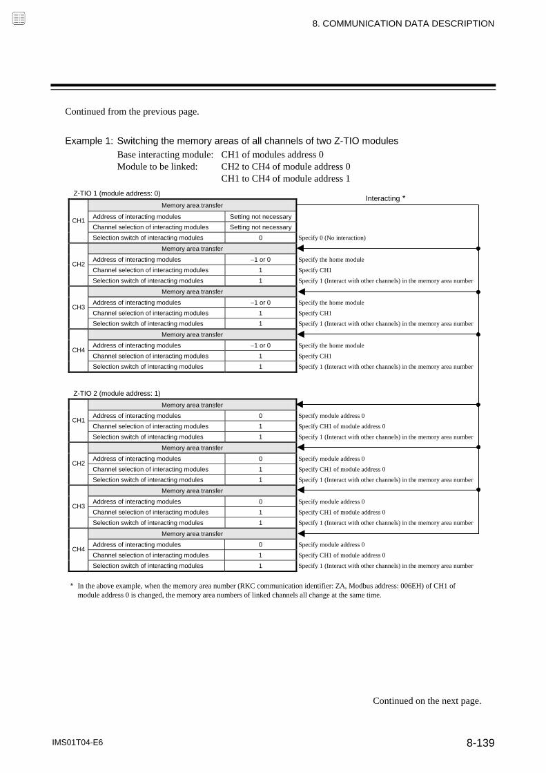
8. COMMUNICATION DATA DESCRIPTION
IMS01T04-E6 8-139
Continued from the previous page.
Example 1: Switching the memory areas of all channels of two Z-TIO modules
Base interacting module: CH1 of modules address 0 Module to be linked: CH2 to CH4 of module address 0 CH1 to CH4 of module address 1
Z-TIO 1 (module address: 0)
Memory area transfer
Address of interacting modules Setting not necessary
Channel selection of interacting modules Setting not necessary CH1
Selection switch of interacting modules 0 Specify 0 (No interaction)
Memory area transfer
Address of interacting modules 1 or 0 Specify the home module
Channel selection of interacting modules 1 Specify CH1 CH2
Selection switch of interacting modules 1 Specify 1 (Interact with other channels) in the memory area number
Memory area transfer
Address of interacting modules 1 or 0 Specify the home module
Channel selection of interacting modules 1 Specify CH1 CH3
Selection switch of interacting modules 1 Specify 1 (Interact with other channels) in the memory area number
Memory area transfer
Address of interacting modules 1 or 0 Specify the home module
Channel selection of interacting modules 1 Specify CH1 CH4
Selection switch of interacting modules 1 Specify 1 (Interact with other channels) in the memory area number
Z-TIO 2 (module address: 1)
Memory area transfer
Address of interacting modules 0 Specify module address 0
Channel selection of interacting modules 1 Specify CH1 of module address 0 CH1
Selection switch of interacting modules 1 Specify 1 (Interact with other channels) in the memory area number
Memory area transfer
Address of interacting modules 0 Specify module address 0
Channel selection of interacting modules 1 Specify CH1 of module address 0 CH2
Selection switch of interacting modules 1 Specify 1 (Interact with other channels) in the memory area number
Memory area transfer
Address of interacting modules 0 Specify module address 0
Channel selection of interacting modules 1 Specify CH1 of module address 0 CH3
Selection switch of interacting modules 1 Specify 1 (Interact with other channels) in the memory area number
Memory area transfer
Address of interacting modules 0 Specify module address 0
Channel selection of interacting modules 1 Specify CH1 of module address 0 CH4
Selection switch of interacting modules 1 Specify 1 (Interact with other channels) in the memory area number
* In the above example, when the memory area number (RKC communication identifier: ZA, Modbus address: 006EH) of CH1 of module address 0 is changed, the memory area numbers of linked channels all change at the same time.
Interacting *
Continued on the next page.

8. COMMUNICATION DATA DESCRIPTION
IMS01T04-E6 8-140
Continued from the previous page.
Example 2: Switching the memory areas of all channels of two Z-TIO modules using one Z-DIO module
Base interacting module: Z-DIO module (module address 16) Module to be linked: CH1 to CH4 of module address 0 CH1 to CH4 of module address 1
Z-TIO 1 (module address: 0) Z-DIO 1 (module address: 16)
Memory area transfer
Address of interacting modules 16 Specify the Z-DIO module address
Channel selection of interacting modules 1 Factory set value (Setting is not effective because Z-DIO is selected) DI 1
CH1
Selection switch of interacting modules 1 Specify 1 (Interact with other channels) in the memory area number Memory area transfer
Memory area transfer DI 2
(1 to 8)
Address of interacting modules 1 or 0 Specify the home module
Channel selection of interacting modules 1 Specify CH1 of the home module DI 3
CH2
Selection switch of interacting modules 1 Specify 1 (Interact with other channels) in the memory area number Memory area setting signal *
Memory area transfer DI 4
*Factory shipment: Invalid
Address of interacting modules 1 or 0 Specify the home module
Channel selection of interacting modules 1 Specify CH1 of the home module DI 5
CH3
Selection switch of interacting modules 1 Specify 1 (Interact with other channels) in the memory area number Operation mode
Memory area transfer DI 6
Address of interacting modules 1 or 0 Specify the home module
Channel selection of interacting modules 1 Specify CH1 of the home module DI 7 Interlock release
CH4
Selection switch of interacting modules 1 Specify 1 (Interact with other channels) in the memory area number
DI 8 Auto/Manual transfer
DI function assignment: 1 (See above for assignments)
Z-TIO 2 (module address: 1)
Memory area transfer
Address of interacting modules 16 Specify the Z-DIO module address
Channel selection of interacting modules 1 Factory set value (Setting is not effective because Z-DIO is selected) CH1
Selection switch of interacting modules 1 Specify 1 (Interact with other channels) in the memory area number
Memory area transfer
Address of interacting modules 1 or 1 Specify the home module
Channel selection of interacting modules 1 Specify CH1 of the home module CH2
Selection switch of interacting modules 1 Specify 1 (Interact with other channels) in the memory area number
Memory area transfer
Address of interacting modules 1 or 1 Specify the home module
Channel selection of interacting modules 1 Specify CH1 of the home module CH3
Selection switch of interacting modules 1 Specify 1 (Interact with other channels) in the memory area number
Memory area transfer
Address of interacting modules 1 or 1 Specify the home module
Channel selection of interacting modules 1 Specify CH1 of the home module CH4
Selection switch of interacting modules 1 Specify 1 (Interact with other channels) in the memory area number
* In the above example, the memory area numbers of all channels of the two linked Z-TIO modules are changed at once at the timing of the DI signals (DI1 to DI3) of the Z-DIO module.
Interacting *
Interacting *
Interacting *
Interacting *
The interval from the change of the setting signal specified as the master channel to the change of the data of the linked channels may be as long as 250 ms in some cases.

8. COMMUNICATION DATA DESCRIPTION
IMS01T04-E6 8-141
Control RUN/STOP holding setting RKC communication
identifier X1
Modbus register address
035AH (858)
It is set whether or not the operation mode before the power supply is turned off is held when the power supply is turned on or power failure recovers.
Attribute: R/W
Digits: 1 digit
Number of data: 1 (Data of each module)
Data range: 0: Not holding (STOP start) 1: Holding (RUN/STOP hold)
Factory set value: 1
Related parameters: RUN/STOP transfer (P. 8-17), Hot/Cold start (P. 8-92), Start determination point (P. 8-93)
When “0: Not holding (STOP mode)” is selected, the action at restoration of power will be as follows.
Operation mode when power failure
recovers Output value when power failure
recovers
STOP mode Started in the control stop (STOP) state regardless of the RUN mode before power failure. 1
Manipulated output value at STOP mode 2
1 If changed to RUN from STOP by RUN/STOP selection after start, set to the operation mode before power failure occurs. 2 For Position proportioning PID control (no feedback resistance input), the action will be the same as the “Valve action at STOP” setting.
Interval time RKC communication
identifier ZX
Modbus register address
035BH (859)
RS-485 sets the transmission transfer time to accurately assure the sending/receiving selection timing.
Attribute: R/W
Digits: 7 digits
Number of data: 1 (Data of each module)
Data range: 0 to 250 ms
Factory set value: 10
The sending and receiving of RS-485 communication is conducted through two wires; consequently, the transmission and reception of data requires precise timing. Then, set the desired transmission transfer time to secure the time until the transmission line is changed to data receiving after the host computer ends its sending. The controller’s interval time must match the specifications of the host computer.

IMS01T04-E6 8-142
MEMO

8. COMMUNICATION DATA DESCRIPTION
IMS01T04-E6 8-143
8.3 Communication Data of Z-DIO Module
8.3.1 Normal setting data items
Model code RKC communication identifier
ID
Modbus register address
This value is the type identifier code of the Z-DIO module.
Attribute: RO
Digits: 32 digits
Number of data: 1 (Data of each module)
Data range: Depends on model code
Factory set value:
ROM version RKC communication
identifier VR
Modbus register address
This value is a version of the ROM loaded on the Z-DIO module.
Attribute: RO
Digits: 8 digits
Number of data: 1 (Data of each module)
Data range: The version of loading software
Factory set value:

8. COMMUNICATION DATA DESCRIPTION
IMS01T04-E6 8-144
Digital input (DI) state 1 RKC communication
identifier L1
Digital input (DI) state 2 RKC communication identifier
L6
Digital input (DI) state Modbus register address
0000H (0)
Each digital input (DI) state of the Z-DIO module is expressed in bit data items.
Attribute: RO
Digits: 7 digits
Number of data: 1 (Data of each module)
Data range: RKC communication: ASCII code data
The digital input (DI) state is assigned as a digit image in ASCII code data of 7 digits.
ASCII code data of 7 digits:
Most significant digit ············ Least significant digit Data: 0: Contact open 1: Contact closed
Modbus: 0 to 255 (bit data) The digital input (DI) state is assigned as a bit image in binary numbers. Bit image: 0000000000000000
Bit 15 ····················· Bit 0 Bit data: 0: Contact open 1: Contact closed
Factory set value:
Related parameters: DI function assignment (P. 8-154), Memory area setting signal (P. 8-156)
Bit 0: DI 1 Bit 1: DI 2 Bit 2: DI 3 Bit 3: DI 4 Bit 4: DI 5 Bit 5: DI 6 Bit 6: DI 7 Bit 7: DI 8 Bit 8 to Bit 15: Unused
[Digital input (DI) state 2] Least significant digit: DI 5 2nd digit: DI 6 3rd digit: DI 7 4th digit: DI 8 5th digit to Most significant digit: Unused
[Digital input (DI) state 1] Least significant digit: DI 1 2nd digit: DI 2 3rd digit: DI 3 4th digit: DI 4 5th digit to Most significant digit: Unused

8. COMMUNICATION DATA DESCRIPTION
IMS01T04-E6 8-145
Digital output (DO) state 1 RKC communication
identifier Q2
Digital output (DO) state 2 RKC communication identifier
Q3
Digital output (DO) state Modbus register address
0001H (1)
Each digital output (DO) state of the Z-DIO module is expressed in bit data items.
Attribute: RO
Digits: 7 digits
Number of data: 1 (Data of each module)
Data range: RKC communication: ASCII code data
The digital output (DO) state is assigned as a digit image in ASCII code data of 7 digits.
ASCII code data of 7 digits:
Most significant digit ············ Least significant digit
Data: 0: OFF 1: ON Modbus: 0 to 225 (bit data) The digital output (DO) state is assigned as a bit image in binary numbers. Bit image: 0000000000000000
Bit 15 ····················· Bit 0
Bit data: 0: OFF 1: ON
Factory set value:
Related parameters: Comprehensive event state (P. 8-4), Burnout state monitor (P. 8-8), Event state monitor (P. 8-9), Heater break alarm (HBA) state monitor (P. 8-9)
DO manual output (P. 8-147), DO signal assignment module address (P. 8-157), DO output assignment (P. 8-158), DO energized/de-energized (P. 8-159)
DO output distribution bias (P. 8-151), DO output distribution ratio (P. 8-151), DO proportional cycle time (P. 8-152), Minimum ON/OFF time of DO proportioning cycle (P. 8-152), DO output distribution master channel module address (P. 8-160), DO output distribution master channel selection (P. 8-161), DO manipulated output value (MV) at STOP mode (P. 8-162), DO output limiter (high/low) (P. 8-162)
[Digital output (DO) state 2] Least significant digit: DO 5 2nd digit: DO 6 3rd digit: DO 7 4th digit: DO 8 5th digit to Most significant digit: Unused
[Digital output (DO) state 1] Least significant digit: DO 1 2nd digit: DO 2 3rd digit: DO 3 4th digit: DO 4 5th digit to Most significant digit: Unused
Bit 0: DO 1 Bit 1: DO 2 Bit 2: DO 3 Bit 3: DO 4 Bit 4: DO 5 Bit 5: DO 6 Bit 6: DO 7 Bit 7: DO 8 Bit 8 to Bit 15: Unused

8. COMMUNICATION DATA DESCRIPTION
IMS01T04-E6 8-146
Error code RKC communication
identifier ER
Modbus register address
0002H (2)
Each error state of the Z-DIO module is expressed in bit data items.
Attribute: RO
Digits: 7 digits
Number of data: 1 (Data of each module)
Data range: 0 to 2 (digits) The error state is assigned as a bit image in binary numbers. However, send data from the SRZ be changed to decimal ASCII code from the bit image in binary numbers for RKC communication. Bit image: 0000000000000000
Bit 15 ····················· Bit 0 Bit data: 0: OFF 1: ON
Factory set value:
Integrated operating time monitor RKC communication
identifier UT
Modbus register address
0003H (3)
This value is an integrated operating time of the Z-DIO module.
Attribute: RO
Digits: 7 digits
Number of data: 1 (Data of each module)
Data range: 0 to 19999 hours
Factory set value:
Backup memory state monitor RKC communication
identifier EM
Modbus register address
0004H (4)
The contents of the RAM and those of the FRAM can be checked.
Attribute: RO
Digits: 1 digit
Number of data: 1 (Data of each module)
Data range: 0: The content of the backup memory does not coincide with that of the RAM. 1: The content of the backup memory coincides with that of the RAM.
Factory set value:
Bit 0: Unused Bit 1: Data back-up error Bit 2 to Bit 15: Unused

8. COMMUNICATION DATA DESCRIPTION
IMS01T04-E6 8-147
RUN/STOP transfer RKC communication
identifier SR
Modbus register address
0046H (70)
Use to transfer the RUN (control RUN) or STOP (control STOP).
Attribute: R/W
Digits: 1 digit
Number of data: 1 (Data of each channel)
Data range: 0: STOP (Control STOP) 1: RUN (Control RUN)
Factory set value: 0
Related parameters: DI function assignment (P. 8-154), DO output distribution selection (P. 8-149), DO output assignment (P. 8-158), Control RUN/STOP holding setting (P. 8-163)
When used together with RKC panel mounted controllers (HA400/900, FB400/900, etc.), be careful that the numbers of indicating “RUN/STOP” of this instrument are opposite from those of the above controllers (0: Control RUN, 1: Control STOP).
DO manual output 1 RKC communication
identifier Q4
DO manual output 2 RKC communication identifier
Q5
DO manual output Modbus register address
0047H (71)
ON/OFF signal for each digital output (DO1 to DO8).
Attribute: R/W
Digits: 7 digits
Number of data: 8 (Data of each channel)
Data range: RKC communication: ASCII code data
The DO manual output (DO) state is assigned as a digit image in ASCII code data of 7 digits.
ASCII code data of 7 digits:
Most significant digit ············ Least significant digit
Data: 0: OFF 1: ON
Continued on the next page.
[DO manual output 2] Least significant digit: DO5 manual output 2nd digit: DO6 manual output 3rd digit: DO7 manual output 4th digit: DO8 manual output 5th digit to Most significant digit: Unused
[DO manual output 1] Least significant digit: DO1 manual output 2nd digit: DO2 manual output 3rd digit: DO3 manual output 4th digit: DO4 manual output 5th digit to Most significant digit: Unused

8. COMMUNICATION DATA DESCRIPTION
IMS01T04-E6 8-148
Continued from the previous page.
Modbus: 0 to 255 (bit data) The DO manual output is assigned as a bit image in binary numbers. Bit image: 0000000000000000
Bit 15 ····················· Bit 0 Bit data: 0: OFF 1: ON
Factory set value: 0
Related parameters: Digital output (DO) state (P. 8-145), DO signal assignment module address (P. 8-157), DO output assignment (P. 8-158), DO Energized/De-energized (P. 8-159)
Bit 0: DO1 manual output Bit 1: DO2 manual output Bit 2: DO3 manual output Bit 3: DO4 manual output Bit 4: DO5 manual output Bit 5: DO6 manual output Bit 6: DO7 manual output Bit 7: DO8 manual output Bit 8 to Bit 15: Unused

8. COMMUNICATION DATA DESCRIPTION
IMS01T04-E6 8-149
DO output distribution selection RKC communication
identifier DO
Modbus register address
ch1: 0048H (72) ch5: 004CH (76) ch2: 0049H (73) ch6: 004DH (77) ch3: 004AH (74) ch7: 004EH (78) ch4: 004BH (75) ch8: 004FH (79)
Select whether or not the manipulated output value of the specified master channel is output from DO.
Attribute: R/W Digits: 1 digit Number of data: 8 (Data of each channel) Data range: 0: DO output
1: Distribution output Factory set value: 0 Related parameters: Digital output (DO) state (P. 8-145), DO output distribution bias (P. 8-151),
DO output distribution ratio (P. 8-151), DO proportional cycle time (P. 8-152), DO minimum ON/OFF time of proportioning cycle (P. 8-152), DO output distribution master channel module address (P. 8-160), DO output distribution master channel selection (P. 8-161), DO manipulated output value (MV) at STOP mode (P. 8-162), DO output limiter (high/low) (P. 8-162)
Function: The output distribution function outputs the manipulated output value computed for the master channel as a manipulated output value from DO of the slave channels. Bias and ratio computations can also be applied to the manipulated output value computed for the master channel before it is output from DO of the slave channels.
Number of output distribution channels: 187 channels maximum (excluding the master channel) [When Z-DIO module: 16 modules, Z-TIO module 4CH type: 15 modules]
Master channel
Z-TIO module
Sensor input
Setting change rate limiter
PID computation
Output limiter
Output
Capture the output value
Output distribution bias
Output limiter
Output Manipulated output value of master channel
Manipulated output value of slave channel
Manipulated output value of master channel
Output distribution ratio
Communication
Slave channel
(Internal communication)
Capture the output value
DO output distribution bias
DO output limiter
Output
Manipulated output value of slave channel
DO output distribution ratio
Slave channel
Communication
Manipulated output value of master channel
Z-DIO module *
* Distribution output from Z-DIO module becomes open collector output or relay contact output.
The manipulated output values of the master channel and slave channels are each output within the limit of the output limiter. The output distribution function only functions within modules that are connected together (SRZ unit).
Continued on the next page.

8. COMMUNICATION DATA DESCRIPTION
IMS01T04-E6 8-150
Continued from the previous page. Operation flow Example: When using one Z-TIO module (4CH type) and one Z-DIO module
Master/Slave:
Master/Slave Module address CH/DO Input Ourpur Master channel (Heater 2)
Module address 0 CH1 Sensor input Control output
Slave channel (Heater 1)
Module address 16 DO1 Distribution output
Slave channel (Heater 3)
Module address 16 DO2 Distribution output
Setting (Z-TIO module): Module address 0 Setting items
CH1 (Master)
Output distribution selection0
(Control output)
Setting (Z-DIO module): Module address 16
Setting items DO1 (Slave)
DO2 (Slave)
DO proportional cycle time Set any value DO output distribution master channel module address
0 (Set Z-TIO module address 0)
0 (Set Z-TIO module address 0)
DO output distribution master channel selection
1 (Set CH1 of Z-TIO module)
1 (Set CH1 of Z-TIO module)
DO output distribution selection
1 (Distribution output)
1 (Distribution output)
DO output distribution bias
Set as needed
DO output distribution ratio
Set as needed
15
Module address 0
Module address 16
11
12
11
12
TC
Heater 1 Heater 2 Heater 3
SSR SSR SSR
CH1
Hot plate
14 CH1
11
12
13
COM
DO1
DO2
15
1. Set the DO output distribution master channel module address
2. Select the DO output distribution master channel
In the slave channel, set the module address number of the module that includes the channel to be specified as the master.
DO output distribution master channel module address (P. 8-160): 1 (Master channel is selected from itself) 0 to 99 (Master channel is selected from other modules)
In the slave channel, select the channel number that will be the master in the master channel module. This setting is not required in the master channel.
DO output distribution master channel (P. 8-161): 1 to 99
3. DO output distribution selection
Set DO output distribution (P. 8-149) switching to “1: Distribution output.” (If DO output is to be used, set “0: DO output.”)
4. Control start
5. Adjust the DO output distribution bias
In each slave, set the bias (P. 8-151) and ratio (P. 8-151) for the manipulated output value from the master. Select these settings as needed based on the actual operation state.
6. Adjust the DO output distribution ratio

8. COMMUNICATION DATA DESCRIPTION
IMS01T04-E6 8-151
DO output distribution bias RKC communication
identifier O8
Modbus register address
ch1: 0050H (80) ch5: 0054H (84) ch2: 0051H (81) ch6: 0055H (85) ch3: 0052H (82) ch7: 0056H (86) ch4: 0053H (83) ch8: 0057H (87)
The bias which is added to the manipulated output value of the master channel that is distributed to DO and output.
Attribute: R/W
Digits: 7 digits
Number of data: 8 (Data of each channel)
Data range: 100.0 to 100.0 %
Factory set value: 0.0
Related parameters: Digital output (DO) state (P. 8-145), DO output distribution selection (P. 8-149), DO output distribution ratio (P. 8-151), DO proportional cycle time (P. 8-152), DO minimum ON/OFF time of proportioning cycle (P. 8-152), DO output distribution master channel module address (P. 8-160), DO output distribution master channel selection (P. 8-161), DO manipulated output value (MV) at STOP mode (P. 8-162), DO output limiter (high/low) (P. 8-162)
This item is enabled when the output distribution function is used.
DO output distribution ratio RKC communication
identifier O9
Modbus register address
ch1: 0058H (88) ch5: 005CH (92) ch2: 0059H (89) ch6: 005DH (93) ch3: 005AH (90) ch7: 005EH (94) ch4: 005BH (91) ch8: 005FH (95)
The ratio (magnification) which is applied to the manipulated output value of the master channel that is distributed to DO and output.
Attribute: R/W
Digits: 7 digits
Number of data: 8 (Data of each channel)
Data range: 9.999 to 9.999
Factory set value: 1.000
Related parameters: Digital output (DO) state (P. 8-145), DO output distribution selection (P. 8-149), DO output distribution bias (P. 8-151), DO proportional cycle time (P. 8-152), DO minimum ON/OFF time of proportioning cycle (P. 8-152), DO output distribution master channel module address (P. 8-160), DO output distribution master channel selection (P. 8-161), DO manipulated output value (MV) at STOP mode (P. 8-162), DO output limiter (high/low) (P. 8-162)
This item is enabled when the output distribution function is used.

8. COMMUNICATION DATA DESCRIPTION
IMS01T04-E6 8-152
DO proportional cycle time RKC communication
identifier V0
Modbus register address
ch1: 0060H (96) ch5: 0064H (100)ch2: 0061H (97) ch6: 0065H (101)ch3: 0062H (98) ch7: 0066H (102)ch4: 0063H (99) ch8: 0067H (103)
Use to set DO proportional cycle time for the DO output.
Attribute: R/W
Digits: 7 digits
Number of data: 8 (Data of each channel)
Data range: 0.1 to 100.0 seconds
Factory set value: Relay contact output: 20.0 Open-collector output: 2.0
Related parameters: Digital output (DO) state (P. 8-145), DO output distribution selection (P. 8-149), DO output distribution bias (P. 8-151), DO output distribution ratio (P. 8-151), DO minimum ON/OFF time of proportioning cycle (P. 8-152), DO output distribution master channel module address (P. 8-160), DO output distribution master channel selection (P. 8-161), DO manipulated output value (MV) at STOP mode (P. 8-162), DO output limiter (high/low) (P. 8-162)
This item is enabled when the output distribution function is used.
DO minimum ON/OFF time of proportioning cycle
RKC communication identifier
VJ
Modbus register address
ch1: 0068H (104) ch5: 006CH (108)ch2: 0069H (105) ch6: 006DH (109)ch3: 006AH (106) ch7: 006EH (110)ch4: 006BH (107) ch8: 006FH (111)
This is the minimum ON/OFF time of the time proportioning cycle.
Attribute: R/W
Digits: 7 digits
Number of data: 8 (Data of each channel)
Data range: 0 to 1000 ms
Factory set value: 0
Related parameters: Digital output (DO) state (P. 8-145), DO output distribution selection (P. 8-149), DO output distribution bias (P. 8-151), DO output distribution ratio (P. 8-151), DO proportional cycle time (P. 8-152), DO output distribution master channel module address (P. 8-160), DO output distribution master channel selection (P. 8-161), DO manipulated output value (MV) at STOP mode (P. 8-162), DO output limiter (high/low) (P. 8-162)
Continued on the next page.

8. COMMUNICATION DATA DESCRIPTION
IMS01T04-E6 8-153
Continued from the previous page.
Function: The DO minimum ON/OFF time of the proportioning cycle is used to prevent output ON or OFF when the output is greater than 0 % or less than 100 %. This is useful when you wish to establish a minimum ON/OFF time to prolong the life of the relay.
Example 1: Setting of DO minimum ON/OFF time of proportioning cycle Computed output More than 0 % (Around 0 %)
Computed output
ON
OFF
* When a long minimum ON/OFF time is required for the relay, set a time longer than that time.
ON
OFF Actual output
ON
OFF
Computed output
ON
OFF Actual output
Setting of Minimum ON/OFF time
ON
OFF
DO proportioning cycle time
(ON time)
*
Less than 100 % (Around 100 %)
Setting of Minimum ON/OFF time
ON
OFF (OFF time)
DO proportioning cycle time
*
Example 2: Setting of DO minimum ON/OFF time of proportioning cycle Computed output More than 0 % (Around 0 %)
Computed output
ON
OFF
* When a long minimum ON/OFF time is required for the relay, set a time longer than that time.
ON
OFF Actual output
ON
OFF
Computed output
ON
OFF Actual output
Setting of Minimum ON/OFF time
ON
OFF
DO proportioning cycle time
(ON time)
*
Less than 100 % (Around 100 %)
Setting of Minimum ON/OFF time
ON
OFF (OFF time)
DO proportioning cycle time
*
Operation will not take place if “DO proportional cycle time DO minimum ON/OFF time of proportioning cycle.”
This item is enabled when the output distribution function is used.

8. COMMUNICATION DATA DESCRIPTION
IMS01T04-E6 8-154
8.3.2 Engineering setting data items Setting procedure of Engineering setting data items
When RUN/STOP switching (RKC communication identifier: RS, Modbus register address: 0046H) is set to “0: STOP (control stop),” Engineering setting data can be configured.
During RUN (control), the attribute of the Engineering setting data is RO (read only). Data explanation
DI function assignment RKC communication identifier
H2
Modbus register address
00A4H (164)
This item is used to assign functions (memory areas, operation modes, etc.) to digital inputs DI1 to DI8.
Attribute: R/W
Digits: 7 digits
Number of data: 1 (Data of each module)
Data range: 0 to 29 (refer to P. 8-155.) Factory set value: Based on model code When not specifying: 0
Related parameters: Address of interacting modules (P. 8-137), Selection switch of interacting modules (P. 8-138), Digital input (DI) state (P. 8-144), Memory area setting signal (P. 8-156)
Switching of functions that have been assigned digital inputs (DI1 to DI8) using the switch of interacting modules is performed by DI switching.
To switch Z-TIO module functions* using DI of a Z-DIO module, the following communication data items must be configured in the Z-TIO module. * Applicable functions: Memory area transfer, Operation mode transfer, AUTO/MAN, REM/LOC, EDS start signal, Interlock release, Soak stop
Address of interacting module: Set the module address of the applicable Z-DIO module Selection switch of interacting modules: Set the applicable bit to “1”
Switching of Z-TIO module functions using DI of a Z-DIO module applies to the entire SRZ unit (multiple Z-TIO or Z-DIO modules connected together).
Continued on the next page.
The Engineering setting data should be set according to the application before setting any parameter related to operation. Once the Engineering setting data are set correctly, those data are not necessary to be changed for the same application under normal conditions. If they are changed unnecessarily, it may result in malfunction or failure of the instrument. RKC will not bear any responsibility for malfunction or failure as a result of improper changes in the Engineering setting.
WARNING!

8. COMMUNICATION DATA DESCRIPTION
IMS01T04-E6 8-155
Continued from the previous page.
DI assignment table
Set value DI1 DI2 DI3 DI4 DI5 DI6 DI7 DI80 No assignment1
Memory area transfer (1 to 8) 1
AUTO/MAN 4 2 REM/LOC 4 3 Interlock release EDS start signal 14 Soak stop 5 RUN/STOP 4 6 REM/LOC 4 7 AUTO/MAN 4 EDS start signal 18 Operation mode 3 Soak stop 9 RUN/STOP 4 10 EDS start signal 111 REM/LOC 4 Soak stop 12 RUN/STOP 4 13 Area set 2
EDS start signal 1 Soak stop
14 RUN/STOP 4
15 Soak stop 16 EDS start signal 117 REM/LOC 4 Soak stop 18 Interlock release AUTO/MAN 4 RUN/STOP 4 19
EDS start signal 1 Soak stop
20 RUN/STOP 4
21 Soak stop 22
EDS start signal 1 Soak stop
23 AUTO/MAN REM/LOC 24
Soak stop RUN/STOP 4
25 REM/LOC EDS start signal 1 26 Memory area
transfer (1, 2) 1 Area set 2 Interlock release RUN/STOP 4 AUTO/MAN 4 REM/LOC 4 Operation mode 3
27 Memory area transfer (1 to 8) 1 Area set 2 Operation mode 3 EDS start signal 1 EDS start signal 228 Memory area
transfer (1, 2) 1 Area set 2
Interlock release RUN/STOP 4 AUTO/MAN 4 REM/LOC 4 29 EDS start signal 1 EDS start signal 2 Operation mode 3
RUN/STOP: RUN/STOP transfer (Contact closed: RUN) AUTO/MAN: Auto/Manual transfer (Contact closed: Manual mode) REM/LOC: Remote/Local transfer (Contact closed: Remote mode) Interlock release (Interlock release when rising edge is detected) EDS start signal 1 (EDS start signal ON when rising edge is detected [for disturbance 1]) EDS start signal 2 (EDS start signal ON when rising edge is detected [for disturbance 2]) Soak stop (Contact closed: Soak stop)
1 Memory area transfer (:Contact open : Contact closed)
Memory area number1 2 3 4 5 6 7 8
DI1 DI2 DI3
2 Area set becomes invalid prior to factory shipment. 3 Operation mode transfer (:Contact open : Contact closed)
Operation modeUnused Monitor Monitor Event function Control
DI5 (DI7) DI6 (DI8)
4 Actual device states (AUTO/MAN, REM/LOC, RUN/STOP)
DI-switched state Communication-switched state Actual device state
Auto/Manual transfer a (AUTO/MAN)
Manual (Contact closed) Manual → Auto
Manual mode Auto → Manual
Auto (Contact open) Manual → Auto
Auto mode Auto → Manual
Remote (Contact closed)
Remote → Local Remote mode
Remote/Local transfer a Local → Remote
(REM/LOC) Local (Contact open)
Remote → Local Local mode
Local → Remote
RUN (Contact closed)
STOP → RUN RUN
RUN/STOP b RUN → STOP STOP
STOP (Contact open) STOP → RUN STOP
a Device state when AUTO/MAN or REM/LOC assigned to DI is set so that the Z-TIO module and Z-DIO module are linked using the Master-slave mode of the Z-TIO module. b STOP of RUN/STOP switching is given priority regardless of communication or DI switching.
Contact closed
Contact open
250 ms or more DI signal will become valid at rising edge after the closed contact is held for 250 ms.
(Rising edge)

8. COMMUNICATION DATA DESCRIPTION
IMS01T04-E6 8-156
Memory area setting signal RKC communication
identifier E1
Modbus register address
00A5H (165)
Use to select the memory area setting signal for memory area transfer.
Attribute: R/W Digits: 1 digit Number of data: 1 (Data of each module) Data range: 0: Valid
1: Invalid Factory set value: 1 Related parameters: Address of interacting modules (P. 8-137),
Selection switch of interacting modules (P. 8-138), Digital input (DI) state (P. 8-144), DI function assignment (P. 8-154)
Transfer timing of Memory area (Control area)
When “0 (Valid)” is selected: After selecting the memory area number by the applicable contacts DI, the memory area number is changed when contact DI (Area Set) is closed from the open condition (Rising edge).
[Example] Change the memory area number to 6 First, close the contacts between DI1 and DI3 and the common terminal. Next, open the contact between DI2 and the common. Then, close the contact between DI4 (Area Set) and the common from open status (Rising edge), the memory area number in the controller will change to “6.”
DI 1: Contact closed
DI 2: Contact open DI 3: Contact closed Rising edge Memory area transfer
Contact open
Contact closed 2
DI 4 (Memory area set)
2 To make contact activation valid, it is necessary to maintain the same contact state (contact closed) for more than 250 ms.
1. Select the Memory area number 1 2. Change the Memory area
1 DI function assignment: When “1 (factory set value)” is selected
When “1 (Invalid)” is selected: The memory area number is set by area switching input, and becomes effective two seconds after it is set.
[Example] Change the memory area number from 1 to 2.
Close the DI1 contact and open the DI2 and DI3 contacts. The memory area number is changed to “2” after a lapse of two seconds following the setting.
DI1 (Contact closed)
(Contact open)
DI2 (Contact open)
DI3 (Contact open)
2 seconds or more
Memory area 1 Memory area 2 Control area

8. COMMUNICATION DATA DESCRIPTION
IMS01T04-E6 8-157
DO signal assignment module address 1 [DO1 to DO4]
RKC communication identifier
LQ
Modbus register address
00A6H (166)
DO signal assignment module address 2 [DO5 to DO8]
RKC communication identifier
LR
Modbus register address
00A7H (167)
Specify the module to be used at the DO signal selected by DO output assignment.
Attribute: R/W
Digits: 7 digits
Number of data: 1 (Data of each module)
Data range: 1, 0 to 99
Factory set value: DO signal assignment module address 1: 1 DO signal assignment module address 2: 1
Related parameters: Comprehensive event state (P. 8-4), Burnout state monitor (P. 8-8), Event state monitor (P. 8-9), Heater break alarm (HBA) state monitor (P. 8-9), Digital output (DO) state (P. 8-145), DO manual output (P. 8-147), DO output assignment (P. 8-158), DO energized/de-energized (P. 8-159)
When “1” is selected, all of the signals of the same type (except temperature rise completion and DO manual output value) are OR-operated and produced as outputs from DO.
To specify the address number of a Z-TIO module, set the number that is set in the address setting switch (0 to F) as a decimal number (0 to 15). To specify the address number of a Z-DIO module, set the number that is set in the address setting switch (0 to F) as a decimal number (0 to 15) with “16” added.
Example: Processing the same signal of two Z-TIO modules (event output, etc.) by OR logic
Module address
0 Module address
1 Module address
16
The HBA state of a Z-CT module can be output from the DO signal (HBA comprehensive output) of a Z-DIO module. In this case, DO signal assignment module address and DO output assignment settings (P. 8-158) are required on the Z-DIO module. For details of the Z-CT module, refer to Z-CT Instruction Manual (IMS01T21-E).
Settings: DO signal assignment module address 1: 1DO signal assignment module address 2: 1 Assignment of DO signals is performed by DO output assignment.

8. COMMUNICATION DATA DESCRIPTION
IMS01T04-E6 8-158
DO output assignment 1 [DO1 to DO4]
RKC communication identifier
LT
Modbus register address
00A8H (168)
DO output assignment 2 [DO5 to DO8]
RKC communication identifier
LX
Modbus register address
00A9H (169)
Assignments to digital outputs (DO1 to DO8) for output of event results of the Z-TIO module and DO manual output states of the Z-DIO module
Attribute: R/W
Digits: 7 digits
Number of data: 1 (Data of each module)
Data range: 0 to 13 (refer to below)
Factory set value: DO output assignment1: Based on model code When not specifying: 0
DO output assignment2: Based on model code When not specifying: 0
Related parameters: Digital output (DO) state (P. 8-145), DO manual output (P. 8-147), DO signal assignment module address (P. 8-157), DO output assignment (P. 8-158), DO energized/de-energized (P. 8-159)
DO assignment table [DO1 to DO4]
Set value DO1 DO2 DO3 DO4
0 No assignment
1 DO1 manual output DO2 manual output DO3 manual output DO4 manual output
2 Event 1 comprehensive output 1 Event 2 comprehensive output 2 Event 3 comprehensive output 3 Event 4 comprehensive output 4
3 Event 1 (CH1) Event 2 (CH1) Event 3 (CH1) Event 4 (CH1)
4 Event 1 (CH2) Event 2 (CH2) Event 3 (CH2) Event 4 (CH2)
5 Event 1 (CH3) Event 2 (CH3) Event 3 (CH3) Event 4 (CH3)
6 Event 1 (CH4) Event 2 (CH4) Event 3 (CH4) Event 4 (CH4)
7 Event 1 (CH1) Event 1 (CH2) Event 1 (CH3) Event 1 (CH4)
8 Event 2 (CH1) Event 2 (CH2) Event 2 (CH3) Event 2 (CH4)
9 Event 3 (CH1) Event 3 (CH2) Event 3 (CH3) Event 3 (CH4)
10 Event 4 (CH1) Event 4 (CH2) Event 4 (CH3) Event 4 (CH4)
11 HBA (CH1) of Z-TIO module HBA (CH2) of Z-TIO module HBA (CH3) of Z-TIO module HBA (CH4) of Z-TIO module
12 Burnout status (CH1) Burnout status (CH2) Burnout status (CH3) Burnout status (CH4)
13 Temperature rise completion 5 HBA comprehensive output 6 Burnout state comprehensive output 7 DO4 manual output
[DO5 to DO8]
Set value DO5 DO6 DO7 DO8
0 No assignment
1 DO5 manual output DO6 manual output DO7 manual output DO8 manual output
2 Event 1 comprehensive output 1 Event 2 comprehensive output 2 Event 3 comprehensive output 3 Event 4 comprehensive output 4
3 Event 1 (CH1) Event 2 (CH1) Event 3 (CH1) Event 4 (CH1)
4 Event 1 (CH2) Event 2 (CH2) Event 3 (CH2) Event 4 (CH2)
5 Event 1 (CH3) Event 2 (CH3) Event 3 (CH3) Event 4 (CH3)
6 Event 1 (CH4) Event 2 (CH4) Event 3 (CH4) Event 4 (CH4)
7 Event 1 (CH1) Event 1 (CH2) Event 1 (CH3) Event 1 (CH4)
8 Event 2 (CH1) Event 2 (CH2) Event 2 (CH3) Event 2 (CH4)
9 Event 3 (CH1) Event 3 (CH2) Event 3 (CH3) Event 3 (CH4)
10 Event 4 (CH1) Event 4 (CH2) Event 4 (CH3) Event 4 (CH4)
11 HBA (CH1) of Z-TIO module HBA (CH2) of Z-TIO module HBA (CH3) of Z-TIO module HBA (CH4) of Z-TIO module
12 Burnout status (CH1) Burnout status (CH2) Burnout status (CH3) Burnout status (CH4)
13 Temperature rise completion 5 HBA comprehensive output 6 Burnout state comprehensive output 7 DO8 manual output
Continued on the next page.

8. COMMUNICATION DATA DESCRIPTION
IMS01T04-E6 8-159
Continued from the previous page.
1 Logical OR of Event 1 (ch1 to ch4) 2 Logical OR of Event 2 (ch1 to ch4) 3 Logical OR of Event 3 (ch1 to ch4) 4 Logical OR of Event 4 (ch1 to ch4) 5 Temperature rise completion status (ON when temperature rise completion occurs for all channels for which Event 3 is set to temperature rise
completion.) 6 The following signals are output depending on the setting of the DO signal assignment module address. ・Logical OR of HBA (ch1 to ch4) of Z-TIO module ・Logical OR of HBA (ch1 to ch12) of Z-CT module ・Logical OR of HBA (ch1 to ch4) of Z-TIO module and HBA (ch1 to ch12) of Z-CT module 7 Logical OR of burnout state (ch1 to ch4)
To output the HBA signal of a Z-CT module from DO, set “13.” For details of the Z-CT module, refer to Z-CT Instruction Manual (IMS01T21-E).
DO Energized/De-energized RKC communication
identifier NB
Modbus register address
ch1: 00AAH (170) ch5: 00AEH (174)ch2: 00ABH (171) ch6: 00AFH (175)ch3: 00ACH (172) ch7: 00B0H (176)ch4: 00ADH (173) ch8: 00B1H (177)
Energized/De-energized can be selected for digital outputs DO1 to DO8.
Attribute: R/W
Digits: 1 digit
Number of data: 8 (Data of each channel)
Data range: 0: Energized 1: De-energized
Factory set value: 0
Related parameters: Comprehensive event state (P. 8-4), Burnout state monitor (P. 8-8), Event state monitor (P. 8-9), Heater break alarm (HBA) state monitor (P. 8-9), Digital output (DO) state (P. 8-145), DO manual output (P. 8-147), DO signal assignment module address (P. 8-157), DO output assignment (P. 8-158)
Function: Action of Energized/De-energized
Energized/De-energized setting
Output state of DO1 to DO8
Non-event state Event state
Energized Event output OFF Event output ON
De-energized Event output ON Event output OFF
Example: Relay contact output Energized: Relay contact is closed under the event or alarm state. De-energized: Relay contact opens under the event or alarm state.
Diagram for explaining operation (At power-ON)
Energized
Non-event state Event state
De- energized
Non-event state Event state

8. COMMUNICATION DATA DESCRIPTION
IMS01T04-E6 8-160
DO output distribution master channel module address
RKC communication identifier
DD
Modbus register address
ch1: 00B2H (178) ch5: 00B6H (182)ch2: 00B3H (179) ch6: 00B7H (183)ch3: 00B4H (180) ch7: 00B8H (184)ch4: 00B5H (181) ch8: 00B9H (185)
To output the manipulated output value computed in the master channel from the DO of the slave channel, set the module address number of the module that includes the channel to be specified as the master.
Attribute: R/W
Digits: 7 digits
Number of data: 8 (Data of each channel)
Data range: 1 (Master channel is selected from itself)
0 to 99 (Master channel is selected from other modules)
Factory set value: 1
Related parameters: Digital output (DO) state (P. 8-145), DO output distribution selection (P. 8-149), DO output distribution bias (P. 8-151), DO output distribution ratio (P. 8-151), DO proportional cycle time (P. 8-152), DO minimum ON/OFF time of proportioning cycle (P. 8-152), DO output distribution master channel selection (P. 8-161), DO manipulated output value (MV) at STOP mode (P. 8-162), DO output limiter (high/low) (P. 8-162)
To specify the address number of a Z-TIO module, set the number that is set in the address setting switch (0 to F) as a decimal number (0 to 15). To specify the address number of a Z-DIO module, set the number that is set in the address setting switch (0 to F) as a decimal number (0 to 15) with “16” added.
Example 1: Setting the CH1 control output of the Z-TIO module as the master in DO1 of the Z-DIO module
Module address
0 Module address
16
Example 2: Setting DO1 of the Z-DIO module as the master in DO2 to DO8 of the same module.
Module address
0 Module address
16
Set “0,” the module address of the Z-TIO module, in DO1 of module address 16.
Set “1” in DO2 to DO8 of module address 16. The module address number “16” of the home module can also be set.
Address setting switch
Address setting switch

8. COMMUNICATION DATA DESCRIPTION
IMS01T04-E6 8-161
DO output distribution master channel selection
RKC communication identifier
DJ
Modbus register address
ch1: 00BAH (186) ch5: 00BEH (190)ch2: 00BBH (187) ch6: 00BFH (191)ch3: 00BCH (188) ch7: 00C0H (192)ch4: 00BDH (189) ch8: 00C1H (193)
Select the channel number that will be the master in the master channel module.
Attribute: R/W
Digits: 7 digits
Number of data: 8 (Data of each channel)
Data range: 1 to 99
Factory set value: 1
Related parameters: Digital output (DO) state (P. 8-145), DO output distribution selection (P. 8-149), DO output distribution bias (P. 8-151), DO output distribution ratio (P. 8-151), DO proportional cycle time (P. 8-152), DO minimum ON/OFF time of proportioning cycle (P. 8-152), DO output distribution master channel module address (P. 8-160), DO manipulated output value (MV) at STOP mode (P. 8-162), DO output limiter (high/low) (P. 8-162)
Example: Combining the master channel and slave channels as shown below
Master/Slave: Master/Slave Module address CH/DO Input Ourpur
Master channel (Heater 2)
Module address 0 CH1 Sensor input Control output
Slave channel (Heater 1)
Module address 16 DO1 Distribution output
Slave channel (Heater 3)
Module address 16 DO2 Distribution output
Setting (Z-TIO module): Module address 0 Setting items
CH1 (Master)
Output distribution selection 0 (Control output)
Setting (Z-DIO module):
Module address 16 Setting items DO1
(Slave) DO2
(Slave) DO proportional cycle time Set any value DO output distribution master channel module address
0 (Set Z-TIO module address 0)
0 (Set Z-TIO module address 0)
DO output distribution master channel selection
1 (Set CH1 of Z-TIO module)
1 (Set CH1 of Z-TIO module)
DO output distribution selection
1 (Distribution output)
1 (Distribution output)
DO output distribution bias
Set as needed
DO output distribution ratio
Set as needed
15
Module address 0
Module address 16
11
12
11
12
TC
Heater 1 Heater 2 Heater 3
SSR SSR SSR
CH1
Hot plate
14 CH1
11
12
13
COM
DO1
DO2
15
There is no need for this setting (selecting the master channel) in the master channel.

8. COMMUNICATION DATA DESCRIPTION
IMS01T04-E6 8-162
DO manipulated output value (MV) at STOP mode
RKC communication identifier
OJ
Modbus register address
ch1: 00C2H (194) ch5: 00C6H (198)ch2: 00C3H (195) ch6: 00C7H (199)ch3: 00C4H (196) ch7: 00C8H (200)ch4: 00C5H (197) ch8: 00C9H (201)
Manipulated output value that is output from the Z-DIO module (DO1 to DO4, DO5 to DO8) when STOP (control stop) occurs.
Attribute: R/W Digits: 7 digits Number of data: 8 (Data of each channel)
Data range: 5.0 to 105.0 %
Factory set value: 5.0 Related parameters: Digital output (DO) state (P. 8-145), RUN/STOP transfer (P. 8-147),
DO output distribution selection (P. 8-149), DO output distribution bias (P. 8-151), DO output distribution ratio (P. 8-151), DO proportional cycle time (P. 8-152), DO minimum ON/OFF time of proportioning cycle (P. 8-152), DO output distribution master channel module address (P. 8-160), DO output distribution master channel selection (P. 8-161), DO output limiter (high/low) (P. 8-162)
This item is enabled when the output distribution function is used. DO output limiter (high) RKC communication
identifier D3
Modbus register address
ch1: 00CAH (202) ch5: 00CEH (206)ch2: 00CBH (203) ch6: 00CFH (207)ch3: 00CCH (204) ch7: 00D0H (208)ch4: 00CDH (205) ch8: 00D1H (209)
DO output limiter (low) RKC communication identifier
D4
Modbus register address
ch1: 00D2H (210) ch5: 00D6H (214)ch2: 00D3H (211) ch6: 00D7H (215)ch3: 00D4H (212) ch7: 00D8H (216)ch4: 00D5H (213) ch8: 00D9H (217)
Use to set the high limit value (low limit value) of Manipulated output (MV).
Attribute: R/W Digits: 7 digits Number of data: 8 (Data of each channel) Data range: DO output limiter (high): DO output limiter (low) to 105.0 %
DO output limiter (low): 5.0 % to DO output limiter (high) Factory set value: DO output limiter (high): 105.0
DO output limiter (low): 5.0
Continued on the next page.

8. COMMUNICATION DATA DESCRIPTION
IMS01T04-E6 8-163
Continued from the previous page.
Related parameters: Digital output (DO) state (P. 8-145), RUN/STOP transfer (P. 8-147), DO output distribution selection (P. 8-149), DO output distribution bias (P. 8-151), DO output distribution ratio (P. 8-151), DO proportional cycle time (P. 8-152), DO minimum ON/OFF time of proportioning cycle (P. 8-152), DO output distribution master channel module address (P. 8-160), DO output distribution master channel selection (P. 8-161), DO manipulated output value (MV) at STOP mode (P. 8-162)
Function: This function limits the output (high limit and low limit) when the Manipulated output value (MV) of the master channel is output from DO.
The Manipulated output value is not produced within this range.
The Manipulated output value is not produced within this range.
Manipulated output value (MV)
100 %
0 %
Output limiter high
Output limiter low
Time
Manipulated output value (MV)
This item is enabled when the output distribution function is used. Control RUN/STOP holding setting RKC communication
identifier X1
Modbus register address
00DAH (218)
When the power is turned on or restored after a power interruption, this setting determines whether or not the operation mode (RUN/STOP state) before the power of the Z-DIO module went off is held.
Attribute: R/W
Digits: 1 digit
Number of data: 1 (Data of each module)
Data range: 0: Not holding (STOP start) 1: Holding (RUN/STOP hold)
Factory set value: 1
Related parameters: RUN/STOP transfer (P. 8-147)
When “0: Not holding (STOP mode)” is selected, the action at restoration of power will be as follows.
Operation mode when power failure
recovers Output value when power failure recovers
STOP mode
Started in the control stop (STOP) state regardless of the RUN mode before power failure.
DO output Contact open
Distribution output
Manipulated output value at STOP mode

8. COMMUNICATION DATA DESCRIPTION
IMS01T04-E6 8-164
Interval time RKC communication
identifier ZX
Modbus register address
00DBH (219)
RS-485 sets the transmission transfer time to accurately assure the sending/receiving selection timing.
Attribute: R/W
Digits: 7 digits
Number of data: 1 (Data of each module)
Data range: 0 to 250 ms
Factory set value: 10
The sending and receiving of RS-485 communication is conducted through two wires; consequently, the transmission and reception of data requires precise timing. Then, set the desired transmission transfer time to secure the time until the transmission line is changed to data receiving after the host computer ends its sending. The controller’s interval time must match the specifications of the host computer.

TROUBLESHOOTING
IMS01T04-E6 9-1
10.1 Solutions for Problems .................................................................... 9-2

9. TROUBLESHOOTING
9-2 IMS01T04-E6
Solutions for Problems
This section explains possible causes and treatment procedures if any abnormality occurs in the instrument. For any inquiries, please contact RKC sales office or the agent, to confirm the specifications of the product. If it is necessary to replace a device, always strictly observe the warnings below.
All wiring must be completed before power is turned on to prevent electric shock, instrument
failure, or incorrect action. The power must be turned off before repairing work for input break and
output failure including replacement of sensor, contactor or SSR, and all wiring must be
completed before power is turned on again.
When replacing the module with a new one, always use the module with the same model code. If the module is replaced, it is necessary to re-set each data item.
To prevent electric shock or instrument failure, always turn off the system power before replacing the instrument.
To prevent electric shock or instrument failure, always turn off the power before mounting or removing the instrument.
To prevent electric shock or instrument failure, do not turn on the power until all wiring is completed. Make sure that the wiring is correct before applying power to the instrument.
To prevent electric shock or instrument failure, do not touch the inside of the instrument.
All wiring must be performed by authorized personnel with electrical experience in this type of work.
WARNING!
CAUTION

9. TROUBLESHOOTING
IMS01T04-E6 9-3
Z-TIO/Z-DIO module
Problem Possible cause Solution
FAIL/RUN lamp does not light up
Power not being supplied Check external breaker etc.
Appropriate power supply voltage not being supplied
Check the power supply
Power supply terminal contact defect
Retighten the terminals
Power supply section defect
Replace Z-TIO (or Z-DIO) module
RX/TX lamp does not flash Wrong connection, no connection or disconnection of the communication cable
Confirm the connection method or condition and connect correctly
Breakage, wrong wiring, or imperfect contact of the communication cable
Confirm the wiring or connector and repair or replace the wrong one
CPU section defect
Replace Z-TIO (or Z-DIO) module
The FAIL/RUN lamp is lit (red): FAIL status
CPU section or power section defect
Replace Z-TIO (or Z-DIO) module

9. TROUBLESHOOTING
IMS01T04-E6 9-4
RKC communication
Problem Possible cause Solution
No response Wrong connection, no connection or disconnection of the communication cable
Confirm the connection method or condition and connect correctly
Breakage, wrong wiring, or imperfect contact of the communication cable
Confirm the wiring or connector and repair or replace the wrong one
Mismatch of the setting data of communication speed and data bit configuration with those of the host computer
Confirm the settings and set them correctly
Wrong address setting
Error in the data format
Reexamine the communication program
Transmission line is not set to the receive state after data send
EOT return The specified identifier is invalid Confirm the identifier is correct or that with the correct function is specified. Otherwise correct it
Error in the data format
Reexamine the communication program
NAK return Error occurs on the line (parity bit error, framing error, etc.)
Confirm the cause of error, and solve the problem appropriately. (Confirm the transmitting data, and resend data)
BCC error
The data exceeds the setting range
Confirm the setting range and transmit correct data
The block data length of the transmission exceeds 136 bytes
Divide the block using ETB before sending it
The specified identifier is invalid Confirm the identifier is correct or that with the correct function is specified. Otherwise correct it

9. TROUBLESHOOTING
IMS01T04-E6 9-5
Modbus
Problem Possible cause Solution
No response Wrong connection, no connection or disconnection of the communication cable
Confirm the connection method or condition and connect correctly
Breakage, wrong wiring, or imperfect contact of the communication cable
Confirm the wiring or connector and repair or replace the wrong one
Mismatch of the setting data of communication speed and data bit configuration with those of the host computer
Confirm the settings and set them correctly
Wrong address setting
There is length of query message exceeds set range
A transmission error (overrun error, framing error, parity error or CRC-16 error) is found in the query message
Re-transmit after time-out occurs or verify communication program
The time interval between adjacent data in the query message is too long, exceeding 24 bit’s time
Error code 1 Function cod error (Specifying nonexistent function code)
Confirm the function code
Error code 2 When the mismatched address is specified
Confirm the address of holding register
Error code 3 When the specified number of data items in the query message exceeds the maximum number of data items available
When the data written exceeds the setting range
Confirm the setting data
Error code 4 Self-diagnostic error Turn off the power to the instrument. If the same error occurs when the power is turned back on, please contact RKC sales office or the agent.

9-6 IMS01T04-E6
MEMO

SPECIFICATIONS
IMS01T04-E6 10-1
10.1 Z-TIO module ................................................................................ 10-2
10.2 Z-DIO module ............................................................................. 10-16

10. SPECIFICATIONS
10-2 IMS01T04-E6
10.1 Z-TIO module
Measured input
Number of inputs: 4 point or 2 point (Isolated between each input)
Input type: Temperature, Current, Voltage (low) and Feedback resistance input group * Thermocouple (TC) K, J, T, S, R, E, B, N (JIS-C1602-1995) PL II (NBS), W5Re/W26Re (ASTM-E988-96) RTD: Pt100 (JIS-C1604-1997) JPt100 (JIS-C1604-1981 of Pt100) 3-wire system Voltage: 0 to 10 mV DC, 0 to 100 mV DC, 0 to 1 V DC Current: 4 to 20 mA DC, 0 to 20 mA DC Feedback resistance (FBR) input: 100 to 6 k (standard: 135 ) [FBR inputs can be used to monitor FBR (Feedback resistance)]
Voltage (high) input group * Voltage: 0 to 5 V DC, 1 to 5 V DC, 0 to 10 V DC
* Universal input (Use the input select switch to change input group.)
Input range: TC input
RTD input Input type Measured range
Pt100 200.0 to 850.0 C (328 to 1562 F, 328.0 to 752.0 F)
JPt100 200.0 to 640.0 C (328 to 1184 F, 328.0 to 752.0 F)
Voltage/Current input Input type Measured range
Voltage (low) 0 to 10 mV DC, 0 to 100 mV DC,
0 to 1 V DC Programmable
range
(19999 to 19999)
[However, a span is 20000 or less.]
Voltage (high) 0 to 5 V DC, 1 to 5 V DC, 0 to 10 V DC
Current 0 to 20 mA DC, 4 to 20 mA DC
Feedback resistance input Measuring range 100 to 6 k (standard: 135 )
Input type Measured range
K 200.0 to 1372.0 C (328 to 2501 F, 0.0 to 800.0 F)
J 200.0 to 1200.0 C (328 to 2192 F, 0.0 to 800.0 F)
T 200.0 to 400.0 C (328 to 752 F, 0.0 to 752.0 F)
S 50 to 1768 C (58 to 3214 F)
R 50 to 1768 C (58 to 3214 F)
E 200.0 to 1000.0 C (328 to 1832 F, 0.0 to 800.0 F)
B 0 to 1800 C (32 to 3272 F)
N 0 to 1300 C (32 to 2372 F)
PLII 0 to 1390 C (32 to 2534 F)
W5Re/W26Re 0 to 2300 C (32 to 4208 F)

10. SPECIFICATIONS
IMS01T04-E6 10-3
Sampling cycle: 250 ms
Influence of external resistance: Approx. 0.125 V/ (Converted depending on TC types)
Influence of input lead: Approx. 0.02 / of PV (RTD input) 10 or less per wire
Input impedance: TC input: 1 M or more Voltage (low) input: 1 M or more Voltage (high) input: Approx. 1 M Current input: Approx. 50
Sensor current: Approx. 250 A (RTD input)
Action at input beak: TC input: Upscale or downscale RTD input: Upscale Voltage (low) input: Upscale or downscale Voltage (high) input: Downscale (display of about 0 V) Current input: Downscale (display of about 0 mA) Feedback resistance input: Upscale
Action at input short circuit: Downscale (RTD input, Feedback resistance input)
Action at input error: Setting range of Input error determination point (high/low): Input scale low − (5 % of input span) to Input scale high + (5 % of input span) High/Low individual setting
Manipulated output value at input error: 105.0 to 105.0
Input correction: PV bias: Input span to Input span PV ratio: 0.500 to 1.500 First order lag digital filter: 0.0 to 100.0 seconds (0.0: OFF)
Square root extraction function (Voltage input, Current input): Calculation method: Measured value = (Input value PV ratio + PV bias)
PV low input cut-off: 0.00 to 25.00 % of input span Current transformer (CT) input [optional]
Number of inputs: 4 points or 2 points
CT type: CTL-6-P-N or CTL-12-S56-10-N (Sold separately)
Input range: CTL-6-P-N: 0.0 to 30.0 A CTL-12-S56-10L-N: 0.0 to 100.0 A Sampling cycle: 500 ms

10. SPECIFICATIONS
IMS01T04-E6 10-4
Output (OUT1 to OUT4)
Number of outputs: 4 points or 2 points
Output contents: Used for control output or logic output
Output type: Relay contact output Contact type: 1a contact Contact rating (Resistive load): 250 V AC 3 A, 30 V DC 1 A Electrical life: 300,000 times or more (Rated load) Mechanical life: 50 million times or more (Switching: 180 times/min) Proportional cycle time *: 0.1 to 100.0 seconds Minimum ON/OFF time: 0 to 1000 ms
Voltage pulse output (Not isolated between output and power supply) Output voltage: 0/12 V DC (Rating) ON voltage: 11.0 to 13.0 V OFF voltage: 0.2 V or less Allowable load resistance: 600 or more Proportional cycle time *: 0.1 to 100.0 seconds Minimum ON/OFF time: 0 to 1000 ms
Current output (Not isolated between output and power supply) Output current (Rating): 4 to 20 mA DC, 0 to 20 mA DC Output range: 1 to 21 mA DC, 0 to 21 mA DC Allowable load resistance: 600 or less Output impedance: 1 M or more
Voltage output (Not isolated between output and power supply) Output voltage (Rating): 0 to 1 V DC, 0 to 5 V DC, 1 to 5 V DC, 0 to 10 V DC Output range: 0.05 to 1.05 V DC, 0.25 to 5.25 V DC, 0.8 to 5.2 V DC, 0.5 to 10.5 V DC Allowable load resistance: 1 k or more Output impedance: 0.1 or less
Triac output Output method: AC output (Zero-cross method) Allowable load current: 0.5 A (Ambient temperature 40 C or less) Ambient temperature 50 C: 0.3 A Load voltage: 75 to 250 V AC Minimum load current: 30 mA ON voltage: 1.6 V or less (at maximum load current) Proportional cycle time *: 0.1 to 100.0 seconds Minimum ON/OFF time: 0 to 1000 ms
Open collector output Output method: Sink type Allowable load current: 100 mA Load voltage: 30 V DC or less Minimum load current: 0.5 mA ON voltage: 2 V or less (at maximum load current) Leakage current at OFF: 0.1 mA or less Proportional cycle time *: 0.1 to 100.0 seconds Minimum ON/OFF time: 0 to 1000 ms * When control output is selected.

10. SPECIFICATIONS
IMS01T04-E6 10-5
Performance (at the ambient temperature 23 ±2 C, mounting angle 3) Input accuracy: Measured input:
Input type Input range Accuracy
K, J, T, PLII, E
Less than −100 C 2.0 C
100 C or more, less than 500 C 1.0 C
500 °C or more (0.2 of Reading +1 digit)
S, R, N, W5Re/W26Re
Less than 1000 C 2.0 C
1000 C or more (0.2 of Reading +1 digit)
B
Less than 400 C 70.0 C
400 or more, less than 1000 C 2.0 C
1000 C or more (0.2 of Reading +1 digit)
Pt100, JPt100 Less than 200 C 0.4 C
200 C or more (0.2 of Reading +1 digit)
Voltage input0.2 of input span
Current inputFeedback
resistance input 0.2 of input span 1 digit
(for adjustment span of open and close) Current transformer (CT) input: 5 of Reading 1 digit or 2 A (whichever is larger)
Noise rejection: Nomal mode: 60 dB or more (50/60 Hz) Common mode: 120 dB or more (50/60 Hz)
Output accuracy: Current output: 3.0 of span Voltage output: 3.0 of span
Cold-junction temperature compensation error (Close horizontal mounting): Within 1.0 C (Terminal type) [When the input is 100 C or less: within 2.0 C]
Within 2.0 C (Connector type) [When the input is 100 C or less: within 4.0 C]
Influence of physical orientation ( 90): Input: TC input: No more than 0.6 of input span or 3.0 C, whichever value is larger RTD input: 0.5 C or less Voltage/Current input: Less than 0.2 of input span Output: Less than 0.3 of output span Indication lamp
Number of indicates: 2 points
Indication contents: Operation state indication (1 point) When normal (RUN): A green lamp is on Self-diagnostic error (FAIL): A green lamp flashes Instrument abnormality (FAIL): A red lamp is on
Communication state indication (1 point) During data send and receive (RX/TX): A green lamp turns on
[For Fahrenheit: Converted value of Celsius]

10. SPECIFICATIONS
IMS01T04-E6 10-6
Control Control method: a) Brilliant II PID control (Direct action/Reverse action is selectable) b) Brilliant II Heat/Cool PID control (Water cooling) c) Brilliant II Heat/Cool PID control (Air cooling) d) Brilliant II Heat/Cool PID control (Cooling gain linear) e) Brilliant II Position proportioning PID control without FBR a) to e) is selectable
Autotuning (AT): a) Enhanced AT (Brilliant II PID control or Position proportioning PID control) b) Heat/Cool PID control for AT
Startup tuning (ST): When in Heat/Cool PID control, it is possible to execute the Startup tuning (ST) function only in the temperature rise direction. The PID values on the heat side are automatically computed. Becomes invalid when in Position proportioning PID control. Brilliant II PID control Setting range: a) Proportional band (P) *
Temperature input: 0 to Input span (unit: C [F]) (Varies with the setting of the decimal point position) Voltage/Current input: 0.0 to 1000.0 of input span
* 0 [0.0]: ON/OFF action ON/OFF action differential gap: Temperature input: 0 to Input span (unit: C [F]) (Varies with the setting of the decimal point position) Voltage/Current input: 0.0 to 100.0 of input span
b) Integral time (I): 0 to 3600 seconds or 0.0 to 1999.9 seconds (0 [0.0]: Integral action OFF) c) Derivative time (D): 0 to 3600 seconds or 0.0 to 1999.9 seconds (0 [0.0]: Derivative action OFF) d) Control response parameter: Slow, Medium and Fast (3-step selection) e) Output limiter high: Output limiter low to 105.0 f) Output limiter low: 5.0 to Output limiter high g) Output change rate limiter (up/down): 0.0 to 100.0 /seconds of manipulated output (0.0: Output change rate limiter OFF) Up/Down individual setting h) Manual reset: 100.0 to 100.0 i) Manual output: Output limiter low to Output limiter high j) Manipulated output value (MV) at STOP mode: 5.0 to 105.0 k) Derivative action: 0 (Measured value derivative), 1 (Deviation derivative) l) Derivative gain: 0.1 to 10.0 m) Integral/Derivative time decimal point position: 0 (1 second setting), 1 (0.1 seconds setting)
Balanceless/bumpless: When the mode is transferred from Manual mode to Auto mode, control starts at manual output value.

10. SPECIFICATIONS
IMS01T04-E6 10-7
Brilliant II Heat/Cool PID control (Only CH1 and CH3 can be set) Setting range: a) Proportional band (P) *
Temperature input: 0 to Input span (unit: C [F]) (Varies with the setting of the decimal point position) Voltage/Current input: 0.0 to 1000.0 of input span
* 0 [0.0]: ON/OFF action ON/OFF action differential gap: Temperature input: 0 to Input span (unit: C [F]) (Varies with the setting of the decimal point position) Voltage/Current input: 0.0 to 100.0 of input span
b) Integral time (I): 0 to 3600 seconds or 0.0 to 1999.9 seconds (0 [0.0]: Integral action OFF) c) Derivative time (D): 0 to 3600 seconds or 0.0 to 1999.9 seconds (0 [0.0]: Derivative action OFF) d) Proportional band [cool-side]: Temperature input: 1 (0.1) to Input span (unit: C [F]) (Varies with the setting of the decimal point position) Voltage/Current input: 0.1 to 1000.0 of input span e) Integral time [cool-side]: 0 to 3600 seconds or 0.0 to 1999.9 seconds (0 [0.0]: Integral action OFF) f) Derivative time [cool-side]: 0 to 3600 seconds or 0.0 to 1999.9 seconds (0 [0.0]: Derivative action OFF) g) Overlap/Deadband: Temperature input: Input span to Input span (unit: C [F]) (Varies with the setting of the decimal point position) Voltage/current input: 100.0 to 100.0 of input span
Minus () setting results in overlap. (However, the overlapping range is within the proportional range.)
h) Control response parameter: Slow, Medium and Fast (3-step selection) i) Output limiter high: Output limiter low to 105.0 Heat-side/Cool-side individual setting j) Output limiter low: 5.0 to Output limiter high Heat-side/Cool-side individual setting k) Output change rate limiter (up/down) (heat-side, cool-side): 0.0 to 100.0 /seconds of manipulated output (0.0: Output change rate limiter OFF) Heat-side/Cool-side individual setting l) Manual reset: 100.0 to 100.0 m) Manual output: Output limiter high [cool-side] to Output limiter high [heat-side] n) Manipulated output value (MV) at STOP mode: 5.0 to 105.0 Heat-side/Cool-side individual setting o) Derivative action: 0 (Measured value derivative), 1 (Deviation derivative) p) Derivative gain: 0.1 to 10.0 q) Integral/Derivative time decimal point position: 0 (1 second setting), 1 (0.1 seconds setting)
Balanceless/bumpless: When the mode is transferred from Manual mode to Auto mode, control starts at manual output value.

10. SPECIFICATIONS
IMS01T04-E6 10-8
Brilliant II Position proportioning PID control without FBR (Only CH1 and CH3 can be set)
Setting range: a) Proportional band (P) * Temperature input: 0 to Input span (unit: C [F]) (Varies with the setting of the decimal point position) Voltage/Current input: 0.0 to 1000.0 of input span
* 0 [0.0]: ON/OFF action ON/OFF action differential gap: Temperature input: 0 to Input span (unit: C [F]) (Varies with the setting of the decimal point position) Voltage/Current input: 0.0 to 100.0 of input span
b) Integral time (I): 1 to 3600 seconds or 0.1 to 1999.9 seconds c) Derivative time (D): 0 to 3600 seconds or 0.0 to 1999.9 seconds
d) Control response parameter: Slow, Medium, Fast (3-step selection) e) Control motor time: 5 to 1000 seconds f) Output limiter high: Output limiter low to 105.0 g) Output limiter low: 5.0 to Output limiter high h) Integrated output limiter: 0.0 to 200.0 % of control motor time
(0.0: OFF) Invalid when Feedback resistance (FBR) input is used.
i) Open/Close output neutral zone: 0.1 to 10.0 j) Open/Close output differential gap: 1/2 of neutral zone k) Manipulated output value (MV) at STOP mode: 5.0 to 105.0 Only when there is Feedback resistance (FBR) input and it does not break. l) Valve action at STOP: Open-side output OFF, Close-side output OFF Open-side output OFF, Close-side output ON Open-side output ON, Close-side output OFF , , or is selectable m) Manual output: When there is Feedback resistance (FBR) input and it does not break: Output limiter low to Output limiter high
When there is no Feedback resistance (FBR) input or the Feedback resistance (FBR) input is disconnected: 0 (Open-side output OFF, Close-side output OFF) 1 (Open-side output OFF, Close-side output ON) 2 (Open-side output ON, Close-side output OFF)
n) Derivative action: 0 (Measured value derivative), 1 (Deviation derivative) o) Derivative gain: 0.1 to 10.0 p) Integral/Derivative time decimal point position: 0 (1 second setting), 1 (0.1 seconds setting)
Balanceless/bumpless: When the mode is transferred from Manual mode to Auto mode, control starts at manual output value.

10. SPECIFICATIONS
IMS01T04-E6 10-9
Event function Number of events: 4 points/channel
Event action: Deviation high, Deviation low, Deviation high/low, Band, Process high, Process low, SV high, SV low, MV high [heat-side] *, MV low [heat-side] *, MV high [cool-side], MV low [cool-side] Deviation high (Local SV), Deviation low (Local SV), Deviation high/low (Local SV), Band (Local SV) Deviation between channels high, Deviation between channels low, Deviation between channels high/low, Deviation between channels band Temperature rise completion (Event 3 only) Control loop break alarm (LBA) (Event 4 only) * Position proportioning PID control: Feedback resistance (FBR) input value
Setting range: Deviation Event setting*: −Input span to +Input span Differential gap*: 0 to Input span Process Event setting*: Same as input range Differential gap*: 0 to Input span SV Event setting*: Same as input range Differential gap*: 0 to Input span MV Event setting: 5.0 to 105.0 % Differential gap: 0.0 to 110.0 % Deviation between channels Event setting*: −Input span to +Input span Differential gap*: 0 to Input span Channel setting: Channel 1 to 4 Temperature rise completion Event setting*: −Input span to +Input span Differential gap*: 0 to Input span Control loop break alarm (LBA) (Heat/Cool PID control: LBA is not selectable) LBA time: 0 to 7200 seconds (0: LBA function OFF) LBA deadband (LBD) *: 0 to Input span * Varies with the setting of the decimal point position
Additional function: Hold action: Hold action is selectable from Hold action OFF, Hold action ON, and Re-hold action ON.
Valid only when the event action (Process, Deviation, or MV) is selected.
Delay timer: 0 to 18000 seconds
Interlock: 0 (Unused), 1 (Used)
Force ON of Event action: 0 (Invalid), 1 (Valid)

10. SPECIFICATIONS
IMS01T04-E6 10-10
Heater break alarm (HBA) [time-proportional control output (optional)]
Number of HBA: 4 points or 2 points
Setting range: 0.0 to 100.0 A (0.0: HBA function OFF) [HBA function OFF: The current value monitoring is available]
CT assignment: 0 (HBA function OFF) 1 (OUT1) to 4 (OUT4)
HBA does not action when control output ON time is 0.1 second or less.
Additional function: Number of HBA delay times: 0 to 255 times Heater break alarm (HBA) [continuous control output (optional)]
Number of HBA: 4 points or 2 points
Setting range: 0.0 to 100.0 A (0.0: HBA function OFF) [HBA function OFF: The current value monitoring is available]
Heater break determination point: 0.0 to 100.0 of HBA set value (0.0: HBA function OFF)
Heater melting determination point: 0.0 to 100.0 of HBA set value (0.0: HBA function OFF)
CT assignment: 0 (HBA function OFF) 1 (OUT1) to 4 (OUT4)
Additional function: Number of HBA delay times: 0 to 255 times Multi-memory area function
Number of areas: 8 area/channel
Stored parameters: Set value (SV), Event function 1 to 4, LBA time, LBA deadband, Proportional band, Integral time, Derivative time, Control response parameter, Proportional band [cool-side], Integral time [cool-side], Derivative time [cool-side], Overlap/Deadband, Manual reset, Setting change rate limiter (up), Setting change rate limiter (down), Soak time setting, Link area number
Method of area transfer: Communication function (optional) Internal communication Area soak time
Memory area link function: Link area number: 0 to 8 (0: No link) Soak time: 0 minutes 00 seconds to 199 minutes 59 seconds or
0 hours 00 minutes to 99 hours 59 minutes (Selectable)
Accuracy: (0.5 of set value 0.25 seconds) Area soak time stop function: 0 (No function) 1 (Event 1) to 4 (Event 4)

10. SPECIFICATIONS
IMS01T04-E6 10-11
Communication
Interface: Based on RS-485 EIA standard
Connection method: 2-wire system, half-duplex multi-drop connection
Synchronous method: Start/Stop synchronous type
Communication speed: 4800 bps, 9600 bps, 19200 bps, 38400 bps
Data bit configuration: Start bit: 1 Data bit: RKC communication: 7 or 8 Modbus: 8 Parity bit: RKC communication: Without, Odd or Even Modbus: Without Stop bit: 1
Protocol: RKC communication (ANSI X3.28-1976 subcategories 2.5 and B1) Modbus-RTU (Selectable)
Error control: RKC communication: Vertical parity, Horizontal parity Modbus: CRC-16
Termination resistor: Externally terminal connected (Example: 120 , 1/2 W)
Interval time: 0 to 250 ms
Data mapping function: Up to 16 items (Modbus only)
Maximum connections: Up to 16 Z-TIO modules The maximum number of SRZ modules (including other function modules) on the same communication line is 31.
Signal logic: RS-485 Signal voltage Logic
V (A) V (B) 2 V 0 (SPACE) V (A) V (B) 2 V 1 (MARK)
Voltage between V (A) and V (B) is the voltage of (A) terminal for the (B) terminal.
Loader communication function
Connection method: Connection with a loader communication cable for our USB converter COM-K (sold separately).
Synchronous method: Start/Stop synchronous type
Communication speed: 38400 bps
Data bit configuration: Start bit: 1 Data bit: 8 Parity bit: Without Stop bit: 1 Data bit configuration is fixed to the above value. Module address is fixed at 0.
Protocol: Based on ANSI X3.28-1976 subcategories 2.5 and B1
Maximum connections: 1 point

10. SPECIFICATIONS
IMS01T04-E6 10-12
Logic output function
Number of logic output points: 8 points
Input: Event output 1 (CH1 to CH4), Event output 2 (CH1 to CH4), Event output 3 (CH1 to CH4), Event output 4 (CH1 to CH4), Heater break alarm1 to 4, Communication switch for logic 1 to 4, FAIL signal
Output assignment selection (each output terminal): 0 (Control output), 1 (Logic outputs result)
Operation mode assignment selection: 0 (No assignment) 1 (Monitor/Control) 2 (Monitor Event function/Control) 3 (Auto/Manual) 4 (Remote/Local) 5 (Unused [Do not set this one])
Additional function: Energized/De-energized: 0 (Energized), 1 (De-energized) Can be selected for each logic output 1 to 4 (OUT1 to OUT4) SV select function
Remote SV function Setting range: SV select function: 0 (Remote SV function) Master channel module address: 1, 0 to 99 Master channel selection: 1 to 99 RS digital filter: 0.0 to 100.0 seconds (0: Filter OFF) RS bias: Input span to Input span RS ratio: 0.001 to 9.999
Ratio setting function Setting range: SV select function: 2 (Ratio setting function) Master channel module address: Common to Remote SV function setting Master channel selection: Common to Remote SV function setting Ratio setting bias: Common to RS bias setting Ratio setting ratio: Common to RS ratio setting Ratio setting filter: Common to RS digital filter setting
Cascade control Setting range: SV select function: 1 (Cascade control function) 3 (Cascade control 2 function) Master channel module address: Common to Remote SV function setting Master channel selection: Common to Remote SV function setting Cascade bias: Common to RS bias setting Cascade ratio: Common to RS ratio setting Cascade filter: Common to RS digital filter setting

10. SPECIFICATIONS
IMS01T04-E6 10-13
Output distribution function Setting range: Output distribution master channel module address: 1, 0 to 99 Master channel selection: 1 to 99 Output distribution bias: 100.0 to 100.0 % Output distribution ratio: 9.999 to 9.999 Output distribution selection: 0 (Control output), 1 (Distribution output) Automatic temperature rise function Setting range: Automatic temperature rise group: 0 to 16 (0: Automatic temperature rise function OFF) Automatic temperature rise learning: 0 (Unused), 1 (Learning) Automatic temperature rise dead time: 0.1 to 1999.9 seconds Automatic temperature rise gradient data: 1 (0.1) to Input span/minutes Varies with the setting of the decimal point position EDS function Setting range: Output distribution master channel module address: 1, 0 to 99 EDS mode (for disturbance 1, for disturbance 2): 0 (No function), 1 (EDS function mode), 2 (Learning mode), 3 (Tuning mode) EDS value 1 (for disturbance 1, for disturbance 2): 100.0 to 100.0 % EDS value 2 (for disturbance 1, for disturbance 2): 100.0 to 100.0 % EDS transfer time (for disturbance 1, for disturbance 2): 0 to 3600 seconds or 0.0 to 1999.9 seconds EDS action time (for disturbance 1, for disturbance 2): 1 to 3600 seconds EDS value learning times: 0 to 10 times EDS action wait time (for disturbance 1, for disturbance 2): 0.0 to 600.0 seconds EDS transfer time decimal point position: 0 (1 second setting), 1 (0.1 seconds setting) Output average processing time for EDS: 0.1 to 200.0 seconds Responsive action trigger point for EDS: 0 to Input span Varies with the setting of the decimal point position EDS start signal: 0 (Start signal OFF), 1 (Start signal ON [for disturbance 1]), 2 (Start signal ON [for disturbance 2]) Peak current suppression function This function is effective for modules connected each other by connectors on the base. The peak current suppression function is performed in coupled modules.

10. SPECIFICATIONS
IMS01T04-E6 10-14
Master-slave mode
Setting range: Address of interacting modules: 1, 0 to 99 Channel selection of interacting modules: 1 to 99
Selection switch of interacting modules: 0 (No interaction) 1 (Interact with other channels)
Bit 0: Memory area number Bit 1: Operation mode Bit 2: Auto/Manual Bit 3: Remote/Local Bit 4: EDS start signal Bit 5: Interlock release Bit 6: Suspension of area soak time
Self-diagnostic function
Control stop: Adjustment data error (Error code 1) Data back-up error (Error code 2) A/D conversion error (Error code 4) Logic output data error (Error code 32)
Action stop (Error number is not displayed [Operation: Impossible]): Power supply voltage monitoring Watchdog timer
Instrument status: When a self-diagnostic error occurs: All output OFF Display: A green lamp flashes (Self-diagnostic error (FAIL)) A red lamp is on (Instrument abnormality (FAIL))
Power
Power supply voltage: 21.6 to 26.4 V DC [Including power supply voltage variation] (Rating 24 V DC)
Power consumption (at maximum load): 140 mA max. (at 24 V DC) [4CH type] 80 mA max. (at 24 V DC) [2CH type] Rush current: 10 A or less
Standard
Safety standards: UL: UL 61010-1 cUL: CAN/CSA-C22.2 No.61010-1
CE marking: LVD: EN61010-1 OVERVOLTAGE CATEGORYII, POLLUTION DEGREE 2, Class II (Reinforced insulation)
EMC: EN61326-1
RCM: EN55011

10. SPECIFICATIONS
IMS01T04-E6 10-15
General specifications
Insulation resistance: Between measuring terminal and grounding: 20 M or more at 500 V DC
Between power supply terminal and grounding: 20 M or more at 500 V DC Between power supply and measuring terminals: 20 M or more at 500 V DC When grounding is not provided: Between panels
Withstand voltage: Time: 1 min.
Grounding terminal
Power terminal 750 V AC
Measured input terminal 750 V AC 750 V AC 400 V AC Output terminal (Relay contact, Triac) 1500 V AC 2300 V AC 2300 V AC 2300 V AC
Output terminal (Voltage, Current) Communication terminal
750 V AC 750 V AC 2300 V AC
Power failure: A power failure of 4 ms or less will not affect the control action.
Memory backup: Backed up by non-volatile memory (FRAM) Number of writing: Approx. ten billion times or more Data storage period: Approx. 10 years
Allowable ambient temperature: 10 to 50 C
Allowable ambient humidity: 5 to 95 RH (Absolute humidity: MAX.W.C 29.3 g/m3 dry air at 101.3 kPa)
Installation environment conditions: Indoor use Altitude up to 2000 m
Transportation and Storage environment conditions: Vibration:
Amplitude: 7.5 mm (2 to 9 Hz) Acceleration: 20 m/s2 (9 to 150 Hz)
Each direction of XYZ axes
Shock: Height 800 mm or less
Temperature: At storage: 25 to 70 C At transport: 40 to 70 C
Humidity: 5 to 95 RH (Non condensing)
Storage period: Within the warranty period
Mounting and Structure: Mounting method: DIN rail mounting or Panel mounting Case material: PPE [Flame retardancy: UL94 V-1] Panel sheet material: Polyester
Weight: Terminal type module: Approx. 160 g Connector type module: Approx. 140 g

10. SPECIFICATIONS
10-16 IMS01T04-E6
10.2 Z-DIO module
Digital input (DI)
Number of inputs: None or 8 points (DI1 to DI8) Isolated input (each common block) Number of commons: 2 points (DI 4 points/common)
Input method: Voltage contact input (Sink type) Open state: 5 V or less Close state: 17.5 V or more Contact current: 3.0 mA or less Allowable applied voltage: 26.4 V DC or less
Capture judgment time: 250 ms Digital output (DO)
Number of outputs: None or 8 points (DO1 to DO8) Isolation input (each common block) Number of commons: 2 points (DO 4 points/common)
Output method: Relay contact output Contact type: 1a contact Contact rating (Resistive load): 250 V AC 1 A, 30 V DC 1 A Electrical life: 300,000 times or more (Rated load) Mechanical life: 20 million times or more (Switching: 300 times/min) Proportional cycle time*: 0.1 to 100.0 seconds Minimum ON/OFF time*: 0 to 1000 ms
Open collector output (Sink type) Output method: Sink type Allowable load current: 100 mA Load voltage: 30 V DC or less Minimum load current: 0.5 mA ON voltage: 2 V or less (at maximum load current) Leakage current at OFF: 0.1 mA or less Proportional cycle time*: 0.1 to 100.0 seconds Minimum ON/OFF time*: 0 to 1000 ms
* Valid only when the output distribution function is used.
Indication lamp
Number of indicates: 2 points
Indication contents: Operation state indication (1 point) When normal (RUN): A green lamp is on Self-diagnostic error (FAIL): A green lamp flashes Instrument abnormality (FAIL): A red lamp is on
Communication state indication (1 point) During data send and receive (RX/TX): A green lamp turns on

10. SPECIFICATIONS
IMS01T04-E6 10-17
Digital input (DI) function
The following Z-TIO functions can be assigned as digital input:
Setting range: DI function assignment: 0 to 29 (refer to P. 1-6)
Signal details: Memory area transfer, Area set *, Operation mode, Interlock release, Auto/Manual transfer, Remote/Local transfer, RUN/STOP transfer, Area soak time stop function, EDS start signal
* Valid/Invalid of the memory area setting signal can be set. (Factory shipment: Invalid)
Digital output (DO) function
The following signals can be assigned as digital output:
Setting range: DO output assignment 1 (DO1 to DO4), DO output assignment 2 (DO5 to DO8): 0 to 13 (refer to P. 1-7)
Signal details: Z-TIO module: Event output 1 to 4 states, Heater break alarm (HBA) state, Temperature rise completion, Burnout state Z-DIO module: DO manual output 1 to 8 states Z-CT module: Heater break alarm (HBA) state
DO signal assignment module address 1 (DO1 to DO4): 1, 0 to 99 DO signal assignment module address 2 (DO5 to DO8): 1, 0 to 99 DO manual output (DO1 to DO8): 0 (OFF), 1 (ON) DO energized/de-energized: 0 (Energized), 1 (De-energized)
DO operational cycle: 250 ms Output distribution function
Outputs the value computed by another channel of Z-TIO or Z-DIO modules from the DO.
Setting range: DO output distribution master channel module address: 1, 0 to 99 DO output distribution master channel selection: 1 to 99 DO output distribution bias: 100.0 to 100.0 % DO output distribution ratio:9.999 to 9.999 DO output distribution selection: 0 (DO output), 1 (Distribution output)
DO output limiter (high): DO output limiter (low) to 105.0 DO output limiter (low): 5.0 to DO output limiter (high) DO_manipulated output value (MV) at STOP mode: 5.0 to 105.0

10. SPECIFICATIONS
IMS01T04-E6 10-18
Communication
Interface: Based on RS-485 EIA standard
Connection method: 2-wire system, half-duplex multi-drop connection
Synchronous method: Start/stop synchronous type
Communication speed: 4800 bps, 9600 bps, 19200 bps, 38400 bps
Data bit configuration: Start bit: 1 Data bit: RKC communication: 7 or 8 Modbus: 8 Parity bit: Without, Odd or Even Stop bit: 1
Protocol: RKC communication (ANSI X3.28-1976 subcategories 2.5 and B1) Modbus-RTU (Selectable)
Error control: RKC communication: Vertical parity, Horizontal parity Modbus: CRC-16
Termination resistor: Externally terminal connected (Example: 120 , 1/2 W)
Interval time: 0 to 250 ms
Data mapping function: Up to 16 items (Modbus only)
Maximum connections: 16 modules (Z-DIO module) The maximum number of SRZ modules (including other function modules) on the same communication line is 31.
Signal logic: RS-485 Signal voltage Logic
V (A) V (B) 2 V 0 (SPACE) V (A) V (B) 2 V 1 (MARK)
Voltage between V (A) and V (B) is the voltage of (A) terminal for the (B) terminal.
Loader communication function
Connection method: Connection with a loader communication cable for our USB converter COM-K (sold separately).
Synchronous method: Start/Stop synchronous type
Communication speed: 38400 bps
Data bit configuration: Start bit: 1 Data bit: 8 Parity bit: Without Stop bit: 1 Data bit configuration is fixed to the above value. Module address is fixed at 0.
Protocol: Based on ANSI X3.28-1976 subcategories 2.5 and B1
Maximum connections: 1 point

10. SPECIFICATIONS
IMS01T04-E6 10-19
Self-diagnostic function
Function stop: Date back-up error (Error code 2)
Action stop (Error number is not displayed [Operation: Impossible]): Power supply voltage monitoring Watchdog timer
Instrument status: When a self-diagnostic error occurs: All output OFF Display: A green lamp flashes (Self-diagnostic error (FAIL)) A red lamp is on (Instrument abnormality (FAIL))
Power
Power supply voltage: 21.6 to 26.4 V DC [Including power supply voltage variation] (Rating 24 V DC)
Power consumption (at maximum load): 70 mA max. (at 24 V DC) Rush current: 10 A or less Standard
Safety standards: UL: UL 61010-1 cUL: CAN/CSA-C22.2 No.61010-1
CE marking: LVD: EN61010-1 OVERVOLTAGE CATEGORYII, POLLUTION DEGREE 2, Class II (Reinforced insulation)
EMC: EN61326-1
RCM: EN55011
General specifications
Insulation resistance: 20 M or more at 500 V DC (Between each insulation block)
Withstand voltage: Time: 1 min.
Grounding terminal
Power terminal 750 V AC
DI terminal 750 V AC 750 V AC 750 V AC DO terminal (Relay) 1500 V AC 2300 V AC 2300 V AC 2300 V AC DO terminal 750 V AC 750 V AC 750 V AC 2300 V AC 750 V AC Communication terminal 750 V AC 750 V AC 2300 V AC 750 V AC
Power failure: A power failure of 4 ms or less will not affect the control action.
Memory backup: Backed up by non-volatile memory (FRAM) Number of writing: Ten billion times or more Data storage period: Approx. 10 years

10. SPECIFICATIONS
IMS01T04-E6 10-20
Allowable ambient temperature: 10 to 50 C
Allowable ambient humidity: 5 to 95 RH (Absolute humidity: MAX.W.C 29.3 g/m3 dry air at 101.3 kPa)
Installation environment conditions: Indoor use Altitude up to 2000 m
Transportation and Storage environment conditions: Vibration:
Amplitude: 7.5 mm (2 to 9 Hz) Acceleration: 20 m/s2 (9 to 150 Hz)
Each direction of XYZ axes
Shock: Height 800 mm or less
Temperature: At storage: 25 to 70 C At transport: 40 to 70 C
Humidity: 5 to 95 RH (Non condensing)
Storage period: Within the warranty period
Mounting and Structure: Mounting method: DIN rail mounting or Panel mounting Case material: PPE [Flame retardancy: UL94 V-1] Panel sheet material: Polyester
Weight: Terminal type module: Approx. 150 g Connector type module: Approx. 130 g

APPENDIX
IMS01T04-E6 11-1
11.1 ASCII 7-bit Code Table ................................................................. 11-2
11.2 Current Transformer (CT) Dimensions ......................................... 11-3
11.3 Cover ............................................................................................ 11-4
11.4 Block Diagram of Logic Output Selection Function ....................... 11-6
11.5 Peak Current Suppression Function ............................................. 11-7
11.6 Example of Using DI/DO ............................................................... 11-9
11.7 Example of Using Unused Heat/Cool PID Control Channel
Inputs .......................................................................................... 11-12

11. APPENDIX
11-2 IMS01T04-E6
11.1 ASCII 7-bit Code Table
This table is only for use with RKC communication.
b7 0 0 0 0 1 1 1 1
b6 0 0 1 1 0 0 1 1
b5 0 1 0 1 0 1 0 1
b5 to b7 b4 b3 b2 b1 0 1 2 3 4 5 6 7
0 0 0 0 0 NUL DLE SP 0 @ P ‘ p
0 0 0 1 1 SOH DC1 ! 1 A Q a q
0 0 1 0 2 STX DC2 ” 2 B R b r
0 0 1 1 3 ETX DC3 # 3 C S c s
0 1 0 0 4 EOT DC4 $ 4 D T d t
0 1 0 1 5 ENQ NAK % 5 E U e u
0 1 1 0 6 ACK SYM & 6 F V f v
0 1 1 1 7 BEL ETB ’ 7 G W g w
1 0 0 0 8 BS CAN ( 8 H X h x
1 0 0 1 9 HT EM ) 9 I Y i y
1 0 1 0 A LF SUB * : J Z j z
1 0 1 1 B VT ESC ; K [ k {
1 1 0 0 C FF FS , < L ¥ l |
1 1 0 1 D CR GS = M ] m }
1 1 1 0 E SO RS . > N ^ n ˜
1 1 1 1 F SI US / ? O _ o DEL

11. APPENDIX
IMS01T04-E6 11-3
11.2 Current Transformer (CT) Dimensions
CTL-6-P-N (For 0 to 30 A)
(Unit: mm)
130 25
14.5
21
5.8
15
10
CTL-12-S56-10L-N (For 0 to 100 A)
(Unit: mm)
100 40
15
30
40
30
12
7.5

11. APPENDIX
11-4 IMS01T04-E6
11.3 Cover
When mounting and removing the terminal cover, apply pressure very carefully for avoid damage to the terminal cover.
Power terminal cover (standard equipment)
Power terminal cover Parts code KSRZ-518A(1)
Ordering code 00514689
Joint connector cover (standard equipment)
Joint connector cover Parts code KSRZ-517A
Ordering code 00433384
To prevent electric shock or instrument failure, always turn off the power before mounting or removing the terminal cover.
WARNING!

11. APPENDIX
IMS01T04-E6 11-5
Terminal cover (optional)
Terminal cover Parts code KSRZ-510A(1)
Ordering code 00501925
This section can be removed by bending it. Remove and then use it depending on the wiring condition.

11. APPENDIX
11-6 IMS01T04-E6
11.4 Block Diagram of Logic Output Selection Function
Z-TIO module
Output 1
CH1
(Output assignment)
<Logic output 1>
・・・・・
<Logic output 5 to 8>
Output 4
<Logic output 4>
0:
2:
4:
1:
3:
5:
No assignment
Operation mode 2
Remote/Local
Operation mode 1
Auto/Manual
Unused [Do not set this one]
(Operation mode assignment)
(Operation mode assignment)
Event 1 Event 2 Event 3 Event 4 HBA1 Communication SW 1 (0: OFF 1: ON)
CH4
・・・・・・
Event 1 Event 2 Event 3 Event 4 HBA1 Communication SW 1 (0: OFF 1: ON)
Event 1 Event 2 Event 3 Event 4 HBA1 Communication SW 1 (0: OFF 1: ON)
Event 1 Event 2 Event 3 Event 4 HBA4 Communication SW 4 (0: OFF 1: ON)
CH1
Event 1 Event 2 Event 3 Event 4 HBA1 Communication SW 1 (0: OFF 1: ON)
CH4
・・・・・・
Event 1 Event 2 Event 3 Event 4 HBA1 Communication SW 1 (0: OFF 1: ON)
Event 1 Event 2 Event 3 Event 4 HBA1 Communication SW 1 (0: OFF 1: ON)
Event 1 Event 2 Event 3 Event 4 HBA4 Communication SW 4 (0: OFF 1: ON)
CH1 Event 1 Event 2 Event 3 Event 4 HBA1 Communication SW 1 (0: OFF 1: ON)
Logic output 5
CH2
Event 1 Event 2 Event 3 Event 4 HBA2 Communication SW 2 (0: OFF 1: ON)
Logic output 6
CH3
Event 1 Event 2 Event 3 Event 4 HBA3 Communication SW 3 (0: OFF 1: ON)
Logic output 7
CH4 Event 1 Event 2 Event 3 Event 4 HBA4 Communication SW 4 (0: OFF 1: ON)
Logic output 8
FAIL output 4
Control output 4
Control output 1
FAIL output 4
0
1
2
Logic output 1Energized/
De-energized
(Output assignment)
(Operation mode assignment)
0
1
2
Energized/ De-energized
Logic output 4
1 Operation mode (monitor, control) 2 Operation mode (monitor, event function, control)
1 Operation mode (monitor, control)
2 Operation mode (monitor, event function, control)
1 Operation mode (monitor, control) 2 Operation mode (monitor, event function, control)
0:
2:
4:
1:
3:
5:
No assignment
Operation mode 2
Remote/Local
Operation mode 1
Auto/Manual
Unused [Do not set this one]
0:
2:
4:
1:
3:
5:
No assignment
Operation mode 2
Remote/Local
Operation mode 1
Auto/Manual
Unused [Do not set this one]
0:
2:
4:
1:
3:
5:
No assignment
Operation mode 2
Remote/Local
Operation mode 1
Auto/Manual
Unused [Do not set this one]
0:
2:
4:
1:
3:
5:
No assignment
Operation mode 2
Remote/Local
Operation mode 1
Auto/Manual
Unused [Do not set this one]
0:
2:
4:
1:
3:
5:
No assignment
Operation mode 2
Remote/Local
Operation mode 1
Auto/Manual
Unused [Do not set this one]
1 Operation mode (Monitor/Control) 2 Operation mode (Monitor Event function/Control)

11. APPENDIX
IMS01T04-E6 11-7
11.5 Peak Current Suppression Function
When the output type is time proportional output, the Peak current suppression function changes the start timing of the proportional cycle so that the outputs of the channels do not turn ON simultaneously. The Peak current suppression function operates within one Z-TIO module. To use this function, the Proportional cycle time (P. 8-40) and the Output limiter (P. 8-107) must be set to the required conditions.
Action
* The output limiter setting conditions are determined in the order “Four-division setting three-division setting two-division setting”.
Requirements for start of peak current suppression function
Requirements for start
The start timing of control (RUN/STOP transfer: RUN, operation mode: control) must be the same for each applicable channel. The proportional cycles of the applicable channels must be the same. The control action must be PID control (Direct action/Reverse action).
Caution is required if the proportional cycle is changed after starting, as the channels may turn ON simultaneously
Four-division setting:
CH1
CH2
Control start
Start of proportional cycle is delayed 1/3 cycles
CH3
Three-division setting: <Output limiter setting conditions>*
When three channels are prevented from turning ON simultaneously (three-division setting), the output limiters of the channels affected by the three-division setting must be set to 33.3 % or less.
When the output limiters of all four channels are 33.3 % or less, CH1, CH2, and CH3 will not turn ON simultaneously.
<Output limiter setting conditions>*
When four channels are prevented from turning ON simultaneously (four-division setting), the output limiters all four channels affected by the four-division setting must be set to 25 % or less.
CH1
CH2
CH3
Start of proportional cycle is delayed 1/4 cycle
CH4
Control start
Two-division setting: <Output limiter setting conditions>*
When two channels are prevented from turning ON simultaneously(two-division setting), the output limiters of the channels affected by thetwo-division setting must be set to 50 % or less.
When the output limiters of all channels are set to 50% or less, CH1 and CH2, and CH3 and CH4, will not turn ON simultaneously.
When the output limiters of three channels are set to 50% or less, the two channels with the lowest channel numbers will not turn ON simultaneously. For example, if CH1 through CH3 are set to 50% or less, CH1 and CH2 will not turn ON simultaneously.
CH1
CH2
Start of proportional cycle is delayed 1/2 cycle
Control start

11. APPENDIX
IMS01T04-E1 11-8
The use of peak current suppression function in the load used in the three phase power supply system may not suppress the peak current. This is because the peak current suppression function works on condition that the target (object) channels are time-proportionally controlled on the voltage with the same frequency. Because of this, if zero-crossing points of the frequency of each channel are different from one another, outputs of different channels may be overlapped and as a result the peak current suppression function may not work properly.

11. APPENDIX
IMS01T04-E6 11-9
11.6 Example of Using DI/DO
Example of using DI Using one Z-DIO module to configure memory area settings and perform AUTO/MAN switching in two Z-TIO modules
Set value
Setting items (Engineering setting data)

11. APPENDIX
IMS01T04-E6 11-10
Example of using DO When outputting events (used as an alarm) and temperature rise completion of two Z-TIO modules from one Z-DIO module

11. APPENDIX
IMS01T04-E6 11-11
Example of output distribution from Z-DIO module When outputting distribution of control output of CH1 and CH2 of Z-TIO module from Z-DIO module

11. APPENDIX
11-12 IMS01T04-E6
11.7 Example of Using Unused Heat/Cool PID Control Channel Inputs
Inputs of unused channels (CH2, CH4) for Heat/Cool PID control can be used as event action inputs.
Sensor input 2 Out
put1
O
utpu
t2 O
utpu
t3
Out
put4
Inpu
t 1
Inp
ut
2
Inpu
t 3
Inp
ut
4
CH1
CH2
CH3
CH4
Sensor input 2 heat-side output
Sensor input 1
4CH type module
Sensor input 2 cool-side output
Sensor input 1 heat-side output
Sensor input 1 cool-side output
2CH type module
Inp
ut
2
CH1
CH2
Sensor input 1
Sensor input 1 heat-side output
Sensor input 1 cool-side output
Out
put1
O
utpu
t2
Inpu
t 1
Example: Setting event operation in unused CH2 (Input 2) to monitor resin temperature in a nozzle
Event occurrence condition: An event occurs when the resin temperature rises above 120 C
Input/Output (Z-TIO module):
Input 1 (CH1) Sensor input 1
Output 1 (CH1) Sensor input 1 heat-side output
Input 2 (CH2) Used as event action input (Monitoring of the resin temperature)
Output 2 (CH2) Sensor input 1 cool-side output
Setting (Z-TIO module):
Setting items CH1 CH2
Contol action * 3 (Brilliant II Heat/Cool PID control [Air cooling])
0 or 1 (This setting will not be used)
Event 1 set value 120 C
Event 1 type 5 (Process high)
Event 1 hold action Set as needed
Event 1 Interlock Set as needed
Event 1 differential gap
Set as needed
Event 1 delay timer Set as needed
* In this example, the Z-TIO module is used as a Heat/Cool PID control [Air cooling] type. Other setting items related to the control action (proportional band, integral time, etc.) are also kept at the factory set values.
Sensor Heater
Cylinder Nozzle
(Extruder) Sensor
Sensor input 1
Sensor input 1 heat-side output
Out
put1
Ou
tput
2
Inpu
t 1
Inpu
t 2
SSR SSR
Sensor input 1 cool-side output
Fan
(Measurement of resin temperature)
Module address0
CH1
CH2
INDEX
IMS01T04-E6 A-1
Alphabetical order
A
Action (high) at input error ······················ 6-26, 7-33, 8-103
Action (low) at input error ······················· 6-26, 7-33, 8-103
Action at feedback resistance (FBR) input error ························································ 6-28, 7-35, 8-117
Address of interacting modules ··············· 6-29, 7-38, 8-137
Address setting switch ············································· 5-2
Area soak time ······································ 6-17, 7-23, 8-30
Area soak time stop function ···················· 6-18, 7-24, 8-43
AT bias ·············································· 6-26, 7-34, 8-108
AT cycles ··········································· 6-26, 7-34, 8-109
AT differential gap time ························· 6-27, 7-34, 8-111
Auto/Manual transfer ······························ 6-15, 7-21, 8-16
Automatic temperature rise dead time ······ 6-28, 7-36, 8-121
Automatic temperature rise gradient data ·· 6-28, 7-36, 8-122
Automatic temperature rise group ············ 6-28, 7-36, 8-121
Automatic temperature rise learning ··········· 6-19, 7-26, 8-56
B
Backup memory state monitor (Z-TIO) ········ 6-15, 7-20, 8-12
Backup memory state monitor (Z-DIO) ····· 6-30, 7-39, 8-146
Burnout direction ···································· 6-20, 7-27, 8-74
Burnout state monitor ······························· 6-14, 7-20, 8-8
C
Channel selection of interacting modules ·· 6-29, 7-38, 8-138
Communication speed ············································· 5-3
Communication switch for logic ················· 6-19, 7-26, 8-60
Comprehensive event state ······················· 6-14, 7-19, 8-4
Control action ········································ 6-25, 7-32, 8-95
Control loop break alarm (LBA) time ·········· 6-15, 7-21, 8-21
Control motor time ································ 6-28, 7-36, 8-118
Control response parameter ····················· 6-16, 7-22, 8-26
Control RUN/STOP holding setting ·········· 6-29, 7-38, 8-141
Control RUN/STOP holding setting (Z-DIO) ························································ 6-31, 7-41, 8-163
CT assignment ······································ 6-25, 7-32, 8-89
CT ratio ················································ 6-25, 7-32, 8-89
Current transformer (CT) input value monitor 6-14, 7-19, 8-7
D
Data bit configuration ··············································· 5-3
Data mapping address (Z-TIO, Z-DIO) ······················ 7-44
Decimal point position ····························· 6-20, 7-27, 8-71
Derivative action ·································· 6-25, 7-32, 8-100
Derivative gain ···································· 6-25, 7-33, 8-101
Derivative time [cool-side] ························ 6-16, 7-22, 8-25
Derivative time [heat-side] ······················· 6-16, 7-22, 8-25
Derivative time adjusting factor [cool-side] 6-27, 7-34, 8-113
Derivative time adjusting factor [heat-side] 6-27, 7-34, 8-113
Derivative time limiter (high) [cool-side] ···· 6-27, 7-35, 8-116
Derivative time limiter (high) [heat-side] ···· 6-27, 7-35, 8-115
Derivative time limiter (low) [cool-side] ····· 6-27, 7-35, 8-116
Derivative time limiter (low) [heat-side] ····· 6-27, 7-35, 8-115
DI function assignment ·························· 6-31, 7-40, 8-154
Digital input (DI) state ··································· 7-39, 8-144
Digital input (DI) state 1 ································· 6-30, 8-144
Digital input (DI) state 2 ································· 6-30, 8-144
Digital output (DO) state ································ 7-39, 8-145
Digital output (DO) state 1 ····························· 6-30, 8-145
Digital output (DO) state 2 ····························· 6-30, 8-145
Display unit ··········································· 6-20, 7-26, 8-70
DO energized/de-energized ··················· 6-31, 7-41, 8-159
DO manipulated output value (MV) at STOP mode ························································ 6-31, 7-41, 8-162
DO manual output ········································ 7-39, 8-147
DO manual output 1 ····································· 6-30, 8-147
DO manual output 2 ····································· 6-30, 8-147
DO minimum ON/OFF time of proportioning cycle ························································ 6-31, 7-40, 8-152
DO output assignment 1 [DO1 to DO4] ····· 6-31, 7-40, 8-158
DO output assignment 2 [DO5 to DO8] ····· 6-31, 7-40, 8-158
DO output distribution bias ····················· 6-30, 7-40, 8-151
DO output distribution master channel module address ························································ 6-31, 7-41, 8-160
DO output distribution master channel selection ························································ 6-31, 7-41, 8-161
DO output distribution ratio ···················· 6-31, 7-40, 8-151
DO output distribution selection ·············· 6-30, 7-40, 8-149
DO output limiter (high) ························· 6-31, 7-41, 8-162
DO output limiter (low) ·························· 6-31, 7-41, 8-162
DO proportional cycle time ····················· 6-31, 7-40, 8-152

INDEX
A-2 IMS01T04-E6
DO signal assignment module address 1 [DO1 to DO4] ························································ 6-31, 7-40, 8-157
DO signal assignment module address 2 [DO5 to DO8] ························································ 6-31, 7-40, 8-157
E
EDS action time (for disturbance 1)············ 6-18, 7-25, 8-49
EDS action time (for disturbance 2)············ 6-18, 7-25, 8-49
EDS action wait time (for disturbance 1) ····· 6-18, 7-25, 8-50
EDS action wait time (for disturbance 2) ····· 6-18, 7-25, 8-50
EDS mode (for disturbance 1) ··················· 6-18, 7-25, 8-44
EDS mode (for disturbance 2) ··················· 6-18, 7-25, 8-44
EDS start signal ····································· 6-19, 7-25, 8-51
EDS transfer time (for disturbance 1) ········· 6-18, 7-25, 8-49
EDS transfer time (for disturbance 2) ········· 6-18, 7-25, 8-49
EDS transfer time decimal point position ··· 6-28, 7-36, 8-122
EDS value 1 (for disturbance 1) ················ 6-18, 7-25, 8-48
EDS value 1 (for disturbance 2) ················ 6-18, 7-25, 8-48
EDS value 2 (for disturbance 1) ················ 6-18, 7-25, 8-48
EDS value 2 (for disturbance 2) ················ 6-18, 7-25, 8-48
EDS value learning times ························· 6-19, 7-25, 8-50
Energized/De-energized (Logic output selection function) ·························································· 6-20, 7-27, 8-76
Error code (Z-TIO) ··································· 6-14, 7-19, 8-6
Error code (Z-DIO) ······························· 6-30, 7-39, 8-146
Event 1 channel setting ··························· 6-21, 7-28, 8-80
Event 1 delay timer ································· 6-21, 7-28, 8-85
Event 1 differential gap ···························· 6-21, 7-28, 8-84
Event 1 hold action ································· 6-21, 7-28, 8-81
Event 1 interlock ···································· 6-21, 7-28, 8-83
Event 1 set value (EV1) ··························· 6-15, 7-21, 8-20
Event 1 state monitor ······························· 6-14, 7-20, 8-9
Event 1 type ·········································· 6-21, 7-28, 8-77
Event 2 channel setting ··························· 6-22, 7-29, 8-80
Event 2 delay timer ································· 6-22, 7-29, 8-85
Event 2 differential gap ···························· 6-22, 7-29, 8-84
Event 2 hold action ································· 6-22, 7-29, 8-81
Event 2 interlock ···································· 6-22, 7-29, 8-83
Event 2 set value (EV2) ··························· 6-15, 7-21, 8-20
Event 2 state monitor ······························· 6-14, 7-20, 8-9
Event 2 type ·········································· 6-22, 7-29, 8-77
Event 3 channel setting ··························· 6-23, 7-30, 8-80
Event 3 delay timer ································ 6-23, 7-30, 8-85
Event 3 differential gap ··························· 6-23, 7-30, 8-84
Event 3 hold action ································· 6-23, 7-30, 8-81
Event 3 interlock ···································· 6-23, 7-30, 8-83
Event 3 set value (EV3) ··························· 6-15, 7-21, 8-20
Event 3 state monitor ······························· 6-14, 7-20, 8-9
Event 3 type ········································· 6-23, 7-30, 8-77
Event 4 channel setting ··························· 6-24, 7-31, 8-80
Event 4 delay timer ································ 6-24, 7-31, 8-85
Event 4 differential gap ··························· 6-24, 7-31, 8-84
Event 4 hold action ································· 6-24, 7-31, 8-81
Event 4 interlock ···································· 6-24, 7-31, 8-83
Event 4 set value (EV4) ··························· 6-15, 7-21, 8-20
Event 4 state monitor ······························· 6-14, 7-20, 8-9
Event 4 type ········································· 6-24, 7-31, 8-77
F
Feedback adjustment ··························· 6-28, 7-35, 8-118
Force ON of Event 1 action ···················· 6-21, 7-28, 8-87
Force ON of Event 2 action ······················ 6-22, 7-29, 8-87
Force ON of Event 3 action ······················ 6-23, 7-30, 8-87
Force ON of Event 4 action ······················ 6-24, 7-31, 8-87
H
Heater break alarm (HBA) set value ·········· 6-17, 7-23, 8-32
Heater break alarm (HBA) state monitor ······ 6-14, 7-20, 8-9
Heater break alarm (HBA) type ················· 6-25, 7-32, 8-90
Heater break determination point ·············· 6-17, 7-23, 8-34
Heater melting determination point ············ 6-17, 7-23, 8-34
Hold action ·························································· 8-81
Holding peak value ambient temperature monitor ·························································· 6-15, 7-20, 8-12
Hot/Cold start ········································ 6-25, 7-32, 8-92
I
Input error determination point (high) ········· 6-20, 7-27, 8-73
Input error determination point (low) ·········· 6-20, 7-27, 8-73
Input scale high ····································· 6-20, 7-27, 8-71
Input scale low ······································ 6-20, 7-27, 8-71

INDEX
IMS01T04-E6 A-3
Input select switch ················································· 8-70
Input type ············································· 6-19, 7-26, 8-69
Integral time [cool-side] ··························· 6-16, 7-22, 8-24
Integral time [heat-side] ··························· 6-16, 7-22, 8-24
Integral time adjusting factor [cool-side] ···· 6-27, 7-34, 8-112
Integral time adjusting factor [heat-side] ···· 6-27, 7-34, 8-112
Integral time limiter (high) [cool-side] ········ 6-27, 7-35, 8-116
Integral time limiter (high) [heat-side] ······· 6-27, 7-35, 8-114
Integral time limiter (low) [cool-side] ········· 6-27, 7-35, 8-116
Integral time limiter (low) [heat-side] ········· 6-27, 7-35, 8-114
Integral/derivative time decimal point position ························································ 6-25, 7-32, 8-100
Integrated operating time monitor (Z-TIO) ··· 6-15, 7-20, 8-12
Integrated operating time monitor (Z-DIO) · 6-30, 7-39, 8-146
Integrated output limiter ························· 6-28, 7-36, 8-119
Interlock release ···································· 6-15, 7-21, 8-19
Interval time (Z-TIO) ····························· 6-29, 7-38, 8-141
Interval time (Z-DIO) ····························· 6-31, 7-41, 8-164
L
LBA deadband ······································ 6-16, 7-21, 8-22
Link area number ··································· 6-17, 7-23, 8-31
Logic output monitor ······································ 7-20, 8-13
Logic output monitor 1 ···································· 6-15, 8-13
Logic output monitor 2 ···································· 6-15, 8-13
M Manipulated output value (MV) monitor [cool-side] ··························································· 6-14, 7-19, 8-7
Manipulated output value (MV) monitor [heat-side] ··························································· 6-14, 7-19, 8-6
Manipulated output value at input error ····· 6-26, 7-33, 8-104
Manipulated output value at STOP mode [cool-side] ························································ 6-26, 7-33, 8-104
Manipulated output value at STOP mode [heat-side] ························································ 6-26, 7-33, 8-104
Manual manipulated output value ·············· 6-18, 7-24, 8-42
Manual reset ········································· 6-17, 7-23, 8-28
Measured value (PV) ······························· 6-14, 7-19, 8-3
Memory area data address ····································· 7-42
Memory area setting signal ···················· 6-31, 7-40, 8-156
Memory area soak time monitor ················ 6-15, 7-20, 8-11
Memory area transfer ····························· 6-15, 7-21, 8-18
Minimum ON/OFF time of proportioning cycle ·························································· 6-18, 7-24, 8-41
Model code (Z-TIO) ········································· 6-14, 8-3
Model code (Z-DIO) ······································ 6-30, 8-143
MV transfer function [Action taken when changed to Manual mode from Auto mode] ················· 6-25, 7-32, 8-95
N Number of heater break alarm (HBA) delay times ·························································· 6-25, 7-32, 8-91
O
ON/OFF action differential gap (lower) ····· 6-25, 7-33, 8-102
ON/OFF action differential gap (upper) ····· 6-25, 7-33, 8-102
Open/Close output neutral zone ·············· 6-27, 7-35, 8-117
Operation mode ····································· 6-19, 7-25, 8-52
Operation mode assignment 1 (Logic output selection function) Logic output 1 to 4 ··················· 6-29, 7-37, 8-126
Operation mode assignment 2 (Logic output selection function) Logic output 5 to 8 ··················· 6-29, 7-37, 8-126
Operation mode state monitor ··················· 6-14, 7-19, 8-5
Output assignment (Logic output selection function) ·························································· 6-20, 7-27, 8-75
Output average processing time for EDS ·· 6-28, 7-36, 8-123
Output change rate limiter (down) [cool-side] ························································ 6-26, 7-34, 8-105
Output change rate limiter (down) [heat-side] ························································ 6-26, 7-33, 8-105
Output change rate limiter (up) [cool-side] · 6-26, 7-33, 8-105
Output change rate limiter (up) [heat-side] 6-26, 7-33, 8-105
Output distribution bias ··························· 6-18, 7-24, 8-40
Output distribution master channel module address ························································ 6-29, 7-37, 8-135
Output distribution master channel selection ························································ 6-29, 7-37, 8-136
Output distribution ratio ··························· 6-18, 7-24, 8-40
Output distribution selection ····················· 6-17, 7-24, 8-38
Output limiter high [cool-side] ················· 6-26, 7-34, 8-107
Output limiter high [heat-side] ················· 6-26, 7-33, 8-107
Output limiter low [cool-side] ·················· 6-26, 7-34, 8-107
Output limiter low [heat-side] ·················· 6-26, 7-33, 8-107
Output state monitor ······························· 6-14, 7-20, 8-10
Output value with AT turned off ··············· 6-26, 7-34, 8-110
Output value with AT turned on ··············· 6-26, 7-34, 8-110
Overlap/Deadband ································· 6-16, 7-22, 8-27

INDEX
A-4 IMS01T04-E6
P
PID/AT transfer ······································ 6-15, 7-21, 8-14
Proportional band [cool-side] ···················· 6-16, 7-22, 8-23
Proportional band [heat-side] ···················· 6-16, 7-22, 8-23
Proportional band adjusting factor [cool-side] ························································ 6-27, 7-34, 8-112
Proportional band adjusting factor [heat-side] ························································ 6-27, 7-34, 8-112
Proportional band limiter (high) [cool-side] · 6-27, 7-35, 8-115
Proportional band limiter (high) [heat-side] 6-27, 7-35, 8-113
Proportional band limiter (low) [cool-side] ·· 6-27, 7-35, 8-115
Proportional band limiter (low) [heat-side] · 6-27, 7-35, 8-113
Proportional cycle time ···························· 6-18, 7-24, 8-40
Protocol ································································ 5-3
PV bias ················································ 6-17, 7-23, 8-35
PV digital filter ······································· 6-17, 7-23, 8-35
PV low input cut-off ································ 6-17, 7-23, 8-36
PV ratio ················································ 6-17, 7-23, 8-35
PV transfer function ······························ 6-29, 7-37, 8-125
R
Re-hold action ······················································ 8-82
Remote setting (RS) input value monitor ······ 6-14, 7-19, 8-8
Remote SV function master channel module address ························································ 6-29, 7-37, 8-133
Remote SV function master channel selection ························································ 6-29, 7-37, 8-134
Remote/Local transfer ····························· 6-15, 7-21, 8-17
Responsive action trigger point for EDS ···· 6-28, 7-36, 8-123
ROM version (Z-TIO) ······································· 6-14, 8-3
ROM version (Z-DIO) ···································· 6-30, 8-143
RS bias ················································ 6-17, 7-24, 8-36
RS digital filter ······································· 6-17, 7-24, 8-37
RS ratio················································ 6-17, 7-24, 8-37
RUN/STOP transfer (Z-TIO) ····················· 6-15, 7-21, 8-17
RUN/STOP transfer (Z-DIO) ··················· 6-30, 7-39, 8-147
S
Selection switch of interacting modules ···· 6-29, 7-38, 8-138
Set value (SV) ······································· 6-16, 7-21, 8-23
Set value (SV) monitor ····························· 6-14, 7-19, 8-7
Setting change rate limiter (down) ············· 6-17, 7-23, 8-29
Setting change rate limiter (up) ················· 6-17, 7-23, 8-29
Setting change rate limiter unit time ········· 6-28, 7-37, 8-124
Setting limiter high ······························· 6-28, 7-37, 8-125
Setting limiter low ································· 6-28, 7-37, 8-125
Soak time unit ····································· 6-28, 7-37, 8-124
Square root extraction ····························· 6-20, 7-27, 8-74
ST derivative time adjusting factor ··········· 6-28, 7-36, 8-120
ST integral time adjusting factor ·············· 6-28, 7-36, 8-120
ST proportional band adjusting factor ······· 6-28, 7-36, 8-120
ST start condition ································· 6-28, 7-36, 8-120
Start determination point ························· 6-25, 7-32, 8-93
Startup tuning (ST) ································· 6-19, 7-26, 8-53
SV select function ································ 6-29, 7-37, 8-127
SV tracking ··········································· 6-25, 7-32, 8-94
T
Temperature rise completion function ······················· 8-79
U
Undershoot suppression factor ··············· 6-25, 7-33, 8-101
V
Valve action at STOP ··························· 6-28, 7-36, 8-119

The first edition: MAY 2006 [IMQ00] The sixth edition: JAN. 2018 [IMQ00]

IMS01T04-E6 JAN. 2018
RKC INSTRUMENT INC.
HEADQUARTERS: 16-6, KUGAHARA 5-CHOME, OHTA-KU TOKYO 146-8515 JAPAN PHONE: 03-3751-9799 (+81 3 3751 9799) E-mail: [email protected] Website: http://www.rkcinst.com/
R