ss series(wiring system: central terminal box) wet type
TRANSCRIPT

E
E-1
So
leno
id V
alve
WET TYPE SOLENOID OPERATEDDIRECTIONAL CONTROL VALVE
SS Series (Wiring System: Central Terminal Box)Wet Type Solenoid Valve
100 to 160rr/min35MPa
Features
Specifications
qVery long lifeThe movable iron core of the wet type sole-noid is immersed in oil, which keeps it lubri-cated and cushions it from impact and vibra-tion, ensuring very long life.
wLow switching noiseThe wet-type solenoid valve provides verylow core switching noise, for quite operation.
eHigh pressure, large capacity, with minimalpressure lossComprehensive fluid reaction force compen-
sation and low pressure compensation con-struction provide large capacity and lowpressure loss. G01 : 35MPa357kgf/cm2100r/minG03 : 35MPa357kgf/cm2160r/min
rEasy connectionsA special wiring box provides a COM portand indicator light as standard for simplewiring and maintenance.
tEasy coil replacementA plug-in type coil enables one-touch coil
replacement. yWide-ranging backward compatibility makes
it simple to replace previous valve modelswith this one. Combining this valve with amodular valve contributes to the compactconfiguration of the overall device.
uGlobal support (G01 size)Meets overseas safety standards (CE, UL,and CSA). It can be safely used anywhere inthe world. Contact your agent for certifiedproducts.
Note) The maximum flow rate of each valve depends on the pressure. For details, see pages E-9 and E-10.
Model No.
SS-G01 SS-G03
Standard Type Shockless Type
Standard Type
Shockless TypeAC Solenoid Type
DC Solenoid Type
(With built-in rectifier)
JIS SymbolOperation
Symbol
MaximumFlow Rater/min
Maximum WorkingPressure
MPakgf/cm2
MaximumFlow Rater/min
Maximum WorkingPressure
MPakgf/cm2
MaximumFlow Rater/min
Maximum WorkingPressure
MPakgf/cm2
MaximumFlow Rater/min
Maximum WorkingPressure
MPakgf/cm2
MaximumFlow Rater/min
Maximum WorkingPressure
MPakgf/cm2
-A2X-
30
35357
30
25255
40
35357
85
35357
85
25255
-H2X-
-E2X- 85
-A3X-80
50 130 160 130
-H3X-
-E3X- 100
-A3Z-
65-H3Z-
-E3Z-
-A4-50
-H4-
-A5-
100
-H5-
-C2-
-C5-
-C9-
-C1S-
-C6S-
-C1- AC Solenoid65
DC Solenoid80-C6-
-C4-
50-C7Y-40 70 25255 100 25255 85
-C8-
E Solenoid Valve(P01-12)_E.q 03.11.21 5:38 PM Page 1

E
E-2
So
leno
id V
alve
SS-G01 SS-G03
AC SolenoidDC Solenoid
AC SolenoidDC Solenoid
Built-in Rectifier Built-in Rectifier
C* E* D* C* E* D*
MaximumWorkingPressure
P, A, B ports 35(25)MPa357(255)kgf/cm2(Note1)
MaximumAllowable
BackpressureT port 21MPa214kgf/cm2 16MPa163kgf/cm2
Switches/min.Standard Type 300
120300 300
120240
Shockless Type − 120 − 120
Standard Indicator light R R
Opt
ion
Shockless − F − F
Surgeless G − G G − G
With manual push-button N N
Quick Return − Q − − Q − Weight
(kg)
Double Solenoid 1.8 2.0 4.2 5.5
Single Solenoid 1.4 1.5 3.5 4.1
Ope
ratin
g
Env
ironm
ent
Dust Resistance/Water Resistance Rank JIS C 0920 IP64 (Dust-tight, Splash-proof)
Ambient Temperature − 20 to 50°C
Ope
ratin
gF
luid
Temperature Range − 20 to 70°C
Viscosity Range 15 to 300mm2/s
Filtration 25 microns or less
Mou
ntin
g bo
lt
Size × Length M5 × 45 (Four)M6 × 70 (Four)
(M8 × 70 (Four))
Tightening Torque M5 5 to 7N.m51 to 71kgf.cmM6 10 to 13N.m102 to 133kgf.cm
(M8 20 to 25N.m204 to 255kgf.cm)
Note) 1. Maximum operating pressure depends on the valve type. For details, see page E-1. 2. For mounting bolts, use 12T or equivalent. 3. Mounting bolts are not included with the 01 size. Bolts are included with the 03 size.
¡HandlingzIn order to realize the full benefits of the
wet type solenoid valve, configure pipingso oil is constantly supplied to the T(R)port. Never use a stopper plug in the T(R)port.
xEnsure that surge pressure in excess ofthe maximum allowable back pressuredoes not reach the T port.
cNote that the maximum flow rate is limitedwhen used as a four-way valve, or byblocking ports for use as a two-way valveor one-way valve.
vAlways keep the operating fluid clean.Allowable contamination is class NAS12or less.
bWhen using petroleum type operatingfluid, use JIS K 2213 Class 1 or Class 2,or equivalent.
nFor details about using fire-resistanthydraulic fluid, see page D-1 for moreinformation.
mUse this valve only within the allowablevoltage range.
,Do not allow the AC solenoid to becomecharged until you install the coil into thevalve.
.In the case of operation symbols A2X,H2X, and E2X, run drain piping from thevalve T port.
⁄0Maintaining a switching position underhigh pressure for a long period can cause
abnormal operation due to hydraulic lock-up. Contact your agent when you need tomaintain a switching position for a longperiod.
⁄1When using a detent type (E2X, 3X, E3Z),use constant energization in order tosecurely maintain the switching position.
⁄2Note that manual pin operating pressurechanges in accordance with tank line backpressure.
⁄3The series described in the table beloware available for use as RSS and RISSeries solenoid control relief valves.
⁄4The coil surface temperature increases ifthis valve is kept continuously energized.Install the valve so there is no chance of itbeing touched directly by hand.
⁄5Use the following table for specificationwhen a sub plate is required.
15RSS-***-AR*-(H)-**-
23
RIS-***-AR*-(H)-**-21
SS-G01-AR-R-**-31
15RSS-***-AQ*-(H)-**-
23
RIS-***-AQ*-(H)-**-21
SS-G01-A3X-R-**-31
15RSS-***-*-F(H)-**-
23SS-G01-A8X0-R-**-31
RIS-***-*-F-**-21 SS-G01-A3X-R-**-31
Model No.Pipe
Diameter
Maximum WorkingPressure
MPakgf/cm2
RecommendedFlow Rate
(r/min)
Weight
(kg)Applicable Valve Type
MSA-01X-10 1/4
25255
201.2 SS-G01-**-R-**-31
MSA-01Y-10 3/8 40
MSA-03-10 3/8 452.3 SS-G03-**-R-**-J21
MSA-03X-10 1/2 80
MS-03-30 3/8 452.3 SS-G03-**-R-**-21
MS-03X-30 1/2 80
E Solenoid Valve(P01-12)_E.q 03.11.21 5:38 PM Page 2

E
E-3
So
leno
id V
alve
Sole
noid
Type
PowerSupplyType
Voltage
(V)
Frequency
(Hz)
For SS-G01 For SS-G03
Solenoid CoilType
Drive Current(A)
Holding Current(A)
Holding Power(W)
AllowableVoltage Range
(V)
Solenoid CoilType
Drive Current(A)
Holding Current(A)
Holding Power(W)
AllowableVoltage Range
(V)
AC
C1AC100
50
EDC64-C1
2.2 0.52 25 80 to 110
ECB64-C1
5.4 0.92 36.0 80 to 110
60 2.0 0.38 2290 to 120
4.6 0.62 34.090 to 120
AC110 60 2.2 0.46 28 5.0 0.78 42.0
C115AC110
50
EDC64-C115
2.0 0.47 25 90 to 120
ECB64-C115
5.0 0.85 36.0 90 to 120
60 1.8 0.35 22100 to 130
4.2 0.57 34.0100 to 130
AC115 60 2.0 0.42 28 4.6 0.72 42.0
C2AC200
50
EDC64-C2
1.1 0.26 25 160 to 220
ECB64-C2
2.7 0.46 36.0 160 to 220
60 1.0 0.19 22180 to 240
2.3 0.31 34.0180 to 240
AC220 60 1.1 0.23 28 2.5 0.39 42.0
C230AC220
50
EDC64-C230
1.0 0.24 25 180 to 240
ECB64-C230
2.5 0.42 36.0 180 to 240
60 0.91 0.17 22200 to 260
2.1 0.29 34.0200 to 260
AC230 60 1.0 0.21 28 2.3 0.36 42.0
DC
with
Bui
lt-in
Rec
tifie
r E1 AC100 50/60 EDC64-E1-1A 0.37 27 90 to 110 ECB64-E1 0.40 34.0 90 to 110
E115AC110
50/60 EDC64-E115-1A0.26 25
100 to 125 ECB64-E1150.33 31.0
100 to 125AC115 0.27 27 0.34 34.0
E2 AC200 50/60 EDC64-E2-1A 0.15 26 180 to 220 ECB64-E2 0.22 37.0 180 to 220
E230AC220
50/60 EDC64-E230-1A0.12 24
200 to 250 ECB64-E2300.16 30.0
200 to 250AC230 0.13 27 0.17 33.0
DC
D1 DC12 EDC64-D1-1A 2.2 26 10.8 to 13.2 ECB64-D1 2.6 31.0 10.8 to 13.2
D2 DC24 EDC64-D2-1A 1.1 26 21.6 to 26.4 ECB64-D2 1.5 36.0 21.6 to 26.4
¡Solenoid Assembly Specifications
Understanding Model Numbers
J21– C2 – R –X 3 A – 03 G – SS
E Solenoid Valve(P01-12)_E.q 03.11.21 5:38 PM Page 3

E
E-4
So
leno
id V
alve
Options (Auxiliary Symbol Explanations)
Shockless Type(Auxiliary Symbol: F)
Surgeless type(Auxiliary Symbol: G)
Manual Button Type (Auxiliary Symbol: N)
Quick Return(Auxiliary Symbol: Q)
L
D
Push-buttonCan be locked by pressing the button and rotating 90°.
Stroke S
φ
Pow
er s
uppl
y
Rec
over
y T
ime
Lim
iter
Circ
uit
Ful
l Wav
e R
ectif
ier
Circ
uit
Sur
ge a
bsor
ber
Sol
enoi
d
SW
The surge pressure waveforms when the DCsolenoid valve power supply is opened andclosed by a relay are shown at the bottom ofthis block. A built-in surge absorber elementeliminates sparking and surge pressure.
¡HandlingzThis type is used in the case of power sup-
ply type E* (with built-in rectifier) to shortenthe spring return time. This also applies toD*.
xThe quick return mechanism is built in.
Model No. L S D
SS-G01AC Solenoid 133.5
7.5 30DC Solenoid 140.5
SS-G03AC Solenoid 155.5
9.5 35DC Solenoid 173.5
Switching Response CharacteristicsThe pressure waveforms for each valve in thehydraulic circuit shown below are shown at the bottomof this block. Opening and closing of a dry type valve generatesshock (noise) and pipe vibration due to the suddendrop or rise in pressure. With a shockless solenoidvalve, pressure fluctuation when the valve is openedor closed is smoothened, which eliminates shock(noise) and pipe vibration.
Storage oscilloscope
Surge suppressor
DC power supply
Relay contact
R=1ΩCurrent
Voltage
T
A B
P
W=150kg63x 35x300
SS-G03-C5-FR-D2-J21
φ φ
Dry type Shockless type Normal form Surgeless time
Spark time
E Solenoid Valve(P01-12)_E.q 03.11.21 5:38 PM Page 4

( )
E
E-5
So
leno
id V
alve
Installation Dimension DrawingsAC SolenoidSS-G01-A**-R-C*-31SS-G01-H**-R-C*-31
Note)SS-G01-H**-R**-31The solenoid is on the opposite side of that shown for SOLa inthe illustrations shown here.
SS-G01-C **-R-C*-31SS-G01-E **-R-C*-31
DDC Solenoid and RectifierSS-G01-A **-R-D/E*-31SS-G01-H **-R-D/E*-31SS-G01-C **-R-D/E*-31SS-G01-E **-R-D/E*-31
For sub plate SS-G01
Gasket Surface DimensionsISO 4401-03-02-0-94JIS B 8355 D-03-02-0-94
26 32
122.8
P
AB
T
SOL a
SOL bIndicator light
Indicator light
Holes for temporary nameplate or customer’s nameplate mounting holes for wiring.
Recommended nameplate dimensions.Self-tapping screws for mounting; 3.5 x 10.
7.5φφ
SOL b
25.5
4871
.587
66
5.5
150.5102
46
48.5
37.5
2 to G (Previously PF) 1/2
Manual push-button
SOL b SOL a
102204
10249.8
Space required for coil removal
SOL b SOL a
48.5109157.5
37.5
60.5 218
5.5φ
Space required for coil removal
T
BP
A B A
T
P
4- 7.54-Rc “E”4-M5x12
4- 9.5x1counterbore5.5hole
12.7
30.240.520
83 7.57.598
2730
5.1
25.9
313
1.7
555
7.5
7.5
70
12 0.75
11.541.5
71.5
11.5
27.5
43.5
21.5
15
.5
φ
φφ
Model No. E Weight
MSA-01X-10 1/4 1.2kg
MSA-01Y-10 3/8 1.2kg
E Solenoid Valve(P01-12)_E.q 03.11.21 5:38 PM Page 5
E
E-6
So
leno
id V
alve
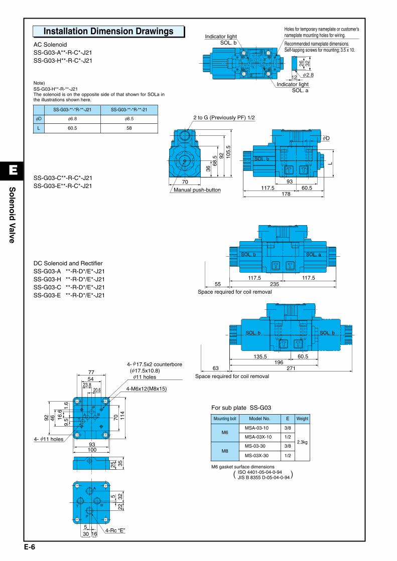
Installation Dimension DrawingsAC SolenoidSS-G03-A**-R-C*-J21SS-G03-H**-R-C*-J21
Note)SS-G03-H**-R-**-J21The solenoid is on the opposite side of that shown for SOLa inthe illustrations shown here.
SS-G03-C**-R-C*-J21SS-G03-E**-R-C*-J21
DC Solenoid and RectifierSS-G03-A **-R-D*/E*-J21SS-G03-H **-R-D*/E*-J21SS-G03-C **-R-D*/E*-J21SS-G03-E **-R-D*/E*-J21
SS-G03-**-*R-**-J21 SS-G03-**-*R-**-21
φD φ6.8 φ8.5
L 60.5 58
For sub plate SS-G03
M6 gasket surface dimensionsISO 4401-05-04-0-94JIS B 8355 D-05-04-0-94( )
A
B
P
T
P
BAT
4- 11 holes
4-M6x12(M8x15)
4- 17.5x2 counterbore ( 17.5x10.8) 11 holes
4-Rc “E”
20.623.8
5477
93100
70 114
1.6
9.516
.64692
522
32
51630
25 35
φφφ
φ
TB
A
P
T 26 32
12 2.8
SOL. b
SOL. a
Indicator light
Indicator light
Holes for temporary nameplate or customer’s nameplate mounting holes for wiring.
Recommended nameplate dimensions.Self-tapping screws for mounting; 3.5 x 10.
φ
SOL. b
Manual push-button
2 to G (Previously PF) 1/2
178
93117.5 60.5
L
3668
.5 92 105.
5
70
Dφ
SOL. b SOL. a
Space required for coil removal 23555
117.5117.5
Space required for coil removal
SOL. b SOL. b
19663
135.5 60.5
271
Mounting bolt Model No. E Weight
M6MSA-03-10 3/8
2.3kgMSA-03X-10 1/2
M8MS-03-30 3/8
MS-03X-30 1/2
E Solenoid Valve(P01-12)_E.q 03.11.21 5:38 PM Page 6
E
E-7
So
leno
id V
alve
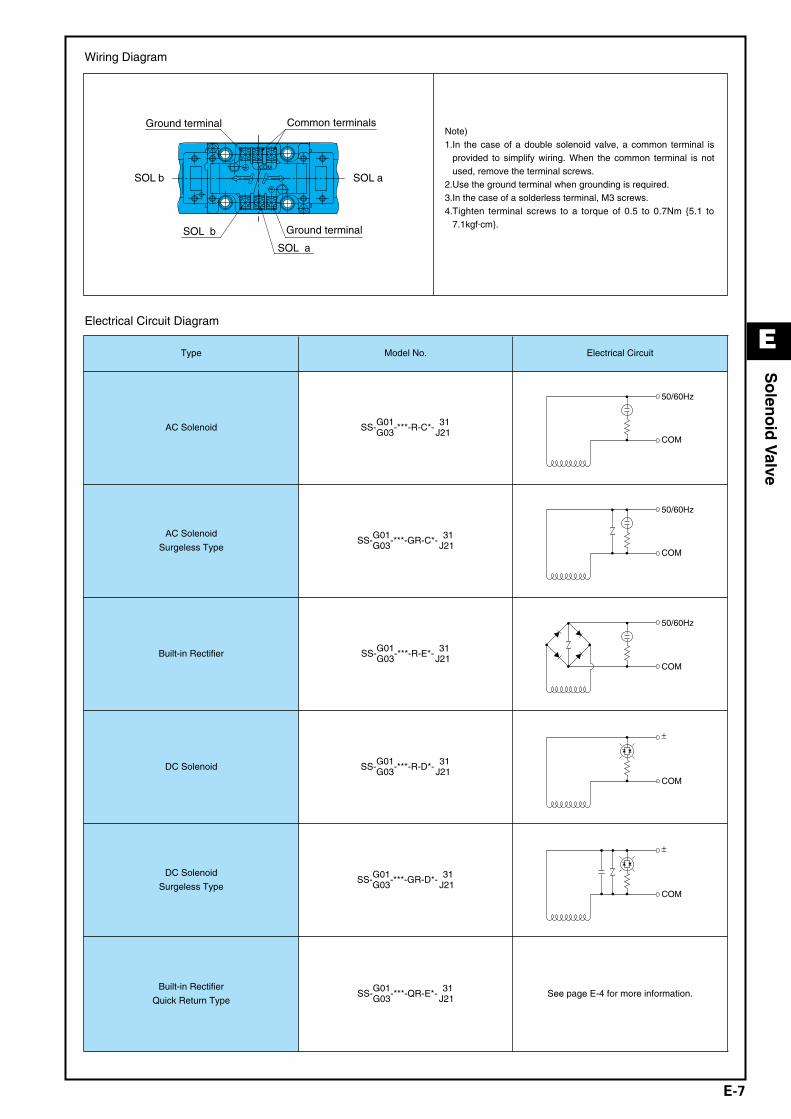
Wiring Diagram
Electrical Circuit Diagram
Note)1.In the case of a double solenoid valve, a common terminal is
provided to simplify wiring. When the common terminal is notused, remove the terminal screws.
2.Use the ground terminal when grounding is required. 3.In the case of a solderless terminal, M3 screws. 4.Tighten terminal screws to a torque of 0.5 to 0.7Nm 5.1 to
7.1kgf.cm.
SOL b SOL aCOM
SOL a
SOL b Ground terminal
Ground terminal Common terminals
Type Model No. Electrical Circuit
AC Solenoid SS-G01G03-***-R-C*- 31
J21
50/60Hz
COM
AC Solenoid
Surgeless TypeSS-G01
G03-***-GR-C*- 31J21
50/60Hz
COM
Built-in Rectifier SS-G01G03-***-R-E*- 31
J21
50/60Hz
COM
DC Solenoid SS-G01G03-***-R-D*- 31
J21
±
COM
DC Solenoid
Surgeless TypeSS-G01
G03-***-GR-D*- 31J21
±
COM
Built-in Rectifier
Quick Return TypeSS-G01
G03-***-QR-E*- 31J21 See page E-4 for more information.
E Solenoid Valve(P01-12)_E.q 03.11.21 5:38 PM Page 7

E
E-8
So
leno
id V
alve
Pressure Loss Characteristics
Switching Response Time
Note) 1.The switching response time changes slightly with operating conditions (pressure, flow rate, viscosity, etc.) 2.In the case of power supply type E* (with built-in rectifier), the spring return time using Quick Return (option symbol: Q) is the same as D*.
Performance Curves Hydraulic Operating Fluid Viscosity 32mm2/s
1008060
2.0
1.6
Flow rate /min
1.2
0.8
MP
a
0.4
20 40
1.8
0
1.4
1.0
0.2
0.6
f e
c
d
b a
kgf/cm2
20.4
16.3
12.2
8.2
4.1
18.4
14.3
10.2
2.0
6.1
2.2
2.4
22.4
24.5
Pre
ssur
e Lo
ss
r
1.6
Flow rate /min
1.2
0.8
MP
a
0.4
200
1.4
1.0
0.2
0.6
kgf/cm2
40 60 80 100 120 140 160
4.1
6.1
8.2
10.2
12.2
14.3
16.3
2
g e d
fc
b
a
Pre
ssur
e Lo
ss
r
PumpType Flow Path P/A P/B A/T B/T P/T
SS-G01
A2X, H2X, E2X d d − − − A3X, H3X b b b b −
E3X b b b b − A3Z, H3Z, E3Z a a a a −
A4, H4, C4 a a a a a
A5, H5, C5, C6S b b b b − C1, C1S b b a b −
C2 a b b b − C6 b b a a −
C7Y f f e e c
C8 a f b e c
C9 a a b b −
PumpType Flow Path P/A P/B A/T B/T P/T
SS-G03
A2X, H2X, E2X e e − − − A5 − c c − − H5 c − − c −
A3X, H3X, E3X c c d d − A3Z, H3Z a a d d −
E3Z b b a a − C1 c c a c − C2 a c c c −
A4, H4, C4 a a a a a
C5, C1S, C6S c c c c − C6 c c a a −
C7Y g g g g f
C8 a g a g f
C9 a a c c −
Model No.Response Time (sec)
Measurement ConditionsSolenoid ON Spring Return
SS-G01-**-R-C*-31
SS-G01-**-(G)R-D*-31
SS-G01-**-R-E*-31
SS-G01-**-F(G)R-D*-31
SS-G01-**-FR-E*-31
0.02 to 0.03
0.03 to 0.04
0.03 to 0.04
0.07 to 0.10
0.07 to 0.10
0.02 to 0.03
0.02 to 0.04
0.07 to 0.10
0.04 to 0.07
0.10 to 0.15
14MPa143kgf/cm2
30r/min
SS-G03-**-R-C*-J21
SS-G03-**-(G)R-D*-J21
SS-G03-**-R-E*-J21
SS-G03-**-F(G)R-D*-J21
SS-G03-**-FR-E*-J21
0.02 to 0.03
0.06 to 0.09
0.07 to 0.10
0.13 to 0.15
0.10 to 0.15
0.02 to 0.03
0.03 to 0.05
0.10 to 0.15
0.08 to 0.15
0.15 to 0.20
14MPa143kgf/cm2
70r/min
E Solenoid Valve(P01-12)_E.q 03.11.21 5:38 PM Page 8

E
E-9
So
leno
id V
alve
Pressure − Flow Volume Allowable Value
I
A
BC
D
EF
G
H
J
K
P
O N
M
L50
40
30
20
10
010
10220
20425
255
Pressure MPa
100
80
60
40
20
010
10230
30635
35720
204
A2X, H2X
E2X
A3X, H3X
E3X
A3Z, H3Z
E3Z
A5
H5
C1, C6
C1S, C5, C6S
C2, C9
A4
H4
C4
C7Y, C8
A2X, H2X
E2X
A3X, H3X
E3X
A3Z, H3Z
E3Z
A5
H5
C1, C6
C1S, C2, C5, C6S, C9
A4, H4
C4
C7Y, C8
K
J
K
J
D
D
−I
I
I
K
F
F
F
K
K
J
K
J
D
D
I
−I
I
K
F
F
F
K
−−L
L
L
L
L
L
M
L
L
L
N
− −B
A
D
D
A
A
Note1) C(E)
A
A
F
F
F
Note2) G(H)
Operation Symbol
Operation Symbol
SS/SA-G01-**-R-**-31
Standard Form, with AC, DC solenoidSize
OperationExample
OperationExample
SS/SA-G01-**-FR-**-31
Shockless Type, with DC solenoidSize
b
T
B a
P
Ab
T
B a
P
Ab a
T
B
P
A b
T
B a
P
Ab
T
B a
P
Ab
T
B a
P
A
P
O
P
O
L
L
−P
P
P
L
L
P
P
O
P
O
L
L
P
−P
P
L
L
P
kgf/cm
Pressure MPakgf/cm
r/m
inF
low
rat
e
r/m
inF
low
rat
e
2
2
Note) 1.Letter in parentheses is for AC solenoid. 2.Letter in parentheses is for solenoid with built-in rectifier (E*), but
without Quick Return, and for DC solenoid (D*) with surge voltageabsorbing diode on the electrical circuit.
E Solenoid Valve(P01-12)_E.q 03.11.21 5:38 PM Page 9

E-10
So
leno
id V
alve
E
Pressure − Flow Volume Allowable Value
Note) 1.Letter in parentheses is for solenoid with built-in rectifier (E*), but without Quick Return, and for DC solenoid (D*) with surge voltage absorbingdiode on the electrical circuit.
2.There is no shockless type for the AC solenoid (C*), so use a solenoid with built-in rectifier (E*) when shockless operation is required with an ACpower supply.
3.The maximum flow rate is the allowable value of each port.
Model No.Standard Form, with AC Solenoid Standard Form, with DC Solenoid
SS-G03-**-R-C*-J21 SS-G03-**-R-**-J21
OperationExample
Operation Symbol
ab
P
BA
T T
A B
P
b a
T
A B
P
b a ab
P
BA
T T
A B
P
b a
T
A B
P
b a
A2X − F E E F
H2X − E F F E
E2X − C C C C
A3X A E E A D F
H3X A E E A F D
A3Z A A C A C C
H3Z A C A A C C
E3X, E3Z A C C A C C
A5 A − D A − E
H5 A D − A E − C1, C1S, C5, C6, C6S A D D A E E
C2 A G D A G E
A4, H4, C4 A A A A A A
C9 A G G A G G
C7Y, C8 B B B Note1) B(H) B(H) B(H)
0 10102
20204
30306
35357
Flo
w r
ate
r/m
in
Pressure MPakgf/cm2
DG
F
20
40
60
80
100
120
140A
B
CE
F
GD
Pressure MPakgf/cm2
Flo
w r
ate
r/m
in
160
140
35357
30306
20204
10102
0
A
60 H
B
40
120
100
E
80
20
C
Model No.Shockless Type, with DC solenoid
SS-G03-**-FR-**-J21
OperationExample
Operation Symbol
ab
P
BA
T T
A B
P
b a
T
A B
P
b a
A2X − E F
H2X − F E
E2X − C C
A3X A D F
H3X A F D
A3Z A C C
H3Z A C C
E3X, E3Z A C C
A5 A − E
H5 A E − C1, C1S, C5, C6, C6S A E E
C2 A G E
A4, H4, C4 A A A
C9 A G G
C7Y, C8 Note1) B(H) B(H) B(H)
F
G
D
Pressure MPakgf/cm2
Flo
w r
ate
r/m
in 100
25255
20204
10102
60
0
A120
H
B
140
80
EC40
20
E Solenoid Valve(P01-12)_E.q 03.11.21 5:38 PM Page 10

E
E-11
So
leno
id V
alve
SS-G01-A**-R-C*-31 SS-G01-C**-R-C*-31
List of Sealing Parts
Note) 1A and 1B are JIS Standard B 2401, while AS568 is SAE standard.
Cross-sectional Drawing
SS-G01-A**-R-D/E*-31 SS-G01-C**-R-D/E*-31
Part
No.Part Name Part Number
Q'ty
SingleSolenoid
DoubleSolenoid
17 O-ring AS568-012(Hs90) 4 4
18 O-ring 1A-P20 1 2
19 O-ring 1B-P18 2 2
20 O-ring S-25 1 2
Part No. Part Name
123456789
10
BodyPlugSpoolRetainer ARetainer BRetainer CSpacerSpring ASpring CNut
Part No. Part Name
11121314151617181920
RodSolenoid guideSolenoid coil PackingTerminal box kitNameplateO-ringO-ringO-ringO-ring
Single Solenoid Double Solenoid
EDCS-A EDCS-C
Seal Kit Number
13 14 15 1620
5 2319 810 11 12 1718 6 41 7
13 14 15 1620
13459 1811 12 17 1019 7
3 11 4
20
618 1710 819 3
161514
2
13
12
20
19 1017
16
11 189 5
151413
4 77 511 12
E Solenoid Valve(P01-12)_E.q 03.11.21 5:38 PM Page 11

E
E-12
So
leno
id V
alve
SS-G03-A**-R-C*-J21 SS-G03-C**-R-C*-J21
List of Sealing Parts
Cross-sectional Drawing
11 9 178 10 7 5 3 1
1819 212 15 1620
46 11 9 178 7 4 3 1
1819 1012 15 1620
6
SS-G03-A**-R-D/E*-J21 SS-G03-C**-R-D/E*-J21
13 46
12 2
911
19 20 15 16 18
1357108 1714 14 378 911
1219 15 16 18
17
20 10
1314 6
Part
No.Part Name
Type/Part Number Q'ty
AC SOL. DC SOL. SingleSolenoid
DoubleSolenoid
17 O-ring AS568-014(Hs90) 5 5
18 O-ring 1B-P28 2 2
19 O-ring 1A-P26 AS568-026 1 2
20 O-ring AS568-029 2 2
Part No. Part Name
123456789
10111213
BodyPlugSpoolRetainerRetainer BSpacerSpringNutRodSolenoid guideSolenoid coil Packing BCoil case
Part No. Part Name
14151617181920
Coil yokeTerminal box kitNameplateO-ringO-ringO-ringO-ring
Seal Kit Number
AC SOL. DC SOL.
Single Solenoid Double Solenoid Single Solenoid Double Solenoid
ECBS-AA ECBS-CA ECBS-AD ECBS-CD
Note) 1A and 1B** indicate JIS Standard B 2401-1A/1B-**.
E Solenoid Valve(P01-12)_E.q 03.11.21 5:38 PM Page 12