ss/264hs/ns 3 2600t series pressure transmitters · 2018-05-09 · data sheet ss/264hs/ns_3 abb...
TRANSCRIPT

Data SheetSS/264HS/NS_3
ABB 2600T SeriesEngineered solutions
for all applications
Base accuracy : ±0.075%
Span limits– 0.65 to 60000kPa; 2.6inH2O to 8700psi– 1.1 to 16000kPa abs; 8mmHg to 2320psia
Reliable sensing system coupled with very latestdigital technologies– provides large turn down ratio up to 100:1
Comprehensive sensor choice– optimize in-use total performance and stability
5–year stability
Flexible configuration facilities– provided locally via local keys combined with LCD
indicator or via hand held terminal orPC configuration platform
Multiple protocol availability– provides integration with HART®, PROFIBUS PA
and FOUNDATION Fieldbus platforms offeringinterchangeability and transmitter upgradecapabilities
Full compliance with PED Category IV– suitable for safety accessory application
FieldIT
2600T Series Pressure Transmitters
Model 264HS GaugeModel 264NS Absolute
high overloadoverpressure up to 90MPa, 13050psi

2600T Pressure TransmittersModel 264HS, 264NS SS/264HS/NS_3
2
Operative limits
Temperature limits °C (°F) :
Ambient (is the operating temperature)
Lower ambient limit for LCD indicators: –20°C (–4°F)
Upper ambient limit for LCD indicators: +70°C (+158°F)
Note : For Hazardous Atmosphere applications see the temperaturerange specified on the certificate/approval relevant to the aimedtype of protection
Process
Lower limit
– refer to lower ambient limits
Upper limit
– Silicone oil: 121°C (250°F) (1)
– Inert fluid (Galden or Halocarbon): 100°C (212°F) (2)
– Inert fluid (Carbon fluoride): 121°C (250°F)
(1) 100°C (212°F) for application below atmospheric pressure
(2) 65°C (150°F) for application below atmospheric pressure
Storage
Lower limit: –50°C (–58°F); –40°C (–40°F) for LCD indicators
Upper limit: +85°C (+185°F)
Span limits
Maximum span = URL
IT IS RECOMMENDED TO SELECT THE TRANSMITTER SENSORCODE PROVIDING THE TURNDOWN VALUE AS LOWEST ASPOSSIBLE TO OPTIMIZE PERFORMANCE CHARACTERISTICS.
Zero suppression and elevation
Zero and span can be adjusted to any value within the range limitsdetailed in the table as long as:
– calibrated span ≥ minimum span
Damping
Selectable time constant : 0, 0.25, 0.5, 1, 2, 4, 8 or 16s.This is in addition to sensor response time
Turn on time
Operation within specification in less than 1s with minimumdamping.
Insulation resistance
> 100MΩ at 1000VDC (terminals to earth)
Functional Specifications
Range and span limits
rosneSedoC
egnaRreppU)LRU(timiL
egnaRrewoL)LRL(timiL
napsmuminiM
SH462eguag
SN462etulosba
GaPk56
rabm056Hni062 2O
sbaaPk70.0sbarabm7.0
gHmm5.0
aPk56.0rabm5.6
Hni6.2 2O
aPk1.1rabm11gHmm8
HaPk061
rabm0061Hni246 2O
sbaaPk70.0sbarabm7.0
gHmm5.0
aPk6.1rabm61
Hni4.6 2O
aPk76.2rabm7.62
gHmm02
MaPk006
rab6isp78
sbaaPk70.0sbarabm7.0
gHmm5.0
aPk6rab60.0isp78.0
aPk01rab1.0isp54.1
PaPk0042
rab42isp843
sbaaPk70.0sbarabm7.0
gHmm5.0
aPk42rab42.0
isp5.3
aPk04rab4.0isp8.5
QaPk0008
rab08isp0611
sbaaPk70.0sbarabm7.0
gHmm5.0
aPk08rab8.0isp6.11
aPk431rab43.1isp4.91
SaPk00061
rab061isp0232
sbaaPk70.0sbarabm7.0
gHmm5.0
aPk061rab6.1isp2.32
aPk762rab76.2isp7.83
VaPk00006
rab006isp0078
sbaaPk70.0sbarabm7.0
gHmm5.0
aPk006rab6isp78
gnilliFSH462ledoM SN462ledoM
SotGsrosneS VrosneS SotGsrosneS
lioenociliS58+dna04–
)581+dna04–(58+dna04–
)581+dna04–(58+dna04–
)581+dna04–(trenI
nedlaG58+dna02–)581+dna4–(
56+dna01–)051+dna41+(
trenInobracolaH
58+dna02–)581+dna4–(
56+dna01–)051+dna41+(
trenIediroulFnobraC
58+dna02–)581+dna4–(

2600T Pressure TransmittersModel 264HS, 264NS SS/264HS/NS_3
3
Pressure limits
Overpressure limits (without damage to the transmitter)
0.067kPa abs, 0.67mbar abs, 0.01psia (double with inert filling) to
– 21MPa, 210bar, 3045psi for sensor codes G to S
– 90MPa, 900bar, 13050psi for sensor code V
Proof pressure
The transmitter can be exposed without leaking to line pressure of up to
– 40MPa, 400bar, 5800psi for sensor codes G to S
– 90MPa, 900bar, 13050psi for sensor code V
Meet ANSI/ISA–S 82.03 hydrostatic test requirements and SAMA PMC27.1.
Environmental limits
Electromagnetic compatibility (EMC)
Comply with EN 61000–6–3 for emission and EN 61000–6–2 forimmunity requirements and test;
Radiated electromagnetic immunity level: 30V/m(according to IEC 1000–4–3, EN61000–4–3)
Conducted electromagnetic immunity level : 30V(according to IEC 1000–4-6, EN 61000–4–6)
Surge immunity level (with surge protector): 4kV(according to IEC 1000-4–5 EN 61000–4–5)
Fast transient (Burst) immunity level: 4kV(according to IEC 1000–4–4 EN 61000–4–4)
Pressure equipment directive (PED)
Comply with 97/23/EEC Category IV Modules D and B.
(Category III Module H for sensor code V).
Humidity
Relative humidity: up to 100% annual average
Condensing, icing: admissible
Vibration resistance
Accelerations up to 2g at frequency up to 1000Hz(according to IEC 60068–2–26)
Shock resistance
Acceleration: 50g
Duration: 11ms
(according to IEC 60068–2–27)
Wet and dust-laden atmospheres
The transmitter is dust and sand tight and protected against immersioneffects as defined by EN 60529 (1989) to IP 67 (IP 68 on request) or byNEMA to 4X or by JIS to C0920.
Hazardous atmospheres
With or without output meter/integral display– INTRINSIC SAFETY/EUROPE:
ATEX/ZELM approvalII 1 GD T50°C, EEx ia IIC T6 (–40°C ≤ Ta ≤+40°C)T95°C, EEx ia IIC T4 (–40°C ≤ Ta ≤+85°C)
– TYPE "N"/EUROPE:ATEX/ZELM type examination (for HART)II 3 GD T50°C, EEx nL IIC T6 (–40°C ≤ Ta ≤+40°C)
T95°C, EEx nL IIC T4 (–40°C ≤ Ta ≤+85°C)(FOUNDATION Fieldbus/PROFIBUS PA): pending
– FLAMEPROOF/EUROPE:ATEX/CESI approvalII 1/2 GD T85°C, EEx d IIC T6 (–40°C ≤ Ta ≤ +75°C)
– CANADIAN STANDARDS ASSOCIATIONand FACTORY MUTUAL:– Explosionproof: Class I, Div. 1, Groups A, B, C, D– Dust ignitionproof : Class II, Div. 1, Groups E, F, G– Suitable for : Class II, Div. 2, Groups F, G; Class III, Div. 1, 2– Nonincendive: Class I, Div. 2, Groups A, B, C, D– Intrinsically safe: Class I, II, III, Div. 1, Groups A, B, C, D, E, F, G
AEx ia IIC T6/T4, Zone 0 (FM)– STANDARDS AUSTRALIA (SAA): pending
TS/WCA ApprovalEx d IIC T5 (Tamb +85°C)/T6 (Tamb +70°C) Class 1 Zone 1;Ex ia IIC T4 (Tamb +85°C) /T5 (Tamb +55°C) T6 Class 1 Zone 0

2600T Pressure TransmittersModel 264HS, 264NS SS/264HS/NS_3
4
Optional surge protection
Up to 4kV
– voltage 1.2µs rise time / 50µs delay time to half value
– current 8µs rise time / 20µs delay time to half value
Output signal
Two–wire 4 to 20mA, user-selectable for linear or 5th order or two 2ndorder switching point selectable programmable polynomial output.
HART® communication provides digital process variable (%, mA orengineering units) superimposed on 4 to 20mA signal, with protocolbased on Bell 202 FSK standard.
Output current limits (to NAMUR standard)
Overload condition
- Lower limit: 3.8mA
- Upper limit: 20.5mA
Transmitter failure mode (to NAMUR standard)
The output signal can be user-selected to a value of 3.7 or 22mA ongross transmitter failure condition, detected by self-diagnostics.
In case of CPU failure the output is driven <3.7mA or >22mA.
Electrical Characteristics and Options
HART digital communication and 4 to 20mA output
Power Supply
The transmitter operates from 10.5 to 42VDC with no load and isprotected against reverse polarity connection (additional load allowsoperations over 42VDC).
For EEx ia and other intrinsically safe approval power supply mustnot exceed 30VDC.
Ripple
20mV max on a 250Ω load as per HART specifications
Load limitations
4 to 20mA and HART total loop resistance :
A minimum of 250Ω is required for HART communication.
Optional indicators
Output meter
CoMeter and Prometer LCD :
5-digit (±99999 counts) programmable with 7.6mm. high (3in),7-segment numeric characters plus sign and digital point for digitalindication of output value in percentage, current or engineer unit;
10-segment bargraph display (10% per segment) for analogindication of output in percentage;
7-digit with 6mm. high (2.3in), 14-segment alphanumericcharacters, for engineer units and configuration display
Analog : 36mm (1.4in) scale on 90°.
Integral display
LCD, 15 lines x 56 column dot matrix providing 2 lines indication as
– top: 5-digit (numeric) plus sign or 7-digit alphanumeric
– bottom: 7-digit alphanumeric
and additional 50-segment bargraph for indication of analog outputin percentage.
User-definable matrix display mode with HART communication:
– process variable in pressure unit or
– output signal as percentage, current or engineering units
Display also indicates in/out transfer function, static pressure, sensortemperature and diagnostic messages and provides configurationfacilities.
R(kΩ) =Supply voltage – min. operating voltage (VDC)–––––––––––––––––––––––––––––––––––––––
22.5
(volts)
MINIMUM OPERATING VOLTAGES
10.5
with integral display
with optional output analog indicator
with optional surge protection
with ProMeter output indicator
10.7 12.3 12.5
no link on output indicator plugs
15.3
with CoMeter indicator and HART communication
13.3

2600T Pressure TransmittersModel 264HS, 264NS SS/264HS/NS_3
5
PROFIBUS PA output
Device type
Pressure transmitter compliant to Profiles 3.0 Class A & B; ident.number 052B HEX.
Power supply
The transmitter operates from 10.5 to 32VDC , polarity independent.
For EEx ia approval power supply must not exceed 17.5VDC.Intrinsic safety installation according to FISCO model.
Current consumptionoperating (quiescent): 10.5mA
fault current limiting: 20mA max.
Output signal
Physical layer in compliance to IEC 1158–2/EN 61158–2 withtransmission to Manchester II modulation, at 31.25kbit/sec.
Output interface
PROFIBUS PA communication according to Profibus DP50170 Part 2/DIN 19245 part 1–3.
Output update time
25ms
Function blocks
2 analog input, 1 transducer, 1 physical
Integral display
LCD, 15 lines x 56 column dot matrix providing 2 lines indication as
– top: 5-digit (numeric) plus sign or 7-digit alphanumeric
– bottom: 7-digit alphanumeric
and additional 50-segment bargraph for indication of output inpercentage of the analog input function block assigned to the primaryvariable.
User-definable matrix display mode:
– process variable in pressure units or
– primary variable in engineering units (output of transducer block) or
– output as percentage or engineering units of analog input functionblocks
Display also indicates diagnostic messages and providesconfiguration facilities.Secondary variable, static pressure and sensor temperature can beread.
Transmitter failure mode
On gross transmitter failure condition, detected by self-diagnostics,the output signal can be driven to defined conditions, selectable by theuser as safe, last valid or calculated value. If electronic failure or shortcircuit occur the transmitter consumption is electronically limited at adefined value (20mA approx), for safety of the network.
FOUNDATION Fieldbus output
Device type
LINK MASTER DEVICE
Link Active Scheduler (LAS) capability implemented.
Power supply
The transmitter operates from 9 to 32VDC, polarity independent.
For EEx ia approval power supply must not exceed 24VDC (entitycertification) or 17.5VDC (FISCO certification), according to FF–816.
Current consumption
operating (quiescent): 10.5mA
fault current limiting: 20mA max.
Output signal
Physical layer in compliance to IEC 1158–2/EN 61158–2 withtransmission to Manchester II modulation, at 31.25kbit/sec.
Function blocks/execution period
2 standard Analog Input blocks/25ms max (each)
1 standard PID block/70ms max.
Additional blocks
1 standard Resource block,
1 custom Pressure with calibration transducer block.
Number of link objects25
Number of VCRs
24
Output interface
FOUNDATION fieldbus digital communication protocol to standard H1,compliant to specification V. 1.5; FF registration number IT019000.
Integral display
LCD, 15 lines x 56 column dot matrix providing 2 lines indication as
– top: 5-digit (numeric) plus sign or 7-digit alphanumeric
– bottom: 7-digit alphanumeric
and additional 50-segment bargraph for indication of output inpercentage of the analog input function block assigned to the primaryvariable.
User-definable matrix display mode:
– process variable in pressure units or
– primary variable in engineering units (output of transducer block) or
– output as percentage or engineering units of analog input functionblocks
Display also indicates diagnostic messages and providesconfiguration facilities.Secondary variable, static pressure and sensor temperature can beread.
Transmitter failure mode
The output signal is "frozen" to the last valid value on gross transmitterfailure condition, detected by self-diagnostics which also indicate aBAD conditions. If electronic failure or short circuit occur the transmitterconsumption is electronically limited at a defined value (20mA approx),for safety of the network.

2600T Pressure TransmittersModel 264HS, 264NS SS/264HS/NS_3
6
Operating influences
Ambient temperature
per 20K (36°F) change between the limits of –20°C to +65°C (–4 to+150°F) :
Optional CoMeter and ProMeter ambient temperature
Total reading error per 20K (36°F) change between the ambient limitsof –20 and +70°C (-4 and +158°F) :
±0.15% of max span (16mA).
Supply voltage
Within voltage/load specified limits the total effect is less than0.005% of URL per volt.
Load
Within load/voltage specified limits the total effect is negligible.
Radio frequency interference
Total effect : less than 0.10% of span from 20 to 1000MHz and forfield strengths up to 30V/m when tested with shielded conduit andgrounding, with or without meter.
Common mode interference
No effect from 100Vrms @ 50Hz, or 50VDC
Mounting position
No effect
Stability
±0.10% of URL over a thirty-six-month period
Vibration effect
±0.10% of URL (according to IEC 61298–3)
URLSpan
URLSpan
Performance specificationsStated at reference condition to IEC 60770 ambient temperature of 20°C(68°F), relative humidity of 65%, atmospheric pressure of 1013hPa(1013mbar), zero based range for transmitter with isolating diaphragms inAISI 316 L ss or Hastelloy and silicone oil fill and HART digital trim valuesequal to 4–20mA span end points, in linear mode.
Unless otherwise specified, errors are quoted as % of span.
Some performance data are affected by the actual turndown (TD) as ratiobetween Upper Range Limit (URL) and calibrated span.
IT IS RECOMMENDED TO SELECT THE TRANSMITTER SENSOR CODEPROVIDING THE TURNDOWN VALUE AS LOWEST AS POSSIBLE TOOPTIMIZE PERFORMANCE CHARACTERISTICS.
Dynamic performance (according to IEC 61298–1 definition)
Dead time: 40ms
Time constant (63.2% of total step change):
– sensor V: 150ms
– sensors M to S: ≤ 70ms
– sensor H: 100ms
– sensor G: 130ms
Response time (total) = dead time + time constant
Accuracy rating% of calibrated span, including combined effects of terminal basedlinearity, hysteresis and repeatability.
For fieldbus versions SPAN refer to analog input function block outscalerange
Model 264HS
– ±0.075% for TD from 1:1 to 15:1
– ±0.005% x for TD from 15:1 to 60:1
Model 264NS
– ±0.075% for TD from 1:1 to 10:1
– ±0.0075% x for TD from 10:1 to 20:1
ledoMrosneS
edoCDTrofotpu
SH462 VotG 1:51 )naps%560.0+LRU%40.0(±
SN462 SotG 1:01 )naps%560.0+LRU%40.0(±

2600T Pressure TransmittersModel 264HS, 264NS SS/264HS/NS_3
7
Physical Specification(Refer to ordering information sheets for variant availability related tospecific model or versions code)
Materials
Process isolating diaphragms (*)
AISI 316 L ss; Hastelloy C276™; Monel 400™;Tantalum;
Hastelloy C276™ on AISI 316 L ss gasket seat.
Process connection (*)
AISI 316 L ss; Hastelloy C276™; Monel 400™.
Sensor fill fluid
Silicone oil (DC200);
inert fill (Halocarbon 4.2™ or Galden™; carbon fluoride for sensor V)
Mounting bracket (**)
Zinc plated carbon steel with chrome passivation;
AISI 316 L ss.
Sensor housing
AISI 316 L ss.
Electronic housing and covers
Barrel version
– Copper-free content aluminium alloy with baked epoxy finish;
– Low-copper content aluminium alloy with baked epoxy finish;
– AISI 316 L ss.
Covers O-ring
Buna N.
Local zero and span adjustments:
Glass filled polycarbonate plastic (removable).
Tagging
AISI 316ss data plate attached to the electronics housing.
CalibrationStandard: at maximum span, zero based range, ambient temperatureand pressure;
Optional: at specified range and ambient conditions.
Optional extras
Mounting brackets
For 60mm. (2in) pipes or wall mounting.
Output indicator
plug-in rotatable type, LCD or analog.
Supplemental customer tag
AISI 316 ss tag screwed/fastened to the transmitter for customer's tagdata up to a maximum of 20 characters and spaces on one line for tagnumber and tag name, and up to a maximum of 3 spaced strings of 10characters each for calibration details (lower and upper values plusunit). Special typing evaluated on request for charges.
Surge protection (only as external unit for PROFIBUS PA and FF)
Cleaning procedure for oxygen service
Test Certificates (test, design, calibration, material traceability)
Tag and manual language
Communication connectors
Process connections1/2in NPT female or male; DIN EN837–1 G 1/2in B; adapter straight (180°)entry; adapter angle (90°) entry.
fixing threads on adapter entries: 7/16in–20 UNF at 41.3mm centredistance.
Electrical connectionsTwo 1/2 NPT or M20x1.5 or PG 13.5 or 1/2 GK threaded conduitentries, direct on housing.
Special communication connector (on request)
– HART : straight or angle Harting Han connector and one plug.
– FOUNDATION Fieldbus, PROFIBUS PA: M12x1 or 7/8.
Terminal block
HART version: three terminals for signal/external meter wiring up to2.5mm2 (14AWG) and three connection points for test andcommunication purposes.
Fieldbus versions: two terminals for signal wiring (bus connection)up to 2.5mm2 (14AWG)
Grounding
Internal and external 6mm2 (10AWG) ground termination points areprovided.
Mounting positionTransmitter can be mounted in any position.Electronics housing may be rotated to any position. A positive stopprevents over travel.
Mass (without options)1.7kg approx (4lb); add 1.5kg (3.4lb) for AISI housing.Add 650g (1.5lb) for packing.
PackingCarton 26 x 26 x 18cm approx (10 x 10 x 7in).

2600T Pressure TransmittersModel 264HS, 264NS SS/264HS/NS_3
8
ConfigurationTransmitter with HART communication and 4 to 20 mA
Standard configuration
Transmitters are factory calibrated to customer's specified range.Calibrated range and tag number are stamped on the tag plate. If acalibration range and tag data are not specified, the transmitter will besupplied with the plate left blank and configured as follows:
Engineering Unit Specify from table4 mA Zero20 mA Upper Range Limit (URL)Output LinearDamping 1 sec.Transmitter failure mode UpscaleSoftware tag characters BlankOptional LCD indicator/display 0 to 100.0% linear
Any or all the above configurable parameters, including Lower range–valueand Upper range-value which must be the same unit of measure, can beeasily changed using the HART hand–held communicator or by a PCrunning the configuration software SMART VISION with DTM for 2600T.The transmitter database is customized with specified flange type andmaterial, O–ring and drain/vent materials and meter code option.Custom configuration (option)The following data may be specified in addition to the standardconfiguration parameters:
Descriptor 16 alphanumeric charactersMessage 32 alphanumeric charactersDate Day, month, year
Transmitter with PROFIBUS PA communicationTransmitters are factory calibrated to customer's specified range.Calibrated range and tag number are stamped on the tag plate. If acalibration range and tag data are not specified, the transmitter will besupplied with the plate left blank and configured as follows:
Measure Profile PressureEngineering Unit kPaOutput scale 0% Lower Range Limit (LRL)Output scale 100% Upper Range Limit (URL)Output LinearHi-Hi Limit Upper Range Limit (URL)Hi Limit Upper Range Limit (URL)Low Limit Lower Range Limit (LRL)Low-Low Limit Lower Range Limit (LRL)Limits hysteresis 0.5% of output scalePV filter 0 sec.Address (settable by local key) 126Tag 32 alphanumeric characters
Any or all the above configurable parameters, including Lower range-valueand Upper range–value which must be the same unit of measure, can beeasily changed by a PC running the configuration software SMART VISIONwith DTM for 2600T. The transmitter database is customized with specified flange type andmaterial, O–ring and drain/vent materials and meter code option.Custom configuration (option)The following data may be specified in addition to the standardconfiguration parameters:
Descriptor 32 alphanumeric charactersMessage 32 alphanumeric charactersDate Day, month, year
Transmitter with FOUNDATION FieldbuscommunicationTransmitters are factory calibrated to customer's specified range.Calibrated range and tag number are stamped on the tag plate. If acalibration range and tag data are not specified, the transmitter will besupplied with the plate left blank and the analog input function block FB1is configured as follows:
Measure Profile PressureEngineering Unit kPaOutput scale 0% Lower Range Limit (LRL)Output scale 100% Upper Range Limit (URL)Output LinearHi-Hi Limit Upper Range Limit (URL)Hi Limit : Upper Range Limit (URL)Low Limit Lower Range Limit (LRL)Low-Low Limit Lower Range Limit (LRL)Limits hysteresis 0.5% of output scalePV filter time 0 sec.Tag 32 alphanumeric characters
The analog input function block FB2 is configured for the sensor tempe-rature measured in °C. Any or all the above configurable parameters,including the range values, can be changed using any host compliant toFOUNDATION fieldbus. The transmitter database is customized withspecified flange type and material, O–ring and drain/vent materials andmeter code option.
For any protocol available engineering units of pressure measure are :Pa, kPa, MPainH2O@4°C, mmH2O@4°C, psiinH2O@20°C, ftH2O@20°C, mmH2O@20°CinHg, mmHg, Torrg/cm2, kg/cm2, atmmbar, bar
™ Hastelloy is a Cabot Corporation trademark
™ Monel is an International Nickel Co. trademark
™ DC 200 is a Dow Corning Corporation trademark
™ Galden is a Montefluos trademark
™ Halocarbon is a Halocarbon Products Co. trademark
(*) Wetted parts of the transmitter.
(**) U-bolt material: AISI 400 ss; screws material: high-strength alloy steel orAISI 316 ss.

2600T Pressure TransmittersModel 264HS, 264NS SS/264HS/NS_3
9
18 (0
.71)
100
(3.9
4)ø 65 (2.56)
135 (5.31)
16 (0
.63)
57 (2.24)
127 (5.00)
17 (0.67)26 (1.02)
17 (0.67)36 (1.42)
19 (0
.75)
36 (1
.42)
MOUNTING DIMENSIONS (not for construction unless certified) – dimensions in mm (in)Transmitter with barrel housing on bracket for 60mm (2in) pipe mounting
Certificationlabel
Identification tagAdjustments
Terminalside
Electronicside
Integraldisplayhousing
Min. clearanceto removethe cover
Output meterhousing
Electricalconnections
1/2in – 14 NPT female connection for sensors G, H, M, P, Q, S
86 (3.39)
CH 32
S
NOSSTIUCRIC
SEL
NOI
NETS
OST U
RREV
UOCE
LRE
DRAG
TNE' M
EF NE BELCI
QUAT
E
ALSTIUCRI
C
IVE
H
COPE
EK
VERTIGT
E
H
WN
!
Covers lockingscrew
Certificationlabel
Identification tagAdjustments
Terminalside
Electronicside
Integraldisplayhousing
Min. clearanceto removethe cover
Output meterhousing
Electricalconnections
1/2in – 14 NPT female connection for sensor V (NOT FOR 264NS)
Covers lockingscrew
100
(3.9
4)
56 (2.20)
135 (5.31)
50 (1
.97)
127 (5.00)
17 (0.67)26 (1.02)
17 (0.67)36 (1.42)
86 (3.39)
CH27
S
NOSSTIUCRIC
SEL
NOI
NETS
OST U
RREV
UOCE
LRE
DRAG
TNE' M
EF NE BELCI
QUAT
E
ALSTIUCRI
C
IVE
H
COPE
EK
VERTIGT
E
H
WN
!

2600T Pressure TransmittersModel 264HS, 264NS SS/264HS/NS_3
10
Electricalconnections
Covers lockingscrew
Certificationlabel
Identification tagAdjustments
Terminalside
Electronicside
Integraldisplayhousing
Min. clearanceto removethe cover
Output meterhousing
DIN–EN837–1 G 1/2in B connection for sensors G, H, M, P, Q, S
86 (3.39)
CH 32
S
NOSSTIUCRIC
SEL
NOI
NETS
OST U
RREV
UOCE
LRE
DRAG
TNE' M
EF NE BELCI
QUAT
E
ALSTIUCRI
C
IVE
H
COPE
EK
VERTIGT
E
H
WN
!
18 (0
.71)
100
(3.9
4)
135 (5.31)
16 (0
.63)
G 1/2"B
57 (2
.24)
42 (1
.65)
ø 17.5 (0.69)
ø 65 (2.56)
57 (2.24)
127 (5.00)
17 (0.67)26 (1.02)
17 (0.67)36 (1.42)
Certificationlabel
Identification tagAdjustments
Terminalside
Electronicside
Integraldisplayhousing
Min. clearanceto removethe cover
Output meterhousing
Electricalconnections
Covers lockingscrew
100
(3.9
4)
56 (2.20)
135 (5.31)
58 (2
.28)
127 (5.00)
17 (0.67)26 (1.02)
17 (0.67)36 (1.42)
86 (3.39)
CH22
S
NOSSTIUCRIC
SEL
NOI
NETS
OST U
RREV
UOCE
LRE
DRAG
TNE' M
EF NE BELCI
QUAT
E
ALSTIUCRI
C
IVE
H
COPE
EK
VERTIGT
E
H
WN
!
G 1/2" B
DIN–EN837–1 G 1/2in B connection for sensor V (NOT FOR 264NS)

2600T Pressure TransmittersModel 264HS, 264NS SS/264HS/NS_3
11
Certificationlabel
Identification tagAdjustments
Terminalside
Electronicside
Integraldisplayhousing
Min. clearanceto removethe cover
Output meterhousing
Electricalconnections
Covers lockingscrew
86 (3.39)
CH 32
S
NOSSTIUCRIC
SEL
NOI
NETS
OST U
RREV
UOCE
LRE
DRAG
TNE' M
EF NE BELCI
QUAT
E
ALSTIU
CRIC
IVE
H
COPE
EK
VERTIGT
E
H
WN
!
1/2 in – 14 NPT male connection for sensors G, H, M, P, Q, S
Electricalconnections
Covers lockingscrew
Certificationlabel
Identification tagAdjustments
Terminalside
Electronicside
Integraldisplayhousing
Min. clearanceto removethe cover
Output meterhousing
1/2 in – 14 NPT male connection for sensor V (NOT FOR 264NS)
100
(3.9
4)
135 (5.31)
55 (2
.17)
127 (5.00)
17 (0.67)26 (1.02)
17 (0.67)36 (1.42)
56 (2.20)
86 (3.39)
CH22
S
NOSSTIUCRIC
SEL
NOI
NETS
OST U
RREV
UOCE
LRE
DRAG
TNE' M
EF NE BELCI
QUAT
E
ALSTIUCRI
C
IVE
H
COPE
EK
VERTIGT
E
H
WN
!
18 (0
.71)
100
(3.9
4)135 (5.31)
16 (0
.63)
1/2" - 14 NPT
ø 65 (2.56)
57 (2.24)
127 (5.00)
17 (0.67)26 (1.02)
17 (0.67)36 (1.42)
39 (1
.54)
54 (2
.13)
2600T Pressure TransmittersModel 264HS, 264NS SS/264HS/NS_3
12
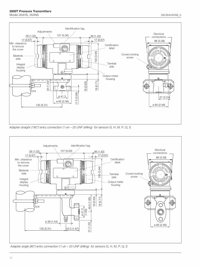
Adapter angle (90°) entry connection (7/16in – 20 UNF drilling) for sensors G, H, M, P, Q, S
18 (0
.71)
100
(3.9
4)
49.5
(1.9
5)
ø 41
.3(1
.63)
ø 39 (1.54)
135 (5.31)
31 (1
.22)
127 (5.00)
17 (0.67)26 (1.02)
17 (0.67)36 (1.42)
16 (0
.63)
42.5 (1.67)
86 (3.39)
S
NOSSTIUCRIC
SEL
NOI
NETS
OST U
RREV
UOCE
LRE
DRAG
TNE' M
EF NE BELCI
QUAT
E
ALSTIU
CRIC
IVE
H
COPE
EK
VERTIGT
E
H
WN
!
ø 65 (2.56)
Electricalconnections
Covers lockingscrew
Certificationlabel
Identification tagAdjustments
Terminalside
Electronicside
Integraldisplayhousing
Min. clearanceto removethe cover
Output meterhousing
Adapter straight (180°) entry connection (7/16in – 20 UNF drilling) for sensors G, H, M, P, Q, S
Certificationlabel
Identification tagAdjustments
Terminalside
Electronicside
Integraldisplayhousing
Min. clearanceto removethe cover
Output meterhousing
Electricalconnections
Covers lockingscrew
18 (0
.71)
100
(3.9
4)
16 (0
.63)
ø 41.3
ø 65 (2.56)135 (5.31) 17
.5 (0
.69)
127 (5.00)
17 (0.67)26 (1.02)
17 (0.67)36 (1.42)
34 (1
.34)
86 (3.39)
S
NOSSTIUCRIC
SEL
NOI
NETS
OST U
RREV
UOCE
LRE
DRAG
TNE' M
EF NE BELCI
QUAT
E
ALSTIU
CRIC
IVE
H
COPE
EK
VERTIGT
E
H
WN
!
57 (2.24)
ø 65 (2.56)
2600T Pressure TransmittersModel 264HS, 264NS SS/264HS/NS_3
13
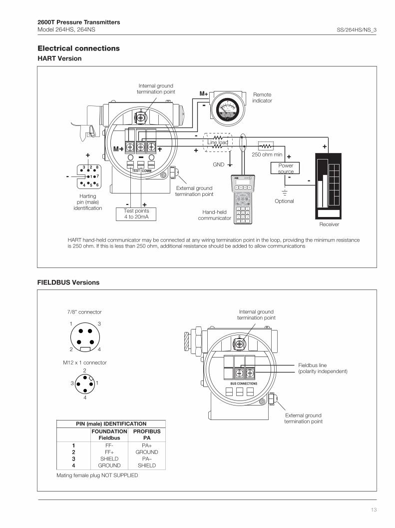
Electrical connectionsHART Version
FIELDBUS Versions
+
+
-
-
++
--691HT
A B C
1
D E F
2
G H I
3
J K L
4
M N O
5
P Q R
6
S T U
7
V W X
8
Y Z #
9
@ % & /
0
+-
PV
REVIEW SERIALLINK
TRIM
F1 F2 F3 F4
CONF
M
Kent-Taylor
0
43
56 7 8
9
1020
40
0
60
100%
2 80
M+
-
- 1
54 6
23 8
7
+
TEST COMM
Internal groundtermination point
Fieldbus line(polarity independent)
External groundtermination point
Test points4 to 20mA
Hartingpin (male)
identification
Internal groundtermination point
External groundtermination point
Hand-heldcommunicator
GND
Line load
Remoteindicator
Powersource
250 ohm min
Receiver
HART hand-held communicator may be connected at any wiring termination point in the loop, providing the minimum resistanceis 250 ohm. If this is less than 250 ohm, additional resistance should be added to allow communications
Optional
BUS CONNECTIONS
2
1
4
3
1 3
42
7/8” connector
M12 x 1 connector
NOITACIFITNEDI)elam(NIPNOITADNUOF
subdleiFSUBIFORP
AP11111222223333344444
-FF+FF
DLEIHSDNUORG
+APDNUORG
–APDLEIHS
Mating female plug NOT SUPPLIED

2600T Pressure TransmittersModel 264HS, 264NS SS/264HS/NS_3
14
BASIC ORDERING INFORMATION model 264HS Gauge Pressure TransmitterSelect one character or set of characters from each category and specify complete catalog number.Refer to additional ordering information code and specify one or more codes for each transmitter if additional options are required.
LEDOMESAB 1– ts 5ot ht sretcarahc 2 6 4 H S X X X X X
%570.0YCARUCCAESAB–rettimsnarTerusserPeguaG
–stimilnapS-ROSNES 6 ht retcarahcaPk56dna56.0aPk061dna6.1
aPk006dna6aPk0042dna42aPk0008dna08
aPk00061dna061aPk00006dna006
rabm056dna5.6rabm0061dna61
rab6dna60.0rab42dna42.0
rab08dna8.0rab061dna6.1
rab006dna6
Hni062dna6.2 2OHni246dna4.6 2Oisp78dna78.0isp843dna5.3
isp0611dna6.11isp0232dna2.32
isp0078dna78
GHMPQSV
)strapdettew(diulflliF/lairetammgarhpaiD 7– ht retcarahcssL613ISIA
)taesISIAno(™672CyolletsaH™672CyolletsaH
™004lenoMmulatnaT
ssL613ISIA)taesISIAno(™672CyolletsaH
™672CyolletsaH™004lenoM
mulatnaTssL613ISIA
)taesISIAno(™672CyolletsaH™672CyolletsaH
™004lenoMmulatnaT
lioenociliSlioenociliSlioenociliSlioenociliSlioenociliS
nedlaG-diulftrenInedlaG-diulftrenI
)VrosnesrofediroulfnobraC(nedlaG-diulftrenInedlaG-diulftrenInedlaG-diulftrenI
nobracolaH-diulftrenInobracolaH-diulftrenInobracolaH-diulftrenInobracolaH-diulftrenInobracolaH-diulftrenI
)2etoN()2etoN(
)2etoN()2etoN(
)2,1setoN()2,1setoN(
)1etoN()2,1setoN()2,1setoN()2,1setoN()2,1setoN()2,1setoN()2,1setoN()2,1setoN(
ECANECANECANECAN
ECANECANECANECAN
ECANECANECANECAN
SHKMTABFCDLQP45
)strapdettew(lairetamnoitcennocssecorP – 8 ht retcarahc
ssL613ISIAssL613ISIAssL613ISIAssL613ISIAssL613ISIA
™672CyolletsaH™672CyolletsaH™672CyolletsaH™672CyolletsaH™672CyolletsaH
™004lenoM™004lenoM™004lenoM
1/2 elamefTPNni1/2 elamTPNni
G1–738NENID 1/2 Bni)tekcarbrofelbaliavaton(yrtne)°081(thgiartsretpadA
yrtne)°09(elgnaretpadA1/2 elamefTPNni1/2 elamTPNni
G1–738NENID 1/2 Bni)tekcarbrofelbaliavaton(yrtne)°081(thgiartsretpadA
yrtne)°09(elgnaretpadA1/2 elamefTPNni1/2 elamTPNni
G1–738NENID 1/2 Bni
)3etoN()3etoN()3etoN(
)3,2setoN()3,2setoN(
)4etoN()4etoN()4etoN(
)4,2setoN()4,2setoN(
)5etoN()5etoN()5etoN(
ECANECANECANECANECANECANECANECANECANECANECANECANECAN
BTPANEKDFC123
noitcennoclacirtcelednalairetamgnisuoH 9– ht retcarahc
)noisrevlerraB(yollamuinimulA)noisrevlerraB(yollamuinimulA)noisrevlerraB(yollamuinimulA)noisrevlerraB(yollamuinimulA)noisrevlerraB(yollamuinimulA)noisrevlerraB(yollamuinimulA
1/2 TPNni)02MC(5.1x02M
5.31gP1/2 KGni
rotcennocnaHgnitraHrotcennocsubdleiF
)ylnoesopruplareneg()6etoN()ylnoesopruplareneg()6etoN(
ABDCEG
)noisrevlerraB(eerf-reppocyollamuinimulA)noisrevlerraB(eerf-reppocyollamuinimulA)noisrevlerraB(eerf-reppocyollamuinimulA)noisrevlerraB(eerf-reppocyollamuinimulA)noisrevlerraB(eerf-reppocyollamuinimulA)noisrevlerraB(eerf-reppocyollamuinimulA
1/2 TPNni)02MC(5.1x02M
5.31gP1/2 KGni
rotcennocnaHgnitraHrotcennocsubdleiF
)ylnoesopruplareneg()6etoN()ylnoesopruplareneg()6etoN(
HLNMPR
)noisrevlerraB(ssL613ISIA)noisrevlerraB(ssL613ISIA)noisrevlerraB(ssL613ISIA)noisrevlerraB(ssL613ISIA)noisrevlerraB(ssL613ISIA
1/2 TPNni)02MC(5.1x02M
5.31gP1/2 KGni
rotcennocsubdleiF )ylnoesopruplareneg()6etoN(
STVUZ
snoitpolanoitiddA/tuptuO 01– ht retcarahc
Am02ot4dnanoitacinummoclatigidTRAHAm02ot4dnanoitacinummoclatigidTRAH
APSUBIFORPAPSUBIFORP
subdleiFNOITADNUOFsubdleiFNOITADNUOF
snoitpolanoitiddaoN)"edocgniredrolanoitiddA"ybderedroebot(detseuqersnoitpO
snoitpolanoitiddaoN)"edocgniredrolanoitiddA"ybderedroebot(detseuqersnoitpO
snoitpolanoitiddaoN)"edocgniredrolanoitiddA"ybderedroebot(detseuqersnoitpO
)8,7setoN()7etoN(
)8,7setoN()8etoN(
)8,7setoN()8etoN(
H1P2F3

2600T Pressure TransmittersModel 264HS, 264NS SS/264HS/NS_3
15
ADDITIONAL ORDERING INFORMATION for model 264HSAdd one or more 2-digit code(s) after the basic ordering information to select all required options
XX XX XX XX XX XX XX XX XX XX XX XX XX XX
)strapdettew(evlavtnev/niarD
ssL613ISIA™672CyolletsaH
™004lenoM
)9,2setoN()01,2setoN()11,2setoN(
ECANECANECAN
AVBVCV
noitacifitreclacirtcelEaixEEytefaScisnirtnI–DG1yrogetaCIIpuorGXETA
dxEEfoorpemalF–DG2/1yrogetaCIIpuorGXETA)21etoN((ecnailpmocngisedLnxEE"N"noitcetorpfoepyT–DG3yrogetaCIIpuorGXETA
ylno()ASC(noitaicossAdradnatSnaidanaC 1/2 )gnisuoh5.31gPdna02M,TPNni)21etoN(5T/6TCIIdxE+4T/5T/6TCIIaixEAASailartsuAsdradnatSotfoorpemalF–ytefaScisnirtnI
htiwylno(lavorppa)MF(lautuMyrotcaF 1/2 )noitcennoclacirtcele5.31gPdna02M,TPNni
1E2E3E4E5E6E
retemtuptuO
noitarbilacdradnatS,reteMorPnoitarbilaclaicepS,reteMorP
elacs%001–0raenilrotacidnituptuogolanA)elacsraenilrofdeificepsebot(noitaudarglaiceps,rotacidnituptuogolanA
)reteMoC(rotarugifnocTRAHdnaretemlangiselbammargorP)noitarugifnocremotsuc–reteMoC(rotarugifnocTRAHdnaretemlangiselbammargorP
)21etoN()21etoN()21etoN()21etoN()21etoN()21etoN(
1D2D3D5D7D8D
DCLlargetnI
yalpsidlargetniDCLlatigiD 1L
)lairetamdnaepahs(tekcarbgnitnuoM
gnitnuomepiproFgnitnuomepiproF
)gnisuohISIArofelbatiustoN( leetsnobraCssL613ISIA
1B2B
egruS
rotcetorPtneisnarT/egruS )21etoN( 1S
launamgnitarepO
namreGnailatIhcnerF
1M2M4M
egaugnalgat&slebaL
namreGnailatIhcnerF
1T2T4T
etalpgatlanoitiddA
etalpleetssselniatsnogatfognitnirpresaL 2I
noitarugifnoC
Hni=erusserP–dradnatS 2 F.ged=erutarepmeT;C°02taisp/OHni=erusserP–dradnatS 2 F.ged=erutarepmeT;C°4taisp/OHni=erusserP–dradnatS 2 C.ged=erutarepmeT;C°02taisp/OHni=erusserP–dradnatS 2 C.ged=erutarepmeT;C°4taisp/O
motsuC
2N3N4N5N6N
erudecorpnoitaraperP
)lliftrenihtiwelbaliavaylno(gninaelcecivresnegyxOP xam T;ediroulfnobraCrofaPM12ronobracolaHrofaPM9,nedlaGrofaPM21= xam F°041/C°06=
1P
setacifitreC
)tniop-9(noitarbilacfoB.1.3–40201NEetacifitrecnoitcepsnIngisedtnemurtsnifo1.2–40201NEredroehthtiwecnailpmocfoetacifitreC
1C6C
ytilibaecartlairetaM
strapdettewssecorpfo1.2–40201NEredroehthtiwecnailpmocfoetacifitreCstrapdettewssecorpfoB.1.3–40201NEetacifitrecnoitcepsnI
1H3H
rotcennoC
8/7subdleiF1x21MsubdleiF
yrtnethgiarts–naHgnitraHyrtneelgna–naHgnitraH
)subdleiFNOITADNUOFrofDEDNEMMOCER()APSUBIFORProfDEDNEMMOCER(
)31,8setoN()31,8setoN()31,7setoN()31,7setoN(
1U2U3U4U

2600T Pressure TransmittersModel 264HS, 264NS SS/264HS/NS_3
16
Note 1: Suitable for oxygen service
Note 2: Not available with Sensor code V
Note 3: Not available with Hastelloy C, Monel and Tantalum diaphragm code K, T, F, D, P, M, C, 4, 5 combined with sensor codes G to S
Note 4: Not available with AISI 316 L ss, Hastelloy C on AISI seat and Monel diaphragm code S, H, A, B, L, Q, M, C, 4
Note 5: Not available with AISI 316 L ss, Hastelloy C on AISI seat, Hastelloy C and Tantalum diaphragm code S, H, K, T, A, B, F, D, L, Q, P, 5
Note 6: Select type in additional ordering code
Note 7: Not available with Electronic Housing code Z, R, G
Note 8: Not available with Electronic Housing code P, E
Note 9: Not available with Process connection code E, K, D, F, C, 1, 2, 3
Note 10: Not available with Process connection code B, T, A, P, N, 1, 2, 3
Note 11: Not available with Process connection code E, K, D, F, C, B, T, A, P, N
Note 12: Not available with PROFIBUS PA and FF output code 2 or 3
Note 13: Not available with Electronic housing code U, S, T, V, H, M, L, N, D, C, A, B
™ Hastelloy is a Cabot Corporation trademark
™ Monel is an International Nickel Co. trademark
™ Galden is a Montefluos trademark
™ Halocarbon is a Halocarbon Products Co. trademark
Standard delivery items (can be differently specified by additional ordering code)– No drain/vent valve
– General purpose (no electrical certification)
– No meter/display, no mounting bracket, no surge protection
– English manual and labels
– Configuration with kPa and deg. C units
– No test, inspection or material traceability certificates
THE SELECTION OF SUITABLE WETTED PARTS AND FILLING FLUID FOR COMPATIBILITY WITH THE PROCESS MEDIA IS A CUSTOMER'SRESPONSIBILITY, IF NOT OTHERWISE NOTIFIED BEFORE MANUFACTURING.

2600T Pressure TransmittersModel 264HS, 264NS SS/264HS/NS_3
17
BASIC ORDERING INFORMATION model 264NS Absolute Pressure TransmitterSelect one character or set of characters from each category and specify complete catalog number.Refer to additional ordering information code and specify one or more codes for each transmitter if additional options are required.
LEDOMESAB 1– ts 5ot ht sretcarahc 2 6 4 N S X X X X X
%570.0YCARUCCAESAB–rettimsnarTerusserPetulosbA
–stimilnapS-ROSNES 6 ht retcarahcaPk56dna1.1
aPk061dna76.2aPk006dna01
aPk0042dna04aPk0008dna431
aPk00061dna762
rabm056dna11rabm0061dna7.62
rab6dna1.0rab42dna4.0
rab08dna43.1rab061dna76.2
gHmm084dna8gHmm0021dna02
isp78dna54.1isp843dna8.5
isp0611dna4.91isp0232dna7.83
GHMPQS
)strapdettew(diulflliF/lairetammgarhpaiD 7– ht retcarahcssL613ISIA
)taesISIAno(™672CyolletsaH™672CyolletsaH
ssL613ISIA)taesISIAno(™672CyolletsaH
™672CyolletsaHssL613ISIA
)taesISIAno(™672CyolletsaH™672CyolletsaH
lioenociliSlioenociliSlioenociliS
nedlaG-diulftrenInedlaG-diulftrenInedlaG-diulftrenI
nobracolaH-diulftrenInobracolaH-diulftrenInobracolaH-diulftrenI
)1etoN()1etoN()1etoN()1etoN()1etoN()1etoN(
ECANECAN
ECANECAN
ECANECAN
SHKABFLQP
)strapdettew(lairetamnoitcennocssecorP – 8 ht retcarahc
ssL613ISIAssL613ISIAssL613ISIAssL613ISIAssL613ISIA
™672CyolletsaH™672CyolletsaH™672CyolletsaH™672CyolletsaH™672CyolletsaH
1/2 elamefTPNni1/2 elamTPNni
G1–738NENID 1/2 Bni)tekcarbrofelbaliavaton(yrtne)°081(thgiartsretpadA
yrtne)°09(elgnaretpadA1/2 elamefTPNni1/2 elamTPNni
G1–738NENID 1/2 Bni)tekcarbrofelbaliavaton(yrtne)°081(thgiartsretpadA
yrtne)°09(elgnaretpadA
)2etoN()2etoN()2etoN()2etoN()2etoN()3etoN()3etoN()3etoN()3etoN()3etoN(
ECANECANECANECANECANECANECANECANECANECAN
BTPANEKDFC
noitcennoclacirtcelednalairetamgnisuoH 9– ht retcarahc
)noisrevlerraB(yollamuinimulA)noisrevlerraB(yollamuinimulA)noisrevlerraB(yollamuinimulA)noisrevlerraB(yollamuinimulA)noisrevlerraB(yollamuinimulA)noisrevlerraB(yollamuinimulA
1/2 TPNni)02MC(5.1x02M
5.31gP1/2 KGni
rotcennocnaHgnitraHrotcennocsubdleiF
)ylnoesopruplareneg()4etoN()ylnoesopruplareneg()4etoN(
ABDCEG
)noisrevlerraB(eerf-reppocyollamuinimulA)noisrevlerraB(eerf-reppocyollamuinimulA)noisrevlerraB(eerf-reppocyollamuinimulA)noisrevlerraB(eerf-reppocyollamuinimulA)noisrevlerraB(eerf-reppocyollamuinimulA)noisrevlerraB(eerf-reppocyollamuinimulA
1/2 TPNni)02MC(5.1x02M
5.31gP1/2 KGni
rotcennocnaHgnitraHrotcennocsubdleiF
)ylnoesopruplareneg()4etoN()ylnoesopruplareneg()4etoN(
HLNMPR
)noisrevlerraB(ssL613ISIA)noisrevlerraB(ssL613ISIA)noisrevlerraB(ssL613ISIA)noisrevlerraB(ssL613ISIA)noisrevlerraB(ssL613ISIA
1/2 TPNni)02MC(5.1x02M
5.31gP1/2 KGni
rotcennocsubdleiF )ylnoesopruplareneg()4etoN(
STVUZ
snoitpolanoitiddA/tuptuO 01– ht retcarahc
Am02ot4dnanoitacinummoclatigidTRAHAm02ot4dnanoitacinummoclatigidTRAH
APSUBIFORPAPSUBIFORP
subdleiFNOITADNUOFsubdleiFNOITADNUOF
snoitpolanoitiddaoN)"edocgniredrolanoitiddA"ybderedroebot(detseuqersnoitpO
snoitpolanoitiddaoN)"edocgniredrolanoitiddA"ybderedroebot(detseuqersnoitpO
snoitpolanoitiddaoN)"edocgniredrolanoitiddA"ybderedroebot(detseuqersnoitpO
)6,5setoN()5etoN(
)6,5setoN()6etoN(
)6,5setoN()6etoN(
H1P2F3
2600T Pressure TransmittersModel 264HS, 264NS SS/264HS/NS_3
18
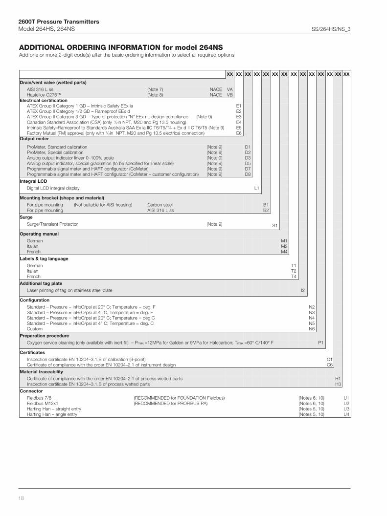
ADDITIONAL ORDERING INFORMATION for model 264NSAdd one or more 2-digit code(s) after the basic ordering information to select all required options
XX XX XX XX XX XX XX XX XX XX XX XX XX XX
)strapdettew(evlavtnev/niarD
ssL613ISIA™672CyolletsaH
)7etoN()8etoN(
ECANECAN
AVBV
noitacifitreclacirtcelEaixEEytefaScisnirtnI–DG1yrogetaCIIpuorGXETA
dxEEfoorpemalF–DG2/1yrogetaCIIpuorGXETA)9etoN(ecnailpmocngisedLnxEE"N"noitcetorpfoepyT–DG3yrogetaCIIpuorGXETA
ylno()ASC(noitaicossAdradnatSnaidanaC 1/2 )gnisuoh5.31gPdna02M,TPNni)9etoN(5T/6TCIIdxE+4T/5T/6TCIIaixEAASailartsuAsdradnatSotfoorpemalF–ytefaScisnirtnI
htiwylno(lavorppa)MF(lautuMyrotcaF 1/2 )noitcennoclacirtcele5.31gPdna02M,TPNni
1E2E3E4E5E6E
retemtuptuO
noitarbilacdradnatS,reteMorPnoitarbilaclaicepS,reteMorP
elacs%001–0raenilrotacidnituptuogolanA)elacsraenilrofdeificepsebot(noitaudarglaiceps,rotacidnituptuogolanA
)reteMoC(rotarugifnocTRAHdnaretemlangiselbammargorP)noitarugifnocremotsuc–reteMoC(rotarugifnocTRAHdnaretemlangiselbammargorP
)9etoN()9etoN()9etoN()9etoN()9etoN()9etoN(
1D2D3D5D7D8D
DCLlargetnI
yalpsidlargetniDCLlatigiD 1L
)lairetamdnaepahs(tekcarbgnitnuoM
gnitnuomepiproFgnitnuomepiproF
)gnisuohISIArofelbatiustoN( leetsnobraCssL613ISIA
1B2B
egruS
rotcetorPtneisnarT/egruS )9etoN( 1S
launamgnitarepO
namreGnailatIhcnerF
1M2M4M
egaugnalgat&slebaL
namreGnailatIhcnerF
1T2T4T
etalpgatlanoitiddA
etalpleetssselniatsnogatfognitnirpresaL 2I
noitarugifnoC
Hni=erusserP–dradnatS 2 F.ged=erutarepmeT;C°02taisp/OHni=erusserP–dradnatS 2 F.ged=erutarepmeT;C°4taisp/OHni=erusserP–dradnatS 2 C.ged=erutarepmeT;C°02taisp/OHni=erusserP–dradnatS 2 C.ged=erutarepmeT;C°4taisp/O
motsuC
2N3N4N5N6N
erudecorpnoitaraperP
P–)lliftrenihtiwelbaliavaylno(gninaelcecivresnegyxO xam T;nobracolaHrofaPM9ronedlaGrofaPM21= xam F°041/C°06= 1P
setacifitreC
)tniop-9(noitarbilacfoB.1.3–40201NEetacifitrecnoitcepsnIngisedtnemurtsnifo1.2–40201NEredroehthtiwecnailpmocfoetacifitreC
1C6C
ytilibaecartlairetaM
strapdettewssecorpfo1.2–40201NEredroehthtiwecnailpmocfoetacifitreCstrapdettewssecorpfoB.1.3–40201NEetacifitrecnoitcepsnI
1H3H
rotcennoC
8/7subdleiF1x21MsubdleiF
yrtnethgiarts–naHgnitraHyrtneelgna–naHgnitraH
)subdleiFNOITADNUOFrofDEDNEMMOCER()APSUBIFORProfDEDNEMMOCER(
)01,6setoN()01,6setoN()01,5setoN()01,5setoN(
1U2U3U4U

2600T Pressure TransmittersModel 264HS, 264NS SS/264HS/NS_3
19
Note 1: Suitable for oxygen service
Note 2: Not available with Hastelloy C diaphragm code K, F, P
Note 3: Not available with AISI 316 L ss and Hastelloy C on AISI seat diaphragm code S, H, A, B, L, Q
Note 4: Select type in additional ordering code
Note 5: Not available with Electronic Housing code Z, R, G
Note 6: Not available with Electronic Housing code P, E
Note 7: Not available with Process connection code E, K, D, F, C
Note 8: Not available with Process connection code B, T, A, P, N
Note 9: Not available with PROFIBUS PA and FF output code 2 or 3
Note 10: Not available with Electronic housing code U, S, T, V, H, M, L, N, D, C, A, B
™ Hastelloy is a Cabot Corporation trademark
™ Galden is a Montefluos trademark
™ Halocarbon is a Halocarbon Products Co. trademark
Standard delivery items (can be differently specified by additional ordering code)– No drain/vent valve
– General purpose (no electrical certification)
– No meter/display, no mounting bracket, no surge protection
– English manual and labels
– Configuration with kPa and deg. C units
– No test, inspection or material traceability certificates
THE SELECTION OF SUITABLE WETTED PARTS AND FILLING FLUID FOR COMPATIBILITY WITH THE PROCESSMEDIA IS A CUSTOMER'S RESPONSIBILITY, IF NOT OTHERWISE NOTIFIED BEFORE MANUFACTURING.

2600T Pressure TransmittersModel 264HS, 264NS SS/264HS/NS_3
ABB LtdHoward Road, St. NeotsCambridgeshire, PE19 3EUUKTel: +44(0)1480 475321Fax: +44(0)1480 217948
ABB Inc.125 E. County Line RoadWarminster, PA 18974USATel: +1 215 674 6000Fax: +1 215 674 7183
ABB SACE spaBusiness Unit InstrumentationVia Statale 11322016 Lenno (CO) ItalyTel: +39 0344 58111Fax: +39 0344 56278
SS
/264
HS
/NS
_3
ABB has Sales & Customer Supportexpertise in over 100 countries worldwide
www.abb.com/instrumentation
The Company’s policy is one of continuous productimprovement and the right is reserved to modify the
information contained herein without notice.
Printed in Italy (04.04)
© ABB 2004