ssab water mains - joining methods and pipe installation
TRANSCRIPT

SSAB Water mainsJOINING METHODS AND PIPE INSTALLATION
This data sheet describes the most common joining methods of steel water mains and the most important phases of installation.
Applications• water mains• sewage pipes
www.ssab.com/infra
SSAB is a Nordic and US-based steel company. SSAB offers value added products and services developed in close cooperation with its customers to create a stronger, lighter and more sustainable world. SSAB has employees in over 50 countries. SSAB has production facilities in Sweden, Finland and the US. SSAB is listed on the NASDAQ OMX Nordic Exchange in Stockholm and has a secondary listing on the NASDAQ OMX in Helsinki. www.ssab.com.

2
GENERAL
This data sheet describes the most common joining methods of steel water mains and the most important installation phases as follows:
- Trench, foundation and filling ................................................1- Joining methods........................................................................2- Installation .................................................................................3- Cutting of pipe at installation site .......................................4- Water flushing of pipeline ......................................................5
Technical specifications, transportation, handling and storage of coated pipes as well as the repair of coatings are presented on separate data sheets.
1. Trench, foundation and filling
The trench is dug wide enough, according to Figure 1, so as to have enough working space on both sides of the pipeline. If necessary, a levelling course is laid on the bottom of the trench. It is to be at least 150 mm thick measured from the exterior bottom of the pipe (See Fig. 2). The max. allowed grain size of the natural stone material used for levelling is always 60 mm, while the max. allowed grain size of the mineral aggregate in direct contact with the pipe coating is 32 mm. No sharp-edged stones are allowed in the levelling layer, and frozen levelling material must not be used. If the subsoil is soft, the pipeline may have to be founded on grid or even on piles.
The entire length of the underside of each pipe must rest on the bottom of the trench except for a distance of about half a metre from the sleeve in both directions (See Fig. 3). Each pipe of the installed line must carry, in addition to its own weight, also the weight of the water and the backfill, as well as other possible external loads.
If support planks or the like are used in installing an earth-covered pipeline, they must be removed before filling in the trench. The initial fill material must meet the same requirements as the levelling course and must be compactable sandy moraine or moraine gravel around the bottom half of the pipe – silt and clay may also be used around the upper half. Fill material must not be dropped onto a pipe so that it moves or gets damaged. It must be placed as evenly as possible on both sides of the pipe and tamped underneath and along the sides minding the pipe’s coating, and finally compacted.
The main principle in filling a trench is that pipes, especially joints, must have sufficient lateral support against overhead loads. Therefore, the initial fill along the sides is tamped mechanically halfway up the pipe in layers of about 30 cm to at least 90% Proctor density, ensuring, however, that the compaction does not lift the pipe up.
The degree of compaction must be determined by measurements. The vibration panel must at no time touch
a pipe or fitting to avoid damage to coating. Mechanical compaction above the pipe is allowed only after 50 cm of fill has been placed on top (See Fig. 2). After final filling, there must be a layer of fill material at least one metre thick, measured from the top of the pipe, containing no stones or boulders more than 300 mm in diameter. Any stone or boulder in the final fill material must not be located closer to the pipe than its diameter. Excavated
Figure 1. Trench
Figure 2. Filling of trench
Figure 3. Trench bottom at sleeve
~0,5 m
DD + 1 m
~ 0,5 m
~ 0,5 m~ 0,5 m

3
soils may be used outside traffic areas. A pipeline must always be plugged temporarily as installation is interrupted in order to prevent impurities from entering pipes. During installation, the water level in the trench must be kept low enough so that buoyancy will not move nor water damage the installed pipe. More detailed instructions on the installation of plastic coated pipings are provided in the municipal engineering regulations of each country. When installing pipes in areas where there are roads or railway lines, the instructions of the pertaining official are to be followed.
2. Joining methods
General
Pipe joints (Fig. 4) are used to join pipes and fittings into an integrated pipeline. Joints can be divided into two main types: tension-resistant and non-resistant ones. Joints may also be divided by applications as follows:
2.1 Butt joint
Used primarily in tension-resistant pressure lines such as oil, natural gas and district heating pipelines. Used in water pipelines especially with pipe sizes ≥ DN 600 when the joint can be repaired from the inside after welding. For a more detailed description, see Figure 6 on Page 5. A Welding collar is used to join new piping or a fitting to an existing line. Internal welding and completion of concrete lining require a manhole in connection with the joint. Installation of the welding collar is described in Figure 9.
2.2 DIN/G welded joint
Used in pipelines where easy installation of the tension-resistant joint and the possibility of making less than 1.0 degree bends are a must. Welded from the outside. Suits pipe diameters DN 400–900 pressure class PN16 and DN1000-1200 pressure class PN10. Only internal concrete lining is used with this type of sleeve, no painting is done. The DIN/G joint is manufactured at the works by incorporating a rubber ring in the concrete lining, which means there is no need to complete the internal concrete lining on site. The rubber ring prevents water from changing in the gap of the sleeve joint. For a more detailed description, see Section 3.2 and Figure 7.
2.3 OV welded joint
Used in water lines to facilitate installation and to allow 1.5 – 3.0 degree bends at joints. Since the joint is welded from the inside to make it tension resistant, it is suitable for diameters ≥ DN 600 and pressures up to 20 bar. For a more detailed description, see Section 3.3 and Figure 8.
2.4 Flanged joint
Flanged joints are widely used in industry. With underground pipes, flanged joints are used e.g. in connection with valves and manholes. For a more detailed description, see Section 3.4 and Figure 10. The joints can be sealed e.g by Klinger-KGS gaskets.
Figure 4. Pipe joints
SS – SS
OM – OSFL – FL
DIN/G – SS
Butt joint DIN/G welded joint with a rubber ring
OV welded joint Flanged joint
Non-tension-resistant couplings Welding collar

4
2.5 Coupling joint
Steel pipes may also be joined by various mechanical pipe couplings such as those manufactured by Straub, Viking-Johnson and Victaulic. Then, the ends of pipes are lathed and external weld seams are ground to fit the couplings. For a more detailed description, see Section 3.5.
2.6 Welding collar
A welding collar is used when connecting new piping or a single new component to an existing piping. The installation of a welding collar is described in Figure 9. When a single new component is installed, it must also have a manhole so that the internal lining can be repaired. The welding collar can be welded only externally up to pressure class PN10, but it also requires internal welding in pressure class PN16. After welding, the internal lining and external corrosion protection coating are completed.
2.7 Selection of joining method
Welding is normally used with underground installation. Welded sleeve joints facilitate installation and allow small bends without angular pipe fittings. In subsoils of low bearing capacity (clay and silt), a welded joint is more secure than a coupling joint. In case a coupling joint is used in weak soils, it is recommended to use sturdier couplings.
The coupling must be supported on a concrete slab or the like to eliminate shear stresses. At high water pressures
(≥ 10 bar) it is also advisable to use a sturdier type of coupling.
The teeth of tension-resistant, toothed couplings damage external protective coatings. Therefore, their use should be limited mainly to dry, indoor installations where external corrosion protection is not needed. Tension-resistant flanged joints are used in institutional and industrial installations to facilitate disassembly. Tension-resistant joints must always be used in submerged installation. When using DIN/G type sleeves, pipes are only lined with concrete internally, no painting is done.
3. Installation
Plastic end covers and temporary plug
The plastic covers at the ends of the pipes shall not be removed until shortly before installation in order to avoid excessive curing or soiling of the internal concrete lining during storage. In summer, the external black PUR coating on the pipe parts is covered with white plastic for the entire storage period, as heat from the sun will soften the coating.When removing the plastic covers, a visual inspection of the ends, internal surfaces and sleeves of the pipes is performed. Hairline cracks in the concrete lining which are caused by excessive curing can be removed in summer by wetting the concrete with household water now and again.
On the bottom of trench open pipe end shall be blocked with temporary, compressed-air driven plug to avoid rainwater not dirty inside cement lining.
Figure 5. Pipe ends protected by plastic covers, black pipe fittings protected with white cover against sun heat in summer

5
PE coating
1,6
±0,8
Pipe end bevelledaccording to EN 10217
≈ 250min. 50
2
30° -0°/+5°
≈ 50
Weld: 2 – 3 runs.Electrode OK 48.00Welding with filler plate
Installation coatingEN 10298
Concrete liningEN 10298
Steel pipeP235 EN 10217
3.1. Butt joint
General
Tension-resistant butt joints (Fig. 6) are used with the entire range of pipe sizes. The joints are welded from the outside with basic electrodes. Working temperature need not be raised. The joints as such do not allow bends, but the end of a pipe can be cut at an angle, or a pipeline with internal concrete lining can be bent safely, if necessary, to the minimum radius of curvature given in the table.
Pipe size Bending radius min R (m)
Bending distance max./12 m (m)
DN 400 200 0.36DN 500 250 0.28DN 600 300 0.24DN 700 350 0.20DN 800 400 0.18DN 900 450 0.16DN 1000 500 0.14DN 1200 600 0.12
Welding
Welding is made by metal arc welding with covered electrodes or MIG/MAG welding. Running of a welding procedure test in accordance with EN ISO 15614-1 is recommended prior to commencing welding.
The welder must have at least the competence required by Standard EN 9606-1. The weld quality class is set out in Standard EN ISO 5817, Class C.
Pipes are adjusted for welding. The weld cavity-reducing effect of tacking and welding must be considered in determining the width of the weld cavity (2 – 4 mm).
After tacking, the joints are welded in 2 – 3 runs with a dry basic electrode, such as Esab OK 48.00, Elga P48, Böhler Fox EV 48, Filarc 35 or equivalent. The thickness of the electrode is determined by the pipe wall thickness, the mode of welding, the type of run and welding position, as well as the competence of the welder. The welding values are selected as per instructions of the welding consumable suppliers.
Control of welded joint
All welds are to be inspected at least visually. Beginning and end defects, undercuts, cracks, etc. surface defects are ground or repaired by welding. Additionally recommendation is that at least 10% of welds are examined by liquid penetrant or magnetic particle testing. Basic requirement is also that at least 5 welds of every welder are to be examined and if any welds fails, test frequency will be higher. Moreover, the tightness of the joints is tested by water pressure test after the pipeline is completed.
Figure 6. Butt joint
All dimensions in millimetres.
Figure 5. Pipe ends protected by plastic covers, black pipe fittings protected with white cover against sun heat in summer
min. 50
Shrinkable sleeve or corrosion protection tape
DIN 30670 N-n

6
Completion of internal concrete lining
Internal concrete lining is completed with pipe sizes ≥ DN 600. After welding, loose rust and weld slag and any possible concrete coming off the joints is brushed off the interior surface. In winter conditions the joint area is heated with a gas flame. The joint area is first moistened and then coated with mortar that consists of equal parts of sand and cement (SR cement). The sand is to be sufficiently clean with a grain size of 0.125 – 1.5 mm. Enough water is added to make a fairly stiff mortar. Only the amount of mortar and cement used in one hour is to be mixed. The mortar is spread with a trowel to the level of the original lining. After about 2 hours the area is rubbed with a wet sponge.
Under site conditions, concrete requires at least 5 days to cure. If possible, the joint area should be kept damp and at over +5 ºC during that period. In winter conditions a warm air blower can be used for heating. Frost proof cement must not be used as it contains water-soluble admixtures unsuitable for drinking water applications.
On interface between old bitumen coating and new cement lining can be used also epoxy adhesive as Sikadur-31 DW, which is suitable for contact of drinking water.
Completion of internal painting
Internal painting is completed with pipe sizes ≥ DN 600. The joint area is treated as per instructions of the paint manufacturer.
Completion of external coating
Bare steel surfaces are cleaned with a steel brush (degree of cleanness St 2), dried with liquid gas flame and anti-corrosive painted (example Temaprime EE) before sleeve will be added. The PE coating is roughened over a distance of about 100 mm. The cleaned and warmed joint area is protected by a heat-shrinkable sleeve or corrosion protection tape (Canusa, Raychem, Denso, Stopaq etc.) as per manufacturer’s instructions.

7
3.2 DIN/G sleeve joint
General
The DIN/G sleeve joint (Fig. 7) is used with pipe sizes DN 400–1200 to facilitate installation. The internal concrete lining has been complemented with a rubber ring incorporated in the sleeve already at the works, which means that the internal concrete lining need not be completed on site after welding. The joint is welded from the outside using a basic electrode. The DIN/G sleeve meets the requirement of Standard DIN 2460. Only internal concrete lining is used with DIN sleeves, no painting is done.
The DIN/G joint allows the maximum bend shown in the table. This bend must not be exceeded. If necessary, the joint must be visually inspected on the inside of the pipe before the final welding of the joint to ensure that the rubber seal and concrete lining completely cover the internal steel surface of the sleeve joint. At the same time, it must be ensured that there is sufficient, but not too much, compression on the rubber seal and that the maximum allowed bend is not exceeded. When moving inside the pipe, care must be taken not to soil the internal lining.
Pipe size Max. bendDN 400 2.25°DN 500 2°DN 600 1.75°DN 700 1.5°DN 800 1.25°DN 900 1°DN 1000 0.75°DN 1200 0.5°
Welding
Welding is made by metal arc welding with covered electrodes or MIG/MAG welding. Running of a welding procedure test in accordance with EN ISO 15614-1 is recommended prior to commencing welding.
The welder must have at least the competence required by Standard EN 9606-1. The weld quality class is set out in Standard EN ISO 5817, Class C.
The insertion distances are marked on the construction site on the coating with lines (min. and max.), and then the straight end of the pipe is inserted in the sleeve. In the case of the DIN/G sleeve joint, the gasket is compressed a max. of 10 mm.
After tacking, the joints are welded in 2 – 3 runs with a dry basic electrode, such as Esab OK 48.00, Elga P48, Böhler Fox EV 48, Filarc 35 or equivalent. The thickness of the electrode is determined by the pipe wall thickness, the mode of welding, the type of run and welding position, as well as the competence of the welder. The welding values are selected as per instructions of the welding consumable suppliers.
Control of welded joint
All welds are to be inspected at least visually. Beginning and end defects, undercuts, cracks, etc. surface defects are ground or repaired by welding. Additionally recommendation is that at least 10% of welds are examined by liquid penetrant or magnetic particle testing. Basic requirement is also that at least 5 welds of every welder are to be examined and if any welds fails, test frequency will be higher. Moreover, the tightness of the joints is tested by water pressure test after the pipeline is completed.
Completion of external coating
Bare steel surfaces are cleaned with a steel brush (degree of cleanness St 2), dried with liquid gas flame and anti-corrosive painted (example Temaprime EE) before sleeve will be added. The PE coating is roughened over a distance of about 100 mm. The cleaned and warmed joint area is protected by a heat-shrinkable sleeve or corrosion protection tape (Canusa, Raychem, Denso, Stopaq etc.) in accordance with the manufacturer’s instructions.
All dimensions in millimetres. The rubber ring is compressed a max. of 10 mm in direct compression; any possible bend is to be considered separately. Compression is effected to within the installation lines (min. and max.) on site marked at the end of the pipe. If necessary, the joint must be visually inspected on the inside of the pipe before the final welding of the joint to ensure that the rubber seal and concrete lining completely cover the steel surface of the sleeve joint.
Figure 7. DIN/G welded joint with a rubber ring
min. 480
min. 50
e
min. 50
Steel pipP235 EN 10217
Weld: 2 – 3 runs.Electrode OK 48.00
Concrete liningEN 10298 Rubber ring
≈ 210 ≈ 60Shrinkable sleeve or corrosion protection tape
PE coating
DIN 30670 N-n100-110
A. Centering of joint B. Fill welding C. Welding D. Final a-measure
First joint shall be centering example with steel wedges, a space shall be almost equal around the whole joint. After centering the joint will be bridge welded with 3-4 pcs, about 50 mm long welds arount joint. Then it will be fill welded, and final welded with 2-3 weld seams. Final effective a-measure of the weld shall be nearly wall thickness of the steel pipe.
1–5 mm
a

8
3.3 OV sleeve joint
General
The OV sleeve joint (Fig. 8) is used with pipes ≥ DN 600. The joint is welded from the inside using a basic electrode. Care must be taken not to soil the internal coating while working inside the pipe.
The OV sleeve joint allows 1.5 – 3.0 degree bends depending on pipe size and sleeve length, i.e. as pipe size increases the possible radius of bend decreases. If larger bends are desired, the sleeveless end of the pipe can be cut at an angle.
Pipe size Max. bendDN 600 3°DN 800 2.5°DN 1000 2°DN 1200 1.5°
The straight end of the OV sleeve joint has an internal bevel of 15–20 degrees. The end on the sleeve side normally has an external bevel in order to avoid sharp angles at joints.
Welding
The welder must have at least the competence required by Standard EN 9606-1. The weld quality class is set out in Standard EN ISO 5817, Class C.
Pipes are adjusted for welding. The weld cavity-reducing effect of tacking and welding must be considered in determining the width of the weld cavity (2 – 4 mm).
After tacking, the joints are welded in 2 – 3 runs with a dry basic electrode, such as Esab OK 48.00, Elga P48, Böhler Fox EV 48, Filarc 35 or equivalent. The thickness of the electrode is determined by the pipe wall thickness, the mode of welding, the type of run and welding position, as well as the competence of the welder. The welding values are selected as per instructions of the welding consumable suppliers. Running of a welding procedure test in accordance with EN ISO 15614-1 is recommended prior to commencing welding.
All welds are to be inspected at least visually. Beginning and end defects, undercuts, cracks, etc. surface defects are ground or repaired by welding. Moreover, the tightness of the joints is tested by pressurised water after the line is completed.
Completion of internal concrete lining
After welding, loose rust and weld slag and any possible concrete coming off the joints is brushed off the interior surface. In winter conditions the joint area is heated with a gas flame. The joint area is first moistened and then coated with mortar that consists of equal parts of sand and cement (SR cement). The sand is to be sufficiently clean with a grain size of 0.125 – 1.5 mm. Enough water is added to make a fairly stiff mortar. Only the amount of mortar and cement used in one hour is to be mixed. The mortar is spread with a trowel to the level of the original lining. After about 2 hours the area is rubbed with a wet sponge.
Under site conditions, concrete requires at least 5 days to cure. If possible, the joint area should be kept damp and at over +5 ºC during that period. In winter conditions a warm air blower can be used for heating. Frost proof cement must not be used as it contains water-soluble admixtures unsuitable for drinking water applications.
Completion of internal painting
Internal painting is completed with pipe sizes ≥ DN 600. The joint area is treated as per instructions of the paint manufacturer.
Completion of external coating
Bare steel surfaces are cleaned with a steel brush (degree of cleanness St 2), dried with liquid gas flame and anti-corrosive painted (example Temaprime EE) before sleeve will be added. The PE coating is roughened over a distance of about 100 mm. The cleaned and warmed OV sleeve gap is filled e.g. with Densyl Mastic or Raychem Mastic Filler S1137 so as to leave no sharp angles in the joint. The cleaned and warmed joint area is finally protected by a heat-shrinkable sleeve or corrosion protection tape (Canusa, Raychem, Denso, Stopaq etc.) as per the manufacturer’s instructions.
Figure 8. OV welded joint
All dimensions in millimetres.
min. 50
20°
min. 5 120 ≈ 100 ≈ 100
PE coating
Concrete liningEN 10298
Installation coatingEN 10298
Weld: 2–3 runs.Electrode OK 48.00
Steel pipeP235 EN 10217Filler
≈ 50
≈ 25
0≈ 0≈
Shrinkable sleeve or corrosion protection tape
DIN 30670 N-n

9
The welding collar can be welded only externally up to pressure class PN10, but it also requires internal welding in pressure class PN16.
200
Installation coating
Figure 9. Installation of welding collar
Examples of welding collar use
a3
The split spot is welded on site
Threaded rod and nut M30
Thread of nut is drilled out so that the rod moves freely through
Convex washer
Rounded nut
The tightening system is welded on site and removed after alignment and fastening
min. 50 min. 50Welding collarWeld: 2 – 3 runs.Electrode OK 48.00
> 50 > 50
Welding collar Welding collar
Manhole DN 600 with blind flange
Welding collar
Manhole DN 600 with blind flange
Old piping Old piping New piping
DN 400
New piping
Shrinkable sleeve or corrosion protection tape
10
Lmin
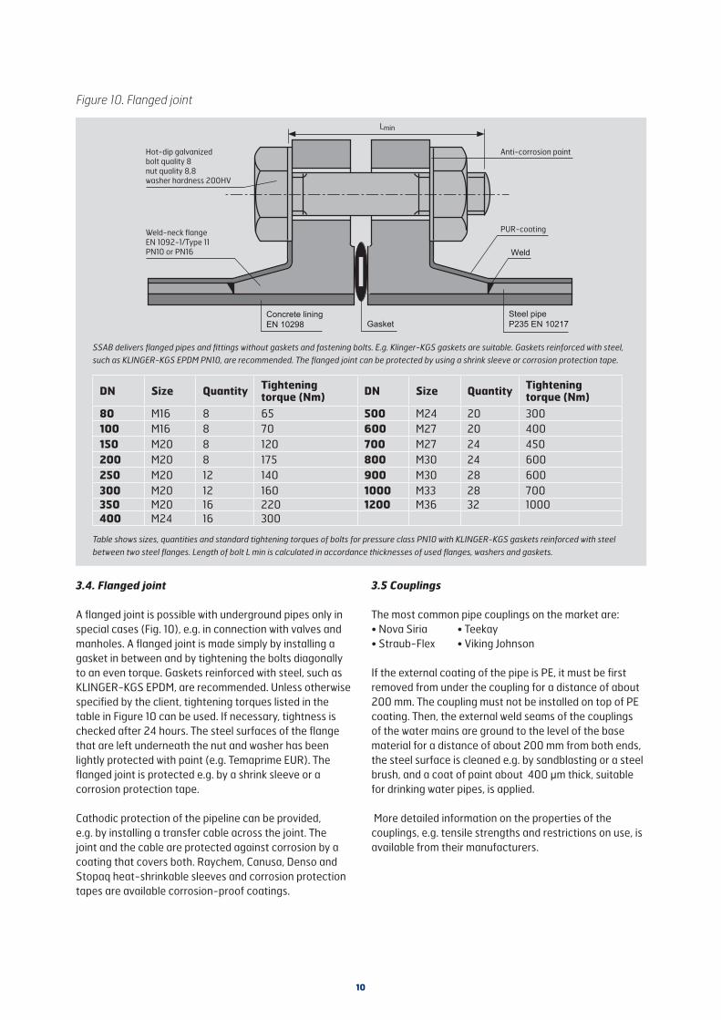
3.4. Flanged joint
A flanged joint is possible with underground pipes only in special cases (Fig. 10), e.g. in connection with valves and manholes. A flanged joint is made simply by installing a gasket in between and by tightening the bolts diagonally to an even torque. Gaskets reinforced with steel, such as KLINGER-KGS EPDM, are recommended. Unless otherwise specified by the client, tightening torques listed in the table in Figure 10 can be used. If necessary, tightness is checked after 24 hours. The steel surfaces of the flange that are left underneath the nut and washer has been lightly protected with paint (e.g. Temaprime EUR). The flanged joint is protected e.g. by a shrink sleeve or a corrosion protection tape.
Cathodic protection of the pipeline can be provided, e.g. by installing a transfer cable across the joint. The joint and the cable are protected against corrosion by a coating that covers both. Raychem, Canusa, Denso and Stopaq heat-shrinkable sleeves and corrosion protection tapes are available corrosion-proof coatings.
3.5 Couplings
The most common pipe couplings on the market are:• Nova Siria • Teekay• Straub-Flex • Viking Johnson
If the external coating of the pipe is PE, it must be first removed from under the coupling for a distance of about 200 mm. The coupling must not be installed on top of PE coating. Then, the external weld seams of the couplings of the water mains are ground to the level of the base material for a distance of about 200 mm from both ends, the steel surface is cleaned e.g. by sandblasting or a steel brush, and a coat of paint about 400 μm thick, suitable for drinking water pipes, is applied.
More detailed information on the properties of the couplings, e.g. tensile strengths and restrictions on use, is available from their manufacturers.
Figure 10. Flanged joint
Weld
SSAB delivers flanged pipes and fittings without gaskets and fastening bolts. E.g. Klinger-KGS gaskets are suitable. Gaskets reinforced with steel, such as KLINGER-KGS EPDM PN10, are recommended. The flanged joint can be protected by using a shrink sleeve or corrosion protection tape.
PUR-coating
Anti-corrosion paintHot-dip galvanized bolt quality 8nut quality 8,8washer hardness 200HV
Weld-neck flangeEN 1092-1/Type 11 PN10 or PN16
GasketConcrete liningEN 10298
Steel pipeP235 EN 10217
DN Size Quantity Tightening torque (Nm) DN Size Quantity Tightening
torque (Nm)80 M16 8 65 500 M24 20 300100 M16 8 70 600 M27 20 400150 M20 8 120 700 M27 24 450200 M20 8 175 800 M30 24 600250 M20 12 140 900 M30 28 600300 M20 12 160 1000 M33 28 700350 M20 16 220 1200 M36 32 1000400 M24 16 300
Table shows sizes, quantities and standard tightening torques of bolts for pressure class PN10 with KLINGER-KGS gaskets reinforced with steel between two steel flanges. Length of bolt L min is calculated in accordance thicknesses of used flanges, washers and gaskets.

11
4. Determine of the cutting point
In order to speed up installation and ensure the performance of joints, pipes delivered to the site ought to be cut to the right size and be completely ready for installation.
However, sometimes pipes have to be shortened under field conditions. Then, cutting and making the pipe end suitable for joining must be implemented with great care and involves the following work phases:
Cutting of pipe
Determining pipe length:Determine the cutting point of the pipe, and mark it all the way round and perpendicular to the centreline of the pipe. Then make a perpendicular cut through to the steel with a carpet knife, or diamond cutting disc etc.
Cutting of pipe
Cutting of the steel pipes is made by diamond cutting disc. After cutting inside cement lining is inspected, and if there
Figure 11. Tension-resistant couplings (Straub)
All dimensions in millimetres. The coupling must not be installed on top of PE coating.
Shrinkable sleeve or corrosion protection tape
is loss of adhesion between steel and lining, loose parts shall be removed and place repaired.
Removing of outside coating
Remove as much of the PE coating (e.g. 150 mm) starting from the mark as was removed from the original pipe end. The width of removal is indicated by a slanted cut through to the steel. Outside coating can be removed also by diamond cutting disc. Then during removal shall be careful of not cutting too much into the steel.
Grinding of weld seam
The spiral joint welding seam must be ground to the level of the base material over the entire length of the pipe, which has had its external coating removed.
5. Water flushing of pipeline
Before new pipeline is in service, water flushing is done. At the beginning pH-value is about 12. Quality and flow of water influence on the time of flushing. Water flushing takes some weeks, then pH-value drops to the level of 8,5.
Figure 12. Non-tension-resistant couplings (Viking Johnson)
All dimensions in millimetres. The coupling must not be installed on top of PE coating. The coupling must not be installed on top of the PE coating; instead, the steel surfaces that are left underneath the coupling are protected against corrosion by painting.
Concrete liningEN 10298 Coupling
Steel pipeP235 EN 10217
PE coating
142
≈ 110
Concrete liningEN 10298
Coupling
Steel pipeP235 EN 10217
PE coating
≈ 110
50DiN 30670 N-n
DIN 30670 N-n

SSAB is a Nordic and US-based steel company. SSAB offers value added products and services developed in close cooperation with its customers to create a stron-ger, lighter and more sustainable world. SSAB has employees in over 50 countries. SSAB has production facilities in Sweden, Finland and the US. SSAB is listed on the NASDAQ OMX Nordic Exchange in Stockholm and has a secondary listing on the NASDAQ OMX in Helsinki. www.ssab.com
The accuracy of this instruction sheet has been inspected with utmost care. However, we do not assume responsibility for any mistakes or direct or indirect damages due to incorrect application of the information. The right to make changes is reserved.
Copyright © 2017 SSAB. All rights reserved. SSAB and SSAB brand names are registered trademarks of SSAB.
SSABHarvialantie 420FI-13300 Hämeenlinna, Finland
Tel. +358 20 5911
www.ssab.com/infra
834-EN
-Water m
ains-Installation-v3-20
19-P
recis