ssbinstallation,operation andmaintenancemanual manuals... · line pressure water feed system. . . ....
TRANSCRIPT
TABLE OF CONTENTSDimensional Information and
Component Identification . . . . . . . . . . . . . . . . . 2
Dimensional & Clearing Specifications . . . . . . . . . 3
Wiring Diagrams . . . . . . . . . . . . . . . . . . . . . . . . . 4-5
InstallationPiping, Wiring . . . . . . . . . . . . . . . . . . . . . . . . . . . 6
Pre-Operation Check . . . . . . . . . . . . . . . . . . . . . . . . 7
Pressure Controls, Operation & Testing . . . . . . . . 7
Operation. . . . . . . . . . . . . . . . . . . . . . . . . . . . . . . . . 8
Blowdown . . . . . . . . . . . . . . . . . . . . . . . . . . . . . . . . 8
Timing Switch . . . . . . . . . . . . . . . . . . . . . . . . . . . . . 9
Digital Timer Operation Instructions. . . . . . . . . . 10
Maintenance . . . . . . . . . . . . . . . . . . . . . . . . . . . . . 11
Standard EquipmentAuxiliary Low Water Cut Off . . . . . . . . . . . . . . . . 12Line Pressure Water Feed System . . . . . . . . . . . . . 12
Optional Equipment . . . . . . . . . . . . . . . . . . . . . . . 12High Pressure Water Feed System. . . . . . . . . . . . . 12Automatic Blowdown System . . . . . . . . . . . . . . . . 12Blowdown Separators . . . . . . . . . . . . . . . . . . . . . 13Control Voltage Stepdown Transformer . . . . . . . . 13Multistage Load Progressive Sequencers . . . . . . . . 13
Blowdown Separator Tanks . . . . . . . . . . . . . . . . . 14
Specification Charts . . . . . . . . . . . . . . . . . . . . . . . 15
Sizing . . . . . . . . . . . . . . . . . . . . . . . . . . . . . . . . . . . 16
Gauge Glass Installation . . . . . . . . . . . . . . . . . . . . 17
Gauge Glass Use and Care . . . . . . . . . . . . . . . . . . 18
Element Replacement . . . . . . . . . . . . . . . . . . . . . . 19
SSB Boilers have Stainless Steel all wetted metal parts. SSBboilers shall be operated using only deionized water, havinga maximum conductance of 1 microSiemen per cm(1 µS/cm) [minimum specific resistivity of 1 megohm per cm(1ΜΩ/cm)].
PRODUCTS COVERED BY THIS MANUAL:
MaxSeries KW Range Steam Rate* BHP Design Pres. Work Pres.______________________________________________________________________SSB 12-180 36-542 lbs/hr 1.2-18.4 0-100 psig 85 psig
*Steam Rate- Steam @ 212 F with 50 F feed water
A Division of Sussman-Automatic Corporation43-20 34th Street, Long Island City, NY 11101 • 718-937-45001-800-238-3535 • Fax: 718-937-4676 • email: [email protected]
PUR 101137SSB 1.17
states a hazardwhich may cause serious injury ordeath if precautions are not followed.
signals a situation whereminor injury or product damage may occurif you do not follow instructions.
IMPORTANT NOTE:This highlights information that is especiallyrelevant to a problem-free installation.
IMPORTANT NOTE:As you follow these instructions, you will notice warning and caution symbols. This blocked information is important for the safe and efficientinstallation and operation of electric boilers. These are two types of potential hazards that may occur during this installation and operation:
Model No. SSB- __________________
Boiler Serial No. _________________
National Board No. ______________
Safety Valve Set Pressure________psig
Power Circuit Voltage ____________
Control Circuit Voltage ___________
Amps _____ Phase _____ HZ ______
IMPORTANT: This data file contains the National BoardRegistration Certificate approving your boiler. It must bekept near the boiler at all times.
! CAUTION! WARNING
SSB Installation, Operationand Maintenance Manual
U S A
Designed, Engineeredand Assembled in the

Installation, Operation & Maintenance Manual
Dimensional Information & Component Identification
2
_______________________________________Water Steam Drain
MODEL H W* L Inlet Outlet Valve_______________________________________SSB 12–18 37" 22" 32" 1/2”NPT 1/2”NPT 1”_________________________________________________SSB 24–72 47" 27" 36" 1/2”NPT 1” NPT 1”_________________________________________________SSB 80–100 63" 29" 36" 1/2”NPT 11⁄2”NPT** 1”_________________________________________________SSB 135–180 63" 30" 38" 1/2”NPT 2” NPT** 1”_______________________________________
* Add 6 inches to the width when suppled with Automatic Blowdown** Steam Outlet is 3” NPT on 15 PSI trimmed SSB-80-180.NOTE: Recommended clearance is 36 inches all around for servicing.
Model SSB
_________________________________SYMBOL ITEM SSB12-18 SSB 24-72 SSB 100 SSB 135-180___________________________________A Steam Outlet 61⁄4" 10" 81⁄4" 9"__________________________________________________________________B Steam Outlet 101⁄4" 17" 171⁄4" 181⁄4"__________________________________________________________________C M/M Drain Valve 5" 12" 17" 163⁄4"__________________________________________________________________D M/M Drain Valve 61⁄2" 6" 61⁄4" 61⁄4"__________________________________________________________________E Check Valve 14" 9" 17" 163⁄4"__________________________________________________________________F PV Drain Valve 23⁄4" 21⁄4" 23⁄4" 23⁄4"__________________________________________________________________G PV Drain Valve 61⁄4" 91⁄2" 73⁄4" 91⁄4"__________________________________________________________________J Clearance 3 3⁄4" 31⁄2" 4" 4"__________________________________________________________________K Check Valve 21⁄2" 23⁄4" 3" 3"__________________________________________________________________M Door Width 83⁄4" 14" 123⁄4" 143⁄4"__________________________________________________________________
A B
K
H
D
G
LW
M
E
J
C
F
Installation, Operation & Maintenance Manual
3
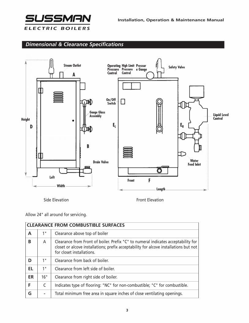
Dimensional & Clearance Specifications
Steam Outlet OperatingPressureControl
High LimitPressureControl
Pressure Gauge Safety Valve
Liquid LevelControl
WaterFeed Inlet
F
ELD
A
B
ER
FrontLeft
Drain Valve
On/OffSwitch
Gauge GlassAssembly
Height
WidthLength
Side Elevation Front Elevation
Allow 24" all around for servicing.
CLEARANCE FROM COMBUSTIBLE SURFACES
A 1" Clearance above top of boiler
B A Clearance from Front of boiler. Prefix "C" to numeral indicates acceptability forcloset or alcove installations; prefix acceptability for alcove installations but notfor closet installations.
D 1" Clearance from back of boiler.
EL 1" Clearance from left side of boiler.
ER 16" Clearance from right side of boiler.
F C Indicates type of flooring: "NC" for non-combustible; "C" for combustible.
G - Total minimum free area in square inches of close ventilating openings.
Installation, Operation & Maintenance Manual
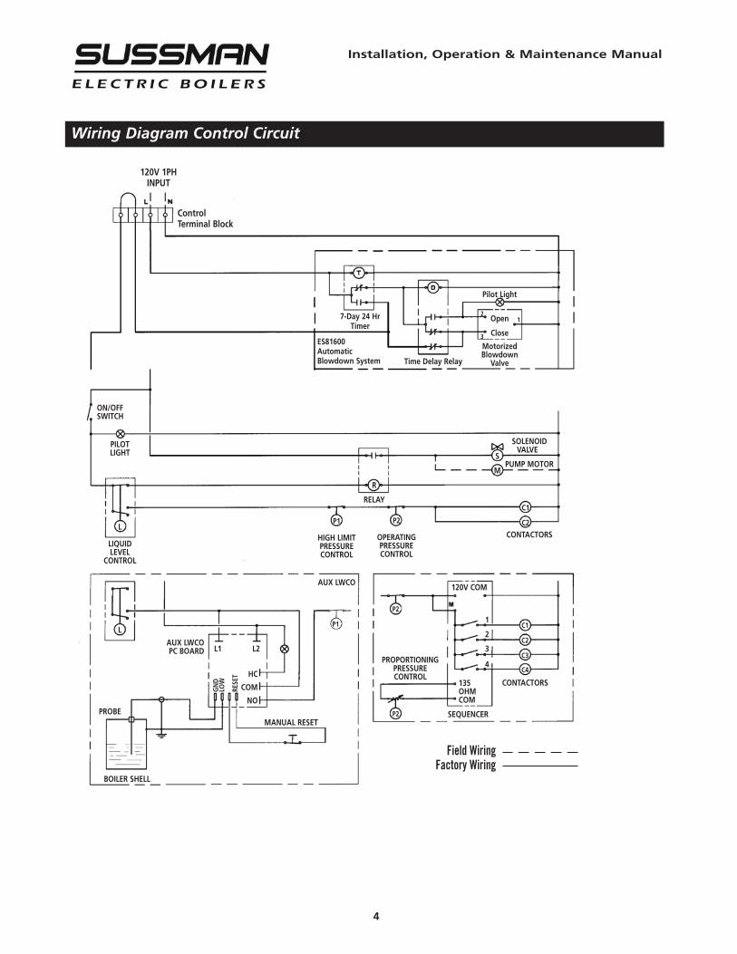
Wiring Diagram Control Circuit
4
Field WiringFactory Wiring
120V 1PHINPUT
ControlTerminal Block
7-Day 24 HrTimer
ES81600AutomaticBlowdown System Time Delay Relay
Pilot Light
Open
Close
MotorizedBlowdown
Valve
SOLENOIDVALVE
PUMP MOTOR
C1
C2
CONTACTORS
R
RELAY
L
P1
HIGH LIMITPRESSURECONTROL
AUX LWCO
PROBE
BOILER SHELL
L1 L2
HC
COM
NO
GND
LOW
RESET
PILOTLIGHT
L
LIQUIDLEVEL
CONTROL
C1
C2
C3
C4
CONTACTORS135OHMCOM
SEQUENCER
120V COM
1
2
3
4
P2
OPERATINGPRESSURECONTROL
PROPORTIONINGPRESSURECONTROL
MANUAL RESET
P2
P1
P2
AUX LWCOPC BOARD
ON/OFFSWITCH
S
M
21
3
Installation, Operation & Maintenance Manual
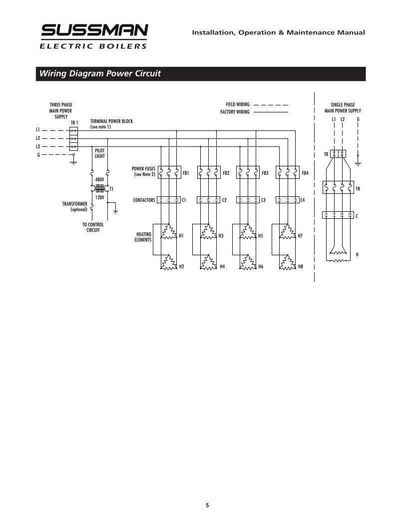
Wiring Diagram Power Circuit
5
ALL ELECTRICAL WIRING MUST BE PERFORMED BY A QUAL-IFIED ELECTRICIAN IN ACCORDANCE WITH NATIONAL ANDLOCAL ELECTRICAL CODES.
Assure that the power voltage and phase beingsupplied to the boiler matches the power voltage and phase ofthe boiler. Connecting incorrect power supply can damage boilercomponents or cause improper boiler operation. If the boilerpower requirements do not match the power to be supplied tothe boiler the boiler must be returned to the factory forconversion. Boilers cannot be field converted. All boilers are pre-wired and tested prior to shipment.1. Ground boiler according to National Electric Code
requirements to avoid shock.2. Power wiring to boiler should be in accordance with National
and Local Electrical Code requirements following wiringdiagram supplied. Use proper size wire. Wire size is specifiedadjacent to field wiring terminals. This label states the wiresize [AWG or MCM], minimum temperature rating (90 C) andconductor material (copper only). Deviation from theserequirements may result in improper or unsafe boileroperation.
3. A disconnect switch employing circuit breakers or fusesshould be installed between the main power source and theboiler. This disconnect switch should be located near theboiler and clearly marked for easy access and identificationshould the boiler need to be turned off due to an emergency.
4. Boiler control circuit is 120 Volt*. Unless boiler has anoptional step down transformer, a separate 120 Volt powerfeed wiring is required to be connected to the control circuitterminal block. A 15 Amp circuit is required for all boilers. If a3/4 HP feed water motor and pump assembly is connected tothe boiler, then a 20 Amp circuit is required.
5. If a separate control circuit is used, it should be connected tothe control circuit terminal block.
6. Remote mounted water feed systems (i.e. motor and pump)should be connected to the junction box provided on theoutside of the boiler jacket.
7. With main power off, make sure all wiring terminations aretight to avoid arcing, carbonizing or overheating of contacts.
Boilers are susceptible to lightning damage dueto water line connections. An industrial type lightning/surgeprotector should be installed according to the manufacturer'srecommendation at the service entrance. Consult yourcontractor or electrical dealer.
Substitution of components or modification ofwiring system voids the warranty and may lead to dangerousoperating conditions.
*220V for 380V and 415V boilers.
Wiring
! CAUTION
! CAUTION
! WARNING
REFER TO NATIONAL AND ALL APPLICA-BLE LOCAL CODES FOR SPECIFIC INSTAL-LATION REQUIREMENTS.
1. The boiler should be mounted on a solid,level foundation.
2. The boiler should be located with suitableclearances, refer to page 2 and 3 and Coderequirements.
Installation
Piping
Installation, Operation & Maintenance Manual
6
ALL PIPING SHOULD BE INSTALLED BY AQUALIFIED LICENSED PLUMBER IN ACCOR-DANCE WITH NATIONAL AND LOCALCODES.
1. When water feed is other than pump typethe water supply pressure must be 10 psiggreater than boiler operating pressure toassure water supply maintains properwater level in the boiler. Insufficient waterlevels can result in improper boileroperation. (Keep feed water valves open atall times during normal operation.)
2. If pump and boiler are plumbed within 30feet (pipe length) a minimum of 2 checkvalves are required to avoid damage topump.
3. Connect steam line with customer suppliedoutlet valve to boiler steam outlet.
4. Provide for boiler drain connection, a dailyblowdown is required. A "BlowdownSeparator Tank" may be necessary, checkwith local code.
5. Safety valve shall be plumbed according tolocal code.
6. SSB Boilers have Stainless Steel all wettedmetal parts. SSB boilers shall be operatedusing only deionized water, having amaximum conductance of 1 microSiemenper cm (1 µS/cm) [minimum specific resistivityof 1 megohm per cm (1ΜΩ/cm)].
NOTE: The safety valve shall not be plumbedwith a line sized less than the outlet size ofthe safety valve.
Installation, Operation & Maintenance Manual
7
Pressure Controls, Operation and Testing
NOTE: All boilers are provided with one high limitpressure control and at least one operating pressurecontrol.1. The high limit pressure control is equipped with a
manual reset feature. There is no subtractivedifferential scale with this type of control
2. All pressure controls are equipped with anadjusting screw, allowing for setting of desiredoperational and high limit pressures. To reducepressure setting, turn adjusting screw in directionthat allows indicator to point to a lower pressuresetting on the scale. To increase pressure settingturn adjusting screw in direction that allowsindicator to point to a higher pressure on the scale
NOTE: It is recommended that the high limit controlbe set 10psig above the desired normal operatingpressure.
3. Operating pressure controls, have a separatedifferential scale. Differential indicates pressurebelow the main operating maximum pressure, thepressure control will re-set. The differential setpoint is adjusted in the same manner by turningthe adjusting screw in the desired direction toincrease or decrease the differential pressurevalue.
Pre-Operation Check (All Boilers)
LWCO/PUMP CONTROL OPERATION AND TESTING
1. All valves for incoming water supply are to be fullyopened. Main disconnect switch is to be in the"on" position. Boiler main switch is to be in the"on" position. Since boiler will be empty the pumpor solenoid will be energized allowing the boilerto fill with water. Control will automatically fillboiler to proper operating water level and thepump/solenoid will be de-energized. Contactorswill then energize, applying voltage to the heatingelements.
2. Pump switch operation – at this point water shouldbe visible approximately half way up the sightglass. Slowly open the drain valve located at thebottom of the boiler. Water level in the sight glasswill begin to drop, allowing the low water cutoff/pump control to energize the feed watersystem. Close valve for proper operation.
3. Low water cutout switch performance – open thedrain valve completely. Maintain this conditionuntil water level falls within the gauge glassenough to cause the low water cutout switch tode-energize the heating elements. All of thecontactors will be in a de-energized or open state
at this time. Close the drain valve, water feed systemwill automatically refill the boiler and the contactorswill re-energize.Boilers equipped with an auxiliary low water cut-offcontrol with a manual re-set button (required asmandatory equipment is some states): once the correctoperating water level has been reached, it will benecessary to depress the reset button in order for thecontactors to re-energize.
NOTE: For boilers equipped with an automaticblowdown system:• FOR TEST 1 - the blowdown time clock must be inthe “run” mode before the boiler will automaticallyfill.• FOR TEST 2 AND 3 - in order for the drain valve toopen the blowdown clock must be in the “off” mode.(See blowdown time clock insert) The automaticblowdown indicator light will be on when the valve isopen. This light will remain on for the duration of theblowdown cycle (a few seconds). It may be necessaryto cycle the time clock from the “run” to “off” modeseveral times.
4. Operating pressure control check: Close steamoutlet valve [supplied by customer] and adjustoperating pressure control to 20psig and thedifferential to 10psig. Set the high limit pressurecontrol to 30psig. Switch boiler on to allow steampressure to build-up. Pressure gauge reading willincrease and the operating pressure control will de-energize the contactor(s) when the pressure gaugeindicates 20psig. Open steam outlet valve to bleedoff pressure. When the pressure gauge readingdecreases below 10psig (differential) the operatingpressure control will re-energize the contactor(s).
5. High limit pressure control check: FOR TESTPURPOSES ONLY! Set the high limit pressure control10psig lower than the operating pressure control.Close the steam outlet valve and switch the boileron to allow boiler to build pressure. When thepressure gauge indicates the pressure at which thehigh limit pressure control is set, the high limitpressure control re-set button will pop-up and thecontrol will de-energize the contactor(s). Open thesteam outlet valve to bleed off pressure. Thecontactor(s) should not re-energize on pressuredrop. The contactor(s) should only re-energize whenthe pressure has dropped and the high limitpressure control reset button is depressed.
Operation
With main disconnect “OFF” tightenall electrical connections before energizing boiler toprevent arcing, carbonizing of contact and/or over-heating
1. Set the desired operating pressure and differentialpressure on the operating pressure control.
2. Set the high limit pressure control. (Recommended tobe 10 psig above the operating pressure setting.)
3. Turn on water supply.4. Turn main disconnect switch on.5. Turn boiler control switch on. The water feed will begin
and continue until the water level reaches half way upthe gauge glass. The water feed will automatically shutoff and the contactor(s) will energize.
Blowdown
A daily blowdown is an essential part of boiler operation. It is the best and most important part ofpreventative maintenance you can give your boiler and will add years of life to the unit. Make sure ablowdown schedule is established and followed regularly.
MANUAL BLOWDOWN INSTRUCTIONS1. At the end of the working day, while boiler is
still operating, turn boiler main switch to the“OFF” position, close water supply valve andopen disconnect switch.
2. If blow down valve is plumbed into ablowdown tank, the boiler can be dischargedat operating pressure.
3. If the blowdown valve is not plumbed into ablowdown tank, consult with local plumbingcodes regarding boiler discharge.
4. When discharge is complete and boiler isdrained, close the blowdown valve, open thewater supply valve, turn boiler main switch to“ON” position and close disconnect switch.
5. When refilling is complete, turn off the boilerunless further operation is needed.
6. If boiler is equipped with a “Manual Re-setAuxiliary Low Water Cut-off” (as required insome states) the re-set button must be pushedbefore the boiler will begin developing steam.Do not push re-set button until the boiler hasrefilled with water.
AUTOMATIC BLOWDOWN INSTRUCTIONS(PN ES81600) 1” NPT, Starts, stops and blows down the boilerautomatically, utilizing a programmable time clock a time-delay relay and motorized ball valve.
If the blowdown valve is plumbed into ablowdown tank, the boiler can be discharged at operatingpressure. If the blowdown valve is not plumbed into ablowdown tank, consult with local plumbing codes regardingboiler discharge.
NOTE: The manual valves from the boiler drain and the lowerfloat control equalization tube must be fully open for theautomatic blowdown to be effective.1. Program time clock by setting the time boiler is to turn on
and off daily. (Refer to instructions in time clock insert.)2. When the time clock turns the boiler “off” the blowdown is
activated. A red pilot light over the time clock will come onand remain on while the motorized ball valve is open. Thetime duration the valve is open is set by an adjustablepotentiometer built into the time delay board. The waterlevel in the boiler after blowdown is complete, will beapproximately at the lower gauge glass valve. (Elements arenot exposed to air between operations.)
3. Boiler will automatically refill at next programmed on cycle.
Blowdown program can be overridden to allow forunscheduled blowdown or operational cycles. Refer to the timeclock instruction insert.
6. Boiler steam pressure will gradually increase tothe operating pressure control set point, atwhich time the contactor(s) will de-energize.
7. With steam demand, the boiler steam pressurewill decrease. When the boiler pressure hasdropped below the operating pressure controldifferential set amount, the contactor(s) will re-energize.
8. The boiler is equipped with float type liquidlevel controls employing micro switches. Theyare extremely sensitive and reliable and willmaintain the proper water level within theboiler pressure vessel automatically during boileroperation.
9. The boiler should be blown down daily. (Seeblowdown instructions.)
! CAUTION
! CAUTION
Installation, Operation & Maintenance Manual
8
Installation, Operation & Maintenance Manual
9
Digital Timer - Operation Instructions
DAYLIGHT SAVING TIME:
The timer does not automatically adjust fordaylight saving time and the time will haveto be adjusted manually.
PROGRAMMED COMBINATIONS:
Switch OFF commands have priority overswitch ON commands.
NOTES:
1. The timer is set according to the boileroperation. When the timer is ON the boileris ON and the blowdown is OFF.
2. During programming, if no button ispressed after 30 seconds, the timer willrevert back to normal operating mode.
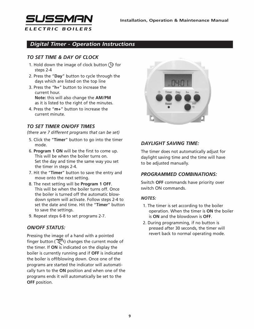
TO SET TIME & DAY OF CLOCK
1. Hold down the image of clock button forsteps 2-4
2. Press the “Day” button to cycle through thedays which are listed on the top line
3. Press the “h+” button to increase thecurrent hour.Note: this will also change the AM/PMas it is listed to the right of the minutes.
4. Press the “m+” button to increase thecurrent minute.
TO SET TIMER ON/OFF TIMES(there are 7 different programs that can be set)
5. Click the “Timer” button to go into the timermode.
6. Program 1 ON will be the first to come up.This will be when the boiler turns on.Set the day and time the same way you setthe timer in steps 2-4.
7. Hit the “Timer” button to save the entry andmove onto the next setting.
8. The next setting will be Program 1 OFF.This will be when the boiler turns off. Oncethe boiler is turned off the automatic blow-down system will activate. Follow steps 2-4 toset the date and time. Hit the “Timer” buttonto save the settings.
9. Repeat steps 6-8 to set programs 2-7.
ON/OFF STATUS:
Pressing the image of a hand with a pointedfinger button ( ) changes the current mode ofthe timer. If ON is indicated on the display theboiler is currently running and if OFF is indicatedthe boiler is off/blowing down. Once one of theprograms are started the indicator will automati-cally turn to the ON position and when one of theprograms ends it will automatically be set to theOFF position.
Installation, Operation & Maintenance Manual
10
24-Hour and 7-Day Time Switches
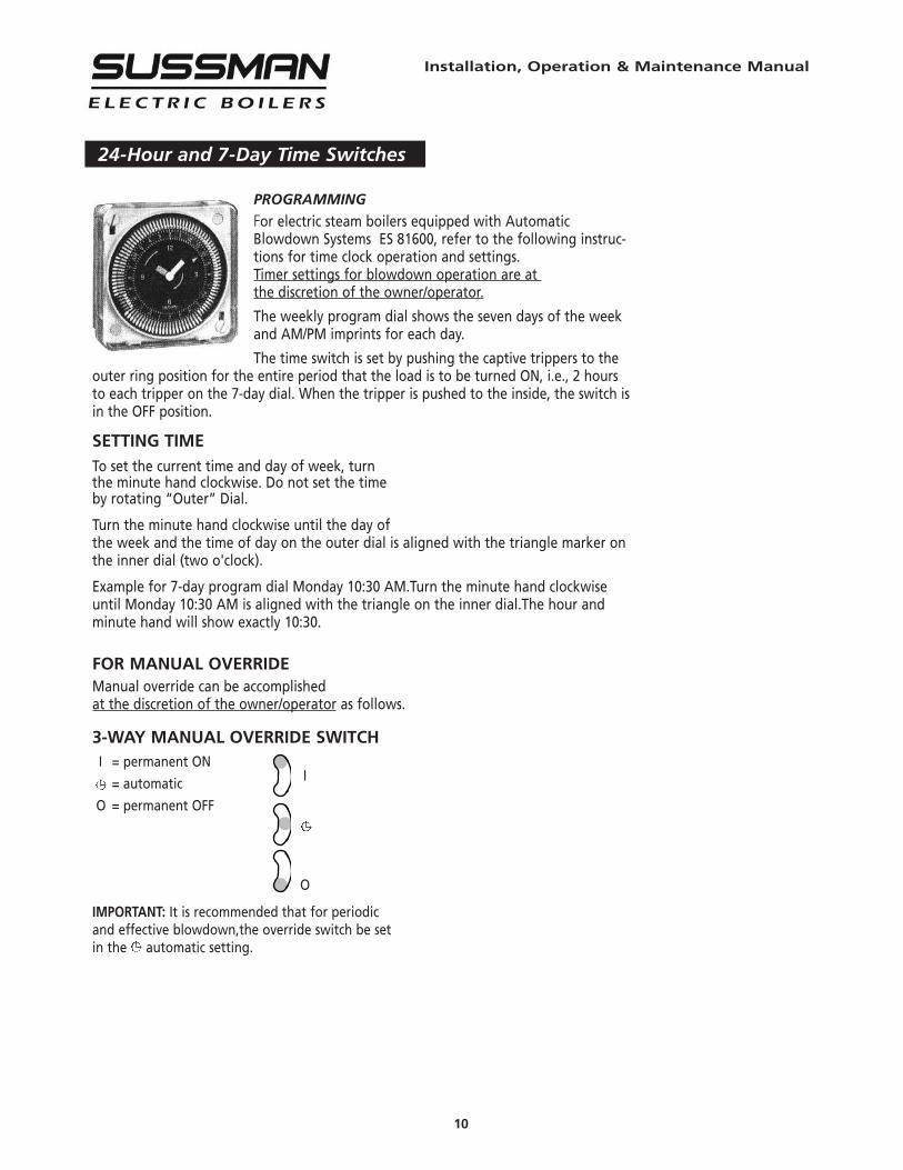
PROGRAMMING
For electric steam boilers equipped with AutomaticBlowdown Systems ES 81600, refer to the following instruc-tions for time clock operation and settings.Timer settings for blowdown operation are atthe discretion of the owner/operator.
The weekly program dial shows the seven days of the weekand AM/PM imprints for each day.
The time switch is set by pushing the captive trippers to theouter ring position for the entire period that the load is to be turned ON, i.e., 2 hoursto each tripper on the 7-day dial. When the tripper is pushed to the inside, the switch isin the OFF position.
SETTING TIME
To set the current time and day of week, turnthe minute hand clockwise. Do not set the timeby rotating “Outer” Dial.
Turn the minute hand clockwise until the day ofthe week and the time of day on the outer dial is aligned with the triangle marker onthe inner dial (two o'clock).
Example for 7-day program dial Monday 10:30 AM.Turn the minute hand clockwiseuntil Monday 10:30 AM is aligned with the triangle on the inner dial.The hour andminute hand will show exactly 10:30.
FOR MANUAL OVERRIDEManual override can be accomplishedat the discretion of the owner/operator as follows.
3-WAY MANUAL OVERRIDE SWITCHI = permanent ON
I= automatic
O = permanent OFF
O
IMPORTANT: It is recommended that for periodicand effective blowdown,the override switch be setin the automatic setting.

Installation, Operation & Maintenance Manual
11
Maintenance
HAZARD OF ELECTRIC SHOCK.DISCONNECT ALL ELECTRICAL POWER BEFORE WORKINGON BOILER.
Sussman Electric Steam Boilers are designed for years of trou-ble-free performance. To establish a good preventative mainte-nance program, we suggest that the facility maintenance per-son or engineer familiarize themselves with these simple rules.
1. Daily blowdown at pressure is essential for ideal boilerperformance. Extended periods of operation may requiremore frequent blowdown. If the boiler is not equippedwith an automatic blowdown, in order to safeguard theheating elements, it is recommended to turn both the maindisconnect switch and the boiler switch to the off positionbefore manually blowing down the boiler.
2. The sight glass should be checked frequently to assure theboiler has adequate water.
3. The sight glass should be checked daily for damage (i.e.scratches, erosion, leaks etc.) The sight glass should bereplaced if damaged. (See insert.)
4. A monthly inspection should be made of the internal wiring.Open the access door and check all electrical connectionsfor tightness. Replace any wires that show signs of damage.
NOTE: The electrical power MUST be shut off during thismaintenance procedure.
7. Heating element mounting bolts should be checked andtightened to a torque of 22 ft.-lbs. If there are indicationsof steam leaks from an element, replace the elementgasket.
8. A monthly check for leaks should be made; any loose ordamaged fittings should be tightened or replaced.
9. Every four months the boiler float control should be checkedfor proper operation. The lower equalization column canbe examined visually and manually to see if is clear andclean. If there are signs of scale or mineral deposit buildupthe float control must be disassembled and cleaned.One of the lower heating elements should be removed. Ifscale or mineral deposits have begun to form all elementsshould be removed cleaned and reinstalled using newelement gaskets.Operating and high limit pressure control operation shouldbe checked. Pressure controls should be removed andcleaned if necessary. Water feed supply check valves shouldbe inspected and replaced if necessary.
10. If the boiler is equipped with an electronic auxiliary lowwater cut-off every four months the probe should beremoved and checked for deposits. The probe should be
! CAUTION
cleaned and reinstalled.11. Replace probe every 10 years. More frequent
replacement of the probe is required if it is usedin locales where significant water treatment isrequired.
12. Replace the auxiliary low water cut-off boardevery 15 years.
13. Perform low water condition test every 12 monthsand confirm auxiliary low water cut-off isoperating as intended.
AUXILIARY LOW WATER CUT-OFF TEST1. To test the auxiliary low water cut-off,
simulate the failure of the primary low watercutoff:
2. Turn off boiler power and control electricsupplies.
3. Drain boiler.4. Close water feed supply valve.5. Open Mercoid level control cover to access its
switches and terminal blocks.6. Turn on boiler control voltage only.7. Verify there is voltage at the yellow wire.8. Manually work the upper switch to disable
pump.9. Manually work the lower switch to engage
the heaters.10. Pilot light near reset button will indicate low
water after 30 seconds.11. Release the switches.12. Open water feed supply valve.13. Allow boiler to fill at proper level.14. Push manual reset button to energize
contactors.15. Install level control cover.

Optional Equipment
Installation, Operation & Maintenance Manual
Standard Equipment
12
AUXILIARY LOW WATER CUT OFF
• For model SSB boilers SSB81017MR(with manual reset).
Senses water level electronically using a resistanceprobe. When a low water condition is detected,the contactor control voltage circuit is interrupt-ed and the heating elements are de-energized.When water level returns to proper levels voltageis restored to the contactor coils and the ele-ments are re-energized. For controls with a man-ual reset button voltage to the contactor coils isnot restored until the water level has returned toproper operating levels and the reset button ispushed. Do not depress the reset button beforethe correct water level is achieved.
LINE PRESSURE WATER FEED SYSTEM
• For model SSB boilers PNPN SSB99117Water feed system used to supply makeup waterto the boiler when incoming water line pressureis 10 psig greater than the operating pressure ofthe boiler. Completely factory plumbed andwired; 0-100psig range; 1/2” NPT size. Consists ofstrainer, solenoid valve (120/1/50-60Hz), and checkvalve for automatic feed. For SSB boilers PNSSB99117 components are of stainless steel con-struction.
HIGH PRESSURE WATER FEED SYSTEM
• For model SSB12-72 PN SSB38002
• For model SSB100-180 PN SSB38020Used to supply makeup water and to maintain con-stant water level when the boiler operating pressureis equal to or greater than incoming water line pres-sure and condensate is not returned to the boiler.
• SSB38002A – Range is 0 – 100 psig, 1/2” NPT sizeconsisting of strainer, solenoid valve and 1/3 HP120/1/60 motor and pump.
• SSB38020A – Range is 0 – 125 psig, 3/4” NPT sizeconsisting of strainer solenoid valve and 1/2 HP120/1/60 motor and pump.These assemblies are mounted on rubber shocks andsecured to a steel base mounting plate. These unitsrequire field plumbing and wiring to the boiler.SSB38002 and SSB38020 pump components are ofstainless steel construction.
AUTOMATIC BLOWDOWN SYSTEM
• Extends life of boiler• Saves labor costs• Starts the boiler automatically every day• Shuts down the boiler every day• Automatically blows down the boiler every day• Completely programmable, can skip days, different
start and shutdown times, different operationaldurations.
• SSB81600 for all model boilers.A stainless steel, motor driven straight-through, self-cleaning ball valve with Teflon seats handles parti-cles and dirty fluid without the use of an up-streamstrainer or other cleaning device. A timer (Standardanalog time clock is set for two hour time intervals,optional digital time clock can be programmed toone minute intervals.) and electronic time delayrelay control the boiler and the blowdown valve.A pilot light indicates when the blowdown valve isopen. The valve shall be plumbed to a proper drainor receptacle. An automatic blowdown system canbe installed on any boiler, regardless of size operat-ing pressure or operating duty cycle.
Installation, Operation & Maintenance Manual
Optional Equipment (cont.)
13
BLOWDOWN SEPARATORS (see page 14)• For models SSB12-48 PN BDT-ASME36• For models SSB60-180 PN BDT-ASME42
A separator accepts the flash steam and effluentfrom the boiler blowdown and reduces the tem-perature and pressure to insure a safe discharge ofwater and sludge. Steam flash and pressure areabsorbed and pass harmlessly to the outside via avent. The separator design utilizes a water seal atthe outlet, which permits the operator to intro-duce cold water from the bottom to mix with thehot water and boiler steam in the blowdown sepa-rator. This reduces outlet temperature to a safedischarge level.These separators require specific plumbing fromthe boiler blowdown valve and require connectionto a cold water supply. (If the separator is less thanhalf full of water after the boiler is blown downcold water must be added to bring the water levelto the halfway mark before the next blowdown).
• 0-30 PSIG pressure gauge; 0-200F temperaturegauge; water sight gauge glass and valve setassembly are included.
CONTROL VOLTAGE STEPDOWNTRANSFORMER• Provides 120 Volt (220 Volt export) from main
power supply. Factory wired and fused.
MULTISTAGE LOAD PROGRESSIVESEQUENCERSAccurate control is provided by automatic progressivesequencing in the use of energy and minimizing wearon electrical components. The sequencers are designedto apply power progressively to larger KW boilers. Afactory installed pressure sensitive sequential controlreacting to steam boiler pressure progressive energizesor de-energizes heating elements through power con-tactors. A delay between sequencer steps before start-up and between each subsequent step eliminatespower surges. Each sequencer is matched and factorypre- set to boiler system requirements. Electronic pro-gressive sequencers give accurate control of multi-stage loads of the type used in steam boilers. Featuresinclude progressive sequencing (first on- first off) thatequalizes the operating time of each load. Integralsolid-state light emitting diodes show active stages.Should a power interruption occur, all elements areinstantly de-energized for safety. Upon resumption ofpower the control will re-stage the loads one at a time.
Installation, Operation & Maintenance Manual
14
Blowdown Separator Tanks- Specifications and Data
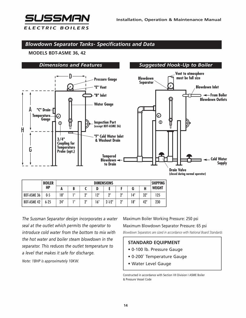
MODELS BDT-ASME 36, 42
D
A
H
G
The Sussman Separator design incorporates a water
seal at the outlet which permits the operator to
introduce cold water from the bottom to mix with
the hot water and boiler steam blowdown in the
separator. This reduces the outlet temperature to
a level that makes it safe for discharge.
Note: 1BHP is approximately 10KW.
Dimensions and Features Suggested Hook-Up to Boiler
"C" DrainTemperature
Gauge
Pressure Gauge
"E" Vent
"B" Inlet
Water Gauge
Inspection Port(except BDT-ASME 36)
"F" Cold Water Inlet& Washout Drain
Maximum Boiler Working Pressure: 250 psi
Maximum Blowdown Separator Pressure: 65 psiBlowdown Separators are sized in accordance with National Board Standards
Constructed in accordance with Section VII Division I ASME Boiler& Pressure Vessel Code
BOILER DIMENSIONS SHIPPING________________________________________________HP A B C D E F G H WEIGHT_______________________________________________________________________
BDT-ASME 36 0-5 18" 1" 2" 12" 2" 2" 14" 32" 125_______________________________________________________________________BDT-ASME 42 6-25 24" 1" 2" 16" 2-1⁄2" 2" 18" 42" 230
BlowdownSeparator
3/4"Coupling forTemperatureProbe (opt.)
Drain Valve(closed during normal operator)
Vent to atmospheremust be full size
TemperedBlowdown
to Drain
STANDARD EQUIPMENT
• 0-100 lb. Pressure Gauge
• 0-200˚ Temperature Gauge
• Water Level Gauge
Blowdown Inlet
From BoilerBlowdown Outlets
Cold WaterSupply
Installation, Operation & Maintenance Manual
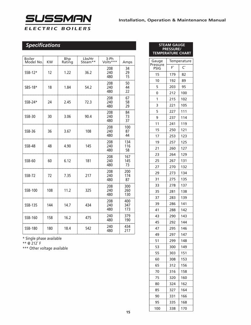
Specifications STEAM GAUGEPRESSURE/
TEMPERATURE CHART
15
__________________________________________Boiler Bhp Lbs/Hr 3-PhModel No. KW Rating Steam** Volts*** Amps__________________________________________
208 34SSB-12* 12 1.22 36.2 240 29
480 15__________________________________________208 50
SBS-18* 18 1.84 54.2 240 44480 22__________________________________________208 67
SSB-24* 24 2.45 72.3 240 58480 29__________________________________________208 84
SSB-30 30 3.06 90.4 240 73480 37__________________________________________208 100
SSB-36 36 3.67 108 240 87480 44__________________________________________208 134
SSB-48 48 4.90 145 240 116480 58__________________________________________208 167
SSB-60 60 6.12 181 240 145480 73__________________________________________208 200
SSB-72 72 7.35 217 240 174480 87__________________________________________208 300
SSB-100 108 11.2 325 240 260480 130__________________________________________208 400
SSB-135 144 14.7 434 240 347480 173__________________________________________
SSB-160 158 16.2 475 240 379480 190__________________________________________
SSB-180 180 18.4 542 240 434480 217__________________________________________
* Single phase available** @ 212˚ F*** Other voltage available
________________Gauge Temperature
PressurePSIG F˚ C˚________________15 179 82________________________10 192 89________________________5 203 95________________________0 212 100________________________1 215 102________________________3 221 105________________________5 227 111________________________9 237 114________________________11 241 119________________________15 250 121________________________17 253 123________________________19 257 125________________________21 260 127________________________23 264 129________________________25 267 131________________________27 270 132________________________29 273 134________________________31 275 135________________________33 278 137________________________35 281 138________________________37 283 139________________________39 286 141________________________41 288 142________________________43 290 143________________________45 292 144________________________47 295 146________________________49 297 147________________________51 299 148________________________53 300 149________________________55 303 151________________________60 308 153________________________65 312 156________________________70 316 158________________________75 320 160________________________80 324 162________________________85 327 164________________________90 331 166________________________95 335 168________________________100 338 170________________________
Installation, Operation & Maintenance Manual
Sizing
16
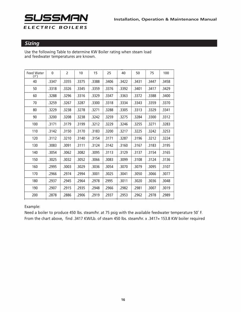
Use the following Table to determine KW Boiler rating when steam loadand feedwater temperatures are known.
_________________________________________________________Feed Water 0 2 10 15 25 40 50 75 100
( F˚)_________________________________________________________40 .3347 .3355 .3375 .3388 .3406 .3422 .3431 .3447 .3458_________________________________________________________50 .3318 .3326 .3345 .3359 .3376 .3392 .3401 .3417 .3429_________________________________________________________60 .3288 .3296 .3316 .3329 .3347 .3363 .3372 .3388 .3400_________________________________________________________70 .3259 .3267 .3287 .3300 .3318 .3334 .3343 .3359 .3370_________________________________________________________80 .3229 .3238 .3278 .3271 .3288 .3305 .3313 .3329 .3341_________________________________________________________90 .3200 .3208 .3238 .3242 .3259 .3275 .3284 .3300 .3312_________________________________________________________100 .3171 .3179 .3199 .3212 .3229 .3246 .3255 .3271 .3283_________________________________________________________110 .3142 .3150 .3170 .3183 .3200 .3217 .3225 .3242 .3253_________________________________________________________120 .3112 .3210 .3140 .3154 .3171 .3287 .3196 .3212 .3224_________________________________________________________130 .3083 .3091 .3111 .3124 .3142 .3160 .3167 .3183 .3195_________________________________________________________140 .3054 .3062 .3082 .3095 .3113 .3129 .3137 .3154 .3165_________________________________________________________150 .3025 .3032 .3052 .3066 .3083 .3099 .3108 .3124 .3136_________________________________________________________160 .2995 .3003 .3029 .3036 .3054 .3070 .3079 .3095 .3107_________________________________________________________170 .2966 .2974 .2994 .3001 .3025 .3041 .3050 .3066 .3077_________________________________________________________180 .2937 .2945 .2964 .2978 2995 .3011 .3020 .3036 .3048_________________________________________________________190 .2907 .2915 .2935 .2948 .2966 .2982 .2981 .3007 .3019_________________________________________________________200 .2878 .2886 .2906 .2919 .2937 .2953 .2962 .2978 .2989_________________________________________________________
Example:Need a boiler to produce 450 lbs. steam/hr. at 75 psig with the available feedwater temperature 50˚ F.From the chart above, find .3417 KW/Lb. of steam 450 lbs. steam/hr. x .3417= 153.8 KW boiler required
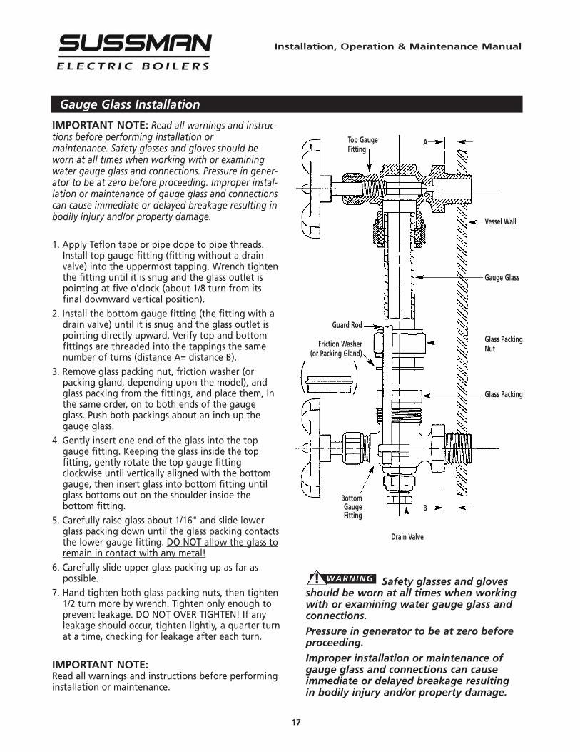
IMPORTANT NOTE: Read all warnings and instruc-tions before performing installation ormaintenance. Safety glasses and gloves should beworn at all times when working with or examiningwater gauge glass and connections. Pressure in gener-ator to be at zero before proceeding. Improper instal-lation or maintenance of gauge glass and connectionscan cause immediate or delayed breakage resulting inbodily injury and/or property damage.
1. Apply Teflon tape or pipe dope to pipe threads.Install top gauge fitting (fitting without a drainvalve) into the uppermost tapping. Wrench tightenthe fitting until it is snug and the glass outlet ispointing at five o'clock (about 1/8 turn from itsfinal downward vertical position).
2. Install the bottom gauge fitting (the fitting with adrain valve) until it is snug and the glass outlet ispointing directly upward. Verify top and bottomfittings are threaded into the tappings the samenumber of turns (distance A= distance B).
3. Remove glass packing nut, friction washer (orpacking gland, depending upon the model), andglass packing from the fittings, and place them, inthe same order, on to both ends of the gaugeglass. Push both packings about an inch up thegauge glass.
4. Gently insert one end of the glass into the topgauge fitting. Keeping the glass inside the topfitting, gently rotate the top gauge fittingclockwise until vertically aligned with the bottomgauge, then insert glass into bottom fitting untilglass bottoms out on the shoulder inside thebottom fitting.
5. Carefully raise glass about 1/16" and slide lowerglass packing down until the glass packing contactsthe lower gauge fitting. DO NOT allow the glass toremain in contact with any metal!
6. Carefully slide upper glass packing up as far aspossible.
7. Hand tighten both glass packing nuts, then tighten1/2 turn more by wrench. Tighten only enough toprevent leakage. DO NOT OVER TIGHTEN! If anyleakage should occur, tighten lightly, a quarter turnat a time, checking for leakage after each turn.
IMPORTANT NOTE:Read all warnings and instructions before performinginstallation or maintenance.
Safety glasses and glovesshould be worn at all times when workingwith or examining water gauge glass andconnections.
Pressure in generator to be at zero beforeproceeding.
Improper installation or maintenance ofgauge glass and connections can causeimmediate or delayed breakage resultingin bodily injury and/or property damage.
Installation, Operation & Maintenance Manual
Gauge Glass Installation
17
Vessel Wall
Gauge Glass
Glass PackingNut
Glass Packing
Top GaugeFitting
Guard Rod
Friction Washer(or Packing Gland)
BottomGaugeFitting
Drain Valve
A
B
! WARNING
Installation, Operation & Maintenance Manual
Gauge Glass Installation - Use and Care
18
DO NOTS
• DO NOT use glass if it contains any scratches, chips, orany other visible signs of damage.
• DO NOT reuse any tubular glass or glass packings.
• DO NOT subject gauge glass to bending or torsionalstresses.
• DO NOT over tighten glass packing nuts.
• DO NOT allow glass to touch any metal parts.
• DO NOT exceed the recommended pressure of thegauge or gauge glass.
• DO NOT clean the gauge or gauge glass while pressur-ized or in operation.
DO'S
• DO verify proper gauge has been supplied.
• DO examine gauge glass and packings carefully fordamage before installation.
• DO install protective guards and utilize automatic ballchecks where necessary to help prevent injuryin case of glass breakage.
• DO inspect the gauge glass daily, keep maintenancerecords, and conduct routine replacements.
• DO protect glass from sudden changes in tempera-tures such as drafts, water spray, etc.
MAINTENANCEExamine the gauge glass regularly for any signsof clouding, scratching, erosion, or corrosion. Theglass should be inspected daily until the need forreplacement becomes apparent. This will helpestablish the routine inspection and routinereplacement schedules.
CLEANINGUse commercial non-abrasive glass cleaners tokeep glass clean. Do not use wire brushes or anyother abrasive materials which could scratch theglass.
INSPECTIONExamine the surface of the glass for scratches,corrosion, chips, cracks, surface flaws, or nicks. Todo this, shine a very bright concentrated light atan angle of about 45 degrees.A defective glasswill glisten as the light strikes imperfections. Glasswhich appears cloudy or roughened, and will notrespond to cleaning, should be replaced.
STORINGKeep gauge glass in original packaging untilready to install.
Installation, Operation & Maintenance Manual
Element Replacement
19
READ INSTRUCTIONS COMPLETELY BEFORE STARTING WORK
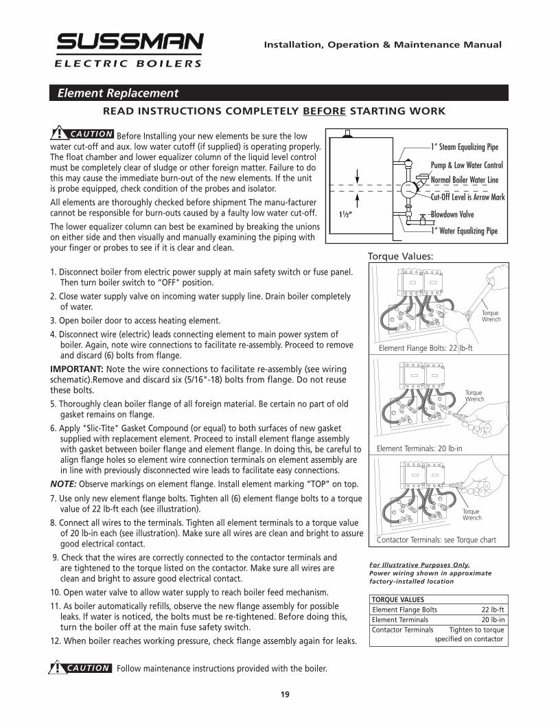
Before Installing your new elements be sure the lowwater cut-off and aux. low water cutoff (if supplied) is operating properly.The float chamber and lower equalizer column of the liquid level controlmust be completely clear of sludge or other foreign matter. Failure to dothis may cause the immediate burn-out of the new elements. If the unitis probe equipped, check condition of the probes and isolator.
All elements are thoroughly checked before shipment The manu-facturercannot be responsible for burn-outs caused by a faulty low water cut-off.
The lower equalizer column can best be examined by breaking the unionson either side and then visually and manually examining the piping withyour finger or probes to see if it is clear and clean.
1. Disconnect boiler from electric power supply at main safety switch or fuse panel.Then turn boiler switch to “OFF" position.
2. Close water supply valve on incoming water supply line. Drain boiler completelyof water.
3. Open boiler door to access heating element.
4. Disconnect wire (electric) leads connecting element to main power system ofboiler. Again, note wire connections to facilitate re-assembly. Proceed to removeand discard (6) bolts from flange.
IMPORTANT: Note the wire connections to facilitate re-assembly (see wiringschematic).Remove and discard six (5/16"-18) bolts from flange. Do not reusethese bolts.
5. Thoroughly clean boiler flange of all foreign material. Be certain no part of oldgasket remains on flange.
6. Apply "Slic-Tite" Gasket Compound (or equal) to both surfaces of new gasketsupplied with replacement element. Proceed to install element flange assemblywith gasket between boiler flange and element flange. In doing this, be careful toalign flange holes so element wire connection terminals on element assembly arein line with previously disconnected wire leads to facilitate easy connections.
NOTE: Observe markings on element flange. Install element marking “TOP” on top.
7. Use only new element flange bolts. Tighten all (6) element flange bolts to a torquevalue of 22 lb-ft each (see illustration).
8. Connect all wires to the terminals. Tighten all element terminals to a torque valueof 20 lb-in each (see illustration). Make sure all wires are clean and bright to assuregood electrical contact.
9. Check that the wires are correctly connected to the contactor terminals andare tightened to the torque listed on the contactor. Make sure all wires areclean and bright to assure good electrical contact.
10. Open water valve to allow water supply to reach boiler feed mechanism.
11. As boiler automatically refills, observe the new flange assembly for possibleleaks. If water is noticed, the bolts must be re-tightened. Before doing this,turn the boiler off at the main fuse safety switch.
12. When boiler reaches working pressure, check flange assembly again for leaks.
Follow maintenance instructions provided with the boiler.
Torque Values:
Element Flange Bolts: 22 lb-ft
Element Terminals: 20 lb-in
Contactor Terminals: see Torque chart
For Illustrative Purposes Only.Power wiring shown in approximatefactory-installed location
TorqueWrench
TorqueWrench
TorqueWrench
11⁄2”
1” Steam Equalizing Pipe
Pump & Low Water Control
Normal Boiler Water Line
Cut-Off Level is Arrow Mark
Blowdown Valve
1” Water Equalizing Pipe
TORQUE VALUESElement Flange Bolts 22 lb-ftElement Terminals 20 lb-inContactor Terminals Tighten to torque
specified on contactor
! CAUTION
! CAUTION

A Division of Sussman-Automatic Corporation43-20 34th Street, Long Island City, NY 11101 • 718-937-45001-800-238-3535 • Fax: 718-937-4676 • email: [email protected]
PUR 101137SSB 1.17
U S A
Designed, Engineeredand Assembled in the