installation,operation, andmaintenancemanual 3910 installation, operation, and maintenance manual 1...
TRANSCRIPT

Installation, Operation,and Maintenance ManualModel 3910


Table of Contents
Model 3910 Installation, Operation, and Maintenance Manual 1
Table of Contents
Introduction ............................................................................................................................. 4Introduction ............................................................................................................................. 4Safety ...................................................................................................................................... 5
Safety terminology and symbols ........................................................................................... 5Environmental safety ............................................................................................................ 6User safety ........................................................................................................................... 7Product approval standards .................................................................................................. 8Safety regulations for Ex-approved products in potentially explosive atmospheres ............. 8
Product warranty ..................................................................................................................... 9
Transportation and Storage ................................................................................................. 11Inspect the delivery ............................................................................................................... 11
Inspect the package ........................................................................................................... 11Inspect the unit ................................................................................................................... 11
Transportation guidelines ...................................................................................................... 11Pump handling ................................................................................................................... 11Lifting methods ................................................................................................................... 11
Storage guidelines ................................................................................................................ 13Pump storage requirements ............................................................................................... 13
Frostproofing ......................................................................................................................... 13
Product Description .............................................................................................................. 14General description 3910 ...................................................................................................... 14Nameplate information .......................................................................................................... 16
Installation ............................................................................................................................. 19Preinstallation ....................................................................................................................... 19
Installation consideration .................................................................................................... 19Pump location guidelines .................................................................................................... 19Installation consideration .................................................................................................... 19Foundation requirements ................................................................................................... 20
Baseplate-mounting procedures ........................................................................................... 21Prepare the baseplate for mounting ................................................................................... 21Prepare the foundation for mounting .................................................................................. 21Install the baseplate using jackscrews ................................................................................ 22
Install the pump, driver, and coupling .................................................................................... 23Pump-to-driver alignment ...................................................................................................... 23
Alignment checks ............................................................................................................... 23Permitted indicator values for alignment checks ................................................................ 24Alignment measurement guidelines ................................................................................... 24Attach the dial indicators for alignment ............................................................................... 25Pump-to-driver alignment instructions ................................................................................ 25
Grout the baseplate .............................................................................................................. 28Piping checklists ................................................................................................................... 29
General piping checklist ..................................................................................................... 29Suction-piping checklist ...................................................................................................... 30Bypass-piping considerations ............................................................................................. 32Auxiliary-piping checklist .................................................................................................... 33Final piping checklist .......................................................................................................... 33
Commissioning, Startup, Operation, and Shutdown ......................................................... 34Preparation for startup .......................................................................................................... 34Remove the coupling guard .................................................................................................. 35

Table of Contents
Model 3910 Installation, Operation, and Maintenance Manual2
Check the rotation - Frame Mounted ..................................................................................... 36Couple the pump and driver .................................................................................................. 37
Coupling guard assembly ................................................................................................... 38Bearing lubrication .............................................................................................................. 48
Shaft sealing with a mechanical seal .................................................................................... 50Connection of sealing liquid for mechanical seals ................................................................. 51Pump priming ........................................................................................................................ 51
Prime the pump with the suction supply above the pump ................................................... 51Prime the pump with the suction supply below the pump ................................................... 51Other methods of priming the pump ................................................................................... 52
Start the pump ...................................................................................................................... 52Pump operation precautions ................................................................................................. 54Shut down the pump ............................................................................................................. 55Make the final alignment of the pump and driver ................................................................... 56Dowel the pump casing (optional) ......................................................................................... 56
Maintenance ........................................................................................................................... 58Maintenance schedule .......................................................................................................... 58Bearing maintenance ............................................................................................................ 59Mechanical-seal maintenance .............................................................................................. 59Disassembly ......................................................................................................................... 60
Disassembly precautions ................................................................................................... 60Tools required .................................................................................................................... 60Drain the pump ................................................................................................................... 61Remove the back pull-out assembly ................................................................................... 61Remove the coupling hub ................................................................................................... 62Remove the impeller 3910 .................................................................................................. 62Remove the impeller (3910LF) ........................................................................................... 62Remove the seal-chamber cover ........................................................................................ 63Remove the optional water-jacket cover ............................................................................. 64Disassemble the power end ............................................................................................... 65
Preassembly inspections ...................................................................................................... 70Replacement guidelines ..................................................................................................... 70Shaft replacement guidelines ............................................................................................. 72Bearings inspection ............................................................................................................ 72Wear rings inspection and replacement 3910LF ................................................................ 73Seal-chamber cover inspection and replacement ............................................................... 79Bearing-frame inspection ................................................................................................... 81Bearing fits and tolerances ................................................................................................. 82
Reassembly .......................................................................................................................... 83Assemble the frame ............................................................................................................ 83Install the optional water-jacket cover ................................................................................. 89Install the seal-chamber cover ............................................................................................ 90Install the cartridge-type mechanical seal and seal-chamber cover ................................... 94Determining impeller spacer thickness (applicable for 3910LF) ......................................... 95Install the impeller 3910 ...................................................................................................... 95Install the impeller (3910LF) ............................................................................................... 95Install the coupling hub ....................................................................................................... 96Install the back pull-out assembly in the casing .................................................................. 96Post-assembly checks ........................................................................................................ 97Assembly references .......................................................................................................... 97
Troubleshooting .................................................................................................................. 101Operation troubleshooting ................................................................................................... 101Alignment troubleshooting .................................................................................................. 102Assembly troubleshooting ................................................................................................... 102

Table of Contents
Model 3910 Installation, Operation, and Maintenance Manual 3
Parts Listings and Cross-Sectionals ................................................................................. 103Parts list .............................................................................................................................. 103
Local ITT Contacts .............................................................................................................. 105Regional offices .................................................................................................................. 105

Introduction
Model 3910 Installation, Operation, and Maintenance Manual4
IntroductionPurpose of this manual
The purpose of this manual is to provide necessary information for:
• Installation
• Operation
• Maintenance
CAUTION:Failure to observe the instructions contained in this manual could result in personal injury andproperty damage, and may void the warranty. Read this manual carefully before installing andusing the product.
NOTICE:Save this manual for future reference and keep it readily available.
Requesting other information
Special versions can be supplied with supplementary instruction leaflets. See the salescontract for any modifications or special version characteristics. For instructions, situations, orevents that are not considered in this manual or in the sales documents, please contact thenearest ITT representative.Always specify the exact product type and identification code when requesting technicalinformation or spare parts.

Introduction
Model 3910 Installation, Operation, and Maintenance Manual 5
Safety
WARNING:• The operator must be aware of the pumpage and take appropriate safety precautions to
prevent physical injury.• Risk of serious injury or death. If any pressure-containing device is over-pressurized, it can
explode, rupture, or discharge its contents. It is critical to take all necessary measures toavoid over-pressurization.
• Risk of death, serious personal injury, and property damage. Installing, operating, ormaintaining the unit using any method not prescribed in this manual is prohibited.Prohibited methods include any modification to the equipment or use of parts not providedby ITT. If there is any uncertainty regarding the appropriate use of the equipment, pleasecontact an ITT representative before proceeding.
• Risk of serious personal injury. Applying heat to impellers, propellers, or their retainingdevices can cause trapped liquid to rapidly expand and result in a violent explosion. Thismanual clearly identifies accepted methods for disassembling units. These methods mustbe adhered to. Never apply heat to aid in their removal unless explicitly stated in thismanual.
• If the pump or motor is damaged or leaking, electric shock, fire, explosion, liberation oftoxic fumes, physical harm, or environmental damage may result. Do not operate the unituntil the problem has been corrected or repaired.
• Risk of serious personal injury or property damage. Dry running may cause rotating partswithin the pump to seize to non-moving parts. Do not run dry.
• Risk of death, serious personal injury, and property damage. Heat and pressure buildupcan cause explosion, rupture, and discharge of pumpage. Never operate the pump withsuction and/or discharge valves closed.
• Running a pump without safety devices exposes operators to risk of serious personalinjury or death. Never operate a unit unless appropriate safety devices (guards, etc.) areproperly installed. See specific information about safety devices in other sections of thismanual.
CAUTION:Risk of injury and/or property damage. Operating a pump in an inappropriate application cancause over pressurization, overheating, and/or unstable operation. Do not change the serviceapplication without the approval of an authorized ITT representative.
Safety terminology and symbols
About safety messagesIt is extremely important that you read, understand, and follow the safety messages andregulations carefully before handling the product. They are published to help prevent thesehazards:
• Personal accidents and health problems
• Damage to the product
• Product malfunction
Hazard levels
Hazard level Indication
DANGER:A hazardous situation which, if not avoided, willresult in death or serious injury

Introduction
Model 3910 Installation, Operation, and Maintenance Manual6
Hazard level Indication
WARNING:A hazardous situation which, if not avoided,could result in death or serious injury
CAUTION:A hazardous situation which, if not avoided,could result in minor or moderate injury
NOTICE:• A potential situation which, if not avoided,
could result in undesirable conditions• A practice not related to personal injury
Hazard categoriesHazard categories can either fall under hazard levels or let specific symbols replace theordinary hazard level symbols.Electrical hazards are indicated by the following specific symbol:
Electrical Hazard:
These are examples of other categories that can occur. They fall under the ordinary hazardlevels and may use complementing symbols:
• Crush hazard
• Cutting hazard
• Arc flash hazard
The Ex symbol
The Ex symbol indicates safety regulations for Ex-approved products when used inatmospheres that are potentially explosive or flammable.
Environmental safety
The work areaAlways keep the station clean to avoid and/or discover emissions.
Waste and emissions regulationsObserve these safety regulations regarding waste and emissions:
• Appropriately dispose of all waste.
• Handle and dispose of the processed liquid in compliance with applicable environmentalregulations.
• Clean up all spills in accordance with safety and environmental procedures.
• Report all environmental emissions to the appropriate authorities.
WARNING:If the product has been contaminated in any way, such as from toxic chemicals or nuclearradiation, do NOT send the product to ITT unless it has been properly decontaminated.
Electrical installationFor electrical installation recycling requirements, consult your local electric utility.

Introduction
Model 3910 Installation, Operation, and Maintenance Manual 7
Recycling guidelines
Always follow local laws and regulations regarding recycling.
User safety
General safety rulesThese safety rules apply:
• Always keep the work area clean.
• Pay attention to the risks presented by gas and vapors in the work area.
• Avoid all electrical dangers. Pay attention to the risks of electric shock or arc flash hazards.
• Always bear in mind the risk of drowning, electrical accidents, and burn injuries.
Safety equipmentUse safety equipment according to the company regulations. Use this safety equipment withinthe work area:
• Helmet
• Safety goggles, preferably with side shields
• Protective shoes
• Protective gloves
• Gas mask
• Hearing protection
• First-aid kit
• Safety devices
Electrical connectionsElectrical connections must be made by certified electricians in compliance with all internation-al, national, state, and local regulations. For more information about requirements, see sectionsdealing specifically with electrical connections.
Precautions before workObserve these safety precautions before you work with the product or are in connection withthe product:
• Provide a suitable barrier around the work area, for example, a guard rail.
• Make sure that all safety guards are in place and secure.
• Allow all system and pump components to cool before you handle them.
• Make sure that you have a clear path of retreat.
• Make sure that the product cannot roll or fall over and injure people or damage property.
• Make sure that the lifting equipment is in good condition.
• Use a lifting harness, a safety line, and a breathing device as required.
• Make sure that the product is thoroughly clean.
• Make sure that there are no poisonous gases within the work area.
• Make sure that you have quick access to a first-aid kit.
• Disconnect and lock out power before servicing.
• Check the explosion risk before you weld or use electric hand tools.
Wash the skin and eyes
1. Follow these procedures for chemicals or hazardous fluids that have come into contact withyour eyes or your skin:

Introduction
Model 3910 Installation, Operation, and Maintenance Manual8
Condition ActionChemicals or hazardousfluids in eyes
1. Hold your eyelids apart forcibly with your fingers.2. Rinse the eyes with eyewash or running water for at least 15 minutes.3. Seek medical attention.
Chemicals or hazardousfluids on skin
1. Remove contaminated clothing.2. Wash the skin with soap and water for at least 1 minute.3. Seek medical attention, if necessary.
Product approval standards
Regular standards
WARNING:Use of equipment unsuitable for the environment can pose risks of ignition and/or explosion.Ensure that the code classifications on the pump are compatible with the specific environmentin which the equipment is to be installed. If they are not compatible, do not operate theequipment and contact an ITT representative before proceeding.
All standard products are approved according to CSA standards in Canada and UL standardsin USA. The drive unit degree of protection follows IP68. See the nameplate for maximumsubmersion, according to standard IEC 60529.
Safety regulations for Ex-approved products in potentially explosiveatmospheres
Description of ATEXThe ATEX directives are a specification enforced in Europe for electrical and non-electricalequipment. ATEX deals with the control of potentially explosive atmospheres and thestandards of equipment and protective systems used within these atmospheres. The relevanceof the ATEX requirements is not limited to Europe. You can apply these guidelines toequipment installed in any potentially explosive atmosphere.
Guidelines for complianceCompliance is only fulfilled when the pump is operated within its intended use, for examplewithin its intended hydraulic range. The conditions of the service must not be changed withoutapproval of an authorized ITT representative. When installing or maintaining explosion-proofpumps, follow these guidelines:
• Always install ATEX-approved equipment in compliance with the directive and applicablestandards (IEC/EN 60079–14).
WARNING:Risk of serious personal injury. Applying heat to impellers, propellers, or their retaining devicescan cause trapped liquid to rapidly expand and result in a violent explosion. This manual clearlyidentifies accepted methods for disassembling units. These methods must be adhered to.Never apply heat to aid in their removal unless explicitly stated in this manual.
If there are any questions regarding these requirements, the intended use, or if the equipmentrequires modification, contact an ITT representative before you proceed.
Personnel requirementsITT disclaims all responsibility for work done by untrained and unauthorized personnel.These are the personnel requirements for Ex-approved products in potentially explosiveatmospheres:
• All work on the product must be carried out by certified electricians and ITT-authorizedmechanics. Special rules apply to installations in explosive atmospheres.
• All users must know about the risks of electric current and the chemical and physicalcharacteristics of the gas and/or vapor present in hazardous areas.

Introduction
Model 3910 Installation, Operation, and Maintenance Manual 9
• Any maintenance for Ex-approved products must conform to international and nationalstandards (for example IEC/EN 60079-17).
Product and product handling requirementsThese are the product and product handling requirements for Ex-approved products inpotentially explosive atmospheres:
• Only use the product in accordance with the approved motor data stated on thenameplates.
• The Ex-approved product must never run dry during normal operation. Dry running duringservice and inspection is only permitted outside the classified area.
• Never start a pump without the proper priming.
• Before you start working with the product, make sure that the product and the control panelare isolated from the power supply and the control circuit, so they cannot be energized.
• Do not open the product while it is energized or in an explosive gas atmosphere.
• Make sure that thermal contacts are connected to a protection circuit according to theapproval classification of the product.
• Intrinsically safe circuits are normally required for the automatic level-control system by thelevel regulator if mounted in zone 0.
• The yield stress of fasteners must be in accordance with the approval drawing and theproduct specification.
• Do not modify the equipment without approval from an authorized ITT representative.
• Only use parts that have been provided by an authorized ITT representative.
Equipment for monitoringFor additional safety, use condition-monitoring devices. Condition-monitoring devices includebut are not limited to these devices:
• Pressure gauges
• Flow meters
• Level indicators
• Motor load readings
• Temperature detectors
• Bearing monitors
• Leak detectors
• PumpSmart control system
Product warrantyCoverage
ITT undertakes to remedy faults in products from ITT under these conditions:
• The faults are due to defects in design, materials, or workmanship.
• The faults are reported to an ITT representative within the warranty period.
• The product is used only under the conditions described in this manual.
• The monitoring equipment incorporated in the product is correctly connected and in use.
• All service and repair work is done by ITT-authorized personnel.
• Genuine ITT parts are used.
• Only Ex-approved spare parts and accessories authorized by ITT are used in Ex-approvedproducts.
LimitationsThe warranty does not cover faults caused by these situations:

Introduction
Model 3910 Installation, Operation, and Maintenance Manual10
• Deficient maintenance
• Improper installation
• Modifications or changes to the product and installation made without consulting ITT
• Incorrectly executed repair work
• Normal wear and tear
ITT assumes no liability for these situations:
• Bodily injuries
• Material damages
• Economic losses
Warranty claimITT products are high-quality products with expected reliable operation and long life. However,should the need arise for a warranty claim, then contact your ITT representative.

Transportation and Storage
Model 3910 Installation, Operation, and Maintenance Manual 11
Transportation and Storage
Inspect the deliveryInspect the package
1. Inspect the package for damaged or missing items upon delivery.2. Note any damaged or missing items on the receipt and freight bill.3. File a claim with the shipping company if anything is out of order.
If the product has been picked up at a distributor, make a claim directly to the distributor.
Inspect the unit1. Remove packing materials from the product.
Dispose of all packing materials in accordance with local regulations.2. Inspect the product to determine if any parts have been damaged or are missing.3. If applicable, unfasten the product by removing any screws, bolts, or straps.
For your personal safety, be careful when you handle nails and straps.4. Contact your sales representative if anything is out of order.
Transportation guidelinesPump handling
WARNING:Dropping, rolling or tipping units, or applying other shock loads, can cause property damageand personal injury. Ensure that the unit is properly supported and secure during lifting andhandling.
CAUTION:Risk of injury or equipment damage from use of inadequate lifting devices. Ensure liftingdevices (such as chains, straps, forklifts, cranes, etc.) are rated to sufficient capacity.
Lifting methods
WARNING:• Risk of serious personal injury or equipment damage. Proper lifting practices are critical to
safe transport of heavy equipment. Ensure that practices used are in compliance with allapplicable regulations and standards.
• Safe lifting points are specifically identified in this manual. It is critical to lift the equipmentonly at these points. Integral lifting eyes or eye bolts on pump and motor components areintended for use in lifting the individual components only.
• Lifting and handling heavy equipment poses a crush hazard. Use caution during lifting andhandling and wear appropriate Personal Protective Equipment (PPE, such as steel-toedshoes, gloves, etc.) at all times. Seek assistance if necessary.
• Units with drivers mounted can be top heavy. Driver weight could cause the assembledunit to overturn and could result in serious physical injury, or damage to pumps.
Table 1: Methods
Pump type Lifting methodA bare pump without lifting han-dles
Use a suitable sling attached properly to solid points like the casing,the flanges, or the frames.
A bare pump with lifting handles Lift the pump by the handles.A base-mounted pump Use slings under the pump casing and the drive unit, or under the base
rails.

Transportation and Storage
Model 3910 Installation, Operation, and Maintenance Manual12
Examples
Figure 1: Example of proper lifting method for bare pump
Figure 2: Example of proper lifting method for units with drivers mounted

Transportation and Storage
Model 3910 Installation, Operation, and Maintenance Manual 13
Figure 3: Example of proper lifting method for units with drivers mounted
Storage guidelinesPump storage requirements
Storage requirements depend on the amount of time that you store the unit. The normalpackaging is designed only to protect the unit during shipping.
Length of time in storage Storage requirementsUpon receipt/short-term (less than six months) • Store in a covered and dry location.
• Store the unit free from dirt and vibrations.Long-term (more than six months) • Store in a covered and dry location.
• Store the unit free from heat, dirt, and vibra-tions.
• Rotate the shaft by hand several times at leastevery three months.
Treat bearing and machined surfaces so that they are well preserved. Refer to drive unit andcoupling manufacturers for their long-term storage procedures.You can purchase long-term storage treatment with the initial unit order or you can purchase itand apply it after the units are already in the field. Contact your local ITT sales representative.
FrostproofingTable 2: Situations when the pump is or is not frostproofSituation ConditionOperating The pump is frostproof.Immersed in a liquid The pump is frostproof.Lifted out of a liquid into a temperature belowfreezing
The impeller might freeze.

Product Description
Model 3910 Installation, Operation, and Maintenance Manual14
Product Description
General description 3910Product description
The model 3910 is a vertical bearing frame in-line centrifugal pump that meets therequirements of API Standard 610 11th Edition (ISO 13709).The model is based on 5 power ends and 27 hydraulic pump sizes.
Figure 4: 3910 pump
WARNING:Use of equipment unsuitable for the environment can pose risks of ignition and/or explosion.Ensure that the code classifications on the pump are compatible with the specific environmentin which the equipment is to be installed. If they are not compatible, do not operate theequipment and contact an ITT representative before proceeding.
CasingThe casing is a vertical in-line mounted design. The gasket is fully confined. ANSI Class 300raised face serrated flanges are standard; ANSI Class 300 flat face serrated and ring jointflanges are available.
ImpellerThe impeller is fully enclosed and key driven by the shaft. An impeller nut with locking set screwprevents axial movement.

Product Description
Model 3910 Installation, Operation, and Maintenance Manual 15
Table 3: Impeller3910 3910 LFEnclosed impeller Semi-open impeller
Seal chamber coverThe model 3910 seal chamber cover meets API 682 3rd Edition dimensions for improvedperformance of mechanical seals.
Power endThe power end has the following characteristics:
• Standard regreasable bearings
• Labyrinth seals on the power end
• Optional pure oil mist lubrication (some modifications are required to convert from greaseto oil mist)
ShaftThe standard shaft is machined and ground to comply with API 610 11th Edition (ISO 13709)criteria.
Bearings
Table 4: BearingsBearing type CharacteristicsInboard (radial) • Consists of a single-row deep-groove ball
bearing• Carries only radial load• Freely floats axially in the frame
Outboard (thrust) • Consists of a duplex-angular contact bearing,which uses a pair of single-row angular contactball bearings mounted back-to-back
• Shouldered and locked to the shaft• Retained in the bearing frame to enable it to
carry radial and thrust loads
Motor supportThe fabricated steel motor support is designed to support the driver and to provide ampleaccess to both the seal piping and the coupling.
Direction of rotationCounterclockwise (left hand) as viewed from the driver, looking at the pump shaft.

Product Description
Model 3910 Installation, Operation, and Maintenance Manual16
Nameplate informationImportant information for ordering
Every pump has a nameplate that provides information about the pump. The nameplate islocated on the pump casing.When you order spare parts, identify this pump information:
• Model
• Size
• Serial number
• Item numbers of the required parts
Refer to the nameplate on the pump casing for most of the information. See Parts List for itemnumbers.
Nameplate typesNameplate DescriptionPump casingPump
Provides information about the hydraulic characteristics of the pump.The formula for the pump size is: Discharge x Suction - Nominal Maximum Impeller Diameter in inches.(Example: 2x3-8)
ATEX If applicable, your pump unit might have an ATEX nameplate affixed to the pump, the baseplate, or thedischarge head. The nameplate provides information about the ATEX specifications of this pump.
IECEx If applicable, your pump unit might have the following IECEx nameplate affixed to the pump and/orbaseplate. The nameplate provides information about the IECEx specifications of this pump.
Nameplate on the pump casing using English units
Figure 5: Nameplate on the pump casing using English units
Nameplate field ExplanationMODEL Pump modelSIZE Size of the pumpFLOW Rated pump flow, in gallons per minuteHEAD Rated pump head, in feetRPM Rated pump speed, in revolutions per minuteHYDRO PRESS Hydrostatic pressure at 100°F, in pounds per square inchMAX. DES. WORKING PRESS Maximum working pressure at temperature °F, in pounds per square inchS/N Serial number of the pumpCONT./ITEM NO. Customer contract or item numberIMP. DIA. Rated impeller diameterMAX. DIA. Maximum impeller diameterSTD. DIM. Standard ANSI dimensional codeMAT'L Material of construction

Product Description
Model 3910 Installation, Operation, and Maintenance Manual 17
Nameplate on the pump casing using metric units
Figure 6: Metric units - nameplate on pump casing
Figure 7: Nameplate on pump casing using metric units
Nameplate field ExplanationMODEL Pump modelSIZE Size of the pumpFLOW Rated pump flow, in gallons per minuteHEAD Rated pump head, in feetRPM Rated pump speed, in revolutions per minuteHYDRO PRESS Hydrostatic pressure at 38°C Kg/cm2MAX. DES. WORKING PRESS Maximum working pressure at temperature °C in kilograms per square centimeterS/N Serial number of the pumpCONT./ITEM NO. Customer contract or item numberIMP. DIA. Rated impeller diameterMAX. DIA. Maximum impeller diameterSTD. DIM. Standard ANSI dimensional codeMAT'L Material of construction
Nameplate on the bearing frame
Figure 8: Nameplate on the bearing frame
Table 5: Explanation of the nameplate on the bearing frameNameplate field ExplanationBRG. O. B. Outboard bearing designationBRG. I. B. Inboard bearing designation

Product Description
Model 3910 Installation, Operation, and Maintenance Manual18
Nameplate field ExplanationS/N Serial number of the pumpLUBE Lubricant, oil or grease
ATEX nameplate
Figure 9: ATEX nameplate
Nameplate field ExplanationII Group 22 Category 2G/D Pump can be used when gas and dust are presentT4 Temperature class
Table 6: Temperature class definitionsCode Maximum permissible surface
temperature in °F (°C)Minimum permissible surfacetemperature in °F (°C)
T1 842 (450) 700 (372)T2 572 (300) 530 (277)T3 392 (200) 350 (177)T4 275 (135) 235 (113)T5 212 (100) Option not availableT6 185 (85) Option not available
WARNING:Use of equipment unsuitable for the environment can pose risks of ignition and/or explosion.Ensure that the code classifications on the pump are compatible with the specific environmentin which the equipment is to be installed. If they are not compatible, do not operate theequipment and contact an ITT representative before proceeding.

Installation
Model 3910 Installation, Operation, and Maintenance Manual 19
Installation
PreinstallationPrecautions
WARNING:
• When installing in a potentially explosive environment, ensure that the motor isproperly certified.
• All equipment being installed must be properly grounded to prevent unexpecteddischarge. Discharge can cause equipment damage, electric shock, and result in seriousinjury. Test the ground lead to verify it is connected correctly.
NOTICE:• Electrical connections must be made by certified electricians in compliance with all
international, national, state and local regulations.
• Supervision by an authorized ITT representative is recommended to ensure properinstallation. Improper installation may result in equipment damage or decreased perfor-mance.
Installation considerationModel 3910 in-line pumps are designed to be mounted directly in the piping. The pump casinghas a flat base which may be mounted on a concrete foundation which has been poured on asolid footing.
Pump location guidelinesGuideline Explanation/commentMake sure that the space around thepump is sufficient.
This facilitates ventilation, inspection, maintenance, and ser-vice.
If you require lifting equipment such as ahoist or tackle, make sure that there isenough space above the pump.
This makes it easier to properly use the lifting equipment andsafely remove and relocate the components to a safe location.
Protect the unit from weather and waterdamage due to rain, flooding, and freez-ing temperatures.
This is applicable if nothing else is specified.
Do not install and operate the equipmentin closed systems unless the system isconstructed with properly-sized safetydevices and control devices.
Acceptable devices:• Pressure relief valves• Compression tanks• Pressure controls• Temperature controls• Flow controls
If the system does not include these devices, consult theengineer or architect in charge before you operate the pump.
Take into consideration the occurrence ofunwanted noise and vibration.
The best pump location for noise and vibration absorption ison a concrete floor with subsoil underneath.
Installation considerationModel 3910 in-line pumps are designed to be mounted directly in the piping. The pump casinghas a flat base which may be mounted on a concrete foundation which has been poured on asolid footing.

Installation
Model 3910 Installation, Operation, and Maintenance Manual20
Foundation requirements
Requirements• The foundation must be able to absorb any type of vibration and form a permanent, rigid
support for the unit.
• The location and size of the foundation bolt holes must match those shown on theassembly drawing provided with the pump data package.
• The foundation must weigh between two and three times the weight of the pump.
• Provide a flat, substantial concrete foundation in order to prevent strain and distortionwhen you tighten the foundation bolts.
Mounting methods
Figure 10: Recommended mounting
Figure 11: Recommended mounting with optional casing supports
NOTICE:Do not bolt down to foundation.

Installation
Model 3910 Installation, Operation, and Maintenance Manual 21
J-type bolts
1. Baseplate2. Shims or wedges3. Foundation4. Dam5. BoltFigure 12: J-type bolts
Baseplate-mounting proceduresPrepare the baseplate for mounting
This procedure assumes you have a basic knowledge of baseplate and foundation design andinstallation methods. Follow industry-standard procedures, such as API RP 686/ PIP REIE 686,or this procedure before you grout the baseplate.1. Make sure that all baseplate surfaces that will contact grout are free from contamination
such as rust, oil, and grime.2. Thoroughly clean all baseplate surfaces that will come in contact with grout.
Make sure to use a cleaner that will not leave residue.
NOTICE:You may need to sandblast the surfaces of a baseplate that come in contact with grout, andthen coat those surfaces with a primer that is grout-compatible. Make sure to remove allequipment before sandblasting.
3. Make sure that all machined surfaces are free from burrs, rust, paint, or any other type ofcontamination.If necessary, use a honing stone to remove burrs.
Prepare the foundation for mounting1. Chip the top of the foundation to a minimum of 25.0 mm | 1.0 in. in order to remove porous
or low-strength concrete.If you use a pneumatic hammer, make sure that it does not contaminate the surface with oilor other moisture.
NOTICE:Do not chip the foundation using heavy tools such as jackhammers. This can damage thestructural integrity of the foundation.
2. Remove water or debris from the foundation bolt holes or sleeves.3. If the baseplate uses sleeve-type bolts, then fill the sleeves with a non-binding, moldable
material. Seal the sleeves in order to prevent the grout from entering.4. Coat the exposed portion of the anchor bolts with a non-bonding compound such as paste
wax in order to prevent the grout from adhering to the anchor bolts.Do not use oils or liquid wax.

Installation
Model 3910 Installation, Operation, and Maintenance Manual22
5. If recommended by the grout manufacturer, coat the foundation surface with a compatibleprimer.
Install the baseplate using jackscrewsTools required:
• Anti-seize compound
• Jackscrews
• Bar stock
• Two machinist's levels
This procedure is applicable to the feature-fabricated steel baseplate and the advantage basebaseplate.1. Apply an anti-seize compound on the jackscrews.
The compound makes it easier to remove the screws after you grout.2. Lower the baseplate carefully onto the foundation bolts and perform these steps:
a) Cut the plates from the bar stock and chamfer the edges of the plates in order to reducestress concentrations.
b) Put the plates between the jackscrews and the foundation surface.c) Use the four jackscrews in the corners in order to raise the baseplate above the
foundation.Make sure that the distance between the baseplate and the foundation surface isbetween 19 mm | 0.75 in. and 38 mm | 1.50 in.
d) Make sure that the center jackscrews do not touch the foundation surface yet.
1. Jackscrew2. Baseplate3. Foundation4. PlateFigure 13: Jackscrews
3. Level the driver mounting pads:
NOTICE:Remove all dirt from the mounting pads in order to ensure that the correct leveling isachieved. Failure to do so can result in equipment damage or decreased performance.
a) Put one machinist's level lengthwise on one of the two pads.b) Put the other machinist's level across the ends of the two pads.c) Level the pads by adjusting the four jackscrews in the corners.
Make sure that the machinist's level readings are as close to zero as possible, bothlengthwise and across.
4. Turn the center jackscrews down so that they rest on their plates on the foundation surface.5. Level the pump mounting pads:

Installation
Model 3910 Installation, Operation, and Maintenance Manual 23
NOTICE:Remove all dirt from the mounting pads in order to ensure that the correct leveling isachieved. Failure to do so can result in equipment damage or decreased performance.
a) Put one machinist's level lengthwise on one of the two pads.b) Put the other level across the center of the two pads.c) Level the pads by adjusting the four jackscrews in the corners.
Make sure that the machinist's level readings are as close to zero as possible, bothlengthwise and across.
6. Hand-tighten the nuts for the foundation bolts.7. Check that the driver's mounting pads are level and adjust the jackscrews and the
foundation bolts if necessary.The correct level measurement is a maximum of 0.0167 mm/m | 0.002 in./ft .The maximum variation from one side of the baseplate to the other is 0.38 mm | 0.015 in.
Install the pump, driver, and coupling1. Mount the driver on the motor support. Use applicable bolts and hand tighten.2. Install the coupling.
See the installation instructions from the coupling manufacturer.
Pump-to-driver alignmentPrecautions
WARNING:• Misalignment can cause decreased performance, equipment damage, and even catas-
trophic failure of frame-mounted units leading to serious injury. Proper alignment is theresponsibility of the installer and the user of the unit. Check the alignment of all drivecomponents prior to operating the unit.• Follow the coupling installation and operation procedures from the coupling manufactur-
er.• Failure to disconnect and lock out driver power may result in serious physical injury or
death. Always disconnect and lock out power to the driver before performing anyinstallation or maintenance tasks.• Electrical connections must be made by certified electricians in compliance with all
international, national, state, and local rules.• Refer to driver/coupling/gear manufacturer's installation and operation manuals (IOM)
for specific instructions and recommendations.
Alignment methodsThree common alignment methods are used:
• Dial indicator
• Reverse dial indicator
• Laser
Follow the instructions from the equipment manufacturer when you use the reverse dialindicator or laser methods. Detailed instructions for using the dial indicator method arecontained in this chapter.
Alignment checks
When to perform alignment checksYou must perform alignment checks under these circumstances:

Installation
Model 3910 Installation, Operation, and Maintenance Manual24
• The process temperature changes.
• The piping changes.
• The pump has been serviced.
Types of alignment checks
Type of check When it is usedInitial alignment (cold alignment)check
Prior to operation when the pump and the driver are at ambienttemperature.
Final alignment (hot alignment)check
After operation when the pump and the driver are at operatingtemperature.
Initial alignment (cold alignment) checks
When WhyBefore you grout the baseplate This ensures that alignment can be accomplished.After you grout the baseplate This ensures that no changes have occurred during the grouting
process.After you connect the piping This ensures that pipe strains have not altered the alignment.
If changes have occurred, you must alter the piping to remove pipestrains on the pump flanges.
Final alignment (hot alignment) checks
When WhyAfter the first run This ensures correct alignment when both the pump and the driver
are at operating temperature.Periodically This follows the plant operating procedures.
Permitted indicator values for alignment checks
NOTICE:The specified permitted reading values are valid only at operating temperature. For coldsettings, other values are permitted. The correct tolerances must be used. Failure to do so canresult in misalignment.
IMPORTANT• For electric motors, the motor shaft initial (cold) parallel vertical alignment setting should
be 0.05 to 0.10 mm | 0.002 to 0.004 in. lower than the pump shaft.
• For other drivers such as turbines and engines, follow the driver manufacturer'srecommendations.
When dial indicators are used to check the final alignment, the pump and drive unit arecorrectly aligned when these conditions are true:
• The Total Indicated Reading (T.I.R.) is at 0.05 mm | 0.002 in. or less at operatingtemperature.
• The tolerance of the indicator is 0.0127 mm per mm | 0.0005 in. per in. of indicatorseparation for the reverse dial indicator or laser method when the pump and driver are atoperating temperature.
Alignment measurement guidelinesGuideline ExplanationRotate the pump coupling half and the driver coupling halftogether so that the indicator rods have contact with the samepoints on the driver coupling half.
This prevents incorrect measurement.
Move or shim only the driver in order to make adjustments. This prevents strain on the piping instal-lations.
Make sure that the hold-down bolts for the driver feet are tightwhen you take indicator measurements.
This keeps the driver stationary sincemovement causes incorrect measure-ment.

Installation
Model 3910 Installation, Operation, and Maintenance Manual 25
Guideline ExplanationMake sure that the hold-down bolts for the driver feet are loosebefore you make alignment corrections.
This makes it possible to move the driverwhen you make alignment corrections.
Check the alignment again after any mechanical adjustments. This corrects any misalignments that anadjustment may have caused.
Attach the dial indicators for alignmentYou must have two dial indicators in order to complete this procedure.1. Attach two dial indicators on the pump coupling half (X):
a) Attach one indicator (P) so that the indicator rod comes into contact with the perimeterof the driver coupling half (Y).This indicator is used to measure parallel misalignment.
b) Attach the other indicator (A) so that the indicator rod comes into contact with the innerend of the driver coupling half.This indicator is used to measure angular misalignment.
Figure 14: Dial indicator attachment
2. Rotate the pump coupling half (X) in order to check that the indicators are in contact withthe driver coupling half (Y) but do not bottom out.
3. Adjust the indicators if necessary.
Pump-to-driver alignment instructionsPerform angular alignment for a vertical correction
1. Set the angular alignment indicator to zero at the top-center position (12 o’clock) of thedriver coupling half (Y).
2. Rotate the indicator to the bottom-center position (6 o’clock).3. Record the indicator reading.
When thereading valueis...
Then...
Negative The coupling halves are farther apart at the bottom than at the top. Perform one ofthese steps:
• Add shims in order to raise the feet of the driver at the shaft end.• Remove shims in order to lower the feet of the driver at the other end.

Installation
Model 3910 Installation, Operation, and Maintenance Manual26
When thereading valueis...
Then...
Positive The coupling halves are closer at the bottom than at the top. Perform one of thesesteps:
• Remove shims in order to lower the feet of the driver at the shaft end.• Add shims in order to raise the feet of the driver at the other end.
1. ShimsFigure 15: Example of incorrect vertical alignment (side view)
Perform angular alignment for a horizontal correction1. Set the angular alignment indicator (A) to zero on left side of the driver coupling half (Y),
90° from the top-center position (9 o’clock).2. Rotate the indicator through the top-center position to the right side, 180° from the start
position (3 o’clock).3. Record the indicator reading.
When the reading value is... Then...Negative The coupling halves are farther apart on the right side than
the left. Perform one of these steps:• Slide the shaft end of the driver to the left.• Slide the opposite end to the right.
Positive The coupling halves are closer together on the right sidethan the left. Perform one of these steps:
• Slide the shaft end of the driver to the right.• Slide the opposite end to the left.
Figure 16: Example of incorrect horizontal alignment (top view)
4. Repeat the previous steps until the permitted reading value is achieved.
Perform parallel alignment for a vertical correctionRefer to the alignment table in "Permitted indicator values for alignment checks" (see Table ofContents for location of table) for the proper cold alignment value based on the motortemperature rise and the pump operating temperature.Before you start this procedure, make sure that the dial indicators are correctly set up.A unit is in parallel alignment when the parallel indicator (P) does not vary by more than0.05 mm | 0.002 in. as measured at four points 90° apart at the operating temperature.

Installation
Model 3910 Installation, Operation, and Maintenance Manual 27
1. Set the parallel alignment indicator (P) to zero at the top-center position (12 o’clock) of thedriver coupling half (Y).
2. Rotate the indicator to the bottom-center position (6 o’clock).3. Record the indicator reading.
When the readingvalue is...
Then...
Negative The pump coupling half (X) is lower than the driver coupling half (Y). Removeshims of a thickness equal to half of the indicator reading value under eachdriver foot.
Positive The pump coupling half (X) is higher than the driver coupling half (Y). Addshims of a thickness equal to half of the indicator reading value to each driverfoot.
1. ShimsFigure 17: Example of incorrect vertical alignment (side view)
4. Repeat the previous steps until the permitted reading value is achieved.
NOTICE:The specified permitted reading values are valid only at operating temperature. For coldsettings, other values are permitted. The correct tolerances must be used. Failure to do socan result in misalignment.
Perform parallel alignment for a horizontal correctionA unit is in parallel alignment when the parallel indicator (P) does not vary by more than0.05 mm | 0.002 in. as measured at four points 90° apart at the operating temperature.1. Set the parallel alignment indicator (P) to zero on the left side of the driver coupling half (Y),
90° from the top-center position (9 o’clock).2. Rotate the indicator through the top-center position to the right side, 180° from the start
position (3 o’clock).3. Record the indicator reading.
When the reading value is... Then...Negative The driver coupling half (Y) is to the left of the pump coupling
half (X).Positive The driver coupling half (Y) is to the right of the pump coupling
half (X).

Installation
Model 3910 Installation, Operation, and Maintenance Manual28
4. Slide the driver carefully in the appropriate direction. Make sure to slide the driver evenly.Failure to do so can negatively affect horizontal angular correction.
Figure 18: Example of incorrect horizontal alignment (top view)
5. Repeat the previous steps until the permitted reading value is achieved.
Perform complete alignment for a vertical correctionA unit is in complete alignment when both the angular indicator (A) and the parallel indicator (P)do not vary by more than 0.05 mm | 0.002 in. as measured at four points 90° apart.1. Set the angular and parallel dial indicators to zero at the top-center position (12 o’clock) of
the driver coupling half (Y).2. Rotate the indicators to the bottom-center position (6 o’clock).3. Record the indicator readings.4. Make corrections according to the separate instructions for angular and parallel alignment
until you obtain the permitted reading values.
Perform complete alignment for a horizontal correctionA unit is in complete alignment when both the angular indicator (A) and the parallel indicator (P)do not vary by more than 0.05 mm | 0.002 in. as measured at four points 90° apart.1. Set the angular and parallel dial indicators to zero at the left side of the driver coupling half
(Y), 90° from the top-center position (9 o’clock).2. Rotate the indicators through the top-center position to the right side, 180° from the start
position (3 o’clock).3. Record the indicator readings.4. Make corrections according to the separate instructions for angular and parallel alignment
until you obtain the permitted reading values.
Grout the baseplateRequired equipment:
• Cleaners: Do not use an oil-based cleaner because the grout will not bond to it. See theinstructions provided by the grout manufacturer.
• Grout: Non-shrink grout is recommended.
NOTICE:It is assumed that the installer who grouts the baseplate has knowledge of acceptablemethods. More detailed procedures are described in various publications, including APIStandard 610, latest edition, Appendix L; API RP 686, Chapter 5; and other industry standards.
1. Clean all the areas of the baseplate that will come into contact with the grout.2. Build a dam around the foundation.3. Thoroughly wet the foundation that will come into contact with the grout.4. Pour grout through the grout hole into the baseplate up to the level of the dam.
When you pour the grout, remove air bubbles from it by using one of these methods:
• Puddle with a vibrator.
• Pump the grout into place.

Installation
Model 3910 Installation, Operation, and Maintenance Manual 29
5. Allow the grout to set.
1. Baseplate2. Shims or wedges3. Grout4. Foundation5. Sleeve6. Dam7. Bolt
Figure 19: Pour grout into baseplate
6. Fill the remainder of the baseplate with grout, and allow the grout to set for at least 48hours.
1. Baseplate2. Grout3. Foundation4. Dam5. Bolt
Figure 20: Fill remainder of baseplate with grout
7. Remove the leveling jackscrews after the grout hardens in order to remove any stresspoints.
8. Tighten the foundation bolts.
Piping checklistsGeneral piping checklist
Piping guidelinesGuidelines for piping are given in the Hydraulic Institute Standards, available from: HydraulicInstitute, 9 Sylvan Way, Parsippany, NJ 07054 and in API RP 686, and must be reviewed priorto pump installation.
Alignment criteria for pump flanges
Type CriteriaAxial The flange gasket thickness is ±0.8 mm | 0.03 in.Parallel Align the flange to be within 0.025 mm/mm to 0.8 mm/mm maximum 0.001 in./
in. to 0.03 in./in. of the flange diameter.

Installation
Model 3910 Installation, Operation, and Maintenance Manual30
Type CriteriaConcentric You can easily install the flange bolts by hand.
Example: Installation for expansion
Correct IncorrectThis illustration shows a correct installation forexpansion:
1. Expansion loop/joint
This illustration shows an incorrect installation forexpansion:
Suction-piping checklist
Performance curve referenceNet positive suction head available (NPSHA) must always exceed NPSH required (NPSHR) asshown on the published performance curve of the pump.
Suction-piping checks
Check Explanation/comment CheckedCheck that the distance between theinlet flange of the pump and the closestelbow is at least five pipe diameters.
This minimizes the risk of cavitation in thesuction inlet of the pump due to turbulence.See the Example sections for illustrations.
Check that elbows in general do nothave sharp bends.
See the Example sections for illustrations.—
Check that the suction piping is one ortwo sizes larger than the suction inlet ofthe pump.Install an eccentric reducer betweenthe pump inlet and the suction piping.
The suction piping must never have a smallerdiameter than the suction inlet of the pump.See the Example sections for illustrations.
Check that the eccentric reducer at thesuction flange of the pump has thefollowing properties:
• Sloping side down• Horizontal side at the top
See the example illustrations.

Installation
Model 3910 Installation, Operation, and Maintenance Manual 31
Check Explanation/comment CheckedSuggested suction strainers are used.Check that they are at least three timesthe area of the suction piping.Monitor the pressure drop across thesuction strainer.An increased pressure drop across thestrainer of 5 psi (34.5 kPa) indicatesthat the strainer should be removedand cleaned.After a period of time (24 hours mini-mum) system flushing should be com-plete and the suction strainer can beremoved.
Suction strainers help to prevent debris fromentering the pump.Mesh holes with a minimum diameter of 1/16 in.(1.6 mm) are recommended.Liquids with specific gravity less than 0.60 apressure drop across the suction strainer may bedue to ice buildup. Ice buildup can cause turbu-lence, low pressure areas and pumpage vapor-ization.
If more than one pump operates fromthe same liquid source, check thatseparate suction-piping lines are usedfor each pump.
This recommendation helps you to achieve ahigher pump performance and prevent vaporlocking especially with specific gravity of liquidless than 0.60.
If necessary, make sure that the suc-tion piping includes a drain valve andthat it is correctly installed.
—
Assure adequate insulation is appliedfor liquids with specific gravity less than0.60.
To assure sufficient NPSHa.
Liquid source below the pump
Check Explanation/comment CheckedMake sure that the suction piping isfree from air pockets.
This helps to prevent the occurrence of air andcavitation in the pump inlet.
Check that the suction piping slopesupwards from the liquid source to thepump inlet.
—
If the pump is not self-priming, checkthat a device for priming the pump isinstalled.
Use a foot valve with a diameter that is at leastequivalent to the diameter of the suction piping.
Liquid source above the pump
Check Explanation/comment CheckedCheck that an isolation valve is in-stalled in the suction piping at a dis-tance of at least two times the pipediameter from the suction inlet.
This permits you to close the line during pumpinspection and maintenance.Do not use the isolation valve to throttle the pump.Throttling can cause these problems:
• Loss of priming• Excessive temperatures• Damage to the pump• Voiding the warranty
Make sure that the suction piping isfree from air pockets.
This helps to prevent the occurrence of air andcavitation in the pump inlet.
Check that the piping is level or slopesdownward from the liquid source.
—
Make sure that no part of the suctionpiping extends below the suction flangeof the pump.
—
Make sure that the suction piping isadequately submerged below the sur-face of the liquid source.
This prevents air from entering the pump througha suction vortex.

Installation
Model 3910 Installation, Operation, and Maintenance Manual32
Example: Elbow close to the pump suction inlet
Correct IncorrectThe correct distance between the inlet flange of thepump and the closest elbow must be at least fivepipe diameters.Where used, elbows should be long radius.
Example: Suction piping equipment
Correct Incorrect
1. Suction pipe sloping upwards from liquid source2. Long-radius elbow3. Strainer4. Foot valve5. Eccentric reducer with a level top
1. Air pocket, because the eccentric reducer is notused and because the suction piping does notslope gradually upward from the liquid source
Bypass-piping considerations
When to use a bypass lineProvide a bypass line for systems that require operation at reduced flows for prolongedperiods. Connect a bypass line from the discharge side (before any valves) to the source ofsuction.
When to install a minimum-flow orificeYou can size and install a minimum-flow orifice in a bypass line in order to prevent bypassingexcessive flows. Consult your ITT representative for assistance in sizing a minimum-floworifice.
When a minimum-flow orifice is unavailableConsider an automatic recirculation control valve or solenoid-operated valve if a constantbypass (minimum-flow orifice) is not possible.

Installation
Model 3910 Installation, Operation, and Maintenance Manual 33
Auxiliary-piping checklist
Precautions
WARNING:
• Cooling systems such as those for bearing lubrication and mechanical-seal systemsmust be operating properly to prevent excess heat generation, sparks, and prematurefailure.
• Sealing systems that are not self-purging or self-venting, such as plan 23, requiremanual venting prior to operation. Failure to do so will result in excess heat generation andseal failure.
NOTICE:
The mechanical seal must have an appropriate seal-flush system. Failure to do so willresult in excess heat generation and seal failure.
When to installYou may need to install auxiliary piping for bearing cooling, seal-chamber cover cooling,mechanical seal flush, or other special features supplied with the pump. Consult the pump datasheet for specific auxiliary piping recommendations.
Checklist
Check Explanation/comment CheckedCheck that the minimum flow for eachcomponent is 4 lpm | 1 gpm.If the bearing and seal chamber covercooling are provided, then the auxiliarypiping must flow at 8 lpm | 2 gpm.
Make sure that these guidelines are followed.
Check that the cooling water pressuredoes not exceed 7.0 kg/cm2 | 100 psig .
Make sure that these guidelines are followed.
Final piping checklistCheck Explanation/comment CheckedCheck that the shaft rotates smoothly. Rotate the shaft by hand. Make sure there is no
rubbing that can lead to excess heat generation orsparks.
Re-check the alignment to make surethat pipe strain has not caused anymisalignment.
If pipe strain exists, then correct the piping.

Commissioning, Startup, Operation, and Shutdown
Model 3910 Installation, Operation, and Maintenance Manual34
Commissioning, Startup, Operation, andShutdown
Preparation for startup
WARNING:• Risk of serious physical injury or death. Exceeding any of the pump operating limits (e.g. -
pressure, temperature, power, etc.) could result in equipment failure, such as explosion,seizure, or breach of containment. Assure that the system operating conditions are withinthe capabilities of the pump.
• Risk of death or serious injury. Leaking fluid can cause fire and/or burns. Ensure allopenings are sealed prior to filling the pump.
• Breach of containment can cause fire, burns, and other serious injury. Failure to followthese precautions before starting the unit may lead to dangerous operating conditions,equipment failure, and breach of containment.
• Risk of serious personal injury or property damage. Dry running may cause rotating partswithin the pump to seize to non-moving parts. Do not run dry.
• Risk of explosion and serious physical injury. Do not operate pump with blocked systempiping or with suction or discharge valves closed. This can result in rapid heating andvaporization of pumpage.
• Risk of breach of containment and equipment damage. Ensure the pump operates onlybetween minimum and maximum rated flows. Operation outside of these limits can causehigh vibration, mechanical seal and/or shaft failure, and/or loss of prime.
• Avoid mechanical seal failure or pump seizure by:• increasing speed at startup to at least 65% of rated speed within 5 seconds and• decreasing speed at shutdown from 65% of rated speed to 0 within 5 seconds
• Foreign objects in the pumped liquid or piping system can block the flow and cause excessheat generation, sparks and premature failure. Make sure that the pump and systems arefree of foreign objects before and during operation.
• A build-up of gases within the pump, sealing system, or process piping system mayresult in an explosive environment. Make sure the process piping system, pump andsealing system are properly vented prior to operation.
• Sealing systems that are not self-purging or self-venting, such as plan 23, requiremanual venting prior to operation. Failure to do so will result in excess heat generation andseal failure.
• Running a pump without safety devices exposes operators to risk of serious personalinjury or death. Never operate a unit unless appropriate safety devices (guards, etc.) areproperly installed.
• Failure to disconnect and lock out driver power may result in serious physical injury ordeath. Always disconnect and lock out power to the driver before performing anyinstallation or maintenance tasks.• Electrical connections must be made by certified electricians in compliance with all
international, national, state, and local rules.• Refer to driver/coupling/gear manufacturer's installation and operation manuals (IOM)
for specific instructions and recommendations.• Starting the pump in reverse rotation can result in the contact of metal parts, heat
generation, and breach of containment. Ensure correct driver settings prior to starting anypump.
• Risk of seizure, breach of containment, or explosion. Ensure balance line is installed andpiped back to either the pump suction or suction vessel. This prevents rapid vaporization ofthe pumped fluid.

Commissioning, Startup, Operation, and Shutdown
Model 3910 Installation, Operation, and Maintenance Manual 35
Precautions
NOTICE:• Make sure that the temperature change does not exceed 19°C | 35°F per minute.
You must follow these precautions before you start the pump:
• Flush and clean the system thoroughly to remove dirt or debris in the pipe system in orderto prevent premature failure at initial startup.
• Bring variable-speed drivers to the rated speed as quickly as possible.
• Run a new or rebuilt pump at a speed that provides enough flow to flush and cool theclose-running surfaces of the stuffing-box bushing.
• If temperatures of the pumped fluid will exceed 93°C | 200°F, then warm up the pump priorto operation. Circulate a small amount of fluid through the pump until the casingtemperature is within 38°C | 100°F of the fluid temperature. Accomplish this by flowing fluidfrom pump inlet to discharge drain (optionally, the casing vent can be included in warm-upcircuit but not required). Soak for (2) hours at process fluid temperature.
At initial startup, do not adjust the variable-speed drivers or check for speed governor or over-speed trip settings while the variable-speed driver is coupled to the pump. If the settings havenot been verified, then uncouple the unit and refer to instructions supplied by the drivermanufacturer.
Remove the coupling guard1. Remove the nut, bolt, and washers from the slotted hole in the center of the coupling guard.2. Slide the driver half of the coupling guard toward the pump.3. Remove the nut, bolt, and washers from the driver half of the coupling guard.4. Remove the driver-side end plate.5. Remove the driver half of the coupling guard:
a) Slightly spread the bottom apart.b) Lift upwards.
1. Annular groove2. Driver half of the coupling guard3. Driver
6. Remove the remaining nut, bolt, and washers from the pump half of the coupling guard.It is not necessary to remove the end plate from the pump side of the bearing housing. Youcan access the bearing-housing tap bolts without removing this end plate if maintenance ofinternal pump parts is necessary.

Commissioning, Startup, Operation, and Shutdown
Model 3910 Installation, Operation, and Maintenance Manual36
7. Remove the pump half of the coupling guard:a) Slightly spread the bottom apart.b) Lift upwards.
1. Annular groove2. Pump-side end plate3. Driver4. Pump half of the coupling guard
Check the rotation - Frame Mounted
WARNING:• Starting the pump in reverse rotation can result in the contact of metal parts, heat
generation, and breach of containment. Ensure correct driver settings prior to starting anypump.
• Failure to disconnect and lock out driver power may result in serious physical injury ordeath. Always disconnect and lock out power to the driver before performing anyinstallation or maintenance tasks.• Electrical connections must be made by certified electricians in compliance with all
international, national, state, and local rules.• Refer to driver/coupling/gear manufacturer's installation and operation manuals (IOM)
for specific instructions and recommendations.
1. Lock out power to the driver.2. Make sure that the coupling hubs are fastened securely to the shafts.3. Make sure that the coupling spacer is removed.
The pump ships with the coupling spacer removed.4. Unlock power to the driver.5. Make sure that everyone is clear, and then jog the driver long enough to determine that the
direction of rotation corresponds to the arrow on the bearing housing or close-coupledframe.
6. Lock out power to the driver.

Commissioning, Startup, Operation, and Shutdown
Model 3910 Installation, Operation, and Maintenance Manual 37
Couple the pump and driver
WARNING:Failure to disconnect and lock out driver power may result in serious physical injury or death.Always disconnect and lock out power to the driver before performing any installation ormaintenance tasks.
• Electrical connections must be made by certified electricians in compliance with allinternational, national, state, and local rules.
• Refer to driver/coupling/gear manufacturer's installation and operation manuals (IOM) forspecific instructions and recommendations.
Couplings must have proper certification to be used in an ATEX classified environment. Usethe instructions from the coupling manufacturer in order to lubricate and install the coupling.Refer to driver/coupling/gear manufacturers IOM for specific instructions and recommenda-tions.

Commissioning, Startup, Operation, and Shutdown
Model 3910 Installation, Operation, and Maintenance Manual38
Coupling guard assemblyThe coupling guard used in an ATEX classified environment must be constructed from a
spark resistant material.
Precautions
WARNING:
• The coupling used in an Ex-classified environment must be properly certified and mustbe constructed from a spark resistant material.
• Misalignment can cause decreased performance, equipment damage, and even catas-trophic failure of frame-mounted units leading to serious injury. Proper alignment is theresponsibility of the installer and the user of the unit. Check the alignment of all drivecomponents prior to operating the unit.• Follow the coupling installation and operation procedures from the coupling manufactur-
er.• Running a pump without safety devices exposes operators to risk of serious personal
injury or death. Never operate a unit unless appropriate safety devices (guards, etc.) areproperly installed.
• Avoid death or serious injury. Assure mechanical seal guard is properly installed usingsupplied fastening hardware.
• Failure to disconnect and lock out driver power may result in serious physical injury ordeath. Always disconnect and lock out power to the driver before performing anyinstallation or maintenance tasks.• Electrical connections must be made by certified electricians in compliance with all
international, national, state, and local rules.• Refer to driver/coupling/gear manufacturer's installation and operation manuals (IOM)
for specific instructions and recommendations.
Required partsThese parts are required:
1. End plate, drive end2. End plate, pump end3. Guard half, 2 required4. 3/8-16 nut, 3 required5. 3/8 in. washer6. 3/8-16 x 2 in. hex head bolt, 3 requiredFigure 21: Required parts

Commissioning, Startup, Operation, and Shutdown
Model 3910 Installation, Operation, and Maintenance Manual 39
Install the coupling guard
WARNING:Running a pump without safety devices exposes operators to risk of serious personal injury ordeath. Never operate a unit unless appropriate safety devices (guards, etc.) are properlyinstalled. See specific information about safety devices in other sections of this manual.
1. Is the end plate (pump end) already installed?
• If yes: Make any necessary coupling adjustments and then proceed to step 2.
• If no: Complete these steps:
a) Remove the spacer portion of the coupling.Refer to the instructions from the coupling manufacturer for assistance.
b) If the coupling hub diameter is larger than the diameter of the opening in the end plate,then remove the coupling hub.
c) Remove the three thrust bearing end cover and bearing frame screws.
234B End plate370N Bearing frame bolts
Figure 22: Thrust bearing end cover removal
d) Align the end plate to the thrust bearing end cover so that the two slots in the end platealign with the bolts remaining in the end cover, and the three holes in the end platealign with the holes in the end cover.
e) Replace the three thrust bearing end cover and bearing frame bolts and torque to thevalues shown in the Maximum torque values for 3910 fasteners table.
f) Replace the coupling hub (if removed) and the spacer portion of the coupling.Refer to the instructions from the coupling manufacturer for assistance.
Complete any coupling adjustments before you proceed with the coupling guard assembly.

Commissioning, Startup, Operation, and Shutdown
Model 3910 Installation, Operation, and Maintenance Manual40
2. Slightly spread the opening of the coupling guard half and place it over the pump end plate.
1. Pump half of the coupling guard2. Annular groove3. Deflector fan guard4. DriverFigure 23: Coupling guard
The annular groove in the guard is located around the end plate.Position the opening (flange) so that it does not interfere with the piping but still allows foraccess when you install the bolts.
1. Annular groove2. Deflector fan guard3. Coupling guard halfFigure 24: Coupling guard
3. Place one washer over the bolt and insert the bolt through the round hole at the front end ofthe guard half.
4. Place a second washer over the exposed end of the bolt.

Commissioning, Startup, Operation, and Shutdown
Model 3910 Installation, Operation, and Maintenance Manual 41
5. Thread a nut onto the exposed end of the bolt and tighten firmly.This figure shows the proper sequence of components:
1. Nut2. Washer3. Bolt
This figure shows an assembled unit:
1. Driver2. Coupling guard halfFigure 25: Coupling guard

Commissioning, Startup, Operation, and Shutdown
Model 3910 Installation, Operation, and Maintenance Manual42
6. Slightly spread the opening of the remaining coupling guard half and place it over theinstalled coupling guard half so that the annular groove in the remaining coupling guard halffaces the driver.
1. Annular groove2. Coupling guard half3. DriverFigure 26: Coupling guard
7. Place the end plate over the driver shaft and locate the end plate in the annular groove atthe rear of the coupling guard half.
1. Annular groove2. End plateFigure 27: End plate and annular groove
8. Repeat steps 3 through 5 for the rear end of the coupling guard half, except that you handtighten the nut.

Commissioning, Startup, Operation, and Shutdown
Model 3910 Installation, Operation, and Maintenance Manual 43
9. Slide the rear coupling guard half towards the motor so that it completely covers the shaftsand coupling.
1. Driver2. Slide to fitFigure 28: Slide to fit
10. Repeat steps 3 through 5 for the center slots in the coupling guard.11. Firmly tighten all nuts on the guard assembly.
Install the coupling guard with the optional air cooling package1. Is the deflector-fan guard support installed?
• If yes: Make any necessary coupling adjustments and then proceed to step 2.
• If no: Complete the following steps:
a) Remove the spacer portion of the coupling.Refer to the coupling manufacturer's instructions.
b) If the coupling hub diameter is larger than the diameter of the opening in the deflector-fan guard support, then remove the coupling hub.

Commissioning, Startup, Operation, and Shutdown
Model 3910 Installation, Operation, and Maintenance Manual44
c) Loosen the thrust deflector-fan set screw.
122 Shaft123B Radial deflector fan123E Thrust deflector fan222 Deflector set screw228 Bearing frame234 Thrust deflector-fan guard234D Thrust deflector-fan guard support496Q Support screws
Figure 29: Coupling guard with optional air cooling package
d) Slide the thrust deflector fan off of the shaft.e) Remove the thrust bearing end cover and the bearing frame screws.f) Align the thrust deflector-fan guard support with the thrust bearing end cover so that the
support slots align with the holes in the end cover.g) Replace the thrust bearing end cover and bearing frame screws and torque to values
shown in the Maximum torque values for fasteners table.
CAUTION:Do not over-tighten the thrust bearing end cover and bearing frame screws.
h) Install the thrust deflector fan over the shaft.i) Position the thrust deflector fan approximately 0.03 in. (0.8 mm) from the thrust bearing
end cover and firmly tighten the deflector set screw.

Commissioning, Startup, Operation, and Shutdown
Model 3910 Installation, Operation, and Maintenance Manual 45
j) Slide the thrust deflector-fan guard over the guard support and align the holes in theguard with the tapped holes in the guard support.
Figure 30: Thrust deflector-fan guard installation
2. Install the thrust deflector-fan guard and support screws and tighten to the torque valuesshown in the Maximum torque values for fasteners table.
3. Replace the coupling hub (if removed) and spacer portion of the coupling.Refer to the coupling manufacturer's instructions for assistance.Complete any coupling adjustments before you proceed with the coupling guard assembly.
4. Slightly spread the opening of the coupling-guard half and place it over the thrust deflector-fan guard so that the annular groove in the guard half is located around the guard supportextension.
1. Rear coupling guard half2. Annular groove3. Deflector fan guard4. DriverFigure 31: Rear coupling-guard half installation

Commissioning, Startup, Operation, and Shutdown
Model 3910 Installation, Operation, and Maintenance Manual46
Locate the opening (flange) so that it does not interfere with the piping but does allowaccess for installing the bolts.
1. Annular groove2. Deflector fan guard3. Coupling guard halfFigure 32: Opening (flange) location
5. Place one washer over the bolt and insert the bolt through the round hole at the front end ofthe guard half.
6. Place a second washer over the exposed end of the bolt and tighten it firmly.7. Thread a nut onto the exposed end of the bolt and tighten it firmly.
This figure shows the proper sequence of components:
1. Nut2. Washer3. Bolt
This figure shows an assembled unit:
1. Driver2. Coupling guard halfFigure 33: Assembled unit

Commissioning, Startup, Operation, and Shutdown
Model 3910 Installation, Operation, and Maintenance Manual 47
8. Slightly spread the opening of the remaining coupling guard half and place it over theinstalled coupling guard half so that the annular groove in the remaining coupling guard halffaces the driver.
1. Annular groove2. Coupling guard half3. DriverFigure 34: Remaining coupling guard half installation
9. Place the end plate over the driver shaft and locate the end plate in the annular groove atthe rear of the coupling guard half.
1. Annular groove2. End plateFigure 35: End plate installation
10. Repeat steps 5 through 7 for the rear end of the coupling guard half, except that you handtighten the nut.

Commissioning, Startup, Operation, and Shutdown
Model 3910 Installation, Operation, and Maintenance Manual48
11. Slide the rear coupling guard half towards the motor so that it completely covers the shaftand coupling.
1. Driver2. Slide to fitFigure 36: Slide to fit
12. Repeat steps 5 through 7 for the center slots in the coupling guards.13. Firmly tighten all of the nuts on the guard assembly.
Bearing lubrication
Precautions
WARNING:
Risk of explosive hazard and premature failure from sparks and heat generation. Ensurebearings are properly lubricated prior to startup.
NOTICE:Avoid equipment damage. Refer to driver/coupling/gear manufactures IOM for instructions andrecommendations for lubrication.
Acceptable oil for lubricating bearings
Acceptable lubricants
Brand Lubricant typeExxon Teresstic EP 68Mobil DTE 68 Heavy MediumSunoco Sunvis 968Royal Purple SYNFILM ISO VG 68 Synthetic Oil
Lubricate the bearings with oil
WARNING:
Risk of explosive hazard and premature failure from sparks and heat generation. Ensurebearings are properly lubricated prior to startup.

Commissioning, Startup, Operation, and Shutdown
Model 3910 Installation, Operation, and Maintenance Manual 49
NOTICE:Do not expose an idle pump to freezing conditions. Drain all liquid that is inside the pump.Failure to do so can cause liquid to freeze and damage the pump.
Ring oil-lubricated pumps are supplied with an oiler that maintains a constant oil level in thebearing housing.1. Fill the oil reservoir in the bearing frame:
a) Fill the bearing chamber through the main body of the Watchdog until it reaches theoptimum fluid level visible in the bullseye sight.
b) Fill the watchdog reservoir using a funnel.c) Verify o-ring is on the Watchdog oiler spout.d) Place your thumb over the reservoir spout. Invert and insert the spout into the internal
threaded boss on the main body.e) Tighten reservoir. Do not over-tighten.f) Verify that proper oil level is maintained per the following diagram.
NOTICE:Do not fill the oil reservoir of the bearing frame through the plug at the top.
2. Check that the oil level is correct. The correct oil level is centered in the bullseye sightglass, when the pump is not in operation. During operation, bullseye sight gives a false oillevel reading. Shown is general schematic. Oil level is below outer race of bearing.
Regrease the grease-lubricated bearings
CAUTION:Grease-lubricated bearings are lubricated at the factory. Do not grease too frequently.
NOTICE:Risk of equipment damage. Ensure that the grease container, the greasing device, and thefittings are clean. Failure to do so can result in impurities entering the bearing housing whileregreasing the bearings.
1. Wipe dirt from the grease fittings.2. Remove the two grease-relief plugs on the bearing housings.3. Fill both of the grease cavities through the fittings with a recommended grease until the
fresh grease comes out of the relief holes.4. Reinstall the grease-relief plugs.5. Wipe off any excess grease.6. Recheck the alignment.The bearing temperature usually rises after you regrease due to an excess supply of grease.Temperatures return to normal in about two to four operating hours as the pump runs andpurges the excess grease from the bearings.For most operating conditions a lithium complex soap based grease of NLGI consistency No. 2is recommended. This grease is acceptable for bearing temperatures of -15°C to 115°C | 5°F to230°F. Bearing temperatures are generally about 20°F (18°C) higher than bearing housingouter surface temperature.The original grease from the factory is a lithium based NLGI. See Lubricating GreaseRequirements Table.

Commissioning, Startup, Operation, and Shutdown
Model 3910 Installation, Operation, and Maintenance Manual50
Lubricating-grease requirements
Precautions
NOTICE:• Avoid equipment damage or decreased performance. Never mix greases of different
consistencies (NLGI 1 or 3 with NLGI 2) or with different thickeners. For example, nevermix a lithium-based grease with a polyurea based grease. If it is necessary to change thegrease type or consistency, remove the rotor and old grease from the housing beforeregreasing.
Lubricate the bearings after a shutdown period1. Flush out the bearings and bearing frame with a light oil to remove contaminants.
During flushing, make sure to rotate the shaft slowly by hand.2. Flush the bearing housing with the proper lubricating oil to ensure oil quality after cleaning.3. Refer to "Reassembly" section for proper bearing greasing procedure.
Shaft sealing with a mechanical sealPrecautions
WARNING:
The mechanical seal used in an Ex-classified environment must be properly certified.
NOTICE:
• The mechanical seal must have an appropriate seal-flush system. Failure to do so willresult in excess heat generation and seal failure.
• Cooling systems such as those for bearing lubrication and mechanical-seal systemsmust be operating properly to prevent excess heat generation, sparks, and prematurefailure.
• Sealing systems that are not self-purging or self-venting, such as plan 23, requiremanual venting prior to operation. Failure to do so will result in excess heat generation andseal failure.
• Follow seal manufacturer's guidelines for proper seal installation procedures.
ShippingPumps may be shipped with or without a mechanical seal installed.
Cartridge-type mechanical sealsCartridge-type mechanical seals are commonly used. Cartridge seals are preset by the sealmanufacturer and require no field settings. Cartridge seals installed by the user requiredisengagement of the holding clips prior to operation, allowing the seal to slide into place.If the seal has been installed in the pump by ITT, these clips have already been disengaged.
Other mechanical seal typesFor other types of mechanical seals, refer to the instructions provided by the seal manufacturerfor installation and setting.

Commissioning, Startup, Operation, and Shutdown
Model 3910 Installation, Operation, and Maintenance Manual 51
Connection of sealing liquid for mechanical sealsSeal lubrication is required
Seal faces must have liquid film between them for proper lubrication. Locate the taps using theillustrations shipped with the seal.
Seal flushing methodsYou can use these methods in order to flush or cool the seal:Method DescriptionProduct flush Run the piping so that the pump pushes the pumped fluid from the casing and
injects it into the seal gland. If necessary, an external heat exchanger cools thepumped fluid before it enters the seal gland.
External flush Run the piping so that the pump injects a clean, cool, compatible liquid directly intothe seal gland. The pressure of the flushing liquid must be 0.35 to 1.01 kg/cm2 | 5to 15 psi greater than the seal chamber pressure. The injection rate must be 2 to 8lpm | 0.5 to 2 gpm.
Other You can use other methods that employ multiple gland or seal chamberconnections. Refer to the mechanical seal reference drawing and piping diagrams.
Pump primingPrime the pump with the suction supply above the pump
1. Slowly open the suction isolation valve.2. Open the air vents on the suction and discharge piping until the pumped fluid flows out.3. Close the air vents.
1. Discharge isolation valve2. Check valve3. Suction isolation valve
Figure 37: Suction supply above pump
1. Discharge isolation valve2. Suction isolation valve3. Check valveFigure 38: Pump priming with suction supply above pump
Prime the pump with the suction supply below the pumpUse a foot valve and an outside source of liquid in order to prime the pump. The liquid cancome from one of these sources:
• A priming pump
• A pressurized discharge line
• Another outside supply
1. Close the discharge isolation valve.

Commissioning, Startup, Operation, and Shutdown
Model 3910 Installation, Operation, and Maintenance Manual52
2. Open the air vent valves in the casing.
WARNING:When handling hazardous and / or toxic fluids, proper personal protective equipment should beworn. If pump is being drained, precautions must be taken to prevent physical injury. Pumpagemust be handled and disposed of in conformance with applicable environment regulations.
3. Open the valve in the outside supply line until only liquid escapes from the vent valves.4. Close the vent valves.5. Close the outside supply line.This illustration is an example of priming the pump with a foot valve and an outside supply:This illustration is an example of priming the pump with a foot valve using a bypass around thecheck valve:
1. Discharge isolation valve2. Check valve3. Shutoff valve4. Bypass lineFigure 39: Pump priming with suction supply below pump using bypass around check valve
Other methods of priming the pumpYou can also use these methods in order to prime the pump:
• Prime by ejector
• Prime by automatic priming pump
Start the pump
WARNING:Risk of equipment damage, seal failure and breach of containment. Ensure all flush and coolingsystems are operating correctly prior to starting pump.

Commissioning, Startup, Operation, and Shutdown
Model 3910 Installation, Operation, and Maintenance Manual 53
NOTICE:• Risk of equipment damage due to dry operation. Immediately observe the pressure
gauges. If discharge pressure is not quickly attained, stop the driver immediately, reprime,and attempt to restart the pump.
• To avoid risk of equipment damage, observe the pump for vibration levels, bearingtemperature, and excessive noise. If normal levels are exceeded, shut down the pump andresolve the issue.
NOTICE:Risk of equipment damage on pure or purge-oil mist-lubricated units. Remove the viewing portplugs to verify that oil mist is flowing properly. Reinstall the plugs after confirming.
Before you start the pump, you must perform these tasks:
• Open the suction valve.
• Open any recirculation or cooling lines.
1. Fully close or partially open the discharge valve, depending on system conditions.2. Start the driver.3. Slowly open the discharge valve until the pump reaches the desired flow.4. Immediately check the pressure gauge to ensure that the pump quickly reaches the correct
discharge pressure.5. If the pump fails to reach the correct pressure, perform these steps:
a) Stop the driver.b) Prime the pump again.c) Restart the driver.
6. Monitor the pump while it is operating:a) Check the pump for bearing temperature, excessive vibration, and noise.b) If the pump exceeds normal levels, then shut down the pump immediately and correct
the problem.A pump can exceed normal levels for several reasons. See Troubleshooting forinformation about possible solutions to this problem.
7. Repeat steps 5 and 6 until the pump runs properly.
Commissioning, Startup, Operation, and Shutdown
Model 3910 Installation, Operation, and Maintenance Manual54
Pump operation precautionsGeneral considerations
NOTICE:• Vary the capacity with the regulating valve in the discharge line. Never throttle the flow
from the suction side. This action can result in decreased performance, unexpected heatgeneration, and equipment damage.
• Risk of equipment damage from unexpected heat generation. Do not overload the driver.Ensure that the pump operating conditions are suitable for the driver. The driver canoverload in these circumstances:
• The specific gravity or viscosity of the fluid is greater than expected
• The pumped fluid exceeds the rated flow rate.
• On pure mist-lubricated units, remove the viewing port plugs to verify that oil mist is flowingproperly. Replace the plugs.
• Make sure to operate the pump at or near the rated conditions. Failure to do so can resultin pump damage from cavitation or recirculation.
• Make sure the oil level has remained steady by checking the oiler.
• Check the bearing temperatures using a pyrometer or other temperature-measuringdevice. Monitor the bearing temperature frequently during initial operation in order todetermine if a bearing problem exists, as well as to establish normal bearing operatingtemperature.
• For pumps with auxiliary piping, make sure that proper flows have been established andthat the equipment is operating properly.
• Establish baseline vibration readings in order to determine normal running conditions. Ifthe unit is running roughly, then consult the factory.
• Monitor all gauges to ensure that the pump is running at or near rating and that the suctionscreen (when used) is not clogged.
Operation at reduced capacity
WARNING:• Risk of breach of containment and equipment damage. Excessive vibration levels can
cause damage to bearings, stuffing box, seal chamber, and/or mechanical seal. Observepump for vibration levels, bearing temperature, and excessive noise. If normal levels areexceeded, shut down and resolve.
• Risk of explosion and serious physical injury. Do not operate pump with blocked systempiping or with suction or discharge valves closed. This can result in rapid heating andvaporization of pumpage.
• Risk of equipment damage and serious physical injury. Heat build-up can cause rotatingparts to score or seize. Observe pump for excessive heat build-up. If normal levels areexceeded, shut down and resolve.
NOTICE:Cavitation can cause damage to the internal surfaces of the pump. Ensure net positive suctionhead available (NPSHA) always exceeds NPSH required (NPSH3) as shown on the publishedperformance curve of the pump.

Commissioning, Startup, Operation, and Shutdown
Model 3910 Installation, Operation, and Maintenance Manual 55
Operation under freezing conditions
NOTICE:Do not expose an idle pump to freezing conditions. Drain all liquid that is inside the pump andany auxiliary equipment. Failure to do so can cause liquid to freeze and damage the pump.
Shut down the pump
WARNING:Precautions must be taken to prevent physical injury. The pump may handle hazardous and/ortoxic fluids. Proper personal protective equipment should be worn. Pumpage must be handledand disposed of in conformance with applicable environmental regulations.
1. Slowly close the discharge valve.2. Shut down and lock out the driver to prevent accidental rotation.

Commissioning, Startup, Operation, and Shutdown
Model 3910 Installation, Operation, and Maintenance Manual56
Make the final alignment of the pump and driver
WARNING:• Failure to disconnect and lock out driver power may result in serious physical injury or
death. Always disconnect and lock out power to the driver before performing anyinstallation or maintenance tasks.• Electrical connections must be made by certified electricians in compliance with all
international, national, state, and local rules.• Refer to driver/coupling/gear manufacturer's installation and operation manuals (IOM)
for specific instructions and recommendations.• Misalignment can cause decreased performance, equipment damage, and even catas-
trophic failure of frame-mounted units leading to serious injury. Proper alignment is theresponsibility of the installer and the user of the unit. Check the alignment of all drivecomponents prior to operating the unit.• Follow the coupling installation and operation procedures from the coupling manufactur-
er.
You must check the final alignment after the pump and driver are at operating temperature. Forinitial alignment instructions, see the Installation chapter.1. Run the unit under actual operating conditions for enough time to bring the pump, driver,
and associated system to operating temperature.2. Shut down the pump and the driver.3. Remove the coupling guard.
See Remove the coupling guard in the Maintenance chapter.4. Check the alignment while the unit is still hot.
See Pump-to-driver alignment in the Installation chapter.5. Reinstall the coupling guard.6. Restart the pump and driver.
Dowel the pump casing (optional)You will need the following tools:
• Two number 7 taper pins
• One number 7 taper pin reamer
• 0.3320 in. or "Q" size drill
• Hardwood block or soft-faced hammer
Also make sure that the final alignment is complete.Dowel the pump casing to the baseplate pedestals in order to make sure that you maintain theproper pump position.1. Drill two holes, one in each casing mounting pad, at the locations provided.
Drill the holes through both the casing mounting pads and the baseplate pedestal, whenpossible. This makes it easier to clean the metal chips produced from the drilling andreaming operations.
NOTICE:If water-cooled pedestals have been provided, then do not drill through the baseplatepedestal. Doing so can result in leakage of cooling water.
2. Clean all burrs and metal chips from the holes.3. Ream the holes with a number 7 taper pin reamer to the proper fit with the taper dowel pins.
Insert the pins deep enough that only the threaded portion is exposed when the pin is fullyseated.
4. Seat the taper pins firmly in the holes with a hardwood block or soft-faced hammer.

Commissioning, Startup, Operation, and Shutdown
Model 3910 Installation, Operation, and Maintenance Manual 57
NOTICE:Always remove the dowel pins before removing the casing. Failure to do so can result incasing damage.

Maintenance
Model 3910 Installation, Operation, and Maintenance Manual58
Maintenance
Maintenance scheduleMaintenance inspections
A maintenance schedule includes these types of inspections:
• Routine maintenance
• Routine inspections
• Three-month inspections
• Annual inspections
Shorten the inspection intervals appropriately if the pumped fluid is abrasive or corrosive or ifthe environment is classified as potentially explosive.
Routine maintenancePerform these tasks whenever you perform routine maintenance:
• Lubricate the bearings.
• Inspect the seal.
Routine inspectionsPerform these tasks whenever you check the pump during routine inspections:
• Check for unusual noise, vibration, and bearing temperatures.
• Check the pump and piping for leaks.
• Analyze the vibration.
• Inspect the discharge pressure.
• Inspect the temperature.
• Check the seal chamber and stuffing box for leaks.
• Ensure that there are no leaks from the mechanical seal.
• Adjust or replace the packing in the stuffing box if you notice excessive leaking.
Three-month inspectionsPerform these tasks every three months:
• Check that the foundation and the hold-down bolts are tight.
• Check the mechanical seal if the pump has been left idle, and replace as required.
• Change the grease every three months (2000 operating hours) at minimum.
• Change the grease more often if there are adverse atmospheric or other conditions thatmight contaminate or break down the grease.
• Check the shaft alignment, and realign as required.
Annual inspectionsPerform these inspections one time each year:
• Check the pump capacity.
• Check the pump pressure.
• Check the pump power.
• Inspect all plugs and seals in the power end.
If the pump performance does not satisfy your process requirements, and the processrequirements have not changed, then perform these steps:
1. Disassemble the pump.2. Inspect it.

Maintenance
Model 3910 Installation, Operation, and Maintenance Manual 59
3. Replace worn parts.
Bearing maintenanceThese bearing lubrication sections list different temperatures of the pumped fluid. If the
pump is ATEX-certified and the temperature of the pumped fluid exceeds the permittedtemperature values, then consult your ITT representative.
Bearing lubrication schedule
Type of bearing First lubrication Lubrication intervalsOil-lubricated bearings Add oil before you install and start
the pump. Change the oil after200 hours for new bearings.
After the first 200 hours, changethe oil every 2000 operating hoursor every three months.
Mechanical-seal maintenance
WARNING:
The mechanical seal used in an Ex-classified environment must be properly certified.
CAUTION:Running a mechanical seal dry, even for a few seconds, can cause seal failure and physicalinjury. Never operate the pump without liquid supplied to the mechanical seal.
NOTICE:
• Sealing systems that are not self-purging or self-venting, such as plan 23, requiremanual venting prior to operation. Failure to do so will result in excess heat generation andseal failure.
• Cooling systems, such as those for bearing lubrication and mechanical-seal systems, mustbe operating properly to prevent excess heat generation, sparks, and premature failure.
• The mechanical seal must have an appropriate seal flush system or excess heatgeneration and seal failure can occur.
Cartridge-type mechanical sealsCartridge-type mechanical seals are commonly used. Cartridge seals are preset by the sealmanufacturer and require no field settings. Cartridge seals installed by the user requiredisengagement of the holding clips prior to operation, allowing the seal to slide into place. If theseal has been installed in the pump by ITT, these clips have already been disengaged.
Other mechanical seal typesFor other types of mechanical seals, refer to the instructions provided by the seal manufacturerfor installation and setting.
Before you start the pumpCheck the seal and all flush piping.
Mechanical seal lifeThe life of a mechanical seal depends on the cleanliness of the pumped fluid. Due to thediversity of operating conditions, it is not possible to give definite indications as to the life of amechanical seal.

Maintenance
Model 3910 Installation, Operation, and Maintenance Manual60
DisassemblyDisassembly precautions
WARNING:• Failure to disconnect and lock out driver power may result in serious physical injury or
death. Always disconnect and lock out power to the driver before performing anyinstallation or maintenance tasks.• Electrical connections must be made by certified electricians in compliance with all
international, national, state, and local rules.• Refer to driver/coupling/gear manufacturer's installation and operation manuals (IOM)
for specific instructions and recommendations.• Risk of serious personal injury. Applying heat to impellers, propellers, or their retaining
devices can cause trapped liquid to rapidly expand and result in a violent explosion. Thismanual clearly identifies accepted methods for disassembling units. These methods mustbe adhered to. Never apply heat to aid in their removal unless explicitly stated in thismanual.
• Handling heavy equipment poses a crush hazard. Use caution during handling and wearappropriate Personal Protective Equipment (PPE, such as steel-toed shoes, gloves, etc.)at all times.
• Precautions must be taken to prevent physical injury. The pump may handle hazardousand/or toxic fluids. Proper personal protective equipment should be worn. Pumpage mustbe handled and disposed of in conformance with applicable environmental regulations.
• Risk of serious physical injury or death from rapid depressurization. Ensure pump isisolated from system and pressure is relieved before disassembling pump, removingplugs, opening vent or drain valves, or disconnecting piping.
• Risk of serious personal injury from exposure to hazardous or toxic liquids. A small amountof liquid will be present in certain areas like the seal chamber upon disassembly.
• Risk of severe physical injury or death from explosion of trapped liquid. Never use heat toremove parts unless explicitly stated in this manual.
CAUTION:• Avoid injury. Worn pump components can have sharp edges. Wear appropriate gloves
while handling these parts.
Tools requiredIn order to disassemble the pump, you need these tools:
• Allen wrenches
• Brass drift punch
• Cleaning agents and solvents
• Dial indicators
• Drill
• Feeler gauges
• Induction heater
• Lifting sling
• Micrometer
• Open end wrenches
• Press
• Soft face hammer
• Spanner wrench
• Spanning type puller
• Tap
• Lifting eyebolt (dependent on pump size)

Maintenance
Model 3910 Installation, Operation, and Maintenance Manual 61
Drain the pump
CAUTION:• Risk of physical injury. Allow all system and pump components to cool before handling.• If the pumped fluid is non-conductive, drain and flush the pump with a conductive fluid
under conditions that will not allow for a spark to be released to the atmosphere.
Remove the back pull-out assemblyWARNING:Lifting and handling heavy equipment poses a crush hazard. Use caution during lifting andhandling and wear appropriate Personal Protective Equipment (PPE, such as steel-toed shoes,gloves, etc.) at all times. Seek assistance if necessary.
1. Remove the casing stud nuts.2. Tighten the jackscrews evenly, using an alternating pattern, in order to remove the back
pull-out assembly.You can use penetrating oil if the adapter to the casing joint is corroded.
184 Seal chamber cover418 Jackscrew
Figure 40: Jackscrew tightening
3. Remove the back pull-out assembly using a lifting sling through the bearing frame.
Figure 41: Lifting sling through bearing frame
4. Remove and discard the casing gasket.You will insert a new casing gasket during reassembly.
5. Remove the jackscrews.6. Clean all gasket surfaces.
Clean surfaces prevent the casing gasket from partially adhering to the casing due tobinders and adhesives in the gasket material.

Maintenance
Model 3910 Installation, Operation, and Maintenance Manual62
7. Secure the back pull-out assembly to prevent movement during transport.8. Transport the back pull-out assembly to a clean work area for further disassembly.
Remove the coupling hub1. If the coupling hub overhangs the shaft, mark the shaft for relocating the coupling hub
during reassembly.Coupling hubs are normally mounted flush with the end of the shaft.
2. Remove the coupling hub using a spanning-type puller or puller holes provided in the hub.Refer to the coupling manufacturer's instructions for assistance.
Remove the impeller 3910
CAUTION:Risk of physical injury from sharp edges. Wear heavy work gloves when handling impellers.
1. Loosen the set screw at the end of the impeller nut.2. Loosen and remove the impeller nut.
The impeller nut has left-hand threads.
122 Shaft198A Set screw304 Impeller nut
3. Pull the impeller from the shaft.Use a spanning-type puller if required.
4. Remove the impeller key.Save the key for reassembly unless it is damaged.
Remove the impeller (3910LF)
CAUTION:Risk of physical injury from sharp edges. Wear heavy work gloves when handling impellers.
1. Loosen and remove the impeller capscrew.The impeller capscrew has left-hand threads.
2. Pull the impeller from the shaft.

Maintenance
Model 3910 Installation, Operation, and Maintenance Manual 63
Use a spanning-type puller if required.
198 Impeller capscrew443A Impeller spacer122 Shaft
Figure 42: Impeller removal
3. Remove the impeller key.Save the key for reassembly unless it is damaged.
4. Remove the impeller spacer.Save the spacer for reassembly unless it is damaged.
Remove the seal-chamber cover1. Loosen and remove the gland stud nuts.2. Slide the cartridge mechanical seal away from the seal-chamber cover.
Figure 43: Cartridge mechanical seal removal
3. Install the eyebolt in the tapped hole provided in the seal-chamber cover.4. Rig the lifting sling to the eyebolt and the overhead lifting device.5. Loosen and remove the seal-chamber cover and the bearing frame bolts.
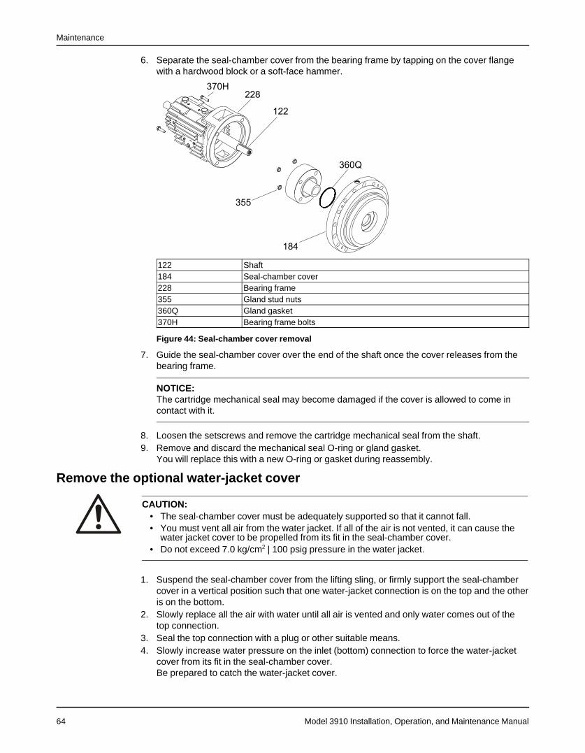
Maintenance
Model 3910 Installation, Operation, and Maintenance Manual64
6. Separate the seal-chamber cover from the bearing frame by tapping on the cover flangewith a hardwood block or a soft-face hammer.
122 Shaft184 Seal-chamber cover228 Bearing frame355 Gland stud nuts360Q Gland gasket370H Bearing frame bolts
Figure 44: Seal-chamber cover removal
7. Guide the seal-chamber cover over the end of the shaft once the cover releases from thebearing frame.
NOTICE:The cartridge mechanical seal may become damaged if the cover is allowed to come incontact with it.
8. Loosen the setscrews and remove the cartridge mechanical seal from the shaft.9. Remove and discard the mechanical seal O-ring or gland gasket.
You will replace this with a new O-ring or gasket during reassembly.
Remove the optional water-jacket cover
CAUTION:• The seal-chamber cover must be adequately supported so that it cannot fall.• You must vent all air from the water jacket. If all of the air is not vented, it can cause the
water jacket cover to be propelled from its fit in the seal-chamber cover.• Do not exceed 7.0 kg/cm2 | 100 psig pressure in the water jacket.
1. Suspend the seal-chamber cover from the lifting sling, or firmly support the seal-chambercover in a vertical position such that one water-jacket connection is on the top and the otheris on the bottom.
2. Slowly replace all the air with water until all air is vented and only water comes out of thetop connection.
3. Seal the top connection with a plug or other suitable means.4. Slowly increase water pressure on the inlet (bottom) connection to force the water-jacket
cover from its fit in the seal-chamber cover.Be prepared to catch the water-jacket cover.

Maintenance
Model 3910 Installation, Operation, and Maintenance Manual 65
5. Remove and discard the outer and inner water-jacket cover O-rings from the grooves in thewater-jacket cover.You will replace these with new O-rings during reassembly.
Disassemble the power endThis procedure explains how to disassemble purge-oil mist-lubricated power end and includesinformation for the disassembly of these optional features:
• Pure oil-mist-lubricated power end
• Radial-heat-flinger end
• Air-cooling package
CAUTION:Do not remove bearings from the shaft unless you need to replace them.
1. Does your power end have an optional air-cooling package?
• If no: Go to step 2.
• If yes:
a) Loosen the radial-heat-flinger set screw.b) Loosen the thrust-fan set screw.
The thrust fan for the SA and MA pumps sits on the coupling diameter.c) Slide the thrust fan off the shaft.d) Loosen and remove the thrust-bearing end cover and bearing-frame screws.

Maintenance
Model 3910 Installation, Operation, and Maintenance Manual66
e) Remove the thrust-fan guard support.
122 Shaft123B Radial deflector fan123E Thrust deflector fan222 Deflector set screw228 Bearing frame234 Thrust deflector-fan guard234D Thrust deflector-fan guard support496Q Support screws
Figure 45: Thrust-fan guard support removal
2. Loosen and remove the thrust-bearing end cover and bearing-frame screws.3. Pry the thrust-bearing end cover thrust deflector out of the bearing frame.

Maintenance
Model 3910 Installation, Operation, and Maintenance Manual 67
SA and MA thrust-bearing end covers are sealed to the bearing frame with a gasket.
109A Thrust-bearing end cover122 Shaft123A Thrust deflector228 Bearing frame358E Oil ring inspection plug360A Gasket370N Bearing-frame screw390C Thrust-bearing end-cover shim469P Oil ring retainer
Figure 46: Thrust bearing end cover removal
Figure 47: Thrust bearing end cover shims
4. Remove and discard the thrust-bearing end-cover shims.For all except SA and MA bearing frames, replace with new shims during reassembly.
5. Remove the two oil ring retainers and the oil ring inspection plugs from the top of thebearing frame.

Maintenance
Model 3910 Installation, Operation, and Maintenance Manual68
SX, MX, LA, LX, XLA, and XLX pumps have two inspection plugs. SA and MA pumps haveone inspection plug.
6. Carefully withdraw the shaft and bearing assembly from the bearing frame.
112 Duplex thrust bearing114 Oil rings122 Shaft136 Thrust-bearing locknut168 Radial bearing382 Lockwasher
Figure 48: Shaft and bearing assembly removal
7. Bend the locking tang of the thrust-bearing lockwasher away from the notch in the bearinglocknut.
NOTICE:Do not reuse bearings if removed from shaft. Doing so may result in equipment damage.Replace the bearings before reassembly.
8. Remove the radial bearing from the shaft:a) Loosen and remove the thrust-bearing locknut and lockwasher.b) Press or pull the duplex thrust bearing from the shaft.c) Press or pull the radial bearing from the shaft.
9. Perform the following based on your pump version:

Maintenance
Model 3910 Installation, Operation, and Maintenance Manual 69
If your pump is... Then...SX, MX, LA, LX,XLA, or XLX
1. Loosen and remove the radial-bearing end cover and bearing-framescrews.
2. Remove and discard the radial-bearing end-cover gasket. You will replacethis with a new gasket during reassembly.
3. Press the radial and thrust deflector out of the radial and thrust end covers.If you have an optional radial heat flinger, it replaces the standard radialdeflector and is removed in the same manner except you loosen three setscrews.
119A Thrust end cover123 Deflector228 Bearing frame360 Radial-bearing end-cover gasket370P Bearing-frame screws
Figure 49: Radial heat flingerSA and MA Remove the radial-bearing end cover and radial deflector with gasket or radial
deflector from the bearing frame by tapping it out of the frame.If you have an optional radial heat flinger, it replaces the standard radialdeflector and is removed in the same manner except you loosen three setscrews.
Figure 50: Radial-bearing end cover and radial deflector with gasket (orradial deflector) removal
10. Remove any remaining plugs and fittings.

Maintenance
Model 3910 Installation, Operation, and Maintenance Manual70
Preassembly inspectionsReplacement guidelines
Casing check and replacement
WARNING:Risk of death or serious injury. Leaking fluid can cause fire and/or burns. Inspect and ensuregasket sealing surfaces are not damaged and repair or replace as necessary.
Inspect the casing for cracks and excessive wear or pitting. Thoroughly clean gasket surfacesand alignment fits in order to remove rust and debris.Repair or replace the casing if you notice any of these conditions:
• Localized wear or grooving that is greater than 3.2 mm | 1/8 in. deep
• Pitting that is greater than 3.2 mm | 1/8 in. deep
• Irregularities in the casing-gasket seat surface
Casing areas to inspectThe arrows point to the areas to inspect for wear on the casing:
100 Casing164 Casing wear ring
Figure 51: Areas to inspect for wear on casing
NOTICE:3910LF does not have wear rings for case, cover and impeller.
Impeller replacementThis table shows the criteria for replacing the impeller:
Impeller parts When to replaceImpeller vanes • When grooved deeper than 1.6 mm | 1/16 in.,
or• When worn evenly more than 0.8 mm | 1/32 in.
Pumpout vanes When worn or bent more than 0.8 mm | 1/32 in.Vane edges When you see cracks, pitting, or corrosion damage
Impeller checks
NOTICE:Protect machined surfaces while cleaning the parts. Failure to do so may result in equipmentdamage.
• Check and clean the impeller bore diameter.
• Check the impeller balance. Rebalance the impeller if it exceeds the ISO 1940 G1.0criteria.
NOTICE:You must have extremely accurate tooling equipment to balance impellers to the ISO 1940G1.0 criteria. Do not attempt to balance impellers to this criteria unless this type of toolingand equipment is available.

Maintenance
Model 3910 Installation, Operation, and Maintenance Manual 71
Impeller areas to inspect
101 Impeller202 and 203 Impeller wear rings
Figure 52: Areas to inspect for wear on impeller
Cartridge mechanical seal replacementCartridge-type mechanical seals should be serviced by the seal manufacturer. Refer to theinstructions from the mechanical seal manufacturer for assistance.
Coupling guard replacementRepair or replace the coupling guard if you notice corrosion or other defects.
Gaskets, O-rings, and seats replacement
WARNING:Risk of death or serious injury. Leaking fluid can cause fire and/or burns. Replace all gasketsand O-rings at each overhaul or disassembly.
• Replace all gaskets and O-rings at each overhaul and disassembly.
• Inspect the seats. They must be smooth and free of physical defects.In order to repair worn seats, skin cut them in a lathe while you maintain dimensionalrelationships with other surfaces.
• Replace parts if the seats are defective.
Additional partsInspect and either repair or replace all other parts, if inspection indicates continued use wouldbe harmful to satisfactory and safe pump operation.Inspection must include the following items:
• Bearing end covers (109A) and (119A)
• INPRO radial labyrinth bearing seal (123) and thrust labyrinth bearing seal (123A)
• Radial heat flinger (123B)*
• Thrust fan (123E)*
• Bearing locknut (136)
• Impeller key (178) and coupling key
• Impeller screw (198)
• Impeller washer (199)
• Impeller lockwasher (199A)
• Impeller nut (304)
• Bearing lockwasher (382)

Maintenance
Model 3910 Installation, Operation, and Maintenance Manual72
• Impeller spacer (443A)
• Water jacket cover (490)*
• All nuts, bolts, and screws
* If supplied.
Fastening
WARNING:Risk of serious personal injury or property damage. Fasteners such as bolts and nuts arecritical to the safe and reliable operation of the product. Ensure appropriate use of fastenersduring installation or reassembly of the unit.
• Use fasteners of the proper size and material only.• Replace all corroded fasteners.• Ensure that all fasteners are properly tightened and that there are no missing fasteners.
Shaft replacement guidelines
Shaft measurement checkCheck the bearing fits of the shaft. If any are outside the tolerances shown in the Bearing fitsand tolerances table, then replace the shaft.
Shaft inspectionCheck the shaft straightness. Use "V" blocks or balance rollers to support the shaft on thebearing fit areas. Replace the shaft if runout exceeds 0.03 mm | 0.001 in.
NOTICE: Do not use shaft centers for the runout check as they may have been damagedduring the removal of the bearings or impeller.
Shaft inspectionCheck the shaft surface for damage, especially in areas indicated by the arrows in the followingfigure. Replace the shaft if it is damaged beyond reasonable repair.
Figure 53: Shaft inspection
Bearings inspection
Condition of bearingsDo not reuse bearings. The condition of the bearings provides useful information on operatingconditions in the bearing frame.
ChecklistPerform these checks when you inspect the bearings:
• Inspect the bearings for contamination and damage.
• Note any lubricant condition and residue.
• Inspect the ball bearings to see if they are loose, rough, or noisy when you rotate them.

Maintenance
Model 3910 Installation, Operation, and Maintenance Manual 73
• Investigate any bearing damage to determine the cause. If the cause is not normal wear,correct the issue before you return the pump to service.
Replacement bearings
Table 7: 3700 bearings based on SKF / MRC designationsReplacement bearings must be the same as, or equivalent to, those listed in this table.Group Radial (inboard) Thrust (outboard)SA 6210 C3 7310 BEGAMMA 6211 C3 7311 BEGAMSX 6212 C3 7312 BEGAMMX, LA 6213 C3 7312 BEGAMLX, XLA 6215 C3 7313 BEGAMXLX 6218 C3 7317 BEGAMXXL 6215 C3 7318 BEGAM
Wear rings inspection and replacement 3910LF
Wear ring typesAll units are equipped with casing, impeller, and seal-chamber cover wear rings. Whenclearances between the rings become excessive, hydraulic performance decreases substan-tially.
Wear ring diameter checkMeasure all wear ring diameters and then calculate the diametrical wear ring clearances. Seethe Minimum running clearances table for more information.
100 Casing164 Casing wear ring
Figure 54: Casing wear ring

Maintenance
Model 3910 Installation, Operation, and Maintenance Manual74
101 Impeller202 Impeller wear ring203 Impeller wear ring (No Requirement for 3910LF)
Figure 55: Impeller wear ring
125 Seal-chamber throat bushing184 Seal-chamber cover230 Seal-chamber cover wear ring
Figure 56: Seal chamber cover wear ring
When to replace wear ringsReplace wear rings when the diametrical clearance exceeds two times the minimum clearanceas shown in this table or when the hydraulic performance has decreased to unacceptablelevels.
NOTICE:For operating temperatures above 260°C | 500°F and for material with greater gallingtendencies (e.g. stainless steel), increase diametral clearance dimensions by 0.13 mm | 0.005in.

Maintenance
Model 3910 Installation, Operation, and Maintenance Manual 75
Table 8: Minimum running clearancesDiameter of impeller wear ring Minimum diametrical clearancein. mm in. mm<2.000 <50 0.010 0.252.000 to 2.4999 To to 64.99 0.011 0.282.500 to 2.999 65 to 79.99 0.012 0.303.000 to 3.499 80 to 89.99 0.013 0.333.500 to 3.999 90 to 99.99 0.014 0.354.000 to 4.499 100 to 114.99 0.015 0.384.500 to 4.999 115 to 124.99 0.016 0.405.000 to 5.999 125 to 149.99 0.017 0.436.000 to 6.999 150 to 174.99 0.018 0.457.000 to 7.999 175 to 199.99 0.019 0.488.000 to 8.999 200 to 224.99 0.020 0.509.000 to 9.999 225 to 249.99 0.021 0.5310.000 to 10.999 250 to 274.99 0.022 0.5510.000 to 11.999 275 to 299.99 0.023 0.5812.000 to 12.999 300 to 324.99 0.024 0.60
Replace the wear rings
WARNING:Dry ice and other chilling substances can cause physical injury. Contact the supplier forinformation and advice for proper handling precautions and procedures.(Not applicable for 3910LF)
CAUTION:• Excessive machining can damage ring fits and render parts unusable.• Wear insulated gloves when you handle rings. Rings will be hot and can cause physical
injury.• For runout checks, firmly support the bearing-frame assembly in the horizontal position.• Risk of physical injury from sharp edges. Wear heavy work gloves when handling
impellers.
NOTICE:
The impeller and wear-ring clearance setting procedures must be followed. Improperlysetting the clearance or not following any of the proper procedures can result in sparks,unexpected heat generation, and equipment damage.
Casing, impeller, and seal chamber cover wear rings are held in place by a press fit and threeset screws.1. Remove the wear rings:
a) Remove the set screws.b) Remove the wear rings from the casing, impeller, and seal-chamber cover using a pry
or puller to force the rings from the fits.2. Clean the wear-ring seats thoroughly, and make sure that they are smooth and free of
scratches.

Maintenance
Model 3910 Installation, Operation, and Maintenance Manual76
3. Heat the new impeller wear rings to 180° to 200°F (82° to 93°C) using a uniform method forheating, such as an oven, and place them on the impeller wear-ring seats.
Item Description101 Impeller202 Impeller wear ring203 Impeller wear ring320 Set screw
Figure 57: Impeller wear ring
4. Chill the new casing wear ring using dry ice or another suitable chilling substance andinstall the ring into the casing fit.Be prepared to tap the ring in place with a wood block or soft-faced hammer.
Item Description100 Casing164 Casing wear ring222E Set screw
Figure 58: Casing wear ring
5. Insert a new seal-chamber-cover wear ring:a) Chill a new seal-chamber-cover wear ring, using dry ice or another suitable chilling
substance, and install the ring into the cover fit.Be prepared to tap the ring in place with a hardwood block or soft faced hammer.
b) Locate, drill, and tap three new equally-spaced set screw holes between the originalholes in each new ring and ring-seat area.

Maintenance
Model 3910 Installation, Operation, and Maintenance Manual 77
c) Install the set screws and upset threads.
184 Cover222E Set screw230 Seal-chamber-cover wear ring
Figure 59: Seal chamber cover wear ring
6. Check the casing wear ring runout and distortion:a) Measure the bore at each set screw location with inside micrometers or vernier
calipers.b) Correct any distortion in excess of 0.003 in. (0.08 mm) by machining before you trim the
new impeller wear rings.
100 Casing164 Casing wear ring
Figure 60: Casing wear ring
7. Measure the bore of the casing wear ring to establish the required impeller wear-ringdiameter you use to provide the recommended running clearances.
8. Repeat steps 6 and 7 for the seal-chamber wear ring.9. Turn the impeller wear rings to size after you mount them on the impeller:

Maintenance
Model 3910 Installation, Operation, and Maintenance Manual78
NOTICE:• All replacement impeller wear rings, except those that are hard-faced, are supplied
0.020 in. to 0.030 in. (0.51 mm to 0.75 mm) oversize.
• Do not machine all wear rings. Spare hard-faced impeller wear rings are supplied topre-established clearances when both impeller and casing wear rings are renewed.
Figure 61: Impeller
10. Install the impeller:a) Install the impeller key on the shaft of the assembled bearing frame from which the
seal-chamber cover has been removed, and on which the runouts are within theestablished specifications. The key should be at the top (12 o’clock) position for theimpeller installation.
b) Install the impeller on the shaft.c) Install the impeller washer.d) Secure the impeller firmly with an impeller screw or impeller nut.
The impeller screw has left-hand threads.11. Check the impeller wear-ring runout:
a) Mount the dial indicator.b) Rotate the shaft so that the indicator rides along the casing-side impeller wear-ring
surface for 360°.

Maintenance
Model 3910 Installation, Operation, and Maintenance Manual 79
c) Repeat steps a and b for the wear ring on the seal-chamber cover side.
101 Impeller122 Shaft202 Casing-side impeller wear-ring228 Seal-chamber cover side wear ring
Figure 62: Impeller wear-ring runout
If the impeller wear ring runout is in excess of 0.005 in. (0.13 mm):
1. Check for distortion at the set screw areas.2. Check the shaft runout and all mating surfaces of the shaft and impeller hub for
perpendicularity.3. True up all damaged surfaces.4. Recheck the impeller wear-ring runout.
Seal-chamber cover inspection and replacement
Two seal-chamber cover versionsThe seal-chamber cover is available in two versions:
• Standard
• Optional
The optional version has a cooling chamber and water jacket cover and is used when elevatedpumped-fluid temperatures are present.
Seal-chamber cover areas to inspect• Ensure all gasket/O-ring sealing surfaces are clean and have no damage that would
prevent sealing.
• Ensure that all cooling (where applicable), flush, and drain passages are clear.

Maintenance
Model 3910 Installation, Operation, and Maintenance Manual80
125 Seal-chamber throat bushing184 Seal-chamber cover
Seal-chamber cover replacement
Seal-chamber cover part When to replaceSeal-chamber cover surfaces When worn, damaged, or corroded more than 0.126
in. (3.2 mm) deepInside diameter of seal-chamber cover bushing When the diametral clearance between the bushing
and the impeller hub exceeds 0.047 in. (1.20 mm)
Replace the seal-chamber cover bushingThe seal-chamber cover bushing is held in place by a press fit and locked by three set screws.1. Remove the bushing:
a) Remove the set screws.b) Press the bushing out of the fit towards the bearing-frame side of the seal-chamber
cover bore.
125 Bushing184 Seal-chamber cover
Figure 63: Seal-chamber cover bushing replacement
2. Install the new seal-chamber cover bushing:a) Thoroughly clean the bushing fit in the seal-chamber cover.

Maintenance
Model 3910 Installation, Operation, and Maintenance Manual 81
b) Chill the new bushing using dry ice or another suitable chilling substance, and installthe bushing into the cover fit.Tap the bushing in place with a wood block or soft-faced hammer.
WARNING:Dry ice and other chilling substances can cause physical injury. Contact the supplier forinformation and advice for proper handling precautions and procedures.
c) Locate, drill, and tap three new equally-spaced set screw holes on the impeller side ofthe cover between the original set screw holes.
d) Install the set screws and upset threads.
1. Seal-chamber cover2. Set screws3. BushingFigure 64: Set screw installation
Bearing-frame inspection
ChecklistCheck the bearing frame for these conditions:
• Visually inspect the bearing frame and frame foot for cracks.
• Check the inside surfaces of the frame for rust, scale, or debris. Remove all loose andforeign material.
• Make sure that all lubrication passages are clear.
• Inspect the inboard-bearing bores.If any bores are outside the measurements in the Bearing fits and tolerances table, replacethe bearing frame.

Maintenance
Model 3910 Installation, Operation, and Maintenance Manual82
Surface inspection locations
This figure shows the areas to inspect for wear on the bearing frame surface.
Figure 65: Surface inspection locations
Bearing fits and tolerancesTable 9: Bearing fits and tolerances table (SI units)
This table references the bearing fits and tolerances according to ISO 286 (ANSI/ABMA Standard 7) ininches (millimeters).
Location Description SA SX MA MX, LA LX, XLA XLX XXLRadial(Inboard)
Shaft OD 1.9690(50.013)1.9686(50.002)
2.3628(60.015)2.3623(60.002)
2.1659(55.015)2.1654(55.002)
2.5597(65.015)2.5592(65.002)
2.9534(75.015)2.9529(75.002)
3.5440(90.018)3.5434(90.003)
3.9377(100.018)3.9371(100.002)
Interference 0.0001(0.002)0.0010(0.025)
0.0001(0.002)0.0012(0.030)
0.0001(0.002)0.0012(0.030)
0.0001(0.002)0.0012(0.030)
0.0001(0.002)0.0012(0.030)
0.0001(0.003)0.0015(0.038)
0.0001(0.002)0.001 (0.038)
Bearing ID 1.9680(49.988)1.9685(50.000)
2.3616(59.985)2.3622(60.0000
2.1647(54.985)2.1653(55.000)
2.5585(64.985)2.5591(65.000)
2.9522(74.985)2.9528(75.000)
3.5425(89.980)3.5433(90.000)
3.9362(99.980)3.9370(100.000)
Frame ID 3.5433(90.000)3.5442(90.022)
4.3307(110.000)4.3316(110.022)
3.9370(100.000)3.9378(100.022)
4.7244(120.000)4.7253(120.022)
5.1181(130.000)5.1191(130.025)
6.2992(160.000)6.3002(160.025)
7.0866(180.000)7.0875(180.023)
Clearance 0.0000(0.000)0.0015(0.037)
0.0000(0.000)0.0015(0.037)
0.0000(0.000)0.0015(0.037)
0.0000(0.000)1.0015(0.037)
0.0000(0.000)0.0017(0.043)
0.0000(0.000)0.0020(0.050)
0.0000(0.000)0.0012(0.048)
Bearing OD 3.5483(90.000)3.5427(89.985)
4.3307(110.000)4.3301(110.022)
3.9390(100.000)3.9363(99.985)
4.7244(120.000)4.7238(119.985)
5.1181(130.000)5.1174(129.982)
6.2992(160.000)6.2982(159.975)
7.0866(180.000)7.0856(179.975)

Maintenance
Model 3910 Installation, Operation, and Maintenance Manual 83
Location Description SA SX MA MX, LA LX, XLA XLX XXLThrust(Outboard)
Shaft OD 1.9691(50.013)1.9686(50.002)
2.3628(60.015)2.3623(60.002)
2.1659(55.015)2.1654(55.002)
2.3628(60.015)2.3623(60.002)
2.5597(65.015)2.5592(65.002)
3.3472(85.018)3.3466(85.003)
3.544(90.018)3.5434(90.002)
Interference 0.0001(0.002)0.0010(0.025)
0.0001(0.002)0.0012(0.030)
0.0001(0.002)0.0012(0.025)
0.0001(0.002)0.0012(0.030)
0.0001(0.002)0.0012(0.030)
0.0001(0.003)0.0015(0.038)
0.0001(0.002)0.002 (0.038)
Bearing ID 1.9680(49.998)1.9685(50.000)
2.3616(59.985)2.3622(60.000)
2.1647(54.985)2.1653(55.000)
2.3616(59.985)2.3622(60.000)
2.5585(64.985)2.5591(65.000)
3.3457(84.980)3.3465(85.000)
3.5425(89.980)3.5433(90.000)
Frame ID 4.3307(110.00004.3315(110.022)
5.1181(130.000)5.1191(130.025)
4.7244(120.000)4.7253(120.022)
5.1181(130.000)5.1191(130.025)
5.5118(140.000)5.5128(140.025)
7.0866(180.000)7.0876(180.025)
7.4802(190.000)7.4814(190.028)
Clearance 0.0000(0.000)0.0015(0.037)
0.0000(0.000)0.0017(0.043)
0.0000(0.000)0.0015(0.037)
0.0000(0.000)0.0017(0.043)
0.0000(0.000)0.0017(0.043)
0.0000(0.000)0.0020(0.050)
0.0000(0.000)0.0002(0.0053)
Bearing OD 4.3307(110.000)4.3301(109.985)
5.1181(130.000)5.1174(129.982)
4.7244(120.000)4.7238(119.985)
5.1181(130.000)5.1174(129.9820
5.5118(140.000)5.5111(139.982)
7.0866(180.000)7.0856(179.975)
7.4802(190.000)7.4793(189.975)
ReassemblyAssemble the frame
CAUTION:• Failure to align the gasket with oil grooves will result in bearing failure from a lack of
lubrication.• Do not over-tighten the thrust-bearing end-cover and bearing-frame screws.• Do not allow the dial indicator to contact the keyway when turning the shaft. Readings will
be incorrect and damage to dial indicator could result.• For runout checks, firmly support the bearing-frame assembly in the horizontal position.
1. Perform the following based on your pump:
If your pumpis...
Then...
SX, MX, LA, LX,XLA, XLX, orXXL
1. Install three thrust-bearing end-cover shims on the thrust-bearing end cover.2. Align the holes.
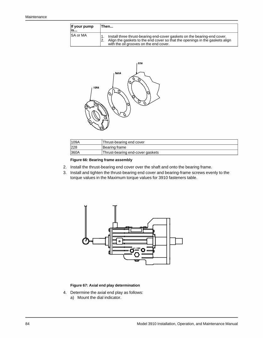
Maintenance
Model 3910 Installation, Operation, and Maintenance Manual84
If your pumpis...
Then...
SA or MA 1. Install three thrust-bearing end-cover gaskets on the bearing-end cover.2. Align the gaskets to the end cover so that the openings in the gaskets align
with the oil grooves on the end cover.
109A Thrust-bearing end cover228 Bearing frame360A Thrust-bearing end-cover gaskets
Figure 66: Bearing frame assembly
2. Install the thrust-bearing end cover over the shaft and onto the bearing frame.3. Install and tighten the thrust-bearing end cover and bearing-frame screws evenly to the
torque values in the Maximum torque values for 3910 fasteners table.
Figure 67: Axial end play determination
4. Determine the axial end play as follows:a) Mount the dial indicator.

Maintenance
Model 3910 Installation, Operation, and Maintenance Manual 85
b) Use a lever to apply axial force to the impeller end of the shaft and firmly seat the thrustbearing against the shoulder in the bearing frame.
c) Apply axial force in the opposite direction and firmly seat the thrust bearing against thethrust-bearing end cover.
d) Repeat steps b and c several times and record the total travel (end play) of the rotatingelement.Total travel (end play) must fall in the range of 0.025 to 0.125 mm | 0.001 to 0.005 in.Achieve the correct axial end play by adding or removing end-cover gaskets (for SAand MA pumps) or end-cover shims (for SX, MX, LA, LX, XLA, XLX, and XXL pumps)between the thrust-bearing end cover and the bearing frame. Add gaskets and shims ifno axial end play is present.
5. Repeat steps 1 through 4.If the measured total travel falls outside the accepted range in step 4, remove or add theappropriate quantity of individual shims or gaskets to obtain the proper total travel.
6. Perform the following based on your pump:
If yourpump is...
Then...
SX, MX, LA,LX, XLA,XLX, or XXL
1. Remove the thrust-bearing end cover.2. Press the INPRO seal into the thrust-bearing end cover and ensure that the
expulsion part is at the 6 o'clock position and is properly seated.3. Install the O-ring into the groove of the thrust-bearing end cover.4. Lubricate the O-ring with a suitable lubricant.
SA or MA 1. Remove the thrust-bearing end cover.2. Press the INPRO seal into the thrust-bearing end cover and ensure that the
expulsion part is at the 6 o'clock position and is properly seated.
7. Install the thrust-bearing end cover with O-ring over the shaft and into the bearing-framebore.Ensure that the O-ring is not damaged while it enters the bearing-frame bore.
8. Perform the following based on whether or not your power end has the optional air-coolingpackage:
If yourpowerend...
Then...
Has the op-tional air-coolingpackage
1. Position the thrust-fan guard support on the thrust-bearing end cover.2. Install and tighten the thrust-bearing end cover and bearing-frame screws evenly to
torque values shown in the Maximum torque values for 3910 fasteners table.3. Install the thrust fan over the shaft.4. Position the thrust-deflector fan approximately 0.8 mm | 0.030 in. from the thrust
INPRO seal on SA and MA pumps. Place the fan against the coupling-diametershoulder and tighten the deflector-fan set screw firmly.
5. Tighten the heat-flinger set screws firmly.

Maintenance
Model 3910 Installation, Operation, and Maintenance Manual86
If yourpowerend...
Then...
Does nothave theoptional air-coolingpackage
1. Install and tighten the thrust-bearing end cover and bearing-frame screws evenly tothe torque values in the Maximum torque values for 3910 fasteners table.
2. Verify that the shaft turns freely. If you detect rubbing or excessive drag, thendetermine the cause and correct it.
122 Shaft123B Radial deflector fan123E Thrust deflector fan222 Deflector set screw228 Bearing frame234 Thrust deflector-fan guard234D Thrust deflector-fan guard support496Q Support screws
Figure 68: Power end assembly
9. Check the following runouts:

Maintenance
Model 3910 Installation, Operation, and Maintenance Manual 87
Check ProcedureShaft impeller fit 1. Mount the dial indicator on the bearing frame.
2. Rotate the shaft through a maximum arc from one side of the keyway to theother. If the total indicator reading is greater than 0.050 mm | 0.002 in.,determine the cause and correct it.
Shaft seal fit 1. Mount the dial indicator.2. Rotate the shaft so that the indicator rides along the shaft surface for 360°. If
the total indicator reading is greater than 0.050 mm | 0.002 in., thendetermine the cause and correct it.

Maintenance
Model 3910 Installation, Operation, and Maintenance Manual88
Check ProcedureBearing-frameface
1. Mount the dial indicator on the shaft.2. Rotate the shaft so that the indicator rides along the bearing-frame face for
360°. If the total indicator reading is greater than 0.10 mm | 0.004 in., thendisassemble and determine the cause and correct it.
Bearing-framelock
1. Mount the dial indicator on the shaft.2. Rotate the shaft so that the indicator rides along the bearing-frame lock for
360°. If the total indicator reading is greater than 0.10 mm | 0.004 in., thendisassemble and determine the cause and correct it.
10. Install and tighten any plugs and fittings removed during disassembly, including the oil-drain plug, and the sight glass.
11. If your power end has the optional water cooling package, install the finned-tube coolingassembly into the bearing frame.

Maintenance
Model 3910 Installation, Operation, and Maintenance Manual 89
Install the optional water-jacket cover1. Install the outer and inner water-jacket-cover O-rings into the grooves in the water jacket
cover.
184 Seal-chamber cover412S Outer water-jacket-cover O-ring490 Water jacket cover497T Outer and inner water-jacket-cover O-ring
Figure 69: Optional water jacket cover
2. Lubricate the sealing surfaces in the seal-chamber cover and O-rings with a suitablelubricant.
3. Insert the water jacket cover with O-rings into the fit in the seal-chamber cover.Make sure that the water jacket cover enters uniformly and that the O-rings are notdamaged.

Maintenance
Model 3910 Installation, Operation, and Maintenance Manual90
Install the seal-chamber cover1. Install the eyebolt in the tapped hole provided in the seal-chamber cover.
122 Shaft184 Seal-chamber cover228 Bearing frame230 Seal-chamber cover wear-ring370H Bearing-frame bolts
Figure 70: Seal chamber cover
2. Set up a sling from the eyebolt to the overhead lifting device.3. Lift the seal-chamber cover and position it so that it aligns with the shaft.4. Install the seal-chamber cover on the bearing-frame assembly:
a) Guide the cover carefully over the shaft and into the bearing-frame lock.b) Install the seal-chamber cover and bearing-frame bolts.c) Tighten the bolts evenly using an alternating pattern.
Torque the bolts to values shown in the Maximum torque values for 3910 fastenerstable.
5. Check the seal-chamber cover face runout:a) Mount the dial indicator on the shaft.

Maintenance
Model 3910 Installation, Operation, and Maintenance Manual 91
b) Rotate the shaft so that the indicator rides along the seal-chamber cover face for 360°.If the total indicator reading is greater than 0.005 in. (0.13 mm), determine the causeand correct it.
Figure 71: Seal-chamber cover face runout
6. Check the seal-chamber cover lock runout:a) Mount the dial indicator on the shaft.b) Rotate the shaft so that the indicator rides along the seal-chamber cover lock for 360°.
If the total indicator reading is greater than 0.005 in. (0.13 mm), determine the causeand correct it.
Figure 72: Seal-chamber cover lock runout
NOTICE:
The impeller and wear-ring clearance setting procedures must be followed. Improperlysetting the clearance or not following any of the proper procedures can result in sparks,unexpected heat generation, and equipment damage.
7. Check the seal-chamber cover wear-ring runout:a) Mount the dial indicator on the shaft.

Maintenance
Model 3910 Installation, Operation, and Maintenance Manual92
b) Rotate the shaft so that the indicator rides on the seal-chamber cover wear-ring surfacefor 360°.If the total indicator reading exceeds 0.006 in. (0.15 mm), determine the cause andcorrect it.
Figure 73: Seal-chamber cover wear-ring runout
8. Check the seal-chamber face runout:a) Mount a dial indicator on the shaft.

Maintenance
Model 3910 Installation, Operation, and Maintenance Manual 93
b) Rotate the shaft so that the indicator rides along the seal-chamber face for 360°.If the total indicator reading is greater than the values shown in this table, determine thecause and correct it.
Table 10: Maximum Allowable Seal Chamber Face RunoutGroup Maximum Allowable Total Indicator ReadingSA 0.0018 in. (0.045 mm)SX, MA 0.002 in. (0.05 mm)MX, LA 0.0024 in. (0.06 mm)LX, XLA 0.0026 in. (0.065 mm)XLX 0.0028 in. (0.07 mm)XXL 0.0031 in. (0.08 mm)
Figure 74: Seal-chamber face runout
9. Check the seal-chamber lock (register) runout:a) Mount a dial indicator on the shaft or shaft sleeve.b) Rotate the shaft so that the indicator rides along the seal-chamber lock (register) for
360°.If the total indicator reading is greater than 0.005 in. (0.125 mm ), determine the causeand correct it.
Figure 75: Seal-chamber lock (register) runout

Maintenance
Model 3910 Installation, Operation, and Maintenance Manual94
Install the cartridge-type mechanical seal and seal-chamber cover
NOTICE:Refer to the mechanical seal manufacturer’s drawings and instructions for assistance duringthe installation of the mechanical seal.
1. Remove the impeller.a) Loosen and remove the impeller nut.
The impeller nut has left-hand threads.b) Remove the impeller, impeller key, and seal-chamber cover as described in the
Disassembly section.2. Lubricate all O-rings with suitable lubricant, unless the seal manufacturer’s instructions
indicate otherwise.3. Slide the cartridge seal assembly (rotary, stationary gland, gland gasket, and sleeve) onto
the shaft.
NOTICE:Ensure that the mechanical-seal gland-piping connections are properly oriented.
122 Shaft184 Seal-chamber cover228 Bearing frame355 Gland stud nut370H Bearing-frame bolts
Figure 76: Cartridge-type mechanical seal and seal-chamber cover
4. Install the seal-chamber cover.a) Set up a sling to the eyebolt and to the overhead lifting device.b) Lift the seal-chamber cover and position it so that it aligns with the shaft.c) Install the seal-chamber cover on the power end by guiding the cover carefully over the
cartridge-seal rotary.Ensure that the gland studs smoothly enter the holes in the cartridge-seal gland andthat the cover fits into the bearing frame lock.
d) Install the seal-chamber cover and bearing-frame bolts and tighten them using analternating pattern.Torque the bolts to the values shown in the Maximum torque values for 3910 fastenerstable.
e) Install the gland stud nuts and tighten evenly to the torque values shown in theMaximum torque values for 3910 fasteners table.

Maintenance
Model 3910 Installation, Operation, and Maintenance Manual 95
5. Tighten the setscrews in the locking collar.6. Disengage the spacer ring or clips.7. Verify that the shaft turns freely.
If you detect rubbing or excessive drag, then determine the cause and correct it.
Determining impeller spacer thickness (applicable for 3910LF)Applicable only to a new spare impeller spacerWith an assembled power end:1. Attach the seal chamber cover to the bearing frame.2. Install impeller spacer as supplied between shaft and impeller.3. Secure impeller to shaft with impeller cap screw or nut.4. Place indicator on the coupling end of the shaft and zero it out (magnetic base attached to
bearing frame).5. Remove (or loosen to provide 3/8” travel) the thrust bearing end cover screws.6. Install back pull-out assembly into the case and tighten down 3 or 4 nuts (equally spaced
around the case).7. Record the travel measured by the indicator.8. Add .030" to the amount of travel measured and then machine this off the face of the
impeller spacer.
Install the impeller 3910
CAUTION:Risk of physical injury from sharp edges. Wear heavy work gloves when handling impellers.
It is recommended that you repeat the runout checks on the seal-chamber cover face, lock, andwear-ring surfaces as described in Install the seal-chamber cover (page 90).1. Install the impeller key in the keyway of the shaft.
The key should be at the top (12 o’clock) position for the impeller installation.2. Install the impeller on the shaft.
Apply anti-galling compound to the impeller bore to aid in assembly and disassembly.3. Install the impeller nut and tighten to the torque values shown in the Maximum torque
values for 3910 fasteners table.The impeller nut has left-hand threads.
4. Tighten the set screw in the end of the impeller nut.5. Verify that the shaft turns freely.
If you notice any rubbing or excessive drag, then determine the cause and correct it.It is recommended that you repeat the runout checks on the impeller wear-ring surface asdescribed in Replace the wear rings.
Install the impeller (3910LF)
CAUTION:Risk of physical injury from sharp edges. Wear heavy work gloves when handling impellers.
It is recommended that you repeat the runout checks on the seal-chamber cover face and locksurfaces as described in Install the seal-chamber cover (page 90).1. Install the impeller spacer on the shaft.2. Install the impeller key in the keyway of the shaft.
The key should be at the top (12 o’clock) position for the impeller installation.3. Install the impeller on the shaft.

Maintenance
Model 3910 Installation, Operation, and Maintenance Manual96
Apply anti-galling compound to the impeller bore to aid in assembly and disassembly.4. Install the impeller capscrew and tighten to the torque values shown in the Maximum torque
values for 3910 fasteners table.The impeller capscrew has left-hand threads.
5. Verify that the shaft turns freely.If you notice any rubbing or excessive drag, then determine the cause and correct it.
Install the coupling hub
CAUTION:Wear insulated gloves to handle the coupling hub. The coupling hub will get hot and can causephysical injury.
NOTICE:If it is necessary to heat the coupling hub due to an interference fit, do not use a torch. Use aheating device such as an oven which uniformly heats the coupling hub.
1. Install the key and pump-half coupling hub on the shaft.2. Make sure that the hub is flush with the end of the shaft or to the mark scribed during
disassembly.Refer to coupling manufacturer’s instructions for assistance.
Figure 77: Coupling hub installation
Install the back pull-out assembly in the casing1. Install a new casing gasket on the gasket surface of the casing.
You can apply anti-galling compound to the casing fits to aid in assembly and disassembly.
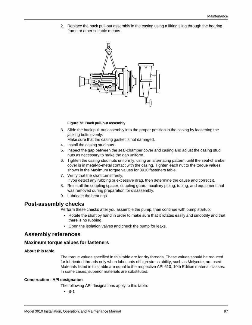
Maintenance
Model 3910 Installation, Operation, and Maintenance Manual 97
2. Replace the back pull-out assembly in the casing using a lifting sling through the bearingframe or other suitable means.
Figure 78: Back pull-out assembly
3. Slide the back pull-out assembly into the proper position in the casing by loosening thejacking bolts evenly.Make sure that the casing gasket is not damaged.
4. Install the casing stud nuts.5. Inspect the gap between the seal-chamber cover and casing and adjust the casing stud
nuts as necessary to make the gap uniform.6. Tighten the casing stud nuts uniformly, using an alternating pattern, until the seal-chamber
cover is in metal-to-metal contact with the casing. Tighten each nut to the torque valuesshown in the Maximum torque values for 3910 fasteners table.
7. Verify that the shaft turns freely.If you detect any rubbing or excessive drag, then determine the cause and correct it.
8. Reinstall the coupling spacer, coupling guard, auxiliary piping, tubing, and equipment thatwas removed during preparation for disassembly.
9. Lubricate the bearings.
Post-assembly checksPerform these checks after you assemble the pump, then continue with pump startup:
• Rotate the shaft by hand in order to make sure that it rotates easily and smoothly and thatthere is no rubbing.
• Open the isolation valves and check the pump for leaks.
Assembly referencesMaximum torque values for fasteners
About this tableThe torque values specified in this table are for dry threads. These values should be reducedfor lubricated threads only when lubricants of high stress ability, such as Molycote, are used.Materials listed in this table are equal to the respective API 610, 10th Edition material classes.In some cases, superior materials are substituted.
Construction - API designationThe following API designations apply to this table:
• S-1

Maintenance
Model 3910 Installation, Operation, and Maintenance Manual98
• S-3
• S-4
• S-5
• S-6
• S-8
• S-8N
• S-9
• C-6
• A-8
• A-8N
• D-1
• Modified A-8 (non-API material)

Maintenance
Model 3910 Installation, Operation, and Maintenance Manual 99
Maximum torque values
Table 11: Maximum torque values 3910/3910LF
ItemNumber Description Group / Size Fastener Size Torque Value
304 Impeller NutSA, SX 5/8" - 18 UNF 80 Nm | 59 ft-lbs
MX 3/4" - 16 UNF 138 Nm | 102 ft-lbsLA,LX, XLX 1" - 12 UNF 331 Nm | 244 ft-lbs
353 and355 Gland Studs and Nuts
SA 1/2" - 13 UNC 88 Nm | 65 ft-lbsAll others 5/8" - 11 UNC 176 Nm | 130 ft-lbs
356Aand 425 Casing Studs & Nuts
SA, SX 3/4" - 10 UNC 312 Nm | 230 ft-lbsMX (11") 3/4" - 10 UNC 312 Nm | 230 ft-lbsMX (13") 7/8" - 9 UNC 503 Nm | 371 ft-lbsLA (16") 1" - 8 UNC 755 Nm | 557 ft-lbs
XLX (21") 1 1/8" - 7 UNC 1070 Nm 789 ft-lbs
370H Screw - Bearing Frame / SealChamber Cover
SA 1/2" - 13 UNC 30 Nm | 22 ft-lbsSX 5/8" - 11 UNC 60 Nm | 44 ft-lbs
MX, LA 3/4" - 10 UNC 107 Nm | 79 ft-lbsLX 7/8" - 9 UNC 168 Nm | 124 ft-lbs
XLX 1" - 8 UNC 259 Nm | 191 ft-lbs
370N Screw - Thrust Bearing EndCover to Frame
SA, SX, MA, LA 1/2" - 13 UNC 30 Nm | 22 ft-lbsLX, XLX 5/8" - 11 UNC 60 Nm | 44 ft-lbs
370Pand
370WOptional
Screw - Radial Bearing EndCover to Frame
SXMX, LA
XLX5/16" - 18 UNC 7 Nm | 5 ft-lbs
469QOptional
Screw - Thrust Deflector FanGuard Support ALL 5/16" - 18 UNC 7 Nm | 5 ft-lbs
NOTICE:• The torque values specified in the above table are for lubricated threads. Multiply
lubricated value by 4/3 for unlubricated values.
• Thread lubricant is required for pressure boundary hardware (Items 353, 355, 356A, &425). Use nickel-based or molybdenum-based anti-seize compound.
• Materials listed in the above table are equal to the respective API 610 material classes. Insome cases, superior materials are substituted.
Spare parts
Critical services spare partsFor critical services, the following parts should be stocked, where applicable:
• Impeller (101) with impeller rings (202 and 203) (Applicable for 3700/3710)
• Impeller (101) (Applicable for 3703/3700LF)
• Thrust bearing end-cover (109A)
• Radial bearing end cover (119A)
• Shaft (122)
• Radial INPRO seal (123)
• Thrust INPRO (123A)
• Radial heat flinger (123B)
• Thrust fan (123E)
• Impeller key (178)

Maintenance
Model 3910 Installation, Operation, and Maintenance Manual100
An alternative approach is to stock a complete back pull-out assembly. This is a group ofassembled parts which includes all but the casing and coupling.
Recommended spare partsWhen ordering spare parts, always state the serial number, and indicate the part name anditem number from the relevant sectional drawing. It is imperative for service reliability to have asufficient stock of readily available spare parts.It is suggested that the following spare parts be stocked, where applicable:
• Bearing locknut (136)
• Bearing lockwasher (382)
• Cartridge mechanical seal (383)
• Casing gasket (351)
• Casing wear ring (164) (Applicable for 3700/3710)
• Finned-tube cooling assembly (494)
• Impeller nut (304) (Applicable for 3700/3710/3703)
• Impeller cap screw (198) (Applicable for 3700LF)
• Impeller wear ring - casing side (202) (Applicable for 3700/3710)
• Impeller wear ring - cover side (203) (Applicable for 3700/3710)
• Oil rings (114)
• Oiler with wire guard (251)
• Radial bearing (168)
• Radial bearing end-cover gasket (360)
• Seal-chamber cover wear ring (230)
• Set screws (222E and 320)
• Throat bushing - seal-chamber cover (125)
• Thrust bearing (duplex pair) (112)
• Thrust bearing end-cover gaskets (360A)
• Thrust bearing end-cover O-ring (412)
• Thrust bearing end-cover shim pack (390C)
• Water jacket cover O-rings (412S and 497T)
• Impeller spacer (443A) (Applicable for 3703/3700LF)

Troubleshooting
Model 3910 Installation, Operation, and Maintenance Manual 101
Troubleshooting
Operation troubleshootingSymptom Cause RemedyThe pump is not deliveringliquid.
The pump is not primed. Re-prime the pump and check that the pump andsuction line are full of liquid.
The suction line is clogged. Remove the obstructions.The impeller is clogged. Back-flush the pump in order to clean the impeller.The shaft is rotating in the wrong direction. Change the rotation. The rotation must match the
arrow on the bearing housing or pump casing.The foot valve or suction pipe opening is notsubmerged enough.
Consult an ITT representative for the proper sub-mersion depth. Use a baffle in order to eliminatevortices.
The suction lift is too high. Shorten the suction pipe.The pump is not producingthe rated flow or head.
The gasket or O-ring has an air leak. Replace the gasket or O-ring.The stuffing box has an air leak. Replace or readjust the mechanical seal.The impeller is partly clogged. Back-flush the pump in order to clean the impeller.The clearance between the impeller and thepump casing is excessive.
Adjust the impeller clearance.
The suction head is not sufficient. Make sure that the suction-line shutoff valve isfully open and that the line is unobstructed.
The impeller is worn or broken. Inspect and replace the impeller if necessary.The pump starts and thenstops pumping.
The pump is not primed. Re-prime the pump and check that the pump andsuction line are full of liquid.
The suction line has air or vapor pockets. Rearrange the piping in order to eliminate airpockets.
The suction line has an air leak. Repair the leak.The bearings are runninghot.
The pump and driver are not aligned properly. Realign the pump and driver.There is not sufficient lubrication. Check the lubricant for suitability and level.The lubrication was not cooled properly. Check the cooling system.
The pump is noisy or vi-brates.
The pump and driver are not aligned properly. Realign the pump and driver.The impeller is partly clogged. Back-flush the pump in order to clean the impeller.The impeller or shaft is broken or bent. Replace the impeller or shaft as necessary.The foundation is not rigid. Tighten the hold-down bolts of the pump and
motor. Make sure the baseplate is properlygrouted without voids or air pockets.
The bearings are worn. Replace the bearings.The suction or discharge piping is not an-chored or properly supported.
Anchor the suction or discharge piping as neces-sary according to recommendations in the Hy-draulic Institute Standards Manual.
The pump is cavitating. Locate and correct the system problem.The mechanical seal is leak-ing excessively.
The packing gland is not adjusted properly.The stuffing box is not packed properly.The mechanical seal parts are worn. Replace the worn parts.The mechanical seal is overheating. Check the lubrication and cooling lines.The shaftor shaft sleeve is scored.
The motor requires exces-sive power.
The discharge head has dropped below therated point and is pumping too much liquid.
Install a throttle valve. If this does not help, thentrim the impeller diameter. If this does not help,then contact your ITT representative.
The liquid is heavier than expected. Check the specific gravity and viscosity.The stuffing-box packing is too tight. Readjust the packing. If the packing is worn, then
replace the packing.Rotating parts are rubbing against each other. Check the parts that are wearing for proper
clearances.The impeller clearance is too tight. Adjust the impeller clearance.

Troubleshooting
Model 3910 Installation, Operation, and Maintenance Manual102
Alignment troubleshootingSymptom Cause RemedyHorizontal (side-to-side) alignment cannotbe obtained (angular or parallel).
The driver feet are bolt-bound. Loosen the pump's hold-down bolts, andslide the pump and driver until youachieve horizontal alignment.
The baseplate is not leveled properly andis probably twisted.
1. Determine which corners of the base-plate are high or low.
2. Remove or add shims at the appropri-ate corners.
3. Realign the pump and driver.
Assembly troubleshootingTable 12: Troubleshooting procedureSymptom Cause RemedyThere is excessive shaft end play. The internal clearance of the bearings is
excessive.Replace the bearings with a bearingof the correct type.
The thrust-bearing end cover is loose. Tighten the screws.There are too many shims under the thrustbearing end cover.
Remove the individual shims to ob-tain the proper thickness.
The runout for the shaft is excessive. The shaft is bent. Replace the shaft.The runout for the bearing-frame flange isexcessive.
The shaft is bent. Replace the shaft.The flange of the bearing frame is distorted. Replace the bearing-frame flange.
The runout for the seal-chamber cover isexcessive.
The seal-chamber cover is improperly seat-ed on the frame.
Replace or re-machine the seal-chamber cover.
There is corrosion or wear on the seal-chamber cover.
Replace the seal-chamber cover.
The runout for the impeller wear ring isexcessive.
The shaft is bent. Replace the shaft.The wear ring was machined improperly. Replace or re-machine the impeller.

Parts Listings and Cross-Sectionals
Model 3910 Installation, Operation, and Maintenance Manual 103
Parts Listings and Cross-Sectionals
Parts listTable 13: Parts list with standard materials of construction
The materials in this table are typical. Refer to the order documentation for the actual materials furnished.Item Part name Quantity
perpump
Construction - API designation
S-6 S-8 C-6 A-8100 Casing 1 1234 1296101 Impeller 1 1222 1222 1265122 Shaft 1 2238 2244 2256125 Throat bushing, seal chamber 1 1001 2244 2244 2256164 1 1001 1232 1232 1265178 Key, impeller 1 2229 2224 2229184 Seal-chamber cover 1 1212 1234 1296202 Wear ring, impeller 1 1001 1299 1299 1071203 Wear ring, impeller 1 1001 1299 1299 1071230 Wear ring, seal-chamber cover 1 1001 1232 1232 1265304 Impeller nut 1 2210 2229355 Nut, gland stud 4 2285356A Stud, casing Varies 2239360 Gasket, radial bearing end cover 1 Vellumoid360A Gasket, thrust bearing end cover 3 Vellumoid370H Screw, bearing frame and seal-
chamber cover4 2210
370N Screw, thrust bearing end cover 5 2210370P Screw, radial bearing end cover 5 2210382 Lockwasher, bearing 1 Steel390C Shim pack, thrust bearing end
cover1 304SS
408A Plug, oil drain 1 Steel with magnetic insert412 O-ring, thrust bearing end cover 1 Buna N418 Bolt, jacking 4 2210443A Impeller spacer 1 2229 2229 2229 2244 2229
Table 14: Materials cross-reference chartMaterial Goulds Pumps Material Code ASTM Material Designation OtherCast iron 1000 A48 Class 25 —Cast iron 1001 A48 Class 20 —Nitronic 60 1071 A743 Gr. CF10SMnN —Carbon steel 1212 A216 WCB —12% chrome steel 1222 A743 Gr. CA6NM —12% chrome steel 1232 A743 Gr. CA15 —12% chrome steel 1234 A487 Gr. CA6MN Class A —316L stainless steel 1265 A743 Gr. CF3M —316L stainless steel 1296 A351 Gr. CF3M —12% chrome steel 1299 A743 Gr. CA15 —Aluminum 1425 SC64D UNS A03190Bismuth bronze 1618 B505 CDA 89320 —Steel 2210 A108 Gr. 1211 UNS G12110316 stainless steel 2229 A276 Type 316 —4140 steel 2238 A434 Gr. 4140 Class BC —4140 steel 2239 A193 Gr. B7 —410 stainless steel 2244 A276 Type 410 UNS S41000316L stainless steel 2256 A276 Type 316L UNS S316034140 steel 2285 A194 Gr. 2H —

Parts Listings and Cross-Sectionals
Model 3910 Installation, Operation, and Maintenance Manual104
Material Goulds Pumps Material Code ASTM Material Designation OtherSteel 3201 A283 Grade D —316L stainless steel 3223 A240 Type 316L —
Table 15: Fasteners and plugsMaterial Goulds Pumps Material Code ASTMCarbon steel 2210 A307 Grade BMonel 6162 F468 Alloy 500316SS 2229 F593 Alloy Group 24140 steel 2239 A193 Grade B7316LSS 2256 A193 Grade B8MLN4140 steel 2285 A194 Grade 2 H

Local ITT Contacts
Model 3910 Installation, Operation, and Maintenance Manual 105
Local ITT Contacts
Regional officesRegion Address Telephone FaxNorth America (Headquarters) ITT - Goulds Pumps
USAAsia Pacific ITT Industrial Process
10 Jalan Kilang #06-01Singapore 159410
+65 627-63693 +65 627-63685
Europe ITT - Goulds PumpsMillwey Rise Industrial EstateAxminster, Devon, EnglandEX13 5HU
+44 1297-630250 +44 1297-630256
Latin America ITT - Goulds PumpsCamino La Colina # 1448Condominio Industrial El RosalHuechuraba Santiago8580000Chile
+562 544-7000 +562 544-7001
Middle East and Africa ITT - Goulds PumpsAchileos Kyrou 4Neo Psychiko 115 25 AthensGreece
+30 210-677-0770 +30 210-677-5642

Visit our website for the latest version of thisdocument and more information:
www.gouldspumps.com
Goulds Pumps240 Fall StreetSeneca Falls, NY 13148USA
© 2018 ITT CorporationThe original instruction is in English. All non-English instructions are translations of the originalinstruction.
Form IOM.3910.en-US.2018-01