installation,operation, andmaintenancemanual ... alignment checks ... 3298 family installation,...
TRANSCRIPT
Installation, Operation,and Maintenance Manual3298 Family

Table of Contents
Table of ContentsIntroduction and Safety .......................................................................................................... 4
Introduction ............................................................................................................................. 4Safety ...................................................................................................................................... 4
Safety terminology and symbols ........................................................................................... 5Environmental safety ............................................................................................................ 6User safety ........................................................................................................................... 6Ex-approved products .......................................................................................................... 7Monitoring equipment ........................................................................................................... 8
Product warranty ..................................................................................................................... 8
Transportation and Storage ................................................................................................. 10Inspect the delivery ............................................................................................................... 10
Inspect the package ........................................................................................................... 10Inspect the unit ................................................................................................................... 10
Transportation guidelines ...................................................................................................... 10Pump handling ................................................................................................................... 10Lifting methods ................................................................................................................... 10
Storage guidelines ................................................................................................................ 13Pump storage requirements ............................................................................................... 13
Product Description .............................................................................................................. 14General description ............................................................................................................... 14Nameplate information .......................................................................................................... 15
Installation ............................................................................................................................. 18Preinstallation ....................................................................................................................... 18
Pump location guidelines .................................................................................................... 18Foundation requirements ................................................................................................... 19
Baseplate-mounting procedures ........................................................................................... 20Prepare the baseplate for mounting ................................................................................... 20Install the baseplate using shims or wedges ...................................................................... 20Install the baseplate using jackscrews ................................................................................ 21Baseplate-leveling worksheet ............................................................................................. 24
Pump-to-driver alignment ...................................................................................................... 25Alignment checks ............................................................................................................... 25Permitted indicator values for alignment checks ................................................................ 26Alignment measurement guidelines ................................................................................... 26Attach the dial indicators for alignment ............................................................................... 27Pump-to-driver alignment instructions ................................................................................ 27
Grout the baseplate .............................................................................................................. 30Piping checklists ................................................................................................................... 31
General piping checklist ..................................................................................................... 32Suction-piping checklist ...................................................................................................... 33Discharge piping checklist .................................................................................................. 36Final piping checklist .......................................................................................................... 36
Commissioning, Startup, Operation, and Shutdown ......................................................... 38Preparation for startup .......................................................................................................... 38Remove the coupling guard .................................................................................................. 39Check the rotation - Frame Mounted ..................................................................................... 41Check the rotation - Close Coupled ...................................................................................... 41Couple the pump and driver .................................................................................................. 42
Install the coupling guard .................................................................................................... 42
3298 Family Installation, Operation, and Maintenance Manual 1
Table of Contents
Bearing lubrication ................................................................................................................ 47Lubricating oil requirements ............................................................................................... 47Acceptable oil for lubricating bearings ................................................................................ 48Lubricate the bearings with oil ............................................................................................ 48
Pump priming ........................................................................................................................ 48Prime the pump with the suction supply above the pump ................................................... 48Prime the pump with the suction supply below the pump ................................................... 49Other methods of priming the pump ................................................................................... 51
Start the pump ...................................................................................................................... 51Minimum continuous recommended flow ........................................................................... 52
Pump operation precautions ................................................................................................. 53Shut down the pump ............................................................................................................. 54Make the final alignment of the pump and driver ................................................................... 55
Maintenance ........................................................................................................................... 56Maintenance schedule .......................................................................................................... 56Bearing maintenance ............................................................................................................ 56Required tools ....................................................................................................................... 57Disassembly ......................................................................................................................... 58
Disassembly precautions ................................................................................................... 58Prepare the pump for disassembly ..................................................................................... 58Disassemble the close-coupled pump ................................................................................ 59Disassemble the frame-mounted pump .............................................................................. 63
Preassembly inspections ...................................................................................................... 65Reassembly .......................................................................................................................... 68
Reassembly precautions .................................................................................................... 68Reassemble the rotary assembly ....................................................................................... 68Reassemble the close-coupled pump ................................................................................ 75Reassemble the frame-mounted pump .............................................................................. 77Complete the reassembly (close-coupled and frame-mounted pumps) ............................. 79Assembly references .......................................................................................................... 81
Spare parts ........................................................................................................................... 85Repair kits .......................................................................................................................... 86
Troubleshooting .................................................................................................................... 87Operation troubleshooting ..................................................................................................... 87Alignment troubleshooting .................................................................................................... 89
Parts Listings and Cross-Sectionals ................................................................................... 903298 XS group close-coupled pump in sizes 1 x 1-1/2 - 5 and 1-1/2 x 2-6 ............................ 903298 S group frame-mounted pump in sizes 1 x 1-1/2 - 6, 1 x 1-1/2 - 8, 1-1/2 x 3-7, and2 x 3-6 ................................................................................................................................... 923298 S group close-coupled pump in sizes 1 x 1-1/2 - 6, 1 x 1-1/2 - 8, 1-1/2 x 3-7, and 2x 3-6 ...................................................................................................................................... 943298 M group frame-mounted pump in sizes 3 x 4 - 7, 1-1/2 x 3 - 8, 2 x 3 - 8, 1 x 2 - 10 ....... 973298 M group close-coupled pump in sizes 3 x 4 - 7, 1-1/2 x 3 - 8, 2 x 3 - 8, 1 x 2 - 10 ......... 993298 L group frame-mounted pump in sizes 1-1/2 x 3 - 10, 2 x 3 - 10, 3 x 4 - 10G, 3 x 4- 10H, and 4 x 6 - 10 ............................................................................................................ 1003298 L group close-coupled pump in sizes 1-1/2 x 3 - 10, 2 x 3 - 10, 3 x 4 - 10G, 3 x 4 -10H, and 4 x 6 - 10 .............................................................................................................. 102SP3298 S group frame-mounted pump in sizes 1 x 1-1/2 - 6 and 2 x 3 - 6 .......................... 104SP3298 S group close-coupled pump in sizes 1 x 1-1/2 - 6 and 2 x 3 - 6 ............................ 106V3298 close-coupled S group pump in sizes 1-1/2 x 2 - 6, 2 x 3 - 6, 1-1/2 x 2 - 8 and Mgroup size 1-1/2 x 2 - 10 ...................................................................................................... 109Interchangeability drawings ................................................................................................ 111Hydraulic coverage charts .................................................................................................. 116
Other Relevant Documentation or Manuals ...................................................................... 119
2 3298 Family Installation, Operation, and Maintenance Manual

Table of Contents
Local ITT Contacts .............................................................................................................. 120Regional offices .................................................................................................................. 120
3298 Family Installation, Operation, and Maintenance Manual 3
Introduction and Safety
Introduction and SafetyIntroductionPurpose of this manual
The purpose of this manual is to provide necessary information for:• Installation• Operation• Maintenance
CAUTION:Read this manual carefully before installing and using the product. Improper use of the productcan cause personal injury and damage to property, and may void the warranty.
NOTICE:Save this manual for future reference, and keep it readily available at the location of the unit.
Requesting other information
Special versions can be supplied with supplementary instruction leaflets. See the salescontract for any modifications or special version characteristics. For instructions, situations, orevents that are not considered in this manual or in the sales documents, please contact thenearest ITT representative.Always specify the exact product type and identification code when requesting technicalinformation or spare parts.
SafetyWARNING:
• The operator must be aware of safety precautions to prevent physical injury.• Any pressure-containing device can explode, rupture, or discharge its contents if it is over-
pressurized. Take all necessary measures to avoid over-pressurization.• Operating, installing, or maintaining the unit in any way that is not covered in this manual
could cause death, serious personal injury, or damage to the equipment. This includes anymodification to the equipment or use of parts not provided by ITT. If there is a questionregarding the intended use of the equipment, please contact an ITT representative beforeproceeding.
• This manual clearly identifies accepted methods for disassembling units. Thesemethods must be adhered to. Trapped liquid can rapidly expand and result in a violentexplosion and injury. Never apply heat to impellers, propellers, or their retaining devices toaid in their removal unless explicitly stated in this manual.
• If the pump/motor is damaged or leaking, do not operate as it may cause an electric shock,fire, explosion, liberation of toxic fumes, physical harm, or environmental damage. Correct/repair the problem prior to putting back in service.
• Do not change the service application without the approval of an authorized ITTrepresentative.
4 3298 Family Installation, Operation, and Maintenance Manual
Introduction and Safety
CAUTION:You must observe the instructions contained in this manual. Failure to do so could result inphysical injury, damage, or delays.
Safety terminology and symbolsAbout safety messages
It is extremely important that you read, understand, and follow the safety messages andregulations carefully before handling the product. They are published to help prevent thesehazards:
• Personal accidents and health problems• Damage to the product• Product malfunction
Hazard levelsHazard level Indication
A hazardous situation which, if not avoided, willresult in death or serious injuryDANGER:
A hazardous situation which, if not avoided,WARNING: could result in death or serious injury
A hazardous situation which, if not avoided,CAUTION: could result in minor or moderate injury
• A potential situation which, if not avoided,NOTICE: could result in undesirable conditions
• A practice not related to personal injury
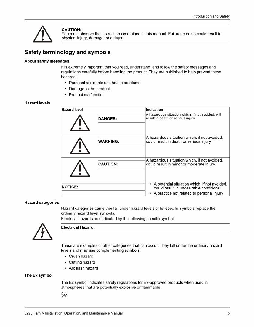
Hazard categoriesHazard categories can either fall under hazard levels or let specific symbols replace theordinary hazard level symbols.Electrical hazards are indicated by the following specific symbol:
Electrical Hazard:
These are examples of other categories that can occur. They fall under the ordinary hazardlevels and may use complementing symbols:
• Crush hazard• Cutting hazard• Arc flash hazard
The Ex symbol
The Ex symbol indicates safety regulations for Ex-approved products when used inatmospheres that are potentially explosive or flammable.
3298 Family Installation, Operation, and Maintenance Manual 5
Introduction and Safety
Environmental safetyThe work area
Always keep the station clean to avoid and/or discover emissions.
Waste and emissions regulationsObserve these safety regulations regarding waste and emissions:
• Appropriately dispose of all waste.• Handle and dispose of the processed liquid in compliance with applicable environmental
regulations.• Clean up all spills in accordance with safety and environmental procedures.• Report all environmental emissions to the appropriate authorities.
WARNING:Do NOT send the product to the manufacturer if it has been contaminated by any nuclearradiation. Inform ITT so that accurate actions can take place.
Electrical installationFor electrical installation recycling requirements, consult your local electric utility.
Recycling guidelines
Always follow local laws and regulations regarding recycling.
User safetyGeneral safety rules
These safety rules apply:• Always keep the work area clean.• Pay attention to the risks presented by gas and vapors in the work area.• Avoid all electrical dangers. Pay attention to the risks of electric shock or arc flash hazards.• Always bear in mind the risk of drowning, electrical accidents, and burn injuries.
Safety equipmentUse safety equipment according to the company regulations. Use this safety equipment withinthe work area:
• Helmet• Safety goggles, preferably with side shields• Protective shoes• Protective gloves• Gas mask• Hearing protection• First-aid kit• Safety devices
NOTICE:Never operate a unit unless safety devices are installed. Also see specific informationabout safety devices in other sections of this manual.
6 3298 Family Installation, Operation, and Maintenance Manual
Introduction and Safety
Electrical connectionsElectrical connections must be made by certified electricians in compliance with all internation-al, national, state, and local regulations. For more information about requirements, see sectionsdealing specifically with electrical connections.
Magnetic precautions
WARNING:Magnetic drive pumps contain very strong magnets that can pose health risks. Always observethese guidelines:
• Avoid working with, being in proximity of, or handling the magnets contained in this pump ifyou have any of these conditions:• An artificial cardiac pacemaker• An implanted defibrillator• A metallic prosthetic heart valve• Internal wound clips, from surgery• Prosthetic joints• Metallic wiring• Any other type of metallic, prosthetic device
• Individuals who have had any surgery, especially to the chest or head, and do not know ifmetallic clips were surgically implanted need to avoid work on this unit unless theirphysician can confirm that no metallic devices exist.
Wash the skin and eyes
1. Follow these procedures for chemicals or hazardous fluids that have come into contact withyour eyes or your skin:Condition ActionChemicals or hazardous 1. Hold your eyelids apart forcibly with your fingers.fluids in eyes 2. Rinse the eyes with eyewash or running water for at least
15 minutes.3. Seek medical attention.
Chemicals or hazardous 1. Remove contaminated clothing.fluids on skin 2. Wash the skin with soap and water for at least 1 minute.
3. Seek medical attention, if necessary.
Ex-approved productsFollow these special handling instructions if you have an Ex-approved unit.
Personnel requirementsThese are the personnel requirements for Ex-approved products in potentially explosiveatmospheres:
• All work on the product must be carried out by certified electricians and ITT-authorizedmechanics. Special rules apply to installations in explosive atmospheres.
• All users must know about the risks of electric current and the chemical and physicalcharacteristics of the gas, the vapor, or both present in hazardous areas.
• Any maintenance for Ex-approved products must conform to international and nationalstandards (for example, IEC/EN 60079-17).
ITT disclaims all responsibility for work done by untrained and unauthorized personnel.
Product and product handling requirementsThese are the product and product handling requirements for Ex-approved products inpotentially explosive atmospheres:
• Only use the product in accordance with the approved motor data.• The Ex-approved product must never run dry during normal operation. Dry running during
service and inspection is only permitted outside the classified area.
3298 Family Installation, Operation, and Maintenance Manual 7

Introduction and Safety
• Before you start work on the product, make sure that the product and the control panel areisolated from the power supply and the control circuit, so they cannot be energized.
• Do not open the product while it is energized or in an explosive gas atmosphere.• Make sure that thermal contacts are connected to a protection circuit according to the
approval classification of the product, and that they are in use.• Intrinsically safe circuits are normally required for the automatic level-control system by the
level regulator if mounted in zone 0.• The yield stress of fasteners must be in accordance with the approval drawing and the
product specification.• Do not modify the equipment without approval from an authorized ITT representative.• Only use parts that are provided by an authorized ITT representative.
Description of ATEX
The ATEX directives are a specification enforced in Europe for electrical and non-electricalequipment installed in Europe. ATEX deals with the control of potentially explosive atmos-pheres and the standards of equipment and protective systems used within these atmos-pheres. The relevance of the ATEX requirements is not limited to Europe. You can apply theseguidelines to equipment installed in any potentially explosive atmosphere.
Guidelines for compliance
Compliance is fulfilled only when you operate the unit within its intended use. Do not changethe conditions of the service without the approval of an ITT representative. When you install ormaintain explosion proof products, always comply with the directive and applicable standards(for example, IEC/EN 60079–14).
Monitoring equipmentFor additional safety, use condition-monitoring devices. Condition-monitoring devices includebut are not limited to these devices:
• Pressure gauges• Flow meters• Level indicators• Motor load readings• Temperature detectors• Bearing monitors• Leak detectors• PumpSmart control system
Product warrantyCoverage
ITT undertakes to remedy faults in products from ITT under these conditions:• The faults are due to defects in design, materials, or workmanship.• The faults are reported to an ITT representative within the warranty period.• The product is used only under the conditions described in this manual.• The monitoring equipment incorporated in the product is correctly connected and in use.• All service and repair work is done by ITT-authorized personnel.• Genuine ITT parts are used.• Only Ex-approved spare parts and accessories authorized by ITT are used in Ex-approved
products.
8 3298 Family Installation, Operation, and Maintenance Manual
Introduction and Safety
LimitationsThe warranty does not cover faults caused by these situations:
• Deficient maintenance• Improper installation• Modifications or changes to the product and installation made without consulting ITT• Incorrectly executed repair work• Normal wear and tear
ITT assumes no liability for these situations:• Bodily injuries• Material damages• Economic losses
Warranty claimITT products are high-quality products with expected reliable operation and long life. However,should the need arise for a warranty claim, then contact your ITT representative.
3298 Family Installation, Operation, and Maintenance Manual 9
Transportation and Storage
Transportation and StorageInspect the deliveryInspect the package
1. Inspect the package for damaged or missing items upon delivery.2. Note any damaged or missing items on the receipt and freight bill.3. File a claim with the shipping company if anything is out of order.
If the product has been picked up at a distributor, make a claim directly to the distributor.
Inspect the unit1. Remove packing materials from the product.
Dispose of all packing materials in accordance with local regulations.2. Inspect the product to determine if any parts have been damaged or are missing.3. If applicable, unfasten the product by removing any screws, bolts, or straps.
For your personal safety, be careful when you handle nails and straps.4. Contact your sales representative if anything is out of order.
Transportation guidelinesPrecautions
WARNING:• Stay clear of suspended loads.• Observe accident prevention regulations in force.
Pump handlingWARNING:
• Make sure that the unit cannot roll or fall over and injure people or damage property.• These pumps might use carbon or ceramic silicon carbide components. Do not drop the
pump or subject it to shock loads as this can damage the internal ceramic components.
NOTICE:Use a forklift truck or an overhead crane with sufficient capacity to move the pallet with thepump unit on top. Failure to do so can result in equipment damage.
Lifting methodsWARNING:
• All lifting must be done in compliance with all applicable regulations/standards.• Assembled units and their components are heavy. Failure to properly lift and support this
equipment can result in serious physical injury and/or equipment damage. Lift equipmentonly at the specifically identified lifting points. Lifting devices such as hoist rings, shackles,slings and spreaders must be rated, selected, and used for the entire load being lifted.
• Crush hazard. The unit and the components can be heavy. Use proper lifting methods andwear steel-toed shoes at all times.
• Do not attach sling ropes to shaft ends.
10 3298 Family Installation, Operation, and Maintenance Manual
Transportation and Storage
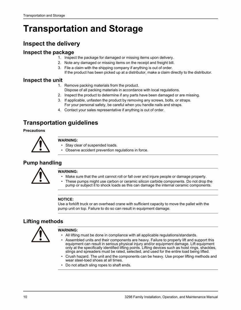
Table 1: Methods
Pump type Lifting methodA bare pump without lifting han- Use a suitable sling attached properly to solid points like the casing,dles the flanges, or the frames.A base-mounted pump Use slings under the pump casing and the drive unit, or under the base
rails.
Examples
Figure 1: Proper lifting method for a bare pump
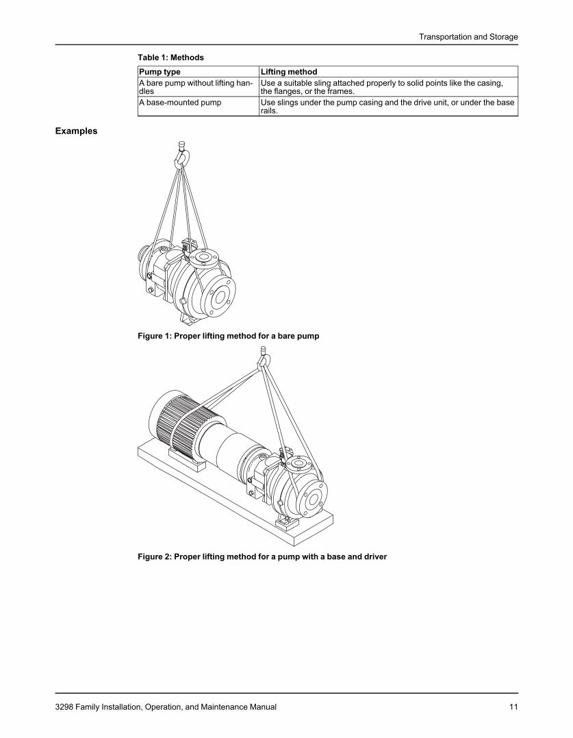
Figure 2: Proper lifting method for a pump with a base and driver
3298 Family Installation, Operation, and Maintenance Manual 11
Transportation and Storage
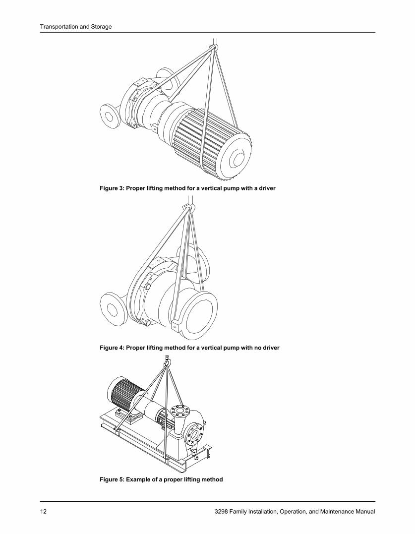
Figure 3: Proper lifting method for a vertical pump with a driver
Figure 4: Proper lifting method for a vertical pump with no driver
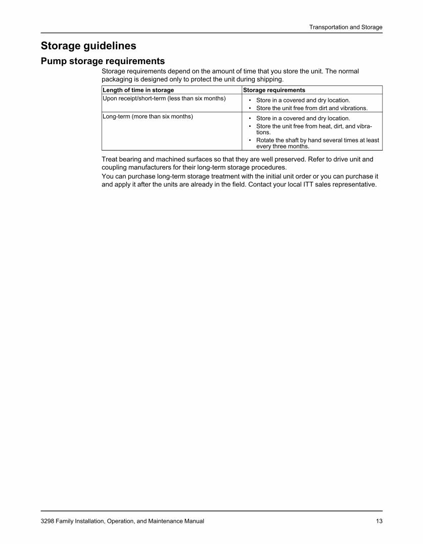
Figure 5: Example of a proper lifting method
12 3298 Family Installation, Operation, and Maintenance Manual
Transportation and Storage
Storage guidelinesPump storage requirements
Storage requirements depend on the amount of time that you store the unit. The normalpackaging is designed only to protect the unit during shipping.Length of time in storage Storage requirementsUpon receipt/short-term (less than six months) • Store in a covered and dry location.
• Store the unit free from dirt and vibrations.Long-term (more than six months) • Store in a covered and dry location.
• Store the unit free from heat, dirt, and vibra-tions.
• Rotate the shaft by hand several times at leastevery three months.
Treat bearing and machined surfaces so that they are well preserved. Refer to drive unit andcoupling manufacturers for their long-term storage procedures.You can purchase long-term storage treatment with the initial unit order or you can purchase itand apply it after the units are already in the field. Contact your local ITT sales representative.
3298 Family Installation, Operation, and Maintenance Manual 13
Product Description
Product DescriptionGeneral descriptionModel 3298
Model 3298 is a sealless, close-coupled or frame-mounted, centrifugal pump with an enclosedimpeller that is driven by a synchronous magnetic coupling. All sizes of the 3298 meet thedimensional standards of ANSI B73.1 except for 1x1.5-5 and the 1.5x2-6.
Model SP3298SP3298 is a self-priming, sealless, close-coupled or frame-mounted, centrifugal pump with anenclosed impeller that is driven by a synchronous magnetic coupling. The pump and the frameor adapter feet locations meet ANSI B73.1 dimensional standards.
Model V 3298V3298 is a vertical in-line, sealless, close-coupled centrifugal pump with an enclosed impellerthat is driven by a synchronous magnetic coupling. Model V3298 meets the dimensionalstandards of ANSI B73.2.
CasingThe casings are one-piece cast ductile iron lined with 1/8-inch Tefzel®1 and have ANSI class150 flanges with a Tefzel® raised face. The 3298 and SP3298 are end-suction, top centerlinedischarge, and are self-venting. The V3298 is side-suction, side-discharge, and is also self-venting.
Impeller magnet assemblyThe 3298 family uses a one- or two-piece impeller magnet assembly. The magnet ring isbalanced to ISO 1940 G6.3 levels and is sealed within the solid, enclosed Tefzel® impellermagnet assembly.
Stationary shaftThe impeller magnet assembly rotates about a solid stationary silicon carbide shaft. The shaftis supported at one end by the containment shell and at the other end by the Tefzel® bearingspider.
Bearing spiderThe bearing spider, constructed from solid Tefzel®, houses one of the key silicon carbide thrustbearings in the pump and supports the stationary shaft at one end.
Rear impeller wear ringA rear impeller wear ring is standard on M and L group pumps. A wear ring is not required ontheS group. The wear ring is pressed into the rear of the impeller assembly. The wear ringreduces axial thrust in the M and L group pumps.
Magnetic couplingThe magnetic coupling is a coaxial synchronous type using rare earth magnets of neodymiumiron (NdFe). This concept results in a compact design and allows the impeller to turn at thesame speed as the motor, which means that there is no slip between the drive and the drivenmagnets.
Containment shellThe containment shell isolates the pumped liquid from the atmosphere. The containment shellconstruction is backed with vinylester FRP.
14 3298 Family Installation, Operation, and Maintenance Manual
Product Description
BearingsThe standard material for radial bearings and thrust bearings is carbon. Pure Sintered AlphaGrade Silicon Carbide or DryGuard® Pure Sintered Alpha Grade Silicon Carbide are optional.
Standard close-coupled mountingThe drive magnet assembly is keyed, setscrewed, and mounted directly to the motor shaft. Thisarrangement eliminates the need to perform pump-to-motor alignment.
Optional frame-mounted power endThe standard configuration for the optional power end is cast iron with flood-oil-lubricated ballbearings. Pure oil mist systems are available as an option. For the protection and reliability ofthe bearings and the lubricant, a labyrinth seal is provided. On the inboard side a lip seal isused to prevent leakage of oil into the magnetic drive assembly. The frame-mounted power endis not available on the V3298.
Nameplate informationImportant information for ordering
Every pump has nameplates that provide information about the pump. The nameplates arelocated on the casing and the bearing frame.When you order spare parts, identify this pump information:
• Model• Size• Serial number• Item numbers of the required parts
Refer to the nameplate on the pump casing for most of the information. See Parts List for itemnumbers.
Nameplate typesNameplate DescriptionPump casing Provides information about the hydraulic characteristics of the pump.Pump The formula for the pump size is: Discharge x Suction - Nominal Maximum Impeller Diameter in inches.
(Example: 2x3-8)Bearing frame Provides information about the lubrication system used.ATEX If applicable, your pump unit might have an ATEX nameplate affixed to the pump, the baseplate, or the
discharge head. The nameplate provides information about the ATEX specifications of this pump.
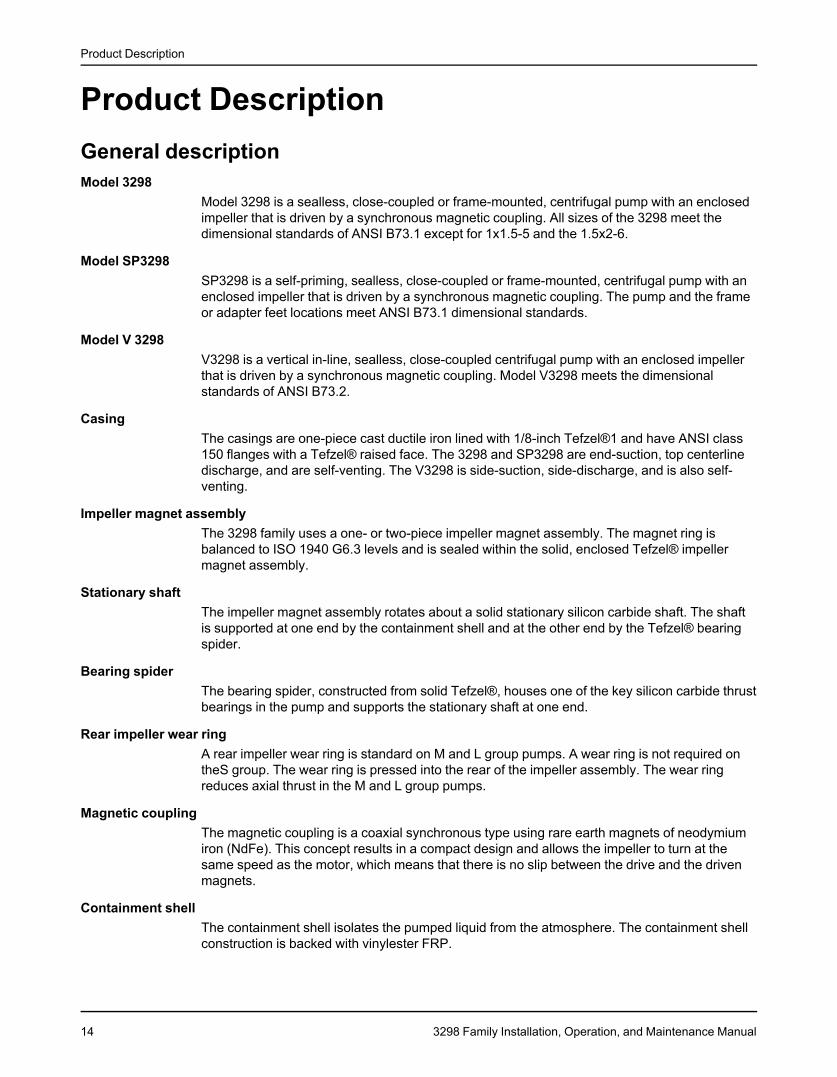
Nameplate on the pump casing using English units
Figure 6: Nameplate on the pump casing using English unitsTable 2: Explanation of nameplate on the pump casingNameplate field ExplanationIMPLR. DIA. Impeller diameter, in inchesMAX. DIA. Maximum impeller diameter, in inches
3298 Family Installation, Operation, and Maintenance Manual 15
Product Description
Nameplate field ExplanationGPM Rated pump flow, in gallons per minuteFT HD Rated pump head, in feetRPM Rated pump speed, revolutions per minuteMOD. Pump modelSIZE Size of the pumpSTD. NO. ANSI standard designationMAT L. CONST. Material of which the pump is constructedSER. NO. Serial number of the pumpMAX DSGN PSI @ Maximum pressure at 100ºF according to the pump design100ºF
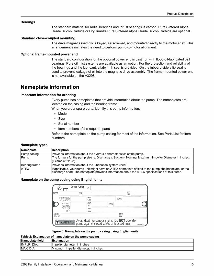
Nameplate on the pump casing using metric units
Figure 7: Metric units - nameplate on pump casingTable 3: Explanation of the nameplate on the pump casingNameplate field ExplanationIMPLR. DIA. Impeller diameterMAX. DIA. Maximum impeller diameterM3/HR Rated pump flow, in cubic meters per hourM HD Rated pump head, in metersRPM Rated pump speed, in revolutions per minuteMOD. Pump modelSIZE Size of the pumpSTD. NO. ANSI standard designationMAT L. CONST Material of which the pump is constructedSER. NO. Serial number of the pumpMAX. DSGN KG/CM3 @ 20°C Kilograms per cubic centimeter at 20°C
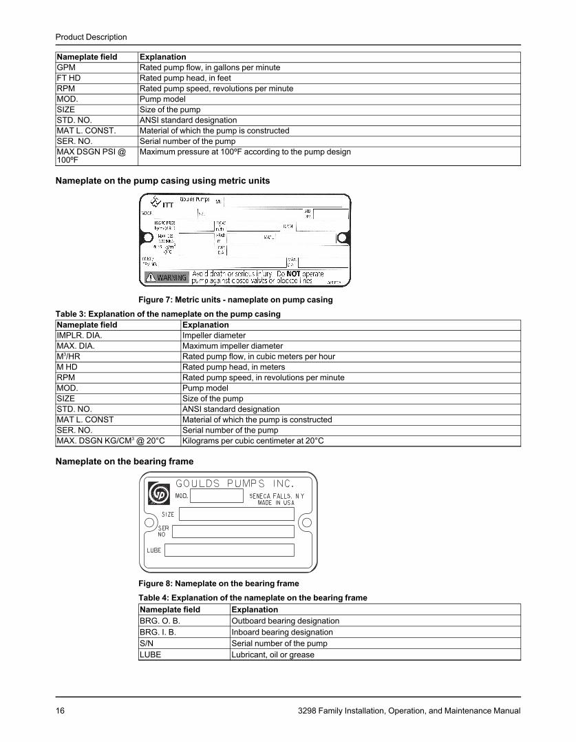
Nameplate on the bearing frame
Figure 8: Nameplate on the bearing frameTable 4: Explanation of the nameplate on the bearing frameNameplate field ExplanationBRG. O. B. Outboard bearing designationBRG. I. B. Inboard bearing designationS/N Serial number of the pumpLUBE Lubricant, oil or grease
16 3298 Family Installation, Operation, and Maintenance Manual
Product Description
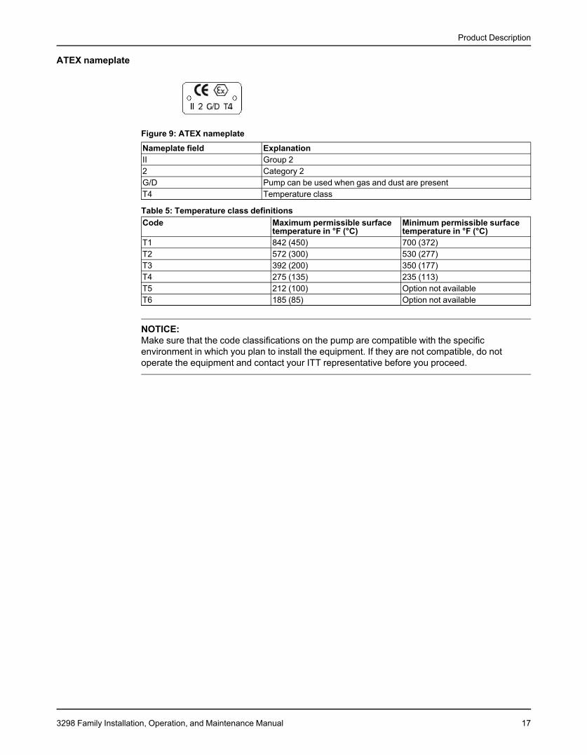
ATEX nameplate
Figure 9: ATEX nameplate
Nameplate field ExplanationII Group 22 Category 2G/D Pump can be used when gas and dust are presentT4 Temperature class
Table 5: Temperature class definitionsCode Maximum permissible surface Minimum permissible surface
temperature in °F (°C) temperature in °F (°C)T1 842 (450) 700 (372)T2 572 (300) 530 (277)T3 392 (200) 350 (177)T4 275 (135) 235 (113)T5 212 (100) Option not availableT6 185 (85) Option not available
NOTICE:Make sure that the code classifications on the pump are compatible with the specificenvironment in which you plan to install the equipment. If they are not compatible, do notoperate the equipment and contact your ITT representative before you proceed.
3298 Family Installation, Operation, and Maintenance Manual 17
Installation
InstallationPreinstallationPrecautions
WARNING:
• When installing in a potentially explosive environment, make sure that the motor isproperly certified.
• You must earth (ground) all electrical equipment. This applies to the pump equipment,the driver, and any monitoring equipment. Test the earth (ground) lead to verify that it isconnected correctly.
• Electrical connections must be made by certified electricians in compliance with allinternational, national, state, and local rules.
NOTICE:Supervision by an authorized ITT representative is recommended to ensure proper installation.Failure to do so may result in equipment damage or decreased performance.
Evaluate the installation in order to determine that the Net Positive Suction Head Available(NPSHA) meets or exceeds the Net Positive Suction Head Required (NPSHR), as stated by thepump performance curve.
Pump location guidelinesWARNING:Assembled units and their components are heavy. Failure to properly lift and support thisequipment can result in serious physical injury and/or equipment damage. Lift equipment onlyat the specifically identified lifting points. Lifting devices such as hoist rings, shackles, slingsand spreaders must be rated, selected, and used for the entire load being lifted.
Guideline Explanation/commentKeep the pump as close to the liquid source as This minimizes the friction loss and keeps thepractically possible. suction piping as short as possible.Make sure that the space around the pump is This facilitates ventilation, inspection, maintenance,sufficient. and service.If you require lifting equipment such as a hoist or This makes it easier to properly use the liftingtackle, make sure that there is enough space above equipment and safely remove and relocate thethe pump. components to a safe location.Protect the unit from weather and water damage This is applicable if nothing else is specified.due to rain, flooding, and freezing temperatures.Do not install and operate the equipment in closed Acceptable devices:systems unless the system is constructed with • Pressure relief valvesproperly-sized safety devices and control devices. • Compression tanks
• Pressure controls• Temperature controls• Flow controlsIf the system does not include these devices,consult the engineer or architect in charge beforeyou operate the pump.
Take into consideration the occurrence of unwanted The best pump location for noise and vibrationnoise and vibration. absorption is on a concrete floor with subsoil
underneath.If the pump location is overhead, undertake special Consider a consultation with a noise specialist.precautions to reduce possible noise transmission.
18 3298 Family Installation, Operation, and Maintenance Manual
Installation
Foundation requirementsPrecautions
CAUTION:If your pump is a Model NM3171, NM3196, 3198, 3298, V3298, SP3298, 4150, 4550, or 3107there is a possible risk of static electric discharge from plastic parts that are not properlygrounded. If the pumped fluid is non-conductive, drain and flush the pump with a conductivefluid under conditions that will not allow for a spark to be released to the atmosphere.
Requirements• The foundation must be able to absorb any type of vibration and form a permanent, rigid
support for the unit.• The location and size of the foundation bolt holes must match those shown on the
assembly drawing provided with the pump data package.• The foundation must weigh between two and three times the weight of the pump.• Provide a flat, substantial concrete foundation in order to prevent strain and distortion
when you tighten the foundation bolts.• Sleeve-type and J-type foundation bolts are most commonly used. Both designs allow
movement for the final bolt adjustment.
Sleeve-type bolts
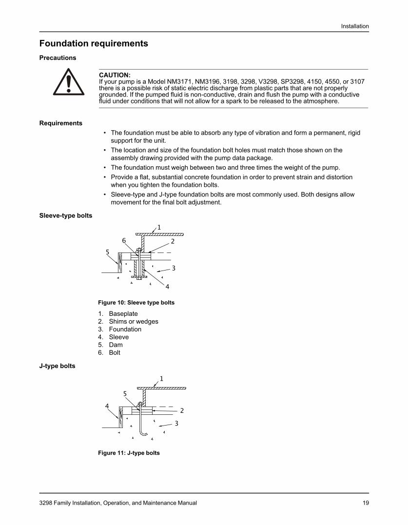
Figure 10: Sleeve type bolts
1. Baseplate2. Shims or wedges3. Foundation4. Sleeve5. Dam6. Bolt
J-type bolts
Figure 11: J-type bolts
3298 Family Installation, Operation, and Maintenance Manual 19
Installation
1. Baseplate2. Shims or wedges3. Foundation4. Dam5. Bolt
Baseplate-mounting proceduresPrepare the baseplate for mounting
1. Remove all the attached equipment from the baseplate.2. Clean the underside of the baseplate completely.3. If applicable, coat the underside of the baseplate with an epoxy primer.
Use an epoxy primer only if you used an epoxy-based grout.4. Remove the rust-proofing coat from the machined mounting pads using an appropriate
solvent.5. Remove water and debris from the foundation-bolt holes.
Install the baseplate using shims or wedgesRequired tools:
• Two sets of shims or wedges for each foundation bolt• Two machinist's levels• Baseplate-leveling worksheet
This procedure is applicable to cast iron and fabricated steel baseplates.1. Remove water and debris from the anchor bolt holes and sleeves.2. If you use sleeve-type bolts, fill the bolt sleeves with packing material or rags to prevent
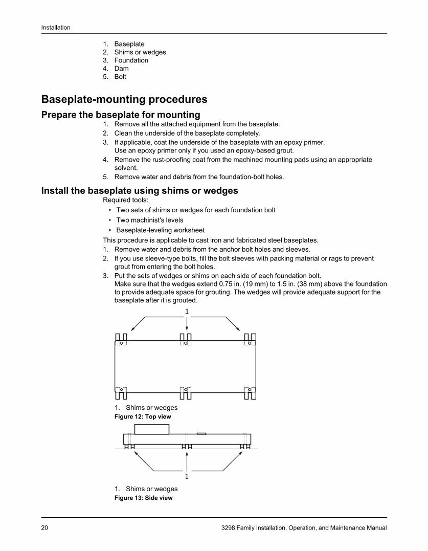
grout from entering the bolt holes.3. Put the sets of wedges or shims on each side of each foundation bolt.
Make sure that the wedges extend 0.75 in. (19 mm) to 1.5 in. (38 mm) above the foundationto provide adequate space for grouting. The wedges will provide adequate support for thebaseplate after it is grouted.
1. Shims or wedgesFigure 12: Top view
1. Shims or wedgesFigure 13: Side view
20 3298 Family Installation, Operation, and Maintenance Manual
Installation
4. Lower the baseplate carefully onto the foundation bolts.5. Put the machinist's levels across the mounting pads of the driver and the mounting pads of
the pump.
NOTICE:Remove all dirt from the mounting pads in order to make sure that you achieve the correctleveling. Failure to do so can result in equipment damage or decreased performance.
6. Level the baseplate both lengthwise and across by adding or removing shims or moving thewedges.These are the leveling tolerances:
• A maximum difference of 0.125 in. (3.2 mm) lengthwise• A maximum difference of 0.059 in. (1.5 mm) across
You can use the baseplate-leveling worksheet when you take the readings.7. Hand-tighten the nuts for the foundation.
Install the baseplate using jackscrewsTools required:
• Anti-seize compound• Jackscrews• Bar stock• Two machinist's levels• Baseplate-leveling worksheet
This procedure applies to the feature-fabricated steel baseplate and the advantage basebaseplate.1. Apply an anti-seize compound on the jackscrews.
The compound makes it easier to remove the screws after you grout.2. Lower the baseplate carefully onto the foundation bolts and perform these steps:
a) Cut the plates from the bar stock and chamfer the edges of the plates in order to reducestress concentrations.
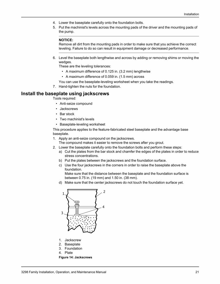
b) Put the plates between the jackscrews and the foundation surface.c) Use the four jackscrews in the corners in order to raise the baseplate above the
foundation.Make sure that the distance between the baseplate and the foundation surface isbetween 0.75 in. (19 mm) and 1.50 in. (38 mm).
d) Make sure that the center jackscrews do not touch the foundation surface yet.
1. Jackscrew2. Baseplate3. Foundation4. PlateFigure 14: Jackscrews
3298 Family Installation, Operation, and Maintenance Manual 21
Installation
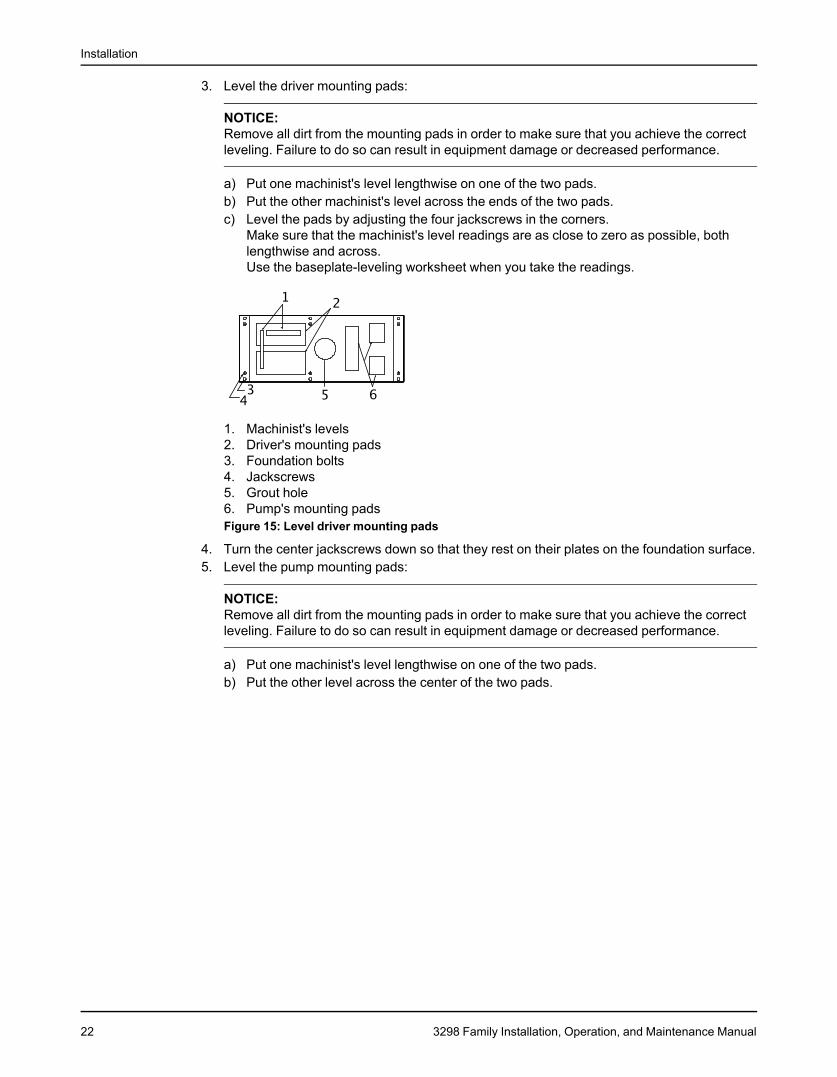
3. Level the driver mounting pads:
NOTICE:Remove all dirt from the mounting pads in order to make sure that you achieve the correctleveling. Failure to do so can result in equipment damage or decreased performance.
a) Put one machinist's level lengthwise on one of the two pads.b) Put the other machinist's level across the ends of the two pads.c) Level the pads by adjusting the four jackscrews in the corners.
Make sure that the machinist's level readings are as close to zero as possible, bothlengthwise and across.Use the baseplate-leveling worksheet when you take the readings.
1. Machinist's levels2. Driver's mounting pads3. Foundation bolts4. Jackscrews5. Grout hole6. Pump's mounting padsFigure 15: Level driver mounting pads
4. Turn the center jackscrews down so that they rest on their plates on the foundation surface.5. Level the pump mounting pads:
NOTICE:Remove all dirt from the mounting pads in order to make sure that you achieve the correctleveling. Failure to do so can result in equipment damage or decreased performance.
a) Put one machinist's level lengthwise on one of the two pads.b) Put the other level across the center of the two pads.
22 3298 Family Installation, Operation, and Maintenance Manual
Installation
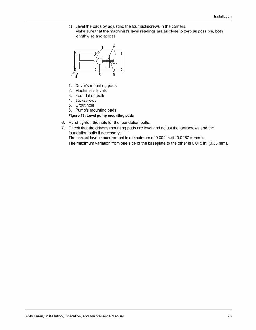
c) Level the pads by adjusting the four jackscrews in the corners.Make sure that the machinist's level readings are as close to zero as possible, bothlengthwise and across.
1. Driver's mounting pads2. Machinist's levels3. Foundation bolts4. Jackscrews5. Grout hole6. Pump's mounting padsFigure 16: Level pump mounting pads
6. Hand-tighten the nuts for the foundation bolts.7. Check that the driver's mounting pads are level and adjust the jackscrews and the
foundation bolts if necessary.The correct level measurement is a maximum of 0.002 in./ft (0.0167 mm/m).The maximum variation from one side of the baseplate to the other is 0.015 in. (0.38 mm).
3298 Family Installation, Operation, and Maintenance Manual 23
Installation
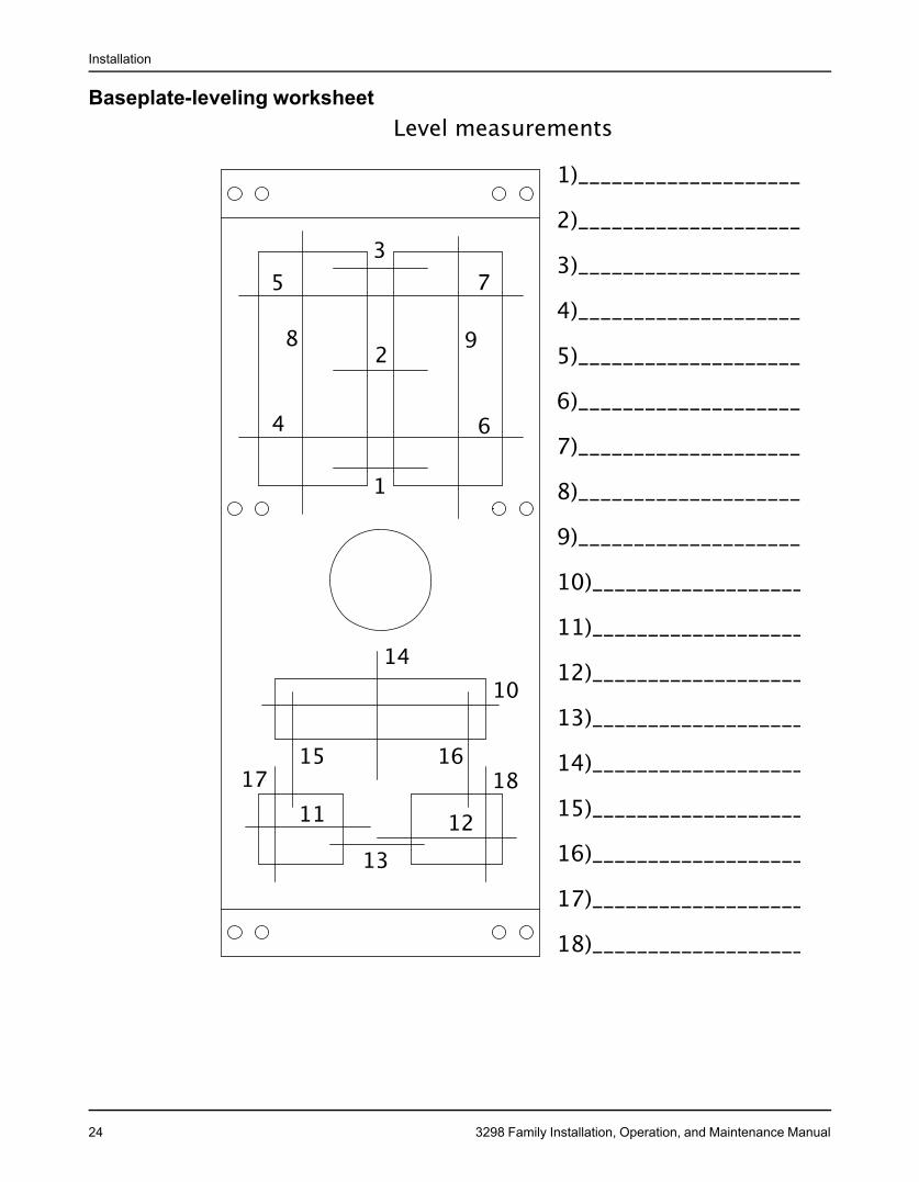
Baseplate-leveling worksheet
24 3298 Family Installation, Operation, and Maintenance Manual
Installation
Pump-to-driver alignmentPrecautions
WARNING:• Follow shaft alignment procedures in order to prevent catastrophic failure of drive
components or unintended contact of rotating parts. Follow the coupling installation andoperation procedures from the coupling manufacturer.
• Always disconnect and lock out power to the driver before you perform any installationor maintenance tasks. Failure to disconnect and lock out driver power will result in seriousphysical injury.• Electrical connections must be made by certified electricians in compliance with all
international, national, state, and local rules.• Refer to driver/coupling/gear manufacturers installation and operation manuals (IOM)
for specific instructions and recommendations.
NOTICE:Proper alignment is the responsibility of the installer and the user of the unit. Check thealignment of frame-mounted units before you operate the unit. Failure to do so can result inequipment damage or decreased performance.
Alignment methodsThree common alignment methods are used:
• Dial indicator• Reverse dial indicator• Laser
Follow the instructions from the equipment manufacturer when you use the reverse dialindicator or laser methods. Detailed instructions for using the dial indicator method arecontained in this chapter.
Alignment checksWhen to perform alignment checks
You must perform alignment checks under these circumstances:• The process temperature changes.• The piping changes.• The pump has been serviced.
Types of alignment checksType of check When it is usedInitial alignment (cold alignment) Prior to operation when the pump and the driver are at ambientcheck temperature.Final alignment (hot alignment) After operation when the pump and the driver are at operatingcheck temperature.
Initial alignment (cold alignment) checksWhen WhyBefore you grout the baseplate This ensures that alignment can be accomplished.After you grout the baseplate This ensures that no changes have occurred during the grouting
process.After you connect the piping This ensures that pipe strains have not altered the alignment.
If changes have occurred, you must alter the piping to remove pipestrains on the pump flanges.
3298 Family Installation, Operation, and Maintenance Manual 25
Installation
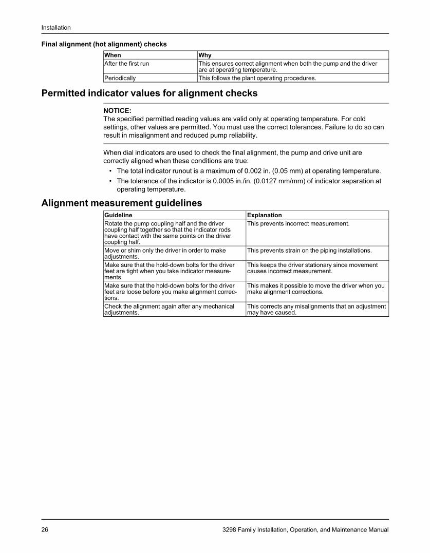
Final alignment (hot alignment) checksWhen WhyAfter the first run This ensures correct alignment when both the pump and the driver
are at operating temperature.Periodically This follows the plant operating procedures.
Permitted indicator values for alignment checks
NOTICE:The specified permitted reading values are valid only at operating temperature. For coldsettings, other values are permitted. You must use the correct tolerances. Failure to do so canresult in misalignment and reduced pump reliability.
When dial indicators are used to check the final alignment, the pump and drive unit arecorrectly aligned when these conditions are true:
• The total indicator runout is a maximum of 0.002 in. (0.05 mm) at operating temperature.• The tolerance of the indicator is 0.0005 in./in. (0.0127 mm/mm) of indicator separation at
operating temperature.
Alignment measurement guidelinesGuideline ExplanationRotate the pump coupling half and the driver This prevents incorrect measurement.coupling half together so that the indicator rodshave contact with the same points on the drivercoupling half.Move or shim only the driver in order to make This prevents strain on the piping installations.adjustments.Make sure that the hold-down bolts for the driver This keeps the driver stationary since movementfeet are tight when you take indicator measure- causes incorrect measurement.ments.Make sure that the hold-down bolts for the driver This makes it possible to move the driver when youfeet are loose before you make alignment correc- make alignment corrections.tions.Check the alignment again after any mechanical This corrects any misalignments that an adjustmentadjustments. may have caused.
26 3298 Family Installation, Operation, and Maintenance Manual
Installation
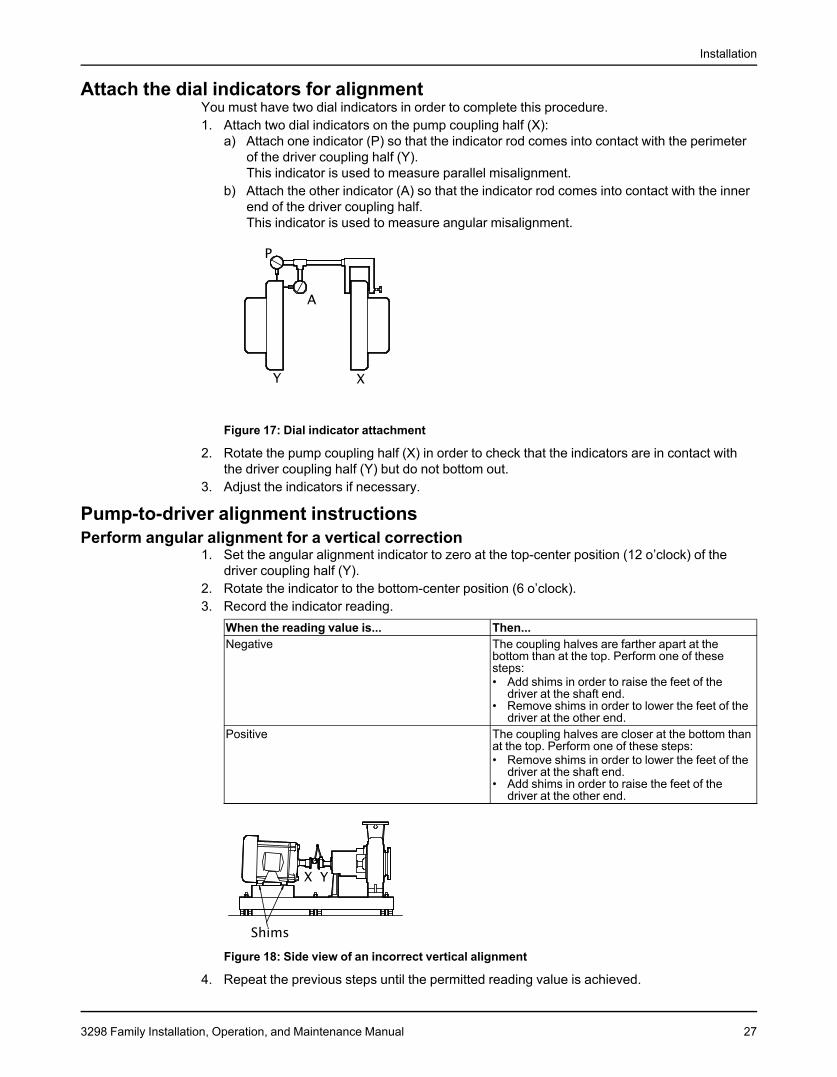
Attach the dial indicators for alignmentYou must have two dial indicators in order to complete this procedure.1. Attach two dial indicators on the pump coupling half (X):
a) Attach one indicator (P) so that the indicator rod comes into contact with the perimeterof the driver coupling half (Y).This indicator is used to measure parallel misalignment.
b) Attach the other indicator (A) so that the indicator rod comes into contact with the innerend of the driver coupling half.This indicator is used to measure angular misalignment.
Figure 17: Dial indicator attachment
2. Rotate the pump coupling half (X) in order to check that the indicators are in contact withthe driver coupling half (Y) but do not bottom out.
3. Adjust the indicators if necessary.
Pump-to-driver alignment instructionsPerform angular alignment for a vertical correction
1. Set the angular alignment indicator to zero at the top-center position (12 o’clock) of thedriver coupling half (Y).
2. Rotate the indicator to the bottom-center position (6 o’clock).3. Record the indicator reading.
When the reading value is... Then...Negative The coupling halves are farther apart at the
bottom than at the top. Perform one of thesesteps:• Add shims in order to raise the feet of the
driver at the shaft end.• Remove shims in order to lower the feet of the
driver at the other end.Positive The coupling halves are closer at the bottom than
at the top. Perform one of these steps:• Remove shims in order to lower the feet of the
driver at the shaft end.• Add shims in order to raise the feet of the
driver at the other end.
Figure 18: Side view of an incorrect vertical alignment
4. Repeat the previous steps until the permitted reading value is achieved.
3298 Family Installation, Operation, and Maintenance Manual 27
Installation
Maximum permitted value for angular alignment:• 0.002 in. (0.05 mm) total indicated runout at operating temperature
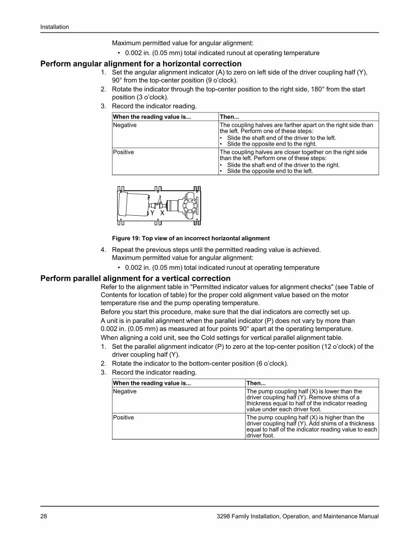
Perform angular alignment for a horizontal correction1. Set the angular alignment indicator (A) to zero on left side of the driver coupling half (Y),
90° from the top-center position (9 o’clock).2. Rotate the indicator through the top-center position to the right side, 180° from the start
position (3 o’clock).3. Record the indicator reading.
When the reading value is... Then...Negative The coupling halves are farther apart on the right side than
the left. Perform one of these steps:• Slide the shaft end of the driver to the left.• Slide the opposite end to the right.
Positive The coupling halves are closer together on the right sidethan the left. Perform one of these steps:• Slide the shaft end of the driver to the right.• Slide the opposite end to the left.
Figure 19: Top view of an incorrect horizontal alignment
4. Repeat the previous steps until the permitted reading value is achieved.Maximum permitted value for angular alignment:
• 0.002 in. (0.05 mm) total indicated runout at operating temperature
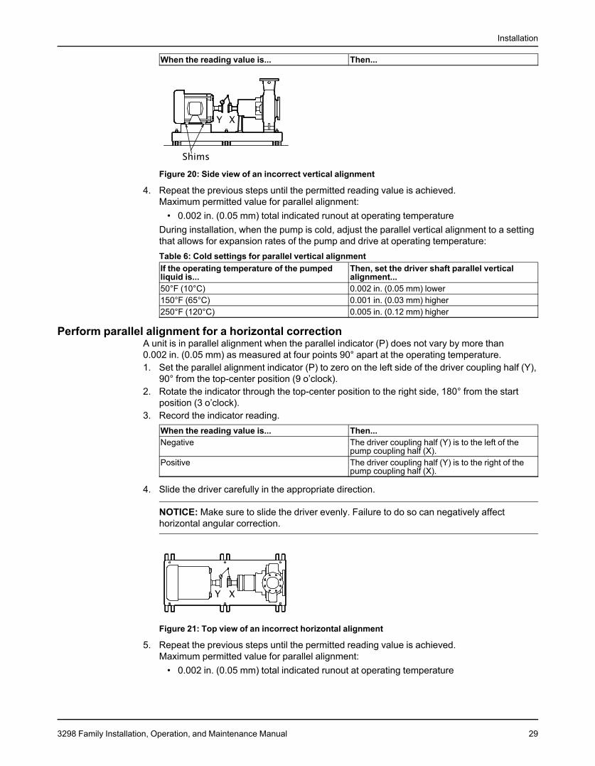
Perform parallel alignment for a vertical correctionRefer to the alignment table in "Permitted indicator values for alignment checks" (see Table ofContents for location of table) for the proper cold alignment value based on the motortemperature rise and the pump operating temperature.Before you start this procedure, make sure that the dial indicators are correctly set up.A unit is in parallel alignment when the parallel indicator (P) does not vary by more than0.002 in. (0.05 mm) as measured at four points 90° apart at the operating temperature.When aligning a cold unit, see the Cold settings for vertical parallel alignment table.1. Set the parallel alignment indicator (P) to zero at the top-center position (12 o’clock) of the
driver coupling half (Y).2. Rotate the indicator to the bottom-center position (6 o’clock).3. Record the indicator reading.
When the reading value is... Then...Negative The pump coupling half (X) is lower than the
driver coupling half (Y). Remove shims of athickness equal to half of the indicator readingvalue under each driver foot.
Positive The pump coupling half (X) is higher than thedriver coupling half (Y). Add shims of a thicknessequal to half of the indicator reading value to eachdriver foot.
28 3298 Family Installation, Operation, and Maintenance Manual
Installation
When the reading value is... Then...
Figure 20: Side view of an incorrect vertical alignment
4. Repeat the previous steps until the permitted reading value is achieved.Maximum permitted value for parallel alignment:
• 0.002 in. (0.05 mm) total indicated runout at operating temperatureDuring installation, when the pump is cold, adjust the parallel vertical alignment to a settingthat allows for expansion rates of the pump and drive at operating temperature:Table 6: Cold settings for parallel vertical alignmentIf the operating temperature of the pumped Then, set the driver shaft parallel verticalliquid is... alignment...50°F (10°C) 0.002 in. (0.05 mm) lower150°F (65°C) 0.001 in. (0.03 mm) higher250°F (120°C) 0.005 in. (0.12 mm) higher
Perform parallel alignment for a horizontal correctionA unit is in parallel alignment when the parallel indicator (P) does not vary by more than0.002 in. (0.05 mm) as measured at four points 90° apart at the operating temperature.1. Set the parallel alignment indicator (P) to zero on the left side of the driver coupling half (Y),
90° from the top-center position (9 o’clock).2. Rotate the indicator through the top-center position to the right side, 180° from the start
position (3 o’clock).3. Record the indicator reading.
When the reading value is... Then...Negative The driver coupling half (Y) is to the left of the
pump coupling half (X).Positive The driver coupling half (Y) is to the right of the
pump coupling half (X).
4. Slide the driver carefully in the appropriate direction.
NOTICE: Make sure to slide the driver evenly. Failure to do so can negatively affecthorizontal angular correction.
Figure 21: Top view of an incorrect horizontal alignment
5. Repeat the previous steps until the permitted reading value is achieved.Maximum permitted value for parallel alignment:
• 0.002 in. (0.05 mm) total indicated runout at operating temperature
3298 Family Installation, Operation, and Maintenance Manual 29
Installation
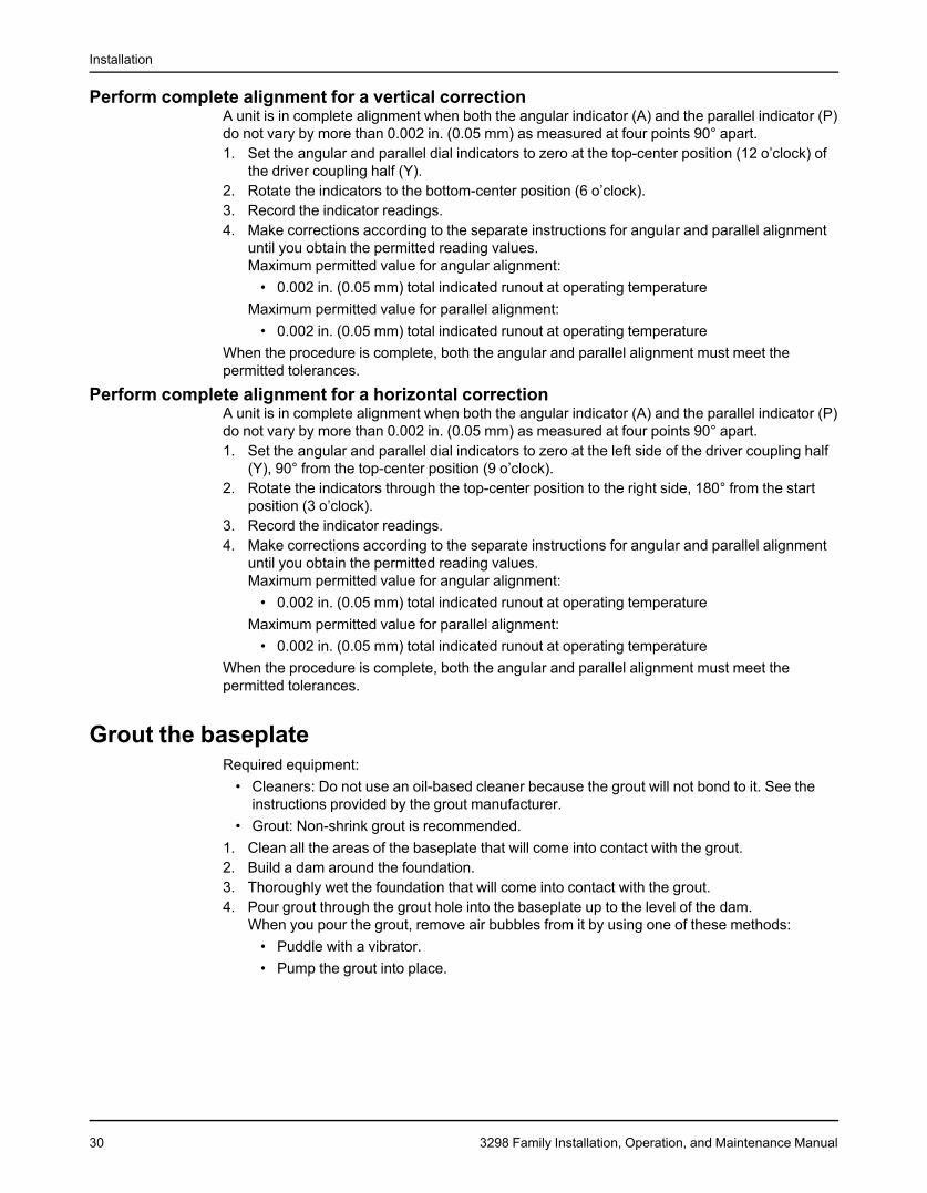
Perform complete alignment for a vertical correctionA unit is in complete alignment when both the angular indicator (A) and the parallel indicator (P)do not vary by more than 0.002 in. (0.05 mm) as measured at four points 90° apart.1. Set the angular and parallel dial indicators to zero at the top-center position (12 o’clock) of
the driver coupling half (Y).2. Rotate the indicators to the bottom-center position (6 o’clock).3. Record the indicator readings.4. Make corrections according to the separate instructions for angular and parallel alignment
until you obtain the permitted reading values.Maximum permitted value for angular alignment:
• 0.002 in. (0.05 mm) total indicated runout at operating temperatureMaximum permitted value for parallel alignment:
• 0.002 in. (0.05 mm) total indicated runout at operating temperatureWhen the procedure is complete, both the angular and parallel alignment must meet thepermitted tolerances.
Perform complete alignment for a horizontal correctionA unit is in complete alignment when both the angular indicator (A) and the parallel indicator (P)do not vary by more than 0.002 in. (0.05 mm) as measured at four points 90° apart.1. Set the angular and parallel dial indicators to zero at the left side of the driver coupling half
(Y), 90° from the top-center position (9 o’clock).2. Rotate the indicators through the top-center position to the right side, 180° from the start
position (3 o’clock).3. Record the indicator readings.4. Make corrections according to the separate instructions for angular and parallel alignment
until you obtain the permitted reading values.Maximum permitted value for angular alignment:
• 0.002 in. (0.05 mm) total indicated runout at operating temperatureMaximum permitted value for parallel alignment:
• 0.002 in. (0.05 mm) total indicated runout at operating temperatureWhen the procedure is complete, both the angular and parallel alignment must meet thepermitted tolerances.
Grout the baseplateRequired equipment:
• Cleaners: Do not use an oil-based cleaner because the grout will not bond to it. See theinstructions provided by the grout manufacturer.
• Grout: Non-shrink grout is recommended.1. Clean all the areas of the baseplate that will come into contact with the grout.2. Build a dam around the foundation.3. Thoroughly wet the foundation that will come into contact with the grout.4. Pour grout through the grout hole into the baseplate up to the level of the dam.
When you pour the grout, remove air bubbles from it by using one of these methods:• Puddle with a vibrator.• Pump the grout into place.
30 3298 Family Installation, Operation, and Maintenance Manual
Installation
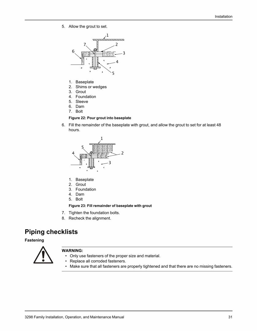
5. Allow the grout to set.
1. Baseplate2. Shims or wedges3. Grout4. Foundation5. Sleeve6. Dam7. BoltFigure 22: Pour grout into baseplate
6. Fill the remainder of the baseplate with grout, and allow the grout to set for at least 48hours.
1. Baseplate2. Grout3. Foundation4. Dam5. BoltFigure 23: Fill remainder of baseplate with grout
7. Tighten the foundation bolts.8. Recheck the alignment.
Piping checklistsFastening
WARNING:• Only use fasteners of the proper size and material.• Replace all corroded fasteners.• Make sure that all fasteners are properly tightened and that there are no missing fasteners.
3298 Family Installation, Operation, and Maintenance Manual 31
Installation
General piping checklistPrecautions
WARNING:• The heating of water and other fluids causes volumetric expansion. The associated forces
can cause the failure of system components and the release of high-temperature fluids. Inorder to prevent this, install properly sized and located compression tanks and pressure-relief valves. Failure to follow these instructions can result in serious personal injury ordeath, or property damage.
CAUTION:• Never draw piping into place by using force at the flanged connections of the pump. This
can impose dangerous strains on the unit and cause misalignment between the pump anddriver. Pipe strain adversely affects the operation of the pump, which results in physicalinjury and damage to the equipment.
• Vary the capacity with the regulating valve in the discharge line. Never throttle the flowfrom the suction side. This action can result in decreased performance, unexpected heatgeneration, and equipment damage.
CAUTION:Flange loads from the piping system, including those from the thermal expansion of the piping,must not exceed the limits of the pump. Deformation can result in contact with rotating parts,which can result in excess heat generation, sparks, and premature failure.
Piping guidelinesGuidelines for piping are given in the Hydraulic Institute Standards available from the HydraulicInstitute at 9 Sylvan Way, Parsippany, NJ 07054-3802. You must review this document beforeyou install the pump.
ChecklistCheck Explanation/comment CheckedCheck that all piping is supported This helps to prevent:independently of, and lined up • Strain on the pumpnaturally with, the pump flange. • Misalignment between the pump and the drive unitSee Alignment criteria for pump • Wear on the pump bearings and the couplingflanges. • Wear on the pump bearings, seal, and shafting
If an isolation base is used, then use flexible piping onthe discharge and suction connections.
Check that only necessary fittings This helps to minimize friction losses.are used.Do not connect the piping to the —pump until:• The grout for the baseplate or
sub-base becomes hard.• The hold-down bolts for the
pump and the driver are tight-ened.
Make sure that all the piping joints This prevents air from entering the piping system orand fittings are airtight. leaks that occur during operation.
If the pump housing has threaded connections, then usea Teflon tape sealer or a high-quality thread sealant.
If the pump handles corrosivefluids, make sure that the pipingallows you to flush out the liquidbefore you remove the pump.
32 3298 Family Installation, Operation, and Maintenance Manual

Installation
Check Explanation/comment CheckedIf the pump handles liquids at This helps to prevent misalignment due to linear expan-elevated temperatures, make sion of the piping.sure that the expansion loops and This helps to prevent misalignment due to thermaljoints are properly installed. expansion of the piping.
Alignment criteria for pump flangesType CriteriaAxial The flange gasket thickness is ±0.03 in. (0.8 mm).Parallel Align the flange to be within 0.001 in./in. to 0.03 in./
in. (0.025 mm/mm to 0.8 mm/mm) of the flangediameter.
Concentric You can easily install the flange bolts by hand.
Example: Installation for expansionCorrect Incorrect
1. Expansion loop/joint
Suction-piping checklistPerformance curve reference
CAUTION:Vary the capacity with the regulating valve in the discharge line. Never throttle the flow fromthe suction side. This action can result in decreased performance, unexpected heatgeneration, and equipment damage.
Net positive suction head available (NPSHA) must always exceed NPSH required (NPSHR) asshown on the published performance curve of the pump.If a suction lift over 10 ft. (3 m) and a liquid temperature higher than 120°F (49°C) are required,then read the pump performance curve for the NPSHR.
Suction-piping checksCheck Explanation/comment CheckedFlush all suction piping before you This reduces the risk of pumpconnect it to the pump. operation problems.Check that the distance between This minimizes the risk of cavita-the inlet flange of the pump and tion in the suction inlet of thethe closest elbow is at least two pump due to turbulence.pipe diameters. See the Example sections for il-
lustrations.
3298 Family Installation, Operation, and Maintenance Manual 33
Installation
Check Explanation/comment CheckedCheck that elbows in general do See the Example sections for il-not have sharp bends. lustrations.Check that the suction piping is The suction piping must neverone or two sizes larger than the have a smaller diameter than thesuction inlet of the pump. suction inlet of the pump.Install an eccentric reducer be- See the Example sections for il-tween the pump inlet and the lustrations.suction piping.Check that the eccentric reducer See the example illustrations.at the suction flange of the pumphas the following properties:• Sloping side down• Horizontal side at the topSuggested suction strainers are Suction strainers help to preventused. Check that they are at least debris from entering the pump.three times the area of the suction Mesh holes with a minimum diam-piping. eter of 1/16 in. (1.6 mm) areMonitor the pressure drop across recommended.the suction strainer. Liquids with specific gravity lessAn increased pressure drop than 0.60 a pressure drop acrossacross the strainer of 5 psi (34.5 the suction strainer may be due tokPa) indicates that the strainer ice buildup. Ice buildup can causeshould be removed and cleaned. turbulence, low pressure areas
and pumpage vaporization.After a period of time (24 hoursminimum) system flushing shouldbe complete and the suctionstrainer can be removed.If more than one pump operates This recommendation helps youfrom the same liquid source, to achieve a higher pump perfor-check that separate suction-piping mance and prevent vapor lockinglines are used for each pump. especially with specific gravity of
liquid less than 0.60.If necessary, make sure that the —suction piping includes a drainvalve and that it is correctly in-stalled.Assure adequate insulation is ap- To assure sufficient NPSHa.plied for liquids with specific grav-ity less than 0.60.
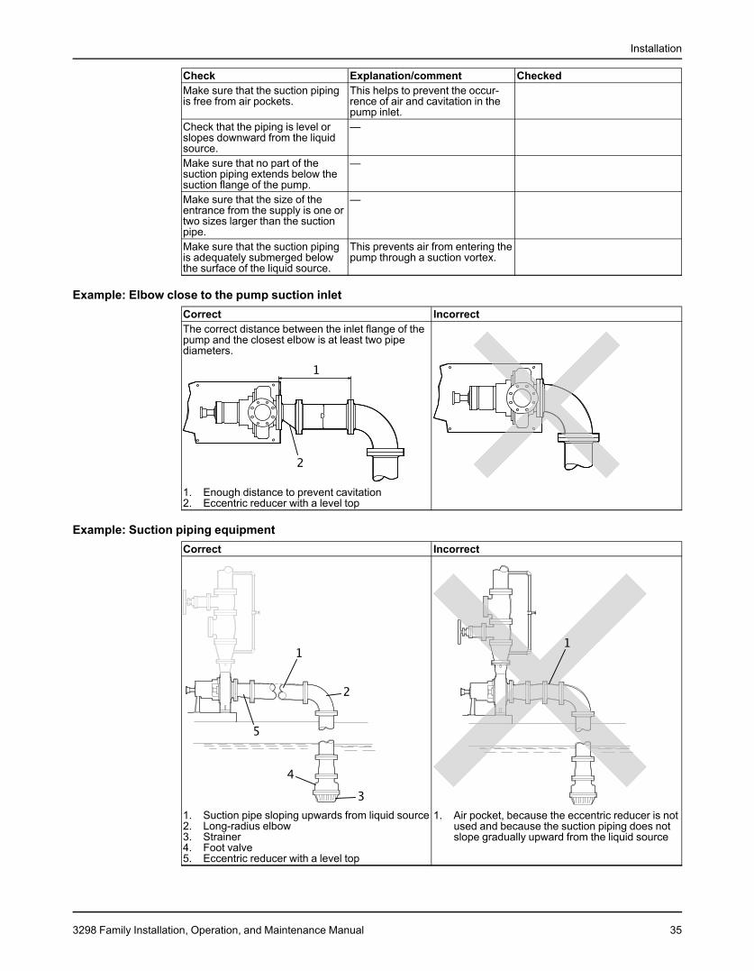
Liquid source below the pumpCheck Explanation/comment CheckedMake sure that the suction piping This helps to prevent the occur-is free from air pockets. rence of air and cavitation in the
pump inlet.Check that the suction piping —slopes upwards from the liquidsource to the pump inlet.Check that all joints are air-tight. —If the pump is not self-priming, Use a foot valve with a diametercheck that a device for priming the that is at least equivalent to thepump is installed. diameter of the suction piping.
Liquid source above the pumpCheck Explanation/comment CheckedCheck that an isolation valve is This permits you to close the lineinstalled in the suction piping at a during pump inspection and main-distance of at least two times the tenance.pipe diameter from the suction Do not use the isolation valve toinlet. throttle the pump. Throttling can
cause these problems:• Loss of priming• Excessive temperatures• Damage to the pump• Voiding the warranty
34 3298 Family Installation, Operation, and Maintenance Manual
Installation
Check Explanation/comment CheckedMake sure that the suction piping This helps to prevent the occur-is free from air pockets. rence of air and cavitation in the
pump inlet.Check that the piping is level or —slopes downward from the liquidsource.Make sure that no part of the —suction piping extends below thesuction flange of the pump.Make sure that the size of the —entrance from the supply is one ortwo sizes larger than the suctionpipe.Make sure that the suction piping This prevents air from entering theis adequately submerged below pump through a suction vortex.the surface of the liquid source.
Example: Elbow close to the pump suction inletCorrect IncorrectThe correct distance between the inlet flange of thepump and the closest elbow is at least two pipediameters.
1. Enough distance to prevent cavitation2. Eccentric reducer with a level top
Example: Suction piping equipmentCorrect Incorrect
1. Suction pipe sloping upwards from liquid source 1. Air pocket, because the eccentric reducer is not2. Long-radius elbow used and because the suction piping does not3. Strainer slope gradually upward from the liquid source4. Foot valve5. Eccentric reducer with a level top
3298 Family Installation, Operation, and Maintenance Manual 35
Installation
Discharge piping checklistChecklist
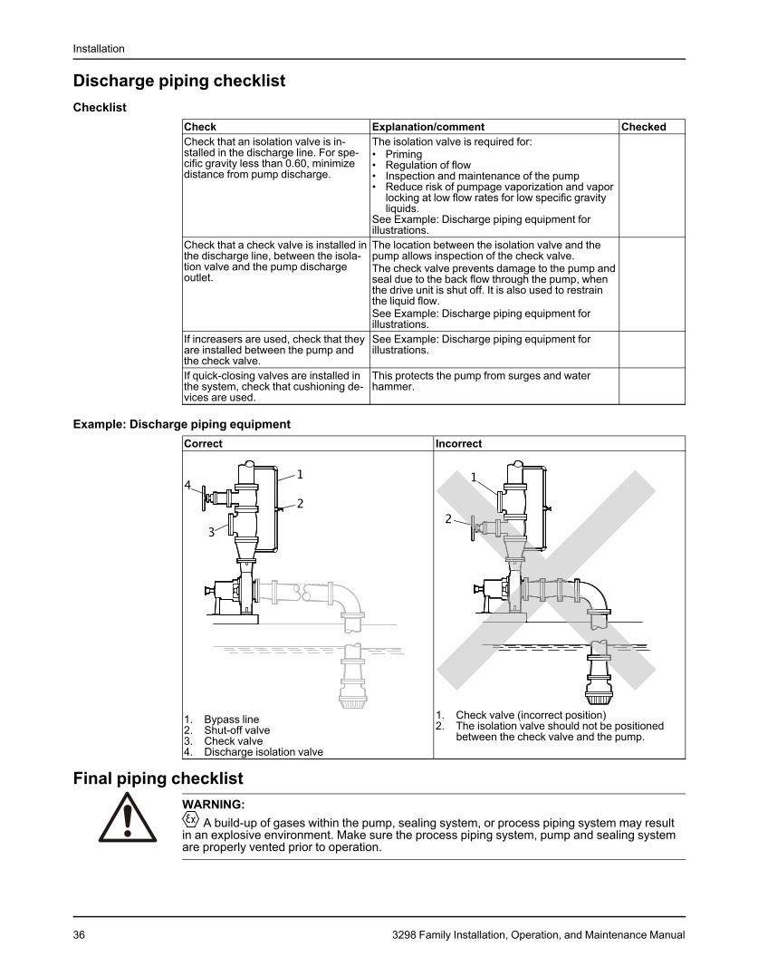
Check Explanation/comment CheckedCheck that an isolation valve is in- The isolation valve is required for:stalled in the discharge line. For spe- • Primingcific gravity less than 0.60, minimize • Regulation of flowdistance from pump discharge. • Inspection and maintenance of the pump
• Reduce risk of pumpage vaporization and vaporlocking at low flow rates for low specific gravityliquids.
See Example: Discharge piping equipment forillustrations.
Check that a check valve is installed in The location between the isolation valve and thethe discharge line, between the isola- pump allows inspection of the check valve.tion valve and the pump discharge The check valve prevents damage to the pump andoutlet. seal due to the back flow through the pump, when
the drive unit is shut off. It is also used to restrainthe liquid flow.See Example: Discharge piping equipment forillustrations.
If increasers are used, check that they See Example: Discharge piping equipment forare installed between the pump and illustrations.the check valve.If quick-closing valves are installed in This protects the pump from surges and waterthe system, check that cushioning de- hammer.vices are used.
Example: Discharge piping equipmentCorrect Incorrect
1. Check valve (incorrect position)1. Bypass line 2. The isolation valve should not be positioned2. Shut-off valve between the check valve and the pump.3. Check valve4. Discharge isolation valve
Final piping checklistWARNING:
A build-up of gases within the pump, sealing system, or process piping system may resultin an explosive environment. Make sure the process piping system, pump and sealing systemare properly vented prior to operation.
36 3298 Family Installation, Operation, and Maintenance Manual
Installation
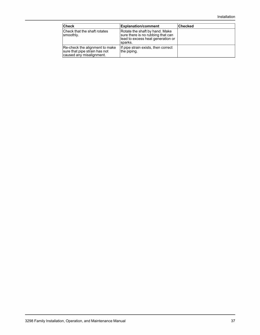
Check Explanation/comment CheckedCheck that the shaft rotates Rotate the shaft by hand. Makesmoothly. sure there is no rubbing that can
lead to excess heat generation orsparks.
Re-check the alignment to make If pipe strain exists, then correctsure that pipe strain has not the piping.caused any misalignment.
3298 Family Installation, Operation, and Maintenance Manual 37
Commissioning, Startup, Operation, and Shutdown
Commissioning, Startup, Operation, andShutdownPreparation for startup
DANGER:Avoid death or serious injury. Explosion and/or seizure of pump can cause fire and/or burns.Never operate pump past the pressure and temperature limits shown on the nameplate on thepump.
WARNING:• Failure to follow these precautions before you start the unit will lead to serious personal
injury and equipment failure.• Do not operate the pump below the minimum rated flows or with the suction or discharge
valves closed. These conditions can create an explosive hazard due to vaporization ofpumped fluid and can quickly lead to pump failure and physical injury.
• Avoid death or serious injury. Leaking fluid can cause fire and/or burns. Operating thepump above maximum rated flow shown on the pump curve leading to an increase inhorsepower and vibration along with an increase in NPSHr resulting in mechanical sealand/or shaft failure and/or loss of prime.
• Avoid death or serious injury. Leaking fluid can cause fire and/or burns. Speed of pumpmust reach 2000 rpm for 2 pole motors and 1000 rpm for 4 pole motors within 10 secondsor an increase in vibration and rotor deflection and decrease in rotor stability leading tomechanical seal and/or shaft failure and/or pump seizure can occur.
• Never operate the pump without the coupling guard correctly installed.
• Always disconnect and lock out power to the driver before you perform any installationor maintenance tasks. Failure to disconnect and lock out driver power will result in seriousphysical injury.• Electrical connections must be made by certified electricians in compliance with all
international, national, state, and local rules.• Refer to driver/coupling/gear manufacturers installation and operation manuals (IOM)
for specific instructions and recommendations.• Operating the pump in reverse rotation can result in the contact of metal parts, heat
generation, and breach of containment.
• When installing in a potentially explosive environment, make sure that the motor isproperly certified.
• Avoid death or serious injury. Explosion and/or seizure of pump can cause fire and/orburns. Assure balance line is installed and either piped to the pump suction or back to thesuction vessel to avoid vaporization of pumped fluid.
DANGER:Avoid death or serious injury. Leaking fluid can cause fire and/or burns. Assure all openingsare sealed off prior to filling pump.
Precautions
NOTICE:• Verify the driver settings before you start any pump.• Make sure that the warm-up rate does not exceed 2.5°F (1.4°C) per minute.
38 3298 Family Installation, Operation, and Maintenance Manual
Commissioning, Startup, Operation, and Shutdown
You must follow these precautions before you start the pump:• Flush and clean the system thoroughly to remove dirt or debris in the pipe system in order
to prevent premature failure at initial startup.• Bring variable-speed drivers to the rated speed as quickly as possible.• Run a new or rebuilt pump at a speed that provides enough flow to flush and cool the
close-running surfaces of the stuffing-box bushing.• If temperatures of the pumped fluid will exceed 200°F (93°C), then warm up the pump prior
to operation. Circulate a small amount of fluid through the pump until the casingtemperature is within 100°F (38°C) of the fluid temperature. Accomplish this by flowingfluid from pump inlet to discharge drain (optionally, the casing vent can be included inwarm-up circuit but not required). Soak for (2) hours at process fluid temperature.
At initial startup, do not adjust the variable-speed drivers or check for speed governor or over-speed trip settings while the variable-speed driver is coupled to the pump. If the settings havenot been verified, then uncouple the unit and refer to instructions supplied by the drivermanufacturer.
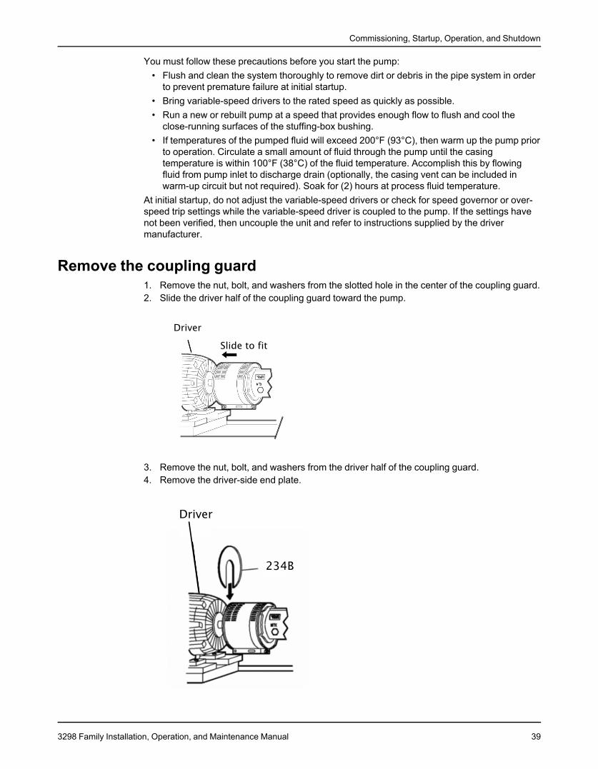
Remove the coupling guard1. Remove the nut, bolt, and washers from the slotted hole in the center of the coupling guard.2. Slide the driver half of the coupling guard toward the pump.
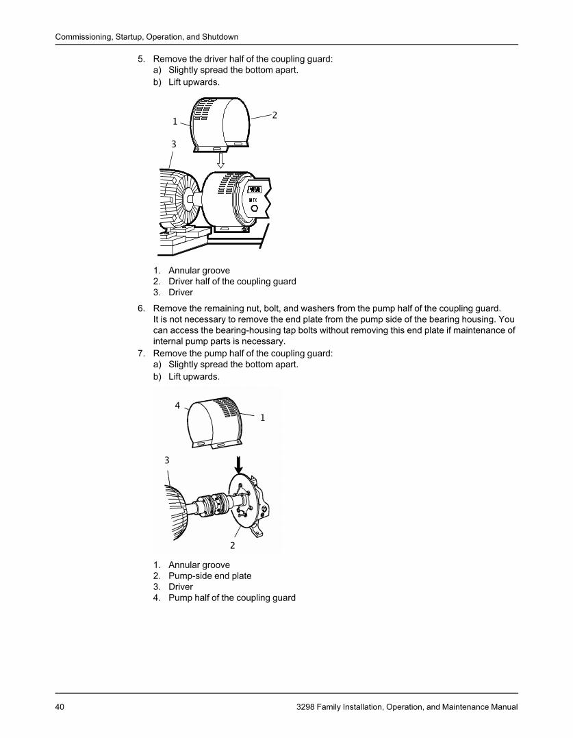
3. Remove the nut, bolt, and washers from the driver half of the coupling guard.4. Remove the driver-side end plate.
3298 Family Installation, Operation, and Maintenance Manual 39
Commissioning, Startup, Operation, and Shutdown
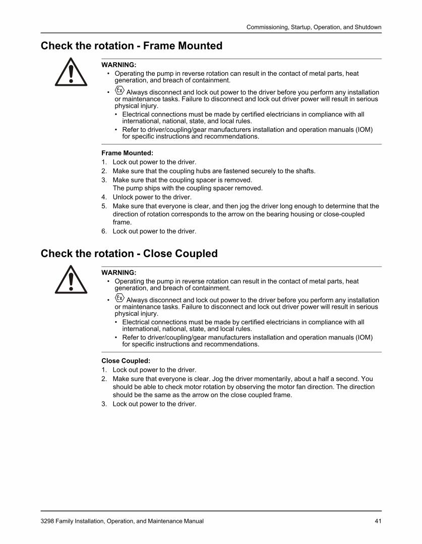
5. Remove the driver half of the coupling guard:a) Slightly spread the bottom apart.b) Lift upwards.
1. Annular groove2. Driver half of the coupling guard3. Driver
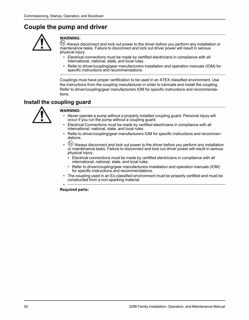
6. Remove the remaining nut, bolt, and washers from the pump half of the coupling guard.It is not necessary to remove the end plate from the pump side of the bearing housing. Youcan access the bearing-housing tap bolts without removing this end plate if maintenance ofinternal pump parts is necessary.
7. Remove the pump half of the coupling guard:a) Slightly spread the bottom apart.b) Lift upwards.
1. Annular groove2. Pump-side end plate3. Driver4. Pump half of the coupling guard
40 3298 Family Installation, Operation, and Maintenance Manual
Commissioning, Startup, Operation, and Shutdown
Check the rotation - Frame MountedWARNING:
• Operating the pump in reverse rotation can result in the contact of metal parts, heatgeneration, and breach of containment.
• Always disconnect and lock out power to the driver before you perform any installationor maintenance tasks. Failure to disconnect and lock out driver power will result in seriousphysical injury.• Electrical connections must be made by certified electricians in compliance with all
international, national, state, and local rules.• Refer to driver/coupling/gear manufacturers installation and operation manuals (IOM)
for specific instructions and recommendations.
Frame Mounted:1. Lock out power to the driver.2. Make sure that the coupling hubs are fastened securely to the shafts.3. Make sure that the coupling spacer is removed.
The pump ships with the coupling spacer removed.4. Unlock power to the driver.5. Make sure that everyone is clear, and then jog the driver long enough to determine that the
direction of rotation corresponds to the arrow on the bearing housing or close-coupledframe.
6. Lock out power to the driver.
Check the rotation - Close CoupledWARNING:
• Operating the pump in reverse rotation can result in the contact of metal parts, heatgeneration, and breach of containment.
• Always disconnect and lock out power to the driver before you perform any installationor maintenance tasks. Failure to disconnect and lock out driver power will result in seriousphysical injury.• Electrical connections must be made by certified electricians in compliance with all
international, national, state, and local rules.• Refer to driver/coupling/gear manufacturers installation and operation manuals (IOM)
for specific instructions and recommendations.
Close Coupled:1. Lock out power to the driver.2. Make sure that everyone is clear. Jog the driver momentarily, about a half a second. You
should be able to check motor rotation by observing the motor fan direction. The directionshould be the same as the arrow on the close coupled frame.
3. Lock out power to the driver.
3298 Family Installation, Operation, and Maintenance Manual 41
Commissioning, Startup, Operation, and Shutdown
Couple the pump and driverWARNING:
Always disconnect and lock out power to the driver before you perform any installation ormaintenance tasks. Failure to disconnect and lock out driver power will result in seriousphysical injury.
• Electrical connections must be made by certified electricians in compliance with allinternational, national, state, and local rules.
• Refer to driver/coupling/gear manufacturers installation and operation manuals (IOM) forspecific instructions and recommendations.
Couplings must have proper certification to be used in an ATEX classified environment. Usethe instructions from the coupling manufacturer in order to lubricate and install the coupling.Refer to driver/coupling/gear manufacturers IOM for specific instructions and recommenda-tions.
Install the coupling guardWARNING:
• Never operate a pump without a properly installed coupling guard. Personal injury willoccur if you run the pump without a coupling guard.
• Electrical Connections must be made by certified electricians in compliance with allinternational, national, state, and local rules.
• Refer to driver/coupling/gear manufacturers IOM for specific instructions and recommen-dations.
• Always disconnect and lock out power to the driver before you perform any installationor maintenance tasks. Failure to disconnect and lock out driver power will result in seriousphysical injury.• Electrical connections must be made by certified electricians in compliance with all
international, national, state, and local rules.• Refer to driver/coupling/gear manufacturers installation and operation manuals (IOM)
for specific instructions and recommendations.• The coupling used in an Ex-classified environment must be properly certified and must be
constructed from a non-sparking material.•
Required parts:
42 3298 Family Installation, Operation, and Maintenance Manual
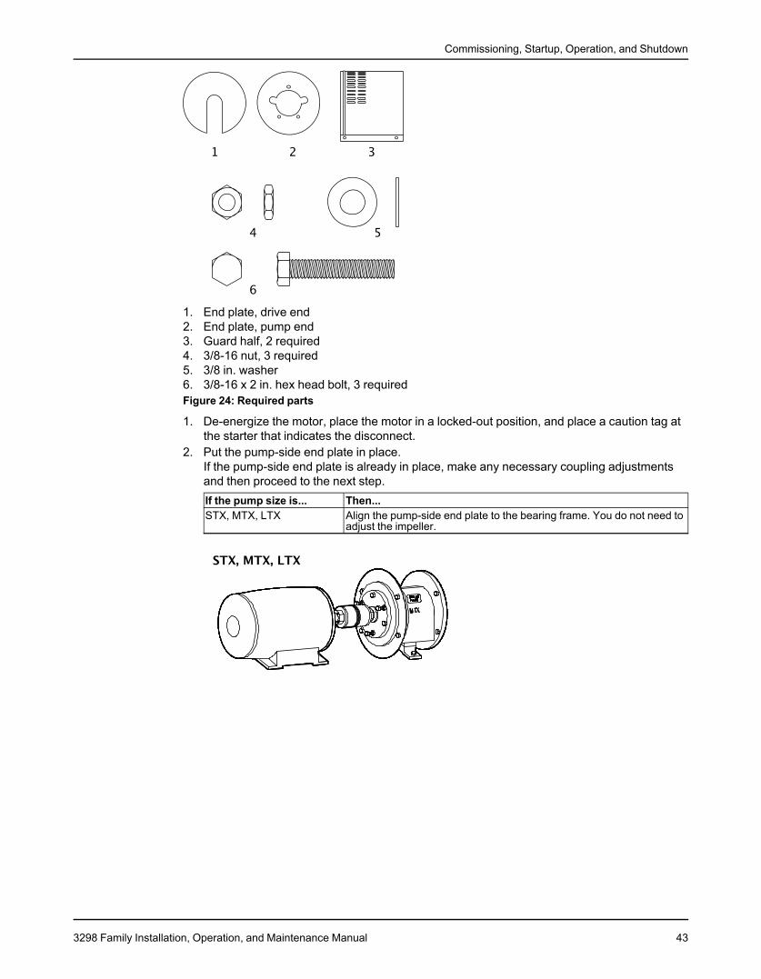
Commissioning, Startup, Operation, and Shutdown
1. End plate, drive end2. End plate, pump end3. Guard half, 2 required4. 3/8-16 nut, 3 required5. 3/8 in. washer6. 3/8-16 x 2 in. hex head bolt, 3 requiredFigure 24: Required parts
1. De-energize the motor, place the motor in a locked-out position, and place a caution tag atthe starter that indicates the disconnect.
2. Put the pump-side end plate in place.If the pump-side end plate is already in place, make any necessary coupling adjustmentsand then proceed to the next step.If the pump size is... Then...STX, MTX, LTX Align the pump-side end plate to the bearing frame. You do not need to
adjust the impeller.
3298 Family Installation, Operation, and Maintenance Manual 43
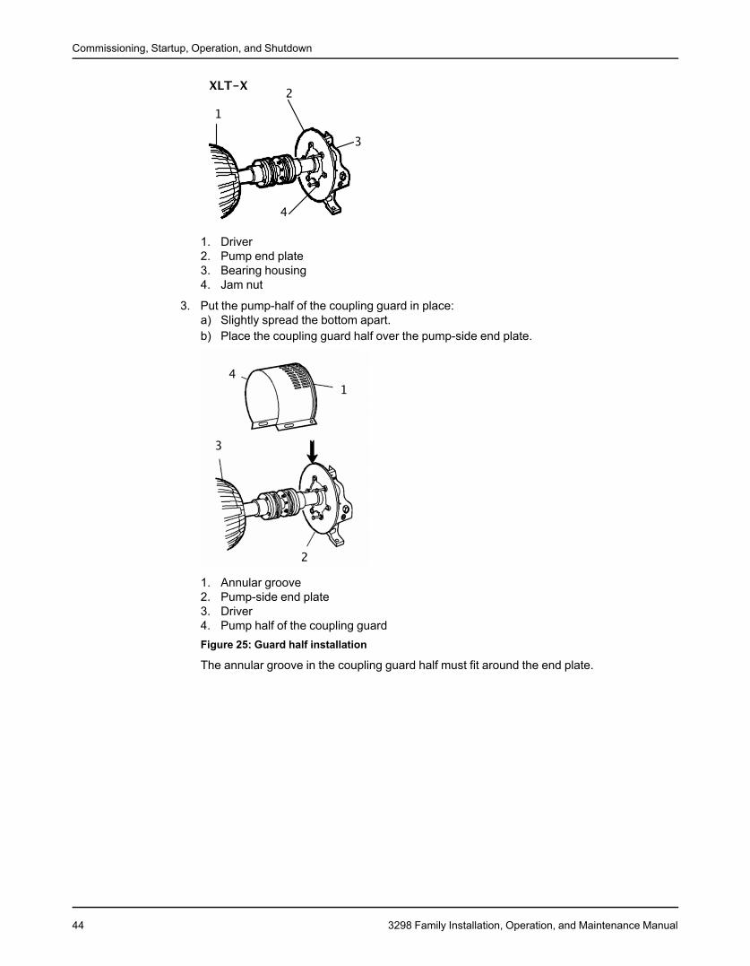
Commissioning, Startup, Operation, and Shutdown
1. Driver2. Pump end plate3. Bearing housing4. Jam nut
3. Put the pump-half of the coupling guard in place:a) Slightly spread the bottom apart.b) Place the coupling guard half over the pump-side end plate.
1. Annular groove2. Pump-side end plate3. Driver4. Pump half of the coupling guardFigure 25: Guard half installation
The annular groove in the coupling guard half must fit around the end plate.
44 3298 Family Installation, Operation, and Maintenance Manual
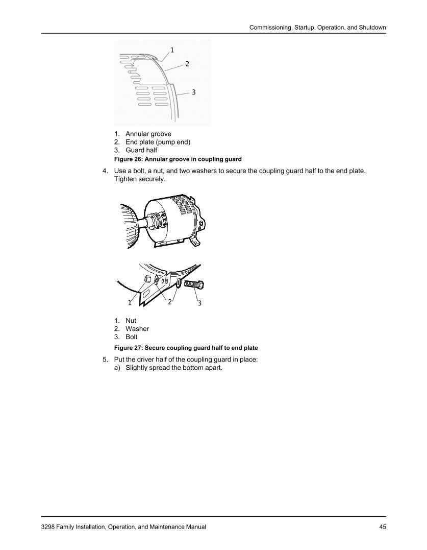
Commissioning, Startup, Operation, and Shutdown
1. Annular groove2. End plate (pump end)3. Guard halfFigure 26: Annular groove in coupling guard
4. Use a bolt, a nut, and two washers to secure the coupling guard half to the end plate.Tighten securely.
1. Nut2. Washer3. BoltFigure 27: Secure coupling guard half to end plate
5. Put the driver half of the coupling guard in place:a) Slightly spread the bottom apart.
3298 Family Installation, Operation, and Maintenance Manual 45
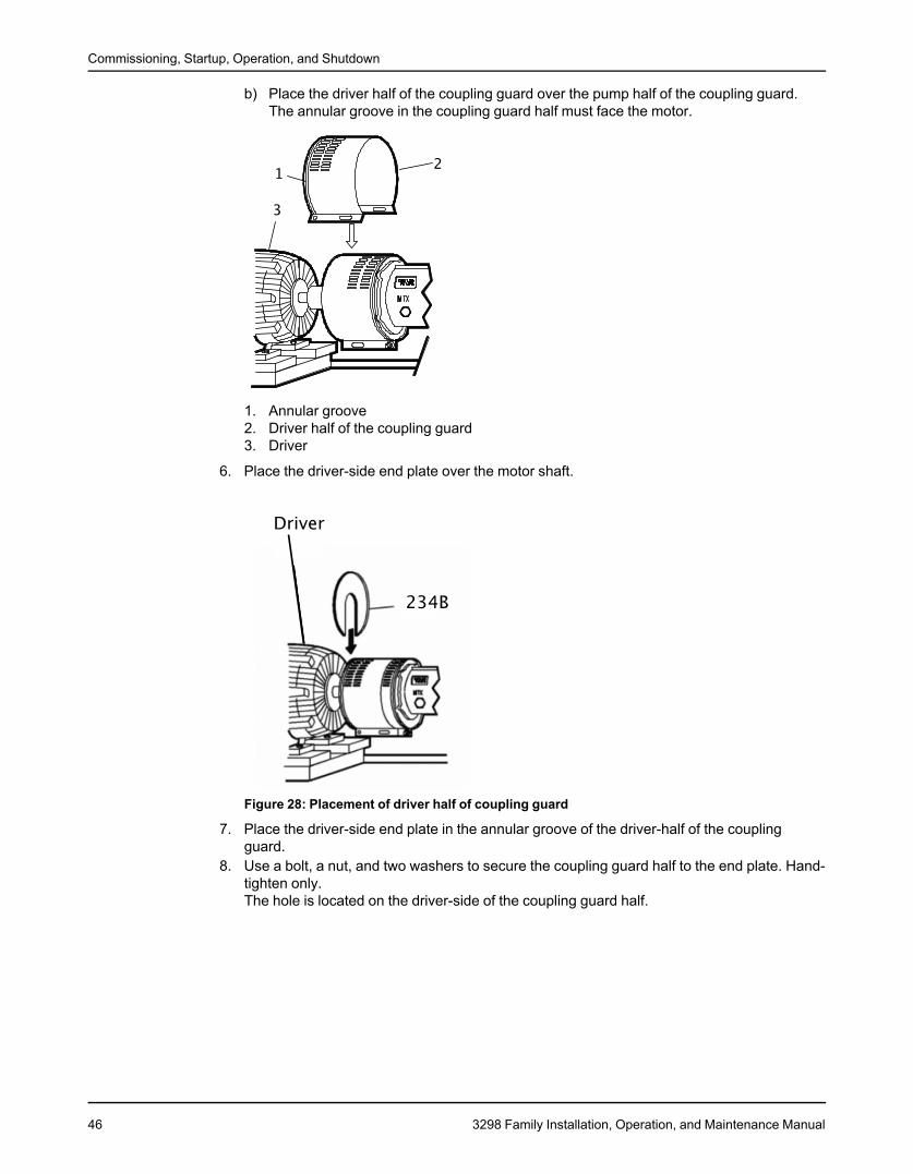
Commissioning, Startup, Operation, and Shutdown
b) Place the driver half of the coupling guard over the pump half of the coupling guard.The annular groove in the coupling guard half must face the motor.
1. Annular groove2. Driver half of the coupling guard3. Driver
6. Place the driver-side end plate over the motor shaft.
Figure 28: Placement of driver half of coupling guard
7. Place the driver-side end plate in the annular groove of the driver-half of the couplingguard.
8. Use a bolt, a nut, and two washers to secure the coupling guard half to the end plate. Hand-tighten only.The hole is located on the driver-side of the coupling guard half.
46 3298 Family Installation, Operation, and Maintenance Manual
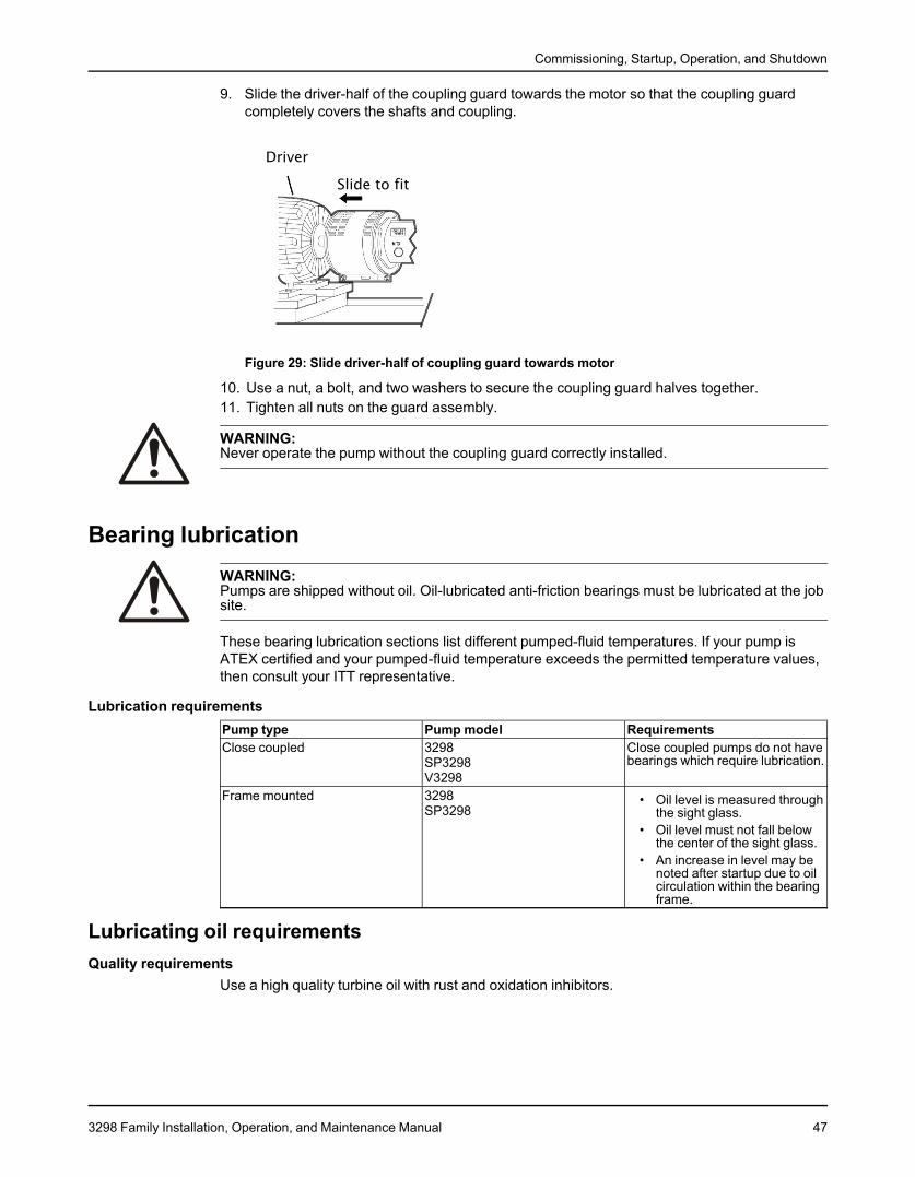
Commissioning, Startup, Operation, and Shutdown
9. Slide the driver-half of the coupling guard towards the motor so that the coupling guardcompletely covers the shafts and coupling.
Figure 29: Slide driver-half of coupling guard towards motor
10. Use a nut, a bolt, and two washers to secure the coupling guard halves together.11. Tighten all nuts on the guard assembly.
WARNING:Never operate the pump without the coupling guard correctly installed.
Bearing lubricationWARNING:Pumps are shipped without oil. Oil-lubricated anti-friction bearings must be lubricated at the jobsite.
These bearing lubrication sections list different pumped-fluid temperatures. If your pump isATEX certified and your pumped-fluid temperature exceeds the permitted temperature values,then consult your ITT representative.
Lubrication requirementsPump type Pump model RequirementsClose coupled 3298 Close coupled pumps do not have
bearings which require lubrication.SP3298V3298
Frame mounted 3298 • Oil level is measured throughSP3298 the sight glass.
• Oil level must not fall belowthe center of the sight glass.
• An increase in level may benoted after startup due to oilcirculation within the bearingframe.
Lubricating oil requirementsQuality requirements
Use a high quality turbine oil with rust and oxidation inhibitors.
3298 Family Installation, Operation, and Maintenance Manual 47
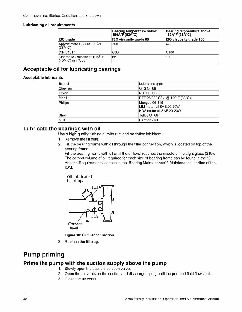
Commissioning, Startup, Operation, and Shutdown
Lubricating oil requirementsBearing temperature below Bearing temperature above180°F (82°C) 180°F (82°C)
ISO grade ISO viscosity grade 68 ISO viscosity grade 100Approximate SSU at 100°F 300 470(38°C)DIN 51517 C68 C100Kinematic viscosity at 105°F 68 100(40°C) mm2/sec
Acceptable oil for lubricating bearingsAcceptable lubricants
Brand Lubricant typeChevron GTS Oil 68Exxon NUTHO H68Mobil DTE 26 300 SSU @ 100°F (38°C)Philips Mangus Oil 315
MM motor oil SAE 20-20WHDS motor oil SAE 20-20W
Shell Tellus Oil 68Gulf Harmony 68
Lubricate the bearings with oilUse a high-quality turbine oil with rust and oxidation inhibitors.1. Remove the fill plug.2. Fill the bearing frame with oil through the filler connection, which is located on top of the
bearing frame.Fill the bearing frame with oil until the oil level reaches the middle of the sight glass (319).The correct volume of oil required for each size of bearing frame can be found in the ‘OilVolume Requirements’ section in the ‘Bearing Maintenance’ / ‘Maintenance’ portion of theIOM.
Figure 30: Oil filler connection
3. Replace the fill plug.
Pump primingPrime the pump with the suction supply above the pump
1. Slowly open the suction isolation valve.2. Open the air vents on the suction and discharge piping until the pumped fluid flows out.3. Close the air vents.
48 3298 Family Installation, Operation, and Maintenance Manual
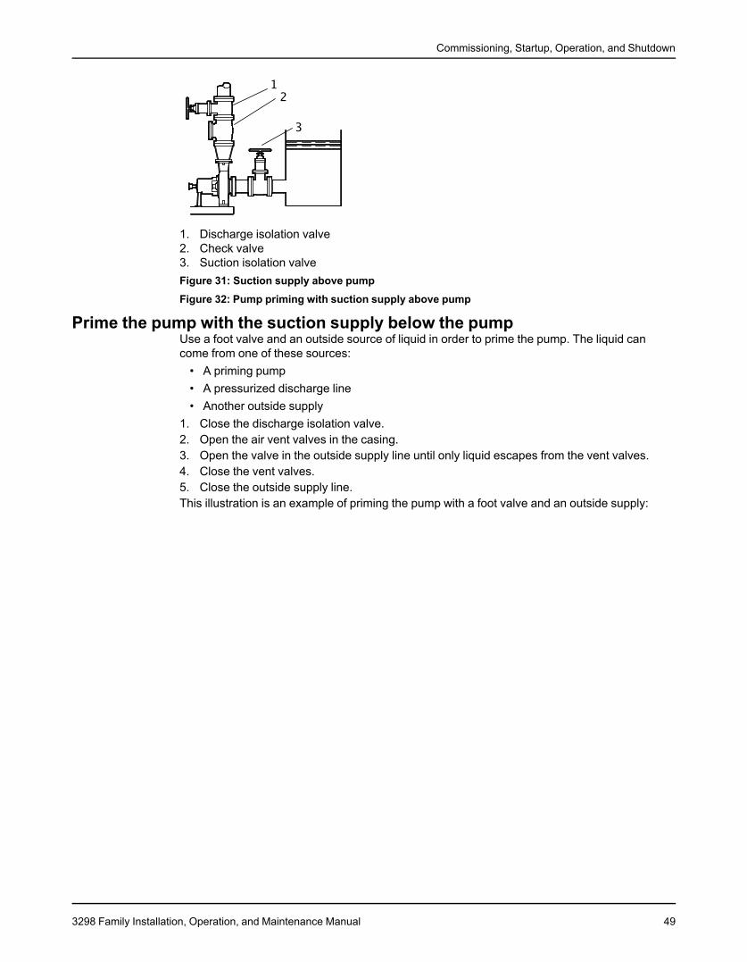
Commissioning, Startup, Operation, and Shutdown
1. Discharge isolation valve2. Check valve3. Suction isolation valveFigure 31: Suction supply above pumpFigure 32: Pump priming with suction supply above pump
Prime the pump with the suction supply below the pumpUse a foot valve and an outside source of liquid in order to prime the pump. The liquid cancome from one of these sources:
• A priming pump• A pressurized discharge line• Another outside supply
1. Close the discharge isolation valve.2. Open the air vent valves in the casing.3. Open the valve in the outside supply line until only liquid escapes from the vent valves.4. Close the vent valves.5. Close the outside supply line.This illustration is an example of priming the pump with a foot valve and an outside supply:
3298 Family Installation, Operation, and Maintenance Manual 49
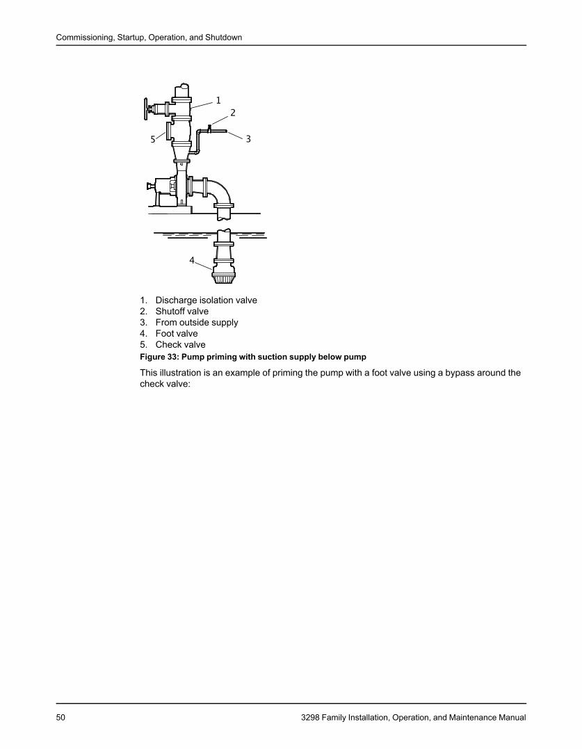
Commissioning, Startup, Operation, and Shutdown
1. Discharge isolation valve2. Shutoff valve3. From outside supply4. Foot valve5. Check valveFigure 33: Pump priming with suction supply below pump
This illustration is an example of priming the pump with a foot valve using a bypass around thecheck valve:
50 3298 Family Installation, Operation, and Maintenance Manual
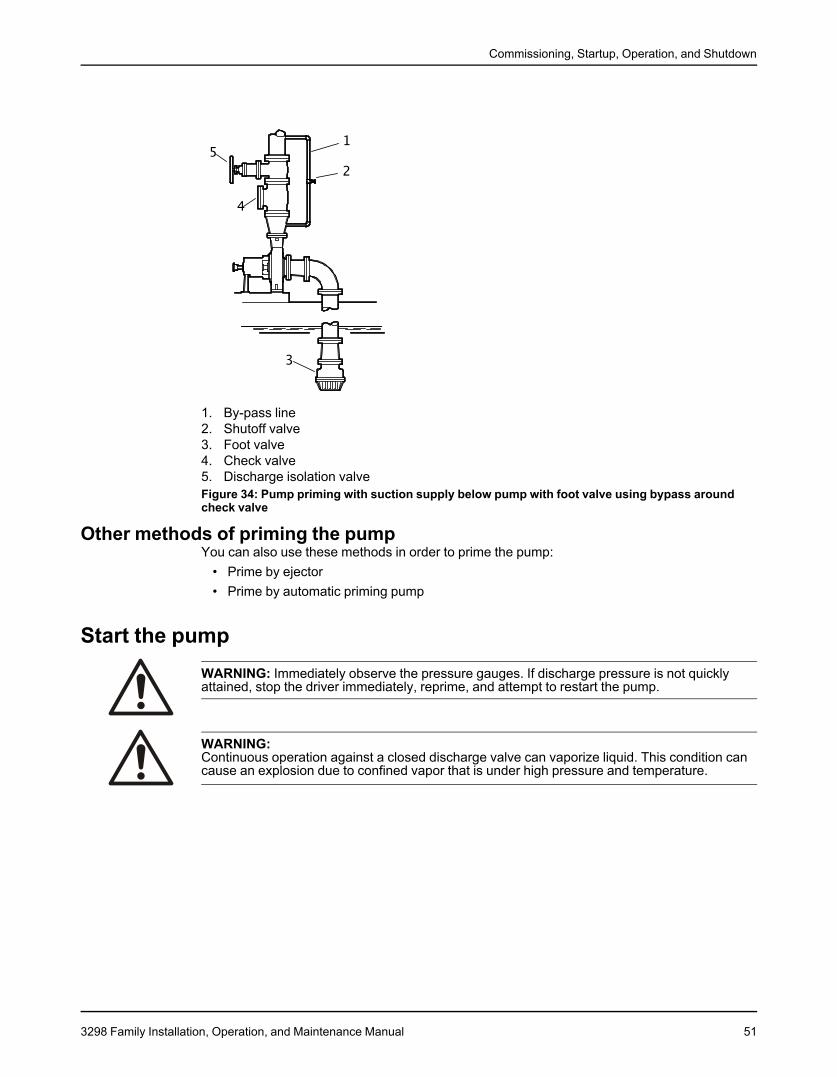
Commissioning, Startup, Operation, and Shutdown
1. By-pass line2. Shutoff valve3. Foot valve4. Check valve5. Discharge isolation valveFigure 34: Pump priming with suction supply below pump with foot valve using bypass aroundcheck valve
Other methods of priming the pumpYou can also use these methods in order to prime the pump:
• Prime by ejector• Prime by automatic priming pump
Start the pumpWARNING: Immediately observe the pressure gauges. If discharge pressure is not quicklyattained, stop the driver immediately, reprime, and attempt to restart the pump.
WARNING:Continuous operation against a closed discharge valve can vaporize liquid. This condition cancause an explosion due to confined vapor that is under high pressure and temperature.
3298 Family Installation, Operation, and Maintenance Manual 51
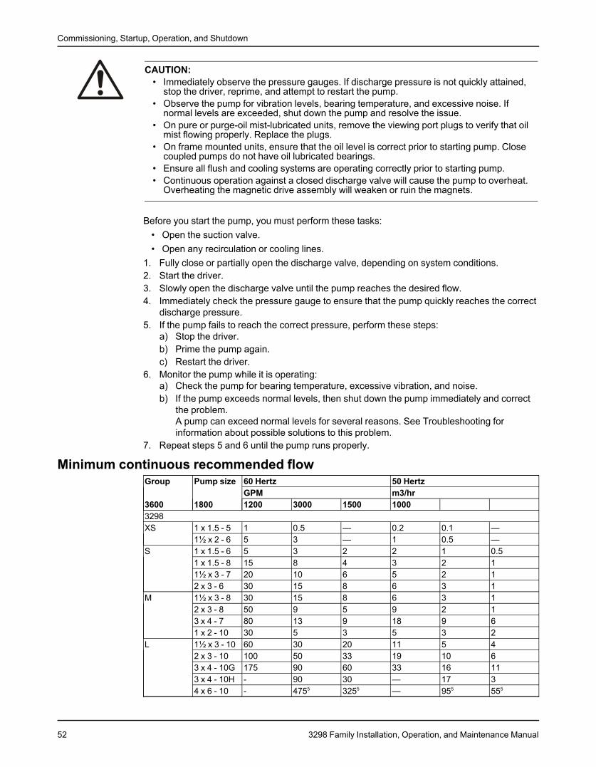
Commissioning, Startup, Operation, and Shutdown
CAUTION:• Immediately observe the pressure gauges. If discharge pressure is not quickly attained,
stop the driver, reprime, and attempt to restart the pump.• Observe the pump for vibration levels, bearing temperature, and excessive noise. If
normal levels are exceeded, shut down the pump and resolve the issue.• On pure or purge-oil mist-lubricated units, remove the viewing port plugs to verify that oil
mist flowing properly. Replace the plugs.• On frame mounted units, ensure that the oil level is correct prior to starting pump. Close
coupled pumps do not have oil lubricated bearings.• Ensure all flush and cooling systems are operating correctly prior to starting pump.• Continuous operation against a closed discharge valve will cause the pump to overheat.
Overheating the magnetic drive assembly will weaken or ruin the magnets.
Before you start the pump, you must perform these tasks:• Open the suction valve.• Open any recirculation or cooling lines.
1. Fully close or partially open the discharge valve, depending on system conditions.2. Start the driver.3. Slowly open the discharge valve until the pump reaches the desired flow.4. Immediately check the pressure gauge to ensure that the pump quickly reaches the correct
discharge pressure.5. If the pump fails to reach the correct pressure, perform these steps:
a) Stop the driver.b) Prime the pump again.c) Restart the driver.
6. Monitor the pump while it is operating:a) Check the pump for bearing temperature, excessive vibration, and noise.b) If the pump exceeds normal levels, then shut down the pump immediately and correct
the problem.A pump can exceed normal levels for several reasons. See Troubleshooting forinformation about possible solutions to this problem.
7. Repeat steps 5 and 6 until the pump runs properly.
Minimum continuous recommended flowGroup Pump size 60 Hertz 50 Hertz
GPM m3/hr3600 1800 1200 3000 1500 10003298XS 1 x 1.5 - 5 1 0.5 — 0.2 0.1 —
1½ x 2 - 6 5 3 — 1 0.5 —S 1 x 1.5 - 6 5 3 2 2 1 0.5
1 x 1.5 - 8 15 8 4 3 2 11½ x 3 - 7 20 10 6 5 2 12 x 3 - 6 30 15 8 6 3 1
M 1½ x 3 - 8 30 15 8 6 3 12 x 3 - 8 50 9 5 9 2 13 x 4 - 7 80 13 9 18 9 61 x 2 - 10 30 5 3 5 3 2
L 1½ x 3 - 10 60 30 20 11 5 42 x 3 - 10 100 50 33 19 10 63 x 4 - 10G 175 90 60 33 16 113 x 4 - 10H - 90 30 — 17 34 x 6 - 10 - 4755 3255 — 955 555
52 3298 Family Installation, Operation, and Maintenance Manual
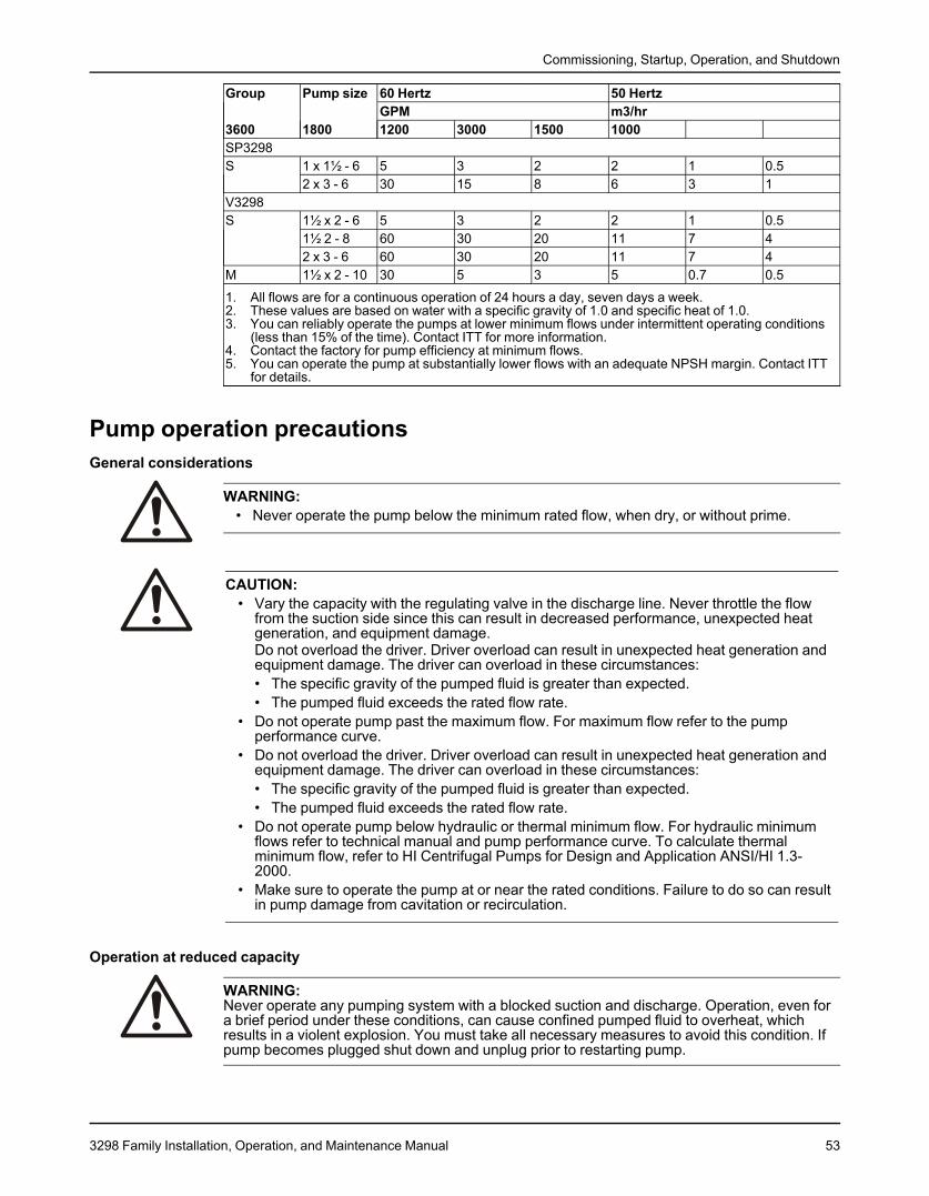
Commissioning, Startup, Operation, and Shutdown
Group Pump size 60 Hertz 50 HertzGPM m3/hr
3600 1800 1200 3000 1500 1000SP3298S 1 x 1½ - 6 5 3 2 2 1 0.5
2 x 3 - 6 30 15 8 6 3 1V3298S 1½ x 2 - 6 5 3 2 2 1 0.5
1½ 2 - 8 60 30 20 11 7 42 x 3 - 6 60 30 20 11 7 4
M 1½ x 2 - 10 30 5 3 5 0.7 0.5
1. All flows are for a continuous operation of 24 hours a day, seven days a week.2. These values are based on water with a specific gravity of 1.0 and specific heat of 1.0.3. You can reliably operate the pumps at lower minimum flows under intermittent operating conditions
(less than 15% of the time). Contact ITT for more information.4. Contact the factory for pump efficiency at minimum flows.5. You can operate the pump at substantially lower flows with an adequate NPSH margin. Contact ITT
for details.
Pump operation precautionsGeneral considerations
WARNING:• Never operate the pump below the minimum rated flow, when dry, or without prime.
CAUTION:• Vary the capacity with the regulating valve in the discharge line. Never throttle the flow
from the suction side since this can result in decreased performance, unexpected heatgeneration, and equipment damage.Do not overload the driver. Driver overload can result in unexpected heat generation andequipment damage. The driver can overload in these circumstances:• The specific gravity of the pumped fluid is greater than expected.• The pumped fluid exceeds the rated flow rate.
• Do not operate pump past the maximum flow. For maximum flow refer to the pumpperformance curve.
• Do not overload the driver. Driver overload can result in unexpected heat generation andequipment damage. The driver can overload in these circumstances:• The specific gravity of the pumped fluid is greater than expected.• The pumped fluid exceeds the rated flow rate.
• Do not operate pump below hydraulic or thermal minimum flow. For hydraulic minimumflows refer to technical manual and pump performance curve. To calculate thermalminimum flow, refer to HI Centrifugal Pumps for Design and Application ANSI/HI 1.3-2000.
• Make sure to operate the pump at or near the rated conditions. Failure to do so can resultin pump damage from cavitation or recirculation.
Operation at reduced capacity
WARNING:Never operate any pumping system with a blocked suction and discharge. Operation, even fora brief period under these conditions, can cause confined pumped fluid to overheat, whichresults in a violent explosion. You must take all necessary measures to avoid this condition. Ifpump becomes plugged shut down and unplug prior to restarting pump.
3298 Family Installation, Operation, and Maintenance Manual 53
Commissioning, Startup, Operation, and Shutdown
CAUTION:• The pump and system must be free of foreign objects. If pump becomes plugged, shut
down and unplug prior to restarting pump.• Avoid excessive vibration levels. Excessive vibration levels can damage the bearings,
stuffing box or seal chamber, and the mechanical seal, which can result in decreasedperformance.
• Avoid increased radial load. Failure to do so can cause stress on the shaft and bearings.• Avoid heat build-up. Failure to do so can cause rotating parts to score or seize.• Avoid cavitation. Failure to do so can cause damage to the internal surfaces of the pump.
Operation under freezing conditions
NOTICE:Do not expose an idle pump to freezing conditions. Drain all liquid that is inside the pump andthe cooling coils. Failure to do so can cause liquid to freeze and damage the pump.
Temperature ratings
CAUTION:Do not operate the pump above the rated temperature range of the magnets. This will weakenor ruin the magnets. The rated temperature is 250°F (121°C) for all sizes.
Shut down the pumpWARNING:The pump can handle hazardous and toxic fluids. Identify the contents of the pump andobserve proper decontamination procedures in order to eliminate the possible exposure to anyhazardous or toxic fluids. Wear the proper personal protective equipment. Potential hazardsinclude, but are not limited to, high temperature, flammable, acidic, caustic, explosive, andother risks. You must handle and dispose of pumped fluid in compliance with the applicableenvironmental regulations.
1. Slowly close the discharge valve.2. Shut down and lock out the driver to prevent accidental rotation.
54 3298 Family Installation, Operation, and Maintenance Manual
Commissioning, Startup, Operation, and Shutdown
Make the final alignment of the pump and driverWARNING:
• Always disconnect and lock out power to the driver before you perform any installationor maintenance tasks. Failure to disconnect and lock out driver power will result in seriousphysical injury.• Electrical connections must be made by certified electricians in compliance with all
international, national, state, and local rules.• Refer to driver/coupling/gear manufacturers installation and operation manuals (IOM)
for specific instructions and recommendations.• Follow shaft alignment procedures in order to prevent catastrophic failure of drive
components or unintended contact of rotating parts. Follow the coupling installation andoperation procedures from the coupling manufacturer.
• Alignment procedures must be followed to prevent unintended contact of rotatingparts. Follow coupling manufacturer’s installation and operation procedures.
You must check the final alignment after the pump and driver are at operating temperature. Forinitial alignment instructions, see the Installation chapter.1. Run the unit under actual operating conditions for enough time to bring the pump, driver,
and associated system to operating temperature.2. Shut down the pump and the driver.3. Remove the coupling guard.
See Remove the coupling guard in the Maintenance chapter.4. Check the alignment while the unit is still hot.
See Pump-to-driver alignment in the Installation chapter.5. Reinstall the coupling guard.6. Restart the pump and driver.
3298 Family Installation, Operation, and Maintenance Manual 55
Maintenance
MaintenanceMaintenance scheduleMaintenance inspections
A maintenance schedule includes these types of inspections:• Routine maintenance• Routine inspections• Three-month inspections• Annual inspections
Shorten the inspection intervals appropriately if the pumped fluid is abrasive or corrosive or ifthe environment is classified as potentially explosive.
Routine maintenancePerform these tasks whenever you perform routine maintenance:
• Lubricate the bearings.• Inspect the seal.
Routine inspectionsPerform these tasks whenever you check the pump during routine inspections:
• Check the level and condition of the oil through the sight glass on the bearing frame.• Check for unusual noise, vibration, and bearing temperatures.• Check the pump and piping for leaks.• Analyze the vibration.• Inspect the discharge pressure.
Three-month inspectionsPerform these tasks every three months:
• Check that the foundation and the hold-down bolts are tight.• Check the shaft alignment, and realign as required.
Annual inspectionsPerform these inspections one time each year:
• Check the pump capacity.• Check the pump pressure.• Check the pump power.
If the pump performance does not satisfy your process requirements, and the processrequirements have not changed, then perform these steps:1. Disassemble the pump.2. Inspect it.3. Replace worn parts.
Bearing maintenanceLubrication schedule
Type of bearing First lubrication Lubrication intervalsOil lubricated Change the oil after 200 hours for After the first 200 hours, change
new bearings. the oil every 4000 operating hoursor every six months.
56 3298 Family Installation, Operation, and Maintenance Manual
Maintenance
Required toolsWARNING:This pump contains extremely strong magnets. You must use non-magnetic tools and worksurfaces.
Non-magnetic tools• 9/16-inch and 3/4-inch socket wrench• Non-metallic hammer
Tools• Long T-handle hex wrench in size 3/16-inch• 1/2-inch, 9/16-inch, and 3/4-inch sockets• Socket wrench with a minimum extension of 4 in. (10 cm)• Screw drivers• Lip seal driver• Hammer• Three 5/16-inch x 2-inch hex capscrews• Three 5/8-inch x 4-inch hex capscrews
Tool kitsYou can use these available tool kits in order to ease the assembly and disassembly of thesepumps:Group Kit number Optional toolsTool number DescriptionXS R298TK04 B03309A 1 x 1½-5 bearing spider installation driver
B04370A 1½ x2-6 bearing spider installation driverB03310A Radial bearing installation toolA06872A Bearing press support tool
S R298TK01 B02496A Bearing spider installation driverB02497A Radial bearing installation tool
M R298TK02 B03147A Bearing spider installation driverB03148A Bearing spider installation driverB03149A Radial bearing installation toolB03189A Magnet assembly/disassembly guide rods
L R298TK03 B03191A Bearing spider installation driverB03175A Radial bearing installation toolB03149A Radial bearing installation toolB03189A Magnetic assembly/disassembly guide rods
3298 Family Installation, Operation, and Maintenance Manual 57
Maintenance
DisassemblyDisassembly precautions
WARNING:• Chemical hazard. You must individually decontaminate each component according to all
federal, state, local, and company environmental regulations.• A build up of gases within the pump, sealing system, or process-piping system can result
in an explosive environment within the pump. Make sure that the process piping system,pump, and sealing system are properly vented prior to operation.
• Burn Hazard. Coupling may be hot. Use proper protection when handling.• Burn Hazard. use proper protection when handling bearings.• Worn parts may have sharp edges. Wear heavy work gloves while handling.• Chemical Hazard. A small amount of liquid may be left in the pump.• Process fluid leaks can result in an explosive atmosphere. Follow all pump and seal
assembly procedures.• Make sure that the pump is isolated from the system and that pressure is relieved before
you disassemble the pump, remove plugs, open vent or drain valves, or disconnect thepiping.
• Crush hazard. The unit and the components can be heavy. Use proper lifting methods andwear steel-toed shoes at all times.
• The pump can handle hazardous and toxic fluids. Identify the contents of the pump andobserve proper decontamination procedures in order to eliminate the possible exposure toany hazardous or toxic fluids. Wear the proper personal protective equipment. Potentialhazards include, but are not limited to, high temperature, flammable, acidic, caustic,explosive, and other risks. You must handle and dispose of pumped fluid in compliancewith the applicable environmental regulations.
CAUTION:• You must keep the shop area clean and free of any substances that can contaminate the
magnets, such as ferrous metals.• The magnets in this unit are extremely powerful. Beware of serious injury to fingers and
hands. Keep magnetic drive components and magnetic tools apart by a minimum of 3 ft (1m).
NOTICE:Use a bench with a non-magnetic work surface such as wood or brass when you work on thepump.
Prepare the pump for disassembly1. Lock out power to the driver.
WARNING:Always disconnect and lock out power to the driver before you perform any installation or
maintenance tasks. Failure to disconnect and lock out driver power will result in seriousphysical injury.
• Electrical connections must be made by certified electricians in compliance with allinternational, national, state, and local rules.
• Refer to driver/coupling/gear manufacturers installation and operation manuals (IOM) forspecific instructions and recommendations.
2. Shut off all valves that control flow to and from the pump.3. Drain and flush the pump before you remove it from the piping.4. Isolate the pump from the system and then flush the pump using a compatible liquid.
58 3298 Family Installation, Operation, and Maintenance Manual
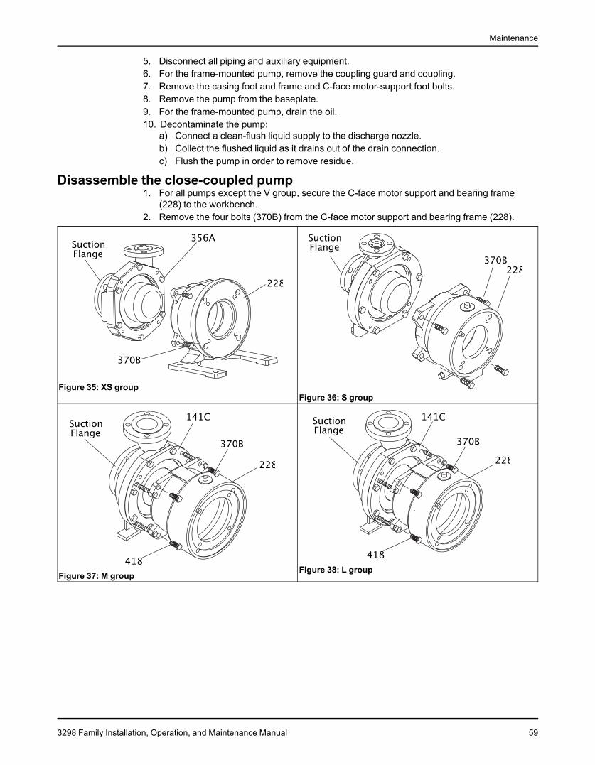
Maintenance
5. Disconnect all piping and auxiliary equipment.6. For the frame-mounted pump, remove the coupling guard and coupling.7. Remove the casing foot and frame and C-face motor-support foot bolts.8. Remove the pump from the baseplate.9. For the frame-mounted pump, drain the oil.10. Decontaminate the pump:
a) Connect a clean-flush liquid supply to the discharge nozzle.b) Collect the flushed liquid as it drains out of the drain connection.c) Flush the pump in order to remove residue.
Disassemble the close-coupled pump1. For all pumps except the V group, secure the C-face motor support and bearing frame
(228) to the workbench.2. Remove the four bolts (370B) from the C-face motor support and bearing frame (228).
Figure 35: XS groupFigure 36: S group
Figure 38: L groupFigure 37: M group
3298 Family Installation, Operation, and Maintenance Manual 59

Maintenance
Figure 39: SP groupFigure 40: V group
3. For the M and L group pumps, tighten the jacking screws (418) until the gap between theclamp ring (141C) and the C-face motor support and bearing frame is 3.50 in. (8.89 cm).
4. For all pumps except the V group, grasp the suction flange of the casing and pull thecasing-liquid end free from the magnet assembly.
5. For all pumps except the SP group, remove the casing bolts (356A).6. Wrap a piece of emery cloth around the containment shell (750) and secure it with a large
hose clamp.
Figure 42: V groupFigure 41: SP group
60 3298 Family Installation, Operation, and Maintenance Manual

Maintenance
Figure 43: XS, X, S, M, and L groups
7. Disassemble the containment shell:a) Screw the C-face motor support and bearing frame bolts (370B) into the tapped holes
of the clamp ring (141C) and tighten evenly in order to remove the containment shell.b) Remove the O-ring (412M) from the containment shell (750) and discard it.c) Remove the hose clamp and emery cloth.
8. For all groups except the SP, remove the impeller assembly (101).
Figure 44: XS, S, M, and L groups
9. Remove the shaft (122A) if replacement is necessary.10. Inspect and replace the bearings, if necessary:
a) Inspect the bearing spider (260).Press it out through the suction of the casing (100) if replacement is necessary.
3298 Family Installation, Operation, and Maintenance Manual 61
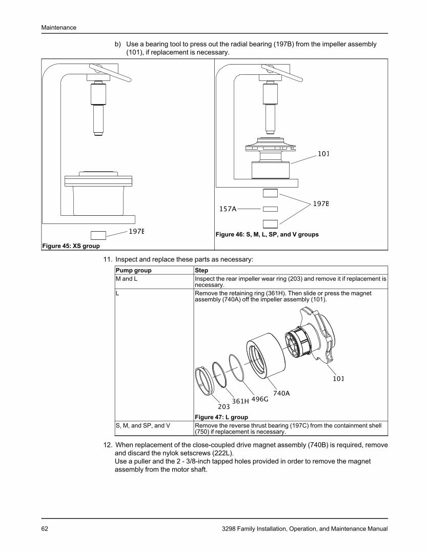
Maintenance
b) Use a bearing tool to press out the radial bearing (197B) from the impeller assembly(101), if replacement is necessary.
Figure 46: S, M, L, SP, and V groups
Figure 45: XS group
11. Inspect and replace these parts as necessary:Pump group StepM and L Inspect the rear impeller wear ring (203) and remove it if replacement is
necessary.L Remove the retaining ring (361H). Then slide or press the magnet
assembly (740A) off the impeller assembly (101).
Figure 47: L groupS, M, and SP, and V Remove the reverse thrust bearing (197C) from the containment shell
(750) if replacement is necessary.
12. When replacement of the close-coupled drive magnet assembly (740B) is required, removeand discard the nylok setscrews (222L).Use a puller and the 2 - 3/8-inch tapped holes provided in order to remove the magnetassembly from the motor shaft.
62 3298 Family Installation, Operation, and Maintenance Manual
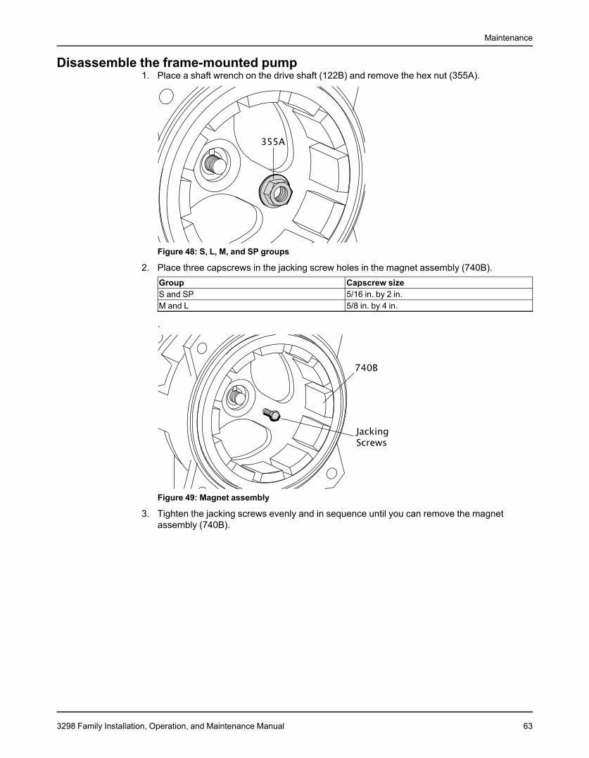
Maintenance
Disassemble the frame-mounted pump1. Place a shaft wrench on the drive shaft (122B) and remove the hex nut (355A).
Figure 48: S, L, M, and SP groups
2. Place three capscrews in the jacking screw holes in the magnet assembly (740B).Group Capscrew sizeS and SP 5/16 in. by 2 in.M and L 5/8 in. by 4 in.
.
Figure 49: Magnet assembly
3. Tighten the jacking screws evenly and in sequence until you can remove the magnetassembly (740B).
3298 Family Installation, Operation, and Maintenance Manual 63
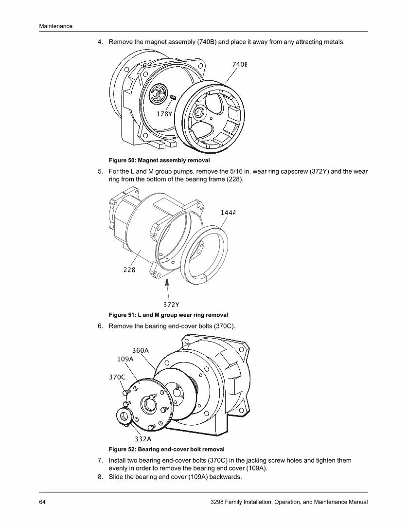
Maintenance
4. Remove the magnet assembly (740B) and place it away from any attracting metals.
Figure 50: Magnet assembly removal
5. For the L and M group pumps, remove the 5/16 in. wear ring capscrew (372Y) and the wearring from the bottom of the bearing frame (228).
Figure 51: L and M group wear ring removal
6. Remove the bearing end-cover bolts (370C).
Figure 52: Bearing end-cover bolt removal
7. Install two bearing end-cover bolts (370C) in the jacking screw holes and tighten themevenly in order to remove the bearing end cover (109A).
8. Slide the bearing end cover (109A) backwards.
64 3298 Family Installation, Operation, and Maintenance Manual
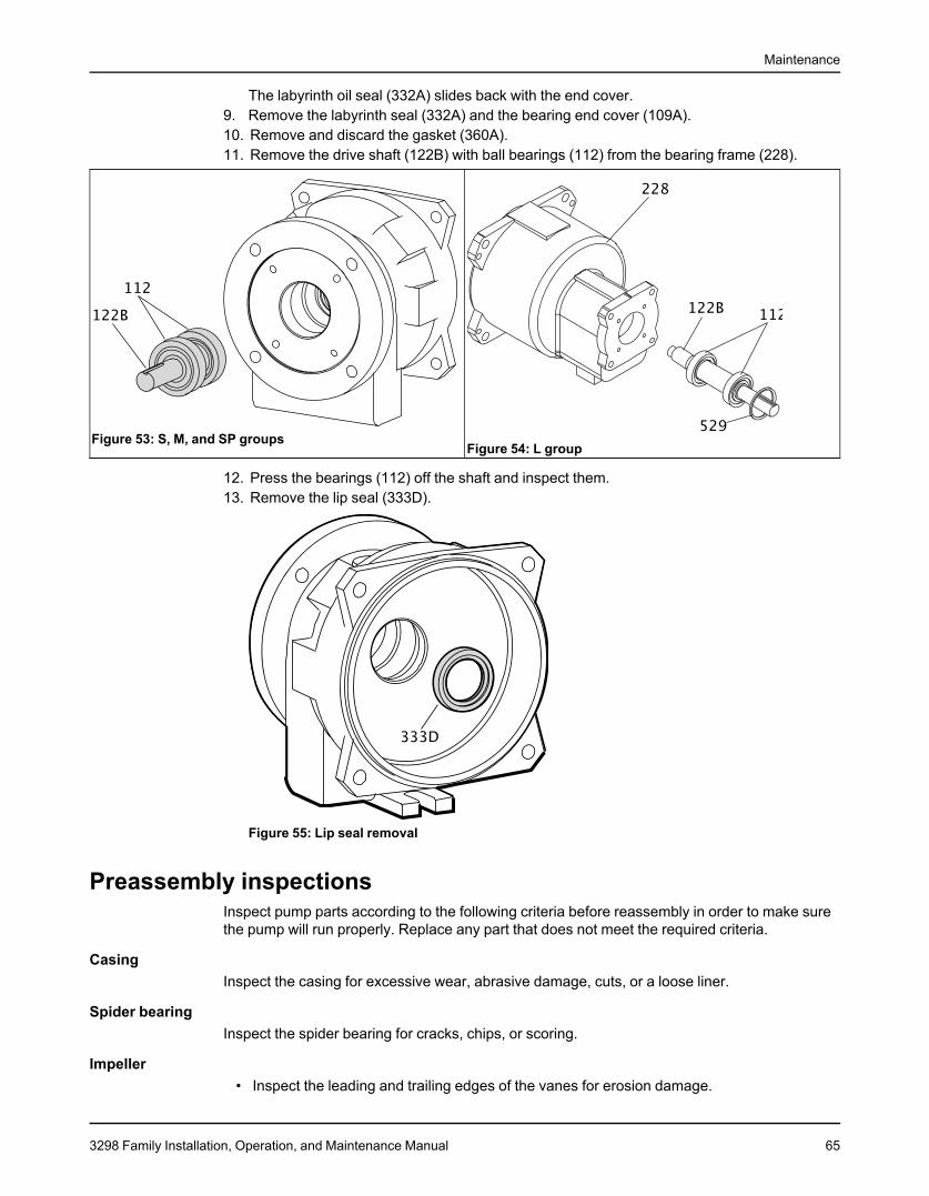
Maintenance
The labyrinth oil seal (332A) slides back with the end cover.9. Remove the labyrinth seal (332A) and the bearing end cover (109A).10. Remove and discard the gasket (360A).11. Remove the drive shaft (122B) with ball bearings (112) from the bearing frame (228).
Figure 53: S, M, and SP groupsFigure 54: L group
12. Press the bearings (112) off the shaft and inspect them.13. Remove the lip seal (333D).
Figure 55: Lip seal removal
Preassembly inspectionsInspect pump parts according to the following criteria before reassembly in order to make surethe pump will run properly. Replace any part that does not meet the required criteria.
CasingInspect the casing for excessive wear, abrasive damage, cuts, or a loose liner.
Spider bearingInspect the spider bearing for cracks, chips, or scoring.
Impeller• Inspect the leading and trailing edges of the vanes for erosion damage.
3298 Family Installation, Operation, and Maintenance Manual 65
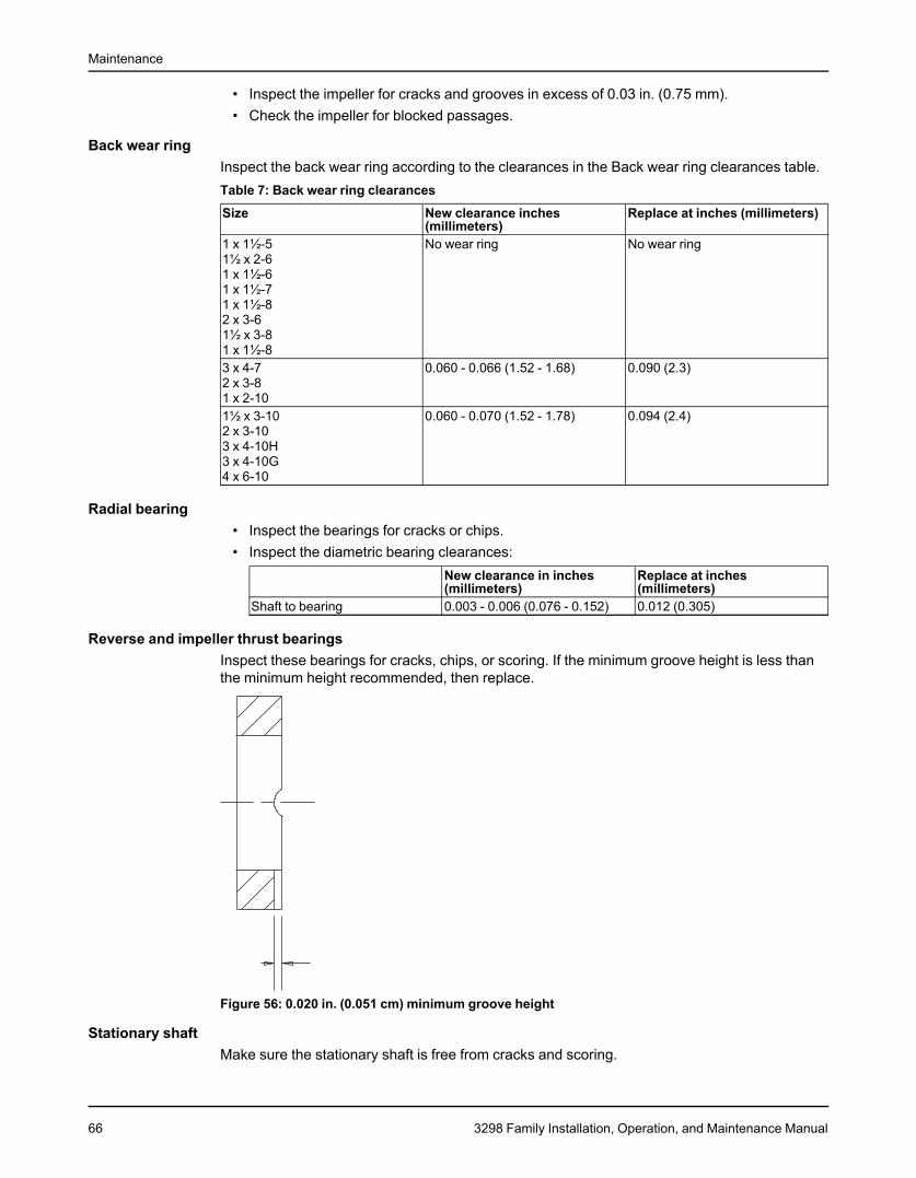
Maintenance
• Inspect the impeller for cracks and grooves in excess of 0.03 in. (0.75 mm).• Check the impeller for blocked passages.
Back wear ringInspect the back wear ring according to the clearances in the Back wear ring clearances table.Table 7: Back wear ring clearances
Size New clearance inches Replace at inches (millimeters)(millimeters)
1 x 1½-5 No wear ring No wear ring1½ x 2-61 x 1½-61 x 1½-71 x 1½-82 x 3-61½ x 3-81 x 1½-83 x 4-7 0.060 - 0.066 (1.52 - 1.68) 0.090 (2.3)2 x 3-81 x 2-101½ x 3-10 0.060 - 0.070 (1.52 - 1.78) 0.094 (2.4)2 x 3-103 x 4-10H3 x 4-10G4 x 6-10
Radial bearing• Inspect the bearings for cracks or chips.• Inspect the diametric bearing clearances:
New clearance in inches Replace at inches(millimeters) (millimeters)
Shaft to bearing 0.003 - 0.006 (0.076 - 0.152) 0.012 (0.305)
Reverse and impeller thrust bearingsInspect these bearings for cracks, chips, or scoring. If the minimum groove height is less thanthe minimum height recommended, then replace.
Figure 56: 0.020 in. (0.051 cm) minimum groove height
Stationary shaftMake sure the stationary shaft is free from cracks and scoring.
66 3298 Family Installation, Operation, and Maintenance Manual
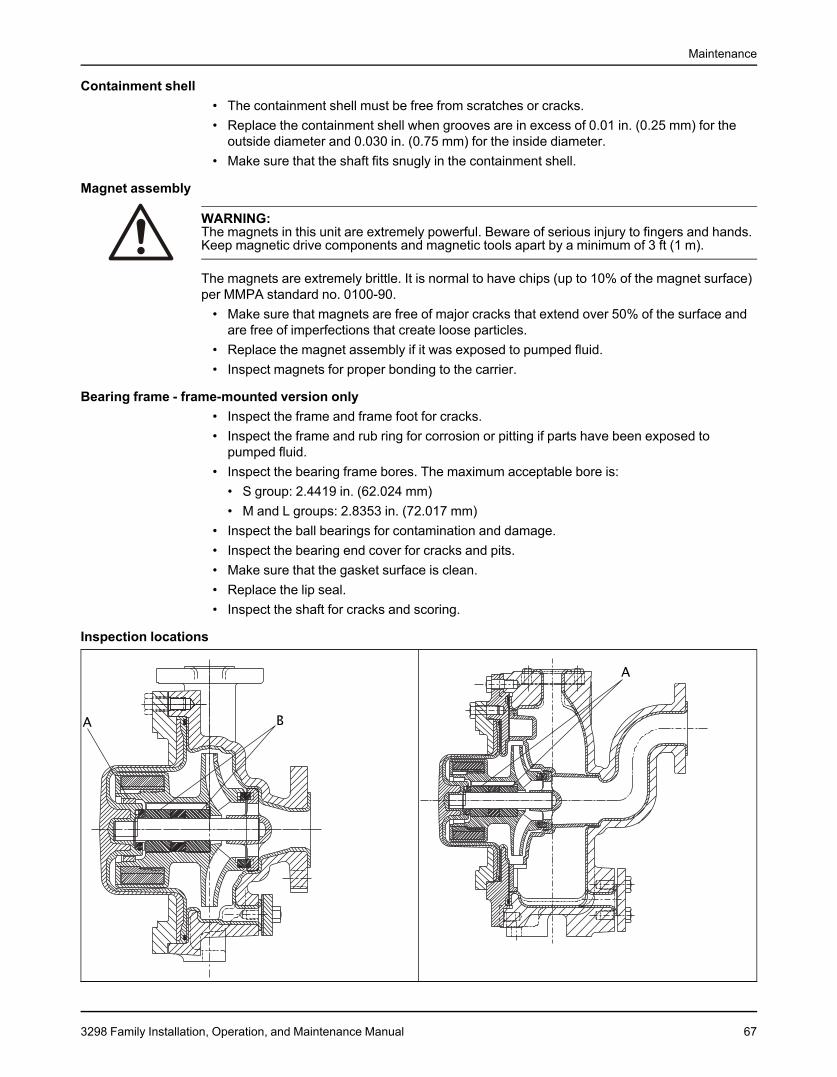
Maintenance
Containment shell• The containment shell must be free from scratches or cracks.• Replace the containment shell when grooves are in excess of 0.01 in. (0.25 mm) for the
outside diameter and 0.030 in. (0.75 mm) for the inside diameter.• Make sure that the shaft fits snugly in the containment shell.
Magnet assembly
WARNING:The magnets in this unit are extremely powerful. Beware of serious injury to fingers and hands.Keep magnetic drive components and magnetic tools apart by a minimum of 3 ft (1 m).
The magnets are extremely brittle. It is normal to have chips (up to 10% of the magnet surface)per MMPA standard no. 0100-90.
• Make sure that magnets are free of major cracks that extend over 50% of the surface andare free of imperfections that create loose particles.
• Replace the magnet assembly if it was exposed to pumped fluid.• Inspect magnets for proper bonding to the carrier.
Bearing frame - frame-mounted version only• Inspect the frame and frame foot for cracks.• Inspect the frame and rub ring for corrosion or pitting if parts have been exposed to
pumped fluid.• Inspect the bearing frame bores. The maximum acceptable bore is:
• S group: 2.4419 in. (62.024 mm)• M and L groups: 2.8353 in. (72.017 mm)
• Inspect the ball bearings for contamination and damage.• Inspect the bearing end cover for cracks and pits.• Make sure that the gasket surface is clean.• Replace the lip seal.• Inspect the shaft for cracks and scoring.
Inspection locations
3298 Family Installation, Operation, and Maintenance Manual 67
Maintenance
ReassemblyReassembly precautions
WARNING:Explosion risk. Rubbing could lead to excess heat generation and sparks. Rotate the shaft byhand to make sure it rotates smoothly and that there is no rubbing.
CAUTION:• The magnets in this unit are extremely powerful. Beware of serious injury to fingers and
hands. Keep magnetic drive components and magnetic tools apart by a minimum of 3 ft (1m).
• Use a non-magnetic socket and wrench.
NOTICE:• Use caution when you use an hydraulic press because you cannot feel when the bearing
hits the bottom of the bore.• Do not hammer the magnet assembly onto the shaft. This will damage the ball bearings.• Pressing the radial bearings into the impeller can cause some ETFE to peel. If this occurs,
press out the bearings, remove any ETFE filings, and then press the bearings back intothe impeller.
• There are several methods you can use to install bearings. The recommended method isto use an induction heater that heats and demagnetizes the bearings.
• You may need to lightly press the shaft with bearings into the bearing frame. It is importantthat you press the bearings in by putting a sleeve on the inner race of the outboard ballbearing.
• Make sure that the shaft O-ring, grooves, shaft keyways, and keyway in the frame are freeof burrs.
Since the bolt pattern for the bearing end cover (109A) is not symmetric, the bearing end covergasket (360A) and bearing end cover (109A) can only go on one way. This ensures that the oilreturn slot will always be down.
Reassemble the rotary assembly1. For the L group, complete these steps:
a) Install the O-ring (496G) into the driven magnet assembly (740A).b) Lubricate the O-ring (496G) with Parker O-ring lube or an equivalent lube.c) Press the driven magnet assembly (740A) onto the impeller assembly (101).
68 3298 Family Installation, Operation, and Maintenance Manual
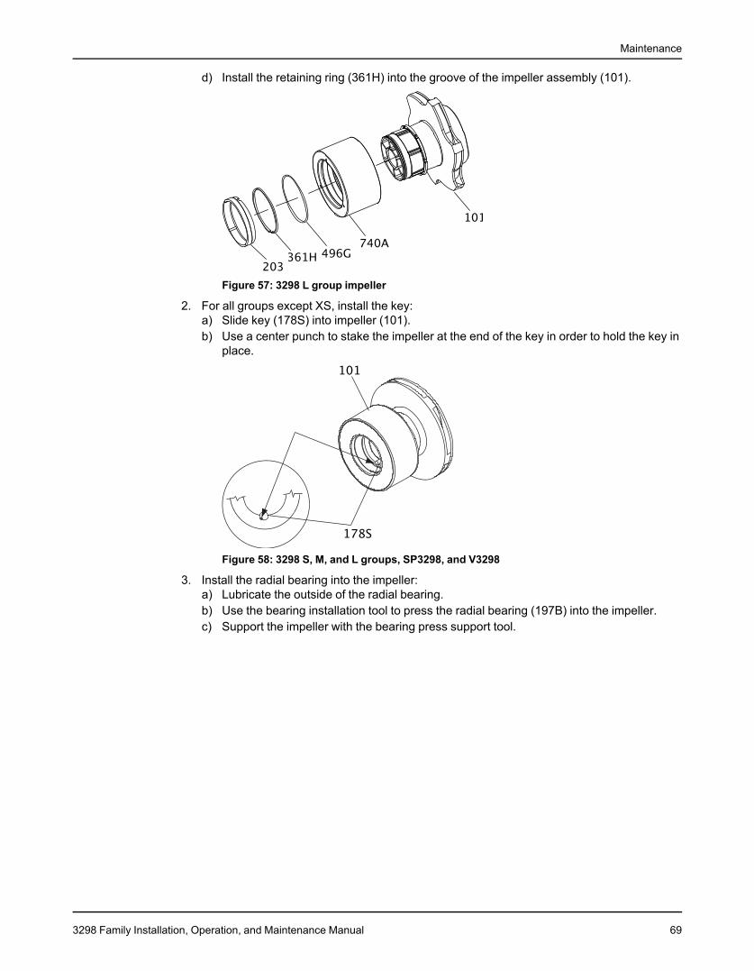
Maintenance
d) Install the retaining ring (361H) into the groove of the impeller assembly (101).
Figure 57: 3298 L group impeller
2. For all groups except XS, install the key:a) Slide key (178S) into impeller (101).b) Use a center punch to stake the impeller at the end of the key in order to hold the key in
place.
Figure 58: 3298 S, M, and L groups, SP3298, and V3298
3. Install the radial bearing into the impeller:a) Lubricate the outside of the radial bearing.b) Use the bearing installation tool to press the radial bearing (197B) into the impeller.c) Support the impeller with the bearing press support tool.
3298 Family Installation, Operation, and Maintenance Manual 69
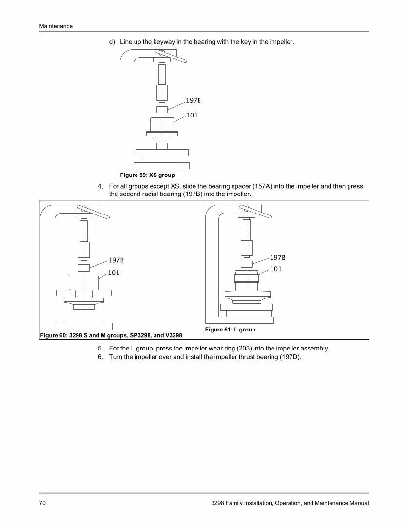
Maintenance
d) Line up the keyway in the bearing with the key in the impeller.
Figure 59: XS group
4. For all groups except XS, slide the bearing spacer (157A) into the impeller and then pressthe second radial bearing (197B) into the impeller.
Figure 61: L groupFigure 60: 3298 S and M groups, SP3298, and V3298
5. For the L group, press the impeller wear ring (203) into the impeller assembly.6. Turn the impeller over and install the impeller thrust bearing (197D).
70 3298 Family Installation, Operation, and Maintenance Manual
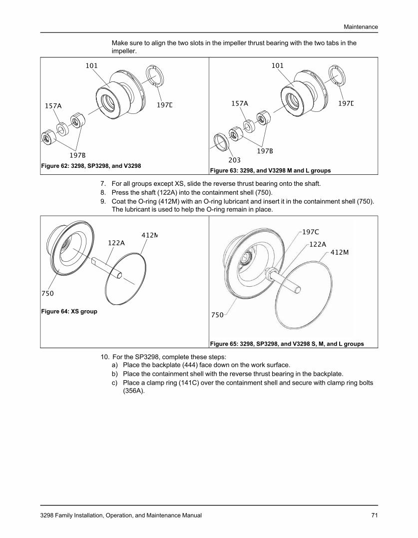
Maintenance
Make sure to align the two slots in the impeller thrust bearing with the two tabs in theimpeller.
Figure 62: 3298, SP3298, and V3298Figure 63: 3298, and V3298 M and L groups
7. For all groups except XS, slide the reverse thrust bearing onto the shaft.8. Press the shaft (122A) into the containment shell (750).9. Coat the O-ring (412M) with an O-ring lubricant and insert it in the containment shell (750).
The lubricant is used to help the O-ring remain in place.
Figure 64: XS group
Figure 65: 3298, SP3298, and V3298 S, M, and L groups
10. For the SP3298, complete these steps:a) Place the backplate (444) face down on the work surface.b) Place the containment shell with the reverse thrust bearing in the backplate.c) Place a clamp ring (141C) over the containment shell and secure with clamp ring bolts
(356A).
3298 Family Installation, Operation, and Maintenance Manual 71
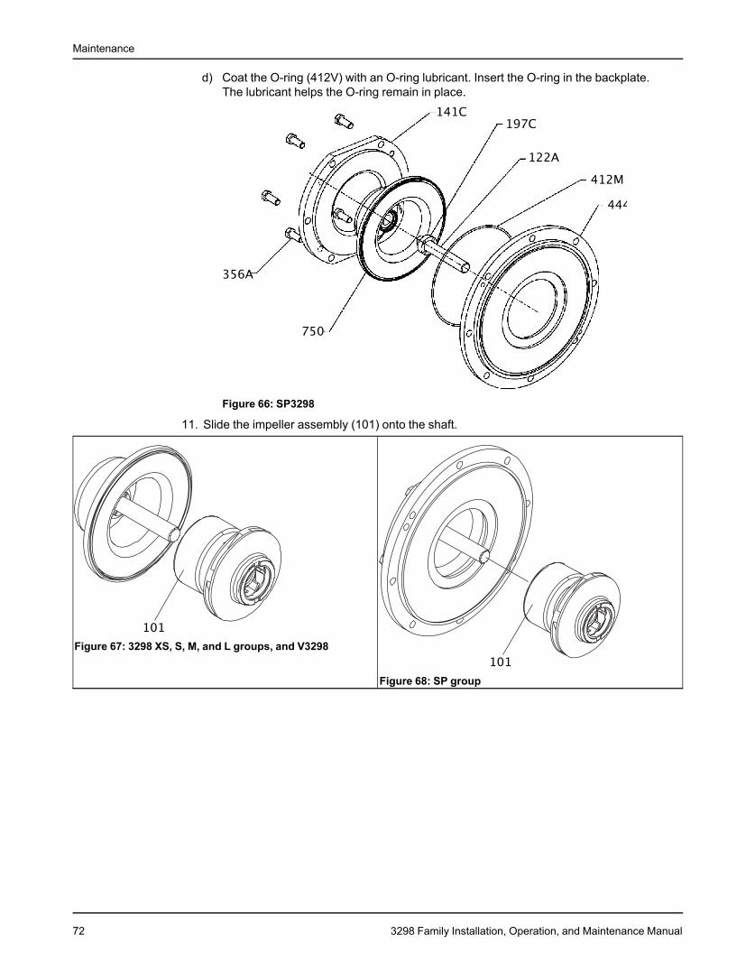
Maintenance
d) Coat the O-ring (412V) with an O-ring lubricant. Insert the O-ring in the backplate.The lubricant helps the O-ring remain in place.
Figure 66: SP3298
11. Slide the impeller assembly (101) onto the shaft.
Figure 67: 3298 XS, S, M, and L groups, and V3298
Figure 68: SP group
72 3298 Family Installation, Operation, and Maintenance Manual
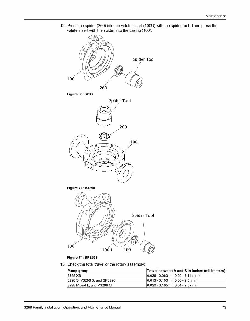
Maintenance
12. Press the spider (260) into the volute insert (100U) with the spider tool. Then press thevolute insert with the spider into the casing (100).
Figure 69: 3298
Figure 70: V3298
Figure 71: SP3298
13. Check the total travel of the rotary assembly:Pump group Travel between A and B in inches (millimeters)3298 XS 0.026 - 0.083 in. (0.66 - 2.11 mm)3298 S, V3298 S, and SP3298 0.013 - 0.100 in. (0.33 - 2.5 mm)3298 M and L, and V3298 M 0.020 - 0.105 in. (0.51 - 2.67 mm
3298 Family Installation, Operation, and Maintenance Manual 73
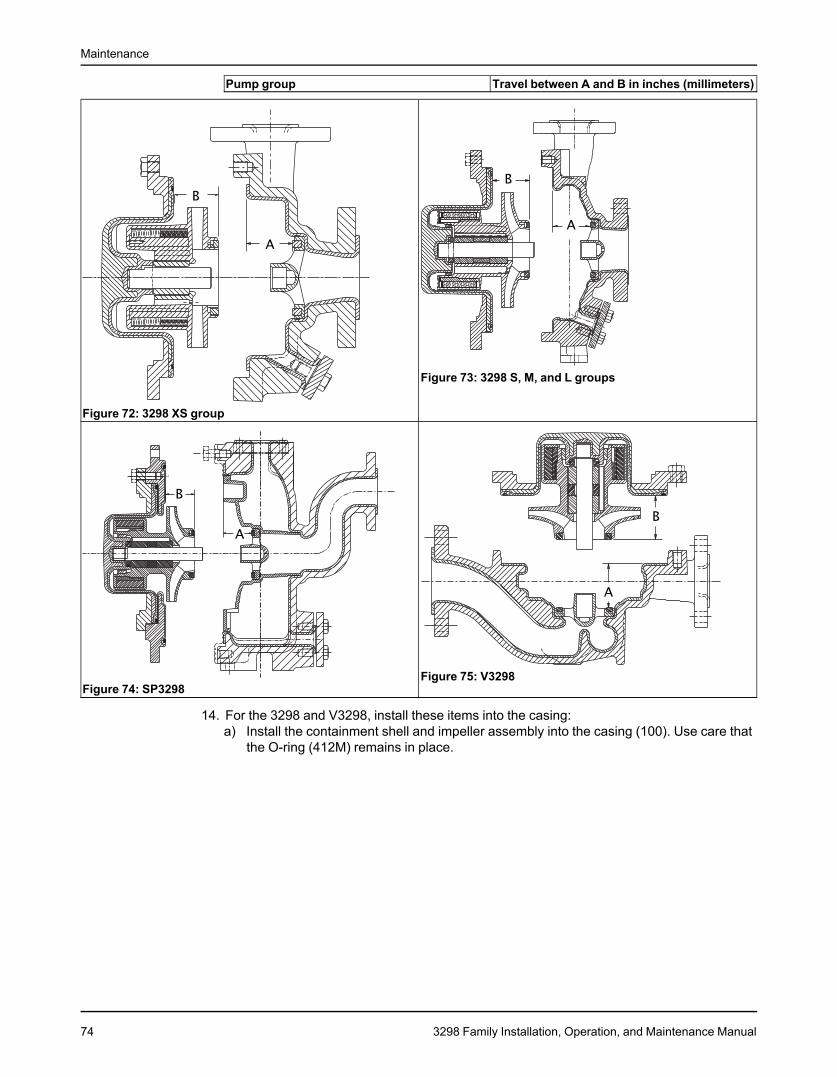
Maintenance
Pump group Travel between A and B in inches (millimeters)
Figure 73: 3298 S, M, and L groups
Figure 72: 3298 XS group
Figure 75: V3298Figure 74: SP3298
14. For the 3298 and V3298, install these items into the casing:a) Install the containment shell and impeller assembly into the casing (100). Use care that
the O-ring (412M) remains in place.
74 3298 Family Installation, Operation, and Maintenance Manual
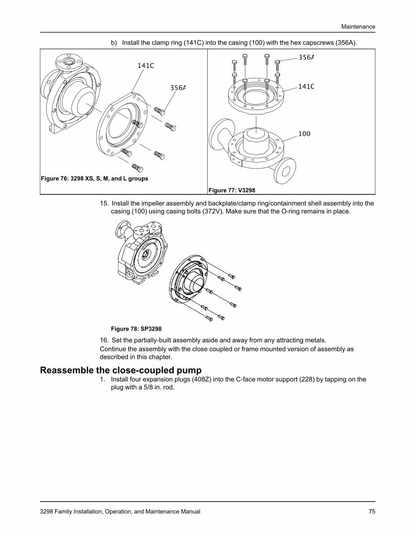
Maintenance
b) Install the clamp ring (141C) into the casing (100) with the hex capscrews (356A).
Figure 76: 3298 XS, S, M, and L groups
Figure 77: V3298
15. Install the impeller assembly and backplate/clamp ring/containment shell assembly into thecasing (100) using casing bolts (372V). Make sure that the O-ring remains in place.
Figure 78: SP3298
16. Set the partially-built assembly aside and away from any attracting metals.Continue the assembly with the close coupled or frame mounted version of assembly asdescribed in this chapter.
Reassemble the close-coupled pump1. Install four expansion plugs (408Z) into the C-face motor support (228) by tapping on the
plug with a 5/8 in. rod.
3298 Family Installation, Operation, and Maintenance Manual 75
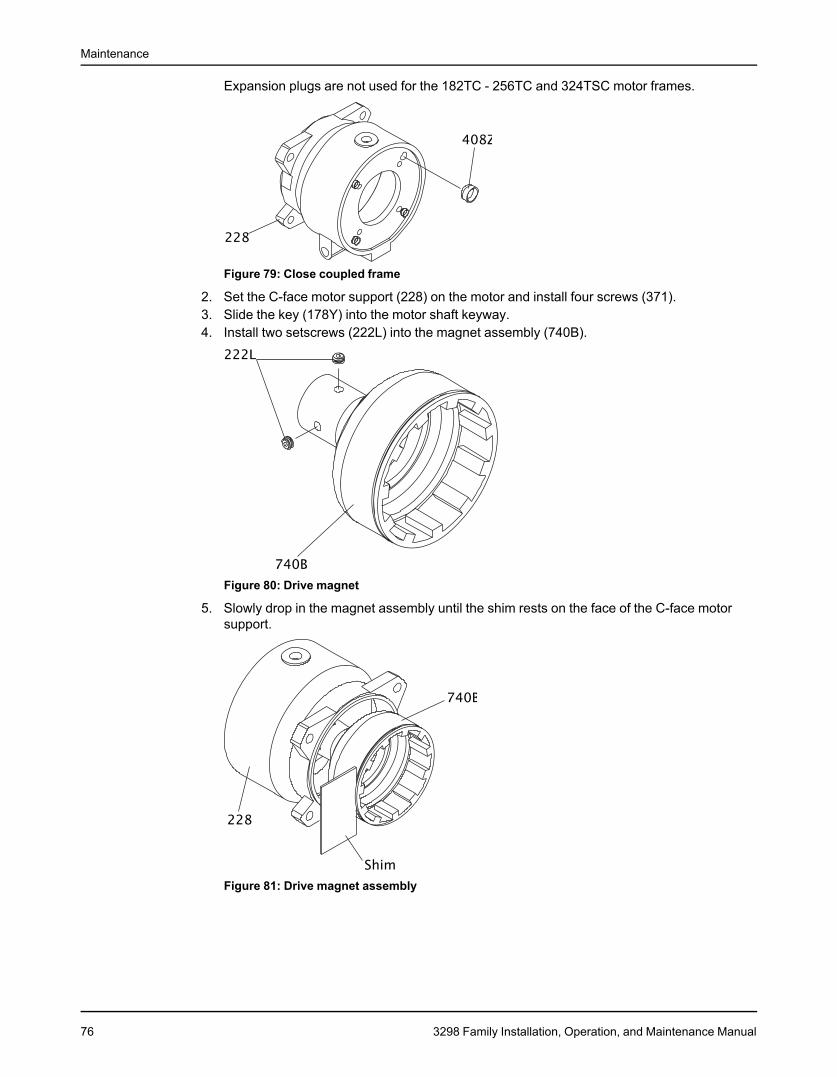
Maintenance
Expansion plugs are not used for the 182TC - 256TC and 324TSC motor frames.
Figure 79: Close coupled frame
2. Set the C-face motor support (228) on the motor and install four screws (371).3. Slide the key (178Y) into the motor shaft keyway.4. Install two setscrews (222L) into the magnet assembly (740B).
Figure 80: Drive magnet
5. Slowly drop in the magnet assembly until the shim rests on the face of the C-face motorsupport.
Figure 81: Drive magnet assembly
76 3298 Family Installation, Operation, and Maintenance Manual
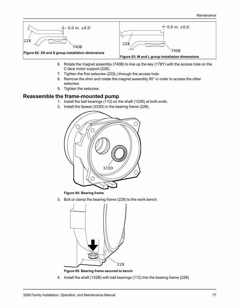
Maintenance
Figure 82: XS and S group installation dimensionsFigure 83: M and L group installation dimensions
6. Rotate the magnet assembly (740B) to line up the key (178Y) with the access hole on theC-face motor support (228).
7. Tighten the first setscrew (222L) through the access hole.8. Remove the shim and rotate the magnet assembly 90° in order to access the other
setscrew.9. Tighten the setscrew.
Reassemble the frame-mounted pump1. Install the ball bearings (112) on the shaft (122B) at both ends.2. Install the lipseal (333D) in the bearing frame (228).
Figure 84: Bearing frame
3. Bolt or clamp the bearing frame (228) to the work bench.
Figure 85: Bearing frame secured to bench
4. Install the shaft (122B) with ball bearings (112) into the bearing frame (228).
3298 Family Installation, Operation, and Maintenance Manual 77
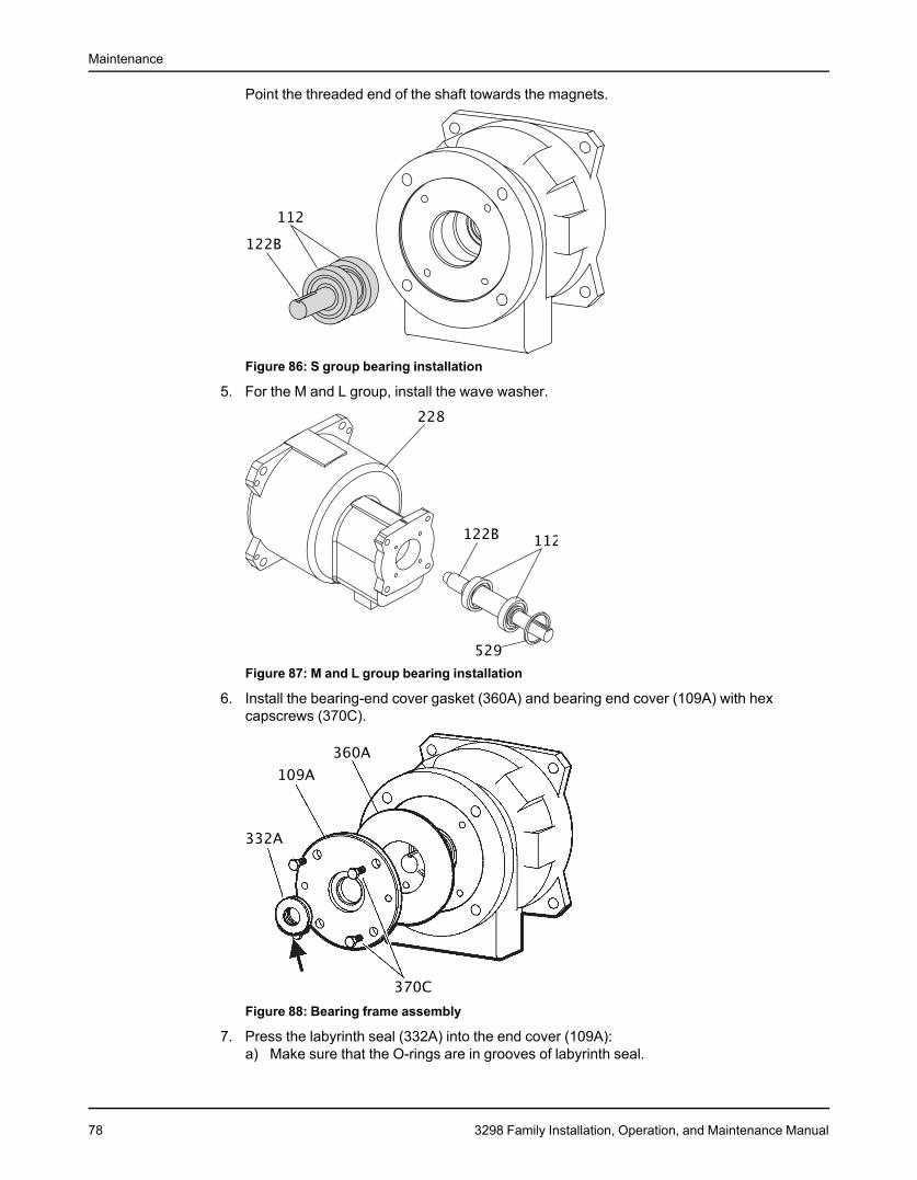
Maintenance
Point the threaded end of the shaft towards the magnets.
Figure 86: S group bearing installation
5. For the M and L group, install the wave washer.
Figure 87: M and L group bearing installation
6. Install the bearing-end cover gasket (360A) and bearing end cover (109A) with hexcapscrews (370C).
Figure 88: Bearing frame assembly
7. Press the labyrinth seal (332A) into the end cover (109A):a) Make sure that the O-rings are in grooves of labyrinth seal.
78 3298 Family Installation, Operation, and Maintenance Manual
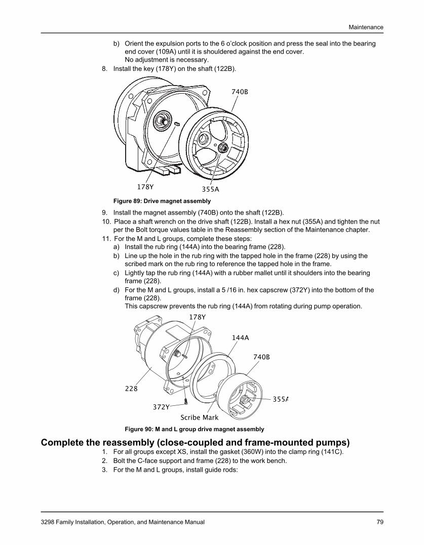
Maintenance
b) Orient the expulsion ports to the 6 o’clock position and press the seal into the bearingend cover (109A) until it is shouldered against the end cover.No adjustment is necessary.
8. Install the key (178Y) on the shaft (122B).
Figure 89: Drive magnet assembly
9. Install the magnet assembly (740B) onto the shaft (122B).10. Place a shaft wrench on the drive shaft (122B). Install a hex nut (355A) and tighten the nut
per the Bolt torque values table in the Reassembly section of the Maintenance chapter.11. For the M and L groups, complete these steps:
a) Install the rub ring (144A) into the bearing frame (228).b) Line up the hole in the rub ring with the tapped hole in the frame (228) by using the
scribed mark on the rub ring to reference the tapped hole in the frame.c) Lightly tap the rub ring (144A) with a rubber mallet until it shoulders into the bearing
frame (228).d) For the M and L groups, install a 5 /16 in. hex capscrew (372Y) into the bottom of the
frame (228).This capscrew prevents the rub ring (144A) from rotating during pump operation.
Figure 90: M and L group drive magnet assembly
Complete the reassembly (close-coupled and frame-mounted pumps)1. For all groups except XS, install the gasket (360W) into the clamp ring (141C).2. Bolt the C-face support and frame (228) to the work bench.3. For the M and L groups, install guide rods:
3298 Family Installation, Operation, and Maintenance Manual 79
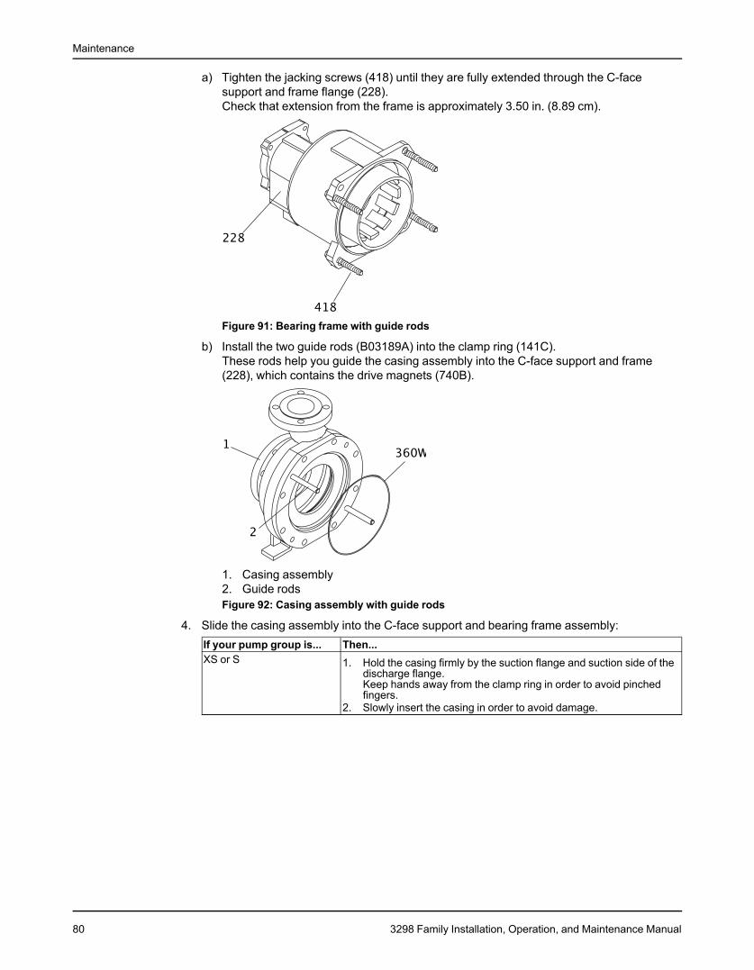
Maintenance
a) Tighten the jacking screws (418) until they are fully extended through the C-facesupport and frame flange (228).Check that extension from the frame is approximately 3.50 in. (8.89 cm).
Figure 91: Bearing frame with guide rods
b) Install the two guide rods (B03189A) into the clamp ring (141C).These rods help you guide the casing assembly into the C-face support and frame(228), which contains the drive magnets (740B).
1. Casing assembly2. Guide rodsFigure 92: Casing assembly with guide rods
4. Slide the casing assembly into the C-face support and bearing frame assembly:If your pump group is... Then...XS or S 1. Hold the casing firmly by the suction flange and suction side of the
discharge flange.Keep hands away from the clamp ring in order to avoid pinchedfingers.
2. Slowly insert the casing in order to avoid damage.
80 3298 Family Installation, Operation, and Maintenance Manual
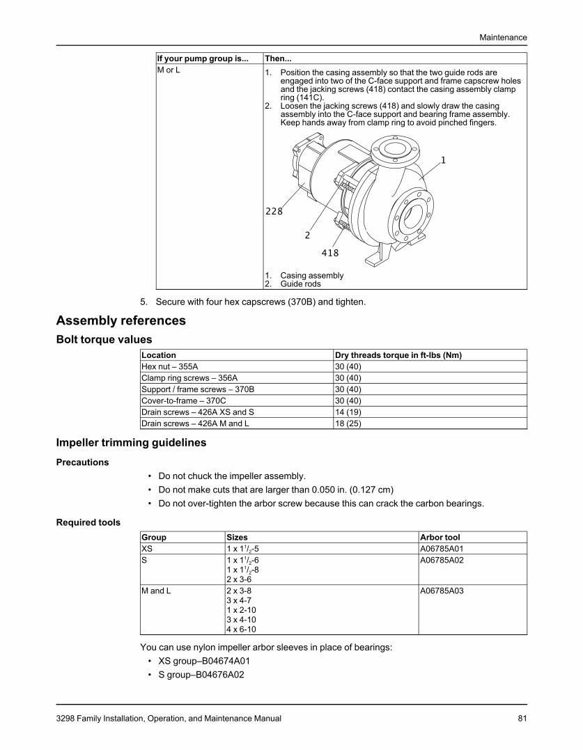
Maintenance
If your pump group is... Then...M or L 1. Position the casing assembly so that the two guide rods are
engaged into two of the C-face support and frame capscrew holesand the jacking screws (418) contact the casing assembly clampring (141C).
2. Loosen the jacking screws (418) and slowly draw the casingassembly into the C-face support and bearing frame assembly.Keep hands away from clamp ring to avoid pinched fingers.
1. Casing assembly2. Guide rods
5. Secure with four hex capscrews (370B) and tighten.
Assembly referencesBolt torque values
Location Dry threads torque in ft-lbs (Nm)Hex nut – 355A 30 (40)Clamp ring screws – 356A 30 (40)Support / frame screws – 370B 30 (40)Cover-to-frame – 370C 30 (40)Drain screws – 426A XS and S 14 (19)Drain screws – 426A M and L 18 (25)
Impeller trimming guidelinesPrecautions
• Do not chuck the impeller assembly.• Do not make cuts that are larger than 0.050 in. (0.127 cm)• Do not over-tighten the arbor screw because this can crack the carbon bearings.
Required toolsGroup Sizes Arbor toolXS 1 x 11/2-5 A06785A01S 1 x 11/2-6 A06785A02
1 x 11/2-82 x 3-6
M and L 2 x 3-8 A06785A033 x 4-71 x 2-103 x 4-104 x 6-10
You can use nylon impeller arbor sleeves in place of bearings:• XS group–B04674A01• S group–B04676A02
3298 Family Installation, Operation, and Maintenance Manual 81
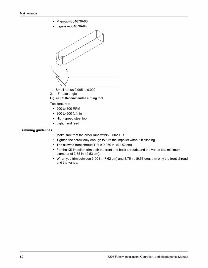
Maintenance
• M group–B04676A03• L group–B04676A04
1. Small radius 0.005 to 0.0022. 45° rake angleFigure 93: Recommended cutting tool
Tool features:• 200 to 300 RPM• 300 to 500 ft./min• High-speed steel tool• Light hand feed
Trimming guidelines• Make sure that the arbor runs within 0.002 TIR.• Tighten the screw only enough to turn the impeller without it slipping.• The allowed front shroud TIR is 0.060 in. (0.152 cm)• For the XS impeller, trim both the front and back shrouds and the vanes to a minimum
diameter of 3.75 in. (9.53 cm).• When you trim between 3.00 in. (7.62 cm) and 3.75 in. (9.53 cm), trim only the front shroud
and the vanes.
82 3298 Family Installation, Operation, and Maintenance Manual
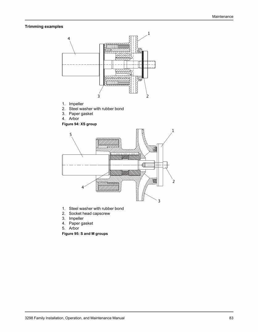
Maintenance
Trimming examples
1. Impeller2. Steel washer with rubber bond3. Paper gasket4. ArborFigure 94: XS group
1. Steel washer with rubber bond2. Socket head capscrew3. Impeller4. Paper gasket5. ArborFigure 95: S and M groups
3298 Family Installation, Operation, and Maintenance Manual 83
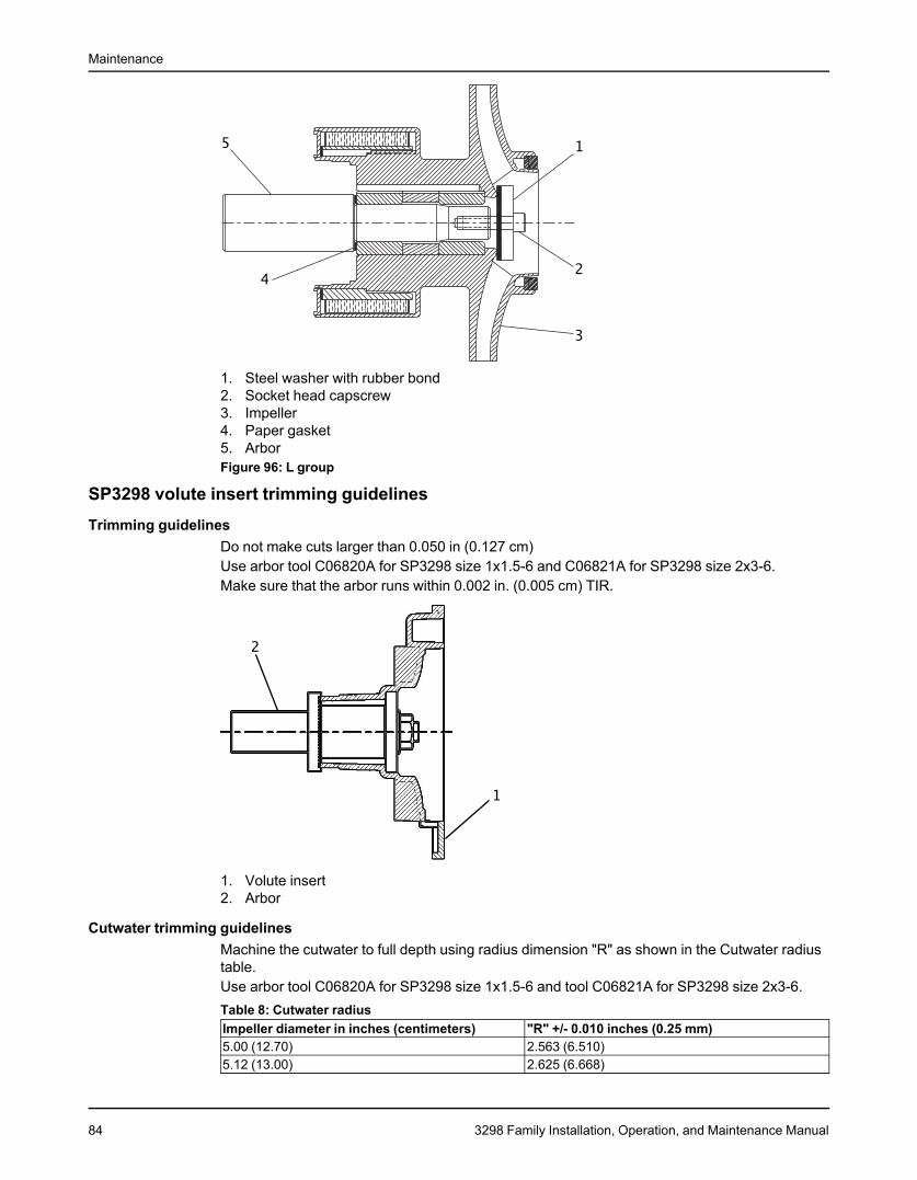
Maintenance
1. Steel washer with rubber bond2. Socket head capscrew3. Impeller4. Paper gasket5. ArborFigure 96: L group
SP3298 volute insert trimming guidelinesTrimming guidelines
Do not make cuts larger than 0.050 in (0.127 cm)Use arbor tool C06820A for SP3298 size 1x1.5-6 and C06821A for SP3298 size 2x3-6.Make sure that the arbor runs within 0.002 in. (0.005 cm) TIR.
1. Volute insert2. Arbor
Cutwater trimming guidelinesMachine the cutwater to full depth using radius dimension "R" as shown in the Cutwater radiustable.Use arbor tool C06820A for SP3298 size 1x1.5-6 and tool C06821A for SP3298 size 2x3-6.Table 8: Cutwater radiusImpeller diameter in inches (centimeters) "R" +/- 0.010 inches (0.25 mm)5.00 (12.70) 2.563 (6.510)5.12 (13.00) 2.625 (6.668)
84 3298 Family Installation, Operation, and Maintenance Manual
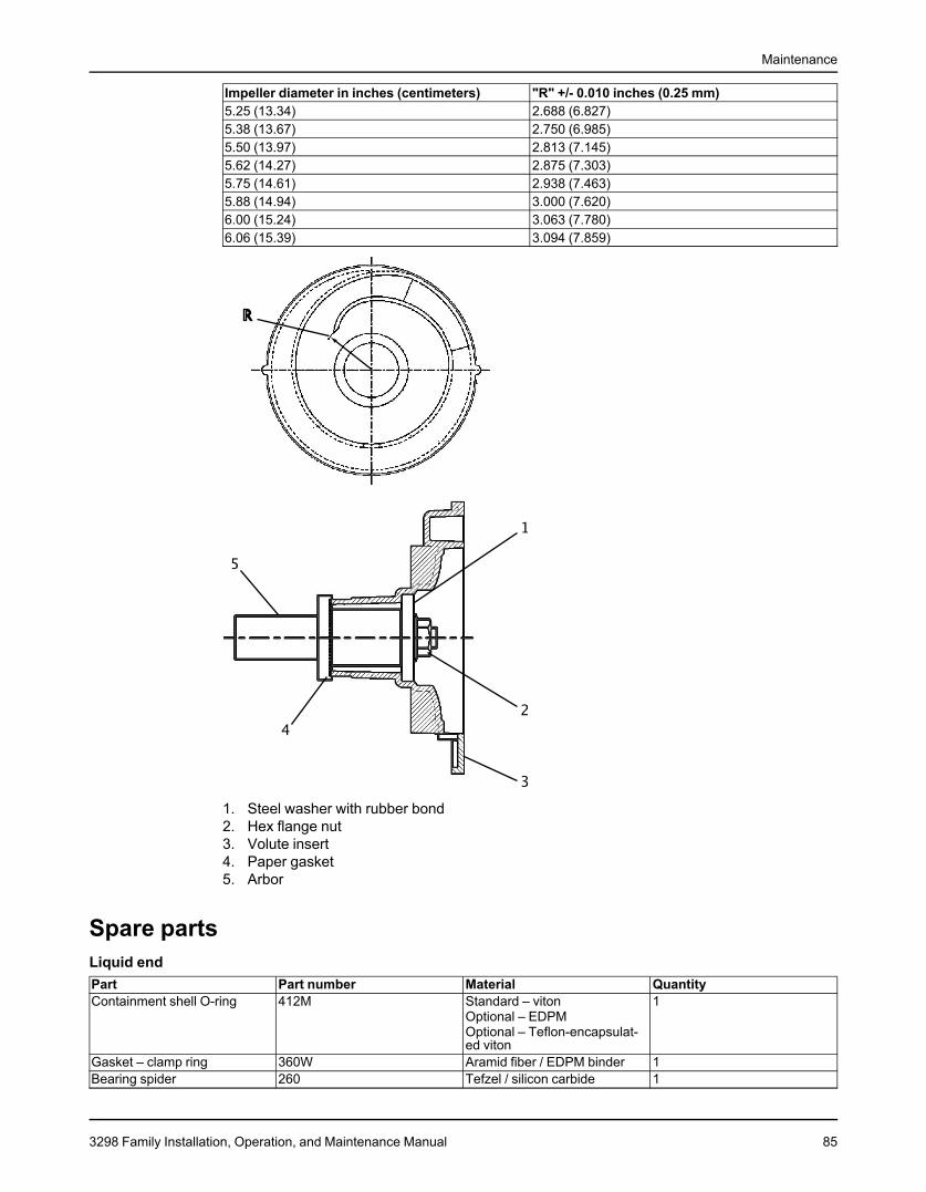
Maintenance
Impeller diameter in inches (centimeters) "R" +/- 0.010 inches (0.25 mm)5.25 (13.34) 2.688 (6.827)5.38 (13.67) 2.750 (6.985)5.50 (13.97) 2.813 (7.145)5.62 (14.27) 2.875 (7.303)5.75 (14.61) 2.938 (7.463)5.88 (14.94) 3.000 (7.620)6.00 (15.24) 3.063 (7.780)6.06 (15.39) 3.094 (7.859)
1. Steel washer with rubber bond2. Hex flange nut3. Volute insert4. Paper gasket5. Arbor
Spare partsLiquid endPart Part number Material QuantityContainment shell O-ring 412M Standard – viton 1
Optional – EDPMOptional – Teflon-encapsulat-ed viton
Gasket – clamp ring 360W Aramid fiber / EDPM binder 1Bearing spider 260 Tefzel / silicon carbide 1
3298 Family Installation, Operation, and Maintenance Manual 85
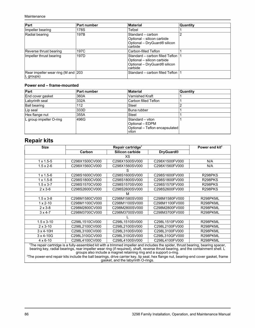
Maintenance
Part Part number Material QuantityImpeller bearing 178S Tefzel 1Radial bearing 197B Standard – carbon 2
Optional – silicon carbideOptional – DryGuard® siliconcarbide
Reverse thrust bearing 197C Carbon-filled Teflon 1Impeller thrust bearing 197D Standard – carbon filled Teflon 1
Optional – silicon carbideOptional – DryGuard® siliconcarbide
Rear impeller wear ring (M and 203 Standard – carbon filled Teflon 1L groups)
Power end – frame-mountedPart Part number Material QuantityEnd cover gasket 360A Varnished Kraft 1Labyrinth seal 332A Carbon filled Teflon 1Ball bearing 112 Steel 2Lip seal 333D Buna rubber 1Hex flange nut 355A Steel 1L group impeller O-ring 496G Standard – viton 1
Optional – EDPMOptional – Teflon encapsulatedviton
Repair kitsSize Repair cartridge1 Power end kit2
Carbon Silicon carbide DryGuard®XS
1 x 1.5-5 C298X1500CV000 C298X1500SV000 C298X1500FV000 N/A1.5 x 2-6 C298X1560CV000 C298X1560SV000 C298X1560FV000 N/A
S1 x 1.5-6 C298S1600CV000 C298S1600SV000 C298S1600FV000 R298PKS1 x 1.5-8 C298S1800CV000 C298S1800SV000 C298S1800FV000 R298PKS1.5 x 3-7 C298S1570CV000 C298S1570SV000 C298S1570FV000 R298PKS2 x 3-6 C298S2600CV000 C298S2600SV000 C298S2600FV000 R298PKS
M1.5 x 3-8 C298M1580CV000 C298M1580SV000 C298M1580FV000 R298PKML1 x 2-10 C298M1100CV000 C298M1100SV000 C298M1100FV000 R298PKML2 x 3-8 C298M2800CV000 C298M2800SV000 C298M2800FV000 R298PKML3 x 4-7 C298M3700CV000 C298M3700SV000 C298M3700FV000 R298PKML
L1.5 x 3-10 C298L1510CV000 C298L1510SV000 C298L1510FV000 R298PKML2 x 3-10 C298L2100CV000 C298L2100SV000 C298L2100FV000 R298PKML
3 x 4-10H C298L3100CV000 C298L3100SV000 C298L3100FV000 R298PKML3 x 4-10G C298L310GCV000 C298L310GSV000 C298L310GFV000 R298PKML4 x 6-10 C298L4100CV000 C298L4100SV000 C298L4100FV000 R298PKML
1The repair cartridge is a fully-assembled kit with a trimmed impeller and includes the spider, thrust bearing, bearing spacer,bearing key, radial bearings, rear impeller wear ring (if required), shaft, reverse thrust bearing, and the containment shell. L
groups also include a magnet retaining ring and a support o-ring.2The power-end repair kits include the ball bearings, drive carrier key, lip seal, hex flange nut, bearing-end cover gasket, frame
gasket, and the labyrinth O-rings.
86 3298 Family Installation, Operation, and Maintenance Manual
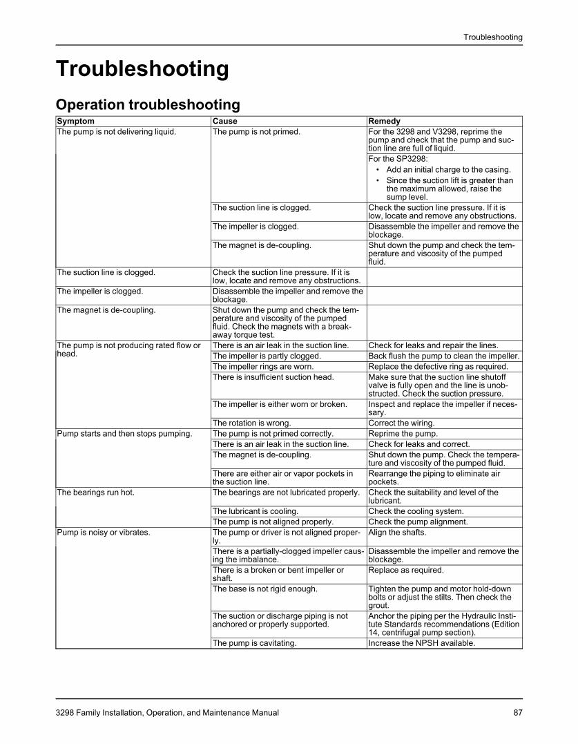
Troubleshooting
TroubleshootingOperation troubleshootingSymptom Cause RemedyThe pump is not delivering liquid. The pump is not primed. For the 3298 and V3298, reprime the
pump and check that the pump and suc-tion line are full of liquid.For the SP3298:
• Add an initial charge to the casing.• Since the suction lift is greater than
the maximum allowed, raise thesump level.
The suction line is clogged. Check the suction line pressure. If it islow, locate and remove any obstructions.
The impeller is clogged. Disassemble the impeller and remove theblockage.
The magnet is de-coupling. Shut down the pump and check the tem-perature and viscosity of the pumpedfluid.
The suction line is clogged. Check the suction line pressure. If it islow, locate and remove any obstructions.
The impeller is clogged. Disassemble the impeller and remove theblockage.
The magnet is de-coupling. Shut down the pump and check the tem-perature and viscosity of the pumpedfluid. Check the magnets with a break-away torque test.
The pump is not producing rated flow or There is an air leak in the suction line. Check for leaks and repair the lines.head. The impeller is partly clogged. Back flush the pump to clean the impeller.
The impeller rings are worn. Replace the defective ring as required.There is insufficient suction head. Make sure that the suction line shutoff
valve is fully open and the line is unob-structed. Check the suction pressure.
The impeller is either worn or broken. Inspect and replace the impeller if neces-sary.
The rotation is wrong. Correct the wiring.Pump starts and then stops pumping. The pump is not primed correctly. Reprime the pump.
There is an air leak in the suction line. Check for leaks and correct.The magnet is de-coupling. Shut down the pump. Check the tempera-
ture and viscosity of the pumped fluid.There are either air or vapor pockets in Rearrange the piping to eliminate airthe suction line. pockets.
The bearings run hot. The bearings are not lubricated properly. Check the suitability and level of thelubricant.
The lubricant is cooling. Check the cooling system.The pump is not aligned properly. Check the pump alignment.
Pump is noisy or vibrates. The pump or driver is not aligned proper- Align the shafts.ly.There is a partially-clogged impeller caus- Disassemble the impeller and remove theing the imbalance. blockage.There is a broken or bent impeller or Replace as required.shaft.The base is not rigid enough. Tighten the pump and motor hold-down
bolts or adjust the stilts. Then check thegrout.
The suction or discharge piping is not Anchor the piping per the Hydraulic Insti-anchored or properly supported. tute Standards recommendations (Edition
14, centrifugal pump section).The pump is cavitating. Increase the NPSH available.
3298 Family Installation, Operation, and Maintenance Manual 87
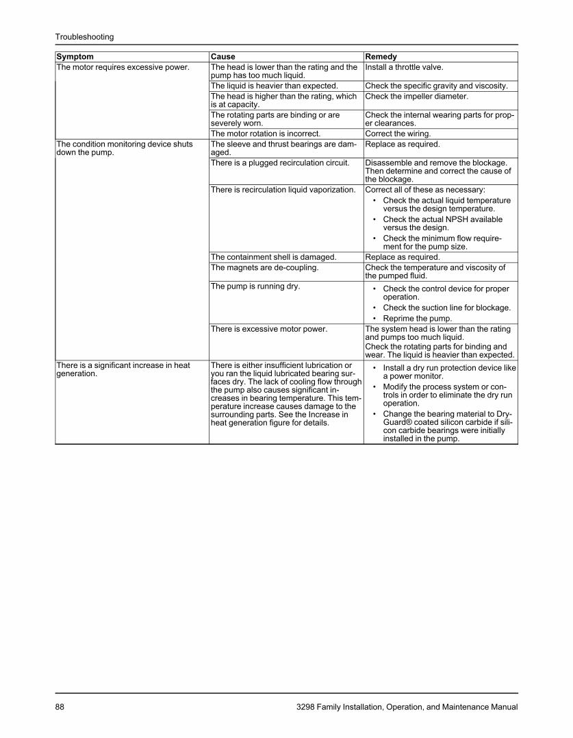
Troubleshooting
Symptom Cause RemedyThe motor requires excessive power. The head is lower than the rating and the Install a throttle valve.
pump has too much liquid.The liquid is heavier than expected. Check the specific gravity and viscosity.The head is higher than the rating, which Check the impeller diameter.is at capacity.The rotating parts are binding or are Check the internal wearing parts for prop-severely worn. er clearances.The motor rotation is incorrect. Correct the wiring.
The condition monitoring device shuts The sleeve and thrust bearings are dam- Replace as required.down the pump. aged.
There is a plugged recirculation circuit. Disassemble and remove the blockage.Then determine and correct the cause ofthe blockage.
There is recirculation liquid vaporization. Correct all of these as necessary:• Check the actual liquid temperature
versus the design temperature.• Check the actual NPSH available
versus the design.• Check the minimum flow require-
ment for the pump size.The containment shell is damaged. Replace as required.The magnets are de-coupling. Check the temperature and viscosity of
the pumped fluid.The pump is running dry. • Check the control device for proper
operation.• Check the suction line for blockage.• Reprime the pump.
There is excessive motor power. The system head is lower than the ratingand pumps too much liquid.Check the rotating parts for binding andwear. The liquid is heavier than expected.
There is a significant increase in heat There is either insufficient lubrication or • Install a dry run protection device likegeneration. you ran the liquid lubricated bearing sur- a power monitor.
faces dry. The lack of cooling flow through • Modify the process system or con-the pump also causes significant in- trols in order to eliminate the dry runcreases in bearing temperature. This tem- operation.perature increase causes damage to the• Change the bearing material to Dry-surrounding parts. See the Increase in
Guard® coated silicon carbide if sili-heat generation figure for details.con carbide bearings were initiallyinstalled in the pump.
88 3298 Family Installation, Operation, and Maintenance Manual
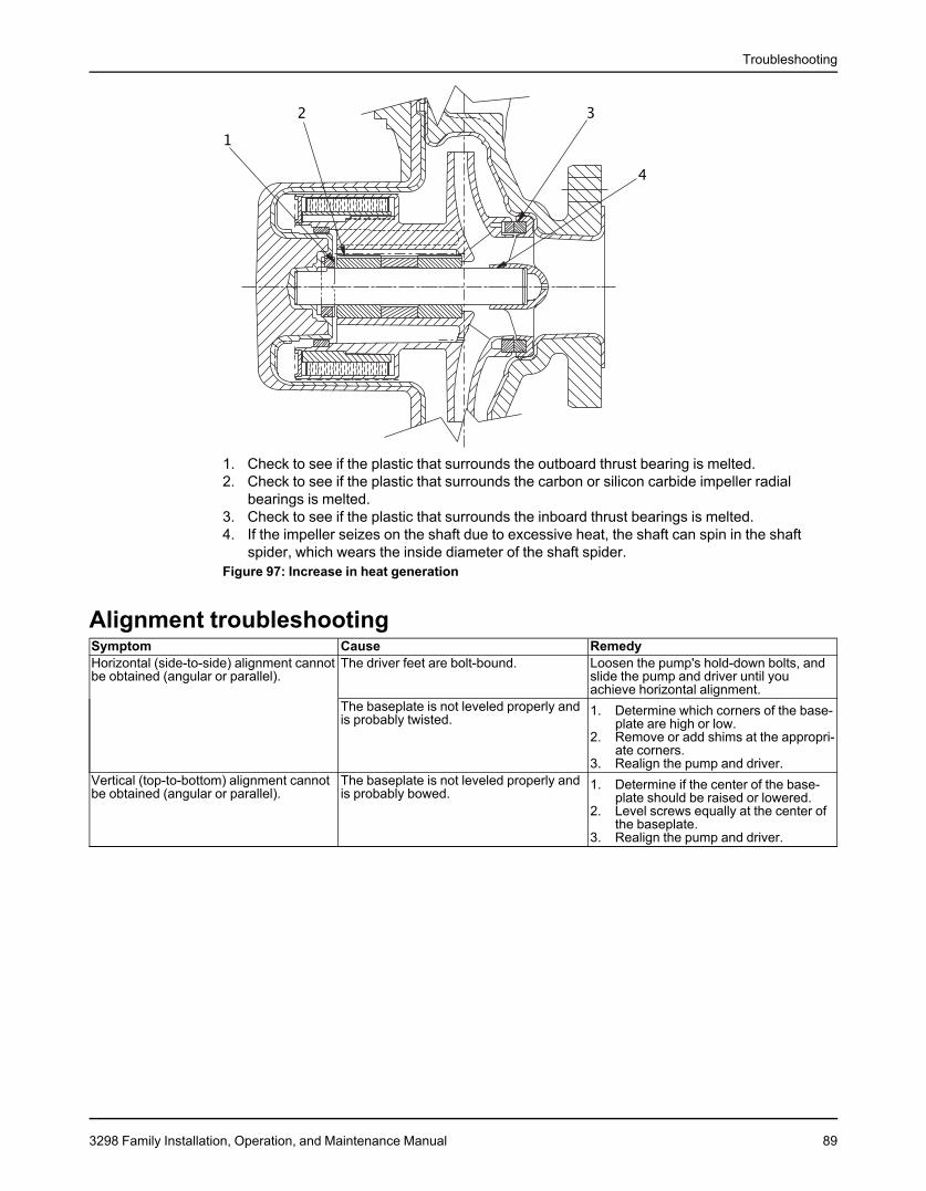
Troubleshooting
1. Check to see if the plastic that surrounds the outboard thrust bearing is melted.2. Check to see if the plastic that surrounds the carbon or silicon carbide impeller radial
bearings is melted.3. Check to see if the plastic that surrounds the inboard thrust bearings is melted.4. If the impeller seizes on the shaft due to excessive heat, the shaft can spin in the shaft
spider, which wears the inside diameter of the shaft spider.Figure 97: Increase in heat generation
Alignment troubleshootingSymptom Cause RemedyHorizontal (side-to-side) alignment cannot The driver feet are bolt-bound. Loosen the pump's hold-down bolts, andbe obtained (angular or parallel). slide the pump and driver until you
achieve horizontal alignment.The baseplate is not leveled properly and 1. Determine which corners of the base-is probably twisted. plate are high or low.
2. Remove or add shims at the appropri-ate corners.
3. Realign the pump and driver.Vertical (top-to-bottom) alignment cannot The baseplate is not leveled properly and 1. Determine if the center of the base-be obtained (angular or parallel). is probably bowed. plate should be raised or lowered.
2. Level screws equally at the center ofthe baseplate.
3. Realign the pump and driver.
3298 Family Installation, Operation, and Maintenance Manual 89
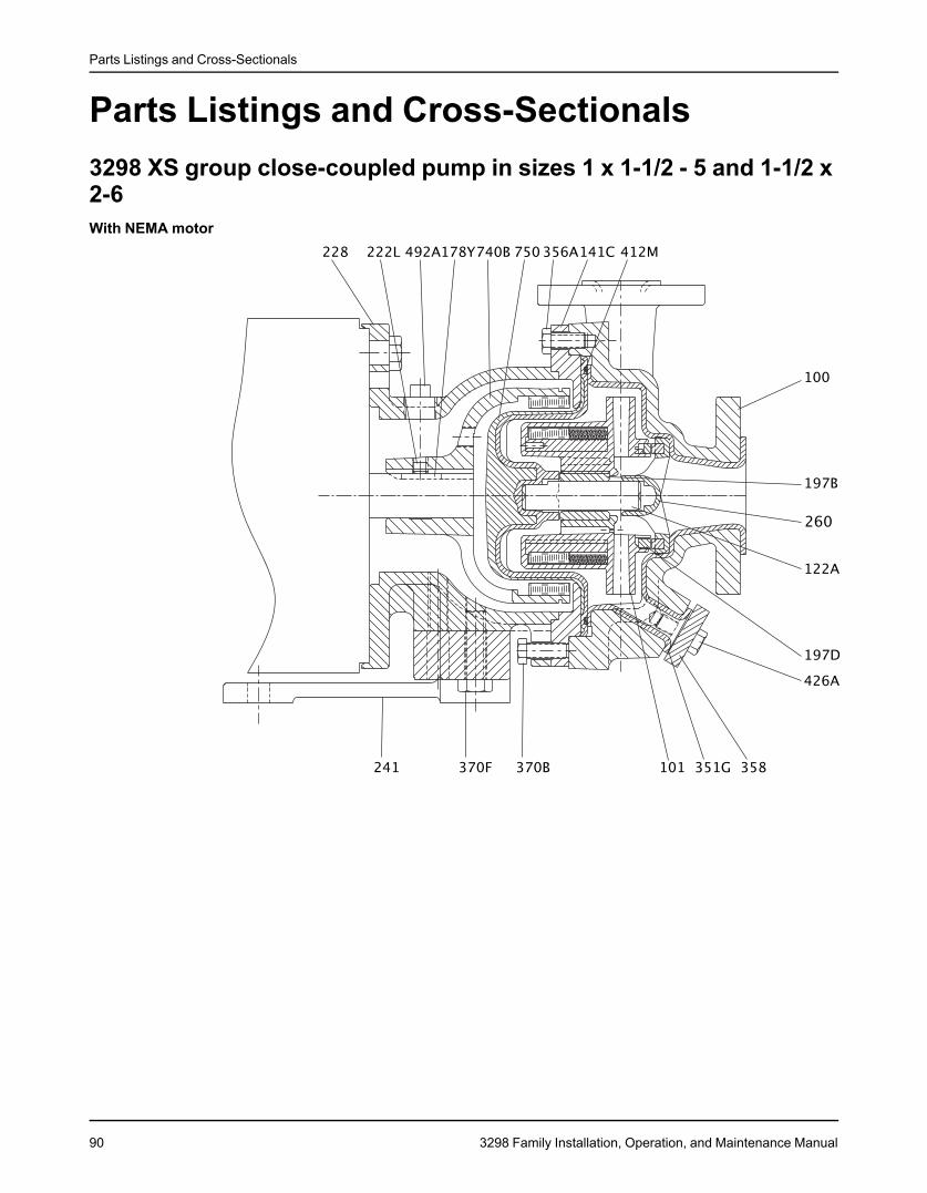
Parts Listings and Cross-Sectionals
Parts Listings and Cross-Sectionals3298 XS group close-coupled pump in sizes 1 x 1-1/2 - 5 and 1-1/2 x2-6With NEMA motor
90 3298 Family Installation, Operation, and Maintenance Manual
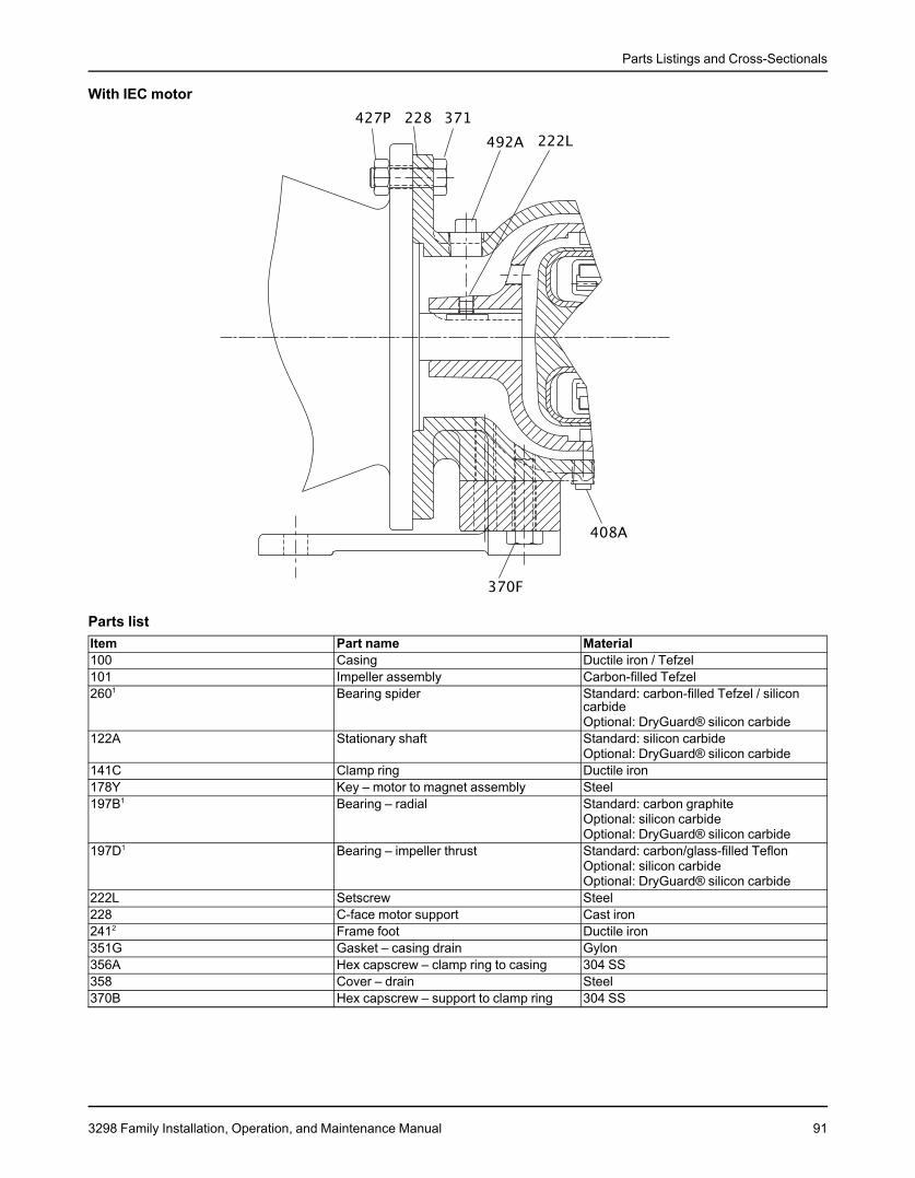
Parts Listings and Cross-Sectionals
With IEC motor
Parts listItem Part name Material100 Casing Ductile iron / Tefzel101 Impeller assembly Carbon-filled Tefzel2601 Bearing spider Standard: carbon-filled Tefzel / silicon
carbideOptional: DryGuard® silicon carbide
122A Stationary shaft Standard: silicon carbideOptional: DryGuard® silicon carbide
141C Clamp ring Ductile iron178Y Key – motor to magnet assembly Steel197B1 Bearing – radial Standard: carbon graphite
Optional: silicon carbideOptional: DryGuard® silicon carbide
197D1 Bearing – impeller thrust Standard: carbon/glass-filled TeflonOptional: silicon carbideOptional: DryGuard® silicon carbide
222L Setscrew Steel228 C-face motor support Cast iron2412 Frame foot Ductile iron351G Gasket – casing drain Gylon356A Hex capscrew – clamp ring to casing 304 SS358 Cover – drain Steel370B Hex capscrew – support to clamp ring 304 SS
3298 Family Installation, Operation, and Maintenance Manual 91
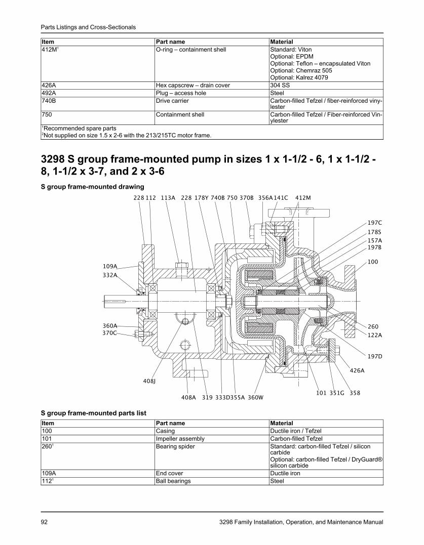
Parts Listings and Cross-Sectionals
Item Part name Material412M1 O-ring – containment shell Standard: Viton
Optional: EPDMOptional: Teflon – encapsulated VitonOptional: Chemraz 505Optional: Kalrez 4079
426A Hex capscrew – drain cover 304 SS492A Plug – access hole Steel740B Drive carrier Carbon-filled Tefzel / fiber-reinforced viny-
lester750 Containment shell Carbon-filled Tefzel / Fiber-reinforced Vin-
ylester1Recommended spare parts2Not supplied on size 1.5 x 2-6 with the 213/215TC motor frame.
3298 S group frame-mounted pump in sizes 1 x 1-1/2 - 6, 1 x 1-1/2 -8, 1-1/2 x 3-7, and 2 x 3-6S group frame-mounted drawing
S group frame-mounted parts listItem Part name Material100 Casing Ductile iron / Tefzel101 Impeller assembly Carbon-filled Tefzel2601 Bearing spider Standard: carbon-filled Tefzel / silicon
carbideOptional: carbon-filled Tefzel / DryGuard®silicon carbide
109A End cover Ductile iron1121 Ball bearings Steel
92 3298 Family Installation, Operation, and Maintenance Manual
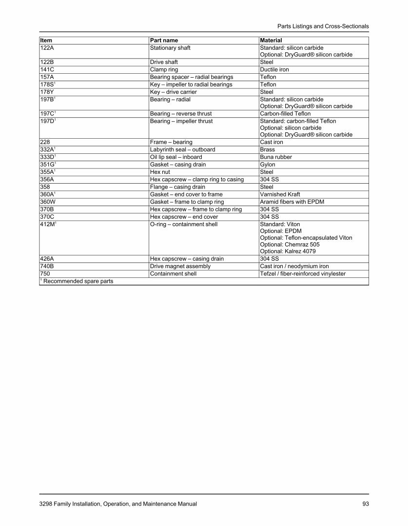
Parts Listings and Cross-Sectionals
Item Part name Material122A Stationary shaft Standard: silicon carbide
Optional: DryGuard® silicon carbide122B Drive shaft Steel141C Clamp ring Ductile iron157A Bearing spacer – radial bearings Teflon178S1 Key – impeller to radial bearings Teflon178Y Key – drive carrier Steel197B1 Bearing – radial Standard: silicon carbide
Optional: DryGuard® silicon carbide197C1 Bearing – reverse thrust Carbon-filled Teflon197D1 Bearing – impeller thrust Standard: carbon-filled Teflon
Optional: silicon carbideOptional: DryGuard® silicon carbide
228 Frame – bearing Cast iron332A1 Labyrinth seal – outboard Brass333D1 Oil lip seal – inboard Buna rubber351G1 Gasket – casing drain Gylon355A1 Hex nut Steel356A Hex capscrew – clamp ring to casing 304 SS358 Flange – casing drain Steel360A1 Gasket – end cover to frame Varnished Kraft360W Gasket – frame to clamp ring Aramid fibers with EPDM370B Hex capscrew – frame to clamp ring 304 SS370C Hex capscrew – end cover 304 SS412M1 O-ring – containment shell Standard: Viton
Optional: EPDMOptional: Teflon-encapsulated VitonOptional: Chemraz 505Optional: Kalrez 4079
426A Hex capscrew – casing drain 304 SS740B Drive magnet assembly Cast iron / neodymium iron750 Containment shell Tefzel / fiber-reinforced vinylester1 Recommended spare parts
3298 Family Installation, Operation, and Maintenance Manual 93
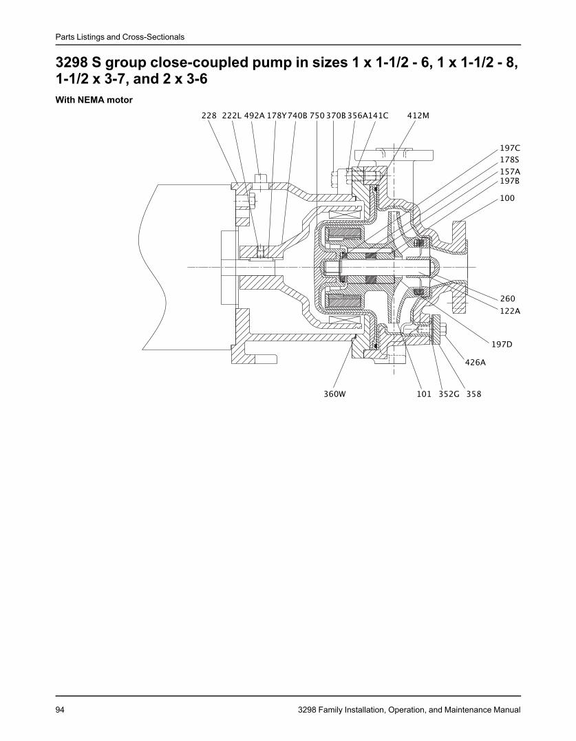
Parts Listings and Cross-Sectionals
3298 S group close-coupled pump in sizes 1 x 1-1/2 - 6, 1 x 1-1/2 - 8,1-1/2 x 3-7, and 2 x 3-6With NEMA motor
94 3298 Family Installation, Operation, and Maintenance Manual
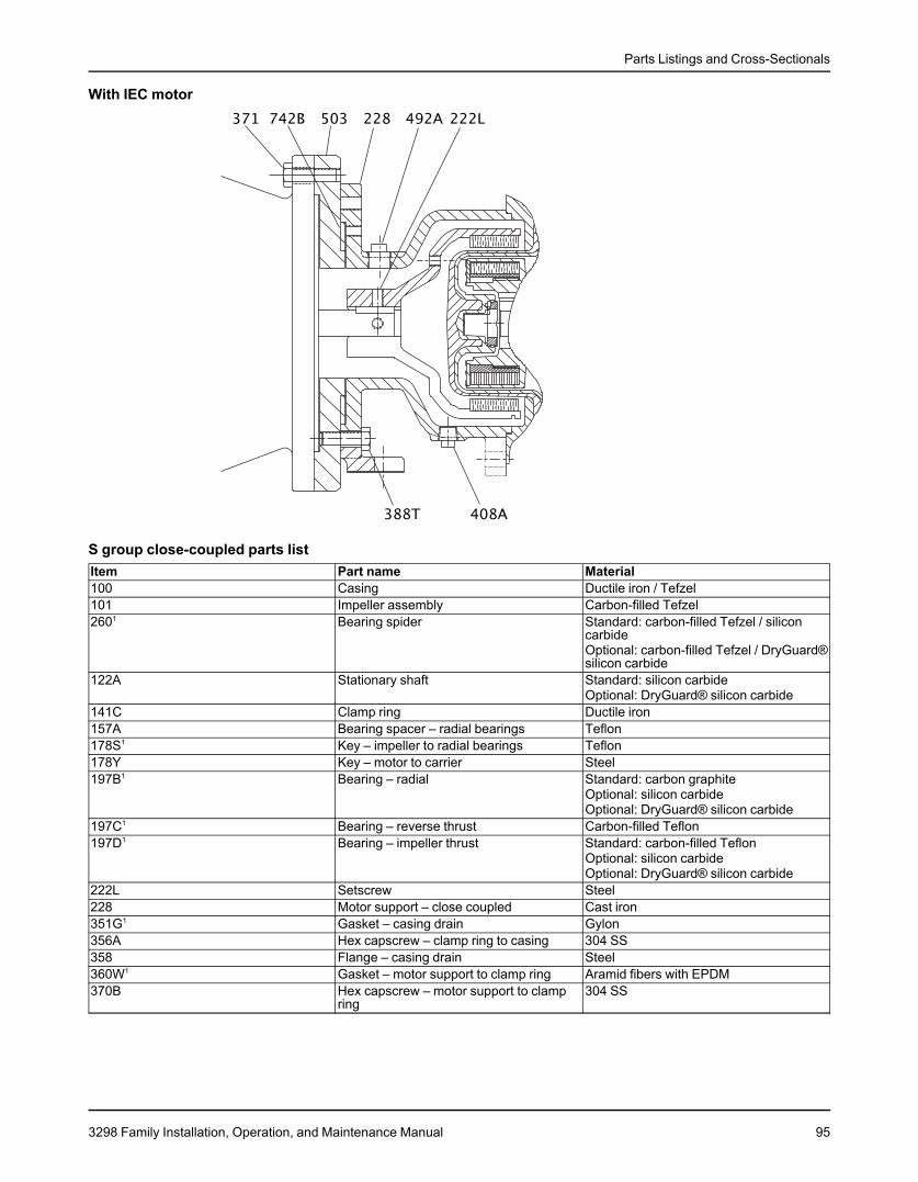
Parts Listings and Cross-Sectionals
With IEC motor
S group close-coupled parts listItem Part name Material100 Casing Ductile iron / Tefzel101 Impeller assembly Carbon-filled Tefzel2601 Bearing spider Standard: carbon-filled Tefzel / silicon
carbideOptional: carbon-filled Tefzel / DryGuard®silicon carbide
122A Stationary shaft Standard: silicon carbideOptional: DryGuard® silicon carbide
141C Clamp ring Ductile iron157A Bearing spacer – radial bearings Teflon178S1 Key – impeller to radial bearings Teflon178Y Key – motor to carrier Steel197B1 Bearing – radial Standard: carbon graphite
Optional: silicon carbideOptional: DryGuard® silicon carbide
197C1 Bearing – reverse thrust Carbon-filled Teflon197D1 Bearing – impeller thrust Standard: carbon-filled Teflon
Optional: silicon carbideOptional: DryGuard® silicon carbide
222L Setscrew Steel228 Motor support – close coupled Cast iron351G1 Gasket – casing drain Gylon356A Hex capscrew – clamp ring to casing 304 SS358 Flange – casing drain Steel360W1 Gasket – motor support to clamp ring Aramid fibers with EPDM370B Hex capscrew – motor support to clamp 304 SS
ring
3298 Family Installation, Operation, and Maintenance Manual 95
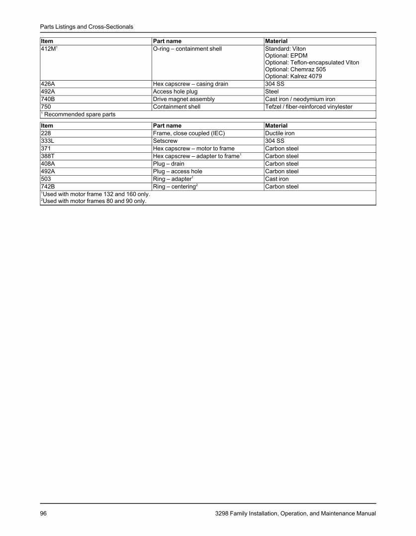
Parts Listings and Cross-Sectionals
Item Part name Material412M1 O-ring – containment shell Standard: Viton
Optional: EPDMOptional: Teflon-encapsulated VitonOptional: Chemraz 505Optional: Kalrez 4079
426A Hex capscrew – casing drain 304 SS492A Access hole plug Steel740B Drive magnet assembly Cast iron / neodymium iron750 Containment shell Tefzel / fiber-reinforced vinylester1 Recommended spare parts
Item Part name Material228 Frame, close coupled (IEC) Ductile iron333L Setscrew 304 SS371 Hex capscrew – motor to frame Carbon steel388T Hex capscrew – adapter to frame1 Carbon steel408A Plug – drain Carbon steel492A Plug – access hole Carbon steel503 Ring – adapter1 Cast iron742B Ring – centering2 Carbon steel1Used with motor frame 132 and 160 only.2Used with motor frames 80 and 90 only.
96 3298 Family Installation, Operation, and Maintenance Manual
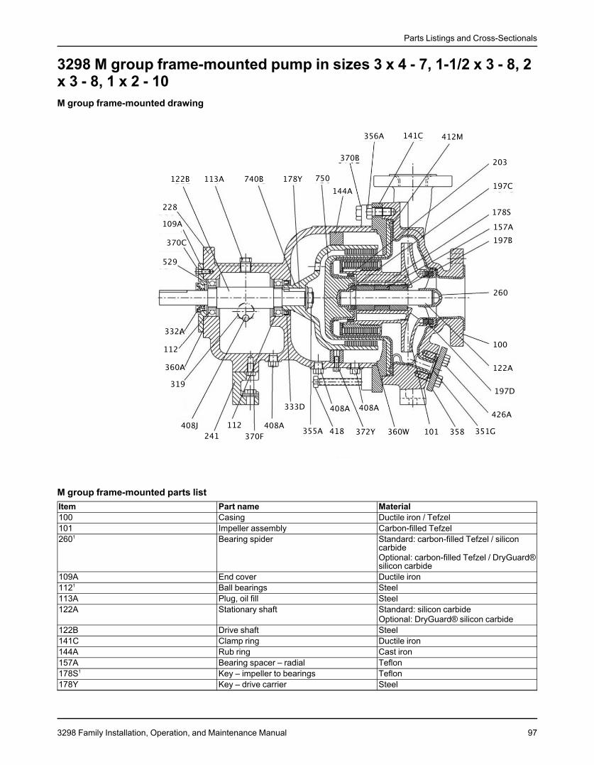
Parts Listings and Cross-Sectionals
3298 M group frame-mounted pump in sizes 3 x 4 - 7, 1-1/2 x 3 - 8, 2x 3 - 8, 1 x 2 - 10M group frame-mounted drawing
M group frame-mounted parts listItem Part name Material100 Casing Ductile iron / Tefzel101 Impeller assembly Carbon-filled Tefzel2601 Bearing spider Standard: carbon-filled Tefzel / silicon
carbideOptional: carbon-filled Tefzel / DryGuard®silicon carbide
109A End cover Ductile iron1121 Ball bearings Steel113A Plug, oil fill Steel122A Stationary shaft Standard: silicon carbide
Optional: DryGuard® silicon carbide122B Drive shaft Steel141C Clamp ring Ductile iron144A Rub ring Cast iron157A Bearing spacer – radial Teflon178S1 Key – impeller to bearings Teflon178Y Key – drive carrier Steel
3298 Family Installation, Operation, and Maintenance Manual 97
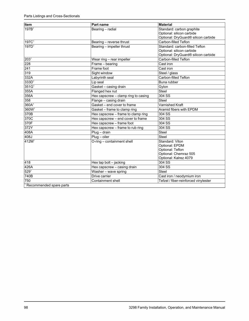
Parts Listings and Cross-Sectionals
Item Part name Material197B1 Bearing – radial Standard: carbon graphite
Optional: silicon carbideOptional: DryGuard® silicon carbide
197C1 Bearing – reverse thrust Carbon-filled Teflon197D1 Bearing – impeller thrust Standard: carbon-filled Teflon
Optional: silicon carbideOptional: DryGuard® silicon carbide
2031 Wear ring – rear impeller Carbon-filled Teflon228 Frame – bearing Cast iron241 Frame foot Cast iron319 Sight window Steel / glass332A Labyrinth seal Carbon-filled Teflon333D1 Lip seal Buna rubber351G1 Gasket – casing drain Gylon355A Flanged hex nut Steel356A Hex capscrew – clamp ring to casing 304 SS358 Flange – casing drain Steel360A1 Gasket – end cover to frame Varnished Kraft360W1 Gasket – frame to clamp ring Aramid fibers with EPDM370B Hex capscrew – frame to clamp ring 304 SS370C Hex capscrew – end cover to frame 304 SS370F Hex capscrew – frame foot 304 SS372Y Hex capscrew – frame to rub ring 304 SS408A Plug – drain Steel408J Plug – oiler Steel412M1 O-ring – containment shell Standard: Viton
Optional: EPDMOptional: TeflonOptional: Chemraz 505Optional: Kalrez 4079
418 Hex tap bolt – jacking 304 SS426A Hex capscrew – casing drain 304 SS5291 Washer – wave spring Steel740B Drive carrier Cast iron / neodymium iron750 Containment shell Tefzel / fiber-reinforced vinylester1 Recommended spare parts
98 3298 Family Installation, Operation, and Maintenance Manual
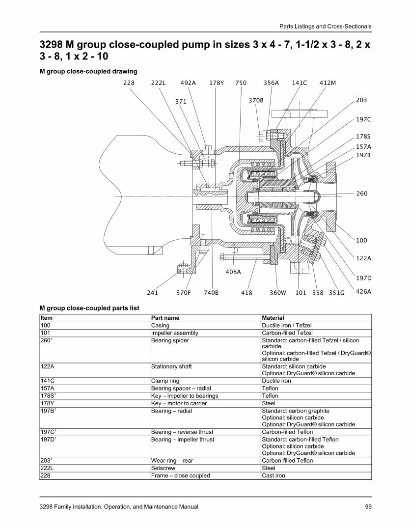
Parts Listings and Cross-Sectionals
3298 M group close-coupled pump in sizes 3 x 4 - 7, 1-1/2 x 3 - 8, 2 x3 - 8, 1 x 2 - 10M group close-coupled drawing
M group close-coupled parts listItem Part name Material100 Casing Ductile iron / Tefzel101 Impeller assembly Carbon-filled Tefzel2601 Bearing spider Standard: carbon-filled Tefzel / silicon
carbideOptional: carbon-filled Tefzel / DryGuard®silicon carbide
122A Stationary shaft Standard: silicon carbideOptional: DryGuard® silicon carbide
141C Clamp ring Ductile iron157A Bearing spacer – radial Teflon178S1 Key – impeller to bearings Teflon178Y Key – motor to carrier Steel197B1 Bearing – radial Standard: carbon graphite
Optional: silicon carbideOptional: DryGuard® silicon carbide
197C1 Bearing – reverse thrust Carbon-filled Teflon197D1 Bearing – impeller thrust Standard: carbon-filled Teflon
Optional: silicon carbideOptional: DryGuard® silicon carbide
2031 Wear ring – rear Carbon-filled Teflon222L Setscrew Steel228 Frame – close coupled Cast iron
3298 Family Installation, Operation, and Maintenance Manual 99
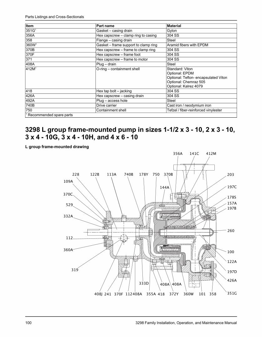
Parts Listings and Cross-Sectionals
Item Part name Material351G1 Gasket – casing drain Gylon356A Hex capscrew – clamp ring to casing 304 SS358 Flange – casing drain Steel360W1 Gasket – frame support to clamp ring Aramid fibers with EPDM370B Hex capscrew – frame to clamp ring 304 SS370F Hex capscrew – frame foot 304 SS371 Hex capscrew – frame to motor 304 SS408A Plug – drain Steel412M1 O-ring – containment shell Standard: Viton
Optional: EPDMOptional: Teflon- encapsulated VitonOptional: Chemraz 505Optional: Kalrez 4079
418 Hex tap bolt – jacking 304 SS426A Hex capscrew – casing drain 304 SS492A Plug – access hole Steel740B Drive carrier Cast iron / neodymium iron750 Containment shell Tefzel / fiber-reinforced vinylester1 Recommended spare parts
3298 L group frame-mounted pump in sizes 1-1/2 x 3 - 10, 2 x 3 - 10,3 x 4 - 10G, 3 x 4 - 10H, and 4 x 6 - 10L group frame-mounted drawing
100 3298 Family Installation, Operation, and Maintenance Manual
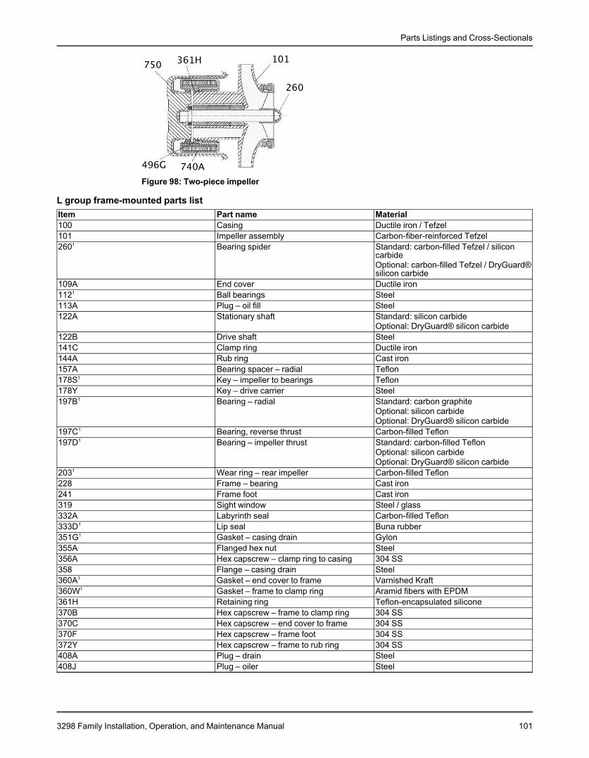
Parts Listings and Cross-Sectionals
Figure 98: Two-piece impeller
L group frame-mounted parts listItem Part name Material100 Casing Ductile iron / Tefzel101 Impeller assembly Carbon-fiber-reinforced Tefzel2601 Bearing spider Standard: carbon-filled Tefzel / silicon
carbideOptional: carbon-filled Tefzel / DryGuard®silicon carbide
109A End cover Ductile iron1121 Ball bearings Steel113A Plug – oil fill Steel122A Stationary shaft Standard: silicon carbide
Optional: DryGuard® silicon carbide122B Drive shaft Steel141C Clamp ring Ductile iron144A Rub ring Cast iron157A Bearing spacer – radial Teflon178S1 Key – impeller to bearings Teflon178Y Key – drive carrier Steel197B1 Bearing – radial Standard: carbon graphite
Optional: silicon carbideOptional: DryGuard® silicon carbide
197C1 Bearing, reverse thrust Carbon-filled Teflon197D1 Bearing – impeller thrust Standard: carbon-filled Teflon
Optional: silicon carbideOptional: DryGuard® silicon carbide
2031 Wear ring – rear impeller Carbon-filled Teflon228 Frame – bearing Cast iron241 Frame foot Cast iron319 Sight window Steel / glass332A Labyrinth seal Carbon-filled Teflon333D1 Lip seal Buna rubber351G1 Gasket – casing drain Gylon355A Flanged hex nut Steel356A Hex capscrew – clamp ring to casing 304 SS358 Flange – casing drain Steel360A1 Gasket – end cover to frame Varnished Kraft360W1 Gasket – frame to clamp ring Aramid fibers with EPDM361H Retaining ring Teflon-encapsulated silicone370B Hex capscrew – frame to clamp ring 304 SS370C Hex capscrew – end cover to frame 304 SS370F Hex capscrew – frame foot 304 SS372Y Hex capscrew – frame to rub ring 304 SS408A Plug – drain Steel408J Plug – oiler Steel
3298 Family Installation, Operation, and Maintenance Manual 101
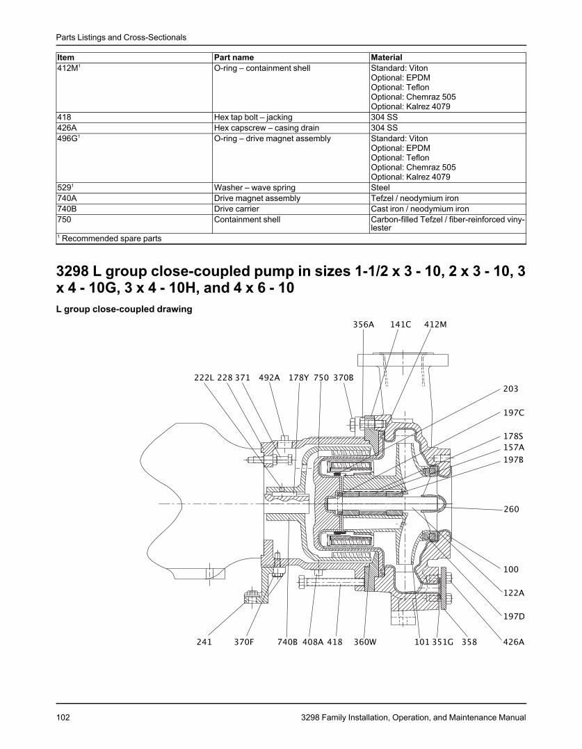
Parts Listings and Cross-Sectionals
Item Part name Material412M1 O-ring – containment shell Standard: Viton
Optional: EPDMOptional: TeflonOptional: Chemraz 505Optional: Kalrez 4079
418 Hex tap bolt – jacking 304 SS426A Hex capscrew – casing drain 304 SS496G1 O-ring – drive magnet assembly Standard: Viton
Optional: EPDMOptional: TeflonOptional: Chemraz 505Optional: Kalrez 4079
5291 Washer – wave spring Steel740A Drive magnet assembly Tefzel / neodymium iron740B Drive carrier Cast iron / neodymium iron750 Containment shell Carbon-filled Tefzel / fiber-reinforced viny-
lester1 Recommended spare parts
3298 L group close-coupled pump in sizes 1-1/2 x 3 - 10, 2 x 3 - 10, 3x 4 - 10G, 3 x 4 - 10H, and 4 x 6 - 10L group close-coupled drawing
102 3298 Family Installation, Operation, and Maintenance Manual

Parts Listings and Cross-Sectionals
Figure 99: Two-piece impeller
L group close-coupled parts listItem Part name Material100 Casing Ductile iron / Tefzel101 Impeller assembly Carbon-filled Tefzel2601 Bearing spider Standard: carbon-filled Tefzel / silicon
carbideOptional: carbon-filled Tefzel / DryGuard®silicon carbide
122A Stationary shaft Standard: silicon carbideOptional: DryGuard® silicon carbide
141C Clamp ring Ductile iron157A Bearing spacer – radial Teflon178S1 Key – impeller to bearings Teflon178Y Key – motor to carrier Steel197B1 Bearing – radial Standard: carbon graphite
Optional: silicon carbideOptional: DryGuard® silicon carbide
197C1 Bearing – reverse thrust Carbon-filled Teflon197D1 Bearing – impeller thrust Standard: carbon-filled Teflon
Optional: silicon carbideOptional: DryGuard® silicon carbide
2031 Wear ring – rear Carbon-filled Teflon222L Setscrew Steel228 Frame – close coupled Cast iron241 Frame foot Cast iron351G1 Gasket – casing drain Gylon356A Hex capscrew – clamp ring to casing 304 SS358 Flange – casing drain Steel360W1 Gasket – frame support to clamp ring Aramid fibers with EPDM361H Retaining ring Teflon-encapsulated silicone370B Hex capscrew – frame to clamp ring 304 SS370F Hex capscrew – frame foot 304 SS371 Hex capscrew – frame to motor 304 SS408A Plug – drain Steel412M1 O-ring – containment shell Standard: Viton
Optional: EPDMOptional: Teflon-encapsulated VitonOptional: Chemraz 505Optional: Kalrez 4079
418 Hex tap bolt – jacking 304 SS426A Hex capscrew – casing drain 304 SS492A Plug – access hole Steel496G O-ring – drive magnet assembly Standard: Viton
Optional: EPDMOptional: Teflon-encapsulated VitonOptional: Chemraz 505Optional: Kalrez 4079
3298 Family Installation, Operation, and Maintenance Manual 103
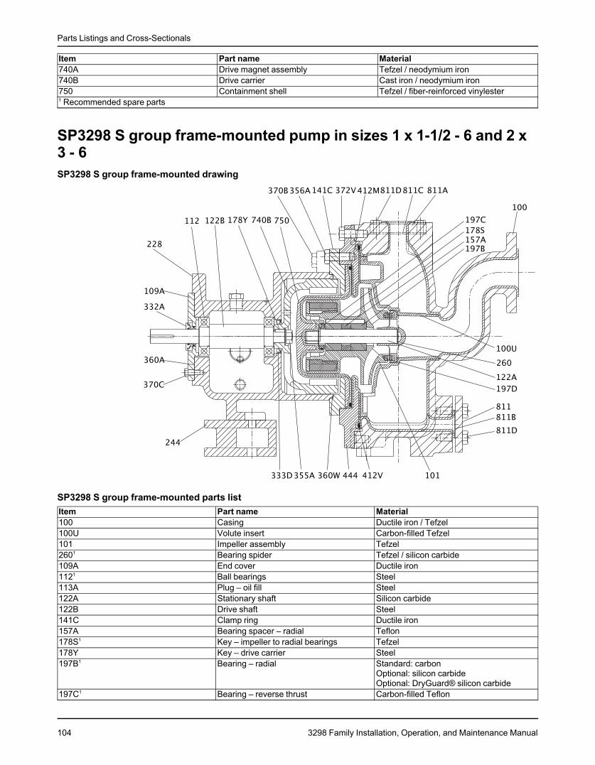
Parts Listings and Cross-Sectionals
Item Part name Material740A Drive magnet assembly Tefzel / neodymium iron740B Drive carrier Cast iron / neodymium iron750 Containment shell Tefzel / fiber-reinforced vinylester1 Recommended spare parts
SP3298 S group frame-mounted pump in sizes 1 x 1-1/2 - 6 and 2 x3 - 6SP3298 S group frame-mounted drawing
SP3298 S group frame-mounted parts listItem Part name Material100 Casing Ductile iron / Tefzel100U Volute insert Carbon-filled Tefzel101 Impeller assembly Tefzel2601 Bearing spider Tefzel / silicon carbide109A End cover Ductile iron1121 Ball bearings Steel113A Plug – oil fill Steel122A Stationary shaft Silicon carbide122B Drive shaft Steel141C Clamp ring Ductile iron157A Bearing spacer – radial Teflon178S1 Key – impeller to radial bearings Tefzel178Y Key – drive carrier Steel197B1 Bearing – radial Standard: carbon
Optional: silicon carbideOptional: DryGuard® silicon carbide
197C1 Bearing – reverse thrust Carbon-filled Teflon
104 3298 Family Installation, Operation, and Maintenance Manual
Parts Listings and Cross-Sectionals
Item Part name Material197D1 Bearing – impeller thrust Standard: carbon-filled Teflon
Optional: silicon carbideOptional: DryGuard® silicon carbide
203 Wear ring – rear Carbon-filled Teflon228 Frame – bearing Cast iron319 Sight window steel / glass332A1 Labyrinth seal Carbon-filled Teflon333D1 Lip seal Buna rubber355A1 Flanged hex nut Steel356A Hex capscrew – clamp ring to backplate 304 SS360A1 Gasket – end cover to frame Varnished Kraft360W Gasket – frame to clamp ring Aramid fibers with EPDM370B Hex capscrew – frame to clamp ring 304 SS370C Hex capscrew – end cover to frame 304 SS372V Hex capscrew – backplate to casing 304 SS408A Plug – drain Steel408J Plug – oiler Steel412M1 O-ring – containment shell Standard: Viton
Optional: EPDMOptional: Teflon-encapsulated VitonOptional: Chemraz 505Optional: Kalrez 4079
412V O-ring – backplate Standard: VitonOptional: EPDMOptional: Teflon-encapsulated VitonOptional: Chemraz 505Optional: Kalrez 4079
444 Backplate Ductile iron / Tefzel740B Drive magnet assembly Cast iron / neodymium iron750 Containment shell Tefzel / fiber-reinforced vinylester811 Cover – casing drain Carbon steel811A Cover – casing fill Carbon steel811B Gasket – casing drain Non-asbestos packing811C Gasket – casing fill Non-asbestos packing811D Hex capscrew – drain cover 304 SS1 Recommended spare parts
3298 Family Installation, Operation, and Maintenance Manual 105
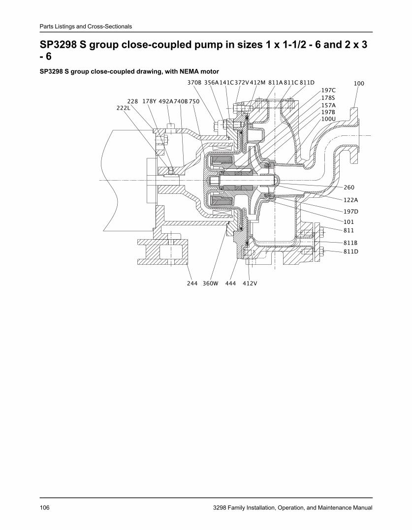
Parts Listings and Cross-Sectionals
SP3298 S group close-coupled pump in sizes 1 x 1-1/2 - 6 and 2 x 3- 6SP3298 S group close-coupled drawing, with NEMA motor
106 3298 Family Installation, Operation, and Maintenance Manual
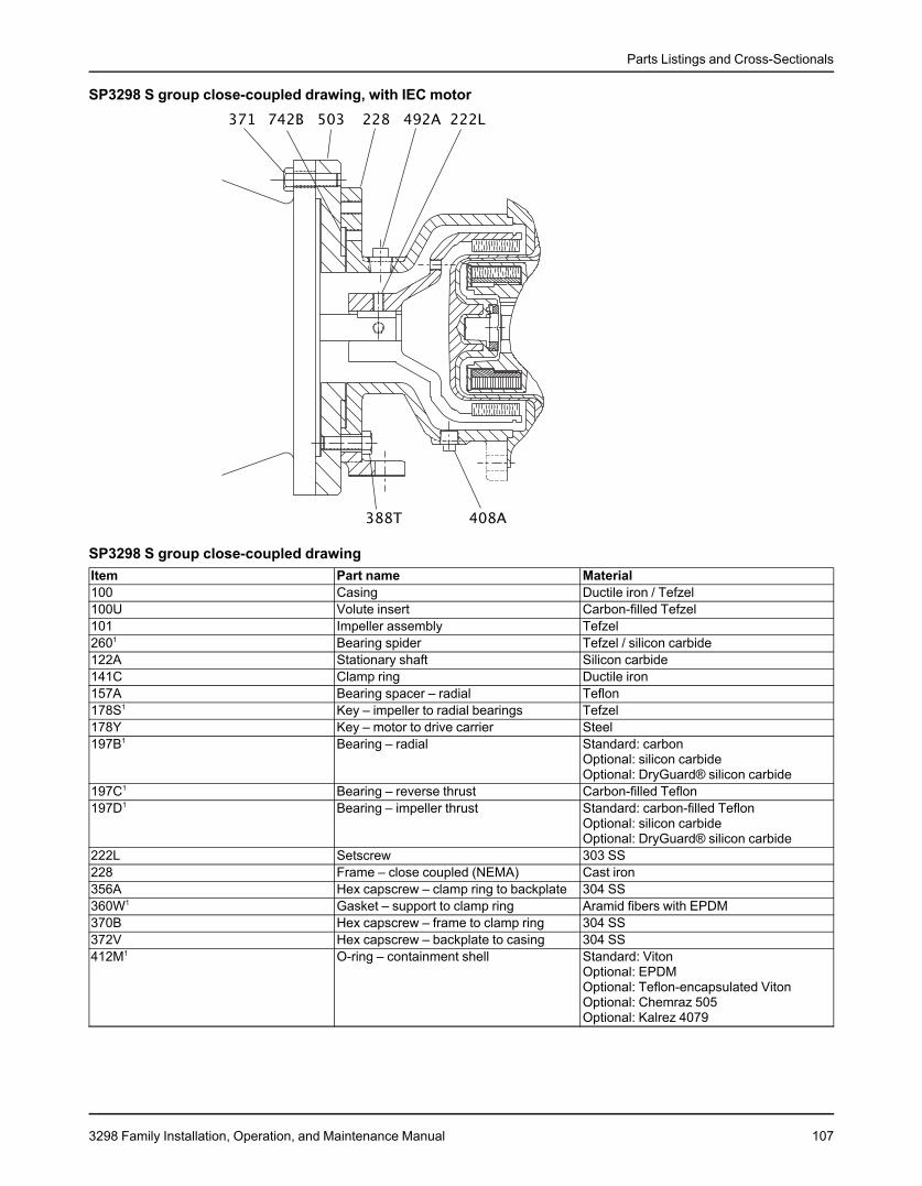
Parts Listings and Cross-Sectionals
SP3298 S group close-coupled drawing, with IEC motor
SP3298 S group close-coupled drawingItem Part name Material100 Casing Ductile iron / Tefzel100U Volute insert Carbon-filled Tefzel101 Impeller assembly Tefzel2601 Bearing spider Tefzel / silicon carbide122A Stationary shaft Silicon carbide141C Clamp ring Ductile iron157A Bearing spacer – radial Teflon178S1 Key – impeller to radial bearings Tefzel178Y Key – motor to drive carrier Steel197B1 Bearing – radial Standard: carbon
Optional: silicon carbideOptional: DryGuard® silicon carbide
197C1 Bearing – reverse thrust Carbon-filled Teflon197D1 Bearing – impeller thrust Standard: carbon-filled Teflon
Optional: silicon carbideOptional: DryGuard® silicon carbide
222L Setscrew 303 SS228 Frame – close coupled (NEMA) Cast iron356A Hex capscrew – clamp ring to backplate 304 SS360W1 Gasket – support to clamp ring Aramid fibers with EPDM370B Hex capscrew – frame to clamp ring 304 SS372V Hex capscrew – backplate to casing 304 SS412M1 O-ring – containment shell Standard: Viton
Optional: EPDMOptional: Teflon-encapsulated VitonOptional: Chemraz 505Optional: Kalrez 4079
3298 Family Installation, Operation, and Maintenance Manual 107
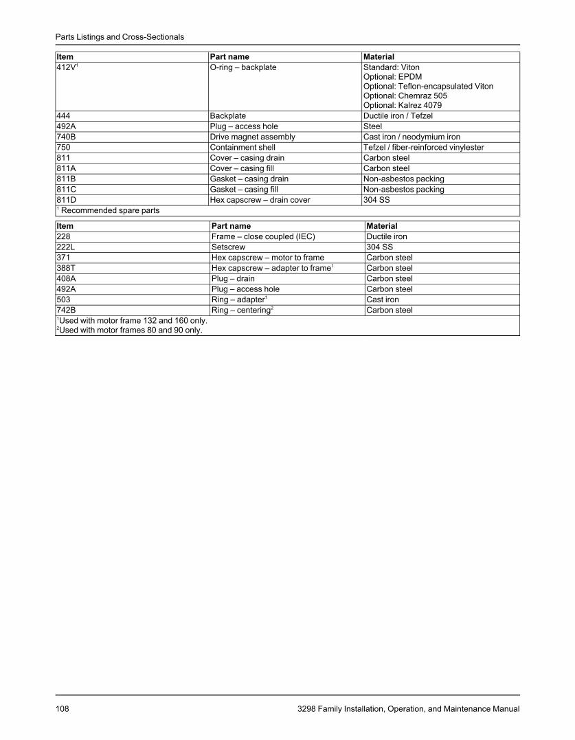
Parts Listings and Cross-Sectionals
Item Part name Material412V1 O-ring – backplate Standard: Viton
Optional: EPDMOptional: Teflon-encapsulated VitonOptional: Chemraz 505Optional: Kalrez 4079
444 Backplate Ductile iron / Tefzel492A Plug – access hole Steel740B Drive magnet assembly Cast iron / neodymium iron750 Containment shell Tefzel / fiber-reinforced vinylester811 Cover – casing drain Carbon steel811A Cover – casing fill Carbon steel811B Gasket – casing drain Non-asbestos packing811C Gasket – casing fill Non-asbestos packing811D Hex capscrew – drain cover 304 SS1 Recommended spare parts
Item Part name Material228 Frame – close coupled (IEC) Ductile iron222L Setscrew 304 SS371 Hex capscrew – motor to frame Carbon steel388T Hex capscrew – adapter to frame1 Carbon steel408A Plug – drain Carbon steel492A Plug – access hole Carbon steel503 Ring – adapter1 Cast iron742B Ring – centering2 Carbon steel1Used with motor frame 132 and 160 only.2Used with motor frames 80 and 90 only.
108 3298 Family Installation, Operation, and Maintenance Manual

Parts Listings and Cross-Sectionals
V3298 close-coupled S group pump in sizes 1-1/2 x 2 - 6, 2 x 3 - 6, 1-1/2 x 2 - 8 and M group size 1-1/2 x 2 - 10V3298 S and M group drawing, with NEMA motor
3298 Family Installation, Operation, and Maintenance Manual 109

Parts Listings and Cross-Sectionals
V3298 S and M group drawing, with IEC motor
V3298 close-coupled S and M group parts listItem Part name Material100 Casing Ductile iron / Tefzel101 Impeller assembly Tefzel260 Bearing spider Tefzel / silicon carbide122A Stationary shaft Silicon carbide141C Clamp ring Ductile iron157A Bearing spacer – radial Teflon178S Key – impeller to radial bearings Tefzel178Y Key – motor to magnet assembly Steel197B Bearing – radial Standard: carbon
Optional: silicon carbideOptional: DryGuard® silicon carbide
197C Bearing – reverse thrust Carbon-filled Teflon197D Bearing – impeller thrust Standard: carbon-filled Teflon
Optional: silicon carbideOptional: DryGuard® silicon carbide
203 Wear ring – rear Carbon-filled Teflon222L Setscrew 303 SS228 Frame – close coupled (NEMA) Cast iron351G Gasket – casing drain Non-asbestos packing356A Hex capscrew – clamp ring to casing 304 SS358 Cover – drain Steel360W Gasket – support to clamp ring Aramid fibers with EPDM370B Hex capscrew – backplate to clamp ring 304 SS412M O-ring – containment shell Standard: Viton
Optional: EPDMOptional: Teflon-encapsulated VitonOptional: Chemraz 505Optional: Kalrez 4079
426A Hex capscrew – drain cover 304 SS492A Plug – access hole Steel740B Drive magnet assembly Cast iron / neodymium iron750 Containment shell Tefzel / fiber-reinforced vinylester
Item Part name Material228 Frame – close coupled (IEC) Ductile iron222L Setscrew 304 SS371 Hex capscrew – motor to frame Carbon steel
110 3298 Family Installation, Operation, and Maintenance Manual
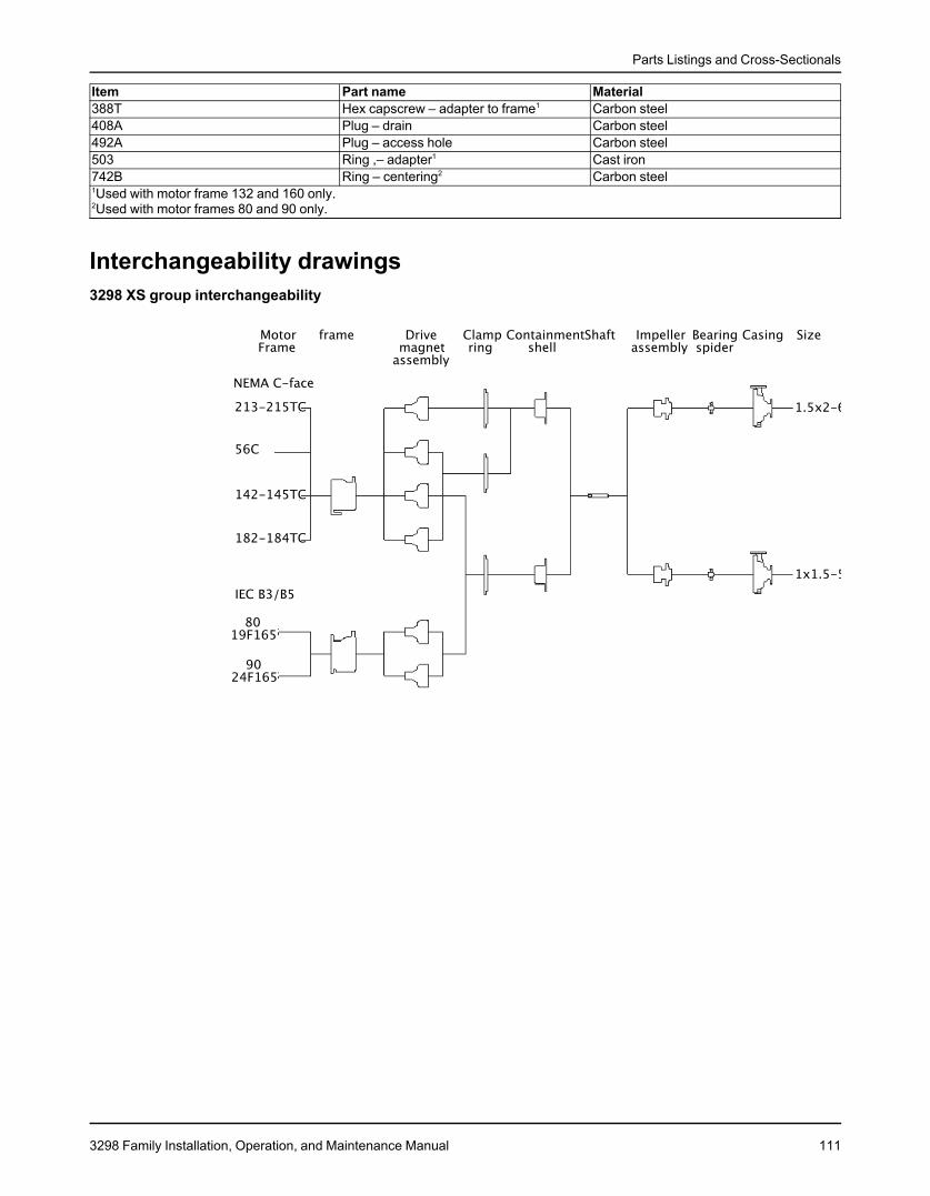
Parts Listings and Cross-Sectionals
Item Part name Material388T Hex capscrew – adapter to frame1 Carbon steel408A Plug – drain Carbon steel492A Plug – access hole Carbon steel503 Ring ,– adapter1 Cast iron742B Ring – centering2 Carbon steel1Used with motor frame 132 and 160 only.2Used with motor frames 80 and 90 only.
Interchangeability drawings3298 XS group interchangeability
3298 Family Installation, Operation, and Maintenance Manual 111
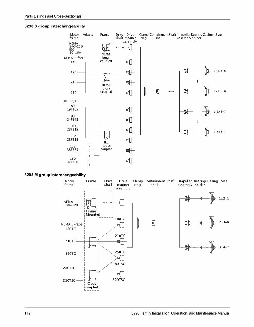
Parts Listings and Cross-Sectionals
3298 S group interchangeability
3298 M group interchangeability
112 3298 Family Installation, Operation, and Maintenance Manual
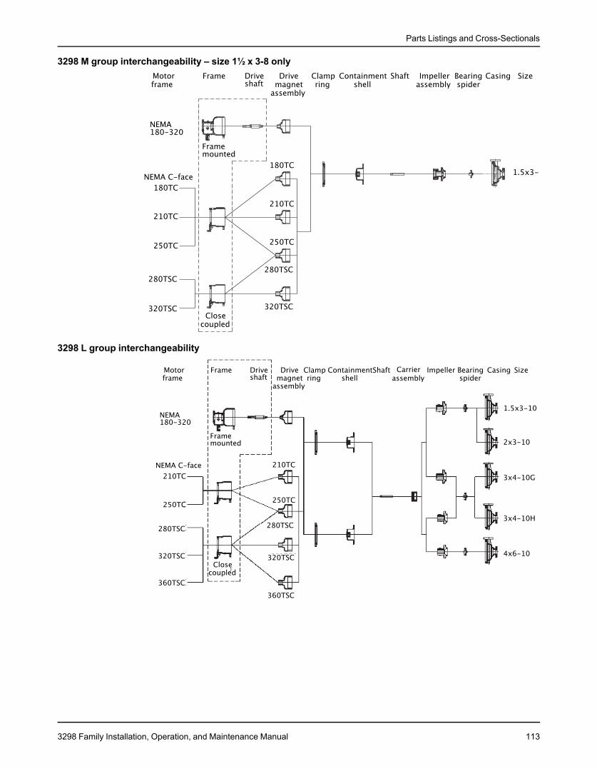
Parts Listings and Cross-Sectionals
3298 M group interchangeability – size 1½ x 3-8 only
3298 L group interchangeability
3298 Family Installation, Operation, and Maintenance Manual 113
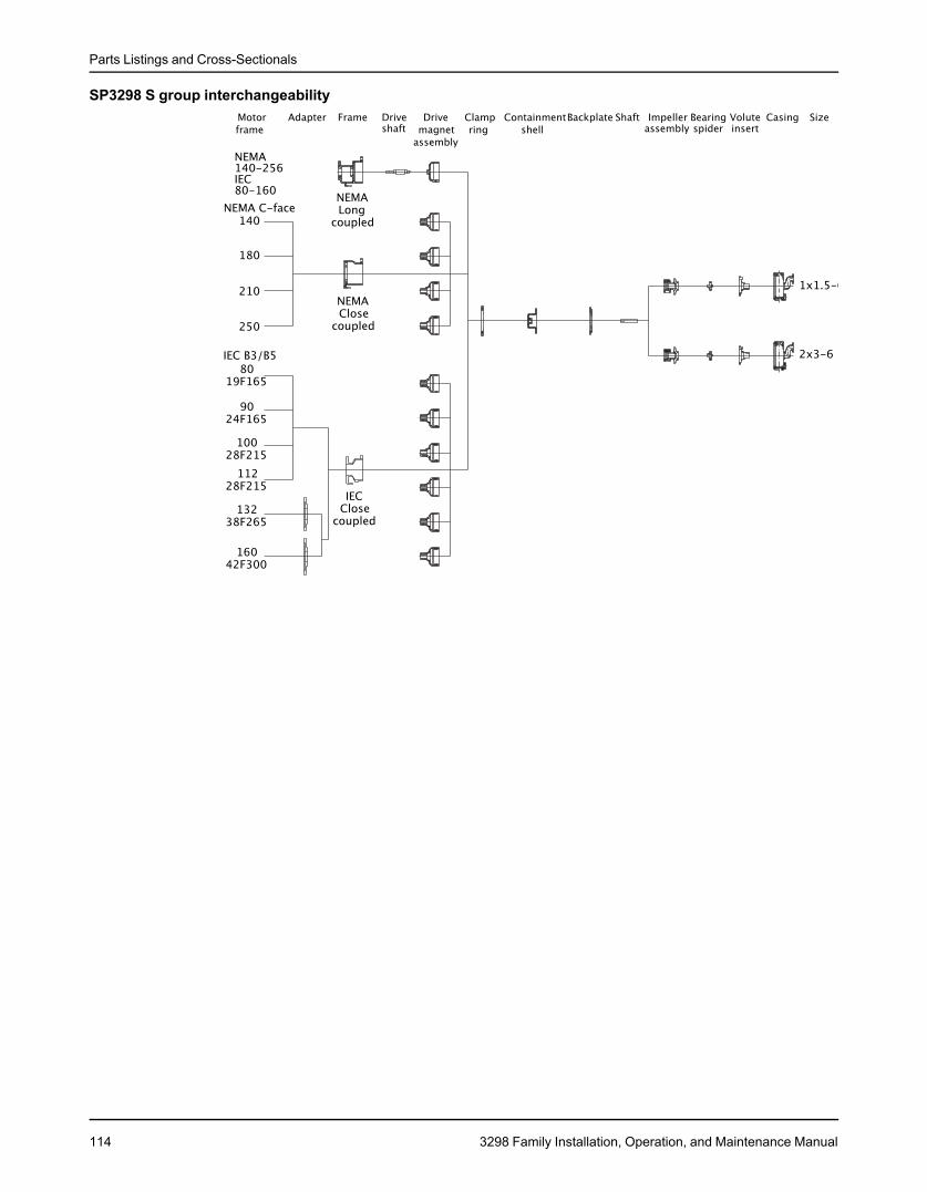
Parts Listings and Cross-Sectionals
SP3298 S group interchangeability
114 3298 Family Installation, Operation, and Maintenance Manual
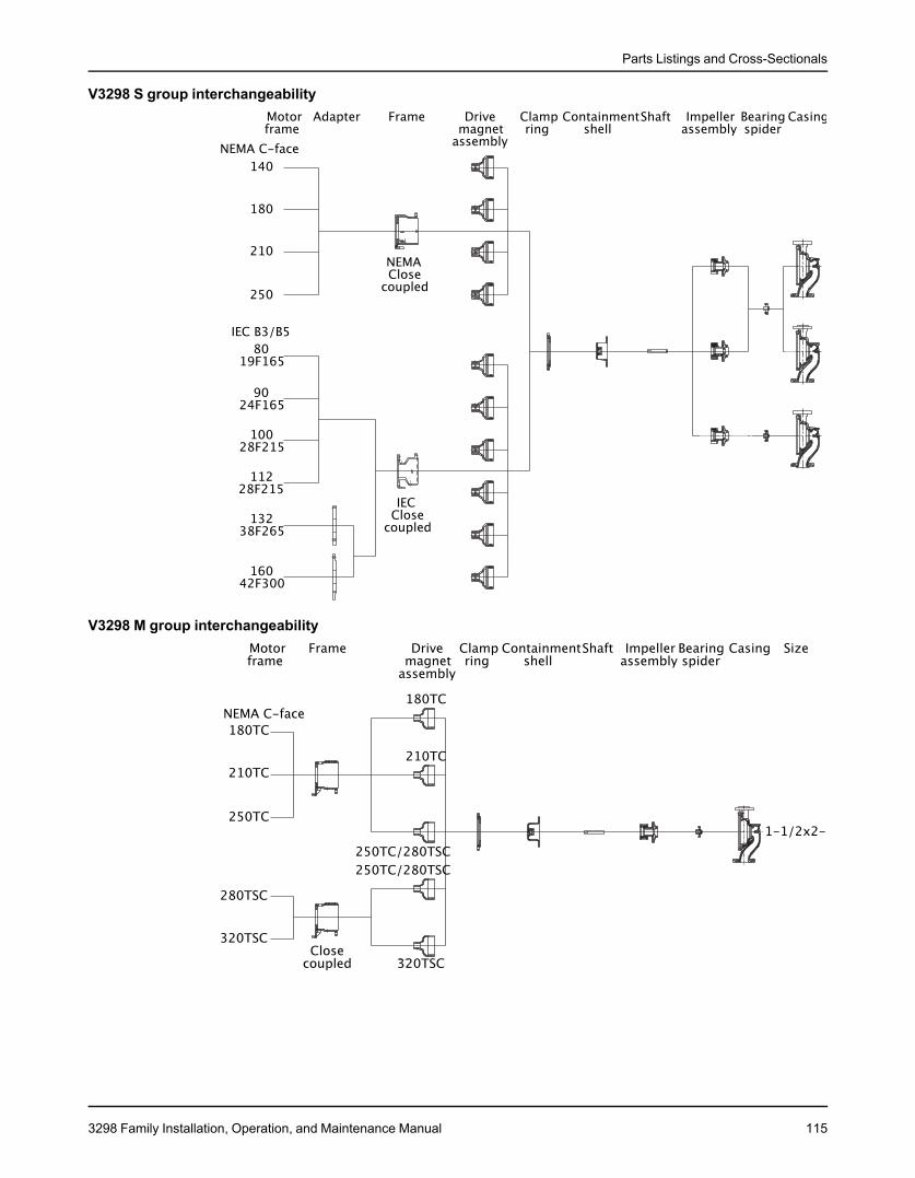
Parts Listings and Cross-Sectionals
V3298 S group interchangeability
V3298 M group interchangeability
3298 Family Installation, Operation, and Maintenance Manual 115
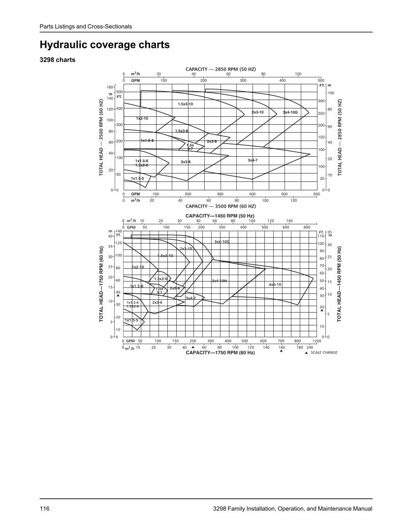
Parts Listings and Cross-Sectionals
Hydraulic coverage charts3298 charts
116 3298 Family Installation, Operation, and Maintenance Manual
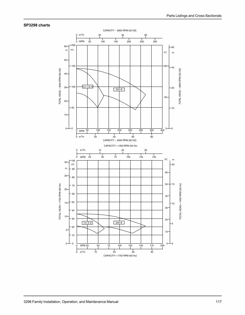
Parts Listings and Cross-Sectionals
SP3298 charts
3298 Family Installation, Operation, and Maintenance Manual 117
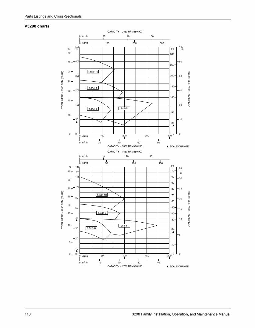
Parts Listings and Cross-Sectionals
V3298 charts
118 3298 Family Installation, Operation, and Maintenance Manual

Other Relevant Documentation or Manuals
Other Relevant Documentation or ManualsFor additional documentation
For any other relevant documentation or manuals, contact your ITT representative.
3298 Family Installation, Operation, and Maintenance Manual 119
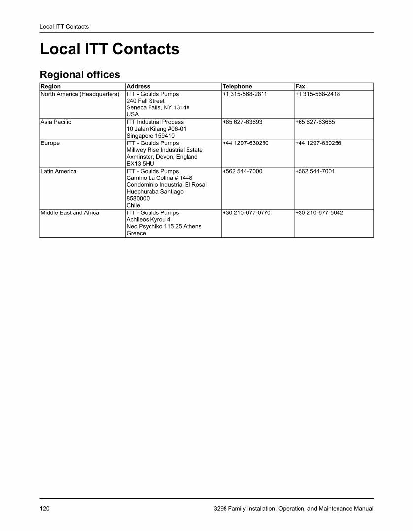
Local ITT Contacts
Local ITT ContactsRegional officesRegion Address Telephone FaxNorth America (Headquarters) ITT - Goulds Pumps +1 315-568-2811 +1 315-568-2418
240 Fall StreetSeneca Falls, NY 13148USA
Asia Pacific ITT Industrial Process +65 627-63693 +65 627-6368510 Jalan Kilang #06-01Singapore 159410
Europe ITT - Goulds Pumps +44 1297-630250 +44 1297-630256Millwey Rise Industrial EstateAxminster, Devon, EnglandEX13 5HU
Latin America ITT - Goulds Pumps +562 544-7000 +562 544-7001Camino La Colina # 1448Condominio Industrial El RosalHuechuraba Santiago8580000Chile
Middle East and Africa ITT - Goulds Pumps +30 210-677-0770 +30 210-677-5642Achileos Kyrou 4Neo Psychiko 115 25 AthensGreece
120 3298 Family Installation, Operation, and Maintenance Manual


Visit our website for the latest version of thisdocument and more information:
www.gouldspumps.com
ITT - Goulds Pumps240 Fall StreetSeneca Falls, NY 13148USATel. 1–315–568–2811Fax 1–315–568–2418
Form en-US.2015-04.IOM.3298© 2015 ITT CorporationThe original instruction is in English. All non-English instructions are translations of the original instruction.