installation,operation, andmaintenancemanual - goulds · pdf filesteam jacket pumps ... model...
TRANSCRIPT
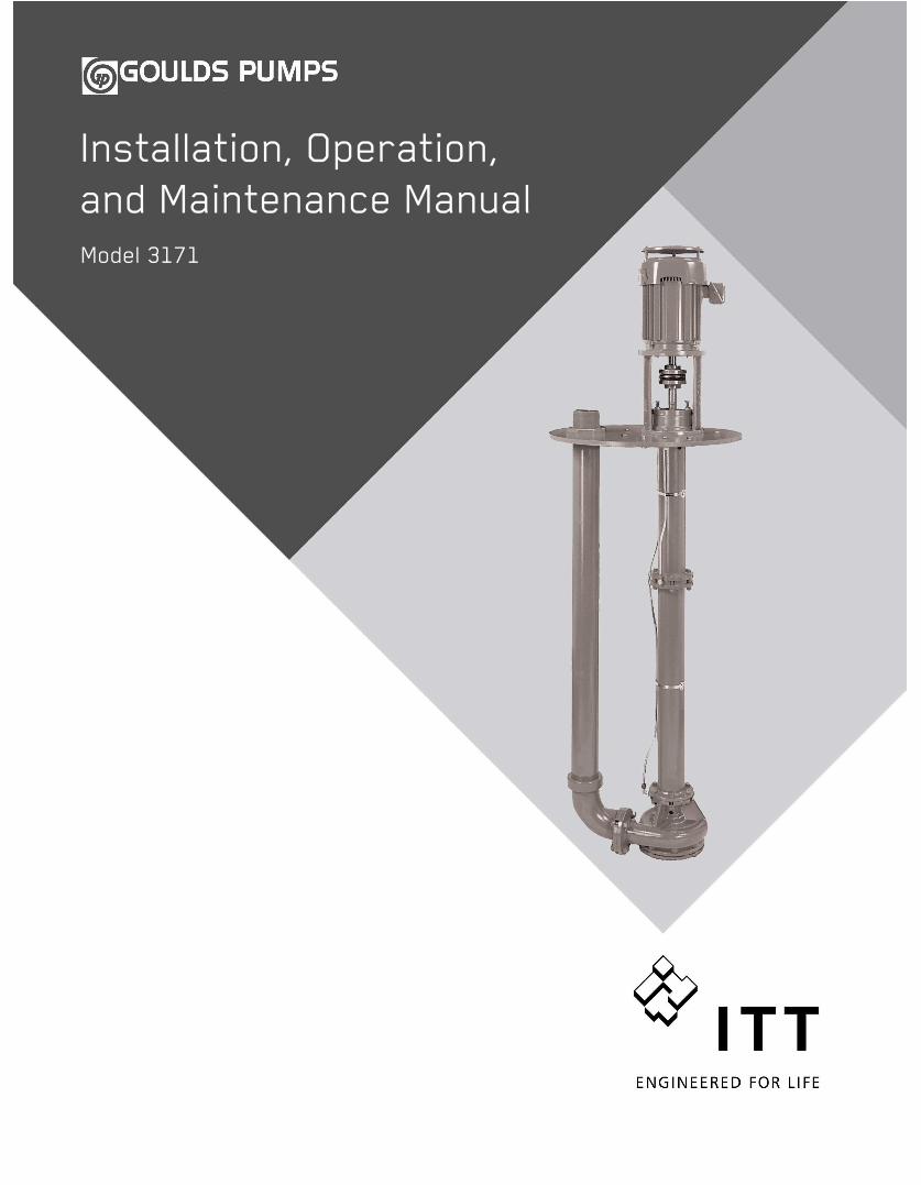
Installation, Operation,and Maintenance ManualModel 3171


Table of Contents
Table of ContentsIntroduction and Safety .......................................................................................................... 3
Introduction ............................................................................................................................. 3Safety ...................................................................................................................................... 3
Safety terminology and symbols ........................................................................................... 4Environmental safety ............................................................................................................ 4User safety ........................................................................................................................... 5Ex-approved products .......................................................................................................... 6Monitoring equipment ........................................................................................................... 7
Product warranty ..................................................................................................................... 7
Transportation and Storage ................................................................................................... 9Receive the unit ...................................................................................................................... 9Unpack the unit ....................................................................................................................... 9Pump handling ........................................................................................................................ 9
Lifting methods ..................................................................................................................... 9Pump storage requirements .................................................................................................. 11
Prepare the pump for long-term storage ............................................................................. 12
Product Description .............................................................................................................. 13General description ............................................................................................................... 13Nameplate information .......................................................................................................... 14Permissible temperatures ..................................................................................................... 15
Installation ............................................................................................................................. 16Preinstallation ....................................................................................................................... 16
Inspect the pump ................................................................................................................ 16Pump location guidelines .................................................................................................... 16Concrete foundation requirements ..................................................................................... 17
Support plate installation ....................................................................................................... 18Install the support plate with a pit cover .............................................................................. 18Install the support plate without a pit cover ......................................................................... 18
Piping checklists ................................................................................................................... 19General piping checklist ..................................................................................................... 19Suction piping for optional dry pit, outside tank mount, and tailpipe applications ............... 20Steam lines ......................................................................................................................... 21Final piping checklist .......................................................................................................... 21
Stuffing box installation ......................................................................................................... 21Install the packed stuffing box ............................................................................................ 22
Install the pump, driver, and coupling .................................................................................... 22Motor installation and coupling alignment ............................................................................. 23
Install the motor .................................................................................................................. 23Alignment checks ............................................................................................................... 23Permitted indicator values for alignment checks ................................................................ 24Alignment measurement guidelines ................................................................................... 24Attach the dial indicators for alignment ............................................................................... 24Align the flexible coupling ................................................................................................... 25Align the flexible coupling with a straight edge ................................................................... 25
Float control installation ........................................................................................................ 25Install the Square D 9036 simplex and 9038 duplex float controls ...................................... 26
Commissioning, Startup, Operation, and Shutdown ......................................................... 28Preparation for startup .......................................................................................................... 28Check the rotation - Frame Mounted ..................................................................................... 29
Model 3171 Installation, Operation, and Maintenance Manual 1
Table of Contents
Thrust bearing lubrication ..................................................................................................... 29Flush the steady bearings .................................................................................................. 29Sealed bearings ................................................................................................................. 30Lubricate the sealed bearings with grease cups ................................................................. 30
Shaft sealing with a mechanical seal .................................................................................... 31Shaft sealing with a stuffing box ............................................................................................ 31Steam jacket pumps (molten sulfur construction) ................................................................. 32Impeller-clearance setting ..................................................................................................... 32
Set the impeller clearance - dial indicator method .............................................................. 32Set the impeller clearance - feeler gauge method .............................................................. 33
Pump priming ........................................................................................................................ 34Install the coupling guard ...................................................................................................... 34Start the pump ...................................................................................................................... 35Pump operation precautions ................................................................................................. 36Shut down the pump ............................................................................................................. 36Make the final alignment of the pump and driver ................................................................... 37
Maintenance ........................................................................................................................... 38Maintenance schedule .......................................................................................................... 38Bearing maintenance ............................................................................................................ 39
Thrust bearings .................................................................................................................. 39Lubricate the bearings after a shutdown period .................................................................. 39Lubricating-grease requirements ........................................................................................ 39Steady bearings ................................................................................................................. 40
Shaft-seal maintenance ........................................................................................................ 40Mechanical-seal maintenance ............................................................................................ 40Packed stuffing-box maintenance ...................................................................................... 41
Disassembly ......................................................................................................................... 42Disassembly precautions ................................................................................................... 42Tools required .................................................................................................................... 42Drain the pump ................................................................................................................... 42Remove the pump from the sump ...................................................................................... 43Remove the impeller ........................................................................................................... 44Disassemble the column .................................................................................................... 45
Preassembly inspections ...................................................................................................... 46Replacement guidelines ..................................................................................................... 46Shaft replacement guidelines ............................................................................................. 47Bearings inspection ............................................................................................................ 47Bearing fits and tolerances ................................................................................................. 48
Reassembly .......................................................................................................................... 48Assemble the column and support plate ............................................................................. 48Assemble the rotating element ........................................................................................... 49Assemble the column ......................................................................................................... 50Assemble the impeller, suction cover, and strainer ............................................................ 50
Troubleshooting .................................................................................................................... 52Operation troubleshooting ..................................................................................................... 52Assembly troubleshooting ..................................................................................................... 53
Parts Listings and Cross-Sectionals ................................................................................... 54Dimensional drawings ........................................................................................................... 54Parts list ................................................................................................................................ 55Cross-sectional diagrams ..................................................................................................... 57
Local ITT Contacts ................................................................................................................ 59Regional offices .................................................................................................................... 59
2 Model 3171 Installation, Operation, and Maintenance Manual
Introduction and Safety
Introduction and SafetyIntroductionPurpose of this manual
The purpose of this manual is to provide necessary information for:• Installation• Operation• Maintenance
CAUTION:Read this manual carefully before installing and using the product. Improper use of the product cancause personal injury and damage to property, and may void the warranty.
NOTICE:Save this manual for future reference, and keep it readily available at the location of the unit.
Requesting other information
Special versions can be supplied with supplementary instruction leaflets. See the salescontract for any modifications or special version characteristics. For instructions, situations, orevents that are not considered in this manual or in the sales documents, please contact thenearest ITT representative.Always specify the exact product type and identification code when requesting technicalinformation or spare parts.
SafetyWARNING:
• The operator must be aware of safety precautions to prevent physical injury.• Any pressure-containing device can explode, rupture, or discharge its contents if it is over-
pressurized. Take all necessary measures to avoid over-pressurization.• Operating, installing, or maintaining the unit in any way that is not covered in this manual could
cause death, serious personal injury, or damage to the equipment. This includes any modification tothe equipment or use of parts not provided by ITT. If there is a question regarding the intended use ofthe equipment, please contact an ITT representative before proceeding.
• This manual clearly identifies accepted methods for disassembling units. These methods must beadhered to. Trapped liquid can rapidly expand and result in a violent explosion and injury. Neverapply heat to impellers, propellers, or their retaining devices to aid in their removal unless explicitlystated in this manual.
• If the pump/motor is damaged or leaking, do not operate as it may cause an electric shock, fire,explosion, liberation of toxic fumes, physical harm, or environmental damage. Correct/repair theproblem prior to putting back in service.
• Do not change the service application without the approval of an authorized ITT representative.
CAUTION:You must observe the instructions contained in this manual. Failure to do so could result in physicalinjury, damage, or delays.
Model 3171 Installation, Operation, and Maintenance Manual 3
Introduction and Safety
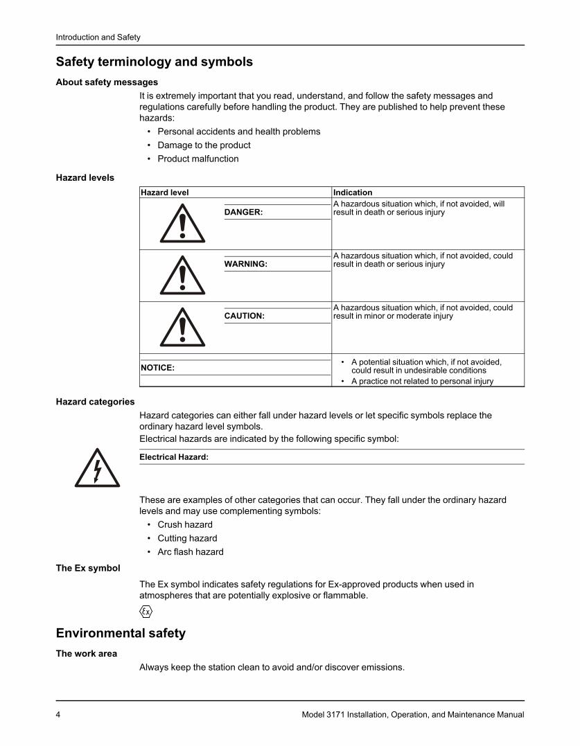
Safety terminology and symbolsAbout safety messages
It is extremely important that you read, understand, and follow the safety messages andregulations carefully before handling the product. They are published to help prevent thesehazards:
• Personal accidents and health problems• Damage to the product• Product malfunction
Hazard levelsHazard level Indication
A hazardous situation which, if not avoided, willDANGER: result in death or serious injury
A hazardous situation which, if not avoided, couldWARNING: result in death or serious injury
A hazardous situation which, if not avoided, couldCAUTION: result in minor or moderate injury
• A potential situation which, if not avoided,NOTICE: could result in undesirable conditions• A practice not related to personal injury
Hazard categoriesHazard categories can either fall under hazard levels or let specific symbols replace theordinary hazard level symbols.Electrical hazards are indicated by the following specific symbol:
Electrical Hazard:
These are examples of other categories that can occur. They fall under the ordinary hazardlevels and may use complementing symbols:
• Crush hazard• Cutting hazard• Arc flash hazard
The Ex symbol
The Ex symbol indicates safety regulations for Ex-approved products when used inatmospheres that are potentially explosive or flammable.
Environmental safetyThe work area
Always keep the station clean to avoid and/or discover emissions.
4 Model 3171 Installation, Operation, and Maintenance Manual
Introduction and Safety
Waste and emissions regulationsObserve these safety regulations regarding waste and emissions:
• Appropriately dispose of all waste.• Handle and dispose of the processed liquid in compliance with applicable environmental
regulations.• Clean up all spills in accordance with safety and environmental procedures.• Report all environmental emissions to the appropriate authorities.
WARNING:Do NOT send the product to the ITT manufacturer if it has been contaminated by any nuclear radiation.Inform ITT so that accurate actions can take place.
Electrical installationFor electrical installation recycling requirements, consult your local electric utility.
Recycling guidelines
Always follow local laws and regulations regarding recycling.
User safetyGeneral safety rules
These safety rules apply:• Always keep the work area clean.• Pay attention to the risks presented by gas and vapors in the work area.• Avoid all electrical dangers. Pay attention to the risks of electric shock or arc flash hazards.• Always bear in mind the risk of drowning, electrical accidents, and burn injuries.
Safety equipmentUse safety equipment according to the company regulations. Use this safety equipment withinthe work area:
• Helmet• Safety goggles, preferably with side shields• Protective shoes• Protective gloves• Gas mask• Hearing protection• First-aid kit• Safety devices
NOTICE:Never operate a unit unless safety devices are installed. Also see specific informationabout safety devices in other sections of this manual.
Electrical connectionsElectrical connections must be made by certified electricians in compliance with all internation-al, national, state, and local regulations. For more information about requirements, see sectionsdealing specifically with electrical connections.
Precautions before workObserve these safety precautions before you work with the product or are in connection withthe product:
• Provide a suitable barrier around the work area, for example, a guard rail.
Model 3171 Installation, Operation, and Maintenance Manual 5
Introduction and Safety
• Make sure that all safety guards are in place and secure.• Allow all system and pump components to cool before you handle them.• Make sure that you have a clear path of retreat.• Make sure that the product cannot roll or fall over and injure people or damage property.• Make sure that the lifting equipment is in good condition.• Use a lifting harness, a safety line, and a breathing device as required.• Make sure that the product is thoroughly clean.• Make sure that there are no poisonous gases within the work area.• Make sure that you have quick access to a first-aid kit.• Disconnect and lock out power before servicing.• Check the explosion risk before you weld or use electric hand tools.
Wash the skin and eyes
1. Follow these procedures for chemicals or hazardous fluids that have come into contact withyour eyes or your skin:Condition ActionChemicals or hazardous 1. Hold your eyelids apart forcibly with your fingers.fluids in eyes 2. Rinse the eyes with eyewash or running water for at least
15 minutes.3. Seek medical attention.
Chemicals or hazardous 1. Remove contaminated clothing.fluids on skin 2. Wash the skin with soap and water for at least 1 minute.
3. Seek medical attention, if necessary.
Ex-approved productsFollow these special handling instructions if you have an Ex-approved unit.
Personnel requirementsThese are the personnel requirements for Ex-approved products in potentially explosiveatmospheres:
• All work on the product must be carried out by certified electricians and ITT-authorizedmechanics. Special rules apply to installations in explosive atmospheres.
• All users must know about the risks of electric current and the chemical and physicalcharacteristics of the gas, the vapor, or both present in hazardous areas.
• Any maintenance for Ex-approved products must conform to international and nationalstandards (for example, IEC/EN 60079-17).
ITT disclaims all responsibility for work done by untrained and unauthorized personnel.
Product and product handling requirementsThese are the product and product handling requirements for Ex-approved products inpotentially explosive atmospheres:
• Only use the product in accordance with the approved motor data.• The Ex-approved product must never run dry during normal operation. Dry running during
service and inspection is only permitted outside the classified area.• Before you start work on the product, make sure that the product and the control panel are
isolated from the power supply and the control circuit, so they cannot be energized.• Do not open the product while it is energized or in an explosive gas atmosphere.• Make sure that thermal contacts are connected to a protection circuit according to the
approval classification of the product, and that they are in use.• Intrinsically safe circuits are normally required for the automatic level-control system by the
level regulator if mounted in zone 0.
6 Model 3171 Installation, Operation, and Maintenance Manual
Introduction and Safety
• The yield stress of fasteners must be in accordance with the approval drawing and theproduct specification.
• Do not modify the equipment without approval from an authorized ITT representative.• Only use parts that are provided by an authorized ITT representative.
Description of ATEX
The ATEX directives are a specification enforced in Europe for electrical and non-electricalequipment installed in Europe. ATEX deals with the control of potentially explosive atmos-pheres and the standards of equipment and protective systems used within these atmos-pheres. The relevance of the ATEX requirements is not limited to Europe. You can apply theseguidelines to equipment installed in any potentially explosive atmosphere.
Guidelines for compliance
Compliance is fulfilled only when you operate the unit within its intended use. Do not changethe conditions of the service without the approval of an ITT representative. When you install ormaintain explosion proof products, always comply with the directive and applicable standards(for example, IEC/EN 60079–14).
Monitoring equipmentFor additional safety, use condition-monitoring devices. Condition-monitoring devices includebut are not limited to these devices:
• Pressure gauges• Flow meters• Level indicators• Motor load readings• Temperature detectors• Bearing monitors• Leak detectors• PumpSmart control system
Product warrantyCoverage
ITT undertakes to remedy faults in products from ITT under these conditions:• The faults are due to defects in design, materials, or workmanship.• The faults are reported to an ITT representative within the warranty period.• The product is used only under the conditions described in this manual.• The monitoring equipment incorporated in the product is correctly connected and in use.• All service and repair work is done by ITT-authorized personnel.• Genuine ITT parts are used.• Only Ex-approved spare parts and accessories authorized by ITT are used in Ex-approved
products.
LimitationsThe warranty does not cover faults caused by these situations:
• Deficient maintenance• Improper installation• Modifications or changes to the product and installation made without consulting ITT• Incorrectly executed repair work• Normal wear and tear
ITT assumes no liability for these situations:
Model 3171 Installation, Operation, and Maintenance Manual 7
Introduction and Safety
• Bodily injuries• Material damages• Economic losses
Warranty claimITT products are high-quality products with expected reliable operation and long life. However,should the need arise for a warranty claim, then contact your ITT representative.
8 Model 3171 Installation, Operation, and Maintenance Manual
Transportation and Storage
Transportation and StorageReceive the unit
1. Inspect the package for damaged or missing items upon delivery.2. Note any damaged or missing items on the receipt and freight bill.3. File a claim with the shipping company if anything is out of order.
Unpack the unit1. Remove packing materials from the unit.
Dispose of all packing materials in accordance with local regulations.2. Inspect the unit to determine if any parts have been damaged or are missing.3. Contact your ITT representative if anything is out of order.
Pump handlingWARNING:
• Make sure that the unit cannot roll or fall over and injure people or damage property.• These pumps might use carbon or ceramic silicon carbide components. Do not drop the pump or
subject it to shock loads as this can damage the internal ceramic components.
NOTICE:Use a forklift truck or an overhead crane with sufficient capacity to move the pallet with thepump unit on top. Failure to do so can result in equipment damage.
Lifting methodsWARNING:
• All lifting must be done in compliance with all applicable regulations/standards.• Crush hazard. The unit and the components can be heavy. Use proper lifting methods and wear
steel-toed shoes at all times.• Do not attach sling ropes to shaft ends.
Use swivel hoist rings (available as an option) and suitable slings in order to lift the pump,without motor, to a vertical position and then lower the unit into the sump. Then use the liftinglugs on the motor and a suitable sling in order to hoist the motor into position. Use a tag lineattached to the casing end in order to prevent the pump from swinging.
Model 3171 Installation, Operation, and Maintenance Manual 9
Transportation and Storage
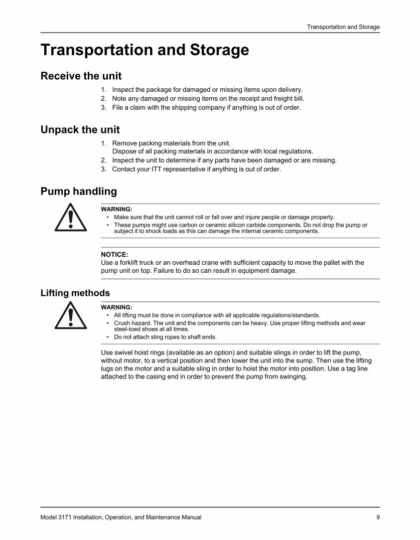
Examples
Figure 1: Proper lifting method
Figure 2: Example of a proper lifting method
Figure 3: Example of a proper lifting method
10 Model 3171 Installation, Operation, and Maintenance Manual
Transportation and Storage
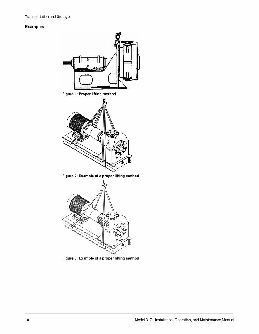
Figure 4: Example of lifting motor properly withlifting lugs
Figure 5: Example of lifting pump properly withsling
Pump storage requirementsRequirements
Vertical pumps require proper preparation for storage and regular maintenance during storage.The pump is considered in storage when it has been delivered to the job site and is awaitinginstallation.For specific requirements for storing motors, gearheads, and engines, contact the equipmentmanufacturer.
Storage preparationCondition Proper preparationIndoor storage area (preferred) • Pave the area.
• Clean the area.• Drain the area and keep it free from flooding.
Model 3171 Installation, Operation, and Maintenance Manual 11
Transportation and Storage
Condition Proper preparationOutdoor storage area (when indoor • Observe all indoor storage requirements.storage is not available) • Use weather-proof coverings such as flame-resistant sheet-
ing or tarpaulins.• Place coverings in a manner that maximizes drainage and
air circulation.• Tie coverings down in order to protect the pump from wind
damage.Placement of pumps and component • Place the unit on skids, pallets, or shoring higher than 6 in.parts (15 cm) from the ground for good air circulation.
• Sort the parts in order to permit easy access for inspectionand/or maintenance without excessive handling.
Stacking of units or component parts • Make sure that racks, containers, or crates bear the fullweight of units or parts in order to prevent distortion.
• Keep identification markings readily visible.• Immediately replace any cover you remove for internal
access.Rotation of the pump and bowl assem- • Rotate the shaft and bowl assembly shaft counterclockwisebly shaft once a month, at a minimum.
• Never leave the shaft in a previous position or in theextreme raised or lowered lateral position.
• Make sure that the shaft rotates freely.Controlled storage facilities • Maintain an even temperature of 10°F (6°C) or higher
above the dew point.• Keep the relative humidity to less than 50%.• Make sure that there is little or no dust.
Uncontrolled storage facilities that • Inspect the unit periodically to make sure that all preserva-have uneven temperatures, higher hu- tives are intact.midity, and/or dusty conditions) • Seal all pipe threads and flanged pipe covers with tape.
When pump is not in regular operationIf a pump has been installed, but is not in regular operation for an extended period of time, suchas during a seasonal shutdown, then operate it for at least 15 minutes every two weeks, ifpossible.
Prepare the pump for long-term storageFor storage periods over six months, you must follow the pump storage requirements and thisprocedure:1. Inspect the lube-oil and seal-flush piping and either fill the piping with rust-preventative oil,
or recoat the piping periodically in order to prevent corrosion.2. Place 10 lbs (4.5 kg) of moisture-absorbing desiccant or 5.0 lbs (2.3 kg) of vapor-phase
inhibitor crystals near the center of the pump.3. If the unit is assembled, place an additional one pound (0.5 kg) in the discharge nozzle and
securely fasten the nozzle to the discharge elbow.4. Install a moisture indicator near the perimeter of the unit.5. Cover the unit with black polyethylene with a minimum thickness of 6.0 mil (0.15 mm), and
seal it with tape.6. Provide a small ventilation hole approximately 0.5 in. (12.0 mm) in diameter.7. Provide a roof or shed shelter in order to protect the unit from direct exposure to the
elements.
12 Model 3171 Installation, Operation, and Maintenance Manual
Product Description
Product DescriptionGeneral descriptionProduct description
The 3171 is a vertical submerged bearing sump and process pump.This model is based on three bearing frames with 17 hydraulic sizes. The S/ST group hasidentical bearings with a slightly different shaft on the impeller end for the S and ST. The M/MTgroup is identical in all aspects for the power end. However, the liquid end of the MT is commonwith the S group except that the MT is modified to accept a larger shaft. There are two MT sizesthat are common with the S/ST group.This table shows the number of hydraulic sizes available for each drive-unit size group. Notethat each pump has a choice of two different discharge pipes which results in fourcombinations.Drive-unit size group Number of hydraulic sizesS/ST 9M/MT 8L 2
CasingThe casing has these features:
• A tangential discharge• Is self-venting• Has an integral bearing retainer• Is precision-bored in order to ensure permanent alignment between the column casing,
suction cover, and bearing
ImpellerThe impeller is fully open, keyed to the shaft, and held in place by a self-locking capscrew inorder to ensure positive locking and prevent damage from reverse rotation. Impellers are spin-balanced (single plane) to ISO G6.3. The impeller is provided with back vanes in order toreduce the axial thrust and prevent the entrance of solids.The impellers on this pump do not meet the dimensional requirements for dynamic balancing.
StrainerThe flat plate strainer is designed to maximize draw-down in a given sump depth. Openings aresized to prevent the entrance of large solids that are commonly found in open sumps.
Discharge elbowThe discharge elbow is designed to allow the pump to fit into the smallest possible opening. Athreaded connection to the discharge pipe allows the pipe to be changed without removing thepump from the sump.
Column pipeThe column pipe has flanged connections that are machined in order to ensure true parallelismand to maintain steady bearings concentric with the shaft.
ShaftThe standard design uses a one-piece shaft in order to ensure accurate alignment. The shaft isprecision-ground, polished, and straightened to keep vibration and deflection to a minimum.Standard bearing spans keep the shaft well below first critical speed for all sizes.
Model 3171 Installation, Operation, and Maintenance Manual 13
Product Description
BearingsThe thrust bearing is a grease-lubed, double-row, angular contact ball bearing. The bearing isshouldered and locked to the shaft and housing. This enables the bearing to carry all of thethrust loads and some of the radial load. All fits are precision-machined to industry standards.The steady bearings are press fit sleeve bearings. Fits are designed for optimum life under alloperating conditions.
SealsThis pump has three seals:Seal type DescriptionUpper labyrinth seal This seal is used to exclude dirt and water from the thrust
bearing.Lower grease seal This seal is used below the thrust bearing in order to contain the
grease and exclude any possible contamination.Carbon Teflon casing collar This seal is installed immediately behind the impeller in the
casing in order to minimize recirculation back to the sump andmaximize hydraulic efficiency.
Motor supportMotor supports are cast construction and precision-machined in order to maintain properalignment between the motor and pump shaft with minimal shimming. Motor supports aredesigned for vertical C-face motors as standard. P-base supports and IEC adapters areavailable upon request.
Direction of rotationThe shaft rotates clockwise when you look down on the pump shaft.
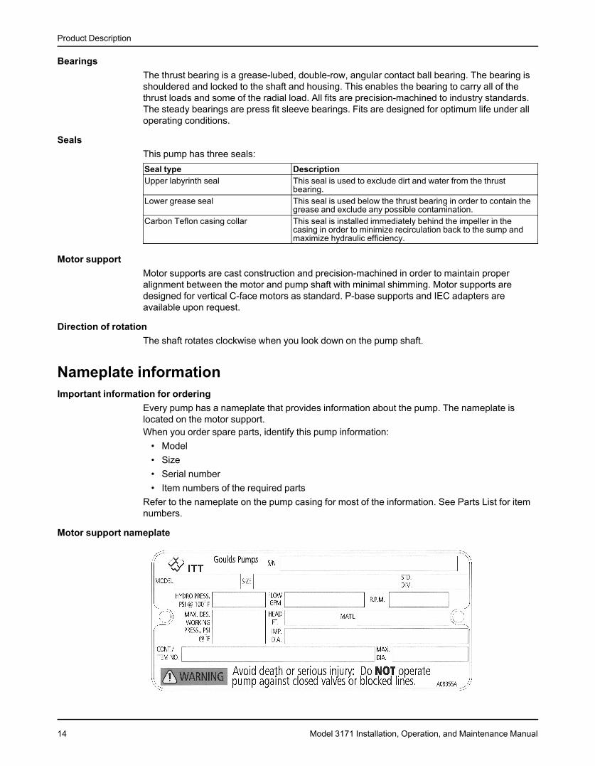
Nameplate informationImportant information for ordering
Every pump has a nameplate that provides information about the pump. The nameplate islocated on the motor support.When you order spare parts, identify this pump information:
• Model• Size• Serial number• Item numbers of the required parts
Refer to the nameplate on the pump casing for most of the information. See Parts List for itemnumbers.
Motor support nameplate
14 Model 3171 Installation, Operation, and Maintenance Manual
Product Description
Table 1: Explanation of the nameplateNameplate field ExplanationMODEL Pump modelSIZE Size of the pumpS/N Serial number of the pumpSTD. DIM. Standard dimensionHYDRO PRESS. PSI @ Hydrotest pressure in pounds per square inch at 100°F100°FFLOW GPM Rated pump flow, in gallons per minuteR.P.M. Rated pump speed, revolutions per minuteMAX. .DES. WORKING Maximum design working pressure, pounds per square inch at °FPRESS., PSI°F.HEAD FT. Rated pump head, in feetMAT'L. Material of constructionIMP. DIA. Diameter of the impellerCONT./ ITEM NO. Contract/item numberMAX. DIA. Maximum impeller diameter
ATEX nameplate
Nameplate field ExplanationII Group 22 Category 2G/D Pump can be used when gas and dust are presentT4 Temperature class
NOTICE:Make sure that the code classifications on the pump are compatible with the specificenvironment in which you plan to install the equipment. If they are not compatible, do notoperate the equipment and contact your ITT representative before you proceed.
Permissible temperaturesCode Maximum permissible surface Maximum permissible liquid
temperature temperatureT1 842°F (450°C) 700°F (372°C)T2 572°F (300°C) 530°F (277°C)T3 392°F (200°C) 350°F (177°C)T4 275°F (135°C) 235°F (113°C)T5 212°F (100°C) Option not availableT6 185°F (85°C) Option not available
NOTICE:The code classification marked on the equipment must be in accordance with the specifiedarea where you plan to install the equipment. If it is not, contact your ITT representative beforeyou proceed.
Model 3171 Installation, Operation, and Maintenance Manual 15
Installation
InstallationPreinstallationPrecautions
WARNING:• When installing in a potentially explosive environment, make sure that the motor is properly certified.• You must earth (ground) all electrical equipment. This applies to the pump equipment, the driver, and
any monitoring equipment. Test the earth (ground) lead to verify that it is connected correctly.• Electrical Connections must be made by certified electricians in compliance with all international,
national, state, and local rules.•
NOTICE:Supervision by an authorized ITT representative is recommended to ensure proper installation.Failure to do so may result in equipment damage or decreased performance.
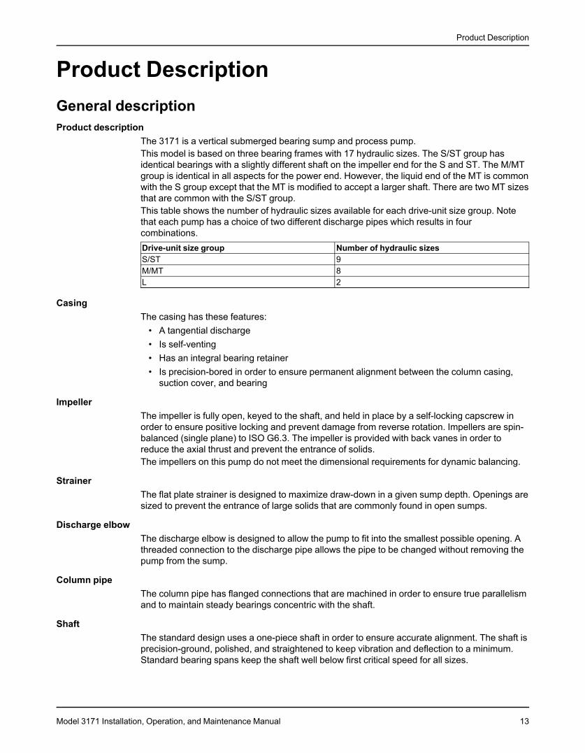
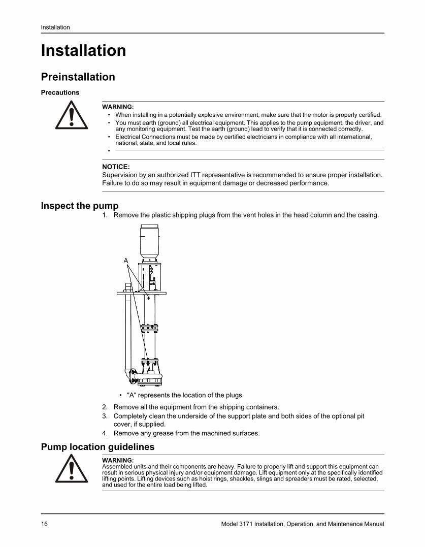
Inspect the pump1. Remove the plastic shipping plugs from the vent holes in the head column and the casing.
• "A" represents the location of the plugs
2. Remove all the equipment from the shipping containers.3. Completely clean the underside of the support plate and both sides of the optional pit
cover, if supplied.4. Remove any grease from the machined surfaces.
Pump location guidelinesWARNING:Assembled units and their components are heavy. Failure to properly lift and support this equipment canresult in serious physical injury and/or equipment damage. Lift equipment only at the specifically identifiedlifting points. Lifting devices such as hoist rings, shackles, slings and spreaders must be rated, selected,and used for the entire load being lifted.
16 Model 3171 Installation, Operation, and Maintenance Manual
Installation
Guideline Explanation/commentMake sure that the space around the pump is This facilitates ventilation, inspection, maintenance,sufficient. and service.If you require lifting equipment such as a hoist or This makes it easier to properly use the liftingtackle, make sure that there is enough space above equipment and safely remove and relocate thethe pump. components to a safe location.Protect the unit from weather and water damage This is applicable if nothing else is specified.due to rain, flooding, and freezing temperatures.Do not install and operate the equipment in closed Acceptable devices:systems unless the system is constructed with • Pressure relief valvesproperly-sized safety devices and control devices. • Compression tanks
• Pressure controls• Temperature controls• Flow controlsIf the system does not include these devices,consult the engineer or architect in charge beforeyou operate the pump.
Take into consideration the occurrence of unwanted The best pump location for noise and vibrationnoise and vibration. absorption is on a concrete floor with subsoil
underneath.
Concrete foundation requirementsRequirements
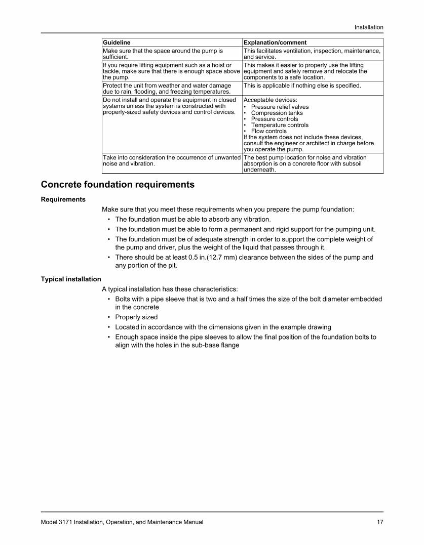
Make sure that you meet these requirements when you prepare the pump foundation:• The foundation must be able to absorb any vibration.• The foundation must be able to form a permanent and rigid support for the pumping unit.• The foundation must be of adequate strength in order to support the complete weight of
the pump and driver, plus the weight of the liquid that passes through it.• There should be at least 0.5 in.(12.7 mm) clearance between the sides of the pump and
any portion of the pit.
Typical installationA typical installation has these characteristics:
• Bolts with a pipe sleeve that is two and a half times the size of the bolt diameter embeddedin the concrete
• Properly sized• Located in accordance with the dimensions given in the example drawing• Enough space inside the pipe sleeves to allow the final position of the foundation bolts to
align with the holes in the sub-base flange
Model 3171 Installation, Operation, and Maintenance Manual 17
Installation
1. Hex nut2. Washer3. Support plate4. 0.5 in. (12.5 mm) anchor bolt5. Anchor bolt sleeve6. Foundation (by customer)Figure 6: Example of a typical installation
Support plate installationInstall the support plate with a pit cover
If access to the bottom of the pit cover is not possible during the installation process, you mustassemble and install the pump (without the motor), support plate, and pit cover as a unit. Youmust install the pit cover perfectly level in order to make sure that the pump remains straight upand down when installed.The vapor-proof option includes machined, gasketed fits between the support plate/pit coverand the pit cover/foundation. You must install these gaskets in order to ensure emissionsperformance. Bolt the pit cover to a metal sole plate with a machined surface in order to ensurean air tight seal.1. Carefully lower the pit cover onto the foundation bolts.2. Use as long a level as possible in order to level the pit cover in all directions with shims or
wedges.3. Hand tighten the anchor bolts. Check the level and re-shim if necessary.4. Tighten all anchor bolts in a star pattern in order to avoid distorting the pit cover.5. If access to the bottom side is possible, carefully lower the pump and support plate onto the
pit cover.6. Install all bolts and hand tighten.7. Check the level on the support plate and re-shim if necessary.8. Tighten all bolts in a star pattern in order to avoid distorting the support plate.
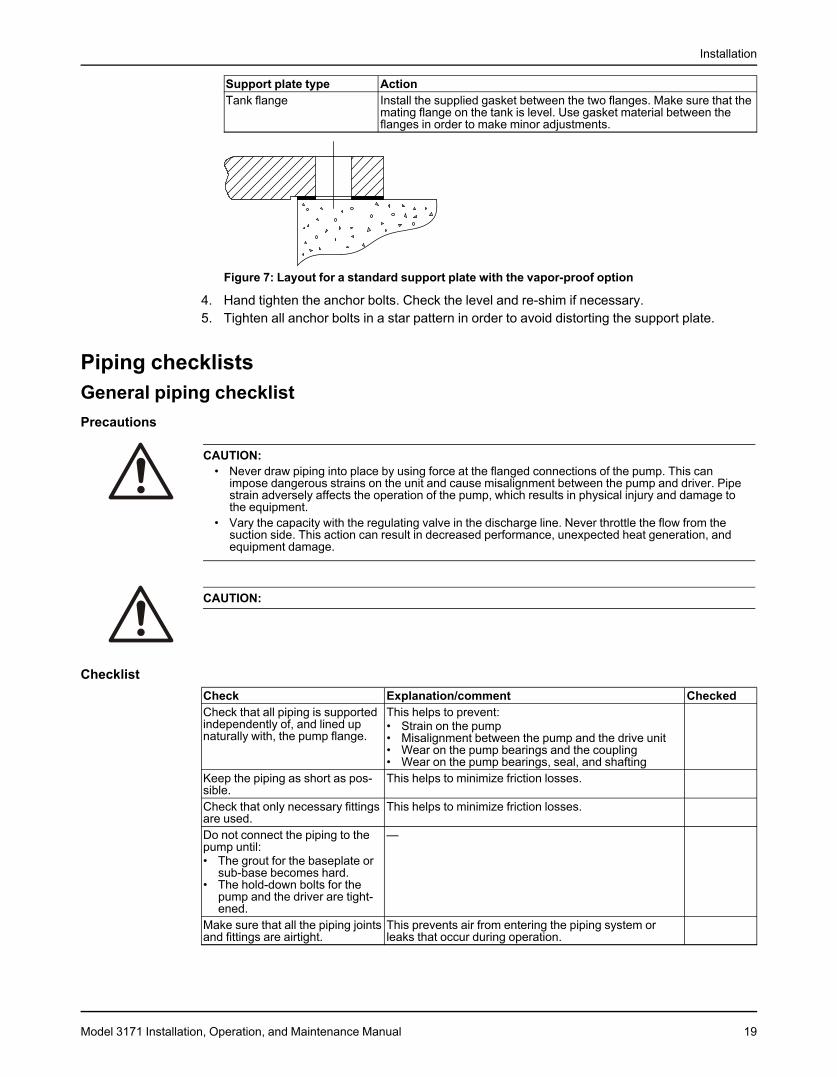
Install the support plate without a pit cover1. Carefully lower the pump and support plate onto the foundation bolts.2. Level the support plate in all directions using shims and wedges.3. If you use the vapor-proof option, then perform one of these actions in order to make sure
that you have an air-tight seal:Support plate type ActionStandard Insert the supplied gasket between the two flanges. Bolt the support
plate to a metal sole plate that has a machined surface.
18 Model 3171 Installation, Operation, and Maintenance Manual
Installation
Support plate type ActionTank flange Install the supplied gasket between the two flanges. Make sure that the
mating flange on the tank is level. Use gasket material between theflanges in order to make minor adjustments.
Figure 7: Layout for a standard support plate with the vapor-proof option
4. Hand tighten the anchor bolts. Check the level and re-shim if necessary.5. Tighten all anchor bolts in a star pattern in order to avoid distorting the support plate.
Piping checklistsGeneral piping checklistPrecautions
CAUTION:• Never draw piping into place by using force at the flanged connections of the pump. This can
impose dangerous strains on the unit and cause misalignment between the pump and driver. Pipestrain adversely affects the operation of the pump, which results in physical injury and damage tothe equipment.
• Vary the capacity with the regulating valve in the discharge line. Never throttle the flow from thesuction side. This action can result in decreased performance, unexpected heat generation, andequipment damage.
CAUTION:
ChecklistCheck Explanation/comment CheckedCheck that all piping is supported This helps to prevent:independently of, and lined up • Strain on the pumpnaturally with, the pump flange. • Misalignment between the pump and the drive unit
• Wear on the pump bearings and the coupling• Wear on the pump bearings, seal, and shafting
Keep the piping as short as pos- This helps to minimize friction losses.sible.Check that only necessary fittings This helps to minimize friction losses.are used.Do not connect the piping to the —pump until:• The grout for the baseplate or
sub-base becomes hard.• The hold-down bolts for the
pump and the driver are tight-ened.
Make sure that all the piping joints This prevents air from entering the piping system orand fittings are airtight. leaks that occur during operation.
Model 3171 Installation, Operation, and Maintenance Manual 19
Installation
Check Explanation/comment CheckedIf the pump handles corrosivefluids, make sure that the pipingallows you to flush out the liquidbefore you remove the pump.If the pump handles liquids at This helps to prevent misalignment due to linear expan-elevated temperatures, make sion of the piping.sure that the expansion loops andjoints are properly installed.Make sure that all piping compo- —nents, valves and fittings, andpump branches are clean prior toassembly.Make sure that the isolation and Locate the check valve between the isolation valve andcheck valves are installed in the the pump. This will permit inspection of the check valve.discharge line. The isolation valve is required for regulation of flow, and
for inspection and maintenance of the pump. The checkvalve prevents pump or seal damage due to reverseflow through the pump when the driver is turned off.
Use cushioning devices. This protects the pump from surges and water hammerif quick-closing valves are installed in the system.
Alignment criteria for pump flangesType CriteriaAxial The flange gasket thickness is ±0.03 in. (0.8 mm).Parallel Align the flange to be within 0.001 in./in. to 0.03 in./
in. (0.025 mm/mm to 0.8 mm/mm) of the flangediameter.
Concentric You can easily install the flange bolts by hand.
Suction piping for optional dry pit, outside tank mount, and tailpipeapplicationsChecklist
Check Explanation/comment CheckedInstall an elbow at the pump. Whenever possible, perform these
actions:• Use long radius elbows.• Move the elbow further from
the suction.• Eliminate unneeded elbows.
Make sure the suction piping is a —larger diameter than the pumpsuction.Install separate suction lines when —more than one pump is operatingfrom the same source of supply.Make sure that the suction piping —contains no air pockets.Make sure that the suction piping —slopes upwards toward the pump.Make sure that all joints are air —tight.Provide a method to prime the For outside tank mount and dry pitpump. applications, allow the fluid level
inside the tank or pit to rise abovethe casing level.In tailpipe applications, submergethe casing before you start thepump.
For outside tank mount and dry pit This allows the line to be closedapplications, install an isolation for pump inspection and mainte-valve in the suction line at least nance. The isolation valve musttwo pipe diameters from the suc- be kept fully open during opera-tion. tion.
20 Model 3171 Installation, Operation, and Maintenance Manual
Installation
Check Explanation/comment CheckedMake sure that the entrance to the This prevents vortices and air en-suction pipe is kept adequately trainment.submerged below the free liquidsurface.For an outside tank mount appli- The column assembly allows thecation, make sure that a column fluid that comes through the lowerassembly is installed. bushings to flow up through the
column and back through the con-nection at the top of the columnback to the tank.Connect the pipe at the top of thepump column back to the sourcetank in order to prevent fluid fromentering the thrust bearing.
Steam linesChecklist
Check Explanation/comment CheckedBefore you install the pump, be- There are three connections above the support plate:come familiar with the location of • Two steam connectionsthe steam lines. • One condensate return connection.
The steam connections are connected to the tops of thecolumn and discharge jackets.
Determine which method to use in There are two methods you can use in order to connectorder to connect the steam lines. the steam lines:
• You can use both steam lines as input for steam(preferred method).
• You can use one steam line as input for steam, whilethe other steam line is used as a feed through toadditional pumps.Only use this method if absolutely necessary, be-cause it is difficult to control the steam at subsequentpumps.
Before you install the pump, The jackets are hydrotested by the factory at 100 psicheck the fittings for leaks. Use before shipment. However, the tube fittings can becomeplant air or high pressure water. loose during transit.
If you use air to check for leaks, use a soap solution ateach joint in order to check for air bubbles.
Provide source of steam at 35 psi Less than ideal conditions require higher pressureand 300°F (149°C). steam in order to keep the correct temperature.After the pump is brought to tem- Refer to Impeller clearance setting in the Operationsperature for the first time, shut chapter.down the unit temporarily andreadjust the impeller clearance.
Final piping checklistCheck Explanation/comment CheckedCheck that the shaft rotates Rotate the shaft by hand. Makesmoothly. sure there is no rubbing that can
lead to excess heat generation orsparks.
Re-check the alignment to make If pipe strain exists, then correctsure that pipe strain has not the piping.caused any misalignment.
Stuffing box installationThis pump is a sealless design. Therefore, when temperatures exceed 180°F (82°C), you mustmove the thrust bearing away from the heat source in the pump by adding the upper stuffingbox. Air can then circulate around the bearing in order to keep it cool.The upper stuffing box is also used to minimize vapor emissions when the pump handlescontrolled substances.
Model 3171 Installation, Operation, and Maintenance Manual 21
Installation
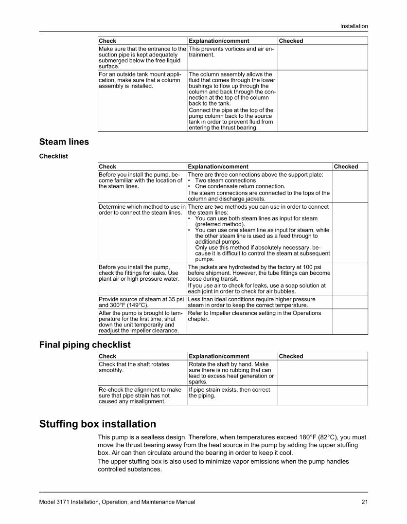
1. Motor support2. Upper stuffing box3. Gasket4. Discharge pipe5. Support plate6. Gasket7. 3 in. (76.2 mm) NPT female connection8. Pit cover9. Gasket
Install the packed stuffing boxWARNING:Packed stuffing boxes are not allowed in an ATEX-classified environment.
The stuffing box is packed at the factory. The packing is lubricated by a grease cup suppliedwith the pump.1. Fill the grease cup with any lithium-based #2 grease.2. Install the grease cup on the tapped opening on the stuffing box.3. Turn the cap on the grease cup several turns in order to inject the grease into the packing.4. Hand-tighten the gland nuts.
Install the pump, driver, and coupling1. Mount and fasten the pump on the baseplate. Use applicable bolts.2. Mount the driver on the baseplate. Use applicable bolts and hand tighten.3. Install the coupling.
See the installation instructions from the coupling manufacturer.
22 Model 3171 Installation, Operation, and Maintenance Manual

Installation
Motor installation and coupling alignmentWARNING:
• Follow shaft alignment procedures in order to prevent catastrophic failure of drive components orunintended contact of rotating parts. Follow the coupling installation and operation procedures fromthe coupling manufacturer.
• Always disconnect and lock out power to the driver before you perform any installation ormaintenance tasks. Failure to disconnect and lock out driver power will result in serious physicalinjury.• Electrical connections must be made by certified electricians in compliance with all international,
national, state, and local rules.• Refer to driver/coupling/gear manufacturers installation and operation manuals (IOM) for specific
instructions and recommendations.
NOTICE:Proper alignment is the responsibility of the installer and the user of the unit. Check thealignment of frame-mounted units before you operate the unit. Failure to do so can result inequipment damage or decreased performance.
Install the motorUse NEMA Vertical C-face motors with this pump. P-base motor adapters and IEC motoradapters are available as options.1. Install both coupling halves before you mount the motor.
Refer to the instructions from the coupling manufacturer.2. Use the lifting lugs on the motor in order to carefully lower the motor onto the pump.
Make sure to align the bolt holes.3. Before you connect the coupling, wire the motor and check the direction of rotation.
The rotation arrow is on the motor support. The correct rotation is clockwise as you lookdown from the drive at the impeller.
Alignment checksWhen to perform alignment checks
You must perform alignment checks under these circumstances:• The process temperature changes.• The piping changes.• The pump has been serviced.
Types of alignment checksType of check When it is usedInitial alignment (cold alignment) Prior to operation when the pump and the driver are at ambientcheck temperature.Final alignment (hot alignment) After operation when the pump and the driver are at operatingcheck temperature.
Initial alignment (cold alignment) checksWhen WhyBefore you grout the baseplate This ensures that alignment can be accomplished.After you grout the baseplate This ensures that no changes have occurred during the grouting
process.After you connect the piping This ensures that pipe strains have not altered the alignment.
If changes have occurred, you must alter the piping to remove pipestrains on the pump flanges.
Model 3171 Installation, Operation, and Maintenance Manual 23
Installation
Final alignment (hot alignment) checksWhen WhyAfter the first run This ensures correct alignment when both the pump and the driver
are at operating temperature.Periodically This follows the plant operating procedures.
Permitted indicator values for alignment checks
NOTICE:The specified permitted reading values are valid only at operating temperature. For coldsettings, other values are permitted. You must use the correct tolerances. Failure to do so canresult in misalignment and reduced pump reliability.
When dial indicators are used to check the final alignment, the pump and drive unit arecorrectly aligned when these conditions are true:
• The total indicator runout is a maximum of 0.002 in. (0.05 mm) at operating temperature.• The tolerance of the indicator is 0.0005 in./in. (0.0127 mm/mm) of indicator separation at
operating temperature.
Alignment measurement guidelinesGuideline ExplanationRotate the pump coupling half and the driver This prevents incorrect measurement.coupling half together so that the indicator rodshave contact with the same points on the drivercoupling half.Move or shim only the driver in order to make This prevents strain on the piping installations.adjustments.Make sure that the hold-down bolts for the driver This keeps the driver stationary since movementfeet are tight when you take indicator measure- causes incorrect measurement.ments.Make sure that the hold-down bolts for the driver This makes it possible to move the driver when youfeet are loose before you make alignment correc- make alignment corrections.tions.Check the alignment again after any mechanical This corrects any misalignments that an adjustmentadjustments. may have caused.
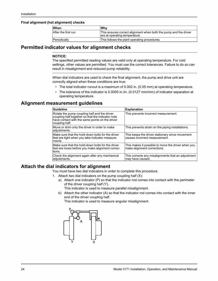
Attach the dial indicators for alignmentYou must have two dial indicators in order to complete this procedure.1. Attach two dial indicators on the pump coupling half (X):
a) Attach one indicator (P) so that the indicator rod comes into contact with the perimeterof the driver coupling half (Y).This indicator is used to measure parallel misalignment.
b) Attach the other indicator (A) so that the indicator rod comes into contact with the innerend of the driver coupling half.This indicator is used to measure angular misalignment.
24 Model 3171 Installation, Operation, and Maintenance Manual
Installation
2. Rotate the pump coupling half (X) in order to check that the indicators are in contact withthe driver coupling half (Y) but do not bottom out.
3. Adjust the indicators if necessary.
Align the flexible couplingWARNING:
• Disconnect and lock out electrical power before installing or servicing the pump.• When installing in a potentially explosive environment, make sure that the motor is properly certified.• The coupling used in an ATEX classified environment must be properly certified.
Alignment of the pump and motor is of extreme importance for trouble-free mechanicaloperation. Straight-edge alignment by an experienced installer proves adequate for mostinstallations. Use dial indicators for disc couplings and applications where alignment to tightertolerances is desirable. Standard dial indicator procedures would apply.
Align the flexible coupling with a straight edgeWARNING:
• Disconnect and lock out electrical power before installing or servicing the pump.• When installing in a potentially explosive environment, make sure that the motor is properly certified.• The coupling used in an ATEX classified environment must be properly certified.
Alignment of the pump and motor is of extreme importance for trouble-free mechanicaloperation. Straight-edge alignment by an experienced installer is adequate for most installa-tions. Use dial indicators for disc couplings and applications where alignment to tightertolerances is desirable. In these cases, use standard dial indicator procedures.1. Lay a straight edge across both coupling rims at four points 90° apart.2. Move the motor until a straight edge rests evenly at each position.3. Repeat these steps until you achieve the correct alignment.4. Install a flexible sleeve between the hubs per the manufacturer's directions included with
the pump data package.5. Tighten all motor bolts.
Float control installationITT supplies several different float controls. Refer to the float control installation instructionsprovided with the controls for the proper installation procedure. This topic describes the SquareD 9036 Simplex and Square D 9038 Duplex float controls.
How float controls workThe on and off levels of the Square D 9036 simplex and the Square D 9038 duplex arecontrolled by adjusting the collars (335). As the liquid level rises, the float rises to contact theupper collar and the upward movement of the float rod causes the mechanical switch inside thecontrol to close. This completes the circuit to the starter. Operation continues until the liquidlevel drops low enough for the float to contact the lower collar. This pulls the rod down, openingthe switch and turning off the pump.The only difference between the Square D 9036 simplex and the Square D 9038 duplex is inthe operating sequence. For the Square D 9038 duplex, the first pump starts as the water levelrises. This allows the float to contact the upper collar. When the water level drops down andshuts off the first pump, a lever arm inside the control mechanically switches to the secondpump and it comes on for the next cycle.If the first pump fails to keep up with demand, or not come on at all, then a continued rise in thelevel turns both pumps on. Both pumps run until the low-water level is reached. If both pumpsare unable to keep up with the demand, then an optional high-water alarm switch can besupplied in the alternator to close a switch if the water level rises past the second pumps on thelevel. This switch can be wired into a customer-supplied alarm horn or light.
Model 3171 Installation, Operation, and Maintenance Manual 25

Installation
APEX high level alarmThe APEX high level alarm is an independent device used to sense fluid level and close aswitch that activates a separate alarm. The switch is mounted on a pipe above the supportplate. The pipe must extend into the sump 4 to 6 in. (10 to 15 cm) below the required actuationpoint. As the liquid level rises in the pipe, trapped air causes bellows inside the switch to inflateand trip a microswitch. The switch can then activate a light, horn, relay, solenoid valve, or otherelectric device.
1. High water alarm2. Reducing adapter, 0.5 in. x 1.0 in. (13.0 mm x
26.0 mm)3. Nipple, 1.0 in. (26.0 mm)4. Coupling, 1.0 in (26.0 mm)5. Pit cover6. Pipe, 1.0 in (26 mm), 8.0 in. (204 mm) shorter
than the pump length7. Cut the pipe 2.5 in. (64 mm) below the required
switch actuation point
Magnetrol displacer-type liquid level switchThe Magnetrol displacer-type liquid level switch is closed by a magnetic seal inside a sealedtube. Switch operation is controlled by the buoyancy of weighted displacers suspended on aspring. As liquid level rises, the resulting change in buoyancy moves the spring upwards. Thespring movement causes a magnetic sleeve to attract a pivoted magnet, closing the actuatingswitch. Refer to installation guide supplied by the manufacturer for proper installation andconfiguration.
Float ball switchesFloat balls are individual switches that are used in multiple configurations to control the pumpcircuit. The float balls are suspended in the sump to the desired control level. When the fluidlevel rises to the float ball, the switch begins to float. The float is either anchored to a pipe orweighted. This allows the switch to tilt when the fluid continues to rise. When the float tilts, aswitch closes that you can use in order to turn the pump on, activate a high-level alarm, orcontrol any other electrical device.
Install the Square D 9036 simplex and 9038 duplex float controlsA single float and rod assembly is used with the 9036 float switch on a simplex unit or the 9038duplex alternator. Refer to the wiring diagram from the manufacturer for the correct wiring ofthe switch.If a pit cover is supplied with the pump, the float switch support pipe (435) and the upper rodguide (337) are installed by the factory. If the pit cover is supplied by others, you must locate,drill, and tap the holes before you install the switch.
26 Model 3171 Installation, Operation, and Maintenance Manual
Installation
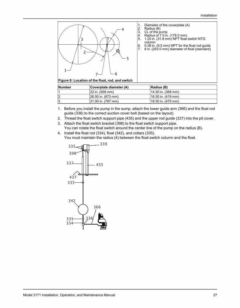
1. Diameter of the coverplate (A)2. Radius (B)3. CL of the pump4. Radius of 7.0 in. (178.0 mm)5. 1.25 in. (31.8 mm) NPT float switch NTG
column6. 0.38 in. (9.5 mm) NPT for the float rod guide7. 8 in. (203.0 mm) diameter of float (standard)
Figure 8: Location of the float, rod, and switch
Number Coverplate diameter (A) Radius (B)1 22 in. (559 mm) 14.50 in. (368 mm)2 26.50 in. (673 mm) 16.50 in. (419 mm)3 31.00 in. (787 mm) 18.50 in. (470 mm)
1. Before you install the pump in the sump, attach the lower guide arm (366) and the float rodguide (336) to the correct suction cover bolt (based on the layout).
2. Thread the float switch support pipe (435) and the upper rod guide (337) into the pit cover.3. Attach the float switch bracket (398) to the float switch support pipe.
You can rotate the float switch around the center line of the pump on the radius (B).4. Install the float rod (334), float (342), and collars (335).
You must maintain the radius (4) between the float switch column and the float.
Model 3171 Installation, Operation, and Maintenance Manual 27
Commissioning, Startup, Operation, and Shutdown
Commissioning, Startup, Operation, andShutdownPreparation for startup
DANGER:Avoid death or serious injury. Explosion and/or seizure of pump can cause fire and/or burns. Neveroperate pump past the pressure and temperature limits shown on the nameplate on the pump.
WARNING:• Failure to follow these precautions before you start the unit will lead to serious personal injury and
equipment failure.• Do not operate the pump below the minimum rated flows or with the suction or discharge valves
closed. These conditions can create an explosive hazard due to vaporization of pumped fluid andcan quickly lead to pump failure and physical injury.
• Avoid death or serious injury. Leaking fluid can cause fire and/or burns. Operating the pump abovemaximum rated flow shown on the pump curve leading to an increase in horsepower and vibrationalong with an increase in NPSHr resulting in mechanical seal and/or shaft failure and/or loss ofprime.
• Avoid death or serious injury. Leaking fluid can cause fire and/or burns. Speed of pump must reach2000 rpm for 2 pole motors and 1000 rpm for 4 pole motors within 10 seconds or an increase invibration and rotor deflection and decrease in rotor stability leading to mechanical seal and/or shaftfailure and/or pump seizure can occur.
• Always disconnect and lock out power to the driver before you perform any installation ormaintenance tasks. Failure to disconnect and lock out driver power will result in serious physicalinjury.• Electrical connections must be made by certified electricians in compliance with all international,
national, state, and local rules.• Refer to driver/coupling/gear manufacturers installation and operation manuals (IOM) for specific
instructions and recommendations.• Operating the pump in reverse rotation can result in the contact of metal parts, heat generation, and
breach of containment.• Avoid death or serious injury. Explosion and/or seizure of pump can cause fire and/or burns. Assure
balance line is installed and either piped to the pump suction or back to the suction vessel to avoidvaporization of pumped fluid.
DANGER:Avoid death or serious injury. Leaking fluid can cause fire and/or burns. Assure all openings are sealedoff prior to filling pump.
Precautions
NOTICE:• Verify the driver settings before you start any pump.• Make sure that the warm-up rate does not exceed 2.5°F (1.4°C) per minute.
You must follow these precautions before you start the pump:• Flush and clean the system thoroughly to remove dirt or debris in the pipe system in order
to prevent premature failure at initial startup.• Bring variable-speed drivers to the rated speed as quickly as possible.• Run a new or rebuilt pump at a speed that provides enough flow to flush and cool the
close-running surfaces of the stuffing-box bushing.
28 Model 3171 Installation, Operation, and Maintenance Manual
Commissioning, Startup, Operation, and Shutdown
• If temperatures of the pumped fluid will exceed 200°F (93°C), then warm up the pump priorto operation. Circulate a small amount of fluid through the pump until the casingtemperature is within 100°F (38°C) of the fluid temperature. Accomplish this by flowingfluid from pump inlet to discharge drain (optionally, the casing vent can be included inwarm-up circuit but not required). Soak for (2) hours at process fluid temperature.
At initial startup, do not adjust the variable-speed drivers or check for speed governor or over-speed trip settings while the variable-speed driver is coupled to the pump. If the settings havenot been verified, then uncouple the unit and refer to instructions supplied by the drivermanufacturer.
Check the rotation - Frame MountedWARNING:
• Operating the pump in reverse rotation can result in the contact of metal parts, heat generation, andbreach of containment.
• Always disconnect and lock out power to the driver before you perform any installation ormaintenance tasks. Failure to disconnect and lock out driver power will result in serious physicalinjury.• Electrical connections must be made by certified electricians in compliance with all international,
national, state, and local rules.• Refer to driver/coupling/gear manufacturers installation and operation manuals (IOM) for specific
instructions and recommendations.
1. Lock out power to the driver.2. Make sure that the coupling hubs are fastened securely to the shafts.3. Make sure that the coupling spacer is removed.
The pump ships with the coupling spacer removed.4. Unlock power to the driver.5. Make sure that everyone is clear, and then jog the driver long enough to determine that the
direction of rotation corresponds to the arrow on the bearing housing or close-coupledframe.
6. Lock out power to the driver.
Thrust bearing lubricationWARNING:Make sure to properly lubricate the bearings. Failure to do so can result in excess heat generation,sparks, and premature failure.
Grease lubricationThis pump comes with a grease-lubricated duplex thrust bearing. The bearing is pre-lubricatedat the factory with a lithium-based grease. Regrease the bearing according to the schedule inthe Maintenance chapter.
Pure oil-mist lubricationPure oil-mist lubrication is an option only available on the API 3171.
Flush the steady bearingsThere are five 1/4-in. NPT pipe plugs on the standard support plate that you use to connect theflush lines. Each plug connects with each of the five bearings. Pumps with less than fivebearings still have five plugs, but only the required number are connected to bearings.1. Remove the plugs from the holes that are connected to flush lines.2. Connect an external source of clean water to the taps.
The water source must be able to deliver 1 to 2 GPM to each bearing.
Model 3171 Installation, Operation, and Maintenance Manual 29
Commissioning, Startup, Operation, and Shutdown
3. Turn on the water in order to begin the flush.
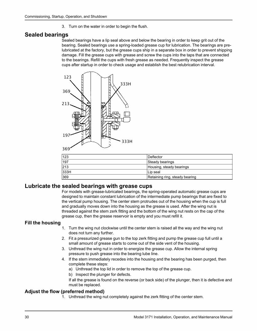
Sealed bearingsSealed bearings have a lip seal above and below the bearing in order to keep grit out of thebearing. Sealed bearings use a spring-loaded grease cup for lubrication. The bearings are pre-lubricated at the factory, but the grease cups ship in a separate box in order to prevent shippingdamage. Fill the grease cups with grease and screw the cups into the taps that are connectedto the bearings. Refill the cups with fresh grease as needed. Frequently inspect the greasecups after startup in order to check usage and establish the best relubrication interval.
123 Deflector197 Steady bearings213 Housing, steady bearings333H Lip seal369 Retaining ring, steady bearing
Lubricate the sealed bearings with grease cupsFor models with grease-lubricated bearings, the spring-operated automatic grease cups aredesigned to maintain constant lubrication of the intermediate pump bearings that are fixed tothe vertical pump housing. The center stem protrudes out of the housing when the cup is fulland gradually moves down into the housing as the grease is used. After the wing nut isthreaded against the stem zerk fitting and the bottom of the wing nut rests on the cap of thegrease cup, then the grease reservoir is empty and you must refill it.
Fill the housing1. Turn the wing nut clockwise until the center stem is raised all the way and the wing nut
does not turn any further.2. Fit a pressurized grease gun to the top zerk fitting and pump the grease cup full until a
small amount of grease starts to come out of the side vent of the housing.3. Unthread the wing nut in order to energize the grease cup. Allow the internal spring
pressure to push grease into the bearing lube line.4. If the stem immediately recedes into the housing and the bearing has been purged, then
complete these steps:a) Unthread the top lid in order to remove the top of the grease cup.b) Inspect the plunger for defects.If all the grease is found on the reverse (or back side) of the plunger, then it is defective andmust be replaced.
Adjust the flow (preferred method)1. Unthread the wing nut completely against the zerk fitting of the center stem.
30 Model 3171 Installation, Operation, and Maintenance Manual

Commissioning, Startup, Operation, and Shutdown
2. Unlock the hex nut of the throttling screw and turn the slotted screw clockwiseapproximately one-half turn at a time.
3. Relock the hex nut and monitor the stem movement.If the grease in the grease cup is completely consumed in 1 to 2 weeks of operation, then theflow is correct and will maintain the proper amount of grease to the bearings.
Adjust the flow (alternate method)This method provides a more precise amount of grease to the bearings independent ofchanging operating temperatures and surrounding conditions. However, you must have a morecontrolled maintenance schedule in order to make sure this is done on a regular basis.1. Leave the throttling screw locked and open.2. Back off the wing nut several turns for every 2 to 3 days of operation.
Shaft sealing with a mechanical sealPrecautions
WARNING:The mechanical seal used in an Ex-classified environment must be properly certified. Prior to startup,make sure that all areas that could leak pumped fluid to the work environment are closed.
NOTICE:• The mechanical seal must have an appropriate seal-flush system. Otherwise, excess heat
generation and seal failure can occur.• Cooling systems such as those for bearing lubrication and mechanical-seal systems must
be operating properly to prevent excess heat generation, sparks, and premature failure.• Sealing systems that are not self-purging or self-venting, such as plan 23, require manual
venting prior to operation. Failure to do so will result in excess heat generation and sealfailure.
ShippingPumps may be shipped with or without a mechanical seal installed.
Cartridge-type mechanical sealsCartridge-type mechanical seals are commonly used. Cartridge seals are preset by the sealmanufacturer and require no field settings. Cartridge seals installed by the user requiredisengagement of the holding clips prior to operation, allowing the seal to slide into place.Customers should always check to make sure the clips have been disengaged before startingthe pump.
Other mechanical seal typesFor other types of mechanical seals, refer to the instructions provided by the seal manufacturerfor installation and setting.
Shaft sealing with a stuffing boxThis pump is a sealless design. Therefore, when temperatures exceed 180°F (82°C), you mustmove the thrust bearing away from the heat source in the pump by adding the upper stuffingbox. Air can then circulate around the bearing in order to keep it cool.The upper stuffing box is also used to minimize vapor emissions when the pump handlescontrolled substances.
Model 3171 Installation, Operation, and Maintenance Manual 31
Commissioning, Startup, Operation, and Shutdown
Steam jacket pumps (molten sulfur construction)The steam jacketed connections are located on the support plate. The "steam in" line isconnected to an appropriate source of steam, and the "steam out/condensate" connections aremade as dictated by the installation requirements. A suitable trap should be used.
Impeller-clearance settingImportance of a proper impeller clearance
A proper impeller clearance ensures that the pump runs at high performance.
WARNING:• The impeller clearance setting procedure must be followed. Improperly setting the clearance or not
following any of the proper procedures can result in sparks, unexpected heat generation, andequipment damage.
Set the impeller clearance - dial indicator methodWARNING:Always disconnect and lock out power to the driver before you perform any installation or maintenancetasks. Failure to disconnect and lock out driver power will result in serious physical injury.
• Electrical connections must be made by certified electricians in compliance with all international,national, state, and local rules.
• Refer to driver/coupling/gear manufacturers installation and operation manuals (IOM) for specificinstructions and recommendations.
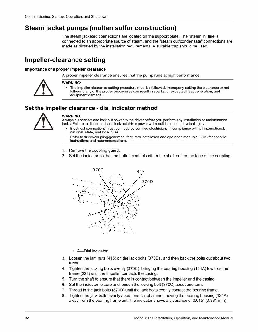
1. Remove the coupling guard.2. Set the indicator so that the button contacts either the shaft end or the face of the coupling.
• A—Dial indicator
3. Loosen the jam nuts (415) on the jack bolts (370D) , and then back the bolts out about twoturns.
4. Tighten the locking bolts evenly (370C), bringing the bearing housing (134A) towards theframe (228) until the impeller contacts the casing.
5. Turn the shaft to ensure that there is contact between the impeller and the casing.6. Set the indicator to zero and loosen the locking bolt (370C) about one turn.7. Thread in the jack bolts (370D) until the jack bolts evenly contact the bearing frame.8. Tighten the jack bolts evenly about one flat at a time, moving the bearing housing (134A)
away from the bearing frame until the indicator shows a clearance of 0.015" (0.381 mm).
32 Model 3171 Installation, Operation, and Maintenance Manual
Commissioning, Startup, Operation, and Shutdown
9. Tighten the bolts evenly in this order:a) Tighten the locking bolts (370C).b) Tighten the jack bolts (370D).Make sure to keep the indicator reading at the proper setting.
10. Make sure the shaft turns freely.
Set the impeller clearance - feeler gauge methodWARNING:Always disconnect and lock out power to the driver before you perform any installation or maintenancetasks. Failure to disconnect and lock out driver power will result in serious physical injury.
• Electrical connections must be made by certified electricians in compliance with all international,national, state, and local rules.
• Refer to driver/coupling/gear manufacturers installation and operation manuals (IOM) for specificinstructions and recommendations.
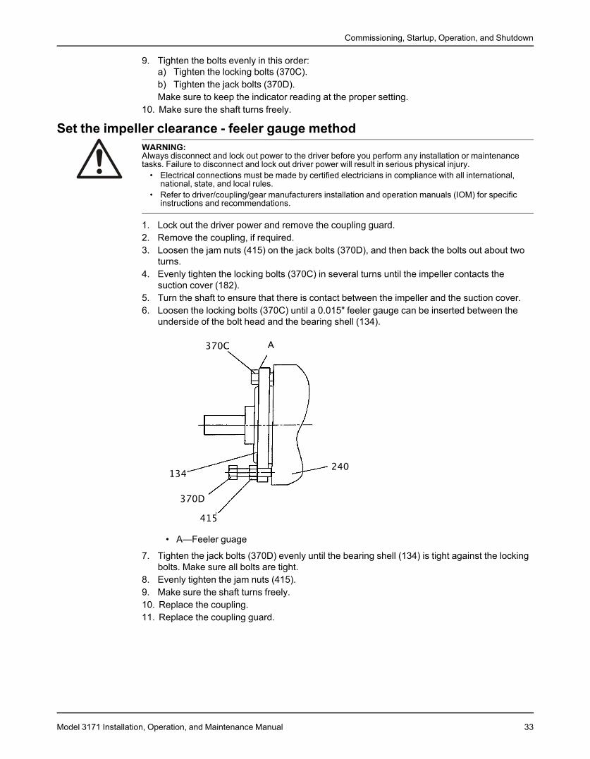
1. Lock out the driver power and remove the coupling guard.2. Remove the coupling, if required.3. Loosen the jam nuts (415) on the jack bolts (370D), and then back the bolts out about two
turns.4. Evenly tighten the locking bolts (370C) in several turns until the impeller contacts the
suction cover (182).5. Turn the shaft to ensure that there is contact between the impeller and the suction cover.6. Loosen the locking bolts (370C) until a 0.015" feeler gauge can be inserted between the
underside of the bolt head and the bearing shell (134).
• A—Feeler guage
7. Tighten the jack bolts (370D) evenly until the bearing shell (134) is tight against the lockingbolts. Make sure all bolts are tight.
8. Evenly tighten the jam nuts (415).9. Make sure the shaft turns freely.10. Replace the coupling.11. Replace the coupling guard.
Model 3171 Installation, Operation, and Maintenance Manual 33
Commissioning, Startup, Operation, and Shutdown
Pump primingWARNING:These pumps are not self priming and must be fully primed at all times during operation. Loss of primecan lead to excessive heat and severe damage to the pump and seal.
CAUTION:Do not run the pump dry.
Never start the pump until it has been properly primed. Fully submerge the pump casing prior tostarting the pump.For dry pit/outside tank mount units:1. Ensure the suction supply line has adequate fluid head to prime the pump.2. Slowly open the suction valve.
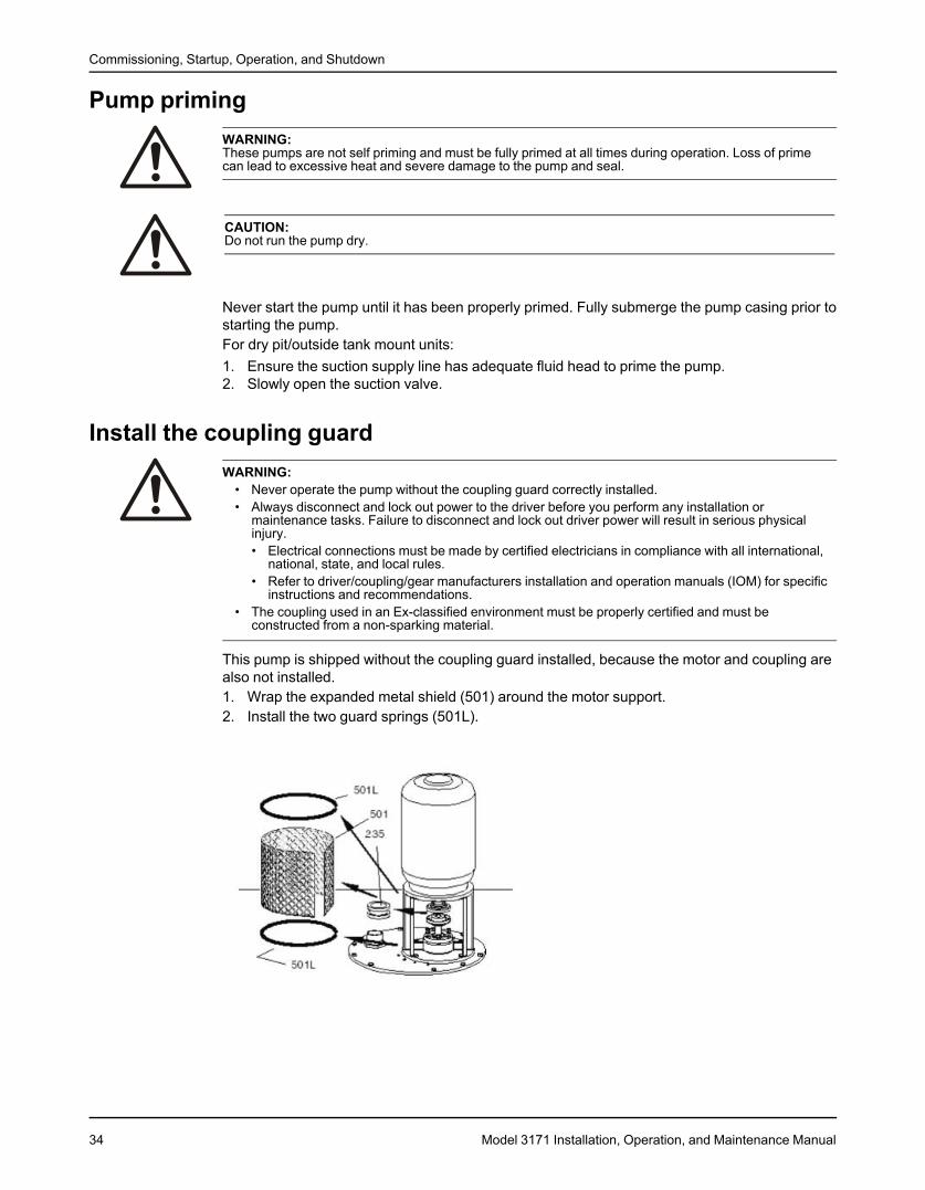
Install the coupling guardWARNING:
• Never operate the pump without the coupling guard correctly installed.• Always disconnect and lock out power to the driver before you perform any installation or
maintenance tasks. Failure to disconnect and lock out driver power will result in serious physicalinjury.• Electrical connections must be made by certified electricians in compliance with all international,
national, state, and local rules.• Refer to driver/coupling/gear manufacturers installation and operation manuals (IOM) for specific
instructions and recommendations.• The coupling used in an Ex-classified environment must be properly certified and must be
constructed from a non-sparking material.
This pump is shipped without the coupling guard installed, because the motor and coupling arealso not installed.1. Wrap the expanded metal shield (501) around the motor support.2. Install the two guard springs (501L).
34 Model 3171 Installation, Operation, and Maintenance Manual
Commissioning, Startup, Operation, and Shutdown
Start the pumpWARNING: Immediately observe the pressure gauges. If discharge pressure is not quickly attained, stopthe driver immediately, reprime, and attempt to restart the pump.
CAUTION:• Immediately observe the pressure gauges. If discharge pressure is not quickly attained, stop the
driver, reprime, and attempt to restart the pump.• Observe the pump for vibration levels, bearing temperature, and excessive noise. If normal levels
are exceeded, shut down the pump and resolve the issue.• On pure or purge-oil mist-lubricated units, remove the viewing port plugs to verify that oil mist
flowing properly. Replace the plugs.• On frame mounted units, ensure that the oil level is correct prior to starting pump. Close coupled
pumps do not have oil lubricated bearings.• Ensure all flush and cooling systems are operating correctly prior to starting pump.
1. Fully close or partially open the discharge valve, depending on system conditions.2. Start the driver.3. Slowly open the discharge valve until the pump reaches the desired flow.4. Immediately check the pressure gauge to ensure that the pump quickly reaches the correct
discharge pressure.5. If the pump fails to reach the correct pressure, perform these steps:
a) Stop the driver.b) Prime the pump again.c) Restart the driver.
6. Monitor the pump while it is operating:a) Check the pump for bearing temperature, excessive vibration, and noise.b) If the pump exceeds normal levels, then shut down the pump immediately and correct
the problem.A pump can exceed normal levels for several reasons. See Troubleshooting forinformation about possible solutions to this problem.
7. Repeat steps 5 and 6 until the pump runs properly.8. After the pump is brought to temperature for the first time, shut the unit down temporarily
and re-adjust the impeller clearance.
Model 3171 Installation, Operation, and Maintenance Manual 35
Commissioning, Startup, Operation, and Shutdown
Pump operation precautionsGeneral considerations
CAUTION:• Vary the capacity with the regulating valve in the discharge line. Never throttle the flow from the
suction side since this can result in decreased performance, unexpected heat generation, andequipment damage.Do not overload the driver. Driver overload can result in unexpected heat generation and equipmentdamage. The driver can overload in these circumstances:• The specific gravity of the pumped fluid is greater than expected.• The pumped fluid exceeds the rated flow rate.
• Do not operate pump past the maximum flow. For maximum flow refer to the pump performancecurve.
• Do not overload the driver. Driver overload can result in unexpected heat generation and equipmentdamage. The driver can overload in these circumstances:• The specific gravity of the pumped fluid is greater than expected.• The pumped fluid exceeds the rated flow rate.
• Do not operate pump below hydraulic or thermal minimum flow. For hydraulic minimum flows referto technical manual and pump performance curve. To calculate thermal minimum flow, refer to HICentrifugal Pumps for Design and Application ANSI/HI 1.3-2000.
• Make sure to operate the pump at or near the rated conditions. Failure to do so can result in pumpdamage from cavitation or recirculation.
Operation at reduced capacity
WARNING:Never operate any pumping system with a blocked suction and discharge. Operation, even for a briefperiod under these conditions, can cause confined pumped fluid to overheat, which results in a violentexplosion. You must take all necessary measures to avoid this condition. If pump becomes plugged shutdown and unplug prior to restarting pump.
CAUTION:• The pump and system must be free of foreign objects. If pump becomes plugged, shut down and
unplug prior to restarting pump.• Avoid excessive vibration levels. Excessive vibration levels can damage the bearings, stuffing box
or seal chamber, and the mechanical seal, which can result in decreased performance.• Avoid increased radial load. Failure to do so can cause stress on the shaft and bearings.• Avoid heat build-up. Failure to do so can cause rotating parts to score or seize.• Avoid cavitation. Failure to do so can cause damage to the internal surfaces of the pump.
Operation under freezing conditions
NOTICE:Do not expose an idle pump to freezing conditions. Drain all liquid that is inside the pump.Failure to do so can cause liquid to freeze and damage the pump.
Shut down the pumpWARNING:The pump can handle hazardous and toxic fluids. Identify the contents of the pump and observe properdecontamination procedures in order to eliminate the possible exposure to any hazardous or toxic fluids.Wear the proper personal protective equipment. Potential hazards include, but are not limited to, hightemperature, flammable, acidic, caustic, explosive, and other risks. You must handle and dispose ofpumped fluid in compliance with the applicable environmental regulations.
1. Slowly close the discharge valve.
36 Model 3171 Installation, Operation, and Maintenance Manual
Commissioning, Startup, Operation, and Shutdown
2. Shut down and lock the driver to prevent accidental rotation.
Make the final alignment of the pump and driverWARNING:
• Always disconnect and lock out power to the driver before you perform any installation ormaintenance tasks. Failure to disconnect and lock out driver power will result in serious physicalinjury.• Electrical connections must be made by certified electricians in compliance with all international,
national, state, and local rules.• Refer to driver/coupling/gear manufacturers installation and operation manuals (IOM) for specific
instructions and recommendations.• Follow shaft alignment procedures in order to prevent catastrophic failure of drive components or
unintended contact of rotating parts. Follow the coupling installation and operation procedures fromthe coupling manufacturer.
• Alignment procedures must be followed to prevent unintended contact of rotating parts. Followcoupling manufacturer’s installation and operation procedures.
You must check the final alignment after the pump and driver are at operating temperature. Forinitial alignment instructions, see the Installation chapter.1. Run the unit under actual operating conditions for enough time to bring the pump, driver,
and associated system to operating temperature.2. Shut down the pump and the driver.3. Remove the coupling guard.
See Remove the coupling guard in the Maintenance chapter.4. Check the alignment while the unit is still hot.
See Pump-to-driver alignment in the Installation chapter.5. Reinstall the coupling guard.6. Restart the pump and driver.
Model 3171 Installation, Operation, and Maintenance Manual 37
Maintenance
MaintenanceMaintenance scheduleMaintenance inspections
A maintenance schedule includes these types of inspections:• Routine maintenance• Routine inspections• Three-month inspections• Annual inspections
Shorten the inspection intervals appropriately if the pumped fluid is abrasive or corrosive or ifthe environment is classified as potentially explosive.
Routine maintenancePerform these tasks whenever you perform routine maintenance:
• Lubricate the thrust bearings.• Inspect the seal or packing, if present.
Routine inspectionsPerform these tasks whenever you check the pump during routine inspections:
• Check for unusual noise, vibration, and bearing temperatures.• Check the pump and piping for leaks.• Analyze the vibration.• Inspect the discharge pressure.• Inspect the temperature.• Check the seal chamber and stuffing box for leaks.
• Ensure that there are no leaks from the mechanical seal.• Adjust or replace the packing in the stuffing box if you notice excessive leaking.
Three-month inspectionsPerform these tasks every three months:
• Check that the foundation and the hold-down bolts are tight.• Check the packing if the pump has been left idle, and replace as required.• Check the shaft alignment, and realign as required.
Annual inspectionsPerform these inspections one time each year:
• Check the pump capacity.• Check the pump pressure.• Check the pump power.
If the pump performance does not satisfy your process requirements, and the processrequirements have not changed, then perform these steps:1. Disassemble the pump.2. Inspect it.3. Replace worn parts.
38 Model 3171 Installation, Operation, and Maintenance Manual
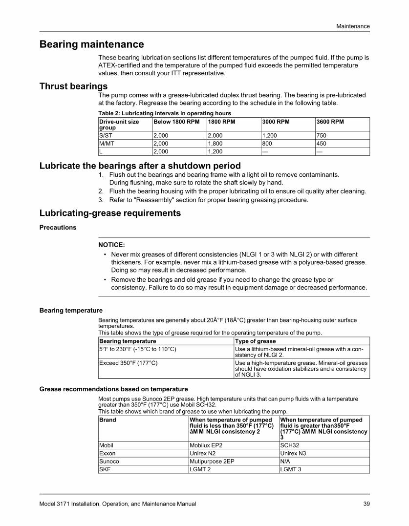
Maintenance
Bearing maintenanceThese bearing lubrication sections list different temperatures of the pumped fluid. If the pump isATEX-certified and the temperature of the pumped fluid exceeds the permitted temperaturevalues, then consult your ITT representative.
Thrust bearingsThe pump comes with a grease-lubricated duplex thrust bearing. The bearing is pre-lubricatedat the factory. Regrease the bearing according to the schedule in the following table.Table 2: Lubricating intervals in operating hoursDrive-unit size Below 1800 RPM 1800 RPM 3000 RPM 3600 RPMgroupS/ST 2,000 2,000 1,200 750M/MT 2,000 1,800 800 450L 2,000 1,200 — —
Lubricate the bearings after a shutdown period1. Flush out the bearings and bearing frame with a light oil to remove contaminants.
During flushing, make sure to rotate the shaft slowly by hand.2. Flush the bearing housing with the proper lubricating oil to ensure oil quality after cleaning.3. Refer to "Reassembly" section for proper bearing greasing procedure.
Lubricating-grease requirementsPrecautions
NOTICE:• Never mix greases of different consistencies (NLGI 1 or 3 with NLGI 2) or with different
thickeners. For example, never mix a lithium-based grease with a polyurea-based grease.Doing so may result in decreased performance.
• Remove the bearings and old grease if you need to change the grease type orconsistency. Failure to do so may result in equipment damage or decreased performance.
Bearing temperatureBearing temperatures are generally about 20°F (18°C) greater than bearing-housing outer surfacetemperatures.This table shows the type of grease required for the operating temperature of the pump.Bearing temperature Type of grease5°F to 230°F (-15°C to 110°C) Use a lithium-based mineral-oil grease with a con-
sistency of NLGI 2.Exceed 350°F (177°C) Use a high-temperature grease. Mineral-oil greases
should have oxidation stabilizers and a consistencyof NGLI 3.
Grease recommendations based on temperatureMost pumps use Sunoco 2EP grease. High temperature units that can pump fluids with a temperaturegreater than 350°F (177°C) use Mobil SCH32.This table shows which brand of grease to use when lubricating the pump.Brand When temperature of pumped When temperature of pumped
fluid is less than 350°F (177°C) fluid is greater than350°FâM M NLGI consistency 2 (177°C) âM M NLGI consistency
3Mobil Mobilux EP2 SCH32Exxon Unirex N2 Unirex N3Sunoco Mutipurpose 2EP N/ASKF LGMT 2 LGMT 3
Model 3171 Installation, Operation, and Maintenance Manual 39
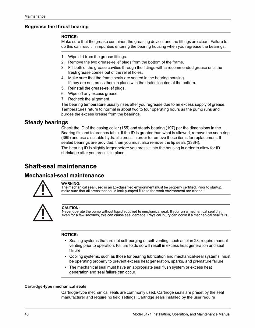
Maintenance
Regrease the thrust bearing
NOTICE:Make sure that the grease container, the greasing device, and the fittings are clean. Failure todo this can result in impurities entering the bearing housing when you regrease the bearings.
1. Wipe dirt from the grease fittings.2. Remove the two grease-relief plugs from the bottom of the frame.3. Fill both of the grease cavities through the fittings with a recommended grease until the
fresh grease comes out of the relief holes.4. Make sure that the frame seals are seated in the bearing housing.
If they are not, press them in place with the drains located at the bottom.5. Reinstall the grease-relief plugs.6. Wipe off any excess grease.7. Recheck the alignment.The bearing temperature usually rises after you regrease due to an excess supply of grease.Temperatures return to normal in about two to four operating hours as the pump runs andpurges the excess grease from the bearings.
Steady bearingsCheck the ID of the casing collar (155) and steady bearing (197) per the dimensions in theBearing fits and tolerances table. If the ID is greater than what is allowed, remove the snap ring(369) and use a suitable hydraulic press in order to remove these items for replacement. Ifsealed bearings are provided, then you must also remove the lip seals (333H).The bearing ID is slightly larger before you press it into the housing in order to allow for IDshrinkage after you press it in place.
Shaft-seal maintenanceMechanical-seal maintenance
WARNING:The mechanical seal used in an Ex-classified environment must be properly certified. Prior to startup,make sure that all areas that could leak pumped fluid to the work environment are closed.
CAUTION:Never operate the pump without liquid supplied to mechanical seal. If you run a mechanical seal dry,even for a few seconds, this can cause seal damage. Physical injury can occur if a mechanical seal fails.
NOTICE:• Sealing systems that are not self-purging or self-venting, such as plan 23, require manual
venting prior to operation. Failure to do so will result in excess heat generation and sealfailure.
• Cooling systems, such as those for bearing lubrication and mechanical-seal systems, mustbe operating properly to prevent excess heat generation, sparks, and premature failure.
• The mechanical seal must have an appropriate seal flush system or excess heatgeneration and seal failure can occur.
Cartridge-type mechanical sealsCartridge-type mechanical seals are commonly used. Cartridge seals are preset by the sealmanufacturer and require no field settings. Cartridge seals installed by the user require
40 Model 3171 Installation, Operation, and Maintenance Manual
Maintenance
disengagement of the holding clips prior to operation, allowing the seal to slide into place. If theseal has been installed in the pump by ITT, these clips have already been disengaged.
Other mechanical seal typesFor other types of mechanical seals, refer to the instructions provided by the seal manufacturerfor installation and setting.
Reference drawingThe manufacturer supplies a reference drawing with the data package. Keep this drawing forfuture use when you perform maintenance and seal adjustments. The seal drawing specifiesthe required flush fluid and attachment points.
Before you start the pumpCheck the seal and all flush piping.If the pump is shipped with oil-lubricated seals, keep the seal faces lubricated with oil at alltimes.
Packed stuffing-box maintenanceWARNING:
• Packed stuffing boxes are not allowed in an ATEX-classified environment.• Never attempt to replace the packing until the driver is properly locked out and the coupling spacer is
removed.
Lubrication intervalsThe lubrication intervals vary and depend upon the temperature and gland tightness. Keep thegrease cup full at all times.Periodically make several turns on the grease-cup cap while you inject fresh grease into thestuffing box. Check the pump daily upon initial operation, and extend this interval as required.
NOTICE:Do not over-tighten the stuffing box. Excessive pressure can wear out packing prematurely andseriously damage the shaft.
Packing replacementReplace the packing in this sequence:1. Three rings of packing2. Lantern ring3. Two rings of packing4. Gland
Model 3171 Installation, Operation, and Maintenance Manual 41
Maintenance
DisassemblyDisassembly precautions
WARNING:• This manual clearly identifies accepted methods for disassembling units. These methods must be
adhered to. Trapped liquid can rapidly expand and result in a violent explosion and injury. Neverapply heat to impellers, propellers, or their retaining devices to aid in their removal unless explicitlystated in this manual.
• Always disconnect and lock out power to the driver before you perform any installation ormaintenance tasks. Failure to disconnect and lock out driver power will result in serious physicalinjury.• Electrical connections must be made by certified electricians in compliance with all international,
national, state, and local rules.• Refer to driver/coupling/gear manufacturers installation and operation manuals (IOM) for specific
instructions and recommendations.• Crush hazard. The unit and the components can be heavy. Use proper lifting methods and wear
steel-toed shoes at all times.• The pump can handle hazardous and toxic fluids. Identify the contents of the pump and observe
proper decontamination procedures in order to eliminate the possible exposure to any hazardous ortoxic fluids. Wear the proper personal protective equipment. Potential hazards include, but are notlimited to, high temperature, flammable, acidic, caustic, explosive, and other risks. You must handleand dispose of pumped fluid in compliance with the applicable environmental regulations.
• A small amount of liquid will be present in certain areas like the seal chamber.
NOTICE:• Avoid injury. Worn pump components can have sharp edges. Wear appropriate gloves
while handling these parts.• Make sure that all replacement parts are available before you disassemble the pump for
overhaul.
Tools requiredIn order to disassemble the pump, you need these tools:
• Bearing puller• Brass drift punch• Cleaning agents and solvents• Dial indicators• Feeler gauges• Hydraulic press• Induction heater• Lifting sling• Micrometer• Rubber mallet• Screwdriver• Snap-ring pliers• Torque wrench with sockets• Wrenches
Drain the pump
CAUTION:• Allow all system and pump components to cool before you handle them to prevent physical injury.
42 Model 3171 Installation, Operation, and Maintenance Manual

Maintenance
1. Close the isolation valves on the suction and discharge sides of the pump.You must drain the system if no valves are installed.
2. Open the drain valve.Do not proceed until liquid stops coming out of the drain valve. If liquid continues to flowfrom the drain valve, the isolation valves are not sealing properly and you must repair thembefore you proceed.
3. Leave the drain valve open.Do not close the drain valve until the reassembly is complete.
4. Drain the liquid from the piping and flush the pump if it is necessary.5. Disconnect all auxiliary piping and tubing.6. Remove the coupling guard.7. Disconnect the coupling.
Remove the pump from the sump1. Remove the motor bolts (371).
2. Place the sling on the motor lifting lugs and remove the motor.3. Remove the support plate anchor bolts.4. Attach the eyebolts to the support plate.5. Use properly-sized slings in order to lift the pump from the sump.
Refer to the Installation chapter for the proper handling procedure.6. Lay the pump horizontally on proper supports where there is sufficient clearance to
disassemble the pump.
Model 3171 Installation, Operation, and Maintenance Manual 43

Maintenance
7. Remove the bolts (317N) in order to remove the strainer (187).
8. Remove the suction cover (182).9. Remove and discard the suction cover gasket (351).
Replace the gasket during reassembly.10. Remove the discharge elbow-casing bolts (370H).11. Disconnect any steady bearing flush tubing (190).
Remove the impeller
CAUTION:Wear heavy work gloves when you handle impellers. The sharp edges can cause physical injury.
1. Loosen the set screw at the end of the impeller nut.2. Loosen and remove the impeller nut.
The impeller nut has left-hand threads.3. Pull the impeller from the shaft.
Use a spanning-type puller if required.
44 Model 3171 Installation, Operation, and Maintenance Manual
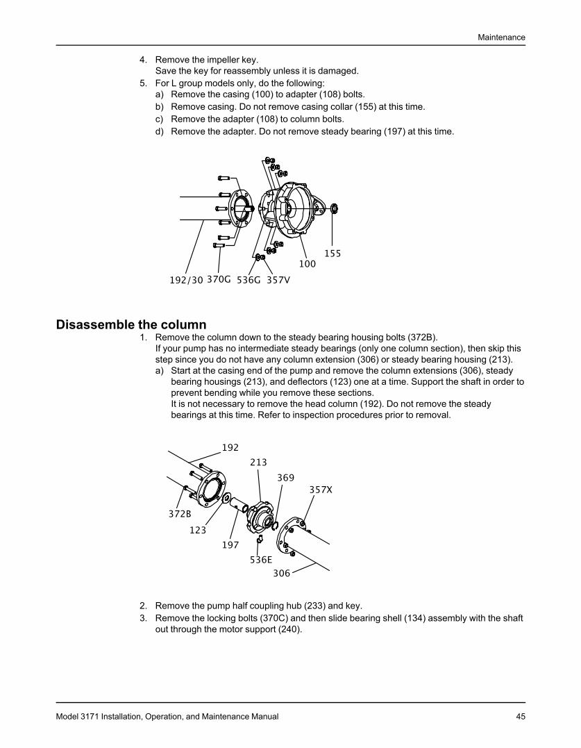
Maintenance
4. Remove the impeller key.Save the key for reassembly unless it is damaged.
5. For L group models only, do the following:a) Remove the casing (100) to adapter (108) bolts.b) Remove casing. Do not remove casing collar (155) at this time.c) Remove the adapter (108) to column bolts.d) Remove the adapter. Do not remove steady bearing (197) at this time.
Disassemble the column1. Remove the column down to the steady bearing housing bolts (372B).
If your pump has no intermediate steady bearings (only one column section), then skip thisstep since you do not have any column extension (306) or steady bearing housing (213).a) Start at the casing end of the pump and remove the column extensions (306), steady
bearing housings (213), and deflectors (123) one at a time. Support the shaft in order toprevent bending while you remove these sections.It is not necessary to remove the head column (192). Do not remove the steadybearings at this time. Refer to inspection procedures prior to removal.
2. Remove the pump half coupling hub (233) and key.3. Remove the locking bolts (370C) and then slide bearing shell (134) assembly with the shaft
out through the motor support (240).
Model 3171 Installation, Operation, and Maintenance Manual 45
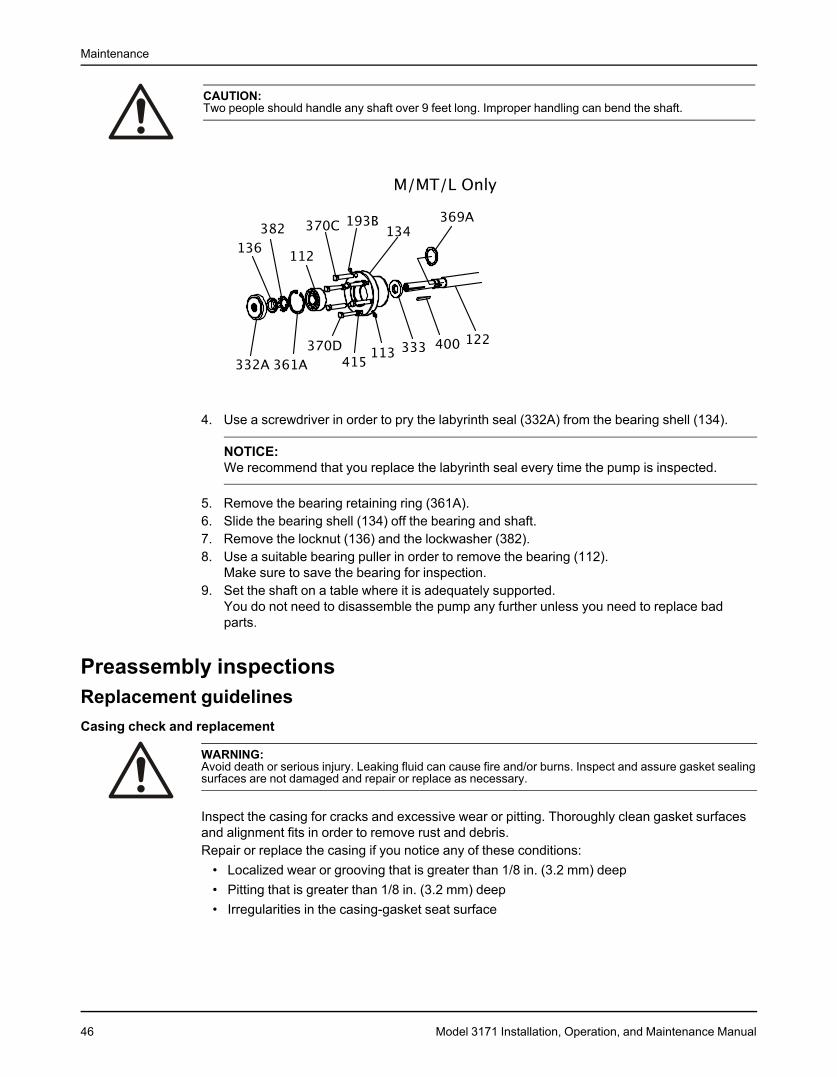
Maintenance
CAUTION:Two people should handle any shaft over 9 feet long. Improper handling can bend the shaft.
4. Use a screwdriver in order to pry the labyrinth seal (332A) from the bearing shell (134).
NOTICE:We recommend that you replace the labyrinth seal every time the pump is inspected.
5. Remove the bearing retaining ring (361A).6. Slide the bearing shell (134) off the bearing and shaft.7. Remove the locknut (136) and the lockwasher (382).8. Use a suitable bearing puller in order to remove the bearing (112).
Make sure to save the bearing for inspection.9. Set the shaft on a table where it is adequately supported.
You do not need to disassemble the pump any further unless you need to replace badparts.
Preassembly inspectionsReplacement guidelinesCasing check and replacement
WARNING:Avoid death or serious injury. Leaking fluid can cause fire and/or burns. Inspect and assure gasket sealingsurfaces are not damaged and repair or replace as necessary.
Inspect the casing for cracks and excessive wear or pitting. Thoroughly clean gasket surfacesand alignment fits in order to remove rust and debris.Repair or replace the casing if you notice any of these conditions:
• Localized wear or grooving that is greater than 1/8 in. (3.2 mm) deep• Pitting that is greater than 1/8 in. (3.2 mm) deep• Irregularities in the casing-gasket seat surface
46 Model 3171 Installation, Operation, and Maintenance Manual
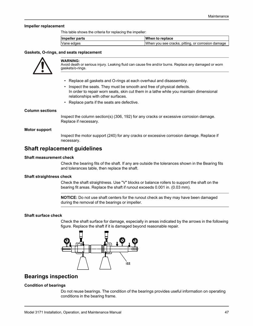
Maintenance
Impeller replacementThis table shows the criteria for replacing the impeller:
Impeller parts When to replaceVane edges When you see cracks, pitting, or corrosion damage
Gaskets, O-rings, and seats replacement
WARNING:Avoid death or serious injury. Leaking fluid can cause fire and/or burns. Replace any damaged or worngaskets/o-rings.
• Replace all gaskets and O-rings at each overhaul and disassembly.• Inspect the seats. They must be smooth and free of physical defects.
In order to repair worn seats, skin cut them in a lathe while you maintain dimensionalrelationships with other surfaces.
• Replace parts if the seats are defective.
Column sectionsInspect the column section(s) (306, 192) for any cracks or excessive corrosion damage.Replace if necessary.
Motor supportInspect the motor support (240) for any cracks or excessive corrosion damage. Replace ifnecessary.
Shaft replacement guidelinesShaft measurement check
Check the bearing fits of the shaft. If any are outside the tolerances shown in the Bearing fitsand tolerances table, then replace the shaft.
Shaft straightness checkCheck the shaft straightness. Use "V" blocks or balance rollers to support the shaft on thebearing fit areas. Replace the shaft if runout exceeds 0.001 in. (0.03 mm).
NOTICE: Do not use shaft centers for the runout check as they may have been damagedduring the removal of the bearings or impeller.
Shaft surface checkCheck the shaft surface for damage, especially in areas indicated by the arrows in the followingfigure. Replace the shaft if it is damaged beyond reasonable repair.
Bearings inspectionCondition of bearings
Do not reuse bearings. The condition of the bearings provides useful information on operatingconditions in the bearing frame.
Model 3171 Installation, Operation, and Maintenance Manual 47

Maintenance
ChecklistPerform these checks when you inspect the bearings:
• Inspect the bearings for contamination and damage.• Note any lubricant condition and residue.• Inspect the ball bearings to see if they are loose, rough, or noisy when you rotate them.• Investigate any bearing damage to determine the cause. If the cause is not normal wear,
correct the issue before you return the pump to service.
Bearing fits and tolerancesTable 3: Steady bearing tolerancesThis table references the bearing fits and tolerances according to ISO 286 (ANSI/ABMA Standard 7) ininches (millimeters).Descripti Bearing ID (pressed into Housing bore Running clearance (1/2on place) diametrical clearance)S/ST M/MT L S/ST M/MT L S/ST M/MT LCarbon 1.132–1. 1.633–1. 2.258–2. 1.621–1. 2.121–2. 2.994–2. 0.0055–0 0.006–0. 0.0065–0
134 635 260 623 123 996 .0035 004 .004(28.753– (41.478– (57.353– (41.173– (53.873– (76.048– (0.140–0. (0.152–0. (0.165–0.28.804) 41.529) 57.404) 41.224) 53.924) 76.098) 089) 102) 102)
Bronze 1.129–1. 1.629–1. 2.256–2. 1.621–1. 2.121–2. 2.994–2. 0.004–0. 0.004–0. 0.0055–0131 631 258 623 123 996 002 002 .003(28.677– 41.377–4 (57.302– (41.173– (53.873– (76.048– (0.102–1. (0.102–1. (0.140–0.28.727) 1.427 57.353) 41.224) 53.924) 76.098) 051) 051) 076)
Fluted 1.126–1. 1.627–1. 2.253–2. 1.621–1. 2.121–2. 2.994–2. 0.0035–0 0.0045–0 0.005–0.elasto- 130 632 257 623 123 996 .0005 .001 004mer (28.600– (41.326– (57.226– (41.173– (53.873– (76.048– (0.089–0. (0.114–0. (0.127–0.
28.702) 41.453) 57.328) 41.224) 53.924) 76.098) 013) 025) 102)Rulon 1.132–1. 1.633–1. 2.258–2. - - - 0.0055–0 0.006–0. 0.0065–0
134 635 260 .0035 004 .004(28.753– (41.478– (57.353– (0.140–0. (0.152–0. (0.165–0.28.804) 41.529) 57.404) 089) 102) 102)
Casing 1.183–1. 1.678–1. 2.299–2. 1.811–1. 2.243–2. 3.243–3. 0.0335–0 0.031–0. 0.029–0.collar 190 685 306 816 245 245 .029 0265 0245
(30.048– (42.621– (58.395– (45.999– (56.972– (82.372– (0.851–0. (0.787–0. (0.737–0.30.226) 42.799) 58.472) 46.126) 57.023) 82.423) 737) 673) 622)
Table 4: Thrust bearing fitsGroup Shaft OD Shell IDS/ST 0.9848/0.9844 2.4416/2.4409
(25.0139/25.0038) (62.0166/61.9989)M/MT 1.5755/1.5749 3.5442/3.5433
(40.0177/40.0025) (90.0227/89.9998)L 2.1660/2.1655 4.7253/4.7240
(55.0164/55.0037) (120.0226/119.9896)
Shaft runout tolerancesThe following shaft runout tolerances apply to all size groups:
• Coupling end: 0.002 in. (0.051 mm)• Shaft body: 0.0005 in./ft.• Impeller end: 0.005 in. (0.127 mm)
ReassemblyAssemble the column and support plate
1. If you use the optional stuffing box, then attach the stuffing box (221) to support plate (189)with bolts (370L).
2. Attach the motor support (240):
48 Model 3171 Installation, Operation, and Maintenance Manual
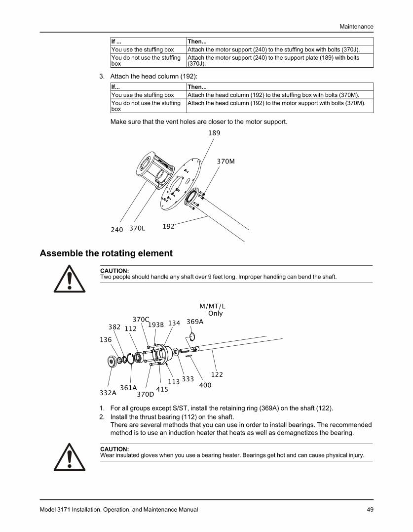
Maintenance
If ... Then...You use the stuffing box Attach the motor support (240) to the stuffing box with bolts (370J).You do not use the stuffing Attach the motor support (240) to the support plate (189) with boltsbox (370J).
3. Attach the head column (192):If... Then...You use the stuffing box Attach the head column (192) to the stuffing box with bolts (370M).You do not use the stuffing Attach the head column (192) to the motor support with bolts (370M).box
Make sure that the vent holes are closer to the motor support.
Assemble the rotating element
CAUTION:Two people should handle any shaft over 9 feet long. Improper handling can bend the shaft.
1. For all groups except S/ST, install the retaining ring (369A) on the shaft (122).2. Install the thrust bearing (112) on the shaft.
There are several methods that you can use in order to install bearings. The recommendedmethod is to use an induction heater that heats as well as demagnetizes the bearing.
CAUTION:Wear insulated gloves when you use a bearing heater. Bearings get hot and can cause physical injury.
Model 3171 Installation, Operation, and Maintenance Manual 49
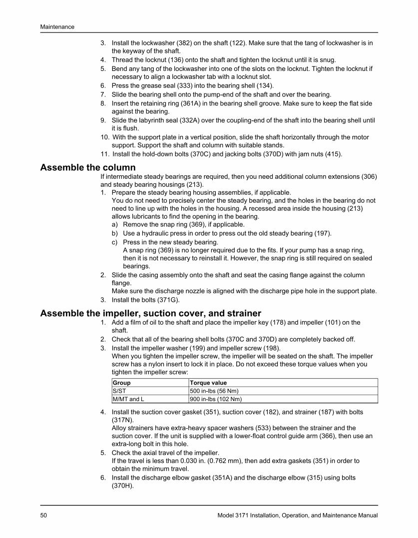
Maintenance
3. Install the lockwasher (382) on the shaft (122). Make sure that the tang of lockwasher is inthe keyway of the shaft.
4. Thread the locknut (136) onto the shaft and tighten the locknut until it is snug.5. Bend any tang of the lockwasher into one of the slots on the locknut. Tighten the locknut if
necessary to align a lockwasher tab with a locknut slot.6. Press the grease seal (333) into the bearing shell (134).7. Slide the bearing shell onto the pump-end of the shaft and over the bearing.8. Insert the retaining ring (361A) in the bearing shell groove. Make sure to keep the flat side
against the bearing.9. Slide the labyrinth seal (332A) over the coupling-end of the shaft into the bearing shell until
it is flush.10. With the support plate in a vertical position, slide the shaft horizontally through the motor
support. Support the shaft and column with suitable stands.11. Install the hold-down bolts (370C) and jacking bolts (370D) with jam nuts (415).
Assemble the columnIf intermediate steady bearings are required, then you need additional column extensions (306)and steady bearing housings (213).1. Prepare the steady bearing housing assemblies, if applicable.
You do not need to precisely center the steady bearing, and the holes in the bearing do notneed to line up with the holes in the housing. A recessed area inside the housing (213)allows lubricants to find the opening in the bearing.a) Remove the snap ring (369), if applicable.b) Use a hydraulic press in order to press out the old steady bearing (197).c) Press in the new steady bearing.
A snap ring (369) is no longer required due to the fits. If your pump has a snap ring,then it is not necessary to reinstall it. However, the snap ring is still required on sealedbearings.
2. Slide the casing assembly onto the shaft and seat the casing flange against the columnflange.Make sure the discharge nozzle is aligned with the discharge pipe hole in the support plate.
3. Install the bolts (371G).
Assemble the impeller, suction cover, and strainer1. Add a film of oil to the shaft and place the impeller key (178) and impeller (101) on the
shaft.2. Check that all of the bearing shell bolts (370C and 370D) are completely backed off.3. Install the impeller washer (199) and impeller screw (198).
When you tighten the impeller screw, the impeller will be seated on the shaft. The impellerscrew has a nylon insert to lock it in place. Do not exceed these torque values when youtighten the impeller screw:Group Torque valueS/ST 500 in-lbs (56 Nm)M/MT and L 900 in-lbs (102 Nm)
4. Install the suction cover gasket (351), suction cover (182), and strainer (187) with bolts(317N).Alloy strainers have extra-heavy spacer washers (533) between the strainer and thesuction cover. If the unit is supplied with a lower-float control guide arm (366), then use anextra-long bolt in this hole.
5. Check the axial travel of the impeller.If the travel is less than 0.030 in. (0.762 mm), then add extra gaskets (351) in order toobtain the minimum travel.
6. Install the discharge elbow gasket (351A) and the discharge elbow (315) using bolts(370H).
50 Model 3171 Installation, Operation, and Maintenance Manual
Maintenance
Accurate alignment of the elbow is critical in order to make sure that there is no obstructionto the flow through the connection.
7. Install the discharge pipe (195), pipe nuts (242), and flange (195S, if used).Make sure that the pipe nuts are tight and that there is no strain on the pump.
8. Rotate the shaft by hand in order to make sure that there is no binding.9. Connect all auxiliary piping.10. Replace the pump half coupling hub (233) and lubricate the pump bearings.
Model 3171 Installation, Operation, and Maintenance Manual 51
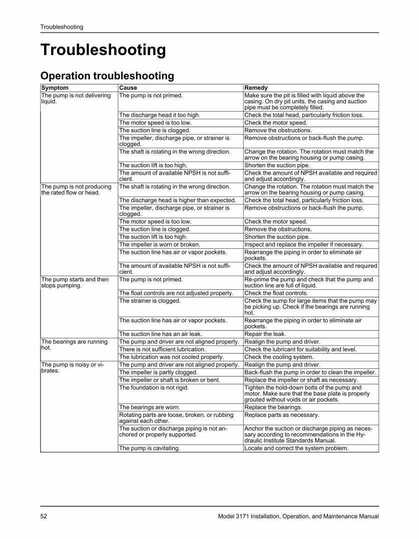
Troubleshooting
TroubleshootingOperation troubleshootingSymptom Cause RemedyThe pump is not delivering The pump is not primed. Make sure the pit is filled with liquid above theliquid. casing. On dry pit units, the casing and suction
pipe must be completely filled.The discharge head it too high. Check the total head, particularly friction loss.The motor speed is too low. Check the motor speed.The suction line is clogged. Remove the obstructions.The impeller, discharge pipe, or strainer is Remove obstructions or back-flush the pump.clogged.The shaft is rotating in the wrong direction. Change the rotation. The rotation must match the
arrow on the bearing housing or pump casing.The suction lift is too high. Shorten the suction pipe.The amount of available NPSH is not suffi- Check the amount of NPSH available and requiredcient. and adjust accordingly.
The pump is not producing The shaft is rotating in the wrong direction. Change the rotation. The rotation must match thethe rated flow or head. arrow on the bearing housing or pump casing.
The discharge head is higher than expected. Check the total head, particularly friction loss.The impeller, discharge pipe, or strainer is Remove obstructions or back-flush the pump.clogged.The motor speed is too low. Check the motor speed.The suction line is clogged. Remove the obstructions.The suction lift is too high. Shorten the suction pipe.The impeller is worn or broken. Inspect and replace the impeller if necessary.The suction line has air or vapor pockets. Rearrange the piping in order to eliminate air
pockets.The amount of available NPSH is not suffi- Check the amount of NPSH available and requiredcient. and adjust accordingly.
The pump starts and then The pump is not primed. Re-prime the pump and check that the pump andstops pumping. suction line are full of liquid.
The float controls are not adjusted properly. Check the float controls.The strainer is clogged. Check the sump for large items that the pump may
be picking up. Check if the bearings are runninghot.
The suction line has air or vapor pockets. Rearrange the piping in order to eliminate airpockets.
The suction line has an air leak. Repair the leak.The bearings are running The pump and driver are not aligned properly. Realign the pump and driver.hot. There is not sufficient lubrication. Check the lubricant for suitability and level.
The lubrication was not cooled properly. Check the cooling system.The pump is noisy or vi- The pump and driver are not aligned properly. Realign the pump and driver.brates. The impeller is partly clogged. Back-flush the pump in order to clean the impeller.
The impeller or shaft is broken or bent. Replace the impeller or shaft as necessary.The foundation is not rigid. Tighten the hold-down bolts of the pump and
motor. Make sure that the base plate is properlygrouted without voids or air pockets.
The bearings are worn. Replace the bearings.Rotating parts are loose, broken, or rubbing Replace parts as necessary.against each other.The suction or discharge piping is not an- Anchor the suction or discharge piping as neces-chored or properly supported. sary according to recommendations in the Hy-
draulic Institute Standards Manual.The pump is cavitating. Locate and correct the system problem.
52 Model 3171 Installation, Operation, and Maintenance Manual
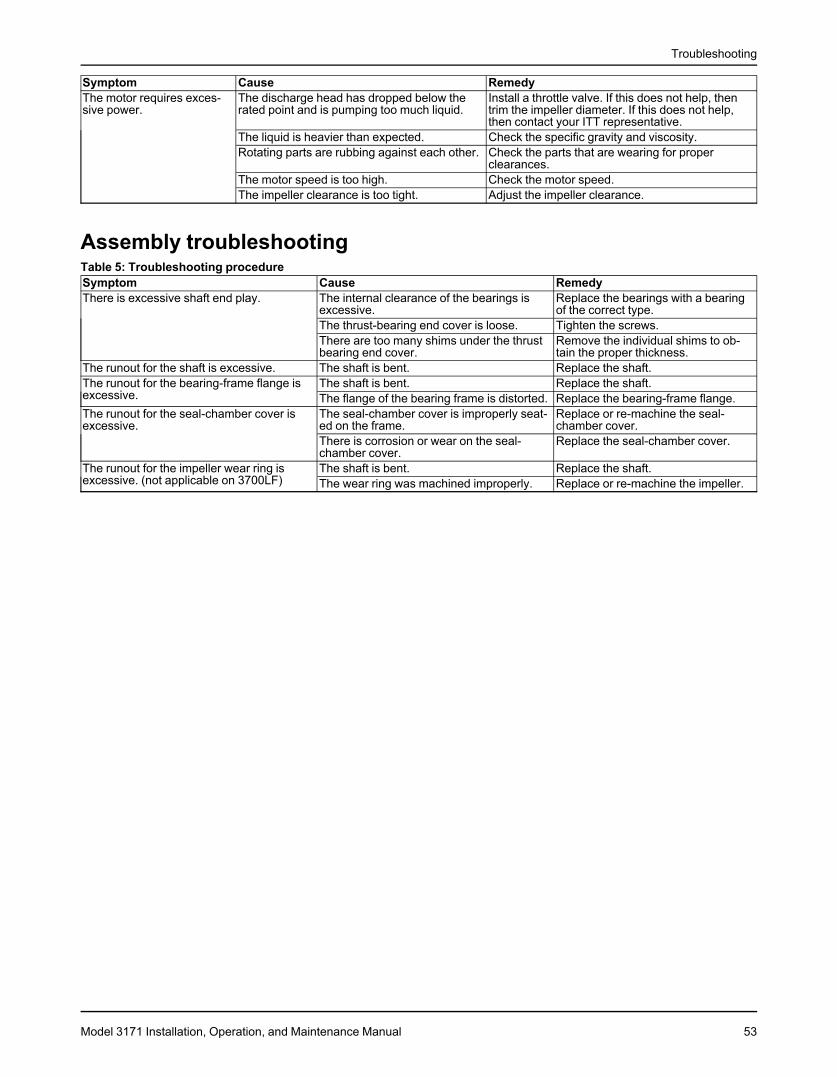
Troubleshooting
Symptom Cause RemedyThe motor requires exces- The discharge head has dropped below the Install a throttle valve. If this does not help, thensive power. rated point and is pumping too much liquid. trim the impeller diameter. If this does not help,
then contact your ITT representative.The liquid is heavier than expected. Check the specific gravity and viscosity.Rotating parts are rubbing against each other. Check the parts that are wearing for proper
clearances.The motor speed is too high. Check the motor speed.The impeller clearance is too tight. Adjust the impeller clearance.
Assembly troubleshootingTable 5: Troubleshooting procedureSymptom Cause RemedyThere is excessive shaft end play. The internal clearance of the bearings is Replace the bearings with a bearing
excessive. of the correct type.The thrust-bearing end cover is loose. Tighten the screws.There are too many shims under the thrust Remove the individual shims to ob-bearing end cover. tain the proper thickness.
The runout for the shaft is excessive. The shaft is bent. Replace the shaft.The runout for the bearing-frame flange is The shaft is bent. Replace the shaft.excessive. The flange of the bearing frame is distorted. Replace the bearing-frame flange.The runout for the seal-chamber cover is The seal-chamber cover is improperly seat- Replace or re-machine the seal-excessive. ed on the frame. chamber cover.
There is corrosion or wear on the seal- Replace the seal-chamber cover.chamber cover.
The runout for the impeller wear ring is The shaft is bent. Replace the shaft.excessive. (not applicable on 3700LF) The wear ring was machined improperly. Replace or re-machine the impeller.
Model 3171 Installation, Operation, and Maintenance Manual 53
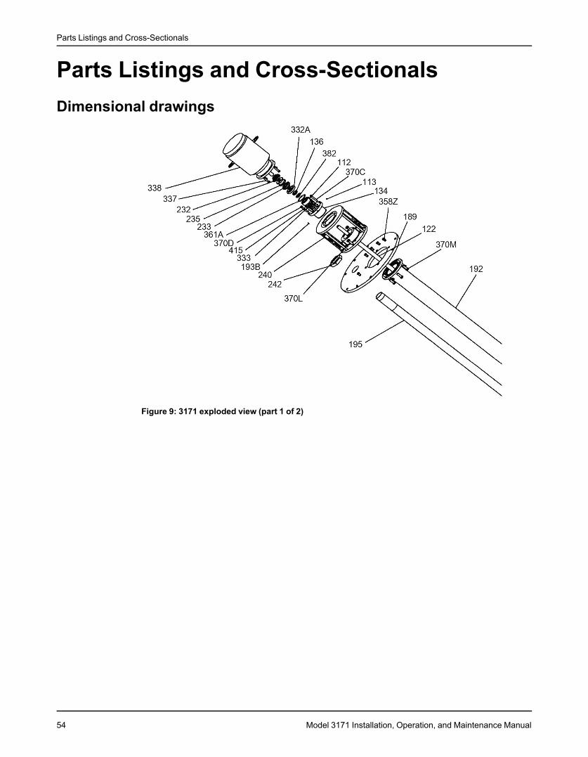
Parts Listings and Cross-Sectionals
Parts Listings and Cross-SectionalsDimensional drawings
Figure 9: 3171 exploded view (part 1 of 2)
54 Model 3171 Installation, Operation, and Maintenance Manual
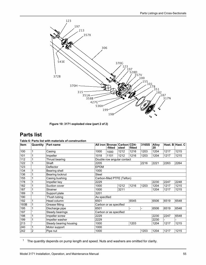
Parts Listings and Cross-Sectionals
Figure 10: 3171 exploded view (part 2 of 2)
Parts listTable 6: Parts list with materials of constructionItem Quantity Part name All iron Bronze Carbon CD4- 316SS Alloy Hast. B Hast. C
-fitted steel fitted 20100 1 Casing 1000 1212 1216 1203 1204 1217 12151000101 1 Impeller 1018 1101 1212 1216 1203 1204 1217 1215112 1 Thrust bearing Double row angular contact122 1 Shaft 2205 2216 2221 2263 2264123 Deflector EPDM134 1 Bearing shell 1000136 1 Bearing locknut Steel155 1 Casing bushing Carbon-filled PTFE (Teflon)178 1 Impeller key 2229 2230 2247 2248182 1 Suction cover 1000 1212 1216 1203 1204 1217 1215187 1 Strainer 1000 3211 1204 1217 1215189 1 Support plate 3201190 1Flush tubing As specified192 1 Head column 6501 6545 6506 6519 6548193B 1 Grease fitting Carbon or as specified195 1 Discharge pipe 6501 - - 6506 6519 6548197 1 Steady bearings Carbon or as specified198 1 Impeller screw 2229 2230 2247 6548199 1 Impeller washer 2229 2230 - -213 1 Steady bearing housing 1000 1203 1204 1217 1215240 1 Motor support 1000242 2 Pipe nut 1000 1203 1204 1217 1215
1 The quantity depends on pump length and speed. Nuts and washers are omitted for clarity.
Model 3171 Installation, Operation, and Maintenance Manual 55

Parts Listings and Cross-Sectionals
Item Quantity Part name All iron Bronze Carbon CD4- 316SS Alloy Hast. B Hast. C-fitted steel fitted 20
306 1 Column extension 6501 6545 6506 - -315 1 Discharge elbow 1000 1212 1216 1203 1204 1217 1215332A 1 Labyrinth seal Carbon Teflon333 1 Lip seal Nitrile lip seal333H 2/Brg Lip seal Nitrile Viton351 1 Gasket (suction cover to casing) Nitrile acrylic351A 1 Gasket (discharge elbow to casing) Nitrile acrylic361A 1 Retaining ring (thrust bearing) Steel369 1 Retaining ring (steady bearing) PH15-7MO Stainless C-20 Hastelloy369A 1 Retaining ring (shaft) M/MT, L Groups Only. Steel370C 3 Clamp bolt (bearing shell) 2210370D 3 Jack bolt (bearing shell) 2210370G 6 Bolt (column to casing) 2210 2229 2230 2247 2248370H 4 Bold (elbow to casing) 2210 2229 2230 2247 2248370L 4 Bolt (motor adapter to support plate) 2210370M 4 Bolt (head column to motor support) 2210 2229 2230 2247 2248371 4 Bolt (motor to motor support) 2210501 1 Coupling guard 3122501L 2 Guard springs Steel
Table 7: Material code cross referenceGoulds code ASTM number1000 A48 CL25B Cast Iron1018 A536-84 60-42-10 Ductile Iron1101 B584 Silicon Brass1203 A743 CF8M 316 Stainless1204 A743 CN7M Alloy 201212 A216 WCB Carbon Steel1215 A494-90 CW6M C1,1 Hastelloy C1216 A890 1A CD4MCuN1217 A494 N-7M Hastelloy B2205 C1045 Carbon Steel Ground and Polished2210 A108 Gr1211 Carbon Steel2216 A276 316 Stainless Ground and Polished2229 A276-91A Stainless2230 B743 20CB3 Carpenter 202247 B335 Type B-2 Hastelloy B2248 B574 C-276 Hastelloy C2263 B335 B-2 Hastelloy B Ground and Polished2264 B574 C-276 Hastelloy C Ground and Polished3122 Aluminum3201 A283 Grade D Carbon Steel Plate3211 A240 316 Steel Plate6501 A53 Type F Carbon Steel Schedule 40 Pipe6506 B464 C20CB3 Carpenter 20 Schedule 40 Pipe6511 Red Brass Pipe SPS6519 B622 Hastelloy B Schedule 40 Pipe6545 A312 316L Stainless Steel Schedule 40 Pipe6548 Hastelloy C C-276 Schedule 40 Pipe
56 Model 3171 Installation, Operation, and Maintenance Manual

Parts Listings and Cross-Sectionals
Cross-sectional diagramsS/ST and M/MT groups
Model 3171 Installation, Operation, and Maintenance Manual 57
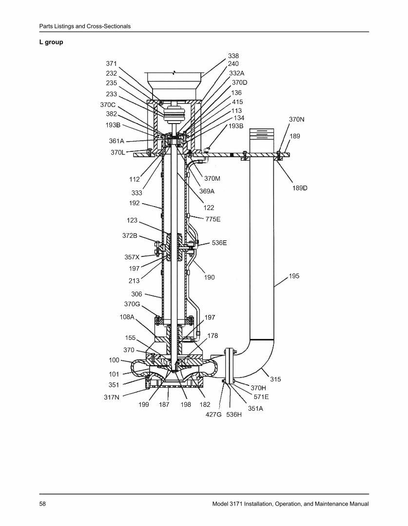
Parts Listings and Cross-Sectionals
L group
58 Model 3171 Installation, Operation, and Maintenance Manual
Local ITT Contacts
Local ITT ContactsRegional officesRegion Address Telephone FaxNorth America (Headquarters) ITT - Goulds Pumps +1 315-568-2811 +1 315-568-2418
240 Fall StreetSeneca Falls, NY 13148USA
Asia Pacific ITT Industrial Process +65 627-63693 +65 627-6368510 Jalan Kilang #06-01Singapore 159410
Europe ITT - Goulds Pumps +44 1297-630250 +44 1297-630256Millwey Rise Industrial EstateAxminster, Devon, EnglandEX13 5HU
Latin America ITT - Goulds Pumps +562 544-7000 +562 544-7001Camino La Colina # 1448Condominio Industrial El RosalHuechuraba Santiago8580000Chile
Middle East and Africa ITT - Goulds Pumps +30 210-677-0770 +30 210-677-5642Achileos Kyrou 4Neo Psychiko 115 25 AthensGreece
Model 3171 Installation, Operation, and Maintenance Manual 59


Visit our website for the latest version of thisdocument and more information:
http://www.gouldspumps.com
Goulds Pumps240 Fall StreetSeneca Falls, NY 13148USATel. 1-800-446-8537Fax (315) 568-2418
Form en_US.2014-07.IOM.3171© 2014 ITT CorporationThe original instruction is in English. All non-English instructions are translations of the original instruction.