ssss.org.sgssssorgs/images/stories/design guide for buildable steel... · design guide for...
TRANSCRIPT

Design Guide
for
Buildable Steel Connections -Bolted and Welded Connection to SS EN1993-1-8

DESIGN GUIDE FOR BUILDABLE STEEL CONNECTIONS
DESIGN GUIDE FOR BUILDABLE STEEL CONNECTIONS
Page | i
Design Guide
for
Buildable Steel Connections -Bolted and Welded Connections to SS EN1993-1-8
J Y Richard Liew National University of Singapore
Honorary fellow, Singapore Structural Steel Society

DESIGN GUIDE FOR BUILDABLE STEEL CONNECTIONS
Page | ii

DESIGN GUIDE FOR BUILDABLE STEEL CONNECTIONS
Page | iii
NOTE
1. Whilst every effort has been made to ensure accuracy of the information contained in this design guide, the Singapore Structural Steel Society (“SSSS”) and Building and Construction Authority (“BCA”) makes no representations or warranty as to the completeness or accuracy thereof. Information in this design guide is supplied on the condition that the user of this publication will make their own determination as to the suitability for his or her purpose(s) prior to its use. The user of this publication must review and modify as necessary the information prior to using or incorporating the information into any project or endeavor. Any risk associated with using or relying on the information contained in the design guide shall be borne by the user. The information in the design guide is provided on an “as is” basis without any warranty of any kind whatsoever or accompanying services or support.
2. Nothing contained in this design guide is to be construed as a recommendation or requirement to use any policy, material, product, process, system or application and SSSS & BCA make no representation or warranty express or implied. NO REPRESENTATION OR WARRANTY, EITHER EXPRESSED OR IMPLIED OF FITNESS FOR A PARTICULAR PURPOSE IS MADE HEREUNDER WITH RESPECT TO INCLUDING BUT NOT LIMITED, WARRANTIES AS TO ACCURACY, TIMELINES, COMPLETENESS, MERCHANTABILITY OR FITNESS FOR A PARTICULAR PURPOSE OR COMPLIANCE WITH A PARTICULAR DESCRIPTION OR ANY IMPLIED WARRANTY ARISING FROM THE COURSE OF PERFORMANCE, COURSE OF DEALING, USAGE OF TRADE OR OTHERWISE, TO THE FULLEST EXTENT PERMITTED BY LAW. In particular, SSSS & BCA make no warranty that the information contained in the design guide will meet the user’s requirements or is error-free or that all errors in the drawings can be corrected or that the drawings will be in a form or format required by the user.
3. In no event will SSSS & BCA or the authors be responsible or liable for damages of any kind resulting from the use or reliance upon information or the policies, materials, products, systems or applications to which the information refers. In addition to and notwithstanding the foregoing, in no event shall SSSS & BCA be liable for any consequential or special damages or for any loss of profits incurred by the user or any third party in connection with or arising out of use or reliance of this design guide.
DESIGN GUIDE FOR BUILDABLE STEEL CONNECTIONS
Page | iv
Copyright @ 2019 Building and Construction Authority, Singapore.
Copyright @ 2019 Singapore Structural Steel Society.
All rights reserved. This document or any part thereof may not be reproduced for any reason whatsoever in any form or means whatsoever and howsoever without the prior written consent and approval of the Building and Construction Authority and Singapore Structural Steel Society. Whilst every effort has been made to ensure the accuracy of the information contained in this publication, the Building and Construction Authority and Singapore Structural Steel Society, its employees or agents shall not be responsible for any mistake or inaccuracy that may be contained herein and all such liability and responsibility are expressly disclaimed by these said parties.

DESIGN GUIDE FOR BUILDABLE STEEL CONNECTIONS
Page | v
Contents Contents v
Foreword by the Author ix
Foreword by the President of SSSS x
Acknowledgement xi
List of Examples xii
1 Introduction 1
1.1 About this design guide 1
1.2 Material 1
1.3 Joint classification 2
2 Buildable Beam to Beam/Column connections 3
2.1 Simple connections 3
2.1.1 Bolted Connections (shear and/or tension connections) 3
2.1.2 Welded Connections (shear and/or tension connections) 3
2.1.3 Recommendation for fin plate connections 3
2.2 Moment-resisting connections 4
2.2.1 Bolted Connections (Moment-resisting connections) 4
2.2.2 Welded Connections (Moment-resisting connections) 4
2.3 Design steps for simple connections – bolted connections 4
2.3.1 Fin plate connection design procedures 5
2.3.2 End plate connection design procedure 13
2.3.3 Example 1 – One-sided Beam-to-Beam connection with extended fin plate 17
2.3.4 Example 2 – Double-sided Beam-to-Beam connection with extended fin plates 36
2.3.5 Example 3 – One-sided Beam-to-Beam skewed connection with extended fin plates 65
2.3.6 Example 4 – Two-sided Beam-to-Column fin plate connection bending about the major axis of the column 80
2.3.7 Example 5 – Two-sided Beam-to-Column extended fin plate connection in minor axis with extended fin plate 105
2.3.8 Example 6 – Fin plate connection to circular hollow column 134
2.3.9 Example 7 – Beam-to-Beam connection 150
2.3.10 Example 8 – Beam-to-Beam connection at different level 167
2.4 Design steps for moment-resisting connections – bolted connections 181
2.4.1 Extended fin plate connections design procedures 182
2.4.2 End plate connections design procedures 191
2.4.3 Example 9 – Double-sided Beam-to-Beam connection with extended fin-plate (moment-resisting connection) for beams of similar depth 199
DESIGN GUIDE FOR BUILDABLE STEEL CONNECTIONS
Page | vi
2.4.4 Example 10 – Double-sided Beam-to-Beam connection with extended fin-plate (moment-resisting connection) for beams of different depths with haunch 214
2.4.5 Example 11 – Double-sided Beam-to-Beam connection with extended fin-plate (moment-resisting connection) for beams of different depths with connection plate 232
2.4.6 Example 12 – I-beams connecting to hollow section column with external ring plate 247
2.4.7 Example 13 – I-beam of different depths connecting to hollow section column with external ring plate 265
2.4.8 Example 14 – Beam-to-Column connection (moment-resisting connection) bending about the major axis of the column with different beam depths 285
2.4.9 Example 15 – Beam-to-Column connection bending about the minor axis of the column with different beam depths 307
2.4.10 Example 16 – Beam-to-Beam connection (moment-resisting connection) in minor axis (Section a) 324
2.4.11 Example 17 – Beam-to-Beam connection (moment-resisting connection) in minor axis (Section b) 351
2.4.12 Example 18 – Beam-to-Beam connection (moment-resisting connection) in major axis and/or minor axis (section b) 370
2.4.13 Example 19 – Beam-to-Beam connection (moment-resisting connection) in major axis and/or minor axis (section c) 400
2.5 Strengthening of the joints 421
2.5.1 Example 20 – Stiffened extended fin-plates for secondary beams 422
2.5.2 Example 21 – Stiffened extended fin-plates connecting to column in the minor axis (Section a) 430
2.5.3 Example 22 – Stiffened extended fin-plates connecting to column in the minor axis (Section b) 437
2.5.4 Example 22 – Stiffened extended fin-plates connecting to column in the minor axis (Section c) 442
2.5.5 Example 23 – Stiffened column web 446
2.6 Splice connections 458
2.6.1 Example 24 – Beam splice – A combination of welding to the top flange and bolting to the web & bottom flange 462
2.6.2 Example 25 – Beam splice – A combination of welding to the top & bottom flanges with bolting to the web 476
3 Base Plate Connections 479
3.1 Base Plate Connection 479
3.2 Design steps 479
3.3 Design basics 480
3.4 Typical Column Base Plate 481
3.4.1 Example 1 – Use of L-Bolt 482
3.4.2 Example 2 – Vertical holding down bolt with nuts and washers 495
3.5 Steel-to-concrete connections 507

DESIGN GUIDE FOR BUILDABLE STEEL CONNECTIONS
Page | vii
3.5.1 Example 3 – Embedded plate into RC wall/column 508
4 Connections for Hollow Steel Sections 515
4.1 Modes of failures 515
4.2 Shear connection using fin plates 516
4.2.1 Example 1 – Shear connection using fin plate (CHS column) 517
4.2.2 Example 2 – Beam to rectangular column connection using fin plate 530
4.3 Connection of I-beam to hollow steel columns using extended endplates 537
4.3.1 Example 3 – Beam to Rectangular column connection using extended end plate 537
4.4 Connection of narrow beam to hollow steel columns 546
4.4.1 Example 4 – Narrow I beam to circular hollow column connection 546
4.5 Connection of I-beam to circular hollow section steel column 571
4.5.1 Example 5 – I beam to circular column connection with beam stub pre-welded to column 571
4.6 Connection of I-beam to hollow steel columns using diaphragm plates 591
4.6.1 Example 6 – I-beam to hollow steel columns with diaphragm plates 591
5 Bracing connections 597
5.1 Introduction 597
5.2 Materials 597
5.3 Design and Detailing 597
5.3.1 Example 1 – Welding of steel rod to a steel plate 598
5.4 Gusset plates to main members 603
5.4.1 Example 2 – Turn buckle and gusset plate connection 603
5.4.2 Example 3 – Gusset plate connection for bracing type 2 612
6 Purlin Connections 627
6.1 Introduction 627
6.2 Design and detailing 627
6.3 Provisions of sag rods 628
7 Non-standard Connections 630
7.1 Introduction 630
7.2 Tubular column-to-column connections (different column sizes) 630
7.3 Member transition in truss chords 635
7.4 Stiffeners in truss chords 636
7.4.1 Example 1 – Stiffened truss connection 636
7.5 Double-sided beam-to-beam composite connection using fin plates and contact plates 648
8 Good Practices for Connections Design 660
8.1 General 660

DESIGN GUIDE FOR BUILDABLE STEEL CONNECTIONS
Page | viii
8.2 Recommendations for cost-effective connection design 660
8.3 Non-preferred steel connections 662
8.4 Alternate connections 665
References 668
Annex A: Case Study for Productivity Improvement 670

DESIGN GUIDE FOR BUILDABLE STEEL CONNECTIONS
Page | ix
Foreword by the Author
This publication covers the range of structural steelwork connections that are seen as buildable from the fabricators’ point of view. It provides a guide to the design of simple connections, moment connections and special connections in steelwork including detailed examples how to design them.
Included in this Guide are bolted and welded connections suitable for use in simple, semi-continuous and continuous frame design. The design is based on SS EN1993-1-8 and Singapore national annex, with supplementary information from SCI Publications: Joints in steel construction- Simple and moment connections, CIDECT design guide 9 – for structural hollow section column connections and GB 50936:2014.
The Guide is produced by the SSSS work group with sponsorship from the Singapore Structural Steel Society. The work group was established in 2017 to bring together academics, consultants and steelwork contractors to work on the development of design guides for buildable connections, which are commonly used in practice. The ideas gathered in the Guide come from the sharing of knowledge of individuals from the steel construction industry. As the Guide is not a static document, there is little doubt that future amendments and improvement to it will depend on the feedback from the professionals and increasing collaboration between SSSS, the Building and Construction Authority (BCA) and the National University of Singapore (NUS).
Much of this collaboration has been on a voluntary basis with professional pooling their knowledge to produce examples and design rules that best reflect the modern practice in steelwork construction. The author gratefully acknowledges the helps he has received from the consultants, BCA, and SSSSS, who publish this Guide.
It is hoped that the readers of this Guide will find it not only a valuable source of reference but also a book that they will use regularly to design and build new structures. The back ground information to this guide also help to provide insights into the behaviour of steel connections. It is also hoped that this collaborative venture will help draw the professional community interested in steel structures closer together to advance the application of structural in construction.
J Y Richard Liew (Lead Author) Professor, National University of Singapore
Honorary Fellow, Singapore Structural Steel Society

DESIGN GUIDE FOR BUILDABLE STEEL CONNECTIONS
Page | x
Foreword by the President of SSSS
The Structural Steel Society of Singapore (SSSS) strives to pursue the Society’s vision for the industry to adopt the use of structural steel in the built environment sector. One of the ways to boost the adoption of structural steel is to improve the current industry practices on the design and detailing of steel connections. Through consultation with the industry, it was found that there is a need to bridge the gap between consultants and steel fabricators that hinders the use of more buildable steel connections in order to facilitate ease of fabrication and site installation of steel structures.
With the assistance of the Building and Construction Authority (BCA) in driving productivity through the use of structural steel construction, SSSS prepared this guide book in order to raise the capability of the industry through the use of standardised buildable connections. It is envisaged that the use of this guide book by design consultants will align with connection details commonly adopted by steel fabricators in their fabrication and erection procedures. Thus, this will also reduce disruption arising from abortive work due to design changes and the time taken to further develop the steel connection details can be minimised.
It is hoped that the guide book will serve a de facto standard for designers to adopt buildable connections in their works as detailed calculations of the various connections are provided for reference. Moving forward, the Society will continue to engage with the SSSS members, consultants, builders, academia and other stakeholders to encourage the use of structural steel construction in our industry.
I would like to thank the workgroup members, authors of the guidebook, officers of the BCA and friends from the building industry for their contributions and support in making this publication a success for the benefit of the industry.
Melvin Soh
President, Singapore Structural Steel Society

DESIGN GUIDE FOR BUILDABLE STEEL CONNECTIONS
Page | xi
Acknowledgement
The Singapore Structural Steel Society (“SSSS”) would like to thank the authors for developing this Guidebook as well as the members of the work group for their valuable comments and contributions.
The authors would also like to acknowledge the preparation of all the drawings by Mr. Zhao Yuzhe of Applied Research Consultants Pte. Ltd.
Authors
Prof. Richard Liew, National University of Singapore
Mr Shi Jiachen, Applied Research Consultants Pte Ltd
Dr Wang Tongyun, National University of Singapore
Members of the Work Group
The Work Group appointed by SSSS to assist in the preparation of this guidebook comprises of the following:
SSSS: Dr Pang Sze Dai (Chairman)
Dr Ng Yiaw Heong
Er. Lee Chee Weye
Er. Joe Lam
Er. Tay Yak Hong
Er. Chua Teck Leng
Er. Chelvadurai Harendran
Mr Shanthakumar Mayooran
BCA: Er. Rose Nguan
Mr Albert Tang
Mr See Toh Chee Fung
Er. Lung Hian Hao
Er. Chin Leong Siong
Er. Jimmy Wong Wan Khin

DESIGN GUIDE FOR BUILDABLE STEEL CONNECTIONS
Page | xii
List of Examples Beam-to-Beam Connections
Type Section/Page
Remark
2.3.3 /Page
17
One-sided with extended
fin plate
2.3.4 /Page
36
Double-sided with extended
fin plate
2.3.5 /Page
65
One-sided skewed
connections with extended
fin plate
2.3.9 /Page 150
Double fin plates
connections

DESIGN GUIDE FOR BUILDABLE STEEL CONNECTIONS
Page | xiii
Beam-to-Beam Connections
Type Section/Page
Remark
2.3.10 /Page 167
Beams connected at
different levels
2.4.3 /Page 199
Double-sided with extended
fin plate
2.4.4 /Page 214
Double-sided with extended fin plate for
beams of different depths
2.4.5 /Page 232
Double-sided with extended fin plate for
beams of different depths
DESIGN GUIDE FOR BUILDABLE STEEL CONNECTIONS
Page | xiv
Beam-to-Beam Connections
Type Section/Page
Remark
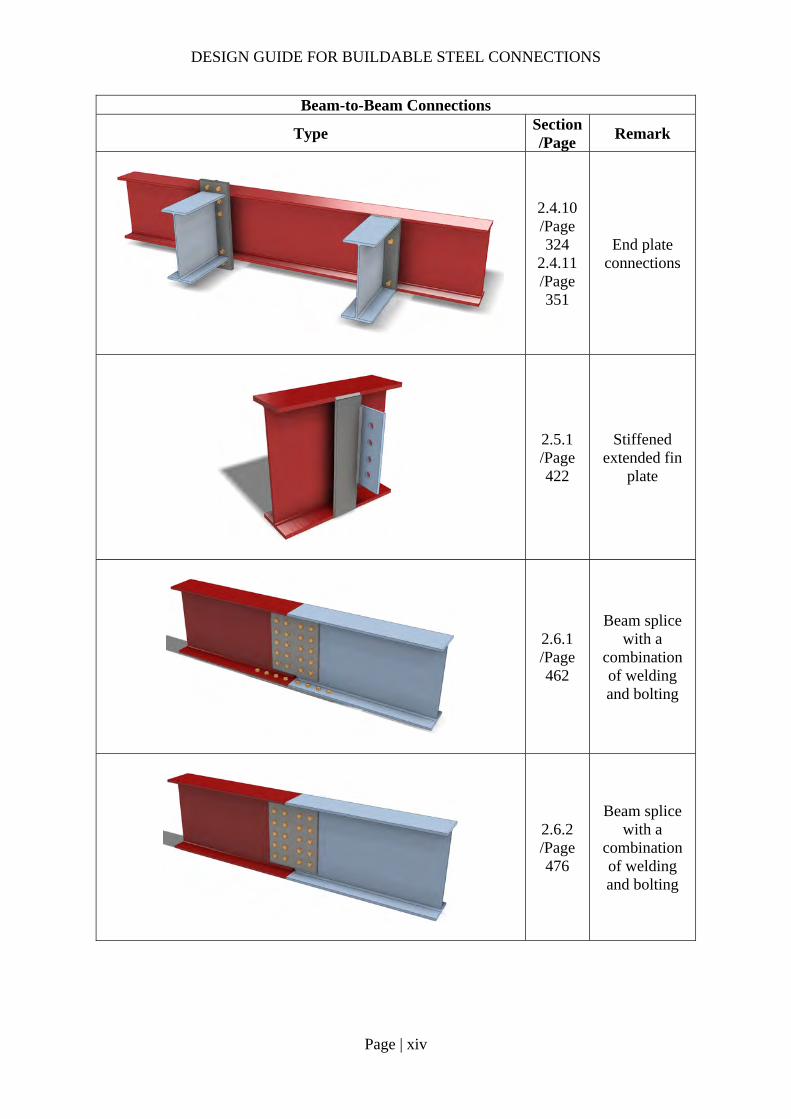
2.4.10 /Page 324
2.4.11 /Page 351
End plate connections
2.5.1 /Page 422
Stiffened extended fin
plate
2.6.1 /Page 462
Beam splice with a
combination of welding and bolting
2.6.2 /Page 476
Beam splice with a
combination of welding and bolting

DESIGN GUIDE FOR BUILDABLE STEEL CONNECTIONS
Page | xv
Beam-to-Column Connections
Type Section/
Page Remark
2.3.6 /Page
80
Fin-plate connection
bending about the major axis
of column
2.3.7 /Page 105
Extended fin plate
connection bending about
the minor axis of the
column
2.3.8 /Page 134
Fin plate connection to
circular hollow column
2.4.6 /Page 247
I-beams connecting to
hollow section
column with external ring
plate
DESIGN GUIDE FOR BUILDABLE STEEL CONNECTIONS
Page | xvi
Beam-to-Column Connections
Type Section/
Page Remark
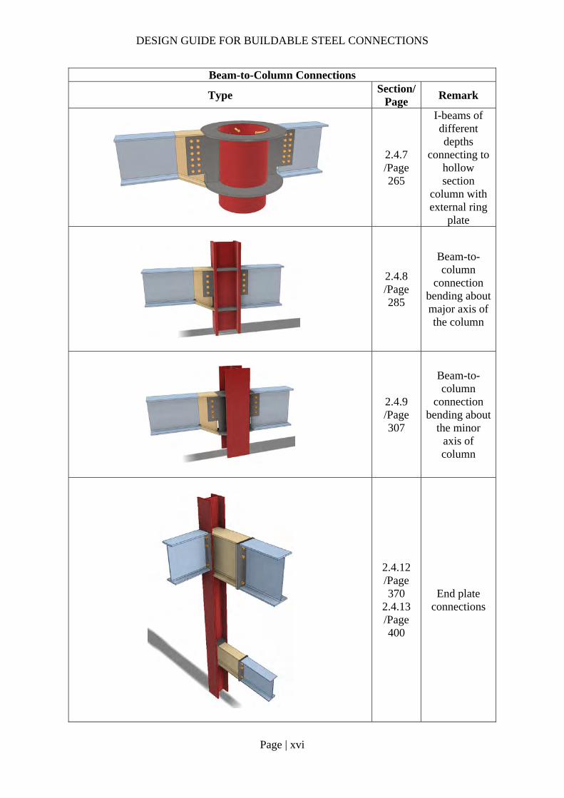
2.4.7 /Page 265
I-beams of different depths
connecting to hollow section
column with external ring
plate
2.4.8 /Page 285
Beam-to-column
connection bending about major axis of the column
2.4.9 /Page 307
Beam-to-column
connection bending about
the minor axis of column
2.4.12 /Page 370
2.4.13 /Page 400
End plate connections
DESIGN GUIDE FOR BUILDABLE STEEL CONNECTIONS
Page | xvii
Beam-to-Column Connections
Type Section/
Page Remark
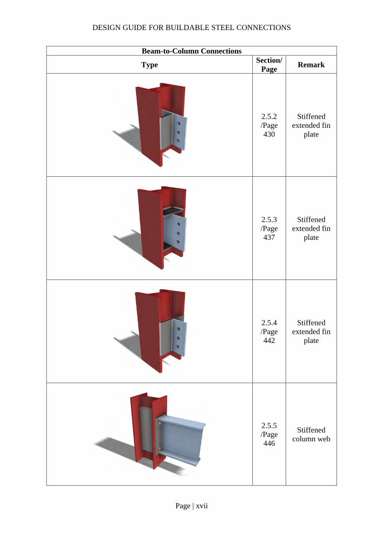
2.5.2 /Page 430
Stiffened extended fin
plate
2.5.3 /Page 437
Stiffened extended fin
plate
2.5.4 /Page 442
Stiffened extended fin
plate
2.5.5 /Page 446
Stiffened column web

DESIGN GUIDE FOR BUILDABLE STEEL CONNECTIONS
Page | xviii
Beam-to-Column Connections
Type Section/
Page Remark
3.5.1 /Page 508
Embedded plate in RC column/wall
4.2.1 /Page 517
Beam to circular column
connection using fin
plate
4.2.2 /Page 530
Beam to rectangular
column connection using fin
plate
4.3.1 /Page 537
Beam to rectangular
column connection
using extended end
plate
DESIGN GUIDE FOR BUILDABLE STEEL CONNECTIONS
Page | xix
Beam-to-Column Connections
Type Section/
Page Remark
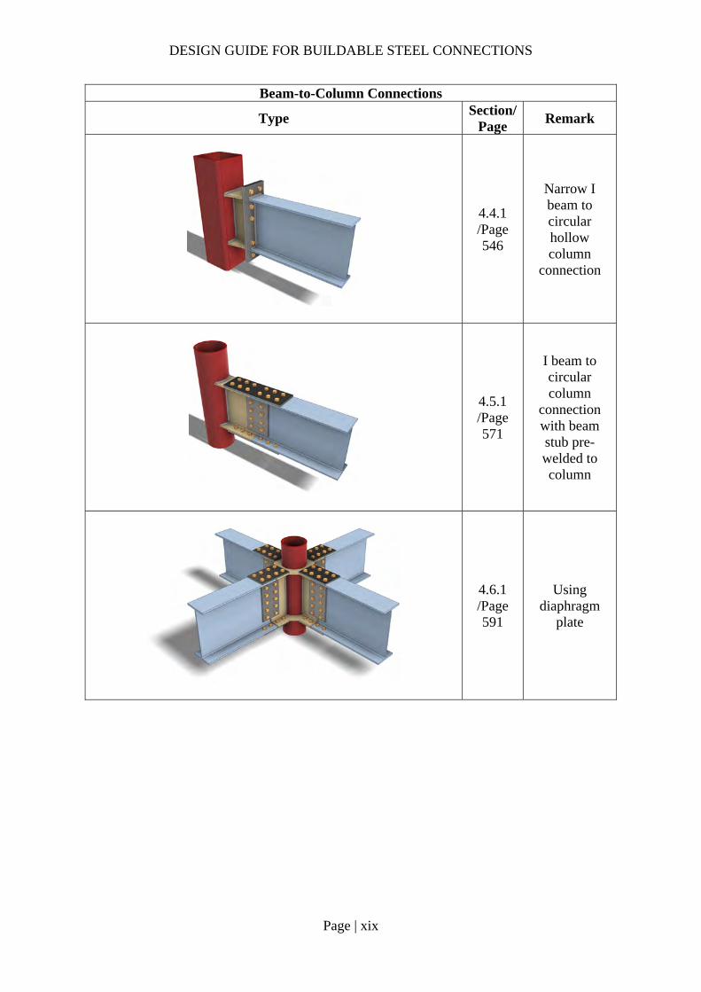
4.4.1 /Page 546
Narrow I beam to circular hollow column
connection
4.5.1 /Page 571
I beam to circular column
connection with beam stub pre-welded to column
4.6.1 /Page 591
Using diaphragm
plate

DESIGN GUIDE FOR BUILDABLE STEEL CONNECTIONS
Page | xx
Bracing connections
Type Section/
Page Remark
5.4.3 /Page 612
Gusset plate
5.3.1 /Page 598
Single sided flare groove
weld
5.3.1 /Page 598
Double sided fillet weld
5.4.1 /Page 603
Turn buckle and gusset
plate
DESIGN GUIDE FOR BUILDABLE STEEL CONNECTIONS
Page | xxi
Base connections
Type Section/
Page Remark
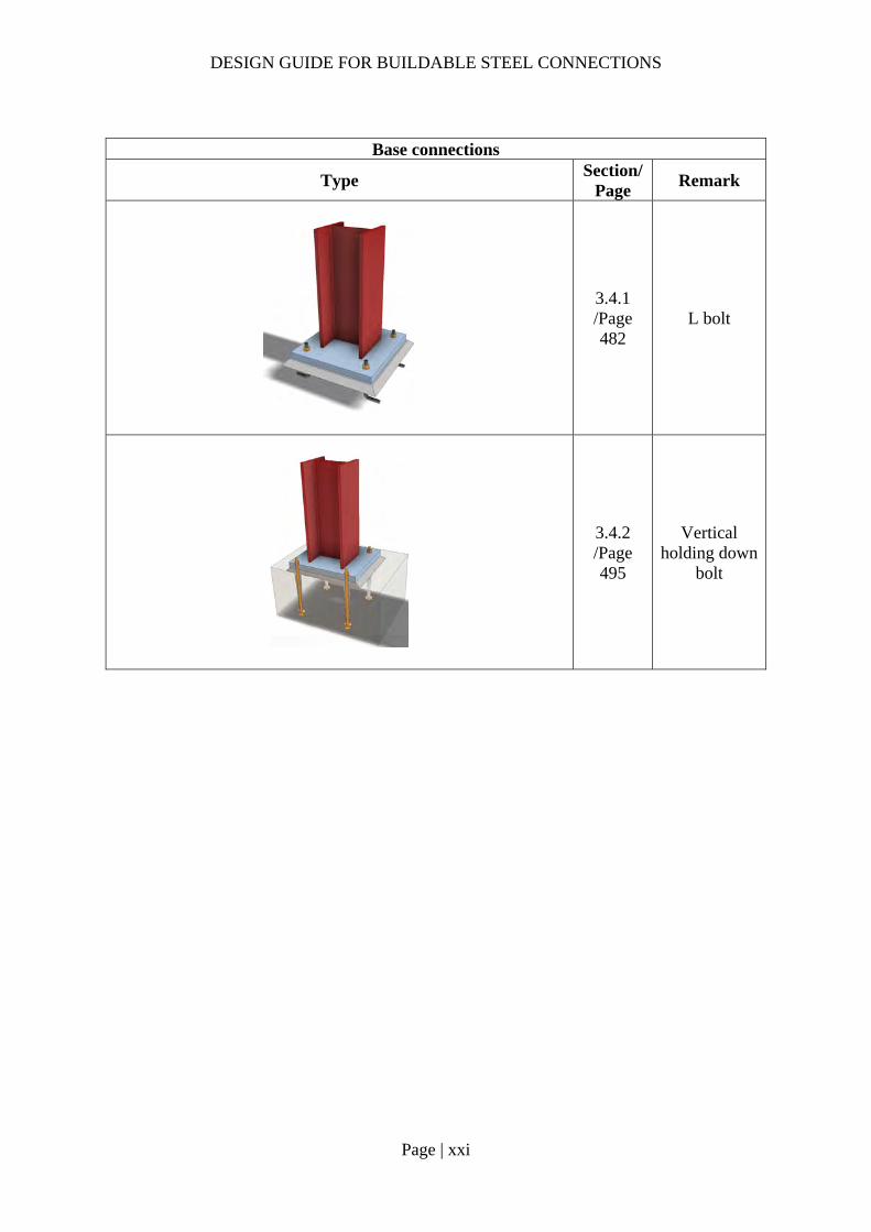
3.4.1 /Page 482
L bolt
3.4.2 /Page 495
Vertical holding down
bolt
DESIGN GUIDE FOR BUILDABLE STEEL CONNECTIONS
Page | xxii
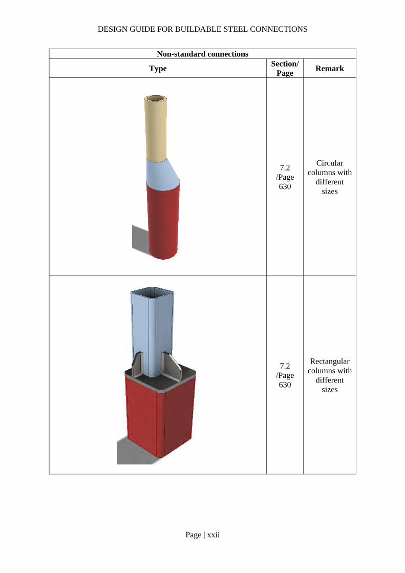
Non-standard connections
Type Section/
Page Remark
7.2 /Page 630
Circular columns with
different sizes
7.2 /Page 630
Rectangular columns with
different sizes

DESIGN GUIDE FOR BUILDABLE STEEL CONNECTIONS
Page | xxiii
Non-standard connections
Type Section/
Page Remark
7.3 /Page 635
Member transition
7.3 /Page 635
Member transition
7.3 /Page 635
Member transition
7.4.1 /Page 636
Stiffeners in truss chord
7.5 /Page 648
Composite connection

DESIGN GUIDE FOR BUILDABLE STEEL CONNECTIONS
Page | 1
1 Introduction 1.1 About this design guide
Connection design is closely related to the fabrication and erection process of a structure. For most of design guides and codes, they only provide engineers with rules to check the resistance, stability and deformations of the connections. There is no specific guideline on buildability of connections. This publication provides guidance for designing various types of connections that are perceived to be more buildable and eventually will improve the speed of steelwork construction. These connections are designed in accordance with SS EN1993-1-8 and SCI Publications P358 & P398. Other relevant design guides are also referred if the rules in Eurocodes are not applicable or not adequate. It should be noted that SS EN1993-1-8 follows the same rules and principles in EN1993-1-8, and hence they are generally referred to as SS EN1993-1-8 in this Guide.
Design procedures are provided for:
a) Beam-to-Beam and Beam-to-Column connections With extended fin plate (for both shear & moment connections) With end plate (for both shear & moment connections)
b) Strengthening of joints Stiffening extended fin plate Supplementary web plates for column web
c) Beam splices A combination of welding and bolting with cover plates
d) Column base plate connections Steel plate with anchorage bolts
e) Connections for hollow steel sections Connecting universal sections to hollow steel sections with fin plates, end plates and diaphragm plates.
f) Bracing connections Weld resistance for connecting steel rod to gusset plate Gusset plate resistance for connecting universal sections
g) Purlin connections h) Non-standard connections
Tubular column-to-column connections for different column sizes Member transition in truss chord Stiffeners in truss chord Semi-continuous composite beam-to-beam joint
Design examples of all the above connections are also given.
1.2 Material
This publication is only valid for connections with material or products comply with standard from Eurocode 3. The material properties used in this guide follow BC 1:2012 and Table 3.1 of SS EN1993-1-1, and only steel grades from S235 to S460 are covered. Nominal values of the yield strength 𝑓 and ultimate strength 𝑓 depend on the thickness of the steel elements.
DESIGN GUIDE FOR BUILDABLE STEEL CONNECTIONS
Page | 2
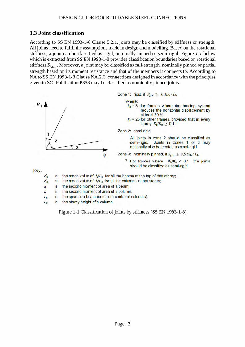
1.3 Joint classification
According to SS EN 1993-1-8 Clause 5.2.1, joints may be classified by stiffness or strength. All joints need to fulfil the assumptions made in design and modelling. Based on the rotational stiffness, a joint can be classified as rigid, nominally pinned or semi-rigid. Figure 1-1 below which is extracted from SS EN 1993-1-8 provides classification boundaries based on rotational stiffness 𝑆 , . Moreover, a joint may be classified as full-strength, nominally pinned or partial strength based on its moment resistance and that of the members it connects to. According to NA to SS EN 1993-1-8 Clause NA.2.6, connections designed in accordance with the principles given in SCI Publication P358 may be classified as nominally pinned joints.
Figure 1-1 Classification of joints by stiffness (SS EN 1993-1-8)

DESIGN GUIDE FOR BUILDABLE STEEL CONNECTIONS
Page | 3
2 Buildable Beam to Beam/Column connections
2.1 Simple connections
Simple joint is assumed to transfer only nominal moment without adversely affecting the overall structural system. Such nominal moment of resistance should not exceed 0.25 times the design moment of resistance required for a full-strength joint if the joint has sufficient rotation capacity.
2.1.1 Bolted Connections (shear and/or tension connections)
Most of the simple joint connections used are based on category type A (bearing type for shear connection) and category type D (for tension connections) where no preloading is required as per table 3.2 of SS EN 1993-1-8. The design resistance depends on the shear and bearing resistance or tensile resistance (where applicable) of the bolt connections.
The usage of bolt where preloading is not required should be “snug” tight while for connections sensitive to slippage, preloading is required. Preloaded bolts (category type B, C or E) will require a certain minimum amount of preload, which is dependent upon the surface smoothness of the threaded area in the bolts and nuts. In addition, the torque required to tighten the preloaded bolts and the recommended torque is usually provided by the bolt manufacturers.
2.1.2 Welded Connections (shear and/or tension connections)
Typically, the type of weld adopted for simple connections is fillet weld. It is recommended to have a symmetric fillet on both sides to distribute the load.
For end plates, the recommendation for the design of the weld is that the end plate should yield before the weld fractures. As for fin plates, full strength fillet weld is recommended. Alternatively, the required fillet weld can be designed based on the actual shear and nominal moments as per SS EN 1993-1-8.
2.1.3 Recommendation for fin plate connections
According to SCI Publication P358, fin plate connection design needs to fulfill the following requirements to ensure the connection provides the necessary rotational capacity and restraint to the supported member:
Fin plate needs to be located as close to the top flange of the supported member as possible to ensure the stability.
The depth of the fin plate should be greater or equal to 0.6 times the depth of the supported member to provide torsional restraint.
The thickness of the fin plate or beam web should not be greater than 0.42 times and 0.5 times of the bolt diameter for S355 and S275 steel, respectively.
The edge and end distance on fin plate or beam web should be at least 2 times the diameter of the bolt.
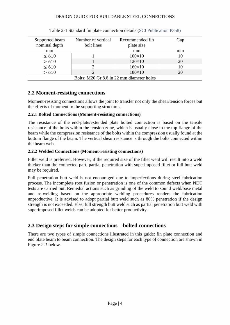
Table 2-1 below shows the standard details of fin plate connections suggested by SCI Publication P358.
DESIGN GUIDE FOR BUILDABLE STEEL CONNECTIONS
Page | 4
Table 2-1 Standard fin plate connection details (SCI Publication P358)
Supported beam nominal depth
Number of vertical bolt lines
Recommended fin plate size
Gap
mm mm mm 610 1 100×10 10 610 1 120×10 20 610 2 160×10 10 610 2 180×10 20
Bolts: M20 Gr.8.8 in 22 mm diameter holes
2.2 Moment-resisting connections
Moment-resisting connections allows the joint to transfer not only the shear/tension forces but the effects of moment to the supporting structures.
2.2.1 Bolted Connections (Moment-resisting connections)
The resistance of the end-plate/extended plate bolted connection is based on the tensile resistance of the bolts within the tension zone, which is usually close to the top flange of the beam while the compression resistance of the bolts within the compression usually found at the bottom flange of the beam. The vertical shear resistance is through the bolts connected within the beam web.
2.2.2 Welded Connections (Moment-resisting connections)
Fillet weld is preferred. However, if the required size of the fillet weld will result into a weld thicker than the connected part, partial penetration with superimposed fillet or full butt weld may be required.
Full penetration butt weld is not encouraged due to imperfections during steel fabrication process. The incomplete root fusion or penetration is one of the common defects when NDT tests are carried out. Remedial actions such as grinding of the weld to sound weld/base metal and re-welding based on the appropriate welding procedures renders the fabrication unproductive. It is advised to adopt partial butt weld such as 80% penetration if the design strength is not exceeded. Else, full strength butt weld such as partial penetration butt weld with superimposed fillet welds can be adopted for better productivity.
2.3 Design steps for simple connections – bolted connections
There are two types of simple connections illustrated in this guide: fin plate connection and end plate beam to beam connection. The design steps for each type of connection are shown in Figure 2-1 below.

DESIGN GUIDE FOR BUILDABLE STEEL CONNECTIONS
Page | 5
Figure 2-1 Design steps for simple connections
For ease of site installation, it is preferable to extend the fin plates beyond the flange of the primary beam. Design checks are required on the stability of the fin plate for lateral torsional buckling in addition to the nominal moment generated from the eccentricity connections.
For the purpose of illustration, all bolts shown in the following worked examples are non-preloaded bolts
2.3.1 Fin plate connection design procedures Bolt shear
Shear resistance of one bolt per shear plane (SS EN1993-1-8 Table 3.4):
𝐹 ,𝛼 𝑓 𝐴𝛾
where
𝐴 : tensile stress area of the bolt
Simple Connections
Fin plate
Two secondary beams
1. Bolt group resistance
2. Fin plate resistance
3. Secondary beam web resistance
4. Weld resistance
5. Local shear resistance
One secondary beam
6. Punching shear resistance
End plate
(Beam to beam)
1. Weld resistance
2. Secondary beam shear
3. Bolt in shear
4. End plate shear resistance
5. T‐stub resistance
6. Stiffener
DESIGN GUIDE FOR BUILDABLE STEEL CONNECTIONS
Page | 6
𝛼 0.6 for classes 4.6 and 8.8
𝛼 0.5 for class 10.9
𝛾 1.25 (SS EN1993-1-8)
𝑓 : nominal values of the ultimate tensile strength of bolts (SS EN 1993-1-8 Table 3.1)
Shear resistance of bolt group (SCI_P358 & SN017):
𝑉𝑛𝐹 ,
1 𝛼𝑛 𝛽𝑛𝑉
where
𝛼 0 for n 1 𝑜𝑟 𝑧𝑝2𝑙
for n 2
𝑧: distance between support and centroid of bolt group
𝑛 : number of bolts lines
𝑛 : number of vertical bolt lines
𝛽6𝑧
𝑛 𝑛 1 𝑝 for 𝑛 1 𝑜𝑟
𝑧𝑝2𝑙
𝑛 1 for 𝑛 2
𝑙𝑛2𝑝
16𝑛 𝑛 1 𝑝
𝑛 𝑛 𝑛 = total number of bolts
Bolt bearing
Bearing resistance of a single bolt (SS EN1993-1-8 Table 3.4):
𝐹 ,𝑘 𝛼 𝑓 𝑑𝑡𝛾
where
𝑑: diameter of bolt
𝑡: thickness of fin plate or beam web
𝑓 : ultimate strength of fin plate or beam web
𝑘 min 2.8𝑒𝑑
1.7;1.4𝑝𝑑
1.7; 2.5
𝛼 min𝑒
3𝑑;𝑝
3𝑑14
;𝑓𝑓
; 1.0
𝑥 2;𝑦 1 for vertical direction bearing
𝑥 1;𝑦 2 for horizontal direction bearing
𝑓 : ultimate strength of bolt
𝑑 : diameter of bolt hole
DESIGN GUIDE FOR BUILDABLE STEEL CONNECTIONS
Page | 7
Bolt bearing resistance of bolt group (SCI_P358):
𝑉𝑛
1 𝛼𝑛𝐹 , ,
𝛽𝑛𝐹 , ,
𝑉
where
𝛼,𝛽: are defined in (1a)
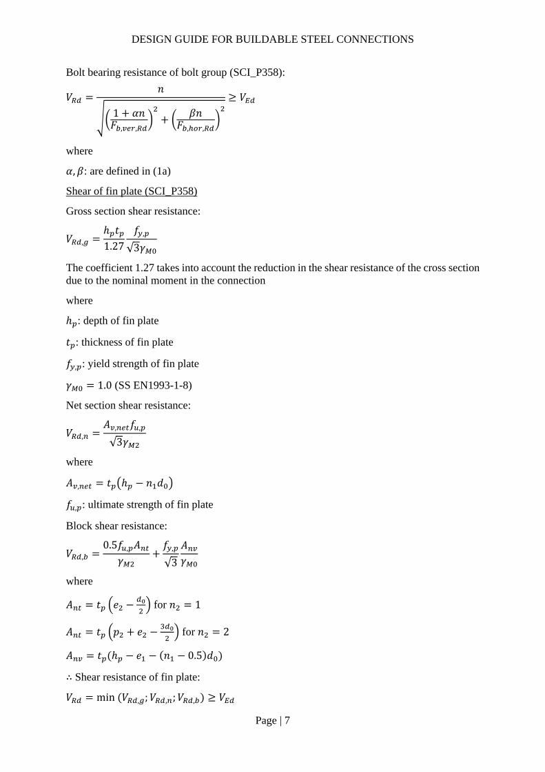
Shear of fin plate (SCI_P358)
Gross section shear resistance:
𝑉 ,ℎ 𝑡1.27
𝑓 ,
√3𝛾
The coefficient 1.27 takes into account the reduction in the shear resistance of the cross section due to the nominal moment in the connection
where
ℎ : depth of fin plate
𝑡 : thickness of fin plate
𝑓 , : yield strength of fin plate
𝛾 1.0 (SS EN1993-1-8)
Net section shear resistance:
𝑉 ,𝐴 , 𝑓 ,
√3𝛾
where
𝐴 , 𝑡 ℎ 𝑛 𝑑
𝑓 , : ultimate strength of fin plate
Block shear resistance:
𝑉 ,0.5𝑓 , 𝐴
𝛾𝑓 ,
√3
𝐴𝛾
where
𝐴 𝑡 𝑒 for 𝑛 1
𝐴 𝑡 𝑝 𝑒 for 𝑛 2
𝐴 𝑡 ℎ 𝑒 𝑛 0.5 𝑑
∴ Shear resistance of fin plate:
𝑉 min 𝑉 , ;𝑉 , ;𝑉 , 𝑉

DESIGN GUIDE FOR BUILDABLE STEEL CONNECTIONS
Page | 8
*If the distance 𝐿 between the centers of the end bolts in a joint is greater than 15 times the diameter of the bolt 𝑖. 𝑒. 𝐿 15𝑑 , reduction factor 𝛽 needs to be applied to the resistance of the bolt group. (SS EN1993-1-8 3.8 (1))
0.75 𝛽 1𝐿 15𝑑
200𝑑1.0
Bending of fin plate (SCI_P358)
If ℎ 2.73𝑧, the bending resistance of fin plate is insignificant.
Else,
𝑉𝑊 ,
𝑧𝑓 ,
𝛾
where
𝑊 ,𝑡 ℎ
6
𝑧: distance between center line of bolt group and support
𝛾 1.0 (SS EN1993-1-8)
Lateral torsional buckling of fin plate (SCI_P358)
If fin plate is classified as Long fin plate (𝑧 𝑡 /0.15 ), the lateral torsional buckling resistance of the fin plate:
𝑉 min𝑊 ,
𝑧𝜒 𝑓 ,
0.6𝛾;𝑊 ,
𝑧𝑓 ,
𝛾
where
The 0.6 factor in the expression for 𝑉 accounts for the triangular shape of the assumed bending moment diagram in the fin plate
𝜒 : reduction factor cater for lateral torsional buckling, can be obtained from (SCI_P358 or SS EN1993-1-1)
𝛾 1.0 (SS EN1993-1-8)
Shear of secondary beam web (SCI_P358)
Gross section shear resistance:
𝑉 , 𝑉 , 𝐴𝑓 ,
√3𝛾
where
𝐴 : shear area of secondary beam
for unnotched beams: 𝐴 𝐴 2𝑏 𝑡 , 𝑡 , 2𝑟 𝑡 , ℎ , 𝑡 ,
𝐴 : cross-section area of beam

DESIGN GUIDE FOR BUILDABLE STEEL CONNECTIONS
Page | 9
𝑏 : width of beam
𝑡 , : thickness of beam flange
𝑡 , : thickness of beam web
𝑟 : root radius of beam
*In this guide, as fin plate is extended beyond the beam flange to facilitate construction, only unnotched beams are considered.
For net shear resistance, the design procedures are same as that in 2(a).
∴ shear resistance of beam web:
𝑉 min 𝑉 , ;𝑉 , 𝑉
Shear and bending interaction of the beam web (SCI_P358)
According to SCI_P358, for short fin plate (𝑧 𝑡 /0.15 , shear and bending interaction check is not significant.
For long fin plate, it is necessary to ensure the connection can resist a moment 𝑉 𝑧 for single line of bolts or 𝑉 𝑧 𝑝 for double lines of bolts.
Moment resistance of section ABCD:
𝑀 𝑀 , , 𝑉 , , 𝑛 1 𝑝 𝑀 𝑉 𝑧 𝑜𝑟 𝑉 𝑧 𝑝
where
𝑀 , , : moment resistance of beam web section BC
for low shear 𝑉 , 0.5𝑉 , , :
𝑀 , ,𝑓 , 𝑡 ,
6𝛾𝑛 1 𝑝
for high shear (𝑉 , 0.5𝑉 , , :
𝑀 , ,𝑓 , 𝑡 ,
6𝛾𝑛 1 𝑝 1
2𝑉 ,
𝑉 , ,1
𝑉 . : shear force on the beam web section BC
𝑉 , 𝑉𝑛 1 𝑝ℎ
𝑉 , , : shear resistance of the beam web section AB
for single vertical line of bolts 𝑛 1 :
𝑉 , ,𝑡 , 𝑒 , 𝑓 ,
√3𝛾
for two vertical lines of bolts 𝑛 2 :
DESIGN GUIDE FOR BUILDABLE STEEL CONNECTIONS
Page | 10
𝑉 , ,𝑡 , 𝑒 , 𝑝 𝑓 ,
√3𝛾
𝑉 , , : shear resistance of beam web section BC
𝑉 , ,𝑡 , 𝑛 1 𝑝 𝑓 ,
√3𝛾
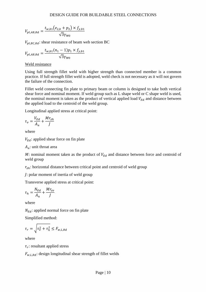
Weld resistance
Using full strength fillet weld with higher strength than connected member is a common practice. If full strength fillet weld is adopted, weld check is not necessary as it will not govern the failure of the connection.
Fillet weld connecting fin plate to primary beam or column is designed to take both vertical shear force and nominal moment. If weld group such as L shape weld or C shape weld is used, the nominal moment is taken as the product of vertical applied load 𝑉 and distance between the applied load to the centroid of the weld group.
Longitudinal applied stress at critical point:
𝜏𝑉𝐴
𝑀𝑟𝐽
where
𝑉 : applied shear force on fin plate
𝐴 : unit throat area
𝑀: nominal moment taken as the product of 𝑉 and distance between force and centroid of weld group
𝑟 : horizontal distance between critical point and centroid of weld group
𝐽: polar moment of inertia of weld group
Transverse applied stress at critical point:
𝜏𝑁𝐴
𝑀𝑟𝐽
where
𝑁 : applied normal force on fin plate
Simplified method:
𝜏 𝜏 𝜏 𝐹 , ,
where
𝜏 : resultant applied stress
𝐹 , , : design longitudinal shear strength of fillet welds
DESIGN GUIDE FOR BUILDABLE STEEL CONNECTIONS
Page | 11
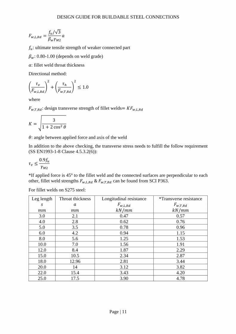
𝐹 , ,𝑓 /√3𝛽 𝛾
𝑎
𝑓 : ultimate tensile strength of weaker connected part
𝛽 : 0.80-1.00 (depends on weld grade)
𝑎: fillet weld throat thickness
Directional method:
𝜏𝐹 , ,
𝜏𝐹 , ,
1.0
where
𝐹 , , : design transverse strength of fillet welds 𝐾𝐹 , ,
𝐾3
1 2 cos 𝜃
𝜃: angle between applied force and axis of the weld
In addition to the above checking, the transverse stress needs to fulfill the follow requirement (SS EN1993-1-8 Clause 4.5.3.2(6)):
𝜏0.9𝑓𝛾
*If applied force is 45° to the fillet weld and the connected surfaces are perpendicular to each other, fillet weld strengths 𝐹 , , & 𝐹 , , can be found from SCI P363.
For fillet welds on S275 steel:
Leg length Throat thickness Longitudinal resistance *Transverse resistance 𝑠 𝑎 𝐹 , , 𝐹 , , 𝑚𝑚 𝑚𝑚 𝑘𝑁/𝑚𝑚 𝑘𝑁/𝑚𝑚 3.0 2.1 0.47 0.57 4.0 2.8 0.62 0.76 5.0 3.5 0.78 0.96 6.0 4.2 0.94 1.15 8.0 5.6 1.25 1.53 10.0 7.0 1.56 1.91 12.0 8.4 1.87 2.29 15.0 10.5 2.34 2.87 18.0 12.96 2.81 3.44 20.0 14 3.12 3.82 22.0 15.4 3.43 4.20 25.0 17.5 3.90 4.78
DESIGN GUIDE FOR BUILDABLE STEEL CONNECTIONS
Page | 12
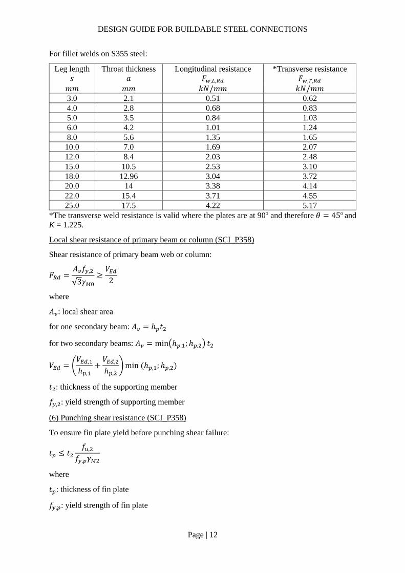
For fillet welds on S355 steel:
Leg length Throat thickness Longitudinal resistance *Transverse resistance 𝑠 𝑎 𝐹 , , 𝐹 , , 𝑚𝑚 𝑚𝑚 𝑘𝑁/𝑚𝑚 𝑘𝑁/𝑚𝑚 3.0 2.1 0.51 0.62 4.0 2.8 0.68 0.83 5.0 3.5 0.84 1.03 6.0 4.2 1.01 1.24 8.0 5.6 1.35 1.65 10.0 7.0 1.69 2.07 12.0 8.4 2.03 2.48 15.0 10.5 2.53 3.10 18.0 12.96 3.04 3.72 20.0 14 3.38 4.14 22.0 15.4 3.71 4.55 25.0 17.5 4.22 5.17
*The transverse weld resistance is valid where the plates are at 90o and therefore 𝜃 45o and K = 1.225.
Local shear resistance of primary beam or column (SCI_P358)
Shear resistance of primary beam web or column:
𝐹𝐴 𝑓 ,
√3𝛾
𝑉2
where
𝐴 : local shear area
for one secondary beam: 𝐴 ℎ 𝑡
for two secondary beams: 𝐴 min ℎ , ;ℎ , 𝑡
𝑉𝑉 ,
ℎ ,
𝑉 ,
ℎ ,min ℎ , ;ℎ ,
𝑡 : thickness of the supporting member
𝑓 , : yield strength of supporting member
(6) Punching shear resistance (SCI_P358)
To ensure fin plate yield before punching shear failure:
𝑡 𝑡𝑓 ,
𝑓 , 𝛾
where
𝑡 : thickness of fin plate
𝑓 , : yield strength of fin plate

DESIGN GUIDE FOR BUILDABLE STEEL CONNECTIONS
Page | 13
𝑓 , : ultimate strength of supporting member
2.3.2 End plate connection design procedure
Weld group resistance
Fillet weld between secondary beam web and end plate is designed to take shear force only. According to SS EN1993-1-8 6.2.2 (1), In weld connections, and in bolted connections with end-plates, the welds connecting the beam web should be designed to transfer the shear force from the connected beam to the joint, without any assistance from the welds connecting the beam flanges.
𝜏 ,𝑉𝐴
𝐹 , ,
where
𝜏 , : applied longitudinal stress
𝐹 , , : longitudinal resistance of fillet weld (may be found in SCI_P363)
𝑉 : applied shear force
𝐴 : unit throat area 2𝑑
Secondary beam shear resistance
𝑉 ,𝐴 𝑓 ,
√3𝛾𝑉
where
𝐴 : shear area of secondary beam
𝐴 𝐴 , 2𝑏 𝑡 , 𝑡 , 2𝑟 𝑡 ,
Bolt group resistance (SCI_P358)
Resistance of bolt group:
If 𝐹 , 0.8𝐹 , , then 𝐹 𝑛𝐹 , 𝑉
If 𝐹 , 0.8𝐹 , , then 𝐹 0.8𝑛𝐹 , 𝑉
where
𝐹 , : shear resistance of one bolt, same as 2.3.1 (1a)
𝐹 , : minimum of the bearing resistance on the end plate and bearing resistance on supporting member per bolt, same as 2.3.1 (1b)
𝑛: number of bolts
0.8: reduction factor allows for the presence of tension force
(4) End plate shear resistance
Gross section shear resistance:

DESIGN GUIDE FOR BUILDABLE STEEL CONNECTIONS
Page | 14
𝑉 , 2𝐴𝑓 ,
√3𝛾
where
𝐴 : shear area of end plate
𝐴 ℎ 𝑡
ℎ : depth of end plate
𝑡 : thickness of end plate
𝑓 , : yield strength of end plate
Net section shear resistance:
𝑉 ,𝐴 , 𝑓 ,
√3𝛾
where
𝐴 , 𝐴 2𝑛 𝑑 𝑡
Block shear resistance:
𝑉 ,0.5𝑓 , 𝐴
𝛾𝑓 ,
√3
𝐴𝛾
where
𝐴 𝑡 𝑒𝑑2
𝐴 𝑡 ℎ 𝑒 𝑛 0.5 𝑑
∴ Shear resistance of end plate:
𝑉 min 𝑉 , ;𝑉 , ;𝑉 , 𝑉
T-stub resistance (SCI_P358)
Mode 1 complete flange yielding resistance:
𝐹 ,8𝑛 2𝑒 𝑀 , ,
2𝑚𝑛 𝑒 𝑚 𝑛
where
𝑛 𝑒 min 𝑒 ; 𝑒 ,
𝑒𝑑4
𝑑 : diameter of the washer or the width across points of the bolt or nut
𝑀 , , : plastic moment resistance of the equivalent T-stub for mode 1 or mode 2

DESIGN GUIDE FOR BUILDABLE STEEL CONNECTIONS
Page | 15
𝑀 , ,0.25𝛴𝑙 𝑡 𝑓 ,
𝛾
𝑙 , : effective length of the equivalent T-stub for Mode 1, taken as the lesser of 𝑙 , and 𝑙 ,
𝑙 , : effective length of the equivalent T-stub for Mode 2, taken as 𝑙 ,
𝑚𝑝 𝑡 , 2 0.8 𝑎√2
2
𝑎: fillet weld throat thickness
Mode 2 Bolt failure with flange yielding resistance:
𝐹 ,2𝑀 , , 𝑛𝛴𝐹 ,
𝑚 𝑛
where
𝐹 ,𝑘 𝑓 𝐴𝛾 ,
𝑘 0.63 for countersunk bolts
0.90 otherwise
𝛾 , 1.25
Mode 3 Bolt failure resistance:
𝐹 , 𝛴𝐹 ,
Resistance of first row of bolt in T-stub:
𝐹 , , min 𝐹 , , ;𝐹 , , ;𝐹 , , 𝐹
Applied tensile force:
𝐹𝑀𝑟
where
𝑀: nominal moment due to eccentricity
𝑟: distance between flanges of secondary beam
Stiffener resistance (SCI_P398)
Design procedure for fillet weld of stiffener is same as 2.3.1 (4)
Design compressive resistance of stiffener:
𝐹 , ,𝜔𝜌𝑏 , , 𝑡 𝑓
𝛾
where
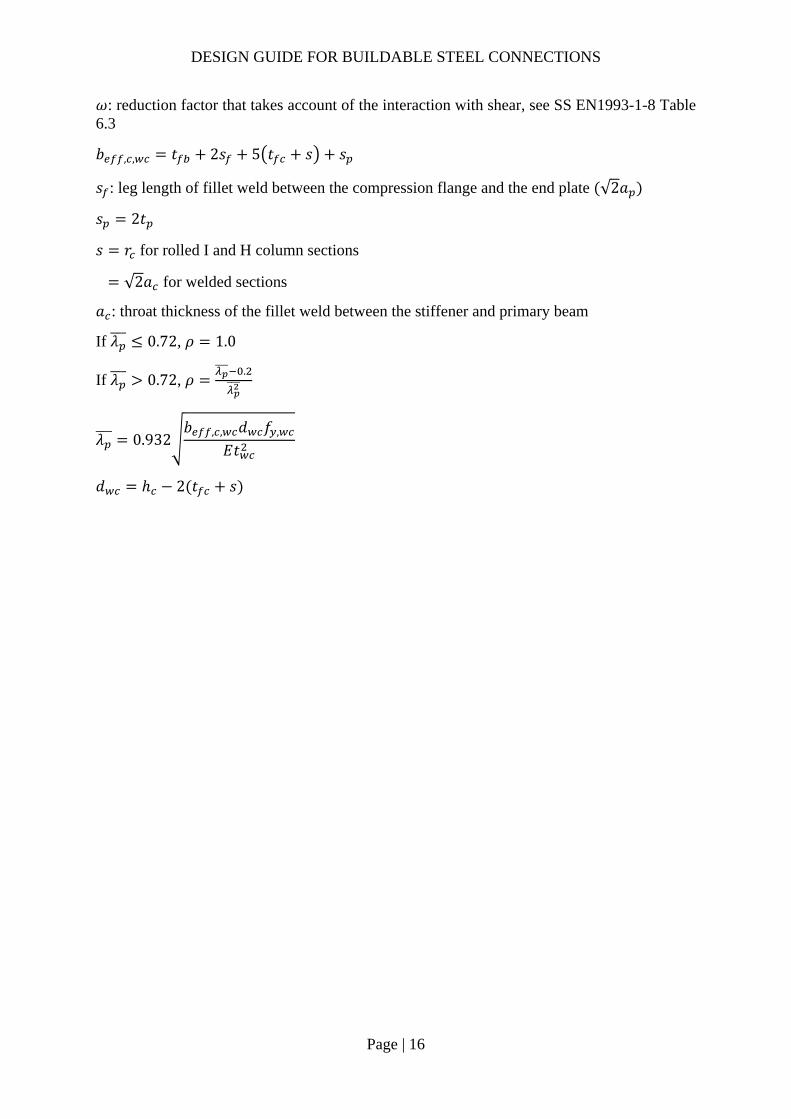
DESIGN GUIDE FOR BUILDABLE STEEL CONNECTIONS
Page | 16
𝜔: reduction factor that takes account of the interaction with shear, see SS EN1993-1-8 Table 6.3
𝑏 , , 𝑡 2𝑠 5 𝑡 𝑠 𝑠
𝑠 : leg length of fillet weld between the compression flange and the end plate √2𝑎
𝑠 2𝑡
𝑠 𝑟 for rolled I and H column sections
√2𝑎 for welded sections
𝑎 : throat thickness of the fillet weld between the stiffener and primary beam
If 𝜆 0.72, 𝜌 1.0
If 𝜆 0.72, 𝜌.
𝜆 0.932𝑏 , , 𝑑 𝑓 ,
𝐸𝑡
𝑑 ℎ 2 𝑡 𝑠

DESIGN GUIDE FOR BUILDABLE STEEL CONNECTIONS
Page | 17
2.3.3 Example 1 – One-sided Beam-to-Beam connection with extended fin plate

DESIGN GUIDE FOR BUILDABLE STEEL CONNECTIONS
Page | 18
Check 1 – Bolt group resistance Ref Calculations Remark
Bolt shear resistance: Using Gr8.8, M20 bolts with: 𝐴 245𝑚𝑚 , 𝑓 800𝑀𝑃𝑎, 𝛼 0.6
SS EN1993-1-8
Shear resistance of a single bolt:
𝐹 ,𝛼 𝑓 𝐴𝛾
0.6 800 245
1.2510
94.08𝑘𝑁
𝛾 1.25 (refer to NA to SS)
𝑧 165𝑚𝑚
SCI_P358 SN017
For single vertical line of bolts (𝑛 1): 𝑛 5, 𝑛 5 1 5 𝛼 0
𝛽6𝑧
𝑛 𝑛 1 𝑝
6 165𝑚𝑚
5 5 1 65𝑚𝑚
0.51
𝑉𝑛𝐹 ,
1 𝛼𝑛 𝛽𝑛
5 94.08
1 0 0.51 510
172.41𝑘𝑁 𝑉 100𝑘𝑁 OK!
DESIGN GUIDE FOR BUILDABLE STEEL CONNECTIONS
Page | 19
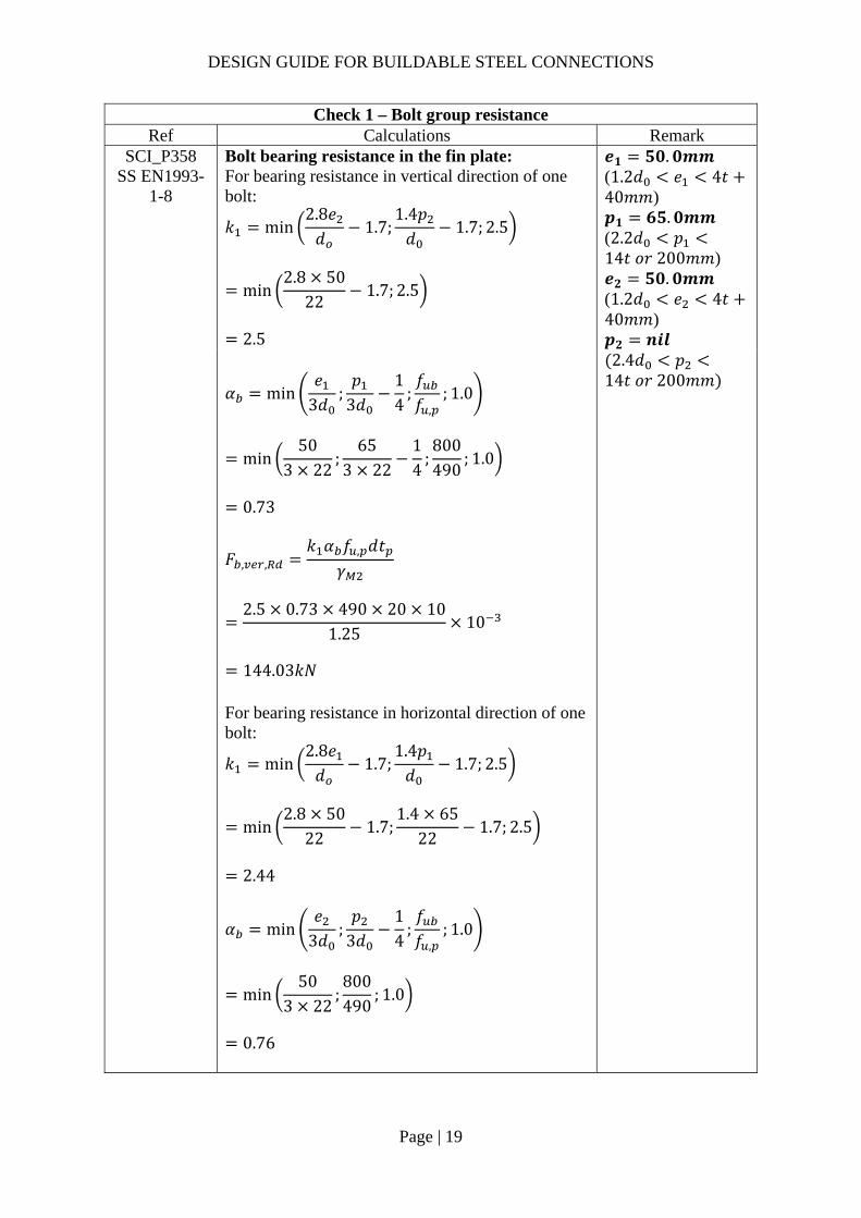
Check 1 – Bolt group resistance Ref Calculations Remark
SCI_P358 SS EN1993-
1-8
Bolt bearing resistance in the fin plate: For bearing resistance in vertical direction of one bolt:
𝑘 min2.8𝑒𝑑
1.7;1.4𝑝𝑑
1.7; 2.5
min2.8 50
221.7; 2.5
2.5
𝒆𝟏 𝟓𝟎.𝟎𝒎𝒎 (1.2𝑑 𝑒 4𝑡40𝑚𝑚) 𝒑𝟏 𝟔𝟓.𝟎𝒎𝒎 (2.2𝑑 𝑝14𝑡 𝑜𝑟 200𝑚𝑚) 𝒆𝟐 𝟓𝟎.𝟎𝒎𝒎 (1.2𝑑 𝑒 4𝑡40𝑚𝑚) 𝒑𝟐 𝒏𝒊𝒍
𝛼 min𝑒
3𝑑;𝑝
3𝑑14
;𝑓𝑓 ,
; 1.0
min50
3 22;
653 22
14
;800490
; 1.0
0.73
𝐹 , ,𝑘 𝛼 𝑓 , 𝑑𝑡
𝛾
2.5 0.73 490 20 10
1.2510
144.03𝑘𝑁
2.4𝑑 𝑝14𝑡 𝑜𝑟 200𝑚𝑚
For bearing resistance in horizontal direction of one bolt:
𝑘 min2.8𝑒𝑑
1.7;1.4𝑝𝑑
1.7; 2.5
min2.8 50
221.7;
1.4 6522
1.7; 2.5
2.44
𝛼 min𝑒
3𝑑;𝑝
3𝑑14
;𝑓𝑓 ,
; 1.0
min50
3 22;800490
; 1.0
0.76

DESIGN GUIDE FOR BUILDABLE STEEL CONNECTIONS
Page | 20
Check 1 – Bolt group resistance Ref Calculations Remark
𝐹 , ,𝑘 𝛼 𝑓 , 𝑑𝑡
𝛾
2.44 0.76 490 20 10
1.2510
144.71kN
Bolt group bearing resistance:
𝑉𝑛
1 𝛼𝑛𝐹 , ,
𝛽𝑛𝐹 , ,
5
1144.03
0.51 5144.71
10
265.02𝑘𝑁 𝑉 100𝑘𝑁
OK!
SCI_P358 SS EN1993-
1-8
Bolt bearing resistance in secondary beam web: Vertical bearing resistance:
𝑘 min2.8𝑒 ,
𝑑1.7;
1.4𝑝𝑑
1.7; 2.5
min2.8 50
221.7; 2.5
2.5
𝛼 min𝑒 ,
3𝑑;𝑝
3𝑑14
;𝑓𝑓 ,
; 1.0
min78.3
3 22;
653 22
14
;800490
; 1.0
0.73
𝐹 , ,𝑘 𝛼 𝑓 , 𝑑𝑡 ,
𝛾
2.5 0.73 490 20 8.1
1.2510
116.66𝑘𝑁
𝒆𝟏,𝒃 𝟕𝟖.𝟑𝒎𝒎 𝒆𝟐,𝒃 𝟓𝟎.𝟎𝒎𝒎

DESIGN GUIDE FOR BUILDABLE STEEL CONNECTIONS
Page | 21
Check 1 – Bolt group resistance Ref Calculations Remark
Horizontal bearing resistance:
𝑘 min2.8𝑒 ,
𝑑1.7;
1.4𝑝𝑑
1.7; 2.5
min2.8 97.3
221.7;
1.4 6522
1.7; 2.5
2.44
𝛼 min𝑒 ,
3𝑑;𝑝
3𝑑14
;𝑓𝑓 ,
; 1.0
min50
3 22;800490
; 1.0
0.76
𝐹 , ,𝑘 𝛼 𝑓 , 𝑑𝑡 ,
𝛾
2.44 0.76 490 20 8.1
1.2510
117.21𝑘𝑁
Bolt group bearing resistance:
𝑉𝑛
1 𝛼𝑛𝐹 , ,
𝛽𝑛𝐹 , ,
5
1116.66
0.52 5117.21
10
214.67𝑘𝑁 𝑉 100𝑘𝑁
OK!

DESIGN GUIDE FOR BUILDABLE STEEL CONNECTIONS
Page | 22
Check 2 – Fin plate resistance Ref Calculations Remark
SS EN1993-1-8
SCI_P358
Fin-plate shear resistance (gross section): 𝑡 10𝑚𝑚 16𝑚𝑚 ∴ 𝑓 , 355𝑀𝑃𝑎 Gross section shear resistance:
𝑉 ,ℎ 𝑡1.27
𝑓 ,
√3𝛾
360 10
1.27355
√3 10
580.99𝑘𝑁
ℎ 360𝑚𝑚 𝛾 1.0 (SS EN1993-1-1)
Fin-plate shear resistance (net section): 𝐴 , 𝑡 ℎ 𝑛 𝑑
10 360 5 22
2500𝑚𝑚 Net area shear resistance:
𝑉 ,𝐴 , 𝑓 ,
√3𝛾
2500490
√3 1.2510
565.80𝑘𝑁

DESIGN GUIDE FOR BUILDABLE STEEL CONNECTIONS
Page | 23
Check 2 – Fin plate resistance Ref Calculations Remark
Fin-plate shear resistance (block shear): For single vertical line of bolts (𝑛 1): Net area subject to tension:
𝐴 𝑡 𝑒𝑑2
10 50222
390𝑚𝑚
Net area subject to shear: 𝐴 𝑡 ℎ 𝑒 𝑛 0.5 𝑑
10 360 50 5 0.5 22
2110𝑚𝑚
𝑉 ,
0.5𝑓 , 𝐴𝛾
𝑓 ,
√3
𝐴𝛾
0.5 490 390
1.25355
√3
21101.0
10
508.90𝑘𝑁
𝑉 , min 𝑉 , ;𝑉 , ;𝑉 ,
min 580.99𝑘𝑁; 565.80𝑘𝑁; 508.90𝑘𝑁
508.90𝑘𝑁 𝑉 100𝑘𝑁
OK!
DESIGN GUIDE FOR BUILDABLE STEEL CONNECTIONS
Page | 24
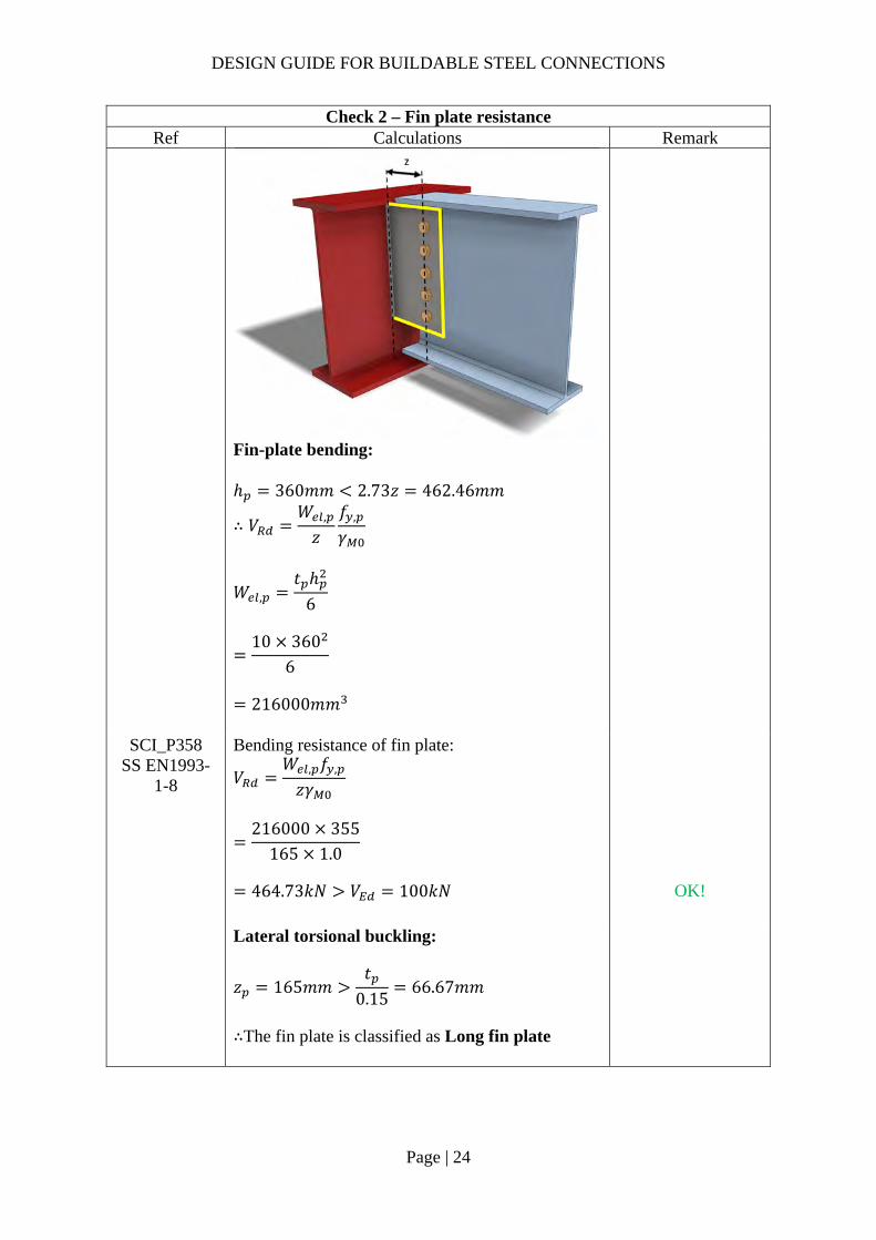
Check 2 – Fin plate resistance Ref Calculations Remark
Fin-plate bending: ℎ 360𝑚𝑚 2.73𝑧 462.46𝑚𝑚
∴ 𝑉𝑊 ,
𝑧𝑓 ,
𝛾
𝑊 ,𝑡 ℎ
6
10 360
6
216000𝑚𝑚
SCI_P358 SS EN1993-
1-8
Bending resistance of fin plate:
𝑉𝑊 , 𝑓 ,
𝑧𝛾
216000 355
165 1.0
464.73𝑘𝑁 𝑉 100𝑘𝑁
OK!
Lateral torsional buckling:
𝑧 165𝑚𝑚𝑡
0.1566.67𝑚𝑚
∴The fin plate is classified as Long fin plate

DESIGN GUIDE FOR BUILDABLE STEEL CONNECTIONS
Page | 25
Check 2 – Fin plate resistance Ref Calculations Remark
Raidus of gyration:
𝑖𝑡
√12
10
√122.89
Slenderness of the fin plate:
𝜆𝐿𝜋𝑖
𝑓𝐸
165𝜋 2.89
355210000
0.748
LTB reduction factor: ∴ 𝜒 0.69
𝑉 min 𝑊 ,
𝑧𝜒 𝑓 ,
0.6𝛾;𝑊 ,
𝑧𝑓 ,
𝛾
min216000 0.69 355
165 0.6 1.0;216000 355
165 1.0
10
𝜒 is calculated based on imperfection class c 𝛾 1.0 (SS EN1993-1-1)
464.73𝑘𝑁 𝑉 100𝑘𝑁 OK!
Note:
Lateral restraint should be provided for primary beam with long fin plate to prevent lateral torsional buckling.

DESIGN GUIDE FOR BUILDABLE STEEL CONNECTIONS
Page | 26
Check 3 – Secondary beam web resistance Ref Calculations Remark
SCI_P358 SS EN1993-
1-8
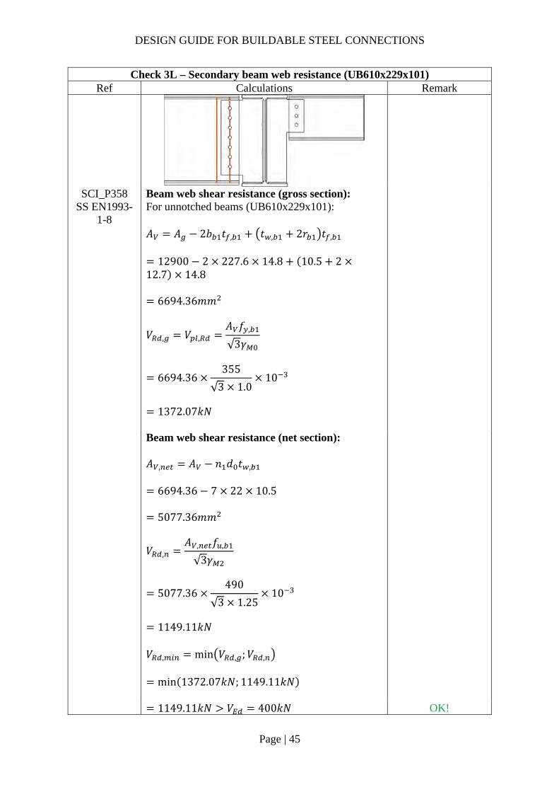
Beam web shear resistance (gross section): For unnotched beams (UB457x152x60): 𝐴 𝐴 2𝑏 𝑡 , 𝑡 , 2𝑟 𝑡 ,
7620 2 152.9 13.3 8.1 2 10.213.3
3931.91𝑚𝑚
𝑉 , 𝑉 ,𝐴 𝑓 ,
√3𝛾
3931.91355
√3 1.010
805.88𝑘𝑁
Beam web shear resistance (net section): 𝐴 , 𝐴 𝑛 𝑑 𝑡 ,
3931.91 5 22 8.1
3040.9𝑚𝑚 1
𝑉 ,𝐴 , 𝑓 ,
√3𝛾
3040.91490
√3 1.2510
688.22𝑘𝑁
𝑉 , min 𝑉 , ;𝑉 ,
min 805.88𝑘𝑁; 688.22𝑘𝑁
688.22𝑘𝑁 𝑉 100𝑘𝑁 OK!

DESIGN GUIDE FOR BUILDABLE STEEL CONNECTIONS
Page | 27
Check 3 – Secondary beam web resistance Ref Calculations Remark
SCI_P358 Shear and bending interaction of secondary beam web: For long fin plate, shear and bending moment interaction check is necessary For single vertical line of bolts (𝑛 1):
𝑉 , ,𝑡 , 𝑒 , 𝑓 ,
√3𝛾
8.1 50 355
√3 1.010
83.01𝑘𝑁
𝑉 ,𝑉 𝑛 1 𝑝
ℎ
100 5 165
454.610
57.19𝑘𝑁
𝑉 , ,
𝑡 , 𝑛 1 𝑃 𝑓 ,
√3𝛾
8.1 5 1 65355
√310
431.64𝑘𝑁

DESIGN GUIDE FOR BUILDABLE STEEL CONNECTIONS
Page | 28
Check 3 – Secondary beam web resistance Ref Calculations Remark
𝑉 ,
𝑉 , ,
2
∴ 𝐿𝑜𝑤 𝑠ℎ𝑒𝑎𝑟
𝑀 , ,𝑓 , 𝑡 ,
6𝛾𝑛 1 𝑝
3558.16
5 1 65 10
32.40𝑘𝑁𝑚
For a single vertical line of bolts (𝑛 1):
𝑉𝑀 , , 𝑉 , , 𝑛 1 𝑝
𝑧
32.40 83.01 5 1 65
165
131.00𝑘𝑁 𝑉 100𝑘𝑁
OK!

DESIGN GUIDE FOR BUILDABLE STEEL CONNECTIONS
Page | 29
Check 4 – Welds (fillet weld) Ref Calculations Remark
SS EN1993-1-8
The weld connection is assumed to be stiffer than the bolt connection, hence the fillet weld for fin plate needs to be designed for nominal moment. Unit throat area: 𝐴 2𝑑 2 345 690𝑚𝑚 Eccentricity between weld and line of action: 𝑒𝑐𝑐 𝑧 165𝑚𝑚 Nominal moment due to eccentricity: 𝑀 𝑉 𝑒𝑐𝑐
100 0.165
16.5𝑘𝑁𝑚 Polar moment of inertia:
𝐽𝑑12
34512
3421969𝑚𝑚
Length of the fillet welds: 𝑑 345𝑚𝑚
Critical point: Vertical stress:
𝜏𝑉𝐴
100690
0.145𝑘𝑁/𝑚𝑚

DESIGN GUIDE FOR BUILDABLE STEEL CONNECTIONS
Page | 30
Check 4 – Welds (fillet weld) Ref Calculations Remark
Transverse stress:
𝜏𝑀𝑟
2𝐽
16500 172.53421969 2
0.416𝑘𝑁/𝑚𝑚
Resultant stress:
𝜏 𝜏 𝜏
0.145 0.416
0.44𝑘𝑁/𝑚𝑚
Vertical distance between critical point and centroid:
𝑟𝑑2
172.5𝑚𝑚
SCI_P363 Based on SCI_P363 design weld resistance for S355 fillet weld: Choose fillet weld with 5mm leg length, 3.5mm throat thickness and grade S355 which matching the beam steel grade: Longitudinal resistance: 𝐹 , , 0.84𝑘𝑁/𝑚𝑚 Transverse resistance: 𝐹 , , 1.03𝑘𝑁/𝑚𝑚
Simplified method:
𝐹 , , 0.84𝑘𝑁/𝑚𝑚 𝜏 0.44𝑘𝑁/𝑚𝑚
OK!
Directional method:
𝑆𝐹𝜏 ,
𝐹 , ,
𝜏 ,
𝐹 , ,
0.1450.84
0.4161.03
0.19 1.00
OK!
DESIGN GUIDE FOR BUILDABLE STEEL CONNECTIONS
Page | 31
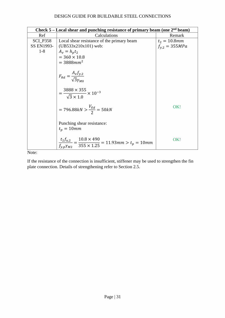
Check 5 – Local shear and punching resistance of primary beam (one 2nd beam) Ref Calculations Remark
SCI_P358 SS EN1993-
1-8
Local shear resistance of the primary beam (UB533x210x101) web: 𝐴 ℎ 𝑡
360 10.8 3888𝑚𝑚
𝐹𝐴 𝑓 ,
√3𝛾
3888 355
√3 1.010
𝑡 10.8𝑚𝑚 𝑓 , 355𝑀𝑃𝑎
796.88𝑘𝑁
𝑉2
50𝑘𝑁
OK!
Punching shear resistance: 𝑡 10𝑚𝑚
𝑡 𝑓 ,
𝑓 , 𝛾10.8 490355 1.25
11.93𝑚𝑚 𝑡 10𝑚𝑚 OK!
Note:
If the resistance of the connection is insufficient, stiffener may be used to strengthen the fin plate connection. Details of strengthening refer to Section 2.5.
DESIGN GUIDE FOR BUILDABLE STEEL CONNECTIONS
Page | 32
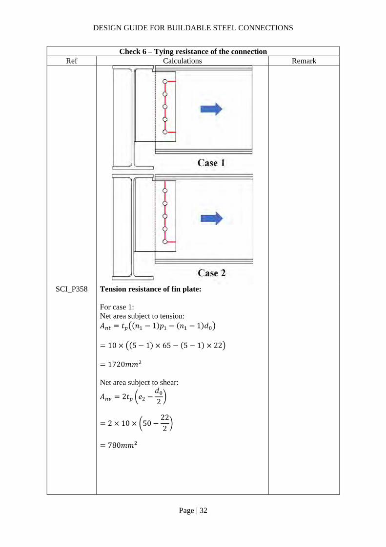
Check 6 – Tying resistance of the connection Ref Calculations Remark
SCI_P358 Tension resistance of fin plate: For case 1: Net area subject to tension: 𝐴 𝑡 𝑛 1 𝑝 𝑛 1 𝑑
10 5 1 65 5 1 22
1720𝑚𝑚 Net area subject to shear:
𝐴 2𝑡 𝑒𝑑2
2 10 50222
780𝑚𝑚

DESIGN GUIDE FOR BUILDABLE STEEL CONNECTIONS
Page | 33
Check 6 – Tying resistance of the connection Ref Calculations Remark
Block tearing tension resistance:
𝐹 ,𝑓 , 𝐴𝛾
𝑓 ,
√3
𝐴𝛾
490 17201.25 10
355 780
√3 1.0 10
834.10𝑘𝑁
For case 2: Net area subject to tension: 𝐴 𝑡 𝑛 1 𝑝 𝑛 0.5 𝑑 𝑒
10 5 1 65 5 0.5 22 50
2110𝑚𝑚 Net area subject to shear:
𝐴 𝑡 𝑒𝑑2
10 50222
390𝑚𝑚
Block tearing tension resistance:
𝐹 ,𝑓 , 𝐴𝛾
𝑓 ,
√3
𝐴𝛾
490 21101.25 10
355 390
√3 1.0 10
907.05𝑘𝑁
Net section tension resistance:
𝐹 ,0.9𝐴 , 𝑓 ,
𝛾
0.9 2500 490
1.25 10
882𝑘𝑁
𝐴 , 𝐴 ,
2500𝑚𝑚

DESIGN GUIDE FOR BUILDABLE STEEL CONNECTIONS
Page | 34
Check 6 – Tying resistance of the connection Ref Calculations Remark
Bolt shear resistance: 𝐹 , 𝑛𝐹 ,
5 94.08
470.4𝑘𝑁
Bolt bearing in fin plate: 𝐹 , 𝑛𝐹 , , ,
5 144.71
723.55𝑘𝑁
Tying resistance of fin plate and bolt: 𝐹 , , min 834.10; 907.05; 882; 470.4; 723.55
470.4𝑘𝑁
Tension resistance of beam web: Net area subject to tension: 𝐴 𝑡 , 𝑛 1 𝑝 𝑛 1 𝑑
8.1 5 1 65 5 1 22
1393.2𝑚𝑚 Net area subject to shear:
𝐴 2𝑡 , 𝑒𝑑2
2 8.1 50222
631.8𝑚𝑚

DESIGN GUIDE FOR BUILDABLE STEEL CONNECTIONS
Page | 35
Check 6 – Tying resistance of the connection Ref Calculations Remark
Block tearing tension resistance:
𝐹 ,𝑓 , 𝐴𝛾
𝑓 ,
√3
𝐴𝛾
490 1393.2
1.25 10355 631.8
√3 1.0 10
675.62𝑘𝑁
Net section tension resistance:
𝐹 ,0.9𝐴 , 𝑓 ,
𝛾
0.9 3040.9 490
1.25 10
1072.82𝑘𝑁
𝐴 , 𝐴 ,
3040.9𝑚𝑚
Bolt bearing in beam web: 𝐹 , 𝑛𝐹 , , ,
5 117.21
586.05𝑘𝑁
Tying resistance of the connection: 𝐹 , min 470.4; 675.62; 1072.82; 586.05
470.4𝑘𝑁
Note: There is a specific requirement to provide horizontal ties for robustness in the Eurocodes. Each tie member, including its end connections, should be capable of sustaining a design tensile load for the accidental limit state. The magnitudes of tie force are calculated from EN 1991-1-7.
For this type of connection, under large shear force, it may cause the primary beam web to buckle as shown in the figure above. Moreover, this one-sided connection will generate extra torsion on the primary beam. If the primary beam is insufficient to take the extra torsion or suffer from beam web buckling, back side stiffener is needed.
𝑉

DESIGN GUIDE FOR BUILDABLE STEEL CONNECTIONS
Page | 36
2.3.4 Example 2 – Double-sided Beam-to-Beam connection with extended fin plates
DESIGN GUIDE FOR BUILDABLE STEEL CONNECTIONS
Page | 37
Check 1L – Bolt group resistance (UB610x229x101) Ref Calculations Remark
Bolt resistance: Using Gr8.8, M20 bolts with: 𝐴 245𝑚𝑚 ; 𝑓 800𝑀𝑃𝑎; 𝛼 0.6
In this example, it is assumed that the extended fin plate is stiff enough to provide support within the welded region. Hence, the value “z” is taken from the bolt line to the line that the cross section of fin plate changed.
SS EN1993-1-8
Shear resistance of a bolt: As the distance between the centres of the end fasters: 𝐿 390𝑚𝑚 15𝑑 300𝑚𝑚 ∴Reduction factor to cater long joints effect is applied
𝛽 1𝐿 15𝑑
200𝑑
1390 15 20
200 20
0.9775
𝐹 ,𝛼 𝑓 𝐴𝛾
𝛽
0.6 800 245
1.250.9775 10
91.96𝑘𝑁
𝛾 1.25 (refer to NA to SS)
DESIGN GUIDE FOR BUILDABLE STEEL CONNECTIONS
Page | 38
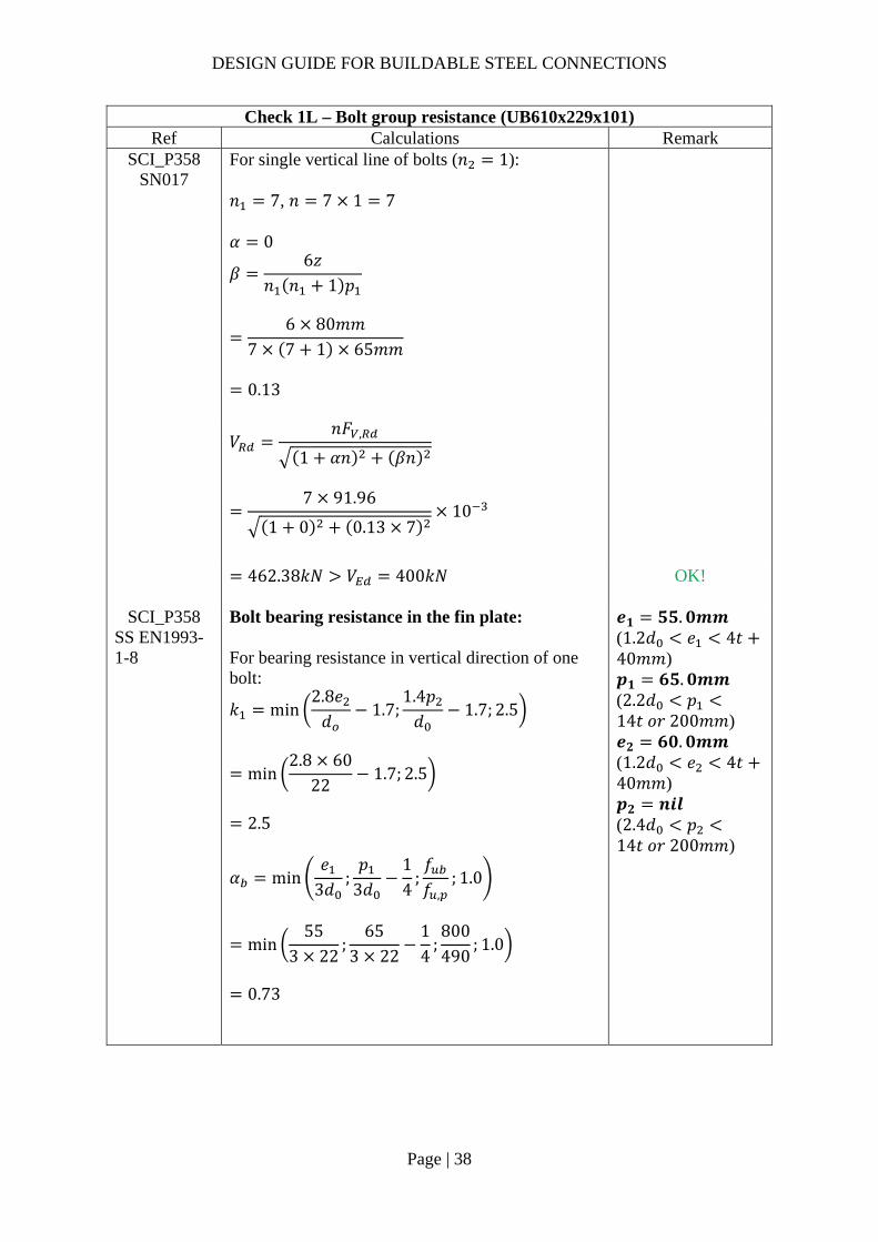
Check 1L – Bolt group resistance (UB610x229x101) Ref Calculations Remark
SCI_P358 SN017
For single vertical line of bolts (𝑛 1): 𝑛 7, 𝑛 7 1 7 𝛼 0
𝛽6𝑧
𝑛 𝑛 1 𝑝
6 80𝑚𝑚
7 7 1 65𝑚𝑚
0.13
𝑉
𝑛𝐹 ,
1 𝛼𝑛 𝛽𝑛
7 91.96
1 0 0.13 710
462.38𝑘𝑁 𝑉 400𝑘𝑁
OK!
SCI_P358 SS EN1993-1-8
Bolt bearing resistance in the fin plate: For bearing resistance in vertical direction of one bolt:
𝑘 min2.8𝑒𝑑
1.7;1.4𝑝𝑑
1.7; 2.5
min2.8 60
221.7; 2.5
2.5
𝛼 min𝑒
3𝑑;𝑝
3𝑑14
;𝑓𝑓 ,
; 1.0
min55
3 22;
653 22
14
;800490
; 1.0
0.73
𝒆𝟏 𝟓𝟓.𝟎𝒎𝒎 (1.2𝑑 𝑒 4𝑡40𝑚𝑚) 𝒑𝟏 𝟔𝟓.𝟎𝒎𝒎 (2.2𝑑 𝑝14𝑡 𝑜𝑟 200𝑚𝑚) 𝒆𝟐 𝟔𝟎.𝟎𝒎𝒎 (1.2𝑑 𝑒 4𝑡40𝑚𝑚) 𝒑𝟐 𝒏𝒊𝒍 (2.4𝑑 𝑝14𝑡 𝑜𝑟 200𝑚𝑚)

DESIGN GUIDE FOR BUILDABLE STEEL CONNECTIONS
Page | 39
Check 1L – Bolt group resistance (UB610x229x101) Ref Calculations Remark
𝐹 , ,
𝑘 𝛼 𝑓 , 𝑑𝑡𝛾
2.5 0.73 490 20 15
1.2510
216.05𝑘𝑁
For bearing resistance in horizontal direction of one bolt:
𝑘 min2.8𝑒𝑑
1.7;1.4𝑝𝑑
1.7; 2.5
min2.8 55
221.7;
1.4 6522
1.7; 2.5
2.44
𝛼 min
𝑒3𝑑
;𝑝
3𝑑14
;𝑓𝑓 ,
; 1.0
min60
3 22;800490
; 1.0
0.91
𝐹 , ,𝑘 𝛼 𝑓 , 𝑑𝑡
𝛾
2.44 0.91 490 20 15
1.2510
260.47kN
Bolt group bearing resistance:
𝑉𝑛
1 𝛼𝑛𝐹 , ,
𝛽𝑛𝐹 , ,
7
1216.05
0.13 7260.47
10
1200.78𝑘𝑁 𝑉 400𝑘𝑁
OK!

DESIGN GUIDE FOR BUILDABLE STEEL CONNECTIONS
Page | 40
Check 1L – Bolt group resistance (UB610x229x101) Ref Calculations Remark
SCI_P358 SS EN1993-
1-8
Bolt bearing resistance in secondary beam web: Vertical bearing resistance:
𝑘 min2.8𝑒 ,
𝑑1.7;
1.4𝑝𝑑
1.7; 2.5
min2.8 60
221.7; 2.5
2.5
𝛼 min𝑒 ,
3𝑑;𝑝
3𝑑14
;𝑓𝑓 ,
; 1.0
min106.33 22
;65
3 2214
;800490
; 1.0
0.73
𝒆𝟏,𝒃 𝟏𝟎𝟔.𝟑𝒎𝒎 𝒆𝟐,𝒃 𝟔𝟎.𝟎𝒎𝒎 𝑡 , 𝟏𝟎.𝟖𝒎𝒎
𝐹 , ,
𝑘 𝛼 𝑓 , 𝑑𝑡 ,
𝛾
2.44 0.73 490 20 10.5
1.2510
151.23𝑘𝑁
Horizontal bearing resistance:
𝑘 min2.8𝑒 ,
𝑑1.7;
1.4𝑝𝑑
1.7; 2.5
min2.8 106.3
221.7;
1.4 6522
1.7; 2.5
2.44
𝛼 min𝑒 ,
3𝑑;𝑝
3𝑑14
;𝑓𝑓 ,
; 1.0
min60
3 22;800510
; 1.0
0.91

DESIGN GUIDE FOR BUILDABLE STEEL CONNECTIONS
Page | 41
Check 1L – Bolt group resistance (UB610x229x101) Ref Calculations Remark
𝐹 , ,
𝑘 𝛼 𝑓 , 𝑑𝑡 ,
𝛾
2.44 0.91 490 20 10.5
1.2510
182.33𝑘𝑁
Bolt group bearing resistance:
𝑉𝑛
1 𝛼𝑛𝐹 , ,
𝛽𝑛𝐹 , ,
7
1157.40
0.13 7189.77
10
840.55𝑘𝑁 𝑉 400𝑘𝑁
OK!

DESIGN GUIDE FOR BUILDABLE STEEL CONNECTIONS
Page | 42
Check 2L – Fin plate resistance (UB610x229x101) Ref Calculations Remark
SS EN1993-1-8
SCI_P358
Fin-plate shear resistance (gross section): 𝑡 15𝑚𝑚 16𝑚𝑚 ∴ 𝑓 , 355𝑀𝑃𝑎 Gross section shear resistance of fin plate:
𝑉 ,ℎ 𝑡1.27
𝑓 ,
√3𝛾
500 15
1.27355
√3 10
1210.39𝑘𝑁
ℎ 500𝑚𝑚 𝛾 1.0 (SS EN1993-1-1)
Fin plate shear resistance (net section): 𝐴 , 𝑡 ℎ 𝑛 𝑑
15 550 7 22
5190𝑚𝑚 Net area shear resistance of fin plate:
𝑉 ,𝐴 , 𝑓 ,
√3𝛾
5190490
√3 1.2510
1174.61𝑘𝑁
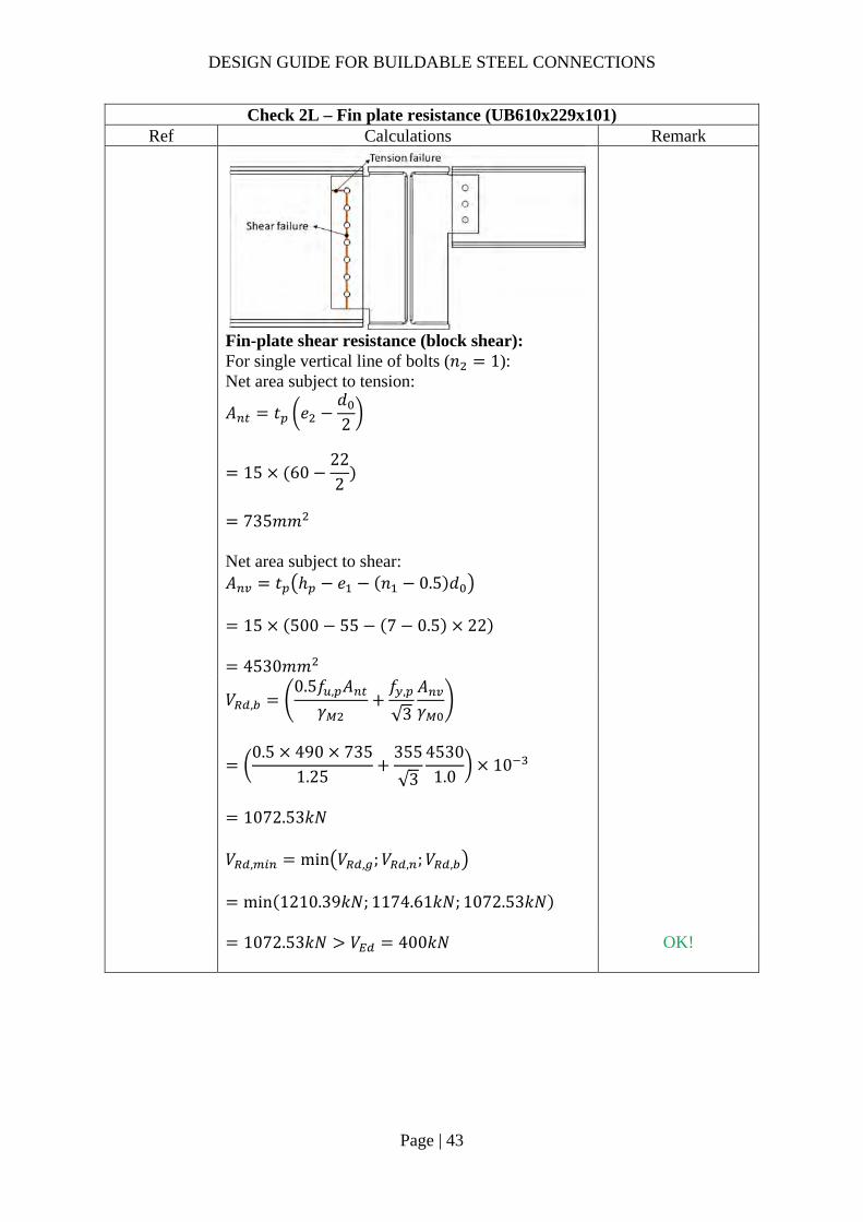
DESIGN GUIDE FOR BUILDABLE STEEL CONNECTIONS
Page | 43
Check 2L – Fin plate resistance (UB610x229x101) Ref Calculations Remark
Fin-plate shear resistance (block shear): For single vertical line of bolts (𝑛 1): Net area subject to tension:
𝐴 𝑡 𝑒𝑑2
15 60222
735𝑚𝑚
Net area subject to shear: 𝐴 𝑡 ℎ 𝑒 𝑛 0.5 𝑑
15 500 55 7 0.5 22
4530𝑚𝑚
𝑉 ,
0.5𝑓 , 𝐴𝛾
𝑓 ,
√3
𝐴𝛾
0.5 490 735
1.25355
√3
45301.0
10
1072.53𝑘𝑁
𝑉 , min 𝑉 , ;𝑉 , ;𝑉 ,
min 1210.39𝑘𝑁; 1174.61𝑘𝑁; 1072.53𝑘𝑁
1072.53𝑘𝑁 𝑉 400𝑘𝑁
OK!

DESIGN GUIDE FOR BUILDABLE STEEL CONNECTIONS
Page | 44
Check 2L – Fin plate resistance (UB610x229x101) Ref Calculations Remark
SCI_P358 SS EN1993-
1-8
Fin plate bending: ℎ 500𝑚𝑚 2.73𝑧 218.4𝑚𝑚 ∴ 𝑉 ∞
Lateral torsional buckling:
𝑧 80.0𝑚𝑚𝑡
0.15100𝑚𝑚
∴The fin plate is classified as Short fin plate
𝑊 ,
𝑡 ℎ6
15 500
6
625000𝑚𝑚
𝑉𝑊 , 𝑓 ,
𝑧𝛾
625000 355
80 1.010
2773.44𝑘𝑁 𝑉 400𝑘𝑁 OK!
DESIGN GUIDE FOR BUILDABLE STEEL CONNECTIONS
Page | 45
Check 3L – Secondary beam web resistance (UB610x229x101) Ref Calculations Remark
SCI_P358 SS EN1993-
1-8
Beam web shear resistance (gross section): For unnotched beams (UB610x229x101): 𝐴 𝐴 2𝑏 𝑡 , 𝑡 , 2𝑟 𝑡 ,
12900 2 227.6 14.8 10.5 212.7 14.8
6694.36𝑚𝑚
𝑉 , 𝑉 ,𝐴 𝑓 ,
√3𝛾
6694.36355
√3 1.010
1372.07𝑘𝑁
Beam web shear resistance (net section): 𝐴 , 𝐴 𝑛 𝑑 𝑡 ,
6694.36 7 22 10.5
5077.36𝑚𝑚
𝑉 ,𝐴 , 𝑓 ,
√3𝛾
5077.36490
√3 1.2510
1149.11𝑘𝑁
𝑉 , min 𝑉 , ;𝑉 ,
min 1372.07𝑘𝑁; 1149.11𝑘𝑁
1149.11𝑘𝑁 𝑉 400𝑘𝑁 OK!

DESIGN GUIDE FOR BUILDABLE STEEL CONNECTIONS
Page | 46
Check 3L – Secondary beam web resistance (UB610x229x101) Ref Calculations Remark
Shear and bending interaction of secondary beam web: For short fin plate, shear and bending moment interaction check is NOT necessary
DESIGN GUIDE FOR BUILDABLE STEEL CONNECTIONS
Page | 47
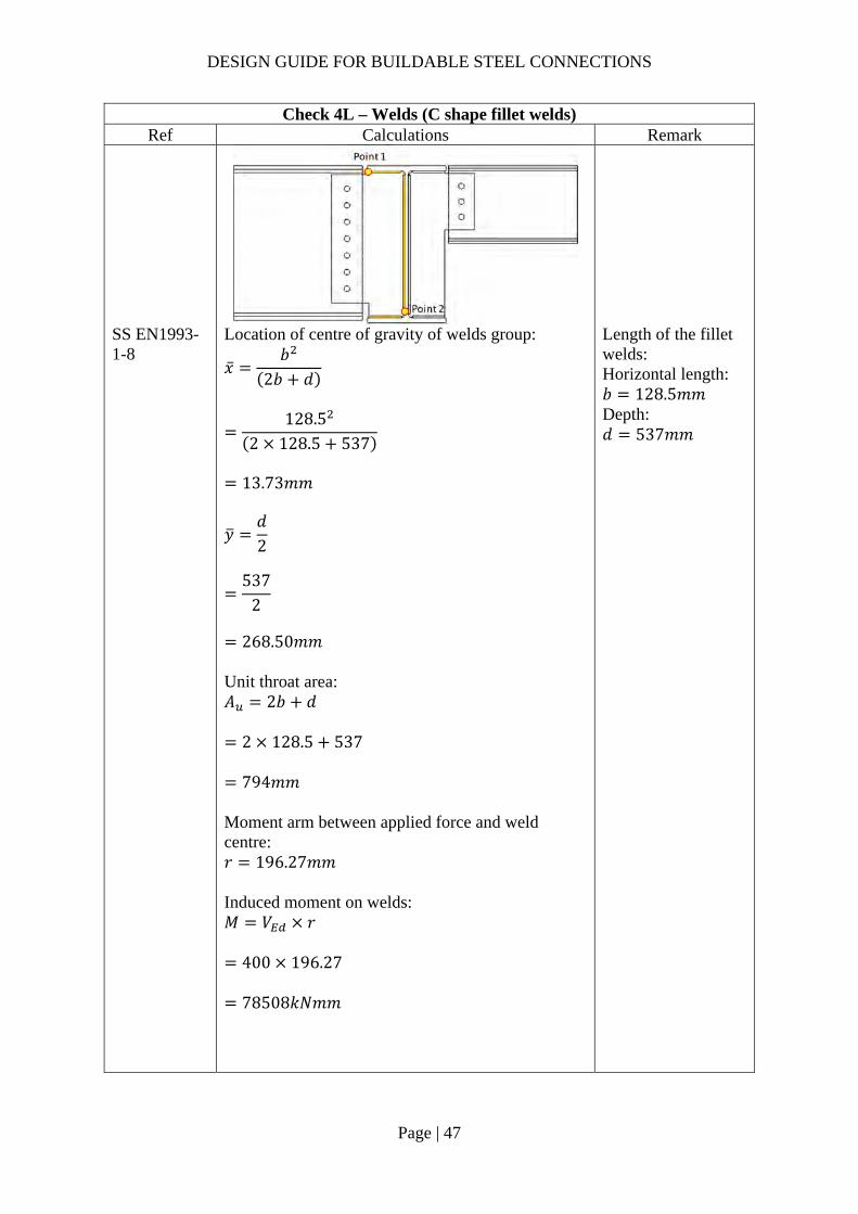
Check 4L – Welds (C shape fillet welds) Ref Calculations Remark
SS EN1993-1-8
Location of centre of gravity of welds group:
�̅�𝑏
2𝑏 𝑑
128.5
2 128.5 537
13.73𝑚𝑚
𝑦𝑑2
537
2
268.50𝑚𝑚
Unit throat area: 𝐴 2𝑏 𝑑
2 128.5 537
794𝑚𝑚 Moment arm between applied force and weld centre: 𝑟 196.27𝑚𝑚 Induced moment on welds: 𝑀 𝑉 𝑟
400 196.27
78508𝑘𝑁𝑚𝑚
Length of the fillet welds: Horizontal length: 𝑏 128.5𝑚𝑚 Depth: 𝑑 537𝑚𝑚

DESIGN GUIDE FOR BUILDABLE STEEL CONNECTIONS
Page | 48
Check 4L – Welds (C shape fillet welds) Ref Calculations Remark
Polar moment of inertia:
𝐽8𝑏 6𝑏𝑑 𝑑
12𝑏
2𝑏 𝑑
8 128.5 6 128.5 537 537
12
128.5
2 128.5 537
32503377𝑚𝑚
End-point 1: Horizontal distance from centroid: 𝑟 𝑏 �̅�
128.5 13.73 114.77𝑚𝑚
Vertical distance from centroid: 𝑟 𝑦 𝑐𝑜𝑝𝑒 ℎ𝑜𝑙𝑒 𝑠𝑖𝑧𝑒
268.5 18𝑚𝑚 286.5𝑚𝑚
Vertical stress:
𝜏𝑉𝐴
𝑀𝑟𝐽
400794
78508 114.7732503377
0.781𝑘𝑁/𝑚𝑚
Horizontal stress:
𝜏𝑀𝑟𝐽
78508 286.5
32503377
0.692𝑘𝑁/𝑚𝑚
Resultant stress:
𝜏 𝜏 𝜏
0.781 0.692
1.04𝑘𝑁/𝑚𝑚

DESIGN GUIDE FOR BUILDABLE STEEL CONNECTIONS
Page | 49
Check 4L – Welds (C shape fillet welds) Ref Calculations Remark
End-point 2: Horizontal distance from centroid: 𝑟 �̅� 𝑐𝑜𝑝𝑒 ℎ𝑜𝑙𝑒 𝑠𝑖𝑧𝑒
13.73 18𝑚𝑚 31.73𝑚𝑚 Vertical distance from centroid: 𝑟 𝑑 𝑦
537 268.5 268.5𝑚𝑚
Vertical stress:
𝜏𝑉𝐴
𝑀𝑟𝐽
400794
78508 31.7332503377
0.580𝑘𝑁/𝑚𝑚
Horizontal stress:
𝜏𝑀𝑟𝐽
78508 268.5
32503377
0.649𝑘𝑁/𝑚𝑚
Resultant stress:
𝜏 𝜏 𝜏
0.580 0.649
0.87𝑘𝑁/𝑚𝑚
Choose fillet weld with 6mm leg length, 4.2mm throat thickness and grade S355 which match beam steel grade: Longitudinal resistance: 𝐹 , , 1.01𝑘𝑁/𝑚𝑚 Transverse resistance: 𝐹 , , 1.24𝑘𝑁/𝑚𝑚
Simplified method:
𝐹 , , 1.01𝑘𝑁/𝑚𝑚𝜏2
0.52𝑘𝑁/𝑚𝑚 OK!

DESIGN GUIDE FOR BUILDABLE STEEL CONNECTIONS
Page | 50
Check 4L – Welds (C shape fillet welds) Ref Calculations Remark
Directional method:
𝑆𝐹𝜏 , /2𝐹 , ,
𝜏 , /2𝐹 , ,
0.391.01
0.351.24
0.23 1.00
OK!
DESIGN GUIDE FOR BUILDABLE STEEL CONNECTIONS
Page | 51
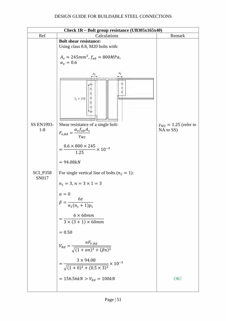
Check 1R – Bolt group resistance (UB305x165x40) Ref Calculations Remark
Bolt shear resistance: Using class 8.8, M20 bolts with: 𝐴 245𝑚𝑚 , 𝑓 800𝑀𝑃𝑎, 𝛼 0.6
SS EN1993-1-8
Shear resistance of a single bolt:
𝐹 ,𝛼 𝑓 𝐴𝛾
0.6 800 245
1.2510
94.08𝑘𝑁
𝛾 1.25 (refer to NA to SS)
SCI_P358 SN017
For single vertical line of bolts (𝑛 1): 𝑛 3, 𝑛 3 1 3 𝛼 0
𝛽6𝑧
𝑛 𝑛 1 𝑝
6 60𝑚𝑚
3 3 1 60𝑚𝑚
0.50
𝑉𝑛𝐹 ,
1 𝛼𝑛 𝛽𝑛
3 94.08
1 0 0.5 310
156.56𝑘𝑁 𝑉 100𝑘𝑁
OK!

DESIGN GUIDE FOR BUILDABLE STEEL CONNECTIONS
Page | 52
Check 1R – Bolt group resistance (UB305x165x40) Ref Calculations Remark
SCI_P358 SS EN1993-
1-8
Bolt bearing resistance in the fin plate: For bearing resistance in vertical direction of one bolt:
𝑘 min2.8𝑒𝑑
1.7;1.4𝑝𝑑
1.7; 2.5
min2.8 50
221.7; 2.5
2.5
𝒆𝟏 𝟓𝟎.𝟎𝒎𝒎 (1.2𝑑 𝑒 4𝑡40𝑚𝑚) 𝒑𝟏 𝟔𝟓.𝟎𝒎𝒎 (2.2𝑑 𝑝14𝑡 𝑜𝑟 200𝑚𝑚) 𝒆𝟐 𝟓𝟎.𝟎𝒎𝒎 (1.2𝑑 𝑒 4𝑡40𝑚𝑚) 𝒑𝟐 𝒏𝒊𝒍
𝛼 min
𝑒3𝑑
;𝑝
3𝑑14
;𝑓𝑓 ,
; 1.0
min50
3 22;
603 22
14
;800490
; 1.0
0.66
𝐹 , ,𝑘 𝛼 𝑓 , 𝑑𝑡
𝛾
2.5 0.66 490 20 15
1.2510
193.77𝑘𝑁
(2.4𝑑 𝑝14𝑡 𝑜𝑟 200𝑚𝑚)
For bearing resistance in horizontal direction of one bolt:
𝑘 min2.8𝑒𝑑
1.7;1.4𝑝𝑑
1.7; 2.5
min2.8 50
221.7;
1.4 6022
1.7; 2.5
2.12
𝛼 min𝑒
3𝑑;𝑝
3𝑑14
;𝑓𝑓 ,
; 1.0
min50
3 22;800430
; 1.0
0.76

DESIGN GUIDE FOR BUILDABLE STEEL CONNECTIONS
Page | 53
Check 1R – Bolt group resistance (UB305x165x40) Ref Calculations Remark
𝐹 , ,
𝑘 𝛼 𝑓 , 𝑑𝑡𝛾
2.12 0.76 490 20 15
1.2510
188.71kN
Bolt group bearing resistance:
𝑉𝑛
1 𝛼𝑛𝐹 , ,
𝛽𝑛𝐹 , ,
5
1193.77
0.51 3188.71
10
316.55𝑘𝑁 𝑉 100𝑘𝑁
OK!
SCI_P358 SS EN1993-
1-8
Bolt bearing resistance in secondary beam web: Vertical bearing resistance:
𝑘 min2.8𝑒 ,
𝑑1.7;
1.4𝑝𝑑
1.7; 2.5
min2.8 50
221.7; 2.5
2.5
𝛼 min𝑒 ,
3𝑑;𝑝
3𝑑14
;𝑓𝑓 ,
; 1.0
min91.7
3 22;
603 22
14
;800490
; 1.0
0.66
𝐹 , ,𝑘 𝛼 𝑓 , 𝑑𝑡 ,
𝛾
2.5 0.66 490 20 6
1.2510
77.51𝑘𝑁
𝒆𝟏,𝒃 𝟗𝟏.𝟕𝒎𝒎 𝒆𝟐,𝒃 𝟓𝟎.𝟎𝒎𝒎

DESIGN GUIDE FOR BUILDABLE STEEL CONNECTIONS
Page | 54
Check 1R – Bolt group resistance (UB305x165x40) Ref Calculations Remark
Horizontal bearing resistance:
𝑘 min2.8𝑒 ,
𝑑1.7;
1.4𝑝𝑑
1.7; 2.5
min2.8 91.7
221.7;
1.4 6022
1.7; 2.5
2.12
𝛼 min
𝑒 ,
3𝑑;𝑝
3𝑑14
;𝑓𝑓 ,
; 1.0
min50
3 22;800490
; 1.0
0.76
𝐹 , ,𝑘 𝛼 𝑓 , 𝑑𝑡 ,
𝛾
2.12 0.76 490 20 6
1.2510
75.48𝑘𝑁
Bolt group bearing resistance:
𝑉𝑛
1 𝛼𝑛𝐹 , ,
𝛽𝑛𝐹 , ,
3
177.51
0.5 375.48
10
126.62𝑘𝑁 𝑉 100𝑘𝑁
OK!

DESIGN GUIDE FOR BUILDABLE STEEL CONNECTIONS
Page | 55
Check 2R – Fin plate resistance (UB305x165x40) Ref Calculations Remark
SS EN1993-1-8
SCI_P358
Fin plate shear resistance (gross section): 𝑡 15𝑚𝑚 16𝑚𝑚 ∴ 𝑓 , 275𝑀𝑃𝑎 Gross section shear resistance:
𝑉 ,ℎ 𝑡1.27
𝑓 ,
√3𝛾
220 15
1.27355
√3 10
532.57𝑘𝑁
ℎ 360𝑚𝑚 𝛾 1.0 (SS EN1993-1-1)
Fin plate shear resistance (net section): 𝐴 , 𝑡 ℎ 𝑛 𝑑
15 220 3 22
2310𝑚𝑚 Net area shear resistance:
𝑉 ,𝐴 , 𝑓 ,
√3𝛾
2310490
√3 1.2510
522.80𝑘𝑁
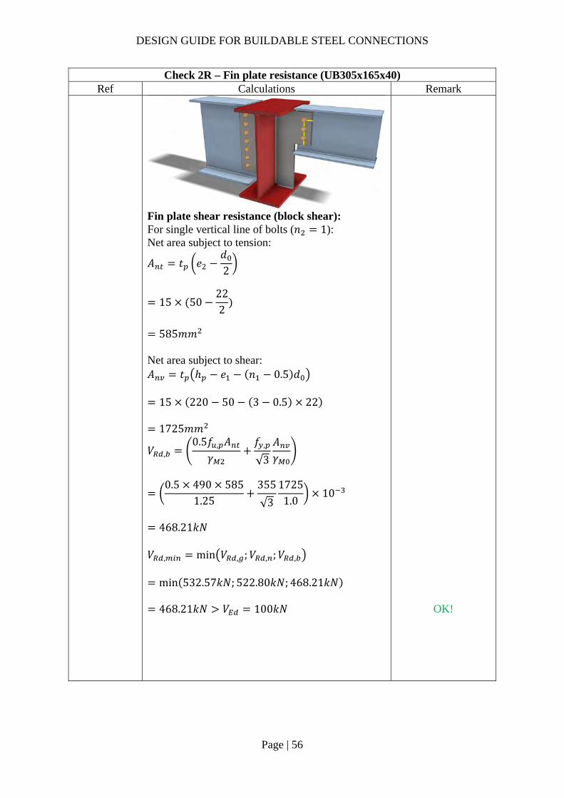
DESIGN GUIDE FOR BUILDABLE STEEL CONNECTIONS
Page | 56
Check 2R – Fin plate resistance (UB305x165x40) Ref Calculations Remark
Fin plate shear resistance (block shear): For single vertical line of bolts (𝑛 1): Net area subject to tension:
𝐴 𝑡 𝑒𝑑2
15 50222
585𝑚𝑚
Net area subject to shear: 𝐴 𝑡 ℎ 𝑒 𝑛 0.5 𝑑
15 220 50 3 0.5 22
1725𝑚𝑚
𝑉 ,
0.5𝑓 , 𝐴𝛾
𝑓 ,
√3
𝐴𝛾
0.5 490 585
1.25355
√3
17251.0
10
468.21𝑘𝑁
𝑉 , min 𝑉 , ;𝑉 , ;𝑉 ,
min 532.57𝑘𝑁; 522.80𝑘𝑁; 468.21𝑘𝑁
468.21𝑘𝑁 𝑉 100𝑘𝑁
OK!

DESIGN GUIDE FOR BUILDABLE STEEL CONNECTIONS
Page | 57
Check 2R – Fin plate resistance (UB305x165x40) Ref Calculations Remark
SCI_P358 SS EN1993-
1-8
Fin plate Bending: ℎ 220𝑚𝑚 2.73𝑧 163.8𝑚𝑚
∴ 𝑉 ∞
OK!
𝑊 ,
𝑡 ℎ6
15 220
6
121000𝑚𝑚
Lateral torsional buckling:
𝑧 60𝑚𝑚𝑡
0.15100𝑚𝑚
∴The fin plate is classified as Short fin plate
𝑉
𝑊 ,
𝑧𝑓 ,
𝛾
121000 355
60 1.0
715.92𝑘𝑁 𝑉 100𝑘𝑁 OK!

DESIGN GUIDE FOR BUILDABLE STEEL CONNECTIONS
Page | 58
Check 3R – Secondary beam web resistance (UB305x165x40) Ref Calculations Remark
SCI_P358 SS EN1993-
1-8
Beam shear resistance (gross section): For unnotched beams (UB406x178x60): 𝐴 𝐴 2𝑏 𝑡 , 𝑡 , 2𝑟 𝑡 ,
5130 2 165 10.2 6.0 2 8.910.2
2006.76𝑚𝑚
𝑉 , 𝑉 ,𝐴 𝑓 ,
√3𝛾
2006.76355
√3 1.010
411.30𝑘𝑁
Beam web shear resistance (net section): 𝐴 , 𝐴 𝑛 𝑑 𝑡 ,
2006.76 3 22 6
1610.76𝑚𝑚
𝑉 ,𝐴 , 𝑓 ,
√3𝛾
1610.76490
√3 1.2510
364.55𝑘𝑁

DESIGN GUIDE FOR BUILDABLE STEEL CONNECTIONS
Page | 59
Check 3R – Secondary beam web resistance (UB305x165x40) Ref Calculations Remark
𝑉 , min 𝑉 , ;𝑉 ,
min 411.30𝑘𝑁; 364.55𝑘𝑁
364.55𝑘𝑁 𝑉 100𝑘𝑁
Shear and bending interaction of secondary beam web: For Short fin plate, shear and bending moment interaction check is NOT necessary

DESIGN GUIDE FOR BUILDABLE STEEL CONNECTIONS
Page | 60
Check 4R – Welds (C shape fillet welds) Ref Calculations Remark
SS EN1993-1-8
Location of centre of gravity of welds group:
�̅�𝑏
2𝑏 𝑑
128.5
2 128.5 464
15.63𝑚𝑚
𝑦𝑑2
464
2
232𝑚𝑚
Unit throat area: 𝐴 2𝑏 𝑑
2 128.5 464
721𝑚𝑚 Moment arm between applied force and weld center: 𝑟 190.87𝑚𝑚 Induced moment on welds: 𝑀 𝑉 𝑟
100 190.87
19087𝑘𝑁𝑚𝑚
Length of the fillet welds: Horizontal length: 𝑏 128.5𝑚𝑚 Depth: 𝑑 464𝑚𝑚

DESIGN GUIDE FOR BUILDABLE STEEL CONNECTIONS
Page | 61
Check 4R – Welds (C shape fillet welds) Ref Calculations Remark
Polar moment of inertia:
𝐽8𝑏 6𝑏𝑑 𝑑
12𝑏
2𝑏 𝑑
8 128.5 6 128.5 464 464
12
128.5
2 128.5 464
23193935𝑚𝑚
End-point 1: Horizontal distance from centroid: 𝑟 𝑏 �̅�
128.5 15.63 112.87𝑚𝑚
Vertical distance from centroid: 𝑟 𝑦 𝑐𝑜𝑝𝑒 ℎ𝑜𝑙𝑒 𝑠𝑖𝑧𝑒
232 18𝑚𝑚 250𝑚𝑚
Vertical stress:
𝜏𝑉𝐴
𝑀𝑟𝐽
100721
19087 112.8723193935
0.2316𝑘𝑁/𝑚𝑚
Horizontal stress:
𝜏𝑀𝑟𝐽
19087 250
23193935
0.2057𝑘𝑁/𝑚𝑚
Resultant stress:
𝜏 𝜏 𝜏
0.2316 0.2057
0.31𝑘𝑁/𝑚𝑚

DESIGN GUIDE FOR BUILDABLE STEEL CONNECTIONS
Page | 62
Check 4R – Welds (C shape fillet welds) Ref Calculations Remark
End-point 2: Horizontal distance from centroid: 𝑟 �̅� 𝑐𝑜𝑝𝑒 ℎ𝑜𝑙𝑒 𝑠𝑖𝑧𝑒
15.63 18𝑚𝑚 33.63𝑚𝑚 Vertical distance from centroid: 𝑟 𝑑 𝑦
464 232 232𝑚𝑚
Vertical stress:
𝜏𝑉𝐴
𝑀𝑟𝐽
100721
19087 33.6323193935
0.1664𝑘𝑁/𝑚𝑚
Horizontal stress:
𝜏𝑀𝑟𝐽
19087 232
23193935
0.1909𝑘𝑁/𝑚𝑚
Resultant stress:
𝜏 𝜏 𝜏
0.1664 0.1909
0.25𝑘𝑁/𝑚𝑚
Choose fillet weld with 5mm leg length, 3.5mm throat thickness and grade S355 which match the beam steel grade: Longitudinal resistance: 𝐹 , , 0.84𝑘𝑁/𝑚𝑚 Transverse resistance: 𝐹 , , 1.03𝑘𝑁/𝑚𝑚
Simplified method: 𝐹 , , 0.84𝑘𝑁/𝑚𝑚 𝜏 /2 0.15𝑘𝑁/𝑚𝑚 OK!

DESIGN GUIDE FOR BUILDABLE STEEL CONNECTIONS
Page | 63
Check 4R – Welds (C shape fillet welds) Ref Calculations Remark
Directional method:
𝑆𝐹𝜏 ,
2𝐹 , ,
𝜏 ,
2𝐹 , ,
0.23
0.84 20.21
1.03 2
0.03 1.00 OK!

DESIGN GUIDE FOR BUILDABLE STEEL CONNECTIONS
Page | 64
Check 5 – Local shear and punching resistance of primary beam (two 2nd beam) Ref Calculations Remark
SCI_P358 SS EN1993-
1-8
Local shear resistance of the primary beam (UB610x305x149) web: ℎ , min ℎ , ;ℎ ,
min 500; 220
220𝑚𝑚 𝐴 ℎ , 𝑡
220 11.8
2596𝑚𝑚
𝐹𝐴 𝑓 ,
√3𝛾
2596 355
√310
532.07𝑘𝑁
𝑉 ,𝑉 ,
ℎ ,
𝑉 ,
ℎ ,ℎ ,
400500
100220
220
276𝑘𝑁
𝐹 532.07𝑘𝑁
𝑉 ,
2138𝑘𝑁
OK!

DESIGN GUIDE FOR BUILDABLE STEEL CONNECTIONS
Page | 65
2.3.5 Example 3 – One-sided Beam-to-Beam skewed connection with extended fin plates
DESIGN GUIDE FOR BUILDABLE STEEL CONNECTIONS
Page | 66
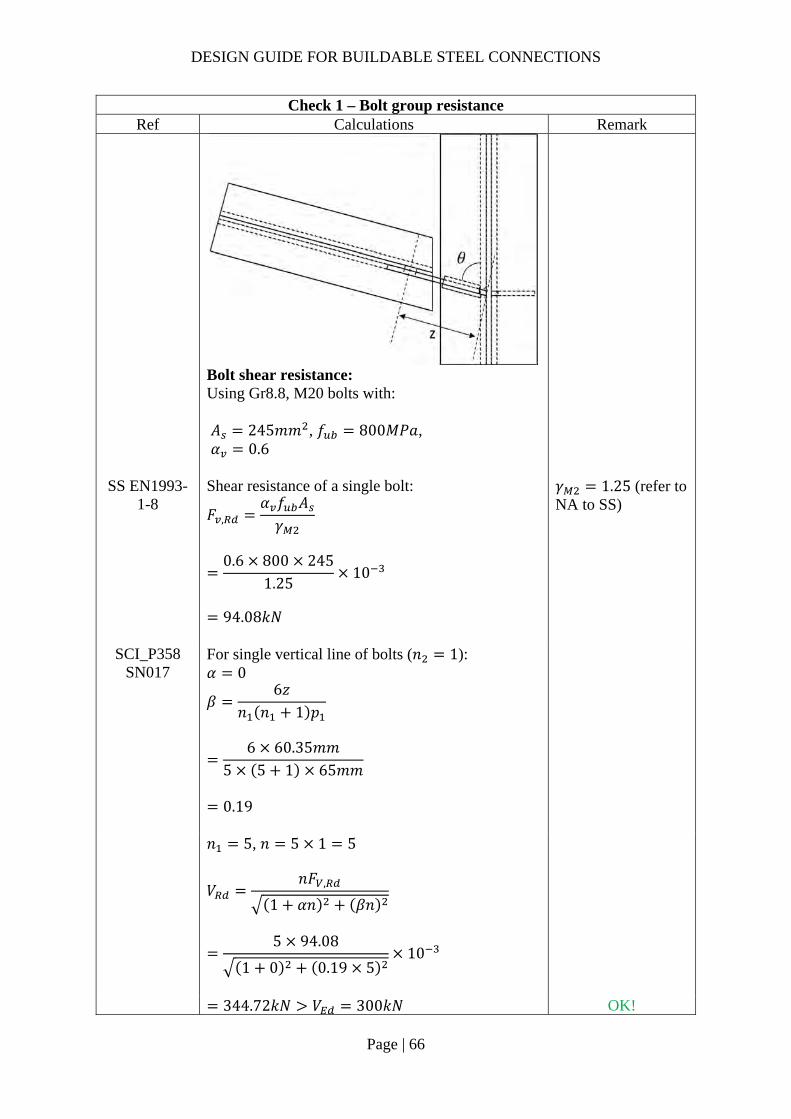
Check 1 – Bolt group resistance Ref Calculations Remark
Bolt shear resistance: Using Gr8.8, M20 bolts with: 𝐴 245𝑚𝑚 , 𝑓 800𝑀𝑃𝑎, 𝛼 0.6
SS EN1993-1-8
Shear resistance of a single bolt:
𝐹 ,𝛼 𝑓 𝐴𝛾
0.6 800 245
1.2510
94.08𝑘𝑁
𝛾 1.25 (refer to NA to SS)
SCI_P358 SN017
For single vertical line of bolts (𝑛 1): 𝛼 0
𝛽6𝑧
𝑛 𝑛 1 𝑝
6 60.35𝑚𝑚
5 5 1 65𝑚𝑚
0.19
𝑛 5, 𝑛 5 1 5
𝑉𝑛𝐹 ,
1 𝛼𝑛 𝛽𝑛
5 94.08
1 0 0.19 510
344.72𝑘𝑁 𝑉 300𝑘𝑁 OK!

DESIGN GUIDE FOR BUILDABLE STEEL CONNECTIONS
Page | 67
Check 1 – Bolt group resistance Ref Calculations Remark
SCI_P358 SS EN1993-
1-8
Bolt bearing resistance in the fin plate: For bearing resistance in vertical direction of one bolt:
𝑘 min2.8𝑒𝑑
1.7;1.4𝑝𝑑
1.7; 2.5
min2.8 50
221.7; 2.5
2.5
𝒆𝟏 𝟓𝟎.𝟎𝒎𝒎 (1.2𝑑 𝑒 4𝑡40𝑚𝑚) 𝒑𝟏 𝟔𝟓.𝟎𝒎𝒎 (2.2𝑑 𝑝14𝑡 𝑜𝑟 200𝑚𝑚) 𝒆𝟐 𝟓𝟎.𝟎𝒎𝒎 (1.2𝑑 𝑒 4𝑡40𝑚𝑚) 𝒑𝟐 𝒏𝒊𝒍
𝛼 min𝑒
3𝑑;𝑝
3𝑑14
;𝑓𝑓 ,
; 1.0
min50
3 22;
653 22
14
;800490
; 1.0
0.73
𝐹 , ,𝑘 𝛼 𝑓 , 𝑑𝑡
𝛾
2.5 0.73 490 20 10
1.2510
144.03𝑘𝑁
(2.4𝑑 𝑝14𝑡 𝑜𝑟 200𝑚𝑚)
For bearing resistance in horizontal direction of one bolt:
𝑘 min2.8𝑒𝑑
1.7;1.4𝑝𝑑
1.7; 2.5
min2.8 50
221.7;
1.4 6522
1.7; 2.5
2.44
𝛼 min
𝑒3𝑑
;𝑝
3𝑑14
;𝑓𝑓 ,
; 1.0
min50
3 22;800490
; 1.0
0.76

DESIGN GUIDE FOR BUILDABLE STEEL CONNECTIONS
Page | 68
Check 1 – Bolt group resistance Ref Calculations Remark
𝐹 , ,
𝑘 𝛼 𝑓 , 𝑑𝑡𝛾
2.44 0.76 490 20 10
1.2510
144.71kN
Bolt group bearing resistance:
𝑉𝑛
1 𝛼𝑛𝐹 , ,
𝛽𝑛𝐹 , ,
5
1144.03
0.19 5144.71
10
528.89𝑘𝑁 𝑉 300𝑘𝑁
OK!
SCI_P358 SS EN1993-
1-8
Bolt bearing resistance in secondary beam web: Vertical bearing resistance:
𝑘 min2.8𝑒 ,
𝑑1.7;
1.4𝑝𝑑
1.7; 2.5
min2.8 50
221.7; 2.5
2.5
𝛼 min𝑒 ,
3𝑑;𝑝
3𝑑14
;𝑓𝑓 ,
; 1.0
min97.3
3 22;
653 22
14
;800490
; 1.0
0.73
𝒆𝟏,𝒃 𝟗𝟕.𝟑𝒎𝒎 𝒆𝟐,𝒃 𝟓𝟎.𝟎𝒎𝒎
𝐹 , ,
𝑘 𝛼 𝑓 , 𝑑𝑡 ,
𝛾
2.5 0.73 490 20 8.1
1.2510
116.66𝑘𝑁

DESIGN GUIDE FOR BUILDABLE STEEL CONNECTIONS
Page | 69
Check 1 – Bolt group resistance Ref Calculations Remark
Horizontal bearing resistance:
𝑘 min2.8𝑒 ,
𝑑1.7;
1.4𝑝𝑑
1.7; 2.5
min2.8 97.3
221.7;
1.4 6522
1.7; 2.5
2.44
𝛼 min
𝑒 ,
3𝑑;𝑝
3𝑑14
;𝑓𝑓 ,
; 1.0
min50
3 22;800490
; 1.0
0.76
𝐹 , ,𝑘 𝛼 𝑓 , 𝑑𝑡 ,
𝛾
2.44 0.76 490 20 8.1
1.2510
117.21𝑘𝑁
Bolt group bearing resistance:
𝑉𝑛
1 𝛼𝑛𝐹 , ,
𝛽𝑛𝐹 , ,
5
1116.66
0.19 5117.21
10
428.40𝑘𝑁 𝑉 300𝑘𝑁
OK!

DESIGN GUIDE FOR BUILDABLE STEEL CONNECTIONS
Page | 70
Check 2 – Fin plate resistance Ref Calculations Remark
SS EN1993-1-8
SCI_P358
Fin plate shear resistance (gross section): 𝑡 10𝑚𝑚 16𝑚𝑚 ∴ 𝑓 , 355𝑀𝑃𝑎 Gross section shear resistance:
𝑉 ,ℎ 𝑡1.27
𝑓 ,
√3𝛾
360 10
1.27355
√3 10
580.99𝑘𝑁
ℎ 360𝑚𝑚 𝛾 1.0 (SS EN1993-1-1)
Fin plate shear resistance (net section): 𝐴 , 𝑡 ℎ 𝑛 𝑑
10 360 5 22
2500𝑚𝑚 Net area shear resistance:
𝑉 ,𝐴 , 𝑓 ,
√3𝛾
2500490
√3 1.2510
565.80𝑘𝑁

DESIGN GUIDE FOR BUILDABLE STEEL CONNECTIONS
Page | 71
Check 2 – Fin plate resistance Ref Calculations Remark
Fin plate shear resistance (block shear): For single vertical line of bolts (𝑛 1): Net area subject to tension:
𝐴 𝑡 𝑒𝑑2
10 50222
390𝑚𝑚
Net area subject to shear: 𝐴 𝑡 ℎ 𝑒 𝑛 0.5 𝑑
10 360 50 5 0.5 22
2110𝑚𝑚
𝑉 ,
0.5𝑓 , 𝐴𝛾
𝑓 ,
√3
𝐴𝛾
0.5 490 390
1.25355
√3
21101.0
10
508.90𝑘𝑁
𝑉 , min 𝑉 , ;𝑉 , ;𝑉 ,
min 580.99𝑘𝑁; 565.80𝑘𝑁; 508.90𝑘𝑁
508.90𝑘𝑁 𝑉 300𝑘𝑁
OK!
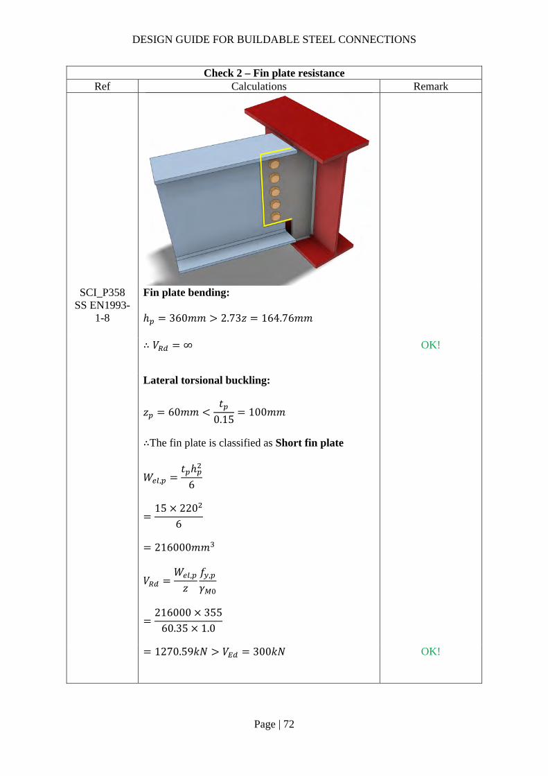
DESIGN GUIDE FOR BUILDABLE STEEL CONNECTIONS
Page | 72
Check 2 – Fin plate resistance Ref Calculations Remark
SCI_P358 SS EN1993-
1-8
Fin plate bending: ℎ 360𝑚𝑚 2.73𝑧 164.76𝑚𝑚
∴ 𝑉 ∞
OK!
Lateral torsional buckling:
𝑧 60𝑚𝑚𝑡
0.15100𝑚𝑚
∴The fin plate is classified as Short fin plate
𝑊 ,𝑡 ℎ
6
15 220
6
216000𝑚𝑚
𝑉𝑊 ,
𝑧𝑓 ,
𝛾
216000 355
60.35 1.0
1270.59𝑘𝑁 𝑉 300𝑘𝑁
OK!
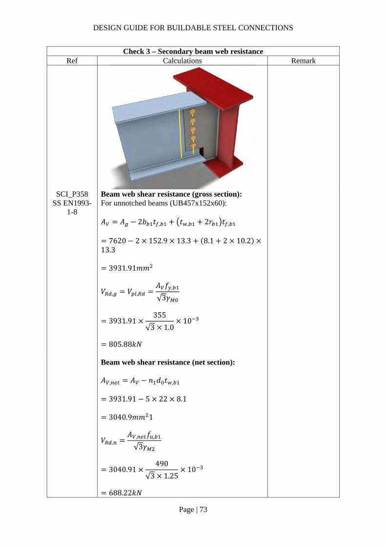
DESIGN GUIDE FOR BUILDABLE STEEL CONNECTIONS
Page | 73
Check 3 – Secondary beam web resistance Ref Calculations Remark
SCI_P358 SS EN1993-
1-8
Beam web shear resistance (gross section): For unnotched beams (UB457x152x60): 𝐴 𝐴 2𝑏 𝑡 , 𝑡 , 2𝑟 𝑡 ,
7620 2 152.9 13.3 8.1 2 10.213.3
3931.91𝑚𝑚
𝑉 , 𝑉 ,𝐴 𝑓 ,
√3𝛾
3931.91355
√3 1.010
805.88𝑘𝑁
Beam web shear resistance (net section): 𝐴 , 𝐴 𝑛 𝑑 𝑡 ,
3931.91 5 22 8.1
3040.9𝑚𝑚 1
𝑉 ,𝐴 , 𝑓 ,
√3𝛾
3040.91490
√3 1.2510
688.22𝑘𝑁

DESIGN GUIDE FOR BUILDABLE STEEL CONNECTIONS
Page | 74
Check 3 – Secondary beam web resistance Ref Calculations Remark
𝑉 , min 𝑉 , ;𝑉 ,
min 805.88𝑘𝑁; 688.22𝑘𝑁
688.22𝑘𝑁 𝑉 300𝑘𝑁
OK!
Shear and bending interaction of secondary beam web: For Short fin plate, shear and bending moment interaction check is NOT necessary
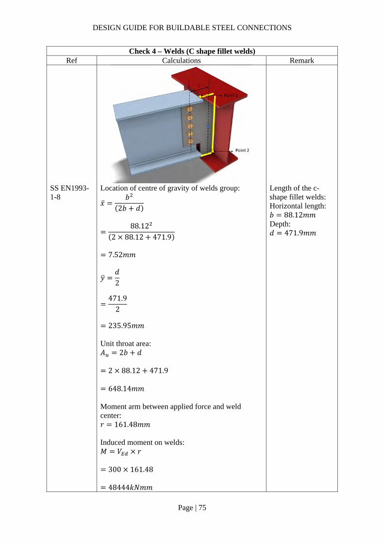
DESIGN GUIDE FOR BUILDABLE STEEL CONNECTIONS
Page | 75
Check 4 – Welds (C shape fillet welds) Ref Calculations Remark
SS EN1993-1-8
Location of centre of gravity of welds group:
�̅�𝑏
2𝑏 𝑑
88.12
2 88.12 471.9
7.52𝑚𝑚
𝑦𝑑2
471.9
2
235.95𝑚𝑚
Unit throat area: 𝐴 2𝑏 𝑑
2 88.12 471.9
648.14𝑚𝑚 Moment arm between applied force and weld center: 𝑟 161.48𝑚𝑚 Induced moment on welds: 𝑀 𝑉 𝑟
300 161.48
48444𝑘𝑁𝑚𝑚
Length of the c-shape fillet welds: Horizontal length: 𝑏 88.12𝑚𝑚 Depth: 𝑑 471.9𝑚𝑚
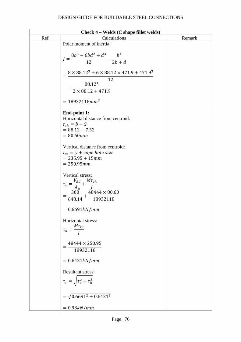
DESIGN GUIDE FOR BUILDABLE STEEL CONNECTIONS
Page | 76
Check 4 – Welds (C shape fillet welds) Ref Calculations Remark
Polar moment of inertia:
𝐽8𝑏 6𝑏𝑑 𝑑
12𝑏
2𝑏 𝑑
8 88.12 6 88.12 471.9 471.9
12
88.12
2 88.12 471.9
18932118𝑚𝑚
End-point 1: Horizontal distance from centroid: 𝑟 𝑏 �̅�
88.12 7.52 80.60𝑚𝑚
Vertical distance from centroid: 𝑟 𝑦 𝑐𝑜𝑝𝑒 ℎ𝑜𝑙𝑒 𝑠𝑖𝑧𝑒
235.95 15𝑚𝑚 250.95𝑚𝑚
Vertical stress:
𝜏𝑉𝐴
𝑀𝑟𝐽
300648.14
48444 80.6018932118
0.6691𝑘𝑁/𝑚𝑚
Horizontal stress:
𝜏𝑀𝑟𝐽
48444 250.95
18932118
0.6421𝑘𝑁/𝑚𝑚
Resultant stress:
𝜏 𝜏 𝜏
0.6691 0.6421
0.93𝑘𝑁/𝑚𝑚

DESIGN GUIDE FOR BUILDABLE STEEL CONNECTIONS
Page | 77
Check 4 – Welds (C shape fillet welds) Ref Calculations Remark
End-point 2: Horizontal distance from centroid: 𝑟 �̅� 𝑐𝑜𝑝𝑒 ℎ𝑜𝑙𝑒 𝑠𝑖𝑧𝑒
7.52 15𝑚𝑚 22.52𝑚𝑚
Vertical distance from centroid: 𝑟 𝑑 𝑦
471.9 235.95 235.95𝑚𝑚
Vertical stress:
𝜏𝑉𝐴
𝑀𝑟𝐽
300
648.1448444 22.52
18932118
0.5205𝑘𝑁/𝑚𝑚
Horizontal stress:
𝜏𝑀𝑟𝐽
48444 235.95
18932118
0.6038𝑘𝑁/𝑚𝑚
Resultant stress:
𝜏 𝜏 𝜏
0.5205 0.6038
0.80𝑘𝑁/𝑚𝑚
Choose fillet weld with 5mm leg length, 3.5mm throat thickness and grade S355 for the side with smaller angle which match beam steel grade: Longitudinal resistance: 𝐹 , , 0.84𝑘𝑁/𝑚𝑚 Transverse resistance: 𝐹 , , 1.03𝑘𝑁/𝑚𝑚
As the angle is 75° (60° 𝜃 75°90°), the assumption that the throat thickness is 70% of leg length is valid (Refer to table in Note)

DESIGN GUIDE FOR BUILDABLE STEEL CONNECTIONS
Page | 78
Check 4 – Welds (C shape fillet welds) Ref Calculations Remark
Simplified method: 𝐹 , , 0.84𝑘𝑁/𝑚𝑚 𝜏 /2 0.47𝑘𝑁/𝑚𝑚 OK!
Directional method:
𝑆𝐹𝜏 , /2𝐹 , ,
𝜏 , /2𝐹 , ,
0.330.84
0.321.03
0.26 1.00 OK!
For weld on the other side of the fin plate: As the angle between fusion faces is: 𝜃 90° 15° 105° The leg length required is:
𝑠𝑎
0.63.50.6
5.9𝑚𝑚
Hence, for the fillet weld on the greater angle side of the fin plate, 5.9mm leg length should be used.
Note:
According to SS EN1993-1-8 Clause 4.3.2.1 (1)- (3), fillet weld may be used where fusion faces form an angle of between 60° and 120°. For angle lesser than 60°, the weld should be designed as partial penetration butt weld and for angle greater than 120°, the weld resistance should be determined by testing. The table below listed the factors used to find the throat thickness for equal leg length fillet weld with different angles between fusion faces.
Angle between fusion faces 𝜃 (degrees) Factor to be applied to the leg length s 60 to 90 0.70
91 to 100 0.65 101 to 106 0.60 107 to 113 0.55 114 to 120 0.50

DESIGN GUIDE FOR BUILDABLE STEEL CONNECTIONS
Page | 79
Check 5 – Shear and bearing resistance of primary beam (One 2nd beam) Ref Calculations Remark
SCI_P358 SS EN1993-
1-8
Local shear resistance of the primary beam (UB533x210x101) web: 𝐴 𝑑𝑡
471.9 10.8 5096.52𝑚𝑚
𝐹𝐴 𝑓 ,
√3𝛾
5096.52 355
√3 1.010
𝑡 10.8𝑚𝑚 𝑓 , 355𝑀𝑃𝑎 𝑑 471.9𝑚𝑚
1044.58𝑘𝑁
𝑉2
150𝑘𝑁
OK!
Punching shear resistance: 𝑡 10𝑚𝑚
𝑡 𝑓 ,
𝑓 , 𝛾10.8 490355 1.25
11.93𝑚𝑚 𝑡 10𝑚𝑚 OK!

DESIGN GUIDE FOR BUILDABLE STEEL CONNECTIONS
Page | 80
2.3.6 Example 4 – Two-sided Beam-to-Column fin plate connection bending about the major axis of the column

DESIGN GUIDE FOR BUILDABLE STEEL CONNECTIONS
Page | 81
Check 1L – Bolt group resistance (UB305x165x46) Ref Calculation Remark
Bolt resistance: Using Gr8.8, M20 bolts with: 𝐴 245𝑚𝑚 ; 𝑓 800𝑀𝑃𝑎; 𝛼 0.6
SS EN1993-1-8
Shear resistance of a single bolt:
𝐹 ,𝛼 𝑓 𝐴𝛾
0.6 800 245
1.2510
94.08𝑘𝑁
𝛾 1.25 (refer to NA to SS) 𝑧 60𝑚𝑚
For single vertical line of bolts (𝑛 1): 𝛼 0
𝛽6𝑧
𝑛 𝑛 1 𝑝
6 60𝑚𝑚
3 3 1 60𝑚𝑚
0.50
𝑛 3, 𝑛 3 1 3
𝑉𝑛𝐹 ,
1 𝛼𝑛 𝛽𝑛
3 94.08
1 0 0.50 310
156.56𝑘𝑁 𝑉 100𝑘𝑁
OK!
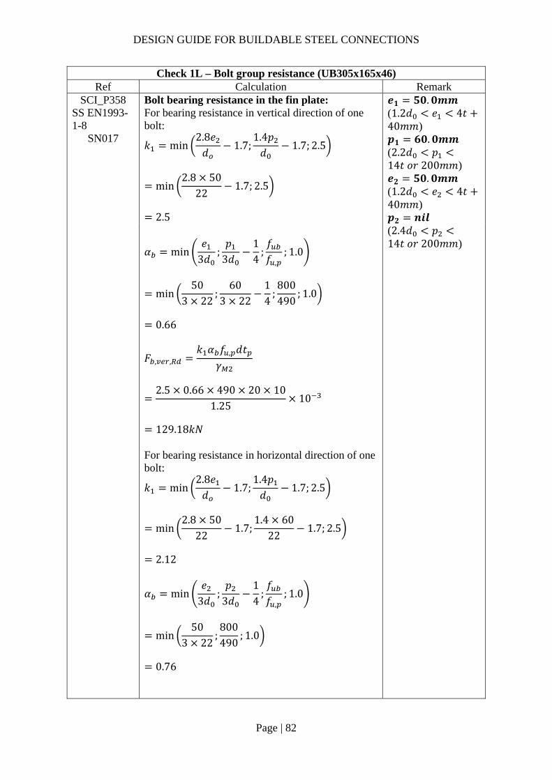
DESIGN GUIDE FOR BUILDABLE STEEL CONNECTIONS
Page | 82
Check 1L – Bolt group resistance (UB305x165x46) Ref Calculation Remark
SCI_P358 SS EN1993-1-8
SN017
Bolt bearing resistance in the fin plate: For bearing resistance in vertical direction of one bolt:
𝑘 min2.8𝑒𝑑
1.7;1.4𝑝𝑑
1.7; 2.5
min2.8 50
221.7; 2.5
2.5
𝒆𝟏 𝟓𝟎.𝟎𝒎𝒎 (1.2𝑑 𝑒 4𝑡40𝑚𝑚) 𝒑𝟏 𝟔𝟎.𝟎𝒎𝒎 (2.2𝑑 𝑝14𝑡 𝑜𝑟 200𝑚𝑚) 𝒆𝟐 𝟓𝟎.𝟎𝒎𝒎 (1.2𝑑 𝑒 4𝑡40𝑚𝑚) 𝒑𝟐 𝒏𝒊𝒍
𝛼 min𝑒
3𝑑;𝑝
3𝑑14
;𝑓𝑓 ,
; 1.0
min50
3 22;
603 22
14
;800490
; 1.0
0.66
𝐹 , ,𝑘 𝛼 𝑓 , 𝑑𝑡
𝛾
2.5 0.66 490 20 10
1.2510
129.18𝑘𝑁
For bearing resistance in horizontal direction of one bolt:
𝑘 min2.8𝑒𝑑
1.7;1.4𝑝𝑑
1.7; 2.5
min2.8 50
221.7;
1.4 6022
1.7; 2.5
2.12
𝛼 min𝑒
3𝑑;𝑝
3𝑑14
;𝑓𝑓 ,
; 1.0
min50
3 22;800490
; 1.0
0.76
(2.4𝑑 𝑝14𝑡 𝑜𝑟 200𝑚𝑚)

DESIGN GUIDE FOR BUILDABLE STEEL CONNECTIONS
Page | 83
Check 1L – Bolt group resistance (UB305x165x46) Ref Calculation Remark
𝐹 , ,
𝑘 𝛼 𝑓 , 𝑑𝑡𝛾
2.12 0.76 490 20 10
1.2510
125.81kN
Bolt group bearing resistance:
𝑉𝑛
1 𝛼𝑛𝐹 , ,
𝛽𝑛𝐹 , ,
3
1129.18
0.50 3125.81
10
211.04𝑘𝑁 𝑉 100𝑘𝑁
OK!
SCI_P358 SS EN1993-
1-8
Bolt bearing resistance in secondary beam web: Vertical bearing resistance:
𝑘 min2.8𝑒 ,
𝑑1.7;
1.4𝑝𝑑
1.7; 2.5
min2.8 50
221.7; 2.5
2.5
𝛼 min𝑒 ,
3𝑑;𝑝
3𝑑14
;𝑓𝑓 ,
; 1.0
min93.3
3 22;
603 22
14
;800490
; 1.0
0.66
𝐹 , ,𝑘 𝛼 𝑓 , 𝑑𝑡 ,
𝛾
2.5 0.66 490 20 6.7
1.2510
86.55𝑘𝑁
𝒆𝟏,𝒃 𝟗𝟑.𝟑𝒎𝒎 𝒆𝟐,𝒃 𝟓𝟎.𝟎𝒎𝒎
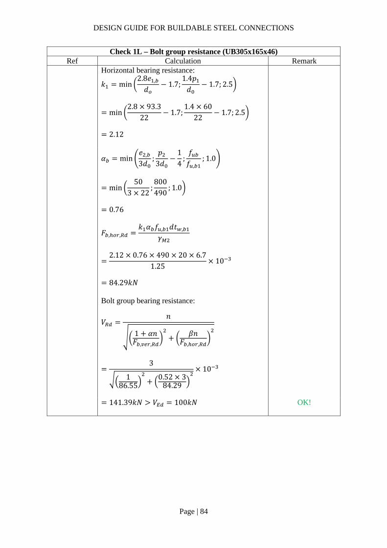
DESIGN GUIDE FOR BUILDABLE STEEL CONNECTIONS
Page | 84
Check 1L – Bolt group resistance (UB305x165x46) Ref Calculation Remark
Horizontal bearing resistance:
𝑘 min2.8𝑒 ,
𝑑1.7;
1.4𝑝𝑑
1.7; 2.5
min2.8 93.3
221.7;
1.4 6022
1.7; 2.5
2.12
𝛼 min
𝑒 ,
3𝑑;𝑝
3𝑑14
;𝑓𝑓 ,
; 1.0
min50
3 22;800490
; 1.0
0.76
𝐹 , ,𝑘 𝛼 𝑓 , 𝑑𝑡 ,
𝛾
2.12 0.76 490 20 6.7
1.2510
84.29𝑘𝑁
Bolt group bearing resistance:
𝑉𝑛
1 𝛼𝑛𝐹 , ,
𝛽𝑛𝐹 , ,
3
186.55
0.52 384.29
10
141.39𝑘𝑁 𝑉 100𝑘𝑁
OK!

DESIGN GUIDE FOR BUILDABLE STEEL CONNECTIONS
Page | 85
Check 2L – Fin plate resistance (UB 305x165x46) Ref Calculations Remark
SS EN1993-1-8
SCI_P358
Fin plate shear resistance (gross section): 𝑡 10𝑚𝑚 16𝑚𝑚 ∴ 𝑓 , 355𝑀𝑃𝑎 Gross section shear resistance:
𝑉 ,ℎ 𝑡1.27
𝑓 ,
√3𝛾
220 10
1.27355
√3 10
355.05𝑘𝑁
ℎ 220𝑚𝑚 𝛾 1.0 (SS EN1993-1-1)
Fin plate shear resistance (net section): 𝐴 , 𝑡 ℎ 𝑛 𝑑
10 220 3 22
1540𝑚𝑚 Net area shear resistance:
𝑉 ,𝐴 , 𝑓 ,
√3𝛾
1540490
√3 1.2510
348.53𝑘𝑁
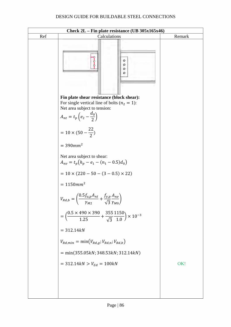
DESIGN GUIDE FOR BUILDABLE STEEL CONNECTIONS
Page | 86
Check 2L – Fin plate resistance (UB 305x165x46) Ref Calculations Remark
Fin plate shear resistance (block shear): For single vertical line of bolts (𝑛 1): Net area subject to tension:
𝐴 𝑡 𝑒𝑑2
10 50222
390𝑚𝑚
Net area subject to shear: 𝐴 𝑡 ℎ 𝑒 𝑛 0.5 𝑑
10 220 50 3 0.5 22
1150𝑚𝑚
𝑉 ,
0.5𝑓 , 𝐴𝛾
𝑓 ,
√3
𝐴𝛾
0.5 490 390
1.25355
√3
11501.0
10
312.14𝑘𝑁
𝑉 , min 𝑉 , ;𝑉 , ;𝑉 ,
min 355.05𝑘𝑁; 348.53𝑘𝑁; 312.14𝑘𝑁
312.14𝑘𝑁 𝑉 100𝑘𝑁
OK!
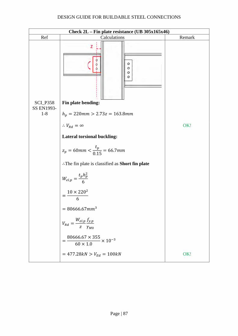
DESIGN GUIDE FOR BUILDABLE STEEL CONNECTIONS
Page | 87
Check 2L – Fin plate resistance (UB 305x165x46) Ref Calculations Remark
SCI_P358 SS EN1993-
1-8
Fin plate bending: ℎ 220𝑚𝑚 2.73𝑧 163.8𝑚𝑚
∴ 𝑉 ∞
OK!
Lateral torsional buckling:
𝑧 60𝑚𝑚𝑡
0.1566.7𝑚𝑚
∴The fin plate is classified as Short fin plate
𝑊 ,𝑡 ℎ
6
10 220
6
80666.67𝑚𝑚
𝑉𝑊 ,
𝑧𝑓 ,
𝛾
80666.67 355
60 1.010
477.28𝑘𝑁 𝑉 100𝑘𝑁 OK!

DESIGN GUIDE FOR BUILDABLE STEEL CONNECTIONS
Page | 88
Check 3L – Beam web resistance (UB305x165x46) Ref Calculations Remark
SCI_P358 SS EN1993-
1-8
Beam web shear resistance (gross section): For unnotched beams (UB305x165x46): 𝐴 𝐴 2𝑏 𝑡 , 𝑡 , 2𝑟 𝑡 ,
5870 2 165.7 11.8 6.7 2 8.911.8
2248.58𝑚𝑚
𝑉 , 𝑉 ,𝐴 𝑓 ,
√3𝛾
2248.58355
√3 1.010
460.87𝑘𝑁
Beam web shear resistance (net section): 𝐴 , 𝐴 𝑛 𝑑 𝑡 ,
2248.58 3 22 6.7
1806.38𝑚𝑚
𝑉 ,𝐴 , 𝑓 ,
√3𝛾
1806.38490
√3 1.2510
408.82𝑘𝑁

DESIGN GUIDE FOR BUILDABLE STEEL CONNECTIONS
Page | 89
Check 3L – Beam web resistance (UB305x165x46) Ref Calculations Remark
𝑉 , min 𝑉 , ;𝑉 ,
min 460.87𝑘𝑁; 408.82𝑘𝑁
408.82𝑘𝑁 𝑉 100𝑘𝑁
OK!
Shear and bending interaction of secondary beam web: For Short fin plate, shear and bending moment interaction check is NOT necessary

DESIGN GUIDE FOR BUILDABLE STEEL CONNECTIONS
Page | 90
Check 4L – Welds (UB305x165x46) Ref Calculations Remark
The fin plate to column connection is assumed to be stiffer than the bolt connection due to the presence of the beam web. There is some nominal moment applied on the fillet weld and hence the welding needs to be designed for nominal moment.
SS EN1993-1-8
Unit throat area: 𝐴 2𝑙 2 220
440𝑚𝑚 Eccentricity between weld and line of action: 𝑒𝑐𝑐 𝑧 60𝑚𝑚 Nominal moment due to eccentricity: 𝑀 𝑉 𝑒𝑐𝑐
100 0.060
6𝑘𝑁𝑚 Polar moment of inertia:
𝐽𝑙12
22012
887333𝑚𝑚
Critical point: Vertical stress:
𝜏𝑉𝐴
100440
0.23𝑘𝑁/𝑚𝑚
Length of fillet weld: 𝑙𝑒𝑛𝑔𝑡ℎ 𝑙 220𝑚𝑚
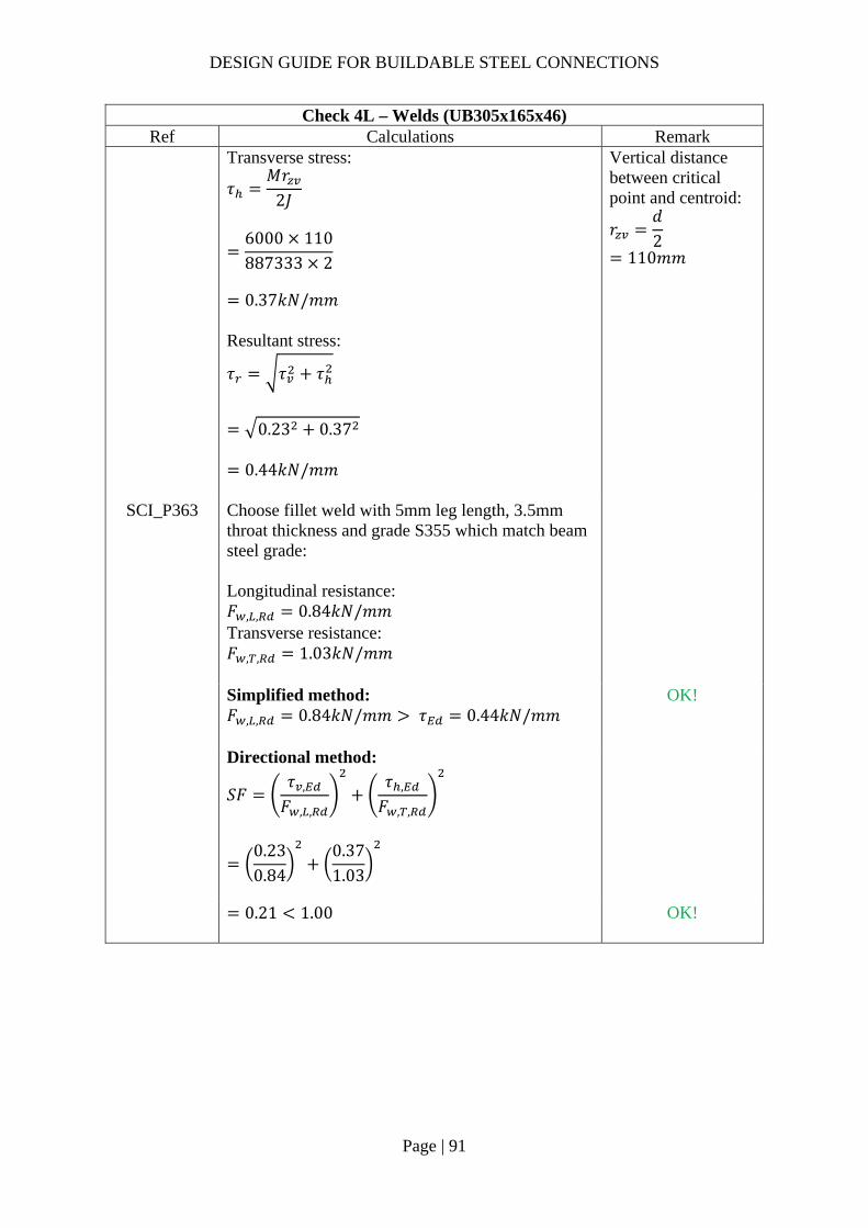
DESIGN GUIDE FOR BUILDABLE STEEL CONNECTIONS
Page | 91
Check 4L – Welds (UB305x165x46) Ref Calculations Remark
Transverse stress:
𝜏𝑀𝑟
2𝐽
6000 110887333 2
0.37𝑘𝑁/𝑚𝑚
Resultant stress:
𝜏 𝜏 𝜏
0.23 0.37
0.44𝑘𝑁/𝑚𝑚
Vertical distance between critical point and centroid:
𝑟𝑑2
110𝑚𝑚
SCI_P363 Choose fillet weld with 5mm leg length, 3.5mm throat thickness and grade S355 which match beam steel grade: Longitudinal resistance: 𝐹 , , 0.84𝑘𝑁/𝑚𝑚 Transverse resistance: 𝐹 , , 1.03𝑘𝑁/𝑚𝑚
Simplified method: 𝐹 , , 0.84𝑘𝑁/𝑚𝑚 𝜏 0.44𝑘𝑁/𝑚𝑚
OK!
Directional method:
𝑆𝐹𝜏 ,
𝐹 , ,
𝜏 ,
𝐹 , ,
0.230.84
0.371.03
0.21 1.00
OK!

DESIGN GUIDE FOR BUILDABLE STEEL CONNECTIONS
Page | 92
Check 5L – Local shear and bearing resistance of column flange Ref Calculation Remark
SCI_P358 Local shear resistance of the column (UC305x305x118) flange: 𝐴 ℎ 𝑡
220 18.7 4114𝑚𝑚
𝐹𝐴 𝑓 ,
√3𝛾
4114 355
√3 1.010
819.45𝑘𝑁
𝑉2
50𝑘𝑁
OK!

DESIGN GUIDE FOR BUILDABLE STEEL CONNECTIONS
Page | 93
Check 1R – Bolt group resistance (UB 457x191x98) Ref Calculations Remark
Bolt shear resistance: Using class 8.8, M20 bolts with: 𝐴 245𝑚𝑚 , 𝑓 800𝑀𝑃𝑎, 𝛼 0.6
SS EN1993-1-8
Shear resistance of a single bolt:
𝐹 ,𝛼 𝑓 𝐴𝛾
0.6 800 245
1.2510
94.08𝑘𝑁
𝛾 1.25 (refer to NA to SS)
SCI_P358 SN017
For single vertical line of bolts (𝑛 1): 𝑛 4, 𝑛 4 1 4 𝛼 0
𝛽6𝑧
𝑛 𝑛 1 𝑝
6 60𝑚𝑚
4 4 1 60𝑚𝑚
0.30
𝑉𝑛𝐹 ,
1 𝛼𝑛 𝛽𝑛
4 94.08
1 0 0.3 410
240.91𝑘𝑁 𝑉 200𝑘𝑁 OK!

DESIGN GUIDE FOR BUILDABLE STEEL CONNECTIONS
Page | 94
Check 1R – Bolt group resistance (UB 457x191x98) Ref Calculations Remark
SCI_P358 SS EN1993-
1-8
Bolt bearing resistance in the fin plate: For bearing resistance in vertical direction of one bolt:
𝑘 min2.8𝑒𝑑
1.7;1.4𝑝𝑑
1.7; 2.5
min2.8 50
221.7; 2.5
2.5
𝒆𝟏 𝟓𝟓.𝟎𝒎𝒎 (1.2𝑑 𝑒 4𝑡40𝑚𝑚) 𝒑𝟏 𝟔𝟎.𝟎𝒎𝒎 (2.2𝑑 𝑝14𝑡 𝑜𝑟 200𝑚𝑚) 𝒆𝟐 𝟓𝟎.𝟎𝒎𝒎 (1.2𝑑 𝑒 4𝑡40𝑚𝑚) 𝒑𝟐 𝒏𝒊𝒍
𝛼 min
𝑒3𝑑
;𝑝
3𝑑14
;𝑓𝑓 ,
; 1.0
min55
3 22;
603 22
14
;800490
; 1.0
0.66
𝐹 , ,𝑘 𝛼 𝑓 , 𝑑𝑡
𝛾
2.5 0.66 490 20 10
1.2510
129.18𝑘𝑁
For bearing resistance in horizontal direction of one bolt:
𝑘 min2.8𝑒𝑑
1.7;1.4𝑝𝑑
1.7; 2.5
min2.8 55
221.7;
1.4 6022
1.7; 2.5
2.12
𝛼 min𝑒
3𝑑;𝑝
3𝑑14
;𝑓𝑓 ,
; 1.0
min50
3 22;800490
; 1.0
0.76
(2.4𝑑 𝑝14𝑡 𝑜𝑟 200𝑚𝑚)

DESIGN GUIDE FOR BUILDABLE STEEL CONNECTIONS
Page | 95
Check 1R – Bolt group resistance (UB 457x191x98) Ref Calculations Remark
𝐹 , ,
𝑘 𝛼 𝑓 , 𝑑𝑡𝛾
2.12 0.76 490 20 10
1.2510
125.81kN
Bolt group bearing resistance:
𝑉𝑛
1 𝛼𝑛𝐹 , ,
𝛽𝑛𝐹 , ,
5
1129.18
0.51 4125.81
10
325.62𝑘𝑁 𝑉 200𝑘𝑁
OK!
SCI_P358 SS EN1993-
1-8
Bolt bearing resistance in secondary beam web: Vertical bearing resistance:
𝑘 min2.8𝑒 ,
𝑑1.7;
1.4𝑝𝑑
1.7; 2.5
min2.8 50
221.7; 2.5
2.5
𝛼 min𝑒 ,
3𝑑;𝑝
3𝑑14
;𝑓𝑓 ,
; 1.0
min143.63 22
;60
3 2214
;800490
; 1.0
0.66
𝐹 , ,𝑘 𝛼 𝑓 , 𝑑𝑡 ,
𝛾
2.5 0.66 490 20 11.4
1.2510
147.27𝑘𝑁
𝒆𝟏,𝒃 𝟏𝟑𝟖.𝟔𝒎𝒎 𝒆𝟐,𝒃 𝟓𝟎.𝟎𝒎𝒎

DESIGN GUIDE FOR BUILDABLE STEEL CONNECTIONS
Page | 96
Check 1R – Bolt group resistance (UB 457x191x98) Ref Calculations Remark
Horizontal bearing resistance:
𝑘 min2.8𝑒 ,
𝑑1.7;
1.4𝑝𝑑
1.7; 2.5
min2.8 143.6
221.7;
1.4 6022
1.7; 2.5
2.12
𝛼 min
𝑒 ,
3𝑑;𝑝
3𝑑14
;𝑓𝑓 ,
; 1.0
min50
3 22;800490
; 1.0
0.76
𝐹 , ,𝑘 𝛼 𝑓 , 𝑑𝑡 ,
𝛾
2.12 0.76 490 20 11.4
1.2510
143.42𝑘𝑁
Bolt group bearing resistance:
𝑉𝑛
1 𝛼𝑛𝐹 , ,
𝛽𝑛𝐹 , ,
4
1147.27
0.5 4143.42
10
371.20𝑘𝑁 𝑉 200𝑘𝑁
OK!

DESIGN GUIDE FOR BUILDABLE STEEL CONNECTIONS
Page | 97
Check 2R – Fin plate resistance (UB457x191x98) Ref Calculations Remark
SS EN1993-1-8
SCI_P358
Fin plate shear resistance (gross section): 𝑡 10𝑚𝑚 16𝑚𝑚 ∴ 𝑓 , 355𝑀𝑃𝑎 Gross section shear resistance:
𝑉 ,ℎ 𝑡1.27
𝑓 ,
√3𝛾
290 10
1.27355
√3 10
468.02𝑘𝑁
ℎ 290𝑚𝑚 𝛾 1.0 (SS EN1993-1-1)
Fin plate shear resistance (net section): 𝐴 , 𝑡 ℎ 𝑛 𝑑
10 290 4 22
2020𝑚𝑚 Net area shear resistance:
𝑉 ,𝐴 , 𝑓 ,
√3𝛾
2020490
√3 1.2510
457.17𝑘𝑁

DESIGN GUIDE FOR BUILDABLE STEEL CONNECTIONS
Page | 98
Check 2R – Fin plate resistance (UB457x191x98) Ref Calculations Remark
Fin plate shear resistance (block shear): For single vertical line of bolts (𝑛 1): Net area subject to tension:
𝐴 𝑡 𝑒𝑑2
10 50222
390𝑚𝑚
Net area subject to shear: 𝐴 𝑡 ℎ 𝑒 𝑛 0.5 𝑑
10 290 55 4 0.5 22
1580𝑚𝑚
𝑉 ,
0.5𝑓 , 𝐴𝛾
𝑓 ,
√3
𝐴𝛾
0.5 490 390
1.25355
√3
15801.0
10
400.28𝑘𝑁
𝑉 , min 𝑉 , ;𝑉 , ;𝑉 ,
min 468.02𝑘𝑁; 457.17𝑘𝑁; 400.28𝑘𝑁
400.28𝑘𝑁 𝑉 200𝑘𝑁
OK!

DESIGN GUIDE FOR BUILDABLE STEEL CONNECTIONS
Page | 99
Check 2R – Fin plate resistance (UB457x191x98) Ref Calculations Remark
SCI_P358 SS EN1993-
1-8
Fin plate bending: ℎ 290𝑚𝑚 2.73𝑧 163.8𝑚𝑚
∴ 𝑉 ∞
OK!
Lateral torsional buckling:
𝑧 60𝑚𝑚𝑡
0.1566.67𝑚𝑚
∴The fin plate is classified as Short fin plate
𝑊 ,𝑡 ℎ
6
10 290
6
140166.7𝑚𝑚
𝑉𝑊 ,
𝑧𝑓 ,
𝛾
140166.7 355
60 1.010
829.32𝑘𝑁 𝑉 200𝑘𝑁
OK!
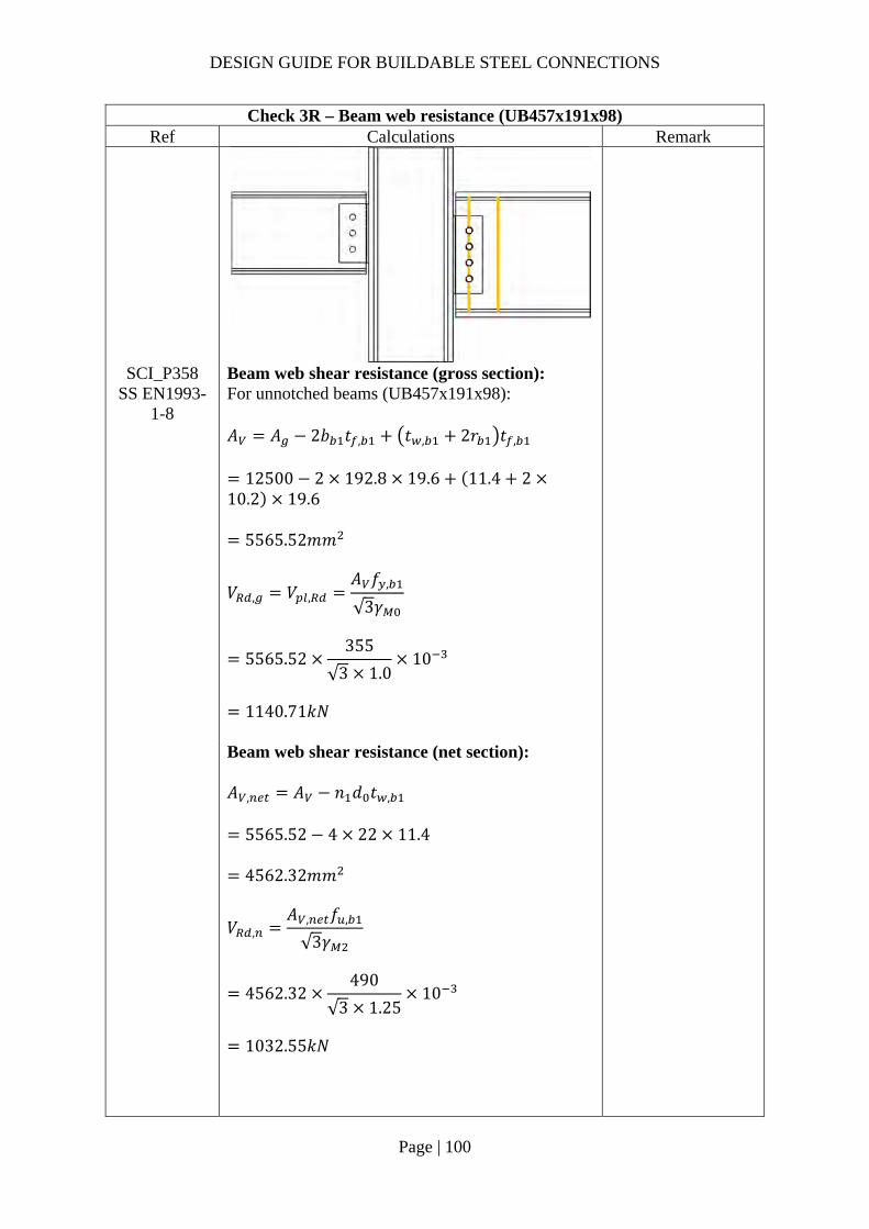
DESIGN GUIDE FOR BUILDABLE STEEL CONNECTIONS
Page | 100
Check 3R – Beam web resistance (UB457x191x98) Ref Calculations Remark
SCI_P358 SS EN1993-
1-8
Beam web shear resistance (gross section): For unnotched beams (UB457x191x98): 𝐴 𝐴 2𝑏 𝑡 , 𝑡 , 2𝑟 𝑡 ,
12500 2 192.8 19.6 11.4 210.2 19.6
5565.52𝑚𝑚
𝑉 , 𝑉 ,𝐴 𝑓 ,
√3𝛾
5565.52355
√3 1.010
1140.71𝑘𝑁
Beam web shear resistance (net section): 𝐴 , 𝐴 𝑛 𝑑 𝑡 ,
5565.52 4 22 11.4
4562.32𝑚𝑚
𝑉 ,𝐴 , 𝑓 ,
√3𝛾
4562.32490
√3 1.2510
1032.55𝑘𝑁

DESIGN GUIDE FOR BUILDABLE STEEL CONNECTIONS
Page | 101
Check 3R – Beam web resistance (UB457x191x98) Ref Calculations Remark
𝑉 , min 𝑉 , ;𝑉 ,
min 1140.71𝑘𝑁; 1035.55𝑘𝑁
1035.55𝑘𝑁 𝑉 200𝑘𝑁
Shear and bending interaction of secondary beam web: For Short fin plate, shear and bending moment interaction check is NOT necessary

DESIGN GUIDE FOR BUILDABLE STEEL CONNECTIONS
Page | 102
Check 4R – Welds (UB457x191x98) Ref Calculations Remark
The fin plate to column connection is assumed to be stiffer than the bolt connection due to the presence of the beam web. There is some nominal moment applied on the fillet weld and hence the welding needs to be designed for nominal moment.
SS EN1993-1-8
Unit throat area: 𝐴 2𝑙 2 290
580𝑚𝑚 Eccentricity between weld and line of action: 𝑒𝑐𝑐 𝑧 60𝑚𝑚 Nominal moment due to eccentricity: 𝑀 𝑉 𝑒𝑐𝑐
200 0.060
12𝑘𝑁𝑚 Polar moment of inertia:
𝐽𝑙12
29012
2032417𝑚𝑚
Critical point: Vertical stress:
𝜏𝑉𝐴
200580
0.34𝑘𝑁/𝑚𝑚
Length of fillet weld: 𝑙𝑒𝑛𝑔𝑡ℎ 𝑙 290𝑚𝑚

DESIGN GUIDE FOR BUILDABLE STEEL CONNECTIONS
Page | 103
Check 4R – Welds (UB457x191x98) Ref Calculations Remark
Transverse stress:
𝜏𝑀𝑟
2𝐽
12000 1452032417 2
0.43𝑘𝑁/𝑚𝑚
Resultant stress:
𝜏 𝜏 𝜏
0.34 0.43
0.55𝑘𝑁/𝑚𝑚
SCI_P363 Choose fillet weld with 5mm leg length, 3.5mm throat thickness and grade S355 which match beam steel grade: Longitudinal resistance: 𝐹 , , 0.84𝑘𝑁/𝑚𝑚 Transverse resistance: 𝐹 , , 1.03𝑘𝑁/𝑚𝑚
Simplified method: 𝐹 , , 0.84𝑘𝑁/𝑚𝑚 𝜏 0.55𝑘𝑁/𝑚𝑚
OK!
Directional method:
𝑆𝐹𝜏 ,
𝐹 , ,
𝜏 ,
𝐹 , ,
0.340.84
0.431.03
0.34 1.00
OK!

DESIGN GUIDE FOR BUILDABLE STEEL CONNECTIONS
Page | 104
Check 5R – Local shear and bearing resistance of column flange Ref Calculation Remark
SCI_P358 Local shear resistance of the column (UC305x305x118) flange: 𝐴 ℎ 𝑡
290 18.7 5423𝑚𝑚
𝐹𝐴 𝑓 ,
√3𝛾
5423 345
√3 1.010
1080.19𝑘𝑁
𝑉2
100𝑘𝑁
OK!
Note:
Since the design forces from the beams acting on two sides of the column are different, there is an unbalanced moment induced on the column. Hence, the column design needs to be designed for the unbalanced moment.

DESIGN GUIDE FOR BUILDABLE STEEL CONNECTIONS
Page | 105
2.3.7 Example 5 – Two-sided Beam-to-Column extended fin plate connection in minor axis with extended fin plate

DESIGN GUIDE FOR BUILDABLE STEEL CONNECTIONS
Page | 106
Check 1L – Bolt group resistance (UB356x171x57) Ref Calculations Remark
Bolt resistance: Using Gr8.8, M20 bolts with: 𝐴 245𝑚𝑚 ; 𝑓 800𝑀𝑃𝑎; 𝛼 0.6
SS EN1993-1-8
Shear resistance of a single bolt:
𝐹 ,𝛼 𝑓 𝐴𝛾
0.6 800 245
1.2510
94.08𝑘𝑁
𝛾 1.25 (refer to NA to SS)
SN017 For single vertical line of bolts (𝑛 1): 𝛼 0
𝛽6𝑧
𝑛 𝑛 1 𝑝
6 60𝑚𝑚
3 3 1 60𝑚𝑚
0.50
𝑛 3, 𝑛 3 1 3
𝑉𝑛𝐹 ,
1 𝛼𝑛 𝛽𝑛
3 94.08
1 0 0.50 310
156.56𝑘𝑁 𝑉 100𝑘𝑁
OK!
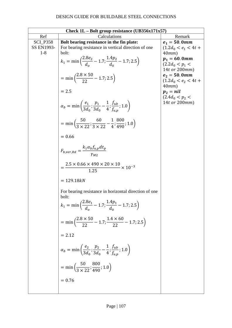
DESIGN GUIDE FOR BUILDABLE STEEL CONNECTIONS
Page | 107
Check 1L – Bolt group resistance (UB356x171x57) Ref Calculations Remark
SCI_P358 SS EN1993-
1-8
Bolt bearing resistance in the fin plate: For bearing resistance in vertical direction of one bolt:
𝑘 min2.8𝑒𝑑
1.7;1.4𝑝𝑑
1.7; 2.5
min2.8 50
221.7; 2.5
2.5
𝒆𝟏 𝟓𝟎.𝟎𝒎𝒎 (1.2𝑑 𝑒 4𝑡40𝑚𝑚) 𝒑𝟏 𝟔𝟎.𝟎𝒎𝒎 (2.2𝑑 𝑝14𝑡 𝑜𝑟 200𝑚𝑚) 𝒆𝟐 𝟓𝟎.𝟎𝒎𝒎 (1.2𝑑 𝑒 4𝑡40𝑚𝑚) 𝒑𝟐 𝒏𝒊𝒍
𝛼 min𝑒
3𝑑;𝑝
3𝑑14
;𝑓𝑓 ,
; 1.0
min50
3 22;
603 22
14
;800490
; 1.0
0.66
𝐹 , ,𝑘 𝛼 𝑓 , 𝑑𝑡
𝛾
2.5 0.66 490 20 10
1.2510
129.18𝑘𝑁
For bearing resistance in horizontal direction of one bolt:
𝑘 min2.8𝑒𝑑
1.7;1.4𝑝𝑑
1.7; 2.5
min2.8 50
221.7;
1.4 6022
1.7; 2.5
2.12
𝛼 min𝑒
3𝑑;𝑝
3𝑑14
;𝑓𝑓 ,
; 1.0
min50
3 22;800490
; 1.0
0.76
(2.4𝑑 𝑝14𝑡 𝑜𝑟 200𝑚𝑚)

DESIGN GUIDE FOR BUILDABLE STEEL CONNECTIONS
Page | 108
Check 1L – Bolt group resistance (UB356x171x57) Ref Calculations Remark
𝐹 , ,
𝑘 𝛼 𝑓 , 𝑑𝑡𝛾
2.12 0.76 490 20 10
1.2510
125.81kN
Bolt group bearing resistance:
𝑉𝑛
1 𝛼𝑛𝐹 , ,
𝛽𝑛𝐹 , ,
3
1129.18
0.50 3125.81
10
211.04𝑘𝑁 𝑉 100𝑘𝑁
OK!
SCI_P358 SS EN1993-
1-8
Bolt bearing resistance in secondary beam web: Vertical bearing resistance:
𝑘 min2.8𝑒 ,
𝑑1.7;
1.4𝑝𝑑
1.7; 2.5
min2.8 50
221.7; 2.5
2.5
𝛼 min𝑒 ,
3𝑑;𝑝
3𝑑14
;𝑓𝑓 ,
; 1.0
min119
3 22;
603 22
14
;800490
; 1.0
0.66
𝐹 , ,𝑘 𝛼 𝑓 , 𝑑𝑡 ,
𝛾
2.5 0.66 490 20 8.1
1.2510
104.64𝑘𝑁
𝒆𝟏,𝒃 𝟏𝟏𝟗𝒎𝒎 𝒆𝟐,𝒃 𝟓𝟎.𝟎𝒎𝒎

DESIGN GUIDE FOR BUILDABLE STEEL CONNECTIONS
Page | 109
Check 1L – Bolt group resistance (UB356x171x57) Ref Calculations Remark
Horizontal bearing resistance:
𝑘 min2.8𝑒 ,
𝑑1.7;
1.4𝑝𝑑
1.7; 2.5
min2.8 119
221.7;
1.4 6022
1.7; 2.5
2.12
𝛼 min
𝑒 ,
3𝑑;𝑝
3𝑑14
;𝑓𝑓 ,
; 1.0
min50
3 22;800490
; 1.0
0.76
𝐹 , ,𝑘 𝛼 𝑓 , 𝑑𝑡 ,
𝛾
2.12 0.76 490 20 8.1
1.2510
101.90𝑘𝑁
Bolt group bearing resistance:
𝑉𝑛
1 𝛼𝑛𝐹 , ,
𝛽𝑛𝐹 , ,
3
1104.64
0.5 3101.90
170.94𝑘𝑁 𝑉 100𝑘𝑁
OK!

DESIGN GUIDE FOR BUILDABLE STEEL CONNECTIONS
Page | 110
Check 2L – Fin plate resistance (UB356x171x57) Ref Calculations Remark
SS EN1993-1-8
SCI_P358
Fin plate shear resistance (gross section): 𝑡 10𝑚𝑚 16𝑚𝑚 ∴ 𝑓 , 355𝑀𝑃𝑎 Gross section shear resistance:
𝑉 ,ℎ 𝑡1.27
𝑓 ,
√3𝛾
220 10
1.27355
√3 10
355.05𝑁
ℎ 220𝑚𝑚 𝛾 1.0 (SS EN1993-1-1)
Fin plate shear resistance (net section): 𝐴 , 𝑡 ℎ 𝑛 𝑑
10 220 3 22
1540𝑚𝑚 Net area shear resistance:
𝑉 ,𝐴 , 𝑓 ,
√3𝛾
1540490
√3 1.2510
348.53𝑘𝑁

DESIGN GUIDE FOR BUILDABLE STEEL CONNECTIONS
Page | 111
Check 2L – Fin plate resistance (UB356x171x57) Ref Calculations Remark
Fin plate shear resistance (block shear): For single vertical line of bolts (𝑛 1): Net area subject to tension:
𝐴 𝑡 𝑒𝑑2
10 50222
390𝑚𝑚
Net area subject to shear: 𝐴 𝑡 ℎ 𝑒 𝑛 0.5 𝑑
10 220 50 3 0.5 22
1150𝑚𝑚
𝑉 ,
0.5𝑓 , 𝐴𝛾
𝑓 ,
√3
𝐴𝛾
0.5 490 390
1.25355
√3
11501.0
10
312.14𝑘𝑁
𝑉 , min 𝑉 , ;𝑉 , ;𝑉 ,
min 355.05𝑘𝑁; 348.53𝑘𝑁; 312.14𝑘𝑁
312.14𝑘𝑁 𝑉 100𝑘𝑁
OK!
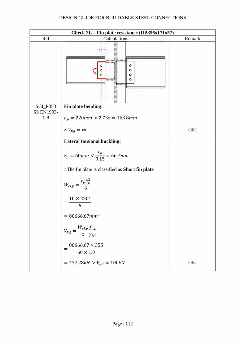
DESIGN GUIDE FOR BUILDABLE STEEL CONNECTIONS
Page | 112
Check 2L – Fin plate resistance (UB356x171x57) Ref Calculations Remark
SCI_P358 SS EN1993-
1-8
Fin plate bending: ℎ 220𝑚𝑚 2.73𝑧 163.8𝑚𝑚
∴ 𝑉 ∞
OK!
Lateral torsional buckling:
𝑧 60𝑚𝑚𝑡
0.1566.7𝑚𝑚
∴The fin plate is classified as Short fin plate
𝑊 ,𝑡 ℎ
6
10 220
6
80666.67𝑚𝑚
𝑉𝑊 ,
𝑧𝑓 ,
𝛾
80666.67 355
60 1.0
477.28𝑘𝑁 𝑉 100𝑘𝑁
OK!

DESIGN GUIDE FOR BUILDABLE STEEL CONNECTIONS
Page | 113
Check 3L – Secondary beam web resistance (UB356x171x57) Ref Calculations Remark
SCI_P358 SS EN1993-
1-8
Beam web shear resistance (gross section): For unnotched beams (UB356x171x57): 𝐴 𝐴 2𝑏 𝑡 , 𝑡 , 2𝑟 𝑡 ,
7260 2 172.2 13 8.1 2 10.213
3153.3𝑚𝑚
𝑉 , 𝑉 ,𝐴 𝑓 ,
√3𝛾
3153.3355
√3 1.010
646.30𝑘𝑁
Beam web shear resistance (net section): 𝐴 , 𝐴 𝑛 𝑑 𝑡 ,
3153.3 3 22 8.1
2618.7𝑚𝑚
𝑉 ,𝐴 , 𝑓 ,
√3𝛾
2618.7490
√3 1.2510
592.67𝑘𝑁

DESIGN GUIDE FOR BUILDABLE STEEL CONNECTIONS
Page | 114
Check 3L – Secondary beam web resistance (UB356x171x57) Ref Calculations Remark
𝑉 , min 𝑉 , ;𝑉 , ;𝑉 ,
min 646.30𝑘𝑁; 592.67𝑘𝑁
592.67𝑘𝑁 𝑉 100𝑘𝑁
OK!
Shear and bending interaction of secondary beam web: For Short fin plate, shear and bending moment interaction check is NOT necessary

DESIGN GUIDE FOR BUILDABLE STEEL CONNECTIONS
Page | 115
Check 4L – Welds (C shape fillet weld) (UB356x171x57) Ref Calculations Remark
SS EN1993-1-8
Location of centre of gravity of welds group:
�̅�𝑏
2𝑏 𝑑
108
2 108 190
23.9𝑚𝑚
𝑦𝑑2
190
2
95𝑚𝑚
Unit throat area: 𝐴 2𝑏 𝑑
2 108 190
406𝑚𝑚 Moment arm between applied force and weld centre: 𝑟 159.1𝑚𝑚 Induced moment on welds: 𝑀 𝑉 𝑟
100 159.1
15910𝑘𝑁𝑚𝑚
Length of the fillet welds: Horizontal length: 𝑏 108𝑚𝑚 Depth: 𝑑 190𝑚𝑚

DESIGN GUIDE FOR BUILDABLE STEEL CONNECTIONS
Page | 116
Check 4L – Welds (C shape fillet weld) (UB356x171x57) Ref Calculations Remark
Polar moment of inertia:
𝐽8𝑏 6𝑏𝑑 𝑑
12𝑏
2𝑏 𝑑
8 108 6 108 190 190
12
108
2 108 190
3025696𝑚𝑚
End-point 1: Horizontal distance from centroid: 𝑟 𝑏 �̅�
108 23.9 84.10𝑚𝑚
Vertical distance from centroid: 𝑟 𝑦 𝑐𝑜𝑝𝑒 ℎ𝑜𝑙𝑒 𝑠𝑖𝑧𝑒
95 15𝑚𝑚 110𝑚𝑚
Vertical stress:
𝜏𝑉2𝐴
𝑀𝑟2𝐽
1002 406
15910 84.102 3025696
0.344𝑘𝑁/𝑚𝑚
Horizontal stress:
𝜏𝑀𝑟
2𝐽
15910 1102 3025696
0.289𝑘𝑁/𝑚𝑚

DESIGN GUIDE FOR BUILDABLE STEEL CONNECTIONS
Page | 117
Check 4L – Welds (C shape fillet weld) (UB356x171x57) Ref Calculations Remark
Resultant stress:
𝜏 𝜏 𝜏
0.344 0.289
0.45𝑘𝑁/𝑚𝑚 End-point 2: Horizontal distance from centroid: 𝑟 �̅� 𝑐𝑜𝑝𝑒 ℎ𝑜𝑙𝑒 𝑠𝑖𝑧𝑒
23.9 15𝑚𝑚 38.90𝑚𝑚 Vertical distance from centroid: 𝑟 𝑑 𝑦
190 95 95𝑚𝑚
Vertical stress:
𝜏𝑉2𝐴
𝑀𝑟2𝐽
100
2 40615910 38.902 3025696
0.225𝑘𝑁/𝑚𝑚
Horizontal stress:
𝜏𝑀𝑟
2𝐽
15910 95
2 3025696
0.250𝑘𝑁/𝑚𝑚
Resultant stress:
𝜏 𝜏 𝜏
0.225 0.250
0.34𝑘𝑁/𝑚𝑚

DESIGN GUIDE FOR BUILDABLE STEEL CONNECTIONS
Page | 118
Check 4L – Welds (C shape fillet weld) (UB356x171x57) Ref Calculations Remark
Choose fillet weld with 5mm leg length, 3.5mm throat thickness and grade S355 which match beam steel grade: Longitudinal resistance: 𝐹 , , 0.84𝑘𝑁/𝑚𝑚 Transverse resistance: 𝐹 , , 1.03𝑘𝑁/𝑚𝑚
Simplified method: 𝐹 , , 0.78𝑘𝑁/𝑚𝑚 𝜏 0.45𝑘𝑁/𝑚𝑚
OK!
Directional method:
𝑆𝐹𝜏 ,
𝐹 , ,
𝜏 ,
𝐹 , ,
0.340.84
0.291.03
0.25 1.00 OK! Note:
The fillet welds between the stiffeners and column adopt the same size of the fillet weld used for the fin plate. The fillet welds for stiffeners will be one side fillet weld due to space constraint.

DESIGN GUIDE FOR BUILDABLE STEEL CONNECTIONS
Page | 119
Check 5L – Local shear resistance of column web (UC254x254x107) Ref Calculations Remark
SCI_P358 Local shear resistance of the column (UC254x254x107) web: 𝐴 ℎ 𝑡
220 12.8 2816𝑚𝑚
𝐹𝐴 𝑓 ,
√3𝛾
2816 355
√3 1.010
577.17𝑘𝑁
𝑉2
50𝑘𝑁
OK!

DESIGN GUIDE FOR BUILDABLE STEEL CONNECTIONS
Page | 120
Check 1R – Bolt group resistance (UB406x178x67) Ref Calculations Remark
Bolt shear resistance: Using class 8.8, M20 bolts with: 𝐴 245𝑚𝑚 , 𝑓 800𝑀𝑃𝑎, 𝛼 0.6
SS EN1993-1-8
Shear resistance of a single bolt:
𝐹 ,𝛼 𝑓 𝐴𝛾
0.6 800 245
1.2510
94.08𝑘𝑁
𝛾 1.25 (refer to NA to SS)
For single vertical line of bolts (𝑛 1): 𝑛 4, 𝑛 4 1 4 𝛼 0
𝛽6𝑧
𝑛 𝑛 1 𝑝
6 60𝑚𝑚
4 4 1 60𝑚𝑚
0.30
𝑉𝑛𝐹 ,
1 𝛼𝑛 𝛽𝑛
4 94.08
1 0 0.3 410
240.91𝑘𝑁 𝑉 200𝑘𝑁
OK!

DESIGN GUIDE FOR BUILDABLE STEEL CONNECTIONS
Page | 121
Check 1R – Bolt group resistance (UB406x178x67) Ref Calculations Remark
SCI_P358 SS EN1993-
1-8
Bolt bearing resistance in the fin plate: For bearing resistance in vertical direction of one bolt:
𝑘 min2.8𝑒𝑑
1.7;1.4𝑝𝑑
1.7; 2.5
min2.8 50
221.7; 2.5
2.5
𝒆𝟏 𝟓𝟓.𝟎𝒎𝒎 (1.2𝑑 𝑒 4𝑡40𝑚𝑚) 𝒑𝟏 𝟔𝟎.𝟎𝒎𝒎 (2.2𝑑 𝑝14𝑡 𝑜𝑟 200𝑚𝑚) 𝒆𝟐 𝟓𝟎.𝟎𝒎𝒎 (1.2𝑑 𝑒 4𝑡40𝑚𝑚) 𝒑𝟐 𝒏𝒊𝒍
𝛼 min𝑒
3𝑑;𝑝
3𝑑14
;𝑓𝑓 ,
; 1.0
min55
3 22;
603 22
14
;800490
; 1.0
0.66
𝐹 , ,𝑘 𝛼 𝑓 , 𝑑𝑡
𝛾
2.5 0.66 490 20 10
1.2510
129.18𝑘𝑁
For bearing resistance in horizontal direction of one bolt:
𝑘 min2.8𝑒𝑑
1.7;1.4𝑝𝑑
1.7; 2.5
min2.8 55
221.7;
1.4 6022
1.7; 2.5
2.12
𝛼 min𝑒
3𝑑;𝑝
3𝑑14
;𝑓𝑓 ,
; 1.0
min50
3 22;800490
; 1.0
0.76
(2.4𝑑 𝑝14𝑡 𝑜𝑟 200𝑚𝑚)
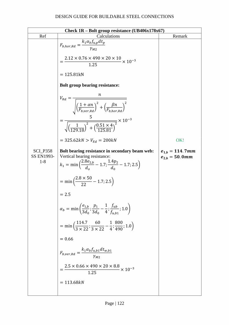
DESIGN GUIDE FOR BUILDABLE STEEL CONNECTIONS
Page | 122
Check 1R – Bolt group resistance (UB406x178x67) Ref Calculations Remark
𝐹 , ,
𝑘 𝛼 𝑓 , 𝑑𝑡𝛾
2.12 0.76 490 20 10
1.2510
125.81kN
Bolt group bearing resistance:
𝑉𝑛
1 𝛼𝑛𝐹 , ,
𝛽𝑛𝐹 , ,
5
1129.18
0.51 4125.81
10
325.62𝑘𝑁 𝑉 200𝑘𝑁
OK!
SCI_P358 SS EN1993-
1-8
Bolt bearing resistance in secondary beam web: Vertical bearing resistance:
𝑘 min2.8𝑒 ,
𝑑1.7;
1.4𝑝𝑑
1.7; 2.5
min2.8 50
221.7; 2.5
2.5
𝛼 min𝑒 ,
3𝑑;𝑝
3𝑑14
;𝑓𝑓 ,
; 1.0
min114.73 22
;60
3 2214
;800490
; 1.0
0.66
𝐹 , ,𝑘 𝛼 𝑓 , 𝑑𝑡 ,
𝛾
2.5 0.66 490 20 8.8
1.2510
113.68𝑘𝑁
𝒆𝟏,𝒃 𝟏𝟏𝟒.𝟕𝒎𝒎 𝒆𝟐,𝒃 𝟓𝟎.𝟎𝒎𝒎

DESIGN GUIDE FOR BUILDABLE STEEL CONNECTIONS
Page | 123
Check 1R – Bolt group resistance (UB406x178x67) Ref Calculations Remark
Horizontal bearing resistance:
𝑘 min2.8𝑒 ,
𝑑1.7;
1.4𝑝𝑑
1.7; 2.5
min2.8 114.7
221.7;
1.4 6022
1.7; 2.5
2.12
𝛼 min
𝑒 ,
3𝑑;𝑝
3𝑑14
;𝑓𝑓 ,
; 1.0
min50
3 22;800490
; 1.0
0.76
𝐹 , ,𝑘 𝛼 𝑓 , 𝑑𝑡 ,
𝛾
2.12 0.76 490 20 8.8
1.2510
110.71𝑘𝑁
Bolt group bearing resistance:
𝑉𝑛
1 𝛼𝑛𝐹 , ,
𝛽𝑛𝐹 , ,
4
1113.68
0.5 4110.71
10
286.54𝑘𝑁 𝑉 200𝑘𝑁
OK!
DESIGN GUIDE FOR BUILDABLE STEEL CONNECTIONS
Page | 124
Check 2R – Fin plate resistance (UB406x178x67) Ref Calculations Remark
SS EN1993-1-8
SCI_P358
Fin plate shear resistance (gross section): 𝑡 10𝑚𝑚 16𝑚𝑚 ∴ 𝑓 , 355𝑀𝑃𝑎 Gross section shear resistance:
𝑉 ,ℎ 𝑡1.27
𝑓 ,
√3𝛾
290 10
1.27355
√3 10
468.02𝑘𝑁
ℎ 290𝑚𝑚 𝛾 1.0 (SS EN1993-1-1)
Fin plate shear resistance (net section): 𝐴 , 𝑡 ℎ 𝑛 𝑑
10 290 4 22
2020𝑚𝑚 Net area shear resistance:
𝑉 ,𝐴 , 𝑓 ,
√3𝛾
2020490
√3 1.2510
457.17𝑘𝑁

DESIGN GUIDE FOR BUILDABLE STEEL CONNECTIONS
Page | 125
Check 2R – Fin plate resistance (UB406x178x67) Ref Calculations Remark
Fin plate shear resistance (block shear): For single vertical line of bolts (𝑛 1): Net area subject to tension:
𝐴 𝑡 𝑒𝑑2
10 50222
390𝑚𝑚
Net area subject to shear: 𝐴 𝑡 ℎ 𝑒 𝑛 0.5 𝑑
10 290 55 4 0.5 22
1580𝑚𝑚
𝑉 ,
0.5𝑓 , 𝐴𝛾
𝑓 ,
√3
𝐴𝛾
0.5 490 390
1.25355
√3
15801.0
10
400.28𝑘𝑁
𝑉 , min 𝑉 , ;𝑉 , ;𝑉 ,
min 468.02𝑘𝑁; 457.17𝑘𝑁; 400.28𝑘𝑁
400.28𝑘𝑁 𝑉 200𝑘𝑁
OK!
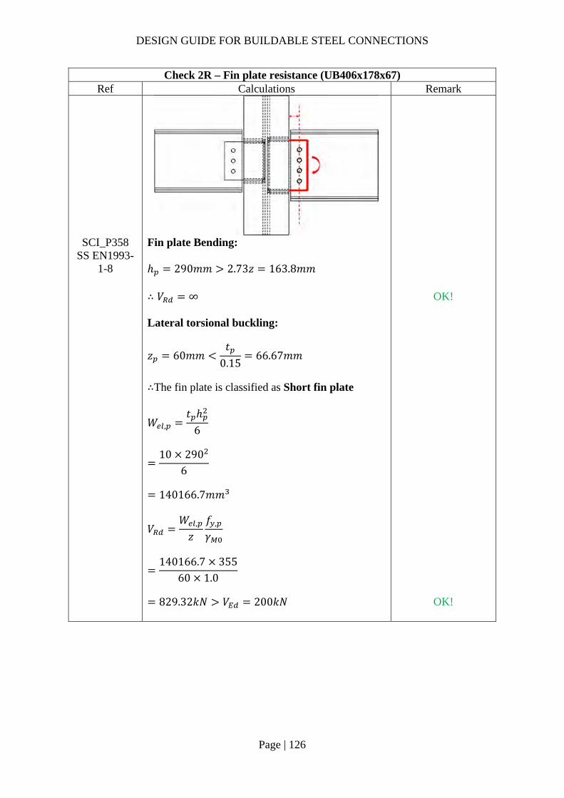
DESIGN GUIDE FOR BUILDABLE STEEL CONNECTIONS
Page | 126
Check 2R – Fin plate resistance (UB406x178x67) Ref Calculations Remark
SCI_P358 SS EN1993-
1-8
Fin plate Bending: ℎ 290𝑚𝑚 2.73𝑧 163.8𝑚𝑚
∴ 𝑉 ∞
OK!
Lateral torsional buckling:
𝑧 60𝑚𝑚𝑡
0.1566.67𝑚𝑚
∴The fin plate is classified as Short fin plate
𝑊 ,𝑡 ℎ
6
10 290
6
140166.7𝑚𝑚
𝑉𝑊 ,
𝑧𝑓 ,
𝛾
140166.7 355
60 1.0
829.32𝑘𝑁 𝑉 200𝑘𝑁
OK!

DESIGN GUIDE FOR BUILDABLE STEEL CONNECTIONS
Page | 127
Check 3R – Beam web resistance (UB406x178x67) Ref Calculations Remark
SCI_P358 SS EN1993-
1-8
Beam web shear resistance (gross section): For unnotched beams (UB406x178x60): 𝐴 𝐴 2𝑏 𝑡 , 𝑡 , 2𝑟 𝑡 ,
8550 2 178.8 14.3 8.8 2 10.214.3
3853.88𝑚𝑚
𝑉 , 𝑉 ,𝐴 𝑓 ,
√3𝛾
3853.88355
√3 1.010
789.89𝑘𝑁
Beam web shear resistance (net section): 𝐴 , 𝐴 𝑛 𝑑 𝑡 ,
3853.88 4 22 8.8
3079.48𝑚𝑚
𝑉 ,𝐴 , 𝑓 ,
√3𝛾
3079.48490
√3 1.2510
696.95𝑘𝑁

DESIGN GUIDE FOR BUILDABLE STEEL CONNECTIONS
Page | 128
Check 3R – Beam web resistance (UB406x178x67) Ref Calculations Remark
𝑉 , min 𝑉 , ;𝑉 ,
min 789.89𝑘𝑁; 696.95𝑘𝑁
696.95𝑘𝑁 𝑉 200𝑘𝑁
OK!
Shear and bending interaction of secondary beam web: For Short fin plate, shear and bending moment interaction check is NOT necessary

DESIGN GUIDE FOR BUILDABLE STEEL CONNECTIONS
Page | 129
Check 4R – Welds (UB406x178x67) Ref Calculations Remark
SS EN1993-1-8
Location of centre of gravity of welds group:
�̅�𝑏
2𝑏 𝑑
108
2 108 260
18.57𝑚𝑚
𝑦𝑑2
260
2
130𝑚𝑚
Unit throat area: 𝐴 2𝑏 𝑑
2 108 260
476𝑚𝑚 Moment arm between applied force and weld centre: 𝑟 164.43𝑚𝑚 Induced moment on welds: 𝑀 𝑉 𝑟
200 164.43
32886𝑘𝑁𝑚𝑚
Length of the fillet welds: Horizontal length: 𝑏 108𝑚𝑚 Depth: 𝑑 260𝑚𝑚
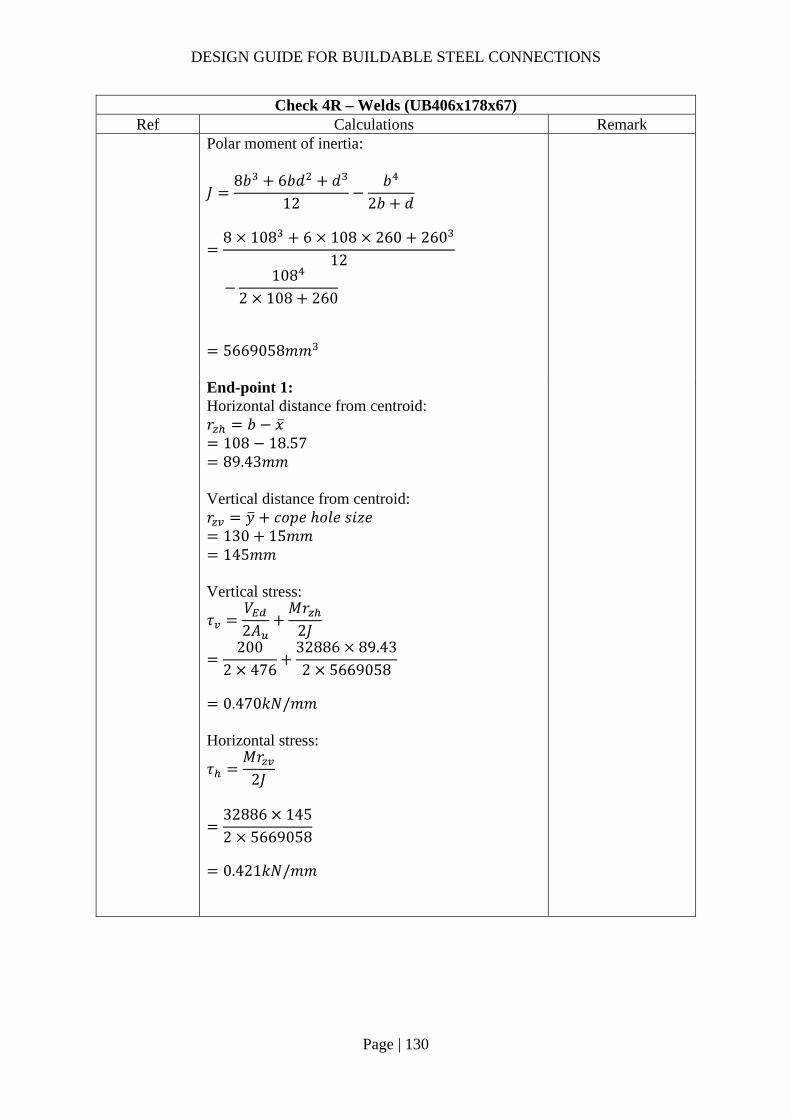
DESIGN GUIDE FOR BUILDABLE STEEL CONNECTIONS
Page | 130
Check 4R – Welds (UB406x178x67) Ref Calculations Remark
Polar moment of inertia:
𝐽8𝑏 6𝑏𝑑 𝑑
12𝑏
2𝑏 𝑑
8 108 6 108 260 260
12
108
2 108 260
5669058𝑚𝑚
End-point 1: Horizontal distance from centroid: 𝑟 𝑏 �̅�
108 18.57 89.43𝑚𝑚
Vertical distance from centroid: 𝑟 𝑦 𝑐𝑜𝑝𝑒 ℎ𝑜𝑙𝑒 𝑠𝑖𝑧𝑒
130 15𝑚𝑚 145𝑚𝑚
Vertical stress:
𝜏𝑉2𝐴
𝑀𝑟2𝐽
2002 476
32886 89.432 5669058
0.470𝑘𝑁/𝑚𝑚
Horizontal stress:
𝜏𝑀𝑟
2𝐽
32886 1452 5669058
0.421𝑘𝑁/𝑚𝑚
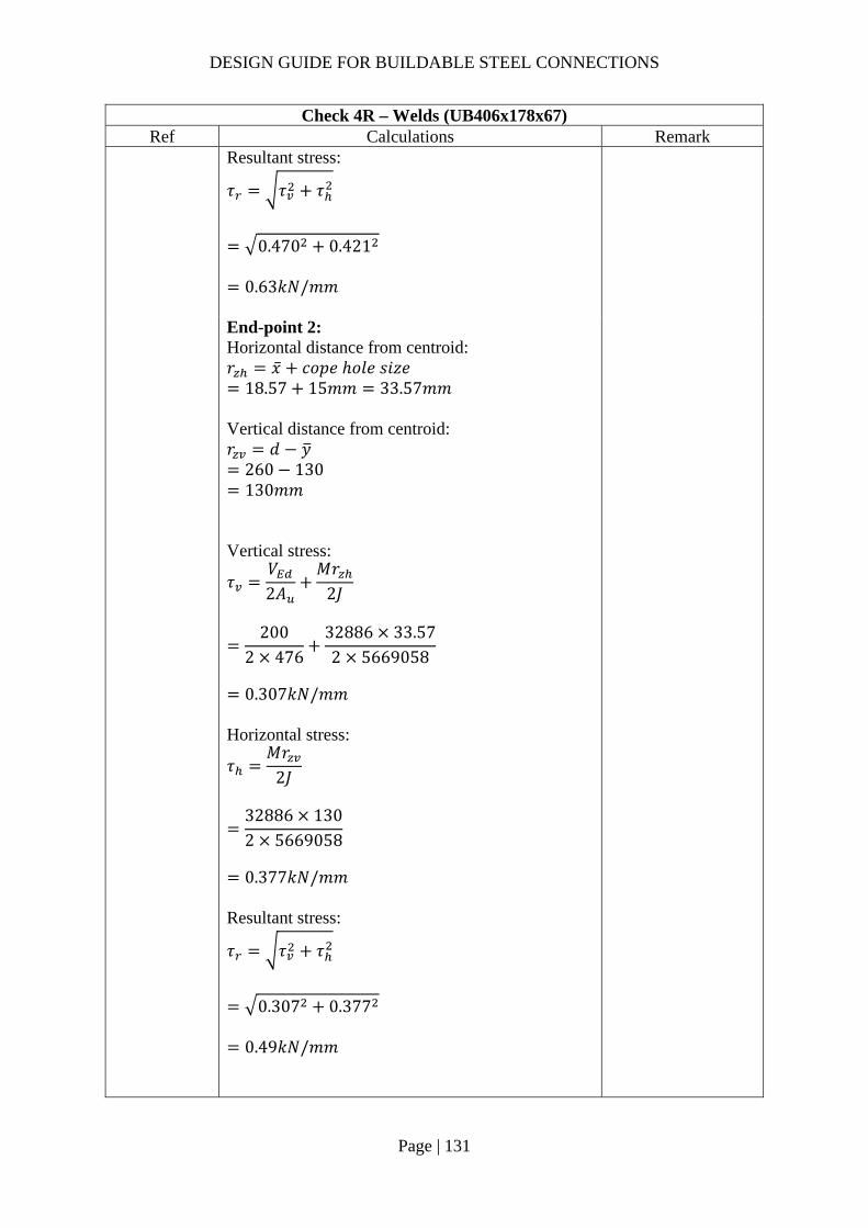
DESIGN GUIDE FOR BUILDABLE STEEL CONNECTIONS
Page | 131
Check 4R – Welds (UB406x178x67) Ref Calculations Remark
Resultant stress:
𝜏 𝜏 𝜏
0.470 0.421
0.63𝑘𝑁/𝑚𝑚
End-point 2: Horizontal distance from centroid: 𝑟 �̅� 𝑐𝑜𝑝𝑒 ℎ𝑜𝑙𝑒 𝑠𝑖𝑧𝑒
18.57 15𝑚𝑚 33.57𝑚𝑚 Vertical distance from centroid: 𝑟 𝑑 𝑦
260 130 130𝑚𝑚
Vertical stress:
𝜏𝑉2𝐴
𝑀𝑟2𝐽
200
2 47632886 33.572 5669058
0.307𝑘𝑁/𝑚𝑚
Horizontal stress:
𝜏𝑀𝑟
2𝐽
32886 1302 5669058
0.377𝑘𝑁/𝑚𝑚
Resultant stress:
𝜏 𝜏 𝜏
0.307 0.377
0.49𝑘𝑁/𝑚𝑚
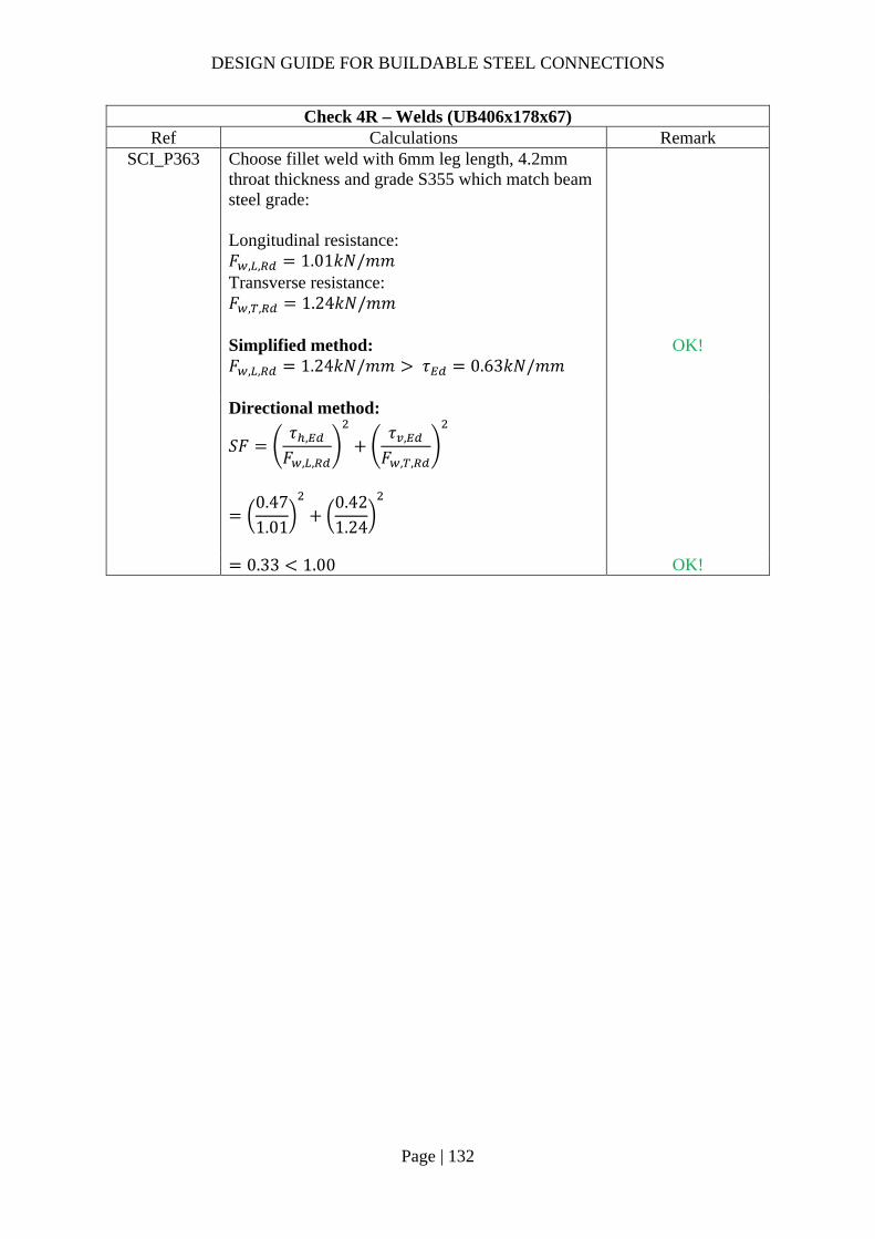
DESIGN GUIDE FOR BUILDABLE STEEL CONNECTIONS
Page | 132
Check 4R – Welds (UB406x178x67) Ref Calculations Remark
SCI_P363 Choose fillet weld with 6mm leg length, 4.2mm throat thickness and grade S355 which match beam steel grade: Longitudinal resistance: 𝐹 , , 1.01𝑘𝑁/𝑚𝑚 Transverse resistance: 𝐹 , , 1.24𝑘𝑁/𝑚𝑚
Simplified method: 𝐹 , , 1.24𝑘𝑁/𝑚𝑚 𝜏 0.63𝑘𝑁/𝑚𝑚
OK!
Directional method:
𝑆𝐹𝜏 ,
𝐹 , ,
𝜏 ,
𝐹 , ,
0.471.01
0.421.24
0.33 1.00 OK!

DESIGN GUIDE FOR BUILDABLE STEEL CONNECTIONS
Page | 133
Check 5R – Local shear resistance of column web (UC254x254x107) Ref Calculations Remark
SCI_P358 Local shear resistance of the column (UC254x254x107) web: 𝐴 ℎ 𝑡
290 12.8 3712𝑚𝑚
𝐹𝐴 𝑓 ,
√3𝛾
3712 355
√3 1.010
760.81𝑘𝑁
𝑉2
100𝑘𝑁
OK!

DESIGN GUIDE FOR BUILDABLE STEEL CONNECTIONS
Page | 134
2.3.8 Example 6 – Fin plate connection to circular hollow column

DESIGN GUIDE FOR BUILDABLE STEEL CONNECTIONS
Page | 135
Check 1 – Bolt group resistance Ref Calculations Remark
Bolt resistance: Using Gr8.8, M20 bolts with: 𝐴 245𝑚𝑚 ; 𝑓 800𝑀𝑃𝑎; 𝛼 0.6
SS EN1993-1-8
Shear resistance of a single bolt: As the distance between the centres of the end fasters: 𝐿 330𝑚𝑚 15𝑑 300𝑚𝑚 ∴Reduction factor to cater long joints effect is applied
𝛽 1𝐿 15𝑑
200𝑑
1330 15 20
200 20
0.9925
𝐹 ,𝛼 𝑓 𝐴𝛾
𝛽
0.6 800 245
1.250.9925 10
93.37𝑘𝑁
𝛾 1.25 (refer to NA to SS) 𝑧 90𝑚𝑚 𝒆𝟏 𝟓𝟎.𝟎𝒎𝒎 (1.2𝑑 𝑒 4𝑡40𝑚𝑚) 𝒑𝟏 𝟔𝟔.𝟎𝒎𝒎 (2.2𝑑 𝑝14𝑡 𝑜𝑟 200𝑚𝑚) 𝒆𝟐 𝟓𝟎.𝟎𝒎𝒎 (1.2𝑑 𝑒 4𝑡40𝑚𝑚) 𝒑𝟐 𝟔𝟎.𝟎𝒎𝒎 (2.4𝑑 𝑝14𝑡 𝑜𝑟 200𝑚𝑚)

DESIGN GUIDE FOR BUILDABLE STEEL CONNECTIONS
Page | 136
Check 1 – Bolt group resistance Ref Calculations Remark
For two vertical lines of bolts (𝑛 2):
𝑙𝑛2𝑝
16𝑛 𝑛 1 𝑝
62
6016
6 6 1 66
163260𝑚𝑚
SN017 𝛼𝑧𝑝2𝑙
90 60
2 163260
0.0165
𝛽𝑧𝑝2𝑙
𝑛 1
90 66
2 1632606 1
0.0910
𝑛 6, 𝑛 2, 𝑛 6 2 12
𝑉
𝑛𝐹 ,
1 𝛼𝑛 𝛽𝑛
12 93.37 10
1 0.0165 12 0.0910 12
686.04𝑘𝑁 𝑉 600𝑘𝑁 OK!
SCI_P358 SS EN1993-
1-8
Bolt bearing resistance in the fin plate: For bearing resistance in vertical direction of one bolt:
𝑘 min2.8𝑒𝑑
1.7;1.4𝑝𝑑
1.7; 2.5
min2.8 50
221.7;
1.4 6022
1.7; 2.5
2.12
𝑡 12𝑚𝑚

DESIGN GUIDE FOR BUILDABLE STEEL CONNECTIONS
Page | 137
Check 1 – Bolt group resistance Ref Calculations Remark
𝛼 min
𝑒3𝑑
;𝑝
3𝑑14
;𝑓𝑓 ,
; 1.0
min50
3 22;
663 22
14
;800490
; 1.0
0.75
𝐹 , ,𝑘 𝛼 𝑓 , 𝑑𝑡
𝛾
2.12 0.75 490 20 12
1.2510
149.46𝑘𝑁
For bearing resistance in horizontal direction of one bolt:
𝑘 min2.8𝑒𝑑
1.7;1.4𝑝𝑑
1.7; 2.5
min2.8 50
221.7;
1.4 6622
1.7; 2.5
2.5
𝛼 min
𝑒3𝑑
;𝑝
3𝑑14
;𝑓𝑓 ,
; 1.0
min50
3 22;
603 22
14
;800490
; 1.0
0.66
𝐹 , ,𝑘 𝛼 𝑓 , 𝑑𝑡
𝛾
2.5 0.66 490 20 12
1.2510
155.02kN
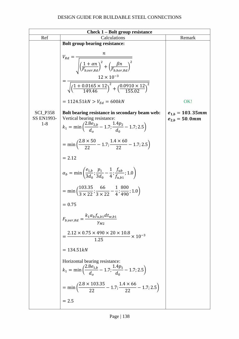
DESIGN GUIDE FOR BUILDABLE STEEL CONNECTIONS
Page | 138
Check 1 – Bolt group resistance Ref Calculations Remark
Bolt group bearing resistance:
𝑉𝑛
1 𝛼𝑛𝐹 , ,
𝛽𝑛𝐹 , ,
12 10
1 0.0165 12149.46
0.0910 12155.02
1124.51𝑘𝑁 𝑉 600𝑘𝑁
OK!
SCI_P358 SS EN1993-
1-8
Bolt bearing resistance in secondary beam web: Vertical bearing resistance:
𝑘 min2.8𝑒 ,
𝑑1.7;
1.4𝑝𝑑
1.7; 2.5
min2.8 50
221.7;
1.4 6022
1.7; 2.5
2.12
𝛼 min𝑒 ,
3𝑑;𝑝
3𝑑14
;𝑓𝑓 ,
; 1.0
min103.353 22
;66
3 2214
;800490
; 1.0
0.75
𝒆𝟏,𝒃 𝟏𝟎𝟑.𝟑𝟓𝒎𝒎 𝒆𝟐,𝒃 𝟓𝟎.𝟎𝒎𝒎
𝐹 , ,
𝑘 𝛼 𝑓 , 𝑑𝑡 ,
𝛾
2.12 0.75 490 20 10.8
1.2510
134.51𝑘𝑁
Horizontal bearing resistance:
𝑘 min2.8𝑒 ,
𝑑1.7;
1.4𝑝𝑑
1.7; 2.5
min2.8 103.35
221.7;
1.4 6622
1.7; 2.5
2.5
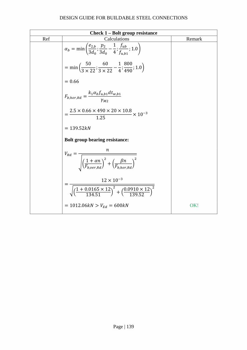
DESIGN GUIDE FOR BUILDABLE STEEL CONNECTIONS
Page | 139
Check 1 – Bolt group resistance Ref Calculations Remark
𝛼 min
𝑒 ,
3𝑑;𝑝
3𝑑14
;𝑓𝑓 ,
; 1.0
min50
3 22;
603 22
14
;800490
; 1.0
0.66
𝐹 , ,𝑘 𝛼 𝑓 , 𝑑𝑡 ,
𝛾
2.5 0.66 490 20 10.8
1.2510
139.52𝑘𝑁
Bolt group bearing resistance:
𝑉𝑛
1 𝛼𝑛𝐹 , ,
𝛽𝑛𝐹 , ,
12 10
1 0.0165 12134.51
0.0910 12139.52
1012.06𝑘𝑁 𝑉 600𝑘𝑁
OK!

DESIGN GUIDE FOR BUILDABLE STEEL CONNECTIONS
Page | 140
Check 2 – Fin plate resistance Ref Calculations Remark
SS EN1993-1-8
SCI_P358
Fin plate shear resistance (gross section): 𝑡 12𝑚𝑚 16𝑚𝑚 ∴ 𝑓 , 355𝑀𝑃𝑎 Gross section shear resistance:
𝑉 ,ℎ 𝑡1.27
𝑓 ,
√3𝛾
430 12
1.27355
√3 10
832.75𝑘𝑁
ℎ 430𝑚𝑚 𝛾 1.0 (SS EN1993-1-1)
Fin plate shear resistance (net section): 𝐴 , 𝑡 ℎ 𝑛 𝑑
12 430 6 22
3576𝑚𝑚 Net area shear resistance:
𝑉 ,𝐴 , 𝑓 ,
√3𝛾
3576490
√3 1.2510
809.32𝑘𝑁

DESIGN GUIDE FOR BUILDABLE STEEL CONNECTIONS
Page | 141
Check 2 – Fin plate resistance Ref Calculations Remark
Fin plate shear resistance (block shear): For single vertical line of bolts (𝑛 2): Net area subject to tension:
𝐴 𝑡 𝑝 𝑒3𝑑
2
12 60 503 22
2
924𝑚𝑚
Net area subject to shear: 𝐴 𝑡 ℎ 𝑒 𝑛 0.5 𝑑
12 430 50 6 0.5 22
3108𝑚𝑚
𝑉 ,
0.5𝑓 , 𝐴𝛾
𝑓 ,
√3
𝐴𝛾
0.5 490 924
1.25355
√3
31081.0
10
818.12𝑘𝑁
𝑉 , min 𝑉 , ;𝑉 , ;𝑉 ,
min 832.75𝑘𝑁; 809.32𝑘𝑁; 818.12𝑘𝑁
809.32𝑘𝑁 𝑉 600𝑘𝑁
OK!

DESIGN GUIDE FOR BUILDABLE STEEL CONNECTIONS
Page | 142
Check 2 – Fin plate resistance Ref Calculations Remark
SCI_P358 SS EN1993-
1-8
Fin plate bending: ℎ 430𝑚𝑚 2.73𝑧 245.7𝑚𝑚
∴ 𝑉 ∞
OK!
Lateral torsional buckling:
𝑧 60𝑚𝑚𝑡
0.1580𝑚𝑚
∴The fin plate is classified as Short fin plate
𝑊 ,𝑡 ℎ
6
12 430
6
369800𝑚𝑚
𝑉𝑊 ,
𝑧𝑓 ,
𝛾
369800 355
90 1.0
1458.66𝑘𝑁 𝑉 600𝑘𝑁
OK!
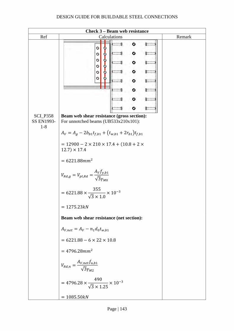
DESIGN GUIDE FOR BUILDABLE STEEL CONNECTIONS
Page | 143
Check 3 – Beam web resistance Ref Calculations Remark
SCI_P358 SS EN1993-
1-8
Beam web shear resistance (gross section): For unnotched beams (UB533x210x101): 𝐴 𝐴 2𝑏 𝑡 , 𝑡 , 2𝑟 𝑡 ,
12900 2 210 17.4 10.8 212.7 17.4
6221.88𝑚𝑚
𝑉 , 𝑉 ,𝐴 𝑓 ,
√3𝛾
6221.88355
√3 1.010
1275.23𝑘𝑁
Beam web shear resistance (net section): 𝐴 , 𝐴 𝑛 𝑑 𝑡 ,
6221.88 6 22 10.8
4796.28𝑚𝑚
𝑉 ,𝐴 , 𝑓 ,
√3𝛾
4796.28490
√3 1.2510
1085.50𝑘𝑁
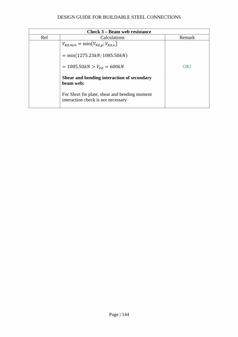
DESIGN GUIDE FOR BUILDABLE STEEL CONNECTIONS
Page | 144
Check 3 – Beam web resistance Ref Calculations Remark
𝑉 , min 𝑉 , ;𝑉 ,
min 1275.23𝑘𝑁; 1085.50𝑘𝑁
1085.50𝑘𝑁 𝑉 600𝑘𝑁
OK!
Shear and bending interaction of secondary beam web: For Short fin plate, shear and bending moment interaction check is not necessary

DESIGN GUIDE FOR BUILDABLE STEEL CONNECTIONS
Page | 145
Check 4 - Welds Ref Calculations Remark
SS EN1993-1-8
Unit throat area: 𝐴 2𝑙 2 430
860𝑚𝑚 Eccentricity between weld and line of action: 𝑒𝑐𝑐 𝑧 90𝑚𝑚 Nominal moment due to eccentricity: 𝑀 𝑉 𝑒𝑐𝑐
600 90
54000𝑘𝑁𝑚𝑚 Polar moment of inertia:
𝐽𝑑12
43012
6625583𝑚𝑚
Critical point: Vertical stress:
𝜏𝑉𝐴
600860
0.70𝑘𝑁/𝑚𝑚
Length of the fillet welds: 𝑙 430𝑚𝑚
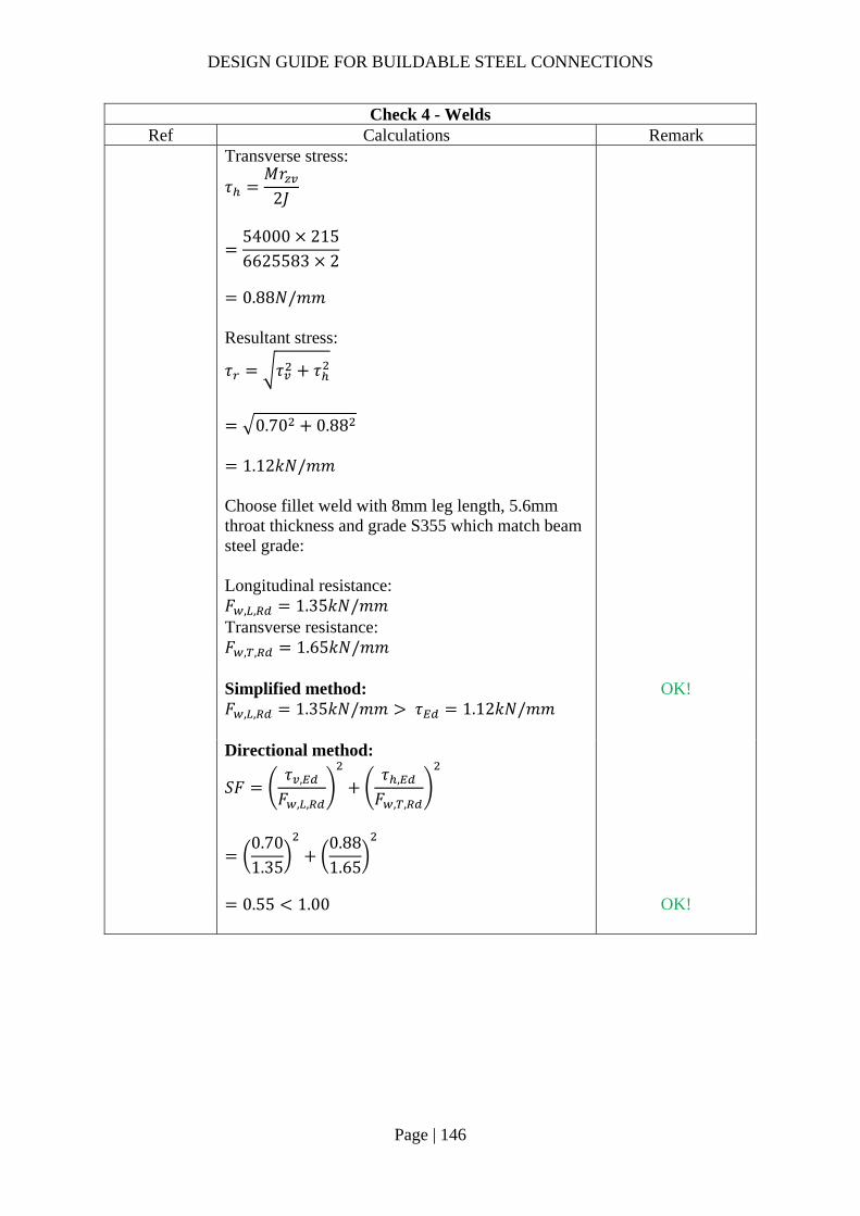
DESIGN GUIDE FOR BUILDABLE STEEL CONNECTIONS
Page | 146
Check 4 - Welds Ref Calculations Remark
Transverse stress:
𝜏𝑀𝑟
2𝐽
54000 2156625583 2
0.88𝑁/𝑚𝑚
Resultant stress:
𝜏 𝜏 𝜏
0.70 0.88
1.12𝑘𝑁/𝑚𝑚 Choose fillet weld with 8mm leg length, 5.6mm throat thickness and grade S355 which match beam steel grade: Longitudinal resistance: 𝐹 , , 1.35𝑘𝑁/𝑚𝑚 Transverse resistance: 𝐹 , , 1.65𝑘𝑁/𝑚𝑚
Simplified method: 𝐹 , , 1.35𝑘𝑁/𝑚𝑚 𝜏 1.12𝑘𝑁/𝑚𝑚
OK!
Directional method:
𝑆𝐹𝜏 ,
𝐹 , ,
𝜏 ,
𝐹 , ,
0.701.35
0.881.65
0.55 1.00
OK!

DESIGN GUIDE FOR BUILDABLE STEEL CONNECTIONS
Page | 147
Check 5 – Local resistance of the column Ref Calculations Remark
SCI_P358 Shear area: 𝐴 ℎ 𝑡
430 16
6880𝑚𝑚 Shear resistance:
𝐹𝐴 𝑓 ,
√3𝛾
6880 355
√310
1410.12𝑘𝑁 𝑉 600𝑘𝑁 OK!
SS EN1993-1-8
Table 7.3 Tying resistance:
𝑁5𝑓 , 𝑡 1 0.25𝜂 0.67
𝛾
5 355 16 1 0.25430/2
508 0.67
1.1
306.06𝑘𝑁
As only half of the fin plate in tension:
𝜂ℎ2
/𝑑
𝑉𝐹 2
3ℎ
𝑒𝑐𝑐306.06
23 430
90
974.84𝑘𝑁 𝑉 600𝑘𝑁 OK!
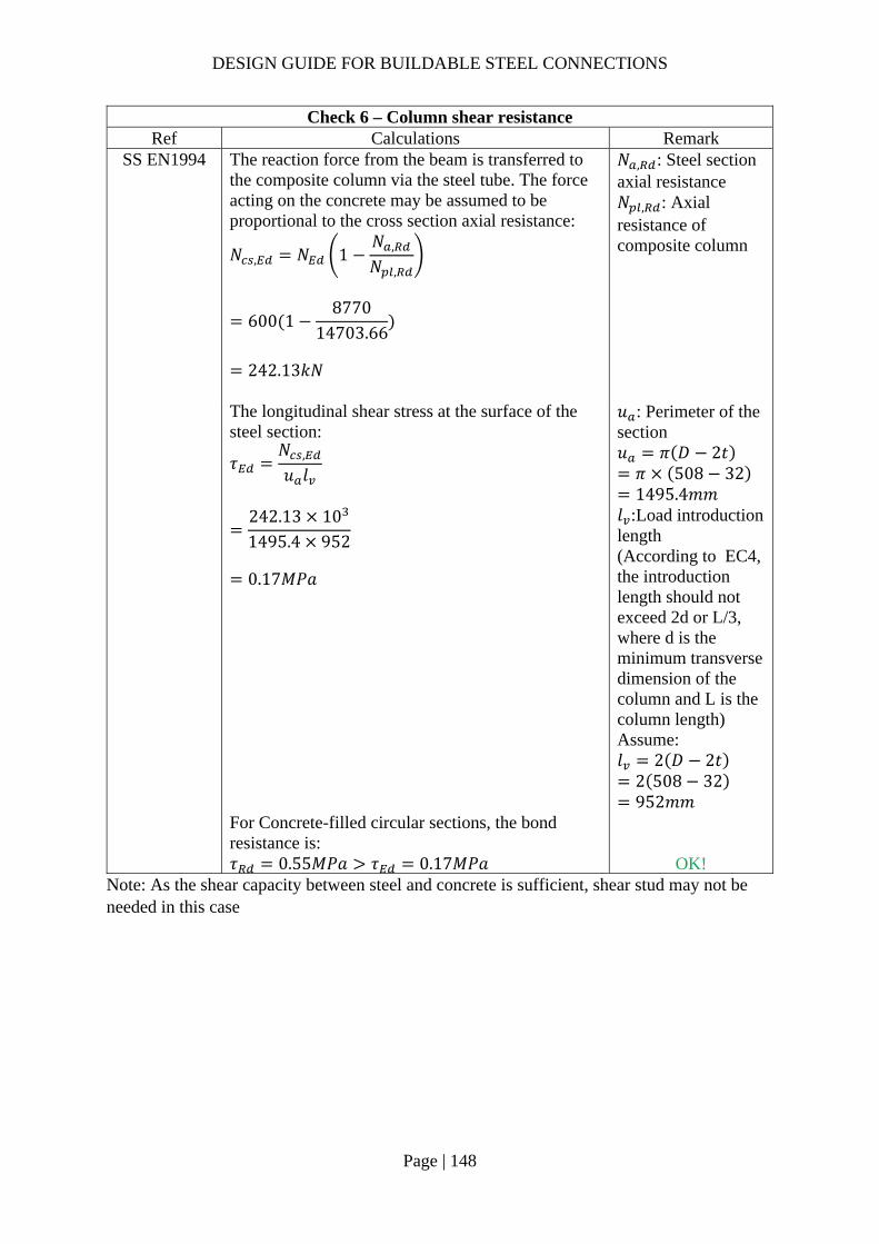
DESIGN GUIDE FOR BUILDABLE STEEL CONNECTIONS
Page | 148
Check 6 – Column shear resistance Ref Calculations Remark
SS EN1994 The reaction force from the beam is transferred to the composite column via the steel tube. The force acting on the concrete may be assumed to be proportional to the cross section axial resistance:
𝑁 , 𝑁 1𝑁 ,
𝑁 ,
600 18770
14703.66
242.13𝑘𝑁
𝑁 , : Steel section axial resistance 𝑁 , : Axial resistance of composite column
The longitudinal shear stress at the surface of the steel section:
𝜏𝑁 ,
𝑢 𝑙
242.13 101495.4 952
0.17𝑀𝑃𝑎
𝑢 : Perimeter of the section 𝑢 𝜋 𝐷 2𝑡 𝜋 508 32 1495.4𝑚𝑚
𝑙 :Load introduction length (According to EC4, the introduction length should not exceed 2d or L/3, where d is the minimum transverse dimension of the column and L is the column length) Assume: 𝑙 2 𝐷 2𝑡
2 508 32 952𝑚𝑚
For Concrete-filled circular sections, the bond resistance is: 𝜏 0.55𝑀𝑃𝑎 𝜏 0.17𝑀𝑃𝑎 OK!
Note: As the shear capacity between steel and concrete is sufficient, shear stud may not be needed in this case

DESIGN GUIDE FOR BUILDABLE STEEL CONNECTIONS
Page | 149
Check 6a (For info) – Shear stud capacity Ref Calculations Remark
SS EN1994 Note: A conservative assumption is to assume that the bond is not effective in transferring the beam force to the concrete. The force acting on the concrete is designed to be resisted by shear studs. Shear capacity of shear stud: For h/d = 5.26 > 4, 𝛼 1.0
𝑃 min 0.8𝑓
𝜋𝑑4
𝛾;0.29𝛼𝑑 𝐹 𝐸
𝛾
min 0.8 450
π194
1.2510 ;
0.29 1.0 19 50 370001.25
10
81.66𝑘𝑁
𝑑: diameter of the shank of the stud 𝑑 19𝑚𝑚 𝑓 : characteristic cylinder strength of the concrete 𝑓 50𝑀𝑃𝑎 𝑓 : ultimate strength of the stud 𝑓 450𝑀𝑃𝑎 ℎ: overall height of the stud ℎ 100𝑚𝑚 𝐸 : Secant modulus of the concrete 𝐸 37000𝑀𝑃𝑎 𝛾 : partial safety factor =1.25
Total resistance: 𝑉 𝑛𝑃 2𝑅 ∴ Number of shear studs required assuming zero bond resistance:
𝑛𝑁 ,
𝑃242.1381.66
3 𝑈𝑠𝑒 4 𝑠𝑡𝑢𝑑𝑠
R should not be considered in this case as it is applicable to concrete encased section SS EN1994-1-1, 6.7.4.2(4).

DESIGN GUIDE FOR BUILDABLE STEEL CONNECTIONS
Page | 150
2.3.9 Example 7 – Beam-to-Beam connection

DESIGN GUIDE FOR BUILDABLE STEEL CONNECTIONS
Page | 151
Check 1 – Bolt group resistance Ref Calculations Remark
Bolt shear resistance: Using Gr8.8, M20 bolts with: 𝐴 245𝑚𝑚 , 𝑓 800𝑀𝑃𝑎, 𝛼 0.6
SS EN1993-1-8
Shear resistance of a bolt: As the distance between the centers of the end fasters: 𝐿 330𝑚𝑚 15𝑑 300𝑚𝑚 ∴Reduction factor to cater long joints effect is applied
𝛽 1𝐿 15𝑑
200𝑑
1330 15 20
200 20
0.9925
𝐹 ,𝛼 𝑓 𝐴𝛾
𝛽
0.6 800 245
1.250.9925 10
93.37𝑘𝑁
𝛾 1.25 (refer to NA to SS)

DESIGN GUIDE FOR BUILDABLE STEEL CONNECTIONS
Page | 152
Check 1 – Bolt group resistance Ref Calculations Remark
SCI_P358 SN017
For single vertical line of bolts (𝑛 1): 𝑛 6, 𝑛 6 1 6 𝛼 0
𝛽6𝑧
𝑛 𝑛 1 𝑝
6 120𝑚𝑚
6 6 1 66𝑚𝑚
0.26
𝑧 120𝑚𝑚
𝑉
𝑛𝐹 ,
1 𝛼𝑛 𝛽𝑛
6 93.37
1 0 0.26 610
300.29𝑘𝑁
𝑉2
150𝑘𝑁
OK!
SCI_P358 SS EN1993-
1-8
Bolt bearing resistance in the gusset plate: For bearing resistance in vertical direction of one bolt:
𝑘 min2.8𝑒𝑑
1.7;1.4𝑝𝑑
1.7; 2.5
min2.8 50
221.7; 2.5
2.5
𝛼 min𝑒
3𝑑;𝑝
3𝑑14
;𝑓𝑓 ,
; 1.0
min50
3 22;
663 22
14
;800490
; 1.0
0.75
𝒆𝟏 𝟓𝟎.𝟎𝒎𝒎 (1.2𝑑 𝑒 4𝑡40𝑚𝑚) 𝒑𝟏 𝟔𝟔.𝟎𝒎𝒎 (2.2𝑑 𝑝14𝑡 𝑜𝑟 200𝑚𝑚) 𝒆𝟐 𝟓𝟎.𝟎𝒎𝒎 (1.2𝑑 𝑒 4𝑡40𝑚𝑚) 𝒑𝟐 𝒏𝒊𝒍 (2.4𝑑 𝑝14𝑡 𝑜𝑟 200𝑚𝑚)
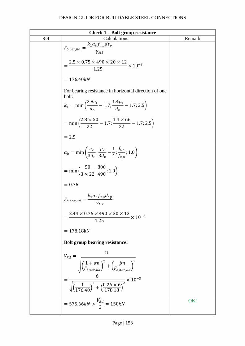
DESIGN GUIDE FOR BUILDABLE STEEL CONNECTIONS
Page | 153
Check 1 – Bolt group resistance Ref Calculations Remark
𝐹 , ,
𝑘 𝛼 𝑓 , 𝑑𝑡𝛾
2.5 0.75 490 20 12
1.2510
176.40𝑘𝑁
For bearing resistance in horizontal direction of one bolt:
𝑘 min2.8𝑒𝑑
1.7;1.4𝑝𝑑
1.7; 2.5
min2.8 50
221.7;
1.4 6622
1.7; 2.5
2.5
𝛼 min
𝑒3𝑑
;𝑝
3𝑑14
;𝑓𝑓 ,
; 1.0
min50
3 22;800490
; 1.0
0.76
𝐹 , ,𝑘 𝛼 𝑓 , 𝑑𝑡
𝛾
2.44 0.76 490 20 12
1.2510
178.18kN
Bolt group bearing resistance:
𝑉𝑛
1 𝛼𝑛𝐹 , ,
𝛽𝑛𝐹 , ,
6
1176.40
0.26 6178.18
10
575.66𝑘𝑁
𝑉2
150𝑘𝑁
OK!

DESIGN GUIDE FOR BUILDABLE STEEL CONNECTIONS
Page | 154
Check 1 – Bolt group resistance Ref Calculations Remark
SCI_P358 SS EN1993-
1-8
Bolt bearing resistance in secondary beam web: Vertical bearing resistance:
𝑘 min2.8𝑒 ,
𝑑1.7;
1.4𝑝𝑑
1.7; 2.5
min2.8 50
221.7; 2.5
2.5
𝛼 min𝑒 ,
3𝑑;𝑝
3𝑑14
;𝑓𝑓 ,
; 1.0
min138.83 22
;66
3 2214
;800490
; 1.0
0.75
𝒆𝟏,𝒃 𝟏𝟑𝟖.𝟖𝒎𝒎 𝒆𝟐,𝒃 𝟓𝟎.𝟎𝒎𝒎 𝑡 , 𝟏𝟏.𝟏𝒎𝒎
𝐹 , ,
𝑘 𝛼 𝑓 , 𝑑𝑡 ,
𝛾
2.5 0.75 490 20 11.1
1.2510
163.17𝑘𝑁
Horizontal bearing resistance:
𝑘 min2.8𝑒 ,
𝑑1.7;
1.4𝑝𝑑
1.7; 2.5
min2.8 138.8
221.7;
1.4 6622
1.7; 2.5
2.5
𝛼 min𝑒 ,
3𝑑;𝑝
3𝑑14
;𝑓𝑓 ,
; 1.0
min50
3 22;800490
; 1.0
0.76

DESIGN GUIDE FOR BUILDABLE STEEL CONNECTIONS
Page | 155
Check 1 – Bolt group resistance Ref Calculations Remark
𝐹 , ,
𝑘 𝛼 𝑓 , 𝑑𝑡 ,
𝛾
2.5 0.76 490 20 11.1
1.2510
164.82𝑘𝑁
Bolt group bearing resistance:
𝑉𝑛
1 𝛼𝑛𝐹 , ,
𝛽𝑛𝐹 , ,
6
1163.17
0.26 6164.82
10
532.48𝑘𝑁 𝑉 300𝑘𝑁 OK!
Check 1a – Bolt group resistance (Nominal moment + shear) Ref Calculations Remark
SS EN1993 Nominal moment: 𝑀 𝑉 𝑒𝑐𝑐
300 120
36000𝑘𝑁𝑚𝑚 Force on bolt due to moment:
𝐹 ,𝑀𝑟
2∑𝑦
36000165
2 7623038.96𝑘𝑁
Force due to vertical shear:
𝐹 ,𝑉2𝑛
3002 6
25𝑘𝑁
Resultant force on bolt:
𝐹 , 𝐹 , 𝐹 , 38.96 25
𝑒𝑐𝑐 𝑧 120𝑚𝑚 ∑𝑦 76230𝑚𝑚 Furthest distance between bolt and centroid: 𝑟 165𝑚𝑚
46.29𝑘𝑁 𝐹 , 93.37𝑘𝑁 OK!

DESIGN GUIDE FOR BUILDABLE STEEL CONNECTIONS
Page | 156
Check 2 – Gusset plate resistance Ref Calculations Remark
SS EN1993-1-8
SCI_P358
Gusset plate shear resistance (gross section): 𝑡 11𝑚𝑚 16𝑚𝑚 ∴ 𝑓 , 355𝑀𝑃𝑎 Gross section shear resistance:
𝑉 ,ℎ 𝑡1.27
𝑓 ,
√3𝛾
430 12
1.27355
√3 10
832.75𝑘𝑁
ℎ 500𝑚𝑚 𝛾 1.0 (SS EN1993-1-1)
Gusset plate shear resistance (net section): 𝐴 , 𝑡 ℎ 𝑛 𝑑
12 430 6 22
3576𝑚𝑚 Net area shear resistance:
𝑉 ,𝐴 , 𝑓 ,
√3𝛾
3576490
√3 1.2510
809.32𝑘𝑁

DESIGN GUIDE FOR BUILDABLE STEEL CONNECTIONS
Page | 157
Check 2 – Gusset plate resistance Ref Calculations Remark
Gusset plate shear resistance (block shear): For single vertical line of bolts (𝑛 1): Net area subject to tension:
𝐴 𝑡 𝑒𝑑2
12 50222
468𝑚𝑚
Net area subject to shear: 𝐴 𝑡 ℎ 𝑒 𝑛 0.5 𝑑
12 430 50 6 0.5 22
3108𝑚𝑚
𝑉 ,
0.5𝑓 , 𝐴𝛾
𝑓 ,
√3
𝐴𝛾
0.5 490 468
1.25355
√3
31081.0
10
728.74𝑘𝑁
𝑉 , min 𝑉 , ;𝑉 , ;𝑉 ,
min 832.75𝑘𝑁; 809.32𝑘𝑁; 728.74𝑘𝑁
728.74𝑘𝑁
𝑉2
150𝑘𝑁 OK!
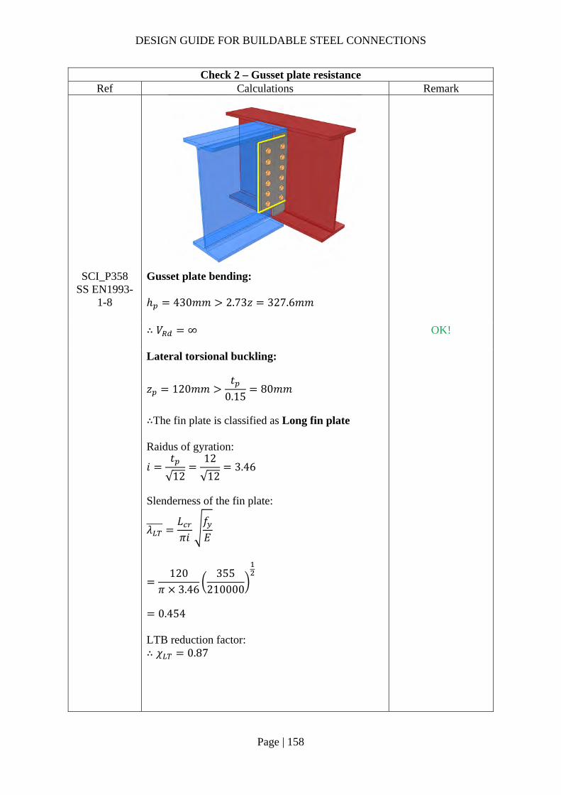
DESIGN GUIDE FOR BUILDABLE STEEL CONNECTIONS
Page | 158
Check 2 – Gusset plate resistance Ref Calculations Remark
SCI_P358 SS EN1993-
1-8
Gusset plate bending: ℎ 430𝑚𝑚 2.73𝑧 327.6𝑚𝑚
∴ 𝑉 ∞
OK!
Lateral torsional buckling:
𝑧 120𝑚𝑚𝑡
0.1580𝑚𝑚
∴The fin plate is classified as Long fin plate Raidus of gyration:
𝑖𝑡
√12
12
√123.46
Slenderness of the fin plate:
𝜆𝐿𝜋𝑖
𝑓𝐸
120𝜋 3.46
355210000
0.454
LTB reduction factor: ∴ 𝜒 0.87

DESIGN GUIDE FOR BUILDABLE STEEL CONNECTIONS
Page | 159
Check 2 – Gusset plate resistance Ref Calculations Remark
𝑊 ,
𝑡 ℎ6
12 430
6
369800𝑚𝑚
𝑉 min
𝑊 ,
𝑧𝜒 𝑓 ,
0.6𝛾;𝑊 ,
𝑧𝑓 ,
𝛾
min369800 0.87 355
120 0.6 1.0;369800 355
120 1.0
10
1093.99𝑘𝑁
𝑉2
150𝑘𝑁
OK!
Note:
Lateral restraint should be provided for primary beam with long fin plate to prevent lateral torsional buckling.
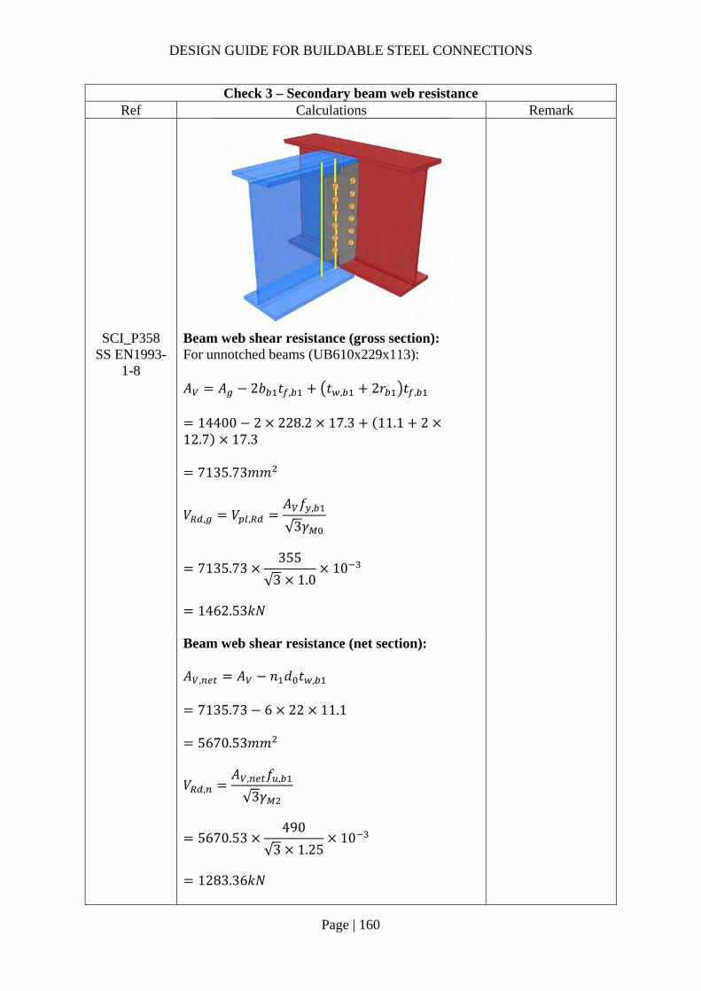
DESIGN GUIDE FOR BUILDABLE STEEL CONNECTIONS
Page | 160
Check 3 – Secondary beam web resistance Ref Calculations Remark
SCI_P358 SS EN1993-
1-8
Beam web shear resistance (gross section): For unnotched beams (UB610x229x113): 𝐴 𝐴 2𝑏 𝑡 , 𝑡 , 2𝑟 𝑡 ,
14400 2 228.2 17.3 11.1 212.7 17.3
7135.73𝑚𝑚
𝑉 , 𝑉 ,𝐴 𝑓 ,
√3𝛾
7135.73355
√3 1.010
1462.53𝑘𝑁
Beam web shear resistance (net section): 𝐴 , 𝐴 𝑛 𝑑 𝑡 ,
7135.73 6 22 11.1
5670.53𝑚𝑚
𝑉 ,𝐴 , 𝑓 ,
√3𝛾
5670.53490
√3 1.2510
1283.36𝑘𝑁

DESIGN GUIDE FOR BUILDABLE STEEL CONNECTIONS
Page | 161
Check 3 – Secondary beam web resistance Ref Calculations Remark
𝑉 , min 𝑉 , ;𝑉 ,
min 1462.53𝑘𝑁; 1283.36𝑘𝑁
1283.36𝑘𝑁 𝑉 300𝑘𝑁
OK!
Shear and bending interaction of secondary beam web: For long fin plate, shear and bending moment interaction check is necessary For single vertical line of bolts (𝑛 1):
𝑉 , ,𝑡 , 𝑒 , 𝑓 ,
√3𝛾
11.1 50 355
√3 1.010
113.75𝑘𝑁
𝑉 ,𝑉 𝑛 1 𝑝
ℎ
300 6 166
607.610
162.94𝑘𝑁

DESIGN GUIDE FOR BUILDABLE STEEL CONNECTIONS
Page | 162
Check 3 – Secondary beam web resistance Ref Calculations Remark
𝑉 , ,
𝑡 , 𝑛 1 𝑃 𝑓 ,
√3𝛾
11.1 6 1 66355
√310
581.58𝑘𝑁
𝑉 ,𝑉 , ,
2
∴ 𝐿𝑜𝑤 𝑠ℎ𝑒𝑎𝑟
𝑀 , ,
𝑓 , 𝑡 ,
6𝛾𝑛 1 𝑝
35511.1
66 1 66 10
71.52𝑘𝑁𝑚
For a single vertical line of bolts (𝑛 1):
𝑉𝑀 , , 𝑉 , , 𝑛 1 𝑝
𝑧
71.52 113.75 6 1 66
120
313.42𝑘𝑁 𝑉 300𝑘𝑁
OK!
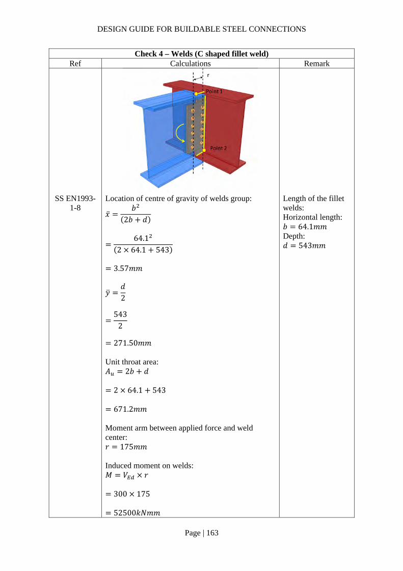
DESIGN GUIDE FOR BUILDABLE STEEL CONNECTIONS
Page | 163
Check 4 – Welds (C shaped fillet weld) Ref Calculations Remark
SS EN1993-1-8
Location of centre of gravity of welds group:
�̅�𝑏
2𝑏 𝑑
64.1
2 64.1 543
3.57𝑚𝑚
𝑦𝑑2
543
2
271.50𝑚𝑚
Unit throat area: 𝐴 2𝑏 𝑑
2 64.1 543
671.2𝑚𝑚 Moment arm between applied force and weld center: 𝑟 175𝑚𝑚 Induced moment on welds: 𝑀 𝑉 𝑟
300 175
52500𝑘𝑁𝑚𝑚
Length of the fillet welds: Horizontal length: 𝑏 64.1𝑚𝑚 Depth: 𝑑 543𝑚𝑚
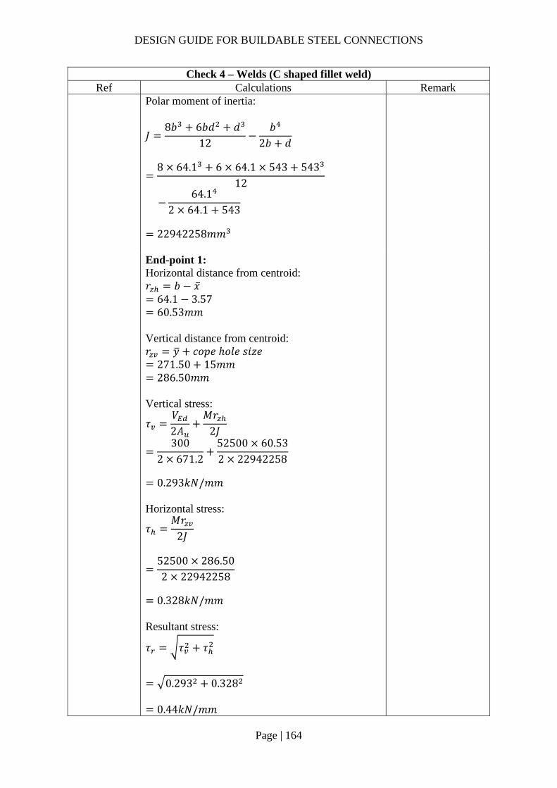
DESIGN GUIDE FOR BUILDABLE STEEL CONNECTIONS
Page | 164
Check 4 – Welds (C shaped fillet weld) Ref Calculations Remark
Polar moment of inertia:
𝐽8𝑏 6𝑏𝑑 𝑑
12𝑏
2𝑏 𝑑
8 64.1 6 64.1 543 543
12
64.1
2 64.1 543
22942258𝑚𝑚
End-point 1: Horizontal distance from centroid: 𝑟 𝑏 �̅�
64.1 3.57 60.53𝑚𝑚
Vertical distance from centroid: 𝑟 𝑦 𝑐𝑜𝑝𝑒 ℎ𝑜𝑙𝑒 𝑠𝑖𝑧𝑒
271.50 15𝑚𝑚 286.50𝑚𝑚
Vertical stress:
𝜏𝑉2𝐴
𝑀𝑟2𝐽
3002 671.2
52500 60.532 22942258
0.293𝑘𝑁/𝑚𝑚
Horizontal stress:
𝜏𝑀𝑟
2𝐽
52500 286.502 22942258
0.328𝑘𝑁/𝑚𝑚
Resultant stress:
𝜏 𝜏 𝜏
0.293 0.328
0.44𝑘𝑁/𝑚𝑚

DESIGN GUIDE FOR BUILDABLE STEEL CONNECTIONS
Page | 165
Check 4 – Welds (C shaped fillet weld) Ref Calculations Remark
End-point 2: Horizontal distance from centroid: 𝑟 �̅� 𝑐𝑜𝑝𝑒 ℎ𝑜𝑙𝑒 𝑠𝑖𝑧𝑒
3.57 15𝑚𝑚 18.57𝑚𝑚 Vertical distance from centroid: 𝑟 𝑑 𝑦
543 271.50 286.50𝑚𝑚
Vertical stress:
𝜏𝑉𝐴
𝑀𝑟𝐽
300
2 671.252500 18.572 22942258
0.245𝑘𝑁/𝑚𝑚
Horizontal stress:
𝜏𝑀𝑟
2𝐽
52500 271.502 22942258
0.311𝑘𝑁/𝑚𝑚
Resultant stress:
𝜏 𝜏 𝜏
0.245 0.311
0.40𝑘𝑁/𝑚𝑚 Choose fillet weld with 5mm leg length, 3.5mm throat thickness and grade S355 which match beam steel grade: Longitudinal resistance: 𝐹 , , 0.84𝑘𝑁/𝑚𝑚 Transverse resistance: 𝐹 , , 1.03𝑘𝑁/𝑚𝑚
Simplified method: 𝐹 , , 0.84𝑘𝑁/𝑚𝑚 𝜏 0.44𝑘𝑁/𝑚𝑚
OK!

DESIGN GUIDE FOR BUILDABLE STEEL CONNECTIONS
Page | 166
Check 4 – Welds (C shaped fillet weld) Ref Calculations Remark
Directional method:
𝑆𝐹𝜏 ,
𝐹 , ,
𝜏 ,
𝐹 , ,
0.290.84
0.331.03
0.23 1.00 OK!

DESIGN GUIDE FOR BUILDABLE STEEL CONNECTIONS
Page | 167
2.3.10 Example 8 – Beam-to-Beam connection at different level

DESIGN GUIDE FOR BUILDABLE STEEL CONNECTIONS
Page | 168
Check 1 – Weld group resistance (secondary beam & end plate) Ref Calculations Remark
SS EN1993-1-8
Assume the beam reaction force is resisted by the welds between secondary beam web and end plate only Length of weld: 𝑙 540𝑚𝑚 Throat area: 𝐴 2𝑙
2 540
1080𝑚𝑚 Applied longitudinal stress:
𝜏𝑉𝐴
800
1080
0.74𝑘𝑁/𝑚𝑚
Choose fillet weld with 10mm leg length, 7.0mm throat thickness and grade S355: Longitudinal resistance:
𝐹 , , 1.69𝑘𝑁/𝑚𝑚 𝜏 0.74𝑘𝑁/𝑚𝑚 OK!
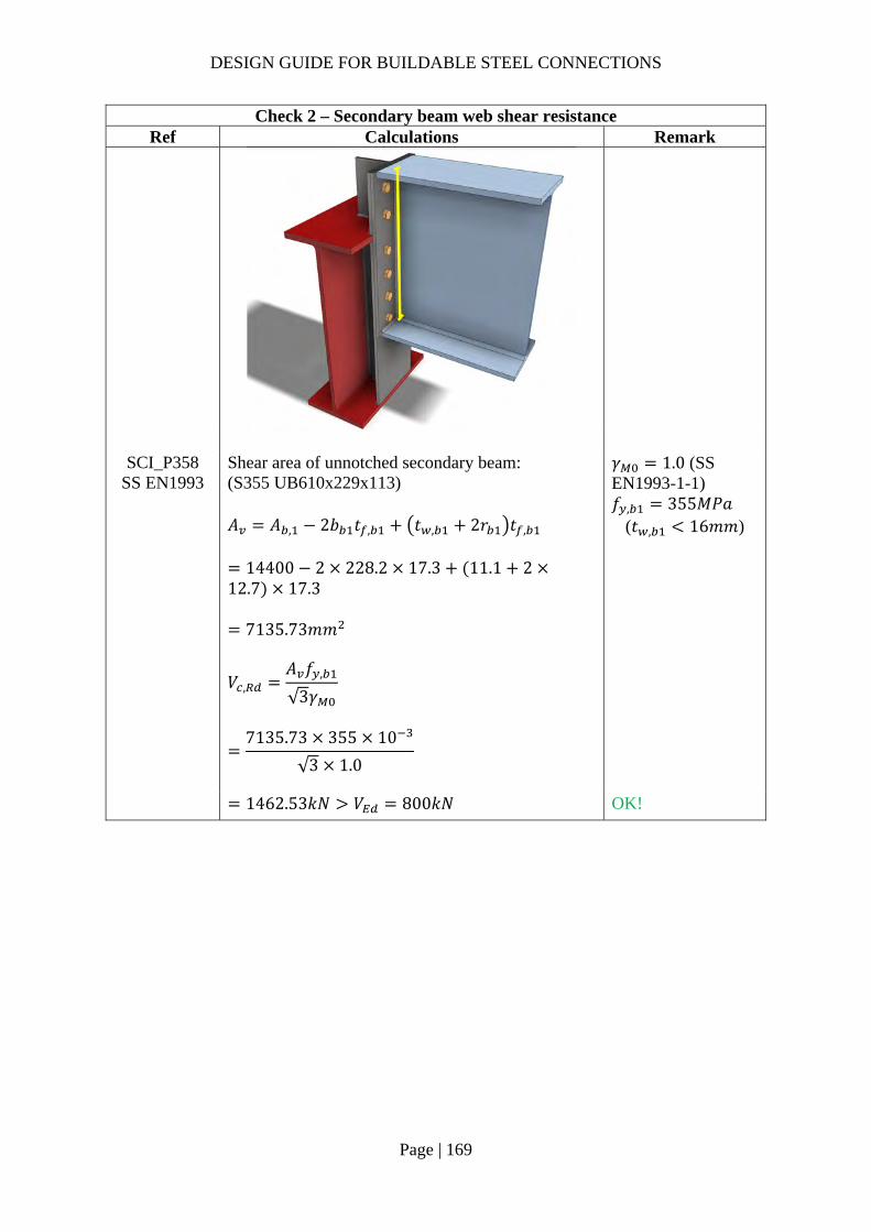
DESIGN GUIDE FOR BUILDABLE STEEL CONNECTIONS
Page | 169
Check 2 – Secondary beam web shear resistance Ref Calculations Remark
SCI_P358
SS EN1993 Shear area of unnotched secondary beam: (S355 UB610x229x113) 𝐴 𝐴 , 2𝑏 𝑡 , 𝑡 , 2𝑟 𝑡 ,
14400 2 228.2 17.3 11.1 212.7 17.3
7135.73𝑚𝑚
𝑉 ,𝐴 𝑓 ,
√3𝛾
7135.73 355 10
√3 1.0
𝛾 1.0 (SS EN1993-1-1) 𝑓 , 355𝑀𝑃𝑎
(𝑡 , 16𝑚𝑚)
1462.53𝑘𝑁 𝑉 800𝑘𝑁 OK!

DESIGN GUIDE FOR BUILDABLE STEEL CONNECTIONS
Page | 170
Check 3 – Bolt group resistance Ref Calculations Remark
SCI_P358 SS EN1993-
1-8
Using Gr8.8, M20 bolts with: 𝐴 245𝑚𝑚 ,𝑓 800𝑀𝑃𝑎 Distance between the centres of the end fasters: 𝐿 486.7𝑚𝑚 15𝑑 360𝑚𝑚 ∴Reduction factor is applied to cater long joints effect
𝛽 1𝐿 15𝑑
200𝑑
1486.7 15 20
200 20
0.953
Shear resistance of one bolt:
𝐹 ,𝛼 𝑓 𝐴𝛾
𝛽
0.6 800 245
1.250.953 10
89.69𝑘𝑁
For 8.8 bolts: 𝛼 0.6 𝛾 1.25 (SS EN1993-1-1)
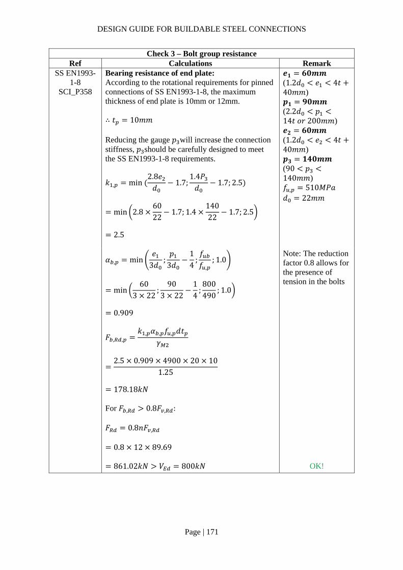
DESIGN GUIDE FOR BUILDABLE STEEL CONNECTIONS
Page | 171
Check 3 – Bolt group resistance Ref Calculations Remark
SS EN1993-1-8
SCI_P358
Bearing resistance of end plate: According to the rotational requirements for pinned connections of SS EN1993-1-8, the maximum thickness of end plate is 10mm or 12mm. ∴ 𝑡 10𝑚𝑚 Reducing the gauge 𝑝 will increase the connection stiffness, 𝑝 should be carefully designed to meet the SS EN1993-1-8 requirements.
𝑘 , min 2.8𝑒𝑑
1.7;1.4𝑃𝑑
1.7; 2.5
min 2.86022
1.7; 1.414022
1.7; 2.5
2.5
𝒆𝟏 𝟔𝟎𝒎𝒎 (1.2𝑑 𝑒 4𝑡40𝑚𝑚) 𝒑𝟏 𝟗𝟎𝒎𝒎 (2.2𝑑 𝑝14𝑡 𝑜𝑟 200𝑚𝑚) 𝒆𝟐 𝟔𝟎𝒎𝒎 (1.2𝑑 𝑒 4𝑡40𝑚𝑚) 𝒑𝟑 𝟏𝟒𝟎𝒎𝒎 (90 𝑝140𝑚𝑚) 𝑓 , 510𝑀𝑃𝑎 𝑑 22𝑚𝑚
𝛼 , min
𝑒3𝑑
;𝑝
3𝑑14
;𝑓𝑓 ,
; 1.0
min60
3 22;
903 22
14
;800490
; 1.0
0.909
𝐹 , ,𝑘 , 𝛼 , 𝑓 , 𝑑𝑡
𝛾
2.5 0.909 4900 20 10
1.25
178.18𝑘𝑁
For 𝐹 , 0.8𝐹 , : 𝐹 0.8𝑛𝐹 ,
0.8 12 89.69
Note: The reduction factor 0.8 allows for the presence of tension in the bolts
861.02𝑘𝑁 𝑉 800𝑘𝑁 OK!

DESIGN GUIDE FOR BUILDABLE STEEL CONNECTIONS
Page | 172
Check 4 – Shear resistance of end plate Ref Calculations Remark
SCI_P358 End plate gross-section resistance: Shear area: 𝐴 2ℎ 𝑡
2 607.6 10
12152𝑚𝑚
𝑉 ,𝐴
1.27𝑓 ,
√3𝛾
12152 355
1.27 √310
1961.15𝑘𝑁
Net shear area: 𝐴 , 𝐴 2𝑛 𝑑 𝑡
12152 2 6 22 10
9512𝑚𝑚
𝑉 ,𝐴 , 𝑓 ,
√3𝛾
9512 490
√3 1.2510
2152.77𝑘𝑁
ℎ 607.6𝑚𝑚 𝑡 10𝑚𝑚 𝑓 , 355𝑀𝑃𝑎 𝑓 , 510𝑀𝑃𝑎
DESIGN GUIDE FOR BUILDABLE STEEL CONNECTIONS
Page | 173
Check 4 – Shear resistance of end plate Ref Calculations Remark
End plate block tearing resistance: Net area subject to tension:
𝐴 𝑡 𝑒𝑑2
10 60222
490𝑚𝑚
Net area subject to shear: 𝐴 𝑡 ℎ 𝑒 𝑛 0.5 𝑑
10 607.6 60 5.5 22
4266𝑚𝑚
𝑉 , 2𝑓 , 𝐴𝛾
𝑓 , 𝐴
√3𝛾
2 49042661.25
355490
√310
2132.87𝑘𝑁
𝑉 min 𝑉 , ;𝑉 , ;𝑉 ,
min 1961.15𝑘𝑁; 2152.77𝑘𝑁; 2132.87𝑘𝑁
1961.15𝑘𝑁 𝑉 800𝑘𝑁 OK!
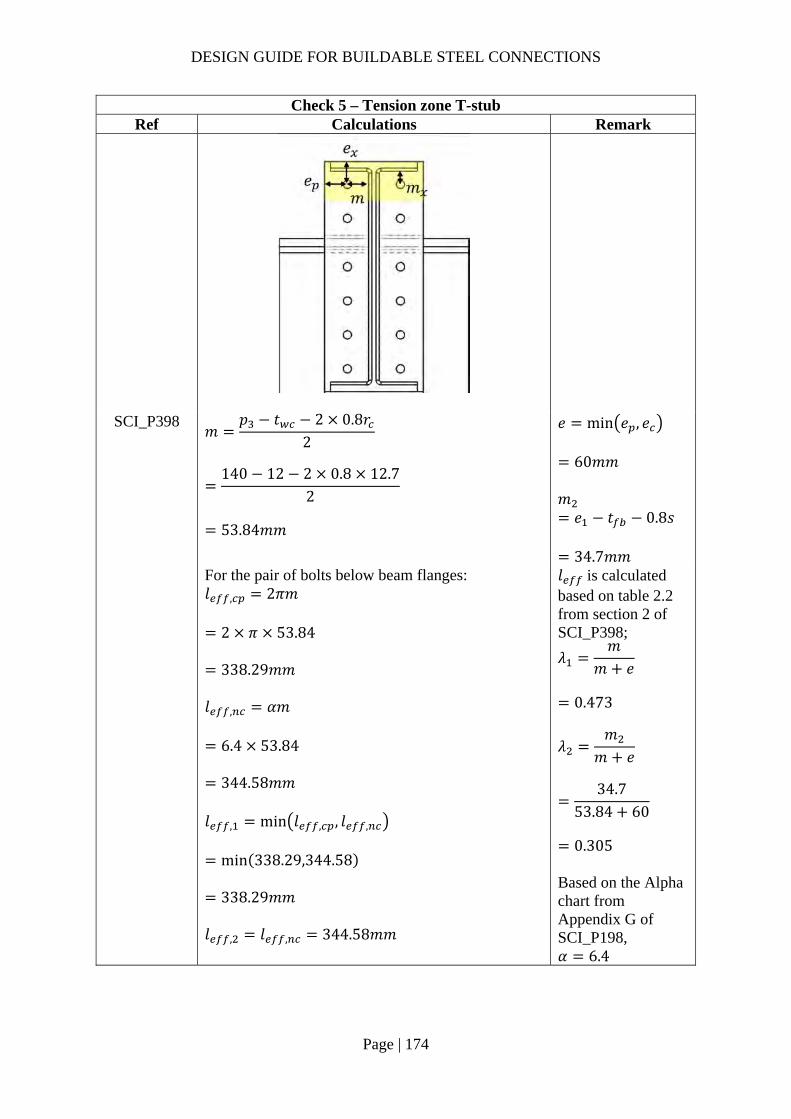
DESIGN GUIDE FOR BUILDABLE STEEL CONNECTIONS
Page | 174
Check 5 – Tension zone T-stub Ref Calculations Remark
SCI_P398 𝑚
𝑝 𝑡 2 0.8𝑟2
140 12 2 0.8 12.7
2
53.84𝑚𝑚
𝑒 min 𝑒 , 𝑒
60𝑚𝑚 𝑚𝑒 𝑡 0.8𝑠
34.7𝑚𝑚
For the pair of bolts below beam flanges: 𝑙 , 2𝜋𝑚
2 𝜋 53.84
338.29𝑚𝑚 𝑙 , 𝛼𝑚
6.4 53.84
344.58𝑚𝑚 𝑙 , min 𝑙 , , 𝑙 ,
min 338.29,344.58
338.29𝑚𝑚 𝑙 , 𝑙 , 344.58𝑚𝑚
𝑙 is calculated based on table 2.2 from section 2 of SCI_P398;
𝜆𝑚
𝑚 𝑒
0.473
𝜆𝑚
𝑚 𝑒
34.7
53.84 60
0.305
Based on the Alpha chart from Appendix G of SCI_P198, 𝛼 6.4

DESIGN GUIDE FOR BUILDABLE STEEL CONNECTIONS
Page | 175
Check 5 – Tension zone T-stub Ref Calculations Remark
Mode 1 resistance:
𝑀 , ,0.25∑ 𝑙 , 𝑡 𝑓
𝛾
0.25 338.29 10 355
1.010
3.058𝑘𝑁𝑚
𝑛 𝑒 1.25𝑚
60𝑚𝑚 1.25 53.84 67.3𝑚𝑚
For bolt M20, diameter of washer 𝑑 33𝑚𝑚
𝑒𝑑4
8.25𝑚𝑚
𝐹 , ,
8𝑛 2𝑒 𝑀 , ,
2𝑚𝑛 𝑒 𝑚 𝑛
8 60 2 8.25 3058
2 53.84 60 8.25 53.84 60
251.61𝑘𝑁
Mode 2 resistance:
𝑀 , ,0.25∑ 𝑙 , 𝑡 𝑓
𝛾
0.25 344.58 10 355
1.010
3114.91𝑘𝑁𝑚𝑚
Tensile resistance of bolt:
𝐹 ,𝑘 𝑓 𝐴𝛾
0.9 800 245
1.2510
141.12𝑘𝑁
For 2 bolts in a row,
𝐹 , 2 141.12 282.24𝑘𝑁

DESIGN GUIDE FOR BUILDABLE STEEL CONNECTIONS
Page | 176
Check 5 – Tension zone T-stub Ref Calculations Remark
𝐹 , ,
2𝑀 , , 𝑛∑𝐹 ,
𝑚 𝑛
2 3114.91 60 282.24
53.84 60
201.71𝑘𝑁
Mode 3 Resistance:
𝐹 , , 𝐹 , 2 141.12 282.24𝑘𝑁
Resistance of end-plate in bending: 𝐹 , , min 𝐹 , , ;𝐹 , , ;𝐹 , ,
min 251.61𝑘𝑁; 201.71𝑘𝑁; 282.14𝑘𝑁
201.71𝑘𝑁
Eccentricity of applied load: 𝑒𝑐𝑐 𝑑𝑖𝑠𝑡𝑎𝑛𝑐𝑒 𝑏𝑒𝑡𝑤𝑒𝑒𝑛 𝑒𝑛𝑑𝑝𝑙𝑎𝑡𝑒 𝑎𝑛𝑑 𝑐𝑒𝑛𝑡𝑟𝑜𝑖𝑑 𝑜𝑓 𝑝𝑟𝑖𝑚𝑎𝑟𝑦 𝑏𝑒𝑎𝑚 𝑏2
266.7
2133.35𝑚𝑚
Nominal moment: 𝑀 𝑉 𝑒𝑐𝑐
800 133.35
106680𝑘𝑁𝑚𝑚
DESIGN GUIDE FOR BUILDABLE STEEL CONNECTIONS
Page | 177
Check 5 – Tension zone T-stub Ref Calculations Remark
Moment arm: 𝑟 𝑑𝑖𝑠𝑡𝑎𝑛𝑐𝑒 𝑏𝑒𝑡𝑤𝑒𝑒𝑛 𝑐𝑒𝑡𝑟𝑜𝑖𝑑 𝑜𝑓 𝑓𝑙𝑎𝑛𝑔𝑒𝑠 𝑜𝑓 𝑠𝑒𝑐𝑜𝑛𝑑𝑎𝑟𝑦 𝑏𝑒𝑎𝑚
607.6 17.3
590.3𝑚𝑚 Tensile force acting on the top flange:
𝐹 ,𝑀𝑟
106680
590.3
180.72𝑘𝑁 𝐹 , , 201.71𝑘𝑁
OK!
Tension resistance of bolt:
𝐹 ,𝑘 𝑓 𝐴𝛾
0.9 800 245
1.2510
141.12𝑘𝑁
Combined shear and tension resistance of bolt: 𝐹 , ,
𝐹 ,
𝐹 , ,
1.4𝐹 ,
𝑉𝑛𝐹 ,
𝐹 ,
4 1.4 𝐹 ,
800
12 89.69180.72
4 1.4 141.12
0.97 1.0
Assume the applied shear force is shared equally among all bolts and the tension force is shared by first two rows of bolt.
Note:
For the T-stub checking, the resistance of first row of bolts is sufficient to resist the tensile force due to the nominal moment, hence, no further checking is carried out for the rows of bolts below. If the resistance of the first row is insufficient, the combine resistance of multiple rows of bolts may be checked.
DESIGN GUIDE FOR BUILDABLE STEEL CONNECTIONS
Page | 178
Check 6 – Welding of stiffener Ref Calculations Remark
SS EN1993 Assume the tensile force on the top flange of the secondary beam is applied on the first row of bolts: 𝑀𝑜𝑚𝑒𝑛𝑡 𝑎𝑐𝑡 𝑜𝑛 𝑡ℎ𝑒 𝑤𝑒𝑙𝑑𝑖𝑛𝑔: 𝑀 𝐹 , 𝑟
180.72 159.2
28770.89𝑘𝑁𝑚𝑚 Polar moment of inertial of the fillet weld:
𝐽𝑑12
133.35
12197604.95𝑚𝑚
Applied transverse stress on the end of the welding:
𝜏
𝑀𝑑22𝐽
28770.89
133.352
2 197604.95
4.85𝑘𝑁/𝑚𝑚
𝑀𝑜𝑚𝑒𝑛𝑡 𝑎𝑟𝑚 𝑑𝑖𝑠𝑡𝑎𝑛𝑐𝑒 𝑎𝑤𝑎𝑦 𝑓𝑟𝑜𝑚 𝑡ℎ𝑒 𝑤𝑒𝑙𝑑𝑖𝑛𝑔 𝑟 159.2𝑚𝑚
𝑙𝑒𝑛𝑔𝑡ℎ 𝑜𝑓 𝑤𝑒𝑙𝑑: 𝑑 133.35𝑚𝑚
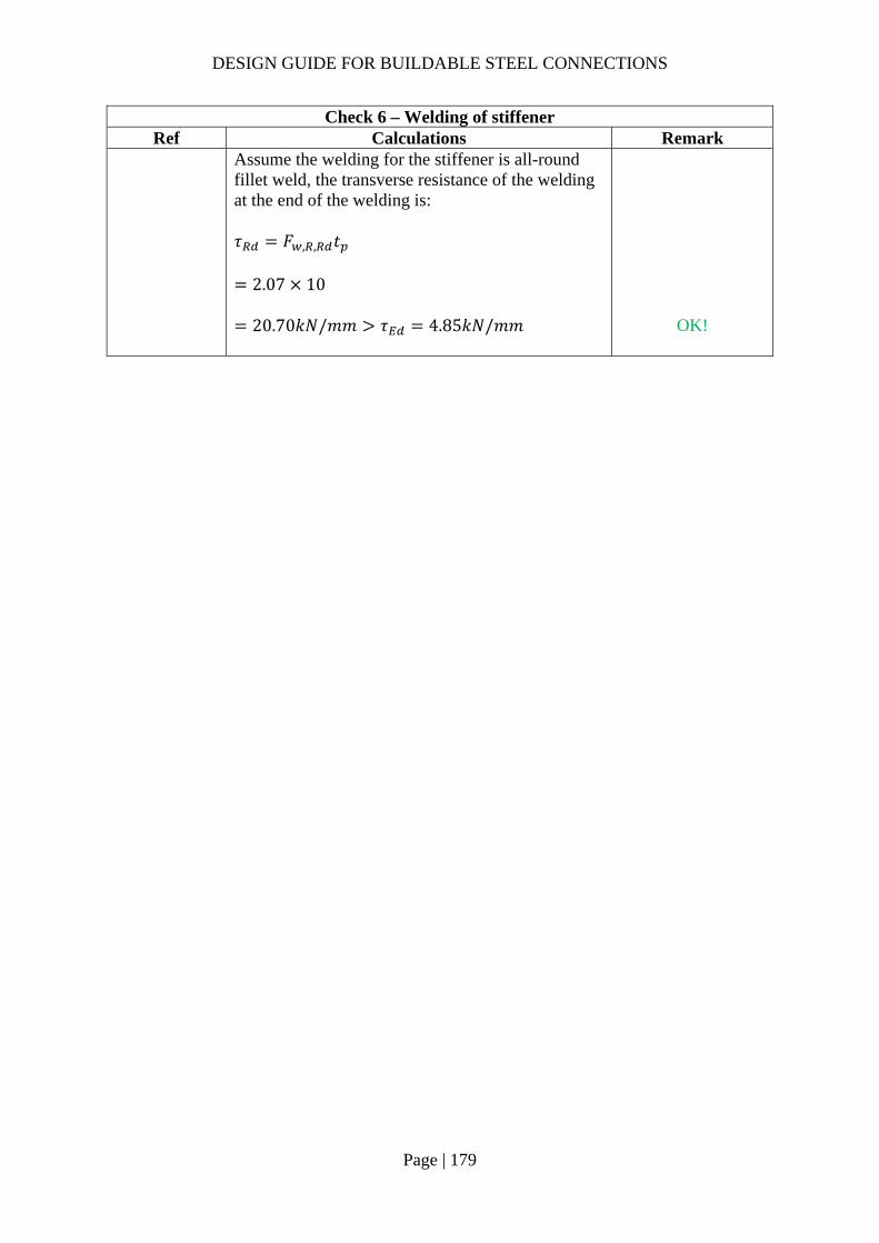
DESIGN GUIDE FOR BUILDABLE STEEL CONNECTIONS
Page | 179
Check 6 – Welding of stiffener Ref Calculations Remark
Assume the welding for the stiffener is all-round fillet weld, the transverse resistance of the welding at the end of the welding is:
𝜏 𝐹 , , 𝑡
2.07 10
20.70𝑘𝑁/𝑚𝑚 𝜏 4.85𝑘𝑁/𝑚𝑚
OK!

DESIGN GUIDE FOR BUILDABLE STEEL CONNECTIONS
Page | 180
Check 7 – Buckling resistance of the stiffener Ref Calculations Remark
SCI_P398 Dispersion length: 𝑏 , , 𝑡 2𝑠 5 𝑡 𝑠 𝑠
17.3 2 10 5 10 12.7 20
170.8𝑚𝑚 Design compression resistance of stiffener:
𝐹 , ,𝜔𝑘 𝜌𝑏 , , 𝑡 𝑓
𝛾
170.8 10 355 10
606.34𝑘𝑁 𝐹 , 180.72𝑘𝑁
Web buckling resistance is adequate without the additional of plate stiffener. No further check is required.
𝑡 17.3𝑚𝑚 𝑡 12𝑚𝑚 𝑠 10𝑚𝑚 𝑠 𝑟 12.7𝑚𝑚 𝑠 2𝑡 20𝑚𝑚 �̅� 0.932
𝑏 , , 𝑑 𝑓𝐸𝑡
0.49 0.72
∴ 𝜌 1 Assume 𝑘 𝜔 1

DESIGN GUIDE FOR BUILDABLE STEEL CONNECTIONS
Page | 181
2.4 Design steps for moment-resisting connections – bolted connections
Figure 2-2 Design steps for moment connections
The moment-resisting connections in this chapter can be divided into two main categories, they are connections with extended fin plate and connections with end plate. The design details for different types of connections are shown in Figure 2-2.
For beam-to-beam moment-resisting connection with hogging moments transferred to the primary beams, it is recommended to have full penetration butt weld to transfer the tension within the top flanges while the bottom flange which is in compression, a partial penetration butt weld will be enough to transfer the compression forces to the bottom flange of the primary beam.
Moment‐resisting
Connections
With extended fin plate
Beam‐to‐beam with similar
depth
1. Bolt group resistance
2. Fin plate resistance
3. Secondary beam web resistance
4. Weld resistance of fin
plate
5. Weld resistance of beam flange (PPBW)
Beam‐to‐beam with different depths
6. Haunch resistance
Beam‐to‐columnn
connections
7. Diaphragm plate check
8. Column capacity check
9. Column tension zone
check
10. Column compression zone check
11. Stiffeners check
12. Weld resistance of stiffener plate
End plate
1. Weld resistance of beam to end
plate
2a. Moment resistance
(Tension zone)
2b. Moment resistance
(Compression zone)
2c. Moment resistance
3. Shear resistance of bolt group
4. Resistance of PPBW
DESIGN GUIDE FOR BUILDABLE STEEL CONNECTIONS
Page | 182
It should be noted that in composite deck construction, welding is usually the preferred connection for the top flange of beams rather than bolting as the use of bolts will clash the installation of the composite decks.
2.4.1 Extended fin plate connections design procedures According to AISC Guide, for flange-plated moment connections, the shear-plate connection can be designed for shear only while the rotation is considered resisted by the flange connections.
Bolt group resistance
Similar to section 2.3.1
Fin plate resistance
Similar to section 2.3.1
Secondary beam web resistance
Similar to section 2.3.1
Weld resistance of fin plate
Similar to section 2.3.1
Weld resistance of beam flange
Assume the applied moment is taken by the flanges of the secondary beam, for full penetration butt weld, assume the strength is equal to the beam flange tensile strength.
Beam flange tensile strength:
𝐹 ,𝑡 𝑏 𝑓 ,
𝛾
where
𝑡 : thickness of beam flange
𝑏 : width of beam flange
𝑓 , : yield strength of beam flange
Applied tensile force on beam flange:
𝐹𝑀𝑟
𝐹 ,
where
𝑟: moment arm
𝑟 ℎ 𝑡
ℎ : depth of secondary beam
Resistance of partial penetration butt weld (PPBW):
The design resistance of a partial penetration butt weld can be determined using the method for a deep penetration fillet weld. (SS EN1993-1-8 Clause 4.7.2(1))

DESIGN GUIDE FOR BUILDABLE STEEL CONNECTIONS
Page | 183
𝐹 𝐹 , , 𝑏
where
𝐹 , , : transverse resistance of welding, can be calculated from 2.3.1 (4)
If the angle between the transverse force and weld throat 𝜃 90°, the transverse resistance of the weld:
𝐹 , ,0.9𝑓𝛾
𝑎
*The minimum throat thickness of a longitudinal partial penetration butt weld should be 2√𝑡 (in mm), where t is the thickness of the thinner part of joint. (BS 5950-1 6.9.2)
Haunch resistance
For beam-to-beam or beam-to-column connections with different beam depths, haunch may be used to provide transition between beams. The haunch resistance hence needs to be checked.
Shear:
In order to reduce stress concentration, the thicknesses of flange and web are same as secondary beam.
Gross section shear resistance:
𝑉 ,ℎ 𝑡 𝑓 ,
√3𝛾
where
ℎ : depth of haunch at bolt line
𝑡 : thickness of haunch web
Net shear resistance:
𝑉 ,𝐴 , 𝑓 ,
√3𝛾
where
𝐴 , : net shear area
𝐴 , ℎ 𝑡 𝑛𝑑 𝑡
Shear resistance of haunch web:
𝑉 min 𝑉 , ,𝑉 , 𝑉
*Suggestions to reduce the stress concentration:
As the thicknesses of the flanges of primary beam and secondary beam may be different, the connection between the flanges may result in stress concentration. In order to reduce the stress concentration, transition should be provided at butt weld area. Figure 2-3 below shows the example of transition.

DESIGN GUIDE FOR BUILDABLE STEEL CONNECTIONS
Page | 184
Figure 2-3 Example of transition between flanges
Shear buckling (SS EN1993-1-5):
To check the shear buckling resistance of the haunch web, the largest height of the haunch was taken as the depth for calculation. The haunch was checked using similar method of checking rectangular girder. If 𝑑𝑡
72𝜀𝜂
the haunch web is susceptible to shear buckling, shear buckling check need to be performed and transverse stiffeners should be provided at the supports.
where
𝜀 235/𝑓
𝜂 1
Maximum allowable slenderness of haunch web:
𝑘𝐸𝑓
𝐴𝐴
𝑑𝑡
where
𝑘 0.55, for elastic moment resistance utilized
𝐴 : cross section area of the compression flange
𝐴 𝑡 𝑏
𝐴 : cross section area of haunch web
FPBWTYP.
PPBWPPBW
Weld access r=25mm
30° transition zone
PPBW thickness a
Weld access r=25mm
30° transition zone
FPBW

DESIGN GUIDE FOR BUILDABLE STEEL CONNECTIONS
Page | 185
𝐴 𝑑𝑡
𝐸 210𝐺𝑃𝑎
Contribution from the web:
𝑉 ,𝜒 𝑓 𝑑𝑡
√3𝛾
where
�̅�𝑑
86.4𝑡 𝜀
𝜒0.83
�̅�
𝑑: distance between fillet of haunch
Contribution from the flange:
𝑉 ,𝑏𝑡 𝑓
𝑐𝛾1
𝑀𝑀 ,
where
𝑀 ,𝑓 𝑏𝑡 ℎ 𝑡
𝛾
𝑐 𝑎 0.251.6𝑏𝑡 𝑓
𝑡 𝑑 𝑓
𝑎: distance between transverse stiffeners
Shear buckling resistance:
𝑉 , 𝑉 , 𝑉 ,𝜂𝑓 𝑑𝑡
√3𝛾𝑉
When haunch is used to connected beams with different height, the length of the haunch should be long enough to ensure the tapered angle is not greater than 45° to prevent stress concentration.
Diaphragm plate check
External diaphragm plate may be used to connect beams to hollow section column. As there is no relevant design guide in SS EN1993 for the width of external diaphragm plate, CIDECT and Chinese code GB were used to calculate the minimum design width.
According to CIDECT design guide 9 – For structural hollow section column connections, the axial resistance of diaphragm ring:
𝑁 19.6𝑑𝑡
. 𝑏𝑑
. 𝑡𝑡
. 𝑑2
𝑓 𝑁
where

DESIGN GUIDE FOR BUILDABLE STEEL CONNECTIONS
Page | 186
𝑑𝑐: diameter of hollow section column
𝑡 : thickness of hollow section column
𝑏: width of the diaphragm plate
𝑡 : thickness of diaphragm plate (at least as thick as the beam flange)
𝑓 : yield strength of hollow section column
Range of validity:
14𝑑𝑡
36
0.05𝑏𝑑
0.14
0.75𝑡𝑡
2.0
According to GB 50936:2014, the minimum width of diaphragm plate:
𝑏𝐹 𝛼 𝑁𝑡 𝑓
𝐹 𝛼 𝑏 𝑡 𝑓𝑡 𝑓
where
𝐹 𝛼0.93
√2 sin 𝛼 1
𝐹 𝛼1.74𝑠𝑖𝑛𝛼
√2 sin 𝛼 1
𝑏 : effective width of external diaphragm ring
𝑏 0.630.88𝑏𝑑
𝑑 𝑡 𝑡
𝛼: angle between axial force and cross section of diaphragm ring where transition occur
𝛼 sin
𝑏2
𝑑 𝑏
𝑏 : width of beam flange
Concrete filled column (SS EN1994-1-1)
For concrete filled circular hollow section column, the shear bond between the concrete and steel shall be checked for adequacy to transfer the reaction force from the beams to the composite column.
The reaction force from the beam is assumed to be transferred to the composite column via the steel tube. The force transfer to the concrete section may be assumed to be proportion to the ratio of the sectional compression resistance as:

DESIGN GUIDE FOR BUILDABLE STEEL CONNECTIONS
Page | 187
𝑁 , 𝑉 𝑉 1𝑁 ,
𝑁 ,
where
𝑁 , : steel section axial resistance
𝑁 , : axial resistance of composite column
𝑉 : shear forces from beams
The longitudinal shear stress at the surface of the steel section:
𝜏𝑁 ,
𝑢 𝑙
where
𝑢 : perimeter of the section
𝑢 𝜋 𝐷 2𝑡
𝑙 : load introduction length (should not exceed 2b,2h or L/3) (b, h and L are width, height and length of beam)
If 𝜏 (maximum longitudinal shear resistance) 𝜏 , shear studs may be used to carry the remaining part of the shear force transferred to the concrete.
Column tension zone check (SCI_P398)
For beam-to-column moment resisting connections in major axis, the applied moment may induce tension and compression forces on the beam flanges and hence the tension and compression resistances of beam flange and column web need to be checked.
Effective width of a beam flange (hot-rolled) connected to an unstiffened column:
𝑏 𝑡 2𝑟 7𝑘𝑡 min 𝑏 ;𝑏
where
𝑡 : thickness of the column web
𝑟 : root radius of column
𝑡 : thickness of the column flange
𝑘𝑡𝑡
𝑓 ,
𝑓 ,1
𝑏 : width of beam
𝑏 : width of column
Design resistance of beam flange:
𝐹 , ,𝑏 𝑡 𝑓 ,
𝛾
where
DESIGN GUIDE FOR BUILDABLE STEEL CONNECTIONS
Page | 188
𝑡 : thickness of beam flange
𝑓 , : yield strength of beam
𝑏 : effective width of beam flange
Effective length of column web:
𝑏 , , 𝑡 2𝑠 5 𝑡 𝑠
where
𝑠 : leg length of beam flange to column fillet welds
𝑡 : thickness of column flange
𝑠: for rolled section is the root radius 𝑟; if column is a welded section, 𝑠 is the leg length of column web to flange fillet welds
Design resistance of column web:
𝐹 , ,𝜔𝑏 , , 𝑡 𝑓
𝛾
where
𝜔: reduction factor for the interaction with shear, can be determined from SS EN1993-1-8 Table 6.3
𝛾 1.0
If design resistance of beam flange or design resistance of column web is insufficient, stiffeners are needed to increase the resistance. The check for resistance of stiffened connection will be shown in section (11).
Column compression zone check
Compression resistance of column web:
𝐹 , ,𝜌𝜔𝑘 𝑏 , , 𝑡 𝑓
𝛾
where
𝜔: reduction factor that takes account of the interaction with shear, can be determined from SS EN1993-1-8 Table 6.3
𝑏 , , : effective length of column web in compression, it is equal to the effective length of column web in tension
𝜌: reduction factor for plate buckling
if 𝜆 0.72, 𝜌 1.0
if 𝜆 0.72, 𝜌 𝜆 0.2 /𝜆

DESIGN GUIDE FOR BUILDABLE STEEL CONNECTIONS
Page | 189
𝜆 0.932𝑏 , , 𝑑 𝑓 ,
𝐸𝑡
𝑑 ℎ 2 𝑡 𝑠
𝑘 : reduction factor for maximum coexisting longitudinal compression stress in the column web, conservatively taken as 0.7
Shear resistance of column web:
If 𝑑 /𝑡 69𝜀, 𝑉 , 0.9𝑓 𝐴 / 𝛾 √3
If 𝑑 /𝑡 69𝜀, 𝑉 , 0.9𝑉 ,
where
𝐴 : shear area of the column
𝐴 𝐴 2𝑏 𝑡 𝑡 2𝑟 𝑡
𝜀235𝑓
𝑉 , : shear buckling resistance of the web, it can be calculated from SS EN1993-1-5 5.2(1)
𝑑 : clear depth of column web
If compressive resistance or shear resistance of column web is lesser than the applied compressive force, stiffeners are needed to strengthen the column web. The detail calculation of stiffened column can be found in section (11).
Stiffeners check (SCI_P398)
Tension stiffener:
Tension stiffeners should be provided symmetrically on either side of the column web and may be full depth or partial depth.
Minimum width of tension stiffener:
𝑏 ,0.75 𝑏 𝑡
2
where
𝑏 : width of column
Tensile resistance of tension stiffener:
𝐹 , ,𝐴 𝑓𝛾
𝐹
where
𝐴 :net area of stiffener
𝐴 2𝑏 𝑡
DESIGN GUIDE FOR BUILDABLE STEEL CONNECTIONS
Page | 190
𝑓 : yield strength of stiffener plates
The above calculation is applicable for full depth stiffener. For partial depth tension stiffeners, additional check on the length for shear in the stiffeners against applied forces is needed. The details of calculations can be found in SCI_P398.
Compression stiffener:
For compression stiffeners, they should be provided symmetrically on either side of the column web and they should be full depth stiffeners. According to SCI_P398, the width to thickness ratio of the stiffener should be limited to 14𝜀 to prevent torsional buckling of the stiffener. The effective stiffener cross section consists of both the stiffener section and part of the column web section. The length of web act as stiffener section is taken as 15𝜀𝑡 on either side of the stiffener.
Resistance of cross-section:
𝑁 ,𝐴 , 𝑓𝛾
where
𝐴 , : effective area of stiffeners
𝐴 , 2𝑏 𝑡 30𝜀𝑡 𝑡 𝑡
𝑏 : width of stiffener
𝑡 : thickness of stiffener
𝑓 : yield strength of stiffener
If �̅� 0.2, flexural buckling resistance of the compression stiffener may be ignored
�̅�𝑙
𝑖 𝜆
where
𝑙: critical buckling length of the stiffener
𝜆 𝜋 𝐸/𝑓
𝑖 : the radius of gyration of the stiffener
𝑖 𝐼 /𝐴 ,
𝐼 : second moment of area of stiffener
𝐼2𝑏 𝑡 𝑡
12
If �̅� 0.2, flexural buckling resistance of the compression stiffener:

DESIGN GUIDE FOR BUILDABLE STEEL CONNECTIONS
Page | 191
𝑁 ,𝜒𝐴 , 𝑓𝛾
where
𝛼 0.49
𝛷 0.5 1 𝛼 �̅� 0.2 𝜆
𝜒1
𝛷 𝛷 𝜆1.0
Weld resistance of stiffener plate
According to SCI_P398, the minimum throat thickness for flange weld of stiffener:
𝑎𝑡2
Applied stress of web weld:
𝜏𝐹2𝑙
where
𝑙: effective length of web weld
𝑙 2 ℎ 2 𝑐𝑜𝑝𝑒 ℎ𝑜𝑙𝑒 𝑠𝑖𝑧𝑒 2𝑠
𝑠: leg length of web weld
Choose fillet weld with longitudinal stress resistance 𝐹 , , 𝜏 .
2.4.2 End plate connections design procedures Weld resistance of beam to end plate
According to SS EN1993-1-8 6.2.2 (1), in weld and bolted connections with end-plates, the welds connecting the beam web should be designed to transfer the shear force from the connected beam to the joint, without any assistance from the welds connecting the beam flanges.
Shear resistance of beam web fillet weld:
𝑉 𝐹 , , 𝐿 𝑉
where
𝐹 , , : longitudinal resistance of web fillet weld
𝐿 : length of fillet weld connecting beam web (2𝑑 )
Tensile resistance of fillet weld connecting beam flange to end plate:
𝐹 𝐿𝐹 , , 𝐹
where
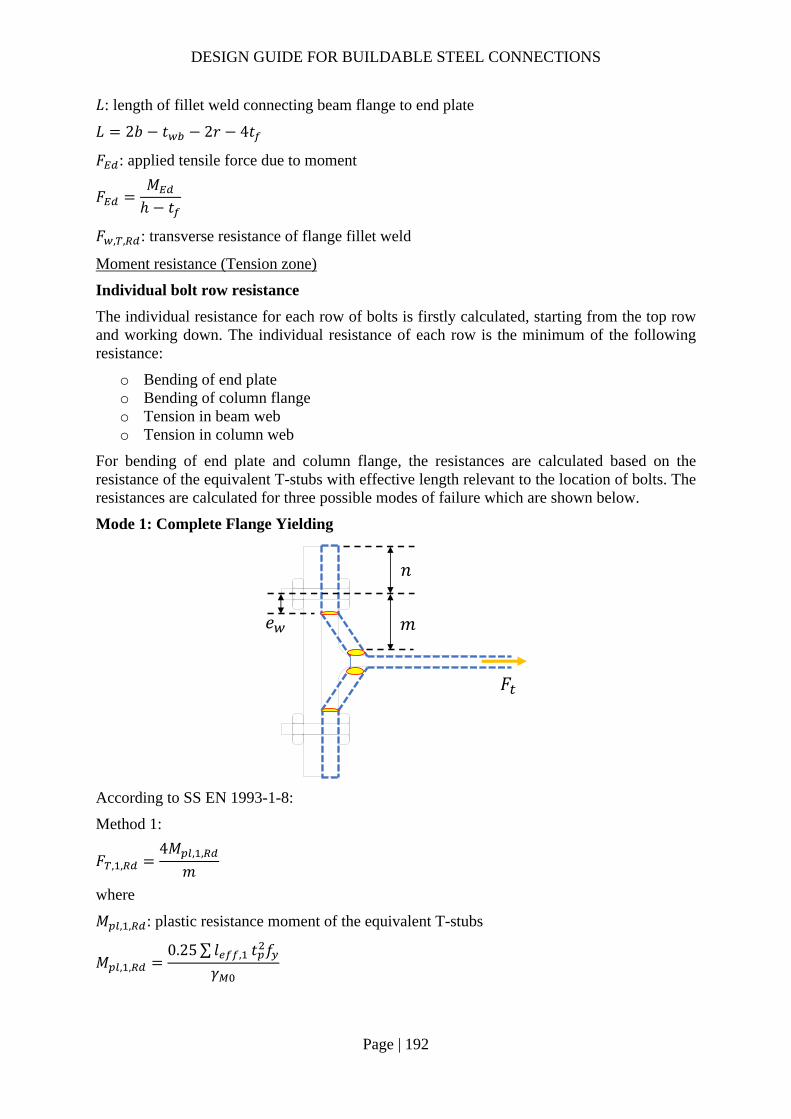
DESIGN GUIDE FOR BUILDABLE STEEL CONNECTIONS
Page | 192
𝐿: length of fillet weld connecting beam flange to end plate
𝐿 2𝑏 𝑡 2𝑟 4𝑡
𝐹 : applied tensile force due to moment
𝐹𝑀ℎ 𝑡
𝐹 , , : transverse resistance of flange fillet weld
Moment resistance (Tension zone)
Individual bolt row resistance
The individual resistance for each row of bolts is firstly calculated, starting from the top row and working down. The individual resistance of each row is the minimum of the following resistance:
o Bending of end plate o Bending of column flange o Tension in beam web o Tension in column web
For bending of end plate and column flange, the resistances are calculated based on the resistance of the equivalent T-stubs with effective length relevant to the location of bolts. The resistances are calculated for three possible modes of failure which are shown below.
Mode 1: Complete Flange Yielding
According to SS EN 1993-1-8:
Method 1:
𝐹 , ,4𝑀 , ,
𝑚
where
𝑀 , , : plastic resistance moment of the equivalent T-stubs
𝑀 , ,0.25∑ 𝑙 , 𝑡 𝑓
𝛾
𝑛
𝑚𝑒
𝐹
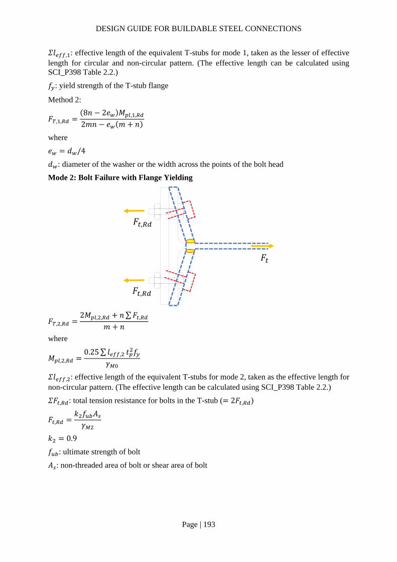
DESIGN GUIDE FOR BUILDABLE STEEL CONNECTIONS
Page | 193
𝛴𝑙 , : effective length of the equivalent T-stubs for mode 1, taken as the lesser of effective length for circular and non-circular pattern. (The effective length can be calculated using SCI_P398 Table 2.2.)
𝑓 : yield strength of the T-stub flange
Method 2:
𝐹 , ,8𝑛 2𝑒 𝑀 , ,
2𝑚𝑛 𝑒 𝑚 𝑛
where
𝑒 𝑑 /4
𝑑 : diameter of the washer or the width across the points of the bolt head
Mode 2: Bolt Failure with Flange Yielding
𝐹 , ,2𝑀 , , 𝑛∑𝐹 ,
𝑚 𝑛
where
𝑀 , ,0.25∑ 𝑙 , 𝑡 𝑓
𝛾
𝛴𝑙 , : effective length of the equivalent T-stubs for mode 2, taken as the effective length for non-circular pattern. (The effective length can be calculated using SCI_P398 Table 2.2.)
𝛴𝐹 , : total tension resistance for bolts in the T-stub ( 2𝐹 , )
𝐹 ,𝑘 𝑓 𝐴𝛾
𝑘 0.9
𝑓 : ultimate strength of bolt
𝐴 : non-threaded area of bolt or shear area of bolt
𝐹
𝐹 ,
𝐹 ,

DESIGN GUIDE FOR BUILDABLE STEEL CONNECTIONS
Page | 194
Mode 3: Bolt Failure Resistance
𝐹 , , 𝐹 , 2𝐹 ,
The stiffness of the end plate connection may not be fully rigid if the first two failure modes govern the failure. The connection can be model as rigid only when mode 3 is the critical mode by making the end plate thickness at least equal to the bolt diameter.
For column web tension resistance:
𝐹 , ,𝜔𝑏 , , 𝑡 𝑓 ,
𝛾
where
𝜔: reduction factor takes account of the interaction with shear, can be calculated from SS EN1993-1-8 Table 6.3.
𝑏 , , : effective length of column web, according to SS EN1993-1-8 6.2.6.3 (3), taken as the effective length of equivalent T-stub representing the column web
If web tension stiffeners are adjacent to the bolt row (within 0.87𝑤), web tension will not govern the resistance of the bolt row.
For beam web tension resistance:
𝐹 , ,𝑏 , , 𝑡 𝑓 ,
𝛾
where
𝑏 , , : effective length of beam web, taken as effective length of equivalent T-stub (SS EN1993-1-8 6.2.6.8 (2))
𝑡 : thickness of beam web
𝑓 , : yield strength of beam web
Groups of bolt row resistance
As there are different failure modes considered, the resistance of a group of bolt rows may be less than the sum of all individual resistance of bolt rows. The resistance of groups of bolt rows are calculated using the same method as the individual bolt row. The effective length of
𝐹
𝐹 ,
𝐹 ,
DESIGN GUIDE FOR BUILDABLE STEEL CONNECTIONS
Page | 195
equivalent T-stubs of a group of bolt row can be calculated using SCI_P398 Table 2.3. If bolt rows are separated by a beam flange or stiffener, no group effect should be considered.
Effective resistance of bolt rows
The resistance of a bolt row may be limited by the group failure mode. It is assumed that the highest row of bolt acts as individual row and the following bolt rows provide the additional resistance. The effective resistances of bolt rows are summarized below:
Effective resistance of first bolt row:
𝐹 , individual resistance of bolt row 1
Effective resistance of second bolt row:
𝐹 , min [ individual resistance of bolt row 2;
(group resistance of bolt row 1 & 2) – individual resistance of bolt row 1]
Effective resistance of third bolt row:
𝐹 , min [ individual resistance of bolt row 3;
(group resistance of bolt row 2 & 3) – individual resistance of bolt row 2;
(group resistance of bolt row 1, 2 & 3) – individual resistance of bolt row 1 & 2]
Subsequent bolt rows will follow the same manner.
Ductility of the bolt rows needs to be checked to ensure the stress distribution between bolt rows. If any of the bolt row is not ductile, reduction of the effective resistances of the bolt rows need to be carried out.
Moment resistance (Compression zone)
The compression zone is at the level of the bottom flange of the beam. On the beam side, the compression resistance is limited by the resistance of the beam flange. On the column side, compression load is dispersed through end plate and column flange by an assumed angle 45° to the column web. Stiffeners may be needed if column web compression resistance is insufficient.
Resistance of column web
𝐹 , ,𝜔𝑘 𝜌𝑏 , , 𝑡 𝑓
𝛾
where
𝑏 , , : effective length of column web resisting compression
𝑏 , , 𝑡 2𝑠 5 𝑡 𝑠 𝑠 (provided the end plate has sufficient depth to ensure the complete dispersion of forces)
𝑠: root radius of rolled section; √2𝑎 for welded section;
𝑎 : throat thickness of fillet weld connecting column web and flange
𝑠 : leg length of the fillet weld connecting beam flange and end plate
𝑠 2𝑡
𝜔: reduction factor that takes account of the interaction with shear, can be determined from SS EN1993-1-8 Table 6.3
DESIGN GUIDE FOR BUILDABLE STEEL CONNECTIONS
Page | 196
if 𝜆 0.72, 𝜌 1.0
if 𝜆 0.72, 𝜌 𝜆 0.2 /𝜆
𝜆 0.932𝑏 , , 𝑑 𝑓 ,
𝐸𝑡
𝑑 ℎ 2 𝑡 𝑠
𝑘 : reduction factor for maximum coexisting longitudinal compression stress in the column web, conservatively taken as 0.7
Resistance of beam flange
Compression resistance of beam flange:
𝐹 , ,𝑀 ,
ℎ 𝑡
where
𝑀 , : design bending resistance of beam cross section, can be calculated from SS EN1993-1-1
ℎ: depth of beam
𝑡 : thickness of beam flange
Column web in shear
If 𝑑 /𝑡 69𝜀, 𝑉 , 0.9𝑓 𝐴 /𝛾 √3
If 𝑑 /𝑡 69𝜀, 𝑉 , 0.9𝑉 ,
where
𝑑 : clear depth of the column web
𝑑 ℎ 2 𝑡 𝑠
𝑠: root radius for rolled section; leg length of fillet weld for welded section;
𝐴 : shear area of the column
𝐴 𝐴 2𝑏 𝑡 𝑡 2𝑟 𝑡 (for rolled section)
𝑉 , : shear buckling resistance of column web, can be calculated from SS EN 1993-1-5 5.2 (1)
Compression zone resistance will be the minimum of the resistance calculated above.
Moment resistance
According to SS EN1993-1-8 6.2.7.2 (9), the effective resistance of the bolt row need not be reduced if the resistance of the individual bolt row is less than 1.9𝐹 , .
UK NA also states the limit for plastic distribution assumption:
𝑡 𝑜𝑟 𝑡 𝑑
1.9𝑓𝑓 ,

DESIGN GUIDE FOR BUILDABLE STEEL CONNECTIONS
Page | 197
Equilibrium of forces
The effective tension resistance of the bolt rows must be in equilibrium with the compression zone resistance. If compression resistance is greater than the effective tension resistance, no reduction is needed. When sum of effective tension resistance of bolt rows and axial load from beam exceeds the compression resistance, reduction of the effective tension resistance of bolt rows is needed. The reduction should start from the bottom row and working up progressively.
𝛴𝐹 𝑁 𝐹 ,
where
𝛴𝐹 : sum of forces in all of the rows of bolts in tension
𝑁 : axial force in the beam, positive for compression
𝐹 , : resistance of compression zone, minimum resistance calculated from section (2b)
Moment resistance
Moment resistance of the connection:
𝑀 , ℎ 𝐹 , ,
where
ℎ : distance from the center of compression to bolt row r
𝐹 , , : effective tension resistance of the bolt row r (after reduction)
Shear resistance of bolt group
Individual bolt resistances (shear and bearing) can be calculated using the same method as section 2.3.1. According to SCI_P398, it is conservative to assume that the bolt in tension zone can provide only 28% of the shear resistance.
Vertical shear resistance of bolt group:
𝑉 𝑛 0.28𝑛 𝐹
where
𝑛 : number of bolts without tension
𝑛 : number of bolts experience tension
𝐹 : shear resistance of individual bolt, minimum values of shear and bearing resistance
Resistance of weld connecting beam flange to end plate (PPBW)
Tensile resistance of the weld:
𝐹 , 𝐹 , , 𝑏
where
𝐹 , , : transverse resistance of weld
𝐹 , ,𝐾𝑓 𝑎
√3𝛽 𝛾

DESIGN GUIDE FOR BUILDABLE STEEL CONNECTIONS
Page | 198
𝐾3
1 2 cos 𝜃
𝜃: angle between applied force and axis of the weld
𝑓 : ultimate strength of weld
𝑎: throat thickness of weld
𝛽 : 0.85 for S275; 0.9 for S355
𝛾 1.25
In addition to the above checking, the transverse stress needs to fulfill the follow requirement (SS EN1993-1-8 Clause 4.5.3.2(6)):
𝜏0.9𝑓𝛾

DESIGN GUIDE FOR BUILDABLE STEEL CONNECTIONS
Page | 199
2.4.3 Example 9 – Double-sided Beam-to-Beam connection with extended fin-plate (moment-resisting connection) for beams of similar depth

DESIGN GUIDE FOR BUILDABLE STEEL CONNECTIONS
Page | 200
Check 1 – Bolt group resistance Ref Calculations Remark
According to AISC Guide, for flange-plated moment connections, the shear-plate connection can be designed for shear only while the moment is considered resisted by the flange connections; Hence, in this case, all shear force is assumed to be resisted by the bolt groups while the butt welds in the beam flanges resists the moment.
SS EN1993-1-8
Bolt resistance: Using Gr8.8, M20 bolts with: 𝐴 245𝑚𝑚 ; 𝑓 800𝑀𝑃𝑎;
As the distance between the centres of the end fasters: 𝐿 360𝑚𝑚 15𝑑 300𝑚𝑚 ∴Reduction factor to cater long joints effect is applied
𝛽 1𝐿 15𝑑
200𝑑
1360 15 20
200 20
0.985

DESIGN GUIDE FOR BUILDABLE STEEL CONNECTIONS
Page | 201
Check 1 – Bolt group resistance Ref Calculations Remark
Shear resistance of a single bolt:
𝐹 ,𝛼 𝑓 𝐴𝛾
𝛽
0.6 800 245
1.250.985 10
92.67𝑘𝑁
For class 8.8: 𝛼 0.6 𝛾 1.25 (refer to NA to SS)
SCI_P358 SN017
For single vertical line of bolts (𝑛 1): 𝑛 7, 𝑛 7 1 7 𝛼 0
𝛽6𝑧
𝑛 𝑛 1 𝑝
6 80𝑚𝑚
7 7 1 60𝑚𝑚
0.14
𝑧 80.00𝑚𝑚
𝑉
𝑛𝐹 ,
1 𝛼𝑛 𝛽𝑛
7 92.67
1 0 0.14 710
458.69𝑘𝑁 𝑉 400𝑘𝑁
OK
SCI_P358
Bearing resistance on fin plate: For bearing resistance in vertical direction of one bolt:
𝛼 min𝑒
3𝑑;𝑝
3𝑑14
;𝑓𝑓
; 1.0
min70
3 22;
603 22
14
;800490
; 1.0
0.66
𝒆𝟏 𝟕𝟎.𝟎𝒎𝒎 (1.2𝑑 𝑒 4𝑡40𝑚𝑚) 𝒑𝟏 𝟔𝟎.𝟎𝒎𝒎 (2.2𝑑 𝑝14𝑡 𝑜𝑟 200𝑚𝑚) 𝒆𝟐 𝟔𝟎.𝟎𝒎𝒎 (1.2𝑑 𝑒 4𝑡40𝑚𝑚) 𝒑𝟐 𝒏𝒊𝒍 (2.4𝑑 𝑝14𝑡 𝑜𝑟 200𝑚𝑚)

DESIGN GUIDE FOR BUILDABLE STEEL CONNECTIONS
Page | 202
Check 1 – Bolt group resistance Ref Calculations Remark
𝑘 min
2.8𝑒𝑑
1.7;1.4𝑝𝑑
1.7; 2.5
𝑡 15.0𝑚𝑚 𝑡 16𝑚𝑚
min
2.8 6022
1.7; 2.5
2.50
𝐹 , ,𝑘 𝛼 𝑓 , 𝑑𝑡
𝛾
2.5 0.66 490 20 15
1.2510
193.77𝑘𝑁
𝑓 , 490𝑀𝑃𝑎 𝑓 , 355𝑀𝑃𝑎
For bearing resistance in horizontal direction of one bolt:
𝑘 min2.8𝑒𝑑
1.7;1.4𝑝𝑑
1.7; 2.5
min2.8 70
221.7;
1.4 6022
1.7; 2.5
2.12
𝛼 min
𝑒3𝑑
;𝑝
3𝑑14
;𝑓𝑓 ,
; 1.0
min60
3 22;800490
; 1.0
0.91
𝐹 , ,𝑘 𝛼 𝑓 , 𝑑𝑡
𝛾
2.12 0.91 490 20 15
1.2510
226.45kN

DESIGN GUIDE FOR BUILDABLE STEEL CONNECTIONS
Page | 203
Check 1 – Bolt group resistance Ref Calculations Remark
Bolt group bearing resistance:
𝑉𝑛
1 𝛼𝑛𝐹 , ,
𝛽𝑛𝐹 , ,
7
1193.77
0.14 7226.45
10
1030.60𝑘𝑁 𝑉 400𝑘𝑁
OK
Bearing resistance on beam web: Vertical bearing resistance:
𝛼 min𝑒 ,
3𝑑;𝑝 ,
3𝑑14
;𝑓𝑓 ,
; 1.0
min126.13 22
;60
3 2214
;800490
; 1.0
0.66
𝑘 min2.8𝑒 ,
𝑑1.7; 2.5
min2.8 60
221.7; 2.5
2.50
𝒆𝟏,𝒃 𝟏𝟐𝟔.𝟏𝒎𝒎 𝒑𝟏,𝒃 𝟔𝟎.𝟎𝒎𝒎 𝒆𝟐,𝒃 𝟔𝟎.𝟎𝒎𝒎 𝒑𝟐,𝒃 𝒏𝒊𝒍
𝑡 , 11.9𝑚𝑚 𝑡 , 16𝑚𝑚 𝑓 , 490𝑀𝑃𝑎 𝑓 , 355𝑀𝑃𝑎
𝐹 , ,
𝑘 𝛼 𝑓 , 𝑑𝑡 ,
𝛾
2.5 0.6591 490 20 11.9
1.25
153.73𝑘𝑁
Horizontal bearing resistance:
𝑘 min2.8𝑒 ,
𝑑1.7;
1.4𝑝𝑑
1.7; 2.5
min2.8 126.1
221.7;
1.4 6022
1.7; 2.5
2.12

DESIGN GUIDE FOR BUILDABLE STEEL CONNECTIONS
Page | 204
Check 1 – Bolt group resistance Ref Calculations Remark
𝛼 min
𝑒 ,
3𝑑;𝑝
3𝑑14
;𝑓𝑓 ,
; 1.0
min60
3 22;800490
; 1.0
0.91
𝐹 , ,𝑘 𝛼 𝑓 , 𝑑𝑡 ,
𝛾
2.12 0.91 490 20 11.9
1.2510
179.65𝑘𝑁
Bolt group bearing resistance:
𝑉𝑛
1 𝛼𝑛𝐹 , ,
𝛽𝑛𝐹 , ,
7
1153.73
0.14 7179.65
817.61𝑘𝑁 𝑉 400𝑘𝑁
OK
Note:
The construction sequence is important for flange-plated moment connection. If the joints are slip critical, friction grip bolts shall be used. In such case, the bolts shall be torqued after the welding is done.
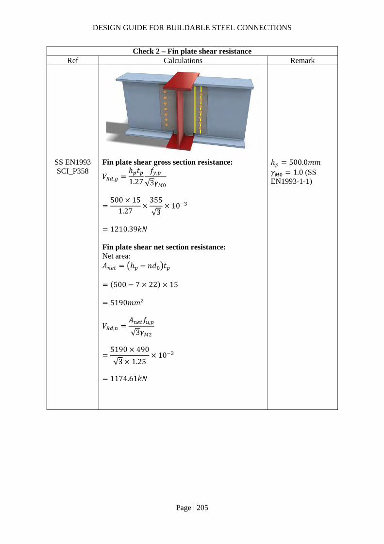
DESIGN GUIDE FOR BUILDABLE STEEL CONNECTIONS
Page | 205
Check 2 – Fin plate shear resistance Ref Calculations Remark
SS EN1993 SCI_P358
Fin plate shear gross section resistance:
𝑉 ,ℎ 𝑡1.27
𝑓 ,
√3𝛾
500 15
1.27355
√310
1210.39𝑘𝑁
Fin plate shear net section resistance: Net area: 𝐴 ℎ 𝑛𝑑 𝑡
500 7 22 15
5190𝑚𝑚
𝑉 ,𝐴 𝑓 ,
√3𝛾
5190 490
√3 1.2510
1174.61𝑘𝑁
ℎ 500.0𝑚𝑚 𝛾 1.0 (SS EN1993-1-1)

DESIGN GUIDE FOR BUILDABLE STEEL CONNECTIONS
Page | 206
Check 2 – Fin plate shear resistance Ref Calculations Remark
Fin plate shear block shear resistance: Net area subject to tension: 𝐴 𝑒 0.5𝑑 𝑡
60 0.5 22 15
735𝑚𝑚 Net area subject to shear: 𝐴 𝑒 𝑛 1 𝑃 𝑛 0.5 𝑑 𝑡
70 6 60 6.5 22 15
4305𝑚𝑚
𝑉 ,0.5𝑓 , 𝐴
𝛾𝑓 , 𝐴
√3𝛾
0.5 490 735
1.25355 4305
√310
1026.41𝑘𝑁
Shear resistance of fin plate: 𝑉 min 𝑉 , ,𝑉 , ,𝑉 ,
min 1210.39,1174.61,1026.41
1026.41𝑘𝑁 𝑉 400𝑘𝑁
OK
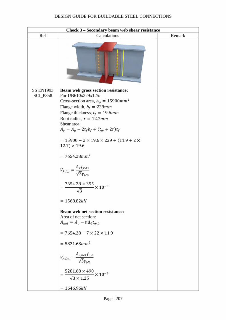
DESIGN GUIDE FOR BUILDABLE STEEL CONNECTIONS
Page | 207
Check 3 – Secondary beam web shear resistance Ref Calculations Remark
SS EN1993 SCI_P358
Beam web gross section resistance: For UB610x229x125: Cross-section area, 𝐴 15900𝑚𝑚 Flange width, 𝑏 229𝑚𝑚 Flange thickness, 𝑡 19.6𝑚𝑚 Root radius, 𝑟 12.7𝑚𝑚 Shear area: 𝐴 𝐴 2𝑡 𝑏 𝑡 2𝑟 𝑡
15900 2 19.6 229 11.9 212.7 19.6
7654.28𝑚𝑚
𝑉 ,𝐴 𝑓 ,
√3𝛾
7654.28 355
√310
1568.82𝑘𝑁
Beam web net section resistance: Area of net section: 𝐴 𝐴 𝑛𝑑 𝑡 ,
7654.28 7 22 11.9
5821.68𝑚𝑚
𝑉 ,𝐴 , 𝑓 ,
√3𝛾
5281.68 490
√3 1.2510
1646.96𝑘𝑁

DESIGN GUIDE FOR BUILDABLE STEEL CONNECTIONS
Page | 208
Check 3 – Secondary beam web shear resistance Ref Calculations Remark
Shear resistance of fin plate: 𝑉 min 𝑉 , ,𝑉 , ,
min 1568.82,1646.96
1568.82𝑘𝑁 𝑉 400𝑘𝑁
OK
For short fin plate, shear and bending moment interaction check is not necessary for beam web.

DESIGN GUIDE FOR BUILDABLE STEEL CONNECTIONS
Page | 209
Check 4 – Weld group resistance of fin plate (Two-side C shape fillet weld) Ref Calculations Remark
SS EN1993-1-8
Location of center of gravity of welds group:
�̅�𝑏
2𝑏 𝑑
88.55
2 88.55 573
10.45𝑚𝑚
𝑦𝑑2
573
2
286.5𝑚𝑚
Unit throat area: 𝐴 2𝑏 𝑑
2 73.55 543
690.1𝑚𝑚 Moment arm between applied force and weld center: 𝑟 162.62𝑚𝑚 Induced moment on welds:
𝑀𝑉
2𝑟
400
2162.62
32524𝑘𝑁𝑚𝑚
Length of fillet weld: Width: 𝑏 88.55𝑚𝑚 Depth: 𝑑 573𝑚𝑚 Cope hole size: 𝑛 15𝑚𝑚 𝑏 𝑏 𝑛
88.55 15 73.55𝑚𝑚
𝑑 𝑑 2𝑛 573 2 15 543𝑚𝑚
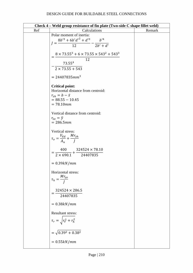
DESIGN GUIDE FOR BUILDABLE STEEL CONNECTIONS
Page | 210
Check 4 – Weld group resistance of fin plate (Two-side C shape fillet weld) Ref Calculations Remark
Polar moment of inertia:
𝐽8𝑏 6𝑏 𝑑 𝑑
12𝑏
2𝑏 𝑑
8 73.55 6 73.55 543 543
12
73.552 73.55 543
24407835𝑚𝑚
Critical point: Horizontal distance from centroid: 𝑟 𝑏 �̅�
88.55 10.45 78.10𝑚𝑚
Vertical distance from centroid: 𝑟 𝑦
286.5𝑚𝑚 Vertical stress:
𝜏𝑉𝐴
𝑀𝑟𝐽
400
2 690.1324524 78.10
24407835
0.39𝑘𝑁/𝑚𝑚
Horizontal stress:
𝜏𝑀𝑟𝐽
324524 286.5
24407835
0.38𝑘𝑁/𝑚𝑚
Resultant stress:
𝜏 𝑟 𝑟
0.39 0.38
0.55𝑘𝑁/𝑚𝑚

DESIGN GUIDE FOR BUILDABLE STEEL CONNECTIONS
Page | 211
Check 4 – Weld group resistance of fin plate (Two-side C shape fillet weld) Ref Calculations Remark
SCI_P363 Choose fillet weld with 6mm leg length, 4.2mm throat thickness and grade S355 which match beam steel grade: Longitudinal resistance: 𝐹 , , 1.01𝑘𝑁/𝑚𝑚 Transverse resistance: 𝐹 , , 1.24𝑘𝑁/𝑚𝑚
Simplified method: 𝐹 , , 1.01𝑘𝑁/𝑚𝑚 𝜏 0.55𝑘𝑁/𝑚𝑚
OK
Directional method:
𝑆𝐹𝜏
𝐹 , ,
𝜏𝐹 , ,
0.401.01
0.381.24
0.25 1.0
OK
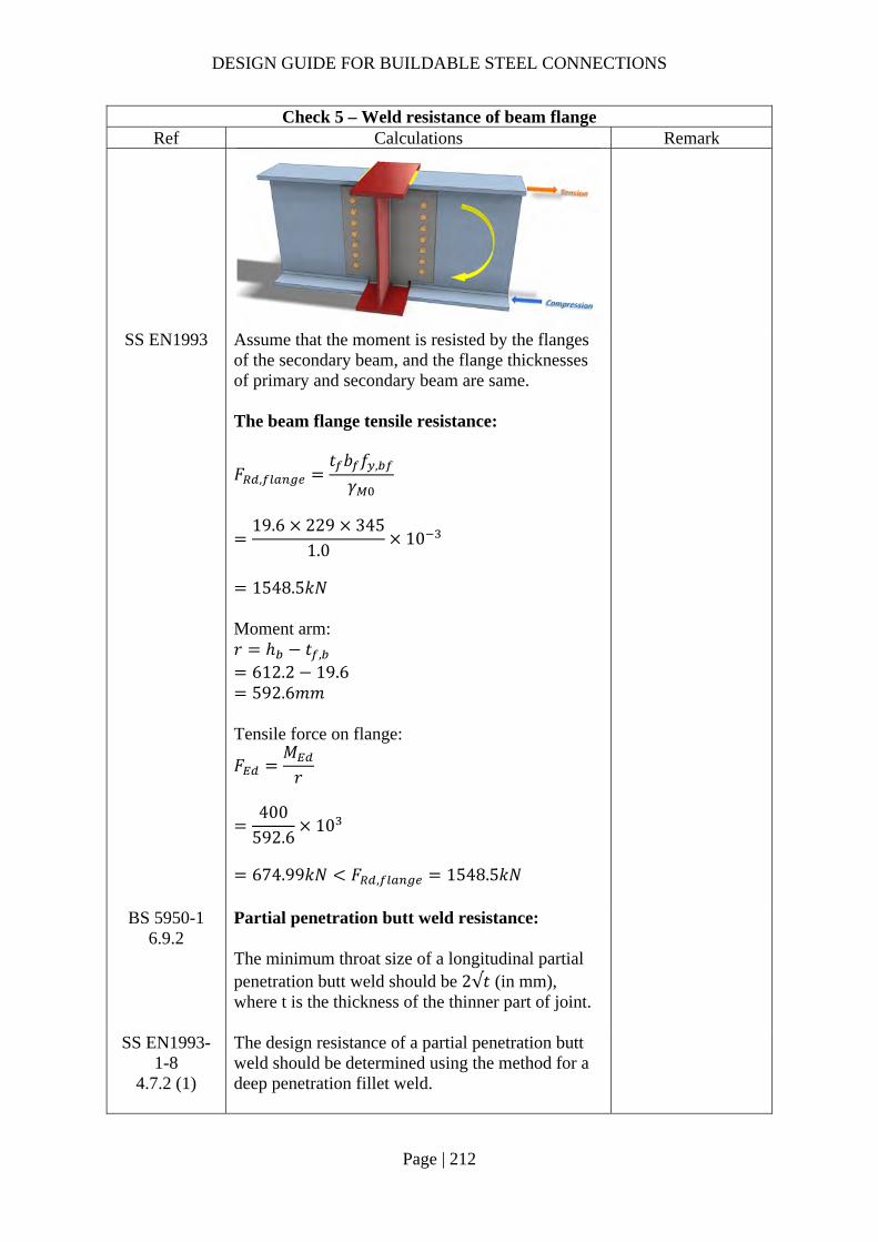
DESIGN GUIDE FOR BUILDABLE STEEL CONNECTIONS
Page | 212
Check 5 – Weld resistance of beam flange Ref Calculations Remark
SS EN1993 Assume that the moment is resisted by the flanges of the secondary beam, and the flange thicknesses of primary and secondary beam are same. The beam flange tensile resistance:
𝐹 ,𝑡 𝑏 𝑓 ,
𝛾
19.6 229 345
1.010
1548.5𝑘𝑁
Moment arm: 𝑟 ℎ 𝑡 ,
612.2 19.6 592.6𝑚𝑚
Tensile force on flange:
𝐹𝑀𝑟
400
592.610
674.99𝑘𝑁 𝐹 , 1548.5𝑘𝑁
BS 5950-1 6.9.2
Partial penetration butt weld resistance: The minimum throat size of a longitudinal partial penetration butt weld should be 2√𝑡 (in mm), where t is the thickness of the thinner part of joint.
SS EN1993-1-8
4.7.2 (1)
The design resistance of a partial penetration butt weld should be determined using the method for a deep penetration fillet weld.

DESIGN GUIDE FOR BUILDABLE STEEL CONNECTIONS
Page | 213
Check 5 – Weld resistance of beam flange Ref Calculations Remark
In this example, the angle between the transverse force and weld throat 𝜃 90°. Provided the groove angle is greater than 60° or U-butt is adopted, the throat thickness is equal to the depth of penetration.
Choose partial butt weld with 12mm ( 2√19.68.85𝑚𝑚 throat thickness and grade S355 which match the beam material properties:
Transverse resistance:
𝐹 , ,0.9𝑓𝛾
𝑎
0.9 47012
1.2510
4.06𝑘𝑁/𝑚𝑚
𝑓 : ultimate strength 410𝑀𝑃𝑎 for
S275 470𝑀𝑃𝑎 for
S355 𝑎: throat thickness 𝛾 1.25
Tensile resistance of the PPBW: 𝐹 𝐹 , , 𝑏
4.06 229
929.92𝑘𝑁 𝐹 674.99𝑘𝑁 OK
Groove angle 60°
𝐷

DESIGN GUIDE FOR BUILDABLE STEEL CONNECTIONS
Page | 214
2.4.4 Example 10 – Double-sided Beam-to-Beam connection with extended fin-plate (moment-resisting connection) for beams of different depths with haunch

DESIGN GUIDE FOR BUILDABLE STEEL CONNECTIONS
Page | 215
Check 1 – Bolt group resistance Ref Calculations Remark
SS EN1993-1-8
Bolt resistance: Using Gr8.8, M20 bolts with: 𝐴 245𝑚𝑚 ; 𝑓 800𝑀𝑃𝑎;
As the distance between the centres of the end fasters: 𝐿 300𝑚𝑚 15𝑑 300𝑚𝑚 ∴Reduction factor to cater long joints effect is not necessary
𝛽 1𝐿 15𝑑
200𝑑
1300 15 20
200 20
1.0
Shear resistance of a single bolt:
𝐹 ,𝛼 𝑓 𝐴𝛾
0.6 800 245
1.2510
94.08𝑘𝑁
For class 8.8: 𝛼 0.6 𝛾 1.25 (refer to NA to SS)
For single vertical line of bolts (𝑛 1): 𝑛 6, 𝑛 6 1 6 𝛼 0
𝑧 75.00𝑚𝑚

DESIGN GUIDE FOR BUILDABLE STEEL CONNECTIONS
Page | 216
Check 1 – Bolt group resistance Ref Calculations Remark
𝛽
6𝑧𝑛 𝑛 1 𝑝
6 75𝑚𝑚
6 6 1 60𝑚𝑚
0.18
𝑉
𝑛𝐹 ,
1 𝛼𝑛 𝛽𝑛
6 94.08
1 0 0.18 610
385.16𝑘𝑁 𝑉 300𝑘𝑁
OK
Bearing resistance on fin plate: For bearing resistance in vertical direction of one bolt:
𝛼 min𝑒
3𝑑;𝑝
3𝑑14
;𝑓𝑓
; 1.0
min50
3 22;
603 22
14
;800490
; 1.0
0.66
𝑘 min2.8𝑒𝑑
1.7;1.4𝑝𝑑
1.7; 2.5
min2.8 50
221.7; 2.5
2.5
𝐹 , ,𝑘 𝛼 𝑓 , 𝑑𝑡
𝛾
2.5 0.66 490 20 12
1.25
155.02𝑘𝑁
𝒆𝟏 𝟓𝟎.𝟎𝒎𝒎 (1.2𝑑 𝑒 4𝑡40𝑚𝑚) 𝒑𝟏 𝟔𝟎.𝟎𝒎𝒎 (2.2𝑑 𝑝14𝑡 𝑜𝑟 200𝑚𝑚) 𝒆𝟐 𝟓𝟎.𝟎𝒎𝒎 (1.2𝑑 𝑒 4𝑡40𝑚𝑚) 𝒑𝟐 𝒏𝒊𝒍 (2.4𝑑 𝑝14𝑡 𝑜𝑟 200𝑚𝑚) 𝑡 12.0𝑚𝑚 𝑡 16𝑚𝑚 𝑓 , 490𝑀𝑃𝑎 𝑓 , 355𝑀𝑃𝑎

DESIGN GUIDE FOR BUILDABLE STEEL CONNECTIONS
Page | 217
Check 1 – Bolt group resistance Ref Calculations Remark
For bearing resistance in horizontal direction of one bolt:
𝑘 min2.8𝑒𝑑
1.7;1.4𝑝𝑑
1.7; 2.5
min2.8 50
221.7;
1.4 6022
1.7; 2.5
2.12
𝛼 min
𝑒3𝑑
;𝑝
3𝑑14
;𝑓𝑓 ,
; 1.0
min50
3 22;800490
; 1.0
0.76
𝐹 , ,𝑘 𝛼 𝑓 , 𝑑𝑡
𝛾
2.5 0.76 490 20 12
1.2510
150.97kN
Bolt group bearing resistance:
𝑉𝑛
1 𝛼𝑛𝐹 , ,
𝛽𝑛𝐹 , ,
6
1155.02
0.16 6150.97
10
625.61𝑘𝑁 𝑉 300𝑘𝑁
OK
Bearing resistance on beam web: Vertical bearing resistance:
𝛼 min𝑒 ,
3𝑑;𝑝 ,
3𝑑14
;𝑓𝑓 ,
; 1.0
min90.853 22
;66
3 2214
;800490
; 1.0
0.75
𝒆𝟏,𝒃 𝟗𝟎.𝟖𝟓𝒎𝒎 𝒑𝟏,𝒃 𝟔𝟔.𝟎𝒎𝒎 𝒆𝟐,𝒃 𝟓𝟎.𝟎𝒎𝒎 𝒑𝟐,𝒃 𝒏𝒊𝒍
𝑡 , 6.7𝑚𝑚 𝑡 , 16𝑚𝑚 𝑓 , 490𝑀𝑃𝑎 𝑓 , 355𝑀𝑃𝑎

DESIGN GUIDE FOR BUILDABLE STEEL CONNECTIONS
Page | 218
Check 1 – Bolt group resistance Ref Calculations Remark
𝑘 min
2.8𝑒 ,
𝑑1.7; 2.5
min2.8 50
221.7; 2.5
2.5
𝐹 , ,
𝑘 𝛼 𝑓 , 𝑑𝑡 ,
𝛾
2.5 0.75 490 20 6.7
1.25
98.49𝑘𝑁
Horizontal bearing resistance:
𝑘 min2.8𝑒 ,
𝑑1.7;
1.4𝑝𝑑
1.7; 2.5
min2.8 90.85
221.7;
1.4 6622
1.7; 2.5
2.5
𝛼 min𝑒 ,
3𝑑;𝑝
3𝑑14
;𝑓𝑓 ,
; 1.0
min50
3 22;800490
; 1.0
0.76
𝐹 , ,𝑘 𝛼 𝑓 , 𝑑𝑡 ,
𝛾
2.5 0.76 490 20 6.7
1.2510
99.48𝑘𝑁

DESIGN GUIDE FOR BUILDABLE STEEL CONNECTIONS
Page | 219
Check 1 – Bolt group resistance Ref Calculations Remark
Bolt group bearing resistance:
𝑉𝑛
1 𝛼𝑛𝐹 , ,
𝛽𝑛𝐹 , ,
6
198.49
0.16 699.48
10
425.38𝑘𝑁 𝑉 300𝑘𝑁
OK
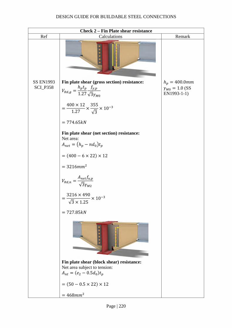
DESIGN GUIDE FOR BUILDABLE STEEL CONNECTIONS
Page | 220
Check 2 – Fin Plate shear resistance Ref Calculations Remark
SS EN1993 SCI_P358
Fin plate shear (gross section) resistance:
𝑉 ,ℎ 𝑡1.27
𝑓 ,
√3𝛾
400 12
1.27355
√310
774.65𝑘𝑁
Fin plate shear (net section) resistance: Net area: 𝐴 ℎ 𝑛𝑑 𝑡
400 6 22 12
3216𝑚𝑚
𝑉 ,𝐴 𝑓 ,
√3𝛾
3216 490
√3 1.2510
727.85𝑘𝑁
ℎ 400.0𝑚𝑚 𝛾 1.0 (SS EN1993-1-1)
Fin plate shear (block shear) resistance: Net area subject to tension: 𝐴 𝑒 0.5𝑑 𝑡
50 0.5 22 12
468𝑚𝑚

DESIGN GUIDE FOR BUILDABLE STEEL CONNECTIONS
Page | 221
Check 2 – Fin Plate shear resistance Ref Calculations Remark
Net area subject to shear: 𝐴 𝑒 𝑛 1 𝑃 𝑛 0.5 𝑑 𝑡
50 5 60 5.5 22 12
2748𝑚𝑚
𝑉 ,
0.5𝑓 , 𝐴𝛾
𝑓 , 𝐴
√3𝛾
0.5 490 468
1.25355 2748
√310
654.96𝑘𝑁
Shear resistance of fin plate: 𝑉 min 𝑉 , ,𝑉 , ,𝑉 ,
min 774.65,727.85,654.96
654.96𝑘𝑁 𝑉 300𝑘𝑁
OK

DESIGN GUIDE FOR BUILDABLE STEEL CONNECTIONS
Page | 222
Check 3 – Secondary beam web shear resistance Ref Calculations Remark
SS EN1993 SCI_P358
Shear area of secondary beam: 𝐴 𝐴 2𝑡 𝑏 2𝑟 𝑡
5870 2 11.8 165.7 2 25 6.7
1624.48𝑚𝑚
𝑉𝐴 𝑓 ,
√3𝛾
1624.48 355
√310
Weld access hole: 𝑟 25𝑚𝑚 For UB305x165x46 𝐴 5870𝑚𝑚 𝑏 165.7𝑚𝑚 𝑡 11.8𝑚𝑚
332.95𝑘𝑁 𝑉 300𝑘𝑁
OK

DESIGN GUIDE FOR BUILDABLE STEEL CONNECTIONS
Page | 223
Check 4 – Haunch resistance Ref Calculations Remark
SCI_P358 SS EN1993
Haunch shear resistance: In order to reduce stress concentration, the thicknesses of flange and web are same as secondary beam UB305x165x46. Gross section:
𝑉 ,ℎ 𝑡 𝑓 ,
√3𝛾
488.1 6.7 355
√310
670.27𝑘𝑁
Net section: Net shear area: 𝐴 , ℎ 𝑡 𝑛𝑑 𝑡
488.1 6.7 6 22 6.7
2385.87𝑚𝑚
𝑉 ,𝐴 , 𝑓 ,
√3𝛾
2385.87 490
√3 1.2510
539.97𝑘𝑁
ℎ 488.1𝑚𝑚 (Depth of haunch at bolt line) 𝛾 1.0 (SS EN1993-1-1)
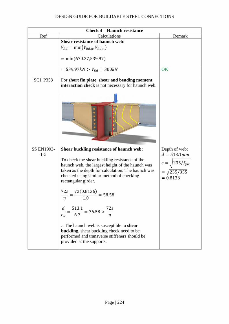
DESIGN GUIDE FOR BUILDABLE STEEL CONNECTIONS
Page | 224
Check 4 – Haunch resistance Ref Calculations Remark
Shear resistance of haunch web: 𝑉 min 𝑉 , ,𝑉 ,
min 670.27,539.97
539.97𝑘𝑁 𝑉 300𝑘𝑁
OK
SCI_P358 For short fin plate, shear and bending moment interaction check is not necessary for haunch web.
SS EN1993-1-5
Shear buckling resistance of haunch web: To check the shear buckling resistance of the haunch web, the largest height of the haunch was taken as the depth for calculation. The haunch was checked using similar method of checking rectangular girder. 72𝜀𝜂
72 0.81361.0
58.58
𝑑𝑡
513.16.7
76.5872𝜀𝜂
∴ The haunch web is susceptible to shear buckling, shear buckling check need to be performed and transverse stiffeners should be provided at the supports.
Depth of web: 𝑑 513.1𝑚𝑚
𝜀 235/𝑓
235/355 0.8136

DESIGN GUIDE FOR BUILDABLE STEEL CONNECTIONS
Page | 225
Check 4 – Haunch resistance Ref Calculations Remark
Maximum allowable slenderness for web:
𝑘𝐸𝐹
𝐴𝐴
0.55210355
3437.771955.26
10
431.41𝑑𝑡
76.58
∴ The maximum allowable slenderness of web check is satisfied. Shear buckling resistance: Assume transverse stiffeners are present at supports only:
�̅�𝑑
86.4𝑡 𝜀
513.1
86.4 6.7 0.8136
1.09 1.08
Assume non-rigid end post:
𝜒0.83
�̅�
0.831.09
0.76
Contribution from the web:
𝑉 ,𝜒 𝑓 𝑑𝑡
√3𝛾
0.76 355 513.1 6.7
√3
536.82𝑘𝑁
For elastic moment resistance utilized: 𝑘 0.55 Cross section area of the compression flange: 𝐴 𝑡 𝑏
1955.26𝑚𝑚 Cross section area of web: 𝐴 𝑑𝑡
3437.77𝑚𝑚 Young’s modules: 𝐸 210𝐺𝑃𝑎

DESIGN GUIDE FOR BUILDABLE STEEL CONNECTIONS
Page | 226
Check 4 – Haunch resistance Ref Calculations Remark
𝑀 ,
𝑓 𝑏𝑡 ℎ 𝑡𝛾
355 165.7 11.8 536.7 11.8
1.0
364.34𝑘𝑁𝑚
𝑐 𝑎 0.251.6𝑏𝑡 𝑓
𝑡 𝑑 𝑓
460.2 0.251.6 165.7 11.8 355
6.7 513.1 355
115.87𝑚𝑚
Contribution from the flange:
𝑉 ,𝑏𝑡 𝑓
𝑐𝛾1
𝑀𝑀 ,
165.7 11.8 355
115.871
250364.34
37.41𝑘𝑁
𝑉 , 𝑉 , 𝑉 ,
536.82 37.41
574.23𝑘𝑁𝜂𝑓 𝑑𝑡
√3𝛾704.60𝑘𝑁
ℎ 536.7𝑚𝑚 𝑎 460.2𝑚𝑚
𝑉 300𝑘𝑁 OK

DESIGN GUIDE FOR BUILDABLE STEEL CONNECTIONS
Page | 227
Check 5 – Weld group of fin plate (Two-side C shape fillet weld) Ref Calculations Remark
SS EN1993-1-8
Location of center of gravity of welds group:
�̅�𝑏
2𝑏 𝑑
74.6
2 74.6 501.9
8.55𝑚𝑚
𝑦𝑑2
501.9
2
250.95𝑚𝑚
Unit throat area: 𝐴 2𝑏 𝑑
2 59.6 471.9
591.1𝑚𝑚 Moment arm between applied force and weld center: 𝑟 144.77𝑚𝑚 Induced moment on welds:
𝑀𝑉
2𝑟
300
2144.77
21715.5𝑘𝑁𝑚𝑚
Length of fillet weld: Width: 𝑏 74.6𝑚𝑚 Depth: 𝑑 501.9𝑚𝑚 Cope hole size: 𝑛 15𝑚𝑚 𝑏 𝑏 𝑛
74.6 15 59.6𝑚𝑚
𝑑 𝑑 2𝑛 501.9 2 15 471.9𝑚𝑚

DESIGN GUIDE FOR BUILDABLE STEEL CONNECTIONS
Page | 228
Check 5 – Weld group of fin plate (Two-side C shape fillet weld) Ref Calculations Remark
Polar moment of inertia:
𝐽8𝑏 6𝑏 𝑑 𝑑
12𝑏
2𝑏 𝑑
8 59.6 6 59.6 471.9 471.9
12
59.62 59.6 471.9
15513212𝑚𝑚
Critical point: Horizontal distance from centroid: 𝑟 𝑏 �̅�
74.6 8.55 66.05𝑚𝑚
Vertical distance from centroid: 𝑟 𝑦
250.95𝑚𝑚 Vertical stress:
𝜏𝑉𝐴
𝑀𝑟𝐽
300
2 591.121715.5 66.05
15513212
0.35𝑘𝑁/𝑚𝑚
Horizontal stress:
𝜏𝑀𝑟𝐽
21715.5 250.95
15513212
0.35𝑘𝑁/𝑚𝑚
Resultant stress:
𝜏 𝑟 𝑟
0.35 0.35
0.49𝑘𝑁/𝑚𝑚
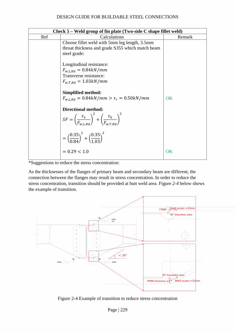
DESIGN GUIDE FOR BUILDABLE STEEL CONNECTIONS
Page | 229
Check 5 – Weld group of fin plate (Two-side C shape fillet weld) Ref Calculations Remark
Choose fillet weld with 5mm leg length, 3.5mm throat thickness and grade S355 which match beam steel grade: Longitudinal resistance: 𝐹 , , 0.84𝑘𝑁/𝑚𝑚 Transverse resistance: 𝐹 , , 1.03𝑘𝑁/𝑚𝑚
Simplified method: 𝐹 , , 0.84𝑘𝑁/𝑚𝑚 𝜏 0.50𝑘𝑁/𝑚𝑚
OK
Directional method:
𝑆𝐹𝜏
𝐹 , ,
𝜏𝐹 , ,
0.350.84
0.351.03
0.29 1.0
OK
*Suggestions to reduce the stress concentration:
As the thicknesses of the flanges of primary beam and secondary beam are different, the connection between the flanges may result in stress concentration. In order to reduce the stress concentration, transition should be provided at butt weld area. Figure 2-4 below shows the example of transition.
Figure 2-4 Example of transition to reduce stress concentration
FPBWTYP.
PPBWPPBW
Weld access r=25mm
30° transition zone
PPBW thickness a
Weld access r=25mm
30° transition zone
FPBW
30°
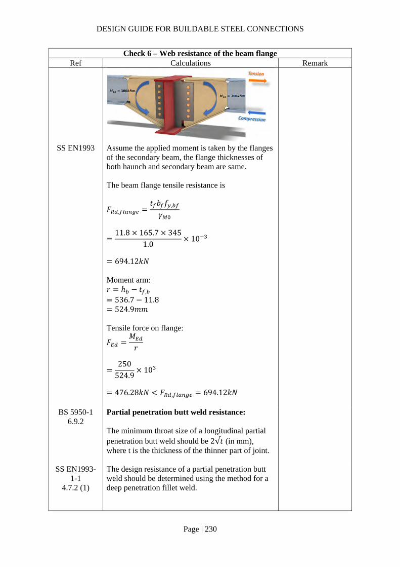
DESIGN GUIDE FOR BUILDABLE STEEL CONNECTIONS
Page | 230
Check 6 – Web resistance of the beam flange Ref Calculations Remark
SS EN1993 Assume the applied moment is taken by the flanges of the secondary beam, the flange thicknesses of both haunch and secondary beam are same. The beam flange tensile resistance is
𝐹 ,𝑡 𝑏 𝑓 ,
𝛾
11.8 165.7 345
1.010
694.12𝑘𝑁
Moment arm: 𝑟 ℎ 𝑡 ,
536.7 11.8 524.9𝑚𝑚
Tensile force on flange:
𝐹𝑀𝑟
250
524.910
476.28𝑘𝑁 𝐹 , 694.12𝑘𝑁
BS 5950-1 6.9.2
Partial penetration butt weld resistance: The minimum throat size of a longitudinal partial penetration butt weld should be 2√𝑡 (in mm), where t is the thickness of the thinner part of joint.
SS EN1993-1-1
4.7.2 (1)
The design resistance of a partial penetration butt weld should be determined using the method for a deep penetration fillet weld.

DESIGN GUIDE FOR BUILDABLE STEEL CONNECTIONS
Page | 231
Check 6 – Web resistance of the beam flange Ref Calculations Remark
In this example, the angle between the transverse force and weld throat 𝜃 90°. Provided the groove angle is greater than 60° or U-butt is adopted, the throat thickness is equal to the depth of penetration.
Choose partial butt weld with 12mm ( 2√11.86.87𝑚𝑚 throat thickness and grade S355 which match the beam material properties:
Transverse resistance:
𝐹 , ,0.9𝑓𝛾
𝑎
0.9 47012
1.2510
4.06𝑘𝑁/𝑚𝑚
Tensile resistance of the PPBW: 𝐹 𝐹 , , 𝑏
4.06 165.7
672.74𝑘𝑁 𝐹 476.28𝑘𝑁
OK
Groove angle 60°
𝐷

DESIGN GUIDE FOR BUILDABLE STEEL CONNECTIONS
Page | 232
2.4.5 Example 11 – Double-sided Beam-to-Beam connection with extended fin-plate (moment-resisting connection) for beams of different depths with connection plate

DESIGN GUIDE FOR BUILDABLE STEEL CONNECTIONS
Page | 233
Check 1 – Bolt group resistance Ref Calculations Remark
SS EN1993-1-8
Bolt resistance: Using Gr8.8, M20 bolts with: 𝐴 245𝑚𝑚 ; 𝑓 800𝑀𝑃𝑎;
Shear resistance of a single bolt:
𝐹 ,𝛼 𝑓 𝐴𝛾
0.6 800 245
1.2510
94.08𝑘𝑁
For class 8.8: 𝛼 0.6 𝛾 1.25 (refer to NA to SS)
For single vertical line of bolts (𝑛 1): 𝑛 3, 𝑛 3 1 3 𝛼 0
𝛽6𝑧
𝑛 𝑛 1 𝑝
3 65𝑚𝑚
3 3 1 60𝑚𝑚
0.54
𝑉𝑛𝐹 ,
1 𝛼𝑛 𝛽𝑛
3 94.08
1 0 0.54 310
𝑧 65.00𝑚𝑚
147.92𝑘𝑁 𝑉 100𝑘𝑁
OK

DESIGN GUIDE FOR BUILDABLE STEEL CONNECTIONS
Page | 234
Check 1 – Bolt group resistance Ref Calculations Remark
Bearing resistance on fin plate: For bearing resistance in vertical direction of one bolt:
𝛼 min𝑒
3𝑑;𝑝
3𝑑14
;𝑓𝑓
; 1.0
min50
3 22;
603 22
14
;800490
; 1.0
0.6591
𝒆𝟏 𝟓𝟎.𝟎𝒎𝒎 (1.2𝑑 𝑒 4𝑡40𝑚𝑚) 𝒑𝟏 𝟔𝟎.𝟎𝒎𝒎 (2.2𝑑 𝑝14𝑡 𝑜𝑟 200𝑚𝑚) 𝒆𝟐 𝟓𝟎.𝟎𝒎𝒎 (1.2𝑑 𝑒 4𝑡40𝑚𝑚) 𝒑𝟐 𝒏𝒊𝒍 (2.4𝑑 𝑝14𝑡 𝑜𝑟 200𝑚𝑚)
𝑘 min
2.8𝑒𝑑
1.7;1.4𝑝𝑑
1.7; 2.5
min2.8 50
221.7; 2.5
2.5
𝐹 , ,𝑘 𝛼 𝑓 , 𝑑𝑡
𝛾
2.5 0.6591 490 20 12
1.25
155.02𝑘𝑁
𝑡 12.0𝑚𝑚 𝑡 16𝑚𝑚 𝑓 , 490𝑀𝑃𝑎 𝑓 , 355𝑀𝑃𝑎
For bearing resistance in horizontal direction of one bolt:
𝑘 min2.8𝑒𝑑
1.7;1.4𝑝𝑑
1.7; 2.5
min2.8 50
221.7;
1.4 6022
1.7; 2.5
2.12
𝛼 min𝑒
3𝑑;𝑝
3𝑑14
;𝑓𝑓 ,
; 1.0
min50
3 22;800490
; 1.0
0.76

DESIGN GUIDE FOR BUILDABLE STEEL CONNECTIONS
Page | 235
Check 1 – Bolt group resistance Ref Calculations Remark
𝐹 , ,
𝑘 𝛼 𝑓 , 𝑑𝑡𝛾
2.12 0.76 490 20 12
1.2510
150.97kN
Bolt group bearing resistance:
𝑉𝑛
1 𝛼𝑛𝐹 , ,
𝛽𝑛𝐹 , ,
3
1155.02
0.54 3150.97
10
239.07𝑘𝑁 𝑉 100𝑘𝑁
OK
Bearing resistance on beam web: Vertical bearing resistance:
𝛼 min𝑒 ,
3𝑑;𝑝 ,
3𝑑14
;𝑓𝑓 ,
; 1.0
min121.73 22
;60
3 2214
;800490
; 1.0
0.6591
𝑘 min2.8𝑒 ,
𝑑1.7; 2.5
min2.8 50
221.7; 2.5
2.5
𝐹 , ,𝑘 𝛼 𝑓 , 𝑑𝑡 ,
𝛾
2.5 0.6591 490 20 9.1
1.25
117.56𝑘𝑁
𝒆𝟏,𝒃 𝟏𝟐𝟏.𝟕𝒎𝒎 𝒑𝟏,𝒃 𝟔𝟎.𝟎𝒎𝒎 𝒆𝟐,𝒃 𝟓𝟎.𝟎𝒎𝒎 𝒑𝟐,𝒃 𝒏𝒊𝒍
𝑡 , 9.1𝑚𝑚 𝑡 , 16𝑚𝑚 𝑓 , 490𝑀𝑃𝑎 𝑓 , 355𝑀𝑃𝑎
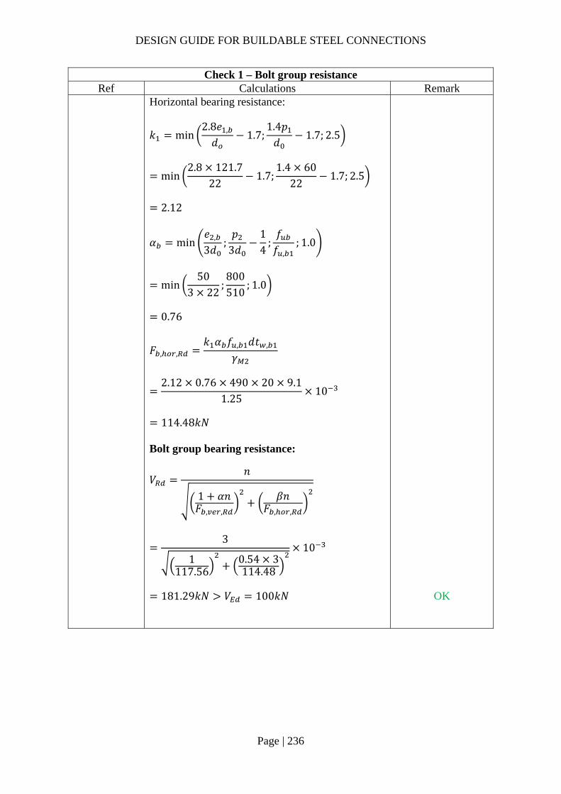
DESIGN GUIDE FOR BUILDABLE STEEL CONNECTIONS
Page | 236
Check 1 – Bolt group resistance Ref Calculations Remark
Horizontal bearing resistance:
𝑘 min2.8𝑒 ,
𝑑1.7;
1.4𝑝𝑑
1.7; 2.5
min2.8 121.7
221.7;
1.4 6022
1.7; 2.5
2.12
𝛼 min𝑒 ,
3𝑑;𝑝
3𝑑14
;𝑓𝑓 ,
; 1.0
min50
3 22;800510
; 1.0
0.76
𝐹 , ,𝑘 𝛼 𝑓 , 𝑑𝑡 ,
𝛾
2.12 0.76 490 20 9.1
1.2510
114.48𝑘𝑁
Bolt group bearing resistance:
𝑉𝑛
1 𝛼𝑛𝐹 , ,
𝛽𝑛𝐹 , ,
3
1117.56
0.54 3114.48
10
181.29𝑘𝑁 𝑉 100𝑘𝑁
OK
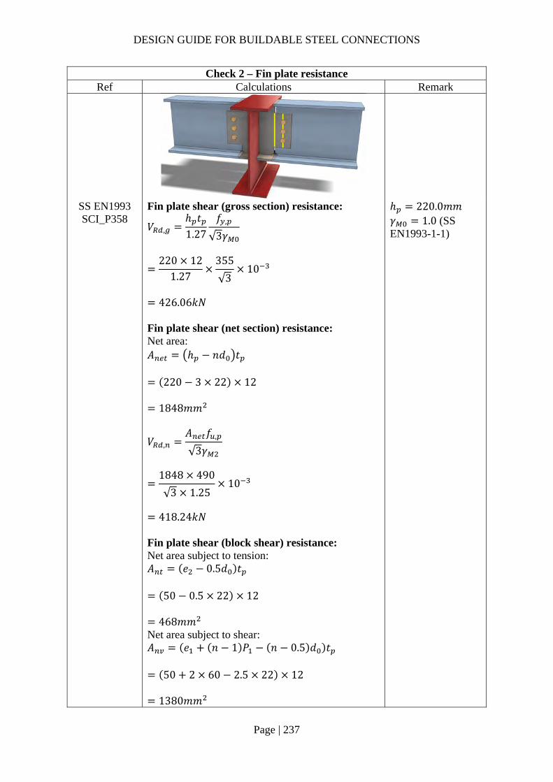
DESIGN GUIDE FOR BUILDABLE STEEL CONNECTIONS
Page | 237
Check 2 – Fin plate resistance Ref Calculations Remark
SS EN1993 SCI_P358
Fin plate shear (gross section) resistance:
𝑉 ,ℎ 𝑡1.27
𝑓 ,
√3𝛾
220 12
1.27355
√310
426.06𝑘𝑁
Fin plate shear (net section) resistance: Net area: 𝐴 ℎ 𝑛𝑑 𝑡
220 3 22 12
1848𝑚𝑚
𝑉 ,𝐴 𝑓 ,
√3𝛾
1848 490
√3 1.2510
418.24𝑘𝑁
Fin plate shear (block shear) resistance: Net area subject to tension: 𝐴 𝑒 0.5𝑑 𝑡
50 0.5 22 12
468𝑚𝑚 Net area subject to shear: 𝐴 𝑒 𝑛 1 𝑃 𝑛 0.5 𝑑 𝑡
50 2 60 2.5 22 12
1380𝑚𝑚
ℎ 220.0𝑚𝑚 𝛾 1.0 (SS EN1993-1-1)
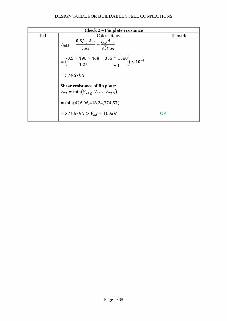
DESIGN GUIDE FOR BUILDABLE STEEL CONNECTIONS
Page | 238
Check 2 – Fin plate resistance Ref Calculations Remark
𝑉 ,
0.5𝑓 , 𝐴𝛾
𝑓 , 𝐴
√3𝛾
0.5 490 468
1.25355 1380
√310
374.57𝑘𝑁
Shear resistance of fin plate: 𝑉 min 𝑉 , ,𝑉 , ,𝑉 ,
min 426.06,418.24,374.57
374.57𝑘𝑁 𝑉 100𝑘𝑁
OK

DESIGN GUIDE FOR BUILDABLE STEEL CONNECTIONS
Page | 239
Check 3 – Secondary beam web shear resistance Ref Calculations Remark
SS EN1993 SCI_P358
Beam web resistance (gross section): For UB356x171x67: Cross-section area, 𝐴 8550𝑚𝑚 Flange width, 𝑏 173.2𝑚𝑚 Flange thickness, 𝑡 15.7𝑚𝑚 Weld access radius, 𝑟 25𝑚𝑚 Shear area: 𝐴 𝐴 2𝑡 𝑏 2𝑟𝑡 ,
8550 2 15.7 173.2 2 25 9.1
2656.52𝑚𝑚
𝑉 ,𝐴 𝑓 ,
√3𝛾
2656.52 355
√310
544.48𝑘𝑁
Beam web shear resistance (net section): Area of net section: 𝐴 𝐴 𝑛𝑑 𝑡 ,
2656.52 3 22 9.1
2055.92𝑚𝑚
𝑉 ,𝐴 , 𝑓 ,
√3𝛾
2055.92 490
√3 1.2510
581.62𝑘𝑁

DESIGN GUIDE FOR BUILDABLE STEEL CONNECTIONS
Page | 240
Check 3 – Secondary beam web shear resistance Ref Calculations Remark
Shear resistance of fin plate: 𝑉 min 𝑉 , ,𝑉 ,
min 544.48,581.62
544.48𝑘𝑁 𝑉 100𝑘𝑁
OK
For short fin plate, shear and bending moment interaction check is not necessary for beam web.

DESIGN GUIDE FOR BUILDABLE STEEL CONNECTIONS
Page | 241
Check 4 – Weld group resistance of fin plate (Two-side C shape fillet weld) Ref Calculations Remark
SS EN1993-1-8
Location of center of gravity of welds group:
�̅�𝑏
2𝑏 𝑑
74.6
2 74.6 332
11.57𝑚𝑚
𝑦𝑑2
332
2
166𝑚𝑚
Unit throat area: 𝐴 2𝑏 𝑑
2 59.6 302
421.2𝑚𝑚 Moment arm between applied force and weld center: 𝑟 142.76𝑚𝑚 Induced moment on welds:
𝑀𝑉
2𝑟
100
2142.76
7138𝑘𝑁𝑚𝑚
Length of fillet weld: Width: 𝑏 74.6𝑚𝑚 Depth: 𝑑 332𝑚𝑚 Cope hole size: 𝑛 15𝑚𝑚 𝑏 𝑏 𝑛
74.6 15 59.6𝑚𝑚
𝑑 𝑑 2𝑛 332 2 15
302𝑚𝑚
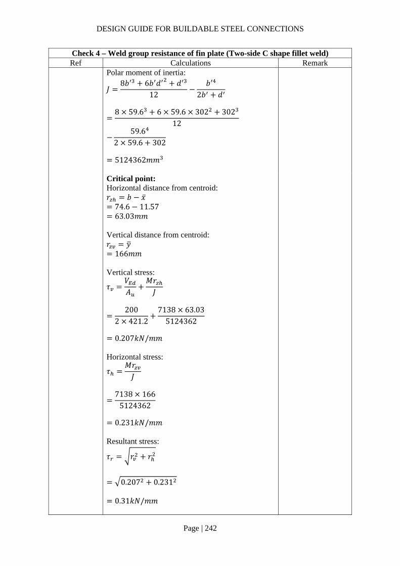
DESIGN GUIDE FOR BUILDABLE STEEL CONNECTIONS
Page | 242
Check 4 – Weld group resistance of fin plate (Two-side C shape fillet weld) Ref Calculations Remark
Polar moment of inertia:
𝐽8𝑏 6𝑏 𝑑 𝑑
12𝑏
2𝑏 𝑑
8 59.6 6 59.6 302 302
12
59.62 59.6 302
5124362𝑚𝑚
Critical point: Horizontal distance from centroid: 𝑟 𝑏 �̅�
74.6 11.57 63.03𝑚𝑚
Vertical distance from centroid: 𝑟 𝑦
166𝑚𝑚 Vertical stress:
𝜏𝑉𝐴
𝑀𝑟𝐽
200
2 421.27138 63.03
5124362
0.207𝑘𝑁/𝑚𝑚
Horizontal stress:
𝜏𝑀𝑟𝐽
7138 166
5124362
0.231𝑘𝑁/𝑚𝑚
Resultant stress:
𝜏 𝑟 𝑟
0.207 0.231
0.31𝑘𝑁/𝑚𝑚
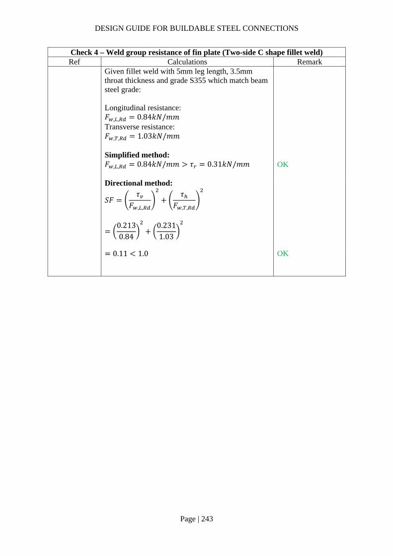
DESIGN GUIDE FOR BUILDABLE STEEL CONNECTIONS
Page | 243
Check 4 – Weld group resistance of fin plate (Two-side C shape fillet weld) Ref Calculations Remark
Given fillet weld with 5mm leg length, 3.5mm throat thickness and grade S355 which match beam steel grade: Longitudinal resistance: 𝐹 , , 0.84𝑘𝑁/𝑚𝑚 Transverse resistance: 𝐹 , , 1.03𝑘𝑁/𝑚𝑚
Simplified method: 𝐹 , , 0.84𝑘𝑁/𝑚𝑚 𝜏 0.31𝑘𝑁/𝑚𝑚
OK
Directional method:
𝑆𝐹𝜏
𝐹 , ,
𝜏𝐹 , ,
0.2130.84
0.2311.03
0.11 1.0
OK

DESIGN GUIDE FOR BUILDABLE STEEL CONNECTIONS
Page | 244
Check 5 – Weld resistance on beam flange Ref Calculations Remark
SS EN1993 Assume the applied moment is taken by the flanges of the secondary beam, the flange thicknesses of both primary and secondary beam are almost similar (15.6mm & 15.7mm for primary and secondary respectively) The beam flange tensile resistance is
𝐹 ,𝑡 𝑏 𝑓 ,
𝛾
15.7 173.2 355
1.010
965.33𝑘𝑁
Moment arm: 𝑟 ℎ 𝑡 ,
363.4 15.7 347.7𝑚𝑚
Tensile force on flange:
𝐹𝑀𝑟
100
347.710
287.60𝑘𝑁 𝐹 , 965.33𝑘𝑁
BS 5950-1 6.9.2
Partial penetration butt weld resistance: The minimum throat size of a longitudinal partial penetration butt weld should be 2√𝑡 (in mm), where t is the thickness of the thinner part of joint.

DESIGN GUIDE FOR BUILDABLE STEEL CONNECTIONS
Page | 245
Check 5 – Weld resistance on beam flange Ref Calculations Remark
SS EN1993-1-1
4.7.2 (1)
The design resistance of a partial penetration butt weld should be determined using the method for a deep penetration fillet weld.
In this example, the angle between the transverse force and weld throat 𝜃 90°. Provided the groove angle is greater than 60° or U-butt is adopted, the throat thickness is equal to the depth of penetration.
Choose partial butt weld with 12mm ( 2√19.68.85𝑚𝑚 throat thickness and grade S355 which match the beam material properties:
Transverse resistance:
𝐹 , ,0.9𝑓𝛾
𝑎
0.9 47012
1.2510
4.06𝑘𝑁/𝑚𝑚
Tensile resistance of the PPBW: 𝐹 𝐹 , , 𝑏
4.06 173.2
703.19𝑘𝑁 𝐹 287.60𝑘𝑁
OK
Classification of connecting plate:
𝜀235𝑓 ,
235355
0.8136
As the thickness of the connecting plate is same as the thickness of the bottom flange of the secondary beam
Groove angle 60°
𝐷

DESIGN GUIDE FOR BUILDABLE STEEL CONNECTIONS
Page | 246
Check 5 – Weld resistance on beam flange Ref Calculations Remark
𝑐𝑡
4.58 9𝜀 7.32
Hence the connecting plate is classified as Class 1 and will not subject to local buckling.

DESIGN GUIDE FOR BUILDABLE STEEL CONNECTIONS
Page | 247
2.4.6 Example 12 – I-beams connecting to hollow section column with external ring plate

DESIGN GUIDE FOR BUILDABLE STEEL CONNECTIONS
Page | 248
Check 1 – Bolt group resistance Ref Calculations Remark
According to AISC Guide, for flange-plated moment connections, the shear-plate connection can be designed for shear only while the rotation is considered resisted by the flange connections; Hence, in this case, all shear force is assumed to be resisted by the bolt groups while the butt weld in the beam flanges resists the applied moment.
SS EN1993-1-8
Bolt resistance: Using Gr8.8, M20 bolts with: 𝐴 245𝑚𝑚 ; 𝑓 800𝑀𝑃𝑎;
Shear resistance of a single bolt:
𝐹 ,𝛼 𝑓 𝐴𝛾
0.6 800 245
1.2510
94.08𝑘𝑁
For class 8.8: 𝛼 0.6 𝛾 1.25 (refer to NA to SS)
SCI_P358 SN017
For two vertical lines of bolts (𝑛 2):
𝑙𝑛2𝑝
16𝑛 𝑛 1 𝑝
62
6016
6 6 1 60
136800𝑚𝑚
𝑧 100𝑚𝑚 𝒆𝟏 𝟓𝟎.𝟎𝒎𝒎 (1.2𝑑 𝑒4𝑡 40𝑚𝑚) 𝒑𝟏 𝟔𝟎.𝟎𝒎𝒎 (2.2𝑑 𝑝14𝑡 𝑜𝑟 200𝑚𝑚) 𝒆𝟐 𝟓𝟎.𝟎𝒎𝒎 (1.2𝑑 𝑒4𝑡 40𝑚𝑚) 𝒑𝟐 𝟔𝟎.𝟎𝒎𝒎

DESIGN GUIDE FOR BUILDABLE STEEL CONNECTIONS
Page | 249
Check 1 – Bolt group resistance Ref Calculations Remark
𝛼𝑧𝑝2𝑙
100 60
2 136800
0.02
𝛽𝑧𝑝2𝑙
𝑛 1
100 60
2 1368006 1
0.11
𝑛 6, 𝑛 2, 𝑛 6 2 12
(2.4𝑑 𝑝14𝑡 𝑜𝑟 200𝑚𝑚)
𝑉
𝑛𝐹 ,
1 𝛼𝑛 𝛽𝑛
12 94.08 10
1 0.02 12 0.11 12
618.96𝑘𝑁 𝑉 500𝑘𝑁
OK!
SCI_P358 SS EN1993-
1-8
Bolt bearing resistance in the fin plate: For bearing resistance in vertical direction of one bolt:
𝑘 min2.8𝑒𝑑
1.7;1.4𝑝𝑑
1.7; 2.5
min2.8 50
221.7;
1.4 6022
1.7; 2.5
2.12
𝛼 min𝑒
3𝑑;𝑝
3𝑑14
;𝑓𝑓 ,
; 1.0
min50
3 22;
603 22
14
;800490
; 1.0
0.66
𝑡 12𝑚𝑚

DESIGN GUIDE FOR BUILDABLE STEEL CONNECTIONS
Page | 250
Check 1 – Bolt group resistance Ref Calculations Remark
𝐹 , ,
𝑘 𝛼 𝑓 , 𝑑𝑡𝛾
2.12 0.66 490 20 121.25
10
131.34𝑘𝑁
For bearing resistance in horizontal direction of one bolt:
𝑘 min2.8𝑒𝑑
1.7;1.4𝑝𝑑
1.7; 2.5
min2.8 50
221.7;
1.4 6022
1.7; 2.5
2.12
𝛼 min
𝑒3𝑑
;𝑝
3𝑑14
;𝑓𝑓 ,
; 1.0
min50
3 22;
603 22
14
;800490
; 1.0
0.66
𝐹 , ,𝑘 𝛼 𝑓 , 𝑑𝑡
𝛾
2.12 0.66 490 20 12
1.2510
131.34kN
Bolt group bearing resistance:
𝑉𝑛
1 𝛼𝑛𝐹 , ,
𝛽𝑛𝐹 , ,
12 10
1 0.02 12131.34
0.11 12131.34
864.11𝑘𝑁 𝑉 500𝑘𝑁
OK!
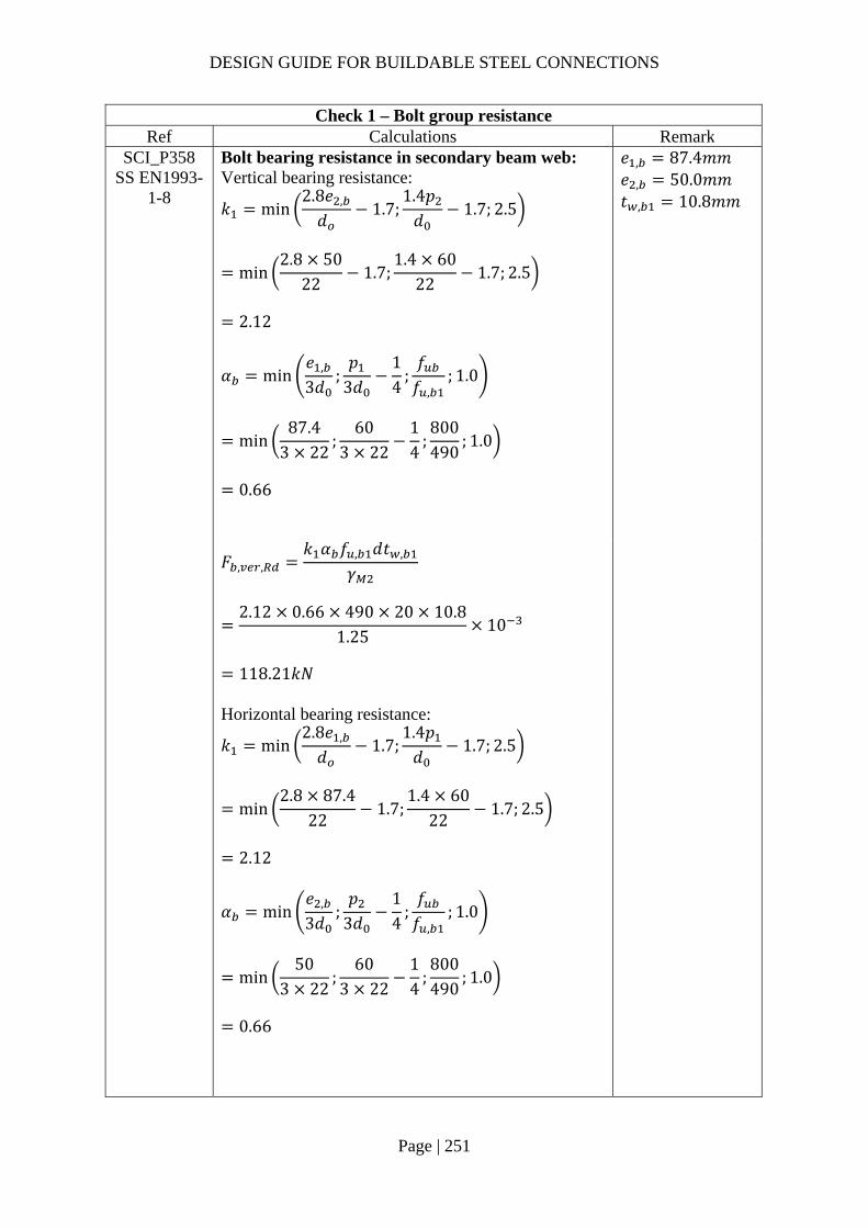
DESIGN GUIDE FOR BUILDABLE STEEL CONNECTIONS
Page | 251
Check 1 – Bolt group resistance Ref Calculations Remark
SCI_P358 SS EN1993-
1-8
Bolt bearing resistance in secondary beam web: Vertical bearing resistance:
𝑘 min2.8𝑒 ,
𝑑1.7;
1.4𝑝𝑑
1.7; 2.5
min2.8 50
221.7;
1.4 6022
1.7; 2.5
2.12
𝛼 min𝑒 ,
3𝑑;𝑝
3𝑑14
;𝑓𝑓 ,
; 1.0
min87.4
3 22;
603 22
14
;800490
; 1.0
0.66
𝑒 , 87.4𝑚𝑚 𝑒 , 50.0𝑚𝑚 𝑡 , 10.8𝑚𝑚
𝐹 , ,
𝑘 𝛼 𝑓 , 𝑑𝑡 ,
𝛾
2.12 0.66 490 20 10.8
1.2510
118.21𝑘𝑁
Horizontal bearing resistance:
𝑘 min2.8𝑒 ,
𝑑1.7;
1.4𝑝𝑑
1.7; 2.5
min2.8 87.4
221.7;
1.4 6022
1.7; 2.5
2.12
𝛼 min𝑒 ,
3𝑑;𝑝
3𝑑14
;𝑓𝑓 ,
; 1.0
min50
3 22;
603 22
14
;800490
; 1.0
0.66

DESIGN GUIDE FOR BUILDABLE STEEL CONNECTIONS
Page | 252
Check 1 – Bolt group resistance Ref Calculations Remark
𝐹 , ,
𝑘 𝛼 𝑓 , 𝑑𝑡 ,
𝛾
2.12 0.66 490 20 10.81.25
10
118.21𝑘𝑁
Bolt group bearing resistance:
𝑉𝑛
1 𝛼𝑛𝐹 , ,
𝛽𝑛𝐹 , ,
12 10
1 0.02 12118.21
0.11 12118.21
777.70𝑘𝑁 𝑉 500𝑘𝑁
OK!

DESIGN GUIDE FOR BUILDABLE STEEL CONNECTIONS
Page | 253
Check 2 – Fin plate resistance Ref Calculations Remark
SS EN1993 SCI_P358
Fin plate shear gross section resistance:
𝑉 ,ℎ 𝑡1.27
𝑓 ,
√3𝛾
400 12
1.27355
√310
774.65𝑘𝑁
Fin plate shear net section resistance: Net area: 𝐴 ℎ 𝑛𝑑 𝑡
400 6 22 12
3216𝑚𝑚
𝑉 ,𝐴 𝑓 ,
√3𝛾
3216 490
√3 1.2510
727.85𝑘𝑁
ℎ 400.0𝑚𝑚 𝛾 1.0 (SS EN1993-1-1)
Fin plate shear block shear resistance: Net area subject to tension: 𝐴 𝑝 𝑒 1.5𝑑 𝑡
60 50 1.5 22 12
924𝑚𝑚

DESIGN GUIDE FOR BUILDABLE STEEL CONNECTIONS
Page | 254
Check 2 – Fin plate resistance Ref Calculations Remark
Net area subject to shear: 𝐴 𝑒 𝑛 1 𝑃 𝑛 0.5 𝑑 𝑡
50 5 60 5.5 22 12
2748𝑚𝑚
𝑉 ,
0.5𝑓 , 𝐴𝛾
𝑓 , 𝐴
√3𝛾
0.5 490 924
1.25355 2748
√310
744.33𝑘𝑁
Shear resistance of fin plate: 𝑉 min 𝑉 , ,𝑉 , ,𝑉 ,
min 774.65,727.85,744.33
727.85𝑘𝑁 𝑉 500𝑘𝑁
OK!

DESIGN GUIDE FOR BUILDABLE STEEL CONNECTIONS
Page | 255
Check 3 – Secondary beam web shear resistance Ref Calculations Remark
SS EN1993 SCI_P358
Beam web gross section resistance: For UB533x210x101: Cross-section area, 𝐴 12900𝑚𝑚 Flange width, 𝑏 210𝑚𝑚 Flange thickness, 𝑡 17.4𝑚𝑚 Root radius, 𝑟 12.7𝑚𝑚 Shear area: 𝐴 𝐴 2𝑡 𝑏 2𝑡 𝑐
12900 2 17.4 210 2 10.8 20
5160𝑚𝑚
𝑉 ,𝐴 𝑓 ,
√3𝛾
5160 355
√310
1057.59𝑘𝑁
Beam web net section resistance: Area of net section: 𝐴 𝐴 𝑛𝑑 𝑡 ,
5160 6 22 10.8
3734.4𝑚𝑚
𝑉 ,𝐴 , 𝑓 ,
√3𝛾
3734.4 490
√3 1.2510
1056.47𝑘𝑁
𝑐 20𝑚𝑚 Weld access hole size
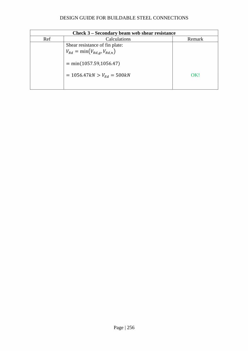
DESIGN GUIDE FOR BUILDABLE STEEL CONNECTIONS
Page | 256
Check 3 – Secondary beam web shear resistance Ref Calculations Remark
Shear resistance of fin plate: 𝑉 min 𝑉 , ,𝑉 ,
min 1057.59,1056.47
1056.47𝑘𝑁 𝑉 500𝑘𝑁
OK!
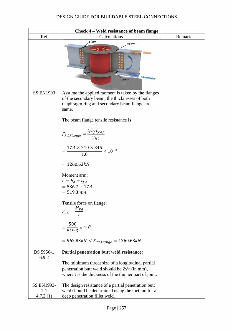
DESIGN GUIDE FOR BUILDABLE STEEL CONNECTIONS
Page | 257
Check 4 – Weld resistance of beam flange Ref Calculations Remark
SS EN1993 Assume the applied moment is taken by the flanges of the secondary beam, the thicknesses of both diaphragm ring and secondary beam flange are same. The beam flange tensile resistance is
𝐹 ,𝑡 𝑏 𝑓 ,
𝛾
17.4 210 345
1.010
1260.63𝑘𝑁
Moment arm: 𝑟 ℎ 𝑡 ,
536.7 17.4 519.3𝑚𝑚
Tensile force on flange:
𝐹𝑀𝑟
500
519.310
962.83𝑘𝑁 𝐹 , 1260.63𝑘𝑁
BS 5950-1 6.9.2
Partial penetration butt weld resistance: The minimum throat size of a longitudinal partial penetration butt weld should be 2√𝑡 (in mm), where t is the thickness of the thinner part of joint.
SS EN1993-1-1
4.7.2 (1)
The design resistance of a partial penetration butt weld should be determined using the method for a deep penetration fillet weld.

DESIGN GUIDE FOR BUILDABLE STEEL CONNECTIONS
Page | 258
Check 4 – Weld resistance of beam flange Ref Calculations Remark
In this example, the angle between the transverse force and weld throat 𝜃 90°. Provided the groove angle is greater than 60° or U-butt is adopted, the throat thickness is equal to the depth of penetration.
Choose partial butt weld with 16mm ( 2√17.48.34𝑚𝑚 throat thickness and grade S355 which match the beam material properties:
Transverse resistance:
𝐹 , ,0.9𝑓𝛾
𝑎
0.9 47016
1.2510
5.41𝑘𝑁/𝑚𝑚
𝑓 : ultimate strength 410𝑀𝑃𝑎 for
S275 470𝑀𝑃𝑎 for
S355 𝑎: throat thickness 𝛾 1.25
Tensile resistance of the PPBW: 𝐹 𝐹 , , 𝑏
5.41 210
1137.02𝑘𝑁 𝐹 962.83𝑘𝑁
OK!
Groove angle 60°
𝐷

DESIGN GUIDE FOR BUILDABLE STEEL CONNECTIONS
Page | 259
Check 5 – External diaphragm ring check Ref Calculations Remark
CIDECT design guide
9
Basic properties: Diameter of CHS column: 𝑑 508𝑚𝑚 Thickness of CHS column: 𝑡 16𝑚𝑚 Width of diaphragm ring: 𝑏 50𝑚𝑚 Thickness of diaphragm ring: 𝑡 18𝑚𝑚 𝑡 Yield strength of column: 𝑓 355𝑀𝑃𝑎 Axial resistance of diaphragm ring:
𝑁 19.6𝑑𝑡
. 𝑏𝑑
. 𝑡𝑡
. 𝑑2
𝑓
19.650816
. 50508
. 1816
. 5082
355 10
1643.97𝑘𝑁 𝐹 962.83𝑘𝑁
OK!
Range of validity:
14𝑑𝑡
50816
31.75 36
0.05𝑏𝑑
50508
0.10 0.14
0.75𝑡𝑡
1816
1.125 2.0
Note:
The thickness of the external diaphragm ring may be slightly thicker than the secondary beam flange, this provides tolerance for positioning the secondary beam.
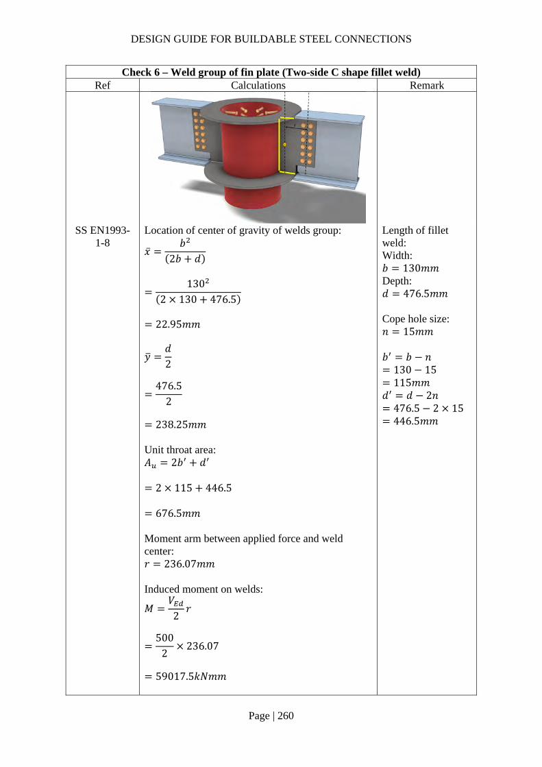
DESIGN GUIDE FOR BUILDABLE STEEL CONNECTIONS
Page | 260
Check 6 – Weld group of fin plate (Two-side C shape fillet weld) Ref Calculations Remark
SS EN1993-1-8
Location of center of gravity of welds group:
�̅�𝑏
2𝑏 𝑑
130
2 130 476.5
22.95𝑚𝑚
𝑦𝑑2
476.5
2
238.25𝑚𝑚
Unit throat area: 𝐴 2𝑏 𝑑
2 115 446.5
676.5𝑚𝑚 Moment arm between applied force and weld center: 𝑟 236.07𝑚𝑚 Induced moment on welds:
𝑀𝑉
2𝑟
500
2236.07
59017.5𝑘𝑁𝑚𝑚
Length of fillet weld: Width: 𝑏 130𝑚𝑚 Depth: 𝑑 476.5𝑚𝑚 Cope hole size: 𝑛 15𝑚𝑚 𝑏 𝑏 𝑛
130 15 115𝑚𝑚
𝑑 𝑑 2𝑛 476.5 2 15 446.5𝑚𝑚

DESIGN GUIDE FOR BUILDABLE STEEL CONNECTIONS
Page | 261
Check 6 – Weld group of fin plate (Two-side C shape fillet weld) Ref Calculations Remark
Polar moment of inertia:
𝐽8𝑏 6𝑏 𝑑 𝑑
12𝑏
2𝑏 𝑑
8 115 6 115 446.5 446.5
12
1152 115 446.5
19636646𝑚𝑚
Critical point: Horizontal distance from centroid: 𝑟 𝑏 �̅�
130 22.95 107.05𝑚𝑚
Vertical distance from centroid: 𝑟 𝑦
238.25𝑚𝑚 Vertical stress:
𝜏𝑉𝐴
𝑀𝑟𝐽
500
2 676.559017.5 107.05
19636646
0.691𝑘𝑁/𝑚𝑚
Horizontal stress:
𝜏𝑀𝑟𝐽
59017.5 238.25
19636646
0.716𝑘𝑁/𝑚𝑚
Resultant stress:
𝜏 𝑟 𝑟
0.691 0.716
1.00𝑘𝑁/𝑚𝑚

DESIGN GUIDE FOR BUILDABLE STEEL CONNECTIONS
Page | 262
Check 6 – Weld group of fin plate (Two-side C shape fillet weld) Ref Calculations Remark
SCI_P363 Choose fillet weld with 8mm leg length, 5.6mm throat thickness and grade S355 which match beam steel grade: Longitudinal resistance: 𝐹 , , 1.35𝑘𝑁/𝑚𝑚 Transverse resistance: 𝐹 , , 1.65𝑘𝑁/𝑚𝑚
Simplified method: 𝐹 , , 1.35𝑘𝑁/𝑚𝑚 𝜏 1.00𝑘𝑁/𝑚𝑚
OK
Directional method:
𝑆𝐹𝜏
𝐹 , ,
𝜏𝐹 , ,
0.6911.35
0.7161.65
0.45 1.0
OK
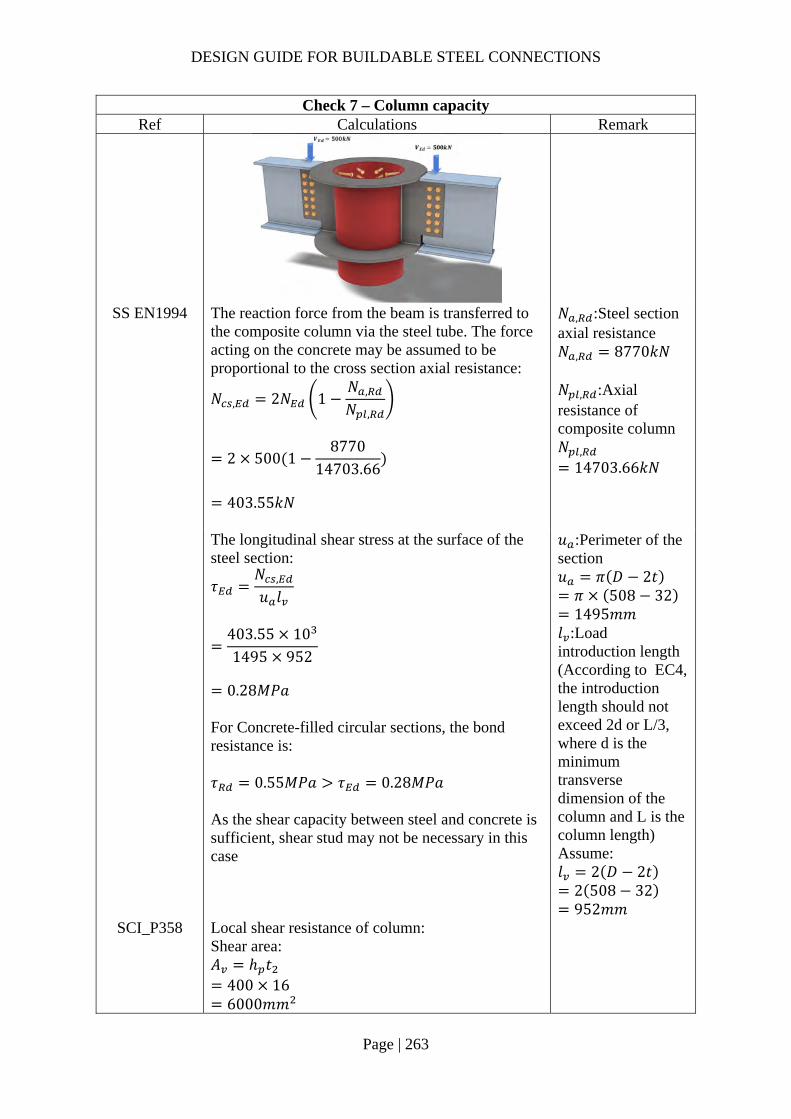
DESIGN GUIDE FOR BUILDABLE STEEL CONNECTIONS
Page | 263
Check 7 – Column capacity Ref Calculations Remark
SS EN1994 The reaction force from the beam is transferred to the composite column via the steel tube. The force acting on the concrete may be assumed to be proportional to the cross section axial resistance:
𝑁 , 2𝑁 1𝑁 ,
𝑁 ,
2 500 18770
14703.66
403.55𝑘𝑁
𝑁 , :Steel section axial resistance 𝑁 , 8770𝑘𝑁 𝑁 , :Axial resistance of composite column 𝑁 ,
14703.66𝑘𝑁
The longitudinal shear stress at the surface of the steel section:
𝜏𝑁 ,
𝑢 𝑙
403.55 101495 952
0.28𝑀𝑃𝑎
For Concrete-filled circular sections, the bond resistance is: 𝜏 0.55𝑀𝑃𝑎 𝜏 0.28𝑀𝑃𝑎 As the shear capacity between steel and concrete is sufficient, shear stud may not be necessary in this case
𝑢 :Perimeter of the section 𝑢 𝜋 𝐷 2𝑡 𝜋 508 32 1495𝑚𝑚
𝑙 :Load introduction length (According to EC4, the introduction length should not exceed 2d or L/3, where d is the minimum transverse dimension of the column and L is the column length) Assume: 𝑙 2 𝐷 2𝑡
2 508 32 952𝑚𝑚
SCI_P358 Local shear resistance of column: Shear area: 𝐴 ℎ 𝑡
400 16 6000𝑚𝑚

DESIGN GUIDE FOR BUILDABLE STEEL CONNECTIONS
Page | 264
Check 7 – Column capacity Ref Calculations Remark
𝐹
𝐴 𝑓 ,
√3𝛾
6000 355
√310
1229.76𝑘𝑁 𝑉 500𝑘𝑁 OK!
Check 7a (for info) – Shear stud capacity Ref Calculations Remark
SS EN1994 Note: A conservative assumption is to assume that the bond is not effective in transferring the beam force to the concrete. The force acting on the concrete is designed to be resisted by shear studs. Shear capacity of shear stud: For h/d = 5.26 > 4, 𝛼 1.0
𝑃 min 0.8𝑓
𝜋𝑑4
𝛾;0.29𝛼𝑑 𝐹 𝐸
𝛾
min 0.8 450
π194
1.2510 ;
0.29 1.0 19 40 350001.25
10
81.66𝑘𝑁
𝑑:diameter of the shank of the stud 𝑑 19𝑚𝑚 𝑓 :characteristic cylinder strength of the concrete 𝑓 40𝑀𝑃𝑎 𝑓 :ultimate strength of the stud 𝑓 450𝑀𝑃𝑎 ℎ:overall height of the stud ℎ 100𝑚𝑚 𝐸 :Secant modulus of the concrete 𝐸 35000𝑀𝑃𝑎 𝛾 :partial safety factor =1.25
Total resistance: 𝑉 𝑛𝑃 2𝑅 ∴ number of shear studs required assuming zero bond resistance:
𝑛𝑁 ,
𝑃403.5581.66
5
(∴ use 6 studs)
R should not be considered in this case as it is applicable to concrete encased section SS EN1994-1-1, 6.7.4.2(4)
Note:
The eccentric and out of balance moment onto the column should be considered.
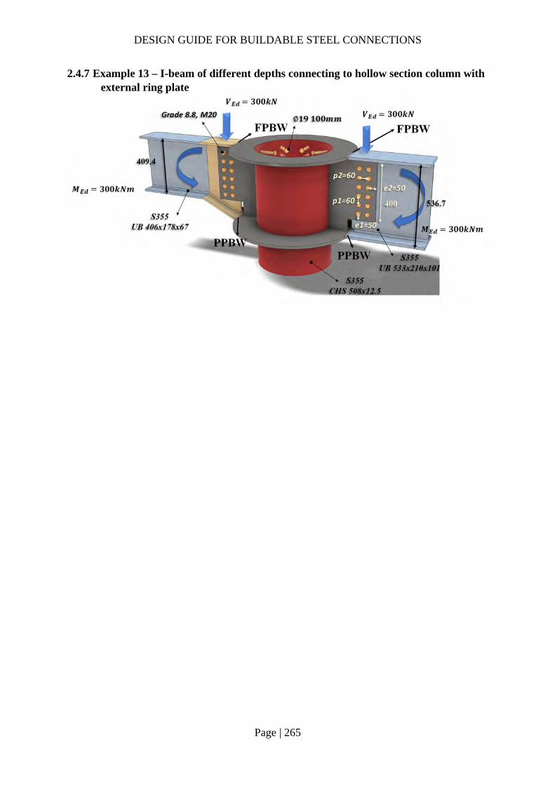
DESIGN GUIDE FOR BUILDABLE STEEL CONNECTIONS
Page | 265
2.4.7 Example 13 – I-beam of different depths connecting to hollow section column with external ring plate

DESIGN GUIDE FOR BUILDABLE STEEL CONNECTIONS
Page | 266
Check 1 – Bolt group resistance Ref Calculations Remark
Assumption: The welds at the top and bottom flanges of the beam are designed to resist the design moment. The bolt group is designed to resist the design shear force.
SS EN1993-1-8
Bolt resistance: Using Gr8.8, M20 bolts with: 𝐴 245𝑚𝑚 ; 𝑓 800𝑀𝑃𝑎;
Shear resistance of a single bolt:
𝐹 ,𝛼 𝑓 𝐴𝛾
0.6 800 245
1.2510
94.08𝑘𝑁
For class 8.8: 𝛼 0.6 𝛾 1.25 (refer to NA to SS)
SCI_P358 SN017
For two vertical lines of bolts (𝑛 2):
𝑙𝑛2𝑝
16𝑛 𝑛 1 𝑝
62
6016
6 6 1 60
136800𝑚𝑚
𝛼𝑧𝑝2𝑙
100 60
2 136800
0.02
𝑧 100𝑚𝑚 𝒆𝟏 𝟓𝟎.𝟎𝒎𝒎 (1.2𝑑 𝑒 4𝑡40𝑚𝑚) 𝒑𝟏 𝟔𝟎.𝟎𝒎𝒎 (2.2𝑑 𝑝14𝑡 𝑜𝑟 200𝑚𝑚) 𝒆𝟐 𝟓𝟎.𝟎𝒎𝒎 (1.2𝑑 𝑒 4𝑡40𝑚𝑚) 𝒑𝟐 𝟔𝟎.𝟎𝒎𝒎 (2.4𝑑 𝑝14𝑡 𝑜𝑟 200𝑚𝑚)
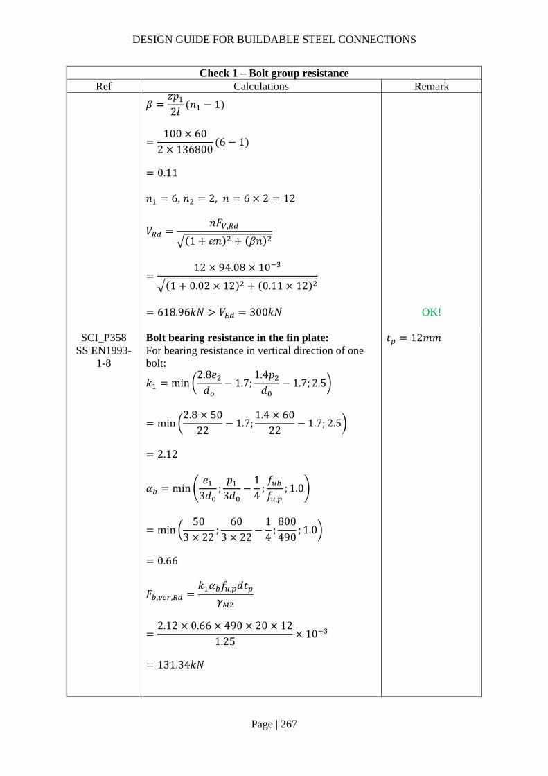
DESIGN GUIDE FOR BUILDABLE STEEL CONNECTIONS
Page | 267
Check 1 – Bolt group resistance Ref Calculations Remark
𝛽𝑧𝑝2𝑙
𝑛 1
100 60
2 1368006 1
0.11
𝑛 6, 𝑛 2, 𝑛 6 2 12
𝑉
𝑛𝐹 ,
1 𝛼𝑛 𝛽𝑛
12 94.08 10
1 0.02 12 0.11 12
618.96𝑘𝑁 𝑉 300𝑘𝑁
OK!
SCI_P358 SS EN1993-
1-8
Bolt bearing resistance in the fin plate: For bearing resistance in vertical direction of one bolt:
𝑘 min2.8𝑒𝑑
1.7;1.4𝑝𝑑
1.7; 2.5
min2.8 50
221.7;
1.4 6022
1.7; 2.5
2.12
𝛼 min𝑒
3𝑑;𝑝
3𝑑14
;𝑓𝑓 ,
; 1.0
min50
3 22;
603 22
14
;800490
; 1.0
0.66
𝐹 , ,𝑘 𝛼 𝑓 , 𝑑𝑡
𝛾
2.12 0.66 490 20 12
1.2510
131.34𝑘𝑁
𝑡 12𝑚𝑚

DESIGN GUIDE FOR BUILDABLE STEEL CONNECTIONS
Page | 268
Check 1 – Bolt group resistance Ref Calculations Remark
For bearing resistance in horizontal direction of one bolt:
𝑘 min2.8𝑒𝑑
1.7;1.4𝑝𝑑
1.7; 2.5
min2.8 50
221.7;
1.4 6022
1.7; 2.5
2.12
𝛼 min
𝑒3𝑑
;𝑝
3𝑑14
;𝑓𝑓 ,
; 1.0
min50
3 22;
603 22
14
;800430
; 1.0
0.66
𝐹 , ,𝑘 𝛼 𝑓 , 𝑑𝑡
𝛾
2.12 0.66 490 20 12
1.2510
131.34kN
Bolt group bearing resistance:
𝑉𝑛
1 𝛼𝑛𝐹 , ,
𝛽𝑛𝐹 , ,
12 10
1 0.02 12131.34
0.11 12131.34
864.11𝑘𝑁 𝑉 300𝑘𝑁
OK!
SCI_P358 SS EN1993-
1-8
Bolt bearing resistance in secondary beam web: Vertical bearing resistance:
𝑘 min2.8𝑒 ,
𝑑1.7;
1.4𝑝𝑑
1.7; 2.5
min2.8 50
221.7;
1.4 6022
1.7; 2.5
2.12
𝑒 , 84.3𝑚𝑚 𝑒 , 50.0𝑚𝑚 𝑡 , 8.8𝑚𝑚

DESIGN GUIDE FOR BUILDABLE STEEL CONNECTIONS
Page | 269
Check 1 – Bolt group resistance Ref Calculations Remark
𝛼 min
𝑒 ,
3𝑑;𝑝
3𝑑14
;𝑓𝑓 ,
; 1.0
min84.3
3 22;
603 22
14
;800490
; 1.0
0.66
𝐹 , ,
𝑘 𝛼 𝑓 , 𝑑𝑡 ,
𝛾
2.12 0.66 490 20 8.8
1.2510
96.32𝑘𝑁
Horizontal bearing resistance:
𝑘 min2.8𝑒 ,
𝑑1.7;
1.4𝑝𝑑
1.7; 2.5
min2.8 84.3
221.7;
1.4 6022
1.7; 2.5
2.12
𝛼 min𝑒 ,
3𝑑;𝑝
3𝑑14
;𝑓𝑓 ,
; 1.0
min50
3 22;
603 22
14
;800490
; 1.0
0.66
𝐹 , ,𝑘 𝛼 𝑓 , 𝑑𝑡 ,
𝛾
2.12 0.66 490 20 8.8
1.2510
96.32𝑘𝑁

DESIGN GUIDE FOR BUILDABLE STEEL CONNECTIONS
Page | 270
Check 1 – Bolt group resistance Ref Calculations Remark
Bolt group bearing resistance:
𝑉𝑛
1 𝛼𝑛𝐹 , ,
𝛽𝑛𝐹 , ,
12 10
1 0.02 1296.32
0.11 1296.32
633.68𝑘𝑁 𝑉 300𝑘𝑁
OK!

DESIGN GUIDE FOR BUILDABLE STEEL CONNECTIONS
Page | 271
Check 2 – Fin plate resistance Ref Calculations Remark
SS EN1993 SCI_P358
Fin plate shear gross section resistance:
𝑉 ,ℎ 𝑡1.27
𝑓 ,
√3𝛾
400 12
1.27355
√310
774.65𝑘𝑁
Fin plate shear net section resistance: Net area: 𝐴 ℎ 𝑛𝑑 𝑡
400 6 22 12
3216𝑚𝑚
𝑉 ,𝐴 𝑓 ,
√3𝛾
3216 490
√3 1.2510
727.85𝑘𝑁
Fin plate shear block shear resistance: Net area subject to tension: 𝐴 𝑝 𝑒 1.5𝑑 𝑡
60 50 1.5 22 12
924𝑚𝑚 Net area subject to shear: 𝐴 𝑒 𝑛 1 𝑃 𝑛 0.5 𝑑 𝑡
50 5 60 5.5 22 12
2748𝑚𝑚
ℎ 400.0𝑚𝑚 𝛾 1.0 (SS EN1993-1-1)
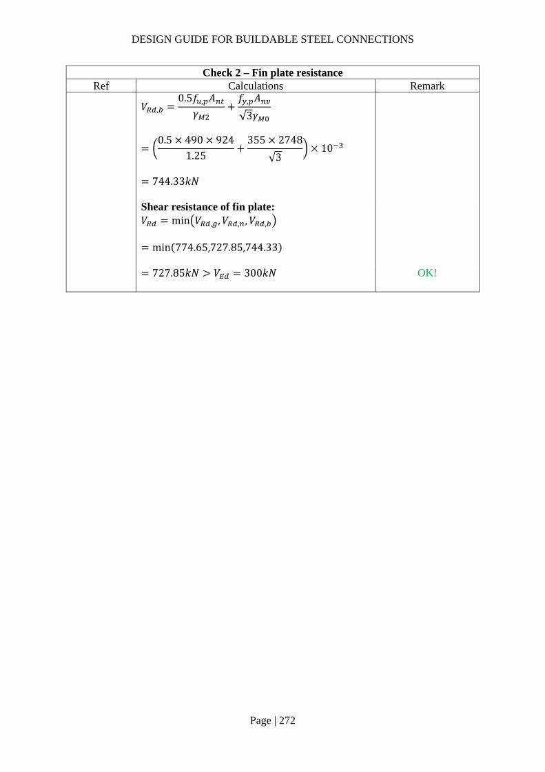
DESIGN GUIDE FOR BUILDABLE STEEL CONNECTIONS
Page | 272
Check 2 – Fin plate resistance Ref Calculations Remark
𝑉 ,
0.5𝑓 , 𝐴𝛾
𝑓 , 𝐴
√3𝛾
0.5 490 924
1.25355 2748
√310
744.33𝑘𝑁
Shear resistance of fin plate: 𝑉 min 𝑉 , ,𝑉 , ,𝑉 ,
min 774.65,727.85,744.33
727.85𝑘𝑁 𝑉 300𝑘𝑁
OK!

DESIGN GUIDE FOR BUILDABLE STEEL CONNECTIONS
Page | 273
Check 3 – Secondary beam web shear resistance Ref Calculations Remark
SS EN1993 SCI_P358
Shear area of secondary beam: 𝐴 𝐴 2𝑡 𝑏 2𝑟 𝑡
8550 2 14.3 178.8 2 20 8.8
3084.32𝑚𝑚
𝑉𝐴 𝑓 ,
√3𝛾
3084.32 355
√310
Weld access hole: 𝑟 20𝑚𝑚 For UB406x178x67 𝐴 8550𝑚𝑚 𝑏 178.8𝑚𝑚 𝑡 14.3𝑚𝑚
632.16𝑘𝑁 𝑉 300𝑘𝑁
OK!

DESIGN GUIDE FOR BUILDABLE STEEL CONNECTIONS
Page | 274
Check 4 – Haunch resistance Ref Calculations Remark
SCI_P358 SS EN1993
Haunch shear resistance: In order to reduce stress concentration, the thicknesses of flange and web are same as secondary beam UB406x178x67. Gross section:
𝑉 ,ℎ 𝑡 𝑓 ,
√3𝛾
468.1 8.8 355
√310
844.28𝑘𝑁
Net section: Net shear area: 𝐴 , ℎ 𝑡 𝑛𝑑 𝑡
468.1 8.8 6 22 8.8
2957.68𝑚𝑚
𝑉 ,𝐴 , 𝑓 ,
√3𝛾
2957.68 490
√3 1.2510
669.39𝑘𝑁
ℎ 468.1𝑚𝑚 (Depth of haunch at bolt line) 𝛾 1.0 (SS EN1993-1-1)

DESIGN GUIDE FOR BUILDABLE STEEL CONNECTIONS
Page | 275
Check 4 – Haunch resistance Ref Calculations Remark
Shear resistance of haunch web: 𝑉 min 𝑉 , ,𝑉 ,
min 844.28,669.39
669.39𝑘𝑁 𝑉 300𝑘𝑁
OK!
SCI_P358 For short fin plate, shear and bending moment interaction check is not necessary for haunch web.
SS EN1993-1-5
Shear buckling resistance of haunch web: To check the shear buckling resistance of the haunch web, the largest height of the haunch was taken as the depth for calculation. The haunch was checked using similar method of checking rectangular girder. 72𝜀𝜂
72 0.81361.0
58.58
Depth of web: 𝑑 508.1𝑚𝑚
𝜀 235/𝑓
235/355 0.8136
𝑑𝑡
508.18.8
57.7472𝜀𝜂
∴ The haunch web is NOT susceptible to shear buckling, shear buckling check is not necessary
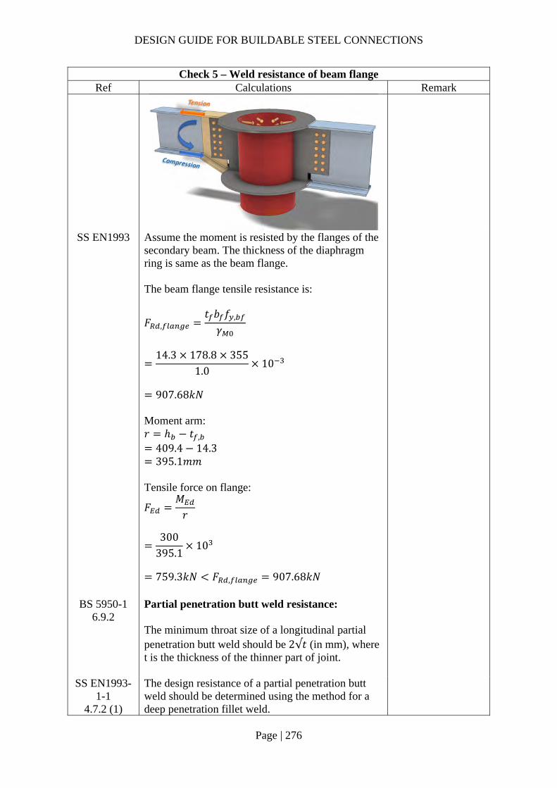
DESIGN GUIDE FOR BUILDABLE STEEL CONNECTIONS
Page | 276
Check 5 – Weld resistance of beam flange Ref Calculations Remark
SS EN1993 Assume the moment is resisted by the flanges of the secondary beam. The thickness of the diaphragm ring is same as the beam flange. The beam flange tensile resistance is:
𝐹 ,𝑡 𝑏 𝑓 ,
𝛾
14.3 178.8 355
1.010
907.68𝑘𝑁
Moment arm: 𝑟 ℎ 𝑡 ,
409.4 14.3 395.1𝑚𝑚
Tensile force on flange:
𝐹𝑀𝑟
300
395.110
759.3𝑘𝑁 𝐹 , 907.68𝑘𝑁
BS 5950-1 6.9.2
Partial penetration butt weld resistance: The minimum throat size of a longitudinal partial penetration butt weld should be 2√𝑡 (in mm), where t is the thickness of the thinner part of joint.
SS EN1993-1-1
4.7.2 (1)
The design resistance of a partial penetration butt weld should be determined using the method for a deep penetration fillet weld.

DESIGN GUIDE FOR BUILDABLE STEEL CONNECTIONS
Page | 277
Check 5 – Weld resistance of beam flange Ref Calculations Remark
In this example, the angle between the transverse force and weld throat 𝜃 90°. Provided the groove angle is greater than 60° or U-butt is adopted, the throat thickness is equal to the depth of penetration.
Choose partial butt weld with 14mm ( 2√14.37.56𝑚𝑚 throat thickness and grade S355 which match the beam material properties:
Transverse resistance:
𝐹 , ,0.9𝑓𝛾
𝑎
0.9 47014
1.2510
4.74𝑘𝑁/𝑚𝑚
𝑓 : ultimate strength 410𝑀𝑃𝑎 for
S275 470𝑀𝑃𝑎 for
S355 𝑎: throat thickness 𝛾 1.25
Tensile resistance of the PPBW: 𝐹 𝐹 , , 𝑏
4.74 178.8
847.51𝑘𝑁 𝐹 759.3𝑘𝑁
OK!
Groove angle 60°
𝐷

DESIGN GUIDE FOR BUILDABLE STEEL CONNECTIONS
Page | 278
Check 6 – External diaphragm ring check Ref Calculations Remark
CIDECT design guide
9
Basic properties: Diameter of CHS column: 𝑑 508𝑚𝑚 Thickness of CHS column: 𝑡 16𝑚𝑚 Width of diaphragm ring: 𝑏 50𝑚𝑚 Thickness of diaphragm ring: 𝑡 15𝑚𝑚 𝑡 Yield strength of column: 𝑓 355𝑀𝑃𝑎 Axial resistance of diaphragm ring:
𝑁 19.6𝑑𝑡
. 𝑏𝑑
. 𝑡𝑡
. 𝑑2
𝑓
19.650816
. 50508
. 1516
. 5082
355 10
1545.15𝑘𝑁 𝐹 759.3𝑘𝑁
OK!
Range of validity:
14𝑑𝑡
50816
31.75 36
0.05𝑏𝑑
50508
0.10 0.14
0.75𝑡𝑡
1516
0.9375 2.0

DESIGN GUIDE FOR BUILDABLE STEEL CONNECTIONS
Page | 279
Figure 2-5 Example of transition between diaphragm plate and beam flange
Note: As the thickness of diaphragm plate is different from that of the haunch, transition between 30° to 45° is necessary at the weld region to minimize the stress concentration as shown in Figure 2-5.
In addition, the thickness of the external diaphragm plate may be slightly thicker (adopt 15mm) to provide tolerance for positioning the secondary beam.
30°

DESIGN GUIDE FOR BUILDABLE STEEL CONNECTIONS
Page | 280
Check 7 – Weld group of fin plate (Two-side C shape fillet weld) Ref Calculations Remark
SS EN1993-1-8
Location of center of gravity of welds group:
�̅�𝑏
2𝑏 𝑑
130
2 130 476.5
22.95𝑚𝑚
𝑦𝑑2
476.5
2
238.25𝑚𝑚
Unit throat area: 𝐴 2𝑏 𝑑
2 115 446.5
676.5𝑚𝑚 Moment arm between applied force and weld center: 𝑟 236.07𝑚𝑚 Induced moment on welds:
𝑀𝑉
2𝑟
300
2236.07
35410.5𝑘𝑁𝑚𝑚
Length of fillet weld: Width: 𝑏 130𝑚𝑚 Depth: 𝑑 476.5𝑚𝑚 Cope hole size: 𝑛 15𝑚𝑚 𝑏 𝑏 𝑛
130 15 115𝑚𝑚
𝑑 𝑑 2𝑛 476.5 2 15 446.5𝑚𝑚

DESIGN GUIDE FOR BUILDABLE STEEL CONNECTIONS
Page | 281
Check 7 – Weld group of fin plate (Two-side C shape fillet weld) Ref Calculations Remark
Polar moment of inertia:
𝐽8𝑏 6𝑏 𝑑 𝑑
12𝑏
2𝑏 𝑑
8 115 6 115 446.5 446.5
12
1152 115 446.5
19636646𝑚𝑚
Critical point: Horizontal distance from centroid: 𝑟 𝑏 �̅�
130 22.95 107.05𝑚𝑚
Vertical distance from centroid: 𝑟 𝑦
238.25𝑚𝑚 Vertical stress:
𝜏𝑉𝐴
𝑀𝑟𝐽
300
2 676.535410.5 107.05
19636646
0.415𝑘𝑁/𝑚𝑚
Horizontal stress:
𝜏𝑀𝑟𝐽
35410.5 238.25
19636646
0.430𝑘𝑁/𝑚𝑚
Resultant stress:
𝜏 𝑟 𝑟
0.415 0.430
0.60𝑘𝑁/𝑚𝑚
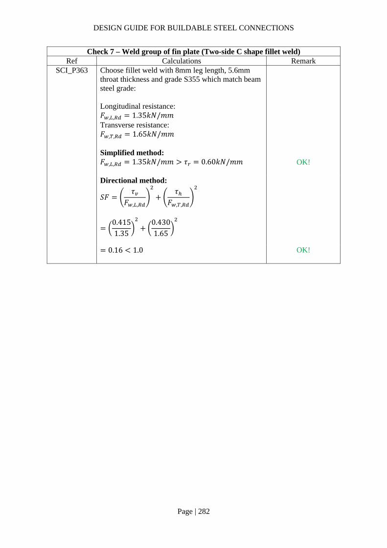
DESIGN GUIDE FOR BUILDABLE STEEL CONNECTIONS
Page | 282
Check 7 – Weld group of fin plate (Two-side C shape fillet weld) Ref Calculations Remark
SCI_P363 Choose fillet weld with 8mm leg length, 5.6mm throat thickness and grade S355 which match beam steel grade: Longitudinal resistance: 𝐹 , , 1.35𝑘𝑁/𝑚𝑚 Transverse resistance: 𝐹 , , 1.65𝑘𝑁/𝑚𝑚
Simplified method: 𝐹 , , 1.35𝑘𝑁/𝑚𝑚 𝜏 0.60𝑘𝑁/𝑚𝑚
OK!
Directional method:
𝑆𝐹𝜏
𝐹 , ,
𝜏𝐹 , ,
0.4151.35
0.4301.65
0.16 1.0
OK!
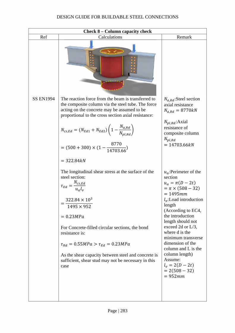
DESIGN GUIDE FOR BUILDABLE STEEL CONNECTIONS
Page | 283
Check 8 – Column capacity check Ref Calculations Remark
SS EN1994 The reaction force from the beam is transferred to the composite column via the steel tube. The force acting on the concrete may be assumed to be proportional to the cross section axial resistance:
𝑁 , 𝑁 𝑁 1𝑁 ,
𝑁 ,
500 300 18770
14703.66
322.84𝑘𝑁
𝑁 , :Steel section axial resistance 𝑁 , 8770𝑘𝑁 𝑁 , :Axial resistance of composite column 𝑁 ,
14703.66𝑘𝑁
The longitudinal shear stress at the surface of the steel section:
𝜏𝑁 ,
𝑢 𝑙
322.84 101495 952
0.23𝑀𝑃𝑎
For Concrete-filled circular sections, the bond resistance is: 𝜏 0.55𝑀𝑃𝑎 𝜏 0.23𝑀𝑃𝑎 As the shear capacity between steel and concrete is sufficient, shear stud may not be necessary in this case
𝑢 :Perimeter of the section 𝑢 𝜋 𝐷 2𝑡 𝜋 508 32 1495𝑚𝑚
𝑙 :Load introduction length (According to EC4, the introduction length should not exceed 2d or L/3, where d is the minimum transverse dimension of the column and L is the column length) Assume: 𝑙 2 𝐷 2𝑡
2 508 32 952𝑚𝑚

DESIGN GUIDE FOR BUILDABLE STEEL CONNECTIONS
Page | 284
Check 8 – Column capacity check Ref Calculations Remark
SCI_P358 Local shear resistance of column: Shear area: 𝐴 ℎ 𝑡
400 16
6000𝑚𝑚
𝐹
𝐴 𝑓 ,
√3𝛾
6000 355
√310
1229.76𝑘𝑁 𝑉 300𝑘𝑁
OK!
SS EN1994 Note: A conservative assumption is to assume that the bond is not effective in transferring the beam force to the concrete. The force acting on the concrete is designed to be resisted by shear studs. Shear capacity of shear stud: For h/d = 5.26 > 4, 𝛼 1.0
𝑃 min 0.8𝑓
𝜋𝑑4
𝛾;0.29𝛼𝑑 𝑓 𝐸
𝛾
min 0.8 450
π194
1.2510 ;
0.29 1.0 19 40 350001.25
10
81.66𝑘𝑁
𝑑:diameter of the shank of the stud 𝑑 19𝑚𝑚 𝑓 :characteristic cylinder strength of the concrete 𝑓 40𝑀𝑃𝑎 𝑓 :ultimate strength of the stud 𝑓 450𝑀𝑃𝑎 ℎ:overall height of the stud ℎ 100𝑚𝑚 𝐸 :Secant modulus of the concrete 𝐸 35000𝑀𝑃𝑎 𝛾 :partial safety factor =1.25
Total resistance: 𝑉 𝑛𝑃 2𝑅 ∴ number of shear studs required assuming zero bond resistance:
𝑛𝑁 ,
𝑃322.8481.66
4
∴ use 4 studs.
R should not be considered in this case as it is applicable to concrete encased section SS EN1994-1-1, 6.7.4.2(4)
Note: The eccentric and out of balance moment onto the column should be considered.
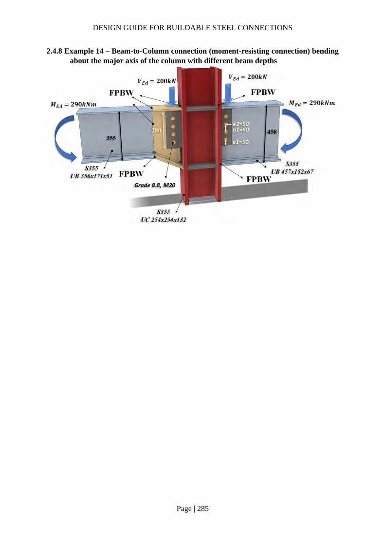
DESIGN GUIDE FOR BUILDABLE STEEL CONNECTIONS
Page | 285
2.4.8 Example 14 – Beam-to-Column connection (moment-resisting connection) bending about the major axis of the column with different beam depths

DESIGN GUIDE FOR BUILDABLE STEEL CONNECTIONS
Page | 286
Check 1 – Bolt group resistance Ref Calculations Remark
SS EN1993-1-8
Bolt resistance: Using Gr8.8, M20 bolts with: 𝐴 245𝑚𝑚 ; 𝑓 800𝑀𝑃𝑎;
Shear resistance of a single bolt:
𝐹 ,𝛼 𝑓 𝐴𝛾
0.6 800 245
1.2510
94.08𝑘𝑁
For class 8.8: 𝛼 0.6 𝛾 1.25 (refer to NA to SS)
For single vertical line of bolts (𝑛 1): 𝑛 4, 𝑛 4 1 4 𝛼 0
𝛽6𝑧
𝑛 𝑛 1 𝑝
6 60𝑚𝑚
4 4 1 60𝑚𝑚
0.30
𝑉𝑛𝐹 ,
1 𝛼𝑛 𝛽𝑛
4 94.08
1 0 0.3 410
𝑧 60.00𝑚𝑚
240.91𝑘𝑁 𝑉 200𝑘𝑁
OK!
DESIGN GUIDE FOR BUILDABLE STEEL CONNECTIONS
Page | 287
Check 1 – Bolt group resistance Ref Calculations Remark
Bearing resistance on fin plate: For bearing resistance in vertical direction of one bolt:
𝛼 min𝑒
3𝑑;𝑝
3𝑑14
;𝑓𝑓
; 1.0
min50
3 22;
603 22
14
;800490
; 1.0
0.66
𝑘 min2.8𝑒𝑑
1.7;1.4𝑝𝑑
1.7; 2.5
min2.8 50
221.7; 2.5
2.5
𝐹 , ,𝑘 𝛼 𝑓 , 𝑑𝑡
𝛾
2.5 0.6591 490 20 12
1.25
155.02𝑘𝑁
𝒆𝟏 𝟓𝟎.𝟎𝒎𝒎 (1.2𝑑 𝑒 4𝑡40𝑚𝑚) 𝒑𝟏 𝟔𝟎.𝟎𝒎𝒎 (2.2𝑑 𝑝14𝑡 𝑜𝑟 200𝑚𝑚) 𝒆𝟐 𝟓𝟎.𝟎𝒎𝒎 (1.2𝑑 𝑒 4𝑡40𝑚𝑚) 𝒑𝟐 𝒏𝒊𝒍 (2.4𝑑 𝑝14𝑡 𝑜𝑟 200𝑚𝑚)
𝑡 12.0𝑚𝑚 𝑡 16𝑚𝑚 𝑓 , 490𝑀𝑃𝑎 𝑓 , 355𝑀𝑃𝑎
For bearing resistance in horizontal direction of one bolt:
𝑘 min2.8𝑒𝑑
1.7;1.4𝑝𝑑
1.7; 2.5
min2.8 50
221.7;
1.4 6022
1.7; 2.5
2.12
𝛼 min𝑒
3𝑑;𝑝
3𝑑14
;𝑓𝑓 ,
; 1.0
min50
3 22;800490
; 1.0
0.76

DESIGN GUIDE FOR BUILDABLE STEEL CONNECTIONS
Page | 288
Check 1 – Bolt group resistance Ref Calculations Remark
𝐹 , ,
𝑘 𝛼 𝑓 , 𝑑𝑡𝛾
2.12 0.76 490 20 12
1.2510
150.97kN
Bolt group bearing resistance:
𝑉𝑛
1 𝛼𝑛𝐹 , ,
𝛽𝑛𝐹 , ,
4
1155.02
0.3 4150.97
10
390.74𝑁 𝑉 200𝑘𝑁
OK!
Bearing resistance on beam web (UB457x152x67): Vertical bearing resistance:
𝛼 min𝑒 ,
3𝑑;𝑝 ,
3𝑑14
;𝑓𝑓 ,
; 1.0
min80
3 22;
603 22
14
;800490
; 1.0
0.66
𝑘 min2.8𝑒 ,
𝑑1.7; 2.5
min2.8 50
221.7; 2.5
2.5
𝐹 , ,𝑘 𝛼 𝑓 , 𝑑𝑡 ,
𝛾
2.5 0.6591 490 20 9.0
1.25
116.26𝑘𝑁
𝒆𝟏,𝒃 𝟖𝟎.𝟎𝒎𝒎 𝒑𝟏,𝒃 𝟔𝟎.𝟎𝒎𝒎 𝒆𝟐,𝒃 𝟓𝟎.𝟎𝒎𝒎 𝒑𝟐,𝒃 𝒏𝒊𝒍
𝑡 , 9.0𝑚𝑚 𝑡 , 16𝑚𝑚 𝑓 , 490𝑀𝑃𝑎 𝑓 , 355𝑀𝑃𝑎

DESIGN GUIDE FOR BUILDABLE STEEL CONNECTIONS
Page | 289
Check 1 – Bolt group resistance Ref Calculations Remark
Horizontal bearing resistance:
𝑘 min2.8𝑒 ,
𝑑1.7;
1.4𝑝𝑑
1.7; 2.5
min2.8 85
221.7;
1.4 6022
1.7; 2.5
2.12
𝛼 min𝑒 ,
3𝑑;𝑝
3𝑑14
;𝑓𝑓 ,
; 1.0
min50
3 22;800490
; 1.0
0.76
𝐹 , ,𝑘 𝛼 𝑓 , 𝑑𝑡 ,
𝛾
2.12 0.76 490 20 9.0
1.2510
113.23𝑘𝑁
Bolt group bearing resistance:
𝑉𝑛
1 𝛼𝑛𝐹 , ,
𝛽𝑛𝐹 , ,
4
1116.26
0.3 4113.23
10
293.06𝑘𝑁 𝑉 200𝑘𝑁
OK!

DESIGN GUIDE FOR BUILDABLE STEEL CONNECTIONS
Page | 290
Check 2 – Fin plate resistance Ref Calculations Remark
SS EN1993 SCI_P358
Fin plate shear gross section resistance:
𝑉 ,ℎ 𝑡1.27
𝑓 ,
√3𝛾
280 12
1.27355
√310
542.25𝑘𝑁
Fin plate shear net section resistance: Net area: 𝐴 ℎ 𝑛𝑑 𝑡
280 4 22 12
2304𝑚𝑚
𝑉 ,𝐴 𝑓 ,
√3𝛾
2304 490
√3 1.2510
521.44𝑘𝑁
Fin plate shear block shear resistance: Net area subject to tension: 𝐴 𝑒 0.5𝑑 𝑡
50 0.5 22 12
468𝑚𝑚 Net area subject to shear: 𝐴 𝑒 𝑛 1 𝑃 𝑛 0.5 𝑑 𝑡
50 3 60 3.5 22 12
1968𝑚𝑚
ℎ 280.0𝑚𝑚 𝛾 1.0 (SS EN1993-1-1)

DESIGN GUIDE FOR BUILDABLE STEEL CONNECTIONS
Page | 291
Check 2 – Fin plate resistance Ref Calculations Remark
𝑉 ,
0.5𝑓 , 𝐴𝛾
𝑓 , 𝐴
√3𝛾
0.5 490 468
1.25355 1968
√310
495.09𝑘𝑁
Shear resistance of fin plate: 𝑉 min 𝑉 , ,𝑉 , ,𝑉 ,
min 542.25,521.44,495.09
495.09𝑘𝑁 𝑉 200𝑘𝑁
OK!
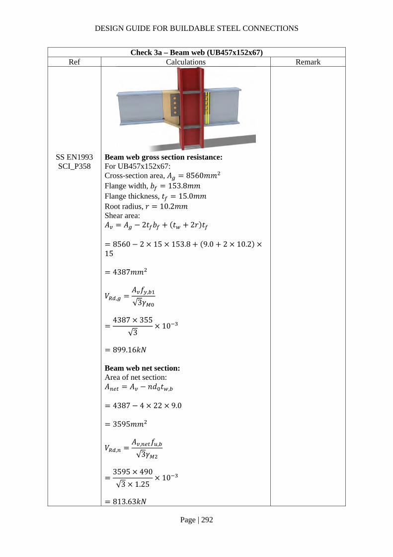
DESIGN GUIDE FOR BUILDABLE STEEL CONNECTIONS
Page | 292
Check 3a – Beam web (UB457x152x67) Ref Calculations Remark
SS EN1993 SCI_P358
Beam web gross section resistance: For UB457x152x67: Cross-section area, 𝐴 8560𝑚𝑚 Flange width, 𝑏 153.8𝑚𝑚 Flange thickness, 𝑡 15.0𝑚𝑚 Root radius, 𝑟 10.2𝑚𝑚 Shear area: 𝐴 𝐴 2𝑡 𝑏 𝑡 2𝑟 𝑡
8560 2 15 153.8 9.0 2 10.215
4387𝑚𝑚
𝑉 ,𝐴 𝑓 ,
√3𝛾
4387 355
√310
899.16𝑘𝑁
Beam web net section: Area of net section: 𝐴 𝐴 𝑛𝑑 𝑡 ,
4387 4 22 9.0
3595𝑚𝑚
𝑉 ,𝐴 , 𝑓 ,
√3𝛾
3595 490
√3 1.2510
813.63𝑘𝑁

DESIGN GUIDE FOR BUILDABLE STEEL CONNECTIONS
Page | 293
Check 3a – Beam web (UB457x152x67) Ref Calculations Remark
Shear resistance of beam web: 𝑉 min 𝑉 , ,𝑉 ,
min 899.16,813.63
813.63𝑘𝑁 𝑉 200𝑘𝑁
OK!
Check 3b – Beam web resistance (UB356x171x51) Ref Calculations Remark
SS EN1993 SCI_P358
Beam web gross section resistance: Shear area: 𝐴 𝐴 2𝑡 𝑏 2𝑡 𝑟
6490 2 11.5 171.5 2 7.4 15
2323.5𝑚𝑚
𝑉𝐴 𝑓 ,
√3𝛾
2323.5 355
√310
For UB356x171x51: Cross-section area, 𝐴 6490𝑚𝑚 Flange width, 𝑏 171.5𝑚𝑚 Flange thickness, 𝑡 11.5𝑚𝑚 Root radius, 𝑟 10.2𝑚𝑚 Weld access hole size, 𝑟 15𝑚𝑚
476.22𝑘𝑁 𝑉 200𝑘𝑁

DESIGN GUIDE FOR BUILDABLE STEEL CONNECTIONS
Page | 294
Check 4 – Tension zone check Ref Calculations Remark
SCI_P398 For column 254x254x132: Depth, ℎ 276.3𝑚𝑚 Width, 𝑏 261.3𝑚𝑚 Flange thickness, 𝑡 25.3𝑚𝑚 Web thickness, 𝑡 15.3𝑚𝑚 Root radius, 𝑟 12.7𝑚𝑚 Depth between flanges, ℎ 225.7𝑚𝑚 Yield strength, 𝑓 355𝑀𝑃𝑎 Ultimate strength, 𝑓 490𝑀𝑃𝑎
The design force acting on the top and bottom flanges of the beam is
𝐹𝑀
ℎ 𝑡
For beam 1 (UB 457x152x67): ℎ 458𝑚𝑚
𝐹290
458 1510 654.63𝑘𝑁
𝑘
𝑡𝑡
𝑓𝑓
1
for beam 1 UB 457x152x67:
𝑘25.315
355355
1.69 1.0
∴ 𝑘 1
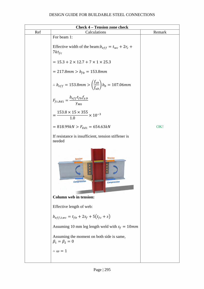
DESIGN GUIDE FOR BUILDABLE STEEL CONNECTIONS
Page | 295
Check 4 – Tension zone check Ref Calculations Remark
For beam 1: Effective width of the beam:𝑏 𝑡 2𝑟7𝑘𝑡
15.3 2 12.7 7 1 25.3
217.8𝑚𝑚 𝑏 153.8𝑚𝑚
∴ 𝑏 153.8𝑚𝑚𝑓𝑓
𝑏 107.06𝑚𝑚
𝐹 ,𝑏 𝑡 𝑓 ,
𝛾
153.8 15 355
1.010
818.99𝑘𝑁 𝐹 654.63𝑘𝑁
OK!
If resistance is insufficient, tension stiffener is needed
Column web in tension: Effective length of web: 𝑏 , , 𝑡 2𝑠 5 𝑡 𝑠 Assuming 10 mm leg length weld with 𝑠 10𝑚𝑚 Assuming the moment on both side is same, 𝛽 𝛽 0 ∴ 𝜔 1

DESIGN GUIDE FOR BUILDABLE STEEL CONNECTIONS
Page | 296
Check 4 – Tension zone check Ref Calculations Remark
For beam 1: 𝑏 , , 15 2 10 5 25.3 12.7
225𝑚𝑚
𝐹 , ,𝜔𝑏 , , 𝑡 𝑓
𝛾
1 225 15.3 355
1.010
1222.09𝑘𝑁 𝐹 654.63𝑘𝑁 OK!

DESIGN GUIDE FOR BUILDABLE STEEL CONNECTIONS
Page | 297
Check 5 – Compression zone check Ref Calculations Remark
SCI_P398 𝑑 ℎ 2 𝑡 𝑟
276.3 2 25.3 12.7
200.3𝑚𝑚 𝑘 0.7 (Conservative assumption)
For beam 1:
�̅� 0.932𝑏 , , 𝑑 𝑓
𝐸𝑡
0.932225 200.3 355
200000 15.3
0.545 0.72
∴ 𝜌 1
𝐹 , ,𝜔𝑘 𝑏 , , 𝑡 𝑓
𝛾
1 0.7 225 15.3 355
1.010
855.46𝑘𝑁 𝐹 654.63𝑘𝑁 If compression resistance is insufficient, stiffener is needed.
OK!

DESIGN GUIDE FOR BUILDABLE STEEL CONNECTIONS
Page | 298
Check 5 – Compression zone check Ref Calculations Remark
Column web in shear:
𝜀235𝑓
235355
0.8136
𝑑𝑡
200.315.3
13.09 69𝜀 56.14
∴ 𝑉 ,0.9𝑓 𝐴
√3𝛾
𝐴 𝐴 2𝑏 𝑡 𝑡 2𝑟 𝑡
16800 2 261.3 25.3 15.3 212.7 25.3
4607.93𝑚𝑚
𝑉 ,
0.9 355 4607.93
√310
850.00𝑘𝑁 F 654.63𝑘𝑁
OK!

DESIGN GUIDE FOR BUILDABLE STEEL CONNECTIONS
Page | 299
Check 6 – Tension stiffeners check (if tension resistance is inadequate) Ref Calculations Remark
SCI_P398 Minimum width of stiffener:
𝑏 ,0.75 𝑏 𝑡
2
0.75 261.3 15.3
2
92.25𝑚𝑚
Use S355 stiffener with width and thickness: 𝑏 110𝑚𝑚, 𝑡 15𝑚𝑚, 𝑓 355𝑀𝑃𝑎 𝑏 𝑏 𝑐𝑜𝑟𝑛𝑒𝑟 𝑐ℎ𝑎𝑚𝑓𝑒𝑟
110 15
95𝑚𝑚 𝐴 2𝑏 𝑡
2 95 15
2850𝑚𝑚
𝐹 , ,𝐴 𝑓𝛾
2850 355
1.010
1011.75𝑘𝑁 𝐹 654.63𝑘𝑁
OK!

DESIGN GUIDE FOR BUILDABLE STEEL CONNECTIONS
Page | 300
Check 7 – Compression stiffeners check (if resistance is inadequate) Ref Calculations Remark
SCI_P398 Let 𝑏 95𝑚𝑚 𝑡 10𝑚𝑚 ℎ 225.7𝑚𝑚 𝑐𝑡𝑠
𝑏𝑡
9510
9.5 14𝜀 11.39
Effective area of stiffeners: 𝐴 , 2𝐴 𝑡 30𝜀𝑡 𝑡
2 95 10 15.3 30 0.82 15.3 10
7766.79𝑚𝑚 The second moment of area of the stiffener:
𝐼2𝑏 𝑡 𝑡
12
2 95 15.3 10
12
7210836𝑚𝑚
The radius of gyration of the stiffener:
𝑖𝐼
𝐴 ,
72108367766.79
30.47𝑚𝑚

DESIGN GUIDE FOR BUILDABLE STEEL CONNECTIONS
Page | 301
Check 7 – Compression stiffeners check (if resistance is inadequate) Ref Calculations Remark
𝜆 𝜋
𝐸𝑓
3.14200000
355
74.53
�̅�
𝑙𝑖 𝜆
225.7
30.47 74.53
0.03 0.2
∴ The buckling effect may be ignored
Resistance of cross-section
𝑁 ,𝐴 , 𝑓𝛾
7766.79 355
1.010
2757.21𝑘𝑁 𝐹 654.63𝑘𝑁
OK!

DESIGN GUIDE FOR BUILDABLE STEEL CONNECTIONS
Page | 302
Check 8 – Haunch resistance Ref Calculations Remark
SCI_P358 SS EN1993
Haunch shear resistance: The thicknesses of flange and web are same as beam UB457×152×67. Haunch gross section resistance:
𝑉 ,ℎ 𝑡 𝑓 ,
√3𝛾
405 9.0 355
√310
747.08𝑘𝑁
Haunch net section resistance: Net shear area: 𝐴 , ℎ 𝑡 𝑛𝑑 𝑡
405 9.0 4 22 9
2853𝑚𝑚
𝑉 ,𝐴 , 𝑓 ,
√3𝛾
2853 490
√3 1.2510
645.69𝑘𝑁
ℎ 405𝑚𝑚 (Depth of haunch at bolt line) 𝛾 1.0 (SS EN1993-1-1)

DESIGN GUIDE FOR BUILDABLE STEEL CONNECTIONS
Page | 303
Check 8 – Haunch resistance Ref Calculations Remark
Shear resistance of haunch web: 𝑉 min 𝑉 , ,𝑉 ,
min 747.08,645.69
645.69𝑘𝑁 𝑉 200𝑘𝑁
OK!
SCI_P358 For short fin plate, shear and bending moment interaction check is not necessary for haunch web.
SS EN1993-1-5
Shear buckling resistance of haunch web: To check the shear buckling resistance of the haunch web, the largest height of the haunch was taken as the depth for calculation. The haunch was checked using similar method of checking rectangular girder. 72𝜀𝜂
72 0.81361.0
58.58
Depth of web: 𝑑 435𝑚𝑚
𝜀 235/𝑓
235/355 0.8136
𝑑𝑡
4359.0
48.3372𝜀𝜂
∴ The haunch web is NOT susceptible to shear buckling, shear buckling check is not necessary

DESIGN GUIDE FOR BUILDABLE STEEL CONNECTIONS
Page | 304
Check 9 – Weld resistance Ref Calculations Remark
SS EN1993 Fin plate welding resistance: Unit throat area: 𝐴 2ℎ
2 280
560mm Applied stress on weld:
𝜏𝑉𝐴
200560
0.36𝑘𝑁/𝑚𝑚
Choose fillet weld with 10mm leg length, 7.0mm throat thickness and grade S355:
ℎ 280.0𝑚𝑚 𝛾 1.0 (SS EN1993-1-1)
Longitudinal resistance: 𝐹 , , 1.69𝑘𝑁/𝑚𝑚 0.36𝑘𝑁/𝑚𝑚
OK!

DESIGN GUIDE FOR BUILDABLE STEEL CONNECTIONS
Page | 305
Check 9 – Weld resistance Ref Calculations Remark
Stiffeners welding resistance: Minimum throat thickness requirement for flange weld of stiffeners:
𝑎𝑡2
152
7.5𝑚𝑚
Choose fillet weld with 12mm leg length, 8.4mm throat thickness and grade S275, the fillet weld between stiffener and column flange is assume achieve full strength of the stiffener
Web weld: Effective length of web weld: 𝑙 2 ℎ 2 𝑐𝑜𝑝𝑒 ℎ𝑜𝑙𝑒 𝑠𝑖𝑧𝑒 2 𝑠
2 225.7 2 15 2 10
351.4𝑚𝑚 Applied stress on weld:
𝜏𝐹2𝑙
844.252 351.4
1.20𝑘𝑁/𝑚𝑚
Choose fillet weld with 10mm leg length, 7.0mm throat thickness and grade S355, Longitudinal resistance:
𝐹 , , 1.69𝑘𝑁/𝑚𝑚 1.20𝑘𝑁/𝑚𝑚
OK!
Full penetration butt weld is adopted to connect the beam flange to the column, hence, only the capacities of the beam flanges need to be checked:

DESIGN GUIDE FOR BUILDABLE STEEL CONNECTIONS
Page | 306
Check 9 – Weld resistance Ref Calculations Remark
Beam 1:
𝐹 ,𝑡 , 𝑏 , 𝑓 ,
𝛾
15 153.8 355
1.010
818.99𝑘𝑁 𝐹 654.63𝑘𝑁
OK! Beam 2:
𝐹 ,𝑡 , 𝑏 , 𝑓 ,
𝛾
11.5 171.5 355
1.010
700.15𝑘𝑁 𝐹 582.24𝑘𝑁
OK!
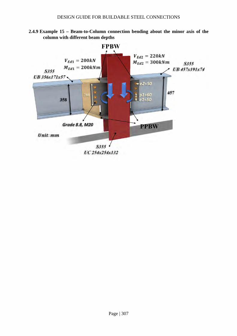
DESIGN GUIDE FOR BUILDABLE STEEL CONNECTIONS
Page | 307
2.4.9 Example 15 – Beam-to-Column connection bending about the minor axis of the column with different beam depths
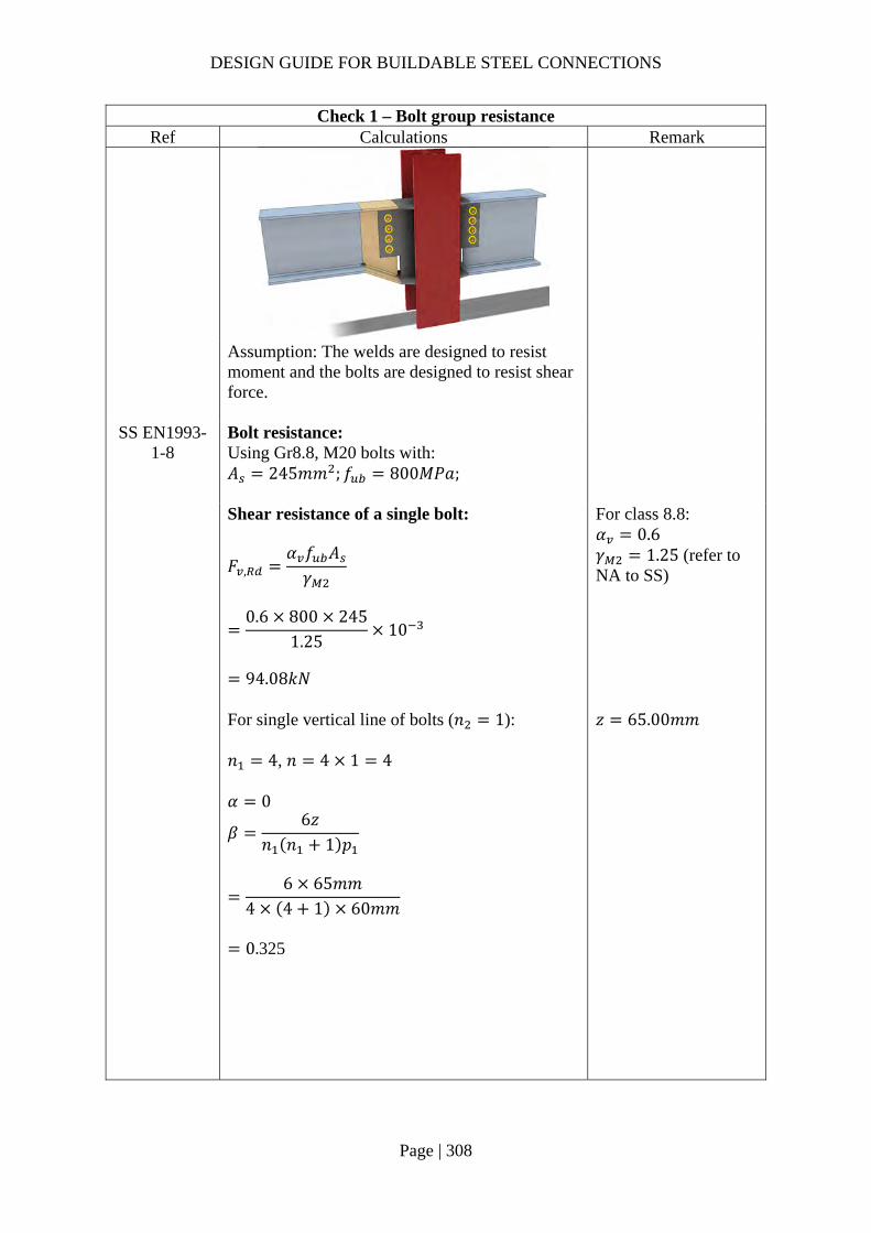
DESIGN GUIDE FOR BUILDABLE STEEL CONNECTIONS
Page | 308
Check 1 – Bolt group resistance Ref Calculations Remark
Assumption: The welds are designed to resist moment and the bolts are designed to resist shear force.
SS EN1993-1-8
Bolt resistance: Using Gr8.8, M20 bolts with: 𝐴 245𝑚𝑚 ; 𝑓 800𝑀𝑃𝑎;
Shear resistance of a single bolt:
𝐹 ,𝛼 𝑓 𝐴𝛾
0.6 800 245
1.2510
94.08𝑘𝑁
For class 8.8: 𝛼 0.6 𝛾 1.25 (refer to NA to SS)
For single vertical line of bolts (𝑛 1): 𝑛 4, 𝑛 4 1 4 𝛼 0
𝛽6𝑧
𝑛 𝑛 1 𝑝
6 65𝑚𝑚
4 4 1 60𝑚𝑚
0.325
𝑧 65.00𝑚𝑚

DESIGN GUIDE FOR BUILDABLE STEEL CONNECTIONS
Page | 309
Check 1 – Bolt group resistance Ref Calculations Remark
𝑉
𝑛𝐹 ,
1 𝛼𝑛 𝛽𝑛
4 94.08
1 0 0.325 410
229.45𝑘𝑁 max 𝑉 ;𝑉 220𝑘𝑁
OK!
Bearing resistance on fin plate: For bearing resistance in vertical direction of one bolt:
𝛼 min𝑒
3𝑑;𝑝
3𝑑14
;𝑓𝑓
; 1.0
min50
3 22;
603 22
14
;800490
; 1.0
0.66
𝑘 min2.8𝑒𝑑
1.7;1.4𝑝𝑑
1.7; 2.5
min2.8 50
221.7; 2.5
2.5
𝐹 , ,𝑘 𝛼 𝑓 , 𝑑𝑡
𝛾
2.5 0.6591 490 20 12
1.25
155.02𝑘𝑁
𝒆𝟏 𝟓𝟎.𝟎𝒎𝒎 (1.2𝑑 𝑒 4𝑡40𝑚𝑚) 𝒑𝟏 𝟔𝟎.𝟎𝒎𝒎 (2.2𝑑 𝑝14𝑡 𝑜𝑟 200𝑚𝑚) 𝒆𝟐 𝟓𝟎.𝟎𝒎𝒎 (1.2𝑑 𝑒 4𝑡40𝑚𝑚) 𝒑𝟐 𝒏𝒊𝒍 (2.4𝑑 𝑝14𝑡 𝑜𝑟 200𝑚𝑚)
𝑡 12.0𝑚𝑚 𝑡 16𝑚𝑚 𝑓 , 490𝑀𝑃𝑎 𝑓 , 355𝑀𝑃𝑎
For bearing resistance in horizontal direction of one bolt:
𝑘 min2.8𝑒𝑑
1.7;1.4𝑝𝑑
1.7; 2.5
min2.8 50
221.7;
1.4 6022
1.7; 2.5
2.12
DESIGN GUIDE FOR BUILDABLE STEEL CONNECTIONS
Page | 310
Check 1 – Bolt group resistance Ref Calculations Remark
𝛼 min
𝑒3𝑑
;𝑝
3𝑑14
;𝑓𝑓 ,
; 1.0
min50
3 22;800490
; 1.0
0.76
𝐹 , ,
𝑘 𝛼 𝑓 , 𝑑𝑡𝛾
2.12 0.76 490 20 12
1.2510
150.97kN
Bolt group bearing resistance:
𝑉𝑛
1 𝛼𝑛𝐹 , ,
𝛽𝑛𝐹 , ,
4
1155.02
0.325 4150.97
10
371.77𝑘𝑁 max 𝑉 ;𝑉 220𝑘𝑁
OK!
Bearing resistance on beam web (UB457x191x74): Vertical bearing resistance:
𝛼 min𝑒 ,
3𝑑;𝑝 ,
3𝑑14
;𝑓𝑓 ,
; 1.0
min78
3 22;
603 22
14
;800490
; 1.0
0.66
𝑘 min2.8𝑒 ,
𝑑1.7; 2.5
min2.8 50
221.7; 2.5
2.5
𝒆𝟏,𝒃 𝟕𝟖.𝟎𝒎𝒎 𝒑𝟏,𝒃 𝟔𝟎.𝟎𝒎𝒎 𝒆𝟐,𝒃 𝟓𝟎.𝟎𝒎𝒎 𝒑𝟐,𝒃 𝒏𝒊𝒍
𝑡 , 9.0𝑚𝑚 𝑡 , 16𝑚𝑚 𝑓 , 490𝑀𝑃𝑎 𝑓 , 355𝑀𝑃𝑎

DESIGN GUIDE FOR BUILDABLE STEEL CONNECTIONS
Page | 311
Check 1 – Bolt group resistance Ref Calculations Remark
𝐹 , ,
𝑘 𝛼 𝑓 , 𝑑𝑡 ,
𝛾
2.5 0.6591 490 20 9.0
1.2510
116.26𝑘𝑁
Horizontal bearing resistance:
𝑘 min2.8𝑒 ,
𝑑1.7;
1.4𝑝𝑑
1.7; 2.5
min2.8 78
221.7;
1.4 6022
1.7; 2.5
2.12
𝛼 min𝑒 ,
3𝑑;𝑝
3𝑑14
;𝑓𝑓 ,
; 1.0
min50
3 22;800490
; 1.0
0.76
𝐹 , ,𝑘 𝛼 𝑓 , 𝑑𝑡 ,
𝛾
2.12 0.76 490 20 9.0
1.2510
113.23𝑘𝑁
Bolt group bearing resistance:
𝑉𝑛
1 𝛼𝑛𝐹 , ,
𝛽𝑛𝐹 , ,
4
1116.26
0.325 4113.23
10
278.83𝑘𝑁 𝑉 220𝑘𝑁
OK!
DESIGN GUIDE FOR BUILDABLE STEEL CONNECTIONS
Page | 312
Check 1 – Bolt group resistance Ref Calculations Remark
Bearing resistance on haunch web: Vertical bearing resistance:
𝛼 min𝑒 ,
3𝑑;𝑝 ,
3𝑑14
;𝑓𝑓 ,
; 1.0
min78
3 22;
603 22
14
;800490
; 1.0
0.66
𝒆𝟏,𝒃 𝟕𝟖.𝟎𝒎𝒎 𝒑𝟏,𝒃 𝟔𝟎.𝟎𝒎𝒎 𝒆𝟐,𝒃 𝟓𝟎.𝟎𝒎𝒎 𝒑𝟐,𝒃 𝒏𝒊𝒍
𝑡 , 8.1𝑚𝑚 𝑡 , 16𝑚𝑚 𝑓 , 490𝑀𝑃𝑎 𝑓 , 355𝑀𝑃𝑎
𝑘 min
2.8𝑒 ,
𝑑1.7; 2.5
min2.8 50
221.7; 2.5
2.5
𝐹 , ,𝑘 𝛼 𝑓 , 𝑑𝑡 ,
𝛾
2.5 0.6591 490 20 8.1
1.2510
104.64𝑘𝑁
Horizontal bearing resistance:
𝑘 min2.8𝑒 ,
𝑑1.7;
1.4𝑝𝑑
1.7; 2.5
min2.8 78
221.7;
1.4 6022
1.7; 2.5
2.12
𝛼 min𝑒 ,
3𝑑;𝑝
3𝑑14
;𝑓𝑓 ,
; 1.0
min50
3 22;800490
; 1.0
0.76
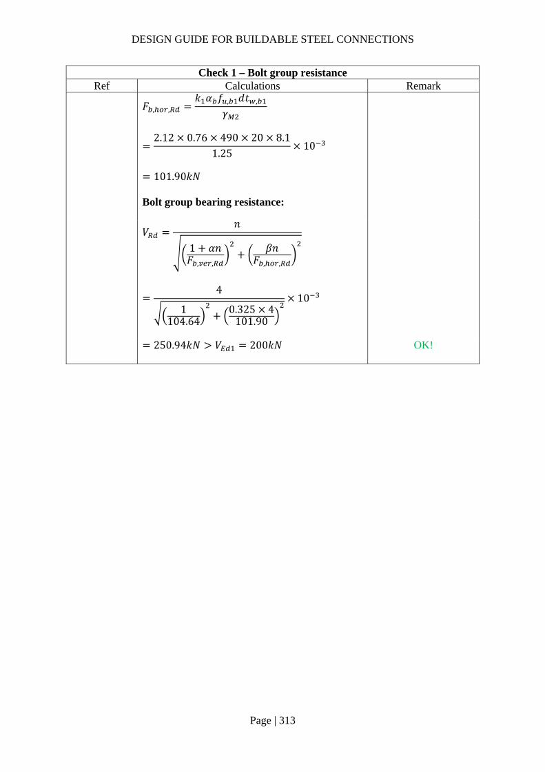
DESIGN GUIDE FOR BUILDABLE STEEL CONNECTIONS
Page | 313
Check 1 – Bolt group resistance Ref Calculations Remark
𝐹 , ,
𝑘 𝛼 𝑓 , 𝑑𝑡 ,
𝛾
2.12 0.76 490 20 8.1
1.2510
101.90𝑘𝑁
Bolt group bearing resistance:
𝑉𝑛
1 𝛼𝑛𝐹 , ,
𝛽𝑛𝐹 , ,
4
1104.64
0.325 4101.90
10
250.94𝑘𝑁 𝑉 200𝑘𝑁
OK!
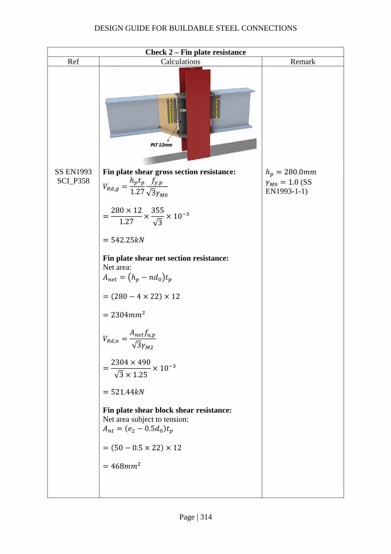
DESIGN GUIDE FOR BUILDABLE STEEL CONNECTIONS
Page | 314
Check 2 – Fin plate resistance Ref Calculations Remark
SS EN1993 SCI_P358
Fin plate shear gross section resistance:
𝑉 ,ℎ 𝑡1.27
𝑓 ,
√3𝛾
280 12
1.27355
√310
542.25𝑘𝑁
Fin plate shear net section resistance: Net area: 𝐴 ℎ 𝑛𝑑 𝑡
280 4 22 12
2304𝑚𝑚
𝑉 ,𝐴 𝑓 ,
√3𝛾
2304 490
√3 1.2510
521.44𝑘𝑁
Fin plate shear block shear resistance: Net area subject to tension: 𝐴 𝑒 0.5𝑑 𝑡
50 0.5 22 12
468𝑚𝑚
ℎ 280.0𝑚𝑚 𝛾 1.0 (SS EN1993-1-1)
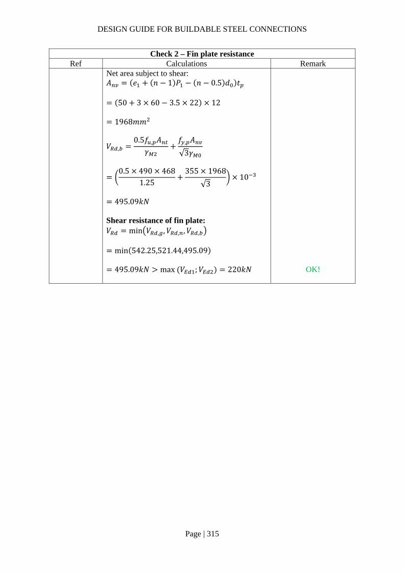
DESIGN GUIDE FOR BUILDABLE STEEL CONNECTIONS
Page | 315
Check 2 – Fin plate resistance Ref Calculations Remark
Net area subject to shear: 𝐴 𝑒 𝑛 1 𝑃 𝑛 0.5 𝑑 𝑡
50 3 60 3.5 22 12
1968𝑚𝑚
𝑉 ,
0.5𝑓 , 𝐴𝛾
𝑓 , 𝐴
√3𝛾
0.5 490 468
1.25355 1968
√310
495.09𝑘𝑁
Shear resistance of fin plate: 𝑉 min 𝑉 , ,𝑉 , ,𝑉 ,
min 542.25,521.44,495.09
495.09𝑘𝑁 max 𝑉 ;𝑉 220𝑘𝑁
OK!

DESIGN GUIDE FOR BUILDABLE STEEL CONNECTIONS
Page | 316
Check 3a – Beam web (UB457×191×74) Ref Calculations Remark
SS EN1993 SCI_P358
Beam web gross section resistance: For UB457x191x74: Cross-section area, 𝐴 9460𝑚𝑚 Flange width, 𝑏 190.4𝑚𝑚 Flange thickness, 𝑡 14.5𝑚𝑚 Root radius, 𝑟 10.2𝑚𝑚 Shear area: 𝐴 𝐴 2𝑡 𝑏 𝑡 2𝑟 𝑡
9460 2 14.5 190.4 9.0 210.2 14.5
4364.7𝑚𝑚
𝑉 ,𝐴 𝑓 ,
√3𝛾
4364.7 355
√310
894.59𝑘𝑁
Beam web net section resistance: Area of net section: 𝐴 𝐴 𝑛𝑑 𝑡 ,
4364.7 4 22 9.0
3572.7𝑚𝑚
𝑉 ,𝐴 , 𝑓 ,
√3𝛾
3572.2 490
√3 1.2510
808.58𝑘𝑁

DESIGN GUIDE FOR BUILDABLE STEEL CONNECTIONS
Page | 317
Check 3a – Beam web (UB457×191×74) Ref Calculations Remark
Shear resistance of haunch web: 𝑉 min 𝑉 , ,𝑉 ,
min 894.59,808.58
808.58𝑘𝑁 𝑉 220𝑘𝑁
OK!
Check 3b – Beam web resistance (UB356×171×57) Ref Calculations Remark
SS EN1993 SCI_P358
Beam web gross section resistance: Shear area: 𝐴 𝐴 2𝑡 𝑏 2𝑡 𝑟
7260 2 13 172.2 2 8.1 15
2539.8𝑚𝑚
𝑉𝐴 𝑓 ,
√3𝛾
2539.8 355
√310
For UB356x171x57: Cross-section area, 𝐴 7260𝑚𝑚 Flange width, 𝑏 172.2𝑚𝑚 Flange thickness, 𝑡13𝑚𝑚 Root radius, 𝑟 10.2𝑚𝑚 Weld access hole size, 𝑟 15𝑚𝑚
520.56𝑘𝑁 𝑉 200𝑘𝑁
OK!
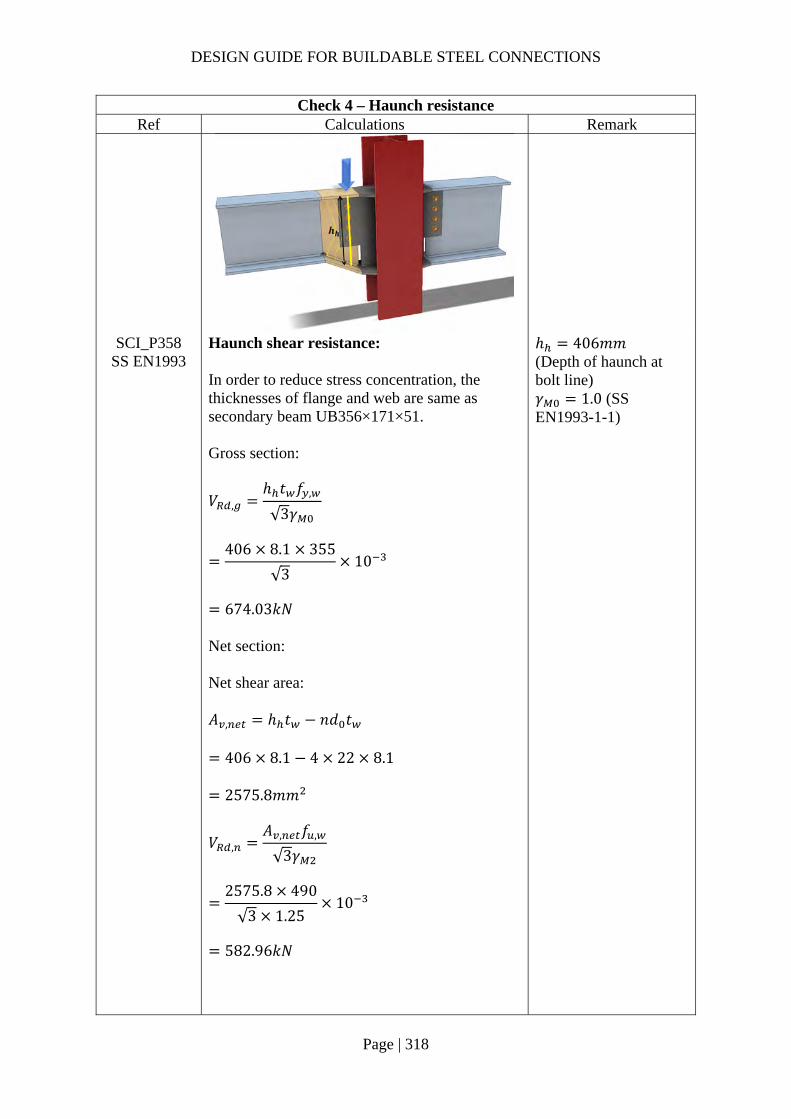
DESIGN GUIDE FOR BUILDABLE STEEL CONNECTIONS
Page | 318
Check 4 – Haunch resistance Ref Calculations Remark
SCI_P358 SS EN1993
Haunch shear resistance: In order to reduce stress concentration, the thicknesses of flange and web are same as secondary beam UB356×171×51. Gross section:
𝑉 ,ℎ 𝑡 𝑓 ,
√3𝛾
406 8.1 355
√310
674.03𝑘𝑁
Net section: Net shear area: 𝐴 , ℎ 𝑡 𝑛𝑑 𝑡
406 8.1 4 22 8.1
2575.8𝑚𝑚
𝑉 ,𝐴 , 𝑓 ,
√3𝛾
2575.8 490
√3 1.2510
582.96𝑘𝑁
ℎ 406𝑚𝑚 (Depth of haunch at bolt line) 𝛾 1.0 (SS EN1993-1-1)

DESIGN GUIDE FOR BUILDABLE STEEL CONNECTIONS
Page | 319
Check 4 – Haunch resistance Ref Calculations Remark
Shear resistance of haunch web: 𝑉 min 𝑉 , ,𝑉 ,
min 674.03,582.96
582.96𝑘𝑁 𝑉 200𝑘𝑁
OK!
SCI_P358 For short fin plate, shear and bending moment interaction check is not necessary for haunch web.
SS EN1993-1-5
Shear buckling resistance of haunch web: To check the shear buckling resistance of the haunch web, the largest height of the haunch was taken as the depth for calculation. The haunch was checked using similar method of checking rectangular girder. 72𝜀𝜂
72 0.81361.0
58.58
Depth of web: 𝑑 428𝑚𝑚
𝜀 235/𝑓
235/355 0.8136
𝑑𝑡
4288.1
52.8472𝜀𝜂
∴ The haunch web is NOT susceptible to shear buckling. Shear buckling check is not necessary.
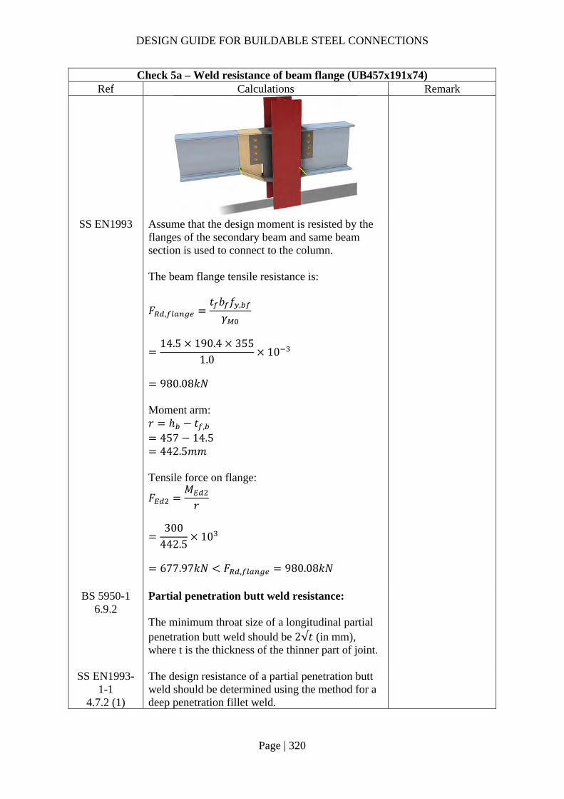
DESIGN GUIDE FOR BUILDABLE STEEL CONNECTIONS
Page | 320
Check 5a – Weld resistance of beam flange (UB457x191x74) Ref Calculations Remark
SS EN1993 Assume that the design moment is resisted by the flanges of the secondary beam and same beam section is used to connect to the column. The beam flange tensile resistance is:
𝐹 ,
𝑡 𝑏 𝑓 ,
𝛾
14.5 190.4 355
1.010
980.08𝑘𝑁
Moment arm: 𝑟 ℎ 𝑡 ,
457 14.5 442.5𝑚𝑚
Tensile force on flange:
𝐹𝑀𝑟
300
442.510
677.97𝑘𝑁 𝐹 , 980.08𝑘𝑁
BS 5950-1 6.9.2
Partial penetration butt weld resistance: The minimum throat size of a longitudinal partial penetration butt weld should be 2√𝑡 (in mm), where t is the thickness of the thinner part of joint.
SS EN1993-1-1
4.7.2 (1)
The design resistance of a partial penetration butt weld should be determined using the method for a deep penetration fillet weld.

DESIGN GUIDE FOR BUILDABLE STEEL CONNECTIONS
Page | 321
Check 5a – Weld resistance of beam flange (UB457x191x74) Ref Calculations Remark
In this example, the angle between the transverse force and weld throat 𝜃 90°. Provided the groove angle is greater than 60° or U-butt is adopted, the throat thickness is equal to the depth of penetration.
Choose partial butt weld with 12mm ( 2√14.57.62𝑚𝑚 throat thickness and grade S355 which match the beam material properties:
Transverse resistance:
𝐹 , ,0.9𝑓𝛾
𝑎
0.9 47012
1.2510
4.06𝑘𝑁/𝑚𝑚
Tensile resistance of the PPBW: 𝐹 𝐹 , , 𝑏
4.06 190.4
773.18𝑘𝑁 𝐹 677.97𝑘𝑁
OK!
Groove angle 60°
𝐷

DESIGN GUIDE FOR BUILDABLE STEEL CONNECTIONS
Page | 322
Check 5b – Weld resistance of beam flange (UB 356x171x57) Ref Calculations Remark
SS EN1993 𝐹 ,
𝑡 𝑏 𝑓 ,
𝛾
13 172.2 355
1.010
794.70𝑘𝑁
Moment arm: 𝑟 ℎ 𝑡 ,
358 13 345𝑚𝑚
Tensile force on flange:
𝐹𝑀𝑟
200345
10
579.71𝑘𝑁 𝐹 , 794.70𝑘𝑁
Choose partial butt weld with 12mm (2√13 7.21𝑚𝑚 throat thickness and grade S355 which match the beam material properties:
Transverse resistance: 𝐹 , , 4.06𝑘𝑁/𝑚𝑚
Tensile resistance of the PPBW: 𝐹 𝐹 , , 𝑏
4.06 172.2
641.88𝑘𝑁 𝐹 579.71𝑘𝑁 OK!
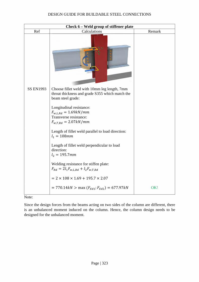
DESIGN GUIDE FOR BUILDABLE STEEL CONNECTIONS
Page | 323
Check 6 – Weld group of stiffener plate Ref Calculations Remark
SS EN1993 Choose fillet weld with 10mm leg length, 7mm throat thickness and grade S355 which match the beam steel grade: Longitudinal resistance: 𝐹 , , 1.69𝑘𝑁/𝑚𝑚 Transverse resistance: 𝐹 , , 2.07𝑘𝑁/𝑚𝑚
Length of fillet weld parallel to load direction: 𝑙 108𝑚𝑚 Length of fillet weld perpendicular to load direction: 𝑙 195.7𝑚𝑚 Welding resistance for stiffen plate: 𝐹 2𝑙 𝐹 , , 𝑙 𝐹 , ,
2 108 1.69 195.7 2.07
770.14𝑘𝑁 max 𝐹 ;𝐹 677.97𝑘𝑁
OK!
Note:
Since the design forces from the beams acting on two sides of the column are different, there is an unbalanced moment induced on the column. Hence, the column design needs to be designed for the unbalanced moment.
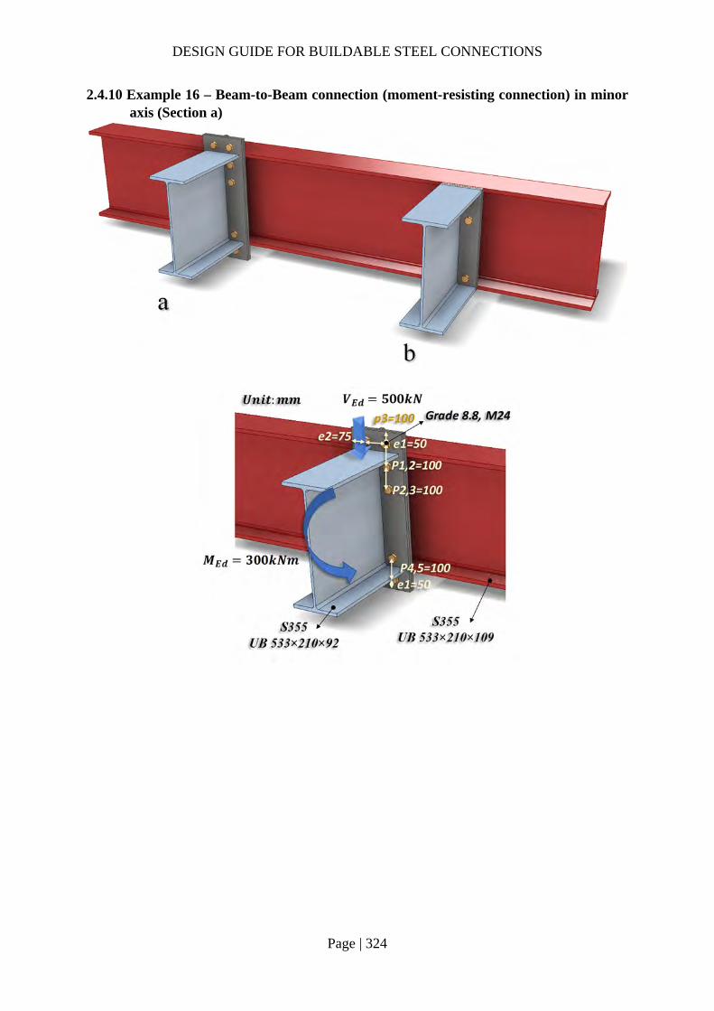
DESIGN GUIDE FOR BUILDABLE STEEL CONNECTIONS
Page | 324
2.4.10 Example 16 – Beam-to-Beam connection (moment-resisting connection) in minor axis (Section a)

DESIGN GUIDE FOR BUILDABLE STEEL CONNECTIONS
Page | 325
Check 1 – Weld of beam web to end plate Ref Calculations Remark
SS EN1993-1-8
6.2.2 (1)
In weld connections, and in bolted connections with end-plates, the welds connecting the beam web should be designed to transfer the shear force from the connected beam to the joint, without any assistance from the welds connecting the beam flanges.
SS EN1993 Length of fillet weld connecting beam web: 𝐿 2𝑑
2 476.5
953𝑚𝑚
For UB533x210x92: Depth between fillets: 𝑑 476.5𝑚𝑚
SCI_P363 Choose fillet weld with 8mm leg length, 5.6mm throat thickness and grade S355: Longitudinal resistance: 𝐹 , , 1.35𝑘𝑁/𝑚𝑚 Transverse resistance: 𝐹 , , 1.65𝑘𝑁/𝑚𝑚
Shear resistance: 𝑉 𝐹 , , 𝐿
1.35 953
1286.55𝑘𝑁 𝑉 500𝑘𝑁
OK

DESIGN GUIDE FOR BUILDABLE STEEL CONNECTIONS
Page | 326
Check 1b – Weld of beam flange to end plate Ref Calculations Remark
SS EN1993-1-8
SCI_P363
Choose fillet weld with 10mm leg length, 7mm throat thickness and grade S355: Transverse resistance: 𝐹 , , 2.07𝑘𝑁/𝑚𝑚 Length of fillet weld: 𝐿 2𝑏 𝑡 2𝑟 4𝑡
2 209.3 10.1 2 12.7 4 15.6
320.7𝑚𝑚 Applied tensile force due to moment:
𝐹𝑀ℎ 𝑡
300
533.1 15.610
579.71𝑘𝑁
Tensile resistance of the fillet weld connecting beam flange and end plate: 𝐹 𝐿𝐹 , ,
320.7 2.07
For UB533×210×92: Width of section: 𝑏 209.3𝑚𝑚 Web thickness: 𝑡 10.1𝑚𝑚 Root radius: 𝑟 12.7𝑚𝑚 Flange thickness: 𝑡 15.6𝑚𝑚 Depth of section: ℎ 533.1𝑚𝑚
663.85𝑘𝑁 𝐹 579.71𝑘𝑁
OK
Note:
Welding cannot be done behind the plate within the flange of the primary beam.

DESIGN GUIDE FOR BUILDABLE STEEL CONNECTIONS
Page | 327
Check 2a – Moment resistance (Tension zone T-stubs) Ref Calculations Remark
Bolt spacings: End distance: 𝑒 50𝑚𝑚 Edge distance: 𝑒 75𝑚𝑚 Spacing (gauge): 𝑤 100𝑚𝑚 Spacing (top row above beam flange): 𝑥 40𝑚𝑚 Spacing row 1 – 2: 𝑝 100𝑚𝑚 Spacing row 2 – 3:𝑝 100𝑚𝑚
SCI_P398 SS EN1993-
1-8
Bolt row 1: End Plate in Beading For pair of bolts in an unstiffened end plate extension: The circular patterns effective length for: Circular yielding: 𝑙 , 2𝜋𝑚 2 𝜋 30.4 191.01𝑚𝑚 Individual end yielding: 𝑙 , 𝜋𝑚 2𝑒 𝜋 30.4 2 50
195.50𝑚𝑚
Assume 12mm fillet weld to connect beam flange to the end plate: 𝑚 𝑥 0.8𝑠
40 0.8 12
30.4𝑚𝑚

DESIGN GUIDE FOR BUILDABLE STEEL CONNECTIONS
Page | 328
Check 2a – Moment resistance (Tension zone T-stubs) Ref Calculations Remark
Circular group yielding: 𝑙 , 𝜋𝑚 𝑤 𝜋 30.4 100
195.50𝑚𝑚 ∴ The circular pattern effective length: 𝑙 , min 191.01; 195.50; 195.50
191.01𝑚𝑚
The Non-circular patterns effective length for: Double curvature:
𝑙 ,𝑏2
2502
125𝑚𝑚
Individual end yielding: 𝑙 , 4𝑚 1.25𝑒
4 30.4 1.25 50 184.1𝑚𝑚 Corner yielding: 𝑙 , 2𝑚 0.625𝑒 𝑒
2 30.4 0.625 50 75
167.05𝑚𝑚 Group end yielding:
𝑙 , 2𝑚 0.625𝑒𝑤2
2 30.4 0.625 50100
2
142.05𝑚𝑚
∴ The non-circular pattern effective length: 𝑙 , min 125.0; 184.10; 167.05; 142.05
125.00𝑚𝑚
Effective length for mode 1: 𝑙 , min 𝑙 , ; 𝑙 , 125.00𝑚𝑚
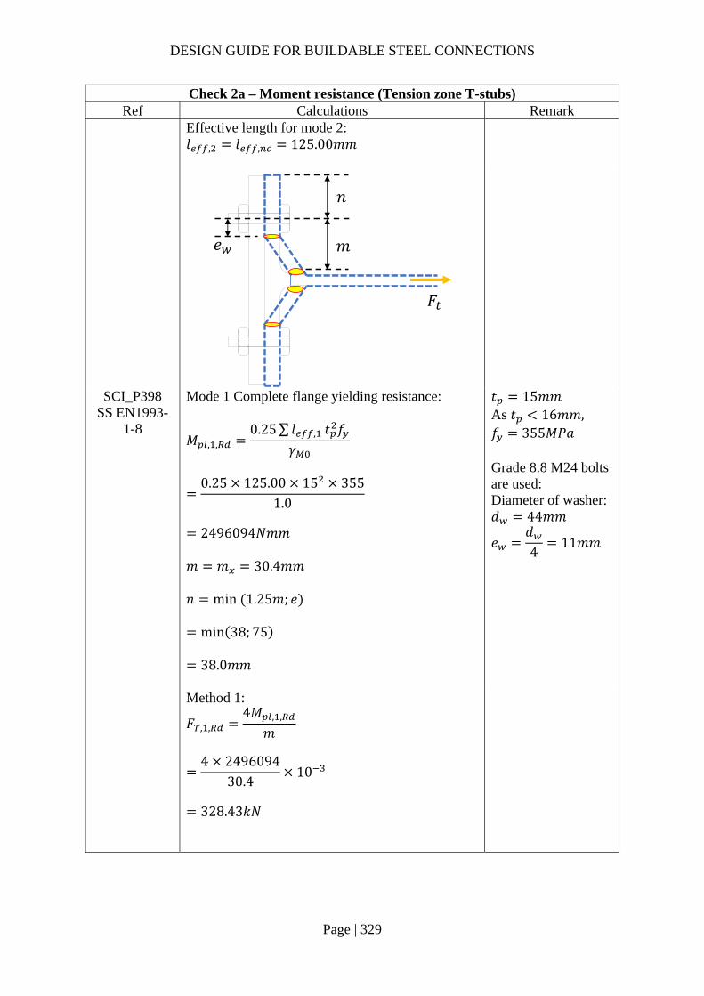
DESIGN GUIDE FOR BUILDABLE STEEL CONNECTIONS
Page | 329
Check 2a – Moment resistance (Tension zone T-stubs) Ref Calculations Remark
Effective length for mode 2: 𝑙 , 𝑙 , 125.00𝑚𝑚
SCI_P398 SS EN1993-
1-8
Mode 1 Complete flange yielding resistance:
𝑀 , ,0.25∑ 𝑙 , 𝑡 𝑓
𝛾
0.25 125.00 15 355
1.0
2496094𝑁𝑚𝑚
𝑚 𝑚 30.4𝑚𝑚 𝑛 min 1.25𝑚; 𝑒
min 38; 75
38.0𝑚𝑚
𝑡 15𝑚𝑚 As 𝑡 16𝑚𝑚, 𝑓 355𝑀𝑃𝑎 Grade 8.8 M24 bolts are used: Diameter of washer: 𝑑 44𝑚𝑚
𝑒𝑑4
11𝑚𝑚
Method 1:
𝐹 , ,4𝑀 , ,
𝑚
4 2496094
30.410
328.43𝑘𝑁
𝑛
𝑚𝑒
𝐹

DESIGN GUIDE FOR BUILDABLE STEEL CONNECTIONS
Page | 330
Check 2a – Moment resistance (Tension zone T-stubs) Ref Calculations Remark
Method 2:
𝐹 , ,8𝑛 2𝑒 𝑀 , ,
2𝑚𝑛 𝑒 𝑚 𝑛
8 38 2 11 2496094
2 30.4 38 11 30.4 3810
451.80𝑘𝑁
Mode 2 Bolt failure with flange yielding resistance:
𝑀 , ,0.25∑ 𝑙 , 𝑡 𝑓
𝛾
0.25 125.0 15 355
1.0
2496094𝑁𝑚𝑚
𝐹 ,𝑘 𝑓 𝐴𝛾
0.9 800 353
1.25
203328𝑁
𝐹 , 2 𝐹 , 2 203328
406656𝑁
For Grade 8.8 M24 bolts: 𝑘 0.9 Ultimate strength: 𝑓 800𝑀𝑃𝑎 Shear area: 𝐴 353𝑚𝑚
𝐹
𝐹 ,
𝐹 ,

DESIGN GUIDE FOR BUILDABLE STEEL CONNECTIONS
Page | 331
Check 2a – Moment resistance (Tension zone T-stubs) Ref Calculations Remark
𝐹 , ,
2𝑀 , , 𝑛∑𝐹 ,
𝑚 𝑛
2 2496094 38 406656
30.4 3810
298.91𝑘𝑁
Mode 3 Bolt failure resistance:
𝐹 , , 𝐹 , 2𝐹 ,
2 203328 10
406.66𝑘𝑁
Resistance of end plate in bending: 𝐹 , , min 𝐹 , , ;𝐹 , , ;𝐹 , ,
min 328.43; 298.91; 406.66
298.91𝑘𝑁
Beam web in tension As bolt row 1 is in the extension of the end plate, the resistance of the beam web in tension is not applicable to this bolt row.
𝐹
𝐹 ,
𝐹 ,
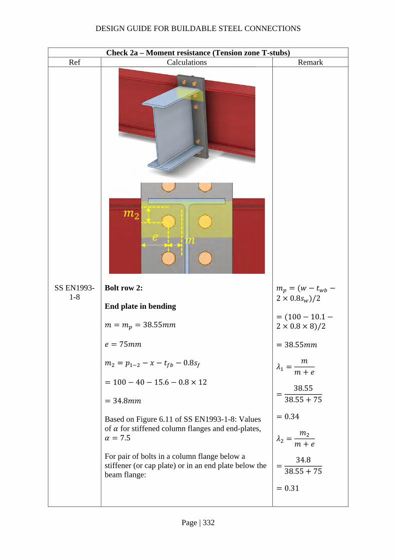
DESIGN GUIDE FOR BUILDABLE STEEL CONNECTIONS
Page | 332
Check 2a – Moment resistance (Tension zone T-stubs) Ref Calculations Remark
SS EN1993-1-8
Bolt row 2: End plate in bending 𝑚 𝑚 38.55𝑚𝑚 𝑒 75𝑚𝑚 𝑚 𝑝 𝑥 𝑡 0.8𝑠
100 40 15.6 0.8 12
34.8𝑚𝑚 Based on Figure 6.11 of SS EN1993-1-8: Values of 𝛼 for stiffened column flanges and end-plates, 𝛼 7.5 For pair of bolts in a column flange below a stiffener (or cap plate) or in an end plate below the beam flange:
𝑚 𝑤 𝑡2 0.8𝑠 /2
100 10.12 0.8 8 /2
38.55𝑚𝑚
𝜆𝑚
𝑚 𝑒
38.55
38.55 75
0.34
𝜆𝑚
𝑚 𝑒
34.8
38.55 75
0.31

DESIGN GUIDE FOR BUILDABLE STEEL CONNECTIONS
Page | 333
Check 2a – Moment resistance (Tension zone T-stubs) Ref Calculations Remark
The circular patterns effective length for: Circular yielding: 𝑙 , 2𝜋𝑚 2𝜋 38.55 242.22𝑚𝑚 The non-circular patterns effective length for: Side yielding near beam flange or a stiffener: 𝑙 , 𝛼𝑚 7.5 38.55 289.13𝑚𝑚 Effective length for mode 1: 𝑙 , min 𝑙 , ; 𝑙 , 242.22𝑚𝑚 Effective length for mode 2: 𝑙 , 𝑙 , 289.13𝑚𝑚
SCI_P398 SS EN1993-
1-8
Mode 1 Complete flange yielding resistance:
𝑀 , ,0.25∑ 𝑙 , 𝑡 𝑓
𝛾
0.25 242.22 15 355
1.0
4836767𝑁𝑚𝑚
𝑛 min 1.25𝑚; 𝑒
min 48.19; 75
48.19𝑚𝑚 Method 1:
𝐹 , ,4𝑀 , ,
𝑚
4 4836767
38.5510
501.87𝑘𝑁
DESIGN GUIDE FOR BUILDABLE STEEL CONNECTIONS
Page | 334
Check 2a – Moment resistance (Tension zone T-stubs) Ref Calculations Remark
Method 2:
𝐹 , ,8𝑛 2𝑒 𝑀 , ,
2𝑚𝑛 𝑒 𝑚 𝑛
8 48.19 2 11 4836767
2 38.55 48.19 11 38.55 48.19
10
636.75𝑘𝑁
Mode 2 Bolt failure with flange yielding resistance:
𝑀 , ,0.25∑ 𝑙 , 𝑡 𝑓
𝛾
0.25 289.13 15 355
1.0
5773465𝑁𝑚𝑚
𝐹 , ,2𝑀 , , 𝑛∑𝐹 ,
𝑚 𝑛
2 5773465 48.19 406656
38.55 48.1910
359.05𝑘𝑁
Mode 3 Bolt failure resistance:
𝐹 , , 𝐹 , 2𝐹 ,
2 203328 10
406.66𝑘𝑁
Resistance of end plate in bending: 𝐹 , , min 𝐹 , , ;𝐹 , , ;𝐹 , ,
min 501.87; 359.05; 406.66
359.05𝑘𝑁

DESIGN GUIDE FOR BUILDABLE STEEL CONNECTIONS
Page | 335
Check 2a – Moment resistance (Tension zone T-stubs) Ref Calculations Remark
SS EN1993-1-8
6.2.6.8 (1)
Beam web in tension
𝐹 , ,𝑏 , , 𝑡 𝑓 ,
𝛾
242.22 10.1 355
1.010
868.47𝑘𝑁
𝑏 , , 𝑙
242.22𝑚𝑚 *Conservatively, consider the smallest 𝑙 (6.2.6.8 (2)) For UB 533x210x92: 𝑡 10.1𝑚𝑚
Bolt row 3: End plate in bending For pair of bolts in a column flange away from any stiffener or in an end plate, away from the flange or any stiffener: The circular patterns effective length for: Circular yielding: 𝑙 , 2𝜋𝑚 2𝜋 38.55 242.22𝑚𝑚

DESIGN GUIDE FOR BUILDABLE STEEL CONNECTIONS
Page | 336
Check 2a – Moment resistance (Tension zone T-stubs) Ref Calculations Remark
The non-circular patterns effective length for: Side yielding: 𝑙 , 4𝑚 1.25𝑒 4 38.55 1.25 75
247.95𝑚𝑚 Effective length for mode 1: 𝑙 , min 𝑙 , ; 𝑙 , 242.22𝑚𝑚 Effective length for mode 2: 𝑙 , 𝑙 , 247.95𝑚𝑚
SCI_P398 SS EN1993-
1-8
Mode 1 Complete flange yielding resistance:
𝑀 , ,0.25∑ 𝑙 , 𝑡 𝑓
𝛾
0.25 242.22 15 355
1.0
4836767𝑁𝑚𝑚
𝑛 min 1.25𝑚; 𝑒
min 48.19; 75
48.19𝑚𝑚 Method 1:
𝐹 , ,4𝑀 , ,
𝑚
4 4836767
38.5510
501.87𝑘𝑁
Method 2:
𝐹 , ,8𝑛 2𝑒 𝑀 , ,
2𝑚𝑛 𝑒 𝑚 𝑛
8 48.19 2 11 4836767 10
2 38.55 48.19 11 38.55 48.19
636.75𝑘𝑁
DESIGN GUIDE FOR BUILDABLE STEEL CONNECTIONS
Page | 337
Check 2a – Moment resistance (Tension zone T-stubs) Ref Calculations Remark
Mode 2 Bolt failure with flange yielding resistance:
𝑀 , ,0.25∑ 𝑙 , 𝑡 𝑓
𝛾
0.25 247.95 15 355
1.0
4951252𝑁𝑚𝑚
𝐹 , ,2𝑀 , , 𝑛∑𝐹 ,
𝑚 𝑛
2 4951252 48.19 406656
38.55 48.1910
340.09𝑘𝑁
Mode 3 Bolt failure resistance:
𝐹 , , 𝐹 , 2𝐹 ,
2 203328 10
406.66𝑘𝑁
Resistance of end plate in bending: 𝐹 , , min 𝐹 , , ;𝐹 , , ;𝐹 , ,
min 501.87; 340.09; 406.66
340.09𝑘𝑁
SS EN1993-1-8
6.2.6.8 (1)
Beam web in tension
𝐹 , ,𝑏 , , 𝑡 𝑓 ,
𝛾
242.22 10.1 355
1.010
868.47𝑘𝑁
𝑏 , , 𝑙
242.22𝑚𝑚
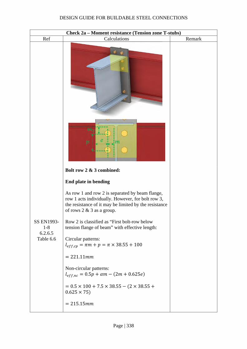
DESIGN GUIDE FOR BUILDABLE STEEL CONNECTIONS
Page | 338
Check 2a – Moment resistance (Tension zone T-stubs) Ref Calculations Remark
Bolt row 2 & 3 combined: End plate in bending As row 1 and row 2 is separated by beam flange, row 1 acts individually. However, for bolt row 3, the resistance of it may be limited by the resistance of rows 2 & 3 as a group.
SS EN1993-1-8
6.2.6.5 Table 6.6
Row 2 is classified as “First bolt-row below tension flange of beam” with effective length: Circular patterns: 𝑙 , 𝜋𝑚 𝑝 𝜋 38.55 100
221.11𝑚𝑚 Non-circular patterns: 𝑙 , 0.5𝑝 𝛼𝑚 2𝑚 0.625𝑒
0.5 100 7.5 38.55 2 38.550.625 75
215.15𝑚𝑚
DESIGN GUIDE FOR BUILDABLE STEEL CONNECTIONS
Page | 339
Check 2a – Moment resistance (Tension zone T-stubs) Ref Calculations Remark
Row 3 is classified as “Other end bolt-row” with effective length: Circular patterns: 𝑙 , 𝜋𝑚 𝑝 𝜋 38.55 100
221.11𝑚𝑚 Non-circular patterns: 𝑙 , 2𝑚 0.625𝑒 0.5𝑝
2 38.55 0.625 75 0.5 100
173.98𝑚𝑚
The total effective length for this bolt group combination:
𝑙 , 221.11 221.11 442.22𝑚𝑚
𝑙 , 215.15 173.98 389.13𝑚𝑚
Effective length for mode 1:
𝑙 , min 𝑙 , ; 𝑙 ,
389.13𝑚𝑚
Effective length for mode 2:
𝑙 , 𝑙 , 389.13𝑚𝑚
Mode 1 Complete flange yielding resistance:
𝑀 , ,0.25∑ 𝑙 , 𝑡 𝑓
𝛾
0.25 389.13 15 355
1.0
7770340𝑁𝑚𝑚
𝑛 min 1.25𝑚; 𝑒
min 48.19; 75
48.19𝑚𝑚

DESIGN GUIDE FOR BUILDABLE STEEL CONNECTIONS
Page | 340
Check 2a – Moment resistance (Tension zone T-stubs) Ref Calculations Remark
Method 1:
𝐹 , ,4𝑀 , ,
𝑚
4 7770340
38.5510
806.26𝑘𝑁
Method 2:
𝐹 , ,8𝑛 2𝑒 𝑀 , ,
2𝑚𝑛 𝑒 𝑚 𝑛
8 48.19 2 11 7770340
2 38.55 48.19 11 38.55 48.19
10
1022.95𝑘𝑁
Mode 2 Bolt failure with flange yielding resistance:
𝑀 , ,0.25∑ 𝑙 , 𝑡 𝑓
𝛾
0.25 389.13 15 355
1.0
7770340𝑁𝑚𝑚
𝐹 , ,2𝑀 , , 𝑛∑𝐹 ,
𝑚 𝑛
2 7770340 48.19 406656
38.55 48.1910
631.01𝑘𝑁
Mode 3 Bolt failure resistance:
𝐹 , , 𝐹 , 4𝐹 ,
4 203328 10
813.31𝑘𝑁

DESIGN GUIDE FOR BUILDABLE STEEL CONNECTIONS
Page | 341
Check 2a – Moment resistance (Tension zone T-stubs) Ref Calculations Remark
Resistance of end plate in bending: 𝐹 , , min 𝐹 , , ;𝐹 , , ;𝐹 , ,
min 806.26; 631.01; 813.31
631.01𝑘𝑁
SS EN1993-1-8
6.2.6.8 (1)
Beam web in tension
𝐹 , ,𝑏 , , 𝑡 𝑓 ,
𝛾
389.13 10.1 355
1.010
1395.23𝑘𝑁
𝑏 , , 𝑙
389.13𝑚𝑚
The resistance of bolt row 3 is limited to: 𝐹 , 𝐹 , 𝐹 , 631.01 359.05
271.96𝑘𝑁
Summary of tension resistance of T-stubs:
Row Resistance Effective
Resistance Row 1 alone 298.91kN 298.91kN Row 2 alone 359.05kN 359.05kN Row 3 alone 340.09kN 271.96kN Row 2 and 3 631.01kN -
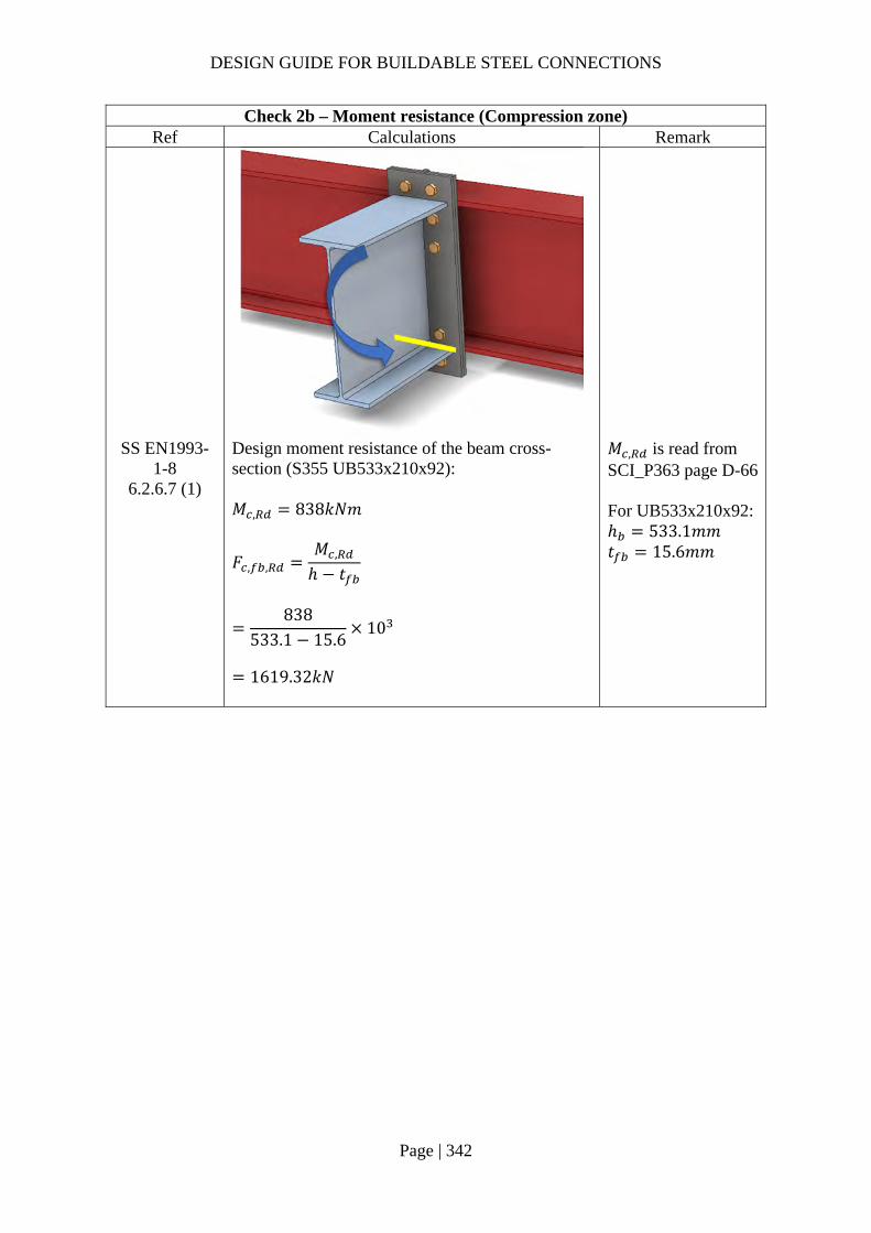
DESIGN GUIDE FOR BUILDABLE STEEL CONNECTIONS
Page | 342
Check 2b – Moment resistance (Compression zone) Ref Calculations Remark
SS EN1993-1-8
6.2.6.7 (1)
Design moment resistance of the beam cross-section (S355 UB533x210x92): 𝑀 , 838𝑘𝑁𝑚
𝐹 , ,𝑀 ,
ℎ 𝑡
838
533.1 15.610
1619.32𝑘𝑁
𝑀 , is read from SCI_P363 page D-66 For UB533x210x92: ℎ 533.1𝑚𝑚 𝑡 15.6𝑚𝑚

DESIGN GUIDE FOR BUILDABLE STEEL CONNECTIONS
Page | 343
Check 2 – Moment resistance Ref Calculations Remark
SS EN1993-1-8
6.2.7.2 (9)
The effective resistances of bolt rows need to be reduced when the bolt row resistance is greater than 1.9𝐹 , 1.9𝐹 , 1.9 203.33 386.32𝑘𝑁 As all bolt row resistances are lesser than 386.32kN, no reduction is required.
Equilibrium of forces Total effective tension resistance:
𝐹 , 298.91 359.05 271.96
929.91𝑘𝑁 𝐹 , , 1619.32𝑘𝑁
Hence, no reduction is required for the tensile resistance.
SS EN1993-1-8
6.2.7.2 (1)
The moment resistance of the connection may be determined using:
𝑀 , ℎ 𝐹 , ,

DESIGN GUIDE FOR BUILDABLE STEEL CONNECTIONS
Page | 344
Check 2 – Moment resistance Ref Calculations Remark
Taking the center of compression to be at the mid-thickness of the compression flange of the beam:
ℎ ℎ𝑡2
𝑥
533.115.6
240
565.3𝑚𝑚
ℎ ℎ 100 465.3𝑚𝑚 ℎ ℎ 100 365.3𝑚𝑚
𝑀 , ℎ 𝐹 , , ℎ 𝐹 , , ℎ 𝐹 , ,
565.3 298.91 465.3 359.05 356.3271.96
435.38𝑘𝑁𝑚 𝑀 300𝑘𝑁𝑚
OK
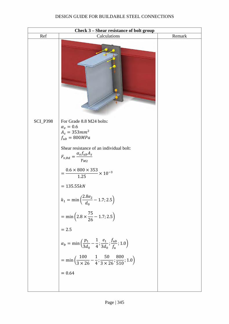
DESIGN GUIDE FOR BUILDABLE STEEL CONNECTIONS
Page | 345
Check 3 – Shear resistance of bolt group Ref Calculations Remark
SCI_P398 For Grade 8.8 M24 bolts: 𝛼 0.6 𝐴 353𝑚𝑚 𝑓 800𝑀𝑃𝑎 Shear resistance of an individual bolt:
𝐹 ,𝛼 𝑓 𝐴𝛾
0.6 800 353
1.2510
135.55𝑘𝑁
𝑘 min2.8𝑒𝑑
1.7; 2.5
min 2.87526
1.7; 2.5
2.5
𝛼 min𝑝
3𝑑14
;𝑒
3𝑑;𝑓𝑓
; 1.0
min100
3 2614
;50
3 26;800510
; 1.0
0.64
DESIGN GUIDE FOR BUILDABLE STEEL CONNECTIONS
Page | 346
Check 3 – Shear resistance of bolt group Ref Calculations Remark
Bearing resistance of an individual bolt:
𝐹 ,𝑘 𝛼 𝑓 𝑑𝑡𝛾
2.5 0.64 510 24 15
1.25
235.38𝑘𝑁
Hence, resistance of an individual bolt: 𝐹 min 𝐹 , ;𝐹 ,
min 135.55; 235.38
135.55𝑘𝑁
According to SCI_P398, the shear resistance of the upper rows may be taken conservatively as 28% of the shear resistance without tension, thus the shear resistance of the bolt group is: 𝑉 4 6 0.28 𝐹
5.68 135.55
769.94𝑘𝑁 𝑉 500𝑘𝑁
OK
Note:
In this example, the primary beam is an edge beam which supports secondary beam on one side only. Torsion on the primary beam should be checked during the beam design.

DESIGN GUIDE FOR BUILDABLE STEEL CONNECTIONS
Page | 347
Additional info (whether stiffeners for protruding plate are required) Ref Calculations Remark
SS EN1993-1-8
SCI_P398
If stiffener is used to strengthen the extension of the end plate, the end plate bending resistance will be increased. 𝑚 𝑚 38.55𝑚𝑚 Bolt row 1: End Plate in Beading For pair of bolts in an unstiffened end plate extension: The circular patterns effective length for: Circular yielding: 𝑙 , 2𝜋𝑚 2 𝜋 38.55 242.22𝑚𝑚 Individual end yielding: 𝑙 , 𝜋𝑚 2𝑒 𝜋 38.55 2 50
221.11𝑚𝑚 ∴ The circular pattern effective length: 𝑙 , min 242.22; 221.11
221.11𝑚𝑚
Stiffeners
DESIGN GUIDE FOR BUILDABLE STEEL CONNECTIONS
Page | 348
Additional info (whether stiffeners for protruding plate are required) Ref Calculations Remark
The Non-circular patterns effective length for: Side yielding: 𝑙 , 4𝑚 1.25𝑒
4 38.55 1.25 50 247.95𝑚𝑚 Corner yielding away from the stiffener/flange: 𝑙 , 2𝑚 0.625𝑒 𝑒
2 38.55 0.625 50 75
173.98𝑚𝑚 Corner yielding: 𝑙 , 𝛼𝑚 2𝑚 0.625𝑒 𝑒
7.7 38.55 2 38.55 0.625 75 50
222.86𝑚𝑚 ∴ The non-circular pattern effective length: 𝑙 , min 247.95; 173.98; 222.86
173.98𝑚𝑚
𝑚 𝑥 0.8𝑠
40 0.8 12
30.4𝑚𝑚 𝜆 0.34 𝜆 0.27 ∴ 𝛼 7.7
Effective length for mode 1: 𝑙 , min 𝑙 , ; 𝑙 , 173.98𝑚𝑚 Effective length for mode 2: 𝑙 , 𝑙 , 173.98𝑚𝑚
Mode 1 Complete flange yielding resistance:
𝑀 , ,0.25∑ 𝑙 , 𝑡 𝑓
𝛾
0.25 173.98 15 355
1.0
3474063𝑁𝑚𝑚
𝑚 𝑚 38.55𝑚𝑚

DESIGN GUIDE FOR BUILDABLE STEEL CONNECTIONS
Page | 349
Additional info (whether stiffeners for protruding plate are required) Ref Calculations Remark
𝑛 min 1.25𝑚; 𝑒
min 48.19; 75
48.19𝑚𝑚
Method 1:
𝐹 , ,4𝑀 , ,
𝑚
4 3474063
38.5510
360.47𝑘𝑁
Method 2:
𝐹 , ,8𝑛 2𝑒 𝑀 , ,
2𝑚𝑛 𝑒 𝑚 𝑛
8 48.19 2 11 3474063
2 38.6 48.2 11 38.6 48.210
457.35𝑘𝑁
Mode 2 Bolt failure with flange yielding resistance:
𝑀 , ,0.25∑ 𝑙 , 𝑡 𝑓
𝛾
0.25 173.98 15 355
1.0
3474063𝑁𝑚𝑚
𝐹 ,𝑘 𝑓 𝐴𝛾
0.9 800 353
1.25
203328𝑁
𝐹 , 2 𝐹 , 2 203328
406656𝑁

DESIGN GUIDE FOR BUILDABLE STEEL CONNECTIONS
Page | 350
Additional info (whether stiffeners for protruding plate are required) Ref Calculations Remark
𝐹 , ,
2𝑀 , , 𝑛∑𝐹 ,
𝑚 𝑛
2 3474063 48.19 406656
38.55 48.1910
306.03𝑘𝑁
Mode 3 Bolt failure resistance:
𝐹 , , 𝐹 , 2𝐹 ,
2 203328 10
406.66𝑘𝑁
Resistance of end plate in bending: 𝐹 , , min 𝐹 , , ;𝐹 , , ;𝐹 , ,
min 360.47; 306.03; 406.66
306.03𝑘𝑁
Moment resistance: 𝑀 , ℎ 𝐹 , , ℎ 𝐹 , , ℎ 𝐹 , ,
565.3 306.03 465.3 359.05 356.3271.96
439.41𝑘𝑁𝑚
Note: In this example, adding a stiffener behind the extended end plate will increase the moment capacity of the connection to a limited extend. Hence, stiffeners is not needed for the extended end plate. However, adding the stiffener may have a more significant effect in increasing load capacity for connections with larger extension.
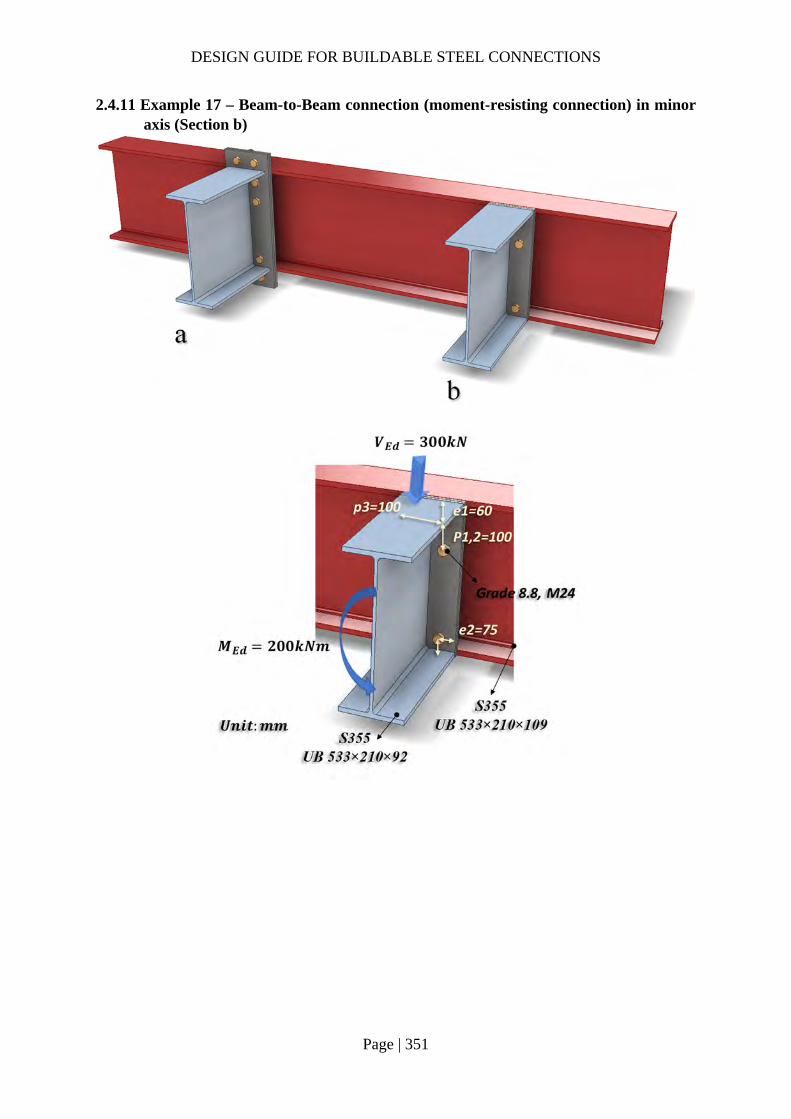
DESIGN GUIDE FOR BUILDABLE STEEL CONNECTIONS
Page | 351
2.4.11 Example 17 – Beam-to-Beam connection (moment-resisting connection) in minor axis (Section b)

DESIGN GUIDE FOR BUILDABLE STEEL CONNECTIONS
Page | 352
Check 1 – Weld of beam web to end plate Ref Calculations Remark
SS EN1993-1-8
6.2.2 (1)
In welded connections and bolted connections with end-plates, the welds connecting the beam web should be designed to transfer the shear force from the connected beam to the joint, without any assistance from the welds connecting the beam flanges.
SS EN1993 Length of fillet weld connecting beam web: 𝐿 2𝑑
2 476.5
953𝑚𝑚
For UB533x210x92: Depth between fillets: 𝑑 476.5𝑚𝑚
SCI_P363 Choose fillet weld with 8mm leg length, 5.6mm throat thickness and grade S355: Longitudinal resistance: 𝐹 , , 1.35𝑘𝑁/𝑚𝑚 Transverse resistance: 𝐹 , , 1.65𝑘𝑁/𝑚𝑚
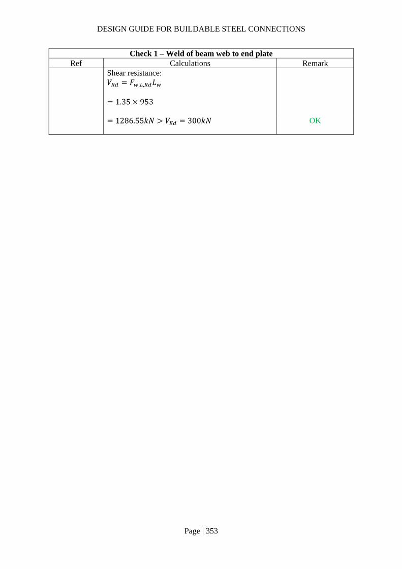
DESIGN GUIDE FOR BUILDABLE STEEL CONNECTIONS
Page | 353
Check 1 – Weld of beam web to end plate Ref Calculations Remark
Shear resistance: 𝑉 𝐹 , , 𝐿
1.35 953
1286.55𝑘𝑁 𝑉 300𝑘𝑁
OK

DESIGN GUIDE FOR BUILDABLE STEEL CONNECTIONS
Page | 354
Check 1a – Resistance of flange PPBW Ref Calculations Remark
BS 5950-1 6.9.2
Partial penetration butt weld resistance: The minimum throat size of a longitudinal partial penetration butt weld should be 2√𝑡 (in mm), where t is the thickness of the thinner part of joint.
SS EN1993-1-1
4.7.2 (1)
The design resistance of a partial penetration butt weld should be determined using the method for a deep penetration fillet weld.
In this example, the angle between the transverse force and weld throat 𝜃 90°. Provided the groove angle is greater than 60° or U-butt is adopted, the throat thickness is equal to the depth of penetration.
Choose partial butt weld with 12mm ( 2√15.67.90𝑚𝑚 throat thickness and grade S355 which match the beam material properties:
𝑓 470𝑀𝑃𝑎 for S355 weld 𝛾 1.25 For UB533x210x92: 𝑏 209.3𝑚𝑚 Groove angle 60°
𝐷

DESIGN GUIDE FOR BUILDABLE STEEL CONNECTIONS
Page | 355
Check 1a – Resistance of flange PPBW Ref Calculations Remark
The design transverse resistance of weld:
𝐹 , ,0.9𝑓𝛾
𝑎
0.9 470 12
1.2510
4.06𝑘𝑁/𝑚𝑚
The tensile resistance of the weld: 𝐹 , 𝐹 , , 𝑏
4.06 209.3
849.93𝑘𝑁 𝐹 , 631.01𝑘𝑁
OK
Note:
Welding cannot be done behind the plate within the flange of the primary beam.
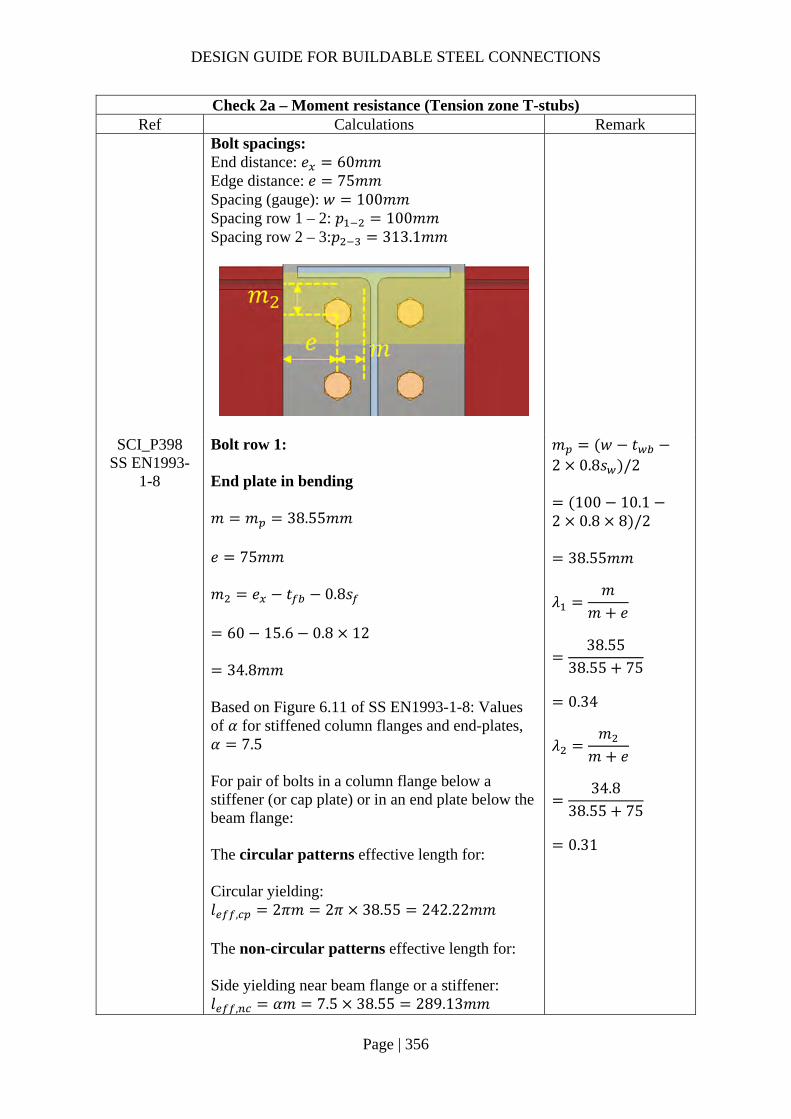
DESIGN GUIDE FOR BUILDABLE STEEL CONNECTIONS
Page | 356
Check 2a – Moment resistance (Tension zone T-stubs) Ref Calculations Remark
Bolt spacings: End distance: 𝑒 60𝑚𝑚 Edge distance: 𝑒 75𝑚𝑚 Spacing (gauge): 𝑤 100𝑚𝑚 Spacing row 1 – 2: 𝑝 100𝑚𝑚 Spacing row 2 – 3:𝑝 313.1𝑚𝑚
SCI_P398 SS EN1993-
1-8
Bolt row 1: End plate in bending 𝑚 𝑚 38.55𝑚𝑚 𝑒 75𝑚𝑚 𝑚 𝑒 𝑡 0.8𝑠
60 15.6 0.8 12
34.8𝑚𝑚 Based on Figure 6.11 of SS EN1993-1-8: Values of 𝛼 for stiffened column flanges and end-plates, 𝛼 7.5 For pair of bolts in a column flange below a stiffener (or cap plate) or in an end plate below the beam flange: The circular patterns effective length for: Circular yielding: 𝑙 , 2𝜋𝑚 2𝜋 38.55 242.22𝑚𝑚 The non-circular patterns effective length for: Side yielding near beam flange or a stiffener: 𝑙 , 𝛼𝑚 7.5 38.55 289.13𝑚𝑚
𝑚 𝑤 𝑡2 0.8𝑠 /2
100 10.12 0.8 8 /2
38.55𝑚𝑚
𝜆𝑚
𝑚 𝑒
38.55
38.55 75
0.34
𝜆𝑚
𝑚 𝑒
34.8
38.55 75
0.31

DESIGN GUIDE FOR BUILDABLE STEEL CONNECTIONS
Page | 357
Check 2a – Moment resistance (Tension zone T-stubs) Ref Calculations Remark
Effective length for mode 1: 𝑙 , min 𝑙 , ; 𝑙 , 242.22𝑚𝑚 Effective length for mode 2: 𝑙 , 𝑙 , 289.13𝑚𝑚
SCI_P398 SS EN1993-
1-8
Mode 1 Complete flange yielding resistance:
𝑀 , ,0.25∑ 𝑙 , 𝑡 𝑓
𝛾
0.25 242.22 15 355
1.0
4836767𝑁𝑚𝑚
𝑛 min 1.25𝑚; 𝑒
min 48.19; 75
48.19𝑚𝑚 Method 1:
𝐹 , ,4𝑀 , ,
𝑚
4 4836767
38.5510
501.87𝑘𝑁
𝑡 15𝑚𝑚 As 𝑡 16𝑚𝑚, 𝑓 355𝑀𝑃𝑎 Grade 8.8 M24 bolts are used: Diameter of washer: 𝑑 44𝑚𝑚
𝑒𝑑4
11𝑚𝑚
Method 2:
𝐹 , ,8𝑛 2𝑒 𝑀 , ,
2𝑚𝑛 𝑒 𝑚 𝑛
8 48.19 2 11 4836767
2 38.55 48.19 11 38.55 48.19
10
636.75𝑘𝑁

DESIGN GUIDE FOR BUILDABLE STEEL CONNECTIONS
Page | 358
Check 2a – Moment resistance (Tension zone T-stubs) Ref Calculations Remark
Mode 2 Bolt failure with flange yielding resistance:
𝑀 , ,0.25∑ 𝑙 , 𝑡 𝑓
𝛾
0.25 289.13 15 355
1.0
5773465𝑁𝑚𝑚
𝐹 ,𝑘 𝑓 𝐴𝛾
0.9 800 353
1.25
203328𝑁
𝐹 , 2 𝐹 , 2 203328
406656𝑁
𝐹 , ,2𝑀 , , 𝑛∑𝐹 ,
𝑚 𝑛
2 5773465 48.19 406656
38.55 48.1910
359.05𝑘𝑁
For Grade 8.8 M24 bolts: 𝑘 0.9 Ultimate strength: 𝑓 800𝑀𝑃𝑎 Shear area: 𝐴 353𝑚𝑚
Mode 3 Bolt failure resistance:
𝐹 , , 𝐹 , 2𝐹 ,
2 203328 10
406.66𝑘𝑁
Resistance of end plate in bending: 𝐹 , , min 𝐹 , , ;𝐹 , , ;𝐹 , ,
min 501.87; 359.05; 406.66
359.05𝑘𝑁

DESIGN GUIDE FOR BUILDABLE STEEL CONNECTIONS
Page | 359
Check 2a – Moment resistance (Tension zone T-stubs) Ref Calculations Remark
SS EN1993-1-8
6.2.6.8 (1)
Beam web in tension
𝐹 , ,𝑏 , , 𝑡 𝑓 ,
𝛾
242.22 10.1 355
1.010
868.47𝑘𝑁
𝑏 , , 𝑙
242.22𝑚𝑚 *Conservatively, consider the smallest 𝑙 (6.2.6.8 (2)) For UB 533x210x92: 𝑡 10.1𝑚𝑚
Bolt row 2: End plate in bending For pair of bolts in a column flange away from any stiffener or in an end plate, away from the flange or any stiffener: The circular patterns effective length for: Circular yielding: 𝑙 , 2𝜋𝑚 2𝜋 38.55 242.22𝑚𝑚 The non-circular patterns effective length for: Side yielding: 𝑙 , 4𝑚 1.25𝑒 4 38.55 1.25 75
247.95𝑚𝑚 Effective length for mode 1: 𝑙 , min 𝑙 , ; 𝑙 , 242.22𝑚𝑚 Effective length for mode 2: 𝑙 , 𝑙 , 247.95𝑚𝑚
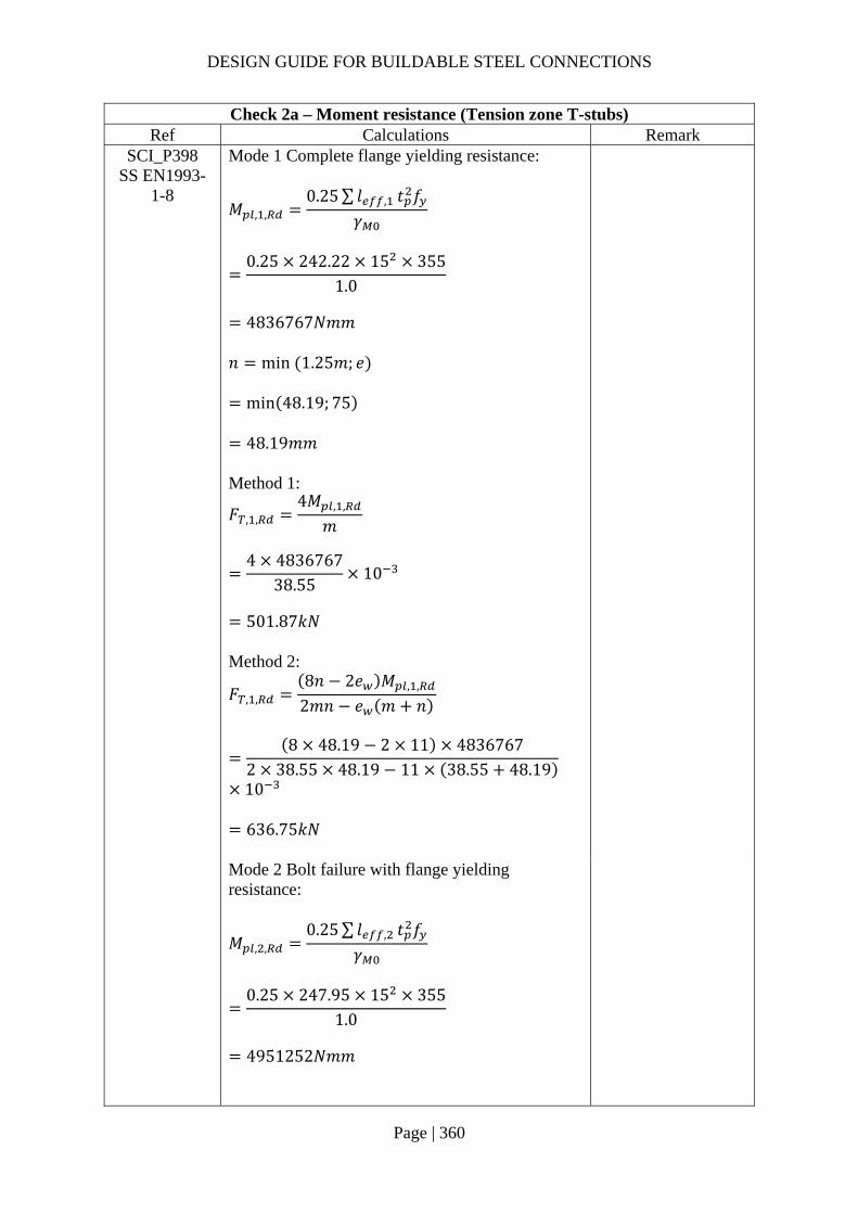
DESIGN GUIDE FOR BUILDABLE STEEL CONNECTIONS
Page | 360
Check 2a – Moment resistance (Tension zone T-stubs) Ref Calculations Remark
SCI_P398 SS EN1993-
1-8
Mode 1 Complete flange yielding resistance:
𝑀 , ,0.25∑ 𝑙 , 𝑡 𝑓
𝛾
0.25 242.22 15 355
1.0
4836767𝑁𝑚𝑚
𝑛 min 1.25𝑚; 𝑒
min 48.19; 75
48.19𝑚𝑚 Method 1:
𝐹 , ,4𝑀 , ,
𝑚
4 4836767
38.5510
501.87𝑘𝑁
Method 2:
𝐹 , ,8𝑛 2𝑒 𝑀 , ,
2𝑚𝑛 𝑒 𝑚 𝑛
8 48.19 2 11 4836767
2 38.55 48.19 11 38.55 48.19
10
636.75𝑘𝑁
Mode 2 Bolt failure with flange yielding resistance:
𝑀 , ,0.25∑ 𝑙 , 𝑡 𝑓
𝛾
0.25 247.95 15 355
1.0
4951252𝑁𝑚𝑚

DESIGN GUIDE FOR BUILDABLE STEEL CONNECTIONS
Page | 361
Check 2a – Moment resistance (Tension zone T-stubs) Ref Calculations Remark
𝐹 , ,
2𝑀 , , 𝑛∑𝐹 ,
𝑚 𝑛
2 4951252 48.19 406656
38.55 48.1910
340.09𝑘𝑁
Mode 3 Bolt failure resistance:
𝐹 , , 𝐹 , 2𝐹 ,
2 203328 10
406.66𝑘𝑁
Resistance of end plate in bending: 𝐹 , , min 𝐹 , , ;𝐹 , , ;𝐹 , ,
min 501.87; 340.09; 406.66
340.09𝑘𝑁
SS EN1993-1-8
6.2.6.8 (1)
Beam web in tension
𝐹 , ,𝑏 , , 𝑡 𝑓 ,
𝛾
242.22 10.1 355
1.010
868.47𝑘𝑁
𝑏 , , 𝑙
242.22𝑚𝑚
Bolt row 1 & 2 combined: End plate in bending For bolt row 2, the resistance of it may be limited by the resistance of rows 1 & 2 as a group.

DESIGN GUIDE FOR BUILDABLE STEEL CONNECTIONS
Page | 362
Check 2a – Moment resistance (Tension zone T-stubs) Ref Calculations Remark
SS EN1993-1-8
6.2.6.5 Table 6.6
Row 1 is classified as “First bolt-row below tension flange of beam” with effective length: Circular patterns: 𝑙 , 𝜋𝑚 𝑝 𝜋 38.55 100
221.11𝑚𝑚 Non-circular patterns: 𝑙 , 0.5𝑝 𝛼𝑚 2𝑚 0.625𝑒
0.5 100 7.5 38.55 2 38.550.625 75
215.15𝑚𝑚
Row 2 is classified as “Other end bolt-row” with effective length: Circular patterns: 𝑙 , 𝜋𝑚 𝑝 𝜋 38.55 100
221.11𝑚𝑚 Non-circular patterns: 𝑙 , 2𝑚 0.625𝑒 0.5𝑝
2 38.55 0.625 75 0.5 100
173.98𝑚𝑚
The total effective length for this bolt group combination:
𝑙 , 221.11 221.11 442.22𝑚𝑚
𝑙 , 215.15 173.98 389.13𝑚𝑚
Effective length for mode 1:
𝑙 , min 𝑙 , ; 𝑙 ,
389.13𝑚𝑚
Effective length for mode 2:
𝑙 , 𝑙 , 389.13𝑚𝑚

DESIGN GUIDE FOR BUILDABLE STEEL CONNECTIONS
Page | 363
Check 2a – Moment resistance (Tension zone T-stubs) Ref Calculations Remark
Mode 1 Complete flange yielding resistance:
𝑀 , ,0.25∑ 𝑙 , 𝑡 𝑓
𝛾
0.25 389.13 15 355
1.0
7770340𝑁𝑚𝑚
𝑛 min 1.25𝑚; 𝑒
min 48.19; 75
48.19𝑚𝑚 Method 1:
𝐹 , ,4𝑀 , ,
𝑚
4 7770340
38.5510
806.26𝑘𝑁
Method 2:
𝐹 , ,8𝑛 2𝑒 𝑀 , ,
2𝑚𝑛 𝑒 𝑚 𝑛
8 48.19 2 11 7770340
2 38.55 48.19 11 38.55 48.19
10
1022.95𝑘𝑁
Mode 2 Bolt failure with flange yielding resistance:
𝑀 , ,0.25∑ 𝑙 , 𝑡 𝑓
𝛾
0.25 389.13 15 355
1.0
7770340𝑁𝑚𝑚
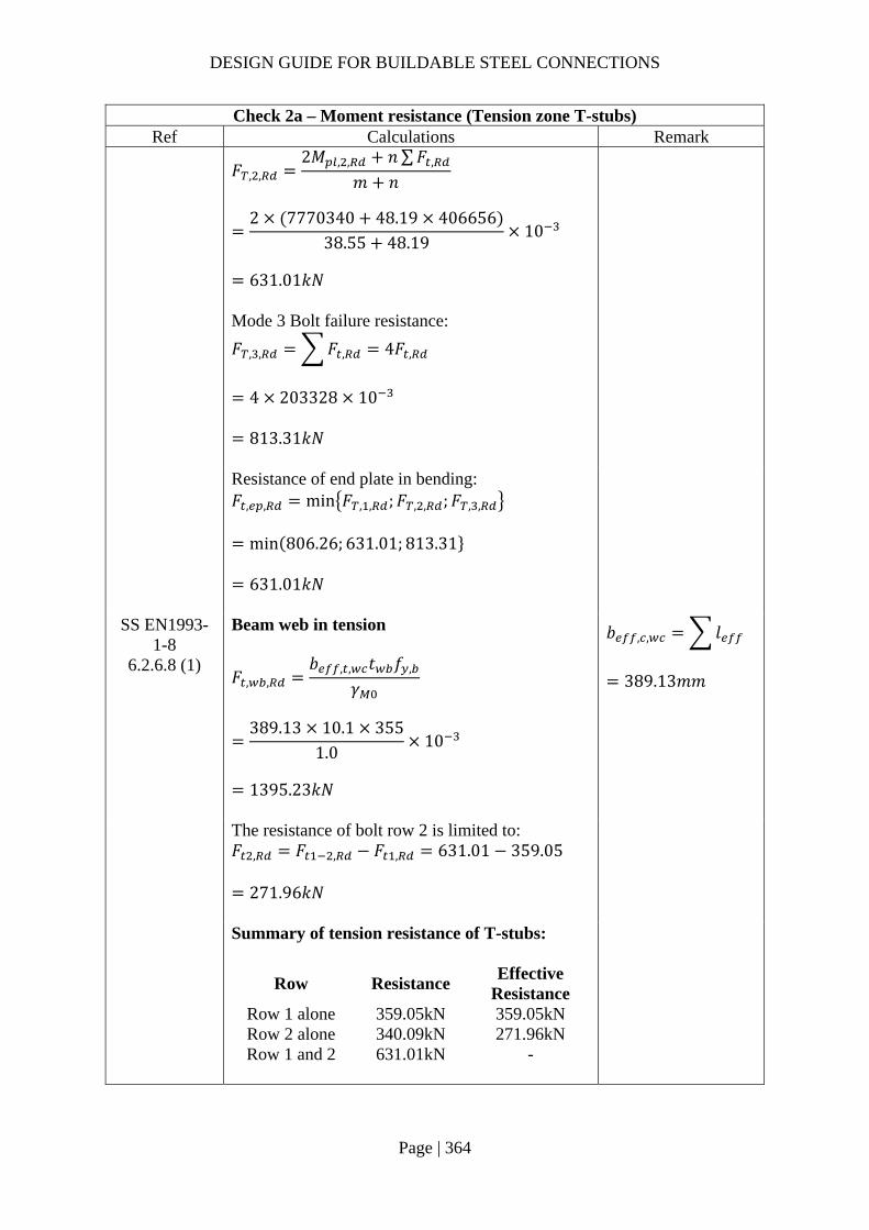
DESIGN GUIDE FOR BUILDABLE STEEL CONNECTIONS
Page | 364
Check 2a – Moment resistance (Tension zone T-stubs) Ref Calculations Remark
𝐹 , ,
2𝑀 , , 𝑛∑𝐹 ,
𝑚 𝑛
2 7770340 48.19 406656
38.55 48.1910
631.01𝑘𝑁
Mode 3 Bolt failure resistance:
𝐹 , , 𝐹 , 4𝐹 ,
4 203328 10
813.31𝑘𝑁
Resistance of end plate in bending: 𝐹 , , min 𝐹 , , ;𝐹 , , ;𝐹 , ,
min 806.26; 631.01; 813.31
631.01𝑘𝑁
SS EN1993-1-8
6.2.6.8 (1)
Beam web in tension
𝐹 , ,𝑏 , , 𝑡 𝑓 ,
𝛾
389.13 10.1 355
1.010
1395.23𝑘𝑁
𝑏 , , 𝑙
389.13𝑚𝑚
The resistance of bolt row 2 is limited to: 𝐹 , 𝐹 , 𝐹 , 631.01 359.05
271.96𝑘𝑁
Summary of tension resistance of T-stubs:
Row Resistance Effective
Resistance Row 1 alone 359.05kN 359.05kN Row 2 alone 340.09kN 271.96kN Row 1 and 2 631.01kN -

DESIGN GUIDE FOR BUILDABLE STEEL CONNECTIONS
Page | 365
Check 2b – Moment resistance (Compression zone) Ref Calculations Remark
SS EN1993-1-8
6.2.6.7 (1)
Design moment resistance of the beam cross-section (S355 UB533x210x92): 𝑀 , 838𝑘𝑁𝑚
𝐹 , ,𝑀 ,
ℎ 𝑡
838
533.1 15.610
1619.32𝑘𝑁
𝑀 , is read from SCI_P363 page D-66 For UB533x210x92: ℎ 533.1𝑚𝑚 𝑡 15.6𝑚𝑚

DESIGN GUIDE FOR BUILDABLE STEEL CONNECTIONS
Page | 366
Check 2 – Moment resistance Ref Calculations Remark
SS EN1993-1-8
6.2.7.2 (9)
The effective resistances of bolt rows need to be reduced when the bolt row resistance is greater than 1.9𝐹 , 1.9𝐹 , 1.9 203.33 386.32𝑘𝑁 As all bolt row resistances are lesser than 386.32kN, no reduction is required.
Equilibrium of forces Total effective tension resistance:
𝐹 , 359.05 271.96
631.01𝑘𝑁 𝐹 , , 1619.32𝑘𝑁
Hence, no reduction is required for the tensile resistance.
SS EN1993-1-8
6.2.7.2 (1)
The moment resistance of the connection may be determined using:
𝑀 , ℎ 𝐹 , ,
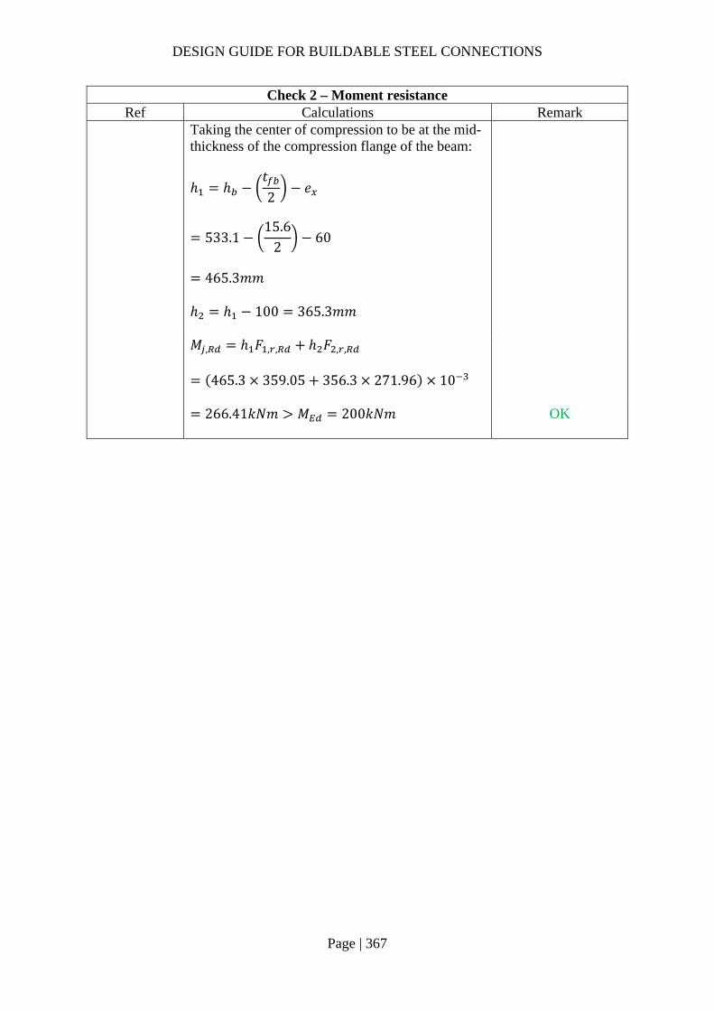
DESIGN GUIDE FOR BUILDABLE STEEL CONNECTIONS
Page | 367
Check 2 – Moment resistance Ref Calculations Remark
Taking the center of compression to be at the mid-thickness of the compression flange of the beam:
ℎ ℎ𝑡2
𝑒
533.115.6
260
465.3𝑚𝑚
ℎ ℎ 100 365.3𝑚𝑚
𝑀 , ℎ 𝐹 , , ℎ 𝐹 , ,
465.3 359.05 356.3 271.96 10
266.41𝑘𝑁𝑚 𝑀 200𝑘𝑁𝑚
OK
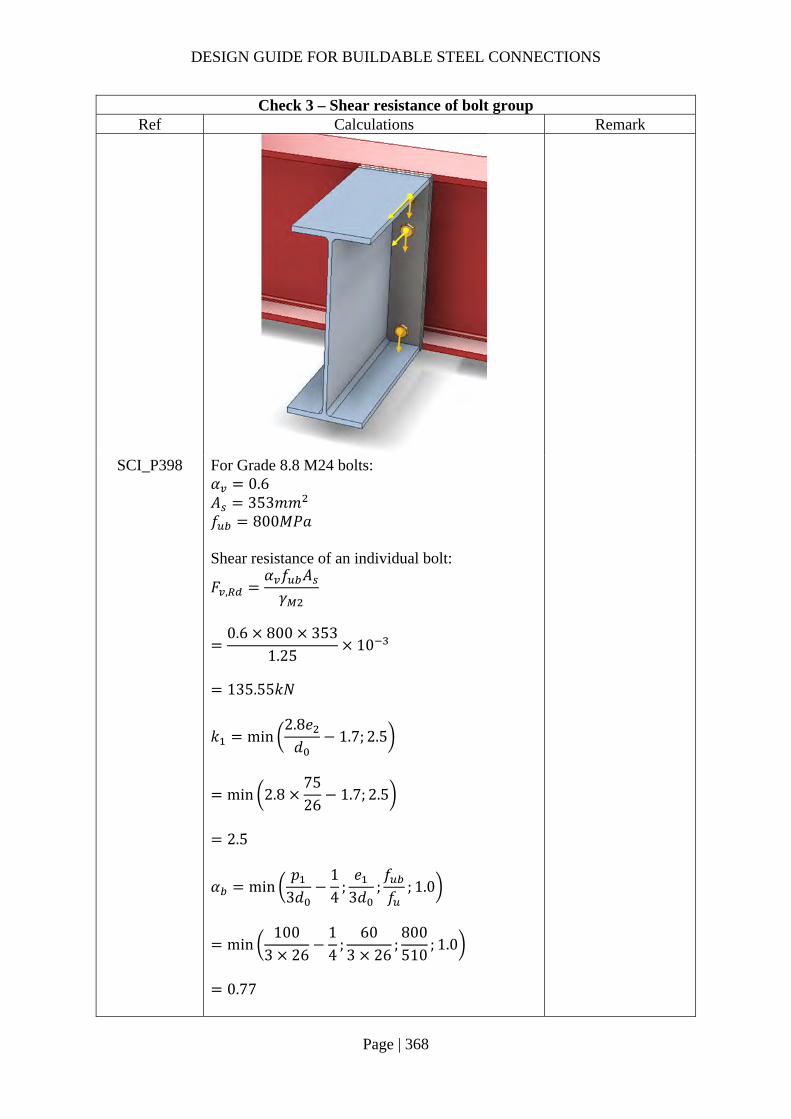
DESIGN GUIDE FOR BUILDABLE STEEL CONNECTIONS
Page | 368
Check 3 – Shear resistance of bolt group Ref Calculations Remark
SCI_P398 For Grade 8.8 M24 bolts: 𝛼 0.6 𝐴 353𝑚𝑚 𝑓 800𝑀𝑃𝑎 Shear resistance of an individual bolt:
𝐹 ,𝛼 𝑓 𝐴𝛾
0.6 800 353
1.2510
135.55𝑘𝑁
𝑘 min2.8𝑒𝑑
1.7; 2.5
min 2.87526
1.7; 2.5
2.5
𝛼 min𝑝
3𝑑14
;𝑒
3𝑑;𝑓𝑓
; 1.0
min100
3 2614
;60
3 26;800510
; 1.0
0.77
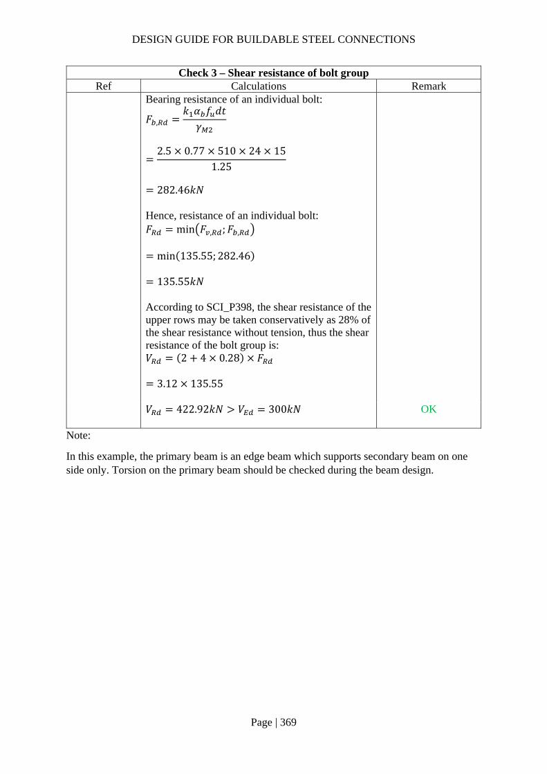
DESIGN GUIDE FOR BUILDABLE STEEL CONNECTIONS
Page | 369
Check 3 – Shear resistance of bolt group Ref Calculations Remark
Bearing resistance of an individual bolt:
𝐹 ,𝑘 𝛼 𝑓 𝑑𝑡𝛾
2.5 0.77 510 24 15
1.25
282.46𝑘𝑁
Hence, resistance of an individual bolt: 𝐹 min 𝐹 , ;𝐹 ,
min 135.55; 282.46
135.55𝑘𝑁
According to SCI_P398, the shear resistance of the upper rows may be taken conservatively as 28% of the shear resistance without tension, thus the shear resistance of the bolt group is: 𝑉 2 4 0.28 𝐹
3.12 135.55
𝑉 422.92𝑘𝑁 𝑉 300𝑘𝑁
OK
Note:
In this example, the primary beam is an edge beam which supports secondary beam on one side only. Torsion on the primary beam should be checked during the beam design.

DESIGN GUIDE FOR BUILDABLE STEEL CONNECTIONS
Page | 370
2.4.12 Example 18 – Beam-to-Beam connection (moment-resisting connection) in major axis and/or minor axis (section b)
As the design calculations for 2.4.12a is similar to that of 2.4.11. Refer to 2.4.11 for details.
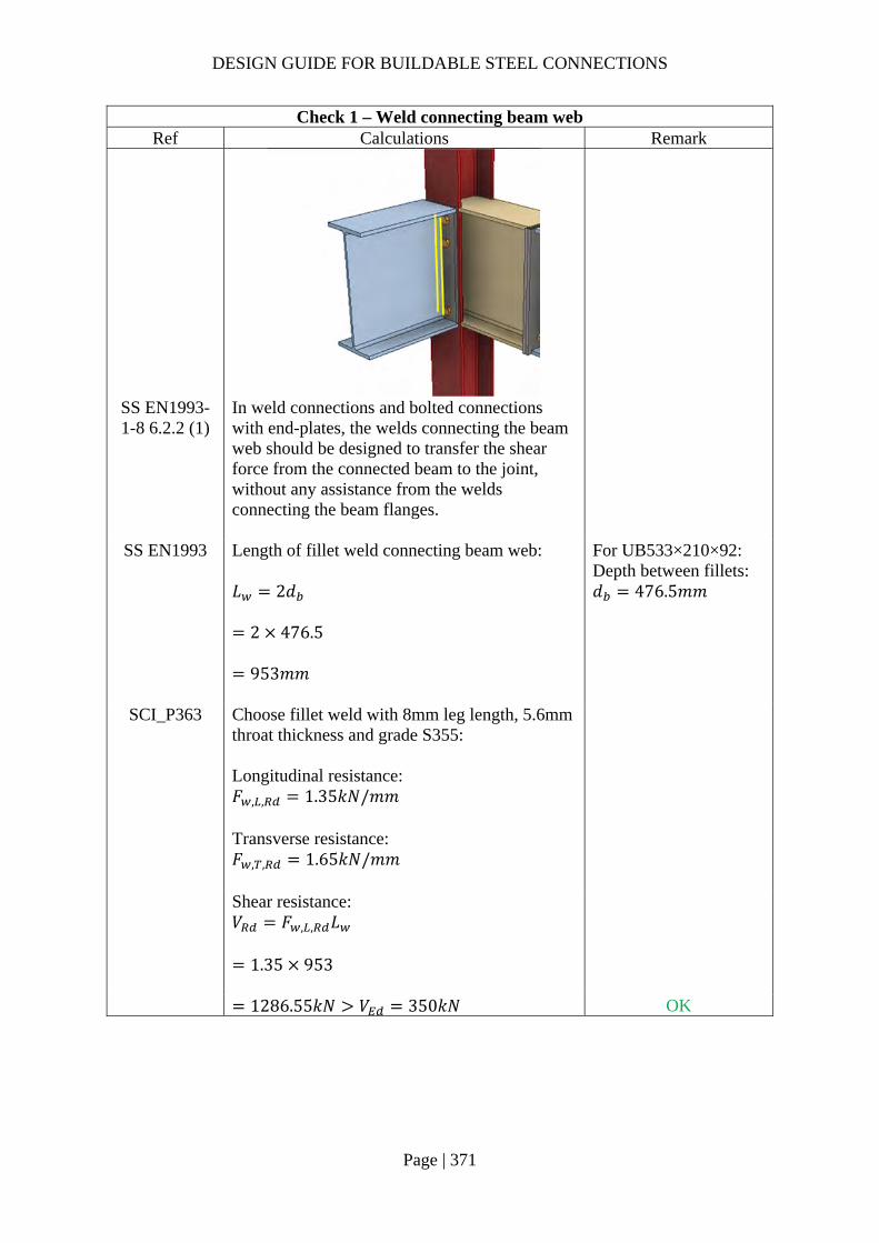
DESIGN GUIDE FOR BUILDABLE STEEL CONNECTIONS
Page | 371
Check 1 – Weld connecting beam web Ref Calculations Remark
SS EN1993-1-8 6.2.2 (1)
In weld connections and bolted connections with end-plates, the welds connecting the beam web should be designed to transfer the shear force from the connected beam to the joint, without any assistance from the welds connecting the beam flanges.
SS EN1993 Length of fillet weld connecting beam web: 𝐿 2𝑑
2 476.5
953𝑚𝑚
For UB533×210×92: Depth between fillets: 𝑑 476.5𝑚𝑚
SCI_P363 Choose fillet weld with 8mm leg length, 5.6mm throat thickness and grade S355: Longitudinal resistance: 𝐹 , , 1.35𝑘𝑁/𝑚𝑚 Transverse resistance: 𝐹 , , 1.65𝑘𝑁/𝑚𝑚
Shear resistance: 𝑉 𝐹 , , 𝐿
1.35 953
1286.55𝑘𝑁 𝑉 350𝑘𝑁 OK

DESIGN GUIDE FOR BUILDABLE STEEL CONNECTIONS
Page | 372
Check 1a– Resistance of PPBW on beam flange and end plate Ref Calculations Remark
BS 5950-1 6.9.2
Partial penetration butt weld resistance: The minimum throat size of a longitudinal partial penetration butt weld should be 2√𝑡 (in mm), where t is the thickness of the thinner part of joint.
SS EN1993-1-1
4.7.2 (1)
The design resistance of a partial penetration butt weld should be determined using the method for a deep penetration fillet weld.
In this example, the angle between the transverse force and weld throat 𝜃 90°. Provided the groove angle is greater than 60° or U-butt is adopted, the throat thickness is equal to the depth of penetration.
Choose partial butt weld with 12mm ( 2√15.67.90𝑚𝑚 throat thickness and grade S355 which match the beam material properties:
𝑓 470𝑀𝑃𝑎 for S355 weld 𝛾 1.25 For UB533x210x92: 𝑏 209.3𝑚𝑚 Groove angle 60°
𝐷

DESIGN GUIDE FOR BUILDABLE STEEL CONNECTIONS
Page | 373
Check 1a– Resistance of PPBW on beam flange and end plate Ref Calculations Remark
The design transverse resistance of weld:
𝐹 , ,0.9𝑓𝛾
𝑎
0.9 470 12
1.2510
4.06𝑘𝑁/𝑚𝑚
The tensile resistance of the weld: 𝐹 , 𝐹 , , 𝑏
4.06 209.3
849.76𝑘𝑁 𝐹 , 409.22𝑘𝑁
OK
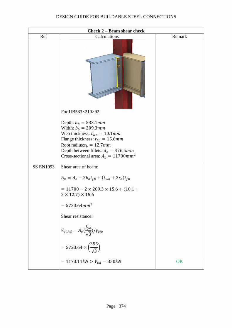
DESIGN GUIDE FOR BUILDABLE STEEL CONNECTIONS
Page | 374
Check 2 – Beam shear check Ref Calculations Remark
For UB533×210×92: Depth: ℎ 533.1𝑚𝑚 Width: 𝑏 209.3𝑚𝑚 Web thickness: 𝑡 10.1𝑚𝑚 Flange thickness: 𝑡 15.6𝑚𝑚 Root radius:𝑟 12.7𝑚𝑚 Depth between fillets: 𝑑 476.5𝑚𝑚 Cross-sectional area: 𝐴 11700𝑚𝑚
SS EN1993 Shear area of beam: 𝐴 𝐴 2𝑏 𝑡 𝑡 2𝑟 𝑡
11700 2 209.3 15.6 10.12 12.7 15.6
5723.64𝑚𝑚 Shear resistance:
𝑉 , 𝐴𝑓
√3/𝛾
5723.64355
√3
1173.11𝑘𝑁 𝑉 350𝑘𝑁
OK

DESIGN GUIDE FOR BUILDABLE STEEL CONNECTIONS
Page | 375
Check 3a – Moment resistance (Tension zone T-stubs) Ref Calculations Remark
For UC203x203x60: Depth: ℎ 209.6𝑚𝑚 Width: 𝑏 205.8𝑚𝑚 Web thickness: 𝑡 9.4𝑚𝑚 Flange thickness: 𝑡 14.2𝑚𝑚 Root radius: 𝑟 10.2𝑚𝑚 Depth between fillets: 𝑑 160.8𝑚𝑚 Cross-sectional area: 𝐴 7640𝑚𝑚
Bolt spacings: End distance: 𝑒 60𝑚𝑚 Edge distance (end plate): 𝑒 75𝑚𝑚 Spacing (gauge): 𝑤 100𝑚𝑚 Edge distance (column flange): 𝑒 0.5 𝑏 𝑤 52.90𝑚𝑚 Spacing row 1 – 2: 𝑝 100𝑚𝑚 Spacing row 2 – 3:𝑝 313.1𝑚𝑚
SCI_P398 SS EN1993-
1-8
Bolt row 1: Column flange in bending
𝑚 𝑚𝑤 𝑡 2 0.8𝑟
2
100 9.4 2 0.8 10.2
2
37.14𝑚𝑚
𝑒
𝑚

DESIGN GUIDE FOR BUILDABLE STEEL CONNECTIONS
Page | 376
Check 3a – Moment resistance (Tension zone T-stubs) Ref Calculations Remark
𝑒 min 𝑒 ; 𝑒
min 52.9; 75
52.9𝑚𝑚 For pair of bolts in a column flange away from any stiffener: The circular patterns effective length for: Circular yielding: 𝑙 2𝜋𝑚 2 𝜋 37.14 233.36𝑚𝑚 The non-circular patterns effective length for: Side yielding: 𝑙 4𝑚 1.25𝑒 4 37.14 1.25 52.9
214.69𝑚𝑚 Effective length for mode 1: 𝑙 , min 𝑙 , ; 𝑙 , 214.69𝑚𝑚 Effective length for mode 2: 𝑙 , 𝑙 , 214.69𝑚𝑚
SCI_P398 SS EN1993-
1-8
Mode 1 Complete flange yielding resistance:
𝑀 , ,0.25∑ 𝑙 , 𝑡 𝑓
𝛾
0.25 214.69 14.2 355
1.0
3841906𝑁𝑚𝑚
𝑛 min 1.25𝑚; 𝑒
min 46.43; 52.9
46.43𝑚𝑚
𝑡 14.2𝑚𝑚16𝑚𝑚
𝑓 355𝑀𝑃𝑎 Grade 8.8 M24 bolts are used: Diameter of washer: 𝑑 44𝑚𝑚
𝑒𝑑4
11𝑚𝑚
DESIGN GUIDE FOR BUILDABLE STEEL CONNECTIONS
Page | 377
Check 3a – Moment resistance (Tension zone T-stubs) Ref Calculations Remark
Method 1:
𝐹 , ,4𝑀 , ,
𝑚
4 3841906
37.1410
413.78𝑘𝑁
Method 2:
𝐹 , ,8𝑛 2𝑒 𝑀 , ,
2𝑚𝑛 𝑒 𝑚 𝑛
8 46.43 2 11 3841906
2 37.14 46.43 11 37.14 46.43
10
530.74𝑘𝑁
Mode 2 Bolt failure with flange yielding resistance:
𝑀 , ,0.25∑ 𝑙 , 𝑡 𝑓
𝛾
0.25 214.69 14.2 355
1.0
3841906𝑁𝑚𝑚
𝐹 ,𝑘 𝑓 𝐴𝛾
0.9 800 353
1.25
203328𝑁
𝐹 , 2 𝐹 , 2 203328
406656𝑁
For Grade 8.8 M24 bolts: 𝑘 0.9 Ultimate strength: 𝑓 800𝑀𝑃𝑎 Shear area: 𝐴 353𝑚𝑚
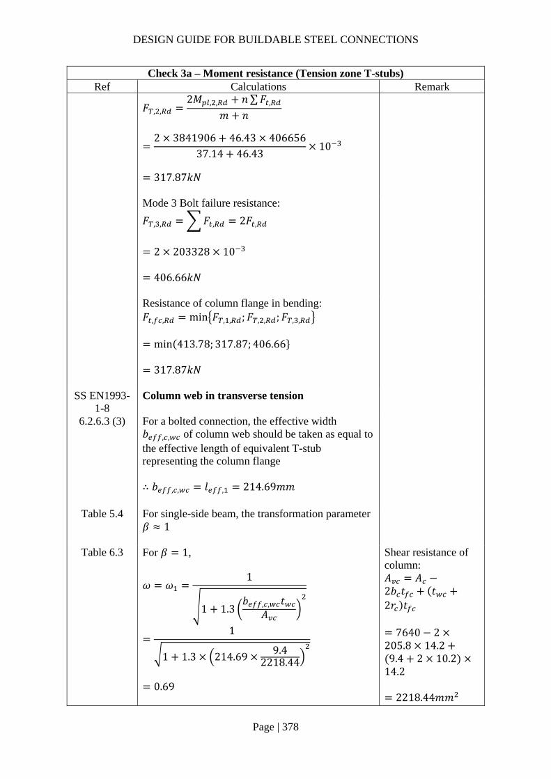
DESIGN GUIDE FOR BUILDABLE STEEL CONNECTIONS
Page | 378
Check 3a – Moment resistance (Tension zone T-stubs) Ref Calculations Remark
𝐹 , ,
2𝑀 , , 𝑛∑𝐹 ,
𝑚 𝑛
2 3841906 46.43 406656
37.14 46.4310
317.87𝑘𝑁
Mode 3 Bolt failure resistance:
𝐹 , , 𝐹 , 2𝐹 ,
2 203328 10
406.66𝑘𝑁
Resistance of column flange in bending: 𝐹 , , min 𝐹 , , ;𝐹 , , ;𝐹 , ,
min 413.78; 317.87; 406.66
317.87𝑘𝑁
SS EN1993-1-8
Column web in transverse tension
6.2.6.3 (3) For a bolted connection, the effective width 𝑏 , , of column web should be taken as equal to the effective length of equivalent T-stub representing the column flange ∴ 𝑏 , , 𝑙 , 214.69𝑚𝑚
Table 5.4 For single-side beam, the transformation parameter 𝛽 1
Table 6.3 For 𝛽 1,
𝜔 𝜔1
1 1.3𝑏 , , 𝑡
𝐴
1
1 1.3 214.69 9.42218.44
0.69
Shear resistance of column: 𝐴 𝐴2𝑏 𝑡 𝑡2𝑟 𝑡
7640 2205.8 14.29.4 2 10.2
14.2
2218.44𝑚𝑚

DESIGN GUIDE FOR BUILDABLE STEEL CONNECTIONS
Page | 379
Check 3a – Moment resistance (Tension zone T-stubs) Ref Calculations Remark
6.2.6.3 Design resistance of unstiffened column web to transverse tension:
𝐹 , ,𝜔𝑏 , , 𝑡 𝑓 ,
𝛾
0.69 214.69 9.4 355
1.010
497.25𝑘𝑁
End plate in bending
𝑚 𝑚𝑤 𝑡 2 0.8𝑠
2
100 10.1 2 0.8 8
2
38.55𝑚𝑚
𝑒 𝑒 75𝑚𝑚 𝑚 𝑒 𝑡 0.8𝑠
60 15.6 0.8 12
34.8𝑚𝑚 Based on Figure 6.11 of SS EN1993-1-8: Values of 𝛼 for stiffened column flanges and end-plates, 𝛼 7.2 For pair of bolts in a column flange below a stiffener (or cap plate) or in an end plate below the beam flange: The circular patterns effective length for: Circular yielding: 𝑙 , 2𝜋𝑚 2𝜋 38.55 242.22𝑚𝑚 The non-circular patterns effective length for: Side yielding near beam flange or a stiffener: 𝑙 , 𝛼𝑚 7.2 38.55 277.56𝑚𝑚
𝜆𝑚
𝑚 𝑒
38.55
38.55 75
0.34
𝜆𝑚
𝑚 𝑒
34.8
38.55 75
0.31
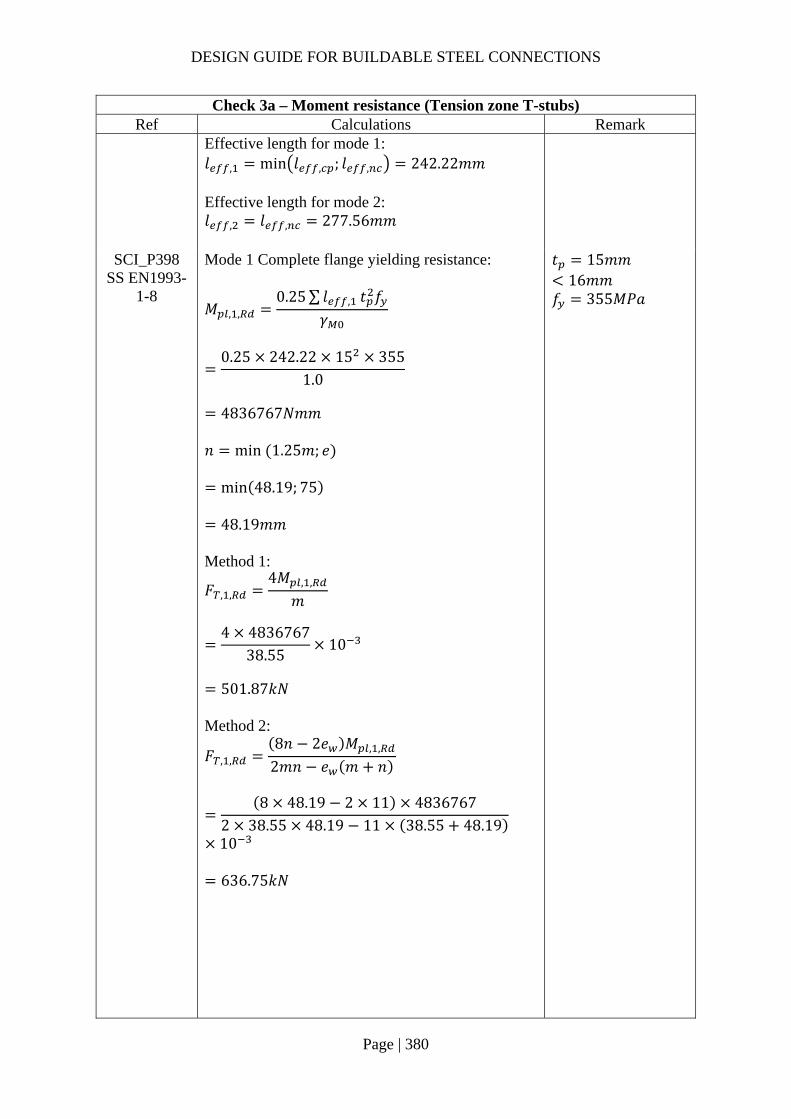
DESIGN GUIDE FOR BUILDABLE STEEL CONNECTIONS
Page | 380
Check 3a – Moment resistance (Tension zone T-stubs) Ref Calculations Remark
Effective length for mode 1: 𝑙 , min 𝑙 , ; 𝑙 , 242.22𝑚𝑚 Effective length for mode 2: 𝑙 , 𝑙 , 277.56𝑚𝑚
SCI_P398 SS EN1993-
1-8
Mode 1 Complete flange yielding resistance:
𝑀 , ,0.25∑ 𝑙 , 𝑡 𝑓
𝛾
0.25 242.22 15 355
1.0
4836767𝑁𝑚𝑚
𝑛 min 1.25𝑚; 𝑒
min 48.19; 75
48.19𝑚𝑚 Method 1:
𝐹 , ,4𝑀 , ,
𝑚
4 4836767
38.5510
501.87𝑘𝑁
Method 2:
𝐹 , ,8𝑛 2𝑒 𝑀 , ,
2𝑚𝑛 𝑒 𝑚 𝑛
8 48.19 2 11 4836767
2 38.55 48.19 11 38.55 48.19
10
636.75𝑘𝑁
𝑡 15𝑚𝑚16𝑚𝑚
𝑓 355𝑀𝑃𝑎

DESIGN GUIDE FOR BUILDABLE STEEL CONNECTIONS
Page | 381
Check 3a – Moment resistance (Tension zone T-stubs) Ref Calculations Remark
Mode 2 Bolt failure with flange yielding resistance:
𝑀 , ,0.25∑ 𝑙 , 𝑡 𝑓
𝛾
0.25 277.56 15 355
1.0
5542526𝑁𝑚𝑚
𝐹 , ,2𝑀 , , 𝑛∑𝐹 ,
𝑚 𝑛
2 5542526 48.19 406656
38.55 48.1910
353.72𝑘𝑁
Mode 3 Bolt failure resistance:
𝐹 , , 𝐹 , 2𝐹 ,
2 203328 10
406.66𝑘𝑁
Resistance of end plate in bending: 𝐹 , , min 𝐹 , , ;𝐹 , , ;𝐹 , ,
min 501.87; 353.72; 406.66
353.72𝑘𝑁
SS EN1993-1-8
6.2.6.8 (1)
Beam web in tension
𝐹 , ,𝑏 , , 𝑡 𝑓 ,
𝛾
242.22 10.1 355
1.010
868.47𝑘𝑁
𝑏 , , 𝑙
242.22𝑚𝑚 *Conservatively, consider the smallest 𝑙 (6.2.6.8 (2))

DESIGN GUIDE FOR BUILDABLE STEEL CONNECTIONS
Page | 382
Check 3a – Moment resistance (Tension zone T-stubs) Ref Calculations Remark
Summary of resistance of T-stubs for bolt row 1 Column flange bending 𝐹 , , 317.87𝑘𝑁 Column web in tension 𝐹 , , 497.25𝑘𝑁 End plate in bending 𝐹 , , 353.72𝑘𝑁 Beam web in tension 𝐹 , , 868.47𝑘𝑁
∴The resistance of bolt row 1: 𝐹 , , 317.87𝑘𝑁
Bolt row 2: Column flange in bending The resistance of the column flange in bending is same as that for bolt row 1. 𝐹 , , 317.87𝑘𝑁
Column web in transverse tension The resistance of the column web in transverse tension is same as that for bolt row 1 𝐹 , , 497.25𝑘𝑁
End plate in bending For pair of bolts in a column flange away from any stiffener or in an end plate, away from the flange or any stiffener:
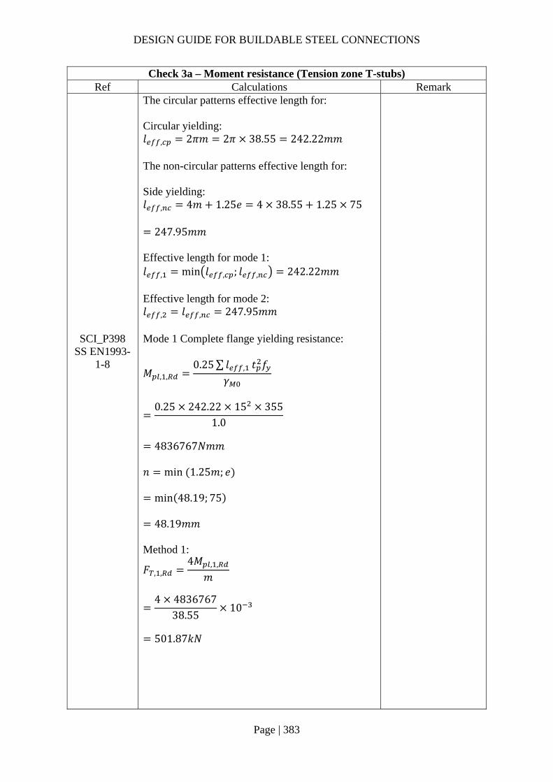
DESIGN GUIDE FOR BUILDABLE STEEL CONNECTIONS
Page | 383
Check 3a – Moment resistance (Tension zone T-stubs) Ref Calculations Remark
The circular patterns effective length for: Circular yielding: 𝑙 , 2𝜋𝑚 2𝜋 38.55 242.22𝑚𝑚 The non-circular patterns effective length for: Side yielding: 𝑙 , 4𝑚 1.25𝑒 4 38.55 1.25 75
247.95𝑚𝑚 Effective length for mode 1: 𝑙 , min 𝑙 , ; 𝑙 , 242.22𝑚𝑚 Effective length for mode 2: 𝑙 , 𝑙 , 247.95𝑚𝑚
SCI_P398 SS EN1993-
1-8
Mode 1 Complete flange yielding resistance:
𝑀 , ,0.25∑ 𝑙 , 𝑡 𝑓
𝛾
0.25 242.22 15 355
1.0
4836767𝑁𝑚𝑚
𝑛 min 1.25𝑚; 𝑒
min 48.19; 75
48.19𝑚𝑚 Method 1:
𝐹 , ,4𝑀 , ,
𝑚
4 4836767
38.5510
501.87𝑘𝑁

DESIGN GUIDE FOR BUILDABLE STEEL CONNECTIONS
Page | 384
Check 3a – Moment resistance (Tension zone T-stubs) Ref Calculations Remark
Method 2:
𝐹 , ,8𝑛 2𝑒 𝑀 , ,
2𝑚𝑛 𝑒 𝑚 𝑛
8 48.19 2 11 4836767
2 38.55 48.19 11 38.55 48.19
10
636.75𝑘𝑁
Mode 2 Bolt failure with flange yielding resistance:
𝑀 , ,0.25∑ 𝑙 , 𝑡 𝑓
𝛾
0.25 247.95 15 355
1.0
4951252𝑁𝑚𝑚
𝐹 , ,2𝑀 , , 𝑛∑𝐹 ,
𝑚 𝑛
24951252 48.19 406656
38.55 48.1910
340.09𝑘𝑁
Mode 3 Bolt failure resistance:
𝐹 , , 𝐹 , 2𝐹 ,
2 203328 10
406.66𝑘𝑁
Resistance of end plate in bending: 𝐹 , , min 𝐹 , , ;𝐹 , , ;𝐹 , ,
min 501.87; 340.09; 406.66
340.09𝑘𝑁

DESIGN GUIDE FOR BUILDABLE STEEL CONNECTIONS
Page | 385
Check 3a – Moment resistance (Tension zone T-stubs) Ref Calculations Remark
SS EN1993-1-8
6.2.6.8 (1)
Beam web in tension
𝐹 , ,𝑏 , , 𝑡 𝑓 ,
𝛾
242.22 10.1 355
1.010
868.47𝑘𝑁
𝑏 , , 𝑙
242.22𝑚𝑚
The above resistance for bolt row 2 all considered the resistance of the row acting alone. The resistance of bolt row 2 may be limited by the resistance of combined blot row 1 and 2.
Bolt rows 1 and 2 combined Column flange in bending 𝑚 𝑚 37.14𝑚𝑚 𝑒 52.9𝑚𝑚 𝑝 100𝑚𝑚 For top row in an unstiffened column: The circular patterns effective length for: Bolt groups close to free edge: 𝑙 , 2𝑒 𝑝 ∗ 𝑒 is large for the column, so this case will not be critical
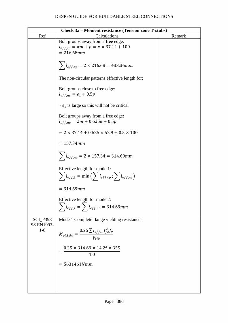
DESIGN GUIDE FOR BUILDABLE STEEL CONNECTIONS
Page | 386
Check 3a – Moment resistance (Tension zone T-stubs) Ref Calculations Remark
Bolt groups away from a free edge: 𝑙 , 𝜋𝑚 𝑝 𝜋 37.14 100
216.68𝑚𝑚
𝑙 , 2 216.68 433.36𝑚𝑚
The non-circular patterns effective length for: Bolt groups close to free edge: 𝑙 , 𝑒 0.5𝑝 ∗ 𝑒 is large so this will not be critical Bolt groups away from a free edge: 𝑙 , 2𝑚 0.625𝑒 0.5𝑝
2 37.14 0.625 52.9 0.5 100
157.34𝑚𝑚
𝑙 , 2 157.34 314.69𝑚𝑚
Effective length for mode 1:
𝑙 , min 𝑙 , ; 𝑙 ,
314.69𝑚𝑚
Effective length for mode 2:
𝑙 , 𝑙 , 314.69𝑚𝑚
SCI_P398 SS EN1993-
1-8
Mode 1 Complete flange yielding resistance:
𝑀 , ,0.25∑ 𝑙 , 𝑡 𝑓
𝛾
0.25 314.69 14.2 355
1.0
5631461𝑁𝑚𝑚

DESIGN GUIDE FOR BUILDABLE STEEL CONNECTIONS
Page | 387
Check 3a – Moment resistance (Tension zone T-stubs) Ref Calculations Remark
𝑛 min 1.25𝑚; 𝑒
min 46.43; 52.9 46.43𝑚𝑚
Method 1:
𝐹 , ,4𝑀 , ,
𝑚
4 5631461
37.1410
606.51𝑘𝑁
Method 2:
𝐹 , ,8𝑛 2𝑒 𝑀 , ,
2𝑚𝑛 𝑒 𝑚 𝑛
8 46.43 2 11 56314612 37.14 46.43 11 37.14 46.43
10
777.96𝑘𝑁
Mode 2 Bolt failure with flange yielding resistance:
𝑀 , ,0.25∑ 𝑙 , 𝑡 𝑓
𝛾
0.25 314.69 14.2 355
1.0
5631461𝑁𝑚𝑚
𝐹 , 4 𝐹 , 4 203328
813312𝑁
𝐹 , ,2𝑀 , , 𝑛∑𝐹 ,
𝑚 𝑛
2 5631461 46.43 813312
37.14 46.4310
586.62𝑘𝑁

DESIGN GUIDE FOR BUILDABLE STEEL CONNECTIONS
Page | 388
Check 3a – Moment resistance (Tension zone T-stubs) Ref Calculations Remark
Mode 3 Bolt failure resistance:
𝐹 , , 𝐹 , 4𝐹 ,
4 203328 10
813.31𝑘𝑁
Resistance of column flange in bending: 𝐹 , , min 𝐹 , , ;𝐹 , , ;𝐹 , ,
min 606.51; 586.62; 813.31
586.62𝑘𝑁
SS EN1993-1-8
Column web in transverse tension
6.2.6.3 (3) For a bolted connection, the effective width 𝑏 , , of column web should be taken as equal to the effective length of equivalent T-stub representing the column flange ∴ 𝑏 , , 𝑙 , 314.69𝑚𝑚
Table 6.3 𝜔 𝜔
1
1 1.3𝑏 , , 𝑡
𝐴
1
1 1.3 314.69 9.42218.44
0.55
6.2.6.3 Design resistance of unstiffened column web to transverse tension:
𝐹 , ,𝜔𝑏 , , 𝑡 𝑓 ,
𝛾
0.55 314.69 9.4 355
1.010
577.08𝑘𝑁

DESIGN GUIDE FOR BUILDABLE STEEL CONNECTIONS
Page | 389
Check 3a – Moment resistance (Tension zone T-stubs) Ref Calculations Remark
SS EN1993-1-8
6.2.6.5 Table 6.6
End plate in bending Row 1 is classified as “First bolt-row below tension flange of beam” with effective length: Circular patterns: 𝑙 , 𝜋𝑚 𝑝 𝜋 38.55 100
221.11𝑚𝑚 Non-circular patterns: 𝑙 , 0.5𝑝 𝛼𝑚 2𝑚 0.625𝑒
0.5 100 7.2 38.55 2 38.550.625 75
203.59𝑚𝑚 Row 2 is classified as “Other end bolt-row” with effective length: Circular patterns: 𝑙 , 𝜋𝑚 𝑝 𝜋 38.55 100
221.11𝑚𝑚 Non-circular patterns: 𝑙 , 2𝑚 0.625𝑒 0.5𝑝
2 38.55 0.625 75 0.5 100
173.98𝑚𝑚
The total effective length for this bolt group combination:
𝑙 , 221.11 221.11 442.22𝑚𝑚
𝑙 , 203.59 173.98 377.56𝑚𝑚
Effective length for mode 1:
𝑙 , min 𝑙 , ; 𝑙 ,
377.56𝑚𝑚
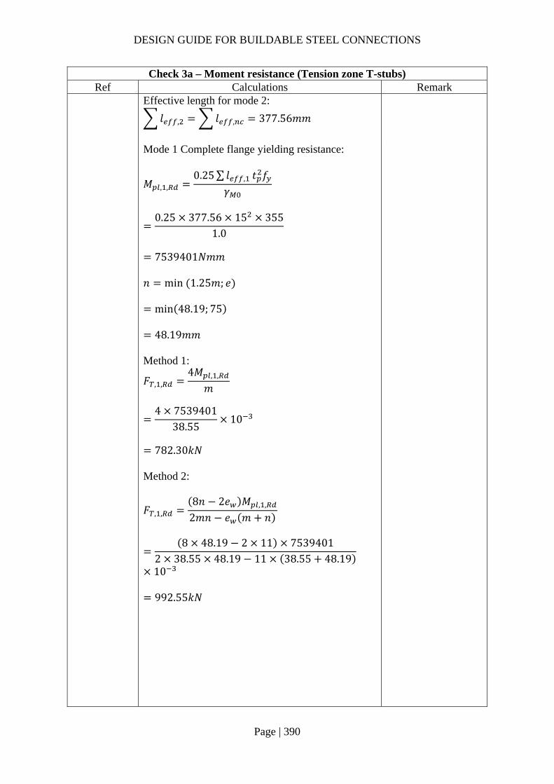
DESIGN GUIDE FOR BUILDABLE STEEL CONNECTIONS
Page | 390
Check 3a – Moment resistance (Tension zone T-stubs) Ref Calculations Remark
Effective length for mode 2:
𝑙 , 𝑙 , 377.56𝑚𝑚
Mode 1 Complete flange yielding resistance:
𝑀 , ,0.25∑ 𝑙 , 𝑡 𝑓
𝛾
0.25 377.56 15 355
1.0
7539401𝑁𝑚𝑚
𝑛 min 1.25𝑚; 𝑒
min 48.19; 75
48.19𝑚𝑚 Method 1:
𝐹 , ,4𝑀 , ,
𝑚
4 7539401
38.5510
782.30𝑘𝑁
Method 2:
𝐹 , ,8𝑛 2𝑒 𝑀 , ,
2𝑚𝑛 𝑒 𝑚 𝑛
8 48.19 2 11 7539401
2 38.55 48.19 11 38.55 48.19
10
992.55𝑘𝑁
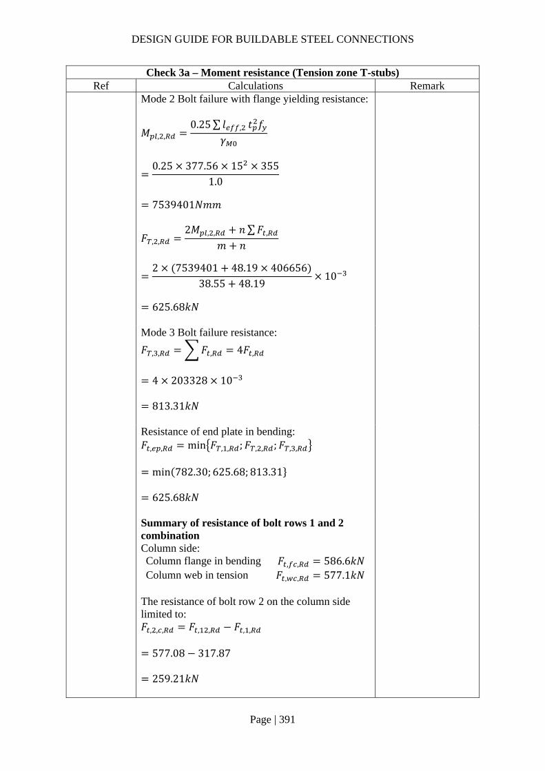
DESIGN GUIDE FOR BUILDABLE STEEL CONNECTIONS
Page | 391
Check 3a – Moment resistance (Tension zone T-stubs) Ref Calculations Remark
Mode 2 Bolt failure with flange yielding resistance:
𝑀 , ,0.25∑ 𝑙 , 𝑡 𝑓
𝛾
0.25 377.56 15 355
1.0
7539401𝑁𝑚𝑚
𝐹 , ,2𝑀 , , 𝑛∑𝐹 ,
𝑚 𝑛
2 7539401 48.19 406656
38.55 48.1910
625.68𝑘𝑁
Mode 3 Bolt failure resistance:
𝐹 , , 𝐹 , 4𝐹 ,
4 203328 10
813.31𝑘𝑁
Resistance of end plate in bending: 𝐹 , , min 𝐹 , , ;𝐹 , , ;𝐹 , ,
min 782.30; 625.68; 813.31
625.68𝑘𝑁
Summary of resistance of bolt rows 1 and 2 combination Column side: Column flange in bending 𝐹 , , 586.6𝑘𝑁 Column web in tension 𝐹 , , 577.1𝑘𝑁
The resistance of bolt row 2 on the column side limited to: 𝐹 , , , 𝐹 , , 𝐹 , ,
577.08 317.87
259.21𝑘𝑁
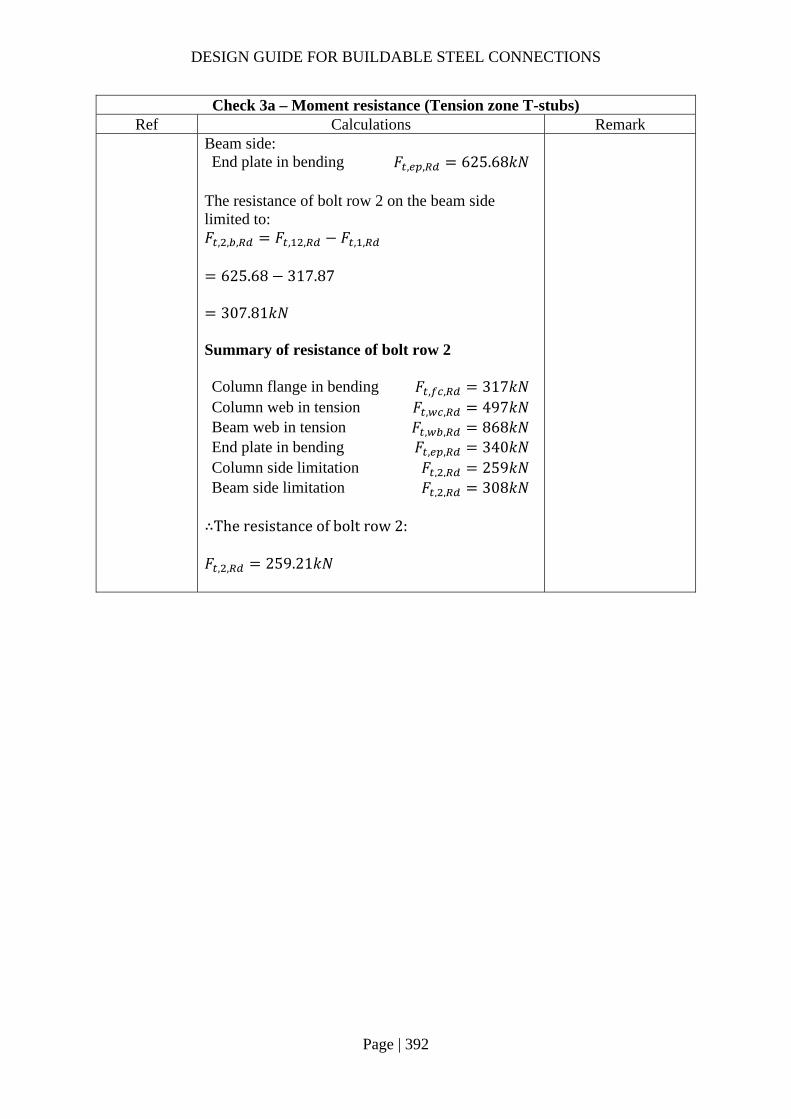
DESIGN GUIDE FOR BUILDABLE STEEL CONNECTIONS
Page | 392
Check 3a – Moment resistance (Tension zone T-stubs) Ref Calculations Remark
Beam side: End plate in bending 𝐹 , , 625.68𝑘𝑁
The resistance of bolt row 2 on the beam side limited to: 𝐹 , , , 𝐹 , , 𝐹 , ,
625.68 317.87
307.81𝑘𝑁
Summary of resistance of bolt row 2 Column flange in bending 𝐹 , , 317𝑘𝑁 Column web in tension 𝐹 , , 497𝑘𝑁 Beam web in tension 𝐹 , , 868𝑘𝑁 End plate in bending 𝐹 , , 340𝑘𝑁 Column side limitation 𝐹 , , 259𝑘𝑁 Beam side limitation 𝐹 , , 308𝑘𝑁
∴The resistance of bolt row 2: 𝐹 , , 259.21𝑘𝑁

DESIGN GUIDE FOR BUILDABLE STEEL CONNECTIONS
Page | 393
Check 3b – Compression zone Ref Calculations Remark
Column web in transverse compression As the depth of the end plate is same as the beam, the dispersion of the force may not be same as normal end plate connection with sufficient depth. Effective length of column web:
𝑏 , , 𝑡 𝑠 5 𝑡 𝑠𝑠2
15.6 12 5 14.2 10.2 15
164.6𝑚𝑚
Plate slenderness:
�̅� 0.932𝑏 , , 𝑑 𝑓
𝐸𝑡
0.932164.6 209.6 355
210000 9.4
0.76 0.72
𝜌�̅� 0.2
�̅�
0.76 0.2
0.76
0.97
𝑡

DESIGN GUIDE FOR BUILDABLE STEEL CONNECTIONS
Page | 394
Check 3b – Compression zone Ref Calculations Remark
As 𝛽 1,
𝜔
1
1 1.3𝑏 , , 𝑡
𝐴
0.78
𝐴 2218.44𝑚𝑚
Design resistance of an unstiffened column web:
𝐹 , ,𝜔𝑘 𝜌𝑏 , , 𝑡 𝑓
𝛾
0.78 0.97 164.6 9.4 355
1.010
417.80𝑘𝑁
𝑘 1
SS EN1993-1-8
6.2.6.7 (1)
Beam flange and web in compression Design moment resistance of the beam cross-section (S355 UB457x152x67): 𝑀 , 838𝑘𝑁𝑚
𝐹 , ,𝑀 ,
ℎ 𝑡
838
533.1 15.610
1619.32𝑘𝑁
𝑀 , is read from SCI_P363 page D-68
Column web in shear The plastic shear resistance of an unstiffened web:
𝑉 ,0.9𝑓 𝐴
√3𝛾
0.9 355 2218.44
√3
409.22𝑘𝑁

DESIGN GUIDE FOR BUILDABLE STEEL CONNECTIONS
Page | 395
Check 3b – Compression zone Ref Calculations Remark
∴ The resistance of the compression zone is: 𝐹 , min 𝐹 , , ;𝐹 , , ;𝑉 ,
min 417.80; 1619.32; 409.22
409.22𝑘𝑁
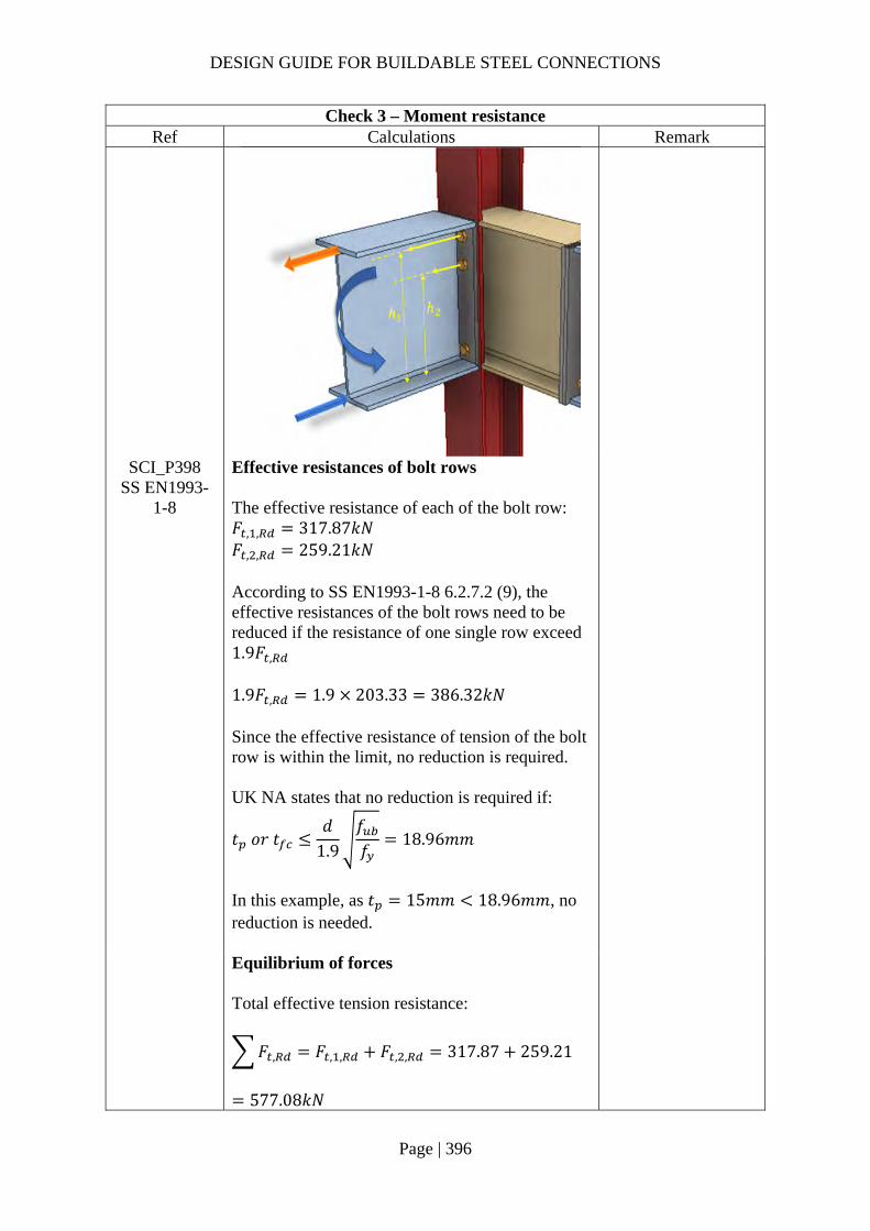
DESIGN GUIDE FOR BUILDABLE STEEL CONNECTIONS
Page | 396
Check 3 – Moment resistance Ref Calculations Remark
SCI_P398 SS EN1993-
1-8
Effective resistances of bolt rows The effective resistance of each of the bolt row: 𝐹 , , 317.87𝑘𝑁 𝐹 , , 259.21𝑘𝑁 According to SS EN1993-1-8 6.2.7.2 (9), the effective resistances of the bolt rows need to be reduced if the resistance of one single row exceed 1.9𝐹 , 1.9𝐹 , 1.9 203.33 386.32𝑘𝑁 Since the effective resistance of tension of the bolt row is within the limit, no reduction is required. UK NA states that no reduction is required if:
𝑡 𝑜𝑟 𝑡𝑑
1.9𝑓𝑓
18.96𝑚𝑚
In this example, as 𝑡 15𝑚𝑚 18.96𝑚𝑚, no reduction is needed.
Equilibrium of forces Total effective tension resistance:
𝐹 , 𝐹 , , 𝐹 , , 317.87 259.21
577.08𝑘𝑁
DESIGN GUIDE FOR BUILDABLE STEEL CONNECTIONS
Page | 397
Check 3 – Moment resistance Ref Calculations Remark
Compression resistance:
𝐹 , 409.22𝑘𝑁 𝐹 ,
∴ Reduction is needed and can be done by reducing the resistance of bottom row of bolt
Hence, 𝐹 , , 259.21 577.08 409.22
91.35𝑘𝑁
SS EN1993-1-8
6.2.7.2 (1)
Moment resistance of joint The moment resistance of the connection may be determined using:
𝑀 , ℎ 𝐹 , ,
Taking the center of compression to be at the mid-thickness of the compression flange of the beam:
ℎ ℎ𝑡2
𝑒
533.115.6
260
465.3𝑚𝑚
ℎ ℎ 100 365.3𝑚𝑚 𝑀 , ℎ 𝐹 , , ℎ 𝐹 , ,
465.3 317.87 365.3 91.35
181.28𝑘𝑁𝑚 𝑀 100𝑘𝑁𝑚
OK

DESIGN GUIDE FOR BUILDABLE STEEL CONNECTIONS
Page | 398
Check 4 – Vertical shear resistance of bolt group Ref Calculations Remark
SCI_P398 For Grade 8.8 M24 bolts: 𝛼 0.6 𝐴 353𝑚𝑚 𝑓 800𝑀𝑃𝑎 Shear resistance of an individual bolt:
𝐹 ,𝛼 𝑓 𝐴𝛾
0.6 800 353
1.2510
135.55𝑘𝑁
Bearing on end plate:
𝑘 min2.8𝑒𝑑
1.7; 2.5
min 2.85026
1.7; 2.5
2.5
𝛼 min𝑝
3𝑑14
;𝑒
3𝑑;𝑓𝑓
; 1.0
min100
3 2614
;60
3 26;800510
; 1.0
0.77

DESIGN GUIDE FOR BUILDABLE STEEL CONNECTIONS
Page | 399
Check 4 – Vertical shear resistance of bolt group Ref Calculations Remark
𝐹 ,
𝑘 𝛼 𝑓 𝑑𝑡𝛾
2.5 0.77 510 24 15
1.25
282.46𝑘𝑁
Hence, resistance of an individual bolt: 𝐹 min 𝐹 , ;𝐹 ,
min 135.55; 282.46
135.55𝑘𝑁
According to SCI_P398, the shear resistance of the upper rows may be taken conservatively as 28% of the shear resistance without tension, thus the shear resistance of the bolt group is: 𝑉 2 4 0.28 𝐹
3.12 135.55
𝑉 422.92𝑘𝑁 𝑉 350𝑘𝑁
OK

DESIGN GUIDE FOR BUILDABLE STEEL CONNECTIONS
Page | 400
2.4.13 Example 19 – Beam-to-Beam connection (moment-resisting connection) in major axis and/or minor axis (section c)
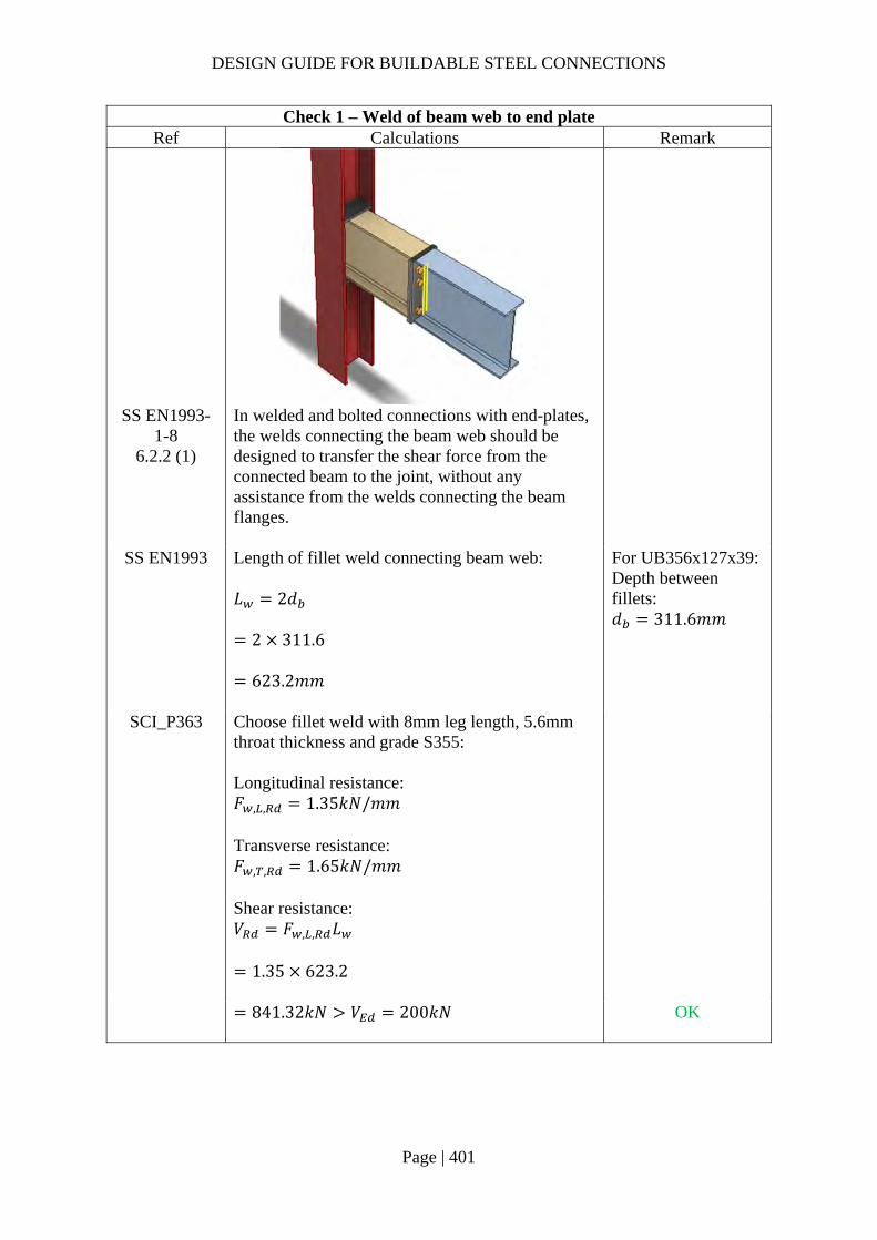
DESIGN GUIDE FOR BUILDABLE STEEL CONNECTIONS
Page | 401
Check 1 – Weld of beam web to end plate Ref Calculations Remark
SS EN1993-1-8
6.2.2 (1)
In welded and bolted connections with end-plates, the welds connecting the beam web should be designed to transfer the shear force from the connected beam to the joint, without any assistance from the welds connecting the beam flanges.
SS EN1993 Length of fillet weld connecting beam web: 𝐿 2𝑑
2 311.6
623.2𝑚𝑚
For UB356x127x39: Depth between fillets: 𝑑 311.6𝑚𝑚
SCI_P363 Choose fillet weld with 8mm leg length, 5.6mm throat thickness and grade S355: Longitudinal resistance: 𝐹 , , 1.35𝑘𝑁/𝑚𝑚 Transverse resistance: 𝐹 , , 1.65𝑘𝑁/𝑚𝑚
Shear resistance: 𝑉 𝐹 , , 𝐿
1.35 623.2
841.32𝑘𝑁 𝑉 200𝑘𝑁
OK

DESIGN GUIDE FOR BUILDABLE STEEL CONNECTIONS
Page | 402
Check 4 – Resistance of PPBW Ref Calculations Remark
BS 5950-1 6.9.2
Partial penetration butt weld resistance: The minimum throat size of a longitudinal partial penetration butt weld should be 2√𝑡 (in mm), where t is the thickness of the thinner part of joint.
SS EN1993-1-1
4.7.2 (1)
The design resistance of a partial penetration butt weld should be determined using the method for a deep penetration fillet weld.
SCI_P363 In this example, the angle between the transverse force and weld throat 𝜃 90°. Provided the groove angle is greater than 60° or U-butt is adopted, the throat thickness is equal to the depth of penetration.
Choose partial butt weld with 8mm ( 2√10.76.54𝑚𝑚 throat thickness and grade S355 which match the beam material properties: The design transverse resistance of weld:
𝐹 , ,0.9𝑓𝛾
𝑎
0.9 470 8
1.2510
2.71𝑘𝑁/𝑚𝑚
𝑓 470𝑀𝑃𝑎 for S355 weld 𝛾 1.25 For UB356x127x39: 𝑏 126𝑚𝑚 Groove angle 60°
𝐷
DESIGN GUIDE FOR BUILDABLE STEEL CONNECTIONS
Page | 403
Check 4 – Resistance of PPBW Ref Calculations Remark
The tensile resistance of the weld: 𝐹 , 𝐹 , , 𝑏
2.71 126
341.11𝑘𝑁 Applied tensile force on beam flange:
𝐹𝑀
ℎ 𝑡
100
353.4 10.710
291.80𝑘𝑁 𝐹 , 341.11𝑘𝑁 OK

DESIGN GUIDE FOR BUILDABLE STEEL CONNECTIONS
Page | 404
Check 5 – Welding on stiffener plate Ref Calculations Remark
SS EN1993 Beam flange tensile resistance:
𝐹 .𝑡 𝑏 𝑓 ,
𝛾
10.7 126 355
1.010
478.61𝑘𝑁
Applied tensile force on beam flange at the connection:
𝐹𝑀 ,
ℎ 𝑡
150
353.4 10.710
437.70𝑘𝑁 𝐹 , 478.61𝑘𝑁
For beam UB356x127x39: 𝑏 126𝑚𝑚 ℎ 353.4𝑚𝑚 𝑡 10.7𝑚𝑚 For column UC203x203x60: ℎ 209.6𝑚𝑚 Depth between fillets: 𝑑 160.8𝑚𝑚 𝑡 9.4𝑚𝑚 𝑟 10.2𝑚𝑚 𝑏 205.8𝑚𝑚
Fillet weld between beam stub and stiffener plate: Length of fillet weld parallel to the tensile force:
𝐿 ,𝑏 𝑡 2 𝑟
2
205.8 9.4 2 10.2
2
88𝑚𝑚
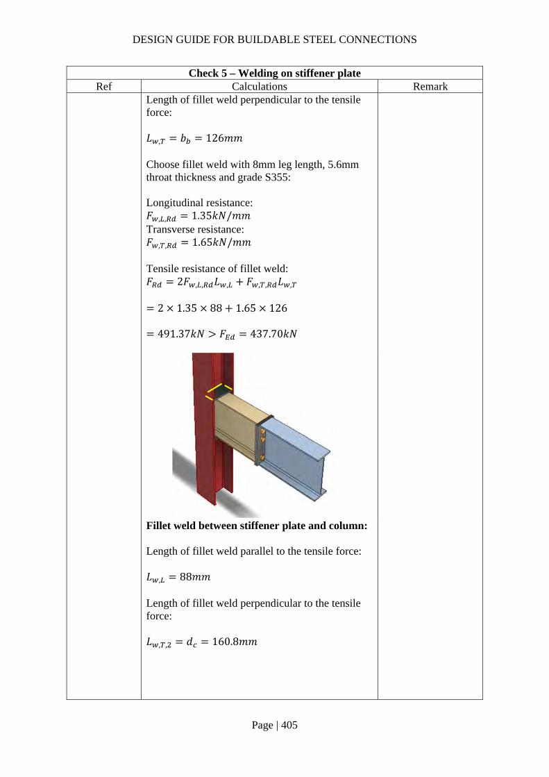
DESIGN GUIDE FOR BUILDABLE STEEL CONNECTIONS
Page | 405
Check 5 – Welding on stiffener plate Ref Calculations Remark
Length of fillet weld perpendicular to the tensile force: 𝐿 , 𝑏 126𝑚𝑚 Choose fillet weld with 8mm leg length, 5.6mm throat thickness and grade S355: Longitudinal resistance: 𝐹 , , 1.35𝑘𝑁/𝑚𝑚 Transverse resistance: 𝐹 , , 1.65𝑘𝑁/𝑚𝑚
Tensile resistance of fillet weld: 𝐹 2𝐹 , , 𝐿 , 𝐹 , , 𝐿 ,
2 1.35 88 1.65 126
491.37𝑘𝑁 𝐹 437.70𝑘𝑁
Fillet weld between stiffener plate and column: Length of fillet weld parallel to the tensile force: 𝐿 , 88𝑚𝑚 Length of fillet weld perpendicular to the tensile force: 𝐿 , , 𝑑 160.8𝑚𝑚

DESIGN GUIDE FOR BUILDABLE STEEL CONNECTIONS
Page | 406
Check 5 – Welding on stiffener plate Ref Calculations Remark
Choose fillet weld with 8mm leg length, 5.6mm throat thickness and grade S355: Longitudinal resistance: 𝐹 , , 1.35𝑘𝑁/𝑚𝑚 Transverse resistance: 𝐹 , , 1.65𝑘𝑁/𝑚𝑚 Tensile resistance of fillet weld: 𝐹 2𝐹 , , 𝐿 , 𝐹 , , 𝐿 ,
2 1.35 88 1.65 160.8
502.92𝑘𝑁 𝐹 437.70𝑘𝑁

DESIGN GUIDE FOR BUILDABLE STEEL CONNECTIONS
Page | 407
Check 2a – Moment resistance (Tension zone T-stubs) Ref Calculations Remark
Bolt spacings: End distance: 𝑒 60𝑚𝑚 Edge distance: 𝑒 40𝑚𝑚 Spacing (gauge): 𝑤 80𝑚𝑚 Spacing row 1 – 2: 𝑝 70𝑚𝑚
SCI_P398 SS EN1993-
1-8
Bolt row 1: End plate in bending 𝑚 𝑚 30.3𝑚𝑚 𝑒 40𝑚𝑚 𝑚 𝑒 𝑡 0.8𝑠
60 10.7 0.8 12
39.7𝑚𝑚 Based on Figure 6.11 of SS EN1993-1-8: Values of 𝛼 for stiffened column flanges and end-plates, 𝛼 5.9
𝑚 𝑤 𝑡2 0.8𝑠 /2
80 6.6 20.8 8 /2
30.3𝑚𝑚
𝜆𝑚
𝑚 𝑒
30.3
30.3 40
0.43
𝑚
𝑒 𝑚

DESIGN GUIDE FOR BUILDABLE STEEL CONNECTIONS
Page | 408
Check 2a – Moment resistance (Tension zone T-stubs) Ref Calculations Remark
For pair of bolts in a column flange below a stiffener (or cap plate) or in an end plate below the beam flange: The circular patterns effective length for: Circular yielding: 𝑙 , 2𝜋𝑚 2𝜋 30.3 190.38𝑚𝑚 The non-circular patterns effective length for: Side yielding near beam flange or a stiffener: 𝑙 , 𝛼𝑚 5.9 30.3 178.77𝑚𝑚 Effective length for mode 1: 𝑙 , min 𝑙 , ; 𝑙 , 178.77𝑚𝑚 Effective length for mode 2: 𝑙 , 𝑙 , 178.77𝑚𝑚
𝜆𝑚
𝑚 𝑒
39.7
30.3 40
0.56
SCI_P398 SS EN1993-
1-8
Mode 1 Complete flange yielding resistance:
𝑀 , ,0.25∑ 𝑙 , 𝑡 𝑓
𝛾
0.25 178.77 15 355
1.0
3569813𝑁𝑚𝑚
𝑛 min 1.25𝑚; 𝑒
min 37.88; 40
37.88𝑚𝑚 Method 1:
𝐹 , ,4𝑀 , ,
𝑚
4 3569813
30.310
471.26𝑘𝑁
𝑡 15𝑚𝑚 As 𝑡 16𝑚𝑚, 𝑓 355𝑀𝑃𝑎 Grade 8.8 M20 bolts are used: Diameter of washer: 𝑑 37𝑚𝑚
𝑒𝑑4
9.25𝑚𝑚

DESIGN GUIDE FOR BUILDABLE STEEL CONNECTIONS
Page | 409
Check 2a – Moment resistance (Tension zone T-stubs) Ref Calculations Remark
Method 2:
𝐹 , ,8𝑛 2𝑒 𝑀 , ,
2𝑚𝑛 𝑒 𝑚 𝑛
8 37.88 2 9.25 3569813
2 30.3 37.88 9.25 30.3 37.88
10
610.12𝑘𝑁
Mode 2 Bolt failure with flange yielding resistance:
𝑀 , ,0.25∑ 𝑙 , 𝑡 𝑓
𝛾
0.25 178.77 15 355
1.0
3569813𝑁𝑚𝑚
𝐹 ,𝑘 𝑓 𝐴𝛾
0.9 800 245
1.25
141120𝑁
𝐹 , 2 𝐹 , 2 141120
282240𝑁
𝐹 , ,2𝑀 , , 𝑛∑𝐹 ,
𝑚 𝑛
2 3569813 37.88 282240
30.3 37.8810
261.53𝑘𝑁
For Grade 8.8 M20 bolts: 𝑘 0.9 Ultimate strength: 𝑓 800𝑀𝑃𝑎 Shear area: 𝐴 245𝑚𝑚
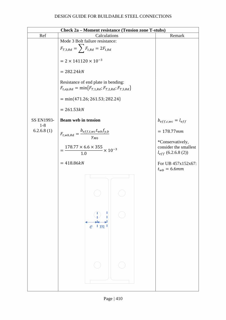
DESIGN GUIDE FOR BUILDABLE STEEL CONNECTIONS
Page | 410
Check 2a – Moment resistance (Tension zone T-stubs) Ref Calculations Remark
Mode 3 Bolt failure resistance:
𝐹 , , 𝐹 , 2𝐹 ,
2 141120 10
282.24𝑘𝑁
Resistance of end plate in bending: 𝐹 , , min 𝐹 , , ;𝐹 , , ;𝐹 , ,
min 471.26; 261.53; 282.24
261.53𝑘𝑁
SS EN1993-1-8
6.2.6.8 (1)
Beam web in tension
𝐹 , ,𝑏 , , 𝑡 𝑓 ,
𝛾
178.77 6.6 355
1.010
418.86𝑘𝑁
𝑏 , , 𝑙
178.77𝑚𝑚 *Conservatively, consider the smallest 𝑙 (6.2.6.8 (2)) For UB 457x152x67: 𝑡 6.6𝑚𝑚
𝑒 𝑚
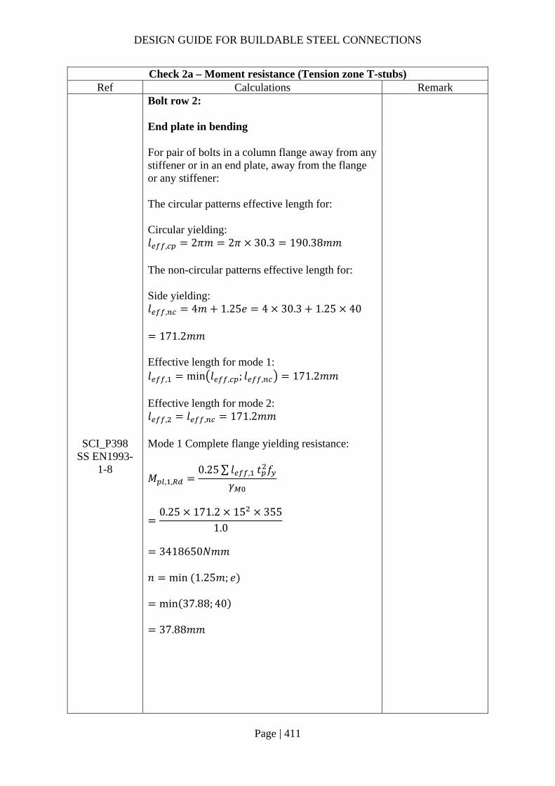
DESIGN GUIDE FOR BUILDABLE STEEL CONNECTIONS
Page | 411
Check 2a – Moment resistance (Tension zone T-stubs) Ref Calculations Remark
Bolt row 2: End plate in bending For pair of bolts in a column flange away from any stiffener or in an end plate, away from the flange or any stiffener: The circular patterns effective length for: Circular yielding: 𝑙 , 2𝜋𝑚 2𝜋 30.3 190.38𝑚𝑚 The non-circular patterns effective length for: Side yielding: 𝑙 , 4𝑚 1.25𝑒 4 30.3 1.25 40
171.2𝑚𝑚
Effective length for mode 1: 𝑙 , min 𝑙 , ; 𝑙 , 171.2𝑚𝑚 Effective length for mode 2: 𝑙 , 𝑙 , 171.2𝑚𝑚
SCI_P398 SS EN1993-
1-8
Mode 1 Complete flange yielding resistance:
𝑀 , ,0.25∑ 𝑙 , 𝑡 𝑓
𝛾
0.25 171.2 15 355
1.0
3418650𝑁𝑚𝑚
𝑛 min 1.25𝑚; 𝑒
min 37.88; 40
37.88𝑚𝑚

DESIGN GUIDE FOR BUILDABLE STEEL CONNECTIONS
Page | 412
Check 2a – Moment resistance (Tension zone T-stubs) Ref Calculations Remark
Method 1:
𝐹 , ,4𝑀 , ,
𝑚
4 3418650
30.310
451.31𝑘𝑁
Method 2:
𝐹 , ,8𝑛 2𝑒 𝑀 , ,
2𝑚𝑛 𝑒 𝑚 𝑛
8 37.88 2 9.25 3418650
2 30.3 37.88 9.25 30.3 37.88
10
584.29𝑘𝑁
Mode 2 Bolt failure with flange yielding resistance:
𝑀 , ,0.25∑ 𝑙 , 𝑡 𝑓
𝛾
0.25 171.2 15 355
1.0
3418650𝑁𝑚𝑚
𝐹 , ,2𝑀 , , 𝑛∑𝐹 ,
𝑚 𝑛
2 3418650 37.88 282240
30.3 37.8810
257.09𝑘𝑁
Mode 3 Bolt failure resistance:
𝐹 , , 𝐹 , 2𝐹 ,
2 141120 10
282.24𝑘𝑁

DESIGN GUIDE FOR BUILDABLE STEEL CONNECTIONS
Page | 413
Check 2a – Moment resistance (Tension zone T-stubs) Ref Calculations Remark
Resistance of end plate in bending: 𝐹 , , min 𝐹 , , ;𝐹 , , ;𝐹 , ,
min 451.31; 257.09; 282.24
257.09𝑘𝑁
SS EN1993-1-8
6.2.6.8 (1)
Beam web in tension
𝐹 , ,𝑏 , , 𝑡 𝑓 ,
𝛾
171.2 6.6 355
1.010
401.12𝑘𝑁
𝑏 , , 𝑙
171.2𝑚𝑚
Bolt row 1 & 2 combined: End plate in bending For bolt row 2, the resistance of it may be limited by the resistance of rows 1 & 2 as a group.
𝑒 𝑚
𝑝

DESIGN GUIDE FOR BUILDABLE STEEL CONNECTIONS
Page | 414
Check 2a – Moment resistance (Tension zone T-stubs) Ref Calculations Remark
SS EN1993-1-8
6.2.6.5 Table 6.6
Row 1 is classified as “First bolt-row below tension flange of beam” with effective length: Circular patterns: 𝑙 , 𝜋𝑚 𝑝 𝜋 30.3 70
165.19𝑚𝑚 Non-circular patterns: 𝑙 , 0.5𝑝 𝛼𝑚 2𝑚 0.625𝑒
0.5 70 5.9 30.3 2 30.3 0.62540
128.17𝑚𝑚
Row 2 is classified as “Other end bolt-row” with effective length: Circular patterns: 𝑙 , 𝜋𝑚 𝑝 𝜋 30.3 70
165.19𝑚𝑚 Non-circular patterns: 𝑙 , 2𝑚 0.625𝑒 0.5𝑝
2 30.3 0.625 40 0.5 70
120.60𝑚𝑚
The total effective length for this bolt group combination:
𝑙 , 165.19 165.19 330.38𝑚𝑚
𝑙 , 128.17 120.60 248.77𝑚𝑚
Effective length for mode 1:
𝑙 , min 𝑙 , ; 𝑙 ,
248.77𝑚𝑚
Effective length for mode 2:
𝑙 , 𝑙 , 248.77𝑚𝑚
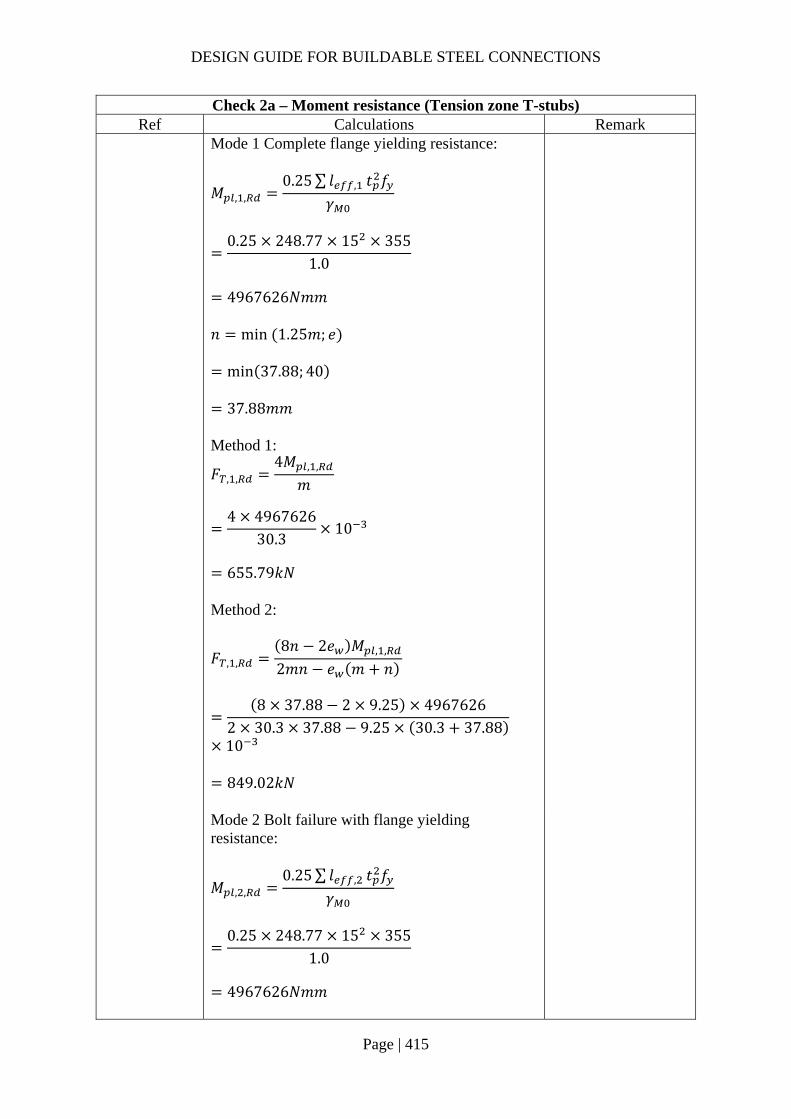
DESIGN GUIDE FOR BUILDABLE STEEL CONNECTIONS
Page | 415
Check 2a – Moment resistance (Tension zone T-stubs) Ref Calculations Remark
Mode 1 Complete flange yielding resistance:
𝑀 , ,0.25∑ 𝑙 , 𝑡 𝑓
𝛾
0.25 248.77 15 355
1.0
4967626𝑁𝑚𝑚
𝑛 min 1.25𝑚; 𝑒
min 37.88; 40
37.88𝑚𝑚 Method 1:
𝐹 , ,4𝑀 , ,
𝑚
4 4967626
30.310
655.79𝑘𝑁
Method 2:
𝐹 , ,8𝑛 2𝑒 𝑀 , ,
2𝑚𝑛 𝑒 𝑚 𝑛
8 37.88 2 9.25 4967626
2 30.3 37.88 9.25 30.3 37.88
10
849.02𝑘𝑁
Mode 2 Bolt failure with flange yielding resistance:
𝑀 , ,0.25∑ 𝑙 , 𝑡 𝑓
𝛾
0.25 248.77 15 355
1.0
4967626𝑁𝑚𝑚

DESIGN GUIDE FOR BUILDABLE STEEL CONNECTIONS
Page | 416
Check 2a – Moment resistance (Tension zone T-stubs) Ref Calculations Remark
𝐹 , ,
2𝑀 , , 𝑛∑𝐹 ,
𝑚 𝑛
2 4967626 37.88 282240
30.3 37.8810
459.33𝑘𝑁
Mode 3 Bolt failure resistance:
𝐹 , , 𝐹 , 4𝐹 ,
4 141120 10
564.48𝑘𝑁
Resistance of end plate in bending: 𝐹 , , min 𝐹 , , ;𝐹 , , ;𝐹 , ,
min 655.79; 459.33; 564.48
459.33𝑘𝑁
Summary of tension resistance of T-stubs:
Row Resistance Effective
Resistance Row 1 alone 261.53kN 261.53kN Row 2 alone 257.09kN 197.81kN Row 1 and 2 459.33kN -
Check 2b – Moment resistance (Compression zone) Ref Calculations Remark
SS EN1993-1-8
6.2.6.7 (1)
Design moment resistance of the beam cross-section (S355 UB533x210x92): 𝑀 , 234𝑘𝑁𝑚
𝐹 , ,𝑀 ,
ℎ 𝑡
234
353.4 10.710
682.81𝑘𝑁
𝑀 , is read from SCI_P363 page D-70 For UB356x127x39: ℎ 353.4𝑚𝑚 𝑡 10.7𝑚𝑚

DESIGN GUIDE FOR BUILDABLE STEEL CONNECTIONS
Page | 417
Check 2 – Moment resistance Ref Calculations Remark
SS EN1993-1-8
6.2.7.2 (9)
The effective resistances of bolt rows need to be reduced when the bolt row resistance is greater than 1.9𝐹 , 1.9𝐹 , 1.9 141.12 268.13𝑘𝑁 As all bolt row resistances are lesser than 268.13kN, no reduction is required.
Equilibrium of forces Total effective tension resistance:
𝐹 , 261.53 197.81
459.33𝑘𝑁 𝐹 , , 682.81𝑘𝑁
Hence, no reduction is required for the tensile resistance.
SS EN1993-1-8
6.2.7.2 (1)
The moment resistance of the connection may be determined using:
𝑀 , ℎ 𝐹 , ,
Taking the center of compression to be at the mid-thickness of the compression flange of the beam:
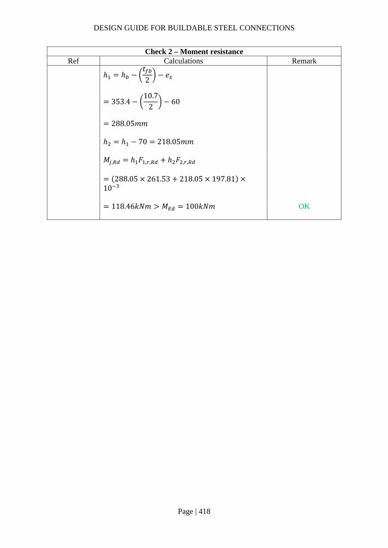
DESIGN GUIDE FOR BUILDABLE STEEL CONNECTIONS
Page | 418
Check 2 – Moment resistance Ref Calculations Remark
ℎ ℎ
𝑡2
𝑒
353.410.7
260
288.05𝑚𝑚
ℎ ℎ 70 218.05𝑚𝑚
𝑀 , ℎ 𝐹 , , ℎ 𝐹 , ,
288.05 261.53 218.05 197.8110
118.46𝑘𝑁𝑚 𝑀 100𝑘𝑁𝑚
OK
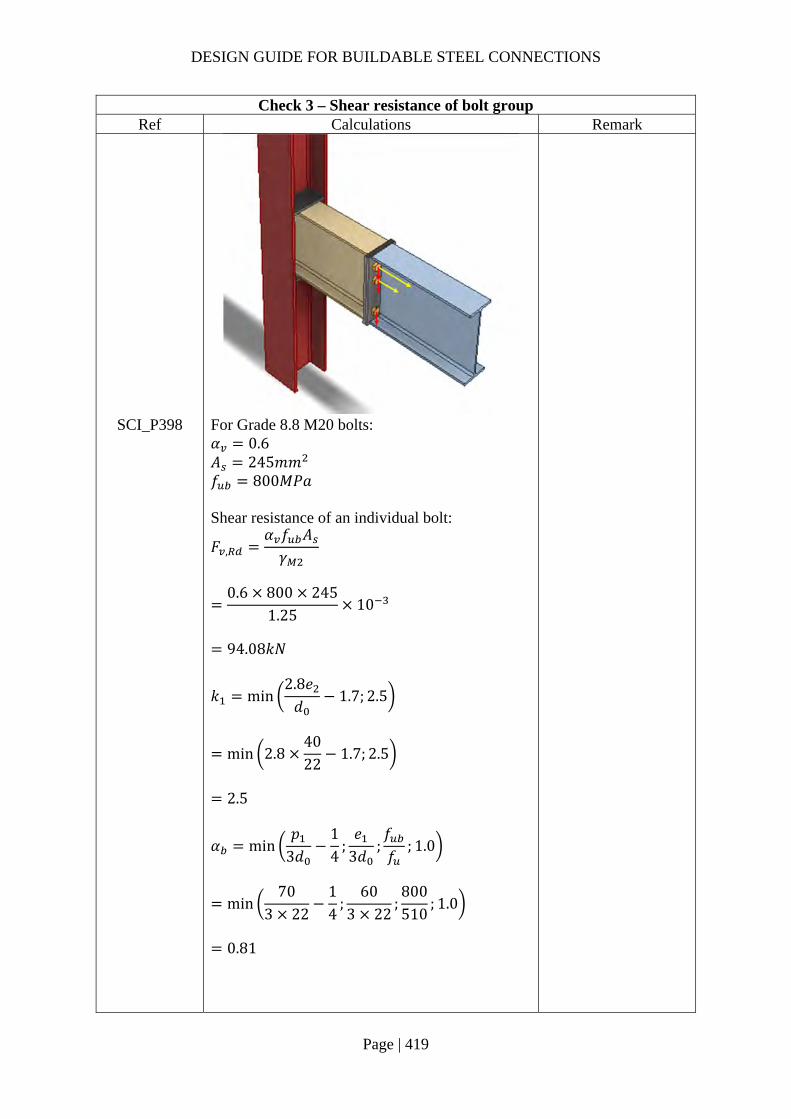
DESIGN GUIDE FOR BUILDABLE STEEL CONNECTIONS
Page | 419
Check 3 – Shear resistance of bolt group Ref Calculations Remark
SCI_P398 For Grade 8.8 M20 bolts: 𝛼 0.6 𝐴 245𝑚𝑚 𝑓 800𝑀𝑃𝑎 Shear resistance of an individual bolt:
𝐹 ,𝛼 𝑓 𝐴𝛾
0.6 800 245
1.2510
94.08𝑘𝑁
𝑘 min2.8𝑒𝑑
1.7; 2.5
min 2.84022
1.7; 2.5
2.5
𝛼 min𝑝
3𝑑14
;𝑒
3𝑑;𝑓𝑓
; 1.0
min70
3 2214
;60
3 22;800510
; 1.0
0.81
DESIGN GUIDE FOR BUILDABLE STEEL CONNECTIONS
Page | 420
Check 3 – Shear resistance of bolt group Ref Calculations Remark
Bearing resistance of an individual bolt:
𝐹 ,𝑘 𝛼 𝑓 𝑑𝑡𝛾
2.5 0.81 510 20 15
1.25
248.05𝑘𝑁
Hence, resistance of an individual bolt: 𝐹 min 𝐹 , ;𝐹 ,
min 94.08; 248.05
94.08𝑘𝑁
According to SCI_P398, the shear resistance of the upper rows may be taken conservatively as 28% of the shear resistance without tension, thus the shear resistance of the bolt group is: 𝑉 2 4 0.28 𝐹
3.12 94.08
𝑉 293.53𝑘𝑁 𝑉 200𝑘𝑁
OK

DESIGN GUIDE FOR BUILDABLE STEEL CONNECTIONS
Page | 421
2.5 Strengthening of the joints The use of stiffener/backing plates may be required when the beam or column capacity is insufficient. Commonly used method of strengthening the joints are as follows.
Horizontal stiffeners (full/partial depth) may be needed for web in tension/compression and flanges in flexure.
Web plate for web in tension/compression or shear. Shear web stiffener (N, Morris, K stiffener). Flange backing plates to increase the column flange flexural resistance.
In this guide, stiffening extended fin plate and strengthening column web with supplementary web plate are considered. For extended fin plate, as the applied load is far away from the weld support, the fin plate is classified as long fin plate in most of the times. Fin plate may be classified as short or long as follows:
Short, 𝑡 /𝑧 0.15; Long, 𝑡 /𝑧 0.15;
𝑧 : distance between face of the support and first line of bolts
The performance of a long fin plate is affected by lateral torsional buckling and bending. In order to improve the performance of a long fin plate, stiffener plates may be used to prevent lateral torsion buckling of the plate and shorten the distance between the bolt line and support. The bending capacity of the combined section and weld resistance connecting the stiffener plate are checked against moment induced by eccentricity.
For column web with insufficient resistance, supplementary web plates (SWPs) may be used to increase the capacity. The SWP needs to meet the following requirements:
o The steel grade of SWP should be same as that of column web o The thickness of SWP should be at least that of column web o The width of SWP should extend to the fillets of the column o The maximum width of SWP is 40𝜀𝑡 o The depth of SWP should extend over at least the effective lengths of the column web o The perimeter fillet welds should be designed for forces transferred to the SWP and
have leg length equal to the thickness of the SWP o For SWP to supplement tension or compression resistance, the longitudinal welds
should be infill weld
To increase the tension and compression resistance of the web panel, adding one plate on one side will increase the effective thickness by 50% while adding two plates on both sides will increase it by 100%. The increased tension and compression resistance should be calculated using the increased effective thickness and the calculation of the reduction factor may be based on the increased shear area.
For shear resistance, adding SWP will increase the shear area of the column web by 𝑏 𝑡 . Only one supplementary plate will contribute to the shear resistance, plates on both sides do not provide any greater increase.

DESIGN GUIDE FOR BUILDABLE STEEL CONNECTIONS
Page | 422
2.5.1 Example 20 – Stiffened extended fin-plates for secondary beams
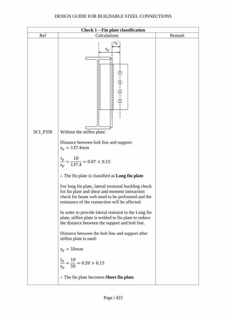
DESIGN GUIDE FOR BUILDABLE STEEL CONNECTIONS
Page | 423
Check 1 – Fin plate classification Ref Calculations Remark
SCI_P358 Without the stiffen plate: Distance between bolt line and support: 𝑧 137.4𝑚𝑚 𝑡𝑧
10137.4
0.07 0.15
∴ The fin plate is classified as Long fin plate. For long fin plate, lateral torsional buckling check for fin plate and shear and moment interaction check for beam web need to be performed and the resistance of the connection will be affected.
In order to provide lateral restraint to the Long fin plate, stiffen plate is welded to fin plate to reduce the distance between the support and bolt line. Distance between the bolt line and support after stiffen plate is used: 𝑧 50𝑚𝑚 𝑡𝑧
1050
0.20 0.15
∴ The fin plate becomes Short fin plate.

DESIGN GUIDE FOR BUILDABLE STEEL CONNECTIONS
Page | 424
Check 1 – Fin plate classification Ref Calculations Remark
For short fin plate, lateral torsional buckling check for fin plate and shear and moment interaction check for beam web are NOT necessary. Shortening distance 𝑧 will increase the capacity of the connection.
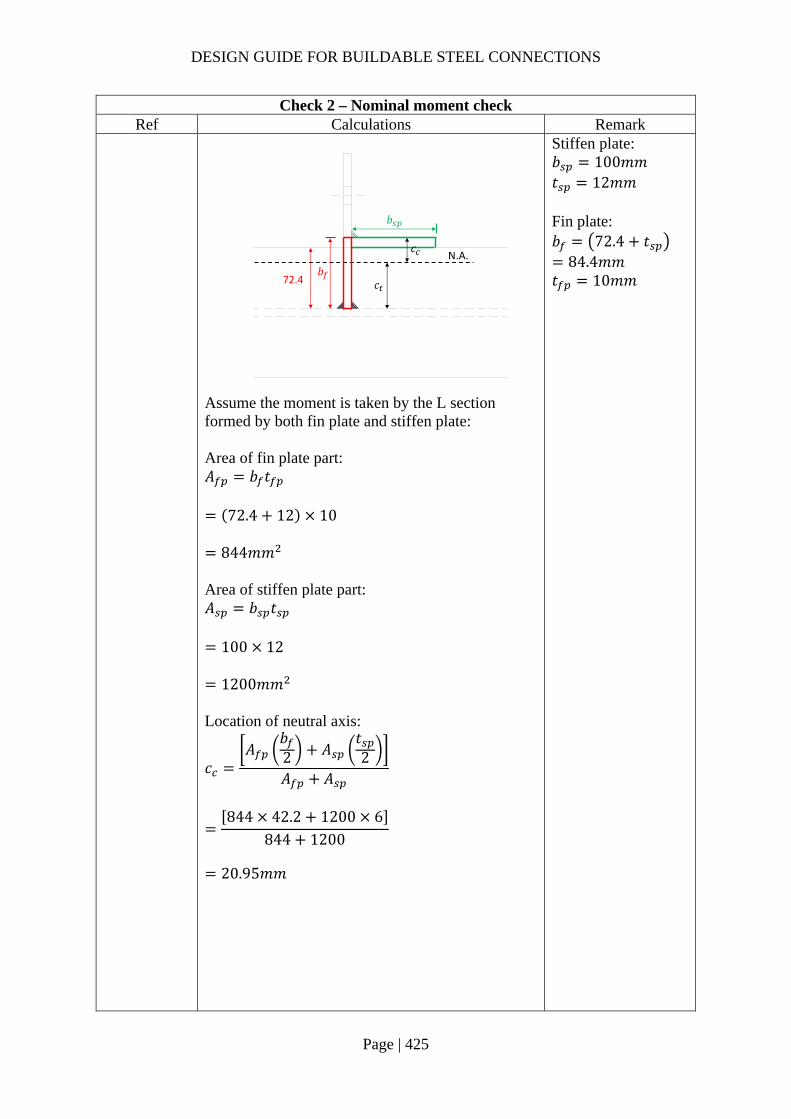
DESIGN GUIDE FOR BUILDABLE STEEL CONNECTIONS
Page | 425
Check 2 – Nominal moment check Ref Calculations Remark
Stiffen plate: 𝑏 100𝑚𝑚 𝑡 12𝑚𝑚 Fin plate: 𝑏 72.4 𝑡
84.4𝑚𝑚 𝑡 10𝑚𝑚
Assume the moment is taken by the L section formed by both fin plate and stiffen plate: Area of fin plate part: 𝐴 𝑏 𝑡
72.4 12 10
844𝑚𝑚 Area of stiffen plate part: 𝐴 𝑏 𝑡
100 12
1200𝑚𝑚 Location of neutral axis:
𝑐𝐴
𝑏2 𝐴
𝑡2
𝐴 𝐴
844 42.2 1200 6
844 1200
20.95𝑚𝑚
72.4
𝑏
𝑏N.A.
𝑐
𝑐

DESIGN GUIDE FOR BUILDABLE STEEL CONNECTIONS
Page | 426
Check 2 – Nominal moment check Ref Calculations Remark
Moment of inertia:
𝐼𝑏 𝑡
12𝐴 𝑐
𝑡2
𝑡 𝑏
12
𝐴𝑏2
𝑐
100 12
121200 20.95
122
10 84.412
84484.4
220.95
1164731𝑚𝑚
𝑐 𝑏 𝑐
84.4 20.95
63.45𝑚𝑚 Yield moment:
𝑀𝑓 𝐼𝑐
275 116473163.45
10
5.05𝑘𝑁𝑚
Nominal moment: 𝑀 𝑉 𝑧
100 50 10
5𝑘𝑁𝑚 𝑀 5.05𝑘𝑁𝑚
After adding stiffen plate: 𝑧 50𝑚𝑚
∴ The fin plate and stiffen plate will not yield under nominal moment

DESIGN GUIDE FOR BUILDABLE STEEL CONNECTIONS
Page | 427
Check 2 – Nominal moment check Ref Calculations Remark
Plastic section modular:
𝑊 𝑧𝑑𝐴
84.4
220.95 844 20.95
122
1200
35874𝑚𝑚
𝑀 𝑓 𝑊
275 35875 10
9.87𝑘𝑁𝑚 𝑀 5𝑘𝑁𝑚
OK
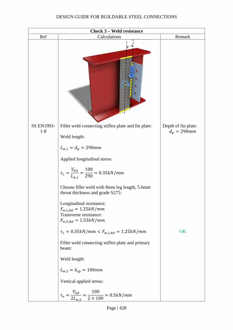
DESIGN GUIDE FOR BUILDABLE STEEL CONNECTIONS
Page | 428
Check 3 – Weld resistance Ref Calculations Remark
SS EN1993-1-8
Fillet weld connecting stiffen plate and fin plate: Weld length: 𝐿 , 𝑑 290𝑚𝑚 Applied longitudinal stress:
𝜏𝑉𝐿 ,
100290
0.35𝑘𝑁/𝑚𝑚
Choose fillet weld with 8mm leg length, 5.6mm throat thickness and grade S275: Longitudinal resistance: 𝐹 , , 1.25𝑘𝑁/𝑚𝑚 Transverse resistance: 𝐹 , , 1.53𝑘𝑁/𝑚𝑚
Depth of fin plate: 𝑑 290𝑚𝑚
𝜏 0.35𝑘𝑁/𝑚𝑚 𝐹 , , 1.25𝑘𝑁/𝑚𝑚
OK
Fillet weld connecting stiffen plate and primary beam: Weld length: 𝐿 , 𝑏 100𝑚𝑚 Vertical applied stress:
𝜏𝑉
2𝐿 ,
1002 100
0.5𝑘𝑁/𝑚𝑚
DESIGN GUIDE FOR BUILDABLE STEEL CONNECTIONS
Page | 429
Check 3 – Weld resistance Ref Calculations Remark
Longitudinal applied stress:
𝜏𝑉 𝑏
2𝑑 𝐿 ,
100 1002 446 100
0.112𝑘𝑁/𝑚𝑚
Resultant stress:
𝜏 𝜏 𝜏
0.5 0.112
0.512𝑘𝑁/𝑚𝑚
Choose fillet weld with 8mm leg length, 5.6mm throat thickness and grade S275: Longitudinal resistance: 𝐹 , , 1.25𝑘𝑁/𝑚𝑚 Transverse resistance: 𝐹 , , 1.53𝑘𝑁/𝑚𝑚
Simplified method: 𝐹 , , 1.25𝑘𝑁/𝑚𝑚 𝜏 0.512𝑘𝑁/𝑚𝑚
OK
Directional method:
𝑆𝐹𝜏
𝐹 , ,
𝜏𝐹 , ,
0.1121.25
0.51.53
0.115 1
OK
Note:
Fillet weld between stiffener plate and primary beam at the internal side is not feasible.

DESIGN GUIDE FOR BUILDABLE STEEL CONNECTIONS
Page | 430
2.5.2 Example 21 – Stiffened extended fin-plates connecting to column in the minor axis (Section a)

DESIGN GUIDE FOR BUILDABLE STEEL CONNECTIONS
Page | 431
Check 1 – Fin plate classification Ref Calculations Remark
SCI_P358 Without the stiffen plate: Distance between bolt line and support: 𝑧 148.2𝑚𝑚 𝑡𝑧
10148.2
0.067 0.15
∴ The fin plate is classified as Long fin plate. For long fin plate, lateral torsional buckling check for fin plate and shear and moment interaction check for beam web need to be performed and the resistance of the connection will be affected.
In order to provide lateral restraint to the Long fin plate, stiffen plate is welded to fin plate to reduce the distance between the support and bolt line. Distance between the bolt line and support after stiffen plate is used: 𝑧 50𝑚𝑚 𝑡𝑧
1050
0.20 0.15
∴ The fin plate becomes Short fin plate. For short fin plate, lateral torsional buckling check for fin plate and shear and moment interaction check for beam web are NOT necessary. Shortening distance 𝑧 will increase the capacity of the connection.
DESIGN GUIDE FOR BUILDABLE STEEL CONNECTIONS
Page | 432
Check 2 – Nominal moment check Ref Calculations Remark
Assume the moment is taken by the L section formed by both fin plate and stiffen plate: Area of fin plate part: 𝐴 𝑏 𝑡
98.2 10 10
1082𝑚𝑚 Area of stiffen plate part: 𝐴 𝑏 𝑡
91.1 10
911𝑚𝑚 Location of neutral axis:
𝑐𝐴
𝑏2 𝐴
𝑡2
𝐴 𝐴
1082 54.1 911 5
1082 911
31.66𝑚𝑚
Stiffen plate: 𝑏 91.1𝑚𝑚 𝑡 10𝑚𝑚 Fin plate: 𝑏 98.2 𝑡
108.2𝑚𝑚 𝑡 10𝑚𝑚
Moment of inertia:
𝐼𝑏 𝑡
12𝐴 𝑐
𝑡2
𝑡 𝑏
12
𝐴𝑏2
𝑐
91.1 10
12911 31.66
102
10 108.212
1082108.2
231.66
1666165𝑚𝑚
𝑐 𝑏 𝑐
108.2 31.66
50.74𝑚𝑚

DESIGN GUIDE FOR BUILDABLE STEEL CONNECTIONS
Page | 433
Check 2 – Nominal moment check Ref Calculations Remark
Yield moment:
𝑀𝑓 𝐼𝑐
275 166616550.74
10
9.03𝑘𝑁𝑚
Nominal moment: 𝑀 𝑉 𝑧
150 50 10
7.5𝑘𝑁𝑚 𝑀 9.03𝑘𝑁𝑚
After adding stiffen plate: 𝑧 50𝑚𝑚
∴ The fin plate and stiffen plate will not yield under nominal moment
Plastic section modular:
𝑊 𝑧𝑑𝐴
108.2
231.66 1082 31.66
102
911
48568𝑚𝑚
𝑀 𝑓 𝑊
275 48568 10
13.36𝑘𝑁𝑚 𝑀 7.5𝑘𝑁𝑚
OK
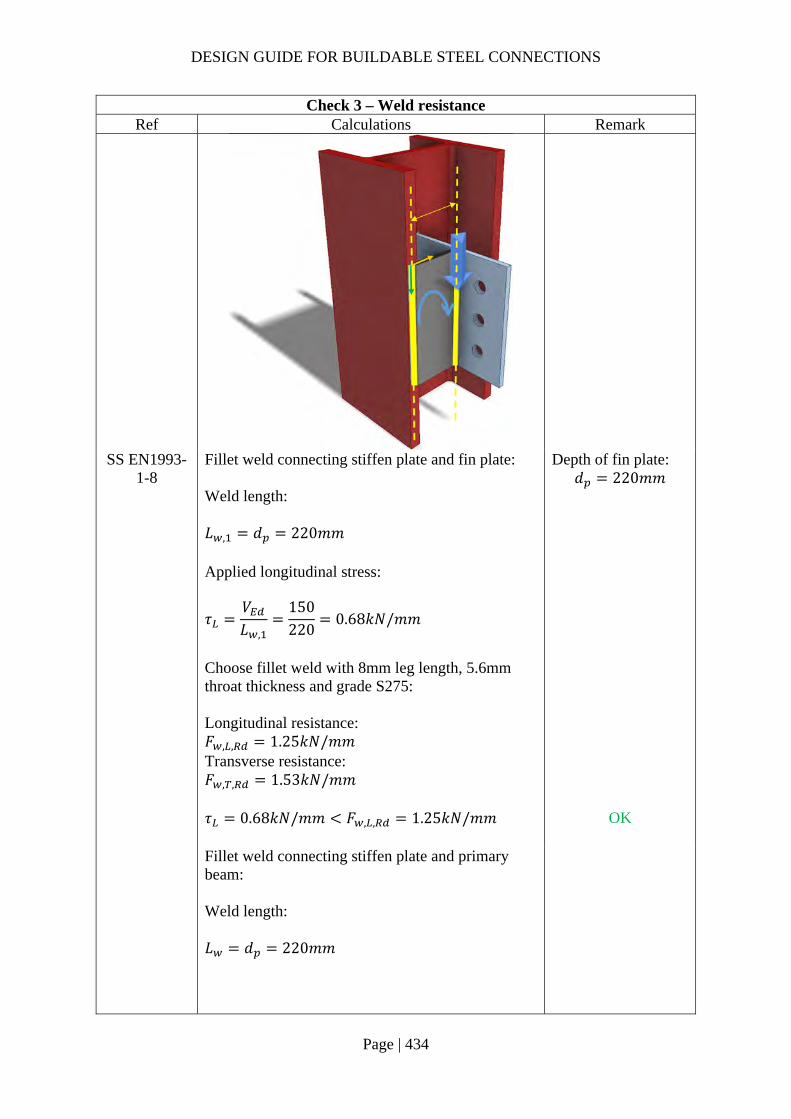
DESIGN GUIDE FOR BUILDABLE STEEL CONNECTIONS
Page | 434
Check 3 – Weld resistance Ref Calculations Remark
SS EN1993-1-8
Fillet weld connecting stiffen plate and fin plate: Weld length: 𝐿 , 𝑑 220𝑚𝑚 Applied longitudinal stress:
𝜏𝑉𝐿 ,
150220
0.68𝑘𝑁/𝑚𝑚
Choose fillet weld with 8mm leg length, 5.6mm throat thickness and grade S275: Longitudinal resistance: 𝐹 , , 1.25𝑘𝑁/𝑚𝑚 Transverse resistance: 𝐹 , , 1.53𝑘𝑁/𝑚𝑚
Depth of fin plate: 𝑑 220𝑚𝑚
𝜏 0.68𝑘𝑁/𝑚𝑚 𝐹 , , 1.25𝑘𝑁/𝑚𝑚
OK
Fillet weld connecting stiffen plate and primary beam: Weld length: 𝐿 𝑑 220𝑚𝑚
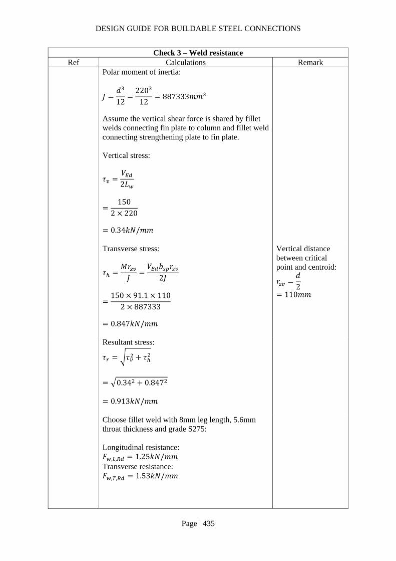
DESIGN GUIDE FOR BUILDABLE STEEL CONNECTIONS
Page | 435
Check 3 – Weld resistance Ref Calculations Remark
Polar moment of inertia:
𝐽𝑑12
22012
887333𝑚𝑚
Assume the vertical shear force is shared by fillet welds connecting fin plate to column and fillet weld connecting strengthening plate to fin plate. Vertical stress:
𝜏𝑉2𝐿
150
2 220
0.34𝑘𝑁/𝑚𝑚
Transverse stress:
𝜏𝑀𝑟𝐽
𝑉 𝑏 𝑟2𝐽
150 91.1 110
2 887333
0.847𝑘𝑁/𝑚𝑚
Vertical distance between critical point and centroid:
𝑟𝑑2
110𝑚𝑚
Resultant stress:
𝜏 𝜏 𝜏
0.34 0.847
0.913𝑘𝑁/𝑚𝑚
Choose fillet weld with 8mm leg length, 5.6mm throat thickness and grade S275: Longitudinal resistance: 𝐹 , , 1.25𝑘𝑁/𝑚𝑚 Transverse resistance: 𝐹 , , 1.53𝑘𝑁/𝑚𝑚
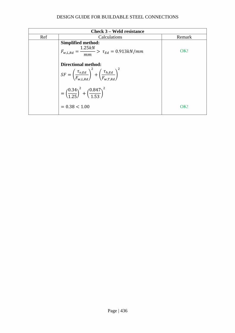
DESIGN GUIDE FOR BUILDABLE STEEL CONNECTIONS
Page | 436
Check 3 – Weld resistance Ref Calculations Remark
Simplified method:
𝐹 , ,1.25𝑘𝑁𝑚𝑚
𝜏 0.913𝑘𝑁/𝑚𝑚
OK!
Directional method:
𝑆𝐹𝜏 ,
𝐹 , ,
𝜏 ,
𝐹 , ,
0.341.25
0.8471.53
0.38 1.00
OK!
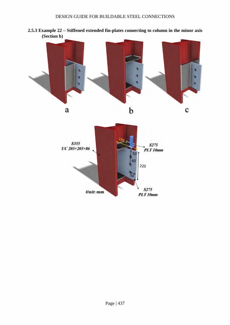
DESIGN GUIDE FOR BUILDABLE STEEL CONNECTIONS
Page | 437
2.5.3 Example 22 – Stiffened extended fin-plates connecting to column in the minor axis (Section b)

DESIGN GUIDE FOR BUILDABLE STEEL CONNECTIONS
Page | 438
Check 1 – Weld resistance Ref Calculations Remark
SS EN1993-1-8
Fillet weld connecting the stiffener plate and column (A): Length of fillet weld parallel to applied load:
𝐿 ,𝑏 𝑡
2𝑐𝑜𝑝𝑒 ℎ𝑜𝑙𝑒 𝑠𝑖𝑧𝑒
209.1 12.7
215
83.2𝑚𝑚
Length of fillet weld perpendicular to applied load: 𝐿 , 𝑑 2𝑡 2 𝑐𝑜𝑝𝑒 ℎ𝑜𝑙𝑒 𝑠𝑖𝑧𝑒
222.2 2 20.5 2 15
151.2𝑚𝑚 Nominal moment: 𝑀 𝑉 𝑒𝑐𝑐
200 50 10
10𝑘𝑁𝑚
For UC203x203x86: 𝑏 209.1𝑚𝑚 𝑡 12.7𝑚𝑚 𝑑 222.2𝑚𝑚 𝑡 20.5𝑚𝑚 Cope hole size: 𝑛 15𝑚𝑚 Depth of fin plate:
𝑑 220𝑚𝑚

DESIGN GUIDE FOR BUILDABLE STEEL CONNECTIONS
Page | 439
Check 1 – Weld resistance Ref Calculations Remark
Applied tensile force:
𝐹𝑀𝑑
10 10
220
45.45𝑘𝑁
Choose fillet weld with 8mm leg length, 5.6mm throat thickness and grade S275: Longitudinal resistance: 𝐹 , , 1.25𝑘𝑁/𝑚𝑚 Transverse resistance: 𝐹 , , 1.53𝑘𝑁/𝑚𝑚
Tensile capacity of the weld: 𝐹 𝐹 , , 𝐿 , 𝐹 , , 𝐿 ,
1.25 83.2 1.53 151.2
335.34𝑘𝑁 𝐹 45.45𝑘𝑁
OK
Two-sided C shape fillet weld connecting fin plate and stiffen plate (B): Location of center of gravity of welds group:
�̅�𝑏
2𝑏 𝑑
98.2
2 98.2 220
23.16𝑚𝑚
𝑦𝑑2
220
2
110𝑚𝑚
Size of fillet weld: Width: 𝑏 98.2𝑚𝑚 Depth: 𝑑 220𝑚𝑚 Cope hole size: 𝑛 15𝑚𝑚 𝑏 𝑏 𝑛
98.2 15 83.2𝑚𝑚
𝑑 𝑑 2𝑛 220 2 15 190𝑚𝑚

DESIGN GUIDE FOR BUILDABLE STEEL CONNECTIONS
Page | 440
Check 1 – Weld resistance Ref Calculations Remark
Unit throat area: 𝐴 2𝑏 𝑑
2 83.2 190
356.4𝑚𝑚 Moment arm between applied force and weld center: 𝑟 125.04𝑚𝑚 Induced moment on welds:
𝑀𝑉
2𝑟
200
2125.04
12504𝑘𝑁𝑚𝑚
Polar moment of inertia:
𝐽8𝑏 6𝑏 𝑑 𝑑
12𝑏
2𝑏 𝑑
8 83.2 6 83.2 190 190
12
83.22 83.2 190
2322849𝑚𝑚
Critical point: Horizontal distance from centroid: 𝑟 𝑏 �̅�
98.2 23.16
75.04𝑚𝑚 Vertical distance from centroid: 𝑟 𝑦
110𝑚𝑚

DESIGN GUIDE FOR BUILDABLE STEEL CONNECTIONS
Page | 441
Check 1 – Weld resistance Ref Calculations Remark
Vertical stress:
𝜏𝑉𝐴
𝑀𝑟𝐽
2002 356.4
12504 75.042322849
0.68𝑘𝑁/𝑚𝑚
Horizontal stress:
𝜏𝑀𝑟𝐽
12504 110
2322849
0.59𝑘𝑁/𝑚𝑚
Resultant stress:
𝜏 𝑟 𝑟
0.68 0.59
0.91𝑘𝑁/𝑚𝑚
Choose fillet weld with 8mm leg length, 5.6mm throat thickness and grade S275: Longitudinal resistance: 𝐹 , , 1.25𝑘𝑁/𝑚𝑚 Transverse resistance: 𝐹 , , 1.53𝑘𝑁/𝑚𝑚
Simplified method: 𝐹 , , 1.25𝑘𝑁/𝑚𝑚 𝜏 0.91𝑘𝑁/𝑚𝑚
OK
Directional method:
𝑆𝐹𝜏
𝐹 , ,
𝜏𝐹 , ,
0.681.25
0.591.53
0.42 1.0
OK

DESIGN GUIDE FOR BUILDABLE STEEL CONNECTIONS
Page | 442
2.5.4 Example 22 – Stiffened extended fin-plates connecting to column in the minor axis (Section c)

DESIGN GUIDE FOR BUILDABLE STEEL CONNECTIONS
Page | 443
Check 1 – Weld resistance Ref Calculations Remark
SS EN1993-1-8
The weld connection is assumed to be stiffer than the bolt connection, hence the fillet weld for fin plate needs to be designed for nominal moment. Unit throat area: 𝐴 2𝑑 2 220 440𝑚𝑚 Eccentricity between weld and line of action: 𝑒𝑐𝑐 𝑧 50𝑚𝑚 Nominal moment due to eccentricity: 𝑀 𝑉 𝑒𝑐𝑐
200 0.05
10𝑘𝑁𝑚 Polar moment of inertia:
𝐽𝑑12
22012
887333𝑚𝑚
Size of the fillet welds: 𝑑 220𝑚𝑚
Critical point: Vertical stress:
𝜏𝑉𝐴
200440
0.45𝑘𝑁/𝑚𝑚
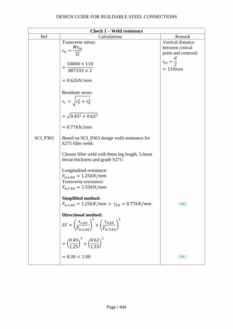
DESIGN GUIDE FOR BUILDABLE STEEL CONNECTIONS
Page | 444
Check 1 – Weld resistance Ref Calculations Remark
Transverse stress:
𝜏𝑀𝑟
2𝐽
10000 110887333 2
0.62𝑘𝑁/𝑚𝑚
Vertical distance between critical point and centroid:
𝑟𝑑2
110𝑚𝑚
Resultant stress:
𝜏 𝜏 𝜏
0.45 0.62
0.77𝑘𝑁/𝑚𝑚
SCI_P363 Based on SCI_P363 design weld resistance for S275 fillet weld: Choose fillet weld with 8mm leg length, 5.6mm throat thickness and grade S275: Longitudinal resistance: 𝐹 , , 1.25𝑘𝑁/𝑚𝑚 Transverse resistance: 𝐹 , , 1.53𝑘𝑁/𝑚𝑚
Simplified method: 𝐹 , , 1.25𝑘𝑁/𝑚𝑚 𝜏 0.77𝑘𝑁/𝑚𝑚
OK!
Directional method:
𝑆𝐹𝜏 ,
𝐹 , ,
𝜏 ,
𝐹 , ,
0.451.25
0.621.53
0.30 1.00
OK!

DESIGN GUIDE FOR BUILDABLE STEEL CONNECTIONS
Page | 445
Check 2 – Tying resistance of stiffen plate Ref Calculations Remark
SCI_P358 Assume the stiffener plate behaves like hollow section wall, the punching shear resistance: 𝑡 10𝑚𝑚
𝑡 𝑓 ,
𝑓 , 𝛾10
410275 1.25
11.92𝑚𝑚
As the above requirement is met, the fin plate will yield before punching shear failure of the stiffener plate.
𝛾 1.25
Note:
The thickness of stiffen plate should be at least as thick as the thickness of fin plate to provide sufficient shear resistance. The design of such connection can follow the standard design for T-stub.

DESIGN GUIDE FOR BUILDABLE STEEL CONNECTIONS
Page | 446
2.5.5 Example 23 – Stiffened column web

DESIGN GUIDE FOR BUILDABLE STEEL CONNECTIONS
Page | 447
Dimensions and properties Ref Calculations Remark
For column UC 305x305x97: Depth of column: ℎ 307.9𝑚𝑚 Width of column: 𝑏 305.3𝑚𝑚 Thickness of column web: 𝑡 9.9𝑚𝑚 Thickness of column flange: 𝑡 15.4𝑚𝑚 Root radius: 𝑟 15.2𝑚𝑚 Depth between fillets: 𝑑 246.7𝑚𝑚 Cross-sectional area of column: 𝐴 12300𝑚𝑚 Yield strength: 𝑓 355𝑀𝑃𝑎 For beam UB 457x152x74: Depth of beam: ℎ 462𝑚𝑚 Width of beam: 𝑏 154.4𝑚𝑚 Thickness of beam web: 𝑡 9.6𝑚𝑚 Thickness of beam flange: 𝑡 17𝑚𝑚 Root radius: 𝑟 10.2𝑚𝑚 Depth between fillets: 𝑑 407.6𝑚𝑚 Cross-sectional area of beam: 𝐴 9450𝑚𝑚 Yield strength: 𝑓 355𝑀𝑃𝑎
For supplementary web plate (SWP): Thickness of the SWP: 𝑡 10𝑚𝑚 𝑡 Width of SWP (infill weld): 𝑏 𝑑 246.7𝑚𝑚 Width of SWP (for shear): 𝑏 ℎ 2 𝑡 𝑟𝑡 226.7𝑚𝑚 Limiting width:
40𝜀𝑡 40235355
10 325.45𝑚𝑚 𝑏
Fillet weld leg length: 𝑠 𝑡 10𝑚𝑚 Depth of SWP: 𝑑 610𝑚𝑚

DESIGN GUIDE FOR BUILDABLE STEEL CONNECTIONS
Page | 448
Check 1 – Column web in tension Ref Calculations Remark
SCI_P398 SS EN1993-
1-8
For T-stubs on column side:
𝑚𝑤 𝑡
20.8𝑟
100 9.9
20.8 15.2
32.89𝑚𝑚
Edge distance: 𝑒 60𝑚𝑚 Effective length for circular patterns: 𝑙 , 2𝜋𝑚 2𝜋 32.89 206.65𝑚𝑚 Effective length for non-circular patterns: 𝑙 , 4𝑚 1.25𝑒 4 32.89 1.25 60
206.56𝑚𝑚
6.2.6.3 (3) Effective width of the column web in tension: 𝑏 , , min 𝑙 , ; 𝑙 ,
min 206.65; 206.56
206.56𝑚𝑚

DESIGN GUIDE FOR BUILDABLE STEEL CONNECTIONS
Page | 449
Check 1 – Column web in tension Ref Calculations Remark
Shear area of column: 𝐴 𝐴 2𝑏 𝑡 𝑡 2𝑟 𝑡
12300 2 305.3 15.4 9.9 215.2 15.4
3517.38𝑚𝑚
For single-sided joint, transformation parameter: 𝛽 1
Table 6.3 Reduction factor:
𝜔 𝜔1
1 1.3𝑏 , , 𝑡
𝐴
1
1 1.3 206.56 9.93517.38
0.83
Column web tension capacity without SWP:
𝐹 , ,𝜔𝑏 , , 𝑡 𝑓
𝛾
0.83 206.56 9.9 355
1.010
605.09𝑘𝑁
After adding one SWP to the column web, the effective thickness of the column web is increased by 50%. 𝑡 , , 1.5𝑡 1.5 9.9 14.85𝑚𝑚

DESIGN GUIDE FOR BUILDABLE STEEL CONNECTIONS
Page | 450
Check 1 – Column web in tension Ref Calculations Remark
Shear area of the column with one SWP: 𝐴 , 1.5 𝐴 2𝑏 𝑡 𝑡 , , 2𝑟 𝑡
1.5 12300 2 305.3 15.4 14.852 15.2 15.4
5041.99𝑚𝑚 Reduction factor with one SWP:
𝜔1
1 1.3𝑏 , , 𝑡 , ,
𝐴 ,
1
1 1.3 206.56 14.855041.99
0.82
Column web tension capacity with one SWP:
𝐹 , ,𝜔′𝑏 , , 𝑡 , , 𝑓
𝛾
0.82 206.56 14.85 355
1.010
894.75𝑘𝑁
After adding two SWPs to the column web, the effective thickness of the column web is increased by 100%. 𝑡 , , 2𝑡 2 9.9 19.8𝑚𝑚 Shear area of the column with one SWP: 𝐴 , 2 𝐴 2𝑏 𝑡 𝑡 , , 2𝑟 𝑡
2 12300 2 305.3 15.4 19.82 15.2 15.4
6566.6𝑚𝑚

DESIGN GUIDE FOR BUILDABLE STEEL CONNECTIONS
Page | 451
Check 1 – Column web in tension Ref Calculations Remark
Reduction factor with one SWP:
𝜔 ′1
1 1.3𝑏 , , 𝑡 , ,
𝐴 ,
1
1 1.3 206.56 19.86566.6
0.82
Column web tension capacity with one SWP:
𝐹 , ,𝜔′′𝑏 , , 𝑡 , , 𝑓
𝛾
0.82 206.56 19.8 355
1.010
1183.79𝑘𝑁

DESIGN GUIDE FOR BUILDABLE STEEL CONNECTIONS
Page | 452
Check 2 – Column web in compression Ref Calculations Remark
SCI_P398 SS EN1993-
1-8
Thickness of the end plate: 𝑡 15𝑚𝑚 Effective length of column web under compression: 𝑏 , , 𝑡 2𝑠 5 𝑡 𝑟 2𝑡
17 2 12 5 15.4 15.2 2 15
224𝑚𝑚
For column web without SWP: Non-dimensional slenderness ratio for plate:
�̅� 0.932𝑏 , , 𝑑 𝑓
𝐸𝑡
0.932224 246.7 355
210000 9.9
0.91 0.72
∴ 𝜌�̅� 0.2
�̅�
0.91 0.2
0.91
0.86
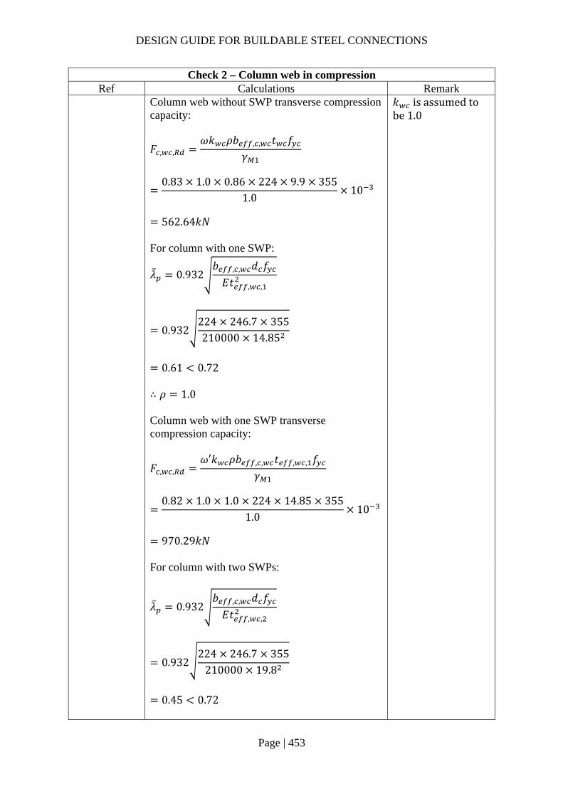
DESIGN GUIDE FOR BUILDABLE STEEL CONNECTIONS
Page | 453
Check 2 – Column web in compression Ref Calculations Remark
Column web without SWP transverse compression capacity:
𝐹 , ,𝜔𝑘 𝜌𝑏 , , 𝑡 𝑓
𝛾
0.83 1.0 0.86 224 9.9 355
1.010
562.64𝑘𝑁
𝑘 is assumed to be 1.0
For column with one SWP:
�̅� 0.932𝑏 , , 𝑑 𝑓
𝐸𝑡 , ,
0.932224 246.7 355210000 14.85
0.61 0.72
∴ 𝜌 1.0
Column web with one SWP transverse compression capacity:
𝐹 , ,𝜔′𝑘 𝜌𝑏 , , 𝑡 , , 𝑓
𝛾
0.82 1.0 1.0 224 14.85 355
1.010
970.29𝑘𝑁
For column with two SWPs:
�̅� 0.932𝑏 , , 𝑑 𝑓
𝐸𝑡 , ,
0.932224 246.7 355
210000 19.8
0.45 0.72
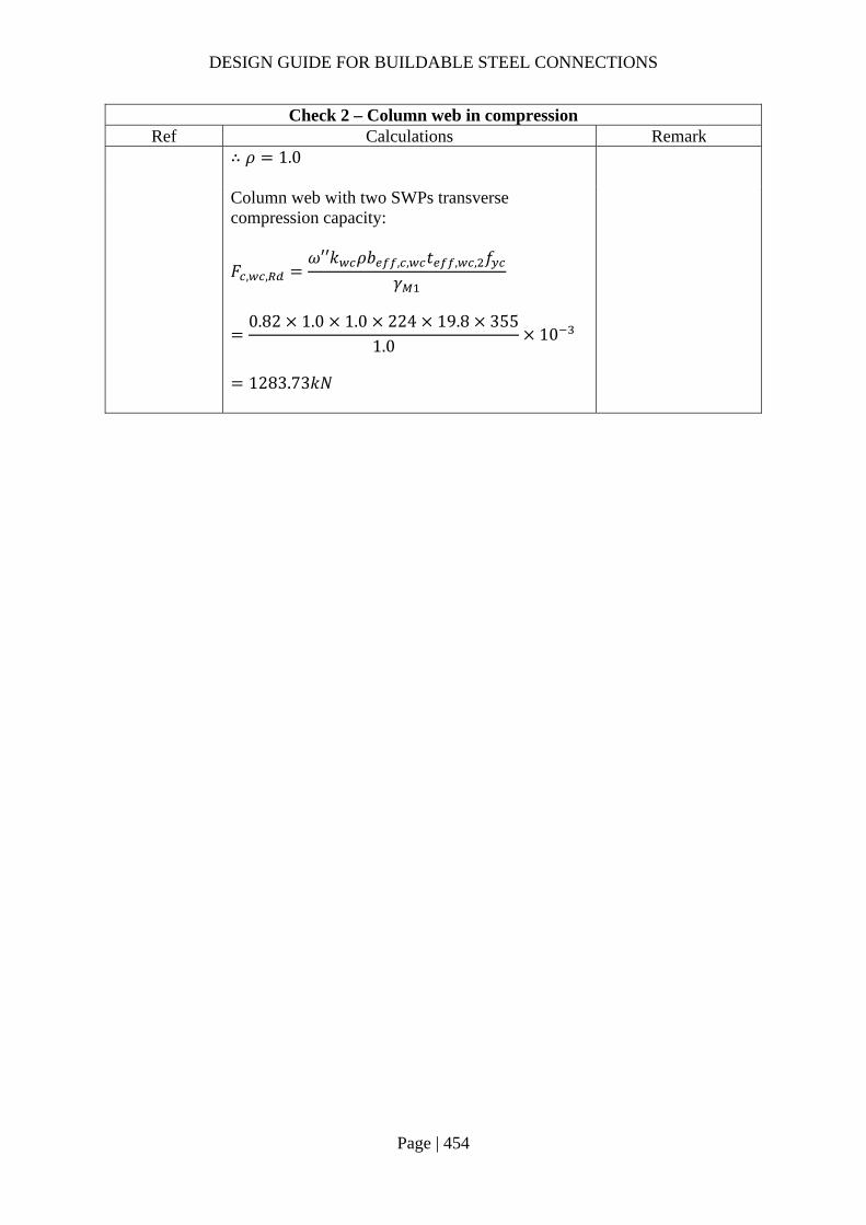
DESIGN GUIDE FOR BUILDABLE STEEL CONNECTIONS
Page | 454
Check 2 – Column web in compression Ref Calculations Remark
∴ 𝜌 1.0
Column web with two SWPs transverse compression capacity:
𝐹 , ,𝜔′′𝑘 𝜌𝑏 , , 𝑡 , , 𝑓
𝛾
0.82 1.0 1.0 224 19.8 355
1.010
1283.73𝑘𝑁

DESIGN GUIDE FOR BUILDABLE STEEL CONNECTIONS
Page | 455
Check 3 – Column web in shear Ref Calculations Remark
For column web without SWP:
𝑑𝑡
246.79.9
24.92 69𝜀 69235355
56.14
Shear resistance of column web:
𝑉 ,0.9𝑓 𝐴
𝛾 √3
0.9 355 3517.38
√310
648.83𝑘𝑁
For column with SWP: *For column web panel with SWP under shear force, only one SWP will contribute to the shear area and the increase is independent of the thickness of the SWP 𝑡 , , 1.5𝑡 14.85𝑚𝑚 𝑑
𝑡 , ,
246.714.85
16.61 69𝜀
𝐴 , 𝐴 𝑏 𝑡
3517.38 226.7 9.9
5761.71𝑚𝑚

DESIGN GUIDE FOR BUILDABLE STEEL CONNECTIONS
Page | 456
Check 3 – Column web in shear Ref Calculations Remark
𝑉 , ,
0.9𝑓 𝐴 ,
𝛾 √3
0.9 355 5761.71
√310
1062.82𝑘𝑁

DESIGN GUIDE FOR BUILDABLE STEEL CONNECTIONS
Page | 457
Check 4 – Dimensions of SWP Ref Calculations Remark
The minimum depth requirement for SWP:
𝑑 , ℎ 𝑒12𝑡 𝑏 , , 𝑏 , ,
462 60172
206.56 224
608.78𝑚𝑚 𝑑 610𝑚𝑚
For SWP is only required for shear, the perimeter fillet welds may just reach the fillets of the column section. As shown in A. For SWP is required to supplement the tension or compression resistance, infill weld should be used. As shown in B.
𝑟 𝑡
𝑏 𝑏
A B

DESIGN GUIDE FOR BUILDABLE STEEL CONNECTIONS
Page | 458
2.6 Splice connections
Splice connections subjected to flexure, shear force and/or axial force for beams and columns can generally be achieved by the following:
Bolted cover plate splice Bolted end plate splice Welded splice
A beam splice connection ensures the continuity between two beams, it resists moment, axial forces and shear in the beam. The flange cover plates resist tension and compression forces while the web cover plate resists shear, bending and axial forces. To ensure the rigidity of the connection, slip resistance of the connection is checked. According to SS EN 1993-1-8 Clause 3.9.3 (1), for hybrid connections, final tightening of the bolts is carried out after the welding is completed.
The design steps of beam spice can be summarized as follow:
Distributions of internal forces
For a splice in a flexural member, the applied moment is shared by the beam web and flange. The proportion of moment taken by beam web depends on the second moment of area of beam web.
The force in flange due to moment:
𝐹 , 1𝐼𝐼
𝑀ℎ 𝑡
where
𝐼 : second moment of area of beam web
𝐼ℎ 2𝑡 𝑡
12
𝐼 : second moment of area of whole beam section
ℎ : depth of beam
𝑡 : thickness of beam flange
𝑀 : design moment in the beam splice
The force in flange due to axial force:
𝐹 , 1𝐴𝐴
𝑁2
where
𝐴 : area of the member web
𝐴: area of the beam cross section
𝑁 : design axial force
Moment in the web due to applied moment:
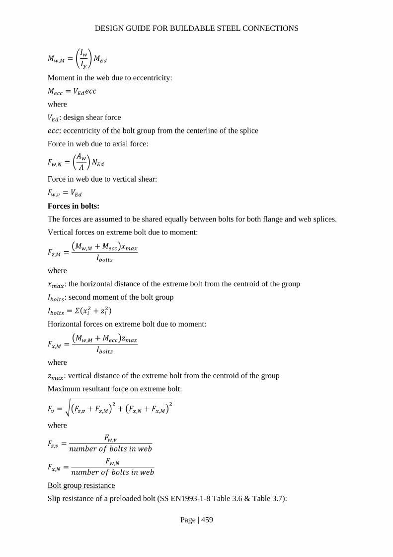
DESIGN GUIDE FOR BUILDABLE STEEL CONNECTIONS
Page | 459
𝑀 ,𝐼𝐼
𝑀
Moment in the web due to eccentricity:
𝑀 𝑉 𝑒𝑐𝑐
where
𝑉 : design shear force
𝑒𝑐𝑐: eccentricity of the bolt group from the centerline of the splice
Force in web due to axial force:
𝐹 ,𝐴𝐴
𝑁
Force in web due to vertical shear:
𝐹 , 𝑉
Forces in bolts:
The forces are assumed to be shared equally between bolts for both flange and web splices.
Vertical forces on extreme bolt due to moment:
𝐹 ,𝑀 , 𝑀 𝑥
𝐼
where
𝑥 : the horizontal distance of the extreme bolt from the centroid of the group
𝐼 : second moment of the bolt group
𝐼 𝛴 𝑥 𝑧
Horizontal forces on extreme bolt due to moment:
𝐹 ,𝑀 , 𝑀 𝑧
𝐼
where
𝑧 : vertical distance of the extreme bolt from the centroid of the group
Maximum resultant force on extreme bolt:
𝐹 𝐹 , 𝐹 , 𝐹 , 𝐹 ,
where
𝐹 ,𝐹 ,
𝑛𝑢𝑚𝑏𝑒𝑟 𝑜𝑓 𝑏𝑜𝑙𝑡𝑠 𝑖𝑛 𝑤𝑒𝑏
𝐹 ,𝐹 ,
𝑛𝑢𝑚𝑏𝑒𝑟 𝑜𝑓 𝑏𝑜𝑙𝑡𝑠 𝑖𝑛 𝑤𝑒𝑏
Bolt group resistance
Slip resistance of a preloaded bolt (SS EN1993-1-8 Table 3.6 & Table 3.7):

DESIGN GUIDE FOR BUILDABLE STEEL CONNECTIONS
Page | 460
𝐹 ,𝑘 𝑛𝜇𝛾
𝐹 , 𝐹
where
𝑛: number of friction planes
𝑘 : can be found in SS EN 1993-1-8 Table 3.6
𝜇: slip factor, given in SS EN 1993-1-8 Table 3.7
The slip factor obtained either by specific tests for the friction surface in accordance with EN 1090-2 Requirements for the execution of steel structures or when relevant as given in Table 3.7.
𝐹 , : preloading forces
𝐹 , 0.7𝑓 𝐴
For bearing resistance in flange and web spices, the checking is same as that in section 2.3.1.
Reduction due to long joint effect may be considered, refer to section 2.3.1 for details.
Resistance of tension flange
Full penetration butt weld is adopted so only the resistance of the tension flange needs to be checked for the flange splice experienced tension.
Resistance of the gross section:
𝐹 ,𝐴 𝑓𝛾
where
𝐴 : area of the gross section
𝐴 𝑏 𝑡
Resistance of the net section:
𝐹 ,0.9𝐴 𝑓𝛾
where
𝐴 : net area of the section
𝐴 𝑏 2𝑑 𝑡
Resistance of compression flange and cover plate
Local buckling of the compression cover plate between rows of bolts needs to be checked if: 𝑝𝑡
9𝜀
where
𝑝 : distance between bolts in compression flange
𝑡 : thickness of flange cover plate
Resistance of web splice

DESIGN GUIDE FOR BUILDABLE STEEL CONNECTIONS
Page | 461
Resistance of gross shear area:
𝑉 , ,ℎ 𝑡
1.27𝑓 ,
√3𝛾
Resistance of net shear area:
𝑉 , ,
𝐴 , ,𝑓
√3𝛾
where
𝐴 , , ℎ 𝑛𝑑 𝑡
𝑛: number of bolt rows in web splice
Shear resistance of web cover plate:
𝑉 , , min 𝑉 , , ;𝑉 , ,
Bending resistance of web cover plate:
𝑀 , ,𝑊 1 𝜌 𝑓
𝛾
where
𝑊 : elastic modulus of cover plate
𝑊𝑡 ℎ
6
For low shear 𝑉 𝑉 , , /2 : 𝜌 0
For high shear 𝑉 𝑉 , , /2 :
𝜌2𝑉
𝑉 , ,1
*If axial loading exists, the web cover plate needs to be checked according to SS EN 1993-1-8 6.2.10 and 6.2.9.2.
𝑁 ,
𝑁 ,
𝑀 ,
𝑀 ,1
The check for shear resistance of beam web is similar to section 2.3.1.
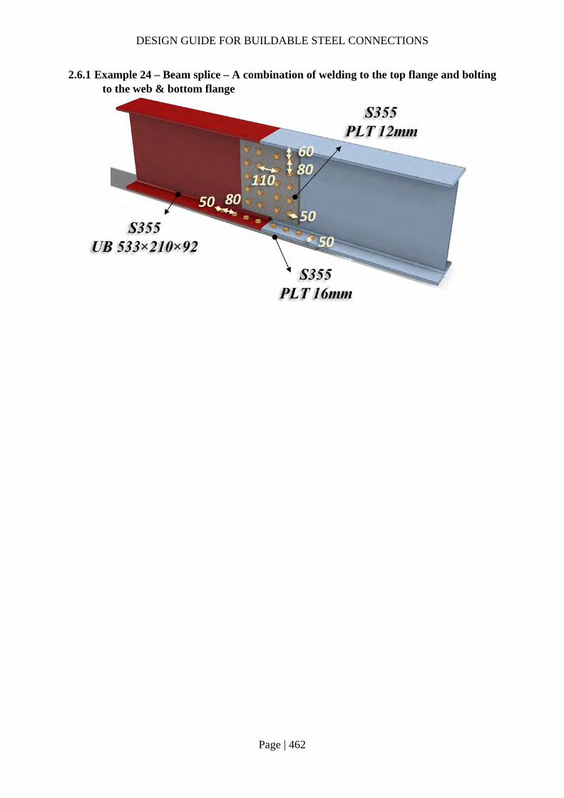
DESIGN GUIDE FOR BUILDABLE STEEL CONNECTIONS
Page | 462
2.6.1 Example 24 – Beam splice – A combination of welding to the top flange and bolting to the web & bottom flange
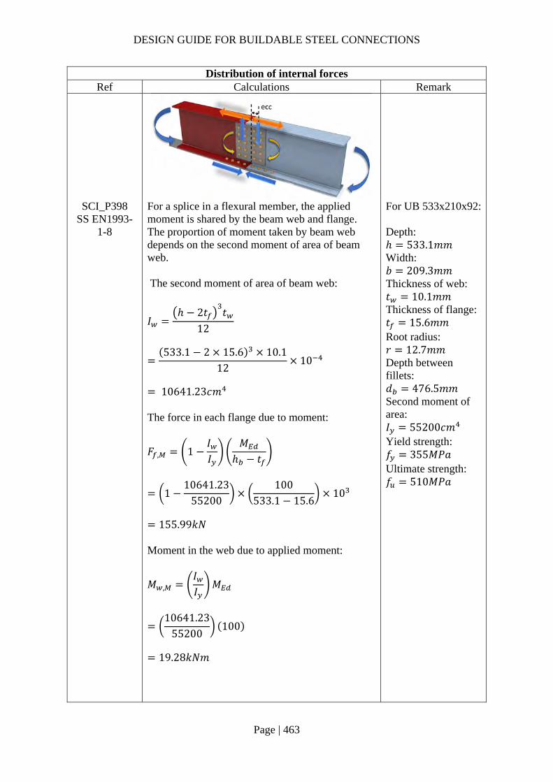
DESIGN GUIDE FOR BUILDABLE STEEL CONNECTIONS
Page | 463
Distribution of internal forces Ref Calculations Remark
SCI_P398 SS EN1993-
1-8
For a splice in a flexural member, the applied moment is shared by the beam web and flange. The proportion of moment taken by beam web depends on the second moment of area of beam web. The second moment of area of beam web:
𝐼ℎ 2𝑡 𝑡
12
533.1 2 15.6 10.1
1210
10641.23𝑐𝑚
The force in each flange due to moment:
𝐹 , 1𝐼𝐼
𝑀ℎ 𝑡
110641.23
55200100
533.1 15.610
155.99𝑘𝑁
Moment in the web due to applied moment:
𝑀 ,𝐼𝐼
𝑀
10641.23
55200100
19.28𝑘𝑁𝑚
For UB 533x210x92: Depth: ℎ 533.1𝑚𝑚 Width: 𝑏 209.3𝑚𝑚 Thickness of web: 𝑡 10.1𝑚𝑚 Thickness of flange: 𝑡 15.6𝑚𝑚 Root radius: 𝑟 12.7𝑚𝑚 Depth between fillets: 𝑑 476.5𝑚𝑚 Second moment of area: 𝐼 55200𝑐𝑚 Yield strength: 𝑓 355𝑀𝑃𝑎 Ultimate strength: 𝑓 510𝑀𝑃𝑎

DESIGN GUIDE FOR BUILDABLE STEEL CONNECTIONS
Page | 464
Distribution of internal forces Ref Calculations Remark
Moment in web due to eccentricity: 𝑀 𝑉 𝑒𝑐𝑐
100110
2802
10
9.5𝑘𝑁𝑚
Force in web due to vertical shear: 𝐹 , 𝑉 100𝑘𝑁 Force in flange bolts:
𝐹 ,𝐹 ,
𝑛155.99
819.50𝑘𝑁
No. of bolts in flange: 𝑛 8
Force in web bolts: Vertical forces per bolt due to shear:
𝐹 ,𝐹 ,
𝑛10010
10𝑘𝑁
Second moment of the bolt group: 𝐼 𝛴 𝑥 𝑧
4 80 4 160 10 40
144000𝑚𝑚 Vertical forces on extreme bolt due to moment:
𝐹 ,𝑀 , 𝑀 𝑥
𝐼
19.28 9.540
14400010
7.99𝑘𝑁
No. of bolts in web: 𝑛 10

DESIGN GUIDE FOR BUILDABLE STEEL CONNECTIONS
Page | 465
Distribution of internal forces Ref Calculations Remark
Horizontal forces on extreme bolt due to moment:
𝐹 ,𝑀 , 𝑀 𝑧
𝐼
19.28 9.5160
14400010
31.98𝑘𝑁
Maximum resultant force on extreme bolt:
𝐹 𝐹 , 𝐹 , 𝐹 ,
10 7.99 31.98
36.69𝑘𝑁
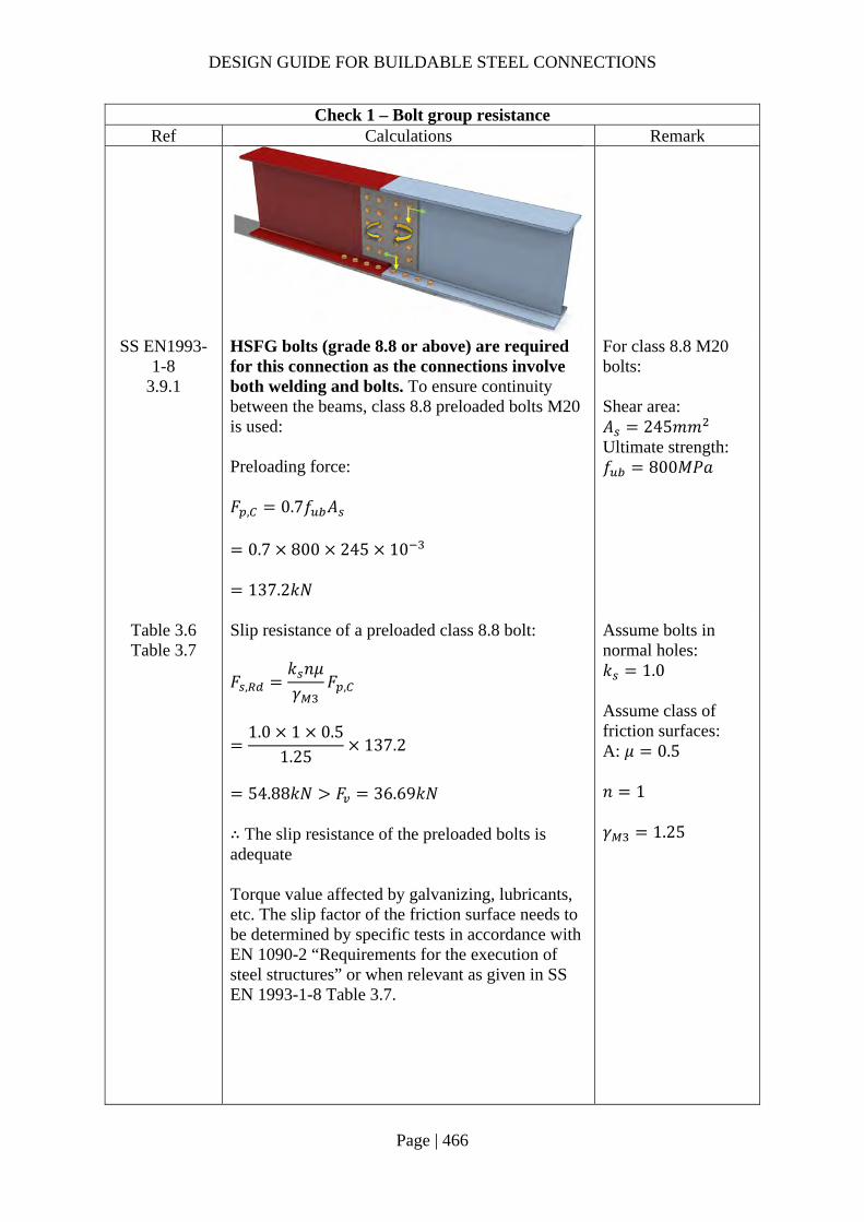
DESIGN GUIDE FOR BUILDABLE STEEL CONNECTIONS
Page | 466
Check 1 – Bolt group resistance Ref Calculations Remark
SS EN1993-1-8
3.9.1
HSFG bolts (grade 8.8 or above) are required for this connection as the connections involve both welding and bolts. To ensure continuity between the beams, class 8.8 preloaded bolts M20 is used: Preloading force: 𝐹 , 0.7𝑓 𝐴
0.7 800 245 10
137.2𝑘𝑁
For class 8.8 M20 bolts: Shear area: 𝐴 245𝑚𝑚 Ultimate strength: 𝑓 800𝑀𝑃𝑎
Table 3.6 Table 3.7
Slip resistance of a preloaded class 8.8 bolt:
𝐹 ,𝑘 𝑛𝜇𝛾
𝐹 ,
1.0 1 0.5
1.25137.2
54.88𝑘𝑁 𝐹 36.69𝑘𝑁
∴ The slip resistance of the preloaded bolts is adequate Torque value affected by galvanizing, lubricants, etc. The slip factor of the friction surface needs to be determined by specific tests in accordance with EN 1090-2 “Requirements for the execution of steel structures” or when relevant as given in SS EN 1993-1-8 Table 3.7.
Assume bolts in normal holes: 𝑘 1.0 Assume class of friction surfaces: A: 𝜇 0.5 𝑛 1 𝛾 1.25

DESIGN GUIDE FOR BUILDABLE STEEL CONNECTIONS
Page | 467
Check 1 – Bolt group resistance Ref Calculations Remark
Bearing resistance in web splice: Web cover plate: In vertical direction:
𝑘 min2.8𝑒𝑑
1.7;1.4𝑝𝑑
1.7; 2.5
min 2.85022
1.7; 1.48022
1.7; 2.5
2.5
𝑡 12𝑚𝑚 𝛾 1.25 𝑓 355𝑀𝑃𝑎 𝑓 510𝑀𝑃𝑎
𝛼 min
𝑒3𝑑
;𝑝
3𝑑14
;𝑓𝑓
; 1.0
min60
3 22;
803 22
14
;800510
; 1.0
0.91
𝐹 , ,𝑘 𝛼 𝑓 𝑑𝑡
𝛾
2.5 0.91 510 20 12
1.2510
222.55𝑘𝑁
In horizontal direction:
𝑘 min2.8𝑒𝑑
1.7;1.4𝑝𝑑
1.7; 2.5
min 2.86022
1.7; 1.48022
1.7; 2.5
2.5
𝛼 min𝑒
3𝑑;𝑝
3𝑑14
;𝑓𝑓
; 1.0
min50
3 22;
803 22
14
;800510
; 1.0
0.76

DESIGN GUIDE FOR BUILDABLE STEEL CONNECTIONS
Page | 468
Check 1 – Bolt group resistance Ref Calculations Remark
𝐹 , ,𝑘 𝛼 𝑓 𝑑𝑡
𝛾
2.5 0.76 510 20 12
1.2510
185.45𝑘𝑁
𝐹 , 𝐹 ,
𝐹 , ,
𝐹 ,
𝐹 , ,
7.99 10
222.2531.98
185.45
0.25 1.0
OK
Beam web: In vertical direction: 𝑘 2.5
𝛼 min𝑒 ,
3𝑑;𝑝
3𝑑14
;𝑓𝑓
; 1.0
min106.553 22
;80
3 2214
;800510
; 1.0
0.96
𝐹 , ,𝑘 𝛼 𝑓 𝑑𝑡
𝛾
2.5 0.96 510 20 10.1
1.2510
198.24𝑘𝑁
In horizontal direction: 𝑘 2.5 𝛼 0.76

DESIGN GUIDE FOR BUILDABLE STEEL CONNECTIONS
Page | 469
Check 1 – Bolt group resistance Ref Calculations Remark
𝐹 , ,
𝑘 𝛼 𝑓 𝑑𝑡𝛾
2.5 0.76 510 20 10.1
1.2510
156.09𝑘𝑁
𝐹 , 𝐹 ,
𝐹 , ,
𝐹 ,
𝐹 , ,
7.99 10
198.2431.98
156.09
0.30 1.0
OK
Bearing resistance in flange splice: Flange cover plate:
𝑘 min2.8𝑒𝑑
1.7;1.4𝑝𝑑
1.7; 2.5
min 2.85022
1.7; 1.4109.3
221.7; 2.5
2.5
𝛼 min𝑒
3𝑑;𝑝
3𝑑14
;𝑓𝑓
; 1.0
min50
3 22;
803 22
14
;800510
; 1.0
0.76
𝐹 ,
𝑘 𝛼 𝑓 𝑑𝑡𝛾
2.5 0.76 510 20 16
1.2510
247.27𝑘𝑁 𝐹 , 19.50𝑘𝑁
OK

DESIGN GUIDE FOR BUILDABLE STEEL CONNECTIONS
Page | 470
Check 1 – Bolt group resistance Ref Calculations Remark
Beam flange: 𝑘 2.5 𝛼 0.76
𝐹 ,𝑘 𝛼 𝑓 𝑑𝑡
𝛾
2.5 0.76 510 20 15.6
1.2510
241.09𝑘𝑁 𝐹 , 19.50𝑘𝑁
OK
Note:
According to SS EN 1993-1-8 Clause 3.9.3 (1), for hybrid connections, final tightening of the bolts is carried out after the welding is completed
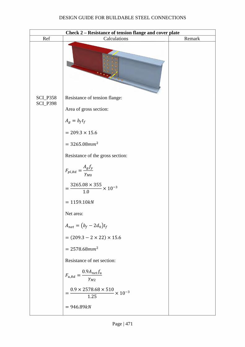
DESIGN GUIDE FOR BUILDABLE STEEL CONNECTIONS
Page | 471
Check 2 – Resistance of tension flange and cover plate Ref Calculations Remark
SCI_P358 SCI_P398
Resistance of tension flange: Area of gross section: 𝐴 𝑏 𝑡
209.3 15.6
3265.08𝑚𝑚 Resistance of the gross section:
𝐹 ,𝐴 𝑓𝛾
3265.08 355
1.010
1159.10𝑘𝑁
Net area: 𝐴 𝑏 2𝑑 𝑡
209.3 2 22 15.6
2578.68𝑚𝑚 Resistance of net section:
𝐹 ,0.9𝐴 𝑓𝛾
0.9 2578.68 510
1.2510
946.89𝑘𝑁
DESIGN GUIDE FOR BUILDABLE STEEL CONNECTIONS
Page | 472
Check 2 – Resistance of tension flange and cover plate Ref Calculations Remark
𝐹 , , min 𝐹 , ;𝐹 ,
min 1159.10; 946.89
946.89𝑘𝑁 𝐹 , 155.99𝑘𝑁
OK

DESIGN GUIDE FOR BUILDABLE STEEL CONNECTIONS
Page | 473
Check 3 – Resistance of web splice Ref Calculations Remark
SCI_P398 Resistance of web cover plate: Resistance of gross shear area:
𝑉 , ,ℎ 𝑡
1.27𝑓 ,
√3𝛾
440 12
1.27355
√310
852.11𝑘𝑁
Net shear area: 𝐴 , , ℎ 5𝑑 𝑡
440 5 22 12
3960𝑚𝑚 Resistance of the net area:
𝑉 , ,
𝐴 , ,𝑓
√3𝛾
3960 510√3
1.2510
932.81𝑘𝑁
Shear resistance of the web cover plate: 𝑉 , min 𝑉 , , ;𝑉 , ,
min 852.11; 9322.81
852.11𝑘𝑁 𝑉 100𝑘𝑁 OK
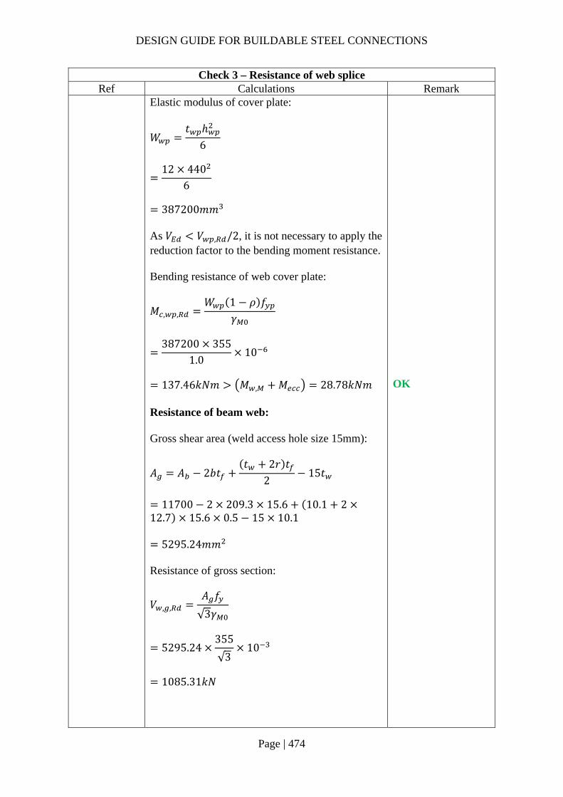
DESIGN GUIDE FOR BUILDABLE STEEL CONNECTIONS
Page | 474
Check 3 – Resistance of web splice Ref Calculations Remark
Elastic modulus of cover plate:
𝑊𝑡 ℎ
6
12 440
6
387200𝑚𝑚
As 𝑉 𝑉 , /2, it is not necessary to apply the reduction factor to the bending moment resistance. Bending resistance of web cover plate:
𝑀 , ,𝑊 1 𝜌 𝑓
𝛾
387200 355
1.010
137.46𝑘𝑁𝑚 𝑀 , 𝑀 28.78𝑘𝑁𝑚
OK
Resistance of beam web: Gross shear area (weld access hole size 15mm):
𝐴 𝐴 2𝑏𝑡𝑡 2𝑟 𝑡
215𝑡
11700 2 209.3 15.6 10.1 2
12.7 15.6 0.5 15 10.1
5295.24𝑚𝑚 Resistance of gross section:
𝑉 , ,𝐴 𝑓
√3𝛾
5295.24355
√310
1085.31𝑘𝑁

DESIGN GUIDE FOR BUILDABLE STEEL CONNECTIONS
Page | 475
Check 3 – Resistance of web splice Ref Calculations Remark
Net shear area: 𝐴 𝐴 5𝑑 𝑡
5295.24 5 22 10.1
4184.24𝑚𝑚 Resistance of net section:
𝑉 , ,
𝐴𝑓√3
𝛾
4184.24 510√3
1.2510
985.64𝑘𝑁
Shear resistance of the beam web: 𝑉 , min 𝑉 , , ;𝑉 , ,
min 1085.31; 985.64
985.64𝑘𝑁 𝑉 100𝑘𝑁
OK

DESIGN GUIDE FOR BUILDABLE STEEL CONNECTIONS
Page | 476
2.6.2 Example 25 – Beam splice – A combination of welding to the top & bottom flanges with bolting to the web
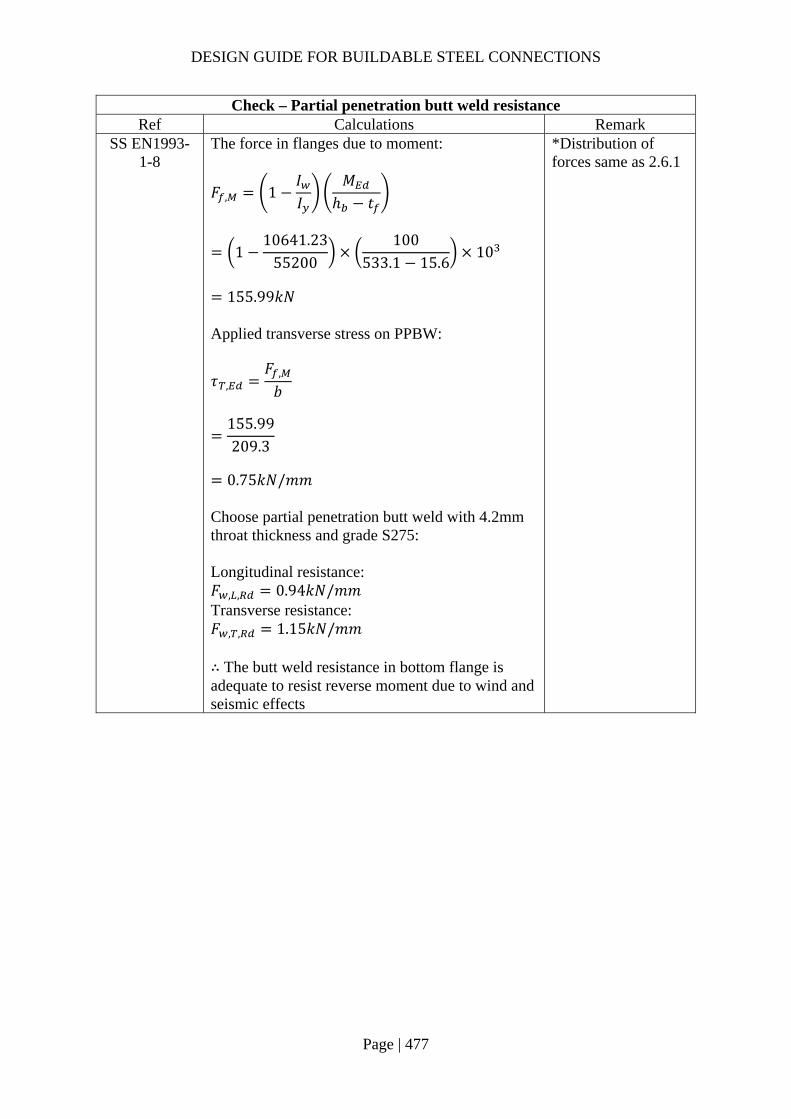
DESIGN GUIDE FOR BUILDABLE STEEL CONNECTIONS
Page | 477
Check – Partial penetration butt weld resistance Ref Calculations Remark
SS EN1993-1-8
The force in flanges due to moment:
𝐹 , 1𝐼𝐼
𝑀ℎ 𝑡
110641.23
55200100
533.1 15.610
155.99𝑘𝑁
Applied transverse stress on PPBW:
𝜏 ,𝐹 ,
𝑏
155.99209.3
0.75𝑘𝑁/𝑚𝑚
Choose partial penetration butt weld with 4.2mm throat thickness and grade S275: Longitudinal resistance: 𝐹 , , 0.94𝑘𝑁/𝑚𝑚 Transverse resistance: 𝐹 , , 1.15𝑘𝑁/𝑚𝑚 ∴ The butt weld resistance in bottom flange is adequate to resist reverse moment due to wind and seismic effects
*Distribution of forces same as 2.6.1
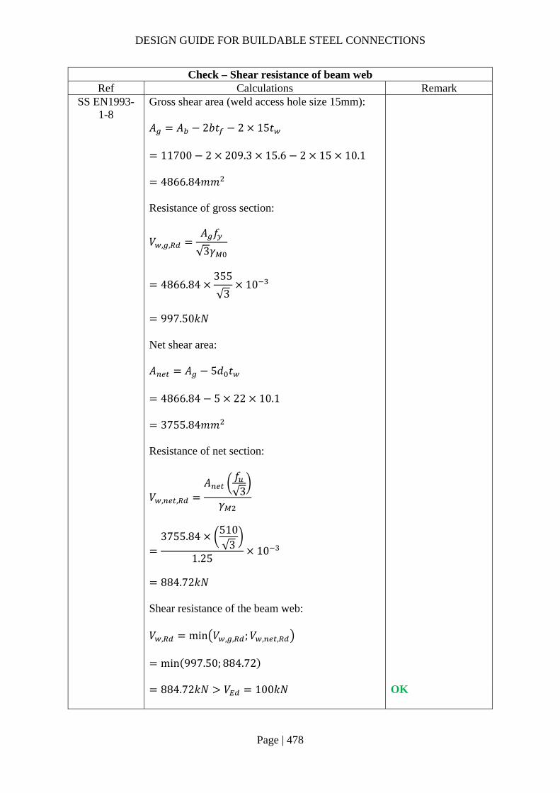
DESIGN GUIDE FOR BUILDABLE STEEL CONNECTIONS
Page | 478
Check – Shear resistance of beam web Ref Calculations Remark
SS EN1993-1-8
Gross shear area (weld access hole size 15mm): 𝐴 𝐴 2𝑏𝑡 2 15𝑡
11700 2 209.3 15.6 2 15 10.1
4866.84𝑚𝑚 Resistance of gross section:
𝑉 , ,𝐴 𝑓
√3𝛾
4866.84355
√310
997.50𝑘𝑁
Net shear area: 𝐴 𝐴 5𝑑 𝑡
4866.84 5 22 10.1
3755.84𝑚𝑚 Resistance of net section:
𝑉 , ,
𝐴𝑓√3
𝛾
3755.84 510√3
1.2510
884.72𝑘𝑁
Shear resistance of the beam web: 𝑉 , min 𝑉 , , ;𝑉 , ,
min 997.50; 884.72
884.72𝑘𝑁 𝑉 100𝑘𝑁
OK

DESIGN GUIDE FOR BUILDABLE STEEL CONNECTIONS
Page | 479
3 Base Plate Connections 3.1 Base Plate Connection
Base plate connection consists of a steel column welded to a base plate, which is ten fastened to the foundation by holding down bolts anchored into the foundation. The foundation in this context can be a pile cap, reinforced concrete (RC) beam, RC wall, RC column or RC slab. The base plate should have sufficient size and thickness to transfer the compressive/tensile, shear force and bending moment from the steel section to the substrate based on bearing resistance of the concrete. The compression force is spread over an effective area of the base plate in contact with the concrete. As for tension due to axial force and/or moments, the tension force is resisted by the holding down bolts anchored into the concrete. The base plate should be able to resist the tensile stress arising from the axial force and/or bending moment. Horizontal shear force should be resisted by the friction between the base plate and the foundation or by the shear capacity of the bolts.
One of the important aspects of base plate connection to ensure buildability is the anchorage length of the holding down bolt. Often, the size of the concrete substrate is not big enough to fit the holding down bolts due to the anchorage length. The use of full tension anchorage based on the bond strength between the concrete and the holding down bolts will result into a longer anchorage length. Instead, the concrete cone pull-out capacity can be adopted to derive the anchorage length needed (ℎ ) as shown in Figure 3-1.
Figure 3-1 Concrete cone pull-out capacity
3.2 Design steps
Five design steps that require attention from designers are:
Step 1 – Find the effective area (𝐴 needed for the base plate to be in contact with the concrete due to the compression force and/or bending moment. The effective area should be checked to ensure that the bearing resistance of the concrete is not exceeded.
Step 2 – Find the minimum base plate thickness based on the minimum projection of the steel plate required from the outer edge of the column based on the effective area derived from Step 1.
Step 3 – Check the weld capacity to resist the shear and axial forces. Step 4 – Check the anchor bolt resistance in terms of tensile, bearing and shear
capacities.
𝐴
ℎ
𝑑
𝑃
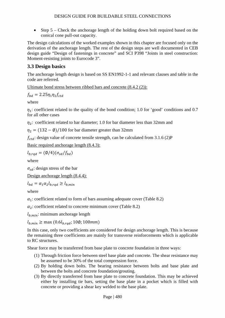
DESIGN GUIDE FOR BUILDABLE STEEL CONNECTIONS
Page | 480
Step 5 – Check the anchorage length of the holding down bolt required based on the conical cone pull-out capacity.
The design calculations of the worked examples shown in this chapter are focused only on the derivation of the anchorage length. The rest of the design steps are well documented in CEB design guide “Design of fastenings in concrete” and SCI P398 “Joints in steel construction: Moment-resisting joints to Eurocode 3”.
3.3 Design basics
The anchorage length design is based on SS EN1992-1-1 and relevant clauses and table in the code are referred.
Ultimate bond stress between ribbed bars and concrete (8.4.2 (2)):
𝑓 2.25𝜂 𝜂 𝑓
where
𝜂 : coefficient related to the quality of the bond condition; 1.0 for ‘good’ conditions and 0.7 for all other cases
𝜂 : coefficient related to bar diameter; 1.0 for bar diameter less than 32mm and
𝜂 132 ∅ /100 for bar diameter greater than 32mm
𝑓 : design value of concrete tensile strength, can be calculated from 3.1.6 (2)P
Basic required anchorage length (8.4.3):
𝑙 , ∅/4 𝜎 /𝑓
where
𝜎 : design stress of the bar
Design anchorage length (8.4.4):
𝑙 𝛼 𝛼 𝑙 , 𝑙 ,
where
𝛼 : coefficient related to form of bars assuming adequate cover (Table 8.2)
𝛼 : coefficient related to concrete minimum cover (Table 8.2)
𝑙 , : minimum anchorage length
𝑙 , max 0.6𝑙 , ; 10∅; 100𝑚𝑚
In this case, only two coefficients are considered for design anchorage length. This is because the remaining three coefficients are mainly for transverse reinforcements which is applicable to RC structures.
Shear force may be transferred from base plate to concrete foundation in three ways:
(1) Through friction force between steel base plate and concrete. The shear resistance may be assumed to be 30% of the total compression force.
(2) By holding down bolts. The bearing resistance between bolts and base plate and between the bolts and concrete foundation/grouting.
(3) By directly transferred from base plate to concrete foundation. This may be achieved either by installing tie bars, setting the base plate in a pocket which is filled with concrete or providing a shear key welded to the base plate.

DESIGN GUIDE FOR BUILDABLE STEEL CONNECTIONS
Page | 481
In base plate connection, if the friction alone is sufficient to transfer the shear force, shear resistance of other components of the connection may not need to be checked. When friction alone is insufficient, the shear force may be assumed to be transferred via holding down bolts. As the bolts are in clearance holes, not all bolts are in contact with the plate. As a result, the shear force may not be assumed to be shared equally among the bolts. This can be overcome by providing washer plates with precise holes and site welded to the base plate. Moreover, in the event where there is an eccentricity between the shear force and the centre of gravity of the bolt group, the bolts need to be checked against the additional shear force due to the eccentric moment. In the case that the shear force acts on the bolts with a level arm, the bending moment will severely reduce the shear resistance of the bolts. Shear loads acting on the hold-down bolts may be assumed to act without a level arm if both of the following conditions are fulfilled (CEB design guide 4.2.1.3):
(1) The fixture must be made of metal and in the area of the anchorage be fixed directly to the concrete foundation without an intermediate layer or with a levelling layer of mortar with a thickness less than 3mm.
(2) The fixture must be adjacent to the anchor over its entire thickness.
In addition to the two conditions stated above, the entire grouting operation needs to be undertaken with care, including proper preparation of the base, cleanliness, mixing and careful placing of grout. In the case that non-shrink structural grout with strength at least equal to that of concrete foundation is used between the base plate and foundation and the hold-down bolts have enough end space (at least 6d in the load direction), zero level arm length may be assumed.
When the shear force is too high to be transferred by friction or by the holding down bolts, the base plate connection may be designed to transfer the significant shears directly to the concrete foundation as mentioned above. Qualified person needs to access the suitability of all assumptions made in design base on site conditions.
3.4 Typical Column Base Plate
For column base plate connections, two types of hold down bolts are commonly used:
(a) L-bolt and/or J-bolt; and (b) Vertical holding down bolt with nuts and washers.

DESIGN GUIDE FOR BUILDABLE STEEL CONNECTIONS
Page | 482
3.4.1 Example 1 – Use of L-Bolt
Design loading:
Axial compression force: 𝑁 2000𝑘𝑁
Shear force: 𝑉 500𝑘𝑁

DESIGN GUIDE FOR BUILDABLE STEEL CONNECTIONS
Page | 483
Check 1 – Required area Ref Calculations Remark
SCI_P358 Design compressive strength of the concrete:
𝑓𝛼 𝑓𝛾
0.85401.5
22.67𝑀𝑃𝑎
Assume 𝛽 2/3, this is reasonable as the grout thickness is 30mm < 50mm and the grout strength is assumed to be same as the concrete foundation. Assume 𝛼 1.5, the dimensions of foundation in this example is unknown. Design bearing resistance of concrete: 𝑓 𝛽 𝛼𝑓
23
1.5 17
22.67𝑀𝑃𝑎
Required bearing area:
𝐴𝑁𝑓
200022.67
10 88235𝑚𝑚
Concrete characteristic strength: 𝑓 40𝑀𝑃𝑎 𝛼 0.85
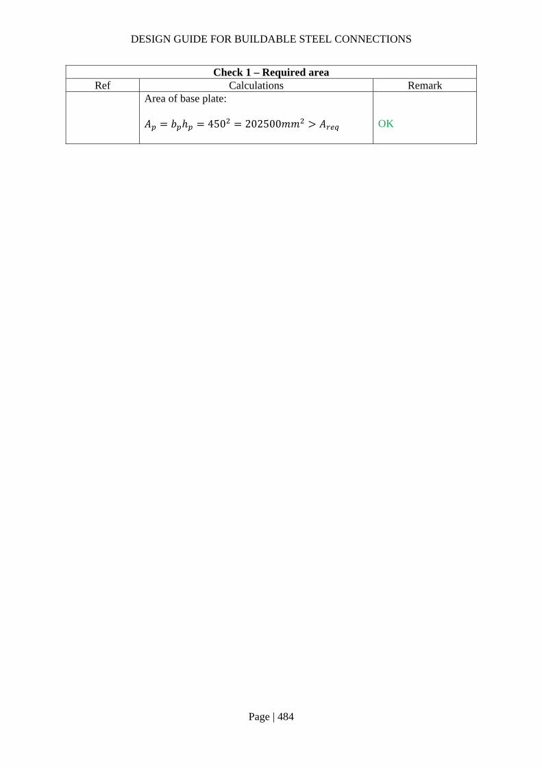
DESIGN GUIDE FOR BUILDABLE STEEL CONNECTIONS
Page | 484
Check 1 – Required area Ref Calculations Remark
Area of base plate:
𝐴 𝑏 ℎ 450 202500𝑚𝑚 𝐴
OK

DESIGN GUIDE FOR BUILDABLE STEEL CONNECTIONS
Page | 485
Check 2 – Effective area Ref Calculations Remark
SCI_P358 Assume there is no overlap among the projection width of the column: For UC section: 𝐴 4𝑐 𝑃 𝑐 𝐴 𝐴 88235𝑚𝑚
∴ 𝑐 36𝑚𝑚 For UC, ℎ 2𝑡
2309.2 2 21.7
2138.55𝑚𝑚 𝑐
∴ the assumption that there is no overlap is valid.
Perimeter of column (UC305x305x137): 𝑃 1824.10𝑚𝑚 𝐴 17400𝑚𝑚
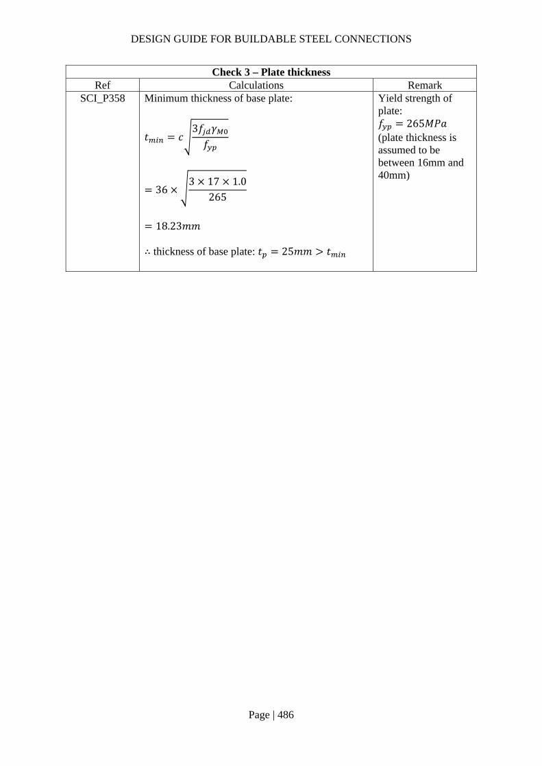
DESIGN GUIDE FOR BUILDABLE STEEL CONNECTIONS
Page | 486
Check 3 – Plate thickness Ref Calculations Remark
SCI_P358 Minimum thickness of base plate:
𝑡 𝑐3𝑓 𝛾𝑓
363 17 1.0
265
18.23𝑚𝑚
∴ thickness of base plate: 𝑡 25𝑚𝑚 𝑡
Yield strength of plate: 𝑓 265𝑀𝑃𝑎 (plate thickness is assumed to be between 16mm and 40mm)
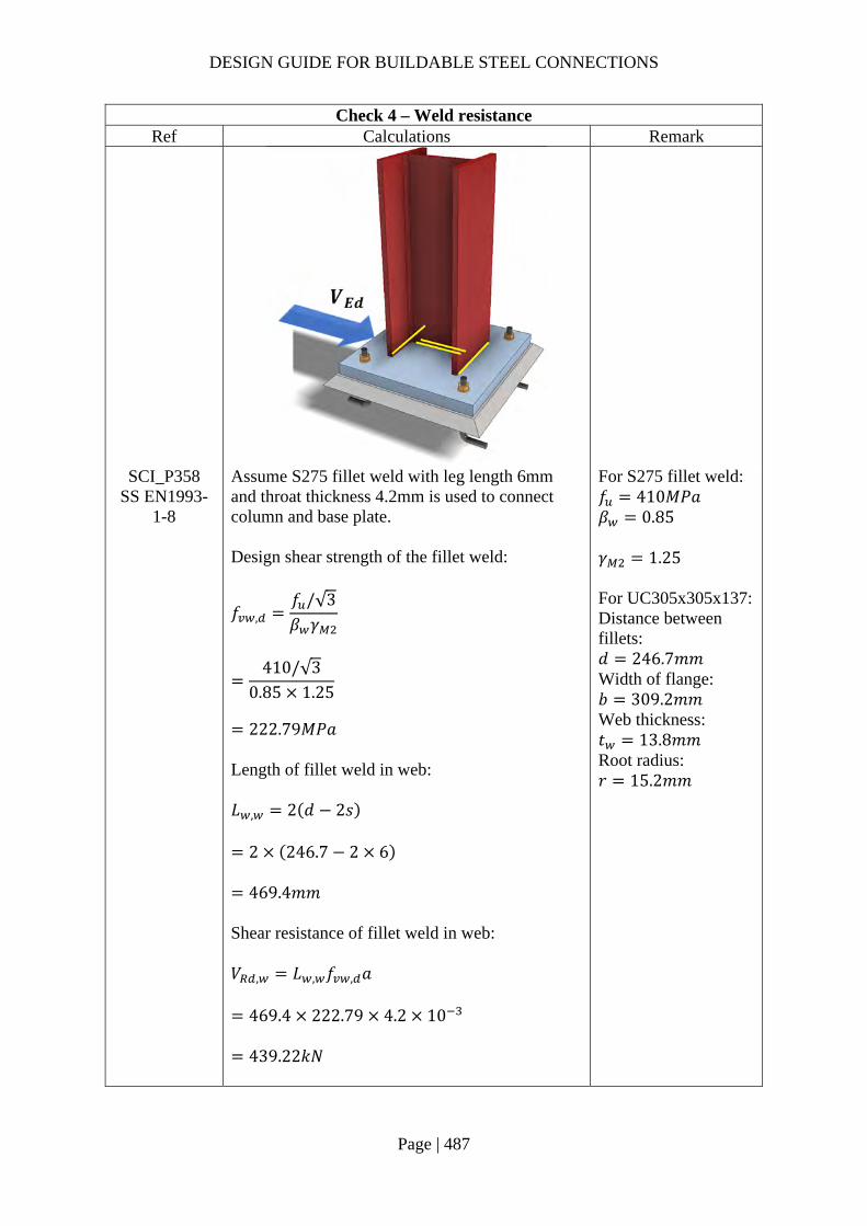
DESIGN GUIDE FOR BUILDABLE STEEL CONNECTIONS
Page | 487
Check 4 – Weld resistance Ref Calculations Remark
SCI_P358 SS EN1993-
1-8
Assume S275 fillet weld with leg length 6mm and throat thickness 4.2mm is used to connect column and base plate. Design shear strength of the fillet weld:
𝑓 ,𝑓 /√3𝛽 𝛾
410/√3
0.85 1.25
222.79𝑀𝑃𝑎
Length of fillet weld in web: 𝐿 , 2 𝑑 2𝑠
2 246.7 2 6
469.4𝑚𝑚 Shear resistance of fillet weld in web: 𝑉 , 𝐿 , 𝑓 , 𝑎
469.4 222.79 4.2 10
439.22𝑘𝑁
For S275 fillet weld: 𝑓 410𝑀𝑃𝑎 𝛽 0.85 𝛾 1.25 For UC305x305x137: Distance between fillets: 𝑑 246.7𝑚𝑚 Width of flange: 𝑏 309.2𝑚𝑚 Web thickness: 𝑡 13.8𝑚𝑚 Root radius: 𝑟 15.2𝑚𝑚
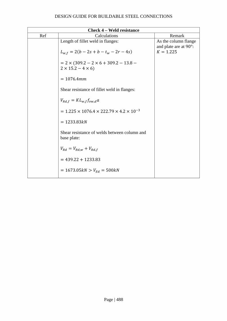
DESIGN GUIDE FOR BUILDABLE STEEL CONNECTIONS
Page | 488
Check 4 – Weld resistance Ref Calculations Remark
Length of fillet weld in flanges: 𝐿 , 2 𝑏 2𝑠 𝑏 𝑡 2𝑟 4𝑠
2 309.2 2 6 309.2 13.82 15.2 4 6
1076.4𝑚𝑚 Shear resistance of fillet weld in flanges: 𝑉 , 𝐾𝐿 , 𝑓 , 𝑎
1.225 1076.4 222.79 4.2 10
1233.83𝑘𝑁 Shear resistance of welds between column and base plate: 𝑉 𝑉 , 𝑉 ,
439.22 1233.83
1673.05𝑘𝑁 𝑉 500𝑘𝑁
As the column flange and plate are at 90°: 𝐾 1.225

DESIGN GUIDE FOR BUILDABLE STEEL CONNECTIONS
Page | 489
Check 5 – Anchorage length of hook Ref Calculations Remark
SS EN1993-1-8
SS EN1992-1-1, 8.4.2
According to SS EN1993-1-8 Clause 6.2.6.12 (5), the anchorage length of the bolt with hooked end should be able to prevent bond failure before yielding of the bolt. Hook type of anchorage should not be used for bolts with yield strength 𝑓 greater than 300𝑁/𝑚𝑚 . In this example, the bond properties of the anchor bolts is assumed to be same as ribbed bars. Ultimate anchorage bond stress for ribbed bars: 𝑓 2.25𝜂 𝜂 𝑓 1.5𝑓 , . 0.315𝑓 /
0.315 40 /
3.68𝑀𝑃𝑎 Basic anchorage length:
𝑙 .𝑓
4𝑓∅
240
4 3.6824
390.85𝑚𝑚
Coefficients:
For grade 4.6 M24 bolts: Yield strength: 𝑓 240𝑀𝑃𝑎 Diameter of bolt: ∅ 24𝑚𝑚

DESIGN GUIDE FOR BUILDABLE STEEL CONNECTIONS
Page | 490
Check 5 – Anchorage length of hook Ref Calculations Remark
Shape of anchor bar: 𝛼 0.7, assume edge distance is greater than three times of the dimeter
Concrete cover to anchor bar: 𝛼 0.7, assume concrete cover is much larger than three times of the dimeter Design anchorage length: 𝑙 𝑙 , 𝛼 𝛼
390.85 0.7 0.7
191.52𝑚𝑚 Minimum require anchorage length: 𝑙 , min 0.3𝑙 , ; 10∅; 100
max 0.3 191.52; 10 24; 100
240𝑚𝑚 𝑙 ∴ 𝑙 240𝑚𝑚
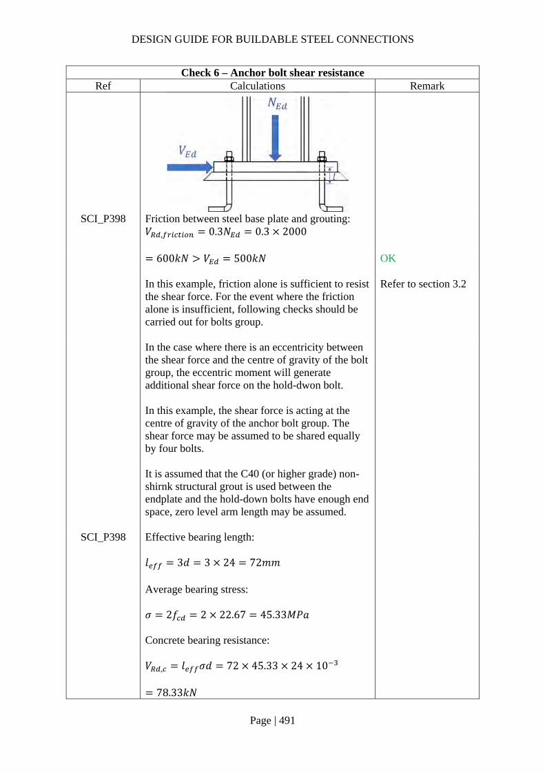
DESIGN GUIDE FOR BUILDABLE STEEL CONNECTIONS
Page | 491
Check 6 – Anchor bolt shear resistance Ref Calculations Remark
SCI_P398 Friction between steel base plate and grouting: 𝑉 , 0.3𝑁 0.3 2000
600𝑘𝑁 𝑉 500𝑘𝑁
OK
In this example, friction alone is sufficient to resist the shear force. For the event where the friction alone is insufficient, following checks should be carried out for bolts group.
Refer to section 3.2
In the case where there is an eccentricity between the shear force and the centre of gravity of the bolt group, the eccentric moment will generate additional shear force on the hold-dwon bolt. In this example, the shear force is acting at the centre of gravity of the anchor bolt group. The shear force may be assumed to be shared equally by four bolts.
It is assumed that the C40 (or higher grade) non-shirnk structural grout is used between the endplate and the hold-down bolts have enough end space, zero level arm length may be assumed.
SCI_P398 Effective bearing length: 𝑙 3𝑑 3 24 72𝑚𝑚 Average bearing stress: 𝜎 2𝑓 2 22.67 45.33𝑀𝑃𝑎 Concrete bearing resistance: 𝑉 , 𝑙 𝜎𝑑 72 45.33 24 10
78.33𝑘𝑁

DESIGN GUIDE FOR BUILDABLE STEEL CONNECTIONS
Page | 492
Check 6 – Anchor bolt shear resistance Ref Calculations Remark
CEB design guide 9.3.2.1
Shear load without level arm: Shear resistance of a anchorage bolt: 𝑉 , 𝑘 𝐴 𝑓 /𝛾
0.6 353 240 10 /1.25
40.67𝑘𝑁
For grade 4.6 M24 bolts: Yield strength: 𝑓 240𝑀𝑃𝑎 Tensile stress area: 𝐴 353𝑚𝑚 𝑘 0.6 𝑛: Number of bolts 𝛾 1.25
Shear resistance of the bolts group: 𝑉 min 𝑉 , ;𝑉 , 𝑛
min 40.67; 78.33 4
162.66𝑘𝑁
However, if non-structural leveling mortar is used between the end plate and the concrete foundation, this grout may not contribute to the shear capacity of the bolts. In this case, the shear resistance of the bolt may be calculated based on shear load with a level arm.
Refer to section 3.2
CEB design guide 9.3.2.2
Shear load with level arm: Elastic section modulus:
𝑊𝐼𝑐
𝜋𝑟4𝑟
𝜋𝑟4
𝜋12
4
1357.168𝑚𝑚
Characteristic bending resistance of an individual bolt: 𝑀 , 1.5𝑊 𝑓
1.5 1357.168 240
488580.5𝑁𝑚𝑚
Radius of the bolt:
𝑟∅2
12𝑚𝑚
For grade 4.6 bolts: 𝑓 240𝑀𝑃𝑎 𝛾 1.25

DESIGN GUIDE FOR BUILDABLE STEEL CONNECTIONS
Page | 493
Check 6 – Anchor bolt shear resistance Ref Calculations Remark
Characteristic resistance of bolt: 𝑁 , 𝐴 𝑓 353 240 10 84.72𝑘𝑁
𝑁 ,𝑁 ,
𝛾84.721.25
67.776𝑘𝑁
Assume applied tensile force on bolt: 𝑁 20𝑘𝑁
𝑀 , 𝑀 , 1
𝑁𝑁 ,
488580.5 120
67.776
344405.4𝑁𝑚𝑚
Assume there is no restraint to the bending of the bolt: 𝛼 1.0
Level arm: 𝑙 0.5𝑑 𝑒
0.5 24 42.5
54.5𝑚𝑚 Characteristic shear resistance:
𝑉 ,𝛼 𝑀 ,
𝑙
1.0 344405.4
54.510
6.32𝑘𝑁
Shear resistance of an anchor bolt:
𝑉 ,𝑉 ,
𝛾4.581.2
5.06𝑘𝑁
Distance between shear load and concrete surface: 𝑒 𝑡 0.5𝑡
30252
42.5𝑚𝑚

DESIGN GUIDE FOR BUILDABLE STEEL CONNECTIONS
Page | 494
Check 6 – Anchor bolt shear resistance Ref Calculations Remark
Shear resistance of bolts group: 𝑉 𝑉 𝑛 5.06 4 20.24𝑘𝑁
It can be observed that the shear resistance is significantly reduced based on shear load with a level arm.

DESIGN GUIDE FOR BUILDABLE STEEL CONNECTIONS
Page | 495
3.4.2 Example 2 – Vertical holding down bolt with nuts and washers
Design loading:
Axial compression: 𝑁 1500𝑘𝑁
Shear force: 𝑉 100𝑘𝑁
Bending moment: 𝑀 200𝑘𝑁𝑚
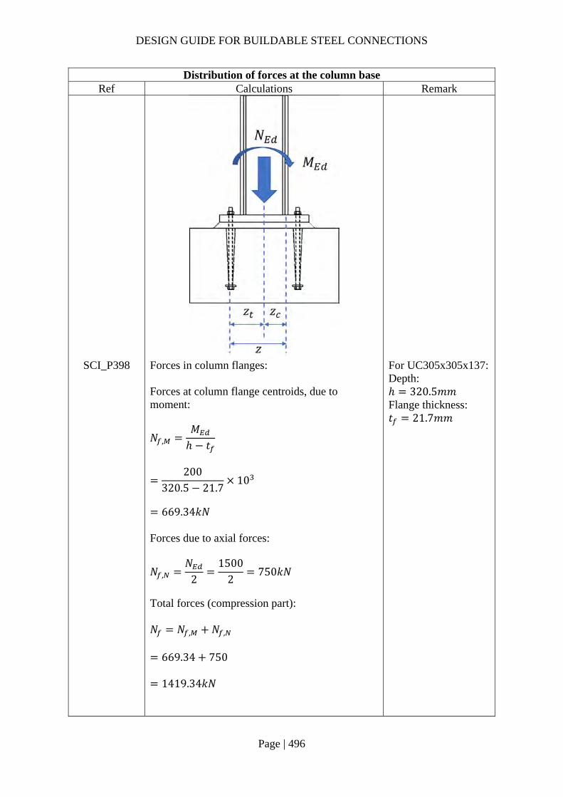
DESIGN GUIDE FOR BUILDABLE STEEL CONNECTIONS
Page | 496
Distribution of forces at the column base Ref Calculations Remark
SCI_P398 Forces in column flanges: Forces at column flange centroids, due to moment:
𝑁 ,𝑀ℎ 𝑡
200
320.5 21.710
669.34𝑘𝑁
Forces due to axial forces:
𝑁 ,𝑁
21500
2750𝑘𝑁
Total forces (compression part): 𝑁 𝑁 , 𝑁 ,
669.34 750
1419.34𝑘𝑁
For UC305x305x137: Depth: ℎ 320.5𝑚𝑚 Flange thickness: 𝑡 21.7𝑚𝑚

DESIGN GUIDE FOR BUILDABLE STEEL CONNECTIONS
Page | 497
Distribution of forces at the column base Ref Calculations Remark
Forces in T-stubs of base plate: Level arm for tension:
𝑧ℎ 2𝑒
2450
2225𝑚𝑚
Level arm for compression:
𝑧ℎ 𝑡
2320.5 21.7
2149.4𝑚𝑚
Force on compression side:
𝑁 ,𝑀𝑧 𝑧
𝑁 𝑧𝑧 𝑧
200 1000225 149.4
1500 225225 149.4
1435.63𝑘𝑁
For base plate: 𝑏 600𝑚𝑚 ℎ 600𝑚𝑚 𝑒 75𝑚𝑚
In this example, there is no tension force at the column base.
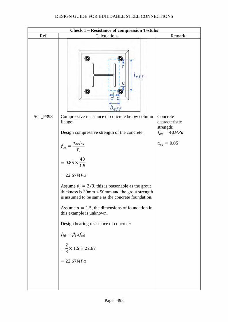
DESIGN GUIDE FOR BUILDABLE STEEL CONNECTIONS
Page | 498
Check 1 – Resistance of compression T-stubs Ref Calculations Remark
SCI_P398 Compressive resistance of concrete below column flange: Design compressive strength of the concrete:
𝑓𝛼 𝑓𝛾
0.85401.5
22.67𝑀𝑃𝑎
Assume 𝛽 2/3, this is reasonable as the grout thickness is 30mm < 50mm and the grout strength is assumed to be same as the concrete foundation. Assume 𝛼 1.5, the dimensions of foundation in this example is unknown. Design bearing resistance of concrete: 𝑓 𝛽 𝛼𝑓
23
1.5 22.67
22.67𝑀𝑃𝑎
Concrete characteristic strength: 𝑓 40𝑀𝑃𝑎 𝛼 0.85

DESIGN GUIDE FOR BUILDABLE STEEL CONNECTIONS
Page | 499
Check 1 – Resistance of compression T-stubs Ref Calculations Remark
Additional bearing width:
𝑐 𝑡𝑓 ,
3𝑓 𝛾
40335
3 22.67 1.0
88.78𝑚𝑚
𝑏 2𝑐 𝑡
2 88.78 21.7
199.27𝑚𝑚
For base plate: 𝑡 40𝑚𝑚 𝑓 , 335𝑀𝑃𝑎
𝑙 2𝑐 𝑏
2 88.78 309.2
486.77𝑚𝑚 Effective bearing area: 𝐴 𝑏 𝑙
199.27 486.77
96995𝑚𝑚
Compression resistance of the foundation: 𝐹 , , 𝐴 𝑓
96995 22.67 10
2198.56𝑘𝑁 𝑁 , 1435.63𝑘𝑁
OK
DESIGN GUIDE FOR BUILDABLE STEEL CONNECTIONS
Page | 500
Check 1 – Resistance of compression T-stubs Ref Calculations Remark
Resistance of the column flange:
𝐹 , ,𝑀 ,
ℎ 𝑡
792
320.5 21.710
From SCI P363: For S355 UC 305x305x137: 𝑀 , 792𝑘𝑁𝑚
2650.60𝑘𝑁 𝑁 1419.34𝑘𝑁
OK

DESIGN GUIDE FOR BUILDABLE STEEL CONNECTIONS
Page | 501
Check 2 – Resistance of tension T-stubs Ref Calculations Remark
SCI_P398 Effective length of T-stubs: Circular patterns: Individual circular yielding: 𝑙 , 2𝜋𝑚 2𝜋 56.75 356.57𝑚𝑚 Individual end yielding: 𝑙 , 𝜋𝑚 2𝑒 𝜋 56.75 2 75
328.29𝑚𝑚 Non-circular patterns: Single curvature:
𝑙 ,𝑏2
6002
300𝑚𝑚
Individual end yielding: 𝑙 , 4𝑚 1.25𝑒
4 56.75 1.25 75
320.75𝑚𝑚 Corner yielding of outer bolts, individual yielding between: 𝑙 , 2𝑚 0.625𝑒 𝑒
2 56.75 0.625 75 75
235.38𝑚𝑚
𝑒 75𝑚𝑚 𝑚 𝑚
ℎ ℎ2
𝑒 𝑠
600 320.5
275
8
56.75𝑚𝑚 𝑤 450𝑚𝑚

DESIGN GUIDE FOR BUILDABLE STEEL CONNECTIONS
Page | 502
Check 2 – Resistance of tension T-stubs Ref Calculations Remark
Group end yielding:
𝑙 , 2𝑚 0.625𝑒𝑤2
2 56.75 0.625 75450
2
385.375𝑚𝑚
𝑙 min 𝑙 , ; 𝑙 ,
235.38𝑚𝑚
𝑀 , ,0.25𝛴𝑙 , 𝑡 𝑓 ,
𝛾
0.25 235.38 40 335
1.0
31540250𝑁𝑚𝑚
Resistance of mode 1 and 2:
𝐹 , ,2𝑀 , ,
𝑚
2 31540250
56.7510
1111.55𝑘𝑁

DESIGN GUIDE FOR BUILDABLE STEEL CONNECTIONS
Page | 503
Check 3 – Tension resistance of anchor bolt Ref Calculations Remark
In this example, there is no tension force acting on the column base. However, the following checks may be performed in the case where tension force is acting on the column base.
SS EN1993-1-8
Table 3.4
Steel failure:
𝐹 ,𝑘 𝑓 𝐴𝛾
0.9 800 353
1.2510
203𝑘𝑁
For grade 8.8 M24 bolts: 𝑘 0.9 𝑓 800𝑀𝑃𝑎 𝐴 353𝑚𝑚
DD_CEN_TS _1992-4-2-
2009
Pull-out failure: Pull out failure is characterized by the crushing of the concrete above the head of the anchor followed by the formation of a concrete failure cone as the head of the anchor approaches the concrete surface, as shown in the above figure.
Diameter of anchor plate: 𝑑 50𝑚𝑚 Diameter of bolt: 𝑑 24𝑚𝑚
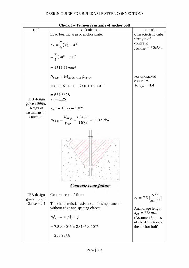
DESIGN GUIDE FOR BUILDABLE STEEL CONNECTIONS
Page | 504
Check 3 – Tension resistance of anchor bolt Ref Calculations Remark
Load bearing area of anchor plate:
𝐴𝜋4𝑑 𝑑
𝜋4
50 24
1511.11𝑚𝑚
Characteristic cube strength of concrete: 𝑓 , 50𝑀𝑃𝑎
𝑁 , 6𝐴 𝑓 , 𝜓 ,
6 1511.11 50 1.4 10
634.66𝑘𝑁
For uncracked concrete: 𝜓 , 1.4
CEB design guide (1996):
Design of fastenings in
concrete
𝛾 1.25 𝛾 1.5𝛾 1.875
𝑁 ,𝑁 ,
𝛾634.661.875
338.49𝑘𝑁
CEB design guide (1996) Clause 9.2.4
Concrete cone failure: The characteristic resistance of a single anchor without edge and spacing effects: 𝑁 , 𝑘 𝑓 . ℎ .
7.5 40 . 384 . 10
356.93𝑘𝑁
𝑘 7.5 𝑁 .
𝑚𝑚 .
Anchorage length: ℎ 384𝑚𝑚 (Assume 16 times of the diameters of the anchor bolt)

DESIGN GUIDE FOR BUILDABLE STEEL CONNECTIONS
Page | 505
Check 3 – Tension resistance of anchor bolt Ref Calculations Remark
Factor taking into account the geometric effects:
𝜓 ,𝐴 ,
𝐴 ,
𝑆 , 𝑤𝑆 ,
3 384 450
3 384
1.93
𝑆 , 3.0ℎ
Characteristic resistance: 𝑁 , 𝑁 , 𝜓 , 𝜓 ,
338.49 1.93 1.4
966.35𝑘𝑁 𝛾 𝛾 1.875
𝑁 ,𝑁 ,
𝛾966.351.875
515.39𝑘𝑁
Factors about influence of edges, group effect and shell spalling are not relevant in this example
Anchor plate design: Generally, anchor plate bending may not govern the failure of the connection, in this example, only punching shear failure is checked for anchor plate. The thickness of the anchor plate is designed in such a way that the bolt failure will occur before the plate is failed by punching.
∴𝜋𝑑𝑡𝑓 ,
√3
𝜋𝑑4
𝑓 ,
𝑡√3𝑑4𝑓 ,
𝑓 ,
√3 244 355
800
23.42𝑚𝑚
∴ 𝑡 24𝑚𝑚
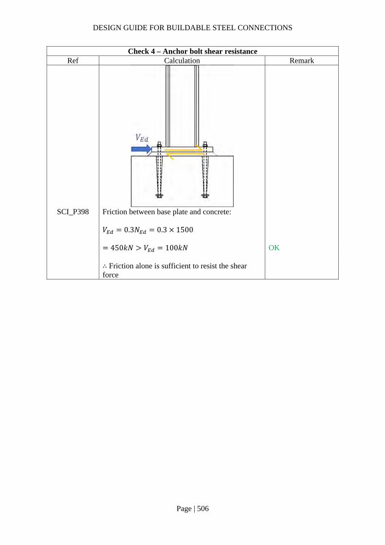
DESIGN GUIDE FOR BUILDABLE STEEL CONNECTIONS
Page | 506
Check 4 – Anchor bolt shear resistance Ref Calculation Remark
SCI_P398 Friction between base plate and concrete: 𝑉 0.3𝑁 0.3 1500
450𝑘𝑁 𝑉 100𝑘𝑁
OK
∴ Friction alone is sufficient to resist the shear force

DESIGN GUIDE FOR BUILDABLE STEEL CONNECTIONS
Page | 507
3.5 Steel-to-concrete connections
For steel-to-concrete connections, the embedded plates are usually connected with bolts which are cast into the concrete walls or columns. It is not recommended to use high tensile bar for the holding down bolts where welding is required. Grade 8.8 bolts have high carbon content and thus should be discouraged where welding is adopted.
When plug weld is adopted, according to SS EN1993-1-8 Clause 4.3.5:
(1) plug weld should not be used to resist externally applied tension. (2) Plug weld should be designed for shear only. Moreover, the thickness of plug weld
should be same as that of parent material for parent material up to 16mm thick (Clause 4.3.5 (4)).
(3) When plug weld is used to connect bolt, which insert in embedded plate, the plate thickness should be at least 16mm and the plug weld thickness should not be less than 16mm and at least half the thickness of the plate.
The following example shows two possible options:
Option A – Embedded plate with the bolt welded flushed with the plate and which entailed the use of butt weld on the external face and fillet weld on the internal face of the plate.
Option B – Embedded plate with the bolt recessed from the plate with the use of plug weld on the external face and fillet weld on the internal face of the plate.
Site welding connecting steel beam to embedded plate is not suggested as it may damage concrete substrate. Option A is generally for shear connection only and it is generally applicable to small welds only. Professional engineers (PE) need to access the suitability of this connection for heavy welding. In addition, if option B was to be adopted, pull out test is to be conducted.
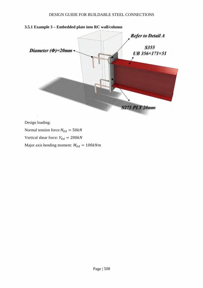
DESIGN GUIDE FOR BUILDABLE STEEL CONNECTIONS
Page | 508
3.5.1 Example 3 – Embedded plate into RC wall/column
Design loading:
Normal tension force:𝑁 50𝑘𝑁
Vertical shear force: 𝑉 200𝑘𝑁
Major axis bending moment: 𝑀 100𝑘𝑁𝑚

DESIGN GUIDE FOR BUILDABLE STEEL CONNECTIONS
Page | 509
Check 1 – Fillet weld resistance Ref Calculations Remark
SS EN1993-1-8
According to SS EN1993-1-8 4.3.5 (1), plug weld should not be designed to take the externally applied tension, hence the tensile force on embedded plate is taken by the fillet weld connecting the anchor bar and plate. Length of fillet weld: 𝐿 𝜋∅ 𝜋 20 62.83𝑚𝑚 Assume S275 fillet weld with leg length 12mm and throat thickness 8.4mm is used to connect column and base plate. Design shear strength of the fillet weld (4.5.3.3 (2)):
𝑓 ,𝑓 /√3𝛽 𝛾
410/√3
0.85 1.25
222.79𝑀𝑃𝑎
Design weld resistance, longitudinal: 𝐹 , , 𝑓 , 𝑎 222.79 8.4 10
1.87𝑘𝑁/𝑚𝑚
Diameter of embedded bar: ∅ 20𝑚𝑚 For S275 fillet weld: 𝑓 410𝑀𝑃𝑎 𝛽 0.85 𝛾 1.25 𝐾 1.225
Plug weld
Fillet weld
Detail A – Option 1
Plug weld does not form of the resistance against applied tension force!
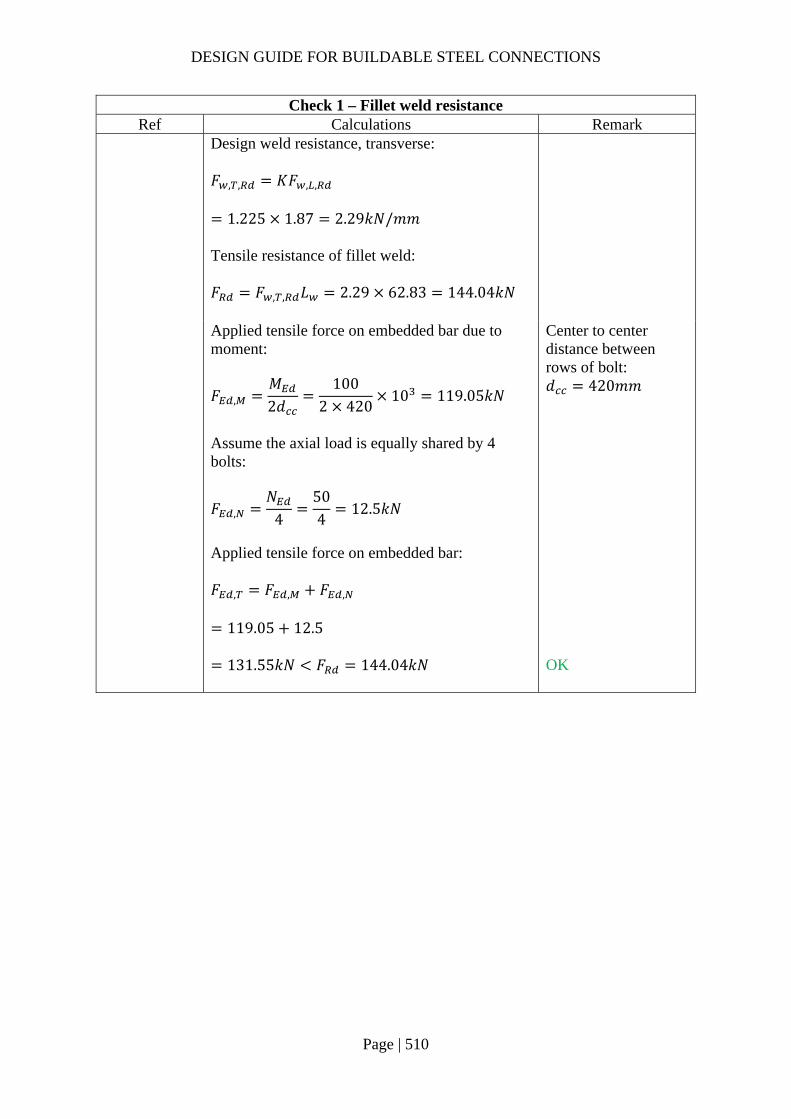
DESIGN GUIDE FOR BUILDABLE STEEL CONNECTIONS
Page | 510
Check 1 – Fillet weld resistance Ref Calculations Remark
Design weld resistance, transverse: 𝐹 , , 𝐾𝐹 , ,
1.225 1.87 2.29𝑘𝑁/𝑚𝑚 Tensile resistance of fillet weld: 𝐹 𝐹 , , 𝐿 2.29 62.83 144.04𝑘𝑁
Applied tensile force on embedded bar due to moment:
𝐹 ,𝑀2𝑑
1002 420
10 119.05𝑘𝑁
Assume the axial load is equally shared by 4 bolts:
𝐹 ,𝑁
4504
12.5𝑘𝑁
Applied tensile force on embedded bar: 𝐹 , 𝐹 , 𝐹 ,
119.05 12.5
Center to center distance between rows of bolt: 𝑑 420𝑚𝑚
131.55𝑘𝑁 𝐹 144.04𝑘𝑁
OK

DESIGN GUIDE FOR BUILDABLE STEEL CONNECTIONS
Page | 511
Check 1a – Fillet weld and PPBW resistance Ref Calculations Remark
In the case that partial penetration butt weld is used together with fillet weld, the throat thickness used in calculations should be the sum of throat thicknesses of both welds.
Assume S275 fillet weld with leg length 12mm and throat thickness 8.4mm and S275 partial penetration butt weld with throat thickness 10mm are used to connect column and base plate. 𝑎 8.4 10 18.4𝑚𝑚 Design weld resistance, longitudinal: 𝐹 , , 𝑓 , 𝑎 222.79 18.4 10
4.10𝑘𝑁/𝑚𝑚 Design weld resistance, transverse: 𝐹 , , 𝐾𝐹 , ,
1.225 4.10 5.02𝑘𝑁/𝑚𝑚 Tensile resistance of fillet weld: 𝐹 𝐹 , , 𝐿 5.02 62.83
315.56𝑘𝑁 𝐹 ,
PPBW
Fillet weld
Detail A – Option 2

DESIGN GUIDE FOR BUILDABLE STEEL CONNECTIONS
Page | 512
Check 2 – Plug weld shear resistance Ref Calculations Remark
SS EN1993-1-8
Design throat area (area of hole):
𝐴𝜋∅
4𝜋
204
314.16𝑚𝑚
Design shear resistance of plug weld: 𝐹 , 𝑓 , 𝐴
222.79 314.16 10
69.99𝑘𝑁 Assume shear force are equally shared by 4 bolts:
𝐹 ,𝑉
4200
450𝑘𝑁 𝐹 ,
Diameter of embedded bar: ∅ 20𝑚𝑚
Check 3 – Anchorage length of bar Ref Calculations Remark
SS EN1992-1-1
Ultimate anchorage bond stress: 𝑓 1.5𝑓 0.315𝑓 /
0.315 30 /
3.04𝑀𝑃𝑎 Applied tensile stress:
𝑓𝐹 ,
𝐴131.55314.16
10 418.73𝑀𝑃𝑎
Characteristic concrete strength: 𝑓 30𝑀𝑃𝑎

DESIGN GUIDE FOR BUILDABLE STEEL CONNECTIONS
Page | 513
Check 3 – Anchorage length of bar Ref Calculations Remark
Basic anchorage length:
𝑙 .𝑓
4𝑓∅
418.73
4 3.0420
688.41𝑚𝑚
Coefficients: Shape of anchor bar: 𝛼 0.7, assume edge distance is greater than three times of the dimeter
𝛼: coefficient to be referred to SS EN 1992-1-1.
Concrete cover to anchor bar non-straight :
𝛼 10.15 𝑐 3∅
∅
1 0.1575 3 20
20
0.8875
Design anchorage length: 𝑙 𝑙 , 𝛼 𝛼
688.41 0.7 0.8875
427.67𝑚𝑚 Minimum require anchorage length: 𝑙 , max 0.3𝑙 , ; 10∅; 100
max 0.3 688.41; 10 20; 100
206.52𝑚𝑚 𝑙 ∴ 𝑙 430𝑚𝑚
Assume concrete cover to the anchor bar: 𝑐 75𝑚𝑚
According to SS EN 1992-1-1 Clause 8, the bent length of the anchorage bar should be at least 5∅.

DESIGN GUIDE FOR BUILDABLE STEEL CONNECTIONS
Page | 514
Alternative design using shear stud Ref Calculations Remark
In this alternative design, applied shear force is assumed to be taken by the shear stud and the applied moment is resisted by the anchored bar. However, the distribution of force for other similar connections should be reviewed by qualified person. The design of shear studs can refer to section 2.4.1 check 8 and SS EN 1994.

DESIGN GUIDE FOR BUILDABLE STEEL CONNECTIONS
Page | 515
4 Connections for Hollow Steel Sections 4.1 Modes of failures
Various modes of failures are identified for hollow steel sections connections, as shown in Figure 4-1, such as:
Local beam flange failure (yielding, local buckling) Weld failure Lamellar tearing Column plastification (face, wall or cross section) Column punching shear Column local buckling Column shear failure
The resistance of the hollow section for different failure modes can be found in SS EN 1993-1-8 Chapter 7 and CIDECT design guide 9. The following design calculations illustrate some common designs and their resistance check.
Figure 4-1 Modes of failure for I beam-to-RHS column joints

DESIGN GUIDE FOR BUILDABLE STEEL CONNECTIONS
Page | 516
4.2 Shear connection using fin plates
Common connections involve the use of a fin plate to connect a hollow steel column to a beam (typically I or H beam). For shear connectors, a fin plate can be used with a backing plate welded to the column to avoid local failure of column flange as shown in Figure 4-2.
Figure 4-2 Shear connection between hollow steel column and beam
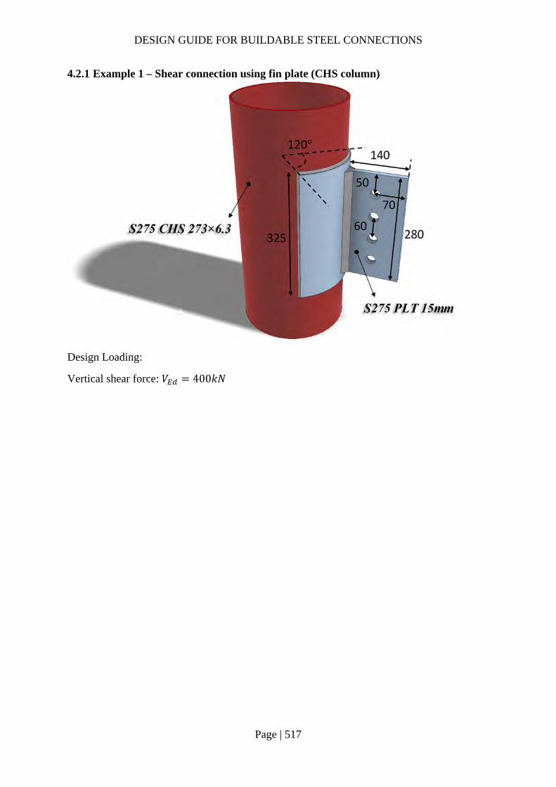
DESIGN GUIDE FOR BUILDABLE STEEL CONNECTIONS
Page | 517
4.2.1 Example 1 – Shear connection using fin plate (CHS column)
Design Loading:
Vertical shear force: 𝑉 400𝑘𝑁

DESIGN GUIDE FOR BUILDABLE STEEL CONNECTIONS
Page | 518
Check 1 – Range of validity Ref Calculations Remark
SS EN1993-1-8
According to SS EN1993-1-8 Clause 7.4.1 (2), for welded joint between CHS members within the range of validity given in Table 7.1, only chord face failure and punching shear need to be considered. Assume the CHS is under compression load: 𝑑𝑡
2736.3
43.33
For CHS 273x6.3: Diameter: 𝑑 273𝑚𝑚 Thickness: 𝑡 6.3𝑚𝑚 Yield strength: 𝑓 , 275𝑀𝑃𝑎 Youngs modulus: 𝐸 210000𝑀𝑃𝑎
10 𝑑 /𝑡 43.33 50
OK
∴ Only chord face failure and punching shear need to be checked.
AISC, 1997: Hollow
structural sections
connections manual
CIDECT
design guide 9
According to CIDECT design guide 9 and AISC manual, for CHS, single shear plate connection would be permitted if CHS is not “slender”. 𝑑𝑡
43.330.114𝐸𝑓 ,
0.114210000
27587
OK
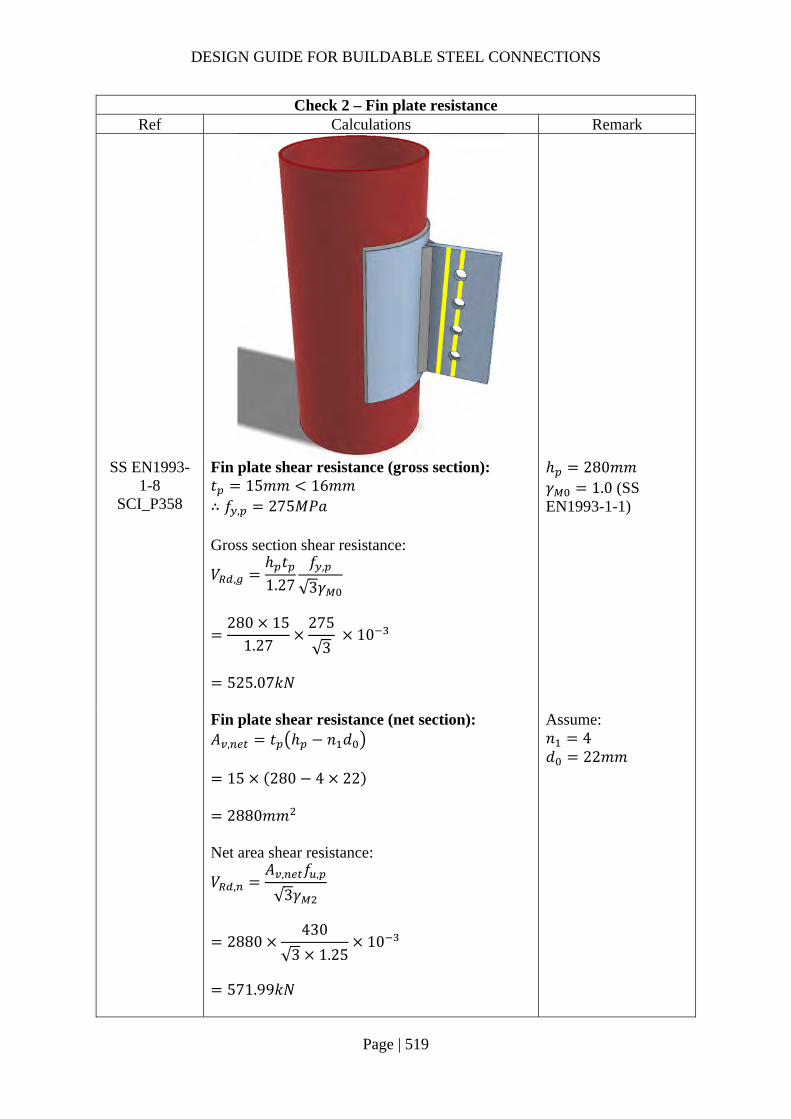
DESIGN GUIDE FOR BUILDABLE STEEL CONNECTIONS
Page | 519
Check 2 – Fin plate resistance Ref Calculations Remark
SS EN1993-1-8
SCI_P358
Fin plate shear resistance (gross section): 𝑡 15𝑚𝑚 16𝑚𝑚 ∴ 𝑓 , 275𝑀𝑃𝑎 Gross section shear resistance:
𝑉 ,ℎ 𝑡1.27
𝑓 ,
√3𝛾
280 15
1.27275
√3 10
525.07𝑘𝑁
ℎ 280𝑚𝑚 𝛾 1.0 (SS EN1993-1-1)
Fin plate shear resistance (net section): 𝐴 , 𝑡 ℎ 𝑛 𝑑
15 280 4 22
2880𝑚𝑚 Net area shear resistance:
𝑉 ,𝐴 , 𝑓 ,
√3𝛾
2880430
√3 1.2510
571.99𝑘𝑁
Assume: 𝑛 4 𝑑 22𝑚𝑚

DESIGN GUIDE FOR BUILDABLE STEEL CONNECTIONS
Page | 520
Check 2 – Fin plate resistance Ref Calculations Remark
Fin plate shear resistance (block shear): For single vertical line of bolts (𝑛 1): Net area subject to tension:
𝐴 𝑡 𝑒𝑑2
15 70222
885𝑚𝑚
Net area subject to shear: 𝐴 𝑡 ℎ 𝑒 𝑛 0.5 𝑑
15 280 50 4 0.5 22
2295𝑚𝑚
End distance: 𝑒 50𝑚𝑚 Edge distance: 𝑒 70𝑚𝑚
𝑉 ,
0.5𝑓 , 𝐴𝛾
𝑓 ,
√3
𝐴𝛾
0.5 430 885
1.25275
√3
22951.0
10
516.60𝑘𝑁
𝑉 , min 𝑉 , ;𝑉 , ;𝑉 ,
min 525.07𝑘𝑁; 571.99𝑘𝑁; 516.60𝑘𝑁
516.60𝑘𝑁 𝑉 400𝑘𝑁
OK
SCI_P358 SS EN1993-
1-8
Fin plate bending: ℎ 280𝑚𝑚 2.73𝑧 191.1𝑚𝑚 ∴ 𝑉 ∞
z 70mm
Lateral torsional buckling:
𝑧 70𝑚𝑚𝑡
0.15100𝑚𝑚
∴The fin plate is classified as Short fin plate

DESIGN GUIDE FOR BUILDABLE STEEL CONNECTIONS
Page | 521
Check 2 – Fin plate resistance Ref Calculations Remark
𝑊 ,
𝑡 ℎ6
15 280
6
196000𝑚𝑚
𝑉𝑊 ,
𝑧𝑓 ,
𝛾
196000 275
70 1.010
770𝑘𝑁 𝑉 400𝑘𝑁
OK

DESIGN GUIDE FOR BUILDABLE STEEL CONNECTIONS
Page | 522
Check 3 – Weld resistance Ref Calculations Remark
SS EN1993-1-8
Length of fillet weld: 𝐿 ℎ 280𝑚𝑚 Nominal moment: 𝑀 𝑉 𝑧
400 70
28000𝑘𝑁𝑚𝑚 Polar moment of inertia:
𝐽𝐿12
28012
1829333𝑚𝑚
Applied vertical shear stress:
𝜏𝑉2𝐿
4002 280
0.714𝑘𝑁/𝑚𝑚
Applied transverse stress:
𝜏
𝑀𝐿2𝐽
28000
2802
1829333
1.07𝑘𝑁/𝑚𝑚

DESIGN GUIDE FOR BUILDABLE STEEL CONNECTIONS
Page | 523
Check 3 – Weld resistance Ref Calculations Remark
Resultant stress:
𝜏 𝜏 𝜏
0.714 1.07
1.29𝑘𝑁/𝑚𝑚
Choose fillet weld with 10mm leg length, 7mm throat thickness and grade S275: Longitudinal resistance: 𝐹 , , 1.56𝑘𝑁/𝑚𝑚 Transverse resistance: 𝐹 , , 1.91𝑘𝑁/𝑚𝑚
Simplified method:
𝐹 , , 1.56𝑘𝑁/𝑚𝑚 𝜏 1.29𝑘𝑁/𝑚𝑚
OK
Directional method:
𝑆𝐹𝜏
𝐹 , ,
𝜏 ,
𝐹 , ,
0.7141.56
1.071.91
0.52 1.00
OK
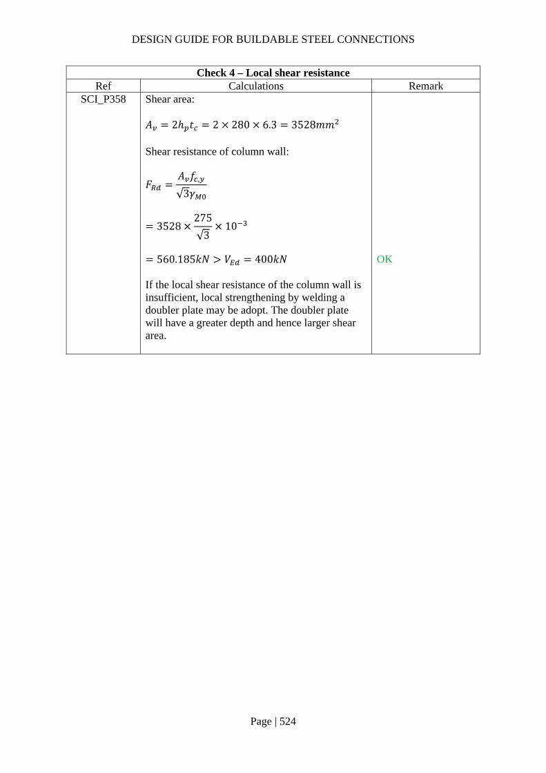
DESIGN GUIDE FOR BUILDABLE STEEL CONNECTIONS
Page | 524
Check 4 – Local shear resistance Ref Calculations Remark
SCI_P358 Shear area: 𝐴 2ℎ 𝑡 2 280 6.3 3528𝑚𝑚 Shear resistance of column wall:
𝐹𝐴 𝑓 ,
√3𝛾
3528275
√310
560.185𝑘𝑁 𝑉 400𝑘𝑁
OK
If the local shear resistance of the column wall is insufficient, local strengthening by welding a doubler plate may be adopt. The doubler plate will have a greater depth and hence larger shear area.

DESIGN GUIDE FOR BUILDABLE STEEL CONNECTIONS
Page | 525
Check 5 – Punching shear resistance Ref Calculations Remark
SCI_P358
SCI_P358 sets the requirement to prevent punching shear failure by ensuring the fin plate yield before punching shear failure.
𝑡𝑡 𝑓 ,
𝑓 , 𝛾
6.3 430
275 1.25
7.88mm
As 𝑡 15𝑚𝑚 7.88𝑚𝑚, the requirement is not satisfied, strengthening is necessary.
𝑓 , 430𝑀𝑃𝑎
SS EN1993-1-8
SCI_P358
According to SS EN1993-1-8 7.4, the punching shear resistance for welded joints connecting plates to CHS members: 𝜎 𝑡 2𝑡 𝑓 , /√3 /𝛾 As there is no axial loading in this case, applied punching stress:
𝜎𝑀𝑊
28000196000
0.143𝑘𝑁/𝑚𝑚
𝜎 𝑡 0.143 15 2142.86𝑁/𝑚𝑚 2𝑡 𝑓 , /√3 /𝛾 2 6.3 275/√3 /1.0
2000.52𝑁/𝑚𝑚 𝜎 𝑡 ∴ Strengthening is necessary
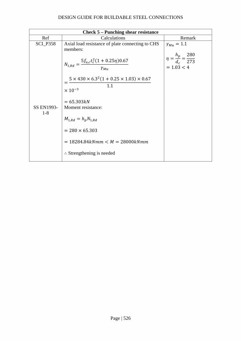
DESIGN GUIDE FOR BUILDABLE STEEL CONNECTIONS
Page | 526
Check 5 – Punching shear resistance Ref Calculations Remark
SCI_P358 Axial load resistance of plate connecting to CHS members:
𝑁 ,5𝑓 , 𝑡 1 0.25𝜂 0.67
𝛾
5 430 6.3 1 0.25 1.03 0.67
1.1
10
65.303𝑘𝑁
𝛾 1.1
𝜂ℎ𝑑
280273
1.03 4
SS EN1993-1-8
Moment resistance: 𝑀 , ℎ 𝑁 ,
280 65.303
18284.84𝑘𝑁𝑚𝑚 𝑀 28000𝑘𝑁𝑚𝑚 ∴ Strengthening is needed

DESIGN GUIDE FOR BUILDABLE STEEL CONNECTIONS
Page | 527
Check 6 – Design of local strengthening cover plate Ref Calculations Remark
Design of welded
structures
For the design of the cover/doubler plate, the thickness of the cover/doubler plate should be at least equal to the larger thickness of the fin plate or the hollow section. 𝑡 max 𝑡 ; 𝑡 15𝑚𝑚 ∴ 𝑡 15 6.3 21.3𝑚𝑚 Effective width for load distribution:
𝑒𝑡′ 𝑟2
21.3273
22
26.96𝑚𝑚
∴ The minimum depth for cover plate: 𝑑 ℎ 2𝑒
280 2 26.96
333.92𝑚𝑚 ∴ The depth for cover plate is chosen to be 335mm.

DESIGN GUIDE FOR BUILDABLE STEEL CONNECTIONS
Page | 528
Check 6 – Design of local strengthening cover plate Ref Calculations Remark
SCI_P358
𝑡𝑡′ 𝑓 ,
𝑓 , 𝛾
21.3 430275 1.25
26.64mm
As 𝑡 15𝑚𝑚 26.64𝑚𝑚, the requirement is satisfied, the fin plate will yield before punching shear failure.
SS EN1993-1-8
SCI_P358
2𝑡 𝑓 , /√3 /𝛾 2 21.3 275/√3 /1.0
67636.58𝑁/𝑚𝑚 𝜎 𝑡 ∴ Punching shear resistance is adequate.
SCI_P358 Axial load resistance of plate connecting to CHS members:
𝑁′ ,5𝑓 , 𝑡′ 1 0.25𝜂 0.67
𝛾
5 430 21.3 1 0.25 1.03 0.67
1.1
10
747.12𝑘𝑁
SS EN1993-1-8
Moment resistance: 𝑀 , ℎ 𝑁′ ,
280 747.12
209193.6𝑘𝑁𝑚𝑚 𝑀 28000𝑘𝑁𝑚𝑚 ∴ Moment resistance is adequate

DESIGN GUIDE FOR BUILDABLE STEEL CONNECTIONS
Page | 529
Check 6 – Design of local strengthening cover plate Ref Calculations Remark
Width of cover plate: Assume the angle of load distribution is 45°, the effective width for load distribution is: 𝑙 𝑡 2𝑠 2𝑡
15 2 10 2 21.3
77.6𝑚𝑚 As recommended, the cover plate should cover at least 1/3 of the CHS, hence the width of the cover plate:
𝑙𝜋𝑑
3𝜋
2733
286𝑚𝑚 𝑙
Fillet welds connecting the cover plate to the column follow the same size as that connecting the fin plate and the cover plate. As the depth of the cover plate is greater than that of fin plate, the shear resistance of the welds is greater than that of fin plate.

DESIGN GUIDE FOR BUILDABLE STEEL CONNECTIONS
Page | 530
4.2.2 Example 2 – Beam to rectangular column connection using fin plate
Design loading:
Vertical shear forces: 𝑉 200𝑘𝑁

DESIGN GUIDE FOR BUILDABLE STEEL CONNECTIONS
Page | 531
Check 1 – Range of validity Ref Calculations Remark
CIDECT design guide
9
According to CIDECT design guide 9, the width to thickness ratio of tee flange should be greater than 13 to provide desired flexibility. 𝑏𝑡
209.315.6
13.42 13
As recommended by AISC (1997), the tee web thickness should be less than 𝑑 /2 2𝑚𝑚.
𝑡 10.1𝑚𝑚100
22 52𝑚𝑚
According to CIDECT design guide 9, the only failure mode for RHS wall to be checked is the shear yield strength of the tube wall adjacent to the vertical welds.
T-section is cut from S275 UB533×210×92: 𝑏 209.3𝑚𝑚 Thickness of the flange: 𝑡 15.6𝑚𝑚 Thickness of the web: 𝑡 10.1𝑚𝑚 Width of tee web: 𝑑 100𝑚𝑚

DESIGN GUIDE FOR BUILDABLE STEEL CONNECTIONS
Page | 532
Check 2 – Tee web resistance Ref Calculations Remark
SCI_P358 SS EN1993-
1-8
Tee web shear resistance (gross section): 𝑡 10.1𝑚𝑚 16𝑚𝑚 ∴ 𝑓 , 275𝑀𝑃𝑎 Gross section shear resistance:
𝑉 ,ℎ 𝑡1.27
𝑓 ,
√3𝛾
220 10.1
1.27275
√3 10
277.79𝑘𝑁
Depth of tee: ℎ 220𝑚𝑚 𝛾 1.0 (SS EN1993-1-1)
Tee web shear resistance (net section): 𝐴 , 𝑡 ℎ 𝑛 𝑑
10.1 220 3 22
1555.4𝑚𝑚 Net area shear resistance:
𝑉 ,𝐴 , 𝑓 ,
√3𝛾
1555.4430
√3 1.2510
308.92𝑘𝑁
Assume: 𝑛 3 𝑑 22𝑚𝑚
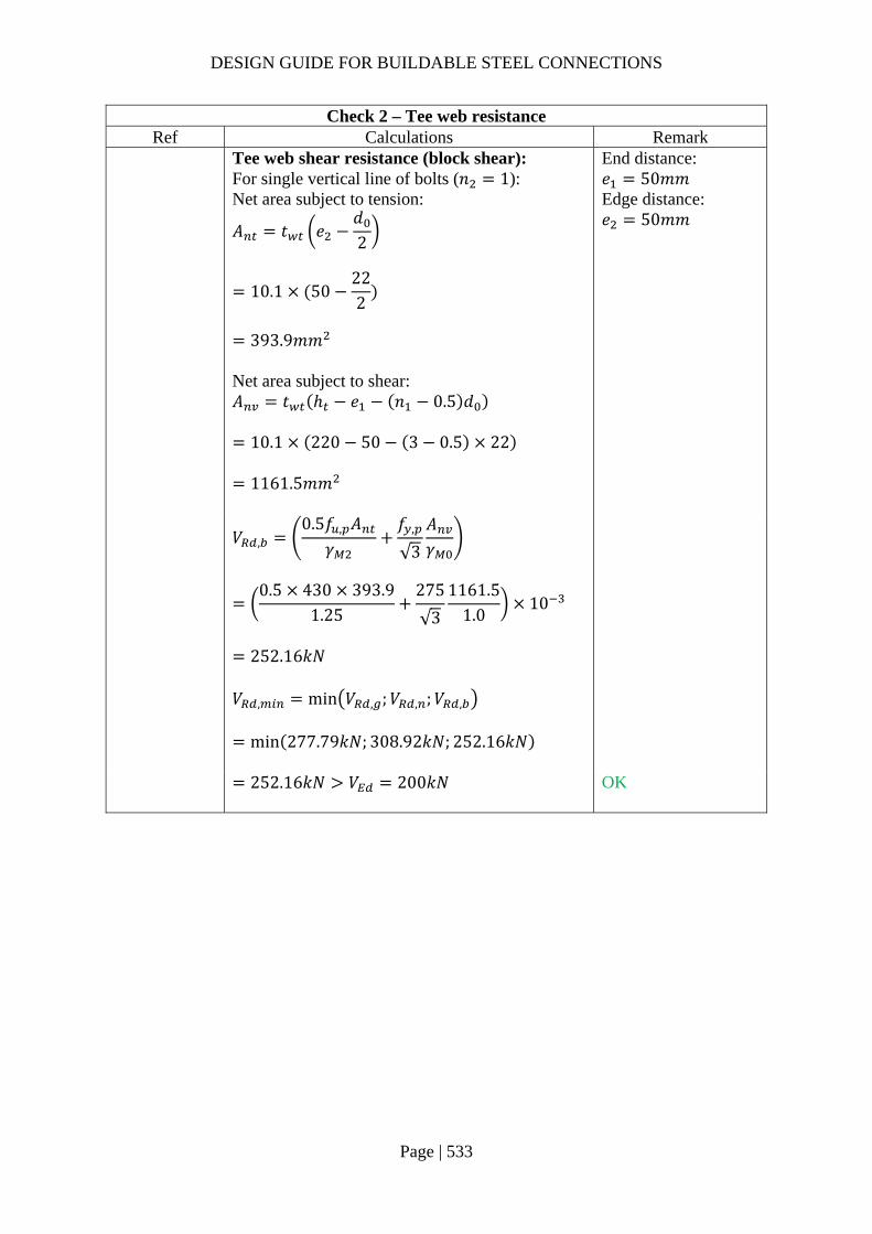
DESIGN GUIDE FOR BUILDABLE STEEL CONNECTIONS
Page | 533
Check 2 – Tee web resistance Ref Calculations Remark
Tee web shear resistance (block shear): For single vertical line of bolts (𝑛 1): Net area subject to tension:
𝐴 𝑡 𝑒𝑑2
10.1 50222
393.9𝑚𝑚
Net area subject to shear: 𝐴 𝑡 ℎ 𝑒 𝑛 0.5 𝑑
10.1 220 50 3 0.5 22
1161.5𝑚𝑚
End distance: 𝑒 50𝑚𝑚 Edge distance: 𝑒 50𝑚𝑚
𝑉 ,
0.5𝑓 , 𝐴𝛾
𝑓 ,
√3
𝐴𝛾
0.5 430 393.9
1.25275
√3
1161.51.0
10
252.16𝑘𝑁
𝑉 , min 𝑉 , ;𝑉 , ;𝑉 ,
min 277.79𝑘𝑁; 308.92𝑘𝑁; 252.16𝑘𝑁
252.16𝑘𝑁 𝑉 200𝑘𝑁
OK
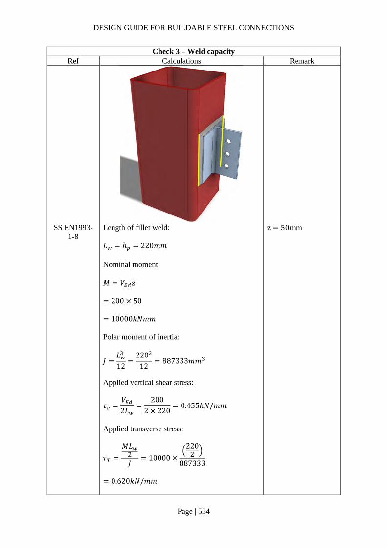
DESIGN GUIDE FOR BUILDABLE STEEL CONNECTIONS
Page | 534
Check 3 – Weld capacity Ref Calculations Remark
SS EN1993-1-8
Length of fillet weld: 𝐿 ℎ 220𝑚𝑚 Nominal moment: 𝑀 𝑉 𝑧
200 50
10000𝑘𝑁𝑚𝑚 Polar moment of inertia:
𝐽𝐿12
22012
887333𝑚𝑚
Applied vertical shear stress:
𝜏𝑉2𝐿
2002 220
0.455𝑘𝑁/𝑚𝑚
Applied transverse stress:
𝜏
𝑀𝐿2𝐽
10000
2202
887333
0.620𝑘𝑁/𝑚𝑚
z 50mm

DESIGN GUIDE FOR BUILDABLE STEEL CONNECTIONS
Page | 535
Check 3 – Weld capacity Ref Calculations Remark
Resultant stress:
𝜏 𝜏 𝜏
0.455 0.620
0.769𝑘𝑁/𝑚𝑚
Choose fillet weld with 8mm leg length, 5.6mm throat thickness and grade S275: Longitudinal resistance: 𝐹 , , 1.25𝑘𝑁/𝑚𝑚 Transverse resistance: 𝐹 , , 1.53𝑘𝑁/𝑚𝑚
Simplified method:
𝐹 , , 1.25𝑘𝑁/𝑚𝑚 𝜏 0.769𝑘𝑁/𝑚𝑚
OK
Directional method:
𝑆𝐹𝜏
𝐹 , ,
𝜏 ,
𝐹 , ,
0.4551.25
0.6201.53
0.30 1.00
OK
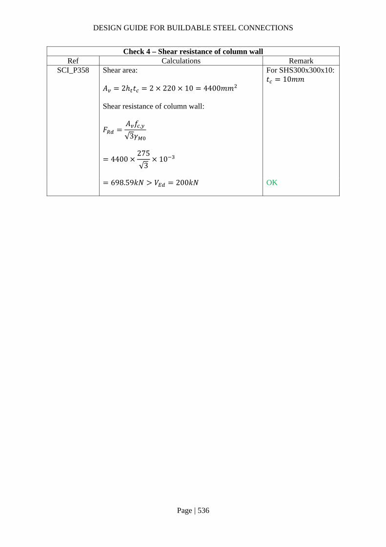
DESIGN GUIDE FOR BUILDABLE STEEL CONNECTIONS
Page | 536
Check 4 – Shear resistance of column wall Ref Calculations Remark
SCI_P358 Shear area: 𝐴 2ℎ 𝑡 2 220 10 4400𝑚𝑚 Shear resistance of column wall:
𝐹𝐴 𝑓 ,
√3𝛾
4400275
√310
For SHS300x300x10: 𝑡 10𝑚𝑚
698.59𝑘𝑁 𝑉 200𝑘𝑁
OK

DESIGN GUIDE FOR BUILDABLE STEEL CONNECTIONS
Page | 537
4.3 Connection of I-beam to hollow steel columns using extended endplates
Extended endplates can be used to connect I-beam to hollow steel column to resist shear and moment.
4.3.1 Example 3 – Beam to Rectangular column connection using extended end plate
Design loading:
Vertical shear load: 𝑉 800𝑘𝑁
Major axis bending moment: 𝑀 100𝑘𝑁𝑚

DESIGN GUIDE FOR BUILDABLE STEEL CONNECTIONS
Page | 538
Check 1 – Bolt group resistance Ref Calculations Remark
In this example, the bolt group is located along two sides of the RHS and is far away from the beam flange and web. As a result, the traditional prying models developed for T-stubs may not be suitable to calculate the resistance. The shear force is assumed to be shared by all bolts and the end plate must be made thick and stiff enough to prevent deformation. The tension force on beam flange by applied moment is assumed to be taken by bolts around the top beam flange.
SS EN1993-1-8
SCI_P358
Bolt shear resistance: Using class 8.8, M24 bolts with: 𝐴 353𝑚𝑚 , 𝑓 800𝑀𝑃𝑎, 𝛼 0.6
𝛾 1.25 (refer to NA to SS)
Shear resistance of a single bolt:
𝐹 ,𝛼 𝑓 𝐴𝛾
0.6 800 353
1.2510
135.55𝑘𝑁
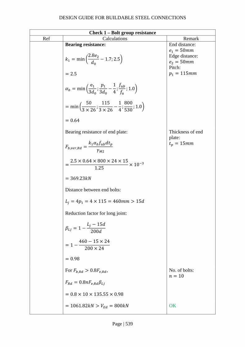
DESIGN GUIDE FOR BUILDABLE STEEL CONNECTIONS
Page | 539
Check 1 – Bolt group resistance Ref Calculations Remark
Bearing resistance:
𝑘 min2.8𝑒𝑑
1.7; 2.5
2.5
𝛼 mine
3𝑑;𝑝
3𝑑14
;𝑓𝑓
; 1.0
min50
3 26;
1153 26
14
;800530
; 1.0
0.64
End distance: 𝑒 50𝑚𝑚 Edge distance: 𝑒 50𝑚𝑚 Pitch: 𝑝 115𝑚𝑚
Bearing resistance of end plate:
𝐹 , ,𝑘 𝛼 𝑓 𝑑𝑡
𝛾
2.5 0.64 800 24 15
1.2510
369.23𝑘𝑁
Thickness of end plate: 𝑡 15𝑚𝑚
Distance between end bolts: 𝐿 4𝑝 4 115 460𝑚𝑚 15𝑑 Reduction factor for long joint:
𝛽 1𝐿 15𝑑
200𝑑
1460 15 24
200 24
0.98
For 𝐹 , 0.8𝐹 , , 𝐹 0.8𝑛𝐹 , 𝛽
0.8 10 135.55 0.98
No. of bolts: 𝑛 10
1061.82𝑘𝑁 𝑉 800𝑘𝑁
OK

DESIGN GUIDE FOR BUILDABLE STEEL CONNECTIONS
Page | 540
Check 1 – Bolt group resistance Ref Calculations Remark
Tension resistance:
𝐹 ,𝑘 𝑓 𝐴𝛾
0.9 800 353
1.2510
203.33𝑘𝑁
𝑘 0.9
Applied shear force on one bolt:
𝑉 ,𝑉𝑛
80010
80𝑘𝑁
Applied tensile force on beam flange:
𝐹𝑀
ℎ 𝑡100
458 1510
225.73𝑘𝑁
Assume the tensile force is taken by four bolts around the beam top flange:
𝐹 , ,𝐹4
225.734
56.43𝑘𝑁
For UB 457x152x67: Beam depth: ℎ 458𝑚𝑚 Beam flange thickness: 𝑡 15𝑚𝑚
Combined shear and tension: 𝑉 ,
𝛽 𝐹 ,
𝐹 , ,
1.4𝐹 ,
80
135.55 0.9856.43
1.4 203.33
0.80 1.0
OK

DESIGN GUIDE FOR BUILDABLE STEEL CONNECTIONS
Page | 541
Check 2 – Compression zone check (Localized stress check) Ref Calculations Remark
SS EN1993-1-8
Assume the angle of load dispersion through end plate to the RHS is 45°. Effective thickness of applied compression stress on RHS: 𝑡 𝑡 2𝑠 2 2𝑡
15 2 8 2 2 15
91𝑚𝑚 Effective width of applied compression stress on RHS: 𝑏 𝑏 2 2𝑡
153.8 2 2 15
213.8𝑚𝑚
Leg length of beam flange fillet weld: 𝑠 8𝑚𝑚 Width of beam: 𝑏 153.8𝑚𝑚

DESIGN GUIDE FOR BUILDABLE STEEL CONNECTIONS
Page | 542
Check 2 – Compression zone check (Localized stress check) Ref Calculations Remark
SS EN1993-1-8
Table 7.13
Ratio of effective width and width of RHS:
𝛽𝑏𝑏
213.8300
0.713
Ratio of effective depth of beam to depth of RHS:
𝜂ℎ ,
ℎ534400
1.335
As 𝜂 2 1 𝛽 2√1 0.713 1.07,it is conservative to assume the design resistance of the I beam section is equal to the design resistance of two transverse plates of similar dimensions to the flanges of the I section.
For RHS 400x300x12.5: Width: 𝑏 300𝑚𝑚 Depth: ℎ 400𝑚𝑚 Thickness of wall: 𝑡 12.5𝑚𝑚 Effective depth of beam: ℎ , ℎ 2𝑠
4𝑡 534𝑚𝑚
For transverse plate with dimensions similar to effective thickness and effective width: As 𝛽 0.71 0.85, Chord face failure:
𝑁 ,𝑘 𝑓 , 𝑡 2 2.8𝛽
1 0.9𝛽/𝛾
Assume 𝑘 1.0 as the axial force on the column is unknown in this example, for cases with known axial forces on column, 𝑘 should be calculated according to SS EN1993-1-8
1.0 355 12.5 2 2.8 0.713
√1 0.9 0.713
10
370.09𝑘𝑁 Punching shear failure:
𝑁 ,𝑓 , 𝑡
√32𝑡 2𝑏 , /𝛾
35512.5
√32 91 2 89.08 10
922.74𝑘𝑁
𝑏 ,10𝑏 /𝑡
𝑏
10
300/12.5213.8
89.08𝑚𝑚
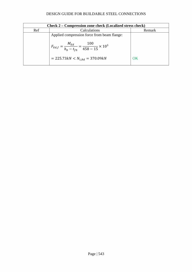
DESIGN GUIDE FOR BUILDABLE STEEL CONNECTIONS
Page | 543
Check 2 – Compression zone check (Localized stress check) Ref Calculations Remark
Applied compression force from beam flange:
𝐹 ,𝑀
ℎ 𝑡100
458 1510
225.73𝑘𝑁 𝑁 , 370.09𝑘𝑁
OK

DESIGN GUIDE FOR BUILDABLE STEEL CONNECTIONS
Page | 544
Check 3 – Weld resistance Ref Calculations Remark
SS EN1993-1-8
Based on SCI_P363 design weld resistance for S355 fillet weld: Choose fillet weld with 8mm leg length, 5.6mm throat thickness and grade S355: Longitudinal resistance: 𝐹 , , 1.35𝑘𝑁/𝑚𝑚 Transverse resistance: 𝐹 , , 1.65𝑘𝑁/𝑚𝑚
According to SS EN1993-1-8 6.2.2 (1), In weld connections, and in bolted connections with end-plates, the welds connecting the beam web should be designed to transfer the shear force from the connected beam to the joint, without any assistance from the welds connecting the beam flanges.
Length of fillet weld connecting beam web: 𝐿 2𝑑
2 407.6
815.2𝑚𝑚
For UB457x152x67: Depth between fillets: 𝑑 407.6𝑚𝑚 Root radius: 𝑟 10.2𝑚𝑚 Thickness of beam web: 𝑡 9𝑚𝑚
Shear resistance: 𝑉 𝐹 , , 𝐿
1.35 815.2
1100.52𝑘𝑁 𝑉 800𝑘𝑁
OK
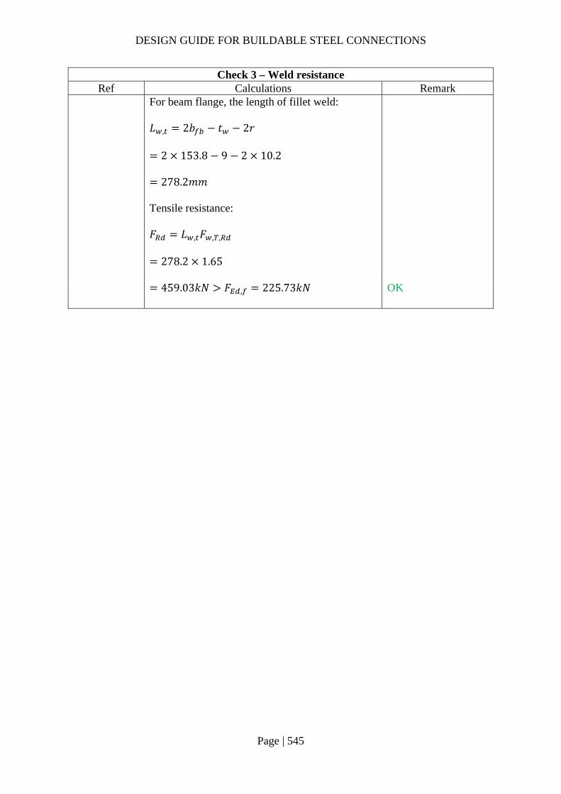
DESIGN GUIDE FOR BUILDABLE STEEL CONNECTIONS
Page | 545
Check 3 – Weld resistance Ref Calculations Remark
For beam flange, the length of fillet weld: 𝐿 , 2𝑏 𝑡 2𝑟
2 153.8 9 2 10.2
278.2𝑚𝑚 Tensile resistance: 𝐹 𝐿 , 𝐹 , ,
278.2 1.65
459.03𝑘𝑁 𝐹 , 225.73𝑘𝑁
OK

DESIGN GUIDE FOR BUILDABLE STEEL CONNECTIONS
Page | 546
4.4 Connection of narrow beam to hollow steel columns
To avoid stiffening the flange of the hollow steel connection due to local buckling, a transition section, which consists of tapered flange plates, may be used to connect the UB section to the square hollow section as shown in the figure below. The flange and web plate thickness of the transition section should match the plate thickness of the respective UB section.
4.4.1 Example 4 – Narrow I beam to circular hollow column connection
Design loading:
Vertical shear force: 𝑉 600𝑘𝑁
Major axis bending moment: 𝑀 200𝑘𝑁𝑚

DESIGN GUIDE FOR BUILDABLE STEEL CONNECTIONS
Page | 547
Check 1 – Weld of beam web to end plate Ref Calculations Remark
According to SS EN1993-1-8 6.2.2 (1), for welded and bolted connections with end-plate, the welds connecting the beam web should be designed to transfer the shear force from the connected beam to the joint, without any assistance from the welds connecting the beam flanges.
SS EN1993 Length of fillet weld connecting beam web: 𝐿 2𝑑
2 407.6
815.2𝑚𝑚
For UB457x152x67: Depth between fillets: 𝑑 407.6𝑚𝑚
SCI_P363 Choose fillet weld with 8mm leg length, 5.6mm throat thickness and grade S355: Longitudinal resistance: 𝐹 , , 1.35𝑘𝑁/𝑚𝑚 Transverse resistance: 𝐹 , , 1.65𝑘𝑁/𝑚𝑚
Shear resistance: 𝑉 𝐹 , , 𝐿
1.35 815.2
1100.52𝑘𝑁 𝑉 600𝑘𝑁 The design of flange welds will be in the later part of the calculations.
OK

DESIGN GUIDE FOR BUILDABLE STEEL CONNECTIONS
Page | 548
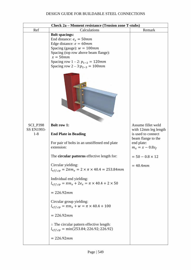
DESIGN GUIDE FOR BUILDABLE STEEL CONNECTIONS
Page | 549
Check 2a – Moment resistance (Tension zone T-stubs) Ref Calculations Remark
Bolt spacings: End distance: 𝑒 50𝑚𝑚 Edge distance: 𝑒 60𝑚𝑚 Spacing (gauge): 𝑤 100𝑚𝑚 Spacing (top row above beam flange): 𝑥 50𝑚𝑚 Spacing row 1 – 2: 𝑝 120𝑚𝑚 Spacing row 2 – 3:𝑝 100𝑚𝑚
SCI_P398 SS EN1993-
1-8
Bolt row 1: End Plate in Beading For pair of bolts in an unstiffened end plate extension: The circular patterns effective length for: Circular yielding: 𝑙 , 2𝜋𝑚 2 𝜋 40.4 253.84𝑚𝑚 Individual end yielding: 𝑙 , 𝜋𝑚 2𝑒 𝜋 40.4 2 50
226.92𝑚𝑚 Circular group yielding: 𝑙 , 𝜋𝑚 𝑤 𝜋 40.4 100
226.92𝑚𝑚 ∴ The circular pattern effective length: 𝑙 , min 253.84; 226.92; 226.92
226.92𝑚𝑚
Assume fillet weld with 12mm leg length is used to connect beam flange to the end plate: 𝑚 𝑥 0.8𝑠
50 0.8 12
40.4𝑚𝑚
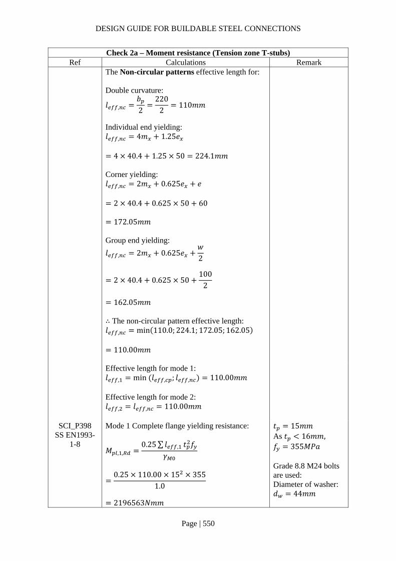
DESIGN GUIDE FOR BUILDABLE STEEL CONNECTIONS
Page | 550
Check 2a – Moment resistance (Tension zone T-stubs) Ref Calculations Remark
The Non-circular patterns effective length for: Double curvature:
𝑙 ,𝑏2
2202
110𝑚𝑚
Individual end yielding: 𝑙 , 4𝑚 1.25𝑒
4 40.4 1.25 50 224.1𝑚𝑚 Corner yielding: 𝑙 , 2𝑚 0.625𝑒 𝑒
2 40.4 0.625 50 60
172.05𝑚𝑚 Group end yielding:
𝑙 , 2𝑚 0.625𝑒𝑤2
2 40.4 0.625 50100
2
162.05𝑚𝑚
∴ The non-circular pattern effective length: 𝑙 , min 110.0; 224.1; 172.05; 162.05
110.00𝑚𝑚
Effective length for mode 1: 𝑙 , min 𝑙 , ; 𝑙 , 110.00𝑚𝑚 Effective length for mode 2: 𝑙 , 𝑙 , 110.00𝑚𝑚
SCI_P398 SS EN1993-
1-8
Mode 1 Complete flange yielding resistance:
𝑀 , ,0.25∑ 𝑙 , 𝑡 𝑓
𝛾
0.25 110.00 15 355
1.0
2196563𝑁𝑚𝑚
𝑡 15𝑚𝑚 As 𝑡 16𝑚𝑚, 𝑓 355𝑀𝑃𝑎 Grade 8.8 M24 bolts are used: Diameter of washer: 𝑑 44𝑚𝑚
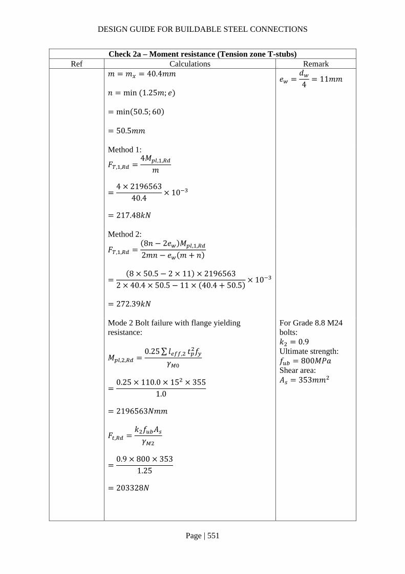
DESIGN GUIDE FOR BUILDABLE STEEL CONNECTIONS
Page | 551
Check 2a – Moment resistance (Tension zone T-stubs) Ref Calculations Remark
𝑚 𝑚 40.4𝑚𝑚 𝑛 min 1.25𝑚; 𝑒
min 50.5; 60
50.5𝑚𝑚
𝑒𝑑4
11𝑚𝑚
Method 1:
𝐹 , ,4𝑀 , ,
𝑚
4 2196563
40.410
217.48𝑘𝑁
Method 2:
𝐹 , ,8𝑛 2𝑒 𝑀 , ,
2𝑚𝑛 𝑒 𝑚 𝑛
8 50.5 2 11 2196563
2 40.4 50.5 11 40.4 50.510
272.39𝑘𝑁
Mode 2 Bolt failure with flange yielding resistance:
𝑀 , ,0.25∑ 𝑙 , 𝑡 𝑓
𝛾
0.25 110.0 15 355
1.0
2196563𝑁𝑚𝑚
𝐹 ,𝑘 𝑓 𝐴𝛾
0.9 800 353
1.25
203328𝑁
For Grade 8.8 M24 bolts: 𝑘 0.9 Ultimate strength: 𝑓 800𝑀𝑃𝑎 Shear area: 𝐴 353𝑚𝑚

DESIGN GUIDE FOR BUILDABLE STEEL CONNECTIONS
Page | 552
Check 2a – Moment resistance (Tension zone T-stubs) Ref Calculations Remark
𝐹 , 2 𝐹 , 2 203328
406656𝑁
𝐹 , ,2𝑀 , , 𝑛∑𝐹 ,
𝑚 𝑛
2 2196563 50.5 406656
40.4 50.510
274.25𝑘𝑁
Mode 3 Bolt failure resistance:
𝐹 , , 𝐹 , 2𝐹 ,
2 203328 10
406.66𝑘𝑁
Resistance of end plate in bending: 𝐹 , , min 𝐹 , , ;𝐹 , , ;𝐹 , ,
min 217.48; 274.25; 406.66
217.48𝑘𝑁
Beam web in tension As bolt row 1 is in the extension of the end plate, the resistance of the beam web in tension is not applicable to this bolt row.
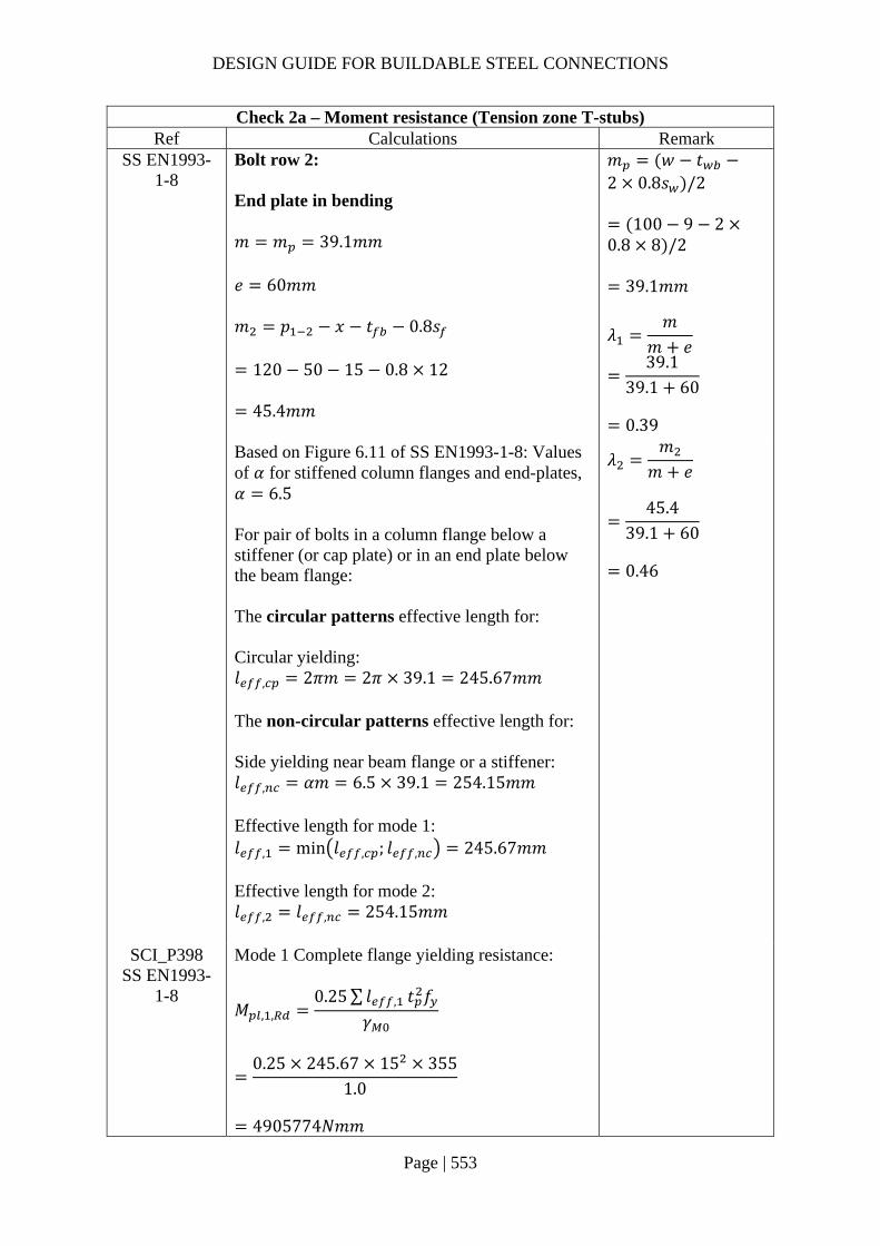
DESIGN GUIDE FOR BUILDABLE STEEL CONNECTIONS
Page | 553
Check 2a – Moment resistance (Tension zone T-stubs) Ref Calculations Remark
SS EN1993-1-8
Bolt row 2: End plate in bending 𝑚 𝑚 39.1𝑚𝑚 𝑒 60𝑚𝑚 𝑚 𝑝 𝑥 𝑡 0.8𝑠
120 50 15 0.8 12
45.4𝑚𝑚
𝑚 𝑤 𝑡2 0.8𝑠 /2
100 9 20.8 8 /2
39.1𝑚𝑚
𝜆𝑚
𝑚 𝑒
39.139.1 60
0.39
Based on Figure 6.11 of SS EN1993-1-8: Values of 𝛼 for stiffened column flanges and end-plates, 𝛼 6.5 For pair of bolts in a column flange below a stiffener (or cap plate) or in an end plate below the beam flange: The circular patterns effective length for: Circular yielding: 𝑙 , 2𝜋𝑚 2𝜋 39.1 245.67𝑚𝑚 The non-circular patterns effective length for: Side yielding near beam flange or a stiffener: 𝑙 , 𝛼𝑚 6.5 39.1 254.15𝑚𝑚 Effective length for mode 1: 𝑙 , min 𝑙 , ; 𝑙 , 245.67𝑚𝑚 Effective length for mode 2: 𝑙 , 𝑙 , 254.15𝑚𝑚
𝜆𝑚
𝑚 𝑒
45.4
39.1 60
0.46
SCI_P398 SS EN1993-
1-8
Mode 1 Complete flange yielding resistance:
𝑀 , ,0.25∑ 𝑙 , 𝑡 𝑓
𝛾
0.25 245.67 15 355
1.0
4905774𝑁𝑚𝑚
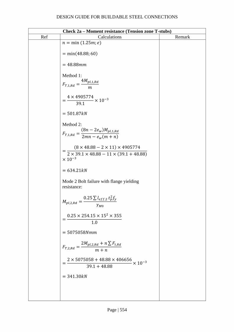
DESIGN GUIDE FOR BUILDABLE STEEL CONNECTIONS
Page | 554
Check 2a – Moment resistance (Tension zone T-stubs) Ref Calculations Remark
𝑛 min 1.25𝑚; 𝑒
min 48.88; 60
48.88𝑚𝑚 Method 1:
𝐹 , ,4𝑀 , ,
𝑚
4 4905774
39.110
501.87𝑘𝑁
Method 2:
𝐹 , ,8𝑛 2𝑒 𝑀 , ,
2𝑚𝑛 𝑒 𝑚 𝑛
8 48.88 2 11 4905774
2 39.1 48.88 11 39.1 48.88
10
634.21𝑘𝑁
Mode 2 Bolt failure with flange yielding resistance:
𝑀 , ,0.25∑ 𝑙 , 𝑡 𝑓
𝛾
0.25 254.15 15 355
1.0
5075058𝑁𝑚𝑚
𝐹 , ,2𝑀 , , 𝑛∑𝐹 ,
𝑚 𝑛
2 5075058 48.88 406656
39.1 48.8810
341.30𝑘𝑁
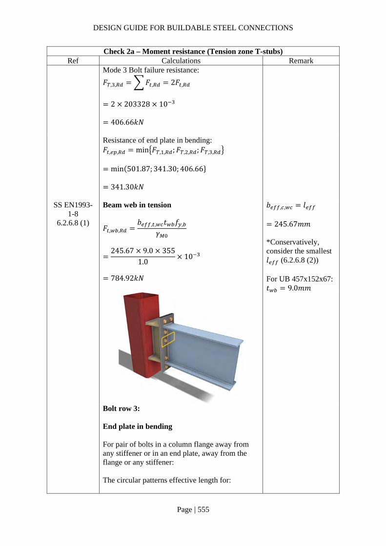
DESIGN GUIDE FOR BUILDABLE STEEL CONNECTIONS
Page | 555
Check 2a – Moment resistance (Tension zone T-stubs) Ref Calculations Remark
Mode 3 Bolt failure resistance:
𝐹 , , 𝐹 , 2𝐹 ,
2 203328 10
406.66𝑘𝑁
Resistance of end plate in bending: 𝐹 , , min 𝐹 , , ;𝐹 , , ;𝐹 , ,
min 501.87; 341.30; 406.66
341.30𝑘𝑁
SS EN1993-1-8
6.2.6.8 (1)
Beam web in tension
𝐹 , ,𝑏 , , 𝑡 𝑓 ,
𝛾
245.67 9.0 355
1.010
784.92𝑘𝑁
𝑏 , , 𝑙
245.67𝑚𝑚 *Conservatively, consider the smallest 𝑙 (6.2.6.8 (2)) For UB 457x152x67: 𝑡 9.0𝑚𝑚
Bolt row 3: End plate in bending For pair of bolts in a column flange away from any stiffener or in an end plate, away from the flange or any stiffener: The circular patterns effective length for:

DESIGN GUIDE FOR BUILDABLE STEEL CONNECTIONS
Page | 556
Check 2a – Moment resistance (Tension zone T-stubs) Ref Calculations Remark
Circular yielding: 𝑙 , 2𝜋𝑚 2𝜋 39.1 245.67𝑚𝑚 The non-circular patterns effective length for: Side yielding: 𝑙 , 4𝑚 1.25𝑒 4 39.1 1.25 60
231.4𝑚𝑚 Effective length for mode 1: 𝑙 , min 𝑙 , ; 𝑙 , 231.4𝑚𝑚 Effective length for mode 2: 𝑙 , 𝑙 , 231.4𝑚𝑚
SCI_P398 SS EN1993-
1-8
Mode 1 Complete flange yielding resistance:
𝑀 , ,0.25∑ 𝑙 , 𝑡 𝑓
𝛾
0.25 231.4 15 355
1.0
4620769𝑁𝑚𝑚
𝑛 min 1.25𝑚; 𝑒
min 48.88; 60
48.88𝑚𝑚 Method 1:
𝐹 , ,4𝑀 , ,
𝑚
4 4620769
39.1010
472.71𝑘𝑁
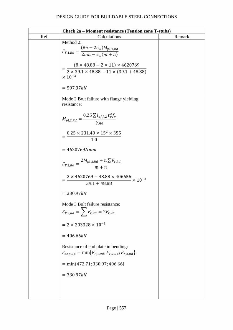
DESIGN GUIDE FOR BUILDABLE STEEL CONNECTIONS
Page | 557
Check 2a – Moment resistance (Tension zone T-stubs) Ref Calculations Remark
Method 2:
𝐹 , ,8𝑛 2𝑒 𝑀 , ,
2𝑚𝑛 𝑒 𝑚 𝑛
8 48.88 2 11 4620769
2 39.1 48.88 11 39.1 48.88
10
597.37𝑘𝑁
Mode 2 Bolt failure with flange yielding resistance:
𝑀 , ,0.25∑ 𝑙 , 𝑡 𝑓
𝛾
0.25 231.40 15 355
1.0
4620769𝑁𝑚𝑚
𝐹 , ,2𝑀 , , 𝑛∑𝐹 ,
𝑚 𝑛
2 4620769 48.88 406656
39.1 48.8810
330.97𝑘𝑁
Mode 3 Bolt failure resistance:
𝐹 , , 𝐹 , 2𝐹 ,
2 203328 10
406.66𝑘𝑁
Resistance of end plate in bending: 𝐹 , , min 𝐹 , , ;𝐹 , , ;𝐹 , ,
min 472.71; 330.97; 406.66
330.97𝑘𝑁

DESIGN GUIDE FOR BUILDABLE STEEL CONNECTIONS
Page | 558
Check 2a – Moment resistance (Tension zone T-stubs) Ref Calculations Remark
SS EN1993-1-8
6.2.6.8 (1)
Beam web in tension
𝐹 , ,𝑏 , , 𝑡 𝑓 ,
𝛾
231.4 9.0 355
1.010
739.32𝑘𝑁
𝑏 , , 𝑙
231.4𝑚𝑚
Bolt row 2 & 3 combined: End plate in bending As row 1 and row 2 is separated by beam flange, row 1 acts individually. However, for bolt row 3, the resistance of it may be limited by the resistance of rows 2 & 3 as a group.
SS EN1993-1-8
6.2.6.5 Table 6.6
Row 2 is classified as “First bolt-row below tension flange of beam” with effective length: Circular patterns: 𝑙 , 𝜋𝑚 𝑝 𝜋 39.1 100
222.84𝑚𝑚 Non-circular patterns: 𝑙 , 0.5𝑝 𝛼𝑚 2𝑚 0.625𝑒
0.5 100 6.5 39.1 2 39.10.625 60
188.45𝑚𝑚
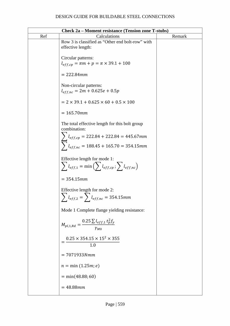
DESIGN GUIDE FOR BUILDABLE STEEL CONNECTIONS
Page | 559
Check 2a – Moment resistance (Tension zone T-stubs) Ref Calculations Remark
Row 3 is classified as “Other end bolt-row” with effective length: Circular patterns: 𝑙 , 𝜋𝑚 𝑝 𝜋 39.1 100
222.84𝑚𝑚 Non-circular patterns: 𝑙 , 2𝑚 0.625𝑒 0.5𝑝
2 39.1 0.625 60 0.5 100
165.70𝑚𝑚
The total effective length for this bolt group combination:
𝑙 , 222.84 222.84 445.67𝑚𝑚
𝑙 , 188.45 165.70 354.15𝑚𝑚
Effective length for mode 1:
𝑙 , min 𝑙 , ; 𝑙 ,
354.15𝑚𝑚
Effective length for mode 2:
𝑙 , 𝑙 , 354.15𝑚𝑚
Mode 1 Complete flange yielding resistance:
𝑀 , ,0.25∑ 𝑙 , 𝑡 𝑓
𝛾
0.25 354.15 15 355
1.0
7071933𝑁𝑚𝑚
𝑛 min 1.25𝑚; 𝑒
min 48.88; 60
48.88𝑚𝑚

DESIGN GUIDE FOR BUILDABLE STEEL CONNECTIONS
Page | 560
Check 2a – Moment resistance (Tension zone T-stubs) Ref Calculations Remark
Method 1:
𝐹 , ,4𝑀 , ,
𝑚
4 7071933
39.1010
723.47𝑘𝑁
Method 2:
𝐹 , ,8𝑛 2𝑒 𝑀 , ,
2𝑚𝑛 𝑒 𝑚 𝑛
8 48.88 2 11 7071933
2 39.1 48.88 11 39.1 48.88
10
914.25𝑘𝑁
Mode 2 Bolt failure with flange yielding resistance:
𝑀 , ,0.25∑ 𝑙 , 𝑡 𝑓
𝛾
0.25 354.15 15 355
1.0
7071933𝑁𝑚𝑚
𝐹 , ,2𝑀 , , 𝑛∑𝐹 ,
𝑚 𝑛
2 7071933 48.88 406656
39.1 48.8810
612.61𝑘𝑁
Mode 3 Bolt failure resistance:
𝐹 , , 𝐹 , 4𝐹 ,
4 203328 10
813.31𝑘𝑁

DESIGN GUIDE FOR BUILDABLE STEEL CONNECTIONS
Page | 561
Check 2a – Moment resistance (Tension zone T-stubs) Ref Calculations Remark
Resistance of end plate in bending: 𝐹 , , min 𝐹 , , ;𝐹 , , ;𝐹 , ,
min 723.47; 612.61; 813.31
612.61𝑘𝑁
SS EN1993-1-8
6.2.6.8 (1)
Beam web in tension
𝐹 , ,𝑏 , , 𝑡 𝑓 ,
𝛾
354.15 9 355
1.010
1131.51𝑘𝑁
𝑏 , , 𝑙
354.15𝑚𝑚
The resistance of bolt row 3 is limited to: 𝐹 , 𝐹 , 𝐹 , 612.61 341.30
271.32𝑘𝑁
Summary of tension resistance of T-stubs:
Row Resistance Effective
Resistance Row 1 alone 217.48kN 217.48kN Row 2 alone 341.30kN 341.30kN Row 3 alone 330.97kN 271.32kN Row 2 and 3 612.61kN -
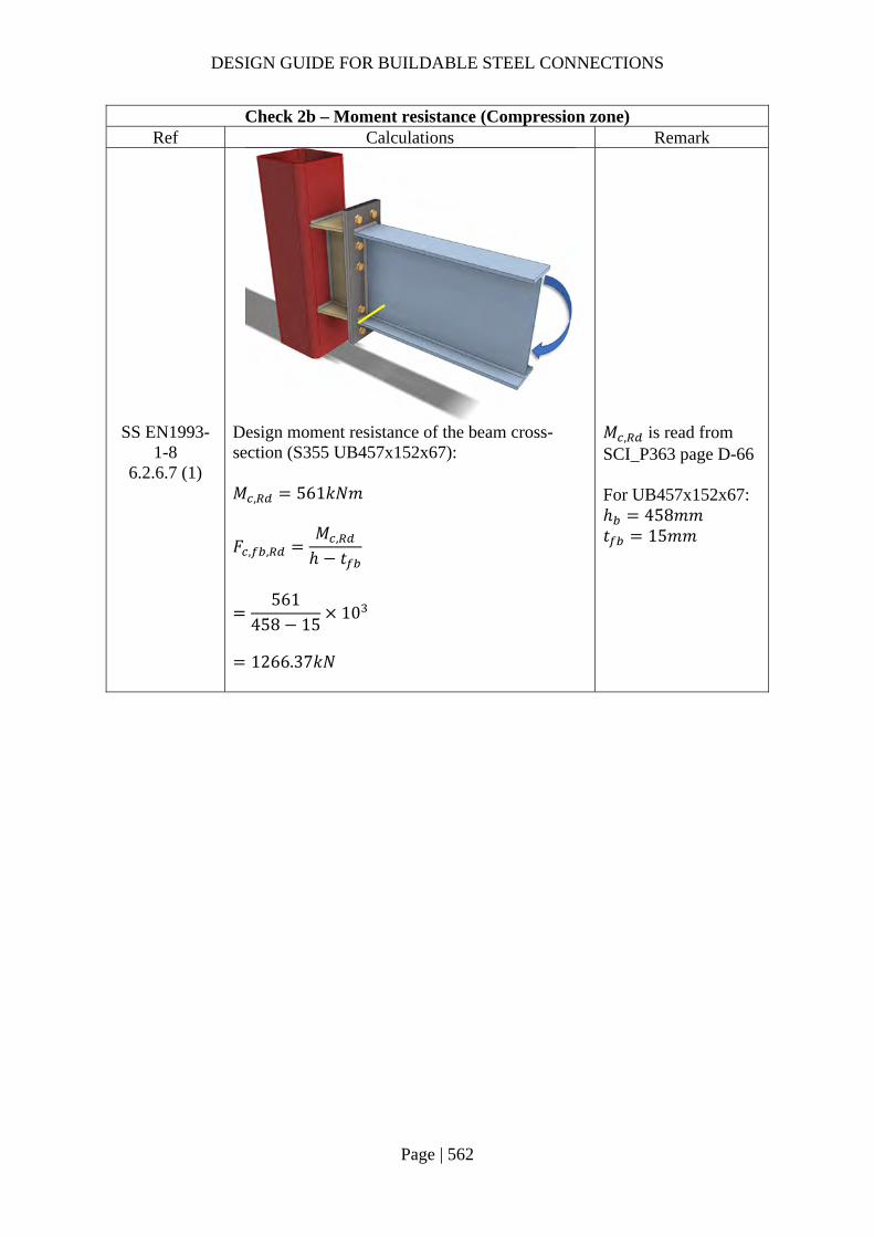
DESIGN GUIDE FOR BUILDABLE STEEL CONNECTIONS
Page | 562
Check 2b – Moment resistance (Compression zone) Ref Calculations Remark
SS EN1993-1-8
6.2.6.7 (1)
Design moment resistance of the beam cross-section (S355 UB457x152x67): 𝑀 , 561𝑘𝑁𝑚
𝐹 , ,𝑀 ,
ℎ 𝑡
561
458 1510
1266.37𝑘𝑁
𝑀 , is read from SCI_P363 page D-66 For UB457x152x67: ℎ 458𝑚𝑚 𝑡 15𝑚𝑚

DESIGN GUIDE FOR BUILDABLE STEEL CONNECTIONS
Page | 563
Check 2 – Moment resistance Ref Calculations Remark
SS EN1993-1-8
6.2.7.2 (9)
The effective resistances of bolt rows need to be reduced when the bolt row resistance is greater than 1.9𝐹 , 1.9𝐹 , 1.9 203.33 386.32𝑘𝑁 As all bolt row resistances are lesser than 386.32kN, no reduction is required.
Equilibrium of forces Total effective tension resistance:
𝐹 , 217.48 341.30 271.32
830.09𝑘𝑁 𝐹 , , 1266.37𝑘𝑁
Hence, no reduction is required for the tensile resistance.
SS EN1993-1-8
6.2.7.2 (1)
The moment resistance of the connection may be determined using:
𝑀 , ℎ 𝐹 , ,

DESIGN GUIDE FOR BUILDABLE STEEL CONNECTIONS
Page | 564
Check 2 – Moment resistance Ref Calculations Remark
Taking the center of compression to be at the mid-thickness of the compression flange of the beam:
ℎ ℎ𝑡2
𝑥
458152
50
500.5𝑚𝑚
ℎ ℎ 120 380.5𝑚𝑚 ℎ ℎ 100 280.5𝑚𝑚
𝑀 , ℎ 𝐹 , , ℎ 𝐹 , , ℎ 𝐹 , ,
500.5 217.48 380.5 341.30 280.5271.32
314.82𝑘𝑁𝑚 𝑀 200𝑘𝑁𝑚
OK
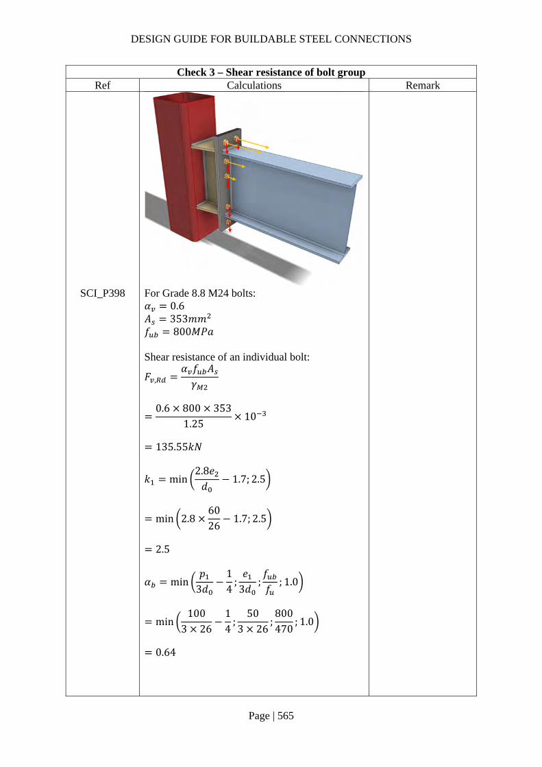
DESIGN GUIDE FOR BUILDABLE STEEL CONNECTIONS
Page | 565
Check 3 – Shear resistance of bolt group Ref Calculations Remark
SCI_P398 For Grade 8.8 M24 bolts: 𝛼 0.6 𝐴 353𝑚𝑚 𝑓 800𝑀𝑃𝑎 Shear resistance of an individual bolt:
𝐹 ,𝛼 𝑓 𝐴𝛾
0.6 800 353
1.2510
135.55𝑘𝑁
𝑘 min2.8𝑒𝑑
1.7; 2.5
min 2.86026
1.7; 2.5
2.5
𝛼 min𝑝
3𝑑14
;𝑒
3𝑑;𝑓𝑓
; 1.0
min100
3 2614
;50
3 26;800470
; 1.0
0.64
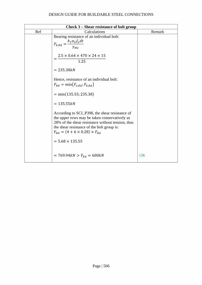
DESIGN GUIDE FOR BUILDABLE STEEL CONNECTIONS
Page | 566
Check 3 – Shear resistance of bolt group Ref Calculations Remark
Bearing resistance of an individual bolt:
𝐹 ,𝑘 𝛼 𝑓 𝑑𝑡𝛾
2.5 0.64 470 24 15
1.25
235.38𝑘𝑁
Hence, resistance of an individual bolt: 𝐹 min 𝐹 , ;𝐹 ,
min 135.55; 235.38
135.55𝑘𝑁
According to SCI_P398, the shear resistance of the upper rows may be taken conservatively as 28% of the shear resistance without tension, thus the shear resistance of the bolt group is: 𝑉 4 6 0.28 𝐹
5.68 135.55
769.94𝑘𝑁 𝑉 600𝑘𝑁
OK

DESIGN GUIDE FOR BUILDABLE STEEL CONNECTIONS
Page | 567
Check 4 – Weld of beam flange to end plate Ref Calculations Remark
SS EN1993 Length of fillet weld connecting beam flange: 𝐿 , 2𝑏 𝑡 2𝑟
2 153.8 9.0 2 10.2
278.2𝑚𝑚
For UB457x152x67: Width of beam flange: 𝑏 153.8𝑚𝑚 Thickness of beam web: 𝑡 9.0𝑚𝑚 Root radius: 𝑟 10.2𝑚𝑚
SCI_P363 Choose fillet weld with 12mm leg length, 8.4mm throat thickness and grade S355: Longitudinal resistance: 𝐹 , , 2.03𝑘𝑁/𝑚𝑚 Transverse resistance: 𝐹 , , 2.48𝑘𝑁/𝑚𝑚
Tensile resistance of flange weld: 𝐹 , , 𝐿 , 𝐹 , ,
278.2 2.48
689.94𝑘𝑁
Applied tensile force on beam flange:
𝐹 , ,𝑀
ℎ 𝑡
200
458 1510
451.47𝑘𝑁 𝐹 , ,
OK

DESIGN GUIDE FOR BUILDABLE STEEL CONNECTIONS
Page | 568
Check 5 – RHS resistance Ref Calculations Remark
SS EN1993-1-8
For RHS 300x300x12.5: Column width: 𝑏 300𝑚𝑚 Thickness of column wall: 𝑡 12.5𝑚𝑚 Yield strength of column: 𝑓 , 355𝑀𝑃𝑎 As the horizontal haunch has same width as the column, the ratio of width of flange to width of RHS 𝛽 1.0. Ratio of depth of haunch to width of RHS:
𝜂ℎ𝑏
458300
1.53
As 𝜂 2 1 𝛽, it is conservative to assume the design resistance of haunch is equal to design resistance of two transverse plates of similar dimensions to the flanges of haunch.
Assume 𝑘 1.0 as the axial force on the column is unknown in this example, for cases with known axial forces on column, 𝑘 should be calculated according to SS EN1993-1-8

DESIGN GUIDE FOR BUILDABLE STEEL CONNECTIONS
Page | 569
Check 5 – RHS resistance Ref Calculations Remark
As the width of haunch 𝑏 𝑏 𝑡 , the failure mode of RHS is chord side wall crushing:
𝑁 ,𝑘 𝑓 , 𝑡 2𝑡 10𝑡
𝛾
1.0 355 12.5 2 15 10 12.5
1.0
10
687.81𝑘𝑁
Distance between end plate center to RHS surface: 𝐿 127𝑚𝑚 Applied shear force on RHS surface: 𝑉 𝑉 600𝑘𝑁 Applied tensile force on haunch flange:
𝐹𝑀
ℎ 𝑡200
458 1510
451.47𝑘𝑁 𝑁 ,
OK
Flange weld resistance: Length of fillet weld connecting beam flange: 𝐿 , 2𝑏 𝑡 2𝑟
2 300 9.0 2 10.2
570.6𝑚𝑚
SCI_P363 Choose fillet weld with 8mm leg length, 5.6mm throat thickness and grade S355: Longitudinal resistance: 𝐹 , , 1.35𝑘𝑁/𝑚𝑚 Transverse resistance: 𝐹 , , 1.65𝑘𝑁/𝑚𝑚
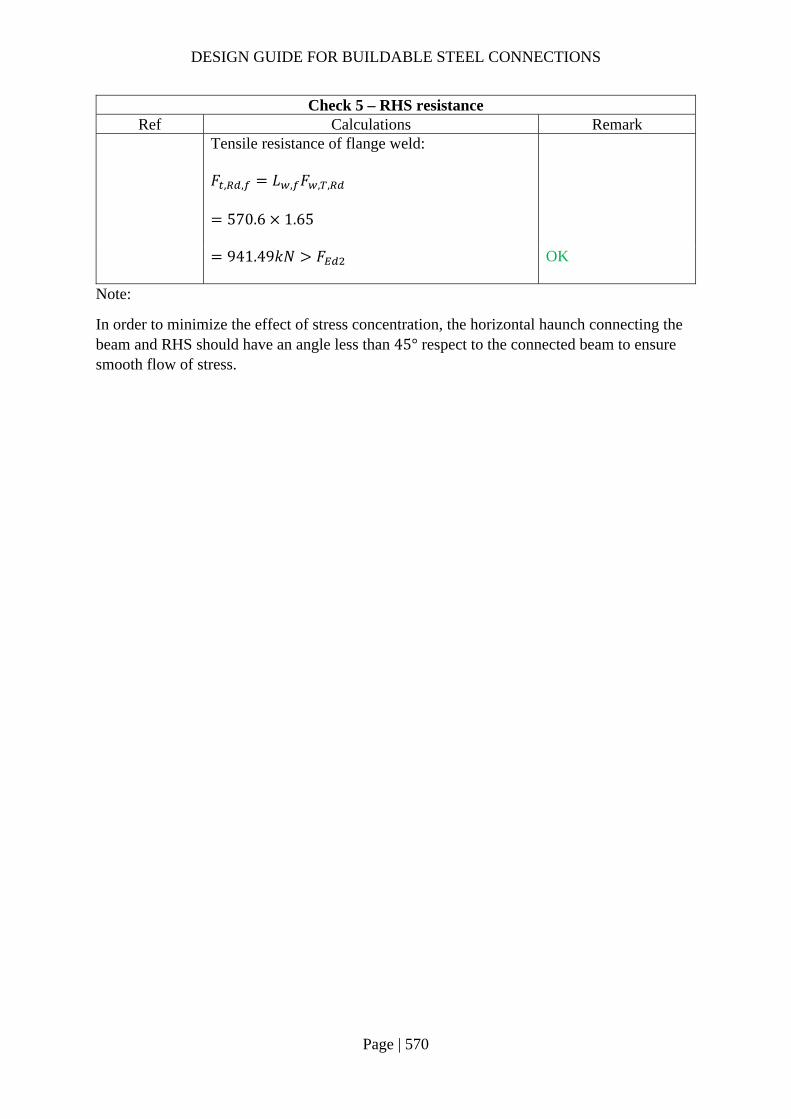
DESIGN GUIDE FOR BUILDABLE STEEL CONNECTIONS
Page | 570
Check 5 – RHS resistance Ref Calculations Remark
Tensile resistance of flange weld: 𝐹 , , 𝐿 , 𝐹 , ,
570.6 1.65
941.49𝑘𝑁 𝐹
OK
Note:
In order to minimize the effect of stress concentration, the horizontal haunch connecting the beam and RHS should have an angle less than 45° respect to the connected beam to ensure smooth flow of stress.

DESIGN GUIDE FOR BUILDABLE STEEL CONNECTIONS
Page | 571
4.5 Connection of I-beam to circular hollow section steel column A good practice for steel construction is to adopt a strategy to weld at the factory and bolt at the site. For beam-to-column moment connections, one way to achieve this good practice is to weld a beam stub to the column in the factory and provide a beam splice bolted connection as shown below. This beam splice connection should have sufficient length away from the column to install the top and cover plates. If the diameter of column is very much larger than the beam for this type of connection, local effect needs to be checked and local strengthening of the column using double plate can be applied.
4.5.1 Example 5 – I beam to circular column connection with beam stub pre-welded to column
Design loading:
Vertical shear force: 𝑉 150𝑘𝑁
Major axis bending moment: 𝑀 100𝑘𝑁𝑚
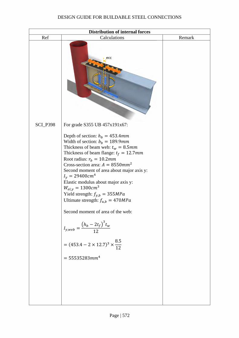
DESIGN GUIDE FOR BUILDABLE STEEL CONNECTIONS
Page | 572
Distribution of internal forces Ref Calculations Remark
SCI_P398 For grade S355 UB 457x191x67: Depth of section: ℎ 453.4𝑚𝑚 Width of section: 𝑏 189.9𝑚𝑚 Thickness of beam web: 𝑡 8.5𝑚𝑚 Thickness of beam flange: 𝑡 12.7𝑚𝑚 Root radius: 𝑟 10.2𝑚𝑚 Cross-section area: 𝐴 8550𝑚𝑚 Second moment of area about major axis y: 𝐼 29400𝑐𝑚 Elastic modulus about major axis y: 𝑊 , 1300𝑐𝑚 Yield strength: 𝑓 , 355𝑀𝑃𝑎 Ultimate strength: 𝑓 , 470𝑀𝑃𝑎
Second moment of area of the web:
𝐼 ,ℎ 2𝑡 𝑡
12
453.4 2 12.78.512
55535283𝑚𝑚
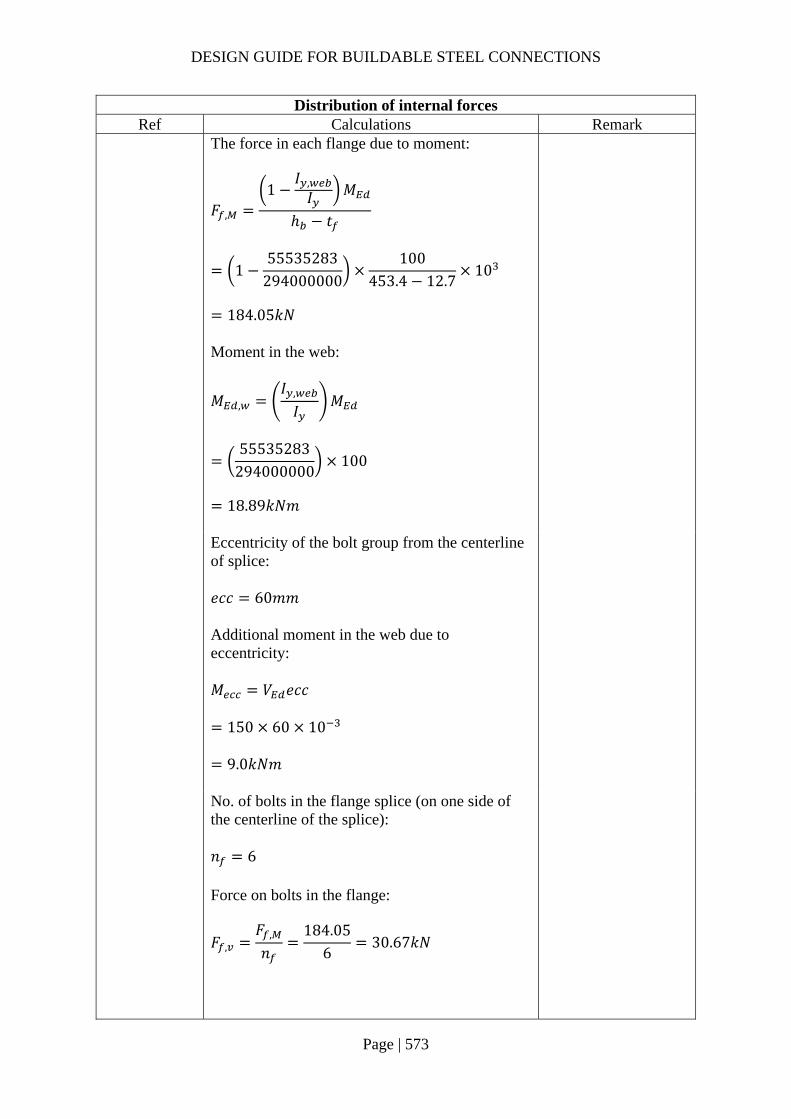
DESIGN GUIDE FOR BUILDABLE STEEL CONNECTIONS
Page | 573
Distribution of internal forces Ref Calculations Remark
The force in each flange due to moment:
𝐹 ,
1𝐼 ,𝐼 𝑀
ℎ 𝑡
155535283
294000000100
453.4 12.710
184.05𝑘𝑁
Moment in the web:
𝑀 ,𝐼 ,
𝐼𝑀
55535283
294000000100
18.89𝑘𝑁𝑚
Eccentricity of the bolt group from the centerline of splice: 𝑒𝑐𝑐 60𝑚𝑚 Additional moment in the web due to eccentricity: 𝑀 𝑉 𝑒𝑐𝑐
150 60 10
9.0𝑘𝑁𝑚
No. of bolts in the flange splice (on one side of the centerline of the splice): 𝑛 6 Force on bolts in the flange:
𝐹 ,𝐹 ,
𝑛184.05
630.67𝑘𝑁
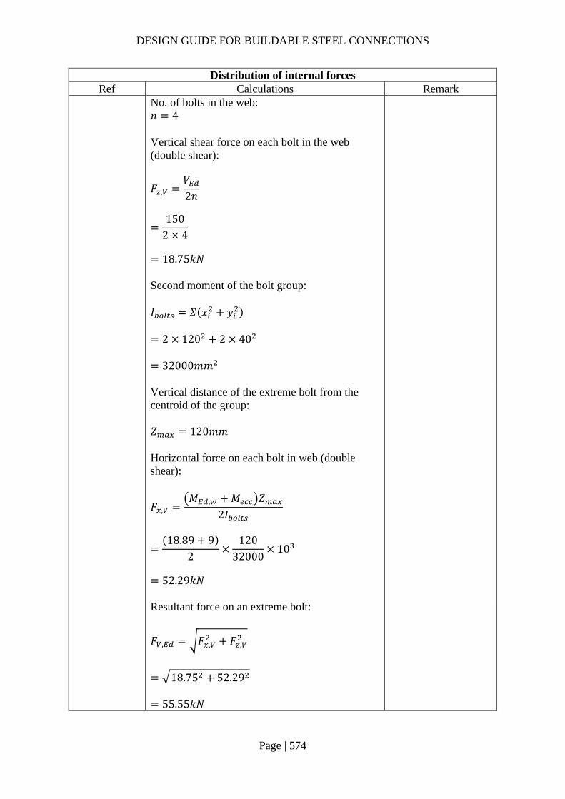
DESIGN GUIDE FOR BUILDABLE STEEL CONNECTIONS
Page | 574
Distribution of internal forces Ref Calculations Remark
No. of bolts in the web: 𝑛 4 Vertical shear force on each bolt in the web (double shear):
𝐹 ,𝑉2𝑛
150
2 4
18.75𝑘𝑁
Second moment of the bolt group: 𝐼 𝛴 𝑥 𝑦
2 120 2 40
32000𝑚𝑚
Vertical distance of the extreme bolt from the centroid of the group: 𝑍 120𝑚𝑚 Horizontal force on each bolt in web (double shear):
𝐹 ,𝑀 , 𝑀 𝑍
2𝐼
18.89 9
2120
3200010
52.29𝑘𝑁
Resultant force on an extreme bolt:
𝐹 , 𝐹 , 𝐹 ,
18.75 52.29
55.55𝑘𝑁
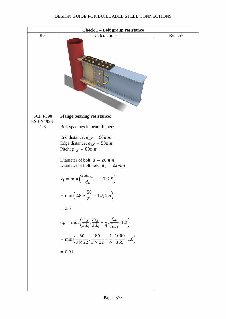
DESIGN GUIDE FOR BUILDABLE STEEL CONNECTIONS
Page | 575
Check 1 – Bolt group resistance Ref Calculations Remark
SCI_P398 SS EN1993-
1-8
Flange bearing resistance: Bolt spacings in beam flange: End distance: 𝑒 , 60𝑚𝑚 Edge distance: 𝑒 , 50𝑚𝑚 Pitch: 𝑝 , 80𝑚𝑚
Diameter of bolt: 𝑑 20𝑚𝑚 Diameter of bolt hole: 𝑑 22𝑚𝑚
𝑘 min2.8𝑒 ,
𝑑1.7; 2.5
min 2.85022
1.7; 2.5
2.5
𝛼 min𝑒 ,
3𝑑;𝑝 ,
3𝑑14
;𝑓𝑓 ,
; 1.0
min60
3 22;
803 22
14
;1000355
; 1.0
0.91
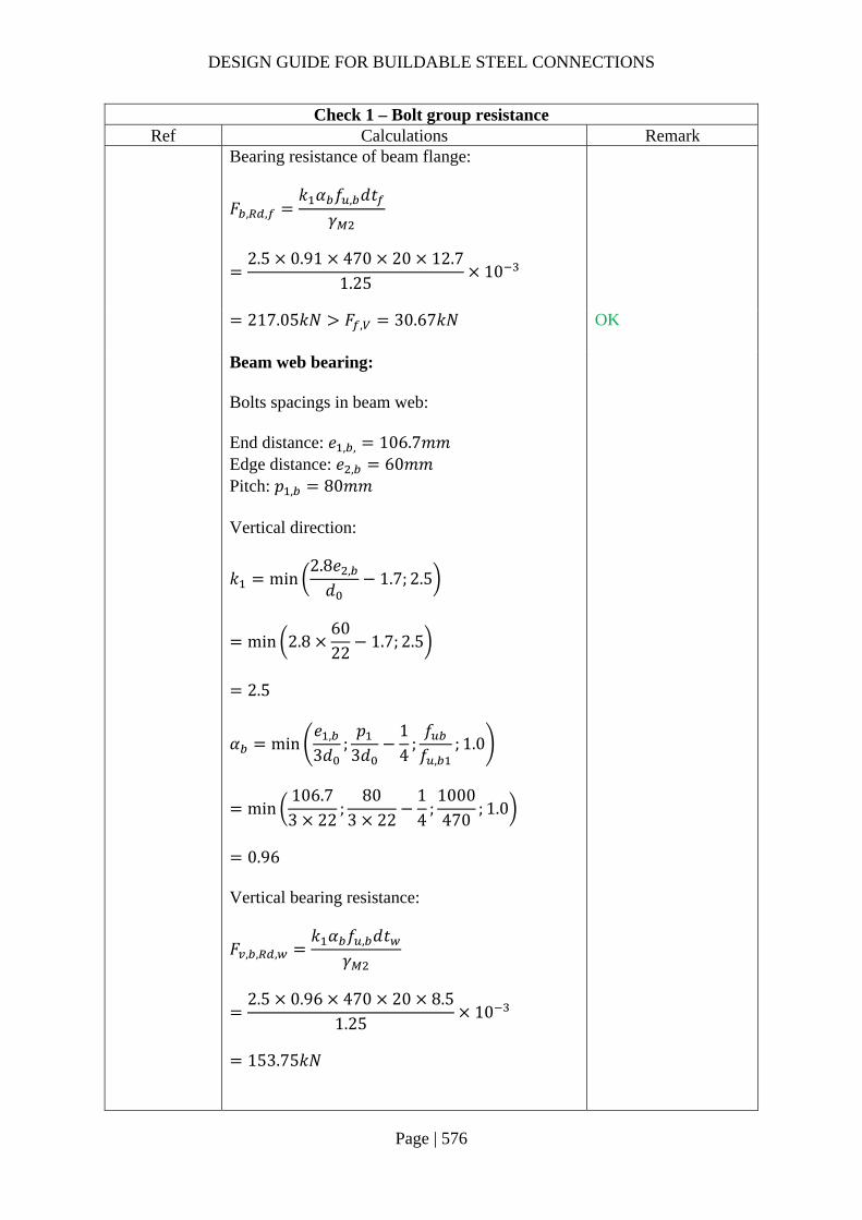
DESIGN GUIDE FOR BUILDABLE STEEL CONNECTIONS
Page | 576
Check 1 – Bolt group resistance Ref Calculations Remark
Bearing resistance of beam flange:
𝐹 , ,𝑘 𝛼 𝑓 , 𝑑𝑡
𝛾
2.5 0.91 470 20 12.7
1.2510
217.05𝑘𝑁 𝐹 , 30.67𝑘𝑁
OK
Beam web bearing: Bolts spacings in beam web: End distance: 𝑒 , , 106.7𝑚𝑚 Edge distance: 𝑒 , 60𝑚𝑚 Pitch: 𝑝 , 80𝑚𝑚
Vertical direction:
𝑘 min2.8𝑒 ,
𝑑1.7; 2.5
min 2.86022
1.7; 2.5
2.5
𝛼 min𝑒 ,
3𝑑;𝑝
3𝑑14
;𝑓𝑓 ,
; 1.0
min106.73 22
;80
3 2214
;1000470
; 1.0
0.96
Vertical bearing resistance:
𝐹 , , ,𝑘 𝛼 𝑓 , 𝑑𝑡
𝛾
2.5 0.96 470 20 8.5
1.2510
153.75𝑘𝑁

DESIGN GUIDE FOR BUILDABLE STEEL CONNECTIONS
Page | 577
Check 1 – Bolt group resistance Ref Calculations Remark
Horizontal direction:
𝑘 min2.8𝑒 ,
𝑑1.7;
1.4𝑃𝑑
1.7; 2.5
min 2.8106.7
221.7; 1.4
8022
1.7; 2.5
2.5
𝛼 min𝑒 ,
3𝑑;𝑓𝑓 ,
; 1.0
min60
3 22;1000470
; 1.0
0.91
Horizontal bearing resistance:
𝐹 , , ,𝑘 𝛼 𝑓 , 𝑑𝑡
𝛾
2.5 0.91 470 20 8.5
1.2510
145.27𝑘𝑁
2𝐹 ,
𝐹 , , ,
2𝐹 ,
𝐹 , , ,
2 18.75
153.752 52.29
145.27
0.96 1
OK
Web cover plate bearing: Bolt spacings in web cover plate: End distance: 𝑒 , 60𝑚𝑚 Edge distance: 𝑒 , 60𝑚𝑚 Pitch: 𝑝 , 80𝑚𝑚
Thickness of web cover plate: 𝑡 10𝑚𝑚 Ultimate strength of web cover plate: 𝑓 , 470𝑀𝑃𝑎

DESIGN GUIDE FOR BUILDABLE STEEL CONNECTIONS
Page | 578
Check 1 – Bolt group resistance Ref Calculations Remark
Vertical direction:
𝑘 min2.8𝑒 ,
𝑑1.7; 2.5
min 2.86022
1.7; 2.5
2.5
𝛼 min𝑒 ,
3𝑑;𝑝
3𝑑14
;𝑓𝑓 ,
; 1.0
min60
3 22;
803 22
14
;1000470
; 1.0
0.91
Vertical bearing resistance:
𝐹 , , ,𝑘 𝛼 𝑓 , 𝑑𝑡
𝛾
2.5 0.91 470 20 10
1.2510
170.91𝑘𝑁
Horizontal direction:
𝑘 min2.8𝑒 ,
𝑑1.7;
1.4𝑃 ,
𝑑1.7; 2.5
min 2.86022
1.7; 1.48022
1.7; 2.5
2.5
𝛼 min𝑒 ,
3𝑑;𝑓𝑓 ,
; 1.0
min60
3 22;1000470
; 1.0
0.91

DESIGN GUIDE FOR BUILDABLE STEEL CONNECTIONS
Page | 579
Check 1 – Bolt group resistance Ref Calculations Remark
Horizontal bearing resistance:
𝐹 , , ,𝑘 𝛼 𝑓 , 𝑑𝑡
𝛾
2.5 0.91 470 20 10
1.2510
170.91𝑘𝑁
𝐹 ,
𝐹 , , ,
𝐹 ,
𝐹 , , ,
18.75
170.9152.29
170.91
0.42 1.0
OK
Bolt shear resistance: Using GR.10.9, M20 bolts with: 𝐴 245𝑚𝑚 , 𝑓 1000𝑀𝑃𝑎
Assume bolts in normal holes: 𝑘 1.0 Slip factor (Class A friction surfaces): 𝜇 0.5 Preloading force: 𝐹 , 0.7𝑓 𝐴
0.7 1000 245 10
171.5𝑘𝑁
𝛾 1.25 𝐸𝑁1993 1 8

DESIGN GUIDE FOR BUILDABLE STEEL CONNECTIONS
Page | 580
Check 1 – Bolt group resistance Ref Calculations Remark
The design slip resistance of a preloaded GR. 10.9 bolt:
𝐹 ,𝑘 𝑛𝜇𝛾
𝐹 ,
1.0 1.0 0.51.25
171
68.6𝑘𝑁 max 𝐹 , ;𝐹 , 55.55𝑘𝑁
OK

DESIGN GUIDE FOR BUILDABLE STEEL CONNECTIONS
Page | 581
Check 2 – Resistance of tension flange and cover plate Ref Calculations Remark
SCI_P398 SS EN1993-
1-8
Tension flange resistance (gross area): 𝐴 𝑏 𝑡 189.9 12.7 2411.73𝑚𝑚 Resistance of the gross section:
𝐹 ,𝐴 𝑓𝛾
2411.733551.0
10
856.16𝑘𝑁
Tension flange resistance (net area): 𝐴 𝑏 2𝑑 𝑡
189.9 2 22 12.7
1852.93𝑚𝑚 Resistance of the net section:
𝐹 ,0.9𝐴 𝑓𝛾
0.9 1852.93 470
1.2510
627.03𝑘𝑁

DESIGN GUIDE FOR BUILDABLE STEEL CONNECTIONS
Page | 582
Check 2 – Resistance of tension flange and cover plate Ref Calculations Remark
Resistance of tension flange: 𝐹 , min 𝐹 , ;𝐹 ,
min 856.16; 627.03
627.03𝑘𝑁 𝐹 , 184.05𝑘𝑁
OK
*As the widths of beam flange and cover plate are same in this example, only the beam flange whose thickness is smaller is checked. If the widths of the flange and cover plate are different, the check above should be performed for both beam flange and cover plate.

DESIGN GUIDE FOR BUILDABLE STEEL CONNECTIONS
Page | 583
Check 3 – Resistance of compression flange and cover plate Ref Calculations Remark
SCI_P398 SS EN1993-
1-8
According to SCI_P398, the compression resistance of the flange and cover plate may be based on gross section. Local buckling resistance of the cover plate needs to be considered when the ratio of distance between rows of bolts to thickness of plate exceed 9𝜀.
𝜀235𝑓 ,
235355
0.814
9𝜀 9 0.814 7.32 Spacing of bolts across the joint in the direction of the bolt: 𝑝 120𝑚𝑚 𝑝𝑡
12015
8 9𝜀 7.32
∴ Local buckling resistance of the cover plate needs to be checked
Thickness of the flange cover plate: 𝑡 15𝑚𝑚 Yield strength of the cover plate: 𝑓 355𝑀𝑃𝑎
𝑖
𝑡
√12
15
√124.33𝑚𝑚
𝐿 0.6𝑝 0.6 120 72𝑚𝑚 𝜆 93.9𝜀 93.9 0.814 76.40
�̅�𝐿𝑖
1𝜆
724.33
176.40
0.218
𝛼 0.49 (for solid section)
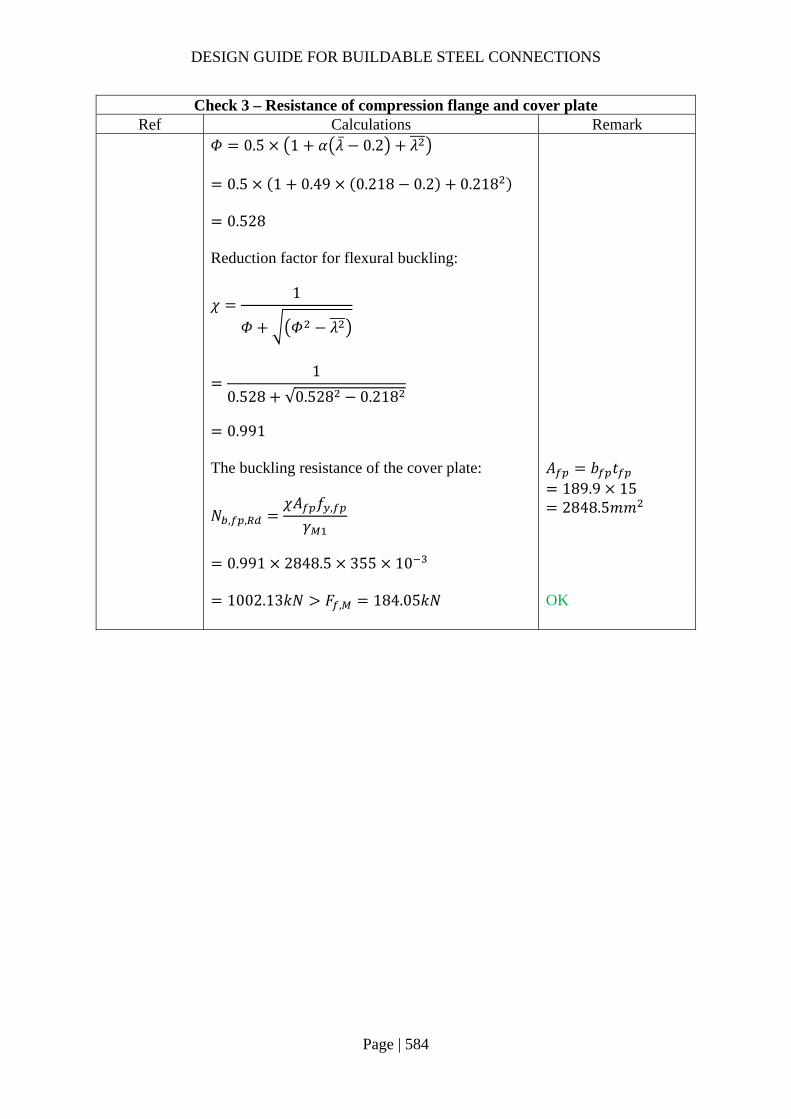
DESIGN GUIDE FOR BUILDABLE STEEL CONNECTIONS
Page | 584
Check 3 – Resistance of compression flange and cover plate Ref Calculations Remark
𝛷 0.5 1 𝛼 �̅� 0.2 𝜆
0.5 1 0.49 0.218 0.2 0.218
0.528 Reduction factor for flexural buckling:
𝜒1
𝛷 𝛷 𝜆
1
0.528 √0.528 0.218
0.991
The buckling resistance of the cover plate:
𝑁 , ,𝜒𝐴 𝑓 ,
𝛾
0.991 2848.5 355 10
𝐴 𝑏 𝑡 189.9 15 2848.5𝑚𝑚
1002.13𝑘𝑁 𝐹 , 184.05𝑘𝑁
OK
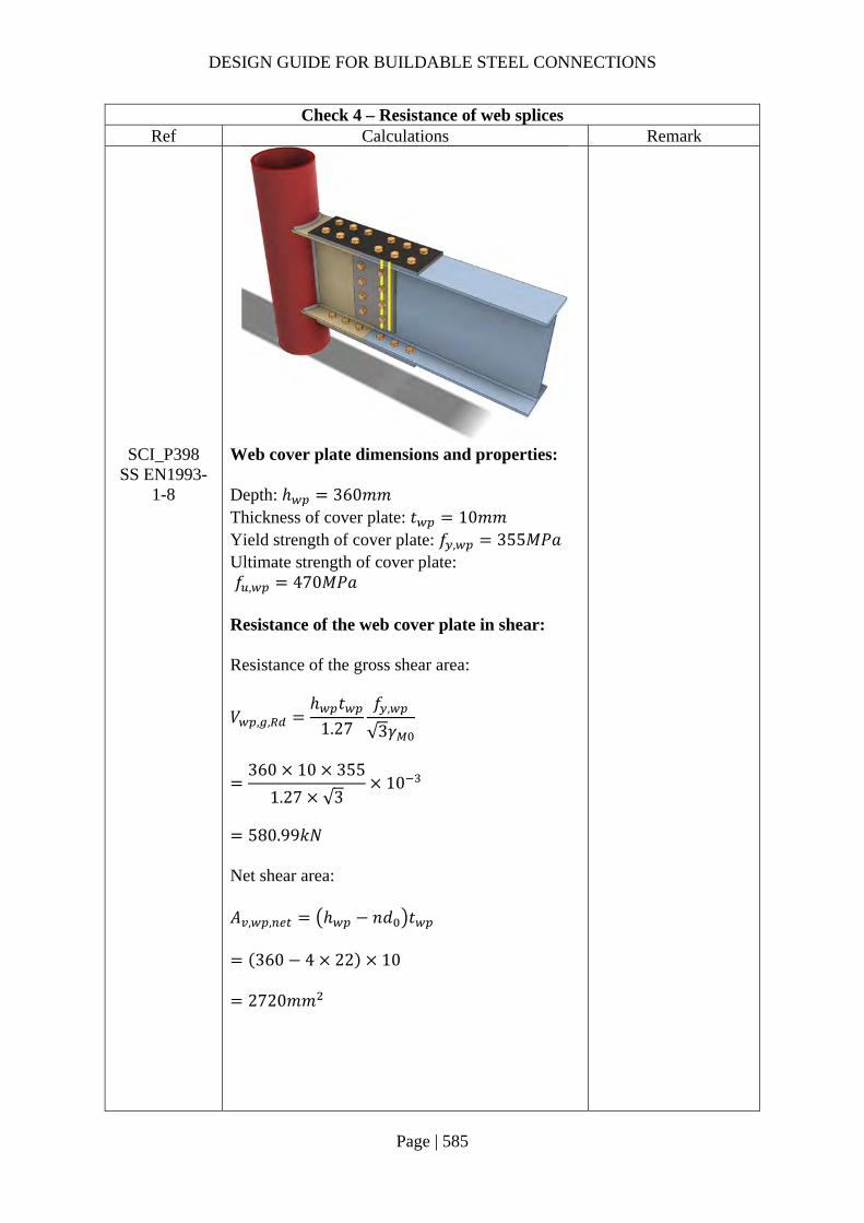
DESIGN GUIDE FOR BUILDABLE STEEL CONNECTIONS
Page | 585
Check 4 – Resistance of web splices Ref Calculations Remark
SCI_P398 SS EN1993-
1-8
Web cover plate dimensions and properties: Depth: ℎ 360𝑚𝑚 Thickness of cover plate: 𝑡 10𝑚𝑚 Yield strength of cover plate: 𝑓 , 355𝑀𝑃𝑎 Ultimate strength of cover plate: 𝑓 , 470𝑀𝑃𝑎 Resistance of the web cover plate in shear: Resistance of the gross shear area:
𝑉 , ,ℎ 𝑡
1.27𝑓 ,
√3𝛾
360 10 355
1.27 √310
580.99𝑘𝑁
Net shear area: 𝐴 , , ℎ 𝑛𝑑 𝑡
360 4 22 10
2720𝑚𝑚
DESIGN GUIDE FOR BUILDABLE STEEL CONNECTIONS
Page | 586
Check 4 – Resistance of web splices Ref Calculations Remark
Resistance of the net shear area:
𝑉 , ,
𝐴 , ,𝑓 ,
√3𝛾
2720
470√3
1.2510
590.47𝑘𝑁
Shear resistance of the web cover plate: 𝑉 , min 𝑉 , , ;𝑉 , ,
min 580.99; 590.47
580.99𝑘𝑁 𝑉 150𝑘𝑁
OK
Web cover plate bending resistance: Elastic modulus of web cover plate (gross section):
𝑊 ,𝑡 ℎ
410
3604
324000𝑚𝑚
Reduction parameter for coexisting shear:
𝜌2𝑉𝑉 ,
1
2150
580.991
0.234
Bending resistance of web cover plate:
𝑀 , ,𝑊 , 1 𝜌 𝑓 ,
𝛾
324000 1 0.234 355 10
88.12𝑘𝑁𝑚 𝑀 𝑀 27.89𝑘𝑁𝑚
OK

DESIGN GUIDE FOR BUILDABLE STEEL CONNECTIONS
Page | 587
Check 4 – Resistance of web splices Ref Calculations Remark
Beam web in shear: Gross shear area of beam web: 𝐴 , 𝐴 2𝑏 𝑡 𝑡 2𝑟 𝑡
8550 2 189.9 12.7 8.5 2 10.2 12.7
4093.57𝑚𝑚
Resistance of the gross shear area:
𝑉 , ,𝐴 , 𝑓 ,
√3
4093.57355
√310
839.02𝑘𝑁
Net shear area: 𝐴 , 𝐴 , 𝑛𝑑 𝑡
4093.57 4 22 8.5
3345.57𝑚𝑚
Resistance of the net shear area:
𝑉 , ,
𝐴 ,𝑓 ,
√3𝛾
3345.57
470√3
1.2510
726.27𝑘𝑁

DESIGN GUIDE FOR BUILDABLE STEEL CONNECTIONS
Page | 588
Check 4 – Resistance of web splices Ref Calculations Remark
Shear resistance of beam web: 𝑉 , min 𝑉 , , ;𝑉 , ,
min 839.02; 726.27
726.27𝑘𝑁 𝑉 150𝑘𝑁
OK

DESIGN GUIDE FOR BUILDABLE STEEL CONNECTIONS
Page | 589
Check 5 – Resistance of the circular hollow section column (CHS) Ref Calculations Remark
SS EN1993-1-8
For CHS 273×12.5: Diameter: 𝑑 273𝑚𝑚 Wall thickness: 𝑡 12.5𝑚𝑚 Yield strength: 𝑓 , 355𝑀𝑃𝑎 Ultimate strength: 𝑓 , 470𝑀𝑃𝑎
Table 7.1 and Table 7.4
Range of validity:
10
𝑑𝑡
21.84 50
OK
𝛽
𝑏𝑑
189.9273
0.696 0.4
OK
𝜂
ℎ𝑑
453.4273
1.66 4
OK
As the axial force on CHS column is unknown, 𝑘 is assumed to be 1. Axial resistance of I beam connects to CHS:
𝑁 ,𝑘 𝑓 , 𝑡 4 20𝛽 1 0.25𝜂
𝛾
1.0 355 12.5 4 20 0.696
1 0.25 1.66 10
1073.66𝑘𝑁

DESIGN GUIDE FOR BUILDABLE STEEL CONNECTIONS
Page | 590
Check 5 – Resistance of the circular hollow section column (CHS) Ref Calculations Remark
𝑀 , ℎ 𝑁 , / 1 0.25𝜂
453.4 1073.661 0.25 1.66
10
343.98𝑘𝑁𝑚
Eccentricity between the CHS surface and beam splice: 𝑒𝑐𝑐 380𝑚𝑚
Applied moment on CHS surface: 𝑀 , 𝑀 𝑉 𝑒𝑐𝑐
100 150 380 10
157𝑘𝑁𝑚 𝑀 , 343.98𝑘𝑁𝑚
OK
Punching shear resistance: As 𝜂 2, 𝑀 ,
𝑊 ,𝑡
1571300000
12.7 10
1.534𝑘𝑁/𝑚𝑚
2𝑡𝑓 ,
√3𝛾
2 12.5355
√310
5.124𝑘𝑁/𝑚𝑚 1.534𝑘𝑁/𝑚𝑚
OK
Note:
If the bending and punching resistance of CHS are insufficient, local strengthening with doubler plate may be used. According to Chinese Technical specification for structures with steel hollow sections (CECS 280:2010) clause 7.3.4, the doubler plate should be at least 4mm thick and cover at least half of the hollow section. In addition, the edge of the plate should be at least 50mm away from the welding but not greater than 2/3 of the height of the I beam.
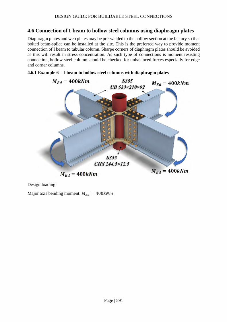
DESIGN GUIDE FOR BUILDABLE STEEL CONNECTIONS
Page | 591
4.6 Connection of I-beam to hollow steel columns using diaphragm plates
Diaphragm plates and web plates may be pre-welded to the hollow section at the factory so that bolted beam-splice can be installed at the site. This is the preferred way to provide moment connection of I beam to tubular column. Sharpe corners of diaphragm plates should be avoided as this will result in stress concentration. As such type of connections is moment resisting connection, hollow steel column should be checked for unbalanced forces especially for edge and corner columns.
4.6.1 Example 6 – I-beam to hollow steel columns with diaphragm plates
Design loading:
Major axis bending moment: 𝑀 400𝑘𝑁𝑚

DESIGN GUIDE FOR BUILDABLE STEEL CONNECTIONS
Page | 592
Dimensions and properties Ref Calculations Remark
For S355 UB 533x210x92: Depth: ℎ 533.1𝑚𝑚 Width: 𝑏 209.3𝑚𝑚 Thickness of flange: 𝑡 15.6𝑚𝑚 Yield strength: 𝑓 , 355𝑀𝑃𝑎 Ultimate strength: 𝑓 , 470𝑀𝑃𝑎
For S355 CHS 244.5x12.5: Diameter: 𝑑 244.5𝑚𝑚 Thickness: 𝑡 12.5𝑚𝑚 Yield strength: 𝑓 , 355𝑀𝑃𝑎 Ultimate strength: 𝑓 , 470𝑀𝑃𝑎
For S355 external diaphragm ring: To allow for construction inaccuracies, the thickness of the diaphragm ring is designed to be slightly thicker than the thickness of flange of the I beam. Thickness: 𝑡 20𝑚𝑚 𝑡 15.6𝑚𝑚 Yield strength: 𝑓 345𝑀𝑃𝑎 Ultimate strength: 𝑓 470𝑀𝑃𝑎
As Eurocode does not provide guideline on designing the width and thickness of the external diaphragm ring for I beam to CHS connection, CIDECT design guides and Chinese technical codes (GB 50936-2014) are referred and the calculations are shown below.

DESIGN GUIDE FOR BUILDABLE STEEL CONNECTIONS
Page | 593
CIDECT design guide 9 Ref Calculations Remark
CIDECT design guide
9
Axial resistance of diaphragm ring:
𝑁 19.6𝑑𝑡
. 𝑏𝑑
. 𝑡𝑡
. 𝑑2
𝑓
19.6244.512.5
. 𝑏244.5
. 2012.5
.
244.5
2355 10
1252.20𝑏
244.5
.
For 𝑁 772.95𝑘𝑁 and to meet the range of validity: 𝑏 15𝑚𝑚
𝑁 1252.2015
244.5
.
847.17𝑘𝑁 𝑁
Range of validity:
14𝑑𝑡
244.512.5
19.56 36
𝑏
𝑡
𝑡
𝑑𝑏
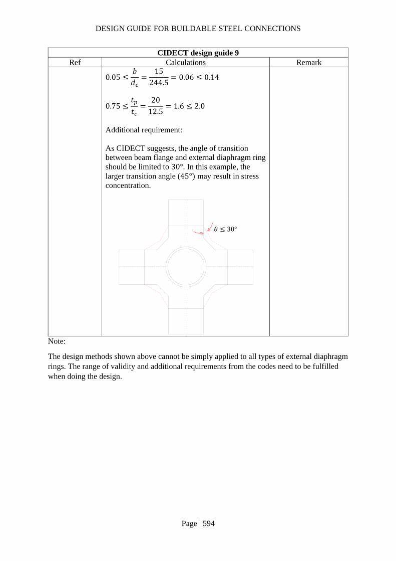
DESIGN GUIDE FOR BUILDABLE STEEL CONNECTIONS
Page | 594
CIDECT design guide 9 Ref Calculations Remark
0.05
𝑏𝑑
15244.5
0.06 0.14
0.75𝑡𝑡
2012.5
1.6 2.0
Additional requirement: As CIDECT suggests, the angle of transition between beam flange and external diaphragm ring should be limited to 30°. In this example, the larger transition angle (45° may result in stress concentration.
Note:
The design methods shown above cannot be simply applied to all types of external diaphragm rings. The range of validity and additional requirements from the codes need to be fulfilled when doing the design.
𝜃 30°

DESIGN GUIDE FOR BUILDABLE STEEL CONNECTIONS
Page | 595
GB 50936:2014 – Technical code for concrete filled steel tubular structures Ref Calculations Remark
GB 50936-2014
Annex C
Note: 𝑟 : transition radius between beam and diaphragm plate depends upon execution class
Angle between axial force on flange and cross section:
𝛼 sin
𝑏2
𝑑 𝑏
Effective width of external diaphragm ring:
𝑏 0.630.88𝑏𝑑
𝑑 𝑡 𝑡
0.630.88 209.3
244.5√244.5 12.5 20
96.47𝑚𝑚
Applied axial force:
𝑁𝑀
ℎ 𝑡
400
533.1 15.610
772.95𝑘𝑁
𝛼
𝑏2
𝑑 𝑏𝑑
𝑏
𝑟 10𝑚𝑚

DESIGN GUIDE FOR BUILDABLE STEEL CONNECTIONS
Page | 596
GB 50936:2014 – Technical code for concrete filled steel tubular structures Ref Calculations Remark
𝐹 𝛼
0.93
√2 sin 𝛼 1
𝐹 𝛼1.74 sin𝛼
√2 sin 𝛼 1
Minimum width required:
𝑏𝐹 𝛼 𝑁𝑡 𝑓
𝐹 𝛼 𝑏 𝑡 𝑓𝑡 𝑓
As both sides of the inequation affected by the unknown 𝑏, iteration is required. After iteration, for 𝑁 772.95𝑘𝑁, 𝑏 65𝑚𝑚 Additional requirement: To minimize the effect of stress concentration, the radius between the I beam flange and diaphragm ring should be at lease 10mm. Range of validity:
0.25𝑏𝑑
96.47244.5
0.40 0.75
0.10𝑏𝑑
65244.5
0.27 0.35
𝑏𝑡
3.25 10
As the equations used above need to fulfill the range of validity, for high applied axial force, this method of calculation may not be appropriate.

DESIGN GUIDE FOR BUILDABLE STEEL CONNECTIONS
Page | 597
5 Bracing connections 5.1 Introduction
Bracing connections are typically constructed using sectional shapes like hollow sections, Universal section (I or H sections), channels and angles resisting tension or compression. The bracings are typically connected to the main members via gusset plates using bolts. If the wind loads are not high, steel rods may be used as tension members to provide lateral load resistance. Steel rods are more economical compared to structural steel sections and they can be easily installed on site. Steel rods are lighter and most of the time can be installed without the use of cranes. Turn-buckle system may be used to pre-tensioned the rod to prevent slackening. This section gives suggestions of how steel rods are to be detailed and design to improve productivity in fabrication and installation.
5.2 Materials
The steel rods and welded plates are recommended to be of BC1’s certified materials. Two types of turn-buckle systems connecting to steel rod is shown in Figure 5-1. As the rods are welded to turnbuckles attachments, it is recommended to use the more weldable mild steel rod such as S275 steel. The use of high tensile rod is not recommended. Engineers are recommended to specific 100% NDT on the welds and performance tests may be carried out to verify its structural performance.
Figure 5-1 Two options of connecting a turn-buckle system to a steel rod
5.3 Design and Detailing
Figure 5-2 shows two ways of welding a steel rod to a steel plate. The design and detailing recommendations pertaining to the connection of the steel rod to the gusset plate are as follows:
1. The welds should be designed to resist 2 times the tension force 2. Option 1 – Flare groove welds to be designed as per cl. 4.3.6 EC3-8. Qualified welding
procedure should be carried out for this weld. For this option, there may be eccentricity between the applied forces and the weld. The weld should be checked against the moment induced by the eccentric load.
3. Option 2 – The rod diameter should be at least double the plate thickness to allow for sufficient welding. The weld should be designed as per fillet weld.

DESIGN GUIDE FOR BUILDABLE STEEL CONNECTIONS
Page | 598
Figure 5-2 Welding of steel rod to a plate (a) Option 1: single sided flare groove weld (b) Option 2: double sided fillet welds (preferred)
For Option 1, the connection should be reviewed if there is a large horizontal force acting onto the connection.
For erection purpose, two bolts are preferred.
5.3.1 Example 1 – Welding of steel rod to a steel plate
Design tension load:
𝐹 200𝑘𝑁

DESIGN GUIDE FOR BUILDABLE STEEL CONNECTIONS
Page | 599
Option 1 Ref Calculations Remark
SS EN1993-1-8
AWS D1.1:2015
For option 1, flare-bevel-groove welds are used to connect the tension rod to the plate. Radius of tension rod: 𝑅 25𝑚𝑚 According to the guide from the American Welding Society, the effective weld sizes of flare groove welds is assumed to be 3/8 of the radius of tension rod for gas metal arc welding (GMAW).
Effective throat thickness of flare-bevel-groove weld:
𝑎38𝑅 25
38
9.375𝑚𝑚
Design shear strength of the weld:
𝑓 ,𝑓
√3𝛽 𝛾
410
√3 0.85 1.25
222.79𝑀𝑃𝑎
Design longitudinal resistance: 𝐹 , , 𝑓 , 𝑎 222.79 9.375 10
2.09𝑘𝑁/𝑚𝑚
For S275 weld: 𝑓 410𝑀𝑃𝑎 𝛽 0.85 𝛾 1.25 (SS EN1993-1-8)

DESIGN GUIDE FOR BUILDABLE STEEL CONNECTIONS
Page | 600
Option 1 Ref Calculations Remark
Cross-section area of tension rod: 𝐴 𝜋𝑅 𝜋 25 1963.50𝑚𝑚 Tension capacity of tension rod: 𝐹 𝑓 𝐴 275 1963.50 10
539.96𝑘𝑁 𝐹 200𝑘𝑁
For S275 tension rod: 𝑓 275𝑀𝑃𝑎
The weld is designed to resist two times the tension force applied. The weld length is calculated as:
𝐿2𝐹
2𝐹 , ,
2 2002 2.09
95.69𝑚𝑚
∴ 𝐿 150𝑚𝑚
Assume the eccentricity between the applied force and flare-bevel-groove weld to be the radius of the tension rod: 𝑒𝑐𝑐 𝑅 25𝑚𝑚 Applied moment on the weld: 𝑀 2𝐹 𝑒𝑐𝑐
400 25 10
10𝑘𝑁𝑚 Polar moment of inertia of weld:
𝐽𝐿12
19212
589824𝑚𝑚

DESIGN GUIDE FOR BUILDABLE STEEL CONNECTIONS
Page | 601
Option 1 Ref Calculations Remark
Applied transverse stress:
𝜏𝑀 𝐿2 2𝐽
10 1502 2 589824
10
0.636𝑘𝑁/𝑚𝑚
Applied longitudinal stress:
𝜏2𝐹2𝐿
4002 150
1.33𝑘𝑁/𝑚𝑚
Design transverse resistance: 𝐹 , , 𝐾𝐹 , ,
1.225 2.09 2.56𝑘𝑁/𝑚𝑚 Directional method:
𝑆𝐹𝜏
𝐹 , ,
𝜏𝐹 , ,
Assume angle between applied transverse stress and effect throat area: 𝜃 45° ∴ 𝐾 1.225
1.332.09
0.6362.56
0.47 1.00
OK
Note:
As flare-bevel-groove weld is one side weld, there will be eccentricity between applied force and weld and the applied moment may induce extra stress on the welding. If the gusset plate is thick and the tension rod is large, the induced moment is large and hence it is not recommended to use option 1 for bracing connection.

DESIGN GUIDE FOR BUILDABLE STEEL CONNECTIONS
Page | 602
Option 2 Ref Calculations Remark
EN1933-1-8
The effective throat 𝑎 is taken as the perpendicular distance from the root of the weld to a straight line joining the fusion faces. In this example, 𝑎 5𝑚𝑚 Design longitudinal resistance: 𝐹 , , 𝑓 , 𝑎 222.79 5 10
1.11𝑘𝑁/𝑚𝑚 Fillet weld length:
𝐿2𝐹
4𝐹 , ,
2 2004 1.11
90𝑚𝑚
∴ 𝐿 100𝑚𝑚
Fillet welds(Option 2)
a
𝒅 𝟓𝟎𝒎𝒎
𝒕𝒑 𝟐𝟓𝒎𝒎

DESIGN GUIDE FOR BUILDABLE STEEL CONNECTIONS
Page | 603
5.4 Gusset plates to main members
As the intersection where the main members and the gusset plates, the connection could be quite congested. It is recommended to allow for some load eccentricity for the ease of fabrication and installation. Engineers should design for the effect of load eccentricity by referring to SCI P358 “Joint in Steel Construction Simple Joints to Eurocode 3” Section 8.
5.4.1 Example 2 – Turn buckle and gusset plate connection
Design loading:
Tensile force: 𝐹 80𝑘𝑁

DESIGN GUIDE FOR BUILDABLE STEEL CONNECTIONS
Page | 604
Check 1 – Gusset plate tensile resistance Ref Calculations Remark
SS EN1993-1-8
For S275 PLT 15mm: Width of the plate: 𝑏 120𝑚𝑚 Length of the plate: 𝐿 400𝑚𝑚 Thickness of the plate: 𝑡 10𝑚𝑚 Yield strength: 𝑓 275𝑀𝑃𝑎 Ultimate strength: 𝑓 410𝑀𝑃𝑎 Bolt hole diameter: 𝑑 26𝑚𝑚 Gross section area: 𝐴 𝑏 𝑡
120 10 1200𝑚𝑚 Gross section resistance:
𝐹 ,𝐴 𝑓𝛾
1200 275
1.010
330𝑘𝑁
Net section area: 𝐴 𝐴 𝑑 𝑡
1200 26 10
940𝑚𝑚
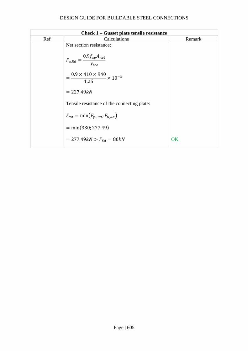
DESIGN GUIDE FOR BUILDABLE STEEL CONNECTIONS
Page | 605
Check 1 – Gusset plate tensile resistance Ref Calculations Remark
Net section resistance:
𝐹 ,0.9𝑓 𝐴
𝛾
0.9 410 940
1.2510
227.49𝑘𝑁
Tensile resistance of the connecting plate: 𝐹 min 𝐹 , ;𝐹 ,
min 330; 277.49
277.49𝑘𝑁 𝐹 80𝑘𝑁
OK

DESIGN GUIDE FOR BUILDABLE STEEL CONNECTIONS
Page | 606
Check 2 – Bolt resistance Ref Calculations Remark
SS EN1993-1-8
Using class 8.8, M24 bolts with: 𝐴 353𝑚𝑚 , 𝑓 800𝑀𝑃𝑎, 𝛼 0.6 Shear resistance of bolt:
𝐹 ,𝛼 𝑓 𝐴𝛾
0.6 800 353
1.2510
135.55𝑘𝑁
𝑘 min2.8𝑒𝑑
1.7; 2.5
min 2.87526
1.7; 2.5
2.5
𝛼 min𝑒
3𝑑;𝑓𝑓
; 1.0
min60
3 26;800410
; 1.0
0.91
Bolt spacing: End distance: 𝑒 60𝑚𝑚 Edge distance: 𝑒 75𝑚𝑚

DESIGN GUIDE FOR BUILDABLE STEEL CONNECTIONS
Page | 607
Check 2 – Bolt resistance Ref Calculations Remark
Bearing resistance of connecting plate:
𝐹 ,𝑘 𝛼 𝑓 𝑑𝑡
𝛾
2.5 0.91 410 24 10
1.2510
178.91𝑘𝑁
Resistance of the bolt joint: 𝐹 min 𝐹 , ;𝐹 , min 135.55; 178.91
135.55𝑘𝑁 𝐹 80𝑘𝑁
OK

DESIGN GUIDE FOR BUILDABLE STEEL CONNECTIONS
Page | 608
Check 3 – Weld resistance Ref Calculations Remark
SS EN1993-1-8
Choose S275 fillet weld with 10mm leg length: Top part: Angle between the gusset plate and beam web: 𝛾 60° Throat thickness:
𝑎 𝑠 ∙ cos𝛾2
10 cos60°
28.66𝑚𝑚
Design shear strength:
𝑓 ,𝑓 /√3𝛽 𝛾
410/√3
0.9 1.25
210.41𝑀𝑃𝑎
Design longitudinal resistance per unit length: 𝐹 , , 𝑓 , 𝑎 210.41 8.66 10
1.82𝑘𝑁/𝑚𝑚

DESIGN GUIDE FOR BUILDABLE STEEL CONNECTIONS
Page | 609
Check 3 – Weld resistance Ref Calculations Remark
𝐾
31 2 cos 𝜃
31 2 cos 30°
1.10
Design transverse resistance per unit length: 𝐹 , , 𝐾𝐹 , , 1.10 1.82
2.00𝑘𝑁/𝑚𝑚
Bottom part: Angle between the tension member and chord: 𝛾 120° Throat thickness:
𝑎 𝑠 ∙ cos𝛾2
10 cos120°
25.0𝑚𝑚
Design longitudinal resistance per unit length: 𝐹 , , 𝑓 , 𝑎 210.41 5.0 10
1.05𝑘𝑁/𝑚𝑚
𝐾3
1 2 cos 𝜃
31 2 cos 60°
1.41
Design transverse resistance per unit length: 𝐹 , , 𝐾𝐹 , , 1.41 1.05
1.48𝑘𝑁/𝑚𝑚
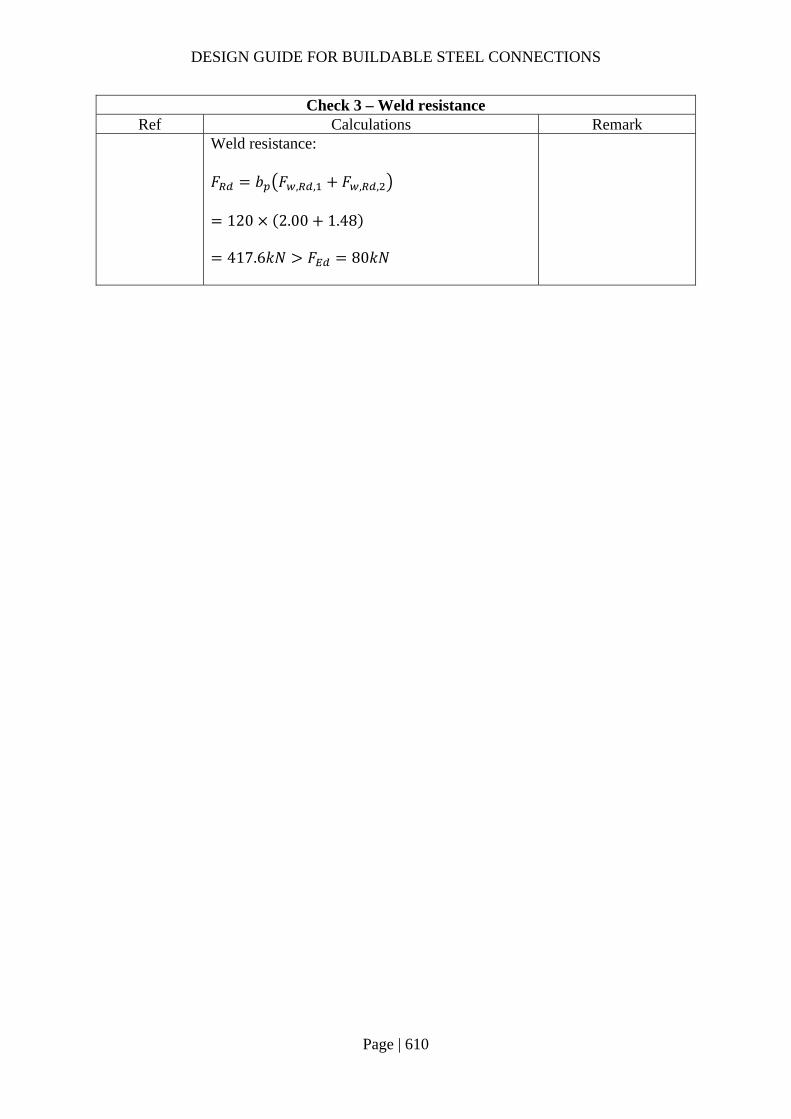
DESIGN GUIDE FOR BUILDABLE STEEL CONNECTIONS
Page | 610
Check 3 – Weld resistance Ref Calculations Remark
Weld resistance: 𝐹 𝑏 𝐹 , , 𝐹 , ,
120 2.00 1.48
417.6𝑘𝑁 𝐹 80𝑘𝑁
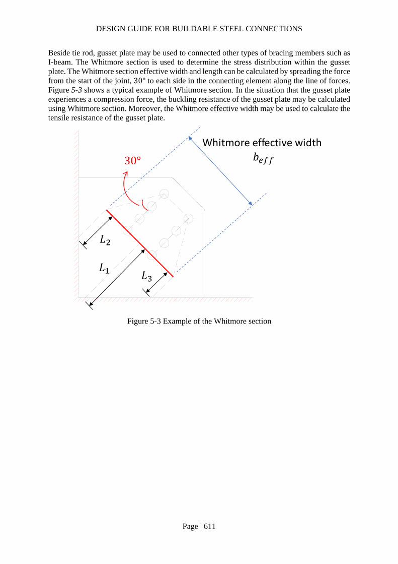
DESIGN GUIDE FOR BUILDABLE STEEL CONNECTIONS
Page | 611
Beside tie rod, gusset plate may be used to connected other types of bracing members such as I-beam. The Whitmore section is used to determine the stress distribution within the gusset plate. The Whitmore section effective width and length can be calculated by spreading the force from the start of the joint, 30° to each side in the connecting element along the line of forces. Figure 5-3 shows a typical example of Whitmore section. In the situation that the gusset plate experiences a compression force, the buckling resistance of the gusset plate may be calculated using Whitmore section. Moreover, the Whitmore effective width may be used to calculate the tensile resistance of the gusset plate.
Figure 5-3 Example of the Whitmore section
30°
Whitmore effective width𝑏
𝐿
𝐿𝐿

DESIGN GUIDE FOR BUILDABLE STEEL CONNECTIONS
Page | 612
5.4.2 Example 3 – Gusset plate connection for bracing type 2
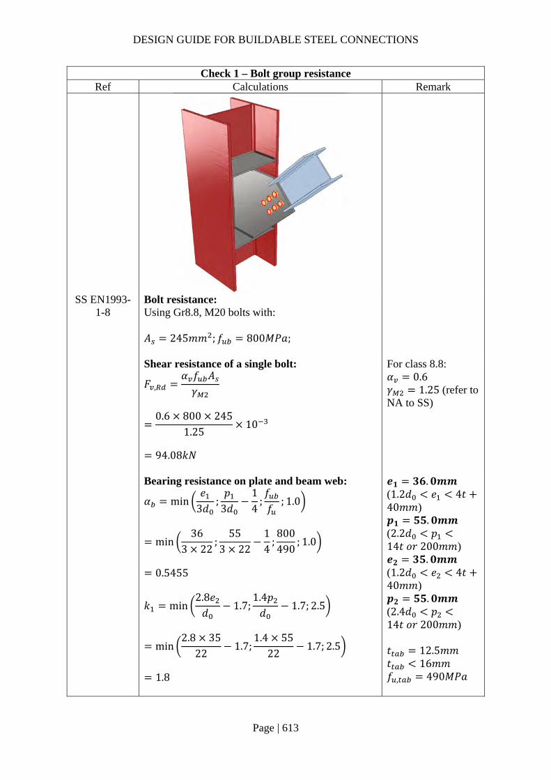
DESIGN GUIDE FOR BUILDABLE STEEL CONNECTIONS
Page | 613
Check 1 – Bolt group resistance Ref Calculations Remark
SS EN1993-1-8
Bolt resistance: Using Gr8.8, M20 bolts with: 𝐴 245𝑚𝑚 ; 𝑓 800𝑀𝑃𝑎;
Shear resistance of a single bolt:
𝐹 ,𝛼 𝑓 𝐴𝛾
0.6 800 245
1.2510
94.08𝑘𝑁
For class 8.8: 𝛼 0.6 𝛾 1.25 (refer to NA to SS)
Bearing resistance on plate and beam web:
𝛼 min𝑒
3𝑑;𝑝
3𝑑14
;𝑓𝑓
; 1.0
min36
3 22;
553 22
14
;800490
; 1.0
0.5455
𝑘 min2.8𝑒𝑑
1.7;1.4𝑝𝑑
1.7; 2.5
min2.8 35
221.7;
1.4 5522
1.7; 2.5
1.8
𝒆𝟏 𝟑𝟔.𝟎𝒎𝒎 (1.2𝑑 𝑒 4𝑡40𝑚𝑚) 𝒑𝟏 𝟓𝟓.𝟎𝒎𝒎 (2.2𝑑 𝑝14𝑡 𝑜𝑟 200𝑚𝑚) 𝒆𝟐 𝟑𝟓.𝟎𝒎𝒎 (1.2𝑑 𝑒 4𝑡40𝑚𝑚) 𝒑𝟐 𝟓𝟓.𝟎𝒎𝒎 (2.4𝑑 𝑝14𝑡 𝑜𝑟 200𝑚𝑚) 𝑡 12.5𝑚𝑚 𝑡 16𝑚𝑚 𝑓 , 490𝑀𝑃𝑎
DESIGN GUIDE FOR BUILDABLE STEEL CONNECTIONS
Page | 614
Check 1 – Bolt group resistance Ref Calculations Remark
𝐹 , ,
𝑘 𝛼 𝑓 , 𝑑𝑡𝛾
1.8 0.5455 490 20 12.5
1.25
96.22𝑘𝑁
𝑓 , 355𝑀𝑃𝑎
Bearing resistance on gusset plate:
𝛼 min𝑒
3𝑑;𝑝
3𝑑14
;𝑓𝑓
; 1.0
min40
3 22;
553 22
14
;800490
; 1.0
0.5833
𝑘 min2.8𝑒𝑑
1.7;1.4𝑝𝑑
1.7; 2.5
min2.8 71
221.7;
1.4 5522
1.7; 2.5
1.8
𝐹 , ,𝑘 𝛼 𝑓 , 𝑑𝑡
𝛾
1.8 0.5833 490 20 16
1.25
131.71𝑘𝑁
𝒆𝟏,𝒈 𝟒𝟎.𝟎𝒎𝒎 𝒑𝟏,𝒈 𝟓𝟓.𝟎𝒎𝒎 𝒆𝟐,𝒈 𝟕𝟏.𝟎𝒎𝒎 𝒑𝟐,𝒈 𝟓𝟓.𝟎𝒎𝒎
𝑡 16.0𝑚𝑚 𝑡 16𝑚𝑚 𝑓 , 490𝑀𝑃𝑎 𝑓 , 355𝑀𝑃𝑎
Design capacity of each bolt: 𝐹 min 𝐹 , ,𝐹 , , ,𝐹 , ,
min 94.08,96.22,131.71
94.08𝑘𝑁
Design capacity of the bolt group: 𝑁 𝑛𝐹
6 94.08
564.48𝑘𝑁 𝑁 200𝑘𝑁 OK
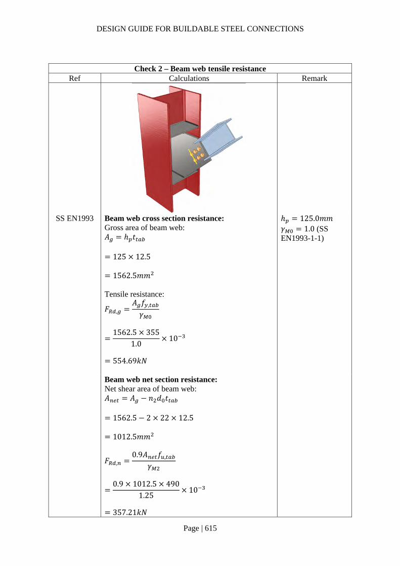
DESIGN GUIDE FOR BUILDABLE STEEL CONNECTIONS
Page | 615
Check 2 – Beam web tensile resistance Ref Calculations Remark
SS EN1993 Beam web cross section resistance: Gross area of beam web: 𝐴 ℎ 𝑡
125 12.5
1562.5𝑚𝑚 Tensile resistance:
𝐹 ,𝐴 𝑓 ,
𝛾
1562.5 355
1.010
554.69𝑘𝑁
ℎ 125.0𝑚𝑚 𝛾 1.0 (SS EN1993-1-1)
Beam web net section resistance: Net shear area of beam web: 𝐴 𝐴 𝑛 𝑑 𝑡
1562.5 2 22 12.5
1012.5𝑚𝑚
𝐹 ,0.9𝐴 𝑓 ,
𝛾
0.9 1012.5 490
1.2510
357.21𝑘𝑁

DESIGN GUIDE FOR BUILDABLE STEEL CONNECTIONS
Page | 616
Check 2 – Beam web tensile resistance Ref Calculations Remark
Beam web block shear tearing resistance: Net area subjected to tension: 𝐴 𝑝 𝑑 𝑡
55 22 12.5
412.5𝑚𝑚 Net area subjected to shear: 𝐴 2 2𝑝 𝑒 1.5𝑑 𝑡
2 55 2 36 2.5 22 12.5
2275𝑚𝑚
𝐹 ,
0.5𝑓 , 𝐴𝛾
𝑓 , 𝐴
√3𝛾
0.5 490 412.5
1.25355 2275
√3 1.0
547.13𝑘𝑁
Tensile resistance of beam web: 𝑁 min 𝐹 , ,𝐹 , ,𝐹 ,
min 554.69𝑘𝑁, 357.21𝑘𝑁, 547.13𝑘𝑁
357.21𝑘𝑁 𝑁 200𝑘𝑁
OK

DESIGN GUIDE FOR BUILDABLE STEEL CONNECTIONS
Page | 617
Check 3 – Weld resistance Ref Calculations Remark
SS EN1993-1-8
Location of centre of gravity of welds group:
�̅�𝑏
2𝑏 𝑑
169.1
2 169.1 444.3
36.54𝑚𝑚
𝑦𝑑2
444.3
2
222.15𝑚𝑚
Unit throat area: 𝐴 2𝑏′ 𝑑′
2 169.1 444.3
750.5𝑚𝑚 Moment arm between applied force and weld center: 𝑟 159.63𝑚𝑚 Induced moment on welds: 𝑀 𝑁 𝑟
200 159.63
31926𝑘𝑁𝑚𝑚
Size of the fillet welds: Horizontal length: 𝑏 169.1𝑚𝑚 Depth: 𝑑 444.3𝑚𝑚 Cope hole size: 𝑛 8𝑚𝑚 𝑏 169.1 𝑛
161.1𝑚𝑚 𝑑 444.3 2𝑛
428.3𝑚𝑚
DESIGN GUIDE FOR BUILDABLE STEEL CONNECTIONS
Page | 618
Check 3 – Weld resistance Ref Calculations Remark
Polar moment of inertia:
𝐽8𝑏′ 6𝑏′𝑑′ 𝑑′
12𝑏
2𝑏 𝑑′
8 161.1 6 161.1 428.3 428.3
12
161.1
2 161.1 428.3
23213356𝑚𝑚
Critical point: Horizontal distance from centroid: 𝑟 𝑏 �̅�
169.1 36.54 132.56𝑚𝑚
Vertical distance from centroid: 𝑟 𝑦
222.15𝑚𝑚
Vertical stress:
𝜏𝑁 ,
𝐴𝑀𝑟𝐽
146.27750.5
31926 132.5623213356
0.38𝑘𝑁/𝑚𝑚
Horizontal stress:
𝜏𝑁 ,
𝐴𝑀𝑟𝐽
136.40750.5
31926 222.1523213356
0.49𝑘𝑁/𝑚𝑚
Resultant stress:
𝜏 𝜏 𝜏
0.38 0.49
0.62𝑘𝑁/𝑚𝑚
Angle between applied force and primary beam: 𝜃 47.0°
0.82𝑟𝑎𝑑 Longitudinal component of applied force: 𝑁 , 𝑁 𝑐𝑜𝑠𝜃
200 𝑐𝑜𝑠47.0° 136.40𝑘𝑁
Transverse component of applied force: 𝑁 , 𝑁 𝑠𝑖𝑛𝜃
200 𝑠𝑖𝑛43.24° 146.27𝑘𝑁

DESIGN GUIDE FOR BUILDABLE STEEL CONNECTIONS
Page | 619
Check 3 – Weld resistance Ref Calculations Remark
Choose fillet weld with 6mm leg length, 4.2mm throat thickness and grade S355 which match beam steel grade: Longitudinal resistance: 𝐹 , , 1.01𝑘𝑁/𝑚𝑚 Transverse resistance: 𝐹 , , 1.24𝑘𝑁/𝑚𝑚
Simplified method: 𝐹 , , 1.01𝑘𝑁/𝑚𝑚 𝜏 0.63𝑘𝑁/𝑚𝑚
OK
Directional method:
𝑆𝐹𝜏
𝐹 , ,
𝜏𝐹 , ,
0.401.24
0.491.01
0.33 1
OK
Weld resistance between tab plate and beam web: Length of fillet weld parallel to the applied force: 𝐿 190𝑚𝑚 2 380𝑚𝑚 Length of fillet weld perpendicular to the applied force: 𝐿 125𝑚𝑚 Axial resistance of the fillet weld: 𝑁 𝐹 , , 𝐿 𝐹 , , 𝐿
1.01 380 1.24 125
538.80𝑘𝑁 𝑁 200𝑘𝑁
OK

DESIGN GUIDE FOR BUILDABLE STEEL CONNECTIONS
Page | 620
Check 4 – Buckling resistance of gusset plate Ref Calculations Remark
SCI_P358 This check is necessary only when the force is in compression. Length of yield line (secondary beam flange): 𝑤 125𝑚𝑚 Length of yield line (gusset plate): 𝑤 310.25𝑚𝑚 As the ‘point of nearest support’ is ‘in front of’ the line of last bolts, the yield line pattern is as shown
Moment amplified factor: 𝑘 1.2 Young’s modules: 𝐸 210𝐺𝑃𝑎
Inertia of tab plate (flange):
𝐼𝑤 𝑡
12
125 12.5
12
20345.05𝑚𝑚
𝑡 12.5𝑚𝑚 𝑡 16𝑚𝑚
Point of support in front of bolt line
Yield line in beam web
Yield line in gusset plate
Point of support behind bolt line
20.00
20.00
40.00
40.00
10.00
51.00
55.00
444.30
20.00
169.10
55.00
55.00
Yield line of gusset plate
Yield line of beam web

DESIGN GUIDE FOR BUILDABLE STEEL CONNECTIONS
Page | 621
Check 4 – Buckling resistance of gusset plate Ref Calculations Remark
Inertia of lap region:
𝐼0.5 𝑤 𝑤 𝑡 𝑡
12
0.5 125 310.25 12.5 16
12
419819𝑚𝑚
Inertia of gusset plate:
𝐼𝑤 𝑡
12
310.25 16
12
105898.7𝑚𝑚
Moment distribution factor:
𝑀1
𝐿𝐸𝐼
𝐿2𝐸𝐼
1 10
40210 20345.05
1102 210 419819
100.14𝑘𝑁𝑚
𝑀1
𝐿𝐸𝐼
𝐿2𝐸𝐼
1
0 1102 210 419819
10
1602.95𝑘𝑁𝑚
𝐿 40𝑚𝑚 𝐿 110𝑚𝑚 𝐿 0𝑚𝑚
𝜇
𝑀𝑀 𝑀
52.91
52.91 1255.92
0.06

DESIGN GUIDE FOR BUILDABLE STEEL CONNECTIONS
Page | 622
Check 4 – Buckling resistance of gusset plate Ref Calculations Remark
𝜇 1 𝜇 1 0.06 0.94
Axial resistance of the tab plate and beam web: 𝑁 ,
𝑤 𝑓 , 𝑡
5𝑘 0.5 𝑡 𝑡 𝜇 𝑡 𝛾
125 355 12.5
5 1.2 0.5 12.5 16 0.06 12.510
395.59𝑘𝑁
Axial resistance of the gusset plate: 𝑁 ,
𝑤 𝑓 , 𝑡
5𝑘 0.5 𝑡 𝑡 𝜇 𝑡 𝛾
310.25 355 16
5 1.2 0.5 12.5 16 0.94 1610
292.26𝑘𝑁
Axial resitance of the connection: 𝑁 min 𝑁 , ;𝑁 ,
min 395.59; 292.26
292.26𝑘𝑁 𝑁 200𝑘𝑁
OK

DESIGN GUIDE FOR BUILDABLE STEEL CONNECTIONS
Page | 623
Check 4 – Buckling resistance of gusset plate Ref Calculations Remark
The compressive stress is distributed to the gusset plate acoording to that defined by Whitmore section as shown below:
𝑙 318.5𝑚𝑚 𝑙 365.7𝑚𝑚 𝑙 280.8𝑚𝑚
ECCS
Eurocode Design
Manuals SS EN1993-
1-1
The buckling length is defined as the average of 𝑙 , 𝑙 and 𝑙 .
𝑙𝑙 𝑙 𝑙
3
318.5 365.7280.8 /3 321.7𝑚𝑚
𝑏 182.0𝑚𝑚
Radius of gyration:
𝑖𝑡
√12
16
√124.62
Non-dimensional slenderness ratio:
𝜆𝑙𝜋𝑖
𝑓𝐸
321.7𝜋 4.62
355210000
0.912
Imperfection factor: 𝛼 0.49 𝛷 0.5 1 𝛼 𝜆 0.2 𝜆
0.5 1 0.49 0.912 0.2 0.912
1.09 Buckling reduction factor:
𝜒1
𝛷 𝛷 𝜆
1
1.09 √1.09 0.912
0.593
20.00
20.00
40.00
40.00
10.00
51.00
55.00
444.30
20.00
169.10
55.00
55.00
𝜃 30°
𝑙
𝑙
𝑙

DESIGN GUIDE FOR BUILDABLE STEEL CONNECTIONS
Page | 624
Check 4 – Buckling resistance of gusset plate Ref Calculations Remark
Buckling resistance: 𝑃 𝜒𝑏 𝑡 𝑓
0.593 182 16 355 10
612.77𝑘𝑁 𝑁 200𝑘𝑁
OK

DESIGN GUIDE FOR BUILDABLE STEEL CONNECTIONS
Page | 625
Check 5 – Gusset plate tensile resistance Ref Calculations Remark
SS EN1993 Gusset plate gross section resistance: Gross area (Whitmore section) of gusset plate: 𝐴 𝑏 𝑡
182 16
2912𝑚𝑚 Tensile resistance:
𝐹 ,𝐴 𝑓 ,
𝛾
2912 355
1.010
1033.76𝑘𝑁
ℎ 240.0𝑚𝑚 𝛾 1.0 (SS EN1993-1-1)
Gusset plate net section resistance: Net shear area of gusset plate: 𝐴 𝐴 𝑛 𝑑 𝑡
2912 2 22 16
2208𝑚𝑚
𝐹 ,0.9𝐴 𝑓 ,
𝛾
0.9 2208 490
1.2510
778.98𝑘𝑁

DESIGN GUIDE FOR BUILDABLE STEEL CONNECTIONS
Page | 626
Check 5 – Gusset plate tensile resistance Ref Calculations Remark
Gusset plate block shear tearing resistance: Net area subjected to tension: 𝐴 𝑝 𝑑 𝑡
55 22 16
528𝑚𝑚 Net area subjected to shear: 𝐴 2 2𝑝 𝑒 1.5𝑑 𝑡
2 55 2 40 2.5 22 16
3040𝑚𝑚
𝐹 ,
0.5𝑓 , 𝐴𝛾
𝑓 , 𝐴
√3𝛾
0.5 490 528
1.25355 3040
√3 1.0
726.56𝑘𝑁
Tensile resistance of gusset plate: 𝑁 min 𝐹 , ,𝐹 , ,𝐹 ,
min 1033.76𝑘𝑁, 778.98𝑘𝑁, 726.56𝑘𝑁
726.56𝑘𝑁 𝑁 200𝐾𝑁
OK

DESIGN GUIDE FOR BUILDABLE STEEL CONNECTIONS
Page | 627
6 Purlin Connections 6.1 Introduction
Purlin connections are generally simple to design, however if detailed wrongly, the installation works will end up very unproductive due to the sheer numbers of purlins to be installed. This section gives suggestions on how purlins are to be detailed so that on-site works can be more productive.
6.2 Design and detailing
Figure 6-1 below shows an unproductive purlin connection. The detail is unproductive because:
1. Adding stiffeners unnecessarily will incur addition fabrication cost and affect productivity.
2. With this configuration, purlin cannot be unhooked from crane until the bolts are installed. This affect site productivity greatly.
Figure 6-1 Example of an unproductive purlin connection
Purlin should be configured in such a way, as shown in Figure 6-2, that it will not slip off the roof after it is unlooked from the crane. As much as possible, the cleats should be designed such that stiffeners can be omitted. As a guide, the recommended value “H” and cleat plate thickness can be obtained from the manufacturer’s product manual and the Engineer should be able to verify that stiffeners are not required. In addition, to prevent water trapping, weep holes should be provided.
C250×75×25×4.5 THKPurlin @ 1200mm c/c
6mm THK Cleat
2 No. M10 GR. 8.8 Bolt and nuts
150×100×8mm THK Angle
6
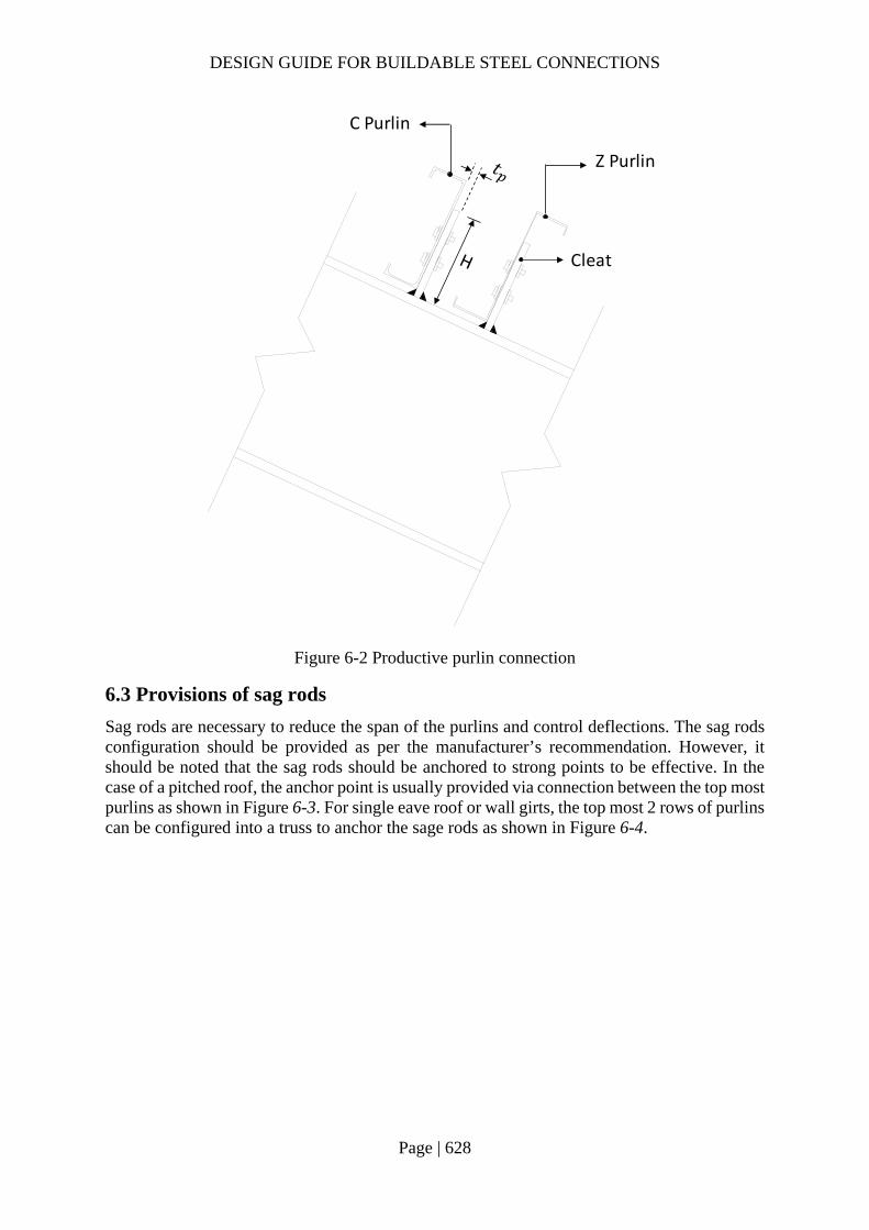
DESIGN GUIDE FOR BUILDABLE STEEL CONNECTIONS
Page | 628
Figure 6-2 Productive purlin connection
6.3 Provisions of sag rods
Sag rods are necessary to reduce the span of the purlins and control deflections. The sag rods configuration should be provided as per the manufacturer’s recommendation. However, it should be noted that the sag rods should be anchored to strong points to be effective. In the case of a pitched roof, the anchor point is usually provided via connection between the top most purlins as shown in Figure 6-3. For single eave roof or wall girts, the top most 2 rows of purlins can be configured into a truss to anchor the sage rods as shown in Figure 6-4.
C Purlin
Z Purlin
Cleat

DESIGN GUIDE FOR BUILDABLE STEEL CONNECTIONS
Page | 629
Figure 6-3 Suggest configuration for pitched roof
Figure 6-4 Suggest configurations for single eave roof (can be applied for wall girts)
Anchor
P P
Purlins
Sag rods Anchored purlin
Loaded area
RoofRafter
30°
Sag rods
Loaded area
RoofRafter
Loaded area
Purlins
Purlin (Compression member)
RoofRafter
Sag rods (tension members)
(more common for wall girts)
Purlins
RoofRafter

DESIGN GUIDE FOR BUILDABLE STEEL CONNECTIONS
Page | 630
7 Non-standard Connections 7.1 Introduction
This section suggests several non-standard details which are commonly adopted in the steelwork construction. When there is no relevant design guide on these types of connections, finite element analysis may be used to analyze the failure mode and stress flow. The connections should be checked to ensure the adequacy of all components in the connections.
7.2 Tubular column-to-column connections (different column sizes)
In a building structure, different sizes of columns are joined and they may be aligned in such a way that they are flushed to the exterior of the building to facilitate façade installation. For such joints, tapered build-up sections or end plate connection with stiffeners can be adopted for connecting CHS, RHS or UC sections with load eccentricity, as shown in Figure 7-1.
Figure 7-1 Connecting tubular columns of different sizes
A tapered CHS section may be used as a transition piece to connect CHS columns with different diameters as shown in Figure 7-2. The wall thickness of the taper section should be at least equal to the thinner one of the connected columns. The transition gradient of the taper section should not be greater than 1:6 to allow smooth flow of stresses from one column to another. Internal diaphragm rings may also be used in the joint between the taper section and CHS columns.
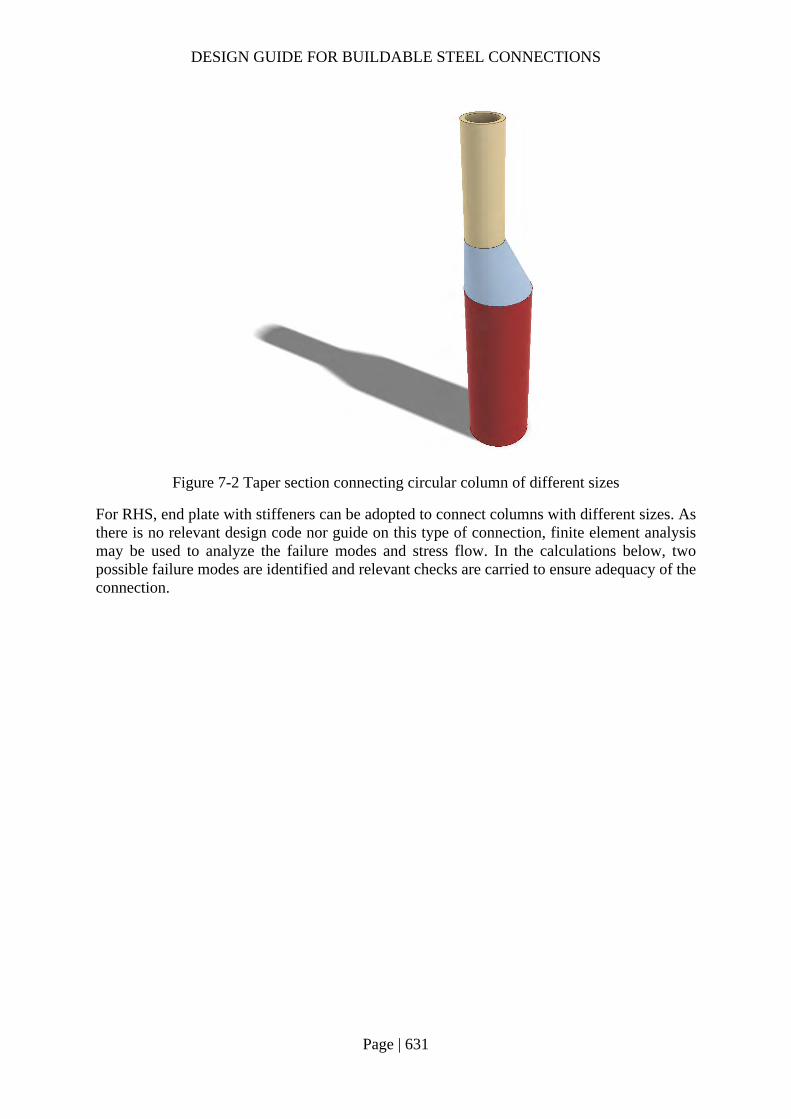
DESIGN GUIDE FOR BUILDABLE STEEL CONNECTIONS
Page | 631
Figure 7-2 Taper section connecting circular column of different sizes
For RHS, end plate with stiffeners can be adopted to connect columns with different sizes. As there is no relevant design code nor guide on this type of connection, finite element analysis may be used to analyze the failure modes and stress flow. In the calculations below, two possible failure modes are identified and relevant checks are carried to ensure adequacy of the connection.

DESIGN GUIDE FOR BUILDABLE STEEL CONNECTIONS
Page | 632
Check 1 – Bending resistance of end plate Ref Calculations Remark
Design axial force = 400kN Larger column: RHS 350×350×12.5 Smaller column: RHS 200×200×10 Width of end plate: 𝑏 350𝑚𝑚 Thickness of end plate: 𝑡 25𝑚𝑚 Height of stiffener: ℎ 150𝑚𝑚 Thickness of stiffener: 𝑡 15𝑚𝑚 Eccentricity between the central lines of columns:
𝑒𝑐𝑐350
2200
275𝑚𝑚
Moment due to eccentricity: 𝑀 , 𝑁 𝑒𝑐𝑐 400 75 10
30𝑘𝑁𝑚
Location of centroid for combined section of end plate and stiffener (from top):
𝑥𝑏 𝑡
𝑡2 ℎ ℎ 𝑡
ℎ2
𝑏 𝑡 ℎ 𝑡
350 25 252 150 150 15 150
2350 25 150 15
144.60𝑚𝑚
Distance between centroid of combined section and centroid of stiffener:
𝑑 𝑥ℎ2
144.60150
269.60𝑚𝑚

DESIGN GUIDE FOR BUILDABLE STEEL CONNECTIONS
Page | 633
Check 1 – Bending resistance of end plate Ref Calculations Remark
Distance between centroid of combined section and centroid of end plate:
𝑑 ℎ𝑡2
𝑥 150252
144.60
12.90𝑚𝑚
Second moment of area of combined section: 𝐼 𝐼 𝐴 𝑑 𝐼 𝐴 𝑑 𝑏 𝑡
12𝑏 𝑡 𝑑
𝑡 ℎ12
𝑡 ℎ 𝑑
350 25
12350 25 12.90
15 15012
15 150 69.60
17030125𝑚𝑚
Elastic modulus of combined section:
𝑊𝐼𝑥
17030125144.60
117772.2𝑚𝑚
Moment capacity: 𝑀 𝑊 𝑓 117772.2 345 10
40.63𝑘𝑁𝑚 𝑀 30𝑘𝑁𝑚
OK

DESIGN GUIDE FOR BUILDABLE STEEL CONNECTIONS
Page | 634
Check 2 – Punching shear in end plate Ref Calculations Remark
Thickness of the larger column (RHS350×350 12.5 : 𝑡 12.5𝑚𝑚 Perimeter of smaller column outside the support: 𝐿 3ℎ 2𝑡 4𝑡
3 200 2 12.5 4 10
535𝑚𝑚 Axial load resistance:
𝑁𝑓
√3𝑡 𝐿
355
√325 535 10
2741.33𝑘𝑁 𝑁 400𝑘𝑁
OK
𝑡
𝑡
ℎ

DESIGN GUIDE FOR BUILDABLE STEEL CONNECTIONS
Page | 635
7.3 Member transition in truss chords Where trusses are concerned, the top chords are usually flushed at the top to allow steel decking or purlins installation. Sometimes the bottom chords are flushed at the bottom for architectural or MEP purposes. For economical purposes or to reduce steel self-weight, the members are sized differently within the cords. A tapered built up section can be used to bridge the transition from the bigger chord to the smaller member. The transition angle should be not greater than 45° (30° is recommended) to prevent stress concentration and allow smooth flow of stress. Figure 7-3 shows three common types of such connections. Full penetration butt weld may be used to connect the members. The thickness of the transition piece should be the smaller thickness of the connecting members. In addition, such connections should not be used for in situation fatigue loading.
Figure 7-3 Connecting chord members of different sizes

DESIGN GUIDE FOR BUILDABLE STEEL CONNECTIONS
Page | 636
7.4 Stiffeners in truss chords
Very often, engineers specify stiffeners to match the incoming web member and this could incur higher cost of fabrication. Engineers should carry out checks according to SS EN 1993-1-5 to determine whether such stiffeners are necessary. For robustness purpose, stiffeners are needed even the compression load resistance of the unstiffened web of chord member is sufficient. This is to cater for unbalance loads in reality.
Check 1 – whether the member is experiencing compression forces
Check 2 – check for unstiffened web bearing and buckling capacity
Check 3 – if web stiffening is required, provide stiffeners and web bearing capacity, and
Check 4 – check stiffened web buckling capacity based on stiffeners provided in “check 3”
For Warren trusses, gusset plate may be used to connect web members to chord member. In structural analysis, the connecting node may be modelled as pin. In such case, the gusset plate should be checked against buckling similar to 2.3.9 and 2.3.10. Stiffeners may be needed to increase the gusset plate capacity.
7.4.1 Example 1 – Stiffened truss connection

DESIGN GUIDE FOR BUILDABLE STEEL CONNECTIONS
Page | 637
Check 1 – Weld resistance Ref Calculations Remark
Assume tensile normal force is resisted by two flanges: Tensile normal force: 𝑁 800𝑘𝑁 Applied tensile force on one flange:
𝐹𝑁
2400𝑘𝑁
SS EN1993-1-8
In this example, fillet weld between the tension member and chord is checked. Choose S355 fillet weld with 10mm leg length: Weld A: Angle between the tension member and chord: 𝛾 60°
For S355 fillet weld: 𝛽 0.9 𝑓 470𝑀𝑃𝑎 𝛾 1.25
𝜃 30°
𝜃 60°
AB
AB
AB
𝑁 800𝑘𝑁

DESIGN GUIDE FOR BUILDABLE STEEL CONNECTIONS
Page | 638
Check 1 – Weld resistance Ref Calculations Remark
Throat thickness:
𝑎 𝑠 ∙ cos𝛾2
10 cos60°
28.66𝑚𝑚
Design shear strength:
𝑓 ,𝑓 /√3𝛽 𝛾
470/√3
0.9 1.25
241.20𝑀𝑃𝑎
Design longitudinal resistance per unit length: 𝐹 , , 𝑓 , 𝑎 241.20 8.66 10
2.09𝑘𝑁/𝑚𝑚
𝐾
31 2 cos 𝜃
31 2 cos 30°
1.10
Design transverse resistance per unit length: 𝐹 , , 𝐾𝐹 , , 1.10 2.09
2.29𝑘𝑁/𝑚𝑚
Angle between applied force and effective throat area: 𝜃 30°
Weld B: Angle between the tension member and chord: 𝛾 120° Throat thickness:
𝑎 𝑠 ∙ cos𝛾2
10 cos120°
25.0𝑚𝑚

DESIGN GUIDE FOR BUILDABLE STEEL CONNECTIONS
Page | 639
Check 1 – Weld resistance Ref Calculations Remark
Design longitudinal resistance per unit length: 𝐹 , , 𝑓 , 𝑎 241.20 5.0 10
1.21𝑘𝑁/𝑚𝑚
𝐾
31 2 cos 𝜃
31 2 cos 60°
1.41
Angle between applied force and effective throat area: 𝜃 60°
Design transverse resistance per unit length: 𝐹 , , 𝐾𝐹 , , 1.41 1.21
1.71𝑘𝑁/𝑚𝑚
For tensile member (UB457x152x60): Depth: ℎ 454.6𝑚𝑚 Width: 𝑏 152.9𝑚𝑚 Thickness of beam flange: 𝑡 13.3𝑚𝑚 Thickness of beam web: 𝑡 8.1𝑚𝑚 Root radius: 𝑟 10.2𝑚𝑚
Tensile resistance: 𝐹 𝑏 𝐹 , , 𝑏 𝑡 2𝑟 𝐹 , ,
152.9 2.29 152.9 8.1 2 10.2 1.71
562.05𝑘𝑁 𝐹 400𝑘𝑁
OK

DESIGN GUIDE FOR BUILDABLE STEEL CONNECTIONS
Page | 640
Check 1 – Weld resistance Ref Calculations Remark
For welds between the tension member and compression member shown in yellow boxes above:
SS EN1993-1-8
4.3.2.1 (2) & (3)
The angles between fusion faces is 30° and 150° respectively. For angles smaller than 60°, the fillet weld may not be effective and penetration butt weld is suggested. For angle greater than 120°, the effectiveness of fillet weld should be verified by testing. In this example, full penetration butt weld is suggested to connect the tension member and compression member.
S355 fillet weld with 10mm leg length and 7mm throat thickness is used to connect the webs of tension member to the bottom chord and compression member:

DESIGN GUIDE FOR BUILDABLE STEEL CONNECTIONS
Page | 641
Check 1 – Weld resistance Ref Calculations Remark
Length of fillet weld: 𝑙 2 230 440 1340𝑚𝑚 Longitudinal resistance: 𝐹 , , 1.69𝑘𝑁/𝑚𝑚 Tensile resistance of web fillet weld: 𝐹 , 𝐹 , , 𝑙
1.69 1340
2264.6𝑘𝑁 𝑁 800𝑘𝑁
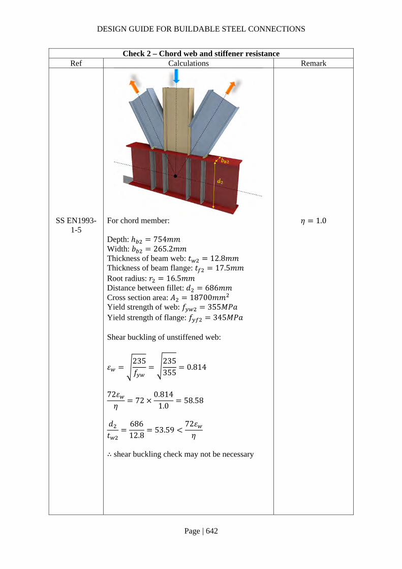
DESIGN GUIDE FOR BUILDABLE STEEL CONNECTIONS
Page | 642
Check 2 – Chord web and stiffener resistance Ref Calculations Remark
SS EN1993-1-5
For chord member: Depth: ℎ 754𝑚𝑚 Width: 𝑏 265.2𝑚𝑚 Thickness of beam web: 𝑡 12.8𝑚𝑚 Thickness of beam flange: 𝑡 17.5𝑚𝑚 Root radius: 𝑟 16.5𝑚𝑚 Distance between fillet: 𝑑 686𝑚𝑚 Cross section area: 𝐴 18700𝑚𝑚 Yield strength of web: 𝑓 355𝑀𝑃𝑎 Yield strength of flange: 𝑓 345𝑀𝑃𝑎 Shear buckling of unstiffened web:
𝜀235𝑓
235355
0.814
72𝜀𝜂
720.814
1.058.58
𝑑𝑡
68612.8
53.5972𝜀𝜂
∴ shear buckling check may not be necessary
𝜂 1.0

DESIGN GUIDE FOR BUILDABLE STEEL CONNECTIONS
Page | 643
Check 2 – Chord web and stiffener resistance Ref Calculations Remark
SS EN1993-1-5
Unstiffened web under transverse load: Assume 𝜆 0.5,
𝑚 0.02𝑑𝑡
0.0268617.5
30.73𝑚𝑚
Effective load length:
𝑙 𝑆 2𝑡 1𝑓 𝑏𝑓 𝑡
𝑚
13.3 2 10 2 17.5
1345 265.2355 12.8
30.73
317.93𝑚𝑚
�̅�
𝑙 𝑓 𝑑0.9𝑘 𝐸𝑡
317.93 355 6860.9 6 210000 12.8
0.65 0.5
𝜒0.5
�̅�
0.50.65
0.77 1.0
Web buckling resistance:
𝐹𝑓 𝜒 𝑙 𝑡
𝛾
355 0.77 317.93 12.8 10
1118.95𝑘𝑁
Assume the distance between stiffeners is large: 𝑘 6
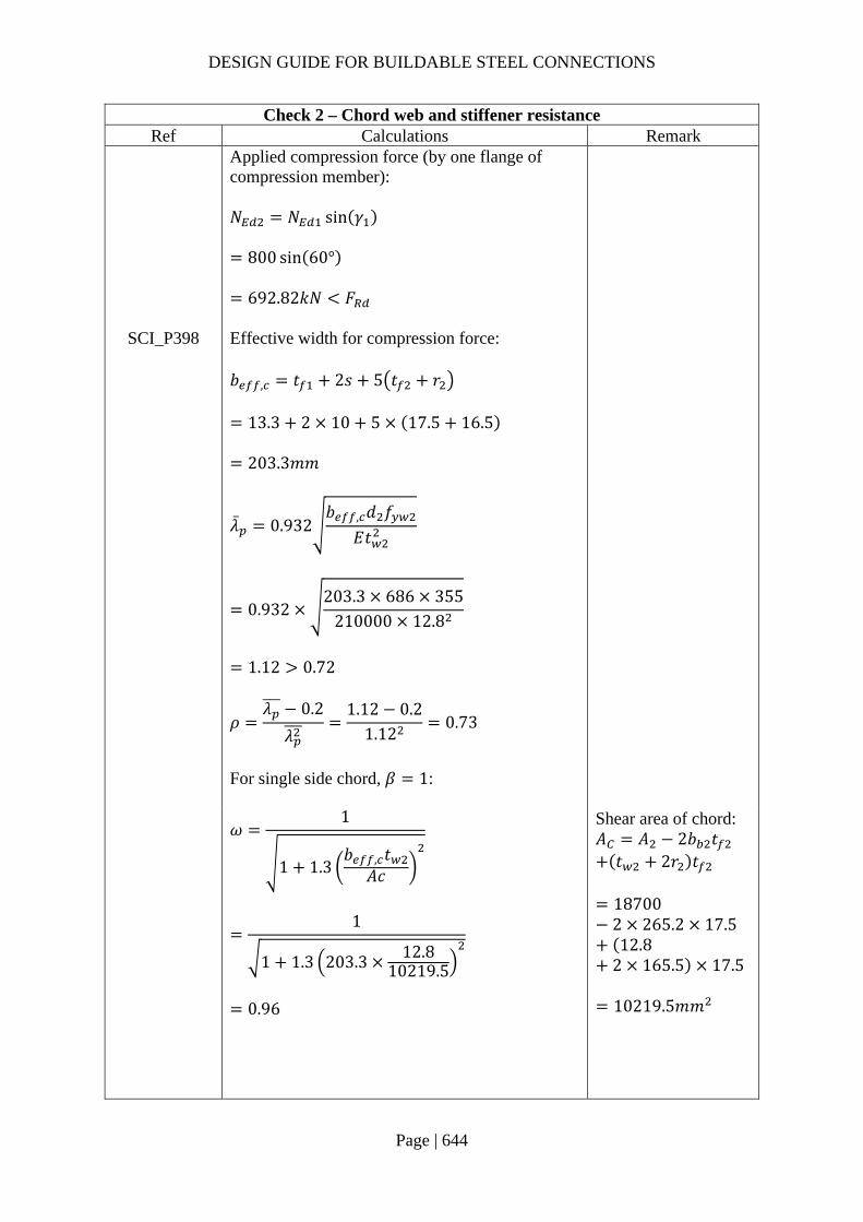
DESIGN GUIDE FOR BUILDABLE STEEL CONNECTIONS
Page | 644
Check 2 – Chord web and stiffener resistance Ref Calculations Remark
Applied compression force (by one flange of compression member): 𝑁 𝑁 sin 𝛾
800 sin 60°
692.82𝑘𝑁 𝐹
SCI_P398 Effective width for compression force: 𝑏 , 𝑡 2𝑠 5 𝑡 𝑟
13.3 2 10 5 17.5 16.5
203.3𝑚𝑚
�̅� 0.932
𝑏 , 𝑑 𝑓
𝐸𝑡
0.932203.3 686 355
210000 12.8
1.12 0.72
𝜌𝜆 0.2
𝜆
1.12 0.21.12
0.73
For single side chord, 𝛽 1:
𝜔
1
1 1.3𝑏 , 𝑡
𝐴𝑐
1
1 1.3 203.3 12.810219.5
0.96
Shear area of chord: 𝐴 𝐴 2𝑏 𝑡 𝑡 2𝑟 𝑡
187002 265.2 17.512.8
2 165.5 17.5
10219.5𝑚𝑚
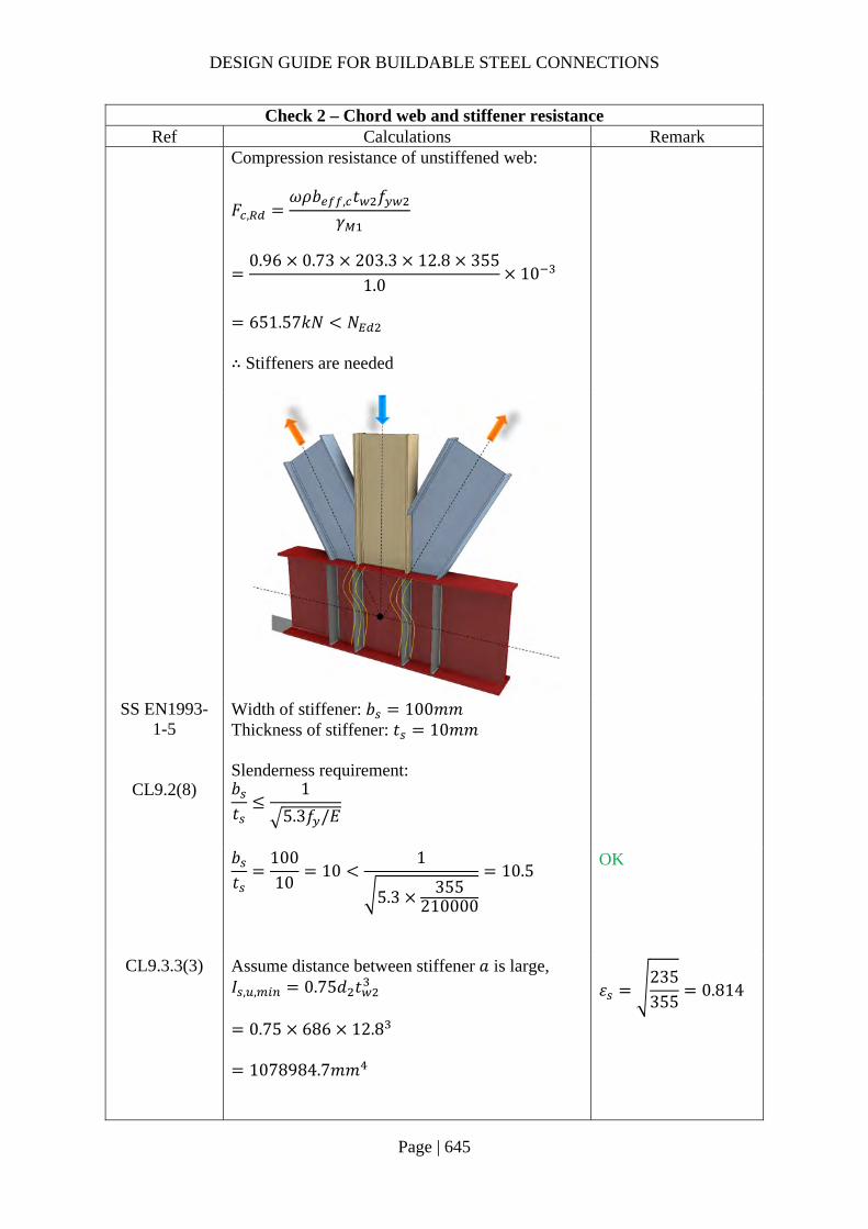
DESIGN GUIDE FOR BUILDABLE STEEL CONNECTIONS
Page | 645
Check 2 – Chord web and stiffener resistance Ref Calculations Remark
Compression resistance of unstiffened web:
𝐹 ,𝜔𝜌𝑏 , 𝑡 𝑓
𝛾
0.96 0.73 203.3 12.8 355
1.010
651.57𝑘𝑁 𝑁
∴ Stiffeners are needed
SS EN1993-1-5
CL9.2(8)
Width of stiffener: 𝑏 100𝑚𝑚 Thickness of stiffener: 𝑡 10𝑚𝑚 Slenderness requirement: 𝑏𝑡
1
5.3𝑓 /𝐸
𝑏𝑡
10010
101
5.3 355210000
10.5
OK
CL9.3.3(3) Assume distance between stiffener 𝑎 is large, 𝐼 , , 0.75𝑑 𝑡
0.75 686 12.8
1078984.7𝑚𝑚
𝜀235355
0.814

DESIGN GUIDE FOR BUILDABLE STEEL CONNECTIONS
Page | 646
Check 2 – Chord web and stiffener resistance Ref Calculations Remark
Second moment of inertia of effective section:
𝐼 ,𝑡 2𝑏 𝑡
1230𝜀 𝑡 𝑡
12
10 2 100 12.8
12
30 0.814 12.8 12.812
8084935.2 𝐼 , ,
CL9.4(3) SCI_P398
Cross section resistance: Effective loading area: 𝐴 , 30𝜀 𝑡 𝑡 𝑡 2 𝑏 𝑐 𝑡
30 0.814 12.8 10 12.8 2 100 20 10
5727.09𝑚𝑚
Bearing resistance of the loading area:
𝐹𝐴 , 𝑓𝛾
5727.09 355 10
2033.12𝑘𝑁 𝑁
Cope hole size: 𝑐 20𝑚𝑚
CL9.4(2) SCI_P398
Buckling resistance:
Radius of gyration:
𝑖 ,𝐼 ,
𝐴 ,
8084935.175727.09
37.57𝑚𝑚
𝛼 0.49 (solid section)
DESIGN GUIDE FOR BUILDABLE STEEL CONNECTIONS
Page | 647
Check 2 – Chord web and stiffener resistance Ref Calculations Remark
Non-dimensional slenderness:
�̅�𝑑𝑖 ,
193.9𝜀
686
37.571
93.9 0.814
0.239
𝛷 0.5 1 𝛼 �̅� 0.2 𝜆
0.5 1 0.49 0.239 0.2 0.239
0.54 Reduction factor:
𝜒1
𝛷 𝛷 �̅�
1
0.54 √0.54 0.239
0.98
Buckling resistance:
𝑁 ,𝜒 𝐴 , 𝑓
𝛾
0.98 5727.09 355 10
1992.79𝑘𝑁 𝑁
Note:
Stiffeners should be provided at all four loading points for the robustness purpose.

DESIGN GUIDE FOR BUILDABLE STEEL CONNECTIONS
Page | 648
7.5 Double-sided beam-to-beam composite connection using fin plates and contact plates
Figure 7-4 Details of double-sided beam-to-beam composite connection
The connection No. --- is a double-sided beam-to-beam composite connection using fin plates and contact plates. Composite connections are covered in SS EN1994-1-1, in which reinforcement can be taken into account in design for the resistance and the stiffness of the connections. Therefore, they can be designed as semi-rigid and partial-strength connections, so that economical design can be achieved by reducing design moment and deflection of beam members. The details of the connection are shown in Figure 7-4. The distance between the face of the support and the line of bolts ‘z’ is 60mm. The fin plates may be classified as short fin plate as the thickness of the plate is most likely larger than 0.15z=9.0mm. The fin plates are welded to the supporting beam and bolted to the supported beams. Contact plates and stiffeners are attached at the bottom flange level of supported beams so that the connection can resist bending moment effectively. The details of contact plates should be elaborated to prevent falling and gaps which will lead to unexpected structural behavior. According to the given geometry, a single vertical bolt line and total five bolts will be used. It should be noted that one-sided connection or double-sided connection with different depth supported beams should be avoided in terms of prevention of torsional deformation of the supporting beam, unless its lateral instability is appropriately prevented. In this example, design shear force VEd and design moment MEd are given. These values can be obtained by the structural analysis considering the rotational stiffness and moment resistance of the connections.
The design check consists of 6 detailed checks as follow:
1. Moment resistance of connection 2. Bolt group of supported beam 3. Fin plate of supported beam 4. Shear resistance of supported beam’s web 5. Welds of fin plate 6. Shear and bearing resistance of supporting beam
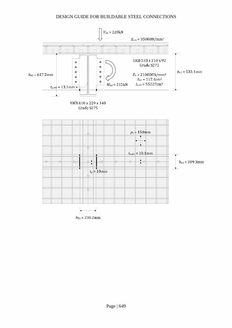
DESIGN GUIDE FOR BUILDABLE STEEL CONNECTIONS
Page | 649
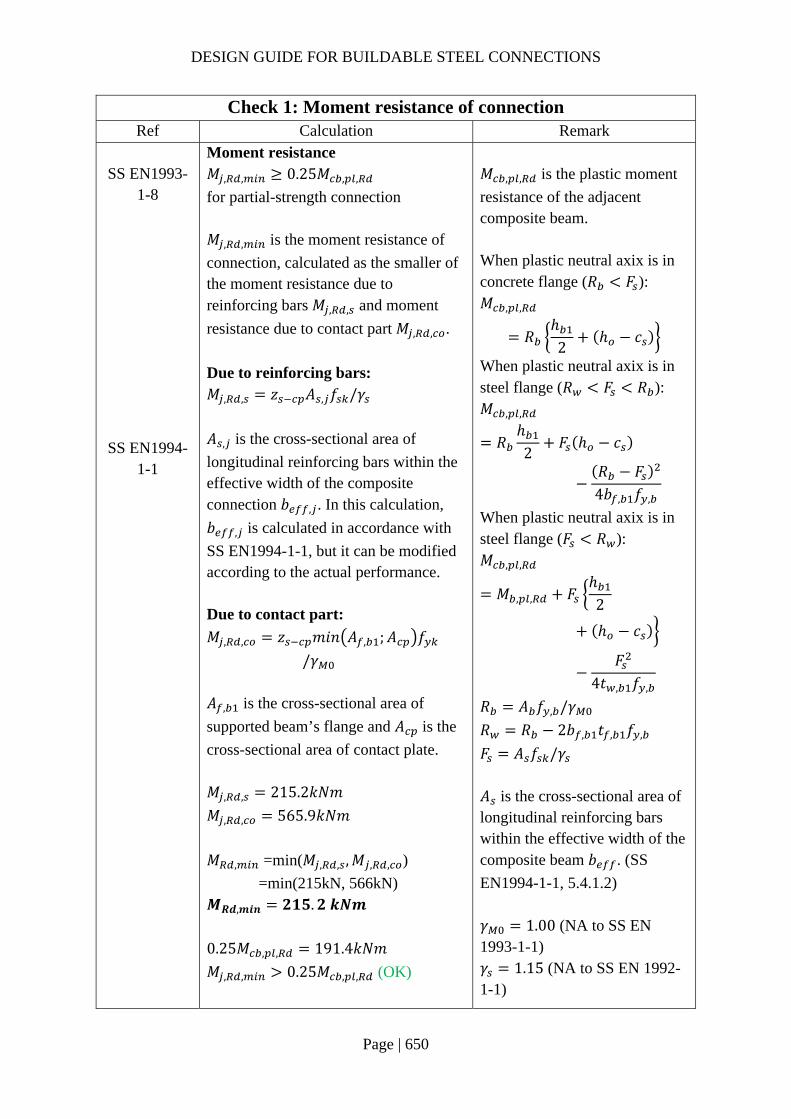
DESIGN GUIDE FOR BUILDABLE STEEL CONNECTIONS
Page | 650
Check 1: Moment resistance of connection
Ref Calculation Remark SS EN1993-
1-8
SS EN1994-1-1
Moment resistance 𝑀 , , 0.25𝑀 , ,
for partial-strength connection 𝑀 , , is the moment resistance of
connection, calculated as the smaller of the moment resistance due to reinforcing bars 𝑀 , , and moment
resistance due to contact part 𝑀 , , .
Due to reinforcing bars: 𝑀 , , 𝑧 𝐴 , 𝑓 /𝛾
𝐴 , is the cross-sectional area of
longitudinal reinforcing bars within the effective width of the composite connection 𝑏 , . In this calculation,
𝑏 , is calculated in accordance with
SS EN1994-1-1, but it can be modified according to the actual performance. Due to contact part:
𝑀 , , 𝑧 𝑚𝑖𝑛 𝐴 , ;𝐴 𝑓
/𝛾 𝐴 , is the cross-sectional area of
supported beam’s flange and 𝐴 is the
cross-sectional area of contact plate. 𝑀 , , 215.2𝑘𝑁𝑚
𝑀 , , 565.9𝑘𝑁𝑚
𝑀 , =min(𝑀 , , ,𝑀 , , )
=min(215kN, 566kN) 𝑴𝑹𝒅,𝒎𝒊𝒏 𝟐𝟏𝟓.𝟐 𝒌𝑵𝒎
0.25𝑀 , , 191.4𝑘𝑁𝑚
𝑀 , , 0.25𝑀 , , (OK)
𝑀 , , is the plastic moment
resistance of the adjacent composite beam. When plastic neutral axix is in concrete flange (𝑅 𝐹 ): 𝑀 , ,
𝑅ℎ2
ℎ 𝑐
When plastic neutral axix is in steel flange (𝑅 𝐹 𝑅 ): 𝑀 , ,
𝑅ℎ2
𝐹 ℎ 𝑐
𝑅 𝐹4𝑏 , 𝑓 ,
When plastic neutral axix is in steel flange (𝐹 𝑅 ): 𝑀 , ,
𝑀 , , 𝐹ℎ2
ℎ 𝑐
𝐹4𝑡 , 𝑓 ,
𝑅 𝐴 𝑓 , /𝛾
𝑅 𝑅 2𝑏 , 𝑡 , 𝑓 ,
𝐹 𝐴 𝑓 /𝛾 𝐴 is the cross-sectional area of longitudinal reinforcing bars within the effective width of the composite beam 𝑏 . (SS
EN1994-1-1, 5.4.1.2) 𝛾 1.00 (NA to SS EN 1993-1-1) 𝛾 1.15 (NA to SS EN 1992-1-1)
DESIGN GUIDE FOR BUILDABLE STEEL CONNECTIONS
Page | 651
Comments:
This composite connection can be designed as a partial-strength connection since its moment resistance 𝑀 , , is greater than 0.25 times the plastic moment resistance of the adjacent composite beam 𝑀 , , defined in SS EN1993-1-8, 5.2.3.3. However, if 𝑀 , , is less than 0.25𝑀 , , , this connection is practically designed as a nominally pinned connection.
In case the moment resistance of the connection 𝑀 , , is insufficient, it can be increased by arranging the additional reinforcing bars over the connection. However, structural analysis should be carried out again because the distribution of moment and deflection of beam members is also varied as the rotational stiffness and moment resistance of the connection vary.
In this design example, it can be found that the given design moment 𝑀 is same as moment resistance of the connection 𝑀 , , . This means that the design moment reached the moment resistance of the connection and a plastic hinge was occurred at the connection accordingly. Refer to SS EN1993-1-8 and SS EN1994-1-1 for the detail procedures of the structural analysis considering plastic hinges at connections. However, it should be noted that the connections should have sufficient rotational capacity when plastic hinges are allowed to occur in structural analysis.
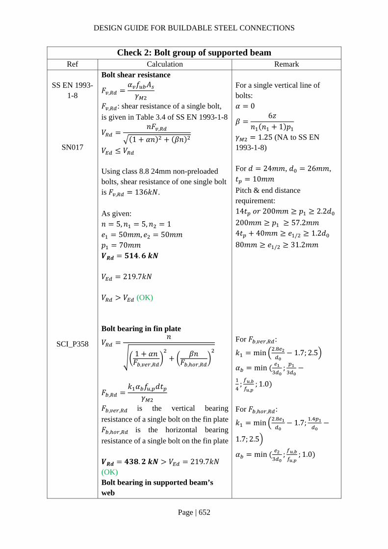
DESIGN GUIDE FOR BUILDABLE STEEL CONNECTIONS
Page | 652
Check 2: Bolt group of supported beam
Ref Calculation Remark SS EN 1993-
1-8
SN017
SCI_P358
Bolt shear resistance
𝐹 ,𝛼 𝑓 𝐴𝛾
𝐹 , : shear resistance of a single bolt,
is given in Table 3.4 of SS EN 1993-1-8
𝑉𝑛𝐹 ,
1 𝛼𝑛 𝛽𝑛
𝑉 𝑉 Using class 8.8 24mm non-preloaded bolts, shear resistance of one single bolt is 𝐹 , 136𝑘𝑁.
As given: 𝑛 5,𝑛 5,𝑛 1 𝑒 50𝑚𝑚, 𝑒 50𝑚𝑚 𝑝 70𝑚𝑚 𝑽𝑹𝒅 𝟓𝟏𝟒.𝟔 𝒌𝑵 𝑉 219.7𝑘𝑁 𝑉 𝑉 (OK) Bolt bearing in fin plate
𝑉𝑛
1 𝛼𝑛𝐹 , ,
𝛽𝑛𝐹 , ,
𝐹 ,𝑘 𝛼 𝑓 , 𝑑𝑡
𝛾
𝐹 , , is the vertical bearing
resistance of a single bolt on the fin plate 𝐹 , , is the horizontal bearing
resistance of a single bolt on the fin plate 𝑽𝑹𝒅 𝟒𝟑𝟖.𝟐 𝒌𝑵 𝑉 219.7𝑘𝑁 (OK) Bolt bearing in supported beam’s web
For a single vertical line of bolts: 𝛼 0
𝛽6𝑧
𝑛 𝑛 1 𝑝
𝛾 1.25 (NA to SS EN 1993-1-8) For 𝑑 24𝑚𝑚, 𝑑 26𝑚𝑚, 𝑡 10𝑚𝑚
Pitch & end distance requirement: 14𝑡 𝑜𝑟 200𝑚𝑚 𝑝 2.2𝑑
200𝑚𝑚 𝑝 57.2𝑚𝑚 4𝑡 40𝑚𝑚 𝑒 / 1.2𝑑
80𝑚𝑚 𝑒 / 31.2𝑚𝑚
For 𝐹 , , :
𝑘 min . 1.7; 2.5
𝛼 min ;
; ,
,; 1.0
For 𝐹 , , :
𝑘 min . 1.7; .
1.7; 2.5
𝛼 min ; ,
,; 1.0

DESIGN GUIDE FOR BUILDABLE STEEL CONNECTIONS
Page | 653
Check 2: Bolt group of supported beam
Ref Calculation Remark
SCI_P358 𝑉
𝑛
1 𝛼𝑛𝐹 , ,
𝛽𝑛𝐹 , ,
𝐹 ,𝑘 𝛼 𝑓 𝑑𝑡 ,
𝛾
𝐹 , , is the vertical bearing
resistance of a single bolt on the fin plate 𝐹 , , is the horizontal bearing
resistance of a single bolt on the fin plate 𝑽𝑹𝒅 𝟒𝟒𝟒.𝟕 𝒌𝑵 𝑉 219.7𝑘𝑁 (OK)

DESIGN GUIDE FOR BUILDABLE STEEL CONNECTIONS
Page | 654
Check 3: Fin plate of supported beam
Ref Calculation Remark SCI_P358 Shear
𝑉 𝑉 ,
𝑉 , is the shear resistance of the fin
plate, calculated as the smaller of the gross section shear resistance 𝑉 , , net
section shear resistance 𝑉 , and block
shear resistance 𝑉 ,
Gross section:
𝑉 ,ℎ 𝑡1.27
𝑓
√3𝛾
ℎ 380𝑚𝑚, 𝑡 10𝑚𝑚
𝑓 275𝑁/𝑚𝑚
𝑉 , 475.1𝑘𝑁
Net section:
𝑉 ,𝐴 , 𝑓 ,
√3𝛾
𝑉 , 538.0𝑘𝑁
Block shear:
𝑉 ,0.5𝑓 , 𝐴
𝛾𝑓 ,
√3
𝐴𝛾
𝑉 , 407.1𝑘𝑁
𝑉 , =min(𝑉 , ,𝑉 , ,𝑉 , )
=min(475kN, 538kN, 407kN) 𝑽𝑹𝒅,𝒎𝒊𝒏 𝟒𝟎𝟕.𝟏 𝒌𝑵 𝑉219.7𝑘𝑁 (OK) Bending As ℎ 380𝑚𝑚 2.73𝑧
163.8𝑚𝑚, 𝑉 ∞ No check is needed.
The coefficient 1.27 takes into account the reduction in the shear resistance of the cross section due to the nominal moment in the connection.
𝐴 , 𝑡 ℎ 𝑛 𝑑
𝐴 𝑡 𝑒𝑑2
𝐴 𝑡 ℎ 𝑒 𝑛
0.5 𝑑
𝛾 1.00 (NA to SS EN 1993-1-1) 𝛾 1.10 (NA to SS EN 1993-1-8)

DESIGN GUIDE FOR BUILDABLE STEEL CONNECTIONS
Page | 655
Check 3: Fin plate of supported beam
Ref Calculation Remark SCI_P358 Lateral torsional buckling
For long fin plate:
𝑉 min𝑊 ,
𝑧𝜒 𝑓 ,
0.6𝛾;𝑊 ,
𝑧𝑓 ,
𝛾
For short fin plate:
𝑽𝑹𝒅𝑾𝒆𝒍,𝒑
𝒛
𝒇𝒚,𝒑
𝜸𝑴𝟎𝟏𝟏𝟎𝟑.𝟏𝒌𝑵 𝑉
219.7𝑘𝑁 (OK)
*For long fin plate, lateral torsional buckling must be checked. 𝜒 is the reduction factor for LTB obtained from table based on the slenderness of the fin plate.
𝜆2.8
86.8𝑧 ℎ1.5𝑡
*Long fin plates should not be used with unrestrained beams without experimental evidence to justify the design

DESIGN GUIDE FOR BUILDABLE STEEL CONNECTIONS
Page | 656
Check 4: Shear resistance of supported beam’s web
Ref Calculation Remark SCI_P358 Shear:
𝑉 𝑉 ,
𝑉 , is the shear resistance of the
supported beam’s web, calculated as the smaller of the gross section shear resistance 𝑉 , , net section shear
resistance 𝑉 , and block shear
resistance 𝑉 ,
Gross section:
𝑉 , 𝑉 ,𝐴 , 𝑓 ,
√3𝛾
𝑉 , 914.8𝑘𝑁
Net section:
𝑉 ,𝐴 , 𝑓 ,
√3𝛾
𝑉 , 957.3𝑘𝑁
𝑉 , =min(𝑉 , ,𝑉 , )
=min(915kN, 957kN) 𝑽𝑹𝒅,𝒎𝒊𝒏 𝟗𝟏𝟒.𝟖 𝒌𝑵 𝑉219.7𝑘𝑁 (OK)
For unnotched beams: 𝐴 , 𝐴 2𝑏 𝑡 ,
𝑡 , 2𝑟 𝑡 , (SS EN
1993-1-8) 𝐴 , 𝐴 , 𝑛 𝑑 𝑡 ,
𝛾 1.00 (NA to SS EN 1993-1-1)

DESIGN GUIDE FOR BUILDABLE STEEL CONNECTIONS
Page | 657
Check 4: Shear resistance of supported beam’s web
Ref Calculation Remark SCI_P358 Shear and bending interaction of the
beam web: 𝑉 𝑧 𝑀 , , 𝑉 , , 𝑛 1 𝑝
𝑀 , , is the moment resistance of the
beam web BC As 𝑉 , 0.5𝑉 , , , the connection
experiences low shear.
𝑀 , ,𝑓 , 𝑡 ,
6𝛾𝑛 1 𝑝
For this case, as the fin plate is considered as short fin plate, according to SCI_P358, resistance of the web does not need to be checked.
*For long fin plates, it is necessary to ensure that the bolted section can resist a moment 𝑉 𝑧
𝑉 , ,𝑡 , 𝑒 , 𝑓 ,
√3𝛾
𝑉 ,𝑉 𝑛 1 𝑝
ℎ
Shear resistance of the beam web AB:
𝑉 , ,𝑡 , 𝑛 1 𝑝 𝑓 ,
√3𝛾
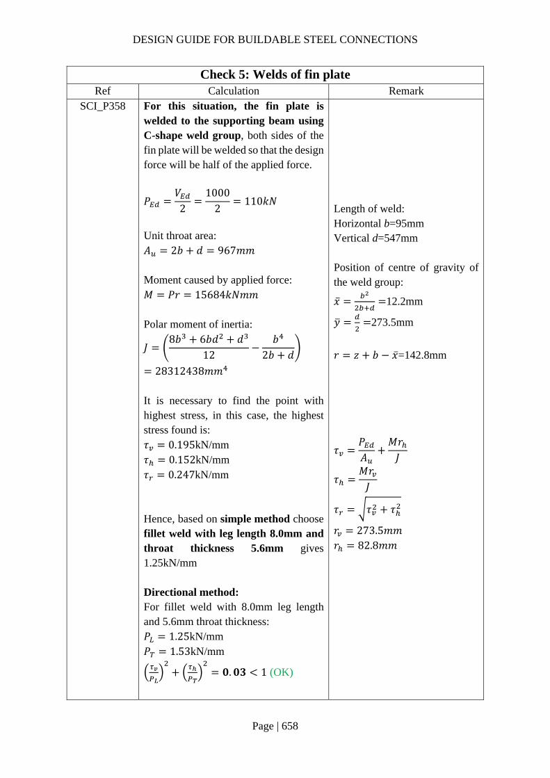
DESIGN GUIDE FOR BUILDABLE STEEL CONNECTIONS
Page | 658
Check 5: Welds of fin plate
Ref Calculation Remark SCI_P358 For this situation, the fin plate is
welded to the supporting beam using C-shape weld group, both sides of the fin plate will be welded so that the design force will be half of the applied force.
𝑃𝑉
21000
2110𝑘𝑁
Unit throat area: 𝐴 2𝑏 𝑑 967𝑚𝑚 Moment caused by applied force: 𝑀 𝑃𝑟 15684𝑘𝑁𝑚𝑚 Polar moment of inertia:
𝐽8𝑏 6𝑏𝑑 𝑑
12𝑏
2𝑏 𝑑
28312438𝑚𝑚 It is necessary to find the point with highest stress, in this case, the highest stress found is: 𝜏 0.195kN/mm 𝜏 0.152kN/mm 𝜏 0.247kN/mm Hence, based on simple method choose fillet weld with leg length 8.0mm and throat thickness 5.6mm gives 1.25kN/mm Directional method: For fillet weld with 8.0mm leg length and 5.6mm throat thickness: 𝑃 1.25kN/mm 𝑃 1.53kN/mm
𝟎.𝟎𝟑 1 (OK)
Length of weld: Horizontal b=95mm Vertical d=547mm Position of centre of gravity of the weld group:
�̅� 12.2mm
𝑦 273.5mm
𝑟 𝑧 𝑏 �̅�=142.8mm
𝜏𝑃𝐴
𝑀𝑟𝐽
𝜏𝑀𝑟𝐽
𝜏 𝜏 𝜏
𝑟 273.5𝑚𝑚 𝑟 82.8𝑚𝑚

DESIGN GUIDE FOR BUILDABLE STEEL CONNECTIONS
Page | 659
Check 6: Shear and bearing resistance of supporting beam
Ref Calculation Remark SCI_P358 Local shear of beam web:
𝑉 ,
2𝐹
𝐹𝐴 𝑓 ,
√3𝛾
𝐹 790.4𝑘𝑁𝑉 ,
2219.7𝑘𝑁
(OK) Punching shear As the connection is double-sided, no check is needed.
𝑉 ,𝑉 ,
ℎ ,
𝑉 ,
ℎ ,ℎ ,
𝐴 ℎ 𝑡 ,
𝑡 , is the thickness of the
supporting beam web 𝛾 1.00 (NA to SS EN 1993-1-1)

DESIGN GUIDE FOR BUILDABLE STEEL CONNECTIONS
Page | 660
8 Good Practices for Connections Design 8.1 General
In practice, the design activity of a steel structure may involve both engineers and fabricators. Apart from satisfying the architectural requirements, good connection designs prioritize safety, serviceability and durability requirements with economy and feasibility of fabrication borne on mind. In order to achieve buildable steel connections, that are fabricator and erector friendly, good communication between engineer and fabricator is needed. Economic steel connection designs are not only derived from less materials, but also time saving derived from easy site erection and minimization of rectifications due to error-prone details. Good connections detailing has been proposed by various regional design guides and committees in professional articles and resources on websites such as www.steelconstruction.info. Some of the relevant recommendations suitable for local practices are compiled in this chapter for readers’ easy reference.
8.2 Recommendations for cost-effective connection design This section provides some recommendations for cost-effective connections design that also could reduce problems at the construction sites:
(1) For bolted splice connections, the width of the flange cover plate should be different from that of the beam flange. Provide at least 15mm difference on each side of the flange plate at the flange and cover plate connection. If bolt holes misalign during the installation, the difference between the cover plate and beam flange provides space for fillet welds to be placed to compensate the missing bolts.
(2) Use oversized bolt holes in beam splice and brace connections. For connections with slip-critical bolts, oversized bolt holes are often preferred over standard bolt holes. Although oversized bolt holes have lower bolt capacity, they provide more erection tolerance and reduce site problems. Typically, standard bolt holes are used in main member while oversized bolt holes are used in detail material such as gusset plate.
(3) Standardizing connections used on one project. Types of connections on a project should be minimized to save fabrication time and cost and reduce possible errors.
(4) Avoid using bolts with diameters close to each other. A minimum difference between bolt sizes is needed to prevent uncertainty and reduce site errors. If necessary, use a maximum of up to three sizes of bolts in each project.
(5) Avoid using different grades of bolts with the same diameter. (6) Bolted connections are preferred over field-welded connections.
For site-welded connections, qualified welder, welding platform and good welding conditions are needed. Compared to site-welded connections, bolted connections are less time consuming and relatively cheaper. It is a good practice to “weld at factory” and “bolt at site”.
(7) Try to use fillet welds instead of penetration butt welds whenever it is possible. Fillet welds are less expensive as base-metal preparation is not required. Moreover, penetration butt welds require more weld metal and inspection.
(8) Limit the maximum fillet weld size.
DESIGN GUIDE FOR BUILDABLE STEEL CONNECTIONS
Page | 661
Smaller, longer welds are preferred over larger, shorter welds. The normal maximum leg length that can be made in a single pass is 8mm.Therefore, if a 12mm fillet weld is required, an 8mm deep penetration weld may be used instead as this can be made in a single pass.
(9) Avoid overhead welding. Overhead welding is challenging, costly and generally yields lower quality welds. Welding positions are preferred to be flat and horizontal.
(10) Use full penetration butt welds only when necessary. Full penetration butt welds cost more due to increased material preparation, testing requirements, weld-metal volume and material distortion. Full penetration butt weld is difficult for hollow steel sections as it requires backing bars.
(11) Avoid excessive connections. Connections may be designed to actual load requirements instead of full capacity of the members. Excessive connections may result in higher cost and over-welding may damage the steel.
(12) Minimize weld volume for penetration butt welds. The weld configuration with the least weld volume is most economical. For weld configuration with double-sided preparation, the additional cost of material preparation may offset the cost saving of less weld volume. For full penetration butt welds, it is economical to prepare one side of plates with a thickness less than 25mm and to prepare both sides of plates with a thickness greater than or equal to 25mm.
(13) Minimizing the usage of slip-critical bolts Slip-critical bolts are more expensive than bearing bolts due to additional installation, inspection and faying surface preparation. Moreover, larger bolts are needed for reduced bolt strength. If slip-critical bolts are needed, they must be clearly indicated on shop drawing.
(14) Avoid using bolt with diameter greater than 30mm. Bolts with diameter greater than 30mm are difficult to tighten and costly.
(15) Avoid slotted holes in plates thicker than the bolt diameter. Slot holes in thick steel plates are hard to punch and must be flame-cut, which is difficult and costly. Standard holes or oversized holes are preferred.
(16) Allow for site adjustment in one direction only for bolted connections. If slotted holes are needed for a bolted connection for site adjustment, the adjustment should be in only one direction.
(17) Cope or block beams instead of cutting flush and grinding smooth. Cutting flush and grinding smooth is more expensive.
(18) For shear plate connection to hollow steel section columns, weld single-plate to HS column instead of using through-plate connections. Through plate shear connections are costly and more difficult to fabricate than welding a fin plate to column.
(19) For beam to hollow steel section column moment connections, use direct moment connections when possible. Moment connections in which the beam flanges are welded directly to the face of the hollow steel section column are the most economical moment connections to hollow section column.
(20) Consider bolted hollow steel section brace connections.
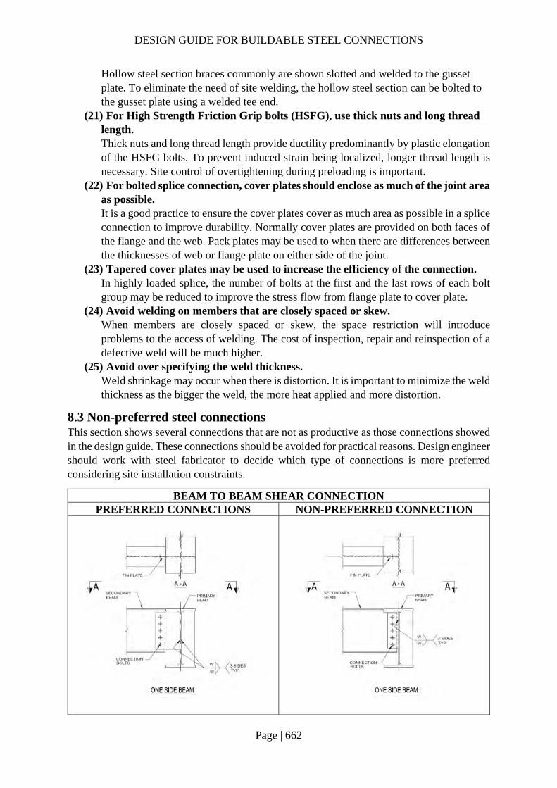
DESIGN GUIDE FOR BUILDABLE STEEL CONNECTIONS
Page | 662
Hollow steel section braces commonly are shown slotted and welded to the gusset plate. To eliminate the need of site welding, the hollow steel section can be bolted to the gusset plate using a welded tee end.
(21) For High Strength Friction Grip bolts (HSFG), use thick nuts and long thread length. Thick nuts and long thread length provide ductility predominantly by plastic elongation of the HSFG bolts. To prevent induced strain being localized, longer thread length is necessary. Site control of overtightening during preloading is important.
(22) For bolted splice connection, cover plates should enclose as much of the joint area as possible. It is a good practice to ensure the cover plates cover as much area as possible in a splice connection to improve durability. Normally cover plates are provided on both faces of the flange and the web. Pack plates may be used to when there are differences between the thicknesses of web or flange plate on either side of the joint.
(23) Tapered cover plates may be used to increase the efficiency of the connection. In highly loaded splice, the number of bolts at the first and the last rows of each bolt group may be reduced to improve the stress flow from flange plate to cover plate.
(24) Avoid welding on members that are closely spaced or skew. When members are closely spaced or skew, the space restriction will introduce problems to the access of welding. The cost of inspection, repair and reinspection of a defective weld will be much higher.
(25) Avoid over specifying the weld thickness. Weld shrinkage may occur when there is distortion. It is important to minimize the weld thickness as the bigger the weld, the more heat applied and more distortion.
8.3 Non-preferred steel connections This section shows several connections that are not as productive as those connections showed in the design guide. These connections should be avoided for practical reasons. Design engineer should work with steel fabricator to decide which type of connections is more preferred considering site installation constraints.
BEAM TO BEAM SHEAR CONNECTION PREFERRED CONNECTIONS NON-PREFERRED CONNECTION
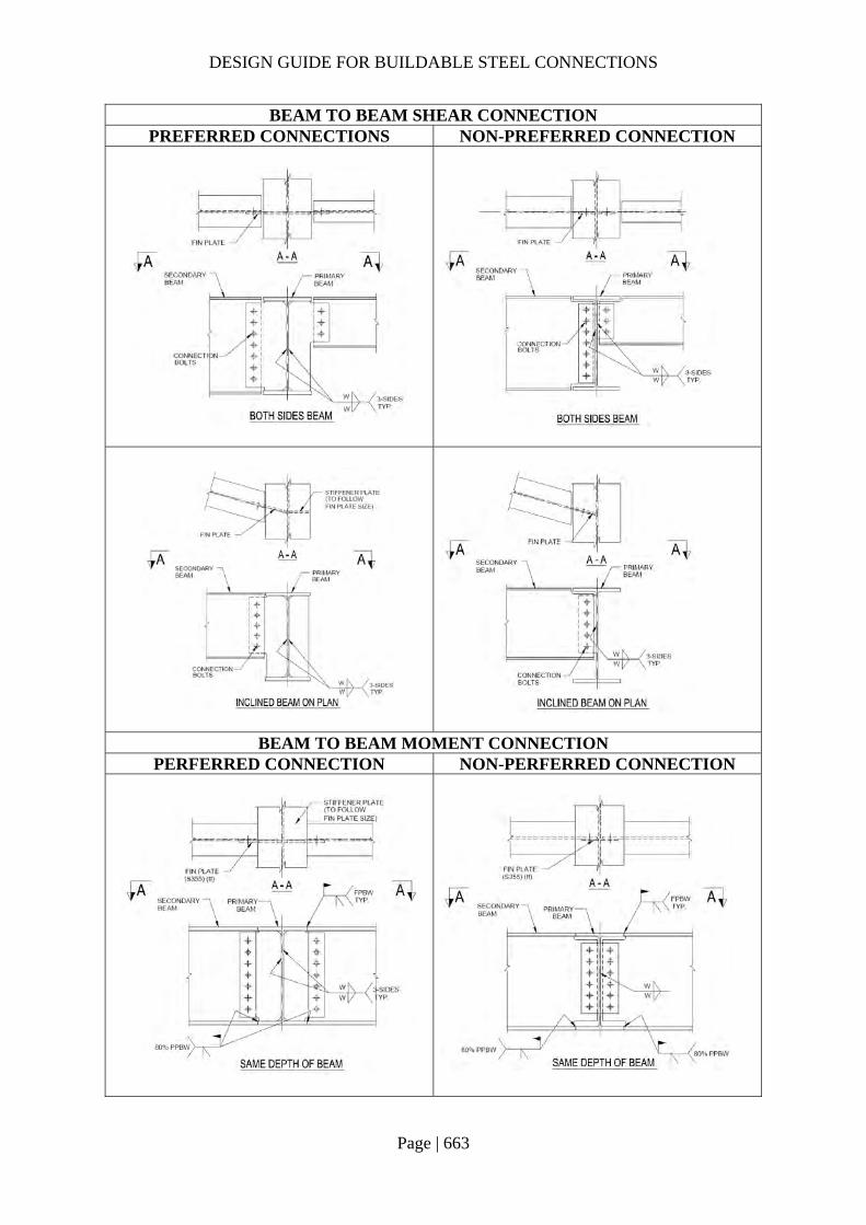
DESIGN GUIDE FOR BUILDABLE STEEL CONNECTIONS
Page | 663
BEAM TO BEAM SHEAR CONNECTION PREFERRED CONNECTIONS NON-PREFERRED CONNECTION
BEAM TO BEAM MOMENT CONNECTION PERFERRED CONNECTION NON-PERFERRED CONNECTION
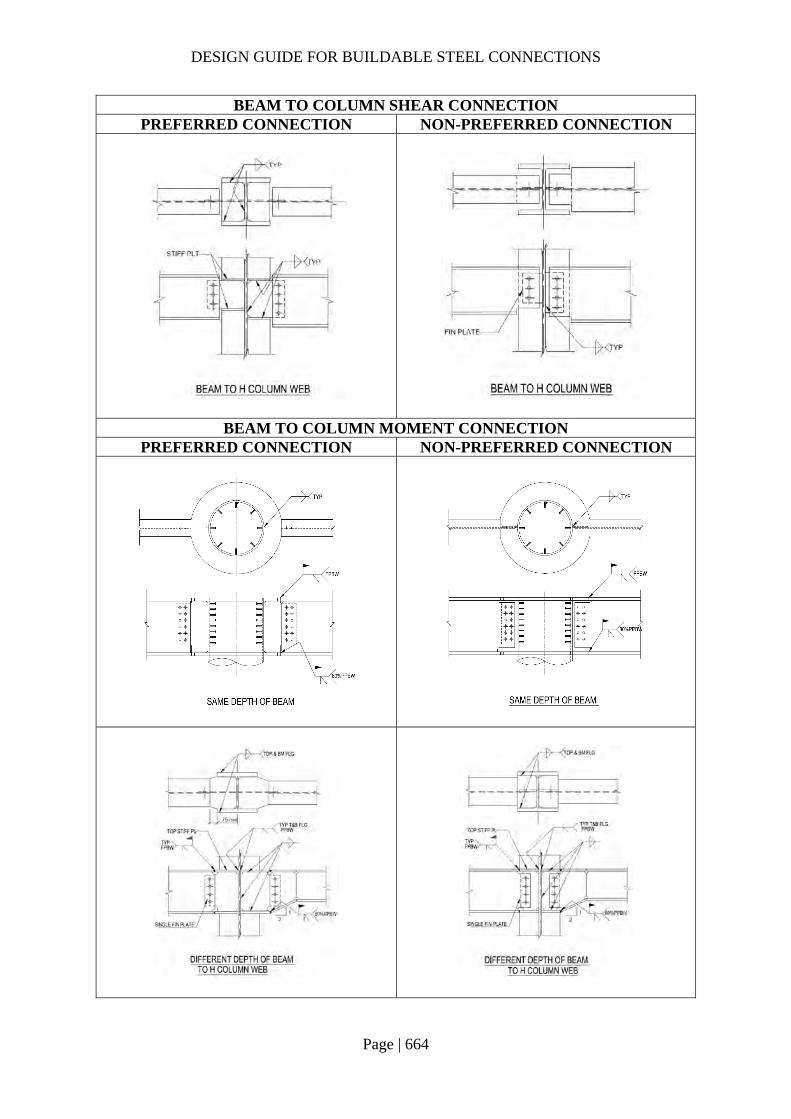
DESIGN GUIDE FOR BUILDABLE STEEL CONNECTIONS
Page | 664
BEAM TO COLUMN SHEAR CONNECTION PREFERRED CONNECTION NON-PREFERRED CONNECTION
BEAM TO COLUMN MOMENT CONNECTION PREFERRED CONNECTION NON-PREFERRED CONNECTION
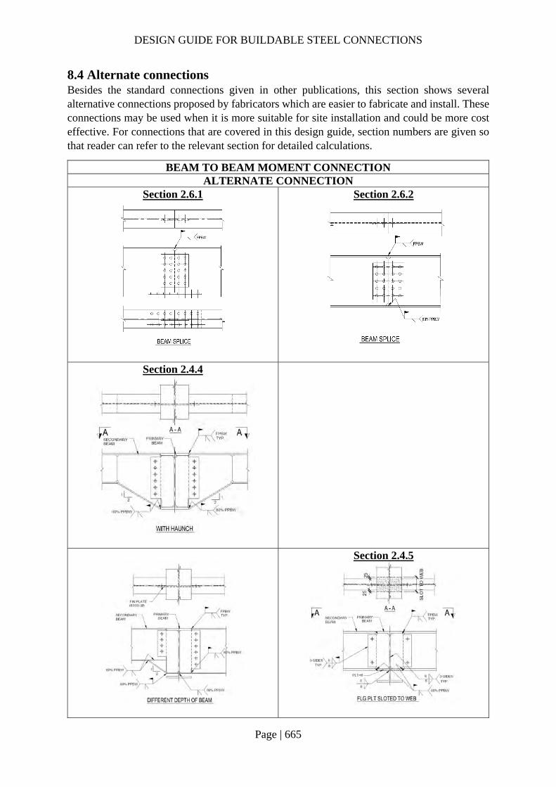
DESIGN GUIDE FOR BUILDABLE STEEL CONNECTIONS
Page | 665
8.4 Alternate connections Besides the standard connections given in other publications, this section shows several alternative connections proposed by fabricators which are easier to fabricate and install. These connections may be used when it is more suitable for site installation and could be more cost effective. For connections that are covered in this design guide, section numbers are given so that reader can refer to the relevant section for detailed calculations.
BEAM TO BEAM MOMENT CONNECTION ALTERNATE CONNECTION
Section 2.6.1
Section 2.6.2
Section 2.4.4
Section 2.4.5
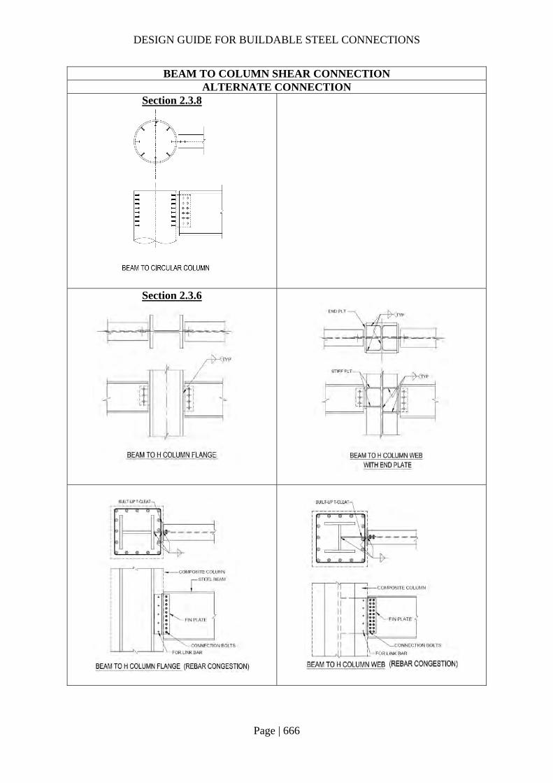
DESIGN GUIDE FOR BUILDABLE STEEL CONNECTIONS
Page | 666
BEAM TO COLUMN SHEAR CONNECTION ALTERNATE CONNECTION
Section 2.3.8
Section 2.3.6

DESIGN GUIDE FOR BUILDABLE STEEL CONNECTIONS
Page | 667
BEAM TO COLUMN MOMENT CONNECTION ALTERNATE CONNECTION
Section 2.4.7
Section 2.4.8

DESIGN GUIDE FOR BUILDABLE STEEL CONNECTIONS
Page | 668
References AISC 310:1997 (2005), Hollow Structural Sections Connections Manual, American Institute of Steel Construction.
AWS D1.1/D1.1M:2015 (2016), Structural Welding Code – Steel, American Welding Society, ANSI.
BC1:2012 (2012), Design guide on use of alternative structural steel to BS5950 and Eurocode 3, Building Construction Authority.
BS 5950-1:2000 (2010), Structural use of steelwork in building. Code of practice for design Rolled and welded sections, BSI
CECS 280:2010, Technical specification for structures with steel hollow sections, China Association for Engineering Construction Standardization.
CIDECT Design Guide 9 (2005), For structural hollow section column connections, Y.Kurobane, J.A.Packer, J.Wardenier, N.Yeomans.
DD CEB/TS 1992-4-2:2009, Design of fastenings for use in concrete, Part 4 – 2: Headed Fasteners, CEN.
Design of Fastenings in Concrete (1996), CEB bulletin dÍnformation No. 226, Thomas Telford.
Design of Joints in Steel and Composite Structures (2016), ECCS Eurocode Design Manuals, Jean-Pierre Jaspart, Klaus Weynand, European Convention for Constructional Steelwork.
Design of welded structures (1966), Omer W.Blodgett, The JAMES F.LINCOLN ARC WELDING FOUNDATION.
GB 50936-2014, Technical code for concrete filled steel tubular structures, Ministry of Housing and Urban-Rural Development.
Joints in steel construction: Simple joints to Eurocode 3 (2014), BCSA, Tata Steel, SCI publication No. P358, jointly published by the British Constructional Steelwork Association and the Steel Construction Institute.
Joints in steel construction: Moment-resisting joints to Eurocode 3 (2015), BSCA, Tata Steel, SCI publication No. P398, jointly published by the British Constructional Steelwork Association and the Steel Construction Institute.
NA to SS EN 1993-1-8: 2010 (2016) - Singapore National Annex to Eurocode 3: Design of steel structures - General rules - Design of joints, Building and Construction Standards Committee, Standards Council of Singapore.
SNO17, NCCI: Shear resistance of a fin plate connection, www.access-steel.com
SS EN 1992-1-1:2004 (2008), Eurocode 2 – Design of concrete structures, Part 1 -1 General rules and rules for buildings, Building and Construction Standards Committee, Standard Council of Singapore.
DESIGN GUIDE FOR BUILDABLE STEEL CONNECTIONS
Page | 669
SS EN 1993-1-1: 2010 (2015), Eurocode 3 – Design of steel structures – General rules for buildings, Building and Construction Standards Committee, Standard Council of Singapore.
SS EN 1993-1-5:2009 (2016), Eurocode 3 – Design of steel structures – Plated structural elements, Building and Construction Standards Committee, Standards Council of Singapore.
SS EN 1993-1-8:2010 (2016), Eurocode 3 - Design of steel structures - Design of joints, Building and Construction Standards Committee, Standards Council of Singapore.
SS EN 1994-1-1: 2009, Eurocode 4 – Design of composite steel and concrete structure – General rules for buildings, Building and Construction Standards Committee, Standard Council of Singapore.
Steel building design: Design Data (2011), BSCA, Tata Steel, SCI publication No. P363, jointly published by the British Constructional Steelwork Association and the Steel Construction Institute.
Carol Drucker (2004), “30 Good rules for connection design”, Modern Steel Construction.
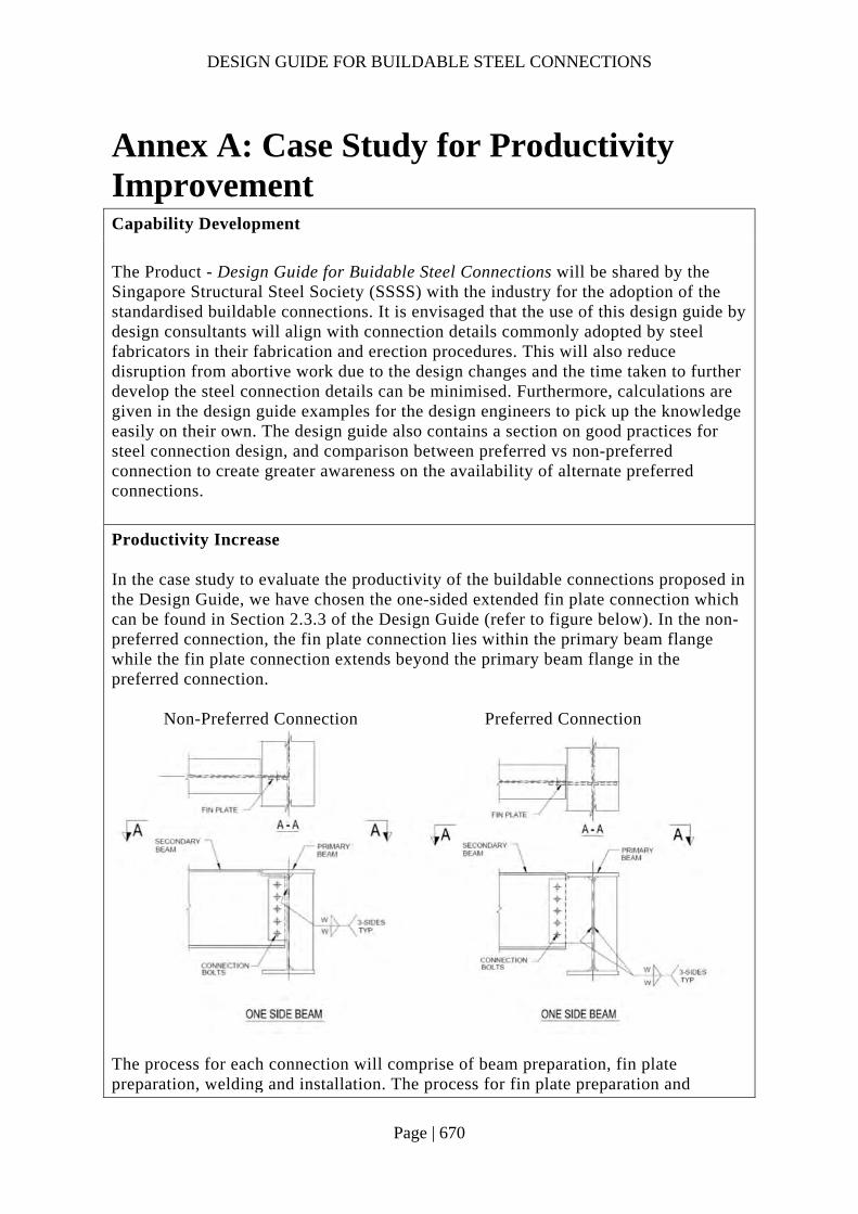
DESIGN GUIDE FOR BUILDABLE STEEL CONNECTIONS
Page | 670
Annex A: Case Study for Productivity Improvement Capability Development
The Product - Design Guide for Buidable Steel Connections will be shared by the Singapore Structural Steel Society (SSSS) with the industry for the adoption of the standardised buildable connections. It is envisaged that the use of this design guide by design consultants will align with connection details commonly adopted by steel fabricators in their fabrication and erection procedures. This will also reduce disruption from abortive work due to the design changes and the time taken to further develop the steel connection details can be minimised. Furthermore, calculations are given in the design guide examples for the design engineers to pick up the knowledge easily on their own. The design guide also contains a section on good practices for steel connection design, and comparison between preferred vs non-preferred connection to create greater awareness on the availability of alternate preferred connections.
Productivity Increase In the case study to evaluate the productivity of the buildable connections proposed in the Design Guide, we have chosen the one-sided extended fin plate connection which can be found in Section 2.3.3 of the Design Guide (refer to figure below). In the non-preferred connection, the fin plate connection lies within the primary beam flange while the fin plate connection extends beyond the primary beam flange in the preferred connection. Non-Preferred Connection Preferred Connection
The process for each connection will comprise of beam preparation, fin plate preparation, welding and installation. The process for fin plate preparation and
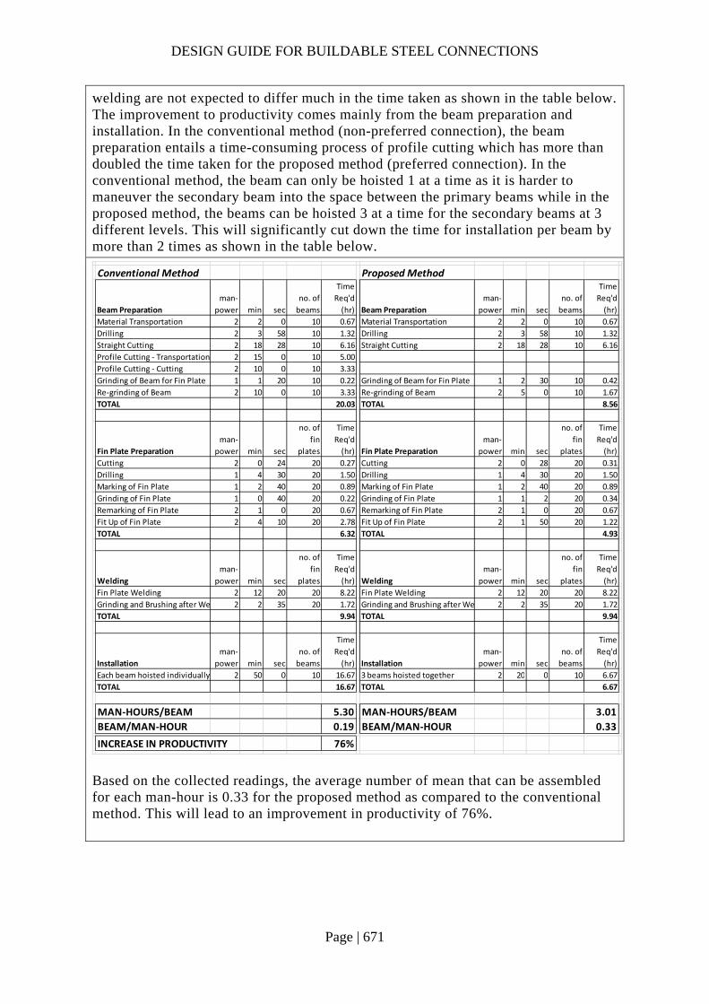
DESIGN GUIDE FOR BUILDABLE STEEL CONNECTIONS
Page | 671
welding are not expected to differ much in the time taken as shown in the table below. The improvement to productivity comes mainly from the beam preparation and installation. In the conventional method (non-preferred connection), the beam preparation entails a time-consuming process of profile cutting which has more than doubled the time taken for the proposed method (preferred connection). In the conventional method, the beam can only be hoisted 1 at a time as it is harder to maneuver the secondary beam into the space between the primary beams while in the proposed method, the beams can be hoisted 3 at a time for the secondary beams at 3 different levels. This will significantly cut down the time for installation per beam by more than 2 times as shown in the table below.
Based on the collected readings, the average number of mean that can be assembled for each man-hour is 0.33 for the proposed method as compared to the conventional method. This will lead to an improvement in productivity of 76%.
Conventional Method Proposed Method
Beam Preparation
man‐
power min sec
no. of
beams
Time
Req'd
(hr) Beam Preparation
man‐
power min sec
no. of
beams
Time
Req'd
(hr)
Material Transportation 2 2 0 10 0.67 Material Transportation 2 2 0 10 0.67
Drilling 2 3 58 10 1.32 Drilling 2 3 58 10 1.32
Straight Cutting 2 18 28 10 6.16 Straight Cutting 2 18 28 10 6.16
Profile Cutting ‐ Transportation 2 15 0 10 5.00
Profile Cutting ‐ Cutting 2 10 0 10 3.33
Grinding of Beam for Fin Plate 1 1 20 10 0.22 Grinding of Beam for Fin Plate 1 2 30 10 0.42
Re‐grinding of Beam 2 10 0 10 3.33 Re‐grinding of Beam 2 5 0 10 1.67
TOTAL 20.03 TOTAL 8.56
Fin Plate Preparation
man‐
power min sec
no. of
fin
plates
Time
Req'd
(hr) Fin Plate Preparation
man‐
power min sec
no. of
fin
plates
Time
Req'd
(hr)
Cutting 2 0 24 20 0.27 Cutting 2 0 28 20 0.31
Drilling 1 4 30 20 1.50 Drilling 1 4 30 20 1.50
Marking of Fin Plate 1 2 40 20 0.89 Marking of Fin Plate 1 2 40 20 0.89
Grinding of Fin Plate 1 0 40 20 0.22 Grinding of Fin Plate 1 1 2 20 0.34
Remarking of Fin Plate 2 1 0 20 0.67 Remarking of Fin Plate 2 1 0 20 0.67
Fit Up of Fin Plate 2 4 10 20 2.78 Fit Up of Fin Plate 2 1 50 20 1.22
TOTAL 6.32 TOTAL 4.93
Welding
man‐
power min sec
no. of
fin
plates
Time
Req'd
(hr) Welding
man‐
power min sec
no. of
fin
plates
Time
Req'd
(hr)
Fin Plate Welding 2 12 20 20 8.22 Fin Plate Welding 2 12 20 20 8.22
Grinding and Brushing after We 2 2 35 20 1.72 Grinding and Brushing after We 2 2 35 20 1.72
TOTAL 9.94 TOTAL 9.94
Installation
man‐
power min sec
no. of
beams
Time
Req'd
(hr) Installation
man‐
power min sec
no. of
beams
Time
Req'd
(hr)
Each beam hoisted individually 2 50 0 10 16.67 3 beams hoisted together 2 20 0 10 6.67
TOTAL 16.67 TOTAL 6.67
MAN‐HOURS/BEAM 5.30 MAN‐HOURS/BEAM 3.01
BEAM/MAN‐HOUR 0.19 BEAM/MAN‐HOUR 0.33
INCREASE IN PRODUCTIVITY 76%