ssv supervision and control systems for fan coil … ssv.pdf · sistemi di supervisione e controllo...
TRANSCRIPT

SS
V
SS
V
®
Climate solutions
SU
PER
VIS
ION
AN
D C
ON
TRO
L S
YS
TEM
S F
OR
FAN
CO
IL U
NIT
S
SIS
TEM
I D
I S
UPER
VIS
ION
E E
CO
NTR
OLLO
PER
VEN
TILC
ON
VETT
OR
I
SS
V

314
SS
V

315
SSV
®INDICEINDEX
0 Caratteristiche principali Pag. 316
1 Tastiera LCD Pag. 316
2 Caratteristiche Costruttive Pag. 317
3 Parametri configurabili Pag. 318
4 Descrizione pannello LCD Pag. 319
5 Collegamento schema base Pag. 319
6 Gestione di zona Pag. 320
7 Gestione con concentratore Pag. 320
8 Integrazione con BMS Pag. 321
0 Main Features Pag. 316
1 LCD keyboard Pag. 316
2 Main features Pag. 317
3 Configurable parameters Pag. 318
4 LCD panel description Pag. 318
5 Base drawing link Pag. 319
6 Zone control Pag. 320
7 Remote control with master Pag. 320
8 Integration with BMS Pag. 321
SS
V

316
1
Applicazione per:
• fancoil e cassette a 2 tubi;• fancoil a 2 tubi con resistenza elettrica integrativa;• fancoil a cassette a 4 tubi;• gestione ventilatori a tre velocità;• gestione ventilatori brushless 0..10V;• valvole 230V on-off
Funzioni principali:
• gestione “caldo-freddo-automatico”;• gestione velocità “MIN-MED-MAX-automatico”;• gestione “hot start-too cold”;• gestione fancoil di zona;• gestione tastiera LCD locale o di zona;• connettività Modbus per BMS tramite modulo plug&play opzionale;• gestione IR opzionale;• gestione parametri configurazione e funzionali.
Applicable for:
• 2 tube fancoil and cassette units;• 2 tube fancoil unit with electric heater integrated;• 4 tube fancoil and cassette units;• three speed fan;• brushless fan with 0..10 V switch;• 230V ON-OFF valves
Main functions:
• “hot-cold-automatic” switch;• “MIN-MED-MAX-automatic” speed switch;• “hot start-too cold” switch;• zone fancoil control;• local or zone LCD keyboard control;• Modbus connectivity through optional plug&play module;• optional IR control;• functional and configuration parameter control.
Dal terminale è possibile modificare i set point di uno o più fan coil interconnessi, variare le velocità e configurare il regolatore.
Possibilità di avere connessione a 3 fili tramite morsetto a vite o plug in.Il sensore è remotizzabile fino a 100 metri e presenta un sensore di temperatura a bordo.Si è in grado di scegliere se utilizzare tale sensore o quello montato a bordo della scheda.
From the terminal it is possible to modify set points of several linked fancoils, change speed and configure the controller.
It is possible to have a 3 wire connection through clip or plug in.The remote temperature sensor may be used up to 100 mt from the unit.It is possible to choose the remote sensor or the one on board.
SSV
®
0SSV
®CARATTERISTICHE PRINCIPALIMAIN CHARACTERISTICS
TASTIERA LCDLCD KEYBOARD
SS
V

317
2SSV
®CARATTERISTICHE COSTRUTTIVEMAIN FEATURES
SCHEMA 3 VELOCITÀ – 0/10V3 SPEED - 0/10V DRAWING
SS
V
TTL (seconda seriale)TTL Quick connector for DMI interface
RS485 (seconda seriale)Connection for RS485 Module
Sonda analogica 1Analogic Air sensor with Quick connector 1
Espansione contattiContact expansion
Connessione terminale LED (prima seriale)Quick connector for on-board control
Sonda analogica 2Analogic water sensorwith quick connector 2
Connessione termilale LOWConnection to terminal LOW
Motore / Motor
Connessione terminale LCD (prima seriale)Remote terminal LCD connection
DriverMotore
Uscita 0-10VOutput 0-10V
Pilotaggio valvoleHeating/cooling valve
Alimentazione di reteSupply 230V
Pilotaggio motore
Relay digital output Low-Med-Max
N DESCRIPTION ASSOCIATED FUNCTION
Analog Inputs 2NTC 10Kohm @ 25°C Temp. ingresso aria - Inlet Air temperature
NTC 10Kohm @ 25°C Temp. acqua - Water Temperature
Digital Inputs 1 Voltage Free Contatto finestra - Window contact
Digital Outputs 5
3 relay 230Vac/5A 3 velocità ventilatore - 3 fan speed
1 relay 230Vac/5A Valvola caldo/freddo - Cooling/Heating Valve
1 relay 230Vac/5A Valvola caldo/resistenza elettrica - Heating Valve/Electric Heater
Analog Outputs 1 0-10V Segnale motore 0÷10V - Fan Speed Modulating
Connectivity
1 LAN Controllo di zona - Zone Control/Keyboards
1 TTL/RS485 MODBUS Controllo Modbus - With plug in module
1 3 wires Tastiera locale - Local Keyboard Low End
Power Supply 230Vac (Switching) Alimentazione - Supply
318
3SSV
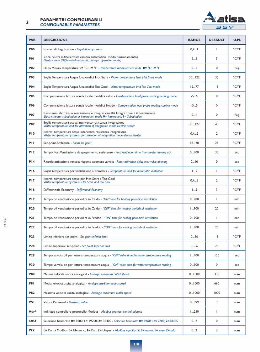
®PARAMETRI CONFIGURABILICONFIGURABLE PARAMETERS
PAR. DESCRIZIONE RANGE DEFAULT U.M.
P00 Isteresi di Regolazione - Regulation hysteresis 0,4...1 1 °C/°F
P01 Zona neutra (Differenziale cambio automatico modo funzionamento) Neutral zone (Differential automatic change operation mode) 2...5 5 °C/°F
P02 Unità Misura Temperatura 0= °C; 1= °F – Temperature measurement units 0= °C; 1= °F 0...1 0 flag
P03 Soglia Temperatura Acqua funzionalità Hot Start - Water temperature limit Hot Start mode 30...122 35 °C/°F
P04 Soglia Temperatura Acqua funzionalità Too Cool - Water temperature limit Too Cool mode 12...77 15 °C/°F
P05 Compensazione lettura sonda locale modalità caldo - Compensation local probe reading heating mode -5...5 0 °C/°F
P06 Compensazione lettura sonda locale modalità freddo - Compensation local probe reading cooling mode -5...5 0 °C/°F
P07 Resistenza elettrica in sostituzione o integrazione 0= Integrazione; 1= Sostituzione Electric heater substitution or integration mode 0= Integration; 1= Substitution 0...1 0 flag
P09 Soglia temperatura acqua intervento resistenza integrazione Water temperature limit for attivation of integration mode electric heater 30...122 40 °C/°F
P10 Isteresi temperatura acqua intervento resistenza integrazione Water temperature hysteresis for attivation of integration mode electric heater 0,4...2 2 °C/°F
P11 Set-point Ambiente - Room set point 18...28 25 °C/°F
P12 Tempo Post Ventilazione da spegnimento resistenze - Post ventilation time from heater turning off- 0...900 30 sec
P14 Ritardo attivazione ventola rispetto apertura valvola - Rotor attivation delay over valve opening 0...10 0 sec
P16 Soglia temperatura per ventilazione automatica - Temperature limit for automatic ventilation 1...5 1 °C/°F
P17 Isteresi temperatura acqua per Hot Start e Too Cool Water temperature hysteresis Hot Start and Too Cool 0,4...5 2 °C/°F
P18 Differenziale Economy - Differential Economy 1...5 3 °C/°F
P19 Tempo on ventilazione periodica in Caldo - “ON” time for heating periodical ventilation 0...900 1 min
P20 Tempo off ventilazione periodica in Caldo - “OFF” time for heating periodical ventilation 1...900 20 min
P21 Tempo on ventilazione periodica in Freddo - “ON” time for cooling periodical ventilation 0...900 1 min
P22 Tempo off ventilazione periodica in Freddo - “OFF” time for cooling periodical ventilation 1...900 20 min
P23 Limite inferiore set-point - Set point inferior limit 0...86 18 °C/°F
P24 Limite superiore set-point - Set point superior limit 0...86 28 °C/°F
P29 Tempo valvola off per lettura temperatura acqua - “OFF” valve time for water temperature reading 1...900 120 sec
P30 Tempo valvola on per lettura temperatura acqua - “ON” valve time for water temperature reading 0...900 0 sec
P80 Minima velocità uscita analogical - Analogic minimum outlet speed 0...1000 330 num
P81 Media velocità uscita analogical - Analogic medium outlet speed 0...1000 660 num
P82 Massima velocità uscita analogical - Analogic maximum outlet speed 0...1000 1000 num
PS1 Valore Password - Password value 0...999 15 num
Adr* Indirizzo controllore protocollo Modbus - Modbus protocol control address 1...250 1 num
bAU Selezione baud-rate 0= 9600; 1= 19200; 2= 38400 - Selection baud-rate 0= 9600; 1=19200; 2=38400 0...2 0 num
PtY Bit Parità Modbus 0= Nessuno; 1= Pari; 2= Dispari - Modbus equality bit 0= noone; 1= even; 2= odd 0...2 2 num
SS
V

319
4
5
SSV
SSV
®
®
DESCRIZIONE PANNELLO LCDLCD PANEL DESCRIPTION
COLLEGAMENTO SCHEMA BASEBASE DRAWING LINK
AREA REF. MEANING
Mode function 1a Cooling mode active
2a Heating mode active
3a Auto mode active
4a OFF mode
Fan speeddescription
1b Fan speed value MIN
2b Fan speed value MED
3b Fan speed value MAX
4b Fan speed value AUTO
Temperature 1c Set temperature
REF. MEANING
A Fan speed selection
B Down
C Up
D MODE selection / ON-OFF
SS
V
A B C D
1b 1a
2b 2a
3b 3a
4b 4a
LCD Display Description
TTL (seconda seriale)TTL Quick connector for DMI interface
RS485 (seconda seriale)Connection for RS485 Module
Sonda analogica 1Analogic Air sensor with Quick connector 1
Espansione contattiContact expansion
Connessione terminale LED (prima seriale)Quick connector for on-board control
Sonda analogica 2Analogic water sensorwith quick connector 2
Connessione termilale LOWConnection to terminal LOW
Motore / Motor
Connessione terminale LCD (prima seriale)Remote terminal LCD connection
DriverMotore
Uscita 0-10VOutput 0-10V
Pilotaggio valvoleHeating/cooling valve
Alimentazione di reteSupply 230V
Pilotaggio motore
Relay digital output Low-Med-Max
320
6SSV
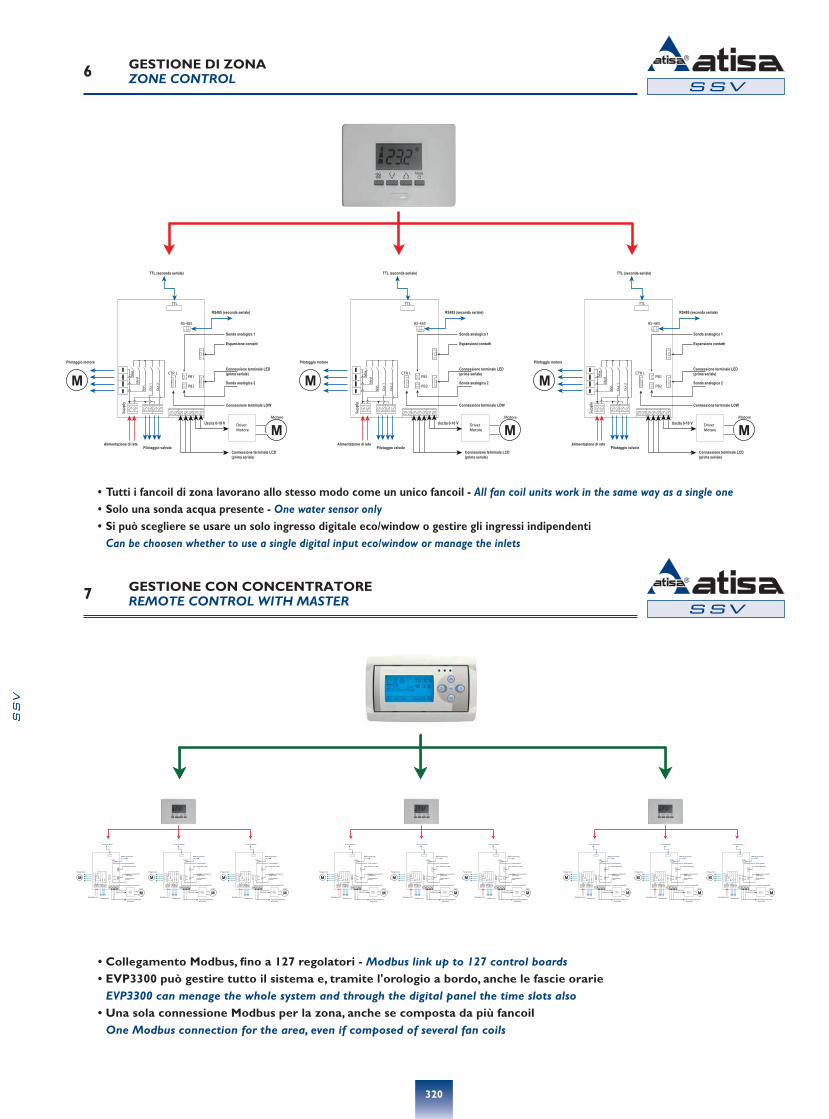
®GESTIONE DI ZONAZONE CONTROL
7SSV
®GESTIONE CON CONCENTRATOREREMOTE CONTROL WITH MASTER
SS
V
• Tutti i fancoil di zona lavorano allo stesso modo come un unico fancoil - All fan coil units work in the same way as a single one• Solo una sonda acqua presente - One water sensor only• Si può scegliere se usare un solo ingresso digitale eco/window o gestire gli ingressi indipendenti Can be choosen whether to use a single digital input eco/window or manage the inlets
• Collegamento Modbus, fino a 127 regolatori - Modbus link up to 127 control boards• EVP3300 può gestire tutto il sistema e, tramite l'orologio a bordo, anche le fascie orarie EVP3300 can menage the whole system and through the digital panel the time slots also• Una sola connessione Modbus per la zona, anche se composta da più fancoil One Modbus connection for the area, even if composed of several fan coils

321
8SSV
®INTEGRAZIONE CON BMSINTEGRATION WITH BMS
SS
V
• Collegamento Modbus, fino a 255 regolatori - Modbus link up to 255 control boards• Con il protocollo Modbus, il sistema può essere facilmente integrato nei sistemi BMS esistenti o in fase di
realizzazione - Modbus protocol can be easily integrated into existing BMS systems or under construction

322
SS
V