stability experiment of the high-speed active magnetic
TRANSCRIPT

Stability Experiment of the High-Speed Active Magnetic Bearing-Flywheel
System in the Rotating Frame
Jinpeng Yu 1,2,3, Yan Zhou 1,2,3, Haoyu Zuo 1,2,3, Kai Zhang 4, Pingfan Liu 2,3, Yanbao Li 5,
Pengcheng Pu 1,2,3, Lei Zhao 1,2,3, and Zhe Sun*1,2,3
1 Institute of Nuclear and New Energy Technology 2 Collaborative Innovation Center of Advanced Nuclear Energy Technology
3 The Key Laboratory of Advanced Reactor Engineering and Safety 4 Department of Engineering Physics
Tsinghua University, Beijing, 100084, China
[email protected], [email protected]*
5 Shanghai Aerospace Control Technology Institute
Shanghai, 200000, China
Abstract ─ The active magnetic bearings (AMBs) can
greatly improve the stability of the flywheel system and
increase the maximum flywheel speed. However, if the
active magnetic bearing-flywheel system (AMB-FS) is
placed in a rotating frame, the strong gyroscopic effect
of high-speed flywheel will greatly affect the system
stability. In this study, to realize the high stability of the
AMB-FS at ultra-high flywheel speed with low power
consumption, the cross feedback PID control was applied
in the AMB-FS. The system stability and the performance
of AMBs were studied. In the experiment, the gyroscopic
effect of the flywheel was effectively suppressed. In the
vacuum environment, the flywheel could runs stably at
any speed within the range of 0 to 30000 rpm, and the
power consumption of AMBs was only 17.82 W and the
system had no need of cooling measures. The flywheel
speed could exceed 31200 rpm and still possessed the
speeding potential. The rotating frame test showed that the
maximum frame rotational speed could reach 3.5 deg/s at the rated flywheel speed of 30000 rpm, and the AMB-
FS run stably.
Index Terms ─ Active magnetic bearing, cross feedback
control, gyroscopic effect, system stability.
I. INTRODUCTION The active magnetic bearing-flywheel system
(AMB-FS) is a nonlinear system with multiple coupling
variables. The rotor imbalance, gyroscopic effect and
external disturbance will bring about high control
requirement for AMBs. Especially in the high-speed
AMB-FS, the strong gyroscopic effect of the flywheel
will impose a great burden on AMBs and bring about the
problem of stability and stability margin [1]. The AMB
controller will fail to meet the control requirements and
only small external disturbance acting on the high-speed
flywheel will lead to the instability of the AMB-FS.
Combining PID controller with other control methods
can achieve good control performance. Displacement
cross feedback and speed cross feedback can suppress
the gyroscopic effect of the flywheel significantly [2].
Zhang [3] implemented the control arithmetic which
included cross feedback based on PD controller on the
spacecraft attitude control. Reference [4] designed an H∞
controller with gain adjustment, which could suppress
the gyroscopic effect significantly. Studies in [5-6]
combined variable gain controller with other control
methods to stabilize the AMB-FS. All the methods could
effectively suppress the gyroscopic effect and improved
the system stability. Meanwhile, accounting the
uncertainty and robust control will also contribute to
improve the control performance and system stability.
Reference [7] derived the nominal model of active
magnetic suspension of rotor and the uncertainty model,
and proposed a robust control with a multi-objective
controller to achieve good robust stability when the
model of a plant was uncertain. Reference [8] presented
the sensitivity and stability margin analyses of the flexible
rotor supported by AMBs with the robust optimal
vibrations control, and the µ-controller was verified in
experimental tests and possessed good performance.
References [9-10] proposed an identification method for
flexible rotor suspended by magnetic bearings to estimate
the unknown parameters and establish the transfer
function matrix model of the AMB system, and finally
eliminated the influence of bearing stiffness and improved
the system stability.
The study in this paper mainly focused on the stability
ACES JOURNAL, Vol. 34, No. 4, April 2019
1054-4887 © ACES
Submitted On: June 30, 2018 Accepted On: October 1, 2018
547

of the AMB-FS on movable base. The rotating frames
accounting the gyroscopic effects is a typical problem,
so the AMB-FS in the rotating frame was studied.
Furthermore, the PID controller with cross feedback was
studied to discover if the controller worked well in the
proposed AMB-FS. And with the optimized design of
the structure and controller, the performance of AMBs
was studied in the experiment. In the second section,
the flywheel stability and cross feedback PID controller
is analyzed and designed. The third section shows the
experiment result of the stability of AMB-FS under cross
feedback PID control. The experiment of the high-speed
AMB-FS in rotating frame is presented in section four.
II. STABILITY ANALYSIS AND
CONTROLLER DESIGN If the system frame rotates in the different direction
from flywheel, the gyroscopic effect of the high-speed
flywheel will impose a great burden on AMBs, which
will seriously affect the flywheel stability and raise strict
control requirements for AMBs. Therefore, for the
AMB-FS, the rotating frame can also be equivalent to
the external disturbance. The system stability is analyzed
based on the horizontal AMB-FS, whose weight is
supported by radial AMBs.
A. Stability Analysis
The system mainly includes flywheel, AMB system,
drive motor, frame, and other appended structures. The
three-dimensional (3D) structure of the AMB-FS is shown
in Fig. 1. The system has an inner rotor structure with
radial AMBs mounted on the outside of the flywheel,
which achieves high inertia ratio of 1.93. The rated
flywheel speed is 500 Hz.
(a) 3D structure of the AMB-FS
(b) The flywheel
Fig. 1. The structure of AMB-FS and flywheel.
Neglecting the influence of the flexible modes of the
flywheel, the rigid body model and the force conditions
are shown in Fig. 2. The high-speed flywheel is placed
horizontally. Since the radial and axial AMBs in the
system are decoupled, only the radial AMBs are analyzed.
Fig. 2. The flywheel model and the force condition.
MBi(𝑖 = 1,2) are radial AMBs. The flywheel
coordinate is 𝑞 = [𝑥, 𝛽, 𝑦, −𝛼]T and the AMB coordinate
is 𝑞𝑏 = [𝑥1, 𝑥2, 𝑦1, 𝑦2]T, which have the transformation
relation 𝑞𝑏 = 𝐿𝑞𝑞, where,
𝐿𝑞 = [
1 −𝑎 0 01 𝑏 0 00 0 1 −𝑎0 0 1 𝑏
]. (1)
𝑎 and 𝑏 are the distance between radial AMBs and the
flywheel centroid. In order to simplify the calculation, it
is considered that the displacement sensor and AMBs
have the same position. So the motion differential
equation of the flywheel is:
{
𝑚�̈� = 𝐹𝑥1 + 𝐹𝑥2 + 𝐹𝑥1𝑡 + 𝐹𝑥2
𝑡
𝑚�̈� = 𝐹𝑦1 + 𝐹𝑦2 + 𝐹𝑦1𝑡 + 𝐹𝑦2
𝑡
𝐽𝑑�̈� = 𝑎(𝐹𝑦1 + 𝐹𝑦1𝑡 ) − 𝑏(𝐹𝑦2 + 𝐹𝑦2
𝑡 ) − 𝐽𝑝𝛺�̇�
𝐽𝑑�̈� = 𝑏(𝐹𝑥2 + 𝐹𝑥1𝑡 ) − 𝑎(𝐹𝑥1 + 𝐹𝑥2
𝑡 ) + 𝐽𝑝𝛺�̇�
, (2)
with 𝑚 the mass of flywheel, 𝑥 and 𝑦 the displacements
of the flywheel centroid, 𝛼 and 𝛽 the rotation angles in
the x and y directions, 𝐽𝑑 and 𝐽𝑝 the diameter and polar
moment of inertia and 𝛺 the flywheel speed. 𝐹𝑥1 , 𝐹𝑥2 , 𝐹𝑦1
and 𝐹𝑦2 are the electromagnetic forces. 𝐹𝑡𝑥1 , 𝐹𝑡𝑥2 , 𝐹𝑡𝑦1
and 𝐹𝑡𝑦2 are the external forces (disturbances). The
flywheel is place in the closed frame, so 𝐹𝑥1𝑡 = 𝐹𝑥2
𝑡 =𝐹𝑦1𝑡 = 𝐹𝑦2
𝑡 = 0.
The motion differential equation of the AMB-FS
can be rewrite in matrix form:
𝑀�̈� + 𝐺�̇� = 𝐿𝐹𝐹, (3)
where 𝑀 = diag(𝑚, 𝐽𝑑 , 𝑚, 𝐽𝑑) , 𝐹 = [𝐹𝑥1 , 𝐹𝑥2 , 𝐹𝑦1 , 𝐹𝑦2]T
,
𝐿𝐹 = 𝐿𝑞T and,
𝐺 = [
0 0 0 00 0 0 10 0 0 00 −1 0 0
] 𝐽𝑝𝛺. (4)
Let 𝐼 = diag(1,1,1,1) .The AMB force can be
linearized as 𝐹 = 𝐾𝑥𝑞𝑏 + 𝐾𝑖𝐼𝑐 , where 𝐾𝑥 = 𝑘𝑥𝐼 and
YU, ZHOU, ZUO, ZHANG, LIU, LI, PU, ZHAO, SUN: HIGH-SPEED ACTIVE MAGNETIC BEARING-FLYWHEEL SYSTEM 548

𝐾𝑖 = 𝑘𝑖𝐼 are force-displacement and force-current
stiffness matrices respectively. Under PID current
feedback control, the AMB current is:
𝐼𝑐 = −𝐺𝑠𝐺𝑖 (𝐾𝑝𝑞𝑏 + 𝐾𝑑𝐶𝑞�̇�
+ 𝐾𝐼 ∫𝑞𝑏 𝑑𝑡), (5)
where 𝐺𝑠 = 𝑔𝑠𝐼 and 𝐺𝑖 = 𝑔𝑖𝐼 the coefficients of the
displacement sensor and power amplifier, 𝐾𝑝 = 𝑘𝑝𝐼 and
𝐾𝑑 = 𝑘𝑑𝐼 the parameter matrices of the PID controller.
The matrix C is the cross feedback coefficient. Substitute
the AMB force into equation (3) and obtain equation (6):
𝑀�̈� + 𝑁�̇� + 𝑉𝑞 +𝑊∫𝑞 𝑑𝑡 = 0, (6)
where 𝑊 = 𝐿𝐹𝐾𝑖𝐺𝑠𝐺𝑖𝐾𝐼𝐿𝑞 , 𝑁 = 𝐺 + 𝐿𝐹𝐾𝑖𝐺𝑠𝐺𝑖𝐾𝑑𝐶𝐿𝑞 ,
and 𝑉 = 𝐿𝐹𝐾𝑖𝐺𝑠𝐺𝑖𝐾𝑝𝐿𝑞 − 𝐿𝐹𝐾𝑠𝐿𝑞 . The state space
equation of the system can be obtained as:
�̇� = 𝐴𝑝, (7)
where 𝑝 = (�̇�, 𝑞, ∫ 𝑞 𝑑𝑡)T and,
𝐴 = [−𝑀−1𝑁 −𝑀−1𝑉 −𝑀−1𝑊
𝐼 𝑂 𝑂𝑂 𝐼 𝑂
]. (8)
Figure 3 shows the PID closed loop system and
Table 1 shows the parameters in the simulation.
Fig. 3. The closed loop system with cross feedback.
Under dynamic condition, the flywheel speed has 𝛺 ≠0. Suppose that the flywheel is under the decentralized
PID control (𝐶 = 𝐶𝑑 = 𝐼 ). When the flywheel speed
increases from 0 Hz to 500 Hz , the eigenvalues of
matrix A change with the flywheel speed. During the
acceleration period, matrix A has three negative real
eigenvalues and three pairs of conjugate eigenvalues.
The negative real eigenvalues, 𝑎1𝑑 = −141.2218, 𝑎2
𝑑 =−96.1456 and 𝑎3
𝑑 = −1.0178 remain unchanged.
However, the three pairs of conjugate eigenvalues, 𝑎4𝑖𝑑 ,
𝑎5𝑖𝑑 and 𝑎6𝑖
𝑑 (𝑖 = 1,2), are greatly affected by the flywheel
speed, as shown in Fig. 4.
Table 1: The parameters in the simulation
Parameter Value Parameter Value
𝑎(m) 0.02 𝑚(kg) 5.2 𝑏(m) 0.02 𝑘𝑥(N/m) 8982.6
𝐽𝑑(kg ∙ m2) 0.014 𝑘𝑖(N/A) 4.5
𝐽𝑝(kg ∙ m2) 0.027 𝑘𝑝 9980.7
𝑔𝑖 1 𝑘𝑖𝑛 0.0138 𝑔𝑠 1 𝑘𝑑 13.8
(a) 𝑎4𝑖
𝑑
(b) 𝑎5𝑖
𝑑
(c) 𝑎6𝑖
𝑑
Fig. 4. The conjugate eigenvalues change as the flywheel
speed up.
As the flywheel speeds up, 𝑎5𝑖𝑑 moves away from the
imaginary axis, while 𝑎4𝑖𝑑 and 𝑎6𝑖
𝑑 approach the imaginary
axis. Therefore, 𝑎4𝑖𝑑 and 𝑎6𝑖
𝑑 become the dominant
eigenvalues for the system as the flywheel speeds up.
When 𝑎4𝑖𝑑 and 𝑎6𝑖
𝑑 approach the imaginary axis, the
absolute value of the real part decrease and the system
stability will be decreased significantly. When the flywheel
speed is near 450 Hz, the real part of 𝑎6𝑖𝑑 turns into
positive value and the AMB-FS is instability. Therefore,
the original PID controller possesses good robustness
under static state but fails to ensure the stability of AMB-
FS at high flywheel speed.
ACES JOURNAL, Vol. 34, No. 4, April 2019549

B. Controller design
In order to improve the stability of the high-speed
AMB-FS, the decentralized PID control was combined
with cross feedback control in the actual experiment. The
cross feedback suppressed the precession and nutation
frequency by taking the displacement signal in the
orthogonal direction as the feedback, as shown in Fig. 5.
Fig. 5. PID controller with cross feedback.
As for precession, the cross feedback with low-pass
characteristics, whose gain in the middle and high
frequency band is very low, can effectively damp the
precession and has little effect on nutation:
𝐺𝑙 =𝑘𝑐𝑙
𝑇𝑙𝑝𝑠 + 1. (9)
As for nutation, the cross feedback with high-pass
characteristics, whose gain in the low frequency band is
very low, can effectively damp the nutation and has little
effect on procession:
𝐺ℎ =𝑘𝑐ℎ𝑠
𝑇ℎ𝑝𝑠 + 1. (10)
In order to suppress both the nutation and precession,
it is necessary to add the both displacement cross feedback
simultaneously, and connect the low-pass and high-pass
filters to the corresponding control channel. Therefore,
the actual transfer function of the cross feedback is:
𝐺(𝑠) =𝑘𝑑
𝑇𝑙𝑝𝑠 + 1+
𝑘𝑐ℎ𝑠
𝑇ℎ𝑝𝑠 + 1. (11)
III. STABILITY EXPERIMENT Figure 6 shows the AMB-FS experiment platform.
The horizontal AMB-FS was placed in the frame, and the
frame was placed on a rotatable base. During the running
of the AMB-FS, the frame could rotate in the x direction.
A. Static suspension
Figure 7 shows the axis orbit of the flywheel in static
suspension. It can be seen that AMBs could suspend
the flywheel stably in the static state, and the radial
displacement of the flywheel was less than 1 μm.
Fig. 6. Experiment platform.
(a) Displacement at MB1 (b) Displacement at MB2
Fig. 7. Flywheel axis orbit under static suspension.
B. Gyroscopic effect suppression
When the flywheel speed is high, the precession
frequency gradually drops to zero, and the nutation
frequency increases continually. It is difficult for the
decentralized PID controller to effectively suppress the
procession and nutation simultaneously. The performance
of the cross feedback PID control on the gyroscopic
effect was studied in the following experiment.
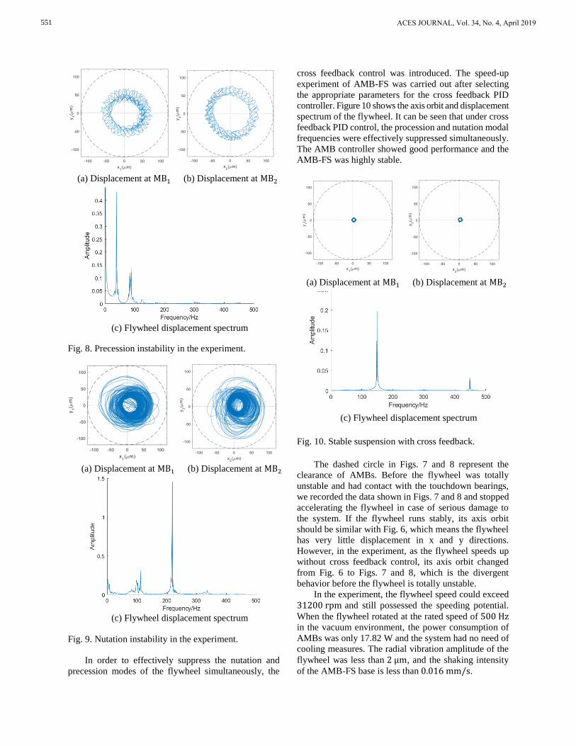
Figure 8 shows the axis orbit and displacement
spectrum of the flywheel without cross feedback control.
When the flywheel speed was 40 Hz, the precession was
unstable and the decentralized PID controller cannot
provide enough damping for the precession mode.
Similarly, without cross feedback control, the
nutation was unstable when the flywheel speed was
110 Hz, as is shown in Fig. 9. The nutation frequency is
210 Hz, and the ratio between the nutation frequency
and the rotor speed is 1.91, which is basically equal to
the inertia ratio of the flywheel [11].
YU, ZHOU, ZUO, ZHANG, LIU, LI, PU, ZHAO, SUN: HIGH-SPEED ACTIVE MAGNETIC BEARING-FLYWHEEL SYSTEM 550
(a) Displacement at MB1 (b) Displacement at MB2
(c) Flywheel displacement spectrum
Fig. 8. Precession instability in the experiment.
(a) Displacement at MB1 (b) Displacement at MB2
(c) Flywheel displacement spectrum
Fig. 9. Nutation instability in the experiment.
In order to effectively suppress the nutation and
precession modes of the flywheel simultaneously, the
cross feedback control was introduced. The speed-up
experiment of AMB-FS was carried out after selecting
the appropriate parameters for the cross feedback PID
controller. Figure 10 shows the axis orbit and displacement
spectrum of the flywheel. It can be seen that under cross
feedback PID control, the procession and nutation modal
frequencies were effectively suppressed simultaneously.
The AMB controller showed good performance and the
AMB-FS was highly stable.
(a) Displacement at MB1 (b) Displacement at MB2
(c) Flywheel displacement spectrum
Fig. 10. Stable suspension with cross feedback.
The dashed circle in Figs. 7 and 8 represent the
clearance of AMBs. Before the flywheel was totally
unstable and had contact with the touchdown bearings,
we recorded the data shown in Figs. 7 and 8 and stopped
accelerating the flywheel in case of serious damage to
the system. If the flywheel runs stably, its axis orbit
should be similar with Fig. 6, which means the flywheel
has very little displacement in x and y directions.
However, in the experiment, as the flywheel speeds up
without cross feedback control, its axis orbit changed
from Fig. 6 to Figs. 7 and 8, which is the divergent
behavior before the flywheel is totally unstable.
In the experiment, the flywheel speed could exceed
31200 rpm and still possessed the speeding potential.
When the flywheel rotated at the rated speed of 500 Hz in the vacuum environment, the power consumption of
AMBs was only 17.82 W and the system had no need of
cooling measures. The radial vibration amplitude of the
flywheel was less than 2 μm, and the shaking intensity
of the AMB-FS base is less than 0.016 mm/s.
ACES JOURNAL, Vol. 34, No. 4, April 2019551

C. Rotating frame experiment
From the theoretical analysis above, it can be seen
that the rotating frame leads to strong gyroscopic effect
of the flywheel at high speed, which will reduce the
AMB controller performance significantly. The flywheel
may collide with the touchdown bearings, leading to the
instability of the AMB-FS. Therefore, in the rotating
frame, the stability of the AMB-FS was analyzed in the
experiment.
In the experiment, the flywheel was suspended
stably at the rated speed of 500 Hz, and the frame rotated
in the x direction at different angular velocity. The axial
orbit of both ends of the flywheel and the flywheel
displacement spectrum is shown in Fig. 11, where the
angular velocity of the frame is 1 deg/s, 1.5 deg/s and
2.5 deg/s, respectively.
(a) 1 deg/s
(b) 1.5 deg/s
(c) 2.5 deg/s
Fig. 11. Axis orbit and displacement frequency.
From the experimental results, it can be seen that the
increase of the frame rotational speed had no effect on
the stability of the AMB-FS. There as little change in
the flywheel axis orbit and the displacement spectrum. It
proves that the cross feedback PID controller possessed
good robustness and had high performance in resisting
the disturbance of the rotating frame. The dynamic
stability of the ultra-high AMB-FS was fully verified
under the disturbance of the rotating frame in the
experiment.
IV. AMB-FS ANALYSIS IN ROTATING
FRAME Since the power amplifier has maximum current and
the ferromagnetic material has saturation magnetization,
AMBs have the maximum force. Influenced by the
gyroscopic effect and limited by the maximum AMB
force, the frame has the maximum rotational speed when
the AMB-FS is stable. Therefore, the experiment of the
AMB-FS in the rotating frame was studied.
Assume that the rotational angle of the frame is 𝜃 =𝜔𝑛 𝑡 + 𝜃0 , where 𝜃0 is the initial angle and 𝜔𝑛 is the
frame rotational speed. Under the conditions of small-
angle change, the AMB force at time 𝑡 is:
{
𝐹𝑥1 = −(𝑘1𝑥1 + 𝑑1�̇�1)
𝐹𝑥1 = −(𝑘2𝑥2 + 𝑑2�̇�2)
𝐹𝑦1 = −[𝑘3(𝑦1 − 𝑎𝜃) + 𝑑3(�̇�1 − 𝑎𝜔𝑛)]
𝐹𝑦2 = −[𝑘4(𝑦2 + 𝑏𝜃) + 𝑑4(�̇�2 + 𝑏𝜔𝑛)]
, (12)
where 𝑘𝑗 (𝑗 = 1, 2, 3, 4) and 𝑑𝑗 are the stiffness and
damping of AMBs. Substitute the equation (12) into the
(2) and obtain the ordinary differential equations with
YU, ZHOU, ZUO, ZHANG, LIU, LI, PU, ZHAO, SUN: HIGH-SPEED ACTIVE MAGNETIC BEARING-FLYWHEEL SYSTEM 552

the bearing coordinates 𝑞𝑏 = [𝑥1, 𝑥2, 𝑦1, 𝑦2 ]T as the
variables, and the solution of equation is:
{
𝑥1 = −
𝐽𝑝𝛺𝜔𝑛
(𝑎 + 𝑏)𝑘1
𝑥2 = 𝐽𝑝𝛺𝜔𝑛
(𝑎 + 𝑏)𝑘2𝑦1 = 𝑎(𝜔𝑛𝑡 + 𝜃0)𝑦2 = −𝑏(𝜔𝑛𝑡 + 𝜃0)
. (13)
Therefore, the AMB force can be obtained by
substituting equation (13) into equation (12):
{
𝐹𝑥1 =
𝐽𝑝𝛺𝜔𝑛
(𝑎 + 𝑏)
𝐹𝑥1 = −𝐽𝑝𝛺𝜔𝑛
(𝑎 + 𝑏)𝐹𝑦1 = 𝐹𝑦2 = 0
. (14)
It can be seen from the result that when the frame
rotates in x direction at speed 𝜔𝑛, there is no force in y
direction while the forces in x direction have the same
values and opposite directions. The AMB force in x
direction is proportional to the product of flywheel speed
and frame rotational speed. Therefore, when the flywheel
speed is high, only a small frame rotational speed will
consume a large amount of AMB force and lead to the
force saturation, which will affect the stability of the
AMB-FS significantly.
A. Maximum frame speed
AMBs in this study can provide a maximum
electromagnetic force of 1200 N. Therefore, with equation
(11) and the model in Fig. 5, the relationship between
flywheel speed and maximum frame rotational speed can
be obtained in Fig. 12, where the solid line is theoretical
result and the dotted line is simulation result.
The maximum frame rotational speed was verified
in the experiment. The flywheel was placed horizontally,
which means its axis was in the horizontal direction and
its weight was supported by the radial AMBs. The AMB-
FS was placed on a rotatable base.
A. The flywheel accelerated to a certain speed and
run stably.
B. As the flywheel rotated stably, accelerated the
base slowly.
C. When the base accelerated to the speed at which
the flywheel vibrated violently, recorded the
speeds of the flywheel and base.
D. Changed the speed of flywheel and repeated the
step A to C.
The dashed line in Fig. 12 shows the experiment
result. It can be seen that the results of theory, simulation
and experiment agree well. As the flywheel speed
increases, the maximum frame rotational speed decreases
rapidly.
Fig. 12. Relationship between flywheel speed and frame
rotational speed.
The experimental results show the high stability of
the AMB-FS at high flywheel speed. And the maximum
frame rotational speed could reach 3.5 deg/s at the rated
flywheel speed of 500 Hz . In the experiment, AMBs
needed to provide extra force to offset the flywheel
gravity. Therefore, If the flywheel is placed vertically,
which means the axis of the flywheel is vertical direction
and the weight is supported by axial AMBs, the robustness
of AMB controller and the maximum frame rotational
speed will be further improved.
B. Features of the AMB Force
In can be seen in the theoretical analysis that
the AMB force had different performance in different
directions. Therefore, the simulation and the experiment
were carried out to observe the features of the AMB
force when the frame rotational speed increased. In
the simulation, the flywheel rotated at the rated speed
of 500 Hz , and the frame rotational speed gradually
increased from 0 deg/s to 3.5 deg/s. Figure 13 shows
the simulation results of frame rotational speed and the
AMB force.
According to theoretical analysis, when the frame
rotates in the x direction, AMBs will generate force in x
direction to suppress the gyroscopic effect of the flywheel.
As shown in Fig. 13 (b), the AMB electromagnetic
forces in x direction increased as the frame rotational
speed increase, and the force direction of two AMB
is opposite. While in the y direction there was only
a certain exciting force at the start and stop state of
the frame acceleration. The results are consistent with
theoretical analysis. Furthermore, in the simulation, the
acceleration of the frame was reflected by the flywheel
rotating in x direction. Therefore, there was no AMB force
in the y direction during the acceleration of the frame.
ACES JOURNAL, Vol. 34, No. 4, April 2019553

(a) Frame rotational speed
(b) AMB force in x direction
(c) AMB force in y direction
Fig. 13. Frame rotational speed and AMB force.
Similarly, in the experiment, the flywheel was
suspended stably and rotates at 100 Hz. Recorded the
control current of radial AMB when the frame rotated at
different rotational speeds. According to the theoretical
analysis, when the flywheel rotated in the rotating frame,
there is no AMB force in y direction. Therefore, only
the control current in x direction was studied in the
experiment. By gradually increasing the frame rotational
speed until the AMB force was saturate, the features of
the AMB force was obtained as Fig. 14 shows.
From the experimental results, it can be seen that the
AMB control current changed with the frame rotational
speed. The high-speed flywheel could be suspended stably
and the axis orbit was small, so the flywheel displacement
could be regarded as a constant. The features of the AMB
force can be obtained as Fig. 15 shows. 𝐹𝑥1 and 𝐹𝑥2 are
the AMB force of MB1 and MB2, and the 𝐹𝑥𝑖+ points to
the positive direction of the x-axis while the 𝐹𝑥𝑖− points to
the negative.
1) When the frame rotational speed is low, the
influence of the gyroscopic effect on the AMB-FS is
small. The AMB forces 𝐹𝑥1+ and 𝐹𝑥2
+ are large, while 𝐹𝑥1−
and 𝐹𝑥2− are zero. Therefore, the electromagnetic force is
mainly used to offset the flywheel gravity.
2) As the frame rotational speed increases, 𝐹𝑥1+
increase rapidly and 𝐹𝑥2+ decreases to zero. The flywheel
is in the cantilever state, with the flywheel gravity is use
to suppress the gyroscopic effect.
3) When frame rotational speed is high, the external
disturbances caused by the gyroscopic effect aggravates.
𝐹𝑥1+ continues to increase while 𝐹𝑥2
− starts to increase. AMBs
at both ends of the flywheel provide electromagnetic
force to suppress the gyroscopic effect.
Fig. 14. The AMB control current in x direction.
(a) Low speed (b) Medium speed
(c) High speed
Fig. 15. The AMB force under different frame rotational
speed.
YU, ZHOU, ZUO, ZHANG, LIU, LI, PU, ZHAO, SUN: HIGH-SPEED ACTIVE MAGNETIC BEARING-FLYWHEEL SYSTEM 554

The resultant force of AMBs is constant, but the
resultant moment about the flywheel centroid increases
as the frame speeds up to suppress gyroscopic effect. The
experimental results agree with the theoretical analysis
and show the features of the AMB force when the frame
rotational speed increases.
C. Stability at maximum frame speed
As AMBs suppresses the gyroscopic effect caused
by the rotating frame, it still need to resist the external
disturbance loaded on the flywheel. So the simulation
was carried out to observe the influence of external
disturbance on the AMB-FS in the rotating frame. When
the flywheel rotated at the rated speed of 500 Hz and
the frame rotated at the maximum speed of 3.5 deg/s, loaded the external disturbance on the flywheel in the
x direction at 6 s. Increased the frame rotational speed
to 3.5 deg/s before 4 s, and loaded 58 N external
disturbance when the AMB-FS runs stably as shown in
Fig. 16 (a), The AMB-FS could return to steady state.
However, to suppress the gyroscopic effect, the AMB
control current in the x direction was very large and the
control current reached saturation during the flywheel
returning to the steady state. When the external disturbance
came to 60 N, the system was unstable and AMBs cannot
meet the control requirement, as shown in Fig. 16 (b).
(a) 58 N in x direction
(b) 58.5 in x direction
Fig. 16. Displacement and control current in x direction.
Similarly, repeated the experiment and loaded the
external disturbance on the flywheel in the y direction.
Increased the frame rotational speed to 3.5 deg/s before
4 s, and loaded 17.5 N external disturbance on the
flywheel at 6s. As the Fig. 17 (a) shows, the AMB-FS
could return to the steady state. However, the AMB
control current in the x direction still reached saturation.
When the external disturbance was only 18 N, the
system was unstable.
As is known in the theoretical analysis, when the
AMB-FS runs in the rotating frame, AMBs in y direction
need not to provide electromagnetic force. Therefore,
theoretically, the external disturbance loaded in the y
direction can be large. However, due to the gyroscopic
effect of the flywheel, the external disturbance loaded
in the y direction will still seriously affect AMBs in x
direction.
(a) 17 N in y direction
(b) 17.5 N in y direction
Fig. 17. Displacement and control current in x direction.
From the simulation and the analysis, it can be
seen that AMBs in the x direction is under seriously
requirement regardless of direction of the external
disturbance. The external disturbance is against the
frame rotational speed. The larger the frame rotational
speed, the more the electromagnetic force is consumed
to suppress the gyroscopic effect. Therefore, AMBs will
ACES JOURNAL, Vol. 34, No. 4, April 2019555

be weak to resist the external disturbance when the frame
speed is high. Limited by the experimental conditions,
the experiment of external disturbance will be carried out
after optimizing the experiment platform.
V. CONCLUSION In this paper, through stability analysis, AMB
controller design, stability experiment and AMB-FS
performance experiment, the AMB-FS was designed
and studied. The stability of the AMB-FS and the high
performance of AMBs were studied in the rotating frame.
Under cross feedback PID control, the gyroscopic
effect of the flywheel was effectively suppressed.
The flywheel could be suspended stably at any
speed within the range of 0 to 30000 rpm in the
vacuum environment, and the AMB-FS showed
high stability.
The flywheel speed could exceed 31200 rpm and
still possessed the speeding potential.
When the flywheel rotated at the rated speed of
500 Hz in the vacuum environment, the power
consumption of AMBs was only 17.82 W and the
system had no need of cooling measures.
The radial vibration amplitude of the flywheel was
less than 2 μm , and the shaking intensity of the
AMB-FS base was less than 0.016 mm/s. The maximum frame rotational speed at different
flywheel speeds was analyzed, and the maximum
frame speed could reach 3.5 deg/s at the rated
flywheel speed of 500 Hz. The dynamic and parametric uncertainties of the
AMB-FS would be carried out in the further experiment.
To reduce the energy loss and improving the stability of
the high-speed AMB-FS, the study about the resistance
moment of AMBs would be carried out.
ACKNOWLEDHGMENT This paper is financially supported by the National
Science and Technology Major Project of China
(2011ZX069) and Project 61305065 supported by NSFC.
REFERENCE [1] P. C. Pu, J. P. Yu, and L. Zhao, “Analysis of stiff-
ness and damping properties of active magnetic
bearing using cross feedback control,” International
Conference on Mechanics and Mechanical Engin-
eering, 2017.
[2] Z. Kai, Z. Lei, and H. Zhao, “Research on control
of flywheel suspended by active magnetic bearing
system with significant gyroscopic effects,” Chinese
Journal of Mechanical Engineering, pp. 63-66, 2004.
[3] K. Zhang, R. Zhu, and H. Zhao, “Experimental
research on a momentum wheel suspended by
active magnetic bearings,” Proceedings of the 8th
ISMB, Mito, 2002.
[4] S. Sivrioglu, “Lmi based gain scheduled h_∞
controller design for amb systems under gyroscopic
and unbalance disturbance effect,” Proc. Int. Symp.
on Magnetic Bearings, pp. 191-196, 1996.
[5] F. Matsumura, T. Namerikawa, K. Hagiwara,
and M. Fujita, “Application of gain scheduled H∞
robustness controllers to a magnetic bearing,” in
IEEE Transactions on Control Systems Technology,
vol. 4, no. 5, pp. 484-493, Sep. 1996.
[6] P. Tsiotras and S. Mason, “Self-scheduled H∞
controllers for magnetic bearings,” International
Mechanical Engineering Congress and Exposition,
Atlanta, GA, pp. 151-158, Nov. 1996.
[7] Z. Gosiewski and A. Mystkowski, “The robust
control of magnetic bearings for rotating machinery,”
Solid State Phenomena, vol. 113, pp. 125-130,
2006.
[8] A. Mystkowski, “Sensitivity and stability analysis
of mu-synthesis AMB flexible rotor,” Solid State
Phenomena, vol. 164, pp. 313-318, 2010.
[9] Z. Sun, J. Zhao, Z. Shi, and S. Yu, “Identification
of flexible rotor suspended by magnetic bearings,”
International Conference on Nuclear Engineering,
pp. V002T03A043 - V002T03A043, 2013.
[10] Z. Sun, Y. He, J. Zhao, et al., “Identification of
active magnetic bearing system with a flexible
rotor,” Mechanical Systems & Signal Processing,
vol. 49, no. 1-2, pp. 302-316, 2014.
[11] F. Jiancheng, Technology of Magnetic Suspension
Control Moment Gyroscope. Nationnal Defense
Industry Press, 2012.
Jinpeng Yu received his B.Sc. degree
in 2015 from Dalian University of
Technology. Now he is studying for
a Ph.D. at the Institute of Nuclear and
New Energy Technology, Tsinghua
University. He is mainly engaged
in active magnetic bearing and its
application in flywheel system.
Zhe Sun is currently an Aassociate
Professor and Ph.D. Supervisor of
Tsinghua University. His research
interests are control and monitoring
of active magnetic levitation system,
rotor dynamics, statistical learning
theory and its engineering applica-
tion, etc. He has published more
than 20 SCI/EI index papers and 10 national patents. He
presides over and participates in a series of National
Science and Technology Major Project of China, National
Natural Science Foundation of China and National High-
tech Research and Development Program of China.
YU, ZHOU, ZUO, ZHANG, LIU, LI, PU, ZHAO, SUN: HIGH-SPEED ACTIVE MAGNETIC BEARING-FLYWHEEL SYSTEM 556