stacked washer and dryer - alliance laundry...
TRANSCRIPT
Installation
/Op
eration
www.comlaundry.com
StackedWasher and Dryer
MeteredElectric and Gas Models
SWD447C
Part No. 802702R5 August 2017
Keep These Instructions for Future Reference.(If this machine changes ownership, this manual must accompany machine.)
Para bajar una copia de estas instrucciones en español, visite www.comlaundry.com.


© Copyright, Alliance Laundry Systems LLC – DO NOT COPY or TRANSMIT802702 1
IMPORTANT: Purchaser must consult the local gas supplier for suggested instructions to be followed if the dryer user smells gas. The gas utility instructions plus the SAFETY and WARNING note directly above must be posted in a prominent location near the dryer for customer use.
The following information applies to the state of Massachusetts, USA.
This appliance can only be installed by a Massachusetts licensed plumber or gas fitter.
This appliance must be installed with a 36 inch (91 cm) long flexible gas connector.
A “T-Handle” type gas shut-off valve must be installed in the gas supply line to this appliance.
This appliance must not be installed in a bedroom or bathroom.
• Do not store or use gasoline or other flammable vapors and liquids in the vicinity of this orany other appliance.
• WHAT TO DO IF YOU SMELL GAS:– Do not try to light any appliance.– Do not touch any electrical switch; do not use any phone in your building.– Clear the room, building or area of all occupants.– Immediately call your gas supplier from a neighbor’s phone. Follow the gas supplier’s
instructions.– If you cannot reach your gas supplier, call the fire department.
• Installation and service must be performed by a qualified installer, service agency or the gassupplier.
W052
FOR YOUR SAFETY, the information in this manual must be followed to minimize the risk of fire or explosion or to prevent property damage, personal injury or death.
W033
WARNING
Installation of unit must be performed by a qualified installer. Install clothes dryer according to manufacturer’s instructions and local codes. DO NOT install a clothes dryer with flexible plastic venting materials. If flexible metal (foil
type) duct is installed, it must be of a specific type identified by the appliance manufactureras suitable for use with clothes dryers. Refer to section on connecting exhaust system.Flexible venting materials are known to collapse, be easily crushed, and trap lint. Theseconditions will obstruct clothes dryer airflow and increase the risk of fire.
W729R1
WARNING
FOR YOUR SAFETY
Do not store or use gasoline or other flammable vapors and liquids in the vicinity of this or any other appliance.
W053

© Copyright, Alliance Laundry Systems LLC – DO NOT COPY or TRANSMIT
© Copyright 2017, Alliance Laundry Systems LLCAll rights reserved. No part of the contents of this book may be reproduced or transmitted in any form or by any means without the expressed written consent of the publisher.
8027022
Table of Contents
Safety Information.............................................................................. 4Explanation of Safety Messages........................................................... 4Important Safety Instructions ............................................................... 4
Installation........................................................................................... 7Before You Start ................................................................................... 9
Supplies............................................................................................ 9Installing the Unit ................................................................................. 10
Step 1: Position Unit Near Installation Area.................................... 10Step 2: Connect Fill Hoses............................................................... 10Step 3: (Non-Gravity Drain Models Only) Connect Drain Hose to Drain Receptacle ..................................................... 12
Step 4: (Gravity Drain Models Only) Connect Drain Outlet to Drain System......................................................... 12
Step 5: (Gas Dryer Only) Connect Gas Supply Pipe ....................... 13Step 6: (Electric Dryer Only) Connect Electrical Plug.................... 14Step 7: Connect Dryer Exhaust System ........................................... 20Step 8: Position and Level the Unit ................................................. 25Step 9: (Washer Only) Remove the Shock Sleeves and Shipping Brace ............................................................................... 27
Step 10: Wipe Out Inside of Washer Drum and Dryer Drum.......... 27Step 11: Plug In the Washer and Dryer ........................................... 28Step 12: Recheck steps 1-11 ............................................................ 30Step 13: Check Heat Source ............................................................ 30
Operation............................................................................................. 32Operation Instructions for MDC Washers............................................ 32
Step 1: Load Laundry....................................................................... 32Step 2: Close Loading Door............................................................. 32Step 3: Add Laundry Supplies ......................................................... 33Step 4: Determine Proper Controls for Washer ............................... 33Step 5: Set Fabric Selector and Wash Temperature(Cycles Vary by Model) ................................................................. 33
Step 6: Insert Coin(s) or Card .......................................................... 34Step 7: Start Washer......................................................................... 34Indicator Lights ................................................................................ 34
Operation Instructions for NetMaster Washers .................................... 35Step 1: Load Laundry....................................................................... 35Step 2: Close Loading Door............................................................. 35Step 3: Add Laundry Supplies ......................................................... 35Step 4: Determine Proper Controls for Washer ............................... 36Step 5: Set Fabric Selector ............................................................... 36Step 6: Set Wash Temperature......................................................... 36Step 7: Insert Coin(s) or Card .......................................................... 36Step 8: Start Washer......................................................................... 37Indicator Lights ................................................................................ 37
Operation Instructions for MDC Dryers............................................... 38Step 1: Clean Lint Filter................................................................... 38Step 2: Load Laundry....................................................................... 38Step 3: Close Loading Door............................................................. 38

© Copyright, Alliance Laundry Systems LLC – DO NOT COPY or TRANSMIT802702 3
Step 4: Determine Proper Controls for Dryer .................................. 39Step 5: Set Fabric Selector ............................................................... 39Step 6: Insert Coin(s) or Card .......................................................... 39Step 7: Start Dryer ........................................................................... 40Indicator Lights ................................................................................ 40
Operation Instructions for NetMaster Dryers ....................................... 41Step 1: Clean Lint Filter................................................................... 41Step 2: Load Laundry....................................................................... 41Step 3: Close Loading Door............................................................. 41Step 4: Determine Proper Controls for Dryer .................................. 42Step 5: Set Fabric Selector ............................................................... 42Step 6: Insert Coin(s) or Card .......................................................... 42Step 7: Start Dryer ........................................................................... 43Indicator Lights ................................................................................ 43
Maintenance ........................................................................................ 44User-Maintenance Instructions............................................................. 44
Lubrication ....................................................................................... 44Cold Weather Care........................................................................... 44Vacations and Extended Non-Use ................................................... 44Care of Your Washer ....................................................................... 44Care of Your Dryer .......................................................................... 45Reinstallation of Shipping Materials ............................................... 46
Motor Overload Protector..................................................................... 46For Energy Conservation...................................................................... 46
Troubleshooting .................................................................................. 47
Contact Information ........................................................................... 49
Installer Checklist ............................................................... Back Cover

© Copyright, Alliance Laundry Systems LLC – DO NOT COPY or TRANSMIT4 802702
Safety InformationExplanation of Safety Messages
Throughout this manual and on machine decals, you will find precautionary statements (“DANGER,” “WARNING,” and “CAUTION”) followed by specific instructions. These precautions are intended for the personal safety of the operator, user, servicer, and those maintaining the machine.
Additional precautionary statements (“IMPORTANT” and “NOTE”) are followed by specific instructions.
IMPORTANT: The word “IMPORTANT” is used to inform the reader of specific procedures where minor machine damage will occur if the procedure is not followed.
NOTE: The word “NOTE” is used to communicate installation, operation, maintenance or servicing information that is important but not hazard related.
Important Safety Instructions
Save These Instructions
1. Read all instructions before using the unit.
2. Refer to the GROUNDING INSTRUCTIONS in the INSTALLATION manual for the proper grounding of the unit.
3. Do not wash or dry articles that have been previously cleaned in, washed in, soaked in, or spotted with gasoline, dry-cleaning solvents, or other flammable or explosive substances as they give off vapors that could ignite or explode.
4. Under certain conditions, hydrogen gas may be produced in a hot water system that has not been used for two weeks or more. HYDROGEN GAS IS EXPLOSIVE. If the hot water system has not been used for such a period, before using a washing machine or combination washer-dryer, turn on all hot water faucets and let the water flow from each for several minutes. This will release any accumulated hydrogen gas. The gas is flammable, do not smoke or use an open flame during this time.
5. Do not allow children to play on or in the unit. Close supervision of children is necessary when the unit is used near children. This is a safety rule for all appliances.
6. Before the unit is removed from service or discarded, remove the doors to the washing and drying compartments.
Indicates an imminently hazardous situation that, if not avoided, will cause severe personal injury or death.
DANGER
Indicates a hazardous situation that, if not avoided, could cause severe personal injury or death.
WARNING
Indicates a hazardous situation that, if not avoided, may cause minor or moderate personal injury or property damage.
CAUTION
To reduce the risk of fire, electric shock, or injury to persons when using your stacked washer and dryer, follow these basic precautions.
W287
WARNING

© Copyright, Alliance Laundry Systems LLC – DO NOT COPY or TRANSMIT
Safety Information
5802702
7. Do not reach into the washer or dryer if thecylinders are revolving.
8. Do not install or store the unit where it will beexposed to water and/or weather.
9. Do not tamper with the controls.
10. Do not repair or replace any part of the unit, orattempt any servicing unless specificallyrecommended in the User-Maintenanceinstructions or in published user-repairinstructions that you understand and have theskills to carry out.
11. Do not add gasoline, dry-cleaning solvents, orother flammable or explosive substances to thewash water. These substances give off vapors that could ignite or explode.
12. Do not use fabric softeners or products toeliminate static unless recommended by themanufacturer of the fabric softener or product.
13. To reduce the risk of an electric shock or fire, DO NOT use an adapter to connect the unit to theelectrical power source.
14. To reduce the risk of fire, DO NOT DRY plasticsor articles containing foam rubber or similarlytextured rubberlike materials.
15. ALWAYS clean the lint filter after every load. Alayer of lint in the filter reduces drying efficiency and prolongs drying time.
16. Keep area around the exhaust opening andadjacent surrounding area free from theaccumulation of lint, dust and dirt.
17. The interior of the dryer and the exhaust ductshould be cleaned periodically by qualifiedservice personnel.
18. If not installed, operated and maintained inaccordance with the manufacturer’s instructionsor if there is damage to or mishandling of thisproduct’s components, use of this product couldexpose you to substances in the fuel or from fuelcombustion which can cause death or seriousillness and which are known to the State ofCalifornia to cause cancer, birth defects or otherreproductive harm.
19. Washer and dryer will not operate with theloading door open. DO NOT bypass the doorsafety switches by permitting the washer or dryer to operate with the doors open. The washer anddryer will stop tumbling when the doors areopened. Do not use the washer or dryer if they do not stop tumbling when the doors are opened orstart tumbling without pressing the STARTmechanisms. Remove the unit from use and callthe service person.
20. Do not put articles soiled with vegetable orcooking oil in the washer or dryer. Due to the oil,the fabric may catch on fire by itself.
21. To reduce the risk of fire, DO NOT put clotheswhich have traces of any flammable substancessuch as machine oil, flammable chemicals,thinner, etc., or anything containing wax orchemicals such as in mops and cleaning cloths, or anything dry-cleaned at home with a dry-cleaning solvent in the dryer.
22. Use your washer only for its intended purpose,washing clothes.
23. Use the dryer only for its intended purpose,drying clothes.
24. Always disconnect the electrical power to thewasher and dryer before attempting service toeither unit. Disconnect the power cords bygrasping the plug, not the cord.
25. If the supply cord is damaged, it must be replaced by a special cord or assembly available from themanufacturer or its service agent.
26. Install this unit according to theINSTALLATION INSTRUCTIONS. Allconnections for electrical power, grounding andgas supply must comply with local codes and bemade by licensed personnel when required. Donot do it yourself unless you know how!
27. Keep your unit in good condition. Bumping ordropping the unit can damage safety features. Ifthis occurs, have your unit checked by a qualified service person.

© Copyright, Alliance Laundry Systems LLC – DO NOT COPY or TRANSMIT
Safety Information
8027026
28. Remove laundry immediately after the dryer stops.
29. Always read and follow manufacturer’s instructions on packages of laundry and cleaning aids. Heed all warnings or precautions. To reduce the risk of poisoning or chemical burns, keep them out of reach of children at all times (preferably in a locked cabinet).
30. Do not tumble fiberglass curtains and draperies unless the label says it can be done. If they are dried, wipe out the cylinder with a damp cloth to remove particles of fiberglass.
31. Be sure water connections have a shut-off valve and that fill hose connections are tight. CLOSE the shut-off valves at the end of each wash day.
32. ALWAYS follow the fabric care instructions supplied by the garment manufacturer.
33. Never operate the unit with any guards and/or panels removed.
34. DO NOT operate the unit with missing or broken parts.
35. DO NOT bypass any safety devices.
36. Failure to install, maintain, and/or operate this machine according to the manufacturer’s instructions may result in conditions which can produce bodily injury and/or property damage.
37. Do not operate washer and dryer if the units have been separated.
IMPORTANT: Solvent vapors from dry-cleaning machines create acids when drawn through the heater of the drying unit. These acids are corrosive to the dryer as well as to the laundry load being dried. Be sure make-up air is free of solvent vapors.
IMPORTANT: Have your unit installed properly. Don’t do it yourself unless you know how!
NOTE: The WARNING and IMPORTANT SAFETY INSTRUCTIONS appearing in this manual are not meant to cover all possible conditions and situations that may occur. Common sense, caution and care must be exercised when installing, maintaining, or operating the dryer.
Always contact your dealer, distributor, service agent or the manufacturer about any problems or conditions you do not understand.
7802702 © Copyright, Alliance Laundry Systems LLC – DO NOT COPY or TRANSMIT
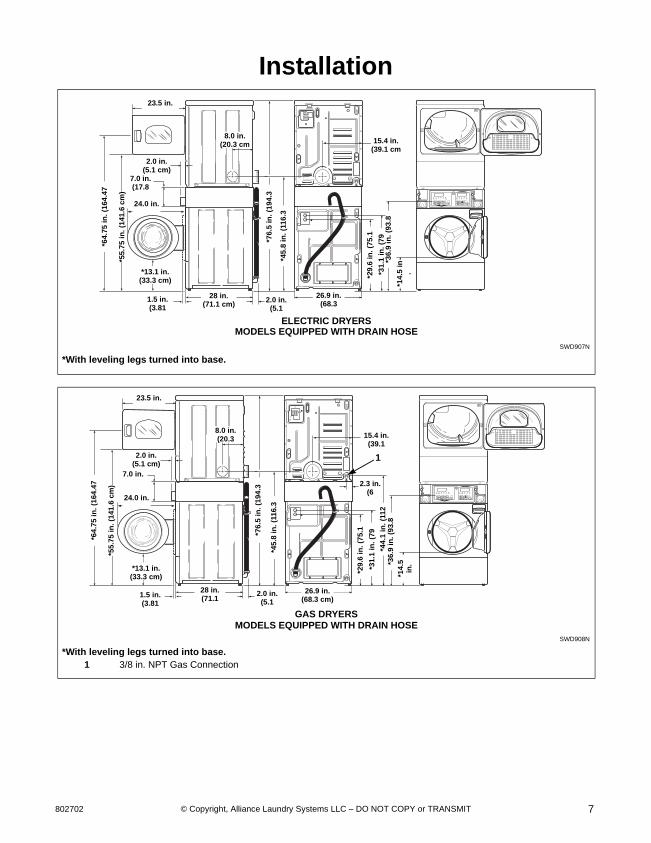
Installation
SWD907N
*With leveling legs turned into base.
SWD908N
*With leveling legs turned into base.1 3/8 in. NPT Gas Connection
SWD907N
23.5 in.
2.0 in.(5.1 cm)
7.0 in.(17.8
*13.1 in.(33.3 cm)
28 in.(71.1 cm)
*29
.6 i
n. (
75
.1
*31
.1 in
. (7
9
*76
.5 i
n.
(19
4.3
*45.
8 in
. (1
16.3
15.4 in.(39.1 cm
26.9 in.(68.3 2.0 in.
(5.1
ELECTRIC DRYERS
8.0 in.(20.3 cm
*36.
9 in
. (9
3.8
*14
.5in
.
24.0 in.
MODELS EQUIPPED WITH DRAIN HOSE
*64
.75
in
. (1
64.4
7
*55
.75
in
. (1
41
.6 c
m)
1.5 in.(3.81
SWD908N
23.5 in.
2.0 in.(5.1 cm)
7.0 in.
*13.1 in.(33.3 cm)
28 in.(71.1
*29
.6 i
n.
(75.
1
*31
.1 in
. (7
9
*76
.5 i
n. (
19
4.3
*45
.8 in
. (1
16.
3
15.4 in.(39.1
26.9 in.(68.3 cm)
2.0 in.(5.1
2.3 in.(6
GAS DRYERS
8.0 in.(20.3
1
*44
.1 i
n. (
112
*3
6.9
in
. (9
3.8
*1
4.5
in
.
24.0 in.
MODELS EQUIPPED WITH DRAIN HOSE
*64
.75
in.
(16
4.4
7
*55.
75 i
n.
(141
.6 c
m)
1.5 in.(3.81

© Copyright, Alliance Laundry Systems LLC – DO NOT COPY or TRANSMIT
Installation
8027028
NOTE: Side and rear exhaust openings are 4 inch (10.2 cm) ducting. Gas models cannot be vented out left side of cabinet because of burner housing.
IMPORTANT: The dryer should have sufficient clearance around it for needed ventilation and for the ease of installation and servicing. For maximum drying performance, we recommend that more clearance be allowed around the dryer than the clearances that are listed throughout this manual.
SWD909N
*With leveling legs turned into base.1 3/8 in. NPT Gas Connection2 1.5 in. (3.81 cm) Inside Diameter
1.86 in. (4.72 cm) Outside Diameter
SWD909N
23.5 in.
2.0 in.(5.1 cm)
7.0 in.
*13.1 in.(33.3 cm)
28 in.(71.1
*29.
6 in
. (7
5.1
*31
.1 i
n. (
79
*76
.5 i
n.
(19
4.3
*4
5.8
in
. (1
16
.3
15.4 in.(39.1
26.9 in.(68.3
2.3 in.(6
GAS DRYERS
8.0 in.(20.3
1
*44.
1 i
n.
(11
2
*36
.9 i
n.
(93
.8
*14.5 in.(36.8
24.0 in.
MODELS WITH GRAVITY DRAIN
*4.1 in.(10.41
4.2 in.(10.67
2
*64.
75 i
n.
(164
.47
*55
.75
in.
(14
1.6
cm
)
1.5 in.(3.81

© Copyright, Alliance Laundry Systems LLC – DO NOT COPY or TRANSMIT
Installation
9802702
Before You Start
Supplies
For most installations, the basic supplies you will need are:
Figure 1
NOTE: An 8 inch (20.32 cm) coin drawer is required for coin operated models.
NOTE: If the the unit is delivered on a cold day (below freezing), or is stored in an unheated room or area during the cold months, do not attempt to operate it until the unit has had a chance to warm up.
NOTE: Some moisture in the wash drum is normal. Water is used during testing at the manufacturer.
SWD692N
1 Safety Glasses2 Wood Block3 Power Cord (Electric Models)4 Wrench5 Screwdriver6 Level7 5/16 Inch Socket Wrench8 Duct Tape9 Teflon Tape (Gas Models)
9/16"
1 23
7
6
54
8
9
Any disassembly requiring the use of tools must be performed by a suitably qualified service person.
W299
WARNING
© Copyright, Alliance Laundry Systems LLC – DO NOT COPY or TRANSMIT
Installation
80270210
Installing the Unit
Step 1: Position Unit Near Installation Area
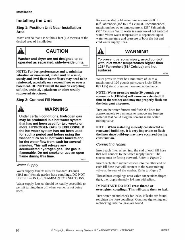
Move unit so that it is within 4 feet (1.2 meters) of the desired area of installation.
NOTE: For best performance and to minimize vibration or movement, install unit on a solid, sturdy and level floor. Some floors may need to be reinforced, especially on a second floor or over a basement. DO NOT install the unit on carpeting, soft tile, pedestal, a platform or other weakly supported structures.
Step 2: Connect Fill Hoses
Water Supply
Water supply faucets must fit standard 3/4 inch (19.1 mm) female garden hose couplings. DO NOT USE SLIP-ON OR CLAMP-ON CONNECTIONS.
Water supply faucets should be readily accessible to permit turning them off when washer is not being used.
Recommended cold water temperature is 60o to 80o Fahrenheit (16o to 27o Celsius). Recommended maximum hot water temperature is 125o Fahrenheit (51o Celsius). Warm water is a mixture of hot and cold water. Warm water temperature is dependent upon water temperature and pressure of both the hot and cold water supply lines.
Water pressure must be a minimum of 20 to a maximum of 120 pounds per square inch (138 to 827 kPa) static pressure measured at the faucet.
NOTE: Water pressure under 20 pounds per square inch (138 kPa) will cause an extended fill time in the washer and may not properly flush out the detergent dispenser.
Turn on the water faucets and flush the lines for approximately two minutes to remove any foreign material that could clog the screens in the water mixing valve.
NOTE: When installing in newly constructed or renovated buildings, it is very important to flush the lines since build-up may have occurred during construction.
Connecting Hoses
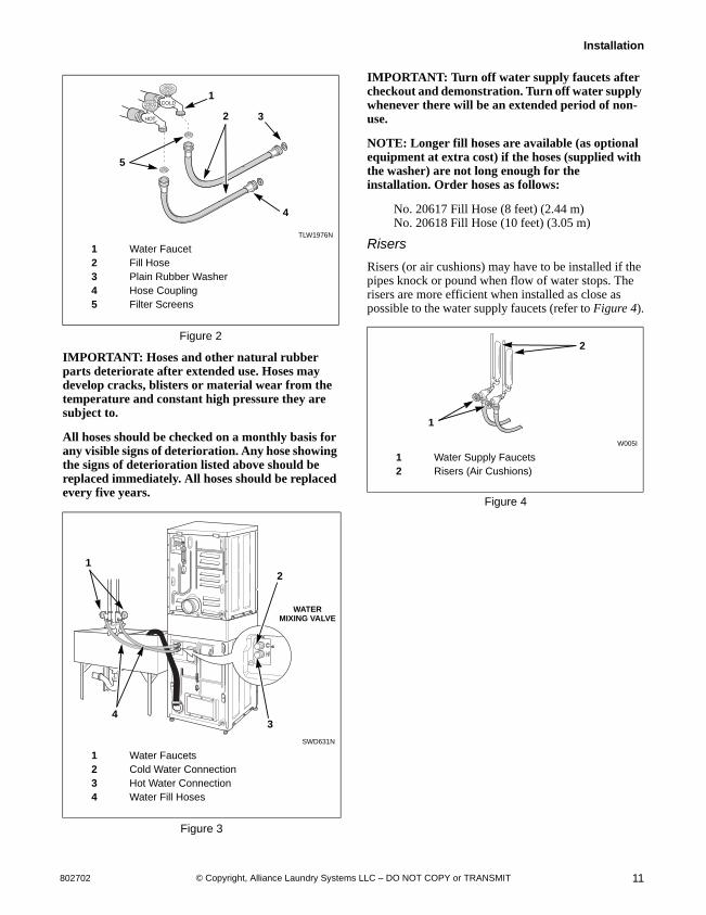
Insert each filter screen into the end of each fill hose that will connect to the water supply faucet. The screen must be facing outward. Refer to Figure 2.
Insert each plain rubber washer into the other end of each fill hose that will connect to the water mixing valve at the rear of the washer. Refer to Figure 2.
Thread hose couplings onto valve connections finger-tight, then approximately 1/4 turn with pliers.
IMPORTANT: DO NOT cross thread or overtighten couplings. This will cause them to leak.
Turn water on and check for leaks. If leaks are found, retighten the hose couplings. Continue tightening and rechecking until no leaks are found.
Washer and dryer are not designed to be operated as separated, side-by-side units.
W187
CAUTION
Under certain conditions, hydrogen gas may be produced in a hot water system that has not been used for two weeks or more. HYDROGEN GAS IS EXPLOSIVE. If the hot water system has not been used for such a period and before using the washer, turn on all hot water faucets and let the water flow from each for several minutes. This will release any accumulated hydrogen gas. The gas is flammable. Do not smoke or use an open flame during this time.
W029
WARNING
To prevent personal injury, avoid contact with inlet water temperatures higher than 125° Fahrenheit (51° Celsius) and hot surfaces.
W748
WARNING
© Copyright, Alliance Laundry Systems LLC – DO NOT COPY or TRANSMIT
Installation
11802702
IMPORTANT: Hoses and other natural rubber parts deteriorate after extended use. Hoses may develop cracks, blisters or material wear from the temperature and constant high pressure they are subject to.
All hoses should be checked on a monthly basis for any visible signs of deterioration. Any hose showing the signs of deterioration listed above should be replaced immediately. All hoses should be replaced every five years.
IMPORTANT: Turn off water supply faucets after checkout and demonstration. Turn off water supply whenever there will be an extended period of non-use.
NOTE: Longer fill hoses are available (as optional equipment at extra cost) if the hoses (supplied with the washer) are not long enough for the installation. Order hoses as follows:
No. 20617 Fill Hose (8 feet) (2.44 m)No. 20618 Fill Hose (10 feet) (3.05 m)
Risers
Risers (or air cushions) may have to be installed if the pipes knock or pound when flow of water stops. The risers are more efficient when installed as close as possible to the water supply faucets (refer to Figure 4).
Figure 4
TLW1976N
1 Water Faucet2 Fill Hose3 Plain Rubber Washer4 Hose Coupling5 Filter Screens
Figure 2
SWD631N
1 Water Faucets2 Cold Water Connection3 Hot Water Connection4 Water Fill Hoses
Figure 3
HOT
COLD
3
1
5
2
4
SWD631N
12
4
WATER MIXING VALVE
3
W005I
1 Water Supply Faucets2 Risers (Air Cushions)
W005I
2
1

© Copyright, Alliance Laundry Systems LLC – DO NOT COPY or TRANSMIT
Installation
80270212
Step 3: (Non-Gravity Drain Models Only) Connect Drain Hose to Drain Receptacle
Remove the drain hose from its shipping position on the rear of the washer by removing the shipping tape.
IMPORTANT: Drain receptacle must be capable of handling a minimum of 1 3/8 inch (3.5 cm) outside diameter drain hose.
Standpipe Installation
Place the drain hose into the standpipe.
Remove the beaded strap from accessories bag and place around standpipe and drain hose and tighten strap to hold hose to standpipe. Refer to Figure 5. This will prevent the drain hose from dislodging from drain receptacle during use.
Step 4: (Gravity Drain Models Only) Connect Drain Outlet to Drain System
Remove drain fitting (four inches long) and hose clamp from accessories bag. Insert drain fitting into drain outlet hose. Clamp hose and fitting.
Connect the drain fitting to a vented drain system using a flexible connection (obtain locally). Inside diameter of fitting is 1.53 in. (3.89 cm) and outside diameter is 1.66 in. (4.22 cm). The drain system must be vented to prevent an air lock or siphoning.
IMPORTANT: Increasing the drain hose length, installing elbows, or causing bends will decrease drain flow rates and increase drain times, impairing machine performance.
Figure 6
SWD835N
1 Drain Hose2 Beaded Tie-Down Strap3 Standpipe 2 in. (5.08 cm) or 1-1/2 in. (4 cm)
Figure 5
1
2
3
24 in. to 36 in. (61 to 91.44 cm) Recommended
Height
SWD745N
1 Drain Trough2 Drain Outlet Hose
SWD745N
2
1

© Copyright, Alliance Laundry Systems LLC – DO NOT COPY or TRANSMIT
Installation
13802702
Step 5: (Gas Dryer Only) Connect Gas Supply Pipe
1. Make certain your dryer is equipped for use withthe type of gas in your laundry room. Dryer isequipped at the factory for Natural Gas with a3/8 inch NPT gas connection.
NOTE: The gas service to a gas dryer must conform with the local codes and ordinances, or in the absence of local codes and ordinances, with the latest edition of the National Fuel Gas Code ANSI Z223.1/NFPA 54 or the CAN/CSA-B149.1 Natural Gas and Propane Installation Code.
Natural Gas, 1000 Btu/ft3 (37.3 MJ/m3), service must be supplied at minimum 5.0 inch water column pressure to maximum 10.5 inch water column pressure.
For proper operation at altitudes above 2000 feet (610 m) the natural gas valve spud orifice size must be reduced to ensure complete combustion. Refer to Table 1.
2. Remove the shipping cap from the gasconnection at the rear of the dryer. Make sure youdo not damage the pipe threads when removingthe cap.
3. Connect to gas supply pipe.
To reduce the risk of gas leaks, fire or explosion:• The dryer must be connected to the type
of gas as shown on nameplate located inthe door recess.
• Use a new flexible stainless steelconnector.
• Use pipe joint compound insoluble in L.P.(Liquefied Petroleum) Gas, or Teflon tape,on all pipe threads.
• Purge air and sediment from gas supplyline before connecting it to the dryer.Before tightening the connection, purgeremaining air from gas line to dryer untilodor of gas is detected. This step isrequired to prevent gas valvecontamination.
• Do not use an open flame to check for gasleaks. Use a non-corrosive leak detectionfluid.
• Any disassembly requiring the use oftools must be performed by a suitablyqualified service person.
W316
WARNING
Natural Gas Altitude Adjustments
Altitude Orifice Size PartNumberfeet m # inches mm
2,000 610 41 0.0960 2.44 D503776
3,000 915 42 0.0935 2.37 D503777
5,500 1,680 43 0.0890 2.26 D503778
7,000 2,135 44 0.0860 2.18 58719
9,000 2,745 45 0.0820 2.08 D503779
10,500 3,200 46 0.0810 2.06 D503780
Table 1
© Copyright, Alliance Laundry Systems LLC – DO NOT COPY or TRANSMIT
Installation
80270214
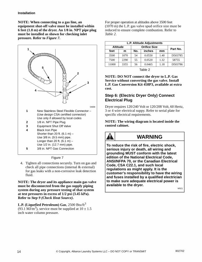
NOTE: When connecting to a gas line, an equipment shut-off valve must be installed within 6 feet (1.8 m) of the dryer. An 1/8 in. NPT pipe plug must be installed as shown for checking inlet pressure. Refer to Figure 7.
4. Tighten all connections securely. Turn on gas and check all pipe connections (internal & external)for gas leaks with a non-corrosive leak detectionfluid.
NOTE: The dryer and its appliance main gas valve must be disconnected from the gas supply piping system during any pressure testing of that system at test pressures in excess of 1/2 psi (3.45 kPa). Refer to Step 9 (Check Heat Source).
L.P. (Liquefied Petroleum) Gas, 2500 Btu/ft3
(93.1 MJ/m3), service must be supplied at 10 ± 1.5inch water column pressure.
For proper operation at altitudes above 3500 feet (1070 m) the L.P. gas valve spud orifice size must be reduced to ensure complete combustion. Refer to Table 2.
NOTE: DO NOT connect the dryer to L.P. Gas Service without converting the gas valve. Install L.P. Gas Conversion Kit 458P3, available at extracost.
Step 6: (Electric Dryer Only) Connect Electrical Plug
Dryer requires 120/240 Volt or 120/208 Volt, 60 Hertz, 3 or 4 wire electrical suppy. Refer to serial plate for specific electrical requirements.
NOTE: The wiring diagram is located inside the control cabinet.
D699I
1 New Stainless Steel Flexible Connector –(Use design CSA certified connector)Use only if allowed by local codes
2 1/8 in. NPT Pipe Plug3 Equipment Shut Off Valve4 Black Iron Pipe
Shorter than 20 ft. (6.1 m) –Use 3/8 in. (9.5 mm) pipe. Longer than 20 ft. (6.1 m) – Use 1/2 in. (12.7 mm) pipe.
5 3/8 in. NPT Gas Connection
Figure 7
D233I
1
3
2
4
5
L.P. Altitude AdjustmentsAltitude Orifice Size
Part No.feet m No. inches mm
3500 1070 54 0.0550 1.40 D503785
7500 2290 55 0.0520 1.32 58755
11000 3355 56 0.0465 1.18 D503786
Table 2
To reduce the risk of fire, electric shock, serious injury or death, all wiring and grounding MUST conform with the latest edition of the National Electrical Code, ANSI/NFPA 70, or the Canadian Electrical Code, CSA C22.1, and such local regulations as might apply. It is the customer’s responsibility to have the wiring and fuses installed by a qualified electrician to make sure adequate electrical power is available to the dryer.
W521
WARNING
© Copyright, Alliance Laundry Systems LLC – DO NOT COPY or TRANSMIT
Installation
15802702
Grounding Information
This appliance must be grounded. In the event of malfunction or breakdown, grounding will reduce the risk of electric shock by providing a path of least resistance for electric current. The cord-kit must be equipped with a cord having an equipment-grounding conductor and a grounding plug. The plug must be plugged into an appropriate outlet that is properly installed and grounded in accordance with all local codes and ordinances.
Do not modify the plug provided with the cord-kit - if it will not fit the outlet, have a proper outlet installed by a qualified electrician.
The dryer has its own terminal block that must be connected to a separate branch, 60 Hertz, single phase circuit, AC (alternating current) circuit, fused at 30 Amperes (the circuit must be fused on both sides of the line). Electrical service for the dryer should be of maximum rated voltage (208 or 240 Volt, depending on heating element) listed on the nameplate. Do not connect dryer to 110, 115, or 120 Volt circuit.
Heating elements are available for field installation in dryers which are to be connected to electrical service of different voltage than that listed on nameplate, such as 208 Volt.
NOTE: Branch circuit wire size requirements to laundry room outlet are shown in Table 3.
The power cord connection between wall receptacle and dryer terminal block IS NOT supplied with dryer. Type of power cord and gauge of wire must conform to local codes.
Improper connection of the equipment-grounding conductor can result in a risk of electric shock. Check with a qualified electrician or service person if you are in doubt as to whether the dryer is properly grounded.
W038
WARNING
Wire Length Wire
Less than 4.5 m (15 ft.) Listed No. 10 AWG Copper wire only
Longer than 4.5 m (15 ft.) Listed No. 8 AWG Copper wire only
Table 3

© Copyright, Alliance Laundry Systems LLC – DO NOT COPY or TRANSMIT
Installation
80270216
IMPORTANT: Use only a new U.L. listed No. 10 (copper wire only) three or four conductor power supply cord kit rated 240 Volts (minimum) 30 Amperes and labeled as suitable for use in a clothes dryer.
Figure 8
Figure 9
D275I
D006I
1 Typical Receptacle2 Power Cord (Not supplied with dryer)3 Strain Relief Nut4 Strain Relief
12
3
4
THREE-WIRE
1
2
3
4
FOUR-WIRE
D679I
D680I
NOTE: Dryer is shown with access cover removed for illustration purposes only. NEVER operate the dryer with access cover removed.
1 Ground Wire2 Ground to Neutral Wire3 Neutral Terminal4 “L2” Terminal5 Center Wire (Neutral)6 Strain Relief (Not supplied with dryer)7 Ground Screw8 “L1” Terminal9 Black Wire
10 White Wire (Neutral)11 Red Wire
D679I
1
8
7
6
5
4
3
2
THREE-WIRE CONNECTION
D680I
1
8
7
6
10
4
3
1
11
9
FOUR-WIRE CONNECTION
© Copyright, Alliance Laundry Systems LLC – DO NOT COPY or TRANSMIT
Installation
17802702
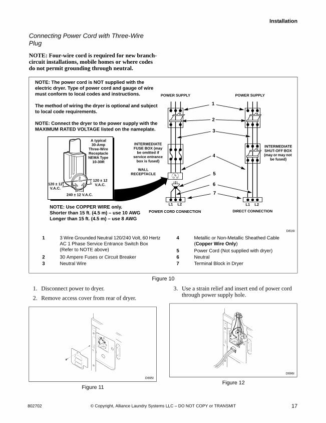
Connecting Power Cord with Three-Wire Plug
NOTE: Four-wire cord is required for new branch-circuit installations, mobile homes or where codes do not permit grounding through neutral.
Figure 10
1. Disconnect power to dryer.
2. Remove access cover from rear of dryer.
Figure 11
3. Use a strain relief and insert end of power cord through power supply hole.
Figure 12
D816I
1 3 Wire Grounded Neutral 120/240 Volt, 60 Hertz AC 1 Phase Service Entrance Switch Box(Refer to NOTE above)
4 Metallic or Non-Metallic Sheathed Cable (Copper Wire Only)
5 Power Cord (Not supplied with dryer)2 30 Ampere Fuses or Circuit Breaker 6 Neutral3 Neutral Wire 7 Terminal Block in Dryer
NOTE: The power cord is NOT supplied with the electric dryer. Type of power cord and gauge of wire must conform to local codes and instructions.
The method of wiring the dryer is optional and subject to local code requirements.
NOTE: Connect the dryer to the power supply with the MAXIMUM RATED VOLTAGE listed on the nameplate.
1
3
5
6
7
4
2
POWER CORD CONNECTION DIRECT CONNECTION
L1 L2 L1 L2
INTERMEDIATE SHUT-OFF BOX (may or may not
be fused)
POWER SUPPLYPOWER SUPPLY
INTERMEDIATE FUSE BOX (may
be omitted if service entrance
box is fused)
WALL RECEPTACLE
A typical 30-Amp
Three-Wire Receptacle NEMA Type
10-30R
120 ± 12V.A.C.
120 ± 12V.A.C.
240 ± 12 V.A.C.
NOTE: Use COPPER WIRE only. Shorter than 15 ft. (4.5 m) – use 10 AWGLonger than 15 ft. (4.5 m) – use 8 AWG
D695I
D696I

© Copyright, Alliance Laundry Systems LLC – DO NOT COPY or TRANSMIT
Installation
80270218
4. Use the three screws from the accessories bag toattach the power cord wires to the terminal block. Refer to Figure 13.
Figure 13
5. Tighten all screws firmly.
IMPORTANT: Failure to tighten these screws firmly may result in wire failure at the terminal block.
6. Secure the strain relief to the power cord, orwires, where they enter the dryer cabinet.
7. Check the continuity of the ground connectionbefore plugging the cord into an outlet. Use anacceptable indicating device connected to thecenter grounding pin of the plug and the greenscrew on the back of the cabinet.
8. Reinstall access cover and screw.
Connecting Power Cord with Four-Wire Plug
NOTE: Four-wire cord is required for new branch-circuit installations, mobile homes or where codes do not permit grounding through neutral.
Figure 14
1. Disconnect power to dryer.
2. Remove access cover from rear of dryer.
Figure 15
D286I
1 “L1” Terminal2 Neutral Terminal3 “L2” Terminal
1 2
3
DRY2016N
1 Typical Four-Wire Receptacle2 Power Cord – Not Supplied with Dryer3 Strain Relief Nut4 Strain Relief
D695I
120 ± 12V.A.C.
120 ± 12V.A.C.
120 ±
12V.A
.C.
120 ±
12V.A
.C.
240 ± 12V.A.C.
0V.A.C.
12
3
4
© Copyright, Alliance Laundry Systems LLC – DO NOT COPY or TRANSMIT
Installation
19802702
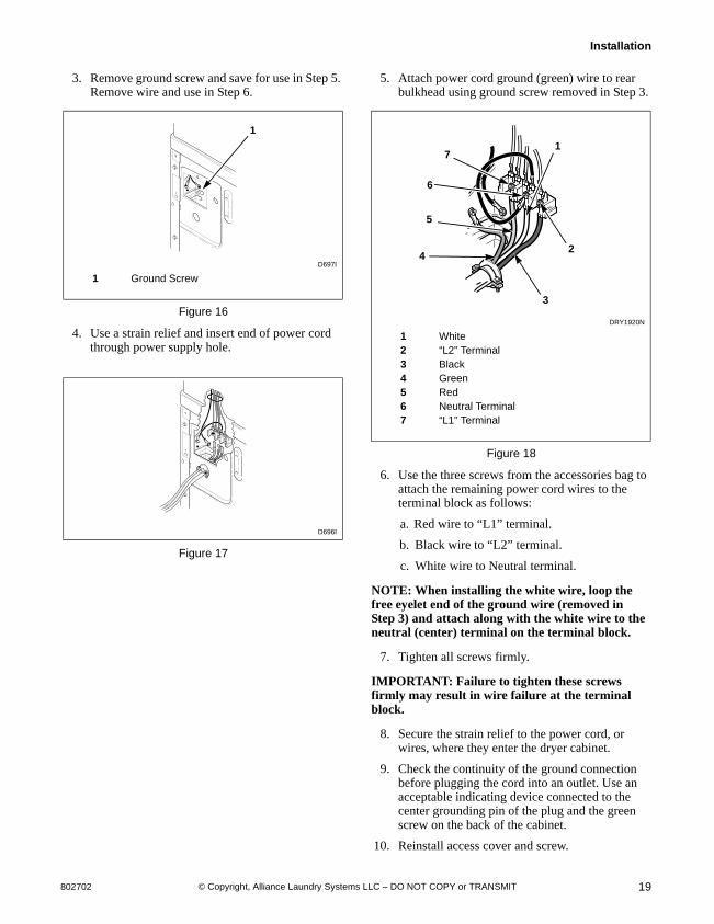
3. Remove ground screw and save for use in Step 5. Remove wire and use in Step 6.
Figure 16
4. Use a strain relief and insert end of power cord through power supply hole.
Figure 17
5. Attach power cord ground (green) wire to rear bulkhead using ground screw removed in Step 3.
Figure 18
6. Use the three screws from the accessories bag to attach the remaining power cord wires to the terminal block as follows:
a. Red wire to “L1” terminal.
b. Black wire to “L2” terminal.
c. White wire to Neutral terminal.
NOTE: When installing the white wire, loop the free eyelet end of the ground wire (removed in Step 3) and attach along with the white wire to the neutral (center) terminal on the terminal block.
7. Tighten all screws firmly.
IMPORTANT: Failure to tighten these screws firmly may result in wire failure at the terminal block.
8. Secure the strain relief to the power cord, or wires, where they enter the dryer cabinet.
9. Check the continuity of the ground connection before plugging the cord into an outlet. Use an acceptable indicating device connected to the center grounding pin of the plug and the green screw on the back of the cabinet.
10. Reinstall access cover and screw.
D697I
1 Ground Screw
D696I
D697I
1
DRY1920N
1 White2 “L2” Terminal3 Black4 Green5 Red6 Neutral Terminal7 “L1” Terminal
DRY1920N
5
71
24
6
3

© Copyright, Alliance Laundry Systems LLC – DO NOT COPY or TRANSMIT
Installation
80270220
Step 7: Connect Dryer Exhaust System IMPORTANT: Installing in-line filters or lint collectors will cause increased static pressure. Failure to maintain the secondary lint system will decrease dryer efficiency and may void machine warranty.
DO NOT use plastic or thin foil ducting. Rigidmetal duct is recommended.
Locate dryer so exhaust duct is as short aspossible.
Be certain old ducts are cleaned before installingyour new dryer.
Use 4 inch (102 mm) diameter rigid or flexiblemetal duct.
The male end of each section of duct must pointaway from the dryer.
Use as few elbows as possible.
Use duct tape or pop-rivets on all duct joints. DONOT use sheet metal screws or fasteners onexhaust pipe joints which extend into the ductand catch lint.
Ductwork that runs through unheated areas mustbe insulated to help reduce condensation and lintbuild-up on pipe walls.
Install backdraft dampers in multi-dryerinstallations.
In mobile home installations, dryer exhaust ductmust be secured to mobile home structure.
Dryer exhaust duct MUST NOT terminate undermobile home.
To reduce the risk of fire and combustion gas accumulation the dryer MUST be exhausted to the outdoors.
W604
To reduce the risk of fire and the accumulation of combustion gases, DO NOT exhaust dryer air into a window well, gas vent, chimney or enclosed, unventilated area, such as an attic, wall, ceiling, crawl space under a building or concealed space of a building.
W045
WARNING
This gas appliance contains or produces a chemical or chemicals which can cause death or serious illness and which are known to the State of California to cause cancer, birth defects, or other reproductive harm. To reduce the risk from substances in the fuel or from fuel combustion, make sure this appliance is installed, operated, and maintained according to the instructions in this manual.
W115
To reduce the risk of fire, DO NOT use plastic or thin foil ducting to exhaust the dryer.
W354
To reduce the risk of fire, the exhaust duct and weather hood MUST be fabricated of a material that will not support combustion. Rigid or flexible metal pipe is recommended for a clothes dryer.
W048
WARNING
To reduce the risk of fire due to increased static pressure, we do not recommend installation of in-line secondary lint filters or lint collectors. If secondary systems are mandated, frequently clean the system to assure safe operation.
W749
WARNING
H312I
Figure 19
H312I
DO DON'T

© Copyright, Alliance Laundry Systems LLC – DO NOT COPY or TRANSMIT
Installation
21802702
Dryer exhausts 220 cfm (measured at back of dryer).
DO NOT install flexible duct in concealed spaces, such as a wall or ceiling.
Static pressure in exhaust duct should not be greater than .6 inches water column (1.5 cm), measured with manometer placed on exhaust duct 2 feet (61 cm) from dryer (check with dryer running and no load). In multi-dryer installations, all dryers connected to the main collector duct should be operating when pressure is checked.
Exhausting dryer in hard-to-reach locations can be done by installing 521P3 Flexible Metal Vent Kit (available as optional equipment at extra cost).
Sufficient make-up air must be supplied to replace the air exhausted by the dryer. The free area of any opening for outside air must be at least 40 in2 (260 cm2).
Energy efficient buildings with low air infiltration rates should be equipped with an air exchanger that can accommodate on demand make-up air needs in the laundry room. These devices can be obtained through your building contractor or building material suppliers.
Do not draw make-up air from a room containing a gas fired water heater, a dry cleaner or a hair salon.
Failure to exhaust dryer properly will void warranty.
NOTE: Venting materials are not supplied with the dryer (obtain locally).
IMPORTANT: DO NOT block the airflow at the bottom of the dryer’s front panel with laundry, rugs, etc. Blockage will decrease airflow through the dryer, thus reducing the efficiency of the dryer.

© Copyright, Alliance Laundry Systems LLC – DO NOT COPY or TRANSMIT
Installation
80270222
Exhaust Direction
The dryer can be exhausted to the outdoors through the back, left, right or bottom of the dryer. EXCEPTION: Gas dryers cannot be vented out the left side because of the burner housing.
Dryer is shipped from factory ready for rear exhaust.
Exhausting the dryer through sides or bottom can be accomplished by installing a Directional Exhaust Kit, 528P3, available as optional equipment at extra cost.
Exhaust System
For best drying results, recommended maximum length of exhaust system is shown in Table 4.
To prevent backdraft when dryer is not in operation, outer end of exhaust pipe must have a weather hood with hinged dampers (obtain locally).
NOTE: Weather hood should be installed at least 12 inches (30.5 cm) above the ground. Larger clearances may be necessary for installations where heavy snowfall can occur.
Table 4
NOTE: The maximum length of a 4 in. (10.2 cm) diameter flexible metal duct must not exceed 7.87 ft. (2.4 m), as required to meet UL2158, clause 7.3.2A.
Number of 90° Elbows
Weather Hood Type
Recommended Use Only for Short Run Installations
Maximum length of 4 in. (10.2 cm) diameter rigid metal duct.
0 65 feet (19.8 m) 55 feet (16.8 m)
1 55 feet (16.8 m) 47 feet (14.3 m)
2 47 feet (14.3 m) 41 feet (12.5 m)
3 36 feet (11.0 m) 30 feet (9.1 m)
4 28 feet (8.5 m) 22 feet (6.7 m)
NOTE: Deduct 6 feet (1.8 m) for each additional elbow.
4 in.(10.2 cm)
4 in.(10.2 cm)
D673I D802I2-1/2 in.
(6.35 cm)

© Copyright, Alliance Laundry Systems LLC – DO NOT COPY or TRANSMIT
Installation
23802702
Multi-Dryer Installation Exhaust Requirements
Figure 20 shows a typical example of a multiple dryer installation. Note how each dryer has its own exhaust system vented to the central exhaust duct.
Figure 20
SWD798N
1 58786 Backdraft Damper (Available through your local authorized parts source)
3 Weather Hood or Sweep Elbow (No cap or screen)
2 Clean Out Cover (must be provided).Inspect monthly.
SWD798N
21
3
24 in. (61 cm) MINIMUM
CLEARANCE TO

© Copyright, Alliance Laundry Systems LLC – DO NOT COPY or TRANSMIT
Installation
80270224
Figure 21
Figure 22 A Backdraft Damper, Part No. 58786 (obtain locally), should be installed in a 4 inch (10.2 cm) diameter VERTICAL duct system. This will prevent a backdraft when dryer is not in use, and will keep the exhaust air in balance within the central exhaust system.
H318I
1 NOTE: Where the exhaust duct pierces a combustible wall or ceiling, the opening must be sized per local codes.
3 2 in. (5 cm) Minimum or Clearance per Local Codes
4 No Screen or Cap2 Wall 5 Clean Out Cover – Inspect Monthly
2
3
4
EXHAUST OUTLET
KJIHGFEDCBA5
30°
1
EXHAUST AIR FLOW MAXIMUM LENGTH OF DUCT
30 feet (9.1 m)
HORIZONTAL EXHAUST INSTALLATION
AIR FLOW
H319I
1 Roof2 No Screen or Cap3 Wall4 2 in. (5 cm) Minimum or Clearance Per Local
Codes5 NOTE: Where the exhaust duct pierces a
combustible wall or ceiling, an opening must be sized as shown or per local codes.
3
1
45
CONNECT TO DRYER
VERTICAL EXHAUST INSTALLATION
2
Duct Station Minimum Diameter of Collector Duct
A 4 inches (10.2 cm)
B 8 inches (20.3 cm)
C 9 inches (22.9 cm)
D 10 inches (25.4 cm)
E 11 inches (27.9 cm)
F 12 inches (30.5 cm)
G 13 inches (32.6 cm)
H 14 inches (35.6 cm)
I 15 inches (38.1 cm)
J 15 inches (38.1 cm)
K 16 inches (40.6 cm)
To reduce the risk of fire and the accumulation of combustion gases, DO NOT exhaust dryer air into a window well, gas vent, chimney or enclosed, unventilated area, such as an attic, wall, ceiling, crawl space under a building or concealed space of a building.
W045
WARNING
© Copyright, Alliance Laundry Systems LLC – DO NOT COPY or TRANSMIT
Installation
25802702
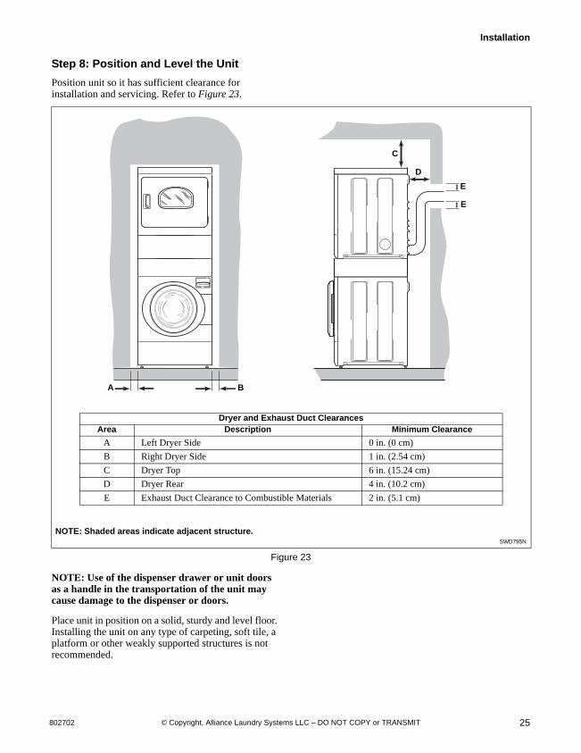
Step 8: Position and Level the Unit
Position unit so it has sufficient clearance for installation and servicing. Refer to Figure 23.
Figure 23
NOTE: Use of the dispenser drawer or unit doors as a handle in the transportation of the unit may cause damage to the dispenser or doors.
Place unit in position on a solid, sturdy and level floor. Installing the unit on any type of carpeting, soft tile, a platform or other weakly supported structures is not recommended.
NOTE: Shaded areas indicate adjacent structure.SWD795N
SWD795NA B
C
D
E
E
Dryer and Exhaust Duct ClearancesArea Description Minimum Clearance
A Left Dryer Side 0 in. (0 cm)
B Right Dryer Side 1 in. (2.54 cm)
C Dryer Top 6 in. (15.24 cm)
D Dryer Rear 4 in. (10.2 cm)
E Exhaust Duct Clearance to Combustible Materials 2 in. (5.1 cm)

© Copyright, Alliance Laundry Systems LLC – DO NOT COPY or TRANSMIT
Installation
80270226
Place a level on the cabinet top and check if the unit is level from side to side and front to back.
NOTE: Level must rest on raised portion of top panel. Refer to Figure 24.
If unit is not level, tilt unit to access the front and rear leveling legs. For easier access to leveling legs, prop up unit with a wooden block. Refer to Figure 25. Loosen the locknuts and adjust legs by screwing into or out of unit base.
Make sure that the unit does not rock. When unit is level and does not rock, tighten locknuts securely against bottom of unit base. If these locknuts are not tight, unit will move out of position during operation.
Leveling legs can be adjusted from inside the unit with a 7/8 inch deep well socket. All four legs must rest firmly on the floor so the weight of the unit is evenly distributed. The unit must not rock and must be level from side-to-side and front-to-back.
NOTE: Do not slide unit across floor once the leveling legs have been extended. Legs and base could become damaged.
Place rubber feet (supplied in accessories bag) on all four leveling legs. Refer to Figure 24.
Verify that unit does not rock.
SWD796N
1 Level2 Rubber Foot3 Leveling Leg4 Locknut5 Unit Base
Figure 24
Units elevated above floor level must be anchored to that elevated surface, base or platform. The material used to elevate the unit should also be anchored to the floor to ensure that the unit will not walk or that the unit can not be physically pulled, tipped or slid from its installed position. Failure to do so may result in conditions which can produce serious injury, death and/or property damage.
W307
WARNING
SW
1
2
3
4
5
SWD799N
1 Wood Block
Figure 25
SWD799N
1

© Copyright, Alliance Laundry Systems LLC – DO NOT COPY or TRANSMIT
Installation
27802702
Step 9: (Washer Only) Remove the Shock Sleeves and Shipping Brace
Remove front access panel by removing the two screws at the bottom of the panel.
Remove the five bolts and lockwashers from shipping brace with 9/16 inch wrench and remove brace. Refer to Figure 26. Four bolts are located on the unit base and one is holding the brace to the weight. Remove all four shock sleeves by pulling on the yellow rope. Refer to Figure 26.
IMPORTANT: The shipping brace, bolts, lockwashers and shock sleeves should be saved and MUST be reinstalled whenever the unit is moved more than 4 feet (1.22 m). Do not lift or transport unit from front or without shipping materials installed. Refer to the Maintenance section for proper instructions on reinstalling the shipping materials.
Remove label from front side of front access panel and place on backside of front access panel for future reference.
Store the shipping materials in the accessories bag. Save materials for use whenever the unit is moved.
Reinstall front access panel.
IMPORTANT: DO NOT tip washer more than 6 inches (152.4 mm) in any direction after shipping brace has removed. Shock absorbers may separate and damage to unit may result. For leveling purposes, the unit may be tilted a maximum of 6 inches (152.4 mm) in any direction.
Step 10: Wipe Out Inside of Washer Drum and Dryer Drum
Before using the washer and dryer for the first time, use an all-purpose cleaner, or a detergent and water solution, and a damp cloth to remove shipping dust from inside the drums.
Figure 27
Figure 28
FLW2124N
1 Shock Sleeves2 Motor Mount3 Hooked End of Shipping Brace4 Bolts and Lockwashers
Figure 26
FLW2124N
1
4
3
2
SWD797N
H315I
SWD797N

© Copyright, Alliance Laundry Systems LLC – DO NOT COPY or TRANSMIT
Installation
80270228
Step 11: Plug In the Washer and Dryer
Electric Dryer
Connect the dryer to an electrical power source. Refer to Step 6 for information on connecting power cord.
Figure 29
Gas Dryer
Dryer requires 120 Volt, 60 Hertz electrical supply and comes equipped with a 3-prong grounding plug. Refer to serial plate for specific electrical requirements.
NOTE: The wiring diagram is located behind the control panel, inside the control cabinet.
When plugging in the dryer:
Do not overload circuits.
Do not use an adapter.
Do not use an extension cord.
Do not operate both a washer and gas dryer on the same circuit. Use separetely fused 15 Amp circuits.
The dryer is designed to be operated on a separate branch, polarized, three-wire, effectively grounded, 120 Volt, 60 Hertz, AC (alternating current) circuit protected by a 15 Ampere fuse, equivalent fusetron or circuit breaker.
The three-prong grounding plug on the power cord should be plugged directly into a polarized three-slot effectively grounded receptacle rated 120 Volts AC (alternating current) 15 Amps. Refer to Figure 30 to determine correct polarity of the wall receptacle.
Grounding Information
The dryer must be grounded. In the event of malfunction or breakdown, grounding will reduce the risk of electric shock by providing a path of least resistance for electric current. The dryer is equipped with a cord having an equipment-grounding conductor and a three-prong grounding plug. The three-prong grounding plug on the power cord should be plugged directly into a polarized three-slot effectively grounded receptacle rated 110/120 Volts AC (alternating current) 15 Amps.
Do not modify the plug provided with the dryer – if it will not fit the outlet, have a proper outlet installed by a qualified electrician.
NOTE: Have a qualified electrician check the polarity of the wall receptacle. If a voltage reading is measured other than that illustrated, the qualified electrician should correct the problem.
Do not operate other appliances on the same circuit when this appliance is operating.
D275I
Connect to 30 Amp circuit.
To reduce the risk of fire, electric shock, serious injury or death, all wiring and grounding MUST conform with the latest edition of the National Electrical Code, ANSI/NFPA 70, or the Canadian Electrical Code, CSA C22.1, and such local regulations as might apply. It is the customer’s responsibility to have the wiring and fuses installed by a qualified electrician to make sure adequate electrical power is available to the dryer.
W521
WARNING
This dryer is equipped with a three-prong (grounding) plug for your protection against shock hazard and should be plugged directly into a properly grounded three-prong receptacle. Do not cut or remove the grounding prong from this plug.
W036
WARNING
Improper connection of the equipment-grounding conductor can result in a risk of electric shock. Check with a qualified electrician or service person if you are in doubt as to whether the dryer is properly grounded.
W038
WARNING

© Copyright, Alliance Laundry Systems LLC – DO NOT COPY or TRANSMIT
Installation
29802702
Washer
Washer requires 120 Volt, 60 Hertz electrical supply and comes equipped with a 3-prong grounding plug. Refer to serial plate for specific electrical requirements.
NOTE: The wiring diagram is located behind the control panel, inside the control cabinet.
DRY2022N
1 L12 Ground3 Neutral4 Neutral Side5 Round Grounding Prong
Figure 30
To reduce the risk of an electric shock or fire, DO NOT use an extension cord or an adapter to connect the dryer to the electrical power source.
W037
WARNING
D254I
DRY2
0 V.A.C120±12V.A.C
Plug cord into separately fused 15 Amp circuit.
32
1
4
5
120±12V.A.C
DRY2022N
1 L12 Ground3 Neutral Side4 Round Grounding Prong5 Neutral
Figure 31
1
23
4 5
Standard 120 Volt, 60 Hertz 3-Wire EffectivelyGrounded Circuit
0 V.A.C.
120±12 V.A.C.
120±12 V.A.C.
To reduce the risk of fire, electric shock, serious injury or death, all wiring and grounding MUST conform with the latest edition of the National Electrical Code, ANSI/NFPA No. 70, and such local regulations as might apply. It is the customer’s responsibility to have the wiring, fuses and circuit breakers installed by a qualified electrician to make sure adequate electrical power is available to the washer.
W518
WARNING

© Copyright, Alliance Laundry Systems LLC – DO NOT COPY or TRANSMIT
Installation
80270230
When plugging in the washer:
DO NOT overload circuits.
DO NOT use an extension cord.
DO NOT use an adapter.
DO NOT operate both a washer and gas dryer on the same circuit. Use separately fused 15 Amp circuits.
The washer is designed to be operated on a separate branch, polarized, three-wire, effectively grounded, 120 Volt, 60 Hertz, AC (alternating current) circuit protected by a 15 Amp fuse, equivalent fusetron or circuit breaker.
The three-prong grounding plug on the power cord should be plugged directly into a polarized three-slot effectively grounded receptacle rated 110/120 Volts AC (alternating current) 15 Amps. Refer to Figure 31 to determine correct polarity of the wall receptacle.
Grounding Information
The washer must be grounded. In the event of malfunction or breakdown, grounding will reduce the risk of electric shock by providing a path of least resistance for electric current.
The washer is equipped with a cord having an equipment-grounding conductor and a three-prong grounding plug. The plug must be plugged into an appropriate outlet that is properly installed and grounded in accordance with all local codes and ordinances.
Do not modify the plug provided with the washer – if it will not fit the outlet, have a proper outlet installed by a qualified electrician.
NOTE: Have a qualified electrician check the polarity of the wall receptacle. If a voltage reading is measured other than that in Figure 31, the qualified electrician should correct the problem.
Step 12: Recheck steps 1-11
Refer to Installer Checklist on the back cover of this manual and make sure that unit is installed correctly.
Run washer through one complete cycle to make sure it is operating properly.
Step 13: Check Heat Source
Electric Dryers
Close the loading door and start the dryer in a heat setting (refer to the Operation section). After the dryer has operated for three minutes, the exhaust air or exhaust pipe should be warm.
Gas Dryers
IMPORTANT: This operation is to be conducted by qualified personnel only.
To view the burner flame, remove the lower front panel of the dryer.
Close the loading door, start the dryer in a heat setting (refer to the Operation section). The unit will start, the igniter will glow red and the main burner will ignite.
IMPORTANT: If all air is not purged out of gas line, gas igniter may go off before gas is ignited. If this happens, after approximately two minutes igniter will again attempt gas ignition.
IMPORTANT: If igniter does not light, make sure gas is turned on.
To reduce the risk of an electric shock or fire, DO NOT use an extension cord or an adapter to connect the washer to the electric power source.
W082
WARNING
Improper connection of the equipment-grounding conductor can result in a risk of electric shock. Check with a qualified electrician or service person if you are in doubt as to whether the washer is properly grounded.
W216
WARNING
This unit is equipped with a three-prong (grounding) plug for your protection against shock hazard and should be plugged directly into a properly grounded three-prong receptacle. Do not cut or remove the grounding prong from this plug.
W213
WARNING

© Copyright, Alliance Laundry Systems LLC – DO NOT COPY or TRANSMIT
Installation
31802702
After the dryer has operated for approximately five minutes, observe burner flame through lower front panel. Adjust the air shutter to obtain a soft, uniform blue flame. (A lazy, yellow-tipped flame indicates lack of air. A harsh, roaring, very blue flame indicates too much air.) Adjust the air shutter as follows:
1. Loosen the air shutter lockscrew.
2. Turn the air shutter to the left to get a luminous yellow-tipped flame, then turn it back slowly to the right to obtain a steady, soft blue flame.
3. After the air shutter is adjusted for proper flame, tighten the air shutter lockscrew securely.
4. Reinstall the lower front panel.
After the dryer has operated for approximately three minutes, exhaust air or exhaust pipe should be warm.
For personal safety, lower front panel must be in place during normal operation.
W046
WARNING
D700I DRY2235N
1 Closed Position 5 1/8 in. (3.1 mm) Pipe Plug2 Shut-Off Valve Handle (For checking manifold pressure)3 Air Shutter Lockscrew 6 Open Position4 Air Shutter
1
4
3
6
2
5
MODELS THROUGH SERIAL NO. 0803
1
4
3
6
2
5
MODELS STARTING SERIAL NO. 0804

© Copyright, Alliance Laundry Systems LLC – DO NOT COPY or TRANSMIT32 802702
OperationOperation Instructions for MDC Washers
IMPORTANT: Prior to first wash, use an all-purpose cleaner, or a detergent and water solution, and a damp cloth to remove shipping dust from inside of washer drum.
IMPORTANT: Remove all sharp objects from laundry to avoid tears and rips to items during normal machine operation.
Step 1: Load Laundry
Load items loosely into wash drum.
NOTE: Small items, such as baby socks, may get caught around the door. Place these articles inside a mesh garment bag.
Figure 32
When washing bulky items such as blankets and comforters, use the DELICATES or DELICATES/COLD cycle (cycles vary by model). The cycle includes agitation and final spin speeds that maintain the load’s balance and minimize wear to the articles.
Step 2: Close Loading Door
Close loading door tightly. The washer will not operate with the loading door open.
Figure 33
SWD800N
To reduce the risk of fire, electric shock, or injury to persons, read the IMPORTANT SAFETY INSTRUCTIONS before operating this appliance.
W727
WARNING
SWD801N

© Copyright, Alliance Laundry Systems LLC – DO NOT COPY or TRANSMIT
Operation
33802702
Step 3: Add Laundry Supplies
Open dispenser drawer. Measure and add low sudsing, high efficiency (HE) detergent (1), bleach (2) and fabric softener (3) to the dispenser drawer. Refer to Figure 34. Close dispenser drawer.
IMPORTANT: If using non-HE detergent, avoid oversudsing by using 1/2 of the detergent manufacturer’s recommended amount.
Figure 34
Step 4: Determine Proper Controls for Washer
The direction of the arrow indicates which controls are for the washer.
Figure 35
Step 5: Set Fabric Selector and Wash Temperature (Cycles Vary by Model)
Push keypad for cycle. Light indicates selection.
NOTE: Changes can be made to Fabric Selector setting up until the first fill is complete.
Figure 36
SWD802N
1 Detergent2 Bleach3 Fabric Softener
Dispenser drawer requires a special tool for removal. Contact a service person if removal is necessary.
W236
CAUTION
1
3
2
DWD960D
SWD976N
SWD976N

© Copyright, Alliance Laundry Systems LLC – DO NOT COPY or TRANSMIT
Operation
80270234
Step 6: Insert Coin(s) or Card
To Insert Money
Insert coin(s) in coin slot. Check pricing as seen on digital display.
Figure 37
To Insert Card
Insert card into opening.
Figure 38
Step 7: Start Washer
After vend price has been satisfied, push the START keypad. Door must be closed to start washer.
Figure 39
Indicator Lights
WASH
WASH is lit at the beginning of a Wash cycle and will remain lit until the Wash cycle is complete.
RINSE
RINSE is lit at the beginning of the Rinse or Extra Rinse cycle and will remain lit until the Rinse cycle is completed.
SPIN
SPIN is lit for all Spin cycles.
DOOR LOCKED
DOOR LOCKED is lit whenever the door is locked. The door cannot be opened when this light is on.
START
START flashes one second on and one second off when the full vend price has been satisfied.
IMPORTANT: If washer fails to operate properly after installation, make sure electrical service and water supply faucets are turned on. Are all the controls properly set? Have a qualified serviceman refer to the wiring diagram (located inside of washer control cabinet), check for broken, loose or incorrect wiring.
NOTE: Once a cycle has started, the door can only be opened by first unplugging the power cord and waiting one minute.
W387I
DRY1927N
SWD977NSWD977N
To reduce the risk of bodily injury, do not remove laundry from washer until all lights are out, and all moving parts have stopped.
W092
WARNING

© Copyright, Alliance Laundry Systems LLC – DO NOT COPY or TRANSMIT
Operation
35802702
Operation Instructions for NetMaster Washers
IMPORTANT: Prior to first wash, use an all-purpose cleaner, or a detergent and water solution, and a damp cloth to remove shipping dust from inside of washer drum.
IMPORTANT: Remove all sharp objects from laundry to avoid tears and rips to items during normal machine operation.
Step 1: Load Laundry
Load items loosely into wash drum.
NOTE: Small items, such as baby socks, may get caught around the door. Place these articles inside a mesh garmet bag.
Figure 40
When washing bulky items such as blankets and comforters, use the DELICATES cycle. The cycle includes agitation and final spin speeds that maintain the load’s balance and minimize wear to the articles.
Step 2: Close Loading Door
Close loading door tightly. The washer will not operate with the loading door open.
Figure 41
Step 3: Add Laundry Supplies
Open dispenser drawer. Measure and add low sudsing, high efficiency (HE) detergent (1), bleach (2) and fabric softener (3) to the dispenser drawer. Refer to Figure 42. Close dispenser drawer.
IMPORTANT: If using non-HE detergent, avoid oversudsing by using 1/2 of the detergent manufacturer’s recommended amount.
Figure 42
SWD805N
To reduce the risk of fire, electric shock, or injury to persons, read the IMPORTANT SAFETY INSTRUCTIONS before operating this appliance.
W727
WARNING
SWD803N
SWD804N
1 Detergent2 Bleach3 Fabric Softener
Dispenser drawer requires a special tool for removal. Contact a service person if removal is necessary.
W236
CAUTION
1
3
2

© Copyright, Alliance Laundry Systems LLC – DO NOT COPY or TRANSMIT
Operation
80270236
Step 4: Determine Proper Controls for Washer
The direction of the arrow indicates which controls are for the washer.
Figure 43
Step 5: Set Fabric Selector
Push keypad for NORMAL, PERM PRESS or DELICATES cycle. Light indicates selection.
NOTE: Changes can be made to Fabric Selector setting up until the first fill is complete.
Figure 44
Step 6: Set Wash Temperature
Push keypad for HOT, WARM or COLD. Light indicates selection.
NOTE: Always follow manufacturer’s care labels.
Figure 45
Step 7: Insert Coin(s) or Card
To Insert Money
Insert coin(s) in coin slot. Check pricing as seen on digital display.
Figure 46
SWD960N
H205I
H205I
HOT WARM
PERMPRESS
COLDSTART
NORMAL DELICATES
H206I
W387I
H206I
HOT WARM
PERMPRESS
COLDSTART
NORMAL DELICATES
© Copyright, Alliance Laundry Systems LLC – DO NOT COPY or TRANSMIT
Operation
37802702
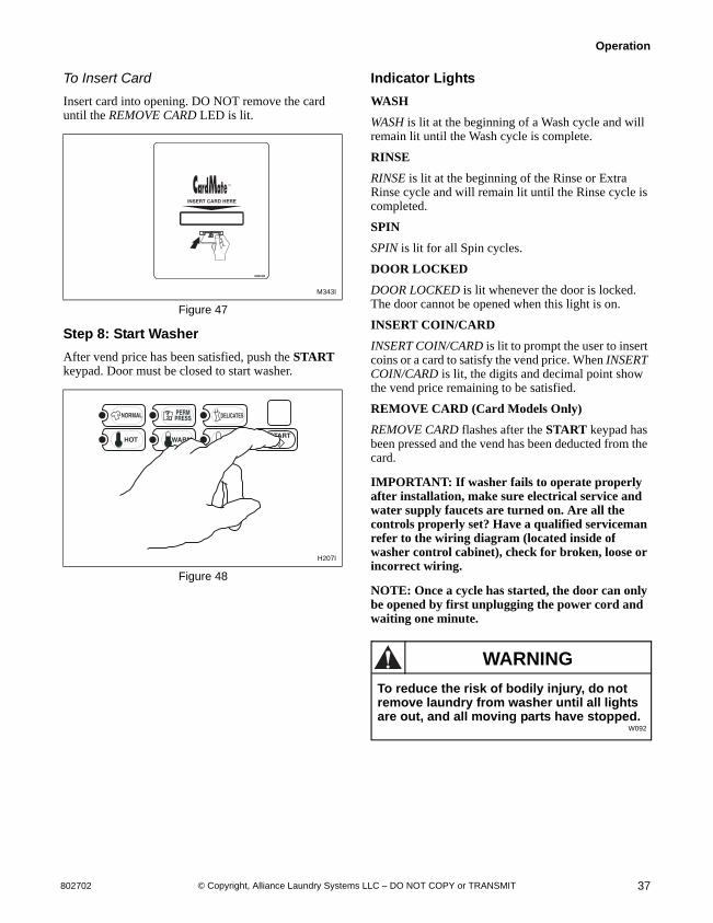
To Insert Card
Insert card into opening. DO NOT remove the card until the REMOVE CARD LED is lit.
Figure 47
Step 8: Start Washer
After vend price has been satisfied, push the START keypad. Door must be closed to start washer.
Figure 48
Indicator Lights
WASH
WASH is lit at the beginning of a Wash cycle and will remain lit until the Wash cycle is complete.
RINSE
RINSE is lit at the beginning of the Rinse or Extra Rinse cycle and will remain lit until the Rinse cycle is completed.
SPIN
SPIN is lit for all Spin cycles.
DOOR LOCKED
DOOR LOCKED is lit whenever the door is locked. The door cannot be opened when this light is on.
INSERT COIN/CARD
INSERT COIN/CARD is lit to prompt the user to insert coins or a card to satisfy the vend price. When INSERT COIN/CARD is lit, the digits and decimal point show the vend price remaining to be satisfied.
REMOVE CARD (Card Models Only)
REMOVE CARD flashes after the START keypad has been pressed and the vend has been deducted from the card.
IMPORTANT: If washer fails to operate properly after installation, make sure electrical service and water supply faucets are turned on. Are all the controls properly set? Have a qualified serviceman refer to the wiring diagram (located inside of washer control cabinet), check for broken, loose or incorrect wiring.
NOTE: Once a cycle has started, the door can only be opened by first unplugging the power cord and waiting one minute.
M343I
H207I
H207I
HOT WARM
PERMPRESS
COLDSTART
NORMAL DELICATES
To reduce the risk of bodily injury, do not remove laundry from washer until all lights are out, and all moving parts have stopped.
W092
WARNING
© Copyright, Alliance Laundry Systems LLC – DO NOT COPY or TRANSMIT
Operation
80270238
Operation Instructions for MDC Dryers
IMPORTANT: Before using dryer for the first time, use an all-purpose cleaner, or a detergent and water solution, and a damp cloth to remove shipping dust from inside of dryer drum.
IMPORTANT: Remove all sharp objects from laundry to avoid tears and rips to items during normal machine operation.
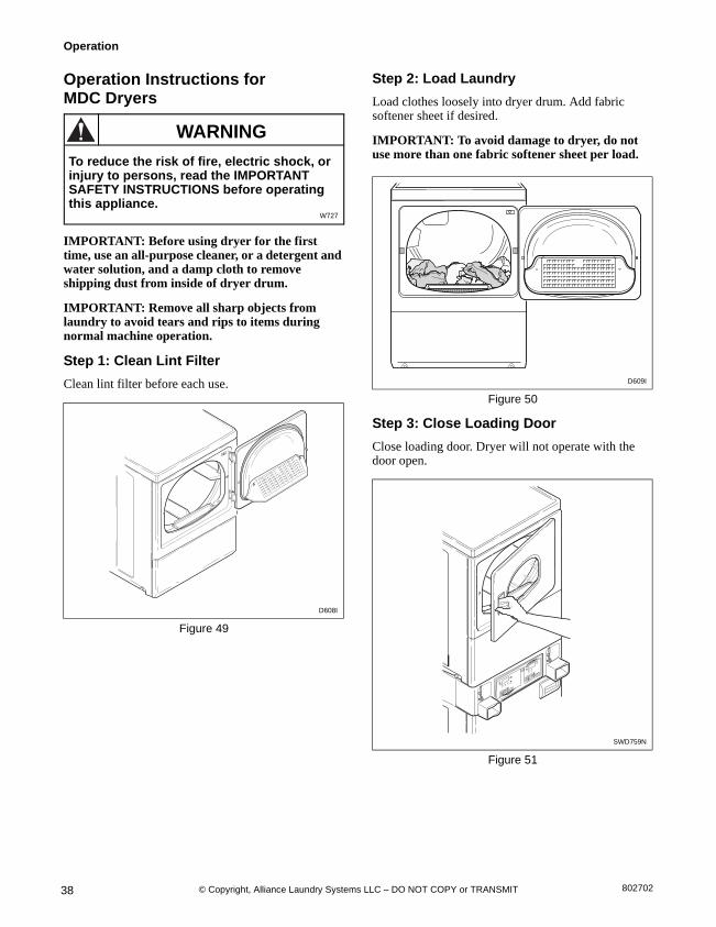
Step 1: Clean Lint Filter
Clean lint filter before each use.
Figure 49
Step 2: Load Laundry
Load clothes loosely into dryer drum. Add fabric softener sheet if desired.
IMPORTANT: To avoid damage to dryer, do not use more than one fabric softener sheet per load.
Figure 50
Step 3: Close Loading Door
Close loading door. Dryer will not operate with the door open.
Figure 51
D608I
To reduce the risk of fire, electric shock, or injury to persons, read the IMPORTANT SAFETY INSTRUCTIONS before operating this appliance.
W727
WARNING
D608I
D609I
SWD759N
D609I
SWD759N

© Copyright, Alliance Laundry Systems LLC – DO NOT COPY or TRANSMIT
Operation
39802702
Step 4: Determine Proper Controls for Dryer
The direction of the arrow indicates which controls are for the dryer.
Figure 52
Step 5: Set Fabric Selector
Select HIGH TEMP, MED TEMP, LOW TEMP or DELICATES by pushing keypad.
NOTE: Always follow manufacturer’s care label instructions.
Figure 53
Step 6: Insert Coin(s) or Card
To Insert Money
Insert coin(s) in coin slot. Check pricing as seen on digital display.
Figure 54
To Insert Card
Insert card into opening.
Figure 55
If Additional Time Feature is turned on, additional dryer time may be purchased at cycle start or while dryer is running.
Remove knits when slightly damp because overdrying may cause shrinkage. Do not tumble dry knit woolens.
SWD960N
DRY1926N
DRY1926N
W387I
DRY1927N

© Copyright, Alliance Laundry Systems LLC – DO NOT COPY or TRANSMIT
Operation
80270240
Step 7: Start Dryer
To start dryer, push START keypad.
To stop dryer at any time, open the door. To restart the dryer, close door and push START keypad.
Cycle is completed when time remaining reaches 00 minutes.
Figure 56
Indicator Lights
START
START is lit when the dryer is not in a cycle, the full vend price has been satisfied and the dryer door is closed. When the START keypad is pressed, the cycle will begin or resume.
DRYING
DRYING is lit to indicate that one of the heated cycles (HIGH TEMP, MED TEMP, LOW TEMP or DELICATES) is currently in operation. DRYING will turn off at the end of a heated cycle or when the COOL DOWN cycle begins.
COOL DOWN
COOL DOWN is lit whenever the COOL DOWN portion of a heated cycle is active. It is also lit when no heat is programmed for a cycle in operation.
DRY1928N
DRY1

© Copyright, Alliance Laundry Systems LLC – DO NOT COPY or TRANSMIT
Operation
41802702
Operation Instructions for NetMaster Dryers
IMPORTANT: Before using dryer for the first time, use an all-purpose cleaner, or a detergent and water solution, and a damp cloth to remove shipping dust from inside of dryer drum.
IMPORTANT: Remove all sharp objects from laundry to avoid tears and rips to items during normal machine operation.
Step 1: Clean Lint Filter
Clean lint filter before each use.
Figure 57
Step 2: Load Laundry
Load clothes loosely into dryer drum. Add fabric softener sheet if desired.
IMPORTANT: To avoid damage to dryer, do not use more than one fabric softener sheet per load.
Figure 58
Step 3: Close Loading Door
Close loading door. Dryer will not operate with the door open.
Figure 59
D608I
1 Lint Filter
To reduce the risk of fire, electric shock, or injury to persons, read the IMPORTANT SAFETY INSTRUCTIONS before operating this appliance.
W727
WARNING
D608I
1
D609I
SWD761N
D609I
SWD761N
© Copyright, Alliance Laundry Systems LLC – DO NOT COPY or TRANSMIT
Operation
80270242
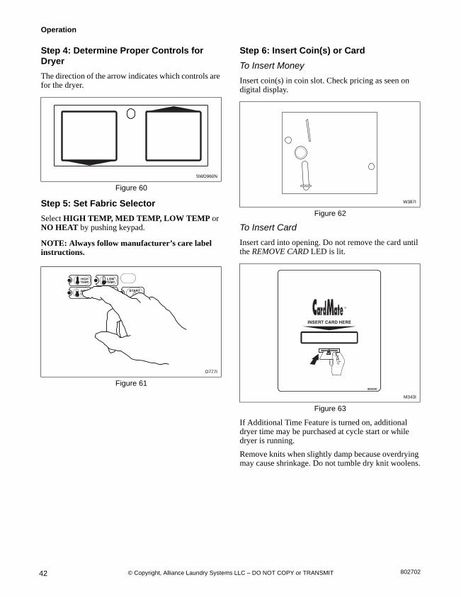
Step 4: Determine Proper Controls for Dryer
The direction of the arrow indicates which controls are for the dryer.
Figure 60
Step 5: Set Fabric Selector
Select HIGH TEMP, MED TEMP, LOW TEMP or NO HEAT by pushing keypad.
NOTE: Always follow manufacturer’s care label instructions.
Figure 61
Step 6: Insert Coin(s) or Card
To Insert Money
Insert coin(s) in coin slot. Check pricing as seen on digital display.
Figure 62
To Insert Card
Insert card into opening. Do not remove the card until the REMOVE CARD LED is lit.
Figure 63
If Additional Time Feature is turned on, additional dryer time may be purchased at cycle start or while dryer is running.
Remove knits when slightly damp because overdrying may cause shrinkage. Do not tumble dry knit woolens.
SWD960N
D777I
W387I
M343I

© Copyright, Alliance Laundry Systems LLC – DO NOT COPY or TRANSMIT
Operation
43802702
Step 7: Start Dryer
To start dryer, push START keypad.
To stop dryer at any time, open the door. To restart the dryer, close door and push START keypad.
Cycle is completed when time remaining reaches 00 minutes.
Figure 64
Indicator Lights
INSERT COINS/CARD
INSERT COINS/CARD is lit to prompt the user to insert coins or card to satisfy the vend price. When INSERT COINS/CARD is lit, the three digits and decimal point will display the vend price remaining to be satisfied.
START
START is lit when the dryer is not in a cycle, the full vend price has been satisfied and the dryer door is closed. When the START keypad is pressed, the cycle will begin or resume.
DRYING
DRYING is lit to indicate that one of the heated cycles (HIGH TEMP, MED TEMP, LOW TEMP) is currently in operation. DRYING will turn off at the end of a heated cycle or when the COOL DOWN cycle begins.
COOL DOWN
COOL DOWN is lit whenever the COOL DOWN portion of a heated cycle is active. It is also lit when the NO HEAT cycle is in operation.
ADD TIME (Card Models Only)
ADD TIME flashes when a card is inserted while a cycle is running or when a card is left in the reader.
REMOVE CARD (Card Models Only)
REMOVE CARD flashes when a card is inserted or left in the reader after a transaction is complete. It will also flash alternately with ADD TIME when a card is inserted while a cycle is running or when a card is left in the reader.
D778I
D778I
© Copyright, Alliance Laundry Systems LLC – DO NOT COPY or TRANSMIT44 802702
MaintenanceUser-Maintenance Instructions
Lubrication
All moving parts are sealed in a permanent supply of lubricant or are equipped with oilless bearings. Additional lubrication will not be necessary.
Do not lubricate the washer door hinge. If the hinge makes noise, replace the hinge.
Cold Weather Care
If the unit is delivered on a cold day (below freezing), or is stored in an unheated room or area during the cold months, do not attempt to operate it until the washer has had a chance to warm up.
Vacations and Extended Non-Use
IMPORTANT: To avoid possible property damage due to flooding, turn off the water supply to the washer whenever there will be an extended period of non-use.
Leave the loading door open during extended periods of non-use to allow the wash drum to dry out and avoid a musty smell.
Care of Your Washer
Use only a damp or sudsy cloth for cleaning the control panel. Some cleaning product sprays may harm the finish on the control panel or damage the interior.
Wipe the washer cabinet as needed. If detergent, bleach or other washing products are spilled on the cabinet, wipe immediately. Some products will cause permanent damage if spilled on the cabinet.
Do not use scouring pads or abrasive cleansers.
The wash drum will need no particular care although it may need rinsing or wiping after an unusual load has been washed.
The outside of the door window can be cleaned with household window cleaner.
Running an occasional rinse cycle with bleach will help avoid a musty smell in the wash drum.
Cleaning Glass Sealing Area
In order to assure that the door properly seals against water leaks, the following surfaces should be wiped off periodically:
The outside perimeter of the door glass where the seal contacts the glass.
The front surface of the door seal lip.
Usually a mild soap solution will work. If there is an extreme build-up of minerals from a hard water supply, the surfaces may need to be cleaned with a lime removal chemical.
Replacing Hoses
Hoses and other natural rubber parts deteriorate after extended use. Hoses may develop cracks, blisters or material wear from the temperature and constant high pressure they are subjected to.
All hoses should be checked on a monthly basis for any visible signs of deterioration. Any hose showing the signs of deterioration listed above should be replaced immediately. All hoses should be replaced every five years.
Cleaning Foreign Object Trap
The washer’s pump has a trap that may collect foreign objects. The trap may need to be cleaned if water is draining slower than usual. To clean:
Disconnect washer from electrical supply.
While supporting the front access panel, remove two screws from the bottom edge of the panel.
Gently lower the panel to remove it from the washer.
NOTE: The pump may have some water in it. Use a rag or a container to catch water. If the wash drum is full of water, use a wet/dry shop vacuum to catch the water.
With rag or vacuum ready, unscrew the cap on the left side of the pump and remove trap.
Clean the debris from the trap.
Reinstall the trap and access panel.
Reconnect washer to electrical supply.
Filter Screen
Check the filter screens in the fill hoses for debris or damage annually. Clean or replace them if necessary.
If the washer is filling with water slower than normal, check the filter screens. Clean or replace them if necessary.
Order filter screen Part No. F270300 from the nearest authorized parts distributor.

© Copyright, Alliance Laundry Systems LLC – DO NOT COPY or TRANSMIT
Maintenance
45802702
Care of Your Dryer
Dryer Interior
Wipe the surfaces using a soft cloth and household cleaner or a non-abrasive paste of powdered laundry detergent and hot water, followed by a short heat cycle with a load of rags.
To remove crayon or ball point ink off the dryer drum, put the heat on high and use old rags in the dryer to absorb the crayon or ink. If unsuccessful, contact the appliance dealer. DO NOT use any chemicals in the dryer.
IMPORTANT: The use of chlorine bleach for removing any discolorations should be avoided because bleach could damage the finish.
Cabinet
Wipe the dryer cabinet as needed. If detergent, bleach or other washing products have been spilled on the dryer, wipe immediately. Some products will cause permanent damage if spilled on the cabinet.
Control Panel
Use only a damp or sudsy cloth for cleaning the control panel. Some spray pretreat products may harm the finish on the control panel.
NOTE: The wiring diagram is located inside the control panel.
Exhaust System
The exhaust duct should be inspected after one year of use and cleaned if necessary by a qualified service person to remove any lint build-up. Inspect and clean exhaust duct every one to two years as required thereafter.
The weather hood should be checked frequently to make sure the dampers move freely, dampers are not pushed in and that nothing has been set against them.
Keep dryer area clear and free from combustible materials, gasoline and other flammable vapors and liquids.
Do not obstruct the flow of combustion and ventilation air.
NOTE: Verify proper operation after servicing.
Lint Filter
CLEAN THE LINT FILTER BEFORE DRYING EACH LOAD. (Refer to Figure 65 for lint filter location.) Cleaning the lint filter is important because a layer or pad of lint on the filter will block the flow of air through the dryer, thus reducing the efficiency of the dryer. The clothes will take longer to dry and energy will be wasted.
The lint filter may be washed if needed. Annually remove lint filter and screw to vacuum the duct under it.
Figure 65
To reduce the risk of an electric shock, serious injury or death, disconnect the electrical service to the dryer before cleaning the interior.
W132
WARNING
Label all wires prior to disconnection when servicing controls. Wiring errors can cause improper and dangerous operation.
W049
WARNING
D608I
1 Lint Filter
To reduce the risk of electric shock, disconnect the electrical service to the dryer before cleaning.
W043
WARNING
D608I
1

© Copyright, Alliance Laundry Systems LLC – DO NOT COPY or TRANSMIT
Maintenance
80270246
Reinstallation of Shipping Materials
To prevent damage while moving the unit, the shipping materials MUST be reinstalled.
Disconnect washer from electrical supply.
While supporting the front access panel, remove two screws from the bottom edge of the panel.
Gently lower the panel to remove it from the washer.
Place the shock sleeves on all four shock absorbers. Refer to Figure 66.
Insert hooked end of shipping brace into the open slot of the motor mount.
Attach the brace with the five bolts and washers. Refer to the illustration below.
Reinstall front access panel.
Figure 66
Refer to Installation section, Step 9, for proper procedures whenever the washer is moved.
Motor Overload Protector
The dryer’s motor overload protector stops the motor automatically in the event of an overload. After cooling, the overload protector will reset itself. Dryer can be restarted by pressing the START pad. If overload protector cycles again, remove the dryer from use and call the service person to correct the problem.
For Energy Conservation
Make sure the lint filter is always clean.
Do not overload dryer.
Do not overdry clothes.
Remove items to be ironed while still damp.
Large loads of similar fabrics dry the most efficiently. However, dry permanent press in smaller loads to prevent wrinkling.
Use the correct temperature FABRIC SELECTOR setting for the type of fabric being dried.
Locate your dryer so the exhaust duct is as short and straight as possible.
Do not open the door during the drying cycle.
Plan to do your laundry on low humidity days; your clothes will dry faster.
Should you plan to dry several loads, do them one after another, then you do not have to reheat the dryer unit’s interior parts each time.
FLW2124N
1 Shock Sleeves2 Motor Mount3 Hooked End of Shipping Brace4 Bolts and Lockwashers
FLW2124N
2
1
4
3
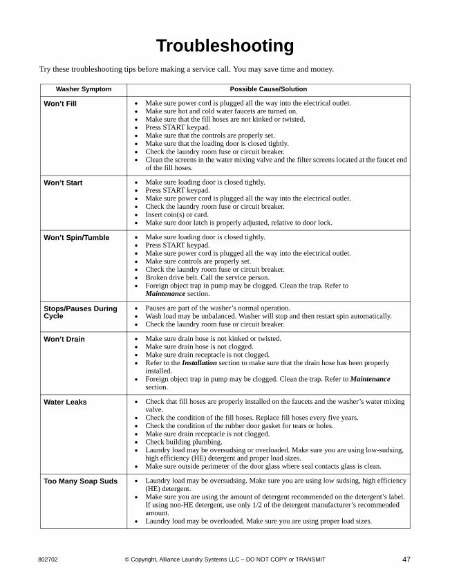
47802702 © Copyright, Alliance Laundry Systems LLC – DO NOT COPY or TRANSMIT
TroubleshootingTry these troubleshooting tips before making a service call. You may save time and money.
Washer Symptom Possible Cause/Solution
Won’t Fill Make sure power cord is plugged all the way into the electrical outlet. Make sure hot and cold water faucets are turned on. Make sure that the fill hoses are not kinked or twisted. Press START keypad. Make sure that the controls are properly set. Make sure that the loading door is closed tightly. Check the laundry room fuse or circuit breaker. Clean the screens in the water mixing valve and the filter screens located at the faucet end
of the fill hoses.
Won’t Start Make sure loading door is closed tightly. Press START keypad. Make sure power cord is plugged all the way into the electrical outlet. Check the laundry room fuse or circuit breaker. Insert coin(s) or card. Make sure door latch is properly adjusted, relative to door lock.
Won’t Spin/Tumble Make sure loading door is closed tightly. Press START keypad. Make sure power cord is plugged all the way into the electrical outlet. Make sure controls are properly set. Check the laundry room fuse or circuit breaker. Broken drive belt. Call the service person. Foreign object trap in pump may be clogged. Clean the trap. Refer to
Maintenance section.
Stops/Pauses During Cycle
Pauses are part of the washer’s normal operation. Wash load may be unbalanced. Washer will stop and then restart spin automatically. Check the laundry room fuse or circuit breaker.
Won’t Drain Make sure drain hose is not kinked or twisted. Make sure drain hose is not clogged. Make sure drain receptacle is not clogged. Refer to the Installation section to make sure that the drain hose has been properly
installed. Foreign object trap in pump may be clogged. Clean the trap. Refer to Maintenance
section.
Water Leaks Check that fill hoses are properly installed on the faucets and the washer’s water mixing valve.
Check the condition of the fill hoses. Replace fill hoses every five years. Check the condition of the rubber door gasket for tears or holes. Make sure drain receptacle is not clogged. Check building plumbing. Laundry load may be oversudsing or overloaded. Make sure you are using low-sudsing,
high efficiency (HE) detergent and proper load sizes. Make sure outside perimeter of the door glass where seal contacts glass is clean.
Too Many Soap Suds Laundry load may be oversudsing. Make sure you are using low sudsing, high efficiency (HE) detergent.
Make sure you are using the amount of detergent recommended on the detergent’s label. If using non-HE detergent, use only 1/2 of the detergent manufacturer’s recommendedamount.
Laundry load may be overloaded. Make sure you are using proper load sizes.

© Copyright, Alliance Laundry Systems LLC – DO NOT COPY or TRANSMIT
Troubleshooting
80270248
Washer Symptom Possible Cause/Solution
Vibrates/Moves Slightly
Make sure washer is level. Uneven leveling can cause vibration. Make sure washer is installed on a solid, sturdy and level floor. The washer should not be
installed on carpeting, soft tile, a platform or other weakly supported structures. Make sure rubber feet are installed on all four leveling legs. Refer to Installation section,
Step 8.
Is Noisy Make sure washer is level. Uneven leveling can cause vibration. Some sounds may be a part of normal operation for a frontload washer.
Load is too Wet Wash load may be unbalanced. The washer may have limited the spin speed to prevent damage to the machine. Redistribute the load.
Load is too small. Add items to make full load.
Wrong Water Temperature
Make sure that the controls are properly set. Check fill hoses. Make sure hot faucet hose is connected to hot mixing valve (indicated
with “H” on the valve bracket) and cold faucet is connected to cold mixing valve (indi-cated with “C” on the valve bracket).
Make sure laundry room water heater is adjusted properly.
Dryer Symptom Possible Cause/Solution
Won’t Start Insert coin(s) or card. For dryers equipped with a power cord, make sure the power cord is plugged all the way
into the electrical outlet. Make sure loading door is closed. Press START pad. Make sure the laundry room fuse(s) isn’t blown or loose, or circuit breakers aren’t open.
The dryer itself does not have an electrical fuse. An electric dryer has an electrical circuit with two fuses.
Check if motor overload protector has cycled. Wait 10 minutes and try again.
Won’t Heat Make sure the laundry room fuse(s) isn’t blown or loose, or circuit breakers aren’t open. The dryer itself does not have an electrical fuse. An electric dryer has an electrical circuit with two fuses.
Make sure controls are in a HEAT setting. Gas dryer only – Make sure equipment and main gas line valves are turned on. Check exhaust duct to outside to see if it is kinked, blocked or needs cleaning. Check weather hood to make sure flapper moves freely, has not been pushed in or has not
been blocked.
Doesn’t Dry Clothes Satisfactorily
Check exhaust duct to outside to see if it is kinked, blocked or needs cleaning. Check weather hood to make sure flapper moves freely, has not been pushed in or has not
been blocked. Clean the lint filter. Make sure the load isn’t too small. Small loads may not tumble properly or dry evenly. Check load being dried. Heavy items dried with lightweight items will not dry as quickly
as the rest of the load.
Is Noisy Check dryer for foreign objects (nails, coins, bobby pins, metal, plastic toys, etc.). Remove items from dryer.
Make sure dryer is level. Uneven leveling can cause vibration. Normal operating sounds include the tick of timer advancing, heat source going on and
off, and humming of air moving through the dryer and exhaust system.
Clothes are too Wrinkled
Check heat setting. Overdrying can cause wrinkling. Check load size. Large loads may not tumble properly and may cause wrinkling.
Clothes Have Odor Check room for odors before drying clothes. Any odor (fried foods, paint, varnish, cleaners, burning wood, etc.) will transfer to clothing as the dryer draws air from the room. Ventilate room before drying clothes.

49802702 © Copyright, Alliance Laundry Systems LLC – DO NOT COPY or TRANSMIT
Contact InformationIf service is required, contact the nearest Factory Authorized Service Center.
If you are unable to locate an authorized service center or are unsatisfied with the service performed on your unit, contact:
Alliance Laundry Systems Shepard StreetP. O. Box 990Ripon, WI 54971-0990U.S.A.www. comlaundry. com Phone: (920) 748-3121
Date Purchased___________________________
Model Number____________________________
Serial Number____________________________
When calling or writing about your unit, PLEASE GIVE THE MODEL AND SERIAL NUMBERS. The model and serial numbers are located on the nameplate. The nameplate will be in the location shown in the illustration below. Please include a copy of your bill of sale and any service receipts you have.
If replacement parts are required, contact the source from which you purchased your unit or contact us at (920) 748-3950 for the name and address of thenearest authorized parts distributor.
D063K
1 Nameplate
Figure 67
1
To reduce the risk of serious injury or death, DO NOT repair or replace any part of the dryer or attempt any servicing unless specifically recommended in the user-maintenance instructions or in published user-repair instructions that you understand and have the skills to carry out.
W133
WARNING


© Copyright, Alliance Laundry Systems LLC – DO NOT COPY or TRANSMIT
Installer ChecklistFast Track for Installing the Stacked Washer and Dryer
(Refer to the manual for more detailed information)
• Position Unit Near Area of Installation.
CHECK
1
• Connect Fill Hoses.
CHECK TLW1976N
HOT
COLD
TLW1976N
2
• Connect Drain Hose to Drain Receptacle.
CHECK
3
SWD631NSWD631N
Non-Gravity Drain Models Only
• Connect Drain Outlet to Drain System.
CHECK
4
SWD745NSWD745N
Gravity Drain Models Only
• Connect Gas Supply Pipe.
• Check for Gas Leaks.
Gas Dryer Only
CHECK D434I
5
• Connect Electrical Plug.
Electric Dryer Only
CHECK
6
D679IE0AD679IE0A
• Connect Dryer Exhaust System.
CHECKH312I
H312I
7
• Position and Level the Unit.
CHECK
8
SWD796NSWD796N
• Remove the Shock Sleeves and Shipping Brace.
9Washer Only
H336IH336I
CHECK
CHECK
• Wipe Out Inside of Washer Drum and Dryer Drum.
10
H315I
SWD797N
SWD797N
H315I
GAS DRYERS AND WASHERS
CHECK
D254I
• Plug In Washer and Dryer.
ELECTRICDRYERS
11
D275IE0ED254I
CHECK
• Recheck Steps 1-11.12
CHECK
13 • Check Heat Source.