standards for sea freight container inspection stands · standards for sea freight container...
TRANSCRIPT

Standards for Sea Freight Container Inspection Stands
Biosecurity

© Commonwealth of Australia 2016
Ownership of intellectual property rights Unless otherwise noted, copyright (and any other intellectual property rights, if any) in this publication is owned by the Commonwealth of Australia (referred to as the Commonwealth).
Creative Commons licence All material in this publication is licensed under a Creative Commons Attribution 3.0 Australia Licence, save for content supplied by third parties, logos and the Commonwealth Coat of Arms.
Creative Commons Attribution 3.0 Australia Licence is a standard form licence agreement that allows you to copy, distribute, transmit and adapt this publication provided you attribute the work. A summary of the licence terms is available from creativecommons.org/licenses/by/3.0/au/deed.en. The full licence terms are available from creativecommons.org/licenses/by/3.0/au/legalcode.
This publication (and any material sourced from it) should be attributed as: Compliance Division, Standards for Sea Freight Container Inspection Stands, Department of Agriculture and Water Resources, Canberra, CC BY 3.0. Department of Agriculture and Water Resources Postal address GPO Box 858 Canberra ACT 2601 Telephone 1800 900 090 Web agriculture.gov.au
Inquiries about the licence and any use of this document should be sent to [email protected].
The Australian Government acting through the Department of Agriculture and Water Resources has exercised due care and skill in preparing and compiling the information and data in this publication. Notwithstanding, the Department of Agriculture and Water Resources, its employees and advisers disclaim all liability, including liability for negligence and for any loss, damage, injury, expense or cost incurred by any person as a result of accessing, using or relying upon any of the information or data in this publication to the maximum extent permitted by law.
Acknowledgements GHD 133 Castlereagh St Sydney NSW 2000 T: +61 2 9239 7100 F: +61 2 9239 7199 E: [email protected] © GHD 2013 The document may only be used for the purpose for which it was commissioned and in accordance with the Terms of Engagement for the commission. Unauthorised use of this document in any form whatsoever is prohibited. www.ghd.com

Contents Standards for Sea Freight Container Inspection Stands ..................................................... 1
1 Introduction ......................................................................................................................................... 4 1.1 Scope, Purpose and Application ......................................................................................................... 4 1.2 New Stands .................................................................................................................................................. 4 1.3 Existing Stands .......................................................................................................................................... 4 1.4 References ................................................................................................................................................... 4 1.5 Definitions and abbreviations ............................................................................................................. 5
2 Statutory Requirements .................................................................................................................. 6
3 Department of Agriculture and Water Resources Inspection Process Requirements ............................................................................................................................................... 7
4 Criteria for design .............................................................................................................................. 8 4.1 Design life .................................................................................................................................................... 8 4.2 Dimensions.................................................................................................................................................. 8 4.3 Protective Coating .................................................................................................................................... 8 4.4 Loading ......................................................................................................................................................... 8 4.5 Securing and locating container on stand .................................................................................... 10 4.6 Other design requirements ................................................................................................................ 11 4.7 Criteria for non-compliant existing stands .................................................................................. 11
5 Requirements for safe use ............................................................................................................ 13 5.1 Location ...................................................................................................................................................... 13 5.2 Damage or faults ..................................................................................................................................... 13 5.3 Placing container on stand ................................................................................................................. 13 5.4 Use during container inspection ...................................................................................................... 13
6 Inspection and maintenance ....................................................................................................... 14 6.1 Qualifications, competencies and requirements ....................................................................... 14 6.2 Inspection and maintenance schedule .......................................................................................... 15 6.3 Register or log of maintenance, inspections/certification and impact reports ............ 17
7 Criteria for limiting defects and repair actions .................................................................... 18
Appendix A – Freight container standards ..................................................................................... 19
Appendix B – Accident and Inspection Sheet ................................................................................ 20
Appendix C – Criteria for Limiting Defects and Associated Repair Actions ....................... 21
Appendix D – Sample Statement of Certification ......................................................................... 22
Statement of Certification ..................................................................................................................... 22 Sea Freight Container Inspection Stand ...................................................................................................... 22
Statement of qualifications ................................................................................................................... 22
Statement of certification ...................................................................................................................... 22
Comments .................................................................................................................................................... 23 Qualification requirements for certifying engineer ................................................................................ 23
Table of Figures
Figure 1 Example certification plate........................................................................................................ 6
Figure 2 Example of gathering guide (Figure 23, AS 3711.10–2000) ..................................... 11
Table Index
Table 1 Series 1 freight containers........................................................................................................... 9
Table 2 Inspection schedule for purpose built container stands .............................................. 16
Table 3 Inspection schedule for existing modified containers used as stands .................... 16

4
1 Introduction 1.1 Scope, Purpose and Application This document specifies the design and maintenance requirements of support structures (stands) for freight containers provided by site/premises authorities at Australian ports and other premises such as Approved Arrangement sites. It is applicable to stands that enable the Department of Agriculture and Water Resources (the department) biosecurity officers to inspect the undersides of freight containers for potential biosecurity risk material.
This document outlines the design, maintenance and safe use of stands to comply with statutory requirements and the department’s inspection obligations, including Work Health and Safety (WHS) policies.
The scope of this document includes the design of new stands and the assessment of existing stands to support series 1 freight containers with the designations 1AAA, 1AA, 1A and 1AX (40 ft containers) and 1CC, 1C and 1CX (20 ft containers) as listed in AS 3711.1–2000.
1.2 New Stands New stands must be designed, constructed and certified to this standard prior to use. Consultation with the department during the construction stage of any new stand is highly recommended.
1.3 Existing Stands Existing stands must be reviewed by a qualified engineer, as defined in this document (see Section 1.5 and Section 6), to the requirements of this standard. All subsequent changes to existing stands must be recertified by a qualified engineer.
1.4 References
At the time of this specification’s development, the follow references are the current versions
available:
AS/NZS 1170.0–2002 Structural design actions – Part 0: General Principles
AS/NZS 1170.1–2002 Structural design actions – Part 1: Permanent, imposed and other
actions
AS/NZS 1170.2–2011 Structural design actions – Part 2: Wind actions
AS 1214–1983 Hot–dip galvanized coatings on threaded fasteners (ISO metric coarse
thread series)
AS/NZS 1554.1–2011 Structural steel welding – Part 1: Welding of steel structures
AS 1657–1992 Fixed platforms, walkways, stairways and ladders — Design,
construction and installation
AS 2312–2002 Guide to the protection of structural steel against atmospheric
corrosion by the use of protective coatings
AS 3711.1–2000 Freight containers – Part 1: Classification, dimensions and ratings
AS 3711.10–2000 Freight containers – Part 10: Handling and securing
AS 4100–1998 Steel structures
AS/NZS 4680–2006 Hot-dip galvanized (zinc) coatings on fabricated ferrous articles

5
1.5 Definitions and abbreviations
BRM Biosecurity Risk Material — Material that has the potential to introduce into Australia
an exotic pest or disease. This could include live insects, seeds, soil, dirt, clay, animal
material and plant material.
CAL Country Action List — A list of countries compiled by the department where there is a
high risk of biosecurity material entering Australia on containers or break bulk cargo.
CAL inspection All containers from CAL countries are subject to a full six-sided inspection of their
external surfaces prior to their release from the wharf, unless special arrangements
have been made with the department.
Container A freight (shipping) container designed to be moved from one mode of transport to
another without unloading and reloading.
The department The Australian Government, Department of Agriculture and Water Resources.
Inspector A department officer tasked to inspect the external sides of containers for biosecurity
risk material.
Leg A vertical support member of a stand.
Port An Australian port/wharf/terminal or another location where international freight
containers are received.
Approved
Arrangement
(AA)
An arrangement that provides for a person covered by the arrangement to carry out
specific biosecurity activities to manage biosecurity risks associated with specified
goods, premises or other things.
Holders of these arrangements are known as biosecurity industry participants. A
defined location specified in an approved arrangement where a physical biosecurity
activity is authorised to be performed is known as an AA site.
Site A place where an inspection stand is located for inspection and/or treatment of
containers.
Stand A structure that supports freight containers and enables the underside of containers to
be inspected or treated.
Qualified
Engineer
An engineer who holds a Bachelor of Civil or Structural Engineering from an Australian
institution or overseas equivalent.
A Bachelor of Mechanical Engineering is acceptable in lieu of Bachelor of Civil or
Structural Engineering on provision of demonstrable experience in the design or
fabrication of steel structures in excess of five years.
Is an independent operative to the site/premises authorities with Chartership with the
Institute of Engineers and meets all other requirements of Section 6.
Structural
Inspector
A person with competency in steel structures (refer to Section 6) who conducts visual
inspections of stands.
SWL Safe working limit — A term used to describe the safe load able to be supported by the
stand.
WHS Work Health and Safety

6
2 Statutory Requirements To ensure a safe workplace environment, the Work, Health and Safety (WHS) Act (Cth) 2011 requires consideration of “Safety In Design” principles associated with the whole life cycle (design, construction, operation/maintenance and disposal) in the design of the stand.
Safe design principles must be applied to eliminate hazards or reduce risks (Section 21–26, WHS Act (Cth), 2011) to as low as reasonably practical for personnel who:
• construct the structure1 at a workplace • at a workplace, use the structure for a purpose for which it was designed • carry out any reasonably foreseeable activity at a workplace in relation to demolition or
disposal of the structure • are at or in the vicinity of a workplace and are exposed to the structure.
In accordance with WHS, design and functional requirements for stands that must be followed are:
• The design must not block the view of the underside of the container or be located in a position that could present a risk to the inspecting officer. The structure must not obstruct access to below the container nor present any trip hazard. Cross bracing is permitted, provided it does not shield any part of the container’s external surface from visual inspection.
• If flooring is provided, and the change in level from the ground is 300 mm or less, access may be gained without the provision of an intermediate step. Where the change of level is greater than 300 mm, intermediate step/s must be provided. Step/s must be a standard step height from the ground (not less than 150 mm and not greater than 215 mm) and provide safe support. Steps must be designed to AS1657 Platforms, Walkways, Steps and Ladders. It must be a flat and level non-slip surface, free of obstacles and trip hazards. Where grated floor is used, the size of grating must be minimised to avoid a trip hazard.
• The stand must not have any protrusions or sharp edges that would present a hazard. • Each stand must have a certification plate clearly displayed. The plate must be
permanent (e.g. pop-riveted or welded), non-corrosive, with an appropriate size and location ensuring it is readily visible and readable (see Figure 1). It must be large enough to contain the following information:
• a unique stand number • date of manufacture • the stand’s safe working limit (SWL) • month and date of last inspection.
Figure 1 Example certification plate
3
1 The WHS Act 2011, Section 4: structure means anything that is constructed, whether fixed or moveable, temporary or permanent, and includes: a) buildings, masts, towers, framework, pipelines, transport infrastructure and underground works (shafts or tunnels); and b) any component of a structure; and c) part of a structure.

7
3 Department of Agriculture and Water Resources Inspection Process Requirements
The biosecurity requirements of the department are that the exterior of freight containers are free of contamination by soil, animal or plant material before release from biosecurity into Australia.
All containers from countries listed on the department’s Country Action List (CAL) must be subjected to a full six-sided inspection of their external surfaces prior to their release into Australia unless alternative arrangements have been made with the department.
All containers destined for rural areas undergo ‘rural tailgate inspections’ which involve an external inspection prior to their release into Australia. Other inspections, such as re-inspections after treatment, may also require the inspection of the underside of containers before release.
In order to carry out the department’s inspection process, it is required that:
• The vertical clearance from the floor of the stand (where personnel stand) to the underside of the container resting on the stand must be a minimum of 1.8 m and maximum of 2 m. The minimum 1.8 m clearance is to allow for ease of movement and prevent head clashes with low members.
• The stand must provide a clear view of the underside of the container, free from obstructions and as free possible from shadows cast by adjacent structures. Cross bracing is permitted, provide it does not shield any part of the container’s external surface from visual inspection.
• The stand structure must allow for easy access/egress below the supported container to minimise trips and falls and facilitate fast exit in emergency situations
• The stand must not impede the use of any fork lifting pockets, if present, within the container. Forklift approach access to the front of the stand must not be prevented by overhang
• All tools and personal protective equipment used during inspections must be compliant with the department’s procedures
• All personnel must be trained and certified (if required by regulations) in equipment operating procedures
• Containers or other loads must not be carried over people • Personnel must be a minimum of 3 m away from the area where the container is being
loaded or unloaded onto a stand • Personnel must be aware of the movement, contents, swing and stability of containers
during transport, loading and unloading • Operators must watch the moving load at all times and provide a signal person, if
required by either the Code of Practice of that premises or the operating environment
• To assist in the cleaning of the container underside, the floor and bracing of the stand must allow contaminants and water to flow onto the ground below using the wash-down methods available. The flooring of stands must be a flat surface.

8
4 Criteria for design New stands must be designed, constructed and certified according to the criteria in Clauses 4.1 to 4.6 of this specification and to AS 4100–1998.
All existing stands must be reviewed to meet the requirements of this specification by a qualified engineer (as defined in Section 1.5 and Section 6) and the Safe Working Limit (SWL) must be displayed on the stand. Consideration must be given to the current state of the stand, for example the extent of corrosion, cracking and any loss of section. In situations where an existing stand does not meet the requirements within Clauses 4.1 to 4.6, refer to Section 4.7 for specific criteria for non-compliant existing stands.
4.1 Design life Stands must have a minimum design life of 30 years.
4.2 Dimensions Stands must be designed to provide full support to 40 foot or 20 foot containers with dimensions as listed in Table 2 of AS 3711.1–2000 and reproduced as Table 1 below.
4.3 Protective Coating New steel container stands must have surface protection in accordance with AS 2312. Where steelwork is to be galvanised, it must be done according to AS/NZS 4680–2006. Galvanising of bolts, screws, nuts and washers must conform to AS 1214–1983.
Metals from incompatible materials must be separated by concealing layers of suitable inert material of suitable thickness, for example plastic sleeves and washers for bolts.
4.4 Loading The stands must be able to resist the loading requirements for the full container dead loads, wind loads and equipment impact loads. The SWL of a stand is the maximum dead load of a container that can be placed on the stand. The minimum SWL of new stands must be the dead load (30,480 kg) as per Section 4.4.1.
4.4.1 Dead load (GF) and (GE)
The dead load of 40 ft and 20 ft containers must consider both the maximum and minimum dead load cases. The maximum dead load is the maximum gross mass of a full container during operation (GF). The minimum dead load is the tare mass of an empty container (GE).
The maximum gross mass of a container during operation is referred to as ‘rating’ in AS 3711.1–2000. The values provided in AS 3711.1 – 2000 are listed in Table 1 below. Also refer to Table 1 for the tare weight of 40 ft and 20 ft containers.
The dead load of the structure (container stand) can also be considered.
4.4.2 Dynamic vertical load (D)
The dynamic vertical load (D) associated with a sudden drop of the container as it is loaded on the stand is equivalent to 1 times the maximum dead load of the container (GF) and is a separate and distinct load to the dead load.
D = 1 x (GF)
Where:
• D is the dynamic vertical load • (GF) is the maximum dead load of a full container.
9
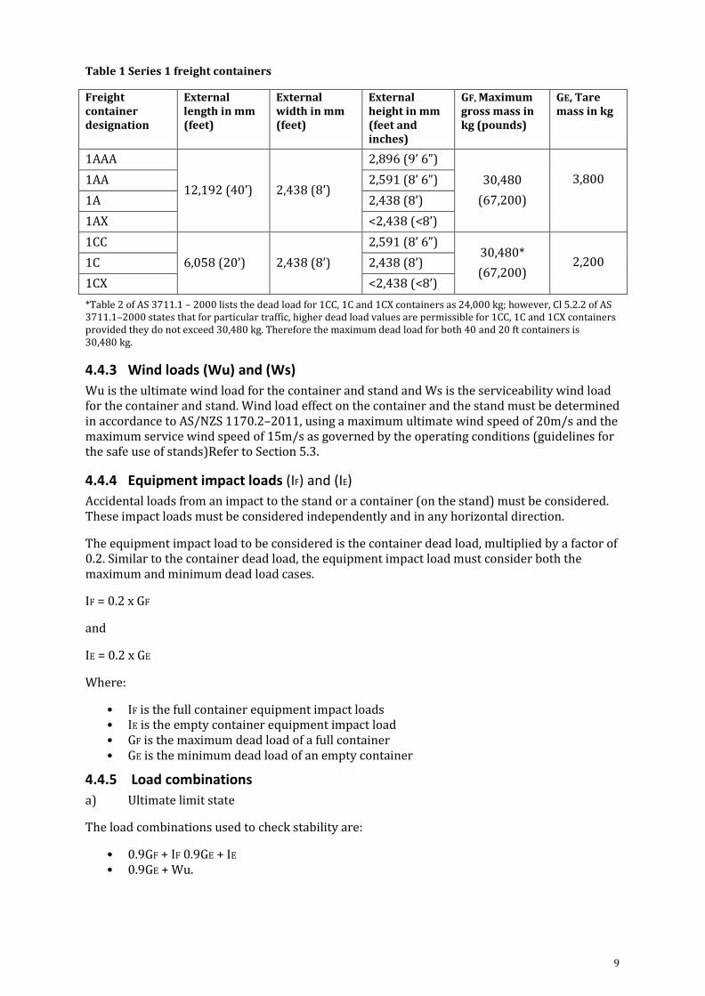
Table 1 Series 1 freight containers
Freight container designation
External length in mm (feet)
External width in mm (feet)
External height in mm (feet and inches)
GF, Maximum gross mass in kg (pounds)
GE, Tare mass in kg
1AAA
12,192 (40’) 2,438 (8’)
2,896 (9’ 6”)
30,480
(67,200)
3,800 1AA 2,591 (8’ 6”)
1A 2,438 (8’)
1AX <2,438 (<8’)
1CC
6,058 (20’) 2,438 (8’)
2,591 (8’ 6”) 30,480*
(67,200)
2,200 1C 2,438 (8’)
1CX <2,438 (<8’)
*Table 2 of AS 3711.1 – 2000 lists the dead load for 1CC, 1C and 1CX containers as 24,000 kg; however, Cl 5.2.2 of AS 3711.1–2000 states that for particular traffic, higher dead load values are permissible for 1CC, 1C and 1CX containers provided they do not exceed 30,480 kg. Therefore the maximum dead load for both 40 and 20 ft containers is 30,480 kg.
4.4.3 Wind loads (Wu) and (Ws)
Wu is the ultimate wind load for the container and stand and Ws is the serviceability wind load for the container and stand. Wind load effect on the container and the stand must be determined in accordance to AS/NZS 1170.2–2011, using a maximum ultimate wind speed of 20m/s and the maximum service wind speed of 15m/s as governed by the operating conditions (guidelines for the safe use of stands)Refer to Section 5.3.
4.4.4 Equipment impact loads (IF) and (IE)
Accidental loads from an impact to the stand or a container (on the stand) must be considered. These impact loads must be considered independently and in any horizontal direction.
The equipment impact load to be considered is the container dead load, multiplied by a factor of 0.2. Similar to the container dead load, the equipment impact load must consider both the maximum and minimum dead load cases.
IF = 0.2 x GF
and
IE = 0.2 x GE
Where:
• IF is the full container equipment impact loads • IE is the empty container equipment impact load • GF is the maximum dead load of a full container • GE is the minimum dead load of an empty container
4.4.5 Load combinations
a) Ultimate limit state
The load combinations used to check stability are:
• 0.9GF + IF 0.9GE + IE • 0.9GE + Wu.

10
The load combinations used to check strength are:
1.2GF + D1.2GF + IF
• 1.2GE + IE • 1.2GF + Wu
b) Serviceability limit state
The load combinations used to check serviceability are:
GF + Ws + IF.
Where:
• GF is the maximum dead load of a full container • GE is the minimum dead load of an empty container • IF is the full container equipment impact load • IE is the empty container equipment impact load • Wu is the ultimate wind load for the container and stand (where the maximum ultimate
wind speed is 20 m/s) • WS is the serviceability wind load for the container and stand (where the maximum
service wind speed is 15 m/s) • D is the dynamic vertical load.
4.4.6 Load distribution between legs of stand
Eccentricity of the vertical loading from the cargo within the container must be considered in the design of the stand‘s legs.
4.4.7 Robustness
The design must provide sufficient robustness as follows:
• All structural components must be tied together in the horizontal and the vertical planes.
• Load paths to the foundations must be provided for forces generated by all types of actions from all parts of the structure.
• Alternate load paths must be provided to ensure that any damage is absorbed and failure of critical members will not result in a major collapse.
• To verify robustness, the stand must be designed to resist a lateral load of 1.5% of the maximum container dead load applied to the loaded stand at the top of the container. The direction of this lateral load must be that which produces the most critical effect in the stand. A lateral load equal to 5% of the maximum container dead load must be able to be transmitted in the connections of the stand.
4.5 Securing and locating container on stand The container must be able to be correctly located onto the stand and be prevented from moving horizontally while on the stand under the stability load combinations. Containers are not required to be tied down to stands and instead gathering guides (see Figure 2), or similar, for each of the container’s corners must be used to locate the container on the stands. Stacking cones can still be used in place of, or in conjunction with, gathering guides. The design provided for locating of containers atop the stands must not impede the method used for placing and lifting containers.

11
Figure 2 Example of gathering guide (Figure 23, AS 3711.10–2000)
4.6 Other design requirements Modified containers, e.g. modified flat racks, are not acceptable for the design and construction of new stands. Stands in current use that are modified containers must be reviewed and re- certified as per Section 4 of this document.
The legs of stands must be braced in both directions. Therefore, “A” frame trestles must not be used to support 40 ft and 20 ft containers unless the frames are braced in both directions. The base of the stand must also be adequately braced.
An inspection plate, as described in Section 2, must be attached to the stand structure.
The design of the stand must conform to the statutory requirements and the department process requirements as per Section 2 and 3.
4.7 Criteria for non-compliant existing stands Where an existing stand has failed to meet any of the criteria specified in Sections 4.1 to 4.6, refer to the appropriate section below.
4.7.1 Design life
The remaining service life of all existing stands must be determined by a qualified engineer in accordance with the requirements of this specification.
4.7.2 Dimensions
Existing stands cannot be used for containers that have different dimensions to the container they are designed to support. Existing stands designed for 20 ft containers must be able to provide full support for 20 ft containers and can only be used for 20 ft containers, likewise for 40 ft containers. Stands that have been designed to support either 20 ft or 40 ft containers can be used for either 20 ft or 40 ft containers.
Where site/premises authorities require two 20 ft stands to be used to support one 40 ft container or a 40 ft stand to support one or two 20 ft container, this requires a review and verification of the arrangement by a qualified engineer as the stands where not designed for this purpose.
4.7.3 Protective Coating
Existing stands must be protected in accordance with AS 2312–2002.
If it is not possible to separate incompatible materials particular attention must be paid to these areas during inspections.

12
4.7.4 Loading
The stands must be able to resist the loading requirements as describe in Clause 4.4. The SWL must be displayed on the stand. Consideration must be given to the current state of the stand, for example the extent of corrosion, cracking and any loss of section. The stand cannot be loaded beyond its displayed SWL.
4.7.5 Securing and locating container on stand
For stands without gathering guides, locating the container on the stand and the prevention of horizontal movement while on the stand, under the stability load combinations, must be verified by a qualified engineer. Stacking cones can still be used in place of, or in conjunction with, gathering guides.

13
5 Requirements for safe use The following guidelines are provided for the safe use of stands:
5.1 Location The stand must be located clear of mobile plant operations and electrical power lines to lower the risk of accidental impacts.
5.2 Damage or faults Following any damage within the tolerance levels of Appendix C (Criteria for Limiting Defects and Associated Repair Actions) including impact, the stand must be initially inspected and assessed by a structural inspector (and qualified engineer if required).
For any damage outside the tolerance levels the stand must be removed from use and a detailed structural inspection and assessment must be performed by a qualified engineer. Once the defect/damage has been rectified/repaired and recertified by a qualified engineer, the stand can re-enter service.
Refer to Section 6 of this document for qualifications required for structural inspector and qualified engineer. Refer to Appendix D for sample Statement of Certification that contains all the mandatory information required for certification.
A record must be kept in accordance with the site’s document procedures, for example by lodging an incident/hazard report. Department staff are also to lodge a WHS incident report if they are aware of any damage or fault as well as reporting to site staff.
5.3 Placing container on stand The stand must be placed on a level and hard surface.
Stands must be positioned so that the longitudinal axis of the supported container is in line with the predominant wind direction. The weather conditions must be evaluated prior to placing the container on the stand. In situations with winds over 15 m/s (the maximum service wind speed) the stand must not be loaded.
Mobile plant/forklift operators must act responsibly and exercise due care when loading stands to prevent unexpected loading on the stands and damage to the stands. Operators should be aware of or trained in AS 3711.10–2000 for handling of containers when placing and removing from the stand.
5.4 Use during container inspection Stands must be used as intended. Stands designed for 20 ft containers and 40 ft containers must only be used for 20 ft containers and for 40 ft containers. Stands that have been designed (or verified by a qualified engineer, refer to Section 4.7.2) to support either 20 ft or 40 ft containers can be used for either 20 ft or 40 ft containers. Loading of a stand must not exceed the SWL marked on the stand.
No attempt is to be made to move the stand whilst a container is upon a stand.
The underside of the container must be checked by site/premises’ staff and department inspectors for damage and excessive sagging before personnel can enter below the container for inspection.

14
6 Inspection and maintenance 6.1 Qualifications, competencies and requirements
6.1.1 Structural inspectors
Structural inspectors are not required to be an independent worker to the site/premises authorities. Structural inspectors must have competency in steel structures. Competency can be obtained by meeting one of the following three criteria:
• successful completion of Transport and Logistics training packages: TLIB2086A (Apply awareness of structures fundamentals) and TLIB3088A (Examine Steel Structures) with 5 years’ experience in the inspection of steel structures
• welding Inspector Certificate as recognised by the Welding Technology Institute of Australia (WTIA)
• more than 15 years’ experience in the inspection or fabrication of steel structures in addition to approval by a qualified engineer (with a membership of Engineers Australia (MIEAust) or equivalent).
Copies of these qualifications must be provided to the department with inspection result and/or certification.
6.1.2 Qualified engineers
As defined in this document, qualified engineers must have EITHER of the following qualifications:
1. A Bachelor of Civil or Structural Engineering from an Australian institution or overseas equivalent
2. A Bachelor of Mechanical Engineering from an Australian institution or overseas equivalent PLUS demonstrable experience in the design or fabrication of steel structures in excess of five years.
Qualified engineers are required to meet ALL of the following:
• Chartership with the Institute of Engineers • Valid state certification (if required) • Be an independent worker to the site/premises authorities.
Copies of these qualifications must be provided to the department with inspection result and/or certification.
6.1.3 Demonstrable experience in design and fabrication of steel structures
A mechanical engineer is required to provide a CV or logbook, going back a minimum of five years which states relevant projects the mechanical engineer has worked on.
To be relevant these projects must involve the design or fabrication of steel structures.
For each project the CV/logbook must detail:
• the project’s scope of work • the dates when the work was undertaken • the company the engineer work for at the time • the client for the works.

15
6.2 Inspection and maintenance schedule The following inspection and maintenance schedule (refer to Table 2) is applicable to all purpose built stands, and does not include existing modified containers currently used as stands. Existing modified containers stands must follow a separate inspection schedule (refer to Section 6.2.2)
6.2.1 Inspection schedule - purpose built stands
Following the initial certification by a qualified engineer, inspections are to be carried out at 2-yearly intervals alternating between inspections conducted by a structural inspector and qualified engineer, as shown in Table 2. The first scheduled inspection by a structural inspector should be conducted 2 years after the stand’s initial certification.
Structural inspectors are to conduct visual inspections. The inspection must record the condition of the structural elements, including legs, connections (welding), bracing members, gussets, any cracks, surface condition and corrosion. Section loss must be recorded. An Accident/Inspection sheet for the structural inspector is provided in Appendix B.
Qualified engineers are to conduct detailed structural inspections and assessments (certification) alternately as scheduled in Table 2. To ensure all the required information is captured in the certification, a sample Statement of Certification has been included at Appendix D. This statement includes all the mandatory information that is required for certification. It is provided as a guide/sample to simplify the certification process and to aid stakeholders in meeting certification requirements.
Additionally, as per Section 7, if the results of the visual inspection by structural inspectors are at or beyond the limiting criteria listed in Appendix C the stand must be removed from use and a detailed structural inspection and assessment (certification) must be performed by a qualified engineer.
Beyond the stand’s 30 year design life, the visual inspections and detailed structural inspections and assessment must be carried out at a reduced inspection interval (with additional visual inspections after an accident or impact affecting structural integrity or where re-certification by a qualified engineer is required per Appendix C – Criteria for Limiting Defects and Associated Repair Actions).
In its 31st year the stand must be inspected by a qualified engineer and in the following year by a structural inspector. This yearly alternating arrangement between the structural inspector and qualified engineer will continue for the remainder of the stand’s use.
The inspection schedule (refer to Table 2) continues until the qualified engineer deems the stand unsuitable for further use. At this point if the site/premises authorities decide not to repair the stand, it is decommissioned.
Please note: Structural inspectors are able to conduct visual inspections with the use of the Accident/inspection sheet provided in Appendix B, however this does not constitute an initial certification of a new or existing stand. Visual inspections are to be conducted in accordance with Clause 6.2 in reference to Tables 2 and 3.

16
Table 2 Inspection schedule for purpose built container stands
This table is indicative of the sequence of inspections. The first inspection after certification is to be by a structural inspector, within 2 years of certification.
6.2.2 Inspection schedule - existing modified containers used as stands
Inspections are to be carried out at yearly intervals alternating between inspections conducted by a structural inspector and qualified engineer, as shown in Table 3. The first scheduled inspection by a structural inspector should be conducted 1 year after the stand’s initial certification by a qualified engineer.
The inspection schedule (refer to Table 3) continues until the qualified engineer deems the stand unsuitable for further use. At this point if the site/premises authorities decide not to repair the stand, it is decommissioned.
Table 3 Inspection schedule for existing modified containers used as stands
Inspection interval
Inspection schedule
0 Initial certification by a qualified engineer
1 Visual inspections by a structural inspector
2 Detailed structural inspections and assessments by a qualified engineer
3 Visual inspections by a structural inspector
4 Detailed structural inspections and assessments by a qualified engineer
5 Visual inspections by a structural inspector
>5 Continue inspections in intervals as described from 1–5, until stand repaired or
decommissioned.
This table is indicative of the sequence of inspections. The first inspection after certification is to be by a structural inspector, within the year following certification.
6.2.3 Inspection requirements after accidents or impacts to stands
After an accident or impact to stand, the stand must be inspected by a structural inspector.
Inspection interval
Inspection schedule
0 Initial certification by a qualified engineer
2 Visual inspections by a structural inspector
4 Detailed structural inspections and assessments by a qualified engineer
6 Visual inspections by a structural inspector
8 Detailed structural inspections and assessments by a qualified engineer
10 Visual inspections by a structural inspector
>10
<30
Continue inspection intervals as described for inspection years 0 – 10) until stand
design life reaches 30 years
30 Visual inspections by a structural inspector
31 Detailed structural inspections and assessments by a qualified engineer
32 Visual inspections by a structural inspector
33 Detailed structural inspections and assessments by a qualified engineer
>36 Continue inspection intervals (as described above for inspection years 30 – 33)
until stand decommissioned

17
An Accident and Inspection sheet for use by the structural inspector is given in Appendix B. As per Section 7, if the results of the visual inspection are at or beyond the limiting criteria listed in Appendix C the stand must be removed from use and a detailed structural inspection and assessment must be performed by a qualified engineer.
Refer to Section 6.3 Register or log of maintenance, inspections/certification and impact reports.
6.3 Register or log of maintenance, inspections/certification and impact reports
All details of maintenance, impact reports and repair work must be recorded, in a register or log in accordance with the site’s document procedure. All maintenance, impact reports and repair work must be provided to the department. This advice must include whether the damage and repair requires the stand to taken out of use.
A regular maintenance plan must be prepared and carried out to ensure continued compliance with inspection schedules.

18
7 Criteria for limiting defects and repair actions The criteria for limiting defects are in place to ensure the safe and continual use of the container stands. The criteria listed in this section are to be used as a guide only and is not exhaustive. Since the design of stands can be different, this section aims to provide a guide covering common defects anticipated in typical stands.
During all inspections, photographs of the stand as a whole and of noted defects must be taken and appended to records, see Appendix B – Accident and Inspection Sheet.
Appendix C specifies defect limits and associated responses, which are intended to be observed by structural inspector/maintenance personnel during scheduled inspections or after reported impact damage. It provides guidelines for the safe operation of the stands in terms of:
• time for repairs to observed defects / deterioration • maximum allowable defects / deterioration for operation • defect criteria requiring a qualified engineer’s re-certification for continued safe usage.
If the results of the visual inspection are at or beyond the limiting criteria listed in Appendix C the stand must be removed from use and a detailed structural inspection and assessment must be performed by a qualified engineer. Once the defect has been rectified and recertified by a qualified engineer, the stand can re-enter service.
The details of any removal from service must be recorded and provided to the site/premises and the department.

19
Appendix A – Freight container standards There are no standards specifically addressing stands.
For reference purposes the following Australian Standards addressing containers, most of which are based on or are technically equivalent to ISO Standards, have been consulted in preparation of this specification.
Standard Description
AS 2361–1990 Freight containers – Automatic identification – Operating
parameters
AS 3711.1–2000 Freight containers – Part 1: Classification, dimensions and ratings
AS/NZS 3711.2–1993 Freight containers – Part 2: Terminology
AS/NZS 3711.2–
1993/Amdt 1–2000
Freight containers – Part 2: Terminology
AS/NZS 3711.3–1993 Freight containers – Part 3: Corner fittings
AS/NZS 3711.4–1993 Freight containers – Part 4: General purpose containers
AS/NZS 3711.4–
1993/Amdt 1–2000
Freight containers – Part4: General purpose containers
AS 3711.5–2000 Freight containers – Part 5: Thermal containers
AS 3711.6–2000 Freight containers – Part 6: Tank containers
AS/NZS 3711.7–1993 Freight containers – Part 7: Dry bulk containers
AS/NZS 3711.7–
1993/Amdt 1–2000
Freight containers – Part 7: Dry bulk containers
AS 3711.8–2000 Freight containers – Part 8: Platform containers
AS 3711.9–2000 Freight containers – Part 9: Coding, identification and marking
AS 3711.10–2000 Freight containers – Part 10: Handling and securing
AS 3773–1990 Bulk solids containers – Safety requirements
AS 3773–1990/Amdt
1–1992
Bulk solids containers – Safety requirements
AS 3774–1996 Loads on bulk solids containers
AS 3774–1996/Amdt
1–1998
Loads on bulk solids containers
AS 3774–1996/Amdt
2–1998
Loads on bulk solids containers
AS 4615.1–2000 Series R freight containers – Requirements for container
compliance
AS 4615.2–2000 Series R freight containers – Platform and platform-based
containers.

20
Appendix B – Accident and Inspection Sheet For use by structural inspector
Port name Date
Site/premises name
Stand identification number
Date of manufacture SWL
Date of last inspection
Element Condition Remarks Photograph
numbers
Good Fair Poor
Surface protection
Vertical support members (legs)
Vertical bracing members
Horizontal bracing members
Gussets
Base members
Floor
Connections -welds
Connections - other
Gathering guides
Name of structural inspector:
Signature:
Comments:
Note: To be used in conjunction with Appendix C – Criteria for limiting defects and associated repair
actions.
Sheet to be referred to qualified engineer for inspection and date of manufacture.
Guide for classification of condition
Good No visible damage, wear or tear or degradation
Fair Some wear and tear but otherwise in an acceptable condition
Poor Unacceptable damage, wear, or tear

21
Appendix C – Criteria for Limiting Defects and Associated Repair Actions Element — Defect / Deterioration
Criteria Action
Condition of
surface protection
Localised failure <
200 mm2 Patch paint
Gross failure
throughout Repaint within 6 months
Section loss due to
corrosion – crevice,
pitting, etc.
Section loss < 10 % Clean and repaint
Section loss ≥ 10 % Remove from use. Require qualified engineer’s re-
certification prior to re-use
Any visual
observation
Do magnetic particle inspection and determine
length
Cracking of weld Crack length < 10 %
of total weld length
Photograph, report to site/premises authorities,
and monitor. Gouge/re-weld within 6 months
Crack length ≥ 10 %
of total weld length
Remove from use. Require qualified engineer’s re-
certification prior to re-use
Main member
fastenings –
Connections
Bolts missing or
loose Replace or tighten bolts prior to use
Unloaded stand –
Leg verticality
Lateral displacement
at top < height / 500
Unloaded stand –
Straightness of any
member
Deviation from
straight line
(between end points)
< length / 500
Unloaded stand –
Dent in any
member
Local dent /
deviation < 5 mm
For displacements/deviations exceeding these
limits, remove stand from use. Require qualified
engineer’s re-certification and a new certification
plate attached prior to re-use
Loaded stand –
Vertical deflection
Vertical deflection <
20 mm
Loaded stand –
Horizontal
deflection
Lateral / horizontal
displacement at top
< height / 200
Note: To be used in conjunction with Appendix B – Accident and Inspection sheet.

22
Appendix D – Sample Statement of Certification
Statement of Certification Sea Freight Container Inspection Stand
All information on this form is mandatory
For use by qualified engineer.
Port name:
Site/premises name:
Stand ID number: SWL (safe working limit):
Date of manufacture: Date of inspection:
Photo/s of stand provided (insert or attach)
Certification plate sighted Permanently affixed to stand
Certification plate contains: Unique stand number Date of manufacture
SWL Date of current inspection
Statement of qualifications:
I, ........................................................ hereby certify that I meet the qualifications, competencies and requirements of a qualified engineer as per Clause 6.1.2 of Standards for Sea Freight Container Inspection Stands.
Copies of qualifications attached (see over for requirements)
Statement of certification:
I, ............................................................... hereby certify that, on the date of inspection shown above, I am Satisfied/Not satisfied*:
that the Sea Freight Container Inspection Stand with ID number ......................... meets all requirements of Section 4 of Standards for Sea Freight Container Inspection Stands, which includes conforming to the statutory requirements and the department process requirements as per Section 2 and 3 of the same document.
* Circle applicable result Please add comments, identify where stand does not meet requirements and what repair action is required, over.
Name: Qualifications:
Address: Signature:
Date certified:

23
Comments:
Date by which repairs are to be completed:
Engineer’s signature: .....................................................................................
Qualification requirements for certifying engineer
Part A Indicate EITHER of the following qualifications:
1. A Bachelor of Civil or Structural Engineering from an Australian institution or overseas equivalent Y/N 2. A Bachelor of Mechanical Engineering from an Australian institution or overseas equivalent Y/N
PLUS provision of demonstrable experience in the design or fabrication of steel structures in excess of 5 years.
Part B Requires ALL of the following:
Chartership with the Institute of Engineers
Valid state certification (if required)
Be an independent worker to the site/premises authority.
Note: This is not a Department of Agriculture and Water Resources approved form and is provided as a sample only.

24
Version history Version Date Amendment details
1.0 March 2014 First publication
2.0 June 2014 Amended to include mechanical engineers in engineer qualifications, inclusion of sample Statement of Certification and clarification of other issues.
3.0 September 2014 Amended to include changes to section 4 Criteria for design, sub section 4.4 loading, to accommodate the requirements of the container loading values and wind speeds for use of container stands for empty container inspections.
4.0 June 2016 Minor amendments to include: department name change, references to quarantine removed.