state of florida of florida department of transportation portland cement concrete pavement...
TRANSCRIPT

State of Florida
Department of Transportation
Portland Cement Concrete Pavement Specifications: State of the Practice
FDOT Office State Materials Office
Research Report Number
FL/DOT/SMO/11-541
Authors Abdenour Nazef
James Greene Hyung Lee Tom Byron
Bouzid Choubane
Date of Publication February, 2011

TABLE OF CONTENTS
1 Disclaimer ............................................................................................................................... 1
2 Executive Summary ................................................................................................................ 2
3 Objective ................................................................................................................................. 3
4 Findings................................................................................................................................... 3
4.1 Pavement Design .............................................................................................................. 3
4.2 Concrete Mix Design ....................................................................................................... 4
4.3 Subgrade and Base Preparation ........................................................................................ 4
4.4 Concrete Production ......................................................................................................... 5
4.5 Dowel Bars ....................................................................................................................... 5
4.6 Texturing .......................................................................................................................... 5
4.7 Curing ............................................................................................................................... 5
4.8 Joints and Joint Sawing .................................................................................................... 6
4.9 Joint Cleaning ................................................................................................................... 6
4.10 Joint Sealing ................................................................................................................. 6
4.11 Smoothness ................................................................................................................... 6
4.12 Deficient Pavement/Acceptance ................................................................................... 7
5 SHA Practices ......................................................................................................................... 8
5.1 Pavement Design .............................................................................................................. 8
5.1.1 Florida ....................................................................................................................... 8
5.1.2 Other States ............................................................................................................... 8
5.1.3 Considerations......................................................................................................... 10
5.2 Mix Design ..................................................................................................................... 11
5.2.1 Florida ..................................................................................................................... 11
5.2.2 Other States ............................................................................................................. 11
5.2.3 Considerations......................................................................................................... 12
5.3 Base and Subgrade ......................................................................................................... 12
5.3.1 Florida ..................................................................................................................... 12
5.3.2 Other States ............................................................................................................. 13
5.3.3 Considerations......................................................................................................... 15

5.4 Dowel Bars ..................................................................................................................... 15
5.4.1 Florida ..................................................................................................................... 15
5.4.2 Other States ............................................................................................................. 15
5.4.3 Considerations......................................................................................................... 16
5.5 Texturing ........................................................................................................................ 16
5.5.1 Florida ..................................................................................................................... 16
5.5.2 Other States ............................................................................................................. 16
5.5.3 Considerations......................................................................................................... 17
5.6 Curing ............................................................................................................................. 17
5.6.1 Florida ..................................................................................................................... 17
5.6.2 Other States ............................................................................................................. 17
5.6.3 Considerations......................................................................................................... 18
5.7 Joint Sawing ................................................................................................................... 18
5.7.1 Transverse Contraction Joints ................................................................................. 18
5.7.2 Transverse Construction Joints ............................................................................... 19
5.7.3 Transverse Expansion Joints ................................................................................... 19
5.7.4 Longitudinal Lane-Tie Joint ................................................................................... 20
5.8 Joint Sealing ................................................................................................................... 20
5.8.1 Florida ..................................................................................................................... 20
5.8.2 Other States ............................................................................................................. 21
5.8.3 Consideration(s) ...................................................................................................... 21
5.9 Smoothness..................................................................................................................... 21
5.9.1 Consideration(s) ...................................................................................................... 21
5.10 Defective Pavement/Acceptance ................................................................................ 21
5.10.1 Florida ..................................................................................................................... 21
5.10.2 Others ...................................................................................................................... 22
5.11 Recommended Practices ............................................................................................. 23
5.11.1 Florida: Results from 2007 tour of PCC projects in Districts 2, 3, 5 and 7. .......... 23
5.11.2 Kansas and FHWA Recommendations ( Better Roads, March 2003) .................... 23
6 References ............................................................................................................................. 26
6.1 FL ................................................................................................................................... 26

6.2 KS ................................................................................................................................... 26
6.3 MI ................................................................................................................................... 26
6.4 MN ................................................................................................................................. 26
6.5 MO ................................................................................................................................. 27
6.6 TX................................................................................................................................... 27
6.7 WI ................................................................................................................................... 27
6.8 IN .................................................................................................................................... 28
6.9 Other Sources ................................................................................................................. 28

LIST OF TABLES
Table 1. Deficient Pavement and Incentive/Disincentive Provisions……………………...7
Table 2. Rigid Pavement Design Inputs……………………………………………….….10
Table 3. Slab Thickness, Base and Subgrade Type………………….……………………13
Table 4. Dowel Bar Specifications.……………………………………………………….16
Table 5. Texturing Techniques………………………………………………....................17
Table 6. Smoothness Specifications……………………………………………………….21
Table 7. Acceptance and Incentives/Disincentives Criteria …....………………………....22

1
1 DISCLAIMER
The information presented herein encompasses mainly the “State of the Practice” of the
following seven states: Florida (FL), Texas (TX), Kansas (KS), Missouri (MO), Minnesota
(MN), Michigan (MI), Wisconsin (WI), and Indiana (IN). The information summarized in this
report is based on a variety of sources that were made available to the authors. A number of
discrepancies were encountered in the process of synthesizing the information, including
inconsistencies within the same source documents. The FDOT staff responsible for gathering,
summarizing and reporting this information has reconciled these discrepancies to the best of their
abilities but cannot attest to the accuracy of all the information provided herein. Comments and
questions arising from any misinterpretation may be submitted to the authors for corrective
actions and/or further clarification. However, the Florida Department of Transportation and the
authors assume no liability for the contents of this report or use thereof.
The reader is cautioned that in some instances, the terminology used in Florida may differ from
the terminology used by other states. For instance, “Embankment” is the term used in Florida for
the natural soil, which in other states is referred to as “Subgrade”. In Florida, the term
“subgrade” refers to the layer below the base which has, in most cases, been specially treated.

2
2 Executive Summary
Specifications and practices from States considered to have strong concrete pavement programs were
reviewed and compared to Florida methods. Methods and techniques that were thought to strengthen
Florida specifications were noted for further consideration. Overall, Florida specifications are generally in
line with those of the states that lead concrete pavement construction.

3
3 Objective
The objective of this effort was to conduct a critical review, analysis, and provide
recommendations on the State-of-the Practice for Concrete Pavement Specifications for Florida
conditions. The specifications and/or recommended practices from State Highway Agencies
(SHA) considered to have a strong concrete pavement program such as Texas (TX), Minnesota
(MN), Kansas (KS), Missouri (MO), and Wisconsin (WI) as well as the Federal Highway
Administration (FHWA) were reviewed and compared to Florida Methods. .
4 Findings
The following is a summary of key findings by practice area:
4.1 PAVEMENT DESIGN
1. Florida is among the majority of states using the 1993 AASHTO Guide. Florida
currently allows the use of the Mechanistic-Empirical Pavement Design Guide (MEPDG)
as an alternate design method.
2. Florida is in line with the other states for design considerations such as rigid pavement
type, joint spacing, structural requirements, design life, and design inputs.
3. Florida uses a 20-year design life; the other States use a 20 to 45 year design life.
4. Florida uses lower Initial Serviceability and Design Reliability compared to other States,
excluding WI.
5. Florida uses 40-year as input to Life Cycle Cost Analysis; the other States use 21 to 50-
year.
6. Considerations
i) Re-assess design life and design inputs.
ii) Continue effort to implement MEPDG.
iii) Optimize project specific designs based on local conditions as opposed to boiler-plate
approach.
iv) Investigate the feasibility of continuously reinforced concrete pavement (CRCP) for
extremely heavy load/high traffic facilities.

4
v) Use sleeper slabs at Portland cement concrete (PCC)/hot mix asphalt (HMA)
interfaces to prevent asphalt concrete (AC) drop off.
vi) Limit slab width to 14 feet to minimize cracking.
vii) Review use of non-standard terminology (ex: Embankment) and revise as
appropriate.
4.2 CONCRETE MIX DESIGN
1. Florida specification for minimum cementitious material content and minimum
compressive strength is on the low side.
2. Considerations
i) Consider allowing a higher compressive strength but limit total cementitious material
in an effort to reduce potential cracking (i.e. allow contractors to optimize their mix
designs).
4.3 SUBGRADE AND BASE PREPARATION
1. Unlike Florida, most of the other states also allow the use of an unbound aggregate base
option.
2. States have similar subgrade moisture and surface condition requirements at the time of
concrete placement.
3. Florida does not specify permeability requirement for the permeable base, except for the
special select option.
4. Florida does not allow use of lime or fly ash as embankment modifier. Most others allow
one or both.
5. Considerations
i) Unbound aggregate base as an optional base. State of the practice for a drainable base
is 200 to 300 ft/day.
ii) Use of lime and/or fly ash as embankment modifier.
iii) Specify a range of permeability for permeable base.
iv) Treat top of Asphalt-Treated Permeable Base (ATPB) with lime solution before
paving to keep base temperature low and prevent flash set of concrete mixture.
5
4.4 CONCRETE PRODUCTION
1. Florida allows up to 22% fly ash per percent cement weight; other states allow up to
30%.
2. Florida allows up to 70% slag per percent cement weight; others allow up to 50%.
3. Florida does not allow use of blended cement types; most other states allow it.
4. Considerations
i) Increase fly ash content up to 30% with contingency for longer curing time.
4.5 DOWEL BARS
1. Florida has similar dowel bar spacing, placement, diameter and alignment tolerances as
the other States, which are within the FHWA/National Cooperative Highway Research
Program (NCHRP) recommended limits (see NCHRP 637).
2. Florida uses secured dowel bar baskets but does not prohibit inserters.
3. Considerations
i) Allow Contractor to demonstrate dowel placement technique for Department
approval to account for innovative methods.
ii) Develop post-construction dowel tolerance requirements (see NCHRP 637).
iii) Verify post-construction dowel alignment using technologies like MIT Scan.
4.6 TEXTURING
1. Florida requires longitudinal diamond grinding for entire project; others spot grind as
required.
2. Florida is the only State that does not use transverse or longitudinal tinning.
3. The majority of states use longitudinal burlap or turf drag (for micro texture) followed by
transverse or longitudinal tinning (for macro texture).
4. Considerations
i) Limited spot grinding as needed to attain ride quality without affecting overall
appearance.
ii) Transverse tinning for friction, safety, and surface drainage as appropriate.
4.7 CURING

6
1. Florida is similar to other States in curing requirements except that Florida is the only
State that tests all curing compounds prior to application.
2. Considerations
i) Given the inconsistencies of curing compounds, continue testing all compounds used.
ii) Clarify curing requirements for special circumstances (i.e., rain, cold, wind, etc.).
iii) Use of evaporation retarders.
4.8 JOINTS AND JOINT SAWING
1. Florida is similar to the other states regarding initial joint cutting requirement except for
the minimum time required to saw certain type of joints.
2. The final joint width specified by the States studied ranged from 1/8 inch to 3/8 inch
depending on sealant type and if sealant is required. Florida specifies a final joint width
of 1/4 inch for contraction and longitudinal joints.
3. Florida has transverse expansion joint requirements while most others do not.
4. Considerations
i) Smaller joint width.
ii) Isolation expansion joints around manholes.
iii) Use of string line to guide longitudinal joints and reducing the 72 hour sawing time
limit.
4.9 JOINT CLEANING
1. Florida is similar to other states.
2. Considerations
i) Ensure air-blowing equipment is capable of filtering surplus oil and water.
4.10 JOINT SEALING
1. Florida has time limits, temperature restrictions and, in general, has more specific
requirements than others.
2. Considerations
i) Refill hot-poured sealant if the level drops significantly.
ii) Shorter time periods before cutting and sealing joints.
4.11 SMOOTHNESS

7
1. States use a variety of different requirements from California Profilograph with various
blanking bands to high-speed laser profilers. Florida is one of the few remaining States
still using a profilograph with a 0.2 inch blanking band.
2. While Florida only specifies an incentive, most others specify both an incentive and a
disincentive.
3. Considerations:
i) Transition from 0.2 inch to zero blanking band for California Profilograph or
implement inertial profiler acceptance with International Roughness Index (IRI) for
smoothness acceptance.
ii) Specify an incentive and a disincentive.
4.12 DEFICIENT PAVEMENT/ACCEPTANCE
1. Florida along with the others, assess some pay adjustment based on thickness and
smoothness; Florida along with some of the States also adjusts pay due to strength.
2. MI also specifies acceptance based on steel embedment and position; KS and WI specify
acceptance based on deficient slabs (e.g., spalling and cracking). FHWA recommends a
pay factor / percent within limits (PWL) method incorporating strength, thickness, air
content, ride and dowel alignment (STAR-D).
Table 1 Surveyed States with Deficient Pavement and Incentive/Disincentive Provisions
Deficient
Criteria
Incentive/Disincentive Provision(s)
Incentive &
Disincentive Disincentive Only Incentive Only Neither
Other States
Thickness 2 4 0 0
Strength 3 1 0 2
Smoothness 5 0 0 1
Other 0 2 0 1
Florida
Thickness √
Strength
√
Smoothness
√
Other

8
5 State Highway Agency Practices
This section summarizes standard practices for the State Highway Agencies (SHA) considered.
To synthesize the information, only practice in key areas have been identified, namely Pavement
design, Mix design, Subgrade and Base Preparation, Paving, Finishing, Texturing, Curing, and
Smoothness.
5.1 PAVEMENT DESIGN
The 1993 AASHTO Guide is the most commonly used design procedure. The MEPDG, which
has many advantages over the 1993 AASHTO Guide, has been implemented in MO and is being
considered an alternate method in FL.
5.1.1 Florida
1. Design Methodology
i) 1993 AASHTO Design Guide.
ii) MEPDG as alternate to 1993 AASHTO Guide.
2. Rigid Pavement Types
i) Jointed Plain Concrete Pavement (JPCP).
3. Joint Spacing
i) 15 feet or 24 times the slab thickness, whichever is smaller.
4. Structural Requirements
i) 12 inch stabilized subgrade with an LBR of 40.
ii) Base layer: treated permeable base, AC base, or special select soil.
iii) Design slab thickness 8 inches minimum.
5. Design Life
i) 20 years.
6. Typical Design Input Values (See Table 2).
5.1.2 Other States
1. Design Methodology
i) Mostly 1993 AASHTO Design Guide.
ii) 1972/1981 AASHTO (WI), 1981 AAASHTO Guide (MN).

9
iii) MEPDG (MO, IN).
2. Rigid Pavement Types
i) JPCP and JRCP: KS and MI.
ii) JPCP only: MO, MN, IN.
iii) JPCP, JRCP, and CRCP: TX and WI.
Note: TX policy requires utilizing CRCPs on all their new and re-construction
projects. Jointed concrete pavements are allowed for use only if specific conditions
are met (e.g., for railroad crossings, approaches to structures or to widen existing
jointed pavement).
3. Joint Spacing
i) 15 feet standard (all States).
ii) 20 feet maximum (TX).
4. Structural Requirements
i) Base Types
(1) 4 inch treated (asphalt or cement) or granular base (KS).
(2) Granular base with a wide range of thickness (MI/10 inch, MN/18 to 2 inch, MO/
4 inch, WI/ 18 inch).
(3) 4 inch thick asphalt (or asphalt treated) base or a minimum of 1 inch asphalt bond
breaker over a 6 inch cement-stabilized base (TX).
(4) 3 inch open graded coarse aggregate on top of 6 inch dense graded coarse
aggregate, both unstabilized ( IN).
ii) Slab thickness
(1) Minimum: 8 inch (KS, MO, TX), 6 inch (WI), 7 inch (MN), 9 inch (MI), 8 inch
(IN).
(2) Maximum: 15 inch (TX, IN).
5. Design Life
i) 20 years (KS, MI,WI); 30 years (TX, IN); 35 years (MN); 45 years (MO).
6. Typical design input values (See Table 2).

10
Table 2 Rigid Pavement Design Inputs
State
Typical Values for Rigid Pavement Design Inputs (Based on AASHTO Guide)
PCC
Modulus of
Elasticity
(ksi)
Concrete
Modulus of
Rupture
(psi)
Drainage
Factor
Joint
Transfer
Factor
Initial
Service
ability
Terminal
Serviceability
∆ PSI
Design
Reliability
(New
Constructio
n)
Subgrade
k-Value
(psi/in)
FL 4,000 635 1.0 3.2 4.2 2.5 1.7 75% to 95% 200
MI 4,200 670 1.0 to 1.05 2.7 to 3.2 4.5 2.5 2.0 95% 50 to 200
MN 4,200 650 Not found 4.5 2.5 2.0 Not found
MO Currently using MEPDG. The values shown below are for the old 1993 design guide.
3,600 690 1.0 2.8 4.5 2.5 2.0 90% to 95% 100 to 150
TX 5,000 620 0.91 to 1.16 2.9 to 4.2 4.5 2.5 2.0 95% 300
WI 4,200 Not found 1.0 2.7 to 3.4 4.0 2.5 1.5 Not found
Note 1: Typical design inputs for KS could not be found at this time; WI is still using 1972/81 AASHTO Design
Guide; MN is using the 1981 AASHTO Guide; IN is using MEPDG.
5.1.3 Considerations
1. Most of FL’s typical design inputs are similar to those of the other States. However, a
couple of input variables were found to be unique to FL. First, FL uses an initial
serviceability value of 4.2 (hence a lower ∆PSI), while others use mostly 4.5 (except WI
using 4.0). Second, FL allows a design reliability ranging from 75% to 95% for new-
construction; the other States use a fixed value of 90% or 95%. It may be worthwhile to
study the effects of these design parameters in the final design.
2. More utilization of MEPDG, especially for heavy truck traffic roads. MO has obtained
more realistic (i.e.; thinner) designs since moving away from the 1993 AASHTO Guide.
MEPDG designs have not been implemented long enough to compare long-term
performance with 1993 AASHTO based designs.
3. Look at optimizing project specific designs based on sound engineering and economic
judgment, as opposed to specifying default pavement thickness.
4. Optimize the use of recycled materials.
5. Include the omitted Table 5.2 referenced in section 5.2.2 of the Florida Rigid Pavement
Design Manual.

11
6. Florida’s Rigid Pavement Design Manual (Section 2.1) specifies a minimum slab
thickness of 8 inches. However, Section 5.2.2 specifies a maximum joint spacing of
either 15 ft or 24 times the slab thickness, whichever is smaller. The underlined criterion
should be removed since all combinations of thickness and calculated joint spacing are
larger than the 15 ft specified maximum.
7. Use of CRCP for heavy load/heavy traffic facilities.
8. Use sleeper slab at PCC/HMA interface to prevent asphalt drop-off and/or cracking.
9. Limit slab width to 14 ft to minimize longitudinal cracking.
5.2 MIX DESIGN
5.2.1 Florida
1. Cement Type(s)
i) I, IP, IS II, and III.
2. Coarse Aggregate Gradations (per ASTM C 33)
i) No. 57 (Nominal size 25.0 to 4.75 mm).
ii) No. 67 (Nominal size 19.0 to 4.75 mm).
iii) No. 78.
iv) No. 8 and No. 89 can be used alone or as a blend with other sizes with approval.
3. Design Requirements
i) Minimum 28-day compressive strength: 3,000 psi.
ii) Total cementitious material content: 470 lb/yd3 minimum.
iii) Maximum water/cement ratio: 0.5.
iv) Design air content: 1.0 to 6.0 %.
v) Target slump: 2 inches.
5.2.2 Other States
1. Cement Type(s)
i) KS, MI, MO: Types I(PM) and I(SM) allowed; Type III not allowed.
ii) IN: Types I, II, and III allowed.
2. Coarse Aggregate Gradations (should be 2. And not 3.)
i) Texas
(1) No. 7, 57, 67, and 467 gradations (per ASTM C-33).

12
(2) Gradations with nominal sizes of 2 inch, 1-1/5 inch, and 3/8 inch.
ii) Wisconsin
(1) AASHTO No. 4 and 67 gradations.
iii) Minnesota
(1) 1.5 inch maximum, MnDOT gradations.
iv) Missouri
(1) 2 inch or 3/8 inch maximum aggregate size.
v) Kansas
(1) 3/4 inch or 1/2 inch maximum aggregate gradations.
vi) Indiana
(1) Minimum of 20% retained on No. 4 sieve, Class AP, Size No. 8.
vii) Michigan
(1) Class 4AA, 6A, 6AA, 6AAA, 17A and 26 A coarse aggregate.
3. Design requirements
i) Minimum 28-day compressive strength: 3,000 psi to 4,400 psi
ii) Minimum total cementitious material content: 451 to 790 lb/yd3
iii) Maximum water/cement ratio: 0.42 to 0.53
iv) Typical air content: 6.0 %
v) Target slump: 1.5 to 4.0 inch.
5.2.3 Considerations
FL specifies a minimum concrete strength of 3,000 psi. However, the actual strength achieved
may be much higher which could cause cracking in the future. More realistic strengths should be
considered or use in design.
5.3 BASE AND SUBGRADE
5.3.1 Florida
1. Unbonded rigid subbase (e.g., cement stabilized subbase) is generally not recommended.
2. Treated permeable base is generally the preferred sub drainage design.
i) 4 inch Asphalt Treated Permeable Base (ATPB) or Cement Treated Permeable Base
(CTPB) built on 2 inch Type SP Structural Course over 12 inch Type B Stabilization
(LBR 40).

13
ii) Edge drains (CTPB or draincrete) required.
3. Special select soil option should only be used when there is a history of successful
construction and performance with concrete pavements:
i) Placed in top 60 inches of embankment
ii) Average permeability of 5 x 10⁻⁵cm/sec with no individual test less than 1 x 10-
5cm/sec.
iii) Permeability based on FHWA-TS-80-224.
iv) Non-plastic A-3 with less than 12% passing #200.
v) Day lighting (i.e.; extending special select soil to shoulder slope) is recommended.
vi) 3 inches of #89 or #57 mixed into the top 6 inches of special select soil.
vii) Edge drains and draincrete required.
5.3.2 Other States
A summary of slab thickness, type of base and subgrade used by the various SHA considered is
given in Table 3.
Table 3 Slab Thickness, Base and Subgrade Type
State
Design Slab Thickness
Base Type Subgrade Type
Minimum
(inch)
Maximum
(inch)
Florida 8 N/A
4 inch treated
permeable base
over 2 inch
asphalt
structural course
(separator layer) 12 inches Type B
stabilized subgrade (LBR
40) for the 4 inch treated
permeable base design
option only.
6 inch special
stabilized sub
base over 60
inch special
select
embankment
(atypical)
Kansas 8
4 inch asphalt
concrete,
cement treated
base or granular
base
12 inch of cement treated
subgrade if recommended
in the soils report

14
Michigan 9
10 inch dense
graded granular
base
Minnesota 7
18 to 24 inch
dense or open
graded granular
(rock) base
Missouri 8 4 inch dense
graded granular
Texas 8 15
4inch asphalt
concrete or
asphalt
stabilized base
Min. 1inch
asphalt concrete
bond breaker
over 6 inch
cement
stabilized base
Wisconsin 6 18 inch dense
graded granular
Indiana 8 15
3 inch open
graded on 6
inch dense
graded
(unstabilized)
14 inch lime stabilized
subgrade
1. Construction
i) All States require a time or distance separation between the paving operation and the
subgrade construction: FL (500ft), KS (3 hours), WI (300ft).
2. Moisture
i) All States, except MI, require maintaining the subgrade at or close to optimum
moisture content until concrete placement; FL specifies ± 2 percent of optimum.
3. Sub-drainage
i) All States allow some form of drainable base, either an unbound granular or treated
permeable base.
ii) Most States require edge drains when using a drainable base option.
4. Rolling and Compaction
i) All States require maintaining the finished subgrade in a smooth compacted condition
prior to placing the concrete. Only TX specific roller requirements for embankment,
sub base and base.
5. Planner
i) Of the States studied, only FL and MN require the use of a planer.

15
5.3.3 Considerations
1. Option to use a graded granular base.
2. Specify a permeability range for permeable base.
3. Specify edge drain testing/maintenance requirement.
5.4 DOWEL BARS
5.4.1 Florida
1. Similar dowel spacing, diameter and alignment tolerances as other States using secured
baskets; use of dowel inserters is optional.
2. Alignment tolerances
i) Longitudinal translation: may not exceed 2 inch.
ii) Vertical translation: may not exceed 1 inch.
iii) Rotation component (horizontal skew and vertical tilt): may not exceed 0.5 inch.
5.4.2 Other States
1. FHWA
i) Longitudinal shift: ± 2 inch for 18 inch bar.
ii) Vertical: mid-depth + 1 inch.
iii) Horizontal or vertical rotation: 0.6 inch over 18 inch dowel.
2. NCHRP 637 study of projects from 17 States reported the following range of as-
constructed dowel misalignment which did not impact pavement performance:
i) Longitudinal translation: ± 2 inch over 18 inch dowels
ii) Vertical translation: ± 0.5 inch for pavements 12 inch or less
iii) Rotation component (horizontal skew and vertical tilt): each less than 0.5 inch over
18 inch dowels
3. Baskets are the most common method of installing dowels although some States allow
inserters.
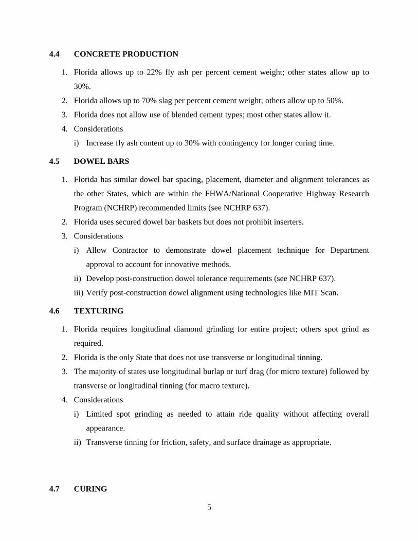
TABLE 4 Dowel Bar Specifications
State Application Method Pavement Thickness
(Dowel Diam.), in Dowel Spacing, in Length, in
FL Metal dowel bar
assembly
8-1/2 (1)
9 to10-1/2 (1-1/4)
≥11 (1-1/2)
12 18
MI Load transfer assembly
or dowel bar inserter
6 to <8 (1)
8 to 11 (1-1/4) 12 18
16
> 11 (1-1/2)
MN Baskets (approve dowel
bar inserters on case-
by-case basis)
<10 (1-1/4)
10.5≤t<13 (1-1/2)
13≤t<14 (1-3/4)
12 15
TX Heavy welded wire
baskets
8 (1)
9 (1-1/8)
11 (1-3/8)
15 (1-7/8)
Increase diam. by 1/8
inch for each additional
inch of thickness
12 18
WI Baskets or mechanical
inserters
7 to 7-1/2 (1)
8 to 9-1/2 (1-1/4)
>10 (1-1/2)
12 18
IN Welded wire assembly MEPDG (1-11/2) 12 18
5.4.3 Considerations
1. Verify alignment of representative dowel population with MIT Scan.
2. Allow/disallow inserters or just provide tolerances.
5.5 TEXTURING
5.5.1 Florida
1. Burlap drag and diamond grinding to produce longitudinal corduroy type texture.
2. Grinding is an effective texturing option that has been shown to significantly reduce tire-
pavement noise and increase friction. The texture produced by grinding is not as deep as
that produced by tinning (1/32 inch versus 1/8 to 5/16 inch deep).
5.5.2 Other States
1. Burlap or turf drag followed by longitudinal or transverse tinning is the most common
texturing method.
Missouri allows the option of grinding the entire pavement as the final texture.
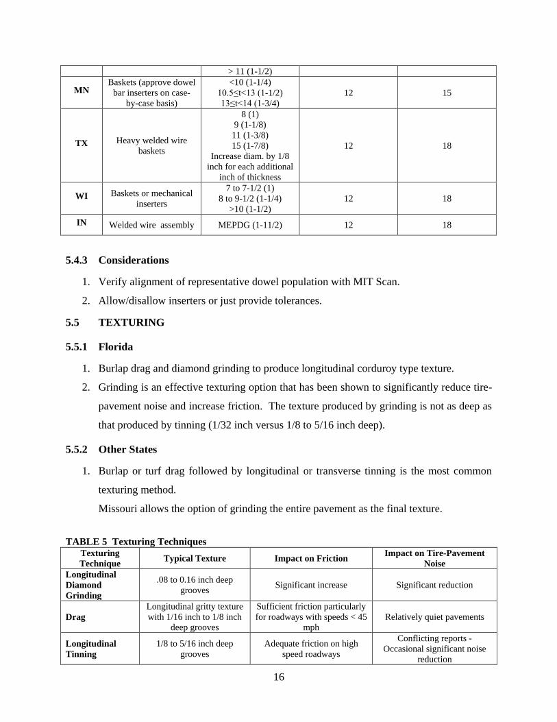
TABLE 5 Texturing Techniques Texturing
Technique Typical Texture Impact on Friction
Impact on Tire-Pavement
Noise
Longitudinal
Diamond
Grinding
.08 to 0.16 inch deep
grooves Significant increase Significant reduction
Drag
Longitudinal gritty texture
with 1/16 inch to 1/8 inch
deep grooves
Sufficient friction particularly
for roadways with speeds < 45
mph
Relatively quiet pavements
Longitudinal
Tinning
1/8 to 5/16 inch deep
grooves
Adequate friction on high
speed roadways
Conflicting reports -
Occasional significant noise
reduction

17
Transverse
Tinning
Sometimes randomly
spaced or skewed 1/8 to
5/16 inch deep grooves
Durable, high friction surfaces
especially on wet pavements Undesirable wheel whine noise
Exposed
Aggregate
Exposed durable aggregate
surface Improved
Conflicting reports – highly
regarded in Europe but results
of trial projects in US have
been mixed
5.5.3 Considerations
1. There is some debate on whether grinding should be performed on a new pavement and
what the effect on the long-term durability of the surface will be. The advantages of
grinding are the exceptionally smooth surfaces and reduced pavement-tire noise. A study
should be considered to investigate the advantages and disadvantages of grinding versus
longitudinal tinning. Some factors in the study should include cost, smoothness, surface
drainage, pavement-tire noise, construction aspects, and surface durability.
5.6 CURING
5.6.1 Florida
1. Liquid membrane curing compound or burlap mat.
i) Liquid membrane curing compound is placed at 1 gal/200 ft2 for a period of 72 hours
exclusive of any period the surface temperature drops below 50°F.
ii) The weight and condition of the burlap mat is also specified.
2. Florida is the only State that tests all curing compound used prior to construction.
3. Weather restrictions relating to evaporation rate should be added to concrete placement
requirements.
5.6.2 Other States
1. Use liquid membrane forming compounds (most common) and curing blankets.
2. Most specify a minimum application rate of 1 gal/ 150 to 200 ft2 per coat of compound.
3. TX: 2 coats at a minimum rate of 1gal/180 ft2; MI: 2 coats at 1 gal/ 225 ft
2 for tined
surfaces and 1 coat at 1 gal/ 225 ft2 for other surfaces.
4. ACPA recommends 1 gal/200 ft2 for normal paving operations, 1 gal/150 ft
2 for fast-track
concrete, and 1 gal/100 ft2 for thin overlays.
5. Curing duration is typically 3 days, except for KS which specifies 4 days. Curing time is
often extended to consider periods of unfavorable temperatures.

18
5.6.3 Considerations
1. Evaluate the effectiveness and benefits of the different curing methods. Curing
compounds provide the most efficient means of curing given the speed of the
construction operation and the need to use the paved surface. If the concrete is still warm
when a burlap mat or plastic sheeting is removed and the ambient temperature is low,
thermal shock can occur, which may cause cracking.
2. Clarify the curing requirements for special circumstances (e.g., rain, cold weather, etc.).
For instance, plastic sheeting may be appropriate for small projects and pervious
concrete. Thermal blankets may be required for lower temperatures. Evaporation
retarders may be required during dry, windy days.
3. Evaluate the need to extend curing time for concrete with fly-ash or other pozzolanic
substitutions.
5.7 JOINT SAWING
5.7.1 Transverse Contraction Joints
Florida
1. Maximum spacing is 15 feet.
2. Initial joint cut is same as for other States. Final joint width is typically 1/4 inch.
3. Joints sawed no later than 12 hours after placement.
4. Final joint cutting to take place just before sealing.
5. Early entry saws are not prohibited but are not mentioned in the specification.
6. Uncontrolled cracks repaired at no expense to the Department by removing and replacing
full width.
Other States
1. Typical maximum transverse joint spacing is 15 feet.
2. Initial saw depths are typically 1/8 inch wide by 1/4 to 1/3 the slab depth.
3. Most States do not specify a specific time to saw cut joints other than requiring the
concrete has to have hardened sufficiently to permit sawing without excess raveling.

19
Considerations
1. Continue existing practice but look for improvements (e.g., nondestructive methods to
determine dowel bar location and orientation).
2. Smaller joint width to reduce noise and enhance smoothness.
5.7.2 Transverse Construction Joints
Florida
1. Form transverse construction joint bulkheads and install dowel bars in construction joint.
2. Construct at the end of all pours and at locations where paving has stopped for 30
minutes or longer.
3. Do not place within 10 feet of any other transverse joint or within 10 feet of a section
end.
4. Saw or form joints in same manner as contraction joints.
Other States
1. Fresh concrete to replace the concrete in the spreader for the last few meters to ensure
that only production quality concrete is used.
2. Most States specify that the construction joint should be placed at a planned contraction
joint or at 15 feet from the last contraction joint.
5.7.3 Transverse Expansion Joints
Florida
1. Limited to bridge approaches and where two pavements intersect at an angle.
2. Uses preformed joint filler and provides dowels.
3. Form and protect joint with bulkhead and metal strips at bottom and side edges.
Other States
1. Expansion joints are typically limited to bridge approaches.
2. Most States do not have specifications specific to expansion joints.

20
Considerations
1. Limited specification/construction information was found on expansion joints since they
are limited in application. The FL practice appears to be as complete as any other state
studied.
2. Use of isolation expansion joint around street manholes to prevent cracking.
5.7.4 Longitudinal Lane-Tie Joint
Florida
1. Complete sawing as soon as possible but within 72 hours.
2. May insert or secure tie-bars to subgrade.
3. Initial cut 1/8 inch wide and at least 1/3 the slab depth. Final joint width is typically 1/4
inch.
Other States
1. Saw longitudinal joints within 36 hours.
2. Align longitudinal joint with string line along centerline.
3. Some States do not expand the joint width from 1/8 inch and do not seal. Since these
joints are not meant to deal with expansion there is no need to keep out incompressible
material or transfer loads. A properly designed graded base should drain any water
infiltration.
Considerations
1. Use string line to guide longitudinal joint saw cuts. Florida does not specify an alignment
tolerance for longitudinal saw cuts.
2. Consider a shorter time period for cutting joints. They are typically cut later than
transverse joints and they are all required to be sealed within 72 hours.
5.8 JOINT SEALING
5.8.1 Florida
1. All joints should be sealed.
2. Complete sealing within 72 hours.

21
3. Temperature should be greater than 50°F for hot-poured sealant and greater than 40°F for
silicone sealant.
5.8.2 Other States
1. Traffic not allowed on joints prior to sealing.
2. Preformed material should not be spliced when used for transverse joints.
3. Refill hot-poured sealant if level drops 3 mm below surface.
4. Some States do not seal all joints.
5.8.3 Consideration(s)
1. Refill hot-poured sealant if level drops significantly.
2. A shorter time period before cutting and sealing joints.
5.9 SMOOTHNESS
TABLE 6 Smoothness Specifications
State Index Blanking
Band, inch Incentive/Disincentive
Localized
Roughness
Provision
Testing Device*
FL PI 0.2 Incentive/Must Correct Yes P
TX IRI N/A Both Yes HSP or LWP
MN PI 0.2 Both Yes P or LWP
KS PI 0.0 Both Yes P
MI IRI N/A Must Correct Yes HSP
MO IRI N/A Incentive/Must Correct Yes HSP
WI IRI N/A Both Yes HSP
IN PI 0 Must Correct Yes P
*P= Profilograph; HSP= High Speed Profiler; LWP= Light Weight Profiler; SE= Straight Edge
5.9.1 Consideration(s)
1. FDOT certified inertial profiler and operator for smoothness quality control and
acceptance by contractor.
2. IRI and localized roughness or smoothness acceptance.
5.10 DEFECTIVE PAVEMENT/ACCEPTANCE
5.10.1 Florida
1. Criteria for Thickness (Incentive & Disincentive), Strength (Disincentive only), and
Smoothness (Incentive only).

22
5.10.2 Others
1. Deficient Pavement/Acceptance criteria (Table 7).
2. Most states have acceptance criteria for thickness, strength and smoothness.
3. MI has criteria for reinforcing steel, cover depth and deviation from design range.
4. KS has acceptance criteria for spalling and cracking.
5. WI has deficiency threshold criteria for cracking.
TABLE 7 Acceptance and Incentives/Disincentives Criteria
State Criteria for Deficient
Pavement
Incentives
and/or
Disincentives
Corrective action
FL
Thickness Yes Both Remove/Replace if the deficiency is enough to seriously impair the
anticipated service life Strength Yes Disincentives
Smoothness Yes Incentives Remove/replace if any area, after grinding, still shows a deviation in
excess of the allowable tolerance
KS
Thickness Yes Both Based on Engineer's judgment
Strength Yes Both
Smoothness Yes Both Contractor's decision to elect remove/replace. DOT will pay for
smoothness based on the PI after replacement
Defective
Slab Yes Neither
Contractor's responsibility to repair or remove/replace slabs with
spalling, longitudinal and transverse cracking
MI
Thickness Yes Disincentives Removal required if the thickness deficiency exceeds 1.0 inch
Strength Yes Both Contractor can remove/replace or get pay adjusted
Smoothness Yes Neither Corrective action required if IRI > 125
Steel
location Yes Disincentives
Remove/Replace if depth of Steel Deviation (from pavement surface
and from design range) is beyond limiting criteria.
MN
Thickness Yes Disincentives Remove/replace or get pay adjustments
Strength No Neither
Smoothness Yes Both Remove/replace or diamond grinding required for 0.1-mile
sections/subsections
MO
Thickness Yes Both Remove/Replace if thickness deficiency exceeds 10 percent of plan
thickness
Strength Yes Both Removal required if compressive strength is less than 3,500 psi
Smoothness Yes Both
Diamond Grinding required for corrected areas (min. 20% deduction
of contract price applied) or entire section of at least 0.1-mile long.
Contractor has an option to remove/replace segments
TX
Thickness Yes Disincentives
Remove/Replace or leave in place without pay if the thickness
deficiency is more than 0.75 inch but less than 1 inch .
Remove/Replace if thickness deficiency is more than 1.0 inch
Strength No Neither
Smoothness Yes Both Corrective action (typically grinding) is required.
WI
Thickness Yes Disincentives Remove/Replace if the thickness deficiency is more than 1.0 inch or
Leave in Place with no pay
Strength No Disincentives Remove/Replace or Leave in Place and receive 50 % of the contract
price unit
Smoothness Yes Both Remove/Replace if the departure from correct cross section or profile
exceeds 1/2 inch in 10 feet
Defective
Slab Yes Disincentives Repair cracked concrete as the engineer directs

23
Thickness Yes Disincentives Remove/Replace or Leave in place with reduced or no payment
Strength
Disincentives Remove/Replace or Leave in place with reduced or no payment
IN
Smoothness Yes Disincentives
Smoothness variance outside specified tolerance shall be corrected
by grinding or by replacement. Pay factor applied depending on PI.
5.11 RECOMMENDED PRACTICES
5.11.1 Florida: Results from 2007 tour of PCC projects in Districts 2, 3, 5 and 7.
1. Cracking is minimized when slabs are <= 14 ft wide and <= 15 ft long.
2. Placing a longitudinal joint in the middle of ramps eliminates cracking in curves/super-
elevations.
3. Ensure proper marking and maintenance of drainage weep holes.
4. Consider a smaller joint spacing to reduce noise and enhance smoothness.
5. Experienced contractor is critical to the project success, in terms of performance and
aesthetics.
6. Localized grinding gives a marred finish to a pavement surface and may affect vehicle
handling.
7. Use of isolation expansion joint around street manholes prevents cracking.
8. Use a sleeper slab at PCC/HMA pavement interface to prevent asphalt drop off and/or
cracking.
5.11.2 Kansas and FHWA Recommendations ( Better Roads, March 2003)
1. Have precise string lines.
i) String lines have the greatest effect on pavement smoothness. Place them carefully,
keep them safe, and use aircraft cable instead of rope; it can be tensioned to eliminate
sag without breaking.
ii) Conventional supports are placed 50 feet apart, but Kansas contractors place them 25
ft apart, which increases labor and material costs.
2. Build from the ground, up.
i) Without a solid, stable, smooth foundation, it is not possible to get a smooth driving
surface.
3. Watch paving speed and delivery rate.
i) The paving train should move at a consistent speed without stops.

24
ii) Having a constantly producing batch plant helps, and so does having adequate
delivery vehicles. Also, delivery vehicles need to have unfettered movement to the
paving area and back to the plant.
4. Control concrete head.
i) Monitor the size of the head of concrete at the paver; it should be neither too high nor
too low. The paver is supposed to finish the surface of the concrete, not act as a
bulldozer.
ii) Because fresh concrete is a plastic fluid mass, hydraulic forces can be set up in the
concrete head that can cause the finished concrete to surge and swell, creating
permanent defects. A spreader/placer in front of the paver can maximize production
while optimizing smoothness.
5. Strive for mix consistency.
i) The design should be proportioned for correct consolidation without excessive
vibration, which can cause segregation and vibrator trails with accompanying rougher
surface and lower strength concrete. Test samples often in order to track slump and
air content.
6. Use minimal hand finishing.
i) If quality controls and pavements are used, hand finishing should be needed only for
surface sealing, edging, and checking with straightedges. Use restraint. Know the
correct texture or tinning to reduce pavement noise (or whine) while keeping surfaces
safe for drivers.
7. Use good equipment.
i) Clean equipment in top working order is necessary.
ii) Equipment is an investment, the benefits of which are realized in the field.
8. Motivate your workforce.
The workforce is the contractor's most important resource. Unique steps can be taken to
motivate employees and create a sense of ownership and consistent self-improvement, including
education in smoothness specifications, pride programs, and distribution of part of earned
smoothness incentives back to employees as end-of-year bonus.

25
6 References
6.1 FL
Section 350 Cement Concrete Pavement
ftp://ftp.dot.state.fl.us/LTS/CO/Specifications/SpecBook/2010Book/350.pdf
Index 305 Concrete Pavement Joints
http://www.dot.state.fl.us/rddesign/rd/rtds/10/305.pdf

26
Rigid Pavement Design Manual
http://www.dot.state.fl.us/pavementmanagement/pcs/RigidPavementManualJanuary12009.pdf
Index 505 Embankment Utilization
http://www.dot.state.fl.us/rddesign/rd/rtds/10/505.pdf
Index 287 Concrete Pavement Sub drainage
http://www.dot.state.fl.us/rddesign/rd/rtds/10/287.pdf
Section 287 Asphalt Treated Permeable Base
ftp://ftp.dot.state.fl.us/LTS/CO/Specifications/SpecBook/2010Book/287.pdf
Section 288 Cement Treated Permeable Base
ftp://ftp.dot.state.fl.us/LTS/CO/Specifications/SpecBook/2010Book/288.pdf
6.2 KS
Section 154 Concrete Pavement Equipment
http://www.ksdot.org/burconsmain/specprov/2007/154.pdf
6.3 MI
Section 602 Concrete Pavement Construction
http://mdotwas1.mdot.state.mi.us/public/specbook/
Road Design Manual
http://mdotwas1.mdot.state.mi.us/public/design/englishroadmanual/
Standard Plan R-40-G Load Transfer Assemblies for Transverse Joints
http://mdotwas1.mdot.state.mi.us/public/design/englishstandardplans/index.htm
6.4 MN
Section 2301 Concrete Pavement
http://www.dot.state.mn.us/pre-letting/spec/2005/div-ii.pdf
Concrete Manual
http://www.dot.state.mn.us/materials/manuals/concrete/Chapter6.pdf
Pavement Design Manual
http://www.dot.state.mn.us/materials/pvmtdesign/docs/Chapter_5-3.pdf
Standard Sheet No. 5-297.221 Pavement Joints: Contraction and Expansion
http://dotapp7.dot.state.mn.us/edms/download?docId=914097
Standard Sheet No. 5-297.221 Pavement Joints: Longitudinal

27
http://dotapp7.dot.state.mn.us/edms/download?docId=914098
6.5 MO
Section 502 Concrete Base and Pavement
http://www.modot.mo.gov/business/standards_and_specs/Sec0502.pdf
Missouri DOT Research Investigation 96-025 Diamond Grinding Newly Placed
Pavement
http://www.igga.net/File/Diamond-Grinding-Newly-Placed-PCCP-_2005.pdf
6.6 TX
Pavement Design Guide
http://onlinemanuals.txdot.gov/txdotmanuals/pdm/index.htm
Section 360 Concrete Pavement
ftp://ftp.dot.state.tx.us/pub/txdot-info/des/specs/specbook.pdf
CPCD-94 Concrete Pavement Details Contraction Design
ftp://ftp.dot.state.tx.us/pub/txdot-info/cmd/cserve/standard/roadway/cpcd94.pdf
6.7 WI
Concrete Pavement Design
http://roadwaystandards.dot.wi.gov/standards/fdm/14-10.pdf
Section 415 Concrete Pavement Construction
http://roadwaystandards.dot.wi.gov/standards/stndspec/Sect415.pdf
Standard Detail Drawing 13C13-7 Urban Doweled Concrete Pavement
http://roadwaystandards.dot.wi.gov/standards/fdm/SDD/13c13-7.pdf
6.8 IN
Section 500 Standard Specifications
http://www.in.gov/dot/div/contracts/standards/book/sep09/5-2010.pdf
6.9 OTHER SOURCES
Integrated Materials and Construction Practices for Concrete Pavement: A State-of-the-
Practice Manual
http://www.cptechcenter.org/publications/imcp/imcp_frontmatter.pdf

28
National Highway Specifications Home (FHWA)
http://fhwapap04.fhwa.dot.gov/nhswp/index.jsp
NCHRP 637 Guidelines for Dowel Alignment in Concrete Pavements
http://onlinepubs.trb.org/onlinepubs/nchrp/nchrp_rpt_637.pdf
FHWA Best Practices for Dowel Alignment 2007
http://www.fhwa.dot.gov/pavement/concrete/pubs/07021/07021.pdf
State Highway Agencies Smoothness Specifications
http://www.smoothpavements.com/