state-of-the-art review of wind turbine technologies for...
TRANSCRIPT

Technical Publication 2008-0502pdf
ElectroTECHnik. Pty Ltd – www.elek.com.au
1 | P a g e
State-of-the-art Review of Wind Turbine Technologies
This technical report provides detailed information about the steady-state and
dynamic behaviour of wind turbine generators.
ElectroTECHnik Pty Ltd has significant experience in wind farm connection. Visit the
website (www.elek.com.au) to purchase this document.
Contents
1. The main types of wind turbine technology .................................................................. 2
2. Type A: Fixed-speed wind turbine equipped with SCIG ............................................ 5
3. Type B: Partly-variable-speed equipped with dynamic rotor resistance ........... 9
4. Type C: Variable-speed wind turbine equipped with DFIG .................................... 16
5. Type D: Variable-speed wind turbine equipped with Full Converter ................ 24
References: ...................................................................................................................................... 25

Technical Publication 2008-0502pdf
ElectroTECHnik. Pty Ltd – www.elek.com.au
2 | P a g e
1. The main types of wind turbine technology
The assessment of the transient stability of wind turbines plays an integral role in power system
security and operation (Salman and Teo 2002). It has been argued that due to the importance and
the urgency in generating more electricity from renewable sources such as wind energy and due to
the current low levels of such generation then power system stability is not of great concern
(Jenkins, Allan et al. 2000). However, the recent increase in wind penetration in Australia, which has
resulted in the offset of significant amounts of synchronous generation, has lead to renewed
concern about the impacts on power system stability. A study by NEMMCO into the potential
security risks due to the predicted high levels of wind generation in South Australia indicates this.
The findings were that increased levels of wind generation will have a severe impact on the
operation of the power system, particularly in the dispatch of ancillary services (NEMMCO 2004). It
is important to understand the impacts of high wind generation in Australia. In Western Denmark
the amount of wind generation is so significant that the situation where power generated by wind
turbines alone can meet all the demand has been realised. The loss of a large amount of wind
generation poses a threat to power system security. Wind turbines that are directly connected at
the transmission or the distribution level affect the dynamics of the power system. Clause S5.2.1 in
the Rules states that all registered participants are required to assist in preventing transient
instability in the power system. With the perspective of greater wind penetration it is important to
be able to show that wind generators stay connected during disturbances to the system and can
contribute to improve the global system dynamic behaviour (Marcus, Nunes et al. 2004).
Technical Publication 2008-0502pdf
ElectroTECHnik. Pty Ltd – www.elek.com.au
3 | P a g e
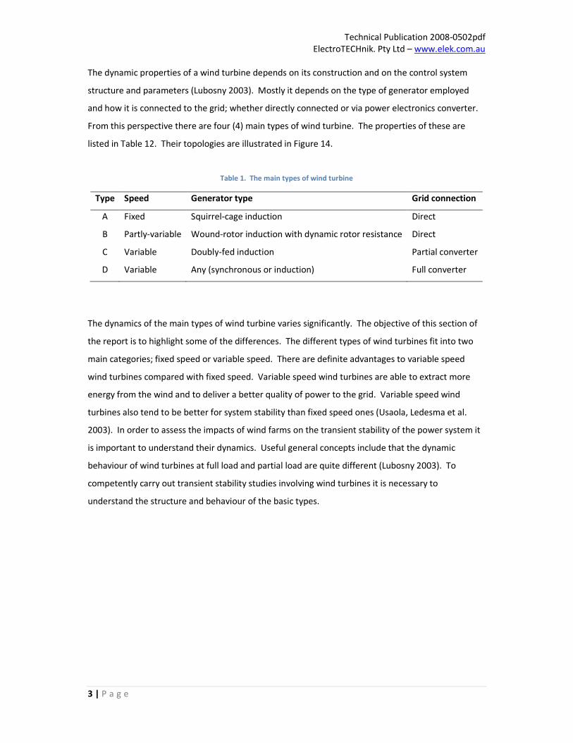
The dynamic properties of a wind turbine depends on its construction and on the control system
structure and parameters (Lubosny 2003). Mostly it depends on the type of generator employed
and how it is connected to the grid; whether directly connected or via power electronics converter.
From this perspective there are four (4) main types of wind turbine. The properties of these are
listed in Table 12. Their topologies are illustrated in Figure 14.
Table 1. The main types of wind turbine
Type Speed Generator type Grid connection
A Fixed Squirrel-cage induction Direct
B Partly-variable Wound-rotor induction with dynamic rotor resistance Direct
C Variable Doubly-fed induction Partial converter
D Variable Any (synchronous or induction) Full converter
The dynamics of the main types of wind turbine varies significantly. The objective of this section of
the report is to highlight some of the differences. The different types of wind turbines fit into two
main categories; fixed speed or variable speed. There are definite advantages to variable speed
wind turbines compared with fixed speed. Variable speed wind turbines are able to extract more
energy from the wind and to deliver a better quality of power to the grid. Variable speed wind
turbines also tend to be better for system stability than fixed speed ones (Usaola, Ledesma et al.
2003). In order to assess the impacts of wind farms on the transient stability of the power system it
is important to understand their dynamics. Useful general concepts include that the dynamic
behaviour of wind turbines at full load and partial load are quite different (Lubosny 2003). To
competently carry out transient stability studies involving wind turbines it is necessary to
understand the structure and behaviour of the basic types.

Technical Publication 2008-0502pdf
ElectroTECHnik. Pty Ltd – www.elek.com.au
4 | P a g e
Figure 1. The four main types of wind turbine. Note: SCIG = squirrel cage induction generator, WRIG = wound rotor
induction generator, PMSG = permanent magnet synchronous generator, WRSG = wound rotor synchronous generator
(source: Ackermann, 2005).

Technical Publication 2008-0502pdf
ElectroTECHnik. Pty Ltd – www.elek.com.au
5 | P a g e
2. Type A: Fixed-speed wind turbine equipped with SCIG
The squirrel-cage induction generator (SCIG) is the most common type used in fixed-speed wind
turbines. Induction generators are employed because they are cheap and due to their superior
characteristics. This type of wind turbine is not equipped with wind wheel and generator control
systems, and therefore is more reliable than other types (Lubosny 2003). The problems which can
occur with SCIG equipped wind turbines are (1) during a fault the rotor speed increases and can
become excessive, and (2) after a fault is cleared the terminal volts may not recover, both of which
can cause it to be disconnected from the grid. Furthermore, since the excitation for a SCIG is
sourced directly from the grid it continually absorbs reactive power (increasingly with speed) and is
incapable of controlling its terminal voltage. These issues pose significant challenges in terms of
controlling the voltage and balancing the reactive power demands in the power system, which
impacts on system stability. In terms of the stability, fixed-speed wind turbines are a robust concept
and may ride-through most unbalanced and balanced faults in the power system (Akhmatov 2005).
However, compared with other types the stability performance of wind turbines which use the SCIG
(directly coupled to the grid) is relatively poor (Marcus, Nunes et al. 2004).
The first-order swing equation that describes the motion of the generator shaft is
me TTdt
dsH −−−−====2 (4)
Where H is the sum of constant inertia of the rotating mass in per unit, s is the slip, Te is the electrical
torque and Tm is the mechanical torque from the turbine hub.
During a fault there is an imbalance between the electrical torque and the mechanical torque that
leads to an acceleration of the generator, which can result in loss of stability. Similar to the equal-
area criterion for synchronous generators, for an induction generator to remain connected to the
power system, a fault must be cleared by the critical clearing slip and the corresponding speed. This
conclusion is completely dependent on the steady-state torque-slip curve of the induction generator
(Chen, Li et al. 2006). Salman and Teo have developed a novel method for determining the critical
clearing slip of a wind turbine with SCIG based on the torque-slip curve (Salman and Teo 2002).

Technical Publication 2008-0502pdf
ElectroTECHnik. Pty Ltd – www.elek.com.au
6 | P a g e
The dynamic response of an induction generator to a fault will be examined using the torque-slip
curve shown in Figure 15. Note that since transient stability studies are concerned with what
happens following a disturbance, the torque-slip curve is derived based on post-fault conditions.
The stability limit of an induction generator changes for different post-fault operating conditions (i.e.
different terminal voltages). It is the post-fault torque-slip curve that determines the ability of an
induction generator to recover to its steady-state operation (Jenkins, Allan et al. 2000).
Figure 2. Configuration of torque-slip and time-slip curves for three-phase short-circuit fault (Chen, Li et al. 2006)
In steady-state operation the electrical torque Te is equal to the mechanical torque Tm and the
generator operates at constant slip s0. When a fault occurs at t0, Te collapses to zero (ignoring the
electrical transients), while the slip at that instant remains the same. The collapse of Te results in a
net increase in the accelerating torque on the rotor (since Te <Tm in Equation 4) and a continuous
increase in slip. If the fault is cleared at time t1, when slip has increased to s1, then Te will recover
from zero to a point on the torque-slip curve that is greater than Tm. This will cause a net decrease
in acceleration torque (due now to Te >Tm in Equation 4) and the rotor will return to its original slip s0
(assuming that the voltage is the same as what it was prior to the fault). For an induction generator
the electrical torque Te of the generator is proportional to the square of the generator terminal
voltage. On the other hand, if the fault is cleared at slip s2 then when Te recovers from zero it will
always be less than Tm and the generator will continue to accelerate, causing it to trip due to over
speed. Therefore, the slip scr is the critical clearing slip for this operating condition at which the SCIG
is capable of recovery from a fault (Chen, Li et al. 2006).

Technical Publication 2008-0502pdf
ElectroTECHnik. Pty Ltd – www.elek.com.au
7 | P a g e
Assuming that the mechanical torque Tm remains the same during a fault, the acceleration of the
generator is determined by the moment of inertia of the rotor and the shaft stiffness. Unlike an
equivalent steam or hydro unit a wind turbine has high inertia and low stiffness of the shaft between
the turbine and generator (Akhmatov 2005). The low stiffness means that during steady-state
operation the shaft stores a substantial amount of potential energy, which is due to the rotational
displacement caused by the two opposing torques Te and Tm (Jenkins, Allan et al. 2000). When Te
collapses during a fault, the stored potential energy in the shaft is transferred as kinetic energy to
the rotor, which contributes significantly to its acceleration. Under these conditions Equation 4 is
strictly not correct in describing the motion of the wind turbine drive system. The contribution of
the shaft stiffness of the wind mill drive train to the acceleration of the generator cannot be ignored
(Jenkins, Allan et al. 2000). Muyeen et al. state that at least a two-mass shaft model is necessary for
accurate transient stability analysis of wind turbines as (Muyeen, Hasan Ali et al. 2007), for example,
that suggested in (Akhmatov 2005).
There are three main stability issues for standard induction generators to be considered:
(1) Trip due to overspeed
By using the law of conservation of energy of mechanical energy, the maximum speed change of an
induction generator immediately after a fault is calculated by (Salman and Teo 2002)
Gs
emG
JK
TT −=∆ω (5)
Where Gω∆ is the speed change of the generator at the faults inception, Ks is the shaft stiffness and
JG is the moment of inertia of the generator rotor.
The maximum post-fault speed ωf of an induction generator is determined by adding the steady-
state speed ωo with the maximum speed change (i.e. Gof ωωω ∆++++==== ) (Salman and Teo 2002). If ωf
exceeds the critical clearing speed ωcr then the generator could become unstable and should trip
due to overspeed. It is imperative that unstable or even potentially unstable generators are tripped
as fast as possible. A case study has shown that when left untripped many induction generators
would oscillate and produce a disturbance that could last up to 4 seconds before overspeed
protection trips them (Usaola, Ledesma et al. 2003). The problem is that such a prolonged

Technical Publication 2008-0502pdf
ElectroTECHnik. Pty Ltd – www.elek.com.au
8 | P a g e
disturbance could invoke the tripping of other wind generators which would not have otherwise
been tripped (Usaola, Ledesma et al. 2003).
(2) Excessive reactive power demand
During a fault an SCIG can decrease the transient stability margin of the power system due to an
increase in reactive power demand. The reactive power absorption EQ and the terminal voltage SU
of an induction generator are speed dependent according to the relation (Akhmatov 2005)
)()(
)(22
2
GTGT
GTSE
XR
XUQ
ωω
ω
++++==== (6)
Therefore, when the generators speed increases during a fault, the reactive power absorption of the
induction generator also increases. The additional reactive power demand from the generator has
to be met somehow by the system. This can lead to unacceptably low voltages and to potential
voltage collapse due to inadequate reserves of reactive power. The situation becomes worse for
wind turbines equipped with induction generators which are installed in locations remote from
synchronous generators.
(3) Post-fault terminal voltage does not recover
Even if an induction generator remains stable and does not trip following a disturbance, the post-
fault terminal voltage may never recover to its pre-fault condition. In a relatively weak system there
is the possibility of de-excitation of the machine if there are insufficient reactive power reserves to
re-excite the machine following the loss of the rotor magnetic field during a disturbance.
Technical Publication 2008-0502pdf
ElectroTECHnik. Pty Ltd – www.elek.com.au
9 | P a g e
3. Type B: Partly-variable-speed equipped with dynamic rotor resistance
The type of wind turbine being discussed here employs a wound-rotor induction generator (WRIG)
which is equipped (singly-fed) with a converter to control the resistance of the rotor. The ability to
vary the rotor resistance allows for the control of generator slip and rotational speed and a blade
pitching system is used to maintain optimal rotational speed of the wind wheel. This type of wind
turbine is referred to as partly-variable-speed (Akhmatov 2005). The ability to operate over a wide
speed (slip) range means that the wind turbine rotates at an optimal speed which extracts more
energy from the wind (at partial load). Wind turbine input power is highly variable and unsteady,
resulting in large and rapid variations in power transfer (Causebrook, Atkinson et al. 2007). The
limited slip range (only around 2%) of a standard induction generator results in the mechanical
power variations caused by the wind to pass almost directly (with little smoothing) to the stator
(Lubosny 2003). The ability to control the rotor resistance leads to an increase in the dynamic slip
range making it possible to smooth the power transferred to the grid – which is the main goal of this
system (Akhmatov 2005). This control [the control of rotor resistance] is mostly applied to reduce
flicker emission from the wind turbines to the grid as the mechanical power variations are converted
to the kinetic energy of the rotor and absorbed by the external rotor resistance of the converter
(Akhmatov 2005). The same sorts of stability issues for standard induction generators occur for
those with dynamic rotor resistance (DRR). For example, the induction generator with DRR still
continuously absorbs reactive power from the grid. However, with DDR it is possible to expand the
critical clearing slip, and combined with blade pitch control, to increase the dynamic stability limit for
an induction generator. Thus, compared with a standard type (fixed-speed Type A wind turbine) the
stability performance of an induction generator with DRR is better.
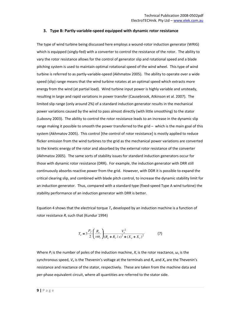
Equation 4 shows that the electrical torque Te developed by an induction machine is a function of
rotor resistance Rr such that (Kundur 1994)
22
2
)()/(23
rere
e
s
rf
eXXsRR
V
s
RPT
++++++++++++
====
ω (7)
Where Pf is the number of poles of the induction machine, Xr is the rotor reactance, ωs is the
synchronous speed, Ve is the Thevenin’s voltage at the terminals and Re and Xe are the Thevenin’s
resistance and reactance of the stator, respectively. These are taken from the machine data and
per-phase equivalent circuit, where all quantities are referred to the stator side.
Technical Publication 2008-0502pdf
ElectroTECHnik. Pty Ltd – www.elek.com.au
10 | P a g e
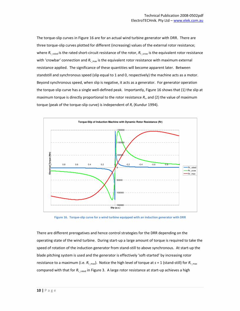
The torque-slip curves in Figure 16 are for an actual wind turbine generator with DRR. There are
three torque-slip curves plotted for different (increasing) values of the external rotor resistance;
where Rr_rated is the rated short-circuit resistance of the rotor, Rr_crow is the equivalent rotor resistance
with ‘crowbar’ connection and Rr_max is the equivalent rotor resistance with maximum external
resistance applied. The significance of these quantities will become apparent later. Between
standstill and synchronous speed (slip equal to 1 and 0, respectively) the machine acts as a motor.
Beyond synchronous speed, when slip is negative, it acts as a generator. For generator operation
the torque-slip curve has a single well-defined peak. Importantly, Figure 16 shows that (1) the slip at
maximum torque is directly proportional to the rotor resistance Rr, and (2) the value of maximum
torque (peak of the torque-slip curve) is independent of Rr (Kundur 1994).
Figure 16. Torque-slip curve for a wind turbine equipped with an induction generator with DRR
There are different prerogatives and hence control strategies for the DRR depending on the
operating state of the wind turbine. During start-up a large amount of torque is required to take the
speed of rotation of the induction generator from stand-still to above synchronous. At start-up the
blade pitching system is used and the generator is effectively ‘soft-started’ by increasing rotor
resistance to a maximum (i.e. Rr_max). Notice the high level of torque at s = 1 (stand-still) for Rr_max
compared with that for Rr_rated in Figure 3. A large rotor resistance at start-up achieves a high
Torque-Slip of Induction Machine with Dynamic Rotor Resistance (Rr)
-150000
-100000
-50000
0
50000
100000
150000
-1-0.8-0.6-0.4-0.200.20.40.60.81
Slip (p.u.)
Ele
ctr
ica
l T
orq
ue
(N
m)
Rr_rated
Rr_crow
Rr_max
Technical Publication 2008-0502pdf
ElectroTECHnik. Pty Ltd – www.elek.com.au
11 | P a g e
starting torque and keeps the magnitude of the in-rush current low and the power factor high
(Akhmatov 2005).
The dynamics of the Type B wind turbine are different during partial and full loading. At partial load
the objective of the controllers is to extract the maximum amount of power from the wind, whereas
at full load it is to keep the electrical power output constant. During partial loading (between cut-in
and rated speed) the rotor resistance varies between Rr_rated and Rr_max (Figure 3) and the blade pitch
angle is controlled to achieve an optimal rotation speed of the turbine which extracts maximum
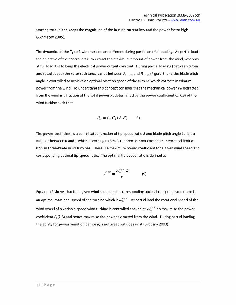
power from the wind. To understand this concept consider that the mechanical power PM extracted
from the wind is a fraction of the total power PV determined by the power coefficient CP(λ,β) of the
wind turbine such that
),(. βλPVM CPP ==== (8)
The power coefficient is a complicated function of tip-speed-ratio λ and blade pitch angle β. It is a
number between 0 and 1 which according to Betz’s theorem cannot exceed its theoretical limit of
0.59 in three-blade wind turbines. There is a maximum power coefficient for a given wind speed and
corresponding optimal tip-speed-ratio. The optimal tip-speed-ratio is defined as
V
ROPT
MOPT .ωλ ==== (9)
Equation 9 shows that for a given wind speed and a corresponding optimal tip-speed-ratio there is
an optimal rotational speed of the turbine which isOPT
Mω . At partial load the rotational speed of the
wind wheel of a variable speed wind turbine is controlled around at OPT
Mω to maximise the power
coefficient CP(λ,β) and hence maximise the power extracted from the wind. During partial loading
the ability for power variation damping is not great but does exist (Lubosny 2003).

Technical Publication 2008-0502pdf
ElectroTECHnik. Pty Ltd – www.elek.com.au
12 | P a g e
The dynamic response of an actual Type B wind turbine rated at 2.1 MW at partial load is shown in
Figure 17. At partial load an increase in wind speed causes a significant change in the operating
point for this type of wind turbine (Lubosny 2003). At an initial wind speed of 9.57 m/s the wind
turbine is generating 1.5 MW and consuming 0.61 MVAr of power. A ramp increase of 4 m/s in wind
speed occurs at t = 5 seconds and takes the effective wind speed up to 13.57 m/s by t = 10 seconds.
The increase in real power due to the increase in wind speed is 0.6 MW. The wind speed and the
rotor speed of a wind turbine are directly proportional (Akhmatov 2005). Therefore the ramp
increase in wind speed causes the generator rotor to accelerate by a maximum of around 12.8 rad/s,
during which time the external resistance (DRR) is increased by the converter, increasing generator
slip. The control of generator slip is achieved by continuous monitoring of the input torque to the
generator. If the change in mechanical torque from the wind wheel with respect to speed is positive
(i.e. δTm/δs > 0) then to maintain an optimal tip-speed-ratio the generator slip is increased by
increasing the rotor resistance. If δTm/δs < 0 then the generator speed is reduced by decreasing the
effective rotor resistance. If δTm/δs ≈ 0 the rotor resistance is held constant. The addition of a pitch
controller is used to optimise the rotational speed of the wind turbine at partial load. During partial
loading the blade pitch angle is fixed at a negative angle to maximise the power extracted from the
wind. At around t = 7.73 s the blade pitch angle controller increases the angle to reduce the
rotational speed and limits the power extracted from the wind. This occurs at a time when the wind
turbine reaches its rated maximum output power of 2.1 MW.
The objective of control at full load is to keep the electrical power output constant. At full load
when the power extracted from the wind by the wind wheel changes the rotor converter alters the
generator slip to compensate. In effect the surplus of energy is transformed into the potential
energy in the rotating shaft, causing the rotor speed to increase. The external rotor resistance is
increased by the converter (increasing slip) to keep the output power of the generator constant,
hence dampening power variations caused by the wind. The external rotor resistance and the slip
are eventually returned to what they were prior to the increase in wind speed. The generator slip
must be kept as low as possible to maximise efficiency. During disturbances oscillations may appear
in the output power due to the dynamic mechanical forces which act on the wind wheel, that are
determined by its mechanical characteristics. These mechanical oscillations manifest themselves in
the rotor as torsional oscillations (called mechanical eigenswings) and some travel through the shaft
and the generator and appear as harmonics on the grid (Lubosny 2003). A study by Lubosny has
shown that for this reason the Type A and the Type B wind turbines do not satisfy the IEEE standards
or the IEC standards for quality of supply (Lubosny 2003).

Technical Publication 2008-0502pdf
ElectroTECHnik. Pty Ltd – www.elek.com.au
13 | P a g e
17.66, 2.10
5.11, 1.50
7.82, 2.14
1.4
1.5
1.6
1.7
1.8
1.9
2
2.1
2.2
0 5 10 15 20
Time (s)
Po
we
r (M
W)
48.5781, -0.0334
10.3083, -0.0885
5.1083, -0.0055
-0.1
-0.09
-0.08
-0.07
-0.06
-0.05
-0.04
-0.03
-0.02
-0.01
0
0 10 20 30 40 50 60
Time (s)
Ge
ne
rato
r S
lip
5.22, 158.07
50.00, 162.33
10.24, 170.82
155
157
159
161
163
165
167
169
171
173
0 10 20 30 40 50 60
Time (s)
Ro
tor
Sp
ee
d (
rad
/s)
10.00, 13.57
5.00, 9.57
8
9
10
11
12
13
14
15
0 5 10 15 20
Time (s)
Win
d S
pe
ed
(m
/s)
10.5749, 8.6474
7.7333, -2
-4
-2
0
2
4
6
8
10
0 5 10 15 20
Time (s)
Bla
de
Pit
ch
An
gle
(d
eg
ree
s)
5.4667, 5.11E-04
10.30, 0.0756
0
0.01
0.02
0.03
0.04
0.05
0.06
0.07
0.08
0 10 20 30 40 50 60
Time (s)
Ex
tern
al R
oto
r R
es
ista
nc
e (
Oh
ms
)
13.96, -0.82
5.12, -0.61
-0.9
-0.8
-0.7
-0.6
-0.5
-0.4
-0.3
-0.2
-0.1
0
0 5 10 15 20
Time (s)
Re
ac
tiv
e P
ow
er
De
ma
nd
(M
VA
r)
0
0.2
0.4
0.6
0.8
1
1.2
0 5 10 15 20
Time (s)
To
rqu
e (
p.u
.)
ELECTRICAL
MECHANICAL
0
0.2
0.4
0.6
0.8
1
1.2
0 5 10 15 20
Time (s)
Te
rmin
al
Vo
lta
ge
(p
.u.)
0.46079
0.4608
0.46081
0.46082
0.46083
0.46084
0.46085
0.46086
0.46087
0 5 10 15 20
Time (s)
Reacti
ve
Po
wer
Co
mp
en
sati
on
(MV
Ar)
Figure 17. Dynamic responses of wind turbine with SCIG and DRR to ramp increase in wind speed at partial load

Technical Publication 2008-0502pdf
ElectroTECHnik. Pty Ltd – www.elek.com.au
14 | P a g e
Figure 18 shows the response of a Type B wind turbine at full load for to a three-phase fault that
occurs at t = 5 s and lasts for 120 ms. During the disturbance the control of the DRR and blade
pitching is used to increase the dynamic stability limit. This leads to improvements of voltage
stability and reduction of capacity demands for dynamic reactive compensation (Akhmatov 2005).
Equation 4 shows that the rotor resistance Rr of an induction machine influences the shape of the
torque-slip curve. In the previous section describing the Type A wind turbine it was explained that
the stability limit is dependent on the torque-slip curve and the corresponding critical clearing slip
scr. Figure 4 shows that the critical clearing slip is expanded and hence the dynamic stability limit is
increased if the rotor resistance is increased. Thus when the three-phase fault occurs the rotor
resistance is increased. This results in the critical speed being expanded. During a fault excessive
currents may be induced into the rotor circuit. The power electronics on the rotor (consisting of
insulated-gate bipolar transistors (IGBTs)) must be protected against thermal overload and against
electrical transients (Lubosny 2003). Once certain limits are exceeded then the converter is blocked
and the rotor circuit is shorted with a ‘crow-bar’ resistance. In this case, the converter is blocked
during the fault (indicated by the Crowbar Status flag). Once the fault is cleared and electrical
transients on the rotor circuit reduce to within tolerable limits then the converter is restarted again.
After the fault is cleared the fluctuations of the electrical and mechanical torques that are present
can lead to excessive over-speeding due to an imbalance caused by a lack of decelerating (electrical)
torque. The temporary reduction in the mechanical torque by the blade pitching improves voltage
stability and ride-through capability (Lubosny 2003). The rotational speed of the shaft is reduced
following the fault and the mechanical fluctuations are effectively damped thereafter by the blade
pitching system.

Technical Publication 2008-0502pdf
ElectroTECHnik. Pty Ltd – www.elek.com.au
15 | P a g e
0
0.02
0.04
0.06
0.08
0.1
0.12
0.14
0.16
0 2 4 6 8 10 12 14
Time(s)
Exte
rnal R
oto
r R
esis
tan
ce (
Oh
ms)
14
16
18
20
22
24
26
28
0 2 4 6 8 10 12 14
Time(s)
Bla
de P
itch
An
gle
(d
eg
rees)
-0.09
-0.08
-0.07
-0.06
-0.05
-0.04
-0.03
-0.02
-0.01
0
0 2 4 6 8 10 12 14
Time(s)
Gen
era
tor
Slip
(p
.u.)
0
0.1
0.2
0.3
0.4
0.5
0.6
0.7
0 2 4 6 8 10 12 14
Time(s)
Reacti
ve P
ow
er
Co
mp
en
sati
on
(MV
Ar)
161
161.5
162
162.5
163
163.5
164
0 2 4 6 8 10 12 14
Time(s)
Ro
tor
Sp
eed
(ra
d/s
)
-0.5
0
0.5
1
1.5
2
2.5
3
3.5
4
4.5
0 2 4 6 8 10 12 14
Time(s)
Po
wer
(MW
)
0.00
1.00
0 2 4 6 8 10 12 14
Time(s)
Cro
wb
ar
Sta
tus (
0 =
OF
F, 1 =
ON
)
0
0.5
1
1.5
2
2.5
3
3.5
4
0 2 4 6 8 10 12 14
Time(s)
Ro
tor
Cu
rren
t M
ag
nit
ud
e (
p.u
.)
-9
-8
-7
-6
-5
-4
-3
-2
-1
0
1
0 5 10 15
Time(s)
Reacti
ve P
ow
er
Co
nsu
mp
tio
n
(MV
Ar)
0
0.2
0.4
0.6
0.8
1
1.2
0 2 4 6 8 10 12 14
Time(s)
Term
inal V
olt
ag
e (
p.u
.)
Figure 18. Dynamic responses of wind turbine with SCIG and DRR to three-phase fault at terminals

Technical Publication 2008-0502pdf
ElectroTECHnik. Pty Ltd – www.elek.com.au
16 | P a g e
4. Type C: Variable-speed wind turbine equipped with DFIG
The Type C wind turbine is the most widely used concept today (Blaabjerg 2006). In contrast to the
Type A and Type B wind turbines discussed previously, the wind turbine equipped with doubly-fed
induction generator (DFIG) is variable speed and a fully controlled system with enhanced dynamic
performance. Variable speed operation has two main advantages: (1) more energy is able to be
extracted from the wind; and (2) power fluctuations are smoothed and mechanical stresses on the
shaft and gearbox are reduced. The doubly-fed generator concept utilises a wound rotor induction
machine with an AC current applied to the rotor windings, thus it can be regarded as a traditional
induction generator with a nonzero rotor voltage (Lei, Mullane et al. 2006). Variable speed
operation is enabled by controlling the frequency of the current applied to the rotor with respect to
that of the stator. The stator of the generator is directly coupled to the grid at a fixed frequency
whereas the rotor is supplied via a converter at a different frequency. As such the generator is said
to be “doubly-fed”. The converter, which is connected between the rotor circuit and the grid,
effectively decouples the grid frequency from the rotor mechanical frequency. An advantage of the
Type C wind turbine is that since the frequency converter only has to deal with the rotor power then
it needs only to be partially rated. This makes it more economical than the Type D wind turbine,
where a fully rated converter connected between the stator and the grid is required. A speed
variation of ±30% around synchronous speed can be achieved with a power converter rated at 30%
of nominal power (Werner 2001; Blaabjerg 2006).
For the Type C wind turbine system both active and reactive power can be controlled independently.
Reactive power can be supplied by the generator to support grid voltages. The controllability of
reactive power help the DFIG equipped wind turbine play a similar role to synchronous generators
(Lei, Mullane et al. 2006). Unlike the induction generators of the Type A and Type B wind turbines
the DFIG is not directly excited from the grid, so does not consume reactive power from the grid.
The Type C wind turbine does not need either a soft starter or reactive power compensation
(Blaabjerg 2006). A problem is that during severe disturbances to protect the sensitive power
electronics the frequency converter is blocked and the rotor circuit is shorted with a crowbar
resistance to damp current transients. The result is that at controllability is lost and the machine
becomes a standard induction generator.

Technical Publication 2008-0502pdf
ElectroTECHnik. Pty Ltd – www.elek.com.au
17 | P a g e
The doubly-fed machine has significant advantages over the standard induction machine. To
understand how speed is controlled consider Equation 10 which states that the resultant magnetic
field produced by the phase windings in a three-phase machine supplied by a balanced source rotate
at a speed in revolutions per minute (Ns) determined by the frequency (f) of the source in hertz (Hz)
and the number of poles (P) in the machine such that
P
fN s
120==== (10)
The stator and the rotor circuits of a doubly-fed machine are supplied from separate sources and
thus develop two magnetic fields which rotate at different speeds. It is the relative speed of the
stator and the rotor fields which determines the speed of the machine. To understand this consider
an example similar to that given by (Wildi 2006). Suppose that the stator windings of 3-phase, 4-
pole wound rotor induction machine are connected to a 50 Hz source and that a second source of 15
Hz is applied to the rotor windings. According to Equation 9 the resultant flux created by the field of
the stator will rotate with respect to a stationary point in a clockwise direction at a speed
rpmpfN s 1500/120 ======== . The resultant flux created by the field of the rotor will rotate in the same
direction but more slowly at rpmN s 450==== . However, for the stator field to lock with the rotor field
they must rotate at the same speed with respect to the stationary point (Wildi 2006). To achieve
this the rotor must turn clockwise at a sub-synchronous speed equal to rpm11504501500 ====−−−− . It is
important to understand that: “If the rotor were to run at any other speed, the rotor poles would
slip past the stator poles and the average torque would be zero. The machine would come to a
stop.” (Wildi 2006). This behaviour is synonymous with that of a synchronous generator. In fact, the
doubly-fed machine is a special case of a synchronous machine which runs at a slip determined by
the frequency applied to the rotor fR and that applied to the stator fS (both in Hz) such that
S
R
f
fs ==== (11)
Another situation presents itself. If the phase sequence of the source on the rotor circuit is reversed
then the resultant flux created by the field of the rotor windings will rotate in the counter-clockwise
direction at rpmN s 450==== . Under these conditions the rotor must rotate again in the clockwise
direction but at a super-synchronous speed rpm19504501500 =+ .

Technical Publication 2008-0502pdf
ElectroTECHnik. Pty Ltd – www.elek.com.au
18 | P a g e
It can be generalised that depending on the frequency and the phase sequence of the source applied
to the rotor circuit the DFIG can either run at super- or sub-synchronous speed determined by
Equation 12 and Equation 13, respectively (Wildi 2006). This is different from a SCIG which can only
operate at super-synchronous speeds within a very limited range (slip).
)(120
sup RS ffP
n ++++==== (12)
)(120
RSsub ffP
n −−−−==== (13)
Depending on whether the wind speed is high or low the rotor frequency and phase with respect to
the stator frequency the DFIG will rotate either above or below synchronous speed. As a result the
wind turbine can be controlled to rotate at an optimal speed which extracts the maximum power
from the wind. The power transfer between the DFIG and the grid is determined by its speed
(Akhmatov 2005). When the generator runs at super-synchronous speed real power is transferred
from both the rotor and stator to the grid. When the generator runs at sub-synchronous speed real
power is transferred to the grid from the stator while the rotor circuit absorbs real power from the
grid. But this is not the end of the story. As already pointed out, if the DFIG were operated in such a
manner (i.e. with constant rotor frequency) then it would behave like a synchronous machine and be
prone to the same sorts of problems, such as difficulties with starting and synchronisation with the
grid and oscillatory transients and pull-out torque (Werner 2001). The situation is different,
however, when the AC excitation of the rotor is made dependant on the line voltage vector and the
angular position of the rotor (Werner 2001). The machine then loses its synchronous characteristics
entirely and can operate at variable speed (Werner 2001). This leads to the consideration of the
frequency converter.

Technical Publication 2008-0502pdf
ElectroTECHnik. Pty Ltd – www.elek.com.au
19 | P a g e
The frequency converter of the Type C wind turbine serves a most important purpose; it facilitates
variable speed operation by decoupling the power system frequency from the rotor frequency. Its
operation has two main functions, these are (1) to convert (rectify) the current drawn from the grid
into DC; and (2) to convert (invert) the DC current into an AC current at the desired frequency and
phase. However, as mentioned previously, depending on the speed of rotation of the generator the
rotor circuit may either be delivering or absorbing power. Therefore, it must be possible for power
to flow through the frequency converter in both directions. The typical configuration for a Type C
wind turbine power converter consists of two back-to-back pulse-width-modulated (PWM) voltage
source inverters connected via a DC link. Power is able to flow from the grid to the rotor and vice
versa because an inverter can be controlled to act as rectifier simply by changing its commutation
(firing) angle by 180 degrees (Hart 1997).
The two back-to-back inverters have different purposes and hence control strategies. The objective
of the grid side inverter is to keep the DC link voltage constant, providing a path for rotor power to
and from the grid at unity power factor. This way the exchange of reactive power with the grid is
made completely through the stator of the generator (Pena 1996). The rotor-side inverter maintains
the stator voltage and the generated electrical power of the machine. Both inverters (the grid-side
and the rotor-side) are voltage source inverters. It is preferable to operate the rotor-side inverter as
a variable frequency voltage source (i.e. without current control) in order not to impede transient
currents in the rotor windings which are caused by disturbances on the rotor side (Pena 1996). The
voltage source of the rotor-side inverter is supplied from the DC-link is composed of a capacitor C
and possibly an inductor L. The DC-link capacitor serves several purposes. Since the instantaneous
input current may assume negative values then this must be absorbed by the DC-link capacitor
(Trzynadlowski 2001). The DC-link capacitor also serves as a source of high frequency components
of the input current to the rotor-side inverter so that it is not drawn from the power system via the
grid-side inverter. In addition, the DC-link capacitor smooths and stabilises the DC voltage. The
optional DC-link inductor serves a less important function which is to provide an extra screen against
high-frequency current drawn by the rotor-side inverter.

Technical Publication 2008-0502pdf
ElectroTECHnik. Pty Ltd – www.elek.com.au
20 | P a g e
The rotor- and grid-side inverters are so-called ‘vector controlled’. The vector control method is
based on the d-q transformation of the machine and system quantities. For the DFIG the interest is
in the control of rotor currents. Equation 14 states the three-phase sequence of currents ia, ib and ic
are converted into a two-dimensional space vector which rotates in the complex plane such that
++++−−−−−−−−−−−−−−−−
++++−−−−
====
c
b
a
q
d
i
i
i
i
i
i
2
1
2
1
2
1
)3
2sin()
3
2sin(sin
)3
2cos()
3
2cos(cos
0
πθ
πθθ
πθ
πθθ
(14)
Under balanced conditions the zero-sequence component current i0 is equal to 0. The two current
components id and iq are completely equivalent to the three-phase currents ia, ib and ic. Note that
the d-q transformation can be applied to any three phase machine or system quantities.
Figure 19. Cross-section of induction machine showing resultant magnetic field (having α and β components) produced
by the windings. Control of the rotor-side inverter in the d-q reference frame is aligned with the peak of this field.
The resultant magnetic field produced by the windings in a three-phase machine is a sinusoid which
rotates around the periphery of the machine. This can be represented as a space vector with
expression in a fixed reference frame (α, β) with origin at the centre of the machine given as
βα jBBB +=r
and with position (maximum value) αβφ BBarctan==== . The control of the rotor-
side inverter works by aligning the d-axis of the rotating d-q reference frame for current control with
the peak of the stator flux vector. This concept is shown in Figure 19.
A’
B’
B
C
C’
A α
β
dj Ψ=Ψ+Ψ=Ψrr
βα
d ω
q αΨ
βΨ
rir
rqi
rdi
θ

Technical Publication 2008-0502pdf
ElectroTECHnik. Pty Ltd – www.elek.com.au
21 | P a g e
By aligning the d-q reference frame with the stator flux vector they rotate at the same speed ω.
Therefore in the steady-state the flux expression in this reference frame is a constant value in the d-
axis dΨ=Ψrr
and the sinusoidal variable becomes a constant (DC) value. However, to fix the
position of the rotating reference frame it is necessary to know the position of the stator flux. In
order to align the d-q reference frame for control of the rotor-side inverter it is necessary to know
the position (the angle) of the resultant magnetic field for use in Equation 14. This can be estimated
from the voltages and currents of the stator, which are known. As mentioned, the d-axis (direct) of
the rotating reference frame is aligned with the stator flux vector while the q-axis is placed 90°
leading. Now all the magnitudes can be expressed and controlled with respect to this reference
frame. The goal of vector control is to make the space vector, in this case the stator flux vector,
rotate at a desired speed and to adjust the magnitude to a desired value.
Once the d-q reference frame is appropriately fixed then the d- and the q-axis components of the
current can be independently controlled to achieve different regulations of the machine. As dri is
aligned with the stator flux vector, more current implies more flux. Thus the d-axis current of the
rotor-side inverter is responsible for the exciting the machine and if the rotor is fed with enough of
this current then no excitation current is required from the stator (i.e. no reactive power is drawn
from the grid). As the q-axis component qri is perpendicular to the stator flux it is directly related
with the torque in the rotor. The turning torque in the rotor is proportional to the product of the
magnetic field by the current perpendicular to it. Therefore, torque regulation can be achieved by
varying either the magnitude of the magnetic field (i.e. with dri ) or the current perpendicular to it
(i.e. with qri ). The magnetic field ( dri ) is usually kept constant as the magnetic time constant is
slower than the electrical. Accordingly, only qri is modified to achieve the desired electrical torque
of the machine. This behaviour is analogous to the DC motor where the magnetic field (excitation
current) is kept constant and only the armature current modified to achieve torque regulation. The
two current magnitudes dri and qri can be controlled independently. The d-axis current is used to
control reactive power and electrical torque is controlled by means of the q-axis current. As the
current components are constant in the steady-state then simple proportional-integral (PI)
controllers can be employed.
Technical Publication 2008-0502pdf
ElectroTECHnik. Pty Ltd – www.elek.com.au
22 | P a g e
The control of the grid-side inverter is principally the same as for the rotor-side; only the reference
frame is different. The control reference for the grid-side inverter control is the three-phase grid
voltage which can be resolved into a stationary vector using the following transformations:
bcab vvv2
33 ++++====α , bcvv
2
3====β (15)
The three-phase grid voltages (va, vb, vc) are converted into the two-dimensional stationary αβ
reference frame using Equation 15 and then into a rotating space vector vr
in the d-q reference
frame, obtaining two voltage components vd and vq. Note that this transformation has no physical
meaning as the magnitudes are not referred to any geometrical position of the machine. Control of
the grid side inverter is then aligned with the grid side voltage vector in the d-q axis and is concerned
with keeping the DC link voltage constant. This is done by charging and discharging the DC link
capacitor. If the DC link voltage goes down the capacitor must be recharged and real power must be
absorbed from the grid. If the DC link voltage goes up the capacitor must be discharged and real
power is supplied to the grid. The goal of the grid-side inverter is to feed the rotor-side inverter with
constant voltage to enable its proper operation.
The real and reactive power exchanged between the grid and the rotor can be defined as
)(3
)(3
dqqd
qqdd
ivivQ
ivivP
++++====
++++==== (16)
By aligning the d-axis of the grid-side inverter control reference frame along the position of the grid
voltage vector vr
then the q-component of the voltage vq is zero and since the amplitude of the
supply voltage is constant then the d-component vd is also constant. Therefore, the active and
reactive power is proportional to the control of id and iq, respectively. The real and reactive power
can be controlled independently. This means that the grid-side converter control is similar to the
control of Statcoms. Since the grid-side inverter is concerned only with the flow of real power to
keep the DC-link capacitor voltage constant then it is only necessary to regulate id and the other
current component iq is free. This flexibility permits the grid-side inverter to supply reactive power
to support grid voltages during steady-state operation and during transients with the limitation
being its rating (around 30% of the generator rating).

Technical Publication 2008-0502pdf
ElectroTECHnik. Pty Ltd – www.elek.com.au
23 | P a g e
It is important to understand the behaviour of DFIG equipped wind turbines during disturbances
such as grid faults. Due to an imbalance between mechanical input and electrical output power a
fault leads to acceleration of the rotor. The voltage dip caused by the fault and transfer of power to
the grid at a reduced voltage then leads to an increase in stator currents. The magnetic coupling
between the stator and the rotor produces high induced currents in the rotor. The machine and
converters are protected by a voltage limiter and an over-current crowbar circuit. Typically the
power electronics of the frequency converters are rated to around 30% of the rated power of the
generator. The reduced size of the converter is the main advantage of the Type C over the Type D
wind turbine concept. However, the relatively small size of the converter introduces restrictions to
the current transients which may be present in the rotor circuit during disturbances and makes
these converters amongst the most sensitive parts of the wind turbine (Akhmatov). Therefore the
advantage of a smaller converter is lost during system faults.
During faults the frequency converter must be controlled in collaboration with the wind turbine
pitch controller (Lei, Mullane et al. 2006). To avoid excessive over-speeding of the generator the
blade pitching system is used to reduce the power drawn from the wind of the wind wheel. In order
to avoid damage to the power electronics the rotor-side converter is blocked and short-circuit
placed across the rotor windings with a fixed crow-bar resistance. When the crowbar is triggered
the DFIG effectively becomes a SCIG directly coupled to the grid with increased rotor resistance
(Aparicio, Chen et al. 2007). With the rotor-side converter blocked and bypassed via a resistance the
controllability of real and reactive power is lost and the magnetisation of the machine is carried out
via the stator which leads to reactive power being drawn from the grid. The value of the crowbar
resistance is chosen to damp the rotor current transients before the rotor-side converter
reconnects, its value influences the reactive power absorbed by the generator. With the rotor-side
converter blocked it is still possible to continue to operate the grid-side inverter as a Statcom to
provide voltage support (Hansen, Michalke et al. 2008). This is possible since the grid-side converter
is not directly connected to the rotor which means that it is not necessary to disconnect it.

Technical Publication 2008-0502pdf
ElectroTECHnik. Pty Ltd – www.elek.com.au
24 | P a g e
A study by Marcus et al. has shown that an increase in the global transient stability margin of a
network is possible where wind turbines equipped with DFIG’s are employed. In the studies a simple
system consisting of a single conventional synchronous generator, a wind farm of 38 turbines, a load
and an infinite busbar representing the rest of a large network was modelled. A three-phase fault
was applied near the synchronous generator bus. The determination of the transient stability
margin was the point at which the synchronous generator became unstable. The critical clearing
time (CCT) of the synchronous generator, which is defined as the maximum duration of a fault which
will not lead to loss of synchronisation, was improved from 445 ms for a wind farm consisting of
squirrel cage induction generators to 500 ms for DFIGs. The simulations performed show that half
and one third of wind generation tripped in the case of SCIGs would be tripped with DFIGs.
During a fault the rotor speed control causes an increase in DFIG power output, which improves the
balance between powers in the system and contributes to a reduction of synchronous generator
acceleration during the fault. Following clearance of the fault the controllers work to counteract the
real power deviation, the rotor current varies and then returns to the previous value before the
fault. During a fault the rotor-side inverter controls the q-axis rotor currents in order to temporarily
produce the specified electrical power to the system. By generating compensated rotor currents,
energy is extracted from the rotor and forced into the network, contributing to the balance between
mechanical and electrical power and therefore contributing to the maintenance of system stability.
5. Type D: Variable-speed wind turbine equipped with Full Converter

Technical Publication 2008-0502pdf
ElectroTECHnik. Pty Ltd – www.elek.com.au
25 | P a g e
References:
Akhmatov, V. (2005). Induction generators for Wind Power, Multi-Science Publishing.
Aparicio, N., Z. Chen, et al. (2007). "Performance of Doubly-Fed Wind Power Generators During
Voltage Dips."
Blaabjerg, F. (2006). Power electronics for modern wind turbines, Morgan & Claypool Publishers.
Causebrook, A., D. J. Atkinson, et al. (2007). "Fault Ride-Through of Large Wind Farms Using Series
Dynamic Graking Resistors." IEEE Transactions on Power Systems 22(3).
Chen, Z., H. Li, et al. (2006). "Comparison and Evaluation of Induction Generator Models in Wind
Turbine Systems for Transient Stability of Power System." 2006 International Conference on Power
System Technology.
Hansen, A. D., G. Michalke, et al. (2008). "Co-Ordinated Voltage Control of DFIG Wind Turbines in
Uninterrupted Operation during Grid Faults." Wind Energy.
Hart, D. W. (1997). Introduction to Power Electronics. United States, Prentice Hall.
Jenkins, N., R. Allan, et al. (2000). Embedded Generation. London, The Institute of Electrical
Engineers.
Kundur, P. (1994). Power System Stability and Control, McGraw-Hill Professional Publishing.
Lei, Y., A. Mullane, et al. (2006). "Modeling of the Wind Turbine With a Doubly Fed Induction
Generator for Grid Integration Studies." IEEE Transactions on Energy Conversion 21(1).
Lubosny, Z. (2003). Wind Turbine Operation in Electric Power Systems. Germany, Springer.
Marcus, V. A., J. A. Nunes, et al. (2004). "Influence of the Variable-Speed Wind Generators in
Transient Stability Margin of the Conventional Generators Integrated in Electrical Grids." IEEE
Transactions on Energy Conversion 19(4).
Muyeen, S. M., M. Hasan Ali, et al. (2007). "Comparative study on transient stability analysis of wind
turbine generator system using different drive train models." IET Renewable Power Generation 1(2):
131-141.
NEMMCO (2004). Assessment of Potential Security Risks due to High Levels of Wind Generation in
South Australia - Summary of DIgSILENT Studies (Stage1). P. S. P. a. Development.
NEMMCO (2008). Geberator System Data and Model Guidelines: Determination and Report.
Pena, R. (1996). "Doubly fed induction generator using back-to-back PWM converters and its
application to variable-speed wind-energy generation." IEEE Transactions on Energy Conversion
143(3).

Technical Publication 2008-0502pdf
ElectroTECHnik. Pty Ltd – www.elek.com.au
26 | P a g e
Salman, S. K. and L. J. Teo (2002). "Investigation into the Estimation of the Critical Clearing Time of a
Grid Connected Wind Power Based Embedded Generator." 2002 IEEE/PES Transmission and
Distribution Conference and Exhibition.
Trzynadlowski, A. (2001). Control of Induction Motors. San Diego, Academic Press.
Usaola, J., P. Ledesma, et al. (2003). "Transient stability studies in grids with great wind power
penetration. Modelling issues and operation requirements." Proceedings of IEEE.
Werner, L. (2001). Control of electrical drives, Springer.
Wildi, T. o. (2006). Electrical machines, drives, and power systems, Pearson Prentice Hall.