state project # h27-n258 a/e project #11060.03 crf/dm
TRANSCRIPT

SECTION 00910 - ADDENDUM NUMBER 1
PARTICULARS
1.01 DATE: November 14, 2012
1.02 UNIVERSITY OF SOUTH CAROLINA SCHOOL OF MEDICINE-CRF/DM Building 4
Mechanical Renovations
1.03 PROJECT NUMBER: H27-N258
1.04 A/E PROJECT #11060.03
1.05 OWNER: University of South Carolina
1.06 ARCHITECT: GMK Associates, Inc.
1.07 TO: Prospective Bidders
A. This Addendum forms a part of the Contract Documents and modifies the Bidding Documents
dated October 25, 2012, with amendments and additions noted below.
B. Acknowledge receipt of this Addendum in the space provided in the Bid Form. Failure to do so
may disqualify the Bidder.
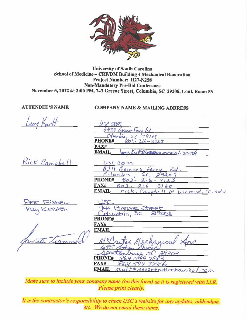
C. This Addendum consists of 3 pages and the following attachments:
1. Pre-Bid Conference Sign In Sheets.
2. Specification Sections 15073, 15835
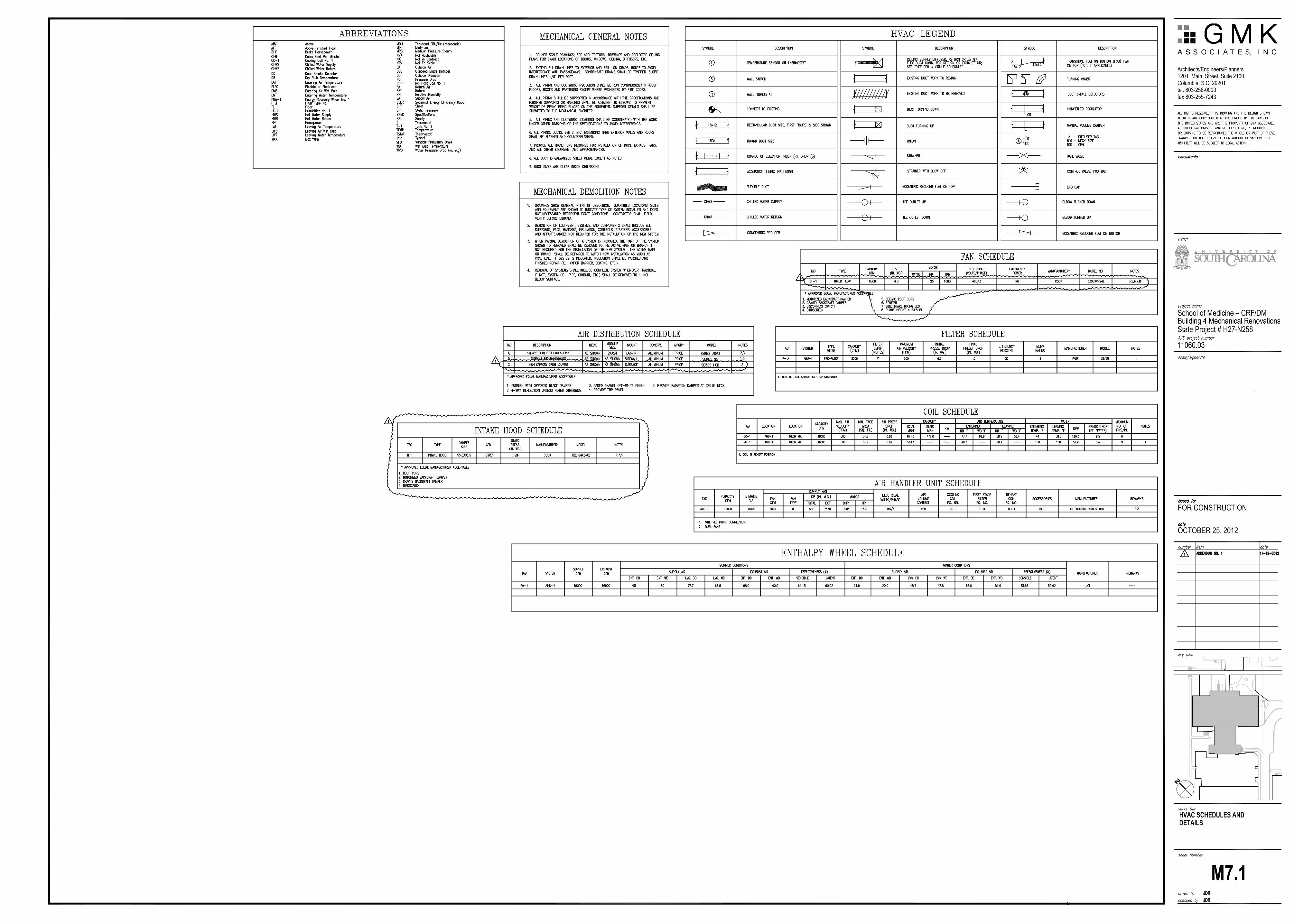
3. Drawings M2.1, M6.2, M7.1, E1.0, E2.0
4. Bid Form
CLARIFICATIONS
2.01 Nothing orally stated in the pre-bid meeting is enforceable. Only that which is in written form is
valid.
2.02 The existing building will remain occupied during the schedule of the Work.
2.03 After hours and/or weekend work may be required. The area of the Work is available 24 hours a
day/7 days a week between May 13, 2013 and July 26, 2013.
2.04 The existing roof is a aggregate surfaced built up roof system and will be penetrated as part of the
work. The existing roof is not under a current warranty or bond.
A. The Contractor is required to protect the existing roof with temporary plywood walkways as
required during the schedule of the Work.
B. A preconstruction roof inspection, with the Owner and Architect in attendance, of the area of
the Work to verify existing leaks, if present, will be required. New roof leaks in the area of the
Work will be contractor's responsibility.
C. Any damage to the existing roof that occurs as part of the Work will be the Contractors
responsibility.
D. At the roof curb, column penetrations or other penetrations through the roof, the Contractor
shall use NRCA approved boot and curb details for built up roof systems to seal the new
penetrations. The details shall be submitted to the architect for approval during construction.
UNIVERSITY OF SOUTH CAROLINA
SCHOOL OF MEDICINE-
CRF/DM Building 4 Mechanical Renovations
COLUMBIA, SC
STATE PROJECT # H27-N258
A/E PROJECT #11060.03
ADDENDUM NUMBER 1 00910-1

2.05 The Owner will accept additional walk-through requests if required by the bidding contractors. To
schedule a walk-through prior to bid, Contractors shall contact Larry Knott, USC School of
Medicine, 803-216-3323.
2.06 USC and/or OSE issue the building permits for the project. There are no permit fees on State
Projects.
2.07 This is a historic building therefore protection of the exterior landscaping, windows, brick, etc. will
be required. Coordinate with the Architect.
CHANGES TO THE PROJECT MANUAL
3.01 Bid Form - Replace the bid form in its entirety.
3.02 Section 01100 - Revise paragraph 1.05 B. to read:
"B. Availability of the construction area for commencement of demolition and alteration
work is limited to Monday, May 13, 2013 through Friday, July 26, 2013.
3.03 Section 15073 - Replace entire specificaiton in its entirety.
3.04 Section 15720 - Add paragarah E to Section 2.01.
"E. Temtrol"
3.05 Section 15720 - Revise paragraph E in section 2.03 to read:
"E. Lights: Provide fluorescetnt lights in each access section and coil section. Lights shall
be suitable for damp locations with wire guards, factory wired to weatherproof switch duplex
outlet mounted on casing exterior."
3.06 Add Section 15835 - Induced Flow Exhaust Fans in its entirety.
3.07 Section 15926 – Revise paragraph 4.04.B.1.a.2 to read:
"2. When the unit goes into the occupied mode and is to be started, the outdoor air damper
will be driven to its minimum CFM position, as sensed by outdoor air CFM measuring device.
3.08 Section 15926 - Revise paragraph 4.04.B.1.c to read:
"c. Discharge air temperature shall be controlled at 53 degrees F. (adjustable) by modulating
the CHW valve as necessary to maintain setpoint."
3.09 Section 15926 - Revise paragraph 4.04.B.1.e to read:
"e. BMS shall energize energy wheel to operate when the unit is in occupied mode. BMS
shall control wheel operation to maintain unit conditions as specified."
3.10 Section 15926 - Add paragraph 4.04.B.1.g to the project manual.
"g. BMS shall have the ability to schedule the air handler and exhaust fan into night setback
mode. The control system shall have the ability to reduce airflow to 50% of its capacity
(adjustable)."
CHANGES TO THE DRAWINGS
5.01 Drawing A2.1: Add the following note to the drawing:
UNIVERSITY OF SOUTH CAROLINA
SCHOOL OF MEDICINE-
CRF/DM Building 4 Mechanical Renovations
COLUMBIA, SC
STATE PROJECT # H27-N258
A/E PROJECT #11060.03
ADDENDUM NUMBER 1 00910-2

A. Relocate fire protection piping & provide upright pendants for new Mechanical Rm B9 and Lab
B3. All fire protection piping & sprinkler locations shall be coordinated with existing and/or new
ceiling heights. FP contractor shall refer to Architectural sheet A7.1 for reflected ceiling plan
layout. Sprinklers shall be centered in ceiling tile. All installation shall conform to NFPA
13-2010 & shall be coordinated with other trades as required.
5.02 Drawing M2.1: Replace Drawing M2.1 in its entirety.
5.03 Drawing M6.2: Replace Drawing M6.2 in its entirety.
5.04 Drawing M7.1: Replace Drawing M7.1 in its entirety.
5.05 Drawing E1.0: Replace Drawing E1.0 in its entirety.
5.06 Drawing E2.0: Replace Drawing E2.0 in its entirety.
END OF ADDENDUM NUMBER 1
UNIVERSITY OF SOUTH CAROLINA
SCHOOL OF MEDICINE-
CRF/DM Building 4 Mechanical Renovations
COLUMBIA, SC
STATE PROJECT # H27-N258
A/E PROJECT #11060.03
ADDENDUM NUMBER 1 00910-3


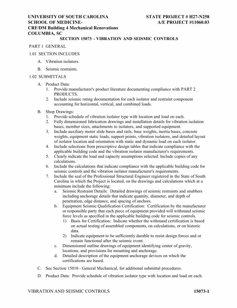
SECTION 15073 - VIBRATION AND SEISMIC CONTROLS
PART 1 GENERAL
1.01 SECTION INCLUDES
A. Vibration isolators.
B. Seismic restraints.
1.02 SUBMITTALS
A. Product Data:1. Provide manufacturer's product literature documenting compliance with PART 2
PRODUCTS.2. Include seismic rating documentation for each isolator and restraint component
accounting for horizontal, vertical, and combined loads.
B. Shop Drawings:1. Provide schedule of vibration isolator type with location and load on each.
2. Fully dimensioned fabrication drawings and installation details for vibration isolation bases, member sizes, attachments to isolators, and supported equipment.
3. Include auxiliary motor slide bases and rails, base weights, inertia bases, concrete
weights, equipment static loads, support points, vibration isolators, and detailed layout of isolator location and orientation with static and dynamic load on each isolator.
4. Include selections from prescriptive design tables that indicate compliance with the applicable building code and the vibration isolator manufacturer's requirements.
5. Clearly indicate the load and capacity assumptions selected. Include copies of any
calculations.6. Include the calculations that indicate compliance with the applicable building code for
seismic controls and the vibration isolator manufacturer's requirements.
7. Include the seal of the Professional Structural Engineer registered in the State of South Carolina in which the Project is located, on the drawings and calculations which at a minimum include the following:
a. Seismic Restraint Details: Detailed drawings of seismic restraints and snubbers including anchorage details that indicate quantity, diameter, and depth of
penetration, edge distance, and spacing of anchors.b. Equipment Seismic Qualification Certification: Certification by the manufacturer
or responsible party that each piece of equipment provided will withstand seismic
force levels as specified in the applicable building code for seismic controls.1) Basis for Certification: Indicate whether the withstand certification is based
on actual testing of assembled components, on calculations, or on historic
data.2) Indicate equipment to be sufficiently durable to resist design forces and or
remain functional after the seismic event.
c. Dimensioned outline drawings of equipment identifying center of gravity, locations, and provisions for mounting and anchorage.
d. Detailed description of the equipment anchorage devices on which the certifications are based.
C. See Section 15010 - General Mechanical, for additional submittal procedures.
D. Product Data: Provide schedule of vibration isolator type with location and load on each.
UNIVERSITY OF SOUTH CAROLINA
SCHOOL OF MEDICINE-
CRF/DM Building 4 Mechanical Renovations
COLUMBIA, SC
STATE PROJECT # H27-N258
A/E PROJECT #11060.03
VIBRATION AND SEISMIC CONTROLS 15073-1

E. Shop Drawings: Indicate inertia bases and locate vibration isolators, with static and dynamic load on each. Indicate seismic control measures.
F. Manufacturer's Instructions: Indicate installation instructions with special procedures and setting dimensions.
1.03 QUALITY ASSURANCE
A. Designer Qualifications: Perform design under direct supervision of a Professional Engineer experienced in design of this type of work and registered and licensed in South Carolina.
PART 2 PRODUCTS
2.01 MANUFACTURERS
A. Isolation Technology, Inc: www.isolationtech.com.
B. Kinetics Noise Control, Inc: www.kineticsnoise.com.
C. Mason Industries: www.mason-ind.com.
2.02 VIBRATION ISOLATION AND SEISMIC RESTRAINTS
A. General:1. Housekeeping Pads
a. Housekeeping pad reinforcement and monolithic pad attachment to the structure
details and design shall be prepared by the restraint vendor if not already indicated on the drawings.
b. Housekeeping pads shall be coordinated with restraint vendor and sized to provide
a minimum edge distance of ten (10) bolt diameters all around the outermost anchor bolt to allow development of full drill-in wedge anchor ratings. If cast-in
anchors are to be used, the housekeeping pads shall be sized to accommodate the ACI requirements for bolt coverage and embedment.
2. Supplementary Support Steel
a. Contractor shall supply supplementary support steel for all equipment, piping, ductwork, etc. including roof mounted equipment, as required or specified.
3. Attachments:
a. Contractor shall supply restraint attachment plates cast into housekeeping pads, concrete inserts, double sided beam clamps, etc. in accordance with the requirements of the vibration vendor’s calculations.
B. Specification Type “E”1. Spring isolators shall be free standing and laterally stable without any housing and
complete with a molded neoprene cup or 1/4" (6mm) neoprene acoustical friction pad between the baseplate and the support. All mountings shall have leveling bolts that
must be rigidly bolted to the equipment. Spring diameters shall be no less than 0.8 of the compressed height of the spring at rated load. Springs shall have a minimum additional travel to solid equal to 50% of the rated deflection. Submittals shall include
spring diameters, deflection, compressed spring height and solid spring height. 2. Mason Industries, Inc. type SLF
C. Specification Type “F”1. Restrained spring mountings shall have an SLF mounting as described in Specification
5, within a rigid housing that includes vertical limit stops to prevent spring extension
UNIVERSITY OF SOUTH CAROLINA
SCHOOL OF MEDICINE-
CRF/DM Building 4 Mechanical Renovations
COLUMBIA, SC
STATE PROJECT # H27-N258
A/E PROJECT #11060.03
VIBRATION AND SEISMIC CONTROLS 15073-2

when weight is removed. The housing shall serve as blocking during erection. Installed and operating heights are equal. A minimum clearance of 1/2" (12mm) shall be
maintained around restraining bolts and between the housing and the spring so as not to interfere with the spring action. Restraining Bolts shall have a neoprene bushing between the bolt and the housing. Limit stops shall be out of contact during normal
operation. Since housings will be bolted or welded in position there must be an internal isolation pad.Housing shall be designed to resist all seismic forces. Mountings shall have Anchorage Preapproval “OPA” Number from OSHPD in the state of California
certifying the maximum certified horizontal and vertical load ratings. 2. Mason Industries, Inc. type SLR or SLRS.
D. Specification Type “J”1. Hangers shall consist of rigid steel frames containing minimum 1 1/4" (32mm) thick
neoprene elements at the top and a steel spring with general characteristics as in specification 5 seated in a steel washer reinforced neoprene cup on the bottom. The neoprene element and the cup shall have neoprene bushings projecting through the steel
box. To maintain stability the boxes shall not be articulated as clevis hangers nor the neoprene element stacked on top of the spring. Spring diameters and hanger box lower hole sizes shall be large enough to permit the hanger rod to swing through a 30 arc
from side to side before contacting the rod bushing and short circuiting the spring. Submittals shall include a hanger drawing showing the 30 capability.
2. Mason Industries, Inc. type 30N.
E. Specification Type “JA”1. Hangers shall be as described in J, but they shall be supplied with a combination
rubberand steel rebound washer as the seismic upstop for suspended piping, ductwork, equipment and electrical cabletrays. Rubber thickness shall be a minimum of 1/4”
(6mm). Submittals shall include a drawing of the hanger showing the installation of the rebound washer.
2. Mason Industries, Inc. type RW30N.
F. Specification Type “K”1. Hangers shall be as described in J, but they shall be precompressed and locked at the
rated deflection by means of a resilient seismic upstop to keep the piping or equipment at a fixed elevation during installation. The hangers shall be designed with a release mechanism to free the spring after the installation is complete and the hanger is
subjected to its full load. Deflection shall be clearly indicated by means of a scale. Submittals shall include a drawing of the hanger showing the 30 capability.
2. Mason Industries, Inc. type PC30N.
G. Specification Type “M”1. Seismic solid braces shall consist of steel angles or channels to resist seismic loads
with a minimum safety factor of 2 and arranged to provide all directional restraint. Seismic solid brace end connectors shall be steel assemblies that swivel to the final
installation angle and utilize two through bolts to provide proper attachment. Seismic solid brace assembly shall have anchorage preapproval “OPA” number from OSHPD in the state of California verifying the maximum certified load ratings.
2. Mason Industries, Inc. type SSB, SSBS or SSRF.3. Specifications M applies to trapeze as well as clevis hanger locations. At trapeze
anchor locations piping must be shackled to the trapeze.
4. Specification M applies to hanging equipment as well.
UNIVERSITY OF SOUTH CAROLINA
SCHOOL OF MEDICINE-
CRF/DM Building 4 Mechanical Renovations
COLUMBIA, SC
STATE PROJECT # H27-N258
A/E PROJECT #11060.03
VIBRATION AND SEISMIC CONTROLS 15073-3

H. Specification Type “N”1. Steel angles, sized to prevent buckling, shall be clamped to pipe or equipment rods
utilizing a minimum of three ductile iron clamps at each restraint location when required. Welding of support rods is not acceptable. Rod clamp assemblies shall have an Anchorage Preapproval “OPA” Number from OSHPD in the State of California.
2. Mason Industries, Inc. type SRC or UC.3. Specifications N applies to trapeze as well as clevis hanger locations. At trapeze
anchor locations piping must be shackled to the trapeze.
4. Specification N applies to hanging equipment as well.
I. Specification Type “O”
1. Pipe clevis cross bolt braces are required in all restraint locations. They shall be special purpose preformed channels deep enough to be held in place by bolts passing over the
cross bolt. Clevis cross braces shall have an Anchorage Preapproval “OPA” Number from OSHPD in the State of California.
2. Mason Industries, Inc. type CCB.
J. Specification Type “P”1. All-directional seismic snubbers shall consist of interlocking steel members restrained
by a one-piece molded neoprene bushing of bridge bearing neoprene. Bushing shall be replaceable and a minimum of 1/4" (6mm) thick. Rated loadings shall not exceed 1000 psi (.7kg/mm2). A minimum air gap of 1/8" (3mm) shall be incorporated in the snubber
design in all directions before contact is made between the rigid and resilient surfaces. Snubber end caps shall be removable to allow inspection of internal clearances. Neoprene bushings shall be rotated to insure no short circuits exist before systems are
activated. Snubbers shall have an Anchorage Preapproval “OPA” Number from OSHPD in the State of California verifying the maximum certified horizontal and
vertical load ratings.2. Mason Industries, Inc. type Z-1225.
K. Specification Type “R”1. Stud wedge anchors shall be manufactured from full diameter wire, not from
undersized wire that is “rolled up” to create the thread. The stud anchor shall also have
a safety shoulder which fully supports the wedge ring under load. The stud anchors shall have an evaluation report number from the I.C.B.O Evaluation Service, Inc. verifying its allowable loads.
2. Mason Industries, Inc. type SAS.
L. Specification Type “S”
1. Female wedge anchors are preferred in floor locations so isolators or equipment can be slid into place after the anchors are installed. Anchors shall be manufactured from full diameter wire, and shall have a safety shoulder to fully support the wedge ring under
load. Female wedge anchors shall have an evaluation report number from the I.C.B.O. Evaluation Service, Inc. verifying to its allowable loads.
2. Mason Industries, Inc. type SAB.
M. Specification Type “W”
1. Flexible spherical expansion joints shall employ peroxide cured EPDM in the covers, liners and Kevlar® tire cord frictioning. Any substitutions must have equal or superior physical and chemical characteristics. Solid steel rings shall be used within the raised
face rubber flanged ends to prevent pullout. Flexible cable bead wire is not acceptable.
UNIVERSITY OF SOUTH CAROLINA
SCHOOL OF MEDICINE-
CRF/DM Building 4 Mechanical Renovations
COLUMBIA, SC
STATE PROJECT # H27-N258
A/E PROJECT #11060.03
VIBRATION AND SEISMIC CONTROLS 15073-4
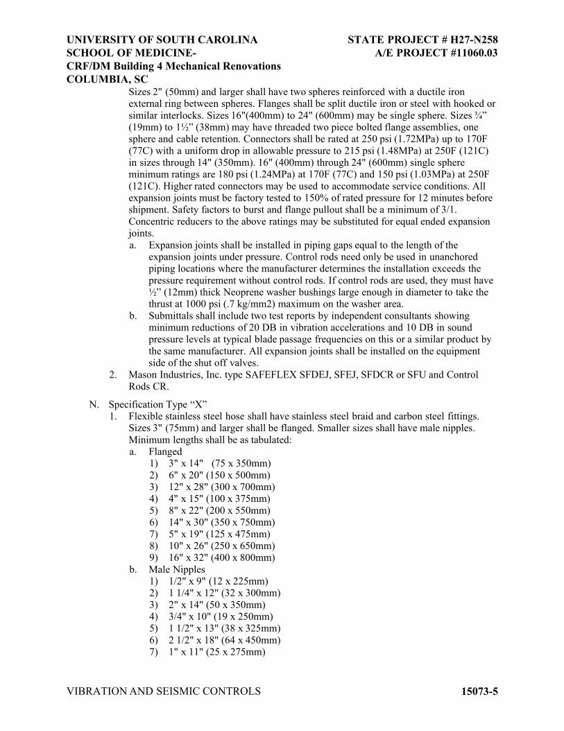
Sizes 2" (50mm) and larger shall have two spheres reinforced with a ductile iron external ring between spheres. Flanges shall be split ductile iron or steel with hooked or
similar interlocks. Sizes 16"(400mm) to 24" (600mm) may be single sphere. Sizes ¾” (19mm) to 1½” (38mm) may have threaded two piece bolted flange assemblies, one sphere and cable retention. Connectors shall be rated at 250 psi (1.72MPa) up to 170F
(77C) with a uniform drop in allowable pressure to 215 psi (1.48MPa) at 250F (121C) in sizes through 14" (350mm). 16" (400mm) through 24" (600mm) single sphere minimum ratings are 180 psi (1.24MPa) at 170F (77C) and 150 psi (1.03MPa) at 250F
(121C). Higher rated connectors may be used to accommodate service conditions. All expansion joints must be factory tested to 150% of rated pressure for 12 minutes before shipment. Safety factors to burst and flange pullout shall be a minimum of 3/1.
Concentric reducers to the above ratings may be substituted for equal ended expansion joints.
a. Expansion joints shall be installed in piping gaps equal to the length of the expansion joints under pressure. Control rods need only be used in unanchored piping locations where the manufacturer determines the installation exceeds the
pressure requirement without control rods. If control rods are used, they must have ½” (12mm) thick Neoprene washer bushings large enough in diameter to take the thrust at 1000 psi (.7 kg/mm2) maximum on the washer area.
b. Submittals shall include two test reports by independent consultants showing minimum reductions of 20 DB in vibration accelerations and 10 DB in sound pressure levels at typical blade passage frequencies on this or a similar product by
the same manufacturer. All expansion joints shall be installed on the equipment side of the shut off valves.
2. Mason Industries, Inc. type SAFEFLEX SFDEJ, SFEJ, SFDCR or SFU and Control Rods CR.
N. Specification Type “X”1. Flexible stainless steel hose shall have stainless steel braid and carbon steel fittings.
Sizes 3" (75mm) and larger shall be flanged. Smaller sizes shall have male nipples.
Minimum lengths shall be as tabulated:a. Flanged
1) 3" x 14" (75 x 350mm)
2) 6" x 20" (150 x 500mm)3) 12" x 28" (300 x 700mm)4) 4" x 15" (100 x 375mm)
5) 8" x 22" (200 x 550mm)6) 14" x 30" (350 x 750mm)
7) 5" x 19" (125 x 475mm)8) 10" x 26" (250 x 650mm)9) 16" x 32" (400 x 800mm)
b. Male Nipples1) 1/2" x 9" (12 x 225mm)2) 1 1/4" x 12" (32 x 300mm)
3) 2" x 14" (50 x 350mm)4) 3/4" x 10" (19 x 250mm)5) 1 1/2" x 13" (38 x 325mm)
6) 2 1/2" x 18" (64 x 450mm)7) 1" x 11" (25 x 275mm)
UNIVERSITY OF SOUTH CAROLINA
SCHOOL OF MEDICINE-
CRF/DM Building 4 Mechanical Renovations
COLUMBIA, SC
STATE PROJECT # H27-N258
A/E PROJECT #11060.03
VIBRATION AND SEISMIC CONTROLS 15073-5
c. Hoses shall be installed on the equipment side of the shut-off valves horizontally and parallel to the equipment shafts wherever possible.
2. Mason Industries, Inc. type BSS.
O. Specification Type “Y”
1. All-directional acoustical pipe anchor, consisting of two sizes of steel tubing separated by a minimum 1/2" (12mm) thick 60 durometer neoprene. Vertical restraint shall be provided by similar material arranged to prevent vertical travel in either direction.
Allowable loads on the isolation material should not exceed 500 psi (.35 kg/mm2) and the design shall be balanced for equal resistance in any direction.
2. Mason Industries, Inc. type ADA.
P. Specification Type “Z”1. Pipe guides shall consist of a telescopic arrangement of two sizes of steel tubing
separated by a minimum 1/2" (12mm) thickness of 60 durometer neoprene. The height of the guides shall be preset with a shear pin to allow vertical motion due to pipe
expansion or contraction. Shear pin shall be removable and reinsertable to allow for selection of pipe movement. Guides shall be capable of ±1 5/8" (41mm) motion, or to meet location requirements.
2. Mason Industries, Inc. type VSG.
Q. Specification Type “AA”
1. Split Wall Seals consist of two bolted pipe halves with minimum 3/4" (19mm) thick neoprene sponge bonded to the inner faces. The seal shall be tightened around the pipe to eliminate clearance between the inner sponge face and the piping. Concrete may be
packed around the seal to make it integral with the floor, wall or ceiling if the seal is not already in place around the pipe prior to the construction of the building member. Seals shall project a minimum of 1" (25mm) past either face of the wall. Where
temperatures exceed 240F(115C), 10# (4.5kg) density fiberglass may be used in lieu of the sponge.
2. Mason Industries, Inc. type SWS.
2.03 VIBRATION ISOLATION OF PIPING
A. Horizontal pipe isolation:1. The first four pipe hangers in the main lines near the mechanical equipment shall be as
described in specification K. Brace hanger rods with SRC clamps specification N.2. Horizontal runs in all other locations throughout the building shall be isolated by
hangers as described in specification J & JA.
3. Piping connected to equipment located in basements and hangs from ceilings under occupied spaces the first three hangers shall have: a. 0.75" (19mm) deflection for pipe sizes up to and including 3" (75mm).
b. 1 1/2" (38mm) deflection for pipe sizes up to and including 6" (150mm).c. 2 1/2" (64mm) deflection thereafter.
d. Hangers shall be located as close to the overhead structure as practical. Hanger locations that also have seismic restraints attached must have type RW Rebound Washers to limit uplift.
4. Where piping connects to mechanical equipment install specification W expansion joints or specification X stainless hoses if W is not suitable for the service.
B. Riser isolation:
UNIVERSITY OF SOUTH CAROLINA
SCHOOL OF MEDICINE-
CRF/DM Building 4 Mechanical Renovations
COLUMBIA, SC
STATE PROJECT # H27-N258
A/E PROJECT #11060.03
VIBRATION AND SEISMIC CONTROLS 15073-6

1. Risers shall be suspended from specification JA hangers or supported by specification E mountings, anchored with specification Y anchors, and guided with specification Z
sliding guides. 2. Steel springs shall be a minimum of 0.75" (19mm) except in those expansion locations
where additional deflection is required to limit load changes to ± 25% of the initial
load. 3. Submittals must include riser diagrams and calculations showing anticipated expansion
and contraction at each support point, initial and final loads on the building structure,
spring deflection changes and seismic loads. Submittal data shall include certification that the riser system has been examined for excessive stresses and that none will exist in the proposed design.
2.04 SEISMIC DESIGN
A. General1. Specifications and plans shall indicate minimum requirements and general intent. The
actual requirements shall be determined by the seismic system designer but those requirements shall not be less than indicated on the plans and in these specifications.
2. Calculations shall be submitted and signed by a licensed professional engineer in the
state where the project is located.3. This project is subject to the seismic bracing requirements of the International Building
Code, 2003 edition. The following criteria are applicable to this project.
a. Seismic Use Group (Table 1604.5): III b.c. Site Class Category (Table 1615.1.1): D
d. Forces shall be calculated for the above requirements and Equation 16-67, 68, & 69 in section 1621.1.4, unless exempted by 1621.1.1.
B. Seismic restraint of piping:1. Seismically restrain all piping listed below. Use specification M cables if isolated.
Specification M or N restraints may be used on unisolated piping.a. Piping located in boiler rooms, mechanical equipment rooms, and refrigeration
equipment rooms that is 1 1/4" (32mm) I.D. and larger.
b. All other piping 2 1/2" (64mm) diameter and larger.2. Transverse piping restraints shall be at 40' (12m) maximum spacing for all pipe sizes,
except where lesser spacing is required to limit anchorage loads.
3. Longitudinal restraints shall be at 80' (24m) maximum spacing for all pipe sizes, except where lesser spacing is required to limit anchorage loads.
4. Where thermal expansion is a consideration, guides and anchors may be used as
transverse and longitudinal restraints provided they have a capacity equal to or greater than the restraint loads in addition to the loads induced by expansion or contraction.
5. Transverse restraint for one pipe section may also act as a longitudinal restraint for a pipe section of the same size connected perpendicular to it if the restraint is installed within 24" (600m) of the elbow or TEE or combined stresses are within allowable
limits at longer distances.6. Hold down clamps must be used to attach pipe to all trapeze members before applying
restraints in a manner similar to clevis supports.
7. Branch lines may not be used to restrain main lines.8. Cast iron pipe of all types, glass pipe and any other pipes joined with a four band
shield and clamp assembly in areas with Ss of 0.35 or greater shall be braced as in
UNIVERSITY OF SOUTH CAROLINA
SCHOOL OF MEDICINE-
CRF/DM Building 4 Mechanical Renovations
COLUMBIA, SC
STATE PROJECT # H27-N258
A/E PROJECT #11060.03
VIBRATION AND SEISMIC CONTROLS 15073-7

sections 3.02.C.2 and 3. For areas with Ss less than 0.35, 2 band clamps may be used with a reduced spacing of 1/2 of those listed in sections 3.02.C.2 and 3.
9. Connection to the structure must be made with a non-friction connection (i.e. no “C” clamps)
10. Hanger locations that also have seismic restraints attached must have Specification JA.
11. Pipe Exclusionsa. Piping in boiler and mechanical rooms less than 1 1/4" (32mm) inside diameter.b. All other piping less than 2 1/2" (64mm) inside diameter.
c. All piping suspended by clevis hangers where the distance from the top of the pipe to the suspension point is 12" or less.
d. All trapezed piping where the distance from the suspension point to the trapeze
member is 12" or less.e. If any suspension location in the run exceeds the above, the entire run must be
braced.
C. Seismic restraint of ductwork:
1. Seismic restraint of ductworka. Seismically restrain all ductwork with specification L or M restraints as listed
below:
1) Restrain rectangular ducts with cross sectional area of 6 sq.ft. (.5 m2) or larger.
2) Restrain round ducts with diameters of 28" (700mm) or larger.
3) Restrain flat oval ducts the same as rectangular ducts of the same nominal size.
b. Transverse restraints shall occur at 30' (9mm) intervals or at both ends of the duct
run if less than the specified interval. Transverse restraints shall be installed at each duct turn and at each end of a duct run.
c. Longitudinal restraints shall occur at 60' (18m) intervals with at least one restraint per duct run. Transverse restraints for one duct section may also act as a longitudinal restraint for a duct section connected perpendicular to it if the
restraints are installed within 4' (1.2m) of the intersection of the ducts and if the restraints are sized for the larger duct. Duct joints shall conform to SMACNA duct construction standards.
d. The ductwork must be reinforced at the restraint locations. Reinforcement shall consist of an additional angle on top of the ductwork that is attached to the support hanger rods. Ductwork is to be attached to both upper angle and lower trapeze.
e. A group of ducts may be combined in a larger frame so that the combined weights and dimensions of the ducts are less than or equal to the maximum weight and
dimensions of the duct for which bracing details are selected.f. Walls, including gypsum board non bearing partitions, which have ducts running
through them may replace a typical transverse brace. Provide channel framing
around ducts and solid blocking between the duct and frame.g. Connection to the structure must be made with a non-friction connection (i.e. no
“C” clamps)
h. Hanger locations that also have seismic restraints attached must have Specification JA.
i. Ductwork Exclusions:
1) Rectangular and square and ducts that are less than 6 square feet in cross sectional area.
UNIVERSITY OF SOUTH CAROLINA
SCHOOL OF MEDICINE-
CRF/DM Building 4 Mechanical Renovations
COLUMBIA, SC
STATE PROJECT # H27-N258
A/E PROJECT #11060.03
VIBRATION AND SEISMIC CONTROLS 15073-8

2) Round duct less than 28" (.5m2) in diameter.3) All trapezed ductwork where the distance from the suspension point to the
trapeze member is 12" or less.4) Ductwork hung with straps where the top of the duct is 12" or less from the
suspension point and the strap has 2 #10 sheet metal screws within 2" of the
top of the duct.5) If any suspension location in the run exceeds the above, the entire run must be
braced.
PART 3 EXECUTION
3.01 INSTALLATION
A. Install in accordance with manufacturer's instructions.
3.02 GENERAL
A. All vibration isolators and seismic restraint systems must be installed in strict accordance with the manufacturers written instructions and all certified submittal data.
B. Installation of vibration isolators and seismic restraints must not cause any change of position of equipment, piping or ductwork resulting in stresses or misalignment.
C. No rigid connections between equipment and the building structure shall be made that degrades the noise and vibration control system herein specified.
D. The contractor shall not install any equipment, piping, duct or conduit which makes rigid connections with the building unless isolation is not specified. “Building” includes, but is
not limited to, slabs, beams, columns, studs and walls.
E. Coordinate work with other trades to avoid rigid contact with the building.
F. Any conflicts with other trades which will result in rigid contact with equipment or piping due to inadequate space or other unforeseen conditions should be brought to the
architects/engineers attention prior to installation. Corrective work necessitated by conflicts after installation shall be at the responsible contractors expense.
G. Bring to the architects/engineers attention any discrepancies between the specifications and the field conditions or changes required due to specific equipment selection, prior to installation. Corrective work necessitated by discrepancies after installation shall be at the
responsible contractors expense.
H. Correct, at no additional cost, all installations which are deemed defective in workmanship
and materials at the contractors expense.
I. Overstressing of the building structure must not occur because of overhead support of
equipment. Contractor must submit loads to the structural engineer of record for approval. Generally bracing may occur from:
1. Flanges of structural beams.2. Upper truss cords in bar joist construction.3. Cast in place inserts or wedge type drill-in concrete anchors.
J. Specification L cable restraints shall be installed slightly slack to avoid short circuiting the isolated suspended equipment, piping or conduit.
K. Specification L cable assemblies are installed taut on non-isolated systems. Specification M
UNIVERSITY OF SOUTH CAROLINA
SCHOOL OF MEDICINE-
CRF/DM Building 4 Mechanical Renovations
COLUMBIA, SC
STATE PROJECT # H27-N258
A/E PROJECT #11060.03
VIBRATION AND SEISMIC CONTROLS 15073-9

seismic solid braces may be used in place of cables on rigidly attached systems only.
L. At locations where specification L or M restraints are located, the support rods must be braced when necessary to accept compressive loads with specification N braces.
M. At locations where specification L cable restraints are installed on support rods with spring isolators, the spring isolation hangers must be specification type JA.
N. At all locations where specification L or M restraints are attached to pipe clevis, the clevis cross bolt must be reinforced with specification type O braces.
O. Drill-in concrete anchors for ceiling and wall installation shall be specification type R, and specification type S female wedge type for floor mounted equipment.
P. Where piping passes through walls, floors or ceilings the vibration isolation manufacturer shall provide specification AA wall seals.
Q. All mechanical equipment shall be vibration isolated and seismically restrained as specified.
3.03 SEISMIC CERTIFICATION AND ANALYSIS:
A. Seismic restraint calculations must be provided for all connections of equipment to the structure. Calculations must be stamped by a registered professional engineer licensed in the
state of the job location.
B. Calculations (including the combining of tensile and shear loadings) to support seismic
restraint designs must be stamped by a registered professional engineer licensed in the state of the job location. Testing and calculations must include both shear and tensile loads as
well as one test or analysis at 45 to the weakest mode.
C. Analysis must indicate calculated dead loads, static seismic loads and capacity of materials
utilized for connections to equipment and structure. Analysis must detail anchoring methods, bolt diameter, embedment and/or welded length. All seismic restraint devices shall be designed to accept, without failure.
3.04 FIELD QUALITY CONTROL
A. Inspect isolated equipment after installation and submit report. Include static deflections.
3.05 SCHEDULE
A. Pipe Isolation Schedule.1. 1 Inch Pipe Size: Isolate 120 diameters from equipment.
2. 2 Inch Pipe Size: Isolate 90 diameters from equipment.3. 3 Inch Pipe Size: Isolate 80 diameters from equipment.4. 4 Inch Pipe Size: Isolate 75 diameters from equipment.
B. Equipment Isolation Schedule.1. Exhaust Fan
a. Isolator Type: F, Pb. Isolator Deflection: 1.5"
END OF SECTION
UNIVERSITY OF SOUTH CAROLINA
SCHOOL OF MEDICINE-
CRF/DM Building 4 Mechanical Renovations
COLUMBIA, SC
STATE PROJECT # H27-N258
A/E PROJECT #11060.03
VIBRATION AND SEISMIC CONTROLS 15073-10

SECTION 15835 - INDUCED FLOW EXHAUST FANS
PART 1 GENERAL
1.01 SECTION INCLUDES
A. Induced Flow Exhaust Fans
1.02 RELATED REQUIREMENTS
A. Section 15065 - Motors for Mechanical Equipment.
B. Section 15073 - Vibration and Seismic Controls for HVAC Piping and Equipment.
C. Section 15820 - Duct Accessories: Backdraft dampers.
1.03 REFERENCE STANDARDS
A. AMCA 99 - Standards Handbook; Air Movement and Control Association International, Inc.; 2010.
B. AMCA 210 - Laboratory Methods of Testing Fans for Aerodynamic Performance Rating; Air Movement and Control Association International, Inc.; 2007 (ANSI/AMCA 210, same
as ANSI/ASHRAE 51).
C. AMCA (DIR) - [Directory of] Products Licensed Under AMCA International Certified
Ratings Program; Air Movement and Control Association International, Inc.; http://www.amca.org/licenses/search.aspx.
D. AMCA 300 - Reverberant Room Method for Sound Testing of Fans; Air Movement and Control Association International, Inc.; 2008.
1.04 SUBMITTALS
A. Product Data: Provide data on fans and accessories including fan curves with specified
operating point clearly plotted, power, RPM, sound power levels at rated capacity, and electrical characteristics and connection requirements.
B. Manufacturer's Instructions: Indicate installation instructions.
C. Maintenance Data: Include instructions for lubrication, motor and drive replacement, spare parts list, and wiring diagrams.
D. Operation and Maintenance Manuals: Include in manuals the information listed below. For information on how to prepare and submit manuals see section 1780 (Closeout Submittals).1. Recommended spare parts
2. Spare parts lists3. Operating instructions4. Maintenance instructions, including preventative and corrective maintenance.
5. Copies of warranties6. Wiring diagrams7. Shop drawings and product data
1.05 QUALITY ASSURANCE
A. Fan impeller shall be statically and dynamically balanced in accordance with AMCA Standard 204-96, "Balance Quality and Vibration Levels for Fans." Vibration tests shall be
conducted and recorded on each assembled fan before shipment at the specified fan RPM.
UNIVERSITY OF SOUTH CAROLINA
SCHOOL OF MEDICINE-
CRF/DM Building 4 Mechanical Renovations
COLUMBIA, SC
STATE PROJECT # H27-N258
A/E PROJECT #11060.03
INDUCED FLOW EXHAUST FANS 15835-1

These readings shall conform to the AMCA 204-96 Standard.
B. Fan entrainment design shall have been verified by computational fluid dynamics (CFD). Computational fluid dynamics (CFD) evaluation of fan discharge and entrainment airflow may also be provided as requested by the owner and/or engineer.
C. Fans shall be manufactured at an ISO 9001 Certified facility.
PART 2 PRODUCTS
2.01 MANUFACTURERS
A. Greenheck: www.greenheck.com.
B. Loren Cook Company: www.lorencook.com.
C. MK Plastics
D. Twin City
2.02 INDUCED FLOW EXHAUST FANS
A. GENERAL
1. Fan performance data shall follow AMCA Standard Conditions of 0 Ft elevation and 70 Deg F. (Air Density shall be 0.075 lb/ft)
2. Fans selected shall allow for +/- 15% variation of scheduled static pressure and airflow.
3. Fan systems shall incorporate integral lifting lugs for ease of installation.
B. FAN HOUSING AND CONSTRUCTION
1. Fan housing shall be a minimum 14 gauge steel construction.2. Adjustable motor plate, where applicable shall utilize threaded studs for positive belt
tensioning.3. Fan shall be constructed with an integral housing drain to alleviate rainwater.4. Fan shall include a bolted and gasketed access door.
5. Belt driven fan shafts shall be AISI C-1045 hot rolled or stainless steel and accurately turned, ground, and polished.
6. Unit fasteners exposed to corrosive airstream shall be of stainless steel construction.
7. Coating shall be salt spray tested per ASTM B117 for in excess of 1000 hours without failure, humidity resistance tested per ASTM D2247 for in excess of 1000 hours without failure, and impact resistance tested per ASTM D2794 and shall pass a
minimum of 100 in-lbs.8. Unit shall bear an engraved aluminum nameplate. Nameplate shall indicate design
CFM, static pressure, and maximum fan RPM.
C. DILUTION NOZZLE
1. Fans shall incorporate a double concentric accelerator fiberglass reinforced plastic (FRP) induction nozzle selected for optimal performance per the plans and specifications. Nozzle shall be constructed and designed to avoid extreme variations in
velocity flows across the outlet, even against wind loading. Where required, CFD shall be provided demonstrating this on submitted nozzle. Bifurcated designs shall not be allowed.
2. Induction nozzle shall be constructed and designed to efficiently handle up to 7000 feet per minute outlet velocity and shall have a optimally matched accelerator for the specified design conditions.
UNIVERSITY OF SOUTH CAROLINA
SCHOOL OF MEDICINE-
CRF/DM Building 4 Mechanical Renovations
COLUMBIA, SC
STATE PROJECT # H27-N258
A/E PROJECT #11060.03
INDUCED FLOW EXHAUST FANS 15835-2

D. CENTRIFUGAL FAN IMPELLER1. Fan impeller shall be steel, non-overloading, centrifugal backward inclined, airfoil
type. Blades shall be continuously welded to the backplate and inlet shroud.2. Fan impeller hub shall be keyed and securely attached to the fan shaft. Fan shaft shall
be AISI C-1045 hot rolled or stainless steel and accurately turned, ground, and polished.
3. Fan impeller shall be statically and dynamically balanced in accordance with AMCA Standard 204-96, "Balance Quality and Vibration Levels for Fans."
4. Fan impeller shall be coated with finish to match the fan housing.
5. Belt driven fan bearings shall be designed and tested specifically for use in air handling applications. Construction shall be heavy duty regreaseable ball or roller type in cast iron pillow block housing.
6. Belt driven fan bearings shall be selected for a minimum L50 life of not less than 200,000 hours.
7. Belt driven fan bearings shall have copper lubrication lines run to a centralized location for ease of maintenance.
E. BYPASS AIR PLENUM1. For constant volume systems the fan and nozzle assembly shall be directly connected to
the roof curb and exhaust duct.
2. For variable volume systems a bypass air plenum shall be supplied as shown on the contract drawings.
3. Bypass air plenum shall introduce outside air above the roof level and shall have rain
hood(s) and bird screen protection over the bypass air damper(s).4. Bypass air plenum shall be constructed of welded steel, minimum 14 gauge, with a
finish to match the fan housing.
5. Bypass dampers shall be opposed blade design, coated to match the fan housing and plenum.
6. A fan isolation damper gravity type coated to match fan housing and plenum shall be provided as show on the project documents.
F. FAN MOTORS AND DRIVES1. Fan motors shall be premium efficiency, NEMA frame, nominal 1800 or 3600 RPM
Totally Enclosed Fan Cooled (TEFC) with a 1.15 service factor.
2. Belt driven fan drive belts shall be oil and heat resistant, static conducting. Fixed drives shall be sized for a minimum 1.5 service factor (150% of the motor horsepower) and shall be readily and easily accessible for service, if required.
3. Belt driven fans shall utilize precision machined cast iron type sheaves, keyed and securely attached to the wheel and motor shafts.
4.
PART 3 EXECUTION
3.01 INSTALLATION
A. Install in accordance with manufacturer's instructions.
B. Provide sheaves required for final air balance.
END OF SECTION
UNIVERSITY OF SOUTH CAROLINA
SCHOOL OF MEDICINE-
CRF/DM Building 4 Mechanical Renovations
COLUMBIA, SC
STATE PROJECT # H27-N258
A/E PROJECT #11060.03
INDUCED FLOW EXHAUST FANS 15835-3