static aeroelastic optimisation to wing structural weight ... · aerodynamic analysis components....
TRANSCRIPT

ABSTRACTEstimating the wing structural weight of an extremely manoeuvrable Unmanned Aerial Vehicle (UAV) during conceptual design has proven to be a significant challenge due to its high load factor (the ratio of an aircraft lift to its weight). The traditional empirical method relies on existing statistical data of previously built aircraft, then is inadequate for the innovative UAV structure design which can endure extremely manoeuvrable load (load factor is greater than 9g). In this paper, the finite element model for wing structure of an extremely manoeuvrable UAV with foreplane was built, and the structural weight was estimated by static aeroelastic optimisation considering structural strength and buckling constraints. The methodology developed here is only consisted of three components, which is much less than that for existing method, thus the procedure developed here sacrificed some accuracy, but it’s faster and more suitable for aircraft conceptual design. It was validated by the overlap between the weights given by the methodology, and the results from empirical equations when the load factors are less than 9g. Through the analysis procedure developed, the wing structural weights of the extremely manoeuvrable UAV were given under different load cases (load factor changes from 5g to 12g).
The AeronAuTicAl JournAl AugusT 2015 Volume 119 no 1218 1033
Paper No. 4278. Manuscript received 18 September 2014 and accepted 21 April 2015.
TECHNICAL NOTE
Static aeroelastic optimisation to wing structural weight estimation of an extremely manoeuvrable UAVL. Yi [email protected] Polytechnical University Xi’an China
Y. Jun and K. BinCheng Du Aircraft Design and Research Institute Cheng Du China

1034 The AeronAuTicAl JournAl AugusT 2015
NOMENCLATUREλ taper ratiot/c aerofoil thickness ratioΛ wing sweep at 25% MACScsw control surface area (wing-mounted), ft2
A aspect ratioKvs 1·19 for variable sweep wing; 1·0 otherwiseKdw 0·768 for delta wing; 1·0 otherwiseNz ultimate load factor; 1·5 × limit load factorSw trapezoidal wing area ft2
Wdg design gross weight, lb[K] stiffness matrix[AICS] aerodynamic influence coefficients matrix{u} displacements at the structural nodes[M] Mass matrix[φr ] rigid-body modes of the free aircraft{ür } vector of rigid-body accelerations[P] Matrix of the rigid aerodynamic force coefficientsq dynamic pressure{δ} vector of aerodynamic trim parameters
1.0 INTRODUCTIONThe methods used for weight estimation can be classified as either empirical or physics-based(1,2). Empirical methods rely on existing statistical data of previously built aircraft. The structural weight of a new aircraft configuration is calculated by inter/extrapolation of existing data according to predefined geometrical, structural or operational parameters(3). For physics-based methods on the other hand, the structural weight results from an optimisation process that includes the structural analysis and sizing of aircraft structures that are stressed according to selecting load cases. Because physics-based methods do not rely on historical data, they are preferable to empirical methods particularly with regard to the analysis of innovative conceptual aircraft (unconventional configurations, extremely maneuvrability) or aircraft structures featuring new material technology such as composites.
The extremely manoeuvrable UAV is designed to exceed human limits in maneuvrability, agility, and acceleration. The extreme maneuvrability allows higher speeds through the same flight path, which means that the wing structure must be able to endure higher load factors than a conventional aircraft does. In such case computational accuracy of the traditional empirical methods cannot be accepted, physics-based methods are better choices.
A finite element model-based structural optimisation procedure with flexible loads was imple-mented to evaluate the wing-bending material weight of the high-speed civil transport (HSCT)(4).The physics-based methods were used to estimate the structural weight of innovative conceptual aircraft (Blended Wing Body/BWB) by many researchers. Giles(5,6) has developed the Equivalent Laminated Plate Solution (ELAPS) computer program and applied it to estimate the structural weight of a Hybrid Wing Body (HWB) configuration. Bradley(7) used the finite element analysis to predict center body structural weight of the HWB. Trevor(8) developed a physics-based multi-disciplinary analysis and weight optimisation environment for the purpose of structural weight

Yi, Jun & Bin sTATic AeroelAsTic opTimizATion To wing sTrucTurAl weighT esTimATion of An... 1035
estimation of the HWB in the conceptual design phase. In this environment with five components the external loads were determined by Panel Method Ames Research Center (PMARC), the outer mold line (OML) data of BWB was created by Vehicle Sketch Pad (VSP), and the finite element model was built by Patran/Nastran and Matlab. Finally the structure of BWB was optimised by HyperSizer until all failure criteria (strength, buckling) were satisfied. In this method the external loads just included the aerodynamic loads, but not the inertial loads which were form the structural weight, as results the applied load(equals the aerodynamic load minus the inertial load) acting on the aircraft was more serious than the real one. On the other hand, the deflections of the structures can change the distribution of the aerodynamic loads acting on the wing, because of the static aeroelastic behavior. In the process of structural optimisation, the design values of structure have to be changed frequently to search the minimal structural weight, thus the deflection of structures can be altered in an each iteration of optimisation, and however there was not iteration process in this method to update the external loads which were certainly altered by the variation of structural deformation.
Therefore, in this paper the static aeroelastic analysis is used to take place of the three compo-nents (External loads, Internal loads and Structural sizing), in order to take the inertial loads into consideration and update the external loads in an each iteration of optimisation. Consequently a simpler and faster procedure has been developed, in which only three components are included. The input information is stored in an EXCEL file, and the finite element model of UAV is built using Patran and Matlab. According to the most serious flight condition, the external load is calculated by the static aeroelastic analysis, and then the wing structure is optimised by Nastran, finally the structural weight of wing can be estimated.
2.0 METHODOLOGY
2.1 Static aeroelastic optimisation and structural weight estimation (SAO/ SWE) environment
Formulating a suitable modelling and simulation environment for the Extremely Manoeuvrable UAV wing structural weight estimation began with identifying the required modelling and optimisation
Figure 1. Formulation and implementation of the parametric modelling andsimulation (M&S) environment for HWB structural weight estimation(8).
1036 The AeronAuTicAl JournAl AugusT 2015
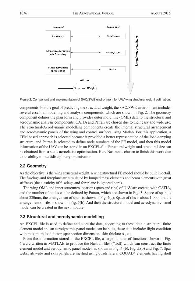
components. For the goal of predicting the structural weight, the SAO/SWE environment includes several essential modelling and analysis components, which are shown in Fig. 2. The geometry component defines the plan form and provides outer mold line (OML) data to the structural and aerodynamic analysis components. CATIA and Patran are chosen due to their easy and wide use. The structural/Aerodynamic modelling components create the internal structural arrangement and aerodynamic panels of the wing and control surfaces using Matlab. For this application, a FEM based approach is selected because it provided a better representation of the load-carrying structure, and Patran is selected to define node numbers of the FE model, and then this model information of the UAV can be stored in an EXCEL file. Structural weight and structural size can be obtained from a static aeroelastic optimisation. Here Nastran is chosen to finish this work due to its ability of multidisciplinary optimisation.
2.2 Geometry
As the objective is the wing structural weight, a wing structural FE model should be built in detail. The fuselage and foreplane are simulated by lumped mass elements and beam elements with great stiffness (the elasticity of fuselage and foreplane is ignored here).
The wing OML and inner structures location (spars and ribs) of UAV are created with CATIA, and the number of nodes can be defined by Patran, which are shown in Fig. 3. Space of spars is about 330mm, the arrangement of spars is shown in Fig. 4(a); Space of ribs is about 1,000mm, the arrangement of ribs is shown in Fig. 5(b). And then the structural model and aerodynamic panel model can be created in the next module.
2.3 Structural and aerodynamic modelling
An EXCEL file is used to define and store the data, according to these data a structural finite element model and an aerodynamic panel model can be built, these data include: flight condition with maximum load factor, spar section dimension, skin thickness , etc.
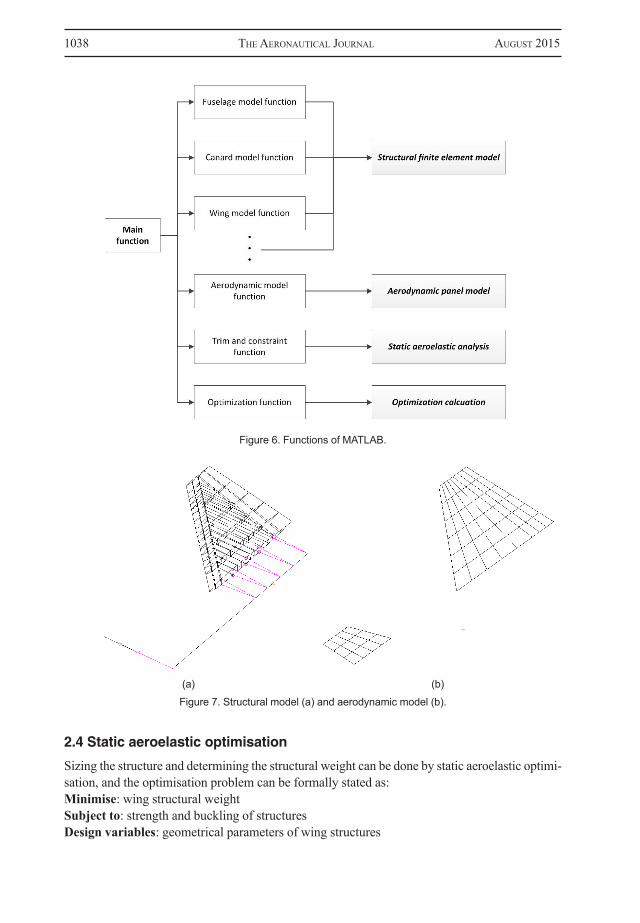
From the information stored in the EXCEL file, a large number of functions shown in Fig. 6 were written in MATLAB to produce the Nastran files (*.bdf) which can construct the finite element model and aerodynamic panel model, as shown in Fig. 4.(b), Fig. 5.(b) and Fig. 7. Spar webs, rib webs and skin panels are meshed using quadrilateral CQUAD4 elements having shell
Figure 2. Component and implementation of SAO/SWE environment for UAV wing structural weight estimation.

Yi, Jun & Bin sTATic AeroelAsTic opTimizATion To wing sTrucTurAl weighT esTimATion of An... 1037
properties, and triangular CTRIA3 elements are used in transition areas. The composite skins are simulated by shell elements, according to the material properties and thickness of the each lay-up, the mechanic properties of these shell elements can be determined by the classic laminate theory. This work can be easily done by the laminate modeler in Patran. Spar and rib caps are modeled with CBAR elements. Only symmetric load cases are considered for this research so only half of the model is generated and symmetric boundary conditions are applied at the centerline.
(a)
(a) Ribs arrangement
(b)
(b) Ribs FE model
Figure 3. (a) Geometry model and structural arrangement, (b) Nodes of FE model.
Figure 4. Arrangement and FE model of spars.
Figure 5. Arrangement and FE model of ribs.
1038 The AeronAuTicAl JournAl AugusT 2015
2.4 Static aeroelastic optimisation
Sizing the structure and determining the structural weight can be done by static aeroelastic optimi-sation, and the optimisation problem can be formally stated as:Minimise: wing structural weightSubject to: strength and buckling of structuresDesign variables: geometrical parameters of wing structures
Figure 6. Functions of MATLAB.
(a) (b)
Figure 7. Structural model (a) and aerodynamic model (b).

Yi, Jun & Bin sTATic AeroelAsTic opTimizATion To wing sTrucTurAl weighT esTimATion of An... 1039
In this work Nastran’ Solution 200 is used for optimisation design, and Solution 144 is used for static aeroelastic analysis. On the basis of the structural and aerodynamic models, we just need to input ultimate flight condition parameters (load factor, dynamic pressure and pitch rate) into the static aeroelastic optimisation module, and then the wing structural size and weight can be estimated efficiently by Nastran.
2.4.1 Static aeroelastic equation
The basic equation(9) for the static aeroelastic analysis of an aircraft is;
[[K]-q[AICS]]{u}+[M][φr ]{ür }=[P]{δ} … (1)
In the first term of the left side of equation, [K] is the stiffness matrix, [AICS] is the aerodynamic influence coefficients matrix transformed to the structural degrees of freedom, {u} are the displacements at the structural nodes; in the second term of the left side of equation, [M] is the mass matrix, [φr] are the rigid-body modes of the free aircraft, {ür} is a vector of rigid-body accelerations, and q is the dynamic pressure; in the right side of equation, [P] is a matrix of the rigid aerodynamic force coefficients caused by aerodynamic trim parameters, and {δ} is the vector of aerodynamic trim parameters (e.g., angle-of-attack, aileron deflection, steady roll rate).
2.4.2 Objective and constraints
The optimisation problem was solved by a modified method of feasible directions algorithm (MMOFD)(10), which is the optimisation algorithm implemented in Nastran.
The objective is the theoretical FEM weight of the sized structure. The sized structure consisted of composite skins, metallic spars and metallic ribs. The constraints are strength (stress cannot exceed the yield stress for metallic structures, the Tsai-Wu criterion is chosen for composite structures) and buckling of the wing structure.
2.4.3 Design variables
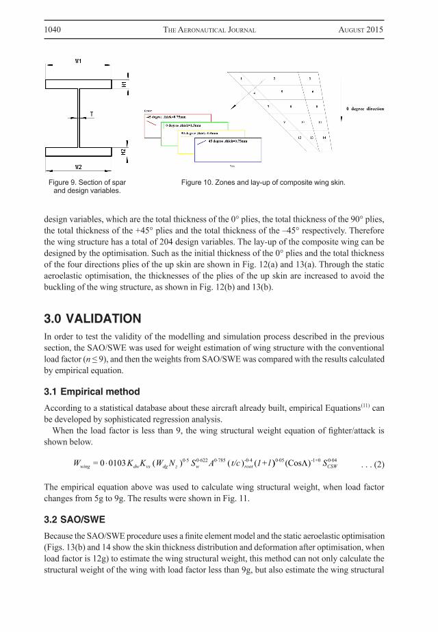
Figure 9 shows a section of spar and lists the design variables used in the optimisation. The up skin and down skin were separately divided into 15 zones shown in Fig. 10, and each zone has four
Figure 8. Flow chart of static aeroelastic optimisation(n – load factor, q – dynamic pressure, p – pitch rate).
1040 The AeronAuTicAl JournAl AugusT 2015
design variables, which are the total thickness of the 0° plies, the total thickness of the 90° plies, the total thickness of the +45° plies and the total thickness of the –45° respectively. Therefore the wing structure has a total of 204 design variables. The lay-up of the composite wing can be designed by the optimisation. Such as the initial thickness of the 0° plies and the total thickness of the four directions plies of the up skin are shown in Fig. 12(a) and 13(a). Through the static aeroelastic optimisation, the thicknesses of the plies of the up skin are increased to avoid the buckling of the wing structure, as shown in Fig. 12(b) and 13(b).
3.0 VALIDATIONIn order to test the validity of the modelling and simulation process described in the previous section, the SAO/SWE was used for weight estimation of wing structure with the conventional load factor (n ≤ 9), and then the weights from SAO/SWE was compared with the results calculated by empirical equation.
3.1 Empirical method
According to a statistical database about these aircraft already built, empirical Equations(11) can be developed by sophisticated regression analysis.
When the load factor is less than 9, the wing structural weight equation of fighter/attack is shown below.
. . . (2)
The empirical equation above was used to calculate wing structural weight, when load factor changes from 5g to 9g. The results were shown in Fig. 11.
3.2 SAO/SWE
Because the SAO/SWE procedure uses a finite element model and the static aeroelastic optimisation (Figs. 13(b) and 14 show the skin thickness distribution and deformation after optimisation, when load factor is 12g) to estimate the wing structural weight, this method can not only calculate the structural weight of the wing with load factor less than 9g, but also estimate the wing structural
Figure 9. Section of spar and design variables.
Figure 10. Zones and lay-up of composite wing skin.
W = K K W N S A t/c 1+lwing dw vs dg z w root0 0103 ( ) ( ) (0 5 0 622 0 785 -0 4 )) (Cos )0 05 -1×0 0 04 SCSW

Yi, Jun & Bin sTATic AeroelAsTic opTimizATion To wing sTrucTurAl weighT esTimATion of An... 1041
Figure 11. Relationship between wing structural weight and load factor(Wwing: wing structural weight, Wdg: Design gross weight).
(a) Initial
(a) Initial
(b) Optimised
(b) Optimised
Figure 12. Thickness distribution of the 00 plies (load factor =12g).
Figure 13. Thickness distribution of the skin (load factor = 12g).

1042 The AeronAuTicAl JournAl AugusT 2015
weight, when load factor is greater than 9g. The results were shown in Fig. 11. When load factor is less than 9g, the results from two different methods are coincident. It’s proved that SAO/SWE developed here is rational.
4.0 CONCLUSIONAn extremely manoeuvrable UAV is an innovative aircraft design, since its structure can endure the load factor that the existing aircraft cannot bear. Its weight information is beyond the scope of rational history data, thus an empirical method is inadequate for this innovative aircraft.
In order to solve this problem, a methodology has been developed here to estimate the structural weight of this type of aircraft. Through comparison with the empirical method based on history data, SAO/SWE procedure developed in this paper was proved to be rational. In this procedure the finite element model is used, so the structural weight of innovative conceptual aircraft can be estimated accurately, and the methodology developed here is only consisted of three compo-nents, which is less than existing method (shown in Fig. 1), thus it is faster and more suitable for innovative aircraft conceptual design.
Polynomial approximations of results from SAO/SWE were shown in Fig. 15. The polynomials are different when load factor exceeded 9g, and the relationship between wing structural weight and load factor are nonlinear, thus physics-based methods (SAO/SWE in this paper) have to be adopted when aircraft have extreme manoeuverability.
Figure 14. Static aeroelastic deformation (load factor = 12g).
Figure 15. Polynomial approximations of results from SAO/SWE.

Yi, Jun & Bin sTATic AeroelAsTic opTimizATion To wing sTrucTurAl weighT esTimATion of An... 1043
In the future, in order to improve the accuracy of SAO/SWE procedure, more complex aerody-namic methods (such as CFD) should be used, and multiple flight conditions (such as pull up and roll) should be considered by the multi-objective optimisation.
ACKNOWLEDGEMENTSThis work was supported by the Fundamental Research Fund of Northwestern Polytechnical University.
REFERENCE1. hürlimAnn, F. Mass Estimation of Transport Aircraft Wing box Structures with a CAD/CAE Based
Multidisciplinary Process, thesis, ETH Zurich, Switzerland, 2010.2. murphY, N.A.D. Analytical Wing Weight Prediction Estimation Using Computer Based Design
Techniques, Department of Aircraft Design, Cranfield Institute of Technology,1987.3. TorenBeek, E. Synthesis of Subsonic Airplane Design, Kluwer Academic Publishers, 1982.4. huAng, X., DuDleY, J., hAfTkA, r.T., grossmAn, B. and mAson, W.H. Structural weight estimation for
multidisciplinary optimisation of a high-speed civil transport, J Aircr, 1996, 33, (3), pp 608-616.5. giles, G.L. Equivalent Plate Analysis of Aircraft Wing Box Structures with General Planform Geometry,
Tech. Rep. NASA-TM-87697, National Aeronautics and Space Administration, March 1986.6. giles, G.L. Further generalization of an equivalent plate representation for aircraft structural analysis,
J Aircr, 1989, 26, (1), pp. 67-74.7. BrADleY, K.R. A Sizing Methodology for the Conceptual Design of Blended-Wing-Body Transports,
Tech. Rep. NASA CR-2004-213016, Langley Research Center, Hampton, Virginia, USA, September 2004.
8. lAughlin, T.w., cormAn, J.A. and mAVris, D.n. A Parametric and Physics-Based Approach to Structural Weight Estimation of the Hybrid Wing Body Aircraft, 51st AIAA Aerospace Sciences Meeting, AIAA 2013-1082.
9. zink, p.s., mAVris, D.m. and rAVeh, D.E. Maneuver trim optimisation techniques for active aeroelastic wings, J Aircr, 2001, (38), 6.
10. MSC. Software Corporation. Design Sensitivity and Optimisation User’s Guide, 2013.11. rAYmer, D.P. Aircraft Design: A Conceptual Approach, AIAA Education Series, 2002.