status of sfr development in korea · status of sfr development in korea fr13, paris, france ......
TRANSCRIPT

Status of SFR Development in Korea
FR13, Paris, France
2013. 3. 5
Yeong-il Kim

2 FR13, Paris, France, 4-7 March 2013
National Plan for SFR Development
Electrical
Heater
7 MWt
Air cooler
FW pump
SG
PHTS
pump IHTS
pumpIHX
545.0 oC
390.0 oC
30kg/s
320.7 oC
526.0 oC
320.0 oC
503.1 oC
23
0.0oC
230.0 oC
Pump
Drain tank
Plugging
indicator
Cold trap
hot air out
Air s
tack
hot sodium in
AHX
cold sodium out
cold air in
PDRC
AHX
Expansion tankArgon
LSDT
DHX
IRACS
Air Blower
Active AHX
System Performance
Test
Design Approval
Detailed Design
Prototype Reactor
Conceptual Design
‘07 ’11 ’16 ’20 ’28 ’26
2017: Safety Analysis Report for Prototype SFR
2020: Design Approval
2028: Completion of Construction

3 FR13, Paris, France, 4-7 March 2013
SFRA
Organized on 16th of May, 2012
Affiliated organization of KAERI
Goal of SFRA : acquisition of design approval for prototype SFR
Background of Organizing SFRA
Phase change in SFR development program
From key technology development in the past
To overall system engineering including SFR system design and
optimization, design v&v tests, major component development etc.
In order to perform prototype SFR development efficiently and
consistently
Project Period : 2012 ~ 2020 (9 years)
SFR development Agency (SFRA)

4 FR13, Paris, France, 4-7 March 2013
Organization of SFRA
Ministry of Education, Science and
Technology (MEST)
Committee for Promotion of
SFR Development
National Research
Foundation of Korea (NRF)
Director Steering Committee
Advisory Board Executive Office
NSSS Design
(KAERI)
Technology
Verification
(KAERI)
Fuel
Development
(KAERI)
BOP Design,
Component Design,
… (industry)
SFRA

5 FR13, Paris, France, 4-7 March 2013
NRF
MEST/ KAERI
Planning and Evaluation,
Funding Allocation
Policy and Public
Relations
Project Management
Role of SFRA
Design and R&D Team SFRA

6 FR13, Paris, France, 4-7 March 2013
Overview of Prototype SFR
Objectives
– Irradiation test of TRU fuels
–Acquisition of design, construction, and operation technologies
Safety analysis is being performed for conceptual design.
Major design features will be finalized in 2013.
MTRU Core
• LTRU and Recycled
TRU Fuels
• Closed Fuel Cycle
• TRU Burning Test
LTRU Core
• LTRU Fuel
• Open Fuel Cycle
• Recycled TRU Fuel
Test
Commercial SFR Burner
• LEU Fuel
• Open Fuel Cycle
• LTRU Fuel Test
LTRU : TRU from LWR spent fuels
MTRU : LTRU and recycled TRU
U Core

7 FR13, Paris, France, 4-7 March 2013
Pool-type Reactor
150 MWe
Fuel : U-Zr -> U-TRU-Zr
Core I/O Temp. : 390/545 ℃
DHR System : PDHRS/ADHRS
2-loop IHTS/SGS
Double-wall tube SG
Superheated Steam Rankine Cycle
Key Design Features (Draft)
AHX #1
AHX #2FHX #1
FHX #2
Steam
Generator#1
Steam Generator
#2
DRAC Piping
IHTS Piping
Guard Vessel
IHTS Pump#1
IHTS Pump#2
Reactor Vessel
Core
Reactor Support

8 FR13, Paris, France, 4-7 March 2013
Parameter Value
Core electric power (MWe) 150
Core thermal power (MWt) 392.6
Core mixed mean inlet/outlet temp. (℃) 390/545
Total flow rate (kg/s) 1,991.8
Effective full power days (EFPD) 290
Number of batches (inner core/outer core) 5/5
Active core height (m) 1.0
Enrichment (IC/OC) (wt.%) 14.0/19.5
Burnup reactivity swing (pcm) 1,184
Discharge burnup (MWD/kg) Avg. 50.2
Peak 78.7
Fast neutron flux (x1015 n/cm2·sec) Avg. 0.98
Peak 1.54
Peak fast neutron fluence (x1023 n/cm2) 1.95
Linear power density (W/cm) Avg. 104.7
Peak 180.0
Avg. power density (W/cm3) 143.6
Bundle pressure drop (MPa) 0.255
Uranium Core Configuration of a 150 MWe Prototype SFR
Fuel : U-Zr metal fuel of < 20 wt.% U-235
Cladding : D9 to secure the mechanical integrity
under the core exit temperature of 545C
D9 cladding dpa : < 100 dpa
Bundle pressure drop : < 0.26 MPa without
uncertainty
Cladding mid-wall temperature : < 650 C to ensure
the cladding CDF < 0.001

9 FR13, Paris, France, 4-7 March 2013
Fluid System Design
Primary Heat Transport System (PHTS)
- Pool type
- 4 IHXs
- 2 mechanical PHTS pumps
Intermediate Heat Transport System (IHTS)
- 2 loops
- 2 double-wall SG
- 2 IHTS pumps
Power Conversion System (PCS)
- Superheated steam Rankine cycle
Residual Heat Removal System (RHRS)
- 2 passive circuits (PDHRS)
- 2 active circuits (ADHRS)
SWR Pressure Relief System (SWRPRS)

10 FR13, Paris, France, 4-7 March 2013
System Heat Balance at 100% Plant Power

11 FR13, Paris, France, 4-7 March 2013
Simple reactor enclosure system
− Reactor vessel has a uniform thickness of 5cm
− There are no penetrations and no attachment on
the reactor vessel
Advanced design technologies
− Mechanical structure design of SSC will be carried
out to be compliance with the elevated temperature
design rules of ASME BPV III, division 5
− Horizontal seismic isolation design will be adapted
for a reactor island including a reactor building, an
auxiliary building, and a wastage/maintenance
building
Advanced design materials
− 9Cr-1Mo-V steel is used for the IHX, DHX, IHTS
piping, and steam generator
− The others such as reactor vessel, reactor internal
structures, and reactor head are composed of 316
stainless steel.
CRDM
Reactor Head
Reactor Support
Reactor Vessel
Guard Vessel
Vessel Liner
Baffle Plate
IHX
IVTM
Core Restraint
Pre-Heater
Receptacle
Center Pivot Core Support Structure
Core
Internal Piping
Separation Plate
TC Instrumentation
Flow Guide Structure
CR Shroud Tube
Upper Internal Structure
Primary Pump
Shielding Plates
Rotating Plug
Mechanical Structure Design
PHTS Arrangement of the Prototype SFR

12 FR13, Paris, France, 4-7 March 2013
STELLA (Sodium Test Loop for Safety Simulation and Assessment)
– Phase 1: STELLA-1
• Performance evaluation of key sodium components
• Heat exchanger design codes V&V
– Phase 2: STELLA-2
• Verification of dynamic plant response after reactor shutdown
• Construction of test DB to support specific design approval for the prototype SFR
Schedule
STELLA

13 FR13, Paris, France, 4-7 March 2013
Main test loop
– Test components
• Sodium-to-sodium heat exchanger
(DHX)
• Sodium-to-air heat exchanger (AHX)
• Mechanical sodium pump (PHTS
pump)
– Electrical loop heaters, EM pumps, Flow
meters, Expansion tanks,
Sodium storage tank
Working fluid Liquid sodium Total electric power 2.5 MW
Total sodium inventory ~ 18 ton Heat capacity of HXs 1.0MW
Design temperature 600oC Design pressure 10 bar
Max. flowrate for HX test 10 kg/s Max. flowrate for Pump test 125 kg/s
Overall Size (W×L×H): 15m×8m×22m
Overall Characteristics of STELLA-1
Sodium Expansion Tank
Mechanical Sodium Pump
Mechanical Sodium Pump Test
PerformanceCoastdownflow
Heater(1000kW)
Sodium-AirHeat Exchanger (AHX)
EM Pump
Blower
EM Flowmeter
Air Out
AHX and DHX Performance Test
Heat transfer characteristicsPressure drop characteristics
Air In
Sodium Storage
Tank
EM Pump
Cold Trap Plugging-meter
Sodium Purification
Heater
Flowmeter
Heater
Flow-meter
Sodium-SodiumHeat Exchanger (DHX)
Flowmeter
EM Pump
Flowmeter
Major Characteristics

14 FR13, Paris, France, 4-7 March 2013
Setup of sodium test facility for the
performance demonstration of under-
sodium visualization technology using
ultrasonic waveguide sensor
– Glove box system, sodium test tank
and storage tank
Design and manufacture of 10 m long
under-sodium ultrasonic waveguide
sensor module
– SS304 waveguide plate (15 mm
thickness)
– Ultrasonic transducer (1 MHz)
installed on the top of the waveguide
sensor module
C-scan performance test of under-
sodium waveguide sensor modules
under 200C liquid sodium
– Spatial resolution : 2 mm slit in
sodium
Development of Under-Sodium Viewing Technology
Sodium test experimental facility and prototype
under-sodium waveguide sensor modules
C-Scan performance test in sodium
2mm 1mm 0.8mm 0.5mm
Test Target Specimen C-Scan Images
Loose parts
(Step Block, Washer, Pin)
Glove
Box
Sodium
Test
Tank
Sodium
Storage
Tank
Bellows
Flange
Ultrasonic
Transducer
Radiation
End Section
Ar Gas
WG sensor (Sodium)
Be coating
(0.25 mm) Ni Plating
(0.1mm)
Rx Internals
ISI Concept

15 FR13, Paris, France, 4-7 March 2013
Fuel slug gravity casting system - Control of volatile elements during casting
Fuel slug fabrication - U-Zr-Ce-Mn slugs(Φ5.0 x 300mmL) with
varying compositions
• U-(5,10,15)Zr, U-10Zr-(2,4,6)RE, U-
10Zr-5Mn, U-10Zr-RE-Mn
• Mn retention(higher than 94%)
- Casting conditions(temperature, pressure,
heating rate, time) optimization
Fuel rod fabrication - Sodium bonding
- End plug welding
- Fuel rod wiring
(U,Si)Zr2
Zr ppt
U-10Zr
Chamber
Mold
Coil
Control Panel
Vacuum Pump
Pressurizer
Chamber
Mold
Coil
Control Panel
Vacuum Pump
Pressurizer
Ce ppt
10Zr
Microstrucure of U-10Zr and U-10Zr-Ce
Fuel Slug and Gamma Radiography
Fuel Rods for HANARO Irradiation Test Fuel Rod Wiring
Na Bonding
Sodium level
Fuel Slug Cladding
He
Fuel Fabrication

16 FR13, Paris, France, 4-7 March 2013
Advanced FMS cladding alloy
development
- Alloy design and manufacturing
• 38 alloys in 3 batches
- Performance tests
• Microstructure examination
• Mechanical / sodium compatibility tests
Creep rupture strength (650oC)
improved by more than 35 % from HT9
Cladding tube fabrication - Process investigation
• Large ingot(1 ton) melting, hot extrusion,
pilgering and drawing
• Effect of cold work and heat treatment
- Cladding tubes of HT9 and Gr.92
(OD7.0mm x WT0.56mm x L3,000mm)
- Performance tests
100 1000100
650 oC
Str
es
s (
MP
a)
Time to Rupture (hr)
HT9
T92
PNC-FMS
KAERI Batch 1
+ Mo + W
+ W
Solid Solution
Strengthening
Solid Solution
Strengthening
+ V + Nb
+ V + NbC, N, B Ta
Precipitation
Strengthening
Precipitation
Strengthening
Strengthening mechanisms of FMSStrengthening mechanisms of FMS
Orange: M23C6
Green: Laves phase
Purple: Z phase
Gray: MX
M23C6
Nb2C
(VNbTa)CN
M23C6
M23C6
M23C6
M23C6
M23C6
(VNbTa)CN
ZA//[110]
1-11-111
Cladding Development
17 FR13, Paris, France, 4-7 March 2013
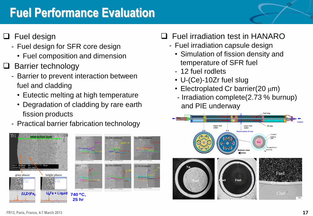
Fuel design
- Fuel design for SFR core design
• Fuel composition and dimension
Barrier technology
- Barrier to prevent interaction between
fuel and cladding
• Eutectic melting at high temperature
• Degradation of cladding by rare earth
fission products
- Practical barrier fabrication technology
Fuel irradiation test in HANARO - Fuel irradiation capsule design
• Simulation of fission density and
temperature of SFR fuel
- 12 fuel rodlets
• U-(Ce)-10Zr fuel slug
• Electroplated Cr barrier(20 μm)
- Irradiation complete(2.73 % burnup)
and PIE underway
Fe
Ce
LaCr
Fe
Cr
Ce
La
Fe
Ce
LaCr
(a) Zr (c) ZrN (Gradient)(b) ZrN (Uniform)
Fe
Cr
Ce
La
VFe
Cr
Ce
La
VFe
Ce
LaCr
V
(d) V (e) VN (Uniform) (f) VN (Gradient)
740 C,
25 hr
Lower fuel rodlet
Upper fuel rodlet
Coolant
Fuel slug
Hf tube
A-AB-B Neutral plane of core
Bottom view
Fuel
Cr barrier
Clad
Fuel Performance Evaluation

18 FR13, Paris, France, 4-7 March 2013
Summary
National SFR development program
Design approval of a prototype SFR by 2020
Construction of a prototype SFR by 2028
SFRA was established in May 2012 for efficient and consistent
development of a prototype SFR
Project Budget Funding and Management of SFR Development Project including NSSS,
BOP, Component Design, and Development of Related Technologies
Current R&D activities for a prototype SFR
Conceptual design is being developed from 2012
NSSS design and related v&v tests, metal fuel development by KAERI
BOP and component designs by industries