status of transmission line and expansion plan in nepal s. rajbhandari
TRANSCRIPT

STATUS OF TRANSMISSION LINE AND EXPANSION PLAN IN NEPAL
S. Rajbhandari
Components of Power System
Electrical power system mainly consist of three systems or components:
Generating system Transmission system Distribution system
Generating system consists of generating stations or power houses where stored in various forms (examples: water at height, heat energy in coal or oil or nuclear energy in the atoms of fissionable fuels) are converted into electrical energy.

Components of Power System contd.
Transmission system transmits electrical energy in bulk, generally from generating stations to the primary substations.
Distribution system is the system from which electrical energy is distributed to various consumers such as domestic, commercial, industrial, non commercial etc.

NEA Transmission System
Grid (INPS) extends from east to west, ie., Anarmani- Mahendranagar
Major hydro stations connected to the grid. GSS Capacity: 1310 MVA 132 kV line length: 2076 cct Km 66 kV line length: 586 cct Km

NEA Transmission System contd.
Principal voltage of grid system is 132 kV. Majority of the lines constructed with
double circuit, except for Bardghat-Hetauda section
Constructed with conductor BEAR and DUCK except for Bardghat-Hetauda and Bharatpur-Pokhara
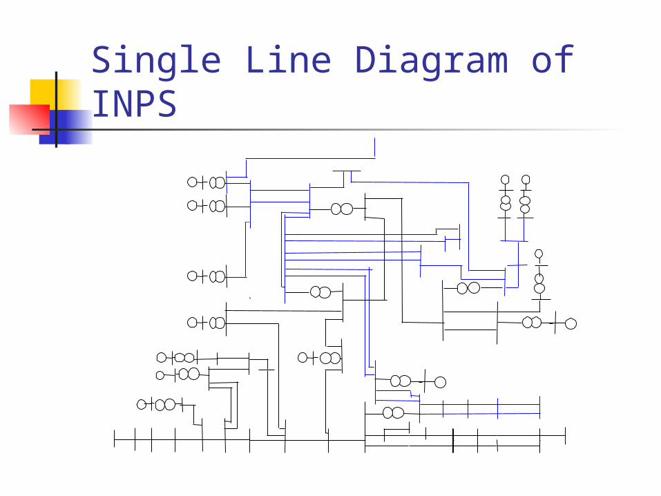
Single Line Diagram of INPS
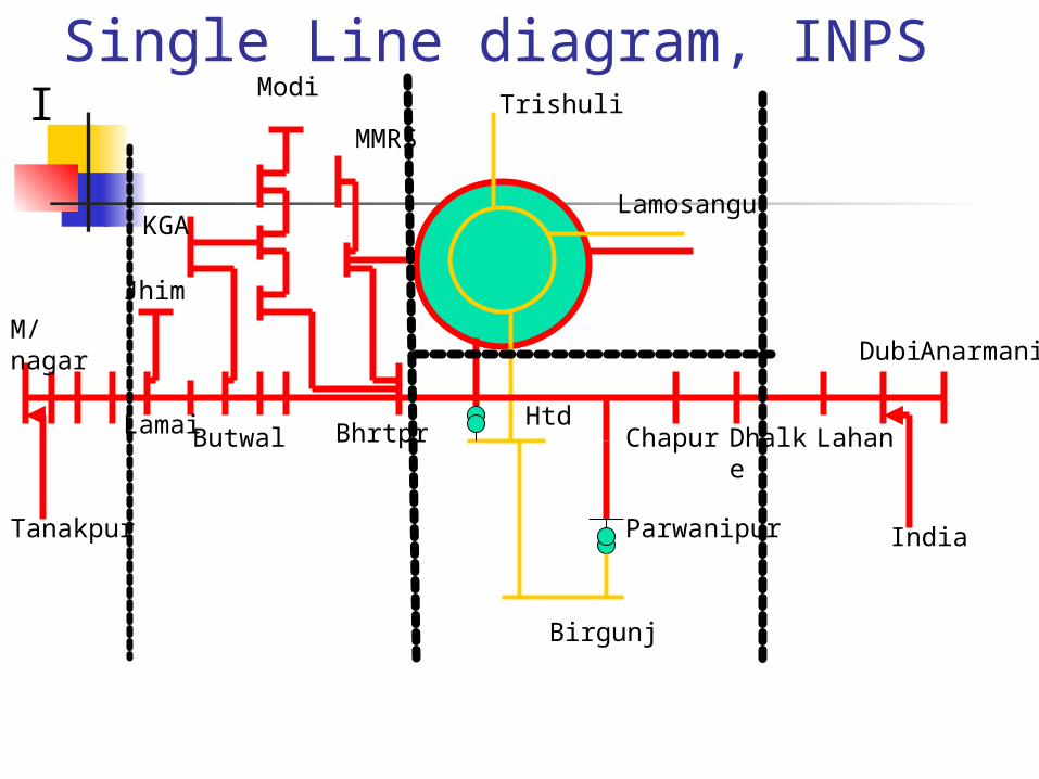
Single Line diagram, INPSI
Lamosangu
Trishuli
AnarmaniM/ nagar
KGA
Modi
Butwal
MMRS
BhrtprHtd
Parwanipur India
Chapur Dhalke
Dubi
Lahan
Jhim
Lamai
Birgunj
Tanakpur

Integrated Nepal Power System (INPS) Map
(NOT TO SCALE)

Why Transmission System Expansion ?
To provide greater reliability and capacity To increase the ability to distribute
available power to meet existing and future demands
To meet NEA’s contractual obligation for transmission with various power producers
To increase NEA’s ability to import/export power

Transmission Development Before 1985: No systematic planning carried out. Transmission expansion mainly by ED, tandem of new
HEP. Major transmission Projects (about 800 km)
Trishuli – Balaju – Hetauda – Birgunj Sunkoshi – Patan Gandak – Bharatpur – Hetauda Devighat – Chabel Bardghat – Butwal - Kohalpur Hetauda – Dhalkebar Bharatpur – Pokhara Suichatar – KL2 - Hetauda

Transmission Development contd. Period Between 1985 - 1992 Transmission network planning started in 80s. NEA Act implemented for effective monopoly NEA Prepared and updated its corporate plan
Long term demand forecasting
LCGEP TSMP Distr. Plan

Transmission Development, 85-92 NEA LCGEP, TSMP & DEP treated as
national plans. NEA responsible for phased
implementation Grid interconnection domestic or interdepartmental affair.
Major Transmission Projects during the period (approx.500km) :
Dhalkebar – Duhabi – Anarmani Kohalpur – Mahendranagar Balaju – Marshyangdi - Bharatpur

Transmission Development after 1992 Period after 1992: New Electricity Act; Hydropower Development
Policy IPPs have access to generation; NEA the grid owner and IPPs the grid user for
existing grid. Absence of national Grid code led many issues
related to grid planning, expansion, operation, interconnection to remain as grey areas.
Grid Interconnection no more interdepartmental issue

Transmission Development after 1992
NEA faced four problems: What level of generation development to be
considered/planned for transmission expansion? IPPs have license throughout country.
Which expansion to be given priority? What performance standards to be adopted for
expansion planning? Source of funding. Where does the money will
come from for transmission expansion?

Mismatched Triangle NEA, IPPs and Government bodies
IPPs
Roles / responsibilitiesAs per Electricity Act
Single buyer marketMissing
Roles ResponsibilitiesFunctionalities Structures
NEA
Roles and Responsibilities as per NEA Act
Monopoly operation
Forced to single buyer
Government bodiesMOWRWECSDOED
Transmission Development after 1992
IPPs are awarded license wherever they apply for and wish to develop power projects where they have license for.
IPPs expect NEA to provide evacuation/ interconnection where they want.
Their proposals for power evacuation include: either to break the existing trunk lines for
interconnection or new transmission line to be constructed by
NEA.

Transmission Development after 1992
NEA refuses: interconnection that harm grid security to add transmission capacity due to lack of
funds. Rigid stands taken by both NEA & IPPs helped to
create bottlenecks or congestion. Ultimately very little transmission expansion
realized. Such expansions include (approx. 345 km):

Transmission Development after 1992
Khimti – Lamosangu – Bhaktapur ( NEA) Lekhnath – Kaligandaki – Butwal (NEA) Chilime – Trisuli (NEA) Pathlaiya – Parwanipur (NEA) Bhotekoshi – Lamosangu (Private) Indrawati – Paanchkhal (Private) Jhimruk – Lamahi (Private)

Current Situation
The conflicting interests created transmission bottlenecks.
Transmission congestion in many sections of the INPS.
NEA transmission plan focuses on meeting its internal demand and limited export.
The TSMP envisages a 220 kV backbone for the purpose.

INPSWestern Area
M/ nagar
KGA
Modi
Butwal
MMRS
BhrtprHtd
Jhim
Lamai
Tanakpur
Pokh
Lekh
Damau
KawasotiBard
MRS

INPSCentral and East
Lamosangu
Trishuli
Anarmani
Htd
Parwanipur India
Chapur Dhalke
Dubi
Lahan
Birgunj
Bharatpur
MRS

Transmission Line Reinforcement Plan
S. No. Transmission lines Proposed year Status
1 Birgunj Corridor 132 kV 2006/07 abandoned
2 Butwal Sunauli 132 kV 2007/08 abandoned
3Thankot-Chapagaon-Bhaktapur 132 kV
2007/08 Under const.
4 Khimti Dhalkebar 220 kV 2007/08 Under const.
5
Kohalpur-Lamahi-Shivpur-Butwal and Khimti Dhalkebar second circuit stringing 2007/08 Planned
6 Hetauda-Bardghat 220 kV 2009/10Under const. (Het-
Bharatpur)
7 Bardghat-Butwal 220 kV 2011/12 Planned
8 Hetauda-Thankot 220 kV 2011/12 Planned
9Bharatpur-Hetauda 220 kV second circuit stringing
2011/12 Planned

Transmission Lines Planned/Proposed for Power Evacuation
S. No. Transmission lines Proposed year Status
1 MiddleMarsyangdi-Marsyangdi 132 kV 2006/07 Completed
2 Kul III-Hetauda 132 kV 2008/09 abandoned
3 Upper Modi-Modi Khola 132 kV 2009/10 Planned
4 Madi I-Lekhnath 132 kV 2009/10 Planned
5 Chamelia-Ataria 132 kV 2010/11 Planned
6 Mewa -Tamor 132 kV 2010/11 Planned
7 Hewa-Kabeli 132 kV 2010/11 Planned
8 Lower Modi-Modi 132 kV 2010/11 Planned
9 Sanjen-Chilime 132 kV 2010/11 Planned
10 Upper Mars-Middle Mars 132 kV 2011/12 Planned

Transmission Lines Planned/Proposed for Power Evacuation contd.
S. No. Transmission lines Proposed year Status
11 Kabeli-Duhabi 132 kV 2011/12 Planned
12 Upper Tamakosi-Khimti 220 kV 2012/13 Planned
13 Tamor-Kabeli 132 kV 2013/14 Planned
14 Kankai-Duhabi 132 kV 2013/14 Planned
15 Upper Karnali-Kohalpur 132 kV 2013/14 Planned
16 Upper Seti-Bharatpur 220 kV 2013/14 Planned
17 West Seti-Ataria 132 kV 2014/15 Planned
18 Likhu-Khimti 132 kV 2017/18 Planned
19 Rahughat-Pokhara 132 kV 2017/18 Planned
20 Dudh Kosi-Dhalkebar 220 kV 2018/19 Planned
21 Andhi khola-Butwal 132 kV 2020/21 Planned
22 Lamosanghu-Singati 132 kV T/L Planned

Planning Dilemma For what capacity to plan the transmission
network? Who can expand transmission when nobody knows what is required? For 83000 MW / 42000 MW? Or for 3200 MW for 2025/26?
Planning horizon? Operational planning of one year. Medium term 1 to 5 years Long term more than 5 years
Where does the money come from if NEA is to satisfy IPPs’ demand?
Over investment: low network utilization

Planning Dilemma contd.
Under investment: limit the use of renewable, increase congestion
A transmission system should have ample margin to allow for contingencies and should deal with the uncertainties of long range forecasts.
A properly designed transmission system provides a good distribution of power flows by avoiding excessive geographic concentrations of generating sources or transmission paths.

Planning Dilemma contd. Performance standards provide the basis for
determining whether system response to the contingency tests is acceptable. What limits/ values to be adopted for these performance standards: thermal, voltage, relay, stability and short circuit.
The maintenance is another issue. An economic network or maintain economy in the life cycle.
What contingency levels to be followed? N-1, N-2 or N-3?
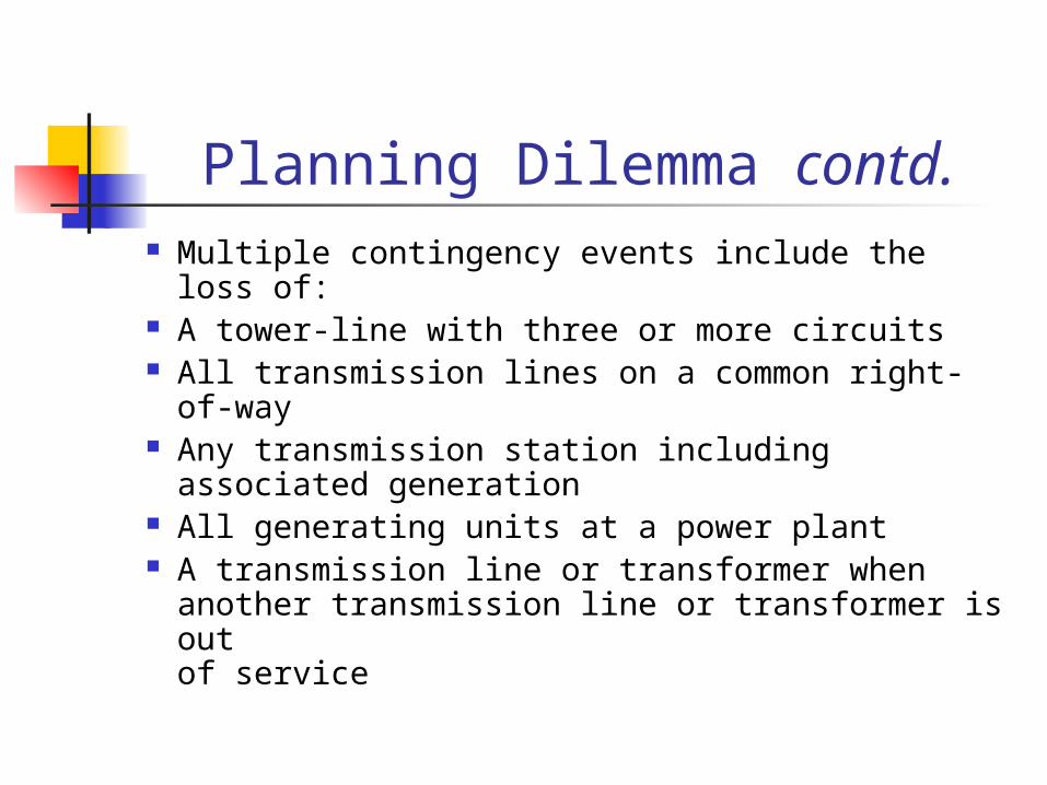
Planning Dilemma contd. Multiple contingency events include the loss of: A tower-line with three or more circuits All transmission lines on a common right-of-way Any transmission station including associated
generation All generating units at a power plant A transmission line or transformer when another
transmission line or transformer is out of service

Development Options and Issues
Generation and Transmission expansion case of chicken or egg story.
For unhindered development of transmission network, Develop networks on the basis of investment, ownership and purpose : INPS owned by Central Transmission Utility (CTU) Commercial or merchant lines of private companies Cross border lines connected to INPS Dedicated cross border lines
Development Options and Issues
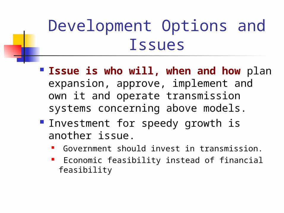
Issue is who will, when and how plan expansion, approve, implement and own it and operate transmission systems concerning above models.
Investment for speedy growth is another issue. Government should invest in transmission. Economic feasibility instead of financial feasibility

Development Options and Issues Shall we have a Central Transmission Utility (CTU)? If we have a CTU then shall we have more than one
domestic transmission operators? How shall we attract private investment in transmission? How to fix wheeling charges: MW Miles, capacity
booked or postage stamp Shall we issue transmission licenses anywhere,
everywhere like generation licenses?

Development Options and Issues For what capacity shall we develop our network :
Shall we have separate domestic and export networks? Or allow domestic network for sole export plants?
What will be interface of domestic and export network, AC Synchronous or HVDC back to back?
How shall we export internal surplus through domestic network?
NEA as net integrator and nodal agency? Generators themselves? (Use of CTU network) Trading companies (Use of CTU network)

Transmission System for Future Plan for a long horizon. North South River basin plans:
Kosi Basin Gandak basin Karnali-Mahakali Basin
Southern East West Trunk Line Mid Hill East West Trunk Line Export System

Overall INPS Scheme (Courtesy: S.S. Bhat)
Modi Damauli
Lamki
Butwal
Kathmandu Khimti
Dhalkebar
DuhabiHetaudaBharatpur
Trishuli

Basin Transmission Plan (Courtesy: S.S. Bhat)
90~120 km
MPP to Trunk Line : 30~40 kmSPP to SPP or MPP: 30~60 kmMini PP to Mini PP or SPP or MPP : 20~30 kmWe are pulling North South lines for each P/S
Mini Pooling PointSub Pooling Point
Main Pooling Point
Mid hill trunkline
SouthernTrunk line
Thank You