steam sterilization handbook · 2020-05-07 · and ultrafiltration membrane filter cartridges....
TRANSCRIPT

GE Healthcare
Steam Sterilization HandbookHollow fiber cartridges for membrane separations
18-1174-71 AA

Steam Sterilization Handbook 3
Table of contents
Important safety considerations 5
IntroductionAbout this handbook 6Target audience 6Where to find more information 6Getting help 6Safety 6Specific advice to help you work safely 6Return authorization 7Warranty 7List of figures 8
Chapter 1—Housing design and assemblyHousing and cartridge design 9
Housing design 10Membrane filter cartridge element design 10How to install a membrane filter cartridge element in a housing 10
Installing an STM cartridge element in an STM housing 10Installing an SMO cartridge element in an SMO housing 10Installing an MSM cartridge element in an MSM housing 11
Where and how to install the filter 12Where to install the housing 12How to install the housing 13
Chapter 2—Expert tipsIntroduction 14General recommendations 15
Streamlining the steam-in-place process 15Process design for effective sterilization 15
Chapter 3—Steam sterilizing procedureThe five SIP stages 16
Stage 1—Configure system for steaming 17Stage 2—Introduce steam, flush, and hold 18Stage 3—Cool and pressurize 19Stage 4—Check filter integrity 20Stage 5—Configure system for processing 21
Index 23

4 Steam Sterilization Handbook

Important safety considerations• Always ensure that all lines and components of your system
are steamable.
• Do not run steam through retentate side only. Steam must beintroduced equally on retentate and permeate sides—see chapter 3 for complete steam sterilizing procedure.
• Ensure that no crimping, blockage, or unwanted valve shutoffoccurs, to prevent rupture or component failure.
• Ensure that steam traps are positioned at low point drains toprevent condensate from cooling in the recirculation loop orpermeate at any point.
• Know—and do not exceed—the maximum operating pressure of your system components.
• Monitor pressure with appropriate instrumentation during sterilization.
• Install cartridges with all requisite O-rings, connectors, and/or clamps.
• Develop and enforce standard operating procedures for effective sterilization.
• Work to maintain sterility by ensuring that no contaminant can enter the system prior to production.
• Check membrane filter cartridge and housing integrity aftersterilization—see page 20 for details.
• Ensure that all system valves, lines, and configurations are set forprocessing before transitioning from sterilization to production.
• Steam that undergoes an abrupt expansion at high flow ratescan carry latent heat, commonly called “superheated steam.”The high temperatures in superheated steam can cause damage to polymers and elastomers. Superheated steam canbe avoided by properly reducing pressure through a sequenceof regulators. The steam pressure on the upstream side of theregulator used to control the pressure on these membranesshould not exceed 2 barg (30 psig).
Steam Sterilization Handbook 5

Introduction
About this handbookThis handbook describes how to assemble, install, and steam sterilize GE Healthcare STM, SMO, and MSM membrane filter cartridges.
This handbook shows the general system features necessary to comply with the steps outlined in the protocol presented. Forexample, the bypass valves that are used to warm the systemunder low pressure conditions are critical to this sequence ofoperations. The membrane filter cartridge expands more than thestainless steel housing and the warming process is necessary toavoid thermal stress that could lead to a breach of integrity.
This handbook is designed for online viewing and navigation usingAdobe® Acrobat®. Print the Acrobat file to obtain a hard copy. Youcan download this handbook from the GE Healthcare Web site.
Target audienceThis handbook is intended for experienced users of microfiltrationand ultrafiltration membrane filter cartridges. Specifically, thehandbook addresses the needs of scientists, process engineers,and technicians who operate research, laboratory, pilot, and production filtration systems.
To use this handbook, you should know how to complete basictechnical procedures. For example, you should be qualified to setup laboratory and pilot equipment; measure temperatures, pres-sures, and flows; and understand filtration applications. If you donot have these capabilities now, call GE Healthcare for assistance.See “Getting help” on this page for contact information.
Where to find more informationThis handbook is a supplement to the Operating Handbook,Hollow fiber cartridges for membrane separations. In addition, GE Healthcare publishes easy-to-use handbooks related to itscross flow filtration equipment. You can view and download these handbooks from our Web site, www.gehealthcare.com
Getting helpContact GE Healthcare customer and technical support teams bycalling 1-800-526-3593 in the USA, or by contacting your local GE Healthcare office.
SafetyWhen using any laboratory, pilot scale, or production filtrationequipment, the potential exists for personal injury unless you follow established safety procedures. When using GE Healthcaretest procedures and products, you should follow OSHA, federal,state, and local safety mandates and regulations. You should follow your company’s safety procedures and the safety instruction provided in this handbook.
This handbook uses highlighted text with safety flags to providesafety information and expert advice:
Specific advice to help you work safelyPotentially, the heat or pressure of steam can rupture a weakenedor improperly assembled connection, kinked hoses or lines, andother system components. Such a rupture can expose personnelto high pressure steam and cause severe injury.
To avoid the unexpected rupture of a filter system or connectiondue to improper assembly or overpressurization you should:
• Ensure you read the entire handbook before sterilizing a cartridge with steam
• Ensure all system components are steamable
• Ensure all system components are assembled correctly
• Know—and do not exceed—the maximum operating pressure of your system components
The Operating Handbook, Hollow fiber cartridges for membraneseparations, describes the maximum operating pressure of thecartridge filters. To avoid exceeding the maximum operating pressure and to monitor the sterilization process effectively, it iscritical that you install pressure gauges on the system asdescribed in this handbook.
To avoid injury in the event of an unexpected steam leak, wearappropriate personal protection gear in accordance with yourcompany’s safety policy (or national or regional regulations).
6 Steam Sterilization Handbook
Figure 1. Other handbooks in the cartridge filter documentation set
Operating Handbook, Hollow fiber cartridges for membrane separations, a downloadable handbook posted on our Web site and available in hard copy from GE Healthcare and its distributors
Selection Handbook, Hollow fiber cartridges and systems for membrane separations,a downloadable handbook posted on our Web site and available in hard copy fromGE Healthcare and its distributors
� Safety
WARNING: A safety warning flag describes conditionsor actions that can cause bodily harm and describeshow to avoid the risk.
� Expert Advice
TIP: An expert advice tip flag provides information touse your hollow fiber membrane cartridge and systemefficiently to achieve the best results.

Return authorizationTo return a cartridge purchased from GE Healthcare in the USA,call us at 1-800-526-3593 to obtain a return authorization number.Clean, sanitize, and securely package cartridges before returningthem. Ship microfiltration cartridges dry. Include the details of itsoperational history—for example, pages from a laboratory notebook. Ship it prepaid to GE Healthcare Corporation, P.O. Box1327, Piscataway, NJ 08855-1327, USA. We will repair or replace defective cartridges. Outside the USA, you can contact your local GE Healthcare representative using the telephone numbers listed on the back cover of this handbook.
WarrantyGE Healthcare Corporation warrants its hollow fiber cartridges to be free from defects in workmanship and materials for a periodof 30 days after the date of shipment from GE Healthcare or itsauthorized dealers, provided that the cartridges have been operatedin accordance with GE Healthcare published specifications andgood engineering practices.
GE Healthcare shall have no liability under this warranty or other-wise for improper application or abuse of the subject cartridge orcartridges. This warranty is exclusive of all other implied warrantiesincluding merchantability or fitness for a particular purpose.
The information contained in this handbook is not intended to constituteany representation of warranty by GE Healthcare Corporation.
Steam Sterilization Handbook 7

List of figuresFigure 1. Other handbooks in the cartridge filter documentation set 6Figure 2. Cutaway view of an STM cartridge element in an STM housing 10Figure 3. Position of components of SMO membrane filter cartridge and housing 10Figure 4. MaxCell™ MSM cartridge and housing 11Figure 5. Typical installation of steam-in-place equipment 12Figure 6. Connection specifications for representative sizes of STM, SMO, and MSM housings 13Figure 7. Starting setup for Stage 1—configure system for steaming 17Figure 8. Starting setup for Stage 2—introduce steam, flush, and hold 18Figure 9. Starting setup for Stage 3—cool and pressurize 19Figure 10. Starting setup for Stage 4—check filter integrity 20Figure 11. Starting setup for Stage 5—configure system for processing 21
8 Steam Sterilization Handbook

Steam Sterilization Handbook 9
Housing design and assembly
This chapter describes:• Housing and cartridge design
• How to install a cartridge in a housing
• Where and how to install a housing in your filtration system
Housing and cartridge designGE Healthcare manufactures three models of steamable housings and membrane filter cartridge elements identified bymodel designations STM, SMO, and MSM. The SMO and STM families are based on a 7.6-cm (3-in) diameter element. SMO cartridges have an open face and a single O-ring seal at eachend. STM units have end caps at each face that neck down to a double O-ring seal for connection to stainless steel end fittings.Larger MSM steam-in-place (SIP) elements have a nominal 10.2-cm (4-in) diameter and an open face configuration.
Chapter 1

Housing designHousings are constructed of stainless steel and accept steamable,replaceable membrane filter cartridge elements. O-rings and endplates seal the membrane filter cartridge element in the housing.Sanitary connectors on the housing end plates enable connectionto your filtration system (Fig 2).
Additional 0.5-in sanitary connections are used for low point condensate drain and steam trap installation.
Membrane filter cartridge element designHollow fiber membranes are cast of polysulfone, and are designedand tested for the temperatures and pressures required for auto-claving and steam-in-place sterilizing as described in this handbook.Membrane filter cartridges are machined of polysulfone also. Thefiber bundles are held within the cartridge by coarse polypropylenescreens. Fibers are potted at each end in CFR-listed food gradeepoxy. All components conform to USP XXVII Class VI Biological Test for Plastics.
GE Healthcare supplies three families of steam-in-place designs:STM, SMO, and MSM. The SMO and STM designs have a diameterof 7.6 cm (3 in), while the MSM design is 10.2 cm (4 in). Each designis unique and requires a dedicated, matching membrane filtercartridge and housing. These devices are not interchangeable,although each of the designs incorporates similar features.
How to install a membrane filter cartridge element in a housingInstalling an STM cartridge element in an STMhousingFollow these steps to install an STM cartridge element into an STMhousing (see Fig 2):
1. Install double O-rings at each end of the cartridge.
2. Place the stainless steel housing horizontally on a work benchand slide the cartridge element into the housing.
3. Holding the cartridge at one end, push a retentate end cap with 3-in gasket over the double O-rings at the other end of theelement. Repeat this process to install the gasket and retentateend cap on the other end of the element.
4. Clamp the housing using the supplied 7.6-cm (3-in) Tri-Clamps®.
Installing an SMO cartridge element in an SMOhousingFollow these steps to install an SMO cartridge element into anSMO housing (see Fig 3):
1. Place the stainless steel housing horizontally on a workbench(see Fig 3 for positioning).
2. Position an O-ring around one end of the cartridge and push itinto place using an end cap.
3. Slide membrane filter cartridge (which now has one O-ring inposition) into one end of housing. Clamp end cap.
4. Add a second O-ring as shown below and clamp end cap.
10 Steam Sterilization Handbook
Figure 2. Cutaway view of an STM cartridge element in an STM housing
Figure 3. Position of components of SMO membrane filter cartridge and housing

Steam Sterilization Handbook 11
Installing an MSM cartridge element in an MSMhousingFollow these steps to install an MSM cartridge element into anMSM housing (see Fig 4):
Figure 4. Maxcell MSM cartridge and housing
The design of the MSM housing and retentate end cap requires a Tri-Clamp gasketbetween the housing and end cap.
� Expert Advice
TIP: Do not strike the cartridge face. Use only handpressure to apply a steady downward force.
2a. To properly center the membrane filter cartridge inside thehousing, place the housing on a protective surface in a verticalorientation. Pushing down on the face of the cartridge, forcethe cartridge into the housing until the lower face makes contact with the surface of the table.
2b. Lay the cartridge in a horizontal position and continue to pushthe cartridge into the housing until the O-ring groove emergesfrom the other end.
1. Install an O-ring on the groove at one end of the cartridge element. If the O-ring seems snug, moisten the O-ring with highpurity water for lubrication.
3. Place the second O-ring in the groove and return the cartridgeto a vertical orientation (housing down/cartridge up) and pushthe cartridge down until centered in the housing.
4. Secure the endplates with Tri-Clamp gaskets and clamps.

12 Steam Sterilization Handbook
Where and how to install the filterWhere to install the housingTo complete steam-in-place sterilization, you must integratesteam lines, steam traps, additional valves, and instrumentationinto the filtration system. Specific installation requirements anddesign can vary according to process variables; however, a typical setup includes a steam line piped into the retentate portand a steam condensate line with a steam trap and isolationvalve piped into the feed line (Fig 5).
� Expert Advice
TIP: We recommend that you connect the vent valveto an air line pressurized to about 1.03 barg (15 psig)to permit the use of an air “overpressure” conditionat the end of the cycle, to ensure that no unsterilizedair can infiltrate the system.
You should place a hydrophobic 0.2-micron micro-porous filter in the vent line to maintain sterility.
You may be able to use steam traps as small as 0.25 in, depending upon the size of your system.
Steam inletRetentate outlet
Steam topermeate side
Permeate outlet
Low-pointpermeate drain
Condensate
Steam trapbypass valve
Condensate
Feed inlet
GE Healthcare filter
Steam trapisolation valveP
ST
ST
P
Steam trapisolation valve
Steam trapbypass valve
Closed valve
Partially open valve
Open valve
Pressure gauge
Steam trap
0.2 micron filter (optional)
P
ST
Retentate steam inlet valve
Steam toretentate side
Air inlet/vent valve
Permeate steam inlet valve
Permeate outlet valve
Figure 5. Typical installation of steam-in-place equipment

Steam Sterilization Handbook 13
How to install the housingPipe the housing into your system using established standardsfor piping and pipe support. Consult national, regional, local, andyour company’s piping regulations and guidelines.
Steamable housing models STM, SMO, and MSM use sanitaryconnectors to connect feed, retentate, permeate, drain, and vent ports. Connect the ports to your system using sanitary connectors, O-rings, and Tri-Clamps (Fig 6).
Figure 6. Connection specifications for representative sizes of STM, SMO, and MSM housings
Housing 35STMLength = 43.4 cm (17.1 in)Diameter = 9.1 cm (3.6 in)Permeate ports = 1.5-in Tri-ClampFeed/retentate ports = 1.5-in Tri-ClampDrain/vent ports = 0.5-in Tri-Clamp
Housing 55STMLength = 75.2 cm (29.6 in)Diameter = 9.1 cm (3.6 in)Permeate ports = 1.5-in Tri-ClampFeed/retentate ports = 1.5-in Tri-ClampDrain/vent ports = 0.5-in Tri-Clamp
Housing 35SMO-DPLength = 37.3 cm (14.7 in)Diameter = 9.1 cm (3.6 in)Permeate ports = 1.5-in Tri-ClampFeed/retentate ports = 1.5-in Tri-ClampDrain port = 0.5-in Tri-Clamp
Housing 55SMO-DPLength = 69.3 cm (27.3 in)Diameter = 9.1 cm (3.6 in)Permeate ports = 1.5-in Tri-ClampFeed/retentate ports = 1.5-in Tri-ClampDrain port = 0.5-in Tri-Clamp
Housing 45MSM-DPLength = 52.8 cm (20.8 in)Diameter = 11.4 cm (4.5 in)Permeate ports = 1.5-in Tri-ClampFeed/retentate ports = 2-in Tri-ClampDrain port = 0.5-in Tri-Clamp
Housing 65MSM-DPLength = 75.7 cm (29.8 in)Diameter = 11.4 cm (4.5 in)Permeate ports = 1.5-in Tri-ClampFeed/retentate ports = 2-in Tri-ClampDrain port = 0.5-in Tri-Clamp
Housing 85MSM-DPLength = 134 cm (52.7 in)Diameter = 11.4 cm (4.5 in)Permeate ports = 1.5-in Tri-ClampFeed/retentate ports = 2-in Tri-ClampDrain port = 0.5-in Tri-Clamp
Optional elbow adapters are available for85MSM stainless steel housing (SS-85MSM-EL-DP)

14 Steam Sterilization Handbook
IntroductionIn many cross flow filtration applications—particularly in thepharmaceutical and biotechnology fields—the sterility of the filtermust be ensured before using it. Steaming-in-place is onemethod to sterilize cartridge filters. Steaming-in-place requiresthe proper equipment, operated properly and consistently, toensure complete sterilization and validation. Therefore, the goalof this chapter is to provide recommendations and techniques tohelp ensure efficient and effective steam sterilization.
Chapter 2
Expert tips

General recommendationsStreamlining the steam-in-place processFrom an operational standpoint, here are some steps that can betaken to streamline the steam-in-place process:
• Permanently install the steam-in-place components on the filtration system to save setup time and not disturb the process system.
• Ensure all components in the system, such as values and pressure gauges, are steamable by reviewing equipment specifications. Using steamable process equipment ensuressafety and minimizes component replacement and maintenance.
Process design for effective sterilizationCartridge integrity and proper sterilizing steps are required to helpensure sterilization.
Establish, through trials, a sterilization procedure that provides the desired results. Validate this procedure, and write and usestandard operating procedures (SOPs) for consistency.
Superheated steam can overheat the cartridge, causing damageto the cartridge or influencing membrane performance. Ensurethe temperature and quality of the steam is consistent.
As part of your SOP, check all valve positions before operating orsteam cleaning your system.
Do not induce a backpressure on the membrane cartridge.
Steam Sterilization Handbook 15
16 Steam Sterilization Handbook
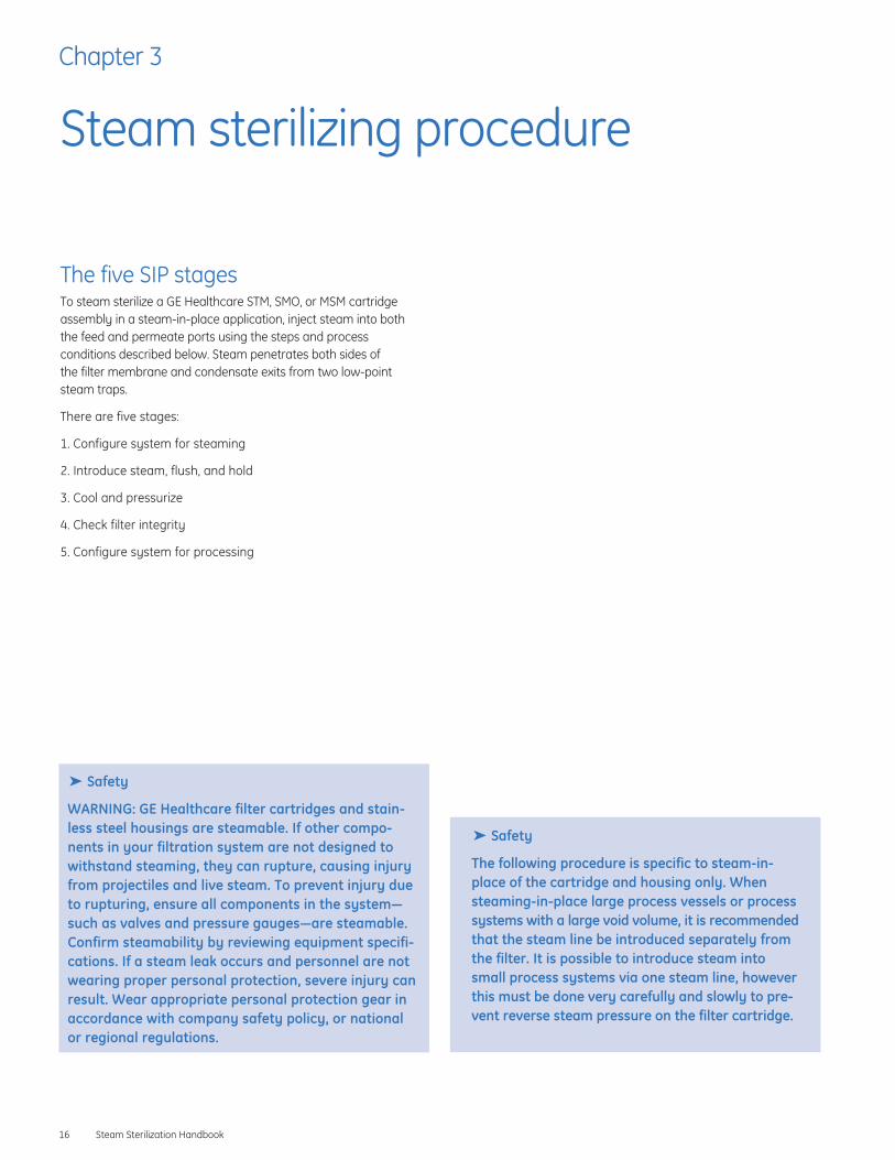
The five SIP stagesTo steam sterilize a GE Healthcare STM, SMO, or MSM cartridgeassembly in a steam-in-place application, inject steam into both the feed and permeate ports using the steps and process conditions described below. Steam penetrates both sides of the filter membrane and condensate exits from two low-pointsteam traps.
There are five stages:
1. Configure system for steaming
2. Introduce steam, flush, and hold
3. Cool and pressurize
4. Check filter integrity
5. Configure system for processing
Chapter 3
Steam sterilizing procedure
� Safety
WARNING: GE Healthcare filter cartridges and stain-less steel housings are steamable. If other compo-nents in your filtration system are not designed towithstand steaming, they can rupture, causing injuryfrom projectiles and live steam. To prevent injury dueto rupturing, ensure all components in the system—such as valves and pressure gauges—are steamable.Confirm steamability by reviewing equipment specifi-cations. If a steam leak occurs and personnel are notwearing proper personal protection, severe injury canresult. Wear appropriate personal protection gear inaccordance with company safety policy, or nationalor regional regulations.
� Safety
The following procedure is specific to steam-in-place of the cartridge and housing only. Whensteaming-in-place large process vessels or processsystems with a large void volume, it is recommendedthat the steam line be introduced separately fromthe filter. It is possible to introduce steam intosmall process systems via one steam line, howeverthis must be done very carefully and slowly to pre-vent reverse steam pressure on the filter cartridge.

Stage 1—Configure system for steamingConfigure the system for steaming (see Fig 7) as follows:
1. Ensure all glycerine is removed from ultrafiltration cartridges.
2. Isolate the steam traps.
3. Close the feed inlet, permeate outlet, low-point permeate drain,retentate outlet, and air inlet/vent valves.
4. Open the retentate and permeate inlet steam valves.
5. Open the feed steam trap bypass valve.
6. Close the permeate steam trap bypass valve.
Steam Sterilization Handbook 17
Figure 7. Starting setup for Stage 1—configure system for steaming
Air inlet/vent valve
Steam inlet
Steam toretentate side
Retentate steam inlet valve
Retentate outlet
Steam to permeate side
Permeate outlet valve
Permeate steam inlet valve
Permeate outlet
Low-pointpermeate drain
Condensate
Steam trapbypass valve
Feed inlet
GE Healthcare filter
Steam trapisolation valveP
ST
ST
P
Steam trapisolation valve
Condensate
Steam trapbypass valve
Closed valve
Partially open valve
Open valve
Pressure gauge
Steam trap
0.2 micron filter (optional)
P
ST

Stage 2—Introduce steam, flush, and holdSteam the cartridge following these steps:
Introduce steam1. Crack open the steam inlet valve or adjust regulator to
0.07 barg (1 psig). Steam and water should trickle from thesteam trap bypass valve (feed). Adjust the steam inlet valve sothat the system outlet temperature reaches about 100°C(212°F) in five to ten minutes (Fig 8).
2. Once the system outlet temperature reaches 100°C, wait fiveminutes and open the permeate steam trap bypass valve. Waitfive more minutes. Close both steam trap bypass valves.
3. Open the steam trap isolation valves, maintaining steam flowinto both sides (retentate and permeate) of the filter.Condensate will drain from the steam traps.
Steam flush—slowly increase the pressure4. Open the process retentate valve slightly.
5. Slowly open the main steam inlet valve.
6. Let the pressure increase, but do not exceed 1.03 barg (15 psig).
Hold steam at pressure7. Open the process feed, retentate outlet, and permeate outlet
valves slightly.
8. If introducing steam to the remainder of a small process system, slowly open the retentate outlet and feed inlet valves,ensuring the steam pressure does not drop. When the remainderof the process system comes up to pressure, fully open theretentate outlet and feed inlet valves.
9. Steam for 30 minutes at the specified pressure.
18 Steam Sterilization Handbook
Figure 8. Starting setup for Stage 2—introduce steam, flush, and hold
Steam inlet
Steam topermeate side
Permeate outlet
Low-pointpermeate drain
Condensate
Steam trapbypass valve
Condensate
GE Healthcare filter
Steam trapisolation valveP
ST
ST
P
Steam trapisolation valve
Steam trapbypass valve
Closed valve
Partially open valve
Open valve
Pressure gauge
Steam trap
0.2 micron filter (optional)
P
ST
Air inlet/vent valveSteam toretentate side
Retentate steam inlet valve
Permeate steam inlet valve
Permeate outlet valve
Retentate outlet
Feed inlet

Stage 3—Cool and pressurizeCool the cartridge element and housing following these steps:
1. Close the steam inlet valve (Fig 9).
2. Release the pressure by opening one of the steam trap bypassvalves and slowly opening the air inlet/vent valve.
3. Allow the cartridge and system to cool to ambient temperature.Typically cooling requires about four hours at ambient temperature.
Note: It is recommended that the vent valve be connected to airpressure adjusted to approximately 1.03 barg (15 psig).Maintaining positive pressure will assure that no unsterilized airinfiltration will occur anywhere in the system. A sterile, 0.2-micronhydrophobic filter must be positioned in the vent line to maintainsterility.
Steam Sterilization Handbook 19
Figure 9. Starting setup for Stage 3—cool and pressurize
Steam inletRetentate outlet
Steam topermeate side
Permeate outlet
Low-pointpermeate drain
Condensate
Steam trapbypass valve
Condensate
Feed inlet
GE Healthcare filter
Steam trapisolation valveP
ST
ST
P
Steam trapisolation valve
Steam trapbypass valve
Closed valve
Partially open valve
Open valve
Pressure gauge
Steam trap
0.2 micron filter (optional)
P
ST
Air inlet/vent valveSteam toretentate side
Retentate steam inlet valve
Permeate steam inlet valve
Permeate outlet valve

Stage 4—Check filter integrity Checking the integrity of the filter is optional, but recommendedand sometimes required in many applications. See the GE Healthcare Integrity testing handbook for additional details.The basic steps to complete integrity testing include:
1. Close all valves except the air inlet/vent valve, retentate steaminlet valve, and permeate steam trap bypass valve (Fig 10).
2. Attach flexible tubing to permeate steam trap bypass valve andimmerse in a beaker of water.
3. Perform pressure hold integrity test by introducing air atapproximately 0.34 barg (5 psig) through the air vent. Watch forbubbles emanating from the permeate drain.
4. If only small bubbles emanate, the cartridge has integrity.
20 Steam Sterilization Handbook
Figure 10. Starting setup for Stage 4—check filter integrity
Steam inletRetentate outlet
Permeate outlet
Condensate
Steam trapbypass valve
GE Healthcare filter
Steam trapisolation valve
ST
P
Condensate
Feed inletP
ST
Steam trapisolation valve
Steam trapbypass valve
Air inlet/vent valveSteam toretentate side
Retentate steam inlet valve
Steam to permeate side
Permeate outlet valve
Permeate steam inlet valve
Closed valve
Partially open valve
Open valve
Pressure gauge
Steam trap
0.2 micron filter (optional)
P
ST

Stage 5—Configure system for processingFollow these steps to configure the system for processing:
1. Close the air inlet/vent valve, retentate, and permeate steaminlet valves, steam trap isolation valves, and steam trap bypassvalves.
2. Open feed inlet valve, permeate outlet valve, and retentate outlet valve.
3. The system is now ready for processing.
Steam Sterilization Handbook 21
Figure 11. Starting setup for Stage 5—configure system for processing
Steam inletRetentate outlet
Low-pointpermeate drain
Condensate
Steam trapbypass valve
Condensate
Feed inlet
GE Healthcare filter
Steam trapisolation valveP
ST
ST
P
Steam trapisolation valve
Steam trapbypass valve
Steam toretentate side
Retentate steam inlet valve
Permeate outlet valve
Permeate outlet
Closed valve
Partially open valve
Open valve
Pressure gauge
Steam trap
0.2 micron filter (optional)
P
ST
Air inlet/vent valve
Steam inlet to permeate side
Permeate steam inlet valve

22 Steam Sterilization Handbook

IndexA
About this handbook, 6
Additional information, 6
C
Cartridge design, 9
Cartridge element installation, 10,11,12,13
Cartridge filter documentation set, 6
Check filter integrity, 20
Configure system for processing, 21
Configure system for steaming, 17
Connection specifications, 13
Contact information, 6
Cooling after steaming, 19
Customer support, 6
D
Drawings
Connection specifications for representative sizes of STM,SMO, and MSM housings, 13
MSM cartridge element installation, 11
MSM cartridge and housing design, 11
SMO cartridge components position, 10
SMO cartridge element installation, 10
STM cartridge element installation, 10
STM cartridge and housing design, 10
Documentation set, 6
E
Expert advice, 6
O-ring installation, 11
Steam trap sizing, 12
Expert advice flags, 6
Expert tips, 14
Introduction, 14
General recommendations, 15
Process design for effective sterilization, 15
Streamlining the steam-in-place process, 15
F
Filter cartridge element design, 9
Filter integrity testing, 20
Flow diagrams
Stage 1—configure system for steaming, 17
Stage 2—introduce steam, flush, and hold, 18
Stage 3—cool and pressurize, 19
Stage 4—check filter integrity, 20
Stage 5—configure system for processing, 21
Typical installation of steam-in-place equipment, 12
H
Handbook introduction, 6
Handbooks, 6
Help, 6
HousingConnector specifications, 13
How to install the housing, 13
Installation location, 12
Housing and cartridge design, 9
Housing design, 10
Housing design and assembly, 9
I
Important safety considerations, 5
Information sources, 6
Installation
Connector specifications, 13
How to install the housing, 13
MSM cartridge element, 11
SMO cartridge element, 10
STM cartridge element, 10
Where to install the housing, 12
Installing a membrane filter cartridge element in a housing,10,11,12,13
Introduce steam to the system, 18
Introduction, 6
Introduction to steaming-in-place, 14
K
Knowledge required to use equipment. see Target audience, 6
Steam Sterilization Handbook 23

24 Steam Sterilization Handbook
L
List of figures, 8
Figure 1. Cartridge filter documentation set, 6
Figure 2. Cutaway view of an STM cartridge element in anSTM housing, 10
Figure 3. Position of components of SMO membrane filtercartridge and housing, 10
Figure 4. MaxCell MSM cartridge and housing, 11
Figure 5. Typical installation of steam-in-place equipment, 12
Figure 6. Connection specifications for representative sizes ofSTM, SMO, and MSM housings, 13
Figure 7. Starting setup for Stage 1—configure system forsteaming, 17
Figure 8. Starting setup for Stage 2—introduce steam, flush,and hold, 18
Figure 9. Starting setup for Stage 3—cool and pressurize, 19
Figure 10. Starting setup for Stage 4—check filter integrity, 20
Figure 11. Starting setup for Stage 5—configure system forprocessing, 21
M
MSM cartridge element installation, 11
Membrane filter cartridge element design, 10
O
Operator skill level. see Target audience, 6
P
Precautions (general), 6
Precautions (steaming), 16
Process design for effective sterilization, 15
R
Return authorization, 7
S
Safety, 6
Safety flags, 6
Safety precautions, 6
SIP stages, 16
Stage 1—Configure system for steaming, 17
Stage 2—Introduce steam, flush, and hold, 18
Stage 3—Cool and pressurize, 19
Stage 4—Check filter integrity, 20
Stage 5—Configure system for processing, 21
SMO cartridge element installation, 10
SOP, 15
Specific advice to help you work safely, 6
Steam trap sizing, 12
Steaming
Specific safety precautions, 16
Standard operating procedures. see SOP, 15
Steam-in-place
Check filter integrity, 20
Configure system for processing, 21
Configure system for steaming, 17
Cool and pressurize, 19
Ensuring effective sterilization, 15
Expert tips, 14
Five stages, 16
Streamlining the process, 15
Steaming the cartridge element, 18
Steam-in-place procedure, 16
Steaming precautions, 16
Steam sterilizing procedure, 16
Sterilization, 15
STM cartridge element installation, 10
Streamlining the steam-in-place process, 15
T
Table of contents, 3
Target audience, 6
Technical support, 6
Tips, 14
U
User skill level. see Target audience, 6
W
Warranty, 7
Web site, 6
Where to find more information, 6


www.gehealthcare.com
Global Headquarters GE HealthcareLittle ChalfontBuckinghamshire, U.K. HP7 9NA
MaxCell is a trademark of GE Healthcare. GE tagline and GEMonogram are trademarks of General Electric Company.
Adobe and Acrobat are trademarks of Adobe Systems. Tri-Clampis a registered trademark of Tri-Clover/Alfa Laval.
All goods and services are sold subject to the terms and conditions of sale of the company within GE Healthcare whichsupplies them. GE Healthcare reserves the right, subject to anyregulatory and contractual approval, if required, to make changesin specifications and features shown herein, or discontinue theproduct described at any time without notice or obligation.Contact your local GE Healthcare representative for the mostcurrent information.
© 2005 General Electric Company–All rights reserved.
Amersham Biosciences AB, a General Electric Company going tomarket as GE Healthcare.
GE Healthcare Amersham Biosciences ABBjörkgatan 30, 751 84 Uppsala, Sweden
GE Healthcare Amersham Biosciences Europe GmbHMunzinger Strasse 9, D-79111 Freiburg, Germany
GE Healthcare Amersham Biosciences UK LtdAmersham Place, Little Chalfont, Buckinghamshire, HP7 9NA, UK
GE Healthcare Amersham Biosciences Corp800 Centennial Avenue, P.O. Box 1327, Piscataway, NJ 08855-1327, USA
GE Healthcare Amersham Biosciences KKSanken Bldg. 3-25-1, Hyakunincho, Shinjuku-ku, Tokyo 169-0073, Japan
GE Healthcare Amersham Biosciences Ltd13/F, Tower 1, Ever Gain Plaza, 88 Container Port RoadKwai Chung, New Territories, HONG KONG
Asia Pacific Tel: +852 2811 8693 Fax: +852 2811 5251 • Australasia Tel: + 61 2 9899 0999 Fax: +61 2 9899 7511 • Austria Tel: 01/57606-1619 Fax: 01/57606-1627 • Belgium Tel: 0800 73 888 Fax: 03 272 1637 • Canada Tel: 800 463 5800 Fax: 800 567 1008 • Central, East, & South East Europe Tel: +43 1 982 3826 Fax: +43 1 985 8327 • Denmark Tel: 45 16 2400 Fax: 45 16 2424 • Finland & Baltics Tel: +358-(0)9-512 39 40 Fax: +358 (0)9 512 39 439 • France Tel: 01 69 35 67 00 Fax: 01 69 41 96 77 • Germany Tel: 0761/4903-490 Fax: 0761/4903-405 • Italy Tel: 02 27322 1 Fax: 02 27302 212 • Japan Tel: +81 3 5331 9336 Fax: +81 3 5331 9370 • Latin America Tel: +55 11 3933 7300 Fax: +55 11 3933 7304 • Middle East & Africa Tel: +30 210 9600 687 Fax: +30 210 9600 693 • Netherlands Tel: 0165 580 410 Fax: 0165 580 401 • Norway Tel: 815 65 555 Fax: 815 65 666 • Portugal Tel: 21 417 7035 Fax: 21 417 3184 • Russia & other C.I.S. & N.I.S Tel: +7 (095) 232 0250, 956 1137 Fax: +7 (095) 230 6377 • South East Asia Tel: 60 3 8024 2080 Fax: 60 3 8024 2090 • Spain Tel: 93 594 49 50 Fax: 93 594 49 55 • Sweden Tel: 018 612 1900 Fax: 018 612 1910 • Switzerland Tel: 0848 8028 12 Fax: 0848 8028 13 • UK Tel: 0800 616928 Fax: 0800 616927 • USA Tel: 800 526 3593 Fax: 877 295 8102
18-1174-71 AA