steel building damage from the christchurch earthquake...
TRANSCRIPT
STEEL BUILDING DAMAGE FROM THE CHRISTCHURCH EARTHQUAKE SERIES OF 2010 and 2011
Charles Clifton1, Michel Bruneau2, Greg MacRae3, Roberto Leon4, and Alistair Fussell5
SUMMARY
This paper presents preliminary field observations on the performance of selected steel structures in
Christchurch during the earthquake series of 2010 to 2011. This comprises 6 damaging earthquakes, on
4 September and 26 December 2010, February 22, June 6 and two on June 13, 2011. Most notable of
these was the 4 September event, at Ms7.1 and MM7 (MM as observed in the Christchurch CBD) and
most intense was the 22 February event at Ms6.3 and MM9‐10 within the CBD. Focus is on performance
of concentrically braced frames, eccentrically braced frames, moment resisting frames, and industrial
storage racks. With a few notable exceptions, steel structures performed well during this earthquake
series, to the extent that inelastic deformations were less than what would have been expected given
the severity of the recorded strong motions. Some hypotheses are formulated to explain this
satisfactory performance.
INTRODUCTION
Widespread failures of unreinforced masonry buildings,the collapse of a few reinforced concrete
buildings, and severe soil liquefaction across the city of Christchurch contributed to make the February
22, 2011, earthquake a tragic national disaster. The scale of human casualties and property damage
from the February 22 event is in sharp contrast to the 4 September event and other earthquakes in the
series which did not cause loss of life. The 5km shallow depth of that earthquake’s hypocentre, at an
horizontal distance of roughly 10km from the city’s Central Business District (CBD) resulted in ground
excitations between 3 and 6 times higher than those recorded during the 4 September first event in the
series. Detailed analyses of the comprehensive set of strong motion data recorded shows that the 4
September event was approximately 0.7 times the Ultimate Limit State (ULS)design level specified by
the New Zealand seismic loading standardover the period range of 0.5 to 4 seconds, the 22 February
event was 1.5 to 2 times the ULS and the largest 13 June earthquake 0.9 times ULS.
While the duration of strong shaking of each earthquake was short (around 10 to 15 seconds) the
cumulative duration of strong shaking was over 60 seconds. Caution was expressed following the
September and February earthquakes that the short duration of strong shaking in each event meant
that duration related damage might have been suppressed compared with what one could have seen
from a single earthquake of longer duration. However, this caution is less warranted when considering
the duration of the total earthquake series. Furthermore, there were reports of duration damage such
1 Associate Professor in Structural Engineering, Dept. of Civil Engineering, University of Auckland, Auckland, New Zealand 2 Professor, Dept. of Civil, Structural, and Environmental Engineering, University at Buffalo, Buffalo, NY, USA 3 Associate Professor in Structural Engineering, Dept. of Civil and Natural Resources Engineering, University of Canterbury, Christchurch, New Zealand 4 Professor, School of Civil and Environmental Engineering, Georgia Tech, Atlanta, GA, USA 5 Senior Structural Engineer, Steel Construction New Zealand, Manukau City, New Zealand
ENG.UOA.0003.1
as low cycle fatigue fracture of reinforcing bar and attachment details to cladding panels following the
June 13 events. Metallurgically, the extended period of this earthquake series is likely to have been
more severe than a single event of comparable duration, due to strain ageing of the steel from the most
intense 22 February earthquake raising the yield strength and decreasing the ductility of yielded
components before the second strongest event of 13 June. For these reasons, the performance of steel
structures is instructive, providing a unique opportunity to gage the adequacy of the current New
Zealand seismic design provisions for steel structures. This is the objective of the paper.
SEISMIC DEMAND
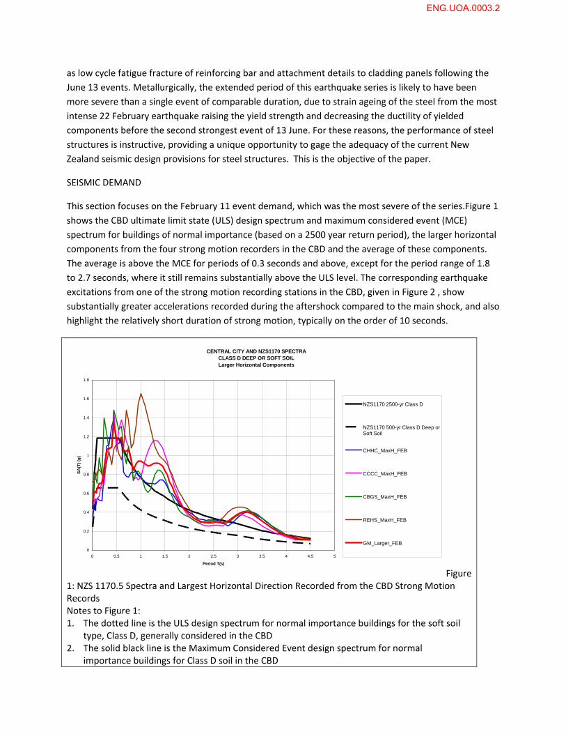
This section focuses on the February 11 event demand, which was the most severe of the series.Figure 1
shows the CBD ultimate limit state (ULS) design spectrum and maximum considered event (MCE)
spectrum for buildings of normal importance (based on a 2500 year return period), the larger horizontal
components from the four strong motion recorders in the CBD and the average of these components.
The average is above the MCE for periods of 0.3 seconds and above, except for the period range of 1.8
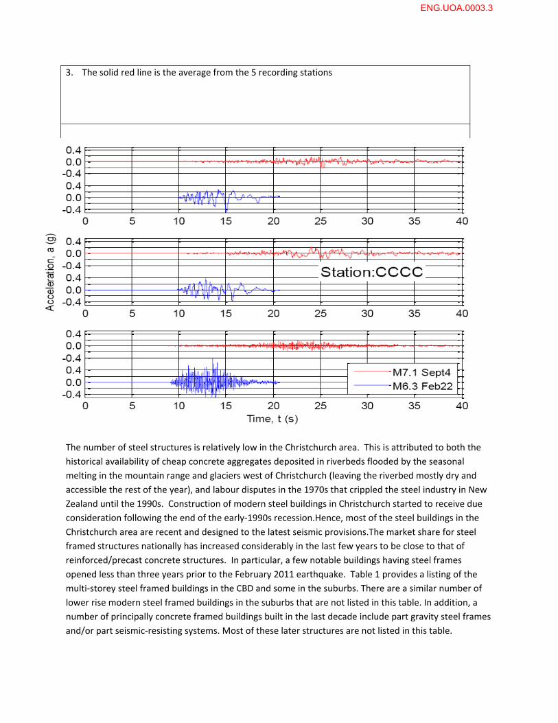
to 2.7 seconds, where it still remains substantially above the ULS level. The corresponding earthquake
excitations from one of the strong motion recording stations in the CBD, given in Figure 2 , show
substantially greater accelerations recorded during the aftershock compared to the main shock, and also
highlight the relatively short duration of strong motion, typically on the order of 10 seconds.
CENTRAL CITY AND NZS1170 SPECTRACLASS D DEEP OR SOFT SOILLarger Horizontal Components
0
0.2
0.4
0.6
0.8
1
1.2
1.4
1.6
1.8
0 0.5 1 1.5 2 2.5 3 3.5 4 4.5 5
Period T(s)
SA
(T)
(g)
NZS1170 2500-yr Class D
NZS1170 500-yr Class D Deep orSoft Soil
CHHC_MaxH_FEB
CCCC_MaxH_FEB
CBGS_MaxH_FEB
REHS_MaxH_FEB
GM_Larger_FEB
Figure 1: NZS 1170.5 Spectra and Largest Horizontal Direction Recorded from the CBD Strong Motion Records Notes to Figure 1: 1. The dotted line is the ULS design spectrum for normal importance buildings for the soft soil
type, Class D, generally considered in the CBD 2. The solid black line is the Maximum Considered Event design spectrum for normal
importance buildings for Class D soil in the CBD
ENG.UOA.0003.2
3. The solid red line is the average from the 5 recording stations
Figure 2 Horizontal and Vertical Spectra from the Canterbury College Strong Motion Recorder Note CCCC = Christchurch Cathedral College
STEEL STRUCTURES IN THE CHRISTCHURCH AREA
The number of steel structures is relatively low in the Christchurch area. This is attributed to both the
historical availability of cheap concrete aggregates deposited in riverbeds flooded by the seasonal
melting in the mountain range and glaciers west of Christchurch (leaving the riverbed mostly dry and
accessible the rest of the year), and labour disputes in the 1970s that crippled the steel industry in New
Zealand until the 1990s. Construction of modern steel buildings in Christchurch started to receive due
consideration following the end of the early‐1990s recession.Hence, most of the steel buildings in the
Christchurch area are recent and designed to the latest seismic provisions.The market share for steel
framed structures nationally has increased considerably in the last few years to be close to that of
reinforced/precast concrete structures. In particular, a few notable buildings having steel frames
opened less than three years prior to the February 2011 earthquake. Table 1 provides a listing of the
multi‐storey steel framed buildings in the CBD and some in the suburbs. There are a similar number of
lower rise modern steel framed buildings in the suburbs that are not listed in this table. In addition, a
number of principally concrete framed buildings built in the last decade include part gravity steel frames
and/or part seismic‐resisting systems. Most of these later structures are not listed in this table.
ENG.UOA.0003.3
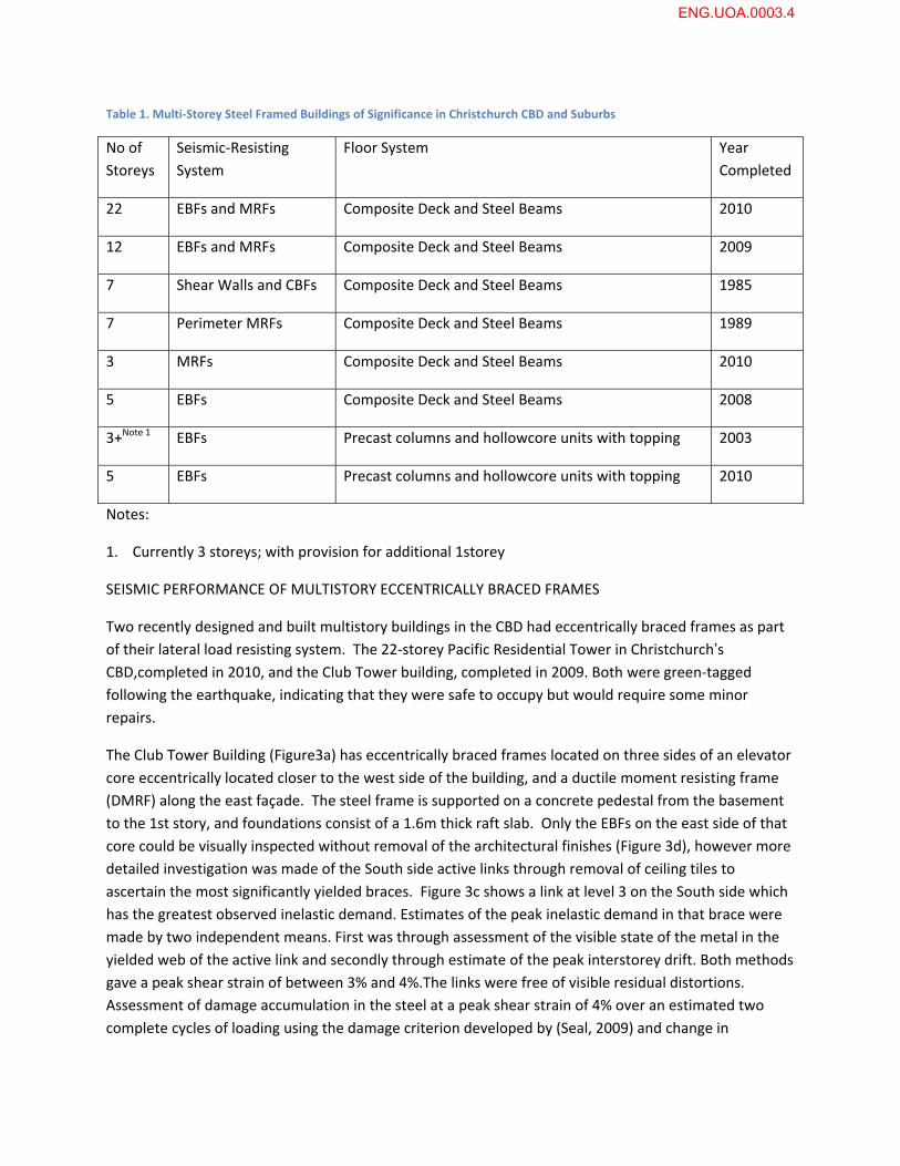
Table 1. Multi‐Storey Steel Framed Buildings of Significance in Christchurch CBD and Suburbs
No of
Storeys
Seismic‐Resisting
System
Floor System Year
Completed
22 EBFs and MRFs Composite Deck and Steel Beams 2010
12 EBFs and MRFs Composite Deck and Steel Beams 2009
7 Shear Walls and CBFs Composite Deck and Steel Beams 1985
7 Perimeter MRFs Composite Deck and Steel Beams 1989
3 MRFs Composite Deck and Steel Beams 2010
5 EBFs Composite Deck and Steel Beams 2008
3+Note 1 EBFs Precast columns and hollowcore units with topping 2003
5 EBFs Precast columns and hollowcore units with topping 2010
Notes:
1. Currently 3 storeys; with provision for additional 1storey
SEISMIC PERFORMANCE OF MULTISTORY ECCENTRICALLY BRACED FRAMES
Two recently designed and built multistory buildings in the CBD had eccentrically braced frames as part
of their lateral load resisting system. The 22‐storey Pacific Residential Tower in Christchurch’s
CBD,completed in 2010, and the Club Tower building, completed in 2009. Both were green‐tagged
following the earthquake, indicating that they were safe to occupy but would require some minor
repairs.
The Club Tower Building (Figure3a) has eccentrically braced frames located on three sides of an elevator
core eccentrically located closer to the west side of the building, and a ductile moment resisting frame
(DMRF) along the east façade. The steel frame is supported on a concrete pedestal from the basement
to the 1st story, and foundations consist of a 1.6m thick raft slab. Only the EBFs on the east side of that
core could be visually inspected without removal of the architectural finishes (Figure 3d), however more
detailed investigation was made of the South side active links through removal of ceiling tiles to
ascertain the most significantly yielded braces. Figure 3c shows a link at level 3 on the South side which
has the greatest observed inelastic demand. Estimates of the peak inelastic demand in that brace were
made by two independent means. First was through assessment of the visible state of the metal in the
yielded web of the active link and secondly through estimate of the peak interstorey drift. Both methods
gave a peak shear strain of between 3% and 4%.The links were free of visible residual distortions.
Assessment of damage accumulation in the steel at a peak shear strain of 4% over an estimated two
complete cycles of loading using the damage criterion developed by (Seal, 2009) and change in
ENG.UOA.0003.4
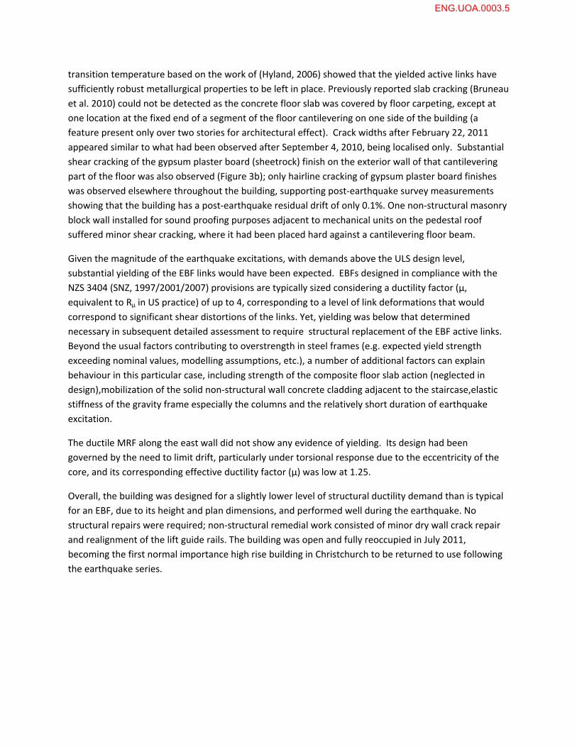
transition temperature based on the work of (Hyland, 2006) showed that the yielded active links have
sufficiently robust metallurgical properties to be left in place. Previously reported slab cracking (Bruneau
et al. 2010) could not be detected as the concrete floor slab was covered by floor carpeting, except at
one location at the fixed end of a segment of the floor cantilevering on one side of the building (a
feature present only over two stories for architectural effect). Crack widths after February 22, 2011
appeared similar to what had been observed after September 4, 2010, being localised only. Substantial
shear cracking of the gypsum plaster board (sheetrock) finish on the exterior wall of that cantilevering
part of the floor was also observed (Figure 3b); only hairline cracking of gypsum plaster board finishes
was observed elsewhere throughout the building, supporting post‐earthquake survey measurements
showing that the building has a post‐earthquake residual drift of only 0.1%. One non‐structural masonry
block wall installed for sound proofing purposes adjacent to mechanical units on the pedestal roof
suffered minor shear cracking, where it had been placed hard against a cantilevering floor beam.
Given the magnitude of the earthquake excitations, with demands above the ULS design level,
substantial yielding of the EBF links would have been expected. EBFs designed in compliance with the
NZS 3404 (SNZ, 1997/2001/2007) provisions are typically sized considering a ductility factor (µ,
equivalent to Rµ in US practice) of up to 4, corresponding to a level of link deformations that would
correspond to significant shear distortions of the links. Yet, yielding was below that determined
necessary in subsequent detailed assessment to require structural replacement of the EBF active links.
Beyond the usual factors contributing to overstrength in steel frames (e.g. expected yield strength
exceeding nominal values, modelling assumptions, etc.), a number of additional factors can explain
behaviour in this particular case, including strength of the composite floor slab action (neglected in
design),mobilization of the solid non‐structural wall concrete cladding adjacent to the staircase,elastic
stiffness of the gravity frame especially the columns and the relatively short duration of earthquake
excitation.
The ductile MRF along the east wall did not show any evidence of yielding. Its design had been
governed by the need to limit drift, particularly under torsional response due to the eccentricity of the
core, and its corresponding effective ductility factor (µ) was low at 1.25.
Overall, the building was designed for a slightly lower level of structural ductility demand than is typical
for an EBF, due to its height and plan dimensions, and performed well during the earthquake. No
structural repairs were required; non‐structural remedial work consisted of minor dry wall crack repair
and realignment of the lift guide rails. The building was open and fully reoccupied in July 2011,
becoming the first normal importance high rise building in Christchurch to be returned to use following
the earthquake series.
ENG.UOA.0003.5
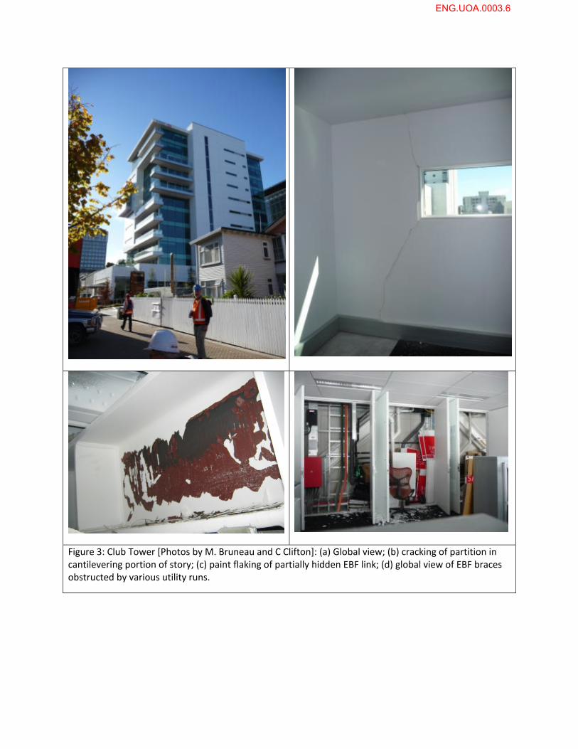
Figure 3: Club Tower [Photos by M. Bruneau and C Clifton]: (a) Global view; (b) cracking of partition in cantilevering portion of story; (c) paint flaking of partially hidden EBF link; (d) global view of EBF braces obstructed by various utility runs.
ENG.UOA.0003.6
As a new landmark and the tallest building on the Christchurch skyline6, the 22‐storey Pacific Tower
consists of perimeter EBFs up to the sixth floor on the western side and up to the eleventh floor on the
north side of the building, shifting to join the other EBFs around the elevator core above those levels.,
with transfer slabs designed to horizontally distribute the seismic loads at those transition points.
Several sections of the EBFs at levels below the level 6 transfer slab were visible, apart from at the top of
the perimeter system, as these levels housed a mechanical multilevel parking elevator system. The
separate bracing system of that mechanical device consisted of flat plates connected with turnbuckles
and hooks. Some of those details failed as the bars un‐hooked when returning into compression after
tension yielding excursions that elongated the braces. The EBFs at intermediate locations (on the NW
frame) were not integral with the floor slab and so did not benefit from the strength increase provided
by that integral action throughout the rest of the building. A range of views for this structure are given in
Figure 4.
Paint flaking and residual link shear deformations were observed in the EBF links at those levels. Design
of the EBFs in that building was governed by the need to limit drift, with a corresponding resulting
design ductility factor (µ) of 1.5 (even though up to 4.0 is permitted for EBF systems, as mentioned
earlier). This is typical of EBFs in tall buildings in New Zealand’s moderate to low seismic zones;
Christchurch is moderate in accordance with the earthquake loadings standard, NZS 1170.5 and a more
typical design ductility level factor range for such buildings is 2 to 3. When the initial internal inspections
were undertaken, there was an absence of significant damage to architectural and other non‐structural
finishings except at level 6 where a few of the hotel room doors along the corridor could not be closed,
suggesting greater residual deformations at that level. This level was the first in which a detailed
evaluation was undertaken. One fractured EBF active link was discovered (Figure 4e) in the top level
(underside of Level 6) of the EBF system at the North‐Western corner of the building. The frame sits
behind the louvre system nearest the camera in Figure 4a. This link had undergone at least one full cycle
of web panel yielding prior to a fracture propagating from one top corner across the active link region
and resulting in significant residual deformation. Temporary strap cross‐bracing was welded to the
active link frame to provide lateral load resistance while a repair strategy was implemented, which
comprised cutting out the damaged link, welding on an endplate system to each collector beam/brace
face and replacing with a site bolted endplate active link. The replacement is scheduled for early
October 2011 and is the only repair to the structural frame required for this building. A detailed
evaluation was undertaken of all active links in the adjacent storeys and throughout the building, with
the frequency of inspection reduced as no further examples requiring replacement were found. This
inspection required removal of architectural finishes.
This type of failure has not been reported in either EBFs tested in the laboratory or from damage reports
from other earthquakes; the reasons for this link fracture are not currently clear and it is to be the
subject of a detailed metallurgical and structural evaluation once removed..
6 The Grand Chancellor Hotel is 85 metres, the Price Waterhouse Cooper building is 76.3 metres, and the C1 Building (a.k.a. the Pacific Tower) stands at 73 metres, is topped by a 13 metres spire, for a total of 86 metres.
ENG.UOA.0003.7
As with Club Tower, some repair of dry‐wall cracking and realignment of lift shaft guide rails is the only
other work required and the intention is to have this completed in time for the building to be fully
opened when public access is restored into this area. It is also worth noting that this is likely to be the
only one of the six high‐rise buildings in Christchurch that will be returned to service.
It is noted that having the lateral load resisting system hidden by architectural elements is a hindrance
to post‐earthquake inspection, making it often only possible to infer the presence of structural damage
from the cracking of non‐structural finishes and other evidence of large inter‐story drifts until the linings
are removed. While this may work well in many cases, experience following the Northridge earthquake
suggests that major fractures of structural elements may remain hidden for years if only non‐structural
damage is relied upon as an indicator of possible problems with the lateral load resisting structure.
Future building code committees may consider the merit of requiring that buildings be design to provide
easy inspection of key structural elements and critical non‐structural elements following severe
earthquakes.
ENG.UOA.0003.8
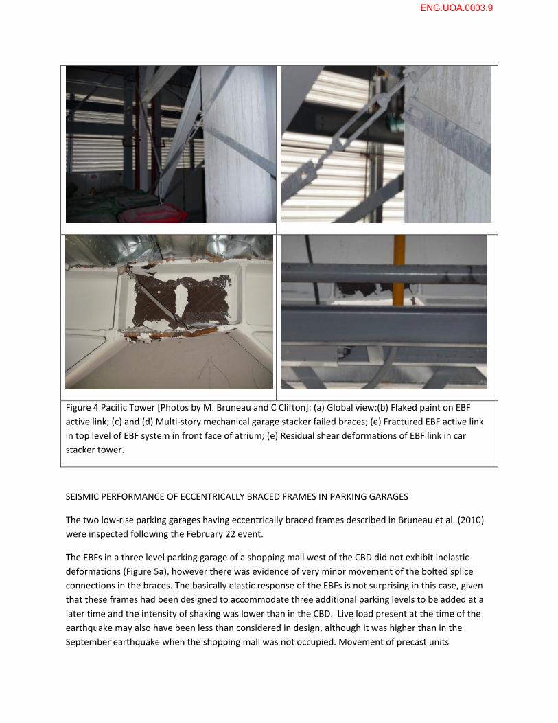
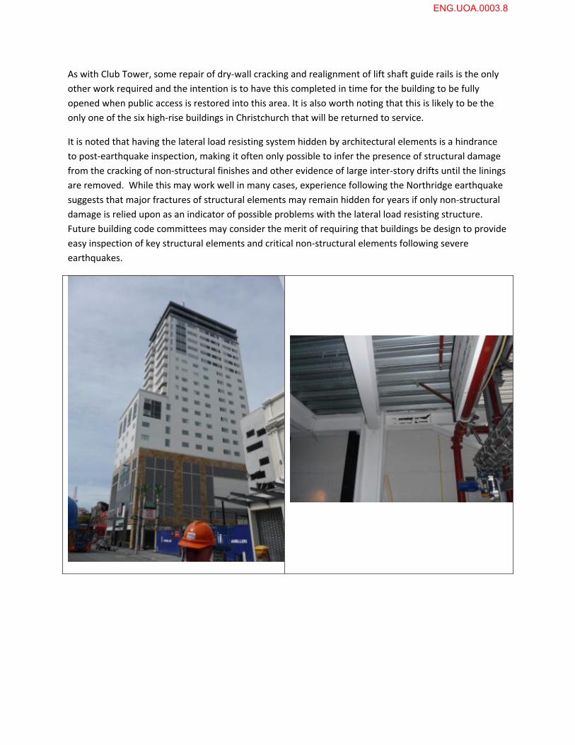
Figure 4 Pacific Tower [Photos by M. Bruneau and C Clifton]: (a) Global view;(b) Flaked paint on EBF
active link; (c) and (d) Multi‐story mechanical garage stacker failed braces; (e) Fractured EBF active link
in top level of EBF system in front face of atrium; (e) Residual shear deformations of EBF link in car
stacker tower.
SEISMIC PERFORMANCE OF ECCENTRICALLY BRACED FRAMES IN PARKING GARAGES
The two low‐rise parking garages having eccentrically braced frames described in Bruneau et al. (2010)
were inspected following the February 22 event.
The EBFs in a three level parking garage of a shopping mall west of the CBD did not exhibit inelastic
deformations (Figure 5a), however there was evidence of very minor movement of the bolted splice
connections in the braces. The basically elastic response of the EBFs is not surprising in this case, given
that these frames had been designed to accommodate three additional parking levels to be added at a
later time and the intensity of shaking was lower than in the CBD. Live load present at the time of the
earthquake may also have been less than considered in design, although it was higher than in the
September earthquake when the shopping mall was not occupied. Movement of precast units
ENG.UOA.0003.9
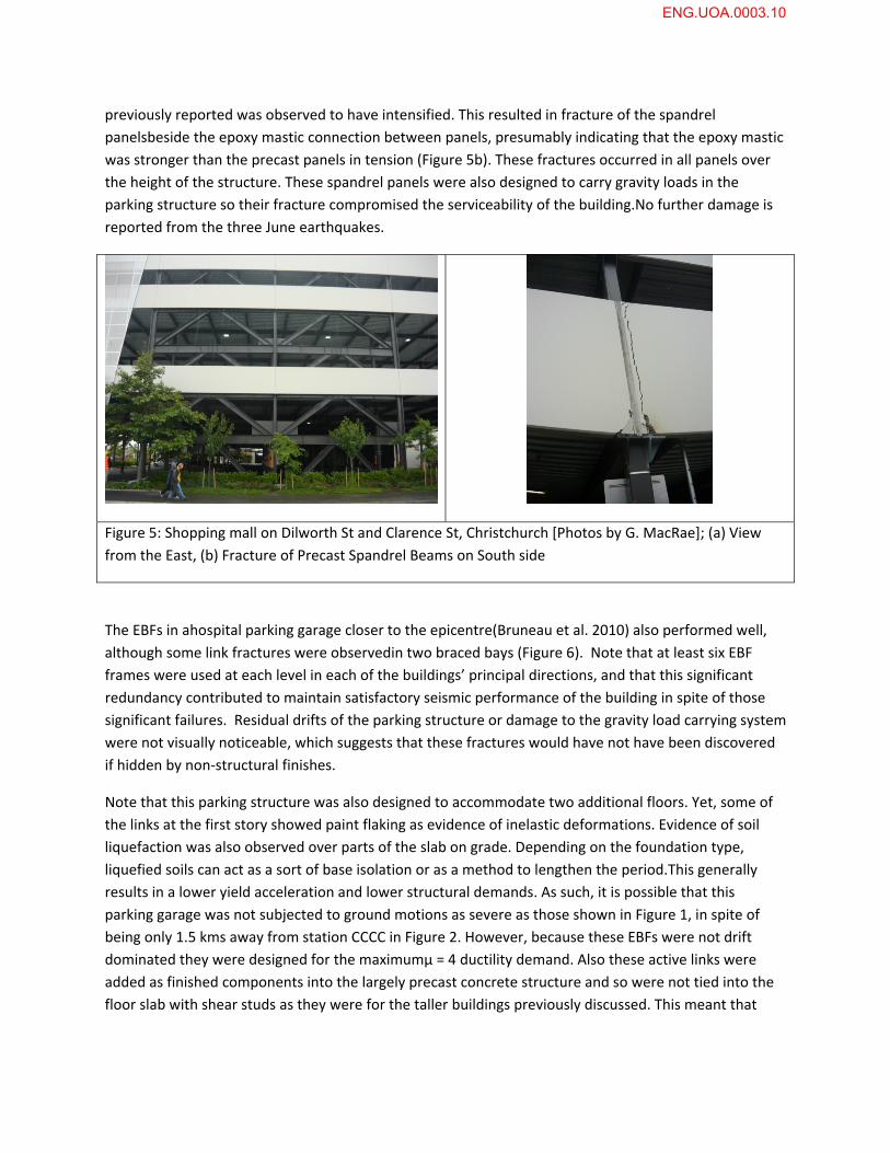
previously reported was observed to have intensified. This resulted in fracture of the spandrel
panelsbeside the epoxy mastic connection between panels, presumably indicating that the epoxy mastic
was stronger than the precast panels in tension (Figure 5b). These fractures occurred in all panels over
the height of the structure. These spandrel panels were also designed to carry gravity loads in the
parking structure so their fracture compromised the serviceability of the building.No further damage is
reported from the three June earthquakes.
Figure 5: Shopping mall on Dilworth St and Clarence St, Christchurch [Photos by G. MacRae]; (a) View
from the East, (b) Fracture of Precast Spandrel Beams on South side
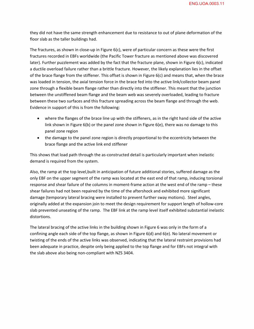
The EBFs in ahospital parking garage closer to the epicentre(Bruneau et al. 2010) also performed well,
although some link fractures were observedin two braced bays (Figure 6). Note that at least six EBF
frames were used at each level in each of the buildings’ principal directions, and that this significant
redundancy contributed to maintain satisfactory seismic performance of the building in spite of those
significant failures. Residual drifts of the parking structure or damage to the gravity load carrying system
were not visually noticeable, which suggests that these fractures would have not have been discovered
if hidden by non‐structural finishes.
Note that this parking structure was also designed to accommodate two additional floors. Yet, some of
the links at the first story showed paint flaking as evidence of inelastic deformations. Evidence of soil
liquefaction was also observed over parts of the slab on grade. Depending on the foundation type,
liquefied soils can act as a sort of base isolation or as a method to lengthen the period.This generally
results in a lower yield acceleration and lower structural demands. As such, it is possible that this
parking garage was not subjected to ground motions as severe as those shown in Figure 1, in spite of
being only 1.5 kms away from station CCCC in Figure 2. However, because these EBFs were not drift
dominated they were designed for the maximumµ = 4 ductility demand. Also these active links were
added as finished components into the largely precast concrete structure and so were not tied into the
floor slab with shear studs as they were for the taller buildings previously discussed. This meant that
ENG.UOA.0003.10
they did not have the same strength enhancement due to resistance to out of plane deformation of the
floor slab as the taller buildings had.
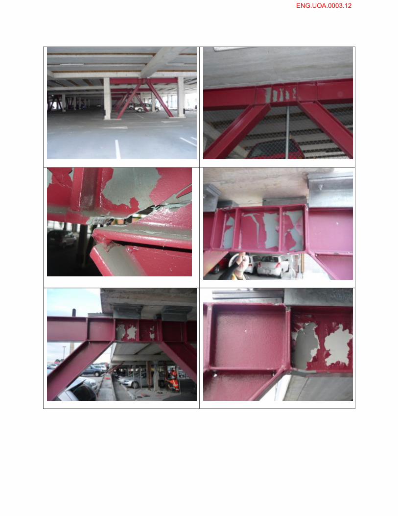
The fractures, as shown in close‐up in Figure 6(c), were of particular concern as these were the first
fractures recorded in EBFs worldwide (the Pacific Tower fracture as mentioned above was discovered
later). Further puzzlement was added by the fact that the fracture plane, shown in Figure 6(c), indicated
a ductile overload failure rather than a brittle fracture. However, the likely explanation lies in the offset
of the brace flange from the stiffener. This offset is shown in Figure 6(c) and means that, when the brace
was loaded in tension, the axial tension force in the brace fed into the active link/collector beam panel
zone through a flexible beam flange rather than directly into the stiffener. This meant that the junction
between the unstiffened beam flange and the beam web was severely overloaded, leading to fracture
between these two surfaces and this fracture spreading across the beam flange and through the web.
Evidence in support of this is from the following:
where the flanges of the brace line up with the stiffeners, as in the right hand side of the active
link shown in Figure 6(b) or the panel zone shown in Figure 6(e), there was no damage to this
panel zone region
the damage to the panel zone region is directly proportional to the eccentricity between the
brace flange and the active link end stiffener
This shows that load path through the as‐constructed detail is particularly important when inelastic
demand is required from the system.
Also, the ramp at the top level,built in anticipation of future additional stories, suffered damage as the
only EBF on the upper segment of the ramp was located at the east end of that ramp, inducing torsional
response and shear failure of the columns in moment‐frame action at the west end of the ramp – these
shear failures had not been repaired by the time of the aftershock and exhibited more significant
damage (temporary lateral bracing were installed to prevent further sway motions). Steel angles,
originally added at the expansion join to meet the design requirement for support length of hollow‐core
slab prevented unseating of the ramp. The EBF link at the ramp level itself exhibited substantial inelastic
distortions.
The lateral bracing of the active links in the building shown in Figure 6 was only in the form of a
confining angle each side of the top flange, as shown in Figure 6(d) and 6(e). No lateral movement or
twisting of the ends of the active links was observed, indicating that the lateral restraint provisions had
been adequate in practice, despite only being applied to the top flange and for EBFs not integral with
the slab above also being non‐compliant with NZS 3404.
ENG.UOA.0003.11
ENG.UOA.0003.12
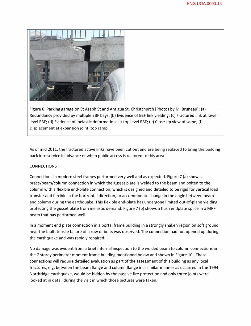
Figure 6: Parking garage on St Asaph St and Antigua St, Christchurch [Photos by M. Bruneau]; (a)
Redundancy provided by multiple EBF bays; (b) Evidence of EBF link yielding; (c) Fractured link at lower
level EBF; (d) Evidence of inelastic deformations at top level EBF; (e) Close‐up view of same; (f)
Displacement at expansion joint, top ramp.
As of mid 2011, the fractured active links have been cut out and are being replaced to bring the building
back into service in advance of when public access is restored to this area.
CONNECTIONS
Connections in modern steel frames performed very well and as expected. Figure 7 (a) shows a
brace/beam/column connection in which the gusset plate is welded to the beam and bolted to the
column with a flexible end‐plate connection, which is designed and detailed to be rigid for vertical load
transfer and flexible in the horizontal direction, to accommodate change in the angle between beam
and column during the earthquake. This flexible end‐plate has undergone limited out‐of‐plane yielding,
protecting the gusset plate from inelastic demand. Figure 7 (b) shows a flush endplate splice in a MRF
beam that has performed well.
In a moment end plate connection in a portal frame building in a strongly shaken region on soft ground
near the fault, tensile failure of a row of bolts was observed. The connection had not opened up during
the earthquake and was rapidly repaired.
No damage was evident from a brief internal inspection to the welded beam to column connections in
the 7 storey perimeter moment frame building mentioned below and shown in Figure 10. These
connections will require detailed evaluation as part of the assessment of this building as any local
fractures, e.g. between the beam flange and column flange in a similar manner as occurred in the 1994
Northridge earthquake, would be hidden by the passive fire protection and only three joints were
looked at in detail during the visit in which those pictures were taken.
ENG.UOA.0003.13
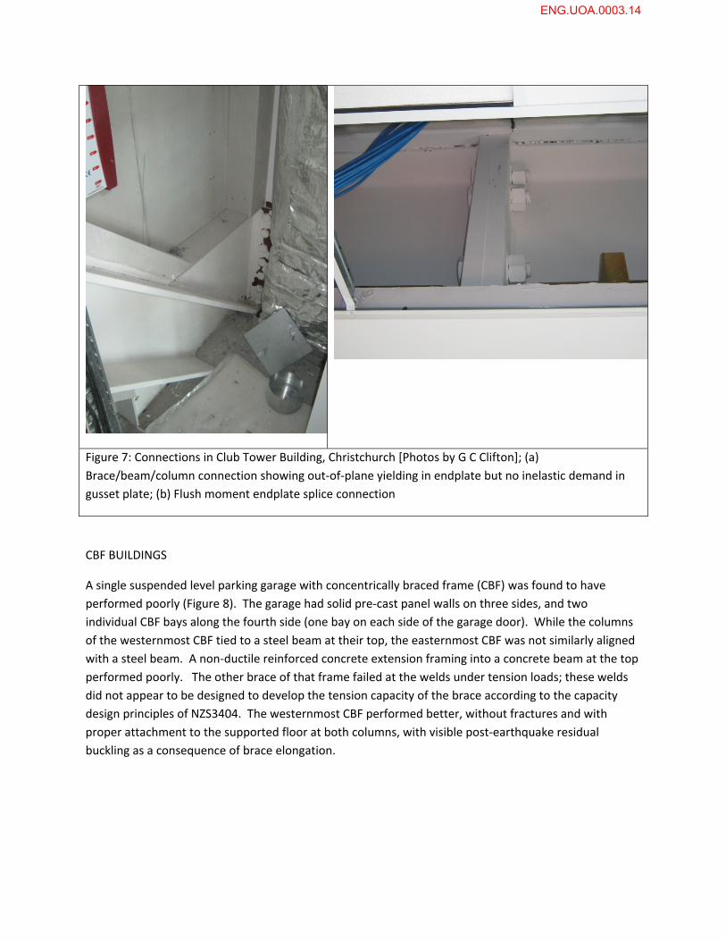
Figure 7: Connections in Club Tower Building, Christchurch [Photos by G C Clifton]; (a)
Brace/beam/column connection showing out‐of‐plane yielding in endplate but no inelastic demand in
gusset plate; (b) Flush moment endplate splice connection
CBF BUILDINGS
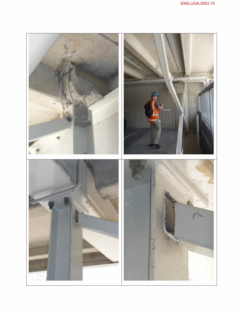
A single suspended level parking garage with concentrically braced frame (CBF) was found to have
performed poorly (Figure 8). The garage had solid pre‐cast panel walls on three sides, and two
individual CBF bays along the fourth side (one bay on each side of the garage door). While the columns
of the westernmost CBF tied to a steel beam at their top, the easternmost CBF was not similarly aligned
with a steel beam. A non‐ductile reinforced concrete extension framing into a concrete beam at the top
performed poorly. The other brace of that frame failed at the welds under tension loads; these welds
did not appear to be designed to develop the tension capacity of the brace according to the capacity
design principles of NZS3404. The westernmost CBF performed better, without fractures and with
proper attachment to the supported floor at both columns, with visible post‐earthquake residual
buckling as a consequence of brace elongation.
ENG.UOA.0003.14
ENG.UOA.0003.15
A seven storey steel framed hotel building with a combination shear walls in one direction and CBFs in
the other direction, could not be inspected because of its immediate proximity to the 22 storey Grand
Chancellor Hotel which was considered to be in a state of imminent collapse following the 22 February
earthquake. It is hoped to visit this building, if it is still intact, once the Grand Chancellor has been
demolished. There is no indication of damage from the street.
MULTI‐STOREY MRF BUILDINGS
A new parking garage (construction completed after the September 2010 earthquake) appeared to have
performed very well, with no visible sign of inelastic deformation at the beam‐to‐column connections
(Figure 9) or in any other part of the structure. However, this assessment could only be done from the
ground below as a collapsed concrete car parking building next door precluded access into the building.
A low rise MRF building in the CBD, which housed a gymnasium, was inspected in detail internally and
externally and had no structural damage.
Finally a 7 storey building located in the region of the CBD that exhibited significant ground instability
was inspected inside and out. The structure comprises a perimeter moment resisting frame along all 4
sides, with a non‐structural stair and services core and composite floor. Inspection of the steel frame
and floor showed no visible damage, however the perimeter frame had sunk a noticeable amount in
relation to the core (Figure 10b) and had acted as pinned base, causing significant interstorey drift which
has subsequently significantly damaged stairs (Figure 10d) and non‐structural components. The extent
of ground movement around the building was considerable and it is likely that significant foundation
movement has occurred. The question of what to do with this building will rest on what has happened
below ground.
Figure 8: Low‐rise CBF parking garage [Photos by M. Bruneau]: (a) Poor column connection detail; (b) Buckled brace; (c) and (d) Fractured non‐ductile brace‐to‐column connection.
ENG.UOA.0003.16
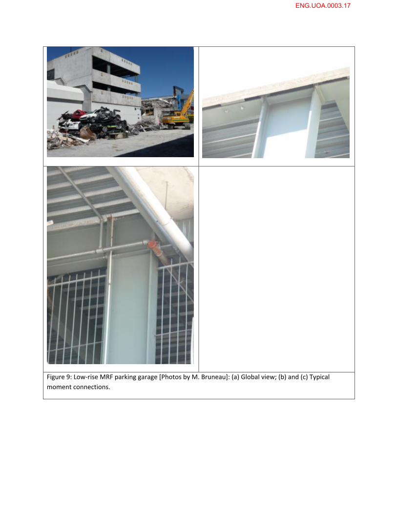
Figure 9: Low‐rise MRF parking garage [Photos by M. Bruneau]: (a) Global view; (b) and (c) Typical
moment connections.
ENG.UOA.0003.17
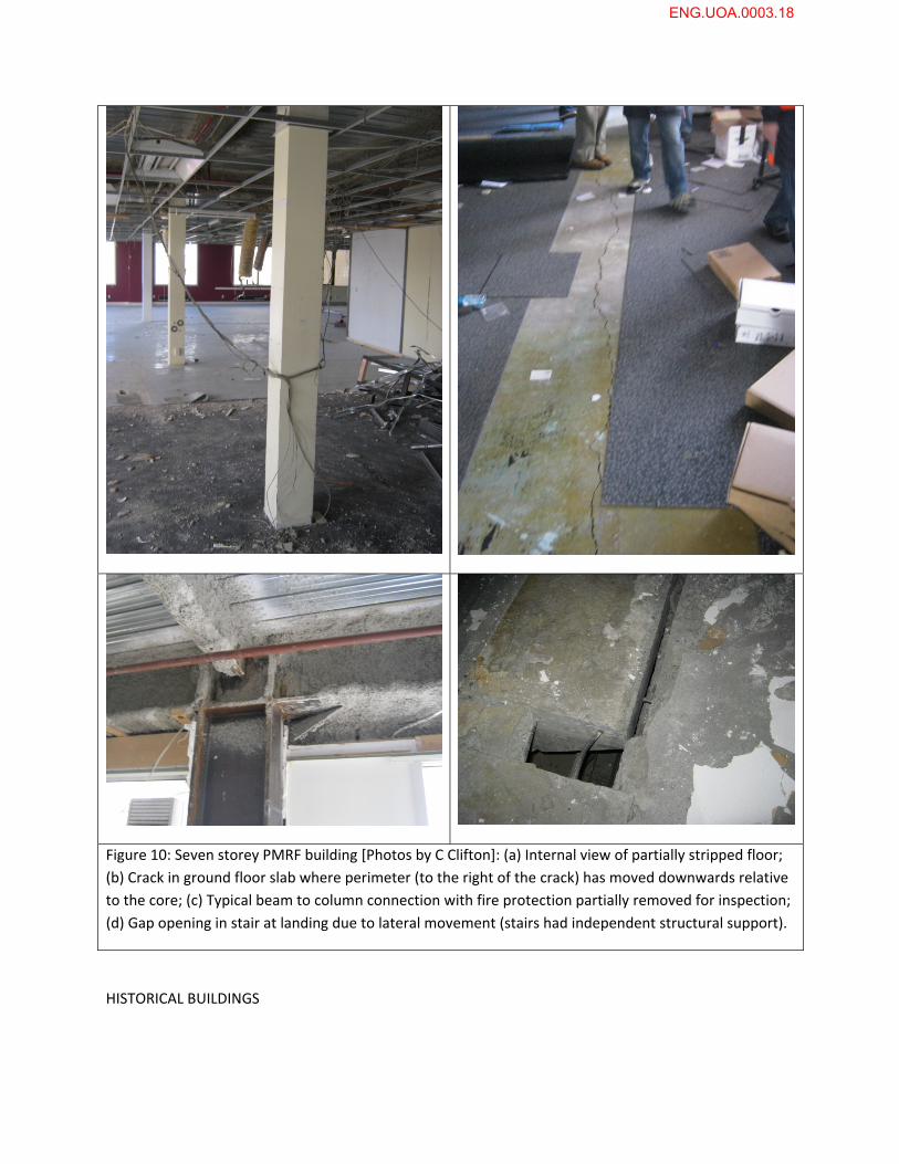
Figure 10: Seven storey PMRF building [Photos by C Clifton]: (a) Internal view of partially stripped floor;
(b) Crack in ground floor slab where perimeter (to the right of the crack) has moved downwards relative
to the core; (c) Typical beam to column connection with fire protection partially removed for inspection;
(d) Gap opening in stair at landing due to lateral movement (stairs had independent structural support).
HISTORICAL BUILDINGS
ENG.UOA.0003.18
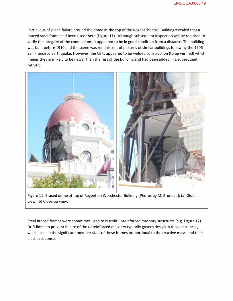
Partial out‐of‐plane failure around the dome at the top of the RegentTheatre) Buildingrevealed that a
braced steel frame had been used there (Figure 11). Although subsequent inspection will be required to
verify the integrity of the connections, it appeared to be in good condition from a distance. The building
was built before 1910 and the scene was reminiscent of pictures of similar buildings following the 1906
San Francisco earthquake. However, the CBFs appeared to be welded construction (to be verified) which
means they are likely to be newer than the rest of the building and had been added in a subsequent
retrofit.
Figure 11: Braced dome at top of Regent on Worchester Building [Photos by M. Bruneau]: (a) Global
view; (b) Close‐up view.
Steel braced frames were sometimes used to retrofit unreinforced masonry structures (e.g. Figure 12).
Drift limits to prevent failure of the unreinforced masonry typically govern design in those instances,
which explain the significant member sizes of these frames proportional to the reactive mass, and their
elastic response.
ENG.UOA.0003.19
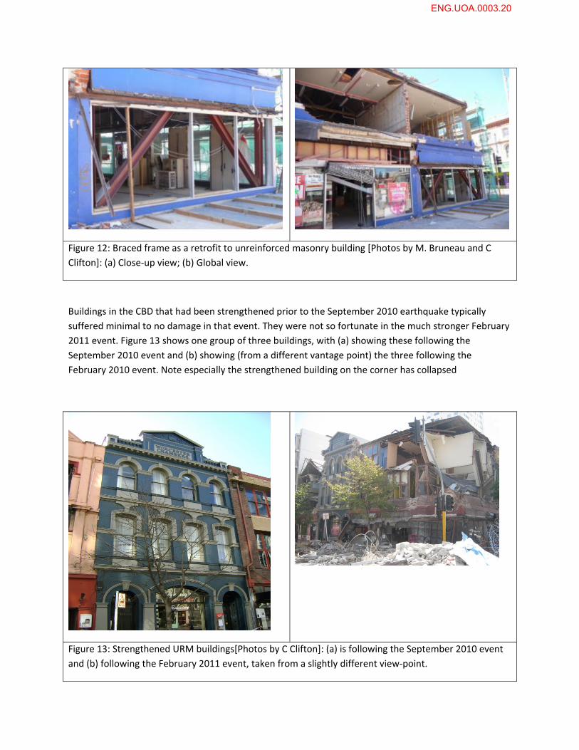
Figure 12: Braced frame as a retrofit to unreinforced masonry building [Photos by M. Bruneau and C
Clifton]: (a) Close‐up view; (b) Global view.
Buildings in the CBD that had been strengthened prior to the September 2010 earthquake typically
suffered minimal to no damage in that event. They were not so fortunate in the much stronger February
2011 event. Figure 13 shows one group of three buildings, with (a) showing these following the
September 2010 event and (b) showing (from a different vantage point) the three following the
February 2010 event. Note especially the strengthened building on the corner has collapsed
Figure 13: Strengthened URM buildings[Photos by C Clifton]: (a) is following the September 2010 event
and (b) following the February 2011 event, taken from a slightly different view‐point.
ENG.UOA.0003.20
Finally, note that the heritage structure described in Bruneau et al. (2010) at the corner of Manchester
and Hereford streets, severely damaged by the September 2010 earthquake, had been demolished by
its owner prior to the February aftershock.
INDUSTRIAL and EDUCATIONAL FACILITIES
Many warehouses close to the epicentresuffered limited damage. These industrial facilities typically
have light roofs and are designed to resist high wind forces; light rod braces are typically used for this
purpose. Following the earthquakes, steel fabricators inspected multiple warehouses, and retightened
sagging braces that had stretched due to yielding during the earthquake.
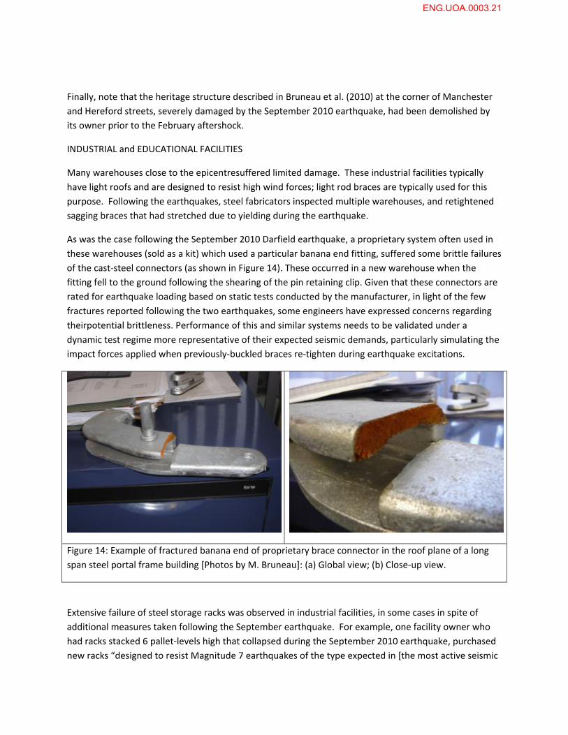
As was the case following the September 2010 Darfield earthquake, a proprietary system often used in
these warehouses (sold as a kit) which used a particular banana end fitting, suffered some brittle failures
of the cast‐steel connectors (as shown in Figure 14). These occurred in a new warehouse when the
fitting fell to the ground following the shearing of the pin retaining clip. Given that these connectors are
rated for earthquake loading based on static tests conducted by the manufacturer, in light of the few
fractures reported following the two earthquakes, some engineers have expressed concerns regarding
theirpotential brittleness. Performance of this and similar systems needs to be validated under a
dynamic test regime more representative of their expected seismic demands, particularly simulating the
impact forces applied when previously‐buckled braces re‐tighten during earthquake excitations.
Figure 14: Example of fractured banana end of proprietary brace connector in the roof plane of a long
span steel portal frame building [Photos by M. Bruneau]: (a) Global view; (b) Close‐up view.
Extensive failure of steel storage racks was observed in industrial facilities, in some cases in spite of
additional measures taken following the September earthquake. For example, one facility owner who
had racks stacked 6 pallet‐levels high that collapsed during the September 2010 earthquake, purchased
new racks “designed to resist Magnitude 7 earthquakes of the type expected in [the most active seismic
ENG.UOA.0003.21
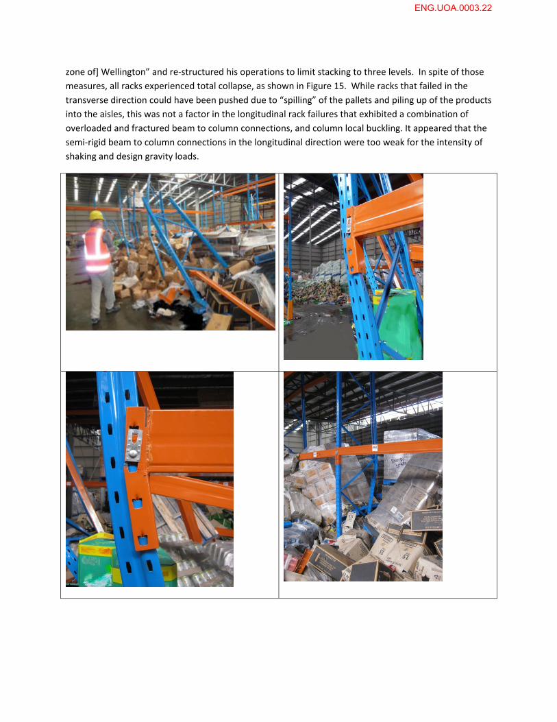
zone of] Wellington” and re‐structured his operations to limit stacking to three levels. In spite of those
measures, all racks experienced total collapse, as shown in Figure 15. While racks that failed in the
transverse direction could have been pushed due to “spilling” of the pallets and piling up of the products
into the aisles, this was not a factor in the longitudinal rack failures that exhibited a combination of
overloaded and fractured beam to column connections, and column local buckling. It appeared that the
semi‐rigid beam to column connections in the longitudinal direction were too weak for the intensity of
shaking and design gravity loads.
ENG.UOA.0003.22
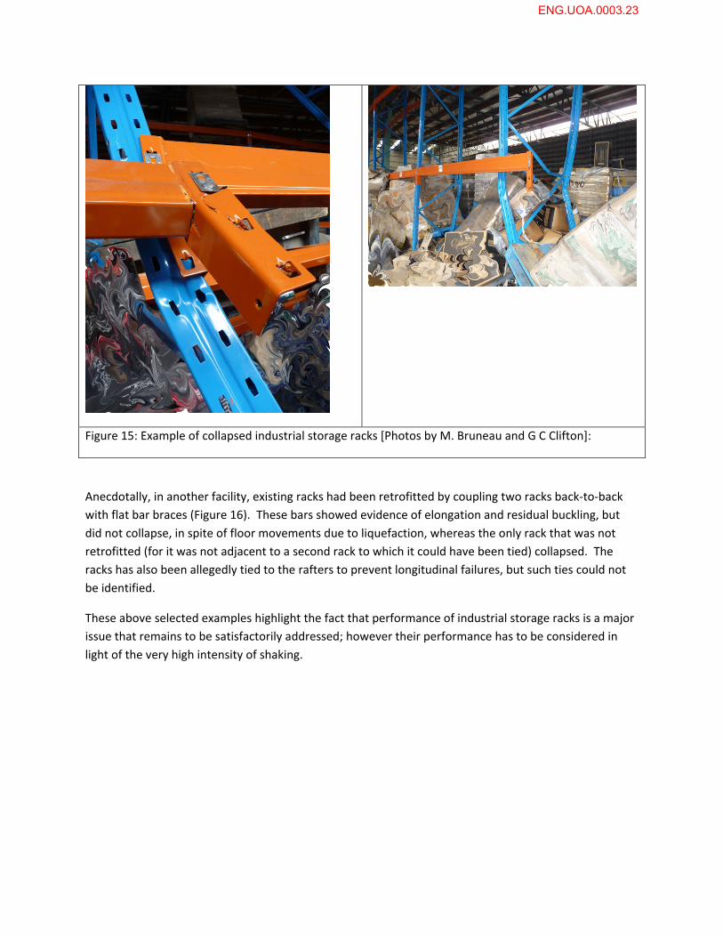
Figure 15: Example of collapsed industrial storage racks [Photos by M. Bruneau and G C Clifton]:
Anecdotally, in another facility, existing racks had been retrofitted by coupling two racks back‐to‐back
with flat bar braces (Figure 16). These bars showed evidence of elongation and residual buckling, but
did not collapse, in spite of floor movements due to liquefaction, whereas the only rack that was not
retrofitted (for it was not adjacent to a second rack to which it could have been tied) collapsed. The
racks has also been allegedly tied to the rafters to prevent longitudinal failures, but such ties could not
be identified.
These above selected examples highlight the fact that performance of industrial storage racks is a major
issue that remains to be satisfactorily addressed; however their performance has to be considered in
light of the very high intensity of shaking.
ENG.UOA.0003.23
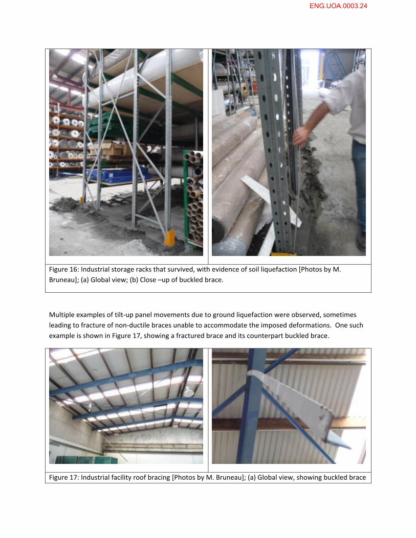
Figure 16: Industrial storage racks that survived, with evidence of soil liquefaction [Photos by M.
Bruneau]; (a) Global view; (b) Close –up of buckled brace.
Multiple examples of tilt‐up panel movements due to ground liquefaction were observed, sometimes
leading to fracture of non‐ductile braces unable to accommodate the imposed deformations. One such
example is shown in Figure 17, showing a fractured brace and its counterpart buckled brace.
Figure 17: Industrial facility roof bracing [Photos by M. Bruneau]; (a) Global view, showing buckled brace
ENG.UOA.0003.24
and fractured brace; (b) Close –up view of fractures weld of tension brace.
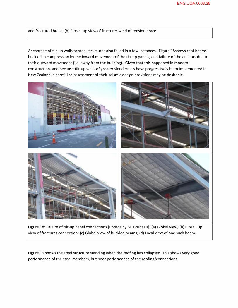
Anchorage of tilt‐up walls to steel structures also failed in a few instances. Figure 18shows roof beams
buckled in compression by the inward movement of the tilt‐up panels, and failure of the anchors due to
their outward movement (i.e. away from the building). Given that this happened in modern
construction, and because tilt‐up walls of greater slenderness have progressively been implemented in
New Zealand, a careful re‐assessment of their seismic design provisions may be desirable.
Figure 18: Failure of tilt‐up panel connections [Photos by M. Bruneau]; (a) Global view; (b) Close –up
view of fractures connection; (c) Global view of buckled beams; (d) Local view of one such beam.
Figure 19 shows the steel structure standing when the roofing has collapsed. This shows very good
performance of the steel members, but poor performance of the roofing/connections.
ENG.UOA.0003.25
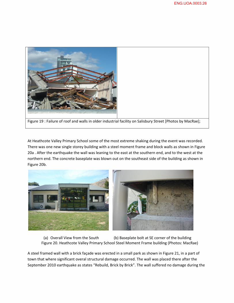
Figure 19 : Failure of roof and walls in older industrial facility on Salisbury Street [Photos by MacRae];
At Heathcote Valley Primary School some of the most extreme shaking during the event was recorded.
There was one new single storey building with a steel moment frame and block walls as shown in Figure
20a . After the earthquake the wall was leaning to the east at the southern end, and to the west at the
northern end. The concrete baseplate was blown out on the southeast side of the building as shown in
Figure 20b.
(a) Overall View from the South (b) Baseplate bolt at SE corner of the building
Figure 20. Heathcote Valley Primary School Steel Moment Frame building (Photos: MacRae)
A steel framed wall with a brick façade was erected in a small park as shown in Figure 21, in a part of
town that where significant overal structural damage occurred. The wall was placed there after the
September 2010 earthquake as states “Rebuild, Brick by Brick”. The wall suffered no damage during the
ENG.UOA.0003.26
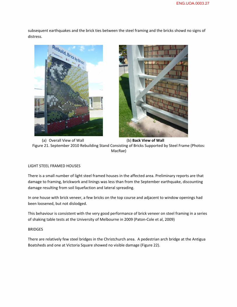
subsequent earthquakes and the brick ties between the steel framing and the bricks showd no signs of
distress.
(a) Overall View of Wall (b) Back View of Wall Figure 21. September 2010 Rebuilding Stand Consisting of Bricks Supported by Steel Frame (Photos:
MacRae)
LIGHT STEEL FRAMED HOUSES
There is a small number of light steel framed houses in the affected area. Preliminary reports are that
damage to framing, brickwork and linings was less than from the September earthquake, discounting
damage resulting from soil liquefaction and lateral spreading.
In one house with brick veneer, a few bricks on the top course and adjacent to window openings had
been loosened, but not dislodged.
This behaviour is consistent with the very good performance of brick veneer on steel framing in a series
of shaking table tests at the University of Melbourne in 2009 (Paton‐Cole et al, 2009)
BRIDGES
There are relatively few steel bridges in the Christchurch area. A pedestrian arch bridge at the Antigua
Boatsheds and one at Victoria Square showed no visible damage (Figure 22).
ENG.UOA.0003.27
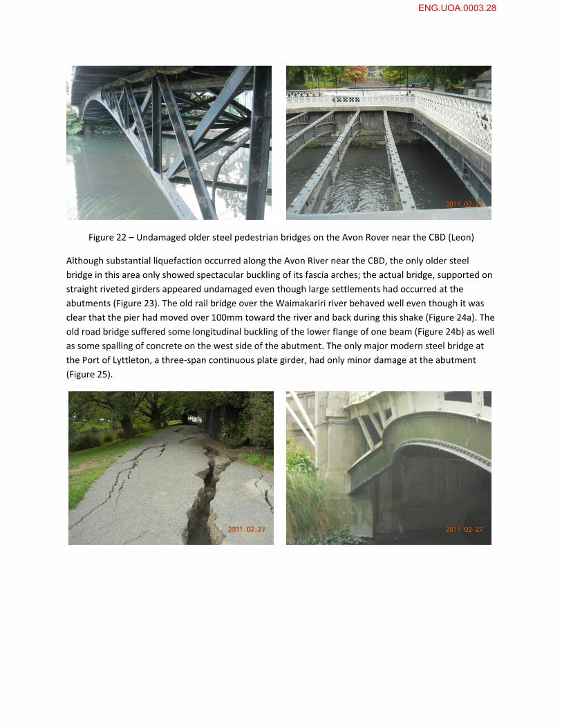
Figure 22 – Undamaged older steel pedestrian bridges on the Avon Rover near the CBD (Leon)
Although substantial liquefaction occurred along the Avon River near the CBD, the only older steel
bridge in this area only showed spectacular buckling of its fascia arches; the actual bridge, supported on
straight riveted girders appeared undamaged even though large settlements had occurred at the
abutments (Figure 23). The old rail bridge over the Waimakariri river behaved well even though it was
clear that the pier had moved over 100mm toward the river and back during this shake (Figure 24a). The
old road bridge suffered some longitudinal buckling of the lower flange of one beam (Figure 24b) as well
as some spalling of concrete on the west side of the abutment. The only major modern steel bridge at
the Port of Lyttleton, a three‐span continuous plate girder, had only minor damage at the abutment
(Figure 25).
ENG.UOA.0003.28
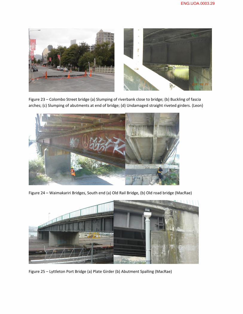
Figure 23 – Colombo Street bridge (a) Slumping of riverbank close to bridge; (b) Buckling of fascia
arches; (c) Slumping of abutments at end of bridge; (d) Undamaged straight riveted girders. (Leon)
Figure 24 – Waimakariri Bridges, South end (a) Old Rail Bridge, (b) Old road bridge (MacRae)
Figure 25 – Lyttleton Port Bridge (a) Plate Girder (b) Abutment Spalling (MacRae)
ENG.UOA.0003.29
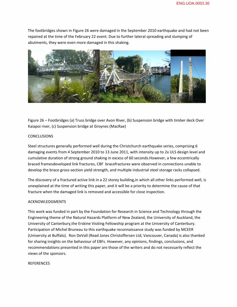
The footbridges shown in Figure 26 were damaged in the September 2010 earthquake and had not been
repaired at the time of the February 22 event. Due to further lateral spreading and slumping of
abutments, they were even more damaged in this shaking.
Figure 26 – Footbridges (a) Truss bridge over Avon River, (b) Suspension bridge with timber deck Over
Kaiapoi river, (c) Suspension bridge at Groynes (MacRae)
CONCLUSIONS
Steel structures generally performed well during the Christchurch earthquake series, comprising 6
damaging events from 4 September 2010 to 13 June 2011, with intensity up to 2x ULS design level and
cumulative duration of strong ground shaking in excess of 60 seconds.However, a few eccentrically
braced framesdeveloped link fractures, CBF bracefractures were observed in connections unable to
develop the brace gross‐section yield strength, and multiple industrial steel storage racks collapsed.
The discovery of a fractured active link in a 22 storey building,in which all other links performed well, is
unexplained at the time of writing this paper, and it will be a priority to determine the cause of that
fracture when the damaged link is removed and accessible for close inspection.
ACKNOWLEDGMENTS
This work was funded in part by the Foundation for Research in Science and Technology through the
Engineering theme of the Natural Hazards Platform of New Zealand, the University of Auckland, the
University of Canterbury,the Erskine Visiting Fellowship program at the University of Canterbury.
Participation of Michel Bruneau to this earthquake reconnaissance study was funded by MCEER
(University at Buffalo). Ron DeVall (Read Jones Christoffersen Ltd, Vancouver, Canada) is also thanked
for sharing insights on the behaviour of EBFs. However, any opinions, findings, conclusions, and
recommendations presented in this paper are those of the writers and do not necessarily reflect the
views of the sponsors.
REFERENCES
ENG.UOA.0003.30
Bruneau, M., Anagnostopoulou, M., MacRae, G., Clifton, C., Fussell, A., “PRELIMINARY REPORT ON STEEL
BUILDING DAMAGE FROM THE DARFIELD EARTHQUAKE OF SEPTEMBER 4, 2010”, Bulletin of the New
Zealand Society for Earthquake Engineering, Vol.43, No.4, pp.351‐359.
Hayes G et al, “THE 09/03/2010 DARFIELD EARTHQUAKE AND ITS AFTERSHOCKS, INCLUDING THE
02/21/2011 CHRISTCHURCH EVENT”, Educational Slides, US Geological Survey, National Earthquake
Information Center, 2011.
Hyland C and Fergusson WG, “A FRACTURE MECHANICS BASED APPROACH TO THE ASSESSMENT OF
SESIMIC RESISTING STEEL STRUCTURES” Key Engineering Materials 312 (2006) 89 – 94
Paton‐Cole, V.P; Gad, E.F; Clifton, G.C; Heath, D.J; Davies, C; Hicks, S; Lam, N. “SEISMIC PERFORMANCE
OF A BRICK VENEER STEEL FRAMED HOUSE”, AEES 2009, Proceedings of the 2009 Conference of the
Australian Earthquake Engineering Society, Newcastle, Australia, ‐ 2009
Seal, C, “PLASTICITY OF STEEL UNDER SESIMIC LOAD CONDITIONS” PhD Thesis report, Faculty of
Engineering, The University of Auckland, 2009
Standards New Zealand, NZS 1170 Part 5: 2004'EARTHQUAKE ACTIONS ‐ NEW ZEALAND' part of the Joint
AustralasianLoadings Standard set AS/NZS 1170 'Structural Design Actions'.
Standards New Zealand, NZS 3404: 1997 incorporating Amendment No 1:2001 and Amendment No 2:
2007, “STEEL STRUCTURES STANDARD”, Wellington, New Zealand
GNS, CHRISTCHURCH CENTRAL BUSINESS DISTRICT SPECTRA, 25/02/2011
ENG.UOA.0003.31