steel-ply - dayton superior
TRANSCRIPT

STEEL-PLY®
FORMING SYSTEM
CONCRETE CONSTRUCTION
SOLUTIONS
BROCHURE
THE POWER OF RED™

WWW.SYMONS.COM2 06/16
Steel-Ply Advantages
The Steel-Ply forming system is a pre-engineered, factory-built, reusable concrete forming system. It may be used in handset or gang form applications, for commercial or residential structures. The Steel-Ply forming system can form walls of almost any shape or size, with accessories for special structures and details. This system is more productive and economical than job-built plywood formwork or other forming methods.Steel-Ply Saves TimeThe Steel-Ply forming system saves time because it is easy to set up and strip. No measuring, sawing, drilling, or nailing is required. Minimal training is needed, so workers are quickly up to maximum efficiency. The only tool required for setup and stripping is a hammer.Steel-Ply Saves MaterialsUnlike job-built formwork, which must be tailored for each specific pour, the Steel-Ply forming system comes in a variety of standard sizes which can be combined to form virtually any dimension. Steel-Ply panels and fillers are made of specially laminated plywood mounted on rugged steel frames. They can be used up to 200 times before being re-plyed.Quality, Consistency and SafetyNo matter what the application, the same basic components and methods are used. Labor performance becomes consistent and predictable, and the lam-inated plywood panels and tight-fitting side rails produce a high quality concrete surface. This engineered system is de-signed and manufactured with a known strength factor, a major consideration for jobsite safety.

The Power of Red™ | 306/16
Service
Superior ServiceThe complete Steel-Ply forming system is available through a worldwide network of Symons Branches, Dealers and Dis-tributors. Each Branch and Distributor is staffed with Symons representatives who are trained and experienced in con-crete forming. These representatives can work with you to develop detailed formwork layout drawings which show component placement and reuse cycles. This includes a complete bill of materials to ensure that all essential elements are available when the job starts.On-the-job crew training, application consultation, Safety Sheets and Applica-tion Guides are also available. This extra assistance helps crews work rapidly, efficiently, and safely during the project.Rent or PurchaseAll standard panel sizes and most ac-cessories are available for rental or pur-chase. This is especially advantageous if you have an unusually large or unique job where purchasing a system is not practical. Another option is to buy the basic panels and accessories and rent some of the specialized components as the need arises.Let a Dayton Superior representative prepare an analysis to determine if the rental or purchase of the Steel-Ply forming system is appropriate for the specific application.
youtu.be/8YWmd6QVDgc

WWW.SYMONS.COM4 06/16
System Design
System DesignSteel-Ply panels and fillers are con-structed from a rugged steel frame. The side rail of the form is rolled exclusively for Symons and has a minimum yield stress of 55,000 psi. Crossmembers have a minimum yield stress of 60,000 psi and are located at one foot centers on all panels and fillers.Symons special ½" 100/30 High Den-sity Overlay (HDO) plywood provides a smooth finish. Each piece is edge sealed to repel moisture and prevent delamina-tion. With proper care, contractors can expect up to 200 reuses before plywood replacement.Steel-Ply requires little training be-cause it has no top or bottom, left or right, and can be used vertically or horizontally. Dado slots at cross-members simplify tie placement. Slots for hardware attachment are located between crossmembers.All Steel-Ply components combine to provide a 1000 psf rated system with a predictable safety factor over the service life of the form.The complete Steel-Ply system consists of over -100 standard panel and filler sizes. Panel and filler heights range from 3' to 10', in 1' increments. Panel widths are 24" and filler widths range from 4" to 22", in 2" increments. A 5" wide filler and steel 1", 1½", and 2" fillers are also available. Wedge Bolts connect panels, fillers and ties in one simple operation.Steel-Ply is also available in metric sizes. Panel and filler heights range from 60 cm to 300 cm in 30 cm incre-ments. Panel widths are 60 cm and filler widths range from 10 cm to 55 cm in 5 cm increments.
The Power of Red™ | 506/16
Quick-Hook™ Handle
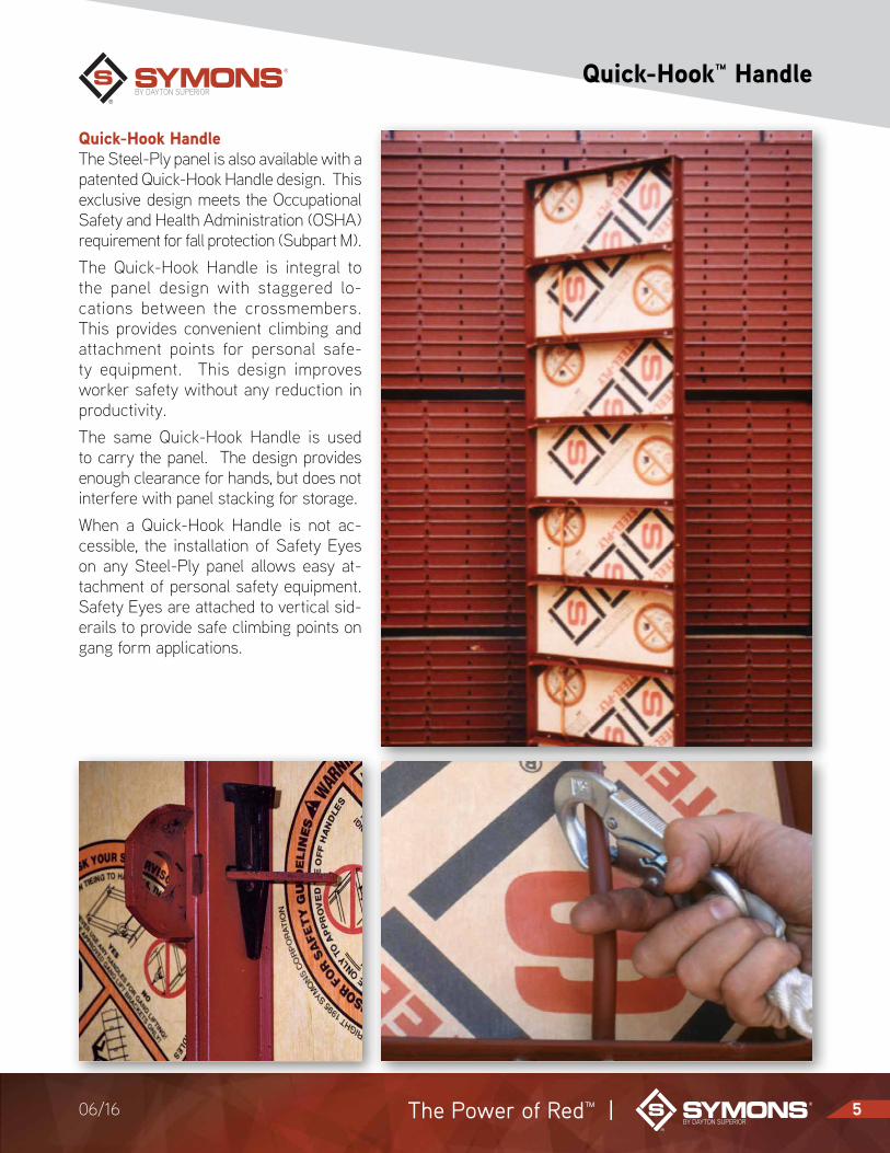
Quick-Hook HandleThe Steel-Ply panel is also available with a patented Quick-Hook Handle design. This exclusive design meets the Occupational Safety and Health Administration (OSHA) requirement for fall protection (Subpart M).The Quick-Hook Handle is integral to the panel design with staggered lo-cations between the crossmembers. This provides convenient climbing and attachment points for personal safe-ty equipment. This design improves worker safety without any reduction in productivity.The same Quick-Hook Handle is used to carry the panel. The design provides enough clearance for hands, but does not interfere with panel stacking for storage.When a Quick-Hook Handle is not ac-cessible, the installation of Safety Eyes on any Steel-Ply panel allows easy at-tachment of personal safety equipment. Safety Eyes are attached to vertical sid-erails to provide safe climbing points on gang form applications.

WWW.SYMONS.COM6 06/16
Connections
For productive setting and stripping of forms, Symons offers a variety of con-necting hardware.Wedge BoltsTwo identical Wedge Bolts function as a lock-bolt set, one as a connecting bolt, the other as a clamping wedge. At typical siderail-to-siderail connections, the loop end of the tie is positioned in dado slots and is secured by the same Wedge Bolts.For typical walls, form connecting Wedge Bolts are only required at standard tie connection positions. Additional Wedge Bolts are utilized at other positions for attachment of walers, scaffold brackets or other accessory components.Long BoltsThe Long Bolt is designed to be used with the 1", 1½" and 2" Steel Filler. The long connecting bolt is punched with two ¼" holes to accommodate a 16d nail to be used to shorten the bolt for Steel Fillers. A vertical Wedge Bolt secures the two panels and filler through the adjoining side rails.Adjustable Long BoltsThe Adjustable Long Bolt is designed to allow two steel fillers to be used side-by-side. It can accommodate up to a 3" combination (i.e. two 1½" steel fillers, or a 1" with a 2" steel filler).Base Tie BoltsThe Base Tie Bolt secures a tie to an endrail or a siderail resting on a foot-ing. It also can be used in situations where panels butt against an existing vertical surface.
Base Tie Bolt Connection
Tie
Base Tie Bolt
16d Nail
Typical Wedge Bolt Connection
Long Bolt Connection
Stee-Ply Panel

The Power of Red™ | 706/16
Ties
Symons has the largest selection of standard and special ties in the industry. Wire ties and flat ties are used for stan-dard Steel-Ply tie spacing, and reusable load-gathering She-Bolts and Taper Ties are used for wider tie spacing.S-Panel TiesThe S-Panel Tie, or wire tie, is the most commonly used tie for commercial and industrial structures. The standard breakback for the S-Panel Tie is 1", with other breakbacks available upon request. The S-Panel Tie can be man-ufactured to almost any length, with optional cones and water resistant washers to meet job specifications.X-Flat TiesX-Flat Ties are commonly used for resi-dential foundations when the 1" standard breakback is not required. The end of the tie extends beyond the back of the form for quick inspection of tie location.Threaded TiesThe Threaded Tie provides adjustment advantages for battered walls. Threaded Ties have a special thread design to gain maximum strength using the maximum diameter thread possible with Symons standard wire tie.S-Base TieThe S-Base Tie has an upturned loop at each end which projects up through the bottom rail. Wedge Bolts are inserted through the loop end to secure the tie and panel. The S-Base Ties are used for small retaining walls or against ex-isting walls.
Flat Ties
Wire Ties
S-Panel Tie
S-Panel Tie with cones
S-Panel Tie with water-resistant washer
S-Panel Pilaster Tie
S-Spandrel Tie
Threaded Tie
Pre-bent Tie
S-Gangform Tie
S-No. 2 Lumber Tie
Single End Threaded toggle
S-Base Tie
X-Flat Tie and Heavy Duty Flat Tie
Adjustable Flat Tie

WWW.SYMONS.COM8 06/16
Corners
Inside Hinged Corner Outside Hinged Corner
Inside and Outside CornersInside and Outside Corners are all-steel corners that lock adjoining forms togeth-er to make a 90° angle.Standard Inside Corners have a face dimension of 4"x4" or 6"x6". Each Inside Corner is manufactured with reinforcing straps to maintain 90°. Dadoes are placed 12" O.C. for tie connection and slots are placed 12" O.C. for connecting hardware.Bay CornersInside Bay Corners opposite Outside Bay Corners form a 135° angle.The Inside Bay Corner has a 3"x3" face dimension, and the Outside Bay Corner has a 7"x7" face dimension. Ties con-nect at adjoining panel joints to complete this forming detail.Bay Corners can also be used hori-zontally to form wall haunches and “Y” walls.Hinged CornersThe Inside Hinged Corner may be used to form inside corners down to a 45° angle. The Outside Hinged Corner forms outside corners from 135° down to a 5° angle.In most wal l appl icat ions, Inside Hinged Corners are used opposite Outside Hinged Corners. Always in-sert connecting Wedge Bolts toward the adjoining panels so that the angle will not be restricted.Corners must always be adequately waled, braced and blocked as required.45° Bay Corner BracketThe 45° Bay Corner Bracket (Patent #5,044,601) can be used in place of the 7"x7" Bay Corner. Two appropriately sized fillers are connected to form the outside 135° angle.
Inside Corner Outside Corner
21/2"
4" or 6" 21/2"
Outside Bay Corner
135°
21/2"
7"7"
Inside Bay Corner
3"3"

The Power of Red™ | 906/16
Walers and Strongbacks
The strength of the panel design makes a waler necessary for alignment only, it is not a structural part of the form-work. Only one row of 2x4 walers on each tier of panels is required, with a variety of time and material saving at-tachment options available to increase your productivity.One-Piece Waler BracketThe One-Piece Waler Bracket is fast and simple to install. Just insert the Waler Bracket into any siderail hole not being used for ties, place a single or double 2x4 piece of lumber on top of the bracket, and drop the attached wedge into position. No additional hardware is needed.Z-Tie HolderThe Waler Tie and Z-Tie Holder combi-nation is another method of attaching walers. Waler Ties are available in two lengths to secure double 2x4 or double 2x6 lumber walers. Once the Waler Tie is fastened with Wedge Bolts, the lumber is positioned and the Z-Tie Holder is used to complete the assembly.StrongbacksStrongbacks are vertical alignment members that are placed at 90° to walers. The Strongbacks are used to align the walers and are commonly placed at 8' O.C. Strongbacks can be doubled 2x4, 2x6 or 2x8 lumber secured with J-Strongback Hooks.
One Piece Waler Bracket Attachment
Z-Tie Holder Attachment
Strongback Attachment
Wedge Bolts
Panels or Fillers
Double 2" x 4" Walers
Captive Locking Wedge Securely Holds Walers
Wedge Bolt Slots
2" x 4" or 2" x 6" Strongback
Nails
Waler
J Strongback Hook
Panels or Fillers

WWW.SYMONS.COM10 06/16
Form Alignment
Attachment Plate Connection
Adjustable Turnbuckle Form Aligners
Aligners are required to position forms, they are not intended to be used as bracing or to resist concrete pressure.Attachment PlateThe Attachment Plate can be bolted or nailed to 2x 4 lumber. Aligners are quickly attached or removed from the forms with standard connecting hardware.TurnbuckleTurnbuckles allow for 6" length adjust-ment. The Turnbuckle is attached with nails to lumber and anchored before final adjustments are made. The end of the Turnbuckle contains a large slot to accommodate a Steel Stake.Pipe Form AlignerThe Pipe Form Aligner eliminates the use of lumber and allows adjustments from 13'-4" to 20'-9". The top end of the Pipe Form Aligner uses a Steel-Ply Adapter Plate which connects to the Steel-Ply panel. The bottom of the Pipe Form Aligner requires a Pipe Form Aligner Shoe for anchoring a ¾" diameter con-crete anchor or a Steel Stake.Pier Cap BracesPier Cap Braces are available in two turnbuckle lengths and two extension tubes. Used in conjunction with the Pipe Form Aligner Shoe and the Steel-Ply Adapter Plate, they provide an adjust-ment range from 5'-9" to 14'-4".Brace Kicker BracketThe Brace Kicker Bracket has two holes for connecting an aligner and a kicker. It is used in place of the Pipe Form Aligner Shoe if a kicker is desired.
Pipe Form Aligner
Panels or Fillers
Wedge Bolts
Attachment Plate
Carriage Bolts or Nails
Nail Holes
Steel Stake
Turnbuckle Form Aligner
2" x 4" Lumber
Adaptor
ShoeCoupling Pin/Hairpin Clip
Turnbuckle
Chained Wedge Bolt
Telescoping Extension

The Power of Red™ | 1106/16
Scaffold Brackets
Scaffold BracketScaffold Brackets are installed where one or more levels of work platform are required for personal safety. The max-imum safe load of the Scaffold Bracket is 500 lbs. (4 to 1 safety factor).The Scaffold Bracket comes with a wedge and cable attachment for quick assembly.Note: Do not use Scaffold Brackets to support cantilevered concrete soffit forms, or for temporary storage of con-struction equipment or material.
Filler AngleFiller Angles provide a means to con-struct a custom size filler with ¾" ply-wood that can be connected to the side rails of adjoining Steel-Ply forms.These Filler Angles are recommended where reinforcing steel, pipes, or other penetrations must protrude through the form face.Steel FillerSteel Fillers are cold-formed U-shaped steel. The 1" and 1½" steel fillers are punched with connecting slots at 6" O.C. A Long Bolt passes through the steel filler to grip adjoining panel side rails.The 2" Steel Filler has connecting slots at 2" O.C. It is used to "step" forms in 2" increments. This steel filler reduces the need to build up under forms when step footings or changing wall eleva-tions occur.
Scaffold Bracket Attachment
Filler Angle Attachment
2" Steel Filler 1" or 1½" Steel Filler
Tie Slots 12" O.C.
Slots 2" O.C.
Tie Slots 12" O.C.
Slots 6" O.C.
Filler Angles
Tie Tie
Scaffold Bracket
Clevis Straddles Siderail
Nail or Bolt to Scaffold Brackets
S Wedge on Cable
Toe PlateWedge Bolt
3/4" Plywood Face
Filler Angle
Wedge Bolt
Side Rail Face
WWW.SYMONS.COM12 06/16
Pilasters and Culverts
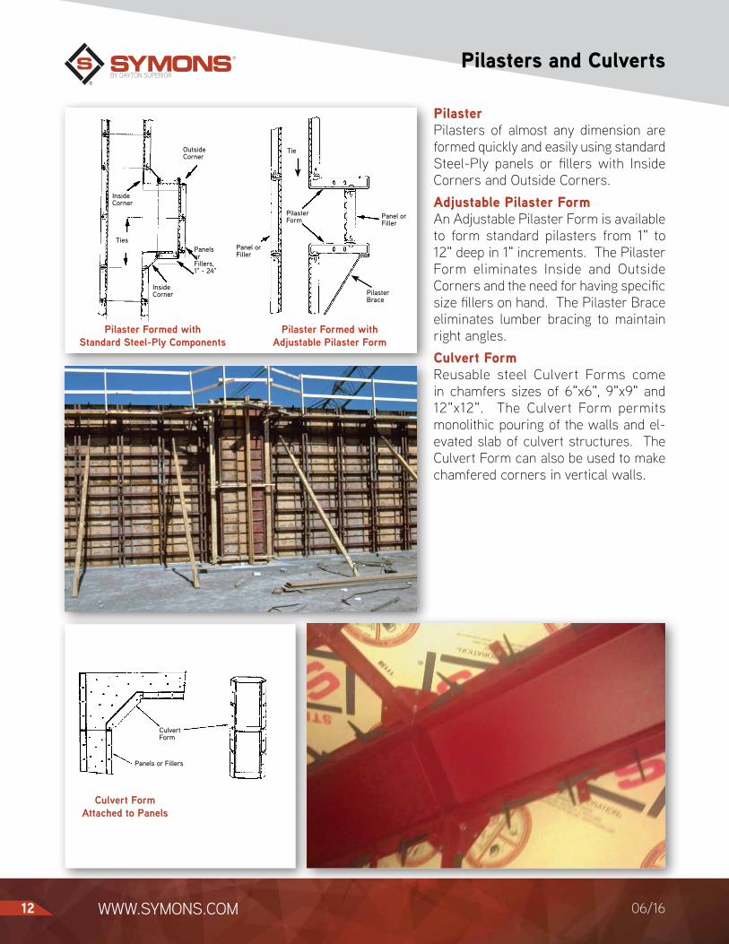
Pilaster Formed with Standard Steel-Ply Components
Pilaster Formed with Adjustable Pilaster Form
Culvert Form Attached to Panels
PilasterPilasters of almost any dimension are formed quickly and easily using standard Steel-Ply panels or fillers with Inside Corners and Outside Corners.Adjustable Pilaster FormAn Adjustable Pilaster Form is available to form standard pilasters from 1" to 12" deep in 1" increments. The Pilaster Form eliminates Inside and Outside Corners and the need for having specific size fillers on hand. The Pilaster Brace eliminates lumber bracing to maintain right angles.Culvert FormReusable steel Culvert Forms come in chamfers sizes of 6"x6", 9"x9" and 12"x12". The Culvert Form permits monolithic pouring of the walls and el-evated slab of culvert structures. The Culvert Form can also be used to make chamfered corners in vertical walls.
Inside Corner
Outside Corner
Panels or Fillers, 1" - 24"
Inside Corner
Ties
Panel or Filler
Pilaster Form
Pilaster Brace
Tie
Panel or Filler
Panels or Fillers
Culvert Form

The Power of Red™ | 1306/16
Lifting Brackets
Double Duty Lift BracketThe Double Duty Lift Bracket provides an attachment point for rigging and handling gangs. A vertical capacity of 2000 lbs. (5 to 1 safety factor) meets OSHA requirements.Application drawings show locations and numbers of Double Duty Lift Brackets per gang.Note: Do not break a gang form loose from a wall by lifting or tugging backwards with the Double Duty Lift Bracket.Waler Lift BracketThe Waler Lift Bracket is an alternative device for lifting gangs. A vertical ca-pacity of 4000 lbs. (5 to 1 safety factor) meets OSHA requirements.Note: Only vertical loads can be imposed at lift holes for the Waler Lift Bracket. A Lift Beam with vertical drop lines connected to Waler Lift Brackets must be used.Column Lift CornerThe Column Lift Corner can be used as the outside corner in the top two feet of ganged columns. The Column Lift Cor-ner extends 4" above the column and is secured with Wedge Bolts. Two Column Lift Corners are required per column. The Column Lift Corner has a safe load capacity of 2000 lbs.
Column Lift Corner Attachment
Waler Lift Bracket Attachment
Double Duty Lift Bracket Attachment
Waler Lift Bracket with (2) 5 8" x 6" Contour Bolts and (4) 5⁄8" Nuts
Lifting Hole
Double Nutted
J Strongback Rod (at Waler Lift Bracket Location Only)
Special Long Bolt Wedge Bolt
Two Wedge Bolt Connections Required Per Leg
Outside Corner
Column Lift Corner

WWW.SYMONS.COM14 06/16
Form Offsets and Extensions
Form Extension BracketThe Form Extension Bracket is a con-venient means to extend the height of a standard panel an additional 3" to 12" for straight or curved walls. The bracket is designed to be used with ¾" plywood and attached with a Wedge Bolt. The bolt comes up from the top rail of the panel below and is locked in with an S-Wedge. A slot in the center of the bracket allows for Waler attachment.Cantilever BracketThe Cantilever Bracket is used to sus-pend a form on the opposite side of the wall. This allows different elevations at the bottom of forms so that a base slab can be mono lith ic ally poured with the wall. Maximum capacity is 700 lbs. Maximum spacing must not exceed panel length when forms are horizontal, and must not exceed 8'-0" when panels are vertical.Brick Ledge BracketThe Brick Ledge Bracket is used to form brick ledges and support various framed boxouts. The bracket is attached to panels or fillers with Wedge Bolts. The bracket spans the wider side of a 2" x 4" piece of lumber to create the offset needed.
Form Extension Bracket Attachment
Cantilever Bracket Attachment
Brick Ledge Bracket Attachment
Wedge Bolt
S Wedge
NailForm Extension Bracket
3/4" Plywood
Panel or Filler
Clip
Fast Pin
Wedge Bolts
Panels or Fillers
14" Max.
Cantilever Bracket
Wedge Bolts
Nail
Panels or Fillers
Bridge Ledge Bracket

The Power of Red™ | 1506/16
Accessories for Less Common Situations
Bulkhead FormingKeyway Forms come in 3', 4', 5', 6' and 8' lengths. When bolted to Bulkhead Bars, they produce a keyway and hold the water stop in position.Bulkhead bars can be used for forming bulkheads in walls 4" to 24" wide. Stan-dard Wedge Bolts attach the bars to the siderails of panels and fillers. Bulkheads can also be formed by using Outside Corners and a panel or filler.Haunch FormingHaunch Brackets provide an ideal way to form haunches or corbels, without any additional lumber support.The Haunch Bracket connects easily with Steel-Ply® panels and is designed to support ¾" plywood. Slots make se-curing walers a simple operation.Footing Corner BracketForming footings, pads and slabs is made easy with the Footing Corner Bracket. Attached at the top and bottom of each corner, Footing Corner Brackets hold the panels firmly. A wide range of dimen-sions in 2" increments is possible.Stake PlateStake Plates are positioned along the top edge of the Steel-Ply for Steel Stakes. The Stake Plates are typically located midway between Steel-Ply crossmem-bers and endrails to provide access for a stake puller.Beam PocketThe Beam Pocket is a reusable tapered steel boxout that leaves a void pocket at the top of the foundation wall for steel or wooden beams. The standard 6” x 8” x 4” deep size comes with a handle for easy carrying and removal.
Haunch Bracket Attachment
Footing Corner Bracket Attachment
Bulkhead Assembly
Haunch Bracket
S Wedge
Waterstop
5⁄16" Bolt
¾" Plywood
Steel-Ply Panel
Rebar
Standard Wedge Bolt Attachment
¾" Plywood
Bulkhead Bar
Keyway Form
4 Wedge Bolt connections
Footing Corner Bracket located top and bottom of forms
Stake Plate
Steel Stake
Steel-Ply used horizontally

WWW.SYMONS.COM16 06/16
Column Forming
Note: Wedge bolts pass through plywood at selected crossmem-ber slots
Stripping a Column with a Hinged Corner
Column Hinge Corner Attachment Quick Column
Hardware Attachment
Column formingOutside Corners and panels or fillers can be combined to form square or rectan-gular columns.Column HingeThe Column Hinge helps set and strip Steel-Ply column forms efficiently. Col-umn formwork can be handled as a single unit that is “closed” around reinforcing steel and “opened” after concrete is placed. Repetitive concrete column de-signs become very productive.Quick Column HardwareThe Quick Column Hardware is used with the Column Hinge for even faster column forming. The hardware attaches to the Steel-Ply Outside Corner opposite the Column Hinge to provide a fast clo-sure and release. Everything remains connected to the column formwork for maximum productivity.Adjustable Column FormThe Adjustable Column Form is for col-umns up to 30" square, in 1" increments (except 28" and 29" increments). For col-umns 27" or less, panels are placed in an overlapping manner. In these instances, ¾" holes are drilled through the plywood at the appropriate connection bolt slot in the crossmember for the hardware.Column Filler AngleThe Column Filler Angle is used with ¾" plywood to extend the top of a column 10" to 24" wide. It is placed in a run-by configuration when column dimensions are under 24".Adjustable Column ExtenderSteel plate assemblies overlap Steel-Ply forms to extend columns 2" to 12". They are used in a run-by configuration for column thicknesses from 10" to 22". The top angle of the plates have nail holes for connecting to deck plywood to facilitate monolithic deck and column pours.
8½" 6"
Outside Corner and Wedge Bolts
Column Hinges
Release Corner
Adjustable Column ExtenderColumn Filler Angle
Typical Adjustable Column Form Application

The Power of Red™ | 1706/16
Gang Forming
Walers Align Forms Strongbacks Align Walers
Productive SystemGang forms are easily assembled on the ground and then moved into place. Stripping the unit as a gang eliminates rebuilding. This saves time and material, increases production, and reduces costs.The lightweight Steel-Ply design is ideal for gangforming. At just 8 lbs. per square foot, including hardware, Walers and Strongbacks, gang form size is limited only by crane capacity.Gang Form BoltGang Form Bolts and Wedge Bolts are used to connect panels and gang form ties. The patented Steel-Ply Gang Form Bolt connects panel siderails and gang form ties in a single operation. This lon-ger end allows you to break the ties back and strip the gang without disassembling the forms.WalerWalers are placed 18" from the top and bottom of the gang, with one Waler for each tier of panels. These Walers align forms within the gang. Walers are as-sembled using 2" x 4" or 2" x 6" lumber with Gang Waler Rods, Waler Plates, and ½" Contour Nuts for a secure connection.StrongbackThe same time and material advantages in waling with the Steel-Ply Forming System are also present in the use of Strongbacks which are needed only to align the Walers. They are usually placed at 8' centers, but spacing depends on the specific job conditions.Steel-Ply Gang FillerThe Steel-Ply Gang Filler increases pro-ductivity by reducing the number of ties required in conventional gangforming. This 2" steel filler features preset tie hole locations for reusable 15mm Taper Ties (1" to ¾"), She Bolts or Tie Rods with 15mm Tie Nuts to secure the tie.
Gang Waler Rod and Plate
Wedge Bolts
Panels or Fillers
Panels or Fillers J Strongback Rod
2" x 4" or 2" x 6" Strongbacks

WWW.SYMONS.COM18 06/16
Load gathering and Heavy Duty Ties
The most economical and productive way to gangform with Steel-Ply form-ing system is to use the load-gathering technique. Steel walers and strongbacks “gather” the load of the panels and high-capacity ties are installed through the panels and Walers. The load is trans-ferred to the ties from the walers.The strength and rigidity of the Steel-Ply system allows ties to be placed farther apart than in conventional gang forming. Fewer ties saves labor when setting, stripping and patching, and increases tie placement adaptability.“Y” WallsLoad-gathered Steel-Ply reduces the number of ties, saving labor and material for typical “Y” walls. Standard Inside and Outside Corners and a Cantilever Bracket form trough walls. Inside and Outside Bay Corners and 45° Walers are combined with Walers and Waler Splices to form “Y” walls.Heavy Duty TiesSymons supplies 50 Kip She-Bolts or Ta-per Ties when 5" walers are used. The strength of these ties, combined with the load-gathering ability of the Steel-Ply pan-els and Walers, permit 4' x 5' tie spacing in most gang form applications. Using fewer ties with each gang reduces overall labor and material costs. 85 Kip She-Bolts and 96 Kip Taper Ties are used with 8" walers.65 Kip She-Bolts and Taper Ties are used with 5" or 8" Walers.Spreader ClipsSpreader Clips are used with Taper Ties or She-Bolts. It is a U-shaped plate that fits over the Cast Bearing Washer and hex nut, preventing inward movement of the gang. A tie with Spreader Clips near the bottom of the forms and one tie with Spreader Clips near the top of the form prevents inward movement and maintains the desired wall thickness.
She-Bolt with Cast Bearing Washer
Spreader Clip
Friction Clamp Bolt
Cast Bearing Washer
She-Bolt with Batter Plate Washer
Batter Plate Washer
50K Cast Contour Nut
Taper Tie with Cast Bearing Washer
Spreader Clip
Friction Clamp Bolt
Cast Bearing Washer
65K Taper Tie
20mm 7" Circular Tie Plate and Bolt

The Power of Red™ | 1906/16
Maxi-Waler Gang Forming
Maxi-Waler Steel ChannelThe Maxi-Waler System uses double 3" steel channels attached to Steel-Ply at 2' O.C. vertical spacing. The channel serves as both load-gathering member and aligner for the gang. “L” Washers and 8" Gang Waler Rods secure the steel channels to the forms for a posi-tive connection.Vertical WalersThe Maxi-Waler System uses double channel steel walers to transfer the load from the 3" channels. J-Strong-back Rods and Plate Washers connect to the 3" channels at specific vertical locations. To prevent slippage, Panel Waler Connectors and Clip Angles are bolted to the Waler at two connection sites. Walers are spaced at 4' centers for maximum form design utilization.5" and 8" Steel WalersFor maximum form design utilization, Symons offers 5" and 8" waler sizes. Tie areas of up to 32 square feet can be achieved, resulting in fewer ties per pour and less tie patching.The 5" and 8" walers are available in standard lengths of 4', 8' 10', 12' and 16'. The 5" walers are also available in a 6' length.
5" Waler 8" Waler
3" Steel Channels Gather Loads and Make Alignments
Double Channel Steel Waler Used as a Strongback
Double 3" Aligner Channels as Walers
J Strongback Rod Provides Secure Connection of Walers and Strongbacks
5" Double Channel Strongback
11/16" dia. Holes 6" O.C.
Welded Plate Gussets
Standard Wedge Bolts Steel-Ply
Forms
Double 3" Aligner Channels
“L” Washer
8" Gang Waler Rod1/2" Contour Nut

WWW.SYMONS.COM20 06/16
Horizontal Gangs
Typical Waler Connection
Panel Waler Connection
5" Versiform Walers Used as a Steel Strongback
Horizontal Steel-Ply GangsHorizontal Steel-Ply gang forms utilize vertical steel walers. This permits the use of high capacity Taper Ties or She-Bolts.Horizontal Steel-Ply gangs are assem-bled using 6' and 3' panels in a “brick” pattern layout.Waler ConnectionSteel walers are easily connected with 8" Gang Waler Rods, Plate Washers and ½" diameter Contour Nuts. Walers are placed 18" from gang ends and at 3' O.C. spacing.Panel Waler ConnectorTo prevent waler slippage, a Panel Waler Connector is attached through the Gang Waler Rod and bolted to the walers.Panel Waler Connectors can also con-nect the horizontal Strongbacks to ver-tical steel Walers.Strongback5" Walers used as Strongbacks provide stiffness and horizontal alignment to the gang. These Walers are attached with 8½" J-Bolts, Plate Washers and 5/8" Contour Nuts. Strongbacks are usually placed at the top and bottom of each gang.
Steel Waler
J Bolt
Steel Strongback
5⁄8" Dia. Nut
Panels or Fillers
Gang Waler Rod
Panel Waler Connector
(2) 5⁄8" x 2" Fit-Up Bolts
Steel Waler
Wedge Bolts
Gang Waler Rod
Plate Washer
½" Dia. Nut
Steel Waler
Horizontal Panels or Fillers
Plate Washer

The Power of Red™ | 2106/16
Core Wall Forms
Double Hinged FillersDouble Hinged Fillers allow gangs for core walls and elevator shafts to be set, stripped, lifted and reset quickly. Mini-mal crane time is needed because they make all four sides of the gang into one movable unit.The Double Hinged Filler is designed with two hinge points to permit inward movement when a Turnbuckle connec-tion is retracted. After positioning the gang for the next pour, the Turnbuckles return the gang form to the rectangular shape.Steel Walers and Strongbacks are used with high capacity She-Bolts or Taper Ties for higher productivity.Multi Shear Wall BracketThe Multi Shear Wall Bracket supports ganged forms for multiple lifts. Used with the Guide Bracket to position gangs snug against the wall, the Multi Shear Wall Bracket can support 3,000 lbs.
Core Wall Forms in the Pouring Position
Core Wall Forms in the Stripping Position
Double Hinged Filler with 90° Inside Corner
Coreform Clearance
2"
Double Hinge Filler
2"
Multi Shear Wall Bracket
Guide Bracket
WWW.SYMONS.COM22 06/16
Radius walls
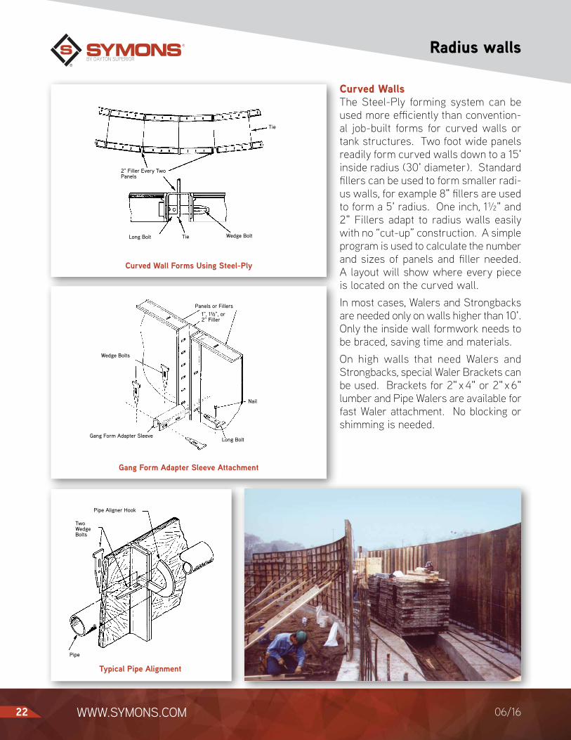
Curved WallsThe Steel-Ply forming system can be used more efficiently than convention-al job-built forms for curved walls or tank structures. Two foot wide panels readily form curved walls down to a 15' inside radius (30' diameter). Standard fillers can be used to form smaller radi-us walls, for example 8" fillers are used to form a 5' radius. One inch, 1½" and 2" Fillers adapt to radius walls easily with no “cut-up” construction. A simple program is used to calculate the number and sizes of panels and filler needed. A layout will show where every piece is located on the curved wall.In most cases, Walers and Strongbacks are needed only on walls higher than 10'. Only the inside wall formwork needs to be braced, saving time and materials.On high walls that need Walers and Strongbacks, special Waler Brackets can be used. Brackets for 2" x 4" or 2" x 6" lumber and Pipe Walers are available for fast Waler attachment. No blocking or shimming is needed.
Curved Wall Forms Using Steel-Ply
Gang Form Adapter Sleeve Attachment
Typical Pipe Alignment
Pipe
Pipe Aligner Hook
Two Wedge Bolts
Panels or Fillers1", 1½", or 2" Filler
Nail
Long Bolt
Wedge Bolts
Gang Form Adapter Sleeve
2" Filler Every Two Panels
Wedge BoltTieLong Bolt
Tie

The Power of Red™ | 2306/16
Transitions
Pipe Aligner Attachment
Transitions from Sym-Ply® to Steel-PlyWedge Bolts allow quick and easy con-nection between Steel-Ply and Sym-Ply. This combination allows contrac-tors who own one or the other system to rent the other as needed.Transitions from Steel-Ply to Max-A-Form® or Flex-Form®
Steel-Ply panels and fillers connect directly to Max-A-Form and Flex-Form with Wedge Bolts. This combination provides the strength and gang forming advantages of the all-steel systems with Steel-Ply versatility for details.Attached Hardware OptionResidential and other repetitive handset jobs are perfect applications for the time-saving attached hardware feature. In this system, panels are supplied with the connecting Drop Bolts and Slide Bolts already attached. Since connect-ing bolts are already attached at the tie locations, workers immediately know where to position each tie.An attached Hardware Kit is also available for contractors who wish to retrofit Steel-Ply panels and fillers they already own.Beam PocketThe Beam Pocket is a reusable tapered steel boxout that leaves a void pocket at the top of the foundation wall for steel or wooden beams. The standard 6"x8"x4" deep size comes with a handle for easy carrying and removal.
Beam Pocket for Foundation Void
Steel-Ply to Max-A-Form Transition
Attached Hardware in the Locked Position
Max-A-Form Panel
Steel-Ply Short Bolt
Steel-Ply Panel or Filler
Slide Wedge
Drop Bolt
Sym-Ply to Steel-Ply Transition
For more information:• Steel-Ply Application Guide• Handset Safety Poster• Gangform Safety Poster• Component ID Poster• www.symons.com• Call 800-800-7966

SYM11606/16
Copyright © 2016 Dayton Superior Corporation, All Rights Reserved.
1125 Byers Road Miamisburg, OH 45342 937-866-0711888-977-9600WWW.SYMONS.COM
THE POWER OF RED™