steel vessels for service on rivers and intracoastal waterways · 2020-01-09 · plan review,...
TRANSCRIPT

RULES FOR BUILDING AND CLASSING
STEEL VESSELS FOR SERVICE ON RIVERS ANDINTRACOASTAL WATERWAYSJULY 2019
American Bureau of ShippingIncorporated by Act of Legislature ofthe State of New York 1862
© 2019 American Bureau of Shipping. All rights reserved.1701 City Plaza DriveSpring, TX 77389 USA

RULES FOR BUILDING AND CLASSING
STEEL VESSELS FOR SERVICE ON RIVERS ANDINTRACOASTAL WATERWAYS
CONTENTSPART 1 Conditions of Classification(Supplement to the ABS Rules
for Conditions of Classification)........................................................ 1CHAPTER 1 Scope and Conditions of Classification............................. 1
PART 3 Hull Construction and Equipment......................................................8CHAPTER 1 General.............................................................................. 9CHAPTER 2 Hull Structures and Arrangements...................................17CHAPTER 3 Subdivision and Stability................................................107CHAPTER 4 Fire Safety Measures.....................................................124CHAPTER 5 Equipment......................................................................133CHAPTER 6 Testing, Trials and Surveys During Construction - Hull..136
PART 4 Vessel Systems and Machinery......................................................150CHAPTER 1 General.......................................................................... 151CHAPTER 2 Propulsion and Maneuvering Machinery....................... 158CHAPTER 3 Pumps and Piping Systems...........................................179CHAPTER 4 Fire Extinguishing Systems and Equipment.................. 236CHAPTER 5 Electrical Installations.................................................... 254
ABS RULES FOR BUILDING AND CLASSING STEEL VESSELS FOR SERVICE ON RIVERS ANDINTRACOASTAL WATERWAYS • 2019
ii

P A R T
1Conditions of Classification(Supplement to the ABS Rules forConditions of Classification)
CONTENTSCHAPTER 1 Scope and Conditions of Classification............................................ 1
Section 1 Classification (1 January 2008)......................................... 3Section 2 Classification Symbols and Notations (1 January
2008)..................................................................................4Section 3 Rules for Classification (1 January 2008).......................... 5Section 4 Submission of Plans.......................................................... 6
ABS RULES FOR BUILDING AND CLASSING STEEL VESSELS FOR SERVICE ON RIVERS ANDINTRACOASTAL WATERWAYS • 2019
1

This Page Intentionally Left Blank

P A R T
1C H A P T E R 1 Scope and Conditions of Classification
CONTENTSForeword (1 January 2008)................................................................. 2
SECTION 1 Classification (1 January 2008).......................................................... 3
SECTION 2 Classification Symbols and Notations (1 January 2008)................. 41 River Service.................................................................................. 43 Special Rules..................................................................................4
SECTION 3 Rules for Classification (1 January 2008)..........................................51 Application...................................................................................... 5
1.1 General.............................................................................. 51.3 Application (2005)..............................................................5
SECTION 4 Submission of Plans............................................................................61 Hull Plans (2011)............................................................................ 63 Machinery Plans............................................................................. 75 Additional Plans..............................................................................7
ABS RULES FOR BUILDING AND CLASSING STEEL VESSELS FOR SERVICE ON RIVERS ANDINTRACOASTAL WATERWAYS • 2019
1

P A R T
1C H A P T E R 1 Scope and Conditions of Classification
Foreword (1 January 2008)
For the 2008 edition, Part 1, “Conditions of Classification” was consolidated into a generic booklet,entitled Rules for Conditions of Classification (Part 1) for all vessels other than those in offshore service.The purpose of this consolidation was to emphasize the common applicability of the classificationrequirements in “Part 1” to ABS-classed vessels, other marine structures and their associated machinery,and thereby make “Conditions of Classification” more readily a common Rule of the various ABS Rulesand Guides, as appropriate.
Thus, this supplement specifies only the unique requirements applicable to steel vessels for service onrivers and Intracoastal waterways. This supplement is always to be used with the aforementioned Rules forConditions of Classification (Part 1).
ABS RULES FOR BUILDING AND CLASSING STEEL VESSELS FOR SERVICE ON RIVERS ANDINTRACOASTAL WATERWAYS • 2019
2

P A R T
1C H A P T E R 1 Scope and Conditions of Classification
S E C T I O N 1 Classification (1 January 2008)
The requirements for conditions of classification are contained in the separate, generic ABS Rules forConditions of Classification (Part 1).
Additional requirements specific to steel vessels for service on rivers and intracoastal waterways arecontained in the following Sections of this Part.
ABS RULES FOR BUILDING AND CLASSING STEEL VESSELS FOR SERVICE ON RIVERS ANDINTRACOASTAL WATERWAYS • 2019
3

P A R T
1C H A P T E R 1 Scope and Conditions of Classification
S E C T I O N 2 Classification Symbols and Notations (1 January2008)
A listing of Classification Symbols and Notations available to the Owners of vessels, offshore drilling andproduction units and other marine structures and systems, “List of ABS Notations and Symbols” isavailable from the ABS website “http://www.eagle.org”.
The following notations are specific to vessels intended for service on rivers or Intracoastal waterways.
1 River ServiceVessels which have been built to the satisfaction of the ABS Surveyors to the requirements of these Rules,where approved by the Committee, will be classed and distinguished in the Record by the symbols ✠ A1,followed by the service limitation River Service.
3 Special RulesVessels which have been built to the satisfaction of the ABS Surveyors to the requirements as contained inthe Rules for special types of vessels and which are approved by the Committee will be classed anddistinguished in the Record by the symbols ✠ A1 followed by appropriate notation and service limitationsuch as Oil Tank Barge, River Service, Barge, River Service, Towing Vessel, River Service,Chemical Tank Barge, River Service, Passenger Vessel, River Service, etc.
ABS RULES FOR BUILDING AND CLASSING STEEL VESSELS FOR SERVICE ON RIVERS ANDINTRACOASTAL WATERWAYS • 2019
4

P A R T
1C H A P T E R 1 Scope and Conditions of Classification
S E C T I O N 3 Rules for Classification (1 January 2008)
1 Application
1.1 GeneralThese Rules have been developed for barges, towboats, cargo vessels and passenger vessels in service onmajor rivers and on connecting intracoastal waterways. These Rules provide for certain features peculiar tothis service such as push-towing, integrated tows consisting of barges in contact and frequent transiting oflocks. However, they are intended to apply to and may be used in development of designs for vesselsintended for service in other bodies of comparatively smooth water. These Rules are not intended to applyto vessels in service on the Great Lakes of North America, coastwise operation, or on any ocean. In thedesign of self-propelled vessels intended to carry dry or liquid cargoes, the arrangements and scantlings inway of the cargo spaces may be taken from the appropriate Sections for barges.
These requirements are applicable to those features that are permanent in nature and can be verified byplan review, calculation, physical survey or other appropriate means. Any statement in the Rules regardingother features is to be considered as a guidance to the designer, builder, owner, et al.
1.3 Application (2005)The application of the Rules is, in general, based on the contract date for construction between theshipbuilder and the prospective owner. (e.g., Rules which became effective on 1 July 2005 are notapplicable to a vessel for which the contract for construction was signed on 30 June 2005.) See also1-1-4/3 of the ABS Rules for Conditions of Classification (Part 1).
ABS RULES FOR BUILDING AND CLASSING STEEL VESSELS FOR SERVICE ON RIVERS ANDINTRACOASTAL WATERWAYS • 2019
5

P A R T
1C H A P T E R 1 Scope and Conditions of Classification
S E C T I O N 4 Submission of Plans
1 Hull Plans (2011)Plans showing the scantlings, arrangements, and details of the principal parts of the hull structure of eachvessel to be built under survey are to be submitted and approved before the work of construction iscommenced. These plans are to indicate clearly the scantlings and details of welding, and they are toinclude, if applicable, such particulars as the design draft and design speed. Where provision is to be madefor any special type of cargo or for any exceptional conditions of loading, whether in ballast or with cargo,particulars of the weights to be carried and of their distribution are also to be given. In general, thefollowing plans are to be submitted for review or reference.
● Vessel Specifications
● General Arrangement
● Midship Section
● Scantling Profile
● Bottom Construction, Floors, Girders, etc.
● Framing
● Rake Framing
● Bow Framing
● Stem
● Inner Bottom
● Shell Plating
● Decks
● Trusses
● Pillars and Girders
● Watertight and Deep Tank Bulkheads
● Shaft Tunnels
● Machinery Casings, Boiler, Engine and Main Auxiliary Foundations
● Stern Framing
● Stern Frame and Rudder
● Shaft Struts
● Superstructures and Deckhouses
● Hatches and Hatch-Closing Arrangements
● Ventilation System on Weather Decks
Plans should generally be submitted in electronically to ABS. However, hard copies will also be accepted.
ABS RULES FOR BUILDING AND CLASSING STEEL VESSELS FOR SERVICE ON RIVERS ANDINTRACOASTAL WATERWAYS • 2019
6

3 Machinery PlansPlans showing the boiler, main propulsion engine, reduction gear, shafting and thrust bearing foundations(See 3-2-1/25 or 3-2-2/21), including holding-down bolts; also machinery general arrangement, installationand equipment plans as referenced in Part 4, are to be submitted and approved before proceeding with thework.
5 Additional PlansWhere certification under 1-1-5/3 or 1-1-5/5 of the ABS Rules for Conditions of Classification (Part 1) isrequested, submission of additional plans and calculations may be required.
Part 1 Conditions of Classification(Supplement to the ABS Rules for Conditions ofClassification)
Chapter 1 Scope and Conditions of ClassificationSection 4 Submission of Plans 1-1-4
ABS RULES FOR BUILDING AND CLASSING STEEL VESSELS FOR SERVICE ON RIVERS ANDINTRACOASTAL WATERWAYS • 2019
7

P A R T
3Hull Construction and Equipment
CONTENTSCHAPTER 1 General..................................................................................................9
Section 1 Definitions........................................................................ 11Section 2 General Requirements.....................................................14
CHAPTER 2 Hull Structures and Arrangements.................................................. 17Section 1 Tank Barges.....................................................................23Section 2 Dry Cargo Barges............................................................ 46Section 3 Barges Intended to Carry Dangerous Chemical
Cargoes in Bulk............................................................... 66Section 4 Towboats..........................................................................70Section 5 Passenger Vessels.......................................................... 81Section 6 Weld Design.................................................................... 98
CHAPTER 3 Subdivision and Stability................................................................ 107Section 1 Passenger Vessels........................................................ 109Section 2 Crane Barges (2015)..................................................... 119
CHAPTER 4 Fire Safety Measures....................................................................... 124Section 1 Passenger Vessels........................................................ 126
CHAPTER 5 Equipment........................................................................................ 133Section 1 Passenger Vessels........................................................ 134
CHAPTER 6 Testing, Trials and Surveys During Construction - Hull...............136Section 1 Tank, Bulkhead and Rudder Tightness Testing (1
July 2012)...................................................................... 137Section 2 Trials.............................................................................. 148Section 3 Surveys..........................................................................149
ABS RULES FOR BUILDING AND CLASSING STEEL VESSELS FOR SERVICE ON RIVERS ANDINTRACOASTAL WATERWAYS • 2019
8

P A R T
3C H A P T E R 1 General
CONTENTSSECTION 1 Definitions...........................................................................................11
1 Application.................................................................................... 113 Length........................................................................................... 11
3.1 Barges..............................................................................113.3 Self-Propelled Vessels..................................................... 11
5 Breadth......................................................................................... 117 Depth............................................................................................ 119 Design Draft.................................................................................. 1111 Baseline........................................................................................ 1113 Truss............................................................................................. 1115 Amidships..................................................................................... 1117 Block Coefficient (Cb)....................................................................1219 Double Ended Rake Barge...........................................................1221 Oil................................................................................................. 1223 Passenger.....................................................................................1225 Superstructure.............................................................................. 1227 Cargo Area................................................................................... 1229 Cargo Pump Room.......................................................................1231 Weathertight................................................................................. 1233 Gross Tonnage............................................................................. 1235 Units..............................................................................................12
SECTION 2 General Requirements.......................................................................141 Materials....................................................................................... 14
1.1 Steel (2017)..................................................................... 141.3 Aluminum Alloys.............................................................. 141.5 Design Consideration...................................................... 141.7 Guidance for Repair.........................................................141.9 Materials Containing Asbestos (2005).............................14
3 Scantlings..................................................................................... 143.1 General............................................................................ 143.3 Workmanship...................................................................15
5 Proportions................................................................................... 157 Structural Sections........................................................................15
7.1 Required Section Modulus...............................................157.3 Serrated Sections............................................................ 15
9 Structural Design Details.............................................................. 159.1 General............................................................................ 15
ABS RULES FOR BUILDING AND CLASSING STEEL VESSELS FOR SERVICE ON RIVERS ANDINTRACOASTAL WATERWAYS • 2019
9

9.3 Termination of Structural Members..................................16
ABS RULES FOR BUILDING AND CLASSING STEEL VESSELS FOR SERVICE ON RIVERS ANDINTRACOASTAL WATERWAYS • 2019
10

P A R T
3C H A P T E R 1 General
S E C T I O N 1 Definitions
1 ApplicationUnless specified otherwise, the following definitions apply in all cases where reference is made in theseRules, Tables and equations.
3 Length
3.1 BargesL is the distance, in meters (feet), measured on the centerline between the inside surfaces of the head logplates at each end. For barges of special form such as those having rounded ends or with wells or recessesin the ends, the length for the purpose of these Rules is to be specially determined.
3.3 Self-Propelled VesselsL is the overall distance, in meters (feet), measured on the centerline, between the inside surfaces of theshell plates at each end.
5 BreadthThe breadth, B, is the greatest horizontal distance, in meters (feet), between the inner surfaces of the sideshell plating.
7 DepthThe depth, D, is the vertical distance, in meters (feet), measured at the middle of L from the base line to theunder surface of the deck plating at the side of the vessel.
9 Design DraftThe design draft, d, is the vertical distance, in meters (feet), measured at the middle of L from the baselineto the deepest design waterline.
11 BaselineThe Baseline is a horizontal line extending through the upper surface of the bottom shell plating at thecenterline.
13 TrussA Truss is a system of internal framing members comprised of top and bottom chords extending eitherlongitudinally or transversely in association with regularly spaced stanchions and diagonals. A single lacedtruss is one having diagonal bracing in only one direction in each space between stanchions; a double lacedtruss is one having diagonal bracing in both directions in each space.
15 AmidshipsAmidships is the middle of the length L.
ABS RULES FOR BUILDING AND CLASSING STEEL VESSELS FOR SERVICE ON RIVERS ANDINTRACOASTAL WATERWAYS • 2019
11

17 Block Coefficient (Cb)The Block Coefficient Cb , is given byCb = ∇/LBdwhere ∇ is the volume of molded displacement, excluding appendages, in cubic meters (cubic feet).
19 Double Ended Rake BargeA Double Ended Rake Barge is a barge with similar rakes at each end and fitted with towing bitts arrangedin such a manner that the barge in normal circumstances may be towed from either end. Each end of bargeswith this configuration is to be considered as the forward end in the application of these Rules.
21 OilAs used in these Rules, the term Oil refers to petroleum products having flash points at or below 60°C(140°F), (closed cup test).
23 PassengerA Passenger is every person other than the master and the members of the crew or other persons employedor engaged in any capacity onboard a vessel on the business of that vessel and children under one year ofage.
25 SuperstructureA Superstructure is a decked structure on the freeboard deck extending from side to side of the barge orvessel, or with the side plating not being inboard of the shell plating more than 0 . 04B.
27 Cargo AreaThe Cargo Area is that part of a barge that contains cargo tanks, slop tanks and cargo pump rooms andincludes ballast and void spaces, cofferdams and pump rooms adjacent to cargo tanks and also deck areasthroughout the entire length and breadth of that part of the barge over the above mentioned spaces. Inchemical and liquefied gas tank barges having independent cargo tanks installed in hold spaces, cofferdamsor ballast or void spaces aft of the aftermost hold space bulkhead or forward of the forward-most holdspace bulkhead are excluded from the cargo area.
29 Cargo Pump RoomA Cargo Pump Room is a space containing pumps and their accessories for the handling of the cargo.
31 WeathertightWeathertight means that in any sea conditions water will not penetrate into the vessel.
33 Gross TonnageFor vessels in domestic service, gross tonnage is the national gross tonnage as specified by the country inwhich the vessel is to be registered. For vessels which are engaged in international voyages, gross tonnageis to be determined by the International Convention on Tonnage Measurement of Ships, 1969.
35 UnitsThese Rules are written in two systems of units, i.e., MKS units and US customary units. Each system is tobe used independently of any other system.
Part 3 Hull Construction and EquipmentChapter 1 GeneralSection 1 Definitions 3-1-1
ABS RULES FOR BUILDING AND CLASSING STEEL VESSELS FOR SERVICE ON RIVERS ANDINTRACOASTAL WATERWAYS • 2019
12

Unless indicated otherwise, the format of presentation in the Rules of the two systems of units is asfollows:
MKS units (US customary units)
Part 3 Hull Construction and EquipmentChapter 1 GeneralSection 1 Definitions 3-1-1
ABS RULES FOR BUILDING AND CLASSING STEEL VESSELS FOR SERVICE ON RIVERS ANDINTRACOASTAL WATERWAYS • 2019
13

P A R T
3C H A P T E R 1 General
S E C T I O N 2 General Requirements
1 Materials
1.1 Steel (2017)These Rules are intended for barges and vessels of welded construction using steels complying with therequirements of Chapters 1 and 2 of the ABS Rules for Materials and Welding (Part 2). Use of steels otherthan those in Chapters 1 and 2 of the above Part 2 and the corresponding scantlings will be speciallyconsidered. Where it is intended to use material of cold flanging quality, this steel is to be indicated on theplans. ASTM A36 steel otherwise manufactured by an ABS approved steel mill, tested and certified to thesatisfaction of ABS may be used in lieu of Grade A for a thickness up to and including 12.5 mm (0.5 in.)for plates and up to and including 19 mm (0.75 in.) for sections.
1.3 Aluminum AlloysThe use of aluminum alloys in hull structures will be considered upon submission of the proposedspecification for the alloy and the method of fabrication.
1.5 Design ConsiderationWhere scantlings are reduced in connection with the use of higher-strength steel or where aluminum alloysare used, adequate buckling strength is to be provided. Where it is intended to use material of cold flangingquality for important longitudinal strength members, this steel is to be indicated on the plans.
1.7 Guidance for RepairWhere a special welding procedure is required for the special steels used in the construction, including anylow temperature steel and those materials not in Chapters 1 and 2 of the ABS Rules for Materials andWelding (Part 2), a set of plans showing the following information for each steel should be placed aboardthe barge or vessel.
● Material Specification
● Welding procedure
● Location and extent of application
These plans are in addition to those normally placed aboard which are to show all material applications.
1.9 Materials Containing Asbestos (2005)See 4-1-1/21.
3 Scantlings
3.1 GeneralSections having appropriate section moduli or areas, in accordance with their functions in the structure asstiffeners, columns or combinations of both, are to be adopted, due regard being given to the thickness of
ABS RULES FOR BUILDING AND CLASSING STEEL VESSELS FOR SERVICE ON RIVERS ANDINTRACOASTAL WATERWAYS • 2019
14

all parts of the sections to provide a proper margin for corrosion. It may be required that calculations besubmitted in support of resistance to buckling for any part of the vessel’s structure.
3.3 WorkmanshipAll workmanship is to be of commercial marine quality and acceptable to the Surveyor. Welding is to be inaccordance with the requirements of 3-2-6. The Surveyors are to satisfy themselves that all operators to beemployed in the construction of barges and vessels to be classed are properly qualified in the type of workproposed and in the proper use of the welding processes and procedures to be followed.
5 ProportionsIn general, these Rules are valid for vessels having lengths not exceeding 30 times their depth, andbreadths not exceeding 6 times their depth. Vessels with other proportions will be specially considered.
7 Structural Sections
7.1 Required Section ModulusThe scantling requirements of these Rules are applicable to structural angles, channels, bars, and rolled orbuilt-up sections. The required section modulus of members such as girders, webs, etc., supporting framesand stiffeners is to be obtained with an effective width of plating basis as described below, unlessotherwise noted. The section modulus is to include the structural member in association with an effectivewidth of plating equal to one-half the sum of the spacing on each side of the member or 33% of theunsupported span ℓ, whichever is less. For girders and webs along hatch openings, an effective breadth ofplating equal to one-half the spacing or 16 . 5% of the unsupported span ℓ, whichever is less, is to be used.Where channel construction is adopted, as illustrated in 3-2-1/25.3 FIGURE 5 and 3-2-2/21.3 FIGURE 5,the required section modulus is to be obtained solely by the channel.
The required section modulus of frames and stiffeners is assumed to be provided by the stiffener and oneframe space of the plating to which it is attached. . For bars or shapes which are not attached to the plating,the section modulus is to be obtained in the member only. It may be required that calculations be submittedin support of the resistance to buckling of longitudinals.
7.3 Serrated SectionsSerrated sections may be used for girders, webs, frames and stiffeners, but the depth of the member is notto be less than 2 times the depth of any cutout. The cutouts are to be arranged to provide regularly spacedpoints of contact with the plating sufficient to obtain the welding required. Where supporting members arecut out for framing and stiffening members, the depth of the cutout should not exceed 50% of the depth ofthe supporting member.
9 Structural Design Details
9.1 GeneralThe designer shall give consideration to the following:
9.1.1The thickness of internals in locations susceptible to rapid corrosion.
9.1.2The proportions of built-up members to comply with established standards for buckling strength.
Part 3 Hull Construction and EquipmentChapter 1 GeneralSection 2 General Requirements 3-1-2
ABS RULES FOR BUILDING AND CLASSING STEEL VESSELS FOR SERVICE ON RIVERS ANDINTRACOASTAL WATERWAYS • 2019
15

9.1.3The design of structural details, such as noted below, against the harmful effects of stressconcentrations and notches:
i) Details of the ends, the intersections of members and associated brackets.
ii) Shape and location of air, drainage, or lightening holes.
iii) Shape and reinforcement of slots or cut-outs for internals.
iv) Elimination or closing of weld scallops in way of butts, “softening” of bracket toes,reducing abrupt changes of section or structural discontinuities.
9.1.4Proportions and thickness of structural members to reduce fatigue response due to cyclic stresses,particularly for higher-strength steels.
9.3 Termination of Structural MembersUnless permitted elsewhere in the Rules, structural members are to be effectively connected to the adjacentstructures in such a manner as to avoid hard spots, notches and other harmful stress concentrations. Wheremembers are not required to be attached at their ends, special attention is to be given to the end taper, byusing soft-toed concave brackets or by a sniped end of not more than 30°. Where the end bracket has aface bar, it is to be sniped and tapered not more than 30°. Bracket toes or sniped ends are to be kept within25 mm (1.0 in.) of the adjacent member, and the depth at the toe or snipe end is generally not to exceed 15mm (0.60 in.). Where a strength deck or shell longitudinal terminates without end attachment, it is toextend into the adjacent transversely framed structure or stop at a local transverse member fitted at aboutone transverse frame space beyond the last floor or web that supports the longitudinal.
Part 3 Hull Construction and EquipmentChapter 1 GeneralSection 2 General Requirements 3-1-2
ABS RULES FOR BUILDING AND CLASSING STEEL VESSELS FOR SERVICE ON RIVERS ANDINTRACOASTAL WATERWAYS • 2019
16

P A R T
3C H A P T E R 2 Hull Structures and Arrangements
CONTENTSSECTION 1 Tank Barges........................................................................................23
1 Application.................................................................................... 233 Classification.................................................................................235 Structural Arrangement.................................................................23
5.1 Between the Rakes..........................................................235.3 Rakes...............................................................................245.5 Double Skin Construction................................................ 24
7 Longitudinal Strength (2001)........................................................ 247.1 Definitions........................................................................ 247.3 Loading Conditions.......................................................... 257.5 Loading/Unloading Sequences and Bending Moment
Calculations..................................................................... 257.7 Hull Girder Section Modulus (1 July 2016)...................... 257.9 Items Included in the Section Modulus Calculation......... 26
9 Deck and Trunk Plating................................................................ 279.1 Between the Rakes..........................................................279.3 Rake Decks..................................................................... 27
11 Frames..........................................................................................2713 Trusses......................................................................................... 28
13.1 Top and Bottom Chords................................................... 2813.3 Stanchions....................................................................... 2813.5 Diagonals.........................................................................29
15 Web Frames, Girders and Stringers............................................. 2917 Tank Head for Scantlings..............................................................29
17.1 Pressure Setting 0.12 kgf/cm2 (1.7 psi) or Less..............2917.3 Pressure Setting Over 0.12 kgf/cm2 (1.7 psi)..................29
19 Bulkheads.....................................................................................3019.1 Arrangement.................................................................... 3019.3 Construction of Tank Boundary Bulkheads......................3019.5 Construction of Other Watertight Bulkheads....................31
21 Shell Plating..................................................................................3221.1 Bottom Shell.................................................................... 3221.3 Side Shell.........................................................................3221.5 Bilge Plating.....................................................................3221.7 Tank Spaces.................................................................... 3221.9 Bilge Angles.....................................................................33
23 Hatches and Fittings.....................................................................3323.1 Hatchways....................................................................... 33
ABS RULES FOR BUILDING AND CLASSING STEEL VESSELS FOR SERVICE ON RIVERS ANDINTRACOASTAL WATERWAYS • 2019
17

23.3 Deck Fittings.................................................................... 3325 Barge Reinforcement....................................................................33
25.1 General............................................................................ 3325.3 Reinforcement................................................................. 33
TABLE 1 Brackets............................................................................... 34
FIGURE 1 Bilge Bracket (see 3-2-1/5.1.3)............................................ 35FIGURE 2 Intermediate Bilge Bracket (see 3-2-1/5.1.3)....................... 35FIGURE 3 Alternative Arrangement (see 3-2-1/5.1.3)...........................36FIGURE 4 Gunwale Bracket (see 3-2-1/5.1.3)...................................... 36FIGURE 5 Tank Barge...........................................................................37FIGURE 6 Tank Barge...........................................................................38FIGURE 7 Tank Barge...........................................................................39FIGURE 8 Double Skin Tank Barge.......................................................40FIGURE 8A Trunk Top Beam End Connection........................................ 41FIGURE 9 Double Skin Tank Barge.......................................................42FIGURE 9A Trunk Top Transverse End Connection................................43FIGURE 10 Double Skin Tank Barge.......................................................44FIGURE 11 Rake Framing.......................................................................45
SECTION 2 Dry Cargo Barges.............................................................................. 461 Application.................................................................................... 463 Structural Arrangement.................................................................46
3.1 Between the Rakes..........................................................463.3 Rakes...............................................................................46
5 Longitudinal Strength....................................................................475.1 Section Modulus.............................................................. 475.3 Section Modulus with Continuous Coaming.................... 47
7 Deck Plating..................................................................................477.1 Minimum Thickness......................................................... 477.3 Between the Rakes..........................................................477.5 Watertight Decks..............................................................477.7 Cargo Decks (2002).........................................................487.9 Wheel Loaded Strength Decks........................................ 48
9 Frames..........................................................................................4811 Trusses......................................................................................... 49
11.1 Top and Bottom Chords................................................... 4911.3 Stanchions....................................................................... 4911.5 Diagonals.........................................................................50
13 Web Frames, Girders and Stringers............................................. 5015 Bulkheads.....................................................................................50
15.1 Construction of Tank Boundary Bulkheads......................50
ABS RULES FOR BUILDING AND CLASSING STEEL VESSELS FOR SERVICE ON RIVERS ANDINTRACOASTAL WATERWAYS • 2019
18

15.3 Construction of Other Watertight Bulkheads....................5117 Shell Plating..................................................................................51
17.1 Bottom Shell.................................................................... 5117.3 Side Shell.........................................................................5217.5 Bilge Plating.....................................................................5217.7 Bilge Angles.....................................................................52
19 Inner Bottoms, Hatches and Fittings.............................................5219.1 Inner Bottom Plating........................................................ 5219.3 Hatchways....................................................................... 5319.5 Hatch Covers................................................................... 5319.7 Continuous Longitudinal Hatch Coamings.......................5319.9 Deck Fittings.................................................................... 5419.11 Cargo Boxes.................................................................... 54
21 Barge Reinforcement....................................................................5421.1 General............................................................................ 5421.3 Reinforcement................................................................. 54
FIGURE 1 Bilge Bracket (see 3-2-2/3.1.3)............................................ 55FIGURE 2 Intermediate Bilge Bracket (see 3-2-2/3.1.3)....................... 55FIGURE 3 Alternative Arrangement (see 3-2-2/3.1.3)...........................56FIGURE 4 Alternative Channel Construction at Bilge (see
3-2-2/3.1.3)...........................................................................56FIGURE 5 Dark Barge...........................................................................57FIGURE 6 Deck Barge.......................................................................... 58FIGURE 7 Deck Barge.......................................................................... 59FIGURE 8 Hopper Barge.......................................................................60FIGURE 9 Hopper Barge.......................................................................61FIGURE 10 Double Skin Hopper Barge.................................................. 62FIGURE 11 Double Skin Hopper Barge with Deckhouse........................63FIGURE 12 Double Skin Hopper Barge.................................................. 64FIGURE 13 Wheel Loading Curves of K................................................. 65
SECTION 3 Barges Intended to Carry Dangerous Chemical Cargoes inBulk..................................................................................................... 661 Application.................................................................................... 663 Classification.................................................................................665 Submission of Data.......................................................................667 Type I and Type II Barges with Integral Tanks..............................66
7.1 Definitions........................................................................ 677.3 Tank Arrangement........................................................... 677.5 Longitudinal Strength (2001)........................................... 677.7 Deck/Trunk Top Transverses........................................... 697.9 Transverse Beams...........................................................69
ABS RULES FOR BUILDING AND CLASSING STEEL VESSELS FOR SERVICE ON RIVERS ANDINTRACOASTAL WATERWAYS • 2019
19

SECTION 4 Towboats.............................................................................................701 Application.................................................................................... 703 Structural Arrangement.................................................................70
3.1 Framing............................................................................703.3 Longitudinal Webs........................................................... 70
5 Longitudinal Strength....................................................................707 Deck Plating..................................................................................70
7.1 Strength Decks................................................................ 707.3 Other Locations............................................................... 71
9 Frames..........................................................................................719.1 Bottom Longitudinals....................................................... 719.3 Side and Deck Framing................................................... 719.5 Framing in Tunnels.......................................................... 72
11 Stanchions....................................................................................7211.1 Permissible Load (2018)..................................................7211.3 Calculated Load...............................................................72
13 Web Frames, Girders and Stringers............................................. 7215 Bulkheads.....................................................................................73
15.1 Arrangement.................................................................... 7315.3 Construction of Tank Boundary Bulkheads......................7315.5 Construction of Other Watertight Bulkheads....................74
17 Shell Plating..................................................................................7417.1 Bottom Shell.................................................................... 7417.3 Side Shell.........................................................................7517.5 Bilge and Tunnel Plating..................................................7517.7 Bilge Angles.....................................................................75
19 Deckhouses..................................................................................7519.1 Scantlings........................................................................ 7519.3 Sill Height.........................................................................75
21 Keels, Stems and Stern Frames...................................................7521.1 Bar Keels......................................................................... 7521.3 Flat Plate Keels................................................................7621.5 Bar Stems........................................................................ 7621.7 Sternposts........................................................................7621.9 Stern Frames................................................................... 77
23 Rudders........................................................................................ 7723.1 Materials.......................................................................... 7723.3 Application....................................................................... 7723.5 Rudder Stocks................................................................. 7723.9 Rudders........................................................................... 7823.11 Couplings.........................................................................78
25 Towing Arrangement and Towing Gear.........................................7925.1 Towing Hook, Towing Winch, Towing Bollard and
Towing Bitts......................................................................80
ABS RULES FOR BUILDING AND CLASSING STEEL VESSELS FOR SERVICE ON RIVERS ANDINTRACOASTAL WATERWAYS • 2019
20

25.3 Supporting Structure........................................................8025.5 Connections.....................................................................80
Figure 1 Towboat Framing..................................................................79
SECTION 5 Passenger Vessels.............................................................................811 Application.................................................................................... 81
1.1 Service.............................................................................811.3 National Regulations........................................................81
3 Classification.................................................................................815 Structural Arrangement.................................................................81
5.1 Framing............................................................................815.3 Longitudinal Webs........................................................... 81
7 Longitudinal Strength....................................................................817.1 Hull Girder Section Modulus............................................ 817.3 Hull Girder Moment of Inertia...........................................827.5 Hull Girder Shear Strength.............................................. 82
9 Deck Plating..................................................................................839.1 Strength Decks................................................................ 839.3 Superstructure Decks...................................................... 839.5 Wheel Loaded Decks.......................................................839.7 Other Locations............................................................... 83
11 Frames..........................................................................................8311.1 Bottom Longitudinals....................................................... 8311.3 Side and Deck Framing................................................... 8311.5 Framing in Tunnels.......................................................... 84
13 Stanchions....................................................................................8413.1 Permissible Load (2018)..................................................8413.3 Calculated Load...............................................................85
15 Web Frames, Girders and Stringers............................................. 8615.1 Proportions...................................................................... 87
17 Bulkheads.....................................................................................8717.1 Arrangement.................................................................... 8717.3 Construction of Tank Boundary Bulkheads......................8717.5 Construction of Other Watertight Bulkheads....................88
19 Shell Plating..................................................................................8919.1 Bottom Shell.................................................................... 8919.3 Side Shell.........................................................................8919.5 Bilge and Tunnel Plating..................................................9019.7 Bilge Angles.....................................................................90
21 Deckhouses..................................................................................9021.1 Side and End Bulkheads................................................. 9021.3 Openings in Bulkheads....................................................91
ABS RULES FOR BUILDING AND CLASSING STEEL VESSELS FOR SERVICE ON RIVERS ANDINTRACOASTAL WATERWAYS • 2019
21

21.5 Doors for Access Openings............................................. 9121.7 Sills of Access Openings................................................. 91
23 Keels, Stems and Stern Frames...................................................9123.1 Bar Keels......................................................................... 9123.3 Flat Plate Keels................................................................9223.5 Bar Stems........................................................................ 9223.7 Sternposts........................................................................9223.9 Stern Frames................................................................... 92
25 Rudders........................................................................................ 9325.1 Materials.......................................................................... 9325.3 Application....................................................................... 9325.5 Rudder Stocks................................................................. 9325.7 Rudders........................................................................... 9525.9 Couplings.........................................................................9625.11 Rudder Stops...................................................................9625.13 Supporting and Anti-Lifting Arrangements.......................96
FIGURE 1 Passenger Vessel Framing.................................................. 96FIGURE 2 Rudder Types.......................................................................97
SECTION 6 Weld Design........................................................................................981 Fillet Welds................................................................................... 98
1.1 General............................................................................ 981.3 Tee-Type Boundary Connections.....................................981.5 Tee-Type End Connections..............................................981.7 Other Tee-Type Connections........................................... 981.9 Lapped Joints.................................................................. 981.11 Overlapped End Connections..........................................991.13 Overlapped Seams.......................................................... 991.15 Plug Welds or Slot Welds................................................ 991.17 Widely Spaced Floors (2017).......................................... 99
3 Alternatives...................................................................................99
TABLE 1A Double Continuous Fillet Weld Sizes – Millimeters..............99TABLE 1B Double Continuous Fillet Weld Sizes – Inches.................. 101TABLE 2A Intermittent Fillet Weld Sizes and Spacing – Millimeters... 102TABLE 2B Intermittent Fillet Weld Sizes and Spacing – Inches.......... 104
ABS RULES FOR BUILDING AND CLASSING STEEL VESSELS FOR SERVICE ON RIVERS ANDINTRACOASTAL WATERWAYS • 2019
22
P A R T
3C H A P T E R 2 Hull Structures and Arrangements
S E C T I O N 1 Tank Barges
1 ApplicationThe following Rules and Tables apply to barges intended for the transportation of liquid cargoes in bulk inservices which require operation in comparatively smooth water exclusively, such as in rivers, intracoastalwaterways, etc. For additional chemical tank barge requirements see Section 3-2-3.
3 ClassificationThe classification ✠A1 Oil Tank Barge, River Service is to be assigned to vessels designed for thecarriage of oil (See 3-1-1/21) cargoes in bulk, and built to the requirements of this Section and otherrelevant Sections of these Rules. Vessels intended to carry fuel oil having a flash point above 60°C(140°F), closed cup test, and to receive classification ✠A1 Fuel Oil Tank Barge, River Service are tocomply with the requirements of this section and other relevant sections of these Rules with the exceptionthat the requirements for cofferdams and gastight bulkhead may be modified.
5 Structural Arrangement
5.1 Between the Rakes5.1.1 Framing
Framing may be arranged either longitudinally, transversely or a combination of both.Longitudinal frames are to be supported by regularly spaced transverse deep frames formed eitherby channels extending across the inner faces of the longitudinal frames, or by flanged platesnotched over the frames and attached to the shell or deck and the longitudinals.
At bulkheads, longitudinals are to be attached at their ends to develop effectively the sectionalarea and resistance to bending.
5.1.2 TrussesTrusses are to be arranged as necessary for the support of the framing. In vessels with transverseframes, the trusses are to extend fore and aft and be arranged to limit the spans of the frames to amaximum of 4 m (13 ft). With longitudinal framing, they may extend either fore and aft orathwartships.
In all vessels where the ratio of Lto (D+ 1 2 the deck crown) exceeds 20, at least one fore-and-aftsingle laced truss is to be fitted on each side of the centerline and where the ratio exceeds 25, atleast one fore-and-aft double laced truss or two single laced trusses are to be fitted on each side; inthe latter case the diagonal bracing in the two trusses on each side should be reversed in directionwith each other to provide tension members whether the conditions of load create either hoggingor sagging forces.h
5.1.3 Bilge and Gunwale BracketsIn tanks where the radius at the bilge exceeds 305 mm (12 in.), the bilge brackets connecting thelower ends of vertical side frames with transverse bottom frames are to be cut to fit against andsupport the bilge plate. In longitudinally framed vessels, a similar arrangement will be required at
ABS RULES FOR BUILDING AND CLASSING STEEL VESSELS FOR SERVICE ON RIVERS ANDINTRACOASTAL WATERWAYS • 2019
23

each main transverse frame and in addition, intermediate brackets are to be fitted spaced not over0.9 m (3 ft) apart. See 3-2-1/25.3 FIGURE 1 and 3-2-1/25.3 FIGURE 2. Similar brackets may berequired to be fitted at the gunwales where no gunwale angle is used. See 3-2-1/25.3 FIGURE 4.As an alternative to the fitting of bilge brackets, an additional inverted angle or flat barlongitudinal may be fitted as shown in 3-2-1/25.3 FIGURE 3.
5.3 RakesThe bottom and deck framing is to consist of longitudinal bottom frames and beams, attached to the rakebulkheads by effective brackets and to the head log by deep diaphragm plates or by a system of verticalchannels which in turn support horizontal stiffening on the head log. The longitudinal bottom frames andbeams are to have intermediate supports obtained by a system of strut angles extending between eachcorresponding beam and frame to form an effective longitudinal truss, or as an alternative, stanchions anddiagonals may be fitted on the longitudinal frames at regular intervals in association with channel orflanged plate transverses for the support of the intervening rake frames and beams. A typical arrangementis shown in 3-2-1/25.3 FIGURE 11.
The sides of rakes may be framed vertically, diagonally or horizontally.
Special heavy plates are to be fitted to form the head logs and these are to be terminated at the corners ofthe barge in special heavy castings or weldments.
5.5 Double Skin ConstructionThese Rules contain requirements for single skin as well as double skin tank barges. Consideration is to begiven to double skin construction as may be required by governmental regulations for certain types ofcargoes.
For an oil barge of U.S. registry less than 10,000 DWT in service exclusively on inland or limited shortprotected coastwise routes, 33CFR157.10d(d) specifies the following double hull dimensions andclearances:
● Double Bottom 610 mm (2 ft) measured at right angles to the bottom shell
● Wing Tank or Space 610 mm (2 ft) measured at right angles to the side shell.
A minimum clearance of 460 mm (18 in.) for passage between framing must be maintained throughout thedouble sides and double bottom.
7 Longitudinal Strength (2001)
7.1 Definitions7.1.1 Limiting Draft
A limiting draft is the maximum draft to which cargo of the specified densities may be loaded.
7.1.2 Homogeneous CargoHomogeneous cargo is a cargo having a density which, when all cargo tanks are completely filled,will submerge the barge to the approved limiting draft. The density of homogeneous cargo isobtained by dividing the cargo deadweight at that limiting draft by the total volume of all cargotanks.
7.1.3 Approved Cargo DensityApproved cargo density is the maximum density corresponding to the limiting draft. It is not to beless than the density of homogeneous cargo or 1.05 whichever is greater.
Part 3 Hull Construction and EquipmentChapter 2 Hull Structures and ArrangementsSection 1 Tank Barges 3-2-1
ABS RULES FOR BUILDING AND CLASSING STEEL VESSELS FOR SERVICE ON RIVERS ANDINTRACOASTAL WATERWAYS • 2019
24

7.3 Loading ConditionsThe following definitions of loading conditions are to be understood for the purpose of these Rules.
7.3.1 Normal ConditionsNormal conditions are those expected during the normal operation of the barge, includingintermediate conditions during loading and unloading.
While in transit, the barge is assumed to be full with homogeneous cargo, unless bending momentcalculations are submitted for other condition intended for normal operation.
7.3.2 High Density Cargo ConditionA high density cargo condition is a condition expected during the normal operation of the bargeincluding intermediate conditions during loading and unloading wherein tanks are loaded withcargo having the maximum approved density that is in excess of homogeneous cargo density.
7.5 Loading/Unloading Sequences and Bending Moment CalculationsFor tank barges of 53 m (175 ft) or above in length, loading/unloading sequences and bending momentcalculations are to be submitted for review as follows:
7.5.1 Loading/unloading SequencesFor each cargo loading condition, a step by step description of the sequence of loading andunloading is to be submitted together with the mass of cargo in each tank at every step.
7.5.2 Bending Moment CalculationsBending moment calculations are to be submitted where any of the following conditions apply:
i) Where conditions other than homogeneous cargo condition are contemplated. See3-2-1/7.3.1.
ii) For high density cargo conditions, or
iii) For any step of loading/unloading as may be required after review of the loading/unloading sequence required above.
7.7 Hull Girder Section Modulus (1 July 2016)The hull girder section modulus within the midship 0 . 5L for vessels of 53 meters (175 feet) in length orabove is to be not less than obtained from the following equation:SM = Msw/fP cm2-m (in2-ft)
whereSM = minimum required hull girder section modulus, in cm2-m (in2-ft)Msw = maximum calculated still water bending moment or Ms, whichever is greater, in tf-m (Ltf-ft). See3-2-1/7.5.Ms = a standard still water bending moment
= L2BD/5 . 76 kN−m for SI units
= L2BD/56 . 44 tf −m for MKS units
= L2BD/2025 Ltf − ft for US unitsfp = nominal permissible bending stress of 13.1 kN/cm2(1.34 tf/cm2, 8.5 Ltf/in2).
Part 3 Hull Construction and EquipmentChapter 2 Hull Structures and ArrangementsSection 1 Tank Barges 3-2-1
ABS RULES FOR BUILDING AND CLASSING STEEL VESSELS FOR SERVICE ON RIVERS ANDINTRACOASTAL WATERWAYS • 2019
25

for compressive side,fp is not to be taken greater than 0.67 times the reference stress (fr) as specifiedbelow, or permissible stress f as specified in 3-2-3/7.5.3(b) whichever is less.fr = kfc{[C2+ (a/st)]/[1 + (a/st)]}fy for longitudinally framed deck or bottom
= [C2s/b+ 0 . 115(1 – s/b)(1 + 1/β2)2]fy for transversely framed deck or bottomC2 = 2 . 25/β – 1 . 25/β2 for β > 1 . 25 = 1 for β < 1 . 25k = 0.8 for serrated longitudinals
= 0.95 for non-serrated longitudinalsfc = fE for fE < 0 . 6 = 1 – 0 . 24/fE for fE > 0 . 6fE = π2EI/[ℓ2(a+ C2st)fy]α = area of longitudinal, in mm2 (in2)ℓ = unsupported span of longitudinals in mm (in.)β = (fy/E)1/2s/ts = spacing of the deck/bottom longitudinals or beams, in mm (in.)b = unsupported length of the deck/bottom transverse beams/frames, in mm (in.)t = thickness of the deck/bottom plating, in mm (in.)fy = yield strength of the deck/bottom material, in N/cm2 (kgf/cm2, lbf/in2)E = modulus of elasticity, in N/cm2 (kgf/cm2, lbf/in2)I = moment of inertia of the deck/bottom longitudinal with its associated effective deck/bottom plating in cm4
(in4)L,B and D are as defined in Section 3-1-1.
Beyond the midship 0 . 5L, scantlings may be tapered to their normal requirements.
7.9 Items Included in the Section Modulus CalculationIn general, the following items may be included in the calculation of the section modulus.
● Deck and trunk plating
● Shell and inner bottom plating
● Deck and bottom girders
● Plating and longitudinal stiffeners of longitudinal bulkheads
● All longitudinals of deck, trunk, sides, bottom and inner bottom
All items are to be continuous or effectively developed at the transverse bulkheads and all other joints. Ingeneral, the net sectional areas of longitudinal-strength members are to be used in the hull girder sectionmodulus calculation.
Part 3 Hull Construction and EquipmentChapter 2 Hull Structures and ArrangementsSection 1 Tank Barges 3-2-1
ABS RULES FOR BUILDING AND CLASSING STEEL VESSELS FOR SERVICE ON RIVERS ANDINTRACOASTAL WATERWAYS • 2019
26

9 Deck and Trunk Plating
9.1 Between the RakesThe thickness of deck, trunk and trunk side plating between the rakes is to be not less than the greater of3-2-1/9.1.1 or 3-2-1/9.1.2 below.
9.1.1 Minimum ThicknessThe thickness of plating is to be not less than determined by the following equations.
● With Transverse Beamst = 0 . 066L+ 3 . 5 mmt = 0 . 0008L+ 0 . 14 in .● With Longitudinal Beamst = 0 . 066L+ 2 . 5 mmt = 0 . 0008L+ 0 . 10 in .Note:
The thickness of decks and trunk tops and sides with longitudinal beams and L ≥ 79 meters (260 ft) need not begreater than 8.0 mm (0.31 in. except as required to provide adequate hull girder strength and resistance tobuckling. For decks and trunks with longitudinal beams, for L ≥ 30 . 5 meters (100 ft), the thickness of the deckand trunk top and side plating is to be not less than 4.5 mm (0.18 in.).
9.1.2 Thickness for Compression (2001)The thickness of plating is to be not less than what is required for longitudinal hull girder strength(see 3-2-1/7).
9.3 Rake DecksThe thickness of rake deck plating is to be not less than 0.01 mm (0.01 in.) per mm (in.) of frame spacing.
11 FramesEach frame, in association with the plating to which it is attached, is to have a section modulus, SM, notless than obtained from the following equation:SM = 7 . 8cℎsℓ2 cm3SM = 0 . 0041cℎsℓ2 in3wherec = coefficient appropriate to the member under consideration and the type of construction employed as given in
3-2-1/Figures 5 through 11
= 1.0 for rake side framesℎ = distance from the middle of ℓ to the deck at side, in m (ft)
= for rake bottom frames, the vertical distance from the middle of ℓ to the height of the deck at side at the rakebulkhead, in m (ft)
= for rake deck transverses and longitudinals, 1.2 m (4.0 ft)
Part 3 Hull Construction and EquipmentChapter 2 Hull Structures and ArrangementsSection 1 Tank Barges 3-2-1
ABS RULES FOR BUILDING AND CLASSING STEEL VESSELS FOR SERVICE ON RIVERS ANDINTRACOASTAL WATERWAYS • 2019
27

= in way of tanks, ℎas defined in 3-2-1/17, but not to be taken less than ℎe as indicated in 3-2-1/Figures 8 and 9for bottom transverses and floors on double skin tank barges with void wing compartmentss = member spacing in m (ft)ℓ = unsupported span of the member, in m (ft). Where brackets of the thicknesses given in 3-2-1/25.3 TABLE 1are fitted, ℓ may be measured to a point 25% of the extent of the bracket beyond its toe.
Rake side vertical frames are to be fitted at their upper and lower ends with brackets extending over to thefirst adjacent longitudinal beam or frame.
13 Trusses
13.1 Top and Bottom ChordsEach top and bottom chord is to have a section modulus, SM, not less than obtained from the followingequation:SM = 7 . 8cℎsℓ2 cm3SM = 0 . 0041cℎsℓ2 in3where c, ℎ, s and ℓ are as defined in 3-2-1/11.
13.3 StanchionsThe spacing of truss stanchions is generally not to exceed the depth of the truss.
13.3.1 Permissible Load (2018)The permissible load, Wa, of each stanchion is to be obtained from the following equation and isto be not less than the calculated load W given in 3-2-1/13.3.2 below.Wa = k − nℓ/r A kN(tf, Ltf)wherek = 12.09 (1.232, 7.83) ordinary strength steel
= 16.11 (1.643, 10.43) HT32 strength steel
= 18.12 (1848, 11.73) HT36 strength steeln = 0.0444 (0.00452, 0.345) ordinary strength steel
= 0.0747 (0.00762, 0.581) HT32 strength steel
= 0.0900 (0.00918, 0.699) HT36 strength steelℓ = unsupported span of the stanchion, in cm (ft)r = least radius of gyration, in cm (in.)A = cross sectional area of the stanchion, in cm2(in2)
13.3.2 Calculated LoadThe calculated load for each truss stanchion is to be determined by the following equation:W = nbℎs tf(Ltf)where
Part 3 Hull Construction and EquipmentChapter 2 Hull Structures and ArrangementsSection 1 Tank Barges 3-2-1
ABS RULES FOR BUILDING AND CLASSING STEEL VESSELS FOR SERVICE ON RIVERS ANDINTRACOASTAL WATERWAYS • 2019
28

n = 1.07 (0.03)b = mean breadth of the area supported, in m (ft)ℎ = distance from the bottom shell at the center of the area supported to the underside of the deck platingat side, in m (ft)s = spacing of the stanchions, in m (ft)
13.5 DiagonalsDiagonals in trusses are to have a sectional area of approximately 50% of that of the stanchions.
15 Web Frames, Girders and StringersEach web frame, girder and stringer is to have a section modulus, SM, not less than obtained from thefollowing equation:SM = 7 . 8cℎsℓ2 cm3SM = 0 . 0041cℎsℓ2 in3where c, ℎ, s and ℓ are as defined in 3-2-1/11.
17 Tank Head for ScantlingsExcept for stanchions (see 3-2-1/13.3.2), the scantling head of structural members in tanks is to beobtained from 3-2-1/17.1 or 3-2-1/17.3 depending upon the pressure setting of the pressure-vacuum valve.
17.1 Pressure Setting 0.12 kgf/cm2 (1.7 psi) or LessThe scantling head, ℎ, in m (ft), is not to be less than ℎ1, nor less than ℎo, where spill valves or rupturedisks are fitted in lieu of high level alarms.ℎ1 = ρℎt+ 1 . 2 mℎ1 = ρℎt+ 4 . 0 ftℎ1 is not to be less than the distance to the top of the hatch.
whereℎo = (2/3)(ρℎs+ 10ps) m ℎo = (2/3)(ρℎs+ 2 . 3ps) ftρ = 1.0 where specific gravity of the liquid is 1.05 or less
= specific gravity of liquid where it is in excess of 1.05ℎt = head from the center of the supported area or lower edge of the plating to the deck at side for tanks outsidetrunks, or to the top of the trunk at side for tanks within trunks.ℎs = head to the spill valve or rupture disc, where fitted, in m (ft)ps = relieving pressure of spill valve or rupture disc, where fitted, in kgf/cm2 (psi)
17.3 Pressure Setting Over 0.12 kgf/cm2 (1.7 psi)The scantling head is to be in accordance with 3-2-1/17.1, except that ℎ2 is to be used in lieu of ℎ1.ℎ2 = ρℎt+ 10p m
Part 3 Hull Construction and EquipmentChapter 2 Hull Structures and ArrangementsSection 1 Tank Barges 3-2-1
ABS RULES FOR BUILDING AND CLASSING STEEL VESSELS FOR SERVICE ON RIVERS ANDINTRACOASTAL WATERWAYS • 2019
29

ℎ2 = ρℎt+ 2 . 3p ftwherep = pressure setting of pressure-vacuum valve, in kg/cm² (psi)
19 Bulkheads
19.1 Arrangement19.1.1 Subdivision
It is assumed that those responsible for the design of the vessels have assured themselves that thesubdivision is such as to ensure sufficient stability in service when the tanks are being filled oremptied. The length of the tanks and the positions of longitudinal bulkheads are to be such as toavoid excessive stresses in the hull structure.
19.1.2 CofferdamsIn vessels intended for the carriage of flammable or combustible liquids having flash points at orbelow 60°C (140°F) (closed-cup test), bulkheads are to be arranged to provide cofferdamsbetween the cargo tanks and any spaces used for living quarters, general cargo, or containingmachinery where sources of vapor ignition are normally present. Spaces containing cargo pumps,steam pumping engines or which are used as tanks for products having flash points not less than60°C (140°F) (closed-cup test) may be considered as cofferdams for the purpose of thisrequirement, but in the latter case the piping and pumping arrangements for the high flash pointliquid are to be entirely separate from and have no means for connection with the arrangements forhandling the low flash point products.
19.1.3 Pump RoomsSpaces containing pumps, piping and valves for handling flammable or combustible liquidshaving flash points below 60°C (140°F) (closed-cup test) are to be completely separated from allsources of vapor ignition by gastight bulkheads. Steam driven engines are not considered sourcesof vapor ignition for the purposes of this requirement. The gastight bulkheads may be pierced byfixed lights for lighting from outside sources and by pumping engine shafts and control rods,provided the shafts and rods are fitted with efficient stuffing boxes where they pass through thebulkhead.
19.3 Construction of Tank Boundary Bulkheads19.3.1 Plating
Plating is to be of thickness obtained from the following equation:t = (s ℎ/254) + 1 . 78 mm (min . t = 5 mm)t = (s ℎ/460) + 0 . 07 in . (min . t = 0 . 20 in . )whereℎ = height, in m (ft), in accordance with 3-2-1/17.s = for flat plate bulkheads, the spacing of stiffeners. in mm (in.)
= for corrugated bulkheads, the greater of dimensions a or c as indicated in Section B-B of 3-2-1/Figures 8 and 9.
For corrugated bulkheads, the angle is to be 45°or more
Part 3 Hull Construction and EquipmentChapter 2 Hull Structures and ArrangementsSection 1 Tank Barges 3-2-1
ABS RULES FOR BUILDING AND CLASSING STEEL VESSELS FOR SERVICE ON RIVERS ANDINTRACOASTAL WATERWAYS • 2019
30
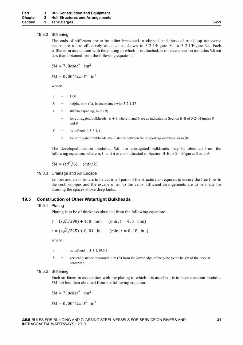
19.3.2 StiffeningThe ends of stiffeners are to be either bracketed or clipped, and those of trunk top transversebeams are to be effectively attached as shown in 3-2-1/Figure 8a or 3-2-1/Figure 9a. Eachstiffener, in association with the plating to which it is attached, is to have a section modulus SMnotless than obtained from the following equation:SM = 7 . 8csℎℓ2 cm3SM = 0 . 0041cℎsℓ2 in3wherec = 1.00ℎ = height, in m (ft), in accordance with 3-2-1/17s = stiffener spacing, in m (ft)
= for corrugated bulkheads, a+ b where a and b are as indicated in Section B-B of 3-2-1/Figures 8and 9ℓ = as defined in 3-2-1/11
= for corrugated bulkheads, the distance between the supporting members, in m (ft)
The developed section modulus, SM, for corrugated bulkheads may be obtained from thefollowing equation, where a, t and d are as indicated in Section B-B, 3-2-1/Figures 8 and 9.SM = (td2/6) + (adt/2)
19.3.3 Drainage and Air EscapeLimber and air holes are to be cut in all parts of the structure as required to ensure the free flow tothe suction pipes and the escape of air to the vents. Efficient arrangements are to be made fordraining the spaces above deep tanks.
19.5 Construction of Other Watertight Bulkheads19.5.1 Plating
Plating is to be of thickness obtained from the following equation:t = (s ℎ/290) + 1 . 0 mm (min . t = 4 . 5 mm)t = (s ℎ/525) + 0 . 04 in . (min . t = 0 . 18 in . )wheres = as defined in 3-2-1/19.3.1ℎ = vertical distance measured in m (ft) from the lower edge of the plate to the height of the deck at
centerline.
19.5.2 StiffeningEach stiffener, in association with the plating to which it is attached, is to have a section modulusSM not less than obtained from the following equation:SM = 7 . 8cℎsℓ2 cm3SM = 0 . 0041cℎsℓ2 in3
Part 3 Hull Construction and EquipmentChapter 2 Hull Structures and ArrangementsSection 1 Tank Barges 3-2-1
ABS RULES FOR BUILDING AND CLASSING STEEL VESSELS FOR SERVICE ON RIVERS ANDINTRACOASTAL WATERWAYS • 2019
31

wherec = 0.46ℎ = vertical distance from the middle of ℓ to the deck at centerline, in m (ft)s = for flat plate bulkheads, stiffener spacing, in m (ft)
= for corrugated bulkheads, a+ b where a and b are as indicated in Section B-B of 3-2-1/Figures 8and 9ℓ = as defined in 3-2-1/19.3.2
Stiffeners on these bulkheads may have unattached sniped ends provided the above value of SM isincreased 25%.
The developed section modulus, SM, for corrugated bulkheads may be obtained as indicated in3-2-1/19.3.2.
21 Shell Plating
21.1 Bottom ShellThe thickness of the bottom shell plating throughout is not to be less than determined by the followingequation:t = 0 . 069L+ 0 . 007s − 05 mm (min . t = 5 mm)t = 0 . 000825L+ 0 . 007s − 0 . 02 in . (min . t = 0 . 20 in . )wheres = stiffener spacing, in mm (in.)L = length of the vessel, in m (ft)
21.3 Side ShellThe thickness of the side shell plating is to be not less than determined by the following equation and notless than 5 mm (0.20 in.).t = 0 . 069L+ 0 . 007s – 1 . 0 mm L < 73 mt = 0 . 069L+ 0 . 007s – 1 . 5 mm L ≥ 73 mt = 0 . 000825L+ 0 . 007s – 0 . 04 in . L < 240 ftt = 0 . 000825L+ 0 . 007s – 0 . 06 in . L ≥ 240 ft
21.5 Bilge PlatingWhere radiused bilges are used, the bottom thickness is to extend to the upper turn of the bilge. Where theradius at the bilge exceeds 305 mm (12 in.), the thickness of the plating should be at least 1.5 mm (0.06in.) greater than the required thickness for side plating.
21.7 Tank SpacesIn way of the cargo tanks the bottom, side and bilge plating are not to have less thickness than required by3-2-1/19.3.1 for the plating of deep tank bulkheads where the spacing of the stiffeners is equal to the framespacing and the value of ℎ in accordance with 3-2-1/17.
Part 3 Hull Construction and EquipmentChapter 2 Hull Structures and ArrangementsSection 1 Tank Barges 3-2-1
ABS RULES FOR BUILDING AND CLASSING STEEL VESSELS FOR SERVICE ON RIVERS ANDINTRACOASTAL WATERWAYS • 2019
32

21.9 Bilge AnglesWhere angles are used at the bilges or gunwales they are to have a thickness at least 1.5 mm (0.06 in.)greater than that of the thinner of the two plates joined.
23 Hatches and Fittings
23.1 HatchwaysHatchways of sufficient size to provide access and ventilation and having substantial oiltight steel coversare to be fitted to each tank. Where openings are located close to the gunwales, doubling plates or othercompensation may be required.
23.3 Deck FittingsThe structure in way of cleats, bitts and chocks is to be suitably reinforced by installation of headers,additional beams, brackets or doubling plates
25 Barge Reinforcement
25.1 GeneralThe following paragraphs are intended to provide for additional protection against contact with locks andriver bottom and against other wear and tear damage associated with normal operation with other floatingequipment.
A design intended for Classification will be reviewed for compliance with 3-2-1/25.3 when requested. Anotation Reinforcement A or Reinforcement B will be entered in the Record indicating compliancewith all of the requirements for reinforcement A or B in 3-2-1/25.3.
25.3 ReinforcementWhere the option for reinforcement in 3-2-1/25.1 is chosen, the hull parts to be reinforced are given in thefollowing table, the reinforced plate thicknesses are to be not less than given in column Reinforcement Aor column Reinforcement B, as appropriate.
Reinforcement A Reinforcement B
Bilge radius for full-length of barge(knuckle plate)
tmin = 16 . 0 mm 5 8in . tmin = 12 . 5 mm 1 2in .Side shell tmin = 11 . 0 mm 7 16in . tmin = 9 . 5 mm 3 8in .Headlog and sternlog plate tmin = 19 . 0 mm 3 4in . tmin = 16 . 0 mm 5 8in .Transom side and bottom periphery(picture frame) plates
tmin = 16 . 0 mm 5 8in . tmin = 12 . 5 mm 1 2in .All side shell, bottom shell and deckstructural members in wing and rakecompartments
Use appropriate Rule coefficients with1.83 m (6 ft) overflow above deck atside. Where no wing tanks are fitted,the reinforcement is to apply to the sideshell structure in way of cargo tanksand the side, bottom and deck structurein way of rakes.
Use appropriate Rule coefficients with1.22 m (4 ft) overflow above deck atside.
Part 3 Hull Construction and EquipmentChapter 2 Hull Structures and ArrangementsSection 1 Tank Barges 3-2-1
ABS RULES FOR BUILDING AND CLASSING STEEL VESSELS FOR SERVICE ON RIVERS ANDINTRACOASTAL WATERWAYS • 2019
33
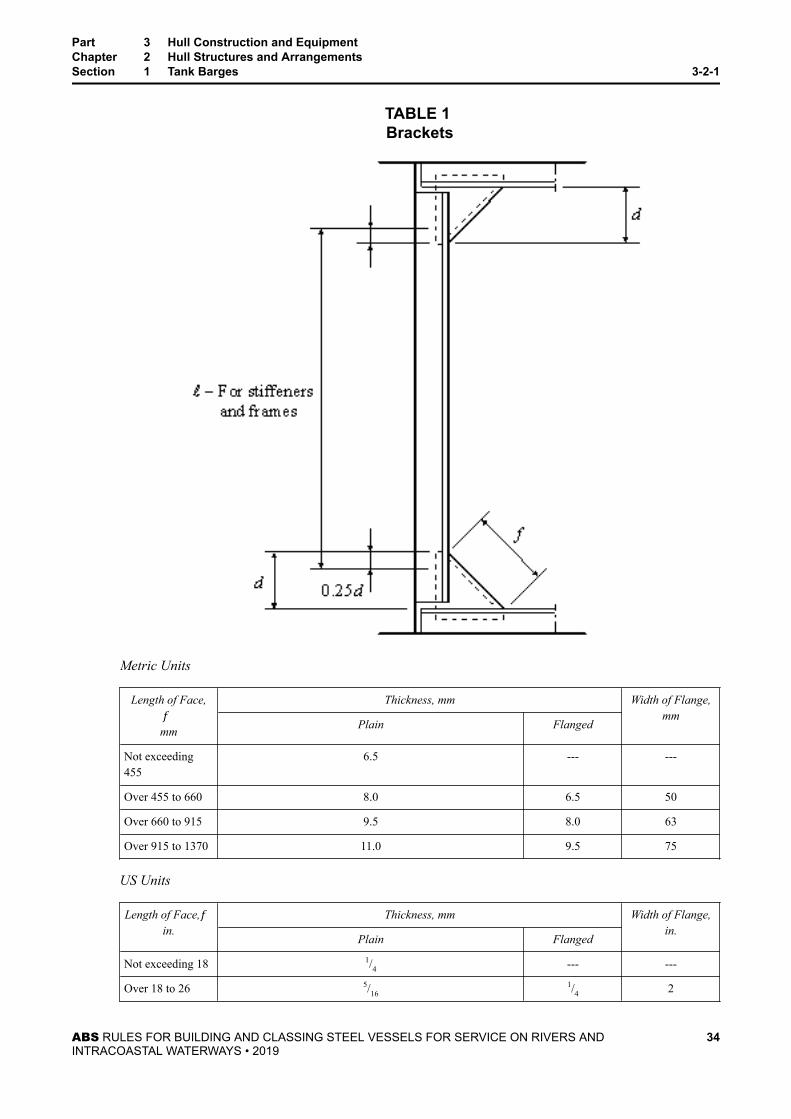
TABLE 1 Brackets
Metric Units
Length of Face,f mm
Thickness, mm Width of Flange,mm
Plain Flanged
Not exceeding455
6.5 --- ---
Over 455 to 660 8.0 6.5 50
Over 660 to 915 9.5 8.0 63
Over 915 to 1370 11.0 9.5 75
US Units
Length of Face,f in.
Thickness, mm Width of Flange,in.
Plain Flanged
Not exceeding 18 1/4 --- ---
Over 18 to 26 5/161/4 2
Part 3 Hull Construction and EquipmentChapter 2 Hull Structures and ArrangementsSection 1 Tank Barges 3-2-1
ABS RULES FOR BUILDING AND CLASSING STEEL VESSELS FOR SERVICE ON RIVERS ANDINTRACOASTAL WATERWAYS • 2019
34

Length of Face,f in.
Thickness, mm Width of Flange,in.
Plain Flanged
Over 26 to 36 3/85/16 2 1/2
Over 36 to 54 7/163/8 3
FIGURE 1 Bilge Bracket (see 3-2-1/5.1.3)
FIGURE 2 Intermediate Bilge Bracket (see 3-2-1/5.1.3)
Part 3 Hull Construction and EquipmentChapter 2 Hull Structures and ArrangementsSection 1 Tank Barges 3-2-1
ABS RULES FOR BUILDING AND CLASSING STEEL VESSELS FOR SERVICE ON RIVERS ANDINTRACOASTAL WATERWAYS • 2019
35

FIGURE 3 Alternative Arrangement (see 3-2-1/5.1.3)
FIGURE 4 Gunwale Bracket (see 3-2-1/5.1.3)
Part 3 Hull Construction and EquipmentChapter 2 Hull Structures and ArrangementsSection 1 Tank Barges 3-2-1
ABS RULES FOR BUILDING AND CLASSING STEEL VESSELS FOR SERVICE ON RIVERS ANDINTRACOASTAL WATERWAYS • 2019
36

FIGURE 5Tank Barge
Bottom transverse c = 1.08 Bottom longitudinal c = 1.28
Side transverse c = 1.75 Side longitudinal c = 1.28
Deck transverse c = 1.08 Deck longitudinal c = 1.75
h = in accordance with 3-2-1/17
Part 3 Hull Construction and EquipmentChapter 2 Hull Structures and ArrangementsSection 1 Tank Barges 3-2-1
ABS RULES FOR BUILDING AND CLASSING STEEL VESSELS FOR SERVICE ON RIVERS ANDINTRACOASTAL WATERWAYS • 2019
37

FIGURE 6Tank Barge
Bottom transverse c = 1.08 Bottom longitudinal c = 1.28
Side transverse c = 1.75 Side longitudinal c = 1.28
Deck transverse c = 1.08 Deck longitudinal c = 1.75
C.L. Bulkheadtransverse
c = 1.08 C.L. Bulkheadlongitudinal
c = 1.00
h = in accordance with 3-2-1/17
Part 3 Hull Construction and EquipmentChapter 2 Hull Structures and ArrangementsSection 1 Tank Barges 3-2-1
ABS RULES FOR BUILDING AND CLASSING STEEL VESSELS FOR SERVICE ON RIVERS ANDINTRACOASTAL WATERWAYS • 2019
38

FIGURE 7Tank Barge
Bottom frame c = 1.00 Deck beam c = 1.00
Truss bottom chord c = 1.08 Side frame c = 1.00
Truss top chord c = 1.08
h = in accordance with 3-2-1/17
Part 3 Hull Construction and EquipmentChapter 2 Hull Structures and ArrangementsSection 1 Tank Barges 3-2-1
ABS RULES FOR BUILDING AND CLASSING STEEL VESSELS FOR SERVICE ON RIVERS ANDINTRACOASTAL WATERWAYS • 2019
39

FIGURE 8Double Skin Tank Barge
Floor c = 1.00 Bulkhead Stiffener c = 1.00
Centerline bulkheadstiffener
c = 1.00 Side frame c = 1.00
Deck beam c = 1.00
h = in accordance with 3-2-1/17
Part 3 Hull Construction and EquipmentChapter 2 Hull Structures and ArrangementsSection 1 Tank Barges 3-2-1
ABS RULES FOR BUILDING AND CLASSING STEEL VESSELS FOR SERVICE ON RIVERS ANDINTRACOASTAL WATERWAYS • 2019
40

(Center compartment – liquid cargo)
(Wing compartment – void or ballast)
FIGURE 8A Trunk Top Beam End Connection
Part 3 Hull Construction and EquipmentChapter 2 Hull Structures and ArrangementsSection 1 Tank Barges 3-2-1
ABS RULES FOR BUILDING AND CLASSING STEEL VESSELS FOR SERVICE ON RIVERS ANDINTRACOASTAL WATERWAYS • 2019
41

FIGURE 9Double Skin Tank Barge
Bottom longitudinal c = 1.08
Side longitudinal c = 1.08 (Wing compartment – void)
c = 1.28 (Wing compartment –ballast)
Inner bottom longitudinal c = 1.00
Bulkhead stiffener c = 1.00
Centerline bulkhead stiffener c = 1.00
Bottom transverse c = 1.08
Side transverse c = 1.08
Deck transverse c = 1.08
Deck longitudinal c = 1.75
Part 3 Hull Construction and EquipmentChapter 2 Hull Structures and ArrangementsSection 1 Tank Barges 3-2-1
ABS RULES FOR BUILDING AND CLASSING STEEL VESSELS FOR SERVICE ON RIVERS ANDINTRACOASTAL WATERWAYS • 2019
42

h = in accordance with3-2-1/17
(Center compartment – liquidcargo)
(Wing compartment – voidor ballast)
FIGURE 9A Trunk Top Transverse End Connection
Part 3 Hull Construction and EquipmentChapter 2 Hull Structures and ArrangementsSection 1 Tank Barges 3-2-1
ABS RULES FOR BUILDING AND CLASSING STEEL VESSELS FOR SERVICE ON RIVERS ANDINTRACOASTAL WATERWAYS • 2019
43

FIGURE 10 Double Skin Tank Barge
Side transverse c = 1.75
Deck transverse c = 1.08
Bulkhead transverse c = 1.08
h = in accordance with 3-2-1/17
(Center compartment – liquid cargo)
(Wing compartment – liquid cargo or ballast)
For side and deck transverses where wing compartment is void, see 3-2-2/21.3 FIGURE 12.
Part 3 Hull Construction and EquipmentChapter 2 Hull Structures and ArrangementsSection 1 Tank Barges 3-2-1
ABS RULES FOR BUILDING AND CLASSING STEEL VESSELS FOR SERVICE ON RIVERS ANDINTRACOASTAL WATERWAYS • 2019
44

FIGURE 11 Rake Framing
Bottom transverse c = 1.08 Bottom longitudinal c = 1.28
Deck transverse c = 1.08 Deck longitudinal c = 1.75
Part 3 Hull Construction and EquipmentChapter 2 Hull Structures and ArrangementsSection 1 Tank Barges 3-2-1
ABS RULES FOR BUILDING AND CLASSING STEEL VESSELS FOR SERVICE ON RIVERS ANDINTRACOASTAL WATERWAYS • 2019
45

P A R T
3C H A P T E R 2 Hull Structures and Arrangements
S E C T I O N 2 Dry Cargo Barges
1 ApplicationThe following Rules and Tables apply to barges intended for the transportation of general or bulk cargoesin services which require operation in comparatively smooth water exclusively, such as in rivers,intracoastal waterways, etc.
3 Structural Arrangement
3.1 Between the Rakes3.1.1 Framing
Framing may be arranged either longitudinally, transversely or a combination of both.Longitudinal frames are to be supported by regularly spaced transverse deep frames formed eitherby channels extending across the inner faces of the longitudinal frames, or by flanged platesnotched over the frames and attached to the shell or deck and the longitudinals.
At bulkheads, longitudinals are to be attached at their ends to effectively develop the sectionalarea and resistance to bending.
3.1.2 TrussesTrusses are to be arranged as necessary for the support of the framing. In vessels with transverseframes, the trusses are to extend fore and aft. With longitudinal framing, they may extend eitherfore and aft or athwartships.
In all vessels where the ratio of L to the overall depth of the effective longitudinal materialincluded in the section modulus calculation (see 3-2-2/5) exceeds 20, special consideration is to begiven to the introduction of longitudinal bulkheads or trusses.
3.1.3 Bilge and Gunwale BracketsIn holds where the radius at the bilge exceeds 305 mm (12 in.), the bilge brackets connecting thelower ends of vertical side frames with transverse bottom frames are to be cut to fit against andsupport the bilge plate. In longitudinally framed vessels, a similar arrangement is to be required ateach main transverse frame and in addition, intermediate brackets are to be fitted spaced not over0.9 m (3 ft) apart (see 3-2-2/21.3 FIGURE 1 and 3-2-2/21.3 FIGURE 2). Similar brackets may berequired to be fitted at the gunwales where no gunwale angle is used. As an alternative to thefitting of bilge brackets, an additional inverted angle or flat bar longitudinal may be fitted asshown in 3-2-2/21.3 FIGURE 3.
3.3 RakesFor structural arrangement of rakes, see 3-2-1/5.3.
ABS RULES FOR BUILDING AND CLASSING STEEL VESSELS FOR SERVICE ON RIVERS ANDINTRACOASTAL WATERWAYS • 2019
46

5 Longitudinal Strength
5.1 Section ModulusThe required hull girder section modulus, SM, at amidships is to be obtained from the following equation:SM = 0 . 347 B+ 12 . 19 DL cm2‐m for L < 76 . 2mSM = 00 . 00455 B+ 12 . 19 DL2 cm2‐m for L ≥ 76 . 2mSM = 0 . 005 B+ 40 DL in2‐ft for L < 250ftSM = 2 . 0 × 10−5 B − 40 DL2 in‐ft for L ≥ 250ftwhere L,B, and D are as defined in Section 3-1-1.
In calculating the section modulus, bottom, bilge, side and inner bottom plating, all bilge, gunwale andother longitudinal angles and frames if continuous or adequately developed at the transverse bulkheads andhopper side and other continuous longitudinal bulkheads may be included. The section modulus to thedeck or bottom is obtained by dividing the moment of inertia by the distance from the neutral axis to themolded deck line at side amidships or to the base line, respectively.
5.3 Section Modulus with Continuous CoamingWhere longitudinal coamings of length greater than 0 . 14L are provided, they are to comply with therequirements of 3-2-2/19.7. Such continuous coamings may be included in the calculation of hull girderinertia which is to be divided by the sum of the distance from neutral axis to deck at side and the height ofcontinuous hatch coaming, to obtain the section modulus to the top of the coaming.
7 Deck Plating
7.1 Minimum ThicknessThe thickness of deck plating throughout is not to be less than 0.01 mm per millimeter (0.01 in. per inch)of the spacing of the beams, sb.
7.3 Between the RakesThe thickness of deck plating between the rakes is to be not less than determined by the followingequations:
● With Transverse Beamst = 0 . 066L+ 3 . 5 mmt = 0 . 0008L+ 0 . 14 in .● With Longitudinal Beamst = 0 . 066L+ 2 . 5 mmt = 0 . 0008L+ 0 . 10 in .
7.5 Watertight DecksThe thickness of plating of decks intended to provide tight divisions for protection against damage to theshell is not to be less than that required for ordinary bulkhead plating at the same level plus 1.0 mm (0.04in.).
Part 3 Hull Construction and EquipmentChapter 2 Hull Structures and ArrangementsSection 2 Dry Cargo Barges 3-2-2
ABS RULES FOR BUILDING AND CLASSING STEEL VESSELS FOR SERVICE ON RIVERS ANDINTRACOASTAL WATERWAYS • 2019
47

7.7 Cargo Decks (2002)The thickness of plating on which cargo is to be carried is not to be less than determined by the followingequations:t = 0 . 00395s ℎ + 1 . 5 mm but not less than 5.0 mmt = 0 . 00218s ℎ + 0 . 06 in. but not less than 0.20 in.
whereℎ = p/0 . 721m(p/45ft)p = uniformly distributed deck load, in tonnes/m2(lbs/ft2)s = spacing of the beams, in mm (in.)
In vessels regularly engaged in trades where cargo is handled by grabs or similar mechanical appliances, itis recommended that flush plating be used in way of the cargo and that increased framing and thickness beprovided.
7.9 Wheel Loaded Strength DecksWhere provision is to be made for the operation or stowage of vehicles having rubber tires, and after allother requirements are met, the thickness of strength deck plating is to be not less than 110% of thethickness required for wheel loaded inner bottoms in 3-2-2/19.1.2.
9 FramesEach frame, in association with the plating to which it is attached, is to have a section modulus, SM, notless than obtained from the following equation:SM = 7 . 8cℎsℓ2 cm3SM = 0 . 0041cℎsℓ2 in3wherec = coefficient appropriate to the member under consideration and the type of construction employed as given in
3-2-2/Figures 5 through 12
= 1.0 for rake side framesℎ = distance, in m (ft), as given in 3-2-2/Figures 5 through 12
= for rake bottom frames, the vertical distance, in m (ft), from the middle of ℓ to the height of the deck at side atthe rake bulkhead
= for rake deck transverses and longitudinals, 1.2 m (4.0 ft)s = member spacing, in m (ft)ℓ = unsupported span of the member, in m (ft)
Where brackets of the thicknesses given in 3-2-1/25.3 TABLE 1 are fitted, ℓ may be measured to a point 25%of the extent of the bracket beyond the its toe.
Where fitted, rake side vertical frames are to have brackets at their upper and lower ends extending over tothe first adjacent longitudinal beam or frame.
Part 3 Hull Construction and EquipmentChapter 2 Hull Structures and ArrangementsSection 2 Dry Cargo Barges 3-2-2
ABS RULES FOR BUILDING AND CLASSING STEEL VESSELS FOR SERVICE ON RIVERS ANDINTRACOASTAL WATERWAYS • 2019
48

11 Trusses
11.1 Top and Bottom ChordsEach top and bottom chord is to have a section modulus, SM, not less than obtained from the followingequation:SM = 7 . 8cℎsℓ2 cm3SM = 0 . 0041cℎsℓ2 in3where c, ℎ, s and ℓ are as defined in 3-2-2/9.
11.3 StanchionsThe spacing of truss stanchions is generally not to exceed the depth of the truss.
11.3.1 Permissible LoadThe permissible load, Wa, of a stanchion is to be obtained from the following equation and is notto be less than the calculated load W defined in 3-2-2/11.3.2 below.Wa = k − nℓ/r A kN(tf,Ltf)wherek = 12.09 (1.232, 7.83) ordinary strength steel
= 16.11 (1.643, 10.43) HT32 strength steel
= 18.12 (1848, 11.73) HT36 strength steeln = 0.0444 (0.00452, 0.345) ordinary strength steel
= 0.0747 (0.00762, 0.581) HT32 strength steel
= 0.0900 (0.00918, 0.699) HT36 strength steelℓ = unsupported span of the stanchion, in cm (ft)r = least radius of gyration, in cm (in.)A = cross sectional area of the stanchion, in cm2(in2)
11.3.2 Calculated Load (2019)The calculated load for each truss stanchion is to be determined by the following equation:W = pbs tf Ltfwherep = design uniform deck cargo load, in tf/m3 (Ltf/ft2)p is not to be less than 1.07ℎ m (0.03ℎ ft)ℎ = distance from the bottom shell at the center of the area supported to the underside of the deck plating
at side, in m (ft). Except where indicated otherwise by 3-2-2/21.3 FIGURE 10 or 3-2-2/21.3 FIGURE11b = mean breadth of the area supported, in m (ft)s = spacing of the stanchions, in m (ft)
Part 3 Hull Construction and EquipmentChapter 2 Hull Structures and ArrangementsSection 2 Dry Cargo Barges 3-2-2
ABS RULES FOR BUILDING AND CLASSING STEEL VESSELS FOR SERVICE ON RIVERS ANDINTRACOASTAL WATERWAYS • 2019
49
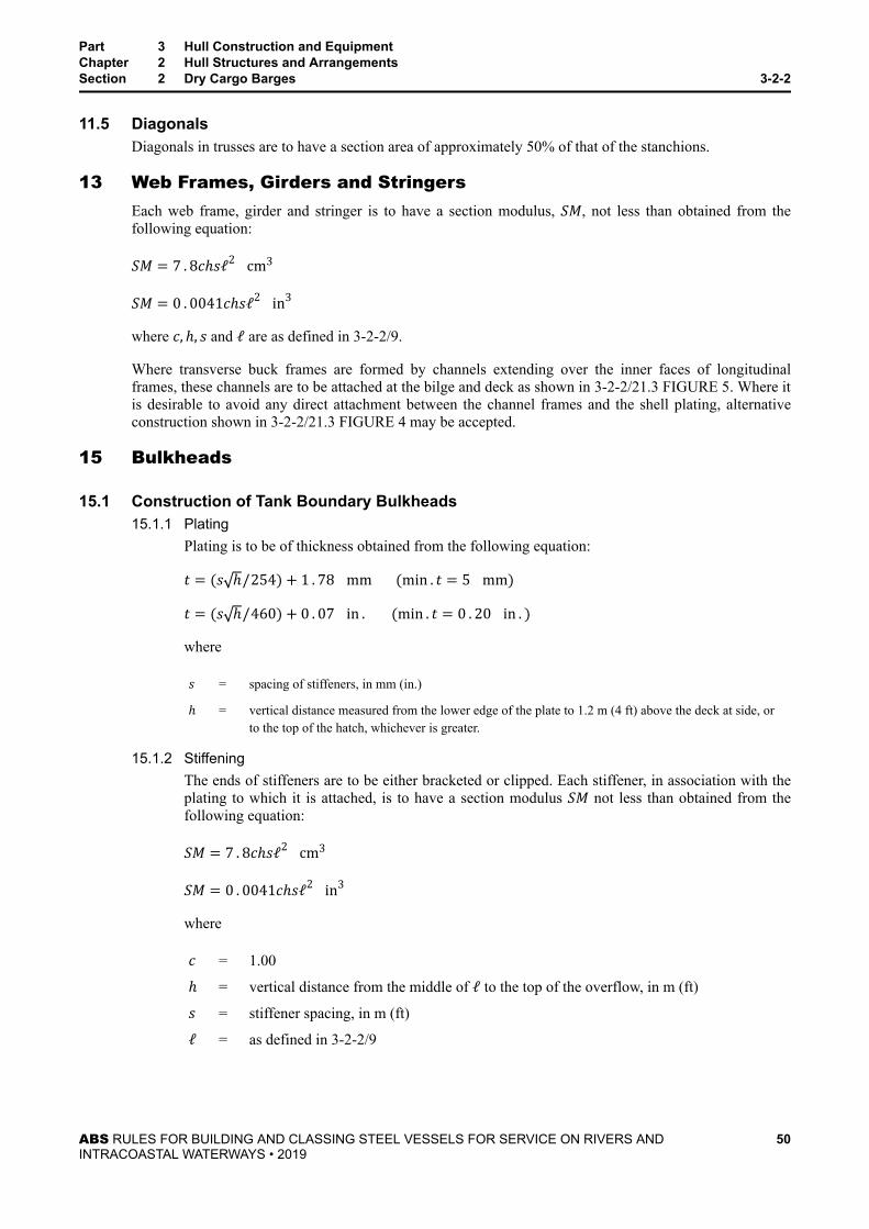
11.5 DiagonalsDiagonals in trusses are to have a section area of approximately 50% of that of the stanchions.
13 Web Frames, Girders and StringersEach web frame, girder and stringer is to have a section modulus, SM, not less than obtained from thefollowing equation:SM = 7 . 8cℎsℓ2 cm3SM = 0 . 0041cℎsℓ2 in3where c, ℎ, s and ℓ are as defined in 3-2-2/9.
Where transverse buck frames are formed by channels extending over the inner faces of longitudinalframes, these channels are to be attached at the bilge and deck as shown in 3-2-2/21.3 FIGURE 5. Where itis desirable to avoid any direct attachment between the channel frames and the shell plating, alternativeconstruction shown in 3-2-2/21.3 FIGURE 4 may be accepted.
15 Bulkheads
15.1 Construction of Tank Boundary Bulkheads15.1.1 Plating
Plating is to be of thickness obtained from the following equation:t = (s ℎ/254) + 1 . 78 mm (min . t = 5 mm)t = (s ℎ/460) + 0 . 07 in . (min . t = 0 . 20 in . )wheres = spacing of stiffeners, in mm (in.)ℎ = vertical distance measured from the lower edge of the plate to 1.2 m (4 ft) above the deck at side, or
to the top of the hatch, whichever is greater.
15.1.2 StiffeningThe ends of stiffeners are to be either bracketed or clipped. Each stiffener, in association with theplating to which it is attached, is to have a section modulus SM not less than obtained from thefollowing equation:SM = 7 . 8cℎsℓ2 cm3SM = 0 . 0041cℎsℓ2 in3wherec = 1.00ℎ = vertical distance from the middle of ℓ to the top of the overflow, in m (ft)s = stiffener spacing, in m (ft)ℓ = as defined in 3-2-2/9
Part 3 Hull Construction and EquipmentChapter 2 Hull Structures and ArrangementsSection 2 Dry Cargo Barges 3-2-2
ABS RULES FOR BUILDING AND CLASSING STEEL VESSELS FOR SERVICE ON RIVERS ANDINTRACOASTAL WATERWAYS • 2019
50

15.3 Construction of Other Watertight Bulkheads15.3.1 Plating
Plating is to be of thickness obtained from the following equation:t = (s ℎ/290) + 1 . 0 mm (min . t = 4 . 5 mm)t = (s ℎ/525) + 0 . 04 in . (min . t = 0 . 18 in . )wheres = spacing of stiffeners, in mm (in.)ℎ = vertical distance measured from the lower edge of the plate to the height of the deck at centerline, in
m (ft)
15.3.2 StiffeningEach stiffener, in association with the plating to which it is attached, is to have a section modulus,SM, not less than obtained from the following equation:SM = 7 . 8cℎsℓ2 cm3SM = 0 . 0041cℎsℓ2 in3wherec = 0.46ℎ = vertical distance from the middle of ℓ to the deck at centerline, in m (ft)s = stiffener spacing, in m (ft)ℓ = as defined in 3-2-2/9
Stiffeners on these bulkheads may have unattached sniped ends provided the above value of SM isincreased 25%.
17 Shell PlatingThe thickness of the bottom, side and bilge plating is to be as required below. In addition, the thickness ofplating in these locations is to be not less than as required by 3-2-2/15.3.1 for tank bulkheads where thespacing of the stiffeners is equal to the frame spacing and the value of h is equal to the distance from thelower edge of the plate to the under surface of the deck plating at side.
17.1 Bottom ShellThe thickness of the bottom shell plating throughout is not to be less than determined by the followingequation:t = 0 . 069L+ 0 . 007s − 0 . 8 mm min. t = 5 mmt = 0 . 000825L+ 0 . 007s − 0 . 02 in. min. t = 0 . 20 in.wheres = stiffener spacing, in mm (in.)L = length of the vessel, in m (ft)
Part 3 Hull Construction and EquipmentChapter 2 Hull Structures and ArrangementsSection 2 Dry Cargo Barges 3-2-2
ABS RULES FOR BUILDING AND CLASSING STEEL VESSELS FOR SERVICE ON RIVERS ANDINTRACOASTAL WATERWAYS • 2019
51

17.3 Side ShellThe thickness of the side shell plating is to be not less than determined by the following equation and notless than 5 mm (0.20 in.).t = Rule Bottom Shell‐0.5 mm L < 73 mt = Rule Bottom Shell‐1.0 mm L ≥ 73 mt = Rule Bottom Shell‐0.02 in. L < 240 ftt = Rule Bottom Shell‐0.04 in. L < 240 ft
17.5 Bilge PlatingWhere radiused bilges are used the bottom thickness is to extend to the upper turn of the bilge; where theradius at the bilge exceeds 305 mm (12 in.), the thickness of the plating should be at least 1.5 mm (0.06in.) greater than the required thickness for side plating.
17.7 Bilge AnglesWhere angles are used at the bilges or gunwales they are to have a thickness at least 1.5 min (0.06 in.)greater than that of the thinner of the two plates joined.
19 Inner Bottoms, Hatches and Fittings
19.1 Inner Bottom Plating19.1.1 Inner Bottom Plating on which Cargo is to be Carried
The thickness of plating, t, is not to be less than determined by the following equations:t = 0 . 01sb+ (0 . 83ℎ – 1 . 78) mm sb ≤ 610 mmt = 0 . 005sb+ (0 . 83ℎ – 1 . 78) + 3 . 1 mm sb > 610 mmt = 0 . 01sb+ 0 . 01(ℎ – 7) in. sb ≤ 24 in.t = 0 . 005sb+ 0 . 01(ℎ – 7) + 0 . 12 in. sb > 24 in.wheresb = spacing of the frames, in mm (in.)ℎ = height to which cargo may be loaded, in m (ft). Where the density of the cargo exceeds 715 kg/m3(45
lbs/ft3), the height is to be proportionally increased.
In vessels regularly engaged in trades where cargo is handled by grabs or similar mechanicalappliances, it is recommended that flush plating be used in way of the cargo and that increasedframing and thickness be provided.
19.1.2 Inner Bottom Under Wheel Loading (2014)Where provision is to be made for the operation or stowage of vehicles having rubber tires, andafter all other requirements are met, the thickness of inner bottom plating is to be not less thanobtained from the following equation:t = kKn W mm (in.)
where
Part 3 Hull Construction and EquipmentChapter 2 Hull Structures and ArrangementsSection 2 Dry Cargo Barges 3-2-2
ABS RULES FOR BUILDING AND CLASSING STEEL VESSELS FOR SERVICE ON RIVERS ANDINTRACOASTAL WATERWAYS • 2019
52

k = 26.4 (1.05)K = [21 . 99 + 0 . 316(a/s)2 – 5 . 328(a/s) + 2 . 6(a/s)(b/s) – 0 . 895(b/s)− 7 . 624(b/s)]10−2 ,derived from the curves indicated in 3-2-2/21.3 FIGURE 13n = 1.0 where ℓ/s ≥ 2 . 0 and 0.85 where ℓ/s = 1 . 0, for intermediate values of ℓ/s,n is to be obtainedby interpolationW = static wheel load, in tf (Ltf)a = wheel imprint dimension parallel to the longer edge, ℓ, of the plate panel, in mm (in.)b = wheel imprint dimension perpendicular to the longer edge, ℓ, of the plate panel, in mm (in.)s = spacing of deck beams or deck longitudinals, in mm (in.)ℓ = length of the plate panel, in mm (in.)
Where the wheels are close together, a combined imprint and load are to be used.
19.3 HatchwaysHatchways or manholes of sufficient size to provide access and ventilation are to be fitted to eachcompartment. Where openings are located close to the gunwales, doubling plates or other compensationmay be required.
All openings in decks are to be so framed as to provide efficient support and attachment for the ends of thehalf beams.
19.5 Hatch Covers19.5.1 Within Closed Deck Houses
Beams and covers for cargo hatches within closed deck houses are to be designed for a load, inkilograms per square meter (pounds per square foot) equal to 220 (45) multiplied by the height ofthe house, in m (ft), and a factor of safety of not less than 3.25 based on the minimum ultimatetensile strength of the material.
19.5.2 On Weather DecksFor all types of covered barges and for other types which may be noted in the Record as havingcovers fitted, the covers are to be weathertight. Where it is not intended to carry cargo on thecovers they are to be designed to withstand a load of 171 kg/m2 (35 lb/ft2) exclusive of the weightof the cover itself with a factor of safety of not less than 3.25 on the minimum ultimate tensilestrength of the material. Where cargo is intended to be carried, the design load is to be suitablyincreased.
19.5.3 Under Wheel LoadingWhere provision is to be made for the operation or stowage of vehicles having rubber tires, thethickness of the hatch cover plating is to be not less than obtained from 3-2-2/19.1.2 using a kfactor of 23.8 (0.94). Where the hatch cover plate panel is adjacent to the edges of the covers, thisvalue of t is to be increased by at least 15%.
19.7 Continuous Longitudinal Hatch CoamingsWhere longitudinal hatch coamings of length greater than 0 . 14L are supported by longitudinal bulkheadsor deep girders, they are in general to be longitudinally stiffened. The coaming plates and stiffeners are tohave scantlings as required for decks. Special consideration will be given for barges less than 61 m (200 ft)in length or where calculations are submitted to show adequate buckling strength in the maximumexpected sagging condition.
Part 3 Hull Construction and EquipmentChapter 2 Hull Structures and ArrangementsSection 2 Dry Cargo Barges 3-2-2
ABS RULES FOR BUILDING AND CLASSING STEEL VESSELS FOR SERVICE ON RIVERS ANDINTRACOASTAL WATERWAYS • 2019
53

19.9 Deck FittingsThe structure in way of cleats, bitts and chocks is to be suitably reinforced by installation of headers,additional beams, brackets or doubling plates.
19.11 Cargo BoxesCargo boxes, flash boards, coamings or other structures for retaining deck cargo, are to be sufficientlystrong for their height, and adequately bracketed to the deck. Effective means for drainage of these spacesare to be provided.
21 Barge Reinforcement
21.1 GeneralThe following paragraphs are intended to provide for additional protection against contact with locks andriver bottom and against other wear and tear damage associated with normal operation with other floatingequipment.
A design intended for Classification will be reviewed for compliance with 3-2-2/21.3 when requested. Anotation “Reinforcement A”or “Reinforcement B”will be entered in the Record indicating compliance withall of the requirements for reinforcement A or B in 3-2-2/21.3.
21.3 ReinforcementWhere the option for reinforcement in 3-2-2/21.1 is chosen, the hull parts to be reinforced are given in thefollowing table, the reinforced plate thicknesses are to be not less than given in column ReinforcementA or column Reinforcement B as appropriate.
Reinforcement A Reinforcement B
Bilge radius for full-length of barge(knuckle plate)
tmin = 16 . 0 mm 5 8 in . tmin = 12 . 5 mm 1 2 in .Side shell tmin = 11 . 0 mm 7 16 in . tmin = 9 . 5 mm 3 8 in .Deck stringer plate – hopper barge tmin = 11 . 0 mm 7 16 in . tmin = 9 . 5 mm 3 8 in .Lower 1.83 m (6 ft) of sides and endsof hopper plating
tmin = 9 . 5 mm 3 8 in . tmin = 9 . 5 mm 3 8 in .Headlog and sternlog plate tmin = 19 . 0 mm 3 4 in . tmin = 16 . 0 mm 5 8 in .Transom side and bottom periphery(picture frame) plates
tmin = 16 . 0 mm 5 8 in . tmin = 12 . 5 mm 1 2 in .All side shell, bottom shell and deckstructural members in wing and rakecompartments
Use appropriate Rule coefficients with1.83 m (6 ft) overflow above deck atside. Where no wing tanks are fitted,this reinforcement is to apply to theside shell structure in cargo/void spacesand the side, bottom and deck structurein way of rakes.
Use appropriate Rule coefficients with1.22 m (4 ft) overflow above deck atside. Where no wing tanks are fitted,this reinforcement is to apply to theside shell structure in cargo/void spacesand the side, bottom and deck structurein way of rakes.
Part 3 Hull Construction and EquipmentChapter 2 Hull Structures and ArrangementsSection 2 Dry Cargo Barges 3-2-2
ABS RULES FOR BUILDING AND CLASSING STEEL VESSELS FOR SERVICE ON RIVERS ANDINTRACOASTAL WATERWAYS • 2019
54

FIGURE 1 Bilge Bracket (see 3-2-2/3.1.3)
FIGURE 2Intermediate Bilge Bracket (see 3-2-2/3.1.3)
Part 3 Hull Construction and EquipmentChapter 2 Hull Structures and ArrangementsSection 2 Dry Cargo Barges 3-2-2
ABS RULES FOR BUILDING AND CLASSING STEEL VESSELS FOR SERVICE ON RIVERS ANDINTRACOASTAL WATERWAYS • 2019
55

FIGURE 3Alternative Arrangement (see 3-2-2/3.1.3)
FIGURE 4 Alternative Channel Construction at Bilge (see 3-2-2/3.1.3)
Part 3 Hull Construction and EquipmentChapter 2 Hull Structures and ArrangementsSection 2 Dry Cargo Barges 3-2-2
ABS RULES FOR BUILDING AND CLASSING STEEL VESSELS FOR SERVICE ON RIVERS ANDINTRACOASTAL WATERWAYS • 2019
56

FIGURE 5Dark Barge
Bottom transverse c = 1 . 00 Bottom longitudinal c = 1 . 08Side transverse c = 1 . 00 Side longitudinal c = 1 . 08Deck transverse c = 0 . 70 Deck longitudinal c = 0 . 70
Part 3 Hull Construction and EquipmentChapter 2 Hull Structures and ArrangementsSection 2 Dry Cargo Barges 3-2-2
ABS RULES FOR BUILDING AND CLASSING STEEL VESSELS FOR SERVICE ON RIVERS ANDINTRACOASTAL WATERWAYS • 2019
57

FIGURE 6Deck Barge
Bottom transverse c = 1 . 00 Bottom longitudinal c = 1 . 08Side transverse c = 1 . 00 Side longitudinal c = 1 . 08Deck transverse c = 0 . 70 Deck longitudinal c = 0 . 70C.L. Bulkhead transverse c = 0 . 70 C.L. Bulkhead longitudinal c = 0 . 70
Part 3 Hull Construction and EquipmentChapter 2 Hull Structures and ArrangementsSection 2 Dry Cargo Barges 3-2-2
ABS RULES FOR BUILDING AND CLASSING STEEL VESSELS FOR SERVICE ON RIVERS ANDINTRACOASTAL WATERWAYS • 2019
58

FIGURE 7Deck Barge
Bottom frame c = 1 . 00 Deck beam c = 0 . 56Truss bottom chord c = 1 . 00 Side frame c = 1 . 00Truss top chord c = 0 . 70
Part 3 Hull Construction and EquipmentChapter 2 Hull Structures and ArrangementsSection 2 Dry Cargo Barges 3-2-2
ABS RULES FOR BUILDING AND CLASSING STEEL VESSELS FOR SERVICE ON RIVERS ANDINTRACOASTAL WATERWAYS • 2019
59

FIGURE 8Hopper Barge
Side Frame Hopper Side Stiffener
Type A (for ℓ) c = 1 . 15 Type A c = 1 . 00Type A (for ℓ1) c = 2 . 00 Type B c = 1 . 10Type B c = 1 . 30 Type C c = 1 . 20Type C c = 1 . 45 Type D c = 1 . 00Type D c = 1 . 08 Hopper Side Chord
Type D c = 1 . 00
Part 3 Hull Construction and EquipmentChapter 2 Hull Structures and ArrangementsSection 2 Dry Cargo Barges 3-2-2
ABS RULES FOR BUILDING AND CLASSING STEEL VESSELS FOR SERVICE ON RIVERS ANDINTRACOASTAL WATERWAYS • 2019
60

FIGURE 9Hopper Barge
Floors
Minimum d = ℓ/24 with wood inner bottomMinimum d = ℓ/30 with steel inner bottom effectively attached to each floors = spacing of floors, in m (ft)ℎ= vertical distance from the baseline to the under surface of the deck plating at side, in m (ft)
c = 1 . 00Where barges are designed exclusively for carrying uniformly distributed dry bulk cargoes and are classed Bulk CargoBarge, c = 0 . 55.
Part 3 Hull Construction and EquipmentChapter 2 Hull Structures and ArrangementsSection 2 Dry Cargo Barges 3-2-2
ABS RULES FOR BUILDING AND CLASSING STEEL VESSELS FOR SERVICE ON RIVERS ANDINTRACOASTAL WATERWAYS • 2019
61

FIGURE 10 Double Skin Hopper Barge (2019)
Truss floor c = 1 . 00 ℓ as shown where the section modulus us that of the combined sectionBottom angle c = 1 . 00Inner bottom angle c = 0 . 56Side frame (for ℎ) c = 1 . 50(for ℎ1) c = 2 . 00Bulkhead stiffener c = 1 . 10Vertical stanchion truss floor ℎ = ℎℎ = ℎ2 whichever is greater
Part 3 Hull Construction and EquipmentChapter 2 Hull Structures and ArrangementsSection 2 Dry Cargo Barges 3-2-2
ABS RULES FOR BUILDING AND CLASSING STEEL VESSELS FOR SERVICE ON RIVERS ANDINTRACOASTAL WATERWAYS • 2019
62
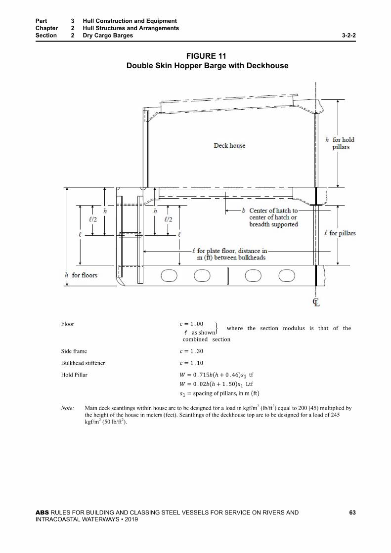
FIGURE 11 Double Skin Hopper Barge with Deckhouse
Floor c = 1 . 00 ℓ as shown where the section modulus is that of the combined sectionSide frame c = 1 . 30Bulkhead stiffener c = 1 . 10Hold Pillar W = 0 . 715b ℎ + 0 . 46 s1 tfW = 0 . 02b ℎ + 1 . 50 s1 Ltfs1 = spacing of pillars, in m ftNote: Main deck scantlings within house are to be designed for a load in kgf/m2 (lb/ft2) equal to 200 (45) multiplied by
the height of the house in meters (feet). Scantlings of the deckhouse top are to be designed for a load of 245kgf/m2 (50 lb/ft2).
Part 3 Hull Construction and EquipmentChapter 2 Hull Structures and ArrangementsSection 2 Dry Cargo Barges 3-2-2
ABS RULES FOR BUILDING AND CLASSING STEEL VESSELS FOR SERVICE ON RIVERS ANDINTRACOASTAL WATERWAYS • 2019
63

FIGURE 12 Double Skin Hopper Barge
Side transverse c = 1 . 00Deck transverse c = 0 . 70Bulkhead transverse c = 0 . 70(Center compartment – dry cargo)
(Center compartment – dry cargo)
Part 3 Hull Construction and EquipmentChapter 2 Hull Structures and ArrangementsSection 2 Dry Cargo Barges 3-2-2
ABS RULES FOR BUILDING AND CLASSING STEEL VESSELS FOR SERVICE ON RIVERS ANDINTRACOASTAL WATERWAYS • 2019
64

FIGURE 13 Wheel Loading Curves of K
Part 3 Hull Construction and EquipmentChapter 2 Hull Structures and ArrangementsSection 2 Dry Cargo Barges 3-2-2
ABS RULES FOR BUILDING AND CLASSING STEEL VESSELS FOR SERVICE ON RIVERS ANDINTRACOASTAL WATERWAYS • 2019
65

P A R T
3C H A P T E R 2 Hull Structures and Arrangements
S E C T I O N 3 Barges Intended to Carry Dangerous ChemicalCargoes in Bulk
1 ApplicationThis Section applies to barges intended to carry dangerous cargoes in bulk in services which requireoperation in comparatively smooth water exclusively, such as in rivers, intracoastal waterways, etc. All theapplicable paragraphs of other Sections of these Rules are to be considered as requirements, except wherethe provisions of this Section are contrary to or in addition thereto. Self-propelled vessels will be speciallyconsidered, taking into account the cargoes carried and the degree of protection proposed.
3 ClassificationThe classification ✠A1 Chemical Tank Barge, River Service followed by the appropriate notationindicating barge type designation as Type I, Type II, or Type III* is to be assigned to vessels designed forand specifically fitted for the carriage of dangerous chemicals in bulk, built to the requirements of thisSection and other relevant sections of these Rules, and complying with 46 CFR Part 151 or otherrecognized standards.
Note: * Type Designation – See 46 CFR 151.10.
5 Submission of DataThe following plans, calculations and information as appropriate are to be submitted in addition to thoserequired by 1-1-4/1 of the Supplement to the ABS Rules for Conditions of Classification (Part 1).
Identification and properties of any dangerous chemical cargo which is intended to be carried on bargesbuilt in accordance with this Section are to be given and are to include chemical composition, specifyingcontaminants, density, vapor pressure, boiling point, combustible range, flash point, compatibility withtank materials and any peculiar characteristics. The temperature and pressure at which the cargo is to becarried and at which it is to be loaded and unloaded are also to be given. Where the cargo has been given ahazard rating by a recognized code or other authority, this is also to be stated.
Arrangement plans indicating watertight bulkheads, decks and all openings therein are to be submitted forreview. Additional plans are to be submitted for each condition of loading in which a dangerous chemicalcargo is carried showing specific gravity and maximum cargo weight in all spaces as well as draft of thevessel in each condition.
Except as indicated in 3-2-3/7, calculations showing compliance with 46 CFR Part 151 or other recognizedstandards are to be submitted for review. Written evidence that the U.S. Coast Guard has certified thevessel as being in compliance with their Regulations will be acceptable in lieu of calculations showingcompliance with 46 CFR Part 151. Vessels designed to other recognized standards may be given similarconsideration.
7 Type I and Type II Barges with Integral TanksBarges of Type I or Type II with integral tanks are to comply with the following requirements. Submittedcalculations showing compliance with 46 CFR Part 151 as indicated in 3-2-3/5 need not includecalculations for those items considered in this Subsection.
ABS RULES FOR BUILDING AND CLASSING STEEL VESSELS FOR SERVICE ON RIVERS ANDINTRACOASTAL WATERWAYS • 2019
66
7.1 Definitions7.1.1 Type I Barge Hull
Barge hull Type I refers to those designed to carry products which require the maximumpreventative measures to preclude the uncontrolled release of the cargo.
7.1.2 Type II Barge HullBarge hull Type II refers to those designed to carry products which require significant preventativemeasures to preclude the uncontrolled release of the cargo.
7.1.3 Limiting DraftA limiting draft is the maximum draft to which cargo of specified densities may be loaded for agiven hull type. A chemical barge may be assigned more than one limiting draft for differentcombinations of cargo density and hull type.
7.3 Tank Arrangement7.3.1 Collision Protection
Tanks containing products which are required to be carried in Type I or Type II hulls (See 46 CFRTable 151.05) are to be located beyond the following minimum distances from the members asshown.
i) From Side Shell and Box End
● Type I 1.22 m (4.0 ft)
● Type II 0.91 m (3.0 ft)
ii) From the Headlog (Except Box Barges and Trail Barges)
● Both Types 7.6 m (25 ft)
7.3.2 Access OpeningEach tank is to be provided with a manhole with a cover plate and a minimum clear opening of380 mm ×460 mm (15 in. ×18 in.). Access trunks, where fitted, are to have a diameter of at least760 mm (30 in.).
7.5 Longitudinal Strength (2001)7.5.1 Loading Conditions
The following definitions of loading conditions are to be understood for the purpose of thisSection.
7.5.1(a) Normal and High Density Cargo Conditions (2001). See 3-2-1/7.3.
7.5.1(b) Grounding Conditions. A grounding condition is a condition wherein the forward rakebulkhead rests on a pinnacle at the water surface with the barge loaded with cargo of approveddensity.
7.5.2 Hull Girder Bending Moment7.5.2(a) Normal Conditions. Subject to compliance with the requirements in Section 3-2-1, nobending moment calculations are required for these conditions except that those calculationsmentioned in 3-2-3/7.5.1(a) for conditions other than homogeneous cargo are to be evaluated inaccordance with 3-2-3/7.5.3(a) below.
7.5.2(b) High Density Cargo and Grounding Conditions (2001). Bending moment calculations areto be submitted for these conditions except that where grounding condition bending momentcalculations for homogeneous cargo are not available, the following formula may be used.
Part 3 Hull Construction and EquipmentChapter 2 Hull Structures and ArrangementsSection 3 Barges Intended to Carry Dangerous Chemical Cargoes in Bulk 3-2-3
ABS RULES FOR BUILDING AND CLASSING STEEL VESSELS FOR SERVICE ON RIVERS ANDINTRACOASTAL WATERWAYS • 2019
67

Ma = L2Bd/(ak)whereMa = expected grounding condition bending moment for barges with homogeneous cargo, in tf-m (Ltf-ft)L = length of barge, in m (ft), as defined in 3-1-1/3.1B = breadth of barge, in m (ft), as defined in 3-1-1/5d = limiting draft, in m (ft)k = L – 10.9 m (L– 35.7 ft), but not to be taken greater than 80.6 m (264.3 ft)a = 0.461 m2/tf (5.04 ft2/Ltf)
7.5.3 Criterion (2001)7.5.3(a) Normal and High Density Cargo Conditions (2001). The hull girder section modulus is tobe in accordance with 3-2-1/7.7.
7.5.3(b) Grounding Conditions (2001).The hull girder section modulus is to be such that the hull girder stress, σ, in the deck or trunk sideas obtained from the equation below does not exceed the permissible stress f or the referencestress fr as defined in 3-2-1/7.7., whichever is less.σ = M/SMwhereM = hull girder bending moment, in tf-m (Ltf-ft), for grounding or overload conditionsSM = as defined in 3-2-1/7.7f = (1− 0 . 25P/Po) × (1 . 09− 0 . 00427ℓ/r)Y for deck or trunk top/side with longitudinals
= k(0 . 72− 0 . 4Bo/B)Y for deck or trunk top/side with transverse beamsP = pressure relief valve setting, in kgf/cm2 (psi), or 0.105ℎ(0.455ℎ), whichever is greaterℎ = design head, in m (ft)Po = 0.21 kgf/cm2 (3 psi)ℓ = unsupported span of the longitudinal, in cm (in.)r = i/Ai = moment of inertia of the longitudinal with deck plating, in cm4 (in4)A = cross sectional area of the longitudinal with deck plating, in cm2 (in2)Y = yield point of the material, in tf/cm2 (Ltf/in2)k = 1.0 for barge without trunk
= 0.87 for barge with trunkBo = width of the transversely framed portion of the deck (if no trunk) or transversely framed trunk topB = breadth of barge, in m (ft), as defined in 3-1-1/5
Part 3 Hull Construction and EquipmentChapter 2 Hull Structures and ArrangementsSection 3 Barges Intended to Carry Dangerous Chemical Cargoes in Bulk 3-2-3
ABS RULES FOR BUILDING AND CLASSING STEEL VESSELS FOR SERVICE ON RIVERS ANDINTRACOASTAL WATERWAYS • 2019
68

7.7 Deck/Trunk Top TransversesThe moment of inertia in cm4(in4) of the deck or trunk top transverses, where applicable, with associateddeck plating, is to be not less than Io as given below.Io = 0 . 34K(b/ℓ)3(b/s)iwhereK = 1 . 0 for transverses without effective end brackets if barge does not have centerline bulkhead or
stanchions
= 0 . 3 for the transverses without effective end brackets if barge has centerline bulkhead or stanchions
= 0 . 19 for the transverses with effective end brackets with or without centerline bulkhead or stanchionsb = unsupported span of the transverses, in m (ft)ℓ = spacing of the transverses, in m (ft)s = spacing of the longitudinals, in m (ft)i = moment of inertia of the longitudinal with deck plating that will satisfy 3-2-3/7.5.3(b)
Where applicable, width of effective deck flange for the transverses is to be taken as b/3 or ℓ, whicheveris less.
7.9 Transverse BeamsThe moment of inertia in cm4 (in4) of the deck or trunk top transverse beam with associated deck plating, isto be not less than Io as given below.Io = 0 . 0367K(t/s)3b4wheres = spacing of the transverse beams, in mm (in.)t = thickness of the deck or trunk top, in mm (in.), that will satisfy 3-2-3/7.5.3(b)b = unsupported length of the transverse beam, in cm (in.)K = coefficient, specified in 3-2-3/7.7
Width of effective deck flange for transverse beam is to be taken as s.
Part 3 Hull Construction and EquipmentChapter 2 Hull Structures and ArrangementsSection 3 Barges Intended to Carry Dangerous Chemical Cargoes in Bulk 3-2-3
ABS RULES FOR BUILDING AND CLASSING STEEL VESSELS FOR SERVICE ON RIVERS ANDINTRACOASTAL WATERWAYS • 2019
69

P A R T
3C H A P T E R 2 Hull Structures and Arrangements
S E C T I O N 4 Towboats
1 ApplicationThe following Rules and Tables apply to self-propelled river towboat type vessels intended for towingoperation in comparatively smooth water exclusively, such as in rivers, intracoastal waterways, etc.
3 Structural Arrangement
3.1 FramingFraming may be arranged either longitudinally, transversely or a combination of both. Longitudinal framesare to be supported by regularly spaced transverse deep frames formed either by channels extending acrossthe inner faces of the longitudinal frames, or by flanged plates notched over the frames and attached to theshell or deck and the longitudinals.
3.3 Longitudinal WebsTrusses or non-tight bulkheads extending fore and aft are to be fitted, one on or near the centerline and oneon each side of the centerline. An arrangement of deep girders at the deck and bottom connected byvertical members will be considered. They are to be arranged so that in association with auxiliarysupporting girders. The spans of the bottom frames do not exceed 4 m (13 ft). Bulkheads may be offset orstepped in a transverse direction provided sufficient overlap is effected to maintain their longitudinalcontinuity.
5 Longitudinal StrengthThe required hull girder section modulus, SM, within the midship 0 . 5L is to be obtained from thefollowing equation.SM = 0 . 764BDL cm2−mSM = 0 . 011BDL in2− ftL,B and D are as defined in Section 3-1-1.
In calculating the actual section modulus, bottom, bilge and side plating, all bilge, gunwale and otherlongitudinal angles if continuous or adequately developed at the transverse bulkheads and the continuousdeck plating may be included. Beyond the midship 0 . 5L, scantlings may be tapered to their normalrequirements at the ends where these are less.
7 Deck Plating
7.1 Strength DecksThe thickness of strength deck plating throughout is not to be less than 0.01 mm per millimeter (0.01 in.per inch) of the spacing of the beams, sb ..
ABS RULES FOR BUILDING AND CLASSING STEEL VESSELS FOR SERVICE ON RIVERS ANDINTRACOASTAL WATERWAYS • 2019
70

7.3 Other LocationsThe thickness of plating forming the tops of deep tanks, watertight flats, bulkhead recesses and tunnel topswhich may be used for stores space is to be 1 mm (0.04 in.) thicker than required for bulkhead plating atthe same level.
9 Frames
9.1 Bottom LongitudinalsEach bottom longitudinal, in association with the plating to which it is attached, is to have a sectionmodulus, SM, not less than obtained from the following equation:SM = 7 . 8cℎsℓ2 cm3SM = 0 . 0041cℎsℓ2 in3wherec = 1.08ℎ = vertical distance from the longitudinal to the deck at side, in m (ft)
= for longitudinals in tanks, the vertical distance from the longitudinal to the top of the overflow, in m (ft)s = longitudinal spacing, in m (ft)ℓ = unsupported span of the member in m (ft). Where brackets of the thicknesses given in 3-2-1/25.3 TABLE 1 arefitted, ℓ may be measured to a point 25% of the extent of the bracket beyond the its toe.
9.3 Side and Deck FramingEach side frame or deck beam, in association with the plating to which it is attached, is to have a sectionmodulus, SM, not less than obtained from the following equation:SM = 7 . 8cℎsℓ2 cm3SM = 0 . 0041cℎsℓ2 in3wherec = coefficient appropriate to the type of construction employed as given in 3-2-4/23.11 Figure 1 for side frames
= 0 . 70 for deck beams in dry spaces
= 1 . 00 for deck beams in way of tanks
= 1 . 08 for side longitudinalsℎ = distance, in m (ft), as given in 3-2-4/25
= in way of tanks, the vertical distance from the middle of ℓ to the top of the overflow, in m (ft), but not less than1.2 m (4.0 ft) for deck beams
= 1.2 (4.0) for support of decks. For decks on which stores may be carried, ℎ is not to be taken less than theheight of the storage space.s = member spacing, in m (ft)ℓ = as defined in 3-2-4/9.1
Part 3 Hull Construction and EquipmentChapter 2 Hull Structures and ArrangementsSection 4 Towboats 3-2-4
ABS RULES FOR BUILDING AND CLASSING STEEL VESSELS FOR SERVICE ON RIVERS ANDINTRACOASTAL WATERWAYS • 2019
71

9.5 Framing in TunnelsSpecial consideration is to be given to increasing the framing in way of propeller tunnels or special typesof nozzles. It is recommended that nontight bulkheads and diaphragms be introduced in way of longtunnels (see also 3-2-4/17.5).
11 Stanchions
11.1 Permissible Load (2018)The permissible load, Wa, of each stanchion is to be obtained from the following equation and is to be notless than the calculated load W given in 3-2-4/11.3 below.Wa = [k − nℓ/r]A kN(tf, Ltf)wherek = 12.09 (1.232, 7.83) ordinary strength steel
= 16.11 (1.643, 10.43) HT32 strength steel
= 18.12 (1848, 11.73) HT36 strength steeln = 0.0444 (0.00452, 0.345) ordinary strength steel
= 0.0747 (0.00762, 0.581) HT32 strength steel
= 0.0900 (0.00918, 0.699) HT36 strength steelℓ = unsupported span of the stanchion, in cm (ft)r = least radius of gyration, in cm (in.)A = cross sectional area of the stanchion, in cm2 (in2)
11.3 Calculated LoadThe calculated load for each stanchion is to be determined by the following equation:W = nbℎs tf(Ltf)wheren = 1 . 07 (0 . 03) where the stanchion supports bottom structure
= 0 . 715 (0 . 02) where the stanchion supports deck structureb = mean breadth of the area supported, in m (ft)ℎ = distance from the bottom shell at the center of the area supported to the underside of the deck plating at side, inm (ft), for support of bottom structure
= 1.2 (4.0) for support of decks. Where decks are intended to carry stores, ℎ is not to be taken less than theheight of the storage space.s = spacing of the stanchions, in m (ft)
13 Web Frames, Girders and StringersEach supporting girder, transverse floor and stringer with transverse framing, and each main transversemember with longitudinal framing, is to have a section modulus, SM, not less than obtained from thefollowing equation:
Part 3 Hull Construction and EquipmentChapter 2 Hull Structures and ArrangementsSection 4 Towboats 3-2-4
ABS RULES FOR BUILDING AND CLASSING STEEL VESSELS FOR SERVICE ON RIVERS ANDINTRACOASTAL WATERWAYS • 2019
72

SM = 7 . 8cℎsℓ2 cm3SM = 0 . 0041cℎsℓ2 in3wherec = 1 . 00 for bottom and side supporting members and for deck supporting members in tanks.
= 0 . 70 for deck supporting members in dry spacesℎ = for bottom and side supporting members, the distance from the middle of ℓ to the deck at side, in m (ft)
● in way of tanks ℎ is to be the vertical distance to the top of the overflow, in m (ft)
= for deck supporting members, 1.2 m (4.0 ft)
● for decks on which stores may be carried, ℎ is not to be less than the height of the storage space
● in way of deep tanks, ℎ is not to be less than the distance to the top of the overflow.s and ℓ are as defined in 3-2-4/9.1.
The thickness of floors or transverses is in general not to be less than 5 mm (3/16 in.) and those under theengines are to be suitably increased.
15 Bulkheads
15.1 ArrangementIntact watertight collision bulkheads are to be fitted up to the deck in all vessels at a distance of not lessthan 0 . 05L from the stem. Watertight after peak bulkheads are to be fitted. Machinery spaces below thedeck are to be enclosed by transverse bulkheads which are watertight to the deck.
15.3 Construction of Tank Boundary Bulkheads15.3.1 Plating
Plating is to be of thickness obtained from the following equation:t = (s ℎ/254) + 1 . 78 mm (min . t = 5 mm)t = (s ℎ/460) + 0 . 07 in . (min . t = 0 . 20 in . )wheres = spacing of stiffeners, in mm (in.)ℎ = vertical distance measured from the lower edge of the plate to the top of the overflow
15.3.2 StiffeningThe ends of stiffeners are to be either bracketed or clipped. Each stiffener, in association with theplating to which it is attached, is to have a section modulus, SM, not less than obtained from thefollowing equation:SM = 7 . 8cℎsℓ2 cm3SM = 0 . 0041cℎsℓ2 in3where
Part 3 Hull Construction and EquipmentChapter 2 Hull Structures and ArrangementsSection 4 Towboats 3-2-4
ABS RULES FOR BUILDING AND CLASSING STEEL VESSELS FOR SERVICE ON RIVERS ANDINTRACOASTAL WATERWAYS • 2019
73

c = 1.00ℎ = vertical distance from the middle of ℓ to the top of the overflow, in m (ft)s = stiffener spacing, in m (ft)ℓ = as defined in 3-2-4/9.1
15.5 Construction of Other Watertight Bulkheads15.5.1 Plating
Plating is to be of thickness obtained from the following equation:t = (s ℎ/290) + 1 . 0 mm (min . t = 4 . 5 mm)t = (s ℎ/525) + 0 . 04 in . (min . t = 0 . 18 in . )wheres = spacing of stiffeners, in mm (in.)ℎ = vertical distance measured from the lower edge of the plate to the height of the deck at centerline, in
m (ft)
15.5.2 StiffeningEach stiffener, in association with the plating to which it is attached, is to have a section modulus,SM, not less than obtained from the following equation:SM = 7 . 8cℎsℓ2 cm3SM = 0 . 0041cℎsℓ2 in3wherec = 0.46ℎ = vertical distance from the middle of ℓ to the deck at centerline, in m (ft)s = stiffener spacing, in m (ft)ℓ = as defined in 3-2-4/9.1
17 Shell PlatingThe thickness of the bottom, side and bilge plating is to be as required below. In addition, the thickness ofplating in these locations is to be not less than as required by 3-2-4/15.3.1 for tank bulkheads where thespacing of the stiffeners is equal to the frame spacing and the value of ℎ is equal to the distance from thelower edge of the plate to the under surface of the deck plating at side. In way of deep tanks, ℎ is to bemeasured to the top of the overflow.
17.1 Bottom ShellThe thickness of the bottom shell plating throughout is not to be less than determined by the followingequation:t = 0 . 069L+ 0 . 007s – 0 . 5 mm (min . t = 5 mm)t = 0 . 000825L+ 0 . 007s – 0 . 02 in . (min . t = 0 . 20 in . )
Part 3 Hull Construction and EquipmentChapter 2 Hull Structures and ArrangementsSection 4 Towboats 3-2-4
ABS RULES FOR BUILDING AND CLASSING STEEL VESSELS FOR SERVICE ON RIVERS ANDINTRACOASTAL WATERWAYS • 2019
74

wheres = stiffener spacing, in mm (in.)L = length of the vessel, in m (ft)
17.3 Side ShellThe thickness of the side shell plating is to be not less than determined by the following equation and notless than 5 mm (0.20 in.).t = 0 . 069L+ 0 . 007s – 1 . 0 mm L < 73 mt = 0 . 069L+ 0 . 007s – 1 . 5 mm L ≥ 73 mt = 0 . 000825L+ 0 . 007s – 0 . 04 in . L < 240 ftt = 0 . 000825L+ 0 . 007s – 0 . 06 in . L ≥ 240 ft
17.5 Bilge and Tunnel PlatingWhere radiused bilges are used, the bottom thickness is to extend to the upper turn of the bilge. Where theradius at the bilge exceeds 305 mm (12 in.), the thickness of the plating should be at least 1.5 mm (0.06in.) greater than the required thickness for side plating. The shell plating in tunnels in way of propellers isto be increased above the requirements of this Subsection.
17.7 Bilge AnglesWhere angles are used at the bilges or gunwales they are to have a thickness at least 1.5 mm (0.06 in.)greater than that of the thinner of the two plates joined.
19 Deckhouses
19.1 ScantlingsDeckhouses on towboats are to be of adequate construction, consideration being given to their size and theloads which may be imposed upon them. The plating of the deckhouses is to be not less than 3.5 mm (10gauge), and where the spacing of stiffeners exceeds 610 mm (24 in.), the plating thickness is to beincreased. Stiffeners are not to be less than 63.5 mm (2.5 in.) in depth and this depth is to be increased ifthe length of the stiffeners is over 2.44 m (8 ft). The scantlings of decks and platforms above the main deckare to be determined from 3-2-4/9.3 and 3-2-4/13 using an ℎ not less than 0.61 m (2.0 ft) for the first levelabove the main deck and 0.457 m (1.5 ft) for the second level or higher.
19.3 Sill HeightOpenings in exposed positions on the weather decks which lead to spaces below are to have sills at least150 mm (6 in.) in height.
21 Keels, Stems and Stern Frames
21.1 Bar KeelsWhere bar keels are used, their thicknesses and depths are to be not less than given by the followingequations:t = 0 . 52L+ 9 . 5 mmt = 0 . 0062L+ 0 . 37 in .
Part 3 Hull Construction and EquipmentChapter 2 Hull Structures and ArrangementsSection 4 Towboats 3-2-4
ABS RULES FOR BUILDING AND CLASSING STEEL VESSELS FOR SERVICE ON RIVERS ANDINTRACOASTAL WATERWAYS • 2019
75
ℎ = 1 . 06L+ 94 . 5 mmℎ = 0 . 0127L+ 3 . 72 in .wheret = thickness, in mm (in.)ℎ = depth, in mm (in.)L = length of the vessel as defined in 3-1-1/3.1
21.3 Flat Plate KeelsFlat plate keels are not to be of less thickness than required for bottom plating.
21.5 Bar StemsWhere bar stems are used, their thicknesses and widths are to be not less than given by the followingequations:t = 0 . 38L+ 11 . 0 mmt = 0 . 0046L+ 0 . 44 in .w = 1 . 09L+ 80 . 0 mmw = 0 . 0131L+ 3 . 15 in .wheret = thickness, in mm (in.)w = width, in mm (in.)L = length of the vessel as defined in 3-1-1/3.1
21.7 SternpostsWhere bar sternposts are fitted, their thicknesses and widths are to be not less than given by the followingequations:t = 0 . 52L+ 9 . 5 mmt = 0 . 0062L+ 0 . 37 in .w = 1 . 09L+ 80 . 0 mmw = 0 . 0131L+ 3 . 15 in .wheret = thickness, in mm (in.)w = width, in mm (in.)L = length of the vessel as defined in 3-1-1/3.1
Part 3 Hull Construction and EquipmentChapter 2 Hull Structures and ArrangementsSection 4 Towboats 3-2-4
ABS RULES FOR BUILDING AND CLASSING STEEL VESSELS FOR SERVICE ON RIVERS ANDINTRACOASTAL WATERWAYS • 2019
76

21.9 Stern Frames21.9.1 Inner Posts
Where stern frames are fitted, the thickness and width of the inner post below the shaft boss are tobe not less than given by the following equations:t = 1 . 20L+ 20 . 0 mmt = 0 . 0144L+ 0 . 78 in .w = 1 . 06L+ 94 . 5 mmw = 0 . 0127L+ 3 . 72 in .wheret = thickness, in mm (in.)w = width, in mm (in.)L = length of the vessel as defined in 3-1-1/3.1
21.9.2 Outer PostsWhere fitted, the outer post is to have a thickness not less than that required for inner posts and awidth not less than 80% of that required for inner posts.
21.9.3 Shoe PieceThe shoe piece is to be as short as possible. The depth is to be at least 10% greater than the abovecalculated thickness and the breadth at least 20% greater than the above calculated breadth.Gudgeons are to have a thickness of 25% of the rudder stock diameter if bushed and 27.5% ifunbushed. The depth of gudgeons is to be not less than 75% of the stock diameter.
23 Rudders
23.1 MaterialsRudder parts such as stocks, palms, gudgeons, etc., may be of cast or forged steel or fabricated sectionsmade from materials complying with the requirements of Chapter 1 of the ABS Rules for Materials andWelding (Part 2).
23.3 ApplicationThis Section refers to rudders of the balanced or partially balanced type having efficient neck bearings,with or without lower bearings. Where rudders are of unusual shape or design or are associated withconstruction features which make the formulas of this Subsection inapplicable, the design and calculationsare to be submitted for approval. In such cases the design conditions are to be verified during the trials ofthe vessel.
23.5 Rudder Stocks23.5.1 Upper Stocks
Upper stocks above the neck bearing are to have diameters not less than given by the followingequation:S = 100 AR3 mmS = 1 . 2 AR3 in .
Part 3 Hull Construction and EquipmentChapter 2 Hull Structures and ArrangementsSection 4 Towboats 3-2-4
ABS RULES FOR BUILDING AND CLASSING STEEL VESSELS FOR SERVICE ON RIVERS ANDINTRACOASTAL WATERWAYS • 2019
77

whereS = diameter of upper stock, in mm (in.)R = distance from the centerline of the stock to the center of gravity of the immersed rudder area forwardor abaft the center of the rudder stock, in m (ft)A = area of the immersed rudder surface forward or abaft the center of the rudder stock, in m2 (ft2)
The values of R and A to be used are those which give the larger products of R and A.
Where the design speed exceeds 16 km/h (10 mph), the diameter is to be increased in the ratio ofthe speed to 16 km/h (10 mph).
23.5.2 Lower StocksLower stocks are to be equivalent to round bars having diameters obtained from the equation:S1 = 100 AR3 mmS1 = 1 . 2 AR3 in .whereS1 = diameter of lower stock, in mm (in.)R = 0 . 25 a+ (a2+ b2) for balanced rudders which have efficient neck and bottom bearings
= a+ a2+ b2 for balanced rudders which have no bottom bearingsA = area of the immersed rudder surface, in m2(ft2)a = vertical distance from the neck bearing to the center of gravity of A, in m (ft)b = horizontal distance from the center of the lower stock to the center of gravity of A, in m (ft)
Where the design speed exceeds 16 km/h (10 mph), the diameter is to be increased in the ratio ofthe speed to 16 km/h (10 mph).
i) Lower stocks of rudders having bottom bearings are to be the full diameter for two-thirdsof the distance from the neck bearing to the bottom bearings, and may be tapered belowthis point to 0 . 75S1 in the bottom bearing. They are to extend into the bottom bearing adistance of 0 . 75S1.
ii) Lower stocks of rudders having no bottom bearings are to be of the full diameter from thetop of the neck bearing to the top of the rudder and may be tapered to 0 . 33S1 at thebottom. The length of the neck bearing need not be greater than 1 . 5S1.
iii) Lower stocks within built-up is equivalent to the stacks required by the above formula.
23.9 RuddersRudders may be of either single or double plate construction and are to have a sufficient number of arms ordiaphragms to provide ample stiffness.
23.11 CouplingsCouplings in rudder stocks or between stock and rudder are to be equivalent to the required diameter ofstock.
Part 3 Hull Construction and EquipmentChapter 2 Hull Structures and ArrangementsSection 4 Towboats 3-2-4
ABS RULES FOR BUILDING AND CLASSING STEEL VESSELS FOR SERVICE ON RIVERS ANDINTRACOASTAL WATERWAYS • 2019
78

Figure 1Towboat Framing
Side Frame
Type A c = 1 . 15 (for ℎ)Type A c = 1 . 15 (for ℎ1)Type B c = 1 . 30Type C c = 1 . 45Type D c = 1 . 00Type E c = 1 . 00
25 Towing Arrangement and Towing Gear (2019)The intended towing arrangement is to be submitted showing the fleeting angles and Safe Working Load(SWL) for each fitting intended for towing operations. The maximum expected towing load for the vesselshould be indicated on the arrangement.
The foundation details of all towing gear/equipment are to be submitted for review.
Part 3 Hull Construction and EquipmentChapter 2 Hull Structures and ArrangementsSection 4 Towboats 3-2-4
ABS RULES FOR BUILDING AND CLASSING STEEL VESSELS FOR SERVICE ON RIVERS ANDINTRACOASTAL WATERWAYS • 2019
79

25.1 Towing Hook, Towing Winch, Towing Bollard and Towing BittsThe towing hook, towing winch, towing bollard and towing bitt are to be capable of sustaining two timesthe maximum expected towing load without permanent deformation. These items are to comply with arecognized standard or code of practice. Name plates indicating the names of standard, rated load, etc., willbe acceptable for that purpose. Other means for verifying compliance will also be considered. Theinstallation of these items is to be to the satisfaction of the Surveyor.
The SWL of all fittings shall be marked on the fitting by bead weld or other similar method (paint only isnot acceptable).
25.3 Supporting StructureThe stresses in the structures supporting the items in 3-2-4/25.1 are not to exceed the following allowablestresses under a pull of 1.5 times the maximum expected towing load, applied in the worst-case directionexpected towing operations.
● Normal stress: 0.75Y● Shear stress: 0.45Ywhere Y is the specified minimum tensile yield strength of the material
25.5 ConnectionsThe size and arrangement of hold-down bolts and welds for the towing gear are to be in accordance with arecognized standard, to the Satisfaction of the Surveyor.
Part 3 Hull Construction and EquipmentChapter 2 Hull Structures and ArrangementsSection 4 Towboats 3-2-4
ABS RULES FOR BUILDING AND CLASSING STEEL VESSELS FOR SERVICE ON RIVERS ANDINTRACOASTAL WATERWAYS • 2019
80

P A R T
3C H A P T E R 2 Hull Structures and Arrangements
S E C T I O N 5 Passenger Vessels
1 Application
1.1 ServiceThe following Rules apply to vessels carrying more than 12 passengers exclusively in smooth domesticwater, such as in rivers, intracoastal waterways, etc. The requirements for river passenger vessels engagedin an international voyage will be subject to special consideration.
1.3 National RegulationsWhere the flag Administration has Regulations acceptable to ABS, including those for stability, structuralfire protection, lifesaving appliances, etc., such Regulations may be considered under 1-1-4/7.3 of the ABSRules for Conditions of Classification (Part 1).
3 ClassificationThe classification ✠A1 Passenger Vessel, River Service is to be assigned to vessels designed andspecifically fitted for the carriage of passengers and built to the requirements of this Section and otherrelevant sections of the Rules.
5 Structural Arrangement
5.1 FramingFraming may be arranged either longitudinally, transversely or a combination of both. Longitudinal framesare to be supported by regularly spaced transverse deep frames formed either by channels extending acrossthe inner faces of the longitudinal frames, or by flanged plates notched over the frames and attached to theshell or deck and the longitudinals. Where longitudinal beams are used on more than one deck, transverseson all decks are to be fitted at the same vertical plane.
5.3 Longitudinal WebsTrusses or non-tight bulkheads extending fore and aft are to be fitted, one on or near the centerline and oneon each side of the centerline. An arrangement of deep girders at the deck and bottom connected byvertical members will be considered. They are to be arranged so that in association with auxiliarysupporting girders, the spans of the bottom frames do not exceed 4 m (13 ft). Bulkheads may be offset orstepped in a transverse direction provided sufficient overlap is effected to maintain their longitudinalcontinuity.
7 Longitudinal Strength
7.1 Hull Girder Section ModulusThe hull girder section modulus within the midship 0.5L is to be not less than obtained from the followingequations i) or ii), whichever is greater.
i) SM = Msw/fpABS RULES FOR BUILDING AND CLASSING STEEL VESSELS FOR SERVICE ON RIVERS ANDINTRACOASTAL WATERWAYS • 2019
81

ii) SM = C1C2L2B(Cb+ 0 . 7)whereSM = minimum required hull girder section modulus, in cm2-m (in2-ft)Msw = maximum calculated still-water bending moment, in tf-m (Ltf-ft), which is to be submitted for review.
fp = nominal permissible bending stress of 1.34 tf/cm2 (8.5 Ltf/in2), but is not to be taken greater than 0.8 times thelowest critical buckling stress of the hull girder structure.C1 = 7 . 32 – 0 . 033L (7 . 32 – 0 . 01L) for L < 61 m (200 ft)
= 4 . 36 – 0 . 016L (4 . 36 – 0 . 0048L) for L < 61 m (200 ft)C2 = 0.01 (1.44 ×10⁻⁴)L,B and Cb are as defined in Section 3-1-1.
Beyond the midship 0 . 5L, scantlings may be tapered to their normal requirements at the ends where theseare less.
7.3 Hull Girder Moment of InertiaThe hull girder moment of inertia of the vessel at amidships is to be not less than obtained from thefollowing equation:I = L(SM/33 . 3) whereI = minimum required hull girder moment of inertia, in cm2-m2 (in2-ft2)L and SM are as defined in 3-2-5/7.1.
7.5 Hull Girder Shear StrengthThe hull girder nominal shear stress f in the side shell plating, obtained from the following equation, is notto exceed nominal permissible shear stress, fs, as defined below.fs = Fm/(2lt)wherefs = nominal permissible shear stress of 1.03 tf/cm2 (6.5 Ltf/in2), but is not to be taken greater than 0.8 times the
lowest critical buckling shear stress of the hull girder structure.I = hull girder moment of inertia at the section under consideration, in cm4 (in4)F = maximum still water shear force calculated at the position being considered, in tf (Ltf)m = first moment of area of the material between the point under consideration and the vertical extremity of theeffective longitudinal material, in cm3 (in3). m is to be taken about the neutral axis at the section underconsiderationt = side shell thickness, in cm (in.)
Part 3 Hull Construction and EquipmentChapter 2 Hull Structures and ArrangementsSection 5 Passenger Vessels 3-2-5
ABS RULES FOR BUILDING AND CLASSING STEEL VESSELS FOR SERVICE ON RIVERS ANDINTRACOASTAL WATERWAYS • 2019
82

9 Deck Plating
9.1 Strength DecksThe thickness of strength deck plating throughout is not to be less than 0.01 mm per millimeter (0.01 in.per inch) of the spacing of the beams, sb.
9.3 Superstructure DecksThe thickness of superstructure deck plating is to be not less than obtained from the following equations:t = 0 . 0063sb+ 1 . 0 mm (min . t = 4 . 5 mm)t = 0 . 0063sb+ 0 . 04 in . (min . t = 0 . 18 in . )where sb is the stiffener spacing in mm (inches).
9.5 Wheel Loaded DecksWhere provision is to be made for the operation or stowage of vehicles having rubber tires, and after allother requirements are met, the thickness of deck plating is to be not less than that required by 3-2-2/7.9.
9.7 Other LocationsThe thickness of plating forming the tops of deep tanks, watertight flats, bulkhead recesses and tunnel topswhich may be used for stores space is to be 1 mm (0.04 in.) thicker than required for bulkhead plating atthe same level.
11 Frames
11.1 Bottom LongitudinalsEach bottom longitudinal, in association with the plating to which it is attached, is to have a sectionmodulus, SM, not less than obtained from the following equation:SM = 7 . 8cℎsℓ2 cm3SM = 0 . 0041cℎsℓ2 in3wherec = 1.08ℎ = vertical distance from the keel to the design draft, in m (ft), but not less than 2/3 the distance from the keel to
the main deck.
= for longitudinals in tanks, the vertical distance from the keel to the top of the overflow, in m (ft)s = longitudinal spacing, in m (ft)ℓ = unsupported span of the member, in m (ft). Where brackets of the thicknesses given in 3-2-5/25.13 FIGURE 1are fitted, ℓ may be measured to a point 25% of the extent of the bracket beyond its toe.
11.3 Side and Deck FramingEach side frame or deck beam, in association with the plating to which it is attached, is to have a sectionmodulus, SM, not less than obtained from the following equation:SM = 7 . 8cℎsℓ2 cm3
Part 3 Hull Construction and EquipmentChapter 2 Hull Structures and ArrangementsSection 5 Passenger Vessels 3-2-5
ABS RULES FOR BUILDING AND CLASSING STEEL VESSELS FOR SERVICE ON RIVERS ANDINTRACOASTAL WATERWAYS • 2019
83

SM = 0 . 0041cℎsℓ2 in3wherec = coefficient appropriate to the type of construction employed as given in 3-2-5/25.13 FIGURE 1 for side frames
● 0 . 70 for deck longitudinals in dry spaces
● 0 . 56 for deck beams in dry spaces
● 1 . 00 for deck beams in way of tanks
● 1 . 08 for side longitudinalsℎ = distance, in m (ft), as given in 3-2-5/25.13 FIGURE 1
● for side longitudinals, the vertical distance from the middle of ℓ to the deck at side, in m (ft)
● in way of tanks, the vertical distance from the middle of ℓ to the top of the overflow, in m (ft)
● 0.01L + 0.61 m (0.01L + 2.0 ft) for main decks.
● 0.67 m (2.2 ft) for superstructure decks. Where deck loading may exceed 360 kgf/m2, (75 lb/ft2), ℎ is tobe proportionately increased.
● 0.30 m (0.98 ft) for rain coverss = member spacing, in m (ft)ℓ = as defined in 3-2-5/11.1
11.5 Framing in TunnelsSpecial consideration is to be given to increasing the framing in way of propeller tunnels or special typesof nozzles, It is recommended that nontight bulkheads and diaphragms be introduced in way of longtunnels.
13 Stanchions
13.1 Permissible Load (2018)The permissible load, Wa, of each stanchion is to be obtained from the following equation and is to be notless than the calculated load W given in 3-2-5/13.3 below.Wa = [k − nℓ/r]A kN(tf, Ltf)wherek = 12.09 (1.232, 7.83) ordinary strength steel
= 16.11 (1.643, 10.43) HT32 strength steel
= 18.12 (1.848, 11.73) HT36 strength steeln = 0.0444 (0.00452, 0.345) ordinary strength steel
= 0.0747 (0.00762, 0.581) HT32 strength steel
= 0.0900 (0.00918, 0.699) HT36 strength steelℓ = unsupported span of the stanchion, in cm (ft)r = least radius of gyration, in cm (in.)A = cross sectional area of the stanchion, in cm2 (in2)
Part 3 Hull Construction and EquipmentChapter 2 Hull Structures and ArrangementsSection 5 Passenger Vessels 3-2-5
ABS RULES FOR BUILDING AND CLASSING STEEL VESSELS FOR SERVICE ON RIVERS ANDINTRACOASTAL WATERWAYS • 2019
84

Special support is to be arranged at the ends and corners of deckhouses, in machinery spaces, at ends ofpartial superstructures and under heavy concentrated weights.
13.3 Calculated Load13.3.1 Bottom Support
Where the stanchions are intended to support bottom structure, the calculated load for eachstanchion is to be determined by the following equation:W = nbℎs tf(Ltf)wheren = 1.07 (0.03)b = mean breadth of the area supported, in m (ft)ℎ = distance from the keel to the design waterline, in m (ft), or 2/3 of the distance to the main deck,
whichever is greaters = spacing of the stanchions, in m (ft)
13.3.2 Deck SupportWhere the stanchions are intended to support deck structure, the calculated load for each stanchionis to be determined by the following equation, where the summations indicate the sum of the loadsfrom all supported stanchions on the deck immediately above. In all cases, subscripts denote thelevel of the tier above the deck supported by the stanchion under consideration. Where thestanchion supports more than three tiers, the same method is to be extended to include theadditional supported tiers.W = n{bℎs+ ∑c[b1ℎ1s1+ ∑c1(b2ℎ2s2+ ∑c2b3ℎ3s3)]} tf(Ltf)
wheren = 0.715 (0.02)b = mean breadth of the area of the deck supported by the stanchion, in m (ft)b1, b2 . . . = for each supported stanchion supporting tiers above, the mean breadth of the area supported bythat stanchion, in m (ft)ℎ = head defined in 3-2-5/11.3 for the deck supported by the stanchionℎ1, ℎ2 . . . = for each supported stanchion supporting tiers above, one half the head defined in 3-2-5/11.3 forthe location supported by that stanchions = mean length of the area of the deck supported by the stanchion, in m (ft)s1, s2 . . . = for each supported stanchion supporting tiers above, the mean length of the area supported bythat stanchion, in m (ft)c = (d – a)/d at the deck supportedc1, c2 . . . = (d – a)/d at each tier above the deck supportedc = horizontal distance between the stanchion above deck and the stanchion below deck, in m (ft)
Part 3 Hull Construction and EquipmentChapter 2 Hull Structures and ArrangementsSection 5 Passenger Vessels 3-2-5
ABS RULES FOR BUILDING AND CLASSING STEEL VESSELS FOR SERVICE ON RIVERS ANDINTRACOASTAL WATERWAYS • 2019
85

d = horizontal distance between the stanchion below deck and next point of support of the girder ortransverse supported, in m (ft)a = horizontal distance between the stanchion above deck and the stanchion below deck beingconsidered, in m (ft)
15 Web Frames, Girders and StringersEach supporting girder, transverse floor and stringer with transverse framing, and each main transversemember with longitudinal framing, is to have a section modulus, SM, not less than obtained from thefollowing equation:SM = 7 . 8cℎsℓ2 cm3SM = 0 . 0041cℎsℓ2 in3wherec = 1 . 00 for bottom and side supporting members and for deck supporting members in tanks
= 0 . 70 for deck supporting members in dry spacesℎ = for bottom supporting member, the vertical distance from the keel to the design draft, in m (ft), but not lessthan 2/3 the distance from the keel to the main deck
● for side supporting members, the distance from the middle of ℓ to the deck at side, in m (ft). In way oftanks,ℎ is to be the vertical distance to the top of the overflow, in m (ft)
● in way of tanks, the vertical distance from the middle of ℓ to the top of the overflow, in m (ft)
● 0.01L + 0.61 m (0.01L + 2.0 ft) for main decks.
● height of storage space, in m (ft), on decks where stores are carried
● 0.67 m (2.2 ft) for superstructure decks. Where deck loading may exceed 360 kgf/m2, (75 lb/ft2),ℎ is to beproportionately increased.
● 0.30 m (0.98 ft) for rain coverss = sum of the half lengths of the supported members, in m (ft)ℓ = as defined in 3-2-5/11.1.
Part 3 Hull Construction and EquipmentChapter 2 Hull Structures and ArrangementsSection 5 Passenger Vessels 3-2-5
ABS RULES FOR BUILDING AND CLASSING STEEL VESSELS FOR SERVICE ON RIVERS ANDINTRACOASTAL WATERWAYS • 2019
86

15.1 Proportions15.1.1 Bottom and Side Web Frames
Bottom and side web frames are to have depths not less than 0.125ℓ (1.5 in. per ft of span). Webthickness is not to be less than 1 mm per 100 mm (0.01 in. per in.) of depth plus 3.5 mm (0.14 in.)but need not exceed 14 mm (0.56 in.).
15.1.2 Deck Girders and Transversesi) Outside tanks, deck girders and transverses are to have depths not less than 0.0583ℓ (0.7
in. per ft of span). Thickness is not to be less than 1 mm per 100 mm (0.01 in. per in.) ofdepth plus 4.0 mm (0.16 in.).
ii) In tanks, deck transverses and girders are to have depths not less than 0.0833ℓ (1.0 in. perft of span). Thickness is not to be less than 1 mm per 100 mm (0.01 in. per in.) of depthplus 4.0 mm (0.16 in.).
17 Bulkheads
17.1 ArrangementIntact watertight collision bulkheads are to be fitted up to the deck in all vessels at a distance of not lessthan 0.05L from the stem. Watertight after peak bulkheads are to be fitted. Machinery spaces below thedeck are to be enclosed by transverse bulkheads which are watertight to the deck. Additional transversewatertight bulkheads are to be provided in accordance with 3-2-5/17.1.1 or 3-2-5/17.1.2 below.
A watertight shaft tunnel or other watertight space(s) separate from the stern tube compartment is to beprovided around the stern gland of such volume that, if flooded by leakage through the stern gland, themargin line will not be submerged.
17.1.1 Vessels of 43.5 m (143 ft) in Length or GreaterEach main transverse watertight bulkhead is to be a minimum of 3 m (10 ft) plus 3 percent of thevessel’s length from the collision bulkhead, every other main transverse bulkhead and from the aftpeak bulkhead.
17.1.2 Vessels Under 43.5 in (143 ft) in LengthEach main transverse watertight bulkhead is to be a minimum of 10 percent of the vessel’s lengthor 1.8 m (6 ft), whichever is greater, from the collision bulkhead, from every other main transversebulkhead and from the aft peak bulkhead.
17.3 Construction of Tank Boundary Bulkheads17.3.1 Plating
Plating is to be of thickness obtained from the following equation:t = (s ℎ/254) + 1 . 78 mm (min . t = 5 mm)t = (s ℎ/460) + 0 . 07 in . (min . t = 0 . 20 in . )wheres = spacing of stiffeners, in mm (in.)ℎ = vertical distance measured from the lower edge of the plate to the top of the overflow, in m (ft)
Part 3 Hull Construction and EquipmentChapter 2 Hull Structures and ArrangementsSection 5 Passenger Vessels 3-2-5
ABS RULES FOR BUILDING AND CLASSING STEEL VESSELS FOR SERVICE ON RIVERS ANDINTRACOASTAL WATERWAYS • 2019
87

17.3.2 StiffenersEach stiffener, in association with the plating to which it is attached, is to have a section modulus,SM, not less than obtained from the following equation. The ends are to be either bracketed orclipped.SM = 7 . 8cℎsℓ2 cm3SM = 0 . 0041cℎsℓ2 in3wherec = 1.00ℎ = for double bottom tanks, height from the middle of ℓ to the tank top, plus 2/3 of the distance from the
tank top to the top of the overflow, in m (ft)
= for other tanks, vertical distance from the middle of ℓ to the top of the overflow, in m (ft)s = stiffener spacing, in m (ft)ℓ = as defined in 3-2-5/11.1
17.3.3 Girders and Webs17.3.3(a) Strength Requirements. Each girder and web supporting bulkhead stiffeners is to have asection modulus not less than required by 3-2-5/17.3.2 for stiffeners, where is the sum of halflengths of the stiffeners supported on each side of the girder or web, in m (ft).
17.3.3(b) Proportions. Webs and girders are to have depths not less than 0.145ℓ (1.75 in. per ft ofspan ℓ) where no struts or ties are fitted. Where struts are fitted, they are to have depths not lessthan 0.0833ℓ (1 in. per ft of span ℓ) plus one-quarter of the depth of the slots for the stiffeners. Ingeneral, the depth is not to be less than 2 times the depth of the slots.
The thickness is not to be less than 1 mm per 100 mm (0.01 in. per in.) of depth plus 3 mm (0.12in.) but need not exceed 11.5 mm (0.46 in.).
17.3.3(c) Tripping Brackets. Tripping brackets are to be fitted at intervals of about 3 m (10 ft) andwhere the width of the face flange exceeds 200 mm (8 in.) on either side of the girder or web,these are to be arranged to support the flange.
17.5 Construction of Other Watertight Bulkheads17.5.1 Plating
Plating is to be of thickness obtained from the following equation:t = (s ℎ/290) + 1 . 0 mm (min . t = 4 . 5 mm)t = (s ℎ/535) + 0 . 04 in . (min . t = 0 . 18 in . )wheres = spacing of stiffeners, in mm (in.)ℎ = vertical distance measured from the lower edge of the plate to the height of the deck at centerline, in
m (ft)
17.5.2 StiffenersEach stiffener, in association with the plating to which it is attached, is to have a section modulus,SM, not less than obtained from the following equation:
Part 3 Hull Construction and EquipmentChapter 2 Hull Structures and ArrangementsSection 5 Passenger Vessels 3-2-5
ABS RULES FOR BUILDING AND CLASSING STEEL VESSELS FOR SERVICE ON RIVERS ANDINTRACOASTAL WATERWAYS • 2019
88

SM = 7 . 8cℎsℓ2 cm3SM = 0 . 0041cℎsℓ2 in3wherec = 0.46ℎ = vertical distance from the middle of ℓ to the main deck at centerline, in m (ft)s = stiffener spacing, in m (ft)ℓ = as defined in 3-2-5/11.1
Stiffeners on these bulkheads may have unattached sniped ends provided the above value of SM isincreased 25%.
17.5.3 Girders and Webs17.5.3(a) Strength Requirements. Each girder and web supporting bulkhead stiffeners is to have asection modulus not less than required by 3-2-5/17.3.2 for stiffeners using c of 0.60 and where sis the sum of half lengths of the stiffeners supported on each side of the girder or web, in m (ft).
17.5.3(b) Proportions. Webs and girders are to have depths not less than 0.0833ℓ (1 in. per ft ofspan ℓ) plus one-quarter of the depth of the slots for the stiffeners.
The thickness is not to be less than 1 mm per 100 mm (0.01 in. per in.) of depth plus 3 mm (0.12in.) but need not exceed 11.5 mm (0.46 in.).
17.5.3(c) Tripping Brackets. Tripping brackets are to be fitted at intervals of about 3 m (10 ft) andwhere the width of the face flange exceeds 200 mm (8 in.) on either side of the girder or web,these are to be arranged to support the flange.
19 Shell PlatingThe thickness of the bottom, side and bilge plating is to be as required below. In addition, the thickness ofplating in these locations is to be not less than as required by 3-2-5/17.3.1 for tank bulkheads where thespacing of the stiffeners is equal to the frame spacing and the value of ℎ is equal to the distance from thelower edge of the plate to the under surface of the deck plating at side.
19.1 Bottom ShellThe thickness of the bottom shell plating throughout is not to be less than determined by the followingequation:t = 0 . 069L+ 0 . 007s – 0 . 5 mm (min . t = 5 mm)t = 0 . 000825L+ 0 . 007s – 0 . 02 in (min . t = 0 . 20 in . )wheres = stiffener spacing, in mm (in.)L = length of the vessel, in m (ft)
19.3 Side ShellThe thickness of the side shell plating is to be not less than determined by the following equation and notless than 5 mm (0.20 in.).
Part 3 Hull Construction and EquipmentChapter 2 Hull Structures and ArrangementsSection 5 Passenger Vessels 3-2-5
ABS RULES FOR BUILDING AND CLASSING STEEL VESSELS FOR SERVICE ON RIVERS ANDINTRACOASTAL WATERWAYS • 2019
89

t = 0 . 069L+ 0 . 007s – 1 . 0 mm L < 73 mt = 0 . 069L+ 0 . 007s – 1 . 5 mm L ≥ 73 mt = 0 . 000825L+ 0 . 007s – 0 . 04 in . L < 240 ftt = 0 . 000825L+ 0 . 007s – 0 . 06 in . L ≥ 240 ft19.5 Bilge and Tunnel Plating
Where radiused bilges are used the bottom thickness is to extend to the upper turn of the bilge; where theradius at the bilge exceeds 305 mm (12 in.), the thickness of the plating should be at least 1.5 mm (0.06in.) greater than the required thickness for side plating. The shell plating in tunnels in way of propellers isto be increased above the requirements of this Subsection.
19.7 Bilge AnglesWhere angles are used at the bilges or gunwales they are to have a thickness at least 1.5 mm (0.06 in.)greater than that of the thinner of the two plates joined.
21 DeckhousesSide structure of multi-tier superstructure is to be designed to effectively withstand racking forces causedby wind loadings. If required, racking calculations are to be submitted to substantiate the design.
Tween deck pillars and structural bulkheads are to be provided and arranged to effectively transmit deckloadings to supports below. Stiffeners on exterior bulkheads are also to be designed to effectively transmitdeck loadings to the main deck. See 3-2-5/13.
21.1 Side and End Bulkheads21.1.1 Plating
Plating is to be of thickness not less than obtained from the following equation:t = (3s ℎ) + 2 . 5 mmt = (s ℎ/50) + 0 . 10 in .wheres = stiffener spacing, in m (ft)ℎ = 0.0224L – 0.56 m (0.0224L – 1.82 ft)L = length of the vessel, in m (ft), as defined in 3-1-1/3, but is not to be taken as less than 50 m (164 ft)t is not to be taken as less than tm, as defined in the following equation:tm = 4 . 0 + 0 . 01L mmtm = 0 . 16 + 0 . 00012L in .
21.1.2 StiffenersEach stiffener, in association with the plating to which it is attached, is to have a section modulus,SM, not less than obtained from the following equation:SM = 7 . 8cℎsℓ2 cm3
Part 3 Hull Construction and EquipmentChapter 2 Hull Structures and ArrangementsSection 5 Passenger Vessels 3-2-5
ABS RULES FOR BUILDING AND CLASSING STEEL VESSELS FOR SERVICE ON RIVERS ANDINTRACOASTAL WATERWAYS • 2019
90

SM = 0 . 0041cℎsℓ2 in3wherec = 0.45ℎ = design head defined in 3-2-5/21.1.1, but not less than 1.4 m (4.6 ft)s = stiffener spacing, in m (ft)ℓ = tween deck height or the distance between vertical webs, in m (ft)
21.1.3 Vertical WebsEach vertical web supporting horizontal stiffeners on exterior side and end bulkheads, inassociation with the plating to which it is attached, is to have a section modulus, SM, as obtainedfrom the equation in 3-2-5/21.1.2, where s is the sum of half lengths of the stiffeners supported oneach side of the web, in m (ft), and ℓ is the tween deck height, in m (ft).
Proportions are to comply with the requirements of 3-2-5/15.1.2.i.
21.3 Openings in BulkheadsAll openings in exterior bulkheads of superstructures or deckhouses are to be provided with efficientmeans of closing. Opening and closing appliances are to be framed and stiffened so that the wholestructure is equivalent to the unpierced bulkhead when closed.
21.5 Doors for Access OpeningsDoors for access openings into superstructures or deckhouses are to be weathertight, permanently andstrongly attached to the bulkhead, and so arranged that they can be operated from both sides of thebulkhead.
21.7 Sills of Access OpeningsOpenings in exposed positions on the weather decks which lead to spaces below are to have sills at least150 mm (6 in.) in height. Where these openings lead into passenger areas with intact decks, this heightmay be reduced or the sills omitted entirely, provided the openings can be made weathertight. Similarconsideration may be given where passenger areas contain below-deck access provided it can be shownthat flooding of the below deck space into which water could enter through the deck access opening wouldnot adversely affect the stability or trim of the vessel.
23 Keels, Stems and Stern Frames
23.1 Bar KeelsWhere bar keels are used, their thicknesses and depths are to be not less than given by the followingequations:t = 0 . 52L+ 9 . 5 mmt = 0 . 0062L+ 0 . 37 in .ℎ = 1 . 06L+ 94 . 5 mmℎ = 0 . 0127L+ 3 . 72 in .where
Part 3 Hull Construction and EquipmentChapter 2 Hull Structures and ArrangementsSection 5 Passenger Vessels 3-2-5
ABS RULES FOR BUILDING AND CLASSING STEEL VESSELS FOR SERVICE ON RIVERS ANDINTRACOASTAL WATERWAYS • 2019
91

t = thickness, in mm (in.)ℎ = depth, in mm (in.)L = length of the vessel, as defined in 3-1-1/3.3
23.3 Flat Plate KeelsFlat plate keels are not to be of less thickness than required for bottom plating.
23.5 Bar StemsWhere bar stems are used, their thicknesses and widths are to be not less than given by the followingequations:t = 0 . 38L+ 11 . 0 mmt = 0 . 0046L+ 0 . 44 in .w = 1 . 09L+ 80 . 0 mmw = 0 . 0131L+ 3 . 15 in .wheret = thickness, in mm (in.)w = width, in mm (in.)L = length of the vessel, as defined in 3-1-1/3.3
23.7 SternpostsWhere bar sternposts are fitted, their thicknesses and widths are to be not less than given by the followingequations:t = 0 . 52L+ 9 . 5 mmt = 0 . 0062L+ 0 . 37 in .w = 1 . 09L+ 80 . 0 mmw = 0 . 0131L+ 3 . 15 in .wheret = thickness, in mm (in.)w = width, in mm (in.)L = length of the vessel, as defined in 3-1-1/3.3
23.9 Stern Frames23.9.1 Inner Posts
Where stern frames are fitted, the thickness and width of the inner post below the shaft boss are tobe not less than given by the following equations:t = 1 . 20L+ 20 . 0 mmt = 0 . 0144L+ 0 . 78 in .
Part 3 Hull Construction and EquipmentChapter 2 Hull Structures and ArrangementsSection 5 Passenger Vessels 3-2-5
ABS RULES FOR BUILDING AND CLASSING STEEL VESSELS FOR SERVICE ON RIVERS ANDINTRACOASTAL WATERWAYS • 2019
92

w = 1 . 06L+ 94 . 5 mmw = 0 . 0127L+ 3 . 72 in .wheret = thickness, in mm (in.)w = width, in mm (in.)L = length of the vessel, as defined in 3-1-1/3.3
23.9.2 Outer PostsWhere fitted, the outer post is to have a thickness not less than that required for inner posts and awidth not less than 80% of that required for inner posts.
23.9.3 ShoepieceThe shoepiece is to be as short as possible, the depth is to be at least 10% greater than the abovecalculated thickness and the breadth at least 20% greater than the above calculated breadth.Gudgeons are to have a thickness of 25% of the rudder stock diameter if bushed and 27.5% ifunbushed. The depth of gudgeons is to be not less than 75% of the stock diameter.
25 Rudders
25.1 MaterialsRudder parts such as stocks, palms, gudgeons, etc., may be of cast or forged steel or fabricated sectionsmade from materials complying with the requirements of Chapter 1 of the ABS Rules for Materials andWelding (Part 2).
25.3 ApplicationThis Section refers to single or twin rudders of the balanced or partially balanced type having efficientneck bearings, with or without lower bearings. Where rudders are of unusual shape or design or areassociated with construction features which make the formulas of this Subsection inapplicable, the designand calculations are to be submitted for approval. In such cases the design conditions are to be verifiedduring the trials of the vessel.
25.5 Rudder Stocks25.5.1 Upper Stocks
Upper stocks above the neck bearing are to have diameters not less than given by the followingequation:S = 12 . 1 bAV23 mmS = 0 . 2 bAV23 in .whereS = diameter of upper stock, in mm (in.)b = horizontal distance from the center of the pintles to the centroid of A in m (ft). See 3-2-5/25.13
FIGURE 2.A = total projected area of the rudder, in m2 (ft2)V = design speed, in km/h (mph)
Part 3 Hull Construction and EquipmentChapter 2 Hull Structures and ArrangementsSection 5 Passenger Vessels 3-2-5
ABS RULES FOR BUILDING AND CLASSING STEEL VESSELS FOR SERVICE ON RIVERS ANDINTRACOASTAL WATERWAYS • 2019
93

The stock diameter is to be adequate for the maximum astern speed.
25.5.2 Lower Stocks on Vessels with ShoepiecesThe stock in and below the neck bearing where a top pintle is not fitted is to have a diameter notless than obtained from the following equation:S1 = 12 . 1 RAV23 mmS1 = 0 . 2 RAV23 in .whereS1 = diameter of lower stock, in mm (in.)R = 0 . 25 a+ a2+ 16b2A = total projected area of the rudder, in m2 (ft2)a = vertical distance from the center of the neck bearing to the centroid of A, in m (ft). See 3-2-5/25.13
FIGURE 2.b = horizontal distance from the center of the pintles to the centroid of A,in m (ft). See 3-2-5/25.13FIGURE 2.V = design speed, in km/h (mph)
The stock is to be of the full diameter for at least two-thirds of the distance from the neck to thebottom bearing and the diameter may be gradually reduced below this point until it is not less than0.75S1 at the bottom of the rudder. Where the diameter of the lower stock in the bottom bearing isless than the diameter of the lower stock at the bottom of the rudder, a suitable transition is to beprovided. The bearings are to be bushed, and the bush is to be effectively secured againstmovement.
25.5.3 Lower Stocks on Vessels with Spade RuddersThe stock in way of and below the neck bearing is to have a diameter not less than obtained fromthe following equation:S1 = 12 . 1 RAV23 mmS1 = 0 . 2 RAV23 in .whereS1 = diameter of lower stock, in mm (in.)R = a+ a2+ b2A = total projected area of the rudder, in m2 (ft2)a = vertical distance from the center of the neck bearing to the centroid of A, in m (ft). See 3-2-5/25.13
FIGURE 2.b = horizontal distance from the center of the rudder stock to the centroid of A, in m (ft). See 3-2-5/25.13FIGURE 2.V = design speed, in km/h (mph)
Part 3 Hull Construction and EquipmentChapter 2 Hull Structures and ArrangementsSection 5 Passenger Vessels 3-2-5
ABS RULES FOR BUILDING AND CLASSING STEEL VESSELS FOR SERVICE ON RIVERS ANDINTRACOASTAL WATERWAYS • 2019
94

The stock is to be of the full diameter to the top of the rudder; the diameter may be graduallyreduced below this point until it is 0.33S1 at the bottom. Above the neck bearing a gradualtransition is to be provided where there is a change in the diameter of the rudder stock. The lengthof the neck bearing is to be at least 1.5S1. An effective upper bearing is to be provided above theneck bearing. This upper bearing may be either part of or separate from the rudder carrier. Boththe upper and neck bearings are to be bushed and the bushings are to be effectively secured againstmovement.
25.5.4 Lower Stocks on Vessels with HornsThe stock in way of and below the neck bearing is to have a diameter not less than obtained fromthe following equation:S1 = 12 . 1 RAV23 mmS1 = 0 . 2 RAV23 in .whereS1 = diameter of lower stock, in mm (in.), but in no case is it to be less than 1.05 times the required upper
stock diameter.R = 0 . 33n+ 0 . 11n2+ b2A = total projected area of the rudder, in m2 (ft2)n = ℓA− ℓp where ℓA ≥ ℓp= ℓA/ℓp ℓA− ℓp where ℓA < ℓpℓA = vertical distance from the center of the neck bearing to the centroid of A, in m (ft). See 3-2-5/25.13
FIGURE 2.ℓp = vertical distance from the center of the neck bearing to the center of the pintle bearing, in m (ft). See3-2-5/25.13 FIGURE 2.b = horizontal distance from the centerline of the pintle to the centroid of A, in m (ft). See 3-2-5/25.13FIGURE 2.V = design speed, in km/h (mph)
The lower stock is to be of the full diameter to the top of the rudder. Below this, the strength ofrudder in way of the axis of the stock is to be not less than that of the lower stock required by3-2-5/25.5.2 and 3-2-5/25.5.3 above.
The bearing is to be bushed and the bushing effectively secured against movement.
Where the rudder horn supports an upper pintle gudgeon, ℓA and ℓp, may be measured from thecenter of the upper pintle bearing, and the vertical extent of the upper stock for a rudder with anupper pintle may be as shown in 3-2-5/25.13 FIGURE 2.
25.7 RuddersRudders may be of either single or double plate construction and are to have a sufficient number of arms ordiaphragms to provide ample stiffness.
Part 3 Hull Construction and EquipmentChapter 2 Hull Structures and ArrangementsSection 5 Passenger Vessels 3-2-5
ABS RULES FOR BUILDING AND CLASSING STEEL VESSELS FOR SERVICE ON RIVERS ANDINTRACOASTAL WATERWAYS • 2019
95

25.9 CouplingsCouplings in rudder stocks or between stock and rudder are to be equivalent to the required diameter ofstock.
25.11 Rudder StopsStrong and effective rudder stops are to be fitted. Where adequate positive stops are provided within thegear, structural stops will not be required.
25.13 Supporting and Anti-Lifting ArrangementsEffective means are to be provided for supporting the weight of the rudder assembly and the horizontalforces on the rudder stock without excessive bearing pressure. They are also to be arranged to preventaccidental unshipping or undue movement of the rudder which may cause damage to the steering gear.
FIGURE 1Passenger Vessel Framing
Side Frame
Type A c = 0 . 80 (for ℎ)
Type A c = 1 . 38 (for ℎ1)
Type B c = 0 . 90Type C c = 1 . 00
Part 3 Hull Construction and EquipmentChapter 2 Hull Structures and ArrangementsSection 5 Passenger Vessels 3-2-5
ABS RULES FOR BUILDING AND CLASSING STEEL VESSELS FOR SERVICE ON RIVERS ANDINTRACOASTAL WATERWAYS • 2019
96

Type D c = 1 . 00Type E c = 1 . 00
FIGURE 2Rudder Types
Part 3 Hull Construction and EquipmentChapter 2 Hull Structures and ArrangementsSection 5 Passenger Vessels 3-2-5
ABS RULES FOR BUILDING AND CLASSING STEEL VESSELS FOR SERVICE ON RIVERS ANDINTRACOASTAL WATERWAYS • 2019
97

P A R T
3C H A P T E R 2 Hull Structures and Arrangements
S E C T I O N 6 Weld Design
1 Fillet Welds
1.1 GeneralThe actual sizes of fillet welds are to be indicated on detail drawings or on a separate welding schedule andsubmitted for approval in each individual case.
In general, the weld throat size, t, is not to be less than 0.7 times the weld leg size, w. Continuous weldingmay be substituted for intermittent welding. It may be required that special precautions, such as the use ofpreheat or low-hydrogen-type electrodes or welding processes, be employed where small fillets are usedfor attachment to heavy plates. Fillet welds may be made by an approved manual or automatic process.
Where the opening between members exceeds 2.0 mm (1/16 in.) and is not greater than 5 mm (3/16 in.), thesize of the fillets is to be increased by the amount of the opening. Spacing between plates forming teejoints is not to exceed 5 mm (3/16 in.).
1.3 Tee-Type Boundary ConnectionsTank boundary connections are to have double continuous welding in accordance with 3-2-6/3 TABLE 1Aand 3-2-6/3 TABLE 1B.
Tight boundaries of dry spaces may have intermittent welding on one side in accordance with 3-2-6/3TABLE 2A and 3-2-6/3 TABLE 2B.
1.5 Tee-Type End ConnectionsTee-type end connections where fillet welds are used are to have continuous welds on each side. In generalthe leg sizes of the welds are to be not less than 3/4 times the thickness of the member being attached, but inspecial cases where heavy members are attached to relatively light plating, the sizes may be modified.Where only the webs of girders, beams and stiffeners are required to be attached to plating, it isrecommended that the unattached face plate or flanges be cut back.
1.7 Other Tee-Type ConnectionsFrames, beams, bulkhead stiffeners, floors and intercostals, etc., are to have at least the disposition andsizes of intermittent or continuous fillet welds as required by 3-2-6/3 TABLE 1A, 3-2-6/3 TABLE 1B,3-2-6/3 TABLE 2A and 3-2-6/3 TABLE 2B.
The stem of a non-watertight tee connection is to be scalloped in way of the joint of both members formingthe tee.
1.9 Lapped JointsLapped joints are generally to have overlaps of not less width than twice the thinner plate thickness plus 25mm (l. in.). Both edges of an overlap joint are to have fillet welds which, depending on the members to beconnected, may be continuous or intermittent and of the size, w, as required by 3-2-6/1.11 or 3-2-6/1.13.
ABS RULES FOR BUILDING AND CLASSING STEEL VESSELS FOR SERVICE ON RIVERS ANDINTRACOASTAL WATERWAYS • 2019
98

1.11 Overlapped End ConnectionsOverlapped end connections of longitudinal strength members within the midship 0 . 5L are to havecontinuous fillet welds on both edges each equal in size, w, to the thickness of the thinner of the two platesjoined. All other overlapped end connections are to have continuous welds on each edge of sizes w suchthat the sum of the two is not less than 1.5 times the thickness of the thinner plate. In addition, forstanchions and diagonals, Note 3 of 3-2-6/Tables 1A, 1B, 2A and 2B is to be complied with. For channelmembers not attached to plating, the minimum weld area of the end connections based on the throatdimension of the fillet is not to be less than 75% of the sectional area of the channel.
1.13 Overlapped SeamsOverlapped seams are to have welds on both edges of the sizes required by 3-2-6/1.7 for tee connections atboundaries.
1.15 Plug Welds or Slot WeldsPlug welds or slot welds may be specially approved for particular applications. Where used in the body ofdoublers and similar locations, such welds may be spaced about 300 mm (12 in.) between centers in bothdirections.
1.17 Widely Spaced Floors (2017)Widely spaced floors are those which typically support longitudinally framed bottom/inner bottomstructure. Closely spaced floors which function as the stiffeners for bottom/inner bottom plating are notconsidered wide spaced floors.
3 AlternativesThe foregoing are considered minimum requirements for electric-arc welding in hull construction, butalternative methods, arrangements and details will be considered for approval. The Marine Vessel Ruleswill be an acceptable alternative. Fillet weld sizes may be determined from structural analyses based onsound engineering principles provided they meet the overall strength standards of the Rules.
TABLE 1ADouble Continuous Fillet Weld Sizes – Millimeters
For weld requirements for thicknesses intermediate to those shown in the Table use the nearest lower thickness shown inthe table.
Structural Items
Weld Size for Lesser Thickness of Members Joined, mm
5 6 7 8 9 10 11 12 13 14 15
Beams
Transverse or longitudinal to deck w 5.0 5.0 5.0 5.0 5.0 5.0 5.0 5.0 5.0 5.0 5.0
t 3.5 3.5 3.5 3.5 3.5 3.5 3.5 3.5 3.5 3.5 3.5
Bulkhead Plating
Oiltight, watertight bulkheads –periphery
w 5.0 5.0 5.0 5.0 5.5 6.0 6.5 7.0 7.5 8.0 8.5
t 3.5 3.5 3.5 3.5 4.0 4.5 4.5 5.0 5.5 5.5 6.0
Bulkhead Stiffeners
Deep tank bulkhead w — 5.0 5.0 5.0 5.0 5.0 5.0 5.0 5.0 5.0 5.0
t — 3.5 3.5 3.5 3.5 3.5 3.5 3.5 3.5 3.5 3.5
Part 3 Hull Construction and EquipmentChapter 2 Hull Structures and ArrangementsSection 6 Weld Design 3-2-6
ABS RULES FOR BUILDING AND CLASSING STEEL VESSELS FOR SERVICE ON RIVERS ANDINTRACOASTAL WATERWAYS • 2019
99
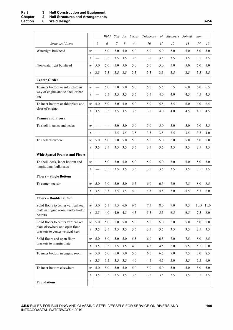
Structural Items
Weld Size for Lesser Thickness of Members Joined, mm
5 6 7 8 9 10 11 12 13 14 15
Watertight bulkhead w — 5.0 5.0 5.0 5.0 5.0 5.0 5.0 5.0 5.0 5.0
t — 3.5 3.5 3.5 3.5 3.5 3.5 3.5 3.5 3.5 3.5
Non-watertight bulkhead w 5.0 5.0 5.0 5.0 5.0 5.0 5.0 5.0 5.0 5.0 5.0
t 3.5 3.5 3.5 3.5 3.5 3.5 3.5 3.5 3.5 3.5 3.5
Center Girder
To inner bottom or rider plate inway of engine and to shell or barkeel
w — 5.0 5.0 5.0 5.0 5.0 5.5 5.5 6.0 6.0 6.5
t — 3.5 3.5 3.5 3.5 3.5 4.0 4.0 4.5 4.5 4.5
To inner bottom or rider plate andclear of engine
w 5.0 5.0 5.0 5.0 5.0 5.0 5.5 5.5 6.0 6.0 6.5
t 3.5 3.5 3.5 3.5 3.5 3.5 4.0 4.0 4.5 4.5 4.5
Frames and Floors
To shell in tanks and peaks w — — 5.0 5.0 5.0 5.0 5.0 5.0 5.0 5.0 5.5
t — — 3.5 3.5 3.5 3.5 3.5 3.5 3.5 3.5 4.0
To shell elsewhere w 5.0 5.0 5.0 5.0 5.0 5.0 5.0 5.0 5.0 5.0 5.0
t 3.5 3.5 3.5 3.5 3.5 3.5 3.5 3.5 3.5 3.5 3.5
Wide Spaced Frames and Floors
To shell, deck, inner bottom andlongitudinal bulkheads
w — 5.0 5.0 5.0 5.0 5.0 5.0 5.0 5.0 5.0 5.0
t — 3.5 3.5 3.5 3.5 3.5 3.5 3.5 3.5 3.5 3.5
Floors – Single Bottom
To center keelson w 5.0 5.0 5.0 5.0 5.5 6.0 6.5 7.0 7.5 8.0 8.5
t 3.5 3.5 3.5 3.5 4.0 4.5 4.5 5.0 5.5 5.5 6.0
Floors – Double Bottom
Solid floors to center vertical keelplate in engine room, under boilerbearers
w 5.0 5.5 5.5 6.0 6.5 7.5 8.0 9.0 9.5 10.5 11.0
t 3.5 4.0 4.0 4.5 4.5 5.5 5.5 6.5 6.5 7.5 8.0
Solid floors to center vertical keelplate elsewhere and open floorbrackets to center vertical keel
w 5.0 5.0 5.0 5.0 5.0 5.0 5.0 5.0 5.0 5.0 5.0
t 3.5 3.5 3.5 3.5 3.5 3.5 3.5 3.5 3.5 3.5 3.5
Solid floors and open floorbrackets to margin plate
w 5.0 5.0 5.0 5.0 5.5 6.0 6.5 7.0 7.5 8.0 8.5
t 3.5 3.5 3.5 3.5 4.0 4.5 4.5 5.0 5.5 5.5 6.0
To inner bottom in engine room w 5.0 5.0 5.0 5.0 5.5 6.0 6.5 7.0 7.5 8.0 8.5
t 3.5 3.5 3.5 3.5 4.0 4.5 4.5 5.0 5.5 5.5 6.0
To inner bottom elsewhere w 5.0 5.0 5.0 5.0 5.0 5.0 5.0 5.0 5.0 5.0 5.0
t 3.5 3.5 3.5 3.5 3.5 3.5 3.5 3.5 3.5 3.5 3.5
Foundations
Part 3 Hull Construction and EquipmentChapter 2 Hull Structures and ArrangementsSection 6 Weld Design 3-2-6
ABS RULES FOR BUILDING AND CLASSING STEEL VESSELS FOR SERVICE ON RIVERS ANDINTRACOASTAL WATERWAYS • 2019
100

Structural Items
Weld Size for Lesser Thickness of Members Joined, mm
5 6 7 8 9 10 11 12 13 14 15
To top plates, shell or inner bottomfor main engines and majorauxiliaries
w 5.0 5.0 5.5 5.5 6.0 6.5 7.0 7.5 8.0 8.5 9.0
t 3.5 3.5 4.0 4.0 4.5 4.5 5.0 5.5 5.5 6.0 6.5
Girders, Webs and Trusses
To shell and to bulkheads or decksin tanks
w — 5.0 5.0 5.0 5.0 5.0 5.0 5.0 5.0 5.5 5.5
t — 3.5 3.5 3.5 3.5 3.5 3.5 3.5 3.5 4.0 4.0
To bulkheads or decks elsewhere w — 5.0 5.0 5.0 5.0 5.0 5.0 5.0 5.0 5.0 5.5
t — 3.5 3.5 3.5 3.5 3.5 3.5 3.5 3.5 3.5 4.0
Webs to face plates w 5.0 5.0 5.0 5.0 5.0 5.0 5.0 5.0 5.0 5.0 5.5
t 3.5 3.5 3.5 3.5 3.5 3.5 3.5 3.5 3.5 3.5 4.0
Intercostals
To shell and inner bottom in wayof engines
w — 5.0 5.0 5.0 5.0 5.0 5.5 5.5 6.0 6.0 6.5
t — 3.5 3.5 3.5 3.5 3.5 4.0 4.0 4.5 4.5 4.5
To shell and inner bottomelsewhere, to floors
w 5.0 5.0 5.0 5.0 5.0 5.0 5.0 5.0 5.0 5.0 5.0
t 3.5 3.5 3.5 3.5 3.5 3.5 3.5 3.5 3.5 3.5 3.5
TABLE 1BDouble Continuous Fillet Weld Sizes – Inches
For weld requirements for thicknesses intermediate to those shown in the Table use the nearest lower thickness shown inthe table.
Structural Items
Weld Size for Lesser Thickness of Members Joined, mm
0.20 0.24 0.28 0.32 0.36 0.40 0.44 0.48 0.52 0.56 0.60
Beams
Transverse or longitudinal to deck 3/163/16
3/163/16
3/163/16
3/163/16
3/163/16
7/32
Bulkhead Plating
Oiltight, watertight bulkheads –periphery
3/163/16
3/163/16
7/321/4
1/49/32
5/165/16
11/32
Bulkhead Stiffeners
Deep tank bulkhead — 3/163/16
3/163/16
3/163/16
3/163/16
3/167/32
Watertight bulkhead — 3/163/16
3/163/16
3/163/16
3/163/16
3/167/32
Non-watertight bulkhead 3/163/16
3/163/16
3/163/16
3/163/16
3/163/16
7/32
Center Girder
To inner bottom or rider plate inway of engine and to shell or barkeel
— 3/163/16
3/163/16
3/167/32
7/321/4
1/41/4
To inner bottom or rider plate andclear of engine
3/163/16
3/163/16
3/163/16
7/327/32
1/41/4
1/4
Part 3 Hull Construction and EquipmentChapter 2 Hull Structures and ArrangementsSection 6 Weld Design 3-2-6
ABS RULES FOR BUILDING AND CLASSING STEEL VESSELS FOR SERVICE ON RIVERS ANDINTRACOASTAL WATERWAYS • 2019
101

Structural Items
Weld Size for Lesser Thickness of Members Joined, mm
0.20 0.24 0.28 0.32 0.36 0.40 0.44 0.48 0.52 0.56 0.60
Frames and Floors
To shell in tanks and peaks — — 3/163/16
3/163/16
3/163/16
3/163/16
7/32
To shell elsewhere 3/163/16
3/163/16
3/163/16
3/163/16
3/163/16
7/32
Wide Spaced Frames and Floors
To shell, deck, inner bottom andlongitudinal bulkheads
— 3/163/16
3/163/16
3/163/16
3/163/16
3/167/32
Floors – Single Bottom
To center keelson 3/163/16
3/163/16
7/321/4
1/49/32
5/165/16
11/32
Floors – Double Bottom
Solid floors to center vertical keelplate in engine room, under boilerbearers
3/167/32
7/321/4
1/45/16
5/163/8
3/87/16
7/16
Solid floors to center vertical keelplate elsewhere and open floorbrackets to center vertical keel
3/163/16
3/163/16
3/163/16
3/163/16
3/163/16
7/32
Solid floors and open floorbrackets to margin plate
3/163/16
3/163/16
7/321/4
1/49/32
5/165/16
11/32
To inner bottom in engine room 3/163/16
3/163/16
7/321/4
1/49/32
5/165/16
11/32
To inner bottom elsewhere 3/163/16
3/163/16
3/163/16
3/163/16
3/163/16
7/32
Foundations
To top plates, shell or inner bottomfor main engines and majorauxiliaries
3/163/16
7/327/32
1/41/4
9/325/16
5/1611/32
3/8
Girders, Webs and Trusses
To shell and to bulkheads or decksin tanks
— 3/163/16
3/163/16
3/163/16
3/163/16
7/327/32
To bulkheads or decks elsewhere — 3/163/16
3/163/16
3/163/16
3/163/16
7/327/32
Webs to face plates 3/163/16
3/163/16
3/163/16
3/163/16
3/163/16
7/32
Intercostals
To shell and inner bottom in wayof engines
— 3/163/16
3/163/16
3/167/32
7/321/4
1/41/4
To shell and inner bottomelsewhere, to floors
3/163/16
3/163/16
3/163/16
3/163/16
3/163/16
7/32
TABLE 2AIntermittent Fillet Weld Sizes and Spacing – Millimeters
For weld requirements for thicknesses intermediate to those shown in the Table use the nearest lower thickness shown inthe table.Weld sizes other than given in the table may be used provided the spacing of welds is modified to give equivalent strength.For double continuous weld sizes equivalent to the intermittent welds see 3-2-6/3 TABLE 1A.
Part 3 Hull Construction and EquipmentChapter 2 Hull Structures and ArrangementsSection 6 Weld Design 3-2-6
ABS RULES FOR BUILDING AND CLASSING STEEL VESSELS FOR SERVICE ON RIVERS ANDINTRACOASTAL WATERWAYS • 2019
102

Weld size for lesser thickness of members joined, mm
5 6.5 8 9.5 11 12.5 14
Length of fillet weld 40 65 65 65 65 65 65
Nominal leg size of fillet w 4.5 5.0 6.5 6.5 8.0 8/0 9.5
Nominal throat size of fillet t 3.0 3.5 4.5 4.5 5.5 5.5 6.5
Structural Items Spacing of Welds S, mm
Beams
Transverse or longitudinal to deck *300 *300 300 300 300 300 300
Watertight Bulkhead Plating – Periphery
One side Continuous weld of leg size of plate thicknessless than 2.0 mm
See 3-2-6/3TABLE 1A fordoublecontinuous weld
Other side — 250 250 250 250 See 3-2-6/3TABLE 1A fordoublecontinuous weld
Bulkhead Stiffeners (See Note 5)
Deep tank bulkhead — 250 250 250 250 250 250
Watertight bulkhead — *300 300 300 300 300 300
Non-watertight bulkhead *300 *350 *350 *350 *350 *350 *350
Center Girder (See Note 6)
To inner bottom or rider plate in way of engine andto shell or bar keel †
— 150 150 150 150 150 150
To inner bottom or rider plate and clear of engine — 150 150 150 150 150 150
Frames and Floors (See Notes 5 & 7)
To shell in tanks and peaks — — 250 250 250 250 250
To shell elsewhere *300 *300 300 300 300 300 300
Wide Spaced Frames and Floor
To shell, deck, inner bottom and longitudinal — 150 150 150 150 150 150
Floors – Single Bottom
To center keelson See 3-2-6/3 TABLE 1A for double continuous welds
Floors – Double Bottom (See Note 7)
Solid floors to center vertical keel plate in engineroom, under boiler bearers
See 3-2-6/3 TABLE 1A for double continuous welds
Solid floors to center vertical keel plate elsewhere,and open-floor brackets to center vertical keel
— *250 *250 250 250 250 250
Solid floors and open-floor brackets to margin plate See 3-2-6/3 TABLE 1A for double continuous welds
To inner bottom in engine room See 3-2-6/3 TABLE 1A for double continuous welds
Part 3 Hull Construction and EquipmentChapter 2 Hull Structures and ArrangementsSection 6 Weld Design 3-2-6
ABS RULES FOR BUILDING AND CLASSING STEEL VESSELS FOR SERVICE ON RIVERS ANDINTRACOASTAL WATERWAYS • 2019
103

Structural Items Spacing of Welds S, mm
To inner bottom elsewhere *300 *300 300 300 300 300 300
Foundations
To top plates, shell or inner bottom for main enginesand major auxiliaries
See 3-2-6/3 TABLE 1A for double continuous welds
Girders, Webs and Trusses
To shell and to bulkheads or decks in tanks — 200 225 225 225 225 225
To bulkheads or decks elsewhere — 250 250 250 250 250 250
Webs to face plate *250 *250 300 300 300 300 300
Intercostals
To shell and inner bottom in way of engine † — 150 150 150 150 150 150
To shell and inner bottom elsewhere, to floors *275 *275 275 275 275 275 275
See General Notes at beginning of Table.* Fillet welds are to be staggered.† Length of fillet to be 75 mm
Notes
1 Where beams, stiffeners, frames, etc., pass through slotted girders, shelves or stringers, there is to be a pair ofmatched intermittent welds on each side of each such intersection, and the beams, stiffeners and frames are tobe efficiently attached to the girders, shelves and stringers.
2 Longitudinal frames are to have 150 mm of double continuous welding at their ends and in way of transversesexcept as follows. Deck longitudinals require 150 mm double continuous welding at ends. Side and decklongitudinals in way of cargo spaces in open hopper barges require a matched pair of welds at their ends.
3 The required welding area of end connections of stanchions and diagonals is not to be less than the following:
● Stanchions –75% of the area of the stanchions
● Diagonals – 50% of the area of the diagonalIn determining the weld area provided, the throat dimension of the fillet is to be used.
4 Brackets generally welded 75 mm on 150 mm centers, both sides. Length of fillet weld based on lesserthickness of members joined.
5 Unbracketed shell and bulkhead stiffeners are to have double continuous welds for one-tenth of their length ateach end.
6 Where center girders are water- or oil-tight a continuous weld is to be used on one side of the connections.
7 Tank end floors are to be welded to shell, center girder and inner bottom as required for deep tank bulkheads.
TABLE 2BIntermittent Fillet Weld Sizes and Spacing – Inches
For weld requirements for thicknesses intermediate to those shown in the Table use the nearest lower thickness shown inthe table.Weld sizes other than given in the table may be used provided the spacing of welds is modified to give equivalent strength.For double continuous weld sizes equivalent to the intermittent welds see 3-2-6/3 TABLE 1B.
Part 3 Hull Construction and EquipmentChapter 2 Hull Structures and ArrangementsSection 6 Weld Design 3-2-6
ABS RULES FOR BUILDING AND CLASSING STEEL VESSELS FOR SERVICE ON RIVERS ANDINTRACOASTAL WATERWAYS • 2019
104

Weld size for lesser thickness of members joined, in.
0.20 0.26 0.32 0.38 0.44 0.50 0.58
Length of fillet weld 11/2 21/2 21/2 21/2 21/2 21/2 21/2
Nominal leg size of fillet w 3/163/16
1/41/4
5/165/16
3/8
Structural Items Spacing of Welds S, in.
Beams
Transverse or longitudinal to deck *12 *12 12 12 12 12 12
Watertight Bulkhead Plating – Periphery
One side Continuous weld of leg size of plate thicknessless than 1/16 in.
See 3-2-6/3TABLE 1B fordoublecontinuous weld
Other side — 10 10 10 10 See 3-2-6/3TABLE 1B fordoublecontinuous weld
Bulkhead Stiffeners (See Note 5)
Deep tank bulkhead — 10 10 10 10 10 10
Watertight bulkhead — *12 12 12 12 12 12
Non-watertight bulkhead *12 *14 *14 *14 *14 *14 *14
Center Girder (See Note 6)
To inner bottom or rider plate in way of engine andto shell or bar keel †
— 6 6 6 6 6 6
To inner bottom or rider plate and clear of engine — 6 6 6 6 6 6
Frames and Floors (See Notes 5 & 7)
To shell in tanks and peaks — — 10 10 10 10 10
To shell elsewhere *12 *12 12 12 12 12 12
Wide Spaced Frames and Floor
To shell, deck, inner bottom and longitudinal — 6 6 6 6 6 6
Floors – Single Bottom
To center keelson See 3-2-6/3 TABLE 1B for double continuous welds
Floors – Double Bottom (See Note 7)
Solid floors to center vertical keel plate in engineroom, under boiler bearers
See 3-2-6/3 TABLE 1B for double continuous welds
Solid floors to center vertical keel plate elsewhere,and open-floor brackets to center vertical keel
— *10 *10 10 10 10 10
Solid floors and open-floor brackets to margin plate See 3-2-6/3 TABLE 1B for double continuous welds
To inner bottom in engine room See 3-2-6/3 TABLE 1B for double continuous welds
To inner bottom elsewhere *12 *12 12 12 12 12 12
Part 3 Hull Construction and EquipmentChapter 2 Hull Structures and ArrangementsSection 6 Weld Design 3-2-6
ABS RULES FOR BUILDING AND CLASSING STEEL VESSELS FOR SERVICE ON RIVERS ANDINTRACOASTAL WATERWAYS • 2019
105

Structural Items Spacing of Welds S, in.
Foundations
To top plates, shell or inner bottom for main enginesand major auxiliaries
See 3-2-6/3 TABLE 1B for double continuous welds
Girders, Webs and Trusses
To shell and to bulkheads or decks in tanks — 8 9 9 9 9 9
To bulkheads or decks elsewhere — 10 10 10 10 10 10
Webs to face plate *10 *10 12 12 12 12 12
Intercostals
To shell and inner bottom in way of engine † — 6 6 6 6 6 6
To shell and inner bottom elsewhere, to floors *11 *11 11 11 11 11 11
See General Notes at beginning of Table.* Fillet welds are to be staggered.† Length of fillet to be 3 in.
Notes
1 Where beams, stiffeners, frames, etc., pass through slotted girders, shelves or stringers, there is to be a pair ofmatched intermittent welds on each side of each such intersection, and the beams, stiffeners and frames are tobe efficiently attached to the girders, shelves and stringers.
2 Longitudinal frames are to have 6 inches of double continuous welding at their ends and in way of transversesexcept as follows. Deck longitudinals require 6 inches double continuous welding at ends. Side and decklongitudinals in way of cargo spaces in open hopper barges require a matched pair of welds at their ends.
3 The required welding area of end connections of stanchions and diagonals is not to be less than the following:
● Stanchions –75% of the area of the stanchions
● Diagonals – 50% of the area of the diagonalIn determining the weld area provided, the throat dimension of the fillet is to be used.
4 Brackets generally welded 3 inches on 6 inches centers, both sides. Length of fillet weld based on lesserthickness of members joined.
5 Unbracketed shell and bulkhead stiffeners are to have double continuous welds for one-tenth of their length ateach end.
6 Where center girders are water- or oil-tight a continuous weld is to be used on one side of the connections.
7 Tank end floors are to be welded to shell, center girder and inner bottom as required for deep tank bulkheads.
Part 3 Hull Construction and EquipmentChapter 2 Hull Structures and ArrangementsSection 6 Weld Design 3-2-6
ABS RULES FOR BUILDING AND CLASSING STEEL VESSELS FOR SERVICE ON RIVERS ANDINTRACOASTAL WATERWAYS • 2019
106

P A R T
3C H A P T E R 3 Subdivision and Stability
CONTENTSSECTION 1 Passenger Vessels...........................................................................109
1 Definitions...................................................................................1091.1 Margin Line.................................................................... 1091.3 Deepest Subdivision Draft............................................. 109
3 Intact Stability............................................................................. 1093.1 Vessels Over 100 Gross Tons, Greater than 20 m
(65 ft) in Length, or Carrying 50 or More Passengers... 1093.3 Self-propelled Vessels Under 100 m (328 ft) in Length. 110
5 Damage Stability.........................................................................1105.1 Permeability................................................................... 1105.3 Extent of Damage...........................................................111
7 Portlights in Cargo Spaces Located Below the Margin Line....... 1119 Automatic Ventilating Portlights...................................................11111 Shell Connections Located Below the Margin Line.....................112
11.1 ....................................................................................... 11211.3 ....................................................................................... 11211.5 ....................................................................................... 112
13 Gangway and Cargo Ports Located Below the Margin Line....... 11213.1 ....................................................................................... 11213.3 ....................................................................................... 112
15 Openings and Penetrations in Watertight Bulkheads..................11215.1 ....................................................................................... 11215.3 ....................................................................................... 11215.5 ....................................................................................... 11215.7 ....................................................................................... 11315.9 ....................................................................................... 113
17 Doors, Manholes and Access Openings.....................................11319 Shaft Tunnel Door and Doors within Propulsion Machinery
Spaces........................................................................................ 11321 Watertight Doors in Watertight Bulkheads.................................. 113
21.1 ....................................................................................... 11321.3 ....................................................................................... 11321.5 ....................................................................................... 11321.7 ....................................................................................... 11421.9 (2014).............................................................................114
23 Power-operated Sliding Watertight Doors...................................11423.1 ....................................................................................... 11423.3 ....................................................................................... 115
ABS RULES FOR BUILDING AND CLASSING STEEL VESSELS FOR SERVICE ON RIVERS ANDINTRACOASTAL WATERWAYS • 2019
107

23.5 ....................................................................................... 11523.7 ....................................................................................... 11623.9 ....................................................................................... 11623.11 ....................................................................................... 11623.13 ....................................................................................... 11623.15 ....................................................................................... 11623.17 Central Operating Console............................................ 116
25 Watertight Doors in Cargo Spaces (2014).................................. 11727 Portable Plates............................................................................11729 Miscellaneous............................................................................. 117
29.1 ....................................................................................... 11729.3 ....................................................................................... 11729.5 ....................................................................................... 118
31 Watertight Decks, Trunks, Tunnels, Duct Keels and Ventilators. 11833 Inclining Experiment....................................................................11835 Deadweight Survey.....................................................................11837 Trim and Stability Booklets..........................................................11839 Damage Control Plans................................................................118
SECTION 2 Crane Barges (2015)........................................................................ 1191 Stability Information.................................................................... 119
1.1 Specific Applicability...................................................... 1191.3 Definitions...................................................................... 119
3 Intact Stability Requirements for Barges Equipped to Lift.......... 1203.1 Counter-balanced and Non-counter-balanced Barges.. 1203.3 Additional Intact Stability Standards –Counter-
ballasted Barges............................................................ 122
TABLE 1 Values of Ch (2015)............................................................ 121
FIGURE 1 Load Radius (2015)............................................................120FIGURE 2 Criteria after Accidental Loss of Crane Load (2015)A1 ≥ 1 . 3 × A2.....................................................................123
ABS RULES FOR BUILDING AND CLASSING STEEL VESSELS FOR SERVICE ON RIVERS ANDINTRACOASTAL WATERWAYS • 2019
108

P A R T
3C H A P T E R 3 Subdivision and Stability
S E C T I O N 1 Passenger Vessels
1 Definitions
1.1 Margin LineThe Margin Line is a line drawn at least 76 mm (3 in.) below the upper surface of the main deck at side.
1.3 Deepest Subdivision DraftDeepest Subdivision Draft is the waterline which corresponds to the greatest draft permitted by thesubdivision requirements which are applicable.
3 Intact Stability
3.1 Vessels Over 100 Gross Tons, Greater than 20 m (65 ft) in Length, or Carrying 50 orMore PassengersThe metacentric height, GM, of these vessels is to be as indicated by the following equations in eachcondition of loading and operation, except that vessels under 20 m (65 ft) in length, of 100 gross tons orless, and carrying between 50 and 150 passengers need only comply with Equation 1.GM ≥ PAH/ Wtan(T) 1GM ≥ Nb/ KWtan T 2where
P = 0 . 028 + L/1309 2tf/m2 0 . 0025 + L/14200 2Ltf/ft2L = length of the vessel, in m (ft), as defined in 3-1-1/3
A = projected lateral area of the portion of the vessel above the waterline, in m2 (ft2)
H = vertical distance from the center of A to the center of the vessel’s underwater lateral area, or approximately tothe one-half draft point, in m (ft)
W = force corresponding to the displacement of the vessel, in tf (Ltf)
T = 14° or the angle of heel at which one half of the freeboard to the deck edge is immersed, whichever is less.
N = number of passengers
b = distance from the centerline of the vessel to the geometric center of the passenger deck on one side of thecenterline, in m (ft)
K = 23.6 passengers/tf (24 passengers/Ltf)
ABS RULES FOR BUILDING AND CLASSING STEEL VESSELS FOR SERVICE ON RIVERS ANDINTRACOASTAL WATERWAYS • 2019
109

3.3 Self-propelled Vessels Under 100 m (328 ft) in LengthThese vessels are to comply with 3-3-1/3.3.1 or 3-3-1/3.3.2 below. For the purpose of demonstratingcompliance with 3-3-1/3.3.1 or 3-3-1/3.3.2 below, at each angle of heel the vessel's righting arm is to becalculated after the vessel is permitted to trim freely until the trimming moment is zero.
3.3.1 Vessels with Maximum Righting Arm Occurring at an Angle of Heel > 30°These vessels are to have:
i) An initial metacentric height (GM) of at least 0.15 m (0.49 ft).
ii) A maximum righting arm (GZ) of at least 0.20 m (0.66 ft) at an angle of heel equal to orgreater than 30°
iii) An area under each righting arm curve of at least 3.15 m-degrees (10.3 ft-degrees) up toan angle of heel of 30°.
iv) An area under each righting arm curve of at least 5.15 m-degrees (16.9 ft-degrees) up toan angle of heel of 40°, or the downflooding angle, whichever is less, and
v) An area under each righting arm curve between the angles of 30°and 40°, or between 30°and the downflooding angle, if this angle is less than 40°, of not less than 1.72 m-degrees(5.6 ft-degrees).
3.3.2 Vessels with Maximum Righting Arm Occurring at an Angle of Heel ≤ 30°These vessels are to comply with 3-3-1/3.3.1 or are to have;
i) An initial metacentric height (GM) of at least 0.15 m (0.49 ft).
ii) A maximum righting arm that occurs at an angle of heel not less than 15°.
iii) An area under each righting arm curve of at least 5.15 m-degrees (16.9 ft-degrees) up toan angle of heel of 40°, or the downflooding angle, whichever is less, and
iv) An area under each righting arm curve between the angles of 30° and 40°, or between 30°and the downflooding angle, if this angle is less than 40°, of not less than 1.72 m-degrees(5.6 ft-degrees).
v) An area under each righting arm curve up to the angle of maximum righting arm of notless than the area determined by the following equations:A = 3 . 15 + 0 . 057 30− Y m‐degreesA = 10 . 3 + 0 . 187 30− Y ft‐degreesA = area, in m-degrees (ft-degrees)Y = angle of maximum righting, in degrees
5 Damage StabilityAll vessels over 100 gross tons, greater than 20 m (65 ft) in length, or carrying more than 150 passengers,are to comply with a one-compartment standard of flooding (no damage to any main transverse watertightbulkhead), irrespective of the maximum number of passengers carried. The following assumptions are tobe made in determining compliance with the one compartment standard.
5.1 PermeabilityThe following uniform average permeabilities are to be assumed:
i) Cargo, stores and baggage spaces: 60%.
ii) Machinery spaces: 85%
Part 3 Hull Construction and EquipmentChapter 3 Subdivision and StabilitySection 1 Passenger Vessels 3-3-1
ABS RULES FOR BUILDING AND CLASSING STEEL VESSELS FOR SERVICE ON RIVERS ANDINTRACOASTAL WATERWAYS • 2019
110

iii) Tanks: 0% or 95%, whichever results in the most disabling condition.
iv) All other spaces: 95%.
5.3 Extent of Damage5.3.1 Vessels of 43.5 m (143 ft) in Length or Greater
For vessels 43.5 m (143 ft) or more in length, the following extent of damage is to be assumed:
5.3.1(a) Longitudinal penetration. 3 m (10 ft) plus 3% of the vessel’s length, or 10.7 m (35 ft)whichever is less.
5.3.1(b) Transverse penetration. B/5 where B is the mean of the maximum beam at the bulkheaddeck and the maximum beam at the deepest subdivision draft, applied inboard from the side of thevessel, at right angles to the centerline, at the level of the deepest subdivision draft.
5.3.1(c) Vertical penetration. Upward without limit.
5.3.2 Vessels Under 43.5 m (143 ft) in LengthFor vessels less than 43.5 m (143 ft) in length, the following extent of damage is to be assumed:
5.3.2(a) Longitudinal penetration. 1.8 m (6 ft) or 10% of the vessel’s length, whichever is greater.
5.3.2(b) Transverse penetration. B/5 where B is the mean of the maximum beam at the bulkheaddeck and the maximum beam at the deepest subdivision draft, applied inboard from the side of thevessel, at right angles to the centerline, at the level of the deepest subdivision draft.
5.3.2(c) Vertical penetration. Upward without limit.
7 Portlights in Cargo Spaces Located Below the Margin LinePortlights located below the margin line are to be fitted with tempered monolithic glass of thicknessobtained from the following equation and are to comply with i, ii, and iii, below.t = 0 . 033dtmin = 8 . 0 mm (0.31 in.)where
d = clear glass diameter, in mm (in.)
t = glass thickness, in mm (in.)
i) Portlights are not to be fitted in any spaces which are used exclusively for the carriage of cargo.
ii) Portlights may be fitted in spaces used alternatively for the carriage of cargo or passengers, butthey are to be of such construction as will effectively prevent any unauthorized opening.
iii) If cargo is carried in spaces mentioned in ii, the portlights and their deadlights are to be closedwatertight and locked before the cargo is shipped.
9 Automatic Ventilating PortlightsAutomatic ventilating portlights are not to be fitted in the shell plating below the margin line withoutspecial approval.
Part 3 Hull Construction and EquipmentChapter 3 Subdivision and StabilitySection 1 Passenger Vessels 3-3-1
ABS RULES FOR BUILDING AND CLASSING STEEL VESSELS FOR SERVICE ON RIVERS ANDINTRACOASTAL WATERWAYS • 2019
111

11 Shell Connections Located Below the Margin Line
11.1All inlets and discharges in the shell plating are to be fitted with efficient and accessible arrangements forpreventing the accidental ingress of water into the vessel.
11.3Except as provided in 3-3-1/11.5, each separate discharge led through the shell plating from spaces belowthe margin line is to be provided with either one automatic non-return valve fitted with a positive means ofclosing from above the bulkhead deck or with two automatic non-return valves without positive means ofclosing, provided that the inboard valve is situated above the deepest draft and is always accessible forexamination under service conditions. Where a valve with positive means of closing is fitted, the operatingposition above the bulkhead deck is always to be readily accessible, and means are to be provided forindicating whether the valve is open or closed.
11.5Machinery space main and auxiliary sea inlets and discharges used in connection with the operation ofmachinery are to be fitted with readily accessible valves between the pipes and the shell plating or betweenthe pipes and fabricated boxes attached to the shell plating. The valves may be controlled locally and are tobe provided with indicators showing whether they are open or closed.
13 Gangway and Cargo Ports Located Below the Margin Line
13.1Gangway and cargo ports fitted below the margin line are to be of sufficient strength. They are to becapable of being effectively closed and secured watertight. The scantlings of the ports are to be equivalentto the scantlings required by the Rules for the hull structure in that location. Ports should normally openoutboard. Ports which open inboard are to have portable strong-backs or props in addition to the regulardogs. If accessible during service, they are to be fitted with a device which prevents unauthorized opening.Shell doublers or insert plates are to be fitted to compensate for the openings and the corners of openingsare to be well rounded. Indicators showing whether the ports are open or secured closed are to be locatedin the wheelhouse or main control center.
13.3Such ports are to be so located as to have their lowest point above the deepest draft waterline.
15 Openings and Penetrations in Watertight Bulkheads
15.1The number of openings in watertight bulkheads is to be reduced to the minimum compatible with thedesign and proper working of the vessel; satisfactory means are to be provided for closing these openings.
15.3Valves not forming part of a piping system are not permitted in watertight subdivision bulkheads.
15.5Lead or other heat sensitive materials are not to be used in systems which penetrate watertight subdivisionbulkheads, where deterioration of such material would in the event of a fire, impair the watertight integrityof the bulkheads.
Part 3 Hull Construction and EquipmentChapter 3 Subdivision and StabilitySection 1 Passenger Vessels 3-3-1
ABS RULES FOR BUILDING AND CLASSING STEEL VESSELS FOR SERVICE ON RIVERS ANDINTRACOASTAL WATERWAYS • 2019
112

15.7Except as provided in 3-3-1/15.9, the collision bulkhead may be pierced below the margin line by not morethan one pipe for dealing with fluid in the forepeak, provided that the pipe is fitted with a screwdown valvecapable of being operated from above the bulkhead deck; the valve chest being located on the collisionbulkhead inside the forepeak.
15.9If the forepeak is divided to hold two kinds of liquids, the collision bulkhead may be pierced below themargin line by two pipes, each of which is fitted as required by paragraph d, provided there is no practicalalternative to the fitting of such a second pipe and that, having regard to the additional subdivisionprovided in the forepeak, the safety of the vessel is maintained.
17 Doors, Manholes and Access OpeningsDoors, manholes, or access openings are not permitted:
i) In the collision bulkhead below the margin line;
ii) In watertight transverse bulkheads dividing a cargo space from an adjoining cargo space or from apermanent or reserve bunker, except as provided in 3-3-1/25.
19 Shaft Tunnel Door and Doors within Propulsion Machinery SpacesWithin spaces containing the main and auxiliary propulsion machinery including boilers serving the needsof propulsion, not more than one watertight door, apart from the watertight doors to shaft tunnels, is to befitted in each main transverse bulkhead. Where two or more shafts are fitted, the tunnels are to beinterconnected by a passage. There is to be only one watertight door between the machinery space and thetunnel spaces where two shafts are fitted, and only two watertight doors where there are more than twoshafts. All these watertight doors are to be of the sliding type and are to be so located as to have their sillsas high as practicable. The hand gear for operating these doors from above the bulkhead deck is to besituated outside the spaces containing the machinery. See also 4-4-1/25.9.4.
21 Watertight Doors in Watertight Bulkheads
21.1Watertight doors, except as provided in 3-3-1/25 are to be power-operated sliding doors complying withthe requirements of 3-3-1/23 capable of being closed simultaneously from the central operating console atthe navigation bridge (or main control station) in not more than 60 seconds with the vessel in the uprightposition.
21.3The means of operation whether by power or by hand of any power-operated sliding watertight door is tobe capable of closing the door with the vessel listed to 15° either way. Consideration is also to be given tothe forces which may act on either side of the door as may be experienced when water is flowing throughthe opening applying a static head equivalent to a water height of at least 1 m (3.28 ft) above the sill on thecenterline of the door.
21.5Watertight door controls, including hydraulic piping and electric cables, are to be kept as close aspracticable to the bulkhead in which the doors are fitted, in order to minimize the likelihood of them beinginvolved in any damage which the vessel may sustain. The positioning of watertight doors and theircontrols are to be such that if the vessel sustains damage within one fifth of the breadth of the vessel, asdefined in 3-1-1/5, such distance being measured at right angles to the centerline at the level of the deepestsubdivision load line, the operation of the watertight doors clear of the damaged portion of the vessel is notimpaired.
Part 3 Hull Construction and EquipmentChapter 3 Subdivision and StabilitySection 1 Passenger Vessels 3-3-1
ABS RULES FOR BUILDING AND CLASSING STEEL VESSELS FOR SERVICE ON RIVERS ANDINTRACOASTAL WATERWAYS • 2019
113

21.7All power-operated sliding watertight doors are to be provided with means of indication which will showat all remote operating positions whether the doors are open or closed. Remote operating positions are tobe at the navigation bridge (or main control station) as required by 3-3-1/23.1.5 and, at the location wherehand operation above the bulkhead deck is required by 3-3-1/23.1.4.
21.9 (2014)Watertight doors are to be tested for operation at the manufacturer’s plant. Watertightness of doors whichbecome immersed by an equilibrium or intermediate waterplane at any stage of assumed flooding is to beconfirmed by prototype hydrostatic testing at the manufacturer’s plant. The head of water used for the testshall correspond at least to the head measured from the lower edge of the door opening, at the location inwhich the door is to be fitted in the vessel, to:
i) the bulkhead deck or freeboard deck, as applicable, or
ii) the most unfavorable damage waterplane, if that be greater
Tests are to be carried out in the presence of the Surveyor and a test certificate is to be issued.
For large doors intended for use in the watertight subdivision boundaries of cargo spaces, structuralanalysis may be accepted in lieu of pressure testing subject to ABS review. Where gasket seals are utilizedfor such doors, a prototype pressure test is be carried out to verify that the gasket material under thecompression is capable of withstanding any deflection indicated in the structural analysis.
Doors above freeboard or bulkhead deck, which are not immersed by an equilibrium or intermediatewaterplane but become intermittently immersed at angles of heel in the required range of positive stabilitybeyond the equilibrium position, are to be hose tested after installation onboard.
23 Power-operated Sliding Watertight Doors
23.1Each power-operated sliding watertight door is to comply with the following:
23.1.1Have either a vertical or a horizontal motion;
23.1.2Subject to 3-3-1/27, normally being limited to a maximum clear opening width of 1.2 m (3.94 ft).Larger doors may be considered to the extent necessary for the effective operation of the vesselprovided that other safety measures, including the following, are taken into consideration:
i) Special consideration is to be given to the strength of the door and its closing appliancesin order to prevent leakages;
ii) The door is to be located inboard of the transverse extent of damage (B/5);
iii) The door is to be kept closed when the vessel is in service, except the door may beopened for limited periods when absolutely necessary.
23.1.3Be fitted with the necessary equipment to open and close the door using electric power, hydraulicpower, or any other acceptable form of power.
23.1.4Be provided with an individual hand-operated mechanism. It is to be possible to open and closethe door by hand from either side of the door, and in addition, close the door from an accessible
Part 3 Hull Construction and EquipmentChapter 3 Subdivision and StabilitySection 1 Passenger Vessels 3-3-1
ABS RULES FOR BUILDING AND CLASSING STEEL VESSELS FOR SERVICE ON RIVERS ANDINTRACOASTAL WATERWAYS • 2019
114

position above the bulkhead deck with an all round crank motion or some other movementproviding the same acceptable degree of safety. Direction of rotation or other movement is to beclearly indicated at all operating positions. The time necessary for the complete closure of thedoor, when operating by hand gear, is not to exceed 90 seconds with the vessel in the uprightposition;
23.1.5Be provided with controls for opening and closing the door by power from both sides of the doorand also for closing the door by power from the central operating console at the navigation bridge(or main control station);
23.1.6Be provided with an audible alarm, distinct from any other alarm in the area, which will soundwhenever the door is closed remotely by power and which is to sound for at least five seconds butno more than ten seconds before the door begins to move and is to continue sounding until thedoor is completely closed. In the case of remote hand operation it is sufficient for the audiblealarm to sound only when the door is moving. Additionally, in passenger areas and areas of highambient noise, the audible alarm is to be supplemented by a warning sign posted on each side ofthe door, an intermittent visual signal at the door; and
23.1.7Have an approximately uniform rate of closure under power. The closure time, from the time thedoor begins to move to the time it reaches the completely closed position, is to be not less than 20seconds or more than 40 seconds with the vessel in the upright position.
23.3The electrical power required for power-operated sliding watertight doors is to be supplied from theemergency switchboard either directly or by a dedicated distribution board situated above the bulkheaddeck. The associated control, indication and alarm circuits are to be supplied from the emergencyswitchboard either directly or by a dedicated distribution board situated above the bulkhead deck.
23.5Power-operated sliding watertight doors are to have one of the following systems,
23.5.1A centralized hydraulic system with two independent power sources each consisting of a motorand pump capable of simultaneously closing all doors. In addition, there are to be for the wholeinstallation hydraulic accumulators of sufficient capacity to operate all the doors at least threetimes (i.e., closed-open-closed) against an adverse list of 15°. This operating cycle is to be capableof being carried out when the accumulator is at the pump cut-in pressure. The fluid used is to bechosen considering the temperatures liable to be encountered by the installation during its service.The power operating system is to be designed to minimize the possibility of having a single failurein the hydraulic piping adversely affect the operation of more than one door. The hydraulic systemis to be provided with a low-level alarm for hydraulic fluid reservoirs serving the power-operatedsystem and a low gas pressure alarm or other effective means of monitoring loss of stored energyin hydraulic accumulators. These alarms are to be audible and visual and are to be situated on thecentral operating console at the navigation bridge (or main control station).
23.5.2An independent hydraulic system for each door with each power source consisting of a motor andpump capable of opening and closing the door. In addition, there is to be a hydraulic accumulatorof sufficient capacity to operate the door at least three times (i.e., closed-open-closed) against anadverse list of 15°. This operating cycle is to be capable of being carried out when the
Part 3 Hull Construction and EquipmentChapter 3 Subdivision and StabilitySection 1 Passenger Vessels 3-3-1
ABS RULES FOR BUILDING AND CLASSING STEEL VESSELS FOR SERVICE ON RIVERS ANDINTRACOASTAL WATERWAYS • 2019
115

accumulator is at the pump cut-in pressure. The fluid used is to be chosen considering thetemperatures liable to be encountered by the installation during its service. A low gas pressuregroup alarm or other effective means of monitoring loss of stored energy in hydraulicaccumulators is to be provided at the central operating console on the navigation bridge (or maincontrol station). Loss of stored energy indication at each local operating position is to be provided.
For the systems specified in 3-3-1/23.5.1 and 3-3-1/23.5.2 above, the power systems for power-operated watertight sliding doors are to be separate from any other power system. A single failurein the electric or hydraulic power-operated system excluding the hydraulic actuator is not toprevent the hand operation of any door.
23.7Control handles are to be provided at each side of the bulkhead at a minimum height of 1.6 m (5.25 ft)above the deck and are to be so arranged as to enable persons passing through the doorway to hold bothhandles in the open position without being able to set the power closing mechanism in operationaccidentally. The direction of movement of the handles in opening and closing the door is to be in thedirection of door movement and is to be clearly indicated.
23.9As far as practicable, electrical equipment and components for watertight doors are to be situated above thebulkhead deck and outside hazardous areas and spaces.
23.11The enclosures of electrical components necessarily situated below the bulkhead deck are to providesuitable protection against the ingress of water.
23.13Electric power, control, indication and alarm circuits are to be protected against fault in such a way that afailure in one door circuit will not cause a failure in any other door circuits. Short circuits or other faults inalarm or indicator circuits of a door are not to result in a loss of power operation of that door.Arrangements are to be such that leakage of water into the electrical equipment located below the maindeck will not cause the door to open.
23.15A single electrical failure in the power operating or control system of a power-operated sliding watertightdoor is not to result in opening of a closed door. Availability of the power supplies is to be continuouslymonitored at a point in the electrical circuit as near as practicable to each of the motors required by3-3-1/23.5 above. Loss of any such power supply is to activate an audible and visual alarm at the centraloperating console at the navigation bridge or main control station).
23.17 Central Operating Console23.17.1
The central operating console at the navigation bridge (or main control station) is to have a“master mode” switch with two modes of control: a “local control” mode which will allow anydoor to be locally opened and locally closed after use without automatic closure, and a “doorsclosed” mode which will automatically close any door that is open. The “doors closed” mode willpermit doors to be opened locally and will automatically reclose the doors upon release of thelocal control mechanism. The “master mode” switch is to be normally in the “local control” mode.
23.17.2The central operating console at the navigation bridge (or main control station) is to be providedwith a diagram showing the location of each door, with visual indicators to show whether each
Part 3 Hull Construction and EquipmentChapter 3 Subdivision and StabilitySection 1 Passenger Vessels 3-3-1
ABS RULES FOR BUILDING AND CLASSING STEEL VESSELS FOR SERVICE ON RIVERS ANDINTRACOASTAL WATERWAYS • 2019
116

door is open or closed. A red light is to indicate a door is fully open and a green light is to indicatea door is fully closed. When the door is closed remotely the red light is to indicate the intermediateposition by flashing. The indicating circuit is to be independent of the control circuit for each door.
23.17.3The arrangements are to be such as to prohibit the opening of any door from the central operatingconsole.
25 Watertight Doors in Cargo Spaces (2014)Watertight doors of substantial construction may be fitted in watertight bulkheads dividing cargo betweendeck spaces. Such doors may be hinged, rolling or sliding doors and are not to be remotely controlled.They are to be fitted at the highest level and as far from the shell plating as practicable, but in no case isthe outboard vertical edge to be situated at a distance from the shell plating which is less than one fifth ofthe breadth of the vessel, such distance being measured at right angles to the centerline of the vessel at thelevel of the deepest draft.
All watertight doors in the cargo spaces are to be kept closed during navigation and should any of thedoors be accessible during the voyage, they are to be fitted with a device which prevents unauthorizedopening. When it is proposed to fit such doors, the number and arrangements are to be speciallyconsidered.
For vessels required to meet stability requirements specified in 3-3-1/3 and 3-3-1/5, the doors whichbecome immersed by an equilibrium or intermediate waterplane at any stage of assumed flooding are to behydrostatically tested at the manufacturer’s plant. The head of water used for the test shall correspond atleast to the head measured from the lower edge of the door opening, at the location in which the door is tobe fitted in the vessel, to the most unfavorable damage waterplane.
27 Portable PlatesPortable plates on bulkheads are not permitted except in machinery spaces. The necessary precautions areto be taken in replacing them to ensure that the joints are watertight.
ABS will consider not more than one power-operated sliding watertight door in each main transversebulkhead larger than 1.2 m (3.94 ft) in clear opening width being substituted for these portable plates,provided these doors are closed during navigation except, in case of urgent necessity, the doors may beopened at the discretion of the master. These doors need not meet the requirements of 3-3-1/23.1.4regarding complete closure by hand-operated gear in 90 seconds provided the doors can be closed in areasonable time.
29 Miscellaneous
29.1Where trunkways or tunnels for piping, or for any other purpose are carried through main transversewatertight bulkheads, they are to be watertight and in accordance with the requirements of 3-2-5/17. Theaccess to at least one end of each such tunnel or trunk-way, if used as a passage during service, is to bethrough a trunk extending watertight to a height sufficient to permit access above the margin line. Theaccess to the other end of the trunk-way or tunnel may be through a watertight door of the type required byits location in the vessel. Such trunk-ways or tunnels are not to extend through the first subdivisionbulkhead abaft the collision bulkhead.
29.3Where it is proposed to fit tunnels piercing main transverse watertight bulkheads, these will be subject tospecial consideration.
Part 3 Hull Construction and EquipmentChapter 3 Subdivision and StabilitySection 1 Passenger Vessels 3-3-1
ABS RULES FOR BUILDING AND CLASSING STEEL VESSELS FOR SERVICE ON RIVERS ANDINTRACOASTAL WATERWAYS • 2019
117

29.5Where trunkways in connection with refrigerated cargo and ventilation or forced draft trunks are carriedthrough more than one watertight bulkhead, the means of closure at such openings are to be operated bypower and be capable of being closed from a central position situated above the bulkhead deck.
31 Watertight Decks, Trunks, Tunnels, Duct Keels and VentilatorsWatertight decks, trunks, tunnels, duct keels and ventilators are to be of the same strength as watertightbulkheads at corresponding levels. The means used for making them watertight, and the arrangementsadopted for closing openings in them are to be submitted for approval. Watertight ventilators and trunksare to be carried at least up to the main deck.
33 Inclining ExperimentA stability test (lightweight survey and inclining experiment) to determine the lightship displacement andcenter of gravity of the vessel is to be carried out in the presence of a Surveyor.
35 Deadweight SurveyIn lieu of an inclining experiment, a deadweight survey may be performed to determine the lightweightdisplacement and longitudinal center of gravity, provided it can be shown that locating the precise positionof the vessel’s vertical center of gravity is not necessary to ensure that the vessel has adequate stability inall probable loading conditions.
37 Trim and Stability BookletsTrim and stability booklets generally will not be required for river service passenger vessels of normalconfiguration with barge-type hulls. Vessels of unusual configuration or with ship-type hulls will besubject to special consideration.
39 Damage Control PlansPlans showing clearly for each deck and hold the boundaries of the watertight compartments, the openingstherein with the means of closure and position of any controls thereof, and the arrangements for thecorrection of any heel due to flooding are tobe permanently exhibited onboard the vessel. In addition,booklets containing the aforementioned information are to be made available to the officers of the vessel.
Part 3 Hull Construction and EquipmentChapter 3 Subdivision and StabilitySection 1 Passenger Vessels 3-3-1
ABS RULES FOR BUILDING AND CLASSING STEEL VESSELS FOR SERVICE ON RIVERS ANDINTRACOASTAL WATERWAYS • 2019
118

P A R T
3C H A P T E R 3 Subdivision and Stability
S E C T I O N 2 Crane Barges (2015)
1 Stability InformationEach barge equipped for lifting heavy loads is to satisfy the following intact stability requirements.Stability calculations and corresponding information for the Master are to be submitted for review andapproval. The submission of evidence showing approval by an Administration of stability of the barge forthe lifting operations in accordance with a recognized standard may be accepted. The dynamic load chartfor each crane shall be included in the guidance for the Master and shall be posted at the crane operator'sstation in the clear view of the crane operator.
1.1 Specific ApplicabilityThis Section applies to each barge that:
i) Is equipped for heavy lifting of cargo or other objects; and
ii) Has a maximum heeling moment due to hook load greater than or equal to:(0 . 67)(∆ )(GM)(F/B) meter-metric tons (foot-long tons)
where:∆ = displacement of the barge with the hook load included, in metric (long) tonsGM = metacentric height with hook load included, in meters (feet)F = freeboard to the deck edge amidships, in meters (feet)B = beam, in meters (feet)
1.3 DefinitionsAs used in this Section:
i) Hook load means the weight of the object lifted by the crane, the weight of all lifting gear beneaththe boom point that is not included as part of the crane (i.e. blocks, weight ball, slings, sheaves,etc.) and the weight of the wire rope between the boom tip and lifted object.
ii) Load radius means the distance illustrated in 3-3-2/1.3 FIGURE 1
iii) Crane Heeling Moment is the maximum heeling moment developed by multiplying the weight ofthe hook load and boom by the horizontal distance from barge’s centerline to the hook load andboom center of gravity, considering the full range of crane elevations and weights. The resultingheeling moment is to be converted to a heeling arm at zero degrees by dividing it by the bargedisplacement. The heeling arm is to be assumed constant for all heel angles.
iv) Equilibrium heel angle is the angle of heel under the combined effects of the hook load, counter-ballasting and a beam wind.
ABS RULES FOR BUILDING AND CLASSING STEEL VESSELS FOR SERVICE ON RIVERS ANDINTRACOASTAL WATERWAYS • 2019
119

FIGURE 1 Load Radius (2015)
3 Intact Stability Requirements for Barges Equipped to Lift
3.1 Counter-balanced and Non-counter-balanced Barges3.1.1
Each barge that is equipped to lift is to comply, by design calculations, with this section under thefollowing conditions:
i) Either for each loading condition and pre-lift condition, or the range of conditions,including pre-lift conditions, delineated by the lifting operations guidelines contained inthe trim and stability booklet; and
ii) Crane Heeling Moment, and
iii) The effect of beam wind on the projected area of the barge (including deck cargo orequipment) should be evaluated for 25.7 m/s (50 knots) wind speed. Should a lesser windspeed be used, that wind speed shall be listed in the trim and stability booklet as anoperational restriction during lifting operations.
The wind heeling moment shall be calculated as:
Part 3 Hull Construction and EquipmentChapter 3 Subdivision and StabilitySection 2 Crane Barges (2015) 3-3-2
ABS RULES FOR BUILDING AND CLASSING STEEL VESSELS FOR SERVICE ON RIVERS ANDINTRACOASTAL WATERWAYS • 2019
120

P × A × H N-m (kgf, lbf-ft)
whereP = wind pressure, calculated as per belowA = projected lateral area, in square meters (square feet), of all exposed surfaces (including deckcargo), in the upright conditionH = vertical distance, in meters (feet), from the center of A to the center of the underwater lateralarea or approximately to the one-half draft point
This wind heeling moment is to remain constant for all heel angles.P = fVk 2CℎCs N/m2 (kgf/m2, lbf/ft2)
wheref = 0.611 (0.0623, 0.00338)Vk = wind velocity in m/s (m/s, knots)
Cs = 1.0, shape coefficient
Cℎ = height coefficient from 3-3-2/3.1.1 TABLE 1
TABLE 1Values of Ch (2015)
H (meters) H (feet) Cℎ0.0–15.3 0–50 1.00
15.3–30.5 50–100 1.10
30.5–46.0 100–150 1.20
46.0–61.0 150–200 1.30
61.0–76.0 200–250 1.37
76.0–91.5 250–300 1.43
91.5 and above 300 and above 1.48
3.1.2Each barge is to have a righting arm curve with the following characteristics:
i) The area under the righting arm curve from the equilibrium heel angle (based upon thewind heeling moment) up to the smallest of the following angles must be at least 0.053meter-radians (10 foot-degrees):
a) The second intercept
b) The downflooding angle
c) 40 degrees
Part 3 Hull Construction and EquipmentChapter 3 Subdivision and StabilitySection 2 Crane Barges (2015) 3-3-2
ABS RULES FOR BUILDING AND CLASSING STEEL VESSELS FOR SERVICE ON RIVERS ANDINTRACOASTAL WATERWAYS • 2019
121

ii) The lowest portion of the weather deck and downflooding point should not be submergedat the equilibrium heel angle.
iii) The heeling angle based on the crane heeling moment and effect of the beam wind shallnot exceed the maximum heel angle from the crane manufacturer.
The righting arm curve is to be corrected for the increase in the vertical center of gravity due tothe lifting operation. (The increase in the VCG is due to the boom being in the elevated position,and the hook load acting at the elevated end of the boom.).
3.3 Additional Intact Stability Standards –Counter-ballasted BargesThe following recommended criteria are based on crane operations taking place in favorable weatherconditions. The analysis should be carried out for the counter-ballast case when the barge is floating with aheel and trim not exceeding the maximum cross angle. The maximum cross angle is the anglecorresponding to the crane operational restrictions.
The righting arm curve is to be corrected for the increase in the vertical center of gravity due to the load.(The increase in the VCG is due to the boom being in the elevated position, and the hook load acting at theelevated end of the boom.).
i) For any condition of loading and crane heeling moment, the first intercept of the heeling armcurve with the righting arm curve (equilibrium point) is to occur prior to submergence of the deckedge.
The following requirements are also to be met, with the vessel at the maximum allowable verticalcenter of gravity, to provide adequate stability in case of sudden loss of crane load:
ii) The residual area between the first intercept and the angle of downflooding or the secondintercept, whichever occurs first, (area A1 in 3-3-2/3.3 FIGURE 2) is not to be less than 30% inexcess of area A2 in 3-3-2/3.3 FIGURE 2.
iii) The angle of the first intercept between the righting lever curve after loss of crane load and themaximum permissible counter ballast lever curve is not to exceed 15°(angle of equilibrium afterloss of crane load).
Part 3 Hull Construction and EquipmentChapter 3 Subdivision and StabilitySection 2 Crane Barges (2015) 3-3-2
ABS RULES FOR BUILDING AND CLASSING STEEL VESSELS FOR SERVICE ON RIVERS ANDINTRACOASTAL WATERWAYS • 2019
122

FIGURE 2 Criteria after Accidental Loss of Crane Load (2015)A1 ≥ 1 . 3 × A2
GZ(1) = righting moment curve at the displacement corresponding to the barge without hook load.
GZ(2) = righting moment curve at the displacement corresponding to the barge with hook load.
HM(1) = heeling moment curve due to the heeling moment of the counter-ballast at the displacement withouthook load.
HM(2) = heeling moment curve due to the combined heeling moments of the hook load and the counter-ballast atthe displacement with hook load.θf = Limit of area integration to the downflooding angle or second intercept on the counter-ballasted side ofthe barge.θc = Limit of area integration to the angle of static equilibrium due to the combined hook load and counter-ballast heeling moment.
Part 3 Hull Construction and EquipmentChapter 3 Subdivision and StabilitySection 2 Crane Barges (2015) 3-3-2
ABS RULES FOR BUILDING AND CLASSING STEEL VESSELS FOR SERVICE ON RIVERS ANDINTRACOASTAL WATERWAYS • 2019
123

P A R T
3C H A P T E R 4 Fire Safety Measures
CONTENTSSECTION 1 Passenger Vessels...........................................................................126
1 Application.................................................................................. 1263 Definitions...................................................................................126
3.1 Accommodation Space..................................................1263.3 Public Space..................................................................1263.5 High Risk Service Space............................................... 1263.7 Special Category Space................................................ 1263.9 Corridors........................................................................ 1263.11 Control Stations............................................................. 1263.13 Machinery Spaces of Category A.................................. 1263.15 Machinery Spaces......................................................... 1273.17 Non Combustible Material............................................. 1273.19 Standard Fire Test......................................................... 1273.21 “A” Class Division.......................................................... 1273.23 “B” Class Division.......................................................... 1273.25 Continuous “B” Class Ceilings or Linings...................... 1283.27 Steel Equivalent Material............................................... 1283.29 Low Flame Spread Surface........................................... 128
5 Main Vertical Zones.................................................................... 1287 Protection of Accommodation Spaces, Service Spaces and
Control Stations.......................................................................... 1287.1 .......................................................................................1287.3 .......................................................................................1287.5 .......................................................................................1287.7 .......................................................................................1297.9 .......................................................................................129
9 Stairways & Elevators.................................................................1299.1 .......................................................................................1299.3 .......................................................................................129
11 Non-Combustible Materials........................................................ 12911.1 .......................................................................................12911.3 .......................................................................................12911.5 .......................................................................................12911.7 .......................................................................................12911.9 .......................................................................................129
13 Exposed Surfaces, Deck Coverings, and Paints, Varnishesand Other Finishes..................................................................... 13013.1 .......................................................................................130
ABS RULES FOR BUILDING AND CLASSING STEEL VESSELS FOR SERVICE ON RIVERS ANDINTRACOASTAL WATERWAYS • 2019
124

13.3 .......................................................................................13013.5 .......................................................................................130
15 Details of Construction................................................................13017 Ventilation................................................................................... 130
17.1 .......................................................................................13017.3 .......................................................................................13017.5 .......................................................................................13117.7 .......................................................................................131
19 Miscellaneous Items................................................................... 13119.1 .......................................................................................13119.3 .......................................................................................13119.5 .......................................................................................13119.7 .......................................................................................131
21 Means of Escape........................................................................13121.1 .......................................................................................13121.3 .......................................................................................13121.5 .......................................................................................13121.7 .......................................................................................13221.9 .......................................................................................13221.11 .......................................................................................13221.13 .......................................................................................132
23 Fire Control Plans.......................................................................132
ABS RULES FOR BUILDING AND CLASSING STEEL VESSELS FOR SERVICE ON RIVERS ANDINTRACOASTAL WATERWAYS • 2019
125

P A R T
3C H A P T E R 4 Fire Safety Measures
S E C T I O N 1 Passenger Vessels
1 ApplicationThese requirements apply to steel vessels. The use of other materials may be accepted, provided that theyprovide an equivalent standard of safety.
3 Definitions
3.1 Accommodation SpaceAccommodation Spaces are those used for public spaces, corridors, lavatories, cabins, offices, hospitals,cinemas, games and hobby rooms, barber shops, pantries containing no cooking appliances and similarspaces.
3.3 Public SpacePublic Spaces are those portions of the accommodation which are used for halls, dining rooms, loungesand similar permanently enclosed spaces.
3.5 High Risk Service SpaceHigh Risk Service Spaces are those used for galleys, pantries containing cooking appliances, paint andlamp rooms, lockers and storerooms having areas of 4 m2 (43 ft2) or more, and workshops other than thoseforming part of the Machinery Spaces.
3.7 Special Category SpaceSpecial Category Spaces are those enclosed spaces above or below the bulkhead deck intended for thecarriage of motor vehicles with fuel in their tanks for their own propulsion, into and from which suchvehicles can be driven and to which passengers have access.
3.9 CorridorsCorridors are passenger and crew corridors and lobbies.
3.11 Control StationsControl Stations are spaces containing emergency sources of power and lighting, wheelhouse andchartroom space containing the ship's radio equipment, fire-extinguishing rooms, fire-control rooms, fire-recording stations and control rooms for propulsion machinery when located outside the machinery space.
3.13 Machinery Spaces of Category AMachinery Spaces of Category A are those spaces and trunks to such spaces which contain:
i) Internal combustion machinery used for main propulsion; or
ii) Internal combustion machinery used for purposes other than main propulsion where suchmachinery has in the aggregate a total power output of not less than 375 KW; or
iii) Any oil fire boiler or oil fuel unit.
ABS RULES FOR BUILDING AND CLASSING STEEL VESSELS FOR SERVICE ON RIVERS ANDINTRACOASTAL WATERWAYS • 2019
126

3.15 Machinery SpacesMachinery Spaces are all machinery spaces of category A and all other spaces containing propulsionmachinery, boilers, oil fuel units, steam and internal combustion engines, generators and major electricalmachinery, oil filling stations, refrigerating, stabilizing, ventilation and air-conditioning machinery, andsimilar spaces and trunks to such spaces.
3.17 Non Combustible MaterialA Non-combustible Material is one which neither burns nor gives off flammable vapors in sufficientquantity for self-ignition when heated to approximately 750°C (1382°F), this being determined by anestablished recognized test procedure which is to be submitted for review.
3.19 Standard Fire TestA Standard Fire Test is one in which specimens of the relevant bulkheads or decks are exposed in a testfurnace to temperatures corresponding approximately to the standard time temperature curve. Thespecimen is to have an exposed surface of not less than 4.65 m2 (50 ft2) and height (or length of deck) of2.44 m (8 ft), resembling as closely as possible the intended construction and including where appropriateat least one joint. The standard time-temperature curve is defined by a smooth curve drawn through thefollowing temperature points measured above the initial furnace temperature:
At the end of the first:
● 5 minutes: 556°C (1033°F)
● 10 minutes: 659°C (1218°F)
● 15 minutes: 718°C (1324°F)
● 30 minutes: 821°C (1510°F)
● 60 minutes: 925°C (1697°F)
3.21 “A” Class Division“A” Class Divisions are divisions formed by bulkheads and decks which comply with the following:
i) They are constructed of steel or other equivalent material
ii) They are suitably stiffened
iii) They are so constructed as to be capable of preventing the passage of smoke and flame until theend of the one hour standard fire test
iv) They are insulated with approved non-combustible materials such that the average temperature ofthe unexposed side will not rise more than 139°C (282°F) above the original temperature, nor willthe temperature, at any one point, including any joint, rise more than 180°C (356°F) above theoriginal temperature within the time listed below:
● Class “A-60” 60 minutes
● Class “A-0” 0 minutes
v) A test of a prototype bulkhead or deck to a recognized standard to ensure that it meets the aboverequirements for integrity and temperature rise may be required.
3.23 “B” Class Division“B” Class Divisions are divisions formed by bulkheads, decks, ceilings, or linings which comply with thefollowing:
i) They are to be so constructed as to be capable of preventing the passage of flame to the end of thefirst half hour of the standard fire test.
Part 3 Hull Construction and EquipmentChapter 4 Fire Safety MeasuresSection 1 Passenger Vessels 3-4-1
ABS RULES FOR BUILDING AND CLASSING STEEL VESSELS FOR SERVICE ON RIVERS ANDINTRACOASTAL WATERWAYS • 2019
127

ii) They are to have an insulation value such that the average temperature of the unexposed side willnot rise more than 139°C (282°F) above the original temperature, nor will the temperature at anyone point, including any joint, rise more than 225°C (437°F) above the original temperature withinthe time listed below.
● Class “B-0” 0 minutes
iii) They are to be constructed of approved non-combustible materials and all materials entering intothe construction and erection of “B” Class divisions are to be non-combustible, with the exceptionthat combustible veneers may be permitted provided they meet other requirements in this section
iv) A test of a prototype division to a recognized standard to ensure that it meets the aboverequirements for integrity and temperature rise may be required.
3.25 Continuous “B” Class Ceilings or LiningsContinuous “B” Class Ceilings or Linings are those “B” Class ceilings or linings which terminate only at“A” or “B” Class Divisions.
3.27 Steel Equivalent MaterialA Steel Equivalent Material is a non-combustible material which, by itself or due to the insulationprovided, has structural and integrity properties equivalent to steel at the end of the applicable exposure tothe standard fire test (i.e., aluminum alloy with appropriate insulation).
3.29 Low Flame Spread SurfaceA Low Flame Spread Surface is a surface that will adequately restrict the spread of flame, this beingdetermined to the satisfaction of the Flag State or ABS by a recognized, established test procedure.
5 Main Vertical ZonesThe hull, superstructure, and deckhouses are to be subdivided by “A-60” divisions into main verticalzones, each with the mean length on any deck generally not in excess of 48 m (157.50 ft) with a squarearea of deck not to exceed 1600 m2 (17222 ft2).
7 Protection of Accommodation Spaces, Service Spaces and ControlStations
7.1Corridor bulkheads are to be “A” or “B” Class divisions extending from deck to deck. Where continuous“B” Class ceilings and/or linings are fitted on both sides of the bulkhead, the “B” Class bulkhead mayterminate at the continuous ceiling or lining. Doors fitted in “B” Class divisions may have a louver in thelower half not exceeding 0.05 m2 (78 in2). As an equivalent, these doors may be undercut up to 25 mm (1in.). Such openings or undercuttings are not to be provided in doors forming a stairway enclosure.
7.3All doors and frames in such bulkheads are to be of non-combustible materials and are to be so constructedand erected as to provide substantial fire resistance, as to maintain the integrity of the division in which thedoors are fitted.
7.5The Machinery Spaces of Category A, High Risk Service Spaces, and Control Stations are to be isolatedfrom adjacent Accommodation Spaces and each other by “A-60” Divisions.
Part 3 Hull Construction and EquipmentChapter 4 Fire Safety MeasuresSection 1 Passenger Vessels 3-4-1
ABS RULES FOR BUILDING AND CLASSING STEEL VESSELS FOR SERVICE ON RIVERS ANDINTRACOASTAL WATERWAYS • 2019
128

7.7The fire integrity of the deck between accommodation spaces is to be steel or equivalent. However, wherea deck is penetrated for the passage of electric cables, pipes and vent ducts, such penetrations are to be of“A” Class integrity
7.9The fire integrity of the divisions between the accommodation spaces and the machinery spaces of otherthan Category “A” is to be “A-0” Class.
9 Stairways & Elevators
9.1Stairways which penetrate only a single deck are to be protected at least at one level by an “A” ClassDivision and self-closing door so as to limit the rapid spread of fire from one deck to another. Elevatortrunks are to be protected by “A” Class divisions. Stairways are to be constructed of steel or equivalentmaterial.
9.3Stairways and elevator trunks which penetrate more than a single deck are to be surrounded by “A” Classdivisions and protected by “A” Class self-closing doors at all levels. Self-closing doors are not to be fittedwith hold-back hooks. However, hold-back arrangements incorporating remote release fittings of failsafetype may be used.
11 Non-Combustible Materials
11.1Ceilings, linings, bulkheads and insulation except for insulation in refrigerated compartments are to be ofnon-combustible material. Vapor barriers and adhesives used in conjunction with the insulation, as well asinsulation of pipe fittings for cold service systems need not be non-combustible, but they should be kept toa minimum and their exposed surfaces are to have resistance to propagation of flame.
11.3Partial bulkheads or decks used to subdivide a space for utility or artistic treatment are also to be of non-combustible materials.
11.5The framing, including grounds and the joint pieces of bulkheads, linings, ceilings and draft stops are to beof non-combustible materials.
11.7Each accommodation space/public space on board vessels with no overnight accommodations is to bedesigned with a maximum fire load not to exceed 14.6 kg/m2(3 lbs/ft2).
11.9For those vessels designed with onboard overnight accommodations, the maximum fire load is not toexceed 48.8 kg/m2 (10 lbs/ft2). This is to provide for 36.6 kg/m2 (7.5 lbs/ft2) for combustible furniture and12.2 kg/m2 (2.5 lbs/ft2) for personal effects.
Part 3 Hull Construction and EquipmentChapter 4 Fire Safety MeasuresSection 1 Passenger Vessels 3-4-1
ABS RULES FOR BUILDING AND CLASSING STEEL VESSELS FOR SERVICE ON RIVERS ANDINTRACOASTAL WATERWAYS • 2019
129
13 Exposed Surfaces, Deck Coverings, and Paints, Varnishes and OtherFinishes
13.1The following surfaces are to have low flame-spread characteristics.
● All exposed surfaces in corridors and stairway enclosures, and of bulkheads, wall and ceiling linings inall accommodation and service spaces and control stations.
13.3The bulkheads, linings and ceilings may have combustible veneers provided that the thickness of suchveneers does not exceed 2 mm (0.08 in.) within any space other than corridors, stairway enclosures andcontrol stations where the thickness is not to exceed 1.5 mm (0.06 in.). Note these veneers are to beincluded in the fire load calculations discussed above.
13.5Paints, varnishes and other finishes used on exposed interior surfaces are not to be of a nature to offer anundue fire hazard and are not to be capable of producing excessive quantities of smoke or toxic fumes.
15 Details of ConstructionIn accommodation and service spaces, control stations, corridors and stairways:
i) Air spaces enclosed behind ceilings, paneling or linings are to be suitably divided by close fittingdraught stops not more than 14 m apart.
ii) In the vertical direction, such enclosed air spaces, including those behind linings of stairways,trunks, etc., are to be closed at each deck.
17 Ventilation
17.1Ducts provided for ventilation of Machinery Spaces of Category A and Galleys are not to pass throughAccommodation and Service Spaces or Control Stations. However, some relaxation from this requirementwill be considered provided that:
i) The ducts are constructed of steel and insulated to “A-60” standards throughout theaccommodations, with no openings in the duct work within the accommodation, service or controlspaces.
OR
ii) The ducts are constructed of steel and fitted with an automatic fire damper close to the boundarypenetrated and insulated to “A-60” standard from the Machinery Space of Category A and galleysto a point at least 5 m (16.4 ft) beyond the fire damper, with no openings in the duct work withinthe accommodation, service or control spaces.
17.3Ventilation ducts in general are not to pass through main vertical zone divisions, however, where this isunavoidable, they are to be equipped with a fail-safe automatic closing fire damper which are also to becapable of being manually closed from each side of the division. In addition, fail-safe automatic closingfire dampers with manual operation from within the stairway enclosure (for stairs serving more than twodecks) are to be fitted to all ventilation ducts, serving both the accommodation and service spaces passingthrough stairways, where the ducts pierce such enclosures. Ventilation ducts serving stairway enclosuresare to serve no other spaces. Ventilation ducts are not to serve more than one main vertical zone.
Part 3 Hull Construction and EquipmentChapter 4 Fire Safety MeasuresSection 1 Passenger Vessels 3-4-1
ABS RULES FOR BUILDING AND CLASSING STEEL VESSELS FOR SERVICE ON RIVERS ANDINTRACOASTAL WATERWAYS • 2019
130

17.5Where they pass through the Accommodation Spaces or Spaces containing combustible materials, theexhaust ducts from galley ranges are to be constructed of “A” Class divisions. Each exhaust duct is to befitted with:
i) A grease trap readily removable for cleaning
ii) A fire damper located in the lower end of the duct
iii) Arrangements, operable from within the galley, for shutting off the exhaust fans
iv) Fixed means for extinguishing a fire within the duct
v) And suitable hatches for inspection and cleaning.
17.7The main inlets and outlets of all ventilation systems are to be capable of being closed from outside thespace being ventilated.
19 Miscellaneous Items
19.1Where “A” or “B” divisions are penetrated for the passage of electric cables, pipes, trunks, ducts, etc., orfor girders, beams or other structural members, arrangements are to be made to ensure that the fireresistance is not impaired.
19.3Pipes penetrating “A” or “B” Class divisions are to be of approved materials having regard to thetemperature such divisions are required to withstand.
19.5In spaces where the penetration of oil products is possible, the surface of insulation is to be impervious tooil or oil vapors.
19.7All waste receptacles are to be constructed of non-combustible materials with no openings in sides orbottoms.
21 Means of Escape
21.1Stairways and ladders are to be arranged to provide ready means of escape to an area of safe refuge.
21.3There are to be at least two means of escape from each main vertical zone and from each restricted spaceof 27.5 m2 or more in enclosed area.
21.5In general there are to be at least two means of escape from each Machinery Space of Category A.However, in ships of less than 1,000 tons gross tonnage one means of escape may be dispensed with,provided due regard is paid to the width and disposition of the space, and the number of persons normallyemployed.
Part 3 Hull Construction and EquipmentChapter 4 Fire Safety MeasuresSection 1 Passenger Vessels 3-4-1
ABS RULES FOR BUILDING AND CLASSING STEEL VESSELS FOR SERVICE ON RIVERS ANDINTRACOASTAL WATERWAYS • 2019
131

21.7The installation of dead end corridors of any length is not permitted.
21.9Elevators are not to be considered as forming one of the required means of escape.
21.11Windows or airport assemblies installed adjacent to weather deck egress routes are to have 1/4 inch thickwire inserted glass mounted in substantial metal frames.
21.13Stairways are to be sized in accordance with recognized national or international standards, but are to havea minimum tread width of 112 cm (44 in.).
23 Fire Control PlansA fire control plan is to be permanently exhibited for the guidance of the vessel’s officers as required by4-4-1/25.19.
Part 3 Hull Construction and EquipmentChapter 4 Fire Safety MeasuresSection 1 Passenger Vessels 3-4-1
ABS RULES FOR BUILDING AND CLASSING STEEL VESSELS FOR SERVICE ON RIVERS ANDINTRACOASTAL WATERWAYS • 2019
132

P A R T
3C H A P T E R 5 Equipment
CONTENTSSECTION 1 Passenger Vessels...........................................................................134
1 Anchoring and Mooring Equipment............................................ 1341.1 General.......................................................................... 1341.3 Berthed Passenger Vessels...........................................1341.5 Environmental Conditions..............................................1341.7 Calculations and Data....................................................1341.9 Anchor Weight and Cable Size......................................134
3 Lifesaving Appliances.................................................................1353.1 Life Jackets....................................................................1353.3 Life Buoys...................................................................... 1353.5 Rescue Boats and Life Rafts......................................... 1353.7 Immersion Suits and Thermal Protective Aids...............1353.9 Portable Radio Apparatus..............................................1353.11 Guards and Rails........................................................... 135
ABS RULES FOR BUILDING AND CLASSING STEEL VESSELS FOR SERVICE ON RIVERS ANDINTRACOASTAL WATERWAYS • 2019
133

P A R T
3C H A P T E R 5 Equipment
S E C T I O N 1 Passenger Vessels
1 Anchoring and Mooring Equipment
1.1 GeneralPassenger vessels, unless 3-5-1/1.3 is applicable, are to have at least one anchor and cable of sufficientweight and size to restrain the vessel during temporary mooring within a harbor or sheltered area whilewaiting berth or tide, etc., under the environmental conditions defined in 3-5-1/1.5.
Means are to be provided for heaving in the cable and for stopping the cable as it is being paid out.
The inboard end of the cable is to be secured to the hull by efficient means.
1.3 Berthed Passenger VesselsThe requirements for ground tackle may be waived for vessels not intended for temporary mooring asdefined above in which case the vessel will be classed as Berthed Passenger Vessel – RiverService.
1.5 Environmental ConditionsIt is the designer’s responsibility to select the environmental conditions suitable for the anticipated service.For the purpose of calculations required in 3-5-1/1.7, they are to be not less than the following:
• Wind 20.6 m/sec (40.0 knots)
• Current 0.50 m/sec (1.0 knot)
• Water Depth 6.1 m (20 ft)
Where a design is approved to a higher value, the approved environmental conditions will be entered in theRecord.
1.7 Calculations and DataCalculations for the drag force on the hull under the selected environmental condition and the resultingcatenary tension are to be submitted.
The methodology for determining the holding capability of the anchor/cable combination under thespecified water depth is also to be submitted together with the substantiating data.
1.9 Anchor Weight and Cable SizeAnchor weight and cable size are to be determined so that the following minimum factor of safety isattained.
• Drag force vs. holding power 1.4
• Catenary tension vs. breaking strength 2 for chain 5 for wire
ABS RULES FOR BUILDING AND CLASSING STEEL VESSELS FOR SERVICE ON RIVERS ANDINTRACOASTAL WATERWAYS • 2019
134

3 Lifesaving AppliancesEach passenger vessel is to be provided with the following lifesaving appliances.
3.1 Life JacketsLife jackets are to be provided for 105% of the total number of persons on board. A number of life jacketssuitable for children equal to at least 10% of the total number of passengers on board are to be provided orsuch greater number as may be required to provide a life jacket for each child.
Each life jacket is to be provided with a light and whistle.
3.3 Life BuoysLifebuoys are to be provided in a quantity not less than that indicated below and placed in locations suchthat they are accessible from exposed locations.
Vessel Length, m (ft) Minimum Number of Lifebuoys
Over Not Over
--- 100 (328) 8
100 (328) 150 (492) 10
150 (492) 200 (656) 12
200 (656) --- 14
Not less than one-half the total number of lifebuoys are to be provided with self-igniting lights. At leasttwo of these are also to be provided with self-activating smoke signals. The lifebuoys provided with lightsand smoke signals are to be equally distributed on both sides of the vessel.
At least one lifebuoy on each side of the vessel is to be provided with a buoyant lifeline at least 30.5 m(100 ft) in length. Those lifebuoys provided with lights and smoke signals are not to be fitted with lifelines.
3.5 Rescue Boats and Life RaftsEach vessel is to be provided with a rescue boat and also sufficient number of life rafts to accommodate125% of the total number of persons on board. Vessels carrying more than 150 persons are to be providedwith two rescue boats.
The rescue boats are to be maintained and attached to the davits and be capable of being launched withinfive minutes.
3.7 Immersion Suits and Thermal Protective AidsAn immersion suit is to be provided for each person assigned to crew the rescue boat. Each rescue boat isto be provided with at least two thermal protective aids.
Immersion suits need not be carried if the vessel is constantly in operation in warm climates where, in theopinion of ABS, immersion suits are unnecessary.
3.9 Portable Radio ApparatusA portable radio apparatus is to be provided to permit communication between the rescue boat(s) and thevessel and between the rescue boat(s) and other craft assisting in an emergency.
3.11 Guards and RailsTo prevent persons from falling, the unprotected perimeter of all floors and deck areas and openings are tobe provided with guards, rails or other devices.
Part 3 Hull Construction and EquipmentChapter 5 EquipmentSection 1 Passenger Vessels 3-5-1
ABS RULES FOR BUILDING AND CLASSING STEEL VESSELS FOR SERVICE ON RIVERS ANDINTRACOASTAL WATERWAYS • 2019
135

P A R T
3C H A P T E R 6 Testing, Trials and Surveys During Construction -
Hull
CONTENTSSECTION 1 Tank, Bulkhead and Rudder Tightness Testing (1 July 2012)......137
1 General (2018)............................................................................1371.1 Application..................................................................... 137
3 Testing Requirements for Ships Built in Compliance withSOLAS1974 as Amended(2018)................................................ 1383.1 Application..................................................................... 1383.3 Test Types and Definitions.............................................1383.5 Test Procedures.............................................................139
5 Testing Requirements for Ships Not Built in Compliance withSOLAS 1974 as Amended (2018).............................................. 1425.1 .......................................................................................1425.3 .......................................................................................1425.5 .......................................................................................1425.7 .......................................................................................1435.9 .......................................................................................1435.11 .......................................................................................143
TABLE 1 Testing Requirements for Tanks and Boundaries (2018)... 143TABLE 2 Additional Testing Requirements for Vessels or Tanks of
Special Service (2016).......................................................146TABLE 3 Application of Leak Testing, Coating and Provision of
Safe Access for Type of Welded Joints (2016).................. 147
SECTION 2 Trials..................................................................................................1481 Bilge System Trials..................................................................... 1483 Steering Trials.............................................................................148
SECTION 3 Surveys............................................................................................. 1491 Construction Welding and Fabrication (1 July 2012).................. 1493 Hull Castings and Forgings.........................................................1495 Hull Piping (1 July 2012).............................................................149
ABS RULES FOR BUILDING AND CLASSING STEEL VESSELS FOR SERVICE ON RIVERS ANDINTRACOASTAL WATERWAYS • 2019
136

P A R T
3C H A P T E R 6 Testing, Trials and Surveys During Construction -
Hull
S E C T I O N 1 Tank, Bulkhead and Rudder Tightness Testing (1July 2012)
1 General (2018)Testing to confirm the watertightness of tanks and watertight boundaries and the structural adequacy oftanks which form the watertight subdivisions(1) of ships is to be completed. Verification of theweathertightness of structures and shipboard outfitting is to be carried out. The tightness of all tanks andtight boundaries of new ships and those tanks and boundaries whose structural integrity is affected bymajor conversions or major repairs(2) is to be confirmed prior to the delivery of the ship or prior to thecompletion of the modification or repair as relevant.
Testing procedures of watertight compartments for ships built in compliance with SOLAS 1974 asamended are to be carried out in accordance with 3-6-3/3, unless:
i) The shipyard provides documentary evidence of the Owner’s agreement to a request to the FlagAdministration for an exemption from the application of Chapter II-1, Regulation 11 of SOLAS1974 as amended, or for an equivalency agreeing that the content of 3-6-1/5 is equivalent toChapter II-1, Regulation 11 of SOLAS 1974 as amended; and
ii) The above-mentioned exemption/equivalency has been granted by the responsible FlagAdministration.
Testing procedures of watertight compartments are to be carried out in accordance with 3-6-1/5 for shipsnot built in compliance with SOLAS 1974 as amended and those ships built in compliance with SOLAS1974 as amended for which:
i) The shipyard provides documentary evidence of the Owner’s agreement to a request to the FlagAdministration for an exemption from the application of Chapter II-1, Regulation 11 of SOLAS1974 as amended, or for an equivalency agreeing that the content of 3-6-1/5 is equivalent toChapter II-1, Regulation 11 of SOLAS 1974 as amended; and
ii) The above-mentioned exemption/equivalency has been granted by the responsible FlagAdministration.
Notes:
1 Watertight subdivision means the transverse and longitudinal subdivisions of the ship required to satisfy thesubdivision requirements of SOLAS Chapter II-1.
2 Major repair means a repair affecting structural integrity.
1.1 ApplicationAll gravity tanks which are subjected to vapor pressure not greater than 0.7 bars (0.7 kgf/cm2, 10 psi) andother boundaries required to be watertight or weathertight are to be tested in accordance with thissubsection and proven to be tight or structurally adequate as follows:
ABS RULES FOR BUILDING AND CLASSING STEEL VESSELS FOR SERVICE ON RIVERS ANDINTRACOASTAL WATERWAYS • 2019
137

1.1.1Gravity Tanks for their structural adequacy and tightness,
1.1.2Watertight Boundaries Other Than Tank Boundaries for their watertightness, and
1.1.3Weathertight Boundaries for their weathertightness.
For the testing of cargo containment systems of liquefied gas carriers, the requirements in 5C-8-4/10 of theMarine Vessel Rules will apply.
Testing of structures not listed in 3-6-1/5 TABLE 1 and 3-6-1/5 TABLE 2 is to be specially considered.
3 Testing Requirements for Ships Built in Compliance with SOLAS1974as Amended(2018)
3.1 ApplicationAll gravity tanks which are subjected to vapor pressure not greater than 0.7 bar (0.7 kgf/cm2, 10 psi) andother boundaries required to be watertight or weathertight are to be tested in accordance with thisSubsection and proven to be tight or structurally adequate as follows:
3.1.1Gravity Tanks for their structural adequacy and tightness,
3.1.2Watertight Boundaries Other Than Tank Boundaries for their watertightness, and
3.1.3Weathertight Boundaries for their weathertightness.
For the testing of cargo containment systems of liquefied gas carriers, the requirements in 5C-8-4/10 of theMarine Vessel Rules will apply.
Testing of structures not listed in 3-6-1/5 TABLE 1 and 3-6-1/5 TABLE 2 is to be specially considered.
3.3 Test Types and Definitions3.3.1
The following two types of tests are specified in this requirement.
3.3.1(a) Structural Test.A test to verify the structural adequacy of tank construction. This may be a hydrostatic test or,where the situation warrants, a hydropneumatic test.
3.3.1(b) Leak Test.A test to verify the tightness of a boundary. Unless a specific test is indicated,this may be ahydrostatic/hydropneumatic test or an air test. A hose test may be considered an acceptable formof leak test for certain boundaries, as indicated by Footnote 3 of 3-6-1/5 TABLE 1.
3.3.2The definition of each test type is as follows:
Part 3 Hull Construction and EquipmentChapter 6 Testing, Trials and Surveys During Construction - HullSection 1 Tank, Bulkhead and Rudder Tightness Testing (1 July 2012) 3-6-1
ABS RULES FOR BUILDING AND CLASSING STEEL VESSELS FOR SERVICE ON RIVERS ANDINTRACOASTAL WATERWAYS • 2019
138

Hydrostatic Test: (Leakand Structural)
A test wherein a space is filled with a liquid to a specified head.
Hydropneumatic Test:(Leak and Structural)
A test combining a hydrostatic test and an air test, wherein a space is partially filledwith a liquid and pressurized with air.
Hose Test: (Leak) A test to verify the tightness of a joint by a jet of water with the joint visible fromthe opposite side.
Air Test: (Leak) A test to verify tightness by means of air pressure differential and leak indicatingsolution. It includes tank air test and joint air tests, such as compressed air filletweld tests and vacuum box tests.
Compressed Air FilletWeld Test: (Leak)
An air test of fillet welded tee joints wherein leak indicating solution is applied onfillet welds.
Vacuum Box Test: (Leak) A box over a joint with leak indicating solution applied on the welds. A vacuum iscreated inside the box to detect any leaks.
Ultrasonic Test: (Leak) A test to verify the tightness of the sealing of closing devices such as hatch coversby means of ultrasonic detection techniques.
Penetration Test: (Leak) A test to verify that no visual dye penetrant indications of potential continuousleakages exist in the boundaries of a compartment by means of low surface tensionliquids (i.e., dye penetrant test).
3.5 Test Procedures3.5.1 General
Tests are to be carried out in the presence of a Surveyor at a stage sufficiently close to thecompletion of work with all hatches, doors, windows, etc. installed and all penetrations includingpipe connections fitted, and before any ceiling and cement work is applied over the joints. Specifictest requirements are given in 3-6-1/3.5.4 and 3-6-1/5 TABLE 1. For the timing of the applicationof coating and the provision of safe access to joints, see 3-6-1/3.5.5, 3-6-1/3.5.6, and 3-6-1/5TABLE 3.
3.5.2 Structural Test Procedures3.5.2(a) Type and Time of Test.Where a structural test is specified in 3-6-1/5 TABLE 1 or 3-6-1/5 TABLE 2, a hydrostatic test inaccordance with 3-6-1/3.5.4(a) will be acceptable. Where practical limitations (strength ofbuilding berth, light density of liquid, etc.) prevent the performance of a hydrostatic test, ahydropneumatic test in accordance with 3-6-1/3.5.4(b) may be accepted instead.
A hydrostatic test or hydropneumatic test for the confirmation of structural adequacy may becarried out while the vessel is afloat, provided the results of a leak test are confirmed to besatisfactory before the vessel is afloat.
3.5.2(b) Testing Schedule for New Construction or Major Structural Conversion.i) Tanks which are intended to hold liquids, and which form part of the watertight
subdivision of the ship(1), shall be tested for tightness and structural strength as indicatedin 3-6-1/5 TABLE 1 and 3-6-1/5 TABLE 2.
ii) The tank boundaries are to be tested from at least one side. The tanks for structural testare to be selected so that all representative structural members are tested for the expectedtension and compression.
iii) The watertight boundaries of spaces other than tanks for structural testing may beexempted, provided that the water-tightness of boundaries of exempted spaces is verifiedby leak tests and inspections. Structural testing may not be exempted and the
Part 3 Hull Construction and EquipmentChapter 6 Testing, Trials and Surveys During Construction - HullSection 1 Tank, Bulkhead and Rudder Tightness Testing (1 July 2012) 3-6-1
ABS RULES FOR BUILDING AND CLASSING STEEL VESSELS FOR SERVICE ON RIVERS ANDINTRACOASTAL WATERWAYS • 2019
139

requirements for structural testing of tanks in 3-6-1/3.5.2(b).i and 3-6-1/3.5.2(b).ii shallapply, for ballast holds, chain lockers and a representative cargo hold if intended for in-port ballasting.
iv) Tanks which do not form part of the watertight subdivision of the ship(1), may beexempted from structural testing provided that the water-tightness of boundaries ofexempted spaces is verified by leak tests and inspections.
Note:
1 Watertight subdivision means the main transverse and longitudinal subdivisions of the ship required tosatisfy the subdivision requirements of SOLAS Chapter II-1.
3.5.3 Leak Test ProceduresFor the leak tests specified in 3-6-1/5 TABLE 1, tank air tests, compressed air fillet weldtests,vacuum box tests in accordance with 3-6-1/3.5.4(d) through 3-6-1/3.5.4(f), or theircombination, will be acceptable. Hydrostatic or hydropneumatic tests may also be accepted as leaktests provided that 3-6-1/3.5.5, 3-6-1/3.5.6, and 3-6-1/3.5.7 are complied with. Hose tests will alsobe acceptable for such locations as specified in 3-6-1/5 TABLE 1, note 3, in accordance with3-6-1/3.5.4(c).
The application of the leak test for each type of welded joint is specified in 3-6-1/5 TABLE 3.
Air tests of joints may be carried out in the block stage provided that all work on the block thatmay affect the tightness of a joint is completed before the test. See also 3-6-1/3.5.5(a) for theapplication of final coatings and 3-6-1/3.5.6 for the safe access to joints and the summary in3-6-1/5 TABLE 3.
3.5.4 Test Methods3.5.4(a) Hydrostatic Test.Unless another liquid is approved, hydrostatic tests are to consist of filling the space with freshwater or sea water, whichever is appropriate for testing, to the level specified in 3-6-1/5 TABLE 1or 3-6-1/5 TABLE 2. See also 3-6-1/3.5.7.
In cases where a tank is designed for cargo densities greater than sea water and testing is withfresh water or sea water, the testing pressure height is to simulate the actual loading for thosegreater cargo densities as far as practicable.
All external surfaces of the tested space are to be examined for structural distortion, bulging andbuckling, other related damage and leaks.
3.5.4(b) Hydropneumatic Test.Hydropneumatic tests, where approved, are to be such that the test condition, in conjunction withthe approved liquid level and supplemental air pressure, will simulate the actual loading as far aspracticable. The requirements and recommendations for tank air tests in 3-6-1/3.5.4(d) will alsoapply to hydropneumatic tests. See also 3-6-1/3.5.7
All external surfaces of the tested space are to be examined for structural distortion, bulging andbuckling, other related damage and leaks.
3.5.4(c) Hose test.Hose tests are to be carried out with the pressure in the hose nozzle maintained at least at 2 bar (2kgf/cm2, 30 psi) during the test. The nozzle is to have a minimum inside diameter of 12 mm (0.5in.) and be at a perpendicular distance from the joint not exceeding 1.5 m (5 ft). The water jet is toimpinge directly upon the weld.
Part 3 Hull Construction and EquipmentChapter 6 Testing, Trials and Surveys During Construction - HullSection 1 Tank, Bulkhead and Rudder Tightness Testing (1 July 2012) 3-6-1
ABS RULES FOR BUILDING AND CLASSING STEEL VESSELS FOR SERVICE ON RIVERS ANDINTRACOASTAL WATERWAYS • 2019
140

Where a hose test is not practical because of possible damage to machinery, electrical equipmentinsulation or outfitting items, it may be replaced by a careful visual examination of weldedconnections, supported where necessary by means such as a dye penetrant test or ultrasonic leaktest or the equivalent.
3.5.4(d) Tank air test.All boundary welds, erection joints and penetrations, including pipe connections, are to beexamined in accordance with approved procedure and under a stabilized pressure differentialabove atmospheric pressure not less than 0.15 bar (0.15 kgf/cm2, 2.2 psi), with a leak indicatingsolution such as soapy water/detergent or a proprietary brand applied.
A U-tube with a height sufficient to hold a head of water corresponding to the required testpressure is to be arranged. The cross sectional area of the U-tube is not to be less than that of thepipe supplying air to the tank. Arrangements involving the use of two calibrated pressure gaugesto verify the required test pressure may be accepted taking into account the provisions in F5.1 andF7.4 of IACS Recommendation 140, “Recommendation for Safe Precautions during Survey andTesting of Pressurized Systems”.
Other effective methods of air testing, including compressed air fillet weld testing or vacuumtesting, may be considered in accordance with 3-6-1/3.5.4(i).
A double inspection is to be made of tested welds. The first is to be immediately upon applyingthe leak indication solution; the second is to be after approximately four or five minutes, withoutfurther application of leak indication solution, in order to detect those smaller leaks which maytake time to appear.
3.5.4(e) Compressed air fillet weld test.In this air test, compressed air is injected from one end of a fillet welded joint and the pressureverified at the other end of the joint by a pressure gauge. Pressure gauges are to be arranged sothat an air pressure of at least 0.15 bar (0.15 kgf/cm2, 2.2 psi) can be verified at each end of allpassages within the portion being tested.
For limited portions of the partial penetration or fillet welded joints forming tank boundaries, suchas corners and section of the weld adjacent to the testing apparatus, the attending Surveyor mayaccept the use of Magnetic Particle Inspection or Dye Penetration examination as an alternative tofillet air testing.
Where a leaking test of partial penetration welding is required and the root face is sufficientlylarge such as 6-8 mm (0.24-0.32 inch), the compressed air test is to be applied in the same manneras for a fillet weld.
3.5.4(f) Vacuum box test.A box (vacuum testing box) with air connections, gauges and an inspection window is placed overthe joint with a leak indicating solution applied to the weld cap vicinity. The air within the box isremoved by an ejector to create a vacuum of 0.20 bar (0.20 kgf/cm2, 2.9 psi) – 0.26 bar (0.27kgf/cm2, 3.8 psi) inside the box.
3.5.4(g) Ultrasonic test.An ultrasonic echo transmitter is to be arranged inside of a compartment and a receiver is to bearranged on the outside. The watertight/weathertight boundaries of the compartment are scannedwith the receiver in order to detect an ultrasonic leak indication. A location where sound isdetectable by the receiver indicates a leakage in the sealing of the compartment.
Part 3 Hull Construction and EquipmentChapter 6 Testing, Trials and Surveys During Construction - HullSection 1 Tank, Bulkhead and Rudder Tightness Testing (1 July 2012) 3-6-1
ABS RULES FOR BUILDING AND CLASSING STEEL VESSELS FOR SERVICE ON RIVERS ANDINTRACOASTAL WATERWAYS • 2019
141

3.5.4(h) Penetration test.A test of butt welds or other weld joints uses the application of a low surface tension liquid at oneside of a compartment boundary or structural arrangement. If no liquid is detected on the oppositesides of the boundaries after the expiration of a defined period of time, this indicates tightness ofthe boundaries. In certain cases, a developer solution may be painted or sprayed on the other sideof the weld to aid leak detection.
3.5.4(i) Other test.Other methods of testing, except as provided in 3-6-1/5, may be considered upon submission offull particulars prior to the commencement of testing.
3.5.5 Application of Coating3.5.5(a) Final Coating.For butt joints welded by an automatic process, the final coating may be applied any time beforethe completion of a leak test of spaces bounded by the joints, provided that the welds have beencarefully inspected visually to the satisfaction of the Surveyor.
Surveyors reserve the right to require a leak test prior to the application of final coating overautomatic erection butt welds.
For all other joints, the final coating is to be applied after the completion of the leak test of thejoint. See also 3-6-1/5 TABLE 3.
3.5.5(b) Temporary Coating.Any temporary coating which may conceal defects or leaks is to be applied at the time as specifiedfor the final coating (see 3-6-1/3.5.5(a)). This requirement does not apply to shop primer.
3.5.6 Safe Access to JointsFor leak tests, safe access to all joints under examination is to be provided. See also 3-6-1/5TABLE 3.
3.5.7 Hydrostatic or Hydropneumatic Tightness TestIn cases where the hydrostatic or hydropneumatic tests are applied instead of a specific leak test,examined boundaries must be dew-free, otherwise small leaks are not visible.
5 Testing Requirements for Ships Not Built in Compliance with SOLAS1974 as Amended (2018)
5.1Testing procedures are to be carried out in accordance with the requirements of 3-6-1/3 in association withthe following alternative procedures for 3-6-1/3.5.2(b) “Testing Schedule for New Construction or MajorStructural Conversion” and alternative test requirements for 3-6-1/5 TABLE 1.
5.3The tank boundaries are to be tested from at least one side. The tanks for structural test are to be selectedso that all representative structural members are tested for the expected tension and compression.
5.5Structural tests are to be carried out for at least one tank of a group of tanks having structural similarity(i.e., same design conditions, alike structural configurations with only minor localized differencesdetermined to be acceptable by the attending Surveyor) on each vessel provided all other tanks are testedfor leaks by an air test. The acceptance of leak testing using an air test instead of a structural test does not
Part 3 Hull Construction and EquipmentChapter 6 Testing, Trials and Surveys During Construction - HullSection 1 Tank, Bulkhead and Rudder Tightness Testing (1 July 2012) 3-6-1
ABS RULES FOR BUILDING AND CLASSING STEEL VESSELS FOR SERVICE ON RIVERS ANDINTRACOASTAL WATERWAYS • 2019
142

apply to cargo space boundaries adjacent to other compartments in tankers and combination carriers or tothe boundaries of tanks for segregated cargoes or pollutant cargoes in other types of ships.
5.7Additional tanks may require structural testing if found necessary after the structural testing of the firsttank.
5.9Where the structural adequacy of the tanks of a vessel were verified by the structural testing required in3-6-1/5 TABLE 1, subsequent vessels in the series (i.e. sister ships built from the same plans at the sameshipyard) may be exempted from structural testing of tanks, provided that:
i) Water-tightness of boundaries of all tanks is verified by leak tests and thorough inspections arecarried out
ii) Structural testing is carried out for at least one tank of each type among all tanks of each sistervessel
iii) Additional tanks may require structural testing if found necessary after the structural testing of thefirst tank or if deemed necessary by the attending Surveyor
For cargo space boundaries adjacent to other compartments in tankers and combination carriers orboundaries of tanks for segregated cargoes or pollutant cargoes in other types of ships, the provisions ofparagraph 3-6-1/5.3 shall apply in lieu of paragraph 3-6-1/5.5.
5.11Sister ships built (i.e., keel laid) two years or more after the delivery of the last ship of the series, may betested in accordance with 3-6-1/5.5 at the discretion of the Surveyor, provided that:
i) General workmanship has been maintained (i.e., there has been no discontinuity of shipbuilding orsignificant changes in the construction methodology or technology at the yard and shipyardpersonnel are appropriately qualified and demonstrate an adequate level of workmanship asdetermined by the Surveyor).
ii) An NDT plan is implemented and evaluated by the Surveyor for the tanks not subject to
iii) structural tests. Shipbuilding quality standards for the hull structure during new construction are tobe reviewed and agreed during the kick-off meeting. Structural fabrication is to be carried out inaccordance with IACS Recommendation 47, “Shipbuilding and Repair Quality Standard”, or arecognized fabrication standard to the satisfaction of the attending Surveyor prior to thecommencement of fabrication/construction. The work is to be carried out in accordance with theRules and under survey of the Surveyor.
TABLE 1Testing Requirements for Tanks and Boundaries (2018)
Tank or Boundary to be Tested Test Type Test Head or Pressure Remarks
1 Double bottom tanks (4) Leak &Structural (1)
The greater of water head- top of the overflow,- to 1.2 m (4 ft) above top of tank (2), or- to bulkhead deck
2 Double bottom voids (5) Leak See 3-6-1/3.5.4(d) through3-6-1/3.5.4(f), as applicable
Including pump roomdouble bottom andbunker tank protectiondouble hull requiredby MARPOL Annex I
Part 3 Hull Construction and EquipmentChapter 6 Testing, Trials and Surveys During Construction - HullSection 1 Tank, Bulkhead and Rudder Tightness Testing (1 July 2012) 3-6-1
ABS RULES FOR BUILDING AND CLASSING STEEL VESSELS FOR SERVICE ON RIVERS ANDINTRACOASTAL WATERWAYS • 2019
143

Tank or Boundary to be Tested Test Type Test Head or Pressure Remarks
3 Double side tanks Leak &Structural (1)
The greater of- top of the overflow,- to 1.2 m (4 ft) above top of tank (2), or- to bulkhead deck
4 Double side voids Leak See 3-6-1/3.5.4(d) through3-6-1/3.5.4(f), as applicable
5 Deep tanks other than thoselisted elsewhere in this table
Leak &Structural (1)
The greater of- top of the overflow, or- to 1.2 m (4 ft) above top of tank (2)
6 Cargo oil tanks Leak &Structural (1)
The greater of- top of the overflow,- to 1.2 m (4 ft) above top of tank (2), or- to top of tank (2) plus setting of anypressure relief valve
7 Ballast hold of bulk carriers Leak &Structural (1)
Top of cargo hatch coaming See item 16 for hatchcovers.
8 Peak tanks Leak &Structural (1)
The greater of- top of the overflow, or- to1.2 m (4 ft) above top of tank (2)
After peak to be testedafter installation ofstern tube
9 .1 Fore peak spaces withequipment
Leak See 3-6-1/3.5.4(c) through3-6-1/3.5.4(f), as applicable
.2 Fore peak voids Leak See 3-6-1/3.5.4(d) through3-6-1/3.5.4(f), as applicable
.3 Aft peak spaces withequipment
Leak See 3-6-1/3.5.4(c) through3-6-1/3.5.4(f), as applicable
.4 Aft peak voids Leak See 3-6-1/3.5.4(d) through3-6-1/3.5.4(f) as applicable
After peak to be testedafter installation ofstern tube
10 Cofferdams Leak See 3-6-1/3.5.4(d) through3-6-1/3.5.4(f), as applicable
11 .1 Watertight bulkheads Leak (8) See 3-6-1/3.5.4(c) through3-6-1/3.5.4(f), as applicable (7)
.2 Superstructure endbulkheads
Leak See 3-6-1/3.5.4(c) through3-6-1/3.5.4(f), as applicable
.3 Cable penetrations inwatertight bulkheads
Leak See 3-6-1/3.5.4(c)
12 Watertight doors belowfreeboard or bulkhead deck
Leak (6, 7) See 3-6-1/3.5.4(c) through3-6-1/3.5.4(f), as applicable
See 3-2-9/9.11 of theMarine Vessel Rulesfor additional test atthe manufacturer.
13 Double plate rudder blades Leak See 3-6-1/3.5.4(d) through3-6-1/3.5.4(f), as applicable
14 Shaft tunnels clear of deeptanks
Leak (3) See 3-6-1/3.5.4(d) through3-6-1/3.5.4(f), as applicable
Part 3 Hull Construction and EquipmentChapter 6 Testing, Trials and Surveys During Construction - HullSection 1 Tank, Bulkhead and Rudder Tightness Testing (1 July 2012) 3-6-1
ABS RULES FOR BUILDING AND CLASSING STEEL VESSELS FOR SERVICE ON RIVERS ANDINTRACOASTAL WATERWAYS • 2019
144

Tank or Boundary to be Tested Test Type Test Head or Pressure Remarks
15 Shell doors Leak (3) See 3-6-1/3.5.4(c) through3-6-1/3.5.4(f), as applicable
16 Weathertight hatch covers andclosing appliances
Leak (3, 7) See 3-6-1/3.5.4(c) through3-6-1/3.5.4(f), as applicable
Hatch covers closed bytarpaulins and battensexcluded
17 Dual purpose tanks/dry cargohatch covers
Leak (3, 7) See 3-6-1/3.5.4(c) through3-6-1/3.5.4(f), as applicable
In addition tostructural test in item 6or 7
18 Chain lockers Leak &Structural (1)
Top of chain pipe
19 L.O. sump tanks and othersimilar tanks/spaces under mainengine
Leak(9) See 3-6-1/3.5.4(c) through3-6-1/3.5.4(f), as applicable
20 Ballast ducts Leak &Structural (1)
The greater of- ballast pump maximum pressure, or- setting of any pressure relief valve
21 Fuel Oil Tanks Leak &Structural (1)
The greater of- top of the overflow, or- to1.2 m (4 ft) above top of tank (2), or- to top of tank (2) plus setting of anypressure relief valve, or- to bulkhead deck
Notes:
1 9.(2018) Refer to 3-6-1/3.5.2(b).
2 Top of tank is the deck forming the top of the tank, excluding any hatchways.
3 (2018) Hose Testing may also be considered as a medium of the test. See 3-6-1/3.3.2.
4 Including tanks arranged in accordance with the provisions of SOLAS regulation II-1/9.4.
5 (2016) Including duct keels and dry compartments arranged in accordance with the provisions of SOLASregulation II-1/11.2 and II-1/9.4 respectively, and/or oil fuel tank protection and pump room bottom protectionarranged in accordance with the provisions of MARPOL Annex I, Chapter 3, Part A regulation 12A andChapter 4, Part A, regulation 22, respectively.
6 Where water tightness of a watertight door has not confirmed by prototype test, testing by filling watertightspaces with water is to be carried out. See SOLAS regulation II-1/16.2 and MSC/Circ.1176.
7 (2018) As an alternative to the hose testing, other testing methods listed in 3-6-1/3.5.4(g) through3-6-1/3.5.4(i) may be applicable subject to adequacy of such testing methods being verified. See SOLASregulation II-1/11.1. For watertight bulkheads (item 11.1) alternatives to the hose testing may only be usedwhere a hose test is not practicable.
8 (2018) A "Leak and structural test", see 3-6-1/3.5.2(b), is to be carried out for a representative cargo hold ifintended for in-port ballasting. The filling level requirement for testing cargo holds intended for in-portballasting is to be the maximum loading that will occur in-port as indicated in the loading manual.
9 (2018) Where L.O. sump tanks and other similar spaces under main engines intended to hold liquid form partof the watertight subdivision of the ship, they are to be tested as per the requirements of Item 5, Deep tanksother than those listed elsewhere in this table.
Part 3 Hull Construction and EquipmentChapter 6 Testing, Trials and Surveys During Construction - HullSection 1 Tank, Bulkhead and Rudder Tightness Testing (1 July 2012) 3-6-1
ABS RULES FOR BUILDING AND CLASSING STEEL VESSELS FOR SERVICE ON RIVERS ANDINTRACOASTAL WATERWAYS • 2019
145

TABLE 2Additional Testing Requirements for Vessels or Tanks of Special Service (2016)
Type of Vesselsor Tanks
Structures to be TestedType ofTesting
Hydrostatic Testing Head Remarks
1 Liquefied GasCarriers
Ballast or Fuel OilTanks adjacent to orbetween Cargo TankHold Spaces
Leak &Structural
The greater of- the top of overflow, or- to 1.22 m (4 ft) above top of tank(2)
See 5C-8-4/20for testingrequirementsapplicable tointegral cargotanks,independentcargo tanksand hullstructuresupportingmembrane orsemi-membranecargo tanks.
2 Edible LiquidTanks
Independent Tanks Leak &Structural(
1)
The greater of- the top of overflow, or- to 0.9 m (3 ft) above top of tank(2)
3 ChemicalCarriers
Integral or IndependentTanks
Leak &Structural(
1)
The greater of- to 1.22 m (4 ft) above top of tank(2), or- to top of tank(2) plus setting of any pressurerelief valve
Where a cargotank isdesigned forthe carriage ofcargoes withspecificgravitieslarger than1.0, anappropriateadditionalhead is to beconsidered.
Notes:
1 (2018) Refer to 3-6-1/3.5.2(b).
2 (2018) Top of tank is the deck forming the top of the tank, excluding any hatchways.
Part 3 Hull Construction and EquipmentChapter 6 Testing, Trials and Surveys During Construction - HullSection 1 Tank, Bulkhead and Rudder Tightness Testing (1 July 2012) 3-6-1
ABS RULES FOR BUILDING AND CLASSING STEEL VESSELS FOR SERVICE ON RIVERS ANDINTRACOASTAL WATERWAYS • 2019
146

TABLE 3Application of Leak Testing, Coating and Provision of Safe Access
for Type of Welded Joints (2016)
Type of Welded Joints Leak Testing Coating (1) Safe Access (2)
Before LeakTesting
After LeakTesting & BeforeStructural Test
Leak Test Structural Test
Butt Automatic Not required Allowed (3) N/A Not required Not required
Manual or Semi-automatic (4)
Required Not allowed Allowed Required Not required
Fillet Boundaryincluding
penetrations
Required Not allowed Allowed Required Not required
Notes:
1 Coating refers to internal (tank/hold coating), where applied, and external (shell/deck) painting. It does notrefer to shop primer.
2 Temporary means of access for verification of the leak testing.
3 The condition applies provided that the welds have been carefully inspected visually to the satisfaction of theSurveyor.
4 (2016) Flux Core Arc Welding (FCAW) semiautomatic butt welds need not be tested provided that carefulvisual inspections show continuous uniform weld profile shape, free from repairs, and the results of the Ruleand Surveyor required NDE testing show no significant defects.
Part 3 Hull Construction and EquipmentChapter 6 Testing, Trials and Surveys During Construction - HullSection 1 Tank, Bulkhead and Rudder Tightness Testing (1 July 2012) 3-6-1
ABS RULES FOR BUILDING AND CLASSING STEEL VESSELS FOR SERVICE ON RIVERS ANDINTRACOASTAL WATERWAYS • 2019
147

P A R T
3C H A P T E R 6 Testing, Trials and Surveys During Construction -
Hull
S E C T I O N 2 Trials
1 Bilge System TrialsAll elements of the bilge system are to be tested to demonstrate satisfactory pumping operation, includingemergency suctions and all controls. Upon completion of the trials, the bilge strainers are to be opened,cleaned and closed up in good order.
3 Steering TrialsRefer to 4-2-3/1.19 and 4-2-3/3.33 for the technical details of the steering trials.
ABS RULES FOR BUILDING AND CLASSING STEEL VESSELS FOR SERVICE ON RIVERS ANDINTRACOASTAL WATERWAYS • 2019
148

P A R T
3C H A P T E R 6 Testing, Trials and Surveys During Construction -
Hull
S E C T I O N 3 Surveys
1 Construction Welding and Fabrication (1 July 2012)For surveys of hull construction welding and fabrication, refer to Chapter 4 of the ABS Rules for Materialsand Welding (Part 2), 3-2-6 of these Rules and the ABS Guide for Nondestructive Inspection of HullWelds.
3 Hull Castings and ForgingsFor surveys in connection with the manufacture and testing of hull castings and forgings, refer to Chapter 1of the ABS Rules for Materials and Welding (Part 2).
5 Hull Piping (1 July 2012)For surveys in connection with the manufacture and testing of hull piping, refer to Part 4, Chapter 3.
ABS RULES FOR BUILDING AND CLASSING STEEL VESSELS FOR SERVICE ON RIVERS ANDINTRACOASTAL WATERWAYS • 2019
149
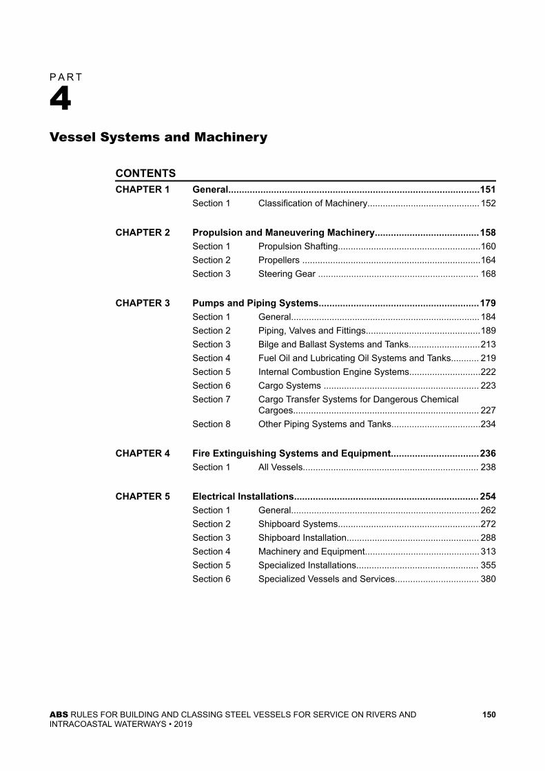
P A R T
4Vessel Systems and Machinery
CONTENTSCHAPTER 1 General..............................................................................................151
Section 1 Classification of Machinery............................................ 152
CHAPTER 2 Propulsion and Maneuvering Machinery.......................................158Section 1 Propulsion Shafting........................................................160Section 2 Propellers ......................................................................164Section 3 Steering Gear ............................................................... 168
CHAPTER 3 Pumps and Piping Systems............................................................179Section 1 General.......................................................................... 184Section 2 Piping, Valves and Fittings.............................................189Section 3 Bilge and Ballast Systems and Tanks............................213Section 4 Fuel Oil and Lubricating Oil Systems and Tanks........... 219Section 5 Internal Combustion Engine Systems............................222Section 6 Cargo Systems ............................................................. 223Section 7 Cargo Transfer Systems for Dangerous Chemical
Cargoes......................................................................... 227Section 8 Other Piping Systems and Tanks...................................234
CHAPTER 4 Fire Extinguishing Systems and Equipment.................................236Section 1 All Vessels..................................................................... 238
CHAPTER 5 Electrical Installations..................................................................... 254Section 1 General.......................................................................... 262Section 2 Shipboard Systems........................................................272Section 3 Shipboard Installation.................................................... 288Section 4 Machinery and Equipment............................................. 313Section 5 Specialized Installations................................................ 355Section 6 Specialized Vessels and Services................................. 380
ABS RULES FOR BUILDING AND CLASSING STEEL VESSELS FOR SERVICE ON RIVERS ANDINTRACOASTAL WATERWAYS • 2019
150

P A R T
4C H A P T E R 1 General
CONTENTSSECTION 1 Classification of Machinery............................................................ 152
1 General.......................................................................................1521.1 Gross Tonnage.............................................................. 152
3 Certification of Machinery (2003)................................................1523.1 Basic Requirements.......................................................1523.3 Type Approval Program................................................. 1523.5 Non-mass Produced Machinery.................................... 1533.7 Details of Certification of Some Representative
Products.........................................................................1535 Machinery Plans and Data..........................................................153
5.1 Details............................................................................1535.3 Plans (2011)...................................................................153
7 Oil Fuel Unit................................................................................1549 Machinery Space Ventilation...................................................... 15411 Boilers and Pressure Vessels.....................................................15413 Turbines, Engines and Reduction Gears....................................15415 Engine Installation Particulars.................................................... 154
15.1 Tank Barges...................................................................15415.3 Engine Exhausts on Tank Barges..................................154
17 Starting Arrangements for Propulsion Engines...........................15417.1 Starting Air System........................................................ 15417.3 Starting Batteries........................................................... 15517.5 Hydraulic Starting.......................................................... 155
19 Trial.............................................................................................15519.1 General.......................................................................... 15519.3 Steering Gear................................................................ 15619.5 Reduction Gears for Propulsion.....................................156
21 Materials Containing Asbestos (2011)........................................ 15623 Units............................................................................................15625 Ambient Temperature ................................................................ 156
TABLE 1 Ambient Temperatures for Unrestricted Service................ 156
ABS RULES FOR BUILDING AND CLASSING STEEL VESSELS FOR SERVICE ON RIVERS ANDINTRACOASTAL WATERWAYS • 2019
151

P A R T
4C H A P T E R 1 General
S E C T I O N 1 Classification of Machinery
1 GeneralThe provisions of Part 1, "Conditions of Classification", are applicable to the classification of machinery.
1.1 Gross TonnageFor vessels in domestic service, "gross tonnage", as used in these Rules, is the national gross tonnage asspecified by the country in which the vessel is to be registered. For vessels which are engaged ininternational voyages, gross tonnage is to be determined by the International Convention on TonnageMeasurement of Ships, 1969.
3 Certification of Machinery (2003)
3.1 Basic RequirementsThe Rules define, to varying degrees, the extent of evaluation required for products, machinery, equipmentand their components based on the level of criticality of each of those items. There are three basicevaluation constituents:
● Design review; type/prototype testing, as applicable;
● Survey during construction and testing at the plant of manufacture; and
● Survey during installation onboard the vessel and at trials.
Where design review is required by the Rules, a letter will be issued by ABS upon satisfactory review ofthe plans to evidence the acceptance of the design. In addition to, or independent of, design review, ABSmay require survey and testing of forgings, castings and component parts at the various manufacturers’plants, as well as survey and testing of the finished product. A certificate or report will be issued uponsatisfactory completion of each survey to evidence acceptance of the forging, casting, component orfinished product. Design review, survey and the issuance of reports or certificates constitute thecertification of machinery.
Based on the intended service and application, some products do not require certification because they arenot directly related to the scope of classification or because normal practices for their construction withinthe industry are considered adequate. Such products may be accepted based on the manufacturers’documentation on design and quality.
In general, surveys during installation onboard the vessel and at trials are required for all items ofmachinery. This is not considered a part of the product certification process. There may be instances,however, where letters or certificates issued for items of machinery contain conditions which must beverified during installation, tests or trials.
3.3 Type Approval ProgramProducts that can be consistently manufactured to the same design and specification may be TypeApproved under the ABS Type Approval Program. The ABS Type Approval Program is a voluntary optionfor the demonstration of the compliance of a product with the Rules or other recognized standards. It may
ABS RULES FOR BUILDING AND CLASSING STEEL VESSELS FOR SERVICE ON RIVERS ANDINTRACOASTAL WATERWAYS • 2019
152

be applied for at the request of the designer or manufacturer. . The ABS Type Approval Program generallycovers Product Type Approval [1-1-4/7.7.3 of the ABS Rules for Conditions of Classification (Part 1)], butis also applicable for a more expeditious procedure towards Unit-Certification, as specified in 1-1-4/7.7.2of the above referenced Part 1.
See the “ABS Type Approval Program” in 1-1-A3 of the ABS Rules for Conditions of Classification (Part1). The ABS Type Approval Program and the indicated references are available for download from theABS website at http://www.eagle.org/rules/downloads.html.
3.5 Non-mass Produced MachineryNon-mass produced critical machinery, such as propulsion boilers, slow speed diesel engines, turbines,steering gears and similar critical items are to be individually unit certified in accordance with theprocedure described in 4-1-1/3.1. However, consideration will be given to granting Type Approval to suchmachinery in the category of Recognized Quality System (RQS). The category of Product QualityAssurance (PQA) will not normally be available for all products, and such limitations will be indicated in4-1-1/9 TABLE 1, 4-1-1/9 TABLE 2, 4-1-1/9 TABLE 3, 4-1-1/9 TABLE 4, 4-1-1/9 TABLE 5, and 4-1-1/9TABLE 6 of the Marine Vessel Rules. In each instance where Type Approval is granted, in addition toquality assurance and quality control assessment of the manufacturing facilities, ABS will require somedegree of product specific survey during manufacture.
3.7 Details of Certification of Some Representative Products4-1-1/9 TABLE 1, 4-1-1/9 TABLE 2, 4-1-1/9 TABLE 3, 4-1-1/9 TABLE 4, 4-1-1/9 TABLE 5, and 4-1-1/9TABLE 6 of the Marine Vessel Rules provide abbreviated certification requirements of representativemachinery based on the basic requirements of the Rules for machinery. The tables also provide theapplicability of the Type Approval Program for each of these machinery items.
For easy reference, the tables contain six product categories as follows:
● Prime movers
● Propulsion, maneuvering and mooring machinery
● Electrical and control equipment
● Fire safety equipment
● Boilers, pressure vessels, fired equipment
● Piping system components
5 Machinery Plans and Data
5.1 DetailsPlans and data enumerated in 4-2-1/1, 4-2-2/1, 4-2-3/1.3, 4-2-3/3.3, 4-3-1/3, 4-3-7/5, 4-4-1/7 and 4-5-1/5,as applicable, for each vessel to be built under survey, are to be submitted and approved before proceedingwith the work. See also 1-1-4/3 of the Supplement to the ABS Rules for Conditions of Classification (Part1). It is desired that the sizes, dimensions, welding and other details, make and size of standard approvedappliances be shown on the plans as clearly and fully as possible. All welded construction is to meet therequirements of Chapter 4 of the ABS Rules for Materials and Welding (Part 2).
5.3 Plans (2011)Plans from the designers and shipbuilders should generally be submitted electronically to ABS. However,hard copies will also be accepted. All plan submissions originating from manufacturers are understood tobe made with the cognizance of the shipbuilder. A fee may be charged for the review of plans for whichthere is no contract of classification.
Part 4 Vessel Systems and MachineryChapter 1 GeneralSection 1 Classification of Machinery 4-1-1
ABS RULES FOR BUILDING AND CLASSING STEEL VESSELS FOR SERVICE ON RIVERS ANDINTRACOASTAL WATERWAYS • 2019
153
7 Oil Fuel UnitOil fuel unit is any equipment, such as pumps, filters and heaters, used for the preparation and delivery offuel oil to oil-fired boilers (including inert gas generators), internal-combustion engines or gas turbines at apressure of more than 1.8 bar (1.8 kgf/cm2, 26 psi).
9 Machinery Space VentilationMachinery spaces are to be ventilated so as to ensure that when machinery is operating at full power in allweather conditions, including heavy weather, an adequate supply of air is maintained for operation of themachinery and safety of the personnel.
11 Boilers and Pressure VesselsBoilers, pressure vessels, fluid power cylinders and heat exchangers are to be designed, constructed, testedand installed in accordance with the applicable requirements of Part 4, Chapter 4 of the Marine VesselRules.
13 Turbines, Engines and Reduction GearsAll steam turbines, gas turbines and internal-combustion engines of 100 kW [135 horsepower (hp)] andover and associated reduction gears are to be constructed and installed in accordance with the applicablerequirements of Part 4, Chapters 2 and 3 of the Marine Vessel Rules. Turbines and engines of less than 100kW (135 hp) and associated gears are to be constructed and equipped in accordance with good commercialpractice, and will be accepted subject to a satisfactory performance test conducted to the satisfaction of theSurveyor after installation.
Internal-combustion engines are also to comply with the requirements in 4-1-1/15 and 4-1-1/17 asapplicable.
15 Engine Installation Particulars
15.1 Tank BargesInternal-combustion engines located on the weather deck are to be provided with ventilation metal hoodsor with a well-ventilated metal housing of sufficient size to allow for proper operation and maintenance.
Where a housing is provided on vessels intended for carrying flammable or combustible liquids having aclosed cup flash point at or below 60°C (140°F), the housing is to be fitted with a cofferdam as required by3-2-1/19.1.2 and all openings in the housing are to be located more than 3 m (10 ft) from any tank, gas orvapor outlet.
15.3 Engine Exhausts on Tank BargesOn vessels intended for carrying flammable or combustible liquids having a closed cup flash point at orbelow 60°C (140°F) in bulk, the engine exhaust lines are to be fitted with spark arresters and are to belocated more than 3 m (10 ft) from the nearest source of flammable vapor or gas. See 4-5-6/1.5.2. Exhaustpiping is to be either insulated or water cooled.
17 Starting Arrangements for Propulsion Engines
17.1 Starting Air System17.1.1 Compressors
For vessels having main propulsion engines arranged for air starting, one or more air compressorsare to be fitted capable of restoring the air capacity within 45 minutes after completion of thestarting tests required in 4-1-1/17.1.2.
Part 4 Vessel Systems and MachineryChapter 1 GeneralSection 1 Classification of Machinery 4-1-1
ABS RULES FOR BUILDING AND CLASSING STEEL VESSELS FOR SERVICE ON RIVERS ANDINTRACOASTAL WATERWAYS • 2019
154

17.1.2 Containers (2013)Vessels having internal-combustion engines arranged for air starting are to be provided with atleast two starting-air reservoirs of approximately equal size. The total capacity of the starting-airreservoirs is to be sufficient to provide, without recharging the air reservoirs, at least the numberof consecutive starts stated below. If other compressed air systems, such as control air, aresupplied from starting-air reservoirs, the aggregate capacity of the air reservoirs is to be sufficientfor continued operation of these systems after the air necessary for the required number of startshas been used.
17.1.2(a) Diesel Propulsion (2006). The minimum number of consecutive starts (total) required tobe provided from the starting-air reservoirs is to be based upon the arrangement of the engines andshafting systems as indicated in the following table:
Engine Type Single Propeller Vessels Multiple Propeller Vessels
One engine coupledto shaft directly orthrough reduction
gear
Two or more enginescoupled to shaft
through clutch andreduction gear
One engine coupledto each shaft directlyor through reduction
gear
Two or more enginescoupled to each
shaft through clutchand reduction gear
Reversible 12 16 16 16
Non-reversible 6 8 8 8
For arrangements of engines and shafting systems which differ from those indicated in the table,the capacity of the starting-air reservoirs will be specially considered based on an equivalentnumber of starts.
17.1.2(b) Diesel-electric Propulsion (2006). The minimum number of consecutive starts requiredto be provided from the starting-air containers is to be determined from the following equation:S = 6 + G(G – 1)whereS = total number of consecutive startsG = number of engines necessary to maintain sufficient electrical load to permit vessel transit at full
seagoing power and maneuvering. The value of total number of consecutive starts need not exceed 3.
17.3 Starting BatteriesStorage batteries to be used for starting the main propulsion engines are to have sufficient capacity withoutrecharging for starting the main engines as required in 4-1-1/17.1.2. See also 4-5-4/5.5.
17.5 Hydraulic StartingHydraulic oil accumulators for starting the main propulsion engines are to have sufficient capacity withoutrecharging for starting the main engines as required in 4-1-1/17.1.2.
19 Trial
19.1 GeneralA final underway trial is to be made of all machinery, including the steering gear, to the satisfaction of theSurveyor.
Part 4 Vessel Systems and MachineryChapter 1 GeneralSection 1 Classification of Machinery 4-1-1
ABS RULES FOR BUILDING AND CLASSING STEEL VESSELS FOR SERVICE ON RIVERS ANDINTRACOASTAL WATERWAYS • 2019
155

19.3 Steering GearTrials for the steering gear are to be in accordance with 4-2-3/1.19 or 4-2-3/3.33.
19.5 Reduction Gears for PropulsionBefore final acceptance, the entire installation is to be operated in the presence of the Surveyor todemonstrate its ability to function satisfactorily under operating conditions and its freedom from harmfulvibrations at speeds within the operating range.
For conventional propulsion gear units above 1120 kW (1500 HP), a record of gear-tooth contact is to bemade at the trials. To facilitate the survey of extent and uniformity of gear-tooth contact, selected bands ofpinion or gear teeth on each meshing are to be coated beforehand with copper or layout dye. See7-6-2/1.1.2 of the ABS Rules for Survey After Construction (Part 7).
The gear-tooth examination for conventional gear units 1120 kW (1500 HP) and below and all epicyclicgear units will be subject to special consideration. The gear unit manufacturer’s recommendations will beconsidered.
21 Materials Containing Asbestos (2011)Installation of materials, which contain asbestos is prohibited.
23 UnitsThese Rules are written in two systems of units (i.e., MKS units and US customary units). Each system isto be used independently of the other system.
Unless indicated otherwise, the format of presentation in the Rules of the two systems of units are asfollows:
MKS units (US customary units)
25 Ambient Temperature (1 July 2019)The ambient temperature, as indicated in 4-1-1/25 TABLE 1, is to be considered in the selection andinstallation of machinery, equipment and appliances. For vessels of restricted or special service, theambient temperature appropriate to the special nature is to be considered.
TABLE 1Ambient Temperatures for Unrestricted Service (1 July 2019)
Air
Installations, Components Location Arrangement (1, 2) Temperature Range (°C)
Machinery and electricalinstallations
Enclosed Spaces - General 0 to +45
Components mounted on machineryassociated with high temperature
According to specific machinery andinstallation
In spaces subject to higher temperature(details to be submitted)
According to the actual maximum ambienttemperature
In spaces with temperature lower than+45°C (details to be submitted)
According to the actual ambienttemperature subject to minimum +40
Open Deck(3) -25 to 44
Water
Part 4 Vessel Systems and MachineryChapter 1 GeneralSection 1 Classification of Machinery 4-1-1
ABS RULES FOR BUILDING AND CLASSING STEEL VESSELS FOR SERVICE ON RIVERS ANDINTRACOASTAL WATERWAYS • 2019
156

Air
Installations, Components Location Arrangement (1, 2) Temperature Range (°C)
Coolant Temperature (°C)
Seawater +32
Notes:
1 Electronic equipment is to be suitable for operations up to 55°C.
2 For environmentally controlled spaces, see 4-5-1/19.3.
3 Control, monitoring and safety devices/systems of equipment for essential services (item (m) of4-5-1/23.3 TABLE 4 and item (s) of 4-5-1/23.3 TABLE 5) when located on the open deck are to be ratedat -25°C to +45°C. However, the ambient temperature above -25°C may be acceptable provided that theselected ambient temperature is specified in the contract specification or the vessel operation manual.
Part 4 Vessel Systems and MachineryChapter 1 GeneralSection 1 Classification of Machinery 4-1-1
ABS RULES FOR BUILDING AND CLASSING STEEL VESSELS FOR SERVICE ON RIVERS ANDINTRACOASTAL WATERWAYS • 2019
157

P A R T
4C H A P T E R 2 Propulsion and Maneuvering Machinery
CONTENTSSECTION 1 Propulsion Shafting.........................................................................160
1 General.......................................................................................1601.1 Definitions (2014)...........................................................160
3 Line Shaft, Tail Shaft, Tube Shaft and Thrust Shaft Diameters.. 1605 Line Shaft Bearing Location........................................................1617 Tail Shaft Inboard End................................................................ 1619 Tail Shaft Propeller-end Design.................................................. 161
9.1 Propeller Forward End...................................................1619.3 Propeller Aft End............................................................1619.5 Non-corrosive Non-pitting Alloys................................... 161
11 Propeller-End Bearings...............................................................16211.1 Water-Lubricated Bearings............................................ 16211.3 Oil-Lubricated Bearings................................................. 162
13 Tail Shaft Liners.......................................................................... 16213.1 Thickness at Bearings................................................... 16213.3 Thickness Between Bearings........................................ 16213.5 Continuous Fitted Liners................................................16213.7 Fit Between Bearings.....................................................16213.9 Material and Fit.............................................................. 16313.11 After-end Seal................................................................16313.13 Glass Reinforced Plastic Coating.................................. 16313.15 Stainless Steel Cladding (2009).................................... 163
15 Hollow Shafts..............................................................................16317 Coupling Bolts.............................................................................16319 Circulating Currents (2014).........................................................163
SECTION 2 Propellers ........................................................................................ 1641 General.......................................................................................1643 Materials and Testing..................................................................164
3.1 Propeller Material...........................................................1643.3 Stud Material..................................................................164
5 Blade Design.............................................................................. 1645.1 Blade Thickness............................................................ 1645.3 Blade-root Fillets............................................................1665.5 Built-up Blades...............................................................1665.7 Tip Thickness.................................................................1665.9 Blade Thickness at Other Radii..................................... 166
7 Studs...........................................................................................166
ABS RULES FOR BUILDING AND CLASSING STEEL VESSELS FOR SERVICE ON RIVERS ANDINTRACOASTAL WATERWAYS • 2019
158

7.1 Stud Area.......................................................................1667.3 Fit of Studs and Nuts..................................................... 166
9 Blade Flange and Mechanisms.................................................. 16711 Key..............................................................................................16713 Protection Against Corrosion......................................................167
SECTION 3 Steering Gear .................................................................................. 1681 Steering Gear Requirements for All Type of Vessels..................168
1.1 General.......................................................................... 1681.3 Plans..............................................................................1681.5 Power Gear Stops (2010).............................................. 1681.7 Strength Requirements..................................................1681.9 Steering Chains............................................................. 1681.11 Sheaves.........................................................................1681.13 Buffers........................................................................... 1691.15 Hydraulic Piping for Steering Gears.............................. 1691.17 Electrical Parts of Steering Gears..................................1691.19 Trials.............................................................................. 169
3 Steering Gear for Passenger Vessels Over 100 Gross Tonsor Carrying More than 150 Passengers......................................1693.1 General.......................................................................... 1693.3 Plans..............................................................................1703.5 Steering-gear Protection................................................1703.7 Power-driven Steering Gear.......................................... 1703.9 Mechanical Components............................................... 1703.11 Power Units................................................................... 1703.13 Mechanical Steering...................................................... 1713.15 Material.......................................................................... 1713.17 Transfer..........................................................................1713.19 Power-gear Stops.......................................................... 1713.21 Rudder Actuators...........................................................1713.23 Piping Arrangement....................................................... 1723.25 Controls......................................................................... 1733.27 Instrumentation and Alarms...........................................1743.29 Electrical Components (1996)....................................... 1763.31 Operating Instructions....................................................1763.33 Trials.............................................................................. 176
ABS RULES FOR BUILDING AND CLASSING STEEL VESSELS FOR SERVICE ON RIVERS ANDINTRACOASTAL WATERWAYS • 2019
159

P A R T
4C H A P T E R 2 Propulsion and Maneuvering Machinery
S E C T I O N 1 Propulsion Shafting
1 GeneralPropellers and propulsion shafting for self-propelled vessels are to be designed, constructed and tested inaccordance with the requirements of this Section. Before proceeding with the construction, prints of thepropeller and shafting plans giving design data and material characteristics are to be submitted. Theconstruction of propellers and shafts on vessels exhibiting special design features may be carried out inaccordance with other applicable ABS Rules or Guides.
1.1 Definitions (2014)For the purposes of using shaft diameter formulas in this section, the following definitions apply.
1.1.1 Tail ShaftTail Shaft is the part of the propulsion shaft aft of the forward end of the propeller end bearing.
1.1.2 Stern Tube ShaftStern Tube Shaft or Tube Shaft is the part of the propulsion shaft passing through the stern tubefrom the forward end of the propeller end bearing to the in-board shaft seal.
1.1.3 Line ShaftLine Shaft is the part of the propulsion shaft in-board of the vessel.
1.1.4 Thrust ShaftThrust Shaft is that part of the propulsion shaft which transmits thrust to the thrust bearing.
1.1.5 Oil Distribution ShaftOil Distribution Shaft is a hollow propulsion shaft where the bore and radial holes are used fordistribution of hydraulic oil in controllable pitch propeller installations.
3 Line Shaft, Tail Shaft, Tube Shaft and Thrust Shaft DiametersFor vessels 45.7 m (150 ft) in length and under, the shafting is to comply with the applicable requirementsof the ABS Marine Vessel Rules. For vessels greater than 45.7 m (150 ft) in length, the least diameter ofshafting is to be determined from the following equation:D = KH/R3whereD = diameter of shaft, mm (in.)K = as defined in the table below:
MKS Units US Units
Line shafts 39.5 ×10⁶/(U+ 16) 3480/(U+ 22.8)
Thrust shafts 59.3 ×10⁶/(U+ 16) 5225/(U+ 22.8)
ABS RULES FOR BUILDING AND CLASSING STEEL VESSELS FOR SERVICE ON RIVERS ANDINTRACOASTAL WATERWAYS • 2019
160

MKS Units US Units
Tail shafts 1.314 ×10⁶ 81.24
Tube shafts 1.202 ×10⁶ 74.34H = horsepower at rated speedR = shaft revolutions per minute at rated speedU = ultimate tensile strength of the shaft material, kg/mm2 (ksi). For tensile strength greater than 80 kg/mm2(115ksi), U equal to 80 kg/mm2 (115 ksi) is to be used.
Notes:
1 When a material other than Grade 2 steel forging is used for tail shafts, the Owners of the vessel are to be notifiedif weld repair of the shaft may be difficult. Material for shafting is to be tested in the presence of a Surveyor. Ingeneral, material with elongation less than 16% in 50 mm (2 in.) is not to be used for shafting, couplings orcoupling bolts.
2 For dimension of coupling bolts, see 4-2-1/17.
3 The thickness of line shaft coupling flanges is not to be less than the minimum required diameter of the couplingbolts, and the fillet radius at the base of the flange is not to be less than one-eighth of the actual shaft diameter.For couplings other than flanged couplings integral with the shaft, the shaft diameter in way of fitted couplingmembers is not to be less than 1.1 times the minimum required line shaft diameter.
4 The thrust shaft diameter is to be determined at the bottom of the collar when it transmits torque.
5 When shafting is exposed to sea water, the diameter is to be increased by 2.5%.
5 Line Shaft Bearing LocationThe location and spacing of line shaft bearings are to take into consideration the effect of thesearrangements on the low-speed gear elements, and the natural frequency of the propulsion shafting.
7 Tail Shaft Inboard EndThe inboard end of a tail shaft may be tapered at the coupling to not less than 1.09 times the minimumrequired line shaft diameter. Abrupt changes in shaft diameters at the coupling between tail shaft and lineshaft are to be avoided. The thickness of the tail shaft coupling flange is not to be less than the minimumrequired diameter of the coupling bolts. The fillet radius at the base of the flange is not to be less than one-eighth of the shaft diameter. Special consideration will be given to fillets of multiple-radii design.
9 Tail Shaft Propeller-end DesignTail shafts are to be provided with an accurate taper fit in the propeller hub, particular attention being givento the fit at the large end of the taper. Means are to be provided for sealing the shaft taper in way of thepropeller assembly against saltwater in accordance with 4-2-2/13 as follows:
9.1 Propeller Forward EndWhere exposed to saltwater, the propeller assembly is to be sealed at the forward end with a well-fittedsoft-rubber packing ring and
9.3 Propeller Aft EndWhere exposed to saltwater, a fairwater cap filled with suitable sealing material or equivalent sealingarrangement is to be provided at the aft end of the propeller.
9.5 Non-corrosive Non-pitting AlloysFor vessels under 45.7 m (150 ft) in length, the sealing in 4-2-1/9.1 and 4-2-1/9.3 is not required where thetail shaft is fabricated of corrosion resistant pitting-resistant alloy unless required by the manufacturer.
Part 4 Vessel Systems and MachineryChapter 2 Propulsion and Maneuvering MachinerySection 1 Propulsion Shafting 4-2-1
ABS RULES FOR BUILDING AND CLASSING STEEL VESSELS FOR SERVICE ON RIVERS ANDINTRACOASTAL WATERWAYS • 2019
161

The key is to fit tightly in the keyway and be of sufficient size to transmit the full torque of the shaft, but itis not to extend into the liner counterbore on the forward side of the propeller hub. The forward end of thekeyway is to be so cut in the shaft as to give a gradual rise from the bottom of the keyway to the surface ofthe shaft. Ample fillets are to be provided in the corners of the keyway and, in general, stressconcentrations are to be reduced as far as practicable.
11 Propeller-End Bearings
11.1 Water-Lubricated BearingsThe length of the bearing next to and supporting the propeller is not to be less than four times the requiredtail shaft diameter, except that the length of metal bearings will be subject to special consideration.
11.3 Oil-Lubricated BearingsThe length of white-metal-lined, oil-lubricated propeller-end bearings fitted with an approved oil-sealgland is to be on the order of two times the required tail shaft diameter. Oil-lubricated cast-iron and bronzebearings will be subject to special consideration.
13 Tail Shaft Liners
13.1 Thickness at Bearings13.1.1 Bronze Liner (2009)
The thickness of bronze liners to be shrink fitted to tail shafts or tube shafts of vessels is not to beless in way of bearings than that given by the following equation:t = T/25 + 5 . 1 mmt = T/25 + 0 . 2 in.wheret = thickness of liner, in mm (in.)T = required diameter of tail shaft, in mm (in.)
13.1.2 Stainless Steel Liner (2009)The thickness of stainless steel liners to be fitted to tail shafts or tube shafts is not to be less thanone-half that required for bronze liners or 6.5 mm (0.25 in.), whichever is greater.
13.3 Thickness Between BearingsThe thickness of a continuous bronze liner between bearings is to be not less than three-fourths of thethickness t determined by the foregoing equation.
13.5 Continuous Fitted LinersContinuous fitted liners are to be in one piece or, if made of two or more lengths, the joining of theseparate pieces is to be done by an approved method of fusion through not less than two-thirds thethickness of the liner or by an approved rubber seal.
13.7 Fit Between BearingsIf the liner does not fit the shaft tightly between the bearing portions, the space between the shaft and lineris to be filled by pressure with an insoluble non-corrosive compound.
Part 4 Vessel Systems and MachineryChapter 2 Propulsion and Maneuvering MachinerySection 1 Propulsion Shafting 4-2-1
ABS RULES FOR BUILDING AND CLASSING STEEL VESSELS FOR SERVICE ON RIVERS ANDINTRACOASTAL WATERWAYS • 2019
162
13.9 Material and FitFitted liners are to be of a high-grade composition, bronze or other approved alloy, free from porosity andother defects, and are to prove tight under hydrostatic test of 1.0 bar (1 kgf/cm2, 15 psi). All liners are to becarefully shrunk or forced upon the shaft by pressure and they are not to be secured by pins.
13.11 After-end SealEffective means are to be provided to prevent sea water having access to the shaft at the part between theafter end of the liner and the propeller hub
13.13 Glass Reinforced Plastic Coating (2019)Glass reinforced plastic coatings may be fitted on propulsion shafting when applied by a trainedtechnician, utilizing a procedure that complies with a nationally recognized standard, such as ASTMD5162, to the satisfaction of the Surveyor. Such coatings are to consist of at least four plies of cross-wovenglass tape impregnated with resin, or an equivalent process. In all cases where reinforced plastic coatingsare employed, effective means are to be provided to prevent water having access to the shaft. Provisionsare to be made for overlapping and adequately bonding the coating to fitted or clad liners.
13.15 Stainless Steel Cladding (2009)Stainless steel cladding of shafts is to be carried out in accordance with an approved procedure. SeeSection 7-A1-11, "Repair and Cladding of Shafts" of the Rules for Survey After Construction (Part 7).
15 Hollow ShaftsThe proportions of hollow shafts are to be such that their strength will be equivalent to that required by theequations for the corresponding solid shafts.
17 Coupling BoltsThe minimum diameter of the shaft coupling bolts is to be determined by the following equation:
d = 0 . 57 D3Nrwhered = diameter of bolts at joint, in mm (in.)D = required diameter of shaft, in mm (in.), as defined 4-2-1/3, using mechanical properties of coupling bolt
materialN = number of bolts fitted in one couplingr = radius of the pitch circle, in mm (in.)
Coupling bolts are to be accurately fitted and where couplings are separate from the shaft, provision is tobe made to resist the astern pull.
19 Circulating Currents (2014)Where means are provided to prevent circulating currents from passing between the propeller, shaft and thehull, a warning notice plate is to be provided in a visible place cautioning against the removal of suchprotection.
Part 4 Vessel Systems and MachineryChapter 2 Propulsion and Maneuvering MachinerySection 1 Propulsion Shafting 4-2-1
ABS RULES FOR BUILDING AND CLASSING STEEL VESSELS FOR SERVICE ON RIVERS ANDINTRACOASTAL WATERWAYS • 2019
163

P A R T
4C H A P T E R 2 Propulsion and Maneuvering Machinery
S E C T I O N 2 Propellers
1 GeneralPropellers and propulsion shafting for self-propelled vessels are to be designed, constructed and tested inaccordance with the requirements of this Section. Before proceeding with the construction, prints of thepropeller and shafting plans giving design data and material characteristics are to be submitted. Theconstruction of propellers and shafts on vessels exhibiting special design features may be carried out inaccordance with other applicable ABS Rules or Guides.
3 Materials and Testing
3.1 Propeller MaterialThe material of the propellers is to be tested in the presence of and inspected by a Surveyor in accordancewith the requirements of Chapter 3 of the ABS Rules for Materials and Welding (Part 2) or to otherrequirements which have been approved by the Committee. The finished and assembled propellers are tobe inspected by the Surveyor.
3.3 Stud MaterialThe material of the studs securing detachable blades to the hub is to be of Grade 2 steel or equallysatisfactory material and is to be tested in the presence of and inspected by the Surveyor in accordancewith the requirements of 2-3-7/7 of the ABS Rules for Materials and Welding (Part 2).
5 Blade Design
5.1 Blade ThicknessWhere the propeller blades are of conventional design, the thickness of the blades is not to be less thandetermined by the following equations:
5.1.1 Fixed-Pitch Propellerst0 . 25 = K1 AHCRN ± 1 . 72BKC mm(in.)whereK1 = 915 (41)A = 1.0+(6.0/P0 . 70)+4.6P0 . 25B = (4300wa/N) (R/100)2(D/20)3C = (1 + 1.5P0 . 25) (Wf− B)t0 . 25 = required thickness at the one-quarter radius, in mm (in.)H = power at rated speed; kW (PS, hp) (1 PS = 735 W; 1 hp = 746 W)R = rpm at rated speed
ABS RULES FOR BUILDING AND CLASSING STEEL VESSELS FOR SERVICE ON RIVERS ANDINTRACOASTAL WATERWAYS • 2019
164

N = number of bladesP0 . 25 = pitch at one-quarter radius divided by propeller diameterP0 . 7 = pitch at seven-tenths radius divided by propeller diameter, corresponding to the design aheadconditionsW = expanded width of a cylindrical section at the 0.25 radius, in mm (in.)a = expanded blade area divided by the disc areaD = propeller diameter, in m (ft)K = rake of propeller blade, in mm/m (in/ft), multiplied by D/2 (with forward rake, use minus signin equation; with aft rake, use plus sign)f,w = material constants from the following table:
Type
Representative PropellerMaterials
[See Chapter 3 of the ABS Rulesfor Materials and Welding (Part
2)]
SI and MKS Units US Customary Unitsf w f w2 Manganese bronze 2.10 8.30 68 0.30
3 Nickel-manganese bronze 2.13 8.00 69 0.29
4 Nickel-aluminum bronze 2.62 7.50 85 0.27
5
Mn-Ni-Al bronze 2.37 7.50 77 0.27
Cast iron 0.66 7.20 25 0.26
Cast steel 2.10 8.30 68 0.30
CF-3 Austenitic stainless steel 2.10 7.75 68 0.28
Notes:
1 For propellers of unusual design, material, or application, the blade thickness will be speciallyconsidered.
2 For vessels below 30 m (100 ft) in length with multiple shafts, and all vessels below 20 m (65 ft) inlength, consideration will be given to the acceptance of propeller designs on the basis of a review of themanufacturer’s design parameters and guarantee of physical properties and suitability for the intendedservice.
5.1.2 Controllable-Pitch Propellerst0 . 35 = K2 AHCRN ± 1 . 09BKC mm(in.)whereK2 = 735 (32.8)A = 1.0 + (6.0/P0 . 7) + 3P0 . 35B = (4900wa/N) (R/100)2(D/20)3C = (1 + 0.6P0.35) (Wf− B)t0 . 35 = required thickness at the 0.35 radius, in mm (in.)P0 . 35 = pitch at 0.35 radius divided by propeller diameter, corresponding to the design ahead conditions
Part 4 Vessel Systems and MachineryChapter 2 Propulsion and Maneuvering MachinerySection 2 Propellers 4-2-2
ABS RULES FOR BUILDING AND CLASSING STEEL VESSELS FOR SERVICE ON RIVERS ANDINTRACOASTAL WATERWAYS • 2019
165
P0 . 7 = pitch at seven-tenths radius divided by propeller diameter, corresponding to the design aheadconditionsW = expanded width of a cylindrical section at the 0.35 radius, in mm (in.)H,R,N,P0 . 7, a,D,K, f and w are as defined in 4-2-2/5.1.1.
5.3 Blade-root FilletsFillets at the root of the blades are not to be considered in the determination of blade thickness.
5.5 Built-up BladesThe required blade section is not to be reduced in order to provide clearance for nuts. The face of theflange is to bear on that of the hub in all cases, but the clearance of the spigot in its counterbore or the edgeof the flange in the recess is to be kept to a minimum.
5.7 Tip ThicknessThe minimum blade thickness, ta, at the tip is to be determined from the following equation where D is thediameter of the propeller in m (ft):ta = 0 . 072D in.ta = 6D mm
5.9 Blade Thickness at Other RadiiThe blade thickness at any radius is not to be less than given by a straight line relationship between thethickness found from 4-2-2/5.1 and the tip thickness ta.
7 Studs
7.1 Stud Areas = 0 . 0018Wt0 . 352 f/rn in2s = 0 . 056Wt0 . 352 f/rn mmwheres = area of one stud at bottom of thread, in mm2 (in2)n = number of studs on driving side of blader = radius of pitch circle of the studs, in mm (in.)t0 . 35 = maximum thickness at the 0.25 or 0.35 radius, in mm (in.), from the propeller drawing.W and f are as defined in 4-2-2/5.
7.3 Fit of Studs and NutsStuds are to be fitted tightly into the hub and provided with effective means for locking. The nuts are alsoto have a tight-fitting thread and be secured by stop screws or other effective locking devices.
Part 4 Vessel Systems and MachineryChapter 2 Propulsion and Maneuvering MachinerySection 2 Propellers 4-2-2
ABS RULES FOR BUILDING AND CLASSING STEEL VESSELS FOR SERVICE ON RIVERS ANDINTRACOASTAL WATERWAYS • 2019
166

9 Blade Flange and MechanismsThe strength of the propeller blade flange and internal mechanisms of controllable-pitch propellerssubjected to the forces from propulsion torque is to be at least 1.5 times that of the blade at design pitchconditions.
11 KeyThe key is to have a true fit in the hub. For shape of keyway in shaft, see 4-2-1/9. Where propellers arefitted without keys, detailed stress calculations and fitting instructions are to be submitted for review.
13 Protection Against CorrosionFor vessels engaged primarily in saltwater service, the exposed steel of the shaft is to be protected from theaction of the water by filling all spaces between cap, hub and shaft with a suitable material. The propellerassembly is to be sealed at the forward end with a well-fitted soft rubber packing ring. When the rubberring seal is fitted in an external gland, the hub counterbore is to be filled with suitable material. Clearancesbetween shaft liner and hub counterbore are to be kept to a minimum. When the rubber ring is fittedinternally, ample clearance is to be provided between liner and hub, and the ring is to be sufficientlyoversize to squeeze into the clearance space when the propeller is driven up on the shaft. Where necessary,a filler piece is to be fitted in the propeller hub keyway to provide a flat unbroken seating for the ring. Therecess formed at the small end of the taper by the overhanging propeller hub is to be packed with red leadputty or rust preventive compound before the propeller nut is put on.
Part 4 Vessel Systems and MachineryChapter 2 Propulsion and Maneuvering MachinerySection 2 Propellers 4-2-2
ABS RULES FOR BUILDING AND CLASSING STEEL VESSELS FOR SERVICE ON RIVERS ANDINTRACOASTAL WATERWAYS • 2019
167

P A R T
4C H A P T E R 2 Propulsion and Maneuvering Machinery
S E C T I O N 3 Steering Gear
1 Steering Gear Requirements for All Type of Vessels
1.1 GeneralAll self-propelled vessels are to be provided with effective means for steering which is to be capable ofputting the rudder from hard over to hard over. In general, power operated steering gears are to be designedto be capable of putting the rudder from 35 degrees on one side to 35 degrees on the other side with thevessel running ahead at the maximum continuous rated shaft RPM and at the design waterline.
Steering gears for passenger vessels which are over 100 gross tons or are intended to carry more than 150passengers are to be designed, constructed and tested in accordance with 4-2-3/3. Steering gears for allother self-propelled vessels are to comply with the following.
1.3 PlansDetailed plans and calculations of the steering arrangement are to be submitted for approval.
1.5 Power Gear Stops (2010)Power gears are to be provided with arrangements, such as limit switches, for stopping the gear before thestructural rudder stops or positive mechanical stops within the steering gear are reached. Thesearrangements are to be synchronized with the position of the gear itself, such as from the rudder stock,tiller, or ram rather than by the control system.
1.7 Strength RequirementsTillers, quadrants, yokes, steering chains, rods, and cables and all parts of steering gears subject to loadfrom the rudder are to be of materials tested in accordance with the applicable requirements of Chapter 1of the ABS Rules for Materials and Welding (Part 2). In general, steering gears are to be so proportionedas to have a strength equivalent to that of the required upper rudder stock (see 3-2-4/23.5.1 or 3-2-5/25.5.1as applicable. Parts in tension or subject to shock (impact) are not to be of cast iron.
1.9 Steering ChainsSteering chains and wire rope are to be of special quality and tested as required by Sections 2-2-1 and2-2-2 of the ABS Rules for Materials and Welding (Part 2), respectively.
1.11 SheavesSheaves are to be of ample size, and so placed as to provide a fair lead to the quadrant and avoid acuteangles. Parts subjected to shock are not to be of cast iron. For sheaves intended to be used with wire ropes,the radius of the grooves is to equal that of the wire rope plus 0.8 mm (1/32 in.) and the sheave diameter isto be determined on the basis of the wire rope flexibility. For 6 × 37 wire rope, the sheave diameters are tobe not less than 18 times that of the wire rope. For wire rope of lesser flexibility, the sheave diameter is tobe increased accordingly. Sheave diameters for chain are to be not less than 30 times the chain diameter.
ABS RULES FOR BUILDING AND CLASSING STEEL VESSELS FOR SERVICE ON RIVERS ANDINTRACOASTAL WATERWAYS • 2019
168

1.13 BuffersSteering gears other than hydraulic types are to be designed with suitable buffer arrangements to relievethe gear from shock from the rudder.
1.15 Hydraulic Piping for Steering GearsA relief valve is to be provided for the protection of the hydraulic system. Pressure piping is to meet therequirements of Part 4, Chapter 3, except that the mill tests need not be witnessed by the Surveyor. Afterfabrication, the piping system or each piping component is to be subjected, in the presence of the Surveyor,to a hydrostatic test equal to 1.5 times the design working pressure. After installation in the vessel, thepiping is to be tested under working conditions including a check of the relief valve operation.
1.17 Electrical Parts of Steering GearsElectrical parts of steering gears are to meet the applicable requirements of Part 4, Chapter 5.
1.19 TrialsThe steering gear is to be tested to demonstrate to the Surveyor’s satisfaction that the requirements of theseRules have been met. Satisfactory performance is to be demonstrated under the following conditions.
1.19.1 Towboats and TugsFrom 35 degrees on either side to 30 degrees on the other side in 20 seconds with vessel mooredto a dock or the river bank and with the main propulsion engines operating at approximately thefull load rack setting.
1.19.2 Passenger Vessels and Other Self-propelled VesselsFrom 35 degrees on either side to 30 degrees on the other side in not more than 28 seconds withthe vessel running ahead at the maximum continuous rated shaft RPM. For controllable pitchpropellers, the propeller pitch is to be at the maximum design pitch approved for the abovemaximum continuous ahead rated RPM. Where a test with the vessel running ahead at full speedis not practicable, the test for towboats and tugs in 4-2-3/1.19.1 may be used.
Consideration may be given to other means for proving the adequacy of the steering arrangementsand power subject to the satisfaction of the attending Surveyor.
3 Steering Gear for Passenger Vessels Over 100 Gross Tons orCarrying More than 150 Passengers
3.1 GeneralAll passenger vessels which are over 100 gross tons or are intended to carry more than 150 passengers areto be provided with an approved means of steering. All power-operated steering gears for such vessels areto be constructed to the satisfaction of and tested in the presence of the Surveyor as follows:
3.1.1 Designi) Capability. The steering gear is to be designed to be capable of:
● Putting the rudder from 35 degrees on one side to 35 degrees on the other side withthe vessel running ahead at the maximum continuous rated shaft RPM and at thedesign waterline, and
● Meeting the performance requirements in accordance with 4-2-3/3.33.1. In thisrespect, any approval is to be understood as being subject to compliance with4-2-3/3.33.1.
Part 4 Vessel Systems and MachineryChapter 2 Propulsion and Maneuvering MachinerySection 3 Steering Gear 4-2-3
ABS RULES FOR BUILDING AND CLASSING STEEL VESSELS FOR SERVICE ON RIVERS ANDINTRACOASTAL WATERWAYS • 2019
169

3.1.2 Special SteeringVessels having cycloidal, azimuthing or similar type propulsion systems in which the steering iseffected by changing the direction of the propulsion thrust are to comply with the provisions inSection 4-3-5 of the Marine Vessel Rules.
3.1.3 Single Failure (1996)The steering gear system is to be designed so that after a single failure in its piping system, one ofthe power units or mechanical connections to the power units the defect can be isolated so that theintegrity of the remaining part of the system will not be impaired and the steering capability canbe maintained or speedily regained.
3.3 PlansDetailed plans of the steering arrangement, including machinery, controls, instrumentation, power supplies,piping systems, and pressure cylinders are to be submitted for approval. See 4-1-1/5.3.
The rated torque of the unit is to be indicated in the data submitted for review.
3.5 Steering-gear ProtectionThe steering gear is to be protected from the weather. Steering gear compartments are to be readilyaccessible. Handrails and gratings or other non-slip surfaces are to be provided in way of steering gearmachinery and controls.
3.7 Power-driven Steering GearThe steering gear is to be power-operated if the required upper stock diameter is 120 mm (4.7 in.) orgreater. Refer to 3-2-5/25.5.1.
3.9 Mechanical ComponentsAll steering gear parts transmitting force to or from the rudder, such as tillers, quadrants, rams, pins, tierods and keys are to be proportioned as to have strength equivalent to that of the upper rudder stockrequired by 3-2-5/25.5.1.
3.11 Power Units3.11.1 Definitions
For purposes of the Rules, a steering gear power unit is:
i) Electric Steering Gear. An electric motor and its associated electrical equipment.
ii) Electro-hydraulic Steering Gear. An electric motor and its associated electrical equipmentand connected pump or pumps.
iii) Other Hydraulic Steering Gear. A driving engine and connected pump or pumps.
3.11.2 CompositionThe steering gear is to be comprised of two or more identical power units and is to be capable ofoperating the rudder as required by 4-2-3/3.33.1 while operating with one or more of the powerunits. Mechanical connections to the power unit are to be of substantial construction.
The steering gear is to be arranged so that a single failure in one of the power units or mechanicalconnections to the power units will not impair the integrity of the remaining part of the steeringgear. See 4-2-3/3.1.3.
3.11.3 TestingA prototype of each new design power unit pump is to be shop tested for a duration of not lessthan 100 hours. The testing is to be carried out in accordance with an approved agenda and is toinclude the following as a minimum:
Part 4 Vessel Systems and MachineryChapter 2 Propulsion and Maneuvering MachinerySection 3 Steering Gear 4-2-3
ABS RULES FOR BUILDING AND CLASSING STEEL VESSELS FOR SERVICE ON RIVERS ANDINTRACOASTAL WATERWAYS • 2019
170

i) The pump and stroke control (or directional control valve) is to be operated continuouslyfrom full flow and relief valve pressure in one direction through idle to full flow andrelief valve pressure in the opposite direction.
ii) Pump suction conditions are to simulate lowest anticipated suction head. The power unitis to be checked for abnormal heating, excessive vibration, or other irregularities.Following the test, the power unit pump is to be disassembled and inspected in thepresence of a Surveyor.
3.13 Mechanical SteeringSteel-wire rope, chain and other mechanical steering systems are to comply with 4-2-3/1.9, 4-2-3/1.11 and4-2-3/1.13.
3.15 Material3.15.1 General
All parts of steering gear transmitting a force to the rudder and pressure retaining components ofhydraulic rudder actuators are to be of steel or other approved ductile material. The use of graycast iron or other material having an elongation less than 12% in 50 mm (2 in.) is not acceptable.
3.15.2 Material Test Attendance (2010)Except as modified below, materials for the parts and components mentioned in 4-2-3/3.15.1 areto be tested in the presence of the Surveyor in accordance with the requirements of Chapter 3 ofthe ABS Rules for Materials and Welding (Part 2). See also 4-2-3/3.23.2.
Material tests for steering gear coupling bolts and torque transmitting keys need not be witnessedby the Surveyor. For upper rudder stock keys, see 3-2-5/25.1.
Material tests for forged, welded or seamless steel parts (including the internal components) ofrudder actuators that are under 150 mm (6 in.) in internal diameter need not be carried out in thepresence of the Surveyor. Such parts are to comply with the requirements of Chapter 3 of the ABSRules for Materials and Welding (Part 2) or such other appropriate material specifications as maybe approved in connection with a particular design, and may be accepted on the basis of a reviewof mill certificates by the Surveyor.
3.17 TransferAn effective means of rapid transfer between power units is to be provided. Such transfer arrangements arealso to include the capability to initiate the transfer process manually (i.e., non-automatic) from thenavigation bridge.
3.19 Power-gear StopsPower gears are to be provided with stops in accordance with 4-2-3/1.5.
3.21 Rudder Actuators3.21.1 General
Hydraulic cylinders and housings of vane-type steering gears are to meet the requirements of4-2-3/3.15 for material and material tests, and also 2-4-2/1 of the ABS Rules for Materials andWelding (Part 2) for welding, see equation 2 of 4-4-1-A1/3.1, 4-4-1-A1/5, and 4-4-1-A1/7 of theMarine Vessel Rules for design, and 4-4-1-A1/21 of the Marine Vessel Rules for hydrostatic tests.For cylinders, see also 4-3-4/1.11 of the Marine Vessel Rules for plans.
3.21.2 Non-duplicated Rudder ActuatorsRegardless of extent of nondestructive testing, casting quality factor is not to exceed 0.85. See thelast note of 4-4-1-A1/21 TABLE 2 (SI units) of the Marine Vessel Rules.
Part 4 Vessel Systems and MachineryChapter 2 Propulsion and Maneuvering MachinerySection 3 Steering Gear 4-2-3
ABS RULES FOR BUILDING AND CLASSING STEEL VESSELS FOR SERVICE ON RIVERS ANDINTRACOASTAL WATERWAYS • 2019
171

3.21.3 Oil SealsOil seals between non-moving parts forming part of the exterior pressure boundary are to be of thepressure seal type. Oil seals between moving parts forming the external pressure boundary are tobe fitted in duplicate so that the failure of one seal does not render the actuator inoperative.Alternative seal arrangements will be considered where they are shown to be equivalent.
3.23 Piping Arrangement3.23.1 General
Piping for hydraulic gears is to be arranged so that transfer between units can be readily effected.The arrangement is to be such that a single failure in one part of the piping will not impair theintegrity of remaining parts of the system. See 4-2-3/3.1.3. Where necessary, arrangements forbleeding air from the hydraulic system are to be provided.
3.23.2 RequirementsPiping systems are to meet the requirements of 4-3-8/1.3 through 4-3-8/1.7. The design pressurefor steering gear system piping and components subject to internal hydraulic pressure is to be atleast 1.25 times the maximum working pressure to be expected in order to satisfy the operationalconditions specified in 4-2-3/3.33.1.
3.23.3 Valves (1996)In general, valves are to comply with the requirements of 4-3-2/11. Isolating valves are to be fittedon the pipe connections to the rudder actuator. For vessels with non-duplicated rudder actuators,the isolating valves are to be directly mounted on the actuator.
3.23.4 Relief Valves (1996)Relief valves are to be provided for the protection of the hydraulic system. Each relief valve is tobe capable of relieving not less than the full flow of all the pumps which can discharge through itincreased by 10%. With this flow condition, the maximum pressure rise is not to exceed 10% ofthe relief valve setting. In this regard, consideration is to be given to the extreme expected ambientconditions in respect to oil viscosity.
The relief valve setting is to be at least 1.25 times the maximum working pressure to be expectedin order to satisfy the operational conditions specified in 4-2-3/3.33.1 but is not to exceed thedesign pressure in 4-2-3/3.33.2.
3.23.5 FiltrationA means is to be provided to maintain cleanliness of the hydraulic fluid.
3.23.6 Storage TankA fixed storage tank having sufficient capacity to recharge the complete hydraulic power systemincluding the power unit reservoirs is to be provided. The tank is to be permanently connected bypiping in such a manner that the system can be readily recharged from a position within thesteering gear compartment. The storage tank is to be provided with an approved level indicatingsystem in accordance with 4-3-3/9.
3.23.7 TestingThe following tests are to be performed in the presence of the Surveyor.
3.23.7(a) Shop Tests (2008). After fabrication, each component of the steering gear piping system,including the power units, hydraulic cylinders and piping, is to be hydrostatically tested at theplant of manufacture to 1.5 times the relief valve setting.
Part 4 Vessel Systems and MachineryChapter 2 Propulsion and Maneuvering MachinerySection 3 Steering Gear 4-2-3
ABS RULES FOR BUILDING AND CLASSING STEEL VESSELS FOR SERVICE ON RIVERS ANDINTRACOASTAL WATERWAYS • 2019
172

3.23.7(b) Installation Test. After installation in the vessel, the complete piping system, includingpower units, hydraulic cylinders and piping, is to be subjected to a hydrostatic test equal to 1.1times the relief valve setting, including a check of the relief-valve operation.
3.25 Controls3.25.1 General (1 July 2011)
Control system is the equipment by which orders are transmitted from the navigation bridge to thepower units. Control systems comprise transmitters, receivers, hydraulic control pumps and theirassociated motors, motor controllers, piping and cables. For the purpose of these Rules, steeringwheels or steering levers are not considered to be part of the control system.
There are to be two independent control systems provided, each of which can be operated from thenavigation bridge. The independent control systems are to meet the following requirements.
3.25.1(a) Redundancy. These control systems are to be independent in all respects and are toprovide on the navigation bridge all necessary apparatus and arrangements for the starting andstopping of steering gear motors and the rapid transfer of steering power and control betweenunits.
The control cables and piping are to be separated throughout their length as widely as ispracticable.
Wires, terminals and the components for duplicated steering gear control systems installed inunits, control boxes, switchboards or bridge consoles are to be separated throughout their length aswidely as is practicable. Where physical separation is not practicable, separation may be achievedby means of a fire retardant plate. See 4-5-2/11.1 and 4-5-6/9.3.
3.25.1(b) Local Steering Gear Control. In addition to the steering gear control systems requiredabove, local steering gear control is to be provided in the steering gear compartment. Thesecontrols if electric are to be supplied from the steering gear power circuit from a point within thesteering gear compartment.
3.25.1(c) Duplication. All electric components of the steering gear control system are to beduplicated. This does not require duplication of a steering wheel or steering lever.
3.25.1(d) Steering Mode Selector Switch. If a joint steering mode selector switch (uniaxial switch)is employed for both steering gear control systems, the connections for the circuits of the controlsystems are to be divided accordingly and separated from each other by an isolating plate or by airgap.
3.25.1(e) Follow-up Amplifier. In the case of double follow-up control, the amplifiers are to bedesigned and fed so as to be electrically and mechanically separated. In the case of non-follow-upcontrol and follow-up control, the follow-up amplifiers are to be protected selectively.
3.25.1(f) Additional Control Systems. Control circuits for additional control systems, e.g. steeringlever or autopilot, are to be designed for all - pole disconnection.
3.25.1(g) Feed-back Units and Limit Switches. The feed-back units and limit switches, if any, forthe steering gear control systems are to be separated electrically and mechanically connected tothe rudder stock or actuator separately.
3.25.1(h) Hydraulic Control Components. Hydraulic system components in the power actuating orhydraulic servo systems controlling the power systems of the steering gear, (e.g. solenoid valves,magnetic valves,) are to be considered as part of the steering gear control system and shall beduplicated and separated.
Part 4 Vessel Systems and MachineryChapter 2 Propulsion and Maneuvering MachinerySection 3 Steering Gear 4-2-3
ABS RULES FOR BUILDING AND CLASSING STEEL VESSELS FOR SERVICE ON RIVERS ANDINTRACOASTAL WATERWAYS • 2019
173

Hydraulic system components in the steering gear control system that are part of a power unit maybe regarded as being duplicated and separated when there are two or more separate power unitsprovided and the piping to each power unit can be isolated.
3.25.2 Hydraulic Telemotor (1 July 2011)When the control comprises a hydraulic telemotor, a second independent control system will notbe required.
3.25.3 Control System Disconnect (1998)Means are to be provided in the steering gear compartment to disconnect the steering gear controlsystem from the power circuit when local control is to be used. Such means for disconnecting areto be operable by one person without the need for tools. Additionally, if more than one steeringstation is provided, a selector switch is to disconnect completely all stations, except the one in use.
3.25.4 CommunicationsA means of communication is to be provided in accordance with 4-5-6/9.7.
3.25.5 Computer-based Systems (1 July 2011)Steering control systems that are computer-based systems are to comply with Section 4-9-3 of theMarine Vessel Rules and are to be considered Category III.
3.25.6 System Response Under Failure (1 July 2017)The failures (as listed, but not limited to items in 4-2-3/3.27) likely to cause uncontrolledmovements of rudder are to be clearly identified. In the event of detection of such failure, therudder should stop in the current position. Alternatively, the rudder may be set to return to themidship/neutral position. Failure Mode and Effect Analysis methodology may be used to identifythe failures.
3.27 Instrumentation and AlarmsThe following instruments and alarms are to be provided. The audible and visual alarms required are to beof the self-monitoring type so that a circuit failure will cause an alarm condition and they are to haveprovisions for testing.
3.27.1 Rudder Position IndicatorThe angular position of the rudder is to be indicated on the navigation bridge and in the steeringgear compartment. The rudder angle indication is to be independent of the steering gear controlsystem, and readily visible from the control position.
3.27.2 Power FailureA visual and audible alarm is to be given on the navigation bridge and engine room control stationto indicate a power failure to any one of the steering gear power units.
3.27.3 Motor Alarms (2000)A visual and audible alarm is to be given on the navigation bridge to indicate an overloadcondition of the steering gear power unit motor. Where a three-phase supply is used a visual andaudible alarm is to be supplied which will indicate failure of any one of the supply phases. Theoperation of this alarm is not to interrupt the circuit.
3.27.4 Control Power FailureA visual and audible alarm is to be given on the navigation bridge and engine room control stationto indicate an electrical power failure in any steering gear control circuit, or remote control circuit.
Part 4 Vessel Systems and MachineryChapter 2 Propulsion and Maneuvering MachinerySection 3 Steering Gear 4-2-3
ABS RULES FOR BUILDING AND CLASSING STEEL VESSELS FOR SERVICE ON RIVERS ANDINTRACOASTAL WATERWAYS • 2019
174

3.27.5 Motor Running IndicatorsIndicators for running indication of motors are to be installed on the navigation bridge and in theengine room control station.
3.27.6 Low Oil-level Alarm (1 July 2017)A visual and audible alarm is to be given on the navigation bridge and engine room control stationto indicate a low oil level in any power unit reservoir. The operation of this alarm is not tointerrupt the power supply circuit.
3.27.7 Hydraulic Lock (2007)Where the arrangement is such that a single failure may cause hydraulic lock and loss of steering,an audible and visual hydraulic lockalarm which identifies the failed system or component is to beprovided on the navigation bridge. The alarm is to be activated upon steering gear failure if:
● Position of the variable displacement pump control system does not correspond to the givenorder, or
● Incorrect position of 3-way full flow valve or similar in constant delivery pump system isdetected.
Alternatively, for follow-up control systems, an independent steering failure alarm complying withthe following requirements may be provided in lieu of a hydraulic lock alarm:
i) The steering failure alarm system is to actuate an audible and visible alarm in thewheelhouse when the actual position of the rudder differs by more than 5 degrees fromthe rudder position ordered by the follow-up control systems for more than:
30 seconds for ordered rudder position changes of 70 degrees;
6.5 seconds for ordered rudder position changes of 5 degrees; and
The time period calculated by the following formula for ordered rudder positions changesbetween 5 degrees and 70 degrees:t = (R/2 . 76) + 4 . 64where:t = maximum time delay in secondsR = ordered rudder change in degrees
ii) The steering failure alarm system mustbe separate from, and independent of, eachsteering gear control system, except for input received from the steering wheel shaft.
iii) Each steering failure alarm system is to be supplied by a circuit that:
a) is independent of other steering gear system and steering alarm circuits.
b) is fed from the emergency power source through the emergency distributionpanel in the wheelhouse, if installed; and
c) has no overcurrent protection except short circuit protection.
3.27.8 Autopilot Override (1999)Steering gear control systems capable of operation in the autopilot mode are to be provided withthe means to automatically disengage the autopilot controls when an effort is made to manuallysteer the vessel from the main steering station at the navigation bridge. Additionally, an audible
Part 4 Vessel Systems and MachineryChapter 2 Propulsion and Maneuvering MachinerySection 3 Steering Gear 4-2-3
ABS RULES FOR BUILDING AND CLASSING STEEL VESSELS FOR SERVICE ON RIVERS ANDINTRACOASTAL WATERWAYS • 2019
175
and visual alarm is to be provided at the navigation bridge in the event the override mechanismfails to respond within a preset period.
3.27.9 Loop Failures (1 July 2011)A visual and audible alarm is to be given on the navigation bridge to indicate a loop failure.
Note:
Monitoring is to be provided for short circuit, broken connections and earth faults for command and feedbackloops. Monitoring for loop failures is not required, when a steering failure alarm system is provided. See4-2-3/3.27.7.
3.27.10 Computer-based System Failures (1 July 2011)For steering control systems that are computer-based systems, a visual and audible alarm is to begiven on the navigation bridge to indicate a computer-based system failure.
Note:
Monitoring is to be provided for data communication errors, computer hardware failures and software failure. Seealso Section 4-9-3 of the Marine Vessel Rules. Monitoring for computer-based system failures is not required,when a steering failure alarm system is provided. See 4-2-3/3.27.7(i), (ii) and (iii).
3.27.11 Earth Fault (1 July 2017)A visual and audible alarm is to be given on the navigation bridge to indicate an earth fault on ACand DC circuits
3.29 Electrical Components (1996)Electrical components of the steering gear are to meet the applicable requirements of Part 4, Chapter 5.The steering gear electrical circuit is to comply with 4-5-2/11.
3.31 Operating InstructionsAppropriate operating instructions with a block diagram showing the changeover procedures for steeringgear control systems and steering gear power units are to be permanently displayed on the navigationbridge and in the steering gear compartment.
3.33 TrialsThe steering gear is to be tried out on the trial trip in order to demonstrate to the Surveyor’s satisfactionthat the requirements of these Rules have been met. The trial is to include the operation of the following:
3.33.1 (2017)The steering gear, including demonstration of the performance requirements as shown below withthe rudder fully submerged. Where full rudder submergence cannot be obtained in ballastconditions, steering gear trials are to be conducted at a displacement as close as reasonablypossible to full-load displacement as required by Section 6.1.2 of ISO 19019:2005 on theconditions that either:
i) The rudder is fully submerged (zero speed waterline) and the vessel is in an acceptabletrim condition.
ii) The rudder load and torque at the specified trial loading condition have been predicted(based on the system pressure measurement) and extrapolated to the full load conditionusing the following method to predict the equivalent torque and actuator pressure at thedeepest seagoing draft:QF = QTα
Part 4 Vessel Systems and MachineryChapter 2 Propulsion and Maneuvering MachinerySection 3 Steering Gear 4-2-3
ABS RULES FOR BUILDING AND CLASSING STEEL VESSELS FOR SERVICE ON RIVERS ANDINTRACOASTAL WATERWAYS • 2019
176

α = 1 . 25 AFAT VFVT 2whereα = extrapolation factorQF = rudder stock moment for the deepest service draft and maximum service speed conditionQT = rudder stock moment for the trial conditionAF = total immersed projected area of the movable part of the rudder in the deepest seagoing
conditionAT = total immersed projected area of the movable part of the rudder in the trial conditionVF = contractual design speed of the vessel corresponding to the maximum continuousrevolutions of the main engine at the deepest seagoing draftVT = measured speed of the vessel (considering current) in the trial condition
Where the rudder actuator system pressure is shown to have a linear relationship to therudder stock torque, the above equation can be taken as:PF = PTαwherePF = estimated steering actuator hydraulic pressure in the deepest seagoing draft conditionPT = maximum measured actuator hydraulic pressure in the trial condition
Where constant volume fixed displacement pumps are utilized, the requirements can bedeemed satisfied if the estimated steering actuator hydraulic pressure at the deepest draftis less than the specified maximum working pressure of the rudder actuator. Where avariable delivery pump is utilized, pump data should be supplied and interpreted toestimate the delivered flow rate that corresponds to the deepest seagoing draft in order tocalculate the steering time and allow it to be compared to the required time.
Where AT is greater than 0 . 95AF, there is no need for extrapolation methods to beapplied.
iii) Alternatively the designer or builder may use computational fluid dynamic (CFD) studiesor experimental investigations to predict the rudder stock moment at the full sea goingdraft condition and service speed. These calculations or experimental investigations are tobe to the satisfaction of ABS.
In any case for the main steering gear trial, the speed of the vessel corresponding to the number ofmaximum continuous revolution of main engine and maximum design pitch applies.
Satisfactory performance is to be demonstrated under the following conditions.
3.33.1(a) Full Speed Trial. From 35 degrees on either side to 30 degrees on the other side in notmore than 28 seconds with the vessel running ahead at the maximum continuous rated shaft RPM.For controllable pitch propellers, the propeller pitch is to be at the maximum design pitchapproved for the above maximum continuous ahead rated RPM. This test is to be met with one ofthe power units in reserve.
Part 4 Vessel Systems and MachineryChapter 2 Propulsion and Maneuvering MachinerySection 3 Steering Gear 4-2-3
ABS RULES FOR BUILDING AND CLASSING STEEL VESSELS FOR SERVICE ON RIVERS ANDINTRACOASTAL WATERWAYS • 2019
177

3.33.1(b) Half Speed Trial. From 15 degrees on either side to 15 degrees on the other side in notmore than 60 seconds while running at one-half of the maximum ahead speed or 7 knots,whichever is the greater. This test is to be conducted with one of the power units in reserve. Thistest may be waived where the steering gear consists of two identical power units with each capableof meeting the requirements in 4-2-3/3.33.1 above.
Where three or more power units are provided, the test procedures are to be specially consideredon basis of the specifically approved operating arrangements of the steering gear system.
3.33.2The power units, including transfer between power units.
3.33.3The emergency power supply required by 4-5-6/9.3.
3.33.4The steering gear controls, including transfer of control, and local control.
3.33.5The means of communications between the navigation bridge, engine room, and the steering gearcompartment.
3.33.6The alarms and indicators required by 4-2-3/3.27 (test may be done at dockside).
3.33.7The storage and recharging system contained in 4-2-3/3.23.6 (test may be done at dockside).
3.33.8The isolation and automatic starting provisions of 4-2-3/3.1.3 (test may be done at dockside).
Part 4 Vessel Systems and MachineryChapter 2 Propulsion and Maneuvering MachinerySection 3 Steering Gear 4-2-3
ABS RULES FOR BUILDING AND CLASSING STEEL VESSELS FOR SERVICE ON RIVERS ANDINTRACOASTAL WATERWAYS • 2019
178

P A R T
4C H A P T E R 3 Pumps and Piping Systems
CONTENTSSECTION 1 General..............................................................................................184
1 Construction and Installation...................................................... 1841.1 General Requirements...................................................1841.3 Piping Groups (2008).....................................................184
3 Plans and Data to Be Submitted.................................................1843.1 Plans (2011)...................................................................1843.3 Data............................................................................... 185
5 Material Tests and Inspection..................................................... 1855.1 Specifications and Purchase Orders............................. 1855.3 Special Materials........................................................... 185
7 General Installation Details.........................................................1857.1 Protection.......................................................................1857.3 Pipes Near Switchboards.............................................. 1857.5 Expansion or Contraction Stresses (2004).................... 1857.7 Molded Expansion Joints (2004)................................... 1867.9 Bulkhead, Deck or Tank Top Penetrations (2013)......... 1877.11 Relief Valves.................................................................. 1877.13 Common Overboard Discharge..................................... 1877.15 Plastic Piping (1997)......................................................1877.17 Standard Thicknesses................................................... 1877.19 Instruments.................................................................... 1877.21 Hose (1 July 2017).........................................................188
SECTION 2 Piping, Valves and Fittings............................................................. 1891 General.......................................................................................1893 Pressure Tests............................................................................189
3.1 General.......................................................................... 1893.3 Fuel Oil Suction and Transfer Lines...............................1893.5 Cargo Oil Piping.............................................................1893.7 Hydraulic Power Piping..................................................1893.9 All Piping........................................................................189
5 Metallic Pipes .............................................................................1895.1 Test and Inspection of Group I Piping............................1895.3 Steel Pipe...................................................................... 1905.5 Copper Pipe...................................................................1905.7 Brass Pipe..................................................................... 1905.9 Plastic Pipe (1997).........................................................1905.11 Working Pressure and Thickness of Metallic Pipe.........190
ABS RULES FOR BUILDING AND CLASSING STEEL VESSELS FOR SERVICE ON RIVERS ANDINTRACOASTAL WATERWAYS • 2019
179

7 Plastic Pipes (1997) ...................................................................1927.1 General (2015)...............................................................1927.3 Plans and Data to be Submitted (2007).........................1927.5 Design............................................................................1937.7 Installation of Plastic Pipes............................................ 1967.9 Manufacturing of Plastic Pipes (1 July 2009).................1987.11 Plastic Pipe Bonding Procedure Qualification............... 1987.13 Tests by the Manufacturer –Fire Endurance Testing
of Plastic Piping in the Dry Condition (For Level 1and Level 2)................................................................... 199
7.15 Test by Manufacturer – Fire Endurance Testing ofWater-filled Plastic Piping (For Level 3).........................200
7.17 Tests by Manufacturer – Flame Spread.........................2037.19 Testing By Manufacturer – General (2007)....................2037.21 Testing Onboard After Installation..................................203
9 Material of Valves and Fittings....................................................2079.1 General.......................................................................... 2079.3 Forged or Cast Steel......................................................2089.5 Cast Iron........................................................................ 2089.7 Ductile (Nodular) Iron.....................................................2089.9 Nonferrous..................................................................... 2089.11 Plastic Compounds (1997)............................................ 208
11 Valves ........................................................................................ 20811.1 General.......................................................................... 20811.3 Construction...................................................................20811.5 Hydrostatic Test and Identification................................. 209
13 Pipe Fittings ...............................................................................20913.1 General.......................................................................... 20913.3 Hydrostatic Test and Identification................................. 21013.5 Nonstandard Fittings......................................................210
15 Welded Nonstandard Valves and Fittings...................................21017 Flanges ......................................................................................210
17.1 General (1996)...............................................................21017.3 Group I Piping Flanges.................................................. 21017.5 Group II Piping Flanges................................................. 210
19 Sea Chests, Sea Valve and Overboard Discharge Connections 21119.1 General.......................................................................... 21119.3 Sea Chests.................................................................... 21119.5 Scuppers........................................................................21119.7 Sanitary Discharges.......................................................211
21 Cooler Installations External to the Hull......................................21221.1 General.......................................................................... 21221.3 Integral Keel Cooler Installations................................... 21221.5 Non-integral Keel Cooler Installations (2006)................ 212
ABS RULES FOR BUILDING AND CLASSING STEEL VESSELS FOR SERVICE ON RIVERS ANDINTRACOASTAL WATERWAYS • 2019
180

TABLE 1 Allowable Stress Values S for Steel Piping N/mm2 (kgf/mm2, psi)............................................................................ 192
TABLE 2 Fire Endurance Requirements Matrix for Plastic Pipes .....204TABLE 3 Standards for Plastic Pipes –Typical Requirements for
All Systems (2007).............................................................206TABLE 4 Standards for Plastic Pipes –Additional Requirements
Depending on Service and/or Location of Piping (2007)... 207
FIGURE 1 Fire Endurance Test Burner Assembly...............................201FIGURE 2 Fire Endurance Test Stand with Mounted Sample.............202
SECTION 3 Bilge and Ballast Systems and Tanks............................................2131 Bilge and Ballast Systems for Self-propelled Vessels................ 213
1.1 General.......................................................................... 2131.3 Pumps............................................................................2131.5 Bilge and Ballast Piping................................................. 213
3 Bilge Systems for Self-propelled Passenger Vessels.................2153.1 General.......................................................................... 2153.3 Bilge Piping System.......................................................2153.5 Bilge Pumps...................................................................216
5 Bilge Systems for Barges........................................................... 2165.1 Unmanned Barges.........................................................2165.3 Manned Barges............................................................. 216
7 Vent, Sounding and Overflow Pipes........................................... 2177.1 General.......................................................................... 2177.3 Size................................................................................2177.5 Termination (2007).........................................................217
9 Sounding ....................................................................................2179.1 General.......................................................................... 2179.3 Sounding Pipes..............................................................2179.5 Gauge Glasses.............................................................. 218
SECTION 4 Fuel Oil and Lubricating Oil Systems and Tanks..........................2191 Fuel Oil Transfer, Filling and Service Systems .......................... 219
1.1 General.......................................................................... 2191.3 Pipes in Oil Tanks.......................................................... 2191.5 Control Valves or Cocks................................................ 2191.7 Valves on Oil Tanks....................................................... 2191.9 Overflows and Drains.................................................... 2201.11 Fuel Oil Purifiers (1997).................................................2201.13 Fuel Oil Injection System............................................... 220
3 Lubricating Oil System ...............................................................2203.1 General.......................................................................... 2203.3 Oil Filters........................................................................220
ABS RULES FOR BUILDING AND CLASSING STEEL VESSELS FOR SERVICE ON RIVERS ANDINTRACOASTAL WATERWAYS • 2019
181

3.5 Protective Features........................................................221
SECTION 5 Internal Combustion Engine Systems........................................... 2221 Cooling Water System................................................................ 222
1.1 General.......................................................................... 2221.3 Sea Suctions..................................................................2221.5 Direct Cooling System................................................... 222
3 Exhaust Piping ...........................................................................222
SECTION 6 Cargo Systems ................................................................................2231 Vessels Carrying Oil in Bulk Having a Flashpoint of 60°C
(140°F) or Less...........................................................................2231.1 Cargo Pumps.................................................................2231.3 Cargo Piping Systems................................................... 2231.5 Other Piping Systems.................................................... 2241.7 Venting Systems............................................................ 2241.9 Inert Gas System Requirements....................................2251.11 Cargo Vapor Emission Control Systems........................225
3 Cargo-handling Systems............................................................ 2263.1 General.......................................................................... 2263.3 Dangerous Chemicals................................................... 2263.5 Liquefied Gases.............................................................2263.7 Pressurized Gases........................................................ 2263.9 Cargo Oil Piping.............................................................2263.11 Noncombustible Liquids.................................................226
SECTION 7 Cargo Transfer Systems for Dangerous Chemical Cargoes........2271 General.......................................................................................2273 Cargo Piping Classification.........................................................227
3.1 Cargo Piping for Barge Type I....................................... 2273.3 Cargo Piping for Barge Types II and III..........................227
5 Plans and Data to be Submitted (2011)......................................2277 Materials..................................................................................... 228
7.1 General.......................................................................... 2287.3 Service Temperature Below -18°C (0°F)........................228
9 Venting........................................................................................2289.1 Open Venting................................................................. 2289.3 Pressure-Vacuum Venting............................................. 2289.5 Safety-Relief Venting..................................................... 229
11 Safety-Relief Valves ...................................................................22911.1 Capacity.........................................................................22911.3 Certification....................................................................23011.5 Installation......................................................................230
ABS RULES FOR BUILDING AND CLASSING STEEL VESSELS FOR SERVICE ON RIVERS ANDINTRACOASTAL WATERWAYS • 2019
182

11.7 Tests.............................................................................. 23013 Pressure Vessels........................................................................23015 Cargo Transfer............................................................................230
15.1 General.......................................................................... 23015.3 Cargo Pumps.................................................................23015.5 Pump Wells....................................................................23115.7 Pump Prime Movers...................................................... 23115.9 Pressure Gauges...........................................................23115.11 Independent Tank Connections..................................... 23115.13 Piping, Valves and Fittings.............................................23115.15 Piping Flexibility Arrangements..................................... 23215.17 Pipe Joints..................................................................... 23215.19 Cargo Filling Lines in Tanks...........................................23215.21 Spillage Containment.....................................................23215.23 Electrical Bonding.......................................................... 232
17 Protective Housing......................................................................23219 Electrical..................................................................................... 23221 Fire Extinguishing....................................................................... 23223 Salvaging Connections...............................................................232
TABLE 1 Values of C for Use in Calculating Safety-Relief ValveCapacity............................................................................. 233
SECTION 8 Other Piping Systems and Tanks................................................... 2341 Hydraulic Piping..........................................................................234
1.1 Arrangements................................................................ 2341.3 Valves............................................................................ 2341.5 Piping.............................................................................2341.7 Pipe Fittings................................................................... 2341.9 Hose.............................................................................. 2351.11 Accumulators................................................................. 2351.13 Fluid Power Cylinders....................................................2351.15 Design Pressure............................................................ 2351.17 Segregation of High Pressure Hydraulic Units in
Machinery Spaces......................................................... 2353 Liquefied Petroleum Gases........................................................ 2355 Ship Service Ammonia System (1996).......................................235
5.1 Compartmentation......................................................... 2355.3 Safety Measures............................................................2355.5 Ammonia Piping.............................................................235
ABS RULES FOR BUILDING AND CLASSING STEEL VESSELS FOR SERVICE ON RIVERS ANDINTRACOASTAL WATERWAYS • 2019
183

P A R T
4C H A P T E R 3 Pumps and Piping Systems
S E C T I O N 1 General
1 Construction and Installation
1.1 General RequirementsAll vessels are to be provided with the necessary pumps and piping systems for safe and efficient operationin the service for which they are intended. Materials and workmanship are to be in accordance with goodmarine practice and to the satisfaction of the Surveyor. The arrangements and details are to comply withthe following requirements.
1.3 Piping Groups (2008)To distinguish between detail requirements for the various systems, the piping on shipboard is divided intotwo groups.
Group I, in general, includes all piping intended for working pressures or temperatures in various services,as follows:
Service Pressure bar (kgf/cm², psi) Temperature °C (°F)
Vapor and Gas over 10.3 (10.5, 150) over 343 (650)
Water over 15.5 (15.8, 225) over 177 (350)
Lubricating Oil over 15.5 (15.8, 225) over 204 (400)
Fuel Oil over 10.3 (10.5, 150) over 66 (150)
Hydraulic Fluid over 15.5 (15.8, 225) over 204 (400)
Group II includes all piping intended for working pressures and temperatures below those stipulated underGroup I. Group II also includes cargo oil and tank-cleaning piping in cargo area on oil carriers and open-ended lines such as drains, overflows, engine exhausts, boiler escapes pipes, and vents, regardless of theworking pressures or temperatures.
3 Plans and Data to Be Submitted
3.1 Plans (2011)Before proceeding with the work, diagrammatic plans are to be submitted, showing clearly thearrangement and details of the following. Plans should generally be submitted electronically to ABS.However, hard copies will also be accepted.
● General arrangement of pumps and piping
● Sanitary systems
● Bilge and ballast systems
● Vent, sounding and overflow pipes
● Fuel oil filling, transfer and service systems
ABS RULES FOR BUILDING AND CLASSING STEEL VESSELS FOR SERVICE ON RIVERS ANDINTRACOASTAL WATERWAYS • 2019
184

● Lubricating oil systems
● Cargo oil pumping systems
● Hydraulic-power piping systems
● Essential raw-water and freshwater service systems
● Fire-main and fire extinguishing systems (See Part 4, Chapter 4)
● Steering-gear piping systems (See Section 4-2-3)
● Starting-air piping
● Exhaust piping for internal combustion engines and auxiliary boilers.
3.3 DataThe plans are to consist of a diagrammatic drawing of each system accompanied by lists of materialsgiving size, wall thickness, maximum working pressure and material of all pipes and the type, size,pressure rating and material of valves and fittings.
5 Material Tests and Inspection
5.1 Specifications and Purchase OrdersThe appropriate material to be used for the various pipes, valves and fittings is indicated in Section 4-3-2,except that tests of material for valves and fittings need not be witnessed by the Surveyors. Where electricwelding is used, the requirements of Chapter 4 of the ABS Rules for Materials and Welding (Part 2) arealso applicable. Copies in duplicate of the purchase orders for material requiring test and inspection at themills or place of manufacture are to be forwarded to ABS for the information of the Surveyors.
5.3 Special MaterialsIf it is desired to use special alloys or other materials not covered by the Rules, the use of such materialswill be specially considered for approval.
7 General Installation Details
7.1 ProtectionPipes, valves and operating rods are to be effectively secured and adequately protected from mechanicaldamage. These protective arrangements are to be fitted so that they may be removed to enable examinationof the pipes, valves and operating rods.
7.3 Pipes Near SwitchboardsThe leading of pipes in the vicinity of switchboards is to be avoided as far as possible. When such leads arenecessary, care is to be taken to fit no flanges or joints over or near the switchboards unless provision ismade to prevent any leakage from damaging the equipment.
7.5 Expansion or Contraction Stresses (2004)Ample provision is to be made to take care of expansion or contraction stresses in pipes due to temperaturechanges or working of the hull. Suitable provisions include, but are not limited to, piping bends, elbows,offsets, changes in direction of the pipe routing or expansion joints. Slip joints of an approved type may beused in systems and locations where possible leakage will not be hazardous.
Where expansion joints are used, the following requirements apply:
● Pipe support. Adjoining pipes are to be suitably supported so that the expansion joints do not carryany significant pipe weight.
Part 4 Vessel Systems and MachineryChapter 3 Pumps and Piping SystemsSection 1 General 4-3-1
ABS RULES FOR BUILDING AND CLASSING STEEL VESSELS FOR SERVICE ON RIVERS ANDINTRACOASTAL WATERWAYS • 2019
185

● Alignment. Expansion joints are not to be used to make up for piping misalignment errors.Misalignment of an expansion joint reduces the rated movements and can induce severe stresses intothe joint material, thus causing reduced service life.
● Anchoring. Expansion joints are to be installed as close as possible to an anchor point. Where ananchoring system is not used, control rods may be installed on the expansion joint to prevent excessivemovements from occurring due to pressure thrust of the line.
● Mechanical damage. Where necessary, expansion joints are to be protected against mechanicaldamage.
● Accessible location. Expansion joints are to be installed in accessible locations to permit regularinspection and/or periodic servicing.
● Mating flange. Mating flanges are to be clean and usually of the flat-faced type. When attachingbeaded-end flange expansion joints to raised face flanges, the use of a ring gasket is permitted. Rubberexpansion joints with beaded-end flange are not to be installed next to wafer-type check or butterflyvalves. Serious damage to the rubber flange bead can result due to lack of flange surface and/or boltconnection.
7.7 Molded Expansion Joints (2004)Molded expansion joints may be Type Approved. See 1-1-A3 of the ABS Rules for Conditions ofClassification (Part 1).
7.7.1 Circulating Water SystemsMolded expansion fittings of reinforced rubber or other suitable materials may be used incirculating water piping systems in machinery spaces. Such fittings are to be oil-resistant. Themaximum working pressure is not to be greater than 25% of the hydrostatic bursting pressure ofthe fitting as determined by a prototype test. Manufacturer’s name and the month and year ofmanufacture are to be embossed or otherwise permanently marked on the outside edge of one ofthe flanges or other easily examined area of all flexible expansion joints intended for use inseawater piping systems over 150 mm (6 in.). Plans of the molded or built-up flexible expansionjoints in seawater piping systems over 150 mm (6 in.), including details of the internalreinforcement arrangements, are to be submitted for approval.
7.7.2 Oil SystemsWhere molded expansion joints of composite construction utilizing metallic material, such as steelor stainless steel or equivalent material, with rubberized coatings inside and/or outside or similararrangements are proposed for use in oil piping systems (fuel, lubricating, or hydraulic oil), thefollowing requirements apply:
7.7.2(a) Expansion joint ratings for temperature, pressure, movements and selection of materialsare to be suitable for the intended service.
7.7.2(b) The maximum allowable working pressure of the system is not to be greater than 25% ofthe hydrostatic bursting pressure determined by a burst test of a prototype expansion joint. Resultsof the burst test are to be submitted.
7.7.2(c) The expansion joints are to pass the fire-resistant test specified in 4-3-1/7.7.3, below.
7.7.2(d) The expansion jointsare to be permanently marked with the manufacturer’s name and themonth and year of manufacture.
7.7.3 Fire-Resistant TestIn order for a molded expansion joint of composite construction utilizing metallic material, asreferenced in 4-3-1/7.7.2, to be considered fire-resistant, a prototype of the molded expansionjointis to be subjected to a fire test for at least 30 minutes at a temperature of not less than 800°C
Part 4 Vessel Systems and MachineryChapter 3 Pumps and Piping SystemsSection 1 General 4-3-1
ABS RULES FOR BUILDING AND CLASSING STEEL VESSELS FOR SERVICE ON RIVERS ANDINTRACOASTAL WATERWAYS • 2019
186

(1472°F) while water at the maximum service pressure is circulated inside. The temperature of thewater at the outlets is not to be less than 80°C (176°F) during the test. The tested moldedexpansion jointis to be complete with end fittings and no leakage is to be recorded during or afterthe test. In lieu of maximum service pressure, the fire test may be conducted with the circulatingwater at a pressure of at least 5 bar (5.1 kgf/cm2, 72.5 lb/in2), and with a subsequent pressure testto twice the design pressure.
7.9 Bulkhead, Deck or Tank Top Penetrations (2013)7.9.1 Watertight Integrity
Where it is necessary for pipes to penetrate watertight bulkheads, decks or tank tops, thepenetrations are to be made by methods which will maintain the watertight integrity. For thispurpose, bolted connections are to have bolts threaded into the plating from one side; throughbolts are not to be used. Welded connections are either to be welded on both sides or to have fullpenetration welds from one side.
7.9.2 Firetight IntegrityWhere pipes penetrate bulkheads, decks or tank-tops which are required to be firetight orsmoketight, the penetrations are to be made by approved methods which will maintain the samedegree of firetight or smoketight integrity.
7.11 Relief ValvesAll systems which may be exposed to pressures greater than that for which they are designed are to besafeguarded by suitable relief valves or the equivalent. Pressure containers such as evaporators, heaters,etc., which may be isolated from a protective device in the line are to have such devices either directly onthe shell or between the shell and the isolation valve.
7.11.1 ExceptionsIn pumping systems such as oil piping and fire main, where relief valves are ordinarily required atthe pump, such valves need not be fitted when the system is served only by centrifugal pumps sodesigned that the pressure delivered cannot exceed that for which the piping is designed.
7.13 Common Overboard DischargeIn general, various types of systems which discharge overboard are not to be interconnected withoutspecial approval; that is, closed pumping systems, deck scuppers, soil lines or sanitary drains are not tohave a common overboard discharge.
7.15 Plastic Piping (1997)Where permitted, plastic piping is to be generally confined to one watertight compartment. Where systemsare connected to the sea, the valve and its connection to the shell are to be metallic. Penetrations ofwatertight bulkheads or decks are to be in accordance with 4-3-2/7.5.5 and 4-3-2/7.5.6.
7.17 Standard ThicknessesPipe thicknesses referred to as standard or extra heavy are the equivalent of American National StandardsInstitute Schedule 40 and Schedule 80 pipe up to a maximum wall thickness of 9.5 mm (0.375 in.) and12.5 mm (0.5 in.), respectively.
7.19 Instruments7.19.1 Temperature
Thermometers and other temperature sensing devices registering through pressure boundaries areto be provided with instrument wells to allow for instrument removal without impairing theintegrity of the pressurized system. Fuel oil tanks, except cargo tanks, are to be provided withsimilar protection.
Part 4 Vessel Systems and MachineryChapter 3 Pumps and Piping SystemsSection 1 General 4-3-1
ABS RULES FOR BUILDING AND CLASSING STEEL VESSELS FOR SERVICE ON RIVERS ANDINTRACOASTAL WATERWAYS • 2019
187

7.19.2 PressurePressure sensing devices are to be provided with valve arrangements to allow for instrumentisolation and removal without impairing the pressurized system’s integrity.
7.21 Hose (1 July 2017).Hose assemblies may be installed between two points where flexibility is required but are not to be subjectto torsional deflection (twisting) under normal operating conditions. In general, hose is to be limited to thelength necessary to provide for flexibility and for proper operation of machinery. Burst pressure of the hoseis not to be less than four times the relief valve setting.
Where the use of non-metallic hose is permitted, the hose materials are to be suitable for the intendedservice. Hoses for oil service are to be fire resistant and reinforced with wire braid or other suitablematerial.
Flexible hose assemblies constructed of non-metallic materials intended for installation in piping systemsfor flammable media and sea water systems where failure may result in flooding, are to be of afire-resistanttype*, except in cases where such hoses are installed on open decks having no fire risk, and not used forfuel oil lines. Fire resistance is to be demonstrated by testing to ISO 15540 and ISO 15541.Note: The installation of a shutoff valve immediately upstream of a sea water hose does not satisfy the requirement for
fire-resistant type hose.
A hose is to be complete with factory assembled end fittings or factory supplied end fittings installed inaccordance with manufacturer’s procedures. The use of non-metallic hoses which are not provided withfactory assembled end fittings will be considered for non-combustible and non-toxic, Group II pipingsystems under 5.2 bar (5.3 kgf/cm2, 75 psi) in pipe sizes up to 114.3 mm O.D. (4 in. NPS). Such hoses areto be located in accessible locations and secured by means of at least two stainless-steel hose clamps ateach end. Such clamps are to be at least 12 cm (0.5 in.) wide and are not to be dependent on spring tensionto remain fastened.
Part 4 Vessel Systems and MachineryChapter 3 Pumps and Piping SystemsSection 1 General 4-3-1
ABS RULES FOR BUILDING AND CLASSING STEEL VESSELS FOR SERVICE ON RIVERS ANDINTRACOASTAL WATERWAYS • 2019
188

P A R T
4C H A P T E R 3 Pumps and Piping Systems
S E C T I O N 2 Piping, Valves and Fittings
1 GeneralThe piping details determined in accordance with 4-3-2/5 through 4-3-2/17 are to be based on themaximum working pressure and temperature to which they may be exposed in service under normalsustained operating conditions. Installations intended for maximum temperatures in excess of 343°C(650°F) will be subject to special consideration.
The following requirements for valves, fittings and flanges are based upon standards of the AmericanNational Standards Institute. However, the suitability and application of those manufactured in accordancewith other recognized standards will be considered.
3 Pressure Tests
3.1 GeneralIn addition to the testing and inspection of materials, as required in Chapter 3 of the ABS Rules forMaterials and Welding (Part 2), the following tests on the fabricated piping are to be witnessed by theSurveyor after bending and the attachment of flanges.
3.3 Fuel Oil Suction and Transfer LinesTransfer systems and fuel oil suction lines are to be tested before installation to 3.4 bar (3.5 kgf/cm2, 50psi).
3.5 Cargo Oil PipingAfter installation, cargo oil piping systems are to be tested to 1.5 times the design pressure.
3.7 Hydraulic Power PipingAfter fabrication, the hydraulic power piping system or each piping component is to be tested to 1.5 timesthe design pressure. For steering gear piping tests, see 4-2-3/1.15 or 4-2-3/3.23, as applicable.
3.9 All PipingAfter installation, all piping is to be tested under working conditions.
5 Metallic Pipes (2019)While references are made to material specifications in the ABS Rules for Materials and Welding (Part 2),equivalent materials complying with a national or international standard will be considered for acceptance.
5.1 Test and Inspection of Group I PipingPipes intended for use in Group I piping systems are to be tested in the presence of and inspected by theSurveyor in accordance with Chapter 3 of the ABS Rules for Materials and Welding (Part 2) or such otherappropriate material specification as may be approved in connection with a particular design.
ABS RULES FOR BUILDING AND CLASSING STEEL VESSELS FOR SERVICE ON RIVERS ANDINTRACOASTAL WATERWAYS • 2019
189
5.3 Steel Pipe5.3.1 Seamless Pipe (2019)
Seamless drawn steel pipe may be used for all purposes. Consideration is to be given to thepossibility of graphite formation in carbon steel at temperatures above 425°C (797°F).
5.3.2 Welded PipeElectric-resistance-welded steel pipe may be used for temperatures up to 343°C (650°F).
Consideration will be given to the use of electric-resistance-welded (ERW) pipe for use above343°C (650°F) where the material is shown to be suitable for the intended service (i.e., in a non-corrosive environment where the design temperature is below the lowest graphitizationtemperature specified for the material, etc.). Furnace butt-welded pipe up to and including 115 mmO.D. (4 in. NPS) may be used for Group II piping for temperatures up to 232°C (450°F), but is notto be used for flammable or combustible fluids.
5.3.3 Stainless Steels (2019)For sea water piping systems in which sea water may be retained within the piping system in astagnant or low flow condition (i.e., less than 1 m/sec), there is a potential for chloride pitting andthe following grades are not to be used for the piping or piping components:
● 304 and 304L stainless steels
● 316 and 316L stainless steels with a molybdenum content of less than 2.5%
Other stainless grades when used are to be confirmed suitable for the application by themanufacturer.
Where the water spray system will be maintained in a dry condition and the system will only beexposed to seawater during actual operations of the water spray, 316 and 316L stainless steels witha molybdenum content of less than 2.5% may be used provided there are provisions toimmediately flush the system with fresh water and then dry the internal portions of the systempiping and components. The requirement for flushing and drying of the system and the proceduresto carry out these efforts are to be clearly posted.
5.5 Copper PipeSeamless drawn and welded copper pipe, unless otherwise prohibited, may be used for all purposes wherethe temperature does not exceed 208°C (406°F).
5.7 Brass PipeSeamless drawn brass pipe, unless otherwise prohibited, may be used where the temperature does notexceed 208°C (406°F).
5.9 Plastic Pipe (1997)Plastic pipe complying with the applicable requirements in 4-3-2/7 may be used where permitted by4-3-2/7.21 TABLE 2.
5.11 Working Pressure and Thickness of Metallic PipeThe maximum allowable working pressure and the minimum thickness of pipes are to be determined bythe following equations, with due consideration being given to the reduction in thickness at the outer radiusof bent pipes:W = KS t − CD −M t − Ct = WDKS+MW + C
Part 4 Vessel Systems and MachineryChapter 3 Pumps and Piping SystemsSection 2 Piping, Valves and Fittings 4-3-2
ABS RULES FOR BUILDING AND CLASSING STEEL VESSELS FOR SERVICE ON RIVERS ANDINTRACOASTAL WATERWAYS • 2019
190

whereW = maximum allowable working pressure, in bar (kgf/cm², psi). See 4-3-2/5.11.t = minimum thickness of pipe, in mm (in.). See 4-3-2/5.11.K = 20 (200, 2)D = actual external diameter of pipe, in mm (in.)S = maximum allowable fiber stress, in N/mm²(kgf/mm², psi) from 4-3-2/5.11 TABLE 1. See 4-3-2/5.11.M = factor from 4-3-2/5.11 TABLE 1C = allowance for threading, grooving or mechanical strength
● 1.65 mm (0.065 in.) for plain-end steel or wrought-iron pipe or tubing up to 115 mm O.D. (4 in. NPS).See 4-3-2/5.11.
● 0.00 mm (0.000 in.) for plain-end steel or wrought-iron pipe or tubing up to 115 mm O.D. (4 in. NPS)used for hydraulic piping systems. See 4-3-2/5.11.
● 0.00 mm (0.000 in.) for plain-end steel or wrought-iron pipe or tubing 115 mm O.D. (4 in. NPS) andlarger. See 4-3-2/5.11.
● 1.27 mm (0.05 in.) for all threaded pipe 17 mm O.D. (3/8 in. NPS) and smaller
● Depth of thread, ℎ,for all threaded pipe over 17 mm O.D. (3/8 in. NPS). See 4-3-2/5.11.
● Depth of groove for grooved pipe
● 0.00 mm (0.000 in.) for plain-end nonferrous pipe or tubing. See 4-3-2/5.11.
Notes:
1 The value of W used in the equations is to be not less than 8.6 bar (8.8 kgf/cm2, 125 psi), except that forsuction and other low-pressure piping of nonferrous material, the actual working pressure may be applied if asuitable addendum is provided against erosion and outside damage. However, in no case is the value Wof to beless than 3.4 bar (3.5 kgf/cm2, 50 psi) for use in the equations.
2 Values of S for other materials are not to exceed the stress permitted by ASME B31.1 Code for PressurePiping, Power Piping.
3 Plain-end pipe or tubing includes those joined by any method in which the wall thickness is not reduced.
4 The depth of thread, ℎ,may be determined by the equation ℎ = 0 . 8/n where n is the number of threads perinch, or in metric units by the equation ℎ = 0 . 8n where n is the number of mm per thread.
5 If pipe is ordered by its nominal wall thickness, the manufacturing tolerance on wall thickness is to be takeninto account.
Part 4 Vessel Systems and MachineryChapter 3 Pumps and Piping SystemsSection 2 Piping, Valves and Fittings 4-3-2
ABS RULES FOR BUILDING AND CLASSING STEEL VESSELS FOR SERVICE ON RIVERS ANDINTRACOASTAL WATERWAYS • 2019
191

TABLE 1Allowable Stress Values S for Steel Piping N/mm2 (kgf/mm2, psi) (2019)
Part 2, Chapter 3,Section 12/
Paragraph No.and (Grade)
NominalComposition
Tensile Strength
Service Temperature—Degrees C (F)
-29°C (-20°F) to343°C (650°F) 372°C (700°F) 399°C (750°F) 427°C (800°F)M = 0 . 8 M = 0 . 8 M = 0 . 8 M = 0 . 8
2-3-12/5.1(Gr. 1)Elec. res. Carbon
Steel
310(31.5, 45000)
46.9(4.78, 6800)
46.6(4.75, 6500)
2-3-12/5.1 (Gr. 2)Elec. res. Carbon
SteelSeamless Carbon
Steel
330(33.7, 48000)
330(33.7, 48000)
70.3(7.17, 10200)
82.8(8.44, 12000)
68.3(6.96, 9900)
80.6(8.22, 11700)
62.8(6.40, 9100)
73.7(7.52, 10700)
53.1(5.41, 7700)
62.1(6.33, 9000)
2-3-12/3.1 (Gr. 3)Elec. res. Carbon
SteelSeamless Carbon
Steel
415(42, 60000)
415(42, 60000)
88.3(9.0, 12800)
103.5(10.55, 15000)
84.1(8.58, 12200)
99.2(10.12, 14400)
75.8(7.73, 11000)
89.6(9.14, 13000)
63.4(6.47, 9200)
74.4(7.59, 10800)
2-3-12/5.3 (Gr. 4)Carbon Steel
330(33.7, 48000)
82.8(8.44, 12000)
80.7(8.23, 11700)
73.7(7.52, 10700)
62.1(6.33, 9000)
2-3-12/5.3 (Gr. 5)Carbon Steel
415(42, 60000)
103.5(10.55, 15000)
99.2(10.12, 14400)
89.6(9.14, 13000)
74.4(7.59, 10800)
Notes:
1 Intermediate values of S may be determined by interpolation.
2 For grades of piping other than those given in 4-3-2/5.11 TABLE 1, S values are not to exceed those permittedby ASTM B31.1 Code for Pressure Piping. See 4-3-2/5.11.
3 See 4-3-2/5.3.1.
7 Plastic Pipes (1997)
7.1 General (2015)Pipes and piping components made of thermoplastic or thermosetting plastic materials with or withoutreinforcement may be used in piping systems referred to in 4-3-2/7.21 TABLE 2 subject to compliancewith the following requirements. For the purpose of these Rules, "plastic" means both thermoplastic andthermosetting plastic materials with or without reinforcement, such as polyvinyl chloride (PVC) and fiberreinforced plastics (FRP). Plastic includes synthetic rubber and materials of similar thermo/mechanicalproperties.
7.3 Plans and Data to be Submitted (2007)Rigid plastic pipes are to be in accordance with a recognized national or international standard acceptableto ABS. Specification for the plastic pipe, including thermal and mechanical properties and chemicalresistance, is to be submitted for review together with the spacing of the pipe supports.
Part 4 Vessel Systems and MachineryChapter 3 Pumps and Piping SystemsSection 2 Piping, Valves and Fittings 4-3-2
ABS RULES FOR BUILDING AND CLASSING STEEL VESSELS FOR SERVICE ON RIVERS ANDINTRACOASTAL WATERWAYS • 2019
192

The following information for the plastic pipes, fittings and joints is to be submitted for approval.
7.3.1 General Informationi) Pipe and fitting dimensions
ii) Maximum internal and external working pressure
iii) Working temperature range
iv) Intended services and installation locations
v) Level of fire endurance
vi) Electrically conductive
vii) Intended fluids
viii) Limits on flow rates
ix) Serviceable life
x) Installation instructions
xi) Details of marking
7.3.2 Drawings and Supporting Documentationi) Certificates and reports for relevant tests previously carried out
ii) Details of relevant standards
iii) All relevant design drawings, catalogues, data sheets, calculations and functionaldescriptions
iv) Fully detailed sectional assembly drawings showing pipe, fittings and pipe connections.
7.3.3 Materialsi) Resin type
ii) Catalyst and accelerator types and concentration employed in the case of reinforcedpolyester resin pipes or hardeners where epoxide resins are employed
iii) A statement of all reinforcements employed where the reference number does not identifythe mass per unit area or the tex number of a roving used in a filament winding process,these are to be detailed
iv) Full information regarding the type of gel-coat or thermoplastic liner employed duringconstruction, as appropriate
v) Cure/post-cure conditions. The cure and post-cure temperatures and times employ forgiven resin/reinforcement ratio
vi) Winding angle and orientation.
7.5 Design7.5.1 Internal Pressure
A pipe is to be designed for an internal pressure not less than the design pressure of the system inwhich it will be used. The maximum internal pressure, Pint, for a pipe is to be the lesser of thefollowing:Pint = Pstℎ4Pint = Pltℎ2 . 5
Part 4 Vessel Systems and MachineryChapter 3 Pumps and Piping SystemsSection 2 Piping, Valves and Fittings 4-3-2
ABS RULES FOR BUILDING AND CLASSING STEEL VESSELS FOR SERVICE ON RIVERS ANDINTRACOASTAL WATERWAYS • 2019
193

wherePstℎ = short-term hydrostatic test failure pressurePltℎ = long-term hydrostatic test failure pressure (> 100,000 hours)
The hydrostatic tests are to be carried out under the following standard conditions:
● Atmospheric pressure = 1 bar (1 kgf/cm2, 14.5 psi)
● Relative humidity = 30%
● Fluid temperature = 25°C (77°F)
The hydrostatic test failure pressure may be verified experimentally or determined by acombination of testing and calculation methods which are to be submitted to ABS for approval.
7.5.2 External PressureExternal pressure is to be considered for any installation which may be subject to vacuumconditions inside the pipe or a head of liquid on the outside of the pipe. A pipe is to be designedfor an external pressure not less than the sum of the pressure imposed by the maximum potentialhead of liquid outside the pipe plus full vacuum, 1 bar (1 kgf/cm2, 14.5 psi), inside the pipe. Themaximum external pressure for a pipe is to be determined by dividing the collapse test pressure bya safety factor of 3.
The collapse test pressure may be verified experimentally or determined by a combination oftesting and calculation methods which are to be submitted to ABS for approval.
7.5.3 Axial Strength7.5.3(a) The sum of the longitudinal stresses due to pressure, weight and other dynamic andsustained loads is not to exceed the allowable stress in the longitudinal direction. Forces due tothermal expansion, contraction and external loads, where applicable, are to be considered whendetermining longitudinal stresses in the system.
7.5.3(b) In the case of fiber reinforced plastic pipes, the sum of the longitudinal stresses is not toexceed one-half of the nominal circumferential stress derived from the maximum internal pressuredetermined according to 4-3-2/7.5.1, unless the allowable longitudinal stress is verifiedexperimentally or by a combination of testing and calculation methods.
7.5.4 Temperature (2007)The maximum allowable working temperature of a pipe is to be in accordance with themanufacturer’s recommendations, but in each case, it is to be at least 20°C (36°F) lower than theminimum heat distortion temperature of the pipe material determined according to ISO 75 methodA or equivalent. The minimum heat distortion temperature is not to be less than 80°C (176°F).This minimum heat distortion temperature requirement is not applicable to pipes and pipecomponents made of thermoplastic materials, such as polyethylene (PE), polypropylene (PP),polybutylene (PB) and intended for non-essential services.
Where low temperature services are considered, special attention is to be given with respect tomaterial properties.
7.5.5 Impact Resistance (2019)Plastic pipes and joints are to have a minimum resistance to impact in accordance with arecognized national or international standard such as ASTM D2444 or equivalent. ASTM D6110,ASTM F2231, ISO14692-2, Clause 6.4.3 or other equivalent standards as appropriate for the resintype. ASTM D256 may also be considered, provided the average minimum required impact
Part 4 Vessel Systems and MachineryChapter 3 Pumps and Piping SystemsSection 2 Piping, Valves and Fittings 4-3-2
ABS RULES FOR BUILDING AND CLASSING STEEL VESSELS FOR SERVICE ON RIVERS ANDINTRACOASTAL WATERWAYS • 2019
194

resistance is 961 J/m of width (18 ft-lbf/in of width) as per Test Method E or a value acceptable tothe Surveyor.
7.5.6 Fire Endurance (2015)4-3-2/7.21 TABLE 2 specifies fire endurance requirements for pipes based upon system andlocation. Pipes and their associated fittings whose functions or integrity are essential to the safetyof the vessel are to meet the indicated fire endurance requirements which are described below.
i) Level 1 will ensure the integrity of the system during a full scale hydrocarbon fire and isparticularly applicable to systems where loss of integrity may cause outflow of flammableliquids and worsen the fire situation. Piping having passed the fire endurance testspecified in 4-3-2/7.13 for a duration of a minimum of one hour without loss of integrityin the dry condition is considered to meet Level 1 fire endurance standard (L1).
Level 1W – Piping systems similar to Level 1 systems except these systems do not carryflammable fluid or any gas and a maximum 5% flow loss in the system after exposure isacceptable. The flow loss must be taken into account when dimensioning the system.
ii) Level 2 intends to ensure the availability of systems essential to the safe operation of thevessel, after a fire of short duration, allowing the system to be restored after the fire hasbeen extinguished. Piping having passed the fire endurance test specified in 4-3-2/7.13 fora duration of a minimum of 30 minutes without loss of integrity in the dry condition isconsidered to meet Level 2 fire endurance standard (L2).
Level 2W – Piping systems similar to Level 2 systems except a maximum 5% flow loss inthe system after exposure is acceptable. The flow loss must be taken into account whendimensioning the system.
iii) Level 3 is considered to provide the fire endurance necessary for a water filled pipingsystem to survive a local fire of short duration. The system’s functions are capable ofbeing restored after the fire has been extinguished. Piping having passed the fireendurance test specified in 4-3-2/7.15 for a duration of a minimum of 30 minutes withoutloss of integrity in the wet condition is considered to meet Level 3 fire endurancestandard (L3).
Where a fire protective coating of pipes and fittings is necessary for achieving the fire endurancestandards required, the following requirements apply.
i) Pipes are generally to be delivered from the manufacturer with the protective coatingapplied, with on-site application limited to that necessary for installation purposes (i.e.,joints). See 4-3-2/7.7.7 regarding the application of the fire protection coating on joints.
ii) The fire protection properties of the coating are not to be diminished when exposed to saltwater, oil or bilge slops. It is to be demonstrated that the coating is resistant to productslikely to come in contact with the piping.
iii) In considering fire protection coatings, such characteristics as thermal expansion,resistance against vibrations and elasticity are to be taken into account.
iv) The fire protection coatings are to have sufficient resistance to impact to retain theirintegrity.
v) (2007) Random samples of pipe are to be tested to determine the adhesion qualities of thecoating to the pipe.
7.5.7 Flame SpreadAll pipes, except those fitted on open decks and within tanks, cofferdams, void spaces, pipetunnels and ducts, are to have low flame spread characteristics. The test procedures in IMO
Part 4 Vessel Systems and MachineryChapter 3 Pumps and Piping SystemsSection 2 Piping, Valves and Fittings 4-3-2
ABS RULES FOR BUILDING AND CLASSING STEEL VESSELS FOR SERVICE ON RIVERS ANDINTRACOASTAL WATERWAYS • 2019
195

Resolution A.653(16) Recommendation on Improved Fire Test Procedures for SurfaceFlammability of Bulkhead, Ceiling, and Deck Finish Materials, modified for pipes as indicated in4-3-2/7.17, are to be used for determining the flame spread characteristics. Piping materials givingaverage values for all of the surface flammability criteria not exceeding the values listed inResolution A.653(16) (surface flammability criteria of bulkhead, wall and ceiling linings) areconsidered to meet the requirements for low flame spread.
Alternatively, flame spread testing in accordance with ASTM D635 may be used in lieu of theIMO flame spread test, provided such test is acceptable to the Administration.
7.5.8 Electrical Conductivity7.5.8(a) Piping conveying fluids with a conductivity less than 1000 pico siemens per meter are tobe electrically conductive.
7.5.8(b) Regardless of the fluid being conveyed, plastic pipes are to be electrically conductive ifthe piping passes through a hazardous area.
7.5.8(c) Where electrically conductive pipe is required, the resistance per unit length of the pipesand fittings is not to exceed 1 ×10⁵ Ohm/m (3 ×10⁴ Ohm/ft). See also 4-3-2/7.7.4.
7.5.8(d) If the pipes and fittings are not homogeneously conductive, the conductive layers are tobe protected against the possibility of spark damage to the pipe wall.
7.5.9 Marking (2007)Plastic pipes and other components are to be permanently marked with identification inaccordance with a recognized standard. Identification is to include pressure ratings, the designstandard that the pipe or fitting is manufactured in accordance with, the material with which thepipe or fitting is madeand the date of fabrication.
7.7 Installation of Plastic Pipes7.7.1 Supports
7.7.1(a) (2015) Selection and spacing of pipe supports in shipboard systems are to be determinedas a function of allowable stresses and maximum deflection criteria. Support spacing is not to begreater than the pipe manufacturer’s recommended spacing. The selection and spacing of pipesupports are to take into account pipe dimensions, length of the piping, mechanical and physicalproperties of the pipe material, mass of pipe and contained fluid, external pressure, operatingtemperature, thermal expansion effects, loads due to external forces, thrust forces, water hammerand vibrations to which the system may be subjected. Combinations of these loads are to bechecked.
7.7.1(b) Each support is to evenly distribute the load of the pipe and its contents over the fullwidth of the support. Measures are to be taken to minimize wear of the pipes where they contactthe supports.
7.7.1(c) Heavy components in the piping system, such as valves and expansion joints, are to beindependently supported.
7.7.1(d) The supports are to allow for relative movement between the pipes and the vessel’sstructure, having due regard for the difference in the coefficients of thermal expansion anddeformations of the vessel’s hull and its structure.
7.7.1(e) When calculating the thermal expansion, the system working temperature and thetemperature at which assembling is performed are to be taken into account.
Part 4 Vessel Systems and MachineryChapter 3 Pumps and Piping SystemsSection 2 Piping, Valves and Fittings 4-3-2
ABS RULES FOR BUILDING AND CLASSING STEEL VESSELS FOR SERVICE ON RIVERS ANDINTRACOASTAL WATERWAYS • 2019
196

7.7.2 External LoadsWhen installing the piping, allowance is to be made for temporary point loads, where applicable.Such allowances are to include at least the force exerted by a load (person) of 980 N (100 kgf, 220lbf) at mid-span on any pipe more than 100 mm (4 in.) nominal diameter.
Pipes are to be protected from mechanical damage where necessary.
7.7.3 Plastic Pipe Connections7.7.3(a) The strength of fittings and joints is not to be less than that of the piping they connect.
7.7.3(b) Pipes may be joined using adhesive-bonded, welded, flanged or other joints.
7.7.3(c) Tightening of flanged or mechanically coupled joints is to be performed in accordancewith manufacturer’s instructions.
7.7.3(d) Adhesives, when used for joint assembly, are to be suitable for providing a permanentseal between the pipes and fittings throughout the temperature and pressure range of the intendedapplication.
Joining techniques are to be in accordance with manufacturer’s installation guidelines. Personnelperforming these tasks are to be qualified to the satisfaction of ABS, and each bonding procedureis to be qualified before shipboard piping installation commences. Requirements for joint bondingprocedures are in 4-3-2/7.11.
7.7.4 Electrical ConductivityWhere electrically conductive pipe is required by 4-3-2/7.5.8, installation of the pipe is to be inaccordance with the following:
7.7.4(a) The resistance to earth (ground) from any point in the system is not to exceed 1 meg-ohm.The resistance is to be checked in the presence of the Surveyor.
7.7.4(b) Where used, earthing wires or bonding straps are to be accessible for inspection. TheSurveyor is to verify that they are in visible locations.
7.7.5 Shell ConnectionsWhere plastic pipes are permitted in systems connected to the shell of the vessel, the valves andthe pipe connection to the shell are to be metallic. The side shell valves are to be arranged forremote control from outside the space in which the valves are located. For further details of theshell valve installation, their connections and material, refer to 4-3-2/19.
7.7.6 Bulkhead and Deck Penetrations7.7.6(a) The integrity of watertight bulkheads and decks is to be maintained where plastic pipespass through them.
7.7.6(b) Where plastic pipes pass through "A" or "B" class divisions, arrangements are to be madeto ensure that the fire endurance is not impaired. These arrangements are to be tested inaccordance with IMO Resolution A 754 (18), Recommendation on Fire Resistance Tests for "A","B" and "F" Class Divisions, as amended.
7.7.6(c) If the bulkhead or deck is also a fire division and destruction by fire of plastic pipes maycause inflow of liquid from a tank, a metallic shut-off valve operable from above the bulkheaddeck is to be fitted at the bulkhead or deck.
7.7.7 Application of Fire Protection CoatingsFire protection coatings are to be applied on the joints, where necessary for meeting the requiredfire endurance criteria in 4-3-2/7.5.6, after performing hydrostatic pressure tests of the piping
Part 4 Vessel Systems and MachineryChapter 3 Pumps and Piping SystemsSection 2 Piping, Valves and Fittings 4-3-2
ABS RULES FOR BUILDING AND CLASSING STEEL VESSELS FOR SERVICE ON RIVERS ANDINTRACOASTAL WATERWAYS • 2019
197

system (see 4-3-2/7.19). The fire protection coatings are to be applied in accordance with themanufacturer’s recommendations, using a procedure approved in each particular case.
7.9 Manufacturing of Plastic Pipes (1 July 2009)The manufacturer is to have a quality system and be certified in accordance with 1-1-A3 and 1-1-A3/5.5 ofthe ABS Rules for Conditions of Classification (Part 1) or ISO 9001(or equivalent). The quality system isto consist of elements necessary to ensure that pipes and components are produced with consistent anduniform mechanical and physical properties in accordance with recognized standardsincluding testing todemonstrate the compliance of plastic pipes, fittings and joints with 4-3-2/7.5.1 through 4-3-2/7.5.8 and4-3-2/7.19, as applicable.
Where the manufacturer does not have a certified quality system in accordance with 1-1-A3/5.3 and 1-1-A3/5.5 of the ABS Rules for Conditions of Classification (Part 1) or ISO 9001 (or equivalent),the tests in4-3-2/7.5.1 through 4-3-2/7.5.8 and 4-3-2/7.19, as applicable, will be required using samples from eachbatch of pipes being supplied for use aboard the vessel and are to be carried out in the presence of theSurveyor.
Each length of pipe and each fitting is to be tested at the manufacturer’s production facility to a hydrostaticpressure not less than 1.5 times the maximum allowable internal pressure of the pipe in 4-3-2/7.5.1.Alternatively, for pipes and fittings not employing hand layup techniques, the hydrostatic pressure test maybe carried out in accordance with the hydrostatic testing requirements stipulated in the recognized nationalor international standard to which the pipe or fittings are manufactured, provided that there is an effectivequality system in place.
Depending upon the intended application, ABS reserves the right to require the hydrostatic pressure testingof each pipe and/or fitting.
If the facility does not have a certified quality system in accordance with 1-1-A3/5.3 and 1-1-A3/5.5 of theABS Rules for Conditions of Classification (Part 1) or ISO 9001 (or equivalent), then the productiontesting must be witnessed by the Surveyor.
The manufacturer is to provide documentation certifying that all piping and piping components suppliedare in compliance with the requirements of 4-3-2/7.
7.11 Plastic Pipe Bonding Procedure Qualification7.11.1 Procedure Qualification Requirements
7.11.1(a) To qualify joint bonding procedures, the tests and examinations specified herein are to besuccessfully completed. The procedure for making bonds is to include the following:
i) Materials used
ii) Tools and fixtures
iii) Environmental requirements
iv) Joint preparation requirements
v) Cure temperature
vi) Dimensional requirements and tolerances
vii) Test acceptance criteria for the completed assembly
7.11.1(b) Any change in the bonding procedure which will affect the physical and mechanicalproperties of the joint will require the procedure to be requalified.
Part 4 Vessel Systems and MachineryChapter 3 Pumps and Piping SystemsSection 2 Piping, Valves and Fittings 4-3-2
ABS RULES FOR BUILDING AND CLASSING STEEL VESSELS FOR SERVICE ON RIVERS ANDINTRACOASTAL WATERWAYS • 2019
198

7.11.2 Procedure Qualification Testing7.11.2(a) A test assembly is to be fabricated in accordance with the procedure to be qualified andit is to consist of at least one pipe-to-pipe joint and one pipe-to-fitting joint. When the testassembly has been cured, it is to be subjected to a hydrostatic test pressure at a safety factor of 2.5times the design pressure of the test assembly for not less than one hour. No leakage or separationof joints is to be allowed. The test is to be conducted so that the joint is loaded in both thelongitudinal and circumferential direction.
7.11.2(b) Selection of the pipes used for the test assembly is to be in accordance with thefollowing:
i) When the largest size to be joined is 200 mm (8 in.) nominal outside diameter or smaller,the test assembly is to be the largest pipe size to be joined.
ii) When the largest size to be joined is greater than 200 mm (8 in.) nominal outsidediameter, the size of the test assembly is to be either 200 mm (8 in.) or 25% of the largestpiping size to be joined, whichever is greater.
7.11.2(c) When conducting performance qualifications, each bonder and each bonding operatorare to make up test assemblies, the size and number of which are to be as required above.
7.13 Tests by the Manufacturer –Fire Endurance Testing of Plastic Piping in the DryCondition (For Level 1 and Level 2)7.13.1 Test Method
7.13.1(a) The specimen is to be subjected to a furnace test with fast temperature increase similarto that likely to occur in a fully developed liquid hydrocarbon fire. The time/temperature is to beas follows:
At the end of 5 minutes 945°C (1733°F)
At the end of 10 minutes 1033°C (1891°F)
At the end of 15 minutes 1071°C (1960°F)
At the end of 30 minutes 1098°C (2008°F)
At the end of 60 minutes 1100°C (2012°F)
7.13.1(b) The accuracy of the furnace control is to be as follows:
i) During the first 10 minutes of the test, variation in the area under the curve of meanfurnace temperature is to be within ±15% of the area under the standard curve.
ii) During the first 30 minutes of the test, variation in the area under the curve of meanfurnace temperature is to be within ±10%
iii) For any period after the first 30 minutes of the test, variation in the area under the curveof mean furnace temperature is to be within ±5% of the area under the standard curve.
iv) At any time after the first 10 minutes of the test, the difference in the mean furnacetemperature from the standard curve is to be within ±100°C (±180°F).
7.13.1(c) The locations where the temperatures are measured, the number of temperaturemeasurements and the measurement techniques are to be approved by ABS.
7.13.2 Test Specimen7.13.2(a) The test specimen is to be prepared with the joints and fittings intended for use in theproposed application.
Part 4 Vessel Systems and MachineryChapter 3 Pumps and Piping SystemsSection 2 Piping, Valves and Fittings 4-3-2
ABS RULES FOR BUILDING AND CLASSING STEEL VESSELS FOR SERVICE ON RIVERS ANDINTRACOASTAL WATERWAYS • 2019
199

7.13.2(b) The number of specimens is to be sufficient to test typical joints and fittings includingjoints between non-metal and metal pipes and metal fittings to be used.
7.13.2(c) The ends of the specimen are to be closed. One of the ends is to allow pressurizednitrogen to be connected. The pipe ends and closures may be outside the furnace.
7.13.2(d) The general orientation of the specimen is to be horizontal and it is to be supported byone fixed support with the remaining supports allowing free movement. The free length betweensupports is not to be less than 8 times the pipe diameter.
7.13.2(e) Most materials will require a thermal insulation to pass this test. The test procedure is toinclude the insulation and its covering.
7.13.2(f) If the insulation contains or is liable to absorb moisture, the specimen is not to be testeduntil the insulation has reached an air dry-condition, defined as equilibrium with an ambientatmosphere of 50% relative humidity at 20 ± 5°C (68 ± 9°F). Accelerated conditioning ispermissible, provided the method does not alter the properties of the component material. Specialsamples are to be used for moisture content determination and conditioned with the test specimen.These samples are to be so constructed as to represent the loss of water vapor from the specimenhaving similar thickness and exposed faces.
7.13.3 Test ConditionA nitrogen pressure inside the test specimen is to be maintained automatically at 0.7 ± 0.1 bar (0.7± 0.1 kgf/cm2, 10 ± 1.5 psi) during the test. Means are to be provided to record the pressure insidethe pipe and the nitrogen flow into and out of the specimen in order to indicate leakage.
7.13.4 Acceptance Criteria7.13.4(a) During the test, no nitrogen leakage from the sample is to occur.
7.13.4(b) (2015) After termination of the furnace test, the test specimen together with fireprotective coating, if any, is to be allowed to cool in still air to ambient temperature and thentested to the maximum allowable pressure of the pipes, as defined in 4-3-2/7.5.1 and 4-3-2/7.5.2.The pressure is to be held for a minimum of 15 minutes. Pipes without leakage qualify as Level 1or 2 depending on the test duration. Pipes with negligible leakage (i.e., not exceeding 5% flowloss) qualify as Level 1W or Level 2W depending on the test duration. Where practicable, thehydrostatic test is to be conducted on bare pipe (i.e., coverings and insulation removed) so that anyleakage will be apparent.
7.13.4(c) Alternative test methods and/or test procedures considered to be at least equivalent,including open pit testing method, may be accepted in cases where the pipes are too large for thetest furnace.
7.15 Test by Manufacturer – Fire Endurance Testing of Water-filled Plastic Piping (For Level3)7.15.1 Test Method
7.15.1(a) A propane multiple burner test with a fast temperature increase is to be used.
7.15.1(b) For piping up to and including 152 mm (6 in.) O.D., the fire source is to consist of tworows of five burners, as shown in 4-3-2/7.15.1 FIGURE 1. A constant heat flux averaging 113.6kW/m2 (36,000 BTU/hr-ft2) ±10% is to be maintained 12.5 ± 1 cm (5 ± 0.4 in.) above thecenterline of the burner array. This flux corresponds to a pre-mix flame of propane with a fuelflow rate of 5 kg/hr (11 lb/hr) for a total heat release of 65 kW (3700 BTU/min.). The gasconsumption is to be measured with an accuracy of at least ±3% in order to maintain a constantheat flux. Propane with a minimum purity of 95% is to be used.
Part 4 Vessel Systems and MachineryChapter 3 Pumps and Piping SystemsSection 2 Piping, Valves and Fittings 4-3-2
ABS RULES FOR BUILDING AND CLASSING STEEL VESSELS FOR SERVICE ON RIVERS ANDINTRACOASTAL WATERWAYS • 2019
200

7.15.1(c) For piping greater than 152 mm (6 in.) O.D., one additional row of burners is to beincluded for each 51 mm (2 in.) increase in pipe diameter. A constant heat flux averaging 113.6kW/m2 (36,000 BTU/hr-ft2) ±10% is still to be maintained at the 12.5 ± 1 cm (5 ± 0.4 in.) heightabove the centerline of the burner array. The fuel flow is to be increased as required to maintainthe designated heat flux.
7.15.1(d) The burners are to be type "Sievert No. 2942" or equivalent which produces an airmixed flame. The inner diameter of the burner heads is to be 29 mm (1.14 in.). See 4-3-2/7.15.1FIGURE 1. The burner heads are to be mounted in the same plane and supplied with gas from amanifold. If necessary, each burner is to be equipped with a valve in order to adjust the flameheight.
7.15.1(e) The height of the burner stand is also to be adjustable. It is to be mounted centrallybelow the test pipe with the rows of burners parallel to the pipe’s axis. The distance between theburner heads and the pipe is to be maintained at 12.5 ±1 cm (5 ±0.4 in.) during the test. The freelength of the pipe between its supports is to be 0.8 ±0.05 m (31.5 ±2 in.). See 4-3-2/7.15.1FIGURE 2.
FIGURE 1 Fire Endurance Test Burner Assembly
Part 4 Vessel Systems and MachineryChapter 3 Pumps and Piping SystemsSection 2 Piping, Valves and Fittings 4-3-2
ABS RULES FOR BUILDING AND CLASSING STEEL VESSELS FOR SERVICE ON RIVERS ANDINTRACOASTAL WATERWAYS • 2019
201

FIGURE 2 Fire Endurance Test Stand with Mounted Sample
7.15.2 Test Specimen7.15.2(a) Each pipe is to have a length of approximately 1.5 m (5 ft).
7.15.2(b) The test pipe is to be prepared with permanent joints and fittings intended to be used.Only valves and straight joints versus elbows and bends are to be tested as the adhesive in the jointis the primary point of failure.
7.15.2(c) The number of pipe specimens is to be sufficient to test all typical joints and fittings.
7.15.2(d) The ends of each pipe specimen are to be closed. One of the ends is to allow pressurizedwater to be connected.
7.15.2(e) If the insulation contains or is liable to absorb moisture, the specimen is not to be testeduntil the insulation has reached an air dry-condition, defined as equilibrium with an ambientatmosphere of 50% relative humidity at 20 ± 5°C (68 ± 9°F). Accelerated conditioning ispermissible, provided the method does not alter the properties of the component material. Specialsamples are to be used for moisture content determination and conditioned with the test specimen.These samples are to be so constructed as to represent the loss of water vapor from the specimenhaving similar thickness and exposed faces.
7.15.2(f) The pipe samples are to rest freely in a horizontal position on two V-shaped supports.The friction between pipe and supports is to be minimized. The supports may consist of twostands, as shown in 4-3-2/7.15.1 FIGURE 2.
7.15.2(g) A relief valve is to be connected to one of the end closures of each specimen.
7.15.3 Test Conditions7.15.3(a) The test is to be carried out in a sheltered test site in order to prevent any draftinfluencing the test.
7.15.3(b) Each pipe specimen is to be completely filled with deaerated water to exclude airbubbles.
7.15.3(c) The water temperature is not to be less than 15°C (59°F) at the start and is to bemeasured continuously during the test. The water is to be stagnant and the pressure maintained at3 ±0.5 bar (3.1 ±0.5 kgf/cm2, 43.5 ±7.25 psi) during the test.
7.15.4 Acceptance Criteria7.15.4(a) During the test, no leakage from the sample(s) is to occur except that slight weepingthrough the pipe wall may be accepted.
7.15.4(b) After termination of the burner test, the test specimen together with fire protectivecoating, if any, is to be allowed to cool to ambient temperature and then tested to the maximumallowable pressure of the pipes, as defined in 4-3-2/7.5.1 and 4-3-2/7.5.2. The pressure is to be
Part 4 Vessel Systems and MachineryChapter 3 Pumps and Piping SystemsSection 2 Piping, Valves and Fittings 4-3-2
ABS RULES FOR BUILDING AND CLASSING STEEL VESSELS FOR SERVICE ON RIVERS ANDINTRACOASTAL WATERWAYS • 2019
202

held for a minimum of 15 minutes without significant leakage [i.e., not exceeding 0.2 1/min. (0.05gpm)]. Where practicable, the hydrostatic test is to be conducted on bare pipe (i.e., coverings andinsulation removed) so that any leakage will be apparent.
7.17 Tests by Manufacturer – Flame Spread7.17.1 Test Method
Flame spread of plastic piping is to be determined by IMO Resolution A.653(16) entitled,"Recommendation on Improved Fire Test Procedures for Surface Flammability of Bulkhead,Ceiling, and Deck Finish Materials" with the following modifications.
7.17.1(a) Tests are to be made for each pipe material and size.
7.17.1(b) The test sample is to be fabricated by cutting pipes lengthwise into individual sectionsand then assembling the sections into a test sample as representative as possible of a flat surface.A test sample is to consist of at least two sections. The test sample is to be at least 800 ±5 mm(31.5 ±0.2 in.) long. All cuts are to be made normal to the pipe wall.
7.17.1(c) The number of sections that must be assembled together to form a test sample is to bethat which corresponds to the nearest integral number of sections which makes up a test samplewith an equivalent linearized surface width between 155 mm (6 in.) and 180 mm (7 in.). Thesurface width is defined as the measured sum of the outer circumference of the assembled pipesections that are exposed to the flux from the radiant panel.
7.17.1(d) The assembled test sample is to have no gaps between individual sections.
7.17.1(e) The assembled test sample is to be constructed in such a way that the edges of twoadjacent sections coincide with the centerline of the test holder.
7.17.1(f) The individual test sections are to be attached to the backing calcium silicate board usingwire (No. 18 recommended) inserted at 50 mm (2 in.) intervals through the board and tightened bytwisting at the back.
7.17.1(g) The individual pipe sections are to be mounted so that the highest point of the exposedsurface is in the same plane as the exposed flat surface of a normal surface.
7.17.1(h) The space between the concave unexposed surface of the test sample and the surface ofthe calcium silicate backing board is to be left void.
7.17.1(i) The void space between the top of the exposed test surface and the bottom edge of thesample holder frame is to be filled with a high temperature insulating wool if the width of the pipesegments extend under the side edges of the sample holding frame.
7.19 Testing By Manufacturer – General (2007)Testing is to demonstrate the compliance of plastic pipes, fittings and joints for which approval, inaccordance with 4-3-2/7, is requested. These tests are to be in compliance with the requirements ofrelevant standards as per 4-3-2/7.21 TABLE 3 and 4-3-2/7.21 TABLE 4.
7.21 Testing Onboard After InstallationPiping systems are to be subjected to a hydrostatic test pressure of not less than 1.5 times the designpressure to the satisfaction of the Surveyor.
For piping required to be electrically conductive, earthing is to be checked and random resistance testing isto be conducted to the satisfaction of the Surveyor.
Part 4 Vessel Systems and MachineryChapter 3 Pumps and Piping SystemsSection 2 Piping, Valves and Fittings 4-3-2
ABS RULES FOR BUILDING AND CLASSING STEEL VESSELS FOR SERVICE ON RIVERS ANDINTRACOASTAL WATERWAYS • 2019
203

TABLE 2Fire Endurance Requirements Matrix for Plastic Pipes (2019)
PIPINGSYSTEMS
LOCATION
A B C D E F G H I J K
CARGO (Flammable cargoes with flash point ≤60°C (140°F))
1 Cargo lines NA NA L1 NA NA 0 NA 0(10) 0 NA L1(2)
2 Crude oil washinglines
NA NA L1 NA NA 0 NA 0(10) 0 NA L1(2)
3 Vent lines NA NA NA NA NA 0 NA 0(10) 0 NA X
INERT GAS
4 Water seal effluentline
NA NA 0(1) NA NA 0(1) 0(1) 0(1) 0(1) NA 0
5 Scrubber effluent line 0(1) 0(1) NA NA NA NA NA 0(1) 0(1) NA 0
6 Main line 0 0 L1 NA NA NA NA NA 0 NA L1(6)
7 Distribution lines NA NA L1 NA NA 0 NA NA 0 NA L1(2)
FLAMMABLE LIQUIDS (flash point > 60°C (140°F))
8 Cargo lines X X L1 X X NA(3) 0 0(10) 0 NA L1
9 Fuel oil X X L1 X X NA(3) 0 0 0 L1 L1
10 Lubricating oil X X L1 X X NA NA NA 0 L1 L1
11 Hydraulic oil X X L1 X X 0 0 0 0 L1 L1
SEA WATER (See Note 1)
12 Bilge main andbranches
L1(7) L1(7) L1 X X NA 0 0 0 NA L1
13 Fire main and waterspray
L1 L1 L1 X NA NA NA 0 0 X L1
14 Foam system L1W L1W L1W NA NA NA NA NA 0 L1W L1W
15 Sprinkler system L1W L1W L3 X NA NA NA 0 0 L3 L3
16 Ballast L3 L3 L3 L3 X 0(10) 0 0 0 L2W L2W
17 Cooling water,essential services
L3 L3 NA NA NA NA NA 0 0 NA L2W
18 Tank cleaningservices, fixedmachines
NA NA L3 NA NA 0 NA 0 0 NA L3(2)
19 Non-essential systems 0 0 0 0 0 NA 0 0 0 0 0
FRESH WATER
20 Cooling water,essential services
L3 L3 NA NA NA NA 0 0 0 L3 L3
21 Condensate return L3 L3 L3 0 0 NA NA NA 0 0 0
22 Non-essential systems 0 0 0 0 0 NA 0 0 0 0 0
Part 4 Vessel Systems and MachineryChapter 3 Pumps and Piping SystemsSection 2 Piping, Valves and Fittings 4-3-2
ABS RULES FOR BUILDING AND CLASSING STEEL VESSELS FOR SERVICE ON RIVERS ANDINTRACOASTAL WATERWAYS • 2019
204

PIPINGSYSTEMS
LOCATION
A B C D E F G H I J K
SANITARY/DRAINS/SCUPPERS
23 Deck drains (internal) L1W(4)
L1W(4)
NA L1W(4)
0 NA 0 0 0 0 0
24 Sanitary drains(internal)
0 0 NA 0 0 NA 0 0 0 0 0
25 Scuppers anddischarges (overboard)
0(1, 8) 0(1, 8) 0(1, 8) 0(1, 8) 0(1, 8) 0 0 0 0 0(1, 8) 0
VENTS/SOUNDING
26 Water tanks/dry spaces 0 0 0 0 0 0(10) 0 0 0 0 0
27 Oil tanks (flashpoint >60°C (140°F))
X X X X X X(3) 0 0(10) 0 X X
MISCELLANEOUS
28 Control air L1(5) L1(5) L1(5) L1(5) L1(5) NA 0 0 0 L1(5) L1(5)
29 Service air (non-essential)
0 0 0 0 0 NA 0 0 0 0 0
30 Brine 0 0 NA 0 0 NA NA NA 0 0 0
31 Auxiliary low pressuresteam (Pressure ≤7 bar(7 kgf/cm2, 100 psi))
L2W L2W 0(9) 0(9) 0(9) 0 0 0 0 0(9) 0(9)
32 Urea L3 L3 L3 NA NA NA NA NA L3 NA 0
Locations Abbreviations
A Category A machinery spaces L1 Fire endurance test in dry conditions, 60 minutes, inaccordance with 4-3-2/7.13
B Other machinery spaces L2 Fire endurance test in dry conditions, 30 minutes, inaccordance with 4-3-2/7.13
C Cargo pump rooms L3 Fire endurance test in wet conditions, 30 minutes, inaccordance with 4-3-2/7.15
D Ro/Ro cargo holds 0 No fire endurance test required
E Other dry cargo holds NA Not applicable (Plastic pipe is not permitted)
F Cargo tanks X Metallic materials having a melting point greater than925°C (1700°F).
G Fuel oil tanks
H Ballast water tanks
I Cofferdams, void spaces, pipe tunnels and ducts
J Accommodation, service and control spaces
K Open decks
Part 4 Vessel Systems and MachineryChapter 3 Pumps and Piping SystemsSection 2 Piping, Valves and Fittings 4-3-2
ABS RULES FOR BUILDING AND CLASSING STEEL VESSELS FOR SERVICE ON RIVERS ANDINTRACOASTAL WATERWAYS • 2019
205

Notes:
1 Where non-metallic piping is used, remotely controlled valves are to be provided at the vessel’s side. Thesevalves are to be controlled from outside the space.
2 Remote closing valves are to be provided at the cargo tanks.
3 When cargo tanks contain flammable liquids with a flash point greater than 60°C (140°F), "0" may replace"NA" or "X".
4 (2015) For drains serving only the space concerned, "0" may replace "L1W".
5 When controlling functions are not required by statutory requirements, "0" may replace "L1".
6 For pipe between machinery space and deck water seal, "0" may replace "L1".
7 For passenger vessels, "X" is to replace "L1".
8 For essential services such as fuel oil tank heating and ship’s whistle, "X" is to replace "0".
TABLE 3Standards for Plastic Pipes –Typical Requirements for All Systems (2007)
Test Typical Standard Notes
1 Internal pressure (1) 4-3-2/7.5.1ASTM D 1599,ASTM D 2992ISO 15493 or equivalent
Top, Middle, Bottom (of eachpressure range)Tests are to be carried out on pipespools made of different pipe sizes,fittings and pipe connections.
2 External pressure (1) 4-3-2/7.5.2ISO 15493 or equivalent
As above,for straight pipes only.
3 Axial strength (1) 4-3-2/7.5.3 As above.
4 Load deformation ASTM D 2412 or equivalent Top, Middle, Bottom (of eachpressure range)
5 Temperature limitations (1) 4-3-2/7.5.4ISO 75 Method A GRP pipingsystem:HDT test on each type of resin acc. toISO 75 method A.Thermoplastic piping systems:ISO 75 Method AISO 306 Plastics –Thermoplastic materials –Determination of Vicat softeningtemperature (VST)VICAT test according to ISO 2507Polyesters with an HDT below 80°Cshould not be used.
Each type of resin
6 Impact resistance (1) 4-3-2/7.5.5ISO 9854: 1994, ISO 9653: 1991 ISO15493ASTM D 2444, or equivalent
Representative sample of each type ofconstruction
7 Ageing Manufacturer's standardISO 9142:1990
Each type of construction
8 Fatigue Manufacturer’s standard or serviceexperience.
Each type of construction
Part 4 Vessel Systems and MachineryChapter 3 Pumps and Piping SystemsSection 2 Piping, Valves and Fittings 4-3-2
ABS RULES FOR BUILDING AND CLASSING STEEL VESSELS FOR SERVICE ON RIVERS ANDINTRACOASTAL WATERWAYS • 2019
206

Test Typical Standard Notes
9 Fluid absorption ISO 8361:1991
10 Material compatibility (2) ASTM C581Manufacturer’s standard
Notes:
1 Where the manufacturer does not have a certified quality system, test to be witnessed by the Surveyor. See4-3-2/7.9.
2 If applicable.
TABLE 4Standards for Plastic Pipes –Additional Requirements Depending on Service
and/or Location of Piping (2007)
Test Typical Standard Notes
1 Fire endurance (1,2) 4-3-2/7.13 Representative samples of each typeof construction and type of pipeconnection.
2 Flame spread (1,2) 4-3-2/7.17 Representative samples of each typeof construction.
3 Smoke generation (2) IMO Fire Test Procedures Code Representative samples of each typeof construction.
4 Toxicity (2) IMO Fire Test Procedures Code Representative samples of each typeof construction.
5 Electrical conductivity (1,2) 4-3-2/7.5.8ASTM F1173-95 or ASTMD 257, NS 6126/ 11.2 or equivalent
Representative samples of each typeof construction
Notes:
1 Where the manufacturer does not have a certified quality system, test to be witnessed by the Surveyor.See 4-3-2/7.9.
2 If applicable.
Note: Test items 1, 2 and 5 in 4-3-2/7.21 TABLE 4 are optional. However, if not carried out, the range of approvedapplications for the pipes will be limited accordingly (see 4-3-2/7.21 TABLE 2).
9 Material of Valves and Fittings
9.1 GeneralThe physical characteristics of such material are to be in accordance with the applicable requirements ofChapter 3 of the ABS Rules for Materials and Welding (Part 2) or other such appropriate materialspecifications as may be approved in connection with a particular design for the stresses and temperaturesto which they may be exposed. Manufacturers are to make physical tests of each melt and, upon request,are to submit the results of such tests to ABS.
Part 4 Vessel Systems and MachineryChapter 3 Pumps and Piping SystemsSection 2 Piping, Valves and Fittings 4-3-2
ABS RULES FOR BUILDING AND CLASSING STEEL VESSELS FOR SERVICE ON RIVERS ANDINTRACOASTAL WATERWAYS • 2019
207

9.3 Forged or Cast SteelIn any system, forged or cast steel may be used in the construction of valves and fittings for all pressuresand temperatures.
9.5 Cast IronFor temperatures not exceeding 232°C (450°F), cast iron of the physical characteristics specified inSection 2-3-6 of the ABS Rules for Materials and Welding (Part 2) may be used in the construction ofvalves and fittings, except as noted in 4-3-2/19.1.2, 4-3-2/19.7 and 4-3-4/1.7.1.
9.7 Ductile (Nodular) IronNodular-iron applications for valves and fittings will be specially considered where the temperature doesnot exceed 343°C (650°F).
9.9 NonferrousBrass or bronze having the physical characteristics as specified in Chapter 3 of the ABS Rules forMaterials and Welding (Part 2) may be used in the construction of valves and fittings intended fortemperatures up to 208°C (406°F). For temperatures greater than 208°C (406°F) but not in excess of 288°C(550°F), high-temperature bronze is to be used and the chemical and physical characteristics are to besubmitted for approval.
Valves, fittings and flanges of nonferrous material may be attached to nonferrous pipe by an approvedsoldering method. For pressures up to 6.9 bar (7 kgf/cm2, 100 psi) and temperatures not exceeding 93°C(200°F), ordinary solder may be used, but for higher pressures and temperatures, the method and thequality of solder to be used will be considered for each case.
9.11 Plastic Compounds (1997)Rigid plastic compounds for valves and fittings in plastic piping systems are to be in accordance with theapplicable requirements in 4-3-2/7. The design pressure and temperature together with the physicalcharacteristics of the material are to be submitted in all cases.
11 Valves
11.1 General11.1.1 Standard Valves
Valves constructed and tested in accordance with a recognized standard may be used, subject tocompliance with 4-3-2/11.5.
11.1.2 Non-Standard ValvesAll other valves not certified by the manufacturer as being in accordance with a recognizedstandard may be accepted based on evidence verifying their suitability for the intended service.Acceptable evidence includes testing or analysis demonstrating adequacy including both structuraland material capability aspects. Drawings of such valves showing details of construction andmaterials are to be submitted for review, as well as the basis for valve pressure rating, such asdesign calculations or appropriate burst test data.
11.3 ConstructionAll valves are to close with a right hand (clockwise) motion of the handwheel when facing the end of thestem and are to be either of the rising-stem type or fitted with an indicator to show whether the valve isopen or closed.
All valves of Group I piping systems having nominal diameters exceeding 50 mm (2 in.) are to havebolted, pressure seal or breech lock bonnets and flanged or welding ends. Welding ends are to be the butt
Part 4 Vessel Systems and MachineryChapter 3 Pumps and Piping SystemsSection 2 Piping, Valves and Fittings 4-3-2
ABS RULES FOR BUILDING AND CLASSING STEEL VESSELS FOR SERVICE ON RIVERS ANDINTRACOASTAL WATERWAYS • 2019
208

weld type, except that socket weld ends may be used for valves having nominal diameters of 80 mm (3 in.)or less, up to and including 39.2 bar (40.0 kgf/cm2) pressure rating class (ASME 600 Class), and for valveshaving nominal diameters of 65 mm (2.5 in.) or less, up to and including 98.1 bar (100 kgf/cm2) pressurerating class (ASME 1500 Class).
All cast iron valves are to have bolted bonnets or are to be of the union bonnet type. For cast iron valves ofthe union bonnet type, the bonnet ring is to be of steel, bronze or malleable iron.
Stems, discs or disc faces, seats and other wearing parts of valves are to be of corrosion-resistant materialssuitable for the intended service.
Valves are to be designed for the maximum pressure to which they will be subjected. The design pressureis to be at least 3.4 bar (3.5 kgf/cm2, 50 psi). Valves used in open systems, such as vent and drain lines, andvalves mounted on atmospheric tanks which are not part of the tank suction or discharge piping(forexample, level gauge and drain cocks) may be designed for a pressure below 3.4 bar (3.5 kg/cm2, 50 psi),subject to the requirements of 4-3-2/11.1. Large fabricated ballast manifolds which connect lines exceeding200 mm (8 in.) nominal pipe size may be specially considered when the maximum pressure to which theywill be subjected does not exceed 1.7 bar (1.75 kgf/cm2, 25 psi).
All valves for Group I piping systems and valves intended for use in steam or oil lines are to beconstructed so that the stem is positively restrained from being screwed out of the body (bonnet). Plugvalves, butterfly valves and valves employing resilient material will be subject to special consideration.Valve operating systems for all valves which cannot be manually operated are to be submitted for approval.
11.5 Hydrostatic Test and IdentificationAll valves are to be subjected by the manufacturer to a hydrostatic test at a pressure equal to that stipulatedby the American National Standards Institute or other recognized standard. They are to bear the trademarkof the manufacturer legibly stamped or cast on the exterior of the valve and the primary pressure rating atwhich the manufacturer identifies the valve as meeting the requirements of the standards.
13 Pipe Fittings
13.1 GeneralAll fittings in Group I piping are to have flanged or welded ends in sizes over 89 mm O.D. (3 in. NPS).Screwed fittings may be used in Group I piping systems, provided the temperature does not exceed 496°C(925°F) and the pressure does not exceed the maximum pressure indicated below for the pipe size.
Pipe Sizemm O.D. (in. NPS)
Maximum Pressurebar (kgf/cm2, psi)
Above 89 (3) Not permitted in Group I piping service
Above 60 (2) through 89 (3) 27.6 (28.10, 400)
Above 33 (1) through 60 (2) 41.4 (42.20, 600)
Above 27 (0.75) through 33 (1) 82.8 (84.40, 1200)
27 (0.75) and smaller 103 (105.50, 1500)
Flared, flareless and compression fittings may be used for tube sizes not exceeding 60 mm O.D. (2 in.NPS) in Group I piping. In Group II piping, screwed fittings, flared, flareless and compression tube fittingswill be accepted without size limitations. Flared fittings are to be used for flammable fluid systems, exceptthat both flared and flareless fittings of the non-bite type may be used when the tubing system is of steel ornickel-copper or copper-nickel alloys. Only flared fittings are to be used when tubing for flammable fluidsystems is of copper or copper-zinc alloys.
Part 4 Vessel Systems and MachineryChapter 3 Pumps and Piping SystemsSection 2 Piping, Valves and Fittings 4-3-2
ABS RULES FOR BUILDING AND CLASSING STEEL VESSELS FOR SERVICE ON RIVERS ANDINTRACOASTAL WATERWAYS • 2019
209

13.3 Hydrostatic Test and IdentificationAll fittings are to be subjected by the manufacturer to a hydrostatic test at a pressure equal to thatstipulated by the American National Standards Institute or other recognized standard. They are to bear thetrademark of the manufacturer legibly stamped or cast on the exterior of the fitting and also the primarypressure rating at which the manufacturer guarantees the fitting to meet the requirements of the standards.
13.5 Nonstandard FittingsFittings which are not certified by the manufacturer as being in accordance with a recognized standard willbe subject to special consideration. Plans showing details of construction and calculations or test resultsestablishing the basis for the fitting’s pressure rating are to be submitted for review.
15 Welded Nonstandard Valves and FittingsNon-standard steel valves and fittings fabricated by means of fusion welding are to also comply with therequirements of Chapter 4 of the ABS Rules for Materials and Welding (Part 2). However, after amanufacturer’s procedure in the fabrication of equipment of this kind has been demonstrated by tests to thesatisfaction of a Surveyor to the Bureau, subsequent tests on the product need not be witnessed, but themanufacturer’s guarantee that the Rules are complied with will be accepted as to other valves and fittingswhich conform to standards of the American National Standards Institute or other recognized standards.
17 Flanges
17.1 General (1996)Flanges are to be designed and fabricated in accordance with a recognized national or internationalstandard. Slip-on flanges from flat plate may be substituted for hubbed slip-on flanges in Group II pipingsystems.
17.3 Group I Piping FlangesIn Group I piping, flanges may be attached to the pipes by any of the following methods appropriate forthe material involved:
17.3.1 Steel PipeOver 60 mm O.D. (2 in. NPS) steel pipes are to be expanded into steel flanges, or they may bescrewed into the flanges and seal-welded. They may in all cases be attached by fusion welding incompliance with the requirements of 2-4-2/9 of the ABS Rules for Materials and Welding (Part2). Smaller pipes may be screwed without seal-welding, but in steam and oil lines are, in addition,to be expanded into the flanges in order to ensure uniformly tight threads.
17.3.2 Nonferrous PipeIn Group I, nonferrous pipes are to be brazed to composition metallic or steel flanges, and in sizesof 60 mm O.D. (2 in. NPS) and under, they may be screwed.
17.5 Group II Piping FlangesSimilar attachments are also to be used in Group II piping. However, modifications are permitted forwelded flanges, as noted in 2-4-2/9.5 and 2-4-2/9.7 of the ABS Rules for Materials and Welding (Part 2),and screwed flanges of suitable material may be used in all sizes.
Part 4 Vessel Systems and MachineryChapter 3 Pumps and Piping SystemsSection 2 Piping, Valves and Fittings 4-3-2
ABS RULES FOR BUILDING AND CLASSING STEEL VESSELS FOR SERVICE ON RIVERS ANDINTRACOASTAL WATERWAYS • 2019
210
19 Sea Chests, Sea Valve and Overboard Discharge Connections
19.1 General19.1.1 Installation (2006)
Sea chests, sea valves and overboard discharge connections bolted to the shell plating are to havethe bolt heads countersunk on the outside and the bolts threaded through the plating. Where areinforcing ring of sufficient thickness is welded to the inside of the shell, studs may be used.
Threaded connections outboard of the shell valves are not considered an acceptable method ofconnection pipe to the shell.
19.1.2 Valve Connections to ShellThe wall thickness of the piping fitted between the sea chest and the valve or the shell and thevalve is generally to be extra heavy. However, the thickness of the pipe need not be greater thanthe thickness of the shell plating. Cast iron is not to be used for any connection to the shell nor forany valve attached to such connections if located below the main deck. The use of nodular iron(also known as ductile iron or spheroidal-graphite iron) will be accepted provided the material hasan elongation not less than 12% in 50 mm (2 in.). Wafer type valves are not to be used forconnections to the vessel’s shell unless specially approved.
19.1.3 Valves Required (2006)Positive closing valves are to be fitted in pump overboard discharges.
Materials readily rendered ineffective by heat are not to be used for connection to the shell wherethe failure of the material in the event of a fire would give rise to danger of flooding.
19.3 Sea Chests19.3.1 Location
The locations of sea chests are to be such as to minimize the probability of blanking off thesuction and arranged so that the valves may be operated from the floors or gratings. Power-operated sea valves are to be arranged for manual operation in the event of a failure of the powersupply.
19.3.2 Strainer PlatesSea chests are to be fitted with strainer plates at the vessel’s side. The strainers are to have a cleararea of at least 1.5 times the area of the sea valves. Efficient means are to be provided for clearingthe strainers.
19.5 ScuppersScuppers of sufficient number and size are to be fitted in all decks and are to be so placed as to provideeffective drainage. Those leading from the weather portions of decks are to be led overboard, and thoseleading from spaces below the main deck are to be led to the bilges, but may be led overboard if fitted withefficient and accessible means for preventing water from passing inboard. Scuppers are to be made of steel,bronze or other approved ductile material. Ordinary cast iron or similar materials are not to be used.
19.7 Sanitary DischargesSanitary discharges led through the vessel’s sides are to be fitted with efficient and accessible means forpreventing water from passing inboard when the inboard open end is located below the main deck. Neitherthe ship shell valve nor its connection to the shell is to be made of cast iron. The use of nodular iron (alsoknown as ductile iron or spheroidal-graphite iron) will be accepted provided the material has an elongationnot less than 12% in 50 mm (2 in.).
Part 4 Vessel Systems and MachineryChapter 3 Pumps and Piping SystemsSection 2 Piping, Valves and Fittings 4-3-2
ABS RULES FOR BUILDING AND CLASSING STEEL VESSELS FOR SERVICE ON RIVERS ANDINTRACOASTAL WATERWAYS • 2019
211

21 Cooler Installations External to the Hull
21.1 General (2019)Unless their omission is permitted by 4-3-2/21.3 or 4-3-2/21.5, positive closing valves are to be fitted atthe locations where the pipes exit and re-enter the shell.
The inlet and discharge connections of external cooler installations are to be in accordance with4-3-2/19.1.2 except that wafer type valves will be acceptable. If a flexible hose or joint is fitted, it shouldbe fire rated when located within the Category A machinery space and located inboard of the isolationvalve.
21.3 Integral Keel Cooler InstallationsThe positive closing valves required by 4-3-2/21.1 need not be provided if the keel (skin) coolerinstallation is integral with the hull. To be considered integral with the hull, the installation is to beconstructed such that channels are welded to the hull with the hull structure forming part of the channel,the channel material is to be at least the same thickness and quality as that required for the hull and theforward end of the cooler is to be faired to the hull with a slope of not greater than 4 to 1.
If positive closing valves are not required at the shell, all flexible hoses or joints are to be positioned abovethe deepest load waterline or be provided with an isolation valve.
21.5 Non-integral Keel Cooler Installations (2006)Where non-integral keel coolers are used, if the shell penetrations are not fully welded, the penetration is tobe encased in a watertight enclosure.
Non-integral cooler installations which are fully recessed into the hull and provided with adequateprotection may be accepted without the shell valve provided all inboard piping is extra heavy and any non-metallic flexible hose is above the deepest waterline which is to be indicated on the plan.
Non-integral keel coolers are to be suitably protected against damage from debris and grounding byrecessing the unit into the hull or by the placement of protective guards.
Part 4 Vessel Systems and MachineryChapter 3 Pumps and Piping SystemsSection 2 Piping, Valves and Fittings 4-3-2
ABS RULES FOR BUILDING AND CLASSING STEEL VESSELS FOR SERVICE ON RIVERS ANDINTRACOASTAL WATERWAYS • 2019
212

P A R T
4C H A P T E R 3 Pumps and Piping Systems
S E C T I O N 3 Bilge and Ballast Systems and Tanks
1 Bilge and Ballast Systems for Self-propelled Vessels
1.1 GeneralA satisfactory pumping plant is to be provided in all vessels capable of pumping from and draining anycompartment. For this purpose, wing suctions will often be necessary, except in narrow compartments.Arrangements are to be made whereby water in the compartment will drain to the suction pipes. Efficientmeans are to be provided for draining water from all tank tops and other watertight flats. Peak tanks maybe drained by ejectors or hand pumps. Bilge systems for passenger vessels greater than 100 gross tons arealso to comply with 4-3-3/3.
1.3 PumpsAll vessels 20 m (65 ft) in length or greater are to be provided with two power-driven bilge pumps, one ofwhich may be attached to the propulsion unit. Vessels below 20 m (65 ft) are to be provided with onepower-driven bilge pump, which may be an attached unit, and one suitable hand pump.
Power-driven bilge pump capacity is to be in accordance with the following:
Vessel Length Minimum Capacity per Pump
Below 20 m (65 ft) 5.5 m3/hr (25 gpm)
20 m (65 ft) or greater 11.0 m3/hr (50 gpm)
1.5 Bilge and Ballast Piping1.5.1 General
The arrangement of the bilge and ballast pumping systems is to be such as to prevent thepossibility of water or oil passing into the cargo and machinery spaces, or from one compartmentto another, whether from the sea, water ballast or oil tanks. The bilge and ballast mains are to haveseparate control valves at the pumps.
1.5.2 InstallationBilge or ballast pipes passing through compartments intended for the carriage of oil are to be ofeither steel or wrought iron.
Where bilge or ballast pipes pass through tanks, efficient means are to be provided to prevent theflooding of the holds in the event of a pipe breaking or joint leaking in the tanks. Such means mayconsist of an oil-tight or watertight tunnel, or making the lines of extra-heavy steel pipe, properlyinstalled, to take care of expansion and having all joints within the tank welded or extra-heavyflanged joints. The number of flanged joints is to be kept to a minimum. When a tunnel is notemployed and the line runs through a deep tank, bilge pipes are to have non-return valves fitted atthe open ends.
ABS RULES FOR BUILDING AND CLASSING STEEL VESSELS FOR SERVICE ON RIVERS ANDINTRACOASTAL WATERWAYS • 2019
213

1.5.3 Manifolds, Cocks and ValvesAll manifolds, cocks and valves in connection with the bilge pumping arrangement are to be inpositions which are accessible at all times under ordinary circumstances. All valves in themachinery space controlling the bilge suctions from the various compartments are to be of thestop-check type. If valves are fitted at the open ends of pipes, they are to be of the non-return type.
1.5.4 StrainersBilge lines in machinery spaces are to be fitted with strainers easily accessible from the floorplates and are to have straight tail pipes to the bilges. The ends of bilge lines in othercompartments are to be fitted with suitable strainers having an open area of not less than threetimes the area of the suction pipe. In addition, strainers are to be fitted in accessible positionsbetween the bilge manifolds and the pumps. The number and sizes of suctions in the machineryspaces are subject to special consideration.
1.5.5 Size of Bilge SuctionsThe least internal diameter of bilge suction pipes is to be that of the nearest commercial sizewithin 6 mm (0.25 in.) of the diameter determined by the following equations:
1.5.5(a) Main Line. For the diameter of main bilge line suctions and direct bilge suctions to thepumps:d = 25 + 1 . 68 L B+ D mmd = 1 + L B+ D /2500 in.
1.5.5(b) Branch Lines. For the equivalent diameter of the combined branch suctions to acompartment:d = 25 + 2 . 16 c B+ D mmd = 1 + c B+ D /1500 in.
whered = internal diameter of pipe, in mm (in)L = length of vessel, as defined in 3-1-1/3, in m (ft)B = breadth of vessel, as defined in 3-1-1/5, in m (ft)c = length of compartment, in m (ft)D = molded depth, as defined in 3-1-1/7, in m (ft),
1.5.5(c) Main Line Reduction. Where engine room bilge pumps are fitted primarily for drainagewithin the engine room, L may be reduced by the combined length of the cargo tanks or cargoholds. In such cases, the cross sectional area of the bilge main is not to be less than twice therequired cross sectional area of the engine room branch lines.
1.5.5(d) Size Limits. No main or branch suction piping is to be less than 38 mm (1.5 in.) nor needbe more than 63 mm (2.5 in.) internal diameter.
1.5.6 Bilge Common-main (2005)The diameter of each common-main bilge line may be determined by the equation for bilgebranches given in 4-3-3/1.5.5(b) using the combined compartment length upstream of the pointwhere the diameter is being determined. In case of double hull construction with full depth wingtanks served by a ballast system, where the beam of the vessel is not representative of the breadth
Part 4 Vessel Systems and MachineryChapter 3 Pumps and Piping SystemsSection 3 Bilge and Ballast Systems and Tanks 4-3-3
ABS RULES FOR BUILDING AND CLASSING STEEL VESSELS FOR SERVICE ON RIVERS ANDINTRACOASTAL WATERWAYS • 2019
214

of the compartment, B may be appropriately modified to the breath of the compartment. However,no common-main bilge pipe needs to be more than the diameter for the bilge main given in4-3-3/1.5.5(a).
3 Bilge Systems for Self-propelled Passenger Vessels
3.1 GeneralPassenger vessels greater than 100 gross tons are to be provided with bilge systems complying with4-3-3/1 in addition to the following.
3.3 Bilge Piping System3.3.1 General
The bilge pumping system is to be capable of operation under all practicable conditions after acasualty whether the vessel is upright or listed. For this purpose wing suctions are to generally befitted except in narrow compartments at the end of the vessel where one suction may be sufficient.In compartments of unusual form, additional suctions may be required. Arrangements are to bemade whereby water in the compartment may find its way to the suction pipes. Where theprovision of drainage may forparticular compartments be undesirable, the provision of drainage tothat compartment will be specially considered if calculations show that the survival capability ofthe vessel will not be impaired by flooding of the compartment.
3.3.2 SpindlesThe spindles of the sea inlet and direct suction valves are to extend well above the engine roomplatform.
3.3.3 Bilge SuctionsAll bilge suction piping up to the connection to the pumps is to be independent of other piping.
3.3.4 Direct Bilge Suction (2006)One of the required independently-driven bilge pumps (see 4-3-3/3.5.1) is to be fitted with asuction led directly from the propulsion machinery space bilge to the suction main of the pump, soarranged that it can be operated independently of the bilge system. The size of this line is not to beless than that determined by 4-3-3/1.5.5(a). The direct bilge suction is to be controlled by a stop-check valve.
If a watertight bulkhead separates the propulsion machinery space into compartments, such directbilge suction is to be fitted from each compartment, unless the pumps available for bilge serviceare distributed throughout these compartments. In such a case, at least one pump with a directsuction is to be fitted in each compartment.
3.3.5 Manifolds, Cocks and ValvesManifolds, cocks and valves in connection with the bilge pumping system are to be so arrangedthat, in the event of flooding, one of the bilge pumps may be operative on any compartment; inaddition, damage to a pump or its pipe connecting to the bilge main outboard of a line drawn atone-fifth of the breadth of the vessel is not to put the bilge system out of action. If there is onlyone system of pipes common to all the pumps, the necessary valves for controlling the bilgesuctions are to be capable of being operated from above the bulkhead deck. If an emergency bilgepumping system is fitted, it is to be independent of the main system and so arranged that a pump iscapable of operating on any compartment under flooding condition as specified in 4-3-3/3.3.1. Inthat case, only the valves necessary for the operation of the emergency system need be capable ofbeing operated from above the main deck.
Part 4 Vessel Systems and MachineryChapter 3 Pumps and Piping SystemsSection 3 Bilge and Ballast Systems and Tanks 4-3-3
ABS RULES FOR BUILDING AND CLASSING STEEL VESSELS FOR SERVICE ON RIVERS ANDINTRACOASTAL WATERWAYS • 2019
215

All cocks and valves referred to above which can be operated from above the bulkhead deck are tohave their controls at their place of operation clearly marked and are to be provided with means toindicate whether they are open or closed.
3.5 Bilge Pumps3.5.1 Number of Pumps
At least two power pumps are to be fitted and connected to the bilge main, one of which may bedriven by the propulsion machinery.
3.5.2 LocationWhere practicable, the power bilge pumps are to be placed in separate watertight compartmentsand so arranged or situated that these compartments will not be flooded by the same damage. Ifthe main propulsion machinery, auxiliary machinery and boilers are in two or more watertightcompartments, the pumps available for bilge service are to be distributed as far as is possiblethroughout these compartments.
3.5.3 ArrangementWith the exception of additional pumps which may be provided for the forepeak compartmentsonly, each required bilge pump is to be so arranged as to draw water from any space required to bedrained.
3.5.4 CapacityThe required capacity Q of each bilge pump is to be determined from the following equation:Q = 5 . 66d21000 m3/hrQ = 16 . 1d2 gpm
whered = internal diameter of main bilge line suction, in mm (in.), required by 4-3-3/1.5.5(a) or 4-3-3/1.5.5(c)
In no case shall the capacity of each required bilge pump be less than 11.4 m3/hr (50 gpm).
5 Bilge Systems for Barges
5.1 Unmanned BargesWhere barges are fitted with below deck machinery spaces or where fixed piping systems are led throughvoid spaces, a satisfactory means is to be provided capable of pumping from and draining such spaces.This means may be by use of suitable hand pumps through fixed bilge piping arrangements or by means ofportable pumps stored onboard the barge. Alternate arrangements will be considered in case of bargeswhere special conditions prevail.
5.3 Manned BargesBarges having facilities for 36 persons or more are to be provided with a fixed power operated bilgesystem capable of pumping from and draining any compartment below the freeboard or bulkhead deck. Atleast two power driven bilge pumps are to be provided and each pump is to have a capacity of not less than11.4 m3/hour (50 gpm). Bilge main and branch section sizes are to comply with 4-3-3/1.5.5.
For barges having facilities for less than 36 persons, at least two (2) hand pumps of suitable capacity maybe substituted for the power pumps in the bilge main.
Part 4 Vessel Systems and MachineryChapter 3 Pumps and Piping SystemsSection 3 Bilge and Ballast Systems and Tanks 4-3-3
ABS RULES FOR BUILDING AND CLASSING STEEL VESSELS FOR SERVICE ON RIVERS ANDINTRACOASTAL WATERWAYS • 2019
216

7 Vent, Sounding and Overflow Pipes
7.1 GeneralIn all vessels, the structural arrangement in double-bottom and other tanks is to be such as to permit thefree passage of air and gases from all parts of the tanks to the vent pipes. Tanks having a comparativelysmall surface, such as fuel oil settling tanks, need be fitted with only one vent pipe, while tanks having acomparatively large surface are to be fitted with at least two vent pipes, one of which is to be located at thehighest part of the tank. Vent pipes are to be arranged to provide adequate drainage under normalconditions. All vent and overflow pipes on the open deck are to terminate by way of return bends.
7.3 SizeThe diameter of each vent pipe is not to be less than 38 mm (1.5 in.) I.D. for freshwater tanks, 51 mm (2in.) I.D. for water-ballast tanks and 63 mm (2.5 in.) I.D. for oil tanks unless specially approved otherwise.Where tanks are to be filled by pump pressure, the aggregate area of the vents in the tank is to be at least125% of the effective area of the filling line, except that when overflows are fitted, the area of the overflowis to be at least 125% of the effective area of the filling line and the vents need not exceed the aboveminimum sizes. Notwithstanding the above, the pump capacity and pressure head are to be considered inthe sizing of vents, and overflows.
7.5 Termination (2007)Vents for all tanks, double bottoms and other compartments which extend to the shell of the vessel are tobe led to above the bulkhead deck. In addition, vents for ballast tanks and fuel oil tanks are to be led to theweather. Vents for other tanks not adjacent to the shell of the vessel may terminate within the machineryspace but are to be located so as to preclude the possibility of overflowing on electrical equipment.
Vent outlets on fuel oil tanks are to be fitted with corrosion resistant flame screens having a clear areathrough the mesh of not less than the required area of the vent pipe and are to be located where thepossibility of ignition of gases issuing from the vent outlets is remote. Either a single screen of corrosion-resistant wire of at least 12 by 12 meshes per lineal cm (30 by 30 mesh per lineal inch), or two screens ofat least 8 by 8 meshes per lineal cm (20 by 20 mesh per lineal inch) spaced not less than 13 mm (0.5 inch)nor more than 38 mm (1.5 inch) apart are acceptable.
Note:
Mesh count is defined as a number of openings in a lineal cm (inch) counted from the center of any wire to the center of aparallel wire.
9 Sounding
9.1 GeneralAll compartments which are not readily accessible are to be fitted with a suitable means of sounding. Forsuch compartments and for tanks integral with the shell of the vessel, sounding pipes are to be providedwhere any portion of the compartment or tank boundary is located below the deepest waterline.Supplemental means of sounding may be provided for these spaces.
9.3 Sounding PipesSounding pipes are not to be less than 38 mm (1.5 in.) inside diameter. They are to be led as straight aspossible from the lowest part of the tank or compartment to the bulkhead deck or to a position which isalways accessible. If sounding pipes terminate below the freeboard deck, they are to be provided withmeans for closing in the following manner:
9.3.1 Oil Tanks (2019)Quick-acting, self-closing valves are required.
Part 4 Vessel Systems and MachineryChapter 3 Pumps and Piping SystemsSection 3 Bilge and Ballast Systems and Tanks 4-3-3
ABS RULES FOR BUILDING AND CLASSING STEEL VESSELS FOR SERVICE ON RIVERS ANDINTRACOASTAL WATERWAYS • 2019
217

9.3.2 Other Tanks (2019)A screw cap secured to the pipe with a chain or a valve is required.
Provision is to be made to prevent damaging the vessel’s plating by the striking of the soundingrod. In general, sounding pipes are not to pass through bilge wells, but if this is not practicable, thepipe is to be at least extra-heavy in the bilge well.
9.5 Gauge GlassesTanks may be fitted with gauge glasses, provided the gauge glasses are fitted with a valve at each end andadequately protected from mechanical damage.
Tanks containing flammable or combustible fluids are to be fitted with gauge glasses of the flat typehaving self-closing valves at each end. For hydraulic oil tanks, cylindrical gauge glasses with approvedself-closing valves at each end will be acceptable provided such spaces do not contain oil fired boilers, oilfuel units, internal combustion engines, generators, major electrical equipment or piping having a surfacetemperature in excess of 220°C (428°F).
Tanks integral with the shell which are located below the deepest water line may be fitted with gaugeglasses provided they are of the flat glass type having self-closing valves at each end.
Part 4 Vessel Systems and MachineryChapter 3 Pumps and Piping SystemsSection 3 Bilge and Ballast Systems and Tanks 4-3-3
ABS RULES FOR BUILDING AND CLASSING STEEL VESSELS FOR SERVICE ON RIVERS ANDINTRACOASTAL WATERWAYS • 2019
218

P A R T
4C H A P T E R 3 Pumps and Piping Systems
S E C T I O N 4 Fuel Oil and Lubricating Oil Systems and Tanks
1 Fuel Oil Transfer, Filling and Service Systems
1.1 GeneralThe fuel oil pumping arrangements are to be distinct from the other pumping systems as far as practicable,and the means provided for preventing dangerous interconnection in service are to be thoroughly effective.
1.3 Pipes in Oil TanksOil pipes and other pipes, where passing through oil tanks, are to be of wrought iron or steel, except thatother materials may be considered where it is demonstrated that the material is suitable for the intendedservice. All packing is to be of a composition not affected by oil. See 4-3-3/1.5.2.
1.5 Control Valves or CocksValves or cocks controlling the various suctions are to be located close to the bulkhead where the suctionsenter the machinery spaces and, wherever practicable, directly over the gutterway in way of fuel oil storageand day tanks. Pumps, strainers, etc., requiring occasional examination are to have drip pans.
1.7 Valves on Oil Tanks1.7.1 General
Where pipe lines emanate from oil tanks at such a level that they will be subjected to a static headof oil from the tank, they are to be fitted with positive closing valves located at the tank or wherethe pipeline enters the machinery space. If the valves are installed on the outside of the tank, theyare to be steel, bronze or other approved ductile material which has elongation not less than 12%in 50 mm (2 in.). Where fitted on tanks having a capacity of 500 liters (132 gals) or greater, thesevalves are to have arrangements for closing at the valve and from a readily accessible and safelocation outside of the compartment in which the valve is located. If the valve is located within thetank, they may be of cast iron and arranged for remote control only, but additional valves for localcontrol are to be located in the machinery space.
1.7.2 Valve Operators (2016)The valves required above may be remotely operated by reach rods or by electric, hydraulic, orpneumatic means. The source of power to operate these values is to be located outside of the spacein which the valves are located. The positioning of the valve by either the local or remote means isnot to interfere with the ability of the other means to close the valve. This remote means of closureis to override all other means of valve control. The use of electric, hydraulic or pneumatic systemto keep the valve in the open position is not acceptable. Materials readily rendered ineffective byheat are not to be used within the space in the construction of the valves or the closure mechanism,unless adequately protected to ensure effective closure facility in the event of fire. If electriccables are utilized, they are to be fire resistant meeting the requirements of IEC 60331 (see4-5-4/13.1.3) or an equivalent recognized standard. Hydraulic systems are to be in accordancewith 4-3-8/1 for both Class I and II piping systems. For a pneumatic system, the air supply may befrom a source from within the space provided a separate receiver complying with the following islocated outside the space.
i) Sufficient capacity to close all connected valves twice
ABS RULES FOR BUILDING AND CLASSING STEEL VESSELS FOR SERVICE ON RIVERS ANDINTRACOASTAL WATERWAYS • 2019
219

ii) Fitted with low air pressure alarm
iii) Air supply line is fitted with a non-return valve adjacent to the receiver
1.7.3 Filling LinesWhere independent filling lines are fitted, they are to enter at or near the top of the tank. If this isimpractical, they are to be fitted with non-return valves at the tank.
1.9 Overflows and DrainsThe oil tank overflows and drains from oil tanks and from drip pans may be led to a waste oil tank. Thetank is to be fitted with a vent to the weather, a sounding pipe, and a method of removing the contents.Non-return valves are to be fitted in drain lines entering the drain tanks except where backflow would notpresent a hazard.
1.11 Fuel Oil Purifiers (1997)Where fuel oil purifiers for heated oil are installed, the arrangement is to be in accordance with 4-4-1/21.
1.13 Fuel Oil Injection SystemStrainers are to be provided in the suction line of the fuel oil injection pump. For main propulsion engines,the arrangement is to be such that the strainers may be cleaned without interrupting the fuel supply to theengine. For auxiliary engines the arrangement is to be such that the strainers may be cleaned without undueinterruption of power necessary for propulsion. Multiple auxiliary engines, each fitted with a separatestrainer and arranged such that changeover to a standby unit can be accomplished without loss ofpropulsion capability, will be acceptable for this purpose.
Where strainers are fitted in parallel to enable cleaning without disrupting the oil supply, means are to beprovided to minimize the possibility of a strainer under pressure being opened inadvertently. Strainers areto be provided with suitable means for venting when being put in operation and being depressurized beforebeing opened. Valves or cocks with drain pipes led to a safe location are to be used for this purpose.Strainers are to be so arranged that in the event of leakage oil cannot be sprayed onto the exhaust manifoldor surfaces with temperatures in excess of 220°C (428°F).
Cut-out valves are to be located at the service tanks and be so arranged as to be operable from a readilyaccessible location and, where considered necessary, from outside the engine hatch. The injection line is tobe of seamless drawn pipe and fittings are to be extra heavy. The material used may be either steel or non-ferrous as approved in connection with the design.
3 Lubricating Oil System
3.1 GeneralLubricating oil piping is to be entirely separated from other piping systems. Where oil coolers areprovided, the sea suctions are to be arranged to minimize the probability of blanking off the cooling water.
3.3 Oil FiltersOil filters are to be provided on all engines. In the case of main propulsion engines which are equippedwith full flow type filters, the arrangement is to be such that the filters may be cleaned without interruptingthe oil supply. For auxiliary engines the arrangement is to be such that the filters may be cleaned withoutundue interruption of power necessary for propulsion. Multiple auxiliary engines, each fitted with aseparate filter and arranged such that changeover to a standby unit may be accomplished without loss ofpropulsion capability, will be acceptable for this purpose. Cartridge type filters with spring load bypass(relief valves) to ensure continuous oil supply will be specially considered for both main and auxiliaryengines. In either instance, the arrangement of the valving or bypass is to be such as to avoid release ofdebris into the lubricating oil system upon activation of the relieving mechanism or opening of the bypassline.
Part 4 Vessel Systems and MachineryChapter 3 Pumps and Piping SystemsSection 4 Fuel Oil and Lubricating Oil Systems and Tanks 4-3-4
ABS RULES FOR BUILDING AND CLASSING STEEL VESSELS FOR SERVICE ON RIVERS ANDINTRACOASTAL WATERWAYS • 2019
220
Where filters are fitted in parallel to enable cleaning without disrupting the oil supply, means are to beprovided to minimize the possibility of a filter under pressure being opened inadvertently. Filters are to beprovided with suitable means for venting when being put in operation and being depressurized beforebeing opened. Valves or cocks with drain pipes led to a safe location are to be used for this purpose. Filtersare to be so arranged that in the event of leakage oil cannot be sprayed onto the exhaust manifold orsurfaces with temperatures in excess of 220°C (428°F).
3.5 Protective FeaturesWhere forced lubrication is used, an alarm is to be fitted to warn of low oil pressure.
Part 4 Vessel Systems and MachineryChapter 3 Pumps and Piping SystemsSection 4 Fuel Oil and Lubricating Oil Systems and Tanks 4-3-4
ABS RULES FOR BUILDING AND CLASSING STEEL VESSELS FOR SERVICE ON RIVERS ANDINTRACOASTAL WATERWAYS • 2019
221

P A R T
4C H A P T E R 3 Pumps and Piping Systems
S E C T I O N 5 Internal Combustion Engine Systems
1 Cooling Water System
1.1 GeneralMeans are to be provided to ascertain the temperature of the circulating water at the return from eachengine and to indicate that the proper circulation is being maintained. Drain cocks are to be provided at thelowest point of all jackets and a relief valve is to be fitted in the main line to the jackets to preventexcessive pressure unless the pumps are of the centrifugal type so designed that the pressure deliveredcannot exceed that for which the piping is designed.
1.3 Sea SuctionsAt least two independent sea suctions are to be provided for supplying water to the engine jackets or to theheat exchangers. The sea suctions are to be located so as to minimize the possibility of blanking off thecooling water.
1.5 Direct Cooling SystemWhere raw water is used for cooling the engine, unless other equivalent arrangements are speciallyapproved, suitable strainers are to be fitted between the sea valves and the pump suctions. The strainers areto be either of the duplex type or otherwise so arranged that they can be cleaned without interrupting thecooling water supply.
3 Exhaust PipingThe exhaust pipes are to be water jacketed or effectively insulated. Exhaust pipes of several engines are notto be connected together but are to be run separately to the atmosphere unless arranged to prevent thereturn of gases to an idle engine. Exhaust lines which are led overboard near the waterline are to beprotected against the possibility of water finding its way inboard. Boiler uptakes and engine exhaust linesare not to be connected except when specially approved as in cases where the boilers are arranged to utilizethe waste heat from the engines.
ABS RULES FOR BUILDING AND CLASSING STEEL VESSELS FOR SERVICE ON RIVERS ANDINTRACOASTAL WATERWAYS • 2019
222

P A R T
4C H A P T E R 3 Pumps and Piping Systems
S E C T I O N 6 Cargo Systems
1 Vessels Carrying Oil in Bulk Having a Flashpoint of 60°C (140°F) orLessVessels classed as Oil Carrier or Oil Barge are to meet the following requirements for the cargo handlingequipment, including pumps, piping and venting.
1.1 Cargo Pumps1.1.1 Construction
Cargo pumps are to be so designed as to minimize the danger of sparking.
1.1.2 InstallationCare is to be taken to prevent leaks at the stuffing box. Where the shafts pass through gastightbulkheads, flexible couplings are to be provided in shafts between the pumps and prime movers.Stuffing boxes are to be fitted at the bulkheads.
Pumps installed in cargo pump rooms and driven by shafts passing through pump room bulkheads,including cargo pumps, ballast pumps and stripping pumps, are to be fitted with temperaturesensing devices for bulkhead shaft glands, bearings and pump casings. Excessive temperature is toactivate an audible and visual alarm at the cargo control room or pump control station.
1.1.3 Relief Valve and BypassA relief valve of suitable type is to be installed in the discharge of each pump, except as noted in4-3-1/7, and piped back into the suction. A bypass is to be provided around the pump for use whenloading through the suction piping.
1.1.4 Pressure GaugesOne pressure gauge for each pump is to be located at the pump discharge. Where the pumps areoperated by engines or motors external to the pump room, additional gauges are to be providedwhich are visible from the operating station.
1.3 Cargo Piping Systems1.3.1 General
Cargo piping systems are to be entirely separate from all other piping systems and are not to passthrough fuel oil tanks nor spaces containing machinery where sources of vapor ignition arenormally present. Cargo loading pipes are to be led as low as practical in the cargo tank. See also4-3-2/3 and 4-3-1/7.
1.3.2 SuctionsWhere water suctions are provided for ballasting, tank cleaning or other purposes, means ofisolating the pumps from the sea chest is to be provided. The means of isolation is to be either ablank flange or a removable spool piece. A shut-off valve is to be fitted on each side of the blankflange or spool piece. As an alternative, the means of isolation may be two valves located inboardof the sea chest, one of which is to be capable of being locked in the closed position. Means are tobe provided for detecting leakage past these valves.
ABS RULES FOR BUILDING AND CLASSING STEEL VESSELS FOR SERVICE ON RIVERS ANDINTRACOASTAL WATERWAYS • 2019
223

1.3.3 Operating Rod Stuffing BoxesStuffing boxes are to be fitted where operating rods from cargo valves pass through gastightstructural parts.
1.5 Other Piping Systems1.5.1 Pump Room and Cofferdam Bilge Systems (2009)
Provision is to be made for removing drainage from the pump room bilges and adjacentcofferdams. A separate bilge pump, eductor or bilge suction from a cargo pump or cargo strippingpump may be provided for this purpose. The pump is not to be located in, nor is the piping to passthrough, spaces containing machinery where sources of vapor ignition are normally present.Where a bilge suction is provided from a cargo or stripping pump, a stop-check valve is to befitted in the bilge suction branch. An additional stop valve is to be fitted when the bilge suctionbranch is arranged so that it may be subjected to a head of oil from the filling line. Pump roombilge suction and discharge valves and bilge-pump controls are to be operable from in the pumproom, unless Flag Administrations have a specific requirement for remote operation, either froman accessible position outside the pump room or from the pump room casing above the freeboarddeck. High levels of liquid in the pump room’s bilge are to activate an audible and visible alarm inthe cargo control room and on the navigation bridge
1.5.2 Piping Through Cargo TanksWhere the arrangement of the vessel is such as to necessitate the passing through the cargo tanksof piping other than that necessary for the handling or heating of the cargo or for fire protection,the piping systems will be subject to special consideration.
1.7 Venting Systems1.7.1 General
Each cargo tank is to be fitted with a pressure-vacuum relief valve, or a vent pipe is to be led fromeach tank into a common header. In the latter case, the header is to be led to a reasonable heightabove the deck and is to be fitted with a flame arrester or pressure-vacuum relief valve at theoutlet to the atmosphere. Means are to be provided to prevent any tank from being subjected toexcessive pressure during any phase of the cargo handling process.
The diameter of the vent pipes is not to be less that 63 mm (2.5 in.) I.D. When it is intended thatthe tanks are to be loaded with closed ullage hatches, the vent pipes are to be sized for 125% ofthe maximum loading rate to prevent the pressure in any cargo tank from exceeding the designpressure. Vent outlets for cargo loading, discharging and ballasting are to be located not less than 3m (10 ft) measured horizontally from deck machinery and equipment which may constitute anignition hazard.
1.7.2 Cargo Oil With Flash Point Above 27°C (80°F)Where a vessel is intended only for the carriage of combustible liquids having a flash point above27°C (80°F), a venting system consisting of individual return-bend vents fitted with flame screensmay be fitted in lieu of that described in 4-3-6/1.7.1.
1.7.3 Inert Gas SystemWhen tank vessels are equipped with a system whereby inert gas is continuously maintained in thetanks for fire prevention, such a system is to be in accordance with 4-3-6/1.9 and the ventingarrangements subject to special consideration.
1.7.4 CofferdamsIn general, cofferdams (see 3-2-1/19.1.2) are to be provided with return bend vents fitted with wiregauze flame screens or pressure-vacuum relief valves.
Part 4 Vessel Systems and MachineryChapter 3 Pumps and Piping SystemsSection 6 Cargo Systems 4-3-6
ABS RULES FOR BUILDING AND CLASSING STEEL VESSELS FOR SERVICE ON RIVERS ANDINTRACOASTAL WATERWAYS • 2019
224

1.9 Inert Gas System RequirementsWhere fitted, the inert gas system is to comply with the following:
1.9.1 PressureThe systems are to be so designed that the maximum pressure which can be exerted on the tanksdoes not exceed 0.24 kgf/cm2 (3.5 psi).
1.9.2 Blower Isolating ValvesShut-off valves are to be fitted on both suction and discharge connections for each blower.
1.9.3 DemisterDemisters or equivalent devices are to be provided to minimize carryover of water from thescrubber and the deck water seal.
1.9.4 Gas Regulating ValveThe gas regulating valve is to be arranged to close automatically when any of the followingadditional conditions apply:
● Loss of water pressure to deck seal(s).
● Loss of control power.
1.9.5 BlowersWhen two blowers are provided, the total required capacity of the inert gas system is preferably tobe divided equally between the two blowers and in no case is one blower to have a capacity lessthan 1/3 of the total capacity required.
1.9.6 Fire ProtectionThe compartment in which any oil-fired, inert gas generator is situated is to meet the requirementsof 4-4-1/19.
1.9.7 VentingArrangements are to be made to vent the inert gas from oil-fired inert gas generators to theatmosphere when the inert gas produced is off-specification (e.g., during starting-up or in theevent of equipment failure).
1.9.8 Fuel Oil ShutdownAutomatic shutdown of the fuel oil supply to inert gas generators is to be arranged onpredetermined limits being reached in respect of low water pressure or low water flow rate to thecooling and scrubbing arrangement and in respect of high gas temperature.
1.9.9 Scrubber Cooling PumpA minimum of two pumps are to be provided for inert gas scrubber cooling, one of which is to bededicated for this service. Pumps, other than the required dedicated pump, may be used for otherservices such as bilge, ballast or general service.
1.11 Cargo Vapor Emission Control SystemsCargo vapor emission control systems, where provided, are to be in accordance with 5C-1-7/21 of theMarine Vessel Rules.
Part 4 Vessel Systems and MachineryChapter 3 Pumps and Piping SystemsSection 6 Cargo Systems 4-3-6
ABS RULES FOR BUILDING AND CLASSING STEEL VESSELS FOR SERVICE ON RIVERS ANDINTRACOASTAL WATERWAYS • 2019
225

3 Cargo-handling Systems
3.1 GeneralAll vessels and barges are to be provided with cargo handling systems for safe and efficient operation inthe service for which they are intended. The construction and installation of the cargo handling systemsand associated auxiliary systems are to be in accordance with the applicable parts of Part 4, Chapter 3, andare also to comply with the detailed requirements as specified below for the particular type of cargo.
3.3 Dangerous ChemicalsThe cargo handling system for vessels and barges carrying dangerous chemical cargoes are to be inaccordance with Section 4-3-7.
3.5 Liquefied GasesCargo-handling systems for refrigerated liquefied gases at a service temperature below -18°C (0°F) andnear atmospheric pressure are to be in accordance with Section 4-3-7 and Chapter 4 of the ABS Rules forMaterials and Welding (Part 2).
3.7 Pressurized GasesCargo-handling systems for loading and discharging pressurized cargo will be specially considered uponsubmittal of the details of the arrangements.
3.9 Cargo Oil PipingCargo oil piping is to be in accordance with 4-3-6/1.3.
3.11 Noncombustible LiquidsWhen a vessel is intended solely for carrying liquid cargo which is neither flammable nor combustible, thearrangements of the cargo and venting systems will be given special consideration in each case. See alsoSection 4-3-7.
Part 4 Vessel Systems and MachineryChapter 3 Pumps and Piping SystemsSection 6 Cargo Systems 4-3-6
ABS RULES FOR BUILDING AND CLASSING STEEL VESSELS FOR SERVICE ON RIVERS ANDINTRACOASTAL WATERWAYS • 2019
226

P A R T
4C H A P T E R 3 Pumps and Piping Systems
S E C T I O N 7 Cargo Transfer Systems for Dangerous ChemicalCargoes
1 GeneralAll vessels intended for the carriage of dangerous chemicals in bulk are to be provided with the necessarycargo transfer systems for safe operation. The construction and installation of the cargo transfer system andassociated auxiliary systems are to be in accordance with the requirements contained in Part 151 ofSubchapter O of Chapter 1 Title 46 Code of Federal Regulations, or other recognized standards asindicated in 3-2-3/3, and are also to comply with the applicable requirements of Part 4, Chapter 3 and thefollowing additional requirements. Cargo transfer systems for refrigerated cargoes will be subject tospecial consideration and are to be designed and constructed to be in general compliance with theapplicable requirements of Part 4, Chapter 3.
Cargo pressure vessels are to be designed and constructed in accordance with the requirements of Part 4,Chapter 4 of the Marine Vessel Rules and the applicable sections of Part 151 of Subchapter O of Chapter ITitle 46 Code of Federal Regulations.
3 Cargo Piping Classification
3.1 Cargo Piping for Barge Type ICargo piping for Barge Type I is to be designed and fabricated as Group I piping for all servicetemperatures or pressures, except where otherwise indicated in Table 151.05 of Part 151 of Subchapter Oof Chapter I Title 46 CFR.
3.3 Cargo Piping for Barge Types II and IIICargo piping for Barge Types II and III may be designed and fabricated as either Group I or Group IIpiping as limited by service temperatures or pressures under 4-3-1/1.3.
5 Plans and Data to be Submitted (2011)Plans and specifications covering the entire cargo handling installation together with all machinery,equipment, piping and electrical devices and systems are to be submitted before proceeding with the work.Plans should generally be submitted electronically to ABS. However, hard copies will be accepted. Theplans and specifications are to include:
● General arrangement of pumps and piping
● Diagram of cargo piping (liquid and vapor) including lists and details of special valves and fittings
● Diagram of venting system including calculations of relief valve capacities
● Arrangement of liquid level gauging devices
● Arrangement of temperature measuring devices
● Details of all electrical apparatus, if fitted, together with schematic wiring diagrams
● Arrangement for electric bonding
● Details of refrigerating or heating plant when fitted
ABS RULES FOR BUILDING AND CLASSING STEEL VESSELS FOR SERVICE ON RIVERS ANDINTRACOASTAL WATERWAYS • 2019
227

● Details of fire extinguishing system when fitted
● Methods for cargo handling
● List of cargoes intended to be carried including vapor pressure at 46°C (115°F) or 41°C (105°F) if thecargo tanks are insulated
7 Materials
7.1 GeneralThe materials for pumps, pipes, valves, fittings, gaskets and other components coming in contact with theproduct are to be suitable for the intended service. Material specifications including the chemicalcomposition and mechanical properties are to be submitted. Materials entering into the fabrication ofGroup I cargo piping are to be tested and inspected by the Surveyors and are to comply with therequirements of Chapter 3 of the ABS Rules for Materials and Welding (Part 2) or such other appropriatematerial specifications as may be approved in connection with a particular design. The tests of material forpumps, valves, fittings and for Group II piping need not be witnessed by the Surveyors. Valves and pipefittings are to comply with the requirements of 4-3-2/11 and 4-3-2/13. Where welding is used, therequirements of Chapter 4 of the ABS Rules for Materials and Welding (Part 2) are also applicable.
7.3 Service Temperature Below -18°C (0°F)Where the service temperature is below -18°C (0°F) the cargo handling system materials are to be ingeneral compliance with the applicable requirements of Chapter 3 of the ABS Rules for Materials andWelding (Part 2).
9 VentingAll tanks intended for dangerous chemical cargoes are to be provided with one of the three venting systemsas listed in 4-3-7/9.1 through 4-3-7/9.5. 46 CFR Table 151.05 referred to in 4-3-7/3.1 specifies the type ofsystems appropriate to the particular cargo. Safety-relief venting applies to compressed or liquefied gas.
Cargo vapor emission control systems, where provided, are to be in accordance with 5C-1-7/21 of theMarine Vessel Rules in addition to the applicable requirements of the Rules.
9.1 Open VentingWhere this system is specified, the requirements elsewhere in these Rules, including 4-3-3/7, are to becomplied with. Due consideration is to be given to 4-3-7/9.3.3 where applicable.
9.3 Pressure-Vacuum Venting9.3.1 System Design
The system is to be sized, allowing for flame screens if fitted, to permit loading at the design ratewithout exceeding the pressure setting used in determining the scantlings in accordance with3-2-1/17.
9.3.2 Vent Line CapacityThe capacity of branch vents, vent headers or risers will depend upon the number of cargo tanksconnected to such branch, header or vent riser as provided for in the following table.
Number of Cargo Tanks Percent of Total Value Discharge
l or 2 100
3 90
4 80
Part 4 Vessel Systems and MachineryChapter 3 Pumps and Piping SystemsSection 7 Cargo Transfer Systems for Dangerous Chemical Cargoes 4-3-7
ABS RULES FOR BUILDING AND CLASSING STEEL VESSELS FOR SERVICE ON RIVERS ANDINTRACOASTAL WATERWAYS • 2019
228

Number of Cargo Tanks Percent of Total Value Discharge
5 70
6 or more 60
9.3.3 CondensationChemicals whose vapors condense or deposit as solids in vent openings will be subject to specialconsideration. In general, tanks carrying such products are to be fitted with vents having anaggregate area at least twice the area of the filling line and safe means are to be provided forinspecting the venting systems and clearing any accumulation or product deposits in the ventopenings.
9.5 Safety-Relief VentingEach tank intended for dangerous chemicals for which this system is specified in 46 CFR Table 151.05 isto have one or more safety-relief valves in accordance with 4-3-7/11.
11 Safety-Relief Valves
11.1 CapacityThe safety-relief valves are to have sufficient capacity to relieve either the vapors formed by heat transferinto the cargo tanks plus the vapors displaced by the maximum loading rate, or the vapors formed by fireas calculated by the following equation, whichever is larger. In no case is a safety-relief valve to be lessthan 100 mm (4 in.) diameter.Q = 5 . 66 × 106FA0 . 82LC ZTM m3/hrQ = 633, 000FA0 . 82LC ZTM ft3/hrwhereQ = minimum required rate of discharge of air at standard conditions 0°C and 1 atm (60°F and 14.7 psia), in m3/
hour (ft3/minute)F = fire exposure factor
= 1.0 except when an approved fireproofing of recommended thickness of a metal screenis used, then F = 0 . 5. Special consideration may be given to a reduction in F whenconsidering the thermal conductance of the insulation on a cargo tank and itsstability under fire exposure
= 0.2 for non-pressure container type tanks in holds
= 0.1 for non-pressure type tanks in holds which are inerted at all timesM = molecular weight of the cargoT = temperature of the gas at relieving conditions, degrees Kelvin, K = 273 + temperature in degrees C (degreesRankine, R = 460 + temperature in degrees F)A = total area of cargo container less the bottom surface area, in m2(ft2)
= πDU for cylindrical tank with hemispherical heads
= D(U+ 0 . 3D) for cylindrical tanks with torispherically- (spherically-) dished or semi-ellipsoidalheads
= πD2 for torispherical (spherical) tanks
Part 4 Vessel Systems and MachineryChapter 3 Pumps and Piping SystemsSection 7 Cargo Transfer Systems for Dangerous Chemical Cargoes 4-3-7
ABS RULES FOR BUILDING AND CLASSING STEEL VESSELS FOR SERVICE ON RIVERS ANDINTRACOASTAL WATERWAYS • 2019
229

D = outside diameter of the tank, in m (ft)U = external overall length of the tank, in m (ft)C = constant based on the relation of the specific heats with values given in 4-3-7/23 TABLE 1k = ratio of specific heats (k = Cp/Cv) Note: If k is not known, use C = 315.L = latent heat of the material being vaporized at relieving conditions, in calorie/gram (BTU/pound)Z = compressibility factor of gas at relieving conditions (if not known, use Z = 1 . 0)
11.3 CertificationCertified copies of the valve manufacturer’s capacity tests for the relief valves, or other data establishingthe relieving capacity, are to be submitted.
11.5 InstallationSafety-relief valves are to be attached to the tank near the highest point of the vapor space. Shutoff valvesare not to be installed between the tanks and safety-relief valves, except manifolds for mounting multiplesafety-relief valves may be fitted with interlocking shutoff valves so arranged at all times as to permit therequired discharge capacity through the open safety-relief valves.
11.7 TestsEach safety-relief valve is to be tested in the presence of the Surveyor before being placed in service. Therelief valves are to be lifted from their seats by pressure in the presence of a Surveyor to verify that eachrelief valve is set to discharge at a pressure not in excess of the tank design pressure.
13 Pressure VesselsPressure vessels carrying liquefied gases under pressure need not be fitted with tank level gauges wherecontact with the gas would be hazardous. Such gases are to be loaded in accordance with methodsrecommended by the gas manufacturer and usually involve charging weighed amounts of a liquefied gasinto a cargo tank until the allowable total weight of a gas cargo has been loaded into a given tank atcontrolling pressure and temperature. A pressure gauge is to be fitted at each cargo tank during the loadingand unloading of the contents of each tank intended for the carriage of compressed gases. For pressurevessel type tanks, each automatic float, continuous reading tape or similar gauge not mounted directly onthe tank or dome is to be fitted with a shutoff device located as close to the tank as practicable.
15 Cargo Transfer
15.1 GeneralCargo unloading arrangements will be influenced by the nature of the cargo and whether carried in ventedgravity tanks or in pressurized tanks. Cargo pumps may be used for discharging most cargoes. Gravity,vapor or gas pressurization, inert gas, or water displacement may be considered for certain cargoesprovided construction of the tank structure is suitable for pressures produced during displacementdischarge.
15.3 Cargo PumpsCargo pumps are to be preferably of the vertical submerged type fabricated of materials suitable for theintended service. The shaft is to be fitted with an effective seal to preclude leakage of the cargo.
Part 4 Vessel Systems and MachineryChapter 3 Pumps and Piping SystemsSection 7 Cargo Transfer Systems for Dangerous Chemical Cargoes 4-3-7
ABS RULES FOR BUILDING AND CLASSING STEEL VESSELS FOR SERVICE ON RIVERS ANDINTRACOASTAL WATERWAYS • 2019
230
15.5 Pump WellsWhere vertical submerged cargo pumps are installed in cylindrical pump wells located within the cargotanks, the arrangement is to be such that the pump wells can be isolated from the cargo to permit theflooding of the wells with water or suitable liquid for the safe removal of cargo pumps for maintenancepurposes. The pump wells may be located external to the cargo tanks, provided they are placed as close tothe centerline and are as far from the bottom and ends of the barge as is practicable. External pump wellsare to be designed and constructed to withstand the maximum pressures which would be expected inservice.
15.7 Pump Prime MoversCargo pump prime movers are to be located preferably in the open and fitted with well-ventilated hoodsfor protection from the weather. See also 4-1-1/15.3.
15.9 Pressure GaugesA pressure gauge is to be installed at each pump discharge. Additionally, where the pressure gauge is notvisible from the pump control station, a pressure display is to be fitted at such station.
15.11 Independent Tank ConnectionsCargo piping is to enter the cargo tanks above the weather deck or at the top of the tanks. Bottom entry ofcargo piping into independent gravity and pressure tanks in association with externally fitted pump wellswill be subject to special consideration.
15.13 Piping, Valves and FittingsGroup I and Group II piping are to be of seamless or electric-resistance-welded steel or alloy, compatiblewith the range of products to be handled. The minimum thickness of Group I carbon steel piping is to be asfollows:
● Less than 100 mm (4 in.) I.D. Schedule 80
● 100 mm (4 in.) I.D. and over Schedule 40
Group II piping is to be at least standard thickness.
15.13.1 Design of PipingAll piping system components are to have a pressure rating at operating temperature not less thanthe maximum pressure to which the system may be subjected. Component materials are to becompatible with the type of cargo carried and subjected to the requirements of 3-2-3/5 and4-3-7/1. Piping which is not protected by a relief valve, or which can be isolated from its reliefvalve, is to be designed for the greatest of the following:
i) The maximum vapor pressure at 46°C (115°F)
ii) The maximum allowable working pressure of the cargo tank
iii) The pressure of the associated pump or compressor relief valve
iv) The total discharge head of the associated pump or compressor where a discharge reliefvalve is not used.
15.13.2 Valves and FittingsValves and fittings in piping systems are to be steel or alloy compatible with the range of productsto be handled and are not to be less than ANSI 150 Class or equivalent. Consideration will begiven to the acceptance of nodular iron, malleable iron, and non-ferrous valves and fittings whenused in accordance with a recognized standard, provided the material has an elongation not lessthan 12%.
Part 4 Vessel Systems and MachineryChapter 3 Pumps and Piping SystemsSection 7 Cargo Transfer Systems for Dangerous Chemical Cargoes 4-3-7
ABS RULES FOR BUILDING AND CLASSING STEEL VESSELS FOR SERVICE ON RIVERS ANDINTRACOASTAL WATERWAYS • 2019
231

15.13.3 Low Temperature PipingLow temperature piping systems are to be in accordance with the applicable requirements ofChapter 3 of the ABS Rules for Materials and Welding (Part 2).
15.15 Piping Flexibility ArrangementsPiping is to be provided with adequate support to take the weight of the piping of valves and fittings and,where subject to a wide temperature range, provision is to be made for expansion and contraction either bymeans of pipe bends, loops, offsets or individually approved bellows-type expansion joints. Slip joints arenot to be used.
15.17 Pipe JointsPiping is to be joined with butt welds wherever practicable and flanged joints kept to a minimum. Socketand slip-on welded connections may be used for sizes 50 mm (2 in.) and smaller. Threaded joints may beused on accessory lines for sizes 25 mm (1 in.) and smaller properly valved off from the cargo lines. Wherethreaded joints are used, they are to be visible and accessible for inspection under all service conditions. Ifthe threaded joints are seal welded they need not be exposed. There are to be no threaded connections tocargo tanks.
15.19 Cargo Filling Lines in TanksCargo filling lines are to have their discharge openings near the bottom of the tanks except in special cargohandling arrangements where cargo filling drop lines would not be practicable.
15.21 Spillage ContainmentDrip pans or other suitable containment are to be provided where cargo leakage or spillage from the pipingsystem may occur and arranged to prevent leakage being washed into any waterway during cargo loadingand unloading.
15.23 Electrical BondingWhere flammable cargoes are carried and the tanks or piping are separated from the vessel’s structure bythermal insulation or nonmetallic chocking or lining material in way of supports, provision is to be madefor electrically bonding both the piping and the tanks. All gasketed pipe joints are to be electricallybonded. Tanks or piping permanently connected to the hull by metallic bolting will be considered as beingelectrically bonded.
17 Protective HousingWhere practicable, connections to cargo pressure tanks are to be protected against mechanical damagepreferably by grouping the necessary fill, discharge, liquid and vapor shutoff valves and safety-reliefvalves in the smallest practicable space and enclosing them in a suitable protective metal housing.
19 ElectricalFor electrical requirements, refer to 4-5-6/7.
21 Fire ExtinguishingRequirements for fire extinguishing systems and equipment are in 4-4-1/23.
23 Salvaging ConnectionsWhere salvaging connections are fitted between the cargo pump wells to permit removal of water from thebuoyancy spaces in an emergency, two valves are to be fitted between the cargo pump well and suchunwatering systems. One of these valves is to be capable of being locked in the closed position.
Part 4 Vessel Systems and MachineryChapter 3 Pumps and Piping SystemsSection 7 Cargo Transfer Systems for Dangerous Chemical Cargoes 4-3-7
ABS RULES FOR BUILDING AND CLASSING STEEL VESSELS FOR SERVICE ON RIVERS ANDINTRACOASTAL WATERWAYS • 2019
232

TABLE 1Values of C for Use in Calculating Safety-Relief Valve Capacity
Constant Constant Constantk C k C k C1.00 315 1.40 356 1.80 357
1.02 318 1.42 358 1.82 388
1.04 320 1.44 359 1.84 390
1.06 322 1.46 361 1.86 391
1.08 324 1.48 363 1.88 392
1.10 327 1.50 364 1.90 394
1.12 329 1.52 366 1.92 395
1.14 331 1.54 368 1.94 397
1.16 333 1.56 369 1.96 398
1.18 335 1.58 371 1.98 399
1.20 337 1.60 372 2.00 400
1.22 339 1.62 374 2.02 401
1.24 341 1.64 376 2.20 412
1.26 343 1.66 377
1.28 345 1.68 379
1.30 347 1.70 380
1.32 349 1.72 382
1.34 351 1.74 383
1.36 352 1.76 384
1.38 354 1.78 386
Part 4 Vessel Systems and MachineryChapter 3 Pumps and Piping SystemsSection 7 Cargo Transfer Systems for Dangerous Chemical Cargoes 4-3-7
ABS RULES FOR BUILDING AND CLASSING STEEL VESSELS FOR SERVICE ON RIVERS ANDINTRACOASTAL WATERWAYS • 2019
233

P A R T
4C H A P T E R 3 Pumps and Piping Systems
S E C T I O N 8 Other Piping Systems and Tanks
1 Hydraulic Piping
1.1 ArrangementsThe arrangements for Group I hydraulic piping systems are to be in accordance with the requirements ofthis Section except that hydraulic systems which form part of a unit which is independently manufacturedand assembled and which does not form part of the vessel’s piping system (such as a crane) are not coveredby this Section. Plans showing clearly the arrangements and details are to be submitted for review.
1.3 Valves1.3.1 General
In general, valves are to comply with the requirements of 4-3-2/11.
1.3.2 Relief ValvesRelief valves are to be provided for the protection of the hydraulic system. Each relief valve is tobe capable of relieving not less than full pump flow with a maximum pressure rise of not morethan 10% of the relief valve setting.
1.5 PipingPiping is to meet the requirements of 4-3-1/5 and 4-3-2/5 except that mill tests need not be witnessed bythe Surveyor. In such cases, mill certificates are to be provided.
1.7 Pipe FittingsFittings and flanges are to meet the requirements of 4-3-2/13 and 4-3-2/15 except as follows:
1.7.1 Non-standard FittingsFittings which are not constructed to a recognized standard will be subject to specialconsideration. Plans showing details of construction, material and design calculations or testresults are to be submitted for review.
1.7.2 Split FlangesSplit flanges are not to be used in steering gear systems. The use of split flanges for all otherapplications will be specially considered.
1.7.3 Straight-thread, O-ring ConnectionsStraight-thread, O-ring type connections may be used for connections to equipment such aspumps, valves, cylinders, accumulators, gauges and hoses. Such connections are not to be used forjoining sections of pipe.
1.7.4 Tapered-threaded ConnectionsTapered-threaded connections up to and including 89 mm O.D. (3 in. NPS) may be used withoutlimitations for connections to equipment such as pumps, valves, cylinders, accumulators, gaugesand hoses. Tapered-threaded connections are not to be used in steering gear systems, controllable
ABS RULES FOR BUILDING AND CLASSING STEEL VESSELS FOR SERVICE ON RIVERS ANDINTRACOASTAL WATERWAYS • 2019
234

pitch propeller systems and other systems associated with propulsion or propulsion control, exceptwhere permitted by 4-3-2/13. Such connections are not to be used for joining sections of pipeexcept where permitted by 4-3-2/13.
1.9 HoseHose assemblies are to be in accordance with 4-3-1/7.21.
1.11 AccumulatorsAccumulators are to meet the requirements of Part 4, Chapter 4 of the Marine Vessel Rules. Eachaccumulator which may be isolated is to be protected by suitable relief valves. Where a gas chargingsystem is used, a relief valve is to be provided on the gas side of the accumulator.
1.13 Fluid Power CylindersFluid power cylinders are to meet the requirements of 4-6-7/3.5.5 of the Marine Vessel Rules.
1.15 Design PressureThe pressure used for determining the strength and design of piping and components is not to be less thanthe relief valve setting.
1.17 Segregation of High Pressure Hydraulic Units in Machinery SpacesHydraulic units with working pressures above 15.5 bar (15.8 kgf/cm2, 225 psi) installed within machineryspaces are to be placed in separate room or rooms or shielded as necessary to prevent any oil or oil mistthat may escape under pressure from coming into contact with surfaces with temperatures in excess of220°C (428°F), electrical equipment or other sources of ignition. For the purposes of this requirement, ahydraulic unit includes the power pack and all components of the hydraulic piping system.
3 Liquefied Petroleum GasesWhere liquid petroleum gases are used in the galley, the cylinders and piping are to be kept in the open asfar as practicable. The installation is to comply with 46 CFR Subpart 58.16.
5 Ship Service Ammonia System (1996)
5.1 CompartmentationAmmonia handling machinery is to be installed in a dedicated compartment with at least two access doors.The doors are to be of the self-closing, gastight type with no hold-back arrangements.
5.3 Safety MeasuresThe following safety measures are to be provided for compartments containing ammonia handlingmachinery, including process vessels.
i) An independent mechanical negative ventilation system capable of providing at least 30 airchanges per hour based on the gross volume of the space
ii) A sprinkler system with control outside of the compartment
iii) A fixed ammonia detector system with alarm inside and outside of the compartment
iv) Water screen devices operable from outside of the compartment, for all access doors.
v) An independent bilge system located within these compartments
5.5 Ammonia PipingAmmonia piping is not to pass through accommodation spaces.
Part 4 Vessel Systems and MachineryChapter 3 Pumps and Piping SystemsSection 8 Other Piping Systems and Tanks 4-3-8
ABS RULES FOR BUILDING AND CLASSING STEEL VESSELS FOR SERVICE ON RIVERS ANDINTRACOASTAL WATERWAYS • 2019
235
P A R T
4C H A P T E R 4 Fire Extinguishing Systems and Equipment
CONTENTSSECTION 1 All Vessels........................................................................................ 238
1 General.......................................................................................2383 Governmental Authority..............................................................2385 Fire Safety Measures..................................................................2387 Plans and Data........................................................................... 238
7.1 Plans (2011)...................................................................2387.3 Data............................................................................... 238
9 Fire Pumps................................................................................. 2399.1 Number of Pumps..........................................................2399.3 Type and Capacity......................................................... 2399.5 Relief Valves.................................................................. 239
11 Fire Mains ..................................................................................23911.1 Size................................................................................23911.3 Cocks or Valves............................................................. 23911.5 Materials (1997).............................................................240
13 Hydrants, Hoses and Nozzles.................................................... 24013.1 Hydrants (1997)............................................................. 24013.3 Hoses (1997)................................................................. 24013.5 Nozzles (1997)...............................................................240
15 Portable Extinguishers ...............................................................24117 Shutdowns and Closures............................................................241
17.1 Ventilation Fans and Openings (2009).......................... 24117.3 Other Auxiliaries (2009)................................................. 241
19 Fixed Fire Extinguishing Systems for Machinery Spaces...........24119.1 Provision........................................................................ 24119.3 Carbon Dioxide Systems (2017)....................................24219.4 Clean Agent Fire Extinguishing Systems (2017)........... 24419.5 Foam (2012).................................................................. 24619.7 Fixed Water Spraying Systems (2012).......................... 246
21 Segregation of Fuel Oil Purifiers (1997)..................................... 24623 Protection of Cargo Spaces........................................................246
23.1 Cargo Vessels of 2000 Gross Tons and Over................24623.3 Fixed Fire-Extinguishing Systems................................. 24623.5 Fire Protection on Chemical Barges.............................. 247
25 Additional Requirements for Vessels Intended to CarryPassengers.................................................................................247
ABS RULES FOR BUILDING AND CLASSING STEEL VESSELS FOR SERVICE ON RIVERS ANDINTRACOASTAL WATERWAYS • 2019
236

25.1 Fixed Fire Detection and Fire Alarm Systems,Automatic Sprinkler, Fire Detection and Fire AlarmSystem...........................................................................247
25.3 Special Category Spaces.............................................. 25025.5 Cargo Spaces, Other than Special Category Spaces,
Intended for the Carriage of Motor Vehicles with Fuelin their Tanks..................................................................251
25.7 Other Cargo Spaces...................................................... 25125.9 Special Arrangements in Machinery Spaces................. 25125.11 Alarm Systems...............................................................25225.13 General or Special Fire Alarm....................................... 25225.15 Public Address System..................................................25225.17 Portable Communication Equipment............................. 25225.19 Fire Control Plans.......................................................... 252
TABLE 1 Classification of Portable and Semi-portableExtinguishers......................................................................252
TABLE 2 Portable and Semi-portable Extinguisher Locations.......... 253
ABS RULES FOR BUILDING AND CLASSING STEEL VESSELS FOR SERVICE ON RIVERS ANDINTRACOASTAL WATERWAYS • 2019
237

P A R T
4C H A P T E R 4 Fire Extinguishing Systems and Equipment
S E C T I O N 1 All Vessels
1 GeneralAll vessels are to be provided with fire extinguishing systems and fire protection equipment as outlined inthis Section.
3 Governmental AuthorityAttention is directed to the appropriate governmental authority in each case, as there may be additionalrequirements depending on the size, type and intended service of the vessel, as well as other particulars anddetails. Consideration will be given to fire extinguishing systems which comply with the publishedrequirements of the governmental authority in which the vessel is to be registered.
5 Fire Safety MeasuresPassenger vessels are to comply with the applicable requirements of Section 3-4-1.
7 Plans and Data
7.1 Plans (2011)Before proceeding with the work, the following plans are to be submitted with supporting data andparticulars as applicable. Plans should generally be submitted electronically to ABS. However, hard copieswill also be accepted. See also 4-1-1/5.
● Arrangement and details of fire main systems
● Foam smothering systems
● Fire control pans
● Fixed fire extinguishing systems
● Fire detection systems
● Other fire extinguishing equipment and appliances
● (2010) The most severe service condition for the operation of the emergency fire pump (e.g., lightestdraft as shown in Trim and Stability Booklet, etc.)
● (2010) Calculations and pump data demonstrating that the emergency fire pump system can meet theoperational requirements specified in 4-4-1/9 with the proposed pump location and pipingarrangements (e.g., adequate suction lift, discharge pressure, capacity, etc.) at the most severe servicecondition
7.3 DataThe number and capacity of fire pumps is to be submitted as well as a list of the fire protection equipmentto be provided.
ABS RULES FOR BUILDING AND CLASSING STEEL VESSELS FOR SERVICE ON RIVERS ANDINTRACOASTAL WATERWAYS • 2019
238
9 Fire Pumps
9.1 Number of Pumps9.1.1 General
All self-propelled vessels, other than passenger vessels, are to be provided with at least one firepump. For vessels over 20 m (65 ft) in length, the pump is to be power-driven. For vessels 20 m(65 ft) in length and under, the pump may be hand-operated.
9.1.2 Passenger VesselsPassenger vessels are to be provided with at least two independently-power-driven fire pumps.One of these pumps is to be dedicated for fire-fighting duties and available for such duties at alltimes. The arrangements of the pumps, sea suctions and sources of power are to be such as toensure that if a fire or casualty in any one space could put all the pumps out of action, analternative means of providing water for fire-fighting purposes is to be provided. This alternativemeans is to be from a fixed independently-driven, power-operated fire pump which has its sourceof power and sea connection located outside the machinery space. The emergency fire pump is tohave a capacity not less than 25 m3/hr (110 gpm) and is to be capable of simultaneously delivering12 m (40 ft) jet throw from any two adjacent hydrants located in accordance with 4-4-1/13.1.
9.3 Type and Capacity9.3.1 Power-driven Pumps
Sanitary, ballast, bilge or general-service pumps may be accepted as fire pumps. Each pump is tobe capable of providing a full supply of water to the fire hoses whereby at least two powerfulstreams can be rapidly and simultaneously directed into any part of the vessel. Each power-drivenpump is to be capable of producing the two streams of water with the throw at any nozzle being atleast 12 m (40 ft). For passenger vessels, the fire pumps required by 4-4-1/9.1.2 are to be capableof delivering for fire-fighting purposes at a pressure of at least 3.1 kgf/cm2(44 psi) a quantity ofwater not less than two-thirds the quantity required to be dealt with by the bilge pumps whenemployed for bilge pumping. See 4-3-3/3.5.4.
9.3.2 Hand-operated PumpsEach hand pump is to have a capacity of at least 1.1 m3/hr (5 gpm) and is to be equipped withsuction and discharge hoses suitable for use in fire-fighting. The hand pump may also serve as abilge pump.
9.5 Relief ValvesRelief valves are to be provided in connection with all power-driven fire pumps unless it can be shown thatthe arrangements are such as to prevent excessive pressure in any part of the fire main system.
11 Fire Mains
11.1 SizeAll vessels for which power-driven fire pumps are required are to be fitted with a fire main system,including fire main, hydrants, hoses and nozzles. The diameter of the fire main is to be sufficient to ensurean adequate supply of water for the simultaneous operation of at least the two fire hoses required in4-4-1/9.3.1.
11.3 Cocks or ValvesCocks or valves are to be fitted in such positions on the pipes that any of the fire hoses may be removedwhile the fire pumps are operating.
Part 4 Vessel Systems and MachineryChapter 4 Fire Extinguishing Systems and EquipmentSection 1 All Vessels 4-4-1
ABS RULES FOR BUILDING AND CLASSING STEEL VESSELS FOR SERVICE ON RIVERS ANDINTRACOASTAL WATERWAYS • 2019
239

11.5 Materials (1997)Materials readily rendered ineffective by heat are not to be used for fire mains unless adequately protected.In order to be considered not "readily rendered ineffective by heat", a component is to be certified ashaving passed an applicable recognized fire test, or the material is to have a melting temperature higherthan the test temperature specified in an applicable fire test.
13 Hydrants, Hoses and Nozzles
13.1 Hydrants (1997)13.1.1 General
The number and position of the hydrants is to be such that at least two streams of water, notemanating from the same hydrant, may be directed to any part of the vessel. One of these streamsis to be from a single length of hose not more than 23 m (75 ft) long for 38 mm (1.5 in.) diameterhose or 15 m (50 ft) long for 63 mm (2.5 in.) diameter hose.
The pipes and hydrants are to be so placed that the fire hoses may be easily coupled to them. Invessels where deck cargo may be carried, the positions of the hydrants are to be such that they arealways readily accessible and the pipes are to be arranged, as far as practicable, to avoid risk ofdamage by such cargo.
Materials readily rendered ineffective by heat are not to be used for hydrants. See 4-4-1/11.5.
13.1.2 Passenger VesselsThe requirement in 4-4-1/13.1.1 is to be met for any part of the vessel normally accessible to thepassengers or crew while the vessel is being navigated and any part of the cargo space whenempty, any ro-ro space or any special category space in which latter case the two jets will reachany part of such space, each from a single length of hose. Furthermore, such hydrants are to bepositioned near the accesses to the protected spaces.
In the accommodation, service and machinery spaces, the number and position of the hydrants areto be such that the above requirements may be complied with when all watertight doors and alldoors in main vertical zone bulkheads are closed.
13.3 Hoses (1997)The number of fire hoses to be provided, each complete with couplings and nozzles, is to be one for each30 m (100 ft) length of the vessel and one spare. This number does not include any hoses required in anymachinery space. Forpassenger vessels, a hose is to be provided for each hydrant and in interior locationsin vessels carrying more than 36 passengers, fire hoses are to be connected to the hydrants at all times.
Fire hoses are to be of approved material. The minimum hose diameter for all vessels over 20 m (65 ft) inlength is to be not less than 38 mm (1.5 in.) diameter. For vessels 20 m (65 ft) and under, 19 mm (0.75 in.)diameter hose may be used. The hoses are to be sufficient in length to project a jet of water to any of thespaces in which they may be required to be used. The maximum length of hose is not to exceed 23 m (75ft).
Each hose is to be provided with a nozzle and necessary couplings. Unless there is provided one hose andnozzle for each hydrant in the vessel, there is to be complete interchangeability of hose couplings andnozzles. Fire hoses, together with any necessary fittings and tools, are to be kept ready for use inconspicuous positions near the water-service hydrants of connections.
13.5 Nozzles (1997)13.5.1 General
The minimum internal diameter of hose nozzles is not to be less than 16 mm (5/8 in.), except asindicated in 4-4-1/13.5.2 or 4-4-1/13.5.3. Nozzles for hoses attached to hydrants in the machinery
Part 4 Vessel Systems and MachineryChapter 4 Fire Extinguishing Systems and EquipmentSection 1 All Vessels 4-4-1
ABS RULES FOR BUILDING AND CLASSING STEEL VESSELS FOR SERVICE ON RIVERS ANDINTRACOASTAL WATERWAYS • 2019
240

spaces are to be suitable for spraying water on oil, or alternatively dual-purpose nozzles. Fire hosenozzles of plastic type material, such as polycarbonate may be accepted subject to review of theircapacity and serviceability as marine use fire hose nozzles.
13.5.2 Vessels 100 Gross Tons and UnderThe minimum internal diameter of nozzles may be 8 mm (5/16 in.). For vessels under 20 m (65 ft)in length, garden type nozzles may be used.
13.5.3 Passenger VesselsStandard nozzle sizes are to be 12 mm (0.5 in.), 16 mm (0.625 in.) and 19 mm (0.75 in.), or asnear thereto as possible. For accommodation and service spaces, a nozzle size greater than 12 mm(0.5 in.) need not be used. For machinery spaces and exterior locations, the nozzle size is to besuch as to obtain the maximum discharge possible from two jets at the referenced pressures in4-4-1/9.3 from the smallest pump. However, a nozzle size greater than 19 mm (0.75 in.) need notbe used.
15 Portable ExtinguishersFor all self-propelled vessels and all barges having facilities for 36 persons or more, portable extinguishersare to be provided in the quantities and locations indicated in 4-4-1/25.19 TABLE 1 and 4-4-1/25.19TABLE 2.
17 Shutdowns and Closures
17.1 Ventilation Fans and Openings (2009)Means are to be provided for stopping ventilating fans serving machinery and cargo spaces, and for closingall doorways, ventilators and other openings to such spaces. These means are to be capable of beingmanually operated from outside of such spaces in the event of a fire. See 4-5-2/17.1.1.
17.3 Other Auxiliaries (2009)Machinery driving forced- and induced-draft fans, oil-fuel transfer pumps, oil-fuel unit pumps and othersimilar fuel pumps, fired equipment such as an incinerator, lubricating oil service pumps, thermal oilcirculating pumps and oil separators (purifiers) are to be fitted with remote shutdowns situated outside ofthe spaces concerned so that they may be stopped in the event of a fire arising in the space. This need notapply to oily water separators. See 4-5-2/17.1.2.
In addition to the remote shutdowns required above, a means to shut down the equipment is to be providedwithin the space itself.
19 Fixed Fire Extinguishing Systems for Machinery Spaces
19.1 ProvisionAn approved fixed fire extinguishing system is to be provided for spaces containing any of the following:
i) Boiler, heater or incinerator of the oil-fired type
ii) Oil-fuel unit used for the preparation and delivery of fuel oil to oil-fired boilers (includingincinerators and inert gas generators), internal-combustion engines or gas turbines at a pressure ofmore than 1.8 kgf/ cm2, 26 psi).
iii) Internal-combustion engines where the aggregate total power output exceeds 375 kW (500 HP)and the vessels gross tonnage exceeds 500.
Part 4 Vessel Systems and MachineryChapter 4 Fire Extinguishing Systems and EquipmentSection 1 All Vessels 4-4-1
ABS RULES FOR BUILDING AND CLASSING STEEL VESSELS FOR SERVICE ON RIVERS ANDINTRACOASTAL WATERWAYS • 2019
241

Paint lockers and flammable liquid lockers with a deck area of 4 m2(43 ft2) or greater are also to be fittedwith a fixed fire extinguishing system.
19.3 Carbon Dioxide Systems (2017)Where a fixed carbon dioxide fire-extinguishing system is installed, the system is to comply with thefollowing requirements:
19.3.1 CylindersContainers for the storage of fire-extinguishing medium and associated pressure components areto be designed in accordance with Part 4, Chapter 4 of the Marine Vessel Rules. Means are to beprovided for the crew to safely check the quantity of medium in the containers.
19.3.2 Storage19.3.2(a) General (2018). The cylinders are to be located outside the protected space in a roomwhich is situated in a safe and readily accessible location. The storage room is to be gastight andeffectively ventilated. The ventilation system is to be independent of the protected space. Anyentrance to the storage room shall be independent of the protected space. The access doors to thestorage space are to open outwards.
Where space limitations do not permit the storage of extinguishing medium bottles in a separatespace, the arrangements are to be in accordance with the following:
i) The door between the storage location and the protected space is to be self-closing withno hold-back arrangements.
ii) The space where cylinders are stored is to be adequately ventilated by a system which isindependent of the protected space.
iii) Means are to be provided to prevent unauthorized release of gas, such as containmentbehind a break glass.
iv) There is to be provision to vent the bottles to the atmosphere in order to prevent a hazardto personnel occupying the storage area.
Where the CO2 system discharge piping is also used for the sample extraction smoke detectionsystem piping, see Chapter 10 of the International Code for Fire Safety Systems (FSS Code), asamended), for the location of the indicating unit.
19.3.2(b) Cargo Spaces (1 July 2007). Fire-extinguishing media protecting the cargo holds (see4-4-1/23.1) may be stored in a room located forward of the cargo holds, but aft of the collisionbulkhead, provided that both the local manual release mechanism and remote control(s) for therelease of the media are fitted, and the latter is of robust construction or so protected as to remainoperable in case of fire in the protected spaces. The remote controls are to be placed in theaccommodation area in order to facilitate their ready accessibility by the crew. The capability torelease different quantities of fire-extinguishing media into different cargo holds so protected is tobe included in the remote release arrangement.
19.3.3 Alarm (2017)Means are to be provided for automatically giving audible warning of the release of fire-extinguishing medium into any space to which personnel normally have access. The audiblealarms are to be located so as to be audible throughout the protected space with all machineryoperating, and the alarms are to be distinguished from other audible alarms by adjustment ofsound pressure or sound patterns. The alarm is to operate for at least a 20-second period before thegas is released.
Part 4 Vessel Systems and MachineryChapter 4 Fire Extinguishing Systems and EquipmentSection 1 All Vessels 4-4-1
ABS RULES FOR BUILDING AND CLASSING STEEL VESSELS FOR SERVICE ON RIVERS ANDINTRACOASTAL WATERWAYS • 2019
242

19.3.4 Controls (2017)Precautions are to be made to prevent the inadvertent release of CO2 into spaces which arerequired, to be provided with means to automatically give an audible warning of the release of fireextinguishing medium. For this purpose, the following arrangements are to be complied with forcarbon dioxide systems for the protection of ro-ro spaces, container holds equipped with integralreefer containers, spaces accessible by doors or hatches, and other spaces in which personnelnormally work or to which they have access:
i) Two separate controls are to be provided at each release location for releasing CO2 into aprotected space and to ensure the activation of the alarm. One control is to be used foropening the valve of the piping which conveys the gas into the protected space and asecond control is to be used to discharge the gas from its storage containers. Positivemeans are to be provided so the controls can only be operated in that order.
ii) The two controls are to be located inside a release box clearly identified for the particularspace. If the box containing the controls is to be locked, a key to the box is to be in abreak-glass type enclosure conspicuously located adjacent to the box.
iii) Systems are to be designed so that opening of the door to a CO2 release mechanism willnot cause an inadvertent blackout condition in machinery spaces.
Means are to be provided to close all openings which may admit air to, or allow gas to escapefrom, a protected space. See 4-4-1/17.
19.3.5 Gas Quantity (2002)For machinery spaces, the quantity of carbon dioxide carried is to be sufficient to give a minimumvolume of free gas equal to the larger of the following volumes, either:
i) 40% of the gross volume of the largest machinery space so protected, the volume toexclude that part of the casing above the level at which the horizontal area of the casing is40% or less of the horizontal area of the space concerned taken midway between the tanktop and the lowest part of the casing; or
ii) 35% of the gross volume of the largest machinery space protected, including the casing;provided that the above mentioned percentages may be reduced to 35% and 30%,respectively, for cargo vessels of less than 2000 gross tonnage; provided also that if twoor more machinery spaces are not entirely separate they are to be considered as formingone space.
For cargo spaces, the quantity of carbon dioxide available is to be sufficient to give a minimumvolume of free gas equal to 30% of the gross volume of the largest cargo space so protected in thevessel.
For the purpose of these requirements, the volume of free carbon dioxide is to be calculated at0.56 m3/kg (9 ft3/lb).
An additional quantity of fire-extinguishing medium is to be provided where the volume of freeair contained in the air receivers in any space is such that it would seriously affect the efficiency ofthe fixed fire-extinguishing system if released into the space in the event of a fire.
Where the quantity of extinguishing medium is required to protect more than one space, theamount of medium available need not be more than the largest quantity required to protect thelargest space.
19.3.6 Gas Distribution System (2017)The fixed piping system is to be such that 85% of the gas can be discharged into the space withintwo minutes. The piping within the space is to be proportioned to give proper distribution to the
Part 4 Vessel Systems and MachineryChapter 4 Fire Extinguishing Systems and EquipmentSection 1 All Vessels 4-4-1
ABS RULES FOR BUILDING AND CLASSING STEEL VESSELS FOR SERVICE ON RIVERS ANDINTRACOASTAL WATERWAYS • 2019
243

outlets. The number, type and location of discharge outlets are to be such as to give uniformdistribution throughout the space.
For container and general cargo spaces (primarily intended to carry a variety of cargoes separatelysecured or packed) the fixed piping system is to be such that at least two thirds of the gas can bedischarged into the space within 10 min. For solid bulk cargo spaces the fixed piping system is tobe such that at least two thirds of the gas can be discharged into the space within 20 min. Thesystem controls are to be arranged to allow one third, two thirds or the entire quantity of gas to bedischarged based on the loading condition of the hold.
19.4 Clean Agent Fire Extinguishing Systems (2017)Fixed gas fire-extinguishing systems equivalent to those specified in 4-4-1/19.1 through 4-4-1/19.3 are tobe submitted for approval, based on the guidelines specified in the IMO MSC/Circ. 848 as amended byMSC/Circ. 1267 and this subsection.
Fire extinguishing systems using Halon 1211, 1301, and 2402 and perfluorocarbons are prohibited. Theuse of a fire-extinguishing medium, which either by itself or under expected conditions of use gives offtoxic gases, liquids and other substances in such quantities as to endanger persons, is not permitted.
19.4.1 Fire Suppression AgentThe agent is to be recognized as a fire extinguishing medium by NFPA Standard 2001 or otherrecognized national standard. The minimum extinguishing concentration for net volume totalflooding of the protected space at the lowest expected operating temperature, but not greater than0°C (32°F), is to be determined by an acceptable cup burner test. The minimum designconcentration is to be at least 30% above the minimum extinguishing concentration and is to beverified by full-scale test (see 4-4-1/19.4.2).
The fire extinguishing agent is to be acceptable for use in occupied spaces by U.S. EPA or otherrecognized national organization. The concentrations for cardiac sensitization NOAEL (NoObserved Adverse Effect Level), LOAEL (Lowest Observed Adverse Effect Level) and ALC(Approximate Lethal Concentration) are to be submitted.
19.4.2 Fire TestsThe system is to pass the fire tests in the Appendix of the IMO MSC/Circ. 848 as amended byMSC/Circ. 1267. The testing is to include the system components.
The system is to pass an additional fire test (number 1 in the Appendix of MSC/Circ. 848) withthe agent storage cylinder at the lowest expected operating temperature, but not greater than 0°C(32°F).
19.4.3 System ComponentsThe system is to be suitable for use in a marine environment. Major components (valves, nozzles,etc.) are to be made of brass or stainless steel, piping is to be corrosion resistant (stainless steel orgalvanized) and the material is to have a melting point of not less than 927°C (1700°F).
The system and its components are to be designed, manufactured and installed in accordance withrecognized national standards.
Containers and associated pressure components are to be designed based upon an ambienttemperature of 55°C (131°F).
Minimum wall thickness for distribution piping is to be in accordance with 4-3-2/5.11.
Part 4 Vessel Systems and MachineryChapter 4 Fire Extinguishing Systems and EquipmentSection 1 All Vessels 4-4-1
ABS RULES FOR BUILDING AND CLASSING STEEL VESSELS FOR SERVICE ON RIVERS ANDINTRACOASTAL WATERWAYS • 2019
244

19.4.4 System Installation19.4.4(a) Storage.As far as practicable, the fire suppression agent is to be stored outside the protected space in adedicated storeroom. The storeroom is to be in accordance with 4-4-1/19.3.2(a), except that whenmechanical ventilation is provided, the location of the exhaust duct (suction) is dependent on thedensity of the agent relative to air.
When allowed by the flag Administration, the fire suppression agent may be stored inside theprotected space. In addition to the related instructions from the Flag Administration, theinstallation is to be in accordance with paragraph 11 of IMO MSC/Circ. 848 as amended by MSC/Circ. 1267.
In the case of new installation in existing units, the storage of the fire suppression agent within alow fire risk space with a net volume at least two (2) times greater than the net volume of theprotected space may be specially considered, based on the type of agent and the possible hazardsfor the personnel within the space.
19.4.4(b) Alarm. (2019)An audible and visual predischarge alarm in accordance with 4-4-1/19.3.3 and paragraph 6 ofIMO MSC/Circ. 848 as amended by MSC/Circ. 1267 is to be provided inside the protected spacein which personnel normally work or to which they have access.
19.4.4(c) Controls.Except as otherwise permitted herein two independent manual control arrangements are to beprovided, one of them being positioned at the storage location and the other in a readily accessibleposition outside of the protected space.
Automatic actuation is not permitted when the protected space is normally manned or interfereswith the safety navigation of the vessel. If the protected space is normally unmanned and may beentered occasionally for brief periods such as for repairs, or maintenance or other purpose,automatic actuation may be allowed in addition to manual actuation, provided that the followingconditions are met:
i) The egress from the protected space is horizontal. Exit doors from the spaces are to beoutward-swinging self-closing doors (i.e., opening in the direction of escape routes)which can be opened from the inside, including when the doors are locked from theoutside.
ii) Notices that the space is protected by an automatic activation system are prominentlyposted at the entrance to the space.
iii) A switch is provided near the entrance to disable the automatic release feature of thesystem.
The switch is to have an indicator of its status such as red pilot light to indicate when theswitch is activated (automatic release feature disabled). A sign is to be posted near theswitch indicating that the automatic release feature is to be disabled when the space isoccupied and that the automatic actuation is to be enabled when leaving the space. Thesign is to also indicate that the manual release of the system remains enabled and thespace is to be vacated immediately when the release alarm sounds.
iv) When the automatic release feature is disabled, all other controls, alarms, etc., are toremain activated.
v) An indicator at the control console is provided to indicate when the automatic releasefeature has been disabled.
Part 4 Vessel Systems and MachineryChapter 4 Fire Extinguishing Systems and EquipmentSection 1 All Vessels 4-4-1
ABS RULES FOR BUILDING AND CLASSING STEEL VESSELS FOR SERVICE ON RIVERS ANDINTRACOASTAL WATERWAYS • 2019
245

vi) The medium release warning alarm is to operate for the length of time needed to evacuatethe space, but in no case less than 30 seconds for space exceeding 6000 ft3 (170 m3) and20 seconds for spaces 6000 ft3 (170 m3) or less before the medium is released.
vii) The automatic release of a clean agent fire extinguishing system is to be approved by thevessel’s flag Administration.
19.4.4(d) Nozzles.The nozzle type, maximum nozzle spacing, maximum height and minimum nozzle pressure are tobe within the limits to provide fire extinction as tested and verified in the appropriate fire test (see4-4-1/19.4.2).
19.5 Foam (2012)Where a fixed high expansion foam system is installed, the system is to comply with the provisions of4-7-3/5.1 of the Marine Vessel Rules.
19.7 Fixed Water Spraying Systems (2012)Where a fixed pressure water-spraying fire-extinguishing system or an equivalent water-mist fire-extinguishing system is installed, the system is to comply with the provisions of 4-7-3/7 of the MarineVessel Rules.
The installed total bilge pump capacity of the vessel is to be sufficient to evacuate 1.5 times the maximumwater flow of the system.
21 Segregation of Fuel Oil Purifiers (1997)Fuel oil purifiers for heated oil are to be placed in a separate room or rooms, enclosed by steel bulkheadsextending from deck-to-deck and provided with self-closing doors. In addition, the room(s) is to beprovided with the following (see also 4-4-1/17):
i) Independent mechanical ventilation or a ventilation arrangement which can be isolated from themachinery space ventilation
ii) Fire detection system
iii) Fixed fire extinguishing system capable of activation from outside the room. The extinguishingsystem is to be separate for the room but may be part of the main fire extinguishing system for themachinery space.
iv) Means of closing ventilation openings from a position close to where the fire extinguishing systemis activated.
If it is impracticable to locate the fuel oil purifiers in a separate room, special consideration will be givenin regard to location, containment of possible leakage, shielding and ventilation. In such cases, a localfixed fire extinguishing system is to be provided and arranged to be activated automatically, wherepermitted, or manually from the machinery control position or from another suitable location. If automaticrelease is provided, additional manual release is also to be arranged.
23 Protection of Cargo Spaces
23.1 Cargo Vessels of 2000 Gross Tons and OverExcept otherwise indicated in these Rules, cargo spaces of cargo vessels of 2,000 gross tons and above areto be provided with approved fixed fire extinguishing systems.
23.3 Fixed Fire-Extinguishing SystemsFixed fire-extinguishing systems for cargo spaces and pump room of tankers, liquefied gas and specialproduct carriers will be specially considered. Where the cargo area or pump room of a vessel intended to
Part 4 Vessel Systems and MachineryChapter 4 Fire Extinguishing Systems and EquipmentSection 1 All Vessels 4-4-1
ABS RULES FOR BUILDING AND CLASSING STEEL VESSELS FOR SERVICE ON RIVERS ANDINTRACOASTAL WATERWAYS • 2019
246
carry chemicals is fitted with a fixed system, care is to be taken to ensure that the extinguishing medium iscompatible with the cargoes being carried.
23.5 Fire Protection on Chemical BargesChemical barges are to comply with the requirements of Part 151 Subchapter O of Chapter I Title 46 CFR.Where Table 151.05 of 46 CFR indicates that fire protection is required, portable fire extinguishers are tobe provided in accordance with 4-4-1/25.19 TABLE 1 and 4-4-1/25.19 TABLE 2 of these Rules.
25 Additional Requirements for Vessels Intended to Carry Passengers
25.1 Fixed Fire Detection and Fire Alarm Systems, Automatic Sprinkler, Fire Detection andFire Alarm System25.1.1 Vessels Carrying 36 Passengers or Less
There is to be installed throughout each separate vertical or horizontal fire zone, in allaccommodation and service spaces, and where it is considered necessary, also in control stations(except such spaces which afford no substantial fire risk, such as void spaces, sanitary spaces, etc.)either:
i) A fixed fire detection and fire alarm system of an approved type and complying with therequirements of 4-4-1/25.1.4 and so installed and arranged as to detect the presence of firein such spaces; or
ii) An automatic sprinkler, fire detection and fire alarm system of an approved type andcomplying with the requirements of 4-4-1/25.1.5 and so installed and arranged as toprotect such spaces and, in addition, a fixed fire detection and fire alarm of an approvedtype complying with the requirements of 4-4-1/25.1.4 so installed and arranged as toprovide smoke detection in corridors, stairways and escape routes within accommodationspaces.
25.1.2 Vessels Carrying More than 36 PassengersAn automatic sprinkler, fire detection and fire alarm system of an approved type and complyingwith the requirements of 4-4-1/25.1.5 is to be installed and arranged to protect all service spaces,control stations and accommodation spaces, including corridors and stairways. As an alternative,control stations where water may cause damage to essential equipment may be fitted with anapproved fire extinguishing system of another type.
In addition to the automatic sprinkler, fire detection and fire alarm system, a fixed fire detectionand fire alarm system of an approved type and complying with 4-4-1/25.1.4 is to be installed andarranged to provide smoke detection in service spaces, control stations and accommodationspaces, including corridors and stairways. Smoke detectors need not be fitted in private bathroomsand galleys.
25.1.3 Control Station for Fire Detection AlarmsThe fire detection alarms for the systems required by 4-4-1/25.1.2 are to be centralized in acontinuously manned central control station. In addition, the controls for remote closing of the firedoors and shutting down the ventilation fans are to be centralized in the same location. Theventilation fans are to be capable of reactivation by the crew at this control station.
The control panels at the central control station are to be capable of indicating the positions of thefire doors (open or closed) and the status of the detectors, alarms, fans (stopped or running). Thecontrol panel is to be continuously powered and is to be provided with an automatic changeover tostandby power upon loss of normal power supply. Power for the control panel is to be supplied bythe main source of electrical power and the emergency source of electrical power.
Part 4 Vessel Systems and MachineryChapter 4 Fire Extinguishing Systems and EquipmentSection 1 All Vessels 4-4-1
ABS RULES FOR BUILDING AND CLASSING STEEL VESSELS FOR SERVICE ON RIVERS ANDINTRACOASTAL WATERWAYS • 2019
247

The control panel is to be designed on the fail-safe principle; an open detector circuit is to causean alarm condition.
25.1.4 Fixed Fire Detection and Fire Alarm SystemsWhere a fixed fire detection and fire alarm system is required, it is to be in accordance with thefollowing:
25.1.4(a) General. Detectors and manually operated call points are to be grouped into sections. Asection of detectors is not to service spaces on both sides of the vessel nor on more than one deck,and it is not to be situated in more than one main vertical zone except that if it can bedemonstrated that the protection of the vessel against fire will not be reduced, such anarrangement may be accepted.
25.1.4(b) Alarm. The activation of any detector or manually operated call points is to initiate avisual and audible fire signal at the control panel and indicating units. If the signals have notreceived attention within two minutes, an audible alarm is to be automatically sounded throughoutthe crew accommodation and service spaces, control stations and propulsion machinery spaces.This alarm sounder system need not be an integral part of the detection system.
25.1.4(c) Control Panel. The control panel is to be located on the navigation bridge or in the mainfire control station.
25.1.4(d) Indicating Units. Indicating units are to denote the section in which a detector ormanually operated call point has operated. At least one unit is to be so located that it is easilyaccessible to responsible members of the crew at all times when underway or in port except whenthe vessel is out of service. One indicating unit is to be located on the navigation bridge if thecontrol panel is located in the main fire control station.
Clear information is to be displayed on or adjacent to each indicating unit about the spacescovered and the location of the sections.
25.1.5 Automatic Sprinkler, Fire Detection and Fire Alarm SystemsFollowing are the requirements for automatic sprinkler, fire detection and fire alarm systemsrequired for vessels over 30.5 m (100 ft). Vessels of 30.5 m (100 ft) and under will be subject tospecial consideration.
25.1.5(a) General. Any required automatic sprinkler, fire detection and fire alarm system is to becapable of immediate operation at all times without requiring action by the crew to set it inoperation. It is to be of the wet type, but small exposed sections may be of the dry type wheredetermined that this is a necessary precaution. Any parts of the system which may be subject tofreezing temperatures in service are to be suitably protected against freezing. The system is to bekept charged at the necessary pressure and is to have provision for a continuous supply of water.
25.1.5(b) Alarm. Each section of sprinklers is to include means for giving a visual and audiblealarm signal automatically at one or more indicating units whenever any sprinkler comes intooperation. Such alarm systems are to indicate any fault in the system upon its occurrence.
25.1.5(c) Indicating Units. Indicating units are to give an indication of fire and its location in anyspace served by the system and are to be centralized on the navigation bridge or in the in the mainfire control station, which is to be manned or equipped so as to ensure that any alarm from thesystem is immediately received by a responsible member of the crew.
A list or plan is to be displayed at each indicating unit showing the spaces covered and thelocations of the zone in respect of each section. Suitable instruction for testing and maintenance isto be available.
Part 4 Vessel Systems and MachineryChapter 4 Fire Extinguishing Systems and EquipmentSection 1 All Vessels 4-4-1
ABS RULES FOR BUILDING AND CLASSING STEEL VESSELS FOR SERVICE ON RIVERS ANDINTRACOASTAL WATERWAYS • 2019
248

25.1.5(d) Sprinklers. Sprinklers are to be grouped into separate sections. A section of sprinklers isnot to serve more than two decks nor be situated in more than one main vertical zone except that ifit can be demonstrated that the protection of the vessel against fire will not be reduced, such anarrangement may be accepted.
The sprinklers are to be resistant to corrosion by marine atmosphere. In accommodation andservice spaces, the sprinklers are to come into operation within the temperature range of 68 to79°C (154 to 174°F), except that in locations such as drying rooms, where high ambienttemperatures might be expected, the operating temperature may be increased no more than 30°C(54°F) above the maximum deck head temperature.
Sprinklers are to be placed in an overhead position and spaced in a suitable pattern to maintain anaverage application rate of not less than 5 l/m2(0.12 gal/ft2) per minute over the nominal areascovered by the sprinklers.
25.1.5(e) Isolation Valves. Each section of sprinklers is to be capable of being isolated by one stopvalve only. The stop valve in each section is to be readily accessible and its location is to beclearly and permanently indicated. Means are to be provided to prevent the operation of stopvalves by unauthorized persons.
25.1.5(f) Pressure Indication. A gauge indicating the pressure in the system is to be provided ateach section stop valve and at a central location.
25.1.5(g) Pressure Tank. A pressure tank is to be provided and contain a standing charge offreshwater equivalent to the amount of water that would be discharged in one minute by the pumpreferred to in item 4-4-1/25.1.5(h). The volume of the pressure tank is to be at least twice that ofthe required charge of freshwater. Arrangements are to such that the air pressure in the tank afterthe standing charge of water has been used will not be less than the working pressure of thesprinkler plus the pressure exerted by a head of water measured from the bottom of the tank to thehighest sprinkler in the system. Suitable means of replenishing the air under pressure and ofreplenishing the freshwater charge in the tank are to be provided. A glass gauge is to be providedto indicate the correct level of water in the tank.
Means are to be provided to prevent the passage of sea water into the tank.
25.1.5(h) Pump and Piping System. An independent-power pump is to be provided solely for thepurpose of automatically continuing the discharge of water from the sprinklers. The pump is to bebrought into action automatically upon pressure drop in the system before the standing freshwatercharge in the pressure tank is completely exhausted.
The pump and piping system are to be capable of maintaining the necessary pressure at the levelof the highest sprinkler to ensure a continuous output of water sufficient for the simultaneouscoverage of a minimum area of 280 m2(3014 ft2) at the application rate required in item4-4-1/25.1.5(d).
25.1.5(i) Test Valve. The pump is to have fitted on the delivery side a test valve with a short open-ended discharge pipe. The effective area through the valve and pipe is to be adequate to permit therelease of the required pump output while maintaining the pressure in the system required in item4-4-1/25.1.5(h).
25.1.5(j) Water Supply. The water inlet to the pump is to be so arranged that when the vessel isafloat, it will not be necessary to shut off the supply of water to the pump for any purpose otherthan inspection or repair of the pump.
Part 4 Vessel Systems and MachineryChapter 4 Fire Extinguishing Systems and EquipmentSection 1 All Vessels 4-4-1
ABS RULES FOR BUILDING AND CLASSING STEEL VESSELS FOR SERVICE ON RIVERS ANDINTRACOASTAL WATERWAYS • 2019
249

25.3 Special Category SpacesSpecial category spaces as defined in 3-4-1/3.7 are to comply with the following:
25.3.1 Fixed Fire Extinguishing SystemEach special category space is to be fitted with an approved fixed pressure water spraying systemfor manual operation which will protect all parts of any deck and vehicle platform in such space.Suitable provisions are to be provided to drain or pump out water that may accumulate due tooperation of the water spraying system. The use of any other fixed fire extinguishing system thathas been shown by full scale test in conditions simulating a flowing petrol fire in a specialcategory space to be not less effective in controlling fires likely to occur in such a space will bespecially considered.
25.3.2 Fire Detection and Alarm Systemi) An approved fixed fire detection and alarm system complying with 4-4-1/25.1.4 is to be
provided. The fixed fire detection system is to be capable of rapidly detecting the onset offire. The spacing and location of detectors is to be tested to the satisfaction of ABS takinginto account the effects of ventilation and other relevant factors.
ii) Manually operated call points are to be provided throughout the special category spacesand one is to be placed close to each exit from such spaces.
25.3.3 Fire Extinguishing EquipmentThe following equipment is to be provided in each special category space.
25.3.3(a) Fog Applicator. At least three water fog applicators.
25.3.3(b) Foam Applicator (1 July 2009). One portable applicator unit complying with thefollowing:
i) Specification. A portable foam applicator unit is to consist of a foam nozzle/branch pipe,either of a self-inducing type or in combination with a separate inductor, capable of beingconnected to the fire main by a fire hose, together with a portable tank containing at least20 l (5.3 US gal) of foam concentrate and at least one spare tank of foam concentrate ofthe same capacity.
ii) System performance
a) The nozzle/branch pipe and inductor is to be capable of producing effective foamsuitable for extinguishing an oil fire, at a foam solution flow rate of at least 200l/min (52.8 gpm) at the nominal pressure in the fire main.
b) The foam concentrate shall be approved by ABS based on guidelines in theGuidelines for the Performance and Testing Criteria and Surveys of Low-expansion Foam Concentrates for Fixed Fire-extinguishing Systems (MSC/Circ.582/Corr.1).
c) The values of the foam expansion and drainage time of the foam produced by theportable foam applicator unit is not to differ more than ± 10% of that determinedin 4-4-1/25.3.3(b).ii.a.
d) The portable foam applicator unit is to be designed to withstand clogging,ambient temperature changes, vibration, humidity, shock, impact and corrosionnormally encountered on ships.
25.3.3(c) Portable Fire Extinguishers. Portable fire extinguishers suitable for fighting oil fires areto be provided at each vehicle deck level in all spaces where vehicles are carried. Extinguishersare to be located not more than 20 m (65 ft) apart, on both sides of the vessel including at least oneextinguisher located at each cargo space access.
Part 4 Vessel Systems and MachineryChapter 4 Fire Extinguishing Systems and EquipmentSection 1 All Vessels 4-4-1
ABS RULES FOR BUILDING AND CLASSING STEEL VESSELS FOR SERVICE ON RIVERS ANDINTRACOASTAL WATERWAYS • 2019
250

25.5 Cargo Spaces, Other than Special Category Spaces, Intended for the Carriage ofMotor Vehicles with Fuel in their TanksAll cargo spaces (other than special category spaces) containing vehicles with fuel in their tanks are tocomply with the following:
25.5.1 Fixed Fire Detection SystemAn approved fixed fire detection and alarm system complying with 4-4-1/25.1.4 or an approvedsample smoke detection system is to be provided. The design and arrangements of this system areto be considered in conjunction with the ventilation requirements.
25.5.2 Fixed Fire Extinguishing SystemAn approved fixed gas fire extinguishing system complying with 4-4-1/19.3 is to be provided,except that the quantity of gas available is to be at least sufficient to give a minimum volume offree gas equal to 45% of the gross volume of the largest such cargo space which is capable ofbeing sealed, and the arrangements are to be such as to ensure that at least two-thirds of the gasrequired for the relevant spaces is introduced within 10 minutes. A fixed high-expansion foamsystem may be fitted provided it gives equivalent protection. As an alternative, a system meetingthe requirements of 4-4-1/25.3.1 may be fitted.
25.5.3 Fire Extinguishing EquipmentPortable fire extinguishers are to be provided as required in 4-4-1/25.3.3(c).
25.7 Other Cargo SpacesFor vessels of 1,000 gross tons and above, cargo spaces not covered under 4-4-1/25.3 or 4-4-1/25.5 are tobe protected by a fixed gas fire extinguishing system complying with 4-4-1/19.3 or by a fixed highexpansion foam fire extinguishing system which gives equivalent protection.
25.9 Special Arrangements in Machinery Spaces25.9.1 Remote Controls
The controls as required in 4-4-1/17 and the controls for any required fire-extinguishing systemare to be situated at one control position or grouped in as few positions as possible. Such positionsare to have a safe access from the open deck.
25.9.2 Fuel Oil TanksFree standing fuel oil tanks are not permitted in defined machinery spaces.
25.9.3 Sounding PipesIn addition to 4-3-3/9, other means of ascertaining the amount of fuel oil in any fuel oil tank willbe considered if such means do not require penetration below the tank top and providing theirfailure or overfilling of the tanks will not permit release of fuel oil.
25.9.4 Doors in Machinery SpacesDoors, other than power-operated sliding watertight doors, are to have positive closure in case offire. Such doors are to have power-operated closing arrangements or self-closing doors capable ofclosing against an opposing inclination of 3.5 degrees which may have a fail-safe hook backarrangement. The closing arrangements are to be operable locally and from the central controlstation. See also 3-3-1/19.
25.9.5 NozzlesIn vessels carrying more than 36 passengers, each machinery space for which a fixed fireextinguishing system is required by 4-4-1/19.1 is to be provided with at least two suitable waterfog applicators.
Part 4 Vessel Systems and MachineryChapter 4 Fire Extinguishing Systems and EquipmentSection 1 All Vessels 4-4-1
ABS RULES FOR BUILDING AND CLASSING STEEL VESSELS FOR SERVICE ON RIVERS ANDINTRACOASTAL WATERWAYS • 2019
251

25.11 Alarm SystemsAn approved manual alarm system complying with the requirements of the Administration or a separatealarm system independent of the vessel’s fire alarm system is to be installed in all areas, other than themain machinery spaces, which are normally accessible to the passengers or crew.
25.13 General or Special Fire AlarmA special fire alarm, operated from the navigation bridge or fire control station, is to be fitted to summonthe crew. This alarm may be part of the vessel’s general alarm system but is to be capable of being soundedindependently of the alarm to the passenger spaces.
25.15 Public Address SystemA public address system or other effective means of communication is to be provided throughout theaccommodation and service spaces and control stations and open decks.
25.17 Portable Communication EquipmentFor vessels carrying more than 36 passengers, a sufficient number of two-way portable radio telephoneapparatus are to be available onboard for each member of the fire patrol.
25.19 Fire Control PlansA fire control plan is to be permanently exhibited for the guidance of the vessel’s officers. Fire controlplans are to be general arrangement plans showing for each deck provision, location, controls andparticulars, as applicable, of fixed fire detection, alarm and extinguishing systems, portable fire-fightingequipment and appliances, controls of fuel oil pumps and valves and ventilation system shut-downs, fancontrol positions and closing of openings. They are also Class divisions, the sections enclosed by "B" Classdivisions, means of access to different compartments, decks, etc., and the identification numbers ofventilating fan serving each section.
TABLE 1Classification of Portable and Semi-portable Extinguishers (1 July 2019)
Fire extinguishers are designated by type as follows: A, for fires in combustible materials such as wood; B, for fires inflammable liquids and greases; C, for fires in electrical equipment.Fire extinguishers are designated by size where II is the smallest and size V is the largest. Size II are hand portableextinguishers and sizes III, IV and V are semi-portable extinguishers.
ClassificationWater, liters (U.S.
gallons)Foam, liters (U.S.
gallons)Carbon Dioxide,
kg (lb)Dry Chemical, kg
(lb)
Wet Chemical,liters (U.S.
gallons)Type Size
ABBBBCCC
F or K
IIIIIIIIVVIIIIIIVII
9 (2.5)————————
9 (2.5)9 (2.5)45 (12)76 (20)152 (40)
————
—5 (11)
15.8 (35)22.5 (50)
45 (100) (1)
5 (11)15.8 (35)22.5 (50)
—
5 (11) (2)
5 (11)9.0 (20)22.5 (50)
22.5 (50) (1)
5 (11)9.0 (20)13.5 (30)
—
9 (2.5)———————
9 (2.5)
Notes:
1 For outside use, double the quantity of agent that must be carried.
2 Must be specifically approved as type A, B, or C extinguisher.
Part 4 Vessel Systems and MachineryChapter 4 Fire Extinguishing Systems and EquipmentSection 1 All Vessels 4-4-1
ABS RULES FOR BUILDING AND CLASSING STEEL VESSELS FOR SERVICE ON RIVERS ANDINTRACOASTAL WATERWAYS • 2019
252

TABLE 2Portable and Semi-portable Extinguisher Locations
Space Classification Quantity and Location (5)
Safety Areas
Communicating corridors A-II or B-II 1 in each main corridor not more than 23 m (75 ft) apart. (May belocated in stairways.) See Note 1
Service Spaces
Galleys B-II or C-II 1 for each 230 m² (2500 ft²) or fraction thereof for hazards involved.
Paint or lamp rooms B-II 1 outside the space in vicinity of exit.
Machinery Spaces
Oil-fired boilers: Spacescontaining oil-fired boilers,or their fuel oil units
B-IIand B-IV
1 required1 required
Internal combustion or gasturbine propulsionmachinery spaces
B-IIand B-III
1 for each 746 kW (1000 hp), but not less than 2 nor more than 6. SeeNote 2.1 required. See Notes 2 and 3.
Electric motors or generatorsof the open type
C-II 1 for each motor or generator unit.
Auxiliary spaces containinginternal combustion or gasturbine units
B-II 1 required in vicinity of exit.
Auxiliary spaces emergencygenerators
C-II 1 required in vicinity of exit.
Cargo Areas
Pump rooms B-II 1 required in vicinity of exit. See Note 4
Cargo tank areas B-IIand B-V
2 required. See Notes 5 and 7.1 required. See Notes 4, 6 and 7.
Notes:
1 In general, portable extinguishers in which the medium is stored under pressure are not to be stored inpassenger or crew accommodations.
2 If oil burning auxiliary boiler fitted in space, the B-IV previously required for the protection of the boiler maybe substituted. Not required where a fixed carbon dioxide system is installed.
3 Not required on vessels of less than 300 gross tons if fuel has a flash point higher than 43°C (110°F).
4 Not required if fixed system installed.
5 If no cargo pump on barge, only one B-II required.
6 Not required for barges less than 100 gross tons.
7 Where foam is used it is to be compatible with cargoes being carried.
Part 4 Vessel Systems and MachineryChapter 4 Fire Extinguishing Systems and EquipmentSection 1 All Vessels 4-4-1
ABS RULES FOR BUILDING AND CLASSING STEEL VESSELS FOR SERVICE ON RIVERS ANDINTRACOASTAL WATERWAYS • 2019
253

P A R T
4C H A P T E R 5 Electrical Installations
CONTENTSSECTION 1 General..............................................................................................262
1 Applications................................................................................ 2623 Definitions...................................................................................262
3.1 Cascade Protection (2014)............................................ 2623.3 Earth (2014)...................................................................2623.5 Earthed Distribution System.......................................... 2623.7 Essential Services (2004).............................................. 2623.9 Explosion-proof (Flameproof) Equipment...................... 2623.11 Hazardous Area (Hazardous Location)......................... 2633.13 High Voltage (2014)....................................................... 2633.15 Hull-return System......................................................... 2633.17 Increased Safety............................................................2633.19 Inhomogeneous Field (2014).........................................2633.21 Intrinsically-safe............................................................. 2633.23 Low Voltage (2016)........................................................2633.25 Minimum Comfortable Condition of Habitability (2014). 2643.27 Nominal Voltage (2014)................................................. 2643.29 Non-periodic Duty Rating...............................................2643.31 Non-sparking Fan.......................................................... 2643.33 Overvoltage Category (2014)........................................ 2643.35 Overvoltage Withstand Test (2014)............................... 2643.37 Periodic Duty Rating...................................................... 2643.39 Pollution Degree (2014).................................................2643.41 Portable Apparatus........................................................ 2643.43 Pressurized Equipment (1997)...................................... 2643.45 Semi-enclosed Space....................................................2653.47 Separate Circuit............................................................. 2653.49 Short Circuit................................................................... 2653.51 Short-time Rating...........................................................265
5 Plans and Data to Be Submitted.................................................2657 Standard Distribution System (2014)..........................................2659 Voltage and Frequency Variations (2008)...................................26511 Inclination....................................................................................26513 Materials..................................................................................... 26615 Insulation Material.......................................................................266
15.1 Class A Insulation.......................................................... 26615.3 Class B Insulation.......................................................... 26615.5 Class E Insulation.......................................................... 266
ABS RULES FOR BUILDING AND CLASSING STEEL VESSELS FOR SERVICE ON RIVERS ANDINTRACOASTAL WATERWAYS • 2019
254

15.7 Class F Insulation.......................................................... 26615.9 Class H Insulation..........................................................26615.11 Insulation for Temperature Above 180°C (356°F)..........266
17 Degree of Protection for Enclosure (2014)................................. 26619 Temperature Ratings.................................................................. 267
19.1 General (2014)...............................................................26719.3 Reduced Ambient Temperature (2005)..........................267
21 Clearances and Creepage Distances.........................................26723 Service Trial................................................................................268
23.1 Electrical Installation for Ship Services..........................26823.3 Communication Facilities...............................................268
TABLE 1 Voltage and Frequency Variations [See 4-5-1/9] (2008).... 268TABLE 2 Degree of Protection of Electrical Equipment (First IP
Numeral)............................................................................ 268TABLE 3 Degree of Protection of Electrical Equipment (Second
IP Numeral) (2016).............................................................269TABLE 4 Primary Essential Services ............................................... 270TABLE 5 Secondary Essential Services (2010)................................ 271
SECTION 2 Shipboard Systems......................................................................... 2721 Plans and Data to be Submitted.................................................272
1.1 Wiring.............................................................................2721.3 Short-circuit Data (2016)................................................2731.5 Protective Device Coordination..................................... 2731.7 Load Analysis (2002)..................................................... 273
3 Main Source of Power................................................................ 2733.1 Propulsion......................................................................2733.3 Ship's Service................................................................ 2733.5 Main Transformers.........................................................273
5 Emergency Source of Power......................................................2735.1 Non-passenger Vessels.................................................2735.3 Passenger Vessels........................................................ 274
7 Distribution System.....................................................................2747.1 Ship Service Distribution System...................................2747.3 Hull Return System........................................................2757.5 Earthed Distribution Systems........................................ 2757.7 External or Shore Power Supply Connection................ 2757.9 Harmonics (1 July 2017)................................................276
9 Circuit Protection System........................................................... 2769.1 System Design...............................................................2769.3 Protection for Generators.............................................. 2789.5 Protection for Alternating-current (AC) Generators....... 2799.7 Protection for Direct Current (DC) Generators.............. 280
ABS RULES FOR BUILDING AND CLASSING STEEL VESSELS FOR SERVICE ON RIVERS ANDINTRACOASTAL WATERWAYS • 2019
255

9.9 Protection for Accumulator Batteries............................. 2809.11 Protection for External or Shore Power Supply............. 2809.13 Protection for Motor Branch Circuits..............................2819.15 Protection for Transformer Circuits................................2829.17 Protection for Meters, Pilot Lamps and Control Circuits 2829.18 Harmonic Distortion for Ship Electrical Distribution
System including Harmonic Filters(1 July 2017)............2829.19 Protection of Harmonic Filter Circuits (1 July 2017)...... 283
11 System for Steering Gear........................................................... 28411.1 Power Supply Feeder (1 July 2016).............................. 28411.3 Protection for Steering Gear Circuit...............................28411.5 Controls, Instrumentation, and Alarms (1999)............... 285
13 Lighting and Navigation Light Systems.......................................28513.1 Lighting System............................................................. 28513.3 Navigation Light System (2017).....................................28613.5 Emergency and Interior-communication Switchboard... 286
15 Refrigerated Space Alarm.......................................................... 28617 Fire Protection Systems..............................................................286
17.1 Emergency Stop............................................................ 28617.3 Fire Detection and Alarm System.................................. 287
SECTION 3 Shipboard Installation..................................................................... 2881 Plans and Data to be Submitted.................................................288
1.1 Booklet of Standard Details (2014)................................2881.3 Arrangement of Electrical Equipment............................ 2881.5 Electrical Equipment in Hazardous Areas..................... 2881.7 Maintenance Schedule of Batteries (2008)....................289
3 Equipment Installation and Arrangement....................................2893.1 General Consideration...................................................2893.3 Generators.....................................................................2903.5 Ship Service Motors.......................................................2903.7 Accumulator Batteries....................................................2913.9 Switchboard................................................................... 2933.11 Distribution Boards........................................................ 2933.13 Motor Controllers and Control Centers.......................... 2943.15 Resistors for Control Apparatus.....................................2943.17 Lighting Fixtures............................................................ 2953.19 Heating Equipment........................................................ 2953.21 Magnetic Compasses.................................................... 2953.23 Portable Equipment and Outlets....................................2953.25 Receptacles and Plugs of Different Ratings (2015).......295
5 Cable Installation........................................................................ 2955.1 General Considerations................................................. 2955.3 Insulation Resistance for New Installation..................... 297
ABS RULES FOR BUILDING AND CLASSING STEEL VESSELS FOR SERVICE ON RIVERS ANDINTRACOASTAL WATERWAYS • 2019
256

5.5 Protection for Electric-magnetic Induction..................... 2975.7 Joints and Sealing......................................................... 2985.9 Support, Fixing and Bending......................................... 2985.11 Cable Run in Bunches................................................... 2995.13 Deck and Bulkhead Penetrations (1 July 2013).............3005.15 Mechanical Protection................................................... 3005.17 Emergency and Essential Feeders................................3015.19 Mineral Insulated Cables............................................... 3015.21 Fiber Optic Cables......................................................... 3015.23 Battery Room.................................................................3015.25 Paneling and Dome Fixtures......................................... 3015.27 Sheathing and Structural Insulation...............................3025.29 Splicing of Electrical Cables.......................................... 3025.31 Splicing of Fiber Optic Cables....................................... 3025.33 Cable Junction Box........................................................3025.35 Installation of Cable Connectors....................................303
7 Earthing...................................................................................... 3047.1 General.......................................................................... 3047.3 Permanent Equipment................................................... 3047.5 Connections...................................................................3047.7 Portable Cords (1998)................................................... 3047.9 Cable Metallic Covering.................................................3047.11 Lightning Earth Conductors........................................... 305
9 Installation in Cargo Hold for Dry Bulk Cargoes......................... 3059.1 Equipment......................................................................3059.3 Self-unloading Controls and Alarms.............................. 305
11 Equipment and Installation in Hazardous Areas.........................30511.1 General Considerations................................................. 30511.3 Certified-safe Type and Pressurized Equipment and
Systems......................................................................... 30611.5 Paint Stores................................................................... 30711.7 Non-sparking Fans........................................................ 308
TABLE 1 Minimum Degree of Protection [See 4-5-3/3.1.1] (2018)... 309TABLE 2 Minimum Bending Radii of Cables [See 4-5-3/5.9.2]
(1999).................................................................................311TABLE 3 Size of Earth-continuity Conductors and Earthing
Connections[See 4-5-3/7.5] (2003).................................... 311
FIGURE 1 Example of Area Affected by Local Fixed PressureWater-spraying or Local Water-mist Fire ExtinguishingSystem in Machinery Spaces (2014)................................. 290
SECTION 4 Machinery and Equipment.............................................................. 313
ABS RULES FOR BUILDING AND CLASSING STEEL VESSELS FOR SERVICE ON RIVERS ANDINTRACOASTAL WATERWAYS • 2019
257

1 Plans and Data to Be Submitted (2010)..................................... 3131.1 Rotating Machines of 100 kW and Over........................ 3131.3 Switchboards, Distribution Boards, Controllers, etc.......313
3 Rotating Machines......................................................................3133.1 General.......................................................................... 3133.3 Testing and Inspection................................................... 3143.5 Insulation Resistance Measurement..............................3153.7 Overload and Overcurrent Capability (1997)................. 3153.9 Dielectric Strength of Insulation..................................... 3153.11 Temperature Ratings..................................................... 3163.13 Construction and Assemblies........................................ 3163.15 Lubrication..................................................................... 3173.17 Turbines for Generators.................................................3173.19 Diesel Engines for Generators.......................................3183.21 Alternating-current (AC) Generators..............................3193.23 Direct-current (DC) Generators..................................... 320
5 Accumulator Batteries.................................................................3215.1 General.......................................................................... 3215.3 Construction and Assembly........................................... 3225.5 Engine-starting Battery.................................................. 322
7 Switchboards, Distribution Boards, Controllers, etc....................3227.1 General.......................................................................... 3227.3 Testing and Inspection................................................... 3237.5 Insulation Resistance Measurement..............................3247.7 Dielectric Strength of Insulation (1997)..........................3247.9 Construction and Assembly........................................... 3247.11 Bus Bars, Wiring and Contacts......................................3257.13 Control and Protective Devices..................................... 3277.15 Switchboards................................................................. 3277.17 Motor Controllers and Control Centers.......................... 3287.19 Battery Systems and Uninterruptiple Power Systems
(UPS) (2008)..................................................................3299 Transformers...............................................................................331
9.1 General.......................................................................... 3319.3 Temperature Rise (2014)............................................... 3319.5 Construction and Assembly........................................... 3319.7 Testing (1999)................................................................ 332
10 Semiconductor Converters for Adjustable Speed MotorDrives (2014).............................................................................. 33210.1 Application..................................................................... 33210.3 Standards of Compliance.............................................. 33210.5 Design, Construction and Assembly Requirements...... 33210.7 Inspection and Testing (2016)........................................33710.9 Integration Requirements.............................................. 340
ABS RULES FOR BUILDING AND CLASSING STEEL VESSELS FOR SERVICE ON RIVERS ANDINTRACOASTAL WATERWAYS • 2019
258

11 Other Electric and Electronics Devices.......................................34011.1 Circuit Breakers............................................................. 34011.3 Fuses............................................................................. 34111.5 Semiconductor Converters............................................ 34111.7 Cable Junction Boxes.................................................... 341
13 Cables and Wires....................................................................... 34213.1 Cable Construction........................................................ 34213.3 Portable and Flexing Electric Cables.............................34313.5 Mineral-insulated Metal-sheathed Cable....................... 34313.7 Cable Connectors.......................................................... 343
TABLE 1 Factory Test Schedule for Generators and Motors ≥ 100kW (135 hp) [See 4-5-4/3.3.1(a)] (2003)............................344
TABLE 2 Dielectric Strength Test for Rotating Machines [See4-5-4/3.9]............................................................................345
TABLE 3 Limits of Temperature Rise for Air-cooled RotatingMachines [See 4-5-4/3.11.1] (2015)...................................346
TABLE 4 Nameplates........................................................................348TABLE 5 Factory Testing Schedule for Switchboards, Chargers,
Motor Control Centers and Controllers [See 4-5-4/7.3.1](2016).................................................................................348
TABLE 6 Clearance and Creepage Distance for Switchboards,Distribution Boards, Chargers, Motor Control Centersand Controllers (1) [See 4-5-4/7.11.6] (2018)...................... 349
TABLE 7 Equipment and Instrumentation for Switchboard [See4-5-4/7.15.4] (2018)........................................................... 349
TABLE 8 Temperature Rise for Transformers (1, 2) (2014)..................351TABLE 9 Types of Cable Insulation [See 4-5-4/13.1.4] (2013)..........351TABLE 10 Maximum Current Carrying Capacity for Cable (2014)......352TABLE 11 Additional Services Requiring Electrical Equipment to
be Designed, Constructed and Tested to theRequirements in Section 4-5-4[See 4-5-4/1, 4-5-4/3.1.1,4-5-4/3.3.1, 4-5-4/7.1.1 and 4-5-4/7.3.1] (2010).................354
SECTION 5 Specialized Installations................................................................. 3551 High Voltage Systems.................................................................355
1.1 General.......................................................................... 3551.3 System Design...............................................................3571.5 Circuit Breakers and Switches – Auxiliary Circuit
Power Supply Systems (2004)...................................... 3571.7 Circuit Protection........................................................... 3581.9 Equipment Installation and Arrangement.......................3591.11 Machinery and Equipment............................................. 3611.13 Design Operating Philosophy (2014).............................3641.15 Preliminary Operations Manual (2014).......................... 366
3 Bridge Control of Propulsion Machinery..................................... 367
ABS RULES FOR BUILDING AND CLASSING STEEL VESSELS FOR SERVICE ON RIVERS ANDINTRACOASTAL WATERWAYS • 2019
259

3.1 Control Capability.......................................................... 3673.3 Emergency Stopping..................................................... 3673.5 Order of Control Station Command............................... 3673.7 Local Control..................................................................3673.9 Bridge Control Indicators............................................... 367
5 Electric Propulsion System.........................................................3675.1 General (2007)...............................................................3675.3 System Design (2007)................................................... 3685.5 Propulsion Power Supply Systems (2014).................... 3695.7 Circuit Protection (2016)................................................ 3705.9 Protection for Earth Leakage......................................... 3715.11 Electric Propulsion Control............................................ 3715.13 Instrumentation at the Control Station........................... 3725.15 Equipment Installation and Arrangement (2014)........... 3735.17 Machinery and Equipment (2014)..................................3735.19 Dock and Sea Trials (2014)........................................... 376
7 Three-wire Dual-voltage DC System.......................................... 3777.1 Three-wire DC Ship’s Generators..................................3777.3 Neutral Earthing.............................................................3777.5 Size of Neutral Conductor..............................................377
9 Energy Storage Systems ...........................................................3779.1 Lithium Batteries............................................................ 3779.3 Supercapacitors.............................................................377
TABLE 1 High Voltage Equipment Locations and MinimumDegree of Protection (2014)...............................................378
SECTION 6 Specialized Vessels and Services.................................................. 3801 Oil Carriers..................................................................................380
1.1 Application..................................................................... 3801.3 Earthed Distribution Systems........................................ 3801.5 Hazardous Areas........................................................... 3801.7 Installation of Equipment and Cables............................ 3811.9 Cargo Oil Pump Room...................................................382
3 Vessels Carrying Coal in Bulk.....................................................3833.1 Application..................................................................... 3833.3 Hazardous Areas........................................................... 3833.5 Installation of Equipment............................................... 383
5 Cargo Vessels Carrying Motor Vehicles with Fuel in Their Tank 3845.1 Application..................................................................... 3845.3 Ventilation System......................................................... 3845.5 Location and Type of Equipment (2010)........................385
7 Vessels Carrying Hazardous Chemicals in Bulk.........................385
ABS RULES FOR BUILDING AND CLASSING STEEL VESSELS FOR SERVICE ON RIVERS ANDINTRACOASTAL WATERWAYS • 2019
260

9 Passenger Vessels..................................................................... 3859.1 Emergency Source of Power......................................... 3859.3 Emergency Power Supply for Steering Gear.................3909.5 Power Supply Through Transformers and Converters.. 3909.7 Interior Communication Systems...................................3909.9 Manually Operated Alarms............................................ 3919.11 Services Required to be Operable Under a Fire
Condition (2008)............................................................ 3919.13 High Fire Risk Areas (1 July 2016)................................ 3929.15 Emergency and Essential Feeders (2013).................... 392
TABLE 1 Electrical Equipment in Hazardous Areas for OilCarriers [See 4-5-6/1.7.1]...................................................393
FIGURE 1 Cables within High Fire Risk Areas (2008)........................ 393
ABS RULES FOR BUILDING AND CLASSING STEEL VESSELS FOR SERVICE ON RIVERS ANDINTRACOASTAL WATERWAYS • 2019
261

P A R T
4C H A P T E R 5 Electrical Installations
S E C T I O N 1 General
1 ApplicationsThe requirements contained in this Section are applicable to vessels having an aggregate electricalgenerating capacity of 75 kW or greater. For electrical installations of generating capacity of less than 75kW, the requirements contained in the ABS Marine Vessel Rules may be considered. The use of machineryand equipment designed in accordance with the standards of the National Electrical ManufacturerAssociation (NEMA) will be acceptable on vessels intended primarily for operation in fresh water.Electrical installations in machinery spaces containing gasoline engines will be the subject of specialconsiderations.
3 DefinitionsThe following definitions apply for the purpose of this Section.
3.1 Cascade Protection (2014)The application of protective devices in which the device nearest to the source of power has short-circuitratings equal to or in excess of the maximum prospective short-circuit current, while devices in succeedingsteps further from the source have lower short-circuit ratings.
3.3 Earth (2014)A large conducting body, such as the metal hull of the ship, used as an arbitrary zero of potential.
3.5 Earthed Distribution SystemA system in which one pole of a single phase system or the neutral point of a three phase system is earthed,but the earthing connection does not normally carry current.
3.7 Essential Services (2004)Essential services are those considered necessary for:
● Continuous operation to maintain propulsion and steering (primary essential services);
● Non-continuous operation to maintain propulsion and steering and a minimum level of safety for thevessel’s navigation and systems, including safety for dangerous cargoes to be carried (secondaryessential services); and
● Emergency services as described in 4-5-2/5 (each service is either primary essential or secondaryessential depending upon its nature).
Examples of primary essential services and secondary essential services are as listed in 4-5-1/23.3 TABLE4 and 4-5-1/23.3 TABLE 5, respectively.
3.9 Explosion-proof (Flameproof) EquipmentExplosion-proof equipment is equipment:
ABS RULES FOR BUILDING AND CLASSING STEEL VESSELS FOR SERVICE ON RIVERS ANDINTRACOASTAL WATERWAYS • 2019
262

3.9.1Having an enclosure capable of:
i) Withstanding an explosion within it of a specified flammable gas or vapor, and
ii) Preventing the ignition of the specified flammable gas or vapor in the atmospheresurrounding the enclosure by sparks, flashes or explosions of the gas or vapor within, and
3.9.2 (2016)Operates at such an external temperature that a surrounding flammable atmosphere will not beignited. Where explosion-proof equipment is required by these Rules, equipment certified as beingflameproof, as defined in IEC Publication 60079 series or other recognized standard may beaccepted.
3.11 Hazardous Area (Hazardous Location)An area where flammable or explosive vapor, gas, or dust may normally be expected to accumulate.
3.13 High Voltage (2014)High Voltage in these Rules refers to voltages above 1000 V up to and including 15 kV AC.
3.15 Hull-return SystemA system in which insulated conductors are provided for connection to one pole or phase of the supply, thehull of the vessel or other permanently earthed structure being used for effecting connections to the otherpole or phase.
3.17 Increased SafetyType of protection applied to electrical apparatus that does not produce arcs or sparks in normal service, inwhich additional measures are applied so as to give increased security against the possibility of excessivetemperatures and of the occurrence of arc and sparks. See IEC Publication 60079-7.
3.19 Inhomogeneous Field (2014)An electric field which does not have a constant voltage gradient between electrodes.
3.21 Intrinsically-safeA circuit or part of a circuit is intrinsically safe when any spark or any thermal effect produced in the testconditions prescribed in a recognized standard (such as IEC Publication 60079-11) is incapable of causingignition of the prescribed explosive gas atmosphere.
3.21.1 Category "ia" (2016)Apparatus which is incapable of causing ignition in normal operation, or with a single fault, orwith any combination of two faults applied, with the following safety factors:
In normal operation: 1.5
With one fault: 1.5
With two faults: 1.0
Above safety factors are applied to the current, voltage, or their combination, as specified in 5.2 ofIEC Publication 60079-11.
3.23 Low Voltage (2016)Low Voltage in these Rules refers to voltages up to and including 1000 V AC and 1500 V DC.
Part 4 Vessel Systems and MachineryChapter 5 Electrical InstallationsSection 1 General 4-5-1
ABS RULES FOR BUILDING AND CLASSING STEEL VESSELS FOR SERVICE ON RIVERS ANDINTRACOASTAL WATERWAYS • 2019
263

3.25 Minimum Comfortable Condition of Habitability (2014)A condition in which at least services such as cooking, heating, domestic refrigeration, mechanicalventilation, sanitary and fresh water are adequately provided.
3.27 Nominal Voltage (2014)Nominal Voltage (Un ) - The nominal value assigned to a circuit or system for the purpose of convenientlydesignating its voltage class (as 120/240 V, 480/277 V, 600 V). The actual voltage at which a circuitoperates can vary from the nominal within a range that permits satisfactory operation of equipment.Uo (as relates to cable voltage rating) – The rated power frequency voltage between conductor and earthor metallic screen for which the cable is designed.
3.29 Non-periodic Duty RatingA rating at which the machine is operated continuously or intermittently with varying load and speedwithin the permissible operating range. The load and speed variations include the overloads appliedfrequently, which may greatly exceed the full load rating of the machine.
3.31 Non-sparking FanA fan consisting of a combination of impeller and housing which are unlikely to produce sparks by staticelectricity or by entry of foreign objects in both normal and abnormal conditions.
3.33 Overvoltage Category (2014)Overvoltage Category (of a circuit or within an electrical system) – Conventional number based onlimiting the values of prospective transient overvoltages occurring in a circuit and depending on the meansemployed to influence the overvoltages.
3.35 Overvoltage Withstand Test (2014)Overvoltage Withstand Test (layer test) - Test intended to verify the power-frequency withstand strengthalong the winding under test and between its phase (strength between turns and between layers in thewindings).
3.37 Periodic Duty RatingA rating at which the machine is operated repeatedly on a cycle of sequential loading with starting, electricbraking, no-load running, rest and de-energized periods, where applicable. The time for the duration ofoperating cycle (duty cycle) is to be 10 minutes and the ratio (i.e., cyclic duration factor) between theperiod of loading (including starting and electric braking) and the duty cycle is to be one of the values of15%, 25%, 40% or 60%.
3.39 Pollution Degree (2014)Pollution Degree (of environmental conditions) - A conventional number based on the amount ofconductive or hygroscopic dust, ionized gas or salt, and on the relative humidity and its frequency ofoccurrence resulting in hygroscopic absorption or condensation of moisture leading to reduction indielectric strength and/or surface resistivity of the insulating materials of devices and components.
3.41 Portable ApparatusPortable apparatus is any apparatus served by a flexible cord.
3.43 Pressurized Equipment (1997)Equipment having an enclosure in which positive pressure is maintained to prevent against the ingress ofexternal atmosphere and complying with the requirements in 4-5-3/11.3.3.
Part 4 Vessel Systems and MachineryChapter 5 Electrical InstallationsSection 1 General 4-5-1
ABS RULES FOR BUILDING AND CLASSING STEEL VESSELS FOR SERVICE ON RIVERS ANDINTRACOASTAL WATERWAYS • 2019
264

3.45 Semi-enclosed SpaceA space limited by decks and/or bulkheads in such a manner that the natural conditions of ventilation inthe space are notably different from those obtained on open deck.
3.47 Separate CircuitA circuit which is independently protected by a circuit protection device at the final sub-circuit and isdedicated to a single load.
3.49 Short CircuitA short circuit is an abnormal connection through a negligible impedance, whether made accidentally orintentionally, between two points of different potential in a circuit.
3.51 Short-time RatingA rating at which the machine is operated for a limited period, which is less than that required to reach thesteady temperature condition, followed by a rest and de-energized period of sufficient duration to re-establish the machine temperature within 2°C (3.6°F) of the coolant.
5 Plans and Data to Be SubmittedSee 4-5-2/1, 4-5-3/1, 4-5-4/1 and 4-5-5/5.1.2.
7 Standard Distribution System (2014)The following are recognized as standard systems of distribution. Distribution systems differing from thesewill be specially considered.
● Two-wire direct current
● Three-wire direct current
● Two-wire single-phase alternating current
● Three-wire three-phase alternating current*
● Four-wire three-phase alternating current with solidly earthed neutral but not with hull return.
Note:
* Three-wire single-phase AC may be used in conjunction with this system for lighting.
9 Voltage and Frequency Variations (2008)Electrical appliances supplied from the main or emergency systems are to be so designed andmanufactured that they are capable of being operated satisfactorily under the normally occurring variationsin voltage and frequency. Unless otherwise stated in national or international standards, the variations fromthe rated value may be taken from the 4-5-1/23.3 TABLE 1. Any special system, such as electroniccircuits, which cannot operate satisfactorily within the limit shown in 4-5-1/23.3 TABLE 1, is not to besupplied directly from the system but by alternative means, such as through a stabilized supply.
For generators, see 4-5-4/3.17.1, 4-5-4/3.19.1, and 4-5-4/3.23.2.
11 InclinationMachines and apparatus are to operate satisfactorily under all conditions with the vessel at the followinginclinations from the normal:
● Transversely: 15 degrees
● Rolling: Up to 22.5 degrees
Part 4 Vessel Systems and MachineryChapter 5 Electrical InstallationsSection 1 General 4-5-1
ABS RULES FOR BUILDING AND CLASSING STEEL VESSELS FOR SERVICE ON RIVERS ANDINTRACOASTAL WATERWAYS • 2019
265

● Longitudinally: 10 degrees, or for vessels of length exceeding 150 m (490 ft), 5 degrees
13 MaterialsAll electrical equipment is to be constructed of durable and flame-retardant materials. Materials are to beresistant to corrosion, moisture, high and low temperatures, and are to have other qualities necessary toprevent deterioration in the ambient conditions that the equipment may be expected to encounter.
15 Insulation MaterialFor the purposes of these requirements, insulating material is designated as follows.
15.1 Class A InsulationMaterials or combinations of materials such as cotton, silk and paper when suitably impregnated or coatedor when immersed in a dielectric liquid such as oil. Other materials or combinations of materials may beincluded in this class if by experience or accepted tests they can be shown to be capable of operation at105°C (221°F).
15.3 Class B InsulationMaterials or combinations of materials such as mica, glass fiber, etc., with suitable bonding substances.Other materials or combinations of materials, not necessarily inorganic, may be included in this class if byexperience or accepted tests they can be shown to be capable of operation at 130°C (266°F).
15.5 Class E InsulationMaterials or combinations of materials which by experience or accepted tests can be shown to be capableof operation at 120°C (248°F) (materials possessing a degree of thermal stability allowing them to beoperated at a temperature 15°C (27°F) higher than Class A materials).
15.7 Class F InsulationMaterials or combinations of materials such as mica, glass fiber, etc., with suitable bonding substances.Other materials or combinations of materials, not necessarily inorganic, may be included in this class if byexperience or accepted tests they can be shown to be capable of operation at 155°C (311°F).
15.9 Class H InsulationMaterials or combinations of materials such as silicone elastomer, mica, glass fiber, etc., with suitablebonding substances such as appropriate silicone resins. Other materials or combinations of materials maybe included in this class if by experience or accepted tests they can be shown to be capable of operation at180ºC (356ºF).
15.11 Insulation for Temperature Above 180°C (356°F)Materials or combination of materials which by experience or accepted tests can be shown to be capable ofsatisfactory operation at temperature over 180°C (356°F) will also be considered. Supporting backgroundexperience or report of tests conducted in accordance with a recognized standard ascertaining theirsuitability for the intended application and temperature operation are to be submitted for review.
17 Degree of Protection for Enclosure (2014)The designation to indicate the degree of protection consists of the characteristic letters "IP" followed bytwo numerals (the "characteristic numerals") indicating conformity with conditions stated in 4-5-1/23.3TABLE 2 and 4-5-1/23.3 TABLE 3. The test and inspection for determining the degree of protection maybe carried out in accordance with IEC Publication 60529 by the manufacturer whose certificate of testswill be acceptable and is to be submitted upon request from ABS. The type of enclosure required forprotection of equipment is to be suitable for the intended location. See 4-5-3/3.1.1 for selection of a
Part 4 Vessel Systems and MachineryChapter 5 Electrical InstallationsSection 1 General 4-5-1
ABS RULES FOR BUILDING AND CLASSING STEEL VESSELS FOR SERVICE ON RIVERS ANDINTRACOASTAL WATERWAYS • 2019
266

protective enclosure for electrical equipment based on location condition. Equipment in compliance withrecognized national standards will also be considered. For high voltage equipment see 4-5-5/9.3 TABLE 1.
19 Temperature Ratings
19.1 General (2014)For purposes of rating of equipment a maximum ambient air temperature of 45°C (113°F) is to beassumed.
Where ambient temperatures in excess of 45°C (113°F) are expected the rating of equipment is to be basedon the actual maximum ambient air temperature.
The use of lower ambient temperatures may be considered provided the total rated temperature of theequipment is not exceeded and where the lower values can be demonstrated. The use of a value forambient temperature less than 40°C (104°F) is only permitted in spaces that are environmentallycontrolled.
19.3 Reduced Ambient Temperature (2005)19.3.1 Environmentally Controlled Spaces
Where electrical equipment is installed within environmentally-controlled spaces, the ambienttemperature for which the equipment is to be rated may be reduced from 40°C and maintained at avalue not less than 35°C, provided:
i) The equipment is not to be used for emergency services.
ii) Temperature control is achieved by at least two independent cooling systems so arrangedthat in the event of loss of one cooling system for any reason, the remaining system(s) iscapable of satisfactorily maintaining the design temperature. The cooling equipment is tobe rated for a 40°C ambient temperature.
iii) The equipment is to be able to initially start to work safely at a 40°C ambient temperatureuntil such a time that the lesser ambient temperature may be achieved.
iv) Audible and visual alarms are provided, at a continually-manned control station, toindicate any malfunction of the cooling systems.
19.3.2 Rating of CablesIn accepting a lesser ambient temperature than 40°C, it is to be ensured that electrical cables fortheir entire length are adequately rated for the maximum ambient temperature to which they areexposed along their length.
19.3.3 Ambient Temperature Control EquipmentThe equipment used for cooling and maintaining the lesser ambient temperature is to be classifiedas a secondary essential service, in accordance with 4-5-1/3.7, and the capability of cooling is tobe witnessed by the Surveyor at sea trial.
21 Clearances and Creepage DistancesThe distances between live parts of different potential and between live parts and the case or other earthedmetal, whether across surfaces or in air, are to be adequate for working voltage having regard to the natureof the insulating material and the conditions of service. See 4-5-4/7.11.6 and 4-5-5/1.1.3 for additionalrequirements for switchboard and high voltage systems.
Part 4 Vessel Systems and MachineryChapter 5 Electrical InstallationsSection 1 General 4-5-1
ABS RULES FOR BUILDING AND CLASSING STEEL VESSELS FOR SERVICE ON RIVERS ANDINTRACOASTAL WATERWAYS • 2019
267

23 Service Trial
23.1 Electrical Installation for Ship ServicesAll auxiliary apparatus is to be tried under working conditions. Each generator is to be run for a timesufficient to show satisfactory operation, and parallel operation with all possible combinations is to bedemonstrated. Each auxiliary motor necessary to the operation of the vessel is to be run for a timesufficient to show satisfactory performance at such load as can readily be obtained. All main switches andcircuit breakers are to be operated, but not necessarily at full load. The operation of the lighting system,heaters, etc., is to be satisfactorily demonstrated. The entire installation is to operate to the satisfaction ofthe Surveyor, and the drop in voltage on any part of the installation is not to exceed 6%. See 4-5-3/5.1.3.
23.3 Communication FacilitiesSatisfactory operation of the interior communications system required by 4-5-6/9.7 is to be demonstratedto the Surveyor during sea trials. Particular attention is to be given to demonstrating that the voicecommunication systems required by 4-5-6/9.7 provide the capability of carrying on a conversation whilethe vessel is being navigated.
TABLE 1Voltage and Frequency Variations [See 4-5-1/9] (2008)
Voltage and Frequency Variations for AC Distribution Systems
Quantity in Operation Permanent Variation Transient Variation (1998)
Frequency ±5% ±10% (5 s)
Voltage +6%, -10% ±20% (1.5 s)
Voltage Variations for DC Distribution Systems (such as systems supplied by DC generators or rectifiers)
Parameters Variations
Voltage tolerance (continuous) ±10%
Voltage cyclic variation deviation 5%
Voltage ripple (AC r.m.s over steady DC voltage) 10%
Voltage Variations for Battery Systems
Type of System Variations
Components connected to the battery during charging (see Note) +30%, -25%
Components not connected to the battery during charging +20%, -25%
Note: Different voltage variations as determined by the charging/discharging characteristics, including the ripplevoltage from the charging device, may be considered.
TABLE 2Degree of Protection of Electrical Equipment (First IP Numeral)
First IPNumeral
Short Description Definition
0 Non-protected No special protection
1 Protected against solid objectsgreater than 50 mm (2 in.)
A large surface of the body, such as a hand (but no protection againstdeliberate access). Solid object exceeding 50 mm (2 in.) in diameter.
Part 4 Vessel Systems and MachineryChapter 5 Electrical InstallationsSection 1 General 4-5-1
ABS RULES FOR BUILDING AND CLASSING STEEL VESSELS FOR SERVICE ON RIVERS ANDINTRACOASTAL WATERWAYS • 2019
268

First IPNumeral
Short Description Definition
2 Protected against solid objectsgreater than 12 mm (0.5 in.)
Fingers or similar objects not exceeding 80 mm (3.15 in.) in length.Solid objects exceeding 12 mm (0.5 in.) in diameter.
3 Protected against solid objectsgreater than 2.5 mm (0.1 in.)
Tools, wires, etc. of diameter or thickness greater than 2.5 mm (0.1 in.).Solid objects exceeding 2.5 mm (0.1 in.) in diameter
4 Protected against solid objectsgreater than 1 mm (0.04 in.)
Wires or strips of thickness greater than 1 mm (0.04 in.). Solid objectsexceeding 1 mm (0.04 in.) in diameter.
5 Dust protected Ingress of dust is not totally prevented, but dust does not enter insufficient quantity to interfere with satisfactory operation of theequipment
6 Dust-tight No ingress of dust
[Designation]
The degree of protection is designated as shown in the following examples:
When it is required to indicate the degree of protection by only one characteristic numeral which shows either degreeof protection against foreign bodies and electrical shock or against liquid, the omitted numeral is to be replaced bythe letter X.
Examples:
1 IP56 The first characteristic numeral of "5"The second characteristic numeral of "6".
2 IPX5 Degree of protection against only liquid.
3 IP2X Degree of protection against only foreign bodies and electrical shock.
TABLE 3Degree of Protection of Electrical Equipment (Second IP Numeral) (2016)
Second IPNumeral
Short Description Definition
0 Non-protected No special protection.
1 Protected against dripping water Dripping water (vertically falling drops) is to have no harmful effect.
2 Protected against dripping waterwhen tilted up to 15°
Vertically dripping water is to have no harmful effect when the enclosureis tilted at any angle up to 15°from its normal position.
3 Protected against spraying water Water falling as spray at an angle up to 60°from the vertical is to have noharmful effect.
4 Protected against splashing water Water splashed against the enclosure from any direction is to have noharmful effect.
5 Protected against water jets Water projected by a nozzle against the enclosure from any direction isto have no harmful effect.
6 Protected against heavy seas Water from heavy seas or water projected in powerful jets is not to enterthe enclosure in harmful quantities.
7 Protected against the effects ofimmersion
Ingress of water in a harmful quantity is not to be possible when theenclosure is immersed in water under defined conditions of pressure andtime.
Part 4 Vessel Systems and MachineryChapter 5 Electrical InstallationsSection 1 General 4-5-1
ABS RULES FOR BUILDING AND CLASSING STEEL VESSELS FOR SERVICE ON RIVERS ANDINTRACOASTAL WATERWAYS • 2019
269

Second IPNumeral
Short Description Definition
8 Protected against submersion The equipment is suitable for continuous submersion in water underconditions which are to be specified by the manufacturer.
Note: Normally, this will mean that the equipment is hermeticallysealed. However, with certain types of equipment, it can meanthat water can enter, but only in such a manner that it producesno harmful effects.
9 (2016) Protected against high pressure andtemperature water jets
Water projected at high pressure and high temperature against theenclosure from any direction shall not have harmful effects
See Designation & examples in 4-5-1/23.3 TABLE 2.
TABLE 4Primary Essential Services (1 July 2019)
(a) Steering gears
(b) Pumps for controllable pitch propellers
(c) (2010) Scavenging air blower, fuel oil supply pumps, fuel valve cooling pumps, lubricating oil pumps and coolingwater pumps for main and auxiliary engines, turbines and shafting necessary for propulsion
(d) Ventilation necessary to maintain propulsion
(e) Forced draft fans, feed water pumps, water circulating pumps, vacuum pumps and condensate pumps for steamplants on steam turbine vessels, and also for auxiliary boilers on vessels where steam is used for equipmentsupplying primary essential services
(f) Oil burning installations for steam plants on steam turbine vessels and for auxiliary boilers where steam is used forequipment supplying primary essential services
(g) (2010) Low duty gas compressor and other boil-off gas treatment facilities supporting boil-off gas usage as fuel tomain propulsion or electric power generation machinery.
(h) Azimuth thrusters which are the sole means for propulsion/steering with lubricating oil pumps, cooling water pumps,etc.
(i) Electrical equipment for electric propulsion plant with lubricating oil pumps and cooling water pumps
(j) Electric generators and associated power sources supplying primary essential equipment
(k) Hydraulic pumps supplying primary essential equipment
(l) Viscosity control equipment for heavy fuel oil
(m) Control, monitoring and safety devices/systems of equipment for primary essential services.
(n) Fire pumps and other fire extinguishing medium pumps.
(o) Navigation lights, aids and signals
(p) Internal safety communication equipment.
(q) Lighting system.
Part 4 Vessel Systems and MachineryChapter 5 Electrical InstallationsSection 1 General 4-5-1
ABS RULES FOR BUILDING AND CLASSING STEEL VESSELS FOR SERVICE ON RIVERS ANDINTRACOASTAL WATERWAYS • 2019
270

TABLE 5Secondary Essential Services (2010)
(a) Windlass
(b) Fuel oil transfer pumps and fuel oil treatment equipment
(c) Lubrication oil transfer pumps and lubrication oil treatment equipment
(d) Pre-heaters for heavy fuel oil
(e) Starting air and control air compressors
(f) Bilge, ballast and heeling pumps
(g) Fire pumps and other fire extinguishing medium pumps
(h) Ventilating fans for engine and boiler rooms
(i) Services considered necessary to maintain dangerous spaces in a safe condition
(j) (2010) Re-liquefaction plant on liquefied gas carriers
(k) Navigation lights, aids and signals
(l) Internal communication equipment required by 4-5-6/9.7 for passenger vessels
(m) Fire detection and alarm system
(n) Lighting system
(o) Electrical equipment for watertight and fire-tight closing appliances
(p) Electric generators and associated power sources supplying secondary essential equipment
(q) Hydraulic pumps supplying secondary essential equipment
(r) Control, monitoring and safety systems for cargo containment systems
(s) Control, monitoring and safety devices/systems of equipment for secondary essential services.
(t) (2005) Ambient temperature control equipment required by 4-5-1/19.3
(u) (2010) Watertight Doors (see 3-3-1/21 and 3-3-1/23 for passenger vessels)
Part 4 Vessel Systems and MachineryChapter 5 Electrical InstallationsSection 1 General 4-5-1
ABS RULES FOR BUILDING AND CLASSING STEEL VESSELS FOR SERVICE ON RIVERS ANDINTRACOASTAL WATERWAYS • 2019
271

P A R T
4C H A P T E R 5 Electrical Installations
S E C T I O N 2 Shipboard Systems
1 Plans and Data to be Submitted
1.1 Wiring1.1.1 Systems
One line diagrams for the following electrical systems are to be submitted for review.
● Power Supply and Distribution
● Lighting including Navigation Light
● Steering Gear Control
● Intrinsically-safe Equipment
● Inert Gas Control, Monitoring, and Alarm
● Internal Communication (for passenger vessels)
● General Emergency Alarm (for passenger vessels)
● Fire Detection and Alarm (for passenger vessels)
● Emergency Generator Starting (for passenger vessels)
1.1.2 Data for Wiring SystemsThe one line diagrams are to show the circuit designation, type and size of cables, cable groupingand banking, trip setting and rating of the circuit protection devices, the location of electricalequipment accompanied by list of components, complete feeder list, rated load current for eachbranch circuit. The one line diagram for power supply and distribution systems is to indicate thefollowing component details.
Note:
For vessels having a length of 61 m (200 ft) and over, a voltage drop calculation for the longest run of each cablesize is to be included.
• Generator: kW rating, voltage, rated current, frequency, number of phases, power factor
• Batteries: type, voltage, capacity, conductor protection (when required)
• Motors: kW rating, remote stops (when required)
• Transformers: kVA rating, rated voltage and current on primary and secondary side, connection method
The one line diagram for power supply and distribution systems is also to include a list ofsequential start of motors and equipment having emergency tripping or preferential trippingfeatures.
ABS RULES FOR BUILDING AND CLASSING STEEL VESSELS FOR SERVICE ON RIVERS ANDINTRACOASTAL WATERWAYS • 2019
272

1.3 Short-circuit Data (2016)In order to establish that the protective devices on the main and emergency switchboards have sufficientshort-circuit breaking and making capacities, data are to be submitted giving the maximum calculatedshort-circuit current in symmetrical rms and asymmetrical peak values available at the main bus barstogether with the maximum allowable breaking and making capacities of the protective device. Similarcalculations are to be made at other points in the distribution system, where necessary, to determine theadequacy of the interrupting capacities of the protective devices.
Reference may be made to IEC Publication 61363-1 Electrical Installations of Ships and Mobile and FixedOffshore Units – Part 1: Procedures for Calculating Short-Circuit Currents in Three-Phase A.C.
1.5 Protective Device CoordinationA protective device coordination study is to be submitted for review. This protective device coordinationstudy is to consist of an organized time-current study of all of the protective devices in series from theutilization equipment to the source for all circuit protection devices having different setting or time-currentcharacteristics for long-time delay tripping, short-time delay tripping and instantaneous tripping, whereapplicable. Where an over-current relay is provided in series and adjacent to the circuit protection device,the operating and time-current characteristics of the relay are to be considered for coordination. See4-5-2/9.1.5.
1.7 Load Analysis (2002)An electric-plant load analysis is to be submitted for review. The electric-plant (including high voltage shipservice transformers or converters, where applicable per 4-5-2/3.5) load analysis is to cover all operatingconditions of the vessel, such as normal voyage, cargo handling (loading/unloading), harbor in/out andemergency operations.
3 Main Source of Power
3.1 PropulsionThe power for the propulsion equipment may be derived from a single generator.
3.3 Ship's ServiceAll vessels using electricity for auxiliary power or light are to be provided with at least two sources ofpower. The aggregate capacity of the power sources is to be sufficient to carry the necessary load undernormal running operation with one power source in reserve.
3.5 Main TransformersWhere transformers are an essential part of the propulsion or ship’s service supply, the system is to bearranged so that the necessary load under normal running operation will be maintained.
5 Emergency Source of Power
5.1 Non-passenger VesselsAn emergency source of power to supply emergency lighting for at least three hours is to be provided onself-propelled vessels regardless of the total generator capacity. The emergency lighting power source maybe any one of the following:
i) Automatic connected or manually controlled storage batteries:
ii) An automatically or manually started generator; or
iii) Relay-controlled, battery-operated lanterns.
Part 4 Vessel Systems and MachineryChapter 5 Electrical InstallationsSection 2 Shipboard Systems 4-5-2
ABS RULES FOR BUILDING AND CLASSING STEEL VESSELS FOR SERVICE ON RIVERS ANDINTRACOASTAL WATERWAYS • 2019
273

5.3 Passenger VesselsFor related requirements for passenger vessels, see 4-5-6/9.1.
7 Distribution System
7.1 Ship Service Distribution System7.1.1 General
Current-carrying parts with potential to earth are to be protected against accidental contact.
For recognized standard distribution systems, see 4-5-1/7. Separate feeders are to be provided foressential and emergency services.
7.1.2 Method of DistributionThe output of the ship’s service generators may be supplied to the current consumers by way ofeither branch system, meshed network system or ring main system. The cables of a ring main orother looped circuit (e.g., interconnecting section boards in a continuous circuit) are to be formedof conductors having sufficient current-carrying and short-circuit capacity for any possible loadand supply configuration.
7.1.3 Through-feed ArrangementsThe size of feeder conductors is to be uniform for the total length, but may be reduced beyond anyintermediate section board and distribution board, provided that the reduced size section of thefeeder is protected by an overload device.
7.1.4 Motor Control Center (2006)Feeder cables from the main switchboard or any section board to the motor control centers are tohave a continuous current-carrying capacity not less than 100% of the sum of the nameplateratings of all of the motors supplied. Feeder cables of lesser current capacity are permitted, wherethe design is such that connected consumers are not operated simultaneously, under any operatingmode.
7.1.5 Motor Branch CircuitA separate circuit is to be provided for each fixed motor having a full-load current rating of 6amperes or more, and the conductors are to have a carrying capacity of not less than 100% of themotor full-load current rating. No branch circuit is to have conductors less than 1.5 mm2 wire (16AWG). Circuit-disconnecting devices are to be provided for each motor branch circuit and to be inaccordance with 4-5-3/3.13.2 and 4-5-4/7.17.2.
7.1.6 Ventilation SystemVentilation fans for cargo space are to have feeders separate from those for accommodations. Seealso 4-5-2/17.1.1, 4-5-3/3.7.3, 4-5-6/1.9.1 and 4-5-6/5.3.
7.1.7 Heating AppliancesEach heater is to be connected to a separate final subcircuit. However, a group of up to ten heaterswhose total current does not exceed 16 A may be connected to a single final subcircuit.
7.1.8 Circuits for Bunker or Cargo SpaceAll lighting and power circuits terminating in a bunker or cargo space are to be provided with amultiple pole switch outside of the space for disconnecting such circuits.
7.1.9 Transformer Cable Sizing (2019)Cables provided for primary and secondary circuits of transformers are to have current carryingcapacities not less than the rated primary and secondary currents, respectively.
Part 4 Vessel Systems and MachineryChapter 5 Electrical InstallationsSection 2 Shipboard Systems 4-5-2
ABS RULES FOR BUILDING AND CLASSING STEEL VESSELS FOR SERVICE ON RIVERS ANDINTRACOASTAL WATERWAYS • 2019
274

7.1.10 Generator Cable Sizing (2019)Generator cable is to have a current carrying capacity of not less than the rated current or the ratedcontinuous overload current of the generator.
7.3 Hull Return System7.3.1 General
7.3.1(a) All Vessels.The hull return system is not to be used for any purpose in a tanker, or forpower, heating or lighting in other type of vessels, except that the following systems may be usedfor all types of vessels.
i) Impressed current cathodic protective systems;
ii) Limited and locally earthed systems, provided that any possible resulting current does notflow directly through any hazardous areas; or
iii) Insulation level monitoring devices, provided the circulation current does not exceed 30mA under all possible conditions.
Current-carrying parts with potential to earth are to be protected against accidental contact.
7.3.1(b) Tankers.In addition to the above, also see 4-5-6/1.3.
7.3.2 Final Subcircuits and Earth WiresWhere the hull return system is used, all final subcircuits (i.e., all circuits fitted after the lastprotective device) are to consist of two insulated wires, the hull return being achieved byconnecting to the hull one of the bus bars of the distribution board from which they originate. Theearth wires are to be in accessible locations to permit their ready examination and to enable theirdisconnection for testing of insulation.
7.5 Earthed Distribution SystemsSystem earthing is to be effected by means independent of any earthing arrangements of the non-current-carrying parts. Means of disconnection is to be provided in the neutral earthing connection of eachgenerator so that the generator may be disconnected for maintenance. In distribution systems with neutralearthed or for generators intended to be run with neutrals interconnected, the machines are to be designedto avoid circulating currents exceeding the prescribed value. Transformer neutral is not to be earthed unlessall corresponding generator neutrals are disconnected from the system (e.g., during shore supply). See4-5-3/7.5.2 and 4-5-6/1.3 for tankers.
7.7 External or Shore Power Supply Connection7.7.1 General
Where arrangements are made for the supply of electricity from a source on shore or otherexternal source, a termination point is to be provided on the vessel for the reception of the flexiblecable from the external source. Fixed cables of adequate rating are to be provided between thetermination point and the main or emergency switchboard. Means for disconnecting the externalor shore power supply are to be provided at the receiving switchboard. See 4-5-2/9.11 for theprotection of external or shore power supply circuit.
7.7.2 Earthing TerminalAn earth terminal is to be provided for connecting the hull to an external earth.
7.7.3 IndicatorsThe external supply connection or shore connection is to be provided with a pilot lamp and avoltmeter (and frequency meter for AC) at main or emergency switchboard to show energizedstatus of the cable.
Part 4 Vessel Systems and MachineryChapter 5 Electrical InstallationsSection 2 Shipboard Systems 4-5-2
ABS RULES FOR BUILDING AND CLASSING STEEL VESSELS FOR SERVICE ON RIVERS ANDINTRACOASTAL WATERWAYS • 2019
275

7.7.4 Polarity or Phase SequenceMeans are to be provided for checking the polarity (for DC) or the phase sequence (for three-phase AC) of the incoming supply in relation to the vessel’s system.
7.7.5 Information PlateAn information plate is to be provided at or near the connection box giving full information on thesystem of supply and the nominal voltage (and frequency if AC) of the vessel’s system and therecommended procedure for carrying out the connection.
7.7.6 Securing of Trailing CableProvision is to be made for securing the trailing cable to a framework to absorb stress on theelectrical terminals by catenary tension of the cable.
7.9 Harmonics (1 July 2017)The total harmonic distortion (THD) in the voltage waveform in the distribution systems is not to exceed8% and any single order harmonics not to exceed 5%. Other higher values may be accepted provided thedistribution equipment and consumers are designed to operate at the higher limits.This relaxation on THDlimits is to be documented (harmonic distortion calculation report) and made available on board as areference for the surveyor at each periodical survey. Where higher values of harmonic distortion areexpected, any other possible effects, such as additional heat losses in machines, network resonances, errorsin control and monitoring systems are to be considered. See also 4-5-2/9.18 and 4-5-2/9.19.
9 Circuit Protection System
9.1 System Design9.1.1 General (1998)
Electrical installations are to be protected against accidental overload and short circuit, except
i) As permitted by 4-5-2/11.3,
ii) Where it is impracticable to do so, such as engine starting battery circuit, and
iii) Where by design, the installation is incapable of developing overload, in which case itmay be protected against short circuit only.
The protection is to be by automatic protective devices for:
i) Continued supply to remaining essential circuits in the event of a fault, and
ii) Minimizing the possibility of damage to the system and fire.
Three-phase, three-wire alternating current circuits are to be protected by a triple-pole circuitbreaker with three overload trips or by a triple-pole switch with a fuse in each phase. All branchcircuits are to be protected at distribution boards only, and any reduction in conductor sizes is tobe protected. Dual-voltage systems having an earthed neutral are not to have fuses in the neutralconductor, but a circuit breaker which simultaneously opens all conductors may be installed, whendesired. In no case is the dual-voltage system to extend beyond the last distribution board.
9.1.2 Protection Against Short-circuit9.1.2(a) Protective Devices. Protection against short-circuit is to be provided for each non-earthedconductor by means of circuit breakers or fuses.
9.1.2(b) Rated Short-circuit Breaking Capacity. The rated short-circuit breaking capacity of everyprotective device is not to be less than the maximum available fault current at that point. Foralternating current (AC), the rated short-circuit breaking capacity is not to be less than the rootmean square (rms) value of the AC component of the prospective short-circuit current at the point
Part 4 Vessel Systems and MachineryChapter 5 Electrical InstallationsSection 2 Shipboard Systems 4-5-2
ABS RULES FOR BUILDING AND CLASSING STEEL VESSELS FOR SERVICE ON RIVERS ANDINTRACOASTAL WATERWAYS • 2019
276
of application. The circuit breaker is to be able to break any current having an AC component notexceeding its rated breaking capacity, whatever the inherent direct current (DC) component maybe at the beginning of the interruption.
9.1.2(c) Rated Short-circuit Making Capacity. The rated short-circuit making capacity of everyswitching device is to be adequate for maximum peak value of the prospective short-circuitcurrent at the point of installation. The circuit breaker is to be able to make the currentcorresponding to its making capacity without opening within a time corresponding to themaximum time delay required.
9.1.3 Protection Against Overload9.1.3(a) Circuit Breakers. Circuit breakers or other mechanical switching devices for overloadprotection are to have a tripping characteristic (overload-trip time) adequate for the overloadcapacity of all elements in the system to be protected and for any discrimination requirements.
9.1.3(b) Fuses. A fuse of greater than 320 amperes is not to be used for overload protection.
9.1.3(c) Rating (2005). Fuse ratings and rating (or settings, if adjustable) of time-delay tripelements of circuit breakers are not to exceed the rated current capacity of the conductor to beprotected as listed in 4-5-4/13.7 TABLE 10, except as otherwise permitted for generator, motorand transformer circuit protection in 4-5-2/9.3, 4-5-2/9.13 and 4-5-2/9.15. If the standard ratingsor settings of overload devices do not correspond to the rating or the setting allowed forconductors, the next higher standard rating or setting may be used, provided that it does notexceed 150% of the allowable current carrying capacity of the conductor, where permitted by theStandard to which the feeder cables have been constructed. Except as otherwise permitted formotor and transformer branch-circuit protection, adjustable-trip circuit breakers of the time-delayor instantaneous type are to be set to operate at not more than 150% of the rated capacity of theconductor to be protected.
9.1.3(d) Indication. The rating or setting of the overload protective device for each circuit is to bepermanently indicated at the location of the protective device.
9.1.4 Back-up Protection (2011)9.1.4(a) Back-up Fuse Arrangements. Circuit breakers having breaking and/or making capacitiesless than the prospective short-circuit current at the point of application will be permitted,provided that such circuit breakers are backed-up by fuses which have sufficient short-circuitcapacity for that application. The fuse is to be specifically designed for back-up combinations withthe circuit breaker, and the maximum fault rating for the combination is to be provided.
9.1.4(b) Cascade Protection. Cascade protection may be permitted, subject to specialconsideration. Such special consideration is not intended for new construction vessels, howevermay be granted when modifications are performed to existing vessels. The cascade protection is tobe arranged such that the combination of circuit protective devices has sufficient short-circuitbreaking capacity at the point of application (see 4-5-2/9.1.2(b)). All circuit protective devices areto comply with the requirements for making capacity (see 4-5-2/9.1.2(c)). Cascade protection isnot to be used for circuits of primary essential services. Where cascade protection is used forcircuits of secondary essential services, such services are to be duplicated, provided with means ofautomatic transfer and the automatic transfer is to alarm at a manned location. Cascade protectionmay be used for circuits of non-essential services.
9.1.5 Coordinated TrippingCoordinated tripping is to be provided between generator, bus tie, bus feeder and feeder protectivedevices. See also 4-5-2/9.3.2 and 4-5-2/9.7.1. Except for cascade system (backup protection) in4-5-2/9.1.4, the coordinated tripping is also to be provided between feeder and branch-circuit
Part 4 Vessel Systems and MachineryChapter 5 Electrical InstallationsSection 2 Shipboard Systems 4-5-2
ABS RULES FOR BUILDING AND CLASSING STEEL VESSELS FOR SERVICE ON RIVERS ANDINTRACOASTAL WATERWAYS • 2019
277

protective devices for essential services. Continuity of service to essential circuits under short-circuit conditions is to be achieved by discrimination of the protective devices, as follows:
9.1.5(a) The tripping characteristics of protective devices in series is to be coordinated.
9.1.5(b) Only the protective device nearest to the fault is to open the circuit, except for the cascadesystem (backup protection), as specified in 4-5-2/9.1.4(a).
9.1.5(c) The protective devices are to be capable of carrying, without opening, a current not lessthan the short-circuit current at the point of application for a time corresponding to the opening ofthe breaker, increased by the time delay required for discrimination.
9.3 Protection for Generators9.3.1 General
Generators of less than 25 kW not arranged for parallel operation may be protected by fuses. Anygenerators arranged for parallel operation and all generators of 25 kW and over are to be protectedby a trip-free circuit breaker whose trip settings are not to exceed the thermal withstand capacityof the generator. The long-time over-current protection is not to exceed 15% above either the full-load rating of continuous rated machines or the overload rating of special-rated machines. Theshutting down of the prime mover is to cause the tripping of the ship service generator circuitbreaker.
9.3.2 Trip Setting for Coordination (2008)The instantaneous and short-time over-current trips of the generators are to be set at the lowestvalues of current and time which will coordinate with the trip settings of feeder circuit breakers.See also 4-5-2/9.1.5, 4-5-2/9.5.1, and 4-5-2/9.5.2(a).
9.3.3 Load-shedding Arrangements (2004)9.3.3(a) In order to safeguard continuity of the electrical power supply, automatic load-sheddingarrangements or other equivalent arrangements are to be provided:
i) Where only one generating set is normally used to supply power for propulsion andsteering of the vessel, and a possibility exists that due to the switching on of additionalloads, whether manually or automatically initiated, the total load exceeds the ratedgenerator capacity of the running generator, or
ii) Where electrical power is normally supplied by more than one generator setsimultaneously in parallel operation for propulsion and steering of the vessel, upon thefailure of one of the parallel running generators, the total connected load exceeds the totalcapacity of the remaining generator(s).
9.3.3(b) Services not Allowed for Shedding. Automatic load-shedding arrangements or otherequivalent arrangements are not to automatically disconnect the following services. See 4-5-1/3.7for the definition of essential services.
i) Primary essential services that, when disconnected, will cause immediate disruption topropulsion and maneuvering of the vessel,
ii) Emergency services as listed in 4-5-2/5, and
iii) Secondary essential services that, when disconnected, will:
● cause immediate disruption of systems required for safety and navigation of thevessel, such as:
Lighting systems,
Part 4 Vessel Systems and MachineryChapter 5 Electrical InstallationsSection 2 Shipboard Systems 4-5-2
ABS RULES FOR BUILDING AND CLASSING STEEL VESSELS FOR SERVICE ON RIVERS ANDINTRACOASTAL WATERWAYS • 2019
278

Navigation lights, aids and signals,
Internal communication systems required by 4-5-6/9.7, etc.
● prevent services necessary for safety from being immediately reconnected when thepower supply is restored to its normal operating conditions, such as:
Fire pumps, and other fire extinguishing medium pumps,
Bilge pumps,
Ventilation fans for engine and boiler rooms
9.3.4 Emergency GeneratorThe emergency generator is also to comply with 4-5-2/9.1, 4-5-2/9.3, 4-5-2/9.5 and 4-5-2/9.7,where applicable. See also 4-5-6/9.1 for passenger vessels.
9.5 Protection for Alternating-current (AC) Generators9.5.1 Short-time Delay Trip (2008)
Short-time delay trips are to be provided with circuit breakers for AC generators. See also4-5-2/9.3.2. The current setting of the short time delay trip is to be less than the steady state short-circuit current of the generator.
For generators with a capacity of less than 200 kW having prime movers such as diesel engines orgas turbines which operate independently of the electrical system, consideration may be given toomission of short-time delay trips if instantaneous trips and long time overcurrent protection (see4-5-2/9.3.1) are provided. When the short time delay trips are omitted, the thermal withstandcapacity of the generator is to be greater than the steady state short-circuit current of the generator,until activation of the tripping system.
9.5.2 Parallel OperationWhere AC generators are arranged for parallel operation with other AC generators, the followingprotective devices are to be provided.
9.5.2(a) Instantaneous Trip (2016). Instantaneous trips are to be installed and set in excess of themaximum short-circuit contribution of the individual generator where three or more generators arearranged for parallel operation. Alternative suitable protection, such as generator differentialprotection, which will trip the generator circuit breaker in the event of a fault in the generator or inthe supply cable between the generator and its circuit breaker, would also be acceptable. See also4-5-2/9.3.2.
9.5.2(b) Reverse Power Protection (2006). A time-delayed reverse active power protection orother devices which provide adequate protection is to be provided. The setting of protectivedevices is to be in the range of 8% to 15% of the rated power for diesel engines. A setting of lessthan 8% of the rated power of diesel engines may be allowed with a suitable time delayrecommended by the diesel engine manufacturer. A fall of 50% in the applied voltage is not torender the reverse power protection inoperative, although it may alter the setting to open thebreaker within the above range.
9.5.2(c) Undervoltage Protection. Means are to be provided to prevent the generator circuitbreaker from closing if the generator is not generating and to open the same when the generatorvoltage collapses.
In the case of an undervoltage release provided for this purpose, the operation is to beinstantaneous when preventing closure of the breaker, but is to be delayed for discriminationpurposes when tripping a breaker.
Part 4 Vessel Systems and MachineryChapter 5 Electrical InstallationsSection 2 Shipboard Systems 4-5-2
ABS RULES FOR BUILDING AND CLASSING STEEL VESSELS FOR SERVICE ON RIVERS ANDINTRACOASTAL WATERWAYS • 2019
279

9.7 Protection for Direct Current (DC) Generators9.7.1 Instantaneous Trip
DC generator circuit breakers are to be provided with an instantaneous trip set below the generatormaximum short-circuit current and are to coordinate with the trip settings of feeder circuitbreakers supplied by the generator.
9.7.2 Parallel Operation9.7.2(a) Reverse Current Protection. DC generators arranged for parallel operation with other DCgenerators or with an accumulator battery are to be provided with instantaneous or short-timedelayed reverse current protection. The setting of the protection devices is to be within the powerrange specified by 4-5-2/9.5.2(a). When an equalizer connection is provided, the reverse currentdevice is to be connected on the pole opposite to the equalizer connection where the seriescompound winding for the generator is connected. Reverse current protection is to be adequate todeal effectively with reverse current conditions emanating from the distribution system (e.g.,electric driven cargo winches).
9.7.2(b) Generator Ammeter Shunts. Generator ammeter shunts are to be so located that theammeters indicate total generator current.
9.7.2(c) Undervoltage Protection. Requirements for AC generator in 4-5-2/9.5.2(c) are alsoapplicable to DC generator.
9.9 Protection for Accumulator Batteries (2019)Accumulator (storage) batteries, other than engine starting batteries, are to be protected against overloadand short circuits by devices placed as near as practicable to the batteries, but outside of the battery rooms,lockers or boxes, except that the emergency batteries supplying essential services are to have short circuitprotection only. Fuses may be used for the protection of emergency lighting storage batteries instead ofcircuit breakers up to and including 320 amperes rating. The charging equipment, except converters, for allbatteries with a voltage of more than 20% of the line voltage is to be provided with reverse currentprotection.
Where equipment or DC distribution panel is fed from two feeders or sources of DC battery powerconnected in parallel from separate battery charger systems, the batteries are to be protected from reversepower by means of:
● Manual change over switch as applicable
● Automatic change over from one source to the other provided in the equipment as required
● Power diodes in the feeder circuit
● Diode relay switching units
9.11 Protection for External or Shore Power Supply9.11.1 General
Where arrangements are made for the supply of electricity from a source on shore or otherexternal source, permanently fixed cables from the external supply or shore connection box to themain or emergency switchboard are to be protected by fuses or circuit breakers located at theconnection box.
9.11.2 Interlocking ArrangementWhere the generator is not arranged for parallel operation with the external or shore power supply,an interlocking arrangement is to be provided for the circuit breakers or disconnecting devicesbetween the generator and the external or shore power supply in order to safeguard fromconnecting unlike power sources to the same bus.
Part 4 Vessel Systems and MachineryChapter 5 Electrical InstallationsSection 2 Shipboard Systems 4-5-2
ABS RULES FOR BUILDING AND CLASSING STEEL VESSELS FOR SERVICE ON RIVERS ANDINTRACOASTAL WATERWAYS • 2019
280

9.13 Protection for Motor Branch Circuits9.13.1 General
Trip elements of circuit breaker for starting and for short-circuit protection are to be in accordancewith 4-5-2/9.13.2 or 4-5-2/9.13.3, except that circuit breakers having only instantaneous trips maybe provided as part of the motor control center. Where circuit breakers having only instantaneoustrips are provided, the motor running protective device is to open all conductors, and the motorcontroller is to be capable of opening the circuit without damage to itself resulting from a currentup to the setting of the circuit breaker. Circuit-disconnecting devices are to be provided for eachmotor branch circuit and to be in accordance with 4-5-3/3.13.2 and 4-5-4/7.17.2.
9.13.2 Direct-current Motor Branch CircuitsThe maximum fuse rating or the setting of the time-delay trip element is to be 150% of the full-load rating of the motor served. If that rating or setting is not available, the next higher availablerating or setting may be used.
9.13.3 Alternating-current Motor Branch CircuitsThe maximum fuse rating or setting of the trip element is to be the value stated below. If thatrating or setting is not available, the next higher available rating or setting may be used.
Type of Motor Rating or Setting in % Motor Full-load Current
Squirrel-cage and Synchronous Full-voltage, Reactoror Resistor-starting
250
Autotransformer Starting 200
Wound Rotor 150
When fuses are used to protect polyphase motor circuits, they are to be arranged to protect againstsingle-phasing.
The setting of magnetic instantaneous trips for short-circuit protection only is to exceed thetransient current inrush of the motor, and to be the standard value nearest to, but not less than, 10times full-load motor current.
9.13.4 Motor Running Protection (2005)Running protection is to be provided for all motors having a power rating exceeding 0.5 kW,except that such protection is not to be provided for steering gear motors (see 4-5-2/11.3). Therunning protection is to be set between 100% and 125% of the motor rated current.
For athwartship thrusters having only instantaneous trips, a motor overload alarm in thewheelhouse is acceptable in lieu of the motor running protection.
9.13.5 Undervoltage Protection and Undervoltage Release (2011)Undervoltage protection is to be provided for motors having power rating exceeding 0.5 kW (0.7hp) to prevent undesired restarting upon restoration of normal voltage, after a stoppage due to alow voltage condition or voltage failure condition.
Undervoltage release is to be provided for the following motors unless the automatic restart uponrestoration of the normal voltage will cause hazardous conditions:
i) Primary essential services (see 4-5-1/23.3 TABLE 4).
ii) Only those secondary essential services (see 4-5-1/23.3 TABLE 5) necessary for safety,such as:
● Fire pumps and other fire extinguishing medium pumps.
Part 4 Vessel Systems and MachineryChapter 5 Electrical InstallationsSection 2 Shipboard Systems 4-5-2
ABS RULES FOR BUILDING AND CLASSING STEEL VESSELS FOR SERVICE ON RIVERS ANDINTRACOASTAL WATERWAYS • 2019
281

● Ventilating fans for engine and boiler rooms where they may prevent the normaloperation of the propulsion machinery (See Note 1 below).
Special attention is to be paid to the starting currents due to a group of motors with undervoltagerelease controllers being restarted automatically upon restoration of the normal voltage. Meanssuch as sequential starting is to be provided to limit excessive starting current, where necessary.
Note 1: Undervoltage protection is to be provided for ventilation fans for engine and boiler room, which aresupplied by an emergency source of power for the purpose of removing smoke from the space after afire has been extinguished.
9.15 Protection for Transformer Circuits9.15.1 Setting of Overcurrent Device
Each power and lighting transformer feeder is to be protected by an overcurrent device rated or setat a value not more than 125% of rated primary current. When a transformer is provided with anovercurrent device in the secondary circuit rated or set at not more than 125% of rated secondarycurrent, the feeder overcurrent device may be rated or set at a value less than 250% of the ratedprimary current.
9.15.2 Parallel Operation (2006)When the transformers are arranged for parallel operation, means are to be provided to disconnectthe transformer from the secondary circuit. Where power can be fed into secondary windings,short-circuit protection (i.e., short-time delay trips) is to be provided in the secondary connections.In addition, when the disconnecting device in primary side of the transformer is opened due to anyreason (e.g., the short-circuit protection, overload protection, or manual operation for opening),the disconnecting device in the secondary side of the transformer is to be arranged to open thecircuit automatically.
9.17 Protection for Meters, Pilot Lamps and Control CircuitsIndicating and measuring devices are to be protected by means of fuses or current limiting devices. Fordevices such as voltage regulators where interruption of the circuit may have serious consequences, fusesare not to be used. If fuses are not used, means are to be provided to prevent fire intheunprotected part ofinstallation. Fuses are to be placed as near as possible to the tapping from the supply.
9.18 Harmonic Distortion for Ship Electrical Distribution System including HarmonicFilters(1 July 2017)9.18.1 Monitoring
Where the electrical distribution system on board a ship includes harmonic filters, such ships areto be fitted with facilities to continuously monitor the levels of harmonic distortion experienced onthe main busbar as well as alerting the crew should the level of harmonic distortion exceed theacceptable limits. Where the engine room is provided with automation systems, this reading is tobe logged electronically, otherwise it is to be recorded in the engine log book for future inspectionby the surveyor. However, harmonic filters installed for single application frequency drives suchas pump motors may be excluded from the requirements of this section.
9.18.2 MeasurementAs a minimum, harmonic distortion levels of main busbar on board such existing ships are to bemeasured annually under seagoing conditions as close to the periodical machinery survey aspossible so as to give a clear representation of the condition of the entire plant to the surveyor.Harmonic distortion readings are to be carried out when the greatest amount of distortion isindicated by the measuring equipment. An entry showing which equipment was running and/orfilters in service is to be recorded in the log so this can be replicated for the next periodical survey.Harmonic distortion levels are also to be measured following any modification to the ship’s
Part 4 Vessel Systems and MachineryChapter 5 Electrical InstallationsSection 2 Shipboard Systems 4-5-2
ABS RULES FOR BUILDING AND CLASSING STEEL VESSELS FOR SERVICE ON RIVERS ANDINTRACOASTAL WATERWAYS • 2019
282

electrical distribution system or associated consumers by suitably trained ship’s personnel or froma qualified outside source. Records of all the above measurements are to be made available to thesurveyor at each periodical survey in accordance with Part 7 of the Rules.
9.18.3 Validation of Calculated HarmonicWhere the electrical distribution system on board a ship includes harmonic filters the systemintegrator of the distribution system is to show, by calculation, the effect of a failure of a harmonicfilter on the level of harmonic distortion experienced.
The system integrator of the distribution system is to provide the ship owner with guidancedocumenting permitted modes of operation of the electrical distribution system while maintainingharmonic distortion levels within acceptable limits during normal operation as well as followingthe failure of any combination of harmonic filters.
The calculation results and validity of the guidance provided are to be verified by the Surveyorduring sea trials.
9.18.4 Filter Protection AlarmArrangements are to be provided to alert the crew in the event of activation of the protection of aharmonic filter circuit.
A harmonic filter is to be arranged as a three phase unit with individual protection of each phase.The activation of the protection arrangement in a single phase is to result in automaticdisconnection of the complete filter. Additionally, there is to be installed a current unbalancedetection system independent of the overcurrent protection alerting the crew in case of currentunbalance.
Consideration is to be given to additional protection for the individual capacitor element as e.g.relief valve or overpressure disconnector in order to protect against damage from rupturing. Thisconsideration is to take into account the type of capacitors used
9.19 Protection of Harmonic Filter Circuits (1 July 2017)Notwithstanding the requirements of 4-5-2/9.18 above, harmonic filters circuits shall be protected againstoverload and short-circuit. An alarm is to be initiated in a continuously manned location in the event of anactivation of overload or short-circuit protection.
In cases where multiple harmonic filter circuits are used in series or in parallel, current imbalance betweenthe different filter circuits is to be continuously monitored. The total RMS current into each phase of apassive harmonic filter circuit is also to be monitored. Detection of a current imbalance shall be alarmed ina continuously manned location. If the current imbalance exceeds the ratings of the individual filter circuitcomponents, the appropriate circuits shall automatically trip and be prevented from interacting with otherparts of the electrical network.
Harmonic filters that contain capacitors are to have means of monitoring and of providing advancewarning of capacitor(s) deterioration. Harmonic filters containing oil filled capacitors are to be providedwith suitable means of monitoring oil temperature or capacitor internal pressure. Refer to 4-5-2/7.9 foradditional requirements Detection of capacitor(s) deterioration shall be alarmed locally at the equipmentand in a continuously manned location. Power to the harmonic filter circuit containing the deterioratedcapacitor(s) shall be automatically disconnected and the capacitor discharged safely upon detection ofdeterioration.
In cases where provisions for automatic/manual switching and/or disconnection of harmonic filter circuitsare provided, there are to be provisions to prevent transient voltages in the system and to automaticallydischarge the capacitors in the harmonic filter circuits before they can be put back on-line.
Part 4 Vessel Systems and MachineryChapter 5 Electrical InstallationsSection 2 Shipboard Systems 4-5-2
ABS RULES FOR BUILDING AND CLASSING STEEL VESSELS FOR SERVICE ON RIVERS ANDINTRACOASTAL WATERWAYS • 2019
283
Capacitors used in harmonic filters/capacitor banks are to be prevented from producing a leading systempower factor which could potentially lead to generator(s) becoming self-excited. In cases where a leadingpower factor condition approaches the point of the generator(s) becoming self-excited, the appropriatecapacitive circuits shall be automatically disconnected and prevented from interacting with the rest of theelectrical network.
11 System for Steering Gear
11.1 Power Supply Feeder (1 July 2016)Each electric or electro-hydraulic steering gear is to be served by at least two exclusive circuits fed directlyfrom the main switchboard. However, one of the circuits may be supplied through the emergencyswitchboard.
For vessels fitted with alternative propulsion and steering arrangements, such as azimuthing propulsors,where the propulsion power exceeds 2,500 kW per thruster unit, see 4-3-5/5.12.3 of the Marine VesselRules.
An auxiliary electric or electro-hydraulic steering gear associated with a main electric or electro-hydraulicsteering gear may be connected to one of the circuits supplying this main steering gear. The circuitssupplying an electric or electro-hydraulic steering gear are to have adequate rating for supplying allmotors, control system and instrumentation which are normally connected to them and operatedsimultaneously. The circuits are to be separated throughout their length as widely as is practicable.
11.3 Protection for Steering Gear Circuit11.3.1 Short Circuit Protection
Each steering gear feeder is to be provided with short-circuit protection which is to be located atthe main or emergency switchboard. Long term overcurrent protection is not to be provided forsteering gear motors.
11.3.1(a) Direct Current (DC) Motors. For DC motors, the feeder circuit breaker is to be set to tripinstantaneously at not less than 300% and not more than 375% of the rated full-load current of thesteering-gear motor, except that the feeder circuit breaker on the emergency switchboard may beset to trip at not less than 200%.
11.3.1(b) Alternating Current (AC) Motors. For AC motors, the protection against excess current,including starting current, if provided, is to be for not less than twice the full load current of themotor or circuit so protected, and is to be arranged to permit the passage of the appropriate startingcurrents.
11.3.1(c) Fuses as Motor-feeder Protection. The use of fuses instead of circuit breakers forsteering gear motor feeder short-circuit protection is not permitted.
11.3.1(d) Overload Indicator (1999). Means are to be provided in the engine room for visuallyindicating an overload condition of the steering gear motor. The operation of the overload deviceis not to interrupt the circuit.
11.3.1(e) Power Failure (1999). Visual and audible alarms are to be provided in the wheelhouseand in the engine room to automatically indicate the opening of the short circuit protection device.
11.3.2 Undervoltage ReleasePower unit motor controllers and other automatic motor controllers are to be fitted withundervoltage release.
Part 4 Vessel Systems and MachineryChapter 5 Electrical InstallationsSection 2 Shipboard Systems 4-5-2
ABS RULES FOR BUILDING AND CLASSING STEEL VESSELS FOR SERVICE ON RIVERS ANDINTRACOASTAL WATERWAYS • 2019
284

11.5 Controls, Instrumentation, and Alarms (1999)For passenger vessels over 100 GT or carrying more than 150 passengers, see 4-2-3/3.25 and 4-2-3/3.27.
13 Lighting and Navigation Light Systems
13.1 Lighting System13.1.1 Main Lighting System
A main electric lighting system is to provide illumination throughout those parts of the vesselnormally accessible to and used by passengers or crew. It is to be supplied from the main source ofelectrical power.
13.1.2 System Arrangement13.1.2(a) Main Lighting System. The arrangement of the main electric lighting system is to besuch that a fire or other casualty in spaces containing the main source of electrical power,associated transforming equipment, if any, the main switchboard and the main lightingswitchboard will not render the emergency electric lighting system required by 4-5-2/5.1 or4-5-6/9.1.2(b) inoperative.
13.1.2(b) Emergency Lighting System. The arrangement of the emergency electric lighting systemis to be such that a fire or other casualty in spaces containing the emergency source of electricalpower, associated transforming equipment, if any, the emergency switchboard and the emergencylighting switchboard will not render the main electric lighting system required by 4-5-2/13.1.1inoperative.
13.1.3 Lighting Circuits13.1.3(a) Machinery Space and Accommodation Spaces (2006).In spaces such as:
● Public spaces;
● Category A machinery spaces;
● Galleys;
● Corridors;
● Stairways leading to boat-decks, including stairtowers and escape trunks;
there is to be more than one final sub-circuit for lighting, one of which may be supplied from theemergency switchboard in such a way that failure of any one circuit does not leave these spaces indarkness.
13.1.3(b) Cargo Spaces. Fixed lighting circuits in cargo spaces are to be controlled by multipole-linked switches situated outside of the cargo spaces. Means are to be provided on the multipolelinked switches to indicate the live status of circuits.
13.1.4 Protection for Lighting CircuitsLighting circuits are to be protected against overload and short-circuit. Overload protectivedevices are to be rated or set at not more than 30 amperes. The connected load is not to exceed thelesser of the rated current carrying capacity of the conductor or 80% of the overload protectivedevice rating or setting. The control switches are to be rated for the load controlled.
13.1.5 Low-voltage Systems, 0-50 VoltsWhere a low-voltage system is used for lighting, standard lamp sockets and receptacles arepreferably to be used, and no circuit is to be fitted with more than 8 lamp sockets or receptacles.Each branch lighting circuit is to be wired with not less than 3.3 mm² (12 AWG) and is to beprotected by fuses of no greater capacity than 20 amperes, except that special circuits supplying
Part 4 Vessel Systems and MachineryChapter 5 Electrical InstallationsSection 2 Shipboard Systems 4-5-2
ABS RULES FOR BUILDING AND CLASSING STEEL VESSELS FOR SERVICE ON RIVERS ANDINTRACOASTAL WATERWAYS • 2019
285

appliances are to have receptacles of 20-ampere rating and are to be wired with not less than 5.27mm² (10 AWG). Where a low-voltage, low-amperage system is used, such as for interiorcommunication, no electrical connection is to be made to a standard voltage system unlessspecially approved.
13.3 Navigation Light System (2017)The following requirements are applicable to all vessels but may be modified for small vessels.
13.3.1 FeederNavigation lights (mast head, side and stern lights) are to be fed by their own exclusivedistribution board located on the bridge. The distribution board is to be supplied from the main aswell as from the emergency source of power (see 4-5-2/5). A means to transfer the power source isto be fitted on the bridge.
13.3.2 Branch CircuitEach navigation light is to have its own branch circuit, and each branch circuit is to be fitted witha protective device.
13.3.3 Duplicate LampEach navigation light is to be fitted with duplicate lamps.
13.3.4 Control and Indication PanelA control and indication panel for the navigation lights is to be provided on the navigation bridge.The panel is to be fitted with the following functions:
i) A means to disconnect each navigation light.
ii) An indicator for each navigation light.
iii) Automatic visual and audible warning in the event of failure of a navigation light. If avisual signal device is connected in series with the navigation light, the failure of thisdevice is not to cause the extinction of the navigation light. The audible device is to beconnected to a separate power supply so that the audible alarm may still be activated inthe event of power or circuit failure to the navigation lights.
13.5 Emergency and Interior-communication SwitchboardEmergency and interior-communication switchboards, when fitted, are to comply with the applicable partsof 4-5-4/7 and attention is directed to the requirements of the governmental authority whose flag the vesselflies.
15 Refrigerated Space AlarmFan and diffuser rooms serving subfreezing compartments are to be provided with a device capable ofactivating an audible and visual alarm in a manned control center and operable from within the latter spacefor the protection of personnel.
17 Fire Protection Systems
17.1 Emergency Stop17.1.1 Ventilation System (2013)
17.1.1(a) General. All electrical ventilation systems are to be provided with means for stoppingthe motors in case of fire or other emergency. These requirements do not apply to closed re-circulating systems within a single space. See also 4-5-6/1.9.1(b), 4-5-6/5.3.6 and 4-4-1/17.
Part 4 Vessel Systems and MachineryChapter 5 Electrical InstallationsSection 2 Shipboard Systems 4-5-2
ABS RULES FOR BUILDING AND CLASSING STEEL VESSELS FOR SERVICE ON RIVERS ANDINTRACOASTAL WATERWAYS • 2019
286

17.1.1(b) Propulsion Machinery Space Ventilation. Machinery-space ventilation is to be providedwith means for stopping the ventilation fans. The means for stopping the power ventilation servingmachinery spaces is to be entirely separate from the means for stopping the ventilation of spacesin 4-5-2/17.1.1(c) and 4-5-2/17.1.1(d).
17.1.1(c) Machinery Spaces other than Propulsion Machinery Spaces. Power ventilation systemsserving these spaces are to be fitted with means for stopping the ventilation fan motors in theevent of fire. The means for stopping the power ventilation serving these spaces is to be entirelyseparate from the means for stopping the ventilation of spaces in 4-5-2/17.1.1(b) and4-5-2/17.1.1(d). See 4-4-1/17.1.
17.1.1(d) Accommodation Spaces, Service Spaces, Control Stations and Other Spaces. A controlstation for all other power ventilation systems is to be located in a centralized fire-fightinglocation or navigation bridge, or in an accessible position leading to, but outside of, the spaceventilated.
17.1.2 Other Auxiliaries (2009)See 4-4-1/17 for emergency tripping and emergency stop for other auxiliaries, such as forced andinduced draft fans, fuel oil units, lubricating oil service pumps, thermal oil circulating pumps andoil separators (purifiers).
17.3 Fire Detection and Alarm SystemSee 4-4-1/25.
Part 4 Vessel Systems and MachineryChapter 5 Electrical InstallationsSection 2 Shipboard Systems 4-5-2
ABS RULES FOR BUILDING AND CLASSING STEEL VESSELS FOR SERVICE ON RIVERS ANDINTRACOASTAL WATERWAYS • 2019
287

P A R T
4C H A P T E R 5 Electrical Installations
S E C T I O N 3 Shipboard Installation
1 Plans and Data to be Submitted
1.1 Booklet of Standard Details (2014)A booklet of the standard wiring practices and details, including such items as cable supports, earthingdetails, bulkhead and deck penetrations, cable joints and sealing, cable splicing, watertight and explosion-proof connections to equipment, earthing and bonding connections, etc., as applicable, is to be submitted.
For high voltage systems see installation requirements given in 4-5-5/1.9.3.
For high voltage cables the minimum cable bending radii and securing arrangements, taking the relevantrecommendations of the cable manufacturer into consideration, are to be included. Cable tray segregation(HV to HV and HV to LV arrangements) are also to be included.
1.3 Arrangement of Electrical Equipment (2019)A general arrangement plan showing the location of at least the following electrical equipment is to besubmitted for review.
● Generator, Essential Motor and Transformer
● Battery
● Switchboard, Battery Charger and Motor Controller
● Emergency Lighting Fixture
● General Emergency Alarm Device and Alarm Actuator (for passenger vessels)
● Detector, Manual Call Point and Alarm Panel for Fire Detection and Alarm System (for passengervessels)
● Certified-safe Type Equipment
Where cable splices, cable connectors, or cable junction boxes are provided, locations of the splices, cableconnectors, and cable junction boxes together with the information of their services are also to besubmitted for review.
1.5 Electrical Equipment in Hazardous AreasA plan showing hazardous areas is to be submitted for review together with the following:
● A list/booklet of intended electrical equipment in the indicated hazardous areas, including adescription of the equipment, applicable degree of protection and ratings. See 4-5-3/11.3.
● For intrinsically-safe systems, also wiring plans, installation instructions with any restrictions imposedby the certification agency.
● Detail of installation for echo sounder, speed log and impressed current cathodic protection systemwhere located in these areas.
ABS RULES FOR BUILDING AND CLASSING STEEL VESSELS FOR SERVICE ON RIVERS ANDINTRACOASTAL WATERWAYS • 2019
288

When the selection of the equipment has been finalized, a list/booklet identifying all equipment in thehazardous areas, their method of protection (flameproof, intrinsically safe, etc.), rating (flammable gasgroup and temperature class), manufacturer’s name, model number and evidence of certification is to besubmitted. A copy of this list/booklet is to be maintained onboard for future reference. See 4-5-3/11.1.4.
1.7 Maintenance Schedule of Batteries (2008)Maintenance Schedule of batteries for essential and emergency services. See 4-5-3/3.7.5.
3 Equipment Installation and Arrangement
3.1 General Consideration3.1.1 Equipment Location (2006)
3.1.1(a) General. Electrical equipment is to be so placed or protected as to minimize theprobability of mechanical injury or damage from the accumulation of dust, oil vapors, steam ordripping liquids. Equipment liable to generate arc is to be ventilated or placed in a compartmentventilated to avoid accumulation of flammable gases, acid fumes and oil vapors. See 4-5-3/11.7.3TABLE 1 for the required degree of protection for various locations.
3.1.1(b) Equipment in Areas Affected by Local Fixed Pressure Water-spraying or Local Water-mistFire Extinguishing System in Machinery Spaces (2014). Electrical and electronic equipmentwithin areas affected by Local Fixed Pressure Water-spraying or Local Water-mist FireExtinguishing Systems are to be suitable for use in the affected area. See 4-5-3/3.1.3 FIGURE 1.Where enclosures have a degree of protection lower than IP44, evidence of suitability for use inthese areas is to be submitted to ABS taking into account:.
i) The actual Local Fixed Pressure Water-spraying or Water-mist Fire Extinguishing systembeing used and its installation arrangements, and
ii) The equipment design and layout, e.g., position of inlet ventilation openings, filters,baffles, etc. to prevent or restrict the ingress of water mist/spray into the equipment. Thecooling airflow for the equipment is to be maintained.
Note:
Additional precautions may be required to be taken with respect to:
a. Tracking as the result of water entering the equipment
b. Potential damage as the result of residual salts from sea water systems
c. High voltage installations
d. Personnel protection against electric shock
Equipment may require maintenance after being subjected to water mist/spray.
3.1.2 Protection from Bilge WaterAll generators, motors and electric couplings are to be so arranged that they cannot be damaged bybilge water; and, if necessary, a watertight coaming is to be provided to form a well around thebase of such equipment with provision for removing water from the well.
3.1.3 AccessibilityThe design and arrangement of electrical apparatus is to provide accessibility to parts requiringinspection or adjustment. Armature and field coils, rotors and revolving fields are to be removableand where air ducts are used, there are to be means of access.
Part 4 Vessel Systems and MachineryChapter 5 Electrical InstallationsSection 3 Shipboard Installation 4-5-3
ABS RULES FOR BUILDING AND CLASSING STEEL VESSELS FOR SERVICE ON RIVERS ANDINTRACOASTAL WATERWAYS • 2019
289

FIGURE 1 Example of Area Affected by Local Fixed Pressure Water-spraying or
Local Water-mist Fire Extinguishing System in Machinery Spaces (2014)
3.3 GeneratorsAll generators are to be located with their shafts in a fore-and-aft direction on the vessel and are to operatesatisfactorily in accordance with the inclination requirements of 4-5-1/11. Where it is not practicable tomount the generators with the armature shafts in the fore-and-aft direction, their lubrication will requirespecial consideration. Provision is to be made to prevent oil or oil vapor from passing into the machinewindings.
3.5 Ship Service Motors3.5.1 General
Motors for use in the machinery space above the floor plate or spaces where subject to mechanicalinjury or dripping of oil or water are to have an enclosure of at least IP22 protection, inaccordance with 4-5-3/11.7.3 TABLE 1. However, where they are protected by drip covers, theymay have an enclosure of a lower protection grade than IP22. The motors having a protectionenclosure of IP22 or lower are to be installed at a location high enough to avoid bilge water.Motors below the level of the floor plates are to have an enclosure of at least IP44 protection.Where motors intended for service at sea are not mounted with the rotor shafts in the fore-and-aftdirection, the type of bearing and lubrication will require special consideration.
3.5.2 Pump MotorsMotors for operating plunger and close-coupled pumps are to have the driving end entirelyenclosed or designed to prevent leakage from entering the motor.
Part 4 Vessel Systems and MachineryChapter 5 Electrical InstallationsSection 3 Shipboard Installation 4-5-3
ABS RULES FOR BUILDING AND CLASSING STEEL VESSELS FOR SERVICE ON RIVERS ANDINTRACOASTAL WATERWAYS • 2019
290

3.5.3 Motors on Weather DecksMotors for use on weather decks are to have an enclosure of at least IP56 protection or are to beenclosed in watertight housings.
3.5.4 Motors Below DecksMotors below decks are to be installed at a location as dry as practicable and away from steam,water and oil piping.
3.7 Accumulator Batteries3.7.1 General
The following requirements are applicable to permanently installed power, control and monitoringstorage batteries of acid or alkaline types. Batteries are to be so arranged that the trays areaccessible and provided with not less than 254 mm (10 in.) headroom. Where a relief valve isprovided for discharging excessive gas due to overcharge, arrangements are to be made forreleasing the gas to the weather deck away from any source of ignition.
3.7.2 Battery Installation and Arrangements3.7.2(a) Large Batteries (2016). Large storage batteries, those connected to a charging device withan output of more than 2 kW, are to be installed in a room assigned to the battery only, but may beinstalled in a deck locker if such a room is not available. No electrical equipment is to be installedin the battery rooms unless essential for the operational purposes and certified safe for batteryroom atmosphere. Electrical equipment installed in battery rooms may be any of the typesindicated in 4-5-3/11.1.1 and is to be IEC Publication 60079-20-1 group IIC class T1.
3.7.2(b) Moderate-size Batteries. Batteries of moderate size, those connected to a charging devicewith a power output of 0.2 kW up to and including 2 kW, may be installed in the battery room ormay be installed in battery lockers or deck boxes in the emergency generator room, machineryspace or other suitable location. Cranking batteries are to be located as closely as possible to theengine or engines served.
3.7.2(c) Small Batteries. Small batteries are to be installed in a battery box and may be located asdesired, except they are not to be located in sleeping quarters unless hermetically sealed.
3.7.2(d) Low-hydrogen-emission Battery Installations (1999). A low-hydrogen-emission batteryinstallation with a battery charger having a charging rate of a large or moderate battery sizeinstallation may be treated as a moderate or small battery installation, respectively, if the followingare met:
i) Calculations under the worst case charging conditions are submitted that demonstrate thatthe low-hydrogen-emission battery installation does not emit more hydrogen undersimilar charging conditions than a bank of standard lead acid batteries supplied by a 2 kWcharger for a moderate battery installation or 0.2 kW charger for a small batteryinstallation, and
ii) A warning notice is placed to notify maintenance personnel that additional batteries arenot to be installed, and batteries are only to be replaced by other batteries of the same orlower hydrogen emission rate.
3.7.2(e) Battery Trays. Trays for batteries are to be chocked with wood strips or equivalent toprevent movement, and each tray is to be fitted with nonabsorbent insulating supports on thebottom and with similar spacer blocks at the sides or with equivalent provision to secure air-circulation space all around each tray.
3.7.2(f) Identification of Battery Types. Lead-acid batteries and alkaline batteries, when placed inthe same battery compartment, are to be effectively identified as to type and segregated.
Part 4 Vessel Systems and MachineryChapter 5 Electrical InstallationsSection 3 Shipboard Installation 4-5-3
ABS RULES FOR BUILDING AND CLASSING STEEL VESSELS FOR SERVICE ON RIVERS ANDINTRACOASTAL WATERWAYS • 2019
291

3.7.3 Ventilation3.7.3(a) Battery Rooms. Battery rooms are to be ventilated to avoid accumulation of flammablegas. Natural ventilation may be employed if ducts are run directly from the top of the battery roomto the open air above.
If natural ventilation is impractical, mechanical exhaust ventilation is to be provided with fanintake at the top of the room. Fans are to be of non-sparking construction in accordance with4-5-3/11.7 and capable of completely changing the air in the battery room in not more than twominutes. Alternatively, a lesser ventilation rate may be considered, provided that satisfactorycalculations are submitted substantiating that adequate ventilation is available to maintain theflammable gases within the battery room to a level below the lower explosive limit (L.E.L.) at themaximum battery charging current. Where the ventilation rate is based on low hydrogen emissiontype batteries, a warning notice to this effect is to be provided in a visible place in the batteryroom. Openings for air inlet are to be provided near the floor.
3.7.3(b) Battery Lockers. Battery lockers are to be ventilated, if practicable, similarly to batteryrooms by a duct led from the top of the locker to the open air or to an exhaust ventilation duct.Louvers or equivalent are to be provided near the bottom for entrance of air.
3.7.3(c) Deck Boxes. Deck boxes are to be provided with a duct from the top of the box,terminating in a goose neck, mushroom head or equivalent to prevent entrance of water. Holes forair inlet are to be provided on at least two opposite sides of the box. The entire deck box,including openings for ventilation, is to be weathertight to prevent entrance of spray or rain.
3.7.3(d) Small Battery Boxes. Boxes for small batteries require no ventilation other than openingsnear the top to permit escape of gas.
3.7.4 Protection from CorrosionThe interiors of battery rooms, including the structural parts and shelves therein, as well asventilation inlets and outlets are to be painted with corrosion-resistant paint. Shelves in batteryrooms or lockers for acid batteries are to have a watertight lining of sheet lead not less than 1.6mm (1/16 in.) on all sides. For alkaline batteries, the shelves are to be similarly lined with steel notless than 0.8 mm (1/32 in.) thick. Alternatively, a battery room may be fitted with a watertight leadpan, steel for alkaline batteries, over the entire deck, carried up not less than 152 mm (6 in.) on allsides. Deck boxes are to be lined in accordance with the above alternative method. Boxes forsmall batteries are to be lined to a depth of 76 mm (3 in.), consistent with the methods describedabove.
3.7.5 Maintenance of Batteries (2008)3.7.5(a) Maintenance Schedule of batteries (1 July 2016). Where batteries are fitted for use foressential and emergency services, a maintenance schedule of such batteries is to be provided andmaintained.
The schedule is to include all batteries used for essential and emergency services, includingsystem batteries installed in battery rooms, battery lockers and deck boxes as well as batteriesinstalled within vendor supplied equipment. Examples of batteries included with equipment are:
● Computer equipment and programmable logic controllers (PLC) used in computer basedsystems and programmable electronic systems, when used for essential or emergency services.
● Navigation equipment, such as the equipment required by SOLAS, Chapter V, Regulation 19.
The schedule is to be submitted for review, during their plan approval or the new building survey,and is to include at least the following information regarding the batteries.
● Type and manufacturer’s type designation.
Part 4 Vessel Systems and MachineryChapter 5 Electrical InstallationsSection 3 Shipboard Installation 4-5-3
ABS RULES FOR BUILDING AND CLASSING STEEL VESSELS FOR SERVICE ON RIVERS ANDINTRACOASTAL WATERWAYS • 2019
292

● Voltage and ampere-hour rating.
● Location.
● Equipment and/or system(s) served.
● Maintenance/replacement cycle dates.
● Date(s) of last maintenance and/or replacement.
● For replacement batteries in storage, the date of manufacture and shelf life (See Note below)
Note:
Shelf life is the duration of storage under specified conditions at the end of which a battery retains the ability togive a specified performance.
3.7.5(b) Procedure of maintenance. Procedures are to be put in place to show that, where batteriesare replaced, they are to be of an equivalent performance type. Details of the schedule, procedures,and the maintenance records are to be included in the ship’s safety management system andintegrated into the ship’s operational maintenance routine, as appropriate, which are to be verifiedby the Surveyor.
3.7.6 Replacement of Batteries (2008)Where a vented type battery (See Note 1) replaces a valve-regulated, sealed type battery (See Note2), the requirements in 4-5-3/3.7.2 and 4-5-3/3.7.3 are to be complied with on the basis of thecharging capacity.
Notes:
1 A vented battery is one in which the cells have a cover provided with an opening through whichproducts of electrolysis and evaporation are allowed to escape freely from the cells to atmosphere.
2 A valve-regulated battery is one in which cells are closed but have an arrangement (valve) whichallows the escape of gas if the internal pressure exceeds a predetermined value.
3.9 SwitchboardSwitchboards are to be so arranged as to give easy access as may be needed to apparatus and equipment,without danger to personnel. Switchboards are to be located in a dry place so as to provide a clear workingspace of at least 914 mm (36 in.) at the front of the switchboard and a clearance of at least 610 mm (24 in.)at the rear which may be reduced to 457 mm (18 in.) in way of stiffeners or frames, except that forswitchboards which are enclosed at the rear and are fully serviceable from the front, clearance at the rearwill not be required unless necessary for cooling. Switchboards are to be secured to a solid foundation.They are to be self-supported or be braced to the bulkhead or the deck above. In case the last method isused, means of bracing is to be flexible to allow deflection of the deck without buckling the assemblystructure.
3.11 Distribution Boards3.11.1 Location and Protection (2004)
Distribution boards are to be located in accessible positions and not in such space as bunkers,storerooms, cargo holds or compartments allotted alternately to passengers or cargo. Distributionboards may be located behind panels/linings within accommodation spaces, including stairwayenclosures, without the need to categorize the space to a fire integrity standard, provided noprovision is made for storage. Distribution boards are to have approved noncombustible, non-hygroscopic enclosures. Metal enclosures and all exposed metal parts in nonmetallic enclosuresare to be earthed to the vessel’s structure. All cases are to be of adequate mechanical strength.
Part 4 Vessel Systems and MachineryChapter 5 Electrical InstallationsSection 3 Shipboard Installation 4-5-3
ABS RULES FOR BUILDING AND CLASSING STEEL VESSELS FOR SERVICE ON RIVERS ANDINTRACOASTAL WATERWAYS • 2019
293

3.11.2 Switchboard-type Distribution BoardsDistribution boards of the switchboard type, unless installed in machinery spaces or incompartments assigned exclusively to electric equipment and accessible only to authorizedpersonnel, are to be completely enclosed or protected against accidental contact and unauthorizedoperation.
3.11.3 Safety-type Panels (1998)If the method of operation demands the handling of switches by persons unfamiliar with electricalequipment, the distribution board is to be of the safety type. This type of distribution board is to beused for controlling branch lighting circuits. Dead front type panels are to be used where voltageto earth is in excess of 50 volts DC or 50 volts AC rms between conductors.
3.13 Motor Controllers and Control Centers3.13.1 Location and Installation
Motor control centers are to be located in a dry place. Clear working space is to be providedaround motor control centers to enable doors to be fully opened and equipment removed formaintenance and replacement. Motor control centers are to be secured to a solid foundation, beself-supported or be braced to the bulkhead.
3.13.2 Disconnecting Arrangements3.13.2(a) Device. Means are to be provided for disconnecting the motor and controller from allsupply conductors, except that a manually operated switch or circuit breaker may serve as bothcontroller and disconnecting means (see 4-5-4/7.17.2).
3.13.2(b) Location (1998). The disconnecting device may be in the same enclosure with thecontroller or may be in a separate enclosure, and is to be externally operated. Except for remotelycontrolled fire extinguishing purpose motors, the branch-circuit switch or circuit breaker on thepower-distribution board or switchboard may serve as the disconnect device if in the samecompartment with the controller.
3.13.2(c) Locking Means (1998). If the disconnecting device is not within sight of both motor andcontroller, or if it is more than 15.25 m (50 ft) from either, it is to be arranged for locking in theopen position. For remotely controlled fire extinguishing purpose motors, the locking means are tobe provided at the feeder circuit breaker for such motors.
3.13.2(d) Identification Plate. The disconnect switch, if not adjacent to the controller, is to beprovided with an identification plate.
3.13.2(e) Open and Close Indications. The disconnect device is to indicate by a position of thehandle, or otherwise, whether it is open or closed.
3.13.3 Indicating-light CircuitsWhere indicating-light circuits are employed, their potential is to be limited to 150 volts if theopening of the foregoing disconnecting devices does not de-energize the indicating circuit.
3.15 Resistors for Control ApparatusThe resistor is to be protected against corrosion either by rust-proofing or embedding in a protectivematerial. Resistors are to be located in well-ventilated compartments and are to be mounted with ampleclearances, about 305 mm (12 in.), to prevent excessive heating of adjacent vessel’s structure or dangerousoverheating of unprotected combustible material. The arrangement of the electrical equipment and wiringlocated within these spaces is to be such as to prevent their exposure to ambient temperatures in excess ofthat for which they have been designed.
Part 4 Vessel Systems and MachineryChapter 5 Electrical InstallationsSection 3 Shipboard Installation 4-5-3
ABS RULES FOR BUILDING AND CLASSING STEEL VESSELS FOR SERVICE ON RIVERS ANDINTRACOASTAL WATERWAYS • 2019
294

3.17 Lighting FixturesLighting fixtures are to be so arranged as to prevent temperature rises which could damage the cables andwiring, and to prevent surrounding material from becoming excessively hot.
3.19 Heating EquipmentElectric radiators, if used, are to be fixed in position and be so constructed as to reduce fire risks to aminimum. Electric radiators of the exposed-element type are not to be used.
3.21 Magnetic CompassesPrecautions are to be taken in connection with apparatus and wiring in the vicinity of the magneticcompass to prevent disturbance of the needle from external magnetic fields.
3.23 Portable Equipment and OutletsPortable equipment are not to be used in cargo oil pump rooms or other hazardous areas nor are portablelights to be used for berth lights in passenger accommodations or crew’s quarters.
3.25 Receptacles and Plugs of Different Ratings (2015)Receptacles and plugs of different electrical ratings are not to be interchangeable. In cases where it isnecessary to use 230 volt portable equipment, the receptacles for their attachment are to be of a type whichwill not permit attaching 115 volt equipment.
5 Cable Installation
5.1 General Considerations5.1.1 Continuity of Cabling (2019)
Electric cables are to be installed in continuous lengths between terminations at equipment or incable junction boxes. See 4-5-3/5.33. However, approved splices and cable connectors will bepermitted at interfaces of new construction modules, when necessary to extend existing circuits fora vessel undergoing repair or alteration, and in certain cases to provide for cables of exceptionallength (See 4-5-3/5.29 and 4-5-3/5.35, respectively).
5.1.2 Choice of CablesThe rated operating temperature of the insulating material is to be at least 10°C (18°F) higher thanthe maximum ambient temperature likely to exist or to be produced in the space where the cable isinstalled.
5.1.3 Cable Voltage Drop for New InstallationThe cross-sectional area of conductors are to be so determined that the drop in voltage from themain or emergency switchboard bus-bars to any and every point of the installation when theconductors are carrying the maximum current under normal steady conditions of service will notexceed 6% of the nominal voltage. For supplies from batteries with a voltage not exceeding 55 V,this figure may be increased to 10%.
The above values are applicable under normal steady conditions. Under special conditions of shortduration, such as motor starting, higher voltage drops may be accepted, provided the installation iscapable of withstanding the effects of these higher voltage drops.
5.1.4 Restricted Location of Cabling (2015)Cables and wiring are to be installed and supported in such a manner as to avoid chafing or otherdamage. Cables are to be located with a view to avoiding, as far as practicable, spaces whereexcessive heat and gases may be encountered, also spaces where they may be exposed to damage,such as exposed sides of deckhouses. Cables are not to be installed in the bilge or tanktop area
Part 4 Vessel Systems and MachineryChapter 5 Electrical InstallationsSection 3 Shipboard Installation 4-5-3
ABS RULES FOR BUILDING AND CLASSING STEEL VESSELS FOR SERVICE ON RIVERS ANDINTRACOASTAL WATERWAYS • 2019
295

unless protected from bilge water. Cables are not to be installed in water tanks, oil tanks, cargotanks, ballast tanks or any liquid tanks except to supply equipment and instrumentationsspecifically designed for such locations and whose functions require it to be installed in the tank.See also 4-5-6/1.7.3 for cables used for echo sounder, speed log and impressed current cathodicprotection system in hazardous area.
5.1.5 Means of Drainage from Cable EnclosuresWhere cables are installed in a cable draw box and horizontal pipes or the equivalent used forcable protection, means of drainage are to be provided.
5.1.6 High Voltage CablesCables serving systems above 1 kV are not to be bunched with cables serving systems of 1 kV andbelow.
5.1.7 Paint on Cables (2006)Where paint or any other coating is systematically and intentionally applied on the electric cables,it is to be established that the mechanical and fire performance properties of the cable are notadversely affected.
In this regard:
i) Fire retardant property is to be confirmed to be in compliance with 4-5-4/13.1.2.
ii) It is to be confirmed that the paint and the solvent used will not cause damages to thecable sheath (e.g., cracking).
Overspray on cables or painted exterior cables are not subject to the requirements of this section.
5.1.8 Cable Installation above High Voltage Switchgear and Control-gear (2006)Where a pressure relief flap is provided for high voltage switchgear and high voltage control-gear,the cables are not to be installed near and above this equipment in order to prevent the damage ofcables from the flare/flame released from the relief flap upon occurrence of short circuit in thisequipment.
5.1.9 Ultraviolet (UV) Light Protection for Wiring Insulation within Fluorescent Light Fixtures (2014)Where the supply cable’s outer sheathing or covering is removed once the cable enters afluorescent light fixture to facilitate routing and/or connection, the insulation on the individualconductors is to be protected against the possible detrimental effects of UV light exposure by oneof the following:
i) The insulation is to be manufactured with additives that protect the insulation from UVlight damage and a test report is to be submitted to ABS.
ii) Adequate shielding arrangements are to be provided inside the fixture for the entire lengthof the exposed insulation within the fixture.
iii) UV protective sleeves are to be installed on the full length of the exposed conductorsinside the fixture during the installation.
5.1.10 Protection of Cables in Tanks (2015)Where cables are installed in liquid tanks, the following arrangements are to be complied with:
i) Cables are to be installed in steel pipes with at least extra-heavy wall thickness with alljoints welded and with corrosion-resistant coating.
ii) Cable gland with gastight packing is to be provided for the cable at both ends of the cableconduit pipe.
Part 4 Vessel Systems and MachineryChapter 5 Electrical InstallationsSection 3 Shipboard Installation 4-5-3
ABS RULES FOR BUILDING AND CLASSING STEEL VESSELS FOR SERVICE ON RIVERS ANDINTRACOASTAL WATERWAYS • 2019
296

iii) Cable inside of the vertical cable conduit pipe is to be suitably supported (e.g., by sand-filling or by strapping to a support-wire). Alternatively, the cable inside of the verticalconduit pipe may be accepted without provided support if the mechanical strength of thecable is sufficient to prevent cable damage due to the cable weight within the conduit pipeunder continuous mechanical load. Supporting documentation is to be submitted to verifythe mechanical strength of the cable with respect to the cable weight inside of the conduit.
5.3 Insulation Resistance for New InstallationEach power and each light circuit is to have an insulation resistance between conductors and between eachconductor and earth of not less than the following values.
Up to 5 amperes load 2 meg ohms
10 amperes load 1 meg ohm
25 amperes load 400,000 ohms
50 amperes load 250,000 ohms
100 amperes load 100,000 ohms
200 amperes load 50,000 ohms
Over 200 amperes load 25,000 ohms
If the above values are not obtained, any or all appliances connected to the circuit may be disconnected forthis test.
5.5 Protection for Electric-magnetic Induction5.5.1 Multiple Conductor Cables
All phase conductors of alternating-current cables are to be contained within the same sheath inorder to avoid overheating due to induction by use of multiple conductor cables.
5.5.2 Single Conductor Cables (1999)AC installations are to be carried out, as far as possible, in twin or multi-conductor cables.However, when it is necessary to use single conductor cables in circuits rated in excess of 20 A,the following arrangements are to be complied with:
5.5.2(a) Cables are supported on non-fragile insulators;
5.5.2(b) There are to be no magnetic materials between cables of a group; and
5.5.2(c) (1999) Where single conductor cables are run in bunches, each group of cables istocomprise 360 electrical degrees. To this end, in three-phase circuits, single conductor cable runsof 30 m (100 ft) or longer and having a cross-sectional area of 185 mm2 (365,005 circ. mils) ormore are to be transposed throughout the length at intervals not exceeding 15 m (50 ft) in order toequalize to some degree the impedance of the three phase circuits. Alternatively, such cables maybe installed in trefoil formation.
See 4-5-4/13.1.5 for armor.
5.5.3 Non-shielded Signal CablesExcept for fiber optic cables, non-shielded signal cables for automation and control systemsessential for the safe operation of the vessel which may be affected by electromagneticinterference are not to be run in the same bunch with power or lighting cables.
Part 4 Vessel Systems and MachineryChapter 5 Electrical InstallationsSection 3 Shipboard Installation 4-5-3
ABS RULES FOR BUILDING AND CLASSING STEEL VESSELS FOR SERVICE ON RIVERS ANDINTRACOASTAL WATERWAYS • 2019
297

5.7 Joints and SealingCables not having a moisture-resistant insulation are to be sealed against the admission of moisture bymethods such as taping in combination with insulating compound or sealing devices. Cables are to beinstalled in such a manner that stresses on the cable are not transmitted to the conductors. Terminations andjoints in all conductors are to be so made as to retain the original electrical, flame retarding and, wherenecessary, fire resisting properties of the cable. Terminal boxes are to be secured in place and the moisture-resistant jacket is to extend through the cable clamp. Enclosures for outlets, switches and similar fittingsare to be flame and moisture-resistant and of adequate mechanical strength and rigidity to protect thecontents and to prevent distortion under all likely conditions of service. See also 4-5-3/5.17.1 and4-5-3/5.29.
5.9 Support, Fixing and Bending5.9.1 Support and Fixing (1999)
5.9.1(a) Where cables are fixed by means of clips, saddles or straps, they are to have a surfacearea so large and shaped such that the cables remain tight without their coverings being damaged.Metal clips may be screwed directly to deck or bulkhead, except on watertight bulkheads.
5.9.1(b) The distances between supports are to be suitably chosen according to the type of cableand the probability of vibration, and are not to exceed 400 mm (16 in.); for a horizontal cable runwhere the cables are laid on cable supports in the form of tray plates, separate support brackets orhanger ladders, the spacing between the fixing points may be up to 900 mm (36 in.), provided thatthere are supports with maximum spacing, as specified above. This exemption does not apply tocable runs along weather decks when the cable run is arranged so that the cables can be subjectedto forces by water washing over the deck.
Note:
When designing a cable support system for single-core cables, consideration is also to be given to the effects ofelectrodynamic forces developing on the occurrence of a short-circuit.
The above-given distances between cable supports are not necessarily adequate for these cables.Further, other recognized standards for cable support and fixing will be considered.
5.9.1(c) The supports and the corresponding accessories are to be robust and are to be ofcorrosion-resistant material or suitably treated before erection to resist corrosion.
5.9.1(d) Cable clips or straps made from an approved material other than metal (such aspolyamide, PVC) may be used.
5.9.1(e) When cables are fixed by means of clips or straps, referred to in Item 4-5-3/5.9.1(d)above, and these cables are not laid on top of horizontal cable trays or cable supports, suitablemetal cable clips or saddles are to be added at regular distances not exceeding2 m (6.5 ft) in orderto prevent the release of cables during a fire. This also applies to the fixing of non-metallicconduits or pipes.
Note:
Item 4-5-3/5.9.1(e) does not necessarily apply in the case of cable runs with only one or a few cables with smalldiameters for the connection of a lighting fitting, alarm transducer, etc.
5.9.1(f) Non-metallic clips, saddles or straps are to be flame retardant in accordance with IECPublication 60092-101.
5.9.2 Bending RadiusFor bending radius requirements, see 4-5-3/11.7.3 TABLE 2.
Part 4 Vessel Systems and MachineryChapter 5 Electrical InstallationsSection 3 Shipboard Installation 4-5-3
ABS RULES FOR BUILDING AND CLASSING STEEL VESSELS FOR SERVICE ON RIVERS ANDINTRACOASTAL WATERWAYS • 2019
298

5.9.3 Plastic Cable Trays and Protective Casings (2004)5.9.3(a) Installations (2008). Cable trays and protective casings made of plastic materials are to besupplemented by metallic fixing and straps such that, in the event of a fire, they and the cablesaffixed are prevented from falling and causing an injury to personnel and/or an obstruction to anyescape route. See 4-5-3/5.9.1(e). Cable trays and protective casings made of plastic materials areto be flame retardant (see 4-8-4-A1 of the Marine Vessel Rules). Where plastic cable trays andprotective casings are used on open deck, they are additionally to be protected against UV light bysuch as anti-UV coating or equivalent.
Note:
"Plastic" means both thermoplastic and thermosetting plastic materials with or without reinforcement, such as PVCand fiber reinforced plastics (FRP). “Protective casing” means a closed cover in the form of a pipe or other closedducts of non-circular shape.
5.9.3(b) Safe Working Load (2008). The load on the cable trays and protective casings is to bewithin the Safe Working Load (SWL). The support spacing is to be not greater than themanufacturer’s recommendation nor in excess of the spacing at the SWL test (see 4-8-4-A1 of theMarine Vessel Rules). In general, the spacing is not to exceed 2 meters.
Notes:
The selection and spacing of cable tray and protective casing supports are to take into account:
● Dimensions of the cable trays and the protective casings;
● Mechanical and physical properties of their material;
● Mass of the cable trays/protective casings;
● Loads due to weight of cables, external forces, thrust forces and vibrations;
● Maximum accelerations to which the system may be subjected;
● Combination of loads.
5.9.3(c) Cable occupation ratio in protective casing. The sum of the total cross-sectional area ofall cables on the basis of their external diameter is not to exceed 40% of the internal cross-sectional area of the protective casing. This does not apply to a single cable in a protective casing.
5.9.3(d) Hazardous Areas (2008). Cable trays and protective casings passing through hazardousareas are to be electrically conductive (see 4-8-4-A1 of the Marine Vessel Rules).
5.9.3(e) Type Testing (2008). Cable trays and protective casings made of plastic materials are to beof the flame retardant type and type tested in accordance with a recognized standard. If noadequate recognized standard is available, refer to Appendix 4-8-4-A1 of the Marine Vessel Rulesfor guidance. The type test report is to be submitted for review.
5.11 Cable Run in Bunches5.11.1 Reduction of Current Rating
Where cables which may be expected to operate simultaneously are laid close together in a cablebunch in such a way that there is an absence of free air circulation around them, the followingreduction factor is to be applied to the current rating obtained from 4-5-4/13.7 TABLE 10:
Number of Cables in One Bunch Reduction Factor
one to six 1.0
seven to twelve 0.85
Part 4 Vessel Systems and MachineryChapter 5 Electrical InstallationsSection 3 Shipboard Installation 4-5-3
ABS RULES FOR BUILDING AND CLASSING STEEL VESSELS FOR SERVICE ON RIVERS ANDINTRACOASTAL WATERWAYS • 2019
299

Bunches of more than twelve cables will be subject to special consideration based on the type andservice of the various cables in the bunch.
5.11.2 Clearance and SegregationA clearance is to be maintained between any two cable bunches of at least the diameter of thelargest cable in either bunch. Otherwise, for the purpose of determining the number of cables inthe bunch, the total number of cables on both sides of the clearance will be used.
5.11.3 Cable of Lower Conductor TemperatureThe current rating of each cable in a bunch is to be determined based on the lowest conductortemperature rating of any cable in the bunch.
5.13 Deck and Bulkhead Penetrations (1 July 2013)5.13.1 General
Where cables pass through watertight, firetight, or smoke-tight bulkheads or decks, thepenetrations are to be made through the use of approved stuffing tubes, transit devices or pourablematerials installed in accordance with manufacturer’s installation procedures to maintain thewatertight integrity or fire-rating of the bulkheads or decks. These devices or pourable materialsare not to damage the cable physically or through chemical action or through heat build-up, andare to be examined and tested as specified in 3-6-1/5 TABLE 1 and 4-5-3/5.13.4.
Where cable conduit pipe or equivalent is carried through decks or bulkheads, arrangements are tobe made to maintain the integrity of the water or gas tightness of the structure.
5.13.2 Non-watertight PenetrationsWhen cables pass through non-watertight bulkheads where the bearing surface is less than 6.4 mm(0.25 in.), the holes are to be fitted with bushings having rounded edges and a bearing surface forthe cable of at least 6.4 mm (0.25 in.) in length. Where cables pass through deck beams or similarstructural parts, all burrs are to be removed in way of the holes and care is to be taken to eliminatesharp edges.
5.13.3 Collision BulkheadCables are not to pass through a collision bulkhead.
5.13.4 Watertight and Fire-rated Deck and Bulkhead Cable PenetrationsDuring installation of deck and bulkhead watertight and fire-rated cable penetrations, the attendingSurveyor is to confirm that the installer is familiar with and has access to the manufacturer’sinstallation procedures for stuffing tubes, transit devices or pourable materials.
After installation, all watertight and fire-rated cable penetrations are to be visually examined.Watertight cable penetrations are to be tested as required by 3-6-1/5 TABLE 1.
5.15 Mechanical Protection5.15.1 Metallic Armor
Electric cables installed in locations liable to damage during normal operation of the vessel are tobe provided with braided, metallic armor and be otherwise suitably protected from mechanicalinjury, as appropriate for the location. See also 4-5-3/11.1.3 for cables in hazardous areas.
5.15.2 Conduit Pipe or Structural ShapesWhere cables are installed in locations in way of cargo ports, hatches, tank tops, open deckssubject to seas, and where passing through decks, they are to be protected by substantial metalshields, structural shapes, pipe or other equivalent means. All such coverings are to be ofsufficient strength to provide effective protection to the cables. When expansion bends are fitted,
Part 4 Vessel Systems and MachineryChapter 5 Electrical InstallationsSection 3 Shipboard Installation 4-5-3
ABS RULES FOR BUILDING AND CLASSING STEEL VESSELS FOR SERVICE ON RIVERS ANDINTRACOASTAL WATERWAYS • 2019
300

they are to be accessible for maintenance. Where cables are installed in metal piping or in a metalconduit system, such piping and systems are to be earthed and are to be mechanically andelectrically continuous across all joints.
5.17 Emergency and Essential Feeders5.17.1 Location (2013)
As far as practicable, cables and wiring for emergency and essential services are not to passthrough high fire risk areas (see 4-5-6/9.13). For Emergency Fire Pumps, see requirements in4-5-3/5.17.2.
These cables and wiring are to be run in such a manner as to preclude their being renderedunserviceable by heating of the bulkheads that may be caused by a fire in an adjacent space.
In those cases when it is not possible for the cables and wiring to be routed clear of high fire riskareas, the methods applicable to passenger vessels in 4-5-6/9.15 may be considered.
5.17.2 Electrical Cables For The Emergency Fire Pump (1 July 2009)The electrical cables to the emergency fire pump are not to pass through the machinery spacescontaining the main fire pumps and their sources of power and prime movers. They are to be of afire resistant type, in accordance with 4-5-4/13.1.3, where they pass through other high fire riskareas.
5.17.3 Requirements by the Governmental AuthorityAttention is directed to the requirements of the governmental authority of the country whose flagthe vessel flies for the installation of emergency circuits required in various types of vessels.
5.19 Mineral Insulated CablesAt all points where mineral-insulated metal-sheathed cable terminates, an approved seal is to be providedimmediately after stripping to prevent entrance of moisture into the mineral insulation. In addition, theconductors extending beyond the sheath are to be insulated with an approved insulating material. Whenmineral-insulated cable is connected to boxes or equipment, the fittings are to be approved for theconditions of service. The connections are to be in accordance with the manufacturer’s installationrecommendation.
5.21 Fiber Optic CablesThe installation of fiber optic cables is to be in accordance with the manufacturer’s recommendations toprevent sharp bends where the fiber optic cables enter the equipment enclosure. Consideration is to begiven to the use of angled stuffing tubes. The cables are to be installed so as to avoid abrading, crushing,twisting, kinking or pulling around sharp edges.
5.23 Battery RoomWhere cables enter battery rooms, the holes are to be bushed, as required for watertight bulkheads in4-5-3/5.13. All connections within battery rooms are to be resistant to the electrolyte. Cables are to besealed to resist the entrance of electrolyte by spray or creepage. The size of the connecting cable is to bebased on current-carrying capacities given in 4-5-4/13.7 TABLE 10 and the starting rate of charge ormaximum discharge rate, whichever is the greater, is to be taken into consideration in determining thecable size.
5.25 Paneling and Dome FixturesCables may be installed behind paneling, provided all connections are accessible and the location ofconcealed connection boxes is indicated. Where a cable strip molding is used for cable installation on theincombustible paneling, it is to be of incombustible material. Dome fixtures are to be installed so that they
Part 4 Vessel Systems and MachineryChapter 5 Electrical InstallationsSection 3 Shipboard Installation 4-5-3
ABS RULES FOR BUILDING AND CLASSING STEEL VESSELS FOR SERVICE ON RIVERS ANDINTRACOASTAL WATERWAYS • 2019
301

are vented or they are to be fitted with fire-resistant material in such a manner as to protect the insulatedwiring leading to the lamps and any exposed woodwork from excessive temperature.
5.27 Sheathing and Structural InsulationCables may be installed behind sheathing, but they are not to be installed behind nor imbedded instructural insulation. They are to pass through such insulation at right angles and are to be protected by acontinuous pipe with a stuffing tube at one end. For deck penetrations, this stuffing tube is to be at theupper end of the pipe and for bulkhead penetrations, it is to be on the uninsulated side of the bulkhead. Forrefrigerated-space insulation, the pipe is to be of phenolic or similar heat-insulating material joined to thebulkhead stuffing tube, or a section of such material is to be inserted between the bulkhead stuffing tubeand the metallic pipe.
5.29 Splicing of Electrical Cables5.29.1 Basis of Approval
Replacement insulation is to be fire-resistant and is to be equivalent in electrical and thermalproperties to the original insulation. The replacement jacket is to be at least equivalent to theoriginal impervious sheath and is to assure a watertight splice. Splices are to be made using anapproved splice kit which contains the following:
● Connector of correct size and number
● Replacement insulation
● Replacement jacket
● Instructions for use
In addition, prior to approval of a splicing kit, it will be required that completed splices be testedfor fire resistance, watertightness, dielectric strength, etc., to the satisfaction of the Surveyor. Thisrequirement may be modified for splice kits which have had such tests conducted and reported onby an independent agency acceptable to ABS.
5.29.2 InstallationAll splices are to be made after the cable is in place and are to be accessible for inspection. Theconductor splice is to be made using a pressure type butt connector by use of a one-cyclecompression tool. See 4-5-3/11.1.3 for splices in hazardous area.
5.29.3 ProtectionSplices may be located in protected enclosures or in open wireways. Armored cables havingsplices will not be required to have the armor replaced, provided that the remaining armor hasbeen earthed in compliance with 4-5-3/7.9 or provided that the armor is made electricallycontinuous. Splices are to be so located such that stresses (as from the weight of the cable) are notcarried by the splice.
5.31 Splicing of Fiber Optic CablesSplicing of fiber optic cables is to be made by means of approved mechanical or fusion methods.
5.33 Cable Junction BoxExcept for propulsion cables, junction boxes may be used in the installation of electric cables aboard thevessel, provided the plans required by 4-5-3/1.3 for junction boxes are submitted and the followingrequirements are complied with.
Part 4 Vessel Systems and MachineryChapter 5 Electrical InstallationsSection 3 Shipboard Installation 4-5-3
ABS RULES FOR BUILDING AND CLASSING STEEL VESSELS FOR SERVICE ON RIVERS ANDINTRACOASTAL WATERWAYS • 2019
302

5.33.1The design and construction of the junction boxes are to comply with 4-5-4/11.7 as well as4-5-3/5.33.2, below.
5.33.2The junction boxes are to be suitable for the environment in which they are installed (i.e.,explosion-proof in hazardous areas, watertight or weathertight on deck, etc.).
5.33.3 (1998)Separate* junction boxes are to be used for feeders and circuits of each of the following ratedvoltage levels:
* A physical barrier may be used in lieu of two separate junction boxes for circuits having rated voltage levelscorresponding to those in 4-5-3/5.33.3(a) and 4-5-3/5.33.3(b).
5.33.3(a) Rated voltage levels not exceeding those specified in 4-5-3/7.1.i.
5.33.3(b) Rated voltage levels exceeding those in 4-5-3/5.33.3(a) up to and including 1 kV. Aphysical barrier is to be used within the junction box to separate distribution systems of differentrated voltages, such as 480 V, 600 V and 750 V.
5.33.3(c) Rated voltage levels exceeding 1 kV. Separate junction boxes are to be used for each ofthe rated voltage levels exceeding 1 kV.
Each junction box and the compartment in the junction box separated by a physical barrier are tobe appropriately identified as regards the rated voltage of the feeders and circuits that it contains.
5.33.4The junction boxes for emergency feeders and circuits are to be separate from those used fornormal ship service feeders and circuits.
5.33.5Cables are to be supported, as necessary, within junction boxes so as not to put stress (as from theweight of the cable) on the cable contact mountings. The connections are to be provided withlocking type connections.
In addition to the above, the applicable requirements in 4-5-5/5 and 4-5-4/13 regarding cableinstallation and application details are to be complied with.
5.35 Installation of Cable Connectors (2019)Cable connectors may be employed to connect cables, provided they are of approved design. See4-5-4/13.7. Cable connectors are not to be used in essential services or for high voltage cables having arated voltage exceeding 1 kV. Where permitted, the following installation details are to be complied with:
i) Cable connectors are to be suitable for the locations of installation in accordance with thedesignated IP degree for the configuration of connector and cable combined.
ii) Cable connectors are not to be installed in bilge space nor in hazardous area.
iii) Cable connectors are to be arranged after the cables are in place and are to be in locationsaccessible for inspection.
iv) Cable connector is to be arranged at a location where the prospected short circuit current at thecircuit does not exceed the short circuit current capacity of the connector.
v) Armored cables are to have their armoring made electrically continuous at the connector or thecable armor is appropriately earthed.
Part 4 Vessel Systems and MachineryChapter 5 Electrical InstallationsSection 3 Shipboard Installation 4-5-3
ABS RULES FOR BUILDING AND CLASSING STEEL VESSELS FOR SERVICE ON RIVERS ANDINTRACOASTAL WATERWAYS • 2019
303

vi) Cable connectors are to be rated for the voltage, current, and short circuit current expected in thesystem at the connection points.
vii) Cables arranged for connection with cable connector are to be well-supported and fastened so thatconductor contacts are not subjected to undue stress.
7 Earthing
7.1 GeneralExposed metal parts of electrical machines or equipment which are not intended to be live but which areliable under fault conditions to become live are to be earthed unless the machines or equipment are:
i) (1998) supplied at a voltage not exceeding 50 volts DC or 50 volts AC rms between conductors;auto-transformers are not to be used for the purpose of achieving this voltage; or
ii) Supplied at a voltage not exceeding 250 volts AC rms by safety isolating transformers supplyingonly one consuming device; or
iii) Constructed in accordance with the principle of double insulation.
7.3 Permanent EquipmentThe metal frames or cases of all permanently installed generators, motors, controllers, instruments andsimilar equipment are to be permanently earthed through a metallic contact with the vessel’s structure.Alternatively, they are to be connected to the hull by a separate conductor, in accordance with 4-5-3/7.5.Where outlets, switches and similar fittings are of non-metallic construction, all exposed metal parts are tobe earthed.
7.5 Connections7.5.1 General
All earthing conductors are to be of copper or other corrosion-resistant material and are to beprotected against damage. The nominal cross-sectional area of every copper earthing conductor isto be not less than that required by 4-5-3/11.7.3 TABLE 3.
7.5.2 Earthed Distribution SystemEarthing conductors in an earthed distribution system are to comply with 4-5-3/7.5.1, except thatthe earthing conductor in line C4 of 4-5-3/11.7.3 TABLE 3 is to be A/2.
7.5.3 Connection to Hull StructureAll connections of an earth-continuity conductor or earthing lead to the vessel’s structure are to bemade in an accessible position and be secured by a screw of brass or other corrosion-resistantmaterial having a cross-sectional area equivalent to the earth-continuity conductor or earthinglead, but not less than 4 mm (0.16 in.) in diameter. The earth connection screw is to be used forthis purpose only.
7.7 Portable Cords (1998)Receptacle outlets operating at 50 volts DC or 50 volts AC rms or more are to have an earthing pole.
7.9 Cable Metallic CoveringAll metal sheaths, armor of cable and mineral-insulated, metal-sheathed cable are to be electricallycontinuous and are to be earthed to the metal hull at each end of the run, except that final sub-circuits maybe earthed at the supply end only. All metallic coverings of power and lighting cables passing throughhazardous areas or connected to equipment in such an area are to be earthed at least at each end.
Part 4 Vessel Systems and MachineryChapter 5 Electrical InstallationsSection 3 Shipboard Installation 4-5-3
ABS RULES FOR BUILDING AND CLASSING STEEL VESSELS FOR SERVICE ON RIVERS ANDINTRACOASTAL WATERWAYS • 2019
304

7.11 Lightning Earth ConductorsEach wooden mast or topmast is to be fitted with lightning earth conductors. They need not be fitted tosteel masts.
9 Installation in Cargo Hold for Dry Bulk Cargoes
9.1 EquipmentThe installation of electrical equipment in cargo holds for dry bulk cargoes is to be limited to only thatwhich is absolutely necessary. Where electrical equipment must be installed in such spaces, it is to beprotected from mechanical damage. All electrical equipment in cargo holds or spaces through which cargopasses is to have an IP55 enclosure, as defined in 4-5-1/17.
9.3 Self-unloading Controls and Alarms9.3.1 General
Where vessels are equipped with self-unloading systems, controls are to be provided for the safeoperation of the self-unloading system. These controls are to be clearly marked to show theirfunctions. Energizing the power unit at a location other than the cargo control station is not to setthe gear in motion.
9.3.2 MonitorsAs appropriate, monitoring is to indicate the system operational status (operating or notoperating), availability of power, overload alarm, air pressure, hydraulic pressure, electrical poweror current, motor running and motor overload and brake mechanism engagement.
9.3.3 Emergency ShutdownsRemote emergency shutdowns of power units for self-unloading equipment are to be providedoutside of the power unit space so that they may be stopped in the event of fire or otheremergency. Where remote controls are provided for cargo gear operation, means for the localemergency shutdowns are to be provided.
11 Equipment and Installation in Hazardous Areas
11.1 General Considerations11.1.1 General (2016)
Electrical equipment and wiring are not to be installed in hazardous areas unless essential foroperational purposes. Generally electrical equipment certified for use in hazardous areas inaccordance with the IEC 60079 series is considered suitable for use in temperatures -20°C to 40°C(-4°F to 104°F). Account is to be taken of the temperature at the point of installation whenselecting electrical equipment for installation in hazardous areas.
11.1.1(a) Electrical Equipment Types. Only electrical equipment of the following types,complying with IEC Publication 60079 series or other recognized standards, is to be consideredfor installation in hazardous areas.
● Intrinsically safe type (Ex i)
● Flameproof (explosion proof) type (Ex d)
● Increased safety type (Ex e)
● Pressurized or purged type (Ex p)
Consideration is to be given to the flammability group and the temperature class of the equipmentfor suitability for the intended hazardous area, see IEC Publication 60079-20.
Part 4 Vessel Systems and MachineryChapter 5 Electrical InstallationsSection 3 Shipboard Installation 4-5-3
ABS RULES FOR BUILDING AND CLASSING STEEL VESSELS FOR SERVICE ON RIVERS ANDINTRACOASTAL WATERWAYS • 2019
305

11.1.1(b) Fans. Fans used for the ventilation of the hazardous areas are to be of non sparkingconstruction in accordance with 4-5-3/11.7.
11.1.2 Lighting Circuits (2002)All switches and protective devices for lighting fixtures in hazardous areas are to interrupt allpoles or phases and are to be located in a non-hazardous area. However, a switch may be locatedin a hazardous area if the switch is of a certified safe type for the hazardous location in which it isto be installed. On solidly grounded distribution systems, the switches need not open the groundedconductor. The switches and protective devices for lighting fixtures are to be suitably labeled foridentification purposes.
11.1.3 Cables Installation (2006)Cables in hazardous areas are to be armored or mineral-insulated metal-sheathed, except for cablesof intrinsically-safe circuits subject to the requirements of 4-5-3/5.15. Where cables pass throughhazardous area boundaries, they are to be run through gastight fittings. No splices are allowed inhazardous areas, except in intrinsically-safe circuits.
11.1.4 Permanent Warning PlatesPermanent warning plates are to be installed in the vicinity of hazardous areas in which electricalequipment is installed, such as the pump room, to advise personnel carrying out maintenance,repair or surveys of the availability of the booklet/list of equipment in hazardous areas referencedin 4-5-3/1.5, if required for their use.
11.3 Certified-safe Type and Pressurized Equipment and Systems11.3.1 Installation Approval
Electrical equipment in hazardous areas is to be of a type suitable for such locations. Wherepermitted by the Rules, electrical equipment of a certified safe type, such as explosion-proof typeand intrinsically-safe electrical instruments, circuitry and devices, will be approved forinstallation, provided such equipment has been type-tested and certified by a competentindependent testing laboratory as explosion-proof or intrinsically-safe and provided that there isno departure in the production equipment from the design so tested and approved.
11.3.2 Intrinsically-safe System (2005)11.3.2(a) Installation of Cables and Wiring. Installations with intrinsically safe circuits are to beerected in such a way that their intrinsic safety is not adversely affected by external electric ormagnetic fields under normal operating condition and any fault conditions, such as a single-phaseshort circuit or earth fault in non-intrinsically safe circuits, etc.
11.3.2(b) Separation and Mechanical Protection.The installation of the cables is to be arranged asfollows:
i) Cables in both hazardous and non-hazardous areas are to meet one of the followingrequirements:
● Intrinsically safe circuit cables are to be installed a minimum of 50 mm (2 in.) fromall non-intrinsically safe circuit cables, or
● Intrinsically safe circuit cables are to be so placed as to protect against the risk ofmechanical damage by use of a mechanical barrier, or
● Intrinsically safe or non-intrinsically safe circuit cables are to be armored, metalsheathed or screened.
ii) Conductors of intrinsically safe circuits and non-intrinsically safe circuits are not to becarried in the same cable.
Part 4 Vessel Systems and MachineryChapter 5 Electrical InstallationsSection 3 Shipboard Installation 4-5-3
ABS RULES FOR BUILDING AND CLASSING STEEL VESSELS FOR SERVICE ON RIVERS ANDINTRACOASTAL WATERWAYS • 2019
306

iii) Cables of intrinsically safe circuits and non-intrinsically safe circuits are not to be in thesame bundle, duct or conduit pipe.
iv) Each unused core in a multi-core cable is to be adequately insulated from earth and fromeach other at both ends by the use of suitable terminations.
11.3.2(c) Sub-compartment. When intrinsically safe components are located by necessity withinenclosures that contain non-intrinsically safe systems, such as control consoles and motor starters,such components are to be effectively isolated in a sub-compartment by earthed metallic ornonmetallic insulating barriers having a cover or panel secured by bolts, locks, Allen-screws, orother approved methods. The intrinsic safety in the sub-compartment is not to be adverselyaffected by external electric or magnetic fields under normal operating condition and any faultconditions in non-intrinsically safe circuits.
11.3.2(d) Termination Arrangements.Where it is impracticable to arrange the terminals ofintrinsically safe circuit in the sub-compartment, they are to be separated from those for non-intrinsically safe circuits by either of the following methods. Other National or Internationalrecognized Standards will also be accepted.
i) When separation is accomplished by distance, then the clearance between terminals is tobe at least 50 mm, or
ii) When separation is accomplished by use of an insulating partition or earthed metalpartition, the partitions are to extend to within 1.5 mm of the walls of the enclosure, oralternatively provide a minimum measurement of 50 mm between the terminals whentaken in any direction around the partition.
11.3.2(e) Identification Plate. The terminals and sub-compartment for intrinsically safe circuit andcomponents are to have a nameplate indicating that the equipment within is intrinsically safe andthat unauthorized modification or repairs are prohibited.
11.3.2(f) Replacement. Unless specifically approved, replacement equipment for intrinsically-safecircuits is to be identical to the original equipment.
11.3.3 Pressurized EquipmentPressurized equipment is to consist of separately ventilated enclosures supplied with positive-pressure ventilation from a closed-loop system or from a source outside the hazardous areas, andprovision is to be made such that the equipment cannot be energized until the enclosure has beenpurged with a minimum of ten air changes and required pressure is obtained. Ventilating pipes areto have a minimum wall thickness of 3 mm (0.12 in. or 11 gage). In the case of loss ofpressurization, power is to be automatically removed from the equipment, unless this would resultin a condition more hazardous than that created by failure to de-energize the equipment. In thiscase, in lieu of removal of power, an audible and visual alarm is to be provided at a normallymanned control station.
Pressurized equipment in compliance with IEC Publication 60079-2, NFPA 496 or otherrecognized standard will also be acceptable.
11.5 Paint Stores11.5.1 General (2016)
Electrical equipment in paint stores and in ventilation ducts serving such spaces as permitted in4-5-3/11.1.1 is to comply with the requirements for group IIB class T3 in IEC Publication60079-20-1.
The following type of equipment will be acceptable for such spaces.
i) Intrinsically-safe defined by 4-5-1/3.21
Part 4 Vessel Systems and MachineryChapter 5 Electrical InstallationsSection 3 Shipboard Installation 4-5-3
ABS RULES FOR BUILDING AND CLASSING STEEL VESSELS FOR SERVICE ON RIVERS ANDINTRACOASTAL WATERWAYS • 2019
307

ii) Explosion-proof defined by 4-5-1/3.9
iii) Pressurized defined by 4-5-1/3.43
iv) Increased safety defined by 4-5-1/3.17
v) Other equipment with special protection recognized as safe for use in explosive gasatmospheres by a national or other appropriate authority.
11.5.2 Open Area Near Ventilation OpeningsIn the areas on open deck within 1 m (3.3 ft) of the ventilation inlet or within 1 m (3.3 ft) (ifnatural) or 3 m (10 ft) (if mechanical) of the exhaust outlet, electrical equipment and cables, wherepermitted by 4-5-3/11.1.1, are to be in accordance with 4-5-3/11.1.2, 4-5-3/11.1.3 and4-5-3/11.3.1.
11.5.3 Enclosed Access SpacesThe enclosed spaces giving access to the paint store may be considered as non-hazardous,provided that:
i) The door to the paint store is gastight with self-closing devices without holding backarrangements,
ii) The paint store is provided with an acceptable, independent, natural ventilation systemventilated from a safe area, and
iii) Warning notices are fitted adjacent to the paint store entrance stating that the storecontains flammable liquids.
11.7 Non-sparking Fans11.7.1 Design Criteria
11.7.1(a) Air Gap. The air gap between the impeller and the casing is to be not less than 10% ofthe shaft diameter in way of the impeller bearing, but not less than 2 mm (0.08 in.). It need not bemore than 13 mm (0.5 in.).
11.7.1(b) Protection Screen. Protection screens of not more than 13 mm (0.5 in.) square mesh areto be fitted in the inlet and outlet of ventilation openings on the open deck to prevent the entranceof an object into the fan casing.
11.7.2 Materials11.7.2(a) Impeller and its Housing. Except as indicated in 4-5-3/11.7.2(c) below, the impeller andthe housing in way of the impeller are to be made of alloys which are recognized as being sparkproof by appropriate test.
11.7.2(b) Electrostatic Charges. Electrostatic charges both in the rotating body and the casing areto be prevented by the use of antistatic materials. Furthermore, the installation on board of theventilation units is to be such as to ensure the safe bonding to the hull of the units themselves.
11.7.2(c) Acceptable Combination of Materials. Tests referred to in 4-5-3/11.7.2(a) above are notrequired for fans having the following combinations:
i) Impellers and/or housings of nonmetallic material, due regard being paid to theelimination of static electricity;
ii) Impellers and housings of non-ferrous materials;
iii) Impellers of aluminum alloys or magnesium alloys and a ferrous (including austeniticstainless steel) housing on which a ring of suitable thickness of non-ferrous materials isfitted in way of the impeller;
Part 4 Vessel Systems and MachineryChapter 5 Electrical InstallationsSection 3 Shipboard Installation 4-5-3
ABS RULES FOR BUILDING AND CLASSING STEEL VESSELS FOR SERVICE ON RIVERS ANDINTRACOASTAL WATERWAYS • 2019
308

iv) Any combination of ferrous (including austenitic stainless steel) impellers and housingswith not less than 13 mm (0.5 in.) tip design clearance.
11.7.2(d) Unacceptable Combination of Materials. The following impellers and housings areconsidered as sparking-producing and are not permitted:
i) Impellers of an aluminum alloy or magnesium alloy and a ferrous housing, regardless oftip clearance;
ii) Housing made of an aluminum alloy or a magnesium alloy and a ferrous impeller,regardless of tip clearance;
iii) Any combination of ferrous impeller and housing with less than 13 mm (0.5 in.) designtip clearance.
11.7.3 Type Test (2007)Type tests on the finished product are to be carried out using an acceptable national orinternational standard. Such type test reports are to be made available when requested by theSurveyor.
TABLE 1Minimum Degree of Protection [See 4-5-3/3.1.1] (2018)
(For high voltage equipment see 4-5-5/9.3 TABLE 1)
Exampleof
Location
Conditionof
Location
Switchboards, Distribution Boards, Motor Control Centers &Controllers (See 4-5-3/3.9 to 4-5-3/3.13)
Generators (See 4-5-3/3.3)
Motors (See 4-5-3/3.5)
Transformers, Converters
Lighting Fixtures (See4-5-3/3.17)
Heating Appliances(See 4-5-3/3.19)
Accessories(3)
Dry accommodation space Danger of touching live partsonly
IP20 - IP20 IP20 IP20 IP20 IP20
Dry control rooms(4) (1999) IP20 - IP20 IP20 IP20 IP20 IP20
Control rooms (1999) Danger of dripping liquidand/or moderate mechanicaldamage
IP22 - IP22 IP22 IP22 IP22 IP22
Machinery spaces above floorplates(5)
IP22 IP22 IP22 IP22 IP22 IP22 IP44
Steering gear rooms IP22 IP22 IP22 IP22 IP22 IP22 IP44
Refrigerating machinery rooms IP22 - IP22 IP22 IP22 IP22 IP44
Emergency machinery rooms IP22 IP22 IP22 IP22 IP22 IP22 IP44
General store rooms IP22 - IP22 IP22 IP22 IP22 IP22
Pantries IP22 - IP22 IP22 IP22 IP22 IP44
Provision rooms IP22 - IP22 IP22 IP22 IP22 IP22
Part 4 Vessel Systems and MachineryChapter 5 Electrical InstallationsSection 3 Shipboard Installation 4-5-3
ABS RULES FOR BUILDING AND CLASSING STEEL VESSELS FOR SERVICE ON RIVERS ANDINTRACOASTAL WATERWAYS • 2019
309
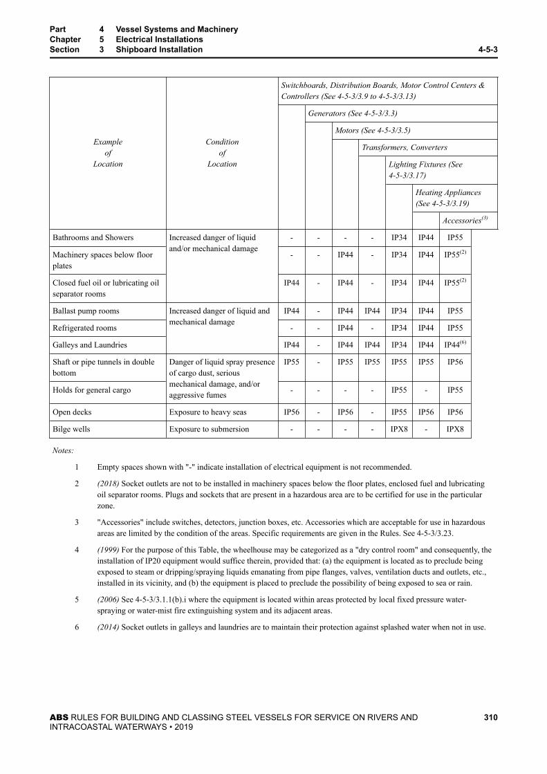
Exampleof
Location
Conditionof
Location
Switchboards, Distribution Boards, Motor Control Centers &Controllers (See 4-5-3/3.9 to 4-5-3/3.13)
Generators (See 4-5-3/3.3)
Motors (See 4-5-3/3.5)
Transformers, Converters
Lighting Fixtures (See4-5-3/3.17)
Heating Appliances(See 4-5-3/3.19)
Accessories(3)
Bathrooms and Showers Increased danger of liquidand/or mechanical damage
- - - - IP34 IP44 IP55
Machinery spaces below floorplates
- - IP44 - IP34 IP44 IP55(2)
Closed fuel oil or lubricating oilseparator rooms
IP44 - IP44 - IP34 IP44 IP55(2)
Ballast pump rooms Increased danger of liquid andmechanical damage
IP44 - IP44 IP44 IP34 IP44 IP55
Refrigerated rooms - - IP44 - IP34 IP44 IP55
Galleys and Laundries IP44 - IP44 IP44 IP34 IP44 IP44(6)
Shaft or pipe tunnels in doublebottom
Danger of liquid spray presenceof cargo dust, seriousmechanical damage, and/oraggressive fumes
IP55 - IP55 IP55 IP55 IP55 IP56
Holds for general cargo - - - - IP55 - IP55
Open decks Exposure to heavy seas IP56 - IP56 - IP55 IP56 IP56
Bilge wells Exposure to submersion - - - - IPX8 - IPX8
Notes:
1 Empty spaces shown with "-" indicate installation of electrical equipment is not recommended.
2 (2018) Socket outlets are not to be installed in machinery spaces below the floor plates, enclosed fuel and lubricatingoil separator rooms. Plugs and sockets that are present in a hazardous area are to be certified for use in the particularzone.
3 "Accessories" include switches, detectors, junction boxes, etc. Accessories which are acceptable for use in hazardousareas are limited by the condition of the areas. Specific requirements are given in the Rules. See 4-5-3/3.23.
4 (1999) For the purpose of this Table, the wheelhouse may be categorized as a "dry control room" and consequently, theinstallation of IP20 equipment would suffice therein, provided that: (a) the equipment is located as to preclude beingexposed to steam or dripping/spraying liquids emanating from pipe flanges, valves, ventilation ducts and outlets, etc.,installed in its vicinity, and (b) the equipment is placed to preclude the possibility of being exposed to sea or rain.
5 (2006) See 4-5-3/3.1.1(b).i where the equipment is located within areas protected by local fixed pressure water-spraying or water-mist fire extinguishing system and its adjacent areas.
6 (2014) Socket outlets in galleys and laundries are to maintain their protection against splashed water when not in use.
Part 4 Vessel Systems and MachineryChapter 5 Electrical InstallationsSection 3 Shipboard Installation 4-5-3
ABS RULES FOR BUILDING AND CLASSING STEEL VESSELS FOR SERVICE ON RIVERS ANDINTRACOASTAL WATERWAYS • 2019
310
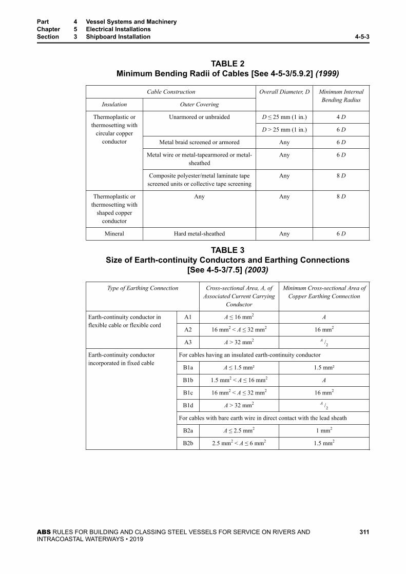
TABLE 2Minimum Bending Radii of Cables [See 4-5-3/5.9.2] (1999)
Cable Construction Overall Diameter, D Minimum InternalBending Radius
Insulation Outer Covering
Thermoplastic orthermosetting with
circular copperconductor
Unarmored or unbraided D ≤ 25 mm (1 in.) 4 D
D > 25 mm (1 in.) 6 D
Metal braid screened or armored Any 6 D
Metal wire or metal-tapearmored or metal-sheathed
Any 6 D
Composite polyester/metal laminate tapescreened units or collective tape screening
Any 8 D
Thermoplastic orthermosetting with
shaped copperconductor
Any Any 8 D
Mineral Hard metal-sheathed Any 6 D
TABLE 3Size of Earth-continuity Conductors and Earthing Connections
[See 4-5-3/7.5] (2003)
Type of Earthing Connection Cross-sectional Area, A, ofAssociated Current Carrying
Conductor
Minimum Cross-sectional Area ofCopper Earthing Connection
Earth-continuity conductor inflexible cable or flexible cord
A1 A ≤ 16 mm2 A
A2 16 mm2 < A ≤ 32 mm2 16 mm2
A3 A > 32 mm2 A /2
Earth-continuity conductorincorporated in fixed cable
For cables having an insulated earth-continuity conductor
B1a A ≤ 1.5 mm² 1.5 mm²
B1b 1.5 mm2 < A ≤ 16 mm2 A
B1c 16 mm2 < A ≤ 32 mm2 16 mm2
B1d A > 32 mm2 A /2
For cables with bare earth wire in direct contact with the lead sheath
B2a A ≤ 2.5 mm2 1 mm2
B2b 2.5 mm2 < A ≤ 6 mm2 1.5 mm2
Part 4 Vessel Systems and MachineryChapter 5 Electrical InstallationsSection 3 Shipboard Installation 4-5-3
ABS RULES FOR BUILDING AND CLASSING STEEL VESSELS FOR SERVICE ON RIVERS ANDINTRACOASTAL WATERWAYS • 2019
311

Type of Earthing Connection Cross-sectional Area, A, ofAssociated Current Carrying
Conductor
Minimum Cross-sectional Area ofCopper Earthing Connection
Separate fixed earthing conductor
C1a
A ≤ 3 mm2
Stranded earthing connection:1.5 mm2 for A ≤ 1.5 mm2
A for A > 1.5 mm2
C1b Unstranded earthing connection:3 mm2
C2 3 mm2 < A ≤ 6 mm2 3 mm2
C3 6 mm2 < A ≤ 125 mm2 A /2
C4 A > 125 mm2 64 mm2 (see Note 1)
Notes:
1 (2003) For earthed distribution systems, the size of earthing conductor is not to be less than A/2.
2 Conversion Table for mm² to circular mils:
mm2 circ.mils
mm2 circ.mils
mm2 circ.mils
mm2 circ.mils
1 1,973 2.5 4,933 6 11,841 70 138,147
1.5 2,960 4 7,894 16 31,576 120 236,823
Part 4 Vessel Systems and MachineryChapter 5 Electrical InstallationsSection 3 Shipboard Installation 4-5-3
ABS RULES FOR BUILDING AND CLASSING STEEL VESSELS FOR SERVICE ON RIVERS ANDINTRACOASTAL WATERWAYS • 2019
312

P A R T
4C H A P T E R 5 Electrical Installations
S E C T I O N 4 Machinery and Equipment
1 Plans and Data to Be Submitted (2010)
1.1 Rotating Machines of 100 kW and OverFor rotating machines of 100 kW and over intended for essential services (primary and secondary) or forservices indicated in 4-5-4/13.7 TABLE 11, drawings showing the following particulars are to besubmitted: assembly, seating arrangements, terminal arrangements, shafts, coupling, coupling bolts, statorand rotor details together with data for complete rating, class of insulation, designed ambient temperature,temperature rise, degree of protection for enclosures, weights and speeds for rotating parts. Plans to besubmitted for generator prime movers are given in 4-2-3/1.5, 4-2-4/1.5 and4-2-1/1.9 of the Marine VesselRules.
1.3 Switchboards, Distribution Boards, Controllers, etc.For switchboards, distribution boards, battery charger units, uninterruptible power system (UPS) units,motor control centers, and motor controllers intended for essential services (primary and secondary) or forservices indicated in 4-5-4/13.7 TABLE 11, drawings showing arrangements and details, front view, andinstallation arrangements are to be submitted for review together with data for protective device rating andsetting, type of internal wiring, and size and rated current carrying capacity (together with short-circuitcurrent data) of bus bars and internal wiring for power circuit. In addition, a schematic or logic diagramwith a written description giving the sequence of events and system operating procedures for electricalpower supply management on switchboards and sequential or automatic change-over of the motors are alsoto be submitted for review.
3 Rotating Machines
3.1 General3.1.1 Applications (2019)
All rotating electrical machines of 100 kW and over intended for essential services (see 4-5-1/3.7)or for services indicated in 4-5-4/13.7 TABLE 11 are to be designed, constructed and tested inaccordance with the requirements of 4-5-4/3.
Furthermore, their design and construction is to withstand all loads (e.g., mechanical, electrical,thermal, cyclic, etc.) that would be imposed during the intended operation.
For squirrel cage electric motors serving essential services, special attention is also to be given tothe method of attachment of the rotor bars to the rotor so that the overall operational integrity ofthe motor will not be affected during service. The common arrangement is with the shorting ringin full contact, via brazing or welding, with the ends of the rotor bars. A less common arrangementis with the shorting ring only in partial contact with the ends of the rotor bars. For these lesscommon arrangements, calculations, analyses, tests and/or operational service history data may berequired in this regard substantiating the design and construction of the rotating machine for itsintended application and service.
ABS RULES FOR BUILDING AND CLASSING STEEL VESSELS FOR SERVICE ON RIVERS ANDINTRACOASTAL WATERWAYS • 2019
313

All other rotating electrical machines are to be designed, constructed and tested in accordancewith established industrial practices and manufacturer’s specifications. Manufacturer’s tests forrotating electric machines less than 100 kW for essential services or for services indicated in4-5-4/13.7 TABLE 11 are to include at least the tests described in 4-5-4/3.3.1(b), regardless of thestandard of construction The test certificates are to be made available when requested by theSurveyor. Acceptance of machines will be based on satisfactory performance test after installation.
3.1.2 Certification on Basis of an Approved Quality Assurance ProgramSee 4-1-1/3.
3.1.3 References3.1.3(a) Inclination. For the requirements covering inclination for design condition, see 4-5-1/11.
3.1.3(b) Insulation Material. For the requirements covering insulation material, see 4-5-1/15.
3.1.3(c) Capacity of Generators. For requirements covering main generator capacity, see 4-5-2/3.1and 4-5-3/3.3. For requirements covering emergency generator capacity, see 4-5-6/9.1.2.
3.1.3(d) Power Supply by Generators. For requirements covering power supply by main oremergency generator, see 4-5-2/3.1, 4-5-2/3.3, 4-5-2/5 and 4-5-6/9.1.3.
3.1.3(e) Protection for Generator Circuits. For requirements covering protection for generator, see4-5-2/9.3, 4-5-2/9.5 and 4-5-2/9.7.
3.1.3(f) Protection for Motor Circuits. For requirements covering protection for motor branchcircuit, see 4-5-2/9.13.
3.1.3(g) Installation. For requirements covering installation, see 4-5-3/3.3 for generators and4-5-3/3.5 for motors.
3.1.3(h) Protection Enclosures and its Selection. For requirements covering degree of theprotection and the selection of equipment, see 4-5-1/17 and 4-5-3/3.1, respectively.
3.3 Testing and Inspection3.3.1 Applications (2010)
3.3.1(a) Machines of 100 kW and Over. All rotating machines of 100 kW and over intended foressential services (see 4-5-1/3.7) or for services indicated in 4-5-4/13.7 TABLE 11 are to be testedin accordance with 4-5-4/13.7 TABLE 1 in the presence of and inspected by the Surveyor,preferably at the plant of the manufacturer.
3.3.1(b) Machines Below 100 kW. All rotating machines of less than 100 kW intended for essentialservices or for services indicated in 4-5-4/13.7 TABLE 11 are to be tested in accordance with4-5-4/13.7 TABLE 1 (item 2 through item 10 and item 12). The tests may be carried out by themanufacturer whose certificate of tests will be acceptable and is to be submitted upon requestfrom ABS.
3.3.1(c) Other Machines. For machines not intended for essential services or for services indicatedin 4-5-4/13.7 TABLE 11, the tests may be carried out by the manufacturer whose certificate oftests will be acceptable and is to be submitted upon request from ABS.
3.3.2 Special Testing ArrangementsIn cases where all of the required tests are not carried out at the plant of the manufacturer, theSurveyor is to be notified and arrangements are to be made so that the remaining tests will bewitnessed.
Part 4 Vessel Systems and MachineryChapter 5 Electrical InstallationsSection 4 Machinery and Equipment 4-5-4
ABS RULES FOR BUILDING AND CLASSING STEEL VESSELS FOR SERVICE ON RIVERS ANDINTRACOASTAL WATERWAYS • 2019
314

3.5 Insulation Resistance MeasurementThe resistance is to be measured before the commencement of the testing and after completion of thetesting for all circuits. Circuits or groups of circuits of different voltages above earth are to be testedseparately. This test is to be made with at least 500 volts DC and the insulation resistance in megohms ofthe circuits while at their operating temperatures is to be normally at least equal to:Rated Volatage of the Machine(Rating in kVA/100) + 1000The minimum insulation resistance of the fields of machines separately excited with voltage less than therated voltage of the machine is to be on the order of one-half to one megohm.
3.7 Overload and Overcurrent Capability (1997)3.7.1 AC Generators (2003)
AC generators are to be capable of withstanding a current equal to 1.5 times the rated current fornot less than 30 seconds.The test may be performed in conjunction with the short circuit testing,provided the electrical input energy to the machine is not less than that required for the aboveoverload capability.
3.7.2 AC Motors3.7.2(a) Overcurrent Capacity (2003). Three phase induction motors having rated output notexceeding 315 kW and rated voltage not exceeding 1 kV are to be capable of withstanding acurrent equal to 1.5 times the rated current for not less than two minutes. For three-phaseinduction motors having rated outputs above 315 kW, the overcurrent capacity is to be inaccordance with the manufacturer’s specification.The test may be performed at a reduced speed.
3.7.2(b) Overload Capacity. Three-phase induction motors are to be capable of withstanding for15 seconds, without stalling or abrupt change in speed, an excess torque of 60% of their ratedtorque, the voltage and frequency being maintained at their rated values.
3.7.2(c) Overload Capacity for Synchronous Motors. Three phase synchronous motors are to becapable of withstanding an excess torque, as specified below, for 15 seconds without falling out ofsynchronism, the excitation being maintained at the value corresponding to the rated load.
Synchronous (wound rotor) induction motors: 35% excess torque
Synchronous (cylindrical rotor) motors: 35% excess torque
Synchronous (salient pole) motors: 50% excess torque
When automatic excitation is used, the limit of torque values is to be the same as with theexcitation equipment operating under normal conditions.
3.9 Dielectric Strength of Insulation3.9.1 Application
The dielectric test voltage is to be successively applied between each electric circuit and all otherelectric circuits and metal parts earthed, and for direct-current (DC) rotating machines betweenbrush rings of opposite polarity. Interconnected polyphase windings are to be considered as onecircuit. All windings except that under test are to be connected to earth.
3.9.2 Standard Voltage Test (2003)The insulation of all rotating machines is to be tested with the parts completely assembled and notwith the individual parts. The dielectric strength of the insulation is to be tested by the continuousapplication for 60 seconds of an alternating voltage having a frequency of 25 to 60 Hz and voltage
Part 4 Vessel Systems and MachineryChapter 5 Electrical InstallationsSection 4 Machinery and Equipment 4-5-4
ABS RULES FOR BUILDING AND CLASSING STEEL VESSELS FOR SERVICE ON RIVERS ANDINTRACOASTAL WATERWAYS • 2019
315

in 4-5-4/13.7 TABLE 2.The requirements in 4-5-4/13.7 TABLE 2 apply to those machines otherthan high voltage systems covered by 4-5-5/1.11.1(e).
3.9.3 Direct Current TestA standard voltage test using a direct current source equal to 1.7 times the required alternating-current voltage will be acceptable.
3.11 Temperature Ratings3.11.1 Temperature Rises
3.11.1(a) Continuous Rating Machines. After the machine has been run continuously under a ratedload until steady temperature condition has been reached, the temperature rises are not to exceedthose given in 4-5-4/13.7 TABLE 3.
3.11.1(b) Short-time Rating Machines. After the machine has been run at a rated load during therated time followed by a rest and a de-energized period of sufficient duration to reestablish themachine temperatures within 2°C (3.6°F) of the coolant, the temperature rises are not to exceedthose given in 4-5-4/13.7 TABLE 3. At the beginning of the temperature measurement, thetemperature of the machine is to be within 5°C (8°F) of the temperature of the coolant.
3.11.1(c) Periodic Duty Rating Machines. The machine has been run at a rated load for thedesigned load cycle to be applied and continued until obtaining the practically identicaltemperature cycle. At the middle of the period causing the greatest heating in the last cycle of theoperation, the temperature rises are not to exceed those given in 4-5-4/13.7 TABLE 3.
3.11.1(d) Non-periodic Duty Rating Machines. After the machine has been run continuously orintermittently under the designed variations of the load and speed within the permissible operatingrange until reaching the steady temperature condition, the temperature rises are not to exceedthose given in 4-5-4/13.7 TABLE 3.
3.11.1(e) Insulation Material Above 180°C (356°F). Temperature rises for insulation materialsabove 180°C (356°F) will be considered in accordance with 4-5-1/15.11.
3.11.2 Ambient Temperature (2007)These final temperatures are based on an ambient temperature of 50°C (122°F), for machineslocated within boiler and engine rooms in accordance with 4-5-1/19. Where provision is made forensuring the ambient temperature of the spacebeing maintained at 40°C (104°F) or less, as by aircooling or by locating the machine outside of the boiler and engine rooms, the temperature rises ofthe windings may be 5°C (9°F) higher. The ambient temperature is to be taken in at least twoplaces within 1.83 m (6 ft) of the machine under test and by thermometers having their bulbsimmersed in oil contained in an open cup.
3.13 Construction and Assemblies3.13.1 Enclosure, Frame and Pedestals
Magnet frames and pedestals may be separate but are to be secured to a common foundation.
3.13.2 Shafts and CouplingsRotating shaft, hollow shaft and coupling flange with bolts are to comply with 4-2-1/15, 4-2-1/17of these Rules and 4-2-4/5.3 of the Marine Vessel Rules. Plans to be submitted are given in4-2-1/1.9, 4-2-3/1.5 and 4-2-4/1.5 of the Marine Vessel Rules.
3.13.3 Circulating CurrentsMeans are to be provided to prevent circulating currents from passing between the journals andthe bearings, where the design and arrangement of the machine is such that damaging current may
Part 4 Vessel Systems and MachineryChapter 5 Electrical InstallationsSection 4 Machinery and Equipment 4-5-4
ABS RULES FOR BUILDING AND CLASSING STEEL VESSELS FOR SERVICE ON RIVERS ANDINTRACOASTAL WATERWAYS • 2019
316

be expected. Where such protection is required, a warning plate is to be provided in a visible placecautioning against the removal of such protection.
3.13.4 Rotating ExcitersRotating exciters are to conform to all applicable requirements for generators.
3.13.5 Insulation of WindingsArmature and field coils are to be treated to resist oil and water.
3.13.6 Protection Against Cooling WaterWhere water cooling is used, the cooler is to be so arranged as to avoid entry of water into themachine, whether through leakage or from condensation in the heat exchanger.
3.13.7 Moisture Condensation Prevention (2014)All generators, and each motor rated 50 kW and over, are to be provided with a means to preventmoisture condensation in the machine when idle.
Where steam-heating coils are installed for this purpose, there are to be no pipe joints inside of thecasings. See item 7 in 4-5-4/13.7 TABLE 7 for space heater pilot lamp for alternating-currentgenerators.
3.13.8 Terminal ArrangementsTerminals are to be provided at an accessible position and protected against mechanical damageand accidental contact for earthing, short-circuit or touching. Terminal leads are to be secured tothe frame and the designation of each terminal lead is to be clearly marked. The ends of terminalleads are to be fitted with connectors. Cable glands or similar are to be provided where cablepenetrations may compromise the protection property of terminal enclosures.
3.13.9 NameplatesNameplates of corrosion-resistant material are to be provided in an accessible position of themachine and are to indicate at least the information as listed in 4-5-4/13.7 TABLE 4.
3.15 LubricationRotating machines are to have continuous lubrication at all running speeds and all normal working bearingtemperatures. Unless otherwise approved, where forced lubrication is employed, the machines are to beprovided with means to shut down their prime movers automatically upon failure of the lubricating system.Each self-lubricating sleeve bearing is to be fitted with an inspection lid and means for visual indication ofoil level or an oil gauge.
3.17 Turbines for GeneratorsGas-turbine prime movers driving generators are to meet the applicable requirements in Section 4-2-3 ofthe Marine Vessel Rules and, in addition, are to comply with the following requirements.
3.17.1 Operating Governor (2004)An effective operating governor is to be fitted on prime movers driving main or emergencyelectric generators and is to be capable of automatically maintaining the speed within thefollowing limits. Special consideration will be given when an installation requires differentcharacteristics.
3.17.1(a) Transient Frequency Variations. The transient frequency variations in the electricalnetwork, when running at the indicated loads below, are to be within ±10% of the rated frequencywhen:
Part 4 Vessel Systems and MachineryChapter 5 Electrical InstallationsSection 4 Machinery and Equipment 4-5-4
ABS RULES FOR BUILDING AND CLASSING STEEL VESSELS FOR SERVICE ON RIVERS ANDINTRACOASTAL WATERWAYS • 2019
317
i) Running at full load (equal to rated output) of the generator and the maximum electricalstep load is suddenly thrown off,
In the case when a step load equivalent to the rated output of a generator is thrown off, atransient frequency variation in excess of 10% of the rated frequency may be acceptable,provided the overspeed protective device, fitted in addition to the governor, as required by4-5-4/3.17.2, is not activated.
ii) Running at no load and 50% of the full load of the generator is suddenly thrown onfollowed by the remaining 50% load after an interval sufficient to restore the frequency tosteady state.
In all instances, the frequency is to return to within ±1% of the final steady state conditionin no more than five seconds.
3.17.1(b) Frequency Variations in Steady State.The permanent frequency variation is to be within±5% of the rated frequency at any load between no load and full load.
3.17.2 Overspeed GovernorIn addition to the normal operating governor, an overspeed governor is to be fitted which will tripthe turbine throttle when the rated speed is exceeded by more than 15%. Provision is to be madefor hand tripping. See 4-5-4/3.15 for pressure-lubricated machines.
3.17.3 Exhaust Steam to the TurbinesIf exhaust steam is admitted to the turbine, means are to be provided to prevent water entering theturbine. An automatic shut-off is to be provided for auxiliary exhaust when exhaust steam isadmitted to the turbine lower stages; this shut-off is to be controlled by the governor and is tofunction when the emergency trip operates.
3.17.4 Extraction of SteamWhere provision is made for extraction of steam, approved means are to be provided forpreventing a reversal of flow to the turbine.
3.17.5 Power Output of Gas TurbinesTo satisfy the requirements of 4-5-2/3.1, the required power output of gas turbine prime moversfor ship’s service generator sets is to be based on the maximum expected inlet air temperature.
3.19 Diesel Engines for GeneratorsDiesel-engine prime movers are to meet the applicable requirements in Part 4, Chapter 2 of the MarineVessel Rules and, in addition, are to comply with the following requirements.
3.19.1 Operating Governor (2004)An effective operating governor is to be fitted on prime movers driving main or emergencyelectric generators and is to be capable of automatically maintaining the speed within thefollowing limits. Special consideration will be given when an installation requires differentcharacteristics.
3.19.1(a) Transient Frequency Variations. The transient frequency variations in the electricalnetwork, when running at the indicated loads below, are to be within ±10% of the rated frequencywhen:
i) Running at full load (equal to rated output) of the generator and the maximum electricalstep load is suddenly thrown off,
In the case when a step load equivalent to the rated output of a generator is thrown off, atransient frequency variation in excess of 10% of the rated frequency may be acceptable,
Part 4 Vessel Systems and MachineryChapter 5 Electrical InstallationsSection 4 Machinery and Equipment 4-5-4
ABS RULES FOR BUILDING AND CLASSING STEEL VESSELS FOR SERVICE ON RIVERS ANDINTRACOASTAL WATERWAYS • 2019
318

provided the overspeed protective device, fitted in addition to the governor, as required by4-5-4/3.19.2, is not activated.
ii) Running at no load and 50% of the full load of the generator is suddenly thrown onfollowed by the remaining 50% load after an interval sufficient to restore the frequency tosteady state.
In all instances, the frequency is to return to within ±1% of the final steady state conditionin no more than five seconds.
iii) Where the electrical power system is fitted with a power management system andsequential starting arrangements, the application of loads in multiple steps of less than50% of rated load in 4-5-4/3.19.1(a).ii will be given special consideration. The details ofthe power management system and sequential starting arrangements are to be submittedand its satisfactory operation is to be demonstrated to the Surveyor.
3.19.1(b) Frequency Variations in Steady State. The permanent frequency variation is to be within±5% of the rated frequency at all loads between no load and full load.
3.19.1(c) Emergency Generator Prime Movers (1998). Prime movers driving emergencygenerators are to be able to maintain the speed within the limits in 4-5-4/3.19.1(a) and4-5-4/3.19.1(b) when the full load of the emergency generator is suddenly thrown on. Where loadsare applied in multiple steps, the first applied load is not to be less than the sum of all emergencyloads that are automatically connected.
3.19.2 Overspeed GovernorIn addition to the normal operating governor, each auxiliary diesel engine having a maximumcontinuous output of 220 kW and over is to be fitted with a separate overspeed device so adjustedthat the speed cannot exceed the maximum rated speed by more than 15%. Provision is to be madefor hand tripping. See 4-5-4/3.15 for pressure-lubricated machines.
3.21 Alternating-current (AC) Generators3.21.1 Control and Excitation of Generators
Excitation current for generators is to be provided by attached rotating exciters or by staticexciters deriving their source of power from the machine being excited.
3.21.2 Voltage Regulation (2007)3.21.2(a) Voltage Regulators.A separate regulator is to be supplied for each AC generator. When it is intended that two or moregenerators will be operated in parallel, reactive-droop compensating means are to be provided todivide the reactive power properly between the generators.
3.21.2(b) Variation from Rated Voltage – Steady Conditions.Each AC generator for ship’s service driven by its prime mover having governor characteristicscomplying with 4-5-4/3.17.1 or 4-5-4/3.19.1 is to be provided with an excitation system capable ofmaintaining the voltage under steady conditions within plus or minus 2.5% of the rated voltage forall loads between zero and rated load at rated power factor. These limits may be increased to plusor minus 3.5% for emergency sets.
3.21.2(c) Variation from Rated Voltage – Transient Conditions (2017).Momentary voltage variations are to be within the range of minus 15% to plus 20% of the ratedvoltage, and the voltage is to be restored to within plus or minus 3% of the rated voltage in notmore than 1.5 seconds when:
● A load equal to the starting current of the largest motor or a group of motors, but in any case,at least 60% of the rated current of the generator, and power factor of 0.4 lagging or less, issuddenly thrown on with the generator running at no load; and
Part 4 Vessel Systems and MachineryChapter 5 Electrical InstallationsSection 4 Machinery and Equipment 4-5-4
ABS RULES FOR BUILDING AND CLASSING STEEL VESSELS FOR SERVICE ON RIVERS ANDINTRACOASTAL WATERWAYS • 2019
319

● A load equal to the above is suddenly thrown off.
Subject to ABS approval, such voltage regulation during transient conditions may be calculatedvalues based on the previous type test records, and need not to be tested during factory testing of agenerator.
Consideration can be given to performing the test required by 4-5-4/13.7 TABLE 1, Item 4according to precise information concerning the maximum values of the sudden loads instead ofthe values indicated above, provided precise information is available. The precise informationconcerning the maximum values of the sudden loads is to be based on the power managementsystem arrangements and starting arrangements provided for the electrical system.
3.21.2(d) Short Circuit Conditions (2017).Under steady-state short-circuit conditions, the generator together with its excitation system is tobe capable of maintaining a steady-state short-circuit current of not less than three times its ratedfull load current for a period of two seconds or of such magnitude and duration as required toproperly actuate the associated electrical protective devices. In order to provide sufficientinformation for determining the discrimination settings in the distribution system where thegenerator is going to be used, the generator manufacturer is to provide documentation showing thetransient behavior of the short circuit current upon a sudden short-circuit occurring when excited,and running at nominal speed. The influence of the automatic voltage regulator is to be taken intoaccount, and the setting parameters for the voltage regulator are to be noted together with thedecrement curve. Such a decrement curve is to be available when the setting of the distributionsystem’s short-circuit protection is calculated. The decrement curve need not be based on physicaltesting. The manufacturer’s simulation model for the generator and the voltage regulator may beused where this has been validated through the previous type test on the same model.
3.21.3 Parallel OperationFor AC generating sets operating in parallel, the following requirements are to be complied with.See also 4-5-2/9.5.2 for protection of AC generators in parallel operation.
3.21.3(a) Reactive Load Sharing. The reactive loads of the individual generating sets are not todiffer from their proportionate share of the combined reactive load by more than 10% of the ratedreactive output of the largest generator, or 25% of the rated reactive output of the smallestgenerator, whichever is the less.
3.21.3(b) Load Sharing. For any load between 20% and 100% of the sum of the rated output(aggregate output) of all generators, the load on any generator is not to differ more than 15% ofthe rated output in kilowatts of the largest generator or 25% of the rated output in kilowatts of theindividual generator in question, whichever is the less, from its proportionate share of thecombined load for any steady state condition. The starting point for the determination of theforegoing load-distribution requirements is to be at 75% of the aggregate output with eachgenerator carrying its proportionate share.
3.21.3(c) Facilities for Load Adjustment. Facilities are to be provided to adjust the governorsufficiently fine to permit an adjustment of load not exceeding 5% of the aggregate output atnormal frequency.
3.23 Direct-current (DC) Generators3.23.1 Control and Excitation of Generators
3.23.1(a) Field Regulations. Means are to be provided at the switchboard to enable the voltage ofeach generator to be adjusted separately. This equipment is to be capable of adjusting the voltageof the DC generator to within 0.5% of the rated voltage at all loads between no-load and full-load.
Part 4 Vessel Systems and MachineryChapter 5 Electrical InstallationsSection 4 Machinery and Equipment 4-5-4
ABS RULES FOR BUILDING AND CLASSING STEEL VESSELS FOR SERVICE ON RIVERS ANDINTRACOASTAL WATERWAYS • 2019
320

3.23.1(b) Polarity of Series Windings. The series windings of each generator for a two wire DCsystem are to be connected to the negative terminal of each machine.
3.23.1(c) Equalizer Connections. See 4-5-4/7.15.3.
3.23.2 Voltage Regulation3.23.2(a) Shunt or Stabilized Shunt-wound Generator. When the voltage has been set at full-loadto its rated value, the removal of the load is not to cause a permanent increase of the voltagegreater than 15% of the rated voltage. When the voltage has been set either at full-load or at no-load, the voltage obtained at any value of the load is not to exceed the no-load voltage.
3.23.2(b) Compound-wound Generator. Compound-wound generators are to be so designed inrelation to the governing characteristics of the prime mover that with the generator at full-loadoperating temperature and starting at 20% load with voltage within 1% of rated voltage, it gives atfull-load a voltage within 1.5% of rated voltage. The average of ascending and descending voltageregulation curves between 20% load and full-load is not to vary more than 3% from rated voltage.
3.23.2(c) Automatic Voltage Regulators. Ship’s service generators which are of a shunt type are tobe provided with automatic voltage regulators. However, if the load fluctuation does not interferewith the operation of essential auxiliaries, shunt-wound generators without voltage regulators orstabilized shunt-wound machines may be used. An automatic voltage regulator will not berequired for the ship’s service generators of an approximately flat-compounded type. Automaticvoltage regulators are to be provided for all service generators driven by variable speed enginesused also for propulsion purposes, whether these generators are of the shunt, stabilized shunt orcompound-wound type.
3.23.3 Parallel OperationFor DC generating sets operating in parallel, the following requirements are to be complied with.See also 4-5-2/9.7.2 for protection of DC generators in parallel operation.
3.23.3(a) Stability. The generating sets are to be stable in operation at all loads from no-load tofull-load.
3.23.3(b) Load Sharing. For any load between 20% and 100% of the sum of the rated output(aggregate output) of all generators, the load on any generator is not to differ more than 12% fromthe rated output in kilowatts of the largest generator or 25% from the rated output in kilowatts ofthe individual generator in question, whichever is the less, from its proportionate share of thecombined load for any steady state condition. The starting point for the determination of theforegoing load-distribution requirements is to be at 75% of the aggregate output with eachgenerator carrying its proportionate share.
3.23.3(c) Tripping of Circuit Breaker. DC generators which operate in parallel are to be providedwith a switch which will trip the generator circuit breaker upon functioning of the overspeeddevice.
5 Accumulator Batteries
5.1 General5.1.1 Application
All accumulator batteries for engine starting, essential or emergency services are to be constructedand installed in accordance with the following requirements. Accumulator batteries for servicesother than the above are to be constructed and equipped in accordance with good commercialpractice. All accumulator batteries will be accepted subject to a satisfactory performance testconducted after installation to the satisfaction of the Surveyor.
Part 4 Vessel Systems and MachineryChapter 5 Electrical InstallationsSection 4 Machinery and Equipment 4-5-4
ABS RULES FOR BUILDING AND CLASSING STEEL VESSELS FOR SERVICE ON RIVERS ANDINTRACOASTAL WATERWAYS • 2019
321

5.1.2 Sealed Type BatteriesWhere arrangements are made for releasing gas through a relief valve following an overchargecondition, calculations demonstrating compliance with the criteria in 4-5-3/3.7.3 under theexpected rate of hydrogen generation are to be submitted together with the details of installationand mechanical ventilation arrangements.
5.1.3 References5.1.3(a) Emergency Services. For requirements covering emergency services and transitionalsource of power, see 4-5-2/5 and 4-5-6/9.1.4, respectively.
5.1.3(b) Protection of Batteries. For requirements covering protection of batteries, see 4-5-2/9.9.
5.1.3(c) Battery Installation. For requirements covering battery installation, ventilation of thebattery location and protection from corrosion, see 4-5-3/3.7.
5.1.3(d) Cable Installation. For requirements covering cable installation in the battery room, see4-5-3/5.23.
5.3 Construction and Assembly5.3.1 Cells and Filling Plugs
The cells are to be so constructed as to prevent spilling of electrolyte due to an inclination of 40deg. from normal. The filling plugs are to be so constructed as to prevent spilling of electrolytedue to the vessel’s movements such as rolling and pitching.
5.3.2 Crates and TraysThe cells are to be grouped in crates or trays of rigid construction equipped with handles tofacilitate handling. For protection from corrosion, see 4-5-3/3.7.4. The mass of crates or trays arenot to exceed 100 kg (220.5 lb).
5.3.3 NameplateNameplates of corrosion-resistant material are to be provided in an accessible position of eachcrate or tray and are to indicate at least the information as listed in 4-5-4/13.7 TABLE 4.
5.5 Engine-starting BatteryBattery systems for engine-starting purposes may be of the one-wire type and the earth lead is to be carriedto the engine frame. See also 4-1-1/17.3 and 4-5-6/9.1.7 for main engine starting and the startingarrangement of the emergency generator (intended for passenger vessels), respectively.
7 Switchboards, Distribution Boards, Controllers, etc.
7.1 General7.1.1 Applications (2010)
Switchboards are to provide adequate control of the generation and distribution of electric power.The following equipment is to be constructed and tested in accordance with the followingrequirements to the satisfaction of the Surveyor.
7.1.1(a) Switchboards. Switchboards for essential services or for services indicated in 4-5-4/13.7TABLE 11 .
7.1.1(b) Motor Controllers. Motor Controllers of 100 kW and over intended for essential servicesor for services indicated in 4-5-4/13.7 TABLE 11.
7.1.1(c) Motor Control Centers. Motor control centers with aggregate loads of 100 kW or moreintended for essential services or for services indicated in 4-5-4/13.7 TABLE 11.
Part 4 Vessel Systems and MachineryChapter 5 Electrical InstallationsSection 4 Machinery and Equipment 4-5-4
ABS RULES FOR BUILDING AND CLASSING STEEL VESSELS FOR SERVICE ON RIVERS ANDINTRACOASTAL WATERWAYS • 2019
322

7.1.1(d) Battery Charger Units and Uninterruptible Power System (UPS) Units. Battery chargerunits of 25 kW and over and uninterruptible power system (UPS) units of 50 kVA intended foressential services, services indicated in 4-5-4/13.7 TABLE 11, emergency source of power ortransitional source of power.
7.1.1(e) Distribution Boards. Distribution boards associated with the charging or discharging ofthe battery system or uninterruptible power system (UPS) in 4-5-4/7.1.1(d).
Switchboard, distribution board, battery charger units, uninterruptible power system (UPS) units,motor control centers and motor controllers not covered by the above paragraph are to beconstructed and equipped in accordance with good commercial practice, and will be acceptedsubject to a satisfactory performance test conducted after installation to the satisfaction of theSurveyor.
7.1.2 References7.1.2(a) Inclination. For requirements covering inclination for design condition, see 4-5-1/11.
7.1.2(b) Emergency Switchboard. For requirements covering emergency switchboard forpassenger vessels, see 4-5-6/9.1.5.
7.1.2(c) Circuit Breakers. For requirements covering generator circuit breakers, see 4-5-4/11.1.
7.1.2(d) Feeder Protection. For requirements covering feeder protection, see 4-5-2/9 to 4-5-2/17,4-5-2/11.3, 4-5-2/13.1.4 and 4-5-2/13.3.3
7.1.2(e) Hull Return and Earthed Distribution System. For requirements covering hull returnsystem and earthed distribution system, see 4-5-2/7.3 and 4-5-2/7.5, respectively
7.1.2(f) Earthing. For requirements covering earthing connections, see 4-5-3/7.
7.1.2(g) Installation. For requirements covering installation, see 4-5-3/3.9 for switchboard,4-5-3/3.11 for distribution boards and 4-5-3/3.13 for motor controllers and control centers.
7.1.2(h) Protection Enclosure and its Selection. For requirements covering degree of theprotection and the selection of equipment, see 4-5-1/17 and 4-5-3/3.1, respectively.
7.3 Testing and Inspection7.3.1 Applications
7.3.1(a) Switchboards (2010). All switchboards intended for essential services or for servicesindicated in 4-5-4/13.7 TABLE 11, are to be tested in the presence of and inspected by theSurveyor, preferably at the plant of the manufacturer. For other switchboards, the tests may becarried out by the manufacturer whose certificate of tests will be acceptable and is to be submittedupon request from ABS.
7.3.1(b) Motor Controllers (2010). All motor controllers of 100 kW and over intended foressential services or for services indicated in 4-5-4/13.7 TABLE 11 are to be tested in the presenceof and inspected by the Surveyor, preferably at the plant of the manufacturer. For other motorcontrollers, the tests may be carried out by the manufacturer whose certificate of tests will beacceptable and is to be submitted upon request from ABS.
7.3.1(c) Motor Control Centers (2010). All motor control centers with aggregate loads of 100 kWand over intended for essential services or for services indicated in 4-5-4/13.7 TABLE 11 are to betested in the presence of and inspected by the Surveyor, preferably at the plant of themanufacturer. For other motor control centers, the tests may be carried out by the manufacturerwhose certificate of tests will be acceptable and is to be submitted upon request from ABS.
Part 4 Vessel Systems and MachineryChapter 5 Electrical InstallationsSection 4 Machinery and Equipment 4-5-4
ABS RULES FOR BUILDING AND CLASSING STEEL VESSELS FOR SERVICE ON RIVERS ANDINTRACOASTAL WATERWAYS • 2019
323

7.3.1(d) Battery Chargers Units, Uninterruptiple Power System (UPS), and Distribution Boards(2010). Battery charger units of 25 kW and over, uninterruptible power system (UPS) units of 50kW and over, and distribution boards [associated with the charging or discharging of the batterysystem or uninterruptible power system (UPS)] are used for essential services (see 4-5-1/3.7),services indicated in 4-5-4/13.7 TABLE 11, emergency source of power (see 4-5-2/5), andtransitional source of power (see 4-5-6/9.1.4) are to be tested in the presence of and inspected bythe Surveyor, preferably at the plant of the manufacturer. For all other battery charger units,uninterruptible power system (UPS) units, and distribution boards, the tests may be carried out bythe manufacturer whose certificate of tests will be acceptable and is to be submitted upon requestfrom ABS.
7.3.1(e) Test Items. Tests are to be carried out in accordance with the requirements in 4-5-4/13.7TABLE 5.
7.3.2 Special Testing ArrangementsIn cases where all of the required tests are not carried out at the plant of the manufacturer, theSurveyor is to be notified and arrangements are to be made so that the remaining tests may bewitnessed.
7.5 Insulation Resistance MeasurementThe insulation resistance between current-carrying parts (connected together for the purpose of this test)and earth and between current-carrying parts of opposite polarity is to be measured at a DC voltage of notless than 500 volts before and after the dielectric strength tests. The insulation resistance measurementafter the dielectric strength tests is to be carried out before components which have been disconnected forthe dielectric tests are reconnected, and the insulation resistance is not to be less than 1 megohm.
7.7 Dielectric Strength of Insulation (1997)The dielectric strength of the insulation is to be tested for 60 seconds by an alternating voltage applied inaccordance with 4-5-4/13.7 TABLE 5 between:
i) All live parts and the interconnected, exposed conductive parts, and
ii) Each phase and all other phases connected for this test to the interconnected exposed conductiveparts of the unit.
The test voltage at the moment of application is not to exceed 50% of the values given in 4-5-4/13.7TABLE 5. It is to be increased steadily within a few seconds to the required test voltage and maintained for60 seconds. Test voltage is to have a sinusoidal waveform and a frequency between 45 Hz and 60 Hz.
7.7.1 Production-line ApparatusStandard apparatus produced in large quantities for which the standard test voltage is 2500 volts orless may be tested for one second with a test voltage 20% higher than the one-minute test voltage.
7.7.2 Devices with Low Insulation StrengthCertain devices such as potential transformers having inherently lower insulation strength are tobe disconnected during the test.
7.9 Construction and Assembly7.9.1 Enclosures and Assemblies
Enclosures and assemblies are to be constructed of steel or other suitable, incombustible,moisture-resistant materials and reinforced as necessary to withstand the mechanical, electrical(magnetic) and thermal stresses likely to be encountered in service, and are to be protected againstcorrosion. No wood is to be used, except for hardwood for nonconducting hand rails. Insulating
Part 4 Vessel Systems and MachineryChapter 5 Electrical InstallationsSection 4 Machinery and Equipment 4-5-4
ABS RULES FOR BUILDING AND CLASSING STEEL VESSELS FOR SERVICE ON RIVERS ANDINTRACOASTAL WATERWAYS • 2019
324

materials are to be flame retardant and moisture resistant. The supporting framework is to be ofrigid construction.
7.9.2 Dead FrontThe dead-front type is to be used. Live-front type is not acceptable, regardless of the voltageratings.
7.9.3 Mechanical StrengthAll levers, handles, hand wheels, interlocks and their connecting links, shafts and bearings for theoperation of switches and contactors are to be of such proportions that they will not be broken ordistorted by manual operation.
7.9.4 Mechanical Protection (2004)The sides and the rear and, where necessary, the front of switchboards are to be suitably guarded.Exposed live parts having voltages to earth exceeding a voltage of 55 volts DC or 55 volts ACr.m.s. between conductors are not to be installed on the front of such switchboards. Unless theswitchboard is installed on an electrically insulated floor, non-conducting mats or gratings are tobe provided at the front and rear of the switchboard. Where the floor on which the switchboard isinstalled is of electrically insulated construction, the insulation level of the floor to the earth is tobe at least 50 MΩ. A notice plate is to be posted at the entrance to the switchboard room or on theswitchboard front panel to state that the floor in the room is of electrically insulated construction.Drip covers are to be provided over switchboards when subject to damage by leaks or fallingobjects.
7.11 Bus Bars, Wiring and Contacts7.11.1 Design
Copper bar is to be used for main and generator bus in the switchboard. Other materials andcombination of materials will be specially considered. Generator bus bars are to be designed onthe basis of maximum generator rating. All other bus bars and bus-bar connections are to bedesigned for at least 75% of the combined full-load rated currents of all apparatus that they supply,except that when they supply one unit or any group of units in continuous operation, they are to bedesigned for full load.
7.11.2 Operating Temperature of Bus BarsBus bars are to be proportioned to avoid temperatures which will affect the normal operation ofelectrical devices mounted on the board.
7.11.3 Short Circuit RatingCircuit breakers and bus bars are to be mounted, braced and located so as to withstand the thermaleffects and mechanical forces resulting from the maximum prospective short circuit current.Switchboard instruments, controls, etc., are to be located with respect to circuit breakers so as tominimize the thermal effects due to short circuit currents.
7.11.4 Internal WiringInstrument and control wiring is to be of the stranded type and is to have heat-resisting and flame-retarding insulation. Wiring from hinged panels is to be of the extra-flexible type.
7.11.5 Arrangement7.11.5(a) Accessibility. The arrangement of bus bars and wiring on the back is to be such that alllugs are readily accessible.
Part 4 Vessel Systems and MachineryChapter 5 Electrical InstallationsSection 4 Machinery and Equipment 4-5-4
ABS RULES FOR BUILDING AND CLASSING STEEL VESSELS FOR SERVICE ON RIVERS ANDINTRACOASTAL WATERWAYS • 2019
325

7.11.5(b) Locking of Connections (2004). All nuts and connections are to be fitted with lockingdevices to prevent loosening due to vibration. Bolted bus bar connections are to be suitably treated(e.g., silver plating) to avoid deterioration of electrical conductivity over time.
7.11.5(c) Soldered Connections. Soldered connections are not to be used for connecting orterminating any wire or cable of nominal cross-sectional area of greater than 2.5 mm2 (4,933 circ.mils). Soldered connections, where used, are to have a solder contact length at least 1.5 times thediameter of the conductor.
7.11.6 Clearances and Creepage Distances7.11.6(a) General. Bare main bus bars, but not including the conductors between the main busbars and the supply side of outgoing units, are to have minimum clearances (in air) and creepagedistances (across surfaces) in accordance with 4-5-4/13.7 TABLE 6.
7.11.6(b) Alternative (2014). Alternatively, reduced creepage and clearance distances may be usedprovided:
i) The equipment is not installed in ‘Machinery Spaces of Category A’ or in areas affectedby a Local Fixed Pressure Water-spraying or Local Water-mist Fire ExtinguishingSystem.
ii) The minimum clearance distance shall not be less than 8 mm.
iii) The minimum creepage distance shall not be less than 16 mm.
iv) The equipment complies with IEC 61439-1
v) In applying IEC 61439-1 the equipment is considered to be:
● Of overvoltage Category III,
● Installed in an environment of pollution degree 3
● Having insulating material of type IIIa, and
● Installed in inhomogeneous field conditions
vi) The temperature dependent criteria in IEC 61439-1 are derated to meet the ambienttemperatures found on marine installations. Refer to 4-1-1/25 TABLE 1.
vii) The equipment is subject to an impulse voltage test with test voltage values shown inTable below. Where intermediate values of rated operational voltage are used, the nexthigher rated impulse withstand test voltage is to be used. The impulse voltage test reportsare to be submitted to ABS for review.
Rated Operational Voltage V Rated Impulse Withstand Test Voltage kV
50 0.8
100 1.5
150 2.5
300 4
600 6
1000 8
7.11.7 Terminals (2009)Terminals or terminal rows for systems of different voltages are to be clearly separated from eachother. The rated voltage is to be clearly indicated at least once for each group of terminals which
Part 4 Vessel Systems and MachineryChapter 5 Electrical InstallationsSection 4 Machinery and Equipment 4-5-4
ABS RULES FOR BUILDING AND CLASSING STEEL VESSELS FOR SERVICE ON RIVERS ANDINTRACOASTAL WATERWAYS • 2019
326

have been separated from the terminals with other voltage ratings. Terminals with differentvoltage ratings, each not exceeding 50 V DC or 50 V AC may be grouped together. Each terminalis to have a nameplate indicating the circuit designation.
7.13 Control and Protective Devices7.13.1 Circuit-disconnecting Devices
7.13.1(a) Systems Exceeding 50 Volts (2016). Distribution boards, chargers or controllers fordistribution to motors, appliances, and lighting or other branch circuits are to be fitted withmultipole circuit breakers or a multipole switch-fuse combination in each unearthed conductor.
7.13.1(b) System of 50 Volts and Less (2016). For distribution boards, chargers or controllerswhere voltage to earth or between poles does not exceed 50 volts DC or 50 volts AC rms, thefuses may be provided without switches.
7.13.1(c) Disconnect Device. The rating of the disconnecting device is to be coordinated with thevoltage and current requirements of the load. The disconnect device is to indicate by position ofthe handle, or otherwise, whether it is open or closed.
7.13.2 Arrangement of Equipment7.13.2(a) Air Circuit Breakers. Air circuit breaker contacts are to be kept at least 305 mm (12 in.)from the vessel’s structure unless insulation barriers are installed.
7.13.2(b) Voltage Regulators. Voltage regulator elements are to be provided with enclosing casesto protect them from damage.
7.13.2(c) Equipment Operated in High Temperature. Where rheostats or other devices that mayoperate at high temperatures are mounted on the switchboard, they are to be naturally ventilatedand so located or isolated by barriers as to prevent excessive temperature of adjacent devices.When this cannot be accomplished, the rheostat or other device is to be mounted separately fromthe switchboard.
7.13.2(d) Accessibility to Fuses. All fuses, except for instrument and control circuits, are to bemounted on or be accessible from the front of the switchboard.
7.13.2(e) Protective Device for Instrumentation. All wiring on the boards for instrumentation is tobe protected by fuses or current limiting devices. See 4-5-2/9.17.
7.13.2(f) Wearing Parts. All wearing parts are to be accessible for inspection and readilyrenewable.
7.13.3 MarkingsIdentification plates are to be provided for each piece of apparatus to indicate clearly its service.Identification plates for feeders and branch circuits are to include the circuit designation and therating of the fuse or circuit-breaker trip setting required by the circuit.
7.15 SwitchboardsIn addition to 4-5-4/7.1 to 4-5-4/7.13, as applicable, the switchboards for essential or emergency servicesare to comply with the following requirements.
7.15.1 HandrailsInsulated handrail or insulated handles are to be provided on the front of the switchboard.Similarly, where access to the rear is required, insulated handrail or insulated handles are also tobe fitted on the rear of the switchboard.
Part 4 Vessel Systems and MachineryChapter 5 Electrical InstallationsSection 4 Machinery and Equipment 4-5-4
ABS RULES FOR BUILDING AND CLASSING STEEL VESSELS FOR SERVICE ON RIVERS ANDINTRACOASTAL WATERWAYS • 2019
327

7.15.2 Main Bus Bar Subdivision (2014)Where the main source of electrical power is necessary for propulsion of the vessel, the main busbar is to be subdivided into at least two sections which are to be normally connected by circuitbreaker or other approved means. As far as practicable, the connection of generating sets and anyother duplicated equipment is to be equally divided between the sections.
If the arrangement is such that the main switchboard is divided into separate sections which areinterconnected by cable, the cable is to be protected at each end against faults.
7.15.3 Equalizer Circuit for Direct-current (DC) Generators7.15.3(a) Equalizer Main Circuit. The current rating of the equalizer main circuit for direct-current (DC) generators is not to be less than half of the rated full-load current of the generator.
7.15.3(b) Equalizer Bus Bars. The current rating of the equalizer bus bars is not to be less thanhalf of the rated full-load current of the largest generator in the group.
7.15.4 Equipment and Instrumentation (2005)Equipment and instrumentation are to be provided in accordance with 4-5-4/13.7 TABLE 7. Theyare to be suitable for starting, stopping, synchronizing and paralleling each generator set from themain switchboard. They may be mounted on the centralized control console, if the mainswitchboard is located in the centralized control station.
7.17 Motor Controllers and Control CentersIn addition to 4-5-4/7.1 to 4-5-4/7.13, as applicable, the motor controllers and control centers for essentialor emergency services are to comply with the following requirements.
7.17.1 Enclosures and AssembliesThe following materials are acceptable for the enclosures:
● Cast metal, other than die-cast metal, at least 3 mm (1/8 in.) thick at every point.
● Nonmetallic materials which have ample strength, are noncombustible and non-absorptive(e.g., laminated phenolic material).
● Sheet metal of adequate strength.
Motor control centers are to be constructed so that they are secured to a solid foundation, self-supported, or braced to the bulkhead.
7.17.2 Disconnect Switches and Circuit Breakers (1999)Means are to be provided for the disconnection of the full load from all live poles of supply ofevery motor rated at 0.5 kW or above and its controlgear. Where the controlgear is mounted on oradjacent to a main or auxiliary distribution switchboard, a disconnecting switch in the switchboardmay be used for this purpose. Otherwise, a disconnecting switch within the controlgear enclosureor a separate enclosed disconnecting switch is to be provided. Disconnect switches and circuitbreakers are to be operated without opening the enclosures in which they are installed.
7.17.3 Auto-startersAlternating-current (AC) motor manual auto-starters with self-contained auto-transformers are tobe provided with switches of the quick-make-and-break type, and the starter is to be arranged sothat it will be impossible to throw to the running position without having first thrown to thestarting position. Switches are to be preferably of the contactor or air-break-type.
Part 4 Vessel Systems and MachineryChapter 5 Electrical InstallationsSection 4 Machinery and Equipment 4-5-4
ABS RULES FOR BUILDING AND CLASSING STEEL VESSELS FOR SERVICE ON RIVERS ANDINTRACOASTAL WATERWAYS • 2019
328
7.19 Battery Systems and Uninterruptiple Power Systems (UPS) (2008)In addition to 4-5-4/7.1 to 4-5-4/7.13, as applicable, equipment for essential, emergency, and transitionalsources of power services are to comply with the following requirements. Such equipment would includethe battery charger unit, uninterruptible power system (UPS) unit, and the distribution boards associatedwith the charging or discharging of the battery system or uninterruptible power system (UPS).
7.19.1 Definitions (2008)Uninterruptible Power System (UPS) – A combination of converters, switches and energy storagemeans, for example batteries, constituting a power system for maintaining continuity of loadpower in case of input power failure.
Off-line UPS unit – A UPS unit where under normal operation the output load is powered from thebypass line (raw mains) and only transferred to the inverter if the bypass supply fails or goesoutside preset limits. This transition will invariably result in a brief (typically 2 to 10 ms) break inthe load supply.
Line interactive UPS unit – An off-line UPS unit where the bypass line switch to stored energypower when the input power goes outside the preset voltage and frequency limits.
On-line UPS unit – A UPS unit where under normal operation the output load is powered from theinverter, and will therefore continue to operate without break in the event of the supply inputfailing or going outside preset limits.
DC UPS unit – A UPS unit where the output is in DC (direct current).
7.19.2 Battery Charging RateExcept when a different charging rate is necessary and is specified for a particular application, thecharging facilities are to be such that the completely discharged battery can be recharged to 80%capacity in not more than 10 hours.
7.19.3 Discharge ProtectionAn acceptable means, such as reverse current protection, is to be provided for preventing a failedcomponent in the battery charger unit or uninterruptible power system (UPS) unit fromdischarging the battery.
7.19.4 Design and Construction (2008)7.19.4(a) Construction.Battery charger units and uninterruptible power system (UPS) units are to be constructed inaccordance with the IEC 62040 Series, or an acceptable and relevant national or internationalstandard.
7.19.4(b) Operation.The operation of the UPS is not to depend upon external services.
7.19.4(c) Type.The type of UPS unit employed, whether off-line, line interactive or on-line, is to be appropriate tothe power supply requirements of the connected load equipment.
7.19.4(d) Continuity of Supply. (2019)An external bypass is to be provided to account for a failure within the uninterruptible powersystem (UPS). A UPS with an integral Maintenance Bypass Switch allowing for batteryreplacement or repair of the inverter converter is acceptable as an alternative to an external bypass.
Part 4 Vessel Systems and MachineryChapter 5 Electrical InstallationsSection 4 Machinery and Equipment 4-5-4
ABS RULES FOR BUILDING AND CLASSING STEEL VESSELS FOR SERVICE ON RIVERS ANDINTRACOASTAL WATERWAYS • 2019
329

7.19.4(e) Monitoring and Alarming.The battery charger unit or uninterruptible power system (UPS) unit is to be monitored andaudible and visual alarm is to be given in a normally attended location for the following.
● Power supply failure (voltage and frequency) to the connected load
● Earth fault,
● Operation of battery protective device,
● When the battery is being discharged, and
● When the bypass is in operation for on-line UPS units.
7.19.5 Location (2008)7.19.5(a) Location. The UPS unit is to be suitably located for use in an emergency. The UPS unitis to be located as near as practical to the equipment being supplied, provided the arrangementscomply with all other Rules, such as 4-5-3/3.7, 4-5-3/3.9, 4-5-3/3.11, and 4-5-3/3.13 for locationof electrical equipment.
7.19.5(b) Ventilation. UPS units utilizing valve regulated sealed batteries may be located incompartments with normal electrical equipment, provided the ventilation arrangements are inaccordance with the requirements of 4-5-3/3.7. Since valve regulated sealed batteries areconsidered low-hydrogen-emission batteries, calculations are to be submitted in accordance with4-5-3/3.7.2(d) to establish the gas emission performance of the valve regulated batteries comparedto the standard lead acid batteries. Arrangements are to be provided to allow any possible gasemission to be led to the weather, unless the gas emission performance of the valve regulatedbatteries does not exceed that of standard lead acid batteries connected to a charging device of 0.2kW.
7.19.5(c) Battery Installation. For battery installation arrangements, see 4-5-3/3.7.
7.19.6 Performance (2008)7.19.6(a) Duration. The output power is to be maintained for the duration required for theconnected equipment as stated in 4-5-2/5 or 4-5-6/9.1 for emergency services and 4-5-6/9.1.4 oftransitional source of power, as applicable.
7.19.6(b) Battery Capacity. No additional circuits are to be connected to the battery charger unit orUPS unit without verification that the batteries have adequate capacity. The battery capacity is, atall times, to be capable of supplying the designated loads for the time specified in 4-5-4/7.19.6(a).
7.19.6(c) Recharging. On restoration of the input power, the rating of the charging facilities are tobe sufficient to recharge the batteries while maintaining the output supply to the load equipment.See also 4-5-4/7.19.2.
7.19.7 Testing and Survey (2008)7.19.7(a) Surveys. Equipment units are to be surveyed during manufacturing and testing inaccordance with 4-5-4/7.3.1.
7.19.7(b) Testing. Appropriate testing is to be carried out to demonstrate that the battery chargerunits and uninterruptible power system (UPS) units are suitable for the intended environment. Thisis expected to include as a minimum the following tests:
● Functionality, including operation of alarms;
● Temperature rise;
● Ventilation rate;
● Battery capacity
Part 4 Vessel Systems and MachineryChapter 5 Electrical InstallationsSection 4 Machinery and Equipment 4-5-4
ABS RULES FOR BUILDING AND CLASSING STEEL VESSELS FOR SERVICE ON RIVERS ANDINTRACOASTAL WATERWAYS • 2019
330

7.19.7(c) Test upon power input failure. Where the supply is to be maintained without a breakfollowing a power input failure, this is to be verified after installation by practical test.
9 Transformers
9.1 General9.1.1 Applications (2004)
All transformers which serve for essential or emergency electrical supply are to be constructed,tested and installed in accordance with the following requirements. Transformers other than theabove services, auto-transformers for starting motors or isolation transformers are to beconstructed and equipped in accordance with good commercial practice. All transformers are to beof the dry and air cooled type. The use of liquid immersed type transformers will be subject tospecial consideration. Transformers other than for essential or emergency services will beaccepted subject to a satisfactory performance test conducted after installation to the satisfactionof the Surveyor.
9.1.2 References9.1.2(a) Power Supply Arrangement. For requirements covering arrangement of power supplythrough transformers to ship’s service systems onboard passenger vessels, see 4-5-6/9.5.
9.1.2(b) Protection. For requirements covering protection of transformers, see 4-5-2/9.15.
9.1.2(c) Protection Enclosures and its Selection. For requirements covering selection of theprotection enclosures for location conditions, see 4-5-3/3.1.1.
9.1.3 Forced Cooling Arrangement (Air or Liquid)Where forced cooling medium is used to preclude the transformer from exceeding temperaturesoutside of its rated range, monitoring and alarm means are to be provided and arranged so that analarm activates when pre-set temperature conditions are exceeded. Manual or automaticarrangements are to be made to reduce the transformer load to a level corresponding to the coolingavailable.
9.3 Temperature Rise (2014)The maximum temperature rise of the transformer insulated windings, based on an ambient temperature of45°C (113°F), is not to exceed the values listed in 4-5-4/13.7 TABLE 8.
9.5 Construction and Assembly9.5.1 Windings
All transformer windings are to be treated to resist moisture, sea atmosphere and oil vapors.
9.5.2 TerminalsTerminals are to be provided in an accessible position. The circuit designation is to be clearlymarked on each terminal connection. The terminals are to be so spaced or shielded that theycannot be accidentally earthed, short-circuited or touched.
9.5.3 NameplateNameplates of corrosion-resistant material are to be provided in an accessible position of thetransformer and are to indicate at least the information as listed in 4-5-4/13.7 TABLE 4.
9.5.4 Prevention of the Accumulation of Moisture (2002)Transformers of 10 kVA/phase and over are to be provided with effective means to preventaccumulation of moisture and condensation within the transformer enclosure where the
Part 4 Vessel Systems and MachineryChapter 5 Electrical InstallationsSection 4 Machinery and Equipment 4-5-4
ABS RULES FOR BUILDING AND CLASSING STEEL VESSELS FOR SERVICE ON RIVERS ANDINTRACOASTAL WATERWAYS • 2019
331

transformer is disconnected from the switchboard during standby (cold standby). Where it isarranged that the transformer is retained in an energized condition throughout a period of standby(hot standby), the exciting current to the primary winding may be considered as a means to meetthe above purpose. In case of hot standby, a warning plate is to be posted at or near thedisconnecting device for the primary side feeder to the transformer.
9.7 Testing (1999)For single-phase transformers rated 1 kVA and above or three-phase transformers rated 5 kVA and aboveintended for essential or emergency services, the following tests are to be carried out by the transformer’smanufacturer in accordance with a recognized standard whose certificate of test is to be submitted forreview upon request.
i) Measurement of winding resistance, voltage ratio, impedance voltage, short circuit impedance,insulation resistance, load loss, no load loss and excitation current, phase relation and polarity.
ii) Dielectric strength.
iii) Temperature rise (required for one transformer of each size and type). See 4-5-4/9.3.
10 Semiconductor Converters for Adjustable Speed Motor Drives (2014)
10.1 ApplicationAll semiconductor converters that are used to control motor drives having a rated power of 100 kW (135hp) and over intended for essential services (see definition in 4-5-1/3) or for services indicated in4-5-4/13.7 TABLE 11 are to be designed, constructed and tested in accordance with the requirements of4-5-4/10.
Manufacturer’s tests for semiconductor converters that are used to control motor drives having a ratedpower less than 100 kW (135 hp) for essential services (see definition in 4-5-1/3) or for services indicatedin 4-5-4/13.7 TABLE 11 are to include at least the tests described in 4-5-4/10.7. All other semiconductorconverters used to control motor drives are to be designed, constructed and tested in accordance withestablished industrial practices and manufacturer’s specifications.
The required tests may be carried out at the manufacturer facility whose certificates of tests will beacceptable and are to be submitted upon request to ABS. All semiconductor converters will only beaccepted subject to a satisfactory performance test conducted to the satisfaction of the attending Surveyorafter installation.
10.3 Standards of ComplianceThe design of semiconductor converters for adjustable speed motor drives, unless otherwise contradictedby ABS Rules, shall be in compliance with the requirements of IEC Publication 61800-5-1:2007 (titled‘Adjustable speed electrical power drive systems : Safety Requirements – Electrical, thermal and energy’)and 60146-1-1:2009 (titled ‘Semiconductor converters – General requirements and line commutatedconverters – Specification of basic requirements). For convenience, the following requirements are listed.
10.5 Design, Construction and Assembly Requirements10.5.1 Rating
Semiconductor converters are to be rated for continuous load conditions and if required by theapplication, are to have specified overload capabilities.
The operation of the semiconductor converter equipment, including any associated transformers,reactors, capacitors and filter circuits, shall not cause harmonic distortion and voltage andfrequency variations in excess of the values mentioned in 4-5-2/7.9 and 4-5-1/23.3 TABLE 1,respectively.
Part 4 Vessel Systems and MachineryChapter 5 Electrical InstallationsSection 4 Machinery and Equipment 4-5-4
ABS RULES FOR BUILDING AND CLASSING STEEL VESSELS FOR SERVICE ON RIVERS ANDINTRACOASTAL WATERWAYS • 2019
332

The semiconductor converter circuits shall be able to withstand voltage and current transients thatthe system may be subject to for certain applications.
The semiconductor converters are to be suitable for environmental conditions found in marineinstallations such as those mentioned in 4-1-1/25 TABLE 1.
10.5.2 EnclosuresEnclosures and assemblies are to be constructed of steel or other suitable incombustible, moisture-resistant materials and reinforced as necessary to withstand the mechanical, electro-magnetic andthermal stresses which may be encountered under both normal and fault conditions.
Enclosures are to be of the closed type. The degree of protection of the enclosure is to be inaccordance with 4-5-3/11.7.3 TABLE 1. For HV converters, the enclosure is to satisfy therequirements in 4-5-5/9.3 TABLE 1.
All wearing parts are to be accessible for inspection and be readily replaceable.
10.5.3 Nameplate DataA nameplate made of corrosion resistant material is to be provided on the semiconductor assemblyand is to indicate at least the following:
i) Manufacturer’s name and identification reference/equipment serial number
ii) Number of input and output phases
iii) Rated input voltage and current
iv) Rated output voltage and current
v) Rated input and output frequency, if any
vi) Range of output frequency
vii) Maximum permissible prospective symmetrical rms short-circuit current of the powersource
viii) Cooling methods
ix) Degree of protection
10.5.4 Warning LabelsAppropriate warning labels informing the user of the dangers with working with the different partsof the converter assembly is to be placed at all appropriate places of the assembly.
10.5.5 Hand RailsInsulated handrails or insulated handles are to be provided for each front panel of the assembly.Where access to the rear is also required, insulated handrails or insulated handles are to be fitted tothe rear of the assembly as well.
10.5.6 AccessibilityAll components of the semiconductor converter assembly are to be mounted in such a manner thatthey can be removed from the assembly for repair or replacement without having to dismantle thecomplete unit.
10.5.7 Capacitor DischargeCapacitors within a semiconductor converter assembly shall be discharged to a voltage less than60 V, or to a residual charge less than 50 µC, within 5 seconds after the removal of power. If thisrequirement cannot be met, appropriate warning labels shall be placed on the assembly.
Part 4 Vessel Systems and MachineryChapter 5 Electrical InstallationsSection 4 Machinery and Equipment 4-5-4
ABS RULES FOR BUILDING AND CLASSING STEEL VESSELS FOR SERVICE ON RIVERS ANDINTRACOASTAL WATERWAYS • 2019
333
10.5.8 Cooling Arrangements (2017)Design of cooling systems is to be based on an ambient air temperature of 45°C (113°F) indicatedin 4-1-1/25.
Semiconductor converter assemblies are to be installed away from sources of radiant energy inlocations where the circulation of air is not restricted to and from the assembly and where thetemperature of the inlet air to air-cooled converters will not exceed that for which the converterhas been designed.
Where arrangements for forced cooling have been provided, the equipment is, unless otherwisespecifically required, to be designed such that power cannot be applied to, or retained on, thesemiconductor circuits, unless effective cooling is maintained. Other effective means of protectionagainst equipment over-temperature such as reduction in the driven load may also be acceptable.
Semiconductor assemblies with forced cooling are to be provided with a means of monitoring thetemperature of the cooling medium. Over-temperature of the cooling medium is to be alarmedlocally and at a continuously manned location and the equipment shutdown when temperatureexceeds the manufacturer specified value.
Semiconductor assemblies with liquid cooling are to be provided with a means to detect leakage.In case of leakage, an audible and visible alarm is to be initiated locally and remotely at acontinuously manned location. Means to contain any leakage are to be provided so that the liquiddoes not cause a failure of the semiconductor assembly or any other electrical equipment locatednear the converter. Where the cooling liquid is required to be non-conducting, the conductivity ofthe cooling liquid is to be monitored and an alarm given both locally and remotely in acontinuously manned location if the conductivity exceeds the manufacturer specified value.
In case of failure of the cooling system, an alarm is to be given both locally and remotely at acontinuously manned location and the output current is to be reduced automatically.
Cooling liquids which are in contact with live unearthed parts of the assembly are to be non-conductive and non-flammable.
10.5.9 Emergency StopWhen required, semiconductor converter assemblies shall be provided with an emergency stopfunction. The emergency stop circuit is to be hard-wired and independent of any control systemsignal.
10.5.10 Electrical Protection (2016)10.7.10(a) Overvoltage Protection. Means are to be provided to prevent excessive overvoltage in asupply system to which semiconductor converters are connected and to prevent the application ofvoltages in excess of the rating of semiconductor devices.
10.7.10(b) Overcurrent Protection. Arrangements are to be made so that the permissible current ofsemiconductor converters or semiconductor devices associated with the semiconductor converterelements cannot be exceeded during operation.
10.7.10(c) Short Circuit Protection. Semiconductor converters and the associated semiconductordevices are to be protected against short circuit.
10.7.10(d) Filter Circuits. Filter circuits are to be protected against overvoltage, overcurrent andshort circuit.
10.5.10(e) Alarms. Visual and audible alarms are to be provided at the control station in the eventof operation of the protection system.
Part 4 Vessel Systems and MachineryChapter 5 Electrical InstallationsSection 4 Machinery and Equipment 4-5-4
ABS RULES FOR BUILDING AND CLASSING STEEL VESSELS FOR SERVICE ON RIVERS ANDINTRACOASTAL WATERWAYS • 2019
334

10.5.11 Clearance and Creepage DistancesClearance and creepage distances used in standard production (COTS) semiconductor converterassemblies are to be in accordance with IEC 61800-5-1 and suitable for overvoltage category III,pollution degree 3 and insulating material group IIIa. The relevant values are reproduced in theTable below for convenience.
System Voltage (V) Minimum Clearance Distance (mm)
≤ 50 0.8
100 0.8
150 1.5
300 3.0
600 5.5
1000 8.0
3600 25
7200 60
12000 90
15000 120
Note: Interpolation is permitted.
Working voltage (rms) (V) Minimum Creepage Distance (mm)
50 1.9
100 2.2
125 2.4
160 2.5
200 3.2
250 4.0
320 5.0
400 6.3
500 8.0
630 10.0
800 12.5
1000 16
1250 20
1600 25
2000 32
2500 40
3200 50
4000 63
5000 80
Part 4 Vessel Systems and MachineryChapter 5 Electrical InstallationsSection 4 Machinery and Equipment 4-5-4
ABS RULES FOR BUILDING AND CLASSING STEEL VESSELS FOR SERVICE ON RIVERS ANDINTRACOASTAL WATERWAYS • 2019
335

Working voltage (rms) (V) Minimum Creepage Distance (mm)
6300 100
8000 125
10000 160
Note: Interpolation is permitted.
10.5.12 Protection and Monitoring RequirementsSemiconductor assemblies, as a minimum, shall have alarm functions for the followingparameters:
i) Overcurrent
ii) Overload
iii) Overvoltage
iv) Ground fault
v) Loss of cooling
vi) Increase in resistivity of cooling medium (for liquid cooled converters)
vii) Over-temperature
viii) Loss of communication to process control
ix) Loss of motor speed feedback
If harmonic filters are used in conjunction with semiconductor converter assemblies, refer to4-5-2/9.19 for additional protection requirements.
For vessels with electric propulsion, refer to 4-9-6/23 TABLE 4B of the ABS Marine Vessel Rules.
10.5.13 Load-SharingWhen semiconductor converters have multiple parallel/series circuits, load sharing between themultiple circuits is to be distributed uniformly, as far as practicable.
10.5.14 EMC Emission RequirementsIf requested by the customer, EM immunity and EM emissions testing of the semiconductorassembly shall be done as an optional test in accordance with IEC 61800-3 (titled ‘Adjustablespeed electrical power drive systems – Part 3: EMC requirements and specific test methods’).
Note:
Radiated and conducted emissions/immunity does not depend on the equipment alone but also on the interactionbetween the semiconductor converter assembly and the rest of the power system. There shall be communicationbetween the manufacturer and the customer as to what installation guidelines may need to be followed to satisfythe different EM emission/immunity requirements, such as cable routing, types of interconnect cables used, cableshielding, etc.
10.5.15 Harmonic Filter RequirementsIf harmonic filter circuits are used in association with semiconductor converter assemblies toreduce the harmonics and transients in the system, they are to comply with the requirements in4-5-2/9.19.
Part 4 Vessel Systems and MachineryChapter 5 Electrical InstallationsSection 4 Machinery and Equipment 4-5-4
ABS RULES FOR BUILDING AND CLASSING STEEL VESSELS FOR SERVICE ON RIVERS ANDINTRACOASTAL WATERWAYS • 2019
336

10.5.16 PerformanceThe converter control system shall be able to control the motor by speed ramp, torque or power, asper customer specification.
Upon loss of the reference signal, the converter shall either decelerate the driven motor tominimum speed/torque/power or down to standstill as per customer specification for the requiredapplication.
When, during normal operation, the motor is decelerated to standstill, it shall be possible to de-energize the motor by blocking the control signals to the power semiconductors, while leaving theconverter input circuit energized.
When automatic restart is specified, the converter shall be capable of catching an already spinningmotor.
10.7 Inspection and Testing (2016)Semiconductor assemblies for motor drives shall undergo Type tests, Routine tests and Optional tests, ifany specifically required by the Owner, at manufacturer’s production facility as per the Table below. TheType tests, Routine tests and Optional tests shall be conducted in the presence of and witnessed by an ABSSurveyor. Type tests shall be carried out one prototype of a converter or the first of a batch of identicalconverters. Routine tests shall be carried on each assembly. A summary of the required type tests androutine tests are given in the table below:
No. Tests(see 4-5-4/10.7)
Type Test Routine Test ABS Reference IEC Test Reference
1 Visual inspection X X 4-5-4/10.7.1 61800-5-1/5.2.1
2 Insulation test (AC or DC voltage test) X X 4-5-4/10.7.2 61800-5-1/5.2.3.2
3 Insulation resistance test X X 4-5-4/10.7.4 60146-1-1/7.2.3.1
4 Impulse voltage test X 4-5-4/10.7.3 61800-5-1/5.2.3.1
5 Cooling system test X X 4-5-4/10.7.5 61800-5-1/5.2.4.5
6 Breakdown of components test X 4-5-4/10.7.6 61800-5-1/5.2.3.6.4
7 Light load and functional test X X 4-5-4/10.7.7 60146-1-1/7.3.1
8 Rated current test X 4-5-4/10.7.8 60146-1-1/7.3.2
9 Temperature rise test X 4-5-4/10.7.9 61800-5-1/5.2.3.8
10 Capacitor discharge test X 4-5-4/10.7.10 61800-5-1/5.2.3.7
10.7.1 Visual InspectionSemiconductor assemblies are subject to visual inspection for the following aspects:
i) Verify enclosure integrity, alignment of different cabinets in the assembly as per systemdrawings
ii) Verify if nameplate is present as per 4-5-4/10.5.3
iii) Check if adequate and visible warning and safety labels are present
iv) General hardware and electrical point-to-point wire check
v) Verify correct routing and connections of fiber optic cables and ethernet cables
vi) Verify correct connection of grounding wires on the assembly
Part 4 Vessel Systems and MachineryChapter 5 Electrical InstallationsSection 4 Machinery and Equipment 4-5-4
ABS RULES FOR BUILDING AND CLASSING STEEL VESSELS FOR SERVICE ON RIVERS ANDINTRACOASTAL WATERWAYS • 2019
337

vii) Point-to-point inspection of cooling system, if applicable. For drive assemblies withliquid cooling, verification of proper installation of piping and hoses, correct orientationof flow restrictors and related coolant liquid monitoring instrumentation.
viii) Door interlocks, if any
10.7.2 Insulation Test (AC or DC Voltage Test) (2017)Semiconductor assemblies shall be subject to insulation tests to ensure adequate dielectric strengthof insulation of its components and to verify that clearance distances have not been compromisedduring manufacturing operations. The insulation test is to be performed with the appropriate ACor DC voltage (equal to the peak value of the specified AC rms voltage) mentioned in Table 21/Table 22/Table 23 of IEC 61800-5-1(2007). The AC test voltage is to be voltage of sinusoidalwave form and a frequency of 50 Hz/60 Hz. The duration of the test is to be at least 5 sec for theType Test and 1 sec for the Routine Test. All main power, control power and logic circuits have tobe subject to the Insulation test.
10.7.3 Impulse Voltage TestSemiconductor assemblies shall be subject to an Impulse voltage test to simulate the impact ofimpulse transient over voltages generated in the mains supply or those caused by switching ofequipment. The impulse voltage test is to be done as per 5.2.3.1 of IEC 61800-5-1(2007). Forpurposes of selection of test voltages, the semiconductor assembly shall be treated as belonging toovervoltage category III.
Impulse voltage tests shall be done as a routine test on assemblies that do not satisfy the clearanceand creepage distance requirements of 4-5-4/10.5.11.
10.7.4 Insulation Resistance TestOne minute after the insulation test, insulation resistance shall be measured by applying a directvoltage of at least 500 V.
10.7.5 Cooling System TestSemiconductor assemblies shall be subject to cooling system tests that test for failure of thecooling system and the associated response of the semiconductor assembly to these coolingsystem failures as per 5.2.4.5 of IEC 61800-5-1 (2007).
In addition, for liquid cooled semiconductor assemblies, the cooling piping system shall be subjectto a coolant leak pressure test. The cooling system piping shall be hydrostatically tested to 1.5times the design pressure for a period of 30 minutes. The pressure relief mechanism shall also bechecked for proper calibration and operation. The cooling system shall be verified as having noleakage by monitoring the pressure and by visual inspection.
The instrumentation critical to the operation of the cooling system such as valve positions,programming of level switch sensors, flow sensors, pressure sensors, temperature sensors,pressure relief valve operation, coolant conductivity sensor, etc., shall be checked to ensure correctcalibration and functionality.
10.7.6 Breakdown of Components TestComponents which have been identified by circuit analysis could result in a thermal or electricshock hazard are to be subject to a breakdown test as per 5.2.3.6.4 of IEC 61800-5-1.
10.7.7 Light Load and Functional TestSemiconductor assemblies shall be subject to a light load and functional test to ensure that all partsof the electrical circuit and the cooling system work properly together and that the assembly meetsthe required proof of performance as per customer requirements. The main things to be checkedinclude, but are not limited to:
Part 4 Vessel Systems and MachineryChapter 5 Electrical InstallationsSection 4 Machinery and Equipment 4-5-4
ABS RULES FOR BUILDING AND CLASSING STEEL VESSELS FOR SERVICE ON RIVERS ANDINTRACOASTAL WATERWAYS • 2019
338

i) Verify that the control equipment, auxiliaries, protection equipment and main circuit areoperating properly together.
ii) Check power supplies to different power and control circuits of the assembly andassociated communication control interfaces.
iii) Check pre-charge circuit settings
iv) Verify the various software parameters
v) Check for voltage/current sharing in the semiconductor devices used in the arms of theconverter.
vi) Testing of the converter for scenarios like, but not limited to, emergency trip of theassembly, input fault protection, loss of cooling, local and remote control operation, etc.
vii) Testing of the converter for any specific customer defined scenario like output powerramp- down on loss of input power, ability of the converter to catch a spinning motorafter recovering from a trip or from automatic restart, etc.
10.7.8 Rated Current TestThe test is carried out to verify that the equipment will operate satisfactorily at rated current. TheDC terminals shall be short-circuited directly or with a reactor and an alternating voltage ofsufficient value, to cause at least the rated continuous direct current to flow, shall be connected tothe AC terminals of the converter and operation of the assembly shall be checked.
10.7.9 Temperature Rise TestThe test is carried out to verify that parts and accessible surfaces of the semiconductor assemblydo not exceed temperature limits specified below and the manufacturer’s temperature limits ofsafety-relevant parts. The temperature rise test is to be conducted is to at worst-case conditions ofrated power and rated output current.
Materials and Components Thermometer Method (°C) Resistance Method (°C)
Rubber/Thermoplastic-insulatedconductors
55 –
User terminals Note 1 –
Copper bus bars and connectingstraps
120 –
Winding InsulationClass AClass EClass BClass FClass HClass N
95100105115135175
105115125135155195
Phenolic composition 145 –
Bare resistor material 395 –
Capacitor Note 2 –
Power switching semiconductors Note 2 –
Printed wiring boards (PWB’s) Note 2 –
Liquid cooling medium Note 2 –
Part 4 Vessel Systems and MachineryChapter 5 Electrical InstallationsSection 4 Machinery and Equipment 4-5-4
ABS RULES FOR BUILDING AND CLASSING STEEL VESSELS FOR SERVICE ON RIVERS ANDINTRACOASTAL WATERWAYS • 2019
339

Notes:
1 Maximum terminal temperature shall not exceed 15°C more than the insulation temperature rating ofthe conductor or cable specified by the manufacturer.
2 Maximum temperature shall be as specified by the manufacturer.
10.7.10 Capacitor Discharge TestVerification of the capacitor discharge time as required in 4-5-4/10.7.7 is required to be done by atest and/or by calculation.
10.9 Integration Requirements10.9.1 Integration
In cases where the semiconductor converters are integrated into larger assemblies that have othercomponents (i.e., transformers, reactors, motors, etc.), the individual tests of the other componentsshall be done in accordance with relevant portions of the ABS Rules.
Installation requirements such as earthing of equipment, selection of cable and acceptable cablelengths, etc., should be as per manufacturer installation guidelines.
10.9.2 Reactors and Transformers for Semiconductor Converters10.9.2(a) Voltage Regulation. Means to regulate transformer output voltage are to be provided totake care of increase in converter forward resistance and, in addition, to obtain the necessaryperformance characteristics of the converter unit in which the transformer is used.
10.9.2(b) High Temperature Alarm. Interphase reactors and transformers used with thesemiconductor converters for main and auxiliary propulsion systems are to be provided with ahigh temperature alarm at the switchboard or the propulsion control station. The setting value ofthe alarm is to be determined by their specific insulation class and is not to exceed the temperaturecorresponding to the limit listed in 4-5-4/9.3.
10.9.3 Critical SpeedsThe semiconductor converter supplier, the driven equipment supplier and the Owner should cometo an agreement on the calculations of the resulting critical lateral speeds of the whole mechanicalstring with special attention being paid to the following:
i) Take into account the influence of the stiffness of the bearing arrangement and thefoundation.
ii) Avoid any continuous running with insufficient damping close to lateral critical speeds (±20%)
11 Other Electric and Electronics Devices
11.1 Circuit Breakers11.1.1 General
Circuit breakers are to be constructed and tested to comply with IEC Publication 60947-2 or otherrecognized standard. The tests may be carried out by the manufacturer whose certificate of testswill be acceptable and is to be submitted upon request from ABS. Circuit breakers of the thermaltype are to be calibrated for an ambient-air temperature, as provided in 4-5-1/19.
Note:
Where thermal-type breakers are mounted within enclosures, it is pointed out that the temperature within theenclosure may exceed the designated ambient-air temperature.
Part 4 Vessel Systems and MachineryChapter 5 Electrical InstallationsSection 4 Machinery and Equipment 4-5-4
ABS RULES FOR BUILDING AND CLASSING STEEL VESSELS FOR SERVICE ON RIVERS ANDINTRACOASTAL WATERWAYS • 2019
340

11.1.2 Mechanical PropertyArc-rupturing and main contacts of all open frame circuit breakers are to be self-cleaning.
11.1.3 IsolationThe electrical system is to be arranged so that portions may be isolated to remove circuit breakerswhile maintaining services necessary for propulsion and safety of the vessel, or circuit breakersare to be mounted or arranged in such a manner that the breaker may be removed from the frontwithout disconnecting the copper or cable connections or without de-energizing the supply to thebreaker.
11.3 FusesFuses are to be constructed and tested to comply with IEC Publication 60269 or other recognized standard.The tests may be carried out by the manufacturer whose certificate of tests will be acceptable and is to besubmitted upon request from ABS. All components of the fuse are to be resistant to heat, mechanicalstresses and corrosive influences which may occur in normal use.
11.5 Semiconductor Converters11.5.1 General
The requirements in this Subsection are applicable to static converters for essential and emergencyservices using semiconductor rectifying elements such as diodes, reverse blocking triodesthyristors, etc. The tests may be carried out by the manufacturer whose certificate of tests will beacceptable and is to be submitted upon request from ABS. All semiconductor converters will beaccepted subject to a satisfactory performance test conducted after installation to the satisfactionof the Surveyor.
11.5.2 Cooling ArrangementsSemiconductor converters are preferably to be of a dry and air-cooled type. Where semiconductorconverters are of a liquid-immersed type, a liquid over-temperature alarm and gas overpressureprotection devices are to be provided. If provision is made for breathing, a dehydrator is to beprovided. Where arrangement for the forced cooling is provided, the circuit is to be designed sothat power cannot be applied to, or retained on, converter stacks unless effective cooling ismaintained.
11.5.3 AccessibilitySemiconductor converter stacks or semiconductor components are to be mounted in such amanner so that they can be removed from equipment without dismantling the complete unit.
11.5.4 NameplateA nameplate or identification is to be provided on the semiconductor converter and is to indicateat least the information as listed in 4-5-4/13.7 TABLE 4.
11.7 Cable Junction Boxes11.7.1 General
The design and construction of the junction boxes are to be in compliance with 4-5-4/11.7.2 orother recognized standard. The tests may be carried out by the manufacturer whose certificate oftests will be acceptable and is to be submitted upon request from ABS.
11.7.2 Design and ConstructionLive parts are to be mounted on durable flame-retardant moisture-resistant material, ofpermanently high dielectric strength and high resistance. The live parts are to be so arranged bysuitable spacing or shielding with flame-retardant insulating material that short-circuit cannotreadily occur between conductors of different polarity or between conductors and earthed metal.
Part 4 Vessel Systems and MachineryChapter 5 Electrical InstallationsSection 4 Machinery and Equipment 4-5-4
ABS RULES FOR BUILDING AND CLASSING STEEL VESSELS FOR SERVICE ON RIVERS ANDINTRACOASTAL WATERWAYS • 2019
341

Junction boxes are to be made of flame-retardant material and are to be clearly identified, definingtheir function and voltage.
13 Cables and Wires
13.1 Cable Construction13.1.1 General (1 July 2017)
Electric cables are to have conductors, insulation and moisture-resistant jackets, in accordancewith IEC Publication 60092-350, 60092-352, 60092-353, 60092-354, 60092-360, 60092-370, orIEEE Std. 45. Other recognized marine standards of an equivalent or higher safety level, will alsobe considered. The tests may be carried out by the manufacturer whose certificate of tests will beacceptable and is to be submitted upon request from ABS. Network cables are to comply with arecognized industry standard.Cables such as flexible cable, fiberoptic cable, etc. used for specialpurposes may be accepted provided they are manufactured and tested in accordance withrecognized standards accepted by ABS. Conductors are to be of copper and stranded in all sizes.Conductors are not to be less than the following in cross sectional size:
● 1.0 mm2 (1,973.5 circ. mils) for power and lighting,
● 0.5 mm2 (986.8 circ. mils) for control cables,
● 0.5 mm2 (986.8 circ. mils) for essential or emergency signaling and communications cables,except for those assembled by the equipment manufacturer, and
● 0.35 mm2 (690.8 circ. mils) for telephone cables for nonessential communication services,except for those assembled by the equipment manufacturer.
See 4-5-4/13.7 TABLE 10 for current carrying capacity for cables.
For electric cables in hazardous areas, the electric cable construction and the cable glands are toachieve the appropriate seal, such that gas cannot migrate through the cable.
Note:
See clause 3.16 and clause 4.6 of IEC 60092-350 concerning the provision of an extruded impervious inner sheaththat will prevent the migration of gas through the cable.
13.1.2 Flame Retardant Property13.1.2(a) Standards. All electric cables are to be at least of a flame retardant type complying withthe following:
● (2016) Depending on the intended installation, cables constructed to IEC Publication 60092standards are to comply with the flammability criteria of IEC Publication 60332-3-22 or60332-3-21, category A or A F/R, or
● Cables constructed to IEEE Std. 45 are to comply with the flammability criteria of thatstandard, or
● (2016) Cables constructed to another recognized marine standard, where specially approved,are to comply with the flammability criteria of IEC Publication 60332-3-22 or 60332-3-21,Category A or A F/R (depending on the intended installation) or other acceptable standards.
Consideration will be given to the special types of cables, such as radio frequency cable, which donot comply with the above requirements.
13.1.2(b) Alternative Arrangement (2005). Flame-retardant marine cables, including networkcables, which have not passed the above-mentioned bunched cable flammability criteria may be
Part 4 Vessel Systems and MachineryChapter 5 Electrical InstallationsSection 4 Machinery and Equipment 4-5-4
ABS RULES FOR BUILDING AND CLASSING STEEL VESSELS FOR SERVICE ON RIVERS ANDINTRACOASTAL WATERWAYS • 2019
342

considered, provided that the cable is treated with approved flame-retardant material or theinstallation is provided with approved fire stop arrangements. Special consideration may be givento the flame retardancy of special types of cables, such as radio frequency cables. Whenspecifically approved, bus duct may be used in lieu of cable.
13.1.3 Fire Resistant Property (2016)Where electrical cables are required to be fire resistant, they are to comply with the requirementsof IEC Standard 60331-1 for cables greater than 20 mm overall in diameter, otherwise they are tocomply with the IEC Standard 60331-2 for cable diameters 20 mm or less. For special cables,requirements in the following standards may be used:
● IEC Standard 60331-23: Procedures and requirements – Electric data cables
● IEC Standard 60331-25: Procedures and requirements – Optical fiber cables
Cables complying with alternative national standards suitable for use in a marine environmentmay be considered. Fire resistant type cables are to be easily distinguishable. See also4-5-3/5.17.1, 4-5-6/9.11, and 4-5-6/9.15.
13.1.4 Insulation MaterialAll electrical cables for power, lighting, communication, control and electronic circuits are to haveinsulation suitable for a conductor temperature of not less than 60°C (140°F). See 4-5-4/13.7TABLE 9 for types of cable insulation.
13.1.5 Armor for Single-conductor CablesThe armor is to be nonmagnetic for single-conductor alternating-current cables.
13.1.6 Fiber Optic CablesFiber optic cables are to be constructed and tested to a recognized fiber optic cable constructionstandard acceptable to ABS. The requirements of flame retardancy for the electrical cables areapplicable to the fiber optic cables. The construction of the fiber optic cable which may passthrough or enter a hazardous area is to be such that escape of gases to a safe area is not possiblethrough the cable.
13.3 Portable and Flexing Electric CablesUnless otherwise required in the Rules, cables for portable equipment and cables subject to flexing serviceneed not be armored.
13.5 Mineral-insulated Metal-sheathed CableMineral-insulated cable provided with approved fittings for terminating and connecting to boxes, outletsand other equipment may be used for any service up to 600 volts and may be used for feeders and branchcircuits in both exposed and concealed work in dry or wet locations. The moisture-resisting jacket (sheath)of mineral-insulated metal-sheathed cable exposed to corrosive conditions is to be made of or protected bymaterials suitable for those conditions.
13.7 Cable Connectors (2019)Cable (wiring) connectors may be accepted in shipboard cabling systems. Other than normal (main sourceof power) lighting, cable connectors shall not be used in shipboard cabling serving essential services.Electrical connectors used within equipment shall be designed, constructed and installed according toappropriate industry standards.
Cable connectors used in shipboard cabling systems are to be constructed of material as described in4-5-1/13. Live parts within the connector are to be provided with suitable clearances and creepagedistances, or with shielding by flame retarding insulation material. Cable connectors are to have a locking
Part 4 Vessel Systems and MachineryChapter 5 Electrical InstallationsSection 4 Machinery and Equipment 4-5-4
ABS RULES FOR BUILDING AND CLASSING STEEL VESSELS FOR SERVICE ON RIVERS ANDINTRACOASTAL WATERWAYS • 2019
343

arrangement so that the connector is not easily disconnected during installation and under operatingcondition. Cables within the connector are to be well supported so as not to put stress on the cable contacts.Cable connectors are not to be used for high voltage cables having a rated voltage exceeding 1 kV. Cableconnectors are to be rated for the voltage, current, and short circuit current expected in the system at theconnection points.
In general, cable connector is to be type tested and at least Tier 2 level (PDA) approved (see 1-1-A3/1 and1-1-A4/Tier 2 of the ABS Rules for Conditions of Classification), unless it complies with a recognizedstandard. The type test is to contain at least the following tests.
● Electrical property tests for insulation resistance test, high voltage withstanding test, IP rating (see4-5-3/11.7.3 TABLE 1);
● Flame retardant test as equivalent to the flame retardant cables;
● In case of power service, short circuit current capacity test to verify if the connector is capable ofwithstanding for the short circuit current at the location where it is installed;
● Vibration test in accordance with item 5 “Vibration” of 4-9-9/15.7 TABLE 1 of the Marine VesselRules, and
● Salt mist test in accordance with item 10 “Salt Mist” of 4-9-9/15.7 TABLE 1 of the Marine VesselRules, where the connector is installed on open deck space.
TABLE 1Factory Test Schedule for Generators and Motors ≥ 100 kW (135 hp)
[See 4-5-4/3.3.1(a)] (2003)
Tests
AC generators AC motors DC machines
Typetest (1)
Routinetest (2)
Typetest (1)
Routinetest (2)
Typetest (1)
Routinetest (2)
1 Visual inspection. x x x x x x
2 Insulation resistance measurement. x x x x x x
3 Winding resistance measurement. x x x x x x
4 (2003) Verification of voltage regulationsystem.
x x (3)
5 Rated load test and temperature risemeasurement.
x x x
6 (2003) Overload/over-current test. x x (4) x x (4) x x (4)
7 Verification of steady short circuitcondition. (5)
x
8 (2003) Over-speed test. x x x (6) x (6) x (6) x (6)
9 Dielectric strength test. x x x x x x
10 Running balance test. (7) x x x x x x
11 Verification of degree of protection. x x x
12 Bearing check after test. x x x x x x
13 Air gap measurement. x x x x
14 Commutation check. x
Part 4 Vessel Systems and MachineryChapter 5 Electrical InstallationsSection 4 Machinery and Equipment 4-5-4
ABS RULES FOR BUILDING AND CLASSING STEEL VESSELS FOR SERVICE ON RIVERS ANDINTRACOASTAL WATERWAYS • 2019
344

Notes
1 Type tests apply to prototype machines or to at least the first of a batch of machines.
2 (2003) Machines to be routine tested are to have reference to the machine of the same type that has passed atype test. Reports of routine tested machines are to contain manufacturers’serial numbers of the type testedmachines and the test results.
3 (2003) Only functional test of voltage regulator system.
4 (2003) Applicable only to generators and motors ≥ 100 kW (135 hp) for essential services.
5 (2003) Verification at steady short circuit condition applies to synchronous generators only.
6 (2003) Where so specified and agreed upon between purchaser and manufacturer. Not required for squirrelcage motors.
7 Static balance (machine rated 500 rpm or less) or dynamic balance (over 500 rpm) will be accepted in lieu ofthe specified test on machines to be close-coupled to engines and supplied without shaft and/or bearings, orwith incomplete set of bearings.
TABLE 2Dielectric Strength Test for Rotating Machines [See 4-5-4/3.9]
Item Machine or Part Test Voltage (AC rms)
1 Insulated windings of rotated machines having ratedoutput less than 1 kVA, and of rated voltage less than100 V with the exception of those in items 4 to 8.
500 V + twice the rated voltage.
2 Insulated windings of rotating machines having ratedoutput less than 10,000 kVA with the exception ofthose in items 1 and 4 to 8 (See Note 2).
1,000 V + twice the rated voltage with minimum of1,500 V (See Note 1).
3 (1999) Insulated windings of rotating machineshaving rated output 10,000 kVA or more, and of ratedvoltage (see Note 1) up to 24,000 V with theexception of those in items 4 to 8 (see Note 2).
1,000 V + twice the rated voltage.
4 Separately-excited field windings of DC machines. 1,000 V + twice the maximum rated circuit voltagewith minimum of 1,500 V (See Note 1).
5 Field windings of synchronous generators andsynchronous motors.
a) Field windings of synchronous generators Ten times the rated excitation voltage with aminimum of 1,500 V and a maximum of 3,500 V.
b) When the machine is intended to be started with thefield winding short-circuited or connected across aresistance of value less than ten times the resistance ofwinding.
Ten times the rated excitation voltage with aminimum of 1,500 V and a maximum of 3,500 V.
c) When the machine will be started either with:–the field winding connected across resistance ormore than ten times the field winding resistance, or–the field windings on open circuit or without a fielddividing switch.
1,000 V + twice the maximum value of the voltagewith a minimum of 1,500 V–between the terminals of the field winding,or–between the terminals of any section for asectionalized field winding,which will be occurred under the specified startingconditions (see Note 3).
Part 4 Vessel Systems and MachineryChapter 5 Electrical InstallationsSection 4 Machinery and Equipment 4-5-4
ABS RULES FOR BUILDING AND CLASSING STEEL VESSELS FOR SERVICE ON RIVERS ANDINTRACOASTAL WATERWAYS • 2019
345

Item Machine or Part Test Voltage (AC rms)
6 Secondary (usually rotor) windings of inductionmotors or synchronous induction motors if notpermanently short-circuited (e.g., if intended forrheostatic starting)
a) For non-reversing motors or motors reversible fromstandstill only.
1,000 V + twice the open-circuit standstill voltage asmeasured between slip-rings or secondary terminalswith rated voltage applied to the primary windings.
b) For motors to be reversed or braked by reversing theprimary supply while the motor is running.
1,000 V + four times the open-circuit standstillsecondary voltage as defined in item 6.a. above.
7 Exciters (except as listed below) Exception 1—Exciters of synchronous motors (includingsynchronous induction motors) if connected to earthor disconnected from the field winding during startingException 2—Separately excited field windings ofexciters (see Item 4 above).
As for windings to which they are connected. 1,000 V+ twice the rated exciter voltage with a minimum of1,500 V.
8 Assembled group of machines and apparatus. A repetition of the tests in items 1 to 7 above is to beavoided if possible. But, if a test on an assembledgroup of several pieces of new apparatus, each one ismade, the test voltage to be applied to such assembledgroup is to be 80% of the lowest test voltageappropriate for any part of the group (see Note 4).
Notes:
1 For two-phase windings having one terminal in common, the rated voltage for the purpose of calculating thetest voltage is to be taken as 1.4 times the voltage of each separate phase.
2 High-voltage tests on machines having graded insulation is to be subject to special consideration.
3 The voltage, which is occurred between the terminals of field windings or sections thereof under the specifiedstarting conditions, may be measured at any convenient reduced supply voltage. The voltage so measured is tobe increased in the ratio of the specified starting supply voltage to the test supply voltage.
4 For windings of one or more machines connected together electrically, the voltage to be considered is themaximum voltage that occurs in relation to earth.
TABLE 3Limits of Temperature Rise for Air-cooled Rotating Machines
[See 4-5-4/3.11.1] (2015)
Ambient Temperatture = 45°C
Part 4 Vessel Systems and MachineryChapter 5 Electrical InstallationsSection 4 Machinery and Equipment 4-5-4
ABS RULES FOR BUILDING AND CLASSING STEEL VESSELS FOR SERVICE ON RIVERS ANDINTRACOASTAL WATERWAYS • 2019
346

Item No. Part of Machine TemperatureMeasuring
Method
Limit of Temperature Rise,°C for Class of Insulation
A E B F H
1 a) AC windings of machines having rated output of 5,000 kW(or kVA) or more
Resistance 55 — 75 95 120
Embedded temp.detector
60 — 80 100 125
b) AC windings of machines having rated output above 200kW (or kVA) but less than 5,000 kW (or kVA)
Resistance 55 70 75 100 120
Embedded temp.detector
60 — 85 105 125
c) AC windings of machines having rated outputs of 200 kW(or kVA) or less (1)
Resistance 55 70 75 100 120
2 Windings of armatures having commutators Thermometer 45 60 65 80 100
Resistance 55 70 75 100 120
3 Field windings of AC and DC machines having DCexcitation, other than those in item 4
Thermometer 45 60 65 80 100
Resistance 55 70 75 100 120
4 a) Field winding of synchronous machines with cylindricalrotors having DC excitation winding embedded in slots,except synchronous induction motors
Resistance — — 85 105 130
b) Stationary field windings of AC machines having more thanone layer
Thermometer 45 60 65 80 100
Resistance 55 70 75 100 120
Embedded temp.detector
— — 85 105 130
c) Low resistance field winding of AC and DC machines andcompensating windings of DC machines having more thanone layer
Thermometer 55 70 75 95 120
Resistance 55 70 75 95 120
d) Single-layer windings of AC and DC machines withexposed bare or varnished metal surfaces and single layercompensating windings of DC machines (2)
Thermometer 60 75 85 105 130
Resistance 60 75 85 105 130
5 Permanently short-circuited windings The temperature rise of any parts is not to bedetrimental to the insulating of that part or toany other part adjacent to it.6 Magnetic cores and all structural components, whether or
not in direct contact with insulation (excluding bearings)
7 Commutators, slip-rings and their brushes and brushing The temperature rise of any parts is not to bedetrimental to the insulating of that part or toany other part adjacent to it.Additionally, the temperature is not to exceedthat at which the combination of brush gradeand commutator/slip-ring materials can handlethe current over the entire operating range.
Part 4 Vessel Systems and MachineryChapter 5 Electrical InstallationsSection 4 Machinery and Equipment 4-5-4
ABS RULES FOR BUILDING AND CLASSING STEEL VESSELS FOR SERVICE ON RIVERS ANDINTRACOASTAL WATERWAYS • 2019
347

Notes
1 With application of the superposition test method to windings of machines rated 200 kW (or kVA) or less withinsulation classes A, E, B or F, the limits of temperature rise given for the resistance method may be increasedby 5°C.
2 Also includes multiple layer windings provided that the under layers are each in contact with the circulatingcoolant.
TABLE 4Nameplates
a. Rotating Machines [See 4-5-4/3.13.9]The manufacturer’s nameThe manufacturer’s serial number (or identification mark)The year of manufactureType of Machine (Generator or motor, etc.)Degree of protection enclosures (by IP code)Class of rating or duty typeThe rated outputThe rated voltageThe rated current and type of current (AC or DC)The rated speed (r.p.m.) or speed rangeThe class of insulation or permissible temperature riseThe ambient temperatureNumber of phase (for AC machines)The rated frequency (for AC machines)Power factor (for AC machines)Type of winding (for DC machines)Exciter voltage (for synchronous machines or DC machineswith separate excitation)Exciter current at rating (for synchronous machines or DCmachines with separate excitation)Open-circuit voltage between slip-rings and the slip-ringcurrent for rated conditions (for wounded-rotor inductionmachines)
b. Accumulator Battery [See 4-5-4/5.3.3]The manufacturer’s nameThe type designationThe rated voltageThe ampere-hour rating at a specific rate of dischargeThe specific gravity of the electrolyte(in the case of a lead-acid battery, the specific gravity whenthe battery is fully charged).c. Transformer [See 4-5-4/9.5.3]The manufacturer’s nameThe manufacturer’s serial number (or identification mark)The year of manufactureThe number of phasesThe rated powerThe rated frequencyThe rated voltage in primary and secondary sidesThe rated current in primary and secondary sidesThe class of insulation or permissible temperature riseThe ambient temperatured. Semiconductor Converter [See 4-5-4/11.5.4]The manufacturer’s nameThe identification number of the equipment
TABLE 5Factory Testing Schedule for Switchboards, Chargers, Motor Control Centers
and Controllers [See 4-5-4/7.3.1] (2016)
1 Insulation resistance measurements in accordance with 4-5-4/7.5.
2 Dielectric strength test in accordance with 4-5-4/7.7 and the table below.
3 (1998) Protective device tripping test, such as overcurrent tripping, emergency tripping, preferential tripping,etc.
4 Inspection of the assembly including inspection of wiring and, if necessary, electrical operation test.
Standard Test Voltage for Dielectric Strength Test
Rated Insulation Voltage Dielectric Test Voltage AC rms
Up to and including 12 V 250 V
over 12 V to 60 V inclusive 500 V
Part 4 Vessel Systems and MachineryChapter 5 Electrical InstallationsSection 4 Machinery and Equipment 4-5-4
ABS RULES FOR BUILDING AND CLASSING STEEL VESSELS FOR SERVICE ON RIVERS ANDINTRACOASTAL WATERWAYS • 2019
348

Rated Insulation Voltage Dielectric Test Voltage AC rms
over 60 V to 300 V inclusive 2000 V
over 300 V to 690 V inclusive 2500 V
over 690 V to 800 V inclusive 3000 V
over 800 V to 1000 V inclusive 3500 V
over 1000 V to 1500 V inclusive* 3500 V
Note: *For Direct-current (DC) only
TABLE 6Clearance and Creepage Distance for Switchboards, Distribution Boards,
Chargers, Motor Control Centers and Controllers (1) [See 4-5-4/7.11.6] (2018)
Rated Insulation Voltage (V) Minimum Clearances, mm (in.) Minimum Creepage Distances, mm (in.)
Up to 250 15 (19/32) 20 (25/32)
From 251 to 690 20 (25/32) 25 (1)
Above 690 25 (1) 35 (13/8)
Notes:
1 The values in this table apply to clearances and creepage distances between live parts as well as between liveparts and exposed conductive parts, including earthing.
2 For 1 kV to 15 kV systems, see 4-5-5/1.1.3.
TABLE 7Equipment and Instrumentation for Switchboard [See 4-5-4/7.15.4] (2018)
Instrumentationand Equipment Alternating-current (AC) Switchboard Direct-current (DC) Switchboard
1. Pilot Lamp A pilot lamp for each generator connected betweengenerator and circuit breaker. (3)
A pilot lamp for each generator connected betweengenerator and circuit breaker.
2. GeneratorDisconnect
A generator switch or disconnecting links in serieswith the generator circuit breaker which is todisconnect completely all leads of the generator andthe circuit breaker from the buses, except the earthlead. (1)
A generator switch, or disconnecting links, in serieswith the circuit breaker which will open positive,negative, neutral and equalizer leads, except that for 3-wire generators, equalizer poles may be provided on thecircuit breaker. For 3-wire generators, the circuitbreakers are to protect against a short circuit on theequalizer buses. (1)
3. FieldRheostat
A field rheostat for each generator and each exciter. (2) A field rheostat for each generator. (2)
4. InsulationMonitorand Alarm
A means for continuously monitoring the electricalinsulation level to earth, and an audible or visual alarmfor abnormally low insulation values. (3)(5)
A means for continuously monitoring the electricalinsulation level to earth, and an audible or visual alarmfor abnormally low insulation values. For 3-wiregenerators, see 4-5-5/7.3. (3)
Part 4 Vessel Systems and MachineryChapter 5 Electrical InstallationsSection 4 Machinery and Equipment 4-5-4
ABS RULES FOR BUILDING AND CLASSING STEEL VESSELS FOR SERVICE ON RIVERS ANDINTRACOASTAL WATERWAYS • 2019
349

Instrumentationand Equipment Alternating-current (AC) Switchboard Direct-current (DC) Switchboard
5. Ammeter An ammeter for each generator with a selector switchto read the current of each phase. (3)
An ammeter for each 2-wire generator. For each 3-wiregenerator, an ammeter for each positive and negativelead and a center-zero ammeter in the earth connectionat the generator switchboard. Ammeters are to be solocated in the circuit as to indicate total generatorcurrent.
6. Voltmeter A voltmeter for each generator, with a selector switchto each phase of the generator and to one phase of thebus. (3)
A voltmeter for each generator with voltmeter switchfor connecting the voltmeter to indicate generatorvoltage and bus voltage. For each 3-wire generator, avoltmeter with voltmeter switch for connecting thevoltmeter to indicate generator voltage, positive tonegative, positive to neutral, and neutral to negative.Where permanent provisions for shore connections arefitted, one voltmeter switch to provide also for readingshore-connection voltage, positive to negative.
7. SpaceHeaterPilot Lamp
Where electric heaters are provided for generators, aheater pilot lamp is to be fitted for each generator.
Where electric heaters are provided for generators, aheater pilot lamp is to be fitted for each generator.
8. Synchroscope orLamps
A synchroscope or synchronizing lamps with selectorswitch for paralleling in any combination. (3)
Not applicable.
9. PrimemoverSpeedControl
Control for prime mover speed for paralleling. (3) Not applicable.
10. Wattmeter Where generators are arranged for parallel operation,an indicating wattmeter is to be fitted for eachgenerator. (3)
Not applicable.
11. FrequencyMeter
A frequency meter with selector switch to connect toany generator. (3)
Not applicable.
12. FieldSwitch
A double-pole field switch with discharge clips andresistor for each generator. (2)
Not applicable.
13. VoltageRegulator
A voltage regulator. (3) Not applicable.
14. StatorWindingTemperature Indicator(1997)
For alternating current propulsion generator above 500kW, a stator winding temperature indicator is to befitted for each generator control panel. (3,4)
For direct current propulsion generator above 500 kW,an interpole winding temperature indicator is to befitted for each generator control panel. (3,4)
Notes:
1 The switch or links may be omitted when draw-out or plug-in mounted generator breakers are furnished.
2 For generators with variable voltage exciters or rotary amplifier exciters, each controlled by voltage-regulator unitacting on the exciter field, the field switch, the discharge resistor and generator field rheostat may be omitted.
3 (2005) Where vessels have centralized control systems in accordance with Part 4, Chapter 9 of the Marine Vessel Rulesand the generators can be paralleled from the centralized control station, and the switchboard is located in thecentralized control station, this equipment may be mounted on the control console. See 4-5-4/7.15.4.
Part 4 Vessel Systems and MachineryChapter 5 Electrical InstallationsSection 4 Machinery and Equipment 4-5-4
ABS RULES FOR BUILDING AND CLASSING STEEL VESSELS FOR SERVICE ON RIVERS ANDINTRACOASTAL WATERWAYS • 2019
350

4 (1997) For high voltage systems, see also 4-5-5/1.11.1(c).
5 (2018). For high voltage systems, see 4-5-5/1.3.5.
TABLE 8Temperature Rise for Transformers (1, 2) (2014)
Insulation Class Average winding-temperature rise limits at rated current, °C(°F)
A (105) 55 (99)
B (120) 70 (126)
B (130) 75 (135)
F (155) 95 (171)
H (180) 120 (216)
200 130 (234)
220 145 (261)
Notes:
1 Metallic parts in contact with or adjacent to insulation are not to attain a temperature in excess of that allowedfor the hottest-spot copper temperature adjacent to that insulation.
2 (2014) Temperature rises are based on an ambient temperature of 45°C (113°F). See 4-5-4/9.3.
TABLE 9Types of Cable Insulation [See 4-5-4/13.1.4] (2013)
Insulation Type Designation Insulation Materials Maximum Conductor Temperature
V75, PVC/A (1997) Polyvinyl Chloride –Heat resisting(1997)
75°C (167°F) *
R85, XLPE Cross-linked Polyethylene 85°C (185°F) *
E85, EPR Ethylene Propylene Rubber 85°C (185°F) *
R90, XLPE Cross-linked Polyethylene 90°C (194°F) *
E90, EPR Ethylene Propylene Rubber 90°C (194°F) *
M95 Mineral (MI) 95°C (203°F) *
S95 Silicone Rubber 95°C (203°F) *
* A maximum conductor temperature of 250°C (482°F) is permissible for special applications and standard endfittings may be used, provided the temperature does not exceed 85°C (185°F) at the end of fittings. However, whenthe temperature at the end of the fittings is higher than 85°C (185°F), special consideration will be given to anappropriate end fitting.
Part 4 Vessel Systems and MachineryChapter 5 Electrical InstallationsSection 4 Machinery and Equipment 4-5-4
ABS RULES FOR BUILDING AND CLASSING STEEL VESSELS FOR SERVICE ON RIVERS ANDINTRACOASTAL WATERWAYS • 2019
351

TABLE 10Maximum Current Carrying Capacity for Cable (2014)
Conductor Size Maximum Current in Amperes (see 4-5-4/13.1.1)45°C (113°F) Ambient; 750 V and Less, AC or DC; see Notes
mm2 103
circmils
1-core 2-core 3- or 4-core
V75 R85XLPEE85EPR
R90XLPEE90EPR
M95S95
V75 R85XLPEE85EPR
R90XLPEE90EPR
M95S95
V75 R85XLPEE85EPR
R90XLPEE90EPR
M95S95
1.0 13 16 20 11 14 17 9 11 14
1.25 15 18 23 13 15 20 11 13 16
1.5 17 21 23 26 14 18 20 22 12 15 16 18
4.11 21 25 32 18 21 27 15 18 22
2.5 24 28 30 32 20 24 26 27 17 20 21 22
6.53 28 34 38 24 29 32 20 24 27
4 32 38 40 43 27 32 34 37 22 27 28 30
10.4 38 45 51 32 38 43 27 32 36
6 41 49 52 55 35 42 44 47 29 34 36 39
16.5 51 60 68 43 51 58 36 42 48
10 57 67 72 76 48 57 61 65 40 47 50 53
20.8 59 70 78 50 60 66 41 49 55
26.3 68 81 91 58 69 77 48 57 64
16 76 91 96 102 65 77 82 87 53 64 67 71
33.1 79 93 105 67 79 89 55 65 74
41.7 91 108 121 77 92 103 64 76 76 85
25 101 120 127 135 86 102 108 115 71 84 89 95
52.6 105 124 140 89 105 119 74 87 98
66.4 121 144 162 103 122 138 85 101 113
35 125 148 157 166 106 126 133 141 88 104 110 116
83.7 140 166 187 119 141 159 98 116 131
50 156 184 196 208 133 156 167 177 109 129 137 146
106 163 193 217 139 164 184 114 135 152
133 188 222 250 160 189 213 132 155 175
70 192 228 242 256 163 194 206 218 134 160 169 179
168 217 257 289 184 218 246 152 180 202
95 232 276 293 310 197 235 249 264 162 193 205 217
212 251 297 335 213 252 285 176 208 235
Part 4 Vessel Systems and MachineryChapter 5 Electrical InstallationsSection 4 Machinery and Equipment 4-5-4
ABS RULES FOR BUILDING AND CLASSING STEEL VESSELS FOR SERVICE ON RIVERS ANDINTRACOASTAL WATERWAYS • 2019
352

Conductor Size Maximum Current in Amperes (see 4-5-4/13.1.1)45°C (113°F) Ambient; 750 V and Less, AC or DC; see Notes
mm2 103
circmils
1-core 2-core 3- or 4-core
V75 R85XLPEE85EPR
R90XLPEE90EPR
M95S95
V75 R85XLPEE85EPR
R90XLPEE90EPR
M95S95
V75 R85XLPEE85EPR
R90XLPEE90EPR
M95S95
120 269 319 339 359 229 271 288 305 188 223 237 251
250 278 330 371 236 281 315 195 231 260
150 309 367 389 412 263 312 331 350 216 257 272 288
300 312 370 416 265 315 354 218 259 291
350 343 407 458 292 346 389 240 285 321
185 353 418 444 470 300 355 377 400 247 293 311 329
400 373 442 498 317 376 423 261 309 349
450 402 476 536 342 405 456 281 333 375
240 415 492 522 553 353 418 444 470 291 344 365 387
500 429 509 572 365 433 486 300 356 400
550 455 540 607 387 459 516 319 379 425
300 477 565 601 636 405 480 511 541 334 396 421 445
600 481 570 641 409 485 545 337 399 449
650 506 599 674 430 509 573 354 419 472
700 529 628 706 450 534 600 370 440 494
750 553 655 737 470 557 626 387 459 516
400 571 677 690 761 485 575 587 647 400 474 483 533
800 576 682 767 490 580 652 403 477 540
850 598 709 797 508 603 677 419 496 558
900 620 734 826 527 624 702 434 514 578
950 641 760 854 545 646 726 449 532 598
500 656 778 780 875 558 661 663 744 459 545 546 613
1000 662 784 882 563 666 750 463 549 617
600 736 872 981 626 741 834 515 610 687
625 755 894 1006 642 760 855 529 626 704
Notes:
1 The values given above have been calculated for an ambient of 45°C (113°F), and assume that a conductor temperatureequal to the maximum rated temperature of the insulation is reached and maintained continuously in the case of a groupof four cables bunched together and laid in free air.
2 The current rating values given in 4-5-4/13.7 TABLE 10 (and those derived therefrom) may be considered applicable,without correction factors, for cables double-banked on cable trays, in cable conduits or cable pipes, except as noted inNote 3.
Part 4 Vessel Systems and MachineryChapter 5 Electrical InstallationsSection 4 Machinery and Equipment 4-5-4
ABS RULES FOR BUILDING AND CLASSING STEEL VESSELS FOR SERVICE ON RIVERS ANDINTRACOASTAL WATERWAYS • 2019
353

3 For bunched cables, see 4-5-3/5.11.1.
4 These current ratings are applicable for both armored and unarmored cables.
5 If ambient temperature differs from 45°C (113°F), the values in 4-5-4/13.7 TABLE 10 are to be multiplied by thefollowing factors.
MaximumConductor
Temperature
Ambient Correction Factor
40°C (104°F) 50°C (122°F) 55°C (131°F) 60°C (140°F) 65°C (149°F) 70°C (158°F)
75°C (167°F) 1.08 0.91 0.82 0.71 0.58 —
85°C (185°F) 1.06 0.94 0.87 0.79 0.71 0.61
90°C (194°F) 1.05 0.94 0.88 0.82 0.74 0.67
95°C (203°F) 1.05 0.95 0.89 0.84 0.77 0.71
6 Where the number of conductors in a cable exceeds four, as in control cables, the maximum current carrying capacityof each conductor is to be reduced as in the following table:
No. of Conductors % of 3–4/C TYPE Values in 4-5-4/13.7 TABLE 10
5–6 80
7–24 70
25–42 60
43 and above 50
7 When a mineral-insulated cable is installed in such a location that its copper sheath is liable to be touched when inservice, the current rating is to be multiplied by the correction factor 0.80 in order that the sheath temperature does notexceed 70°C (158°F).
8 Cables being accepted based on approved alternate standard may have current carrying capacity of that standard,provided the cables are in full compliance with that standard.
TABLE 11Additional Services Requiring Electrical Equipment to be Designed,
Constructed and Tested to the Requirements in Section 4-5-4
[See 4-5-4/1, 4-5-4/3.1.1, 4-5-4/3.3.1, 4-5-4/7.1.1 and 4-5-4/7.3.1] (2010)
(a) Equipment necessary for specific class notations (Such as refrigerated cargo notations, dynamic positioning systems,etc.). See Note.
(b) Cargo Pump Motors (oil carriers, gas carriers, chemical carriers, liquefied gas carriers, etc.)
(c) Motors for hydraulic power unit for hydraulically driven cargo pump motors
(d) High duty gas compressors on liquefied gas carriers
Note: See 6-2-1/7 of the Marine Vessel Rules for refrigerated cargo notations and the ABS Guide for DynamicPositioning Systems for dynamic positioning notations.
Part 4 Vessel Systems and MachineryChapter 5 Electrical InstallationsSection 4 Machinery and Equipment 4-5-4
ABS RULES FOR BUILDING AND CLASSING STEEL VESSELS FOR SERVICE ON RIVERS ANDINTRACOASTAL WATERWAYS • 2019
354

P A R T
4C H A P T E R 5 Electrical Installations
S E C T I O N 5 Specialized Installations
1 High Voltage Systems
1.1 General1.1.1 Application (2003)
The following requirements in this Subsection are applicable to AC systems with nominal voltage(phase to phase) exceeding 1 kV. Unless stated otherwise, high voltage equipment and systems areto comply with the other parts in Part 4, Chapter 5 for low voltage equipment and systems,as well.
1.1.2 Standard Voltages (2003)The nominal standard voltage is not to exceed 15 kV. A higher voltage may be considered forspecial application.
1.1.3 Air Clearance and Creepage Distance (1 July 2016)1.1.3(a) Air Clearance. Phase-to-phase air clearances and phase-to-earth air clearances betweennon-insulated parts are to be not less than the minimum as specified below.
Nominal VoltagekV
Minimum Air Clearancemm (in.)
3 – 3.3 55 (2.2)
6 – 6.6 90 (3.6)
10 – 11 120 (4.8)
15 160 (6.3)
Where intermediate values of nominal voltages are accepted, the next higher air clearance is to beobserved.
1.1.3(b) Reduction. Alternatively, reduced clearance distances may be used provided:
i) The equipment is not installed in ‘Machinery Spaces of Category A’ or in areas affectedby a Local Fixed Pressure Water-spraying or Local Water-mist Fire ExtinguishingSystem.
ii) The equipment is subject to an impulse voltage test with test voltage values shown inTable below. Where intermediate values of rated operational voltage are used, the nexthigher rated impulse withstand test voltage is to be used. The impulse voltage test reportsare to be submitted to ABS for review.
Rated VoltagekV
Rated Impulse Withstand VoltagekV (peak value)
3.6 40
7.2 60
ABS RULES FOR BUILDING AND CLASSING STEEL VESSELS FOR SERVICE ON RIVERS ANDINTRACOASTAL WATERWAYS • 2019
355

Rated VoltagekV
Rated Impulse Withstand VoltagekV (peak value)
12 75
15 95
1.1.3(c) Insulating Material. Any insulating material that is used to cover live parts of equipmentused to comply with clearance distance requirements are to be suitable for the application. Theequipment manufacturer is to submit documentation which demonstrates the suitability of suchinsulation material.
1.1.3(d) Creepage Distance (1 July 2016). Creepage distances between live parts and between liveparts and earthed metal parts are to be in accordance with IEC 60092-503 for the nominal voltageof the system, the nature of the insulation material, and the transient overvoltage developed byswitch and fault conditions.
i) The minimum creepage distances for main switchboards and generators are given in theTable below:
Nominal VoltageV
Minimum Creepage Distance for Proof Tracking Indexmm (in.)
300 V 375 V 500 V > 600 V
1000 - 1100 26 (1.02)(1) 24 (0.94)(1) 22 (0.87)(1) 20 (0.79)(1)
< 3300 63 (2.48) 59 (2.32) 53 (2.09) 48 (1.89)
< 6600 113 (4.45) 108 (4.25) 99 (3.9) 90 (3.54)
≤ 11000(2) 183 (7.20) 175 (6.89) 162 (6.38) 150 (5.91)
Notes:
1 A distance of 35 mm is required for busbars and other bare conductors in mainswitchboards.
2 Creepage distances for equipment with nominal voltage above 11 kV shall be subject toconsideration.
ii) The minimum creepage distances for equipment other than main switchboards andgenerators are given in the Table below:
Nominal VoltageV
Minimum Creepage Distance for Proof Tracking Indexmm (in.)
300 V 375 V 500 V > 600 V
1000 - 1100 18 (0.71) 17 (0.67) 15 (0.59) 14 (0.55)
< 3300 42 (1.65) 41 (1.61) 38 (1.50) 26 (1.02)
< 6600 83 (3.27) 80 (3.15) 75 (2.95) 70 (2.76)
≤ 11000* 146 (5.75) 140 (5.51) 130 (5.11) 120 (4.72)
* Note: Creepage distances for equipment with nominal voltage above 11 kV shall be subject toconsideration.
Part 4 Vessel Systems and MachineryChapter 5 Electrical InstallationsSection 5 Specialized Installations 4-5-5
ABS RULES FOR BUILDING AND CLASSING STEEL VESSELS FOR SERVICE ON RIVERS ANDINTRACOASTAL WATERWAYS • 2019
356

1.3 System Design1.3.1 Selective Coordination
Selective coordination is to be in accordance with 4-5-2/9.1.5, regardless of the system neutralearthing arrangement.
1.3.2 Earthed Neutral Systems1.3.2(a) Neutral earthing (2003). The current in the earth fault condition is to be not in excess offull load current of the largest generator on the switchboard or relevant switchboard section and inno case less than three times the minimum current required for operation of any device in the earthfault condition.
At least one source neutral to ground connection is to be available whenever the system is in theenergized mode.
1.3.2(b) Equipment (2003). Electrical equipment in directly earthed neutral or other neutralearthed systems is to be able to withstand the current due to a single phase fault against earth for aperiod necessary to trip the protection device.
1.3.3 Neutral DisconnectionEach generator neutral is to be provided with means for disconnection.
1.3.4 Hull Connection of Earthing Impedance (2003)All earthing impedances are to be connected to the hull. The connection to the hull is to be soarranged that any circulating currents in the earth connections will not interfere with radio, radar,communication and control equipment circuits. In systems with neutral earthed, connection of theneutral to the hull is to be provided for each generator switchboard section.
1.3.5 Earth Fault Detection and Indication (2018)i) In unearthed or high impedance earthed systems an earth fault is to be indicated by visual
and audible means at the centralized control station.
ii) In low impedance or direct earthed systems, provision is to be made to automaticallydisconnect the faulty circuits. Audible and visual indication is to be provided at thecentralized control station to indicate that a ground fault had occurred and has beencleared by ground fault protection. An audible alarm is to be provided if the ground faultwas not successfully cleared.
iii) In high impedance earthed systems where outgoing feeders will not be isolated in case ofan earth fault, the insulation of the equipment is to be designed for the phase to phasevoltage.
1.3.6 Number and Capacity of Transformers (2014)For transformers with a high voltage winding over 1000 V, the following would not be accepted ascomplying with the above requirement:
i) The provision of a spare single phase transformer to substitute a failed transformer.
ii) The operation of two single phase transformers in an open delta (V-V) connection.
1.5 Circuit Breakers and Switches – Auxiliary Circuit Power Supply Systems (2004)1.5.1 Source and Capacity of Power Supply
Where electrical energy or mechanical energy is required for the operation of circuit breakers andswitches, a means of storing such energy is to be provided with a capacity at least sufficient fortwo on/off operation cycles of all of the components. However, the tripping due to overload orshort-circuit, and under-voltage is to be independent of any stored electrical energy sources. Thisdoes not preclude the use of stored energy for shunt tripping,provided alarms are activated upon
Part 4 Vessel Systems and MachineryChapter 5 Electrical InstallationsSection 5 Specialized Installations 4-5-5
ABS RULES FOR BUILDING AND CLASSING STEEL VESSELS FOR SERVICE ON RIVERS ANDINTRACOASTAL WATERWAYS • 2019
357

loss of continuity in the release circuits and power supply failures.The stored energy may besupplied from within the circuit in which the circuit breakers or switches are located.
1.5.2 Number of External Sources of Stored EnergyWhere the stored energy is supplied from a source external to the circuit, such supply is to be fromat least two sources so arranged that a failure or loss of one source will not cause the loss of morethan one set of generators and/or essential services. Where it will be necessary to have the sourceof supply available for dead ship startup, the source of supply is to be provided from theemergency source of electrical power
1.7 Circuit Protection1.7.1 Protection of Generator (2003)
Protection against phase-to-phase fault in the cables connecting the generators to the switchboardand against inter-winding faults within the generator is to be provided. This is to trip the generatorcircuit breaker and automatically de-excite the generator. In distribution systems with a lowimpedance earthed neutral, phase-to-earth faults are to be likewise treated.
1.7.2 Protection of Power Transformers (2014)Power transformers are to be provided with overload and short circuit protection. Each high-voltage transformer intended to supply power to the low-voltage ship service switchboard is to beprotected in accordance with 4-5-2/9.15. In addition, the following means for protecting thetransformers or the electric distribution system are to be provided:
1.7.2(a) Coordinated Trips of Protective Devices (2002). Discriminative tripping is to be providedfor the following. See 4-5-2/9.1.5.
i) Between the primary side protective device of the transformer and the feeder protectivedevices on the low-voltage ship service switchboard, or
ii) Between the secondary side protective device of the transformer, if fitted, and the feederprotective devices on the low-voltage ship service switchboard.
1.7.2(b) Load Shedding Arrangement (2002). Where the power is supplied through a single set ofthree-phase transformers to a low-voltage ship service switchboard, automatic load sheddingarrangements are to be provided when the total load connected to the low voltage ship serviceswitchboard exceeds the rated capacity of the transformer. See 4-5-2/1.7 and 4-5-2/9.3.3.
1.7.2(c) Protection from Electrical Disturbance (2002). Means or arrangements are to be providedfor protecting the transformers from voltage transients generated within the system due to circuitconditions, such as high-frequency current interruption and current suppression (chopping) as theresult of switching, vacuum cartridge circuit breaker operation or thyristor-switching.
An analysis or data for the estimated voltage transients is to be submitted to show that theinsulation of the transformer is capable of withstanding the estimated voltage transients. See4-5-5/1.11.3(b).
1.7.2(d) Protection from Earth-faults (2002). Where a Y-neutral of three-phase transformerwindings is earthed, means for detecting an earthfault are to be provided. The detection of theearth fault is to activate an alarm at the manned control station or to automatically disconnect thetransformer from the high-voltage power distribution network.
1.7.2(e) Transformers Arranged in Parallel (2014). Refer to 4-5-2/9.15.2 for requirements.
Part 4 Vessel Systems and MachineryChapter 5 Electrical InstallationsSection 5 Specialized Installations 4-5-5
ABS RULES FOR BUILDING AND CLASSING STEEL VESSELS FOR SERVICE ON RIVERS ANDINTRACOASTAL WATERWAYS • 2019
358

1.7.3 Voltage Transformers for Control and Instrumentation (2003)Voltage transformers are to be provided with overload and short circuit protection on thesecondary side.
1.7.4 Fuses (2003)Fuses are not to be used for overload protection.
1.7.5 Over Voltage Protection (2003)Lower voltage systems supplied through transformers from high voltage systems are to beprotected against overvoltages. This may be achieved by:
i) Direct earthing of the lower voltage system,
ii) Appropriate neutral voltage limiters, or
iii) Earthed screen between primary and secondary winding of transformers
1.9 Equipment Installation and Arrangement1.9.1 Degree of Protection
The degree of equipment protection is to be in accordance with 4-5-5/9.3 TABLE 1.
1.9.2 Protective Arrangements1.9.2(a) Interlocking Arrangements.Where high-voltage equipment is not contained in an enclosure but a room forms the enclosure ofthe equipment, the access doors are to be so interlocked that they cannot be opened until thesupply is isolated and the equipment earthed down.
1.9.2(b) Warning Plate (1 July 2016)At the entrance of such spaces, a suitable marking is to be placed which indicates danger of high-voltage and the maximum voltage inside the space. For high-voltage electrical equipment installedoutside these spaces, a similar marking is to be provided. An adequate, unobstructed workingspace is to be left in the vicinity of high voltage equipment for preventing potential severe injuriesto personnel performing maintenance activities. In addition, the clearance between theswitchboard and the ceiling/deckhead above is to meet the requirements of the Internal ArcClassification according to IEC 62271-200.
1.9.2(c) Exposure of HV Equipment to Damaging Environments (2014).Consideration should be given to designing the arrangement of the installation to avoid exposureof high voltage equipment to contaminants, such as oil or dust, as might be found in machineryspaces or close to ventilation air inlets to the space, or to water spray from water-mist systems andlocal fire hose connections.
1.9.3 Cables1.9.3(a) Runs of Cables (2003).In accommodation spaces, high voltage cables are to be run in enclosed cable transit systems.
1.9.3(b) Segregation (2003).High voltage cables of different voltage ratings are not to be installed in the same cable bunch,duct, pipe or box. Where high voltage cables of different voltage ratings are installed on the samecable tray, the air clearance between cables is not to be less than the minimum air clearance for thehigher voltage side in 4-5-5/1.1.3(a). However, high voltage cables are not to be installed on thesame cable tray for the cables operating at the nominal system voltage of 1 kV or less.
Part 4 Vessel Systems and MachineryChapter 5 Electrical InstallationsSection 5 Specialized Installations 4-5-5
ABS RULES FOR BUILDING AND CLASSING STEEL VESSELS FOR SERVICE ON RIVERS ANDINTRACOASTAL WATERWAYS • 2019
359

Higher voltage equipment is not to be combined with lower voltage equipment in the sameenclosure, unless segregation or other suitable measures are taken to ensure safe access to lowervoltage equipment
1.9.3(c) Installation Arrangements (2003).High voltage cables are to be installed on cable trays or equivalent when they are provided with acontinuous metallic sheath or armor which is effectively bonded to earth.Otherwise,they are to beinstalled for their entire length in metallic casings effectively bonded to earth.
1.9.3(d) Termination and Splices (2014).Terminations in all conductors of high voltage cables are to be, as far as practicable, effectivelycovered with suitable insulating material. In terminal boxes, if conductors are not insulated, phasesare to be separated from earth and from each other by substantial barriers of suitable insulatingmaterials. High voltage cables of the radial field type (i.e.,having a conductive layer to control theelectric field within the insulation)are to have terminations which provide electric stress control.
Terminations are to be of a type compatible with the insulation and jacket material of the cableand are to be provided with means to ground all metallic shielding components (i.e.,tapes, wiresetc.).
Splices and joints are not permitted in propulsion cables.For purposes of this Rule, propulsioncables are those cables whose service is related only to propulsion.
1.9.3(e) Cable Rating. (2019)The rated phase to earth voltage (Uo) of high voltage cables shall not be less than shown in Tablebelow:
Nominal System Voltage(Un)(kV)
Highest System Voltage(Um)(kV)
Minimum Rated Voltage of Cable (Uo /U )(kV)
Systems with AutomaticDisconnection UponDetection of an Earth
Fault
Systems without AutomaticDisconnection UponDetection of an Earth
Fault
3.0/3.3 3.6 1.8/3.0 3.6/6.0
6.0/6.6 7.2 3.6/6.0 6.0/10.0
10.0/11.0 12.0 6.0/10.0 8.7/15.0
15.0/16.5 17.5 8.7/15.0 12.0/20.0
20.0/22.0 24.0 12.0/20.0 18.0/30.0
30.0/33.0 36.0 18.0/30.0 ---
Notes:
1 Nominal System Voltage (Un) in 50 Hz and 60 Hz.
2 Cables being accepted based on approved alternate standard may have voltage ratings of that standardprovided the cables are in full compliance with that standard.
1.9.3(f) Cable Current Carrying Capacities. (2019)The maximum current carrying capacity of high voltage cables is to be in accordance with4-5-4/13.7 TABLE 10.
Part 4 Vessel Systems and MachineryChapter 5 Electrical InstallationsSection 5 Specialized Installations 4-5-5
ABS RULES FOR BUILDING AND CLASSING STEEL VESSELS FOR SERVICE ON RIVERS ANDINTRACOASTAL WATERWAYS • 2019
360

1.9.3(g) Marking.High voltage cables are to be readily identifiable by suitable marking.
1.9.3(h) Cable Test after Installation (1 July 2016).
A voltage withstand test is to be carried out on each completed cable and its accessories before anew high voltage installation, including additions to an existing installation, is put into service.
An insulation resistance test is to be carried out prior to the voltage withstand test beingconducted.
For cables with rated voltage (Uo/U) above 1.8/3 kV (Um = 3.6 kV) an AC voltage withstand testmay be carried out upon advice from high voltage cable manufacturer. One of the following testmethods to be used:
i) An AC test voltage for 5 min with the phase‐to‐phase voltage of the system appliedbetween the conductor and the metallic screen/sheath.
ii) An AC voltage test for 24 h with the normal operating voltage of the system.
iii) A DC test voltage equal to 4Uo may be applied for 15 minutes.
For cables with rated voltage (Uo/U) up to 1.8/3 kV (Um = 3.6 kV), a DC voltage equal to 4Uoshall be applied for 15 minutes.
After completion of the test, the conductors are to be connected to earth for a sufficient period inorder to remove any trapped electric charge.
The insulation resistance test is then repeated.
The above tests are for newly installed cables. If due to repairs or modifications, cables whichhave been in use are to be tested, lower voltages and shorter durations should be considered.
1.9.4 High Voltage Shore Connection (2014)Where arrangements are made for the supply of electricity at high voltage from onshore, anddesigned to allow the shipboard generators to be shut down while in port, the requirements givenin the ABS Guide for High Voltage Shore Connection.
1.11 Machinery and Equipment1.11.1 Rotating Machines
1.11.1(a) Protection (2014). Rotating machines are to have a degree of protection of at least IP23;for terminal box, IP44; and for motors accessible to unqualified personnel, IP43. Refer to4-5-5/9.3 TABLE 1 for ingress protection (IP) requirements.
1.11.1(b) Windings (2003). Generator stator windings are to have all phase ends brought out forthe installation of the differential protection.
1.11.1(c) Temperature Detectors. Rotating machines are to be provided with temperature detectorsin their stator windings to actuate a visual and audible alarm in a normally attended positionwhenever the temperature exceeds the permissible limit. If embedded temperature detectors areused, means are to be provided to protect the circuit against over-voltage.
1.11.1(d) Space Heater. Effective means are to be provided to prevent the accumulation ofmoisture and condensation within the machines when they are idle.
1.11.1(e) Tests (2014). Each design of HV generator and motor is to be assessed by testing inaccordance with the “type tests” schedule indicated in 4-5-4/13.7 TABLE 1. Each subsequent
Part 4 Vessel Systems and MachineryChapter 5 Electrical InstallationsSection 5 Specialized Installations 4-5-5
ABS RULES FOR BUILDING AND CLASSING STEEL VESSELS FOR SERVICE ON RIVERS ANDINTRACOASTAL WATERWAYS • 2019
361

production unit of and accepted design is to be tested in accordance with the “routine tests”schedule also indicated in 4-5-4/13.7 TABLE 1.
i) Inter-turn Insulation Test. In addition to the tests normally required for rotatingmachinery, a high frequency high voltage test in accordance with IEC Publication60034-15 is to be carried out on the individual coils in order to demonstrate a satisfactorywithstand level of the inter-turn insulation to steep fronted switching surges.
ii) Immediately after the high voltage test the insulation resistance is to be measured using adirect current insulation test meter between:
a) All current carrying parts connected together and earth
b) All current carrying parts of different polarity or phase where both the ends ofeach polarity or phase are individually accessible.
The minimum values of test voltage and corresponding insulation resistance are given inthe table below. The insulation resistance is to be measured close to the operatingtemperature. If this is not possible then an approved method of calculation is to be used.
Rated Voltage Un(V)
Minimum Test Voltage(V)
Minimum Insulation Resistance(MΩ)
1000 < Un ≤ 7200 1000 Un/1000 + 17200 < Un ≤ 15000 5000 Un/1000 + 1
1.11.2 Switchgear and Control-gear Assemblies (2014)Switchgear and control gear assemblies are to be constructed according to the IEC Publication62271-200 and the following additional requirements:
1.11.2(a) Mechanical Construction and Configuration (2016).
i) Switchgear is to be of metal-enclosed type in accordance with IEC Publication 62271-200or of the insulation-enclosed type in accordance with IEC Publication 62271-201
ii) Refer to 4-5-4/7.15.2 for requirements for the division of main bus bars.
1.11.2(b) Clearance and Creepage Distances.For clearance and creepage distances, see4-5-5/1.1.3.
1.11.2(c) Locking Facilities. Withdrawable circuit breakers and switches are to be provided withmechanical locking facilities in both service and disconnected positions. For maintenancepurposes, key locking of withdrawable circuit breakers, switches and fixed disconnectors is to bepossible. Withdrawable circuit breakers, when in the service position, are to have no relativemotion between fixed and moving parts.
1.11.2(d) Shutters (1 July 2016).The fixed contacts of withdrawable circuit breakers and switchesare to be so arranged that in the withdrawn position,the live contacts of the bus bars areautomatically covered. Shutters are to be clearly marked for incoming and outgoing circuits. Thismay be achieved with the use of colors or labels.
1.11.2(e) Earthing and Short-circuiting Facilities (2003). For maintenance purposes, an adequatenumber of earthing and short circuiting facilities are to be provided to enable equipment andcables to be earthed or short-circuited to earth before being worked upon.
1.11.2(f) Arc Flash and Associated Installation Requirements (1 July 2016)
Part 4 Vessel Systems and MachineryChapter 5 Electrical InstallationsSection 5 Specialized Installations 4-5-5
ABS RULES FOR BUILDING AND CLASSING STEEL VESSELS FOR SERVICE ON RIVERS ANDINTRACOASTAL WATERWAYS • 2019
362
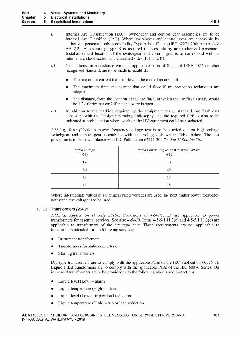
i) Internal Arc Classification (IAC). Switchgear and control gear assemblies are to beInternal Arc Classified (IAC). Where switchgear and control gear are accessible byauthorized personnel only accessibility Type A is sufficient (IEC 62271-200; Annex AA;AA 2.2). Accessibility Type B is required if accessible by non-authorized personnel.Installation and location of the switchgear and control gear is to correspond with itsinternal arc classification and classified sides (F, L and R).
ii) Calculations, in accordance with the applicable parts of Standard IEEE 1584 or otherrecognized standard, are to be made to establish:
● The maximum current that can flow in the case of an arc fault
● The maximum time and current that could flow if arc protection techniques areadopted.
● The distance, from the location of the arc flash, at which the arc flash energy wouldbe 1.2 calories per cm2 if the enclosure is open.
iii) In addition to the marking required by the equipment design standard, arc flash dataconsistent with the Design Operating Philosophy and the required PPE is also to beindicated at each location where work on the HV equipment could be conducted.
1.11.2(g) Tests (2014). A power frequency voltage test is to be carried out on high voltageswitchgear and control-gear assemblies with test voltages shown in Table below. The testprocedure is to be in accordance with IEC Publication 62271-200 Section 7/ Routine Test.
Rated Voltage(kV)
Rated Power Frequency Withstand Voltage(kV)
3.6 10
7.2 20
12 28
15 38
Where intermediate values of switchgear rated voltages are used, the next higher power frequencywithstand test voltage is to be used.
1.11.3 Transformers (2002)1.11.3(a) Application (1 July 2016).. Provisions of 4-5-5/1.11.3 are applicable to powertransformers for essential services. See also 4-5-4/9. Items 4-5-5/1.11.3(c) and 4-5-5/1.11.3(d) areapplicable to transformers of the dry type only. These requirements are not applicable totransformers intended for the following services:
● Instrument transformers.
● Transformers for static converters.
● Starting transformers.
Dry type transformers are to comply with the applicable Parts of the IEC Publication 60076-11.Liquid filled transformers are to comply with the applicable Parts of the IEC 60076 Series. Oilimmersed transformers are to be provided with the following alarms and protections:
● Liquid level (Low) – alarm
● Liquid temperature (High) – alarm
● Liquid level (Low) – trip or load reduction
● Liquid temperature (High) – trip or load reduction
Part 4 Vessel Systems and MachineryChapter 5 Electrical InstallationsSection 5 Specialized Installations 4-5-5
ABS RULES FOR BUILDING AND CLASSING STEEL VESSELS FOR SERVICE ON RIVERS ANDINTRACOASTAL WATERWAYS • 2019
363

● Gas pressure relay (High) – trip
1.11.3(b) Plans (2002). In addition to the details required in 4-5-4/9.1, the applicable standard ofconstruction and the rated withstanding voltage of the insulation are also to be submitted forreview.
1.11.3(c) Enclosure (2003). Transformers are to have a degree of protection in accordance with4-5-1/23.3 TABLE 2, but not less than IP23. However, when installed in spaces accessible tounqualified personnel, the degree of protection is to be increased to IP44. For transformers notcontained in enclosures, see 4-5-5/1.9.1.
1.11.3(d) Space heater. Effective means to prevent accumulation of moisture and condensationwithin the transformers (when de-energized) is to be provided.
1.11.3(e) Testing (2002). Three-phase transformers or three-phase bank transformers of 100 kVAand above are to be tested in the presence of the Surveyor. The test items are to be in accordancewith the standard applicable to the transformer. The tests are also to be carried out in the presenceof the Surveyor for each individual transformer. Transformers of less than 100 kVA will beaccepted subject to a satisfactory performance test conducted to the satisfaction of the Surveyorafter installation.
Specific requirements are applicable for the following tests:
i) In the dielectric strength test, the short duration power frequency withstand voltage to beapplied is to follow the standard applicable to the transformer but not less than theestimated voltage transient generated within the system. If the short duration powerfrequency withstand voltage is not specified in the applicable standard, IEC 60076-3 is tobe referred to. For the voltage transient, see 4-5-5/1.7.2(c).
ii) The induced over-voltage withstand test (layer test) is also to be carried out in accordancewith the standard applicable to the transformers in the presence of the Surveyor. This testis intended to verify the power-frequency withstand strength along the winding under testand between its phase (strength between turns and between layers in the windings). If theinduced over-voltage withstand test is not specified in the applicable standard, IEC60076-3 is to be referred to.
1.11.3(f) Nameplate (2002). In addition to the requirements in 4-5-4/13.7 TABLE 4, the followinginformation is also to be indicated on the nameplate:
● Applicable standard
● Short duration power frequency withstand voltage for verification of insulation level of eachwinding
1.11.4 Cables (2003)1.11.4(a) Standards. Cables are to be constructed to IEC Publication 60092-353, 60092-354 orother equivalent recognized standard. See also 4-5-4/13.1.
1.13 Design Operating Philosophy (2014)1.13.1 Objective
While this section covers the specific ABS requirements for High Voltage (HV) systems, it isrecognized that system design and equipment construction are only parts of an overall approachthat are required to allow HV systems to be operated safely. Other aspects that contribute towardsHV safety include maintenance procedures, vessel and equipment operating procedures, permit towork procedures, company safety policy, personal protective equipment (PPE) and training, mostof which are beyond the role of Classification. However, in order to assist ABS in its review of the
Part 4 Vessel Systems and MachineryChapter 5 Electrical InstallationsSection 5 Specialized Installations 4-5-5
ABS RULES FOR BUILDING AND CLASSING STEEL VESSELS FOR SERVICE ON RIVERS ANDINTRACOASTAL WATERWAYS • 2019
364

design and construction of the vessel and its equipment it is necessary for ABS to be assured thatthe design is part of a larger overall approach or plan.
The High Voltage Design Principles document is to outline the concepts that are the basis of thedesign. It should identify risks and document the strategies that are used to mitigate each of therisks (e.g., remote switching, arc flash energy reduction equipment).
1.13.2 HV System FailuresThe design should take into account each reasonably foreseeable failure type and address whatactions will be expected of the crew for each failure. Due to the limited availability of specialisttools, equipment and spare parts on board and recognizing the additional dangers associated withspace limitations, the remoteness of specialized medical help and facilities in the event ofemergencies, it is desirable that, as far as practicable, the crew is not exposed to dangers that couldbe avoided. For these reasons it is preferable that the vessel’s HV electrical system be designedsuch that the crew can safely isolate any damaged distribution equipment and switch to alternativesupplies without the need to open the HV equipment.
1.13.3 ActivitiesFor all HV switchboards and distribution boards, each type of operation or activity is to beidentified and the means of undertaking the operation or activity safely is to be established. Theoperations and activities to be considered are to include the following:
i) Taking readings
ii) Normal operational switching
iii) Isolation and making safe
iv) Maintenance
v) Fault finding
vi) Inspection
vii) Class Surveys
Where switchgear design calls for circuit breakers to be inspected prior to being put back intoservice following operation on overcurrent then this should also be covered.
1.13.4 Accessibility (1 July 2016)An adequate, unobstructed working space of at least 2 m (6 ft) is to be left in the vicinity of highvoltage equipment for preventing potential severe injuries to personal performing maintenanceactivities. Where the clear space around a location where activity is taking place is less than 2 m(6 ft), then the activities are to be covered in sufficient detail to take into account the workinvolved and the possible need to have clear and safe access for emergency medical evacuation.Where recommended by the switchgear manufacturer, the working space may be reduced to aminimum of 1.5 m (5 ft) due to special considerations such as the use of arc resistant switchgear.
Activities that do not require operation at the switchboard (e.g., telephones or manual call points)should not require the operator to be within 2 m (6 ft) of the switchboard.
1.13.5 ModificationsNo modifications are to be made to HV switchgear without the plans being approved and thedrawings being made available to the ABS Surveyor in advance of the work taking place. Testingof approved modifications is to be conducted in the presence of the ABS Surveyor. Temporaryrepairs are to be in full compliance with the requirements of these Rules.
Part 4 Vessel Systems and MachineryChapter 5 Electrical InstallationsSection 5 Specialized Installations 4-5-5
ABS RULES FOR BUILDING AND CLASSING STEEL VESSELS FOR SERVICE ON RIVERS ANDINTRACOASTAL WATERWAYS • 2019
365

1.13.6 HV Systems with Enhanced Operating RedundancyWhere the HV electrical system is designed with sufficient redundancy to allow switching andisolation along the principles in 4-5-5/1.13.2 and still meet the requirements of 4-5-2/3.3 with onegenerator in reserve, then the activity associated with that failure is not required to be included.
1.15 Preliminary Operations Manual (2014)1.15.1 Objective
The preliminary operations manual contains the shipyard’s description of operations affecting thevessel’s HV equipment. The description ‘preliminary’ is used to capture the fact that it may notthe final document used by the vessel’s Owner.
The manual is to be complete and sufficiently detailed to capture each piece of HV equipment andhow the activities associated with that equipment can be achieved consistently with the DesignOperating Philosophy. This manual is to be made available to the Owner by the shipyard.
The Owner will need the information contained in the preliminary operations manual tounderstand how the shipyard designed the HV equipment to be operated safely. It is likely that theOwner will modify some aspects of the manual to bring it in line with their own company policies,organizational responsibilities and legal duties.
The preliminary operations manual is to include for each piece of HV equipment:
i) Details of the tasks (operations and activities) associated with that piece of equipment
ii) Details of the ‘Authorization’ needed to perform each of the tasks
iii) Details of the tools required to perform each of the tasks
iv) Details of PPE and safety equipment (locks, barriers, tags, rescue hooks, etc.)
v) Identify the tasks for which a ‘permit to work’ system is to be used.
1.15.2 Details of AuthorizationFor each operation or task involving HV switchgear and for access to the HV switchgear rooms,the appropriate authorizations are to be determined before delivery.
1.15.3 Training Requirements for AuthorizationPart of the basis of establishing any level of authorization is training. It is not expected that theshipyard will stipulate what training qualifications are required; however, a description of thesubjects that would need to be covered in the training for each level of authorization should beincluded.
The Owner can be guided by the above information in making decisions regarding the crewtraining requirements.
1.15.4 Test, Maintenance Tools and PPEWhere tasks require the use of PPE, the required protection clothing rating should be identifiablein the preliminary operations manual and on a label on the HV equipment where that task will takeplace. The level of protection offered by the PPE is to be readily identified on the PPE itself in thesame terms or units as used on the labels.
Some PPE for general use is not suitable for High Voltage or arc flash hazards, mostly throughinappropriate fire performance; such PPE is to be excluded from high voltage switchgear rooms.Information alerting the crew of the need to be able to recognize and use the right PPE is to beincluded in the manual.
Part 4 Vessel Systems and MachineryChapter 5 Electrical InstallationsSection 5 Specialized Installations 4-5-5
ABS RULES FOR BUILDING AND CLASSING STEEL VESSELS FOR SERVICE ON RIVERS ANDINTRACOASTAL WATERWAYS • 2019
366

1.15.5 Inspection and Maintenance of Test Equipment Tools and PPEWhere PPE or test equipment is provided by the shipyard the means for its proper use, inspection,calibration and maintenance is to be made available. The instructions or directions regardingwhere they are kept are to be contained in the Preliminary Operations Manual.
Where the PPE is not provided by the shipyard a description or specification regarding therequired tools and PPE should be provided in the Preliminary Operations Manual.
3 Bridge Control of Propulsion Machinery
3.1 Control CapabilityUnder all sailing conditions, including maneuvering, the speed, direction of thrust and, if applicable, thepitch of the propeller are to be fully controllable from the navigation bridge. This control is to beperformed by a single control device for each independent propeller, with automatic performance of allassociated services, including, where necessary, means of preventing overload of the propulsionmachinery.
3.3 Emergency StoppingThe propulsion machinery is to be provided with an emergency stopping device on the navigation bridgeand independent from the bridge control system.
3.5 Order of Control Station CommandRemote control of the propulsion machinery is to be possible only from one station at a time; at one controlstation interconnected control units are permitted. There is to be at each station an indicator showing whichstation is in control of the propulsion machinery. The transfer of control between navigation bridge andmachinery spaces is to be possible only in the machinery space.
3.7 Local ControlIt is to be possible to control essential machinery and the propelling machinery locally in the case of failurein any part of the automatic or remote control systems.
3.9 Bridge Control IndicatorsIndicators for the following are to be fitted on the navigation bridge:
i) Propeller speed and direction where fixed pitch propellers are fitted.
ii) Propeller speed and pitch position where controllable pitch propellers are fitted.
iii) An alarm is to be provided to indicate low starting air pressure and is to be set at a level which stillpermits main engine starting operations.
iv) An alarm and warning light indicating high bilge water level in the main propulsion machineryspace.
v) An alarm and warning light indicating the presence of a fire in the main propulsion machineryspace.
5 Electric Propulsion System
5.1 General (2007)5.1.1 Application (2014)
The following requirements in this subsection are applicable to the electric propulsion system.Electric propulsion systems complying with other recognized standards will also be considered,provided it can be shown, through either satisfactory service experience or a systematic analysis
Part 4 Vessel Systems and MachineryChapter 5 Electrical InstallationsSection 5 Specialized Installations 4-5-5
ABS RULES FOR BUILDING AND CLASSING STEEL VESSELS FOR SERVICE ON RIVERS ANDINTRACOASTAL WATERWAYS • 2019
367

based on sound engineering principles, to meet the overall safety standards of these Rules. Unlessstated otherwise, electric propulsion equipment and systems are to comply with the applicablerequirements in other parts of Part 4, Chapter 5, as well.
5.1.2 Plans and Data to be SubmittedIn addition to the plans and data to be submitted in accordance with 4-5-2/1, 4-5-3/1 and 4-5-4/1,the following plans and data are to be submitted for review.
● One-line diagrams of the propulsion control system for power supply, circuit protection,alarm, monitoring, safety and emergency shutdown systems, including list of alarm andmonitoring points.
● Plans showing the location of the propulsion controls and its monitoring stations.
● Arrangements and details of the propulsion control console or panel, including schematicdiagram of the system therein.
● Arrangements and details of electric coupling.
● Arrangements and details of the semiconductor converters enclosure for the propulsionsystem, including data for the semiconductor converter and cooling system with itsinterlocking arrangement.
5.3 System Design (2007)5.3.1 General (2016)
For the purposes of the electric propulsion system requirements, an electric propulsion system isone in which the main propulsion of the vessel is provided by at least one electric motor. A vesselmay have more than one electrical propulsion system.
An integrated electric propulsion system is a system where a common set of generators supplypower to the vessel service loads as well as the propulsion loads.
In the case of an integrated electrical propulsion system the electrical drive train is considered toconsist of the equipment connected to the electrical network such as a drive (frequency converter)and the propulsion motor (s).
All electrical equipment that is part of the electric propulsion drive train is to be built withredundancy such that a single failure will not completely disable the propulsion of the vessel.Where electric motors are to provide the sole means of propulsion for a vessel, a single propulsionmotor with dual windings does not meet this requirement.
5.3.2 Generating CapacityFor vessels with an integrated electric propulsion system, under normal sea-going conditions,when one generator is out of service, the remaining generator capacity is to be sufficient to carryall of the vessel services (essential services, normal services and for minimum comfortableconditions of habitability) and an effective level of propulsion.
5.3.3 Power Management System (2014)For vessels with an integrated electric propulsion system, a power management system is to beprovided. The power management system is to control load sharing between generators, preventblackouts, maintain power to the essential service loads and maintain power to the propulsionloads.
The system is to account for the following operating scenarios.
● All generators in operation, then the loss of one generator
Part 4 Vessel Systems and MachineryChapter 5 Electrical InstallationsSection 5 Specialized Installations 4-5-5
ABS RULES FOR BUILDING AND CLASSING STEEL VESSELS FOR SERVICE ON RIVERS ANDINTRACOASTAL WATERWAYS • 2019
368

● When at least one generator is not in operation and there is an increase in the propulsion loadsor a loss of one of the generators, that would result in the need to start a generator that was notin operation.
● Upon failure of the power management system, there is to be no change in the availableelectrical power. Failure of the power management system is to be alarmed at a mannedcontrol station.
Further, the system is to prevent overloading the generators, by reducing the propulsion load orload shedding of non-essential loads. In general, the system is to limit power to the propulsionloads to maintain power to the vessel’s essential service loads. However, the system is to shednon-essential loads to maintain power to the propulsion loads.
An audible and visible alarm is to be installed at each propulsion control location and is to beactivated when the system is limiting the propulsion power in order to maintain power to the otheressential service loads.
When at least one generator is not in operation, consideration should be given to keeping onegenerator in standby mode, so that it can be brought on line within 45 seconds, upon failure of oneof the running generators.
Operation with only one generator on line should only be considered, when another generator canbe brought on line within 45 seconds of failure of the running generator.
5.3.4 Regenerative Power (2014)For systems where regenerative power may be developed, the regenerative power is not to causeover speeding of the prime mover or variations in the system voltage and frequency whichexceeds the limits of 4-5-1/9. See also 4-5-5/5.17.4(a) and 4-5-5/5.17.4(e).
5.3.5 Harmonics (2014)A harmonic distortion calculation is to be submitted for review for all vessels with electricpropulsion. The calculation is to indicate that the harmonic distortion levels at all locationsthroughout the power distribution system (main generation switchboard, downstream powerdistribution switchboards, etc.) are within the limits of 4-5-2/7.9. The harmonic distortion levels atdedicated propulsion buses are also to be within the limits of 4-5-2/7.9, otherwise documentationfrom the manufacturer is to be submitted indicating that the equipment is designed for operation ata higher level of distortion.
Where higher values of harmonic distortion are expected, any other possible effects, such asadditional heat losses in machines, network resonances, errors in control and monitoring systemsare to be considered.
Means of monitoring voltage harmonic distortion shall be provided, including alarms at the maingeneration switchboard and at continuously manned stations when to notify of an increase in totalor individual harmonic distortion levels above the maximum allowable levels.
Harmonic filters, if used, are to comply with requirements mentioned in 4-5-2/9.19.
5.5 Propulsion Power Supply Systems (2014)5.5.1 Propulsion Generators
5.5.1(a) Power Supply. The power for the propulsion equipment may be derived from a singlegenerator. If a ship service generator is also used for propulsion purposes other than for boostingthe propulsion power, such generator and power supply circuits to propulsion systems are also tocomply with the applicable requirements in this Subsection.
Part 4 Vessel Systems and MachineryChapter 5 Electrical InstallationsSection 5 Specialized Installations 4-5-5
ABS RULES FOR BUILDING AND CLASSING STEEL VESSELS FOR SERVICE ON RIVERS ANDINTRACOASTAL WATERWAYS • 2019
369

5.5.1(b) Single System. If a propulsion system contains only one generator and one motor andcannot be connected to another propulsion system, more than one exciter set is to be provided foreach machine. However, this is not necessary for self-excited generators or for multi-propellerpropulsion vessels where any additional exciter set may be common for the vessel.
5.5.1(c) Multiple Systems. Systems having two or more propulsion generators, two or moresemiconductor converters or two or more motors on one propeller shaft are to be so arranged thatany unit may be taken out of service and disconnected electrically without preventing theoperation of the remaining units.
5.5.1(d) Excitation Systems. Arrangements for electric propulsion generators are to be such thatpropulsion can be maintained in case of failure of an excitation system or failure of a powersupply for an excitation system. Propulsion may be at reduced power under such conditions wheretwo or more propulsion generators are installed, provided such reduced power is sufficient toprovide for a speed of not less than 7 knots or 1/2 of design speed, whichever is the lesser.
5.5.1(e) Features for Other Services. If the propulsion generator is used for other purposes thanfor propulsion, such as dredging, cargo oil pumps and other special services, overload protectionin the auxiliary circuit and means for making voltage adjustments are to be provided at the controlboard. When propulsion alternating-current generators are used for other services for operation inport, the port excitation control is to be provided with a device that is to operate just below normalidling speed of the generator to remove excitation automatically.
5.5.2 Propulsion Excitation5.5.2(a) Excitation Circuits. Every exciter set is to be supplied by a separate feeder. Excitationcircuits are not to be fitted with overload circuit-interrupting devices, except those intended tofunction in connection with the protection for the propulsion generator. In such cases, the fieldcircuit breaker is to be provided with a discharge resistor, unless a permanent discharge resistor isprovided.
5.5.2(b) Field Circuits. Field circuits are to be provided with means for suppressing voltage risewhen a field switch is opened. Where fuses are used for excitation circuit protection, it is essentialthat they do not interrupt the field discharge resistor circuit upon rupturing.
5.5.2(c) Ship’s Service Generator Connection. Where the excitation supply is obtained from theship’s service generators, the connection is to be made to the generator side of the generator circuitbreaker with the excitation supply passing through the overload current device of the breaker.
5.7 Circuit Protection (2016)5.7.1 Setting
Overcurrent protective devices, if any, in the main circuits are to be set sufficiently high so as notto operate on overcurrents caused by maneuvering or normal operation in heavy seas or in floatingbroken ice.
5.7.2 Direct-current (DC) Propulsion Circuits5.7.2(a) Circuit Protection. Direct-current propulsion circuits are not to have fuses. Each circuit isto be protected by overload relays to open the field circuits or by remote-controlled main-circuitinterrupting devices. Provision is to be made for closing circuit breakers promptly after opening.
5.7.2(b) Protection for Reversal of the Rotation. Where separately driven DC generators areconnected electrically in series, means shall be provided to prevent reversal of the rotation of agenerator upon failure of the driving power of its prime mover.
Part 4 Vessel Systems and MachineryChapter 5 Electrical InstallationsSection 5 Specialized Installations 4-5-5
ABS RULES FOR BUILDING AND CLASSING STEEL VESSELS FOR SERVICE ON RIVERS ANDINTRACOASTAL WATERWAYS • 2019
370

5.7.3 Excitation CircuitsAn overload protection is not to be provided for opening of the excitation circuit.
5.7.4 Reduction of Magnetic FluxesMeans are to be provided for selective tripping or rapid reduction of the magnetic fluxes of thegenerators and motors so that overcurrents do not reach values which may endanger the plant.
5.7.5 Direct-current (DC) Propulsion Motors Supplied by Semiconductor Converters (2008)The protection features of the semiconductor converters are to be arranged to avoid a damagingflashover in the DC propulsion motor. A possible cause of a damaging flashover would beremoval of the field current. The protection features of the semiconductor converters are to takeinto account the increase in armature current created by the removal of the field current, due toaccidental loss of the field, or activation of a protection feature intended to protect the field.
To verify compliance with the above, the maximum time-current characteristics that can becommutated by the motor as well as the time-current characteristics of the protective features ofthe semiconductor converters are to be submitted for review. To avoid a damaging flashover, themaximum time-current characteristics of the motor is to be provided by the motor manufacturerand is to be used by the semiconductor converter manufacturer to determine the appropriate setpoints for the protection features of the semiconductor converters.
5.9 Protection for Earth Leakage5.9.1 Main Propulsion Circuits
Means for earth leakage detection are to be provided for the main propulsion circuit and bearranged to operate an alarm upon the occurrence of an earth fault. When the fault current flowingis liable to cause damage, arrangements for opening the main propulsion circuit are also to beprovided.
5.9.2 Excitation CircuitsMeans are to be provided for earth leakage detection in excitation circuits of propulsion machinesbut may be omitted in circuits of brushless excitation systems and of machines rated up to 500kW.
5.9.3 Alternating current (AC) SystemsAlternating current propulsion circuits are to be provided with an earthing detector alarm orindicator. If the neutral is earthed for this purpose, it is to be through an arrangement which willlimit the current at full-rated voltage so that it will not exceed approximately 20 amperes upon afault to earth in the propulsion system. An unbalance relay is to be provided which is to open thegenerator and motor-field circuits upon the occurrence of an appreciable unbalanced fault.
5.9.4 Direct-current (DC) SystemsThe earthing detector may consist of a voltmeter or lights. Provision is to be made for protectionagainst severe overloads, excessive currents and electrical faults likely to result in damage to theplant. Protective equipment is to be capable of being so set as not to operate on the overloads orovercurrents experienced in a heavy seaway or when maneuvering.
5.11 Electric Propulsion Control5.11.1 General
Failure of a control signal is not to cause an excessive increase in propeller speed. The referencevalue transmitters in the control stations and the control equipment are to be so designed that anydefect in the desired value transmitters or in the cables between the control station and thepropulsion system will not cause a substantial increase in the propeller speed.
Part 4 Vessel Systems and MachineryChapter 5 Electrical InstallationsSection 5 Specialized Installations 4-5-5
ABS RULES FOR BUILDING AND CLASSING STEEL VESSELS FOR SERVICE ON RIVERS ANDINTRACOASTAL WATERWAYS • 2019
371

5.11.2 Testing and InspectionControls for electric propulsion equipment are to be inspected when finished and dielectricstrength tests and insulation resistance measurements made on the various circuits in the presenceof the Surveyor, preferably at the plant of manufacture. The satisfactory tripping and operation ofall relays, contactors and the various safety devices are also to be demonstrated.
5.11.3 Initiation of ControlThe control of the propulsion system can be activated only when the delegated control lever is inzero position and the system is ready for operation.
5.11.4 Emergency StopEach control station shall have an emergency stop device which is independent of the controllever.
5.11.5 Prime Mover ControlWhere required by the system of control, means are to be provided at the control assembly forcontrolling the prime mover speed and for mechanically tripping the throttle valve.
5.11.6 Control Power FailureIf failure of the power supply occurs in systems with power-aided control (e.g., with electric,pneumatic or hydraulic aid), it is to be possible to restore control in a short time.
5.11.7 ProtectionArrangements are to be made so that opening of the control system assemblies or compartmentswill not cause inadvertent or automatic loss of propulsion. Where steam and oil gauges aremounted on the main-control assembly, provision is to be made so that the steam or oil will notcome in contact with the energized parts in case of leakage.
5.11.8 InterlocksAll levers for operating contactors, line switches, field switches and similar devices are to beinterlocked to prevent their improper operation. Interlocks are to be provided with the field leverto prevent the opening of any main circuit without first reducing the field excitation to zero,except that when the generators simultaneously supply power to an auxiliary load apart from thepropulsion, the field excitation need only be reduced to a low value.
5.13 Instrumentation at the Control Station5.13.1 Indication, Display and Alarms
The necessary instruments to indicate existing conditions at all times are to be provided andmounted on the control panel convenient to the operating levers and switches. Instruments andother devices mounted on the switchboard are to be labeled and the instruments provided with adistinguishing mark to indicate full-load conditions. Metallic cases of all permanently installedinstruments are to be permanently earthed. The following instruments, where applicable, are to beprovided.
5.13.1(a) For AC Systems (1997). Ammeter, voltmeter, indicating wattmeter and field ammeter (*)for each propulsion generator and for each synchronous motor.
5.13.1(b) For DC Systems. An ammeter for each main circuit and one or more voltmeters withselector switches for reading voltage on each propulsion generator and motor.
5.13.1(c) For Electric Slip Couplings. An ammeter for the coupling excitation circuit.
* Field ammeter is not required for brushless generators
Part 4 Vessel Systems and MachineryChapter 5 Electrical InstallationsSection 5 Specialized Installations 4-5-5
ABS RULES FOR BUILDING AND CLASSING STEEL VESSELS FOR SERVICE ON RIVERS ANDINTRACOASTAL WATERWAYS • 2019
372

5.13.2 Indication of Propulsion System StatusThe control stations of the propulsion systems are to have at least the following indications foreach propeller.
5.13.2(a) "Ready for Operation". Power circuits and necessary auxiliaries are in operation.
5.13.2(b) "Faulty". Propeller is not controllable.
5.13.2(c) "Power Limitation". In case of disturbance, for example, in the ventilators for propulsionmotors, in the converters, cooling water supply or load limitation of the generators.
5.15 Equipment Installation and Arrangement (2014)5.15.1 General
The arrangement of bus bars and wiring on the back of propulsion-control assemblies is to be suchthat all parts, including the connections, are accessible. All nuts and connections are to be fittedwith locking devices to prevent loosening due to vibration. Clearance and creepage distance are tobe provided between parts of opposite polarity and between live parts and earth to prevent arcing.See 4-5-1/21, 4-5-4/7.11.6 and 4-5-5/1.11.2(b).
5.15.2 Accessibility and Facilities for Repairs5.15.2(a) Accessibility. For purposes of inspection and repair, provision is to be made for access tothe stator and rotor coils, and for the withdrawal and replacement of field coils. Adequate access isto be provided to permit resurfacing of commutators and slip-rings, as well as the renewal andbedding of brushes.
5.15.2(b) Facility for Supporting. Facilities shall be provided for supporting the shaft to permitinspection and withdrawal of bearings.
5.15.2(c) Slip-couplings. Slip-couplings are to be designed to permit removal as a unit withoutaxial displacement of the driving and driven shaft, and without removing the poles.
5.15.3 Propulsion CablesPropulsion cables are not to have splices or joints, except terminal joints, and all cable terminalsare to be sealed against the admission of moisture or air. Similar precautions are to be taken duringinstallation by sealing all cable ends until the terminals are permanently attached. Cable supportsare to be designed to withstand short-circuited conditions. They are to be spaced less than 915 mm(36 in.) apart and are to be arranged to prevent chafing of the cable. See 4-5-3/5.9.1.
5.17 Machinery and Equipment (2014)5.17.1 Material Tests
The following materials intended for main propulsion installation are to be tested in accordancewith the ABS Rules for Materials and Welding (Part 2): thrust shafts, line shafts, propeller shafts,shafting for propulsion generators and motors, coupling bolts, and in the case of direct-connectedturbine-driven propulsion generators, fan shrouds, centering and retaining rings. Major castings orbuilt-up parts such as frames, spiders and end shields are to be surface inspected and the weldingis to be in accordance with the ABS Rules for Materials and Welding (Part 2).
5.17.2 Temperature RatingWhen generators, motors or slip-couplings for electric propulsion are fitted with an integral fanand will be operated at speeds below the rated speed with full-load torque, full-load current orfull-load excitation temperature rise limits according to 4-5-4/13.7 TABLE 3 are not to beexceeded.
Part 4 Vessel Systems and MachineryChapter 5 Electrical InstallationsSection 5 Specialized Installations 4-5-5
ABS RULES FOR BUILDING AND CLASSING STEEL VESSELS FOR SERVICE ON RIVERS ANDINTRACOASTAL WATERWAYS • 2019
373

5.17.3 Protection Against Moisture Condensation4-5-4/3.13.7 is applicable for rotating machines and converters, regardless of the weight of themachines.
5.17.4 Prime Movers5.17.4(a) Capability. The prime mover rated output is to have adequate overloading and build-upcapacity for supplying the power which is necessary during transitional changes in operatingconditions of the electrical equipment. When maneuvering from full propeller speed ahead to fullpropeller speed astern with the vessel making full way ahead, the prime mover is be capable ofabsorbing a proportion of the regenerated power without tripping due to overspeed.
5.17.4(b) Speed Control. Prime movers of any type are to be provided with a governor capable ofmaintaining the preset steady speed within a range not exceeding 5% of the rated full-load speedfor load changes from full-load to no-load.
5.17.4(c) Manual Controls. Where the speed control of the propeller requires speed variation ofthe prime mover, the governor is to be provided with means for local manual control, as well asfor remote control. For turbines driving AC propulsion generators, where required by the systemof control, the governor is to be provided with means for local hand control, as well as remoteadjustment from the control station.
5.17.4(d) Parallel Operation. In case of parallel operation of generators, the governing system isto permit stable operation to be maintained over the entire operational speed range of the primemovers.
5.17.4(e) Protection for Regenerated Power. Braking resistors or ballast consumers are to beprovided to absorb excess amounts of regenerated energy and to reduce the speed of rotation ofthe propulsion motor. These braking resistors or ballast consumers are to be located external to themechanical and electric rotating machines. Alternatively, the amount of regenerated power may belimited by the action of the control system.
5.17.5 Rotating Machines for PropulsionThe following requirements are applicable to propulsion generators and propulsion motors.
5.17.5(a) Ventilation and Protection. Electric rotating machines for propulsion are to be enclosedventilated or be provided with substantial wire or mesh screen to prevent personnel injury orentrance of foreign matter. Dampers are to be provided in ventilating air ducts, except when re-circulating systems are used.
5.17.5(b) Fire-extinguishing Systems. Electric rotating machines for propulsion which areenclosed or in which the air gap is not directly exposed are to be fitted with fire-extinguishingsystems suitable for fires in electrical equipment. This will not be required where it can beestablished that the machinery and insulation is self-extinguishing.
5.17.5(c) Air Coolers (2004). Air cooling systems for propulsion generators are to be inaccordance with 4-6-5/7.5 and 4-6-5/7.7.1 of the Marine Vessel Rules. Water-air heat exchangersof rotating propulsion machines for single systems (single generator and single motor), asspecified in 4-5-5/5.5.1(b) of these Rules, are to have double wall tubes and be fitted with a leakdetector feature to monitor for any water leakage. A visual and audible alarm is to be provided at anormally manned location to indicate such water leakage.
5.17.5(d) Temperature Sensors (1997). Stator windings of AC machines and interpole windings ofDC machines rated above 500 kW are to be provided with temperature sensors. See 4-9-6/23TABLE 4A of the Marine Vessel Rules .
Part 4 Vessel Systems and MachineryChapter 5 Electrical InstallationsSection 5 Specialized Installations 4-5-5
ABS RULES FOR BUILDING AND CLASSING STEEL VESSELS FOR SERVICE ON RIVERS ANDINTRACOASTAL WATERWAYS • 2019
374

5.17.5(e) Generator Excitation (2014). Excitation current for propulsion generators may bederived from attached rotating exciters, static exciters, excitation motor-generator sets or specialpurpose generating units. Power for these exciters may be derived from the machine being excitedor from any ship service, emergency or special purpose generating units.
5.17.5(f) Propulsion Motors (2014). Propulsion motors are to be designed to be capable ofwithstanding the mechanical and thermal effects of a short-circuit at its terminals.
5.17.6 Direct-current (DC) Propulsion Motors5.17.6(a) Rotors. The rotors of DC propulsion motors are to be capable of withstandingoverspeeding up to the limit reached in accordance with the characteristics of the overspeedprotection device at its normal operational setting.
5.17.6(b) Overspeed Protection. An overspeed protection device is to be provided to preventexcessive overspeeding of the propulsion motors due to light loads, loss of propeller, etc.
5.17.7 Electric Couplings5.17.7(a) General. Couplings are to be enclosed ventilated or be provided with wire or meshscreen to prevent personnel injury or the entrance of foreign material. All windings are to bespecially treated to resist moisture, oil and salt air.
5.17.7(b) Accessibility for Repairs. The coupling is to be designed to permit removal as a unitwithout moving the engine. See also 4-5-5/5.15.2.
5.17.7(c) Temperature Rating. The limits of temperature rise are to be the same as for alternating-current generators given in 4-5-4/13.7 TABLE 3, except that when a squirrel-cage element is used,the temperature of this element may reach such values as are not injurious. Depending upon thecooling arrangements, the maximum temperature rise may occur at other than full-load rating sothat heat runs will require special consideration. For this purpose, when an integral fan is fitted,the coupling temperatures are not to exceed the limits in 4-5-4/13.7 TABLE 3 when operatedcontinuously at 70% of full-load rpm, full excitation and rated torque. Temperature rises forinsulation materials above 180°C (356°F) will be considered in accordance with 4-5-1/15.11.
5.17.7(d) Excitation. Excitation is to be provided as required for propulsion generators. See4-5-4/3.21.1, 4-5-4/3.23.1 and 4-5-5/5.17.5(e).
5.17.7(e) Control Equipment. Electric-coupling control equipment is to be combined with theprime mover speed and reversing control and is to include a two-pole disconnect switch, short-circuit protection only, ammeter for reading coupling current, discharge resistor and interlockingto prevent energizing the coupling when the prime mover control levers are in an inappropriateposition.
5.17.7(f) Nameplates. Nameplates of corrosion-resistant material are to be provided in anaccessible position of the electric coupling and are to contain the following typical details:
● Manufacturer's name, serial number and frame designation
● Rated output and type of rating
● Ambient temperature range
● Rated voltage, speed and temperature rise
● Rated exciter voltage and current
5.17.8 Semiconductor Converters for Propulsion (2014)Semi-conductor converters are to comply with the requirements in 4-5-4/10.
Part 4 Vessel Systems and MachineryChapter 5 Electrical InstallationsSection 5 Specialized Installations 4-5-5
ABS RULES FOR BUILDING AND CLASSING STEEL VESSELS FOR SERVICE ON RIVERS ANDINTRACOASTAL WATERWAYS • 2019
375

5.17.9 Reactors and Transformers for Semiconductor Converters5.17.9(a) General. Interphase reactors and transformers used with semiconductor converters are toconform with the requirements of 4-5-4/9.1.1, 4-5-4/9.1.2(c), 4-5-4/9.3, 4-5-4/9.5.1 and4-5-4/9.5.2, and the following.
5.17.9(b) Voltage Regulation. Means to regulate transformer output voltage are to be provided totake care of increase in converter forward resistance and, in addition, to obtain the necessaryperformance characteristics of the converter unit in which the transformer is used.
5.17.9(c) High Temperature Alarm. Interphase reactors and transformers used with thesemiconductor converters for main and auxiliary propulsion systems are to be provided with hightemperature alarm at the switchboard or the propulsion control station. The setting value of thealarm is to be determined by their specific insulation class and is not to exceed the temperaturecorresponding to the limit listed in 4-5-4/13.7 TABLE 3.
5.17.10 Switches5.17.10(a) General Design. All switches are to be arranged for manual operation and so designedthat they will not open under ordinary shock or vibration. Contactors, however, may be operatedpneumatically, by solenoids or other means in addition to the manual method which is to beprovided, unless otherwise approved.
5.17.10(b) Generator and Motor Switches. Switches for generators and motors are preferably to beof the air-break type, but for alternating-current systems, where they are to be designed to openfull-load current at full voltage, oil-break switches using nonflammable liquid may be used ifprovided with leak-proof, non-spilling tanks.
5.17.10(c) Field Switches. Where necessary, field switches are to be arranged for dischargeresistors unless discharge resistors are permanently connected across the field. For alternating-current systems, means are to be provided for de-energizing the excitation circuits by theunbalance relay and ground relay.
5.17.11 Propulsion Cables5.17.11(a) Conductors. The conductors of cables external to the components of the propulsionplant, other than cables and interconnecting wiring for computers, data loggers or otherautomation equipment requiring currents of very small value, are to consist of not less than sevenstrands and have a cross-sectional area of not less than 1.5 mm² (2,960 circ. mils).
5.17.11(b) Insulation Materials. Ethylene-propylene rubber, cross-linked polyethylene or siliconerubber insulated cables are to be used for propulsion power cables, except that polyvinyl chlorideinsulated cables may be used where the normal ambient temperature will not exceed 50°C(122°F).
5.17.11(c) Braided Metallic Armor and Impervious Metallic Sheaths (1998). Propulsion cablesneed not have braided metallic armor nor impervious metallic sheaths. Where metallic sheaths areprovided, they are not to be used with single alternating current cables.
5.17.11(d) Inner Wiring. The insulation of internal wiring in main control gear, includingswitchboard wiring, shall be of flame-retardant quality.
5.17.11(e) Testing. All propulsion cables, other than internal wiring in control gears andswitchboards, are to be subjected to dielectric and insulation tests in the presence of the Surveyor.
5.19 Dock and Sea Trials (2014)Complete tests of the entire electric propulsion system are to be carried out during sea-trials including thefollowing:
i) Duration runs with the ship at full propulsion load.
Part 4 Vessel Systems and MachineryChapter 5 Electrical InstallationsSection 5 Specialized Installations 4-5-5
ABS RULES FOR BUILDING AND CLASSING STEEL VESSELS FOR SERVICE ON RIVERS ANDINTRACOASTAL WATERWAYS • 2019
376

ii) Maneuvering tests which should include a reversal of the vessel from full speed ahead to fullspeed astern during which important measurements such as system currents, voltages, speed, etc.shall be recorded.
iii) Tests to check for operation of all protective devices, safety functions, alarms, indicators, controlmodes and stability tests for control.
All tests necessary to demonstrate that major components of the electric propulsion plant and the system asa whole are satisfactory for duty are to be performed. Immediately prior to trials, the insulation resistanceis to be measured and recorded.
7 Three-wire Dual-voltage DC System
7.1 Three-wire DC Ship’s GeneratorsSeparate circuit-breaker poles are to be provided for the positive, negative, neutral and also for theequalizer leads, unless protection is provided by the main poles. When equalizer poles are provided for thethree-wire generators, the overload trips are to be of the algebraic type. No overload trip is to be providedfor the neutral pole, but it is to operate simultaneously with the main poles. A neutral overcurrent relay andalarm system is to be provided and set to function at a current value equal to the neutral rating.
7.3 Neutral Earthing7.3.1 Main Switchboard
The neutral of three-wire dual-voltage direct-current systems is to be solidly earthed at thegenerator switchboard with a zero-center ammeter in the earthing connection. The zero-centerammeter is to have a full-scale reading of 150% of the neutral-current rating of the largestgenerator and be marked to indicate the polarity of earth. The earth connection is to be made insuch a manner that it will not prevent checking the insulation resistance of the generator to earthbefore the generator is connected to the bus. The neutrals of three-wire DC emergency powersystems are to be earthed at all times when they are supplied from the emergency generator orstorage battery. The earthed neutral conductor of a three-wire feeder is to be provided with ameans for disconnecting and is to be arranged so that the earthed conductor cannot be openedwithout simultaneously opening the unearthed conductors.
7.3.2 Emergency SwitchboardNo direct earth connection is to be provided at the emergency switchboard. The neutral bus orbuses are to be solidly and permanently connected to the neutral bus of the main switchboard. Nointerrupting device is to be provided in the neutral conductor of the bus-tie feeder connecting thetwo switchboards.
7.5 Size of Neutral ConductorThe capacity of the neutral conductor of a dual-voltage feeder is to be 100% of the capacity of theunearthed conductors.
9 Energy Storage Systems (2019)
9.1 Lithium Batteries (2019)For vessels installed with lithium batteries, see the requirements in the ABS Guide for Use of LithiumBatteries in the Marine and Offshore Industries.
9.3 Supercapacitors (2019)For vessels installed with supercapacitors, see the requirements in the ABS Guide for Use ofSupercapacitors in the Marine and Offshore Industries.
Part 4 Vessel Systems and MachineryChapter 5 Electrical InstallationsSection 5 Specialized Installations 4-5-5
ABS RULES FOR BUILDING AND CLASSING STEEL VESSELS FOR SERVICE ON RIVERS ANDINTRACOASTAL WATERWAYS • 2019
377

TABLE 1High Voltage Equipment Locations and Minimum Degree of Protection (2014)
Exampleof
Location
Conditionof
Location
Switchboards, Distribution Boards, MotorControl Centers and Controllers
Generators
Motors
Transformers,Converters
Junction/ConnectionBoxes
Dry control roomsAuthorized Personnel Only
Danger of touching live partsonly
IP32 N/A N/A IP23 IP44
Dry control rooms IP42 N/A N/A IP44 IP44
Control roomsAuthorized Personnel Only
Danger of dripping liquidand/or moderate mechanicaldamage
IP32 N/A N/A IP23 IP44
Control rooms IP42 N/A N/A IP44 IP44
Above floor plates in machinery spacesAuthorized Personnel Only (1)
IP32 IP23 IP23 IP23 IP44
Above floor plates in machinery spaces (1) IP42 IP23 IP43 IP44 IP44
Emergency machinery roomsAuthorized Personnel Only
IP32 IP23 IP23 IP23 IP44
Emergency machinery rooms IP42 IP23 IP43 IP44 IP44
Below floor plates in machinery spacesAuthorized Personnel Only
Increased danger of liquidand/or mechanical damage
N/A N/A * * IP44
Below floor plates in machinery spaces N/A N/A * N/A IP44
Ballast pump roomsAuthorized Personnel Only
Increased danger of liquid andmechanical damage
IP44 N/A IP44 IP44 IP44
Ballast pump rooms IP44 N/A IP44 IP44 IP44
Holds for general cargo Danger of liquid spray presenceof cargo dust, seriousmechanical damage, and/oraggressive fumes
* * * * IP55
Open decks (2) Not exposed to seas N/A IP56 IP56 IP56 IP56
Open decks (2) Exposed to seas N/A N/A * * *
"*" indicates that equipment in excess of 1000V is not normally permitted in these locations
Notes:
1 See 4-5-3/3.1.1 where the equipment is located within areas affected by local fixed pressure water-spraying orwater-mist fire extinguishing systems.
Part 4 Vessel Systems and MachineryChapter 5 Electrical InstallationsSection 5 Specialized Installations 4-5-5
ABS RULES FOR BUILDING AND CLASSING STEEL VESSELS FOR SERVICE ON RIVERS ANDINTRACOASTAL WATERWAYS • 2019
378

2 For High Voltage Shore Connections (HVSC) see the requirements in the ABS Guide for High Voltage ShoreConnection.
3 Where the IP rating of the high voltage electrical equipment has been selected on the basis that it is onlyaccessible to authorized personnel, the entrance doors to the spaces in which such equipment is located, are tobe marked accordingly.
Part 4 Vessel Systems and MachineryChapter 5 Electrical InstallationsSection 5 Specialized Installations 4-5-5
ABS RULES FOR BUILDING AND CLASSING STEEL VESSELS FOR SERVICE ON RIVERS ANDINTRACOASTAL WATERWAYS • 2019
379
P A R T
4C H A P T E R 5 Electrical Installations
S E C T I O N 6 Specialized Vessels and Services
1 Oil Carriers
1.1 ApplicationIn addition to the foregoing requirements of this Section, the following requirements are applicable tovessels carrying oil having a flash point not exceeding 60°C (140°F).
Note:
The electric installation on bulk oil vessels carrying oil having a flash point above 60°C (140°F), closed-cup test, will besubject to special consideration in each case.
1.3 Earthed Distribution SystemsAn earthed distribution system is not to be used, except for the following applications.
i) Earthed intrinsically-safe circuits.
ii) Power supplied, control circuits and instrumentation circuits where technical or safety reasonspreclude the use of a system without an earthing connection, provided the current in the hull islimited to 5 amperes or less in both normal and fault conditions.
iii) Limited and locally earthed systems, provided that any possible resulting current does not flowdirectly through any hazardous areas.
iv) Alternating-current power networks of 1 kV root mean square (rms) (line to line) and over,provided that any possible resulting current does not flow directly through any hazardous areas.
1.5 Hazardous Areas1.5.1 Self-Propelled Vessels
For self-propelled vessels, the hazardous areas include:
i) Cargo tanks and cargo piping
ii) Cofferdams, and permanent (for example, segregated) ballast tanks adjacent to cargotanks
iii) Cargo pump rooms
iv) Compartments for cargo hoses
v) Enclosed or semi-enclosed spaces immediately above cargo pump rooms or havingbulkheads above and in line with cargo bulkheads
vi) Enclosed or semi-enclosed spaces, immediately above cargo pump rooms, or abovevertical cofferdams adjacent to cargo tanks, unless separated by a gas-tight deck andsuitably mechanically ventilated
vii) Spaces, other than cofferdams, adjacent to and below the top of a cargo tank (for example,trunks, passageways and holds)
ABS RULES FOR BUILDING AND CLASSING STEEL VESSELS FOR SERVICE ON RIVERS ANDINTRACOASTAL WATERWAYS • 2019
380

viii) Areas on open decks, or semi-enclosed spaces on open decks, within 3 m of any cargotank outlets, gas or vapor outlet, cargo manifold valve, cargo valve, cargo pipe flange,cargo pump room entrances or cargo pump room ventilation openings
Note:
Such areas are, for example, all areas within 3 m of cargo tank hatches, sight ports, tank cleaningopening, valve openings, sounding pipes, cargo vapor outlets, cofferdam of cargo tanks.
ix) Areas on open deck within spillage coamingsurrounding cargo manifold valves and 3 mbeyond these and other coamings intended to keep spillages clear of accommodation andservice spaces, up to a height of 2.4 m above the deck
x) Areas on open deck over all cargo tanks (including all ballast tanks within cargo tankarea) and to the full breadth of the vessel plus 3 m fore and aft on open deck, up to aheight of 2.4 m above the deck which do not belong to the hazardous areas defined in4-5-6/1.5.1.viii) and 4-5-6/1.5.1.ix)
xi) Enclosed or semi-enclosed spaces, having an opening into any hazardous area
1.5.2 BargesFor barges, the hazardous areas include:
i) Areas described in 4-5-6/1.5.1i) through 4-5-6/1.5.1viii)
ii) Areas on open deck within spillage coaming surrounding cargo manifold valves and 3 mbeyond these and other coamings intended to keep spillages clear of accommodation andservice spaces
1.7 Installation of Equipment and Cables1.7.1 General
Electrical equipment and wiring are not to be installed in any hazardous areas unless essential foroperation purposes. In such cases, the installation of equipment and wiring are to comply with4-5-6/9.15.3 TABLE 1.
1.7.2 CablesAll cables installed within the hazardous areas described in 4-5-6/1.5 are to be sheathed with anonmetallic external impervious sheath over a metallic braiding or a metallic armoring or to be ofmineral-insulated copper- or stainless steel-sheathed type. A nonmetallic impervious sheath is tobe applied over the metallic braiding, armoring or sheathing of all cables which may be subject tocorrosion. Cables installed on open deck or on fore-and-aft gangways are to be protected againstmechanical damage. Cable and protective supports are to be so installed as to avoid strain orchafing and due allowance made for expansion or working of the structure.
1.7.3 Sea Depth Sounder, Speed Log, and Impressed Current Cathodic Protection Systems (2005)Hull fittings containing transducers for electrical depth sounding or speed log devices orcontaining terminals or shell penetrations for anodes or electrodes of an impressed currentcathodic protection system for underwater hull protection are not to be installed in any cargo tanksof an oil carrier. However, it may be installed in hazardous areas, as permitted by 4-5-6/9.15.3TABLE 1, provided the following are complied with:
1.7.3(a) Hull fittings containing terminals or shell-plating penetrations are to be housed within agas-tight enclosure and are not to be located adjacent to cargo tank bulkhead;
1.7.3(b) The box containing actual electrical connection of the cable, such as terminal box orjunction box, is to be filled with insulating material, such as silicon grease, silicon sealing orequivalent and also to be of gastight construction;
Part 4 Vessel Systems and MachineryChapter 5 Electrical InstallationsSection 6 Specialized Vessels and Services 4-5-6
ABS RULES FOR BUILDING AND CLASSING STEEL VESSELS FOR SERVICE ON RIVERS ANDINTRACOASTAL WATERWAYS • 2019
381

1.7.3(c) All associated cables passing through these spaces are to be installed in extra-heavy steelpipe with gas-tight joints (no flanged joints), and with corrosion resistant coating up to, andincluding the underside of the main deck;
1.7.3(d) Cable gland with gastight packing is to be provided for the cable at both ends of the cableconduit pipe; and
1.7.3(e) Cable inside the vertical cable conduit pipe is to be suitably supported, e.g., by sand-filling, or by strapping to a support-wire. Alternatively, the cable inside the vertical conduit pipemay be accepted without provided support if the mechanical strength of the cable is sufficient toprevent cable damage due to the cable weight within the conduit pipe under continuousmechanical load. Supporting documentation is to be submitted to verify the mechanical strength ofthe cable with respect to the cable weight inside the conduit.
1.9 Cargo Oil Pump Room1.9.1 Ventilation
1.9.1(a) System and Arrangement. Cargo oil pump rooms are to have a mechanical extractionventilating system and ducting, in accordance with 4-5-6/1.9.1(a).i, 4-5-6/1.9.1(a).ii,4-5-6/1.9.1(a).iii, and 4-5-6/1.9.1(a).iv below.
i) Lower Intake. Lower (main) intakes are to be located at the lowest floor level. Thenumber of air changes through the main intake with the damper in item ii) closed is to beat least twenty changes per hour based on the gross volume of the pump room.
ii) Emergency Intake. An emergency intake is to be provided at approximately 2 m (6.5 ft)above the lowest floor with damper capable of being opened or closed from the exposedmain deck and lowest floor level so that it can be used when the lower intakes are notavailable. The air changes in that condition is to be at least fifteen changes per hour.
iii) Dampers. Where the ratio of areas of the upper emergency intake and lower main intakesis such that the required number of respective air changes in items i) and ii) above can beobtained, the dampers may not be required.
iv) Floor Plate. Floors are to be open grating type to allow the free flow of air.
1.9.1(b) Fan Motors and Fans. Fan motors are to be located outside of the pump room and outsideof the ventilation ducts. Fans are to be of non-sparking construction in accordance with 4-5-3/11.7.Provision is to be made for immediate shutdown of the fan motors upon release of the fireextinguishing medium.
1.9.2 Gas Detection (1999)A system for continuously monitoring the concentration of hydrocarbon gases in the pump room isto be fitted. A system utilizing sequential sampling is acceptable, provided the system is dedicatedsolely to the pump room, thereby minimizing the sampling cycle. Sampling points or detectorheads are to be located in the exhaust ventilation duct and lower parts of the pump room at thefloor level. The system is to give a visual indication of the level of concentration of hydrocarbongases and an audible alarm if the concentration exceeds 10% of the lower explosive limit. Suchalarm is to be provided in the cargo control room and on the navigation bridge.
1.9.3 Lighting (2002)1.9.3(a) Lighting fitted outside the pump room. As far as practicable, the lighting fixtures for pumproom spaces are to be permanently wired and fitted outside of the pump room, except as notedbelow. Pump rooms adjacent to engine rooms or similar safe spaces may be lighted throughsubstantial glass lenses or ports permanently fitted in the bulkhead or deck.
The construction of the glass lens port is to be as follows:
Part 4 Vessel Systems and MachineryChapter 5 Electrical InstallationsSection 6 Specialized Vessels and Services 4-5-6
ABS RULES FOR BUILDING AND CLASSING STEEL VESSELS FOR SERVICE ON RIVERS ANDINTRACOASTAL WATERWAYS • 2019
382

● Capable of maintaining watertight and gastight integrity of the bulkhead and deck.
● Suitably protected from mechanical damage.
● Provided with a steel cover capable of being closed and secured on the side of the safe space.
● Both the glass lens and its sealing arrangement will not be impaired by working of the hull.
● Structural strength of the pierced bulkhead or deck is suitably reinforced.
See also 5C-1-1/5.11 and 5C-2-1/5.9 of the Marine Vessel Rules.
1.9.3(b) Lighting fitted inside the pump room. As an alternative to 4-5-6/1.9.3(a), certified safelighting fixtures (see 4-5-6/9.15.3 TABLE 1) may be installed in the pump room, provided theyare wired with moisture-resisting jacketed (impervious-sheathed) and armored or mineral-insulated metal-sheathed cable. Lighting circuits are to be so arranged that the failure of any onebranch circuit will not leave these spaces in darkness. All switches and protective devices are to belocated outside of the pump room. See also 4-5-3/11.1.2 for lighting circuits in hazardous areas.
1.9.4 Cable InstallationWhere it is necessary for cables, other than those of intrinsically-safe circuits and those cablessupplying lighting fixtures in the pump room, to pass through cargo pump rooms, they are to beinstalled in extra-heavy steel pipes or other arrangements providing the same degree of gastightness and protection.
3 Vessels Carrying Coal in Bulk
3.1 ApplicationIn addition to the foregoing requirements in this Section, the following requirements are applicable tovessels intended to carry coal in bulk by which an explosive and flammable atmosphere may occur.
3.3 Hazardous AreasSpace in which combustible and explosive dust/gas and air mixture is likely to occur in normal operationare to be identified as hazardous areas, such as cargo hold spaces, spaces with a direct opening to cargohold spaces, or areas within 3 m (10 ft) of cargo hold ventilation outlets.
3.5 Installation of Equipment3.5.1 Classified Electrical Equipment in Hazardous Area
Machinery, all electrical power, control and safety devices and wiring installed in locations wherean explosive and flammable atmosphere (as may occur in spaces for coal) is expected to exist areto have a temperature classification T4 or higher (maximum surface temperature 132°C (275°F) orlower) and are to be suitable for operation in at least a Group IIA environmental classification, asdefined in IEC Publication 60079-12.
3.5.2 Internal Combustion Engines in Hazardous AreaWhere essential for operational purposes, the installation of internal combustion engines inhazardous areas will be subject to special consideration. In all instances, exhaust outlets are to beoutside of all hazardous areas, excluding that produced by the exhaust outlet itself, and air intakesare to be not less than 3 m (10 ft) from hazardous areas.
3.5.3 Cargo Hold (1999)3.5.3(a) Instruments for Measuring (1999). Readings are to be obtainable without entry into thecargo hold and without endangering the cargo and cargo hold’s atmosphere. Instruments formeasuring the following are to be provided: *
i) Concentration of methane in the atmosphere,
Part 4 Vessel Systems and MachineryChapter 5 Electrical InstallationsSection 6 Specialized Vessels and Services 4-5-6
ABS RULES FOR BUILDING AND CLASSING STEEL VESSELS FOR SERVICE ON RIVERS ANDINTRACOASTAL WATERWAYS • 2019
383

ii) Concentration of oxygen in the atmosphere,
iii) Concentration of carbon monoxide in the atmosphere,
iv) pH value of cargo hold bilge samples.
Note:
In addition to the instruments specified in 4-5-6/3.5.3(a), it is recommended that consideration should be given bythe Owner/designers to provide the means for measuring the temperature of the cargo in the range of 0°C (32°F) to100°C (212°F), where it is intended to carry self-heating coal. Such arrangements should permit the temperature ofthe coal to be measured during the loading operations and during the voyage without requiring entry into the cargospace.
3.5.3(b) Cargo Atmosphere Measuring Equipment (1999). An instrument for measuring methane,oxygen and carbon monoxide concentrations is to be provided, together with an aspirator, flexibleconnection, a length of tubing and means for sealing the sampling hole in order to enable arepresentative sample to be obtained from within the hatch cover surroundings. Alternative meansfor obtaining a representative sample will be considered.
3.5.3(c) Sampling Points (1999). Sampling points are to be provided for each hold, one on the portside and another on the starboard side of the hatch cover, as near to the top of the hatch cover aspossible. Each sampling point is to be fitted with a screw cap and a threaded stub of approximately12 mm (0.5 in.) bore, welded to the side of the hatch cover to prevent ingress of water and air.Alternative sampling point arrangements/details will be considered.
3.5.3(d) Warning Plate (1999). Permanent warning plates are to be installed in conspicuous placesin cargo areas to state that smoking, naked flames, burning, cutting, chipping, welding or othersources of ignition are prohibited.
5 Cargo Vessels Carrying Motor Vehicles with Fuel in Their Tank
5.1 ApplicationIn addition to the foregoing requirements in this Section, the following requirements are applicable to thecargo spaces carrying motor vehicles with fuel in their tanks.
5.3 Ventilation System5.3.1 Arrangement
The ventilating system for enclosed spaces intended for the carriage of motor vehicles with fuel intheir tanks for their own propulsion is to be independent from other ventilation systems and is tobe capable of being controlled from a position outside of the space.
5.3.2 CapacityAn effective power ventilation system, sufficient to give at least six air changes per hour based onthe volume of empty enclosed spaces in which vehicles are to be transported or stored, is to beprovided. See also 4-5-6/5.5.2.
5.3.3 FansExhaust fans are to be of non-sparking construction in accordance with 4-5-3/11.7.
5.3.4 Material and Arrangement of DuctsVentilation ducts, including dampers, are to be of steel. Ducts serving spaces capable of beingsealed are to be separated for such space.
Part 4 Vessel Systems and MachineryChapter 5 Electrical InstallationsSection 6 Specialized Vessels and Services 4-5-6
ABS RULES FOR BUILDING AND CLASSING STEEL VESSELS FOR SERVICE ON RIVERS ANDINTRACOASTAL WATERWAYS • 2019
384

5.3.5 Exhaust Inlet and OutletInlet for exhaust ducts are to be located within 450 mm (17.75 in.) above the vehicle deck. Theoutlet is to be sited in a safe position, having regard to the source of ignition near the outlet.
5.3.6 Emergency ShutdownArrangements are to be provided to permit a rapid shutdown and effective closure of theventilation system in case of fire, taking into account the weather and sea conditions. See also4-5-6/5.3.1.
5.3.7 Navigation Bridge IndicationMeans are to be provided on the navigation bridges or other appropriate locations to indicate anyloss of the ventilating capacity.
5.5 Location and Type of Equipment (2010)5.5.1 Certified Safe Type Equipment
Closed ro-ro cargo spaces carrying motor vehicles with fuel in their tank for their own propulsionare to be regarded as hazardous. Electrical equipment and wiring, except where permittedotherwise in 4-5-6/5.5.2 below, are to be of the types certified safe and suitable for use inflammable petrol and air mixture. Specifically, certified safe equipment for use in Zone 1 areas inaccordance with IEC Publication 60079 Part 14 (Gas Group IIA and Temperature Class T3) isrequired.
5.5.2 Alternative ArrangementsExcept for a distance within 450 mm (17.75 in.) above a platform that does not have openings ofsufficient size permitting penetration of petroleum gases downward, electrical equipment of a typeso enclosed and protected as to prevent the escape of sparks may be permitted as an alternative.Specifically, an enclosure of at least IP55 or apparatus suitable for use in Zone 2 areas inaccordance with IEC Publication 60079 Part 14 is required.
In such cases, the ventilating system is to be so designed and operated as to provide continuousventilation of the cargo spaces at the rate of at least ten air changes per hour whenever vehicles areonboard.
5.5.3 Equipment in Ducts from Vehicle SpaceElectrical equipment and wiring installed within an exhaust duct are to be increased-safety,explosion-proof or intrinsically-safe type.
7 Vessels Carrying Hazardous Chemicals in BulkVessels intended for the carriage of hazardous chemicals in bulk are to comply with the requirements inPart 151 of Subchapter 0 of Chapter I Title 46 Code of Federal Regulations or other recognized standard.See also 3-2-3/3.
9 Passenger VesselsIn addition to the foregoing requirements in this Section, passenger vessels having a gross tonnage over100 tons are to comply with the requirements in this Subsection.
9.1 Emergency Source of Power9.1.1 General
A self-contained emergency source of electrical power is to be provided.
9.1.1(a) Location (2018). The emergency source of electrical power, associated powertransformer, if any, transitional source of emergency power, emergency switchboard, emergency
Part 4 Vessel Systems and MachineryChapter 5 Electrical InstallationsSection 6 Specialized Vessels and Services 4-5-6
ABS RULES FOR BUILDING AND CLASSING STEEL VESSELS FOR SERVICE ON RIVERS ANDINTRACOASTAL WATERWAYS • 2019
385

lighting switchboard, and the fuel oil tank for emergency generator prime mover are to be locatedabove the uppermost continuous deck, outside the machinery casing, and are to be readilyaccessible from the open deck. They are not to be located forward of the collision bulkhead.
The emergency electrical power space is to contain only machinery and equipment supporting thenormal operation of the emergency power source.
9.1.1(b) Separation
i) Machinery Space of Category A. The location of the emergency source of electricalpower, associated power transformer, if any, the transitional source of emergency power,the emergency switchboard and the emergency lighting switchboard in relation to themain source of electrical power, associated transforming equipment, if any, and the mainswitchboard is to be such that a fire or other casualty in the space containing the mainsource of electrical power, power transformer, if any, and the main switchboard, or in anymachinery space of Category A will not interfere with the supply, control and distributionof emergency electrical power. As far as practicable, the space containing the emergencysource of electrical power, associated transforming equipment, if any, the transitionalsource of emergency electrical power and the emergency switchboard, including trunks tosuch spaces, are not to be contiguous to the boundaries of machinery spaces of category Aor those spaces containing the main source of electrical power, associated transformingequipment, if any, and the main switchboard.
ii) Machinery Space Other Than Category A. Spaces containing emergency sources ofpower are to be separated from machinery spaces other than Category A machineryspaces, by a boundary insulated to a level of not less than A-15 for bulkheads and decksand A-0 for the overhead from any such space (including trunks to such spaces). Wherethe emergency source of power is a generator, the above is not intended to preclude thelocation of the emergency generator in the same space as its prime mover, regardless ofsize.
iii) Alternative Arrangement. Where it can be shown that the arrangements of the spacescontaining the emergency source of power in relation to machinery space of Category Aare in compliance with the requirements of the governmental authority of the countrywhose flag the vessel flies, either of the following may be considered in lieu of4-5-6/9.1.1(b).i:
● Contiguous boundaries insulated to A-60 with the insulation extending at least 450mm (18 in.) beyond the boundary of the space containing the emergency source ofpower.
● Separation by a cofferdam having dimensions as required for ready access andextending at least 150 mm (6 in.) beyond the boundaries of the space containing theemergency source of power. Except for cables feeding services located in themachinery space of Category A or those spaces containing main source of electricalpower, associated transformer or converter, if any, and main switchboard, emergencyelectric cables are not to be installed in such cofferdams unless the cofferdam isinsulated to A-60.
9.1.2 Emergency Services9.1.2(a) General. The electrical power available is to be sufficient to supply all those services thatare essential for safety in an emergency, due regard being paid to such services as may have to beoperated simultaneously and for equipment which can be shown as not being required in actualservice to draw their rated loads, In the latter case, supporting details are to be submitted. Theemergency source of electrical power is to be capable, having regard to starting currents and thetransitory nature of certain loads, of supplying simultaneously at least the following services for
Part 4 Vessel Systems and MachineryChapter 5 Electrical InstallationsSection 6 Specialized Vessels and Services 4-5-6
ABS RULES FOR BUILDING AND CLASSING STEEL VESSELS FOR SERVICE ON RIVERS ANDINTRACOASTAL WATERWAYS • 2019
386

the period specified in 4-5-6/9.1.2(b) through 4-5-6/9.1.2(g), if they depend upon an electricalsource for their operation.
9.1.2(b) Lighting Systems and Navigation Light for a period of 3 hours:
i) At muster and embarkation stations for the survival craft
ii) At the survival craft, their launching appliances and the area of water into which they areto be launched.
iii) In all service and accommodation alleyways, stairways and exits, personnel elevators andshafts;
iv) In the machinery spaces and main generating stations, including their control positions;
v) In all control stations, machinery control rooms, and at each main and emergencyswitchboard;
vi) At all stowage positions for firemen’s outfits;
vii) At the steering gear
viii) At the fire pump referred to in 4-5-6/9.1.2(d), at the sprinkler pump, if any, at theemergency bilge pump, if any, and at the starting positions of their motors; and
ix) Navigation lights and other lights required by the governmental authority.
9.1.2(c) Communication System, Navigation Aid, and Alarm Systems for a period of 3 hours:
i) All internal communication equipment as required in an emergency.
ii) Navigational aids.
iii) Required fire detection and fire alarm systems.
iv) Intermittent operation of the daylight signaling lamp, the ship’s whistle, manuallyoperated call points, and other internal signals that are required in an emergency; unlesssuch services have an independent supply for the period of 3 hours from an accumulatorbattery suitably located for use in an emergency,
9.1.2(d) Emergency Fire Pump. For a period of 3 hours, one of the fire pumps which may berequired by 4-4-1/9.1.2 if dependent upon the emergency generatorfor its source of power.
9.1.2(e) Steering Gear. Steering gear to comply with 4-5-6/9.3 if powered from emergency source,for a period of 10 minutes of continuous operation.
9.1.2(f) Watertight Doors. For a period of half an hour, any watertight doors required by Section3-3-1 to be power-operated together with their indicators and warning signals.
9.1.2(g) Elevators. For a period of half an hour, the emergency arrangements to bring the elevatorsto deck level for the escape of persons. The passenger elevators may be brought to deck levelsequentially in an emergency.
9.1.3 Power Supply9.1.3(a) General. The emergency source of electrical power may be either a generator or anaccumulator battery in accordance with 4-5-6/9.1.3(b) or 4-5-6/9.1.3(c) below:
9.1.3(b) Generator (2014). Where the emergency source of electrical power is a generator, it is tobe:
i) Driven by a prime mover with an independent supply of fuel, having a flashpoint (closedcup test) of not less than 43°C (110°F), and
Part 4 Vessel Systems and MachineryChapter 5 Electrical InstallationsSection 6 Specialized Vessels and Services 4-5-6
ABS RULES FOR BUILDING AND CLASSING STEEL VESSELS FOR SERVICE ON RIVERS ANDINTRACOASTAL WATERWAYS • 2019
387

ii) Started automatically upon failure of the main source of electrical power supply andconnected automatically to the emergency switchboard, then those services referred to in4-5-6/9.1.4 are to be connected automatically to the emergency generator as quickly as issafe and practicable subject to a maximum of 45 seconds, or provided with a transitionalsource of emergency electrical power as specified in 4-5-6/9.1.4 unless an emergencygenerator is provided capable both of supplying the services referred to in 4-5-6/9.1.4 ofbeing automatically started and supplying the required load as quickly as is safe andpracticable subject to a maximum of 45 seconds, and
iii) An adequate fuel capacity for the emergency generator prime mover is to be provided.
Where it is intended to use fuel with a flash point of less than 60°C (140°F) then details of theprecautions used to address the associated hazardous area issues are to be submitted to ABS forreview, (see also 4-6-5/3.1.2 of the Marine Vessels Rules).
9.1.3(c) Accumulator Battery. Where the emergency source of electrical power is an accumulatorbattery, it is to be capable of:
i) Carrying the emergency electrical load without recharging while maintaining the voltageof the battery throughout the discharge period within 12% above or below its nominalvoltage;
ii) Automatically connecting to the emergency switchboard in the event of failure of themain source of electrical power; and
iii) Immediately supplying at least those services specified in 4-5-6/9.1.4.
9.1.3(d) Emergency Generator for Non-emergency Services (2008). Provided that suitablemeasures are taken for safeguarding independent emergency operation under all circumstances,the emergency generator may be used, exceptionally, and for short periods, to supply nonemergency circuits during blackout situation, dead ship condition and routine use for testing. Thegenerator is to be safeguarded against overload by automatically shedding such non-emergencyservices so that supply to the required emergency loads is always available. See also4-5-6/9.1.5(e).
9.1.4 Transitional Source of PowerThe transitional source of emergency electrical power where required by 4-5-6/9.1.3(b).ii is toconsist of an accumulator battery which is to operate without recharging while maintaining thevoltage of the battery throughout the discharge period within 12% above or below its nominalvoltage and be of sufficient capacity and be so arranged as to automatically supply in the event offailure of either the main or the emergency source of electrical power for half an hour at least thefollowing services if they depend upon an electrical source for their operation:
i) The lighting required by 4-5-6/9.1.2(b). For this transitional phase, the requiredemergency electric lighting, in respect of the machinery space and accommodation andservice spaces may be provided by permanently fixed, individual, automatically charged,relay operated accumulator lamps; and
ii) All services required by 4-5-6/9.1.2(c).i, 4-5-6/9.1.2(c).iii and 4-5-6/9.1.2(c).iv unlesssuch services have an independent supply for the period specified from an accumulatorbattery suitably located for use in an emergency.
9.1.5 Emergency Switchboard9.1.5(a) General. The emergency switchboard is to be installed as near as is practicable to theemergency source of electrical power.
Part 4 Vessel Systems and MachineryChapter 5 Electrical InstallationsSection 6 Specialized Vessels and Services 4-5-6
ABS RULES FOR BUILDING AND CLASSING STEEL VESSELS FOR SERVICE ON RIVERS ANDINTRACOASTAL WATERWAYS • 2019
388

9.1.5(b) Emergency Switchboard for Generator. Where the emergency source of electrical poweris a generator, the emergency switchboard is to be located in the same space unless the operationof the emergency switchboard would thereby be impaired.
9.1.5(c) Accumulator Battery. No accumulator battery fitted in accordance with 4-5-6/9.1.3(c) or4-5-6/9.1.4 is to be installed in the same space as the emergency switchboard. An indicator is to bemounted on the main switchboard or in the machinery control room to indicate when thesebatteries are being discharged.
9.1.5(d) Interconnector Feeder Between Emergency and Main Switchboards (2014). Theemergency switchboard is to be supplied during normal operation from the main switchboard byan interconnector feeder which is to be protected at the main switchboard against overload andshort circuit. The interconnector feeder is to be disconnected automatically at the emergencyswitchboard upon failure of the main source of electrical power. Where the system is arranged forfeedback operation, the interconnector feeder is also to be protected at the emergency switchboardagainst short circuit. In addition, the circuit protection device at the emergency switchboard on theinterconnector feeder is to trip to prevent overloading of the emergency generator.
In designs where the main switchboard voltage is different from that of the emergencyswitchboard the power to the emergency switchboard is to be supplied from the main ship serviceswitchboard.
As far as practicable, the circuit coordination is to be arranged such that the outgoing circuits fromthe main ship service switchboard will coordinate with the transformer circuit breakers to preventthe supply to the emergency switchboard from being unavailable due to a fault on one of the otheroutgoing circuits from the main ship service switchboard.
Note:
For the purpose of this Rule, the main ship service switchboard is a switchboard which is connected to thesecondary of step-down transformer producing the required voltage.
9.1.5(e) Disconnection of Non-emergency Circuits. For ready availability of the emergency sourceof electrical power, arrangements are to be made where necessary to automatically disconnectnon-emergency circuits from the emergency switchboard so that electrical power is to be availableautomatically to the emergency circuits.
9.1.6 Arrangements for Periodic TestingProvision is to be made to enable the periodic testing of the complete emergency system and is toinclude the testing of automatic starting arrangements.
9.1.7 Starting Arrangements for Emergency Generator Sets9.1.7(a) Cold Conditions. Emergency generating sets are to be capable of being readily started intheir cold condition at a temperature of 0°C (32°F). If this is impracticable, or if lowertemperatures are likely to be encountered, heating arrangements are to be provided for readystarting of the generating sets.
9.1.7(b) Number of Starts. Each emergency generator that is arranged to be automatically startedis to be equipped with approved starting devices with a stored energy capability of at least threeconsecutive starts. Unless a second independent means of starting is provided, the source of storedenergy is to be protected to preclude critical depletion by automatic starting system (i.e., theautomatic starting system is only allowable for consumption of the stored energy source to a levelthat would still provide the capability for starting the emergency generator upon intervention by apersonnel). In addition, a second source of energy is to be provided for an additional three startswithin 30 minutes unless manual starting can be demonstrated to be effective to the Surveyor.
Part 4 Vessel Systems and MachineryChapter 5 Electrical InstallationsSection 6 Specialized Vessels and Services 4-5-6
ABS RULES FOR BUILDING AND CLASSING STEEL VESSELS FOR SERVICE ON RIVERS ANDINTRACOASTAL WATERWAYS • 2019
389

9.1.7(c) Charging of Stored Energy. The stored energy is to be maintained at all times, as follows:
i) Electrical and hydraulic starting systems are to be maintained from the emergencyswitchboard;
ii) Compressed air starting systems may be maintained by the main or auxiliary compressedair receivers through a suitable non-return valve or by an emergency air compressorwhich, if electrically driven, is supplied from the emergency switchboard;
iii) All of these starting, charging and energy storing devices are to be located in theemergency generator space; these devices are not to be used for any purpose other thanthe operation of the emergency generating set. This does not preclude the supply to the airreceiver of the emergency generating set from the main or auxiliary compressed airsystem through the non-return valve fitted in the emergency generator space.
9.1.7(d) Manual Starting. Where automatic starting is not required, manual (hand) starting ispermissible, such as manual cranking, inertia starters, manually charged hydraulic accumulators,or power charge cartridges, where they can be demonstrated as being effective to the Surveyor.
When manual (hand) starting is not practicable, the requirements of 4-5-6/9.1.7(b) and4-5-6/9.1.7(c) are to be complied with except that starting may be manually initiated.
9.3 Emergency Power Supply for Steering GearWhere the rudder stock is required by 3-2-4/23.5.1 to be over 230 mm (9 in) diameter using Ks = 1 . 0 inway of the tiller, excluding strengthening for navigation in ice, an alternative power supply, sufficient atleast to supply the steering gear power unit and also its associated control system and rudder angleindicator, is to be provided automatically, within 45 seconds, either from the emergency source of electricalpower or from an independent source of power located in the steering gear compartment. The steering gearpower unit under alternative power supply is to be capable of moving the rudder from 15 degrees on oneside to 15 degrees on the other side in not more than 60 seconds with the vessel at the summer draft whilerunning at one half the maximum speed ahead or 7 knots, whichever is the greater. The capacity is to besufficient for at least 10 minutes of continuous operation.
9.5 Power Supply Through Transformers and ConvertersEach required transformer is to be located as a separate unit with separate enclosure or equivalent, and is tobe served by separate circuits on the primary and secondary sides. Each of the secondary circuits is to beprovided with a multipole isolating switch. A circuit breaker provided in the secondary circuit inaccordance with 4-5-2/9.15.1 will be acceptable in lieu of multipole isolating switch.
9.7 Interior Communication Systems9.7.1 Main Propulsion Control Stations
A common talking means of voice communication and calling is to be provided between the localpropulsion control station and local control positions for main propulsion engines and controllablepitch propellers. Voice communication systems are to provide the capability of carrying on aconversation while the vessel is being navigated. Final subcircuits for power supply to these are tobe independent of the other electrical system and the control, monitoring and alarm systems.Communication network and power supply circuit for the voice communication system may becombined with the system required in 4-5-6/9.7.2.
9.7.2 Voice Communications9.7.2(a) Propulsion and Steering Control Stations. A common talking means of voicecommunication and calling is to be provided between the navigation bridge, local propulsioncontrol station, and the steering gear compartment so that the simultaneous talking among these
Part 4 Vessel Systems and MachineryChapter 5 Electrical InstallationsSection 6 Specialized Vessels and Services 4-5-6
ABS RULES FOR BUILDING AND CLASSING STEEL VESSELS FOR SERVICE ON RIVERS ANDINTRACOASTAL WATERWAYS • 2019
390

spaces is possible at all times and the calling to these spaces is always possible even if the line isbusy.
9.7.2(b) Elevator. Where an elevator is installed, a telephone is to be permanently installed in allcars and connected to a continuously manned area. The telephone may be sound powered, batteryoperated or electrically powered from the emergency source of power,
9.7.2(c) Independence of Power Supply Circuit. Final subcircuit for power supply to these voicecommunication systems is to be independent of other electrical systems and control, monitoring,and alarm systems. See 4-5-6/9.1.2(c) for power supply.
9.9 Manually Operated Alarms9.9.1 General Emergency Alarm System (2009)
9.9.1(a) The general emergency alarm system is to be capable of sounding the general emergencyalarm signal consisting of seven or more short blasts followed by one long blast on the vessel’swhistle or siren and additionally on an electrically operated bell or klaxon or other equivalentwarning system, which is to be powered from the vessel’s main supply and the emergency sourceof electrical power required by 4-5-6/9.1, as appropriate. The system is to be capable of operationfrom the navigation bridge and, except for the vessel’s whistle, also from other strategic points.
9.9.1(b) There are to be not less than two sources of power supply for the electrical equipmentused in the operation of the General Emergency Alarm System, one of which is to be from theemergency switchboard and the other from the main switchboard. The supply is to be provided byseparate feeders reserved solely for that purpose. Such feeders are to run to an automatic change-over switch situated in, or adjacent to, the main general emergency alarm control panel.
9.9.1(c) An alarm is to be provided to indicate when there is a loss of power in any one of thefeeders required by 4-5-6/9.9.1(b).
9.9.1(d) As an alternative to two feeders as described in 4-5-6/9.9.1(b), a battery may beconsidered as one of the required sources, provided the battery has the capacity of at least 30minutes of continuous operation for alarming and 18 hours in standby. A low voltage alarm for thebattery and the battery charger output is to be provided. The battery charger is to be supplied fromthe emergency switchboard.
9.9.1(e) The system is to be audible throughout all the accommodation and normal crew workingspaces and open decks. The alarm is to continue to function after it has been triggered until it ismanually turned off or is temporarily interrupted by a message on the public address system.
9.9.2 Engineers’AlarmAn engineers’alarm operable from the main propulsion control station is to be provided. It is to beaudible in the engineers’accommodation. See 4-5-6/9.1.2(c) for power supply.
9.9.3 ElevatorA device which will activate an audible and visual alarm in a manned control center is to beprovided in all cars. Such alarm system is to be independent of power and control systems of theelevator. See 4-5-6/9.1.2(c) for power supply.
9.11 Services Required to be Operable Under a Fire Condition (2008)For the purpose of 4-5-6/9.15, services required to be operable under a fire condition include, but notlimited thereto, are the following:
i) Fire and general alarm system
ii) Fire extinguishing system including fire extinguishing medium release alarms
Part 4 Vessel Systems and MachineryChapter 5 Electrical InstallationsSection 6 Specialized Vessels and Services 4-5-6
ABS RULES FOR BUILDING AND CLASSING STEEL VESSELS FOR SERVICE ON RIVERS ANDINTRACOASTAL WATERWAYS • 2019
391

iii) Emergency Fire Pump
iv) Fire detection system
v) Control and power systems for all power operated fire doors and their status indicating systems
vi) Control and power systems for all power operated watertight doors and their status indicatingsystems
vii) Emergency lighting
viii) Public address system
ix) Remote emergency stop/shutdown arrangement for systems which may support the propagation offire and/or explosion
x) Low Location Lighting
9.13 High Fire Risk Areas (1 July 2016)For the purpose of 4-5-6/9.15, the examples of the high fire risk areas are the following:
i) Machinery spaces as defined by 3-4-1/3.13 and 3-4-1/3.15,except spaces having little or no firerisk such as machinery spaces which do not contain machinery having a pressure lubricationsystem and where storage of combustibles is prohibited (e.g., ventilation and air-conditioningrooms, windlass room, steering gear room, stabilizer equipment room, electrical propulsion motorroom, rooms containing section switchboards and purely electrical equipment other than oil-filledelectrical transformers (above 10 kVA), shaft alleys and pipe tunnels, and spaces for pumps andrefrigeration machinery not handling or using flammable liquids).
ii) Spaces containing fuel treatment equipment and other highly flammable substances
iii) Galley and pantries containing cooking appliances
iv) Laundry containing drying equipment
v) For vessels carrying more than 36 passengers, the spaces defined by paragraph (8), (12), and (14)of 5C-7-4/5.5.2 of the Marine Vessel Rules.
9.15 Emergency and Essential Feeders (2013)9.15.1 Location
As far as practicable, cables and wiring for emergency and essential services, including thoselisted in 4-5-6/9.11, are not to pass through high fire risk areas (see 4-5-6/9.13). For EmergencyFire Pumps, see requirements in 4-5-6/9.15.3.
These cables and wiring are also to be run in such a manner as to preclude their being renderedunserviceable by heating of the bulkheads that may be caused by a fire in an adjacent space.
9.15.2 Services Necessary Under a Fire ConditionWhere cables for services required to be operable under a fire condition (see 4-5-6/9.11) includingtheir power supplies pass through high fire risk areas (see 4-5-6/9.13) or main vertical fire zones(see 3-4-1/5), other than those which they serve, they are to be so arranged that a fire in any ofthese areas or zones does not affect the operation of the service in any other area or zone. ForEmergency Fire Pumps, see requirements in 4-5-6/9.15.3. This may be achieved by any of thefollowing measures:
9.15.2(a) Fire resistant cables in accordance with 4-5-4/3.13.3 are installed and run continuous tokeep the fire integrity within the high fire risk area. See 4-5-6/9.15.3 FIGURE 1.
Part 4 Vessel Systems and MachineryChapter 5 Electrical InstallationsSection 6 Specialized Vessels and Services 4-5-6
ABS RULES FOR BUILDING AND CLASSING STEEL VESSELS FOR SERVICE ON RIVERS ANDINTRACOASTAL WATERWAYS • 2019
392

9.15.2(b) At least two loops/radial distributions run as widely apart as is practicable and soarranged that in the event of damage by fire at least one of the loops/radial distributions remainsoperational.
Systems that are self monitoring, fail safe or duplicated with cable runs separated as widely aspracticable, may be exempted from the requirements in 4-5-6/9.15.2(a) and 4-5-6/9.15.2(b).
9.15.3 Electrical Cables For The Emergency Fire PumpThe electrical cables to the emergency fire pump are not to pass through the machinery spacescontaining the main fire pumps and their sources of power and prime movers. They are to be of afire resistant type, in accordance with 4-5-4/13.1.3, where they pass through other high fire riskareas.
FIGURE 1Cables within High Fire Risk Areas (2008)
TABLE 1Electrical Equipment in Hazardous Areas for Oil Carriers [See
4-5-6/1.7.1]
Hazardous Area Acceptable Electrical Equipment
Cargo tanks and cargo piping as defined by4-5-6/1.5.1.i and 4-5-6/1.5.2.i.
a1 Category “ia”intrinsically-safe apparatus and itsassociated wiring only.
Cofferdams and permanent (for example,segregated) ballast tanks adjacent to cargo tanks,as defined by 4-5-6/1.5.1.ii and 4-5-6/1.5.2.i).
b1 Category “ia”intrinsically-safe apparatus and itsassociated wiring.
b2 Hull fittings containing transducers for electricaldepth sounding or log devices or containing theterminals. See 4-5-6/1.7.3.
b3 Shell penetrations for anodes or electrodes of animpressed current cathodic protection system forunderwater hull protection. See 4-5-6/1.7.3.
Part 4 Vessel Systems and MachineryChapter 5 Electrical InstallationsSection 6 Specialized Vessels and Services 4-5-6
ABS RULES FOR BUILDING AND CLASSING STEEL VESSELS FOR SERVICE ON RIVERS ANDINTRACOASTAL WATERWAYS • 2019
393

Cargo pump rooms, as defined by 4-5-6/1.5.1.iiiand 4-5-6/1.5.2.i.
c1 Intrinsically-safe apparatus.
c2 Electrical devices as described in items b2 and b3above this Table.
c3 Explosion-proof lighting fixtures. See4-5-3/11.1.2 and 4-5-6/1.9.3.
c4 Explosion-proof type audible and/or visualdevices for communication, general alarm andfire extinguishing medium release alarm.
c5 Through-run of cables in extra-heavy pipe. See4-5-6/1.9.4.
Compartments for cargo hoses, as defined by4-5-6/1.5.1.iv) and 4-5-6/1.5.2.i).Enclosed orsemi-enclosed spaces, as defined by4-5-6/1.5.1.v), 4-5-6/1.5.1.vi) and 4-5-6/1.5.2.i).
d1 Intrinsically-safe apparatus.
d2 Explosion-proof type lighting fixtures. See4-5-3/11.1.2.
d3 Through-runs of cable.
Spaces adjacent to and below the top of cargotank, except for cofferdams, as defined by4-5-6/1.5.1.vii) and 4-5-6/1.5.2.i).
e1 Intrinsically-safe apparatus.
e2 Electrical devices as described in items b2 and b3of this Table.
e3 Explosion-proof type lighting fixtures. See4-5-3/11.1.2
e4 Explosion-proof type audible and/or visualdevices for communication, general alarm andfire extinguishing medium release alarm.
e5 Through-run of cable; excepting those forintrinsically-safe circuits, such cables requirespecial consideration.
Areas on open deck or semi-enclosed spaces onopen deck, as defined by 4-5-6/1.5.1.viii) and4-5-6/1.5.2.i).Areas on open deck as defined by4-5-6/1.5.1.ix) and 4-5-6/1.5.2.ii)
f1 Explosion-proof, intrinsically-safe, increasedsafety or pressurized type equipment suitable foruse on open deck.
f2 Through-runs of cables without expansion bendsin these areas.
Areas on open deck over all cargo tanks,including all ballast tanks within cargo tank area,as defined by 4-5-6/1.5.1.x).
g1 Explosion-proof, intrinsically safe, increasedsafety or pressurized type equipment suitable foruse on open deck.
g2 Through-runs of cables.
Enclosed or semi-enclosed spaces having anopening into any hazardous area, as defined by4-5-6/1.5.1.xi).
h1 Explosion-proof or intrinsically-safe typeequipment.
Part 4 Vessel Systems and MachineryChapter 5 Electrical InstallationsSection 6 Specialized Vessels and Services 4-5-6
ABS RULES FOR BUILDING AND CLASSING STEEL VESSELS FOR SERVICE ON RIVERS ANDINTRACOASTAL WATERWAYS • 2019
394