step 2: build the model · pdf filestep 2: build the model to build the model, you will first...
TRANSCRIPT

Step 2: Build the Model To build the model, you will first resize the room to its proper size. You will then create the featuresof the room, including a person, a lab workstation, and the various components of the airflow system. Tosave time, some objects will be created as copies of previous objects.
1. Resize the default room.
Model Room
(a)In the room Edit panel, enter the following coordinates:
xS 0
yS 0
zS 0
xE 4.8
yE 3.6
zE 3.6
(b)Click Modify to resize the room.
(c)Click on Orient in the Options menu and select Isometric from the Orient drop-down list todisplay an isometric view of the room.
2. Create the top of the lab table.
Model Blocks
(a)Click New in the block Edit panel.
Airpak will create a new hollow prism block in the center of the room. You will need tochange both the size of the block and its location within the room.
(b)Click Edit to modify the default block in the Blocks panel.
(c)Enter the following coordinates for the top of the table:
Step 2: Build the Model http://www.ualberta.ca/dept/chemeng/package/FluentCDs/airpak-doc/a...
1 از 13 ق.ظ 07:54 2010/01/22 ٔصفحه

xS 0 xE 1.0
yS 0.95 yE 1.0
zS 1.29 zE 2.31
(d)Enter the name tabletop in the Name field.
(e)Click Update to modify the block.
3. Create the first leg for the table.
(a)Click New in the Blocks panel.
(b)Enter the following coordinates for the table leg:
xS 0 xE 0.08
yS 0 yE 0.95
zS 2.23 zE 2.31
(c)Enter the name table-leg in the Name field.
(d)Click Done to update the block and close the Blocks panel.
4. Copy the first leg of the table ( table-leg) to create the second leg ( table-leg.1).
(a)In the block Edit panel, select table-leg in the Blocks list.
(b)Click Copy.
Airpak will open the Copy block table-leg panel.
(c)Turn on the Translate option and specify an X offset of 0.92.
(d)Click Apply.
Airpak will create a copy of the original leg that is offset 0.92 m in the x direction.
5.
Step 2: Build the Model http://www.ualberta.ca/dept/chemeng/package/FluentCDs/airpak-doc/a...
2 از 13 ق.ظ 07:54 2010/01/22 ٔصفحه

Create the remaining two legs of the table.
(a)Create a group consisting of the two legs you have already created.
Model Groups
i.Click Create in the Group control panel.
ii.Click Add and select Pattern.
The Pattern for group add panel will open.
iii.Enter table-leg* as the Pattern for objects to add.
iv.Click Accept.
table-leg and table-leg.1 will be added to the Objects in group list in the Groupcontrol panel.
(b)Make a copy of this group.
i.In the Group control panel, click Copy to open the Copy group group.1 panel.
ii.Keep the Translate option turned on.
iii.Set the X offset to 0, the Y offset to 0, and the Z offset to -0.94.
iv.Click Apply.
The display will be updated to show all four legs of the table.
v.Click Done to close the Group control panel.
6. Create the wall support for the hood.
Model Blocks
(a)Click New in the block Edit panel.
(b)Click Edit to modify the default block in the Blocks panel.
(c)Enter the following coordinates:
Step 2: Build the Model http://www.ualberta.ca/dept/chemeng/package/FluentCDs/airpak-doc/a...
3 از 13 ق.ظ 07:54 2010/01/22 ٔصفحه

xS 0 xE 0.5
yS 1.8 yE 2.2
zS 1.29 zE 2.31
(d)Enter the name hood-mount in the Name field.
(e)Click Update to modify the block.
7. Create the hood for the lab table.
(a)Click New in the Blocks panel.
(b)Enter the following coordinates:
xS 0.5 xE 1.3
yS 2.0 yE 2.2
zS 1.29 zE 2.31
(c)Enter the name hood in the Name field.
(d)Click Update to modify the block.
8. Create the air exhaust pipe.
(a)Click New in the Blocks panel.
(b)For Geometry, select Cylinder.
(c)Enter the following information for the pipe:
xC 0.25 Radius 0.13
yC 2.2 Int Radius 0
zC 1.8 Height 1.4
Step 2: Build the Model http://www.ualberta.ca/dept/chemeng/package/FluentCDs/airpak-doc/a...
4 از 13 ق.ظ 07:54 2010/01/22 ٔصفحه

(d)Enter the name cylinder in the Name field.
(e)Click Done to modify the block and close the panel.
9. Copy the air exhaust pipe ( cylinder) to create the air intake pipe ( cylinder.1).
(a)In the block Edit panel, select cylinder in the Blocks list.
(b)Click Copy.
Airpak will open the Copy block cylinder panel.
(c)Keep the Translate option turned on.
(d)Set the X offset to 0.65, the Y offset to 0, and the Z offset to 0.
(e)Click Apply to generate the second pipe and close the panel.
Airpak will create a second cylinder that is identical to the first and offset 0.65 m in the xdirection.
10. Create the air outflow duct.
(a)Click New in the block Edit panel.
(b)Click Edit to modify the default block in the Blocks panel.
(c)For the Geometry, select Polygon.
(d)Change the Plane to X-Y.
(e)Click the Add button to add a new vertex to the list of vertices.
(f)Click the Add button three more times to add three more vertices to the list.
There will be seven vertices in the list. If you add too many, select each extra vertex andclick Rem.
(g)Next to Height, enter 1.02 m.
(h)
Step 2: Build the Model http://www.ualberta.ca/dept/chemeng/package/FluentCDs/airpak-doc/a...
5 از 13 ق.ظ 07:54 2010/01/22 ٔصفحه
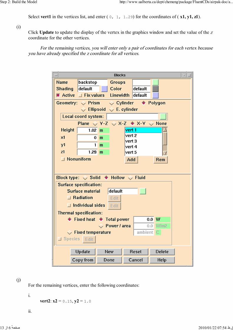
Select vert1 in the vertices list, and enter ( 0, 1, 1.29) for the coordinates of ( x1, y1, z1).
(i)Click Update to update the display of the vertex in the graphics window and set the value of the zcoordinate for the other vertices.
For the remaining vertices, you will enter only a pair of coordinates for each vertex becauseyou have already specified the z coordinate for all vertices.
(j)For the remaining vertices, enter the following coordinates:
i.vert2: x2 = 0.15, y2 = 1.0
ii.
Step 2: Build the Model http://www.ualberta.ca/dept/chemeng/package/FluentCDs/airpak-doc/a...
6 از 13 ق.ظ 07:54 2010/01/22 ٔصفحه

vert3: x3 = 0.15, y3 = 1.1
iii.vert4: x4 = 0.20, y4 = 1.2
iv.vert5: x5 = 0.40, y5 = 1.4
v.vert6: x6 = 0.50, y6 = 1.8
vi.vert7: x7 = 0.00, y7 = 1.8
(k)Enter the name backstop in the Name field.
(l)Click Done to modify the block and close the Blocks panel.
11. Create the first side panel for the backstop.
Model Partitions
(a)Click New in the partition Edit panel.
Airpak will create a 2D partition in the center of the room.
(b)Click Edit to modify the default partition in the Partitions panel.
(c)For the Geometry, select Polygon.
(d)Select vert1 in the vertices list, and enter ( 0, 1, 1.29) for the coordinates of ( x1, y1, z1).
(e)Click Update to update the display of the vertex in the graphics window and set the value of the zcoordinate for the other vertices.
(f)For the remaining vertices, enter the following coordinates:
i.vert2: x2 = 0.3, y2 = 1.0
ii.vert3: x3 = 0.5, y3 = 1.8
iii.vert4: x4 = 0.0, y4 = 1.8
(g)Enter the name backstop-end in the Name field.
Step 2: Build the Model http://www.ualberta.ca/dept/chemeng/package/FluentCDs/airpak-doc/a...
7 از 13 ق.ظ 07:54 2010/01/22 ٔصفحه

(h)Click Done to modify the partition and close the Partitions panel.
12. Copy the side of the backstop ( backstop-end) to create the other side ( backstop-end.1).
(a)In the partition Edit panel, select backstop-end in the Partitions list.
(b)Click Copy.
Airpak will open the Copy partition backstop-end panel.
(c)Set the X offset to 0, the Y offset to 0, and the Z offset to 1.02.
(d)Click Apply to generate the second side and close the panel.
Airpak will create a second side panel that is identical to the first and offset 1.02 m in the zdirection.
13. Create the first exhaust opening.
This opening will extract air from the table.
Model Openings
(a)Click New in the opening Edit panel.
Airpak will create a 2D opening in the center of the room. You will need to change theorientation and specify air flow information.
(b)Click Edit to modify the default opening in the Openings panel.
(c)Change the Plane to Y-Z.
(d)Enter the following coordinates for the opening:
xS 0.15 xE ---
yS 1.0 yE 1.1
zS 1.29 zE 2.31
(e)Select X Velocity and enter a value of -2 m/s.
(f)
Step 2: Build the Model http://www.ualberta.ca/dept/chemeng/package/FluentCDs/airpak-doc/a...
8 از 13 ق.ظ 07:54 2010/01/22 ٔصفحه
Click Update to modify the opening.
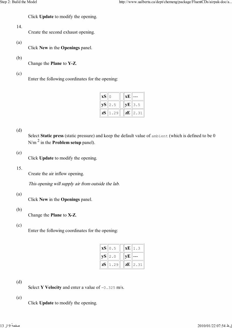
14. Create the second exhaust opening.
(a)Click New in the Openings panel.
(b)Change the Plane to Y-Z.
(c)Enter the following coordinates for the opening:
xS 0 xE ---
yS 2.5 yE 3.5
zS 1.29 zE 2.31
(d)Select Static press (static pressure) and keep the default value of ambient (which is defined to be 0N/m 2 in the Problem setup panel).
(e)Click Update to modify the opening.
15. Create the air inflow opening.
This opening will supply air from outside the lab.
(a)Click New in the Openings panel.
(b)Change the Plane to X-Z.
(c)Enter the following coordinates for the opening:
xS 0.5 xE 1.3
yS 2.0 yE ---
zS 1.29 zE 2.31
(d)Select Y Velocity and enter a value of -0.325 m/s.
(e)Click Update to modify the opening.
Step 2: Build the Model http://www.ualberta.ca/dept/chemeng/package/FluentCDs/airpak-doc/a...
9 از 13 ق.ظ 07:54 2010/01/22 ٔصفحه

16. Create the first inlet air diffuser.
(a)Click New in the Openings panel.
(b)Change the Plane to X-Z.
(c)Enter the following coordinates for the opening:
xS 1.9 xE 2.2
yS 3.6 yE ---
zS 1.4 zE 2.2
(d)Select Y Velocity and enter a value of -0.143 m/s.
(e)Click Done to modify the opening and close the Openings panel.
17. Copy the last opening you created ( opening.4) to create two more openings on the ceiling of thelab.
(a)In the opening Edit panel, select opening.4 in the Openings list.
(b)Click Copy.
Airpak will open the Copy opening opening.4 panel.
(c)Enter 2 as the Number of copies.
(d)Keep the Translate option turned on.
(e)Set the X offset to 0.35, the Y offset to 0, and the Z offset to 0.
(f)Click Apply to generate the new openings and close the panel.
Airpak will create two additional openings that are identical to the first and offset by 0.35 min the x direction.
18. Create the person working at the lab table.
Model Person
Step 2: Build the Model http://www.ualberta.ca/dept/chemeng/package/FluentCDs/airpak-doc/a...
10 از 13 ق.ظ 07:54 2010/01/22 ٔصفحه

(a)Click New in the person Edit panel.
Airpak will generate the outline of a person standing at the center of the room. You will nowchange the shape and position of the person.
(b)Click Edit to modify the default person in the Person panel.
(c)Next to Facing direction, select X and then select Backward.
(d)Set the location and the dimensions of the person.
i.Enter ( 1.25, 0, 1.8) as the ( X, Y, Z) coordinates for the Location of the person.
ii.Enter the following information for the person's overall dimensions:
Total height 1.785
Body width 0.4
Body depth 0.25
(e)Select the Radiation option.
(f)Click Done to update the person and close the panel.
Step 2: Build the Model http://www.ualberta.ca/dept/chemeng/package/FluentCDs/airpak-doc/a...
11 از 13 ق.ظ 07:54 2010/01/22 ٔصفحه

The completed model will look like Figure 2.2.
Figure 2.2: Completed Model for the Lab Exhaust Simulation
19. Check the model to be sure that there are no problems (e.g., objects that are too close together to
Step 2: Build the Model http://www.ualberta.ca/dept/chemeng/package/FluentCDs/airpak-doc/a...
12 از 13 ق.ظ 07:54 2010/01/22 ٔصفحه

allow for proper mesh generation).
Model Utilities Check model
Airpak should report in the Message window that 0 problems were found and all tolerances areacceptable.
20. Check the definition of the modeling objects to ensure that you specified them properly.
Model Summary
Airpak will list the specifications for all modeling objects in the Parameter summary panel. Youcan check them here and then click Done when you are satisfied. If you notice any incorrectspecifications, you can change them in the Parameter summary panel by clicking your mouse on theappropriate entry and editing the value.
Note: The problem described here is symmetric, and you could have reduced the size of the computationaldomain by creating a hollow block and a symmetry plane to effectively block out half of the domain.However, anticipating that additional objects may be introduced into the model or that swirling flows maybe considered at a later time, the current analysis will be carried out without taking advantage of thesymmetry present.
Previous: Step 1: Open andUp: Laboratory ExhaustNext: Step 3: Generate a© Fluent Inc. 2002-02-27
Step 2: Build the Model http://www.ualberta.ca/dept/chemeng/package/FluentCDs/airpak-doc/a...
13 از 13 ق.ظ 07:54 2010/01/22 ٔصفحه