stillwater energy center engineering, procurement
TRANSCRIPT

Stillwater Energy Center
Engineering, Procurement,
Construction Management Quality
Plan
Rev No. Issue Date Description Prepared by: Approved by:
A 11/20/2014 Draft Steven E. McKenna Anthony Decker Chris Guggino
0 02/10/2015 Issued for Contract 8110 Chris Guggino

EPCM Quality Plan
SEC EPCM Quality Plan i 11/20/2014
TABLE OF CONTENTS
1.0 INTRODUCTION ......................................................................................................... 1-1 1.1 Purpose & Scope .............................................................................................................. 1-1 1.2 Quality Policy .................................................................................................................. 1-1 1.3 Quality Objectives ........................................................................................................... 1-1
2.0 NOT USED .................................................................................................................. 2-1
3.0 QUALITY PLAN FOR CONSTRUCTION .................................................................... 3-1 3.1 Organization ..................................................................................................................... 3-1 3.2 Document Control ............................................................................................................ 3-1 3.3 Material Management ...................................................................................................... 3-1 3.4 Measure and Testing Equipment ..................................................................................... 3-2 3.5 Construction Quality Verification and Acceptance ......................................................... 3-3 3.6 Turnover Packages ........................................................................................................... 3-7 3.7 Non-Conformance Control .............................................................................................. 3-7 3.8 Corrective and Preventative Action ................................................................................. 3-8
4.0 NOT USED .................................................................................................................. 4-1
5.0 QUALITY VERIFICATION PROCEDURES ................................................................. 5-1
6.0 QUALITY VERIFICATION CHECKLISTS ................................................................... 6-1
7.0 CONSTRUCTION FORMS .......................................................................................... 7-1

SEC EPCM Quality Plan 1-1 11/20/2014
1.0 INTRODUCTION
1.1 Purpose & Scope This document describes the processes utilized by Stillwater Utility Authority (SUA) to control and improve the
quality of services and deliverables for the Stillwater Energy Center (SEC).
1.2 Quality Policy Contractors will strive to provide services which satisfy all contractual and regulatory requirements, with an
additional focus on internal and external customer expectations.
All contractors are expected to perform their responsibilities in accordance with the applicable quality
requirements, and to strive for customer satisfaction and continuous improvement. Maintaining high degrees of
quality, integrity, and responsiveness are core values at SUA.
1.3 Quality Objectives All quality verifications, inspections, and reporting are intended to verify compliance with Quality standards. The
processes described in the SEC Engineering, Procurement, and Construction Management Quality Plan will also
result in identifying where quality is not being achieved on isolated and repetitive tasks. Repetitive issues require
a heightened vigilance with training, greater management, improved execution, and verification of the work
specific to the recurring issue. Quality, integrity, and personal accountability are core values at SUA.

SEC EPCM Quality Plan 2-1 11/20/2014
2.0 NOT USED

SEC EPCM Quality Plan 3-1 11/20/2014
3.0 QUALITY PLAN FOR CONSTRUCTION
The responsibility for Quality Control shall be upon every member of the Project Site personnel. At no point shall
quality be compromised for the sake of production. This Quality Plan has been developed specifically for the
Stillwater Energy Center project. This plan addresses construction, material fabrication, material receiving, and
material handling.
3.1 Organization All verification personnel will be fully qualified in the particular discipline for which they are responsible.
3.2 Document Control Quality documents are defined as documents that specify design, testing, and inspection information such as
technical specifications, design drawings, material test reports, testing and examination reports, Punch-out Phase
punch lists and Non-conformance Reports.
Resident Project Representatives will perform Document Control Audits on a random basis.
Contractor Quality records will be delivered to Resident Project Representative as project progresses and are
completed. Resident Project Representative will collect and store these Quality records at field office. The Quality
records will be placed into their defined System Turnover Package for traceability. SUA will have access to these
Quality records for review at any time requested. The hard copies will be stored onsite until final completion of
the project.
3.3 Material Management
3.3.1 General 1. Materials management activities include the receipt, identification, storage, and maintenance of
materials at the jobsite.
2. Materials include equipment, parts, components, assemblies, and construction materials.
3. Materials management activities will be performed by Contractor.
3.3.2 Receiving 1. Materials will be checked upon receipt to verify the following:
A. Quantities are correct.
B. Labels or tags specify the correct information.
C. Items were not damaged during shipment.
Quality Plan for Construction
SEC EPCM Quality Plan 3-2 11/20/2014
2. Additional inspections will be made at the time of receiving when required for a particular material.
3. Material receipts will be documented. Additionally, any items found to be unacceptable or incorrect
upon receipt will be identified and documented for disposition.
4. Documentation received with material deliveries (e.g. operating manuals, installation instructions,
material certifications, etc.) will be identified and stored in accordance with project procedures.
3.3.3 Storage 1. Materials will be stored in designated areas.
2. Materials will be stored in accordance with specification requirements and manufacturer’s
recommendations to prevent damage or degradation prior to use.
3.3.4 Maintenance 1. Materials will be maintained in accordance with specification requirements and manufacturer’s
recommendations.
2. A Material Maintenance Log will be prepared for each material or material group to specify the
required maintenance activities and the schedule for performing the activities.
3. Maintenance activities will be documented on the Maintenance Log and supplemental reports when
applicable.
3.4 Measure and Testing Equipment
3.4.1 Equipment Measuring and test equipment shall be of the proper type, range and accuracy, and shall be checked for accuracy
at established intervals.
3.4.2 Calibration Intervals The Contractor’s QA/QC Manuals shall establish the intervals or amount of use between calibration checks based
on instrument stability characteristics, intended use and, where applicable, Code requirements.
3.4.3 Calibration Identification Each controlled instrument shall be identified with a unique control number and a calibration label indicating the
calibration due date. Instruments requiring calibration checks shall not be used until calibrated. Doubtful or
damaged equipment shall be rechecked for accuracy prior to use.

Quality Plan for Construction
SEC EPCM Quality Plan 3-3 11/20/2014
3.4.4 Custodial Control and Care 1. Contractor shall be responsible for the receipt, storage and control of measuring and testing equipment
(M&TE) at Site locations.
2. M&TE logs, as well as a calibration records file, shall be maintained at each project by the Contractor’s
Quality Control Representative. The log shall indicate the M&TE requiring calibration, serial number
of the M&TE, initial calibration due date, frequency of recalibration, the date the M&TE is returned or
transfers to another location and the location of transfer.
3. Upon receipt of M&TE at any location (whether new or transferred), Contractors shall: assign a control
number (new M&TE only – if not assigned by the manufacture); verify the M&TE’s calibration status;
apply a calibration label (if applicable); enter the calibration record into the calibration records file,
and; add the equipment to the M&TE Log.
3.4.5 Calibration Checks and Records 1. Calibration checks shall be performed by an independent calibration agency using reference standards
or devices which have a known valid relationship to national standards, where such standards exist.
2. Calibration checks shall be documented on a certificate of calibration, or other suitable certification,
attesting to the use of a nationally recognized standard. A certification sticker or label, with the
calibration date and calibration due date, including the initials of the technician performing the test,
shall be attached to the test equipment permanently.
3. Resident Project Representative will verify that appropriate calibration records are being maintained by
all Contractors and that the records are available when requested.
3.5 Construction Quality Verification and Acceptance
3.5.1 General Each Contractor is responsible for developing and implementing an effective quality control system to ensure that
construction activities are performed in accordance with the applicable specification requirements. The
Contractors are responsible for performing quality control inspections of their work.
3.5.2 Contractor Quality Control System The Contractor shall submit their quality control manual with quality records to Resident Project Representative
for review and approval. If the Contractor’s quality control system does not meet the minimum requirements set
forth in this Quality Plan, then Contractor may adopt this manual as their Quality Plan or resubmit a revised
Quality Plan that is acceptable to SUA.

Quality Plan for Construction
SEC EPCM Quality Plan 3-4 11/20/2014
The Contractor will establish witness and hold points for each inspection operation and activity. The Inspection &
Test Plans (ITP’s) will incorporate all SUA’s requested inspection and hold points. The ITP’s will be reviewed
prior to starting work activities. If the Contractor does not have sufficient ITP’s then the Contractor shall adopt
SUA’s CF-014 Inspection Matrix.
3.5.3 Quality Verifications, and Testing Site Personnel will perform all field quality-related verifications and testing as required by this Quality Plan, and
the Contract Specification requirements.
• Resident Project Representative will monitor the quality of the Contractor’s work in phases through
document review, preparatory meetings, and random inspections of the construction work. The
inspections may be performed by using third party inspectors and laboratories, superintendents, or quality
assurance personnel. General activities associated with each phase are specified in the following sections.
3.5.4 Document Review Resident Project Representative will review and/or approve the Contractor’s documents which are required to be
submitted per the Contract Documents. Resident Project Representative will verify all necessary documents are
approved prior to starting a particular work activity.
3.5.5 Preparatory Meetings Resident Project Representative will hold a preparatory meeting with each major Contractor. The preparatory
meeting will include the following items:
1. Review of the Contract scope of work.
2. Review of the Contract Specifications with regard to materials, welding, erection, installation, testing,
coatings, handling, documentation, etc.
3. Review of the requirements associated with the quality verification activities to be performed by the
Contractor during the course of construction.
4. Review of the requirements specified on the construction documents.
5. Verify the Contractor has a written quality control program fully addressing all of the above
requirements.
6. Review of all necessary Contractor submittals required prior to mobilization.

Quality Plan for Construction
SEC EPCM Quality Plan 3-5 11/20/2014
Resident Project Representative will document the items discussed during the meeting in a written report. Any
items that require further action will be identified along with the party responsible for resolving the issue and the
due date. Reports shall be distributed in accordance with project procedures.
3.5.6 Initial Inspection Resident Project Representative will perform an Initial Inspection early in the start of each major work activity to
verify that the Contractor is fulfilling their responsibilities with respect to the quality control requirements. The
Initial Inspection will include the following activities:
1. Verify any action items identified during the Preparatory Meeting were resolved.
2. Inspect the initial work performed by the Contractor to verify the Contractor’s work is in accordance
with the requirements specified in the Quality Assurance Manual and any pertinent Contract
Documents.
3. Verify the Contractor is implementing their quality control procedures at the jobsite.
4. Prepare a report documenting the specific activities performed during the Initial Inspection, and
identify any items of non-conformance or other items of concern for follow-up and resolution.
3.5.7 Follow-Up Inspections Resident Project Representative will perform Follow-up Inspections of the Contractor’s work on a random basis
after the Initial Inspection and through the completion of the work activity. The frequency and extent of Follow-
up Inspections will be based on the scope of work, and the Contractor performance. The Follow-up Inspections
will include the following activities:
1. Verify any non-conformances or action items identified during the Initial Inspection or a previous
Follow-up Inspection have been resolved. Work should not be proceeding where non-conformances
have been identified but have not been resolved, unless an approved work-around plan is in place.
2. Inspect a representative sample of work performed by the Contractor since the Initial Inspection or
previous Follow-up Inspection to verify conformance with the requirements specified in the contract
documents.
3. Verify that the Contractor is implementing their quality control procedures at the jobsite.
4. Prepare a report documenting the specific activities performed during each Follow-up Inspection, and
identify any items of non-conformance or other items of concern for follow-up and resolution

Quality Plan for Construction
SEC EPCM Quality Plan 3-6 11/20/2014
3.5.8 Final Inspection Resident Project Representative will perform final inspections on a random basis at or near the completion of
work activities or pre-defined increments of the work activities. These inspections will include the following
items:
1. Perform final inspections of any work performed by the Contractor found deficient during the Initial
and Follow-up Inspections. Verify all work is in compliance with the specifications and most current
drawing revision at the time of final inspection.
2. Prepare a report documenting the specific activities performed during each Final Inspection. From the
inspection, develop a punch list of all items found to be incomplete or not in compliance with the
Contract Documents, referenced specifications, and the latest drawing revision at the time of the
inspection. This would include any outstanding items of non-conformance or action items identified
during previous Preparatory Meetings, Initial Inspections, and Follow-up Inspections for the particular
work activity.
3. Perform follow-up activities to verify that each item on the punch list is completed and/or corrected and
is acceptable.
3.5.9 Acceptance Resident Project Representative will typically accept or release construction activities by phases, areas, or
segments. The project will define the method and the construction activities associated with each phase, area, or
segment.
Resident Project Representative will verify the following prior to issuing final acceptance for a particular phase,
area, or segment:
1. Construction is complete.
2. Resident Project Representative and Contractors have completed all inspection, testing, and quality
control activities.
3. Resident Project Representative has completed all quality verification activities.
4. All final inspection punch list items and non-conformance items are resolved and accepted.
5. All pertinent testing and commissioning reports have been provided and accepted by Resident Project
Representative.
Quality Plan for Construction
SEC EPCM Quality Plan 3-7 11/20/2014
3.6 Turnover Packages The Turnover Package is a collection of construction documentation associated with a particular phase, area, or
system. It typically includes all quality documentation such as material certifications, test reports, inspection
reports, non-conformance reports, and final inspection punch lists. It may also include selected drawings and/or
other documentation required per the Contract Documents.
1. The project will define the System Turnover Packages associated with the particular project.
2. Resident Project Representative will assemble, review, and approve the Turnover Packages associated
with each project. In some cases, documents provided by Contractors may be pre-assembled by the
Contractor.
3.7 Non-Conformance Control
3.7.1 Definition Non-conformances (NCRs) are defined as items or conditions that are not in compliance with designated
requirements, instructions, or specifications.
3.7.2 Identification Non-conformances may be identified by any party, including SUA, Suppliers, and Contractors.
3.7.3 Documented All non-conformances are to be documented and tracked to verify they are resolved in an acceptable manner. The
method of documentation varies depending on the type of non-conformance, the point at which it was detected,
and the method that was used to detect it.
Items or conditions deemed to be serious, critical, and/or major non-conformances shall be documented via a
formal Non-conformance Report. Examples that fall into this category would include the following:
1. A failure to plan or fully implement the proper quality control activities for a particular item.
2. Identification of completed work that is not in accordance with specification requirements.
3. Multiple or chronic minor non-conformances of the same type that continue to occur over a period of
time. This represents a failure in the quality control system, or implementation of the system, to carry
out corrective action in a timely manner.
4. A Non-conformance that may adversely impact safety or operability unless repaired by a controlled
process that has not been previously approved.
Quality Plan for Construction
SEC EPCM Quality Plan 3-8 11/20/2014
3.7.4 Identification Materials and work products found to be out of compliance will be identified and may not be used for operation
or subsequent work activities until the Non-conformance has been resolved.
Processes or testing activities found to be out of compliance will be identified and will not be considered as
acceptable until the Non-conformance has been resolved.
3.7.5 Disposition Non-conformances will be evaluated by a responsible party to determine the most appropriate response or follow-
up. This would generally fall into one of the following categories:
1. Non-conformance can be accepted in the current condition.
2. Non-conformance will require some re-work or corrective action although the final product or process
will still not be fully compliant with the specification requirements.
3. Non-conformance will require some re-work or corrective action in order to bring the final product or
process into full compliance with the specification requirements.
4. Non-conformance can or will not be accepted and the product or process will need to be replaced.
The proposed disposition and associated corrective action, if required, should generally be suggested by the
supplier or Contractor responsible for the work.
A disposition to accept a Non-conformance in that it is not fully in accordance with the specification requirements
must be approved by an authorized representative of SUA.
3.7.6 Acceptance A disposition to accept a Non-conformance that is not fully in accordance with the specification requirements
must be approved by an authorized representative of SUA.
A disposition that requires re-work or corrective action will be verified by the appropriate inspection, testing, or
document review method prior to being accepted.
3.8 Corrective and Preventative Action Resident Project Representative will review and monitor NCR’s and quality reports on a regular basis to identify
trends that require corrective and/or preventative action. NCR’s are Key Performance Indicators on how well
Contractors are adhering to Quality Requirements within the Contract Specifications and this quality plan.

Quality Plan for Construction
SEC EPCM Quality Plan 3-9 11/20/2014
Repetitive issues require a heightened vigilance with training, management involvement, improved execution and
verification of the work specific to the reoccurring issues.

Not used
SEC EPCM Quality Plan 4-1 11/20/2014
4.0 NOT USED

Quality Verification Procedures
SEC EPCM Quality Plan 5-1 11/20/2014
5.0 QUALITY VERIFICATION PROCEDURES
All Quality Verification Procedure are not required however employed on an as-needed basis.
Procedure No. Quality Verification Procedures Rev SECTION - 1 SITE WORK
QVP-1.01 Site Preparation & Excavation 0
QVP-1.02 Misc. Site Work 0
SECTION - 2 CONCRETE
QVP-2.01 Concreting 3
SECTION - 3 NOT USED
SECTION - 4 NOT USED
SECTION - 5 PIPING
QVP-5.00 General Verification Procedure for Piping 1
QVP-5.01 Verification Procedure for Pre-Hydro - Hydro - Post-Hydro 2
QVP-5.03 Verification Procedure for Pneumatic Testing 0
SECTION - 6 NOT USED
SECTION - 7 NOT USED
SECTION - 8 NOT USED
SECTION - 9 NOT USED
SECTION - 10 SPECIAL PROCESSES
QVP-10.01 Welding 1
QVP-10.02 Nondestructive Testing 1
Quality Verification Checklists
SEC EPCM Quality Plan 6-1 11/20/2014
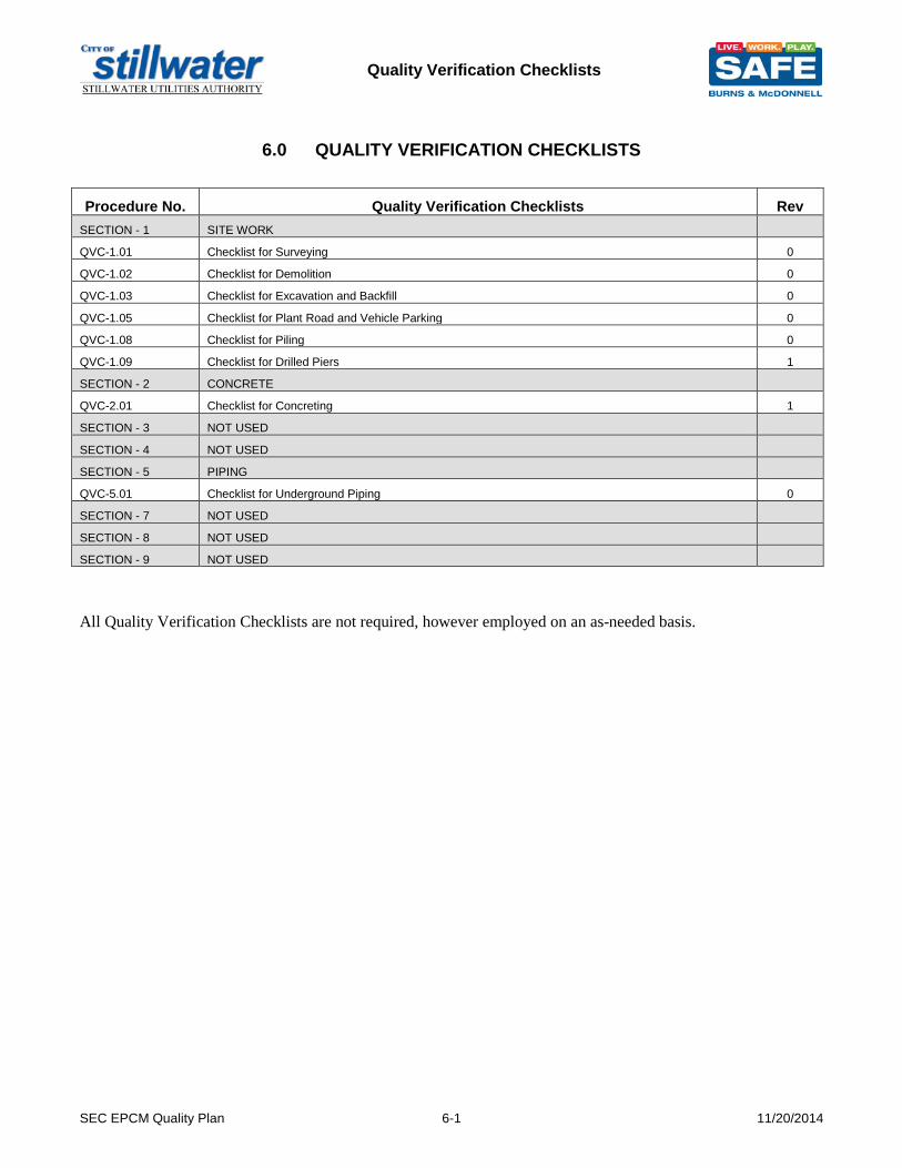
6.0 QUALITY VERIFICATION CHECKLISTS
Procedure No. Quality Verification Checklists Rev SECTION - 1 SITE WORK
QVC-1.01 Checklist for Surveying 0
QVC-1.02 Checklist for Demolition 0
QVC-1.03 Checklist for Excavation and Backfill 0
QVC-1.05 Checklist for Plant Road and Vehicle Parking 0
QVC-1.08 Checklist for Piling 0
QVC-1.09 Checklist for Drilled Piers 1
SECTION - 2 CONCRETE
QVC-2.01 Checklist for Concreting 1
SECTION - 3 NOT USED
SECTION - 4 NOT USED
SECTION - 5 PIPING
QVC-5.01 Checklist for Underground Piping 0
SECTION - 7 NOT USED
SECTION - 8 NOT USED
SECTION - 9 NOT USED
All Quality Verification Checklists are not required, however employed on an as-needed basis.

Construction Forms
SEC EPCM Quality Plan 7-1 11/20/2014
7.0 CONSTRUCTION FORMS
Form No. Construction Forms Rev SECTION - 0 GENERAL
CF-001 Notice of Acceptance 2
CF-002 Nonconformance Report 0
CF-003 Non-Conformance Report Log 1
CF-004 Material Receiving Report 0
CF-005 Material Receiving Log 1
CF-006 Signoff Contractor to Burns & McDonnell 3
CF-007 Receiving Overage, Shortage, and Damage Report 0
CF-008 Welding Conformance 0
CF-009 Master Punch list 0
CF-010 Equipment Maintenance Log 0
CF-011 Daily Field Report 2
CF-012 Drawing Control Audit 1
CF-013 Quality Performance Measurement System 2
CF-014 Burns & McDonnell Inspection Matrix 0
SECTION - 1 SITE WORK
CF-101 Pier/Pile Installation Log 0
CF-102 Soils Log 0
CF-103 Authorization to Backfill Record 1
SECTION - 2 CONCRETE
CF-200 Concrete Placement Log 1
CF-201 Concrete Placement Application, Authorization, and Record 2
CF-202 Grout Placement Application, Authorization, and Record 3
SECTION - 3 NOT USED
SECTION - 4 NOT USED
SECTION - 5 PIPING
CF-501 Piping Pressure Test Record 2
CF-503 Holiday Test Record Log 3
CF-504 Tie-In Application, Authorization, and Record 1
SECTION - 6 NOT USED
SECTION - 7 NOT USED
SECTION - 8 NOT USED
SECTION - 9 NOT USED
SECTION - 10 NOT USED
CF-1004 NDE Rejects 0
All Construction Forms are not required, however employed on an as-needed basis.

Stillwater Utilities Authority Construction Quality Verification Procedure
QVP No. 1.01 – Site Preparation & Excavation Activities Rev 0
Uncontrolled Copy Page 1 of 6
1.0 Scope 1.1 This procedure defines the activities that Stillwater Utilities Authority will perform in verifying the
quality of work performed by Contractors associated with Site Preparation & Excavation construction activities.
1.2 This procedure is to be used in conjunction with the general requirements specified in Stillwater
Utilities Authority Construction Quality Verification Procedure No. 1.00 – Site Work – General. 1.3 Requirements that pertain to the contractor with regard to construction, testing, inspection,
documentation, etc., are specified in the contract package, referenced specifications, and construction drawings.
2.0 References 2.1 Forms
The following forms are used to document the quality verification activities specified in this procedure.
QVC-1.01 – Survey Inspection Checklist
QVC-1.02 – Demolition Inspection Checklist QVC-1.03 – Excavation & Backfill Inspection Checklist
CF-102 – Soils Log CF-103 – Authorization to Backfill Record
2.2 Standards
PIP CVS02005 – Topographic and Plant Surveys Specification PIP CVS02100 – Site Preparation, Excavation and Backfill Specification PIP CVS02700 – Excavation and Backfill for Underground Piping ASTM D1557 – Standard test methods for Laboratory Compaction Characteristics of Soil using modified effort ASTM D698 – Standard Test Methods for Laboratory Compaction Characteristics of Soil Using Standard Effort ASTM D6938 – Standard Test Method for In-Place Density and Water Content of Soil and Soil- Aggregate by Nuclear Methods (Shallow Test) ASTM D4429 – Standard Test Method for CBR (California Bearing Ratio) of Soils in Place PIP CVS02350 – Roadway and Area paving Construction Specification AREA – American Railroad Engineering Association Burns & McDonnell Engineering Specifications
3.0 Definitions
See associated PIP Specifications for the definition of terms. 4.0 Procedure 4.1 General
4.1.1 Surveying:

Stillwater Utilities Authority Construction Quality Verification Procedure
QVP No. 1.01 – Site Preparation & Excavation Activities Rev 0
Uncontrolled Copy Page 2 of 6
• The Engineering drawings and specifications shall describe the benchmarks, base
lines, and control points to be used for basic control. A system of permanent monuments shall be established onsite from this base line and elevation unless provided for by the owner.
4.1.2 The following work activities are generally associated with Surveying activities:
• Equipment Type
• Equipment Calibration • Layout and Checking • Earth Work • Foundation Locations • Underground Utilities • Traversing
4.1.3 Demolition
• All demolition of existing equipment, piping, instruments, and foundations shall be performed as indicated on the Contract Drawings, including Demolition Piping Plans and Elevation Drawings, Demolition P&ID’s, Foundation Demolition Drawings, and demolition details.
4.1.4 Site Preparation
• Clearing and Grubbing • Stripping • Rough Grading • Erosion Control
4.1.5 Excavation
• Structural Excavation • Earthen Excavation • Trenching for Pipe, Conduit, etc…(PIP CVS02700) • Rock Excavation
4.1.6 Stockpiling
• Stockpile material for proper drainage • Dispose of contaminated soils
4.1.7 Disposal of Excess and Waste Materials
• Designate a spoil area with Client and plan for removal
4.1.8 Backfill
• An independent soils consultant shall be used for compaction testing. The Soils Consulting Firm will perform the necessary laboratory tests for the soil material being compacted to determine the maximum density at optimum moisture content following the ASTM test method specified.
• The Soils Consulting Firm will perform in-place tests to determine the density of the compacted fill using the specified test method. The results of the tests shall be recorded and delivered to Stillwater Utilities Authority.

Stillwater Utilities Authority Construction Quality Verification Procedure
QVP No. 1.01 – Site Preparation & Excavation Activities Rev 0
Uncontrolled Copy Page 3 of 6
• Cohesion-less soils shall be compacted to the relative density as specified in the contract documents. The Soils Consulting Firm shall perform the necessary laboratory tests to determine the in-place density required to meet the specified relative density. The Soils Consulting Firm shall perform in-place tests to determine the relative density of the compacted fill. The results of the tests shall be recorded and delivered to Stillwater Utilities Authority.
• The contractor may use any type of compaction equipment deemed necessary to obtain the specified density. If the results of the compaction test show that the fill material must be dried, the fill shall be dried by scarifying, disk harrowing or rotary tilling of the loose lifts to reduce moisture by aeration. If the material is to be wetted, water shall be added either on the fill or at the borrow pit.
• Analyze the suitability of backfill: special backfill, compacted backfill, and structural quality backfill.
• Sieve Analysis (ASTM C136, ASTM D422 or ASTM D1140) • Liquid and Plastic limit determination (ASTM D4318) • Modified Proctor Test (ASTM D1557) or Standard Proctor Test (ASTM D698) • Granular Soils Tests (ASTM D4253) and (ASTM D4254) • Test the Density and Moisture content of compacted backfill material (ASTM D2922)
4.1.9 Base Course
• Cleared, grubbed and stripped • Modified Proctor test (ASTM D1557) or Standard Proctor Test (ASTM D698)
4.1.10 Dewatering
• Provide proper drainage of all excavations, fills, stockpiles, borrow pits throughout the project.
4.1.11 Stillwater Utilities Authority will perform quality verification activities to ensure that each
work activity is completed in accordance with the project specifications. These quality verification activities can be classified into one of the following categories:
• Preparatory meeting prior to starting construction. • Initial inspections of construction. • Inprocess inspections during construction – random to full-time. • Final inspection after completing construction – random to 100% • Review of records of construction
4.1.12 The type of quality verification activities to be performed for each work activity, and the
extent thereof, is described in this procedure. 4.1.13 All quality verification activities will be performed by personnel that have the necessary
skills, training, and certifications for the particular task.
4.2 Preparatory Meetings
4.2.1 Preparatory Meetings are held with contractors prior to the start of construction for each major work activity or group of activities. The purpose of the Preparatory Meeting is to verify the following:

Stillwater Utilities Authority Construction Quality Verification Procedure
QVP No. 1.01 – Site Preparation & Excavation Activities Rev 0
Uncontrolled Copy Page 4 of 6
• Verify that the contractor fully understands the job specification requirements.
• Review the contractor’s quality control program and how it will be implemented for the work activity.
• Verify that all required documentation has been reviewed or approved and that the
contractor has the most current versions.
• Review requirements for permits and/or authorizations that will be required during the course of construction.
• Review the quality verification activities that Stillwater Utilities Authority plans to
perform and coordinate the necessary notifications from the contractor for any hold or witness points.
4.2.2 The following work activities require a Preparatory Meeting prior to starting construction.
• Surveying • Demolition • Excavation • Trenching • Stockpiling • Backfilling • Testing & Inspection Requirements
4.2.3 When multiple contractors are responsible for a given work activity, a separate
Preparatory Meeting will be held with each contractor. 4.2.4 When a given contractor is responsible for multiple work activities, the Preparatory
Meeting may include more than one work activity. 4.2.5 For work activities with multiple phases, a separate Preparatory Meeting is not
necessarily required for each phase. For example, only one Preparatory Meeting would typically be held with a contractor responsible for Excavating although their scope may include several areas over the course of the project. However, a follow-up meeting may be warranted if there are extended periods between phases or if problems are identified during inspections of the contractor’s work.
4.3 Initial Inspections
4.3.1 Stillwater Utilities Authority will perform a thorough inspection of the initial construction work performed by each contractor for each work activity. The purpose of this inspection is to verify that the contractor is capable of performing the work in accordance with the project specifications. The initial inspection will include the following:
• Verify any action items identified during the Preparatory Meeting were resolved.
• Fully inspect the initial work performed by contractor to verify that it is in accordance
with the requirements specified in the contract documents.

Stillwater Utilities Authority Construction Quality Verification Procedure
QVP No. 1.01 – Site Preparation & Excavation Activities Rev 0
Uncontrolled Copy Page 5 of 6
• Verify that the contractor is implementing their quality control procedures at the jobsite.
• Prepare a Master Punch-list documenting the specific activities performed during the
Initial Inspection and identify any items of nonconformance or other action items for follow-up and resolution.
4.4 Follow-up Inspections
4.4.1 Stillwater Utilities Authority will perform Follow-up Inspections of the contractor’s work on a random but regular basis starting immediately after the Initial Inspection and through the completion of the work activity. The frequency and extent of Follow-up Inspections will be based on the scope of work, contractor performance, and associated risk to the project. The Follow-up Inspections will include the following activities:
Verify that any Nonconformancies or action items identified during the Initial
Inspection or a previous Follow-up Inspection have been resolved. Work should not be proceeding where Nonconformancies have been identified but have not been resolved, unless an approved work-around plan is in place. Follow Construction Site Quality Manual 7.0. Use CF-002 forms.
Inspect a representative sample of work performed by the contractor since the Initial
Inspection or previous Follow-up Inspection to verify that it is in accordance with the requirements specified in the contract documents.
Verify that the contractor is implementing their quality control procedures at the
jobsite. Prepare a Master Punch-list documenting the specific activities performed during
each Follow-up Inspection and identify any items of nonconformance or other action items for follow-up and resolution.
4.5 Final Inspection
4.5.1 Stillwater Utilities Authority will perform a Final Inspection at or near the completion of the pre-placement activities. The Final Inspection will include the following items:
Perform a final inspection of any work performed by the contractor that was not
previously inspected during the Initial and Follow-up Inspections but would be prudent to assure the final quality of the work. Verify that all work is in compliance with the specifications and most current drawing revision at the time of final inspection.
Prepare a Master Punch-list documenting the specific activities performed during
each Final Inspection and develop a punch list of all items that were found to be incomplete or not in compliance with the contract documents, referenced specifications, and the latest drawing revision at the time of the inspection. This would include any outstanding items of nonconformance or action items identified during previous Preparatory Meetings, Initial Inspections, and Follow-up Inspections for the particular work activity.

Stillwater Utilities Authority Construction Quality Verification Procedure
QVP No. 1.01 – Site Preparation & Excavation Activities Rev 0
Uncontrolled Copy Page 6 of 6
Specify the estimated date for which each item on the punch list should be completed or corrected to be in compliance.
Perform follow-up activities to verify that each item on the punch list is completed
and/or corrected and is acceptable.
4.6 Acceptance
4.6.1 Stillwater Utilities Authority will typically accept or release each area prior to commencing Site Work activities.
4.6.2 Burns & McDonnell will verify the following prior to issuing final acceptance for a
particular area:
• Pre-placement activities are complete. • The contractor has completed all inspection, testing, and quality control activities.
• Stillwater Utilities Authority has completed all quality verification activities.
• All final inspection punch list items are resolved and accepted.
5.0 Records 5.1 The Quality Verification Activities associated with this procedure are recorded on the following
forms:
• QVC-1.01 – Survey Inspection Checklist • QVC-1.02 – Demolition Inspection Checklist • QVC-1.03 – Excavation & Backfill Inspection Checklist • CF-102 – Soils Log • CF-103 – Authorization to Backfill Record
Stillwater Utilities Authority Construction Quality Verification Procedure
QVP No. 1.02 –Misc. Site Work Activities Rev 0
Uncontrolled Copy Page 1 of 5
1.0 Scope 1.1 This procedure defines the activities that Stillwater Utilities Authority will perform in verifying the
quality of work performed by contractors associated with Misc. Site Work construction activities. 1.2 This procedure is to be used in conjunction with the general requirements specified in Stillwater
Utilities Authorityl Construction Quality Verification Procedure No. 1.00 – Site Work – General. 1.3 Requirements that pertain to the contractor with regard to construction, testing, inspection,
documentation, etc., are specified in the contract package, referenced specifications, and construction drawings.
2.0 References 2.1 Forms
The following forms are used to document the quality verification activities specified in this procedure.
QVC-1.05 – Inspection Checklist for Plant Road and Vehicle Parking
2.2 Standards
PIP CVS02350 – Roadway and Area paving Construction Specification PIP STS03001 – Plain and Reinforced Concrete Specifications AREA – American Railroad Engineering Association Burns & McDonnell Engineering Specifications
3.0 Definitions
See associated PIP Specifications for the definition of terms. 4.0 Procedure 4.1 General
4.1.1 Unpaved Surfaces
• Topsoil • Seed and sod • Placement of topsoil, seed, or sod • Weed Control
4.1.2 Plant Road and Vehicle Parking
• Gravel Pavement • Asphalt Pavement • Concrete Pavement
4.1.3 Fencing
• Post distances
Stillwater Utilities Authority Construction Quality Verification Procedure
QVP No. 1.02 –Misc. Site Work Activities Rev 0
Uncontrolled Copy Page 2 of 5
• Concrete Foundation • Concrete Finish • Gates
4.1.4 Railroad
• Site Preparation • Tie Material and Spacing • Rail Weight • Tie Plate and Spiking • Tie Joints • Tie Welding • Ballast quality, size graduation, thickness, and compaction. • Switch Installation • Track Alignment
4.1.5 Stillwater Utilities Authority will perform quality verification activities to ensure that each work activity is completed in accordance with the project specifications. These quality verification activities can be classified into one of the following categories:
• Preparatory meeting prior to starting construction. • Initial inspections of construction. • Inprocess inspections during construction – random to full-time. • Final inspection after completing construction – random to 100% • Review of records of construction
4.1.6 The type of quality verification activities to be performed for each work activity, and the
extent thereof, is described in this procedure. 4.1.7 All quality verification activities will be performed by personnel that have the necessary
skills, training, and certifications for the particular task.
4.2 Preparatory Meetings
4.2.1 Preparatory Meetings are held with contractors prior to the start of construction for each major work activity or group of activities. The purpose of the Preparatory Meeting is to verify the following: • Verify that the contractor fully understands the job specification requirements.
• Review the contractor’s quality control program and how it will be implemented for
the work activity.
• Verify that all required documentation has been reviewed or approved and that the contractor has the most current versions.
• Review requirements for permits and/or authorizations that will be required during
the course of construction.
• Review the quality verification activities that Burns & McDonnell plans to perform and coordinate the necessary notifications from the contractor for any hold or witness points.

Stillwater Utilities Authority Construction Quality Verification Procedure
QVP No. 1.02 –Misc. Site Work Activities Rev 0
Uncontrolled Copy Page 3 of 5
4.2.2 The following work activities require a Preparatory Meeting prior to starting construction.
• Seeding and Sodding • Plant Roads and Vehicle parking • Fencing • Railroads • Testing & Inspection Requirements
4.2.3 When multiple contractors are responsible for a given work activity, a separate
Preparatory Meeting will be held with each contractor. 4.2.4 When a given contractor is responsible for multiple work activities, the Preparatory
Meeting may include more than one work activity. 4.2.5 For work activities with multiple phases, a separate Preparatory Meeting is not
necessarily required for each phase. For example, only one Preparatory Meeting would typically be held with a contractor responsible for Asphalting although their scope may include several areas over the course of the project. However, a follow-up meeting may be warranted if there are extended periods between phases or if problems are identified during inspections of the contractor’s work.
4.3 Initial Inspections
4.3.1 Stillwater Utilities Authority will perform a thorough inspection of the initial construction work performed by each contractor for each work activity. The purpose of this inspection is to verify that the contractor is capable of performing the work in accordance with the project specifications. The initial inspection will include the following:
• Verify any action items identified during the Preparatory Meeting were resolved.
• Fully inspect the initial work performed by contractor to verify that it is in accordance
with the requirements specified in the contract documents.
• Verify that the contractor is implementing their quality control procedures at the jobsite.
• Prepare a Master Punch-list documenting the specific activities performed during the
Initial Inspection and identify any items of nonconformance or other action items for follow-up and resolution.
4.4 Follow-up Inspections
4.4.1 Stillwater Utilities Authority will perform Follow-up Inspections of the contractor’s work on a random but regular basis starting immediately after the Initial Inspection and through the completion of the work activity. The frequency and extent of Follow-up Inspections will be based on the scope of work, contractor performance, and associated risk to the project. The Follow-up Inspections will include the following activities:
Verify that any Nonconformancies or action items identified during the Initial
Inspection or a previous Follow-up Inspection have been resolved. Work should not be proceeding where Nonconformancies have been identified but have not been

Stillwater Utilities Authority Construction Quality Verification Procedure
QVP No. 1.02 –Misc. Site Work Activities Rev 0
Uncontrolled Copy Page 4 of 5
resolved, unless an approved work-around plan is in place. Follow Construction Site Quality Manual 7.0. Use CF-002 forms.
Inspect a representative sample of work performed by the contractor since the Initial
Inspection or previous Follow-up Inspection to verify that it is in accordance with the requirements specified in the contract documents.
Verify that the contractor is implementing their quality control procedures at the
jobsite. Prepare a Master Punch-list documenting the specific activities performed during
each Follow-up Inspection and identify any items of nonconformance or other action items for follow-up and resolution.
4.5 Final Inspection
4.5.1 Stillwater Utilities Authority will perform a Final Inspection at or near the completion of the pre-placement activities. The Final Inspection will include the following items:
Perform a final inspection of any work performed by the contractor that was not
previously inspected during the Initial and Follow-up Inspections but would be prudent to assure the final quality of the work. Verify that all work is in compliance with the specifications and most current drawing revision at the time of final inspection.
Prepare a Master Punch-list documenting the specific activities performed during
each Final Inspection and develop a punch list of all items that were found to be incomplete or not in compliance with the contract documents, referenced specifications, and the latest drawing revision at the time of the inspection. This would include any outstanding items of nonconformance or action items identified during previous Preparatory Meetings, Initial Inspections, and Follow-up Inspections for the particular work activity.
Specify the estimated date for which each item on the punch list should be
completed or corrected to be in compliance. Perform follow-up activities to verify that each item on the punch list is completed
and/or corrected and is acceptable.
4.6 Acceptance
4.6.1 Stillwater Utilities Authority will typically accept or release each area prior to commencing Site Work activities.
4.6.2 Stillwater Utilities Authority will verify the following prior to issuing final acceptance for a
particular area:
• Pre-placement activities are complete. • The contractor has completed all inspection, testing, and quality control activities.
• Stillwater Utilities Authority has completed all quality verification activities.
Stillwater Utilities Authority Construction Quality Verification Procedure
QVP No. 1.02 –Misc. Site Work Activities Rev 0
Uncontrolled Copy Page 5 of 5
• All final inspection punch list items are resolved and accepted.
5.0 Records 5.1 The Quality Verification Activities associated with this procedure are recorded on the following
forms:
• QVC-1.04 – Inspection Checklist for Unpaved Surfaces • QVC-1.05 – Inspection Checklist for Plant Road and Vehicle Parking • QVC-1.06 – Inspection Checklist for Site Fencing • QVC-1.07 – Inspection Checklist for Plant Railroad

Stillwater Utilities Authority Construction Quality Verification Procedure
QVP No. 2.01 – Concreting Rev 3
Uncontrolled Copy Page 1 of 4
1.0 Scope
1.1 This procedure defines the activities that Stillwater Utilities Authority will perform in verifying the quality of work performed by contractors associated with concreting construction activities.
1.2 Requirements that pertain to the contractor with regard to construction, testing, inspection, documentation, etc., are specified in the contract package, referenced specifications, and construction drawings.
2.0 References
2.1 Forms
The following forms are used to document the quality verification activities specified in this procedure.
QVC-2.01 – Inspection Checklist for Concreting
CF-200 – Concrete Log CF-201 – Concrete Placement Application, Authorization, and Record CF-202 – Grout Placement Application, Authorization, and Record
2.2 Standards
ACI 311.1R – Manual for Concrete Inspection ACI 311.4R – Guide for Concrete Inspection
3.0 Definitions
See ACI 116R for the definition of terms associated with concreting.
4.0 Procedure
4.1 General
4.1.1 The following work activities are associated with concrete pre-placement activities:
• Excavation • Dewatering • Bearing Capacity • Trenching • Formwork • Reinforcement • Embedded Items
4.1.2 The following work activities are associated with concrete placement activities:
• Mixing • Pour / Application • Slump Tests • Air Content Tests • Test Sample Preparation
4.1.3 The following work activities are associated with concrete placement activities:
• Curing • Form Removal • Concrete Testing • Final Visual and Dimensional Inspection

Stillwater Utilities Authority Construction Quality Verification Procedure
QVP No. 2.01 – Concreting Rev 3
Uncontrolled Copy Page 2 of 4
4.1.4 Stillwater Utilities Authority will perform quality verification activities to ensure that each work activity is completed in accordance with the project specifications. These quality verification activities can be classified into one of the following categories:
• Preparatory meeting prior to starting construction. • Initial inspections of construction. • Inprocess inspections during construction – random to full-time. • Final inspection after completing construction – random to 100% • Review of records of construction
4.1.5 The type of quality verification activities to be performed for each work activity and the
extent thereof is described in this procedure. 4.1.6 All quality verification activities will be performed by personnel that have the necessary
skills, training and certifications for the particular task.
4.2 Preparatory Meetings
4.2.1 Preparatory Meetings are held with contractors prior to the start of construction for each major work activity or group of activities. The purpose of the Preparatory Meeting is to verify the following: • Verify that the contractor fully understands the job specification requirements.
• Review the contractor’s quality control program and how it will be implemented for
the work activity.
• Verify that all required documentation has been reviewed or approved and that the contractor has the most current versions.
• Review requirements for permits and/or authorizations that will be required during
the course of construction.
• Review the quality verification activities that Stillwater Utilities Authority plans to perform and coordinate the necessary notifications from the contractor for any hold or witness points.
4.2.2 When multiple contractors are responsible for a given work activity, a separate
Preparatory Meeting will be held with each contractor. 4.2.3 When a given contractor is responsible for multiple work activities, the Preparatory
Meeting may include more than one work activity. 4.2.4 For work activities with multiple phases, a separate Preparatory Meeting is not
necessarily required for each phase. For example, only one Preparatory Meeting would typically be held with a contractor responsible for formwork although their scope may include constructing the forms for many foundations over the course of the project. However a follow-up meeting may be warranted if there are extended periods between phases or if problems are identified during inspections of the contractor’s work.

Stillwater Utilities Authority Construction Quality Verification Procedure
QVP No. 2.01 – Concreting Rev 3
Uncontrolled Copy Page 3 of 4
4.3 Initial Inspections
4.3.1 Stillwater Utilities Authority will perform a thorough inspection of the initial construction work performed by each contractor for each work activity. The purpose of this inspection is to verify that the contractor is capable of performing the work in accordance with the project specifications. The initial inspection will include the following:
• Verify any action items identified during the Preparatory Meeting were resolved.
• Fully inspect the initial work performed by contractor to verify that it is in accordance
with the requirements specified in the contract documents.
• Verify that the contractor is implementing their quality control procedures at the jobsite.
• Prepare a Master Punch-list documenting the specific activities performed during the
Initial Inspection and identify any items of nonconformance or other action items for follow-up and resolution.
4.4 Follow-up Inspections
4.4.1 Stillwater Utilities Authority will perform Follow-up Inspections of the contractor’s work on a random but regular basis starting immediately after the Initial Inspection and through the completion of the work activity. The frequency and extent of Follow-up Inspections will be based on the scope of work, contractor performance and associated risk to the project. The Follow-up Inspections will include the following activities:
Verify that any Nonconformancies or action items identified during the Initial
Inspection or a previous Follow-up Inspection have been resolved. Work should not be proceeding where Nonconformancies have been identified but have not been resolved, unless an approved work-around plan is in place. Follow Construction Site Quality Manual 7.0 Non Conformance Control. Use CF-002 forms.
Inspect a representative sample of work performed by the contractor since the Initial
Inspection or previous Follow-up Inspection to verify that it is in accordance with the requirements specified in the contract documents.
Verify that the contractor is implementing their quality control procedures at the
jobsite. Prepare a Master Punch-list documenting the specific activities performed during
each Follow-up Inspection and identify any items of nonconformance or other action items for follow-up and resolution.
4.5 Final Inspection
4.5.1 Stillwater Utilities Authority will perform a Final Inspection at or near the completion of the pre-placement, placement and post-placement activities. The Final Inspection will include the following items:
Perform a final inspection of any work performed by the contractor that was not
previously inspected during the Initial and Follow-up Inspections but would be

Stillwater Utilities Authority Construction Quality Verification Procedure
QVP No. 2.01 – Concreting Rev 3
Uncontrolled Copy Page 4 of 4
prudent to assure the final quality of the work. Verify that all work is in compliance with the specifications and most current drawing revision at the time of final inspection.
Prepare a Master Punch-list documenting the specific activities performed during
each Final Inspection and develop a punch list of all items that were found to be incomplete or not in compliance with the contract documents, referenced specifications, and the latest drawing revision at the time of the inspection. This would include any outstanding items of nonconformance or action items identified during previous Preparatory Meetings, Initial Inspections and Follow-up Inspections for the particular work activity.
Specify the estimated date for which each item on the punch list should be
completed or corrected to be in compliance. Perform follow-up activities to verify that each item on the punch list is completed
and/or corrected and is acceptable.
4.6 Acceptance
4.6.1 Stillwater Utilities Authority will typically accept or release each area prior to commencing concrete placement activities.
4.6.2 Stillwater Utilities Authority will verify the following prior to issuing final acceptance for a
particular area:
• Pre-placement, Placement and Post-placement activities are complete. • The contractor has completed all inspection, testing, and quality control activities.
• Stillwater Utilities Authority has completed all quality verification activities.
• All final inspection punch list items are resolved and accepted.
5.0 Records
5.1 The Quality Verification Activities associated with this procedure are recorded on the following forms:
• QVC-2.01 – Inspection Checklist for Concreting
• CF-200 – Concrete Placement Log
• CF-201 – Concrete Placement Application, Authorization, and Record
• CF-202 – Grout Placement Application, Authorization, and Record

Stillwater Utilities Authority
Construction Quality Verification Procedure No. 5.00 – Piping – General Rev RICE
Uncontrolled Copy Page 1 of 5
1.0 Scope 1.1 This procedure defines the general activities that Stillwater Utilities Authority will perform in
verifying the quality of work performed by contractors associated with Piping Fabrication and Erection.
1.2 Additional detailed requirements are specified in supplemental Construction Quality Verification
Procedures for specific operations associated with Piping Fabrication and Erection. 1.3 Requirements that pertain to the contractor with regard to construction, testing, inspection,
documentation, etc., are specified in the contract package, referenced specifications, and construction drawings.
2.0 References 2.1 Supplemental Stillwater Utilities Authority Construction Quality Verification Procedures
The following procedures are to be used in conjunction with this procedure in verifying the work performed by contractors for specific operations associated with Piping Fabrication and Erection. QVP-5.01 – Pre-Hydro Inspection Activities QVP-5.01 – Hydro inspection activities QVP-5.01 – Post-Hydro Inspection Activities
2.2 Standard Industry Specifications
The following is a list of standard specifications associated with Piping Fabrication and Erection that may be referenced in this procedure, supplemental Construction Quality Verification Procedures, and/or contract specifications.
ASME II – Materials ASME V – Nondestructive Examination ASME IX– Welding and Brazing Qualifications ASME B31.1 – Power Piping ASME B31.9 – Building services Piping ASNT– SNT-TC-1A – Nondestructive Examination Burns & McDonnell Engineering Specifications
2.3 Forms
The following forms are used to document quality verification activities.
CF-501 – Hydro Inspection CF-009 – Master Punch List Log CF-503 – Holiday Test Record Log
3.0 Definitions
See Governing Spec or Code 4.0 Procedure

Stillwater Utilities Authority
Construction Quality Verification Procedure No. 5.00 – Piping – General Rev RICE
Uncontrolled Copy Page 2 of 5
4.1 Tie-In Approval
4.1.1 The following work activities are associated with Tie-In Processes:
4.1.1.1 Identify Quality Procedures for Tie-In work.
4.1.1.2 Verify proper Location of the Tie-in.
4.1.1.3 Verify Lock out Tag out Procedure is met.
4.1.1.4 Existing pipe thickness measurement via Ultrasonic Inspection verified before cutting into existing pipe.
4.1.1.5 Surface Preparation for welding per QVP-10.01, Section 4.10.
4.1.1.6 PT Inspection per QVP-10.2.
4.1.1.7 Repair of Base Metal Defects per QVP-10.01 Section 4.11.
4.1.1.8 Contractor shall verify proper Fit-up and Alignment per QVP-10.01 Section 4.12, Contractors WPS and Governing Codes.
4.1.1.9 Verify Welding per Contractor’s WPS.
4.1.1.10 Final NDE per QVP-10.02.
4.1.1.11 Hydro Testing shall either be completed with a Car-Ber testing method or NDE in Lieu of Hydro and a Service Test with prior approval.
4.1.1.11.1 NDE in Lieu of Hydro shall be kept to a minimum.
4.1.1.12 Verify Painting is complete
4.1.1.13 Verify Heat Tracing is complete
4.1.1.14 Verify Insulation is complete
4.1.1.15 Fill out and Complete CF-504 Tie-In Placement Application, Authorization, and Record.
4.2 Flange Inspections:
4.2.1 The following work activities are associated with Flange Inspection Procedures.
4.2.1.1 Identify whether Stillwater Utilities Authority procedure meets the Client’s requirements or if Stillwater Utilities Authority needs to overlay our procedure with the Client’s procedure.
4.2.2 All Other Bolted Piping and Equipment Flange Connections.
4.2.2.1 All flange connections shall use gasket materials specified in the Engineering Drawings.
4.2.2.2 Garlock gaskets may be used in lieu of permanent gaskets for Pressure Testing purposes.
4.2.2.2.1 Garlock gaskets shall only be used where Temporary Hydro blinds will be installed. Use one Garlock gasket per side of the blind.
4.2.2.2.2 Do not use Garlock gaskets beyond their pressure rating.

Stillwater Utilities Authority
Construction Quality Verification Procedure No. 5.00 – Piping – General Rev RICE
Uncontrolled Copy Page 3 of 5
4.2.2.3 Upon completion of Pressure Testing, replace all temporary gaskets with their specified permanent gaskets and retighten the bolts.
4.2.2.3.1 The Inspector shall use a Hammer to perform the “Tap of the Nut” Inspection for loose bolts.
4.2.2.3.2 Thread protrusion shall protrude a minimum 2 threads beyond the nut and not to exceed 4 threads beyond the nut. This provides ease for maintenance.
4.2.2.3.3 Repeat the prior steps until the QC Inspector deems the flange connection acceptable.
4.2.2.4 All other gaskets within the Pressure Test Boundaries shall be deemed Acceptable upon Acceptance of the Pressure Test and Sign off of the Post Hydro Test Release located on CF-501.
4.3 Stillwater Utilities Authority will perform activities to verify the quality of the following work activities associated with Above Ground Piping Fabrication and Erection.
4.3.1 Pre-Hydro Test Release: signatures required
• Tie-In Approval Procedure • Piping Conforms to Drawings and Specifications • NDE/PMI/PWHT/BHN Complete • In-Line Instruments removed • Valve orientation correct • Valves open as required • Blinds installed as applicable • Data logged into the System Line List Tracker • Data logged into Master Punch List • Red-Line and mark-up Hydro Boundaries on Master set of P&ID’s
4.3.2 Hydro Test: signatures required
• Gauge Number • Gauge Range encompasses middle third • Gauge Calibration • Test media • Test pressure • Temperature • Test length
4.3.3 Post-Hydro test release: signatures required
• Blinds pulled • Supports Installed • Spring Hanger stops removed • Plugs installed • High Point and Low Point plugs installed • In-line Instruments installed • Proper Bolts and Gaskets • Valve orientation correct • System blown free of test medium

Stillwater Utilities Authority
Construction Quality Verification Procedure No. 5.00 – Piping – General Rev RICE
Uncontrolled Copy Page 4 of 5
4.3.4 Final Acceptance Signature:
• Painting Complete • Insulation Complete • Heat Tracing Complete and Tested • Holiday Testing Complete and Signed off • Master Punch List Log Complete and Signed off
4.4 Stillwater Utilities Authority will perform activities to verify the quality of the following work activities associated with Underground Piping Fabrication and Erection in correlation of paragraph 4.2 of this procedure.
4.4.1 Preparation of bedding for underground pipe is very important. Proper preparation will help ensure an installation which will be trouble free.
• Pipe to be installed in clay, shale or rock may require a compacted loam or fine granular material base. See Burns & McDonnell supplied piping specifications.
• Pipe to be installed in compacted sand, sandy loam or granular soil may require no additional base work unless specified on contract drawings or in the Piping Specifications.
• Sand filled cloth bags may be used to aid in setting underground lines. These sand bags need not be removed upon completion of installation. This procedure requires the design engineer’s approval.
4.4.2 Applications of field coating and wrapping shall be in accordance with contract specifications. Check for the following:
• Welds are clear of splatter • Pipe is clear of loose mill scale, rust, oil, grease, dirt and other foreign matter. • Primer is being used which is compatible with the existing line coating system. • Proper overlap of tape according to specifications. • Coating of valves for complete coverage.
4.2.5 Test and inspect coated and wrapped pipe for voids and leaks by means of a holiday detector prior to installation in ditch and prior to backfilling. The test should be witnessed by Stillwater Utilities Authority. Record results on the Holiday Test Record Log CF-503. Records will be maintained by Contractor. Move pipe with slings only.
4.2.6 Inspect initial backfill of coated and wrapped pipe to ensure that soil is free from debris that could damage coating. Initial backfill is to be same material as bedding. Pipe shall be covered with this material to a depth specified which will protect the pipe from damage, after which the excavation may be backfilled with any suitable material, or as specified in job specifications or job standards.
4.2.7 Prior to testing, inspect underground pressure system using underground piping
drawings to ensure that proper anchors, supports, and thrust blocks have been installed.
4.2.8 Lines which include service hydrants with self draining valves must be set in a well drained, granular base and thoroughly flushed to prevent debris from causing valve malfunction.
4.2.9 Use QVP-5.01 – Pre-Hydro – Hydro – Post Hydro Inspection Activities and QVC-5.01 Checklist for Underground Piping to supplement this procedure.
4.5 The quality verification activities performed by Stillwater Utilities Authority for each work activity are categorized as follows:
Stillwater Utilities Authority
Construction Quality Verification Procedure No. 5.00 – Piping – General Rev RICE
Uncontrolled Copy Page 5 of 5
• Preparatory meeting prior to starting construction. • In-process inspections during construction – random to full-time. • Final inspection after completing construction – random to 100% • Review of records of construction
A detailed list of the type and extent of quality verification activities associated with each category is specified in the supplemental Construction Quality Verification Procedures applicable to the particular work activity.
4.6 All quality verification activities will be performed by personnel that have the necessary skills, training, and certifications to perform the particular task.
Stillwater Utilities Authority Construction Quality Verification Procedure
QVP No. 5.01 – Pre-Hydro – Hydro – Post Hydro Inspection Activities Rev RICE
Uncontrolled Copy Page 1 of 6
1.0 Scope 1.1 This procedure defines the activities that Stillwater Utilities Authority will perform in verifying the
quality of work performed by contractors associated with Piping Fabrication and Erection. 1.2 This procedure is to be used in conjunction with the general requirements specified in Stillwater
Utilities Authority Construction Quality Verification Procedure No. 5.00 – Piping Fabrication and Erection – General.
1.3 Requirements that pertain to the contractor with regard to construction, testing, inspection,
documentation, etc., are specified in the contract package, referenced specifications, and construction drawings.
2.0 References 2.1 Forms
The following forms are used to document the quality verification activities specified in this procedure. QVC-5.01 - Checklist for Underground Piping
CF-501 – Hydro Inspection Workbook pages 1 thru 4 CF-502 – System Line List Tracker CF-009 – Master Punch List Log CF-503 – Holiday Test Record Log CF-504 – Tie-In Placement Application, Authorization, and Record
3.0 Definitions
See Governing Spec or Code table of contents for definitions 4.0 Procedure 4.1 General
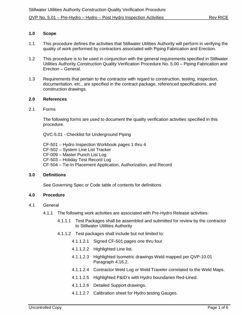
4.1.1 The following work activities are associated with Pre-Hydro Release activities:
4.1.1.1 Test Packages shall be assembled and submitted for review by the contractor to Stillwater Utilities Authority
4.1.1.2 Test packages shall include but not limited to:
4.1.1.2.1 Signed CF-501 pages one thru four.
4.1.1.2.2 Highlighted Line list.
4.1.1.2.3 Highlighted Isometric drawings Weld mapped per QVP-10.01 Paragraph 4.16.2.
4.1.1.2.4 Contractor Weld Log or Weld Traveler correlated to the Weld Maps.
4.1.1.2.5 Highlighted P&ID’s with Hydro boundaries Red-Lined.
4.1.1.2.6 Detailed Support drawings.
4.1.1.2.7 Calibration sheet for Hydro testing Gauges.
Stillwater Utilities Authority Construction Quality Verification Procedure
QVP No. 5.01 – Pre-Hydro – Hydro – Post Hydro Inspection Activities Rev RICE
Uncontrolled Copy Page 2 of 6
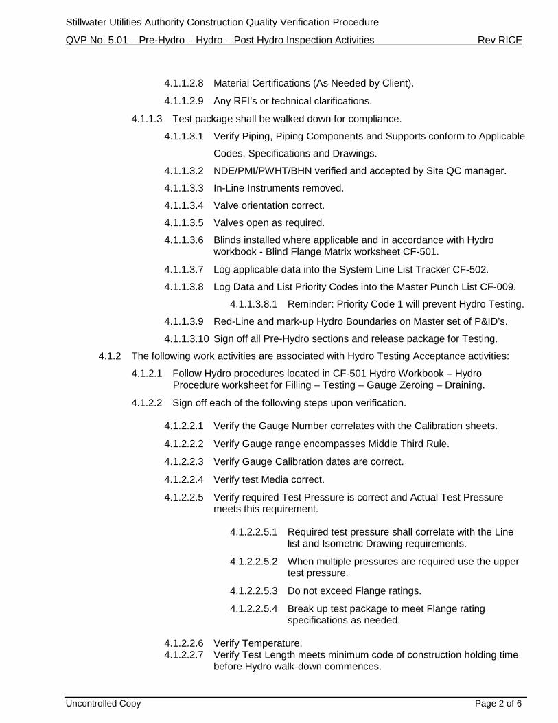
4.1.1.2.8 Material Certifications (As Needed by Client).
4.1.1.2.9 Any RFI’s or technical clarifications.
4.1.1.3 Test package shall be walked down for compliance.
4.1.1.3.1 Verify Piping, Piping Components and Supports conform to Applicable
Codes, Specifications and Drawings.
4.1.1.3.2 NDE/PMI/PWHT/BHN verified and accepted by Site QC manager.
4.1.1.3.3 In-Line Instruments removed.
4.1.1.3.4 Valve orientation correct.
4.1.1.3.5 Valves open as required.
4.1.1.3.6 Blinds installed where applicable and in accordance with Hydro workbook - Blind Flange Matrix worksheet CF-501.
4.1.1.3.7 Log applicable data into the System Line List Tracker CF-502.
4.1.1.3.8 Log Data and List Priority Codes into the Master Punch List CF-009.
4.1.1.3.8.1 Reminder: Priority Code 1 will prevent Hydro Testing.
4.1.1.3.9 Red-Line and mark-up Hydro Boundaries on Master set of P&ID’s.
4.1.1.3.10 Sign off all Pre-Hydro sections and release package for Testing.
4.1.2 The following work activities are associated with Hydro Testing Acceptance activities:
4.1.2.1 Follow Hydro procedures located in CF-501 Hydro Workbook – Hydro Procedure worksheet for Filling – Testing – Gauge Zeroing – Draining.
4.1.2.2 Sign off each of the following steps upon verification.
4.1.2.2.1 Verify the Gauge Number correlates with the Calibration sheets.
4.1.2.2.2 Verify Gauge range encompasses Middle Third Rule.
4.1.2.2.3 Verify Gauge Calibration dates are correct.
4.1.2.2.4 Verify test Media correct.
4.1.2.2.5 Verify required Test Pressure is correct and Actual Test Pressure meets this requirement.
4.1.2.2.5.1 Required test pressure shall correlate with the Line
list and Isometric Drawing requirements.
4.1.2.2.5.2 When multiple pressures are required use the upper test pressure.
4.1.2.2.5.3 Do not exceed Flange ratings.
4.1.2.2.5.4 Break up test package to meet Flange rating specifications as needed.
4.1.2.2.6 Verify Temperature. 4.1.2.2.7 Verify Test Length meets minimum code of construction holding time
before Hydro walk-down commences.
Stillwater Utilities Authority Construction Quality Verification Procedure
QVP No. 5.01 – Pre-Hydro – Hydro – Post Hydro Inspection Activities Rev RICE
Uncontrolled Copy Page 3 of 6
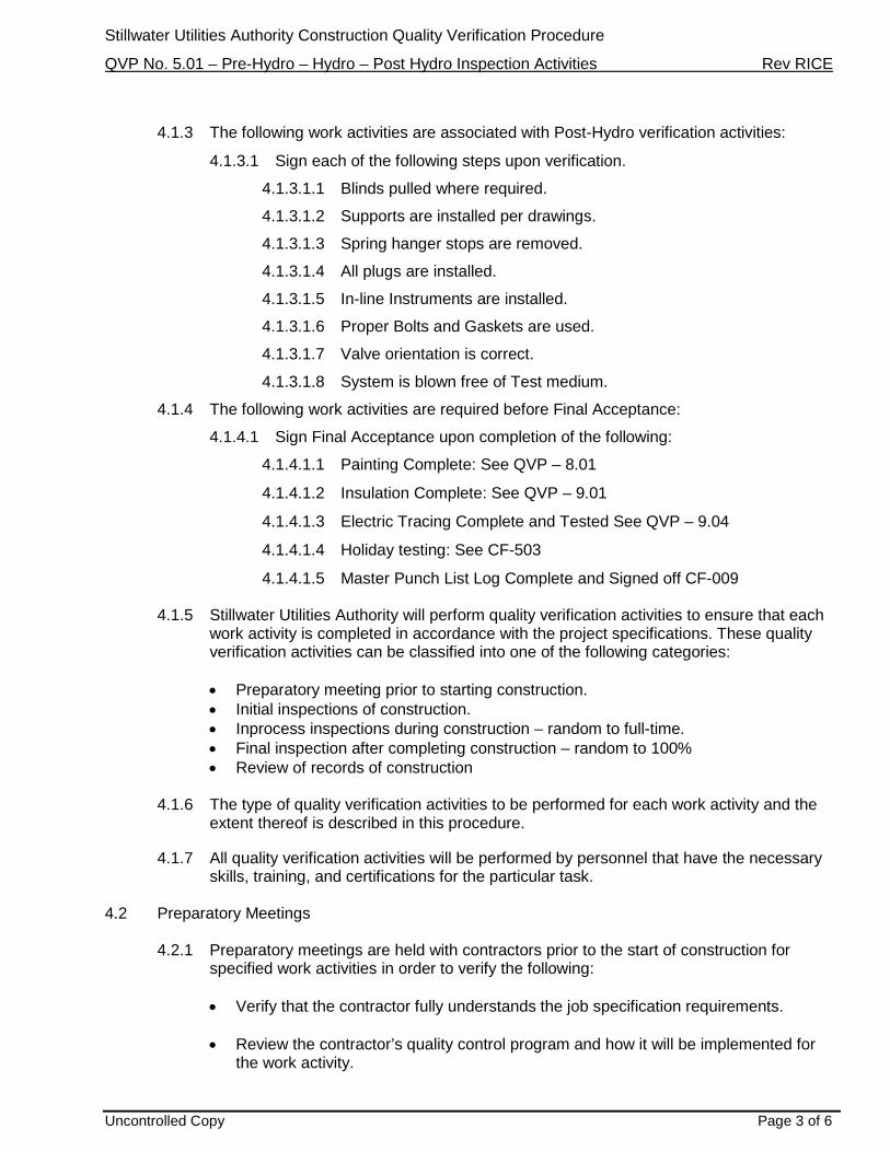
4.1.3 The following work activities are associated with Post-Hydro verification activities:
4.1.3.1 Sign each of the following steps upon verification.
4.1.3.1.1 Blinds pulled where required.
4.1.3.1.2 Supports are installed per drawings.
4.1.3.1.3 Spring hanger stops are removed.
4.1.3.1.4 All plugs are installed.
4.1.3.1.5 In-line Instruments are installed.
4.1.3.1.6 Proper Bolts and Gaskets are used.
4.1.3.1.7 Valve orientation is correct.
4.1.3.1.8 System is blown free of Test medium.
4.1.4 The following work activities are required before Final Acceptance:
4.1.4.1 Sign Final Acceptance upon completion of the following:
4.1.4.1.1 Painting Complete: See QVP – 8.01
4.1.4.1.2 Insulation Complete: See QVP – 9.01
4.1.4.1.3 Electric Tracing Complete and Tested See QVP – 9.04
4.1.4.1.4 Holiday testing: See CF-503
4.1.4.1.5 Master Punch List Log Complete and Signed off CF-009
4.1.5 Stillwater Utilities Authority will perform quality verification activities to ensure that each work activity is completed in accordance with the project specifications. These quality verification activities can be classified into one of the following categories:
• Preparatory meeting prior to starting construction. • Initial inspections of construction. • Inprocess inspections during construction – random to full-time. • Final inspection after completing construction – random to 100% • Review of records of construction
4.1.6 The type of quality verification activities to be performed for each work activity and the extent thereof is described in this procedure.
4.1.7 All quality verification activities will be performed by personnel that have the necessary
skills, training, and certifications for the particular task.
4.2 Preparatory Meetings
4.2.1 Preparatory meetings are held with contractors prior to the start of construction for specified work activities in order to verify the following: • Verify that the contractor fully understands the job specification requirements. • Review the contractor’s quality control program and how it will be implemented for
the work activity.
Stillwater Utilities Authority Construction Quality Verification Procedure
QVP No. 5.01 – Pre-Hydro – Hydro – Post Hydro Inspection Activities Rev RICE
Uncontrolled Copy Page 4 of 6
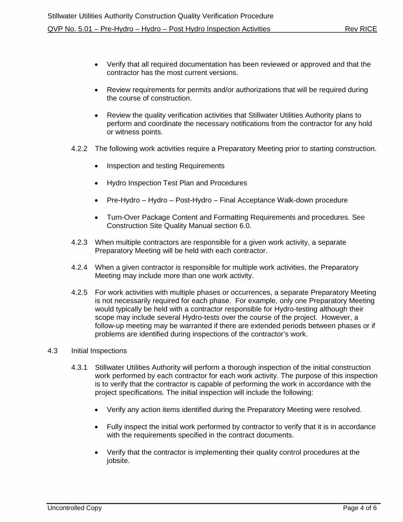
• Verify that all required documentation has been reviewed or approved and that the
contractor has the most current versions. • Review requirements for permits and/or authorizations that will be required during
the course of construction. • Review the quality verification activities that Stillwater Utilities Authority plans to
perform and coordinate the necessary notifications from the contractor for any hold or witness points.
4.2.2 The following work activities require a Preparatory Meeting prior to starting construction.
• Inspection and testing Requirements • Hydro Inspection Test Plan and Procedures • Pre-Hydro – Hydro – Post-Hydro – Final Acceptance Walk-down procedure • Turn-Over Package Content and Formatting Requirements and procedures. See
Construction Site Quality Manual section 6.0.
4.2.3 When multiple contractors are responsible for a given work activity, a separate Preparatory Meeting will be held with each contractor.
4.2.4 When a given contractor is responsible for multiple work activities, the Preparatory
Meeting may include more than one work activity. 4.2.5 For work activities with multiple phases or occurrences, a separate Preparatory Meeting
is not necessarily required for each phase. For example, only one Preparatory Meeting would typically be held with a contractor responsible for Hydro-testing although their scope may include several Hydro-tests over the course of the project. However, a follow-up meeting may be warranted if there are extended periods between phases or if problems are identified during inspections of the contractor’s work.
4.3 Initial Inspections
4.3.1 Stillwater Utilities Authority will perform a thorough inspection of the initial construction work performed by each contractor for each work activity. The purpose of this inspection is to verify that the contractor is capable of performing the work in accordance with the project specifications. The initial inspection will include the following:
• Verify any action items identified during the Preparatory Meeting were resolved.
• Fully inspect the initial work performed by contractor to verify that it is in accordance
with the requirements specified in the contract documents.
• Verify that the contractor is implementing their quality control procedures at the jobsite.

Stillwater Utilities Authority Construction Quality Verification Procedure
QVP No. 5.01 – Pre-Hydro – Hydro – Post Hydro Inspection Activities Rev RICE
Uncontrolled Copy Page 5 of 6
• Prepare a Master Punch-list documenting the specific activities performed during the Initial Inspection and identify any items of nonconformance or other action items for follow-up and resolution.
4.4 Follow-up Inspections
4.4.1 Stillwater Utilities Authority will continually monitor the placement activities through completion. The Follow-up Inspections will include the following activities:
• Verify that piping is being placed in accordance with the requirements specified in
the contract documents.
• Verify that the contractor is implementing their quality control procedures during this activity.
• Verify that any Nonconformancies or action items identified during placement are
quickly resolved. Work should not be proceeding where Nonconformancies have been identified but have not been resolved, unless an approved work-around plan is in place. Follow Construction Site Quality Manual 7.0. Use CF-002 forms.
• Prepare a Master Punch-list documenting the specific activities performed during
each Follow-up Inspection and identify any items of nonconformance or other action items for follow-up and resolution.
4.5 Final Inspection
4.5.1 Stillwater Utilities Authority will perform a Final Inspection at or near the completion of the placement activities. The Final Inspection will include the following items:
• Perform a final inspection of any work performed by the contractor that was not
previously inspected during the Initial and Follow-up Inspections but would be prudent to assure the final quality of the work. Verify that all work is in compliance with the specifications and most current drawing revision at the time of final inspection.
• Prepare a Master Punch-list documenting the specific activities performed during
each Final Inspection and develop a punch list of all items that were found to be incomplete or not in compliance with the contract documents, referenced specifications, and the latest drawing revision at the time of the inspection. This would include any outstanding items of nonconformance or action items identified during previous Preparatory Meetings, Initial Inspections, and Follow-up Inspections for the particular work activity.
• Specify the estimated date for which each item on the punch list should be
completed or corrected to be in compliance. CF-009
• Perform follow-up activities to verify that each item on the punch list is completed and/or corrected and is acceptable.
4.6 Acceptance
4.6.1 Stillwater Utilities Authority will verify the following prior to issuing final acceptance for a particular area:

Stillwater Utilities Authority Construction Quality Verification Procedure
QVP No. 5.01 – Pre-Hydro – Hydro – Post Hydro Inspection Activities Rev RICE
Uncontrolled Copy Page 6 of 6
• Pipe fabrication, erection, welding and coating activities are complete. • The contractor has completed all inspection, testing, and quality control activities.
• Stillwater Utilities Authority has completed all quality verification activities.
• All final inspection punch list items are resolved and accepted.
5.0 Records 5.1 The Quality Verification Activities associated with this procedure are recorded on the following
forms
• QVC-501 - Checklist for Underground Piping
• CF-501 – Hydro Inspection Workbook pages 1 thru 4
• CF-502 – System Line List Tracker
• CF-009 – Master Punch List Log
• CF-503 - Holiday Test Record Log
• CF-504 – Tie-In Placement Application, Authorization, and Record

Stillwater Utilities Authority
Engineering
Pneumatic Testing
Procedure

FLINT HILLS RESOURCES EPC Quality Manual Rev. DRAFT
Date: 06 Jun 2012
Page 2 of 8
Rev No. Issue Date Description Prepared by: Approved by:
0 9/22/2014 Pneumatic Testing Steven E. McKenna Don Bogart

Stillwater Utilities Authority Construction Quality Verification
Procedure
QVP No. 5.03 - Pneumatic Testing Rev 0
i
TABLE OF CONTENTS
1.0 SCOPE ............................................................................................................................ 1
2.0 REFERENCES ................................................................................................................ 1 2.1 Forms ...................................................................................................................................1 2.2 Standard Industry Specifications .........................................................................................1
3.0 DEFINITIONS .................................................................................................................. 2 See ASME PCC-2 ............................................................................................................................2
4.0 PROCEDURE .................................................................................................................. 2 4.1 Safety ...................................................................................................................................2
5.0 PRE- PNEUMATIC TESTING VERIFICATIONS ............................................................. 3
6.0 PNEUMATIC TESTING VERIFICATIONS ...................................................................... 4 6.1 Test Medium ........................................................................................................................4 6.2 Competent Person ................................................................................................................4 6.3 Regulation of Pressure .........................................................................................................5 6.4 Termination Valve ...............................................................................................................5 6.5 Overpressure relief protection..............................................................................................5 6.6 Gauge Location ....................................................................................................................5 6.7 Pressurization .......................................................................................................................6
7.0 POST-PNEUMATIC TESTING VERIFICATION ACTIVITIES ......................................... 6 7.1 QVP-5.01 .............................................................................................................................6
8.0 ATTACHMENT A ............................................................................................................ 7
Stillwater Utilities Authority Construction Quality Verification
Procedure
QVP No. 5.03 - Pneumatic Testing Rev 0
Page 1 of 8
1.0 Scope
1.1 This document defines the Stillwater Utilities Authority procedure used when performing
Pneumatic Testing.
1.2 Due to the potential for the release of significant amounts of stored energy, pneumatic testing is
neither the preferred nor recommended practice of Stillwater Utilities Authority. In certain
circumstances projects may request to perform pneumatic testing in which case Burns &
McDonnell requires prior approval from the CDB Manager of Field Operations, Corporate
Director of Safety, CDB Manager of Quality, Piping Engineer of Record, and EPC Project
Manager. See attachment “A” below for approval process signatures. Attachment “A” shall be
developed by the Stillwater Utilities Authority Project Management Team.
1.3 This procedure is to be used in conjunction with the requirements specified in Stillwater Utilities
Authority Construction Quality Verification Procedure No. 5.01 – Pre-Hydro – Hydro – Post
Hydro Inspection Activities.
2.0 References
2.1 Forms
2.1.1 The following forms are used to document the quality verification activities specified in
this procedure.
CF-501 – Pressure Testing Inspection Workbook pages 1 thru 4
2.2 Standard Industry Specifications
2.2.1 The following is a list of standard specifications associated with Pneumatic Testing
that may be referenced in this procedure, supplemental Construction Quality
Verification Procedures, and/or contract specifications.
ASME PCC-2 – Part 5 Examination and Testing Section ASME B31.1 – Power Piping ASME B31.3 – Process Piping ASME B31.4 – Pipeline Transportation Systems for Liquids and Slurries ASME B31.5 – Refrigeration Piping and Heat transfer Components ASME B31.8 – Gas Transmission and Distribution Piping systems ASME B31.9 – Building services Piping

Stillwater Utilities Authority Construction Quality Verification
Procedure
QVP No. 5.03 - Pneumatic Testing Rev 0
Page 2 of 8
3.0 Definitions
See ASME PCC-2: Pneumatic test requirements section for definitions
4.0 Procedure
4.1 Safety
4.1.1 Due to the potential for the release of significant amounts of stored energy, Safety
shall be thoroughly planned.
4.1.2 A Safety Meeting shall be held with all personnel to discuss the planned pneumatic
testing activities.
4.1.3 Test boundaries shall be calculated using the Stillwater Utilities Authority Pneumatic
Testing Calculator.
4.1.3.1 The Stillwater Utilities Authority Pneumatic Testing Calculator is a MS Excel
Spreadsheet developed by using ASME PCC-2 Article 5.1, Mandatory
Appendix II Stored Energy Calculations for Pneumatic Pressure Tests
Formulas and ASME PCC-2 Article 5.1, Mandatory Appendix III Safe
Distance Calculations for Pneumatic Pressure Tests Formulas.
4.1.3.2 The MS Excel Spreadsheet was developed by Steven E. McKenna, Burns &
McDonnell Manager of Quality, CDB and has been verified and validated by
Anthony Jercha, P.E., Stillwater Utilities Authority P&I Chief Piping Engineer.
4.1.3.3 All boundaries shall be marked with red “Danger Do Not Enter” flagging with
signs distributed around the calculated safety perimeter. The perimeter shall
be calculated using the Stillwater Utilities Authority Pneumatic Testing
Calculator. The test boundary shall include all piping within the test. The
radius is defined by the distance from the pressurized pipe.
4.1.4 All nonessential personnel shall be evacuated from the designated test boundaries.

Stillwater Utilities Authority Construction Quality Verification
Procedure
QVP No. 5.03 - Pneumatic Testing Rev 0
Page 3 of 8
4.1.4.1 Stillwater Utilities Authority prefers pneumatic testing be performed during off
work hours; such as evenings or weekends when all nonessential personnel
are not onsite.
4.1.5 Only essential personnel (Inspectors, pressure regulator operators) are allowed inside
the test boundaries.
4.1.6 During increases of pressure on the system, all essential personnel shall identify the
safest location within boundaries as practical.
4.1.7 Perimeter watchers shall be located as such to prevent any personnel from entering
into the test boundaries.
5.0 Pre- Pneumatic Testing Verifications
5.1 Develop Site Specific Pneumatic Testing Procedures and submit to Stillwater Utilities Authority
Construction Design-Build Manager of Field Operations, Corporate Director of Safety, Manager
of Quality - CDB, Piping Engineer of Record, and EPC Project Manager for approval. See
attachment “A” below. Attachment “A” shall be developed by the Stillwater Utilities Authority
Project Management Team.
5.2 The Testing Procedure shall establish the following:
5.2.1 Define the Code of Construction; i.e. ASME B31.3, B31.1…
5.2.2 Define the piping system’s Design Pressure in psig from the Project Engineering Line
List.
5.2.2.1 Work with the Project Piping Engineer when reviewing the Line List and
determining Pneumatic Test Pressures
5.2.3 Calculate piping system Test Pressures using the rules from the code of construction
as limitations differ per each Code book
5.2.4 Measure the Center Line Linear Footage of the piping system to be tested. The piping
linear footage shall be measured using the Center Line to Center Line approach.
5.2.5 Define the pipe diameters of the system to be tested

Stillwater Utilities Authority Construction Quality Verification
Procedure
QVP No. 5.03 - Pneumatic Testing Rev 0
Page 4 of 8
5.2.6 Define the pipe wall thickness of the system to be tested
5.2.7 Perform the calculations using the Stillwater Utilities Authority Pneumatic Testing
Calculator
5.2.8 For each test calculate Stored Energy measured in ft-lbs
5.2.9 For each test calculate TNT Comparator measured in lbs
5.2.10 Any test exceeding .5 lbs in TNT Comparator is unacceptable
5.2.11 For each test calculate the required test boundaries
5.3 Submit the test procedure per section 5.0 for approval
5.4 Follow QVP-5.01 - Verification Procedure for Pre-Hydro - Hydro - Post-Hydro procedure for pre-
test walk downs and releases. Stillwater Utilities Authority will verify installations and sign the
release to test section of CF-502 prior to testing all systems.
6.0 Pneumatic Testing Verifications
6.1 Test Medium
6.1.1 The test medium shall be either clean, dry, oil-free air, or a nonflammable, nontoxic
gas. The air should meet the requirements of Class 1, 2, or 3 air per ISO 8573-1:2001,
Compressed Air - Part 1: Contaminants and Purity Classes, should be used with a
dew point ranging from −4°F to −94°F. Inert gases such as Nitrogen is preferred
however not required.
6.2 Competent Person
6.2.1 Pressurization shall be under the control by one competent person at all times.
6.2.2 The Competency of this person shall be evaluated by the Stillwater Utilities Authority
Site Manager. The Stillwater Utilities Authority Site Manager shall evaluate and
approve the contractor’s elected competent person’s training and experience in
Pneumatic Testing.

Stillwater Utilities Authority Construction Quality Verification
Procedure
QVP No. 5.03 - Pneumatic Testing Rev 0
Page 5 of 8
6.3 Regulation of Pressure
6.3.1 Regulation of the pressure through a manual valve is not allowed. In all tests the
pressure shall be regulated through an automatic pressure regulator. The operability
of pressure regulator shall be verified by Stillwater Utilities Authority and the
contractor.
6.4 Termination Valve
6.4.1 The temporary air supply piping from the compressor shall have a Ball Valve for quick
termination of supply air at the first sign of any discrepancies. The Stillwater Utilities
Authority approved competent person shall be located at the termination valve
throughout the pressure test.
6.5 Overpressure relief protection
6.5.1 Overpressure relief protection shall be provided. The set pressure of a calibrated
pressure relief device shall be not more than the greater of the test pressure plus 5
psig, or 105% of the test pressure. Each over pressure relief device shall have
documentation of calibration traceable to the calibration sticker placed on the over
pressure relief device. Calibration of each pressure relief device shall be within 6
month intervals.
6.5.2 The overpressure relief device shall be placed downstream of the termination valve on
the temporary air supply piping. No obstructions shall be placed between the
termination valve and the overpressure relief valve.
6.6 Gauge Location
6.6.1 At least two calibrated pressure gauges shall be placed into the system test. One at
the source of pressure and the other at the furthest extent of the pressure test from
the source. Each pressure gauge shall have documentation of calibration traceable to
the calibration sticker placed on each gauge.
6.6.2 The pressure source shall be isolatable from the piping to be tested without isolating
the pressure gauges from the piping being tested.
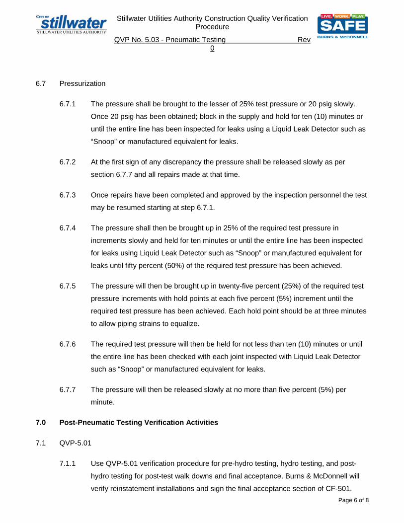
Stillwater Utilities Authority Construction Quality Verification
Procedure
QVP No. 5.03 - Pneumatic Testing Rev 0
Page 6 of 8
6.7 Pressurization
6.7.1 The pressure shall be brought to the lesser of 25% test pressure or 20 psig slowly.
Once 20 psig has been obtained; block in the supply and hold for ten (10) minutes or
until the entire line has been inspected for leaks using a Liquid Leak Detector such as
“Snoop” or manufactured equivalent for leaks.
6.7.2 At the first sign of any discrepancy the pressure shall be released slowly as per
section 6.7.7 and all repairs made at that time.
6.7.3 Once repairs have been completed and approved by the inspection personnel the test
may be resumed starting at step 6.7.1.
6.7.4 The pressure shall then be brought up in 25% of the required test pressure in
increments slowly and held for ten minutes or until the entire line has been inspected
for leaks using Liquid Leak Detector such as “Snoop” or manufactured equivalent for
leaks until fifty percent (50%) of the required test pressure has been achieved.
6.7.5 The pressure will then be brought up in twenty-five percent (25%) of the required test
pressure increments with hold points at each five percent (5%) increment until the
required test pressure has been achieved. Each hold point should be at three minutes
to allow piping strains to equalize.
6.7.6 The required test pressure will then be held for not less than ten (10) minutes or until
the entire line has been checked with each joint inspected with Liquid Leak Detector
such as “Snoop” or manufactured equivalent for leaks.
6.7.7 The pressure will then be released slowly at no more than five percent (5%) per
minute.
7.0 Post-Pneumatic Testing Verification Activities
7.1 QVP-5.01
7.1.1 Use QVP-5.01 verification procedure for pre-hydro testing, hydro testing, and post-
hydro testing for post-test walk downs and final acceptance. Burns & McDonnell will
verify reinstatement installations and sign the final acceptance section of CF-501.

Burns & McDonnell Construction Quality Verification Procedure
QVP No. 5.03 - Pneumatic Testing Rev 0
Page 7 of 8
8.0 ATTACHMENT A
This is for Pneumatic Pressure Testing Approval only
Line # Service Material Type
Actual Pipe
Diameter
Material Thickness (inches)
Design Pressure
Testing Pressure
(psig)
Center Line Pipe
linear footage
Stored Energy (ft-lbs)
TNT Comp. (lbs)
Minimum Boundary
Radius (ft)
Approvals Printed Name Signature Date
Stillwater Utilities Authority Manager of Field Operations
Stillwater Utilities Authority Director of Safety
Stillwater Utilities Authority CDB Manager of Quality
Piping Engineer of Record
EPC Project Manager

Stillwater Utilities Authority
Construction Quality Verification Procedure No. 10.01 – General Welding Standards Rev 2
Page 1 of 16
1.0 SCOPE
1.1 This standard applies to the fabrication, installation, repair and alteration of welded piping systems. This is a general welding standard to aid in determining Contractor adherence to Governing Codes and Design Specifications.
1.2 This procedure defines the activities that Stillwater Utilities Authority will perform
in verifying the quality of work performed by contractors associated with Welding.
1.3 This procedure is to be used in conjunction with the general requirements specified in Stillwater Utilities Authority Construction Quality Verification Procedure No. 10.00 – Special Processes – General.
1.4 Requirements that pertain to the contractor with regard to construction, testing,
inspection, documentation, etc., are specified in the contract package, referenced specifications, and construction drawings.
2.0 References
2.1 Standard Industry Specifications: See QV-10.0 - General Verification Procedure for Special Processes Paragraph 2.2
2.2 Forms
The following forms are used to document the quality verification activities specified in this procedure. QVC-10.01 - Checklist for Welding CF-1001 – Weld Log / Traveler CF-1002 – Welder’s Continuity Log CF-1003 – Hot Tap Application, Authorization, and Record
3.0 Definitions
See Governing Spec or Code table of contents for definitions
4.0 Procedure
4.1 The following will aid in determining Applicable Governing Codes. See References below, Project Specifications and ASME Code Book Introduction Sections for further details.
4.1.1 B31.1 Power Piping generally refers to: Steam Piping systems having an
operating pressure in excess of 15 psig; high temperature water piping systems subject to temperatures in excess of 250°F and/or pressures in excess of 160 psig; any piping system using an organic or combustible thermal fluid or gas as a heat transfer media and subject to temperatures in excess of 250°F and; fuel gas or fuel piping systems downstream of the plant’s meter set assembly within the plant’s property lines.

Stillwater Utilities Authority
Construction Quality Verification Procedure No. 10.01 – General Welding Standards Rev 2
Page 2 of 16
4.1.2 Boiler External Piping (BEP) systems in which Section I of the ASME Boiler and Pressure Vessel Code has administrative control. BEP is considered as that piping which begins at power boiler terminal points and extends up to and includes the valve or valves required by ASME Section I. The boiler terminal points are: the first circumferential joint for welding end connections; the face of the first flange in bolted flanged connections, or; the first threaded joint in that type of connection. All other piping within the scope of this standard is defined as non-boiler external piping.
4.1.3 Process Piping refers to a variety of piping systems found in petroleum
refineries, chemical, pharmaceutical, textile, paper, semiconductor, and cryogenic plants, and related processing plants and terminals. There are four (4) classifications of process piping; high pressure piping; category M fluid service; category D fluid service, and; normal fluid service.
4.1.3.1 A piping system is classified as a High Pressure Piping
System when design or operating pressures exceed the pressure limits of a class 2,500 ANSI flange at the intended operating temperature.
4.1.3.2 A piping system is classified as a Category M Process Piping
System when the medium is toxic or hazardous, and when the potential for personal exposure is judged to be significant and exposure to a small amount of media caused by leakage can produce serious irreversible harm to persons on breathing or bodily contact, even when prompt restorative measures are taken.
4.1.3.3 A piping system is classified as a Category D Process Piping
System when all of the following apply:
4.1.3.3.1 The fluid handled by the system is nontoxic and not damaging to human tissue;
4.1.3.3.2 The design gage pressure between 15 and 150 psi,
and;
4.1.3.3.3 The design operating temperature range of the piping system is between –20°F and 366°F.
4.1.3.4 Process piping systems not subject to the rules of .1, .2 and .3
above are classified as Normal Fluid Service Process Piping Systems (e.g., the base code piping systems).
4.1.3.5 An additional term that may apply to process piping systems is
Severe Cycle Conditions. The owner is responsible for identifying severe cyclic conditions, where it applies and the specific manufacturing, installation, inspection and testing requirements.

Stillwater Utilities Authority
Construction Quality Verification Procedure No. 10.01 – General Welding Standards Rev 2
Page 3 of 16
4.2 This standard supplements the Sub-contractors Welding Procedure Specifications (WPS) and Quality Manual by providing the general fabrication, quality control and welding requirements necessary to comply with the referenced construction codes and project specifications. The Contractor shall be responsible for implementation of Quality Functions before and during fabrication, erection and testing
4.3 Welding Procedure Specifications
4.3.1 All WPS shall be Verified and Accepted by Stillwater Utilities Authority before welding commences.
4.3.2 The Contractor shall supply all WPS’s with supporting PQR’s to Stillwater
Utilities Authority for Record retention.
4.4 Base Metals
4.4.1 Materials and piping components for BEP shall be controlled in accordance with requirements established in Stillwater Utilities Authority Site Quality Manual Section 4.0. When the scope of the project involves both BEP and Non-Boiler External piping, BEP materials shall be segregated from non-boiler external piping materials unless all materials are purchased and received using BEP procedures and material certification. Site specific material control procedures may be established where needed.
4.4.2 The physical identification of materials and piping components shall be
maintained throughout construction up to and including the point of installation.
4.4.3 The Sub-Contractor shall be responsible for transferring identification
markings to all pieces prior to subdividing materials.
4.4.4 Should it become impossible to maintain full physical identification, a coded identification system may be used. The coded identification system used for BEP shall be acceptable to the Authorized Inspector.
4.4.5 Contractor shall verify that the mill test reports are forwarded to job file. If
MTRs are not accompanying material at time of receiving, the Contractor shall request MTR be supplied by Material Vendor.
4.4.6 All materials shall be checked by the contractor for any obvious signs of
imperfections (e.g., gouges, laminations, laps, dog marks, etc) See paragraphs 4.10 and 4.11 of this procedure.
4.4.6.1 NCR’s shall be written for materials that do not meet required
specifications following the Construction Site Quality Manual Paragraph 7.0
4.5 Welding Filler Metals and Storage
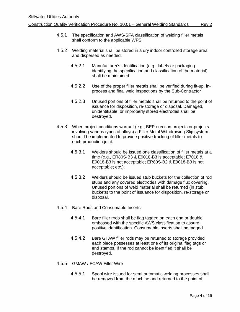
Stillwater Utilities Authority
Construction Quality Verification Procedure No. 10.01 – General Welding Standards Rev 2
Page 4 of 16
4.5.1 The specification and AWS-SFA classification of welding filler metals shall conform to the applicable WPS.
4.5.2 Welding material shall be stored in a dry indoor controlled storage area
and dispersed as needed.
4.5.2.1 Manufacturer's identification (e.g., labels or packaging identifying the specification and classification of the material) shall be maintained.
4.5.2.2 Use of the proper filler metals shall be verified during fit-up, in-
process and final weld inspections by the Sub-Contractor
4.5.2.3 Unused portions of filler metals shall be returned to the point of issuance for disposition, re-storage or disposal. Damaged, unidentifiable, or improperly stored electrodes shall be destroyed.
4.5.3 When project conditions warrant (e.g., BEP erection projects or projects
involving various types of alloys) a Filler Metal Withdrawing Slip system should be implemented to provide positive tracking of filler metals to each production joint.
4.5.3.1 Welders should be issued one classification of filler metals at a
time (e.g., ER80S-B3 & E9018-B3 is acceptable; E7018 & E9018-B3 is not acceptable; ER80S-B2 & E9018-B3 is not acceptable; etc.).
4.5.3.2 Welders should be issued stub buckets for the collection of rod
stubs and any covered electrodes with damage flux covering. Unused portions of weld material shall be returned (in stub buckets) to the point of issuance for disposition, re-storage or disposal.
4.5.4 Bare Rods and Consumable Inserts
4.5.4.1 Bare filler rods shall be flag tagged on each end or double
embossed with the specific AWS classification to assure positive identification. Consumable inserts shall be tagged.
4.5.4.2 Bare GTAW filler rods may be returned to storage provided
each piece possesses at least one of its original flag tags or end stamps. If the rod cannot be identified it shall be destroyed.
4.5.5 GMAW / FCAW Filler Wire
4.5.5.1 Spool wire issued for semi-automatic welding processes shall be removed from the machine and returned to the point of
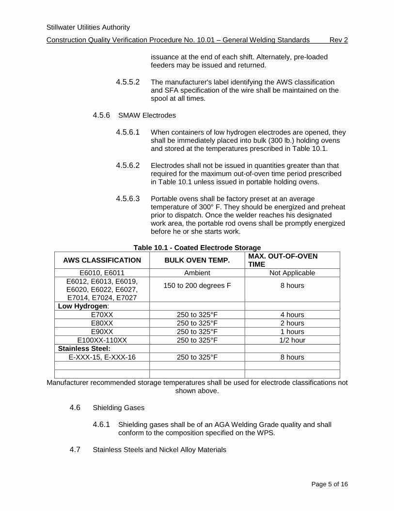
Stillwater Utilities Authority
Construction Quality Verification Procedure No. 10.01 – General Welding Standards Rev 2
Page 5 of 16
issuance at the end of each shift. Alternately, pre-loaded feeders may be issued and returned.
4.5.5.2 The manufacturer's label identifying the AWS classification
and SFA specification of the wire shall be maintained on the spool at all times.
4.5.6 SMAW Electrodes
4.5.6.1 When containers of low hydrogen electrodes are opened, they shall be immediately placed into bulk (300 lb.) holding ovens and stored at the temperatures prescribed in Table 10.1.
4.5.6.2 Electrodes shall not be issued in quantities greater than that
required for the maximum out-of-oven time period prescribed in Table 10.1 unless issued in portable holding ovens.
4.5.6.3 Portable ovens shall be factory preset at an average
temperature of 300° F. They should be energized and preheat prior to dispatch. Once the welder reaches his designated work area, the portable rod ovens shall be promptly energized before he or she starts work.
Table 10.1 - Coated Electrode Storage
AWS CLASSIFICATION BULK OVEN TEMP. MAX. OUT-OF-OVEN TIME
E6010, E6011 Ambient Not Applicable E6012, E6013, E6019, E6020, E6022, E6027, E7014, E7024, E7027
150 to 200 degrees F
8 hours
Low Hydrogen: E70XX 250 to 325°F 4 hours E80XX 250 to 325°F 2 hours E90XX 250 to 325°F 1 hours
E100XX-110XX 250 to 325°F 1/2 hour Stainless Steel:
E-XXX-15, E-XXX-16 250 to 325°F 8 hours
Manufacturer recommended storage temperatures shall be used for electrode classifications not shown above.
4.6 Shielding Gases
4.6.1 Shielding gases shall be of an AGA Welding Grade quality and shall
conform to the composition specified on the WPS.
4.7 Stainless Steels and Nickel Alloy Materials
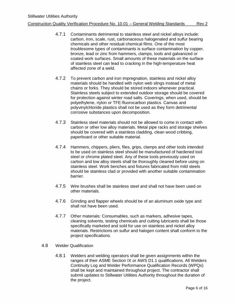
Stillwater Utilities Authority
Construction Quality Verification Procedure No. 10.01 – General Welding Standards Rev 2
Page 6 of 16
4.7.1 Contaminants detrimental to stainless steel and nickel alloys include: carbon, iron, scale, rust, carbonaceous halogenated and sulfur bearing chemicals and other residual chemical films. One of the most troublesome types of contaminants is surface contamination by copper, bronze, lead or zinc from hammers, clamps, tools and galvanized or coated work surfaces. Small amounts of these materials on the surface of stainless steel can lead to cracking in the high-temperature heat affected zone of a weld.
4.7.2 To prevent carbon and iron impregnation, stainless and nickel alloy
materials should be handled with nylon web slings instead of metal chains or forks. They should be stored indoors whenever practical. Stainless steels subject to extended outdoor storage should be covered for protection against winter road salts. Coverings, when used, should be polyethylene, nylon or TFE-fluorocarbon plastics. Canvas and polyvinylchloride plastics shall not be used as they form detrimental corrosive substances upon decomposition.
4.7.3 Stainless steel materials should not be allowed to come in contact with
carbon or other low alloy materials. Metal pipe racks and storage shelves should be covered with a stainless cladding, clean wood cribbing, paperboard or other suitable material.
4.7.4 Hammers, chippers, pliers, files, grips, clamps and other tools intended
to be used on stainless steel should be manufactured of hardened tool steel or chrome plated steel. Any of these tools previously used on carbon and low alloy steels shall be thoroughly cleaned before using on stainless steel. Work benches and fixtures fabricated from mild steels should be stainless clad or provided with another suitable contamination barrier.
4.7.5 Wire brushes shall be stainless steel and shall not have been used on
other materials.
4.7.6 Grinding and flapper wheels should be of an aluminum oxide type and shall not have been used.
4.7.7 Other materials: Consumables, such as markers, adhesive tapes,
cleaning solvents, testing chemicals and cutting lubricants shall be those specifically marketed and sold for use on stainless and nickel alloy materials. Restrictions on sulfur and halogen content shall conform to the project specifications.
4.8 Welder Qualification
4.8.1 Welders and welding operators shall be given assignments within the
ranges of their ASME Section IX or AWS D1.1 qualifications. All Welders Continuity Log and Welder Performance Qualification Records (WPQs) shall be kept and maintained throughout project. The contractor shall submit updates to Stillwater Utilities Authority throughout the duration of the project.

Stillwater Utilities Authority
Construction Quality Verification Procedure No. 10.01 – General Welding Standards Rev 2
Page 7 of 16
4.8.2 Contractor shall assign each qualified welder a stencil to be used for
work identification. Stencils shall be issued by the Contractor.
4.8.2.1 Every weld must be stamped at least once. Continuous welds are to be stamped a minimum of once every three (3) linear feet. A paint marker may be substituted with prior approval by Stillwater Utilities Authority.
4.8.3 Stillwater Utilities Authority, with justification, shall have the right to
require requalification of a welder or welding operator.
4.8.4 The Contractor shall be responsible for assigning and supervising Code welders.
4.9 Welding machines
4.9.1 Stillwater Utilities Authority shall be supplied Welding Machine Certifications prior to welding by the contractor.
4.9.2 All welding machines shall have a calibration sticker placed in common
view for inspections
4.9.3 Stillwater Utilities Authoirty QC Inspector shall verify Welding Machine calibrations and sticker placement per QVC-10.01
4.10 Surface Preparation for Welding
4.10.1 Weld joint design shall be as specified on the applicable WPS. The butt
welding end preparations given in ANSI B16.25 are also acceptable.
4.10.2 Base materials may be prepared by thermal cutting, machining, chipping, grinding, or combinations of these, provided the required alignment can be achieved. When thermal methods are used, excess material (dross) shall be removed from the surface by mechanical means to assure all oxidized metal is removed from the surface to be welded.
4.10.3 Thermal cutting of stainless steel shall be limited to the plasma (PAC)
cutting processes.
4.10.4 Surfaces for welding shall be clean and shall be free from paint, oil, rust, scale, and other contaminants detrimental to welding. Oil or grease should be removed by wiping with a clean lint free material moistened with isopropyl alcohol or other approved solvents.
4.10.5 Weld preps shall be checked for any obvious signs of imperfections (e.g.,
laminations, laps, dog marks, etc.). If detected, minor exploratory grinding may commence to remove the defect as long as the weld prep tolerances of the WPS can be maintained.

Stillwater Utilities Authority
Construction Quality Verification Procedure No. 10.01 – General Welding Standards Rev 2
Page 8 of 16
4.10.5.1 Weld metal build-up to correct fabricator errors, gaps and alignment criteria shall only be accomplished after generating an NCR and a repair plan is made. See paragraphs 3.8 and 3.14.
4.11 Repair of Base Metal Defects
4.11.1 Unacceptable defects identified in base materials shall be removed by
grinding or machining, and need not be repaired by welding, provided the remaining section thickness is not reduced below the required minimum thickness and the area is blended into the surrounding surface (maintaining the required 3 to 1 taper). If welded repairs are necessary: Verify the defect has been removed by either MT or PT Inspection before welding commences. See QVP-10.02.
4.12 Fitting And Alignment
4.12.1 The inside diameters of piping components to be butt welded shall be
aligned as accurately as is practicable within existing Code tolerances on diameters, wall thicknesses, and out-of roundness. Alignment shall be preserved during welding using bars, jacks, clamps, tack welds, or other appropriate means.
4.12.2 The internal misalignment of the ends to be joined shall not exceed 1/16
in. unless the piping design or governing code specifically state otherwise.
4.12.3 When the internal misalignment exceeds the allowable, the component with the wall extending internally shall be internally transitioned. Transitioning shall result in a piping component thickness not less than the minimum design thickness and the change in contour shall not exceed 30° degrees. Spacing of the root shall conform to the WPS.
4.12.4 When components with different outside diameters or wall thicknesses
are welded together the weld shall form a gradual transition not exceeding a slope of 30 degrees from the smaller to the larger diameter component. This condition may be met by adding weld metal, if necessary, beyond what would otherwise be the toe of the weld.
4.12.5 Backing Rings may only be used when permitted by Project
Specifications. Backing Rings shall be made of weldable quality and compatible with the base metals.
4.12.6 Tack welds used to secure alignment shall either be removed completely
when they have served their purpose, or their starting and stopping ends shall be feathered by suitable means so that they may be satisfactorily incorporated into the final weld.
4.13 Socket Welded Assembly
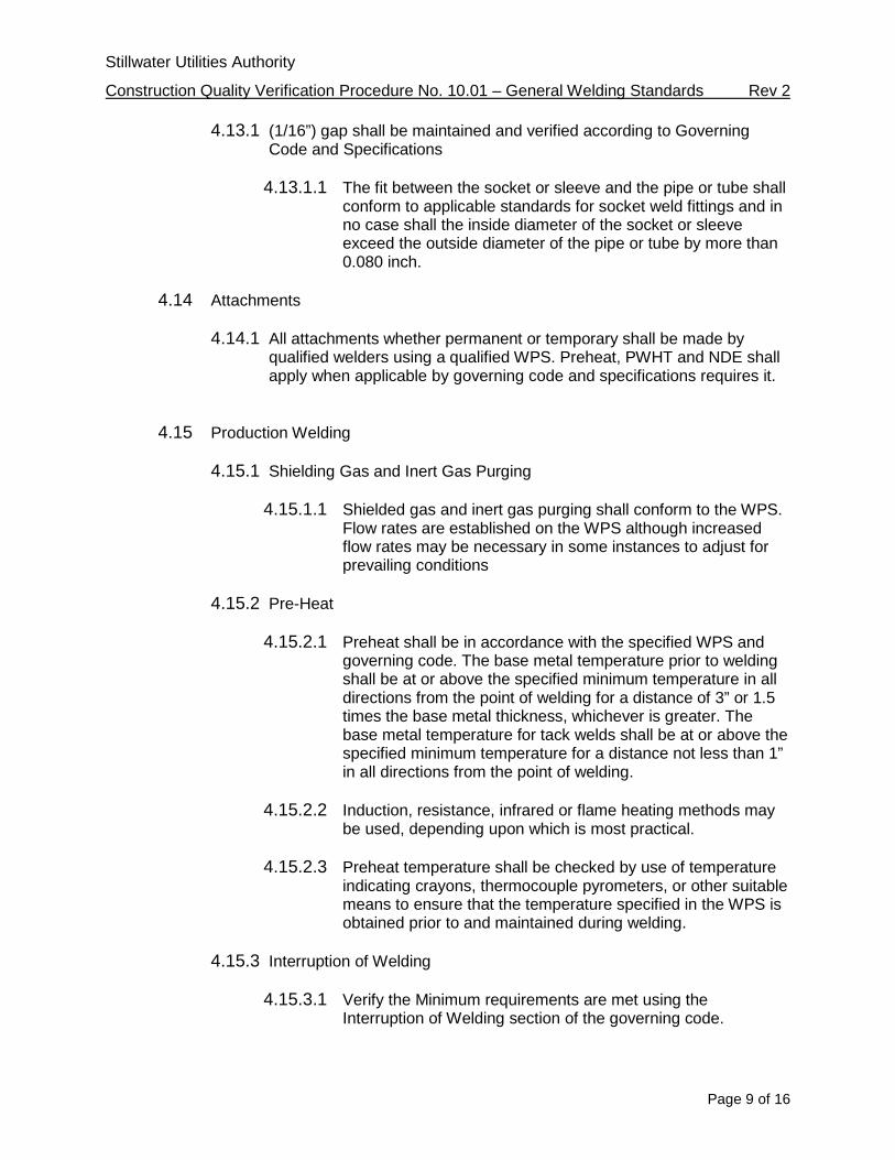
Stillwater Utilities Authority
Construction Quality Verification Procedure No. 10.01 – General Welding Standards Rev 2
Page 9 of 16
4.13.1 (1/16”) gap shall be maintained and verified according to Governing Code and Specifications
4.13.1.1 The fit between the socket or sleeve and the pipe or tube shall
conform to applicable standards for socket weld fittings and in no case shall the inside diameter of the socket or sleeve exceed the outside diameter of the pipe or tube by more than 0.080 inch.
4.14 Attachments
4.14.1 All attachments whether permanent or temporary shall be made by
qualified welders using a qualified WPS. Preheat, PWHT and NDE shall apply when applicable by governing code and specifications requires it.
4.15 Production Welding 4.15.1 Shielding Gas and Inert Gas Purging
4.15.1.1 Shielded gas and inert gas purging shall conform to the WPS.
Flow rates are established on the WPS although increased flow rates may be necessary in some instances to adjust for prevailing conditions
4.15.2 Pre-Heat
4.15.2.1 Preheat shall be in accordance with the specified WPS and governing code. The base metal temperature prior to welding shall be at or above the specified minimum temperature in all directions from the point of welding for a distance of 3” or 1.5 times the base metal thickness, whichever is greater. The base metal temperature for tack welds shall be at or above the specified minimum temperature for a distance not less than 1” in all directions from the point of welding.
4.15.2.2 Induction, resistance, infrared or flame heating methods may
be used, depending upon which is most practical.
4.15.2.3 Preheat temperature shall be checked by use of temperature indicating crayons, thermocouple pyrometers, or other suitable means to ensure that the temperature specified in the WPS is obtained prior to and maintained during welding.
4.15.3 Interruption of Welding
4.15.3.1 Verify the Minimum requirements are met using the Interruption of Welding section of the governing code.

Stillwater Utilities Authority
Construction Quality Verification Procedure No. 10.01 – General Welding Standards Rev 2
Page 10 of 16
4.15.3.2 Verify Pre-Heat specified in the WPS is applied before welding resumes.
4.15.4 Weld progression
4.15.4.1 Vertical welding progression shall govern unless prior approval from Site Quality Control Manager. Horizontal position welding requires that the succeeding beads be deposited on the lower face of the groove and placed one above the other. This sequence may be modified to allow placement of one stringer bead at the top of the groove with the remainder of the passes layered from bottom to top.
4.15.5 Intermediate Passes
4.15.5.1 Each bead of a weld shall be cleaned of slag, flux and other foreign material prior to depositing subsequent beads. Starts and stops shall be staggered, cleaned carefully and ground if necessary to provide sound weld material prior to depositing additional weld metal.
4.16 Finished Welds
4.16.1 All welds shall be Visually Inspected by the Sub-contractors certified QC
Inspector 4.16.2 All welds shall be Weld Mapped, As-Built and Weld Logged.
4.16.2.1 Isometric Drawings in correlation with As-Builts shall have all
field welds identified by a pre-approved method.
4.16.2.1.1 Isometric drawings have associated line numbers designated.
4.16.2.1.2 Start numbering welds per Isometric drawing. If an Isometric drawing has multiple pages with a single designated line number continue numbering from previous weld mapped Isometric drawing.
4.16.2.1.3 If an Isometric drawing has multiple line numbers, weld map per Isometric drawing.
4.16.2.1.4 Contractors weld log shall distinguish each weld associated with Isometric drawing and line number. Use CF-1001 Weld Log.
4.16.3 Each welder shall mark his assigned identifying symbol adjacent to the
welds which he makes using an approved method of marking.
4.16.4 All finished welds shall be visually free of cracks, porosity, slag, under-fill, under-cut, surface lack of fusion, arc strikes and any other linear indications.

Stillwater Utilities Authority
Construction Quality Verification Procedure No. 10.01 – General Welding Standards Rev 2
Page 11 of 16
4.16.5 Surface of welds shall be sufficiently free from coarse ripples, grooves,
overlaps and abrupt ridges and valleys to permit proper interpretation of required Nondestructive examinations.
4.17 Fillet and Socket Welds
4.17.1 In making fillet welds, the weld metal shall be deposited in such a way as
to secure adequate penetration into the base metal at the root of the weld.
4.17.2 Sharp transition angles and re-entrant corners shall be avoided.
4.17.3 A minimum of two weld passes shall be deposited on each weld joint
with staggered starts and stops. Welding shall not be performed without the addition of filler metal.
4.17.4 When preheat is required, it shall be applied evenly around the weld area
and shall include a minimum of four inches on all sides of the weld toes, or as the component configuration permits.
4.18 Seal Welds
4.18.1 Seal welds on threaded joints shall cover all exposed threads and shall
be performed by qualified welders using the appropriate Welding Procedure Specification. When threaded joints are to be seal welded, joint compounds shall not be used.
4.19 Branch Connections
4.19.1 Three main types: See Governing Codes and Design Specification for details
4.19.1.1 Partial Penetration Branch Connections
4.19.1.2 Full Penetration Threaded and Socket Welded Branch
Connections
4.19.1.3 Welded Pipe to Pipe Branch Connections
4.20 Hot Tapping
4.20.1 See API RP 2201 – Safe Hot Tapping Practices for Guidelines. 4.20.2 These procedures for making hot taps on equipment and pipelines
containing flammable, toxic or other materials represent a composite of petroleum industry safe practices for this type of work as compiled by the American Petroleum Institute Committee on Safety and Fire Protection. They are to be used as minimum standards; however, they cannot be expected to cover all contingencies which may be encountered. If a

Stillwater Utilities Authority
Construction Quality Verification Procedure No. 10.01 – General Welding Standards Rev 2
Page 12 of 16
special need or problem exists, additional restrictions or precautions will be imposed by the Contractor and approved by Burns & McDonnell, keeping in mind that safety of the operation is the first consideration. In this procedure, the term equipment is to include vessels, columns, tanks, exchangers, piping and any other equipment under internal or external pressure.
4.20.3 Hot tapping involves welding and subsequent drilling on equipment that
is in service. Drilling or plugging associated with leak repairs does not fall within the scope of this procedure. The possibility of burning through the wall of the equipment during welding can be minimized by equipment prior to welding. Every case is different, and equipment or piping containing most materials may be hot tapped, provided the temperature-pressure limitations stamped on the hot tap machine nameplate are not exceeded, and all preliminary preparations have been followed.
4.20.4 Welding or hot tapping equipment in service shall not be performed if the
following mechanical or material limitations are exceeded, unless the Plant Engineer or Plant Manager has evaluated the circumstances and approved welding and/or hot tapping.
4.20.4.1 Metal temperature less than 50°F. 4.20.4.2 Metal temperature greater than 700°F unless supplemental
cooling of the hot tapping machine is provided.
4.20.4.3 Pressure less than atmospheric.
4.20.4.4 Materials requiring post weld heat treatment.
4.20.4.5 Equipment that is clad or lined (loose strip or refractory).
4.20.5 Welding of clips or other attachments to pressure equipment that is in service requires the same approval procedure followed for hot tap approval.
4.20.6 Pressure equipment requiring welding of attachments or hot tapping
must have an established flow or, in the case of storage tanks or vessels, the hot work must be a minimum of two (2) feet below the surface of the liquid contained.
4.20.7 Multiple hot taps may not be approved on a single form. Each hot tap
requires individual evaluation and approval process.
4.21 Repair of Weld Metal Defects 4.21.1 Weld metal surface defects shall be removed to sound metal by an
approved procedure and repaired using the applicable WPS.

Stillwater Utilities Authority
Construction Quality Verification Procedure No. 10.01 – General Welding Standards Rev 2
Page 13 of 16
4.21.2 After repairs are made, the repaired area shall be re-inspected and/or re-examined using the same inspection and examination methods used on the original weld.
4.22 Stillwater Utilities Authority will perform quality verification activities to ensure that
each work activity is completed in accordance with the project specifications. These quality verification activities can be classified into one of the following categories:
• Preparatory meeting prior to starting construction. • Initial inspections of construction. • In-process inspections during construction – random to full-time. • Final inspection after completing construction – random to 100% • Review of records of construction
4.23 The type of quality verification activities to be performed for each work activity and the extent thereof is described in this procedure.
4.24 All quality verification activities will be performed by personnel that have the necessary skills, training, and certifications for the particular task.
4.25 Preparatory Meetings
4.25.1 Preparatory meetings are held with contractors prior to the start of
construction for specified work activities in order to verify the following:
• Verify that the contractor fully understands the job specification requirements.
• Review the contractor’s quality control program and how it will be implemented for the work activity.
• Verify that all required documentation has been reviewed or approved and that the contractor has the most current versions.
• Review requirements for permits and/or authorizations that will be required during the course of construction.
• Review the quality verification activities that Burns & McDonnell plans to perform and coordinate the necessary notifications from the contractor for any hold or witness points.
4.25.2 The following work activities require a Preparatory Meeting prior to
starting construction.
• Inspection and testing Requirements • Hydro Inspection Test Plan and Procedures • Pre-Hydro – Hydro – Post-Hydro – Final Acceptance Walk-down
procedure • Turn-Over Package Content and Formatting Requirements and
procedures. See Construction Site Quality Manual section 6.0.
4.25.3 When multiple contractors are responsible for a given work activity, a separate Preparatory Meeting will be held with each contractor.

Stillwater Utilities Authority
Construction Quality Verification Procedure No. 10.01 – General Welding Standards Rev 2
Page 14 of 16
4.25.4 When a given contractor is responsible for multiple work activities, the
Preparatory Meeting may include more than one work activity.
4.25.5 For work activities with multiple phases or occurrences, a separate Preparatory Meeting is not necessarily required for each phase. For example, only one Preparatory Meeting would typically be held with a contractor responsible for welding although their scope may include different welding processes over the course of the project. However, a follow-up meeting may be warranted if there are extended periods between phases or if problems are identified during inspections of the contractor’s work.
4.26 Initial Inspections
4.26.1 Stillwater Utilities Authority will perform a thorough inspection of the initial
construction work performed by each contractor for each work activity. The purpose of this inspection is to verify that the contractor is capable of performing the work in accordance with the project specifications. The initial inspection will include the following:
• Verify any action items identified during the Preparatory Meeting were
resolved. • Fully inspect the initial work performed by contractor to verify that it is
in accordance with the requirements specified in the contract documents.
• Verify that the contractor is implementing their quality control procedures at the jobsite.
• Prepare a Master Punch-list documenting the specific activities performed during the Initial Inspection and identify any items of nonconformance or other action items for follow-up and resolution.
4.27 Follow-up Inspections
4.27.1 Stillwater Utilities Authority will continually monitor the installation activities through completion. The Follow-up Inspections will include the following activities:
• Verify that welding is being performed in accordance with the
requirements specified in the contract documents.
• Verify that the contractor is implementing their quality control procedures during this activity.
• Verify that any Nonconformancies or action items identified during
placement are quickly resolved. Work should not be proceeding where Nonconformancies have been identified but have not been resolved, unless an approved work-around plan is in place.

Stillwater Utilities Authority
Construction Quality Verification Procedure No. 10.01 – General Welding Standards Rev 2
Page 15 of 16
• Prepare a Master Punch-list documenting the specific activities performed during each Follow-up Inspection and identify any items of nonconformance or other action items for follow-up and resolution.
4.28 Final Inspection
4.28.1 Stillwater Utilities Authority will perform a Final Inspection at or near the completion of the system installation activities. The Final Inspection will include the following items:
• Perform a final inspection of any work performed by the contractor
that was not previously inspected during the Initial and Follow-up Inspections but would be prudent to assure the final quality of the work. Verify that all work is in compliance with the specifications and most current drawing revision at the time of final inspection.
• Prepare a Master Punch-list documenting the specific activities
performed during each Final Inspection and develop a punch list of all items that were found to be incomplete or not in compliance with the contract documents, referenced specifications, and the latest drawing revision at the time of the inspection. This would include any outstanding items of nonconformance or action items identified during previous Preparatory Meetings, Initial Inspections, and Follow-up Inspections for the particular work activity.
• Specify the estimated date for which each item on the punch list
should be completed or corrected to be in compliance.
• Perform follow-up activities to verify that each item on the punch list is completed and/or corrected and is acceptable.
4.29 Acceptance
4.29.1 Stillwater Utilities Authority will verify the following prior to issuing final acceptance for a particular area:
• Welding activities are complete.
• The contractor has completed all inspection, testing, and quality
control activities.
• Stillwater Utilities Authority has completed all quality verification activities.
• All final inspection punch list items are resolved and accepted.
4.29.2 Welder Conformance Sheet
• Shall be filled out and signed and incorporated in each system turnover package in section 6 following the Turnover Master procedure.

Stillwater Utilities Authority
Construction Quality Verification Procedure No. 10.01 – General Welding Standards Rev 2
Page 16 of 16
5.0 Records
5.1 The Quality Verification Activities associated with this procedure are recorded on the following forms
• QVC-10.01 - Checklist for Welding
• CF-1001 – Weld Log / Traveler • CF-1002 – Welder’s Continuity Log • CF-1003 – Hot Tap Application, Authorization, and Record
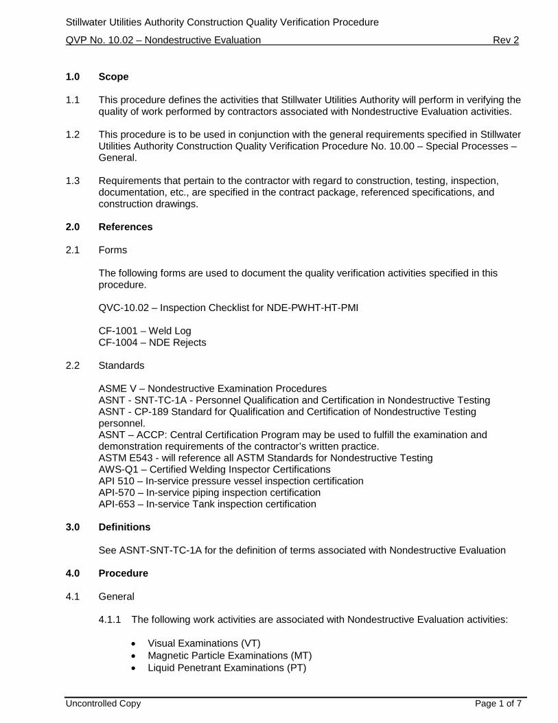
Stillwater Utilities Authority Construction Quality Verification Procedure
QVP No. 10.02 – Nondestructive Evaluation Rev 2
Uncontrolled Copy Page 1 of 7
1.0 Scope 1.1 This procedure defines the activities that Stillwater Utilities Authority will perform in verifying the
quality of work performed by contractors associated with Nondestructive Evaluation activities. 1.2 This procedure is to be used in conjunction with the general requirements specified in Stillwater
Utilities Authority Construction Quality Verification Procedure No. 10.00 – Special Processes – General.
1.3 Requirements that pertain to the contractor with regard to construction, testing, inspection,
documentation, etc., are specified in the contract package, referenced specifications, and construction drawings.
2.0 References 2.1 Forms
The following forms are used to document the quality verification activities specified in this procedure.
QVC-10.02 – Inspection Checklist for NDE-PWHT-HT-PMI
CF-1001 – Weld Log CF-1004 – NDE Rejects
2.2 Standards
ASME V – Nondestructive Examination Procedures ASNT - SNT-TC-1A - Personnel Qualification and Certification in Nondestructive Testing ASNT - CP-189 Standard for Qualification and Certification of Nondestructive Testing personnel. ASNT – ACCP: Central Certification Program may be used to fulfill the examination and demonstration requirements of the contractor’s written practice. ASTM E543 - will reference all ASTM Standards for Nondestructive Testing AWS-Q1 – Certified Welding Inspector Certifications API 510 – In-service pressure vessel inspection certification API-570 – In-service piping inspection certification API-653 – In-service Tank inspection certification
3.0 Definitions
See ASNT-SNT-TC-1A for the definition of terms associated with Nondestructive Evaluation 4.0 Procedure 4.1 General
4.1.1 The following work activities are associated with Nondestructive Evaluation activities:
• Visual Examinations (VT) • Magnetic Particle Examinations (MT) • Liquid Penetrant Examinations (PT)
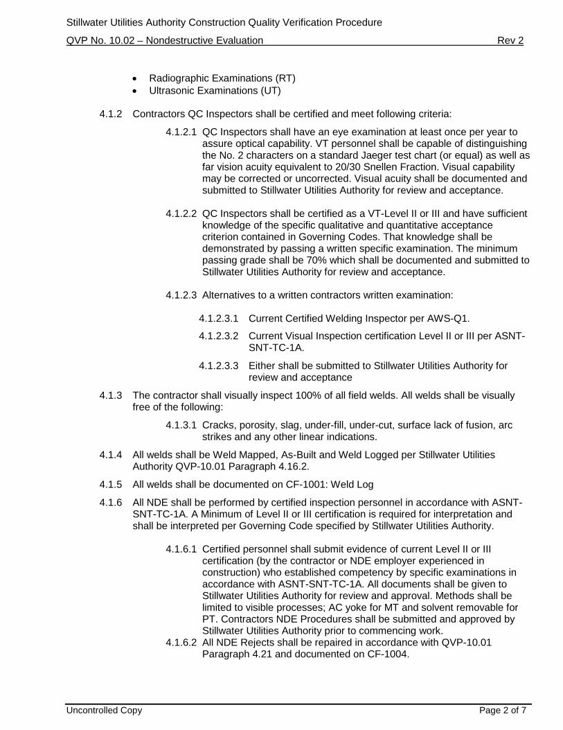
Stillwater Utilities Authority Construction Quality Verification Procedure
QVP No. 10.02 – Nondestructive Evaluation Rev 2
Uncontrolled Copy Page 2 of 7
• Radiographic Examinations (RT) • Ultrasonic Examinations (UT)
4.1.2 Contractors QC Inspectors shall be certified and meet following criteria:
4.1.2.1 QC Inspectors shall have an eye examination at least once per year to assure optical capability. VT personnel shall be capable of distinguishing the No. 2 characters on a standard Jaeger test chart (or equal) as well as far vision acuity equivalent to 20/30 Snellen Fraction. Visual capability may be corrected or uncorrected. Visual acuity shall be documented and submitted to Stillwater Utilities Authority for review and acceptance.
4.1.2.2 QC Inspectors shall be certified as a VT-Level II or III and have sufficient
knowledge of the specific qualitative and quantitative acceptance criterion contained in Governing Codes. That knowledge shall be demonstrated by passing a written specific examination. The minimum passing grade shall be 70% which shall be documented and submitted to Stillwater Utilities Authority for review and acceptance.
4.1.2.3 Alternatives to a written contractors written examination:
4.1.2.3.1 Current Certified Welding Inspector per AWS-Q1.
4.1.2.3.2 Current Visual Inspection certification Level II or III per ASNT-SNT-TC-1A.
4.1.2.3.3 Either shall be submitted to Stillwater Utilities Authority for review and acceptance
4.1.3 The contractor shall visually inspect 100% of all field welds. All welds shall be visually free of the following:
4.1.3.1 Cracks, porosity, slag, under-fill, under-cut, surface lack of fusion, arc strikes and any other linear indications.
4.1.4 All welds shall be Weld Mapped, As-Built and Weld Logged per Stillwater Utilities Authority QVP-10.01 Paragraph 4.16.2.
4.1.5 All welds shall be documented on CF-1001: Weld Log
4.1.6 All NDE shall be performed by certified inspection personnel in accordance with ASNT-SNT-TC-1A. A Minimum of Level II or III certification is required for interpretation and shall be interpreted per Governing Code specified by Stillwater Utilities Authority.
4.1.6.1 Certified personnel shall submit evidence of current Level II or III
certification (by the contractor or NDE employer experienced in construction) who established competency by specific examinations in accordance with ASNT-SNT-TC-1A. All documents shall be given to Stillwater Utilities Authority for review and approval. Methods shall be limited to visible processes; AC yoke for MT and solvent removable for PT. Contractors NDE Procedures shall be submitted and approved by Stillwater Utilities Authority prior to commencing work.
4.1.6.2 All NDE Rejects shall be repaired in accordance with QVP-10.01 Paragraph 4.21 and documented on CF-1004.

Stillwater Utilities Authority Construction Quality Verification Procedure
QVP No. 10.02 – Nondestructive Evaluation Rev 2
Uncontrolled Copy Page 3 of 7
4.1.6.2.1 Weld repairs shall be examined using the same technique, procedures and acceptance criteria used to examine the original welds.
4.1.6.3 All NDE contractors shall submit their Quality manual containing NDE procedures, personnel certification documents, calibration of measurement and test equipment, radiation safety procedures and a site emergency action plan to recover their radiation source in a time efficient and safe manner.
4.1.6.4 The Site emergency action plan shall be reviewed and accepted by Stillwater Utilities Authority and the client site management prior to commencing work.
4.1.7 MT/PT Inspections:
4.1.7.1 During the Preparatory meeting, all MT/PT Inspections shall be specified and approved in order to determine best application for sensitivity for each scenario. For example PT Inspection would be best suited for Surface preparation inspections for Tie-In procedures. MT Inspections would be best suited for final inspection on Slip-On flange welds. MT/PT Inspection requirements shall conform to Engineering specifications, Client specifications and Governing Codes.
4.1.7.2 All MT/PT Inspections shall conform to Pre-Approved NDE Contractors procedures, ASME Section V procedures and ASTM E543 referenced procedures.
4.1.7.3 Interpretations and results shall be delivered to Stillwater Utilities Authority in a Pre-Approved documented report. Each Report shall be given a Control Number starting with MT/PT-001 and continues until the end of project. Control numbers shall be logged for each weld inspected on CF-1001 form. Traceability shall be maintained throughout the project.
4.1.7.3.1 Each report shall contain the following but not limited to: Date, Project Number, Line Number, Field Weld Number, Material Type, Size, Thickness, Weld Joint Configuration, Welder Stencil and Governing Code.
4.1.7.4 All equipment shall be inspected for current and documented calibration stickers and has traceability to documents provided in the Quality manual submitted.
4.1.8 RT/UT Inspections:
4.1.8.1 During the Preparatory meeting, all RT/UT Inspections shall be specified and approved in order to determine best application for sensitivity for each scenario. For example RT Inspection would be best suited for all butt welded joints. UT Shear-wave inspections shall have prior-approval from Burns & McDonnell and the Client. RT/UT Inspection requirements shall conform to Engineering specifications, Client specifications and Governing Codes.
4.1.8.2 All RT/UT Inspections shall conform to Pre-Approved NDE Contractors procedures, ASME Section V procedures and ASTM E543 referenced procedures.
Stillwater Utilities Authority Construction Quality Verification Procedure
QVP No. 10.02 – Nondestructive Evaluation Rev 2
Uncontrolled Copy Page 4 of 7
4.1.8.3 Radiography and or Ultrasonic Inspections shall be performed in accordance governing Codes, Standards and Engineering specifications. When the Weld is required to be Post Weld Heat Treated all Radiography and Ultrasonic Inspections shall be performed After Post Weld Heat Treatment.
4.1.8.4 Interpretations and results shall be delivered to Stillwater Utilities Authority in a Pre-Approved documented report. Each Report shall be given a Control Number starting with RT/UT-001 and continues until the end of project. Control numbers shall be logged for each weld inspected on CF-1001 form. The Control number shall be labeled on the Film Envelope, RT/UT report and weld log. Traceability shall be maintained throughout the project.
4.1.8.5 All Line numbers and Field weld numbers and subsequent views shall be recorded and interpreted on approved RT report. Densities shall be recorded for each radiograph. All relevant information shall be recorded on the RT report and submitted for review and acceptance by Stillwater Utilities Authority.
4.1.8.5.1 Each report shall contain the following but not limited to: Date, Project Number, Line Number, Field Weld Number, Material Type, Size, Thickness, Weld Joint Configuration, Welder Stencil and Governing Code.
4.1.8.6 All Radiographs shall be Reviewed and Accepted by Stillwater Utilities Authority. Stillwater Utilities Authority reserves the right to reject film due to poor Quality and film handling techniques at contractor’s expense. Stillwater Utilities Authority reserves the right to reject or accept weld quality issues in accordance with governing codes.
4.1.8.7 All equipment shall be inspected for current and documented calibration stickers and has traceability to documents provided in the Quality manual submitted.
4.1.8.8 All RT personnel shall have Calibrated radiation survey meters on their person during device exposure, Calibrated Radiation Safety Alarms and Calibrated Pocket Dosimeters. All Barricades shall be in place with signs in accordance with Radiation safety procedures.
4.1.9 Stillwater Utilities Authority will perform quality verification activities to ensure that each work activity is completed in accordance with the project specifications. These quality verification activities can be classified into one of the following categories:
• Preparatory meeting prior to starting construction. • Initial inspections of construction. • Inprocess inspections during construction – random to full-time. • Final inspection after completing construction – random to 100% • Review of records of construction
4.1.10 The type of quality verification activities to be performed for each work activity, and the extent thereof, is described in this procedure.
4.1.11 All quality verification activities will be performed by personnel that have the necessary skills, training, and certifications for the particular task.
4.2 Preparatory Meetings

Stillwater Utilities Authority Construction Quality Verification Procedure
QVP No. 10.02 – Nondestructive Evaluation Rev 2
Uncontrolled Copy Page 5 of 7
4.2.1 Preparatory Meetings are held with contractors prior to the start of construction for each
major work activity or group of activities The purpose of the Preparatory Meeting is to verify the following: • Verify that the contractor fully understands the job specification requirements.
• Review the contractor’s quality control program and how it will be implemented for
the work activity.
• Verify that all required documentation has been reviewed or approved and that the contractor has the most current versions.
• Review requirements for permits and/or authorizations that will be required during
the course of construction.
• Review the quality verification activities that Stillwater Utilities Authority plans to perform and coordinate the necessary notifications from the contractor for any hold or witness points.
4.2.2 The following work activities require a Preparatory Meeting prior to starting construction.
• Contractors QC Inspectors Activities • VT, MT, PT, RT and UT Requirements per Governing Code • Tie-In NDE Procedure • NDE in Lieu of Hydro Allowances
4.2.3 When multiple contractors are responsible for a given work activity, a separate
Preparatory Meeting will be held with each contractor. 4.2.4 When a given contractor is responsible for multiple work activities, the Preparatory
Meeting may include more than one work activity. 4.2.5 For work activities with multiple phases, a separate Preparatory Meeting is not
necessarily required for each phase. For example, only one Preparatory Meeting would typically be held with a contractor responsible for Tie-Ins although their scope may include performing Tie-Ins for many systems over the course of the project. However, a follow-up meeting may be warranted if there are extended periods between phases or if problems are identified during inspections of the contractor’s work.
4.3 Initial Inspections
4.3.1 Stillwater Utilities Authority will perform a thorough inspection of the initial construction work performed by each contractor for each work activity. The purpose of this inspection is to verify that the contractor is capable of performing the work in accordance with the project specifications. The initial inspection will include the following:
• Verify any action items identified during the Preparatory Meeting were resolved.
• Fully inspect the initial work performed by contractor to verify that it is in accordance
with the requirements specified in the contract documents.

Stillwater Utilities Authority Construction Quality Verification Procedure
QVP No. 10.02 – Nondestructive Evaluation Rev 2
Uncontrolled Copy Page 6 of 7
• Verify that the contractor is implementing their quality control procedures at the
jobsite.
• Prepare a Master Punch-list documenting the specific activities performed during the Initial Inspection and identify any items of nonconformance or other action items for follow-up and resolution.
4.4 Follow-up Inspections
4.4.1 Stillwater Utilities Authority will perform Follow-up Inspections of the contractor’s work on a random but regular basis starting immediately after the Initial Inspection and through the completion of the work activity. The frequency and extent of Follow-up Inspections will be based on the scope of work, contractor performance, and associated risk to the project. The Follow-up Inspections will include the following activities:
Verify that any Nonconformancies or action items identified during the Initial
Inspection or a previous Follow-up Inspection have been resolved. Work should not be proceeding where Nonconformancies have been identified but have not been resolved, unless an approved work-around plan is in place. Follow Construction Site Quality Manual 7.0. Use CF-002 forms.
Inspect a representative sample of work performed by the contractor since the Initial
Inspection or previous Follow-up Inspection to verify that it is in accordance with the requirements specified in the contract documents.
Verify that the contractor is implementing their quality control procedures at the
jobsite. Prepare a Master Punch-list documenting the specific activities performed during
each Follow-up Inspection and identify any items of nonconformance or other action items for follow-up and resolution.
4.5 Final Inspection
4.5.1 Stillwater Utilities Authority will perform a Final Inspection at or near the completion of the inspection activities. The Final Inspection will include the following items:
Perform a final inspection of any work performed by the contractor that was not
previously inspected during the Initial and Follow-up Inspections but would be prudent to assure the final quality of the work. Verify that all work is in compliance with the specifications and most current drawing revision at the time of final inspection.
Prepare a Master Punch-list documenting the specific activities performed during
each Final Inspection and develop a punch list of all items that were found to be incomplete or not in compliance with the contract documents, referenced specifications, and the latest drawing revision at the time of the inspection. This would include any outstanding items of nonconformance or action items identified during previous Preparatory Meetings, Initial Inspections, and Follow-up Inspections for the particular work activity.

Stillwater Utilities Authority Construction Quality Verification Procedure
QVP No. 10.02 – Nondestructive Evaluation Rev 2
Uncontrolled Copy Page 7 of 7
Specify the estimated date for which each item on the punch list should be completed or corrected to be in compliance.
Perform follow-up activities to verify that each item on the punch list is completed
and/or corrected and is acceptable.
4.6 Acceptance
4.6.1 Stillwater Utilities Authority will typically accept or release each area prior to commencing NDE activities.
4.6.2 Stillwater Utilities Authority will verify the following prior to issuing final acceptance for a
particular area:
• Stillwater Utilities Authority has reviewed and accepted all documentation • The contractor has completed all inspection, testing, and quality control activities.
• Stillwater Utilities Authority has completed all quality verification activities.
• All final inspection punch list items are resolved and accepted.
5.0 Records 5.1 The Quality Verification Activities associated with this procedure are recorded on the following
forms:
• QVC-10.02 – Inspection Checklist for NDE-PWHT-HT-PMI • CF-1001 – Weld Log • CF-1004 – NDE Rejects

Stillwater Utility Authority Surveying Inspection Checklist
Subcontract No. Inspector:
Subcontractor: Signature:
Item or Area I.D.: Date:
THE INSPECTOR SHALL VERIFY THAT THE FOLLOWING ITEMS ARE IN ACCORDANCE WITH THE SPECIFICATION AND DRAWING REQUIREMENTS AT THE TIME OF SURVEYING.
No. Description Accept Reject Comments
QVC-1.01 – Inspection Checklist for Surveying
1 Verify Equipment used is in accordance with the Contract Documents
2 Verify Equipment is Calibrated in accordance with Manufacturers Specifications
3 Verify Survey Markers are easily identified and placed securely
4 Verify all Earth work baselines are set outside of the excavated areas to avoid destruction
5 Verify Foundation Orientations and Locations are in accordance with Engineering Specifications and Drawings.
6 Verify Anchor Bolt Locations before and after Concrete Pour
7 Verify a Centerline has been established for ditches and trenches needing dug
8 Verify surveyor is using a closed, loop or connecting traverse to control the parcel/project boundary area.
9 Verify traverses originate and tie into an existing control point of similar accuracy.
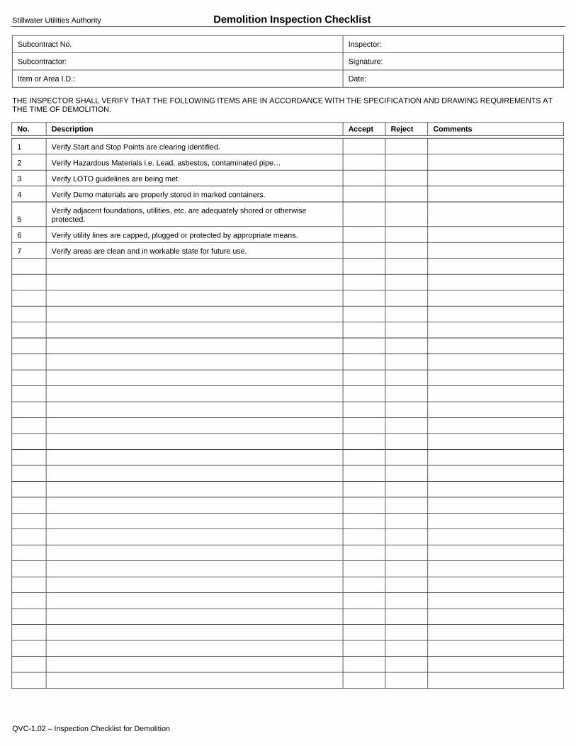
Stillwater Utilities Authority Demolition Inspection Checklist
Subcontract No. Inspector:
Subcontractor: Signature:
Item or Area I.D.: Date:
THE INSPECTOR SHALL VERIFY THAT THE FOLLOWING ITEMS ARE IN ACCORDANCE WITH THE SPECIFICATION AND DRAWING REQUIREMENTS AT THE TIME OF DEMOLITION.
No. Description Accept Reject Comments
QVC-1.02 – Inspection Checklist for Demolition
1 Verify Start and Stop Points are clearing identified.
2 Verify Hazardous Materials i.e. Lead, asbestos, contaminated pipe…
3 Verify LOTO guidelines are being met.
4 Verify Demo materials are properly stored in marked containers.
5 Verify adjacent foundations, utilities, etc. are adequately shored or otherwise protected.
6 Verify utility lines are capped, plugged or protected by appropriate means.
7 Verify areas are clean and in workable state for future use.
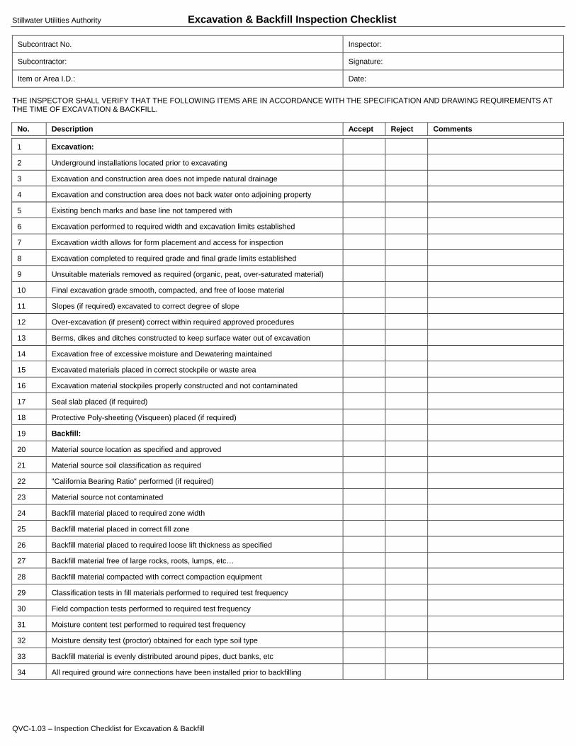
Stillwater Utilities Authority Excavation & Backfill Inspection Checklist
Subcontract No. Inspector:
Subcontractor: Signature:
Item or Area I.D.: Date:
THE INSPECTOR SHALL VERIFY THAT THE FOLLOWING ITEMS ARE IN ACCORDANCE WITH THE SPECIFICATION AND DRAWING REQUIREMENTS AT THE TIME OF EXCAVATION & BACKFILL.
No. Description Accept Reject Comments
QVC-1.03 – Inspection Checklist for Excavation & Backfill
1 Excavation:
2 Underground installations located prior to excavating
3 Excavation and construction area does not impede natural drainage
4 Excavation and construction area does not back water onto adjoining property
5 Existing bench marks and base line not tampered with
6 Excavation performed to required width and excavation limits established
7 Excavation width allows for form placement and access for inspection
8 Excavation completed to required grade and final grade limits established
9 Unsuitable materials removed as required (organic, peat, over-saturated material)
10 Final excavation grade smooth, compacted, and free of loose material
11 Slopes (if required) excavated to correct degree of slope
12 Over-excavation (if present) correct within required approved procedures
13 Berms, dikes and ditches constructed to keep surface water out of excavation
14 Excavation free of excessive moisture and Dewatering maintained
15 Excavated materials placed in correct stockpile or waste area
16 Excavation material stockpiles properly constructed and not contaminated
17 Seal slab placed (if required)
18 Protective Poly-sheeting (Visqueen) placed (if required)
19 Backfill:
20 Material source location as specified and approved
21 Material source soil classification as required
22 "California Bearing Ratio" performed (if required)
23 Material source not contaminated
24 Backfill material placed to required zone width
25 Backfill material placed in correct fill zone
26 Backfill material placed to required loose lift thickness as specified
27 Backfill material free of large rocks, roots, lumps, etc…
28 Backfill material compacted with correct compaction equipment
29 Classification tests in fill materials performed to required test frequency
30 Field compaction tests performed to required test frequency
31 Moisture content test performed to required test frequency
32 Moisture density test (proctor) obtained for each type soil type
33 Backfill material is evenly distributed around pipes, duct banks, etc
34 All required ground wire connections have been installed prior to backfilling

Stillwater Utilities Authority Plant Road and Vehicle Parking Inspection Checklist
Subcontract No. Inspector:
Subcontractor: Signature:
Item or Area I.D.: Date:
THE INSPECTOR SHALL VERIFY THAT THE FOLLOWING ITEMS ARE IN ACCORDANCE WITH THE SPECIFICATION AND DRAWING REQUIREMENTS AT THE TIME OF INITIAL, FOLLOW-UP, AND FINAL INSPECTIONS
No. Description Accept Reject Comments
QVC-1.05 – Inspection Checklist for Plant Road and Vehicle Parking Page 1 of 2
1 Sub-grade Scarifying:
2 • Removal of rock, etc., depth
3 • Moisture content
4 • Sub-grade elevations
5 Sub-grade Preparation:
6 • Materials to specifications
7 • Proper equipment
8 • Ditches
9 • Elevations, density after rolling
10 • Shaping, compacting
11 Laboratory tests
12 • Gradation of materials
13 • Curves and densities
14 • Field density tests (Forms completed and signed)
15 Asphalt concrete pavement
16 • Asphalt cement as specified
17 • Coarse aggregate as specified
18 • Fine aggregate as specified
19 • Cement mixed as specified
20 Asphalt tack coat
21 • Material as specified
22 • Surface clean and dry
23 • Uniform spray
24 Prime tack coat
25 • Material as specified
26 • Base course clean and dry
27 • Base coat uniform spray
28 Transporting
29 • Truck beds free of holes an depressions
30 • Truck equipped with proper tarps
31 • Truck beds coated
32 • Truck bed insulated (as applicable)
33 Spreading
34 • Availability of personnel and equipment
35 • Uniform mix
36 • Mix temperature

Stillwater Utilities Authority Plant Road and Vehicle Parking Inspection Checklist
Subcontract No. Inspector:
Subcontractor: Signature:
Item or Area I.D.: Date:
THE INSPECTOR SHALL VERIFY THAT THE FOLLOWING ITEMS ARE IN ACCORDANCE WITH THE SPECIFICATION AND DRAWING REQUIREMENTS AT THE TIME OF INITIAL, FOLLOW-UP, AND FINAL INSPECTIONS
No. Description Accept Reject Comments
QVC-1.05 – Inspection Checklist for Plant Road and Vehicle Parking Page 2 of 2
37 • Surface tolerances
38 • Spread depth
39 • Number of Samples
40 Rolling
41 • Procedure as specified
42 • Proper rolling of joints and edges, etc.
43 • Surfaces true to established grade
44 Final
45 • Surface areas as specified
46 • Traffic protection
47 • Site cleanup
48 • Quality records

Stillwater Utilities Authority Piling Inspection Checklist
Subcontract No. Inspector:
Subcontractor: Signature:
Item or Area I.D.: Date:
THE INSPECTOR SHALL VERIFY THAT THE FOLLOWING ITEMS ARE IN ACCORDANCE WITH THE SPECIFICATION AND DRAWING REQUIREMENTS AT THE TIME OF INITIAL, FOLLOW-UP, AND FINAL INSPECTIONS
No. Description Accept Reject Comments
QVC-1.08 – Inspection Checklist for Piling
1 Verify Geo-Tech Report is available on-site
2 Verify Piling Installation Procedures and Execution Plan meet Site Requirements
3 Verify Pile Type, Size and Length meet the required Engineering Specifications
4 Verify Pile Driving Equipment meet the required Engineering Specifications:
5 • Ram
6 • Anvil
7 • Striker Plate
8 • Hammer Cushion
9 • Drive Head
10 • Pile Cushion
11 Verify Calibration Certificates of Pressure gauges are current
12 Verify Operating Rate and Pressure of Pile Driving equipment are within Engineering Specifications and procedures
13 Verify Blow Counts are recorded and in compliance with Engineering Specifications
14 Verify Grouting Procedures are in compliance for Auger Cast in Place Piles
15 Verify Design Mix and Compliance Verifications are met for Auger Cast in Place Piles
16 Verify Grout Flow Tests meet the required Engineering Specifications for Auger Cast in Place Piles
17 Verify Volume of Grout used for Auger Cast in Place Piles
18 Verify Reinforcement Bar MTR’s are in compliance
19 Verify Reinforcement Bar Cages meet Engineering Design and Specifications
20 Verify Pile Splices are within Engineering Specifications
21 Verify Welding QVP-10.01 Procedures have been met if applicable
22 Verify Pile Cut-Off and Tip elevations
23 Verify Pile Heave is within Engineering Specifications
24 Verify Degree of Axial Alignment is within Engineering Specifications
25 Verify Pile is not damaged during installation
26 Verify Pile Load tests are performed per Contract Documents and meet Engineering Specifications
27 Verify Pile Spacing is in compliance with Engineering Specifications
28 Verify All field revisions recorded on "AS-BUILT" drawings.

Stillwater Utilities Authority Drilled Pier Inspection Checklist
Subcontract No. Inspector:
Subcontractor: Signature:
Item or Area I.D.: Date:
THE INSPECTOR SHALL VERIFY THAT THE FOLLOWING ITEMS ARE IN ACCORDANCE WITH THE SPECIFICATION AND DRAWING REQUIREMENTS AT THE TIME OF INITIAL, FOLLOW-UP, AND FINAL INSPECTIONS
No. Description Accept Reject Comments
QVC-1.09 – Inspection Checklist for Drilled Piers
1 Verify Geo-Tech Report is available on-site
2 Verify Drilled Pier Installation Procedures and Execution Plan meet Site Requirements
3 Verify Depth of excavations are in compliance with Engineering Specifications
4 Verify Bell Dimensions are in compliance with Engineering Specifications
5 Verify size, length, material type and wall thickness of the steel casing meet the required Engineering Specifications:
6 Verify size, length, material type and strength of liner meet the required Engineering Specifications:
7 Verify Splice Details are in accordance with Engineering Specifications
8 Verify Pier Diameters are in accordance with Engineering Specifications
9 Verify In-Hole Slurry Tests meets Engineering Specifications
10 Verify Concreting QV-2.0 Procedures are in compliance
11 Verify Reinforcement Bar MTR’s are in compliance
12 Verify Reinforcement Bar Cages meet Engineering Design and Specifications
13 Verify Design Mix and Compliance Verifications are met
14 Verify Test Specimens meet the required Engineering Specifications
15 Verify Batch Plant Pour Cards are received and in accordance with Engineering Specifications
16 Verify Sand Cement Grout mixture is in accordance with Engineering Specifications
17 Verify Welding QVP-10.01 Procedures have been met
18 Verify Pier Cut-Off and Tip elevations
19 Verify Degree of Axial Alignment is within Engineering Specifications
20 Verify NDE report: Sonic Echo, Impulse Test or Cross-hole sonic logging (if applicable)
21 Verify Drilled Pier Spacing is in compliance with Engineering Specifications
22 Verify All field revisions recorded on "AS-BUILT" drawings.
23 Verify anchorage embedment’s are installed in compliance with Engineering Design and Specifications
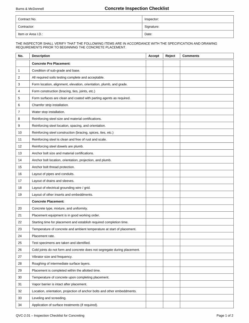
Burns & McDonnell Concrete Inspection Checklist
Contract No. Inspector:
Contractor: Signature:
Item or Area I.D.: Date:
THE INSPECTOR SHALL VERIFY THAT THE FOLLOWING ITEMS ARE IN ACCORDANCE WITH THE SPECIFICATION AND DRAWING REQUIREMENTS PRIOR TO BEGINNING THE CONCRETE PLACEMENT.
No. Description Accept Reject Comments
QVC-2.01 – Inspection Checklist for Concreting Page 1 of 2
Concrete Pre Placement:
1 Condition of sub-grade and base.
2 All required soils testing complete and acceptable.
3 Form location, alignment, elevation, orientation, plumb, and grade.
4 Form construction (bracing, ties, joints, etc.)
5 Form surfaces are clean and coated with parting agents as required.
6 Chamfer strip installation.
7 Water stop installation.
8 Reinforcing steel size and material certifications.
9 Reinforcing steel location, spacing, and orientation.
10 Reinforcing steel construction (bracing, spices, ties, etc.)
11 Reinforcing steel is clean and free of rust and scale.
12 Reinforcing steel dowels are plumb.
13 Anchor bolt size and material certifications.
14 Anchor bolt location, orientation, projection, and plumb.
15 Anchor bolt thread protection.
16 Layout of pipes and conduits.
17 Layout of drains and sleeves.
18 Layout of electrical grounding wire / grid.
19 Layout of other inserts and embeddments.
Concrete Placement:
20 Concrete type, mixture, and uniformity.
21 Placement equipment is in good working order.
22 Starting time for placement and establish required completion time.
23 Temperature of concrete and ambient temperature at start of placement.
24 Placement rate.
25 Test specimens are taken and identified.
26 Cold joints do not form and concrete does not segregate during placement.
27 Vibrator size and frequency.
28 Roughing of intermediate surface layers.
29 Placement is completed within the allotted time.
30 Temperature of concrete upon completing placement.
31 Vapor barrier is intact after placement.
32 Location, orientation, projection of anchor bolts and other embeddments.
33 Leveling and screeding.
34 Application of surface treatments (if required).
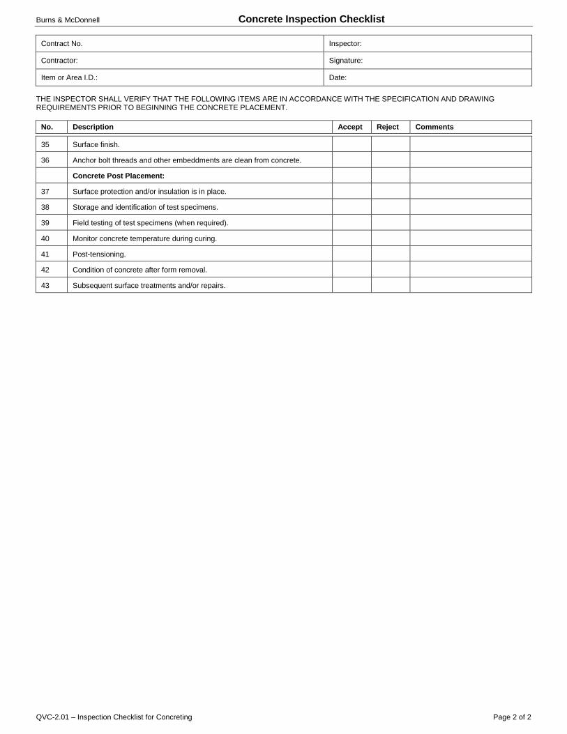
Burns & McDonnell Concrete Inspection Checklist
Contract No. Inspector:
Contractor: Signature:
Item or Area I.D.: Date:
THE INSPECTOR SHALL VERIFY THAT THE FOLLOWING ITEMS ARE IN ACCORDANCE WITH THE SPECIFICATION AND DRAWING REQUIREMENTS PRIOR TO BEGINNING THE CONCRETE PLACEMENT.
No. Description Accept Reject Comments
QVC-2.01 – Inspection Checklist for Concreting Page 2 of 2
35 Surface finish.
36 Anchor bolt threads and other embeddments are clean from concrete.
Concrete Post Placement:
37 Surface protection and/or insulation is in place.
38 Storage and identification of test specimens.
39 Field testing of test specimens (when required).
40 Monitor concrete temperature during curing.
41 Post-tensioning.
42 Condition of concrete after form removal.
43 Subsequent surface treatments and/or repairs.

Stillwater Utilities Authority Underground Piping Inspection Checklist
Contract No. Inspector:
Contractor: Signature:
Item or Area I.D.: Date:
THE INSPECTOR SHALL VERIFY THAT THE FOLLOWING ITEMS ARE IN ACCORDANCE WITH THE SPECIFICATION AND DRAWING REQUIREMENTS AT THE TIME OF INITIAL, IN-PROCESS AND FINAL INSPECTIONS.
No. Description Accept Reject Comments
QVC-5.01 – Inspection Checklist for Underground Piping Page 1 of 2
1 Underground firewater, open/closed process drains and cooling water lines:
2 • Latest Engineering documentation and Proper Records
3 • Proper Materials, Fit-up, WPS’s, PQR’s and WPQ’s
4 • Coating material meet specifications
5 • Proper Handling being used: slings and padded cribbing
6 • Installation per Engineering Drawings and Specifications
7 • Welded joints wrapped
8 • Holiday free per specifications
9 • Holiday repairs per specifications
10 • Pressure Tested per QVP-5.00 and QVP-5.01
11 • Proper ditch, bedding, backfill, compaction and slope on drain lines
12 • Required Inspections complete
13 • Thrust blocks per specifications
14 • Elevation and Installation of buffalo boxes
15 • Valve extensions installed
16 Concrete Lined Pipe:
17 • Latest Engineering documentation and Proper Records
18 • Proper Materials, Fit-up, WPS’s, PQR’s and WPQ’s
19 • Installation per Engineering Drawings and Specifications
20 • Damage to Lining
21 • Proper Joint “Buttering”
22 • Required Inspections and Testing complete
23 • Proper ditch, bedding, backfill, compaction and slope
24 Reinforced Concrete Pipe:
25 • Latest Engineering documentation and Proper Records
26 • Proper Materials, Fit-up, WPS’s, PQR’s and WPQ’s
27 • Installation per Engineering Drawings and Specifications
28 • Proper Joint Seals
29 • Required Inspections and Testing complete
30 • Proper ditch, bedding, backfill, compaction and slope
31 Furan, PVC and Epoxy Pipe:
32 • Latest Engineering documentation and Proper Records
33 • Installation per Engineering Drawings and Specifications
34 • Proper Joint Make-up
35 • Required Inspections and Testing complete

Stillwater Utilities Authority Underground Piping Inspection Checklist
Contract No. Inspector:
Contractor: Signature:
Item or Area I.D.: Date:
THE INSPECTOR SHALL VERIFY THAT THE FOLLOWING ITEMS ARE IN ACCORDANCE WITH THE SPECIFICATION AND DRAWING REQUIREMENTS AT THE TIME OF INITIAL, IN-PROCESS AND FINAL INSPECTIONS.
No. Description Accept Reject Comments
QVC-5.01 – Inspection Checklist for Underground Piping Page 2 of 2
36 • Proper ditch, bedding, backfill, compaction and slope
37 Vitrified Clay and Cast Iron Pipe
38 • Latest Engineering documentation and Proper Records
39 • Installation per Engineering Drawings and Specifications
40 • Proper Joint Make-up
41 • Proper ditch, bedding, backfill, compaction and slope
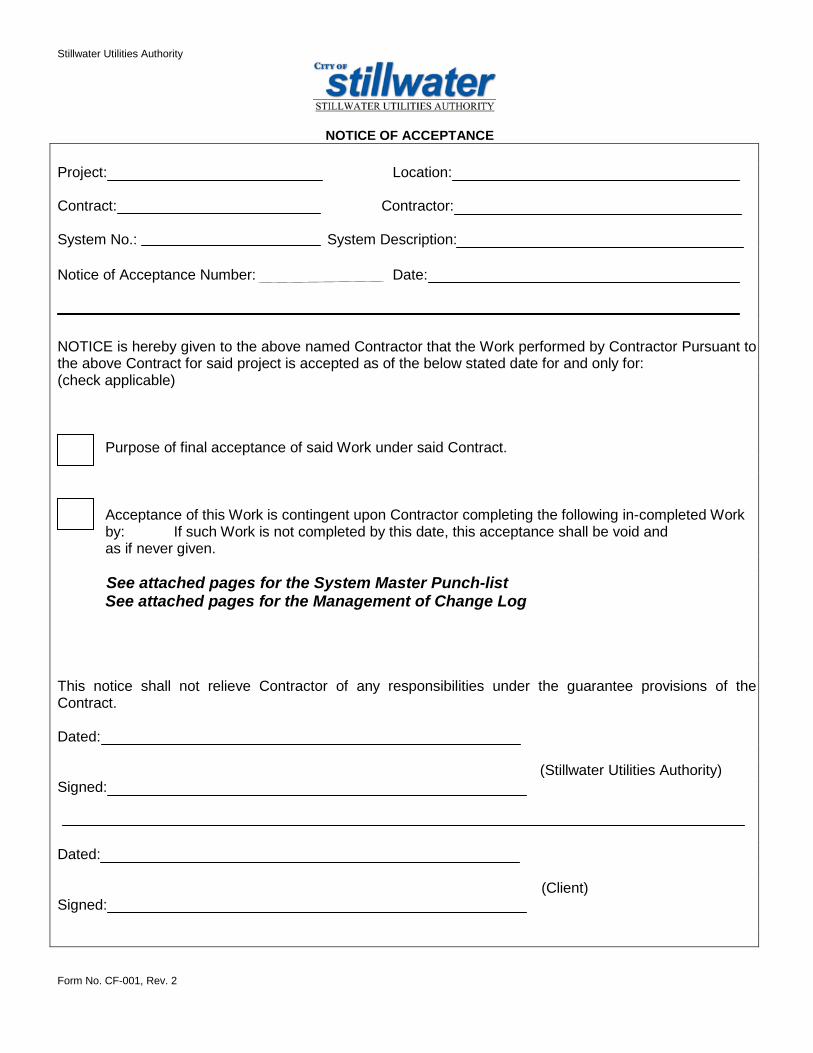
Stillwater Utilities Authority
Form No. CF-001, Rev. 2
NOTICE OF ACCEPTANCE Project: Location: Contract: Contractor: System No.: System Description: Notice of Acceptance Number: Date: NOTICE is hereby given to the above named Contractor that the Work performed by Contractor Pursuant to the above Contract for said project is accepted as of the below stated date for and only for: (check applicable)
Purpose of final acceptance of said Work under said Contract. Acceptance of this Work is contingent upon Contractor completing the following in-completed Work by: If such Work is not completed by this date, this acceptance shall be void and as if never given.
See attached pages for the System Master Punch-list See attached pages for the Management of Change Log
This notice shall not relieve Contractor of any responsibilities under the guarantee provisions of the Contract. Dated: (Stillwater Utilities Authority) Signed:
Dated: (Client) Signed:

Stillwater Utilities Authority Non-Conformance Report
Project No. Report No.
Contract, Subcontract, or Purchase Order No. Page No.
Contractor, Subcontractor, or Supplier: Date:
Form No. CF-002, Rev. 0
SECTION 1 – IDENTIFICATION
Item No.: Supplier or Sub:
Item Description: Location:
Contact:
Phone:
Description of Non-Conformance and Original Requirement::
Non-Conformance Identified By (Name): Signature: Date:
SECTION 2 – DISPOSITION AND CORRECTIVE ACTION
Disposition: Accept As-Is Accept Pending Further Corrective Action Reject / Scrap
Description of Proposed Corrective Action:
Disposition / Corrective Action Proposed By (Name): Signature: Date:
Approved By SUA (Name): Signature: Date:
SECTION 3 – VERIFICATION OF CORRECTIVE ACTION (IF REQUIRED)
Corrective Action Completed On (Date):
Corrective Action Verified By (Name): Signature: Date:
Approved By SUA (Name): Signature: Date:

Form No. CF-003, Rev. 1 6 of 7
Stillwater Utilities Authority Project Number:Project: Non-Conformance Log
Non-Conformance
Report No.
Contractor / Supplier
Unit or Area
Date Opened Description
Date Disposition Approved
Date Closed Remarks
Location:

Stillwater Utilities Authority Material Receiving Report
Form No. CF-004, Rev. 0
Project No.: MRR No.:
Supplier: Date Received:
PO/Contract #: Carrier:
Comments:
RECEIVING INSTRUCTIONS
1. Perform receiving inspection, complete checklist, and initial all items.
2. If material is damaged or quantities do not match the Bill of Lading, complete separate form CF-007, Overage, Shortage, and Damage Report and obtain carrier’s signature prior to leaving the jobsite. Record OS&D report number.
3. Document all items included in shipment and/or attach shipping papers that specify the number of pieces, boxes, or barrels making up the total shipment.
RECEIVING CHECKLIST
No. Activity Acceptable Unacceptable OS&D Rpt. No. Initial
1 Verify quantities received are in accordance with the quantities specified in the Shipping Papers. □ □
2 Inspect materials for signs of damage including missing tags, coating damage, etc. □ □
3 Mark boxes and crates to be put into storage are marked with the purchase order number and tag number(s). □ □
RECORD OF ITEMS RECEIVED
Item No. on P.O.
Quantity Ordered Unit
Quantity Receive
d Description Tag No. Storage
Area
□ CHECK BOX IF ADDITIONAL ITEMS ARE LISTED ON SUPPLEMENTAL SHEET
DELIVERY / RECEIPT APPROVED BY
Organization Name (Print) Signature Date
Carrier
Subcontractor
Contractor
Owner

Stillwater Utilities Authority Material Receiving Report
Form No. CF-004, Rev. 0
MRR No.: Supplementary Sheet No.:
SUPPLEMENTAL RECORD OF ITEMS RECEIVED
Item No. on P.O.
Quantity Ordered Unit Quantity
Received Description Tag No. Account Codes

Form No. CF-005, Rev. 1 1 of 5
Stillwater Utilities Authority Project Number:Project: Material Receiving Log
Contract No. Load No. Item on P.O. MRR No. OS&D
No. P.O. No. Supplier Item Description Part No. Date Received
Laydown Yard Location Quantity Unit Notes
Location:
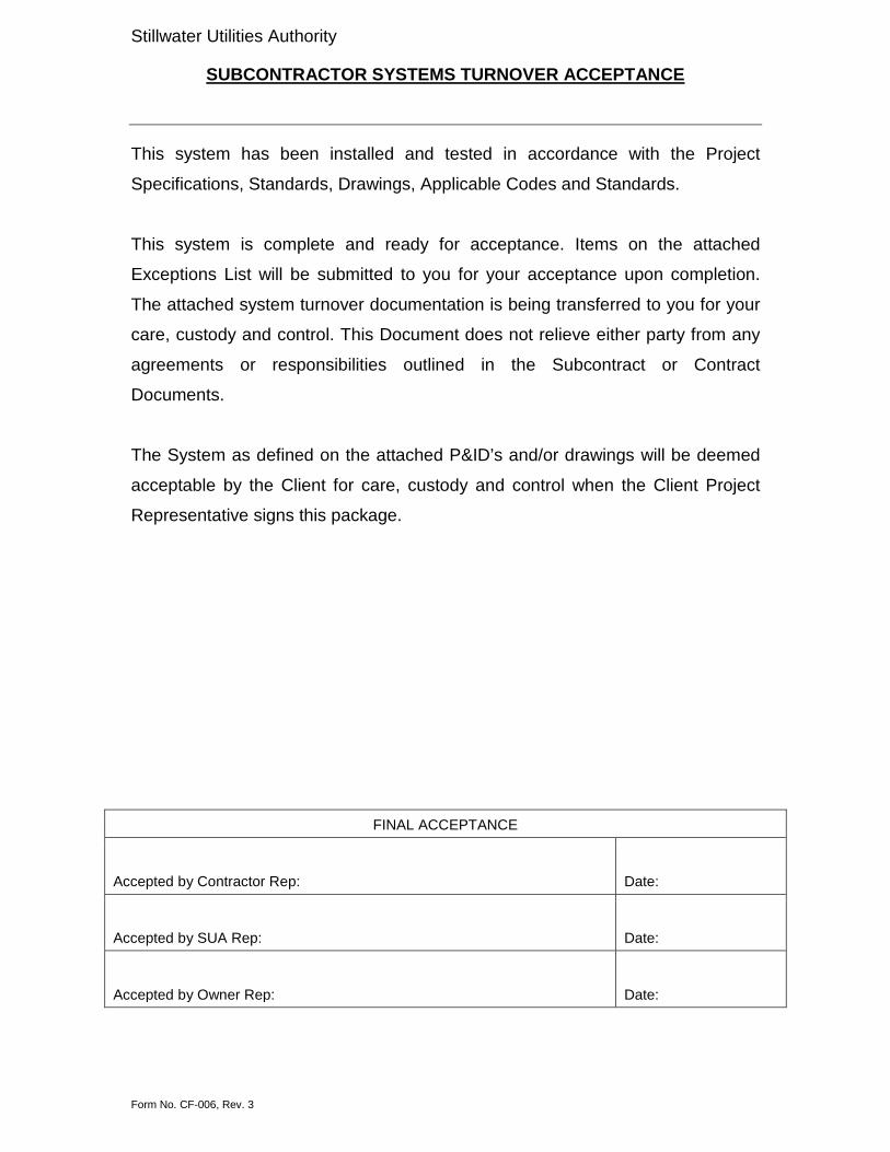
Stillwater Utilities Authority
SUBCONTRACTOR SYSTEMS TURNOVER ACCEPTANCE
Form No. CF-006, Rev. 3
This system has been installed and tested in accordance with the Project
Specifications, Standards, Drawings, Applicable Codes and Standards.
This system is complete and ready for acceptance. Items on the attached
Exceptions List will be submitted to you for your acceptance upon completion.
The attached system turnover documentation is being transferred to you for your
care, custody and control. This Document does not relieve either party from any
agreements or responsibilities outlined in the Subcontract or Contract
Documents.
The System as defined on the attached P&ID’s and/or drawings will be deemed
acceptable by the Client for care, custody and control when the Client Project
Representative signs this package.
FINAL ACCEPTANCE
Accepted by Contractor Rep: Date:
Accepted by SUA Rep: Date:
Accepted by Owner Rep: Date:

Stillwater Utilities Authority Overage, Shortage, and Damage Report
Form No. CF-007 Rev. 0
Project No.: OS&D No.:
Supplier/Contractor: MRR No.:
PPO/Contract #: Date Received:
Carrier:
Comments:
Item No. on P.O.
Over Short Damaged Quantity Ordered
Quantity Received Description of Damage Tag No’s.
□ □ □
□ □ □
□ □ □
□ □ □
□ □ □
□ □ □
□ □ □
□ □ □
□ □ □
□ □ □
□ □ □
□ □ □
□ □ □
□ □ □
□ □ □
□ □ □
□ □ □
□ □ □
□ □ □
□ □ □
□ □ □
OVERAGE, SHORTAGE, OR DAMAGE AKNOWLEDGED BY
Organization Name (Print) Signature Date
Carrier
Subcontractor
Contractor
Owner
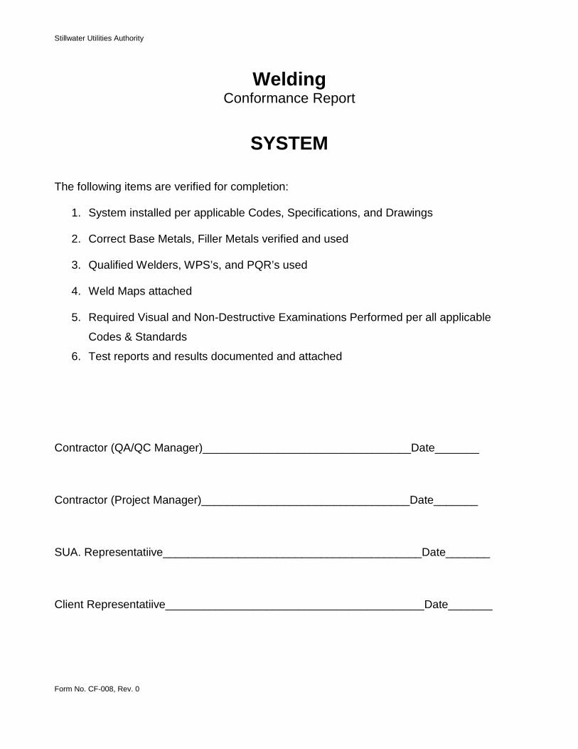
Stillwater Utilities Authority
Form No. CF-008, Rev. 0
Welding Conformance Report
SYSTEM The following items are verified for completion:
1. System installed per applicable Codes, Specifications, and Drawings
2. Correct Base Metals, Filler Metals verified and used
3. Qualified Welders, WPS’s, and PQR’s used
4. Weld Maps attached
5. Required Visual and Non-Destructive Examinations Performed per all applicable
Codes & Standards
6. Test reports and results documented and attached Contractor (QA/QC Manager)_________________________________Date_______ Contractor (Project Manager)_________________________________Date_______ SUA. Representatiive_________________________________________Date_______ Client Representatiive_________________________________________Date_______

Form No. CF-009, Rev. 0 1 of 2
Project
Client (1) Must be completed before hydro
Contract # (2) Must be completed before startup
CContractor Complete (3) Can be completed after startupContractor Total
Item Description LocationHydro /Line
#Priority
Date Reported
Responsible Party
Promise Date
% Complete & Date
ContractorStillwater Utilities
AuthorityOwner
MASTER PUNCHLIST
Priority Codes
SIGN-OFFS

Form No. CF-010 REV 0 1 of 1
Stillwater Utilities Authority Project Number:
TAG NO. DATE Description of Work Performed Lube Rotate Megger HeaterNitrogen Blanket Person
Project: Location:
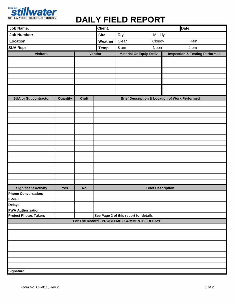
Form No. CF-011, Rev 2 1 of 2
DAILY FIELD REPORT Site Weather Temp
Visitors Vendor Material Or Equip Deliv. Inspection & Testing Performed
SUA or Subcontractor Quantity Craft Brief Description & Location of Work Performed
Yes No
Client:
For The Record - PROBLEMS / COMMENTS / DELAYS
8 am Noon 4 pm
Clear Cloudy Rain
Dry Muddy
Job Name: Job Number: Location:SUA Rep:
See Page 2 of this report for details
E-Mail:Phone Conversation:
Signature:
Delays:FWA Authorization:Project Photos Taken:
Date:
Significant Activity Brief Description
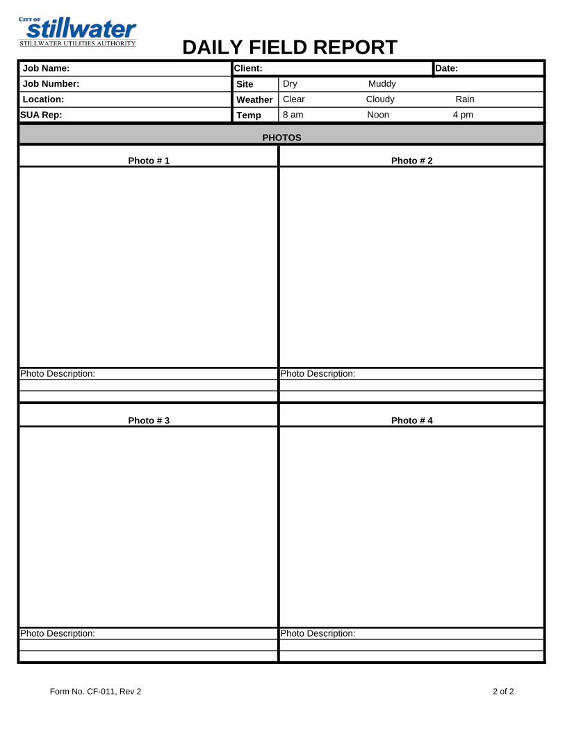
Form No. CF-011, Rev 2 2 of 2
DAILY FIELD REPORT Site Weather Temp
Client:
8 am Noon 4 pm
Clear Cloudy Rain
Dry Muddy
Job Name: Job Number: Location:SUA Rep:
Date:
Photo Description: Photo Description:
PHOTOS
Photo # 1 Photo # 2
Photo # 3 Photo # 4
Photo Description: Photo Description:

Stillwater Utilities Authority Drawing Control Audit
Form No. CF-012, Rev 1
PROJECT INFORMATION
Client: Contract No.:
Project No.: Contractor:
DRAWINGS FROM STILLWATER UTILITIES AUTHORITY SITE OFFICE TO SUBCONTRACTOR’S SITE OFFICE
Drawing No. Revision No. Type of Drawing Date Received
Acceptable (Y/N) Comments
1
2
3
4
5
SAME DRAWINGS FROM SUBCONTRACTOR’S SITE OFFICE TO SUBCONTRACTOR’S FIELD FOREMEN’S OFFICE
Drawing No. Revision No. Type of Drawing Date Received
Acceptable (Y/N) Comments
1
2
3
4
5
NEW DRAWINGS FROM SUBCONTRACTOR’S FIELD FOREMEN’S OFFICE TO SUBCONTRACTOR’S SITE OFFICE
Drawing No. Revision No. Type of Drawing Date Received
Acceptable (Y/N) Comments
1
2
3
4
5
SAME DRAWINGS FROM SUBCONTRACTOR’S SITE OFFICE TO STILLWATER UTILITIES AUTHORITY SITE OFFICE
Drawing No. Revision No. Type of Drawing Date Received
Acceptable (Y/N) Comments
1
2
3
4
5
Approved by SUA Site QC Manager: Date:
Approved by SUA Site Manager: Date:

1 of 1
Total OpenTotal Open
Total NDE AcceptedTotal NDE Rejected
NDE Rejection Rate20% BW's 100% BW's
NonconformanceClosedProcurement Driven
5% BW's
Contractor Driven Closed
Quality Key Performance Indicators
Report as of
Reject Rate
Total NDE Complete2% SW's 10% BW's
2/12/2015Project Name: Project No:

P66 TOP Flex ProjectResponsibility Matrix for Inspections and Signoffs
Form No. CF-014, Rev 1 1 of 3 Printed 2/12/2015; 8:21 AM
Form No. Description Contractor Stillwater Utilities Authority Client Client Representative Comments
CF-001 System Notice of AcceptanceCF-002 Non-Conformance Report N/ACF-004 Material Receiving Record N/ACF-006 Subcontractor Signoff to SUA N/ACF-007 Receiving Overage, Shortage and Damage Report N/ACF-008 Welding Conformance N/ACF-009 Master PunchlistCF-012 Drawing Control Audit N/ACF-103 Authorization to Backfill
1) Authorization to Backfill2) Final Testing3) Final Acceptance
CF-201 Concrete Placement Application, Authorization and Record reference to mechanical completion matrix item H-41) Authorization to Place Concrete2) Concrete Placement Record/ Inspection3) Record of Post Placement / Form Removal4) Final Acceptance
CF-202 Grout Placement Application, Authorization and Record1) Authorization to Place Grout2) Grout Placement Record/ Inspection3) Record of Post Placement / Form Removal4) Final Acceptance
CF-301 Structural Steel Authorization and Acceptance Record reference to mechanical completion matrix item I-41) Authorization to Place Structural Steel2) Structural Steel Placement Record/ Inspections3) Record of Post Placement 4) Final Acceptance
QVC-4.01 Checklist for BuildingsCF-501 Hydrotesting Inspections reference to mechanical completion matrix item C-2,6,8
1) Pre-Hydro Test Release Participate in Pre-hydro walk down2) Hydro Test3) Post-Hydro/ System Restoration4) Final Acceptance Participate in Post-hydro walk down
CF-503 Holiday Test Record LogCF-504 Tie-in Placement Application, Authorization and Record
1) Authorization to Perform Tie-In2) Record of Tie-In3) Record of Post-Tie-In Activities4) Final Acceptance
CF-601 Loop Acceptance Record reference to mechanical completion matrix item B-191) Instrument Calibration Acceptance2) Instrument Installation Acceptance3) Loop Functional Acceptance Scheduled loop tests
CF-702 Stationary Equipment Placement Application, Authorization and Record reference to mechanical completion matrix item D-4 & 5, F-31) Authorization to Place Stationary Equipment2) Record of Stationary Equipment Placement3) Record of Post Placement Activities

P66 TOP Flex ProjectResponsibility Matrix for Inspections and Signoffs
Form No. CF-014, Rev 1 2 of 3 Printed 2/12/2015; 8:21 AM
Form No. Description Contractor Stillwater Utilities Authority Client Client Representative Comments
4) Final AcceptanceCF-703 Equipment Plumb RecordCF-704 Equipment Final Closing Authorization Record
1) Authorizatation to Close2) Final Acceptance of Closure
CF-705 Rotating Equipment Placement Application, Authorization and Record1) Authorization to Place Rotating Equipment2) Record of Rotating Equipment Placement3) Record of Post Placement Activities4) Final Acceptance
CF-706 Coupling Alignment Record1) Final Acceptance of Alignment
CF-801 Coating Record reference to mechanical completion matrix item K-3CF-901 Insulation Placement Application, Authorization and Record reference to mechanical completion matrix item L-3
1) Authorization to Place Insulation2) Final Acceptance of Insulation System
CF-902 Fireproofing Placement Application, Authorization and Record reference to mechanical completion matrix item J-31) Authorization to Place Fireproofing2) Final Inspection
CF-903 Steam Tracing Placement Application, Authorization and Record1) Authorization to Place Steam Tracing2) Final Inspection
CF-904 Electric Tracing Placement Application, Authorization and Record1) Authorization of Electric Tracing Installation2) Record of Post-Placement Activities3) Megger Testing (4X)4) Final Acceptance
QV6.02-03 Conduit Checklist - Routing PlanQV6.02-04 Underground Electrical Conduit InspectionQV6.02-05 Conduit Seals and Drains ChecklistQV6.02-06 Cable Tray ChecklistQV6.02-07 Lighting ChecklistQV6.02-08 Pole Lines ChecklistQV6.02-09 Grounding ChecklistQV6.02-10 Grounding Test ReportQV6.02-11 Ground Rod Resistance Test ReportQV6.02-12 Cable and Wire ChecklistQV6.02-13 Insulation Resistance Test and DC High Voltage Test on Cables and WiresQV6.02-14 Switchgear Test RecordQV6.02-15 Switchgear Circuit Breakers Test RecordQV6.02-16 AC Medium Voltage Motors Test RecordQV6.02-17 600 Volt Motors Test Record
Signature TitleSUA Acceptance
Date
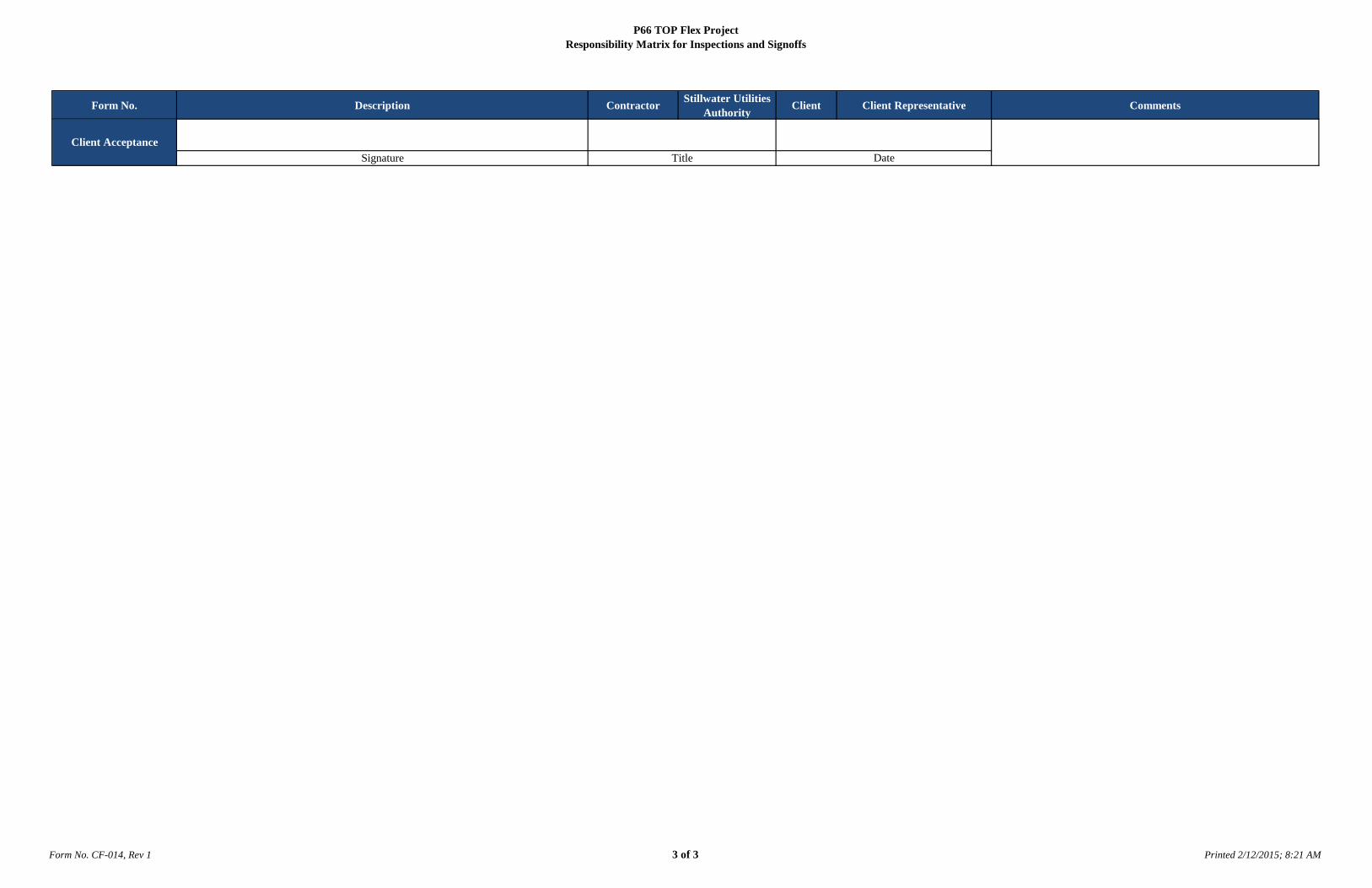
P66 TOP Flex ProjectResponsibility Matrix for Inspections and Signoffs
Form No. CF-014, Rev 1 3 of 3 Printed 2/12/2015; 8:21 AM
Form No. Description Contractor Stillwater Utilities Authority Client Client Representative Comments
SignatureClient Acceptance
Title Date
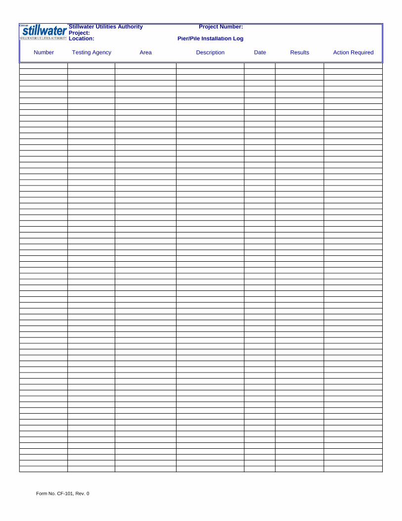
Stillwater Utilities Authority Project Number:
Pier/Pile Installation Log
Number Testing Agency Area Description Date Results Action Required
Project: Location:
Form No. CF-101, Rev. 0

Form No. CF-102, Rev. 0
Stillwater Utilities Authority Project Number:
Number Testing Agency Location Description Date Results Action Required
Project: Location:

Stillwater Utilities Authority Authorization to Backfill Record
Form No. CF-103, Rev1
EXCAVATION INFORMATION
Project No.: Date of Backfill:
Contract No.: Civil Work Completed and Acceptable (Y/N):
Contractor: Piping Work Completed and Acceptable (Y/N):
Unit / Area: Electrical Work Completed and Acceptable (Y/N):
Drawing No.: Fill Material Inspected and Acceptable (Y/N):
Recorded By (Name): Date:
RECORD OF COMPLIANCE
THE ABOVE EXCAVATED AREA HAS BEEN TESTED AND INSPECTED IN ACCORDNCE WITH THE APPLICABLE CONSTRUCTION DRAWINGS, CODES AND ENGINEERING SPECIFICATIONS. ALL WORK IS CERTIFIED TO BE ACCEPTABLE. FILL MATERIAL HAS BEEN INSPECTED FOR SUITABILITY AND IS FREE OF ALL CONTAMINATED DEBRIS.
Accepted by SUA Site Superintendent: Date:
AUTHORIZATION TO BACKFILL
AUTHORIZATION IS HEREBY GRANTED FOR BACKFILLING THE SPECIED AREA ABOVE.
Accepted by SUA Site Quality Manager: Date:
FINAL TESTING
FINAL TESTING HAS BEEN COMPLETED BY A THIRD PARTY INSPECTION COMPANY AND DEEMED ACCEPTABLE. ALL RECORDS HAVE BEEN OBTAINED AND FILED ACCORDINGLY.
Accepted by SUA Site Quality Manager: Date:
FINAL ACCEPTANCE
Accepted by Contractor Rep: Date:
Accepted by SUA Rep : Date:
Accepted by Owner Rep: Date:

Stillwater Utilities Authority Project Number:
Batch Ticket Pour Date QVC-2.01CF-201
CF-202Test Number Test Date Area Area Description Contractor Testing Agency
7 Day
Break
14 Day
Break
28 Day
Break
56 Day
BreakAcceptance
Project: Location: Concrete Installation Log
Form No. CF-200, Rev. 1

Stillwater Utilities Authority Concrete Placement Application, Authorization, and Record
Form No. CF-201, Rev 2
APPLICATION TO PLACE CONCRETE
Project No.: Estimated Quantity of Concrete Pour (Cu. Yards):
Contract No.: Target Slump:
Contractor: Required Design Strength:
Pour No. / I.D.: Required Elevation:
Unit / Area: Required Finish:
Ref. Drawing No.: Required Curing Time:
Scheduled Date / Time of Pre-Placement Inspection: Compaction Report Required (Y/N):
Scheduled Date / Time of Concrete Placement: Compressive Break Strength Testing Required (Y/N):
Application Made By (Name): Date:
RECORD OF PRE-PLACEMENT ACTIVITIES
Soils Compaction Testing Completed and Accepted (Y/N): Completed Pre-Placement Inspection Checklist (Y/N):
Recorded By (Name): Date:
AUTHORIZATION TO PLACE CONCRETE
Contractors Contractor Owner (if required)
Civil Mechanical Electrical Other
Company Name: Stillwater Utilities
Authority
Authorized By:
Date:
RECORD OF CONCRETE PLACEMENT
Date / Time of Starting Placement: Description of Weather During Placement:
Date / Time of Completing Placement: Temperature During Placement (High and Low):
Actual Quantity of Concrete Pour (Cu. Yards): Number of Test Specimens Taken:
Observed Slump: Completed Placement Inspection Checklist (Y/N):
Recorded By (Name): Date:
RECORD OF POST-PLACEMENT ACTIVITIES
Date / Time of Form Removal: Completed Post-Placement Inspection Checklist (Y/N):
Recorded By (Name): Date:
FINAL ACCEPTANCE
Approved by Contractor Rep: Date:
Approved by SUA Rep: Date:
Approved by Client Rep: Date: Note: Attach applicable Concrete Testing Reports.
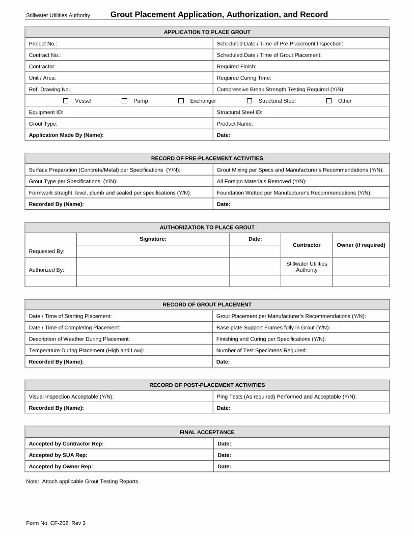
Stillwater Utilities Authority Grout Placement Application, Authorization, and Record
Form No. CF-202, Rev 3
APPLICATION TO PLACE GROUT
Project No.: Scheduled Date / Time of Pre-Placement Inspection:
Contract No.: Scheduled Date / Time of Grout Placement:
Contractor: Required Finish:
Unit / Area: Required Curing Time:
Ref. Drawing No.: Compressive Break Strength Testing Required (Y/N):
Vessel Pump Exchanger Structural Steel Other
Equipment ID: Structural Steel ID:
Grout Type: Product Name:
Application Made By (Name): Date:
RECORD OF PRE-PLACEMENT ACTIVITIES
Surface Preparation (Concrete/Metal) per Specifications (Y/N): Grout Mixing per Specs and Manufacturer’s Recommendations (Y/N):
Grout Type per Specifications (Y/N): All Foreign Materials Removed (Y/N):
Formwork straight, level, plumb and sealed per specifications (Y/N): Foundation Wetted per Manufacturer’s Recommendations (Y/N):
Recorded By (Name): Date:
AUTHORIZATION TO PLACE GROUT
Signature: Date: Contractor Owner (if required)
Requested By:
Authorized By: Stillwater Utilities
Authority
RECORD OF GROUT PLACEMENT
Date / Time of Starting Placement: Grout Placement per Manufacturer’s Recommendations (Y/N):
Date / Time of Completing Placement: Base-plate Support Frames fully in Grout (Y/N):
Description of Weather During Placement: Finishing and Curing per Specifications (Y/N):
Temperature During Placement (High and Low): Number of Test Specimens Required:
Recorded By (Name): Date:
RECORD OF POST-PLACEMENT ACTIVITIES
Visual Inspection Acceptable (Y/N): Ping Tests (As required) Performed and Acceptable (Y/N):
Recorded By (Name): Date:
FINAL ACCEPTANCE
Accepted by Contractor Rep: Date:
Accepted by SUA Rep: Date:
Accepted by Owner Rep: Date: Note: Attach applicable Grout Testing Reports.

Project
Client (1) Must be completed before hydro
Contract # (2) Must be completed before startup
CContractor Complete (3) Can be completed after startupCContractor Total
Item Description Location Hydro /Line # Priority Date
ReportedResponsible
PartyPromise
Date% Complete
& Date Contractor Stillwater Utilities Authority Owner
MASTER PUNCHLIST
Priority Codes
SIGN-OFFS
Form No. CF-009, Rev. 0 1 of 2

Stillwater Utilities Authority Holiday Test Record Log
Form No. CF-503, Rev 3
PROJECT INFORMATION
Project No.: Unit / Area:
Contract No.: System:
Contractor: Holiday Equipment Name:
HOLIDAY INSPECTION SPECIFICATIONS
TEST VOLTAGE = 250 x √microns or TEST VOLTAGE = 1250 x √ mils
FUSION BOND EPOXY = 1600 – 3000 V
TAPES = 6000 – 12000 V
HEAT SHRINK = 8000 – 15000 V
COALTAR = 12500 – 35000V
RECORD OF HOLIDAY INSPECTIONS
Line No.: Sht. No.: Test Origin: Test Termination: Release Date:
HOLIDAY INSPECTION PROCEDURE
1) Calculate Test Voltage as described in formulae above or use Project Specifications
2) Fix a Lead from pipe substrate to ground
3) Connect Leads to Holiday Detector in accordance with operation instructions
4) Adjust to required test voltage
5) Test Holiday detector by touching electrode to exposed subtrate
6) Pass electrode over coated surface at maximum rate of 20 feet per minute
7) Mark Holiday areas
8) Repair area as needed
9) Follow Safety precautions per Owner’s Manual
FINAL ACCEPTANCE
Accepted by Contractor Rep: Date:
Accepted by SUA Rep: Date:
Accepted by Owner’s Rep: Date:

Stillwater Utilities Authority Tie-In Application, Authorization, and Record
Form No. CF-504, Rev 1
APPLICATION TO PERFORM TIE-IN
Project No.: System:
Contract No.: Isometric Drawing:
Contractor: P&ID:
Unit / Area: Tie-in No’s.:
RECORD OF PRE-PLACEMENT ACTIVITIES
Clients Tie-In Specifications Reviewed (Y/N) Ultrasonic Thickness Test Performed and Acceptable (Y/N):
Tie-in Location Verified and Acceptable (Y/N): Bake out Procedure Performed (As Required) and Acceptable (Y/N):
Pre Task Analysis Performed and Signed (Y/N): WPS w/ Supporting PQR Reviewed and Acceptable (Y/N):
LOTO Performed and Verified (Y/N): Welder Performance Qualification (WPQ) Acceptable (Y/N):
Materials of Construction (MTR’s) Obtained and Acceptable (Y/N): PWHT Procedures (As required) Reviewed and Acceptable (Y/N):
PMI (As Required) Performed and Acceptable (Y/N): NDE Procedures Reviewed and Acceptable (Y/N):
Recorded By (Name): Date:
AUTHORIZATION TO PERFORM TIE-IN
Signature: Date: Contractor Owner (if required)
Requested By:
Authorized By: Stillwater Utilities
Authority
Authorized By:
RECORD OF TIE-IN
Surface Preparation within Specifications (Y/N): In-Process NDE Performed (As Required) and Acceptable (Y/N):
Surface Prep. NDE Inspection Performed and Acceptable (Y/N): Piping Installed per Drawings and Specifications (Y/N):
Fit-up and Alignment with Specifications (Y/N): 5% NDE Requirements Met and Acceptable: (Y/N):
Welding in Accordance with WPS (Y/N): NDE in Lieu of Hydro (As Required) Complete and Acceptable (Y/N):
Hardness Testing Complete and Acceptable (Y/N): Car Ber Hydro Test (As required) Performed and Acceptable (Y/N):
Recorded By (Name): Date:
RECORD OF POST-TIE-IN ACTIVITIES
Area Clean and Acceptable to Client (Y/N): Insulation (As Required) Performed and Acceptable (Y/N):
Painting Performed and Acceptable (Y/N): Flange Connections (Bolting and Gaskets) Acceptable (Y/N):
Heat Tracing (As Required) Performed and Acceptable (Y/N): Service Test (As required) Performed and Acceptable (Y/N):
Recorded By (Name): Date:
SUMMARY OF TIE-IN INSPECTIONS
Recorded By (Name): Date:
FINAL ACCEPTANCE
Accepted by Contractor Rep: Date:
Accepted by SUA Rep: Date:
Accepted by Owner’s Rep: Date:

Project Number:
Welds Rejected
Count Line No. Weld No. Welder ID Rej view Reason R1 Acc/Rej R2 Acc/Rej Tracer 1 Acc/Rej Tracer 2 Acc/Rej
1
2
3
4
5
6
7
8
9
10
11
12
13
14
15
16
17
18
19
20
21
22
23
24
25
26
27
28
29
30
31
32
33
34
35
Stillwater Utilities AuthorityProject: Location:
Form No. CF-1004, Rev 0

Stillwater Utilities Authority Project Number:
Pier/Pile Installation Log
Number Testing Agency Area Description Date Results Action Required
Project: Location:
Form No. CF-101, Rev. 0

Form No. CF-102, Rev. 0
Stillwater Utilities Authority Project Number:
Number Testing Agency Location Description Date Results Action Required
Project: Location:

Stillwater Utilities Authority Authorization to Backfill Record
Form No. CF-103, Rev1
EXCAVATION INFORMATION
Project No.: Date of Backfill:
Contract No.: Civil Work Completed and Acceptable (Y/N):
Contractor: Piping Work Completed and Acceptable (Y/N):
Unit / Area: Electrical Work Completed and Acceptable (Y/N):
Drawing No.: Fill Material Inspected and Acceptable (Y/N):
Recorded By (Name): Date:
RECORD OF COMPLIANCE
THE ABOVE EXCAVATED AREA HAS BEEN TESTED AND INSPECTED IN ACCORDNCE WITH THE APPLICABLE CONSTRUCTION DRAWINGS, CODES AND ENGINEERING SPECIFICATIONS. ALL WORK IS CERTIFIED TO BE ACCEPTABLE. FILL MATERIAL HAS BEEN INSPECTED FOR SUITABILITY AND IS FREE OF ALL CONTAMINATED DEBRIS.
Accepted by SUA Site Superintendent: Date:
AUTHORIZATION TO BACKFILL
AUTHORIZATION IS HEREBY GRANTED FOR BACKFILLING THE SPECIED AREA ABOVE.
Accepted by SUA Site Quality Manager: Date:
FINAL TESTING
FINAL TESTING HAS BEEN COMPLETED BY A THIRD PARTY INSPECTION COMPANY AND DEEMED ACCEPTABLE. ALL RECORDS HAVE BEEN OBTAINED AND FILED ACCORDINGLY.
Accepted by SUA Site Quality Manager: Date:
FINAL ACCEPTANCE
Accepted by Contractor Rep: Date:
Accepted by SUA Rep : Date:
Accepted by Owner Rep: Date:

Stillwater Utilities Authority Project Number:
Batch Ticket Pour Date QVC-2.01CF-201
CF-202Test Number Test Date Area Area Description Contractor Testing Agency
7 Day
Break
14 Day
Break
28 Day
Break
56 Day
BreakAcceptance
Project: Location: Concrete Installation Log
Form No. CF-200, Rev. 1

Stillwater Utilities Authority Concrete Placement Application, Authorization, and Record
Form No. CF-201, Rev 2
APPLICATION TO PLACE CONCRETE
Project No.: Estimated Quantity of Concrete Pour (Cu. Yards):
Contract No.: Target Slump:
Contractor: Required Design Strength:
Pour No. / I.D.: Required Elevation:
Unit / Area: Required Finish:
Ref. Drawing No.: Required Curing Time:
Scheduled Date / Time of Pre-Placement Inspection: Compaction Report Required (Y/N):
Scheduled Date / Time of Concrete Placement: Compressive Break Strength Testing Required (Y/N):
Application Made By (Name): Date:
RECORD OF PRE-PLACEMENT ACTIVITIES
Soils Compaction Testing Completed and Accepted (Y/N): Completed Pre-Placement Inspection Checklist (Y/N):
Recorded By (Name): Date:
AUTHORIZATION TO PLACE CONCRETE
Contractors Contractor Owner (if required)
Civil Mechanical Electrical Other
Company Name: Stillwater Utilities
Authority
Authorized By:
Date:
RECORD OF CONCRETE PLACEMENT
Date / Time of Starting Placement: Description of Weather During Placement:
Date / Time of Completing Placement: Temperature During Placement (High and Low):
Actual Quantity of Concrete Pour (Cu. Yards): Number of Test Specimens Taken:
Observed Slump: Completed Placement Inspection Checklist (Y/N):
Recorded By (Name): Date:
RECORD OF POST-PLACEMENT ACTIVITIES
Date / Time of Form Removal: Completed Post-Placement Inspection Checklist (Y/N):
Recorded By (Name): Date:
FINAL ACCEPTANCE
Approved by Contractor Rep: Date:
Approved by SUA Rep: Date:
Approved by Client Rep: Date: Note: Attach applicable Concrete Testing Reports.

Stillwater Utilities Authority Grout Placement Application, Authorization, and Record
Form No. CF-202, Rev 3
APPLICATION TO PLACE GROUT
Project No.: Scheduled Date / Time of Pre-Placement Inspection:
Contract No.: Scheduled Date / Time of Grout Placement:
Contractor: Required Finish:
Unit / Area: Required Curing Time:
Ref. Drawing No.: Compressive Break Strength Testing Required (Y/N):
Vessel Pump Exchanger Structural Steel Other
Equipment ID: Structural Steel ID:
Grout Type: Product Name:
Application Made By (Name): Date:
RECORD OF PRE-PLACEMENT ACTIVITIES
Surface Preparation (Concrete/Metal) per Specifications (Y/N): Grout Mixing per Specs and Manufacturer’s Recommendations (Y/N):
Grout Type per Specifications (Y/N): All Foreign Materials Removed (Y/N):
Formwork straight, level, plumb and sealed per specifications (Y/N): Foundation Wetted per Manufacturer’s Recommendations (Y/N):
Recorded By (Name): Date:
AUTHORIZATION TO PLACE GROUT
Signature: Date: Contractor Owner (if required)
Requested By:
Authorized By: Stillwater Utilities
Authority
RECORD OF GROUT PLACEMENT
Date / Time of Starting Placement: Grout Placement per Manufacturer’s Recommendations (Y/N):
Date / Time of Completing Placement: Base-plate Support Frames fully in Grout (Y/N):
Description of Weather During Placement: Finishing and Curing per Specifications (Y/N):
Temperature During Placement (High and Low): Number of Test Specimens Required:
Recorded By (Name): Date:
RECORD OF POST-PLACEMENT ACTIVITIES
Visual Inspection Acceptable (Y/N): Ping Tests (As required) Performed and Acceptable (Y/N):
Recorded By (Name): Date:
FINAL ACCEPTANCE
Accepted by Contractor Rep: Date:
Accepted by SUA Rep: Date:
Accepted by Owner Rep: Date: Note: Attach applicable Grout Testing Reports.

Form No. CF-501, Rev. 2
1 of 4
Requested By:
Approved By:
Approved By:
Test Number
Location
Next CalLast Cal
P&ID's:System Number (s)
Valves open as required
Gauge Range
Date:
Stillwater Utilities Authority
HYDRO INSPECTION TEST PLAN
ITP
System Description
Client Rep
Date:
In-Line Instruments removed
H2O
Valve Orientation Correct
Client RepPRE-HYDRO TEST RELEASE
Sub Cont Rep SUA. Rep
Sub Cont Rep SUA. Rep Client RepHYDRO TEST
Piping conforms to Drawings and SpecificationsVT/NDE/PMI/PWHT/BHN Complete
Temperature
Blinds installed where applicable
Gauge Number
Test Pressure Req.
Test Media
Gauge Calibration
Actual Test psi.
Guides installed
Test Complete
Test Start
Test Length
Spring Hanger Stops removedSupports installedBlinds pulled as required
POST-HYDRO TEST COMPLETESub Cont Rep SUA. RepDate:
Proper Bolts and Gaskets
High Point and Low Point Plugs installedIn-Line Instruments Installed
Client Representative
Project Number
Date
Client
Date
Date
Burns & McDonnell Representative
Valve Orientation CorrectSystem blown free of test medium
Contractor Representative
Flange Rating:
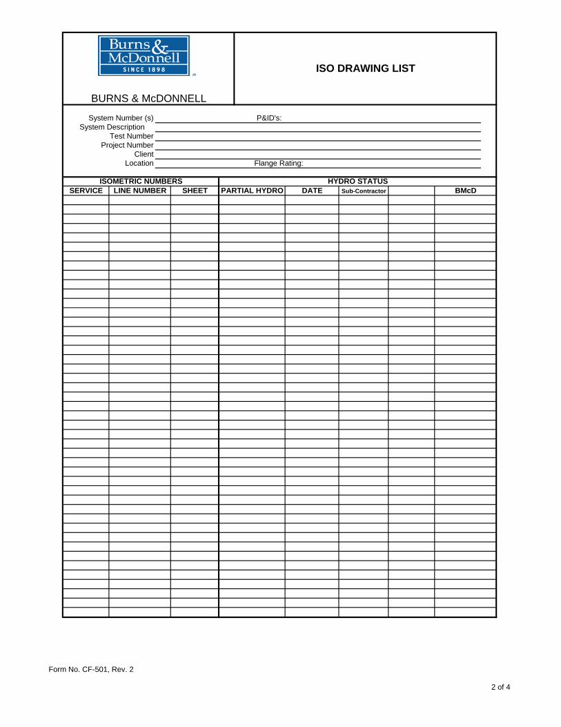
Form No. CF-501, Rev. 2
2 of 4
DATE Sub-Contractor
Location
PARTIAL HYDRO
Project Number
System DescriptionSystem Number (s)
Test Number
Client
HYDRO STATUSBMcD
BURNS & McDONNELL
ISO DRAWING LIST
ISOMETRIC NUMBERSSERVICE LINE NUMBER SHEET
P&ID's:
Flange Rating:

Form No. CF-501, Rev. 2
3 of 4
The following items are incomplete or require correction:
Client
ResponsiblePartyIdentification and Location Date
Discovered BMcD Signature of
Completion
Project Number
System Number (s)
Test Number
Location
ItemNumber
Priority Codes
P&ID's:
DateCorrected
Priority
BURNS & McDONNELL
PIPING PUNCH LIST
(1) Must be complete before hydro (2) Must be complete before mechanical completion(3) Must be complete before substantial completion
DefinitionsMechanical completion: The system is operationally safe to operate Substantial completion: All contractual obligations are complete and accepted.
System Description
Flange Rating:
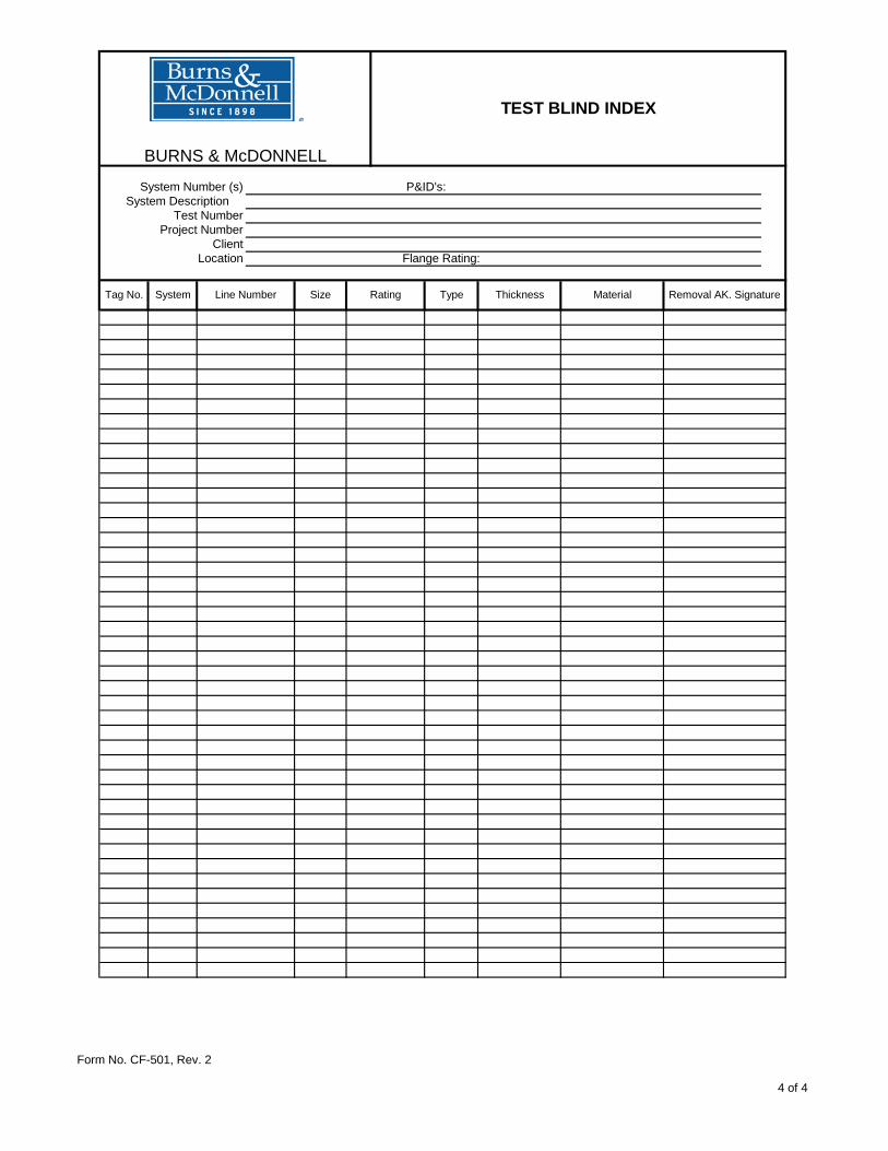
Form No. CF-501, Rev. 2
4 of 4
Material
Test Number
Tag No. Removal AK. SignatureThickness
Location
Project NumberClient
System DescriptionSystem Number (s)
BURNS & McDONNELL
TEST BLIND INDEX
System TypeRatingSizeLine Number
P&ID's:
Flange Rating:
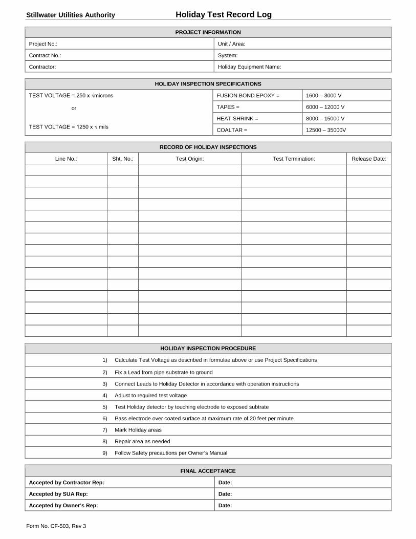
Stillwater Utilities Authority Holiday Test Record Log
Form No. CF-503, Rev 3
PROJECT INFORMATION
Project No.: Unit / Area:
Contract No.: System:
Contractor: Holiday Equipment Name:
HOLIDAY INSPECTION SPECIFICATIONS
TEST VOLTAGE = 250 x √microns or TEST VOLTAGE = 1250 x √ mils
FUSION BOND EPOXY = 1600 – 3000 V
TAPES = 6000 – 12000 V
HEAT SHRINK = 8000 – 15000 V
COALTAR = 12500 – 35000V
RECORD OF HOLIDAY INSPECTIONS
Line No.: Sht. No.: Test Origin: Test Termination: Release Date:
HOLIDAY INSPECTION PROCEDURE
1) Calculate Test Voltage as described in formulae above or use Project Specifications
2) Fix a Lead from pipe substrate to ground
3) Connect Leads to Holiday Detector in accordance with operation instructions
4) Adjust to required test voltage
5) Test Holiday detector by touching electrode to exposed subtrate
6) Pass electrode over coated surface at maximum rate of 20 feet per minute
7) Mark Holiday areas
8) Repair area as needed
9) Follow Safety precautions per Owner’s Manual
FINAL ACCEPTANCE
Accepted by Contractor Rep: Date:
Accepted by SUA Rep: Date:
Accepted by Owner’s Rep: Date:
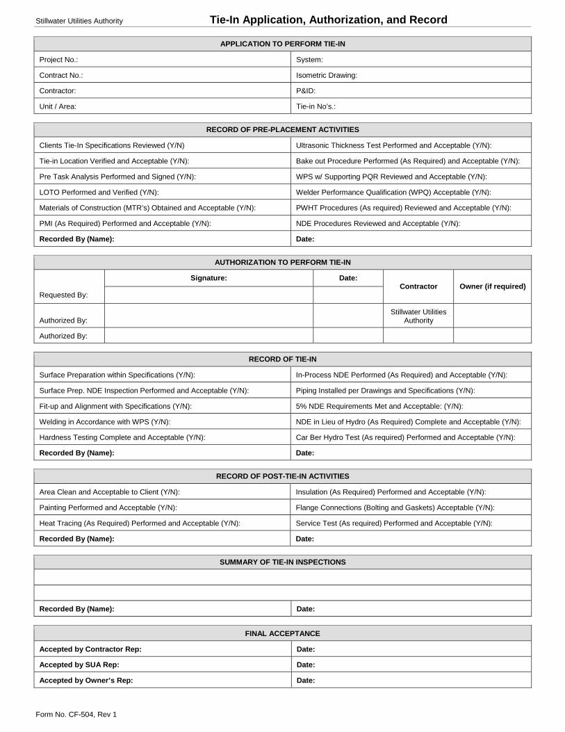
Stillwater Utilities Authority Tie-In Application, Authorization, and Record
Form No. CF-504, Rev 1
APPLICATION TO PERFORM TIE-IN
Project No.: System:
Contract No.: Isometric Drawing:
Contractor: P&ID:
Unit / Area: Tie-in No’s.:
RECORD OF PRE-PLACEMENT ACTIVITIES
Clients Tie-In Specifications Reviewed (Y/N) Ultrasonic Thickness Test Performed and Acceptable (Y/N):
Tie-in Location Verified and Acceptable (Y/N): Bake out Procedure Performed (As Required) and Acceptable (Y/N):
Pre Task Analysis Performed and Signed (Y/N): WPS w/ Supporting PQR Reviewed and Acceptable (Y/N):
LOTO Performed and Verified (Y/N): Welder Performance Qualification (WPQ) Acceptable (Y/N):
Materials of Construction (MTR’s) Obtained and Acceptable (Y/N): PWHT Procedures (As required) Reviewed and Acceptable (Y/N):
PMI (As Required) Performed and Acceptable (Y/N): NDE Procedures Reviewed and Acceptable (Y/N):
Recorded By (Name): Date:
AUTHORIZATION TO PERFORM TIE-IN
Signature: Date: Contractor Owner (if required)
Requested By:
Authorized By: Stillwater Utilities
Authority
Authorized By:
RECORD OF TIE-IN
Surface Preparation within Specifications (Y/N): In-Process NDE Performed (As Required) and Acceptable (Y/N):
Surface Prep. NDE Inspection Performed and Acceptable (Y/N): Piping Installed per Drawings and Specifications (Y/N):
Fit-up and Alignment with Specifications (Y/N): 5% NDE Requirements Met and Acceptable: (Y/N):
Welding in Accordance with WPS (Y/N): NDE in Lieu of Hydro (As Required) Complete and Acceptable (Y/N):
Hardness Testing Complete and Acceptable (Y/N): Car Ber Hydro Test (As required) Performed and Acceptable (Y/N):
Recorded By (Name): Date:
RECORD OF POST-TIE-IN ACTIVITIES
Area Clean and Acceptable to Client (Y/N): Insulation (As Required) Performed and Acceptable (Y/N):
Painting Performed and Acceptable (Y/N): Flange Connections (Bolting and Gaskets) Acceptable (Y/N):
Heat Tracing (As Required) Performed and Acceptable (Y/N): Service Test (As required) Performed and Acceptable (Y/N):
Recorded By (Name): Date:
SUMMARY OF TIE-IN INSPECTIONS
Recorded By (Name): Date:
FINAL ACCEPTANCE
Accepted by Contractor Rep: Date:
Accepted by SUA Rep: Date:
Accepted by Owner’s Rep: Date: