storagetek t9x40 tape drive - oracle help center comments about this document to...
TRANSCRIPT
Submit comments about this document to [email protected].
StorageTek T9x40 Tape Drive
Systems Assurance Guide
Part Number: E28189_03 September 2014
2 T9x40 SAG September 2014
StorageTek T9x40 Tape Drive Systems Assurance Guide
E28189_03
Oracle welcomes your comments and suggestions for improving this book. Contact us at [email protected] include the title, part number, issue date, and revision.
Copyright © 1998, 2014, Oracle and/or its affiliates. All rights reserved.
This software and related documentation are provided under a license agreement containing restrictions on use and disclosure and areprotected by intellectual property laws. Except as expressly permitted in your license agreement or allowed by law, you may not use, copy,reproduce, translate, broadcast, modify, license, transmit, distribute, exhibit, perform, publish, or display any part, in any form, or by anymeans. Reverse engineering, disassembly, or decompilation of this software, unless required by law for interoperability, is prohibited.
The information contained herein is subject to change without notice and is not warranted to be error-free. If you find any errors, please reportthem to us in writing.
If this is software or related software documentation that is delivered to the U.S. Government or anyone licensing it on behalf of the U.S.Government, the following notice is applicable:
U.S. GOVERNMENT END USERS: Oracle programs, including any operating system, integrated software, any programs installed on thehardware, and/or documentation, delivered to U.S. Government end users are "commercial computer software" pursuant to the applicableFederal Acquisition Regulation and agency-specific supplemental regulations. As such, use, duplication, disclosure, modification, andadaptation of the programs, including any operating system, integrated software, any programs installed on the hardware, and/ordocumentation, shall be subject to license terms and license restrictions applicable to the programs. No other rights are granted to the U.S.Government.
This software or hardware is developed for general use in a variety of information management applications. It is not developed or intended foruse in any inherently dangerous applications, including applications which may create a risk of personal injury. If you use this software orhardware in dangerous applications, then you shall be responsible to take all appropriate fail-safe, backup, redundancy, and other measures toensure the safe use. Oracle Corporation and its affiliates disclaim any liability for any damages caused by use of this software or hardware indangerous applications.
Oracle and Java are registered trademarks of Oracle and/or its affiliates. Other names may be trademarks of their respective owners.
Intel and Intel Xeon are trademarks or registered trademarks of Intel Corporation. All SPARC trademarks are used under license and aretrademarks or registered trademarks of SPARC International, Inc. AMD, Opteron, the AMD logo, and the AMD Opteron logo are trademarks orregistered trademarks of Advanced Micro Devices. UNIX is a registered trademark of The Open Group.
This software or hardware and documentation may provide access to or information on content, products, and services from third parties.Oracle Corporation and its affiliates are not responsible for and expressly disclaim all warranties of any kind with respect to third-party content,products, and services. Oracle Corporation and its affiliates will not be responsible for any loss, costs, or damages incurred due to your access toor use of third-party content, products, or services.
September 2014 3
Table of Contents
List of Figures .......................................................................................................................... 7
List of Tables ............................................................................................................................ 9
Preface ...................................................................................................................................... 11Access to Oracle Support .......................................................................................................... 11
1 Product Overview ................................................................................................................. 13Descriptions ............................................................................................................................. 13
T9840 Tape Drive ................................................................................................................ 13T9940 Tape Drive ................................................................................................................ 14T9x40 VolSafe ..................................................................................................................... 15
Configurations ......................................................................................................................... 16T9840 Configurations .......................................................................................................... 16T9940 Configurations .......................................................................................................... 17Configuration Details .......................................................................................................... 17
Interfaces ................................................................................................................................. 21ESCON .............................................................................................................................. 21FC ....................................................................................................................................... 22FICON ................................................................................................................................ 22SCSI ................................................................................................................................... 24
Tape Cartridges and Labels ...................................................................................................... 249840 Cartridge Description ................................................................................................. 249940 Cartridge Description .................................................................................................. 26
Mixed-Media Management ...................................................................................................... 27Mixed Data Density ............................................................................................................ 27Mixed Emulation Image ...................................................................................................... 28
Virtual Operator Panel ............................................................................................................. 29
2 System Assurance ............................................................................................................... 31System Assurance Planning Meetings ...................................................................................... 31Customer Team Member Contact Sheet.................................................................................... 33Client Processor Teams ........................................................................................................... 34
CPU Hardware Vendor Contacts ........................................................................................ 34CPU Software Vendor Contacts .......................................................................................... 34
Oracle Team Member Contact Sheet......................................................................................... 35
4 T9x40 SAG September 2014
3 Library Firmware/Host Software ..................................................................................... 37Library Firmware .................................................................................................................... 37Host Software Configuration ................................................................................................... 37
T9x40-Supported Software ................................................................................................. 37Software Configuration Worksheets .................................................................................... 38
4 Preinstallation Checklists ................................................................................................. 41Predelivery Checklist ............................................................................................................... 41Delivery and Handling Information ......................................................................................... 43Access and Administrative Issues ............................................................................................ 44
5 Information for Ordering .................................................................................................... 45Tape Drive Order Numbers for Libraries ................................................................................. 45
T9840 Library Attached Tape Drives ................................................................................... 45T9940 Library Attached Tape Drives ................................................................................... 48
Desktop and Rack Mount Tape Drive ....................................................................................... 50T9840 Rack Mount and Desktop Drives ............................................................................... 50T9940 Rack Mount Drives ................................................................................................... 51
Cable Order Numbers.............................................................................................................. 52ESCON Cable Order Numbers ........................................................................................... 52Single Mode FC/FICON (LC, long wave) Cables ................................................................ 55Multimode FC/FICON (LC, short wave) Cables ................................................................. 56Multimode FC Cables (Type SC, 1-Gb) ............................................................................... 56
Conversion Bills/Kits .............................................................................................................. 57Encryption Feature ................................................................................................................... 59Ordering Media and Labels ..................................................................................................... 60
A Specifications ........................................................................................................................ 61T9840 ....................................................................................................................................... 61
Power Specifications .......................................................................................................... 62Performance Specification ................................................................................................... 63Environmental Requirements .............................................................................................. 65Physical Specifications ....................................................................................................... 66Library Attachments .......................................................................................................... 69
T9940 ....................................................................................................................................... 70Physical Specifications ....................................................................................................... 70Power Specifications .......................................................................................................... 71Performance Specifications ................................................................................................. 72Environmental Requirements .............................................................................................. 74Library Attachments .......................................................................................................... 76
B Controlling Contaminants ................................................................................................. 77Environmental Contaminants ................................................................................................... 77Required Air Quality Levels ..................................................................................................... 77Contaminant Properties and Sources ........................................................................................ 78
Operator Activity ................................................................................................................ 79Hardware Movement .......................................................................................................... 79Outside Air ......................................................................................................................... 79Stored Items ........................................................................................................................ 79
September 2014 5
Outside Influences .............................................................................................................. 79Cleaning Activity ................................................................................................................ 80
Contaminant Effects ................................................................................................................. 80Physical Interference ........................................................................................................... 80Corrosive Failure ................................................................................................................ 80Shorts ................................................................................................................................. 81Thermal Failure .................................................................................................................. 81
Room Conditions ..................................................................................................................... 81Exposure Points ....................................................................................................................... 82Filtration .................................................................................................................................. 83Positive Pressurization and Ventilation .................................................................................... 84Cleaning Procedures and Equipment ....................................................................................... 84
Daily Tasks ......................................................................................................................... 85Weekly Tasks ...................................................................................................................... 85Quarterly Tasks .................................................................................................................. 86Biennial Tasks ..................................................................................................................... 86
Activity and Processes ............................................................................................................. 87
Glossary ................................................................................................................................... 89
Index ............................................................................................................................................ 1

6 T9x40 SAG September 2014

September 2014 List of Figures 7
List of Figures
FIGURE 1-1 T9840B/C/D Tape Drive ............................................................................................ 13FIGURE 1-2 T9940B Tape Drive ..................................................................................................... 14FIGURE 1-3 T9840 Tape Drive Common Configurations ................................................................ 18FIGURE 1-4 T9940 Tape Drive, Library attached ............................................................................ 19FIGURE 1-5 T9940 Tape Drive, Rack Mount ................................................................................... 21FIGURE 1-6 9840 Cartridge .......................................................................................................... 25FIGURE 1-7 9940 Cartridge .......................................................................................................... 27FIGURE 1-8 Virtual Operator Panel ............................................................................................... 29FIGURE 5-1 ESCON Cable Connectors .......................................................................................... 53

8 T9x40 SAG September 2014

September 2014 List of Tables 9
List of Tables
TABLE 1-1 T9x40 Tape Drive - VolSafe Cartridge Compatibility Matrix ....................................... 16TABLE 1-2 Data Cartridge Read, Write Append Matrix ............................................................... 28TABLE 2-1 System Assurance Task Checklist ............................................................................... 32TABLE 3-1 NCS Software Configuration Worksheet .................................................................... 38TABLE 3-2 ACSLS Software Configuration Worksheet................................................................. 39TABLE 3-3 RMLS Software Configuration Worksheet .................................................................. 39TABLE 4-1 Predelivery Checklist ................................................................................................. 41TABLE 4-2 Delivery and Handling Information ........................................................................... 43TABLE 4-3 Access and Administrative Issues............................................................................... 44TABLE 5-1 T9840D Library Configuration (Used) Marketing PNs ................................................ 46TABLE 5-2 T9840C (Used) ROHS Compliant Marketing PNs ....................................................... 47TABLE 5-3 T9840C (Used) Non-ROHS Marketing PNs ................................................................. 47TABLE 5-4 T9840B (Used) Non-ROHS Marketing PNs .................................................................. 48TABLE 5-5 T9940B (Used) ROHS Compliant Marketing PNs........................................................ 48TABLE 5-6 T9940B (Used) Non-ROHS Marketing PNs .................................................................. 49TABLE 5-7 T9940A (Used) Non-ROHS Marketing PNs ................................................................. 50TABLE 5-8 T9840 Non-library Drives - No Longer Available ........................................................ 50TABLE 5-9 T9940 Non-library Drives (No Longer Available)........................................................ 51TABLE 5-10 9/125 Micron Cable Part Numbers ............................................................................. 55TABLE 5-11 50/125 Micron (LC Connector) Cable Part Numbers................................................... 56TABLE 5-12 T9840 Drive Tray Conversion Kits (LOD Card)........................................................... 57TABLE 5-13 T9840D Rackmount Conversion Bills (No Longer Available) ...................................... 58TABLE 5-14 T9840 Drive Tray Conversion Kits - HBD Card (No Longer Available) ....................... 58TABLE 5-15 T9x40 Common Conversion Bills (ROHS Compliant) - No Longer Available .............. 59TABLE 5-16 T9940 Conversion Bills (No Longer Available)............................................................ 59TABLE 5-17 VolSafe Cartridge Summary ....................................................................................... 60TABLE A-1 T9840 Tape Drive Power Specifications ...................................................................... 62TABLE A-2 T9840 Tape Drive Performance Specifications............................................................. 63TABLE A-3 9840 Data Cartridge Performance Specifications ......................................................... 64TABLE A-4 T9840 Environmental Requirements ........................................................................... 65TABLE A-5 9840 Data Cartridge Environmental Requirements ..................................................... 66TABLE A-6 T9840 Tape Drive Library-attached Weights ............................................................... 67TABLE A-7 T9840 Tape Drive Desktop Physical Specifications...................................................... 67TABLE A-8 T9840 Tape Drive Rack Mount Physical Specifications................................................ 68TABLE A-9 T9840 Tape Drive Library Attachments ...................................................................... 69TABLE A-10 T9940 Tape Drive Rack Mount Physical Specifications................................................ 70TABLE A-11 T9940 Tape Drive Library attached Weights ............................................................... 71TABLE A-12 T9940 Tape Drive Power Specifications ...................................................................... 71TABLE A-13 T9940 Tape Drive Performance Specifications............................................................. 72TABLE A-14 9940 Data Cartridge Specifications.............................................................................. 73TABLE A-15 T9940 Environmental Requirements ........................................................................... 74TABLE A-16 9940 Cartridge Environmental Requirements ............................................................. 75TABLE A-17 T9940 Tape Drive Library Attachments ...................................................................... 76

10 T9x40 SAG September 2014
September 2014 Preface 11
Preface
This book provides pre-sales and planning information for Oracle’s StorageTekT9840D tape drive. It also provides information about the various cartridges,cartridge labels, and older models of the T9x40 tape drive family.
The term T9x40 is used in this publication to generically reflect all drive models.Whenever model differentiation is appropriate, the specific model nomenclature isindicated.
Access to Oracle SupportOracle customers have access to electronic support through My Oracle Support. Forinformation, visit http://www.oracle.com/support/contact.html or visit http://www.oracle.com/accessibility/support.html if you are hearing impaired.

Access to Oracle Support
12 T9x40 SAG September 2014

September 2014 Product Overview 13
1Product Overview
This chapter provides an overview of T9x40 tape drives.
DescriptionsThe T9x40 tape drives are small, modular, high-performance drives designed for theenterprise and client-server environments. There are four generations of T9840access-centric drives and two generations of T9940 high-capacity drives.
T9840 Tape DriveThe T9840 tape drives (FIGURE 1-1) provide applications with high data throughputand fast recall. T9840 tape drives read/write dual-reel cartridges (see “9840 CartridgeDescription” on page 24, for more information about 9840 cartridges). The dual-reelcartridge loads to midpoint, which eliminates tape threading time and minimizesfirst-file access time (see TABLE A-2 on page 63).
• T9840A/B tape drives read/write 20-GigaByte (GB) dual-reel cartridges.
• The T9840C tape drive is an enhanced version for 40-GB recording, using partialresponse maximum likelihood (PRML) format.
FIGURE 1-1 T9840B/C/D Tape Drive
Descriptions
14 T9x40 SAG September 2014
• The T9840D encryption-capable drive provides 75-GB recording when using blocksizes between 32 KB and 256 KB. With drive code level 1.44.x04 and KeyManagement System (2.1) or Oracle Key Manager, the drive complies with FIPSLevel 1. Level 1 is the lowest classification and has production-graderequirements.
The T9840B/C/D rear panel has a Maintenance Port (standard RJ45 receptacle) forService Delivery Platform (SDP) and service representative interface.
The T9840D maintenance port supports the use of the Virtual Operator Panel toperform drive operations, retrieve error information, and configure the tape drive.VOP version 1.0.13, or higher, in conjunction with the appropriate drive code levelsupports the use of an IPv6 address.
T9840 tape drives are also capable of reading/writing specially designated, write-only (VolSafe) cartridges, which provide a non-erasable, non-rewritable storagesolution for important data. See “T9x40 VolSafe” on page 15 for additionalinformation.
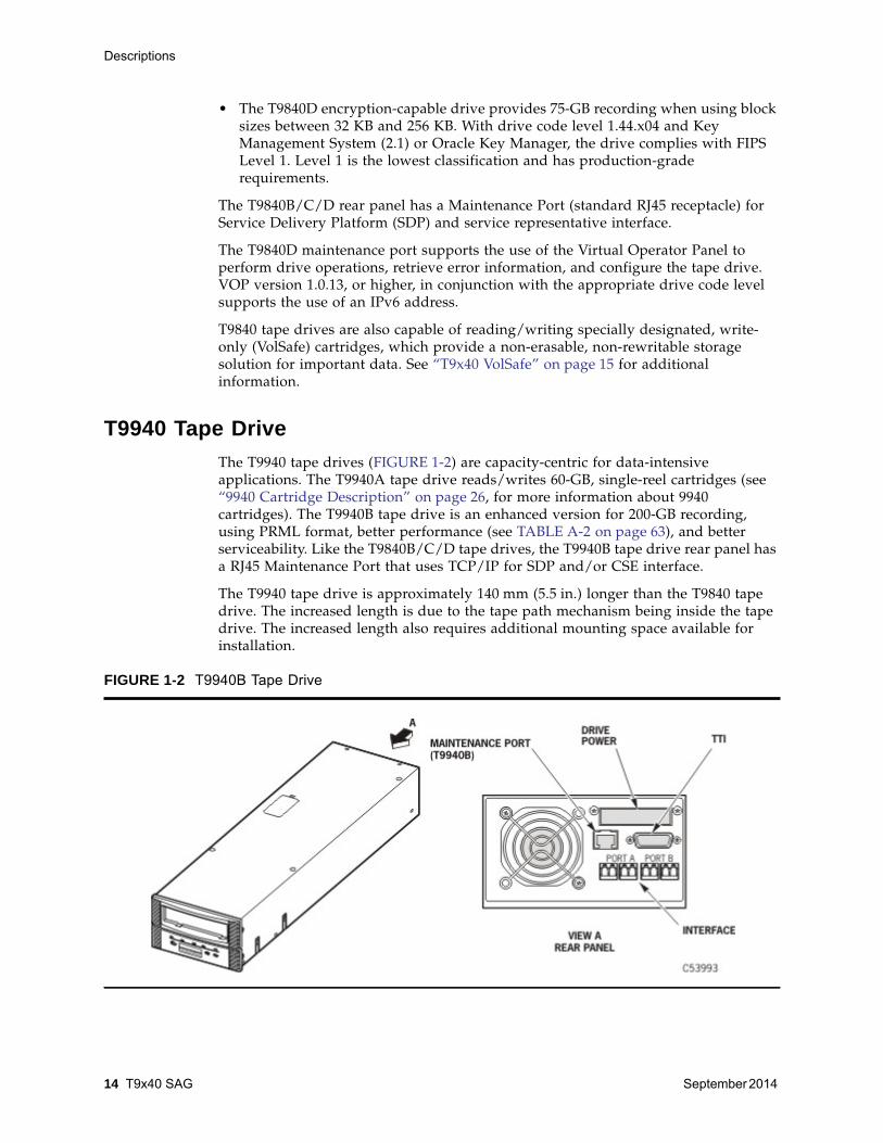
T9940 Tape DriveThe T9940 tape drives (FIGURE 1-2) are capacity-centric for data-intensiveapplications. The T9940A tape drive reads/writes 60-GB, single-reel cartridges (see“9940 Cartridge Description” on page 26, for more information about 9940cartridges). The T9940B tape drive is an enhanced version for 200-GB recording,using PRML format, better performance (see TABLE A-2 on page 63), and betterserviceability. Like the T9840B/C/D tape drives, the T9940B tape drive rear panel hasa RJ45 Maintenance Port that uses TCP/IP for SDP and/or CSE interface.
The T9940 tape drive is approximately 140 mm (5.5 in.) longer than the T9840 tapedrive. The increased length is due to the tape path mechanism being inside the tapedrive. The increased length also requires additional mounting space available forinstallation.
FIGURE 1-2 T9940B Tape Drive

Descriptions
September 2014 Product Overview 15
T9940B tape drives are also capable of reading/writing specially designated, write-only (VolSafe) cartridges, which provide a non-erasable, non-rewritable storagesolution for important data. See “T9x40 VolSafe” on page 15 for additionalinformation.
T9x40 VolSafeT9x40 VolSafe capability is a combination of hardware (VolSafe enabled tape drives),microcode, and special media (VolSafe cartridges). This combination provides write-once, read-many (WORM) functionality to safeguard selected data files. Once writtento a VolSafe cartridge, data cannot be over-written or erased. New data can be added(appended) to a density-compatible VolSafe cartridge until the cartridge is full.
VolSafe cartridges have a magnetic signature in the Media Information Region (MIR),distinct machine readable features, and are visually identified by colored labels andwrite-protect switches. See “9840 Cartridge Description” on page 24 or “9940Cartridge Description” on page 26 for more information on VolSafe cartridgeidentification features.
WriteTo write to a VolSafe cartridge, a T9x40 tape drive must have compatible data densitywith the specific VolSafe cartridge, and the drive must be VolSafe-enabled. Forinstance:
• T9840A/B drives write to 20-GB 9840 VolSafe cartridges only (yellowidentification).
• T9840C drives write to 40-GB 9840C VolSafe cartridges only (green identification).
• T9840D drives write to 75-GB 9840D VolSafe cartridges only (purpleidentification).
Note – See “9840 Cartridge Description” on page 24, for VolSafecartridge identification
• T9940B tape drives write to 200-GB 9940B VolSafe cartridges only (see “9940Cartridge Description” on page 26, for VolSafe cartridge identification).
The specific tape drive’s VolSafe configuration setting must also be enabled(indicated by Ready A, when a compatible VolSafe cartridge is loaded).
ReadTo read VolSafe cartridges, a T9x40 tape drive only needs to be density-compatible,the tape drive VolSafe configuration setting need not be enabled. The tape driverecognizes VolSafe cartridges as file-protected (Ready F), regardless of the write-protect switch position. For instance, the T9840C tape drive reads 40-GB 9840CVolSafe cartridges and 20-GB 9840 VolSafe cartridges, but T9840A/B tape drives onlyread 20-GB 9840 VolSafe cartridges.
Configurations
16 T9x40 SAG September 2014
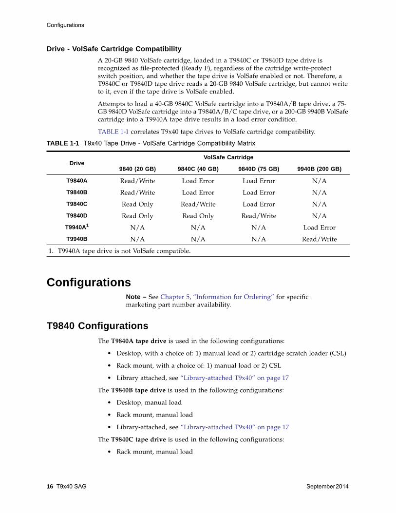
Drive - VolSafe Cartridge CompatibilityA 20-GB 9840 VolSafe cartridge, loaded in a T9840C or T9840D tape drive isrecognized as file-protected (Ready F), regardless of the cartridge write-protectswitch position, and whether the tape drive is VolSafe enabled or not. Therefore, aT9840C or T9840D tape drive reads a 20-GB 9840 VolSafe cartridge, but cannot writeto it, even if the tape drive is VolSafe enabled.
Attempts to load a 40-GB 9840C VolSafe cartridge into a T9840A/B tape drive, a 75-GB 9840D VolSafe cartridge into a T9840A/B/C tape drive, or a 200-GB 9940B VolSafecartridge into a T9940A tape drive results in a load error condition.
TABLE 1-1 correlates T9x40 tape drives to VolSafe cartridge compatibility.
ConfigurationsNote – See Chapter 5, “Information for Ordering” for specificmarketing part number availability.
T9840 ConfigurationsThe T9840A tape drive is used in the following configurations:
• Desktop, with a choice of: 1) manual load or 2) cartridge scratch loader (CSL)
• Rack mount, with a choice of: 1) manual load or 2) CSL
• Library attached, see “Library-attached T9x40” on page 17
The T9840B tape drive is used in the following configurations:
• Desktop, manual load
• Rack mount, manual load
• Library-attached, see “Library-attached T9x40” on page 17
The T9840C tape drive is used in the following configurations:
• Rack mount, manual load
TABLE 1-1 T9x40 Tape Drive - VolSafe Cartridge Compatibility Matrix
DriveVolSafe Cartridge
9840 (20 GB) 9840C (40 GB) 9840D (75 GB) 9940B (200 GB)
T9840A Read/Write Load Error Load Error N/A
T9840B Read/Write Load Error Load Error N/A
T9840C Read Only Read/Write Load Error N/A
T9840D Read Only Read Only Read/Write N/A
T9940A1 N/A N/A N/A Load Error
T9940B N/A N/A N/A Read/Write
1. T9940A tape drive is not VolSafe compatible.

Configurations
September 2014 Product Overview 17
• Library attached, see “Library-attached T9x40” on page 17
The T9840D tape drive is used in the following configurations:
• Rack mount, manual load
• Library attached, see “Library-attached T9x40” on page 17
T9940 ConfigurationsThe T9940A tape drive is used in the following configurations:
• Rack mount, manual load, shipboard.
• Library attached, see “Library-attached T9x40” on page 17.
The T9940B tape drive is used in the following configurations:
• Rack mount, manual load, shipboard.
• Library attached, see “Library-attached T9x40” on page 17.
Configuration DetailsThis section provides a list of available configurations for the various drive models.Library configurations are listed first, followed by rack mount, and finally desktop.
Library-attached T9x40 The T9840 tape drive is attached to trays for the following StorageTek libraries:
• 9310 (PowderHorn): Up to 80 tape drives in four 20-drive walls
• 9360 (WolfCreek) (T9840A only): Up to 20 tape drives [end of support]
• 9710 (TimberWolf) (T9840A/B only): Up to 10 drives [end of support]
• 9738 (TimberWolf) (T9840A only): Up to 3 drives [end of support]
• 9740 (TimberWolf) [T9840D is not supported]: Up to 10 tape drives
• L180 Tape Library: Up to 6 tape drives
• L700/L1400 Tape Library: Up to 12 tape drives
• L5510 LSM (L5500 ACS) [T9840D is not supported]: Up to 77 tape drives infour 20-drive walls
• StorageTek SL3000 modular library system (T9840C/D only): Up to 56 tapedrives
• StorageTek SL8500 modular library system: Up to 64 tape drives in a singlemodule or up to 640 tape drives in a 10 module library complex
FIGURE 1-3 shows some common configurations of the T9840 tape drive.
Configurations
18 T9x40 SAG September 2014
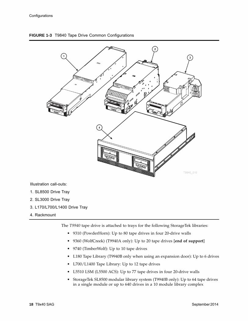
The T9940 tape drive is attached to trays for the following StorageTek libraries:
• 9310 (PowderHorn): Up to 80 tape drives in four 20-drive walls
• 9360 (WolfCreek) (T9940A only): Up to 20 tape drives [end of support]
• 9740 (TimberWolf): Up to 10 tape drives
• L180 Tape Library (T9940B only when using an expansion door): Up to 6 drives
• L700/L1400 Tape Library: Up to 12 tape drives
• L5510 LSM (L5500 ACS): Up to 77 tape drives in four 20-drive walls
• StorageTek SL8500 modular library system (T9940B only): Up to 64 tape drivesin a single module or up to 640 drives in a 10 module library complex
FIGURE 1-3 T9840 Tape Drive Common Configurations
Illustration call-outs:
1. SL8500 Drive Tray
2. SL3000 Drive Tray
3. L170/L700/L1400 Drive Tray
4. Rackmount
Configurations
September 2014 Product Overview 19
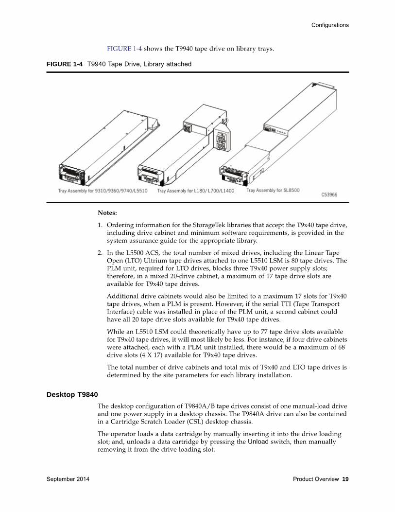
FIGURE 1-4 shows the T9940 tape drive on library trays.
Notes:
1. Ordering information for the StorageTek libraries that accept the T9x40 tape drive,including drive cabinet and minimum software requirements, is provided in thesystem assurance guide for the appropriate library.
2. In the L5500 ACS, the total number of mixed drives, including the Linear TapeOpen (LTO) Ultrium tape drives attached to one L5510 LSM is 80 tape drives. ThePLM unit, required for LTO drives, blocks three T9x40 power supply slots;therefore, in a mixed 20-drive cabinet, a maximum of 17 tape drive slots areavailable for T9x40 tape drives.
Additional drive cabinets would also be limited to a maximum 17 slots for T9x40tape drives, when a PLM is present. However, if the serial TTI (Tape TransportInterface) cable was installed in place of the PLM unit, a second cabinet couldhave all 20 tape drive slots available for T9x40 tape drives.
While an L5510 LSM could theoretically have up to 77 tape drive slots availablefor T9x40 tape drives, it will most likely be less. For instance, if four drive cabinetswere attached, each with a PLM unit installed, there would be a maximum of 68drive slots (4 X 17) available for T9x40 tape drives.
The total number of drive cabinets and total mix of T9x40 and LTO tape drives isdetermined by the site parameters for each library installation.
Desktop T9840 The desktop configuration of T9840A/B tape drives consist of one manual-load driveand one power supply in a desktop chassis. The T9840A drive can also be containedin a Cartridge Scratch Loader (CSL) desktop chassis.
The operator loads a data cartridge by manually inserting it into the drive loadingslot; and, unloads a data cartridge by pressing the Unload switch, then manuallyremoving it from the drive loading slot.
FIGURE 1-4 T9940 Tape Drive, Library attached
Configurations
20 T9x40 SAG September 2014
With the T9840A desktop CSL chassis, the operator stacks up to seven data cartridgesin the CSL mechanism; the mechanism then loads and unloads the cartridgessequentially. Also, operators can manually load/unload a single data cartridgethrough the loading slot.
Rack Mount The rack mount T9840 drive tray chassis mounts into a 483-mm (19-in.) rack cabinet.The chassis consists of single/dual manual-load tape drives. The T9840A drive canalso be configured in a rack mount CSL chassis. Each tray can hold:
• One manual-load drive in position A (T9840A/B/C/D)
• Two manual-load drives, side-by-side, positions A and B (T9840A/B/C/D)
• One CSL chassis (one T9840A drive only)
The rack mount configuration of the T9940 tape drive consists of two manual-loadtape drives mounted on a shock absorbing platform in a rack mount tray.
Rack Cabinets
The rack mount configurations of the T9x40 tape drives are designed to fit into astandard 483-mm (19-in.) rack cabinet. If the customer supplies the rack cabinet,make sure that the cabinet is at least 780 mm (30.75 inches) deep. You can mount:
• Up to six T9840 drive trays in any combination of one drive, two drive, or CSLconfigurations in a single rack cabinet.
• Up to four T9940 rack mount drive trays in single rack cabinet.
T9940 rack mount trays in combination with T9840 and T10000 rack mount trayswithin the same rack cabinet. Therefore, the tray totals are limited to the followingcombinations:
Note – The total vertical space cannot exceed 24U (106.7 cm /42.0 inches).
• One T9940 tray and from one to four T9840 or T10000 trays
Note – Each T9940 drive tray is 6U (266.7 mm / 10.5 inches). EachT9840 or T10000 drive tray is 4U (177.8 mm / 7.0 inches).
• Two T9940 trays and from one to three T9840 or T10000 trays
• Three T9940 trays and one T9840 or T10000 tray
To supply power to rack mount drive trays in a rack cabinet, you must order oneinternal AC power cord per drive tray to connect to a power strip mounted in thecabinet.
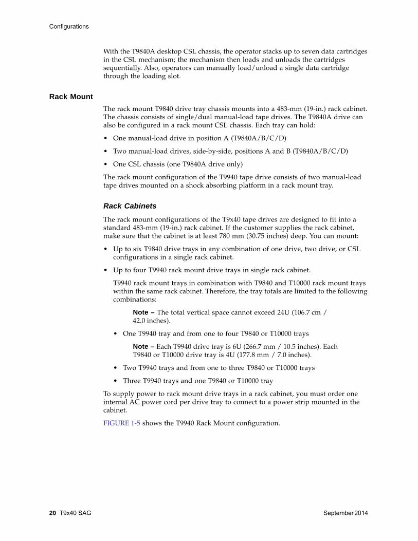
FIGURE 1-5 shows the T9940 Rack Mount configuration.
Interfaces
September 2014 Product Overview 21
Power Cords
The power cord options for the desktop and rack mount T9x40 tape drive are:
• Desktop or rack mount 120 VAC operation in the U.S. and Canada with a 120 VACthree-prong standard plug
• Desktop 250 VAC operation outside the U.S. and Canada with a continentalEuropean standard plug
• Rack Mount 250 VAC operation in the U.S. and Canada with either a Hubbell or aRussellstoll plug
Device Emulation Modes Supported (T9840D)• Fibre Channel:
• T9840D native mode
• 3490E11 and 3590E11 (AS400 attachments)
• T9840C (testing only)
• FICON: 3490E11 and 3590H10
• ESCON: 3490E11 and 3590H10
Interfaces The following interface types are available on T9x40 tape drives:
ESCON The ESCON-configured T9x40 tape drives have one ESCON Duplex interface port toconnect a 62.5-micron (mm) ESCON Duplex cable.
• The drive emulates a single-port 3490E or 3590 tape drive.
• 128 logical paths.
FIGURE 1-5 T9940 Tape Drive, Rack Mount

Interfaces
22 T9x40 SAG September 2014
Note – Maximum total non-repeated channel distance for anESCON tape drive, using a 62.5 micron multimode cable is 3 km(1.86 mile).
FCThe FC-configured T9x40 tape drives have dual fiber-optic ports to allow for point-to-point, arbitrated-loop (including redundant-loop) and fabric topology.
• T9x40A tape drives use short wavelength transceivers with SC type ports andoperate on a 1-Gb channel.
• The T9840B tape drive uses short wavelength transceivers with LC type ports andoperate on a 2-Gb channel.
• The T9840C/D and T9940B tape drives use small form-factor pluggable (SFP)transceivers with LC type ports and operate on a 2-Gb channel. The drivessupport the use of short or long wavelength SFP modules.
See “Fibre Channel and FICON Cable Facts” on page 23 for information on types offiber-optic cable and maximum cable lengths.
The FC interface for the T9x40 uses Ultra-SCSI protocol. The FC T9x40 tape drivesconnect to other devices with the following equipment:
• A hub that connects FC devices to each other in a loop
• A switch that connects FC devices to each other in a fabric
The drive supports connection of both ports, in accordance with ANSI Fibre Channelspecifications (ref. InterNational Committee on Information Technology Standards[INCITS] documents: SCSI Primary Commands -3, Section 5.6, and Fibre ChannelProtocol -3).
Note – The drive will support two hosts, providing that bothhosts honor the “reserve/release” and/or the “persistent reserve/release” specifications.
FICONFibre Connection (FICON) is a proprietary channel for IBM processors. T9x40 FICONtape drives can be configured with:
• A single-port, short or long wave transceiver
• Dual-port, short or long wave transceivers; or
• Dual-port, mixed wave (one short wave and one long wave transceiver)
The benefits of a FICON channel include greater bandwidth, more logical paths,more devices per channel, and greater distance.
• A total of 256 logical paths are possible. On dual-port tape drives, the 256 totallogical paths can be unevenly split between Port A and Port B.
• Approximately six T9x40 FICON tape drives, concurrently reading/writing large(64-KB) blocks, can be attached to a single channel.

Interfaces
September 2014 Product Overview 23
• Approximately sixteen T9x40 FICON tape drives, concurrently reading/writingsmall (16-KB) blocks, can be attached to a single channel.
T9x40 FICON drives use small form-factor pluggable (SFP) transceivers.
The drive supports connection of both ports, in accordance with ANSI Fibre Channelspecifications (ref. InterNational Committee on Information Technology Standards[INCITS] documents: SCSI Primary Commands -3, Section 5.6, and Fibre ChannelProtocol -3).
Note – The drive will support two hosts, providing that bothhosts honor the “reserve/release” and/or the “persistent reserve/release” specifications.
Hardware Configuration Definition Once you have installed FICON drives, you need to set the hardware configurationdefinition (HCD) for each drive. Go to the White Papers section of the SE Toolswebsite at:
http://my.oracle.com/site/pd/sss/products/tape/support-tools/WHITE_Content/index.html
Select the appropriate drive article for HCD information and guidelines.
Fibre Channel and FICON Cable FactsT9x40 Fibre Channel and FICON tape drives use Fibre Channel cables.
Use multimode cables when connecting to short wave ports. Multimode cables havean orange jacket, and the fiber within the cable is 50 microns in diameter.
Use single mode cables when connecting to long wave ports. Single mode cables havea yellow jacket, a blue LC connector, and the fiber within the cable is 9 microns indiameter.
Notes:
1. Maximum total non-repeated channel distance for a short wave 850 nmtransceiver using a 50 micron multimode cable on a 100 MB/s channel is 500 m(1640 ft.).
2. Maximum total non-repeated channel distance for a short wave 850 nmtransceiver using a 50 micron multimode cable on a 200 MB/s channel is 300 m(984 ft.).
3. Maximum total non-repeated channel distance for a long wave 1310 nmtransceiver using a single mode cable is 10 km (6.21 mi).
4. Single mode cable maximum distances can be extended through an amplifier-repeater unit (RPQ) to 20 km (12.4 mi) for a 100 MB/s channel or to 12 km(7.46 mi) for a 200 MB/s channel.
Tape Cartridges and Labels
24 T9x40 SAG September 2014
SCSI The SCSI-configured T9840A/B and T9940A tape drives have two connectors toattach 68-conductor SCSI P-cables. SCSI enables devices to be connected eitherdirectly, in a daisy-chain configuration, or in a combination of direct and daisy-chainconfigurations. Two connectors facilitate daisy-chaining tape drives. The followingSCSI equipment may also be required:
• A terminator that connects to the last device in a SCSI daisy chain
• A bridge that connects SCSI devices to an FC network
A maximum of two daisy-chained devices are possible, with the total SCSI cablelength of no more than 25 meters (82 feet).
Note – SCSI interface T9x40 Tape Dives are only available as usedequipment.
SCSI on the T9x40 is either differential, wide ultra, or a lesser implementation. TheT9x40 tape drive does not supply terminator power; therefore, the host bus adaptor(HBA) card must supply SCSI terminator power.
Tape Cartridges and LabelsThe following pages describe the 9x40 data cartridges, VolSafe cartridges, cleaningcartridges, and bar-coded volume serial number (VOLSER) labels. See “Informationfor Ordering” on page 45 to order cartridges and/or labels.
Note – Maximum block size is 256 Kilobytes.
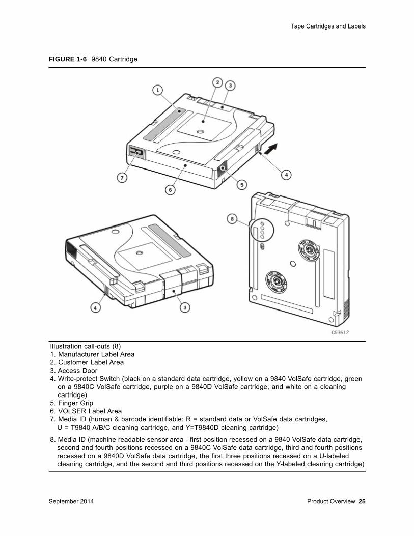
9840 Cartridge Description The T9840 tape drives use a cartridge (FIGURE 1-6 on page 25) that is the samephysical size as a 3490 or 9940 data cartridge; however, they are not interchangeable.Three types of cartridges are available: data, VolSafe and cleaning (100 usesmaximum).
The media identification labels for 9840 cartridges have unique letters:
Data CartridgeThe 9840 data cartridges achieve fast access by having both the supply and takeupreels in the cartridge and by facilitating midpoint loading. The standard datacartridge has an uncompressed capacity of:
• 20 GB when written by T9840A/B tape drives
• 40 GB when written by a T9840C tape drive
• 75 GB when written by a T9840D tape drive
R 9840 standard data and VolSafe data cartridges
U 9840 cleaning cartridge (use with T9840A/B/C drives)
Y 9840D cleaning cartridge (use with T9840D only)
Tape Cartridges and Labels
September 2014 Product Overview 25
FIGURE 1-6 9840 Cartridge
Illustration call-outs (8)1. Manufacturer Label Area 2. Customer Label Area3. Access Door4. Write-protect Switch (black on a standard data cartridge, yellow on a 9840 VolSafe cartridge, green
on a 9840C VolSafe cartridge, purple on a 9840D VolSafe cartridge, and white on a cleaning cartridge)
5. Finger Grip6. VOLSER Label Area7. Media ID (human & barcode identifiable: R = standard data or VolSafe data cartridges,
U = T9840 A/B/C cleaning cartridge, and Y=T9840D cleaning cartridge)
8. Media ID (machine readable sensor area - first position recessed on a 9840 VolSafe data cartridge, second and fourth positions recessed on a 9840C VolSafe data cartridge, third and fourth positions recessed on a 9840D VolSafe data cartridge, the first three positions recessed on a U-labeled cleaning cartridge, and the second and third positions recessed on the Y-labeled cleaning cartridge)
Tape Cartridges and Labels
26 T9x40 SAG September 2014
VolSafe CartridgeThree variations of the VolSafe data cartridge are available for append-only use:
• 20-GB 9840 VolSafe cartridge, with yellow identifying features
• 40-GB 9840C VolSafe cartridge, with green identifying features
• 75-GB 9840D VolSafe cartridge, with purple identifying features
Note – The different VolSafe cartridges are NOT interchangeable(see “Drive - VolSafe Cartridge Compatibility” on page 16).
Cartridge ReclaimNative reclaim: the ability of a drive to reclaim a cartridge it has previously written.
Forward reclaim: the ability of a drive to reclaim a cartridge previously written by alegacy drive. Note that the T9840D is able to reclaim a standard data cartridgepreviously written by a T9840A, T9840B, or T9840C tape drive.
Backward reclaim: the ability of a drive to reclaim a cartridge written by a non-legacy drive. Note that the T9840A and T9840B drives cannot distinguish betweenT9840C and T9840D formats.
A cartridge written by a T9840D drive that is loaded on a legacy drive that hasbeen given the instruction to write from BOT will be allowed to write on thecartridge provided the write-protect switch allows it and the cartridge is not aVolSafe cartridge.
Note – VolSafe cartridges cannot be forward or backwardreclaimed.
A VolSafe cartridge containing 25 blocks, or less, that are all tape marks or 80-byte records will be capable of being native reclaimed.
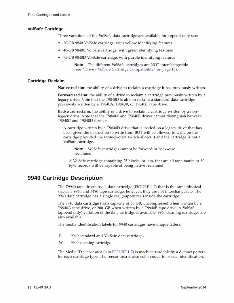
9940 Cartridge DescriptionThe T9940 tape drives use a data cartridge (FIGURE 1-7) that is the same physicalsize as a 9840 and 3490 tape cartridge; however, they are not interchangeable. The9940 data cartridge has a single reel (supply reel) inside the cartridge.
The 9940 data cartridge has a capacity of 60 GB, uncompressed when written by aT9940A tape drive, or 200 GB when written by a T9940B tape drive. A VolSafe(append only) variation of the data cartridge is available. 9940 cleaning cartridges arealso available.
The media identification labels for 9940 cartridges have unique letters:
The Media ID sensor area (6 in FIGURE 1-7) is machine-readable by a distinct patternfor each cartridge type. The sensor area is also color coded for visual identification.
P 9940 standard and VolSafe data cartridges
W 9940 cleaning cartridge

Mixed-Media Management
September 2014 Product Overview 27
Mixed-Media ManagementExtra media management measures must be taken whenever T9x40 tape drives anddata cartridges of mixed data density, or mixed Emulation images co-exist in thesame library system.
The extra measures essentially involve creation and management of separate mediapools/sub-pools for formatted/written 9x40 data cartridges. Guidelines for creationand maintenance of media pools/sub-pools are located in ACSLS, HSC, andindependent software vender (ISV) documentation sets.
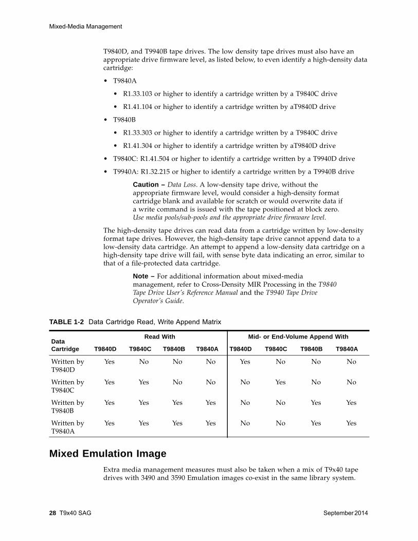
Mixed Data DensitySince all T9840 tape drive models use the same 9840 data cartridge, and both T9940tape drive models use the same 9940 data cartridge, extra media managementmeasures must be taken because low density tape drives (T9840A/B and T9940A)cannot read data from a data cartridge written in the high-density format by T9840C,
FIGURE 1-7 9940 Cartridge
Illustration call-outs (6):1. Media ID (human & barcode identifiable, yellow background on a VolSafe cartridge,
P = standard data or VolSafe data cartridge, W= cleaning cartridge)2. Manufacturer Label Area (yellow background on a VolSafe cartridge)3. Customer Label Area4. VOLSER Label Area
5. Write-protect Switch 6. Media ID, machine readable sensor area (black on a standard data cartridge, yellow on a VolSafe
cartridge, or white on a cleaning cartridge)
Mixed-Media Management
28 T9x40 SAG September 2014
T9840D, and T9940B tape drives. The low density tape drives must also have anappropriate drive firmware level, as listed below, to even identify a high-density datacartridge:
• T9840A
• R1.33.103 or higher to identify a cartridge written by a T9840C drive
• R1.41.104 or higher to identify a cartridge written by aT9840D drive
• T9840B
• R1.33.303 or higher to identify a cartridge written by a T9840C drive
• R1.41.304 or higher to identify a cartridge written by aT9840D drive
• T9840C: R1.41.504 or higher to identify a cartridge written by a T9940D drive
• T9940A: R1.32.215 or higher to identify a cartridge written by a T9940B drive
Caution – Data Loss. A low-density tape drive, without theappropriate firmware level, would consider a high-density formatcartridge blank and available for scratch or would overwrite data ifa write command is issued with the tape positioned at block zero.Use media pools/sub-pools and the appropriate drive firmware level.
The high-density tape drives can read data from a cartridge written by low-densityformat tape drives. However, the high-density tape drive cannot append data to alow-density data cartridge. An attempt to append a low-density data cartridge on ahigh-density tape drive will fail, with sense byte data indicating an error, similar tothat of a file-protected data cartridge.
Note – For additional information about mixed-mediamanagement, refer to Cross-Density MIR Processing in the T9840Tape Drive User’s Reference Manual and the T9940 Tape DriveOperator’s Guide.
Mixed Emulation ImageExtra media management measures must also be taken when a mix of T9x40 tapedrives with 3490 and 3590 Emulation images co-exist in the same library system.
TABLE 1-2 Data Cartridge Read, Write Append Matrix
Data Cartridge
Read With Mid- or End-Volume Append With
T9840D T9840C T9840B T9840A T9840D T9840C T9840B T9840A
Written byT9840D
Yes No No No Yes No No No
Written byT9840C
Yes Yes No No No Yes No No
Written byT9840B
Yes Yes Yes Yes No No Yes Yes
Written byT9840A
Yes Yes Yes Yes No No Yes Yes

Virtual Operator Panel
September 2014 Product Overview 29
• Data cartridges written by T9x40 tape drives running with 3590 Emulation imageare not readable by T9x40 tape drives running with 3490 Emulation image.
• Data cartridges written by T9x40 tape drives running with 3490 Emulation imageare readable by T9x40 tape drives running with 3590 Emulation image, but cannotbe written by the 3590 Emulation image tape drive.
Guidelines for creation and maintenance of media pools/sub-pools are located inHSC and independent software vender (ISV) documentation sets.
Virtual Operator PanelFIGURE 1-8 shows an example of the virtual operator panel (VOP) graphical userinterface (GUI) for the T9840D tape drive. The VOP enables operators and servicerepresentatives to monitor and perform tasks on a single tape drive.
Note – VOP version 1.0.13, or higher, in conjunction with theappropriate drive code level supports the use of an IPv6 address.
FIGURE 1-8 Virtual Operator Panel

Virtual Operator Panel
30 T9x40 SAG September 2014
September 2014 System Assurance 31
2System Assurance
The system assurance process is the exchange of information among team membersto assure that no aspects of the sale, order, installation, and implementation for theStorageTek T9x40 tape drive are overlooked. The system assurance team membersensure that all aspects of the process are planned carefully and performed efficientlyto promote an error-free installation and contribute to overall customer satisfaction.
This process begins when the customer accepts the sales proposal.
System Assurance Planning MeetingsThe purpose of the system assurance planning meetings is to:
• Introduce the customer to the T10000 tape drive
• Explain the system assurance process and establish a team
• Identify and define the customer requirements
• Identify the proposed configurations
• Complete the sales order
• Identify any additional items needed (such as cables and tape cartridges)
• Prepare for the installation and implementation
• Schedule and track the entire process
System Assurance Planning Meetings
32 T9x40 SAG September 2014
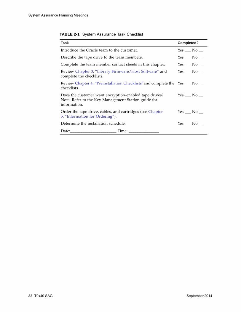
TABLE 2-1 System Assurance Task Checklist
Task Completed?
Introduce the Oracle team to the customer. Yes ___ No __
Describe the tape drive to the team members. Yes ___ No __
Complete the team member contact sheets in this chapter. Yes ___ No __
Review Chapter 3, “Library Firmware/Host Software” andcomplete the checklists.
Yes ___ No __
Review Chapter 4, “Preinstallation Checklists”and complete thechecklists.
Yes ___ No __
Does the customer want encryption-enabled tape drives?Note: Refer to the Key Management Station guide forinformation.
Yes ___ No __
Order the tape drive, cables, and cartridges (see Chapter5, “Information for Ordering”).
Yes ___ No __
Determine the installation schedule:
Date:_______________________ Time: _______________
Yes ___ No __
Customer Team Member Contact Sheet
September 2014 System Assurance 33
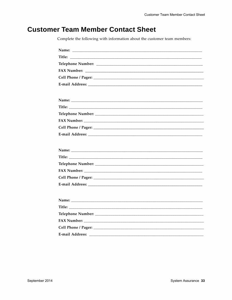
Customer Team Member Contact Sheet Complete the following with information about the customer team members:
Name: ___________________________________________________________________
Title: ____________________________________________________________________
Telephone Number: _______________________________________________________
FAX Number: _____________________________________________________________
Cell Phone / Pager: _________________________________________________________
E-mail Address: ___________________________________________________________
Name: ____________________________________________________________________
Title: _____________________________________________________________________
Telephone Number: ________________________________________________________
FAX Number: ______________________________________________________________
Cell Phone / Pager: _________________________________________________________
E-mail Address: ___________________________________________________________
Name: ____________________________________________________________________
Title: _____________________________________________________________________
Telephone Number: ________________________________________________________
FAX Number: _____________________________________________________________
Cell Phone / Pager: _________________________________________________________
E-mail Address: ___________________________________________________________
Name: ____________________________________________________________________
Title: _____________________________________________________________________
Telephone Number: ________________________________________________________
FAX Number: ______________________________________________________________
Cell Phone / Pager: _________________________________________________________
E-mail Address: ___________________________________________________________
Client Processor Teams
34 T9x40 SAG September 2014
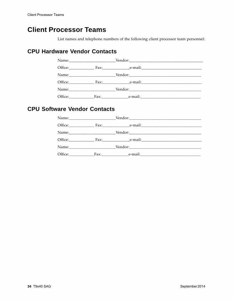
Client Processor Teams List names and telephone numbers of the following client processor team personnel:
CPU Hardware Vendor Contacts Name:________________________Vendor:______________________________________
Office:_____________ Fax:______________e-mail:_______________________________
Name:________________________Vendor:_____________________________________
Office:_____________ Fax:______________e-mail:_______________________________
Name:________________________Vendor:_____________________________________
Office:_____________Fax:______________e-mail:_______________________________
CPU Software Vendor Contacts Name:________________________Vendor:_____________________________________
Office:_____________ Fax:______________e-mail:_______________________________
Name:________________________Vendor:_____________________________________
Office:_____________ Fax:______________e-mail:_______________________________
Name:________________________Vendor:_____________________________________
Office:_____________Fax:______________e-mail:_______________________________

Oracle Team Member Contact Sheet
September 2014 System Assurance 35
Oracle Team Member Contact SheetComplete the following with information about the team members. (Members mayinclude: marketing and sales representatives, installation coordinator, systemsengineers (SEs), and service representatives.)
Name: ____________________________________________________________________
Title: _____________________________________________________________________
Telephone Number: ________________________________________________________
FAX Number: ______________________________________________________________
Cell Phone / Pager: _________________________________________________________
E-mail Address: ___________________________________________________________

Oracle Team Member Contact Sheet
36 T9x40 SAG September 2014
September 2014 Library Firmware/Host Software 37
3Library Firmware/Host Software
When you are adding new/used T9x40 tape drive models to existing libraries, youmust verify that library firmware level and host software release levels support thenew drive models.
Library Firmware For library configurations, determine the customer’s existing library firmware level,and compare it with the currently available library firmware:
Update library firmware as required to support incoming drive models.
Host Software Configuration The T9x40 tape drives operate with MVS, UNIX, or Windows NT platforms.Certification with these platforms and host-based applications is an ongoing process.For up-to-date information about platforms and applications, see the Tape DeviceSoftware area at the following URL:
http://www.oracle.com/us/products/servers-storage/storage/tape-storage/index.html
T9x40-Supported Software Depending upon the host platform and the type of interface, T9x40 tape drives aresubject to one the following software application groups:
• Nearline Control Solutions (NCS), which includes:
• Host Software Component (HSC)
Note – In HSC, implementation of VolSafe requires definition ofesoteric names and cartridge tape subpools. Refer to the VolSafeSoftware Information Guide Release 2.0.
• Multiple Virtual Storage/Client System Component (MVS/CSC)
• LibraryStation
Use TABLE 3-1 on page 38 to record the customer’s current NCS softwareconfiguration against obtained requirements.

Host Software Configuration
38 T9x40 SAG September 2014
• Automated Cartridge System Library Software (ACSLS)
Use TABLE 3-2 on page 39 to record the customer’s current ACSLS softwareconfiguration against obtained requirements.
• Removable Media Library Software (RMLS)
Use TABLE 3-3 on page 39 to record the customer’s current RMLS/CSC softwareconfiguration against obtained requirements.
Software Configuration WorksheetsRecord the customer’s NCS software configuration in TABLE 3-1.
TABLE 3-1 NCS Software Configuration Worksheet
ItemProcessor 1 Processor 2
Existing Required Existing Required
Operating system and versionor release level
DFP maintenance level
Backup/recovery software
Archival/migration software
Additional information
Host Software Configuration
September 2014 Library Firmware/Host Software 39
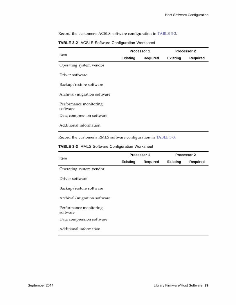
Record the customer's ACSLS software configuration in TABLE 3-2.
Record the customer's RMLS software configuration in TABLE 3-3.
TABLE 3-2 ACSLS Software Configuration Worksheet
ItemProcessor 1 Processor 2
Existing Required Existing Required
Operating system vendor
Driver software
Backup/restore software
Archival/migration software
Performance monitoringsoftware
Data compression software
Additional information
TABLE 3-3 RMLS Software Configuration Worksheet
ItemProcessor 1 Processor 2
Existing Required Existing Required
Operating system vendor
Driver software
Backup/restore software
Archival/migration software
Performance monitoringsoftware
Data compression software
Additional information

Host Software Configuration
40 T9x40 SAG September 2014
September 2014 Preinstallation Checklists 41
4Preinstallation Checklists
This chapter provides checklists that the system assurance team should completebefore the delivery and installation of the equipment.
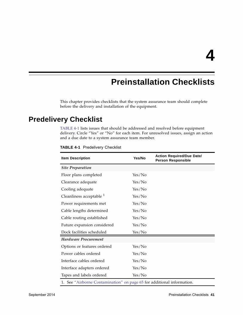
Predelivery ChecklistTABLE 4-1 lists issues that should be addressed and resolved before equipmentdelivery. Circle “Yes” or “No” for each item. For unresolved issues, assign an actionand a due date to a system assurance team member.
TABLE 4-1 Predelivery Checklist
Item Description Yes/No Action Required/Due Date/ Person Responsible
Site Preparation
Floor plans completed Yes/No
Clearance adequate Yes/No
Cooling adequate Yes/No
Cleanliness acceptable 1 Yes/No
Power requirements met Yes/No
Cable lengths determined Yes/No
Cable routing established Yes/No
Future expansion considered Yes/No
Dock facilities scheduled Yes/No
Hardware Procurement
Options or features ordered Yes/No
Power cables ordered Yes/No
Interface cables ordered Yes/No
Interface adapters ordered Yes/No
Tapes and labels ordered Yes/No
1. See “Airborne Contamination” on page 65 for additional information.
Predelivery Checklist
42 T9x40 SAG September 2014
Software Procurement
Software prerequisites met Yes/No
Software Installation
Scheduled Yes/No
Completed Yes/No
JCL Changes
Scheduled Yes/No
Completed Yes/No
I/O Generation Changes
Scheduled Yes/No
Completed Yes/No
Mixed-media Subpools
Scheduled Yes/No
Completed Yes/No
Hardware Installation
Delivery schedule completed Yes/No
Dock hours scheduled Yes/No
Pre-staging area set Yes/No
Installation team identified Yes/No
Site access arranged Yes/No
Installation hours defined Yes/No
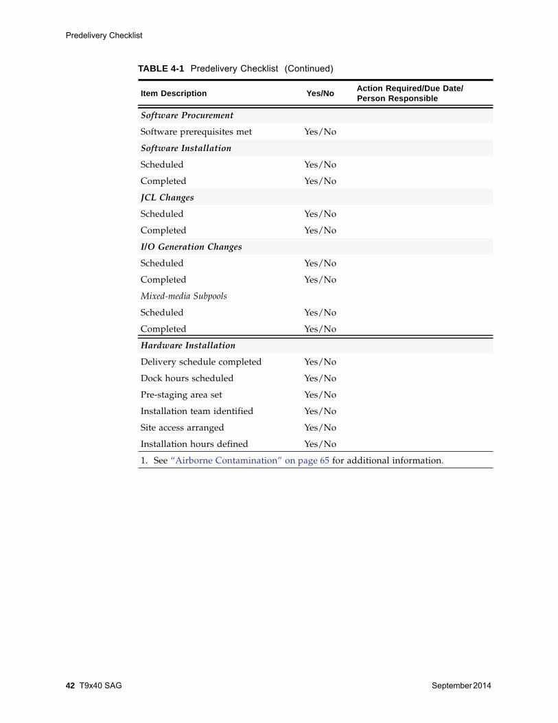
TABLE 4-1 Predelivery Checklist (Continued)
Item Description Yes/No Action Required/Due Date/ Person Responsible
1. See “Airborne Contamination” on page 65 for additional information.
Delivery and Handling Information
September 2014 Preinstallation Checklists 43
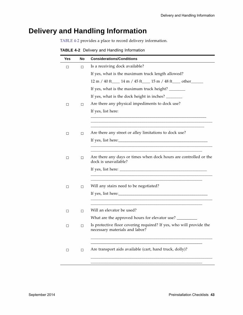
Delivery and Handling Information TABLE 4-2 provides a place to record delivery information.
TABLE 4-2 Delivery and Handling Information
Yes No Considerations/Conditions
□ □ Is a receiving dock available?
If yes, what is the maximum truck length allowed?
12 m / 40 ft____ 14 m / 45 ft____ 15 m / 48 ft____ other______
If yes, what is the maximum truck height? ________
If yes, what is the dock height in inches? ________
□ □ Are there any physical impediments to dock use?
If yes, list here:_____________________________________________________________________________________________________________________________________________________________________________
□ □ Are there any street or alley limitations to dock use?
If yes, list here:_______________________________________________________________________________________________________________________________________________________________
□ □ Are there any days or times when dock hours are controlled or thedock is unavailable?
If yes, list here: ______________________________________________________________________________________________________________________________________________________________
□ □ Will any stairs need to be negotiated?
If yes, list here:_______________________________________________________________________________________________________________________________________________________________
□ □ Will an elevator be used?
What are the approved hours for elevator use? __________
□ □ Is protective floor covering required? If yes, who will provide thenecessary materials and labor?
___________________________________________________________________________________________________________________
□ □ Are transport aids available (cart, hand truck, dolly)?
___________________________________________________________________________________________________________________
Access and Administrative Issues
44 T9x40 SAG September 2014
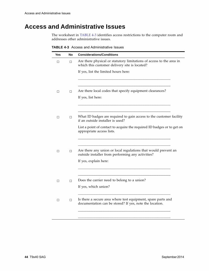
Access and Administrative Issues The worksheet in TABLE 4-3 identifies access restrictions to the computer room andaddresses other administrative issues.
TABLE 4-3 Access and Administrative Issues
Yes No Considerations/Conditions
□ □ Are there physical or statutory limitations of access to the area inwhich this customer delivery site is located?
If yes, list the limited hours here:
_____________________________________________________
_____________________________________________________
□ □ Are there local codes that specify equipment clearances?
If yes, list here:
_____________________________________________________
_____________________________________________________
□ □ What ID badges are required to gain access to the customer facilityif an outside installer is used?
List a point of contact to acquire the required ID badges or to get onappropriate access lists.
_____________________________________________________
_____________________________________________________
□ □ Are there any union or local regulations that would prevent anoutside installer from performing any activities?
If yes, explain here:
_____________________________________________________
_____________________________________________________
□ □ Does the carrier need to belong to a union?
If yes, which union?
_____________________________________________________
□ □ Is there a secure area where test equipment, spare parts anddocumentation can be stored? If yes, note the location.
_____________________________________________________
_____________________________________________________

September 2014 Information for Ordering 45
5Information for Ordering
Use this chapter to help order cables, tape drive conversion kits, an encryption key,and media for the T9x40 tape drive.
• “Cable Order Numbers” on page 52
• “Conversion Bills/Kits” on page 57
Use conversion bills to obtain the necessary parts to:
• Add a second drive to a rack chassis.
• Change the type of SFP module in the drive.
• Transfer a drive from one library model to a different library model.
• “Encryption Feature” on page 59
• “Ordering Media and Labels” on page 60
Tape Drive Order Numbers for Libraries Tape drive order numbers are provided as reference information only:
• “T9840 Library Attached Tape Drives”
• “T9940 Library Attached Tape Drives” on page 48
• “Desktop and Rack Mount Tape Drive” on page 50
T9840 Library Attached Tape Drives• TABLE 5-1, “T9840D Library Configuration (Used) Marketing PNs” on page 46
• TABLE 5-2, “T9840C (Used) ROHS Compliant Marketing PNs” on page 47
• TABLE 5-3, “T9840C (Used) Non-ROHS Marketing PNs” on page 47
• TABLE 5-4, “T9840B (Used) Non-ROHS Marketing PNs” on page 48
Tape Drive Order Numbers for Libraries
46 T9x40 SAG September 2014
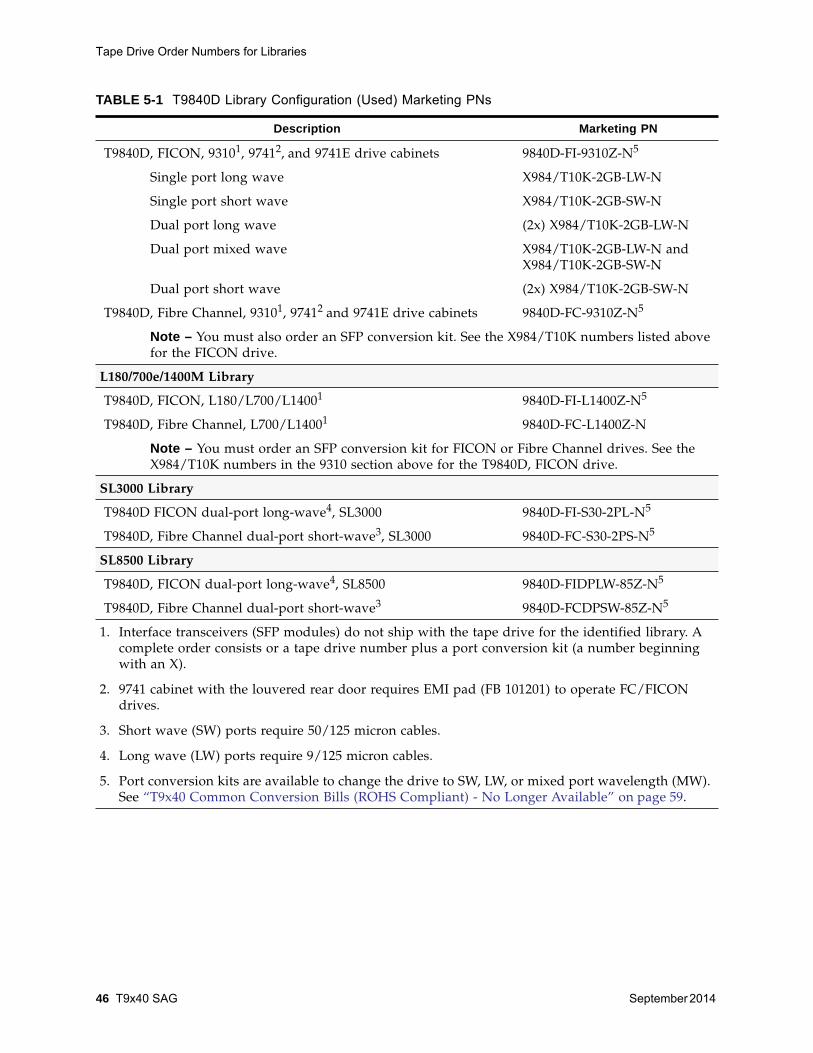
TABLE 5-1 T9840D Library Configuration (Used) Marketing PNs
Description Marketing PN
T9840D, FICON, 93101, 97412, and 9741E drive cabinets 9840D-FI-9310Z-N5
Single port long wave X984/T10K-2GB-LW-N
Single port short wave X984/T10K-2GB-SW-N
Dual port long wave (2x) X984/T10K-2GB-LW-N
Dual port mixed wave X984/T10K-2GB-LW-N andX984/T10K-2GB-SW-N
Dual port short wave (2x) X984/T10K-2GB-SW-N
T9840D, Fibre Channel, 93101, 97412 and 9741E drive cabinets 9840D-FC-9310Z-N5
Note – You must also order an SFP conversion kit. See the X984/T10K numbers listed abovefor the FICON drive.
L180/700e/1400M Library
T9840D, FICON, L180/L700/L14001 9840D-FI-L1400Z-N5
T9840D, Fibre Channel, L700/L14001 9840D-FC-L1400Z-N
Note – You must order an SFP conversion kit for FICON or Fibre Channel drives. See theX984/T10K numbers in the 9310 section above for the T9840D, FICON drive.
SL3000 Library
T9840D FICON dual-port long-wave4, SL3000 9840D-FI-S30-2PL-N5
T9840D, Fibre Channel dual-port short-wave3, SL3000 9840D-FC-S30-2PS-N5
SL8500 Library
T9840D, FICON dual-port long-wave4, SL8500 9840D-FIDPLW-85Z-N5
T9840D, Fibre Channel dual-port short-wave3 9840D-FCDPSW-85Z-N5
1. Interface transceivers (SFP modules) do not ship with the tape drive for the identified library. Acomplete order consists or a tape drive number plus a port conversion kit (a number beginningwith an X).
2. 9741 cabinet with the louvered rear door requires EMI pad (FB 101201) to operate FC/FICONdrives.
3. Short wave (SW) ports require 50/125 micron cables.
4. Long wave (LW) ports require 9/125 micron cables.
5. Port conversion kits are available to change the drive to SW, LW, or mixed port wavelength (MW).See “T9x40 Common Conversion Bills (ROHS Compliant) - No Longer Available” on page 59.

Tape Drive Order Numbers for Libraries
September 2014 Information for Ordering 47
TABLE 5-2 T9840C (Used) ROHS Compliant Marketing PNs
Description Marketing PN
Library Attached:
ESCON, 9310/9740/L5500, 97411 and 9741E drive cabinets Y9840C-ES-9310Z-N
ESCON, L180/L700/L1400 Y9840C-ES-L700Z-N
ESCON, SL8500 Y9840C-ES-SL85Z-N
Fibre Channel, 2Gb, 9310/9740/L5500, 97411 and 9741E drive cabinets Y9840C-FC-9310Z-N
Fibre Channel, 2Gb, L180/L700/L1400 Y9840C-FC-L700Z-N
Fibre Channel, 2Gb, SL8500 Y9840C-FC-SL85Z-N
FICON, 9310/9740/L5500, 97411 and 9741E drive cabinets Y9840C-FI-9310Z-N
FICON, L180/L700/L1400 Y9840C-FI-L700Z-N
FICON, SL8500, SPSW (single-port short-wave2) Y9840C-FIS85-1PS-N
FICON, SL8500, DPSW (dual-port short-wave2) Y9840C-FIS85-2PS-N
FICON, SL8500, SPLW (single-port long-wave3) Y9840C-FIS85-1PL-N
FICON, SL8500, DPLW (dual-port long-wave3) Y9840C-FIS85-2PL-N
FICON, SL8500, DPMW (dual-port mixed-wave2,3) Y9840C-FIS85-2PM-N
Notes:1. 9741 cabinet with louvered rear door requires EMI pad (FB 101201) to operate FC/FICON drives.2. Short wave ports require 50/125 micron cables.3. Long wave ports require 9/125 micron cables.
TABLE 5-3 T9840C (Used) Non-ROHS Marketing PNs
Description Marketing PN
Library Attached:
ESCON, 9310/9740/L5500, 97411 and 9741E drive cabinets Y9840C-ES-9310-N
ESCON, L180/L700/L1400 Y9840C-ES-L700-N
ESCON, SL8500 Y9840C-ES-SL85-N
Fibre Channel, 2Gb, 9310/9740/L5500, 97411 and 9741E drive cabinets Y9840C-FC-9310-N
Fibre Channel, 2Gb, L180/L700/L1400 Y9840C-FC-L700-N
Fibre Channel, 2Gb, SL8500 Y9840C-FC-SL85-N
FICON, 9310/9740/L5500, 97411 and 9741E drive cabinets Y9840C-FI-9310-N
FICON, L180/L700/L1400 Y9840C-FI-L700-N
FICON, SL8500, SPSW (single-port short-wave2) Y9840CFI-S85-1PS-N
FICON, SL8500, DPSW (dual-port short-wave2) Y9840CFI-S85-2PS-N
FICON, SL8500, SPLW (single-port long-wave3) Y9840CFI-S85-1PL-N
FICON, SL8500, DPLW (dual-port long-wave3) Y9840CFI-S85-2PL-N

Tape Drive Order Numbers for Libraries
48 T9x40 SAG September 2014
T9940 Library Attached Tape Drives• TABLE 5-5, “T9940B (Used) ROHS Compliant Marketing PNs” on page 48
• TABLE 5-6, “T9940B (Used) Non-ROHS Marketing PNs” on page 49
• TABLE 5-7, “T9940A (Used) Non-ROHS Marketing PNs” on page 50
FICON, SL8500, DPMW (dual-port mixed-wave2,3) Y9840CFI-S85-2PM-N
Notes:1. 9741 cabinet with louvered rear door requires EMI pad (FB 101201) to operate FC/FICON drives.2. Short wave ports require 50/125 micron cables.3. Long wave ports require 9/125 micron cables.
TABLE 5-3 T9840C (Used) Non-ROHS Marketing PNs (Continued)
Description Marketing PN
TABLE 5-4 T9840B (Used) Non-ROHS Marketing PNs
Description Marketing PN
ESCON, 9310/9740/L5500, 97411 and 9741E drive cabinets Y9840B-ES-9741X-N
ESCON, L180/L700/L1400 Y9840B-ES-L700-N
ESCON, SL8500 Y9840B-ES-SL8500-N
Fibre Channel, 2Gb, 9310/9740/L5500, 97411 and 9741E drive cabinets Y9840B-FC-9741X-N
Fibre Channel, 2Gb, SL8500 Y9840B-FC-SL8500-N
FICON, 9310/9740/L5500, 97411 and 9741E drive cabinets Y9840B-FI-9741X-N
FICON, L180/L700/L1400 Y9840B-FI-L700-N
FICON, SL8500, DPLW (dual-port long-wave2) Y9840B-FI-S85-2PL-N
Notes:1. 9741 cabinet with louvered rear door requires EMI pad (FB 101201) to operate FC/FICON drives.2. Long wave ports require 9/125 micron cables.
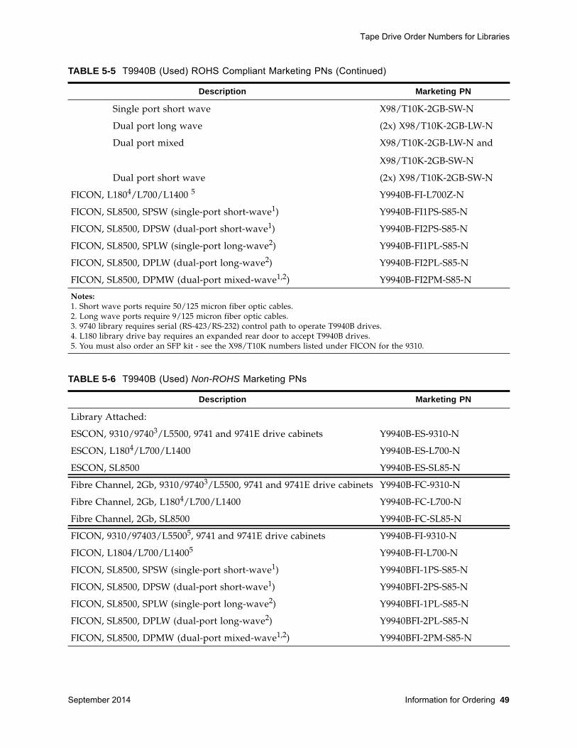
TABLE 5-5 T9940B (Used) ROHS Compliant Marketing PNs
Description Marketing PN
Library Attached:
ESCON, 9310/97403/L5500, 9741 and 9741E drive cabinets5 Y9940B-ES-9310Z-N
ESCON, L1804/L700/L14005 Y9940B-ES-L700Z-N
ESCON, SL8500 Y9940B-ES-SL85Z-N
Fibre Channel, 2Gb, 9310/97403/L5500, 9741 and 9741E drive cabinets Y9940B-FC-9310Z-N
Fibre Channel, 2Gb, L1804/L700/L1400 Y9940B-FC-L700Z-N
Fibre Channel, 2Gb, SL8500 Y9940B-FC-SL85Z-N
FICON, 9310/97403/L5500, 9741 and 9741E drive cabinets5 Y9940B-FI-9310Z-N
Single port long wave X98/T10K-2GB-LW-N
Tape Drive Order Numbers for Libraries
September 2014 Information for Ordering 49
Single port short wave X98/T10K-2GB-SW-N
Dual port long wave (2x) X98/T10K-2GB-LW-N
Dual port mixed X98/T10K-2GB-LW-N and
X98/T10K-2GB-SW-N
Dual port short wave (2x) X98/T10K-2GB-SW-N
FICON, L1804/L700/L1400 5 Y9940B-FI-L700Z-N
FICON, SL8500, SPSW (single-port short-wave1) Y9940B-FI1PS-S85-N
FICON, SL8500, DPSW (dual-port short-wave1) Y9940B-FI2PS-S85-N
FICON, SL8500, SPLW (single-port long-wave2) Y9940B-FI1PL-S85-N
FICON, SL8500, DPLW (dual-port long-wave2) Y9940B-FI2PL-S85-N
FICON, SL8500, DPMW (dual-port mixed-wave1,2) Y9940B-FI2PM-S85-N
Notes:1. Short wave ports require 50/125 micron fiber optic cables.2. Long wave ports require 9/125 micron fiber optic cables.3. 9740 library requires serial (RS-423/RS-232) control path to operate T9940B drives.4. L180 library drive bay requires an expanded rear door to accept T9940B drives.5. You must also order an SFP kit - see the X98/T10K numbers listed under FICON for the 9310.
TABLE 5-5 T9940B (Used) ROHS Compliant Marketing PNs (Continued)
Description Marketing PN
TABLE 5-6 T9940B (Used) Non-ROHS Marketing PNs
Description Marketing PN
Library Attached:
ESCON, 9310/97403/L5500, 9741 and 9741E drive cabinets Y9940B-ES-9310-N
ESCON, L1804/L700/L1400 Y9940B-ES-L700-N
ESCON, SL8500 Y9940B-ES-SL85-N
Fibre Channel, 2Gb, 9310/97403/L5500, 9741 and 9741E drive cabinets Y9940B-FC-9310-N
Fibre Channel, 2Gb, L1804/L700/L1400 Y9940B-FC-L700-N
Fibre Channel, 2Gb, SL8500 Y9940B-FC-SL85-N
FICON, 9310/97403/L55005, 9741 and 9741E drive cabinets Y9940B-FI-9310-N
FICON, L1804/L700/L14005 Y9940B-FI-L700-N
FICON, SL8500, SPSW (single-port short-wave1) Y9940BFI-1PS-S85-N
FICON, SL8500, DPSW (dual-port short-wave1) Y9940BFI-2PS-S85-N
FICON, SL8500, SPLW (single-port long-wave2) Y9940BFI-1PL-S85-N
FICON, SL8500, DPLW (dual-port long-wave2) Y9940BFI-2PL-S85-N
FICON, SL8500, DPMW (dual-port mixed-wave1,2) Y9940BFI-2PM-S85-N

Desktop and Rack Mount Tape Drive
50 T9x40 SAG September 2014
Desktop and Rack Mount Tape DriveUse this section to determine the order numbers for the purchase of T9840 or T9940desktop and rack mount drives:
• “T9840 Rack Mount and Desktop Drives”
• “T9940 Rack Mount Drives” on page 51
T9840 Rack Mount and Desktop DrivesNote – Conversion kits are available to add a second drive(“T9840D Rackmount Conversion Bills (No Longer Available)”on page 58) or to change the port type (“T9x40 CommonConversion Bills (ROHS Compliant) - No Longer Available”on page 59). Both drive ports must be either short wavelength(SW) or long wavelength (LW).
Notes:1. Short wave ports require 50/125 micron fiber optic cables.2. Long wave ports require 9/125 micron fiber optic cables.3. 9740 library requires serial (RS-423/RS-232) control path to operate T9940B drives.4. L180 library drive bay requires an expanded rear door to accept T9940B drives.5. You must also order an SFP kit. See the Y9x40 numbers listed in TABLE 5-5 on page 48.
TABLE 5-6 T9940B (Used) Non-ROHS Marketing PNs (Continued)
Description Marketing PN
TABLE 5-7 T9940A (Used) Non-ROHS Marketing PNs
Description Marketing PN
Library Attached:
ESCON, 9310, 9741E drive cabinet Y9940A-ES-9741E-N
Fibre Channel, 1Gb, 9741E drive cabinet Y9940A-FC-9741E-N
TABLE 5-8 T9840 Non-library Drives - No Longer Available (Sheet 1 of 2)
Description Marketing Part Number
Rack Mount: T9840D (Used)
FICON, single drive, DPLW (dual-port long-wave1) 9840D-FIDPLW1RKZ-N
Fibre Channel, single drive, DPSW (dual-port short-wave2) 9840D-FCDPSW1RKZ-N
Rack Mount: T9840C (Used) ROHS Compliant
ESCON, single drive Y9840C-ES-RK1Z-N
ESCON, dual drive Y9840C-ES-RK2Z-N
Notes:1. Long wave ports require 9/125 micron fiber optic cables.2. Short wave ports require 50/125 micron fiber optic cables.
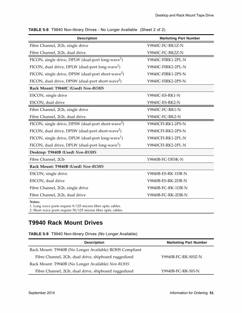
Desktop and Rack Mount Tape Drive
September 2014 Information for Ordering 51
T9940 Rack Mount Drives
Fibre Channel, 2Gb, single drive Y9840C-FC-RK1Z-N
Fibre Channel, 2Gb, dual drive Y9840C-FC-RK2Z-N
FICON, single drive, DPLW (dual-port long-wave1) Y9840C-FIRK1-2PL-N
FICON, dual drive, DPLW (dual-port long-wave1) Y9840C-FIRK2-2PL-N
FICON, single drive, DPSW (dual-port short-wave2) Y9840C-FIRK1-2PS-N
FICON, dual drive, DPSW (dual-port short-wave2) Y9840C-FIRK2-2PS-N
Rack Mount: T9840C (Used) Non-ROHS
ESCON, single drive Y9840C-ES-RK1-N
ESCON, dual drive Y9840C-ES-RK2-N
Fibre Channel, 2Gb, single drive Y9840C-FC-RK1-N
Fibre Channel, 2Gb, dual drive Y9840C-FC-RK2-N
FICON, single drive, DPSW (dual-port short-wave2) Y9840CFI-RK1-2PS-N
FICON, dual drive, DPSW (dual-port short-wave2) Y9840CFI-RK2-2PS-N
FICON, single drive, DPLW (dual-port long-wave1) Y9840CFI-RK1-2PL-N
FICON, dual drive, DPLW (dual-port long-wave1) Y9840CFI-RK2-2PL-N
Desktop: T9840B (Used) Non-ROHS
Fibre Channel, 2Gb Y9840B-FC-DESK-N
Rack Mount: T9840B (Used) Non-ROHS
ESCON, single drive Y9840B-ES-RK-1DR-N
ESCON, dual drive Y9840B-ES-RK-2DR-N
Fibre Channel, 2Gb, single drive Y9840B-FC-RK-1DR-N
Fibre Channel, 2Gb, dual drive Y9840B-FC-RK-2DR-N
TABLE 5-8 T9840 Non-library Drives - No Longer Available (Sheet 2 of 2)
Description Marketing Part Number
Notes:1. Long wave ports require 9/125 micron fiber optic cables.2. Short wave ports require 50/125 micron fiber optic cables.
TABLE 5-9 T9940 Non-library Drives (No Longer Available)
Description Marketing Part Number
Rack Mount: T9940B (No Longer Available) ROHS Compliant
Fibre Channel, 2Gb, dual drive, shipboard ruggedized Y9940B-FC-RK-SHZ-N
Rack Mount: T9940B (No Longer Available) Non-ROHS
Fibre Channel, 2Gb, dual drive, shipboard ruggedized Y9940B-FC-RK-SH-N
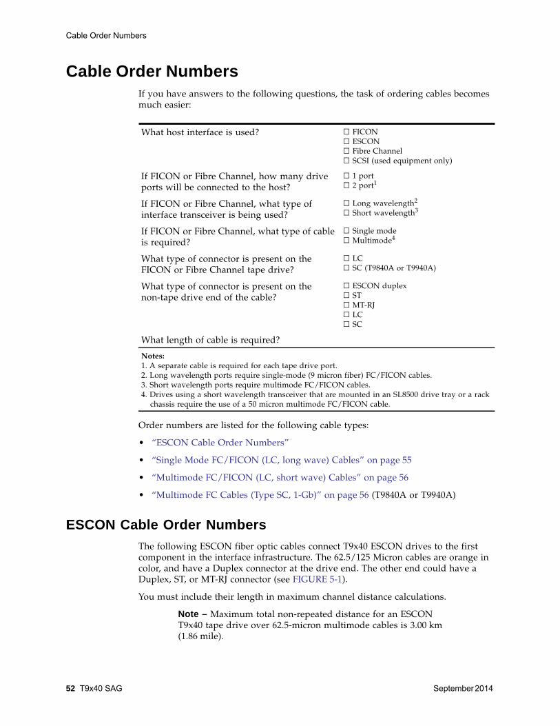
Cable Order Numbers
52 T9x40 SAG September 2014
Cable Order NumbersIf you have answers to the following questions, the task of ordering cables becomesmuch easier:
Order numbers are listed for the following cable types:
• “ESCON Cable Order Numbers”
• “Single Mode FC/FICON (LC, long wave) Cables” on page 55
• “Multimode FC/FICON (LC, short wave) Cables” on page 56
• “Multimode FC Cables (Type SC, 1-Gb)” on page 56 (T9840A or T9940A)
ESCON Cable Order Numbers The following ESCON fiber optic cables connect T9x40 ESCON drives to the firstcomponent in the interface infrastructure. The 62.5/125 Micron cables are orange incolor, and have a Duplex connector at the drive end. The other end could have aDuplex, ST, or MT-RJ connector (see FIGURE 5-1).
You must include their length in maximum channel distance calculations.
Note – Maximum total non-repeated distance for an ESCONT9x40 tape drive over 62.5-micron multimode cables is 3.00 km(1.86 mile).
What host interface is used? □ FICON□ ESCON□ Fibre Channel□ SCSI (used equipment only)
If FICON or Fibre Channel, how many driveports will be connected to the host?
□ 1 port□ 2 port1
If FICON or Fibre Channel, what type ofinterface transceiver is being used?
□ Long wavelength2
□ Short wavelength3
If FICON or Fibre Channel, what type of cableis required?
□ Single mode□ Multimode4
What type of connector is present on theFICON or Fibre Channel tape drive?
□ LC□ SC (T9840A or T9940A)
What type of connector is present on thenon-tape drive end of the cable?
□ ESCON duplex□ ST□ MT-RJ□ LC□ SC
What length of cable is required?
Notes:1. A separate cable is required for each tape drive port.2. Long wavelength ports require single-mode (9 micron fiber) FC/FICON cables.3. Short wavelength ports require multimode FC/FICON cables.4. Drives using a short wavelength transceiver that are mounted in an SL8500 drive tray or a rack
chassis require the use of a 50 micron multimode FC/FICON cable.

Cable Order Numbers
September 2014 Information for Ordering 53
FIGURE 5-1 ESCON Cable Connectors
Description (Sheet 1 of 2) Marketing PN1 Quantity
Duplex to Duplex, 62.5/125 Micron:
□ 13 m (42 ft) Duplex, Plenum CABLE10800285-Z ____________
□ 31 m (100 ft) Duplex, Plenum CABLE10800286-Z ____________
□ 61 m (200 ft Duplex, Plenum CABLE10800287-Z ____________
□ 107 m (350 ft) Duplex, Plenum CABLE10800288-Z ____________
□ 13 m (42 ft) Duplex, Riser CABLE10800289-Z ____________
□ 31 m (100 ft) Duplex, Riser CABLE10800290-Z ____________
□ 61 m (200 ft Duplex, Riser CABLE10800291-Z ____________
□ 107 m (350 ft) Duplex, Riser CABLE10800292-Z ____________
Duplex to MT-RJ, 62.5/125 Micron:
□ 13 m (42 ft) Duplex - MT-RJ, Plenum CABLE10800327-Z ____________
□ 31 m (100 ft) Duplex - MT-RJ, Plenum CABLE10800328-Z ____________
□ 61 m (200 ft Duplex - MT-RJ, Plenum CABLE10800329-Z ____________
□ 13 m (42 ft) Duplex - MT-RJ, Riser CABLE10800324-Z ____________
□ 31 m (100 ft) Duplex - MT-RJ, Riser CABLE10800325-Z ____________
□ 61 m (200 ft Duplex - MT-RJ, Riser CABLE10800326-Z ____________
Duplex to ST, 62.5/125 Micron:
□ 3 m (10 ft) Duplex, Plenum CABLE10800081 _____________
□ 7 m (22 ft) Duplex, Plenum CABLE10800082 _____________
□ 13 m (42 ft) Duplex, Plenum CABLE10800083 _____________
□ 22 m (72 ft Duplex, Plenum CABLE10800084 _____________
1. Suffix “-Z” indicates ROHS-compliant component.

Cable Order Numbers
54 T9x40 SAG September 2014
□ 31 m (100 ft) Duplex, Plenum CABLE10800085CABLE10800293-Z _____________
□ 46 m (150 ft) Duplex, Plenum CABLE10800086 _____________
□ 61 m (200 ft Duplex, Plenum CABLE10800087 _____________
□ 77 m (250 ft Duplex, Plenum CABLE10800088 _____________
□ 92 m (300 ft) Duplex, Plenum CABLE10800089 _____________
□ 107 m (350 ft) Duplex, Plenum CABLE10800090 _____________
□ 122 m (400 ft Duplex, Plenum CABLE10800091 _____________
□ 3 m (10 ft) Duplex, Riser CABLE10800070 _____________
□ 7 m (22 ft) Duplex, Riser CABLE10800071 _____________
□ 13 m (42 ft) Duplex, Riser CABLE10800072 _____________
□ 22 m (72 ft Duplex, Riser CABLE10800073 _____________
□ 31 m (100 ft) Duplex, Riser CABLE10800074 _____________
□ 46 m (150 ft) Duplex, Riser CABLE10800075 _____________
□ 61 m (200 ft Duplex, Riser CABLE10800076 _____________
□ 77 m (250 ft Duplex, Riser CABLE10800077 _____________
□ 92 m (300 ft) Duplex, Riser CABLE10800078 _____________
□ 107 m (350 ft) Duplex, Riser CABLE10800079 _____________
□ 122 m (400 ft Duplex, Riser CABLE10800080 _____________
Description (Sheet 2 of 2) Marketing PN1 Quantity
1. Suffix “-Z” indicates ROHS-compliant component.
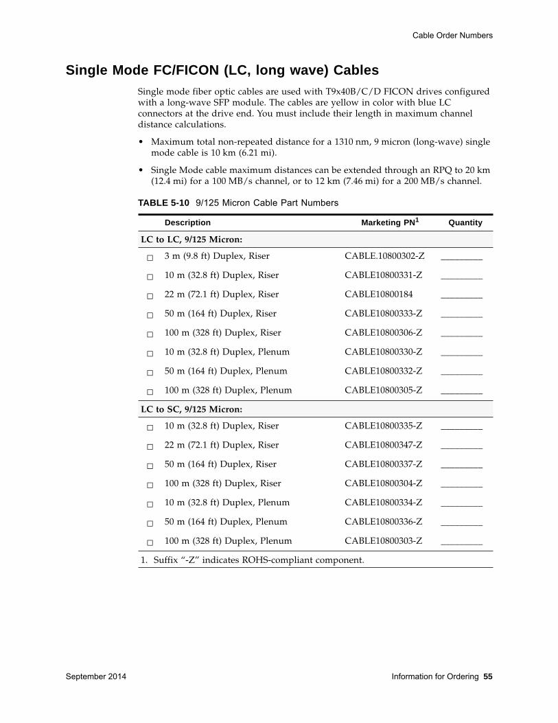
Cable Order Numbers
September 2014 Information for Ordering 55
Single Mode FC/FICON (LC, long wave) Cables Single mode fiber optic cables are used with T9x40B/C/D FICON drives configuredwith a long-wave SFP module. The cables are yellow in color with blue LCconnectors at the drive end. You must include their length in maximum channeldistance calculations.
• Maximum total non-repeated distance for a 1310 nm, 9 micron (long-wave) singlemode cable is 10 km (6.21 mi).
• Single Mode cable maximum distances can be extended through an RPQ to 20 km(12.4 mi) for a 100 MB/s channel, or to 12 km (7.46 mi) for a 200 MB/s channel.
TABLE 5-10 9/125 Micron Cable Part Numbers
Description Marketing PN1 Quantity
LC to LC, 9/125 Micron:
□ 3 m (9.8 ft) Duplex, Riser CABLE.10800302-Z _________
□ 10 m (32.8 ft) Duplex, Riser CABLE10800331-Z _________
□ 22 m (72.1 ft) Duplex, Riser CABLE10800184 _________
□ 50 m (164 ft) Duplex, Riser CABLE10800333-Z _________
□ 100 m (328 ft) Duplex, Riser CABLE10800306-Z _________
□ 10 m (32.8 ft) Duplex, Plenum CABLE10800330-Z _________
□ 50 m (164 ft) Duplex, Plenum CABLE10800332-Z _________
□ 100 m (328 ft) Duplex, Plenum CABLE10800305-Z _________
LC to SC, 9/125 Micron:
□ 10 m (32.8 ft) Duplex, Riser CABLE10800335-Z _________
□ 22 m (72.1 ft) Duplex, Riser CABLE10800347-Z _________
□ 50 m (164 ft) Duplex, Riser CABLE10800337-Z _________
□ 100 m (328 ft) Duplex, Riser CABLE10800304-Z _________
□ 10 m (32.8 ft) Duplex, Plenum CABLE10800334-Z _________
□ 50 m (164 ft) Duplex, Plenum CABLE10800336-Z _________
□ 100 m (328 ft) Duplex, Plenum CABLE10800303-Z _________
1. Suffix “-Z” indicates ROHS-compliant component.
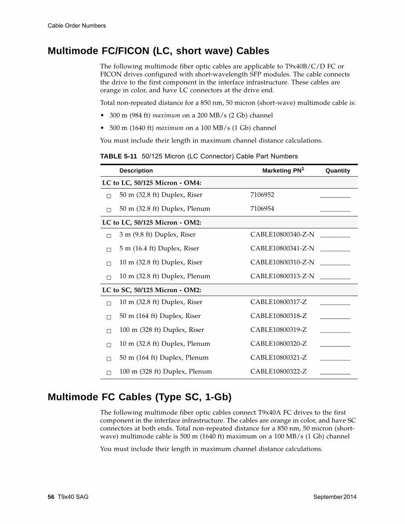
Cable Order Numbers
56 T9x40 SAG September 2014
Multimode FC/FICON (LC, short wave) Cables The following multimode fiber optic cables are applicable to T9x40B/C/D FC orFICON drives configured with short-wavelength SFP modules. The cable connectsthe drive to the first component in the interface infrastructure. These cables areorange in color, and have LC connectors at the drive end.
Total non-repeated distance for a 850 nm, 50 micron (short-wave) multimode cable is:
• 300 m (984 ft) maximum on a 200 MB/s (2 Gb) channel
• 500 m (1640 ft) maximum on a 100 MB/s (1 Gb) channel
You must include their length in maximum channel distance calculations.
Multimode FC Cables (Type SC, 1-Gb) The following multimode fiber optic cables connect T9x40A FC drives to the firstcomponent in the interface infrastructure. The cables are orange in color, and have SCconnectors at both ends. Total non-repeated distance for a 850 nm, 50 micron (short-wave) multimode cable is 500 m (1640 ft) maximum on a 100 MB/s (1 Gb) channel
You must include their length in maximum channel distance calculations.
TABLE 5-11 50/125 Micron (LC Connector) Cable Part Numbers
Description Marketing PN1 Quantity
LC to LC, 50/125 Micron - OM4:
□ 50 m (32.8 ft) Duplex, Riser 7106952 _________
□ 50 m (32.8 ft) Duplex, Plenum 7106954 _________
LC to LC, 50/125 Micron - OM2:
□ 3 m (9.8 ft) Duplex, Riser CABLE10800340-Z-N _________
□ 5 m (16.4 ft) Duplex, Riser CABLE10800341-Z-N _________
□ 10 m (32.8 ft) Duplex, Riser CABLE10800310-Z-N _________
□ 10 m (32.8 ft) Duplex, Plenum CABLE10800313-Z-N _________
LC to SC, 50/125 Micron - OM2:
□ 10 m (32.8 ft) Duplex, Riser CABLE10800317-Z _________
□ 50 m (164 ft) Duplex, Riser CABLE10800318-Z _________
□ 100 m (328 ft) Duplex, Riser CABLE10800319-Z _________
□ 10 m (32.8 ft) Duplex, Plenum CABLE10800320-Z _________
□ 50 m (164 ft) Duplex, Plenum CABLE10800321-Z _________
□ 100 m (328 ft) Duplex, Plenum CABLE10800322-Z _________
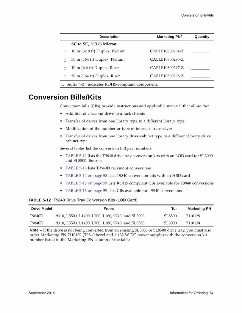
Conversion Bills/Kits
September 2014 Information for Ordering 57
Conversion Bills/Kits Conversion bills (CBs) provide instructions and applicable material that allow the:
• Addition of a second drive to a rack chassis
• Transfer of drives from one library type to a different library type
• Modification of the number or type of interface transceiver
• Transfer of drives from one library drive cabinet type to a different library drivecabinet type
Several tables list the conversion bill part numbers:
• TABLE 5-12 lists the T9840 drive tray conversion kits with an LOD card for SL3000and SL8500 libraries
• TABLE 5-13 lists T9840D rackmont conversions
• TABLE 5-14 on page 58 lists T9840 conversion kits with an HBD card
• TABLE 5-15 on page 59 lists ROHS compliant CBs available for T9840 conversions
• TABLE 5-16 on page 59 lists CBs available for T9940 conversions
Description Marketing PN1 Quantity
SC to SC, 50/125 Micron:
□ 10 m (32.8 ft) Duplex, Plenum CABLE10800294-Z _________
□ 50 m (164 ft) Duplex, Plenum CABLE10800295-Z _________
□ 10 m (6.6 ft) Duplex, Riser CABLE10800297-Z _________
□ 50 m (164 ft) Duplex, Riser CABLE10800298-Z _________
1. Suffix “-Z” indicates ROHS-compliant component.
TABLE 5-12 T9840 Drive Tray Conversion Kits (LOD Card)
Drive Model From: To: Marketing PN
T9840D 9310, L5500, L1400, L700, L180, 9740, and SL3000 SL8500 7110129
T9840D 9310, L5500, L1400, L700, L180, 9740, and SL8500 SL3000 7110134
Note – If the drive is not being converted from an existing SL3000 or SL8500 drive tray, you must alsoorder Marketing PN 7110139 (T9840 bezel and a 132 W DC power supply) with the conversion kitnumber listed in the Marketing PN column of the table.
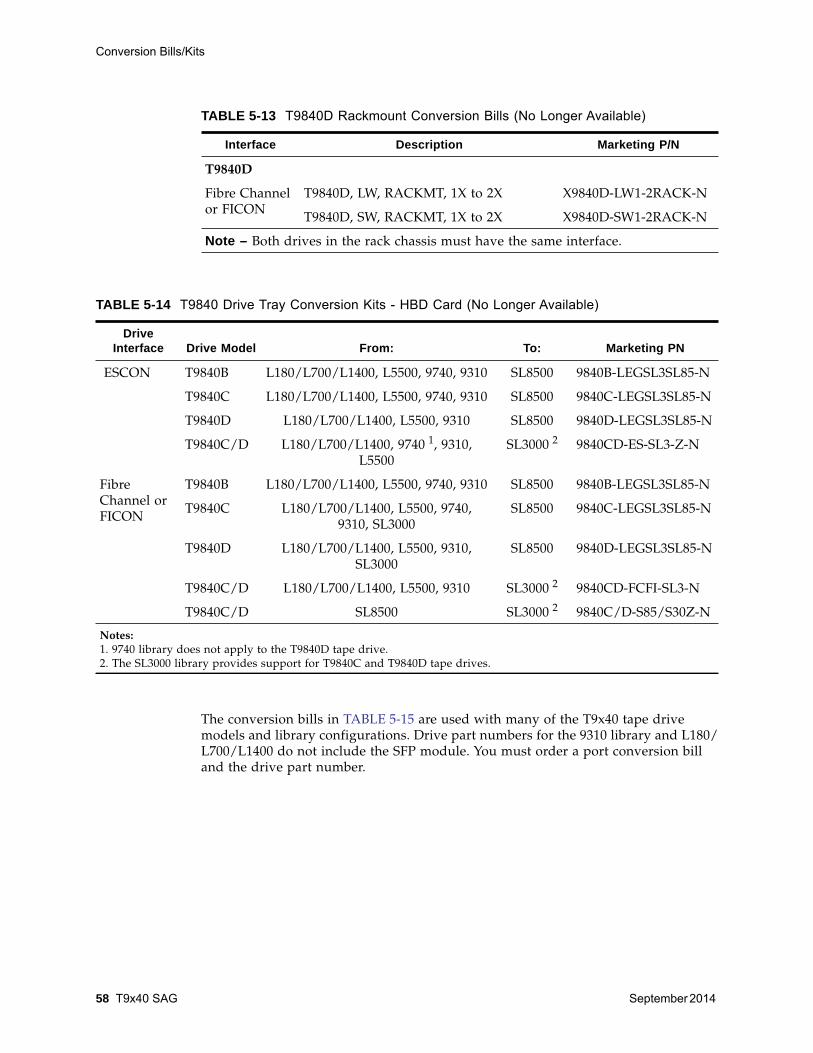
Conversion Bills/Kits
58 T9x40 SAG September 2014
The conversion bills in TABLE 5-15 are used with many of the T9x40 tape drivemodels and library configurations. Drive part numbers for the 9310 library and L180/L700/L1400 do not include the SFP module. You must order a port conversion billand the drive part number.
TABLE 5-13 T9840D Rackmount Conversion Bills (No Longer Available)
Interface Description Marketing P/N
T9840D
Fibre Channelor FICON
T9840D, LW, RACKMT, 1X to 2X X9840D-LW1-2RACK-N
T9840D, SW, RACKMT, 1X to 2X X9840D-SW1-2RACK-N
Note – Both drives in the rack chassis must have the same interface.
TABLE 5-14 T9840 Drive Tray Conversion Kits - HBD Card (No Longer Available)
Drive Interface Drive Model From: To: Marketing PN
ESCON T9840B L180/L700/L1400, L5500, 9740, 9310 SL8500 9840B-LEGSL3SL85-N
T9840C L180/L700/L1400, L5500, 9740, 9310 SL8500 9840C-LEGSL3SL85-N
T9840D L180/L700/L1400, L5500, 9310 SL8500 9840D-LEGSL3SL85-N
T9840C/D L180/L700/L1400, 9740 1, 9310,L5500
SL3000 2 9840CD-ES-SL3-Z-N
FibreChannel orFICON
T9840B L180/L700/L1400, L5500, 9740, 9310 SL8500 9840B-LEGSL3SL85-N
T9840C L180/L700/L1400, L5500, 9740,9310, SL3000
SL8500 9840C-LEGSL3SL85-N
T9840D L180/L700/L1400, L5500, 9310,SL3000
SL8500 9840D-LEGSL3SL85-N
T9840C/D L180/L700/L1400, L5500, 9310 SL3000 2 9840CD-FCFI-SL3-N
T9840C/D SL8500 SL3000 2 9840C/D-S85/S30Z-N
Notes:1. 9740 library does not apply to the T9840D tape drive.2. The SL3000 library provides support for T9840C and T9840D tape drives.
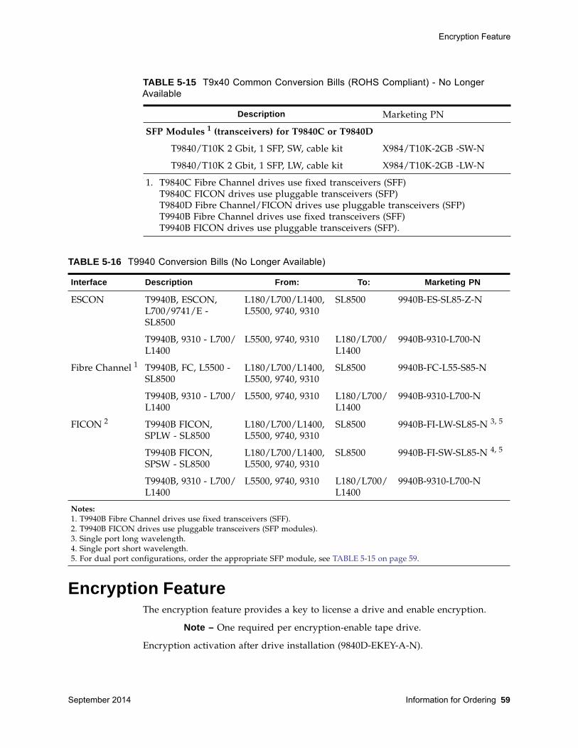
Encryption Feature
September 2014 Information for Ordering 59
Encryption FeatureThe encryption feature provides a key to license a drive and enable encryption.
Note – One required per encryption-enable tape drive.
Encryption activation after drive installation (9840D-EKEY-A-N).
TABLE 5-15 T9x40 Common Conversion Bills (ROHS Compliant) - No Longer Available
Description Marketing PN
SFP Modules 1 (transceivers) for T9840C or T9840D
T9840/T10K 2 Gbit, 1 SFP, SW, cable kit X984/T10K-2GB -SW-N
T9840/T10K 2 Gbit, 1 SFP, LW, cable kit X984/T10K-2GB -LW-N
1. T9840C Fibre Channel drives use fixed transceivers (SFF)T9840C FICON drives use pluggable transceivers (SFP)T9840D Fibre Channel/FICON drives use pluggable transceivers (SFP)T9940B Fibre Channel drives use fixed transceivers (SFF)T9940B FICON drives use pluggable transceivers (SFP).
TABLE 5-16 T9940 Conversion Bills (No Longer Available)
Interface Description From: To: Marketing PN
ESCON T9940B, ESCON,L700/9741/E -SL8500
L180/L700/L1400,L5500, 9740, 9310
SL8500 9940B-ES-SL85-Z-N
T9940B, 9310 - L700/L1400
L5500, 9740, 9310 L180/L700/L1400
9940B-9310-L700-N
Fibre Channel 1 T9940B, FC, L5500 -SL8500
L180/L700/L1400,L5500, 9740, 9310
SL8500 9940B-FC-L55-S85-N
T9940B, 9310 - L700/L1400
L5500, 9740, 9310 L180/L700/L1400
9940B-9310-L700-N
FICON 2 T9940B FICON,SPLW - SL8500
L180/L700/L1400,L5500, 9740, 9310
SL8500 9940B-FI-LW-SL85-N 3, 5
T9940B FICON,SPSW - SL8500
L180/L700/L1400,L5500, 9740, 9310
SL8500 9940B-FI-SW-SL85-N 4, 5
T9940B, 9310 - L700/L1400
L5500, 9740, 9310 L180/L700/L1400
9940B-9310-L700-N
Notes:1. T9940B Fibre Channel drives use fixed transceivers (SFF).2. T9940B FICON drives use pluggable transceivers (SFP modules).3. Single port long wavelength.4. Single port short wavelength.5. For dual port configurations, order the appropriate SFP module, see TABLE 5-15 on page 59.
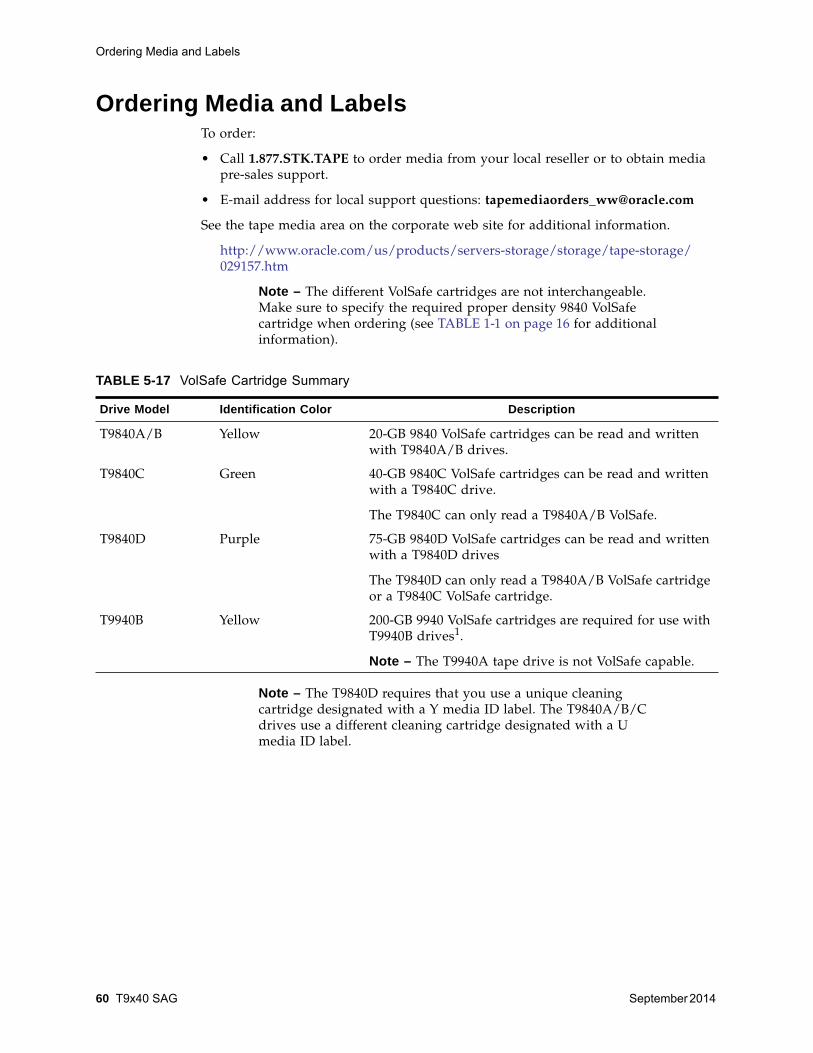
Ordering Media and Labels
60 T9x40 SAG September 2014
Ordering Media and Labels To order:
• Call 1.877.STK.TAPE to order media from your local reseller or to obtain mediapre-sales support.
• E-mail address for local support questions: [email protected]
See the tape media area on the corporate web site for additional information.
http://www.oracle.com/us/products/servers-storage/storage/tape-storage/029157.htm
Note – The different VolSafe cartridges are not interchangeable.Make sure to specify the required proper density 9840 VolSafecartridge when ordering (see TABLE 1-1 on page 16 for additionalinformation).
Note – The T9840D requires that you use a unique cleaningcartridge designated with a Y media ID label. The T9840A/B/Cdrives use a different cleaning cartridge designated with a Umedia ID label.
TABLE 5-17 VolSafe Cartridge Summary
Drive Model Identification Color Description
T9840A/B Yellow 20-GB 9840 VolSafe cartridges can be read and writtenwith T9840A/B drives.
T9840C Green 40-GB 9840C VolSafe cartridges can be read and writtenwith a T9840C drive.
The T9840C can only read a T9840A/B VolSafe.
T9840D Purple 75-GB 9840D VolSafe cartridges can be read and writtenwith a T9840D drives
The T9840D can only read a T9840A/B VolSafe cartridgeor a T9840C VolSafe cartridge.
T9940B Yellow 200-GB 9940 VolSafe cartridges are required for use withT9940B drives1.
Note – The T9940A tape drive is not VolSafe capable.
September 2014 Specifications 61
ASpecifications
This appendix provides specifications for “T9840” and “T9940” on page 70.
T9840The following information is provided for T9840 tape drives:
• Power specifications
• Performance specifications
• Environmental requirements
• Physical specifications
• Library attachments
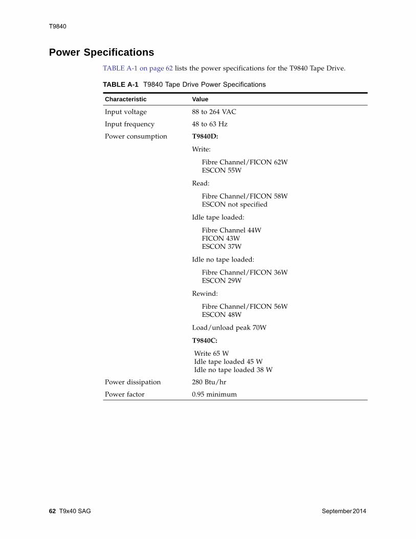
T9840
62 T9x40 SAG September 2014
Power Specifications TABLE A-1 on page 62 lists the power specifications for the T9840 Tape Drive.
TABLE A-1 T9840 Tape Drive Power Specifications
Characteristic Value
Input voltage 88 to 264 VAC
Input frequency 48 to 63 Hz
Power consumption T9840D:
Write:
Fibre Channel/FICON 62WESCON 55W
Read:
Fibre Channel/FICON 58WESCON not specified
Idle tape loaded:
Fibre Channel 44WFICON 43WESCON 37W
Idle no tape loaded:
Fibre Channel/FICON 36WESCON 29W
Rewind:
Fibre Channel/FICON 56WESCON 48W
Load/unload peak 70W
T9840C:
Write 65 WIdle tape loaded 45 WIdle no tape loaded 38 W
Power dissipation 280 Btu/hr
Power factor 0.95 minimum

T9840
September 2014 Specifications 63
Performance SpecificationThis section describes tape drive and data cartridge performance specifications.
Tape DriveTABLE A-2 on page 63 lists the performance specifications of the T9840 tape drive.
TABLE A-2 T9840 Tape Drive Performance Specifications
CharacteristicValue
T9840A T9840B T9840C T9840D
Capacity and Performance
Capacity, native
Data buffer sizeTape speed, read/writeMaximum block sizePerformance, native (head-to-tape)
(uncompressed)(compressed, maximum)Burst (FC & FICON)Burst (ESCON)
20 GB
8 MB2 m/s256K
10 MB/s35 MB/s100 MB/s17 MB/s
20 GB
32 MB4 m/s256K
19 MB/s60 MB/s200 MB/s17 MB/s
40 GB1
64 MB3.295 m/s256K
30 MB/s60 MB/s200 MB/s17 MB/s
75 GB1
64 MB3.4 m/s256K
30 MB/s60 MB/s2
200 MB/s17 MB/s
Interface data
Fibre ChannelUltra-SCSI HVDESCONFICON
1 Gb40 MB/s17 MB/sNA
2 Gb40 MB/s17 MB/s2 Gb
2 GbNA17 MB/s2 Gb
2 GbNA17 MB/s2 Gb
Access times
Tape load and thread to readyFile access, first (average)Rewind (maximum/average)Unload
7 sec8 sec16/8 sec8 sec
7 sec8 sec16/8 sec8 sec
6.5 sec8 sec16/8 sec11.5 sec
8.5 sec8 sec16/8 sec12.5 sec
Reliability
Mean time between failure (MBTF)Power on @ 100% duty cycle
Tape load @ 10/day (100K loads)Tape path motion (TPM)@ 70% duty cycle
Head life @ 70% TPM duty cycleUncorrected bit error rateUndetected bit error rate
290,000 hr240,000 hr216,000 hr
5 years1 x 10-18
1 x 10-33
290,000 hr240,000 hr216,000 hr
5 years1 x 10-18
1 x 10-33
290,000 hr240,000 hr216,000 hr
5 years1 x 10-18
1 x 10-33
290,000 hr240,000 hr216,000 hr
5 years1 x 10-18
1 x 10-33
Notes:1. VR2 is a trademark of Overland Storage. VR2 technology is used to achieve T9840C/D capacity and performance.2. Fibre Channel (FC) write and 55 MB/s FICON write
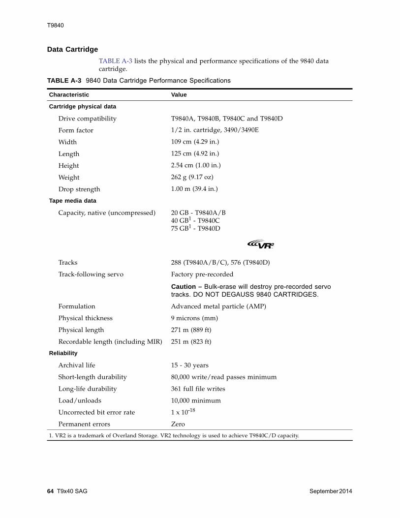
T9840
64 T9x40 SAG September 2014
Data CartridgeTABLE A-3 lists the physical and performance specifications of the 9840 datacartridge.
TABLE A-3 9840 Data Cartridge Performance Specifications
Characteristic Value
Cartridge physical data
Drive compatibility T9840A, T9840B, T9840C and T9840D
Form factor 1/2 in. cartridge, 3490/3490E
Width 109 cm (4.29 in.)
Length 125 cm (4.92 in.)
Height 2.54 cm (1.00 in.)
Weight 262 g (9.17 oz)
Drop strength 1.00 m (39.4 in.)
Tape media data
Capacity, native (uncompressed) 20 GB - T9840A/B40 GB1 - T9840C75 GB1 - T9840D
Tracks 288 (T9840A/B/C), 576 (T9840D)
Track-following servo Factory pre-recorded
Caution – Bulk-erase will destroy pre-recorded servo tracks. DO NOT DEGAUSS 9840 CARTRIDGES.
Formulation Advanced metal particle (AMP)
Physical thickness 9 microns (mm)
Physical length 271 m (889 ft)
Recordable length (including MIR) 251 m (823 ft)
Reliability
Archival life 15 - 30 years
Short-length durability 80,000 write/read passes minimum
Long-life durability 361 full file writes
Load/unloads 10,000 minimum
Uncorrected bit error rate 1 x 10-18
Permanent errors Zero
1. VR2 is a trademark of Overland Storage. VR2 technology is used to achieve T9840C/D capacity.
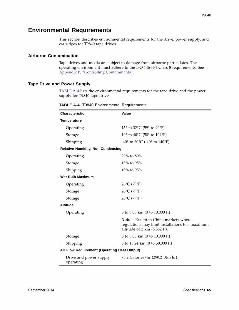
T9840
September 2014 Specifications 65
Environmental Requirements This section describes environmental requirements for the drive, power supply, andcartridges for T9840 tape drives.
Airborne ContaminationTape drives and media are subject to damage from airborne particulates. Theoperating environment must adhere to the ISO 14644-1 Class 8 requirements. SeeAppendix B, “Controlling Contaminants”.
Tape Drive and Power Supply TABLE A-4 lists the environmental requirements for the tape drive and the powersupply for T9840 tape drives.
TABLE A-4 T9840 Environmental Requirements
Characteristic Value
Temperature
Operating 15° to 32°C (59° to 90°F)
Storage 10° to 40°C (50° to 104°F)
Shipping -40° to 60°C (-40° to 140°F)
Relative Humidity, Non-Condensing
Operating 20% to 80%
Storage 10% to 95%
Shipping 10% to 95%
Wet Bulb Maximum
Operating 26°C (79°F)
Storage 26°C (79°F)
Storage 26°C (79°F)
Altitude
Operating 0 to 3.05 km (0 to 10,000 ft)
Note – Except in China markets whereregulations may limit installations to a maximumaltitude of 2 km (6,562 ft).
Storage 0 to 3.05 km (0 to 10,000 ft)
Shipping 0 to 15.24 km (0 to 50,000 ft)
Air Flow Requirement (Operating Heat Output)
Drive and power supplyoperating
73.2 Calories/hr (290.2 Btu/hr)
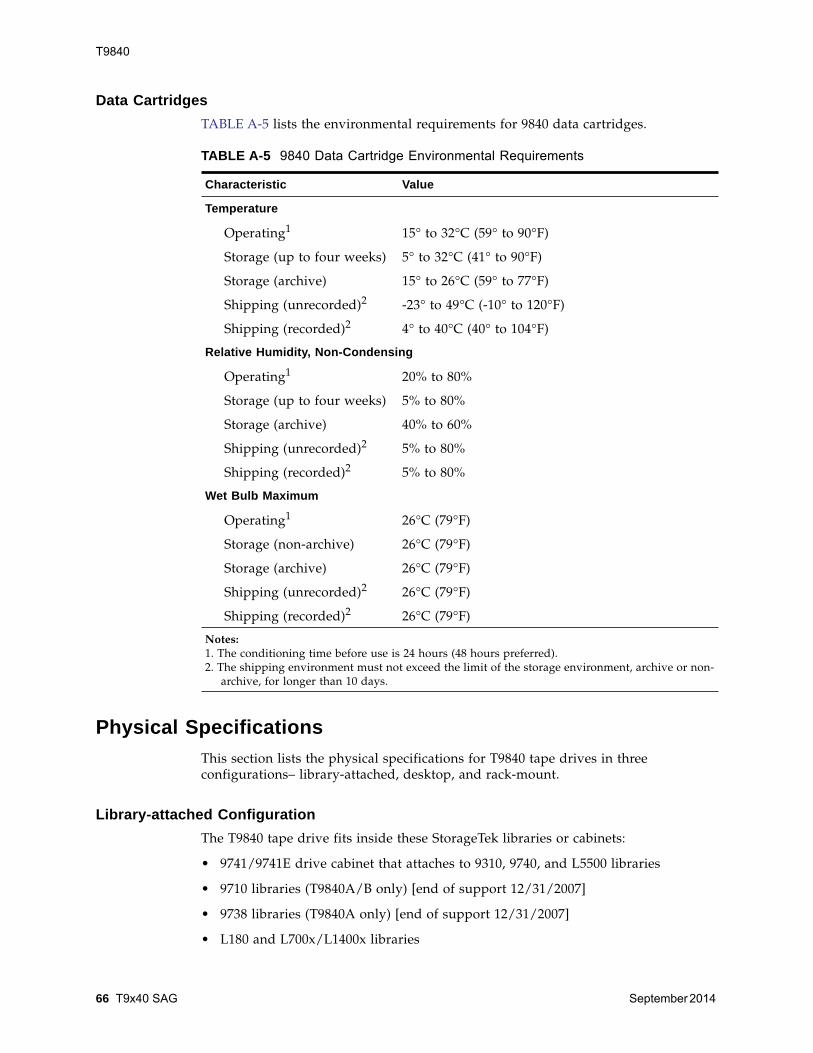
T9840
66 T9x40 SAG September 2014
Data Cartridges TABLE A-5 lists the environmental requirements for 9840 data cartridges.
Physical Specifications This section lists the physical specifications for T9840 tape drives in threeconfigurations– library-attached, desktop, and rack-mount.
Library-attached Configuration The T9840 tape drive fits inside these StorageTek libraries or cabinets:
• 9741/9741E drive cabinet that attaches to 9310, 9740, and L5500 libraries
• 9710 libraries (T9840A/B only) [end of support 12/31/2007]
• 9738 libraries (T9840A only) [end of support 12/31/2007]
• L180 and L700x/L1400x libraries
TABLE A-5 9840 Data Cartridge Environmental Requirements
Characteristic Value
Temperature
Operating1 15° to 32°C (59° to 90°F)
Storage (up to four weeks) 5° to 32°C (41° to 90°F)
Storage (archive) 15° to 26°C (59° to 77°F)
Shipping (unrecorded)2 -23° to 49°C (-10° to 120°F)
Shipping (recorded)2 4° to 40°C (40° to 104°F)
Relative Humidity, Non-Condensing
Operating1 20% to 80%
Storage (up to four weeks) 5% to 80%
Storage (archive) 40% to 60%
Shipping (unrecorded)2 5% to 80%
Shipping (recorded)2 5% to 80%
Wet Bulb Maximum
Operating1 26°C (79°F)
Storage (non-archive) 26°C (79°F)
Storage (archive) 26°C (79°F)
Shipping (unrecorded)2 26°C (79°F)
Shipping (recorded)2 26°C (79°F)
Notes:1. The conditioning time before use is 24 hours (48 hours preferred).2. The shipping environment must not exceed the limit of the storage environment, archive or non-
archive, for longer than 10 days.
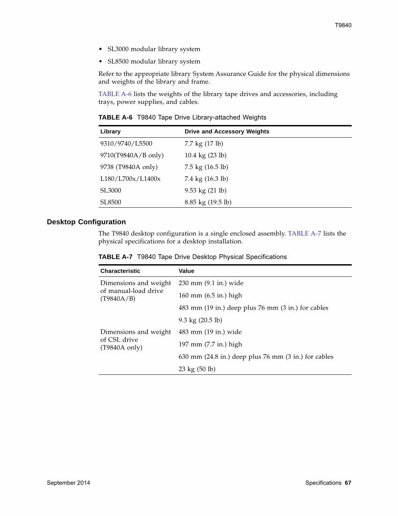
T9840
September 2014 Specifications 67
• SL3000 modular library system
• SL8500 modular library system
Refer to the appropriate library System Assurance Guide for the physical dimensionsand weights of the library and frame.
TABLE A-6 lists the weights of the library tape drives and accessories, includingtrays, power supplies, and cables.
Desktop Configuration The T9840 desktop configuration is a single enclosed assembly. TABLE A-7 lists thephysical specifications for a desktop installation.
TABLE A-6 T9840 Tape Drive Library-attached Weights
Library Drive and Accessory Weights
9310/9740/L5500 7.7 kg (17 lb)
9710(T9840A/B only) 10.4 kg (23 lb)
9738 (T9840A only) 7.5 kg (16.5 lb)
L180/L700x/L1400x 7.4 kg (16.3 lb)
SL3000 9.53 kg (21 lb)
SL8500 8.85 kg (19.5 lb)
TABLE A-7 T9840 Tape Drive Desktop Physical Specifications
Characteristic Value
Dimensions and weightof manual-load drive(T9840A/B)
230 mm (9.1 in.) wide
160 mm (6.5 in.) high
483 mm (19 in.) deep plus 76 mm (3 in.) for cables
9.3 kg (20.5 lb)
Dimensions and weightof CSL drive(T9840A only)
483 mm (19 in.) wide
197 mm (7.7 in.) high
630 mm (24.8 in.) deep plus 76 mm (3 in.) for cables
23 kg (50 lb)
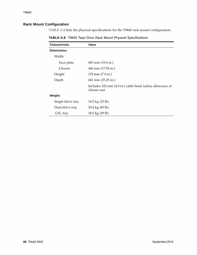
T9840
68 T9x40 SAG September 2014
Rack Mount Configuration TABLE A-8 lists the physical specifications for the T9840 rack mount configuration.
TABLE A-8 T9840 Tape Drive Rack Mount Physical Specifications
Characteristic Value
Dimensions:
Width:
Face plate 483 mm (19.0 in.)
Chassis 446 mm (17.56 in.)
Height 178 mm (7.0 in.)
Depth 641 mm (25.25 in.)
Includes 102 mm (4.0 in.) cable bend radius allowance atchassis rear
Weight:
Single-drive tray 14.5 kg (32 lb)
Dual-drive tray 20.4 kg (45 lb)
CSL tray 18.0 kg (39 lb)
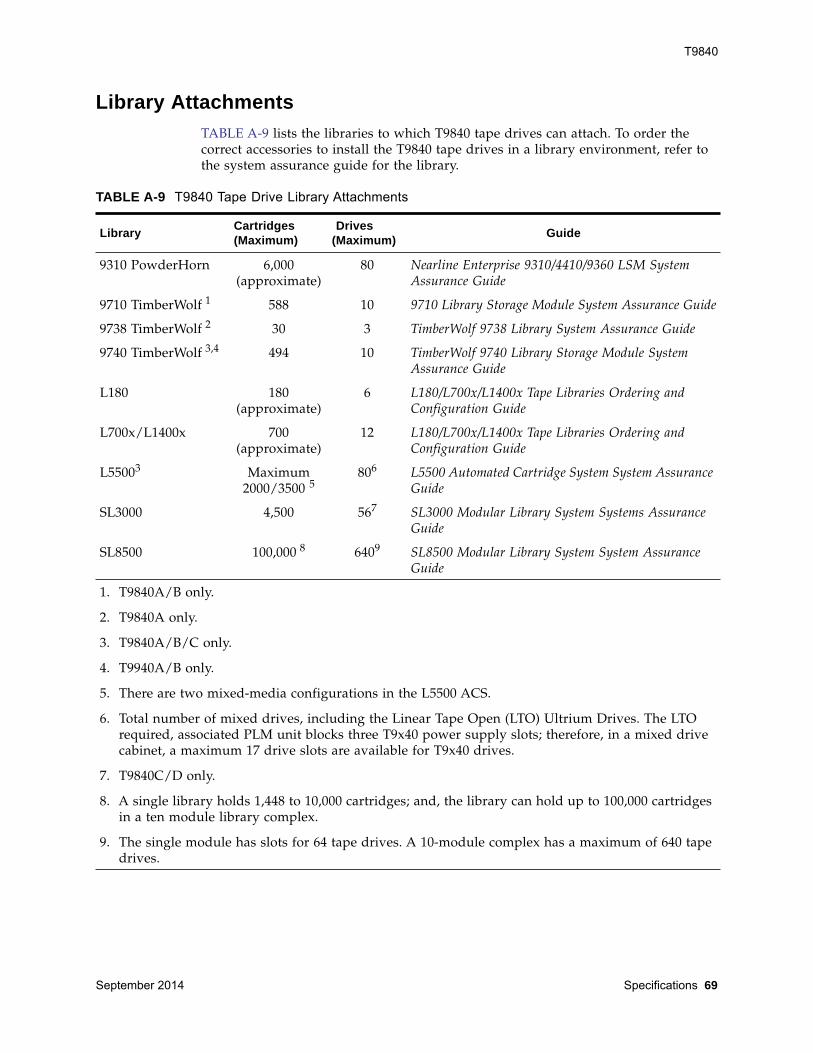
T9840
September 2014 Specifications 69
Library Attachments TABLE A-9 lists the libraries to which T9840 tape drives can attach. To order thecorrect accessories to install the T9840 tape drives in a library environment, refer tothe system assurance guide for the library.
TABLE A-9 T9840 Tape Drive Library Attachments
Library Cartridges (Maximum)
Drives (Maximum) Guide
9310 PowderHorn 6,000(approximate)
80 Nearline Enterprise 9310/4410/9360 LSM SystemAssurance Guide
9710 TimberWolf 1 588 10 9710 Library Storage Module System Assurance Guide
9738 TimberWolf 2 30 3 TimberWolf 9738 Library System Assurance Guide
9740 TimberWolf 3,4 494 10 TimberWolf 9740 Library Storage Module SystemAssurance Guide
L180 180(approximate)
6 L180/L700x/L1400x Tape Libraries Ordering andConfiguration Guide
L700x/L1400x 700(approximate)
12 L180/L700x/L1400x Tape Libraries Ordering andConfiguration Guide
L55003 Maximum2000/3500 5
806 L5500 Automated Cartridge System System AssuranceGuide
SL3000 4,500 567 SL3000 Modular Library System Systems AssuranceGuide
SL8500 100,000 8 6409 SL8500 Modular Library System System AssuranceGuide
1. T9840A/B only.
2. T9840A only.
3. T9840A/B/C only.
4. T9940A/B only.
5. There are two mixed-media configurations in the L5500 ACS.
6. Total number of mixed drives, including the Linear Tape Open (LTO) Ultrium Drives. The LTOrequired, associated PLM unit blocks three T9x40 power supply slots; therefore, in a mixed drivecabinet, a maximum 17 drive slots are available for T9x40 drives.
7. T9840C/D only.
8. A single library holds 1,448 to 10,000 cartridges; and, the library can hold up to 100,000 cartridgesin a ten module library complex.
9. The single module has slots for 64 tape drives. A 10-module complex has a maximum of 640 tapedrives.
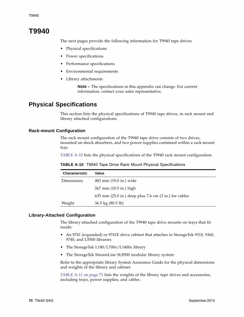
T9940
70 T9x40 SAG September 2014
T9940The next pages provide the following information for T9940 tape drives:
• Physical specifications
• Power specifications
• Performance specifications
• Environmental requirements
• Library attachments
Note – The specifications in this appendix can change. For currentinformation, contact your sales representative.
Physical Specifications This section lists the physical specifications of T9940 tape drives, in rack mount andlibrary attached configurations.
Rack-mount ConfigurationThe rack mount configuration of the T9940 tape drive consists of two drives,mounted on shock absorbers, and two power supplies contained within a rack mounttray.
TABLE A-10 lists the physical specifications of the T9940 rack mount configuration.
Library-Attached Configuration The library-attached configuration of the T9940 tape drive mounts on trays that fitinside:
• An 9741 (expanded) or 9741E drive cabinet that attaches to StorageTek 9310, 9360,9740, and L5500 libraries
• The StorageTek L180/L700x/L1400x library
• The StorageTek StreamLine SL8500 modular library system
Refer to the appropriate library System Assurance Guide for the physical dimensionsand weights of the library and cabinet.
TABLE A-11 on page 71 lists the weights of the library tape drives and accessories,including trays, power supplies, and cables.
TABLE A-10 T9940 Tape Drive Rack Mount Physical Specifications
Characteristic Value
Dimensions 483 mm (19.0 in.) wide
267 mm (10.5 in.) high
635 mm (25.0 in.) deep plus 7.6 cm (3 in.) for cables
Weight 36.5 kg (80.5 lb)
T9940
September 2014 Specifications 71
Power Specifications TABLE A-12 lists the power specifications of the T9940 tape drive.
TABLE A-11 T9940 Tape Drive Library attached Weights
Library Weight, Drive plus Library Tray (SCSI)
9310/9740/L5500 9.1 kg (20 lb)
L180/L700x/L1400x 9.6 kg (21.2 lb)
SL8500 10.4 kg (24.0 lb)
TABLE A-12 T9940 Tape Drive Power Specifications
Characteristics Value
Input voltage 100 to 240 VAC
Input frequency 50 to 60 Hz
Power consumption 82 Watts
Power dissipation 280 Btu/hr
Power factor 0.96 minimum
T9940
72 T9x40 SAG September 2014
Performance Specifications This section describes tape drive and data cartridge performance.
Tape Drive TABLE A-13 lists performance specifications of the T9940 tape drive.
TABLE A-13 T9940 Tape Drive Performance Specifications
CharacteristicValue
T9940A T9940B
Capacity and Performance
Capacity, native
Data buffer sizeTape speed, read/writePerformance, native (head-to-tape)
(uncompressed)(compressed, maximum)Burst (FC / FICON)Burst (ESCON)
60 GB
16 MB2 m/sec
10 MB/sec35 MB/sec100 MB/sec17 MB/sec
200 GB1
64 MB3.4 m/sec
30 MB/sec1
70 MB/sec200 MB/sec17 MB/sec
Interface data
Fibre ChannelUltra-SCSI HVDESCONFICON
1 Gb40 MB/sec20 MB/secNA
2 GbN/A20 MB/sec2 Gb
Access times
Tape load and thread to readyFile access, first (average)
Rewind (maximum/average)Unload
18 sec59 sec
90/45 sec18 sec
18 sec59 sec
90/45 sec18 sec
Reliability
Mean time between failure (MBTF)Power on @ 100% duty cycle
Tape load @ 10/day (100K loads)Tape path motion (TPM)
@ 70% duty cycleHead life @ 70% TPM duty cycleUncorrected bit error rateUndetected bit error rate
290,000 hr240,000 hr196,000 hr
8.5 yr.1 x 10-18
1 x 10-33
290,000 hr240,000 hr196,000 hr
8.5 yr.1 x 10-18
1 x 10-33
1. VR2 is a trademark of Overland Storage. VR2 technology is used to achieve T9940B capacity andperformance.
T9940
September 2014 Specifications 73
Data Cartridge TABLE A-14 lists physical and performance specifications of the 9940 data cartridge.
TABLE A-14 9940 Data Cartridge Specifications
Characteristic Value
Cartridge physical data
Drive compatibility T9940A, T9940B
Form factor 1/2 in. cartridge, 3490/3490E
Width 109 cm (4.29 in.)
Length 125 cm (4.92 in.)
Height 25.4 cm (1.00 in.)
Weight 262 g (9.17 oz)
Drop strength 1.00 m (39.4 in.)
Tape media data
Capacity, native (uncompressed) 60 GB (Low density, T9940A)200 GB1 (High density, T9940B)
Tracks 288 (Low density, T9940A)576 (High density, T9940B)
Track-following servo Factory pre-recorded
Caution – Bulk-erase will destroy pre-recorded servo tracks. DO NOT DEGAUSS T9940 CARTRIDGES.
Formulation Advanced metal particle (AMP)
Physical thickness 9 microns (mm)
Physical length 700 m (2,296 ft)
Recordable length (including MIR) 650 m (2,134 ft)
Reliability
Archival life 15 - 30 years
Short-length durability 80,000 write/read passes minimum
Long-life durability 3,000 write/read passes minimum
Load/unloads 10,000 minimum
Uncorrected bit error rate 1 x 10-18
Permanent errors Zero
1. VR2 is a trademark of Overland Storage. VR2 technology is used to achieve T9940B capacity.
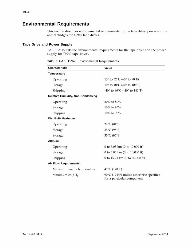
T9940
74 T9x40 SAG September 2014
Environmental Requirements This section describes environmental requirements for the tape drive, power supply,and cartridges for T9940 tape drives.
Tape Drive and Power Supply TABLE A-15 lists the environmental requirements for the tape drive and the powersupply for T9940 tape drives.
TABLE A-15 T9940 Environmental Requirements
Characteristic Value
Temperature
Operating 15° to 32°C (60° to 90°F)
Storage 10° to 40°C (50° to 104°F)
Shipping -40° to 60°C (-40° to 140°F)
Relative Humidity, Non-Condensing
Operating 20% to 80%
Storage 10% to 95%
Shipping 10% to 95%
Wet Bulb Maximum
Operating 29°C (84°F)
Storage 35°C (95°F)
Storage 35°C (95°F)
Altitude
Operating 0 to 3.05 km (0 to 10,000 ft)
Storage 0 to 3.05 km (0 to 10,000 ft)
Shipping 0 to 15.24 km (0 to 50,000 ft)
Air Flow Requirements
Maximum media temperature 49°C (120°F)
Maximum chip Tj 90°C (194°F) unless otherwise specifiedfor a particular component
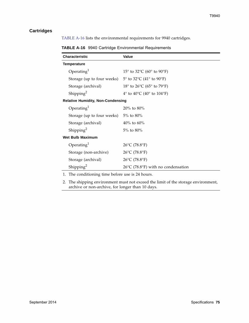
T9940
September 2014 Specifications 75
Cartridges TABLE A-16 lists the environmental requirements for 9940 cartridges.
TABLE A-16 9940 Cartridge Environmental Requirements
Characteristic Value
Temperature
Operating1 15° to 32°C (60° to 90°F)
Storage (up to four weeks) 5° to 32°C (41° to 90°F)
Storage (archival) 18° to 26°C (65° to 79°F)
Shipping2 4° to 40°C (40° to 104°F)
Relative Humidity, Non-Condensing
Operating1 20% to 80%
Storage (up to four weeks) 5% to 80%
Storage (archival) 40% to 60%
Shipping2 5% to 80%
Wet Bulb Maximum
Operating1 26°C (78.8°F)
Storage (non-archive) 26°C (78.8°F)
Storage (archival) 26°C (78.8°F)
Shipping2 26°C (78.8°F) with no condensation
1. The conditioning time before use is 24 hours.
2. The shipping environment must not exceed the limit of the storage environment,archive or non-archive, for longer than 10 days.
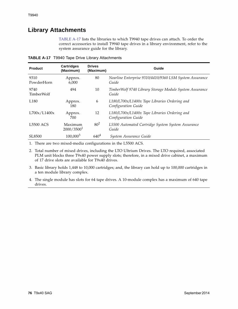
T9940
76 T9x40 SAG September 2014
Library Attachments TABLE A-17 lists the libraries to which T9940 tape drives can attach. To order thecorrect accessories to install T9940 tape drives in a library environment, refer to thesystem assurance guide for the library.
TABLE A-17 T9940 Tape Drive Library Attachments
Product Cartridges (Maximum)
Drives (Maximum) Guide
9310PowderHorn
Approx.6,000
80 Nearline Enterprise 9310/4410/9360 LSM System AssuranceGuide
9740TimberWolf
494 10 TimberWolf 9740 Library Storage Module System AssuranceGuide
L180 Approx.180
6 L180/L700x/L1400x Tape Libraries Ordering andConfiguration Guide
L700x/L1400x Approx.700
12 L180/L700x/L1400x Tape Libraries Ordering andConfiguration Guide
L5500 ACS Maximum2000/35001
802 L5500 Automated Cartridge System System AssuranceGuide
SL8500 100,0003 6404 System Assurance Guide
1. There are two mixed-media configurations in the L5500 ACS.
2. Total number of mixed drives, including the LTO Ultrium Drives. The LTO required, associatedPLM unit blocks three T9x40 power supply slots; therefore, in a mixed drive cabinet, a maximumof 17 drive slots are available for T9x40 drives.
3. Basic library holds 1,448 to 10,000 cartridges; and, the library can hold up to 100,000 cartridges ina ten module library complex.
4. The single module has slots for 64 tape drives. A 10-module complex has a maximum of 640 tapedrives.
September 2014 Controlling Contaminants 77
BControlling Contaminants
Environmental ContaminantsControl over contaminant levels in a computer room is extremely important becausetape libraries, tape drives, and tape media are subject to damage from airborneparticulates. Most particles smaller than ten microns are not visible to the naked eyeunder most conditions, but these particles can be the most damaging. As a result, theoperating environment must adhere to the following requirements:
• ISO 14644-1 Class 8 Environment.
• The total mass of airborne particulates must be less than or equal to 200micrograms per cubic meter.
• Severity level G1 per ANSI/ISA 71.04-1985.
Oracle currently requires the ISO 14644-1 standard approved in 1999, but will requireany updated standards for ISO 14644-1 as they are approved by the ISO governingbody. The ISO 14644-1 standard primarily focuses on the quantity and size ofparticulates as well as the proper measurement methodology, but does not addressthe overall mass of the particulates. As a result, the requirement for total masslimitations is also necessary as a computer room or data center could meet the ISO14644-1 specification, but still damage equipment because of the specific type ofparticulates in the room. In addition, the ANSI/ISA 71.04-1985 specificationaddresses gaseous contaminations as some airborne chemicals are more hazardous.All three requirements are consistent with the requirements set by other major tapestorage vendors.
Required Air Quality LevelsParticles, gasses and other contaminants may impact the sustained operations ofcomputer hardware. Effects can range from intermittent interference to actualcomponent failures. The computer room must be designed to achieve a high level ofcleanliness. Airborne dusts, gasses and vapors must be maintained within definedlimits to help minimize their potential impact on the hardware.
Airborne particulate levels must be maintained within the limits of ISO 14644-1 Class8 Environment. This standard defines air quality classes for clean zones based onairborne particulate concentrations. This standard has an order of magnitude lessparticles than standard air in an office environment. Particles ten microns or smallerare harmful to most data processing hardware because they tend to exist in large

Contaminant Properties and Sources
78 T9x40 SAG September 2014
numbers, and can easily circumvent many sensitive components’ internal airfiltration systems. When computer hardware is exposed to these submicron particlesin great numbers they endanger system reliability by posing a threat to moving parts,sensitive contacts and component corrosion.
Excessive concentrations of certain gasses can also accelerate corrosion and causefailure in electronic components. Gaseous contaminants are a particular concern in acomputer room both because of the sensitivity of the hardware, and because a propercomputer room environment is almost entirely recirculating. Any contaminant threatin the room is compounded by the cyclical nature of the airflow patterns. Levels ofexposure that might not be concerning in a well ventilated site repeatedly attack thehardware in a room with recirculating air. The isolation that prevents exposure of thecomputer room environment to outside influences can also multiply any detrimentalinfluences left unaddressed in the room.
Gasses that are particularly dangerous to electronic components include chlorinecompounds, ammonia and its derivatives, oxides of sulfur and petrol hydrocarbons.In the absence of appropriate hardware exposure limits, health exposure limits mustbe used.
While the following sections will describe some best practices for maintaining an ISO14644-1 Class 8 Environment in detail, there are some basic precautions that must beadhered to:
• Do not allow food or drink into the area.
• Cardboard, wood, or packing materials must not be stored in the data center cleanarea.
• Identify a separate area for unpacking new equipment from crates and boxes.
• Do not allow construction or drilling in the data center without first isolatingsensitive equipment and any air targeted specifically for the equipment.Construction generates a high level of particulates that exceed ISO 14644-1 Class 8criteria in a localized area. Dry wall and gypsum are especially damaging tostorage equipment.
Contaminant Properties and SourcesContaminants in the room can take many forms, and can come from numeroussources. Any mechanical process in the room can produce dangerous contaminants oragitate settled contaminants. A particle must meet two basic criteria to be considereda contaminant:
• It must have the physical properties that could potentially cause damage to thehardware.
• It must be able to migrate to areas where it can cause the physical damage.
The only differences between a potential contaminant and an actual contaminant aretime and location. Particulate matter is most likely to migrate to areas where it can dodamage if it is airborne. For this reason, airborne particulate concentration is a usefulmeasurement in determining the quality of the computer room environment.Depending on local conditions, particles as big as 1,000 microns can become airborne,but their active life is very short, and they are arrested by most filtration devices.
Contaminant Properties and Sources
September 2014 Controlling Contaminants 79
Submicron particulates are much more dangerous to sensitive computer hardware,because they remain airborne for a much longer period of time, and they are moreapt to bypass filters.
Operator ActivityHuman movement within the computer space is probably the single greatest sourceof contamination in an otherwise clean computer room. Normal movement candislodge tissue fragments, such as dander or hair, or fabric fibers from clothing. Theopening and closing of drawers or hardware panels or any metal-on-metal activitycan produce metal filings. Simply walking across the floor can agitate settledcontamination making it airborne and potentially dangerous.
Hardware MovementHardware installation or reconfiguration involves a great deal of subfloor activity,and settled contaminants can very easily be disturbed, forcing them to becomeairborne in the supply air stream to the room's hardware. This is particularlydangerous if the subfloor deck is unsealed. Unsealed concrete sheds fine dustparticles into the airstream, and is susceptible to efflorescence -- mineral salts broughtto the surface of the deck through evaporation or hydrostatic pressure.
Outside AirInadequately filtered air from outside the controlled environment can introduceinnumerable contaminants. Post-filtration contamination in duct work can bedislodged by air flow, and introduced into the hardware environment. This isparticularly important in a downward-flow air conditioning system in which the sub-floor void is used as a supply air duct. If the structural deck is contaminated, or if theconcrete slab is not sealed, fine particulate matter (such as concrete dust orefflorescence) can be carried directly to the room's hardware.
Stored ItemsStorage and handling of unused hardware or supplies can also be a source ofcontamination. Corrugated cardboard boxes or wooden skids shed fibers whenmoved or handled. Stored items are not only contamination sources; their handling inthe computer room controlled areas can agitate settled contamination already in theroom.
Outside InfluencesA negatively pressurized environment can allow contaminants from adjoining officeareas or the exterior of the building to infiltrate the computer room environmentthrough gaps in the doors or penetrations in the walls. Ammonia and phosphates areoften associated with agricultural processes, and numerous chemical agents can beproduced in manufacturing areas. If such industries are present in the vicinity of thedata center facility, chemical filtration may be necessary. Potential impact fromautomobile emissions, dusts from local quarries or masonry fabrication facilities orsea mists should also be assessed if relevant.
Contaminant Effects
80 T9x40 SAG September 2014
Cleaning ActivityInappropriate cleaning practices can also degrade the environment. Many chemicalsused in normal or “office” cleaning applications can damage sensitive computerequipment. Potentially hazardous chemicals outlined in the “Cleaning Proceduresand Equipment” section should be avoided. Out-gassing from these products ordirect contact with hardware components can cause failure. Certain biocidetreatments used in building air handlers are also inappropriate for use in computerrooms either because they contain chemicals, that can degrade components, orbecause they are not designed to be used in the airstream of a re-circulating airsystem. The use of push mops or inadequately filtered vacuums can also stimulatecontamination.
It is essential that steps be taken to prevent air contaminants, such as metal particles,atmospheric dust, solvent vapors, corrosive gasses, soot, airborne fibers or salts fromentering or being generated within the computer room environment. In the absenceof hardware exposure limits, applicable human exposure limits from OSHA, NIOSHor the ACGIH should be used.
Contaminant EffectsDestructive interactions between airborne particulate and electronic instrumentationcan occur in numerous ways. The means of interference depends on the time andlocation of the critical incident, the physical properties of the contaminant and theenvironment in which the component is placed.
Physical InterferenceHard particles with a tensile strength at least 10% greater than that of the componentmaterial can remove material from the surface of the component by grinding actionor embedding. Soft particles will not damage the surface of the component, but cancollect in patches that can interfere with proper functioning. If these particles aretacky they can collect other particulate matter. Even very small particles can have animpact if they collect on a tacky surface, or agglomerate as the result of electrostaticcharge build-up.
Corrosive FailureCorrosive failure or contact intermittence due to the intrinsic composition of theparticles or due to absorption of water vapor and gaseous contaminants by theparticles can also cause failures. The chemical composition of the contaminant can bevery important. Salts, for instance, can grow in size by absorbing water vapor fromthe air (nucleating). If a mineral salts deposit exists in a sensitive location, and theenvironment is sufficiently moist, it can grow to a size where it can physicallyinterfere with a mechanism, or can cause damage by forming salt solutions.
Room Conditions
September 2014 Controlling Contaminants 81
ShortsConductive pathways can arise through the accumulation of particles on circuitboards or other components. Many types of particulate are not inherently conductive,but can absorb significant quantities of water in high-moisture environments.Problems caused by electrically conductive particles can range from intermittentmalfunctioning to actual damage to components and operational failures.
Thermal FailurePremature clogging of filtered devices will cause a restriction in air flow that couldinduce internal overheating and head crashes. Heavy layers of accumulated dust onhardware components can also form an insulative layer that can lead to heat-relatedfailures.
Room ConditionsAll surfaces within the controlled zone of the data center should be maintained at ahigh level of cleanliness. All surfaces should be periodically cleaned by trainedprofessionals on a regular basis, as outlined in the “Cleaning Procedures andEquipment” section. Particular attention should be paid to the areas beneath thehardware, and the access floor grid. Contaminants near the air intakes of thehardware can more easily be transferred to areas where they can do damage.Particulate accumulations on the access floor grid can be forced airborne when floortiles are lifted to gain access to the sub-floor.
The subfloor void in a downward-flow air conditioning system acts as the supply airplenum. This area is pressurized by the air conditioners, and the conditioned air isthen introduced into the hardware spaces through perforated floor panels. Thus, allair traveling from the air conditioners to the hardware must first pass through thesubfloor void. Inappropriate conditions in the supply air plenum can have a dramaticeffect on conditions in the hardware areas.
The subfloor void in a data center is often viewed solely as a convenient place to runcables and pipes. It is important to remember that this is also a duct, and thatconditions below the false floor must be maintained at a high level of cleanliness.Contaminant sources can include degrading building materials, operator activity orinfiltration from outside the controlled zone. Often particulate deposits are formedwhere cables or other subfloor items form air dams that allow particulate to settleand accumulate. When these items are moved, the particulate is re-introduced intothe supply airstream, where it can be carried directly to hardware.
Damaged or inappropriately protected building materials are often sources ofsubfloor contamination. Unprotected concrete, masonry block, plaster or gypsumwall-board will deteriorate over time, shedding fine particulate into the air. Corrosionon post-filtration air conditioner surfaces or subfloor items can also be a concern. Thesubfloor void must be thoroughly and appropriately decontaminated on a regularbasis to address these contaminants. Only vacuums equipped with High EfficiencyParticulate Air (HEPA) filtration should be used in any decontamination procedure.Inadequately filtered vacuums will not arrest fine particles, passing them through theunit at high speeds, and forcing them airborne.
Exposure Points
82 T9x40 SAG September 2014
Unsealed concrete, masonry or other similar materials are subject to continueddegradation. The sealants and hardeners normally used during construction are oftendesigned to protect the deck against heavy traffic, or to prepare the deck for theapplication of flooring materials, and are not meant for the interior surfaces of asupply air plenum. While regular decontaminations will help address looseparticulate, the surfaces will still be subject to deterioration over time, or as subflooractivity causes wear. Ideally all of the subfloor surfaces will be appropriately sealedat the time of construction. If this is not the case, special precautions will be necessaryto address the surfaces in an on-line room.
It is extremely important that only appropriate materials and methodology are usedin the encapsulation process. Inappropriate sealants or procedures can actuallydegrade the conditions they are meant to improve, impacting hardware operationsand reliability. The following precautions should be taken when encapsulating thesupply air plenum in an on-line room:
• Manually apply the encapsulant. Spray applications are totally inappropriate in anon-line data center. The spraying process forces the sealant airborne in the supplyairstream, and is more likely to encapsulate cables to the deck.
• Use a pigmented encapsulant. The pigmentation makes the encapsulant visible inapplication, ensuring thorough coverage, and helps in identifying areas that aredamaged or exposed over time.
• It must have a high flexibility and low porosity to effectively cover the irregulartextures of the subject area, and to minimize moisture migration and waterdamage.
• The encapsulant must not out-gas any harmful contaminants. Many encapsulantscommonly used in industry are highly ammoniated or contain other chemicalsthat can be harmful to hardware. It is very unlikely that this out-gassing couldcause immediate, catastrophic failure, but these chemicals will often contribute tocorrosion of contacts, heads or other components.
Effectively encapsulating a subfloor deck in an on-line computer room is a verysensitive and difficult task, but it can be conducted safely if appropriate proceduresand materials are used. Avoid using the ceiling void as an open supply or return forthe building air system. This area is typically very dirty and difficult to clean. Oftenthe structural surfaces are coated with fibrous fire-proofing, and the ceiling tiles andinsulation are also subject to shedding. Even before filtration, this is an unnecessaryexposure that can adversely affect environmental conditions in the room. It is alsoimportant that the ceiling void does not become pressurized, as this will force dirtyair into the computer room. Columns or cable chases with penetrations in both thesubfloor and ceiling void can lead to ceiling void pressurization.
Exposure PointsAll potential exposure points in the data center should be addressed to minimizepotential influences from outside the controlled zone. Positive pressurization of thecomputer rooms will help limit contaminant infiltration, but it is also important tominimize any breaches in the room perimeter. To ensure the environment ismaintained correctly, the following should be considered:
• All doors should fit snugly in their frames.
• Gaskets and sweeps can be used to address any gaps.
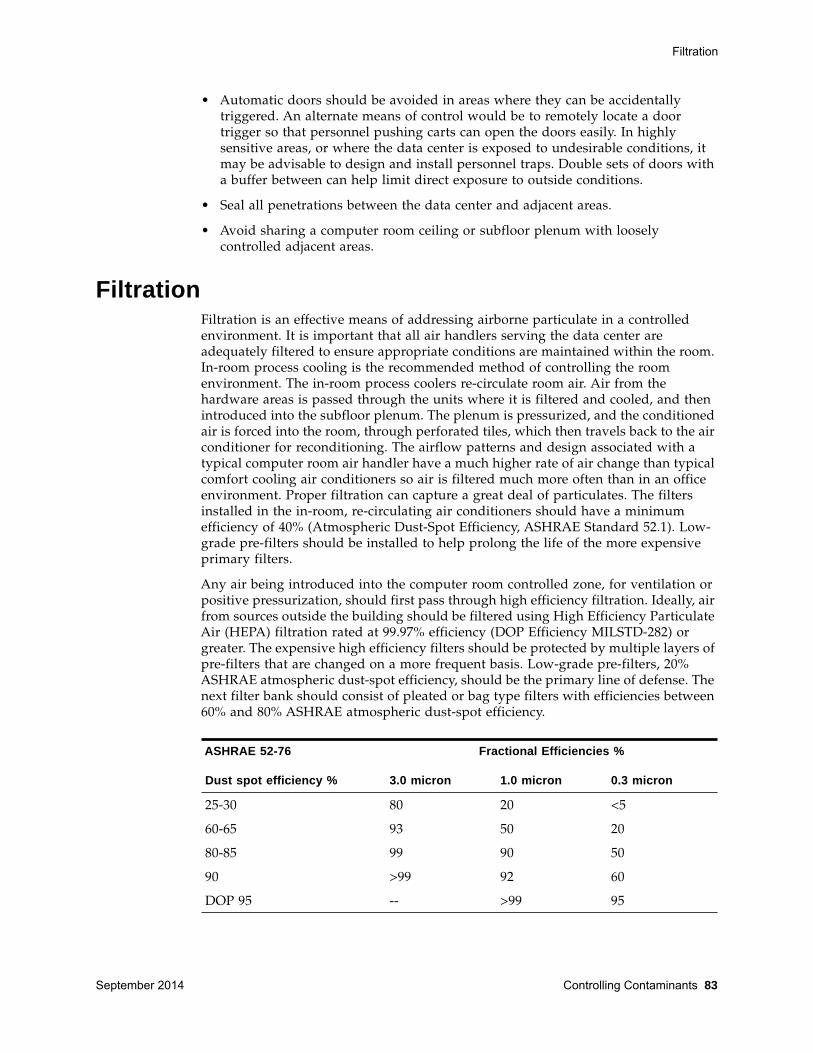
Filtration
September 2014 Controlling Contaminants 83
• Automatic doors should be avoided in areas where they can be accidentallytriggered. An alternate means of control would be to remotely locate a doortrigger so that personnel pushing carts can open the doors easily. In highlysensitive areas, or where the data center is exposed to undesirable conditions, itmay be advisable to design and install personnel traps. Double sets of doors witha buffer between can help limit direct exposure to outside conditions.
• Seal all penetrations between the data center and adjacent areas.
• Avoid sharing a computer room ceiling or subfloor plenum with looselycontrolled adjacent areas.
FiltrationFiltration is an effective means of addressing airborne particulate in a controlledenvironment. It is important that all air handlers serving the data center areadequately filtered to ensure appropriate conditions are maintained within the room.In-room process cooling is the recommended method of controlling the roomenvironment. The in-room process coolers re-circulate room air. Air from thehardware areas is passed through the units where it is filtered and cooled, and thenintroduced into the subfloor plenum. The plenum is pressurized, and the conditionedair is forced into the room, through perforated tiles, which then travels back to the airconditioner for reconditioning. The airflow patterns and design associated with atypical computer room air handler have a much higher rate of air change than typicalcomfort cooling air conditioners so air is filtered much more often than in an officeenvironment. Proper filtration can capture a great deal of particulates. The filtersinstalled in the in-room, re-circulating air conditioners should have a minimumefficiency of 40% (Atmospheric Dust-Spot Efficiency, ASHRAE Standard 52.1). Low-grade pre-filters should be installed to help prolong the life of the more expensiveprimary filters.
Any air being introduced into the computer room controlled zone, for ventilation orpositive pressurization, should first pass through high efficiency filtration. Ideally, airfrom sources outside the building should be filtered using High Efficiency ParticulateAir (HEPA) filtration rated at 99.97% efficiency (DOP Efficiency MILSTD-282) orgreater. The expensive high efficiency filters should be protected by multiple layers ofpre-filters that are changed on a more frequent basis. Low-grade pre-filters, 20%ASHRAE atmospheric dust-spot efficiency, should be the primary line of defense. Thenext filter bank should consist of pleated or bag type filters with efficiencies between60% and 80% ASHRAE atmospheric dust-spot efficiency.
ASHRAE 52-76
Dust spot efficiency %
Fractional Efficiencies %
3.0 micron 1.0 micron 0.3 micron
25-30 80 20 <5
60-65 93 50 20
80-85 99 90 50
90 >99 92 60
DOP 95 -- >99 95
Positive Pressurization and Ventilation
84 T9x40 SAG September 2014
Low efficiency filters are almost totally ineffective at removing sub-micronparticulates from the air. It is also important that the filters used are properly sizedfor the air handlers. Gaps around the filter panels can allow air to bypass the filter asit passes through the air conditioner. Any gaps or openings should be filled usingappropriate materials, such as stainless steel panels or custom filter assemblies.
Positive Pressurization and VentilationA designed introduction of air from outside the computer room system will benecessary to accommodate positive pressurization and ventilation requirements. Thedata center should be designed to achieve positive pressurization in relation to moreloosely controlled surrounding areas. Positive pressurization of the more sensitiveareas is an effective means of controlling contaminant infiltration through any minorbreaches in the room perimeter. Positive pressure systems are designed to applyoutward air forces to doorways and other access points within the data processingcenter to minimize contaminant infiltration of the computer room. Only a minimalamount of air should be introduced into the controlled environment. In data centerswith multiple rooms, the most sensitive areas should be the most highly pressurized.It is, however, extremely important that the air being used to positively pressurizethe room does not adversely affect the environmental conditions in the room. It isessential that any air introduction from outside the computer room is adequatelyfiltered and conditioned to ensure that it is within acceptable parameters. Theseparameters can be looser than the goal conditions for the room since the airintroduction should be minimal. A precise determination of acceptable limits shouldbe based on the amount of air being introduced and the potential impact on theenvironment of the data center.
Because a closed-loop, re-circulating air conditioning system is used in most datacenters, it will be necessary to introduce a minimal amount of air to meet theventilation requirements of the room occupants. Data center areas normally have avery low human population density; thus the air required for ventilation will beminimal. In most cases, the air needed to achieve positive pressurization will likelyexceed that needed to accommodate the room occupants. Normally, outside airquantities of less than 5% make-up air should be sufficient (ASHRAE Handbook:Applications, Chapter 17). A volume of 15 CFM outside air per occupant orworkstation should sufficiently accommodate the ventilation needs of the room.
Cleaning Procedures and EquipmentEven a perfectly designed data center requires continued maintenance. Data centerscontaining design flaws or compromises may require extensive efforts to maintainconditions within desired limits. Hardware performance is an important factorcontributing to the need for a high level of cleanliness in the data center.
Operator awareness is another consideration. Maintaining a fairly high level ofcleanliness will raise the level of occupant awareness with respect to specialrequirements and restrictions while in the data center. Occupants or visitors to thedata center will hold the controlled environment in high regard and are more likelyto act appropriately. Any environment that is maintained to a fairly high level ofcleanliness and is kept in a neat and well organized fashion will also commandrespect from the room’s inhabitants and visitors. When potential clients visit theroom they will interpret the overall appearance of the room as a reflection of an

Cleaning Procedures and Equipment
September 2014 Controlling Contaminants 85
overall commitment to excellence and quality. An effective cleaning schedule mustconsist of specially designed short-term and long-term actions. These can besummarized as follows:
Daily TasksThis statement of work focuses on the removal of each day’s discarded trash andrubbish from the room. In addition, daily floor vacuuming may be required in PrintRooms or rooms with a considerable amount of operator activity.
Weekly TasksThis statement of work focuses on the maintenance of the access floor system. Duringthe week, the access floor becomes soiled with dust accumulations and blemishes.The entire access floor should be vacuumed and damp mopped. All vacuums used inthe data center, for any purpose, should be equipped with High Efficiency ParticulateAir (HEPA) filtration. Inadequately filtered equipment cannot arrest smaller particles,but rather simply agitates them, degrading the environment they were meant toimprove. It is also important that mop-heads and dust wipes are of appropriate non-shedding designs.
Cleaning solutions used within the data center must not pose a threat to thehardware. Solutions that could potentially damage hardware include products thatare:
• Ammoniated
• Chlorine-based
• Phosphate-based
• Bleach enriched
• Petro-chemical based
• Floor strippers or re-conditioners
It is also important that the recommended concentrations are used, as even anappropriate agent in an inappropriate concentration can be potentially damaging.The solution should be maintained in good condition throughout the project, andexcessive applications should be avoided.
Frequency Task
Daily Actions Rubbish removal
Weekly Actions Access floor maintenance (vacuum and damp mop)
Quarterly Actions Hardware decontamination
Room surface decontamination
Bi-Annual Actions Subfloor void decontamination
Air conditioner decontamination (as necessary)
Cleaning Procedures and Equipment
86 T9x40 SAG September 2014
Quarterly TasksThe quarterly statement of work involves a much more detailed and comprehensivedecontamination schedule and should only be conducted by experienced computerroom contamination-control professionals. These actions should be performed threeto four times per year, based on the levels of activity and contamination present. Allroom surfaces should be thoroughly decontaminated including cupboards, ledges,racks, shelves and support equipment. High ledges and light fixtures and generallyaccessible areas should be treated or vacuumed as appropriate. Vertical surfacesincluding windows, glass partitions, doors, etc. should be thoroughly treated. Specialdust cloths that are impregnated with a particle absorbent material are to be used inthe surface decontamination process. Do not use generic dust rags or fabric cloths toperform these activities. Do not use any chemicals, waxes or solvents during theseactivities.
Settled contamination should be removed from all exterior hardware surfacesincluding horizontal and vertical surfaces. The unit’s air inlet and outlet grillesshould be treated as well. Do not wipe the unit’s control surfaces as these areas canbe decontaminated by the use of lightly compressed air. Special care should also betaken when cleaning keyboards and life-safety controls. Specially treated dust wipesshould be used to treat all hardware surfaces. Monitors should be treated with opticalcleansers and static-free cloths. No Electro-Static Discharge (ESD) dissipativechemicals should be used on the computer hardware, since these agents are causticand harmful to most sensitive hardware. The computer hardware is sufficientlydesigned to permit electrostatic dissipation thus no further treatments are required.After all of the hardware and room surfaces have been thoroughly decontaminated,the access floor should be HEPA vacuumed and damp mopped as detailed in theWeekly Actions.
Biennial TasksThe subfloor void should be decontaminated every 18 months to 24 months based onthe conditions of the plenum surfaces and the degree of contaminant accumulation.Over the course of the year, the subfloor void undergoes a considerable amount ofactivity that creates new contamination accumulations. Although the weekly abovefloor cleaning activities will greatly reduce the subfloor dust accumulations, a certainamount of surface dirt will migrate into the subfloor void. It is important to maintainthe subfloor to a high degree of cleanliness since this area acts as the hardware’ssupply air plenum. It is best to perform the subfloor decontamination treatment in ashort time frame to reduce cross contamination. The personnel performing thisoperation should be fully trained to assess cable connectivity and priority. Eachexposed area of the subfloor void should be individually inspected and assessed forpossible cable handling and movement. All twist-in and plug-in connections shouldbe checked and fully engaged before cable movement. All subfloor activities must beconducted with proper consideration for air distribution and floor loading. In aneffort to maintain access floor integrity and proper psychrometric conditions, thenumber of floor tiles removed from the floor system should be carefully managed. Inmost cases, each work crew should have no more than 24 square feet (six tiles) ofopen access flooring at any one time. The access floor’s supporting grid systemshould also be thoroughly decontaminated, first by vacuuming the loose debris andthen by damp-sponging the accumulated residue. Rubber gaskets, if present, as themetal framework that makes up the grid system should be removed from the grid
Activity and Processes
September 2014 Controlling Contaminants 87
work and cleaned with a damp sponge as well. Any unusual conditions, such asdamaged floor suspension, floor tiles, cables and surfaces, within the floor voidshould be noted and reported.
Activity and ProcessesIsolation of the data center is an integral factor in maintaining appropriateconditions. All unnecessary activity should be avoided in the data center, and accessshould be limited to necessary personnel only. Periodic activity, such as tours, shouldbe limited, and traffic should be restricted to away from the hardware so as to avoidaccidental contact. All personnel working in the room, including temporaryemployees and janitorial personnel, should be trained in the most basic sensitivitiesof the hardware so as to avoid unnecessary exposure. The controlled areas of the datacenter should be thoroughly isolated from contaminant producing activities. Ideally,print rooms, check sorting rooms, command centers or other areas with high levels ofmechanical or human activity should have no direct exposure to the data center.Paths to and from these areas should not necessitate traffic through the main datacenter areas.

Activity and Processes
88 T9x40 SAG September 2014
September 2014 Glossary 89
Glossary
This glossary defines new or special terms and abbreviations used in this guide. Fordefinitions about other 9840/T9840/T9940 drive subsystem terms, or terms aboutother StorageTek products, refer to the glossary in the appropriate manuals.
Many of the definitions are taken from the IBM Dictionary of Computing. Thefollowing letters in parentheses following the definition indicate the source of thedefinition:
(A): The American National Standard Dictionary for Information Systems, ANSI X3.172-1990, copyright 1990 by the American National Standards Institute (ANSI).
(E): the ANSI/Electronic Industries Association (EIA) Standard-440-A, Fiber OpticTerminology.
(I): the Information Technology Vocabulary, developed by Subcommittee 1, JointTechnical Committee 1, of the International Organization for Standardization andInternational Electrotechnical Commission (ISO/IEC/JTC1/SC1).
(IBM): The IBM Dictionary of Computing, copyright 1994.
(T): international standards committee drafts, and working papers being developedby the ISO/IEC/JTC1/SC1.
Aaccess timeThe mean time in seconds from the load ready position to a distance beingapproximately half way from COT (center of tape) to either EOT (end of tape).
ACSLSSee automated cartridge system library software.
adapterHardware used to join different connector types.
ANSIAmerican National Standards Institute.
Arbitrated Loop One topology used in Fibre Channel that provides multiple connections for devicesthat share a single loop, over which only two devices can communicate at once.
90 T9x40 SAG September 2014
Arbitrated Loop Physical Address (AL_PA)A one-byte value that identifies a port in an arbitrated loop topology.
Automated Cartridge System Library Software (ACSLS)UNIX-based software that allows multiple computing platforms to access a Nearlineautomated cartridge system (ACS).
BBit(1) A unit of information equal to a 1 or a 0. (2) Either of the digits 0 or 1 when usedin the binary numeration system. (T)
British thermal unit (Btu)A standard measure of a device’s heat output. The amount of heat required to raiseone pound of water one degree Fahrenheit.
BtuSee British thermal unit.
Byte(1) A string that consists of a number of bits, treated as a unit, and representing acharacter. (T) (2) A number of bits, treated as a unit, and representing a character.
CCalorieThe amount of heat required to raise one kilogram of water one degree Celsius. Equalto 3.968 Btu.
cartridgeA storage device that consists of magnetic tape on supply and take up reels, in aprotective housing. (IBM).
Cartridge Scratch Loader (CSL)In the 9840 tape drive, a device attached to the 9840 drive which automatically feedscartridges to the drive. Cartridges are manually placed in an input bin, and after use,are deposited automatically in an output bin.
cleaning cartridgeA cartridge containing special material used to clean the tape path in a transport.
Client System Component (CSC)Software that provides an interface between the client computing system’s operatingsystem and the StorageTek library software, such as ACSLS, HSC, or LibraryStation.
connectorAn electrical part used to join two or more other electrical parts. (IBM)
CSCSee Client System Component.
CSESee Customer Services Engineer.
CSLSee Cartridge Scratch Loader.
September 2014 Glossary 91
Customer Services Engineer (CSE)An employee trained to install, maintain, and repair StorageTek equipment.
configurationThe manner in which the hardware and software of an information processing systemare organized and interconnected. (T)
Ddaisy chainA method of device interconnection for determining interrupt priority by connectingthe interrupt sources serially.
data migrationThe orderly movement of data from one storage medium to another.
differentialA SCSI bus alternative with a maximum cable length of 25 meters (82 feet).
EEnterprise Systems Connection (ESCON)A set of IBM products and services that provide a dynamically-connectedenvironment within an enterprise. (IBM)
environmental requirementAny of the physical conditions required for the protection and proper operation of afunctional unit; the requirement is usually specified as a nominal value and atolerance range. For a device, there may be more than one set of environmentalrequirements; for example, one set for transport, another for storage, and another foroperation. (T) (A)
equipment rackA free-standing cabinet or framework that holds electronic equipment.
ESCONSee Enterprise Systems Connection.
FfabricThe FC topology that is similar to a telephone switch in that the initiator of a “call” tothe receiving port simply provides the receiver with the port address, and the fabricroutes the transmission to the proper port. A fabric differs from a point-to-point orarbitrated loop topology in that it provides for interconnections between portswithout having a point-to-point connection. The fabric also serves as a media typeconverter.
FCSee Fibre Channel

92 T9x40 SAG September 2014
FIBFormat identifier block. A FIB is required to identify tapes written by a T9840C orT9840D tape drive. The T9840C has a unique FIB, and the T9840D has a unique FIB.Earlier generation drives detect the FIB (T9840A/B identify the FIB for tapes writtenby either a T9840C or T9840D while the T9840C detects the FIB for tapes written by aT9840D).
fiber opticsThe branch of optical technology concerned with the transmission of radiant powerthrough fibers made of transparent materials such as glass, fused silica, and plastic.(E)
Fibre Channel (FC)The ANSI standard that defines an ultra high-speed, content independent, multi-leveldata transmission interface that can support multiple protocols simultaneously,support connectivity to millions of devices over copper and/or fiber optic physicalmedia, and provides the best characteristics of both networks and channels, overdiverse topologies.
Fibre Connection (FICON)An ESA/390 and zSeries computer peripheral interface. The I/O interface uses ESA/390 and zSeries FICON protocols (FC-FS and FC-SB-2) over a Fibre Channel serialinterface that configures units attached to a FICON supported Fibre Channelcommunications fabric.
FICONSee Fibre Connection.
field replaceable unit (FRU)An assembly that is replaced in its entirety when any of its components fails. (IBM)
firmwareAn ordered set of instructions and data stored in a way that is functionallyindependent of main storage; for example, microprograms stored in a ROM. (T)
FRUSee field replaceable unit.
frameA cabinet that holds an array of tape drives for attachment to a library.
GGBSee Gigabyte.
GbGigabit, equal to 109 bits.
GBICSee Gigabit Interface Converter
gigabit (Gb)One billion (109) bits.
Gigabit Interface Converter (GBIC)An adapter that connects a fiber-optic or copper-wire cable to a Fibre Channel hub orswitch.
September 2014 Glossary 93
gigabyte (GB)One billion (109) bytes when referring to disk and tape capacity. When referring tomemory capacity, one gigabyte equals 1,073,741,824 in decimal notation.
HhardwareAll or part of the physical components of an information processing system, such ascomputers or peripheral devices. (T) (A)
HBASee host bus adaptor
hostThe primary computer on a network, with which other computers interact.
host bus adapter (HBA)A circuit installed in a multi-platform host or device that interfaces between thedevice and the bus.
host interfaceInterface between a network and host computer. (T)
Host Software Component (HSC)The StorageTek software that provides client volume location information through itsControl Data Set (CDS) and provides the interface to the Nearline ACS hardware andclient operator console.
HSCSee Host Software Component
hubA piece of hardware, separate from the actual FC interface accessible on thebackplane of a device, which houses the port bypass circuitry for configurations of 8to 16 ports per hub. Hubs may be cascaded to support larger configurations, and canusually support a mix of both electrical and optical media ports in the same hub.
IIBMInternational Business Machines, Inc.
IDIdentifier or identification.
interfaceHardware, software, or both, that links systems, programs, or devices. (IBM)
Internet Protocol (IP)A protocol used to route data from its source to its destination in a internetenvironment. (IBM)
Internet Protocol (IP) v4 addressA four-byte value that identifies a device and makes it accessible through a network.The format of an IPv4 address is a 32-bit numeric value written as four numbersseparated by periods. Each number can be from 0 to 255. For example, 129.80.145.23.
94 T9x40 SAG September 2014
Internet Protocol (IP) v6 addressThe next generation Internet protocol. It provides a much larger address space thenIPv4. This is based upon the definition of a 128-bit address - IPv4 used a 32-bitaddress. The format of an IPv6 address is eight fields of four hexadecimal charactersseparated by colons (for example: 2001:0db8:85a3:0000:0000:8a2e:0370:7334).
LLCUSee library control unit.
library(1) A library is composed of one or more automated cartridge systems (ACSs),attached transports (such as cartridge drives or controller transport units), volumesplaced into the ACSs, host software that controls and manages the ACSs andassociated volumes, and the library control data sets that describe the state of theACSs. (2) A robotic system that stores, moves, mounts, and dismounts cartridges thatare used in data read or write operations. (3) A hardware component in a tapeautomation system.
library control unit (LCU)The portion of an automated library that controls the choosing, mounting,dismounting, and replacing of cartridges.
library management unit (LMU)The portion of an automated cartridge system that controls the library storagemodule and communicates with the Host Software Component.
LibraryStationSoftware that allows an MVS system to be used as a library control server.
library storage module (LSM)A housing that contains cartridges and a robot that moves the tapes between storagecells and the attached transports. Synonymous with tape library.
LMUSee library management unit.
load timeThe time from when a cartridge is first put into the loader and the instruction is givento load the cartridge to when the drive becomes ready. This includes the lowering ofthe elevator, engaging the tape and read/write head, successfully reading of the MIR,successfully read of the FIB (if needed), and then moving the tape to the nearestlocation of where first data would normally be located on tape.
long waveFiber optics transmission using 1310 nm wavelength laser.
LSMSee library storage module.
Mmegabyte (MB)Megabytes or 1,000,000 bytes for disk or tape storage, but 1,048,576 (220) bytes ofmemory capacity.

September 2014 Glossary 95
migrationSee data migration.
multimodeAn optical fiber designed to carry multiple signals, distinguished by frequency orphase, at the same time.
Multiple Virtual Storage (MVS)IBM's Multiple Virtual Storage, consisting of MVS/System Product Version 1 and theMVS/370 Data Facility Product operating on a System/370 processor. (IBM)
MVSSee Multiple Virtual Storage
NNCSSee Nearline Control Solution.
NearlineA registered trademark, this term is used in association with the StorageTek family oftape-library information storage and retrieval products.
Nearline Control Solution (NCS)An MVS-based Nearline software product that supports multiple MVS imagessharing a library complex.
Ooperating systemSoftware that controls the execution of program and that may provide services suchas resource allocation, scheduling, input/output control, and data management.Although operating systems are predominately software, partial hardwareimplementations are possible. (T)
RrackSee equipment rack.
Removable Media Library Software (RMLS)StorageTek software that runs on each iSeries host or LPAR, and provides roboticcontrol via ACSLS to StorageTek libraries.
RMLSSee Removable Media Library Software.
SSCSISee small computer system interface.
Shared Services CenterA StorageTek office that processes orders.
96 T9x40 SAG September 2014
short waveiber optics transmission using 850 nm wavelength laser.
single modeFiber with a relatively narrow diameter, through which only one mode willcommunicate. Single mode fiber carries higher bandwidth than multimode fiber, butrequires a light source with a narrow spectral width.
small computer system interface (SCSI)An ANSI standard for controlling peripheral devices by one or more hosts.
softwareAll or part of the programs, procedures, rules, and associated documentation of adata processing system. Software is an intellectual creation that is independent of themedium on which it is recorded. (T)
StorageTek SL8500 Modular Library SystemAn automated tape library comprised of:
• Customer interface module
• Robotics interface module
• Drive and electronics module
• Storage expansion module (optional)
switch(1) A device or programming technique for making a selection; for example, a toggle,a conditional jump. (A) (2) In Fibre Channel technology, a device that connects FibreChannel devices together in a fabric.
Systems AssuranceThe exchange of information among product-installation team members to promotean error-free installation and contribute to customer satisfaction.
Ttape driveA device for moving magnetic tape and controlling its movement. (T)
VVOLSER See volume serial number.
volume serial numberA number in a volume label assigned when a volume is prepared for use in a system.(IBM)
September 2014 Index 1
Index
A
access and administrative issues 44ACSLS software configuration worksheet 39address, IPv6 14air quality 77airborne contamination 65
B
bridge, FC 24
C
cable order worksheetESCON 52multimode FC (Type SC, 1-Gb) 56multimode FC/FICON (LC, short wave) 56single mode FC/FICON (LC, long wave) 55
cartridge scratch loader. See CSLchecklists
access and administrative issues 44predelivery 41receiving dock information 43
cleaningcartridge
T9840A/B/C 24, 60T9840D 24, 60
data center 84cleanliness of data center 65client processor team members 34configuration
desktop, T9840A/B 19host software 37library-attached 17rack mount 20
contaminants, controlling 77contamination, airborne 65conversion bills
listing 57T9x40 (ROHS compliant) 57
CPUhardware vendor contacts 34software vendor contacts 34
CSLdescription 20desktop 19rack mount 20
customer contact sheet 33
D
data center cleaning procedures 84data center cleanliness 65desktop configuration
physical specifications 67T9840A/B 19
dust 65
E
Enterprise Systems Connection. See ESCONenvironmental
contaminants 77environmental requirements
airborne contamination 65tape cartridge
T9840 66T9940 75
tape drive and power supplyT9840 65T9940 74
equipment rack description 20ESCON
cables worksheet 52interface 21
F
FCbridge 24hub 22interface 22switch 22
Fibre Channel. See FCFICON
hardware configuration definition 23interface 22
2 T9x40 SAG September 2014
filtration 83FIPS Level 2 13firmware requirements for library 37
H
hardwareconfiguration definition 23ordering 45, 50
HCD 23hub, FC 22
I
interfaceESCON 21FC 22FICON 22SCSI 24
IPv6 address 14
L
labelsdescription 24ordering 60
libraryattachment
T9840 69T9940 76
configuration/attached 17drive physical specifications
T9840 66T9940 70
firmware requirements 37trays 17
M
manual-load drivesT9840A 20T9940 20
media, ordering 60microcode. See firmwaremixed data density, management 27mixed emulation image, management 28mixed-media management
mixed data density 27mixed emulation image 28
multimode cable order worksheetFC (Type SC, 1-Gb) 56FC/FICON (LC, short wave) 56
N
NCS software configuration worksheet 38
O
operating systems supported by T9x40 37Oracle team member contact sheet 35ordering
hardware 45, 50overview of T9x40 tape drives 13
P
partner contact sheet 35performance specifications 72physical specifications
T9840 66T9940 70
powercords, description of 21specifications
T9840 62T9940 71
predelivery checklist 41product overview 13publications, related to
T9840 drives 69T9940 drives 76
R
rack mountconfiguration 20physical specifications
T9840 68T9940 70
read, VolSafe 15receiving dock information 43related publications 69, 76RMLS software configuration worksheet 39
S
scratch loader. See CSLSCSI overview 24single mode FC/FICON (LC, long wave) cables
order worksheet 55small computer system interface. See SCSI overviewsoftware
host configuration 37supported by T9x40 37
specificationsperformance 63, 64
tape cartridge 73
September 2014 Index 3
tape drive 72T9840
physical 66, 67, 68power 62
T9940physical 70power 71
switch, FC 22system assurance
customer contact sheet 33Oracle team member contact sheet 35
T
T9840 tape drivecleaning cartridge 60description 13FICON hardware configuration definition 23specifications 61VolSafe cartridge 60VolSafe cartridge identification 25VolSafe compatibility 16
T9840A CSL 19T9840D
cleaning cartridge 24, 60VolSafe cartridge 60
T9940 tape drivedescription 14FICON hardware configuration definition 23specifications 70VolSafe cartridge identification 27VolSafe compatibility 16VolSafe description 15
tape cartridgecleaning 24environmental requirements
T9840 66T9940 75
labels 24ordering 60
performance specifications 64, 73VolSafe 24
tape driveenvironmental requirements
T9840 65T9940 74
performance specifications 63, 72physical specifications
T9840 66T9940 70
trays 17
V
VolSafeabout 15data cartridge
9840 25drive compatibility 16ordering 60T9840D 25T9940B 27, 60
media identification9840 259940 27
summary, cartridge 60
W
worksheets, cable orderESCON 52multimode
FC (Type SC, 1-Gb) 56FC/FICON (LC, short wave) 56
single mode FC/FICON (LC, long wave) 55worksheets, software configuration
ACSLS 39NCS 38RMLS 39
write, VolSafe 15

4 T9x40 SAG September 2014