storm drainage design standards
TRANSCRIPT
CITY OF TALENT
STORM DRAINAGE DESIGN STANDARDS
Section I. GENERAL PROVISIONS
A. Purpose and Applicability
The purpose of these Stormwater Management Design Standards (hereinafter, the “Standards”) is to provide a consistent policy direction for physical improvements necessary for stormwater management. These Standards shall govern all construction and upgrading of all public and private drainage facilities in the City of Talent and any other applicable work in its service areas.
These standards cannot be expected to provide for all possible situations. They are intended to assist, but not be substituted for the competent work of system design professionals. These standards are also not intended to place unreasonable limitations on any innovative or creative effort, which could result in better quality facilities, cost savings, or both. Any proposed departure from the standards will be considered if it is demonstrated that the approach will produce a compensating or comparable result, to the benefit of both the City and the system user.
The objective is a stormwater management system that will:
1) Be consistent with all other city codes and land use plans and policies;
2) Be of adequate design to safely manage all volumes of water generated upstream and on the site to an approved point of disposal;
3) Provide points of disposal for stormwater generated by future development upstream;
4) Prevent the uncontrolled or irresponsible discharge of stormwater onto adjoining public or private property;
5) Prevent the capacity of downstream channels and storm drainage facilities from being exceeded;
6) Have sufficient structural strength to resist erosion and all external loads that may be imposed;
7) Maintain the runoff characteristics of the original undeveloped drainage basin, where feasible, as determined by the Public Works Director;
8) Maximize efficient use of Talent’s natural drainage system including streams, seasonal draws and wetlands;
9) Maintain the highest feasible level of water quality;
City of Talent Storm Drainage Design Standards Res. No. 517 (1998)
10) Be designed in a manner that allows economical ongoing maintenance; and
11) Be designed using materials that ensure a minimum practical design life of fifty years.
B. Interpretation of Terms and Definitions
Interpretation of Terms: Wherever the following terms or similar ones are used in these standards; directed, required, permitted, or ordered are used, they shall be understood to mean the direction, requirement, permission, or order of the Public Works Director. Where qualitative terms such as “important”, major, or minor are used, they shall be understood to be based upon the judgement of the Director. Similarly, the words approved, acceptable, or satisfactory shall be understood to mean approved, acceptable, or satisfactory to the Director.
Definitions:
Backwater Curve - A plot of the water surface elevation along a channel that reflects the effects of physical constrictions.
Building Storm Drain - A building storm drain is that part of the piping of a stormwater drainage system that begins at the connection to the building drain at a point five (5) feet outside the established line of the building or structure, and that conveys stormwater to the approved point of disposal.
Catchbasin - A structure that captures surface runoff and discharges it into an underground storm drain pipe system. Catchbasins shall be constructed to City Standard Details, and in accordance with the City Encroachment Permit Resolution (Res. No. 98-511-R).
Cleanout - A structure to allow access to a storm drain for cleaning. Cleanouts are required every 100 feet in private storm drain systems. In public systems they are typically located at a catchbasin at the end of each line.
Creek - Any and all surface water routes generally consisting of a channel having a bed, banks, and/or sides in which surface waters flow from the drainage of higher to lower ground, whether perennial or intermittent, but excluding flows that do not persist for more than twenty-four (24) hours after cessation of a one-half (½) inch rainfall within a 24 hour period, October through March.
Curb and Gutter - A concrete surface facility that directs runoff into catchbasins of curb inlets. Curb and gutter shall be constructed to City Standard Details, and in accordance with the City Encroachment Permit Resolution (Res. No. 98-511-R).
Cut Sheets - Sheets of tabulated data that indicates stationings, structures, fittings, angle points, the beginning points of curves, points on curves, end points of curves, storm drain slope, staking offsets, various elevations, offset cuts and storm drain depths.
Page 2
City of Talent Storm Drainage Design Standards Res. No. 517 (1998)
Design Storm - The high water level for the frequency storm that a particular system or system component must be designed to carry. To determine which frequency storm is to be used in a particular situation, refer to the applicable section in these regulations.
Detention Facilities - The holding of runoff for a short period of time and then releasing it at a controlled rate into the area storm drain system. Note the relation to “Retention Facilities”, below.
Development - For the purposes of these regulations, “development” means any construction project, including any commercial, industrial, institutional, and single-or multi-family project or the development of a private road, that creates new impervious surfaces that total three thousand square feet or more.
Director - The Public Works Director of the City of Talent or an authorized representative.
Drainage Facilities - Pipes ditches, detention basins, creeks, culvert bridges, etc., used singularly or in combination with each other for the purpose of conveying or storing runoff.
Drainage Master Plan - A document adopted by the City of Talent that describes the existing and planned storm drainage system. The planned drainage system is based on projected runoff based upon full buildout of the city as planned in the adopted Comprehensive Plan.
Easement - An area along the line of any public storm drain (or other utility line) that is located outside of an existing dedicated storm drain easement, road easements or right-of-way, and that allows practical access to the facility for maintenance and other necessary work related to the facility. Easements shall be established according to state and local law and shall be recorded with the County Clerk.
Floodplain - Any area of land subject to inundation by water from any source; particularly any area designated as being within the floodway or one-hundred year flood boundary in the most recent available data of the National Flood Insurance Program.
Floodway - The channel of a creek or other watercourse and the adjacent areas that must be reserved in order to discharge a one-hundred year flood without cumulatively increasing the water surface elevation more than one foot.
Freeboard - The distance between the predicted water surface elevation for a given storm and the top of a bank, levee, or other structure. Freeboard is provided as a margin of safety, providing some adjustment for the effects of sediment deposition, debris and other variables on actual high water elevations.
French Drain - A covered trench that has been excavated and filled with washed gravel around a perforated delivery pipe installed to receive stormwater. A French Drain is only effective where the soil where it is installed is porous enough to permit
Page 3
City of Talent Storm Drainage Design Standards Res. No. 517 (1998)
the stormwater to seep into the ground, and is generally not allowed unless connection to the public stormwater drainage system is not possible.
Grade - Grade or Slope is the vertical change in elevation divided by the horizontal distance between the same two points. Slope is usually expressed in feet per foot (rise over run). Grade is often expressed as a percentage (rise divided by run X 100).
Impervious Surface Area - Areas of land that do not absorb or resist absorption of rainwater or runoff. Under normal conditions, soil and gravel areas on undeveloped land absorb a significant amount of surface water, mitigating runoff effects on downhill properties. Impervious surface areas created by development include but are not limited to roofs, concrete and asphalt sidewalks, patios, driveways, parking lots and compacted, graveled, oiled, macadam and other prepared surfaces.
Invert - The bottom or flow line of a channel, pipe, or manhole.
Leach Line - Same as “French Drain”, above.
Natural Location - The location of those channels, swales and other water conveyance systems existing prior to human development and as indicated on the earliest available documented topographic contours or other reliable information such as maps or photographs.
On-Site Detention - Storage of excess runoff on a development site prior to its entry into the public storm drain system and gradual release of the stored runoff after the peak of the runoff event has passed.
Owner - An individual, partnership, firm, or corporation shown as the landowner of record in the most recent tax rolls or deed records of Jackson County, or who is purchasing land under written contract.
Peak Discharge - The maximum water runoff rate (cfs) determined for the design storm.
Plans - Construction plans, including system site plans, storm drain plans and profiles, cross sections, detailed drawings, etc., or reproduction thereof, showing the location, character, dimensions, and details for the work proposed, and approved or to be approved by the Director and/or City Engineer. When approved such plans become a supplement to these standards.
Private Storm Drain - A storm drain that is located on private property, that serves more than one structure on a premises and/or parking lot catch basins, and that is not maintained by the City of Talent.
Project Engineer - The Oregon Licensed Civil Engineer under whose direction plans, profiles and details for work are prepared and submitted to the City for review and approval. For public projects the project engineer will be the City Engineer or other consulting engineer contracted by the City.
Page 4

City of Talent Storm Drainage Design Standards Res. No. 517 (1998)
Public Storm Drain - Any storm drain in a public right-of-way or easement that is operated and maintained by the City.
Receiving Body of Water - A creek, stream, lake or other body of water into which surface runoff is artificially or naturally discharged.
Release Rate - The controlled rate of release of drainage, storm and runoff water from property, storage pond, runoff detention pond, or other facility during and following a storm event.
Retention Facilities - Facilities designed to or that do hold water for a considerable period of time, with the intention that the water will be dissipated by evaporation, plant transpiration and/or infiltration into the soil. Note the relation to “Detention Facilities”, above.
Right-of-Way - Any land or interest therein that is reserved for or dedicated to the use of the public by deed, conveyance, agreement, easement, dedication, usage or process of law, and within which the City shall have the right to install and maintain storm drains and other necessary facilities.
Sedimentation - The deposition of soil, other mineral materials and debris carried by stormwater runoff and deposited at a lower elevation as a result of slack water or the withdrawal of flood waters.
Silt - Fine textured soil particles including clay, colloidal materials and sand, as differentiated from coarse sand and gravel.
Siltation - 1) The deposition of waterborne silt and 2) the smoothing or cementing effect of the deposition of silt over sand and gravel beds when the transporting water evaporates.
Slope - Expressed as a horizontal measure over a vertical measure.
Spring Line - The centerline of a pipe.
Standard Details, Standard Drawing, Standard Construction Specifications - The drawings and specifications for structures and facilities commonly used for City projects, and so specified on the plans.
Page 5
City of Talent Storm Drainage Design Standards Res. No. 517 (1998)
Standard, Standards - When capitalized, Standard(s) means the entire body of standards in these regulations. When not capitalized, standard(s) means the standard in the subject subsection unless the context indicates otherwise.
Street or Road - Any public highway, road, street, avenue, alley, way, easement, or right-of-way used or to be used for vehicle movement.
Structure - As used in these regulations, structure includes a structure or device such as a catch basin or manhole.. Detailed drawings of structures and devices commonly used in City projects are included in Standard Construction Specifications.
Subdivision - 1) The action of dividing a parcel of land into four or more lots in a single application; and 2) The resulting group of lots.
Terrace - A relatively level step constructed or excavated into the face of a grade surface intended to improve drainage and/or control erosion.
Top of Bank - The point where the slope of the bank intersects the horizontal plane of the surrounding land. For design purposes, this will include, at a minimum, the area inundated by the design storm.
Tributary Area - The total area that contributes runoff to a given point of discharge.
Trunk Drainage System - A portion of the drainage system of the City that receives water from an adjacent land area of twenty (20) or more acres. A trunk drainage system is the primary drainage system for an area as designated on any adopted Stormwater Management Plan map, and may include natural drainage courses and manmade facilities such as pipes, ditches and culverts.
Waterway - An open channel that conveys water.
Wetland - An area subject to periodic or perennial inundation and containing wetland characteristics including hydric soils and plants, as defined in the Oregon Division of State Lands standard wetland delineation methodology. For purposes of these regulations, wetland shall mean any wetland included in the adopted Wetland and Riparian Area inventory and other areas that meet the state definition of wetland but that were too small (less than one half acre) to be included in the inventory.
C. Engineering Policy
It is the policy of the City of Talent to require strict compliance with Oregon Revised Statute Chapter 672. All engineering plans, documents or reports shall be prepared by a registered professional Civil Engineer, or by a subordinate employee under his/her direction, and shall be signed by the engineer and stamped with his/her seal to indicate his/her responsibility for them. It shall be the project engineer’s responsibility to review any proposed design work, to determine any special requirements and to determine whether the proposal is permissible. City approval of a preliminary plan or approval for construction does not in any way relieve or diminish the responsibility of the project engineer to satisfy all city requirements and to protect the life, health and property of the public. The Plan for any job shall be revised or
Page 6
City of Talent Storm Drainage Design Standards Res. No. 517 (1998)
supplemented at any time it is determined that the full requirements of the City have not been met.
D. Approval of Alternative Materials or Methods
An alternative material or method not explicitly approved herein will be considered for approval on the basis of the objectives stated in subsection 1.A of these regulations Section and the following:
1) Persons seeking such approval shall apply in writing. The written application shall include, at a minimum, manufacturer’s specifications and test results, design drawings, calculations and any other pertinent information.
2) When requested by the City, full design calculations shall be submitted for review with the request for approval.
3) To be approved, the proposed alternative must meet or exceed the minimum requirements of these Standards.
Review shall be on a case-by-case basis, and approval shall be by the Director. Approval of any major deviation from these standards will be in writing and will be retained in the public record. Approval of minor deviations will be in writing if so requested.
E. Applicability
Permanent drainage facilities that comply with these Standards shall be provided at the time of all property improvements within the City of Talent including the following:
1) Partitions and Subdivisions.
2) All commercial, industrial, institutional, and multi-family developments creating new impervious surfaces that total three thousand square feet or more within any twelve month period. This standard is intended to fulfill the requirements of Section 1406, “Special Storm Sewers,” of the Uniform Plumbing Code for private storm drains.
3) Any construction project that would change a point of discharge of surface water or the quantity of discharge, or that would discharge surface water at a higher velocity than the rate of discharge before construction, or that would add to pollution of surface waters.
4) Construction or reconstruction of public roads and temporary detours.
5) Construction projects in or adjacent to any existing stream of other surface watercourses including intermittent streams.
6) Construction projects in or adjacent to the one-hundred year floodplain.
Page 7
City of Talent Storm Drainage Design Standards Res. No. 517 (1998)
Section II. GENERAL DESIGN CONSIDERATIONS
A. Minimum Performance Standards - The following provisions are intended to adequately control runoff from all streets, buildings, and impervious surface areas, and ensure the capability to extend the drainage system to all developable areas of the city:
1) Surface or subsurface drainage caused by a) changes in grade, b) removal of vegetative cover, or c) placement of impervious surfaces shall not flow over adjacent public or private property in a volume or location materially different from runoff conditions before development occurred. Such drainage water shall be collected and conveyed in an approved manner to an approved point of discharge. All project design, survey work, and construction shall be consistent with City Standard Details, and in accordance with the City Encroachment Permit Resolution (Res. No. 98-511-R).
2) Surface water entering and leaving the subject property shall be by the naturally occurring or previously established locations, with adequate dissipation of volume and velocity within the subject property to minimize downstream impacts.
3) The point of disposal for all stormwater may be any storm drain, existing open channel, creek, or detention or retention pond approved by the City Engineer.
4) It is the developer’s responsibility to obtain and cause to be recorded any necessary easements across private property that are needed to connect a development site with an approved point of discharge. Dimensions and other characteristics of the easement area shall be approved by the City Engineer. Closed conduit systems are required when a drainage system must cross an intervening property.
5) The design storm peak discharge from the subject property may not be increased from conditions existing prior to the proposed development, except when it can be demonstrated by the applicant that there will be no adverse impact, subject to approval of the City Engineer.
6) Retention/detention facilities must be provided in order to maintain surface water discharge rates at or below the existing design storm peak discharges, except when it can be demonstrated by the applicant that there will be no adverse impact, subject to the approval of the City Engineer.
7) Detention basins are required to reduce release rates below ten-year frequency design storm flows for existing land use conditions. Release rates shall be designed to prevent any increase in flooding conditions downstream. A detention basin may be an off-line basin or an on-line component of a swale system.
8) The minimum width of an access easement from an existing public road to a drainage facility shall be twenty (20) feet.
9) Drainage from Roofs, Footings and Downspouts
a) Drainage from roofs, footings and downspouts may drain directly to a street
Page 8
City of Talent Storm Drainage Design Standards Res. No. 517 (1998)
through the curb under the following circumstances:
i) The minimum slope of the lot shall meet or exceed the minimum standard of the Uniform Plumbing Code, and
ii) The existing street is not constructed in a way that will permit runoff to flow across the street, or
iii) Type A curb and gutter is or will be installed.
b) Where road conditions do not warrant discharge of stormwater through the curb, it shall be discharged to an enclosed drainage pipe unless an alternative plan has been approved by the Director.
10) Vegetation shall be established in disturbed areas to prevent erosion, in accordance with Section III of these regulations.
B. Runoff Calculation and System Capacity
1) Runoff Calculation
a) Peak Discharge, expressed in cubic feet per second, shall be determined by the Rational Method as described in the Oregon Department of Transportation (ODOT) Hydraulic Manual.
b) Detention Volume Calculations - The following parameters shall be used to determine detention storage for a given site:
i) Allowable Rate of Release is based upon a citywide average rainfall for a ten-year storm. The maximum allowable rate of release is 0.25 cfs/acre (which is the equivalent of 0.25 inches per hour) for the portion of the subject site tributary to the point of release. The allowable rate of release shall not exceed the rainfall intensity of a ten-year storm. Storage must be provided for water in excess of the allowable rate of release.
ii) Storage Requirements: The storage requirement for impervious areas shall be 2500 cubic feet per acre of impervious area. No credit will be given for any volume below the 10 year water surface elevation of the receiving stream or storm drain.
iii) Controlled Overflow Requirements: All detention storage facilities shall include provision for and control of overflow, and suitable data shall be provided to support the overflow design.
2) Drainage System Capacity: To determine flow rates for the various components of a drainage system, the following components are defined and evaluated separately:
a) Catch basins, gutters, connector pipes - This part of the drainage system comprises the curbed gutters in streets, catchbasin inlets that collect surface runoff,
Page 9
City of Talent Storm Drainage Design Standards Res. No. 517 (1998)
and twelve (12) inch diameter connector and/or outlet pipes. At the downstream point at which the twelve (12) inch pipe system can no longer convey the 10-year flow in an unsurcharged state, the system becomes a “lateral”.
b) Laterals - This part of the storm drainage system begins with an eighteen (18) inch or larger diameter pipe at the discharge point of the “catch basin, gutter, and connector pipe system”. This part of the system is designed to convey the ten-year frequency flow of the entire contributing area when the area’s planned land uses are fully developed. This part of the system ends at the downstream point at which it can no longer convey the flow in an unsurcharged state. At this point the system becomes a “trunkline”.
c) Trunk Lines - This part of the drainage system can be a pipe or an open channel. It begins with a twenty-four (24) inch or larger pipe at the point of discharge of the lateral system. Trunk lines are designed to convey the ten year frequency storm flow of the entire contributing area when the area’s planned land uses are fully developed, or have the equivalent capacity of any existing ditch, whichever is greater. This assumes that onsite facilities will be incorporated into the system for any vacant land in the tributary area. This part of the system ends at the point at which it can no longer convey the flow in an unsurcharged state in a pipe diameter less than thirty-six (36) inches.
d) Creek or Drainage Ways not shown with a floodplain on Federal Insurance Rate Maps (FIRM) - This part of the storm drainage system can be a covered facility such as a pipe, or an open channel. Division of State Lands regulations protecting wetlands may prohibit the development of an underground system. This part of the system begins with an equivalent thirty-six (36) inch or larger pipe at the discharge point of the trunk system. Systems shall be designed to convey the ten year frequency storm flow of the entire contributing area when the area’s planned land uses are fully developed, or the capacity of the existing waterway, whichever is greater. The system designer must demonstrate that any new creek crossing will not significantly increase flooding upstream of the crossing during a 100-year flood. The creek or drainage way system ends at the downstream point of discharge at which the system is clearly a creek with a designated floodplain on the FIRM Map, or that is determined to be a flood hazard area by the City Engineer.
e) Waterways with Floodplains shown on the FIRM Map - This part of the drainage system is almost always an open channel except where culverts cross streets, etc. As a drainage system component, it must be designed in conformance with all applicable flood management regulations. Its design capacity shall be for the one-hundred (100) year frequency storm flow for the entire contributing area when the area’s planned land uses are fully developed.
f) Detention Facilities - Detention facilities hold runoff for a short period of time, then release it to the storm drainage system at a controlled rate. A detention facility may be an on-site facility or a regional facility. Where detention facilities are used in conjunction with the other components of a drainage system, the design release rate from the detention facility controls the sizing of the system component
Page 10
City of Talent Storm Drainage Design Standards Res. No. 517 (1998)
immediately downstream.
C. Storm Drain Construction Plans
1) General: Complete plans and specifications for all proposed drainage improvements, including any necessary dedications and easements, shall be submitted to the Department of Public Works for approval. Prior to construction, applicant must receive an approved encroachment permit, attend a pre-construction conference if required by the Director, and receive an official Notice to Proceed.
2) Plan Preparation: Construction plans and specifications shall be prepared by a professional civil engineer licensed in the State of Oregon in accordance with the following requirements:
a) Dimensions - Construction plans shall be clearly and legibly drawn on engineering tracing paper 22 by 34 inches, with a one and one-half (1.5) inch clear margin on the left edge and one (1) inch on all other sides.
Plans from consultants for construction permit projects shall be blueline drawings of the same size. Twenty-four (24) by thirty-six (36) inch blueline prints are acceptable.
b) Scale - Horizontal scale shall be 1" = 50'; Vertical scale shall be 1" = 5', or as approved by the City Engineer.
c) Form - Applications for review shall include a Title Sheet, Plan and Profiles, Storm Drain Appurtenances, and Site Drainage Plan, as further described below. For projects showing five (5) or fewer lots, the title sheet information, plan and profile may be shown on the same sheet if approved by the City Engineer. The Title Sheet shall include the following information:
i) A Plan View (Site Plan) of the entire project showing street right-of-way, subdivision layout, etc. at a scale of 1"=100'. A scale of 1"=200' may be used for projects that are too large for the preferred scale, upon approval by the City Engineer. The Site Plan shall be a composite drawing showing all complete properties to be served by the storm drain improvements and properties adjacent to and within 250 feet of the properties serves, existing and proposed natural and artificial streams, swales, storm drain lines, line sizes, structures and their numbers, lot numbers or owner names, street names and total acreage served including streets.
ii) An Index of Sheets.
iii) A complete Legend of symbols used.
iv) A Vicinity Map to a scale of not less than 1" = 800' showing the project location and drainage basin used to size the system.
v) Title Block in the lower right hand corner or right edge of paper that includes the scale, north point, date, drawing number, the engineer’s name, address
Page 11
City of Talent Storm Drainage Design Standards Res. No. 517 (1998)
and official stamp and, where applicable, the developer’s name and address.
vi) Temporary and permanent benchmarks and their descriptions.
vii) Any general and special notes relating to construction methods.
D. Plan and Profiles
1) Plan - Plan view of storm drain lines shall be to a scale of 1" = 50' and shall contain the following information in addition to the above:
a) Adjacent street curbs and property lines, right-of-way and utility easements referenced to property corners, street intersections, or section lines. Adequate two (2) foot contour lines or property line and curb elevations to help determine the points of disposal for building storm drains.
b) The location of each manhole and catchbasin shall be numbered and stationed to facilitate checking the plans against the profiles. The stationing shall be tied to existing property corners and/or street monuments, with the relationship shown between manholes or catchbasins and property corners (minimum two directions). Each line with a separate designation shall be stationed continuously upgrade from Station 0+00 at its point of connection to another line.
c) The location of water courses, railroad crossings, culverts, and sanitary sewers that cross the alignment within 250 feet of the proposed extension. All water course channels shall be drawn with the floodway and 100 year floodplain, the channel invert, the top of the bank, and channel cross sections. The location of the example cross sections shall be shown on the plan view.
d) The location of water mains, valves, pump stations, blow-offs, services, gas mains, underground power, and other utilities that either cross the alignment within 250 feet of the terminus of the proposed extension, or are adjacent to the proposed extension within the public right-of-way or within ten (10) feet of the easement line. This information is necessary to prevent future grade conflicts with any future extensions.
e) The location and elevation of the bench mark used as the basis of vertical control in the design shall be shown on the plans and referenced to property corners and/or street monuments.
2) Profiles and Cross Sections - Profiles for individual storm drain lines and open channels shall be to the same horizontal scale, on the same sheet, and drawn immediately below the corresponding plan view to a vertical scale of 1" = 5' reading from 0+00 left to right. Right to left or a smaller scale may be allowed where conditions warrant such a variation. Profiles shall include at a minimum all of the following information:
The design engineer shall field locate and verify the alignment, depth, and inverts, of all existing facilities shown on the plans that will be crossed by proposed facilities
Page 12

City of Talent Storm Drainage Design Standards Res. No. 517 (1998)
and shall certify them with a note on the plans. City as-builts may only be used as an aid to field verifying the existing facilities.
a) Location of catchbasins, manholes, and other appurtenances, with each manhole and catchbasin numbered and stationed as in item D.1) b), above.
b) Profile of the existing and proposed ground and/or pavement surface, storm drain invert, and backwater curve for the design storm.
c) Size, slope, length and type of material of the line between consecutive catchbasins or manholes type of pipe bedding and backfill material. Type of pipe may be designated using the abbreviations listed under Section II, subsection (L), below.
d) Elevation of original ground, finished grade, proposed rim elevation, and storm drain inverts at each catchbasin or manhole (Mean Sea Level Datum, U.S.G.S.)
e) Railroad crossing, ditch or creek channels with elevations of the ditch or creek bed and the 100-year flood elevation profile.
f) Utility crossings that conflict with the proposed storm drain installation.
g) All existing facilities upon which work is to be performed such as installation, repair or removal.
E. Storm Drain Appurtenances - Detailed drawings shall be included for all storm drain appurtenances including manholes, catchbasins, culverts, head walls, orifice controls, detention diversion structures, etc. Appropriate references to City of Talent Standard Details may be used, and shall be listed and/or copied as an additional page of plans.
F. Detailed Drainage Site Plan - A drainage site plan shall include both an “Existing Drainage Plan” and a “Proposed Drainage Plan” as described in subsections “G” and “H”, below. For projects including five or fewer lots, the existing drainage plan and the proposed drainage plan may be shown on the same sheet if approved by the City Engineer.
G. Existing Drainage Plan - An topographic contour map including all of the following:
1) Existing land contours at two (2) foot intervals or as approved by the City Engineer.
2) Existing buildings, structures, and public and private utilities on the subject property and existing buildings or structures on adjacent property located within fifteen (15) feet of the proposed drainage facility.
3) All areas within 250 feet of the site, improved or unimproved, located upstream and draining to or through the proposed development.
4) Location of existing drainage facilities which transport surface water onto, across, or from the site, including natural watercourses, artificial channels, drain pipes or culverts.
Page 13
City of Talent Storm Drainage Design Standards Res. No. 517 (1998)
5) Locations of springs or other subsurface water outlets.
6) Arrows indicating drainage direction on all public and private property and for all storm drainage systems.
H. Proposed Drainage Plan - A topographic contour map including al of the following:
1) Proposed contours of the land after completion of the project at two (2) foot intervals or as approved by the City Engineer. Elevations, dimensions and location, extent, and slopes of all grading work that is proposed.
2) Identify cut and fill areas, desilting facilities, interceptor ditches (channels), velocity check dams, soils, topography, vegetation and areas of proposed reseeding.
3) Location of proposed drainage facilities which transport surface water across or from the site, including natural watercourses, artificial channels, underground drain lines and culverts.
4) Boundaries of all areas that will be paved or otherwise altered in a manner that will increase surface water runoff, and boundaries of all areas to remain in an existing or natural condition.
5) Ten-year and 100-year floodplain for any watercourses affecting the subject property.
I. Supporting Data and Calculations
1) Background computations for sizing drainage facilities shall include:
a) Peak discharge and volume of surface water for both a ten (10) year and 100-year design storm under pre-development conditions. Discharge volumes shall be computed for current land use conditions and total development of the tributary basin area.
b) Estimate of the volume of subsurface water entering the property and the methodology used to make that estimate.
c) Peak discharge and rate of runoff that will be generated by the design storm within the property after development occurs.
d) Existing and post-development volumes for peak discharge and rate of runoff generated by the design storm at all naturally occurring points of discharge.
e) Peak discharge for ten-year and 100-year flood for any waterway affecting the subject property.
2) The proposed methods for handling, storage and discharge of peak loads, including the following:
a) Proposed improvements for handling the computed runoff including the
Page 14
City of Talent Storm Drainage Design Standards Res. No. 517 (1998)
location and capacity of all natural or proposed drainage facilities and easements, the method of discharging stormwater offsite at the naturally occurring location, and provisions needed to restrict the velocity and direction of discharge to minimize damage to other properties.
b) Drawings of any proposed open channel to be shown on construction drawings as follows:
i) Proposed cross-sections of channel(s) at intervals no greater than 200 feet, showing stable side slopes.
ii) Within the banks of the low flow channel, include spot elevations at intervals no greater than five (5) feet.
iii) Indicate the water surface elevation (backwater curve) of the design storm flow on cross-sections.
J. Plan Submittal - Three copies of construction plans shall be submitted to Public Works/Engineering through the Talent Community Development office to be checked for compliance with these Standards, any other applicable city standards, and good engineering practice. Plans submitted shall include specifications, test data, a materials list, drainage calculations, a soils report and design recommendations, easement and right-of-way descriptions, ties to the area benchmark and monument system, and other material as requested by the City Engineer. A plan check fee will be charged at the time plans are submitted to the Community Development department.
The consulting engineer is responsible for all necessary surveying service required to stake the project. The consulting engineer is also responsible for the preparation of as-built drawings for the City’s records when the project is complete. Said drawings shall be completed and submitted to the Director prior to City acceptance of the project.
K. Storm Drain Requirements - This Section contains the physical design requirements for public storm drains in the City. These design requirements may be used for private systems when plumbing code requirements cannot otherwise be met, provided the system is designed by a professional civil engineer.
1) Pipe Materials - Pipe materials in public storm drains shall be concrete pipe unless an alternative is approved by the City Engineer. All pipe types shall be bell/spigot type, with watertight joints. Acceptable abbreviations for types of pipe are as follows:
ABS - Acrylonitrile Butadiene Styrene AC - Asbestos Cement CI - Cast Iron DI - Ductile Iron PVC - Poly-Vinyl Chloride CP - Concrete Pipe CMP - Corrugated Metal Pipe CHDPE Corrugated High Density Polyethylene
Page 15
City of Talent Storm Drainage Design Standards Res. No. 517 (1998)
a) Corrugated Metal Pipe (CMP) may be used in open channel design for culvert pipe crossings for city streets and driveways upon approval of the City Engineer.
b) Private storm drain pipe materials shall comply with the requirements of Section 1403 of the Uniform Plumbing Code.
c) Pipe load analysis calculations must be submitted when requested by the City Engineer. Instances which may call for a load analysis include shallow cover, excessive cover, or a proposal to use the most economical pipe class.
d) Except where pipe load analysis dictates otherwise, the minimum standard for non-reinforced, precast concrete pipe that is eighteen (18) inches in diameter or less shall be Class II (ASTM C-14) with rubber ring bell and spigot joints. Concrete pipe lines twenty-one (21) inches in diameter or larger that are laid to traversed to traffic in the street section, and that are subject to wheel loads shall be reinforced concrete, rubber ringed, Class III C-76 or better.
e) Approval of alternate materials, including cast-in-place piping methods, will be reviewed on a case-by-case basis, and are subject to the approval of the City Engineer.
f) CHDPE shall not be used for road crossings, culverts, driveway culverts, outfalls to creeks, or other locations that have exposed ends.
g) Only lubricants and joining compounds approved by the pipe manufacturer may be used on ABS, PVC or CHPDE.
2. Size and Separation - Main line and lateral storm drains shall not be less than twelve (12) inches inside diameter and shall begin at a structure and terminate at an approved point of disposal. Where two (2) parallel lines are installed in lieu of a box culvert, the minimum separation between the pipes shall be one (1) foot or one third the diameter of the pipe, whichever is greater. This requirement may be waived if the void between the pipes below the spring line is filled by grouting or other approved method.
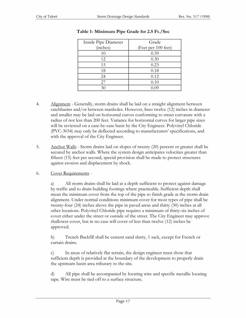
3. Minimum Grade - All storm drains shall be laid on a grade that will produce a mean velocity of at least two-and-one-half (2.5) feet per second when flowing full, based upon Manning’s pipe friction formula using a roughness coefficient of not less than 0.013, or the pipe manufacturers recommendation, whichever is greater. The minimum acceptable grade for various pipe sizes with an “n” value of 0.013 are listed below:
The minimum grade may be reduced from the listed grades to produce an absolute minimum velocity of 2.0 feet per second upon approval of the City Engineer. In any case, circumstances requiring flatter grades than those listed will be reviewed on a case-by-case basis. Engineers are cautioned not to specify storm drains in sizes larger than necessary simply to reduce the required grade.
Page 16
City of Talent Storm Drainage Design Standards Res. No. 517 (1998)
Table 1- Minimum Pipe Grade for 2.5 Ft./Sec
Inside Pipe Diameter (inches)
Grade (Feet per 100 feet)
10 0.39 12 0.30 15 0.23 18 0.18 24 0.12 27 0.10 30 0.09
4. Alignment - Generally, storm drains shall be laid on a straight alignment between catchbasins and/or between manholes. However, lines twelve (12) inches in diameter and smaller may be laid on horizontal curves conforming to street curvature with a radius of not less than 200 feet. Variance for horizontal curves for larger pipe sizes will be reviewed on a case-by-case basis by the City Engineer. Polyvinyl Chloride (PVC-3034) may only be deflected according to manufacturers’ specifications, and with the approval of the City Engineer.
5. Anchor Walls - Storm drains laid on slopes of twenty (20) percent or greater shall be secured by anchor walls. Where the system design anticipates velocities greater than fifteen (15) feet per second, special provision shall be made to protect structures against erosion and displacement by shock.
6. Cover Requirements -
a) All storm drains shall be laid at a depth sufficient to protect against damage by traffic and to drain building footings where practicable. Sufficient depth shall mean the minimum cover from the top of the pipe to finish grade at the storm drain alignment. Under normal conditions minimum cover for most types of pipe shall be twenty-four (24) inches above the pipe in paved areas and thirty (30) inches at all other locations. Polyvinyl Chloride pipe requires a minimum of thirty-six inches of cover either under the street or outside of the street. The City Engineer may approve shallower cover, but in no case will cover of less than twelve (12) inches be approved.
b) Trench Backfill shall be cement sand slurry, 1 sack, except for French or curtain drains.
c) In areas of relatively flat terrain, the design engineer must show that sufficient depth is provided at the boundary of the development to properly drain the upstream basin area tributary to the site.
d) All pipe shall be accompanied by locating wire and specific metallic locating tape. Wire must be tied off to a surface structure.
Page 17
City of Talent Storm Drainage Design Standards Res. No. 517 (1998)
7. Vertical Location - Where storm drains are being designed for installation parallel to other utility pipe or conduit lines, the lines shall be designed with a vertical location that permits future side connections of main or lateral storm drains, and that prevents conflicts with parallel utilities without resorting to abrupt changes in vertical grade or lateral storm drains.
8. Storm Drains in Streets or Easements
a) Under normal conditions, storm drains shall be located in the street right-of-way within two (2) feet of the curb line and preferably on the low side of the street, except where the location of catchbasins warrants other wise. Any request for an exception to this standard will be reviewed on a case-by-case basis.
b) When it is necessary to locate storm drains in easements, the storm drain shall be centered in the easement, except that when the easement is centered on a property line, the storm drain shall be offset eighteen (18) inches from the property line, measured from the property line to the center of the pipe. All storm drain easements shall be exclusive and shall not be used for any purpose that may interfere with unrestricted use of the storm drain line. Any request for an exception to this standard will be reviewed on a case-by-case basis.
c) Easements for storm drain lines fifteen (15) inches in diameter or smaller shall be at least ten (10) feet wide. Easements for pipelines larger than fifteen (15), and up to thirty-six inches in diameter shall be at least fifteen (15) feet wide. Easements for all pipe lines larger than thirty-six (36) inches in diameter shall be a minimum of twenty (20) feet wide.
d) Open channels shall be located in an easement at least as wide as the widest area defined by the following:
i) The 100-year floodway plus 10 feet on one side where a 100-year design storm is required; or
ii) Fifteen feet from the waterway centerline; or
iii) Ten feet from the top of the recognized bank; or
iv) Sufficient area to handle discharge of the ten-year design storm and allow access for maintenance crews.
For a channel fourteen (14) feet wide or wider, a fifteen (15) foot wide access easement shall be provided on both sides of the channel, measured from the top of the recognized bank. Access on only one side may be allowed, to be determined on a case-by-case basis.
e) For facilities serving a Planned Unit Development (PUD), apartment complex, or commercial/industrial development, easements shall be located in parking lots, private drives, or similar open areas that will permit unrestricted vehicle access for maintenance by the City.
Page 18

City of Talent Storm Drainage Design Standards Res. No. 517 (1998)
f) All easements must be reviewed and approved by the City before recording.
9) Connections Between Storm Drain Lines, Channels and Creeks - Storm drain lines shall enter creeks and channels at an angle of 90o or less to the direction of flow. The outlet shall have a head wall and/or scour pad or riprap to prevent erosion of the existing bank or channel bottom. The size of pipe or channel being entered will govern which protective measure are required. All protective measures shall conform to the requirements of Section III of these standards.
10) Slope Intercept Drainage - Slope intercept drains shall be designed to comply with the erosion control requirements in Section III, and shall be provided at the following locations:
a) Along the upper boundaries of a development site where the natural slope of the ground is greater than ten percent (10%), drainage facilities shall be installed to intercept drainage from the tributary area above the site.
b) Along the lower boundary of a development where the natural ground slope exceeds ten percent (10%), drainage facilities shall be installed to prevent drainage onto a lower tributary area other than by an approved point of disposal.
c) Drainage facilities shall also be installed along the top of all cuts that exceed four (4) feet, that have cut slopes in excess of 2:1, and where the tributary drainage area above the cut slopes towards the hinge point of the cut with a drainage path greater that forty (40) feet measured horizontally.
11) Subsurface Drainage - Subsurface drains or underdrains shall begin at a cleanout and end at an approved point of disposal, and shall be provided at the following locations:
a) To stabilize soils on all cut and fill slopes in excess of four (4) feet except when demonstrated to be unnecessary by a soils report prepared and submitted by a registered professional engineer with soils experience.
b) To drain any existing springs or springs intercepted during construction of other facilities such as sewer and water lines, or street excavations.
c) To prevent land slippage or underfloor flooding of buildings where there is a high water table or when there is a need to reduce the groundwater level to an acceptable level.
12) Catchbasins, Cleanouts, Manholes, and Curb and Gutter - In general, storm drains shall be designed with access for cleaning at intervals not greater than 400 feet apart, with junctions made at manholes, cleanouts, or catchbasins.
a) Cleanouts and Catchbasins
i) Catchbasins and cleanouts may be used for the junction of pipes fifteen (15) inches in diameter or smaller, and where the depth from rim to invert is less
Page 19
City of Talent Storm Drainage Design Standards Res. No. 517 (1998)
than four (4) feet. During new construction, pipe lines eighteen (18) inches in diameter may be connected to the larger dimension of the Catchbasin/cleanout structure when the structure is formed and poured around the pipe during new construction. Any variance from the four (4) foot maximum depth for fifteen (15) inch and eighteen (18) inch diameter pipes will be considered for approval on a case-by-case basis.
ii) The maximum length of curb and gutter that may be drained by a catchbasin is eight hundred (800) feet. On all streets terminating on a descending grade, catchbasins shall be installed where the improvement ends, and piped to an approved point of disposal.
iii) In new main line and lateral construction, catchbasin laterals less than thirty (30) feet long or less than twelve (12) inches in diameter may tie into the main line with a shop fabricate “T” is such connection is located not more than one hundred (100) feet from a manhole or cleanout on a mainline not less than fifteen (15) inches in diameter.
iv. Curb and gutter facilities shall be constructed so that flow from a five (5) year design storm does not go past the shoulder or top the curb.
v. Catchbasins shall be constructed to completely intercept gutter flow from a five (5) year design storm.
vi. Side inlet catchbsins consistent with City of Talent Standard Details shall be used at all locations where other construction permits (e.g. driveways and pedestrian ramps). Exceptions will be considered on a case-by-case basis.
vii. Type “A” grates shall be used in street sags. Type “B” grates shall be used on construction grades.
b) Manholes
i. Manholes shall be installed at all pipe junctions where the depth from rim to invert exceeds four (4) feet or when the pipe is eighteen (18) inches in diameter of larger, except as provided in subsection (a)(I), above.
ii. Manholes for pipes twenty-four (24) inches in diameter or larger shall conform to Standard Details.
iii. Where the upstream pipe is smaller than the downstream pipe at the manhole, the crowns of the pipes shall be installed at the same level.
iv. Any public manhole located outside of a City right-of-way shall have a lockdown bolted lid.
c) Curb and Gutter - In general, curb and gutter shall be installed in all new street construction or reconstruction (See Standard Detail). Exceptions may be made for reconstruction projects in residential areas in the Historic District where the
Page 20
City of Talent Storm Drainage Design Standards Res. No. 517 (1998)
Comprehensive Plan prescribes minimizing paved areas and maintaining the historic character of the area.
i. Type “A” curb and gutter shall be used for all street edges. The minimum gutter grade permitted shall be 0.12 feet per one hundred (100) feet , of .12 percent.
ii. Type “C” curb shall be used for edges for traffic islands only.
L. Surface Drainage - For purposes of these Standards, surface drainage routes will be classified as either “artificial watercourses” or as “natural creeks”. In addition to all of the above requirements, plans for surface drainage courses shall include the following supporting data and calculations:
1. Plan Requirements
a) The plan shall be drawn at a scale of not less than 1"=100' with north arrow and vicinity map. Contours at two (2) foot intervals shall be shown. If all or part of the project is in the 100-year floodplain of any waterway, include the 100-year flood line and floodway.
b) The plan shall include a profile of the channel showing the existing flowline and top of bank, the proposed flowline and top of bank, and the design stormwater surface profile or backwater curve.
c) A minimum of three (3) cross sections of the existing channel adjoining or crossing the subject property, taken at the upstream, midsection, and downstream boundaries of the property. More sections may be required depending upon the length of the reach and the existing channel alignment.
d) Calculating the Design Flow Rate: The City will furnish flow rates if available. Systems shall be designed to carry the design storm with one foot of freeboard to the top of the bank. For channels shown on FIRM Maps, the system shall be designed to discharge the 100-year flood at or below the 100-year flood elevation.
2. Artificial Watercourse Requirements
a) Artificial watercourses and modifications to natural waterways shall be designed with a “natural” curved alignment with variable side slopes that do not exceed 4:1. In tight spots created by existing natural features, such as boulders, large trees, etc., the slope can be 3:1 to bypass the intervening feature. In places where steeper slopes are needed, they may be allowed if hydraulic efficiency of the waterway is not impeded.
b) The top of the bank of an artificial watercourse shall be below the finished grade of the surrounding land. Levees will only be approved where there is no practicable alternative.
Page 21
City of Talent Storm Drainage Design Standards Res. No. 517 (1998)
c) Banks shall be designed to maintain one foot of freeboard for a 100-year design storm, with a minimum width of six (6) feet between the top banks. Wider channels may be required for maintenance purposes.
d) Design shall be curvilinear with a 100-foot minimum radius. Tighter curves may be used when the City Engineer determines that the design erosion control measures that will maintain stable bank conditions.
e) A low flow channel shall be designed to carry a two-year design storm or the normal low water flow of a year-round creek, whichever is greater. Low flow channel slopes shall not exceed 2:1, and shall be stabilized to the satisfaction of the City Engineer. In general, bank stabilization will be required in any channel with a design flow velocity that exceeds three (3) feet per second. The invert shall be paved with concrete if the flow is less than three (3) feet per second to prevent ponding to abate mosquitos.
f) Storm drain systems for new development may not include new roadside ditches adjacent to public streets unless the City Engineer finds that there are special circumstances that warrant it. Open drainage ditches, including temporary drainage ditches, when permitted, shall be engineered to contain stormwater without causing erosion or other adverse impacts to the intervening property.
g) The capacity of channels shall be determined using friction coefficients based upon the following:
Type of Channel Manning’s “n”
Natural Creeks 0.06 to 0.1
Unmaintained Ditches 0.08 to 0.13
Maintained Ditches 0.045 to 0.06
h) Any existing ditch approved as a point of disposal for stormwater from ditches or culverts shall have its bottom and side slopes lined with rock at the point of discharge and for at least eight feet downstream.
i) The sides and bottom of channels shall be seeded, sodded or lined with rock immediately following construction. Bank stabilization measures shall be consistent with the requirements of Section III of these Standards unless the City Engineer finds that proposed alternatives provide equal or better erosion control.
j) Points of discharge from culverts and storm drains into ditches and swales with grades of 15% or more shall be lined with boulders with one face a minimum of twenty-four (24) inches in diameter. The rock channel lining shall be at least the width of the diameter of the storm drain or culvert plus three (3) feet, and shall extend at least ten (10) feet from the point of discharge. Other types of energy dissipators may be substituted for boulders at the discretion of the City Engineer.
Page 22
City of Talent Storm Drainage Design Standards Res. No. 517 (1998)
k) Work in or adjacent to existing watercourses shall incorporate both temporary and permanent erosion control measures consistent with the requirements of Section III of these regulations. No channel modifications will be allowed that will reduce the capacity of any existing waterway.
3. Natural Creeks - Bear and Wagner Creeks are salmon producing creeks. All instream projects in the City shall be conducted in a manner that maximizes opportunities to maintain and improve habitat values that support salmon populations. The Oregon Department of Fish and Wildlife restricts work in streams at times when the production of sediment would interfere with salmon spawning. For Bear and Wagner Creeks, instream work is limited to the period from June 15th to September 15th. In addition to the following requirements, permits must be obtained from the Division of State Lands and the Oregon Department of Fish and Wildlife for any work proposed between the banks of Bear or Wagner Creek.
a) Creek bed alterations shall be done in a way that provides diversified habitat features for a variety of aquatic species, and that creates a pleasant appearance. Creek bed alterations are subject to review and approval based upon a determination that there is adequate provision of all of the following:
i) Sufficient water depth to support fish and other aquatic life during low flows.
ii) Diversity of velocities created by varying the streambed with pools, clear channels and riffles, etc.
iii) A meandering channel to facilitate (i) and (ii), above.
iv) sufficient creek bed gradient to provide adequate flow velocities.
b) Creek bed gravel shall be well rounded rock in gradations consistent with natural conditions in the stream, with larger rock in sufficient quantities to provide adequate riffling, subject to approval by the Oregon Department of Fish and Wildlife.
c) Any alteration to a creek shall be designed and constructed to provide stability, and adequate shade and cover for fish and other aquatic life. Shading shall be provided by planting appropriate trees and other plants, as discussed further in Section III of these regulations. Creek bank design and vegetation plans will be considered for approval on a case-by-case basis.
d) Vertical creek banks or walls will not normally be allowed because they increase velocities and decrease channel carrying capacity compared to sloped banks.
e) All creek work and channel design shall include a construction sequence schedule that implements erosion control measures in a timely manner and that facilitates construction. The construction sequence may be modified by the City Engineer during construction as field conditions warrant. Modifications may include increased or decreased erosion control, or a construction shut down.
Page 23
City of Talent Storm Drainage Design Standards Res. No. 517 (1998)
f) Natural creeks shall be preserved and all work in or adjacent to creeks shall incorporate both temporary and permanent erosion control measures consistent with the requirements of Section III of these regulations. No alteration will be permitted that reduces the carrying capacity of the creek.
g) Creek channel design and construction practices shall be based upon consideration of the cumulative effects of existing and proposed projects necessary to develop the tributary area so erosion, siltation, sedimentation, water quality effects, increased water velocity, adverse impacts on groundwater drainage and adverse impacts on aquatic life are all minimized.
f) Creek construction and/or reconstruction may be approved only if the City Engineer determines that such a project will result in a net gain in the value of the surface water system in terms of 1) water quantity and quality, 2) creek and riparian appearance and 3) aquatic and terrestrial habitat values.
g) Any and all work in creeks shall be consistent with the floodplain management policies and regulations of the City.
h) Any and all work in creeks shall be consistent with the Stormwater Master Plan.
M. Stormwater Detention - Detention facilities are required whenever development will create conditions that will increase storm flows beyond the surface flows under undeveloped or current conditions. Detention facilities hold runoff for a short period of time and then release it at a controlled rate into the area storm drain system. The rest of this Section sets out standards for design and construction of detention facilities:
1. General Requirements
a) All stormwater that originates from and/or drains to a development site shall be controlled and/or conveyed in accordance with these Standards. Where existing conditions make stormwater detention impossible for part of a site, compensatory storage volume may be provided on another part of the site if the total site area is tributary to a single drainage basin both before and after development. In no case shall the runoff from the total site exceed the allowable release rate.
b) Detention requirements may be waived by the City Engineer when discharge will be released directly into Bear Creek or into a channel that has been improved to carry a 100-year design storm where it can be shown that detention would actually increase peak flows by superimposing release of stored waters on the natural peak flow. Permission to discharge directly into such a channel does not waive requirements to include erosion control or other water quality control measures in the project design.
c) Detention facilities may be open basins or ponds, roof top storage, parking lot ponding, underground storage such, gravel-filled trench storage or infiltration trenches, or a combination.
Page 24
City of Talent Storm Drainage Design Standards Res. No. 517 (1998)
d) Drainage plans shall include a plan and profile of detention facilities, and, at a minimum, all of the following information:
i) Grades and bottom elevations of ditches, channels, ponds and swales, parking lots and recharge trenches;
ii) Inverts of pipes;
iii) Inverts and tops of all structures such as manholes, catchbasins, chambers or similar structures;
iv) Size, length and slope all pipes or other detention or conveyance facilities, including the invert elevations of any existing and/or proposed storm drainage system(s) that the drainage system for the development site is proposed to be tied into; and
v) The design volume of all detention ponds and a note indicating that ponds shall be inspected before paving and/or landscaping.
e) System design should be based upon a careful conceptualization of how water will move into, through and out of the system, anticipating possible problems such as flow impediments, construction difficulties, future maintenance and erosion problems. The on-site drainage system, including conveyance, flow restriction, detention, and emergency elements, must be properly designed to handle both on-site runoff and conveyance through the site of off-site runoff.
f) Public health, safety, maintenance needs, nuisance abatement, and vector control must all be carefully considered for every drainage control system plan. Mitigating measures will be required when appropriate, and shall themselves be designed to prevent nuisance or hazard conditions.
g) The impacts of system failure on the subject property, downstream properties or affected public or private drainage systems shall be assessed and considered in system design.
h) Systems shall be designed to anticipate, enable, and minimize future maintenance needs.
i) Multiple use of facilities is encouraged, for example using tennis courts for detention facilities. The City Engineer will work with system designers to facilitate multiple use of facilities, but in no case will such considerations be used to justify building a system with any increased risk of system failure.
j) Site evaluation shall include a determination whether hazardous materials or other pollutants are present and whether any extraordinary design considerations are necessary as a result.
k) Visual impacts and other aesthetic concerns shall be mitigated. The extent to which this is necessary and the measures to be used will be assessed on a site-by-site
Page 25
City of Talent Storm Drainage Design Standards Res. No. 517 (1998)
basis.
i) Runoff from rooftops shall pass through the detention system. Plans shall show how this will be accomplished.
m) The City shall have dedicated easements providing access sufficient to move appropriate equipment to all control structures.
2. Parking Lot Ponds
a) Maximum depth of any parking lot pond shall be one (1) foot.
b) Slopes for parking lot ponds shall be no less than one (1) percent and no more than five (5) percent ( the latter to minimize fuel leaks from standing vehicles and to improve traction under icy conditions). A sand and oil separator may be required at the outfall to the public storm drain system.
c) When and underground detention facility is built, a sand and oil separator may be required at the point of entry of water into the underground storage facility.
d) Parking lot ponds shall be designed and constructed with a surface elevation at least .25 feet lower than any and all structures designed to detain the ponded water.
e) Parking lot ponds shall be designed and constructed with a design flood surface elevation at least one (1) foot below the lowest habitable floor elevation of buildings in proximity to the pond. Systems shall be designed so that no flooding can occur in habitable building areas even in the event of a system failure.
f) Parking lot detention facilities may not be incorporated into parking lots under buildings. Such sites should be flood proofed to the extent practicable, with, at a minimum, electrical and mechanical equipment installed above the elevation of flood risk. and with pumping capability including an auxiliary power supply.
g) When parking lot ponds are used, a note shall be made on the Plan stating that “Precise Grading is critical to the effective function of the detention system, and the plan must be strictly followed.”
h) Parking lot pond design volumes shall be shown on plans, and the pond volume shall be inspected prior to paving, with a note that states the latter included on the plans.
i) Where curbing is used to contain a parking lot pond, vertical, type “C” curbing shall be used, as shown in Standard Details.
3. Other Types of Surface Ponds
a) Interior Slopes
Page 26
City of Talent Storm Drainage Design Standards Res. No. 517 (1998)
i) Ponds in Subdivisions, Planned Unit Developments and Land Partitions shall be constructed with interior side slopes that do not exceed 3:1. Exterior side slopes shall not exceed 2:1.
ii) Ponds in commercial, industrial, multi-family or other developments that will remain under private ownership and maintenance shall have at least one interior slope that does not exceed 3:1. The remaining side slopes may be steeper if designed by a licensed professional engineer experienced with soil mechanics. Exterior side slopes shall not exceed 2:1.
b) The minimum dimension for the bottom of a pond less than three (3) feet deep shall be six (6) feet unless approved by the City Engineer. The minimum dimension for ponds three (3) feet deep or deeper shall be fifteen (15) feet.
c) Ponds suitable for multiple uses are encouraged. Examples of multiple use ponds include but are not limited to sport courts, play areas, neighborhood parks, and picnic areas. Such ponds may be designed with engineered walls that may have walls steeper than 3:1, subject to approval by the City Engineer.
d) Ponds shall be landscaped for aesthetic purposes and to stabilize banks. Sodding, seeding and planting trees and shrubs should be used in combination. In no case will the use of easily floatable or erodible materials such as bark mulch be allowed on pond interiors.
e) Maintenance of Landscaping of Surface Ponds
i) Surface detention pond landscape areas in commercial, industrial and multi-family developments shall be maintained by the property owner or owners’ association.
ii) Surface detention pond landscape areas in single-family residential areas shall be located on one or more of the lots in the development. Maintenance of the detention pond shall be the responsibility of property owners.
iii) Surface detention pond landscape areas and multiple use detention ponds in planned unit developments and condominium developments shall be maintained by an owners’ association or community club, and such responsibility shall be assigned by a note on the face of the plat.
iv) Failure to maintain a weed abatement program will be cause for the City to perform the work and bill the owners.
f) Use of Berms as Banks of Detention Ponds - Compliance with the following standards shall be certified by a engineer with soils experience, and noted on the detention pond plans submitted to the City for review:
i) The pond or earth dam as designed will be safe for its intended use.
ii) Berm soils shall consist of material suitable for placement in maximum six (6)
Page 27
City of Talent Storm Drainage Design Standards Res. No. 517 (1998)
to eight (8) inch lifts.
iii) Berm soils shall have a permeability (k) of no more than 3 x 10⁻⁵ cm/sec.
iv) Berm soils shall consist of material that conforms to the following gradation:
Sieve Size % Passing
3” 100%
#4 65-90%
#200 12-20%
v) Vegetation on berm soils shall be shallow rooted and/or be planted in topsoil added above or adjacent to engineered berm soils.
vi) Design variations that have been developed by a licensed engineer with soil mechanics experience will be considered on a case-by-case basis.
g) City maintained detention pond control structures that do not abut a public right-of-way shall be accessible by a fifteen (15) foot wide or wider access easement improved as needed to allow vehicle access.
h) Detention pond control structures shall be designed and constructed to operate automatically as much as possible.
i) The access grade into the any detention/retention pond shall be no steeper than 5:1.
j) Detention ponds other than parking lot ponds shall be designed and constructed with one (1) foot of freeboard above the elevation of the design flood.
k) Any embankment higher than three (3) feet must be designed by a qualified soils engineer and approved by the City Engineer. The minimum top width of the embankment shall be fifteen feet unless otherwise approved. The designing engineer shall also inspect and certify the construction of the pond.
i) An embankment less than three (3) feet high that forms the side of a pond shall be at least six feet wide at the top of the berm with a backslope not to exceed 2:1. Variations to this standard must be designed by a qualified soils engineer and approved by the City Engineer.
m) The bottom of any constructed and graded detention/retention pond shall be sloped no flatter than a one percent (1%) toward drainage outlets.
n) Use of “flow through” detention ponds may be approved. Any flow through pond shall have a well-defined low flow channel to contain the runoff of lesser storms.
o) Outlets of detention ponds shall be protected from blockage and plugging by
Page 28

City of Talent Storm Drainage Design Standards Res. No. 517 (1998)
suitable debris barriers.
p) The maximum design depth for ponds other than parking lot ponds is five (5) feet. Ponds deeper than four (4) feet will require protective fencing and a locked gate.
q) The design volume of the detention pond shall be shown on the plans. The pond volume shall be inspected prior to landscaping, and a note to that effect shall be shown on the plans.
r) Surface storage ponds may be allowed in the public right-of -way in a street cul-de-sac bulb. Such detention facilities require an inverted crown with a drain in the center of the bulb. A minimum of .25 feet of freeboard must be maintained at the curb for the 10-year flood.
4. Closed Detention Systems - Maintenance of closed, private detention or conveyance systems, such as underground pipes, gravel filled trenches, and both underground and surface vaults shall be the responsibility of property owners for systems serving a single lot, and by an owner, property manager or owners’ association for systems serving commercial, industrial, multi-family of multi-lot development. A sand and oil separator may be required at the point of inlet to the system. Adequate access shall be designed and constructed into the system at both the inlet and outlet ends.
Page 29
City of Talent Storm Drainage Design Standards Res. No. 517 (1998)
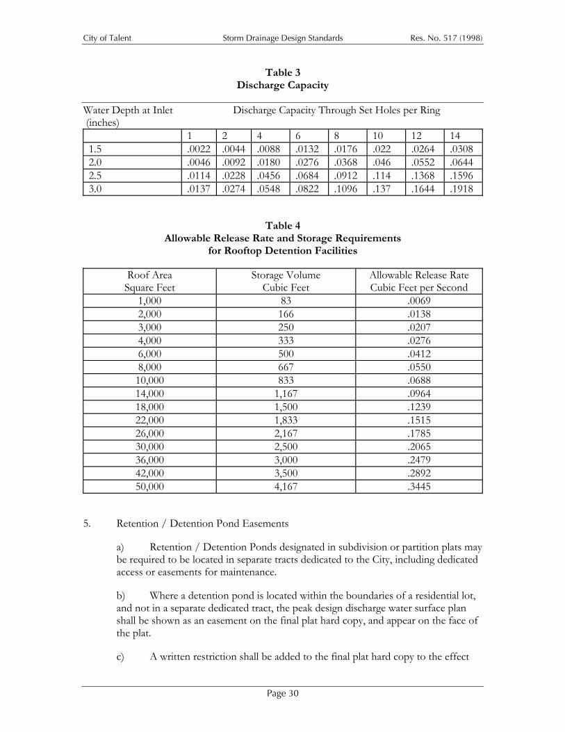
Table 3 Discharge Capacity
Water Depth at Inlet Discharge Capacity Through Set Holes per Ring (inches) 1 2 4 6 8 10 12 14 1.5 .0022 .0044 .0088 .0132 .0176 .022 .0264 .0308 2.0 .0046 .0092 .0180 .0276 .0368 .046 .0552 .0644 2.5 .0114 .0228 .0456 .0684 .0912 .114 .1368 .1596 3.0 .0137 .0274 .0548 .0822 .1096 .137 .1644 .1918
Table 4 Allowable Release Rate and Storage Requirements
for Rooftop Detention Facilities
Roof Area Square Feet
Storage Volume Cubic Feet
Allowable Release Rate Cubic Feet per Second
1,000 83 .0069 2,000 166 .0138 3,000 250 .0207 4,000 333 .0276 6,000 500 .0412 8,000 667 .0550 10,000 833 .0688 14,000 1,167 .0964 18,000 1,500 .1239 22,000 1,833 .1515 26,000 2,167 .1785 30,000 2,500 .2065 36,000 3,000 .2479 42,000 3,500 .2892 50,000 4,167 .3445
5. Retention / Detention Pond Easements
a) Retention / Detention Ponds designated in subdivision or partition plats may be required to be located in separate tracts dedicated to the City, including dedicated access or easements for maintenance.
b) Where a detention pond is located within the boundaries of a residential lot, and not in a separate dedicated tract, the peak design discharge water surface plan shall be shown as an easement on the final plat hard copy, and appear on the face of the plat.
c) A written restriction shall be added to the final plat hard copy to the effect
Page 30
City of Talent Storm Drainage Design Standards Res. No. 517 (1998)
that no structure, fill, or obstructions (including fences) shall be located within any drainage easement or delineated floodplain area.
d) An access gate for maintenance access roads may be required, and shall be structurally and aesthetically appropriate for the proposed use and location. Alternative traffic controls will be considered on a case-by-case basis.
e) A drainage easement is required for all closed public storm drainage detention systems. An easement width in excess of typical easement widths may be required for facilities with pipe diameter or vault widths greater than four (4) feet, at the discretion of the City Engineer.
f) All publicly maintained facilities that are not located in a public right-of-way shall be located in a recorded drainage easement, including any necessary easements for access. The owner in fee simple or contract purchaser of the property upon which the facility will be located shall execute said easement. Where a facility must cross an intervening private tract, it is the responsibility of the developer / project site owner to arrange for all necessary easements.
Section III. EROSION AND SEDIMENT CONTROL
This Section applies to all development sites before, during and after construction. Erosion control measures shall be implemented from the first entry into the land until landscape vegetation is established and the site storm drainage system is operational. Note that these measures are required by the City in addition to the formal Erosion Control Plans required by the Oregon Department of Environmental Quality for project sites of five acres or larger.
A. Erosion control measures shall be incorporated into excavation, construction, and post-construction site management practices to control runoff, erosion and sedimentation until vegetation and other measures effectively stabilize the site.
B. For new subdivisions, temporary erosion control measures shall be implemented during site preparation work, road and utility construction and all construction projects including the construction of individual homes and other lot improvements.
C. Before initial clearing and grading of any land for development, provision shall be made for interception of all potential silt-laden runoff that could result from said clearing and grading. Said interception shall prevent any silt-laden runoff from discharging from the site to any downstream property or watercourse. Said interception shall convey such silt-laden runoff to an open ditch or other temporary facility as needed to settle out silt and other eroded materials prior to downstream discharge.
D. An erosion control plan under this Section shall include careful assessment of all of the following:
1. Soil Erodibility - Soil Erodibility shall be assessed based upon the ratings included in the Natural Resources Conservation Service soil survey. Erosion control measures
Page 31
City of Talent Storm Drainage Design Standards Res. No. 517 (1998)
used shall be designed accordingly.
2. Slope and Runoff - Cleared areas will require protection from runoff, with steeper slopes requiring more aggressive measures.
3. Cover - Erosion protection is required for all disturbed areas, including temporary cover and permanent vegetative cover. Geo-textiles and other non-vegetative cover may be approved where shown to be appropriate.
E. Temporary and/or permanent hydroseeding or other acceptable seeding and mulching must be provided whenever perennial cover cannot be established on a site that will be exposed for sixty (60) days or more. Note that floatable mulching materials are discouraged, and may not be used on pond interiors.
Page 32