preliminary storm water drainage...
TRANSCRIPT

PRELIMINARY
STORM WATER
DRAINAGE
REPORT
for
QuikTrip Store #0189
Missouri Highway 45 & Missouri Highway 9
Parkville, Missouri
Prepared For:
QuikTrip Corporation
5725 Foxridge Drive
Mission, Kansas 66202
Prepared By:
Darla K. Holman, P.E.
Project Civil Engineer
6734 Red Oak Drive
Shawnee, Kansas 66217
913.248.9385
February 23, 2015

ENGINEER’S CERTIFICATION
Preliminary Storm Water Drainage Report
QuikTrip Store #0189
MO HWY 45 & MO HWY 9
Parkville, Missouri
I Hereby Certify that this Engineering Document was prepared by me and that I am a duly
Registered Professional Engineer under the laws of the State of Missouri.
__________________________
Darla K. Holman, P.E.
Project Civil Engineer
Missouri Registration No. 13652
___________________________
Date Seal
REPORT PURPOSE
This preliminary report has been prepared to detail the preliminary design concept for the storm
water management and water quality treatment proposed for the QuikTrip Store #0189 facility to
be located at the southeast corner of Missouri Highway 45 and Missouri Highway 9.
PROJECT SUMMARY
QuikTrip Corporation is proposing to build a new Generation III convenience store at the
southeast corner of Missouri Highway 45 and Missouri Highway 9 in Parkville, Missouri. The
store will be oriented to face Missouri Highway. The new facility will feature a 5,858 square feet
convenience store and a 9 multi-dispenser fueling canopy. The property, after right of way
purchase, will contain 117,982 s.f. (2.7085 acres).
EXISTING DEVELOPMENT
The existing property once contained two residential lots. Based on historical images from
Google Earth, the original homes and gravel driveways were removed around 2007. From these
images it was determined that the property once contained approximately 4,025 s.f. of
impervious roof areas, and approximately 19,573 s.f. of gravel driveways (approximately 11.7%
impervious).
The property is on a hill crest. No off-site storm water currently drains across the property. The
property currently is divided into three drainage areas as detailed on the Pre-Development
Drainage Map included in the Appendix. Runoff calculations for the 50% and 1% storm events
are included on the map.
February 23, 2015

PROPOSED DEVELOPMENT
The proposed development will contain 76,274 s.f. of impervious area (64.6%). An on-site
storm drainage system will be designed to capture a majority of the 1% storm water runoff from
the site’s impervious areas and direct it through an underground detention system. Water
Quality Storm Inlet Insert Filters and a Water Quality Proprietary Unit will be installed to meet
the required Value Rating for the development.
Since there are no downstream systems available on the east side of Missouri Highway 9 (within
public right of way or within public storm drainage easements); a storm pipe is proposed to be
installed from the QuikTrip site to an existing grated intake on the west side of the Highway 9.
This existing public system will require analysis to ensure it can handle the additional discharge
from the QuikTrip development. Peak discharge from the QuikTrip development will be limited
to the allowable release rates detailed in the Section 5600 of APWA. The QT detention system
can be enlarged and the peak discharge decreased if required by the capacity of the public storm
system.
A majority of the site’s storm water runoff will be discharged to Missouri Highway 9 thus
practically eliminating any storm water discharge to the east and south. For this reason, the peak
discharge from the detention cannot exceed the current peak discharge limitations from the
existing drainage area that currently discharges to MO Highway 9 (Drainage Area 3 on the Pre-
Development Drainage Map).
WATERSHED
This property lies within the Riss Lake watershed.
FLOODPLAIN CERTIFICATE
According to "Flood Insurance Rate Map" Community Panel No. 290291007-B, as published by
the Federal Emergency Management Agency, this property lies within Zone C, areas of minimal
flooding, determined to be outside the 100 year and 500 year flood plain.
STORM WATER PEAK RUNOFF CONTROL
The storm water management system for this site is inevitably controlled by the outlet point (the
existing flowline of the area intake on the west side of MO Highway 9). The proposed
underground detention elevation is controlled by the curb inlet and vane drain on the access drive
at the bank property.
The allowable peak flows from the site will be limited to the existing drainage area’s peak flows
currently flowing to Missouri 9 Highway. The allowable peak flows were calculated assuming
an undeveloped site. Since only 1.5888 acres currently discharge to this area the maximum peak
discharges from the detention facility must be limited to (refer to Pre-Development Drainage
Area Map):

2 year – 2.52 cfs
5 year – 3.48 cfs
100 year – 6.16 cfs
However, the APWA manual restricts runoff from a development as follows:
2 year – 0.5 cfs / acre or 2.52 X 0.5 = 1.26 cfs
5 year – 2.0 cfs / acre or 2.52 X 2.0 = 5.04 cfs
100 year – 3.0 cfs / acre or 2.52 X 3.0 = 7.56 cfs
Since 2,188 s.f. (0.0502 acres) of proposed impervious area will bypass the detention the
allowable release rate for each storm event must be limited to:
2 –year :1.26 cfs – 0.24 cfs = 1.02 cfs
5 – year: 3.48 cfs – 0.33 cfs = 3.15 cfs
100-year: 6.16 cfs – 0.58 cfs = 5.58 cfs
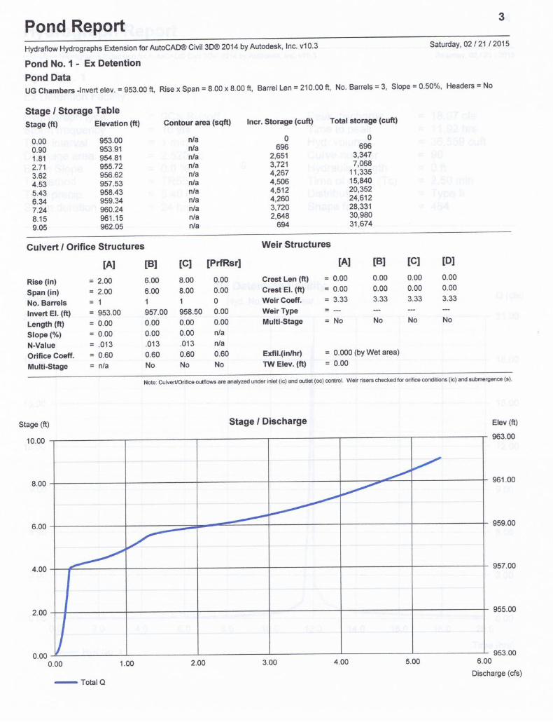
A preliminary underground detention system has been sized and designed with a staged release
system that will result in the following storage/discharge values:
Storm Event Storage Used Peak Discharge
2-year 12,341 c.f. 0.766 cfs
10-year 20,253 c.f. 1.9444 cfs
100-year 30,323 c.f. 4.820 cfs
The preliminary detention system design contains 31,945 c.f. of storage in an 8-feet diameter
underground pipe system. The staged discharge will be controlled by three orifices (2”, 6” and
8”).
WATER QUALITY TREATMENT
To address the water quality for this site, calculations were performed to determine the required
Value Rating (VR) for the site and develop a BMP Mitigation Package for the proposed
improvements per the 2012 APWA BMP Manual. Because the site once contained residential
lots, these were considered when determining the required level of service. Worksheets for these
calculations are included in the Appendix and are detailed as follows:
Step 1: Determine the amount of site area to be disturbed by redevelopment activities. Calculate
the required area for treatment by subtracting the amount of existing impervious area within the
disturbed area from the total disturbed area.
Total Disturbed Area: 2.71
Required Area for Treatment: 2.71 – 0.31 = 2.40

Step 2: Calculate the proposed percent impervious for the post-development condition by
dividing the net increase in impervious area within the disturbed area by the required area for
treatment. Enter Table 4.3 with the result to determine the required Level of Service.
Net Increase in Impervious: 1.68 – 0.31 = 1.37.
Proposed Percent Impervious: 1.37 / 2.40 = 0.57 or 57%
Required Level of Service from Table 4.3 is 5.8
Step 3: Determine the Minimum Required Total Value Rating of the BMP by multiplying the LS
by the required area for treatment.
Total Required Value Rating: 5.8 X 2.40 = 13.91
Step 4: Calculate the Mitigation Package Total VR based on assigned VR for each BMP and the
area of the site that the BMP would treat. If the proposed Mitigation Package does not meet the
required Total VR, apply different BMPs or apply multiple BMPs in a “treatment train”
approach.
Mitigation Package Total Value Rating:
Areas to WQ Unit & WQ Inlet Inserts (TT) 2.17 X 8.0 = 17.36
Areas to WQ Unit 0.35 X 5.0 = 1.75
Areas of bypass 0.19 X 0.00 = 0.00
Total VR 19.11 > 13.04
PROPRIETARY UNITS
Since this is a fuel dispensing facility (labeled as a “hot spot” in the BMP manual) it has the
capability of producing higher concentrations of pollutants and best management practices
should be considered in the design. When a development is considered a “hot spot”, a water
quality protection package should be created that avoids the use of typical BMPs (such as
infiltration practices) in order to avoid contributing to groundwater contamination. For this
reason two separate proprietary units are proposed to treat water quality. One system will be a
curb inlet insert that contains a filter to capture hydrocarbons. These will be installed at every
curb inlet on the property. Several options for these curb inlet inserts are under review. Two
options are included in the appendix. The second system is a FloGard Dual –Vortex with oil
filter by Kristar. This unit will be placed downstream from the storm water detention facility so
almost all of the storm water runoff from this property will be treated. Detailed information on
these units can be found in the Appendix.

STORM DRAINAGE SYSTEM DESIGN METHODOLOGY
The Rational Method will be used to calculate the peak discharges. The site’s storm sewer
systems will be designed to convey the 100-year storm peak runoff to the proposed storm water
detention facility.
The design of the on-site storm drainage systems will be included in the Final Storm Water
Drainage Report.
CONCLUSION
A storm water detention system will be designed and constructed to meet and exceed the City’s
Storm Drainage Design Criteria. The peak storm water discharge from the property will be less
than the undeveloped site’s peak storm water discharge for the 2-year, 10-year and 100-year
storm events. This should prevent any adverse effects on adjacent properties.
A water quality mitigation package is proposed that will treat the water quality to meet and
exceed the 2012 APWA BMP Manual. With the use of the proprietary units, all runoff from the
property can safely be released to the existing public storm sewer system and more importantly
to Riss Lake.

QuikTrip Store #0189
MO HWY 45 & MO HWY 9
Parkville, Missouri
APPENDIX
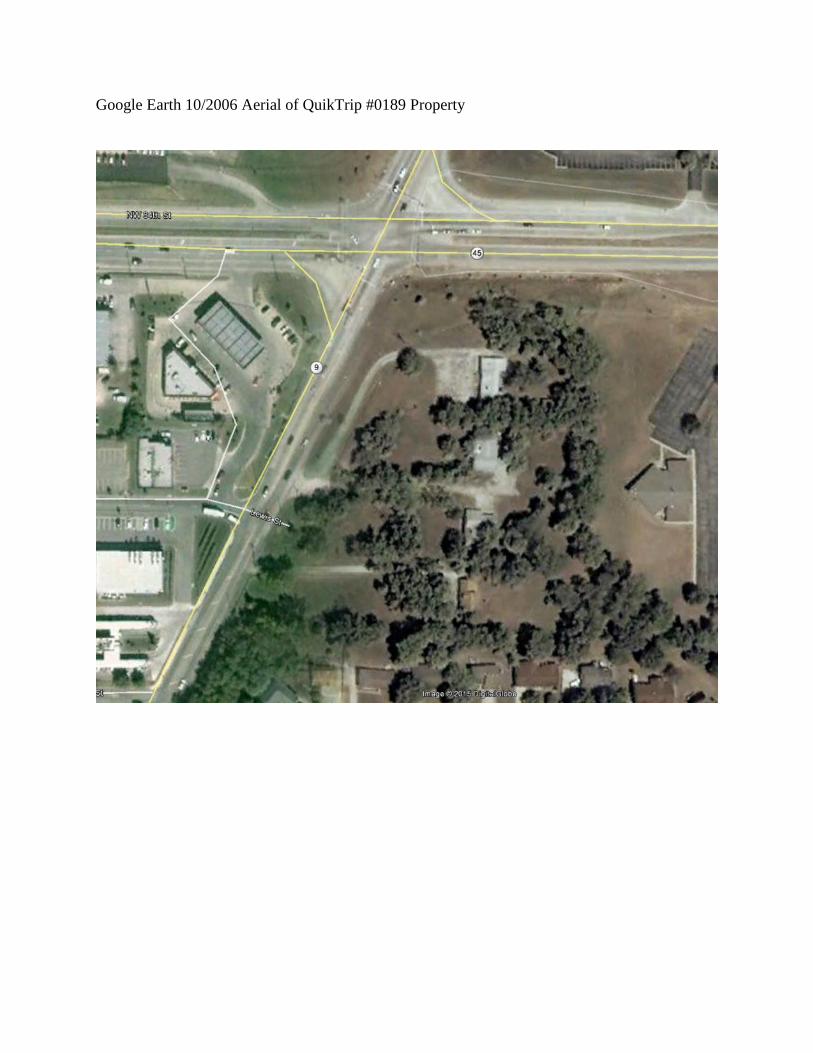
Google Earth 10/2006 Aerial of QuikTrip #0189 Property

APWA / MARC BMP Manual 4-17 October 2012
QuikTrip #0189
MO Hwy 45 & MO Hwy 9, Parkville, MODKH
DKH
02/23/15
02/23/15
QT Property 2.71
Former Gravel (50%) 0.22Former Houses 0.09
0.31
2.40
Roofs and Pavement 1.68
1.68
0.31
1.37
57
5.8
13.92

APWA / MARC BMP Manual 4-18 October 2012
QuikTrip #0189MO Hwy 45 & MO Hwy 9, Parkville, MO
DKHDKH
02/23/1502/23/15
13.92
Areas to TT 2.17 8.0 17.36Areas to WQ Unit 0.35 5.0 1.75Untreated Areas 0.19 0 0
2.71 19.11 Total VR
Yes
Treatment Train =WQ Proprietary Unit &Curb Inlet WQ Inserts

APWA / MARC BMP Manual 4-9 October 2012
TABLE 4.3 Required Level of Service for Previously Developed Sites

APWA / MARC BMP Manual 4-10 October 2012
Median
Expected Effluent EMC TSS (mg/L)a
Value Ratings
Cover Type or BMP
Water Quality Value
Volume Reduction
Temperature Reduction
Oils/ Floatables Reduction
Overall Value Rating
Vegetation N/A 5.25 2 1 1 9.25 Native Vegetation preserved or established Rain Garden < 10 4 2 1 2 9.0 A small residential depression planted with native vegetation designed to capture and infiltrate runoff
Infiltration Practices < 10 4 2 1 2 9.0 Infiltration Basin Infiltration Trenches Bioretention < 10 4 1.5 1 2 8.5 Small engineered and landscaped basins designed to filter runoff before release
Pervious or Porous Pavement 10-20 3 1.5 1 2 7.5 Pervious Concrete Porous Asphalt Modular Concrete Block Extended Detention Wetland < 10 4 2 0 1 7.0 A land area that is permanently wet with hydric soils sized to detain the WQv for a minimum of 40 hours.
Media Filtration Practices < 10 4 0 0 2 6.0 Surface Sand Filter Underground Sand Filter Pocket Sand Filter Perimeter Sand Filter Extended Wet Detention 10 - 20 3 2 -1 1 5.0 A basin intended to have a permanent pool and sized to detain the WQv for a minimum of 40 hours
Vegetated Filter Strip 10 - 20 3 1 0 1 5.0 Buffer strip with native vegetation treating sheet flow Native Vegetation Swale 10 - 20 3 1 0 0 4.0 Native grasses and forbes planted in a swale to reduce velocity of runoff and promote infiltration
Extended Dry Detention Basin 20 - 50 2 1 0 1 4.0 A basin lined with native plant species designed to detain the WQv for a minimum of 40 hours with no permanent impoundment of water
Other Systems 10 - 100 (b) 1-3 (c) 0 0 2 3.0-5.0 (d)
Proprietary Media Filtration Devices Hydrodynamic Devices Baffle Boxes Catch Basin Inserts Signage N/A N/A N/A N/A N/A BMP VR +
0.25 ( e)
Green Roofs – No VR, Credit for Post Concrstrcution CN Reduction, See Design Section
CN Credit See Design
Notes: TSS Total suspended solids mg/L Milligrams per liter
a Expected median event mean concentrations of TSS is based on analysis of studies in International BMP Database www.bmpdatabase.org Source: Analysis of Treatment System Performance, International Stormwater Best Management Practices (BMP) Database 1999-2005. Feb. 2006
b Jurisdiction will assign the score based on independent 3rd party field data showing expected event mean concentrations TSS in the effluent. However, if the proprietary BMP relies on sedimentation as the primary pollutant removal mechanism, then performance data over the range of particle size distributions must be submitted for the range of expected flow rates.
c Water Quality Value will vary based on the median concentration of TSS in the effluent (measured in mg/l). d Overall Value Rating will vary based on the sum of the four Value Ratings. e See Section 7.7 for additional guidance on signage.
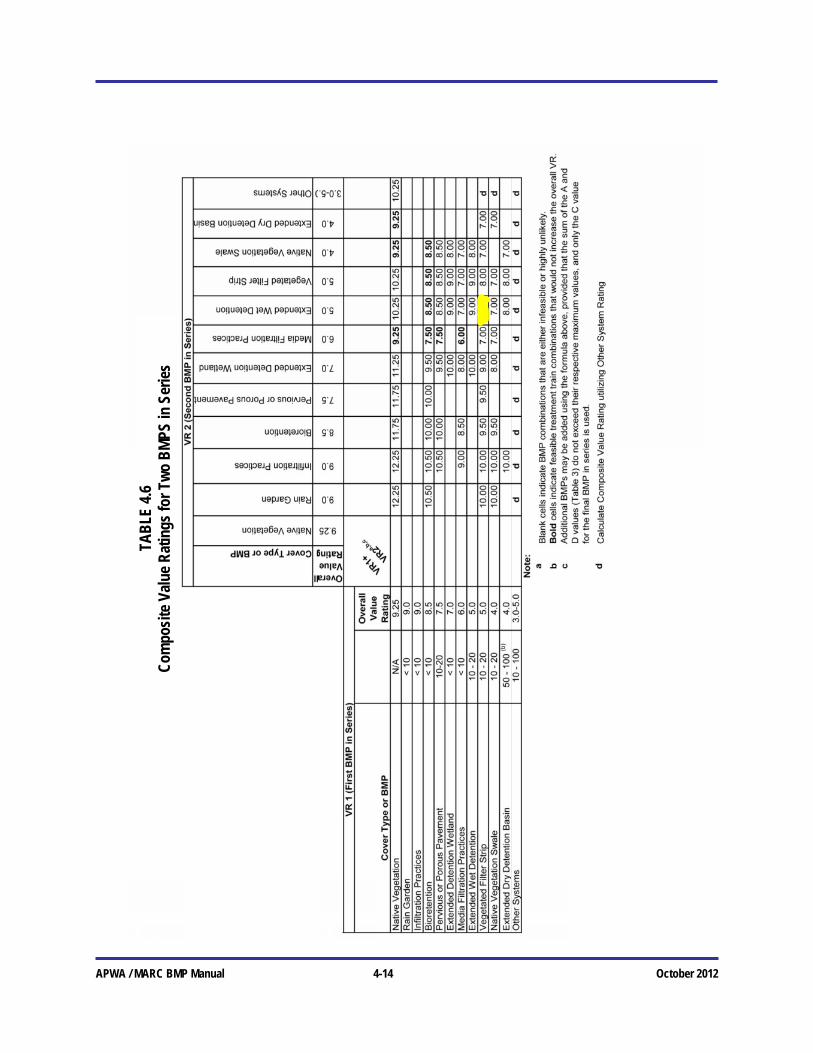
Table 4.4 Best Management Practice Value Ratings
APWA / MARC BMP Manual 4-14 October 2012
TAB
LE 4
.6
Com
posi
te V
alue
Rat
ings
for T
wo
BM
PS in
Ser
ies


TRITON CATCH BASIN INSERTS
First line of defense against trash in storm
drain systems
Specifications• Easytoinstallinnewandexisting
catchbasins
• Meetsbestavailabletechnologyforuse
instormwaterbestmanagementpractices
(BMP)
• Round,square,rectangular,lowprofileand
custommodels
• Non-reactivehighdensitypolyethylene
(HDPE)plasticconstruction,withU.V.
inhibitors
• Media-Pakcartridgesavailableforthe
removalofsediments,hydrocarbons,and
litter
• Quickandeasyservicingmadeavailableby
replaceableMedia-Paks
Notes:
1.Alldimenionsareininches
2.UnitsareconstructedfromHDPEplasticwithU.V.inhibitors
3.MediacartridgescanbeinterchangedwithGeotrapseriesassiteconditionschange
4. Lowprofilecartridgesarealsoavailableforshallowcatchbasins
5.Customsizesareavailabletofitmostapplications
6.Optionaltrashanddebrisguardavailable
7.Dualstageanddualcapacitycartridgesalsoavailable
D
B
C A
E
F
*Dimenions“A”and“B”canbeadjustedtosuitvaryingsizesofeachbasins.
**Dimension“G”isbasindepth.***Dimension“H”iscartridgeheight.
Model # A* B* C D E F G** # cartridges H*** Basin Type
TR1212 15.0 15.0 11.0 11.0 6.75 3.50 6.0 1Short 4.5 HDPE
TR12RD Ø15.0 Ø11.0 6.75 3.5 6.0 1Short 4.5 HDPE
TR1616 20.0 20.0 14.0 14.0 6.75 3.5 10.5 1Std 8.5 HDPE
TR16RD Ø20.0 Ø11.0 6.75 3.5 6.0 1Short 4.5 HDPE
TR1818 24.0 24.0 18.0 18.0 10.0 6.25 10.5 1Std 8.5 HDPE
TR18RD Ø24.0 Ø16.5 6.75 3.5 10.5 1Std 8.5 HDPE
TR1824 19.0 25.0 18.0 18.0 10.0 6.25 10.5 1Std 8.5 HDPE
TR2024 21.0 25.0 18.0 18.0 10.0 6.25 10.5 1Std 8.5 HDPE
TR24SR 27.0 27.0 23.5 23.5 14.0 10.0 13.0 1Std 8.5 HDPE
TR24RD Ø28.0 Ø21.0 14.0 10.0 13.0 1Std 8.5 HDPE
TR2436 32.0 40.0 22.0 29.0 14.0 10.0 21.0 1Tall 16.5 HDPE
TR3030 34.0 34.0 22.0 29.0 14.0 10.0 21.0 1Tall 16.5 HDPE
TR36SR 36.0 36.0 33.0 33.0 14.0 10.0 22.0 1Tall 16.5 FIBRG
TR36RD Ø36.0 Ø33.0 14.0 10.0 22.0 1Tall 16.5 FIBRG
TR42RD Ø42.0 Ø33.0 14.0 10.0 22.0 1Tall 16.5 FIBRG
TR4848 48.0 48.0 42.0 42.0 24.0 19.75 22.0 1Tall 17.5 FIBRG
TR48RD Ø48.0 Ø33.0 14.0 10.0 22.0 1Tall 16.5 FIBRG
Standard Dimensions (in inches)
ENGINEERED SOLUTIONS
800.338.1122•www.ContechES.com
Triton Drop InletTheTritonDropInletinserttrapshydrocarbonsandothercontaminantssuchasmetalssandandsilt
fromstormwaterrunoff.Itisinstalledbelowthegrateofstormdraininlets.

UGTritonCatchBasin9/14
©2014ContechEngineeredSolutionsLLC
800.338.1122
www.ContechES.com
AllRightsReserved.PrintedintheUSA.
NOTHINGINTHISCATALOGSHOULDBECONSTRUE.ASANEXPRESSEDWARRANTY
ORANIMPLIEDWARRANT.OFMERCHANTABILITYORFITNESSFORANYPARTICULAR
PURPOSE.SEETHECONTECHSTANDARDCONDITIONSOFSALE(VIEWABLEAT
WWW.CONTECHES.COM/COS)FORMOREINFORMATION.
ENGINEERED SOLUTIONS
Get Social With Us!
Specifications• Easytoinstallinnewandexistingcurbinlets
• Meetsbestavailabletechnologyforuse
instormwaterbestmanagementpractices
(BMP)
• Non-reactivehighimpactpolystyreneplastic
constructionwithU.V.inhibitors.Over40
percentoftheplasticusedcomesfrom
recycledcontent.
• Media-Pakscartridgesavailableforthe
removalofsediments,hydrocarbonsand
litter
• DisposableMedia-Pakisconstructedfrom
durablegeotextile,polypropylenefabric
• OptionalStormWeb™systemdesignedto
assistintheremovaloftrashanddebris,in
compliancewithTMDLrequirements.
• Media-Pakmayberemovedthroughthe
curbopeningforeaseofmaintenance
Model A (curb opening)
TRC2 2.00
TRC2.5 2.50
TRC3 3.00
TRC3.5 3.50
TRC4 4.00
TRC5 5.00
TRC6 6.00
TRC7 7.00
TRC8 8.00
TRC9 9.00
TRC10 10.0
TRC12 12.00
TRC14 14.00
TRC21 21.00
TRC28 28.00
Standard Dimensions (in feet)
Notes:
1.Alldimensionsareinfeet.Customsizesalsoavailable.
2.ProductisconstructedofHighImpactPolystyrenePlastic,withU.V.inhibitors.Over40%recycledcontent.
3.DisposableMedia-Pakisconstructedofdurablegeotextilefabric,wovenwithperforatedpoly-propylene.
4.Media-Pakcageisconstructedusing8gaugeType304StainlessSteel.
5.Insertbodyissecuredtoinsidewallusing(2)1/4”thickbracketspersection,attachedusing3/8”x3”expansionanchorbolts.
6.OptionalStormWeb™,designedforcapturinglargertrashanddebris.
7.Mediaisnon-hazardousperEPAandOSHAstandards.
8.Insertshallbeinstalledandmaintainedinaccordancewithmanufacturerrecommendations.
Triton Curb InletTheTritonCurbInletisdesignedtobeinsertedbelowthestreet/curbopeningofstormdraininlets.
Itattachestosidesofcatchbasinusinghardwaresuppliedbymanufacturer.Flowisdesignedtobypassinsertinlargestormevents.
TRITON CATCH BASIN INSERTS

Version 1.00c – July 6, 2011
FloGard® Dual Vortex
Hydrodynamic Separator
Operations and Maintenance (O & M)
Manual

2 | P a g e - FloGard® Dual-Vortex Hydrodynamic Separator O & M Manual
KriStar Enterprises, Inc. P.O. Box 18187
Atlanta, GA 30319-8187 (800) 579-8819
www.kristar.com
FloGard® Dual-Vortex Hydrodynamic Separator Description / Basic Function The Dual-Vortex Hydrodynamic Separator is a stormwater filtration device used to reduce
pollutant loading in runoff from urban developments. Impervious surfaces and other urban and
suburban landscapes generate a variety of contaminants that can enter stormwater, polluting
downstream receiving waters. The DVS captures and retains sediment, oils, metals and other
target constituents close to the source and reduces the total discharge load.
DVS units are designed to effect greater than 80% removal of TSS reflective of typical urban
runoff. Units are sized to treat stormwater at the design removal efficiency in an equal or
smaller footprint than other typical hydrodynamic separators. DVS units offer an economical
alternative structural BMP for use in developments where land area necessitates compact,
effective treatment for removal of suspended pollutants from stormwater runoff.
The DVS internal components may be manufactured from durable stainless steel, concrete or
marine-grade fiberglass materials. The internal components are configured to fit into industry
standard precast concrete circular, square, or rectangular manholes.
How It Works Particle settling or floatation is accelerated by centripetal forces induced by the tangential flow
pattern augmented by a highly circuitous flow path. The unit uses two independent cylindrical
separators: Low flow is diverted by the inlet to the first separator, while moderate flow begins to
overflow the first control weir and enter the second separator. Settled particles collect in the
bottom storage area of the unit which is isolated from the fluid outlet, minimizing re-suspension.
Floating debris and oils are temporarily held at the top of each separator and deposited in the
upper storage area by peak storm events. Optional “Fossil Rock” oil booms can be added to this
area to enhance oil removal/retention. Once the unit treatment capacity is exceeded, excess
flow breaches a second control weir at the inlet and passes through the bypass pipe without
decreasing the treatment flow or re-entraining captured pollutants.
Maintenance Overview for DVS Systems State and Local regulations require that stormwater management systems be maintained and
serviced on a recurring basis. The purpose of maintaining a clean and obstruction-free system
is to preserve the performance and function of the device to ensure the protection of
downstream receiving waters. Trash and debris, floatables, oil, gross pollutants and sediment
are intended to build up in any stormwater treatment system. Without consistent maintenance,
pollutant buildup can cause the system to function improperly by reducing removal efficiency,
increasing the potential for pollutant loss through scour, or by impeding flow in or out of the
3 | P a g e - FloGard® Dual-Vortex Hydrodynamic Separator O & M Manual
KriStar Enterprises, Inc. P.O. Box 18187
Atlanta, GA 30319-8187 (800) 579-8819
www.kristar.com
system. Upstream areas may run the risk of flooding and deleterious environmental impact
downstream could occur.
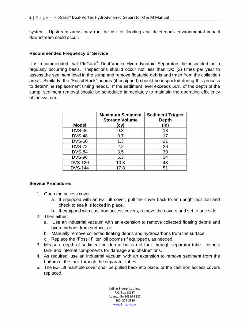
Recommended Frequency of Service It is recommended that FloGard® Dual-Vortex Hydrodynamic Separators be inspected on a
regularly occurring basis. Inspections should occur not less than two (2) times per year to
assess the sediment level in the sump and remove floatable debris and trash from the collection
areas. Similarly, the “Fossil Rock” booms (if equipped) should be inspected during this process
to determine replacement timing needs. If the sediment level exceeds 50% of the depth of the
sump, sediment removal should be scheduled immediately to maintain the operating efficiency
of the system.
Model
Maximum Sediment Storage Volume
(cy)
Sediment Trigger Depth
(in)
DVS-36 0.3 13
DVS-48 0.7 17
DVS-60 1.3 21
DVS-72 2.2 26
DVS-84 3.5 30
DVS-96 5.3 34
DVS-120 10.3 43
DVS-144 17.8 51
Service Procedures
1. Open the access cover
a. If equipped with an EZ Lift cover, pull the cover back to an upright position and
check to see it is locked in place.
b. If equipped with cast iron access covers, remove the covers and set to one side.
2. Then either:
a. Use an industrial vacuum with an extension to remove collected floating debris and
hydrocarbons from surface, or;
b. Manually remove collected floating debris and hydrocarbons from the surface.
c. Replace the “Fossil Filter” oil booms (if equipped), as needed.
3. Measure depth of sediment buildup at bottom of tank through separator tube. Inspect
tank and internal components for damage and obstructions.
4. As required, use an industrial vacuum with an extension to remove sediment from the
bottom of the tank through the separator tubes.
5. The EZ-Lift manhole cover shall be pulled back into place, or the cast iron access covers
replaced.

4 | P a g e - FloGard® Dual-Vortex Hydrodynamic Separator O & M Manual
KriStar Enterprises, Inc. P.O. Box 18187
Atlanta, GA 30319-8187 (800) 579-8819
www.kristar.com
Inspection / Maintenance Requirements Listed below are some recommendations for equipment and training for personnel to inspect
and maintain a FloGard® Dual-Vortex Hydrodynamic Separator system.
Personnel - OSHA Confined Space Entry training and certification is a prerequisite for
entrance into a system.
Equipment - Record Taking (pen, paper, voice recorder)
Proper Clothing (appropriate footwear, gloves, hardhat, safety glasses,
etc.)
Flashlight
Tape Measure
Measuring Stick
Pry Bar
Traffic Control (Flagging, barricades, signage, cones, etc.)
First aid materials
Debris and Contaminant collectors
Debris and Contaminant containers
Vacuum Truck
Parts - There are no replacement wear parts required on a standard DVS unit,
with the exception of the optional “Fossil Rock” oil booms. If equipped
with the booms, replacement parts are readily available from Kristar.
Should any of the internal components be damaged in some manner,
contact Kristar for locally available materials.
Disposal of Pollutants
The collected gross pollutants, hydrocarbons, sediment, and absorbent (where applicable) shall
be disposed of in accordance with local, state and/or federal agency requirements.

How Rubberizer® Products Work*
Rubberizer® Product Line transforms spilled hydrocarbons into a rubber-like solid on contact, and does not re-release when it is retrieved. The solidification process is non-chemical in nature allowing the US EPA to classify Rubberizer® as a sorbent.
This product, which comes in booms, pillows or granular form can be used to clean oil from bilges, deck spills, around hydraulic storage tanks, under hydraulic machinery, in all engineering spaces and most importantly, in any hydrocarbon fuel spill where leaking oil comes in contact with water.
Rubberizer® has been used in clean-up operations around the world and is patented in 22 countries.
The key advantages of the Rubberizer® Product Line when compared to many of the characteristics of the more conventional products include:
• Works on land or water borne spills • Remains buoyant • Solidifies and is landfill approved • Resistant to leaching • Does not release solidified oils under
pressure • Incinerates with less that .1% residual ash • Reduces overall clean-up time • Reduces overall costs
Rubberizer® products sorb and transform into a rubber-like material many petroleum products including:
• Gasoline • Jet Fuel • Diesel Fuels • Transformer Oils • Hydraulic Oils • Lube Oils • Aromatic Solvents • Chlorinated Solvents • Light Crudes
and many other compounds...
Rubberizer® Particulate is a mixture of hydrocarbon polymers plus additives resulting in a grainy material used primarily for cleanup operations where sweeping and shoveling are involved. It can also be used for clarification of various emulsions, or solidification and removal of various petroleum-based slicks from the surface of water which is in a controlled state.
This product, (and the booms & pillows) in which it is the filler, exhibit characteristics that include:
• light weight enabling rapid deployment and retrieval (apparent specific gravity approximately = 0.4) • rapid sorption and solidification (measured in minutes), hydrophobic (no affinity for water) • permanently buoyant (both before and after sorption) • will not release solidified liquids under pressure • resistant to leaching upon aqueous contact • high sorbed liquid to sorbent ratios (nominally 5 parts liquid to 1 part sorbent) • minimal incineration residue (less than .1%) • little volume increase of sorbed liquids (15% in laboratory tests, nominally 25% in field applications)
One pound of this product will solidify into a rubber-like material up to 2/3 gallon of jet fuel diesel, gasoline, transformer oil, hydraulic oils, light crude and many other liquids.
*Rubberizer® = Fossil Rock

M
I
S
S
O
U
R
I
S
T
A
T
E
H
I
G
H
W
A
Y
9
MISSOURI STATE
HIGHWAY 45
214.08'
N89°01'46"W
156.61'
N00°58'14"E
1
0
7
.
5
8
'
N
4
4
°
5
7
'
5
4
"
W
83.74'
N89°57'54"W
7
1
.
4
3
'
S
3
6
°
2
0
'
4
7
"
W
8
1
.
5
5
'
N
7
1
°
2
5
'4
9
"
W
1
9
.
8
6
'
N
4
0
°
4
5
'
3
8
"
E
70.3
8'
S85°36'42"E
2
9
3
.
0
0
'
N
2
6
°
5
6
'
4
4
"
E
1
4
7
.
4
1
'
N
6
5
°
3
4
'1
9
"
E
142.81'S88°55'16"E
377.21'
S00°13'39"W
N
2
6
°
5
6
'
4
4
"
E
5
8
.
6
5
'
32.4
9'
N
5
5
°
1
3
'
4
4
"
E
6
3
.
3
1
'
1
0
1
.
9
4
'
FL:956.3(8"PVC)
FL:956.3(4"PVC)
Area InletTop Grate:956.85FL:954.6 (S)
Area InletTop Grate:956.46FL:954.1 (N)FL:954.1 (NW)FL:954.0 (SE)
Area InletTop Grate:961.60FL:959.1 (W)FL:959.5 (W)FL:958.8 (E)
FL:947.8(8"PVC)
8" PVC
10" P
VC
8" PVC
15" CMP
4" PVC
FL:953.9
New Covenant Baptist Church8501 NW 64th Street
Parkville, MOFinish Floor El. 963.0
TrashEnclosure
Church Sign
WoodenStorage Shed
Y
Y
212.05'N89°03'34"W
156.73'
S00°13'39"W
37.8
9'
1
9
1
.
0
6
'
PRE-DEVELOPEDDRAINAGE MAP
40 20 0 40 80
N
A
SHEET TITLE:
SHEET NUMBER:
DIVISION:
DESIGNED BY:
1
© COPYRIGHT QUIKTRIP CORPORATION 2011
ANY UNAUTHORIZED USE, REPRODUCTION,
PUBLICATION, DISTRIBUTION, OR SALE IN
WHOLE OR IN PART, IS STRICTLY FORBIDDEN.
ORIG
IN
AL ISSU
E D
ATE:
PROTOTYPE:
VERSION:
PROJECT NO.:
DRAWN BY:
REVIEWED BY:
REV
DATE
DESCRIPTIO
N
B
C
D
E
F
G
H
J
K
L
M
N
P
Q
A
B
C
D
E
F
G
H
J
K
L
M
N
P
Q
2 3 4 5 6 7 8 9 10 11 12 13 14 15
1 2 3 4 5 6 7 8 9 10 11 12 13 14 15
0189
MO
H
WY 45 &
M
O H
WY 9
PARKVILLE, M
ISSO
URI
02-0189
01/23/2015
P-81 (11/01/14)
02
001
DKH
DKH
WAR
A
SHEET TITLE:
SHEET NUMBER:
DIVISION:
DESIGNED BY:
1
© COPYRIGHT QUIKTRIP CORPORATION 2011
ANY UNAUTHORIZED USE, REPRODUCTION,
PUBLICATION, DISTRIBUTION, OR SALE IN
WHOLE OR IN PART, IS STRICTLY FORBIDDEN.
ORIG
IN
AL ISSU
E D
ATE:
PROTOTYPE:
VERSION:
PROJECT NO.:
DRAWN BY:
REVIEWED BY:
REV
DATE
DESCRIPTIO
N
B
C
D
E
F
G
H
J
K
L
M
N
P
Q
A
B
C
D
E
F
G
H
J
K
L
M
N
P
Q
2 3 4 5 6 7 8 9 10 11 12 13 14 15
1 2 3 4 5 6 7 8 9 10 11 12 13 14 15
engineering
civil
DARLA K HOLMAN, PE
HOLMAN ENGINEERING
6734 RED OAK
SHAWNEE, KS 66217
P 913.248.9385
F 913.962.5974
02/23/15

M
I
S
S
O
U
R
I
S
T
A
T
E
H
I
G
H
W
A
Y
9
MISSOURI STATE
HIGHWAY 45
W W
214.08'
N89°01'46"W
156.61'
N00°58'14"E
1
0
7
.
5
8
'
N
4
4
°
5
7
'
5
4
"
W
83.74'
N89°57'54"W
7
1
.
4
3
'
S
3
6
°
2
0
'
4
7
"
W
8
1
.
5
5
'
N
7
1
°
2
5
'4
9
"
W
1
9
.
8
6
'
N
4
0
°
4
5
'
3
8
"
E
70.3
8'
S85°36'42"E
2
9
3
.
0
0
'
N
2
6
°
5
6
'
4
4
"
E
1
4
7
.
4
1
'
N
6
5
°
3
4
'1
9
"
E
142.81'S88°55'16"E
377.21'
S00°13'39"W
N
2
6
°
5
6
'
4
4
"
E
5
8
.
6
5
'
32.4
9'
N
5
5
°
1
3
'
4
4
"
E
6
3
.
3
1
'
1
0
1
.
9
4
'
FL:956.3(8"PVC)
FL:956.3(4"PVC)
Area InletTop Grate:956.85FL:954.6 (S)
Area InletTop Grate:956.46FL:954.1 (N)FL:954.1 (NW)FL:954.0 (SE)
Area InletTop Grate:961.60FL:959.1 (W)FL:959.5 (W)FL:958.8 (E)
FL:947.8(8"PVC)
8" PVC
10" P
VC
8" PVC
15" CMP
4" PVC
FL:953.9
New Covenant Baptist Church8501 NW 64th Street
Parkville, MOFinish Floor El. 963.0
TrashEnclosure
Church Sign
WoodenStorage Shed
Y
Y
212.05'N89°03'34"W
156.73'
S00°13'39"W
37.89'
1
9
1
.
0
6
'
POST-DEVELOPEDDRAINAGE MAP
40 20 0 40 80
N
A
SHEET TITLE:
SHEET NUMBER:
DIVISION:
DESIGNED BY:
1
© COPYRIGHT QUIKTRIP CORPORATION 2011
ANY UNAUTHORIZED USE, REPRODUCTION,
PUBLICATION, DISTRIBUTION, OR SALE IN
WHOLE OR IN PART, IS STRICTLY FORBIDDEN.
ORIG
IN
AL ISSU
E D
ATE:
PROTOTYPE:
VERSION:
PROJECT NO.:
DRAWN BY:
REVIEWED BY:
REV
DATE
DESCRIPTIO
N
B
C
D
E
F
G
H
J
K
L
M
N
P
Q
A
B
C
D
E
F
G
H
J
K
L
M
N
P
Q
2 3 4 5 6 7 8 9 10 11 12 13 14 15
1 2 3 4 5 6 7 8 9 10 11 12 13 14 15
0189
MO
H
WY 45 &
M
O H
WY 9
PARKVILLE, M
ISSO
URI
02-0189
01/23/2015
P-81 (11/01/14)
02
001
DKH
DKH
WAR
A
SHEET TITLE:
SHEET NUMBER:
DIVISION:
DESIGNED BY:
1
© COPYRIGHT QUIKTRIP CORPORATION 2011
ANY UNAUTHORIZED USE, REPRODUCTION,
PUBLICATION, DISTRIBUTION, OR SALE IN
WHOLE OR IN PART, IS STRICTLY FORBIDDEN.
ORIG
IN
AL ISSU
E D
ATE:
PROTOTYPE:
VERSION:
PROJECT NO.:
DRAWN BY:
REVIEWED BY:
REV
DATE
DESCRIPTIO
N
B
C
D
E
F
G
H
J
K
L
M
N
P
Q
A
B
C
D
E
F
G
H
J
K
L
M
N
P
Q
2 3 4 5 6 7 8 9 10 11 12 13 14 15
1 2 3 4 5 6 7 8 9 10 11 12 13 14 15
engineering
civil
DARLA K HOLMAN, PE
HOLMAN ENGINEERING
6734 RED OAK
SHAWNEE, KS 66217
P 913.248.9385
F 913.962.5974
02/23/15

M
I
S
S
O
U
R
I
S
T
A
T
E
H
I
G
H
W
A
Y
9
MISSOURI STATE
HIGHWAY 45
WW
156.61'
N00°58'14"E
1
0
7
.
5
8
'
N
4
4
°
5
7
'
5
4
"
W
83.74'
N89°57'54"W
7
1
.
4
3
'
S
3
6
°
2
0
'
4
7
"
W
8
1
.
5
5
'
N
7
1
°
2
5
'4
9
"
W
1
9
.
8
6
'
N
4
0
°
4
5
'
3
8
"
E
70.3
8'
S85°36'42"E
2
9
3
.
0
0
'
N
2
6
°
5
6
'
4
4
"
E
1
4
7
.
4
1
'
N
6
5
°
3
4
'1
9
"
E
142.81'S88°55'16"E
377.21'
S00°13'39"W
N
2
6
°
5
6
'
4
4
"
E
5
8
.
6
5
'
32.4
9'
N
5
5
°
1
3
'
4
4
"
E
6
3
.
3
1
'
1
0
1
.
9
4
'
FL:956.3(8"PVC)
FL:956.3(4"PVC)
Area InletTop Grate:956.85FL:954.6 (S)
Area InletTop Grate:956.46FL:954.1 (N)FL:954.1 (NW)FL:954.0 (SE)
Area InletTop Grate:961.60FL:959.1 (W)FL:959.5 (W)FL:958.8 (E)
8" PVC8" PVC
15" CMP
4" PVC
FL:953.9
New Covenant Baptist Church8501 NW 64th Street
Parkville, MOFinish Floor El. 963.0
Church Sign
WoodenStorage Shed
212.05'N89°03'34"W
156.73'
S00°13'39"W
37.8
9'
1
9
1
.
0
6
'
GRADING & STORM PLAN
30 15 0 30 60
N
A
SHEET TITLE:
SHEET NUMBER:
DIVISION:
DESIGNED BY:
1
© COPYRIGHT QUIKTRIP CORPORATION 2011
ANY UNAUTHORIZED USE, REPRODUCTION,
PUBLICATION, DISTRIBUTION, OR SALE IN
WHOLE OR IN PART, IS STRICTLY FORBIDDEN.
ORIG
IN
AL ISSU
E D
ATE:
PROTOTYPE:
VERSION:
PROJECT NO.:
DRAWN BY:
REVIEWED BY:
REV
DATE
DESCRIPTIO
N
B
C
D
E
F
G
H
J
K
L
M
N
P
Q
A
B
C
D
E
F
G
H
J
K
L
M
N
P
Q
2 3 4 5 6 7 8 9 10 11 12 13 14 15
1 2 3 4 5 6 7 8 9 10 11 12 13 14 15
0189
MO
H
WY 45 &
M
O H
WY 9
PARKVILLE, M
ISSO
URI
02-0189
01/23/2015
P-81 (11/01/14)
02
001
DKH
DKH
WAR
A
SHEET TITLE:
SHEET NUMBER:
DIVISION:
DESIGNED BY:
1
© COPYRIGHT QUIKTRIP CORPORATION 2011
ANY UNAUTHORIZED USE, REPRODUCTION,
PUBLICATION, DISTRIBUTION, OR SALE IN
WHOLE OR IN PART, IS STRICTLY FORBIDDEN.
ORIG
IN
AL ISSU
E D
ATE:
PROTOTYPE:
VERSION:
PROJECT NO.:
DRAWN BY:
REVIEWED BY:
REV
DATE
DESCRIPTIO
N
B
C
D
E
F
G
H
J
K
L
M
N
P
Q
A
B
C
D
E
F
G
H
J
K
L
M
N
P
Q
2 3 4 5 6 7 8 9 10 11 12 13 14 15
1 2 3 4 5 6 7 8 9 10 11 12 13 14 15
engineering
civil
DARLA K HOLMAN, PE
HOLMAN ENGINEERING
6734 RED OAK
SHAWNEE, KS 66217
P 913.248.9385
F 913.962.5974
GRADING LEGEND
02/23/15