guam storm water drainage manual
TRANSCRIPT
5/13/2018 Guam Storm Water Drainage Manual - slidepdf.com
http://slidepdf.com/reader/full/guam-storm-water-drainage-manual 1/486
Phone: (671) 646-3131Fax: (671) 649-6178
Department of Public Works542 North Marine CorpTamuningGuam 96913
AUGUST 2010
GUAM TRANSPORTATION
STORMWATER DRAINAGE MANUAL

5/13/2018 Guam Storm Water Drainage Manual - slidepdf.com
http://slidepdf.com/reader/full/guam-storm-water-drainage-manual 2/486
This page intentionally left blank
5/13/2018 Guam Storm Water Drainage Manual - slidepdf.com
http://slidepdf.com/reader/full/guam-storm-water-drainage-manual 3/486

5/13/2018 Guam Storm Water Drainage Manual - slidepdf.com
http://slidepdf.com/reader/full/guam-storm-water-drainage-manual 4/486

5/13/2018 Guam Storm Water Drainage Manual - slidepdf.com
http://slidepdf.com/reader/full/guam-storm-water-drainage-manual 5/486
ACKNOWLEDGEMENTS
This Transportation Stormwater Drainage Manual discusses approaches, methods, and assumptions appliedin the design and analysis of highway drainage structures. PARSONS TRANSPORTATION GROUP developed
this manual for the Guam Department of Public Works (DPW). This manual is intended for use by DPW’s
highway staff involved in design and construction projects, and consultants and contractors involved in
projects that require work within DPW highway rights-of-way, or projects that connect or discharge to DPW
highways.
We wish to acknowledge the Guam Environmental Protection Agency and DPW for their significant
contributions in the production of this manual. The development of this manual was facilitated and funded by
the Federal Highway Administration (FHWA).
Prepared By-
PARSONS TRANSPORTATION GROUP
Parsons

5/13/2018 Guam Storm Water Drainage Manual - slidepdf.com
http://slidepdf.com/reader/full/guam-storm-water-drainage-manual 6/486
This page intentionally left blank
5/13/2018 Guam Storm Water Drainage Manual - slidepdf.com
http://slidepdf.com/reader/full/guam-storm-water-drainage-manual 7/486

5/13/2018 Guam Storm Water Drainage Manual - slidepdf.com
http://slidepdf.com/reader/full/guam-storm-water-drainage-manual 8/486
This page intentionally left blank
5/13/2018 Guam Storm Water Drainage Manual - slidepdf.com
http://slidepdf.com/reader/full/guam-storm-water-drainage-manual 9/486
TOC - 1 August 2010
TABLE OF CONTENTS
TABLES AND FIGURES
ACRONYMS AND ABBREVIATIONS
GLOSSARY
1 PURPOSE AND SCOPE ........................................................................................................ 1-1
1.1 THE IMPORTANCE OF STORMWATER MANAGEMENT
1.2 MANAGEMENT OF RUNOFF FROM TRANSPORTATION PROJECTS
1.3 ORGANIZATION OF THIS MANUAL
1.4 HOW TO USE THIS MANUAL
1.5 REVIEW PROCESS AND REGULATORY STANDING OF THIS MANUAL
2 STORMWATER PLANNING AND GUAM DRAINAGE POLICIES ........................................ 2-1
2.1 DRAINAGE MASTER PLAN AND PROJECT DEVELOPMENT2.2 SPECIAL DESIGN CONSIDERATIONS
2.3 OVERVIEW OF FEDERAL, TERRITORIAL, AND LOCAL ORDINANCES
2.4 DRAINAGE SUBMITTALS AND REVIEW PROCEDURES
2.5 SUBMITTAL REQUIREMENTS FOR DRAINAGE REVIEW
3 MINIMUM REQUIREMENTS .................................................................................................. 3-1
3.1 INTRODUCTION
3.2 MINIMUM REQUIREMENTS
4 HYDROLOGICAL ANALYSIS ................................................................................................ 4-1
4.1 GENERAL HYDROLOGY
4.2 DESIGN STORM SELECTION
4.3 TIME OF CONCENTRATION
4.4 PROCEDURES FOR DETERMINING PEAK RUNOFF FLOW
5 HYDRAULICS ANALYSIS ..................................................................................................... 5-1
5.1 GENERAL
5.2 FREQUENCY POLICY
5.3 ROADWAY DRAINAGE
5.4 OPEN CHANNELS AND DITCHES
5.5 STORM DRAINS
5.6 CROSS DRAINAGE
6 PERMANENT BEST MANAGEMENT PRACTICES .............................................................. 6-1
6.1 INTRODUCTION
6.2 TYPES AND FUNCTIONS OF BMPs
6.3 DESIGN POLLUTION PREVENTION BMPs
6.4 QUALITY TREATMENT BMPs
6.5 FLOW CONTROL BMPs
6.6 STORMWATER FACILITY COMPONENTS

5/13/2018 Guam Storm Water Drainage Manual - slidepdf.com
http://slidepdf.com/reader/full/guam-storm-water-drainage-manual 10/486
TOC - 2 August 2010
6.7 OPERATION AND MAINTENANCE
7 CONSTRUCTION SITE BEST MANAGEMENT PRACTICES ............................................... 7-1
7.1 SOIL STABILIZATION PRACTICES
7.2 TEMPORARY SEDIMENT CONTROL PRACTICES7.3 WIND EROSION CONTROL PRACTICES
7.4 TRACKING CONTROL BMPs
7.5 NON-STORMWATER MANAGEMENT PRACTICES
BIBLIOGRAPHY
APPENDIX I .................................................................................................................................. I-1
APPENDIX IA ............................................................................................................................... IA-1
APPENDIX II ................................................................................................................................. II-1
APPENDIX III ................................................................................................................................ III-1
5/13/2018 Guam Storm Water Drainage Manual - slidepdf.com
http://slidepdf.com/reader/full/guam-storm-water-drainage-manual 11/486
TABLES AND FIGURES - 1 August 2010
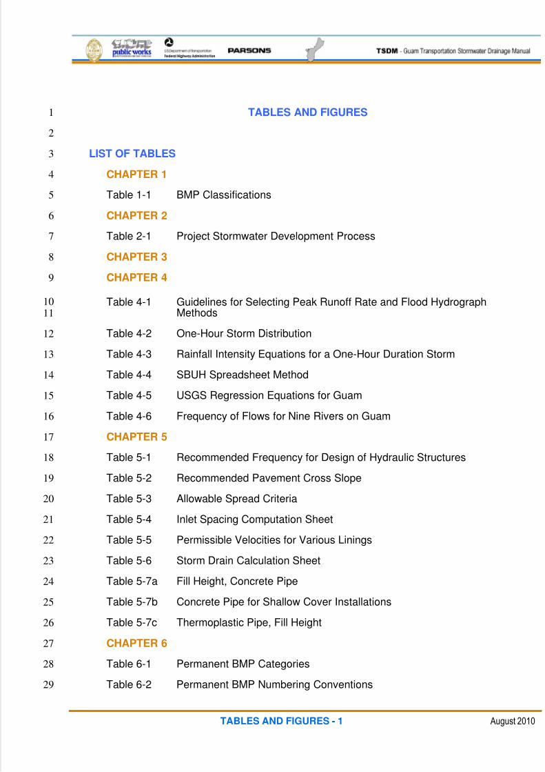
TABLES AND FIGURES1
2
LIST OF TABLES3
CHAPTER 14
Table 1-1 BMP Classifications5
CHAPTER 26
Table 2-1 Project Stormwater Development Process7
CHAPTER 38
CHAPTER 49
Table 4-1 Guidelines for Selecting Peak Runoff Rate and Flood Hydrograph10
Methods11
Table 4-2 One-Hour Storm Distribution12
Table 4-3 Rainfall Intensity Equations for a One-Hour Duration Storm13
Table 4-4 SBUH Spreadsheet Method14
Table 4-5 USGS Regression Equations for Guam15
Table 4-6 Frequency of Flows for Nine Rivers on Guam16
CHAPTER 517
Table 5-1 Recommended Frequency for Design of Hydraulic Structures18
Table 5-2 Recommended Pavement Cross Slope19
Table 5-3 Allowable Spread Criteria20
Table 5-4 Inlet Spacing Computation Sheet21
Table 5-5 Permissible Velocities for Various Linings22
Table 5-6 Storm Drain Calculation Sheet23
Table 5-7a Fill Height, Concrete Pipe24
Table 5-7b Concrete Pipe for Shallow Cover Installations25
Table 5-7c Thermoplastic Pipe, Fill Height26
CHAPTER 627
Table 6-1 Permanent BMP Categories28
Table 6-2 Permanent BMP Numbering Conventions29
5/13/2018 Guam Storm Water Drainage Manual - slidepdf.com
http://slidepdf.com/reader/full/guam-storm-water-drainage-manual 12/486
TABLES AND FIGURES - 2 August 2010
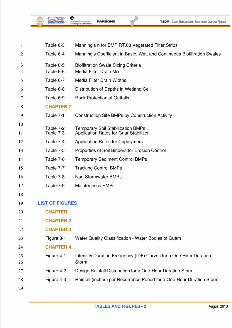
Table 6-3 Manning’s n for BMP RT.03 Vegetated Filter Strips1
Table 6-4 Manning’s Coefficient in Basic, Wet, and Continuous Biofiltration Swales2
Table 6-5 Biofiltration Swale Sizing Criteria3
Table 6-6 Media Filter Drain Mix4
Table 6-7 Media Filter Drain Widths5
Table 6-8 Distribution of Depths in Wetland Cell6
Table 6-9 Rock Protection at Outfalls7
CHAPTER 78
Table 7-1 Construction Site BMPs by Construction Activity9
Table 7-2 Temporary Soil Stabilization BMPs10
Table 7-3 Application Rates for Guar Stabilizer11
Table 7-4 Application Rates for Copolymers12
Table 7-5 Properties of Soil Binders for Erosion Control13
Table 7-6 Temporary Sediment Control BMPs14
Table 7-7 Tracking Control BMPs15
Table 7-8 Non-Stormwater BMPs16
Table 7-9 Maintenance BMPs17
18
LIST OF FIGURES19
CHAPTER 120
CHAPTER 221
CHAPTER 322
Figure 3-1 Water Quality Classification - Water Bodies of Guam23
CHAPTER 424
Figure 4-1 Intensity Duration Frequency (IDF) Curves for a One-Hour Duration25
Storm26
Figure 4-2 Design Rainfall Distribution for a One-Hour Duration Storm27
Figure 4-3 Rainfall (inches) per Recurrence Period for a One-Hour Duration Storm28
29
5/13/2018 Guam Storm Water Drainage Manual - slidepdf.com
http://slidepdf.com/reader/full/guam-storm-water-drainage-manual 13/486
TABLES AND FIGURES - 3 August 2010
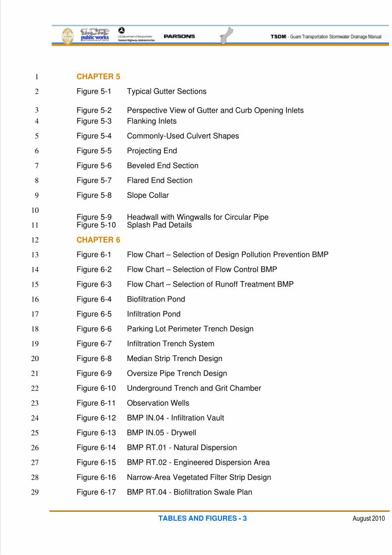
CHAPTER 51
Figure 5-1 Typical Gutter Sections2
Figure 5-2 Perspective View of Gutter and Curb Opening Inlets3
Figure 5-3 Flanking Inlets4
Figure 5-4 Commonly-Used Culvert Shapes5
Figure 5-5 Projecting End6
Figure 5-6 Beveled End Section7
Figure 5-7 Flared End Section8
Figure 5-8 Slope Collar9
Figure 5-9 Headwall with Wingwalls for Circular Pipe10
Figure 5-10 Splash Pad Details11
CHAPTER 612
Figure 6-1 Flow Chart – Selection of Design Pollution Prevention BMP13
Figure 6-2 Flow Chart – Selection of Flow Control BMP14
Figure 6-3 Flow Chart – Selection of Runoff Treatment BMP15
Figure 6-4 Biofiltration Pond16
Figure 6-5 Infiltration Pond17
Figure 6-6 Parking Lot Perimeter Trench Design18
Figure 6-7 Infiltration Trench System19
Figure 6-8 Median Strip Trench Design20
Figure 6-9 Oversize Pipe Trench Design21
Figure 6-10 Underground Trench and Grit Chamber22
Figure 6-11 Observation Wells23
Figure 6-12 BMP IN.04 - Infiltration Vault24
Figure 6-13 BMP IN.05 - Drywell25
Figure 6-14 BMP RT.01 - Natural Dispersion26
Figure 6-15 BMP RT.02 - Engineered Dispersion Area27
Figure 6-16 Narrow-Area Vegetated Filter Strip Design28
Figure 6-17 BMP RT.04 - Biofiltration Swale Plan29
5/13/2018 Guam Storm Water Drainage Manual - slidepdf.com
http://slidepdf.com/reader/full/guam-storm-water-drainage-manual 14/486
TABLES AND FIGURES - 4 August 2010
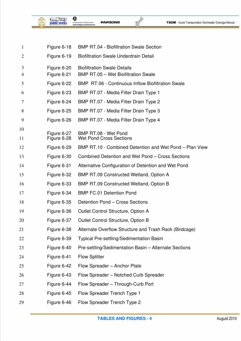
Figure 6-18 BMP RT.04 - Biofiltration Swale Section1
Figure 6-19 Biofiltration Swale Underdrain Detail2
Figure 6-20 Biofiltration Swale Details3
Figure 6-21 BMP RT.05 – Wet Biofiltration Swale4
Figure 6-22 BMP RT.06 - Continuous Inflow Biofiltration Swale5
Figure 6-23 BMP RT.07 - Media Filter Drain Type 16
Figure 6-24 BMP RT.07 - Media Filter Drain Type 27
Figure 6-25 BMP RT.07 - Media Filter Drain Type 38
Figure 6-26 BMP RT.07 - Media Filter Drain Type 49
Figure 6-27 BMP RT.08 - Wet Pond10
Figure 6-28 Wet Pond Cross Sections11
Figure 6-29 BMP RT.10 - Combined Detention and Wet Pond – Plan View12
Figure 6-30 Combined Detention and Wet Pond – Cross Sections13
Figure 6-31 Alternative Configuration of Detention and Wet Pond14
Figure 6-32 BMP RT.09 Constructed Wetland, Option A15
Figure 6-33 BMP RT.09 Constructed Wetland, Option B16
Figure 6-34 BMP FC.01 Detention Pond17
Figure 6-35 Detention Pond – Cross Sections18
Figure 6-36 Outlet Control Structure, Option A19
Figure 6-37 Outlet Control Structure, Option B20
Figure 6-38 Alternate Overflow Structure and Trash Rack (Birdcage)21
Figure 6-39 Typical Pre-settling/Sedimentation Basin22
Figure 6-40 Pre-settling/Sedimentation Basin – Alternate Sections23
Figure 6-41 Flow Splitter24
Figure 6-42 Flow Spreader – Anchor Plate25
Figure 6-43 Flow Spreader – Notched Curb Spreader26
Figure 6-44 Flow Spreader – Through-Curb Port27
Figure 6-45 Flow Spreader Trench Type 128
Figure 6-46 Flow Spreader Trench Type 229
5/13/2018 Guam Storm Water Drainage Manual - slidepdf.com
http://slidepdf.com/reader/full/guam-storm-water-drainage-manual 15/486
TABLES AND FIGURES - 5 August 2010
Figure 6-47 Pipe/Culvert Outlet Rock Protection1
Figure 6-48 Gabion Outlet Protection2
CHAPTER 73
Figure 7-1 Weir Tank4
Figure 7-2 De-Watering Tanks5
Figure 7-3 Typical Ford Crossing6
Figure 7-4 In-Stream Erosion and Sediment Control Isolation Techniques7
Figure 7-5 Gravel Berm with Impermeable Membrane8
Figure 7-6 Gravel Bag Technique9
Figure 7-7 In-Stream Erosion and Sediment Control Isolation10
Figure 7-8 K-Rail11
12

5/13/2018 Guam Storm Water Drainage Manual - slidepdf.com
http://slidepdf.com/reader/full/guam-storm-water-drainage-manual 16/486
This page intentionally left blank

5/13/2018 Guam Storm Water Drainage Manual - slidepdf.com
http://slidepdf.com/reader/full/guam-storm-water-drainage-manual 17/486
ACRONYMS - 1 August 2010
ACRONYMS AND ABBREVIATIONS
Acronym/Abbreviation Term
AASHTO American Association of State Highway and TransportationOfficials
ACP Asphalt Concrete Pavement
AHD Allowable Headwater Depth
AHW Allowable High Water
ASTM American Society for Testing and Materials
BFM Bonded Fiber Matrix
BMPs Best Management Practices
BOD Biochemical Oxygen Demand
BST Bituminous Surface Treatment
CAVFS Compost-Amended Vegetated Filter Strip
CCS Cellular Confinement System
CEC Cation Exchange Capacity
CERCLAComprehensive Environmental Response, Compensation, andLiability Act
CESCL Certified Erosion and Sediment Control Lead
CN Curve Number
COE U.S. Army Corps of EngineersCSBC Crushed Surfacing Base Course
CWA Clean Water Act
DAWR Guam Division of Aquatic and Wildlife Resources
DHW Design High Water
DPW Department of Public Works
DSA Disturbed Soil Area
EGL Energy Grade Line
EPA U.S. Environmental Protection Agency
EPP Environmental Protection Plan
ESA Endangered Species Act
ESC Erosion and Sediment Control
FAA Federal Aviation Administration
FC Freeboard Check
FEMA Federal Emergency Management Agency

5/13/2018 Guam Storm Water Drainage Manual - slidepdf.com
http://slidepdf.com/reader/full/guam-storm-water-drainage-manual 18/486
ACRONYMS - 2 August 2010
FHWA Federal Highway Administration
GEPA Guam Environmental Protection Agency
HDPE High-Density Polythethylene
HGL Hydraulic Grade Line
IDF Intensity-Duration-Frequency curve
IPM Integrated Pest Management
MEP Maximum Extent Practicable
MFD Media Filter Drain
N Newton’s Measure of Force
NCHRP National Cooperative Highway Research Program
NEPA National Environmental Policy Act
NOAA National Oceanic and Atmospheric Administration
NPDES National Pollutant Discharge Elimination System
NPS Non-Point Source Pollution
NRCSUSDA National Resources Conservation Service (Formerlyknown as the Soil Conservation Service or SCS)
NWI National Wetlands Inventory
OHW or OHWL Ordinary High Water Level
PCC Portland Cement Concrete
PCCP Portland Cement Concrete Pavement
PGIS Pollution-Generating Impervious SurfacesPLS Pure Live Seed
PS&E Plans, Specifications, and Estimates
RCRA Resource Conservation Recovery Act
RE Resident Engineer
RECP Rolled Erosion Control Product
RSP Rock Slope Protection
SA Surface Area
SBUH Santa Barbara Urban Hydrograph method
SCA Sanitary Control Area
SCR Special Contract Requirements
SDM Stormwater Drainage Manual
SDWA Safe Drinking Water Act
SF Safety Factor
SPCC Spill Prevention, Control, and Countermeasures
5/13/2018 Guam Storm Water Drainage Manual - slidepdf.com
http://slidepdf.com/reader/full/guam-storm-water-drainage-manual 19/486
ACRONYMS - 3 August 2010
SWPE Solid Wall Polyethylene
SWPPP Stormwater Pollution Prevention Plan
Tc Time of Concentration
TESC Temporary Erosion and Sediment Control
TLUC Territorial Land Use Commission
TSS Total Suspended Solids
UH Unit Hydrograph
UIC Underground Injection Control
USACE U.S. Army Corps of Engineers
USDA U.S. Department of Agriculture
USDOT U.S. Department of Transportation
USFWS U.S. Fish and Wildlife Service
USGS U.S. Geological Survey
UV Ultraviolet
WHPP Wellhead Protection Program
WPC Water Planning Committee
WQS Water Quality Standards
WRCA Guam Water Resources Conservation Act
WSEL Water Surface Elevations

5/13/2018 Guam Storm Water Drainage Manual - slidepdf.com
http://slidepdf.com/reader/full/guam-storm-water-drainage-manual 20/486
This page intentionally left blank
5/13/2018 Guam Storm Water Drainage Manual - slidepdf.com
http://slidepdf.com/reader/full/guam-storm-water-drainage-manual 21/486
GLOSSARY - 1 August 2010
GLOSSARY
Term Definition
80 percent capture rule
The 80 percent capture rule is based on an analysis of therainfall frequency spectrum. It is the impervious surface runoff from a design storm that produces 80 percent of all averageannual rainfall from a statistical viewpoint.
90 percent capture rule
The 90 percent capture rule is based on an analysis of therainfall frequency spectrum. It is the impervious surface runoff from a design storm that produces 90 percent of all averageannual rainfall from a statistical viewpoint.
Areal Extent The magnitude of an area.
Artificial ChannelsMan-made channels, including ditch, interceptor ditch, swale,median ditch, outfall ditch, lateral ditch, and canal.
Backwater A body of water in which the flow is slowed or turned back byan obstruction such as a bridge or dam, an opposing current,or the movement of the tide.
Baffle A vertical divider placed across the entire width of the wetpond, stopping short of the bottom.
Biofiltration
A pollution control technique using living material to captureand biologically degrade process pollutants. Common usesinclude processing wastewater, capturing harmful chemicals or silt from surface runoff, and microbiotic oxidation of contaminants in the air.
Biofiltration SwalesVegetation-lined channels designed to remove suspended
solids from stormwater.
Bioinfiltration A surface infiltration system covered with grass, but possiblytrees or shrubs.
Bioinfiltration Ponds Also known as bioinfiltration swales, combine filtration, soilsorption, and uptake by vegetative root zones, removesstormwater pollutants by percolation into the ground.
Buffer StripRefers to an area of natural indigenous vegetation that can beenhanced or preserved as part of a riparian buffer or stormwater dispersion system.
Check Dams
Reduce scour and channel erosion by reducing flow velocityand encouraging sediment settlement. A check dam is a small
device constructed of rock, gravel bags, sandbags, fiber rolls,or other proprietary product placed across a natural or man-made channel or drainage ditch.
Clear Water Diversion
A system of structures and measures that intercept clear surface water runoff upstream of a project site, transport itaround the work area, and discharge it downstream, withminimal water quality degradation for either the projectconstruction operations or construction of the diversion.
5/13/2018 Guam Storm Water Drainage Manual - slidepdf.com
http://slidepdf.com/reader/full/guam-storm-water-drainage-manual 22/486
GLOSSARY - 2 August 2010
Combination InletsConsist of both a curb opening inlet and a grate inlet placed ina side-by-side configuration, but the curb opening may belocated in part upstream of the grate.
Critical Areas
Defined as wetlands, floodplains, aquifer recharge areas,
geologically hazardous areas, and those areas necessary for fish and wildlife conservation.
Crown A crown is defined as the highest point of the internal surfaceof the transverse cross section of a pipe.
Curb Opening Inlets Vertical openings in the curb covered by a top slab.
Development
The term development encompasses all categories of construction and earth-moving, as well as other types of landuse and water-oriented construction. For the purposes of roadways, development is defined as the creation of newimpervious area.
Downgradient The direction that stormwater flows.
Engineered Dispersion
Similar to natural dispersion, this BMP can be used for impervious or pervious surfaces that are graded to drain viasheet flow or are graded to collect and convey stormwater toengineered dispersion areas after going through a flow-spreading or energy-dissipating device. Engineered dispersionuses the existing vegetation or landscaped areas, existingsoils or engineered compost-amended soils, and topographyto effectively provide flow control and runoff treatment. Siteselection is very important to the success of this BMP.
Eutrophication
The enrichment of water by nutrients, especially nitrogenand/or phosphorous, which can cause accelerated growth of algae and higher plant life that produce changes in the
ecological balance and deterioration in water quality.
Evapotranspiration
The total loss of water from a crop into the air. Water evaporates from any moist surface into the air unless the air issaturated. Water surfaces in contact with air, such as lakes,plant leaves, and moist soils, all evaporate water.
Fiber Rolls
Consists of wood excelsior, rice or wheat straw, or coconutfibers rolled or bound into a tight tubular roll and placed on thetoe and face of slopes to intercept runoff, reduce its flowvelocity, release the runoff as sheet flow, and provide removalof sediment from the runoff.
Flow Control BMPs
Reduce the peak rate of runoff during a storm event by storingthe flow and releasing it at a slower rate, thus protecting
stream ecosystems from excessive erosion (typical examplesare detention ponds and dry vaults).
Flow Splitter
A hydraulic structure used to maintain the stormwater qualitytreatment volume or flow to an off-line treatment facility whilebypassing larger flows. Usually a manhole or catch basinstructure having internal weir and orifice controls.
Frontal FlowThe water flowing in a section of gutter inlet occupied by agrate.
5/13/2018 Guam Storm Water Drainage Manual - slidepdf.com
http://slidepdf.com/reader/full/guam-storm-water-drainage-manual 23/486
GLOSSARY - 3 August 2010
Froude Number (Fr)
A dimensionless number comparing inertia and gravitationalforces. It may be used to quantify the resistance of an objectmoving through water, and compare objects of different sizes.Named after William Froude, the Froude number is based onhis speed/length ratio.
Grate InletsConsist of an opening in the gutter or ditch, covered by agrate.
Gravity Bag Filter Is also referred to as a de-watering bag and is a square or rectangular bag made of non-woven geotextile fabric thatcollects sand, silt, and fines.
Guar Guar is a nontoxic, biodegradable, natural galactomannan-based hydrocolloid treated with dispersant agents for easyfield mixing.
Hydraulic Matrix A combination of wood fiber mulch and a tackifier applied as aslurry.
Hydraulic Mulch
Hydraulic mulch consists of applying a mixture of shreddedwood fiber or a hydraulic matrix and a stabilizing emulsion or tackifier with hydroseeding equipment, which temporarilyprotects exposed soil from erosion by raindrop impact or wind.This is one of five temporary soil stabilization alternatives toconsider.
Hydrology
For the Highway Designer, the primary focus of hydrology isthe water that moves on the Earth’s surface and, in particular,that part that crosses transportation arterials (i.e., highwaystream crossings). Hydrology is the science and art of converting rainfall to runoff for design purposes.
HydroperiodThe cyclical changes in the amount or stage of water in an
aqueous habitat.
Hydroseeding
Typically consists of applying a mixture of wood fiber, seed,fertilizer, and stabilizing emulsion with hydromulch equipment,which temporarily protects exposed soils from erosion by water and wind. This is one of five temporary soil stabilizationalternatives to consider.
Hyetograph A graphical representation of the distribution of rainfall over time.
InfiltrationThe preferred method for flow control and runoff treatment andoffers the highest level of pollutant removal.
Infiltration Ponds
Infiltration ponds are usually earthen impoundments used for the collection, temporary storage, and infiltration of incomingstormwater runoff to groundwater. Infiltration ponds can alsobe designed to provide runoff treatment.
Isolation Techniques Methods that isolate near-shore work from a water body.
Kinematic Wave Equations A mathematical equation used to determine overland flowtravel times.
5/13/2018 Guam Storm Water Drainage Manual - slidepdf.com
http://slidepdf.com/reader/full/guam-storm-water-drainage-manual 24/486
GLOSSARY - 4 August 2010
Manning’s Equation
The Manning equation is an open-channel flow equation usedto find either the depth of flow or the velocity in the channelwhere the channel roughness, slope, depth, and shape remain
constant (steady uniform flow).
Mean High-Water MarkThe highest point that the water may reach for a navigablewaterway, lake, or ocean.
Mean Low-Water Mark The average low tide.
Media Filter Drain (MFD)
A linear flow-through stormwater runoff treatment device thatcan be sited along highway side slopes. MFDs have four basiccomponents: a gravel no-vegetation zone, a grass strip, theMFD mix bed, and a conveyance system for flows leaving theMFD mix.
Minimum RequirementsNine requirements intended to achieve compliance with federaland Guam water quality regulations, while catering to the
unique linear features of most transportation projects.
National Pollutant Discharge Elimination System (NPDES) Construction usually requires a NPDES permit.
National Wetlands Inventory (NWI)
Provides information on the characteristics, extent, and statusof the nation's wetlands and deep water habitats and other wildlife habitats. The inventory is conducted by the U.S. Fishand Wildlife Service.
Nomograph A graph consisting of three coplanar curves, each graduatedfor a different variable so that a straight line cutting all threecurves intersects the related values of each variable.
Oil Containment Boom A weather-resistant, hydrophobic, absorbent-filled boom for removing hydrocarbon sheens from water.
Open Channel
An open channel is a watercourse that allows part of the flowto be exposed to the atmosphere. Classified as those whichoccur naturally or those which are man-made or improvednatural channels.
Operational BMPsNonstructural practices that prevent or reduce pollutants fromentering stormwater.
Ordinary High-Water or Ordinary High-Water Level (OHWL)
For stormwater design purposes, this level is identified byenvironmental biologists based on vegetation types. Thesurface boundary is then identified, surveyed, and used as thecontrol for project impacts to the waterbody.
Overside Drains
Overside drains are conveyance systems used to protect
slopes against erosion.
Permanent BMPsPermanent BMPs are used to quality treat or flow controlhighway stormwater for the design life of the project site.
Piezometer A small-diameter observation well used to measure thehydraulic head of groundwater in aquifers.
Plans, Specifications, and Estimates (PS&E)Plans, Specifications, and Estimates usually relating to a finalset of construction contract documents.

5/13/2018 Guam Storm Water Drainage Manual - slidepdf.com
http://slidepdf.com/reader/full/guam-storm-water-drainage-manual 25/486
GLOSSARY - 5 August 2010
Pollution-Generating Impervious Surfaces (PGIS)
PGIS is any impervious surface expected to generatepollutants, such as bike lanes, travel lanes, and shoulders. Anexample of an impervious surface not expected to generatepollutants is sidewalks that are sloped away from the roadway.If the sidewalk slopes towards the roadway, then it contributesto the quantity of stormwater coming from the PGIS.
Presettling BasinProcess of allowing stormwater to settle the larger pollutionparticulates prior to entering a primary stormwater qualitytreatment or flow control facility.
Presumptive Approach
Meaning that projects that follow the stormwater BMPscontained in the SDM are presumed to have satisfied thewater quality requirements and are not required to providetechnical justification to support the selection of BMPs.
Projecting End A projecting end is a treatment where the culvert is simplyallowed to protrude out of the embankment.
Psyllium
Psyllium is composed of the finely ground mucilloid coating of
plantago seeds that is applied as a dry powder or in a wetslurry to the surface of the soil.
Regression EquationsThe equation representing the relation between selectedvalues of one variable and observed values of the other.
Reynold’s Number
A dimensionless number, the ratio of intertial forces to viscousforces, equal to pvl/n where p is density, v is velocity, n isviscosity relative to some length l , e.g., radius of pipe. For steady flow, the flow lines take the same form at a givenReynold’s number.
Sandbag Barrier
A temporary linear sediment barrier consisting of stackedsandbags, designed to intercept and slow the flow of
sediment-laden sheet flow runoff.
Santa Barbara Urban Hydrograph method (SBUH)
The SBUH method is based on the curve number (CN)approach, and also uses USDA National ResourcesConservation Service equations for computing soil absorptionand precipitation excess. The SBUH method converts theincremental runoff depths into instantaneous hydrographswhich are then routed through an imaginary reservoir with atime delay equal to the basin time of concentration.
Sediment/Desilting Basin
A sediment/desilting basin is a temporary basin formed byexcavating and/or constructing an embankment so thatsediment-laden runoff is temporarily detained under quiescentconditions, allowing sediment to settle out before the runoff isdischarged.
Sediment Trap
A temporary containment area that allows sediment incollected stormwater to settle out during infiltration or beforethe runoff is discharged through a stabilized spillway.

5/13/2018 Guam Storm Water Drainage Manual - slidepdf.com
http://slidepdf.com/reader/full/guam-storm-water-drainage-manual 26/486
GLOSSARY - 6 August 2010
Silviculture
The art and science of controlling the establishment, growth,composition, health, and quality of forests to meet diverseneeds and values of the many landowners, societies and
cultures.
Slotted InletsConsist of a pipe cut along the longitudinal axis, with barsperpendicular to the opening to maintain the slotted opening.
Slope Drain
A pipe used to intercept and direct surface runoff or groundwater into a stabilized watercourse, trapping device, or stabilized area.
Slope Rounding A design technique to minimize the formation of concentratedflows.
Soil Binders
Materials applied to the soil surface to temporarily preventwater-induced erosion of exposed soils on construction sites.Soil binders also provide temporary dust, wind, and soil
stabilization (erosion control) benefits.
Source Control BMPsInclude operational and structural BMPs. See also operationalBMPs and structural BMPs.
Spill Prevention, Control, and Countermeasures (SPCC) A set of plans that must be prepared and followed by thecontractor, once approved.
StarchStarch is non-ionic, cold-water soluble (pre-gelatinized)granular cornstarch.
Storm Drain
The portion of the highway drainage system that receivessurface water through inlets and conveys the water throughconduits to an outfall. It is composed of different length or sizes of pipe or conduit connected by appurtenant structures.
Stormwater Pollution Prevention Plan (SWPPP)The SWPPP is prepared by the contractor and includes theTESC and SPCC plans.
Straw Bale Barrier
A temporary linear sediment barrier consisting of straw bales,designed to intercept and slow sediment-laden sheet flowrunoff.
Straw Mulch
Straw mulch consists of placing a uniform layer of straw andincorporating it into the soil with a studded roller or anchoring itwith a stabilizing emulsion.
Structural BMPsPhysical, structural, or mechanical devices or facilitiesintended to prevent pollutants from entering stormwater.
Tailwater Defined as the depth of water downstream of a culvert or other conveyance discharge measured from the outlet invert.
Temporary BMPs
Designed to prevent the introduction of pollutants into runoff for the duration of the construction project and are concurrentwith construction of the permanent BMPs. Common examplesof temporary BMPs include the mulching of bare ground, siltfencing, and spill control and containment.

5/13/2018 Guam Storm Water Drainage Manual - slidepdf.com
http://slidepdf.com/reader/full/guam-storm-water-drainage-manual 27/486
GLOSSARY - 7 August 2010
Temporary Erosion and Sediment Control (TESC) PlansPlans that describe the measures used during construction toprotect state waters from degradation.
Territorial Seashore Reserve A distinct and valuable natural resource, existing as adelicately balanced ecosystem, protected by the TerritorialSeashore Protection Act.
Turbidity Curtain A fabric barrier used to isolate the near-shore work area.
Vegetated Surface A permanent perennial vegetative cover on areas that havebeen disturbed.
Wet PondConstructed basins containing a permanent pool of water throughout the wet season.

5/13/2018 Guam Storm Water Drainage Manual - slidepdf.com
http://slidepdf.com/reader/full/guam-storm-water-drainage-manual 28/486
This page intentionally left blank

5/13/2018 Guam Storm Water Drainage Manual - slidepdf.com
http://slidepdf.com/reader/full/guam-storm-water-drainage-manual 29/486
1 - 1 August 2010
1 PURPOSE AND SCOPE1
The purpose of this Guam Transportation Stormwater Drainage Manual (TSDM) is to2
provide guidelines for the planning and design of stormwater management facilities for3
transportation projects on the island of Guam. Transportation projects include any new4development, redevelopment, reconstruction, rehabilitation, or restoration of highways,5
roadways, and parking, including the appurtenant structures such as bridges and culverts.6
Conformance to the provisions of this TSDM will result in consistent design procedures and7
should support acceptance of stormwater planning by regulatory agencies. These8
guidelines take into account the variations in climatic, geologic, and hydrogeologic9
conditions of the island.10
This TSDM establishes the guidelines and provides uniform technical criteria for avoiding11
and mitigating impacts to water resources associated with the development of roadways12
and the associated infrastructure. This TSDM will be updated regularly to reflect changes in13
regulations and advances in stormwater management technology, and to clarify issues.14
The intended users of this TSDM are the Department of Public Work’s (DPW’s) consultants,15
site planners, engineers, contractors, reviewers, maintenance staff, and construction16
managers who design and construct transportation drainage systems.17
The design criteria established in this TSDM supersedes other previously-published18
stormwater drainage manuals and guidelines used by DPW.19
Transportation stormwater management requirements for Guam have been developed to20
help mitigate the effects of hydrologic change and water quality degradation that can occur21
from project development on receiving waters of Guam and the United States.22
This TSDM follows a presumptive approach to achieve compliance with federal and local23
water quality regulations. Projects that follow the stormwater Best Management Practices24
(BMPs) contained in this TSDM will be better suited to satisfy Guam EPA (GEPA) and25
federal requirements. This TSDM includes documentation guidelines that will be necessary26
for the permitting review process.27
1.1 THE IMPORTANCE OF STORMWATER MANAGEMENT28
Land development changes the physical, chemical, and biological conditions of waterways29
and water resources. The addition of buildings, roadways, parking lots, and other30
impervious surfaces can reduce natural infiltration, increase runoff, and provide additional31
sources of pollution.32
Depending on the magnitude of changes to the land surface, the total runoff volume can33
increase dramatically. These changes can also accelerate the rate at which runoff flows34
across the land. This effect is further exacerbated by drainage systems such as gutters,35
storm sewers, and lined channels that are designed to carry runoff to rivers and streams36
quickly.37
5/13/2018 Guam Storm Water Drainage Manual - slidepdf.com
http://slidepdf.com/reader/full/guam-storm-water-drainage-manual 30/486
1 - 2 August 2010
Without proper planning and design, development and impervious surfaces reduce the1
amount of water that infiltrates into the soil and groundwater, thus reducing the amount of2
water that can recharge aquifers and feed stream flow during periods of dry weather.3
Unmanaged stormwater from development and urbanization affects both the quantity and4
quality of the runoff. Development can increase the concentration and types of pollutants5
carried by runoff.6
Linear in nature, transportation projects tend to encompass multiple drainage basins and7
impact multiple receiving waters. Even though the runoff from highways may be a fraction8
of the runoff affecting nearby water bodies, it can contribute to the cumulative degradation9
of those waters unless suitable BMPs are utilized.10
The construction of roadway projects can contribute to surface runoff contamination,11
primarily due to suspended solids associated with soil erosion. Without suitable controls,12
construction activities can also result in the contamination of stormwater that results from13
vehicle operations and maintenance; use and storage of fuels, solvents and paints; and14uncured asphalt and concrete. Those impacts can be severe and long-lasting if appropriate15
actions are not taken to control construction site runoff quality.16
1.2 MANAGEMENT OF RUNOFF FROM TRANSPORTATION PROJECTS17
Federal and Guam regulations call for the implementation of both operational and18
technology-based BMPs to reduce the discharge of pollutants in stormwater to the19
maximum extent possible, before discharging back to natural waterways.20
The application of BMPs is the key to managing stormwater runoff from transportation21
projects. The term BMP refers to operational activities or physical controls that control flows22
and velocities and/or reduce pollution that would otherwise impact the receiving water23
bodies.24
BMPs identified as temporary and permanent have been classified into four categories, as25
shown in Table 1-1 below. Pollution prevention BMPs are the incorporation of good26
engineering practices during design and planning to limit a project’s adverse affect on the27
natural ground cover and flow patterns. Oftentimes, additional planning in the layout and28
staging of a project can reduce the disturbed ground area and maintain more natural runoff29
patterns then what typically might be expected.30
Runoff treatment BMPs are the application of long-term facilities that control flow rates31
and/or remove pollutants from runoff. This is typically accomplished by using detention32storage and ground infiltration. Other BMPs use gravity settling of particulate matter,33
vegetative and physical filtration, biological uptake, and soil absorption to remove34
pollutants. Flow control BMPs reduce the peak rate of runoff during a storm event by either35
infiltration into the soil profile or by storing the flow and releasing it at a slower rate. This36
helps to maintain the existing and more natural flow rates to limit erosive effects on37
downstream waterways. Permanent BMPs are used to treat highway runoff for the design38
life of the project site.39
5/13/2018 Guam Storm Water Drainage Manual - slidepdf.com
http://slidepdf.com/reader/full/guam-storm-water-drainage-manual 31/486
1 - 3 August 2010
Construction site BMPs are temporary measures designed to prevent the introduction of1
pollutants into runoff for the duration of the construction project. These measures also2
include infiltration, filtration, and particulate settling devices, which are installed and3
functioning prior to the start of construction. Common examples of temporary BMPs include4
bare- ground mulching, silt fencing, sedimentation basins, and spill control.5
Maintenance BMPs are the long-term maintenance of the roadway project area and the6
associated BMPs to keep them operating at proper efficiencies. These can include such7
maintenance activities as sweeping and mowing to remove pollutants at the source. Other8
typical long-term maintenance activities include keeping ponds and storm sewers clean of9
debris and sediments. This TSDM only discusses maintenance guidelines for stormwater10
BMPs. General maintenance activities are not listed in detail in this TSDM, because they11
are the subject of separate DPW guidelines.12
BMP Description
Design Pollution PreventionBMPs
Minimizing flow and quality impacts byimproved design and planning
Runoff Treatment BMPsPermanent quality treatment and flowcontrol devices and facilities
Construction Site BMPsTemporary sediment and waste controlduring the construction process
Maintenance BMPsLong term regular maintenance of thetransportation facilities and associatedBMPs
Table 1-1: BMP Classifications13
1.3 ORGANIZATION OF THIS MANUAL14
This TSDM is divided into eight chapters for the aid of the designer. Chapter 1 gives15
background information on the development of this TSDM and an overview of the16
stormwater problems associated with roadways and other parts of the transportation17
infrastructure.18
Chapter 2 provides an overview of the design process and how the stormwater/drainage19
design elements should be integrated into that process. Guidelines are provided for20
gathering pre-design data, reviewing design alternatives, and finalizing the selected21
alternative.22
Chapter 3 describes the minimum requirements that apply to the planning and design of23
stormwater facilities and BMPs. Guidelines are provided to determine which of the nine24
minimum requirements must be met for a given transportation project. The purpose and25
applicability of the minimum requirements are also described in this chapter.26
Chapter 4 discusses transportation hydrology; the conversion of rainfall to runoff as needed27
for conveyance; and BMP engineering purposes. This chapter lists which analysis methods28
to use, providing the required data and assumptions.29
5/13/2018 Guam Storm Water Drainage Manual - slidepdf.com
http://slidepdf.com/reader/full/guam-storm-water-drainage-manual 32/486
1 - 4 August 2010
Chapter 5 contains a discussion and guidelines on stormwater hydraulic design. This1
chapter also contains criteria on the selection, sizing, and documentation of the stormwater2
conveyance systems.3
Chapter 6 guides the designer through the process of selecting and designing permanent4
stormwater quality treatment and flow control BMPs that are applicable for Guam’s5
transportation conditions. This chapter includes details of the design and construction6
criteria for each BMP.7
Chapter 7 includes criteria for selecting appropriate Temporary Erosion and Sediment8
Control (TESC) measures. Appropriate TESC BMPs are required for all transportation9
projects and should also be included in the contractor’s stormwater pollution prevention10
plan, when required.11
1.4 HOW TO USE THIS MANUAL12
The designer should follow the guidelines included in Chapter 2 for integrating the planning13
and design of stormwater-related project elements into the context of the project14
development process. This process should be completed prior to using the guidelines in15
Chapter 3 to determine which minimum requirements must be satisfied for a specific16
project. In most instances, this process will prompt design of the post-construction BMPs17
according to the criteria provided in Chapters 4, 5, 6, and 7. Most projects lend themselves18
to a relatively straight-forward application of one or more of the BMP options presented in19
this TSDM. Finally, while working from a constructability point of view in accordance with20
the project construction staging plan and schedule, the designer will prepare a TESC plan21
in accordance with Appendix I.22
1.5 REVIEW PROCESS AND REGULATORY STANDING OF THIS MANUAL23
This TSDM provides guidelines for the planning and design of stormwater management24
facilities for transportation projects on the island of Guam. This TSDM meets the level of25
stormwater management established by GEPA in its Draft GEPA 2010 Stormwater26
Management Regulations and the Guam Water Quality Regulations; however, GEPA27
reserves the right to enforce regulatory compliance as provided for in Guam statutes and28
regulations. See Appendix IA.29
30

5/13/2018 Guam Storm Water Drainage Manual - slidepdf.com
http://slidepdf.com/reader/full/guam-storm-water-drainage-manual 33/486
2 - 1 August 2010
2 STORMWATER PLANNING AND GUAM DRAINAGE POLICIES1
This chapter provides guidelines for integrating the planning and design of stormwater-2
related project elements into the context of the Department of Public Work’s (DPW’s)3
project development process. It also describes various federal and local policies that4regulate stormwater discharges. This Guam Transportation Stormwater Drainage Manual5
(TSDM) makes all attempts to adhere to all current regulations. Because regulations evolve6
with time, this TSDM will be updated to remain current with regulations.7
2.1 DRAINAGE MASTER PLANNING AND PROJECT DEVELOPMENT8
Stormwater master planning is an important tool a designer can use to assess and prioritize9
both existing and potential future stormwater problems, as well as consider alternative10
stormwater management solutions.11
Stormwater planning is often used to address specific single functions such as drainage12
provisions, flood mitigation, cost-benefit analyses, or risk assessments. Multi-objective13
stormwater master planning broadens this traditional definition to potentially include land14
use planning and zoning, water quality, habitat, recreation, and aesthetic considerations.15
The integration of stormwater planning and design is crucial to DPW’s project development16
process. How the process applies to a specific project depends on the type, size, and17
complexity of the project. The project development process consists of the distinct phases18
described below. In practice, the phases actually overlap, and some design modifications19
may occur during the construction phase. Consultants may or may not be involved in any20
phase, but inclusion of this process into this TSDM reinforces DPW’s commitment to21
integrate stormwater planning and design into project development.22
Scoping phase : Development of this phase is based on the general project description and23
early estimates of needs and costs. Under this phase, a number of project alternatives may24
be evaluated and reviewed. Based on the relative merits of the alternatives, the better25
alternatives are selected and included in a summary document. The environmental section26
of the project summary establishes the environmental classification of the project and the27
level of environmental documentation required for the project.28
Preliminary design phase : Based on the summaries and cost estimates completed as29
part of the scoping and programming work, DPW will make a decision as to a selected30
alternative for additional storm drainage refinement and environmental assessment work to31
be performed. This is the preliminary design phase during which the stormwater design is32
further progressed; the Best Management Practices (BMPs) selected; and the33
environmental assessments completed. The subsequent hydraulic and environmental34
documentation is reviewed, and upon acceptance, DPW issues a “start work” order for both35
the permit applications and preparation of the final design and construction bid documents.36
Environmental permitting and final plans, specifications, and cost estimates (PS&E) 37
phase : The final design and construction cost estimate for the stormwater BMPs is38
5/13/2018 Guam Storm Water Drainage Manual - slidepdf.com
http://slidepdf.com/reader/full/guam-storm-water-drainage-manual 34/486
2 - 2 August 2010
accomplished during this phase. All environmental commitments are incorporated and the1
final project permits are obtained, while the final design plans and specifications are2
finalized and submitted ready for construction bidding.3
The design and environmental process continues during construction as part of shop4
drawing reviews, design support for change orders, and Requests for Information (RFIs).5
DPW should be consulted at each phase of the project development process for reviews6
and approvals, and to gain feedback regarding any project-specific requirements. Adhering7
to the minimum requirements and the BMP selection process discussed in this TSDM plays8
a critical role in the project development process, because it minimizes costly design9
changes, reduces delays in obtaining permits, and keeps the project in compliance during10
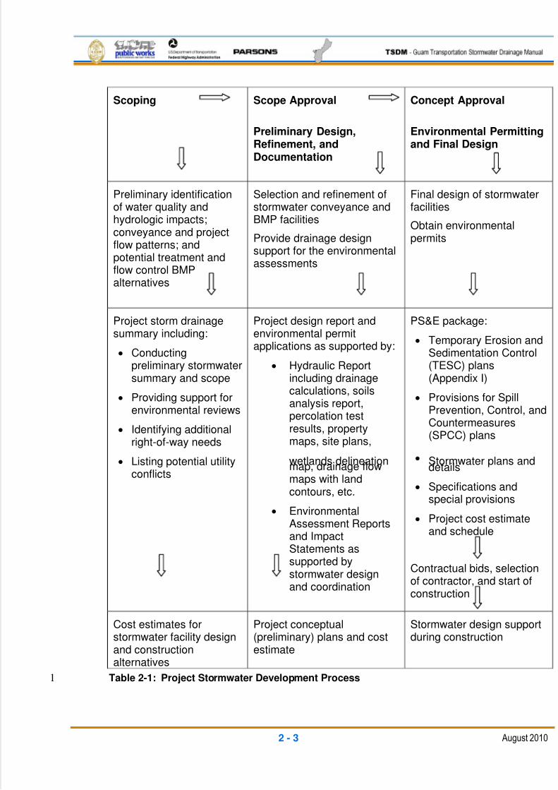
construction, operation, and maintenance activities. Table 2-1 describes the project11
development process.12
5/13/2018 Guam Storm Water Drainage Manual - slidepdf.com
http://slidepdf.com/reader/full/guam-storm-water-drainage-manual 35/486
2 - 3 August 2010
Scoping Scope Approval
Preliminary Design,Refinement, andDocumentation
Concept Approval
Environmental Permittingand Final Design
Preliminary identificationof water quality andhydrologic impacts;conveyance and projectflow patterns; andpotential treatment andflow control BMPalternatives
Selection and refinement ofstormwater conveyance andBMP facilities
Provide drainage designsupport for the environmentalassessments
Final design of stormwaterfacilities
Obtain environmentalpermits
Project storm drainagesummary including:
Conductingpreliminary stormwatersummary and scope
Providing support forenvironmental reviews
Identifying additionalright-of-way needs
Listing potential utilityconflicts
Project design report andenvironmental permitapplications as supported by:
Hydraulic Reportincluding drainagecalculations, soilsanalysis report,percolation testresults, propertymaps, site plans,
wetlands delineationmap, drainage flowmaps with landcontours, etc.
EnvironmentalAssessment Reportsand ImpactStatements assupported bystormwater designand coordination
PS&E package:
Temporary Erosion andSedimentation Control(TESC) plans(Appendix I)
Provisions for SpillPrevention, Control, andCountermeasures(SPCC) plans
Stormwater plans anddetails
Specifications andspecial provisions
Project cost estimateand schedule
Contractual bids, selectionof contractor, and start ofconstruction
Cost estimates forstormwater facility designand constructionalternatives
Project conceptual(preliminary) plans and costestimate
Stormwater design supportduring construction
Table 2-1: Project Stormwater Development Process1
5/13/2018 Guam Storm Water Drainage Manual - slidepdf.com
http://slidepdf.com/reader/full/guam-storm-water-drainage-manual 36/486
2 - 4 August 2010
2.1.1 SCOPING AND PLANNING1
This section describes various stormwater planning activities that should be undertaken to2
scope a project. The assessment and documentation of stormwater impacts and mitigation3
measures begins during project scoping. Project type, size, and complexity are key factors4
in the development of the stormwater strategy.5
2.1.1.1 SITE ASSESSMENT6
Understanding each site’s drainage patterns is essential to optimizing stormwater design for7
a project. The design team must identify all natural areas and off-site flows coming to the8
site, including streams and stormwater discharges. This information is shown on a9
“drainage map”. The drainage map should be prepared to sufficient detail and scale to10
show the entire watershed (in particular, the upstream watershed limits) that the project11
may be intersecting. The map should include the types of ground cover, soil types,12
elevation contours, flow paths, existing wetlands and streams, existing conveyance,13
existing cross-culverts, right-of-ways and easements, and existing water quality treatment14
and flow control facilities. The map is the key planning tool for design of the project15
stormwater facilities by including the project drainage basins and sub-basins, discharge16
locations, critical areas, downstream impact locations, and potential BMP sites. The map is17
also the basis for determining runoff calculation parameters such as times of concentration,18
drainage areas, curve numbers, and conveyance slopes.19
Further, as the design is developed, the proposed improvements, drainage conveyance,20
and BMPs are added to the map. The drainage map becomes the main exhibit in the21
project’s hydraulic report, which is part of the design and construction record.22
The transportation facility should allow for the passage of all off-site flows. The designer23
should work to maintain the existing flow patterns as much as possible. To minimize24
conveyance and BMP costs, it is generally best to keep off-site flows separate from the25
highway runoff. Most importantly, runoff from the project should not adversely impact26
downstream receiving waters and properties.27
The conservation of natural areas helps to minimize project impacts. Some of these areas28
may be used as part of the project’s stormwater management approach, especially if they29
are appropriate areas for dispersion and infiltration.30
2.1.1.2 GEOTECHNICAL EVALUATIONS31
Understanding the soils, geology, geologic hazards, and groundwater conditions is the first32
step to good drainage planning and design. The stormwater designer should provide input33
as to what is needed in regards to the stormwater planning when the design team scopes34
the overall geotechnical investigation work. The main items needed for drainage are35
geotechnical evaluations of geological hazards and groundwater issues, especially where36
existing problems have been identified. The geotechnical investigations should include soil37
characteristics in the project vicinity, including estimates of infiltration rates and38
5/13/2018 Guam Storm Water Drainage Manual - slidepdf.com
http://slidepdf.com/reader/full/guam-storm-water-drainage-manual 37/486
2 - 5 August 2010
groundwater depths at potential stormwater BMP locations. Specific soil investigations will1
be required for any proposed hydraulic structures, and for new storage or infiltration2
facilities.3
Seasonal variations of the groundwater table for infiltration and treatment pond designs4
require the installation of piezometers. One year of monitoring is desirable, but at a5
minimum, water level readings should be taken through one rainy season. Critical issues to6
consider include the following:7
Depth to water table (including any seasonal variations)8
Presence of soft or otherwise unstable soils9
Presence in soils of shallow bedrock or boulders that could adversely affect10
constructability11
Presence of existing adjacent facilities that could be adversely affected by12
construction of the stormwater facilities13
Presence of geologic hazards such as earthquake faults, abandoned mines,14
landslides, steep slopes, or rock fall15
Adequacy of drainage gradient to ensure functionality of the system16
Potential effects of the proposed facilities on future corridor needs17
Maintainability of the proposed facilities18
Potential impacts on adjacent wetlands and other environmentally sensitive areas19
Presence of hazardous materials in the area20
Whether or not the proposed stormwater plan will meet the requirements of21
resource agencies22
Infiltration capacity (infiltration and percolation rates for project sites)23
2.1.1.3 RIGHT-OF-WAY24
Examine the proposed layout of the project, and determine the most suitable sites available25
to locate the stormwater facilities. Typically, the stormwater designer should be able to fit26
the required conveyance systems, treatment and detention facilities, and outfalls within the27
existing right-of-way. However, infiltration and detention ponds may require additional plots28
outside of DPW’s boundaries. The locations and specifics for additional right-of-way should29
be established as early as possible, as the acquisition process is lengthy and will contribute30
heavily to the project’s cost. Often times, the designer is required to provide a legal right-of-31
way survey, drawings, and other support for the property acquisition process.32
33
34
5/13/2018 Guam Storm Water Drainage Manual - slidepdf.com
http://slidepdf.com/reader/full/guam-storm-water-drainage-manual 38/486
2 - 6 August 2010
2.1.1.4 UTILITIES1
A search of utility company records should be conducted to obtain information about2
locations and easements of existing utilities (and utilities planned to be installed in the near3
future) that may be impacted by the project. These records are assembled into an “Existing4
Utility Plan” for planning and future design use. Potential conflicts must be further evaluated5
and resolved prior to the start of construction. While it is usually best to try and plan6
stormwater facilities to avoid conflicts with existing utilities, sometimes the utility must be7
relocated. Depending on the existing utility agreement with DPW, the relocation may be a8
project cost or the obligation of the utility company. Often times, relocation involves either9
establishing or providing new easements for the utility company. Early planning of the10
drainage to minimize utility impacts will also help to limit the overall project costs and11
reduce impacts to the schedule.12
2.1.1.5 MAINTENANCE REVIEW13
There are several design reviews that should be completed with DPW’s maintenance staff.14
The first review is usually completed during the preliminary scoping or preliminary design15
phase to determine locations having specific drainage issues. This review helps to define16
locations that have frequent flooding, flow over-topping, sediment and debris buildup,17
groundwater issues, and erosion problems. This is also the time to obtain the maintenance18
staff’s preferences and procedures with regards to regular maintenance work.19
Understanding their approach to maintenance work, the type of equipment used, frequency20
of work, and access requirements will be critical when deciding on locations, types, and21
features of the selected stormwater facilities.22
Once the preliminary design for the project is finished, the features of the stormwater23
facilities should be reviewed with the maintenance staff. Their input will be critical in24
finalizing the permanent conveyance and treatment systems with regards to ease of access25
for inspections and cleaning. Maintenance work becomes an overall long-term cost to the26
project, and design coordination with the maintenance staff will help to minimize those27
costs.28
2.1.1.6 ENVIRONMENTAL SUPPORT29
The thorough documentation of stormwater-related environmental impacts and tracking of30
stormwater design commitments is a required element of the National Environmental Policy31
Act (NEPA), as well as other environmental laws and environmental permitting agencies.32
As a project’s scope is defined by the design team, a parallel effort is made by the33
environmental specialists to define the project’s impacts on the environment and methods34
to avoid or otherwise mitigate those impacts. The environmental evaluations will become35
the basis for the permitting applications and agency reviews. After the initial scope is36
approved, a more formal environmental assessment is made and documented;37
environmental commitments are made; and permit applications are prepared. Much of the38
5/13/2018 Guam Storm Water Drainage Manual - slidepdf.com
http://slidepdf.com/reader/full/guam-storm-water-drainage-manual 39/486
2 - 7 August 2010
environmental assessment is based on the project’s temporary and permanent impacts due1
to stormwater runoff.2
The stormwater designer should be prepared to support the project’s environmental3
specialist team during both the scoping and preliminary design phases, by providing the4
proposed stormwater configuration layouts, BMP types and locations, and discharge5
locations. Information typically needed by the environmental team is drainage basin and6
sub-basin areas; discharge locations for each drainage basin; acres of existing and new7
impervious surfaces; locations and areas of impacts to wetlands and waterways; area and8
volume of fill in waterways below the ordinary high water level; areas of new and existing9
pavement runoff being treated by watershed or drainage basin per outfall location; types of10
treatment; pavement areas having runoff flow control; pre- versus post-pollution loading11
calculations; quantities of fill in floodplains; and upstream and downstream hydraulic12
impacts due to cross-drain and culvert work. The information provided will need to be13
supported with exhibits and calculations.14
To limit impacts to critical areas, the stormwater designer should coordinate with the15
environmental specialist frequently while locating stormwater facilities and outfalls. Early16
discussions between the designer and specialist may help to avoid later permit issues with17
regards to such things as bridge and culvert placement, aquatic habitats and fish passage,18
erosion and sedimentation control, groundwater or potable water well contamination, local19
vegetative mitigation, and project pollution loadings.20
Through the final design, the coordination between the environmental specialist and the21
stormwater designer continues as the designer prepares the TESC plans and designs22
facilities that meet the environmental permit commitments and requirements. The23
stormwater designer often supports construction and/or the contractor’s environmental24
manager in the preparation of water monitoring plans, pollution and spill control plans, and25
TESC updates.26
2.1.1.7 STORMWATER SUMMARY27
Stormwater documentation during the scoping phase of project development is referred to28
here as the stormwater summary and scope. This package contains the information used to29
predetermine stormwater impacts and the initial selection of stormwater BMPs. It is the30
source of stormwater information needed to complete the project summary documents. This31
package must include a brief summary report containing the following:32
Identification of the project program33
Brief project description34
Synopsis of data gathered during the site assessment35
Drainage map36
Basin and sub-basin identification37
5/13/2018 Guam Storm Water Drainage Manual - slidepdf.com
http://slidepdf.com/reader/full/guam-storm-water-drainage-manual 40/486
2 - 8 August 2010
Discharge area delineations indicating flow paths and outfalls to receiving waters1
Area determinations2
Applicable minimum requirements3
Other applicable regulatory requirements related to stormwater4
Design criteria required for flow control and runoff treatment5
Known problems and commitments6
Design alternatives and assumptions for flow control and runoff treatment7
Cost estimates8
The stormwater summary report documents the design efforts and decisions made during9
the scoping phase of the project’s development, and must be retained and easily-10
retrievable. Once the project is reviewed, alternatives are selected, and the designer is11
selected by DPW, the file and report become the starting point for the preliminary design12
phase. Note that the report is internal to DPW and its consultants, and serves as a starting13
point for preliminary design.14
2.1.2 PRELIMINARY DESIGN15
The preliminary design develops the preferred stormwater drainage alternatives16
(alternatives that were identified in the scoping phase) into a workable concept with enough17
detail to enable preparation of cost estimates. As part of the preliminary design process,18
data is developed to support the parallel environmental assessment and permit application19
preparation efforts.20
2.1.2.1 HYDRAULIC REPORT21
The hydraulic report is intended to serve as a complete record containing the engineering22
justification for all drainage design and design modifications that occur as a result of project23
construction. The report documents the pre-project existing hydraulic conditions, as well as24
the post-project stormwater management facilities. The report contains all of the designer’s25
intent, criteria, and calculations for the stormwater design. The hydraulic report is the basis26
for approval of the project drainage facilities by DPW. This report is then updated during27
construction, with any modifications, to act as a permanent as-built record of the project’s28
stormwater management facilities. Appendix II contains detailed instructions and a sample29
outline required for preparation of the hydraulic report.30
During the preliminary design phase, a draft (or preliminary) hydraulic report is prepared.31
This preliminary hydraulic report is an expansion of the stormwater summary report32
developed as part of the scoping phase. The preliminary hydraulic report contains the33
existing condition descriptions and the layout and general support calculations for the34
selected stormwater management alternatives. At this stage of the project development, the35
stormwater flows, general conveyance routing, and BMP types and sizes are finalized, from36

5/13/2018 Guam Storm Water Drainage Manual - slidepdf.com
http://slidepdf.com/reader/full/guam-storm-water-drainage-manual 41/486
2 - 9 August 2010
which the cost estimates and right-of-way requirements can be determined. However, the1
preliminary report lacks many of the final sizing and design details prepared during the final2
design phase. The preliminary hydraulic report must be reviewed and approved by DPW3
prior to start of the final stormwater design.4
The final hydraulic report is a detailed compilation of the final stormwater management5
design. This final report contains detailed descriptions and calculations for all hydraulic6
design assumptions and decisions. It also includes the development of the TESC plans for7
construction, as well as the permanent post-development facilities.8
If any changes are made to the final stormwater design during construction, the changes9
are documented with all supporting calculations, plans, and exhibits as attachments to the10
hydraulic report. Major revisions require separate documentation and approval by DPW.11
Minor revisions are assembled and included as a final attachment to the hydraulic report as12
an as-built record of the project’s stormwater management development.13
2.1.3 FINAL DESIGN14
The final design of the project follows the approval of the preliminary design, cost15
estimates, and environmental documentation by DPW. The project’s permit applications16
and final design preparation is usually completed on a parallel schedule, typically taking17
approximately the same amount of time. The final design work can proceed by two different18
procedures in accordance with DPW’s direction and according to the type and suitability of19
the project. The first method is a final design prepared for the traditional design-bid-build20
method of project implementation. The second is a final design prepared for a design-build21
project approach.22
2.1.3.1 DESIGN-BID-BUILD23
In the design-bid-build method, the designer develops the preliminary plans into a detailed24
set of plans and specifications ready for contractor bidding. The stormwater management25
facility designs are brought up to a level of plan and detail that describes the specific26
requirements the contractor must meet with regard to layout, levels, grades, and materials.27
While not telling the contractor exactly how to conduct its operations, the plans, details, and28
specifications describe as precisely as possible the level of performance and testing29
standards that must be met. As part of the process, the designer also prepares a30
construction schedule and cost estimate for DPW’s use to assist in defining the contractual31
time limit to complete the work, and to compare against the contractor bids.32
Although not part of the contractual bid package, the stormwater designer must prepare a33
final hydraulic report. The designer will obtain DPW’s final approval of the stormwater34
facility plans and supporting calculations, accomplished through review and approval of the35
final hydraulic report. This report confirms that DPW’s drainage criteria, environmental36
commitments, and permit requirements have been met.37
5/13/2018 Guam Storm Water Drainage Manual - slidepdf.com
http://slidepdf.com/reader/full/guam-storm-water-drainage-manual 42/486
2 - 10 August 2010
The stormwater designer is usually responsible for a number of elements in the final project1
design package. These normally include:2
Drainage plans: Show proposed roadway alignment and edge of pavement; existing3
stormwater system including proposed conveyance structures, pipes, ditches, and4
channels; and proposed stormwater quality treatment and flow control facilities.5
Each structure and pipe is uniquely numbered for reference in the quantities tables6
and profile detail sheets. Deletions of the existing systems and other construction7
constraints are shown by notes.8
Drainage profile details: The details for installation of the stormwater conveyance9
facilities are shown on pipe profile sheets. Each structure, ditch, and pipe is shown10
in profile, with existing and proposed ground surfaces; layout station and offset;11
type; size or dimension; pipe length; slope; and any specific requirements such as12
rock protection at outlets, unique connection collars, headwalls, type of grate or13
cover, connection to existing, etc. Each pipe, ditch, and structure is identified by its14
corresponding number on the plan sheets.15
Drainage details: Most drainage structural and installation details are contained in16
DPW’s Standard Drawings. These are referred to on the profile sheets and by17
reference in the contract documents. However, most projects will require unique18
hydraulic structure designs requiring specifically-detailed design sheets. Other items19
requiring more detail for construction are items such as stormwater treatment and20
flow control BMPs, where each facility requires a unique design to fit the site.21
Quantity sheets: The contractual plan set includes a listing of pipes, structures, and22
earthwork in tablature. Each item is identified by its corresponding number on the23plan sheets. The stormwater designer is responsible for assembling a detailed24
listing of stormwater structure, pipe, and earthwork quantities.25
TESC plans: The stormwater designer prepares a detailed TESC plan set for the26
project. The plan includes details for controlling and minimizing sediment in the27
stormwater runoff during construction for each major construction phase. The plans28
are prepared in close coordination with the project schedule and staging designers.29
These plans are sometimes prepared earlier, in support of the environmental permit30
application review process. After award of the contract, the contractor will modify31
these plans as applicable to fit its specific staging and work elements. Appendix I32
contains detailed instructions and a sample outline required for preparation of the33
TESC plans.34
Stormwater Pollution Prevention Plans (SWPPP): The SWPPP usually consists of35
the TESC and spill prevention, control and countermeasures (SPCC) plans. The36
details of SWPPP are usually a requirement of the contractor to produce. However,37
most plan and specification contract packages will have an example plans or details38
of what will be required.39

5/13/2018 Guam Storm Water Drainage Manual - slidepdf.com
http://slidepdf.com/reader/full/guam-storm-water-drainage-manual 43/486
2 - 11 August 2010
Specifications: Most of the performance and other technical standards are included1
in DPW’s Standard Specifications. However, there are always unique elements in2
every project that require a new specification be prepared. These are called Special3
Provisions, and are written in a standard format that includes the unique item4
description, performance requirements (materials and installation), and5
measurement and payment methods.6
Bid list: The project items to be constructed are summarized by type in accordance7
with the appropriate specification pay item description. The quantities are8
summarized for the contractor to enter its bids into the tablature format. The9
stormwater designer is responsible for assembling the stormwater and TESC items10
and quantities.11
Construction cost estimate: The stormwater designer will prepare a construction12
cost estimate based on the quantity of each pay item in the project. Each item is13
assigned a unit price estimate of materials and installation cost by a contractor. The14
pricing of items is based on experience with past project and construction methods,15
using prices from other recent bids by DPW or other similar projects nationally. This16
cost estimate is for DPW’s use and is kept confidential until after the contractual17
bids are opened.18
Construction schedule: The stormwater designer will provide input as to how the19
project can be staged during construction, with estimates on how long it takes to20
perform the work, for an overall estimated construction schedule. This schedule21
becomes the basis for the contractual time length and for DPW’s monitoring of the22
contractor’s work.23
The stormwater designer will provide support during the contractual bidding process to24
answer any stormwater questions by the bidders and to further review any required bid25
submittals after bid opening in regard to contractor qualifications and procedures that26
contribute to the final selection of a contractor.27
The stormwater designer is usually required to support the construction management28
process by responding to the contractor’s or DPW’s RFI on the design, and help to prepare29
any required change orders that pertain to drainage work. The designer should also finalize30
any modifications to the drainage design and the as-built drawings as an amendment31
(attachment) to the final hydraulic report.32
2.1.3.2 DESIGN-BUILD33
For the design-build project delivery method, the designer assembles the preliminary plans34
(often called concept plans) and prepares a set of performance specifications. The final35
design is the responsibility of the design-build contracting company. DPW maintains control36
of the performance specifications for the design by only allowing the design-builder to make37
changes from the conceptual plans to within limited performance-type boundaries.38
5/13/2018 Guam Storm Water Drainage Manual - slidepdf.com
http://slidepdf.com/reader/full/guam-storm-water-drainage-manual 44/486
2 - 12 August 2010
As part of the design-build process, the bidding process requires each design-build1
contractor to further develop the conceptual drawings with additional design, such that they2
can develop a lump sum bid .The uniqueness of this process is that the contractor can3
develop its own design (within specified limits) to match its own methodologies and4
scheduling, to ultimately obtain the best price possible. Usually, selection of the best5
design-build contractor is based on a combination of the lump sum price and a rating6
system of the proposed methods and schedules to perform the work.7
The stormwater designer will support the bidding process by answering the design-build8
contractor’s questions. The designer will also review the various proposals for conformance9
to the specifications and rate the methods and procedures of the drainage work for10
comparison and contractor selection.11
It will be the design-builder’s (usually contractors partnered with design consultants)12
responsibility to prepare the final design and specifications for construction. For stormwater13
drainage, this includes the calculations and supporting documentation as a final hydraulic14report. Typically, DPW will review the design-builder’s designs at the preliminary, final, and15
released for construction stages. The designs are generally only accepted with comments,16
and not approved until the final handover of all project requirements. However, the design is17
usually performed in close coordination with DPW’s project management staff during over-18
the-shoulder type reviews. Depending on DPW’s project management organization, the19
stormwater designer will typically be involved in reviews of the design-builder’s stormwater20
submittals.21
2.2 SPECIAL DESIGN CONSIDERATIONS22
2.2.1 CRITICAL AND SENSITIVE AREAS23
Critical areas are defined as wetlands (including streams and lakes), floodplains, shorelines24
and reefs, aquifer recharge areas, sink holes, well heads, geologically hazardous areas,25
and those areas necessary for fish and wildlife conservation.26
2.2.2 WETLANDS27
Altering land cover and natural drainage patterns may alter stormwater input into28
surrounding wetlands. Hydrologic changes have more immediate and greater effects on the29
composition of vegetation and amphibian communities than do other environmental30
changes, including water quality degradation. Wetlands are protected under federal law and31
any project encroachment or impacts to the wetlands and their buffers must be mitigated.32Project stormwater facilities should attempt to maintain the same flow patterns, rates, and33
quality of runoff to the wetlands as the existing conditions.34
Wetland ecosystems are highly effective managers of stormwater runoff. They effectively35
and naturally remove pollutants, attenuate flows, and recharge groundwater. Minimum36
Requirement 7 (see Chapter 3) addresses wetland protection. Note that natural wetlands37
5/13/2018 Guam Storm Water Drainage Manual - slidepdf.com
http://slidepdf.com/reader/full/guam-storm-water-drainage-manual 45/486
2 - 13 August 2010
cannot be used for temporary or permanent project stormwater quality treatment and flow1
control facilities as required under the minimum requirements in Chapter 3.2
All projects with the potential to adversely affect wetlands should be evaluated by biologists3
who assess possible impacts and provide guidance to design teams. The evaluation should4
include a determination of each wetland's classification, characteristics, quality, and5
functions. Wetland boundaries are delineated and surveyed when they are close to or6
overlap with project work areas. The surveyed wetland boundaries should be included on7
the plans for the project.8
Upon completion of the field review, a wetland report is prepared for each project,9
documenting the information gathered on wetlands in the project area, and summarizing the10
nature and extent of project impacts.11
The design professionals should follow strict protocols requiring avoidance of all wetland12
impacts or, where avoidance is not practical, minimization to the greatest extent practical.13
Special emphasis should be placed on avoiding impacts to high-quality wetlands. When the14
objectives of a transportation project cannot be met without adverse impacts to wetlands, a15
wetland mitigation plan detailing how lost wetland functions will be compensated should be16
prepared. Subsequently, wetland mitigation plans are submitted to one or more regulatory17
agencies, typically the U.S. Army Corps of Engineers (USACE) and local governments, for18
their review and permit approval. Even when the impacts are insignificant enough to fall19
below regulatory thresholds, the department follows a "no-net-loss" directive requiring20
compensatory mitigation for any wetland loss.21
2.2.3 FLOODPLAINS22
Hydraulic flood plain storage that is displaced by roadway fill or other structures will result in23
a corresponding increase in floodplain water surface levels. This increase may also change24
wetland hydrodynamics; cause upstream property damage; increase downstream stream25
flows; and produce additional channel erosion, downstream flooding, and decreased26
infiltration and summer base flows. Projects may be required to mitigate the loss of27
hydraulic storage by creating new storage elsewhere within the floodplain.28
Stormwater discharge from the project area’s new impervious surfaces or changed29
discharge patterns may also impact the floodplain water surface levels. As part of the30
downstream analysis, impacts should be checked and mitigated. Refer to the requirements31
for Minimum Requirement Number 4 in Chapter 3.32
Stormwater quality treatment and flow control facilities should be placed above the 50-year33
floodplain level. Stormwater quality treatment facilities should be designed such that flood34
levels cannot flush the previously-removed pollutants back into the natural water bodies. It35
is also pointless to install detention facilities that reduce the floodplain storage volume,36
which must be mitigated elsewhere.37
38
5/13/2018 Guam Storm Water Drainage Manual - slidepdf.com
http://slidepdf.com/reader/full/guam-storm-water-drainage-manual 46/486
2 - 14 August 2010
2.2.4 AQUIFERS AND WELLHEADS1
In general, it is desirable to recharge the underlying limestone bedrock aquifer in the2
northern Guam area. However, roadway runoff must be pre-treated prior to infiltration into3
the aquifer. The infiltration BMP description protects the aquifer by requiring pre-treatment4
prior to the infiltration facility, with the infiltration being through at least 2 ft. of soil depth5
above the limestone bedrock. The soil interaction with the stormwater provides entrapment,6
oxidation, and vegetative absorption of the stormwater pollutants. Where less than 2 ft. of7
soil exists above the limestone bedrock or the groundwater table, the runoff must pass8
through a prescribed quality treatment BMP prior to infiltration. Likewise, any project9
discharge to a limestone area sinkhole must be quality treated using an appropriate BMP.10
The project should be of sufficient distance or provide barriers for physical protection of well11
heads and limestone area sinkholes. Untreated stormwater from the project area should not12
be allowed to discharge or infiltrate closer than 1000 ft. to a well.13
2.2.5 STREAMS AND RIPARIAN AREAS14
Similar to protection of wetlands, the project’s environmental specialist will establish the15
boundaries of the stream and its buffer. The stream boundary is usually identified by its16
Ordinary High Water Level (OHWL or OHW), which is determined by field observation of17
the vegetative and flow-level indications by the environmental specialist.18
Similar to the wetlands, the streams are protected by federal law and any project19
encroachments and impacts to stream channels and their boundaries must be mitigated.20
Where at all possible, avoid any filling within the OHWL boundaries. For roadway21
widenings, often times culvert extensions can be avoided by using headwalls, with no need22
for embankment fill below the OHWL. Other measures to minimize the project’s impacts is23
using flow spreaders on stormwater outlets for a more natural sheet flow across the stream24
bank and buffer area into the water body. DPW also prefers using the vegetative erosion25
protection measures, such as tree stakes and grasses, as a more sensitive alternative to26
structures or riprap.27
The design professionals should follow strict protocols requiring avoidance of all riparian28
impacts or, where avoidance is not practical, minimization to the greatest extent practical.29
When the objectives of a transportation project cannot be met without adverse impacts to30
stream and riparian habitats, a mitigation plan detailing how lost riparian functions will be31
compensated should be prepared. Subsequently, stream and riparian mitigation plans are32
submitted to one or more regulatory agencies, typically the USACE and local governments,33
for their review and permit approval.34
2.2.6 ENDANGERED SPECIES35
A biological evaluation or biological assessment must be prepared whenever it is suspected36
that Endangered Species Act (ESA)-listed species inhabit the vicinity of a project. The37
scoping team must contact the biologist early in the scoping process to request assistance38
5/13/2018 Guam Storm Water Drainage Manual - slidepdf.com
http://slidepdf.com/reader/full/guam-storm-water-drainage-manual 47/486
2 - 15 August 2010
in determining ESA-related issues and how these issues and needs affect project design1
and cost considerations.2
2.2.7 AIRPORTS3
Special consideration must be given to the design of stormwater facilities for projects4located near airports. Roadside features, including standing water (such as wet ponds) and5
certain types of vegetation, can attract birds both directly and indirectly. The presence of6
large numbers of birds near airports creates hazards for airport operations and must be7
avoided. Before planning and designing facilities for a project near an airport, contact the8
airport and the Federal Aviation Administration (FAA) for wildlife management manuals and9
other site-specific criteria.10
2.2.8 BRIDGES11
Because the over-water portion of the bridge surface captures only the portion of rainfall12
that otherwise would fall directly into the receiving water body, that portion of the bridge13
makes no contribution to the increased rate of discharge associated with surface runoff to14
the water body.15
Bridges are typically so close to receiving waters that it is often difficult to find sufficient16
elevations or areas in which to site a stormwater quality treatment solution. In the past,17
bridges were constructed with small bridge drains that discharged the runoff directly into the18
receiving waters by way of downspouts. Since this practice is no longer allowed, it becomes19
challenging to incorporate runoff collection, conveyance, and treatment facilities into the20
project design.21
Sometimes the treatment can be completed by treating runoff from another equivalent22
pavement area that drains into the same waterway.23
The use of suspended pipe systems to convey bridge runoff must be avoided whenever24
possible because these systems have a tendency to become plugged with debris and are25
difficult to clean. The preferred method of conveyance is to hold the runoff on the bridge26
surface and intercept it at the ends of the bridge with larger inlets. This method requires27
adequate shoulder width to accommodate flows so that they do not spread farther into the28
traveled way than allowed. In cases where a closed system must be used, it is29
recommended that bridge drain openings and pipe diameters be larger, and that 90-degree30
bends be avoided to ensure the system’s operational integrity. Early coordination with31
DPW’s maintenance staff is essential if a closed system is being considered.32
2.3 OVERVIEW OF FEDERAL, TERRITORIAL, AND LOCAL ORDINANCES33
The list of laws, regulations, and ordinances below are provided only for guidance. It should34
not be read as a complete list of applicable regulations. Regulations are evolving on a35
continuous basis. The reader should contact individual agencies for permit requirements.36
37
5/13/2018 Guam Storm Water Drainage Manual - slidepdf.com
http://slidepdf.com/reader/full/guam-storm-water-drainage-manual 48/486
2 - 16 August 2010
FEDERAL ACTS1
Federal Clean Water Act (CWA) 2
The objective of the CWA is to restore and maintain the chemical, physical, and biological3
integrity of the nation’s waters. It established broad and comprehensive rules, regulations,4and authorities for the protection, maintenance, and improvement of water quality for all5
waters of the United States; and it established specific actions to carry out necessary water6
pollution prevention efforts by federal and state governments. The applicable sections are:7
§104 - Authorizes the U.S. Environmental Protection Agency (EPA) to establish8
programs for the prevention, reduction, and elimination of pollution.9
§303 - Requires states to establish Water Quality Standards (WQS) and identify10
those waters that do not comply with standards.11
§304 - Requires the U.S. EPA to issue guidance to states for identifying and12
evaluating the extent of Non-Point Source Pollution (NPS) pollutants and methods13
to control NPS discharges from agriculture, silviculture, construction, and14
hydromodification.15
§305 - Requires states to submit biennial reports describing the quality of all16
navigable waters within the state, including a description of the nature and extent of17
the NPS source of pollution and recommendations to control such sources.18
§314 - Requires federal government entities to comply with local requirements to the19
same extent as any nongovernmental entity.20
§401 - Requires any applicant for a federal license or permit conducting an activity21
that may cause a discharge to navigable waters to acquire a water quality22
certification from the state indicating that such discharges will not violate the state’s23
WQS.24
§402 - National Pollutant Discharge Elimination System (NPDES) permits – Require25
federal permits for point source dischargers.26
§404 - Requires individuals/entities conducting construction activities within all27
jurisdictional waters to acquire a Section 404 permit from the USACE and a28
Section 401 water quality certification from the state.29
Federal Safe Drinking Water Act (SDWA) 30
§1428 - Requires states to create a Wellhead Protection Program (WHPP). This is31
an effective means for local governments to protect and manage groundwater32
resources. Preventing groundwater from becoming contaminated protects the public33
health and the environment, and is cost-effective.34
5/13/2018 Guam Storm Water Drainage Manual - slidepdf.com
http://slidepdf.com/reader/full/guam-storm-water-drainage-manual 49/486
2 - 17 August 2010
§1424 - Allows for the designation of principal or sole-source aquifers. In 1978, the1
groundwater lens of northern Guam was defined as a “principal source aquifer” by2
the U.S. EPA.3
Federal Coastal Zone Act - Reauthorization Amendments of 1990 4
§6217 - Led to the establishment of the Guam Non-Point Source Pollution5
Management Plan, which has received conditional federal approval. This plan is a6
coordinating document with the goal of controlling NPS through the use of various7
management measures, and should be adopted and implemented with legal8
authority. Oversight is provided by the U.S. EPA and the National Oceanic and9
Atmospheric Administration (NOAA).10
Federal Comprehensive Environmental Response, Compensation, and Liability Act 11
(CERCLA) 12
CERCLA regulates the investigation and cleanup strategies of hazardous materials13and groundwater contamination resulting from military activities.14
Federal Resource Conservation Recovery Act (RCRA) 15
This act includes hazardous waste and underground storage tank provisions (see16
40CFR, Part 280, for relevant regulations).17
TITLE 10 OF THE GUAM CODE ANNOTATED18
10 GCA, Chapter 46. Guam Water Resources Conservation Act (WRCA) 19
WRCA requires the conservation and beneficial use of all surface and underground water20
resources; the management of such resources to prevent operation modifications, over-21pumping by maintenance, abandonment, and destruction; and the avoidance of22
contamination of water wells as a result of extraction. WRCA established all water23
resources as the property of the people of Guam.24
Controls the drilling and operation of wells25
Authorizes the Groundwater Management Program26
10 GCA, Chapter 47, Water Pollution Control Act 27
This requires that the Government of Guam conserve, protect, maintain, and improve the28
quality and potability of public water supplies for the propagation of wildlife, fish, and29
aquatic life, and for agricultural, industrial, recreational, and other beneficial uses through30
the prevention, abatement, and control of new or existing water pollution sources.31
Guam’s soil erosion and sediment control regulations32
Guam’s feedlot waste management regulations33
Guam’s WQS34
5/13/2018 Guam Storm Water Drainage Manual - slidepdf.com
http://slidepdf.com/reader/full/guam-storm-water-drainage-manual 50/486
2 - 18 August 2010
10 GCA, Chapter 48, Toilet Facilities and Sewage Disposal 1
Sewer connection regulations2
Individual wastewater system regulations3
10 GCA, Chapter 49, Air Pollution Control Act 4
Air pollution standards and implementation plan5
10 GCA, Chapter 50, Guam Pesticide Act 6
Guam pesticide regulations7
10GCA, Chapter 53, Safe Drinking Water Act (SDWA) 8
Guam’s SDWA.9
§7289(f) - Underground Injection Control Regulations and Program, which protects10
underground sources of drinking water from contamination.11
Guam’s WHPP, approved in 1993, provides for three levels of protection: 1) the12
1,000-foot radius around each drinking water production well; 2) the groundwater13
protection zone; and 3) the whole northern Guam lens.14
10 GCA, Chapter 51, Solid Waste Management and Litter Control 15
Solid waste and hazardous waste regulations16
TITLE 21 OF THE GUAM CODE ANNOTATED17
21 GCA, Chapter 61, Zoning Act 18
The Guam Territorial Land Use Commission (TLUC) and Application Review19
Committee (ARC), under the Department of Land Management, review all projects20
with respect to the 1996 Guam Zoning Law and Regulations.21
21 GCA, Chapter 61, Subdivision Act 22
The TLUC and ARC, under the Department of Land Management, review all23
projects with respect to the 1997 Guam Subdivision Rules and Regulations.24
OTHER PUBLIC LAWS AND EXECUTIVE ORDERS25
Protection of Wetlands - Guam Executive Order 90-13 26
This executive order declares that the National Wetlands Inventory Map, produced by the27
U.S. Fish and Wildlife Service, serves as the official, interim wetland map for Guam, and28
that all government agencies use the map in the review of physical development projects. It29
further directs the appropriate government agencies including the Guam Environmental30
Protection Agency (GEPA), the Department of Agriculture, and the Bureau of Planning, to31
complete a study of wetlands; prepare public information; and draft necessary legislation,32
rules, and regulations, and/or an executive order to protect wetland resources, including33
5/13/2018 Guam Storm Water Drainage Manual - slidepdf.com
http://slidepdf.com/reader/full/guam-storm-water-drainage-manual 51/486
2 - 19 August 2010
water quality and wildlife habitat. During 1999, GEPA released a contract to complete this1
mandate.2
Territorial Seashore Protection Act, Public Law 12-108, 1974 3
This declares that the Territorial Seashore Reserve is a distinct and valuable natural4resource, existing as a delicately-balanced ecosystem, and that the permanent protection of5
natural, scenic, and historical resources in the reserve is of paramount importance. This act6
specifies four primary actions that must be accomplished: 1) studying the seashore reserve7
to determine the ecological planning principals required to ensure conservation; 2)8
preparing a comprehensive and enforceable plan based on the study for the long-range9
conservation, management, and development of the reserve; 3) ensuring interim10
development will be consistent with this law; and 4) mandating the Board of Directors of the11
Territorial Seashore Protection Commission to implement the provisions of the law. The12
Bureau of Planning recently provided funds to the Department of Land Management to13
complete the plan. The plan will mandate guidelines for approving each development permit14for Guam’s seashore reserve areas, regardless of zoning. (Seashore reserves include all15
land between the 10-fathom contour seaward and 100 meters inland from the mean high-16
water mark.) It will include development setbacks for erosion control and allowable uses17
that will minimize impacts.18
Watershed Protection Executive Order - Guam Executive Order 99-09 19
This order affirms the Water Planning Committee’s (WPC) work on watersheds; provides20
emphasis and direction for agency directors to participate in this important endeavor;21
emphasizes that watershed protection should be approached from a multiple-ownership22
and use perspective; directs GEPA to review the statutory fit and applicability of the23
watershed approach locally; and directs appropriate data management.24
Interim adoption of Stormwater Management Criteria for Department of Public Works 25
and Other Government of Guam Projects- Guam Executive Order -2005-35 26
This order affirms adoption of CNMI and Guam Stormwater Management Criteria in interim27
for all Government of Guam projects, to include new roads and road repairs. It also directs28
DPW to use the new criteria to design stormwater management systems. The interim29
adoption precludes private development from adoption of the new criteria.30
2.4 DRAINAGE SUBMITTALS AND REVIEW PROCEDURES31
A drainage review is the evaluation by DPW’s staff of a proposed project’s compliance with32
the drainage requirements of this TSDM. All DPW projects that have the following minimum33
characteristics require drainage design submittals in accordance with Section 2.1:34
Disturbs 5,000 sq. ft. or more of land35
Located within the limestone bedrock aquifer recharge area of northern Guam36
Disturbs any existing drainage facilities37
5/13/2018 Guam Storm Water Drainage Manual - slidepdf.com
http://slidepdf.com/reader/full/guam-storm-water-drainage-manual 52/486
2 - 20 August 2010
Any project that requires additional stormwater facilities to meet treatment criteria for1
at least 40 percent of the impervious surface2
Have a culvert replacement or extension3
Have previously-identified drainage or groundwater problems4
Located adjacent to a natural water body, shoreline, wetland, or stream5
Located within a floodplain6
Reviews and Approvals7
Reviews performed by DPW are required for stormwater management alternatives8
identified during the project scoping phase. Approval will be required before proceeding to9
the preliminary or concept development phase. DPW’s approval of the selected alternatives10
and the concept designs should be obtained before proceeding with final designs and11
contractual documents. The final drainage design plans must be reviewed and approved by12
DPW prior to advertising the construction document package for bids.13
DPW’s approval does not supersede the designer’s obligations to perform within the ethics14
and standards normally acceptable for the engineering profession. The designer is also15
obligated to prepare the work to project permit commitments and requirements, federal16
laws, and local ordinances and regulations.17
2.5 SUBMITTAL REQUIREMENTS FOR DRAINAGE REVIEW18
2.5.1 QUALIFICATIONS OF ENGINEERS19
The project stormwater designs should be prepared directly by or under the direction of a20
graduate engineer having direct experience in stormwater management design. The21
engineer should be a Professional Engineer with a current Territory of Guam license. All22
plans, specifications, reports, calculations, and other submittals that will become part of the23
permanent record of the project must be dated and bear the Professional Engineer’s official24
seal and signature.25
2.5.2 HYDRAULIC REPORT26
All drainage designs should have a hydraulic report. The hydraulic report will be the basis27
for DPW’s review and approval of the project’s stormwater management facilities. The28
hydraulic report is intended to serve as a complete documented record containing the29
engineering justifications for all drainage modifications that occur as result of the project.30
See Appendix II for additional requirements and an outline of the hydraulic report.31
2.5.3 PLAN COMPONENTS32
This section defines the general requirements for stormwater plans, reports, and other33
documents submitted to DPW for review.34
5/13/2018 Guam Storm Water Drainage Manual - slidepdf.com
http://slidepdf.com/reader/full/guam-storm-water-drainage-manual 53/486
2 - 21 August 2010
Each submittal to DPW for review should be accompanied by a cover letter stating1
the purpose of the submittal; a list of the attachments; the project identification titles2
and numbers; the requested action; the authority of the person making the3
submittal; and the time limit for review comments. Submittals should be made in4
both hard copy and electronic format.5
Each design submittal should be made in standard DPW formats, with a title page6
and index.7
Each design submittal should include a vicinity map. The vicinity map should show8
the project’s general location on Guam, with a blow-up to further define the location9
by showing the village name, adjacent streets and roads, and recognized local10
landmarks. An additional blow up to scale should show the project’s limits, with11
enough detail so that beginning and end stations and main project features can be12
identified in a site visit. For drainage design submittals, the main watercourses,13
drainage basins, and water bodies should be shown.14
Depending on the nature of the type of report or design submittal, reports should15
start with either a description and purpose section, or with an executive summary16
stating the purpose, problems, proposal, and conclusions. Reports should be17
prepared with clear and precise wording, further supported with exhibits, graphs,18
charts, and tables, as much as possible. Reports should be formatted to 8.5 x 11-19
inch paper size with fold out exhibits on 11 x 17-inch size as necessary. Hardcopies20
should be neatly bound with a protective cover.21
Design plans and details should be submitted in an 11 x 17-inch paper format with22
scale and text that allows for easy reading. The design plans should be prepared to23DPW’s standard formats with regard to borders, layout, and components. DPW24
CADD preferences can be supplied. All layout plans should include a north arrow, a25
bar scale, and identifying features to locate the sheet within the plan set and the26
proposed components by survey on the site. Details and sections should be clearly27
identified as to what view they are and where the section is taken.28
If a final design submittal, the cover of reports and specifications should be signed29
and sealed by the Engineer of Record. Each final design and detail drawing sheet30
should be signed and sealed by the Engineer of Record for that discipline’s work. If31
a draft submittal, then each sheet should be marked “draft” in large letters on the32
cover and in the header or footer of each following page. Draft design plans and33
detail drawings should be marked “draft - not for construction” in prominent lettering34
on each sheet. All project plan and detail design sheets should be prepared using a35
recent version of MicroStation or AutoCAD compatible with DPW’s CADD systems.36
All designs should use English standard units. Tables, graphs, scales, and other37
grids should be divisible by ten.38

5/13/2018 Guam Storm Water Drainage Manual - slidepdf.com
http://slidepdf.com/reader/full/guam-storm-water-drainage-manual 54/486
This page intentionally left blank
5/13/2018 Guam Storm Water Drainage Manual - slidepdf.com
http://slidepdf.com/reader/full/guam-storm-water-drainage-manual 55/486
3 - 1 August 2010
3 MINIMUM REQUIREMENTS1
3.1 INTRODUCTION2
Each of the Department of Public Work’s (DPW’s) roadway development projects should be3
reviewed against the Minimum Requirements listed in this chapter. These Minimum4
Requirements are intended to achieve compliance with federal and Guam water quality5
regulations, while catering to the unique linear features of most transportation projects.6
There are nine Minimum Requirements, as follows:7
1) Stormwater planning8
2) Construction stormwater pollution prevention9
3) Source control of pollutants10
4) Maintenance of natural drainage11
5) Runoff treatment12
6) Flow control13
7) Wetlands protection14
8) Watershed-based planning15
9) Operation and maintenance16
All of the minimum requirements apply to every project, unless the project is exempted (see17
Section 3.1.1 below). The minimum requirements apply to the entire project area or limits.18
The project limits are defined as the length of the project and the width of the right-of-way.19
3.1.1 EXEMPTIONS20
The Permitting Authority can allow exemptions. The following activities may be exempted21
from meeting the minimum requirements if the authority determines that the scope and size22
of the activity will not create either erosion or other hazards to Guam’s surface waters or23
marine waters, and reports that determination in writing:24
Pothole and square-cut patching25
Disturbs less than 5,000 sq. ft. of land26
Cleaning and general maintenance of stormwater conveyance, quality treatment,27
and flow control facilities28
Overlaying or replacing the existing impervious roadway and parking surfaces29
without expanding the area of coverage, provided stormwater management facilities30
already exist that meet the requirements of this TSDM31
Edge of pavement (shoulder) grading/shaping32
Roadway surface crack sealing33
5/13/2018 Guam Storm Water Drainage Manual - slidepdf.com
http://slidepdf.com/reader/full/guam-storm-water-drainage-manual 56/486
3 - 2 August 2010
Vegetation maintenance1
Exploratory excavations for the purpose of soils testing, provided that no grubbing or2
grading is to be performed3
Clearing of land for the purpose of making topographic surveys and hand-clearing4
trails for survey lines and access for soil exploration equipment5
3.2 MINIMUM REQUIREMENTS6
This Section describes the Minimum Requirements that must be met by non-exempt7
transportation projects.8
3.2.1 MINIMUM REQUIREMENT 1: STORMWATER PLANNING9
See Chapter 2, Section 2.1 for the details of incorporating stormwater planning into project10
development. The integration of stormwater planning and design is crucial to DPW’s project11
development process.12
All non-exempt DPW transportation projects will require stormwater planning and a positive13
method to deal with the stormwater within the project limits. Project area runoff must be14
contained within the project limits, treated, detained, and either infiltrated or conveyed for15
discharge to a natural water body (stream, river, wetland, tidal water, pond, or lake). Prior to16
infiltration or discharge, the project area stormwater may be subject to additional treatment17
and flow control requirements, as discussed in these Minimum Requirements. Project18
stormwater is not allowed to flow off site to damage or flood neighboring properties.19
3.2.1.1 GUIDELINES20
The basic steps involved in stormwater planning are as follows:21
STEP 1- Collect and analyze information on existing conditions.22
STEP 2- Prepare a drainage map with conceptual layout.23
STEP 3- Perform an off-site analysis.24
STEP 4- Prepare a permanent stormwater management plan.25
STEP 5- Prepare a temporary erosion and sedimentation control plan. This plan will26
be incorporated into the contractors’ Construction Stormwater Pollution27
Prevention Plan (SWPPP).28
STEP 6- Prepare a hydraulic report.29
STEP 7- Check compliance with all applicable minimum requirements.30
STEP 1 – Collect and Analyze Information on Existing Conditions31
Collect and review information on existing site conditions including topography; drainage32
patterns; soils; ground cover; and the presence of any critical areas, adjacent areas,33

5/13/2018 Guam Storm Water Drainage Manual - slidepdf.com
http://slidepdf.com/reader/full/guam-storm-water-drainage-manual 57/486
3 - 3 August 2010
existing development, existing stormwater facilities, and adjacent on- and off-site utilities.1
Then analyze the data to determine the site limitations, including:2
Areas with a high potential for erosion and sediment deposition (based on soil3
properties, slope, etc.)4
Locations of sensitive and critical areas (e.g., vegetative buffers, wetlands, steep5
slopes, floodplains, geologic hazard areas, streams, etc.)6
Prepare an Existing Conditions Summary that will be submitted as part of the Hydraulic7
Report. The information collected in this step should be transferred to the drainage map8
prepared as part of Step 2.9
STEP 2 – Prepare a Preliminary Project Layout and Drainage Map10
Based on the analysis of existing site conditions, locate the topographic features for the11
proposed project and prepare a conceptual stormwater layout.12
Fit the project to the terrain to minimize land disturbance; and confine construction13
activities to the least area necessary and away from critical areas.14
Define drainage basins that the project intersects. Define on-site sub-basins and15
points of discharge.16
Preserve areas with natural vegetation, especially forested areas, as much as17
possible.18
Minimize impervious areas.19
Maintain and utilize the natural drainage patterns, and locate the project outfalls.20
Locate drainage constraints such as high and low points on the project profile, sites21
that may be available for stormwater quality treatment or flow control, and the22
locations of steep grades or cross-slopes, etc.23
Prepare a drainage map showing the basins, sub-basins, cross drains, soil types,24
project layout, various ground cover conditions, elevation contours, main flow paths,25
outfalls, sensitive areas, and right-of-ways.26
STEP 3 – Perform an Off-Site Analysis27
An off-site analysis is required for all projects. The objective of the off-site analysis is to28
evaluate and identify:29
Conveyance system capacity problems, both cross-drains and on-site collection30
systems31
Localized flooding32
Upland erosion impacts, including landslide hazards33
Stream channel erosion at the outfall location34
5/13/2018 Guam Storm Water Drainage Manual - slidepdf.com
http://slidepdf.com/reader/full/guam-storm-water-drainage-manual 58/486
3 - 4 August 2010
Existing downstream flow conditions, for use when reviewing project impacts1
STEP 4 – Prepare a Permanent Stormwater Management Plan2
Select stormwater control Best Management Practices (BMPs) and facilities that will serve3
the project site in its developed condition. This selection process is presented in detail in4
Chapter 6 of this Guam Transportation Stormwater Drainage Manual (TSDM). The5
permanent stormwater management system should contain the following main items:6
Permanent Stormwater Management Plan – Existing Site Hydrology7
If flow control facilities are proposed to comply with Minimum Requirement 6, provide a list8
of assumptions and site parameters used in analyzing the existing site hydrology. The soil9
types, existing streams and water bodies, existing drainage features, and land covers10
affected by the project should be included on the drainage map. Additional exhibits showing11
areas in more detail may be needed. The drainage map should also include:12
Contour intervals with basin and sub-basin boundaries shown accurately13
The delineation and acreage of basins and sub-basins14
The conceptual water quality treatment and flow control facility locations15
Outfalls16
Overflow routes17
The direction of flow and the project right-of-ways and limits should be indicated. Each18
basin within or flowing through the site should be named for reference when performing the19
hydrology calculations.20
Permanent Stormwater Management Plan: Developed Site Hydrology21
Totals of pre-development and post-development impervious and pervious surfaces must22
be tabulated for each drainage basin within the project limits. These are needed to confirm23
the threshold limits for the application of treatment facilities (Minimum Requirement 5) and24
flow control facilities (Minimum Requirement 6) for the project.25
Provide narrative, mathematical, and graphic presentations of hydrology input parameters26
selected for the pre-developed and post-developed site conditions, including basin27
acreages, soil types, and land covers. The basin descriptions should be cross-referenced to28
the naming convention shown on the drainage map and to any calculation sheets and29
computer printouts. Pre-development and post-development basin flows should be30
tabulated, and will apply to both on- and off-site basins that the project intersects or31
otherwise impacts.32
Any documents used to determine the developed site hydrology should be included.33
Whenever possible, maintain the same basin name as used for the pre-developed site34
hydrology. If the boundaries of a basin have been modified by the project, that modification35
5/13/2018 Guam Storm Water Drainage Manual - slidepdf.com
http://slidepdf.com/reader/full/guam-storm-water-drainage-manual 59/486
3 - 5 August 2010
should be clearly shown on a map and the name modified to indicate the change. Final1
grade topographic maps should also be provided.2
Permanent Stormwater Management Plan: Performance Standards and Goals3
If quality treatment facilities are proposed, provide a tabulation of the water quality criteria4used. If flow control facilities are proposed, provide a confirmation of the flow control5
standard being achieved. Provide full support or backup for the reasons why the BMPs6
were selected, how they were sized, and any other constraints that were taken into account7
during the design process. Document efforts to limit stormwater discharge by infiltrating as8
much of the runoff as possible within the project limits.9
Permanent Stormwater Management Plan: Flow Control System10
Provide a drawing of the flow control facility and its appurtenances. This drawing must show11
the basic measurements necessary to calculate the storage volumes available from zero to12
the maximum head, all orifice/restrictor sizes and head relationships, control13
structure/restrictor placement, and placement on the site.14
Include all final computer modeling printouts, calculations, equations, references,15
storage/volume tables, and graphs, as necessary, to show the results and methodology16
used to determine the storage facility volumes.17
Permanent Stormwater Management Plan: Stormwater Quality Treatment System18
Provide a drawing of the proposed stormwater quality treatment BMPs. The drawing must19
show the overall measurements and dimensions, placement on the site, and20
locations/details of inflow, bypass, and discharge systems.21
Include any computer modeling printouts, calculations, equations, references, and graphs,22
as necessary, to show that the facilities are designed to be consistent with the TSDM23
requirements.24
Permanent Stormwater Management Plan: Conveyance System Analysis and Design25
Present an analysis of any existing conveyance systems and the analysis and design of the26
proposed stormwater conveyance system for the project. This information should be27
presented in a clear, concise manner that can be easily followed, checked, and verified. All28
pipes, culverts, catch basins, channels, swales, and other stormwater conveyance29
appurtenances must be clearly labeled and correspond directly to the engineering plans.30
More complicated storm drain systems should be sized by routing the flow hydrographs31
using a hydraulic modeling program.32
Main cross-drains should be identified by name on the drainage map and all other33
calculations and exhibits cross-referenced to that name.34
5/13/2018 Guam Storm Water Drainage Manual - slidepdf.com
http://slidepdf.com/reader/full/guam-storm-water-drainage-manual 60/486
3 - 6 August 2010
STEP 5 – Prepare Construction TESC Plan1
See Appendix I for the development of the Temporary Erosion and Sedimentation Control2
(TESC) plans, which are incorporated into the construction SWPPP.3
STEP 6 – Complete the Hydraulic Report4
This document encompasses the entire drainage management plan, which is reviewed by5
DPW prior to the start of construction. See Appendix II for the hydraulic report outline and6
additional preparation guidelines.7
STEP 7 – Check Compliance with All Applicable Minimum Requirements8
A correctly designed and implemented permanent stormwater management plan should9
specifically fulfill all minimum requirements applicable to the project. The plan should be10
reviewed to check that these requirements are satisfied.11
3.2.2 MINIMUM REQUIREMENT 2: CONSTRUCTION STORMWATER12
POLLUTION PREVENTION13
All projects with a disturbance of 1 acre or more, or smaller projects that are part of a larger14
program plan greater than 1 acre, are required to prepare and implement a SWPPP in15
accordance with the National Pollutant Discharge Elimination System (NPDES) Phase II16
Stormwater Program. The USEPA Web site is located at http://cfpub.epa.gov/npdes/ 17
stormwater/swphases.cfm. The NPDES Notice of Intent application page is located at18
http://cfpub.epa.gov/npdes/stormwater/application_coverage.cfm. In addition, a SWPPP will19
be required where the project impacts a Guam Environmental Protection Agency (GEPA)20
designated stormwater “hotspot”. The EPA’s construction stormwater permit and SWPPP21
template can also be found at http://cfpub.epa.gov/npdes/stormwater/const.cfm. The22stormwater hotspot is defined as a land use or activity that generates higher concentrations23
of hydrocarbons, trace metals, or toxins than are found in typical stormwater runoff, based24
on monitoring studies (See Section 2 of the Commonwealth of Northern Mariana Islands 25
(CNMI) and the Guam Stormwater Management Manual, Vol. 1: Final – October 2006 , for26
more details on GEPA-designated hotspots). The two main components of the SWPPP are:27
Temporary Erosion and Sedimentation Control (TESC)28
Spill Prevention, Control, and Countermeasures (SPCC) planning29
Together, TESC and SPCC plans should satisfy the construction SWPPP requirements.30
The objective of SWPPP preparation is to ensure that construction projects do not impair31
water quality by allowing sediment discharge from the site or allowing pollutant spills.32
Further to the project areas requiring a SWPPP (as listed above), a TESC plan and report33
must be prepared for all DPW projects that are not otherwise exempt in accordance with34
Section 3.1.1. An initial TESC design is usually included in the bid package. After project35
award and before construction, the contractor will be required to accept or update the bid36
5/13/2018 Guam Storm Water Drainage Manual - slidepdf.com
http://slidepdf.com/reader/full/guam-storm-water-drainage-manual 61/486
3 - 7 August 2010
document’s TESC plan. The TESC plan may need to be modified to fit the contractor’s1
staging and work plan elements.2
DPW exempt projects must still fully-address construction erosion control and the 123
elements of TESC. However, a stand-alone TESC report and plan is not required.4
See Appendix I for details on each element of TESC (See Chapter 7 for design and5
applicability guidelines for TESC BMPs). Below are the 12 TESC elements:6
ELEMENT 1 - Mark clearing limits7
ELEMENT 2 - Establish construction access8
ELEMENT 3 - Control flow rates9
ELEMENT 4 - Install sediment controls10
ELEMENT 5 - Stabilize soils11
ELEMENT 6 - Protect slopes12
ELEMENT 7 - Protect drain inlets13
ELEMENT 8 - Stabilize channels and outlets14
ELEMENT 9 - Control pollutants15
ELEMENT 10- Control de-watering16
ELEMENT 11- Maintain BMPs17
ELEMENT 12- Manage the project18
All construction site measures should be designed to accommodate (i.e., safely convey19
without creating erosive conditions) the 10-year frequency storm. All temporary sediment20
trapping devices should be designed to treat runoff from a minimum of the three-year21
frequency storm.22
All projects involving mechanized equipment or construction material that could potentially23
contaminate stormwater or soils require SPCC plans. The SPCC plan is another element of24
the contractor’s SWPPP, (prepared by the contractor) and contains the following:25
Site information and project description26
Spill prevention and containment27
Spill response28
Material and equipment requirements29
Reporting information30
Program management31
Plans to contain preexisting contamination, if necessary32
5/13/2018 Guam Storm Water Drainage Manual - slidepdf.com
http://slidepdf.com/reader/full/guam-storm-water-drainage-manual 62/486
3 - 8 August 2010
3.2.3 MINIMUM REQUIREMENT 3: SOURCE CONTROL OF POLLUTANTS1
All known, available, and reasonable source control BMPs must be applied and must be2
selected, designed, and maintained in accordance with the TSDM. The primary objective of3
this requirement is prevention. It is more cost-effective to prevent pollutants from coming in4
contact and mixing with the stormwater rather than removing pollutants after they have5
mixed with runoff.6
Source control BMPs include operational and structural BMPs. Operational BMPs are7
practices that prevent (or reduce) pollutants from entering stormwater. Examples include8
preventive maintenance procedures (such as sweeping pavements, cleaning of sediment9
traps and catch basins, etc.), spill prevention and cleanup, and the inspection of potential10
pollutant sources.11
Structural BMPs are physical, structural, or mechanical devices or facilities intended to12
prevent pollutants from entering stormwater. Examples include installing vegetation for13
temporary and permanent erosion control, putting roofs over outside storage areas, and14
putting berms around potential pollutant source areas to prevent both stormwater run-on15
and pollutant runoff. See Chapter 7 for criteria on the design of source control BMPs.16
3.2.4 MINIMUM REQUIREMENT 4: MAINTAINING THE NATURAL DRAINAGE17
SYSTEM18
The objective of this minimum requirement is to preserve and use natural drainage systems19
to the fullest extent because of the multiple stormwater benefits these systems provide, and20
to prevent erosion at and downstream of the discharge location.21
Discharges from the project site should occur at the natural location, to the maximum extent22
practicable. The runoff must avoid adverse impacts to downstream receiving waters and23
down-gradient properties. All outfalls must be reviewed for erosion potential and energy24
dissipation applied as necessary. The designer must use the best available design25
practices to maintain hydrologic function and drainage patterns based on site geology,26
hydrology, and topography.27
Project area stormwater should infiltrate and/or discharge into the same watershed per28
watershed boundary encompassing that portion of the project. Moving of project area runoff29
from one watershed to another is not allowable.30
It is desirable and usually most cost effective to keep on-site stormwater separated from off-31
site flows prior to the project area runoff treatment and discharge (or infiltration).32
Stormwater management plans should attempt to maintain off-site flows in the existing or33
natural waterway with the least disturbance or change in hydraulic conditions possible.34
See also Section 3.2.6, Minimum Requirement 6: Flow Control, for additional criteria and35
details.36
5/13/2018 Guam Storm Water Drainage Manual - slidepdf.com
http://slidepdf.com/reader/full/guam-storm-water-drainage-manual 63/486
3 - 9 August 2010
3.2.5 MINIMUM REQUIREMENT 5: RUNOFF TREATMENT1
The primary objective of runoff treatment is to reduce pollutant loads and concentrations in2
stormwater runoff using physical, biological, and chemical removal mechanisms to maintain3
or enhance the beneficial uses of receiving waters.4
Additional requirements include:5
Infiltration is considered a treatment for northern Guam; however, all stormwater6
infiltrated should be performed in accordance with the appropriate infiltration BMP7
requirements listed in Chapter 6.8
Refer to Chapter 2 for incorporating the stormwater treatment strategy into the9
project development process.10
Select the appropriate BMPs in accordance with the guidelines in Chapter 6. The11
BMPs should be sized in accordance with the hydrology and hydraulics methods12
listed in Chapters 4 and 5.13
3.2.5.1 RUNOFF TREATMENT EXCEPTIONS14
Runoff treatment is not required on:15
Projects where the only work involved is the addition of paved surfaces not intended16
for use by motor vehicles, such as sidewalks or bike trails, and that are separate17
from the adjacent roadway.18
Maintenance-related activities such as fixing of potholes.19
Exemptions upon request by demonstrating and documenting a physical limitation20
that would make implementation impractical.21
3.2.5.2 CRITERIA22
The stormwater quality treatment volume for new development (i.e., new transportation23
facility where no roadway presently exists) should meet the following criteria:24
All project area stormwater should be contained on site and treated prior to25
discharge and/or infiltration. Infiltration is a preferred BMP. The designer should26
make all efforts possible to use infiltration over discharge.27
The stormwater quality treatment volume should meet the 90% Rule, when28
discharge is to high quality waters and/or involving hotspot land uses. The29
stormwater quality volume should meet the 80% Rule where project discharge is to30
moderate quality waters. High quality waters, hotspot land uses, and moderate31
quality waters are defined in Volume I, Chapter 2 of the CNMI and Guam 32
Stormwater Management Manual, Vol. 1: Final – October 2006 . See Figure 3-1 for a33
delineation of the high quality and moderate quality water body areas.34
5/13/2018 Guam Storm Water Drainage Manual - slidepdf.com
http://slidepdf.com/reader/full/guam-storm-water-drainage-manual 64/486
3 - 10 August 2010
The stormwater quality treatment volume for redevelopment (i.e., any transportation project1
involving improvements to an existing facility or roadway) should meet the following criteria:2
All project area stormwater should be contained on site and the appropriate3
amounts of pavement area runoff treated prior to discharge and/or infiltration.4
Provide stormwater treatment BMPs where they do not currently exist for at least 405
percent of the impervious cover. Applicability of the 90% or 80% Rules should be6
governed by the discharge location.7
The 80% and 90% Rules: The stormwater quality volume is the amount of stormwater to8
be treated in accordance with the runoff from a storm event that corresponds to the 90 or9
80 percentile amount of total annual average rainfall. In accordance with the statistical10
analysis of the rainfall for Guam. The 80 percent amount corresponds to 56 percent of the11
two-year, one-hour storm precipitation depth, whereas the 90 percent amount corresponds12
to 72 percent of the two-year, one-hour storm precipitation depth. Flow-based quality13
treatment BMPs should be designed for the peak runoff flow rate from the two-year, one-14
hour storm event.15
See Chapters 4 and 5 for methods to calculate these runoff volumes and corresponding16
flow rates. See Chapter 6 for additional guidelines on the applicability and criteria for the17
associated treatment BMPs.18
As much of the project area stormwater as practical should be infiltrated, in particular within19
the limestone bedrock regions of Guam. Pre-treatment of stormwater is required before20
infiltration. The designer should also investigate the possibility of using soil amendments to21
enhance the suitability of sites for infiltration for GEPA-defined hotspot locations. One22
hundred percent of the project area stormwater requires quality treatment before infiltration.23
See the applicable infiltration BMP descriptions in Chapter 6 for more details.24

5/13/2018 Guam Storm Water Drainage Manual - slidepdf.com
http://slidepdf.com/reader/full/guam-storm-water-drainage-manual 65/486
3 - 11 August 2010
1
Figure 3-1: Water Quality Classification – Water Bodies of Guam2
3
5/13/2018 Guam Storm Water Drainage Manual - slidepdf.com
http://slidepdf.com/reader/full/guam-storm-water-drainage-manual 66/486
3 - 12 August 2010
3.2.6 MINIMUM REQUIREMENT 6: FLOW CONTROL1
Projects must provide flow control to reduce the impacts of stormwater runoff from2
impervious surfaces and land cover conversions. This requirement applies to all nonexempt3
projects that discharge stormwater directly or indirectly through a conveyance system to a4
surface freshwater body. The objective of flow control is to prevent increases in the stream5
channel erosion rates beyond those characteristics of natural existing conditions.6
3.2.6.1 CRITERIA7
Flow control requires 24 hours of detention of the post-developed, one-year, one-hour8
storm event runoff from the project area. The one-year, one-hour storm event runoff is9
captured and released over a 24-hour period. Also, the post-development project discharge10
rates must not exceed pre-development peak discharge rates for the 25-year, one-hour11
storm event. Detention volumes for the 25-year, one-hour storm event should be emptied12
within a 72-hour period from the start of the design storm event.13
Depending on the shape and land use of a watershed, it is possible that upstream peak14
discharge may arrive at the same time as the project is releasing its peak discharge (even15
with detention), thus increasing the total downstream discharge. A downstream analysis is16
thus required for projects over 50 acres with on-site impervious cover greater than 2517
percent or when deemed appropriate by the reviewing authority when existing conditions18
are already causing a problem (such as known flooding or channel erosion problems). The19
downstream analysis is a hydrologic and hydraulic evaluation extended downstream to the20
point where the site represents 10 percent of the total drainage area. If the flow rates and21
velocities increase by more than 5 percent, then the project detention must be redesigned22
to lessen the impacts.23
It is desirable and usually more cost effective to infiltrate project area stormwater to the24
maximum extent possible, particularly in the limestone bedrock area of northern Guam. All25
project stormwater must be contained and conveyed on site for detention (prior to discharge26
to a natural water body) or infiltration within the project limits. Project stormwater facilities27
should be checked for the 100-year event, and provided with a suitable over-topping type28
discharge point to a natural water body without damage or flooding of neighboring29
properties. Where project stormwater discharge is by infiltration alone, without a suitable30
over-topping discharge site, then the 100-year storm runoff volume should be contained.31
See Figure 6-2 in Chapter 6 for the selection of flow control BMPs, in the event flow control32
is required.33
3.2.6.2 EXEMPTIONS34
Projects able to disperse stormwater without discharging runoff either directly or35
indirectly through a conveyance system to surface waters, such as infiltration and36
dispersion BMPs.37
Projects discharging runoff to coastal waters subject to tidal action.38
5/13/2018 Guam Storm Water Drainage Manual - slidepdf.com
http://slidepdf.com/reader/full/guam-storm-water-drainage-manual 67/486
3 - 13 August 2010
Project areas from over-water structures like bridges, docks, and piers (the portion1
of an over-water structure over the ordinary high-water mark).2
Projects that discharge through man-made conveyance directly to a large reservoir3
or lake, or a stream or river with a contributory drainage area greater than 5 square4
miles.5
Exemptions upon request by demonstrating and documenting a physical limitation6
that would make implementation impractical.7
3.2.7 MINIMUM REQUIREMENT 7: WETLANDS PROTECTION8
This requirement is in place to ensure that wetlands receive the same level of protection as9
any other waters of Guam. Wetlands are extremely important natural resources that provide10
multiple stormwater benefits, including groundwater recharge, flood control, and stream11
channel erosion protection. They are easily impacted by development unless careful12
planning and management are conducted.13
Wetlands can be severely degraded by stormwater discharges from urban development14
due to pollutants in the runoff, and also due to disruptions of the natural hydrologic15
functioning of the wetlands system. Changes in water levels and the frequency and duration16
of inundations are of particular concern and should not be altered by the project.17
Wetlands and streams should be protected by limiting clearing within 25 ft. from top of18
bank, with perimeter sediment controls during construction. Stormwater discharges should19
be performed using low impact type spreader trenches or swales for a more natural non-20
erosive sheet flow into the water body.21
These requirements apply to projects where stormwater discharges into a wetland, either22
directly or indirectly, through a conveyance system. All project area discharge to a wetland23
must meet the requirements of Section 3.2 5 for quality treatment and Section 3.2.6 for flow24
control.25
3.2.8 MINIMUM REQUIREMENT 8: INCORPORATING WATERSHED26
PLANNING INTO STORMWATER MANAGEMENT27
This requirement is meant to promote watershed-based planning as a means of developing28
and implementing comprehensive water quality protection measures. The primary29
objectives of watershed-based planning are to reduce pollutant loads and hydrologic30
impacts to surface water and groundwater in order to protect beneficial uses.31
Although Minimum Requirements 1 through 7 establish general standards for individual32
sites, they do not evaluate the overall pollution impacts and protection opportunities that33
could exist at the watershed level. In order for a watershed plan to serve as a means of34
modifying the Minimum Requirements, the following conditions must be met:35
The plan must be formally adopted by all jurisdictions with responsibilities under the36
plan37
5/13/2018 Guam Storm Water Drainage Manual - slidepdf.com
http://slidepdf.com/reader/full/guam-storm-water-drainage-manual 68/486
3 - 14 August 2010
All ordinances or regulations called for by the plan must be in effect1
3.2.9 MINIMUM REQUIREMENT 9: OPERATIONS AND MAINTENANCE2
The objective of this requirement is to ensure that stormwater control facilities can be3
adequately maintained and operated properly. This will better ensure that preventive4
maintenance and performance inspections are completed regularly.5
Chapter 6 describes some of the general maintenance requirements that are identified with6
specific BMPs. In addition, the designer should review the stormwater management7
concepts with DPW’s maintenance staff for adequacy of access to allow for regular and8
convenient maintenance and inspection of facilities. This review will further improve the9
designer’s ability with the BMP configurations, where specific design parameters are based10
on maintainability factors.11
12
5/13/2018 Guam Storm Water Drainage Manual - slidepdf.com
http://slidepdf.com/reader/full/guam-storm-water-drainage-manual 69/486
4 - 1 August 2010
4 HYDROLOGIC ANALYSIS1
4.1 GENERAL HYDROLOGY2
Hydrology is often defined as the science that addresses the physical properties,3
occurrences, and movements of water in the atmosphere, on the surface of the Earth, and4
in the outer crust of the Earth. For the Highway Designer, the primary focus of hydrology is5
the water that moves on the Earth's surface and, in particular, that part that ultimately6
crosses transportation corridors (i.e., highway stream crossings). A secondary interest is7
providing interior drainage for roadways, median areas, and interchanges.8
The runoff of water over land has long been studied, and some rather sophisticated9
theories and methods have been proposed and developed for estimating flood flows. Most10
attempts to describe the process have been only partially successful at best. This is due to11
the complexity of the process and interactive factors. Although hydrology is not an exact12
science, it is possible to obtain solutions that are functionally acceptable to form the basis13for the design of roadway drainage facilities.14
Regardless of the size or cost of the drainage feature, the most important step prior to15
hydraulic design is estimating the discharge (rate of runoff) or volume of runoff that the16
drainage facility will be required to convey or control. The extent of such studies should be17
commensurate with the importance of the highway, potential for damage to the highway,18
loss of property, and hazard to life associated with the facilities. The choice of analytical19
method must be a conscious decision made as each problem arises. To make an informed20
decision, the Highway Engineer must determine:21
What level of hydrologic analysis is justified?22
What data are available or must be collected?23
What methods of analysis are available, including the relative strengths and24
weaknesses in terms of costs and accuracy?25
For example, cross drainage design normally requires more extensive hydrologic analyses26
than what is necessary for roadway drainage design. The well-known and relatively simple27
Rational Method is generally adequate for estimating the rate of runoff for the design of on-28
site roadway drainage facilities and the removal of runoff from highway pavement.29
Alternately, more complex hydrograph or modeling methods are usually required for30
estimating flows from larger off-site watersheds.31
4.1.1 GENERAL PROCEDURES32
Drainage studies often follow a similar sequence of calculations for all procedures because33
precipitation must be routed through watersheds, channels, and reservoirs. In most cases,34
stormwater runoff will be estimated using the following general procedure:35
5/13/2018 Guam Storm Water Drainage Manual - slidepdf.com
http://slidepdf.com/reader/full/guam-storm-water-drainage-manual 70/486
4 - 2 August 2010
Divide the watershed into appropriate sub-areas to correspond with homogenous1
land use conditions and the placement of drainage facilities such as inlets, ponds,2
and open channels.3
Collect and analyze watershed data. Every drainage problem is unique, so the need4for a field survey that appraises and collects site-specific hydrologic and hydraulic5
data cannot be overstated. Any historical and maintenance records should also be6
collected.7
Establish design storm characteristics (frequency, rainfall depth, and intensity) as8
appropriate for the structural element and design procedure selected.9
Calculate the peak runoff rate or determine the time distribution of rainfall excess.10
No further calculations are generally required if only the peak runoff rate is desired.11
Develop a Unit Hydrograph (UH) for the watershed if a runoff hydrograph is desired12
and the procedure selected uses a UH.13
Develop the direct runoff hydrograph or rainfall excess determined above, as14
appropriate.15
Perform downstream channel and reservoir routing as appropriate.16
4.1.2 PROCEDURE SELECTION17
Stream flow measurements for determining peak runoff rates for pre-project conditions are18
usually unavailable. In such cases, it is accepted practice to estimate peak runoff using19
several different methods. In general, results should be compared, not averaged, and the20
method that best reflects project conditions should be used, with the reasons well21
documented.22
A consideration for peak runoff rates for design conditions is generally adequate for23
conveyance systems such as storm drains or open channels. However, if the design must24
include flood routing (e.g., storage basins or complex conveyances), a flood hydrograph is25
usually required. Although the development of a runoff hydrograph is often accomplished26
using computer programs, only desktop procedures are presented in this Transportation27
Stormwater Drainage Manual (TSDM).28
Applicable methods for determining peak runoff rates and flood hydrographs for various29
size drainage basins are presented in Table 4-1.30
Applicable Runoff Determination Methods31
Rational Method: The Rational Method provides peak runoff rates for small and32
intermediate urban or rural watersheds, but it is best suited for urban storm systems.33
It should be used with caution if the Time of Concentration (Tc) exceeds 30 minutes.34
Where the Tc exceeds 30 minutes, the basin should be broken down by topographic35
and/or land cover conditions and the separate flows routed through the conveyance36
to the point of interest.37
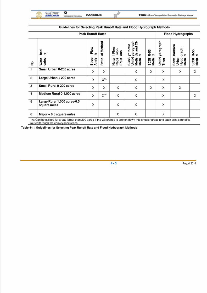
5/13/2018 Guam Storm Water Drainage Manual - slidepdf.com
http://slidepdf.com/reader/full/guam-storm-water-drainage-manual 71/486
4 - 3 August 2010
Guidelines for Selecting Peak Runoff Rate and Flood Hydrograph Methods
Peak Runoff Rates Flood Hydrographs
N o
W a t e r s
h e d
c a t e g o
r y
S t r e a m
F l o w
A n a l y s
i s
R a t i o n
a l M e t h o d
N a t u r a
l F l o w
R e g r e s
s i o n
E q u a t i o n s
S C S S y n t h e t i c
U n i t H y d r o g r a p h
M e t h o d s a n d C N
M e t h o d
S C S T R - 5 5
M e t h o d
U n i t H y d r o g r a p h
T h e o r y
S a n t a B a r b a r a
U r b a n
H y d r o g r a p h
M e t h o d
S C S T R - 5 5
M e t h o d
1 Small Urban 0-200 acresX X X X X X X
2 Large Urban + 200 acresX X1A X X
3 Small Rural 0-200 acresX X X X X X X
4 Medium Rural 0-1,000 acresX X1A X X X X
5 Large Rural 1,000 acres-6.5square miles X X X X
6 Major + 6.5 square miles X X X
1A: Can be utilized for areas larger than 200 acres if the watershed is broken down into smaller areas and each area’s runoff isrouted through the conveyance reach.
Table 4-1: Guidelines for Selecting Peak Runoff Rate and Flood Hydrograph Methods
5/13/2018 Guam Storm Water Drainage Manual - slidepdf.com
http://slidepdf.com/reader/full/guam-storm-water-drainage-manual 72/486
4 - 4 August 2010
Regression Equations: Regression equations are alternative runoff calculation1
methods for natural flow conditions. Regression equations are developed for2
specific watersheds having recorded peak flow data by using statistical analytical3
techniques. These equations (with appropriate adjustments) can then be used for4
adjacent watersheds with similar characteristics.5
Curve Number and Unit Hydrograph Methods: The USDA, National Resources6
Conservation Service (NRCS) runoff equation, Curve Number (CN), and UH7
procedures can be adapted to a variety of conditions for both rural and urban8
watersheds. The NRCS combined CN method and runoff equation is widely used in9
estimating direct runoff volume because of its simplicity, flexibility, and availability.10
The only input parameter needed is CN, and the hydrologic data used to estimate11
CN are normally available for most un-gauged watersheds. Because the CN is the12
only parameter required, the runoff prediction is entirely dependent on the accuracy13
of the CN. A runoff hydrograph and the peak discharge rate can be calculated14directly from the runoff equation using the NRCS UH procedures.15
TR-55: The NRCS Technical Release TR-55 (TR-55) is a good reference with16
regards to application of the CN runoff equation. However, the graphical and tabular17
methods presented in the technical release are not applicable to the Guam18
transportation projects, since they are based on the NRCS standard rainfall19
distribution 24-hour storms. See Section 4.2 for the applicable Guam design storms.20
Note that the CN runoff equation is usually restricted to estimating peak runoff21
volume for homogenous areas less than 300 acres.22
Santa Barbara Urban Hydrograph: The Santa Barbara Urban Hydrograph23(SBUH) method will develop a synthetic runoff hydrograph, applicable to small and24
large urban watersheds, as long as an appropriate delineation of homogenous land25
use areas is performed. The SBUH was developed by the Santa Barbara Flood26
Control and Water Conservation District in California as a short cut to the NRCS27
UH. The primary difference between the SBUH and the NRCS UH method is the28
use of the unit hydrograph in computing the runoff hydrograph. The SBUH replaces29
the unit hydrograph with an algorithm. The SBUH method greatly simplifies the30
computation of runoff hydrographs and is particularly applicable for computer31
modeling.32
Hydrology Modeling Programs: The use of computer programs, which usually33allow both hydrology and hydraulic analyses, is highly recommended for the routing34
of complex systems. There are a number of programs available, including public35
domain programs such as WinTR20, that use the NRCS CN and UH methods for36
developing the flow rates and volumes. Most hydrology/hydraulic modeling37
programs will also allow the use of the SBUH method for developing the runoff38
hydrographs.39
40
5/13/2018 Guam Storm Water Drainage Manual - slidepdf.com
http://slidepdf.com/reader/full/guam-storm-water-drainage-manual 73/486
4 - 5 August 2010
4.1.3 PRECIPITATION CHARACTERISTICS IN DRAINAGE CALCULATIONS1
The characteristics of precipitation typically considered in drainage calculations include:2
Intensity3
Duration4
Time distribution of rainfall (hyetograph)5
Storm shape, size, and movement6
Frequency7
Intensity: Intensity is the rate of precipitation, commonly given in units of inches per hour.8
In any given storm, the instantaneous intensity is the slope of mass rainfall curve at a9
particular time. From the standpoint of drainage calculations, intensity is perhaps the most10
important of the rainfall characteristics because discharge from a given watershed will11
increase as the intensity rises. See Figure 4-1 for the intensity curves to use on Guam12
Transportation Projects.13
Duration: Duration is the time length of the precipitation event. The precipitation durations14
used in Figures 4-1 and 4-2 have been selected based on statistical analysis of recorded15
precipitation events (see Appendix III). The Department of Public Works (DPW) is using a16
one-hour storm event as the standard storm duration for design and analysis purposes of a17
surface water management system for transportation projects.18
Time Distribution of Rainfall or Hyetograph: A hyetograph provides a distribution of19
incremental precipitation versus time. In practice, depth duration data for particular design20
frequency are generally used to develop a synthetic design storm event. A design storm21distribution with a one-hour duration will be used for transportation projects on Guam (see22
Figure 4-2).23
Shape, Size, and Movement: Storm shape, size, and movement are normally determined24
by the type of storm. All three factors determine the areal extent of precipitation and the25
size of the drainage area that contribute over time to the surface runoff.26
Rainfall varies spatially on the island owing to orographic effects (increases in rainfall with27
altitude). Mean annual rainfall is less than 90 in. on some coastal lowland areas and greater28
than 115 in. on mountainous areas in southern Guam. Since temperature and humidity are29
fairly uniform throughout the year, the variations of wind and rainfall are what define the30
seasons in Guam.31
Highly seasonal rainfall and wind patterns in the region provide Guam with distinctive wet32
and dry seasons. The dry season (January through May) is dominated by northeasterly33
trade winds with scattered and light showers. Rainfall during the dry season accounts for 1534
to 20 percent of the total annual rainfall. The wet season (July through November) accounts35
for an average of 65 percent of the annual rainfall. During the rainy season, westerly-36
moving storm systems and occasional typhoons bring heavy, steady rain and strong winds.37

5/13/2018 Guam Storm Water Drainage Manual - slidepdf.com
http://slidepdf.com/reader/full/guam-storm-water-drainage-manual 74/486
4 - 6 August 2010
Monthly rainfall totals vary from less than 1 in. from February to April to more than 20 in.1
from August to November. Exceptionally dry years recur about once every four years in2
correlation with episodes of El Nino Southern Oscillation in the Pacific.3
Frequency: Frequency quantifies the likelihood of the recurrence of precipitation with a4
given duration and average intensity. The major concern of highway design is with the5
frequency of occurrence for the surface runoff resulting from precipitation and, in particular,6
the frequency of the peak discharges. See Chapter 5, Section 5.2 for a more detailed7
description of the frequency policy for Guam transportation projects.8
Refer to Chapter 2 of the FHWA publication Hydraulic Design Series-2, Highway Hydrology 9
(HDS-2) for additional information on precipitation characteristics.10
4.1.4 RUNOFF COMPONENTS11
The four main components of runoff generally considered in stream flow data analysis are:12
Overland flow13
Channel precipitation14
Interflow15
Groundwater flow16
Overland flow travels over the ground surface to the stream channel. Channel precipitation17
is direct rainfall on the water surface. Runoff that enters a stream channel by traveling18
laterally through the upper layer of soil is called interflow, while stream flow generated by19
the occurrence of water table conditions above the channel bottom is called groundwater or20
base flow.21
This chapter addresses the relationships between precipitation and overland flow.22
Precipitation that does not convert to overland flow is lost to evaporation, soil storage, and23
infiltration. The infiltrated portion becomes interflow and groundwater flow.24
Refer to Chapter 2 of the FHWA publication HDS-2 for detailed information on runoff25
characteristics.26
4.2 DESIGN STORM SELECTION27
Stormwater management facilities must be sized to create a logical balance between the28
safety of the project and the economics of installation, maintenance, and replacement.29
Accordingly, different aspects of stormwater conveyance, quality treatment, and flow control30
are designed to different levels or frequencies of storm events. These design storm events31
are selected based on an updated statistical analysis of the Guam precipitation records.32
The details of the statistical analysis and discussion on the selection of the design storms33
are discussed in Appendix III.34
A one-hour duration storm will be used for the design of transportation stormwater facilities35
for Guam. The one-hour storm duration was selected from statistical analysis that showed36
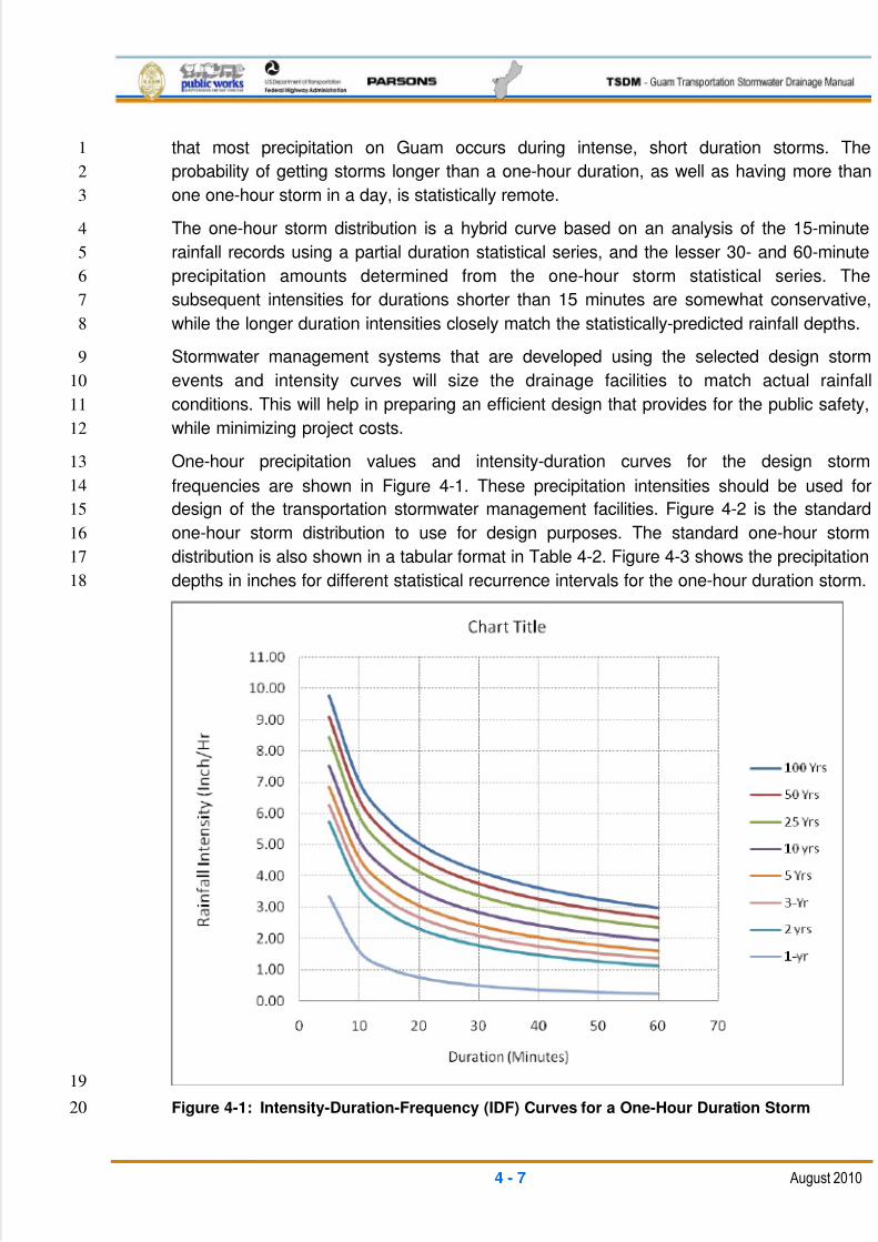
5/13/2018 Guam Storm Water Drainage Manual - slidepdf.com
http://slidepdf.com/reader/full/guam-storm-water-drainage-manual 75/486
4 - 7 August 2010
that most precipitation on Guam occurs during intense, short duration storms. The1
probability of getting storms longer than a one-hour duration, as well as having more than2
one one-hour storm in a day, is statistically remote.3
The one-hour storm distribution is a hybrid curve based on an analysis of the 15-minute4
rainfall records using a partial duration statistical series, and the lesser 30- and 60-minute5
precipitation amounts determined from the one-hour storm statistical series. The6
subsequent intensities for durations shorter than 15 minutes are somewhat conservative,7
while the longer duration intensities closely match the statistically-predicted rainfall depths.8
Stormwater management systems that are developed using the selected design storm9
events and intensity curves will size the drainage facilities to match actual rainfall10
conditions. This will help in preparing an efficient design that provides for the public safety,11
while minimizing project costs.12
One-hour precipitation values and intensity-duration curves for the design storm13
frequencies are shown in Figure 4-1. These precipitation intensities should be used for14
design of the transportation stormwater management facilities. Figure 4-2 is the standard15
one-hour storm distribution to use for design purposes. The standard one-hour storm16
distribution is also shown in a tabular format in Table 4-2. Figure 4-3 shows the precipitation17
depths in inches for different statistical recurrence intervals for the one-hour duration storm.18
19
Figure 4-1: Intensity-Duration-Frequency (IDF) Curves for a One-Hour Duration Storm20
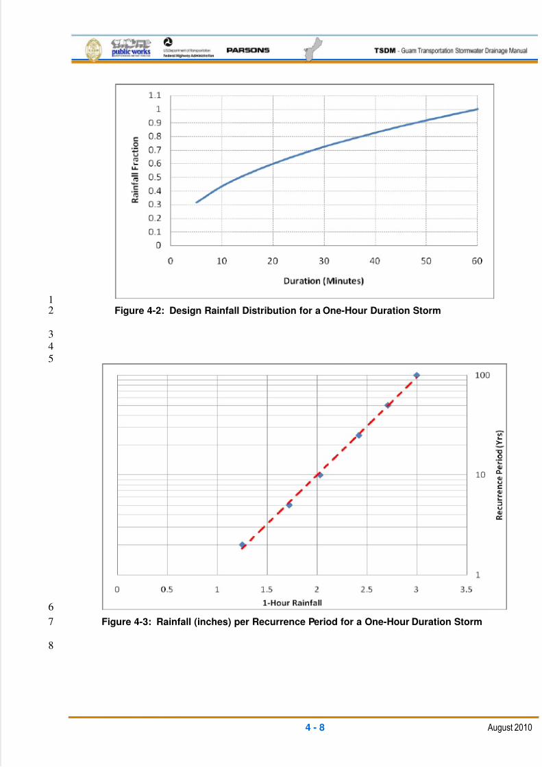
5/13/2018 Guam Storm Water Drainage Manual - slidepdf.com
http://slidepdf.com/reader/full/guam-storm-water-drainage-manual 76/486
4 - 8 August 2010
1Figure 4-2: Design Rainfall Distribution for a One-Hour Duration Storm2
34
5
6
Figure 4-3: Rainfall (inches) per Recurrence Period for a One-Hour Duration Storm7
8

5/13/2018 Guam Storm Water Drainage Manual - slidepdf.com
http://slidepdf.com/reader/full/guam-storm-water-drainage-manual 77/486
4 - 9 August 2010
Time (Minutes) Rainfall Fraction
5 0.315
10 0.435
15 0.52520 0.600
25 0.666
30 0.725
35 0.778
40 0.828
45 0.875
50 0.919
55 0.960
60 1.000
Table 4-2: One-Hour Storm Distribution1
4.3 TIME OF CONCENTRATION2
The Tc is the time required for a hydraulic wave to travel across a watershed. It is often3
approximated as the time required for runoff to travel from the most hydraulically remote4
part of the watershed to the point of interest. Most peak discharge, hydrograph, and5
channel routing calculation methods use computed travel times. Thus, estimating travel6
times are central to a variety of hydrologic design problems.7
A segmental approach for calculating the Tc, commonly known as the velocity method, is8
recommended for most applications. The velocity method of estimating the Tc typically9
requires an evaluation of three flow components:10
Overland flow11
Rill, shallow channel, and street gutter flow12
Open channel flow13
Overland flow is sheet flow over plane surfaces, usually limited to a maximum length of14
300 ft. After 300 ft., overland flow generally becomes concentrated into rills, small channels,15
or gutters. Open channel flow is appropriate when the main conveyance system is16
encountered.17
After short distances, sheet flow tends to concentrate in rills and then gullies of increasing18
proportions. Such flow is usually referred to as shallow concentrated flow. The flow in19
gullies is usually collected by channels or pipes.20
The travel time for any flow segment can be estimated as the ratio of flow length to the21
velocity of flow, as follows:22
23
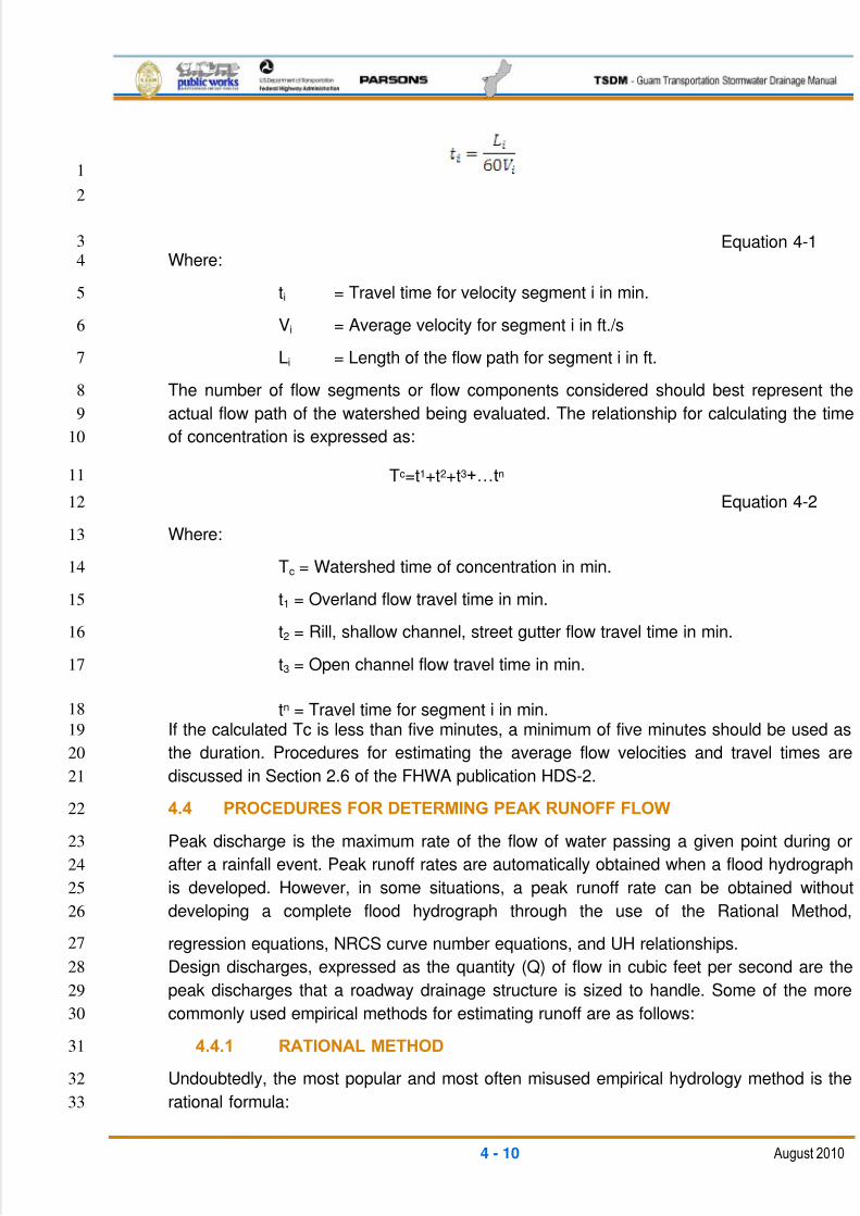
5/13/2018 Guam Storm Water Drainage Manual - slidepdf.com
http://slidepdf.com/reader/full/guam-storm-water-drainage-manual 78/486
4 - 10 August 2010
1
2
Equation 4-13
Where:4
ti = Travel time for velocity segment i in min.5
Vi = Average velocity for segment i in ft./s6
Li = Length of the flow path for segment i in ft.7
The number of flow segments or flow components considered should best represent the8
actual flow path of the watershed being evaluated. The relationship for calculating the time9
of concentration is expressed as:10
Tc=t1+t2+t3+…tn 11
Equation 4-212
Where:13
Tc = Watershed time of concentration in min.14
t1 = Overland flow travel time in min.15
t2 = Rill, shallow channel, street gutter flow travel time in min.16
t3 = Open channel flow travel time in min.17
tn = Travel time for segment i in min.18
If the calculated Tc is less than five minutes, a minimum of five minutes should be used as19
the duration. Procedures for estimating the average flow velocities and travel times are20
discussed in Section 2.6 of the FHWA publication HDS-2.21
4.4 PROCEDURES FOR DETERMING PEAK RUNOFF FLOW22
Peak discharge is the maximum rate of the flow of water passing a given point during or23
after a rainfall event. Peak runoff rates are automatically obtained when a flood hydrograph24
is developed. However, in some situations, a peak runoff rate can be obtained without25
developing a complete flood hydrograph through the use of the Rational Method,26
regression equations, NRCS curve number equations, and UH relationships.27
Design discharges, expressed as the quantity (Q) of flow in cubic feet per second are the28
peak discharges that a roadway drainage structure is sized to handle. Some of the more29
commonly used empirical methods for estimating runoff are as follows:30
4.4.1 RATIONAL METHOD31
Undoubtedly, the most popular and most often misused empirical hydrology method is the32
rational formula:33
5/13/2018 Guam Storm Water Drainage Manual - slidepdf.com
http://slidepdf.com/reader/full/guam-storm-water-drainage-manual 79/486
4 - 11 August 2010
Q = C I A1
Where:2
Q = Design discharge in ft.³/s3
C = Coefficient of runoff; function of watershed cover, and flood frequency4
I = Rainfall intensity in in./hr5
A = Drainage area in acres6
Assumptions7
The assumptions in the rational formula are as follows:8
The drainage area should be smaller than 200 acres.9
Peak discharge occurs when the entire watershed is contributing.10
A storm that has a duration equal to Tc produces the highest peak discharge for this11
frequency.12
The rainfall intensity is uniform over a storm time duration equal to the Tc. The Tc is13
the time required for water to travel from the most hydrologically remote point of the14
basin to the outlet or point of interest.15
The frequency of the computed peak flow is equal to the frequency of the rainfall16
intensity. In other words, the 10-year rainfall intensity, i, is assumed to produce the17
10-year peak discharge.18
4.4.1.1 RUNOFF COEFFICIENTS19
The runoff coefficient, C, is a function of ground cover. It represents the percent of water20
that will run off the ground surface during the storm. Commonly accepted runoff coefficients21
are discussed in Table 5.7 of FHWA publication HDS-2.22
Should the basin contain varying amounts of different covers, a weighted runoff coefficient23
for the entire basin can be determined as:24
25
26
27Where:28
Ci = Runoff coefficient for cover type i that covers area A i 29
A = Total area30
31
32
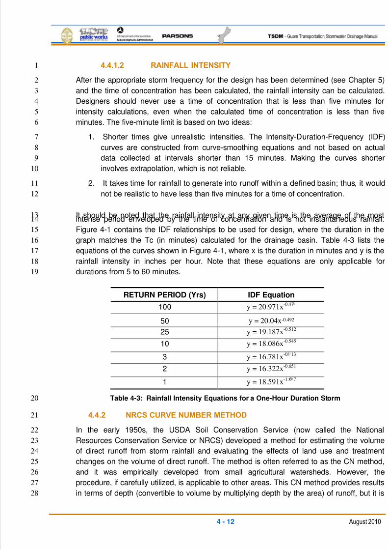
5/13/2018 Guam Storm Water Drainage Manual - slidepdf.com
http://slidepdf.com/reader/full/guam-storm-water-drainage-manual 80/486
4 - 12 August 2010
4.4.1.2 RAINFALL INTENSITY1
After the appropriate storm frequency for the design has been determined (see Chapter 5)2
and the time of concentration has been calculated, the rainfall intensity can be calculated.3
Designers should never use a time of concentration that is less than five minutes for4
intensity calculations, even when the calculated time of concentration is less than five5
minutes. The five-minute limit is based on two ideas:6
1. Shorter times give unrealistic intensities. The Intensity-Duration-Frequency (IDF)7
curves are constructed from curve-smoothing equations and not based on actual8
data collected at intervals shorter than 15 minutes. Making the curves shorter9
involves extrapolation, which is not reliable.10
2. It takes time for rainfall to generate into runoff within a defined basin; thus, it would11
not be realistic to have less than five minutes for a time of concentration.12
It should be noted that the rainfall intensity at any given time is the average of the most13intense period enveloped by the time of concentration and is not instantaneous rainfall.14
Figure 4-1 contains the IDF relationships to be used for design, where the duration in the15
graph matches the Tc (in minutes) calculated for the drainage basin. Table 4-3 lists the16
equations of the curves shown in Figure 4-1, where x is the duration in minutes and y is the17
rainfall intensity in inches per hour. Note that these equations are only applicable for18
durations from 5 to 60 minutes.19
RETURN PERIOD (Yrs) IDF Equation
100 y = 20.971x-0.47
50 y = 20.04x-0.492
25 y = 19.187x-0.512
10 y = 18.086x-0.545
3 y = 16.781x-0. 13
2 y = 16.322x-0.651
1 y = 18.591x-1.0 7
Table 4-3: Rainfall Intensity Equations for a One-Hour Duration Storm 20
4.4.2 NRCS CURVE NUMBER METHOD21
In the early 1950s, the USDA Soil Conservation Service (now called the National22
Resources Conservation Service or NRCS) developed a method for estimating the volume23
of direct runoff from storm rainfall and evaluating the effects of land use and treatment24
changes on the volume of direct runoff. The method is often referred to as the CN method,25
and it was empirically developed from small agricultural watersheds. However, the26
procedure, if carefully utilized, is applicable to other areas. This CN method provides results27
in terms of depth (convertible to volume by multiplying depth by the area) of runoff, but it is28
5/13/2018 Guam Storm Water Drainage Manual - slidepdf.com
http://slidepdf.com/reader/full/guam-storm-water-drainage-manual 81/486
4 - 13 August 2010
not applicable to the estimation of peak design discharge unless the design hydrograph is1
developed. For a description of the hydrograph development method used by the NRCS,2
see NRCS publication National Engineering Handbook, Section 4, Hydrology , dated 1985.3
See also the NRCS publication Technical Paper TP-149 , dated 1973. The routing of4
hydrographs through a watershed is explained in NRCS Technical Release TR-20 , dated5
1973. TR-20 has now been updated as a public domain computer program which will6
develop runoff hydrographs and route them through a watershed.7
The use of TR-20 (WinTR20 computer program) is most applicable for determining flows8
from larger basins, such as streams, where sizing of cross-culverts or bridge openings is9
needed. The design one-hour storm precipitation (Figure 4-3) and storm rainfall distribution10
(Table 4-2) can be applied directly in the program.11
Simplified procedures for estimating runoff volumes from small urban watersheds is12
presented in NRCS publication Technical Release TR-55, Urban Hydrology for Small 13
Watersheds, June 1986. This publication provides a description of the runoff CN method.14
Note that the graphical peak flow and tabular hydrograph methods presented in TR-55 (and15
associated WinTR55 computer program) cannot be directly applied to Guam transportation16
projects, since the TR-55 methods use the NRCS standardized 24-hour rainfall17
distributions.18
Alternately, peak discharge using the TR-55 CN formula with the Guam one-hour storm19
distribution (Table 4-2) can be closely approximated by computing the runoff volume (runoff20
depth multiplied by drainage area) for short time increments during the one-hour storm21
duration, where the amount of precipitation for each time increment is based on the fraction22
of rainfall from Table 4-2. The easiest way to do this is by tabulating the incremental23calculations in a computer spreadsheet where the volume of runoff for each time period can24
be accumulated to form a simple runoff hydrograph. Each time increment should be equal25
in length and not longer than a few minutes. The spreadsheet can be further expanded as26
needed to determine constraints for simple routing and required detention storage for pre-27
versus post-development conditions (sample spreadsheets for use as design aids may be28
available from DPW representatives on a case-by-case basis).29
The TR-20 public domain computer program and user manual can be downloaded at:30
http://www.wsi.nrcs.usda.gov/products/W2Q/H&H/Tools_Models/tool_mod.html 31
4.4.3 UNIT HYDROGRAPH (UH)32
A dimensionless UH is defined as the direct runoff hydrograph resulting from a rainfall event33
that has a specific temporal and spatial distribution, and that lasts for a unit duration of time.34
The ordinates of the UH are such that the volume of direct runoff represented by the area35
under the hydrograph is equal to 1 in. of runoff from the drainage area. In the development36
of a UH, there are several underlying assumptions made, such as uniform rainfall intensity37
and duration over the entire watershed.38
5/13/2018 Guam Storm Water Drainage Manual - slidepdf.com
http://slidepdf.com/reader/full/guam-storm-water-drainage-manual 82/486
4 - 14 August 2010
The NRCS has developed a UH procedure that has been widely used for watershed flows1
and flood estimating purposes. The UH used by this method is based on an analysis of a2
large number of natural UHs from a broad cross section of geographic locations and3
hydrologic regions. This method is easy to apply. The only parameters that need to be4
determined are the peak discharge and the time to peak. A standard UH is constructed5
using these two parameters.6
Procedures for estimating the runoff volume using UH methods are discussed in7
Section 6.1 of FHWA publication HDS-2.8
4.4.4 SANTA BARBARA URBAN HYDROGRAPH (SBUH) METHOD9
The SBUH was developed by the Santa Barbara Flood Control and Water Conservation10
District in California as a short cut to the NRCS UH method. The primary difference11
between the SBUH and the NRCS UH method is the use of the unit hydrograph in12
computing the runoff hydrograph. The SBUH replaces the unit hydrograph with an13
algorithm. The SBUH method greatly simplifies the computation of runoff hydrographs.14
The SBUH uses two steps to synthesize the runoff hydrograph:15
1. Compute the instantaneous hydrograph16
2. Compute the runoff hydrograph17
The instantaneous hydrograph, It, in cubic feet per second (cfs), for each time step dt, is18
computed as follows:19
20
Where21
Rt=total runoff depth at time increment dt (inches)22
A=area in acres23
dt=time interval in minutes24
The runoff hydrograph, Qt, is then obtained by routing the instantaneous hydrograph, It, 25
through an imaginary reservoir with a time delay equal to the Tc of the drainage basin. The26
following equation estimates the routed flow, Q t:27
28
Where:29
30
This procedure is best applied using a spreadsheet, described as follows:31
32
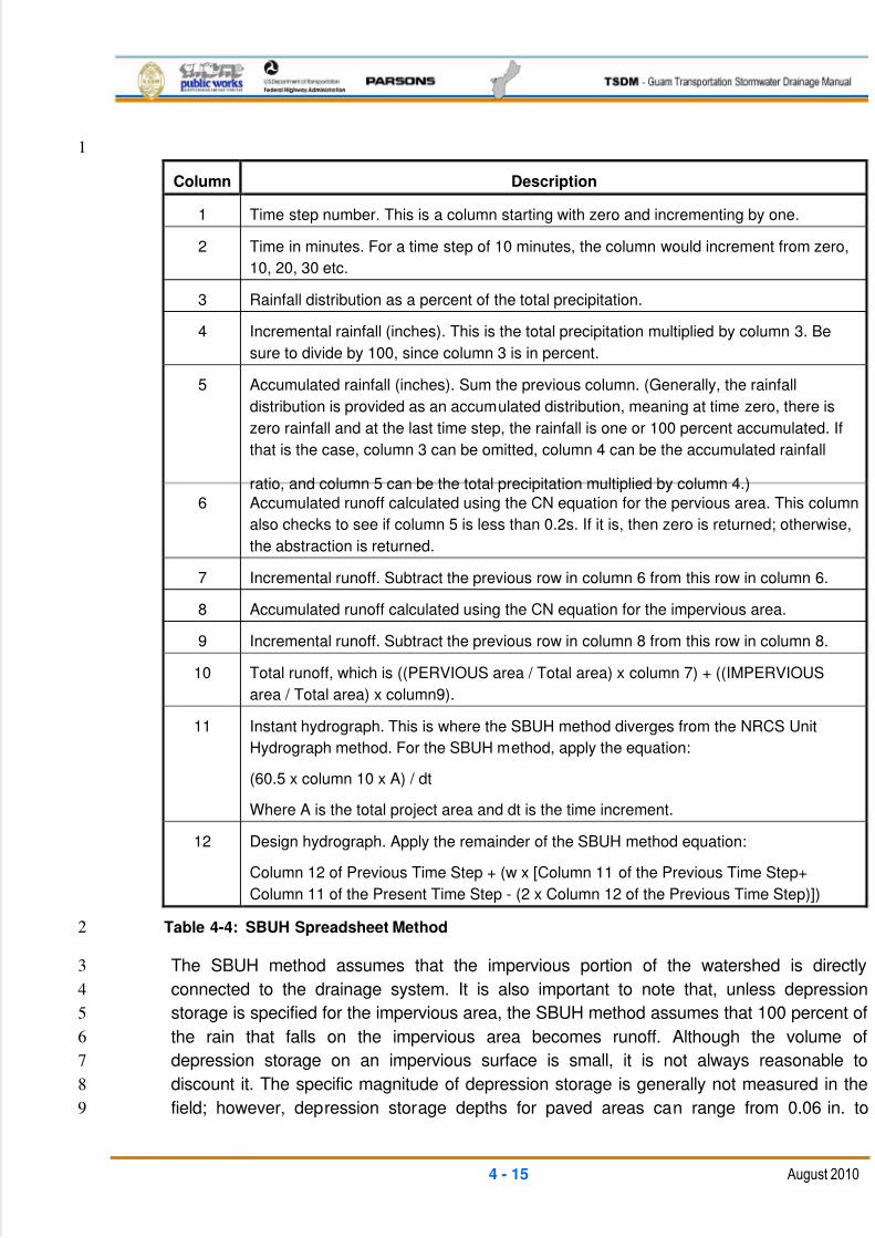
5/13/2018 Guam Storm Water Drainage Manual - slidepdf.com
http://slidepdf.com/reader/full/guam-storm-water-drainage-manual 83/486
4 - 15 August 2010
1
Column Description
1 Time step number. This is a column starting with zero and incrementing by one.
2 Time in minutes. For a time step of 10 minutes, the column would increment from zero,
10, 20, 30 etc.
3 Rainfall distribution as a percent of the total precipitation.
4 Incremental rainfall (inches). This is the total precipitation multiplied by column 3. Be
sure to divide by 100, since column 3 is in percent.
5 Accumulated rainfall (inches). Sum the previous column. (Generally, the rainfall
distribution is provided as an accumulated distribution, meaning at time zero, there is
zero rainfall and at the last time step, the rainfall is one or 100 percent accumulated. If
that is the case, column 3 can be omitted, column 4 can be the accumulated rainfall
ratio, and column 5 can be the total precipitation multiplied by column 4.)
6 Accumulated runoff calculated using the CN equation for the pervious area. This column
also checks to see if column 5 is less than 0.2s. If it is, then zero is returned; otherwise,
the abstraction is returned.
7 Incremental runoff. Subtract the previous row in column 6 from this row in column 6.
8 Accumulated runoff calculated using the CN equation for the impervious area.
9 Incremental runoff. Subtract the previous row in column 8 from this row in column 8.
10 Total runoff, which is ((PERVIOUS area / Total area) x column 7) + ((IMPERVIOUS
area / Total area) x column9).
11 Instant hydrograph. This is where the SBUH method diverges from the NRCS Unit
Hydrograph method. For the SBUH method, apply the equation:
(60.5 x column 10 x A) / dt
Where A is the total project area and dt is the time increment.
12 Design hydrograph. Apply the remainder of the SBUH method equation:
Column 12 of Previous Time Step + (w x [Column 11 of the Previous Time Step+
Column 11 of the Present Time Step - (2 x Column 12 of the Previous Time Step)])
Table 4-4: SBUH Spreadsheet Method 2
The SBUH method assumes that the impervious portion of the watershed is directly3
connected to the drainage system. It is also important to note that, unless depression4
storage is specified for the impervious area, the SBUH method assumes that 100 percent of5
the rain that falls on the impervious area becomes runoff. Although the volume of6
depression storage on an impervious surface is small, it is not always reasonable to7
discount it. The specific magnitude of depression storage is generally not measured in the8
field; however, depression storage depths for paved areas can range from 0.06 in. to9
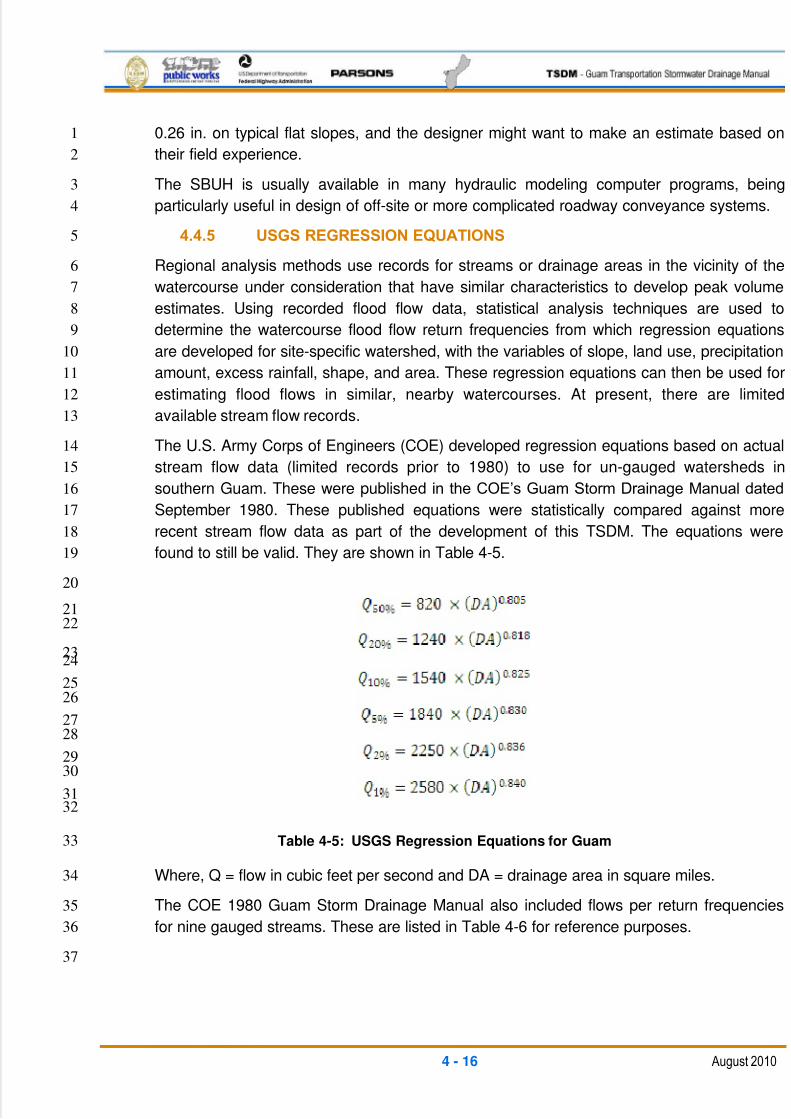
5/13/2018 Guam Storm Water Drainage Manual - slidepdf.com
http://slidepdf.com/reader/full/guam-storm-water-drainage-manual 84/486
4 - 16 August 2010
0.26 in. on typical flat slopes, and the designer might want to make an estimate based on1
their field experience.2
The SBUH is usually available in many hydraulic modeling computer programs, being3
particularly useful in design of off-site or more complicated roadway conveyance systems.4
4.4.5 USGS REGRESSION EQUATIONS5
Regional analysis methods use records for streams or drainage areas in the vicinity of the6
watercourse under consideration that have similar characteristics to develop peak volume7
estimates. Using recorded flood flow data, statistical analysis techniques are used to8
determine the watercourse flood flow return frequencies from which regression equations9
are developed for site-specific watershed, with the variables of slope, land use, precipitation10
amount, excess rainfall, shape, and area. These regression equations can then be used for11
estimating flood flows in similar, nearby watercourses. At present, there are limited12
available stream flow records.13
The U.S. Army Corps of Engineers (COE) developed regression equations based on actual14
stream flow data (limited records prior to 1980) to use for un-gauged watersheds in15
southern Guam. These were published in the COE’s Guam Storm Drainage Manual dated16
September 1980. These published equations were statistically compared against more17
recent stream flow data as part of the development of this TSDM. The equations were18
found to still be valid. They are shown in Table 4-5.19
20
2122
2324
2526
2728
2930
3132
Table 4-5: USGS Regression Equations for Guam33
Where, Q = flow in cubic feet per second and DA = drainage area in square miles.34
The COE 1980 Guam Storm Drainage Manual also included flows per return frequencies35
for nine gauged streams. These are listed in Table 4-6 for reference purposes.36
37
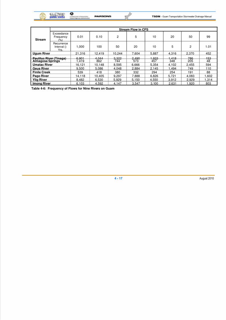
5/13/2018 Guam Storm Water Drainage Manual - slidepdf.com
http://slidepdf.com/reader/full/guam-storm-water-drainage-manual 85/486
4 - 17 August 2010
Stream
Stream Flow in CFS
ExceedanceFrequency
(%)0.01 0.10 2 5 10 20 50 99
RecurrenceInterval ()
Yrs.1,000 100 50 20 10 5 2 1.01
Ugum River 21,316 12,419 10,244 7,604 5,887 4,316 2,370 452
Pauliluc River (Tinaga) 6,901 4,044 3,322 2,490 1,933 1,418 786 153Almagosa Springs 1,419 862 744 573 457 348 205 48Umatac River 16,121 10,148 8,595 6,666 5,354 4,102 2,455 594Geus River 9,500 5,086 4,048 2,884 2,145 1,494 749 110Finile Creek 539 418 380 332 294 254 191 88Pago River 14,118 10,405 9,297 7,888 6,826 5,721 4,083 1,602Ylig River 8,482 6,530 5,929 5,150 4,550 3,912 2,929 1,314Imong River 6,103 4,592 4,147 3,547 3,100 2,631 1,920 803
Table 4-6: Frequency of Flows for Nine Rivers on Guam
5/13/2018 Guam Storm Water Drainage Manual - slidepdf.com
http://slidepdf.com/reader/full/guam-storm-water-drainage-manual 86/486
4 - 18 August 2010
4.4.6 HYDROLOGIC COMPUTER PROGRAMS1
The rapid development of computer technology in recent years has resulted in the2
development of many mathematical models for the purpose of calculating runoff and3
other hydrologic phenomenon.4
Hydrograph methods can be computationally involved, so computer programs such as5
HEC-1, HEC-HMS (developed by COE), TR-20 (developed by NRCS), StormShed and6
HYDRAIN (developed by FHWA), are almost exclusively used to generate runoff7
hydrographs. Many of these programs will also hydraulically route these hydrographs,8
which is important in the design of stormwater detention, other water quality facilities,9
and pump stations. They can also be used to evaluate conveyance flows by routing10
through large storm drainage systems to more precisely reflect flow peaking conditions11
in each segment of complex systems. Since the above-referenced techniques require a12
large amount of time and data to perform basin-wide computer simulation and rainfall-13
runoff modeling, these should be reserved for larger or special projects that justify14
applying the additional time and manpower. The additional time and cost must be15
balanced against the need for a higher level of detail and accuracy that can be obtained.16
As a word of caution, the designer should refrain from accepting the computer generated17
input without questioning the reasonableness of the results obtained from a hydrologic18
viewpoint.19
Depending upon the amount of detail and accuracy of the input data, these models can20
be very efficient at showing conveyance system response to particular designs and21
assist the designer in preparing an adequate conveyance or flood protection system in22
the most efficient and cost effective manner.23
5/13/2018 Guam Storm Water Drainage Manual - slidepdf.com
http://slidepdf.com/reader/full/guam-storm-water-drainage-manual 87/486
5 - 1 August 2010
5 HYDRAULICS ANALYSIS1
5.1 GENERAL2
Stormwater drainage design is an integral component of overall stormwater3
management. Good drainage design must strive to maintain compatibility and minimize4
interference with existing drainage patterns; control flooding of property, structures, and5
roadways; and minimize the environmental impacts.6
Highway drainage design is much more than the application of technical principles of7
hydrology and hydraulics. Good drainage design is a matter of properly balancing8
technical principles and data with the environment, while giving due consideration to9
other factors such as safety and economics. Such design can only be accomplished10
through the liberal use of sound engineering judgment. A goal in highway drainage11
design should be to perpetuate natural drainage, insofar as it is practical.12
Various types of drainage facilities are required to protect the highway against surface13
and sub-surface water. Drainage facilities must be designed to convey the water across,14
along, or away from the highway in the most economical, efficient, and safe manner,15
while protecting the highway and without impacting or damaging the adjacent property.16
The purpose of this chapter of the Guam Transportation Stormwater Drainage Manual17
(TSDM) is to provide hydraulic analysis requirements specific to highway design on the18
Island of Guam.19
5.2 FREQUENCY POLICY20
A range of runoff discharges from a range of storm recurrence intervals are used to21
evaluate drainage facilities. The rate of runoff from a drainage area will vary depending22
on the recurrence interval of the storm being analyzed. The recurrence interval defines23
the frequency that a given event (e.g., rainfall or runoff) is equaled or exceeded on24
average, once in a period of years. For example, if the 25-year frequency rainfall is25
2.4 in., a storm event of this size or greater would be expected to occur on average once26
every 25 years over an infinite time period. The exceedance probability, which is the27
reciprocal of the recurrence interval of this 2.4-in. storm, would have a 0.04 probability,28
or a 4 percent chance of occurrence in any given year.29
Drainage frequencies that are commensurate with the relative importance of the30
highway, associated risks, and possible damage to adjacent property should be31
selected. When selecting a storm frequency for design purposes, consideration is given32
to the potential degree of damage to the roadway and adjacent property; the potential33
hazard and inconvenience to the public; the number of users on the roadway; and the34
initial construction cost of the hydraulic structure. The way in which these factors35
interrelate can become quite complex. The policy regarding design storm frequency for36
typical hydraulic structures is listed in Table 5-1. Thus, the designer does not have to37
perform a risk analysis for each structure on each project.38
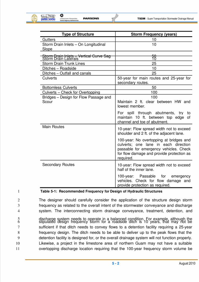
5/13/2018 Guam Storm Water Drainage Manual - slidepdf.com
http://slidepdf.com/reader/full/guam-storm-water-drainage-manual 88/486
5 - 2 August 2010
Type of Structure Storm Frequency (years)
Gutters 10
Storm Drain Inlets – On LongitudinalSlope
10
Storm Drain Inlets – Vertical Curve Sag 50Storm Drain Laterals 10
Storm Drain Trunk Lines 25
Ditches – Roadside 10
Ditches – Outfall and canals 25
Culverts 50-year for main routes and 25-year forsecondary routes.
Bottomless Culverts 50
Culverts – Check for Overtopping 100
Bridges – Design for Flow Passage andScour
100Maintain 2 ft. clear between HW andlowest member.
For spill through abutments, try to
maintain 10 ft. between top edge ofchannel and toe of abutment.
Main Routes10-year: Flow spread width not to exceedshoulder and 2 ft. of the adjacent lane.
100-year: No overtopping at bridges andculverts; one lane in each directionpassable for emergency vehicles. Check
for flow damage and provide protection asrequired.
Secondary Routes 10-year: Flow spread width not to exceed
half of the inner lane.
100-year: Passable for emergencyvehicles. Check for flow damage andprovide protection as required.
Table 5-1: Recommended Frequency for Design of Hydraulic Structures1
The designer should carefully consider the application of the structure design storm2
frequency as related to the overall intent of the stormwater conveyance and discharge3
system. The interconnecting storm drainage conveyance, treatment, detention, and4
discharge system needs to operate in a balanced condition. For example, although the5stipulated design frequency storm for a roadside ditch is 10 years, that may not be6
sufficient if that ditch needs to convey flows to a detention facility requiring a 25-year7
frequency design. The ditch needs to be able to deliver up to the peak flows that the8
detention facility is designed for, or the overall drainage system will not function properly.9
Likewise, a project in the limestone area of northern Guam may not have a suitable10
overtopping discharge location requiring that the 100-year frequency storm volume be11
5/13/2018 Guam Storm Water Drainage Manual - slidepdf.com
http://slidepdf.com/reader/full/guam-storm-water-drainage-manual 89/486
5 - 3 August 2010
contained within the project limits until it can fully infiltrate. For this case, the individual1
drainage system components may require sizing to a different performance level (i.e.,2
different from the capacity required using the design frequency shown in Table 5-1)3
depending on their location and function within the interconnecting system.4
5.3 ROADWAY DRAINAGE5
Water on the pavement will slow traffic and contribute to accidents from hydroplaning6
and loss of visibility from splash and spray, so removal of water on pavement in an7
expeditious and efficient manner is important. Pavement drainage design will provide for8
effective removal of water from the roadway surface.9
Pavement drainage design is typically based on a design discharge and an allowable10
spread of water across the pavement. Design features such as cross slope, longitudinal11
slope, and gutter section can affect the size, type, and spacing of inlets. This Section12
provides the fundamentals of gutter flow, inlet interception capacity, bridge deck13
drainage, and an evaluation of the potential for hydroplaning.14
The level of service of facilities that provide for the drainage of roadway surfaces should15
be consistent with the level of service being provided by the roadway. Guidelines are16
given for evaluating roadway features as they relate to pavement drainage, and for17
selecting an appropriate design frequency. Procedures for performing gutter flow18
calculations are based on a modification of the Manning Equation. Inlet capacity is19
discussed for curb opening inlets, grated gutter inlets, combination inlets, slotted pipe20
and trench drain, and bridge deck drains.21
5.3.1 ROADWAY FEATURES22
Roadway features considered during gutter, inlet, and pavement drainage calculations23
include:24
Longitudinal slope25
Cross slope26
Curb and gutter27
Ditches28
Bridge decks29
5.3.1.1 LONGITUDINAL SLOPE30
A minimum longitudinal gradient is important for curbed pavement because it is31
susceptible to stormwater spread. Flat gradients on uncurbed pavement can lead to a32
spread problem if vegetation is allowed to build up along the pavement edge.33
Desirable gutter grades should not be less than 0.5 percent for curbed pavements, and34
not less than 0.3 percent on very flat terrain. Minimum grades can be maintained on very35
flat terrain through the use of warping the cross slope or rolling the profile.36
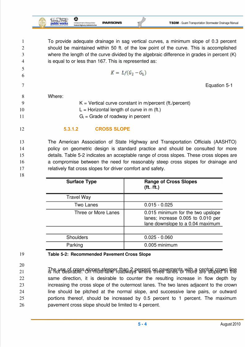
5/13/2018 Guam Storm Water Drainage Manual - slidepdf.com
http://slidepdf.com/reader/full/guam-storm-water-drainage-manual 90/486
5 - 4 August 2010
To provide adequate drainage in sag vertical curves, a minimum slope of 0.3 percent1
should be maintained within 50 ft. of the low point of the curve. This is accomplished2
where the length of the curve divided by the algebraic difference in grades in percent (K)3
is equal to or less than 167. This is represented as:4
5
6
Equation 5-1 7
Where:8
K = Vertical curve constant in m/percent (ft./percent)9
L = Horizontal length of curve in m (ft.)10
Gi = Grade of roadway in percent11
5.3.1.2 CROSS SLOPE12
The American Association of State Highway and Transportation Officials (AASHTO)13
policy on geometric design is standard practice and should be consulted for more14
details. Table 5-2 indicates an acceptable range of cross slopes. These cross slopes are15
a compromise between the need for reasonably steep cross slopes for drainage and16
relatively flat cross slopes for driver comfort and safety.17
18
Surface Type Range of Cross Slopes(ft. /ft.)
Travel Way
Two Lanes 0.015 - 0.025
Three or More Lanes 0.015 minimum for the two upslopelanes; increase 0.005 to 0.010 perlane downslope to a 0.04 maximum
Shoulders 0.025 - 0.060
Parking 0.005 minimum
Table 5-2: Recommended Pavement Cross Slope19
The use of cross slopes steeper than 2 percent on pavements with a central crown line20
is not desirable. On multi-lane roadways where three lanes or more are sloped in the21
same direction, it is desirable to counter the resulting increase in flow depth by22
increasing the cross slope of the outermost lanes. The two lanes adjacent to the crown23
line should be pitched at the normal slope, and successive lane pairs, or outward24
portions thereof, should be increased by 0.5 percent to 1 percent. The maximum25
pavement cross slope should be limited to 4 percent.26
5/13/2018 Guam Storm Water Drainage Manual - slidepdf.com
http://slidepdf.com/reader/full/guam-storm-water-drainage-manual 91/486
5 - 5 August 2010
Additional guidelines related to cross slope are:1
Although not encouraged, inside lanes can be sloped toward the median if2
conditions warrant.3
Median and off-site areas should not be drained across travel lanes.4
The number and length of flat slope pavement sections in cross slope transition5
areas should be minimized. Consideration should be given to increasing cross6
slopes in sag vertical curves, crest vertical curves, and in sections of flat7
longitudinal grades.8
Shoulders should be sloped to drain away from the pavement, except with9
raised, narrow medians and along superelevations.10
5.3.1.3 CURB AND GUTTER11
Curbing at the outside edge of pavements is normal practice for urban roadway facilities.12
Curbs can be combined with formed concrete gutters. The gutters are generally 12 in. to13
30 in. wide (refer to the Department of Public Work‘s [DPW‘s] standard construction14
drawings for additional details), matching the pavement cross slope on the high side and15
depressed with a steeper cross slope on the low side, usually at 8 percent. Typical16
practice is to place curbs at the outside edge of the traveled way, the shoulders, or the17
parking lanes, depending on the type of roadway. The gutter width is normally included18
as a part of the pavement width.19
Shoulder gutters are used to protect fill slopes from erosion caused by water from the20
roadway pavement. Shoulder gutters are required on all fill slopes higher than 10 ft.21
where the side slope is steeper than 3 horizontal to 1 vertical. Shoulder gutters are also22
required at the bridge ends where concentrated flow from the bridge deck would23
otherwise run down the slope or over a retaining wall/abutment. Shoulder gutters are24
formed by placing a curb at the edge of the shoulder under the face of the guardrail, or25
by concrete barriers such as those used at bridge approaches and on high fills.26
5.3.1.4 DITCHES27
Roadside channels and ditches are commonly used with uncurbed roadway sections to28
convey runoff from the highway pavement and from areas that drain toward the highway.29
Due to access and right-of-way limitations, roadside ditches cannot be used on most30
urban arterials. They can be used in cut sections, depressed sections, and other31locations where sufficient right-of-way is available and driveways or intersections are32
infrequent.33
Curbed roadway sections are relatively inefficient at conveying water, so the area34
tributary to the gutter section should be kept to a minimum to reduce the hazard of water35
on the pavement. Where practicable, the flow from the major area draining toward the36
5/13/2018 Guam Storm Water Drainage Manual - slidepdf.com
http://slidepdf.com/reader/full/guam-storm-water-drainage-manual 92/486
5 - 6 August 2010
curbed pavement should be intercepted by ditches or other pipe/inlet systems, as1
appropriate.2
It is preferable to slope the median areas and inside shoulders to a center swale to3
prevent drainage from the median area running across the pavement. This is particularly4
important for facilities with two or more lanes of traffic in each direction. In some cases,5
detention can be included in shallow medians to reduce the size of runoff facilities.6
5.3.1.5 BRIDGE DECK7
Bridge deck drainage is similar to that of curbed roadway sections. It is often less8
efficient because cross slopes are flatter; parapets collect large amounts of debris; and9
smaller drainage inlets or scuppers have a high potential for becoming clogged by10
debris. Bridge deck constructability usually requires a constant cross slope, so the usual11
guidelines do not apply. Because of the difficulties in providing and maintaining12
adequate deck drainage systems, gutter flow from roadways should be intercepted13
before it reaches a bridge. In many cases, deck drainage must be carried several spans14
to the bridge-end disposal.15
Zero gradients and sag vertical curves should be avoided on bridges. The minimum16
desirable longitudinal slope for bridge deck drainage should be 0.2 percent. When17
bridges are placed on a vertical curve and the longitudinal slope is less than 0.2 percent,18
the gutter spread should be checked to ensure a safe, reasonable design.19
Piped and grated scupper-type inlets are the recommended method for deck drainage20
because they can reduce the problems of transporting a relatively large concentration of21
runoff in an area of generally limited right-of-way. They also have a low initial cost and22
are relatively easy to maintain. However, the use of scuppers should be evaluated for23
site-specific concerns, and scuppers should always be piped in down drains to stable24
and erosion-protected runoff points. Runoff collected and transported to the end of the25
bridge should generally be collected by inlets and down drains, although paved flumes26
may be used for minor flows in some areas.27
5.3.2 HYDROPLANING28
Hydroplaning occurs when a tire is separated from the roadway surface by a layer of29
fluid. Hydroplaning is a function of the water depth, roadway geometrics, vehicle speed,30
tread depth, tire inflation pressure, and conditions of the pavement surface. In problem31
areas, hydroplaning may be reduced by the following:32
Design the highway geometries to reduce the drainage path lengths of the water33
flowing over the pavement. This will prevent flow build-up.34
Increase the pavement surface texture depth by methods such as grooving35
Portland Cement Concrete (PCC). An increase of pavement surface texture will36
increase the drainage capacity at the tire pavement interface.37
5/13/2018 Guam Storm Water Drainage Manual - slidepdf.com
http://slidepdf.com/reader/full/guam-storm-water-drainage-manual 93/486
5 - 7 August 2010
The use of open-graded asphaltic pavements has been shown to greatly reduce1
the hydroplaning potential of the roadway surface. This reduction is due to the2
ability of the water to be forced through the pavement, under the tire. This3
releases any hydrodynamic pressures that are created, and the potential for the4
tire to hydroplane.5
The use of drainage structures along the roadway to capture the flow of water6
over the pavement will reduce the thickness of the film of water and reduce the7
hydroplaning potential of the roadway surface.8
5.3.3 SPREAD9
The design frequency for pavement drainage should be consistent with the frequency10
selected for other components of drainage systems.11
5.3.3.1 SPREAD CRITERIA12
Spread is dependent on the road classification, as noted in Table 5-3 below:13
14
Road Classification DesignFrequency
Design Spread
Main Routes WithShoulder
10 years Shoulder + 2 ft.
WithoutShoulder
10 years Gutter + 3 ft.
SagLocation
50 years Shoulder + 2 ft.
Collector and LocalStreets
With orWithoutShoulders
10 years Half of Outside DrivingLane
SagLocation
50 years Half of Outside DrivingLane
Table 5-3: Allowable Spread Criteria15
5.3.4 GUTTER FUNDAMENTALS16
A pavement gutter is the section of a roadway normally located at its outer edge to17
convey stormwater runoff. It may include a portion of a travel lane or be a separate18
section at the edge of the traveled way or at the edge of the shoulder, but it usually has19
a triangular shape, defined by the cross slope and curb. In lieu of curbs, it is possible to20
use a V-shaped monolithic pavement section; but only when traffic control is21
unnecessary, such as with a low-volume residential street.22
Major components of the typical gutter section include:23
24
5/13/2018 Guam Storm Water Drainage Manual - slidepdf.com
http://slidepdf.com/reader/full/guam-storm-water-drainage-manual 94/486
5 - 8 August 2010
Pavement cross slope (Sx)1
Longitudinal slope (SL)2
Width of flow or spread (T)3
Width of depressed gutter flow (W)4
Depth of gutter flow (d)5
Cross slope of depressed gutter (Sw)6
Sketches showing the relationship of these components for three typical sections are7
presented in Figure 5-1. The first sketch shows a curb and gutter section with a straight8
cross slope; the second, a V-shaped section without a curb; and the third, a depressed9
curb and gutter section of width (W) and cross slope (SW). These sketches are provided10
to define fundamental parameters and are not intended to be used as the Guam11
Department of Public Works‘ (DPW) standard details.12
Gutter flow is a form of open-channel flow that should be analyzed using a modified form13
of the Manning Equation. Application details and example problems can be found in14
Section 6.2 of FHWA publication HDS 4, Introduction to Highway Hydraulics, No. FHWA- 15
NHI-08-090, June 2008 .16
17
18
19
Curb with Straight Cross Slope20
21
22
No Curb, V-Shaped Gutter23
5/13/2018 Guam Storm Water Drainage Manual - slidepdf.com
http://slidepdf.com/reader/full/guam-storm-water-drainage-manual 95/486
5 - 9 August 2010
1
2
Curb with Depressed Gutter3
4
Figure 5-1: Typical Gutter Sections5
5.3.4.1 FLOW IN SAG VERTICAL CURVES6
As gutter flow approaches the low point in a sag vertical curve, the flow can exceed the7
allowable design spread values as a result of the continually decreasing gutter slope.8
The spread in these areas should be checked to ensure it remains within the allowable9
limits. If the computed spread exceeds the design values, additional inlets should be10
provided to reduce the flow as it approaches the low point.11
5.3.5 INLET FUNDAMENTALS12
Storm drain inlets are used to collect runoff and discharge it to an underground storm13
drainage system. Inlets are typically located in gutter sections, paved medians, and14
roadside and median ditches. Inlets used for the drainage of highway surfaces can be15
divided into the following three classes:16
Grate inlets17
Curb opening inlets18
Combination inlets19
Grate inlets consist of an opening in the gutter or ditch, covered by a grate. Curb20
opening inlets are vertical openings in the curb, covered by a top slab. Slotted inlets21
consist of a pipe cut along the longitudinal axis with bars perpendicular to the opening to22
maintain the slotted opening. Combination inlets consist of both a curb opening inlet and23
a grate inlet placed in a side-by-side configuration, but the curb opening may be located,24
in part, upstream of the grate.25
Curb opening inlets are openings in the curb face that are generally placed in a gutter26
section. They are more effective on flatter slopes, in sags, and with flows that typically27
carry significant amounts of floating debris. The interception capacity of curb opening28
inlets decreases as the gutter grade steepens.29
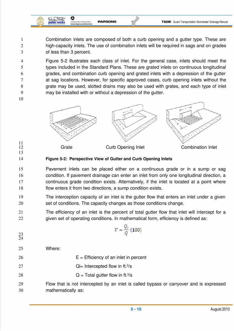
5/13/2018 Guam Storm Water Drainage Manual - slidepdf.com
http://slidepdf.com/reader/full/guam-storm-water-drainage-manual 96/486
5 - 10 August 2010
Combination inlets are composed of both a curb opening and a gutter type. These are1
high-capacity inlets. The use of combination inlets will be required in sags and on grades2
of less than 3 percent.3
Figure 5-2 illustrates each class of inlet. For the general case, inlets should meet the4
types included in the Standard Plans. These are grated inlets on continuous longitudinal5
grades, and combination curb opening and grated inlets with a depression of the gutter6
at sag locations. However, for specific approved cases, curb opening inlets without the7
grate may be used, slotted drains may also be used with grates, and each type of inlet8
may be installed with or without a depression of the gutter.9
10
11
Grate Curb Opening Inlet Combination Inlet12
13
Figure 5-2: Perspective View of Gutter and Curb Opening Inlets14
Pavement inlets can be placed either on a continuous grade or in a sump or sag15
condition. If pavement drainage can enter an inlet from only one longitudinal direction, a16
continuous grade condition exists. Alternatively, if the inlet is located at a point where17
flow enters it from two directions, a sump condition exists.18
The interception capacity of an inlet is the gutter flow that enters an inlet under a given19
set of conditions. The capacity changes as those conditions change.20
The efficiency of an inlet is the percent of total gutter flow that inlet will intercept for a21
given set of operating conditions. In mathematical form, efficiency is defined as:22
2324
Where:25
E = Efficiency of an inlet in percent26
Qi= Intercepted flow in ft.³/s27
Q = Total gutter flow in ft.³/s28
Flow that is not intercepted by an inlet is called bypass or carryover and is expressed29
mathematically as:30
5/13/2018 Guam Storm Water Drainage Manual - slidepdf.com
http://slidepdf.com/reader/full/guam-storm-water-drainage-manual 97/486
5 - 11 August 2010
12
Where:3
Qb = Bypass flow in ft.³/s4
Qi = Intercepted flow in ft.³/s5
Q = Total gutter flow in ft.³/s6
In most cases, an increase in total gutter flow causes an increase in the interception7
capacity of an inlet and a decrease in efficiency.8
Pavement inlets do not provide an efficient method for collecting large quantities of9
stormwater. Therefore, non-pavement drainage should be collected upstream of the10
pavement, where possible.11
Chapters 7 and 8 of FHWA publication HEC 12, Drainage of Highway Pavement, No.12FHWA-TS-84-202, March 1984 should be used for calculating the interception capacity13
of inlets.14
In accordance with the Standard Plans, generally only two types of inlets will be used for15
curb and gutter sections. The Grated Inlet Type 1 or Type 1A will be used on continuous16
grades. The Combination Curb and Grate Inlet-Type 2 will be used at sag locations.17
5.3.5.1 CONTINUOUS GRADE: GRATE INLETS18
The water flowing in a section of gutter inlet occupied by grate is called frontal flow.19
When gutter flow velocity is low enough, the grate inlet intercepts all of the frontal flow20
and a small portion of the side flow, which occurs along the length of the grate. As the21
gutter flow velocity increases, water may begin to skip or splash over the grate, and the22
efficiency of the inlet may be reduced. If splash-over does not occur, the capacity and23
efficiency of a gutter inlet will increase with an increase of the longitudinal slope.24
For interception calculations used for gutter spread analysis, the side flow portion should25
be ignored, and only that portion of the gutter flow passing directly over the top width of26
the grate will be accepted as intercepted flow. The remaining gutter flow will be27
considered to be bypass flow.28
5.3.5.2 SAG LOCATIONS: COMBINATION INLETS29
Combination inlets consisting of a grate and a curb opening are required for use in sags30
where hazardous ponding can occur. The interception capacity of the combination inlet31
is essentially equal to that of a grate alone in weir flow, unless the grate opening32
becomes clogged. Because of the potential for clogging, assume no less than33
60 percent of the grate area is clogged. In orifice flow, the capacity is equal to the34
capacity of the unclogged grate opening plus the capacity of the curb opening.35
5/13/2018 Guam Storm Water Drainage Manual - slidepdf.com
http://slidepdf.com/reader/full/guam-storm-water-drainage-manual 98/486
5 - 12 August 2010
5.3.6 INLET LOCATIONS1
There are a number of locations where inlets may be necessary, with little regard to the2
contributing drainage area. These locations should be marked on the plans prior to any3
computations regarding discharge, water spread, inlet capacity, or flow bypass.4
Examples of such locations are:5
At all low points in the gutter grade6
Immediately upstream of median breaks, entrance/exit ramp gores, cross walks,7
and street intersections (i.e., at any location where water could flow onto the8
traveled way)9
Immediately upgrade of bridges (to prevent pavement drainage from flowing onto10
bridge decks)11
Immediately downstream of bridges (to intercept bridge deck drainage)12
Within 10 ft. upgrade of cross slope reversals (i.e., the flat cross slope location of13
super elevation transitions)14
Immediately upgrade from pedestrian crosswalks15
At the end of channels in cut sections16
On side streets immediately upgrade from intersections17
Behind curbs, shoulders, or sidewalks to drain low areas18
In addition to the areas identified above, runoff from areas draining toward the highway19
pavement should be intercepted by roadside channels or inlets before it reaches the20roadway. This applies to drainage from cut slopes, side streets, and other areas along21
the pavement. Curbed pavement sections and pavement drainage inlets are inefficient22
means for handling extraneous drainage.23
In addition, it is good engineering practice to place flanking inlets on each side of the24
low-point inlet when in a depressed area that has no outlet except through the system.25
The purpose of the flanking inlets is to relieve the inlet at the low point if it should26
become clogged or if the design spread is exceeded.27
Flanking inlets can be located so they will function before water spread exceeds the28
allowable spread at the sump location. The flanking inlets should be located so that they29
will receive all of the flow when the primary inlet at the bottom of the sag is clogged.30
They should do this without exceeding the allowable spread at the bottom of the sag. If31
the flanking inlets are the same dimension as the primary inlet, they will each intercept32
one-half of the design flow when they are located so that the depth of ponding at the33
flanking inlets is 63 percent of the depth of ponding at the low point. Figure 5-3 below34
illustrates the logic.35
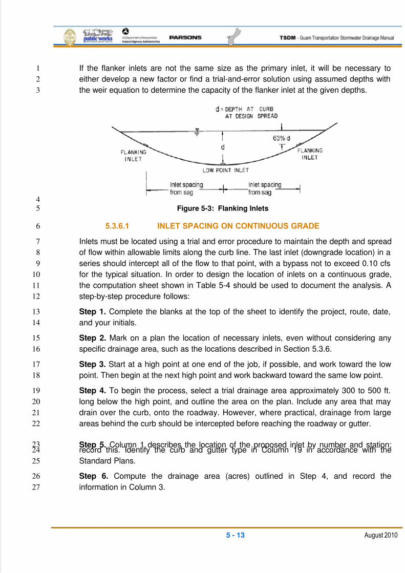
5/13/2018 Guam Storm Water Drainage Manual - slidepdf.com
http://slidepdf.com/reader/full/guam-storm-water-drainage-manual 99/486
5 - 13 August 2010
If the flanker inlets are not the same size as the primary inlet, it will be necessary to1
either develop a new factor or find a trial-and-error solution using assumed depths with2
the weir equation to determine the capacity of the flanker inlet at the given depths.3
4
Figure 5-3: Flanking Inlets5
5.3.6.1 INLET SPACING ON CONTINUOUS GRADE6
Inlets must be located using a trial and error procedure to maintain the depth and spread7
of flow within allowable limits along the curb line. The last inlet (downgrade location) in a8
series should intercept all of the flow to that point, with a bypass not to exceed 0.10 cfs9
for the typical situation. In order to design the location of inlets on a continuous grade,10
the computation sheet shown in Table 5-4 should be used to document the analysis. A11
step-by-step procedure follows:12
Step 1. Complete the blanks at the top of the sheet to identify the project, route, date,13
and your initials.14
Step 2. Mark on a plan the location of necessary inlets, even without considering any15
specific drainage area, such as the locations described in Section 5.3.6.16
Step 3. Start at a high point at one end of the job, if possible, and work toward the low17
point. Then begin at the next high point and work backward toward the same low point.18
Step 4. To begin the process, select a trial drainage area approximately 300 to 500 ft.19
long below the high point, and outline the area on the plan. Include any area that may20
drain over the curb, onto the roadway. However, where practical, drainage from large21
areas behind the curb should be intercepted before reaching the roadway or gutter.22
Step 5. Column 1 describes the location of the proposed inlet by number and station;23record this. Identify the curb and gutter type in Column 19 in accordance with the24
Standard Plans.25
Step 6. Compute the drainage area (acres) outlined in Step 4, and record the26
information in Column 3.27
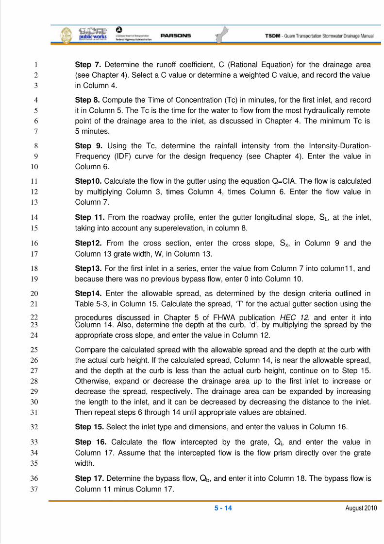
5/13/2018 Guam Storm Water Drainage Manual - slidepdf.com
http://slidepdf.com/reader/full/guam-storm-water-drainage-manual 100/486
5 - 14 August 2010
Step 7. Determine the runoff coefficient, C (Rational Equation) for the drainage area1
(see Chapter 4). Select a C value or determine a weighted C value, and record the value2
in Column 4.3
Step 8. Compute the Time of Concentration (Tc) in minutes, for the first inlet, and record4
it in Column 5. The Tc is the time for the water to flow from the most hydraulically remote5
point of the drainage area to the inlet, as discussed in Chapter 4. The minimum Tc is6
5 minutes.7
Step 9. Using the Tc, determine the rainfall intensity from the Intensity-Duration-8
Frequency (IDF) curve for the design frequency (see Chapter 4). Enter the value in9
Column 6.10
Step10. Calculate the flow in the gutter using the equation Q=CIA. The flow is calculated11
by multiplying Column 3, times Column 4, times Column 6. Enter the flow value in12
Column 7.13
Step 11. From the roadway profile, enter the gutter longitudinal slope, SL, at the inlet,14
taking into account any superelevation, in column 8.15
Step12. From the cross section, enter the cross slope, Sx, in Column 9 and the16
Column 13 grate width, W, in Column 13.17
Step13. For the first inlet in a series, enter the value from Column 7 into column11, and18
because there was no previous bypass flow, enter 0 into Column 10.19
Step14. Enter the allowable spread, as determined by the design criteria outlined in20
Table 5-3, in Column 15. Calculate the spread, ‗T‘ for the actual gutter section using the21
procedures discussed in Chapter 5 of FHWA publication HEC 12 , and enter it into22
Column 14. Also, determine the depth at the curb, ‗d‘, by multiplying the spread by the23
appropriate cross slope, and enter the value in Column 12.24
Compare the calculated spread with the allowable spread and the depth at the curb with25
the actual curb height. If the calculated spread, Column 14, is near the allowable spread,26
and the depth at the curb is less than the actual curb height, continue on to Step 15.27
Otherwise, expand or decrease the drainage area up to the first inlet to increase or28
decrease the spread, respectively. The drainage area can be expanded by increasing29
the length to the inlet, and it can be decreased by decreasing the distance to the inlet.30
Then repeat steps 6 through 14 until appropriate values are obtained.31
Step 15. Select the inlet type and dimensions, and enter the values in Column 16.32
Step 16. Calculate the flow intercepted by the grate, Qi, and enter the value in33
Column 17. Assume that the intercepted flow is the flow prism directly over the grate34
width.35
Step 17. Determine the bypass flow, Qb, and enter it into Column 18. The bypass flow is36
Column 11 minus Column 17.37
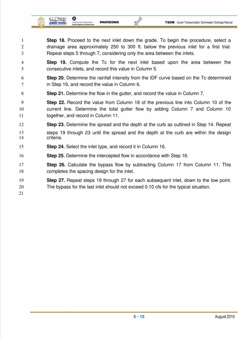
5/13/2018 Guam Storm Water Drainage Manual - slidepdf.com
http://slidepdf.com/reader/full/guam-storm-water-drainage-manual 101/486
5 - 15 August 2010
Step 18. Proceed to the next inlet down the grade. To begin the procedure, select a1
drainage area approximately 250 to 300 ft. below the previous inlet for a first trial.2
Repeat steps 5 through 7, considering only the area between the inlets.3
Step 19. Compute the Tc for the next inlet based upon the area between the4
consecutive inlets, and record this value in Column 5.5
Step 20. Determine the rainfall intensity from the IDF curve based on the Tc determined6
in Step 19, and record the value in Column 6.7
Step 21. Determine the flow in the gutter, and record the value in Column 7.8
Step 22. Record the value from Column 18 of the previous line into Column 10 of the9
current line. Determine the total gutter flow by adding Column 7 and Column 1010
together, and record in Column 11.11
Step 23. Determine the spread and the depth at the curb as outlined in Step 14. Repeat12
steps 19 through 23 until the spread and the depth at the curb are within the design13
criteria.14
Step 24. Select the inlet type, and record it in Column 16.15
Step 25. Determine the intercepted flow in accordance with Step 16.16
Step 26. Calculate the bypass flow by subtracting Column 17 from Column 11. This17
completes the spacing design for the inlet.18
Step 27. Repeat steps 19 through 27 for each subsequent inlet, down to the low point.19
The bypass for the last inlet should not exceed 0.10 cfs for the typical situation.20
21
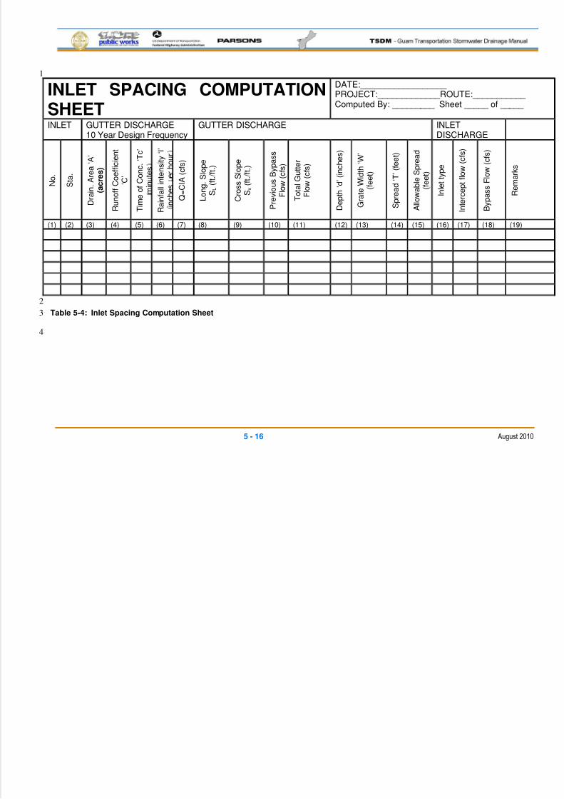
5/13/2018 Guam Storm Water Drainage Manual - slidepdf.com
http://slidepdf.com/reader/full/guam-storm-water-drainage-manual 102/486
5 - 16 August 2010
1
INLET SPACING COMPUTATIONSHEET
DATE:__________________ PROJECT:_____________ROUTE:___________ Computed By: _________ Sheet _____ of _____
INLET GUTTER DISCHARGE10 Year Design Frequency
GUTTER DISCHARGE INLETDISCHARGE
N o .
S t a
.
D r a
i n .
A r e a ‗ A ‘
( a c r e s )
R u n o
f f C o e
f f i c i e n
t
‗ C ‘
T i m e o
f C o n c .
‗ T c ‘
m i n u
t e s
R a
i n f a l l i n t e n s
i t y ‗ I ‘
i n c
h e s
e r
h o u r
Q =
C I A ( c f s )
L o n g .
S l o p e
S L
( f t . / f t . )
C r o s s
S l o p e
S x
( f t . / f t . )
P r e v
i o u s
B y p a s s
F l o w
( c f s )
T o
t a l G u
t t e r
F l o w
( c f s )
D e p
t h ‗ d ‘ ( i n c
h e s
)
G r a
t e W i d t h ‗ W ‘
( f e e
t )
S p r e a
d ‗ T ‘ ( f e e
t )
A l l o w a
b l e S p r e a
d
( f e e
t )
I n l e t t y p e
I n t e r c e p
t f l o w
( c f s )
B y p a s s
F l o w
( c f s )
R e m a r k s
(1) (2) (3) (4) (5) (6) (7) (8) (9) (10) (11) (12) (13) (14) (15) (16) (17) (18) (19)
2
Table 5-4: Inlet Spacing Computation Sheet3
4
5/13/2018 Guam Storm Water Drainage Manual - slidepdf.com
http://slidepdf.com/reader/full/guam-storm-water-drainage-manual 103/486
5 - 17 August 2010
5.3.6.2 BRIDGE DECK DRAINAGE1
Similarities between bridge deck and roadway drainage inlets are understandable2
because these two types of drainage processes are, as a whole, very similar. The3
hydraulic fundamental for the inlets are identical; however, design requirements for4
bridge deck systems differ in the following respects from roadway systems:5
Total or near-total interception is desirable up gradient of expansion joints6
Deck systems are highly susceptible to inlet clogging7
Inlet spacing is often predetermined by bent spacing8
Inlet sizes are often constrained by structural considerations9
To the extent possible, roadway drainage should be intercepted up gradient of a10
bridge deck11
The interception capacity of bridge scuppers can be generally determined as listed12
above for curb and grated gutter inlets. See FHWA publication HEC-21 Bridge Deck 13
Drainage , May 1993 for additional design considerations.14
5.3.7 ROADWAY GRADES15
The critical step for establishing roadway grade lines is the determination of a roadway16
Design High Water (DHW) elevation. The DHW provides an elevation for establishing a17
roadway base clearance that will adequately protect the base from saturation, consistent18
with the service requirements of the roadway.19
The DHW for setting roadway grades is generally based on a determination of high20
water surface for the selected storm frequency. Setting the roadway base courses above21
this DHW level will help to avoid problems with saturation of the subgrade and22
premature failures of the pavement. The following procedure can provide a framework23
for such determinations:24
a. Establish the drainage feature likely to control the water level. The following25
features should be considered:26
i. Published flood plain levels27
ii. Streams and culverts.28
iii. Canals, ditches, and swales29
iv. Retention/detention facilities30
v. Reservoirs31
vi. Wetlands32
vii. Pumping facilities- stormwater33
5/13/2018 Guam Storm Water Drainage Manual - slidepdf.com
http://slidepdf.com/reader/full/guam-storm-water-drainage-manual 104/486
5 - 18 August 2010
viii. Water table1
ix. Local hydrogeology2
b. Establish the service requirements for the roadway, and select an appropriate3
design frequency for drainage facilities. Roadway classification will be either the4
main routes or secondary roads. Use Table 5-1 to select the flood frequency for5
various structures and conditions (i.e., 50-year for culvert crossing and 10-year6
for roadway ditch water surface levels for main routes).7
c. Based on the drainage feature and design frequency from Step A and Step B,8
respectively, find the design event water surface elevation. Use procedures9
discussed in Chapters 4 and 5 as appropriate for this analysis and determination.10
This elevation is the DHW.11
d. The bottom of the pavement aggregate sub-base course should be located12
above the DHW, or alternately, the drainage conveyance systems should be13
designed to maintain the DHW below the existing or proposed pavement sub-14
base level, by a minimum clearance level. This clearance level should be 2 to15
3 ft. on the main routes, and no less than 1 foot on secondary roads.16
5.3.8 CONSTRUCTION AND MAINTENANCE CONSIDERATION17
Visual, surface-level inspections of drainage facilities should be made by maintenance18
supervisors to identify obvious defects, hazards, or potential problems, and also to19
monitor known problems. These inspections should be made annually and during and20
after each major storm. Gutters should be inspected periodically and maintained to21
permit free flow. Formed gutters should be sealed or repaired to maintain structural22
integrity.23
When curbs fail to perform their function due to settlement, heave, or damage, they24
should be repaired or replaced. Curbs that are attached to sidewalks should be25
maintained to the level of the sidewalks, approximately.26
When the inlet is located in the clear zone, the designer should place the inlet as close27
to parallel in the direction of traffic as possible. Placing the inlet at an angle may cause28
an errant vehicle to overturn.29
Quarry spalls should not be placed around inlets. This creates a safety hazard for the30
maintenance personnel who need good footing to lift the heavy lids. If quarry spall check31
dams are desired for erosion control, locate them a minimum of 10 ft. away from the32
grate inlet.33
5.4 OPEN CHANNELS AND DITCHES34
Open-channel hydraulics provide the basis for evaluating the hydraulic capacity of most35
roadway drainage facilities. An open channel is a watercourse that allows part of the flow36
to be exposed to the atmosphere. This type of channel includes rivers, culverts, storm37
5/13/2018 Guam Storm Water Drainage Manual - slidepdf.com
http://slidepdf.com/reader/full/guam-storm-water-drainage-manual 105/486
5 - 19 August 2010
drain systems that flow by gravity, roadside ditches, and roadway gutters. Open-channel1
flow design criteria are used in several areas of transportation design, including:2
Stream and river changes3
Flood plain analysis4
Stream bank protection5
Culverts and associated inlet/outlet channel revisions6
Roadside ditches7
Conveyance channels8
Storm drains9
Bridge waterways10
Outlet discharge and downstream analysis11
Proper design requires that open channels have sufficient hydraulic capacity to convey12
the flow of the design storm. In the case of earth-lined channels, erosion protection is13
required if the velocities are high enough to cause scouring.14
5.4.1 GEOMETRIC ELEMENTS15
Most open-channel flow problems require an evaluation of various geometric elements16
associated with the shape of the channel. For most artificial or constructed open17
channels, geometric elements can be determined mathematically in terms of depth of18
flow and other dimensions for channel shape. However, for most natural channel19
sections, profile sections based on the actual variations in the depth of flow across the20
section are generally required. The following geometric terminology is pertinent to the21
fundamentals of open-channel hydraulics.22
Prismatic Channel: An artificial channel with non-varying cross section and23
constant bottom slope.24
Channel Section: The cross section of a channel taken perpendicular to the25
direction of the flow.26
Depth of Flow: The vertical distance of the lowest point of a channel27
section from the free surface.28
Stage: The elevation or vertical distance of the free surface above29
a given point.30
Top Width: The width of the channel section at the free surface.31
Flow Area: The cross-sectional area of the flow perpendicular to the32
direction of the flow.33
5/13/2018 Guam Storm Water Drainage Manual - slidepdf.com
http://slidepdf.com/reader/full/guam-storm-water-drainage-manual 106/486
5 - 20 August 2010
Wetted Perimeter: The length of the line of intersection of the channels wetted1
surface on a cross-sectional plane perpendicular to the2
direction of flow.3
Hydraulic Radius: The ratio of the flow area to its wetted perimeter.4
Hydraulic Depth: The ratio of the flow area to its top width.5
Critical Flow Section Factor: The product of the flow area and the square root of the6
hydraulic depth. 7
Uniform-Flow Section Factor: The product of the flow area and the hydraulic radius8
raised to 2/3 power.9
Steady Flow: Steady flow occurs in an open channel when the discharge10
or rate of flow at any location along the channel remains11
constant with respect to time.12
Unsteady Flow: Open-channel flow is unsteady when discharge at any13
location in the channels changes with respect to the time.14
Uniform Flow: Uniform flow occurs only in a channel of a constant cross15
section, slope, and roughness known as uniform open16
channel. Generally, uniform flow is also steady flow.17
Normal Depth: When the requirements of the uniform flow are met, the18
depth of flow for a given discharge is defined as normal19
depth.20
Unsteady Uniform Flow: Flow in which there are variations of both space and time21
is the most complex type of flow to evaluate22
mathematically.23
Rapidly Varied Flow: Also known as local phenomenon, examples of which24
include hydraulic jump and hydraulic drop. The primary25
example of gradually varied flow occurs when sub-critical26
flow is restricted by a culvert or storage reservoir. The27
water-surface profile caused by such a restriction is28
generally referred to as a backwater curve.29
Laminar Flow: Generally occurs when the viscous forces are strong30
relative to inertial forces, causing water to flow in31
streamlines.32
Turbulent Flow: When viscous forces are weak relative to the inertial33
forces, the flow can be classified as turbulent.34
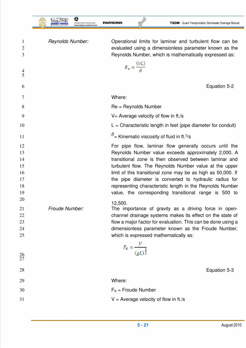
5/13/2018 Guam Storm Water Drainage Manual - slidepdf.com
http://slidepdf.com/reader/full/guam-storm-water-drainage-manual 107/486
5 - 21 August 2010
Reynolds Number: Operational limits for laminar and turbulent flow can be1
evaluated using a dimensionless parameter known as the2
Reynolds Number, which is mathematically expressed as:3
4
5
Equation 5-26
Where:7
Re = Reynolds Number8
V= Average velocity of flow in ft./s9
L = Characteristic length in feet (pipe diameter for conduit)10
= Kinematic viscosity of fluid in ft.2 /s11
For pipe flow, laminar flow generally occurs until the12
Reynolds Number value exceeds approximately 2,000. A13
transitional zone is then observed between laminar and14
turbulent flow. The Reynolds Number value at the upper15
limit of this transitional zone may be as high as 50,000. If16
the pipe diameter is converted to hydraulic radius for17
representing characteristic length in the Reynolds Number18
value, the corresponding transitional range is 500 to19
12,500.20
Froude Number: The importance of gravity as a driving force in open-21
channel drainage systems makes its effect on the state of22
flow a major factor for evaluation. This can be done using a23
dimensionless parameter known as the Froude Number,24
which is expressed mathematically as:25
2627
Equation 5-328
Where:29
FR = Froude Number30
V = Average velocity of flow in ft./s31
5/13/2018 Guam Storm Water Drainage Manual - slidepdf.com
http://slidepdf.com/reader/full/guam-storm-water-drainage-manual 108/486
5 - 22 August 2010
L = Characteristic length in ft. (hydraulic depth for open1
channels)2
g= Acceleration due to gravity in 32 ft./s2 3
If the Froude Number value is greater than one, inertial4
forces dominate, and the flow is super-critical. The flow in5
this regime will also tend to be turbulent and unsteady for6
the general case. If the Froude Number is less than one,7
gravity forces dominate, and the flow is called sub-critical8
or tranquil flow. When the Froude Number is equal to one,9
then flow is defined as the critical flow.10
5.4.2 CHANNEL DESIGN CRITERIA11
Channels and ditches should be designed to convey the required frequency storm event12
runoff with a 0.5-foot freeboard. The preferred cross section of a ditch is trapezoidal;13
however, a V-ditch can also be used where right-of-way is limited and/or the design14
requirements can still be met. The depth of channel should be sufficient to remove the15
water while maintaining the required design water surface clearance below the16
pavement sub-base.17
Side slopes can vary but should be limited to no steeper than 2 horizontal to 1 vertical18
for earth channels with a grassed lining. Roadside ditch side slopes along the roadway19
should meet the clear zone design requirements and be limited to less than a 2-foot20
design depth, unless guardrail or barrier traffic protection is provided.21
5.4.2.1 CHANNEL TYPES22
Open channels can be generally classified as those that occur naturally, are man-made,23
or improve natural channels. Man-made channels are also called artificial channels,24
including the following types, in use on most roadway projects:25
Roadside ditch26
Interceptor ditch27
Swale28
Median ditch (swale)29
Outfall ditch30
Lateral ditch31
Canal32
Each of these channel types are artificial systems designed to provide specific drainage33
capacities. In general, roadside and median ditches are relatively shallow trapezoidal34
channels, while swales and interceptor ditches are shallow triangular channels. These35
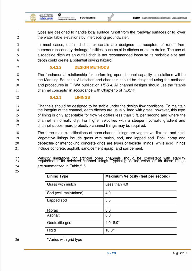
5/13/2018 Guam Storm Water Drainage Manual - slidepdf.com
http://slidepdf.com/reader/full/guam-storm-water-drainage-manual 109/486
5 - 23 August 2010
types are designed to handle local surface runoff from the roadway surfaces or to lower1
the water table elevations by intercepting groundwater.2
In most cases, outfall ditches or canals are designed as receptors of runoff from3
numerous secondary drainage facilities, such as side ditches or storm drains. The use of4
a roadside ditch as an outfall ditch is not recommended because its probable size and5
depth could create a potential driving hazard.6
5.4.2.2 DESIGN METHODS7
The fundamental relationship for performing open-channel capacity calculations will be8
the Manning Equation. All ditches and channels should be designed using the methods9
and procedures in FHWA publication HDS 4 . All channel designs should use the ―stable10
channel concepts‖ in accordance with Chapter 5 of HDS 4 .11
5.4.2.3 LININGS12
Channels should be designed to be stable under the design flow conditions. To maintain13
the integrity of the channel, earth ditches are usually lined with grass; however, this type14
of lining is only acceptable for flow velocities less than 5 ft. per second and where the15
channel is normally dry. For higher velocities with a steeper hydraulic gradient and16
channel slopes, more protective channel linings may be required.17
The three main classifications of open-channel linings are vegetative, flexible, and rigid.18
Vegetative linings include grass with mulch, sod, and lapped sod. Rock riprap and19
geotextile or interlocking concrete grids are types of flexible linings, while rigid linings20
include concrete, asphalt, sand/cement riprap, and soil cement.21
Velocity limitations for artificial open channels should be consistent with stability22requirements for selected channel linings. Typical guideline velocities for these linings23
are summarized in Table 5-5.24
25
Lining Type Maximum Velocity (feet per second)
Grass with mulch Less than 4.0
Sod (well-maintained) 4.0
Lapped sod 5.5
Riprap 6.0
Asphalt 8.0
Geotextile grid 4.0- 8.0*
Rigid 10.0**
*Varies with grid type26
5/13/2018 Guam Storm Water Drainage Manual - slidepdf.com
http://slidepdf.com/reader/full/guam-storm-water-drainage-manual 110/486
5 - 24 August 2010
** Higher velocities acceptable with provision for energy dissipation1
Table 5-5: Permissible Velocities for Various Linings2
Linings should be designed using a shear stress approach, and using the calculation3
guidelines and procedures in Chapter 5 of FHWA publication, HDS 4 .4
5.4.3 CONSTRUCTION AND MAINTENANCE CONSIDERATION5
The design of an open channel should be consistent with DPW‘s standard construction6
and maintenance practices. If special provisions are warranted, this information should7
be presented in the design documents.8
To prevent cracking and failure, concrete linings must be placed on a firm, well-drained9
foundation. In saturated soils, empty channels with a rigid lining such as concrete, may10
float or break up due to the buoyancy of displaced water. The total upward force on an11
empty channel is equal to the weight of the displaced water. To prevent this, the lining12
should be increased in thickness to add weight, or if the flow is sub-critical, weep holes13
may be placed at intervals in the channel bottom to relieve the upward pressure on the14
channel. When flow is super-critical, sub-surface drainage should be used instead of15
weep holes, with properly-designed filters to avoid soil piping through the sub-drains.16
Open channels rapidly lose their effectiveness unless they are adequately maintained.17
Maintenance includes repairing erosion damage, mowing grass, cutting brush, and18
removing any sediments or debris from the channel.19
Ditches, outfalls, and detention areas must be provided, with maintenance access.20
5.5 STORM DRAINS21
A storm drain is the portion of the highway drainage system that receives surface water22
through inlets and conveys the water through conduits to an outfall. It is composed of23
different lengths and sizes of pipe or conduit connected by appurtenant structures. A24
section of conduit connecting one inlet or appurtenant structure to another is termed a25
"segment" or "run." The storm drain conduit is most often a circular pipe, but it can also26
be a box or other enclosed conduit shape. Typical structure types include inlets, catch27
basins, manholes, cleanouts, junction chambers, headwalls, flow controls, energy28
dissipaters, and outlets.29
All storm drain designs should be based on an engineering analysis that takes into30
consideration runoff rates, pipe flow capacity, hydraulic grade line, soil characteristics,31
pipe strength, potential construction problems, and potential runoff treatment issues. The32
majority of time spent on a storm drain design is calculating runoff from an area and33
designing the enclosed conveyance system to carry the flow. A storm drain design may34
be performed by hand calculations or by one of several available computer programs35
and spreadsheets. See Sections 4.4.6 and 5.5.4 for general information on hydraulic36
modeling programs.37
5/13/2018 Guam Storm Water Drainage Manual - slidepdf.com
http://slidepdf.com/reader/full/guam-storm-water-drainage-manual 111/486
5 - 25 August 2010
Runoff flows are determined using the procedures in Chapters 2 and 4 of this TSDM.1
The storm drain hydraulic design should follow the guidelines and procedures in2
Chapters 7 and 8 of FHWA publication HDS 4 .3
5.5.1 DESIGN FEATURES4
Along with determining the required pipe sizes for flow conveyance, storm drain system5
design incorporates the following features:6
1. Soil Conditions — Soil with adequate bearing capacity must be present to interact7
with the pipes and support the load imparted by them. Surface and sub-surface drainage8
must be provided to ensure stable soil conditions. Soil resistivity and pH must also be9
known so the proper pipe material can be used. Pipe installation in poor soil conditions10
should be performed in accordance with the review and recommendations of a qualified11
Geotechnical Engineer, to determine additional soil treatments and bedding12
improvements that may be required.13
2. Inlet Spacing and Capacity — Design guidelines are detailed in Section 5.3.5.14
3. Junction Spacing — Junctions (catch basins, grate inlets, and manholes) should be15
placed at all breaks in grade and horizontal alignment. Pipe runs between junctions16
should not exceed 300 ft. for pipes smaller than 48 in. in diameter, and 500 ft. for pipes17
48 in. or larger in diameter. When grades are flat, pipes should be small or there could18
be debris issues. Designers should consider reducing the minimum spacing.19
4. Future Expansion — If it is anticipated that a storm drain system may be expanded20
in the future, provisions for the expansion should be incorporated into the current design.21
Additionally, the existing system should be inspected for structural integrity and hydraulic22
capacity prior to expansion.23
5. Velocity — The velocity of flow should be 3 ft. per second or greater to prevent the24
pipes from clogging due to siltation. Velocity of flow should not be excessively high,25
because high flow velocities (approaching and above 10 ft. per second) produce very26
large energy losses in the storm drain system and also cause excessive wear and27
damage to the pipes and structures due to accelerated abrasion wear and surge28
impacts. The velocity should be calculated under full flow conditions, even if the pipe is29
only flowing partially full with the design storm.30
The designer should obtain separate approval for any pipes having velocities exceeding31
10 ft. per second. The high velocity pipe designs will require features such as restrained32
joints, thrust blocks, pipe-to-wall thrust collars, special bedding, bedding restraints, pipe33
types resistant to abrasion damage, energy dissipaters, etc.34
6. Grades at Junctions — Pipe crowns of branch or trunk lines entering and exiting35
junctions should be at the same elevation. If a lateral is placed so its flow is directed36
against the main flow through the manhole or catch basin, the lateral invert must be37
5/13/2018 Guam Storm Water Drainage Manual - slidepdf.com
http://slidepdf.com/reader/full/guam-storm-water-drainage-manual 112/486
5 - 26 August 2010
raised to match the crown of the inlet pipe. (A crown is defined as the highest point of1
the internal surface of the transverse cross section of a pipe.)2
7. Minimum Pipe Diameter — The minimum pipe diameter should be 12 in., except that3
pipe located under roadway travel lanes should be 18 in. minimum.4
8. Maximum Pipe Diameter – Designers should verify the maximum available pipe5
diameters per manufacturing type and as suitable for the bedding and cover conditions.6
Designers should make sure that their selected structure types and sizes are suitable for7
the size and type of pipe to be attached to it.8
9. Energy Losses — Energy losses are calculated to determine the hydraulic grade9
line. The hydraulic grade line should be established as part of all storm drain systems10
(other than capacity checks for simple layout systems involving one or two pipes).11
Energy losses can be significant and of concern for the following situations:12
High flow velocities in the system13
Maintaining sufficient velocity in pipes on flat slopes14
When inlet and outlet pipes form a sharp angle at junctions15
When there are multiple flows entering a junction16
When pipes entering and leaving the junction are very shallow17
High water surface elevations at an inlet and/or outlet18
When the hydraulic grade line is higher than the pipe profile19
10. Outfalls — An outfall is where the storm drain system discharges to the natural or20
existing waterway. Typically, the outfall should be designed to minimize disturbance to21
streams and wetlands and include erosion protection.22
Additional considerations for outfalls include energy dissipaters and tidal gates. Energy23
dissipaters prevent erosion at the storm drain outfall. Energy dissipation should be in24
accordance with the guidelines of Chapter 10 of FHWA publication HDS 4 . Another25
reference for the design of energy dissipaters is FHWA publication HEC No. 14,26
Hydraulic Design of Energy Dissipaters for Culverts and Channels, No. FHWA-NHI-06- 27
086, July 2006 .28
The installation of tide gates may be necessary when the outfall is in a tidal area to help29
limit backflow through the pipe system. Tide gate outfalls need to be sized (diameters30
and storage bay sizes) using a mass flow procedure. An older, but still available31
reference on sizing of tide gates is the USDA National Resources Conservation Service32
(NRCS) Technical Release No. 1, July 28, 1955 .33
In all cases, the flow velocity at the outlet of the dissipater structure should be non-34
erosive for the existing conditions, and be less than the velocity in the natural/existing35
5/13/2018 Guam Storm Water Drainage Manual - slidepdf.com
http://slidepdf.com/reader/full/guam-storm-water-drainage-manual 113/486
5 - 27 August 2010
channel. When discharging to natural streams and wetlands, consideration should be1
made to discharge using a level spreader trench located parallel to the wetland or2
stream vegetated buffer. The spreader trench should be designed as a combination3
infiltration trench for low flows and to produce non-erosive surface sheet flow for larger4
storm events.5
11. Location — Medians and outer edges of shoulders usually offer the most desirable6
storm drain location. In the absence of medians or shoulders, a location beyond the7
edge of pavement on right-of-way or on easements is preferable. When a storm drain is8
placed beyond the edge of the pavement, it is generally recommended that a one-trunk9
system with connecting laterals be used instead of running two separate trunk lines10
down each side of the road.11
12. Confined Space and Structures — Any structure (catch basin, manhole, inlet,12
junction chamber, etc.) more than 4 ft. in depth is considered a confined space. As such,13
any structure exceeding 4 ft. in depth that could be accessed by personnel must be14sized with room for personnel to maneuver and stand up. This requires a minimum15
inside dimension of 4 ft. wide by 6 ft. high. All confined spaces should meet OSHA16
regulations for ventilation and access. Structures more than 15 ft. deep should be17
avoided due to the limitations of cleaning by suction and rodding maintenance trucks.18
Any design requiring a structure deeper than 15 ft. must have specific review and19
approval on the access and maintenance aspects.20
5.5.2 HYDRAULICS OF STORM DRAIN SYSTEMS21
The hydraulic design of storm drainage systems requires an understanding of basic22
hydrologic and hydraulic concepts and principles, which include flow classification, the23
conservation of mass, the conservation of momentum, and the conservation of energy.24
FHWA publication HDS 4 will be the primary reference used for design reviews by DPW.25
5.5.3 STORM DRAIN DESIGN: MANUAL METHOD26
It is recommended that storm drain systems be designed using one of the readily-27
available computer modeling programs that ―route‖ the runoff flows through the system.28
Basic pipe system designs using handheld calculator methods will be acceptable if29
documented similar to Table 5-6. The design using Table 5-6 should be further30
supported with exhibits showing the layouts, contributory drainage boundaries, contours,31
runoff travel paths, outfalls, and existing/proposed topography. Table 5-6 has five32
divisions -- location, discharge, drain design, drain profile, and remarks, as follows:33
Location34
The location section provides all of the layout information for the drain.35
Column 1 gives a general location reference for the individual drain lines, typically by36
the name of a street or a survey line.37
5/13/2018 Guam Storm Water Drainage Manual - slidepdf.com
http://slidepdf.com/reader/full/guam-storm-water-drainage-manual 114/486
5 - 28 August 2010
Columns 2 and 3 show the stationing and offset of the inlets, catch basins, or manholes1
— either along a roadway survey line or along a drain line.2
Discharge3
The discharge section presents the runoff information and total flow into the drain.4
Column 4 is used to designate the various drainage areas that contribute to a particular5
point in the drain system. The drainage areas should be numbered or lettered according6
to some reference system on the drainage area maps. The type of ground cover7
(pavement, median, etc.) may be indicated. Because drainage areas must be subdivided8
according to soil and ground cover types, a drainage area may have several different9
parts.10
Column 5 shows the cumulated drainage area used for the associated pipe section11
design in acres.12
Column 6 shows the Rational Equation runoff coefficient (see Chapter 4). Each13
individual drainage area must have a corresponding runoff coefficient.14
Column 7 is the product of columns 5 and 6. Column 7 is also the effective impervious15
area for the subsection.16
Column 8. is the summation of the product of the coefficient ‗C‘ and the drainage area17
‗A‘ of all of the effective areas contributing runoff to the point in the system designated in18
Column 2. All of the individual CxA values in Column 7 contributing to a point in19
Column 2 are summed.20
Column 9 shows the Tc to the structure indicated in Column 2. Generally, the time21
chosen here would be the longest time required for water to travel from the most22
hydraulically remote part of the storm drain system to this point. This would include flow23
over the drainage basin and flow through the storm drain pipes. The Tc should be24
expressed to the nearest minute and should never be less than five minutes.25
When the runoff from a drainage area enters a storm drain and the Tc of the new area is26
shorter than the accumulated Tc of the flow in the drain line, the flow in the downstream27
pipe should be calculated using the overall accumulated Tc with the accumulated areas28
(both new and upstream areas combined).29
The easiest method for determining the Tc of the flow already in the system (upstream of30
the structure in Column 2) is to add the Tc from Column 9 of the previous run of pipe31
(this value should be on the row above the row that is currently being filled in) to the time32
it took the flow to travel through the previous run of pipe. To determine the time of flow33
(or more precisely, the travel time) in a pipe, the velocity of flow in the pipe and the34
length of the pipe must be calculated. Velocity is computed using the Manning Equation35
and is found in Column 16 of the previous run of pipe. The length used is the value36
5/13/2018 Guam Storm Water Drainage Manual - slidepdf.com
http://slidepdf.com/reader/full/guam-storm-water-drainage-manual 115/486
5 - 29 August 2010
entered in Column 18 for the previous run of pipe. Obviously, this calculation is not1
performed for the very first (most upstream) run of pipe in a storm drain system.2
T1 = L/(60V)3
Where:4
T1 = Tc of flow in pipe in minutes5
L = Length of pipe in ft. (m), Column 186
V = Velocity in ft./s (m/s), Column 16 of the previous run of pipe7
The designer should note that this calculation assumes that the pipe is flowing full. It is8
accurate for pipes flowing slightly less than half full up to completely full. It will be slightly9
conservative for Tc calculations when the pipe is flowing significantly less than half full.10
Column 10 shows the rainfall intensity corresponding to the time indicated in Column 911
and the location of the project.12
The intensity is in inches per hour to the nearest hundredth. The rainfall intensity used is13
a 25-year recurrence interval for storm drain laterals and trunks and the 10-year14
recurrence interval for laterals without trunks. See Chapter 4 for the related intensity15
charts.16
Column 11 shows the amount of runoff to the nearest 10th of a cubic foot per second,17
up to the point indicated in Column 2. It is computed as the product of columns 8 and 10.18
This is simply applying the Rational Method to compute runoff from the entire drainage19
area upstream of the pipe being analyzed.20
Column 12 shows any flow, other than the runoff calculated in Column 11, to the21nearest 10th of a cubic foot per second that is entering the system up to the point22
indicated in Column 2. It is rare to have flow entering a system other than runoff from the23
drainage basin, but this does occur. For instance, this occurs when an underdrain that is24
draining groundwater is connected to the storm drain. The label for this column indicates25
that these flows are considered constant for the duration of the storm, so they are26
independent of the Tc.27
This column is also used when the junction is a drywell and a constant rate of flow is28
leaving the system through infiltration. When this occurs, the value listed in Column 12 is29
negative. See Chapter 6 for drywell design criteria.30
Column 13 is the sum of columns 11 and 12 and shows the total flow in cubic feet per31
second to the nearest 10th to which the pipe must be designed.32
Drain Design Section33
This section presents the hydraulic parameters and calculations required to design storm34
drain pipes.35
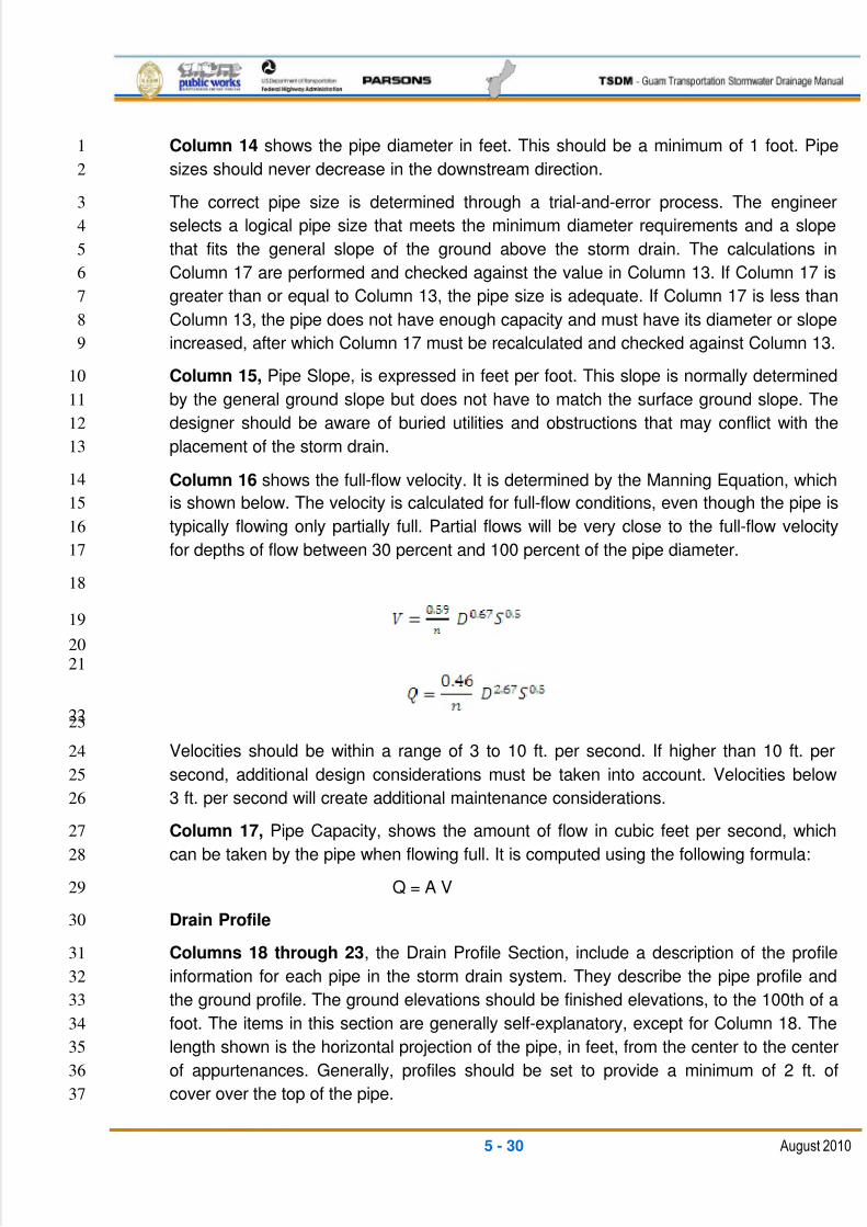
5/13/2018 Guam Storm Water Drainage Manual - slidepdf.com
http://slidepdf.com/reader/full/guam-storm-water-drainage-manual 116/486
5 - 30 August 2010
Column 14 shows the pipe diameter in feet. This should be a minimum of 1 foot. Pipe1
sizes should never decrease in the downstream direction.2
The correct pipe size is determined through a trial-and-error process. The engineer3
selects a logical pipe size that meets the minimum diameter requirements and a slope4
that fits the general slope of the ground above the storm drain. The calculations in5
Column 17 are performed and checked against the value in Column 13. If Column 17 is6
greater than or equal to Column 13, the pipe size is adequate. If Column 17 is less than7
Column 13, the pipe does not have enough capacity and must have its diameter or slope8
increased, after which Column 17 must be recalculated and checked against Column 13.9
Column 15, Pipe Slope, is expressed in feet per foot. This slope is normally determined10
by the general ground slope but does not have to match the surface ground slope. The11
designer should be aware of buried utilities and obstructions that may conflict with the12
placement of the storm drain.13
Column 16 shows the full-flow velocity. It is determined by the Manning Equation, which14
is shown below. The velocity is calculated for full-flow conditions, even though the pipe is15
typically flowing only partially full. Partial flows will be very close to the full-flow velocity16
for depths of flow between 30 percent and 100 percent of the pipe diameter.17
18
19
20
21
2223
Velocities should be within a range of 3 to 10 ft. per second. If higher than 10 ft. per24
second, additional design considerations must be taken into account. Velocities below25
3 ft. per second will create additional maintenance considerations.26
Column 17, Pipe Capacity, shows the amount of flow in cubic feet per second, which27
can be taken by the pipe when flowing full. It is computed using the following formula:28
Q = A V29
Drain Profile30
Columns 18 through 23, the Drain Profile Section, include a description of the profile31
information for each pipe in the storm drain system. They describe the pipe profile and32
the ground profile. The ground elevations should be finished elevations, to the 100th of a33
foot. The items in this section are generally self-explanatory, except for Column 18. The34
length shown is the horizontal projection of the pipe, in feet, from the center to the center35
of appurtenances. Generally, profiles should be set to provide a minimum of 2 ft. of36
cover over the top of the pipe.37
5/13/2018 Guam Storm Water Drainage Manual - slidepdf.com
http://slidepdf.com/reader/full/guam-storm-water-drainage-manual 117/486
5 - 31 August 2010
Remarks1
Column 24, Remarks, is for any information that might be helpful in reviewing the2
calculations. This space should note unique features such as drop manholes or energy3
dissipaters, reasons as to non-conventional slopes or grade changes, specific types of4
pipes due to loading and cover depths, velocity or maintenance considerations, changes5
in design frequency, etc.6
7
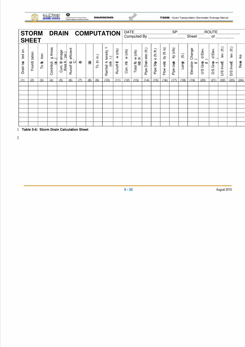
5/13/2018 Guam Storm Water Drainage Manual - slidepdf.com
http://slidepdf.com/reader/full/guam-storm-water-drainage-manual 118/486
5 - 32 August 2010
STORM DRAIN COMPUTATIONSHEET
DATE__________________ SP_____________ROUTE___________ Computed By __________________ Sheet ______ of _________
D r a
i n l o c a
t e d o n .
F r o m
S t a t i o n
T o
S t a
t i o n
C o n
t r i b u t i n
g A r e a s
( a c . )
C u m .
D r a
i n a g e
A r e a ‗ A ‘ ( a c . )
R u n o
f f C o e
f f i c i e n
t
‗ C ‘
C A Σ C A
T c
( m
i n . )
R a
i n f a l l I n t e n s
i t y ‗ I ‘
( i n . / h
r . )
R u n o
f f F l o
w ( c f s )
C o n .
I n f l o
w ( c f s )
T o
t a l F l o w
( c f s )
W i d t h
P i p e
D i a m e
t e r
( f t . )
P i p e
S l o p e
( f t . / f t . )
F l o w v e
l o c i t y ( f t . / s )
P i p e c a p a c
i t y ( c f s )
L e n g t h
( f t . )
E l e v a
t i o n C h a n g e
( f t . )
U / S G r o u n
d E l e v .
( f t . )
D / S G r o u n
d E l e v .
f t .
U / S I n v e r t E
l e v .
( f t . )
D / S I n v e r t E
l e v .
( f t . )
R e m a
r k s
(1) (2) (3) (4) (5) (6) (7) (8) (9) (10) (11) (12) (13) (14) (15) (16) (17) (18) (19) (20) (21) (22) (23) (24)
Table 5-6: Storm Drain Calculation Sheet1
2
5/13/2018 Guam Storm Water Drainage Manual - slidepdf.com
http://slidepdf.com/reader/full/guam-storm-water-drainage-manual 119/486
5 - 33 August 2010
5.5.4 COMPUTER ANALYSIS1
Storm drain design by computer analysis offers some distinct advantages over calculations2
performed by hand. Chief among these advantages is the ability to perform complex flow3
routings through the system, which can take into account the detention due to storage4
within the pipes and structures and overlapping of various basin runoff hydrographs. This5
analysis develops a more accurate picture of the hydraulic grade lines and flow conditions6
within a storm drain system for the design storm peak conditions.7
Most computer programs will have the ability to process various runoff hydrograph8
calculation methods that use the Rational Method or NRCS curve numbers, as well as the9
ability to enter storm distributions and rainfall intensity data unique to a specific location.10
They also will allow selection of different routing methods. Most of these programs will have11
sub-routines for designing detention within a system or accepting the input of additional12
detention storage and discharge controls. The designer should develop a full understanding13
of the various runoff and routing methodologies and in particular, select those that are best14
for the application when using these programs.15
There are several commercially-available computer programs for storm drain design. Two16
programs accepted by DPW are StormShed by Engenious Systems, Inc. and FlowMaster17
by Haestad Methods.18
5.5.5 PIPE MATERIALS FOR STORM DRAINS19
There are various pipe materials that are acceptable for storm drains. Pipe material20
selection includes hydraulic characteristics, site conditions, geologic conditions, corrosion21
resistance, safety considerations, and cost. Pipe types appropriate for a project are22
dependent on several factors, including but not limited to fill height, size, strength,23
corrosion, abrasion potential, debris passage, and necessary end treatments.24
Pipe design and installation is based on two general categories -- rigid and flexible pipes.25
The designer should be familiar with the design theories for both. The pipe type selection26
and installation methodology used should be prepared using the appropriate design27
principle.28
Pipe selection should be made in accordance with the following constraints.29
5.5.5.1 PIPE MATERIALS30
Pipe materials used by DPW can be categorized into three main categories -- storm sewer31
pipe (or otherwise called storm drain pipe), underdrain pipe, and culvert pipe.32
Storm sewer pipe usually ranges from 12 to 48 in. in diameter, and is used to convey33
roadway runoff or groundwater away from the roadway profile. Types of storm sewer pipes34
and materials should be selected based on the corrosion resistance and strength35
requirements suitable for the specific requirements. Pipe types can include concrete,36
reinforced concrete, metal, corrugated metal, and thermoplastic solid and corrugated wall.37
5/13/2018 Guam Storm Water Drainage Manual - slidepdf.com
http://slidepdf.com/reader/full/guam-storm-water-drainage-manual 120/486
5 - 34 August 2010
All storm sewer pipes should use gasketed, leak-proof joints, and be pressure-tested after1
installation to indicate the presence of leaking seams or joints. The design life for storm2
sewer pipes should generally match the design life of the roadway pavement, or a minimum3
of 25 years. If the pipe is to be installed in deep fills crossing the roadway section, then the4
design life should be the same as required for culvert pipe.5
Underdrain pipe is smaller diameter, perforated pipe intended to intercept groundwater and6
convey it away from areas such as roadbeds or from behind retaining walls. Typical7
underdrain applications use 6- to 8-in. diameter pvc, or polyethylene pipe, both solid wall8
and corrugated, but larger diameters can be specified. Underdrain pipe is generally used in9
conjunction with well-draining backfill material and a geotextile filter fabric. The design life of10
underdrain pipe should be the same as required for storm sewer pipe.11
Culvert pipe is a conduit under a roadway or embankment used to maintain flow from a12
natural channel or drainage ditch. Culverts are often located under high fills and usually13
cross the roadway making replacement difficult. Because of this, a minimum design life14expectancy of 50 year is required for all culverts under the main route roadways. A15
minimum 25-year design life should be used for other secondary road locations. The type of16
culvert selected can vary substantially from one location to another due to the hydraulic17
requirements, loadings, and corrosion resistance. Culverts use storm sewer pipe, reinforced18
concrete box sections (both rectangular and bottomless), corrugated metal, corrugated19
plastic pipe, corrugated metal pipe arch, and structural plate.20
5.5.5.2 PIPE DURABILITY21
Once a designer has determined the pipe classification needed for an application, the next22
step is to ensure that the pipe durability will extend for the entire design life. There are two23
main durability factors -- corrosion potential and abrasion resistance.24
Corrosion potential will be categorized generally as moderate or extreme. If the soil or water25
pH is less than 5 and greater than 8.5 and/or with a soil resistivity less than 1,000 ohm-cm26
then there is a potential for extreme corrosion conditions. All pipe installations in the coastal27
environment or brackish water conditions can also be considered as extreme corrosion28
conditions. If the pH and soil resistivity of the installation site is not known, then testing29
should be performed and pipe material selection made accordingly.30
Pipes suitable for the moderate condition include thermoplastic, concrete, and metal. Metal31
pipes should have protective treatments. These treatments are typically protecting on both32
sides with asphaltic or polymer coatings. Where abrasion of the bottom of pipes due to high33
velocities and heavy bed loads is a problem, then additional coatings such as asphalt invert34
paving is required. Corrugated steel pipe polymer coatings should conform to AASHTO M-35
246, composed of a minimum of 10 mils thick polyethylene and acrylic acid copolymer.36
Asphaltic coatings are usually a proprietary manufacturing process, using a spun asphalt37
lining on the inside for a hydraulically-smooth interior. Galvanized metal is not suitable due38
to its potential for loading of zinc into the environment. An alternative to asphalt protective39
5/13/2018 Guam Storm Water Drainage Manual - slidepdf.com
http://slidepdf.com/reader/full/guam-storm-water-drainage-manual 121/486
5 - 35 August 2010
treatments for corrugated steel pipes is to increase the wall thickness to compensate for1
loss of metal for the desired life span.2
Pipes suitable for high corrosion potential conditions are thermoplastic and concrete pipes3
only.4
Abrasion is the wearing away of pipe material by water-carrying sands, gravels, and rocks.5
All types of pipe material are subject to abrasion and can experience structural failure6
around the pipe invert if not adequately protected. Particular concern would be for streams7
with high bed loads, and with frequent or steady low flows with velocities 6 to 10 ft. per8
second. For these conditions, consideration should be given to placing the culverts on flat9
grades to encourage deposition within the culvert; reducing velocity through the culvert by10
increasing diameters and flattening grades; providing extra asphaltic paving of the inverts;11
and increasing wall thickness by at least one or two standard gauges on metal pipes.12
Where velocities are greater than 10 ft. per second, asphaltic coatings will have extremely13
short life expectancies and the wear on concrete inverts can be quite rapid depending on14
the amount of abrasives in the flow. For these conditions, the use of thermoplastic pipe with15
restrained joints is recommended. Solid wall High Density Polyethylene (HDPE) pipe with16
fusion welded joints is probably the most resistant to the abrasion forces. The use of17
continuous wall HDPE requires additional considerations for the thermo and dynamic forces18
involved, such as pipe anchors, wall flanges, and surge blocks.19
Pipes that have deteriorated over time due to either corrosion or abrasion will significantly20
affect the structural integrity of the roadway embankment. Once identified, these pipes21
should be replaced as soon as possible. In particular, they should be replaced as part of a22
new project‘s overall construction. Failure of a pipe will usually result in the ultimate failure23
of a roadway. 24
5.5.5.3 FILL HEIGHT25
Pipe types are constrained by their ability to carry the loadings from live vehicular traffic and26
longer-term, dead loads from soil cover. Assuming that the pipe is installed in accordance27
with DPW‘s standards, the pipe should perform satisfactorily if placed within the limitations28
shown in the Fill Height Tables 5-7a through 5-7c.29
Pipe systems should be designed to provide at least 2 ft. of cover over the pipe measured30
from the outside diameter of the pipe to the bottom of the pavement. This measurement31
does not include any asphalt or concrete paving above the top course. This depth tends to32provide adequate structural distribution of the live load and also allows a significant number33
of pipe alternatives to be specified on a contract.34
During construction, these minimum cover requirements may not be adequate to protect the35
pipe from equipment loadings, where additional cover or protected crossings may be36
required.37
38
5/13/2018 Guam Storm Water Drainage Manual - slidepdf.com
http://slidepdf.com/reader/full/guam-storm-water-drainage-manual 122/486
5 - 36 August 2010
ConcretePipe
Diameter(inches)
Maximum Cover in Feet
PlainAASHTO
M 86
Class IIAASHTO
M 170
Class IIIAASHTO
M170
Class IVAASHTO
M 170
Class VAASHTO
M 170
12 18 10 14 21 2618 18 11 14 22 28
24 16 11 15 22 29
30 11 15 23 29
36 11 15 23 29
48 12 15 23 2960 12 16 24 30
72 12 16 24 30
84 12 16 24 30
Table 5-7a: Fill Height, Concrete Pipe1
2
ConcretePipe
Diameter(inches)
Pipe WallThick.
(inches)
Minimum Cover in FeetPlain
AASHTOM 86
Class IIIAASHTO
M170
Class IVAASHTO
M 170
Class VAASHTO M
17012 2 1.5 1.5 1.0 0.518 2.5 1.5 1.5 1.0 0.524 3 1.5 1.5 1.0 0.530 3.5 1.5 1.5 1.0 0.536 4 1.5 1.5 1.0 0.548 5 1.5 1.0 0.560 6 1.5 1.0 0.5
72 7 1.5 1.0 0.584 8 1.5 1.0 0.5
Table 5-7b: Concrete Pipe for Shallow Cover Installations3
4
Solid Wall PVC Profile Wall PVC Corrugated PolyethyleneASTM D 3034 SDR 35
3 in. to 15 in. dia.
ASTM F 679 Type 118 in. to 48 in. dia.
AASHTO M 304or
ASTM F 794 Series 464 in. to 48 in. dia.
AASHTO M 294 Type S12 in. to 60 in. dia.
25 ft.
All diameters
25 ft.
All diameters
15 ft.
All diametersTable 5-7c: Thermoplastic Pipe, Fill Height 5
Minimum and maximum fill heights for corrugated metal pipe should be based on loading6
calculations established for flexible pipe theory in accordance with the pipe manufacturer‘s7
recommendations for that specific size, corrugation type/size, material type, and wall8
thickness.9
5/13/2018 Guam Storm Water Drainage Manual - slidepdf.com
http://slidepdf.com/reader/full/guam-storm-water-drainage-manual 123/486
5 - 37 August 2010
5.5.6 SUB-SURFACE DRAINAGE1
Sub-surface drainage is provided for the control of groundwater encountered at roadway2
locations. Groundwater, as distinguished from capillary water, is free water occurring in a3
zone of saturation below the ground surface. The sub-surface discharge depends on the4
effective hydraulic head and on the permeability, depth, slope, thickness, and extent of the5
aquifer.6
Solving sub-surface drainage problems often calls for specialized knowledge of geology7
and the application of soil mechanics. The designer should work directly with the8
Geotechnical Engineer regarding the final design of underdrains.9
Typical underdrain installations would be those provided for control of seepage in cuts or10
side hills, or the lowering of the groundwater table for proper subgrade drainage. Sub-11
surface drainage pipe size should be determined from the Geotechnical Engineer ‘s12
recommendations, or based on the area of interception, the permeability of the contributing13
soil layers, and most likely, the internal soil hydraulic grade line. When sub-surface14
drainage is connected to a storm drain system, the invert of the underdrain pipe should be15
placed above the operating water level in the storm drain. This helps to prevent reverse16
flow into the underdrain and in particular flooding of pavement sub-base layers for subgrade17
underdrains.18
5.6 CROSS DRAINAGE19
5.6.1 INTRODUCTION20
A culvert is a closed conduit under a roadway or embankment used to maintain flow from a21
natural channel or drainage ditch. A culvert should convey flow without causing damaging22
backwater, excessive flow constriction, or excessive outlet velocities.23
In addition to determining the design flows and corresponding hydraulic performance of a24
particular culvert, other factors can affect the ultimate design of a culvert and should be25
taken into consideration. These factors can include the economy of alternative pipe26
materials and sizes, horizontal and vertical alignment, environmental concerns, and the27
necessary culvert end treatments.28
During a given storm event, a culvert may operate under inlet control, outlet control, or both.29
Different variables and equations determine the culvert‘s capacity for each type of control.30
5.6.2 CULVERT TYPES31
Common culvert shapes generally available and used in highway applications are:32
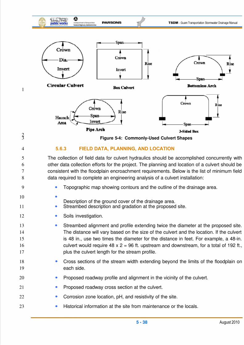
5/13/2018 Guam Storm Water Drainage Manual - slidepdf.com
http://slidepdf.com/reader/full/guam-storm-water-drainage-manual 124/486
5 - 38 August 2010
1
2Figure 5-4: Commonly-Used Culvert Shapes3
5.6.3 FIELD DATA, PLANNING, AND LOCATION4
The collection of field data for culvert hydraulics should be accomplished concurrently with5
other data collection efforts for the project. The planning and location of a culvert should be6
consistent with the floodplain encroachment requirements. Below is the list of minimum field7
data required to complete an engineering analysis of a culvert installation:8
Topographic map showing contours and the outline of the drainage area.9
Description of the ground cover of the drainage area.10
Streambed description and gradation at the proposed site.11
Soils investigation.12
Streambed alignment and profile extending twice the diameter at the proposed site.13
The distance will vary based on the size of the culvert and the location. If the culvert14
is 48 in., use two times the diameter for the distance in feet. For example, a 48-in.15
culvert would require 48 x 2 = 96 ft. upstream and downstream, for a total of 192 ft.,16
plus the culvert length for the stream profile.17
Cross sections of the stream width extending beyond the limits of the floodplain on18
each side.19
Proposed roadway profile and alignment in the vicinity of the culvert.20
Proposed roadway cross section at the culvert.21
Corrosion zone location, pH, and resistivity of the site.22
Historical information at the site from maintenance or the locals.23
5/13/2018 Guam Storm Water Drainage Manual - slidepdf.com
http://slidepdf.com/reader/full/guam-storm-water-drainage-manual 125/486
5 - 39 August 2010
Any other unique features that can affect design, such as low-lying structures that1
could be affected by excessive headwater or other considerations.2
Inspect and document the physical condition of the existing culvert.3
5.6.4 CULVERT FUNDAMENTALS4
Flow Conditions A culvert barrel may flow full over all of its length or partly f ull. Full flow5
in a culvert barrel is rare. Generally, at least part of the barrel flows partly full. A water6
surface profile calculation is the only way to accurately determine how much of the barrel7
flows full.8
Full Flow The hydraulic condition in a culvert flowing full is called pressure flow. If the9
cross-sectional area of the culvert in pressure flow is increased, the flow area will expand.10
One condition that can create pressure flow in a culvert is the back pressure caused by a11
high downstream water surface elevation. A high upstream water surface elevation may12
also produce full flow. Regardless of the cause, the capacity of a culvert operating under13pressure flow is affected by upstream and downstream conditions and by the hydraulic14
characteristics of the culvert.15
Partly Full (Free Surface) Flow Free-surface flow or open-channel flow may be16
categorized as sub-critical, critical, or super-critical. A determination of the appropriate flow17
regimen is accomplished by evaluating the dimensionless number, Fr, called the Froude18
Number. When Fr > 1.0, the flow is super-critical and is characterized as swift. When Fr <19
1.0, the flow is sub-critical and characterized as smooth and tranquil. If Fr = 1.0, the flow is20
said to be critical.21
Types of Flow Control Inlet and outlet control are the two basic types of flow control.22
The basis for the classification system is the location of the control section. The23
characterization of pressure and the sub-critical and super-critical flow regimens play an24
important role in determining the location of the control section, and thus the type of control.25
The hydraulic capacity of a culvert depends on a different combination of factors for each26
type of control.27
Inlet Control Inlet control occurs when the culvert barrel is capable of conveying more28
flow than the inlet will accept. The control section of a culvert operating under inlet control is29
located just inside the entrance. Critical depth occurs at or near this location, and the flow30
regimen immediately downstream is super-critical. Hydraulic characteristics downstream of31
the inlet control section do not affect the culvert capacity. The upstream water surface32elevation and the inlet geometry represent the major flow controls. The inlet geometry33
includes the barrel shape, the cross-sectional area, and the inlet edge.34
Outlet Control Outlet control flow occurs when the culvert barrel is not capable of35
conveying as much flow as the inlet opening will accept. The control section for outlet36
control flow in a culvert is located at the barrel exit or further downstream. Either sub-critical37
or pressure flow exists in the culvert barrel under these conditions. All of the geometric and38
5/13/2018 Guam Storm Water Drainage Manual - slidepdf.com
http://slidepdf.com/reader/full/guam-storm-water-drainage-manual 126/486
5 - 40 August 2010
hydraulic characteristics of the culvert play a role in determining its capacity. These1
characteristics include all of the factors governing inlet control; the water surface elevation2
at the outlet; and the slope, length, and hydraulic roughness of the culvert barrel.3
Headwater Energy is required to force flow through a culvert. This energy takes the form4
of an increased water surface elevation on the upstream side of the culvert. The depth of5
the upstream water surface measured from the invert at the culvert entrance is generally6
referred to as headwater depth.7
A considerable volume of water may be ponded upstream of a culvert installation under8
high fills or in areas with flat ground slopes. The ponding on the upstream of roadway fills is9
discouraged for the general case unless the ponding is a pre-construction existing case and10
the ponding has no detrimental effect on upstream structures and other property.11
Allowable Headwater Circular culverts, box culverts, and pipe arches should be12
designed so that the ratio of the headwater (HW) to diameter (D) during the design flow13
event is less than or equal to 1.25 (HW i /D < 1.25). HWi /D ratios larger than 1.25 are14
permitted, provided that existing site conditions such as available ponding areas on deeper15
fills, warrant a larger ratio. The maximum allowable HW i /D ratios should not exceed 3.0.16
The headwater that occurs during the 100-year flow event must also be investigated. Two17
sets of criteria exist for the allowable headwater during the 100-year flow event, depending18
on the type of roadway over the culvert:19
1. If the culvert is under a main highway route that must be kept open during major20
storm events, the culvert must be designed so that the 100-year flow event can be21
passed without overtopping the roadway.22
2. If the culvert is under a secondary roadway, it is recommended that the culvert be23
designed so that there is no roadway overtopping during the 100-year flow event.24
However, there may be situations where it is more cost-effective to design the25
roadway embankment to withstand overtopping rather than to provide a structure or26
group of structures capable of passing the design flow.27
Bottomless culverts with footings should be designed so that 1 foot of debris clearance from28
the water surface to the culvert crown is provided during the design flow event. Bottomless29
culverts should also be designed so that the 100-year event can be passed without the30
headwater depth exceeding the height of the culvert. Flow depths greater than the height31
can cause potential scour problems near the footings.32
Tailwater Tailwater is defined as the depth of water downstream of the culvert measured33
from the outlet invert. It is an important factor in determining culvert capacity under outlet34
control conditions. Tailwater may be caused by an obstruction in the downstream channel35
or by the hydraulic resistance of the channel. In either case, backwater calculations from36
the downstream control point are required to precisely define tailwater. When appropriate,37
normal depth approximations may be used instead of backwater calculations.38
5/13/2018 Guam Storm Water Drainage Manual - slidepdf.com
http://slidepdf.com/reader/full/guam-storm-water-drainage-manual 127/486
5 - 41 August 2010
Outlet Velocity Because a culvert usually constricts the available channel area, flow1
velocities in the culvert are likely to be higher than in the channel. These increased2
velocities can cause streambed scour and bank erosion in the vicinity of the culvert outlet.3
Energy dissipaters and outlet protection devices are oftentimes required to avoid scour at4
the culvert outlet. All culverts must be designed for downstream channel stability. The5
velocity of flow from the culvert outlet or energy dissipater/protection section should be6
laminar, sub-critical, and in no case exceed the natural velocity of the existing channel.7
Alignment and Grade It is recommended that culverts be placed on the same alignment8
and grade as the natural streambed, especially on year-round streams. This tends to9
maintain the natural drainage system and minimize downstream impacts. Locate and use10
headwalls to minimize fill impacts within the existing stream ordinary high water level.11
Allowable Velocities Culverts should be designed for the required life span (50 years12
on main routes, 25 years on secondary roads), where corrosion and abrasion are the13
primary cause of pipe failure. The type of culvert material, dimensions, and configurations14should be compatible with the velocity to reduce abrasion wear to acceptable levels, while15
operating within acceptable hydraulic parameters with stable inlets and outlet conditions.16
Minimum Spacing When multiple lines of pipe or pipe-arch greater than 48 in. in17
diameter or span are used, they should be spaced so that the sides of the pipe are no18
closer than one-half a diameter or 3 ft., whichever is less, so there is space for adequate19
compaction of the fill material available. For diameters up to 48 in., the minimum distance20
between the sides of the pipe should be no less than 2 ft. Utility lines may be closer.21
5.6.5 ENGINEERING ANALYSIS22
Collected field data should be used to perform an engineering analysis. The intent of the23
engineering analysis is to ensure that the designer considers a number of issues, including24
flow capacity requirements, foundation conditions, embankment construction, runoff25
conditions, soil characteristics, stream characteristics, construction problems that may26
occur, estimated cost, environmental concerns, and any other factors that may be involved27
in and pertinent to the design. An additional analysis may be required in floodplain areas to28
demonstrate that the culvert does not increase upstream levels over existing conditions.29
Once the engineering analysis is completed, it will be part of the hydraulic report and should30
include:31
Culvert hydraulic and hydrology calculations.32
Approved modeling software, such as HY-8, can also be used in lieu of hand33
calculations. If the designers wish to use different software, prior approval is34
required prior to submitting final designs.35
Proposed roadway stationing of the culvert location.36
Culvert and stream profile.37
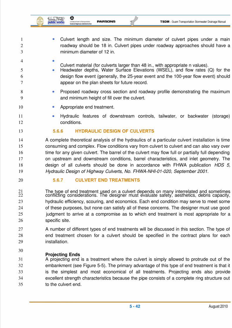
5/13/2018 Guam Storm Water Drainage Manual - slidepdf.com
http://slidepdf.com/reader/full/guam-storm-water-drainage-manual 128/486
5 - 42 August 2010
Culvert length and size. The minimum diameter of culvert pipes under a main1
roadway should be 18 in. Culvert pipes under roadway approaches should have a2
minimum diameter of 12 in.3
Culvert material (for culverts larger than 48 in., with appropriate n values).4
Headwater depths, Water Surface Elevations (WSEL), and flow rates (Q) for the5
design flow event (generally, the 25-year event and the 100-year flow event) should6
appear on the plan sheets for future record.7
Proposed roadway cross section and roadway profile demonstrating the maximum8
and minimum height of fill over the culvert.9
Appropriate end treatment.10
Hydraulic features of downstream controls, tailwater, or backwater (storage)11
conditions.12
5.6.6 HYDRAULIC DESIGN OF CULVERTS13
A complete theoretical analysis of the hydraulics of a particular culvert installation is time14
consuming and complex. Flow conditions vary from culvert to culvert and can also vary over15
time for any given culvert. The barrel of the culvert may flow full or partially full depending16
on upstream and downstream conditions, barrel characteristics, and inlet geometry. The17
design of all culverts should be done in accordance with FHWA publication HDS 5,18
Hydraulic Design of Highway Culverts, No. FHWA-NHI-01-020, September 2001.19
5.6.7 CULVERT END TREATMENTS20
The type of end treatment used on a culvert depends on many interrelated and sometimes21conflicting considerations. The designer must evaluate safety, aesthetics, debris capacity,22
hydraulic efficiency, scouring, and economics. Each end condition may serve to meet some23
of these purposes, but none can satisfy all of these concerns. The designer must use good24
judgment to arrive at a compromise as to which end treatment is most appropriate for a25
specific site.26
A number of different types of end treatments will be discussed in this section. The type of27
end treatment chosen for a culvert should be specified in the contract plans for each28
installation.29
Projecting Ends30
A projecting end is a treatment where the culvert is simply allowed to protrude out of the31
embankment (see Figure 5-5). The primary advantage of this type of end treatment is that it32
is the simplest and most economical of all treatments. Projecting ends also provide33
excellent strength characteristics because the pipe consists of a complete ring structure out34
to the culvert end.35
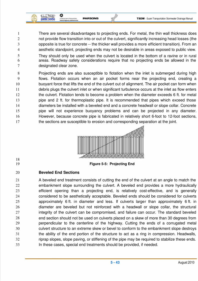
5/13/2018 Guam Storm Water Drainage Manual - slidepdf.com
http://slidepdf.com/reader/full/guam-storm-water-drainage-manual 129/486
5 - 43 August 2010
There are several disadvantages to projecting ends. For metal, the thin wall thickness does1
not provide flow transition into or out of the culvert, significantly increasing head losses (the2
opposite is true for concrete -- the thicker wall provides a more efficient transition). From an3
aesthetic standpoint, projecting ends may not be desirable in areas exposed to public view.4
They should only be used when the culvert is located in the bottom of a ravine or in rural5
areas. Roadway safety considerations require that no projecting ends be allowed in the6
designated clear zone.7
Projecting ends are also susceptible to flotation when the inlet is submerged during high8
flows. Flotation occurs when an air pocket forms near the projecting end, creating a9
buoyant force that lifts the end of the culvert out of alignment. The air pocket can form when10
debris plugs the culvert inlet or when significant turbulence occurs at the inlet as flow enters11
the culvert. Flotation tends to become a problem when the diameter exceeds 6 ft. for metal12
pipe and 2 ft. for thermoplastic pipe. It is recommended that pipes which exceed those13
diameters be installed with a beveled end and a concrete headwall or slope collar. Concrete14
pipe will not experience buoyancy problems and can be projected in any diameter.15
However, because concrete pipe is fabricated in relatively short 6-foot to 12-foot sections,16
the sections are susceptible to erosion and corresponding separation at the joint.17
18
Figure 5-5: Projecting End19
Beveled End Sections20
A beveled end treatment consists of cutting the end of the culvert at an angle to match the21
embankment slope surrounding the culvert. A beveled end provides a more hydraulically22
efficient opening than a projecting end, is relatively cost-effective, and is generally23
considered to be aesthetically acceptable. Beveled ends should be considered for culverts24
approximately 6 ft. in diameter and less. If culverts larger than approximately 6 ft. in25
diameter are beveled but not reinforced with a headwall or slope collar, the structural26
integrity of the culvert can be compromised, and failure can occur. The standard beveled27
end section should not be used on culverts placed on a skew of more than 30 degrees from28
perpendicular to the centerline of the highway. Cutting the ends of a corrugated metal29
culvert structure to an extreme skew or bevel to conform to the embankment slope destroys30
the ability of the end portion of the structure to act as a ring in compression. Headwalls,31
riprap slopes, slope paving, or stiffening of the pipe may be required to stabilize these ends.32
In these cases, special end treatments should be provided, if needed.33
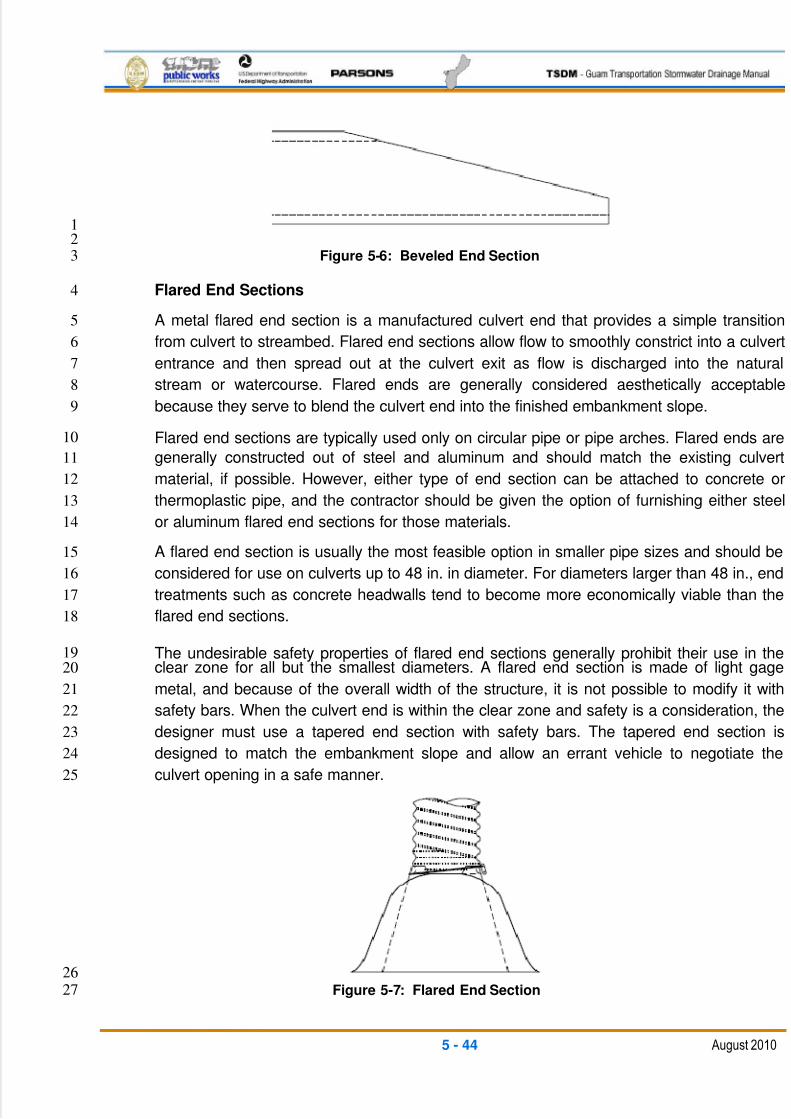
5/13/2018 Guam Storm Water Drainage Manual - slidepdf.com
http://slidepdf.com/reader/full/guam-storm-water-drainage-manual 130/486
5 - 44 August 2010
1
2
Figure 5-6: Beveled End Section3
Flared End Sections4
A metal flared end section is a manufactured culvert end that provides a simple transition5
from culvert to streambed. Flared end sections allow flow to smoothly constrict into a culvert6
entrance and then spread out at the culvert exit as flow is discharged into the natural7
stream or watercourse. Flared ends are generally considered aesthetically acceptable8
because they serve to blend the culvert end into the finished embankment slope.9
Flared end sections are typically used only on circular pipe or pipe arches. Flared ends are10
generally constructed out of steel and aluminum and should match the existing culvert11
material, if possible. However, either type of end section can be attached to concrete or12
thermoplastic pipe, and the contractor should be given the option of furnishing either steel13
or aluminum flared end sections for those materials.14
A flared end section is usually the most feasible option in smaller pipe sizes and should be15
considered for use on culverts up to 48 in. in diameter. For diameters larger than 48 in., end16
treatments such as concrete headwalls tend to become more economically viable than the17
flared end sections.18
The undesirable safety properties of flared end sections generally prohibit their use in the19
clear zone for all but the smallest diameters. A flared end section is made of light gage20
metal, and because of the overall width of the structure, it is not possible to modify it with21
safety bars. When the culvert end is within the clear zone and safety is a consideration, the22
designer must use a tapered end section with safety bars. The tapered end section is23
designed to match the embankment slope and allow an errant vehicle to negotiate the24
culvert opening in a safe manner.25
26
Figure 5-7: Flared End Section27
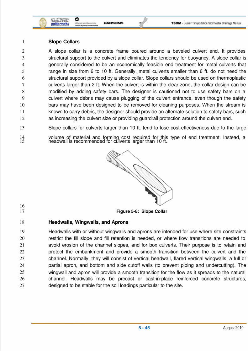
5/13/2018 Guam Storm Water Drainage Manual - slidepdf.com
http://slidepdf.com/reader/full/guam-storm-water-drainage-manual 131/486
5 - 45 August 2010
Slope Collars1
A slope collar is a concrete frame poured around a beveled culvert end. It provides2
structural support to the culvert and eliminates the tendency for buoyancy. A slope collar is3
generally considered to be an economically feasible end treatment for metal culverts that4
range in size from 6 to 10 ft. Generally, metal culverts smaller than 6 ft. do not need the5
structural support provided by a slope collar. Slope collars should be used on thermoplastic6
culverts larger than 2 ft. When the culvert is within the clear zone, the collar design can be7
modified by adding safety bars. The designer is cautioned not to use safety bars on a8
culvert where debris may cause plugging of the culvert entrance, even though the safety9
bars may have been designed to be removed for cleaning purposes. When the stream is10
known to carry debris, the designer should provide an alternate solution to safety bars, such11
as increasing the culvert size or providing guardrail protection around the culvert end.12
Slope collars for culverts larger than 10 ft. tend to lose cost-effectiveness due to the large13
volume of material and forming cost required for this type of end treatment. Instead, a14headwall is recommended for culverts larger than 10 ft.15
16
Figure 5-8: Slope Collar17
Headwalls, Wingwalls, and Aprons18
Headwalls with or without wingwalls and aprons are intended for use where site constraints19
restrict the fill slope and fill retention is needed, or where flow transitions are needed to20
avoid erosion of the channel slopes, and for box culverts. Their purpose is to retain and21
protect the embankment and provide a smooth transition between the culvert and the22
channel. Normally, they will consist of vertical headwall, flared vertical wingwalls, a full or23
partial apron, and bottom and side cutoff walls (to prevent piping and undercutting). The24
wingwall and apron will provide a smooth transition for the flow as it spreads to the natural25
channel. Headwalls may be precast or cast-in-place reinforced concrete structures,26
designed to be stable for the soil loadings particular to the site.27
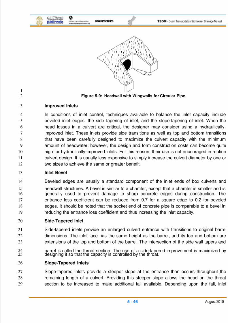
5/13/2018 Guam Storm Water Drainage Manual - slidepdf.com
http://slidepdf.com/reader/full/guam-storm-water-drainage-manual 132/486
5 - 46 August 2010
1
Figure 5-9: Headwall with Wingwalls for Circular Pipe2
Improved Inlets3
In conditions of inlet control, techniques available to balance the inlet capacity include4
beveled inlet edges, the side tapering of inlet, and the slope-tapering of inlet. When the5
head losses in a culvert are critical, the designer may consider using a hydraulically-6
improved inlet. These inlets provide side transitions as well as top and bottom transitions7
that have been carefully designed to maximize the culvert capacity with the minimum8
amount of headwater; however, the design and form construction costs can become quite9
high for hydraulically-improved inlets. For this reason, their use is not encouraged in routine10
culvert design. It is usually less expensive to simply increase the culvert diameter by one or11
two sizes to achieve the same or greater benefit.12
Inlet Bevel13
Beveled edges are usually a standard component of the inlet ends of box culverts and14
headwall structures. A bevel is similar to a chamfer, except that a chamfer is smaller and is15
generally used to prevent damage to sharp concrete edges during construction. The16
entrance loss coefficient can be reduced from 0.7 for a square edge to 0.2 for beveled17
edges. It should be noted that the socket end of concrete pipe is comparable to a bevel in18
reducing the entrance loss coefficient and thus increasing the inlet capacity.19
Side-Tapered Inlet20
Side-tapered inlets provide an enlarged culvert entrance with transitions to original barrel21
dimensions. The inlet face has the same height as the barrel, and its top and bottom are22
extensions of the top and bottom of the barrel. The intersection of the side wall tapers and23
barrel is called the throat section. The use of a side-tapered improvement is maximized by24designing it so that the capacity is controlled by the throat.25
Slope-Tapered Inlets26
Slope-tapered inlets provide a steeper slope at the entrance than occurs throughout the27
remaining length of a culvert. Providing this steeper slope allows the head on the throat28
section to be increased to make additional fall available. Depending upon the fall, inlet29
5/13/2018 Guam Storm Water Drainage Manual - slidepdf.com
http://slidepdf.com/reader/full/guam-storm-water-drainage-manual 133/486
5 - 47 August 2010
capacities can be increased 100 percent or greater above conventional culverts with square1
edges.2
5.6.8 CONSTRUCTION AND MAINTENANCE CONSIDERATION3
The design of a culvert should be consistent with standard construction and specifications.4
If special provisions are warranted in order to properly construct or maintain the proposed5
facility, this information should be specified in the design documentation. The designer must6
also consider maintenance of traffic requirements because cost and disruption of the7
installation may be the major concern for some locations.8
In all cases, the culverts should be designed to have self-cleaning velocities, and both ends9
should have some type of erosion protection. The material selected should have a 50-year10
or longer life span estimate, because most roads can be resurfaced a number of times to11
increase their life without the reconstruction of subgrade.12
The use of multiple culvert openings is discouraged except in situations where very little13
vertical distance is available from the roadway to the culvert invert. Alternatives to multiple14
culvert installations are low-profile arches and three-sided box structures that provide15
significant horizontal span lengths while minimizing the vertical rise.16
Where possible, maintenance access should be provided at the upstream end of cross17
culverts. For shallow culverts, this can be a widened shoulder pull-out on which to park a18
vehicle. For culverts in deeper fills, provide a separate maintenance access road from off19
the embankment. Access roads should be a minimum of 12 ft. wide and should not exceed20
a 15 percent slope. The maintenance road should be paved to match the anticipated21
maintenance vehicle loadings, but should never be less than a 6-in. thick layer of crushed22
gravel over a geotextile filter fabric.23
Safety fencing should be provided along the tops of all culvert headwalls with a vertical face24
of 6 ft. or more.25
5.6.9 ENERGY DISSIPATERS26
When the outlet velocities of a culvert are excessive for the site conditions, the designer27
must consider erosion protection. The protection can be fairly simple inlet and outlet28
channel stabilization methods, such as riprap slope and bottom protection, splash pads,29
and vegetated slope protection measures. Or it may require the installation of energy30
dissipaters. Dissipaters are hydraulic control structures to reduce velocities to within31
tolerable limits. Culvert erosion protection and energy dissipaters should be designed in32
accordance with FHWA publication HEC 14, Hydraulic Design of Energy Dissipaters for 33
Culverts and Channels , No. FHWA-NHI-06-086, July 2006 . Typical protected outlets and34
energy dissipaters include:35
36
37
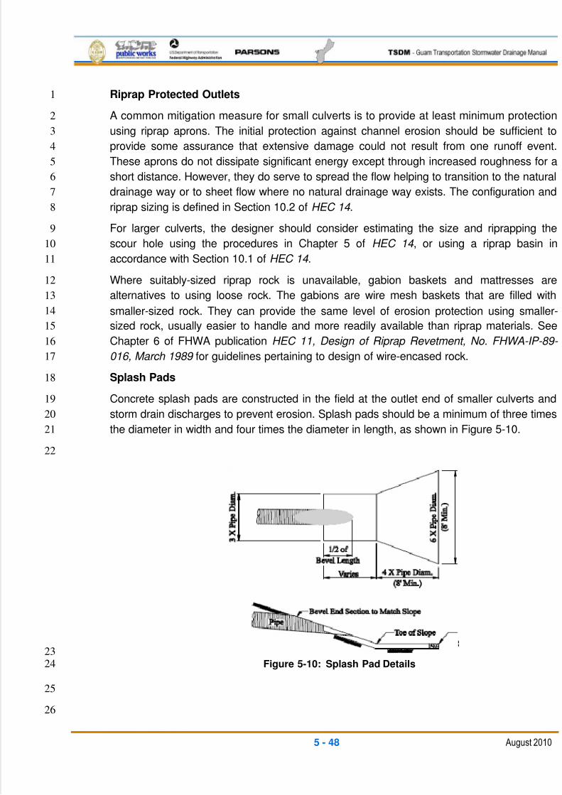
5/13/2018 Guam Storm Water Drainage Manual - slidepdf.com
http://slidepdf.com/reader/full/guam-storm-water-drainage-manual 134/486
5 - 48 August 2010
Riprap Protected Outlets1
A common mitigation measure for small culverts is to provide at least minimum protection2
using riprap aprons. The initial protection against channel erosion should be sufficient to3
provide some assurance that extensive damage could not result from one runoff event.4
These aprons do not dissipate significant energy except through increased roughness for a5
short distance. However, they do serve to spread the flow helping to transition to the natural6
drainage way or to sheet flow where no natural drainage way exists. The configuration and7
riprap sizing is defined in Section 10.2 of HEC 14 .8
For larger culverts, the designer should consider estimating the size and riprapping the9
scour hole using the procedures in Chapter 5 of HEC 14 , or using a riprap basin in10
accordance with Section 10.1 of HEC 14 .11
Where suitably-sized riprap rock is unavailable, gabion baskets and mattresses are12
alternatives to using loose rock. The gabions are wire mesh baskets that are filled with13
smaller-sized rock. They can provide the same level of erosion protection using smaller-14
sized rock, usually easier to handle and more readily available than riprap materials. See15
Chapter 6 of FHWA publication HEC 11, Design of Riprap Revetment, No. FHWA-IP-89- 16
016, March 1989 for guidelines pertaining to design of wire-encased rock.17
Splash Pads18
Concrete splash pads are constructed in the field at the outlet end of smaller culverts and19
storm drain discharges to prevent erosion. Splash pads should be a minimum of three times20
the diameter in width and four times the diameter in length, as shown in Figure 5-10.21
22
23
Figure 5-10: Splash Pad Details24
25
26
5/13/2018 Guam Storm Water Drainage Manual - slidepdf.com
http://slidepdf.com/reader/full/guam-storm-water-drainage-manual 135/486
5 - 49 August 2010
Other Energy Dissipating Structures1
Other structures include impact basins, stilling basins/wells, and drop structures. These2
structures may consist of baffles, posts, or other means of creating roughness and3
hydraulic jumps to dissipate excessive velocity. See FHWA publication HEC 14 for the4
selection and design criteria.5
Energy dissipaters have a reputation for collecting debris on the baffles, so the designer6
should consider this possibility when choosing a dissipater design. In areas of high debris,7
the dissipater should be a self-clearing type and easily accessible to maintenance crews.8
5.6.10 CULVERT DEBRIS9
Debris problems can cause even an adequately-designed culvert to experience hydraulic10
capacity problems. Debris may consist of anything from limbs and sticks, or orchard11
pruning, to logs and trees. Silt, sand, gravel, and boulders can also be classified as debris.12
The culvert site is a natural place for these materials to settle and accumulate. No method13
is available for accurately predicting debris problems. Examining the maintenance history of14
each site is the most reliable way of determining potential problems. Sometimes, upsizing a15
culvert is necessary to enable it to pass debris more effectively. Upsizing may also allow a16
culvert to be more easily cleaned.17
Methods to counter debris at culverts are discussed in Section 5.2 of FHWA publication18
HEC 9, Debris Control Structures, Evaluation and Countermeasures, Third Edition, No.19
FHWA-IF-04-016, October 2005 . In all cases, culverts should be designed to have20
maintenance access for debris removal at the inlets.21
22

5/13/2018 Guam Storm Water Drainage Manual - slidepdf.com
http://slidepdf.com/reader/full/guam-storm-water-drainage-manual 136/486
This page intentionally left blank
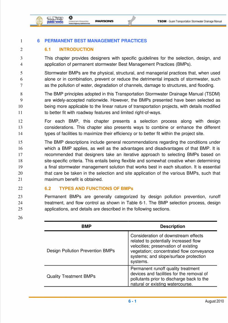
5/13/2018 Guam Storm Water Drainage Manual - slidepdf.com
http://slidepdf.com/reader/full/guam-storm-water-drainage-manual 137/486
6 - 1 August 2010
6 PERMANENT BEST MANAGEMENT PRACTICES1
6.1 INTRODUCTION2
This chapter provides designers with specific guidelines for the selection, design, and3
application of permanent stormwater Best Management Practices (BMPs).4
Stormwater BMPs are the physical, structural, and managerial practices that, when used5
alone or in combination, prevent or reduce the detrimental impacts of stormwater, such6
as the pollution of water, degradation of channels, damage to structures, and flooding.7
The BMP principles adopted in this Transportation Stormwater Drainage Manual (TSDM)8
are widely-accepted nationwide. However, the BMPs presented have been selected as9
being more applicable to the linear nature of transportation projects, with details modified10
to better fit with roadway features and limited right-of-ways.11
For each BMP, this chapter presents a selection process along with design12
considerations. This chapter also presents ways to combine or enhance the different13
types of facilities to maximize their efficiency or to better fit within the project site.14
The BMP descriptions include general recommendations regarding the conditions under15
which a BMP applies, as well as the advantages and disadvantages of that BMP. It is16
recommended that designers take an iterative approach to selecting BMPs based on17
site-specific criteria. This entails being flexible and somewhat creative when determining18
a final stormwater management solution that works best in each situation. It is essential19
that care be taken in the selection and site application of the various BMPs, such that20
maximum benefit is obtained.21
6.2 TYPES AND FUNCTIONS OF BMPs22
Permanent BMPs are generally categorized by design pollution prevention, runoff23
treatment, and flow control as shown in Table 6-1. The BMP selection process, design24
applications, and details are described in the following sections.25
26
BMP Description
Design Pollution Prevention BMPs
Consideration of downstream effectsrelated to potentially increased flowvelocities; preservation of existingvegetation; concentrated flow conveyancesystems; and slope/surface protectionsystems.
Quality Treatment BMPs
Permanent runoff quality treatmentdevices and facilities for the removal ofpollutants prior to discharge back to thenatural or existing watercourse.
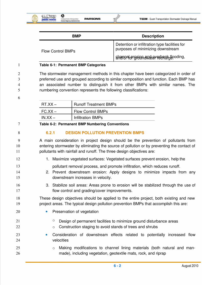
5/13/2018 Guam Storm Water Drainage Manual - slidepdf.com
http://slidepdf.com/reader/full/guam-storm-water-drainage-manual 138/486
6 - 2 August 2010
BMP Description
Flow Control BMPs
Detention or infiltration type facilities forpurposes of minimizing downstream
channel erosion and overbank flooding,and/or for groundwater recharge.
Table 6-1: Permanent BMP Categories1
The stormwater management methods in this chapter have been categorized in order of2
preferred use and grouped according to similar composition and function. Each BMP has3
an associated number to distinguish it from other BMPs with similar names. The4
numbering convention represents the following classifications:5
6
RT.XX – Runoff Treatment BMPs
FC.XX – Flow Control BMPs
IN.XX – Infiltration BMPs
Table 6-2: Permanent BMP Numbering Conventions7
6.2.1 DESIGN POLLUTION PREVENTION BMPS8
A main consideration in project design should be the prevention of pollutants from9
entering stormwater by eliminating the source of pollution or by preventing the contact of10
pollutants with rainfall and runoff. The three design objectives are:11
1. Maximize vegetated surfaces: Vegetated surfaces prevent erosion, help the12
pollutant removal process, and promote infiltration, which reduces runoff.13
2. Prevent downstream erosion: Apply designs to minimize impacts from any14
downstream increases in velocity.15
3. Stabilize soil areas: Areas prone to erosion will be stabilized through the use of16
flow control and grading/cover improvements.17
These design objectives should be applied to the entire project, both existing and new18
project areas. The typical design pollution prevention BMPs that accomplish this are:19
Preservation of vegetation20
o Design of permanent facilities to minimize ground disturbance areas21
o Construction staging to avoid stands of trees and shrubs22
Consideration of downstream effects related to potentially increased flow23
velocities24
o Making modifications to channel lining materials (both natural and man-25
made), including vegetation, geotextile mats, rock, and riprap26
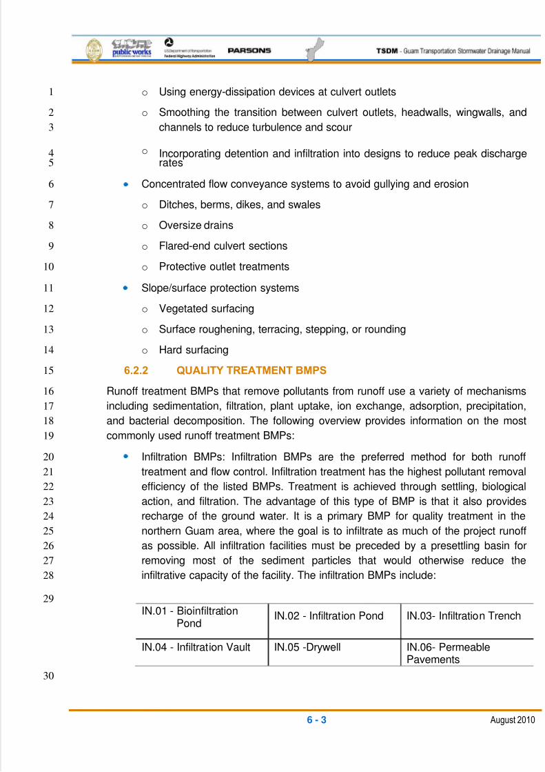
5/13/2018 Guam Storm Water Drainage Manual - slidepdf.com
http://slidepdf.com/reader/full/guam-storm-water-drainage-manual 139/486
6 - 3 August 2010
o Using energy-dissipation devices at culvert outlets1
o Smoothing the transition between culvert outlets, headwalls, wingwalls, and2
channels to reduce turbulence and scour3
o Incorporating detention and infiltration into designs to reduce peak discharge4rates5
Concentrated flow conveyance systems to avoid gullying and erosion6
o Ditches, berms, dikes, and swales7
o Oversize drains8
o Flared-end culvert sections9
o Protective outlet treatments10
Slope/surface protection systems11
o Vegetated surfacing12
o Surface roughening, terracing, stepping, or rounding13
o Hard surfacing14
6.2.2 QUALITY TREATMENT BMPS15
Runoff treatment BMPs that remove pollutants from runoff use a variety of mechanisms16
including sedimentation, filtration, plant uptake, ion exchange, adsorption, precipitation,17
and bacterial decomposition. The following overview provides information on the most18
commonly used runoff treatment BMPs:19
Infiltration BMPs: Infiltration BMPs are the preferred method for both runoff20
treatment and flow control. Infiltration treatment has the highest pollutant removal21
efficiency of the listed BMPs. Treatment is achieved through settling, biological22
action, and filtration. The advantage of this type of BMP is that it also provides23
recharge of the ground water. It is a primary BMP for quality treatment in the24
northern Guam area, where the goal is to infiltrate as much of the project runoff25
as possible. All infiltration facilities must be preceded by a presettling basin for26
removing most of the sediment particles that would otherwise reduce the27
infiltrative capacity of the facility. The infiltration BMPs include:28
29
IN.01 - BioinfiltrationPond
IN.02 - Infiltration Pond IN.03- Infiltration Trench
IN.04 - Infiltration Vault IN.05 -Drywell IN.06- PermeablePavements
30
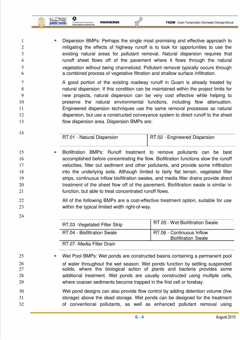
5/13/2018 Guam Storm Water Drainage Manual - slidepdf.com
http://slidepdf.com/reader/full/guam-storm-water-drainage-manual 140/486
6 - 4 August 2010
Dispersion BMPs: Perhaps the single most promising and effective approach to1
mitigating the effects of highway runoff is to look for opportunities to use the2
existing natural areas for pollutant removal. Natural dispersion requires that3
runoff sheet flows off of the pavement where it flows through the natural4
vegetation without being channelized. Pollutant removal typically occurs through5
a combined process of vegetative filtration and shallow surface infiltration.6
A good portion of the existing roadway runoff in Guam is already treated by7
natural dispersion. If this condition can be maintained within the project limits for8
new projects, natural dispersion can be very cost effective while helping to9
preserve the natural environmental functions, including flow attenuation.10
Engineered dispersion techniques use the same removal processes as natural11
dispersion, but use a constructed conveyance system to direct runoff to the sheet12
flow dispersion area. Dispersion BMPs are:13
14RT.01 - Natural Dispersion RT.02 - Engineered Dispersion
Biofiltration BMPs: Runoff treatment to remove pollutants can be best15
accomplished before concentrating the flow. Biofiltration functions slow the runoff16
velocities, filter out sediment and other pollutants, and provide some infiltration17
into the underlying soils. Although limited to fairly flat terrain, vegetated filter18
strips, continuous inflow biofiltration swales, and media filter drains provide direct19
treatment of the sheet flow off of the pavement. Biofiltration swale is similar in20
function, but able to treat concentrated runoff flows.21
All of the following BMPs are a cost-effective treatment option, suitable for use22
within the typical limited width right-of-way.23
24
RT.03 -Vegetated Filter Strip RT.05 - Wet Biofiltration Swale
RT.04 - Biofiltration Swale RT.06 - Continuous InflowBiofiltration Swale
RT.07 -Media Filter Drain
Wet Pool BMPs: Wet ponds are constructed basins containing a permanent pool25
of water throughout the wet season. Wet ponds function by settling suspended26
solids, where the biological action of plants and bacteria provides some27
additional treatment. Wet ponds are usually constructed using multiple cells,28
where coarser sediments become trapped in the first cell or forebay.29
Wet pond designs can also provide flow control by adding detention volume (live30
storage) above the dead storage. Wet ponds can be designed for the treatment31
of conventional pollutants, as well as enhanced pollutant removal using32
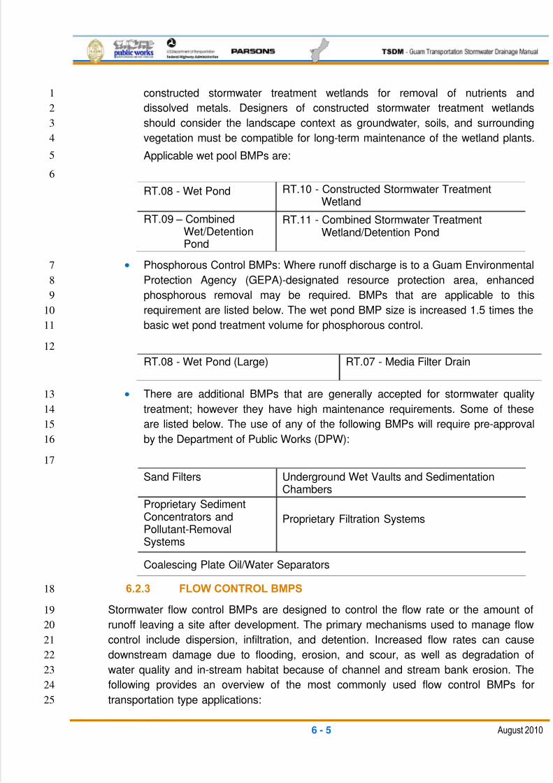
5/13/2018 Guam Storm Water Drainage Manual - slidepdf.com
http://slidepdf.com/reader/full/guam-storm-water-drainage-manual 141/486
6 - 5 August 2010
constructed stormwater treatment wetlands for removal of nutrients and1
dissolved metals. Designers of constructed stormwater treatment wetlands2
should consider the landscape context as groundwater, soils, and surrounding3
vegetation must be compatible for long-term maintenance of the wetland plants.4
Applicable wet pool BMPs are:5
6
RT.08 - Wet Pond RT.10 - Constructed Stormwater TreatmentWetland
RT.09 – CombinedWet/DetentionPond
RT.11 - Combined Stormwater TreatmentWetland/Detention Pond
Phosphorous Control BMPs: Where runoff discharge is to a Guam Environmental7
Protection Agency (GEPA)-designated resource protection area, enhanced8
phosphorous removal may be required. BMPs that are applicable to this9
requirement are listed below. The wet pond BMP size is increased 1.5 times the10
basic wet pond treatment volume for phosphorous control.11
12
RT.08 - Wet Pond (Large) RT.07 - Media Filter Drain
There are additional BMPs that are generally accepted for stormwater quality13
treatment; however they have high maintenance requirements. Some of these14
are listed below. The use of any of the following BMPs will require pre-approval15
by the Department of Public Works (DPW):16
17
Sand Filters Underground Wet Vaults and SedimentationChambers
Proprietary SedimentConcentrators andPollutant-RemovalSystems
Proprietary Filtration Systems
Coalescing Plate Oil/Water Separators
6.2.3 FLOW CONTROL BMPS18
Stormwater flow control BMPs are designed to control the flow rate or the amount of19
runoff leaving a site after development. The primary mechanisms used to manage flow20
control include dispersion, infiltration, and detention. Increased flow rates can cause21
downstream damage due to flooding, erosion, and scour, as well as degradation of22
water quality and in-stream habitat because of channel and stream bank erosion. The23
following provides an overview of the most commonly used flow control BMPs for24
transportation type applications:25
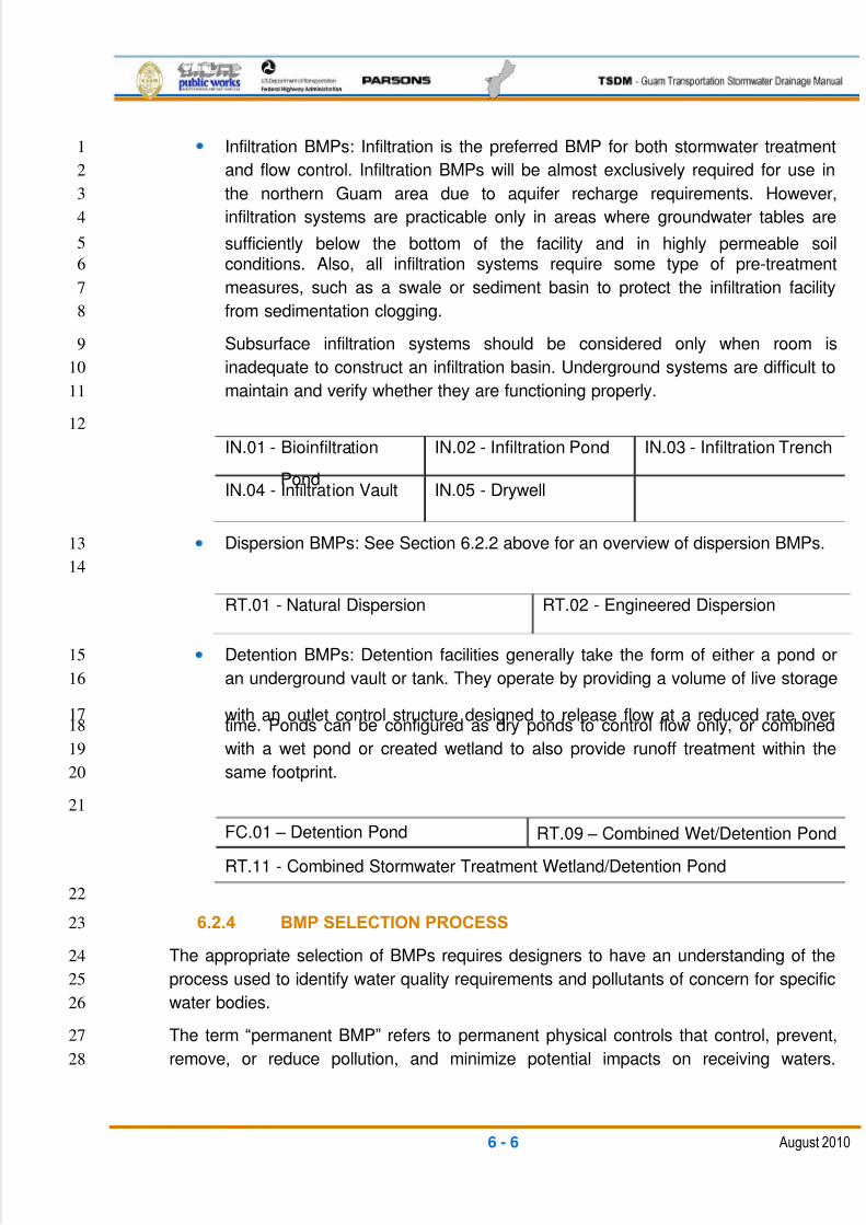
5/13/2018 Guam Storm Water Drainage Manual - slidepdf.com
http://slidepdf.com/reader/full/guam-storm-water-drainage-manual 142/486
6 - 6 August 2010
Infiltration BMPs: Infiltration is the preferred BMP for both stormwater treatment1
and flow control. Infiltration BMPs will be almost exclusively required for use in2
the northern Guam area due to aquifer recharge requirements. However,3
infiltration systems are practicable only in areas where groundwater tables are4
sufficiently below the bottom of the facility and in highly permeable soil5
conditions. Also, all infiltration systems require some type of pre-treatment6
measures, such as a swale or sediment basin to protect the infiltration facility7
from sedimentation clogging.8
Subsurface infiltration systems should be considered only when room is9
inadequate to construct an infiltration basin. Underground systems are difficult to10
maintain and verify whether they are functioning properly.11
12
IN.01 - Bioinfiltration
Pond
IN.02 - Infiltration Pond IN.03 - Infiltration Trench
IN.04 - Infiltration Vault IN.05 - Drywell
Dispersion BMPs: See Section 6.2.2 above for an overview of dispersion BMPs.13
14
RT.01 - Natural Dispersion RT.02 - Engineered Dispersion
Detention BMPs: Detention facilities generally take the form of either a pond or15
an underground vault or tank. They operate by providing a volume of live storage16
with an outlet control structure designed to release flow at a reduced rate over17time. Ponds can be configured as dry ponds to control flow only, or combined18
with a wet pond or created wetland to also provide runoff treatment within the19
same footprint.20
21
FC.01 – Detention Pond RT.09 – Combined Wet/Detention Pond
RT.11 - Combined Stormwater Treatment Wetland/Detention Pond
22
6.2.4 BMP SELECTION PROCESS23
The appropriate selection of BMPs requires designers to have an understanding of the24
process used to identify water quality requirements and pollutants of concern for specific25
water bodies.26
The term ―permanent BMP‖ refers to permanent physical controls that control, prevent,27
remove, or reduce pollution, and minimize potential impacts on receiving waters.28
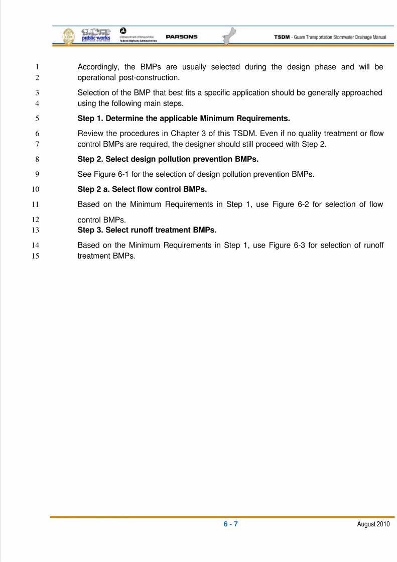
5/13/2018 Guam Storm Water Drainage Manual - slidepdf.com
http://slidepdf.com/reader/full/guam-storm-water-drainage-manual 143/486
6 - 7 August 2010
Accordingly, the BMPs are usually selected during the design phase and will be1
operational post-construction.2
Selection of the BMP that best fits a specific application should be generally approached3
using the following main steps.4
Step 1. Determine the applicable Minimum Requirements.5
Review the procedures in Chapter 3 of this TSDM. Even if no quality treatment or flow6
control BMPs are required, the designer should still proceed with Step 2.7
Step 2. Select design pollution prevention BMPs.8
See Figure 6-1 for the selection of design pollution prevention BMPs.9
Step 2 a. Select flow control BMPs.10
Based on the Minimum Requirements in Step 1, use Figure 6-2 for selection of flow11
control BMPs.12
Step 3. Select runoff treatment BMPs.13
Based on the Minimum Requirements in Step 1, use Figure 6-3 for selection of runoff14
treatment BMPs.15
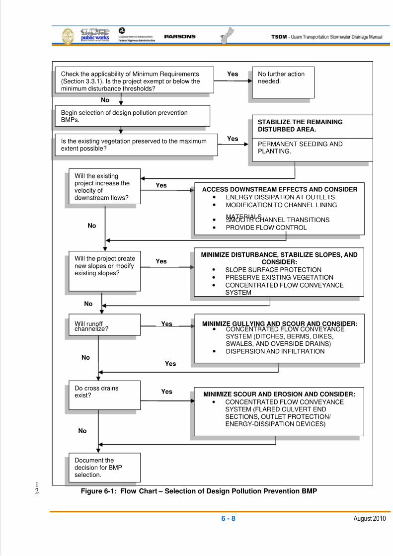
5/13/2018 Guam Storm Water Drainage Manual - slidepdf.com
http://slidepdf.com/reader/full/guam-storm-water-drainage-manual 144/486
6 - 8 August 2010
1Figure 6-1: Flow Chart – Selection of Design Pollution Prevention BMP2
No
Check the applicability of Minimum Requirements(Section 3.3.1). Is the project exempt or below theminimum disturbance thresholds?
No further actionneeded.
Is the existing vegetation preserved to the maximumextent possible?
STABILIZE THE REMAININGDISTURBED AREA.
PERMANENT SEEDING ANDPLANTING.
Yes
Yes
Begin selection of design pollution preventionBMPs.
Will the existingproject increase thevelocity ofdownstream flows?
Will the project createnew slopes or modifyexisting slopes?
ACCESS DOWNSTREAM EFFECTS AND CONSIDER
ENERGY DISSIPATION AT OUTLETS
MODIFICATION TO CHANNEL LINING
MATERIALSSMOOTH CHANNEL TRANSITIONS
PROVIDE FLOW CONTROL
Will runoffchannelize?
YesMINIMIZE DISTURBANCE, STABILIZE SLOPES, AND
CONSIDER:
SLOPE SURFACE PROTECTION
PRESERVE EXISTING VEGETATION
CONCENTRATED FLOW CONVEYANCESYSTEM
No
No
MINIMIZE GULLYING AND SCOUR AND CONSIDER:CONCENTRATED FLOW CONVEYANCESYSTEM (DITCHES, BERMS, DIKES,SWALES, AND OVERSIDE DRAINS)
DISPERSION AND INFILTRATION
Do cross drainsexist?
Yes
Yes
MINIMIZE SCOUR AND EROSION AND CONSIDER:
CONCENTRATED FLOW CONVEYANCESYSTEM (FLARED CULVERT ENDSECTIONS, OUTLET PROTECTION/ ENERGY-DISSIPATION DEVICES)
Yes
Document thedecision for BMPselection.
Yes
No
No
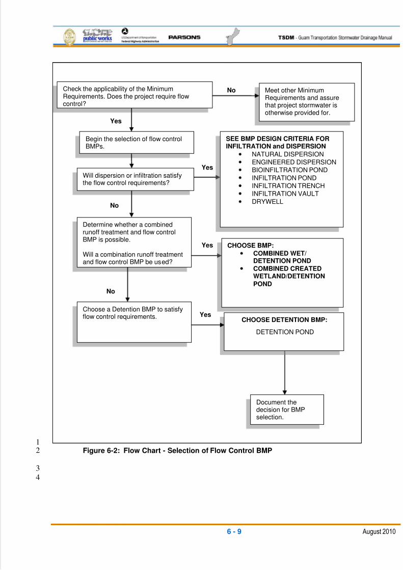
5/13/2018 Guam Storm Water Drainage Manual - slidepdf.com
http://slidepdf.com/reader/full/guam-storm-water-drainage-manual 145/486
6 - 9 August 2010
1Figure 6-2: Flow Chart - Selection of Flow Control BMP2
3
4
Yes
Yes
NoCheck the applicability of the MinimumRequirements. Does the project require flowcontrol?
Meet other MinimumRequirements and assurethat project stormwater isotherwise provided for.
Will dispersion or infiltration satisfythe flow control requirements?
Yes
Begin the selection of flow controlBMPs.
Determine whether a combinedrunoff treatment and flow controlBMP is possible.
Will a combination runoff treatmentand flow control BMP be used?
Choose a Detention BMP to satisfyflow control requirements.
Yes CHOOSE BMP:
COMBINED WET/DETENTION POND
COMBINED CREATEDWETLAND/DETENTION
POND
No
Document thedecision for BMPselection.
SEE BMP DESIGN CRITERIA FORINFILTRATION and DISPERSION
NATURAL DISPERSION
ENGINEERED DISPERSION
BIOINFILTRATION POND
INFILTRATION POND
INFILTRATION TRENCH
INFILTRATION VAULT
DRYWELL
CHOOSE DETENTION BMP:
DETENTION POND
No

5/13/2018 Guam Storm Water Drainage Manual - slidepdf.com
http://slidepdf.com/reader/full/guam-storm-water-drainage-manual 146/486
6 - 10 August 2010
1Figure 6-3: Flow Chart – Selection of Runoff Treatment BMP2
Yes
No
YesYes
No
Yes
Check the applicability of the MinimumRequirements. Does the project require runofftreatment?
Meet other MinimumRequirements and assure thatproject stormwater is otherwiseprovided for.
Was dispersionchosen for flowcontrol?
No
Was infiltrationchosen for flowcontrol?
Determine receiving
waters and pollutantsof concern.
APPLY PRE-TREATMENT
Vegetated filter strips
Biofiltration swales
Wet biofiltrationswalesSedimentation basin
No
Yes
APPLY INFILTRATION
Infiltration basin
Infiltration trench
Infiltration vault
Drywell
Permeable Pavement
Does the soil havecharacteristics that would allowinfiltration?
Check ifphosphorous controlis required.
APPLY PHOSPHOROUSCONTROL
Wet pond (large)
Media filter drain
Was a combined flowcontrol and treatmentfacility chosen?
APPLY COMBINED FACILITY
Constructed wetland/ detention pond
Wet/detention pond
No
No
APPLY TREATMENT BMP
Vegetated filter strips
Biofiltration swales
Wet biofiltrationswales
Wet pond
Media filter drain
Constructed wetland
Document decisionfor BMP selection.
APPLY DISPERSION
Natural dispersion
Engineered dispersion
Yes
Will soil amendment allow
infiltration?
No Yes
5/13/2018 Guam Storm Water Drainage Manual - slidepdf.com
http://slidepdf.com/reader/full/guam-storm-water-drainage-manual 147/486
6 - 11 August 2010
6.3 DESIGN POLLUTION PREVENTION BMPs1
6.3.1 CONSIDERATION OF DOWNSTREAM EFFECTS RELATED TO2
POTENTIALLY INCREASED FLOW VELOCITIES3
Changes in the velocity or volume of runoff, the sediment load, or other hydraulic4changes from stream encroachments, crossings, or realignment may affect downstream5
channel stability.6
The designer will evaluate the effects on downstream channel stability and the7
applicability of the mitigation measures described under the implementation for this8
BMP.9
Appropriate Applications10
During the design of both new and reconstructed facilities, the designer may include new11
road surfaces or additional surface paving to enhance the operational safety and12
functionality of the facility. The designer must also consider the effect of collecting and13concentrating flows in roadside ditches and storm drain systems or the effect of re-14
directing flows to treatment BMPs.15
Diversions or overflows from large storm events in these instances may create16
concentrated discharges in areas that have not historically received these flows.17
Implementation18
If these changes result in an increased potential for downstream effects in channels, the19
designer should consider the following:20
Making modifications to channel lining materials (both natural and man-made),21including vegetation, geotextile mats, rock, and riprap. The primary goal will be to22
use vegetative stabilization techniques whenever the conditions allow, such as23
use of ―tree stakes‖ along toes and sides of channel banks, and/or provide24
vegetation plantings to stabilize stream banks and overflow areas.25
Using energy-dissipation devices at outlets. This includes such items as rock26
pads, gabion pads, and constructed structures at outlets of ditches and pipes.27
More natural alternatives include the discharge to spreader swales or spreader28
ditches that sheet flow over the bank to the stream channel.29
Smoothing the transition between culvert and ditch outlets to the natural30
waterway using headwalls, wingwalls, and riprap/gabion protection to reduce31
turbulence and scour.32
Modifying the existing waterway to a more stable hydraulic design.33
Incorporating detention and infiltration into designs to reduce peak discharge34
rates. Typical applications are the inclusion of low areas in the terrain into the35
conveyance system, over-sizing of conveyance system components, or providing36
5/13/2018 Guam Storm Water Drainage Manual - slidepdf.com
http://slidepdf.com/reader/full/guam-storm-water-drainage-manual 148/486
6 - 12 August 2010
specific detention ponds. The effectiveness of these features should be1
determined by using a hydraulic routing computer model of the overall2
conveyance system and matching the conveyance discharge hydrograph with3
the stream hydrograph. A downstream analysis may be needed if the stream4
flows are increased. Refer to Section 3.2.6.1 for more details.5
The designer should implement the appropriate measures to ensure that runoff from6
stormwater facilities will not increase downstream erosion.7
6.3.2 PRESERVATION OF EXISTING VEGETATION8
Description9
The preservation of existing vegetation involves the identification and protection of10
desirable vegetation. In particular, identification and protection of those locations which11
provide specific runoff filtration and soil stabilization benefits.12
Appropriate Applications13
The designer should preserve existing vegetation at areas on a site where no14
construction activity is planned or where it will occur at a later date.15
Implementation 16
The following general steps should be taken to preserve existing vegetation:17
Designers should review and include vegetation types/features on the18
topographic surveys. Use the topographic surveys to prepare designs that19
help to minimize the specific runoff benefit of vegetation removal.20
Designers should identify and delineate in the contract documents all21
vegetation to be retained.22
The contractor should delineate the areas to be preserved in the field prior to23
the start of soil-disturbing activities.24
The contractor should minimize disturbed areas by locating temporary25
construction access, work areas, and staging areas to avoid stands of trees26
and shrubs, and follow existing contours to reduce cutting and filling.27
When removing vegetation, the designer and contractor should consider28
impacts (increased exposure or wind damage) to the adjacent vegetation that29
will be preserved.30
6.3.3 CONCENTRATED FLOW CONVEYANCE SYSTEMS31
Concentrated flow conveyance systems consist of permanent design measures that are32
used alone or in combination to intercept and divert surface flows, and to convey and33
discharge concentrated flows with minimum soil erosion.34
35
5/13/2018 Guam Storm Water Drainage Manual - slidepdf.com
http://slidepdf.com/reader/full/guam-storm-water-drainage-manual 149/486
6 - 13 August 2010
Ditches, Berms, Dikes, and Swales1
Description 2
These are permanent devices typically used to intercept and direct surface runoff to3
an over-side (or slope) drain or stabilized watercourse.4
Appropriate Applications 5
Ditches, berms, dikes, and swales are typically implemented:6
At the top of slopes to divert run-on from adjacent slopes and areas7
At bottom and mid-slope locations to intercept sheet flow and convey8
concentrated flows9
At other locations to convey runoff to over-side drains, stabilized10
watercourses, and stormwater drainage system inlets (catch basins), pipes,11
and channels12
To intercept runoff from paved surfaces13
Along roadways and facilities subject to flooding14
Implementation 15
The hydraulic designs must be in accordance with Chapter 5 of this TSDM. Select16
design storm frequencies based on the risk evaluation of erosion, overtopping, and17
flow backups. Conveyances must be lined when velocities exceed allowable limits for18
bare soil (see Chapter 5). Liners can consist of vegetative types, rock riprap, gabion19
mats, and engineering erosion control fabric.20Consider outlet protection where localized scour is anticipated. Examine the site for21
run-on from off-site sources and try to divert the flows around the work area. Review22
the order-of-work provisions to install and use permanent dikes, swales, and ditches23
early in the construction process.24
Over-side Drains25
Description 26
Over-side drains are conveyance systems used to protect slopes against erosion.27
Over-side drains are usually piped drains, flumes, or paved spillways that protect28
slopes against erosion by collecting surface runoff from the roadbed, the tops of cuts,29
and benches (in cut or fill slopes), conveying it down the slope to a stabilized outlet.30
Appropriate Applications 31
Over-side drains are typically used at sites where slopes may be eroded by gully flow32
action.33
34
5/13/2018 Guam Storm Water Drainage Manual - slidepdf.com
http://slidepdf.com/reader/full/guam-storm-water-drainage-manual 150/486
6 - 14 August 2010
Implementation 1
The hydraulic design must be in accordance with Chapter 5 of this TSDM.2
Pipe drains are storm sewer pipes adaptable to any slope. They are3
recommended where side slopes are 1:4 (V:H) or steeper. Design and4installation will require additional energy dissipation and pipe stability5
measures for high-velocity situations.6
Pipe and flume down drains are surface-mounted pipes or cut pipe sections.7
They are best adapted for low flow rates on slopes that are 1:2 (V:H) or8
flatter. Pipe and flume down drains should only be used for temporary9
applications, and must be securely anchored to the slope.10
Paved spillways are recommended on side slopes flatter than 1:4 (V:H). On11
steeper slopes, pipe drains should be used.12
Provide over-side drains every 300 ft. to 500 ft. from benches in cut-and-fill13
slopes.14
Flared Culvert End Sections15
Description 16
These are devices typically placed at inlets and outlets of pipes and channels to17
improve the hydraulic operation, retain the embankment near pipe conveyances, and18
help prevent scour and minimize erosion at these inlets and outlets.19
Appropriate Applications 20
Use flared culvert end sections at outlets of storm drains, for over-side drains, and on21
both the inlet and outlet of culverts.22
Implementation 23
The design must be in accordance with Chapter 5 of this TSDM. Alternatives to24
manufactured flared end sections are riprap pads, concrete slope collars, and25
headwalls.26
Outlet Protection/Velocity Dissipation Devices27
Description 28
These devices are typically placed at pipe outlets to prevent scour and reduce the29
outlet velocity and/or energy of exiting stormwater flows. They function to transition30
from the ditch or pipe flow section to the existing waterway section. The purpose is to31
protect the existing soil from erosion, while helping to dissipate flow energy and32
transitioning the flow to a wider, flatter, and less velocity condition. Depending on the33
flow energy, the outlet protection can consist of spreader swales or ditches, rock34
5/13/2018 Guam Storm Water Drainage Manual - slidepdf.com
http://slidepdf.com/reader/full/guam-storm-water-drainage-manual 151/486
6 - 15 August 2010
pads, riprap sections, flared-end sections, concrete collars, concrete pads,1
headwalls, headwalls with wingwalls and aprons, and energy dissipater structures.2
Appropriate Applications 3
These devices are typically used at the outlets of ditches, pipes, drains, culverts,4slope drains, diversion ditches, swales, conduits, or channels where localized5
scouring is anticipated.6
Implementation 7
The hydraulic design must be in accordance with Chapter 5 of this TSDM8
Install riprap, grouted riprap, slope collars, headwalls, gabion mats, or energy9
dissipater structures at the selected outlet10
Designs are usually related to outlet flow rate and tailwater level11
For the proper operation of aprons and rock pads, align the apron with the12receiving stream and keep it straight throughout its length13
6.3.4 SLOPE PROTECTION SYSTEMS14
Surface protection consists of permanent design measures that are used alone or in15
combination to minimize erosion from sloped ground surfaces. Vegetated surface16
protection is preferred as it offers advantages such as infiltration with lower runoff rates,17
slower flow velocities, longer times of concentration, and lesser costs. However, where18
site- or slope-specific conditions would prevent adequate establishment and19
maintenance of a vegetative cover, hard surfacing should be considered.20
Vegetated Surfaces21
Description 22
A vegetated surface is a permanent perennial vegetative cover on all project23
pervious areas. The purpose of a vegetated surface (from a water quality24
perspective) is to prevent surface soil erosion, allow infiltration, and help to filter out25
pollutants from surface flows.26
Appropriate Applications 27
Vegetated surfaces should be established on areas of disturbed soil after28
construction is completed and in areas where existing vegetation is not suitable as a29stabilization measure. Vegetated surfaces should only be considered for areas that30
can support the selected vegetation long term. The vegetation type and application31
should be selected in accordance with the guidance and recommendations of the32
Guam Division of Aquatic and Wildlife Resources (DAWR). Another resource for33
vegetation type and application guidelines is the USDA, National Resources34
Conservation Service (NRCS).35
5/13/2018 Guam Storm Water Drainage Manual - slidepdf.com
http://slidepdf.com/reader/full/guam-storm-water-drainage-manual 152/486
6 - 16 August 2010
Implementation 1
The following steps are typically implemented by the designer:2
Evaluate the site. The site evaluation should consider soil type, site3
topography, and availability of equipment access.4
Prepare grading plans as required to provide more efficient stabilization and5
bed preparation for the plantings. Vegetated surfaces should be designed to6
sheet flow conditions, and maximize contact time between water and7
vegetated surfaces. This will enhance infiltration and pollutant removal8
opportunities.9
Select vegetation species to match site conditions and seasonal restraints in10
accordance with NRCS‘s or DAWR‘s recommendations. Provide vegetation11
application and seed bed preparation specifications and details. Require a12
one-year maintenance guarantee from the contractor. Include temporary13irrigation, mulching and planting methods as may be necessary to match site14
conditions and seasonal variations.15
Site preparation may include removal and stockpiling of topsoil for later16
replacement over the finished site grading.17
Slope Roughening/Terracing/Rounding/Stepping18
Roughening and terracing are techniques for creating furrows, terraces, serrations, stair-19
steps, or track marks on the soil surface to increase the effectiveness of temporary and20
permanent soil stabilization practices. Slope rounding is a design technique to minimize21
the formation of concentrated flows.22
Use vegetated surfaces on embankment or cut slopes prior to the application of23
temporary soil stabilization or permanent seeding.24
Hard Surfaces25
Description 26
Hard surfaces consist of placing concrete, rock, or rock and mortar slope protection.27
The designer should consider the effects of increased runoff from impervious areas.28
Appropriate Applications 29
Apply hard surfaces on soil areas where vegetation would not provide adequate30
erosion protection. Hard surfaces are also considered where it is difficult to maintain31
vegetation.32
33
34
35
5/13/2018 Guam Storm Water Drainage Manual - slidepdf.com
http://slidepdf.com/reader/full/guam-storm-water-drainage-manual 153/486
6 - 17 August 2010
Implementation 1
Rock Slope Protection:2
Consists of riprap rock revetment courses along water courses. Angular rocks of3
specified sizes are placed over filter fabric and/or gravel and used as riprap to4armor slopes, stream banks, etc.5
Remove loose, sharp, or extraneous material from the slope to be treated.6
Place underlayment fabric loosely over the surface so that the fabric conforms to7
the surface without damage. Protect the fabric from puncture with a sand/gravel8
overlay prior to placing the rock. Equipment or vehicles should not be driven9
directly on the fabric.10
Revetments along streams/rivers with potential for high velocities and/or stream11
bed degradation should have an excavated toe trench with additional rock fill to12
anchor the upper-rocked slope.13
Alternatives to rock slope protection are rock-filled gabion baskets, gabion mats,14
and vegetative stabilization. Vegetative-type slope protection measures are the15
more preferred if conditions warrant. Vegetative measures can be combined with16
rock and gabion slope protection measures.17
Concreted Rock Slope Protection (Grouted Riprap):18
Angular rocks of specified sizes are placed over engineering filter fabric19
protected by a layer of sand/gravel mixture.20
Lean concrete is placed into the rock interstices. Rock should be wetted21
immediately prior to placement. Use of vibrators helps to work the concrete down22
into the rock volume.23
Grouted riprap is used where flow velocities exceed the loose riprap resistance,24
or where larger riprap size and density suitable for the flow energy conditions is25
not available.26
Rock Blanket:27
A rock blanket consists of round cobble rock placed as a landscape feature in28
areas often inundated with water. The rock should be placed over a graded29
sand/gravel filter layer and/or filter fabric.30
Sacked Concrete Slope Protection:31
Bags are filled with concrete mix and stacked against the slope to cure. Rebar32
can be driven into the wet mix and bags.33
Sacked concrete slope protection is aesthetically less desirable and is often34
times used as an emergency measure to protect a higher-value structure.35

5/13/2018 Guam Storm Water Drainage Manual - slidepdf.com
http://slidepdf.com/reader/full/guam-storm-water-drainage-manual 154/486
6 - 18 August 2010
Slope Paving:1
Slope paving is used almost exclusively below bridge decks at abutments. It2
provides erosion control and soil stabilization in areas too dark for vegetation to3
establish. It may be constructed of finish poured Portland Cement Concrete4
(PCC), shotcrete, or masonry paving units.5
Gabions:6
Gabions are wire cages filled with rock. These units are then constructed into7
structures of various configurations. They are an excellent alternative to riprap-8
type rock, where riprap rock of suitable density and size is not available. They9
also allow for vegetative plantings using tree stakes and/or with a layer of soil for10
seeding. They can be installed in locations of limited access by heavy machinery11
using hand labor.12
6.4
QUALITY TREATMENT BMPs13
6.4.1 INFILTRATION BMPS14
Infiltration BMPs for runoff treatment include the following:15
IN.01 Bioinfiltration Pond IN.04 Infiltration Vault16
IN.02 Infiltration Pond IN.05 Drywell17
IN.03 Infiltration Trench18
In addition to being the preferred method for flow control, infiltration is a preferred19
method for runoff treatment, offering the highest level of pollutant removal. Treatment is20
achieved through settling, biological action, and filtration. One important advantage to21using infiltration is that it recharges the groundwater, thereby helping to maintain dry22
season base flows for streams. Infiltration also produces a natural reduction in stream23
temperature, which is an important factor in maintaining a healthy habitat. Infiltration will24
be the primary stormwater quality treatment BMP in the northern area of Guam, due to25
the aquifer recharge requirements.26
Infiltration facilities must be preceded by a pre-settling basin for removing most of the27
sediment particles that would otherwise reduce the infiltrative capacity of the soil.28
6.4.1.1 IN.01: BIOINFILTRATION POND29
General Description30
Bioinfiltration ponds, also known as bioinfiltration swales, combine filtration, soil31
absorption, and uptake by vegetative root zones to remove stormwater pollutants by32
percolation into the ground.33
34
5/13/2018 Guam Storm Water Drainage Manual - slidepdf.com
http://slidepdf.com/reader/full/guam-storm-water-drainage-manual 155/486
6 - 19 August 2010
Overflows are typically routed through an appropriate conveyance system to a higher1
permeability infiltration BMP, such as a drywell or infiltration pond, or to a surface water2
discharge point with flow control, as necessary.3
Appropriate Applications4
This BMP meets the runoff treatment objectives for all treated pollution-generating5
impervious surfaces. Treatment is provided by a combination of the plant filtration and6
root uptake of nutrients and the infiltration through soil. The infiltration capacity of these7
facilities is usually insufficient to provide flow control to meet the criteria of Minimum8
Requirement 6 as defined in Chapter 3 of this TSDM. Unless a very large area is9
available for the shallow water depth required of a bioinfiltration pond, flow control must10
be implemented using a different facility. Bioinfiltration ponds require moderately11
permeable soil for proper function. In general, the site-suitability criteria are similar to12
that of an infiltration pond.13
Implementation14
Pre-settling/Pre-Treatment 15
Pre-treatment for removal of suspended solids, trash, and oils is required to prevent16
the bioinfiltration pond treatment soil from clogging. Pre-treatment BMPs can be17
bioswales, wet bioswales, wet ponds, and sedimentation ponds.18
Flows To Be Treated 19
Bioinfiltration ponds are designed as volume-based infiltration treatment facilities.20
The runoff volume to be treated should be calculated using the guidelines in21
Chapter 4 of this TSDM.22
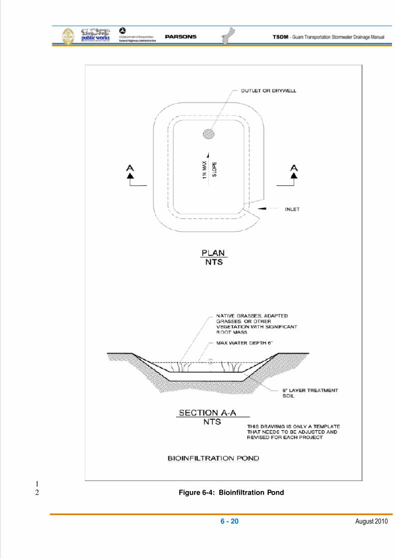
5/13/2018 Guam Storm Water Drainage Manual - slidepdf.com
http://slidepdf.com/reader/full/guam-storm-water-drainage-manual 156/486
6 - 20 August 2010
1Figure 6-4: Bioinfiltration Pond2
5/13/2018 Guam Storm Water Drainage Manual - slidepdf.com
http://slidepdf.com/reader/full/guam-storm-water-drainage-manual 157/486
6 - 21 August 2010
Geometry 1
Sizing methods for bioinfiltration ponds are the same as those for infiltration ponds2
designed for runoff treatment, except for the following:3
Drawdown time for the maximum ponded volume is 72 hours following the4design storm event.5
The maximum ponded level is 6 in. prior to overflow to a drywell or other6
infiltrative or overflow facility.7
The swale bottom should be flat with a longitudinal slope less than 1 percent.8
A concrete or riprap apron should be provided at the inlet to spread the flow9
and keep vegetation from blocking the inlet.10
The treatment zone depth of 6 in. or more should contain sufficient organics11
and texture to ensure good vegetation growth. The average infiltration rate of12the 6-in. thick layer of treatment soil should not exceed 1 in. per hour for a13
system relying on the root zone to enhance pollutant removal. Furthermore, a14
maximum infiltration rate of 2.4 in. per hour is applicable.15
Native grasses, adapted grasses, or other vegetation with significant root16
mass should be used.17
Pre-treatment may be used to prevent clogging of the treatment soil and18
vegetation by debris, Total Suspended Solids (TSS), and oil and grease.19
Site Design Elements 20
Initial excavation should be conducted to within 1 ft. of the final elevation of the floor21
of the bioinfiltration pond. Defer final excavation to the finished grade until all22
disturbed areas in the up-gradient drainage area have been stabilized or protected.23
The final phase of excavation should remove all accumulated sediment. After24
construction is completed, prevent sediment from entering the bioinfiltration pond by25
first conveying the runoff water through an appropriate pre-treatment system, such26
as a pre-settling basin.27
Bioinfiltration ponds, as with all types of infiltration facilities, should generally not be28
used as temporary sediment traps during construction. If a bioinfiltration pond is to29
be used as a sediment trap, do not excavate to final grade until after the up-gradient30drainage area has been stabilized. Remove any accumulation of silt in the swale31
before putting the swale into service.32
Relatively light-tracked equipment is recommended for excavation to avoid33
compacting the floor of the bioinfiltration pond. Consider the use of draglines and34
track hoes. The bioinfiltration pond area should be flagged or marked to keep35
equipment away.36
5/13/2018 Guam Storm Water Drainage Manual - slidepdf.com
http://slidepdf.com/reader/full/guam-storm-water-drainage-manual 158/486
6 - 22 August 2010
Setback Requirements 1
Setback requirements for bioinfiltration ponds are the same as those for infiltration2
ponds.3
Right-of-Way 4
Right-of-way requirements for bioinfiltration ponds are the same as those for5
detention ponds.6
Landscaping (Planting Considerations) 7
Use native or adapted grass species for the entire area of the bioinfiltration pond.8
Maintenance Access Roads (Access Requirements) 9
Access requirements for bioinfiltration ponds are the same as those for infiltration10
ponds.11
6.4.1.2 IN.02: INFILTRATION POND12
General Description13
Infiltration ponds for stormwater quality treatment are earthen impoundments used for14
the collection, temporary storage, and infiltration of incoming stormwater runoff to15
groundwater. Infiltration ponds can also be designed as combination detention/infiltration16
ponds for flow control where soil conditions limit full infiltration of the runoff.17
Appropriate Applications:18
Infiltration of runoff is the preferred method of stormwater quality treatment and flow19
control. Runoff in excess of the infiltration capacity must be detained and released in20compliance with the flow control requirement described as part of Minimum21
Requirement 6 in Chapter 3 of this TSDM.22
Site-Suitability Criteria23
Infiltration ponds require permeable soil conditions for proper function. For a site to be24
considered suitable for an infiltration pond, the design infiltration rate must be at least 0.525
in. per hour. Infiltration can still be considered in the design if the infiltration rate is less,26
but infiltration would be considered a secondary function in this case.27
The infiltration rate to use for design should be established by site testing. Site infiltration28
should be determined in-situ by a method that accurately estimates the infiltration rate of29the soil layer at the bottom of pond elevation. One such method is the ASTM D3385-30
Standard Test Method for Infiltration Rate of Soils in Field Using Double-Ring31
Infiltrometer. At least three tests should be taken over each infiltration site. The design32
infiltration rate will be the average value of the tests divided by a Safety Factor (SF). The33
SF varies depending on the regular maintenance of the facility and the designer‘s 34
estimate of sedimentation loads that could plug and seal off the infiltration facility. For35
5/13/2018 Guam Storm Water Drainage Manual - slidepdf.com
http://slidepdf.com/reader/full/guam-storm-water-drainage-manual 159/486
6 - 23 August 2010
example, the SF will vary from a minimum of two for a facility with good maintenance1
access serving a village street with curb and gutter inlets having relatively clean inflows,2
to a SF of four for difficult to access sites with off-site inflows subject to higher3
sedimentation and organic debris.4
The base of all infiltration ponds should typically be 5 ft. above the seasonal high-water5
mark, bedrock (or hardpan), or other low-permeability layer. This vertical distance may6
be reduced to a minimum of 2 ft. if the following apply:7
The groundwater mounding analysis, volumetric receptor capacity, and design of8
the overflow or bypass structures are judged by the designer to be adequate to9
prevent overtopping.10
For the northern Guam aquifer recharge area, the bottom of the infiltration pond11
must be at least 2 ft. above the top of the limestone bedrock (permeable aquifer12
layer) to provide suitable soil filtration treatment prior to inflow to the aquifer. If13
the infiltration pond bottom is less than 2 ft. above the limestone bedrock, then14
another stormwater water quality treatment BMP must be incorporated prior to15
flow to the infiltration pond.16
The facility meets all other criteria listed in this BMP description.17
Pre-settling/Pre-treatment 18
Infiltration ponds should follow a runoff treatment or pre-treatment facility to prevent19
sediment build-up and clogging of the infiltrative soils. A pre-settling sedimentation20
cell can be included in the infiltration pond design, as shown in Figure 6-5. If an21
infiltration pond cannot meet the site-suitability criteria for treatment, a quality22
treatment BMP must be provided prior to infiltration.23
Design Flow Elements 24
Flows To Be Infiltrated25
Site runoff should be infiltrated to the extent required in Minimum Requirement 5,26
as described in Chapter 3 of this TSDM. Runoff in excess of the infiltration27
capacity must be detained and released in compliance with the flow control28
requirement described as part of Minimum Requirement 6.29
For a site to be considered suitable for an infiltration pond, the design infiltration30
rate must be at least 0.5 in. per hour. Infiltration can still be considered in flow31
control facility design if the infiltration rate is less than this, but infiltration must be32
considered a secondary function in that case. A pond should be designed to a33
desirable depth of 3 ft. and a maximum depth of 6 ft., with a minimum freeboard34
of 1 ft. above the design water level.35
An infiltration pond must be designed using a single-event hydrograph model to36
infiltrate the stormwater quality treatment volume out of the pond within 72 hours.37
5/13/2018 Guam Storm Water Drainage Manual - slidepdf.com
http://slidepdf.com/reader/full/guam-storm-water-drainage-manual 160/486
6 - 24 August 2010
An infiltration pond must be designed using a single-event hydrograph model to1
detain and infiltrate the design frequency storm with an overflow for the higher2
events. For locations without suitable overflow outlets, the 100-year frequency3
storm should be detained and fully-infiltrated.4
Outlet Control Structure5
Runoff in excess of the infiltration capacity must be detained and released in6
compliance with the flow control requirement described as part of Minimum7
Requirement 6 as defined in Chapter 3 of this TSDM.8
Refer to BMP FC.01 – Detention Pond for design of the outlet control structure.9

5/13/2018 Guam Storm Water Drainage Manual - slidepdf.com
http://slidepdf.com/reader/full/guam-storm-water-drainage-manual 161/486
6 - 25 August 2010
1Figure 6-5: Infiltration Pond2
5/13/2018 Guam Storm Water Drainage Manual - slidepdf.com
http://slidepdf.com/reader/full/guam-storm-water-drainage-manual 162/486
6 - 26 August 2010
Site Design Elements 1
Setback Requirements2
For infiltration facilities, the designer should evaluate the geotechnical report. The3
report should address the adequacy of pond locations and recommend the4necessary setbacks from any steep slopes and building foundations.5
Infiltration facilities should be set back at least 1000 ft. from drinking water wells,6
and at least 100 ft. from septic tank drain field systems.7
Infiltration facilities must be located at least 20 ft. downslope and 100 ft. upslope8
from building foundations, and must be 5 ft. from any property line.9
Flow Splitters10
When designed to serve only as a runoff treatment facility, the pond may be11
located offline. The facility must be designed to infiltrate all water quality volume12
directed to it. All bypassed flow must be conveyed to a flow control facility, unless13
it is directly discharged to an exempt water body. Note: Infiltration ponds14
designed for flow control must be located on-line.15
Emergency Overflow Spillway16
An emergency overflow-type, non-erodible outlet or spillway must be constructed17
to discharge flow in excess of the design flows to the downstream conveyance18
system, as described in BMP FC.01-Detention Pond. Ponding depth, drawdown19
time, and storage volume are calculated from the overflow elevation.20
Structural Design Considerations21
Geometry 22
The slope of the floor of an infiltration pond must not exceed 3 percent in any23
direction.24
Embankments 25
Requirements for infiltration pond embankments are the same as those for26
BMP FC.01-Detention Pond. In addition to the testing for establishing the27
design soil infiltration rate, the geotechnical investigation must include the28
following:29
Stability analysis of side slopes for ponds30
Seepage analysis of any berms or dams31
Liners 32
The floor of infiltration ponds can be covered with a 6-in. to 12-in. layer of33
filter material such as coarse sand. Over time, incoming organic materials34
5/13/2018 Guam Storm Water Drainage Manual - slidepdf.com
http://slidepdf.com/reader/full/guam-storm-water-drainage-manual 163/486
6 - 27 August 2010
and fine soil particles will seal the surface of the pond, lowering the infiltration1
rate. This filter layer can be readily replaced or cleaned as it becomes2
clogged.3
Site Design Elements 4
Initial excavation should be conducted to within 1 ft. of the final elevation of5
the infiltration pond floor. Final excavation to the finished grade should be6
deferred until all disturbed areas in the up-gradient drainage area have been7
stabilized or protected. The final phase of excavation should remove all8
accumulated sediment.9
Infiltration ponds, as with all types of infiltration facilities, should generally not10
be used as temporary sediment traps during construction. If an infiltration11
pond is to be used as a sediment trap, it must not be excavated to final grade12
until after the upstream drainage area has been stabilized. Any accumulation13
of silt in the pond must be removed before the pond is put into service.14
Low-ground-pressure equipment is recommended for excavation to avoid15
compacting the floor of the infiltration pond. The use of draglines and track16
hoes should be considered. The infiltration area should be flagged or marked17
to keep equipment away.18
Landscaping (Planting Considerations) 19
The interior of the infiltration pond, as well as surrounding berms, spoil areas,20
borrow areas, and other disturbed areas, should be stabilized and planted,21
preferably with suitable type grass. Without healthy vegetation, the surface22
soil pores quickly plug. Vegetative planting mixes should use seed mix23
suitable for the site and seasonal conditions. The actual seed mix, fertilizer,24
and planting methods should be performed in accordance with NRCS or25
DAWR recommendations.26
Fencing 27
Fencing requirements for an infiltration pond are identical to those required28
for BMP FC.01-Detention Pond.29
Signage 30
Signage requirements for an infiltration pond are identical to those required31for BMP FC.01-Detention Pond32
Maintenance Access Roads (Access Requirements) 33
Vehicle access must be provided for removal of sediment from the pre-34
treatment sedimentation cell (or forebay), and for maintenance of the outfall35
5/13/2018 Guam Storm Water Drainage Manual - slidepdf.com
http://slidepdf.com/reader/full/guam-storm-water-drainage-manual 164/486
6 - 28 August 2010
structure. Access roads and ramps should meet the minimum requirements1
listed for BMP FC.01-Detention Pond.2
Operation and Maintenance 3
Infiltration ponds, as with all BMPs, must have routine inspection and4maintenance designed into the life performance of the facility. They should be5
inspected regularly during the wet season to ensure that the inlet and6
overflow devices are not plugged and working correctly. They should also be7
checked immediately after any large storm event and any damage should be8
repaired immediately. The sedimentation cell should be checked annually for9
sediment buildup and the accumulated sediment should be removed if it10
exceeds 18 in. of depth. As part of the sediment removal process, the11
disturbed soil areas and any other eroded spots should be re-graded to the12
original grade and re-seeded. Infiltration facilities should also be checked at13
least on an annual basis during the wet season for infiltration capacity. This14can be accomplished by observing that the time to empty after a storm event15
is within the basic design requirements.16
6.4.1.3 IN.03: INFILTRATION TRENCH17
General Description18
Infiltration trenches are long, narrow, stone-filled trenches used for the collection,19
temporary storage, and infiltration of stormwater runoff to groundwater. They can be a20
useful alternative for sites with constraints that make siting an infiltration pond difficult.21
Infiltration trenches may be placed beneath parking areas, along the site periphery, or in22
other suitable linear areas. For infiltration trench concept details, see Figures 6-623through 6-11.24
Appropriate Applications 25
The infiltration of runoff is the preferred method of runoff quality treatment and flow26
control. Runoff in excess of the infiltration capacity must be otherwise detained and27
released in compliance with the flow control requirement described as part of28
Minimum Requirement 6 in Chapter 3 of this TSDM.29
Site-Suitability Criteria 30
Site-suitability criteria are the same as those for BMP IN-01 Infiltration Ponds.31
Pre-settling/Pre-treatment 32
Infiltration trenches should follow a runoff treatment or sedimentation (pre-treatment)33
facility to limit sediment build-up and clogging of the trench. Where surface runoff is34
routed directly to the infiltration trench, it should pass as sheet flow over a grassed35
slope or through a biofiltration swale to help remove as much of the coarser36
sediments as possible.37
5/13/2018 Guam Storm Water Drainage Manual - slidepdf.com
http://slidepdf.com/reader/full/guam-storm-water-drainage-manual 165/486
6 - 29 August 2010
Design Flow Elements1
Flows To Be Infiltrated 2
The flows to be treated by an infiltration trench are identical to those for an infiltration3
pond.4
Overflow or Bypass 5
Because infiltration trenches are generally used for small drainage areas, an6
emergency spillway is not necessary. However, a non-erosive overflow system7
leading to a stabilized watercourse should be provided. If a suitable overflow site is8
not available, then all the volume from the 100-year storm event should be detained9
and infiltrated.10
Outlet Control Structure 11
Outlet control structure requirements for an infiltration trench are identical to those for12
an infiltration pond.13
Flow Splitters 14
Flow splitter requirements for an infiltration trench are identical to those for an15
infiltration pond.16
Structural Design Considerations 17
Geometry18
Infiltration trench-sizing methods use the volume of the voids of the rock, any19
storage area above the rock, and additional volume within a pipe in the trench, as20
appropriate, to detain the stormwater quality treatment and/or flow control volume21
designed by routing the design storm inflow against the infiltration outflow. The22
design method is essentially the same as that for BMP IN.02-Infiltration Pond,23
where the design is based on in-situ infiltration testing. Note that in the Guam24
limestone aquifer recharge area, the bottom of the infiltration volume must be at25
least 2 ft. above the limestone bedrock surface. If less than 2 ft. of soil exists,26
then the flows to the infiltration trench must be pretreated by another stormwater27
quality treatment BMP.28
Materials 29
Backfill Material30
The backfill material for the infiltration trench should consist of clean aggregate31
with a maximum diameter of 3 in. and a minimum diameter of 1.5 in. Void space32
for the aggregate should be in the range of 30 percent to 40 percent.33
5/13/2018 Guam Storm Water Drainage Manual - slidepdf.com
http://slidepdf.com/reader/full/guam-storm-water-drainage-manual 166/486
6 - 30 August 2010
Geotextile Filter Fabric1
An engineering geotextile material, which can be a sand/gravel mixture or natural2
grassed soil condition, must encase all of the aggregate fill material under the top3
6 in. to 12 in. of trench. Geotextile fabric with acceptable properties must be4
carefully selected to avoid plugging.5
Additional guidelines on geotextile filter fabric design and installation can be6
found in FHWA publication NHI Course No. 13213, Geosynthetic Design and7
Construction Guidelines, No. FHWA HI-95-038, April 1998.8
Observation Well 9
An observation well should be installed at the lower end of the infiltration trench to10
check water levels, draw-down time, and sediment accumulation, and to allow for11
water-quality monitoring. The well should consist of a perforated PVC pipe 4 in. to12
6 in. in diameter, with the top constructed flush with the ground elevation. For larger13trenches, a 12-in. diameter to 36-in. diameter well can be installed to facilitate14
maintenance operations, such as pumping out trapped sediment. The top of the well15
should be capped to discourage vandalism and tampering. See Figure 6-11 for16
typical details.17
Groundwater Issues 18
Groundwater issues for an infiltration trench are identical to those for an infiltration19
pond.20
Site Design Elements21
Setback Requirements 22
Setback requirements for an infiltration trench are identical to those for an infiltration23
pond.24
Landscaping (Planting Considerations) 25
All disturbed earth surfaces and slopes should be vegetated with an erosion26
protection type grass seed mix. The seed mix should be suitable for the site and27
seasonal conditions. The actual seed mix, fertilizer, and planting methods should be28
specified in accordance with NRCS or DAWR recommendations.29
Maintenance Access Roads (Access Requirements) 30
Similar to all other hydraulic systems, the inlet/outlet structures that are more31
susceptible to sedimentation and clogging by debris should be accessible for32
maintenance by suction/rodding-type maintenance trucks. The observation well33
should include a lockable cap or cover and be located for easy access by34
maintenance personnel.35
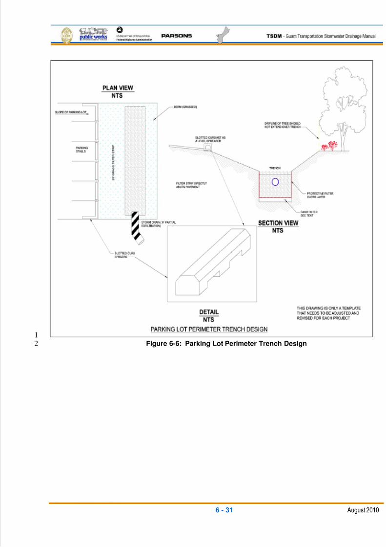
5/13/2018 Guam Storm Water Drainage Manual - slidepdf.com
http://slidepdf.com/reader/full/guam-storm-water-drainage-manual 167/486
6 - 31 August 2010
1Figure 6-6: Parking Lot Perimeter Trench Design2
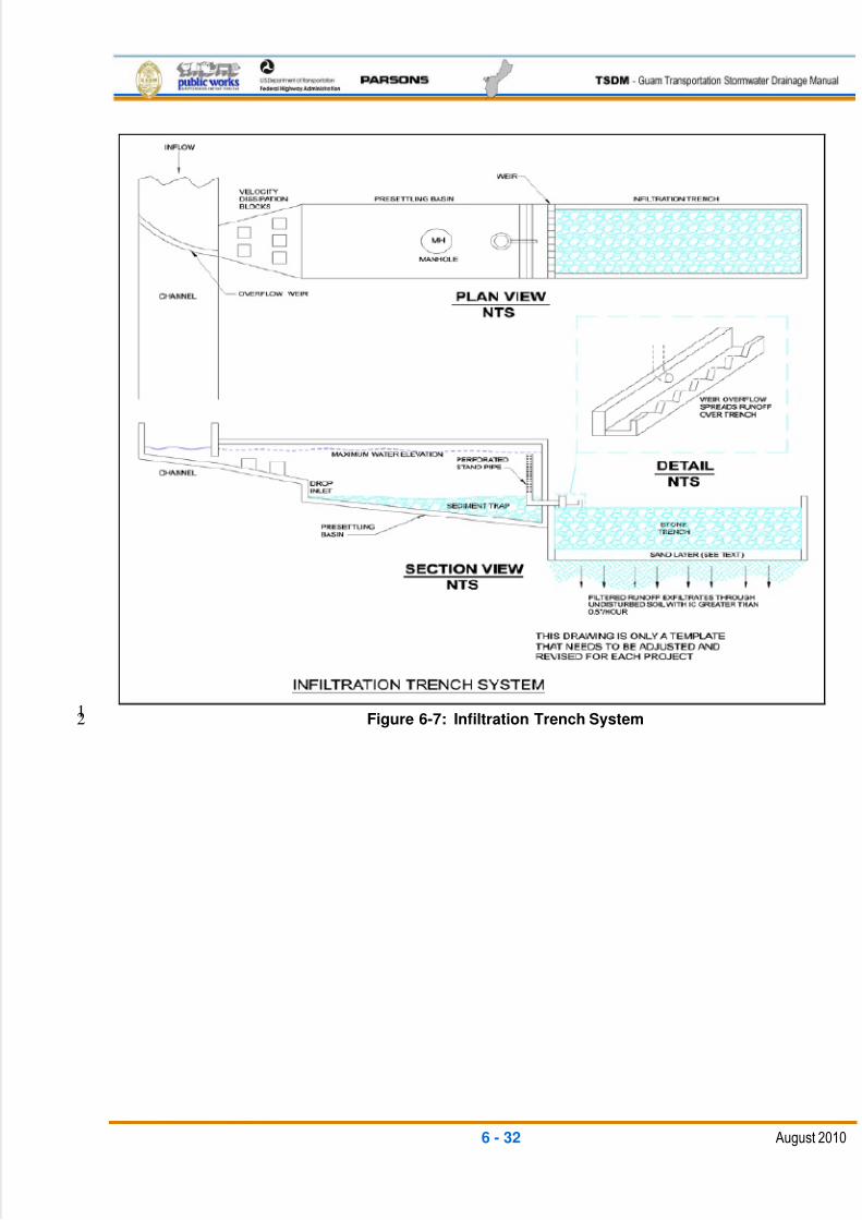
5/13/2018 Guam Storm Water Drainage Manual - slidepdf.com
http://slidepdf.com/reader/full/guam-storm-water-drainage-manual 168/486
6 - 32 August 2010
1Figure 6-7: Infiltration Trench System2
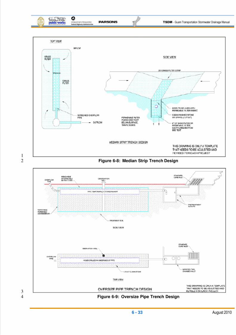
5/13/2018 Guam Storm Water Drainage Manual - slidepdf.com
http://slidepdf.com/reader/full/guam-storm-water-drainage-manual 169/486
6 - 33 August 2010
1Figure 6-8: Median Strip Trench Design2
3Figure 6-9: Oversize Pipe Trench Design4
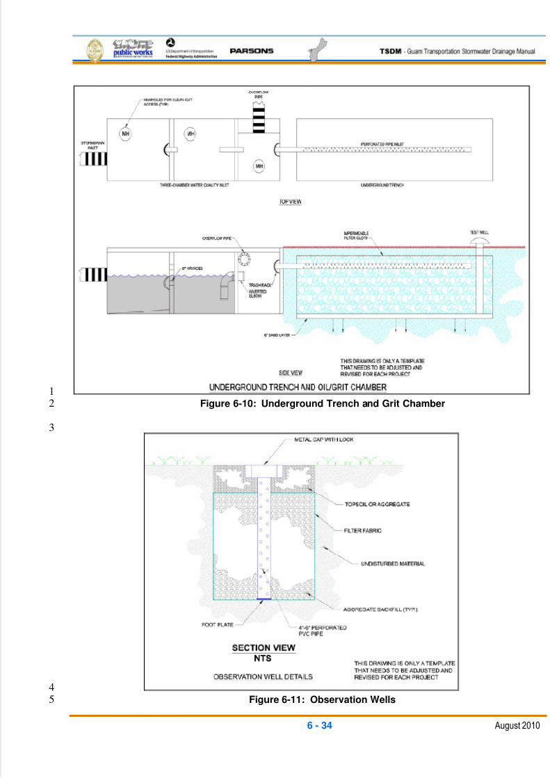
5/13/2018 Guam Storm Water Drainage Manual - slidepdf.com
http://slidepdf.com/reader/full/guam-storm-water-drainage-manual 170/486
6 - 34 August 2010
1Figure 6-10: Underground Trench and Grit Chamber2
3
4Figure 6-11: Observation Wells5
5/13/2018 Guam Storm Water Drainage Manual - slidepdf.com
http://slidepdf.com/reader/full/guam-storm-water-drainage-manual 171/486
6 - 35 August 2010
Implementation1
Trench Preparation 2
Excavated materials must be placed away from the trench sides to enhance trench3
wall stability. Care should be taken to keep this material away from slopes,4neighboring property, sidewalks, and streets. It is recommended that this material be5
covered with plastic.6
Stone Aggregate Placement and Compaction 7
The stone aggregate should be placed in lifts and compacted using plate8
compactors. As a rule of thumb, a maximum loose-lift thickness of 12 in. is9
recommended. The compaction process ensures geotextile conformity to the10
excavation sides, thereby reducing potential piping and geotextile clogging as well as11
settlement problems.12
Separation of Aggregate from Surrounding Soil 13
Natural or fill soils must not intermix with the stone aggregate. If the stone aggregate14
becomes mixed with the soil, the stone aggregate must be removed and replaced15
with uncontaminated stone aggregate.16
Overlapping and Covering 17
The stone aggregate should be wrapped in a geotextile filter fabric. The fabric is18
draped in the trench prior to the stone placement. Following stone aggregate19
placement and compaction, the geotextile is then folded over the stone aggregate to20
form a 12-in. minimum longitudinal overlap. When overlaps are required between21
rolls, the upstream roll should overlap a minimum of 2 ft. over the downstream roll to22
provide a shingled effect.23
Voids Behind Geotextile 24
Voids between the geotextile and excavation sides must be avoided. The space left25
by boulders or other obstacles removed from the trench walls is one source of such26
voids. Natural soils should be placed in these voids at the most convenient time27
during construction to ensure geotextile conformity to the excavation sides. Soil28
piping, geotextile clogging, and possible surface subsidence can be avoided by this29
remedial process.30
Unstable Excavation Sites 31
Vertically excavated walls may be difficult to maintain in areas where the soil32
moisture is high or where soft or cohesionless soils predominate. Trapezoidal rather33
than rectangular cross sections may be needed.34
Initial excavation should be conducted to within 1 ft. of the final elevation of the35
infiltration pond floor. Final excavation to the finished grade should be deferred until36
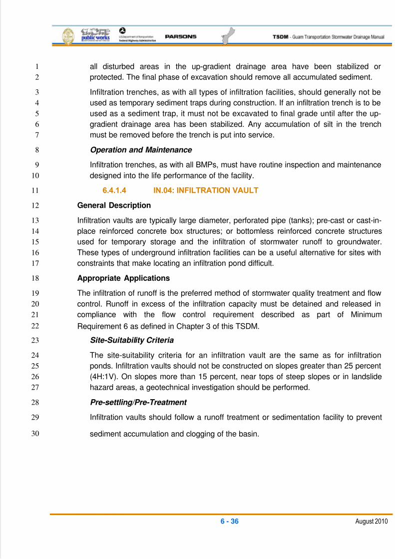
5/13/2018 Guam Storm Water Drainage Manual - slidepdf.com
http://slidepdf.com/reader/full/guam-storm-water-drainage-manual 172/486
6 - 36 August 2010
all disturbed areas in the up-gradient drainage area have been stabilized or1
protected. The final phase of excavation should remove all accumulated sediment.2
Infiltration trenches, as with all types of infiltration facilities, should generally not be3
used as temporary sediment traps during construction. If an infiltration trench is to be4
used as a sediment trap, it must not be excavated to final grade until after the up-5
gradient drainage area has been stabilized. Any accumulation of silt in the trench6
must be removed before the trench is put into service.7
Operation and Maintenance 8
Infiltration trenches, as with all BMPs, must have routine inspection and maintenance9
designed into the life performance of the facility.10
6.4.1.4 IN.04: INFILTRATION VAULT11
General Description12
Infiltration vaults are typically large diameter, perforated pipe (tanks); pre-cast or cast-in-13
place reinforced concrete box structures; or bottomless reinforced concrete structures14
used for temporary storage and the infiltration of stormwater runoff to groundwater.15
These types of underground infiltration facilities can be a useful alternative for sites with16
constraints that make locating an infiltration pond difficult. 17
Appropriate Applications18
The infiltration of runoff is the preferred method of stormwater quality treatment and flow19
control. Runoff in excess of the infiltration capacity must be detained and released in20
compliance with the flow control requirement described as part of Minimum21
Requirement 6 as defined in Chapter 3 of this TSDM.22
Site-Suitability Criteria 23
The site-suitability criteria for an infiltration vault are the same as for infiltration24
ponds. Infiltration vaults should not be constructed on slopes greater than 25 percent25
(4H:1V). On slopes more than 15 percent, near tops of steep slopes or in landslide26
hazard areas, a geotechnical investigation should be performed.27
Pre-settling/Pre-Treatment 28
Infiltration vaults should follow a runoff treatment or sedimentation facility to prevent29
sediment accumulation and clogging of the basin.30
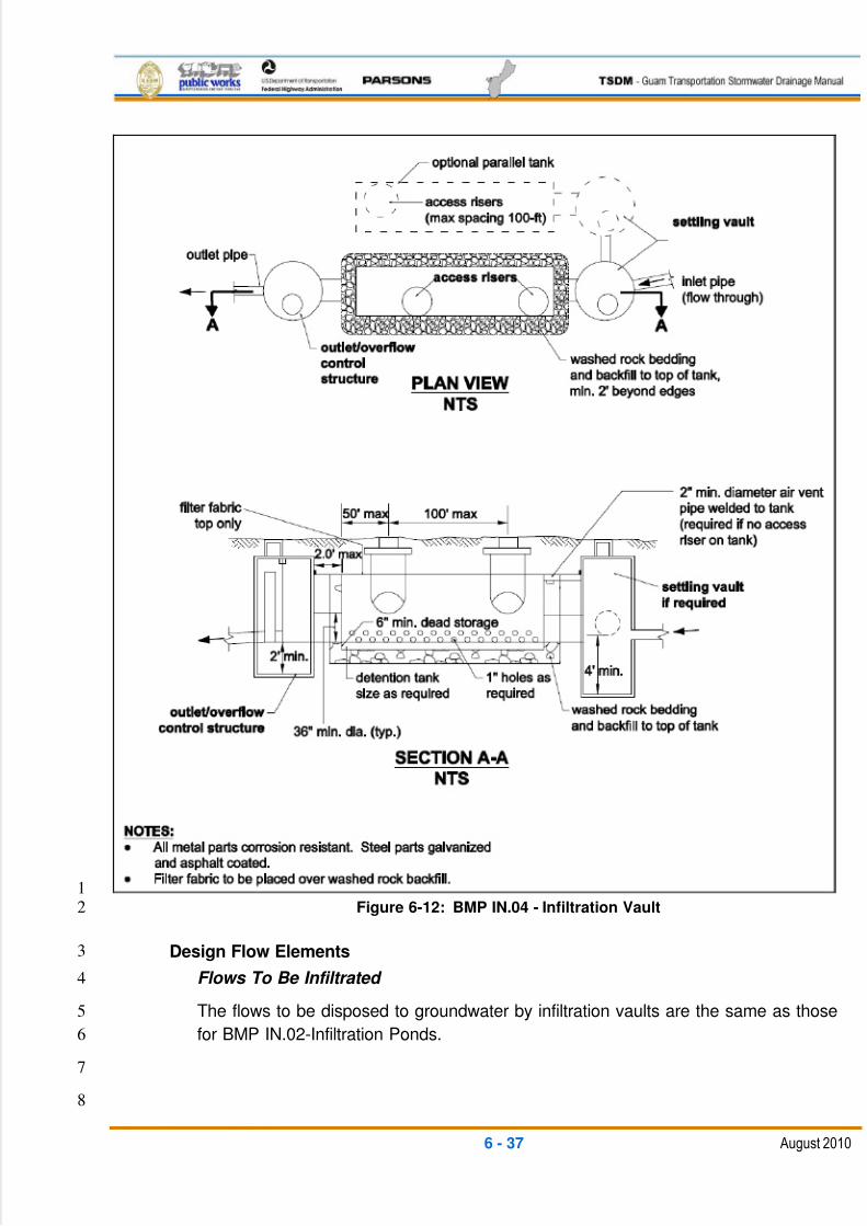
5/13/2018 Guam Storm Water Drainage Manual - slidepdf.com
http://slidepdf.com/reader/full/guam-storm-water-drainage-manual 173/486
6 - 37 August 2010
1Figure 6-12: BMP IN.04 - Infiltration Vault2
Design Flow Elements3
Flows To Be Infiltrated 4
The flows to be disposed to groundwater by infiltration vaults are the same as those5
for BMP IN.02-Infiltration Ponds.6
7
8
5/13/2018 Guam Storm Water Drainage Manual - slidepdf.com
http://slidepdf.com/reader/full/guam-storm-water-drainage-manual 174/486
6 - 38 August 2010
Overflow or Bypass 1
For on-line vaults, a primary overflow must be provided to bypass flows larger than2
the design storm event to the infiltration vault. See BMP FC.01-Detention Pond for3
overflow structure types. For off-line facilities, a flow splitter may be used to direct the4
stormwater quality treatment volume to the vault, while bypassing larger frequency5
storms.6
Outlet Control Structure 7
Outlet control structure requirements for infiltration vaults are the same as those for8
BMP IN.02-Infiltration Pond.9
Flow Splitters 10
Flow splitter requirements for infiltration vaults are the same as those for BMP IN.02-11
Infiltration Pond12
Structural Design Considerations 13
Geometry14
Infiltration vault geometric design requirements are similar to those for BMP15
IN.02-Infiltration Pond. Where used only for stormwater quality treatment, the16
storage volume sizing is based on a routing of the treatment volume inflow rate17
with regard to the design infiltration outflow rate. For combination quality18
treatment and flow control, the storage volume is based on the detention19
requirements between the pre-development and post-development land cover20
conditions for the design frequency storm. The infiltration rate is included as part21
of the discharge flow rate for the detention sizing calculations.22
Materials23
All vaults (both perforated pipe and reinforced concrete) must meet structural24
requirements for overburden support. Vaults located under roadways must meet25
the live load requirements of the FHWA Standard Specifications for Construction 26
of Roads and Bridges on Federal Highway Projects (Standard Specification FP-27
03). Structural designs should be prepared by a Licensed Structural Engineer.28
Bottomless vaults must be provided with footings placed on stable, well-29
consolidated native material and sized in consideration of overburden support,30
traffic loading (assume maintenance traffic if vault is placed outside of right-of-31way), and lateral soil pressures when the vault is dry. Infiltration vaults should not32
be constructed in fill slopes unless a geotechnical analysis determines fill33
stability.34
Large diameter perforated pipe, bedding, and backfill should consist of washed,35
drain rock extending at least 1 ft. below the bottom of the structure, at least 2 ft.36
beyond the sides, and up to the top of the structure. The drain rock must be37

5/13/2018 Guam Storm Water Drainage Manual - slidepdf.com
http://slidepdf.com/reader/full/guam-storm-water-drainage-manual 175/486
6 - 39 August 2010
wrapped with geotextile filter fabric for separation from the native soil. If the drain1
rock becomes mixed with soil, the effected rock material must be removed and2
replaced with washed, drain rock to provide maximum infiltration effectiveness.3
The perforations (holes) in the bottom half of the pipe should be 1 in. in diameter4
and start at an elevation of 6 in. above the invert. The non-perforated portion of5
the pipe in the lower 6 in. is intended for sediment storage to protect clogging of6
the native soil beneath the structure. The number and spacing of the perforations7
should be sufficient to allow complete infiltration of the soils with a safety factor of8
2.0, without jeopardizing the structural integrity of the pipe.9
The design must take into account the serviceability and design life of the10
materials, as well as the structural stability, buoyancy, maintenance access,11
access roads, and right-of-way.12
Groundwater Issues 13
Groundwater issues for infiltration vaults are the same as those for BMP IN.02-14
Infiltration Pond.15
Implementation16
Initial excavation should be conducted to within 1 ft. of the final elevation of the17
infiltration vault base. Final excavation to the finished grade should be deferred18
until all disturbed areas in the up-gradient drainage area have been stabilized or19
protected. The final phase of excavation should remove all accumulated20
sediment.21
Infiltration vaults, as with all types of infiltration facilities, should generally not be22used as temporary sediment traps during construction. If an infiltration vault is to23
be used as a sediment trap, it must not be excavated to the final grade until after24
the up-gradient drainage area has been stabilized. Any accumulation of silt in the25
vault must be removed before the vault is put into service.26
Relatively light-tracked equipment is recommended for excavation to avoid27
compacting the soil beneath the base of the infiltration vault. The use of draglines28
and track hoes should be considered. The infiltration area should be flagged or29
marked to keep equipment away.30
Operation and Maintenance 31
Infiltration vaults, as with all BMPs, must have routine inspection and maintenance32
designed into the life performance of the facility. Access is required suitable for33
suction/rodding-type maintenance trucks for removal of sediments, and for34
maintenance personnel for routine inspections.35
36

5/13/2018 Guam Storm Water Drainage Manual - slidepdf.com
http://slidepdf.com/reader/full/guam-storm-water-drainage-manual 176/486
6 - 40 August 2010
6.4.1.5 IN.05: DRYWELL1
General Description2
Drywells are sub-surface concrete structures, typically pre-cast, that convey stormwater3
runoff into the soil matrix. They can be used as stand-alone structures or as part of a4larger drainage system (for example, the overflow for a bioinfiltration pond).5
Appropriate Applications6
Drywells may be used for both stormwater quality treatment and flow control. Flow7
splitters or overflow devices must be used for flows greater than the runoff treatment8
design storm, and for flows greater than the design infiltration rate.9
Drywells may be used for the same applications as BMP IN.02-Infiltration Ponds and10
BMP IN.03-Infiltration Trench.11
Pre-settling/Pre-Treatment 12
Drywells should follow a runoff treatment or sedimentation (pre-treatment) facility to13
limit sediment build-up and clogging of the infiltration media. Where surface runoff is14
routed directly to the drywell, it should pass as sheet flow over a grassed slope or15
through a biofiltration swale to help remove as much of the coarser sediments as16
possible.17
Implementation18
Inflow to infiltration facilities is calculated according to the methods described in19
Chapter 4 of this TSDM. Storage volume should be provided within and above the20
drywell as required for the necessary detention to contain the treatment volume and/or21
flow control volume as required for infiltration of the design flows. The infiltration rate is22
used in conjunction with the size of the storage area to design the facility. To prevent the23
onset of anaerobic conditions, the infiltration facility must be designed to completely24
drain 72 hours after the end of the design storm.25
In general, an infiltration facility should have two discharge modes. The primary mode of26
discharge is infiltration into the ground. However, when the infiltration capacity of the27
facility is reached, a secondary overflow system is required to safely pass the flow from28
storms larger than the design frequency. Overflows from an infiltration facility must29
comply with Minimum Requirement 6 as defined in Chapter 3 of this TSDM.30
Flows To Be Infiltrated 31
The flows to be disposed to groundwater by drywells are the same as those for BMP32
IN.02-Infiltration Pond.33
Overflow or Bypass 34
On-line systems should have an overflow provision to safely pass storm flows larger35
than the design frequency. Drywells used off-line for stormwater quality treatment36
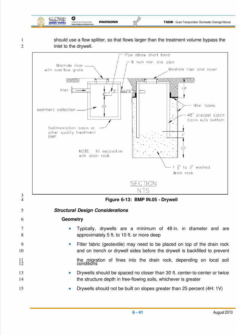
5/13/2018 Guam Storm Water Drainage Manual - slidepdf.com
http://slidepdf.com/reader/full/guam-storm-water-drainage-manual 177/486
6 - 41 August 2010
should use a flow splitter, so that flows larger than the treatment volume bypass the1
inlet to the drywell.2
3Figure 6-13: BMP IN.05 - Drywell 4
Structural Design Considerations 5
Geometry6
Typically, drywells are a minimum of 48 in. in diameter and are7
approximately 5 ft. to 10 ft. or more deep8
Filter fabric (geotextile) may need to be placed on top of the drain rock9
and on trench or drywell sides before the drywell is backfilled to prevent10
the migration of fines into the drain rock, depending on local soil11conditions12
Drywells should be spaced no closer than 30 ft. center-to-center or twice13
the structure depth in free-flowing soils, whichever is greater14
Drywells should not be built on slopes greater than 25 percent (4H: 1V)15
5/13/2018 Guam Storm Water Drainage Manual - slidepdf.com
http://slidepdf.com/reader/full/guam-storm-water-drainage-manual 178/486
6 - 42 August 2010
Drywells should not be placed on or above a landslide hazard area or1
slopes greater than 15 percent without a geotechnical evaluation2
Groundwater Issues 3
Drywell bottoms should be a minimum of 5 ft. above the seasonal high- groundwater4level or impermeable soil layers. In northern Guam, this requirement is waived if5
located above the limestone aquifer recharge area. However, if the discharge6
infiltration level is less than 2 ft. above the limestone bedrock, the inflows must be7
pre-treated through another stormwater quality treatment BMP.8
Site Design Elements9
Setback Requirements 10
The setback requirements for drywells are the same as those for BMP IN.02-11
Infiltration Ponds.12
Signage 13
The requirements for signs are the same as those for BMP IN.02-Infiltration Ponds.14
6.4.1.6 IN.05: PERMEABLE PAVEMENT15
General Description16
Permeable (porous or pervious) surfaces can be applied to non-pollution-generating17
surfaces such as pedestrian/bike paths, raised traffic islands, and sidewalks.18
Permeable surfaces with a media filtration sub-layer (such as sand or an amended19
soil) could be applied to pollution generating surfaces (such as parking lots) for20
calculating runoff treatment. Permeable surfaces allow stormwater to pass through21and infiltrate the soil below, thereby reducing the rate and volume of runoff22
associated with conventional surfacing and fostering groundwater recharge.23
The permeable concrete or asphalt pavement surface is an open-graded mix placed24
in a manner that results in a high degree of interstitial spaces or voids within the25
cemented aggregate. This technique demonstrates a high degree of absorption or26
storage within the voids and infiltration to sub-soils. The pavement may be27
permeable concrete, permeable asphalt, or manufactured systems such as28
interlocking brick or a combination of sand and brick lattice. Geo-cell with geotextile29
and aggregate material may also be considered for limited applications.30
Appropriate Applications 31
Possible areas for use of these permeable surface materials include the following:32
Sidewalks, bicycle trails, community trail/pedestrian path systems, or any33
pedestrian-accessible paved areas (such as traffic islands)34

5/13/2018 Guam Storm Water Drainage Manual - slidepdf.com
http://slidepdf.com/reader/full/guam-storm-water-drainage-manual 179/486
6 - 43 August 2010
Vehicle access areas, including emergency stopping lanes,1
maintenance/enforcement areas on divided highways, and facility2
maintenance access roads3
Public and municipal parking lots, including perimeter and overflow4parking areas5
Permeable surface systems function as stormwater infiltration areas and temporary6
stormwater retention areas that can accommodate pedestrians and light- to medium-7
load parking areas. They are applicable to both residential and commercial8
applications, with the exception of heavy truck traffic. This combination of functions9
offers the following benefits:10
Captures and retains precipitation on-site11
Mimics natural soils filtration throughout the pavement depth, underlying12
sub-base reservoir, and native soils for improved groundwater quality13
Eliminates surface runoff, depending on existing soil conditions14
Greatly reduces or eliminates the need for an on-site stormwater15
management system16
Reduces drainage water runoff temperatures17
Increases recharge of groundwater18
Provides runoff treatment with a media filtration layer19
Handling and placement practices for permeable surfaces are different from20
conventional pavement placement. Unlike conventional pavement construction, it is21
important that the underlying native or sub-grade soils be nominally consolidated to22
prevent settling and minimize the effect of intentional or inadvertent heavy23
compaction due to heavy equipment operation during construction. Consolidation24
can be accomplished using static dual-wheel small mechanical rollers or plate25
vibration machines. If heavy compaction does occur, then tilling may be necessary to26
a depth of 2 ft. below the material placement. This would occur prior to subsequent27
application of the separation and base layers.28
Permeable surfaces are vulnerable to clogging from sediment in runoff. The following29
techniques will reduce this potential:30
Surface runoff. Permeable surfaces should not be located where turbid31
runoff from adjacent areas can introduce sediments onto the permeable32
surface. Designs should slope impervious runoff away from permeable33
pavement installations to the maximum extent possible.34
Diversion. French drains, or other diversion structures, may be designed35
into the system to avoid unintended off-site runoff. Permeable systems36
5/13/2018 Guam Storm Water Drainage Manual - slidepdf.com
http://slidepdf.com/reader/full/guam-storm-water-drainage-manual 180/486
6 - 44 August 2010
can be separated using edge drain systems, turnpikes, and 0.15-foot-high1
tapered bumps.2
Slopes. Off-site drainage slopes immediately adjacent to the permeable3
surface should be less than 5 percent to reduce the chance of soil loss4
that would cause clogging.5
Limitations 6
Suitable grades, subsoil drainage characteristics, and groundwater table conditions7
require good multidisciplinary analysis and design. Proper construction techniques8
and diligent field inspection during the placement of permeable surfaces are also9
essential to a successful installation.10
Installation works best with level, adjacent slopes — 1 percent to 211
percent — and on upland soils. Permeable surface installations are not12
appropriate when adjacent draining slopes are 5 percent or greater.13
An extended period of saturation of the base material underlying the14
surface is undesirable. Therefore, the subsurface reservoir layer should15
fully drain in a period of less than 36 hours.16
The minimum depth from the bottom of the base course to bedrock and17
seasonally high water table should be 3 feet, unless it is possible to18
engineer a groundwater bypass into the system.19
Examples of situations where the use of permeable surfaces is not currently20
recommended include the following:21
Roadway lanes because of a number of considerations (such as dynamic22
loading, safety, clogging, and heavy loads). More study and experience23
are needed before using permeable surfaces in these situations. Use of24
any type of shoulder application whereby the retained moisture drains25
away from the main line requires coordinated approval from materials,26
roadway design, hydraulics, and maintenance support staff.27
Areas where the permeable surface will be routinely exposed to heavy28
sediment loading.29
Areas such as maintenance yards that are subject, or potentially subject,30
to higher pollutant loadings, spills, and piles of bulk materials (such as31
sand or salt) should not incorporate permeable pavements.32
Areas where the risk of groundwater contamination from organic33
compounds is high (e.g., fueling stations, commercial truck parking areas,34
and maintenance and storage yards).35
5/13/2018 Guam Storm Water Drainage Manual - slidepdf.com
http://slidepdf.com/reader/full/guam-storm-water-drainage-manual 181/486
6 - 45 August 2010
Within 100 feet of a drinking water well and within areas designated as1
sole source aquifers.2
Areas with a high water table or impermeable soil layer.3
Within 100 feet up-gradient or 10 feet down-gradient from building4foundations. Closer up-gradient distances may be considered where the5
minimum seasonal depth to groundwater lies below the foundation or6
where it can be demonstrated that infiltrating water from the permeable7
surface will not affect the foundation.8
General Design Considerations 9
All projects considering the use of permeable surfaces should be further explored in10
coordination with the Design, Materials Lab, Hydraulics, and Maintenance offices.11
As long as runoff is not directed to the permeable asphalt from adjacent12
surfaces, the estimated long-term infiltration rate may be as low as 0.113
inch/hour. Soils with lower infiltration rates should have underdrains to14
prevent prolonged saturated soil conditions at or near the ground surface15
within the pavement section.16
For initial planning purposes, permeable surface systems will work well17
on Hydrologic Soil Groups A and B and can be considered for Group C18
soils.19
Standard three-layer placement sections for Group D soils may not be20
applicable.21
For projects constructed on Group C and D soils, a minimum of three soil22
gradation analyses or three infiltration tests should be conducted to23
establish on-site soil permeability. Otherwise, a minimum of one such test24
should be conducted for Group A and B soils to verify adequate25
permeability.26
Ideally, the base layer should be designed with sufficient depth to meet27
flow control requirements (taking into account infiltration). If the infiltration28
rate and base layer‘s recharge bed storage does not meet flow control 29
requirements, an underdrain system may be required. The underdrain30
could be discharged to a bioretention area, dispersion system, or31stormwater detention facility.32
Turbid runoff to the permeable surface from off-site areas is not allowed.33
Designs may incorporate infiltration trenches or other options to ensure34
long-term infiltration through the permeable surface.35

5/13/2018 Guam Storm Water Drainage Manual - slidepdf.com
http://slidepdf.com/reader/full/guam-storm-water-drainage-manual 182/486
6 - 46 August 2010
Any necessary boreholes must be installed to a depth of 10 feet below1
the base of the reservoir layer, and the water table must be monitored at2
least monthly for a year.3
Infiltration systems perform best on upland soils.4On-site soils should be tested for porosity, permeability, organic content, and5
potential for cation exchange. These properties should be reviewed when designing6
the recharge bed of pervious surfaces.7
Once a permeable surface site is identified, a geotechnical investigation should be8
performed to determine the quantity and depth of borings/test pits required and any9
groundwater monitoring needed to characterize the soil.10
For on-site locations where subgrade materials are marginal, the use of a heavy-duty11
geogrid placed directly on subgrade may be necessary. A sand layer is placed above12
the heavy geogrid, followed by geotextile for drainage.13
Design Flow Elements 14
For sizing purposes, use the following guidelines:15
The bottom area of an ―infiltration basin‖ will typically be equivalent to the 16
area below the surrounding grade underlying the permeable surface.17
Adjust the depth of this ―infiltration basin‖ so that it is sufficient to store the18
required design volume.19
Multiply this depth by a factor of five. This will determine the depth of the20
gravel base underlying the permeable surface. This assumes a void ratio21
of 0.20 — a conservative assumption. When a base material that has a22
different porosity will be used, that value may be substituted to determine23
the depth of the base. The minimum base depth is 6 inches, which allows24
for adequate structural support of the permeable surface.25
For a large, contiguous area of permeable surface, such as a parking lot,26
the area may be designed with a level surface grade and a sloped27
subgrade to prevent water buildup on the surface, except under extreme28
conditions. Rare instances of shallow ponding in a parking lot are29
normally acceptable.30
For projects where ponding is unacceptable under any condition, the31
surface of the parking lot may be graded at a 1 percent slope leading to a32
shallow swale, which would function to ensure emergency drainage33
(similar to an emergency overflow from a conventional infiltration pond).34
However, the design depth of the base material must be maintained at all35
locations.36
37

5/13/2018 Guam Storm Water Drainage Manual - slidepdf.com
http://slidepdf.com/reader/full/guam-storm-water-drainage-manual 183/486
6 - 47 August 2010
Maintenance Considerations 1
Permeable surfaces require more maintenance than conventional pavement2
installations. The primary concern in maintaining the continued effectiveness of a3
permeable surface system is to prevent the surface from clogging with fine4
sediments and debris.5
Materials 6
Permeable surfaces consist of a number of components — the surface pavement, an7
underlying base layer, a separation layer, and the native soil or subgrade soil. An8
overflow or underdrain system may need to be considered as part of the pavement‘s9
overall design.10
Surface Layer11
The surface layer is the first component of a permeable system‘s design that creates12
the ability for water to infiltrate through the surface. Permeable paving systems allow13infiltration of storm flows; however, the wearing course should not be allowed to14
become saturated from excessive water volume stored in the aggregate base layer.15
Portland Cement-Based Pervious Pavement Materials16
The surface layer consists of specially formulated mixtures of Portland cement,17
uniform open-graded coarse aggregate, and potable water. The depth of the surface18
layer may increase from a minimum of 4 inches, depending on the required bearing19
strength and pavement design requirements. The gradation required to obtain a20
pervious concrete pavement is of the open-graded or coarse type (AASHTO Grading21
No. 67, ¾ inch and lower).22
Due to the relatively low water content of the concrete mix, an agent may be added23
to retard concrete setup time. When properly handled and installed, pervious24
pavement has a higher percentage of void space than conventional pavement25
(approximately 12 percent to 21 percent), which allows rapid percolation of26
stormwater through the pavement. The initial permeability can commonly exceed 20027
inches per hour28
Asphalt-Based Pervious Pavement Materials 29
The surface asphalt layer consists of an open-graded asphalt mixture. The depth of30
the surface layer may increase from a minimum of 4 inches, depending on the31required bearing strength and pavement design requirements.32
Pervious asphalt pavement consists of an open-graded coarse aggregate. The33
pervious asphalt creates a surface layer with interconnected voids that provide a34
high rate of permeability.35
36
5/13/2018 Guam Storm Water Drainage Manual - slidepdf.com
http://slidepdf.com/reader/full/guam-storm-water-drainage-manual 184/486
6 - 48 August 2010
Paving and Lattice Stones 1
Paving and lattice stones consist of a high-compressive-strength stone that may2
increase from a minimum depth of 4 inches, depending on the required bearing3
strength and pavement design requirements. When placed together, these paving4
stones create a reinforced surface layer. An open-graded fine aggregate fills the5
voids, which creates a system that provides infiltration into a permeable base layer.6
This system can be used in parking lots, bike paths, or areas that receive common7
local traffic.8
Geo-Cell (PVC Containment Cell) 9
A Geo-Cell surface stabilization system consists of a high-strength, UV-resistant,10
PVC-celled panel that is 4 inches thick. The celled panels can be filled with soil and11
covered with turf by installing sod. Base gravel may also be used to fill the celled12
panels. Both applications create a surface layer.13
The Geo-Cell creates an interlock layer with interconnected voids that provide a high14
rate of permeability of water to an infiltrative base layer. The common applications for15
this system are on slopes and pedestrian/bike paths and in parking and low-traffic16
areas.17
Base Layer 18
The underlying base material is the second component of a permeable surface's19
design. The base material is a crushed aggregate and provides the following:20
A stable base for the pavement.21
A high degree of permeability to disperse water downward through the22
underlying layer to the separation layer.23
A temporary reservoir that slows the migration of water prior to infiltration24
into the underlying soil.25
Base material is often composed of larger aggregate (1.5 to 2.5 inches)26
with smaller stone (leveling or choker course) between the larger stone27
and the wearing course. Typical void space in base layers ranges from 2028
percent to 40 percent.29
Depending on the target flow control standard and physical setting,30
retention or detention requirements can be partially or entirely met in the31
aggregate base.32
Aggregate base depths of 18 to 36 inches are common depending on33
storage needs, and they provide the additional benefit of increasing the34
strength of the wearing course by isolating underlying soil movement and35
imperfections that may be transmitted to the wearing course.36
5/13/2018 Guam Storm Water Drainage Manual - slidepdf.com
http://slidepdf.com/reader/full/guam-storm-water-drainage-manual 185/486
6 - 49 August 2010
Separation Layer1
The third component of permeable systems is the separation layer. This layer2
consists of a non-woven geotextile fabric and possibly a treatment media base3
material. A geotextile fabric layer is placed between the base material and the native4
soil to prevent migration of fine soil particles into the base material, followed by a5
runoff treatment media layer if required.6
For geotextile, see Standard Specifications.7
For separation base material, see the FHWA manual ―Construction of 8
Pavement Subsurface Drainage Systems‖ (2002) for aggregate gradation 9
separation base guidance.10
A treatment media layer is not required where subgrade soil is11
determined to have a long-term infiltration rate less than 2.4 inches per12
hour and a CEC of the subgrade soil that is at least 5 milliequivalents/10013grams of dry soil or greater.14
If a treatment media layer is used, it must be distributed below the15
geotextile layer and above the subgrade soil. The media can consist of a16
sand filter layer or amended soil. Engineered amended soil layers should17
be a minimum of 18 inches and incorporate compost, sphagnum peat18
moss, or other organic material to provide a cation exchange capacity of19
greater than or equal to 5 milliequivalents/100 grams of dry soil.20
Gradations of the treatment media should follow base sizing.21
Subgrade Soil22The underlying subgrade soil is the fourth component of pervious pavement. Runoff23
infiltrates into the soil and moves to the local interflow or groundwater layer.24
Compaction of the subgrade must be kept to an absolute minimum to ensure the soil25
maintains a high rate of permeability while maintaining the structural integrity of the26
pavement.27
Liners28
The primary purpose of a permeable pavement system is to promote infiltration. An29
impervious liner will discontinue infiltration; therefore, a flow control credit is not30
allowed and the surface is modeled as impervious.3132
6.4.2 DISPERSION: BMPS33
Perhaps the single most promising and effective approach to mitigating the effects of34
highway runoff in non-urbanized areas is to look for opportunities to use the existing35
natural area capacity to remove pollutants. Natural dispersion requires that runoff cannot36
become concentrated in any way as it flows into a preserved, naturally vegetated area.37
5/13/2018 Guam Storm Water Drainage Manual - slidepdf.com
http://slidepdf.com/reader/full/guam-storm-water-drainage-manual 186/486
6 - 50 August 2010
The preserved, naturally vegetated area must have topographic, soil, and vegetation1
characteristics that provide for the removal of pollutants. Pollutant removal typically2
occurs through a combined process of vegetative filtration and shallow surface3
infiltration. Dispersion BMPs include:4
RT.01 – Natural Dispersion5
RT.02 – Engineered Dispersion6
6.4.2.1 RT.01: NATURAL DISPERSION7
General Description8
Natural dispersion is the simplest method of flow control and stormwater quality runoff9
treatment. This BMP can be used for impervious and pervious surfaces that are graded10
so that runoff occurs by sheet flow. Natural dispersion uses the existing vegetation, soils,11
and topography to effectively provide flow control and runoff treatment. It generally12
requires little or no construction activity. Site selection is very important to the success of13
this BMP. The pollutant-removal processes include infiltration into the existing soils and14
through vegetation root zones, evaporation, and uptake and transpiration by the15
vegetation.16
The key to natural dispersion is that flows from the impervious area enter the natural17
dispersion area as sheet flow. Because stormwater enters the dispersion area as sheet18
flow, it only needs to traverse a narrow band of contiguous vegetation for effective19
attenuation and treatment. The goal is to have the flows dispersed into the surrounding20
landscape so that there is a low probability that any surface runoff will reach a flowing21
body of water.22
When modeling the hydrology of the project site and the threshold discharge area, the23
designer should treat natural dispersion areas and their tributary drainage areas as24
disconnected from the project site because they do not contribute flow to other flow25
control or runoff treatment BMPs.26
Applications and Limitations27
Applications 28
Natural dispersion is ideal for highways and linear roadway projects29
Natural dispersion helps maintain the temperature norms of stormwater30
because it promotes infiltration, evaporation, and transpiration, and should31
not have a surface discharge to a lake or a stream32
Natural dispersion areas meet runoff treatment criteria set forth in Minimum33
Requirement 5 as defined in Chapter 3 of this TSDM34
Natural dispersion areas meet flow control criteria set forth in Minimum35
Requirement 6 as defined in Chapter 3 of this TSDM36
5/13/2018 Guam Storm Water Drainage Manual - slidepdf.com
http://slidepdf.com/reader/full/guam-storm-water-drainage-manual 187/486
6 - 51 August 2010
Limitations 1
The effectiveness of natural dispersion relies on maintaining sheet flow to the2
dispersion area, which maximizes soil and vegetation contact and prevents3
short-circuiting due to channelized flow. If sheet flow cannot be maintained,4
natural dispersion will not be effective.5
Natural dispersion areas must be within the project right-of-way limits. Natural6
dispersion areas must be protected from future development. DPW may7
ultimately have to purchase right-of-way or easements to satisfy the criteria8
for natural dispersion areas, but this should be the last option a designer9
should choose.10
Natural dispersion areas initially may cost as much as other constructed11
BMPs (ponds or vaults) because right-of-way or easements often need to be12
purchased, but long-term maintenance costs are lower. These natural areas13
will also contribute to the preservation of native habitat and provide visual14
buffering of the roadway.15
Floodplains are not suitable areas for natural dispersion.16
Site Design Elements17
Siting Criteria 18
The key to natural dispersion is having vegetative land cover with an established root19
zone, where the roots, organic matter, and soil macro-organisms provide macro-20
pores to reduce surface compaction and prevent soil pore sealing. The vegetative21
cover also provides filtration and maintains sheet flow, reducing the chance for22erosion. The following public agency owned areas are considered appropriate23
candidates for natural dispersion because they are likely to retain these vegetative24
conditions over the long term:25
Within DPWs right-of-ways26
Village or Territorial-protected beautification areas27
Parks28
Other Government-owned lands29
Where outside of the DPW right-of-way, the dispersion area will require30
permanent easements to restrict any other use or development by the other31
public agency.32
33
34
35
5/13/2018 Guam Storm Water Drainage Manual - slidepdf.com
http://slidepdf.com/reader/full/guam-storm-water-drainage-manual 188/486
6 - 52 August 2010
Design Flow Elements1
Flows To Be Dispersed 2
The size of the natural dispersion area depends on the flow-contributing area and the3
predicted rates of water loss through the dispersion system. The designer should4ensure the dispersion area is sufficient to dispose the runoff through infiltration,5
evaporation, transpiration, and soil absorption.6
Sheet Flow 7
The sheet flow dispersion criteria for natural dispersion areas are as follows:8
The sheet flow path leading to the natural dispersion area should not be9
longer than 150 ft. The sheet flow path is measured in the direction of the10
flow and generally represents the width of the pavement area.11
Pervious shoulders and side slopes are not counted in determining the sheet12
flow path.13
The longitudinal length of the dispersion area should be equivalent to the14
longitudinal length of roadway that is contributing sheet flow.15
The longitudinal pavement slope contributing flow to a dispersion area should16
be less than 5 percent. The lateral pavement slope should be less than17
8 percent.18
Roadway side slopes leading to natural dispersion areas should be19
25 percent (4H:1V) or flatter. Slopes steeper than 25 percent are allowed if20
the existing side slopes are well-vegetated and show no signs of erosion21problems.22
For any existing slope that will lead to a natural dispersion area, if evidence of23
channelized flows (rills or gullies) is present, a flow spreading device should24
be used before those flows are allowed to enter the dispersion area.25
Sizing Criteria26
Based on Soil Characteristics 27
The following criteria are specific to sheet flow dispersion on all NRCS Type A and28
some Type B soils, depending on the saturated hydraulic conductivity rates:29
For saturated hydraulic conductivity rates of 4 in. per hour or greater, and for30
the first 20 ft. along the sheet flow path of impervious surface that drains to31
the dispersion area, there must be 10 lateral ft. of dispersion area width. For32
each additional foot of impervious surface along the sheet flow path that33
drains to the dispersion area, 0.25 lateral ft. of dispersion area should be34
provided.35
5/13/2018 Guam Storm Water Drainage Manual - slidepdf.com
http://slidepdf.com/reader/full/guam-storm-water-drainage-manual 189/486
6 - 53 August 2010
For dispersion areas that receive sheet flow from only disturbed pervious1
areas (bare soil and non-native landscaping), for every 6 ft. along the sheet2
flow path of disturbed pervious area, 1 lateral ft. width of dispersion area is3
required.4
Criteria for sheet flow dispersion on all NRCS Type C and Type D soils and some5
Type B soils with saturated hydraulic conductivity rates of 4 in. per hour or less:6
For every 1 ft. of contributing pavement width, a dispersion area width of7
6.5 ft. is needed.8
Figure 6-14 illustrates the configuration of a typical natural dispersion area relative to9
the roadway10
Structural Design Considerations11
Geometry 12
Be well vegetated with established root zones13
Have an average longitudinal slope of 6H:1V or flatter14
Have an average lateral slope of 6H:1V or flatter for both the roadway side15
slope and the natural area to be part of the natural dispersion area16
Have infiltrative soil properties that are verified by geotechnical evaluation17
Natural dispersion areas should have a separation of at least 2 ft. between the18
existing ground elevation and the average annual maximum groundwater elevation.19
This separation depth requirement applies to the entire limits of the dispersion area.20
There should be no discernible continuous flow paths through the dispersion area.21
Setback Requirements 22
Natural dispersion areas can extend beyond DPW‘s right-of-ways, provided that the23
documentation on right-of-way plans ensures (through easements) that the24
dispersion area is not developed in the future. Off-site dispersion areas will normally25
be limited to other public agency lands.26
Natural dispersion areas should be set back at least 1,000 ft. from drinking water27
wells and 100 ft. from septic tank drain field systems.28
The project must not drain onto adjacent off-site properties. Otherwise, a drainage29easement will be required or additional right-of-way purchased.30
Signage 31
The limits of the natural dispersion area should be physically marked in the field,32
both during and after construction.33

5/13/2018 Guam Storm Water Drainage Manual - slidepdf.com
http://slidepdf.com/reader/full/guam-storm-water-drainage-manual 190/486
6 - 54 August 2010
Signage helps ensure the natural dispersion area is not cleared or disturbed after the1
construction project.2
Construction Considerations3
For the installation of dispersal BMPs and conveyance systems near dispersion areas,4the area that needs to be cleared or grubbed should be minimized. Maintaining plant5
root systems is important for dispersion areas.6
The area around dispersion areas should not be compacted.7
To the maximum extent practicable, low-ground-pressure vehicles and equipment8
should be used during construction.9
Maintenance Considerations10
Maintenance pullout areas should be considered to promote successful maintenance11
practices at dispersion areas. Pullout areas should be large enough to accommodate a12
typical maintenance vehicle.13
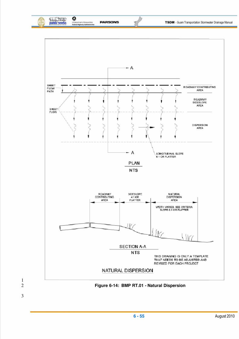
5/13/2018 Guam Storm Water Drainage Manual - slidepdf.com
http://slidepdf.com/reader/full/guam-storm-water-drainage-manual 191/486
6 - 55 August 2010
1Figure 6-14: BMP RT.01 - Natural Dispersion2
3
5/13/2018 Guam Storm Water Drainage Manual - slidepdf.com
http://slidepdf.com/reader/full/guam-storm-water-drainage-manual 192/486
6 - 56 August 2010
6.4.2.2 RT.02: ENGINEERED DISPERSION1
General Description2
Engineered dispersion is similar to natural dispersion. This BMP can be used for3
stormwater quality treatment and flow control at end of conveyance ditch or pipe4locations. The stormwater conveyance discharges by sheet flow through level-flow5
spreaders across engineered dispersion areas. Engineered dispersion uses the existing6
vegetation or landscaped areas, existing soils or engineered compost-amended soils,7
and topography to effectively provide flow control and runoff treatment. Site selection is8
very important to the success of this BMP. The pollutant-removal processes include9
infiltration to the existing or engineered soils and through vegetation root zones,10
evaporation, and uptake and transpiration by the existing vegetation or landscaped11
areas.12
Applications and Limitations13
Applications 14
Engineered dispersion is ideal for highways and linear roadway projects that15
collect and convey stormwater to discrete discharge points along the project16
Engineered dispersion maintains the temperature norms of stormwater17
because it promotes infiltration, evaporation, and transpiration, and should18
not have a surface discharge to a lake or stream19
Engineered dispersion areas meet the basic and enhanced runoff treatment20
criteria set forth in Minimum Requirement 5 as defined in Chapter 3 of this21
TSDM22
Engineered dispersion areas meet flow control criteria set forth in Minimum23
Requirement 6 as defined in Chapter 3 of this TSDM24
Limitations 25
The effectiveness of engineered dispersion relies on maintaining sheet flow to the26
dispersion area, which maximizes soil and vegetated contact and prevents short-27
circuiting due to channelized flow. If sheet flow cannot be maintained, engineered28
dispersion will not be effective.29
The project must ensure that the engineered dispersion area is not developed in the30
future. This requires that the engineered dispersion be constructed within the project31
right-of-way. Alternately, the dispersion could be placed on other suitable public32
agency property, although an easement or agreement will be needed. Otherwise,33
additional right-of-way acquisition may be necessary.34
5/13/2018 Guam Storm Water Drainage Manual - slidepdf.com
http://slidepdf.com/reader/full/guam-storm-water-drainage-manual 193/486
6 - 57 August 2010
Engineered dispersion areas may cost as much as other BMPs (ponds or vaults)1
because right-of-way and easements may need to be purchased and compost-2
amended soils may need to be added.3
Floodplains are not suitable areas for engineered dispersion.4
Design Flow Elements5
Flows To Be Dispersed 6
The required size of the engineered dispersion area depends on the area7
contributing flow and the predicted rates of water loss through the dispersion system.8
The design flow is the stormwater quality treatment volume and/or the flow control9
design storm frequency.10
Structural Design Considerations11
Geometry 12
The average longitudinal slope of the dispersion area should not exceed13
6H:1V14
The average lateral slope of the dispersion area should not exceed 6H:1V15
There should be no discernible flow paths through the dispersion area16
There should be no surface water discharge from the dispersion area to a17
conveyance system18
Materials 19
Compost-amended soils should be generously applied to the dispersion areas. The20final organic content of the soil in the dispersion areas should be 10 percent.21
Site Design Elements22
Siting Criteria 23
The following areas are appropriate engineered dispersion areas because they are24
likely to remain in their existing condition over the long term:25
DPW right-of-way26
Protected beautification areas27
Agricultural areas28
Parks29
Other Government-owned forestlands30
Rural areas with zoned densities of less than one dwelling unit per 5 acres31
5/13/2018 Guam Storm Water Drainage Manual - slidepdf.com
http://slidepdf.com/reader/full/guam-storm-water-drainage-manual 194/486
6 - 58 August 2010
Engineered dispersion areas should have infiltrative soil properties that are verified1
by a geotechnical evaluation, and should not be sited above slopes greater than2
20 percent.3
Engineered dispersion areas should have a separation of at least 2 ft. between the4
existing ground elevation and the average annual maximum groundwater elevation.5
Sizing Criteria6
Figure 6-15 illustrates a typical engineered dispersion area relative to the adjacent7
roadway.8
Concentrated runoff from the roadway and adjacent upstream areas (e.g., in a ditch9
or cut slope) must be incrementally discharged from the conveyance system, such10
as a ditch, gutter, or storm sewer, through cross culverts or at the ends of cut11
sections. These incremental discharges of newly-concentrated flows should not12
exceed 0.5 cfs for a single discharge point from the conveyance system for the 100-13year runoff event. Where flows exceed this limit, the design of the associated14
discharge point and associated flow spreader should be carefully designed to avoid15
any erosion or surface gullying for the 100-yr storm.16
Discharge points with up to 0.5 cfs discharge for the peak 100-year flow may use17
rock pads or level flow spreaders (spreader swales or trenches) to disperse flows.18
Discharge points with 0.5 cfs and larger discharge for the 100-year peak flow must19
use level flow spreaders or swales to disperse flows.20
Level flow spreaders must be designed to accept surface flows (free discharge) from21
a pipe, culvert, or ditch end. They must be aligned perpendicular to the flow path22
(see Section 6.6.3 for level flow spreader design guidelines). Sheet flow over the23
level spreader berm or control weir should not exceed 4 in. in depth. Level flow24
spreaders must have a minimum spacing of 50 ft.25
Flow paths from adjacent discharge points must not intersect within the required flow26
path lengths, and dispersed flow from a discharge point must not be intercepted by27
another discharge point.28
Engineered dispersion areas should be selected so that there is no chance for any29
surface flow (flow not otherwise infiltrated) entering a stream, wetland, or other30
waterbody.31
The width of the dispersion area should be at least three times the width required to32
infiltrate the flow depth over the weir from the flow spreader trench or swale. The33
infiltration width should be conservatively calculated using Mannings Equation for34
sheet flow over a natural grass ground cover (see design guidelines for the bioswale35
and vegetated filter strip BMPs) to obtain the flow velocity. Use the flow depth at the36
overflow weir crest for the calculations. The infiltration width corresponds to the time37
needed to infiltrate that depth of water times the sheet flow velocity. The required38
5/13/2018 Guam Storm Water Drainage Manual - slidepdf.com
http://slidepdf.com/reader/full/guam-storm-water-drainage-manual 195/486
6 - 59 August 2010
dispersion area width is at least three times the calculated infiltration width.1
Infiltration rates used for the calculations can be either determined by infiltration site2
testing by a qualified Geotechnical Engineer, or using the lower end of the ranges for3
infiltration rates as determined by the NRCS soil surveys for the particular soil types,4
by ground cover, slopes, and hydrologic soil group.5
Pipe or Ditch Conveyance System6
Flows collected in a pipe or ditch conveyance system require energy dissipation and7
dispersal at the end of the conveyance system before entering the dispersion area.8
Setback Requirements 9
Engineered dispersion areas can extend beyond DPW‘s right-of-way, provided that10
documentation on the right-of-way plans ensures (through easement or agreement)11
that the dispersion area is not developed in the future.12
Engineered dispersion areas should be set back at least 1,000 ft. from drinking water13wells and 100 ft. from septic tank drain fields.14
If the project significantly increases flows to off-site properties, a drainage easement15
may be required or right-of-way purchased.16
Signage 17
The limits of the engineered dispersion area should be marked as a stormwater18
management facility and should also be physically marked in the field (during and19
after construction).20
Signage helps ensure that the engineered dispersion area is not cleared or disturbed21
after the construction project.22
Construction Considerations23
For the installation of dispersal BMPs and conveyance systems near dispersion areas,24
the area that needs to be cleared or grubbed should be minimized. Maintaining plant25
root systems is important for dispersion areas.26
The area around dispersion areas should not be compacted.27
To the maximum extent practicable, low-ground-pressure vehicles and equipment28
should be used during construction.29
Maintenance Considerations30
Allow for off-road parking for maintenance vehicles/personnel. Pullout areas should be31
large enough to accommodate a typical maintenance vehicle.32
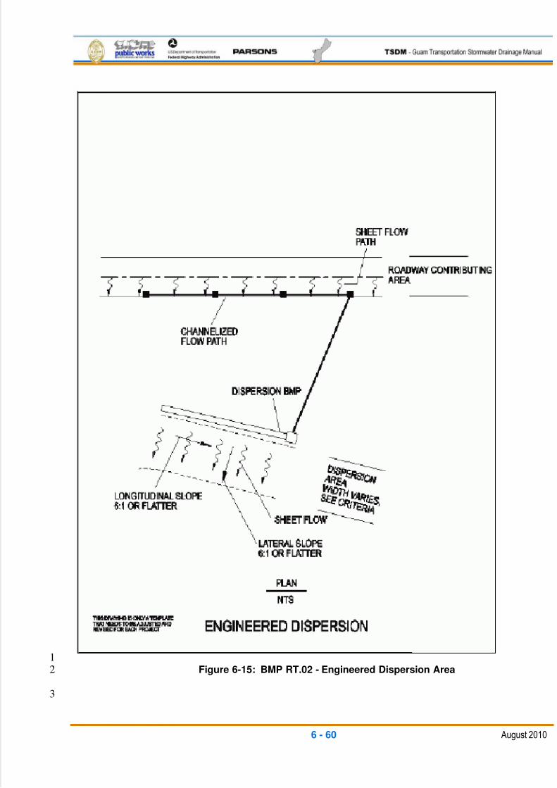
5/13/2018 Guam Storm Water Drainage Manual - slidepdf.com
http://slidepdf.com/reader/full/guam-storm-water-drainage-manual 196/486
6 - 60 August 2010
1Figure 6-15: BMP RT.02 - Engineered Dispersion Area2
3

5/13/2018 Guam Storm Water Drainage Manual - slidepdf.com
http://slidepdf.com/reader/full/guam-storm-water-drainage-manual 197/486
6 - 61 August 2010
6.4.3 DESIGN CRITERIA: BIOFILTRATION BMPS1
Biofiltration BMPs are discussed in this chapter and include the following:2
RT.03 – Vegetated Filter Strip (basic, narrow area, and compost-amended)3
RT.04 –Biofiltration Swale4
RT.05 –Wet Biofiltration Swale5
RT.06 – Continuous Inflow Biofiltration Swale6
RT.07 – Media Filter Drain7
6.4.3.1 RT.03: VEGETATED FILTER STRIP8
Vegetated filter strips are land areas of planted vegetation and amended soils situated9
between the pavement surface and a surface water collection system, pond, wetland,10
stream, or river. The term buffer strip is sometimes used interchangeably with vegetated11
filter strip, but in this TSDM, buffer strip refers to an area of natural indigenous12
vegetation that can be enhanced or preserved as part of a riparian buffer or stormwater13
dispersion system.14
Runoff treatment to remove pollutants can be best accomplished before concentrating15
the flow. A vegetated filter strip provides a very efficient and cost-effective runoff16
treatment option. Vegetated filter strips function by slowing runoff velocities and filtering17
out sediment and other pollutants, and by providing some infiltration into underlying18
soils.19
Vegetated filter strips consist of gradually sloping areas that run adjacent to the20
roadway. As highway runoff sheets off the roadway surface, it flows through the grass21filter. The flow can then be intercepted by a ditch or other conveyance system and22
routed to a flow control BMP or outfall.23
One challenge associated with vegetated filter strips is that sheet flow can sometimes be24
difficult to maintain. Consequently, vegetated filter strips can be short-circuited by25
concentrated flows, which create eroded rills or flow channels across the strips. This26
results in little or no treatment of stormwater runoff.27
The design approach for vegetated filter strips involves site design techniques to28
maintain prescribed maximum sheet flow distances as well as to ensure adequate29
temporary storage so that the design storm runoff is treated. There is limited ponding or30storage associated with vegetated filter strips unless soil amendments and sub-surface31
storage are incorporated into the design to reduce runoff volumes and peak discharges.32
Vegetated filter strips can also be used as a pre-treatment BMP in conjunction with33
infiltration BMPs. The sediment and particulate pollutant load that could reach the34
primary BMP is reduced by the pre-treatment, which in turn reduces maintenance costs35
and enhances the pollutant-removal capabilities of the primary BMP.36
5/13/2018 Guam Storm Water Drainage Manual - slidepdf.com
http://slidepdf.com/reader/full/guam-storm-water-drainage-manual 198/486
6 - 62 August 2010
There are three methods described in this section for designing vegetated filter strips:1
basic vegetated filter strips, Compost-Amended Vegetated Filter Strips (CAVFS), and2
narrow-area vegetated filter strips. The narrow-area vegetated filter strip is the simplest3
method to design; however, its use is limited to impervious flow paths less than 30 ft. If4
space is available to use the basic vegetated filter strip design or the CAVFS, either of5
the two designs should be used in preference to the narrow-area vegetated filter strip.6
For flow paths greater than 30 ft., designers should follow the design method for the7
basic vegetated filter strip or the CAVFS.8
The basic vegetated filter strip is a compacted roadside embankment that is9
subsequently hydroseeded. The CAVFS is a variation of the basic vegetated filter strip10
that adds soil amendments to the roadside embankment. The soil amendments improve11
infiltration characteristics, increase surface roughness, and improve plant sustainability.12
The CAVFS design incorporates compost into the native soils. The CAVFS bed should13
have a final organic content of 10 percent. Once permanent vegetation is established,14the advantages of the CAVFS are higher surface roughness, greater retention and15
infiltration capacity, improved removal of soluble cationic contaminants through sorption,16
improved overall vegetative health, and a reduction of invasive weeds.17
Compost-amended systems have somewhat higher construction costs due to more18
expensive materials, but require less land area for runoff treatment, which can reduce19
overall costs.20
Applications and Limitations21
Vegetated filter strips (narrow area, CAVFS, and basic) can be used to meet runoff22
quality treatment objectives or as part of a treatment train to provide pre-treatment for23removal of sediments.24
Applications 25
Vegetated filter strips can be effective in reducing sediments and the pollutants26
associated with sediments such as phosphorus, pesticides, or insoluble metallic27
salts.28
Because they do not pond water on the surface for long periods, vegetated filter29
strips help maintain the temperature norms of the water and deter the creation of30
habitat for disease vectors, such as mosquitoes.31
In less urbanized areas, vegetated filter strips can generally be located on existing32
roadside embankments, reducing the need for additional right-of-way acquisitions.33
Designs can be modified to reduce runoff volumes and peak flows when needed or34
desired to reduce right-of-way acquisitions.35
36
5/13/2018 Guam Storm Water Drainage Manual - slidepdf.com
http://slidepdf.com/reader/full/guam-storm-water-drainage-manual 199/486
6 - 63 August 2010
Limitations 1
If sheet flow cannot be maintained, vegetated filter strips will not be effective2
Vegetated filter strips are generally not suitable for steep slopes or large3
impervious areas that can generate high-velocity runoff4
The use of vegetated filter strips can be impracticable in watersheds where5
open land is scarce or expensive6
For most project applications where less than 10 ft. of roadside embankment7
is available for water quality treatment, the Media Filter Drain (MFD) (see8
BMP RT.07), is a more suitable BMP option9
Improper grading can render this BMP ineffective10
Design Flow Elements11
Flows To Be Treated 12
Vegetated filter strips must be designed to treat the runoff treatment flow rate13
discussed as part of Minimum Requirement 5 as defined in Chapter 3 of this TSDM,14
and the guidelines and criteria provided in this section.15
Design Criteria and Specifications16
Drainage Area Limitations 17
Vegetated filter strips are used to treat small drainage areas. Flow must enter the18
vegetated filter strip as sheet flow, spread out over the length (long dimension19
perpendicular to flow) of the strip, generally no deeper than 1 in. For basic vegetated20filter strips and CAVFS, the greatest flow path from the contributing area delivering21
sheet flow to the vegetated filter strip should not exceed 150 ft. For the narrow-area22
vegetated filter strip, the maximum contributing flow path should not exceed 30 ft.23
The longitudinal slope of the contributing drainage area parallel to the edge of24
pavement should be 2 percent or less. The lateral slope of the contributing drainage25
area perpendicular to the pavement edge should be 5 percent or less.26
Vegetated filter strips should be fully integrated within site designs, and should be27
constructed outside of the natural stream buffer area, whenever possible, to maintain28
a more natural buffer along the streambank.29
Vegetated Filter Strip Geometry 30
Vegetated filter strips must provide a minimum residence time of nine minutes for full31
water-quality treatment.32
Vegetated filter strips can be used for pre-treatment to another water quality BMP.33
Wherever a basic vegetated filter strip or CAVFS system cannot fit within the34
available space, a narrow area vegetated filter strip system can be used solely as a35
5/13/2018 Guam Storm Water Drainage Manual - slidepdf.com
http://slidepdf.com/reader/full/guam-storm-water-drainage-manual 200/486
6 - 64 August 2010
pre-treatment device. A narrow area design should have a minimum width of 4 ft.,1
and should take advantage of all available space.2
Basic vegetated filter strips should be designed for lateral slopes (along the direction3
of flow) between 2 percent and 15 percent. Steeper slopes encourage the4
development of concentrated flow; flatter slopes encourage standing water.5
Vegetated filter strips should not be used on soils that cannot sustain a dense grass6
cover with high flow retardance. In areas where lateral grades are between 157
percent and 25 percent, designers should consider using a CAVFS or an MFD (see8
BMP RT.07). The MFD will usually require less treatment area to achieve the water9
quality treatment objectives.10
The minimum width of the vegetated filter strip generally is dictated by the design11
method.12
Both the top and toe of the slope should be as flat as possible to encourage sheet13
flow and prevent erosion.14
The Manning‘s n to be used in the vegetated filter strip design calculations depends15
on the type of soil amendment and vegetation conditions used in construction of the16
vegetated filter strip (see Table 6-3).17
When the runoff treatment peak flow rate QWQ has been established, the design flow18
velocity can be estimated using Manning‘s Equation to calculate the width of the19
vegetated filter strip parallel to the direction of flow.20
Water Depth and Velocity 21
The maximum depth of sheet flow through a vegetated filter strip for the runoff22treatment design flow rate is 1.0 in. The maximum flow velocity for the runoff23
treatment design flow velocity is 0.5 ft. per second.24
Maintain Sheet Flow Conditions 25
Sheet flow conditions from the pavement into the vegetated filter strip should be26
maintained. A no-vegetation zone may help establish and maintain this condition.27
In areas where it may be difficult to maintain sheet flow conditions, consider using28
aggregate as a flow spreader. Aggregate should be placed between the pavement29
surface and the vegetated filter strip. The aggregate should meet the specifications30
for crushed base course listed in the Standard Specifications or other aggregate31should be used that provides the equivalent functionality.32
If there are concerns that water percolated within the aggregate flow spreader may33
exfiltrate into the highway prism, impervious geotextiles can be used to line the34
bottom of the aggregate layer.35
36
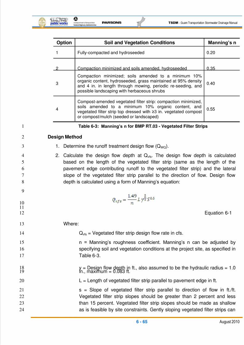
5/13/2018 Guam Storm Water Drainage Manual - slidepdf.com
http://slidepdf.com/reader/full/guam-storm-water-drainage-manual 201/486
6 - 65 August 2010
Option Soil and Vegetation Conditions Manning’s n
1 Fully-compacted and hydroseeded 0.20
2 Compaction minimized and soils amended, hydroseeded 0.35
3
Compaction minimized; soils amended to a minimum 10%organic content, hydroseeded, grass maintained at 95% densityand 4 in. in length through mowing, periodic re-seeding, andpossible landscaping with herbaceous shrubs
0.40
4
Compost-amended vegetated filter strip: compaction minimized,soils amended to a minimum 10% organic content, andvegetated filter strip top dressed with ≥3 in. vegetated compostor compost/mulch (seeded or landscaped)
0.55
Table 6-3: Manning’s n for BMP RT.03 - Vegetated Filter Strips1
Design Method2
1. Determine the runoff treatment design flow (QWQ).3
2. Calculate the design flow depth at Qvfs. The design flow depth is calculated4
based on the length of the vegetated filter strip (same as the length of the5
pavement edge contributing runoff to the vegetated filter strip) and the lateral6
slope of the vegetated filter strip parallel to the direction of flow. Design flow7
depth is calculated using a form of Manning‘s equation: 8
9
1011
Equation 6-112
Where:13
Qvfs = Vegetated filter strip design flow rate in cfs.14
n = Manning‘s roughness coefficient. Manning‘s n can be adjusted by15
specifying soil and vegetation conditions at the project site, as specified in16
Table 6-3.17
y = Design flow depth in ft., also assumed to be the hydraulic radius = 1.018in., maximum = 0.083 ft.19
L = Length of vegetated filter strip parallel to pavement edge in ft.20
s = Slope of vegetated filter strip parallel to direction of flow in ft./ft.21
Vegetated filter strip slopes should be greater than 2 percent and less22
than 15 percent. Vegetated filter strip slopes should be made as shallow23
as is feasible by site constraints. Gently sloping vegetated filter strips can24
5/13/2018 Guam Storm Water Drainage Manual - slidepdf.com
http://slidepdf.com/reader/full/guam-storm-water-drainage-manual 202/486
6 - 66 August 2010
produce the required residence time for runoff treatment using less space1
than steeper vegetated filter strips.2
Rearranging Equation 6-1 to solve for y yields:3
45
Equation 6-2 6
If the calculated depth y is greater than 1 in., either adjust the vegetated filter7
strip geometry or use other runoff treatment BMPs.8
3. Calculate the design flow velocity passing through the vegetated filter strip at the9
vegetated filter strip design flow rate. The design flow velocity (VWQ) is based on10
the vegetated filter strip design flow rate, the length of the vegetated filter strip,11and the calculated design flow depth from Step 2:12
1314
Equation 6-3 15
Where:16
VWQ = Design flow velocity in ft./s17
y = Design flow depth in ft.18
19
4. Calculate the vegetated filter strip width. The width of the vegetated filter strip is20
determined by the residence time of the flow through the vegetated filter strip. A21
nine-minute (540-second) residence time is used to calculate vegetated filter strip22
width:23
2425
Where:26
W = Vegetated filter strip width in ft.27
T = Time in s28
VWQ = Design flow velocity in ft./s29
A minimum width of 8 ft. is recommended in order to ensure the long-term30
effectiveness of the vegetated filter strip.31
5/13/2018 Guam Storm Water Drainage Manual - slidepdf.com
http://slidepdf.com/reader/full/guam-storm-water-drainage-manual 203/486
6 - 67 August 2010
Narrow Area Vegetated Filter Strip1
As previously discussed, narrow-area vegetated filter strips are limited to impervious2
flow paths less than 30 ft. For flow paths greater than 30 ft., designers should follow the3
basic vegetated filter strip guidelines. The sizing of a narrow-area vegetated filter strip is4
based on the width of the roadway surface parallel to the flow path of the vegetated filter5
strip and the lateral slope of the vegetated filter strip.6
1. Determine the width of the roadway surface parallel to the flow path 7
draining to the vegetated filter strip. Determine the width of the roadway8
surface parallel to the flow path from the upstream to the downstream edge of9
the impervious area draining to the vegetated filter strip. This is the same as the10
width of the paved area.11
2. Determine the average lateral slope of the vegetated filter strip. Calculate12
the lateral slope of the vegetated filter strip (parallel to the flow path), averaged13
over the total length of the vegetated filter strip. If the slope is less than14
2 percent, use 2 percent for sizing purposes. The maximum lateral slope allowed15
is 15 percent.16
3. Determine the required width of the vegetated filter strip. Use Figure 6-16 to17
size the vegetated filter strip. Locate the width of the impervious surface parallel18
with the flow path on one of the curves; interpolate between curves as19
necessary. Next, move along the curve to the point where the design lateral20
slope of the vegetated filter strip is directly below. Read the vegetated filter strip21
width to the left on the y axis. The vegetated filter strip must be designed to22
provide this minimum width, W, along the entire stretch of pavement draining to23it.24
Materials25
Vegetation 26
Vegetated filter strips should be planted with grass that can withstand relatively high-27
velocity flows as well as wet and dry periods. Filter strips may also incorporate native28
vegetation such as small herbaceous shrubs to make the system more effective in29
treating runoff and providing root penetration into subsoils, thereby enhancing30
infiltration. Use NRCS or DAWR recommendations for a mix of grasses and plants31
suitable for the project site.32
Site Design Elements33
Maintenance Access Roads (Access Requirements) 34
Access should be provided at the upper edge of all vegetated filter strips to enable35
maintenance of the gravel flow spreader and permit lawnmower entry to the36
vegetated filter strip.37
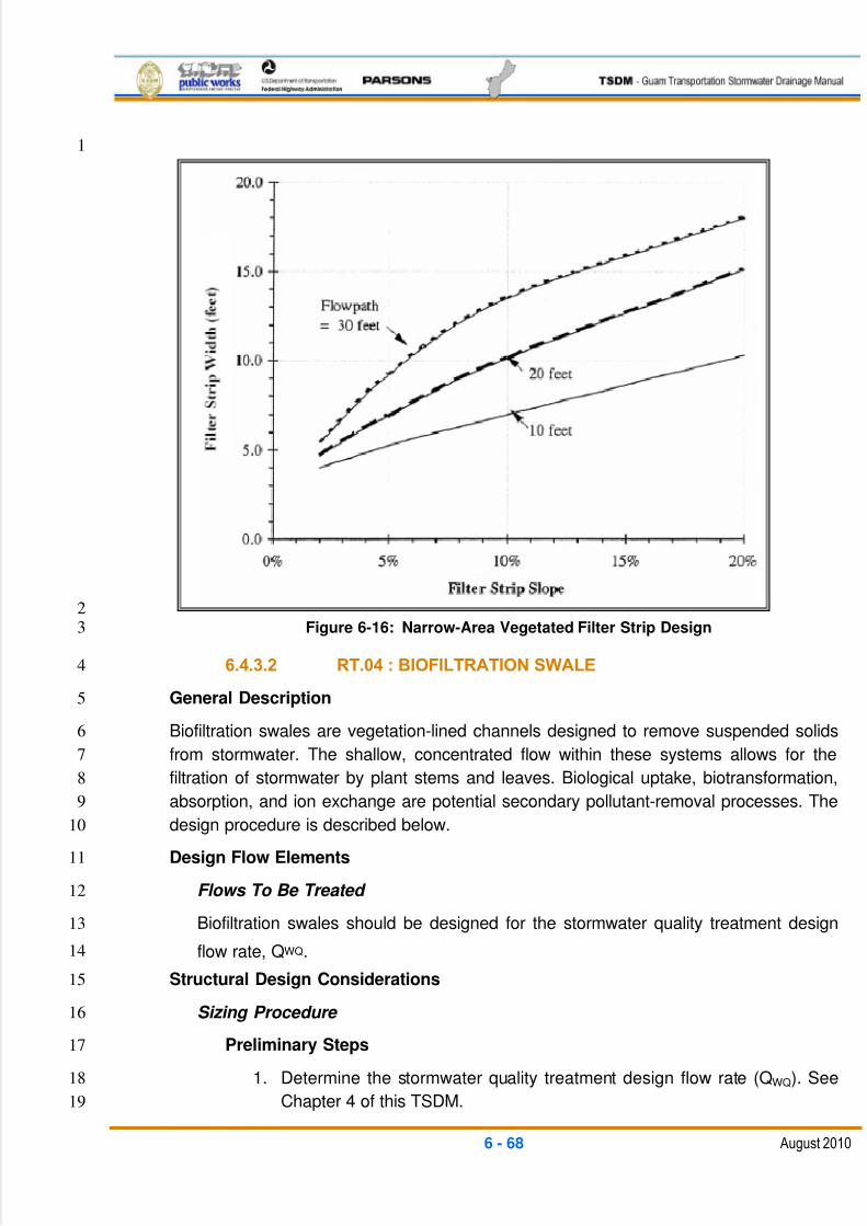
5/13/2018 Guam Storm Water Drainage Manual - slidepdf.com
http://slidepdf.com/reader/full/guam-storm-water-drainage-manual 204/486
6 - 68 August 2010
1
2Figure 6-16: Narrow-Area Vegetated Filter Strip Design3
6.4.3.2 RT.04 : BIOFILTRATION SWALE4
General Description5
Biofiltration swales are vegetation-lined channels designed to remove suspended solids6
from stormwater. The shallow, concentrated flow within these systems allows for the7
filtration of stormwater by plant stems and leaves. Biological uptake, biotransformation,8
absorption, and ion exchange are potential secondary pollutant-removal processes. The9
design procedure is described below.10
Design Flow Elements11
Flows To Be Treated 12
Biofiltration swales should be designed for the stormwater quality treatment design13
flow rate, QWQ.14
Structural Design Considerations15
Sizing Procedure 16
Preliminary Steps17
1. Determine the stormwater quality treatment design flow rate (QWQ). See18
Chapter 4 of this TSDM.19
5/13/2018 Guam Storm Water Drainage Manual - slidepdf.com
http://slidepdf.com/reader/full/guam-storm-water-drainage-manual 205/486
6 - 69 August 2010
2. Select a suitable site location having suitable grade and topographic1
characteristics. 2
3. Establish the longitudinal slope of the proposed biofiltration swale (see3
Table 6-5 for criteria).4
4. Select a soil and vegetation cover suitable for the biofiltration swale. The5
grass seed mix and planting requirements should be selected based on6
NRCS or DAWR recommendations per site and seasonal conditions.7
Design Steps8
5. Select a trial depth of flow, Y (see Table 6-5).9
6. Select a trial swale cross-sectional width.10
7. Use Manning‘s Equation (Equation 6-5) to make an initial approximation11
relating hydraulic radius and dimensions for the selected swale shape.12
Use trial and error for various values of ‗Y‘ and ‗b‘ until Qbiofl = QWQ:13
1415
Equation 6-416
Where:17
Qbiofil = Swale flow rate in cfs18
A = Wetted area in ft.2 19
R = A/P = Hydraulic radius in ft.20
P = Wetted perimeter in ft.21
s = Longitudinal slope of swale in ft./ft.22
n = Manning‘s coefficient (see Table 6-4)23
Y = Swale flow depth in ft.24
b = Swale bottom width in ft.25
8. Compute the flow velocity at Qbiofil:26
2728
Equation 6-5 29
Where:30
Vbiofil = Flow velocity at Qbiofil in ft./s31
5/13/2018 Guam Storm Water Drainage Manual - slidepdf.com
http://slidepdf.com/reader/full/guam-storm-water-drainage-manual 206/486
6 - 70 August 2010
If Vbiofil > 1.0 ft./s, increase width (b) or investigate ways to reduce Qwq,1
and then repeat steps 3, 4, and 5 until Vbiofil ≤ 1.0 ft./s. A velocity greater2
than 1.0 ft./s will flatten grasses, thus reducing filtration.3
9. Compute the swale length, L in ft.:4
5
L = V biofil t (60 s/min.) 6
Equation 6-6 7
Where:8
t = Hydraulic residence time (a minimum of nine minutes. for basic9
biofiltration swales)10
10. If there is not sufficient space for the biofiltration swale, consider the11
following solutions:12
Divide the site drainage to flow to multiple biofiltration swales13
Use infiltration or dispersion to provide lower QWQ 14
Alter the design depth of flow if possible (see Table 6-5)15
Reduce the developed surface area to gain space for the16
biofiltration swale17
Reduce the longitudinal slope by meandering the biofiltration18
swale19
Nest the biofiltration swale within or around another stormwater20
BMP21
22
23
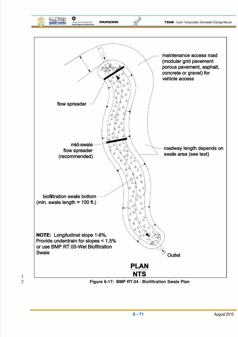
5/13/2018 Guam Storm Water Drainage Manual - slidepdf.com
http://slidepdf.com/reader/full/guam-storm-water-drainage-manual 207/486
6 - 71 August 2010
1Figure 6-17: BMP RT.04 - Biofiltration Swale Plan2
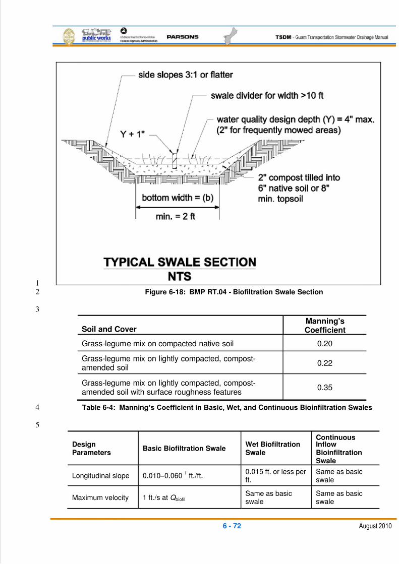
5/13/2018 Guam Storm Water Drainage Manual - slidepdf.com
http://slidepdf.com/reader/full/guam-storm-water-drainage-manual 208/486
6 - 72 August 2010
1Figure 6-18: BMP RT.04 - Biofiltration Swale Section2
3
Soil and CoverManning'sCoefficient
Grass-legume mix on compacted native soil 0.20
Grass-legume mix on lightly compacted, compost-amended soil
0.22
Grass-legume mix on lightly compacted, compost-amended soil with surface roughness features
0.35
Table 6-4: Manning’s Coefficient in Basic, Wet, and Continuous Bioinfiltration Swales4
5
DesignParameters
Basic Biofiltration Swale Wet BiofiltrationSwale
ContinuousInflowBioinfiltrationSwale
Longitudinal slope 0.010 –0.0601
ft./ft.0.015 ft. or less perft.
Same as basicswale
Maximum velocity 1 ft./s at Q biofilSame as basicswale
Same as basicswale
5/13/2018 Guam Storm Water Drainage Manual - slidepdf.com
http://slidepdf.com/reader/full/guam-storm-water-drainage-manual 209/486
6 - 73 August 2010
DesignParameters
Basic Biofiltration Swale Wet BiofiltrationSwale
ContinuousInflowBioinfiltrationSwale
Maximum waterdepth at Q biofil , ‗Y‘
2 in. if swale mowedfrequently; 4 in. if mowedinfrequently or inconsistently.For dry land grasses, setdepth to 3 in.
4 in.Same as basicswale
Manningcoefficient, ‗n‘, atQ biofil
See Table 6-4 Same as basicswale
Same as basicswale
Bed width, ‗b‘ 2ft.2- 10 ft.
22 ft. - 25 ft.
Same as basicswale
Freeboard height1 ft. for the peak conveyanceflow rate (Q convey)
3Same as basicswale
Same as basicswale
Minimum length, ‗L‘ 100 ft. Same as basicswale
Same as basicswale
Maximum sideslope(for trapezoidalcross section)
3H:1VSame as basicswale
Same as basicswale
Table 6-5: Bioinfiltration Swale Sizing Criteria1
1. For basic biofiltration swale on slopes less than 1.5 percent, install an underdrain system (see Figure 6-219)3
Backfill should be covered by at least 4 in. of amended soil or topsoil. Install the low-flow drain 6 in. deep in4the soil (see Figure 6-19). Underdrains can be made of 6-in. Schedule 40 PVC perforated pipe with 6 in. of5drain gravel on the pipe. The gravel and pipe must be enclosed by geotextile fabric. The pipe outlet should6be protected from erosion.7
2. Multiple parallel swales can be constructed when the calculated swale bottom width exceeds 10 ft. using a8divider berm or concrete curb.9
3. Q convey should be based on the peak capacity of the incoming conveyance system to the biofiltration10swale. For off-line bioswales, this will be the design QWQ. For on-line bioswales this should be the maximum11capacity of the conveyance system, but not less than Q25-yr. 12
13
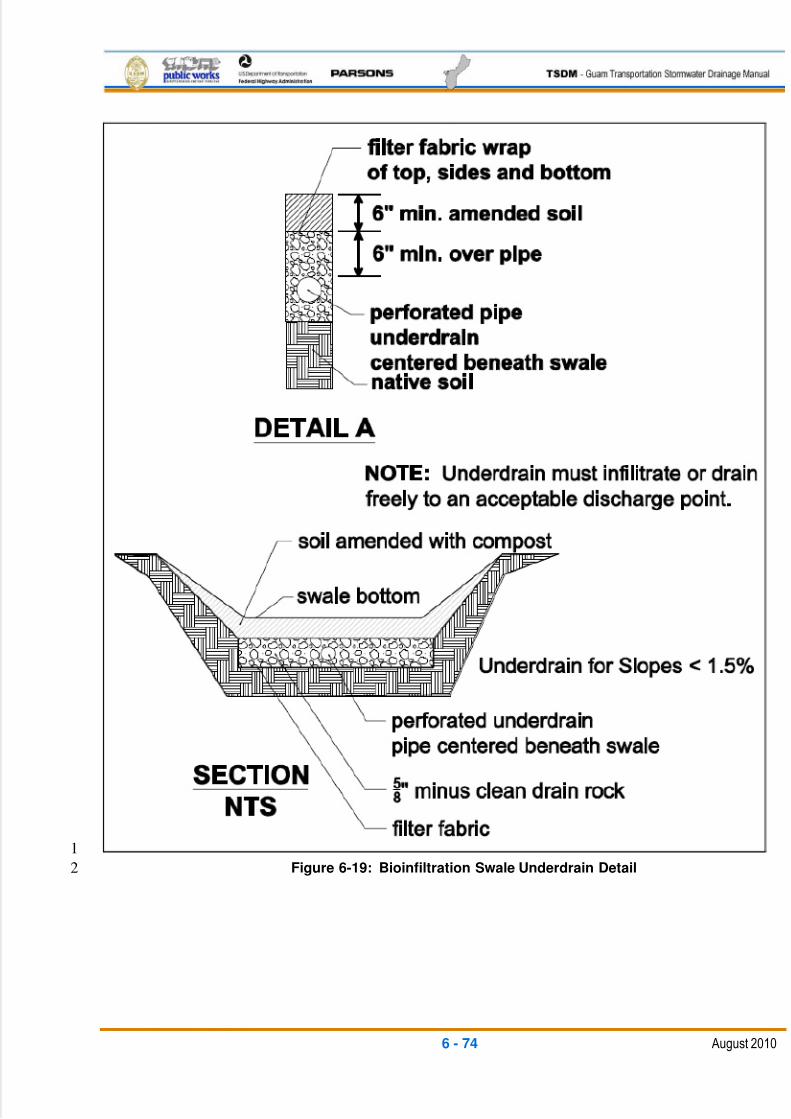
5/13/2018 Guam Storm Water Drainage Manual - slidepdf.com
http://slidepdf.com/reader/full/guam-storm-water-drainage-manual 210/486
6 - 74 August 2010
1
Figure 6-19: Bioinfiltration Swale Underdrain Detail2

5/13/2018 Guam Storm Water Drainage Manual - slidepdf.com
http://slidepdf.com/reader/full/guam-storm-water-drainage-manual 211/486
6 - 75 August 2010
1Figure 6-20: Bioinfiltration Swale Details2
3
5/13/2018 Guam Storm Water Drainage Manual - slidepdf.com
http://slidepdf.com/reader/full/guam-storm-water-drainage-manual 212/486
6 - 76 August 2010
Freeboard Check (FC)1
A Freeboard Check (FC) must be performed for the combination of highest expected2
flow and least vegetation coverage and height. The FC is not necessary for biofiltration3
swales that are located off-line from the primary conveyance and detention system (that4
is, when flows in excess of QWQ bypass the biofiltration swale). Off-line is the preferred5
configuration of biofiltration swales. Ensure swale depth exceeds flow depth at Q convey by6
a minimum of 1 ft. (1-ft. minimum freeboard).7
Site Design Elements8
Install level spreaders at the head of the biofiltration swale in swales that are 6 ft. or9
greater in bottom width. Include sediment cleanouts at the head of the swale as needed.10
It is recommended that swales with a bottom width in excess of 6 ft. or greater have a11
level spreader for every 50 ft. of swale length.12
Use energy dissipaters for swales on longitudinal slopes exceeding 2.5 percent.13Specify that topsoil extends to at least an 8-in. depth, unless an underdrain system is14
needed (see Table 6-5).15
To improve infiltration on longitudinal slopes less than 1.5 percent, ensure the swale bed16
material contains a sand percentage greater than 70 percent (greater than 70 percent by17
weight retained on the No. 40 sieve) before organic amendments are added.18
Provide an access road for maintenance vehicles. The width of access should normally19
be 20 ft., but in no case should it be less than 12 ft. The access road should be surfaced20
with a permeable surface suitable for heavier vehicular loadings such as crushed gravel,21
vegetative paver blocks, or permeable pavement. The access road should provide22access for cleaning the inlet structures and extend along one side of the swale. The23
length of the access road should be at least one-half of the length of the swale to24
accommodate removal of accumulated sediments in the upper area.25
Landscaping (Planting Considerations) 26
Select grasses suitable for the site conditions in accordance with DAWR‘s27
recommendations28
Select fine, turf-forming grasses where moisture is appropriate for growth29
Plant wet-tolerant species for wet site locations30
Stabilize soil areas upslope of the biofiltration swale to prevent erosion and31
excessive sediment deposition32
Apply seed using a hydroseeder or broadcaster33
34
35
5/13/2018 Guam Storm Water Drainage Manual - slidepdf.com
http://slidepdf.com/reader/full/guam-storm-water-drainage-manual 213/486
6 - 77 August 2010
Construction Criteria 1
Do not put the biofiltration swale into operation until areas of exposed soil in2
the contributing drainage catchment have been sufficiently stabilized3
Keep effective erosion and sediment control measures in place until the4swale vegetation is established5
Avoid over-compaction during construction6
Grade biofiltration swales to attain uniform longitudinal and lateral slopes7
6.4.3.3 RT.05: WET BIOFILTRATION SWALE8
General Description9
A wet biofiltration swale is a variation of a basic biofiltration swale for use where the10
longitudinal slope is slight, water tables are high, or continuous base flow is likely to11
result in saturated soil conditions. Where saturation exceeds about two continuous12weeks, typical grasses die; so vegetation specifically adapted to saturated soil conditions13
is needed. This type of vegetation, in turn, requires modification of several of the design14
parameters for the basic biofiltration swale to remove low concentrations of pollutants,15
such as sediments, heavy metals, nutrients, and petroleum hydrocarbons.16
Applications and Limitations17
Wet biofiltration swales are applied where a basic biofiltration swale is desired but not18
allowed or advisable because of one or more of the following conditions:19
The swale is on thin soils with low permeability on flat slopes20
The swale is downstream of a detention pond providing flow control21
Saturated soil conditions are likely because of seeps, high groundwater, or base22
flows on the site23
Longitudinal slopes are slight (generally less than 1.5 percent), and ponding is24
likely25
Design Flow Elements26
Flows To Be Treated 27
Wet biofiltration swales should be designed to treat the runoff treatment flow rate28discussed as part of Minimum Requirement 5 as defined in Chapter 3 of this TSDM.29
Overflow or Bypass 30
To accommodate flows exceeding the stormwater quality treatment flow rate, the31
following two design options are available:32
5/13/2018 Guam Storm Water Drainage Manual - slidepdf.com
http://slidepdf.com/reader/full/guam-storm-water-drainage-manual 214/486
6 - 78 August 2010
1. A high-flow bypass can be installed for flows greater than the runoff treatment1
design flow to protect wetland vegetation from damage. Unlike grass, wetland2
vegetation does not quickly regain an upright attitude after being flattened by3
high flows. New growth, usually from the base of the plant and often taking4
several weeks, is required for the grass to regain its upright form. The bypass5
may be a flow-splitter structure for a storm drain system, or an overflow type6
open channel parallel to the wet biofiltration swale.7
2. Alternatively, swale bottom width may be tripled to accommodate high flows.8
The following features must be included:9
An energy dissipater and level spreader must be set at the head of the10
swale to ensure the equal distribution of influent and reduce the potential11
for scour. Gravel filter berms must be placed every 30 ft. across the full12
width of the swale. The minimum required swale length should not include13
the length occupied by gravel filter berms.14
If the calculated width to convey high flows exceeds 25 ft., then a high15
flow channel with a bed elevation 0.5 ft. above the swale depth can be16
constructed. The high-flow channel can be either planted or rock-lined.17
Structural Design Considerations18
Geometry 19
Use the same design approach as for basic biofiltration swales, except add the20
following:21
Extended wet season flow adjustment. If the swale is downstream of a22detention pond providing flow control, multiply the treatment area (bottom width23
times length) of the swale by two and readjust the swale length or width to24
provide an equivalent area. Maintain a 5:1 length-to-width ratio.25
Intent: The treatment area of swales following detention ponds needs to be 26
increased because of the differences in vegetation established in a constant flow 27
environment. Flows following detention are much more prolonged. These 28
prolonged flows result in more stream-like conditions than are typical for other 29
wet biofiltration situations. Because vegetation growing in streams is often less 30
dense, an increase in treatment area is needed to ensure equivalent pollutant 31
removal is achieved in extended flow situations.32
Swale geometry. Use the same geometry specified for basic biofiltration swales33
(see Table 6-5), except for the following modifications:34
The bottom width may be increased to 25 ft. maximum, but a length-to35
width ratio of 5:1 must be maintained. No longitudinal dividing berm is36
needed. Note: The minimum swale length is 100 ft.37
5/13/2018 Guam Storm Water Drainage Manual - slidepdf.com
http://slidepdf.com/reader/full/guam-storm-water-drainage-manual 215/486
6 - 79 August 2010
If longitudinal slopes are greater than 1.5 percent, the wet swale must be1
stepped so that the slope within the stepped sections averages 1.52
percent or less. Steps may be made of concrete or block walls, short3
riprap sections, or similar structures. Steps must be designed to prevent4
scour or undermining on the downstream side of the step. No underdrain5
or low-flow drain is required.6
Water depth and base flow. Use the same criteria specified for basic7
biofiltration swales, except that the design water depth must be 4 in. for all8
wetland vegetation selections, and no underdrains or low-flow drains are9
required.10
Flow velocity, energy dissipation, and flow spreading. Use the same criteria11
specified for basic biofiltration swales.12
Site Design Elements13
Landscaping (Planting Considerations) 14
Use the same design considerations specified for basic biofiltration swales, except15
for the following modifications:16
In general, it is best to plant several species to increase the likelihood that at17
least some of the selected species will find growing conditions favorable.18
A wetland seed mix may be applied by hydroseeding, but if coverage is poor,19
planting rootstock or nursery stock is required. Poor coverage is considered20
to be more than 30 percent bare area through the upper two-thirds of the21
swale after four weeks.22
Use plant species suitable for a wetland environment in accordance with23
NRCS or DAWR recommendations.24
Construction Considerations 25
Use the same construction considerations specified for basic biofiltration swales.26
27
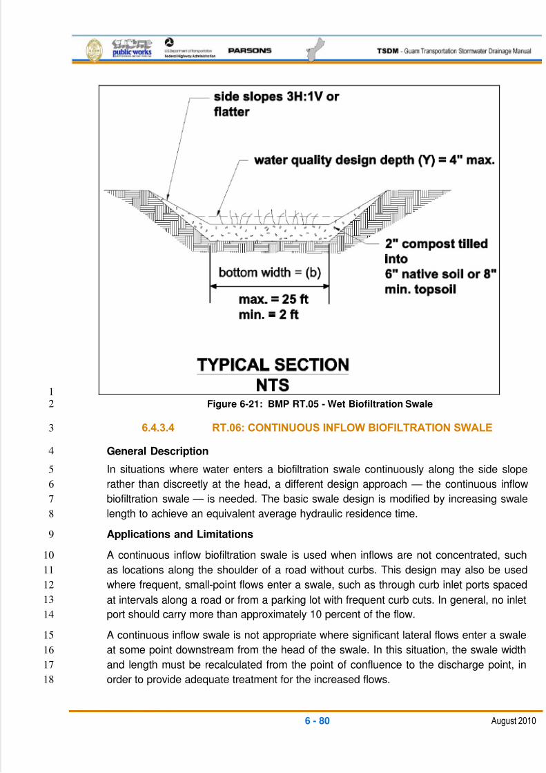
5/13/2018 Guam Storm Water Drainage Manual - slidepdf.com
http://slidepdf.com/reader/full/guam-storm-water-drainage-manual 216/486
6 - 80 August 2010
1Figure 6-21: BMP RT.05 - Wet Biofiltration Swale2
6.4.3.4 RT.06: CONTINUOUS INFLOW BIOFILTRATION SWALE3
General Description4
In situations where water enters a biofiltration swale continuously along the side slope5
rather than discreetly at the head, a different design approach — the continuous inflow6
biofiltration swale — is needed. The basic swale design is modified by increasing swale7
length to achieve an equivalent average hydraulic residence time.8
Applications and Limitations9
A continuous inflow biofiltration swale is used when inflows are not concentrated, such10
as locations along the shoulder of a road without curbs. This design may also be used11
where frequent, small-point flows enter a swale, such as through curb inlet ports spaced12
at intervals along a road or from a parking lot with frequent curb cuts. In general, no inlet13
port should carry more than approximately 10 percent of the flow.14
A continuous inflow swale is not appropriate where significant lateral flows enter a swale15
at some point downstream from the head of the swale. In this situation, the swale width16
and length must be recalculated from the point of confluence to the discharge point, in17
order to provide adequate treatment for the increased flows.18
5/13/2018 Guam Storm Water Drainage Manual - slidepdf.com
http://slidepdf.com/reader/full/guam-storm-water-drainage-manual 217/486
6 - 81 August 2010
Design Considerations 1
Use the same considerations specified for BMP RT.04 –Biofiltration Swale (see2
Table 6-5), except for the following:3
For the design flow, include runoff from the pervious side slopes draining to4the swale along the entire swale length.5
If only a single design flow is used, use the flow rate at the outlet. The goal is6
to achieve an average residence time through the swale of nine minutes.7
Assuming an even distribution of inflow into the side of the swale, double the8
hydraulic residence time to a minimum of 18 minutes.9
For continuous inflow biofiltration swales, plant interior side slopes above the10
runoff treatment design elevation in grass. Landscape plants or groundcovers11
other than grass generally should not be used between the runoff inflow12
elevation and the bottom of the swale.13
Intent: The use of grass on interior side slopes reduces the chance of soil erosion 14
and transfer of pollutants from landscape areas to the biofiltration treatment area.15
After the cross-sectional size of the biofiltration swale is determined using Q biofil,16
complete the following steps. This is to account for the hydraulic residence time of17
flow moving through the vegetated side slopes (3H:1V or shallower and slope length18
>5 ft.) at various points along the length of the swale.19
1. Break the drainage basin of the swale into areas so that no area contributes20
more than 20 percent of the flow. Include only those areas that discharge21
sheet flow to the vegetated side slopes and biofiltration swale.22
2. Determine the velocity of flows through each vegetated side slope, Vn,ss (feet23
per second), for each of the contributing areas by completing steps 124
through 3 of the vegetated filter strip design methodology.25
3. Determine the hydraulic residence time within each vegetated side slope, tss26
(second), for each area using:27
Ln,ss /Vn,ss = tn,ss 28
Where:29
Ln,ss = Length of vegetated side slope of the nth swale sub-basin in ft.30
4. Determine the weighted mean hydraulic residence time, tmean,ss, for all flows31
passing through vegetated side slopes using:32
[Q1(tss,1)+Q2(tss,2 )+….+Qn(tss,n )]/Qtotal,ss= tmean,ss 33
34
35
5/13/2018 Guam Storm Water Drainage Manual - slidepdf.com
http://slidepdf.com/reader/full/guam-storm-water-drainage-manual 218/486
6 - 82 August 2010
Where:1
Qn = Flow rate for nth contributing area in cfs2
Qtotal,ss = Total flow that passes through all of the vegetated side3
slopes in cfs4
5. Multiply tmean,ss by R5
Where:6
tmean,ss x R = tadj 7
R = Qtotal,ss / Qbiofil 8
Qbiofil = QWQ (for the properly-sized swale section)9
6. If the head of the swale is located downstream of the last contributing10
vegetated side slope section, subtract tadj from 540 seconds (= nine minutes)11
to determine the tdesign. If the swale is located along the entire toe of the12
contributing vegetated side slope, subtract tadj from 1,080 seconds (=1813
minutes) to determine tdesign. Note: In the latter case, the swale must be at14
least as long as the contributing vegetated side slopes.15
7. Using the downstream flow rate (Qbiofil), determine the velocity through the16
swale, and use tdesign, calculated in Step 6, to determine the total swale length17
required. Make any necessary adjustments to ensure the criteria in Table 6-518
are met.19
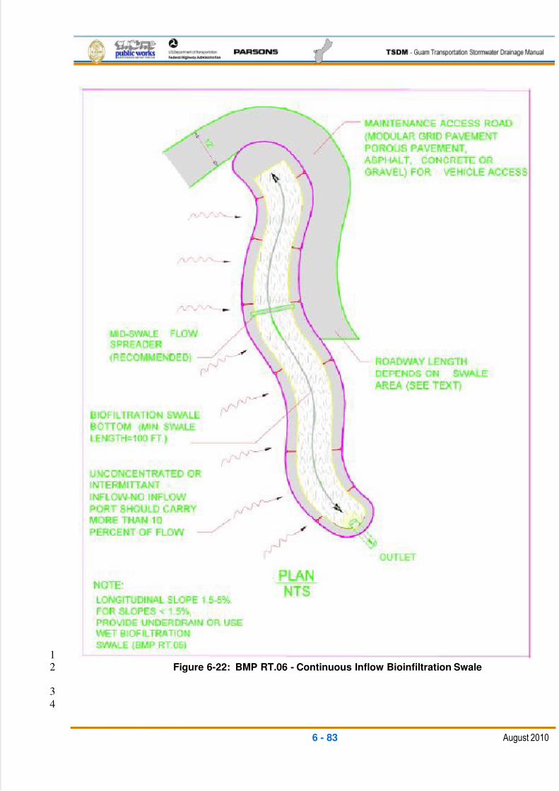
5/13/2018 Guam Storm Water Drainage Manual - slidepdf.com
http://slidepdf.com/reader/full/guam-storm-water-drainage-manual 219/486
6 - 83 August 2010
1Figure 6-22: BMP RT.06 - Continuous Inflow Bioinfiltration Swale2
3
4
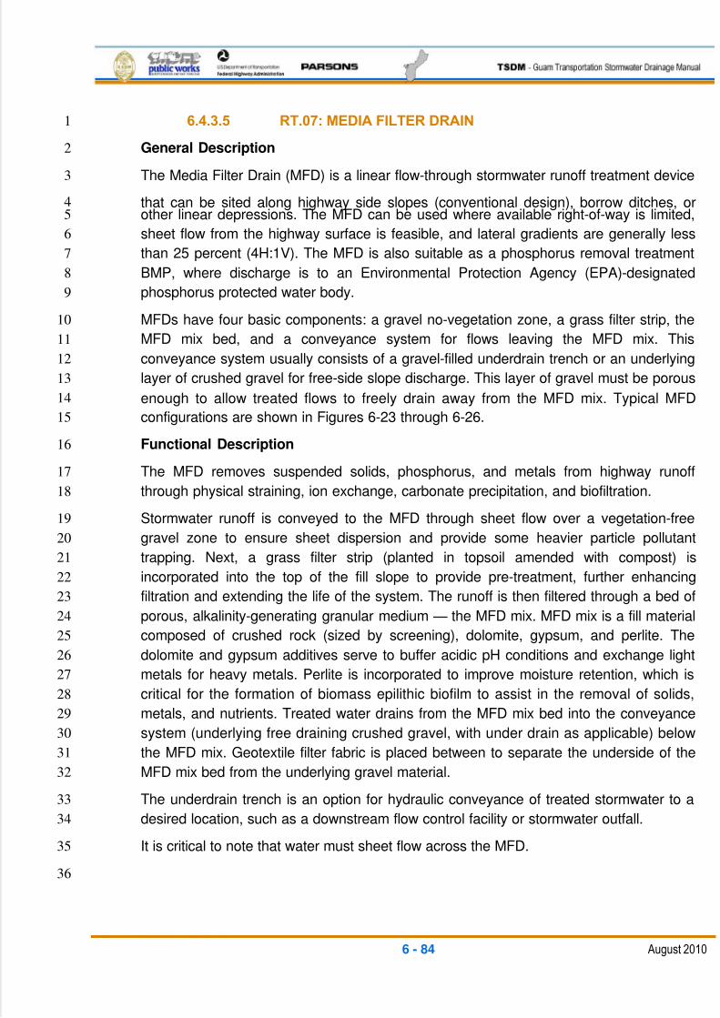
5/13/2018 Guam Storm Water Drainage Manual - slidepdf.com
http://slidepdf.com/reader/full/guam-storm-water-drainage-manual 220/486
6 - 84 August 2010
6.4.3.5 RT.07: MEDIA FILTER DRAIN1
General Description2
The Media Filter Drain (MFD) is a linear flow-through stormwater runoff treatment device3
that can be sited along highway side slopes (conventional design), borrow ditches, or4other linear depressions. The MFD can be used where available right-of-way is limited,5
sheet flow from the highway surface is feasible, and lateral gradients are generally less6
than 25 percent (4H:1V). The MFD is also suitable as a phosphorus removal treatment7
BMP, where discharge is to an Environmental Protection Agency (EPA)-designated8
phosphorus protected water body.9
MFDs have four basic components: a gravel no-vegetation zone, a grass filter strip, the10
MFD mix bed, and a conveyance system for flows leaving the MFD mix. This11
conveyance system usually consists of a gravel-filled underdrain trench or an underlying12
layer of crushed gravel for free-side slope discharge. This layer of gravel must be porous13
enough to allow treated flows to freely drain away from the MFD mix. Typical MFD14
configurations are shown in Figures 6-23 through 6-26.15
Functional Description16
The MFD removes suspended solids, phosphorus, and metals from highway runoff17
through physical straining, ion exchange, carbonate precipitation, and biofiltration.18
Stormwater runoff is conveyed to the MFD through sheet flow over a vegetation-free19
gravel zone to ensure sheet dispersion and provide some heavier particle pollutant20
trapping. Next, a grass filter strip (planted in topsoil amended with compost) is21
incorporated into the top of the fill slope to provide pre-treatment, further enhancing22
filtration and extending the life of the system. The runoff is then filtered through a bed of23
porous, alkalinity-generating granular medium — the MFD mix. MFD mix is a fill material24
composed of crushed rock (sized by screening), dolomite, gypsum, and perlite. The25
dolomite and gypsum additives serve to buffer acidic pH conditions and exchange light26
metals for heavy metals. Perlite is incorporated to improve moisture retention, which is27
critical for the formation of biomass epilithic biofilm to assist in the removal of solids,28
metals, and nutrients. Treated water drains from the MFD mix bed into the conveyance29
system (underlying free draining crushed gravel, with under drain as applicable) below30
the MFD mix. Geotextile filter fabric is placed between to separate the underside of the31
MFD mix bed from the underlying gravel material.32
The underdrain trench is an option for hydraulic conveyance of treated stormwater to a33
desired location, such as a downstream flow control facility or stormwater outfall.34
It is critical to note that water must sheet flow across the MFD.35
36
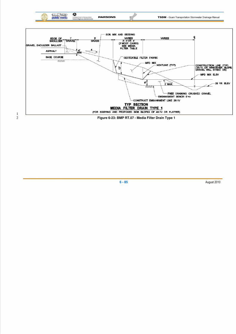
5/13/2018 Guam Storm Water Drainage Manual - slidepdf.com
http://slidepdf.com/reader/full/guam-storm-water-drainage-manual 221/486
6 - 85 August 2010
1Figure 6-23: BMP RT.07 - Media Filter Drain Type 12
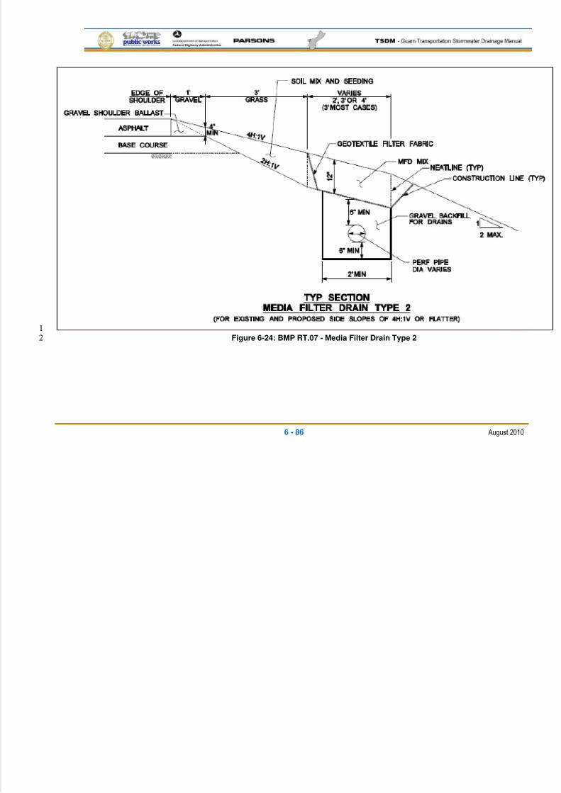
5/13/2018 Guam Storm Water Drainage Manual - slidepdf.com
http://slidepdf.com/reader/full/guam-storm-water-drainage-manual 222/486
6 - 86 August 2010
1Figure 6-24: BMP RT.07 - Media Filter Drain Type 22
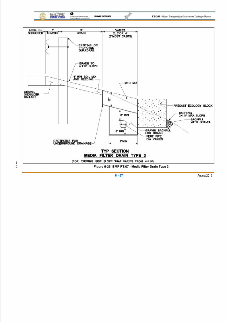
5/13/2018 Guam Storm Water Drainage Manual - slidepdf.com
http://slidepdf.com/reader/full/guam-storm-water-drainage-manual 223/486
6 - 87 August 2010
1Figure 6-25: BMP RT.07 - Media Filter Drain Type 32
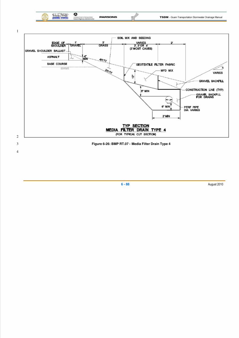
5/13/2018 Guam Storm Water Drainage Manual - slidepdf.com
http://slidepdf.com/reader/full/guam-storm-water-drainage-manual 224/486
6 - 88 August 2010
1
2
Figure 6-26: BMP RT.07 - Media Filter Drain Type 43
4
5/13/2018 Guam Storm Water Drainage Manual - slidepdf.com
http://slidepdf.com/reader/full/guam-storm-water-drainage-manual 225/486
6 - 89 August 2010
Applications and Limitations1
Applications 2
Media Filter Drains3
The MFD can achieve basic, phosphorus, and enhanced water quality treatment.4
Because maintaining sheet flow across the MFD is required for its proper5
function, the ideal locations for MFDs in highway settings are highway side6
slopes or other long, linear grades with lateral side slopes less than 4H:1V and7
longitudinal slopes no steeper than 5 percent. As side slopes approach 3H:1V,8
without design modifications, sloughing may become a problem due to friction9
limitations between the separation geotextile and underlying soils. The longest10
flow path from the contributing area delivering sheet flow to the MFD should not11
exceed 150 ft.12
Four typical applications are shown in Figures 6-23 through 6-26. Figure 6-2313(Type 1) shows the typical installation for roadways that have a roadside ditch for14
stormwater conveyance. The design stormwater level in the ditch should be15
below the media filter mix; otherwise, erosion of the mix and flushing of the16
trapped contaminates may occur.17
Figure 6-24 (Type 2) shows the typical application where flow from the media18
filter mix needs to be collected and transported by perforated pipe to a separate19
storm drain, outfall, or detention facility.20
Figure 6-25 (Type 3) is where a MFD needs to be installed on an existing side21
slope that is less than 4H:1V. Figure 6-26 (Type 4) is the typical situation for a22
roadway in a cut slope condition, where there is no room for a conventional edge23
of road drainage ditch. For this condition, the underdrain must be sized for not24
only the roadway runoff, but the back slope and any off-site runoff as well.25
Note that the underdrain section can be sized to act as an infiltration trench for26
the Types 2, 3 and 4 media filter drains. The underlying infiltration trench would27
be sized to detain the design stormwater volume until it infiltrates into the28
underlying soil or limestone bedrock strata. Where infiltration capacity is not29
sufficient to fully infiltrate the design volume, the perforated underdrain pipe can30
be utilized as a conveyance to a separate overflow type discharge or detention31
location.32
Limitations 33
Media Filter Drains34
Steep slopes. Avoid construction on longitudinal slopes steeper than 5 percent.35
Avoid construction on steeper than 3H:1V lateral slopes, and preferably use36
4H:1V slopes or less. In areas where lateral slopes exceed 4H:1V, it may be37
5/13/2018 Guam Storm Water Drainage Manual - slidepdf.com
http://slidepdf.com/reader/full/guam-storm-water-drainage-manual 226/486
6 - 90 August 2010
possible to construct terraces to create 4H:1V slopes or to otherwise stabilize up1
to 3H:1V slopes. (For details, see ―Geometry, Components, and Sizing Criteria,2
Cross Section in the Structural Design Considerations‖ section, below).3
Wetlands. Do not construct in wetlands and wetland buffers. In many cases, an4
MFD (due to its small lateral footprint) can fit within the highway fill slopes5
adjacent to a wetland buffer. In those situations where the highway fill prism is6
located adjacent to wetlands, an interception trench/underdrain will need to be7
incorporated as a design element in the MFD.8
Shallow groundwater. Mean high-water table levels at the project site need to9
be determined to ensure the MFD mix bed and the underdrain, if needed, will not10
become saturated by shallow groundwater.11
Unstable slopes. In areas where slope stability may be problematic, consult a12
Geotechnical Engineer.13
Design Flow Elements14
Flows To Be Treated 15
The basic design concept behind the MFD is to fully filter all the roadway runoff16
through the MFD mix. Therefore, the infiltration capacity of the medium and drainage17
below needs to match or exceed the design frequency storm hydraulic loading rate.18
Where the MFD underdrain is acting as the roadway collection conveyance, then the19
infiltration and underdrain capacity must meet the appropriate design storm20
frequency (see Chapter 5).21
Structural Design Considerations22
Geometry 23
No-Vegetation Zone24
The no-vegetation zone (vegetation-free zone) is a shallow, gravel trench located25
directly adjacent to the highway pavement. The no-vegetation zone is a crucial26
element in a properly-functioning MFD or other BMPs that use sheet flow to27
convey runoff from the highway surface to the BMP. The no-vegetation zone28
functions as a level spreader to promote sheet flow and as a deposition area for29
coarse sediments. The no-vegetation zone should be between 1 ft. and 3 ft.30
wide. Depth will be a function of how the roadway section is built from sub-grade31
to finished grade; the resultant cross section will typically be triangular to32
trapezoidal.33
Grass Strip34
The width of the grass strip is dependent on the availability of space within the35
highway side slope. The baseline design criterion for the grass strip within the36
5/13/2018 Guam Storm Water Drainage Manual - slidepdf.com
http://slidepdf.com/reader/full/guam-storm-water-drainage-manual 227/486
6 - 91 August 2010
MFD is a 3-ft. minimum width, but wider grass strips are recommended if1
additional space is available. The designer should bring in a suitable topsoil or2
native soil with at least 2 in. of compost tilled in. The designer may consider3
adding aggregate to the soil mix to help minimize rutting problems from errant4
vehicles. The soil mix should ensure grass growth for the design life of the MFD.5
The grass seed mix should be a seed mix as recommended by the NRCS or6
DAWR for the site location and the seasonal conditions at the time of planting.7
Media Filter Drain Mix Bed8
The MFD mix is a mixture of crushed rock (screened to 3/8 in. to #10 sieve),9
dolomite, gypsum, and perlite (see Table 6-6). The crushed rock provides the10
support matrix of the medium; the dolomite and gypsum add alkalinity and ion11
exchange capacity to promote the precipitation and exchange of heavy metals;12
and the perlite improves moisture retention to promote the formation of biomass13
within the MFD mix. The combination of physical filtering, precipitation, ion14exchange, and biofiltration enhances the water treatment capacity of the mix.15
The MFD mix has an estimated initial filtration rate of 50 in./hour and a long-term16
filtration rate of 28 in./hour, due to siltation. With an additional safety factor, the17
rate used to size the length of the MFD should be 10 in./hour.18
19
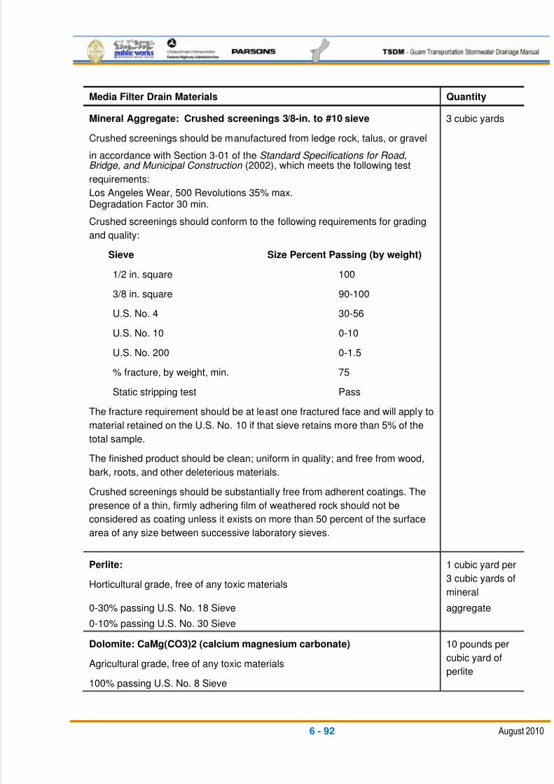
5/13/2018 Guam Storm Water Drainage Manual - slidepdf.com
http://slidepdf.com/reader/full/guam-storm-water-drainage-manual 228/486
6 - 92 August 2010
Media Filter Drain Materials Quantity
Mineral Aggregate: Crushed screenings 3/8-in. to #10 sieve
Crushed screenings should be manufactured from ledge rock, talus, or gravel
in accordance with Section 3-01 of the Standard Specifications for Road,Bridge, and Municipal Construction (2002), which meets the following test
requirements:
Los Angeles Wear, 500 Revolutions 35% max.Degradation Factor 30 min.
Crushed screenings should conform to the following requirements for grading
and quality:
Sieve Size Percent Passing (by weight)
1/2 in. square 100
3/8 in. square 90-100
U.S. No. 4 30-56
U.S. No. 10 0-10
U.S. No. 200 0-1.5
% fracture, by weight, min. 75
Static stripping test Pass
The fracture requirement should be at least one fractured face and will apply to
material retained on the U.S. No. 10 if that sieve retains more than 5% of the
total sample.
The finished product should be clean; uniform in quality; and free from wood,
bark, roots, and other deleterious materials.
Crushed screenings should be substantially free from adherent coatings. The
presence of a thin, firmly adhering film of weathered rock should not be
considered as coating unless it exists on more than 50 percent of the surface
area of any size between successive laboratory sieves.
3 cubic yards
Perlite:
Horticultural grade, free of any toxic materials
0-30% passing U.S. No. 18 Sieve
0-10% passing U.S. No. 30 Sieve
1 cubic yard per
3 cubic yards of
mineral
aggregate
Dolomite: CaMg(CO3)2 (calcium magnesium carbonate)
Agricultural grade, free of any toxic materials
100% passing U.S. No. 8 Sieve
10 pounds per
cubic yard of
perlite
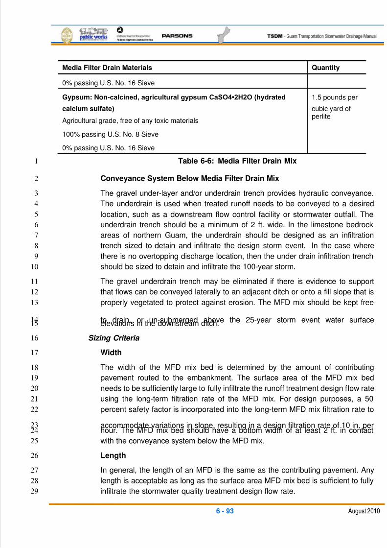
5/13/2018 Guam Storm Water Drainage Manual - slidepdf.com
http://slidepdf.com/reader/full/guam-storm-water-drainage-manual 229/486
6 - 93 August 2010
Media Filter Drain Materials Quantity
0% passing U.S. No. 16 Sieve
Gypsum: Non-calcined, agricultural gypsum CaSO4•2H2O (hydrated
calcium sulfate)
Agricultural grade, free of any toxic materials
100% passing U.S. No. 8 Sieve
0% passing U.S. No. 16 Sieve
1.5 pounds per
cubic yard ofperlite
Table 6-6: Media Filter Drain Mix1
Conveyance System Below Media Filter Drain Mix2
The gravel under-layer and/or underdrain trench provides hydraulic conveyance.3
The underdrain is used when treated runoff needs to be conveyed to a desired4
location, such as a downstream flow control facility or stormwater outfall. The5
underdrain trench should be a minimum of 2 ft. wide. In the limestone bedrock6
areas of northern Guam, the underdrain should be designed as an infiltration7
trench sized to detain and infiltrate the design storm event. In the case where8
there is no overtopping discharge location, then the under drain infiltration trench9
should be sized to detain and infiltrate the 100-year storm.10
The gravel underdrain trench may be eliminated if there is evidence to support11
that flows can be conveyed laterally to an adjacent ditch or onto a fill slope that is12
properly vegetated to protect against erosion. The MFD mix should be kept free13
to drain, or un-submerged above the 25-year storm event water surface14elevations in the downstream ditch.15
Sizing Criteria 16
Width17
The width of the MFD mix bed is determined by the amount of contributing18
pavement routed to the embankment. The surface area of the MFD mix bed19
needs to be sufficiently large to fully infiltrate the runoff treatment design flow rate20
using the long-term filtration rate of the MFD mix. For design purposes, a 5021
percent safety factor is incorporated into the long-term MFD mix filtration rate to22
accommodate variations in slope, resulting in a design filtration rate of 10 in. per23hour. The MFD mix bed should have a bottom width of at least 2 ft. in contact24
with the conveyance system below the MFD mix.25
Length26
In general, the length of an MFD is the same as the contributing pavement. Any27
length is acceptable as long as the surface area MFD mix bed is sufficient to fully28
infiltrate the stormwater quality treatment design flow rate.29
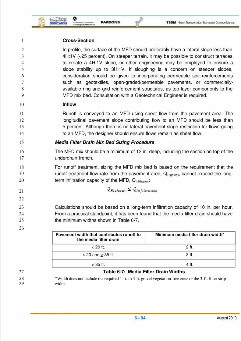
5/13/2018 Guam Storm Water Drainage Manual - slidepdf.com
http://slidepdf.com/reader/full/guam-storm-water-drainage-manual 230/486
6 - 94 August 2010
Cross-Section1
In profile, the surface of the MFD should preferably have a lateral slope less than2
4H:1V (<25 percent). On steeper terrain, it may be possible to construct terraces3
to create a 4H:1V slope, or other engineering may be employed to ensure a4
slope stability up to 3H:1V. If sloughing is a concern on steeper slopes,5
consideration should be given to incorporating permeable soil reinforcements6
such as geotextiles, open-graded/permeable pavements, or commercially-7
available ring and grid reinforcement structures, as top layer components to the8
MFD mix bed. Consultation with a Geotechnical Engineer is required.9
Inflow10
Runoff is conveyed to an MFD using sheet flow from the pavement area. The11
longitudinal pavement slope contributing flow to an MFD should be less than12
5 percent. Although there is no lateral pavement slope restriction for flows going13
to an MFD, the designer should ensure flows remain as sheet flow.14
Media Filter Drain Mix Bed Sizing Procedure 15
The MFD mix should be a minimum of 12 in. deep, including the section on top of the16
underdrain trench.17
For runoff treatment, sizing the MFD mix bed is based on the requirement that the18
runoff treatment flow rate from the pavement area, QHighway, cannot exceed the long-19
term infiltration capacity of the MFD, QInfiltration:20
21
22
Calculations should be based on a long-term infiltration capacity of 10 in. per hour.23
From a practical standpoint, it has been found that the media filter drain should have24
the minimum widths shown in Table 6-7.25
26
Pavement width that contributes runoff tothe media filter drain
Minimum media filter drain width*
< 20 ft. 2 ft.
> 20 and < 35 ft. 3 ft.
> 35 ft. 4 ft.
Table 6-7: Media Filter Drain Widths27
*Width does not include the required 1-ft. to 3-ft. gravel vegetation-free zone or the 3-ft. filter strip28width.29
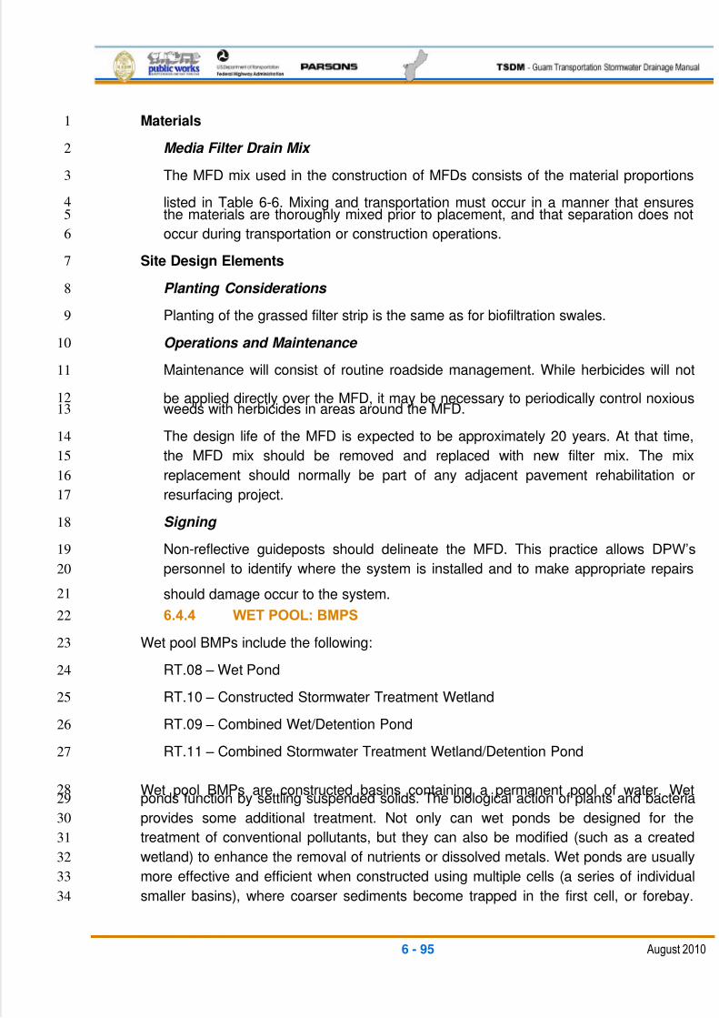
5/13/2018 Guam Storm Water Drainage Manual - slidepdf.com
http://slidepdf.com/reader/full/guam-storm-water-drainage-manual 231/486
6 - 95 August 2010
Materials1
Media Filter Drain Mix 2
The MFD mix used in the construction of MFDs consists of the material proportions3
listed in Table 6-6. Mixing and transportation must occur in a manner that ensures4the materials are thoroughly mixed prior to placement, and that separation does not5
occur during transportation or construction operations.6
Site Design Elements7
Planting Considerations 8
Planting of the grassed filter strip is the same as for biofiltration swales.9
Operations and Maintenance 10
Maintenance will consist of routine roadside management. While herbicides will not11
be applied directly over the MFD, it may be necessary to periodically control noxious12weeds with herbicides in areas around the MFD.13
The design life of the MFD is expected to be approximately 20 years. At that time,14
the MFD mix should be removed and replaced with new filter mix. The mix15
replacement should normally be part of any adjacent pavement rehabilitation or16
resurfacing project.17
Signing 18
Non-reflective guideposts should delineate the MFD. This practice allows DPW‘s19
personnel to identify where the system is installed and to make appropriate repairs20
should damage occur to the system.21
6.4.4 WET POOL: BMPS22
Wet pool BMPs include the following:23
RT.08 – Wet Pond24
RT.10 – Constructed Stormwater Treatment Wetland25
RT.09 – Combined Wet/Detention Pond26
RT.11 – Combined Stormwater Treatment Wetland/Detention Pond27
Wet pool BMPs are constructed basins containing a permanent pool of water. Wet28ponds function by settling suspended solids. The biological action of plants and bacteria29
provides some additional treatment. Not only can wet ponds be designed for the30
treatment of conventional pollutants, but they can also be modified (such as a created31
wetland) to enhance the removal of nutrients or dissolved metals. Wet ponds are usually32
more effective and efficient when constructed using multiple cells (a series of individual33
smaller basins), where coarser sediments become trapped in the first cell, or forebay.34
5/13/2018 Guam Storm Water Drainage Manual - slidepdf.com
http://slidepdf.com/reader/full/guam-storm-water-drainage-manual 232/486
6 - 96 August 2010
Wet pond designs can also provide flow control by adding detention volume (live1
storage) above the dead storage.2
A wet pool BMP can be either an on- or off-line facility receiving the stormwater quality3
treatment volume.4
Constructed stormwater quality treatment wetlands offer a suitable alternative to wet5
ponds or biofiltration swales and can also provide treatment for dissolved metals.6
However, designers must consider the availability of water and the water needs of plants7
used in the stormwater wetland. The landscape context for stormwater wetland8
placement must be appropriate for the creation of an artificial wetland (groundwater,9
soils, and surrounding vegetation). Natural wetlands cannot be used for stormwater10
treatment purposes.11
6.4.4.1 RT.08: WET POND12
General Description13A wet pond is a constructed stormwater pond that retains a permanent pool of water14
(wet pool), at least during the wet season. The volume of the wet pool is related to the15
effectiveness of the pond in settling particulate pollutants. As an option, a shallow marsh16
area can be created within the permanent pool volume to provide additional treatment17
for nutrient removal. The BMP RT.09 Combined Wet/Detention Pond is the wet pond18
provided with live storage area above the permanent pool for detention flow control.19
Figures 6-27 and 6-28 illustrate a typical wet pond BMP.20
Applications and Limitations21
Wet ponds can be designed in two sizes -- basic and large. A basic wet pond is the22stormwater quality treatment BMP for the usual case. Large wet ponds are designed for23
higher levels of pollutant removal and are an appropriate treatment BMP for phosphorus24
removal. In areas of higher soil permeability, wet ponds should be lined with25
impermeable membranes.26
Refer to RT.09-Combined Wet/Detention Pond if the pond is to be used for flow control27
in addition to runoff treatment.28
Design Flow Elements29
Flows To Be Treated 30
Basic wet ponds are designed to treat the runoff treatment volume described as part31
of Minimum Requirement 5 as defined in Chapter 3 of this TSDM. Large wet ponds32
are designed to treat a volume 1.5 times greater than the water quality treatment33
volume.34
35
36
5/13/2018 Guam Storm Water Drainage Manual - slidepdf.com
http://slidepdf.com/reader/full/guam-storm-water-drainage-manual 233/486
6 - 97 August 2010
Overflow or Bypass 1
The overflow criteria for single-purpose (treatment only, not combined with flow2
control) wet ponds are as follows:3
An open-top, standpipe riser in the control structure satisfies the requirement4for primary overflow design.5
The top of the riser should be set at the water quality design water surface6
elevation.7
If it is an on-line pond, the primary overflow should be sized to pass the 100-8
year flow. If the pond is off-line (upstream flow splitter to bypass the flows in9
excess of the design stormwater quality treatment flow), the primary overflow10
should be sized to pass the upstream conveyance capacity.11
Emergency Overflow Spillway 12
An emergency spillway or structure must be provided and designed according to the13
requirements for BMP FC.01-Detention Pond. The control surface of the emergency14
overflow spillway must be set at the design water surface elevation.15
Structural Design Considerations16
Geometry 17
Design Criteria18
The wet pond is divided into a minimum of two cells, separated by a baffle or19
berm. The first cell must contain between 25 percent and 35 percent of the total20
wet pond volume. The baffle or berm volume does not count as part of the total21
wet pond volume. The term baffle means a vertical divider placed across the22
entire width of the pond, stopping short of the bottom. A berm is a vertical divider23
typically built up from the bottom; in a wet vault, it connects all the way to the24
bottom.25
Intent: The full-length berm or baffle promotes plug flow and enhances 26
quiescence and laminar flow through as much of the entire water volume as 27
possible. Alternative methods to the full-length berm or baffle that provide 28
equivalent flow characteristics may be approved on a case-by-case basis by 29
DPW. 30
Sediment storage is provided in the first cell. The minimum depth of the sediment31
storage must be 1 ft. A fixed sediment depth monitor should be installed in the32
first cell to gauge sediment accumulation, or an alternative gauging method33
should be used.34
5/13/2018 Guam Storm Water Drainage Manual - slidepdf.com
http://slidepdf.com/reader/full/guam-storm-water-drainage-manual 234/486
6 - 98 August 2010
The minimum depth of the first cell must be 4 ft., exclusive of sediment storage1
requirements. The depth of the first cell may be greater than the depth of the2
second cell.3
The maximum depth of each cell must not exceed 8 ft. (exclusive of sediment4
storage in the first cell). Pool depths of 3 ft. or shallower (second cell) must be5
planted with emergent wetland vegetation (see ―Landscaping‖ later in this6
section).7
Inlets and outlets must be placed to maximize the flow path through the facility.8
The ratio of flow path length to width from the inlet to the outlet must be at least9
2:1. The flow path length is defined as the distance from the inlet to the outlet, as10
measured at mid-depth. The width at mid-depth is calculated as follows: width =11
(average top width + average bottom width)/2.12
Wet ponds with wet pool volumes less than or equal to 4,000 cu. ft. may be13
single-celled (no baffle or berm is required). However, it is especially important14
that the flow path length be maximized in single-celled wet ponds. The ratio of15
flow path length to width must be greater than 4:1 in single-celled wet ponds.16
All inlets must enter the first cell. If there are multiple inlets, the length-to-width17
ratio is based on the average flow path length for all inlets.18
Sizing Procedure19
Design Steps (D) 20
D-1 Identify the required wet pool volume (Volwq). For large wet ponds,21
the wet pool volume is 1.5 times the water quality volume.22
D-2 Estimate wet pool dimensions satisfying the following design23
criterion:24
Volwq = [h1(At1 + Ab1) / 2] + [h2(At2 + Ab2) / 2] +……+ [hn(Atn 25
+ Abn) / 2]26
Where:27
Atn = Top area of wet pool surface in cell n in ft. 2 28
Abn = Bottom area of wet pool surface in cell n in ft.2 29
hn = Depth of wet pool in cell n (above top of sediment30
storage) in ft.31
D-3 Design pond outlet pipe and determine primary overflow water32
surface33
34
35

5/13/2018 Guam Storm Water Drainage Manual - slidepdf.com
http://slidepdf.com/reader/full/guam-storm-water-drainage-manual 235/486
6 - 99 August 2010
Inlet and Outlet1
For details on the following requirements, see Figures 6-27 and 6-28.2
The inlet to the wet pond must be submerged, with the inlet pipe invert a minimum of3
2 ft. from the pond bottom (not including the 1-ft. minimum sediment storage). The top of4the inlet pipe should be submerged at least 1 ft. below the runoff treatment design water5
surface, if possible. The designer should compute the Hydraulic Grade Line (HGL) of the6
inlet pipe to verify that backwater conditions are acceptable.7
Intent: The inlet is submerged to dissipate the energy of the incoming flow. The distance 8
from the bottom is set to minimize the re-suspension of settled sediments. Alternative 9
inlet designs that accomplish these objectives are acceptable.10
An outlet structure must be provided. No sump is required in the outlet structure for wet11
ponds not providing detention storage. The outlet structure receives flow from the pond12
outlet pipe. The birdcage opening provides an overflow route should the pond outlet pipe13become clogged.14
The pond outlet pipe (from the pond into the outlet structure) must be back-sloped, or15
have a turn-down elbow, and extend 1 ft. below the runoff treatment design water16
surface. A floating outlet, set to draw water from 1 ft. below the water surface, is also17
acceptable if vandalism concerns are adequately addressed.18
Intent: The inverted outlet pipe traps oils and floatables in the wet pond.19
The pond outlet pipe must be sized, at a minimum, to pass the runoff treatment design20
flow. Note: The highest invert of the outlet pipe sets the runoff treatment design water21
surface elevation.22
Materials23
All metal parts must be corrosion-resistant. Galvanized materials should not be used24
unless unavoidable.25
Intent: Galvanized metal contributes zinc to stormwater, sometimes in very high 26
concentrations.27
Berms, Baffles, and Slopes28
A berm or baffle must extend across the full width of the wet pool and tie into the wet29
pond side slopes. If the berm embankments are greater than 4 ft. high, the berm must be30constructed by excavating a key trench equal to 50 percent of the embankment cross-31
sectional height and width. A Geotechnical Engineer may waive this requirement for32
specific site conditions. A geotechnical analysis must address situations in which one of33
the two cells is empty while the other remains full of water.34
The top of the berm should be submerged 1 ft. below this surface. Earthen berms should35
have a minimum top width of 5 ft.36

5/13/2018 Guam Storm Water Drainage Manual - slidepdf.com
http://slidepdf.com/reader/full/guam-storm-water-drainage-manual 236/486
6 - 100 August 2010
Intent: The submerged berm of 1 ft. provides a surface skimming effect to improve the 1
sedimentation settlement efficiency.2
If good vegetation cover is not established on the berm, erosion control measures3
should be used to prevent erosion of the berm back-slope when the pond is initially filled.4
Instead of an interior berm, a structural type retaining wall may be used.5
The criteria for wet pond side slopes are as follows:6
Interior side slopes should be no steeper than 2H:1V. However, slopes of 3H:1V7
or flatter are preferred. If using 2H:1V slopes, the pond must be fenced for safety8
reasons.9
Exterior side slopes must be no steeper than 2H:1V.10
Slopes should be no steeper than 4H:1V if they are to be mowed.11
Pond sides may be retaining walls, provided that a fence is situated along the top12of the wall and at least 25 percent of the pond perimeter is a vegetated side13
slope no steeper than 3H: 1V.14
The toe of the exterior slope must be no closer than 5 ft. from the right-of-way15
line.16
Embankments17
The berm embankment must be constructed of material consisting of a minimum of 3018
percent clay, a maximum of 60 percent sand, a maximum of 60 percent silt, and19
negligible gravel and cobble.20
To prevent undermining, installation of a perimeter cutoff trench underneath or near21
embankments should be considered.22
Anti-seepage collars must be placed on outflow pipes in berm embankments impounding23
water deeper than 8 ft. at the runoff treatment design water surface. Anti-seepage collars24
may also be necessary in other situations.25
Ponds having storage impoundments of 10 ac-ft. or greater, must have DPW‘s pre-26
approval, where the design of the pond should meet federal or typical industry large dam27
safety guidelines in regards to the hydrology, geotechnical, structural, and hydraulic28
considerations.29
Site Design Elements30
Setback Requirements 31
Wet ponds must be a minimum of 5 ft. from any property line or vegetative buffer,32
and must be 100 ft. from any septic tank or drain field.33
5/13/2018 Guam Storm Water Drainage Manual - slidepdf.com
http://slidepdf.com/reader/full/guam-storm-water-drainage-manual 237/486
6 - 101 August 2010
The designer should request a geotechnical report for the project that evaluates any1
potential structural site instability due to extended sub-grade saturation or head-2
loading of the permeable layer. This includes the potential impacts to down-gradient3
properties, especially on hills with known side-hill seeps. The report should address4
the adequacy of the proposed wet pond locations and recommend the necessary5
setbacks from any steep slopes and building foundations.6
Landscaping (Planting Considerations) 7
Planting requirements for detention ponds also apply to wet ponds.8
The cells in large wet ponds intended for phosphorus control should not be planted9
because the plants release phosphorus in the winter when they die off.10
If the second cell of a basic wet pond is 3 ft. or shallower, the bottom area must be11
planted with emergent wetland vegetation. This results in habitat for natural12
predators of mosquitoes such as dragonflies, birds, fish, and frogs.13Intent: The planting of shallow pond areas helps to stabilize settled sediment and 14
prevent re-suspension.15
Vegetation that forms floating mats should not be planted because the mats protect16
mosquito larvae.17
A variety of plant species should be planted to encourage a diversity of mosquito18
predators. This variety can also make the overall predator population more robust to19
withstand environmental changes to the facility.20
If the wet pond discharges to a phosphorus-sensitive lake or wetland, shrubs that21
form a dense cover should be planted on slopes above the runoff treatment design22
water surface on at least three sides. For banks that are berms, no planting is23
allowed if the berm is regulated by dam safety requirements. The purpose of planting24
is to provide shading.25
Fencing 26
Pond walls may be retaining walls as long as a fence is provided along the top of the27
wall and at least 25 percent of the pond perimeter will have a slope of 3H:1V or28
flatter. For safety reasons, the pond must be fenced if the slopes are steeper than29
3H:1V.30
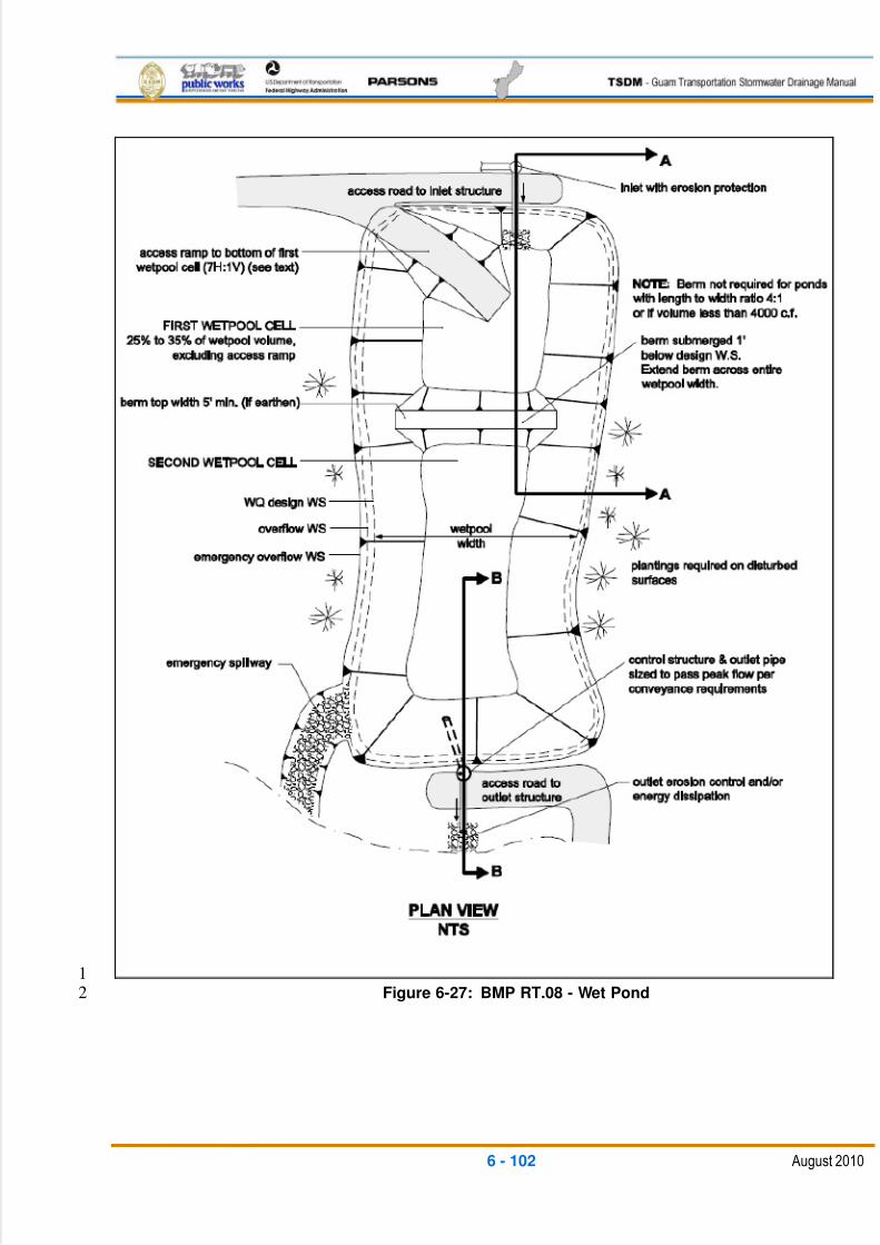
5/13/2018 Guam Storm Water Drainage Manual - slidepdf.com
http://slidepdf.com/reader/full/guam-storm-water-drainage-manual 238/486
6 - 102 August 2010
1Figure 6-27: BMP RT.08 - Wet Pond2
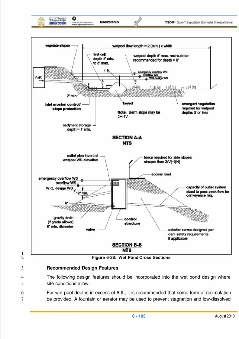
5/13/2018 Guam Storm Water Drainage Manual - slidepdf.com
http://slidepdf.com/reader/full/guam-storm-water-drainage-manual 239/486
6 - 103 August 2010
1Figure 6-28: Wet Pond Cross Sections2
Recommended Design Features3
The following design features should be incorporated into the wet pond design where4
site conditions allow:5
For wet pool depths in excess of 6 ft., it is recommended that some form of recirculation6
be provided. A fountain or aerator may be used to prevent stagnation and low-dissolved7
5/13/2018 Guam Storm Water Drainage Manual - slidepdf.com
http://slidepdf.com/reader/full/guam-storm-water-drainage-manual 240/486
6 - 104 August 2010
oxygen conditions. Alternatively, a small amount of base flow could be directed to the1
pond to maintain circulation and reduce the potential for low-oxygen conditions.2
Trees should be planted along the west and south sides of ponds to reduce thermal3
heating, except that no trees or shrubs may be planted on compacted fill berms. Trees4
should be set back so that the branches will not extend over the pond.5
The number of inlets to the facility should be limited; ideally, there should be only one6
inlet. Regardless of the number of inlets, the flow path length between the inlet and7
outlet should be maximized.8
Where possible, the following design features should be incorporated to enhance9
aesthetics:10
Provide side slopes that are sufficiently gentle (3H:1V or flatter) to avoid the need11
for fencing. Gentler slopes typically allow a facility to better blend into its12
surroundings.13
Use sinuous or irregularly-shaped ponds to create a more naturalistic landscape.14
Provide visual enhancement with clusters of trees and shrubs. On most pond15
sites, it is important to amend the soil before planting because ponds are typically16
placed well below the native soil horizon in very poor soils. Make sure that dam17
safety restrictions against planting do not apply.18
Orient the pond length along the direction of prevailing summer winds to enhance19
wind mixing.20
Impermeable liners may be necessary to maintain the wet pool volume in21
permeable soils.22
Construction Criteria23
If the pond has been used for temporary sedimentation purposes during construction,24
the accumulated sediment must be cleaned out at the end of construction.25
6.4.4.2 RT.10: COMBINED WET/DETENTION POND26
General Description27
A combined detention and runoff treatment wet pond facility has the appearance of a28
detention facility but contains a permanent pool of water as well. The following design29
procedures, requirements, and recommendations cover differences in the design of the30
stand-alone runoff treatment facility when combined with detention storage.31
There are two sizes of the combined wet pond -- basic and large. The facility sizes32
(basic and large) are related to the pollutant-removal goals.33
34
35
5/13/2018 Guam Storm Water Drainage Manual - slidepdf.com
http://slidepdf.com/reader/full/guam-storm-water-drainage-manual 241/486
6 - 105 August 2010
Applications and Limitations1
Combined detention and runoff treatment facilities are very efficient for sites that also2
have flow control requirements, but are not conducive to dispersion or infiltration. The3
runoff treatment BMP may often be placed beneath detention storage without increasing4
the overall facility surface area. However, the fluctuating water surface of the live storage5
creates unique challenges for plant growth and aesthetics.6
The basis for pollutant removal in combined facilities is the same as that for stand-alone7
runoff treatment facilities. However, in the combined facility, the detention function8
creates fluctuating water levels and added turbulence. For simplicity, the positive effect9
of the extra live storage volume and the negative effect of increased turbulence are10
assumed to balance, and are thus ignored when the wet pool volume is sized. For the11
combined detention/stormwater wetland, criteria that limit the extent of water level12
fluctuation are specified to better ensure survival of the wetland plants.13
Unlike the wet pool volume, the live storage component of the facility must be provided14
above the seasonal high-water table. It is recommended that all stormwater quality15
treatment BMPs that use permanent wet pools use facility liners.16
Typical design details and concepts for a combined detention and wet pond are shown17
in Figures 6-29 and 6-30. The detention portion of the facility must meet the design18
criteria and sizing procedures set forth in the flow control BMP FC.01 - Detention Pond.19
Design Flow Elements20
Flows To Be Treated 21
Basic combined wet/detention ponds are designed to treat the runoff treatment22volume and detain flows according to the criteria described as part of Minimum23
Requirements 5 and 6, respectively, as defined in Chapter 3 of this TSDM. Large24
combined wet/detention ponds are designed to treat 1.5 times the runoff treatment25
volume.26
Structural Design Considerations27
Geometry 28
The geometry criteria for wet ponds (see BMP RT.08) apply, with the following29
modifications and clarifications:30
The permanent pool may be made shallower to take up most of the pond bottom, or31
it may be deeper and positioned to take up only a limited portion of the bottom. Wet32
pond criteria governing water depth, however, must still be met. (See Figure 6-31 for33
alternate possibilities for wet pool cell placement.)34
Intent: This flexibility in positioning cells allows for multiple-use options in live storage 35
areas during the drier months.36
5/13/2018 Guam Storm Water Drainage Manual - slidepdf.com
http://slidepdf.com/reader/full/guam-storm-water-drainage-manual 242/486
6 - 106 August 2010
The minimum sediment storage depth in the first cell is 1 ft. The 6 in. of sediment1
storage required for a detention pond does not need to be added to this, but 6 in. of2
sediment storage must be added to the second cell to comply with the detention3
sediment storage requirement.4
The wet pool and sediment storage volumes are not included in the required5
detention volume.6
Sizing Procedure 7
The sizing procedure for combined detention and wet ponds is identical to that8
outlined for wet ponds (see BMP RT.08) and detention ponds (see BMP FC.01).9
Inlet and Outlet 10
The inlet and outlet criteria for wet ponds (see BMP RT.08) apply, with the following11
modifications:12
A sump must be provided in the outlet control structure of combined ponds13
The detention flow restrictor and its outlet pipe must be designed according to14
the requirements for detention ponds (see BMP FC.01)15
Berms, Baffles, and Slopes 16
The criteria are the same as for wet ponds (see BMP RT.08).17
Groundwater Issues 18
Live storage requirements are the same as for detention ponds (see BMP FC.01).19
This does not apply to the wet pond dead storage component.20
Site Design Elements 21
General maintenance requirements and setback criteria are the same as for wet22
ponds (see BMP RT.08).23
Planting Requirements 24
The criteria are the same as for wet ponds (see BMP RT.08).25
26
5/13/2018 Guam Storm Water Drainage Manual - slidepdf.com
http://slidepdf.com/reader/full/guam-storm-water-drainage-manual 243/486
6 - 107 August 2010
1Figure 6-29: BMP RT.10 - Combined Detention and Wet Pond – Plan View2
5/13/2018 Guam Storm Water Drainage Manual - slidepdf.com
http://slidepdf.com/reader/full/guam-storm-water-drainage-manual 244/486
6 - 108 August 2010
1
2
3Figure 6-30: Combined Detention and Wet Pond – Cross Sections4
56
5/13/2018 Guam Storm Water Drainage Manual - slidepdf.com
http://slidepdf.com/reader/full/guam-storm-water-drainage-manual 245/486
6 - 109 August 2010
1Figure 6-31: Alternative Configuration of Detention and Wet Pond2
6.4.4.3 RT.09: CONSTRUCTED STORMWATER TREATMENT3
WETLAND4
General Description5
Stormwater treatment wetlands are shallow constructed wetlands designed to treat6
stormwater through settling, filtering, and the biological processes associated with7
emergent aquatic plants. Stormwater treatment wetlands, like wet ponds, are used to8
capture and transform pollutants. Over time, these pollutants concentrate in the9
sediment.10
5/13/2018 Guam Storm Water Drainage Manual - slidepdf.com
http://slidepdf.com/reader/full/guam-storm-water-drainage-manual 246/486
6 - 110 August 2010
Instead of treating stormwater runoff, some wetlands are constructed to replace or1
mitigate impacts when natural wetlands are filled or impacted by development (mitigation2
wetlands). Natural wetlands and mitigation wetlands cannot be used to treat stormwater.3
Applications and Limitations4
As an enhanced treatment BMP, stormwater wetlands can be considered for roadways5
where metal removal is a concern. Stormwater wetlands occupy roughly the same6
surface area as wet ponds, but they have the potential to be better aesthetically7
integrated into a site because of the abundance of emergent aquatic vegetation. The8
most critical factor for a successful design is an adequate supply of water for most of the9
year. Careful planning is needed to ensure sufficient water is retained to sustain good10
wetland plant growth. Because water depths in stormwater wetlands are shallower than11
in wet ponds, water loss by evaporation is an important concern. Stormwater wetlands12
are a good runoff treatment facility choice in areas where groundwater levels are high in13
the wet season. It is recommended that all runoff treatment BMPs that use permanent14wet pools use facility liners.15
Design Flow Elements16
Flows To Be Treated 17
Constructed stormwater treatment wetlands are designed for the stormwater quality18
treatment volume (VolWQ) described as part of Minimum Requirement 5 as defined in19
Chapter 3 of this TSDM.20
Overflow or Bypass 21
The overflow criteria for single-purpose wetlands (treatment only, not combined with22flow control) follow the same criteria for wet ponds (see BMP RT.08).23
Emergency Overflow Spillway 24
An emergency spillway must be provided and designed according to the25
requirements for detention ponds (see BMP FC.01). In addition, a bypass or shutoff26
valve to enable the wetland to be taken off-line for maintenance purposes should be27
provided, if possible.28
Bioengineered stabilization measures should be provided at the end of the outlet29
pipe and spillway to minimize the need for riprap and to increase aesthetics.30
Structural Design Considerations31
Geometry 32
Design Criteria33
1. Stormwater wetlands must consist of two cells -- a pre-settling cell and a34
wetland cell.35
5/13/2018 Guam Storm Water Drainage Manual - slidepdf.com
http://slidepdf.com/reader/full/guam-storm-water-drainage-manual 247/486
6 - 111 August 2010
2. The pre-settling cell must contain approximately 33 percent of the wet1
pool volume.2
3. The depth of the pre-settling cell must be between 4 ft. (minimum) and3
8 ft. (maximum), excluding sediment storage.4
4. The pre-settling cell must provide 1 ft. of sediment storage.5
5. The wetland cell must have an average water depth of approximately6
1.5 ft. (plus or minus 3 in.).7
Sizing Procedure 8
Step 1. Specify the depth of the pre-settling cell (Dpc ft.). See Criterion 3 in9
―Design Criteria,‖ listed above.10
Step 2. Determine the volume of the pre-settling cell (Vpc ft.3) by using Criterion 211
in ―Design Criteria,‖ listed above.12
Step 3. Determine the surface area of the pre-settling cell (Apc ft.2) of the13
stormwater wetland using the pre-settling cell volume and depth. Apc = Vpc / Dpc.14
Step 4. Calculate the surface area of the stormwater wetland. The surface area15
of the entire wetland (Atotal ft.2) must be the same as the top area of a wet pond16
sized for the same site conditions. The surface area of the entire stormwater17
wetland is the runoff treatment wet pool volume divided by the wet pool water18
depth (use 3 ft.).19
Atotal = Vtotal / 3 ft.20
Step 5. Determine the surface area of the wetland cell (Awc ft.2
). Subtract the21surface area of the pre-settling cell from the total wetland surface area.22
(Atotal). Awc = Atotal – Apc. 23
Step 6. Determine water depth distributions in the wetland cell. Decide whether24
the top of the dividing berm is at the surface or submerged (designer's choice).25
Adjust the distribution of water depths in the wetland cell according to the surface26
area of the wetland cell (Awc) and the discussion below. Note: This results in a27
facility that holds less volume than the runoff treatment volume; which is28
acceptable.29
Intent: The surface area of the stormwater wetland is set to be roughly equivalent to 30
that of a wet pond (with an average depth of the wetland cell of 1.5 ft.) designed for 31
the same site so as not to discourage use of this option.32
Two examples for grading the bottom of the wetland cell are shown in Figures 6-3233
and 6-33. Option A is a shallow, evenly-graded slope from the upstream to the34
downstream edge of the wetland cell. The second example, Option B, is a35
naturalistic alternative with the specified range of depths intermixed throughout the36
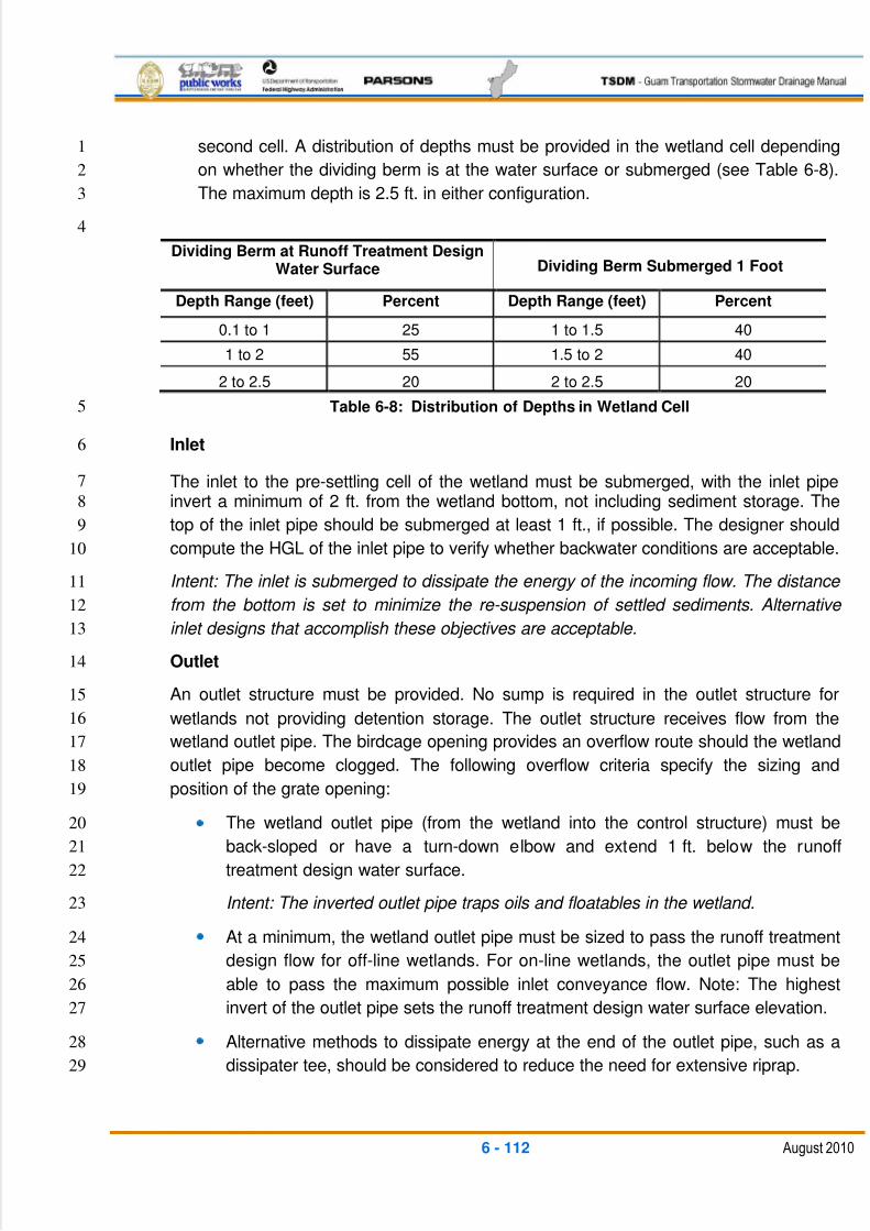
5/13/2018 Guam Storm Water Drainage Manual - slidepdf.com
http://slidepdf.com/reader/full/guam-storm-water-drainage-manual 248/486
6 - 112 August 2010
second cell. A distribution of depths must be provided in the wetland cell depending1
on whether the dividing berm is at the water surface or submerged (see Table 6-8).2
The maximum depth is 2.5 ft. in either configuration.3
4
Dividing Berm at Runoff Treatment DesignWater Surface Dividing Berm Submerged 1 Foot
Depth Range (feet) Percent Depth Range (feet) Percent
0.1 to 1 25 1 to 1.5 40
1 to 2 55 1.5 to 2 40
2 to 2.5 20 2 to 2.5 20
Table 6-8: Distribution of Depths in Wetland Cell5
Inlet6
The inlet to the pre-settling cell of the wetland must be submerged, with the inlet pipe7
invert a minimum of 2 ft. from the wetland bottom, not including sediment storage. The8
top of the inlet pipe should be submerged at least 1 ft., if possible. The designer should9
compute the HGL of the inlet pipe to verify whether backwater conditions are acceptable.10
Intent: The inlet is submerged to dissipate the energy of the incoming flow. The distance 11
from the bottom is set to minimize the re-suspension of settled sediments. Alternative 12
inlet designs that accomplish these objectives are acceptable.13
Outlet14
An outlet structure must be provided. No sump is required in the outlet structure for15
wetlands not providing detention storage. The outlet structure receives flow from the16
wetland outlet pipe. The birdcage opening provides an overflow route should the wetland17
outlet pipe become clogged. The following overflow criteria specify the sizing and18
position of the grate opening:19
The wetland outlet pipe (from the wetland into the control structure) must be20
back-sloped or have a turn-down elbow and extend 1 ft. below the runoff21
treatment design water surface.22
Intent: The inverted outlet pipe traps oils and floatables in the wetland. 23
At a minimum, the wetland outlet pipe must be sized to pass the runoff treatment24
design flow for off-line wetlands. For on-line wetlands, the outlet pipe must be25
able to pass the maximum possible inlet conveyance flow. Note: The highest26
invert of the outlet pipe sets the runoff treatment design water surface elevation.27
Alternative methods to dissipate energy at the end of the outlet pipe, such as a28
dissipater tee, should be considered to reduce the need for extensive riprap.29
5/13/2018 Guam Storm Water Drainage Manual - slidepdf.com
http://slidepdf.com/reader/full/guam-storm-water-drainage-manual 249/486
6 - 113 August 2010
Berms, Baffles, and Slopes1
The berm separating the two cells must be shaped so that its downstream side gradually2
slopes to form the second shallow wetland cell (see the section view in Figure 6-31).3
Alternately, the second cell may be graded naturalistically from the top of the dividing4
berm (see ―Sizing Procedure,‖ Step 6, above).5
The top of the berm must be either at the runoff treatment design water surface or6
submerged 1 ft. below this surface, as for wet ponds.7
Correspondingly, the side slopes of the berm must meet the following criteria:8
If the top of the berm is at the runoff treatment design water surface, then for9
safety reasons, the berm should not be greater than 3H:1V, just as the wetland10
banks should not be greater than 3H:1V if the wetland is not fenced.11
If the top of the berm is submerged 1 ft., the upstream side slope may be up to12
2H:1V. If submerged, the berm is not considered accessible, and the steeper13
slope is allowable.14
Liners15
If soil permeability allows for sufficient water retention, lining is not necessary. In16
infiltrative soils, both cells of the stormwater wetland must be lined with an impermeable17
membrane.18
Site Design Elements19
Setback Requirements 20
Stormwater treatment wetlands must be a minimum of 5 ft. from any property line or21
vegetative buffer.22
Unlined stormwater treatment wetlands must be 100 ft. from any septic tank or drain23
field. Lined wetlands must be a minimum of 20 ft.24
The designer should request a geotechnical report for the project that evaluates any25
potential structural site instability due to extended sub-grade saturation and/or head-26
loading of the permeable layer. This includes the potential impacts to down-gradient27
properties, especially on hills with known side-hill seeps. The report should address28
the adequacy of the proposed stormwater treatment wetland locations and29
recommend the necessary setbacks from any steep slopes and building foundations.30
Landscaping (Planting Considerations) 31
When used for stormwater treatment, stormwater wetlands incorporate some of the32
same design features as wet ponds. However, instead of gravity settling being the33
dominant treatment process, pollutant removal mediated by aquatic vegetation (and34
the microbiological community associated with that vegetation) becomes the35
dominant treatment process. Thus, water volume is not the dominant design criterion36
5/13/2018 Guam Storm Water Drainage Manual - slidepdf.com
http://slidepdf.com/reader/full/guam-storm-water-drainage-manual 250/486
6 - 114 August 2010
for stormwater wetlands; rather, factors that affect plant vigor and biomass are the1
primary concerns. It is critical to involve a Wetland Scientist, Biologist, or Landscape2
Architect throughout the design process.3
The wetland cells must be planted with emergent wetland plants following those of a4
Wetland Specialist, Biologist, or Landscape Architect.5
Soil Amendments and Protection 6
The method of construction for soil/landscape systems can affect the natural7
selection of specific plant species. Consult a wetland specialist for site-specific soil8
amendment recommendations. The formulation should encourage desired species9
and discourage undesired species. Soils should be stabilized with permanent or10
temporary cover to prevent washout due to storm flows.11
Soil Preparation 12
The incorrect control of soil moisture is the most frequent cause of failure to establish13wetland plants. Inadequate water results in the desiccation of roots. Too much water14
results in oxygen depletion in the root zone; submergence and drowning or flotation15
of plants; and/or slow growth or plant death.16
To maintain adequate soil moisture during plant establishment, a reliable and17
adequate supply of water for site irrigation is needed. When feasible, a water source18
for plant establishment is usually the stormwater treated in the wetland. However, if19
stormwater is not available, another irrigation source must be identified to maximize20
planting success. Adequate pumps, piping, and sprinklers or hoses must be provided21
to allow even flow distribution.22
The recommended sequence for maintaining soil moisture for wetland planting starts23
with the initial saturation of soil by sprinkling or flood irrigation. For optimal plant24
growth, the soil should be fully or partially saturated with water immediately before25
planting and should not be allowed to completely dry out any time after planting. High26
soil moisture must be maintained after planting for the first few weeks without27
creating flooded conditions for more than a few hours. The best method of28
maintaining soil saturation without excessive flooding is to start planting at the down-29
gradient end of the wetland and continue planting up-gradient, while gradually raising30
water levels using the wetland outlet water level controls or gravity drain, if possible.31
When planting is complete, water levels can be dropped or raised as needed to32maintain saturated soil conditions. Sprinklers can also be used to irrigate evenly over33
planted areas.34
After an entire cell is planted, the water should be maintained at a level that ensures35
all areas of the cell continue to have saturated soil conditions between waterings.36
This can be achieved by flood-irrigating the entire cell with enough water to allow37
infiltration or evapotranspiration to eliminate the applied surface water within one or38
5/13/2018 Guam Storm Water Drainage Manual - slidepdf.com
http://slidepdf.com/reader/full/guam-storm-water-drainage-manual 251/486
6 - 115 August 2010
two days, or distributing water through the inlet distribution structures or down the1
embankment side slopes and allowing this water to re-saturate the wetland soils as it2
sheet flows across the wetland to the outlet. Weirs or outlet water control gates3
should be removed or left open during plant establishment to prevent flooding if4
rainfall is high or if a sprinkler or irrigator is accidentally left running. At no time5
should flood irrigation result in complete submergence of above-ground portions of6
installed plants. Permits may be required to use water from nearby natural aquatic7
water bodies for temporary irrigation purposes.8
As the wetland plants grow, they have an increased ability to transport oxygen to the9
root zone from their leaves. Thus the plants are able to withstand longer periods of10
flooding. However, the best technique for establishing rapid plant cover is to maintain11
saturated soil conditions without surface flooding. The higher soil oxygen condition12
resulting from the absence of floodwaters allows maximum root metabolism, effective13
nutrient use, and rapid development of the plants within the wetland. This soil14
condition should, optimally, be maintained until plants achieve complete cover (10015
percent) or at least the minimum cover required for system startup (about 60 percent16
to 80 percent).17
Design and construction should allow the design water surface to be temporarily18
modified to enable plant installation and establishment before the system is brought19
on line. Strategies may be available depending on the project situation, schedule,20
and site conditions.21
If the system must go on-line the same year it is constructed, plant the22
constructed wetland cell early in the dry season and irrigate to maintain23
saturated soils without plant submergence or flotation, until plants are24
sufficiently developed to operate the system at the start of the wet season.25
If the system can remain off-line during the wet season, plant the constructed26
wetland cell at the start of the wet season and monitor water conditions,27
maintaining saturated soils without plant submergence or flotation by28
irrigating or draining as necessary, until plants are sufficiently developed to29
allow operation of the system the following year.30
Several methods could be used to temporarily control water levels during plant31
establishment, depending on project conditions.32
Build the treatment wetland before the project is started, so that wetland33
plants are established before flows are introduced34
Keep the treatment wetland off-line until wetland plants become established35
by bypassing the treatment wetland36
Temporarily operate the drain of the treatment wetland as the outlet to37
maintain water surface elevations below the design water surface level38
5/13/2018 Guam Storm Water Drainage Manual - slidepdf.com
http://slidepdf.com/reader/full/guam-storm-water-drainage-manual 252/486
6 - 116 August 2010
Plant during the dry season when water surface elevations are naturally lower1
Pump out water to lower the wetland cell for planting and establishment2
A wetland treatment system can typically begin operation when plant cover is at least3
60 percent to 80 percent, which may require at least three to four months of active4growth. If this coverage is achieved during the first growing season after planting, the5
wetland system can begin operating during the ensuing wet season.6
Planting 7
Seed embankment areas above the runoff treatment design water surface and below8
the emergency overflow water level. Areas with permanent pools that are protected9
from erosion do not need to be seeded.10
Consider planting trees along the west and south sides of wetlands to reduce11
thermal heating, except that no trees or shrubs may be planted on berms meeting12
the criteria of dams regulated for safety. Trees should be set back so that the13
branches will not extend over the wetland.14
Include trees and shrubs on slopes and on top of banks to increase aesthetics. If the15
treatment wetland discharges to a phosphorus-sensitive lake or natural wetland,16
shrubs that form a dense cover should be planted on slopes above the runoff17
treatment design water surface on at least three sides. For banks that are berms, no18
planting is allowed if the berm is regulated by dam safety requirements. The purpose19
of planting is to provide shading.20
General Maintenance Requirements21
A drain in the wetland cell (or cells) may also be necessary to avoid surface flooding22
during wetland plant installation and establishment.23
Recommended Design Features24
Where possible, the following design features should be incorporated to enhance25
aesthetics:26
Provide maintenance access to shallow pool areas enhanced with emergent27
wetland vegetation. This allows the wetland to be accessible for vegetation28
maintenance without incurring safety risks.29
Provide side slopes that are sufficiently gentle to avoid the need for fencing30(3H:1V or flatter). Ponds with submerged slopes steeper than 3H:1V must be31
fenced.32
Provide visual enhancement with clusters of trees and shrubs. On most wetland33
sites, it is important to amend the soil before planting because wetlands are34
typically placed well below the native soil horizon in very poor soils. Make sure35
that dam safety restrictions against planting do not apply.36
5/13/2018 Guam Storm Water Drainage Manual - slidepdf.com
http://slidepdf.com/reader/full/guam-storm-water-drainage-manual 253/486
6 - 117 August 2010
Consider extending the access and maintenance road along the full length of the1
treatment wetland. The maintenance road should have a permeable surface.2
Where right-of-way allows, orient the wetland length along the direction of3
prevailing winds to enhance wind mixing.4Construction5
Construction and maintenance considerations are the same as those for wet ponds (see6
BMP RT.08).7
The naturalistic grading alternative (see Figure 6-33) can be constructed by first8
excavating the entire area to the 1.5-foot average depth. Soil subsequently excavated to9
form deeper areas can then be deposited to raise other areas until the distribution of10
design depths is achieved.11
Ideally, a period of approximately one year is desirable to establish plants before the12
system goes on-line.13
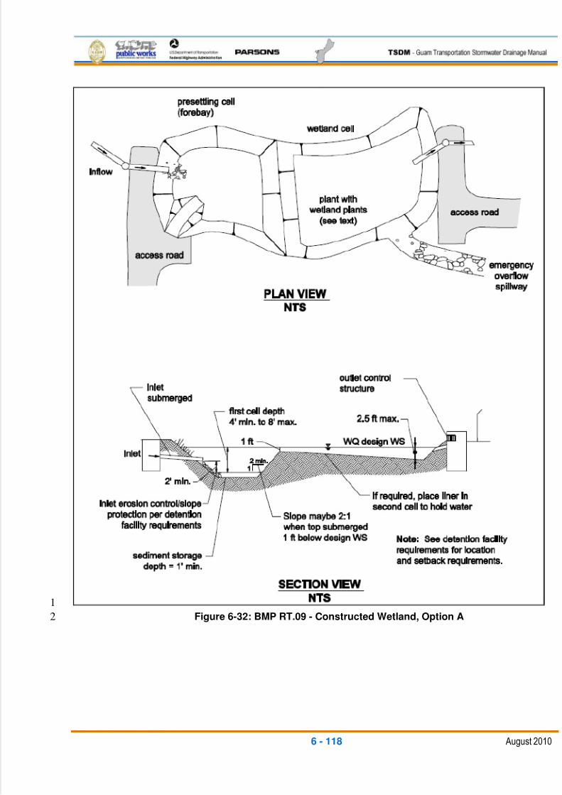
5/13/2018 Guam Storm Water Drainage Manual - slidepdf.com
http://slidepdf.com/reader/full/guam-storm-water-drainage-manual 254/486
6 - 118 August 2010
1
Figure 6-32: BMP RT.09 - Constructed Wetland, Option A2
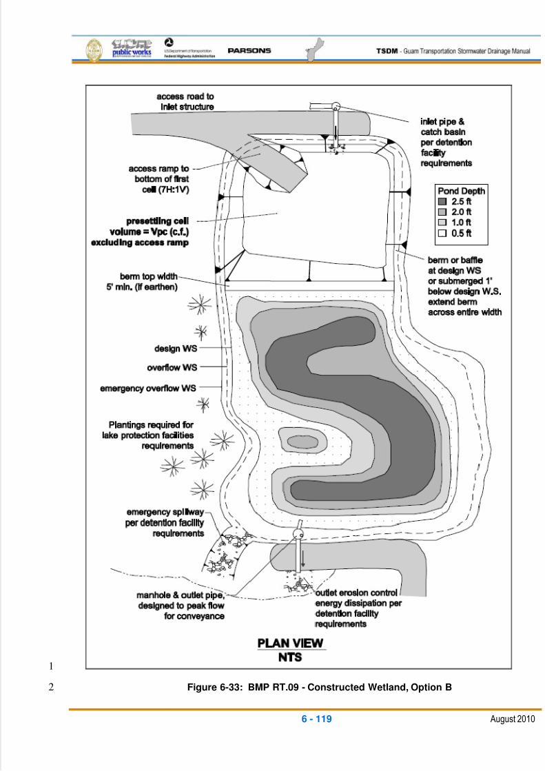
5/13/2018 Guam Storm Water Drainage Manual - slidepdf.com
http://slidepdf.com/reader/full/guam-storm-water-drainage-manual 255/486
6 - 119 August 2010
1
Figure 6-33: BMP RT.09 - Constructed Wetland, Option B2
5/13/2018 Guam Storm Water Drainage Manual - slidepdf.com
http://slidepdf.com/reader/full/guam-storm-water-drainage-manual 256/486
6 - 120 August 2010
6.4.4.4 RT.11: COMBINED STORMWATER TREATMENT1
WETLAND/DETENTION POND2
General Description3
The combined stormwater treatment wetland/detention pond is best described as a4wetland system that provides for the extended detention of runoff during and following5
storm events. This BMP is useful in areas with limited right-of-way, where separate6
runoff treatment and flow control facilities are not feasible. It is recommended that all7
BMPs that use permanent wet pools also use facility liners.8
Design Flow Elements9
Flows To Be Treated 10
The sizing procedure for the combined stormwater treatment wetland and detention11
pond is identical to that outlined for stormwater wetlands (see BMP RT.09) and for12
combined wet/detention ponds (see BMP RT.10). Follow the procedures outlined in13those sections to determine the stormwater wetland size.14
Structural Design Considerations15
Geometry 16
The design criteria for detention ponds (see BMP FC.01) and constructed17
stormwater treatment wetlands (see BMP RT.09) must both be met, except for the18
following modification:19
The minimum sediment storage depth in the first cell is 1 ft. The 6 in. of20
sediment storage required for detention ponds and the 6 in. of sediment21storage in the second cell of detention ponds does not need to be added to22
this.23
Intent: Because emergent plants are limited to shallower water depths, the 24
deeper water created before sediments accumulate is considered detrimental 25
to robust emergent growth. Therefore, sediment storage is confined to the 26
first cell, which functions as a pre-settling cell.27
The inlet and outlet criteria for constructed stormwater treatment wetlands (see BMP28
RT.09) apply, with the following modifications:29
A sump must be provided in the outlet control structure of combined facilities.30
The detention flow restrictor and its outlet pipe must be designed according to31
the requirements for detention ponds (see BMP FC.01).32
Groundwater Issues 33
Live storage requirements are the same as the requirements for detention ponds (see34
BMP FC.01). This does not apply to the dead storage component of the constructed35
5/13/2018 Guam Storm Water Drainage Manual - slidepdf.com
http://slidepdf.com/reader/full/guam-storm-water-drainage-manual 257/486
6 - 121 August 2010
stormwater treatment wetlands. The maximum live storage depth over the permanent1
pool water surface should not exceed 3 ft.2
Landscaping (Planting) 3
Check with a Wetlands Scientist; although usually, landscaping requirements for4constructed stormwater treatment wetlands should suffice.5
6.5 FLOW CONTROL BMPs6
Flow control BMPs include the following:7
FC.01 – Detention Pond8
General Description9
Flow control or detention ponds are open basins that provide live storage volume to10
enable the reduction of stormwater runoff flow rates discharged from a project site (see11
Figure 6-34). Detention ponds are commonly used for flow control in locations where12space is available for an above-ground stormwater facility, but where infiltration of runoff13
is not feasible. Detention ponds are designed to drain within 72 hours after a storm14
event, so that the live storage volume is available for the next event.15
Detention pond requirements discussed in this TSDM generally relate to ponds having16
impoundment volumes less than 10 ac-ft. Larger ponds will usually require more17
stringent geotechnical, hydraulic, and safety designs meeting federal dam guidelines.18
Larger pond designs should be pre-approved by DPW.19
Applications and Limitations20
Runoff infiltration is the preferred method of flow control following appropriate runoff21treatment. However, in areas where infiltration is not feasible, runoff detention should be22
implemented.23
Detention ponds can be combined with wet pool stormwater quality treatment BMPs to24
make more effective use of available land area (see BMP RT.10, Combined25
Wet/Detention Pond, and BMP RT.11, Combined Stormwater Treatment26
Wetland/Detention Pond).27

5/13/2018 Guam Storm Water Drainage Manual - slidepdf.com
http://slidepdf.com/reader/full/guam-storm-water-drainage-manual 258/486
6 - 122 August 2010
1Figure 6-34: BMP FC.01 - Detention Pond2
3
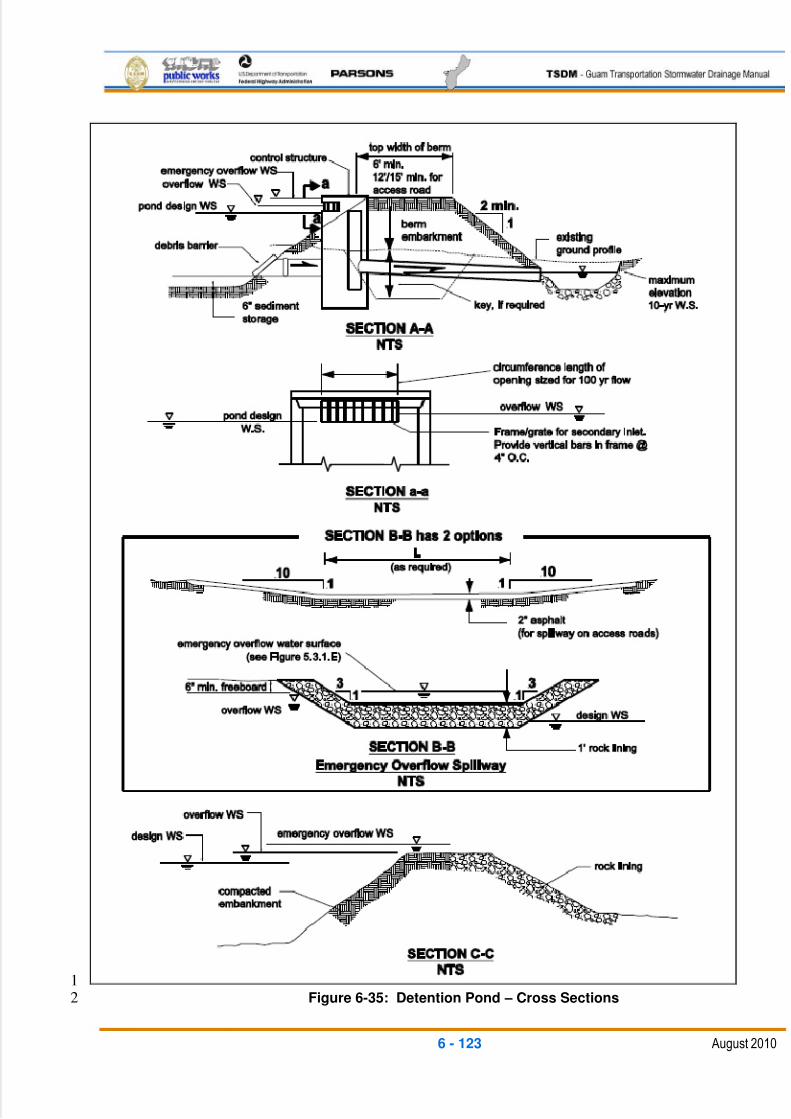
5/13/2018 Guam Storm Water Drainage Manual - slidepdf.com
http://slidepdf.com/reader/full/guam-storm-water-drainage-manual 259/486
6 - 123 August 2010
1Figure 6-35: Detention Pond – Cross Sections2
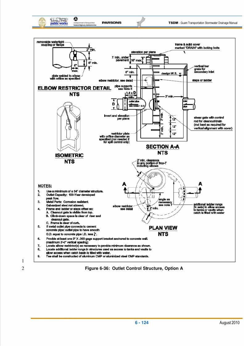
5/13/2018 Guam Storm Water Drainage Manual - slidepdf.com
http://slidepdf.com/reader/full/guam-storm-water-drainage-manual 260/486
6 - 124 August 2010
1
Figure 6-36: Outlet Control Structure, Option A2
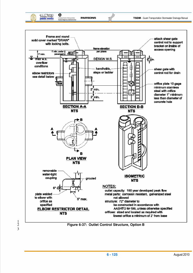
5/13/2018 Guam Storm Water Drainage Manual - slidepdf.com
http://slidepdf.com/reader/full/guam-storm-water-drainage-manual 261/486
6 - 125 August 2010
1Figure 6-37: Outlet Control Structure, Option B2
3
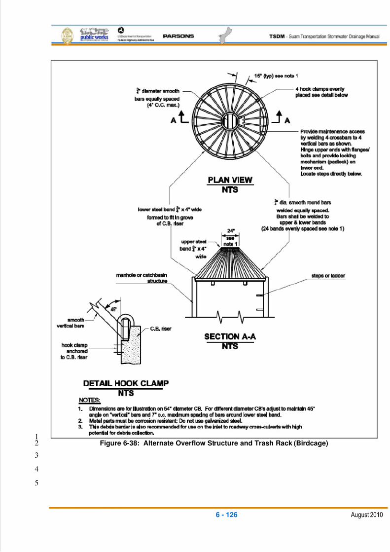
5/13/2018 Guam Storm Water Drainage Manual - slidepdf.com
http://slidepdf.com/reader/full/guam-storm-water-drainage-manual 262/486
6 - 126 August 2010
1Figure 6-38: Alternate Overflow Structure and Trash Rack (Birdcage)2
3
4
5
5/13/2018 Guam Storm Water Drainage Manual - slidepdf.com
http://slidepdf.com/reader/full/guam-storm-water-drainage-manual 263/486
6 - 127 August 2010
Design Flow Elements1
Flows To Be Detained 2
The volume and outflow design for detention ponds with a minimum 1-ft. freeboard3
above the design water surface elevation must be determined in accordance with the4flow control criteria presented as part of Minimum Requirement 6 as defined in5
Chapter 3 of this TSDM. The design water surface elevation is the highest water6
surface elevation that is projected in order to satisfy the flow control requirements.7
Note: If the inlet pipe is submerged below the design water surface elevation, the8
designer should then compute the HGL of the inlet pipe to verify that backwater9
conditions are acceptable.10
Detention Ponds in Infiltrative Soils 11
Detention ponds may occasionally be sited on soils that are sufficiently permeable12
for a properly-functioning infiltration system. These detention ponds have both a13surface discharge and a sub-surface discharge. If infiltration is accounted for in the14
detention pond sizing calculations, the pond design process and corresponding site15
conditions must meet all of the requirements for infiltration ponds (see BMP IN.02),16
including a soils report, soil infiltration testing, groundwater monitoring, pre-settling,17
and construction techniques.18
Overflow or Bypass 19
A primary overflow (usually a riser pipe within the outlet control structure) must be20
provided for the detention pond system to bypass the 100-year, post-developed peak21
flow over or around the flow restrictor system. Overflow can occur when the facility is22
full of water due to plugging of the outlet control structure or high inflows; the primary23
overflow is intended to protect against breaching of the pond embankment (or24
overflows of the upstream conveyance system). The design must provide controlled25
discharge of pond overflows directly into the downstream conveyance system or26
another acceptable discharge point.27
A secondary inlet to the pond discharge control structure should be provided as28
additional protection against overflows due to plugging of the primary inlet pipe to the29
control structure. One option for the secondary inlet is a grated opening, called a30
jailhouse window, (see Section a-a, Figure 6-35) in the control structure that31
functions as a weir when used as a secondary inlet. The maximum circumferential32length of a jailhouse window weir opening must not exceed one-half the control33
structure circumference.34
Another common option for a secondary inlet is to allow flow to spill over the top of35
the discharge control structure or another structure linked to the discharge control36
structure that is fitted with a debris cage, called a birdcage (see Figure 6-38).37
38

5/13/2018 Guam Storm Water Drainage Manual - slidepdf.com
http://slidepdf.com/reader/full/guam-storm-water-drainage-manual 264/486
6 - 128 August 2010
Outlet Control Structure 1
Control structures are catch basins or manholes with a restrictor device for2
controlling outflow from a facility to meet the desired performance. Riser-type3
restrictor devices also provide some incidental oil/water separation to temporarily4
detain oil or other floatable pollutants in runoff due to accidental spill or illegal5
dumping.6
The restrictor device usually consists of two or more orifices or an orifice/weir section7
sized to meet performance requirements.8
Discharge from the outlet pipe back to the existing or natural waterway should have9
positive erosion protection, and if necessary, an energy dissipater structure. See10
Section 6.6.4 for a discussion on outfalls.11
Multiple Orifice Restrictor 12
In most cases, control structures need only two orifices -- one at the bottom and one13near the top of the riser, although additional orifices may optimize the detention14
storage volume. Several orifices may be located at the same elevation if necessary15
to meet performance requirements.16
The minimum circular orifice diameter is 0.5 in. and the minimum vertical rectangular17
orifice length is 0.25 in. Orifices may be constructed on a tee section.18
In some cases, performance requirements may require the top orifice or elbow to be19
located too high on the riser to be physically constructed (e.g., a 13-in. diameter20
orifice cannot be positioned 6 in. from the top of the riser). In these cases, a notch21
weir in the riser pipe may be used to meet performance requirements.22
Consideration must be given to the backwater effect of water surface elevations in23
the downstream conveyance system. High tailwater elevations may affect24
performance of the restrictor system and reduce live storage volumes.25
Riser and Weir Restrictor 26
Properly-designed weirs may be used as flow restrictors; however, they must be27
designed to provide for primary overflow of the developed 100-year peak flow28
discharging to the detention facility.29
The combined orifice and riser (or weir) overflow may be used to meet performance30
requirements; however, the design must still provide for primary overflow of the31
developed 100-year peak flow, assuming all orifices are plugged.32
Emergency Overflow Spillway 33
In addition to the overflow provisions described above, detention ponds must have34
an emergency overflow spillway that is sized to pass the 100-year, post-developed,35
un-detained peak flow in the event of total control structure failure, such as blockage36
5/13/2018 Guam Storm Water Drainage Manual - slidepdf.com
http://slidepdf.com/reader/full/guam-storm-water-drainage-manual 265/486
6 - 129 August 2010
of the control structure outlet pipe, or extreme inflows. Emergency overflow spillways1
are intended to control the location where flows overtop the pond perimeter and2
direct overflows into the downstream conveyance system or other acceptable3
discharge point. The bottom of the emergency overflow spillway must be set at the4
design frequency water surface elevation.5
As an option, emergency overflow may be provided by a manhole fitted with a6
birdcage, as shown in Figure 6-38. Where an emergency overflow spillway would7
discharge to a steep slope, consideration should be given to providing an emergency8
overflow structure in addition to the spillway.9
The emergency overflow spillway must be armored with riprap that is sized in10
conformance with the guidelines in Chapter 4 of FHWA publication HEC-11. The11
spillway must be armored across its full width and also must be armored down the12
embankment, as shown in Figure 6-35.13
Emergency overflow spillway designs as shown in Figure 6-35 must be analyzed as14
broad-crested trapezoidal weirs. The minimum bottom width of the weir should be15
6 ft.16
Emergency overflow spillway designs using a manhole fitted with a birdcage, as17
shown in Figure 6-38, should be analyzed as a sharp-crested weir with no end18
contractions to pass the 100-year, post-developed, un-detained peak flow.19
Structural Design Considerations20
Geometry 21
Pond inflows must enter through a conveyance system separate from the outlet22control structure and outflow conveyance system. Maximizing the distance between23
the inlet and outlet is encouraged to promote sediment trapping.24
Pond bottoms must be level and a minimum of 0.5 ft. below the outlet invert elevation25
to provide sediment storage.26
Berms, Baffles, and Slopes 27
Interior side slopes up to the emergency overflow water surface should not be28
steeper than 3H:1V, unless a fence is provided (see ―Fencing‖, below).29
Exterior side slopes must not be steeper than 2H:1V, unless they are analyzed for30stability by a Geotechnical Engineer.31
Pond walls may be vertical retaining walls subject to the following:32
Cast-in-place wall sections must be designed as retaining walls. A Licensed33
Civil Engineer with structural expertise must stamp structural designs for34
cast-in-place walls. All construction joints must be provided with water stops.35
5/13/2018 Guam Storm Water Drainage Manual - slidepdf.com
http://slidepdf.com/reader/full/guam-storm-water-drainage-manual 266/486
6 - 130 August 2010
Gravity type block walls (rockery or ecology block types) may be used to no1
more than 9 ft. vertical height. These gravity walls must be backfilled with a2
free-draining, structural backfill using either well-graded aggregate or a3
geotextile to act as a filter layer to protect soil fines from migrating through4
the block openings.5
Walls must be placed on stable, well-consolidated native material with6
suitable bedding. Walls must not be placed in fill slopes unless the slopes7
have been analyzed in a geotechnical report for stability and constructability.8
A fence is provided along the top of the wall.9
Although the entire pond perimeter may be retaining walls, it is recommended10
that at least 25 percent of the pond perimeter be a vegetated soil slope not11
steeper than 3H:1V.12
If the entire pond perimeter is to be retaining walls, ladders should be13provided on the full height of the walls for safe access by maintenance staff.14
Embankments 15
The minimum top width of berm embankments should be 5 ft. or as recommended by16
a Geotechnical Engineer. If used for maintenance access, the berm tops should be a17
minimum of 12 ft. wide.18
Pond berm embankments are usually constructed on native consolidated soil (or19
adequately compacted and stable fill soils analyzed by a Geotechnical Engineer),20
and free of loose surface soil materials, roots, and other organic debris.21
Pond berm embankments greater than 4 ft. high must be constructed by excavating22
a key trench equal to 50 percent of the berm embankment ‘s cross-sectional height23
and width, unless otherwise specified by a Geotechnical Engineer.24
Anti-seepage filter-drain diaphragms (pipe collars) must be placed on outflow pipes25
in berm embankments impounding water with depths greater than 8 ft. at the design26
water surface. The size of the pipe collars should be such to extend the seepage27
flow path at least 1.5 times the length of the buried pipe section.28
Groundwater Issues29
Identification and Avoidance 30
Flow control BMPs must be constructed above the seasonal high groundwater table.31
Storage capacity and proper flow attenuation are compromised if groundwater levels32
exceed the live storage elevations. The project should locate the pond so that there33
is a separation between the local groundwater table elevation and the bottom of the34
proposed BMP. In some cases, this may require that a much shallower pond be35
constructed in order to function properly.36
5/13/2018 Guam Storm Water Drainage Manual - slidepdf.com
http://slidepdf.com/reader/full/guam-storm-water-drainage-manual 267/486
6 - 131 August 2010
The groundwater table elevation in and around the flow control facility needs to be1
determined early in the project. This can be done by installing piezometers at the2
BMP location and taking water table readings over at least one wet season.3
Designers should look for opportunities to provide flow control to an equivalent area4
in the project that discharges to the same watershed.5
Site Design Elements6
Setback Requirements 7
Detention ponds must be a minimum of 5 ft. from any property line or vegetative8
buffer. This distance may need to be increased based on the permit requirements of9
the local jurisdiction.10
Detention ponds must be 100 ft. from any septic tank or drain field.11
The designer should request a geotechnical report for the project that evaluates any12
potential structural site instability due to extended sub-grade saturation or head13
loading of the permeable layer, including the potential impacts to down-gradient14
properties, especially on hills with known side-hill seeps. The report should address15
the adequacy of the proposed detention pond locations and recommend the16
minimum excavation and fill slopes, plus necessary setbacks from any steep slopes17
and building foundations.18
Landscaping (Planting Considerations) 19
Earthen ponds should be vegetated with a good erosion control grass seed mix that20
is tolerant of being submerged for short periods of time. All disturbed soil surfaces21
should be covered with topsoil or mulch amended and seeded with an erosion22
control grass mix as recommended by NRCS or DAWR for the site and climate23
conditions.24
Fencing 25
Ponds having submerged slopes steeper than 3H:1V must be fenced to restrict26
public access.27
6.6 STORMWATER FACILITY COMPONENTS28
6.6.1 PRE-SETTLING/SEDIMENTATION BASIN29
General Description30
A pre-settling basin provides pre-treatment of runoff to remove suspended solids that31
can impact other primary runoff treatment BMPs (see Figures 6-39 and 6-40).32
33
34
5/13/2018 Guam Storm Water Drainage Manual - slidepdf.com
http://slidepdf.com/reader/full/guam-storm-water-drainage-manual 268/486
6 - 132 August 2010
Applications and Limitations1
The most attractive aspect of a pre-settling basin is its isolation from the rest of the2
facility. Pre-settling basins allow sediment to fall out of suspension. However, they do not3
detain water long enough for the removal of most pollutants (such as some metals). Pre-4
settling basins are frequently used as pre-treatment for downstream infiltration facilities5
and to protect more sensitive facilities, such as constructed stormwater treatment6
wetlands, from excessive sediment loads. Runoff treated by a pre-settling basin may not7
be discharged directly to a receiving water body; it must be further treated by a8
stormwater quality treatment BMP.9
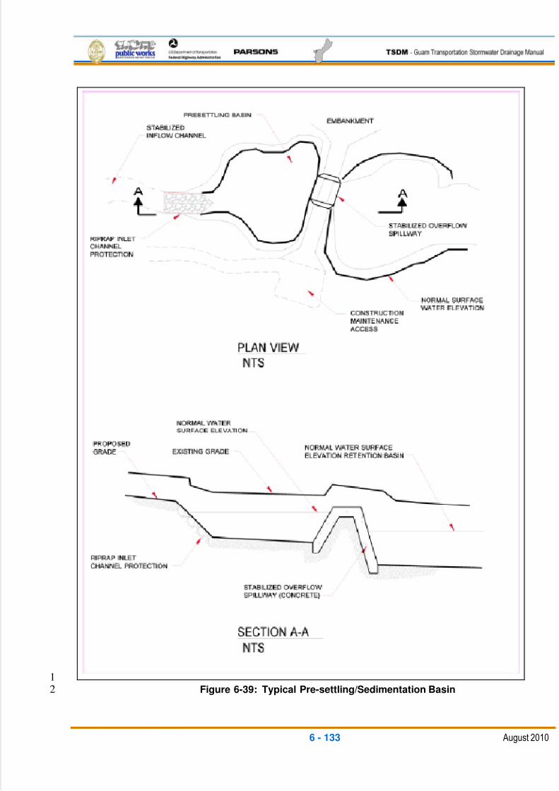
5/13/2018 Guam Storm Water Drainage Manual - slidepdf.com
http://slidepdf.com/reader/full/guam-storm-water-drainage-manual 269/486
6 - 133 August 2010
1Figure 6-39: Typical Pre-settling/Sedimentation Basin2
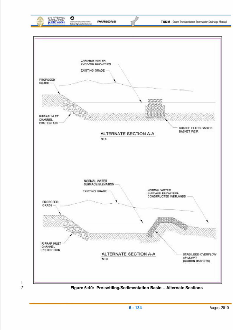
5/13/2018 Guam Storm Water Drainage Manual - slidepdf.com
http://slidepdf.com/reader/full/guam-storm-water-drainage-manual 270/486
6 - 134 August 2010
1Figure 6-40: Pre-settling/Sedimentation Basin – Alternate Sections2
5/13/2018 Guam Storm Water Drainage Manual - slidepdf.com
http://slidepdf.com/reader/full/guam-storm-water-drainage-manual 271/486
6 - 135 August 2010
Design Flow Elements1
Flows To Be Treated 2
A pre-settling basin should be designed as a wet pool. The wet pool volume must be3
at least 30 percent of the total volume of runoff from the three-year frequency storm4event. The wet pool volume should be allowed to dry out between rain storms, either5
by infiltration and evaporation, or by providing a pipe outlet with a perforated type6
riser to allow for low-flow percolation flows.7
Overflow or Bypass 8
Pre-settling basin design must take into consideration the possibility of overflows. A9
designed overflow section should be constructed along the pre-settling basin10
embankment to allow flows to exit at a non-erosive velocity during the design11
frequency storm event. The overflow may be set at the permanent pool level. The12
use of an aquatic bench with emergent vegetation around the perimeter helps with13water quality.14
Any basin design must consider both a primary discharge and an emergency15
overflow discharge in accordance with the requirements of BMP FC.01. Overflow16
non-piped outlets can also function for the emergency case as long as they are sized17
for the maximum peak inlet conveyance flow (or the 100-year frequency storm with18
1 ft. of freeboard).19
Inlet Structure 20
The runoff treatment volume should be discharged uniformly and at a low velocity21
into the pre-settling basin to maintain near-quiescent conditions, which are22necessary for effective treatment. It is desirable for the heavier-suspended material23
to drop out near the front of the basin. Energy-dissipation devices may be necessary24
to reduce inlet velocities that exceed 3 ft. per second.25
Outlet Control Structure 26
The outlet structure conveys the runoff treatment volume from the pre-settling basin27
to the primary treatment BMP (e.g., an infiltration pond). The outlet control structure28
should skim the surface water. It can be a piped outlet structural overflow weir (see29
Figure 6-38), or it can be created as an earthen berm, gabion, concrete, or riprap30
wall along the separation embankment preceding the primary treatment BMP.31
Structural Design Considerations32
Geometry 33
A long, narrow basin is preferred because it is less prone to short-circuiting and34
tends to maximize the available treatment area. The length-to-width ratio should be35
5/13/2018 Guam Storm Water Drainage Manual - slidepdf.com
http://slidepdf.com/reader/full/guam-storm-water-drainage-manual 272/486
6 - 136 August 2010
at least 3:1, and preferably 5:1. The inlet and outlet should be at opposite ends of the1
basin.2
Berms, Embankments, and Slopes 3
Berm embankments must be constructed on suitably-prepared native soil (or4adequately-compacted and stable fill soils analyzed by a geotechnical report) and5
free of loose surface soil materials, roots, and other organic debris.6
Exposed earth on the side slopes and bottom should be sodded or seeded with the7
appropriate seed mixture as soon as practicable. If necessary, geotextile or matting8
may be used to stabilize slopes until seeding or sodding become established.9
If composed of a structural retaining wall, interior side slopes may be nearly vertical,10
as long as maintenance access is provided. Otherwise, they should be no steeper11
than 3H:1V. Exterior embankment slopes should be 2H:1V or less. The bottom of the12
basin should have a 2 percent slope to allow for complete drainage. The minimum13depth must be 4 ft. and the maximum depth must be 6 ft.14
Liners 15
Infiltration from the typical sediment basin is desirable, except where the bottom of16
the basin is less than 3 ft. above the limestone bedrock in the aquifer recharge areas17
of northern Guam. In that case, the pre-treatment pond must be lined with an18
impermeable membrane.19
Site Design Elements20
Setback Requirements 21
Pre-settling basins must be a minimum of 5 ft. from any property line or vegetative22
buffer. This distance may need to be increased based on the permit requirements of23
the local jurisdiction.24
Pre-settling basins must be 100 ft. from any septic tank or drain field, except wet25
vaults, which must be a minimum of 20 ft. If lined with an impermeable membrane,26
the pre-settling basins may be within 20 ft. of a drain field.27
The designer should request a geotechnical report for the project that evaluates any28
potential structural site instability due to extended sub-grade saturation or head-29
loading of the permeable layer, including the potential impacts to down-gradient30
properties (especially on hills with known side-hill seeps). The report should address31
the adequacy of the proposed pre-settling basin locations and recommend the32
necessary setbacks from any steep slopes and building foundations.33
Safety, Signage, and Fencing 34
Basins that are readily-accessible to populated areas should incorporate all possible35
safety precautions. Dangerous outlet facilities should be protected by an enclosure.36
5/13/2018 Guam Storm Water Drainage Manual - slidepdf.com
http://slidepdf.com/reader/full/guam-storm-water-drainage-manual 273/486
6 - 137 August 2010
Warning signs should be used wherever appropriate and placed so that at least one1
is clearly visible and legible from all adjacent streets, sidewalks, or paths.2
Maintenance 3
The failure of large impoundment structures can cause significant property damage4and even loss of life. Impoundment structures should be regularly inspected for signs5
of failure, such as seepage or cracks in the walls or berm.6
Pre-settling basins are less likely than wet ponds to build up excessive levels of7
heavy metals from sediments washed off of impervious areas. Routine maintenance8
should remove and properly dispose of any significant sediment deposits. Sediment9
should be removed every three to five years or when 6 in. to 12 in. have10
accumulated, whichever comes first. More frequent removal of sediment from the11
pre-settling basin may be less costly over the same time period than a one-time12
cleaning of the entire basin.13
6.6.2 FLOW SPLITTERS14
Although volume-based (wet pool) runoff treatment BMPs must be designed as on-line15
facilities, many flow rate-based runoff treatment BMPs can be designed as either on-line16
or off-line. On-line systems allow flows above the runoff treatment design flow to pass17
through the facility at a lower pollutant-removal efficiency. However, it is sometimes18
desirable to restrict flows to an off-line runoff treatment facility and bypass the remaining19
higher flows around the BMP. This can be accomplished by splitting flows in excess of20
the runoff treatment design flow upstream of the facility, and diverting higher flows to a21
bypass pipe or channel. The bypass typically enters a detention pond or the downstream22
receiving drainage system, depending on flow control requirements. In most cases, it is23the designer‘s choice whether runoff treatment facilities are designed as on- or off-line.24
A crucial factor in designing flow splitters is ensuring that low flows are delivered to the25
treatment facility up to the runoff treatment design flow rate. Above this rate, additional26
flows are diverted to the bypass system, with minimal increase in head at the flow splitter27
structure, to avoid surcharging the runoff treatment facility under high flow conditions.28
Flow splitters are typically manholes or vaults with concrete baffles. In place of baffles,29
the splitter mechanism may be a half-tee section with a solid top and an orifice in the30
bottom of the tee section. A full tee option may also be used, as described below in31
―General Design Criteria.‖ One possible design for flow splitters is shown in Figure 6-41.32Other equivalent designs that achieve the result of splitting low flows and diverting33
higher flows around the facility are also acceptable.34
General Design Criteria35
A flow splitter must be designed to deliver the stormwater quality treatment design flow36
rate to the runoff treatment facility. For the wet pond and created wetland, which are37

5/13/2018 Guam Storm Water Drainage Manual - slidepdf.com
http://slidepdf.com/reader/full/guam-storm-water-drainage-manual 274/486
6 - 138 August 2010
sized based on volume, use the stormwater quality treatment design flow rate to design1
the splitter.2
The typical flow splitter is based on a weir design. The top of the weir must be located at3
the water surface for the design flow. Excess spillover flows enter the bypass line.4
The maximum head must be minimized for flow in excess of the runoff treatment design5
flow. Specifically, flow to the runoff treatment facility in the 100-year event must not6
increase the runoff treatment design flow by more than 10 percent.7
Special applications may require the use of a modified flow splitter. The baffle wall may8
be fitted with a notch and adjustable weir plate to proportion runoff volumes other than9
high flows.10
Ladder or step-and-handhold access must be provided. If the weir wall is higher than11
36 in., two ladders, one on either side of the wall, must be used.12
Materials13
The splitter baffle may be installed in a manhole or vault.14
The baffle wall must be made of reinforced concrete or another suitable material15
resistant to corrosion and have a minimum 4-in. thickness. The minimum clearance16
between the top of the baffle wall and the bottom of the manhole cover must be 4 ft.;17
otherwise, dual access points should be provided.18
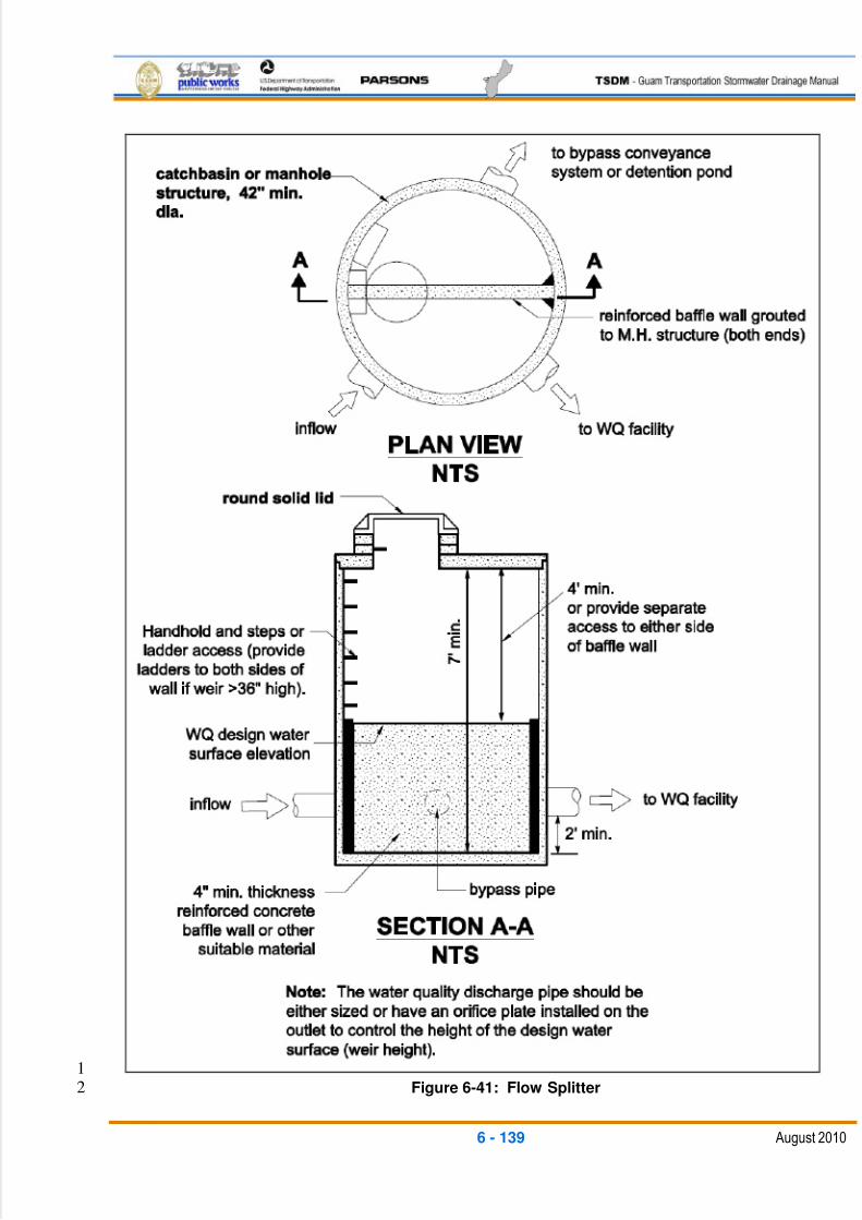
5/13/2018 Guam Storm Water Drainage Manual - slidepdf.com
http://slidepdf.com/reader/full/guam-storm-water-drainage-manual 275/486
6 - 139 August 2010
1Figure 6-41: Flow Splitter2
5/13/2018 Guam Storm Water Drainage Manual - slidepdf.com
http://slidepdf.com/reader/full/guam-storm-water-drainage-manual 276/486
6 - 140 August 2010
All metal parts must be corrosion-resistant. Examples of preferred materials include1
aluminum, stainless steel, and plastic. Avoid the use of zinc and galvanized materials2
because of their aquatic toxicity potential, when substitutes are available. Painting metal3
parts for corrosion resistance is not allowed because paint does not provide long-term4
protection.5
6.6.3 FLOW-SPREADING OPTIONS6
Flow spreaders function to uniformly spread flows across the inflow portion of runoff7
treatment facilities (such as a biofiltration swale, or a vegetated filter strip). Seven flow8
spreader options are presented in this section:9
Option A – Anchored plate10
Option B – Concrete sump box11
Option C – Notched curb spreader12
Option D – Through-curb ports13
Option E – Interrupted curb14
Option F – Flow Spreader Trench15
Option G – Flow Spreader Swale16
Options A through C, F, and G can be used for spreading flows that are concentrated.17
Any one of these options can be used when spreading is required by the facility design18
criteria. Options A through C, F, and G can also be used for un-concentrated flows; in19
some cases they must be used, such as to correct for moderate grade changes along a20
vegetated filter strip.21
Options D and E are only for runoff that is already in a sheet flow condition and enters a22
vegetated filter strip, continuous inflow biofiltration swale, or infiltration trench.23
General Design Criteria24
Flows entering the spreader structure should be sub-critical non-erosive velocities. If25
required, energy dissipation should be provided by using rock or concrete pads or stilling26
structures (typically an inlet structure with flow overflowing the grated top into the27
spreader).28
Option A – Anchored Plate 29
Anchor plates can be used wherever concentrated flows need to be spread for a30
uniform sheet flow condition such as at biofiltration swales and engineered31
dispersion BMPs. An anchored plate flow spreader (see Figure 6-42) must be32
preceded by a sump having a minimum depth of 8 in. and a minimum width of 24 in.33
If not otherwise stabilized, the sump area must be rock riprap protected to reduce34
erosion and dissipate energy.35
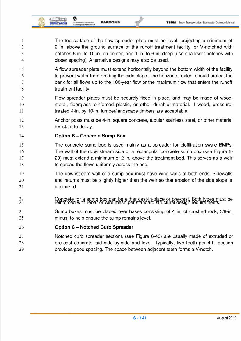
5/13/2018 Guam Storm Water Drainage Manual - slidepdf.com
http://slidepdf.com/reader/full/guam-storm-water-drainage-manual 277/486
6 - 141 August 2010
The top surface of the flow spreader plate must be level, projecting a minimum of1
2 in. above the ground surface of the runoff treatment facility, or V-notched with2
notches 6 in. to 10 in. on center, and 1 in. to 6 in. deep (use shallower notches with3
closer spacing). Alternative designs may also be used.4
A flow spreader plate must extend horizontally beyond the bottom width of the facility5
to prevent water from eroding the side slope. The horizontal extent should protect the6
bank for all flows up to the 100-year flow or the maximum flow that enters the runoff7
treatment facility.8
Flow spreader plates must be securely fixed in place, and may be made of wood,9
metal, fiberglass-reinforced plastic, or other durable material. If wood, pressure-10
treated 4-in. by 10-in. lumber/landscape timbers are acceptable.11
Anchor posts must be 4-in. square concrete, tubular stainless steel, or other material12
resistant to decay.13
Option B – Concrete Sump Box14
The concrete sump box is used mainly as a spreader for biofiltration swale BMPs.15
The wall of the downstream side of a rectangular concrete sump box (see Figure 6-16
20) must extend a minimum of 2 in. above the treatment bed. This serves as a weir17
to spread the flows uniformly across the bed.18
The downstream wall of a sump box must have wing walls at both ends. Sidewalls19
and returns must be slightly higher than the weir so that erosion of the side slope is20
minimized.21
Concrete for a sump box can be either cast-in-place or pre-cast, Both types must be22reinforced with rebar or wire mesh per standard structural design requirements.23
Sump boxes must be placed over bases consisting of 4 in. of crushed rock, 5/8-in.24
minus, to help ensure the sump remains level.25
Option C – Notched Curb Spreader26
Notched curb spreader sections (see Figure 6-43) are usually made of extruded or27
pre-cast concrete laid side-by-side and level. Typically, five teeth per 4-ft. section28
provides good spacing. The space between adjacent teeth forms a V-notch.29
5/13/2018 Guam Storm Water Drainage Manual - slidepdf.com
http://slidepdf.com/reader/full/guam-storm-water-drainage-manual 278/486
6 - 142 August 2010
1Figure 6-42: Flow Spreader – Anchor Plate2
3
4
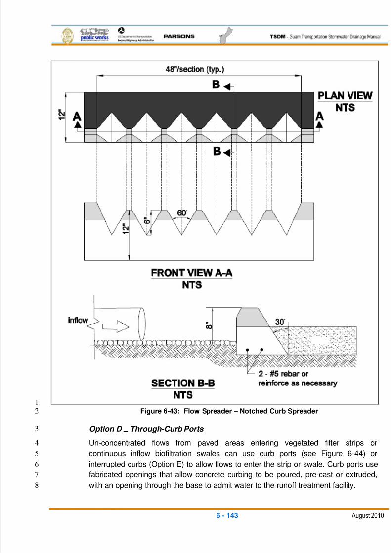
5/13/2018 Guam Storm Water Drainage Manual - slidepdf.com
http://slidepdf.com/reader/full/guam-storm-water-drainage-manual 279/486
6 - 143 August 2010
1Figure 6-43: Flow Spreader – Notched Curb Spreader2
Option D –
Through-Curb Ports 3
Un-concentrated flows from paved areas entering vegetated filter strips or4
continuous inflow biofiltration swales can use curb ports (see Figure 6-44) or5
interrupted curbs (Option E) to allow flows to enter the strip or swale. Curb ports use6
fabricated openings that allow concrete curbing to be poured, pre-cast or extruded,7
with an opening through the base to admit water to the runoff treatment facility.8
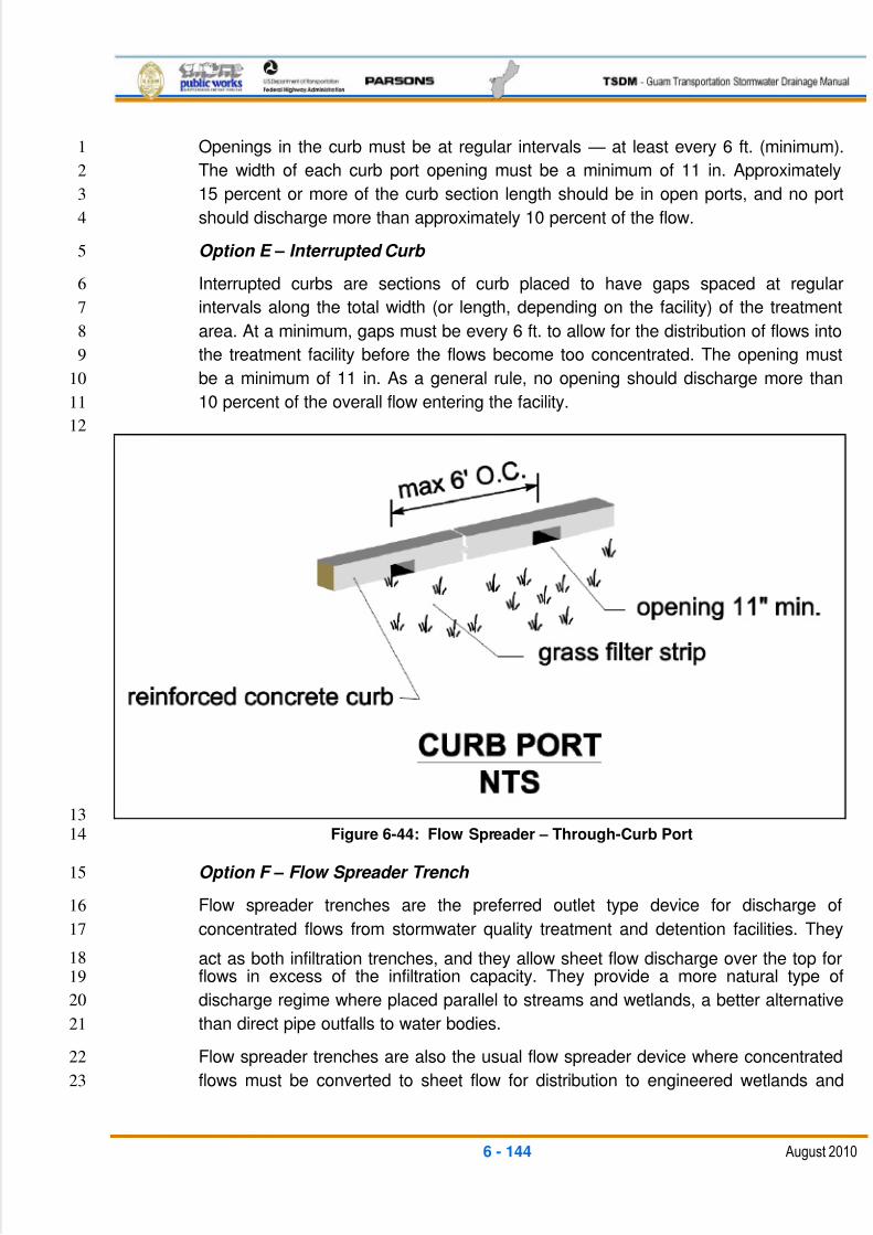
5/13/2018 Guam Storm Water Drainage Manual - slidepdf.com
http://slidepdf.com/reader/full/guam-storm-water-drainage-manual 280/486
6 - 144 August 2010
Openings in the curb must be at regular intervals — at least every 6 ft. (minimum).1
The width of each curb port opening must be a minimum of 11 in. Approximately2
15 percent or more of the curb section length should be in open ports, and no port3
should discharge more than approximately 10 percent of the flow.4
Option E – Interrupted Curb 5
Interrupted curbs are sections of curb placed to have gaps spaced at regular6
intervals along the total width (or length, depending on the facility) of the treatment7
area. At a minimum, gaps must be every 6 ft. to allow for the distribution of flows into8
the treatment facility before the flows become too concentrated. The opening must9
be a minimum of 11 in. As a general rule, no opening should discharge more than10
10 percent of the overall flow entering the facility.11
12
13Figure 6-44: Flow Spreader – Through-Curb Port14
Option F – Flow Spreader Trench 15
Flow spreader trenches are the preferred outlet type device for discharge of16
concentrated flows from stormwater quality treatment and detention facilities. They17
act as both infiltration trenches, and they allow sheet flow discharge over the top for18flows in excess of the infiltration capacity. They provide a more natural type of19
discharge regime where placed parallel to streams and wetlands, a better alternative20
than direct pipe outfalls to water bodies.21
Flow spreader trenches are also the usual flow spreader device where concentrated22
flows must be converted to sheet flow for distribution to engineered wetlands and23
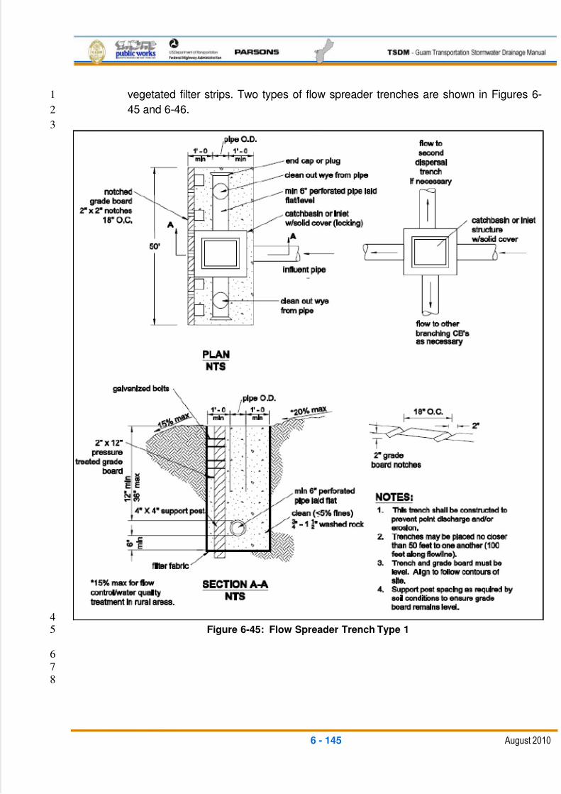
5/13/2018 Guam Storm Water Drainage Manual - slidepdf.com
http://slidepdf.com/reader/full/guam-storm-water-drainage-manual 281/486
6 - 145 August 2010
vegetated filter strips. Two types of flow spreader trenches are shown in Figures 6-1
45 and 6-46.2
3
4Figure 6-45: Flow Spreader Trench Type 15
6
7
8
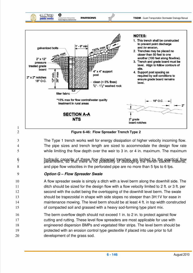
5/13/2018 Guam Storm Water Drainage Manual - slidepdf.com
http://slidepdf.com/reader/full/guam-storm-water-drainage-manual 282/486
6 - 146 August 2010
1Figure 6-46: Flow Spreader Trench Type 22
The Type 1 trench works well for energy dissipation of higher velocity incoming flow.3
The pipe sizes and trench length are sized to accommodate the design flow rate4
while limiting the flow depth over the weir to 3 in. or 4 in. maximum. The maximum5
hydraulic capacity of these flow dispersal trenches are limited by the practical flow6parameters, so that there is no possibility of dislodging the trench backfill material,7
and pipe flow velocities in the perforated pipe are no more than 5 fps to 6 fps. 8
Option G – Flow Spreader Swale 9
A flow spreader swale is simply a ditch with a level berm along the downhill side. The10
ditch should be sized for the design flow with a flow velocity limited to 2 ft. or 3 ft. per11
second with the outlet being the overtopping of the downhill level berm. The swale12
should be trapezoidal in shape with side slopes no steeper than 3H:1V for ease in13
maintenance mowing. The level berm should be at least 4 ft. in top width constructed14
of compacted soil and grassed with a heavy sod-forming type plant mix.15
The berm overflow depth should not exceed 1 in. to 2 in. to protect against flow16
cutting and rutting. These level flow spreaders are most applicable for use with17
engineered dispersion BMPs and vegetated filter strips. The level berm should be18
protected with an erosion control type geotextile if placed into use prior to full19
development of the grass sod.20
5/13/2018 Guam Storm Water Drainage Manual - slidepdf.com
http://slidepdf.com/reader/full/guam-storm-water-drainage-manual 283/486
6 - 147 August 2010
Level flow spreaders should have frequent maintenance checking for any signs of1
erosion or soil rutting. Any damaged areas on the level berm should be immediately2
repaired and reseeded. The level flow swales also require frequent mowing, and3
should not be used in areas inaccessible to this requirement. 4
6.6.4 OUTFALLS5
Properly-designed outfalls are critical to reducing the chance of adverse impacts as the6
result of concentrated discharges from pipe systems and culverts, both on-site and7
downstream.8
Outfall systems include rock splash pads, flow spreader trenches, gabion, or other9
energy pipe used to convey flows down a steep or sensitive slope with appropriate10
energy dissipation at the discharge end.11
General Design Criteria12
At a minimum, all outfalls must be provided with a rock splash pad (see Table 6-9 and13Figure 6-47).14
Where discharging from a stormwater quality treatment BMP to a natural stream or15
wetland, the preferred outfall is the flow spreader trench (see Figures 6-45 and 6-46).16
The flow spreader trench provides a combination infiltration/sheet flow discharge that is17
more natural and protective of the existing water body.18
For outfalls with a design velocity greater than 8 ft. to 10 ft per second, an engineered19
energy dissipater may be required. There are many possible designs. One example for20
typical-sized storm drainage pipe outfalls with higher velocities is the gabion basket21
protection (see Figure 6-48). Note: The gabion outfall detail shown in Figure 6-48 is22illustrative only. A design engineered to specific site conditions must be developed.23
Tight-line systems may be needed to prevent aggravation or creation of a downstream24
erosion problem.25
Outfalls to marine waters require specific engineering designs to account for the26
additional corrosion effects and energy of the receiving waters, and to minimize impacts27
to the ecology of the tidal zone. In marine waters, rock splash pads and gabion28
structures are not recommended. Rock splash pads can be destroyed by wave action,29
and gabion baskets will corrode in saltwater and, potentially, be dislocated by wave30
action.31
If the discharge cannot be made above the mean high water in marine waters, tight line32
systems are used. The energy dissipation is performed within the submerged section of33
the outfall pipeline/structures. The outfall pipeline is normally trenched to discharge34
below extreme low water, often times using a ‗T‘ diffuser on the end. The outfall must be35
protected by heavy riprap blankets from wave and tidal current action, and boat36
anchorage.37
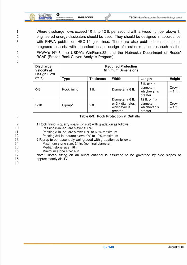
5/13/2018 Guam Storm Water Drainage Manual - slidepdf.com
http://slidepdf.com/reader/full/guam-storm-water-drainage-manual 284/486
6 - 148 August 2010
Where discharge flows exceed 10 ft. to 12 ft. per second with a Froud number above 1,1
engineered energy dissipaters should be used. They should be designed in accordance2
with FHWA publication HEC-14 guidelines. There are also public domain computer3
programs to assist with the selection and design of dissipater structures such as the4
FHWA‘s HY-8, the USDA‘s WinFlume32, and the Nebraska Department of Roads‘5
BCAP (Broken-Back Culvert Analysis Program).6
7
DischargeVelocity atDesign Flow(ft./s)
Required ProtectionMinimum Dimensions
Type Thickness Width Length Height
0-5 Rock lining1
1 ft. Diameter + 6 ft.
8 ft. or 4 xdiameter,whichever isgreater
Crown+ 1 ft.
5-10 Riprap2
2 ft.
Diameter + 6 ft.
or 3 x diameter,whichever isgreater
12 ft. or 4 x
diameter,whichever isgreater
Crown+ 1 ft.
Table 6-9: Rock Protection at Outfalls8
1 Rock lining is quarry spalls (pit run) with gradation as follows:9Passing 8-in.-square sieve: 100%10Passing 3-in.-square sieve: 40% to 60% maximum11Passing 3/4-in.-square sieve: 0% to 10% maximum12
2 Riprap to be reasonably well-graded with gradation as follows:13Maximum stone size: 24 in. (nominal diameter)14Median stone size: 16 in.15Minimum stone size: 4 in.16
Note: Riprap sizing on an outlet channel is assumed to be governed by side slopes of17approximately 3H:1V.18
19
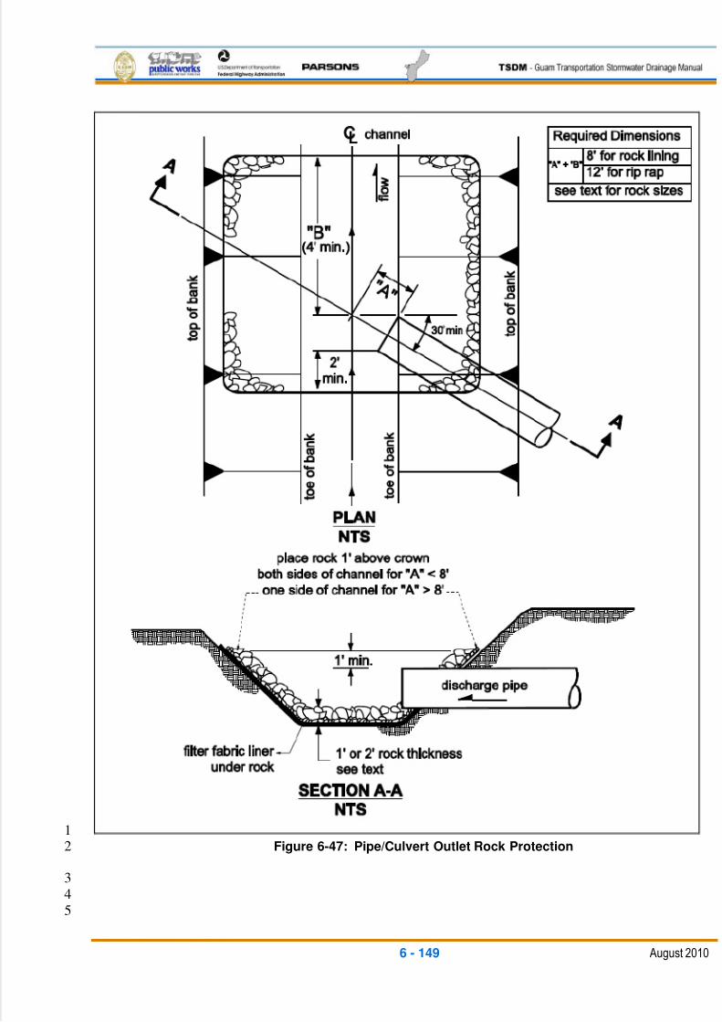
5/13/2018 Guam Storm Water Drainage Manual - slidepdf.com
http://slidepdf.com/reader/full/guam-storm-water-drainage-manual 285/486
6 - 149 August 2010
1Figure 6-47: Pipe/Culvert Outlet Rock Protection2
3
4
5
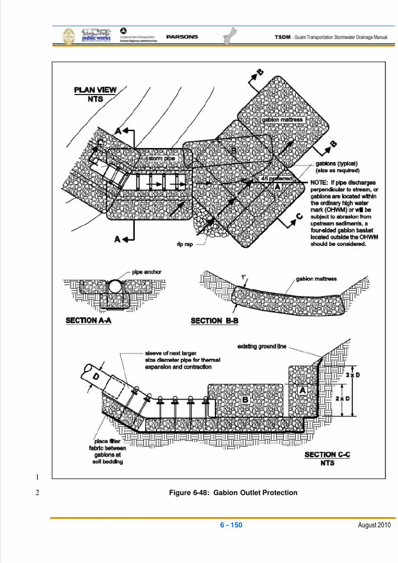
5/13/2018 Guam Storm Water Drainage Manual - slidepdf.com
http://slidepdf.com/reader/full/guam-storm-water-drainage-manual 286/486
6 - 150 August 2010
1
Figure 6-48: Gabion Outlet Protection2
5/13/2018 Guam Storm Water Drainage Manual - slidepdf.com
http://slidepdf.com/reader/full/guam-storm-water-drainage-manual 287/486
6 - 151 August 2010
Tight-Line Systems 1
Mechanisms that reduce runoff velocity prior to discharge from an outfall are2
encouraged. Two of these mechanisms are drop manholes and the rapid expansion3
of pipe diameter.4
Bank stabilization, bioengineering, and habitat features may be required for disturbed5
areas. Outfall structures should be located and configured to minimize impacts to the6
riparian habitat, and in particular, avoid impacts below the Ordinary High Water of7
natural water bodies.8
6.6.5 SOIL AMENDMENTS9
General Description10
Soil amendments, including compost and other organic materials, help restore11
the health of the soil and increase environmental functions such as rainwater12
infiltration and natural detention, evapotranspiration, and plant health. Soil13amendments can help prevent or minimize adverse stormwater impacts during14
construction and are used along with vegetation as a permanent runoff treatment15
BMP. Compost is a versatile material that can be used as a component in many16
other permanent and temporary stormwater BMPs.17
Compost-amended soils can be modeled as pasture on native soil. The final18
organic content of these soils should be 10 percent for all areas, excluding turf19
areas, which are expected to receive a high amount of foot traffic. Turf (lawn)20
areas with high foot traffic must have a 5 percent final organic content.21
Applications and Limitations22
Soil amendments can be used in most unpaved areas within the project. If soil23
amendments are applied as a blanket, they perform erosion control functions24
immediately by providing a cover to bare soils. When incorporated into the soil,25
they increase infiltration and adsorption of metals and aid in the uptake of26
nutrients. They also enhance vegetation growth and plant establishment.27
Compost provides an excellent growing medium for roadside vegetation.28
Traditional highway construction methods typically result in the excavation and29
removal of the area‘s topsoil. Roadway embankments are then constructed from30
material that has few nutrients, is low in organic material, and is compacted to 9531
percent maximum density. Adding compost to roadway slopes and ditches32
provides soil cover, improves soil fertility and texture, and greatly improves the33
vegetative growth and soil stability, thereby reducing erosion.34
Organic soil amendments soak up water like a sponge and store it until it can be35
slowly infiltrated into the ground or taken up by plants. In some BMP applications,36
5/13/2018 Guam Storm Water Drainage Manual - slidepdf.com
http://slidepdf.com/reader/full/guam-storm-water-drainage-manual 288/486
6 - 152 August 2010
the volume of compost can be sized to absorb and hold the runoff treatment1
storm.2
Compost is an excellent filtration medium, which provides treatment for highway3
runoff. Compost has a high cation exchange capacity (CEC) that chemically traps4
dissolved heavy metals and binds them to the compost material. Oils, grease,5
and floatables are also removed from stormwater as it is filtered through the6
compost.7
Compost is very absorbent when dry, but when saturated it has a high infiltration8
rate. Therefore, greater storm events can pass through compost medium without9
hindering the infiltration rates of underlying soils or drain materials. Compost has10
also been shown to improve the infiltration rates of underlying soils, even till soils.11
Placement of a compost blanket on bare soil helps stabilize the soil and prevent12
surface erosion by intercepting rainfall. This type of application changes the13
texture and workability of the soil, lengthens the acceptable seeding windows,14
and encourages plant growth.15
Compost soil amendments can be used in the construction phase of projects as16
compost berms and compost socks in lieu of conventional geotextile silt fences17
for sediment control. While being an effective sediment trap during the18
construction phase, compost berms are advantageous in that they can be bladed19
out at the construction site, which avoids bid items for the haul and disposal of20
silt fences. If the permanent stormwater design involves use of compost-21
amended vegetated filter strips, a batch of compost can be used as sediment22
control in a berm, then the berm can be bladed out along a highway roadside,23where it can be used as part of vegetated filter strip construction. Compost socks24
can be left in place and will deteriorate with time.25
Maintenance 26
Compost, as with sand filters or other filter mediums, can become plugged with27
fines and sediment, which may require removal and replacement. Including28
vegetation with compost helps prevent the medium from becoming plugged with29
sediment by breaking up the sediment and creating root pathways for stormwater30
to penetrate into the compost. It is expected that soil amendments will have a31
removal and replacement cycle; however, this time frame has not yet been32
established.33
34
35
5/13/2018 Guam Storm Water Drainage Manual - slidepdf.com
http://slidepdf.com/reader/full/guam-storm-water-drainage-manual 289/486
6 - 153 August 2010
6.7 OPERATION AND MAINTENANCE1
Inadequate maintenance is a common cause of failure for stormwater control facilities.2
Proper maintenance requires regular inspection and prompt repair and cleaning of3
structures when needed. The designer should simplify this process by providing designs4
that promote easy access for maintenance inspections and regular maintenance work.5
The stormwater designer should follow these guidelines as a minimum:6
Review other stormwater BMP installations and observe those items that are7
ineffective, poorly-maintained, and/or working correctly for what should not be or8
what should be incorporated into the planned BMPs.9
Review all preliminary BMP designs with DPW‘s maintenance staff for their input10
on the maintainability.11
Provide safe, convenient access to the BMPs for ease of regular maintenance.12
This should include properly-designed traffic pull-out areas that allow for safe13egress in and out of traffic, with surfaced parking and walking access. Working14
pads and access ramps should be suitable for the facility in regards to the15
equipment needed to maintain the facility, such as surfaced pads large enough to16
maneuver trucks for cleaning and loading, ramps surfaced on slopes suitable for17
the equipment, parking in front of gates for inspection vehicles, etc.18
Provide vehicle access for cleaning of all inlet and outlet control structures.19
Provide pullout locations for maintenance vehicles with trailers where mowing is20
required.21
Underground structures should have suitable work pads around the access22
opening for equipment, with access openings suitable for both inspection23
manhole access and larger sediment/trash removal equipment.24
Provide lighting and ventilation where regular access must be made in enclosed25
space locations such as underground sumps and pump chambers.26
For critical drainage and flood control facilities, provide emergency failure alarms27
based on high water levels or pump failure, with red flashing light and signs at28
the site plus a wireless signal to DPW‘s maintenance headquarters.29
30

5/13/2018 Guam Storm Water Drainage Manual - slidepdf.com
http://slidepdf.com/reader/full/guam-storm-water-drainage-manual 290/486
This page intentionally left blank
5/13/2018 Guam Storm Water Drainage Manual - slidepdf.com
http://slidepdf.com/reader/full/guam-storm-water-drainage-manual 291/486
7 - 1 August 2010
7 CONSTRUCTION SITE BEST MANAGEMENT PRACTICES1
This chapter of the Transportation Stormwater Drainage Manual (TSDM) provides designers2
with specific guidelines and criteria on the proper selection, design, and application of3
construction site stormwater management techniques. A selection process is presented,4along with design considerations for each Best Management Practice (BMP).5
Construction site BMPs are applied during construction activities to reduce the pollutants in6
stormwater discharges throughout construction. These construction site BMPs provide both7
temporary erosion and sediment control, as well as control for potential pollutants other than8
sediment. There are five categories of BMPs suitable for controlling potential pollutants on9
construction sites. They are:10
Soil stabilization practices11
Sediment control practices12
Wind erosion control13
Tracking control practices14
Non-stormwater controls15
It is generally accepted that practices that perform well by themselves can be16
complemented by other BMPs to raise the collective effectiveness level for erosion control17
and sediment retention.18
Effective erosion and sediment control planning relies on a system of BMPs such as19
mulches for source control, fiber rolls on slopes for reducing runoff velocities, and silt fences20
at the toe of slopes for capturing sediment, among others.21
To meet regulatory requirements and protect the site resources, every project must include22
an effective combination of erosion and sediment control measures. These measures must23
be selected from all of the BMP categories presented in this section -- soil stabilization24
practices, sediment control practices, tracking control practices, and wind erosion control25
practices.26
Additionally, the project plan must include non-stormwater controls, waste management,27
and material pollution controls.28
Table 7-1 is a matrix of the construction site BMPs that are generally used during29
construction. Detailed descriptions and guidance regarding the implementation of these30
BMPs may be found in later sections of this chapter. The individual BMPs, designated by an31
“X” in Table 7-1 as being applicable to a particular, typical construction activity, is a guideline32
only, and the final selection of BMPs will depend on the actual site conditions and33
contractor’s work elements, staging, schedule, and site management philosophy.34
35
5/13/2018 Guam Storm Water Drainage Manual - slidepdf.com
http://slidepdf.com/reader/full/guam-storm-water-drainage-manual 292/486
7 - 2 August 2010
The last section of this chapter discusses post construction source control BMPs,1
sometimes also known as “maintenance BMPs”. The objective of implementing maintenance2
BMPs is to provide preventative measures to ensure that maintenance activities are3
conducted in a manner that reduces the amount of pollutants discharged to surface waters4
through DPW’s stormwater drainage systems. DPW’s maintenance activities involve the use5
of a variety of products. Under normal, intended conditions of use, these materials are not6
considered “pollutants of concern.” However, if these products are used, stored, spilled, or7
disposed of in a way that may cause them to contact stormwater or enter stormwater8
drainage systems, they may become a concern for water quality.9
10

5/13/2018 Guam Storm Water Drainage Manual - slidepdf.com
http://slidepdf.com/reader/full/guam-storm-water-drainage-manual 293/486
7 - 3
D e m o
l i s h
P a v e m e n
t a n
d
S t r u c
t u r e s
C l e a r a n
d G r u
b
C o n s
t r u c
t A c c e s s
R o a
d s
G r a
d i n g
( i n c
. c u
t
a n
d f i l l s
l o p e s
)
C h a n n e
l
E x c a v a
t i o n
T r e n c
h i n g a n
d
U n
d e r g r o u n
d
D r a
i n a g e
U t i l i t y T r e n c
h i n g
U t i l i t y I n s
t a l l a t i o n
S u
b g r a
d e
p r e p a r a
t i o n
B a s e
P a v
i n g
P a v
i n g
S a w
C u
t t i n g
J o
i n t S e a
l i n g
G r i n
d / G r o o v e
S t r u c
t u r e
E x c a v a
t i o n
E r e c
t F a
l s e w o r k
B r i d g e
/ S t r u c
t u r e
C o n s
t r u c
t i o n
R e m o v e
F a
l s e w o r k
Construction Best ManagementPractices
Soil Stabilization Practices Scheduling X X X X X X X X X X X X X X X X
Preservation of Existing Vegetation X X X X X X X X
Hydraulic Mulch X X X X X
Hydroseeding X X X X X
Soil Binders X X X X X X
Fiber Mulch X X X X X X X X X X
Geotextile, Plastic Covers, andErosion Control Blankets/Mats
X X X X X X X X X X
Temporary Concentrated FlowConveyance Controls
X X X X
Streambank Stabilization X X X X X X
Sediment Control Practices Silt Fence X X X X X X X X X X
Sediment Basin X X X X
Sediment Traps X X X X X X X X X X
Check Dams X X X X X X X X X X
Fiber Rolls/Wattles X X X X X X X X X X
Gravel Bag Berm X X X X X X X X X X
Street Sweeping and Vacuuming X X X X X X X X X X
Storm Drain Inlet Protection X X X X X X X X X X
Streambank Sediment Control X X X X X X X X X X
Wind Erosion Control Tracking Control Practices
Stabilized ConstructionEntrance/Exit
X X X
Stabilized Construction Roadway X X X
Entrance/Outlet Tire Wash X X X
Non-stormwater Controls Water Conservation Practices X X X X X X X X X X X X X
De-Watering Operation X X X X X X X X
Temporary Stream Crossing X X X X X X X
Clear Water Diversion X X X X X X
Potable Water/Irrigation
Vehicle and Equipment Cleaning X X X X X X X X X X X X X X X X X X
Vehicle and Equipment Fueling X X X X X X X X X X X X X X X X X X
Vehicle and EquipmentMaintenance
X X X X X X X X X X X X X X X X X X

5/13/2018 Guam Storm Water Drainage Manual - slidepdf.com
http://slidepdf.com/reader/full/guam-storm-water-drainage-manual 294/486
7 - 4
D e m o
l i s h
P a v e m e n
t a n
d
S t r u c
t u r e s
C l e a r a n
d G r u
b
C o n s
t r u c
t A c c e s s
R o a
d s
G r a
d i n g
( i n c
. c u
t
a n
d f i l l s
l o p e s
)
C h a n n e
l
E x c a v a
t i o n
T r e n c
h i n g a n
d
U n
d e r g r o u n
d
D r a
i n a g e
U t i l i t y T r e n c
h i n g
U t i l i t y I n s
t a l l a t i o n
S u
b g r a
d e
p r e p a r a
t i o n
B a s e
P a v
i n g
P a v
i n g
S a w
C u
t t i n g
J o
i n t S e a
l i n g
G r i n
d / G r o o v e
S t r u c
t u r e
E x c a v a
t i o n
E r e c
t F a
l s e w o r k
B r i d g e
/ S t r u c
t u r e
C o n s
t r u c
t i o n
R e m o v e
F a
l s e w o r k
Pile-Driving Operations X X X X Concrete Curing X X X
Material and Equipment Use Over Water
X X X X X X X X X X
Concrete Finishing X
Structure Demolition Over Or Adjacent To Water
X X X
Table 7-1: Construction Site BMPs by Construction Activity1
5/13/2018 Guam Storm Water Drainage Manual - slidepdf.com
http://slidepdf.com/reader/full/guam-storm-water-drainage-manual 295/486
7 - 5 August 2010
7.1 SOIL STABILIZATION PRACTICES1
Temporary soil stabilization practices consist of preparing the soil surface and applying2
one of the BMPs shown in Table 7-2, or a combination thereof, to disturbed soil areas.3
4
BMP Name
Scheduling
Preservation of Existing Vegetation
Hydraulic Mulch
Hydroseeding
Soil Binders
Fiber Mulch
Geotextiles, Plastic Covers, and Erosion Control Blankets/Mats
Temporary Concentrated Flow Conveyance Controls
Stream Bank Stabilization
Table 7-2: Temporary Soil Stabilization BMPs5
7.1.1 SCHEDULING6
Definition and Purpose7
This BMP involves developing a schedule for every project that includes the sequencing8
of construction activities with the implementation of construction site BMPs such as9
temporary soil stabilization (erosion control) and temporary sediment control measures.10
The purpose is to reduce the amount and duration of soil exposed to erosion by wind,11
rain, runoff, and vehicle tracking, and to perform the construction activities and control12
practices in accordance with the planned schedule.13
Appropriate Applications14
Construction sequencing should be scheduled to minimize land disturbance for all15
projects during the rainy season. Appropriate BMPs should be implemented during both16
rainy and non-rainy seasons.17
Limitations18
None identified.19
Standards and Specifications20
Developing a schedule and planning the project are the very first steps in an21
effective stormwater program. The schedule should clearly show how the rainy22
5/13/2018 Guam Storm Water Drainage Manual - slidepdf.com
http://slidepdf.com/reader/full/guam-storm-water-drainage-manual 296/486
7 - 6 August 2010
season relates to soil-disturbing and re-stabilization activities. The construction1
schedule should be incorporated into the Stormwater Pollution Prevention Plan2
(SWPPP).3
The schedule should include details on the rainy season implementation and4
deployment of:5
o Temporary soil stabilization BMPs6
o Temporary sediment control BMPs7
o Tracking control BMPs8
o Wind erosion control BMPs9
o Non-stormwater BMPs10
o Waste management and materials pollution control BMPs11
The schedule should also include dates for significant long-term operations or12
activities that may have planned non-stormwater discharges such as de-13
watering, saw-cutting, grinding, drilling, boring, crushing, blasting, painting,14
hydro-demolition, mortar mixing, bridge cleaning, etc.15
Schedule work to minimize soil-disturbing activities during the rainy season.16
o Develop the sequencing and timetable for the start and completion of17
each item, such as site clearing and grubbing, grading, excavation,18
paving, pouring foundations, installing utilities, etc., to minimize the active19
construction area during the rainy season.20
o Schedule major grading operations for the non-rainy season when21
practical.22
o Stabilize non-active areas within two days during wet season and seven23
days during dry season, or one day prior to the onset of precipitation,24
whichever occurs first.25
o Monitor the weather forecast for rainfall.26
o When rainfall is predicted, adjust the construction schedule to allow the27
implementation of soil stabilization and sediment controls and sediment28
treatment controls on all disturbed areas prior to the onset of rain.29
Be prepared year-round to deploy soil stabilization and sediment control30
practices. Erosion may be caused during dry seasons by unseasonal rainfall,31
wind, and vehicle tracking. Keep the site stabilized year round, and retain and32
maintain rainy-season sediment-trapping devices in operational condition.33
Sequence trenching activities so that most open portions are closed before new34
trenching begins.35
5/13/2018 Guam Storm Water Drainage Manual - slidepdf.com
http://slidepdf.com/reader/full/guam-storm-water-drainage-manual 297/486
7 - 7 August 2010
Incorporate staged seeding and the re-vegetation of graded slopes as work1
progresses.2
Consider scheduling when establishing permanent vegetation (appropriate3
planting time for specified vegetation).4
Apply permanent erosion control to areas deemed substantially complete during5
the project’s defined seeding window.6
Maintenance and Inspection7
Verify that work is progressing in accordance with the schedule. If progress8
deviates, take corrective actions.9
Amend the schedule when changes are warranted.10
The contractual specifications may require the annual submittal of a rainy season11
implementation schedule. Amend the schedule prior to the rainy season to show12
updated information on the deployment and implementation of construction site13
BMPs.14
7.1.2 PRESERVATION OF EXISTING VEGETATION15
Definition and Purpose16
The preservation of existing vegetation is the identification and protection of desirable17
vegetation that provides erosion and sediment control benefits. The purpose of18
preserving natural vegetation is to reduce erosion wherever practicable. Limiting site19
disturbance is the single most effective method for reducing erosion.20
Appropriate Applications21
Preserve existing vegetation at areas on a site where no construction activity is22
planned or where construction will occur at a later date. Specifications for the23
preservation of existing vegetation can be found in the Federal Highway 24
Administration (FHWA) Standard Specifications for Construction of Roads and 25
Bridges on Federal Highway Projects, Section 201 (FP-03) (Standard26
Specifications). On a year-round basis, temporary fencing should be placed27
around areas not to be disturbed prior to the commencement of clearing and28
grubbing operations or other soil-disturbing activities.29
Clearing and grubbing operations should be staged to preserve existing30
vegetation.31
Limitations32
The protection of existing vegetation requires planning and may limit the area available33
for construction activities.34
35
5/13/2018 Guam Storm Water Drainage Manual - slidepdf.com
http://slidepdf.com/reader/full/guam-storm-water-drainage-manual 298/486
7 - 8 August 2010
Standards and Specifications1
Timing 2
The preservation and fencing-off of existing vegetation should be provided3
prior to the commencement of clearing and grubbing operations or other soil-4
disturbing activities in areas identified on the plans to be preserved,5
especially on areas designated as environmentally sensitive.6
The preservation of existing vegetation should conform to the approved7
project schedule.8
Design and Layout 9
Mark areas to be preserved with temporary fencing made of orange10
polypropylene that is stabilized against ultraviolet (UV) light. The temporary11
fencing should be at least 3.2 ft. tall and should have openings no larger than12
2 in. by 2 in.13
At the contractor’s discretion, fence posts should be either wood or metal, as14
appropriate for the intended purpose. The post spacing and depth should be15
adequate to completely support the fence in an upright position.16
Minimize the disturbed areas by locating temporary roadways to avoid stands17
of trees and shrubs and to follow existing contours to reduce cutting and18
filling.19
Consider the impact of grade changes to existing vegetation and the root20
zone.21
Installation 22
Construction materials, equipment storage, and parking areas should be23
located where they will not cause root compaction.24
Keep equipment away from trees to prevent trunk and root damage.25
Maintain existing irrigation systems.26
Employees and subcontractors should be instructed to honor protective27
devices.28
No heavy equipment, vehicular traffic, or storage piles of any construction29
materials should be permitted within the drip line of any tree to be retained.30
Removed trees should not be felled, pushed, or pulled into any retained31
trees.32
Fires should not be permitted within 100 ft. of the drip line of any retained33
trees. Any fires should be of limited size and should be kept under continual34
5/13/2018 Guam Storm Water Drainage Manual - slidepdf.com
http://slidepdf.com/reader/full/guam-storm-water-drainage-manual 299/486
7 - 9 August 2010
surveillance. No toxic or construction materials (including paint, acid, nails,1
gypsum board, chemicals, fuels, and lubricants) should be stored within 50 ft.2
of the drip line of any retained trees, nor disposed of in any way that would3
injure vegetation.4
Trenching and Tunneling 5
Trenching should be as far away from tree trunks as possible, usually outside6
of the tree drip line or canopy. Curve trenches around trees to avoid large7
roots or root concentrations. If roots are encountered, consider tunneling8
under them. When trenching and/or tunneling near or under trees to be9
retained, tunnels should be at least 18 in. below the ground surface and not10
below the tree center, to minimize impact on the roots.11
Tree roots should not be left exposed to air; they should be covered with soil12
as soon as possible, protected, and kept moistened with wet burlap or peat13
moss until the tunnel and/or trench can be completed.14
The ends of damaged or cut roots should be cut off smoothly.15
Trenches and tunnels should be filled as soon as possible. Careful filling and16
tamping will eliminate air spaces in the soil, which can damage roots.17
Remove any trees intended for retention if those trees are damaged seriously18
enough to affect their survival. If replacement is desired or required, the new19
tree should be of a similar species, and at least 2 in. caliper, unless otherwise20
required by the contract documents.21
After all other work is complete, fences and barriers should be removed last.22
This is because protected trees may be destroyed by carelessness during23
final cleanup and landscaping.24
Maintenance and Inspection 25
During construction, the limits of disturbance should remain clearly marked at26
all times. Irrigation or maintenance of existing vegetation should conform to27
the requirements in the landscaping plan. If damage to protected trees28
occurs, the trees should be attended to by an arborist.29
7.1.3 HYDRAULIC MULCH30
Definition and Purpose31
Hydraulic mulch consists of applying a mixture of shredded wood, plant, or pulp fiber, or32
another bonded fiber matrix and a stabilizing emulsion or tackifier with hydroseeding33
equipment, which temporarily protects exposed soil from erosion by raindrop impact or34
wind. This is one of five temporary soil stabilization alternatives to consider.35
36
5/13/2018 Guam Storm Water Drainage Manual - slidepdf.com
http://slidepdf.com/reader/full/guam-storm-water-drainage-manual 300/486
7 - 10 August 2010
Appropriate Applications1
Hydraulic mulch is applied to disturbed areas requiring temporary protection until2
permanent vegetation is established or disturbed areas that must be re-3
disturbed, following an extended period of inactivity.4
Limitations5
Hydraulic mulches are generally short-lived (only last a part of a growing season) and6
need 24 hours to dry before rainfall occurs, to be effective. Avoid use in areas where the7
mulch would be incompatible with immediate future earthwork activities and would have8
to be removed.9
Standards and Specifications10
Prior to application, roughen embankment and fill areas by rolling with a crimping11
or punching-type roller or by track walking. Track walking should only be used12
where other methods are impractical.13
Hydraulic matrices require 24 hours to dry before rainfall occurs to be effective.14
Avoid mulch overspray onto the traveled way, sidewalks, lined drainage15
channels, and existing vegetation.16
Hydraulic mulch should be applied in accordance with Standard Specification,17
Section 625.08 (b), Hydraulic Method. 18
Materials for hydraulic mulches and hydraulic matrices should conform to19
Standard Specification, Section 713.05.20
Hydraulic Mulch 21
Wood fiber mulch is a component of hydraulic applications. It is typically22
applied at the rate of 2,000 pounds per acre to 4,000 pounds per acre, with 023
percent to 5 percent by weight of a stabilizing emulsion or tackifier, such as24
guar, psyllium, and acrylic copolymer, and applied as a slurry. This type of25
mulch is manufactured from wood or wood waste from lumber mills or from26
urban sources. 27
A hydraulic matrix is a combination of fiber mulch and a tackifier applied as a28
slurry. It is typically applied at the rate of 1,500 pounds per acre, with29
5 percent to 10 percent by weight of a stabilizing emulsion or tackifier such as30
guar, psyllium, and acrylic copolymer.31
Bonded Fiber Matrix (BFM) is a hydraulically-applied system of fibers and32
adhesives that, upon drying, forms an erosion-resistant blanket that promotes33
vegetation and prevents soil erosion. BFMs are typically applied at rates from 34
3,400 kilograms per hectare to 4,500 kilograms per hectare, based on the35
manufacturer’s recommendation. The biodegradable BFM is composed of36
5/13/2018 Guam Storm Water Drainage Manual - slidepdf.com
http://slidepdf.com/reader/full/guam-storm-water-drainage-manual 301/486
7 - 11 August 2010
materials that are 100 percent biodegradable. The binder in the BFM should1
also be biodegradable and should not dissolve or disperse upon re-wetting.2
Typically, biodegradable BFMs should not be applied immediately before,3
during, or after rainfall, if the soil is saturated. Depending on the product,4
BFMs require 12 hours to 24 hours to dry to become effective.5
Maintenance and Inspections6
Maintain an unbroken, temporary mulched ground cover throughout the period of7
construction when the soils are not being reworked. Inspect the ground cover8
before expected rain storms, repair any damaged ground cover, and re-mulch9
the exposed areas of bare soil.10
After any rainfall event, the contractor is responsible for maintaining all slopes to11
prevent erosion.12
7.1.4 HYDROSEEDING13
Definition and Purpose14
Hydroseeding typically consists of applying a mixture of wood, plant or pulp fiber, seed,15
fertilizer, and stabilizing emulsion with hydromulch equipment, which temporarily16
protects exposed soils from erosion by water and wind. This is one of five temporary soil17
stabilization alternatives to consider.18
Appropriate Applications19
Hydroseeding is applied on disturbed soil areas requiring temporary protection until20
permanent vegetation is established, or disturbed soil areas that must be re-disturbed21
following an extended period of inactivity.22
Limitations23
Hydroseeding may be used alone only when there is sufficient time in the season24
to ensure adequate vegetation establishment and erosion control. Otherwise,25
hydroseeding must be used in conjunction with a soil binder or heavier layer of26
mulching such as wood, plant, or pulp fiber mulch.27
Steep slopes are difficult to protect with temporary seeding.28
Temporary seeding may not be appropriate in dry periods without supplemental29
irrigation.30
Temporary vegetation may have to be removed before permanent vegetation is31
applied.32
Temporary vegetation is not appropriate for short-term inactivity.33
34
35
5/13/2018 Guam Storm Water Drainage Manual - slidepdf.com
http://slidepdf.com/reader/full/guam-storm-water-drainage-manual 302/486
7 - 12 August 2010
Standards and Specifications1
To select appropriate hydroseeding mixtures, an evaluation of site conditions should be2
performed with respect to:3
Soil conditions4
Site topography5
Season and climate6
Vegetation types7
Maintenance requirements8
Sensitive adjacent areas9
Water availability10
Plans for permanent vegetation11
The following steps should be followed for implementation:12
Seed mix should comply with the Standard Specifications, Section 713.04, and13
be of type to match the application and climate conditions in accordance with the14
guidance provided by the Guam Division of Aquatic and Wildlife Resources15
(DAWR) or the USDA, National Resources Conservation Service (NRCS).16
Hydroseeding should be performed in accordance with Standard Specifications17
625.06 or 625.07.18
Prior to application, roughen the slope, fill area, or area to be seeded with the19
furrows trending along the contours. Rolling with a crimping or punching-type20
roller or track walking is required on all slopes prior to hydroseeding. Track21
walking should only be used where other methods are impractical.22
Apply a fiber mulch to keep seeds in place and to moderate soil moisture and23
temperature until the seeds germinate and grow. Refer to Standard Specification24
625.08.25
Follow-up applications should be made as needed to cover weak spots and to26
maintain adequate soil protection.27
Avoid overspray onto the traveled way, sidewalks, lined drainage channels, and28
existing vegetation.29
Maintenance and Inspection30
All seeded areas should be inspected for failures and re-seeded, fertilized, and31
mulched within the planting season, using not less than half the original32
5/13/2018 Guam Storm Water Drainage Manual - slidepdf.com
http://slidepdf.com/reader/full/guam-storm-water-drainage-manual 303/486
7 - 13 August 2010
application rates. Any temporary re-vegetation efforts that do not provide1
adequate cover must be reapplied.2
After any rainfall event, the contractor is responsible for maintaining all slopes to3
prevent erosion.4
7.1.5 SOIL BINDERS5
Definition and Purpose6
Soil binders consist of applying and maintaining a soil stabilizer to exposed soil surfaces.7
Soil binders are materials applied to the soil surface to temporarily prevent water-8
induced erosion of exposed soils on construction sites. Soil binders also provide9
temporary dust, wind, and soil stabilization (erosion control) benefits. This is one of five10
temporary soil stabilization alternatives to consider.11
Appropriate Applications12
Soil binders are typically applied to disturbed areas requiring short-term temporary13
protection. Because soil binders can often be incorporated into the work, they may be a14
good choice for areas where grading activities will soon resume, and as an application15
on stockpiles to prevent water and wind erosion.16
Limitations17
Soil binders are temporary in nature and may need reapplication.18
Soil binders require a minimum curing time until fully-effective, as prescribed by19
the manufacturer, which may be 24 hours or longer. Soil binders may need20
reapplication after a storm event.21
Soil binders will generally experience spot failures during heavy rainfall events. If22
runoff penetrates the soil at the top of a slope treated with a soil binder, it is likely23
that the runoff will undercut the stabilized soil layer and discharge at a point24
farther down slope.25
Soil binders do not hold up to pedestrian or vehicular traffic across treated areas.26
Soil binders may not penetrate soil surfaces made up primarily of silt and clay,27
particularly when compacted.28
Some soil binders may not perform well with low relative humidity. Under rainy29
conditions, some agents may become slippery or leach out of the soil.30
Standards and Specifications31
General Considerations 32
Site-specific soil types will dictate the appropriate soil binders to be used.33
Refer to the soil binder supplier’s literature for proper soil types and34
5/13/2018 Guam Storm Water Drainage Manual - slidepdf.com
http://slidepdf.com/reader/full/guam-storm-water-drainage-manual 304/486
7 - 14 August 2010
application.1
A soil binder must be environmentally benign (non-toxic to plant and animal2
life), easy to apply, easy to maintain, economical, and should not stain paved3
or painted surfaces.4
Some soil binders are not compatible with existing vegetation. Check the5
supplier’s guidelines for applications.6
Avoid overspray onto the traveled way, sidewalks, lined drainage channels,7
and existing vegetation.8
Soil Binders Applications9
After selecting an appropriate soil binder, the untreated soil surface must be prepared10
before applying the soil binder. The untreated soil surface must contain sufficient11
moisture to assist the agent in achieving uniform distribution. In general, the following12
steps should be followed:13
Follow the manufacturer’s recommendations for the application rates, pre-wetting14
of the application area, and cleaning of equipment after use.15
Prior to application, roughen embankment and fill areas by rolling with a crimping16
or punching-type roller or by track walking. Track walking should only be used17
where rolling is impractical.18
Consider the drying time for the selected soil binder and apply with sufficient time19
before anticipated rainfall. Soil binders should not be applied during or20
immediately before rainfall.21
More than one treatment is often necessary, although the second treatment may22
be diluted or have a lower application rate.23
Generally, soil binders require a minimum curing time of 24 hours before they are24
fully effective. Refer to the manufacturer’s instructions for specific cure times.25
For Liquid Agents 26
Crown or slope ground to avoid ponding.27
Uniformly pre-wet ground at 0.03 gallons per square yard of area, or28
according to the manufacturer’s recommendations.29
Apply the solution under pressure. Overlap the solution 6 in. to 12 in.30
Allow the treated area to cure for the time recommended by the31
manufacturer, typically at least 24 hours.32
In low humidity, reactivate chemicals by re-wetting with water at 0.1 gallon33
per square yard area to 0.2 gallon per square yard.34
5/13/2018 Guam Storm Water Drainage Manual - slidepdf.com
http://slidepdf.com/reader/full/guam-storm-water-drainage-manual 305/486
7 - 15 August 2010
Selecting a Soil Binder1
The properties of common soil binders used for erosion control are provided in Table 7-2
5. Factors to consider when selecting a soil binder include the following:3
Suitability to situation: Consider where the soil binder will be applied; determine if4
it needs a high resistance to leaching or abrasion, and whether it needs to be5
compatible with any existing vegetation. Determine the length of time soil6
stabilization will be needed and if the soil binder will be placed in an area where it7
will degrade rapidly. In general, slope steepness is not a discriminating factor for8
the listed soil binders.9
Soil types and surface materials: Fines and moisture content are key properties10
of surface materials. Consider a soil binder’s ability to penetrate, its likelihood of11
leaching, and its ability to form a surface crust on the surface materials.12
Frequency of application: The frequency of application can be affected by13subgrade conditions, surface type, climate, and maintenance schedule. Frequent14
applications could lead to high costs. Application frequency may be minimized if15
the soil binder has good penetration, low evaporation, and good longevity. Also16
consider that frequent application will require frequent equipment cleanup.17
After considering the above factors, the soil binders in Table 7-5 will be generally18
appropriate, as follows:19
Plant Material Based (Short-Lived) 20
Guar: Guar is a nontoxic, biodegradable, natural galactomannan-based21
hydrocolloid treated with dispersant agents for easy field mixing. It should be22
diluted at the rate of 1 pound to 5 pounds per 100 gallons of water, depending on23
the capacity of the application machine. The recommended minimum application24
rates are as follows:25
26
Slope(V:H)
Flat 1:4 1:3 1:2 1:1
Lb/Acres 40 45 50 60 70
Table 7-3: Application Rates for Guar Stabilizer27
Psyllium: Psyllium is composed of the finely-ground mucilloid coating of28
plantago seeds that is applied as a dry powder or in a wet slurry to the surface of29
the soil. It dries to form a firm but re-wettable membrane that binds soil particles30
together but permits germination and seed growth. Psyllium requires 2 hours to31
8 hours of drying time. Psyllium should be applied at a rate of 80 pounds per acre32
5/13/2018 Guam Storm Water Drainage Manual - slidepdf.com
http://slidepdf.com/reader/full/guam-storm-water-drainage-manual 306/486
7 - 16 August 2010
to 200 pounds per acre, with enough water in the solution to allow for a uniform1
slurry flow.2
Starch: Starch is non-ionic, cold-water soluble (pre-gelatinized), granular3
cornstarch. The material is mixed with water and applied at the rate of 1504
pounds per acre. The approximate drying time is 9 hours to 12 hours.5
Plant Material Based (Long-Lived)6
Pitch and Rosin Emulsion: Generally, a non-ionic pitch and rosin emulsion has7
a minimum solids content of 48 percent. The rosin should be a minimum of 268
percent of the total solids content. The soil stabilizer should be non-corrosive,9
water-dilutable, emulsion that upon application, cures to a water-insoluble10
binding and cementing agent. For soil erosion control applications, the emulsion11
is diluted and should be applied as follows:12
o For clayey soil: Five parts water to 1 part emulsion13
o For sandy soil: Zero parts water to 1 part emulsion14
The application can be by water truck or hydraulic seeder, with the15
emulsion/product mixture applied at the rate specified by the manufacturer. The16
approximate drying time is 19 hours to 24 hours.17
Polymeric Emulsion Blends18
Acrylic Copolymers and Polymers: Polymeric soil stabilizers should consist of19
a liquid or solid polymer or copolymer with an acrylic base that contains a20
minimum of 55 percent solids. The polymeric compound should be handled and21
mixed in a manner that will not cause foaming, or it should contain an anti-22
foaming agent. The polymeric emulsion should not exceed its shelf life or23
expiration date; manufacturers should provide the expiration date. Polymeric soil24
stabilizer should be readily miscible in water, non-injurious to seed or animal life,25
and non-flammable; provide surface soil stabilization for various soil types26
without totally inhibiting water infiltration; and not re-emulsify when cured. The27
applied compound should air cure within a maximum of 36 hours to 48 hours.28
Liquid copolymer should be diluted at a rate of 10 parts water to 1 part polymer,29
and applied to soil at a rate of 11,000 liters per hectare (1,175 gallons per acre).30
Liquid Polymers of Methacrylates and Acrylates: This material consists of a31tackifier/sealer that is a liquid polymer of methacrylates and acrylates. It is an32
aqueous 100 percent acrylic emulsion blend of 40 percent solids by volume that33
is free from styrene, acetate, vinyl, ethoxylated surfactants, or silicates. For soil34
stabilization applications, it is diluted with water in accordance with the35
manufacturer’s recommendations and applied with a hydraulic seeder at the rate36
5/13/2018 Guam Storm Water Drainage Manual - slidepdf.com
http://slidepdf.com/reader/full/guam-storm-water-drainage-manual 307/486
7 - 17 August 2010
of 190 liters per hectare (20 gallons per acre). The drying time is 12 hours to 181
hours after application.2
Copolymers of Sodium Acrylates and Acrylamides : These materials are3
nontoxic, dry powders that are copolymers of sodium acrylate and acrylamide.4
They are mixed with water and applied to the soil surface for erosion control at5
rates that are determined by slope gradient:6
7
Slope Gradient (V:H) Lbs/Acres
Flat to 1:5 3-5
1:5 to 1:3 5-10
1:2 to 1:1 10-20
Table 7-4: Application Rates for Copolymers8
Polyacrylamide and Copolymer of Acrylamide: Linear copolymer9
polyacrylamide is packaged as a dry-flowable solid. When used as a stand-alone10
stabilizer, it is diluted at a rate of 1 pound per 100 gallons of water and applied at11
the rate of 15 pounds per acre.12
Hydrocolloid Polymers: Hydrocolloid polymers are various combinations of dry-13
flowable polyacrylamides, copolymers, and hydrocolloid polymers that are mixed14
with water and applied to the soil surface at rates of 60 kilograms per hectare to15
70 kilograms per hectare (53 pounds per acre to 62 pounds per acre). Drying16
times are 0 hours to 4 hours.17
Cementitious-Based Binders18
Gypsum: This is a formulated gypsum-based product that readily mixes with19
water and mulch to form a thin protective crust on the soil surface. It is composed20
of high-purity gypsum that is ground, calcined, and processed into calcium21
sulfate hemihydrate with a minimum purity of 86 percent. It is mixed in a22
hydraulic seeder and applied at rates of 4,000 pounds per acre to 12,000 pounds23
per acre. The drying time is 4 hours to 8 hours.24
Maintenance and Inspection25
Reapplying the selected soil binder may be needed for proper maintenance.26
High-traffic areas should be inspected daily, and lower traffic areas should be27
inspected weekly.28
After any rainfall event, the contractor is responsible for maintaining all slopes to29
prevent erosion.30
5/13/2018 Guam Storm Water Drainage Manual - slidepdf.com
http://slidepdf.com/reader/full/guam-storm-water-drainage-manual 308/486
7 - 18 August 2010
Maintain an unbroken, temporary stabilized area while disturbed soil areas are1
non-active.2
Repair any damaged, stabilized area and reapply soil binder to exposed areas.3
4
Properties of Soil Binders for Erosion Control
Chemicals
Plant-MaterialBased (Short-
Lived)
Plant-MaterialBased (Long-
Lived)
PolymericEmulsion
Blends
Cementitious-Based Binders
Relative Cost Low Low Low Low
Resistance toLeaching
High High Low to Moderate Moderate
Resistance toAbrasion
Moderate Low Moderate to High Moderate to High
Longevity Short to Medium Medium Medium to Long Medium
Minimum CuringTime Before Rain
9 to 18 hours 19 to 24 hours 0 to 24 hours 4 to 8 hours
Compatibility withExistingVegetation
Good Poor Poor Poor
Mode ofDegradation
Biodegradable Biodegradable Photodegradable/ ChemicallyDegradable
Photodegradable/ ChemicallyDegradable
Labor Intensive No No No No
SpecializedApplicationEquipment
Water Truck orHydraulicMulcher
Water Truck orHydraulicMulcher
Water Truck orHydraulicMulcher
Water Truck orHydraulicMulcher
Liquid/Powder Powder Liquid Liquid/Powder Powder
Surface Crusting Yes, butdissolves on re-
wetting
Yes Yes, butdissolves on
rewetting
Yes
Cleanup Water Water Water Water
Erosion ControlApplication Rate
Varies (1) Varies (1) Varies (1) 4,500 to 13,500kg/ha
(1) See application rate Tables 7-3 and 7-4.5
Table 7-5: Properties of Soil Binders for Erosion Control6
7.1.6 FIBER MULCH7
Definition and Purpose8
Using fiber mulch involves placing a uniform layer of wood, vegetable, or pulp fibers, and9
incorporating it into the soil with a studded roller or anchoring it with a stabilizing10
emulsion. This is one of five temporary soil stabilization alternatives to consider.11
Appropriate Applications12
Fiber mulch is typically used for soil stabilization as a temporary surface cover on13
disturbed areas until soils can be prepared for re-vegetation and permanent14
vegetation is established.15
5/13/2018 Guam Storm Water Drainage Manual - slidepdf.com
http://slidepdf.com/reader/full/guam-storm-water-drainage-manual 309/486
7 - 19 August 2010
Also, fiber mulch is typically used in combination with temporary and/or1
permanent seeding strategies to enhance plant establishment.2
Limitations3
The availability of erosion control contractors and fiber may be limited prior to the4
rainy season due to high demand.5
There is a potential for the introduction of weed-seed and unwanted plant6
material in vegetable fiber such as grass or straw mulch.7
When blowers are used to apply fiber mulch, the treatment areas must be within8
150 ft. of a road or surface capable of supporting trucks.9
Fiber mulch applied by hand is more time intensive and potentially costly.10
Fiber mulch may have to be removed prior to permanent seeding or soil11
stabilization.12
The “punching” of fiber mulch does not work in sandy soils.13
Standards and Specifications14
All materials should conform to the Standard Specifications. A tackifier is the15
preferred method for anchoring fiber mulch to the soil on slopes.16
Crimping, punch roller-type rollers, or track walking may also be used to17
incorporate fiber mulch into the soil on slopes. Track walking should only be used18
where other methods are impractical.19
Avoid placing mulch onto the traveled way, sidewalks, lined drainage channels,20sound walls, and existing vegetation.21
Fiber mulch with tackifier should not be applied during or immediately before22
rainfall.23
Application Procedures24
Apply loose fiber at a minimum rate of 3,200 pounds per acre or, as indicated in25
the Standard Specification 625.08.26
If stabilizing emulsion will be used to anchor the fiber mulch, roughen the27
embankment or fill areas by rolling with a crimping or punching-type roller, or by28
track walking before placing the mulch. Track walking should only be used where29
rolling is impractical.30
The fiber mulch must be evenly distributed on the soil surface.31
Anchor the mulch in place by using a tackifier or by punching it into the soil32
mechanically (incorporating).33
5/13/2018 Guam Storm Water Drainage Manual - slidepdf.com
http://slidepdf.com/reader/full/guam-storm-water-drainage-manual 310/486
7 - 20 August 2010
A tackifier acts to glue the mulch fibers together and to the soil surface. The1
tackifier should be selected based on its longevity and ability to hold the fibers in2
place.3
A tackifier is typically applied at a rate of 125 pounds per acre. In windy4
conditions, the rates are typically 178 pounds per acre.5
Methods for holding the fiber mulch in place depend upon the slope steepness,6
accessibility, soil conditions, and longevity. If the selected method is the7
incorporation of fiber mulch into the soil, then perform the following:8
o Applying and incorporating fiber should follow the requirements of9
Standard Specification 625.08.10
o On small areas, a spade or shovel can be used.11
o On slopes with soils that are stable enough and of sufficient gradient to12
safely support construction equipment without contributing to compaction13
and instability problems, mulch can be punched into the ground using a14
knife blade roller or a straight-bladed coulter, known commercially as a15
crimper.16
o On small areas and/or steep slopes, straw can also be held in place using17
plastic netting or jute. The netting should be held in place using 11-gauge18
wire staples, geotextile pins, or wooden stakes.19
Maintenance and Inspections20
The key consideration in maintenance and inspection is that the mulch needs to21
last long enough to achieve erosion control objectives.22
Maintain an unbroken, temporary mulched ground cover while disturbed soil23
areas are non-active. Repair any damaged ground cover and re-mulch exposed24
areas.25
The reapplication of fiber mulch and tackifier may be required to maintain26
effective soil stabilization over disturbed areas and slopes.27
After any rainfall event, the contractor is responsible for maintaining all slopes to28
prevent erosion29
7.1.7 GEOTEXTILES, PLASTIC COVERS, AND EROSION CONTROL30
BLANKETS/MATS31
Definition and Purpose32
This BMP involves the placement of geotextiles, mats, plastic covers, or erosion control33
blankets to stabilize disturbed soil areas and protect soils from erosion by wind or water.34
This is one of the five temporary soil stabilization alternatives to consider.35
5/13/2018 Guam Storm Water Drainage Manual - slidepdf.com
http://slidepdf.com/reader/full/guam-storm-water-drainage-manual 311/486
7 - 21 August 2010
Appropriate Applications1
These measures are used when disturbed soils may be particularly difficult to stabilize,2
including the following situations:3
Steep slopes, generally steeper than 1:3 (V:H)4
Slopes where the erosion potential is high5
Slopes and disturbed soils where plants are slow to develop6
Slopes and disturbed soils where mulch must be anchored7
Channels with flows exceeding 3.3 ft. per second8
Channels to be vegetated9
Stockpiles10
Slopes adjacent to environmentally sensitive areas11
Limitations12
Blankets and mats are more expensive than other erosion control measures due13
to labor and material costs. This usually limits their application to areas14
inaccessible to hydraulic equipment or where other measures are not applicable,15
such as channels.16
Blankets and mats are generally not suitable for excessively rocky sites or areas17
where final vegetation will be mowed (because staples and netting can get18
caught in the mower).19
Blankets and mats must be removed and disposed of prior to the application of20
permanent soil stabilization measures.21
Plastic sheet is easily vandalized, easily torn, and photodegradable, and must be22
disposed of at a landfill.23
Plastic results in 100 percent runoff, which may cause serious erosion problems24
in the areas receiving increased flows.25
The use of plastic should be limited to covering stockpiles, or very small graded26
areas for short periods of time (such as through one imminent storm event), until27
alternative measures, such as seeding and mulching, may be installed.28
Geotextile, mats, plastic covers, and erosion control blankets have maximum29
flow rate limitations; consult the manufacturer for proper selection.30
Standards and Specifications31
There are many types of erosion control blankets and mats, and selection of the32
appropriate type should be based on the specific type of application and site conditions.33
5/13/2018 Guam Storm Water Drainage Manual - slidepdf.com
http://slidepdf.com/reader/full/guam-storm-water-drainage-manual 312/486
7 - 22 August 2010
Selections made by the contractor must be approved with certification compliance made1
in accordance with the Standard Specifications.2
Geotextile 3
Materials should be woven polypropylene fabric with a minimum thickness of4
0.06 in.; a minimum width of 12 ft.; and a minimum tensile strength of 0.675
kiloNewtons (warp), 0.36 kiloNewtons (fill), in conformance with the6
requirements in the American Society for Testing and Materials (ASTM)7
Designation D4491. The fabric should have a UV stability of 70 percent in8
conformance with the requirements in ASTM Designation D4355. Geotextile9
blankets should be secured in place with wire staples or sandbags and by10
keying into the tops of slopes and edges to prevent the infiltration of surface11
waters under geotextile. Staples should be made of 0.12 in. of steel wire and12
U-shaped, with 8-in. legs and a 2-in. crown.13
Geotextile materials may be reused if they are suitable for their intended use.14
Plastic Covers 15
Plastic sheeting should have a minimum thickness of 6 mils and should be16
keyed in at the top of the slope and firmly placed with sandbags or other17
weights placed no more than 10 ft. apart. Seams are typically taped or18
weighted down their entire length, and there should be at least a 12-in. to a19
24-in. overlap of all seams. Edges should be embedded a minimum of 6 in. in20
soil.21
All sheeting should be inspected periodically after installation and after22
significant rainstorms to check for erosion, undermining, and anchorage23
failure. Any failure should be repaired immediately. If washout or breakages24
occur, the material should be re-installed after repairing damage to the slope.25
Erosion Control Blankets/Mats 26
Biodegradable Rolled Erosion Control Products (RECPs) are typically27
comprised of jute fibers, curled wood fibers, straw, coconut fibers, or a28
combination of these materials. For an RECP to be considered 100 percent29
biodegradable, the netting, sewing, or adhesive system that holds the30
biodegradable mulch fibers together must also be biodegradable.31
Jute is a natural fiber that is made into yarn, which is loosely woven into a32
biodegradable mesh. It is designed to be used in conjunction with vegetation33
and has a longevity of approximately one year. The material is supplied in34
rolled strips, which should be secured to soil with U-shaped staples or stakes35
in accordance with the manufacturer’s recommendations.36
5/13/2018 Guam Storm Water Drainage Manual - slidepdf.com
http://slidepdf.com/reader/full/guam-storm-water-drainage-manual 313/486
7 - 23 August 2010
Excelsior (curled wood fiber) blanket materials should consist of machine-1
produced mats of curled wood excelsior with 80 percent of the fiber 6 in. or2
longer. The excelsior blanket should be of consistent thickness. The wood3
fiber should be evenly distributed over the entire area of the blanket. The top4
surface of the blanket should be covered with a photodegradable extruded5
plastic mesh. The blanket should be smolder resistant without the use of6
chemical additives and nontoxic and non-injurious to plant and animal life. An7
excelsior blanket should be furnished in rolled strips, a minimum of 48 in.8
wide, and should have an average weight of 12 pounds per square foot, ± 109
percent, at the time of manufacture. Excelsior blankets should be secured in10
place with wire staples. Staples should be made of 0.12-in. steel wire U-11
shaped, with 8-in. legs and a 2-in. crown.12
Straw blanket should be machine-produced mats of straws with lightweight13
biodegradable netting top layers. The straw should be attached to the netting14
with biodegradable threads or glue strips. The straw blanket should be of15
consistent thickness. The straw should be evenly distributed over the entire16
area of the blanket. Straw blanket should be furnished in rolled strips a17
minimum of 6.5 ft. wide, a minimum of 80 ft. long, and a minimum of 6.418
pounds per square foot. Blankets should be secured to the ground using wire19
staples. Staples should be made of 0.12-in. steel wires and U-shaped, with 8-20
in. legs and a 2-in. crown.21
Wood fiber blanket is composed of biodegradable fiber mulch, with extruded22
plastic netting held together with adhesives. The material is designed to23
enhance re-vegetation. The material is furnished in rolled strips, which should24
be secured to the ground with U-shaped staples or stakes in accordance with25
the manufacturer’s recommendations.26
Coconut fiber blanket should be machine-produced mats of 100 percent27
coconut fiber with biodegradable netting on the top and bottom. The coconut28
fiber should be attached to the netting with biodegradable thread or glue29
strips. The coconut blanket should be of consistent thickness. The coconut30
fiber should be evenly distributed over the entire area of the blanket. The31
coconut fiber blanket should be furnished as rolled strips a minimum of 6.5 ft.32
wide, 80 ft. long, and 6.4 pounds per square foot. Coconut fiber blankets33
should be secured in place with wire staples. Staples should be made of34
0.12-in. steel wire and U-shaped, with 8-in. legs and a 2-in. crown.35
Coconut fiber mesh is a thin permeable membrane made from coconut or36
corn fiber that is spun into yarn and woven into a biodegradable mat. It is37
designed to be used in conjunction with vegetation and typically has a38
longevity of several years. The material is supplied in rolled strips, which39
5/13/2018 Guam Storm Water Drainage Manual - slidepdf.com
http://slidepdf.com/reader/full/guam-storm-water-drainage-manual 314/486
7 - 24 August 2010
should be secured to the soil with U-shaped staples or stakes in accordance1
with the manufacturer’s recommendations.2
Straw coconut fiber blankets should be machine-produced mats of 703
percent straw and 30 percent coconut fiber with a biodegradable netting top4
layer and a biodegradable bottom net. The straw and coconut fiber should be5
attached to the netting with biodegradable thread or glue strips. The straw6
coconut fiber blankets should be of consistent thickness. The straw coconut7
fiber should be evenly distributed over the entire area of the blanket. Straw8
coconut fiber blankets should be furnished in rolled strips a minimum of 6.5 ft.9
wide, 80 ft. long, and 6.4 pounds per square foot. Straw coconut fiber10
blankets should be secured in place with wire staples. Staples should be11
made of 0.12-in. steel wires and U-shaped, with 8-in. legs and a 2-in. crown.12
Non-biodegradable RECPs are typically composed of polypropylene,13
polyethylene, nylon, or synthetic fibers. In some cases, a combination of14
biodegradable and synthetic fibers is used to construct the RECP. Netting is15
used to hold these fibers together and is also typically non-biodegradable.16
Plastic netting is a lightweight biaxial-oriented netting designed for securing17
loose mulches like straw to soil surfaces to establish vegetation. The netting18
is photo-biodegradable. The netting is supplied in rolled strips, which should19
be secured with U-shaped staples or stakes in accordance with the20
manufacturer’s recommendations.21
Plastic mesh is an open-weave geotextile that is composed of an extruded22
synthetic fiber woven into a mesh with an opening size of less than 0.2 in. It is23used with re-vegetation or may be used to secure loose fibers to the ground,24
such as straw. The material is supplied in rolled strips, which should be25
secured to the soil with U-shaped staples or stakes in accordance with the26
manufacturer’s recommendations.27
Synthetic fibers with netting form a mat composed of durable synthetic28
fibers treated to resist chemicals and UV light. The mat is a dense, three-29
dimensional mesh of synthetic fibers (typically polyolefin) stitched between30
two polypropylene nets. The mat is designed to be re-vegetated and provide31
a permanent composite system of soils, roots, and geomatrix. The material is32
furnished in rolled strips, which should be secured with U-shaped staples or33
stakes in accordance with the manufacturer’s recommendations.34
Bonded synthetic fibers consist of three-dimensional geomatrix nylon (or35
other synthetic) matting. Typically, the matting has more than 90 percent36
open area, which facilitates root growth. It can reinforce roots, anchor37
vegetation, and protect against hydraulic lift and shear forces created by38
high-volume discharges. It can be installed over prepared soil, followed by39
5/13/2018 Guam Storm Water Drainage Manual - slidepdf.com
http://slidepdf.com/reader/full/guam-storm-water-drainage-manual 315/486
7 - 25 August 2010
seeding into the mat. Once vegetated, it becomes an invisible composite1
system of soils, roots, and geomatrix. The material is furnished in rolled2
strips, which should be secured with U-shaped staples or stakes in3
accordance with the manufacturer’s recommendations.4
Combination synthetic and biodegradable RECPs consist of5
biodegradable fibers, such as wood fibers or coconut fiber, with a heavy6
polypropylene net stitched to the top and a high-strength continuous filament7
geomatrix or net stitched to the bottom. The material is designed to enhance8
re-vegetation. The material is furnished in rolled strips, which should be9
secured with U-shaped staples or stakes in accordance with the10
manufacturer’s recommendations.11
Site Preparation12
Proper site preparation is essential to ensure complete contact of the blanket or13
matting with the soil grade, and shape the area of installation.14
Remove all rocks, clods, vegetation, or other obstructions so that the installed15
blankets or mats will have complete direct contact with soil.16
Prepare the seed bed by loosening 2 in. to 3 in. of soil.17
Seeding18
Seed the area before blanket installation for erosion control and re-vegetation. Seeding19
after mat installation is often specified for turf reinforcement application. When seeding20
prior to blanket installation, all check slots and other areas disturbed during installation21
must be re-seeded. Where soil filing is specified, seed the matting and the entire22
disturbed area after installation and prior to filling the mat with soil.23
Anchoring24
U-shaped wire staples, metal geotextile stake pins, or triangular wooden stakes25
can be used to anchor mats and blankets to the ground.26
Staples should be made of 0.12-in. steel wire and U-shaped, with 8-in. legs and a27
2-in. crown.28
Metal stake pins should be 0.188-in. diameter steel with a 1.5-in. steel washer at29
the head of the pin.30
Wire staples and metal stakes should be driven flush to the soil surface.31
All anchors should be 6 in. to 8 in. long and have sufficient ground penetration to32
resist pullout. Longer anchors may be required for loose soils.33
5/13/2018 Guam Storm Water Drainage Manual - slidepdf.com
http://slidepdf.com/reader/full/guam-storm-water-drainage-manual 316/486
7 - 26 August 2010
Installation on Slopes1
Installations should be in accordance with the manufacturer’s recommendations. In2
general, these will be as follows:3
Begin at the top of the slope, and anchor the blanket in 6-in. deep by 6-in. wide4
trench. Backfill the trench and tamp the earth gently.5
Unroll the blanket down-slope in the direction of water flow.6
Overlap the edges of the adjacent, parallel roll 2 in. to 3 in., and staple it every7
3 ft.8
When blankets must be spliced, place the blankets end-over-end (shingle style),9
with a 6-in. overlap. Staple through the overlap area, approximately 12 in. apart.10
Temporary Soil Stabilization Removal11
When no longer required for work, temporary soil stabilization should become the12
property of the contractor. Temporary soil stabilization removed from the site of the work13
should be disposed of outside of highway rights-of-way.14
Maintenance and Inspection15
Areas treated with temporary soil stabilization should be inspected weekly and16
after each heavy rain. Areas treated with temporary soil stabilizations should be17
maintained to provide adequate erosion control. Temporary soil stabilization18
should be reapplied or replaced on exposed soils when the area becomes19
exposed or exhibits visible erosion.20
Installation should be inspected after significant rainstorms to check for erosion21
and undermining. Any failures should be repaired immediately.22
If washout or breakage occurs, re-install the material after repairing the damage23
to the slope of the channel.24
7.1.8 TEMPORARY CONCETRATED FLOW CONVEYANCE CONTROLS25
Temporary concentrated flow conveyance controls consist of a system of measures or26
BMPs that are used alone or in combination to intercept, divert, convey, and discharge27
concentrated flows with a minimum of soil erosion, both on-site and downstream (off-28
site). Temporary concentrated flow conveyance controls may be required to direct run-29
on around or through the project in a non-erodible fashion. Temporary concentrated flow30
conveyance controls include the following BMPs:31
Earth dikes, drainage swales, and lined ditches32
Outlet protection/velocity dissipation devices33
Slope drains34
5/13/2018 Guam Storm Water Drainage Manual - slidepdf.com
http://slidepdf.com/reader/full/guam-storm-water-drainage-manual 317/486
7 - 27 August 2010
7.1.8.1 EARTH DIKES, DRAINAGE SWALES, AND LINED DITCHES1
Definition and Purpose2
These are structures that intercept, divert, and convey surface run-on, generally sheet3
flow, to prevent erosion.4
Appropriate Applications5
Earth dikes, drainage swales, and lined ditches may be used to:6
o Convey surface runoff down sloping land7
o Intercept and divert runoff to avoid flow over sloped surfaces8
o Divert and direct runoff toward a stabilized watercourse, drainage pipe, or9
channel10
o Intercept runoff from paved surfaces11
Earth dikes, drainage swales, and lined ditches also may be used:12
o Below steep grades where runoff begins to concentrate13
o Along roadways and facility improvements subject to flood drainage14
o At the top of slopes to divert run-on from adjacent or undisturbed slopes15
o At bottom and mid-slope locations to intercept sheet flow and convey16
concentrated flows17
This BMP may be implemented on a project-by-project basis with other BMPs,18
when determined necessary and feasible.19
Limitations20
Earth dikes, drainage swales, and lined ditches are not suitable as sediment-21
trapping devices.22
It may be necessary to use other soil stabilization and sediment controls, such as23
check dams, plastics, and blankets, to prevent scour and erosion in newly-24
graded dikes, swales, and ditches.25
Standards and Specifications26
Care must be applied to correctly size and locate earth dikes, drainage swales,27and lined ditches. Excessively steep, unlined dikes and swales are subject to28
erosion and gully formation.29
Conveyances should be stabilized.30
Use a lined ditch for high flow velocities.31
5/13/2018 Guam Storm Water Drainage Manual - slidepdf.com
http://slidepdf.com/reader/full/guam-storm-water-drainage-manual 318/486
7 - 28 August 2010
Select flow velocity based on careful evaluation of the risks due to erosion of the1
measure, soil types, overtopping, flow back-ups, washout, and drainage flow2
patterns for each project site.3
Compact any fills to prevent unequal settlement.4
Do not divert runoff from the highway right-of-way onto other property.5
When possible, install and utilize permanent dikes, swales, and ditches early in6
the construction process.7
Provide stabilized outlets.8
Maintenance and Inspections9
Inspect temporary measures prior to the rainy season, after significant rainfall10
events, and regularly (approximately once per week) during the rainy season.11
Inspect ditches and berms for washouts. Replace lost riprap, damaged linings, or12
soil stabilizers as needed.13
Inspect channel linings, embankments, and beds of ditches and berms for14
erosion and the accumulation of debris and sediment. Remove debris and15
sediment, and repair linings and embankments as needed.16
Temporary conveyances should be completely removed as soon as the17
surrounding drainage area has been stabilized, or at the completion of18
construction.19
7.1.8.2 OUTLET PROTECTION/VELOCITY DISSIPATION DEVICES20
Definition and Purpose21
These devices are placed at pipe outlets to prevent scour and reduce the velocity and/or22
energy of stormwater flows.23
Appropriate Applications24
Outlets of pipes, drains, culverts, slope drains, diversion ditches, swales,25
conduits, or channels26
Outlets located at the bottom of mild to steep slopes27
Discharge outlets that carry continuous flows of water28
Outlets subject to short, intense flows of water, such as flash floods29
Points where lined conveyances discharge to unlined conveyances30
This BMP may be implemented on a project-by-project basis with other BMPs31
when determined necessary and feasible.32
5/13/2018 Guam Storm Water Drainage Manual - slidepdf.com
http://slidepdf.com/reader/full/guam-storm-water-drainage-manual 319/486
7 - 29 August 2010
Limitations1
Loose rock may have stones washed away during high flows.2
If there is not adequate under-drainage and water builds up behind grouted3
riprap, it may cause the grouted riprap to break up due to the resulting4
hydrostatic pressure.5
Standards and Specifications6
There are many types of energy dissipaters. See FHWA publication HEC-14 for7
details on types, applications, and design guidelines.8
Install riprap, grouted riprap, or concrete apron at the selected outlet. Riprap9
aprons are best suited for temporary use during construction.10
Carefully place riprap to avoid damaging the filter fabric.11
For proper operation of apron:12
o Align apron with receiving stream and keep straight throughout its length.13
If a curve is needed to fit site conditions, place it in the upper section of14
apron.15
o If the size of the apron riprap is large, protect underlying filter fabric with a16
gravel blanket.17
Outlets on slopes steeper than 10 percent should have additional protection.18
Maintenance and Inspection19
Inspect temporary measures prior to the rainy season, after rainfall events, and20
regularly (approximately once per week) during the rainy season.21
Inspect the apron for displacement of the riprap and/or damage to the underlying22
fabric. Repair fabric and replace riprap that has washed away.23
Inspect for scour beneath the riprap and around the outlet. Repair damage to24
slopes or underlying filter fabric immediately.25
Temporary devices should be completely removed as soon as the surrounding26
drainage area has been stabilized, or at the completion of construction.27
7.1.8.3 SLOPE DRAINS28
Definition and Purpose29
A slope drain is a pipe used to intercept and direct surface runoff or groundwater into a30
stabilized watercourse, trapping device, or stabilized area. Slope drains are used with31
lined ditches to intercept and direct surface flow away from slope areas to protect cut or32
fill slopes.33
5/13/2018 Guam Storm Water Drainage Manual - slidepdf.com
http://slidepdf.com/reader/full/guam-storm-water-drainage-manual 320/486
7 - 30 August 2010
Appropriate Applications1
Slope drains may be used on construction sites where slopes may be eroded by2
surface runoff.3
This BMP may be implemented on a project-by-project basis with other BMPs,4
when determined necessary and feasible.5
Limitations6
Severe erosion may result when slope drains fail by overtopping, piping, or pipe7
separation.8
Standards and Specifications9
When using slope drains, limit the drainage area to 10 acres per pipe. For larger10
areas, use a rock-lined channel or a series of pipes.11
The maximum slope is generally limited to 1:2 (V:H), as energy dissipation below12
steeper slopes is difficult.13
Direct surface runoff to slope drains with interceptor dikes.14
Slope drains can be placed on or buried underneath the slope surface.15
Recommended materials are PVC, ABS, or comparable pipe.16
When installing slope drains:17
o Install slope drains perpendicular to slope contours.18
o Compact soil around and under the entrance, outlet, and along the pipe’s19
length.20
o Securely anchor and stabilize pipe and appurtenances into soil.21
o Check to ensure that pipe connections are watertight.22
o Protect the area around the inlet with filter cloth. Protect the outlet with23
riprap or another energy-dissipation device. For high-energy discharges,24
reinforce riprap with concrete or use a reinforced-concrete device.25
o Protect the inlet and outlet of slope drains; use standard flared-end26
sections at the entrance and exit for pipe slope drains 12 in. and larger.27
Maintenance and Inspection28
Inspect before and after each rain storm and twice monthly until the tributary29
drainage area has been stabilized. Follow routine inspection procedures for inlets30
thereafter.31
Inspect the outlet for erosion and downstream scour. If eroded, repair the32
damage and install additional energy dissipation measures. If downstream scour33
5/13/2018 Guam Storm Water Drainage Manual - slidepdf.com
http://slidepdf.com/reader/full/guam-storm-water-drainage-manual 321/486
7 - 31 August 2010
is occurring, it may be necessary to reduce flows being discharged into the1
channel unless other preventive measures are implemented.2
Inspect slope drainage for accumulations of debris and sediment.3
Remove built-up sediment from entrances, outlets, and within drains as required.4
Make sure water is not ponding onto inappropriate areas (e.g., active traffic5
lanes, material storage areas, etc.).6
7.1.9 STREAMBANK STABILIZATION7
Definition and Purpose8
Drainage systems, including the stream channel, streambank, and associated riparian9
areas, are dynamic and sensitive ecosystems that respond to changes in land use10
activity. Streambank and channel disturbance resulting from construction activities can11
increase the stream’s sediment load, which can cause channel erosion or sedimentation12
and have adverse affects on the biotic system. BMPs can reduce the discharge of13
sediment and other pollutants and minimize the impact of construction activities on14
watercourses.15
Appropriate Applications16
These procedures typically apply to all construction projects that disturb or occur within17
stream channels and their associated riparian areas.18
Limitations19
Specific permit requirements such as a 401 certification or a U.S. Army Corps of20
Engineers (COE) 404 permit, may be included in the contract documents.21
Standards and Specifications22
Planning 23
Proper planning, design, and construction techniques can minimize impacts normally24
associated with in-stream construction activities. Poor planning can adversely affect25
soil, fish, and wildlife resources, land uses, or land users. Planning should take the26
following into account -- scheduling, avoiding in-stream construction, minimizing the27
disturbance area and construction time period, using pre-disturbed areas, selecting a28
crossing location, and selecting equipment.29
Scheduling 30
Construction activities should be scheduled according to the relative sensitivity of the31
environmental concerns and in accordance with scheduling. When working in or near32
streams, work should be performed during the dry season. However, when closing33
the site at the end of the project, wash any fines (see washing fines) that34
accumulated in the channel back into the bed material to decrease pollution from the35
5/13/2018 Guam Storm Water Drainage Manual - slidepdf.com
http://slidepdf.com/reader/full/guam-storm-water-drainage-manual 322/486
7 - 32 August 2010
first rainstorm (“first flush”) of the season. When working near streams, erosion and1
sediment controls (see silt fences, etc.) should be implemented to keep sediment out2
of the stream channel.3
Minimizing Disturbance 4
Minimize disturbance by selecting the narrowest crossing location, limiting the5
number of equipment trips across a stream during construction, and minimizing the6
number and size of work areas (equipment staging areas and spoil storage areas).7
Place work areas at least 50 ft. from the stream channel. Provide stabilized access to8
the stream when in-stream work is required. Field reconnaissance should be9
conducted during the planning stage to identify work areas.10
Using Pre-Disturbed Areas11
Locate project sites and work areas in pre-disturbed areas when possible.12
Selecting a Project Site13
Avoid steep and unstable banks, highly erodible or saturated soils, or highly14
fractured rock.15
Select a project site that minimizes disturbance to aquatic species or habitat.16
Selecting Equipment17
Select equipment that reduces the amount of pressure exerted on the ground surface18
and, therefore, reduces erosion potential, and/or use overhead or aerial access for19
transporting equipment across drainage channels. Use equipment that exerts ground20
pressures of less than 5 pounds or 6 pounds per sq. in., where possible. Low ground21
pressure equipment includes wide or high flotation tires 34 in. to 72 in. wide, dual tires,22
bogie axle systems, tracked machines, lightweight equipment, and central tire inflation23
systems.24
Preservation of Existing Vegetation25
Preserve existing vegetation to the maximum extent possible. The preservation of26
existing vegetation provides the following benefits:27
Water Quality Protection28
Vegetated buffers on slopes trap sediment and promote groundwater recharge. The29
buffer width needed to maintain water quality ranges from 16 ft. to 98 ft. On gradual30
slopes, most of the filtering occurs within the first 33 ft. Steeper slopes require a31
greater width of vegetative buffer to provide water quality benefits.32
As a general rule, the width of a buffer strip between a road and the stream is33
recommended to be 48 ft. plus four times the percent slope of the land, measured34
between the road and the top of streambank.35
5/13/2018 Guam Storm Water Drainage Manual - slidepdf.com
http://slidepdf.com/reader/full/guam-storm-water-drainage-manual 323/486
7 - 33 August 2010
Streambank Stabilization1
The root system of riparian vegetation stabilizes streambanks by increasing tensile2
strength in the soil. The presence of vegetation modifies the moisture condition of3
slopes (infiltration, evapotranspiration, interception) and increases bank stability.4
Riparian Habitat5
Buffers of diverse riparian vegetation provide food and shelter for riparian and6
aquatic organisms. Minimizing impacts to fisheries habitat is a major concern when7
working near streams and rivers. Riparian vegetation provides shade, shelter,8
organic matter (leaf detritus and large woody debris), and other nutrients that are9
necessary for fish and other aquatic organisms.10
When working near watercourses, it is important to understand the work site’s11
placement in the watershed. Riparian vegetation in the headwater streams has a12
greater impact on overall water quality than vegetation in downstream reaches.13
Preserving existing vegetation upstream is necessary to maintain water quality,14
minimize bank failure, and maximize riparian habitat downstream of the work site.15
Vegetative Stabilization of Disturbed Soil Areas16
Disturbed soil areas above the ordinary high water level should be immediately17
stabilized by using the seeding, mulching, and/or soil binder BMPs listed above. Do not18
place mulch, fertilizer, seed, and binders below the ordinary water level, as these19
materials could wash into the channel and impact water quality.20
Geotextiles, Plastic Covers, and Erosion Control Blankets/Mats 21
Install geotextiles, erosion control blankets, and plastic BMPs as described earlier to22
stabilize disturbed channels and streambanks. Geotextile fabrics that are not23
biodegradable are not appropriate for in-stream use. Additionally, geotextile fabric or24
blankets placed in channels must be adequate to sustain anticipated hydraulic forces.25
Earth Dikes/Drainage Swales, and Lined Ditches 26
Convey, intercept, or divert runoff from disturbed streambanks using earth dikes,27
drainage swales, and lined ditches, as described above.28
Limitations29
Do not place earth dikes in watercourses, as these structures are only suited for30
intercepting sheet flow and should not be used to intercept concentrated flow.31
Place appropriately-sized outlet protection and energy dissipation devices at outlets32
of pipes, drains, culverts, slope drains, diversion ditches, swales, conduits, or33
channels.34
35
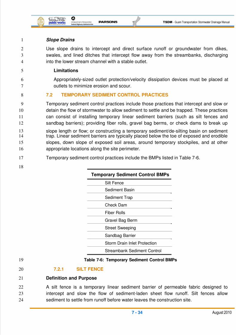
5/13/2018 Guam Storm Water Drainage Manual - slidepdf.com
http://slidepdf.com/reader/full/guam-storm-water-drainage-manual 324/486
7 - 34 August 2010
Slope Drains 1
Use slope drains to intercept and direct surface runoff or groundwater from dikes,2
swales, and lined ditches that intercept flow away from the streambanks, discharging3
into the lower stream channel with a stable outlet.4
Limitations5
Appropriately-sized outlet protection/velocity dissipation devices must be placed at6
outlets to minimize erosion and scour.7
7.2 TEMPORARY SEDIMENT CONTROL PRACTICES8
Temporary sediment control practices include those practices that intercept and slow or9
detain the flow of stormwater to allow sediment to settle and be trapped. These practices10
can consist of installing temporary linear sediment barriers (such as silt fences and11
sandbag barriers); providing fiber rolls, gravel bag berms, or check dams to break up12
slope length or flow; or constructing a temporary sediment/de-silting basin on sediment13
trap. Linear sediment barriers are typically placed below the toe of exposed and erodible14
slopes, down slope of exposed soil areas, around temporary stockpiles, and at other15
appropriate locations along the site perimeter.16
Temporary sediment control practices include the BMPs listed in Table 7-6.17
18
Temporary Sediment Control BMPs
Silt Fence
Sediment Basin
Sediment Trap
Check Dam
Fiber Rolls
Gravel Bag Berm
Street Sweeping
Sandbag Barrier
Storm Drain Inlet Protection
Streambank Sediment Control
Table 7-6: Temporary Sediment Control BMPs19
7.2.1 SILT FENCE20
Definition and Purpose21
A silt fence is a temporary linear sediment barrier of permeable fabric designed to22
intercept and slow the flow of sediment-laden sheet flow runoff. Silt fences allow23
sediment to settle from runoff before water leaves the construction site.24
5/13/2018 Guam Storm Water Drainage Manual - slidepdf.com
http://slidepdf.com/reader/full/guam-storm-water-drainage-manual 325/486
7 - 35 August 2010
Appropriate Applications1
Below the toe of exposed and erodible slopes2
Down slope of exposed soil areas3
Around temporary stockpiles4
Along streams and channels5
Along the perimeter of a project6
Limitations7
Not intended for use as mid-slope protection on slopes greater than 1:4 (V:H).8
Must be maintained.9
Must be removed and disposed of.10
Not intended for use below slopes subject to creep, slumping, or landslides.11
Not intended for use in streams, channels, drain inlets, or anywhere flow is12
concentrated.13
Not intended to divert flow.14
Standards and Specifications15
Design and Layout 16
The maximum length of slope draining to any point along the silt fence should17
be 200 ft. or less.18
Slope of area draining to silt fence should be less than 1:1 (V:H).19
Limit to locations suitable for temporary ponding or deposition of sediment.20
Fabric life span generally limited to between five and eight months. Longer21
periods may require fabric replacement.22
Silt fences should not be used in concentrated flow areas.23
For slopes steeper than 1:2 (V:H) and that contain a high number of rocks or24
large dirt clods that tend to dislodge, it may be necessary to install additional25
protection immediately adjacent to the bottom of the slope prior to installing26
the silt fence. Additional protection may be a chain link fence or a cable27
fence.28
For slopes adjacent to water bodies or other environmentally-sensitive areas,29
additional temporary soil stabilization BMPs should be used.30
5/13/2018 Guam Storm Water Drainage Manual - slidepdf.com
http://slidepdf.com/reader/full/guam-storm-water-drainage-manual 326/486
7 - 36 August 2010
Materials1
Silt fence fabric should be woven polypropylene with a minimum width of2
36 in. and a minimum tensile strength of 0.45-kN. The fabric should conform3
to the requirements in ASTM Designation D4632 and have an integral4
reinforcement layer. The reinforcement layer should be a polypropylene, or5
equivalent, net provided by the manufacturer. The permeability of the fabric6
should be in conformance with the requirements in ASTM Designation7
D4491. The contractor must submit a certificate of compliance.8
Wood stakes should be commercial-quality lumber of the size and shape9
shown on the plans. Each stake should be free from decay, splits, or cracks10
longer than the thickness of the stake or other defects that would weaken the11
stakes and cause the stakes to be structurally unsuitable.12
Bar reinforcement may be used, and its size should be equal to a number13
four or greater. End protection should be provided for any exposed bar14
reinforcement.15
Staples used to fasten the fence fabric to the stakes should be not less than16
1.75 in. long and fabricated from 0.06-in or heavier wire. The wire used to17
fasten the tops of the stakes together when joining two sections of fence18
should be 0.12-in. or heavier wire.19
Galvanizing of the fastening wire is not required.20
Installation21
Generally, silt fences should be used in conjunction with soil stabilization22
source controls up-slope to provide effective erosion and sediment control.23
The bottom of the silt fence should be keyed to a minimum of 12 in.24
Trenches should not be excavated wider and deeper than necessary for25
proper installation of the temporary linear sediment barriers.26
Excavation of the trenches should be performed immediately before27
installation of the temporary linear sediment barriers.28
Construct silt fences with a setback of at least 3 ft. from the toe of a slope.29
Where a silt fence is determined not to be practical due to specific site30conditions, the silt fence may be constructed at the toe of the slope, but as far31
from the toe of the slope as practical.32
Construct the length of each reach so that the change in base elevation along33
the reach does not exceed one-third the height of the barrier; in no case34
should the reach exceed 490 ft.35
5/13/2018 Guam Storm Water Drainage Manual - slidepdf.com
http://slidepdf.com/reader/full/guam-storm-water-drainage-manual 327/486
7 - 37 August 2010
Cross barriers should be a minimum of one-third and a maximum of half the1
height of the linear barrier.2
Maintenance and Inspection3
Repair undercut silt fences.4
Repair or replace split, torn, slumping, or weathered fabric.5
Inspect silt fence weekly and after each significant rainfall. Immediately perform6
any necessary maintenance and repairs.7
Maintain silt fences to provide an adequate sediment holding capacity. Sediment8
should be removed when the sediment accumulation reaches one-third of the9
barrier height. Removed sediment should be incorporated in the project or10
disposed of outside of the right-of-way in conformance with the project11
requirements.12
Silt fences that are damaged and become unsuitable for their intended purpose13
should be removed from the site of work, disposed of outside of the highway14
right-of-way in conformance with the contract requirements, and replaced with15
new silt fence barriers.16
Holes, depressions, or other ground disturbance caused by the removal of the17
temporary silt fences should be backfilled and repaired.18
Remove silt fence when no longer needed. Fill and compact post holes and19
anchorage trench, remove sediment accumulation, and grade the fence20
alignment to blend with the adjacent ground.21
7.2.2 SEDIMENT BASIN22
Definition and Purpose23
A sediment basin (pond) is a temporary basin formed by excavating and/or constructing24
an embankment so that sediment-laden runoff is temporarily detained under quiescent25
conditions, allowing sediment to settle out before the runoff is discharged.26
Appropriate Applications27
Prior to leaving a construction site, stormwater runoff must pass through a sediment28
basin or other appropriate sediment removal BMP.29
A sediment basin should be used where the contributing drainage area is 3 acres or30
more. Ponds must be used in conjunction with erosion control practices to reduce the31
amount of sediment flowing into the basin.32
33
34
5/13/2018 Guam Storm Water Drainage Manual - slidepdf.com
http://slidepdf.com/reader/full/guam-storm-water-drainage-manual 328/486
7 - 38 August 2010
Limitations1
Alternative BMPs must be thoroughly investigated for erosion control before selecting2
temporary sediment basins.3
Sediment basins require large surface areas to permit the settling of sediment.4
Sediment basins are not appropriate for drainage areas greater than 75 acres.5
Sediment basins should not be located in live streams.6
For safety reasons, basins should have protective fencing.7
The size of sediment basins may be limited by the availability of right-of-way.8
Standards and Specifications9
Try to limit the contributing area to the sediment basin to only the runoff from the10
disturbed soil areas. Use temporary concentrated flow conveyance controls to11
divert runoff from undisturbed areas. This will help to keep the sediment basin as12
small as possible.13
Sediment Basin14
At a minimum, sediment basins should be designed as follows:15
If permanent runoff control facilities are part of the project, they should be used16
for sediment retention. The surface area requirements of the sediment basin17
must be met. This may require enlarging the permanent basin to comply with the18
surface area requirements. If a permanent control structure is used, it must have19
the outlet controls blocked to accommodate the sedimentation design.20
Outlets for sediment basins should be an overflow structure, weir, berm, or21
floating intake so that discharge is skimmed off of the upper pond surface.22
The use of infiltration facilities for sedimentation basins during construction tends23
to clog the soils and reduce their capacity to infiltrate. If infiltration facilities are to24
be used, the sides and bottom of the facility must only be roughly excavated to a25
minimum of 2 ft. above the final grade. Final grading of the infiltration facility26
should occur only when all contributing drainage areas are fully stabilized. The27
infiltration pre-treatment facility should be fully constructed and used with the28
sedimentation basin to help prevent clogging.29
Sediment basins should be designed for the three-year frequency storm30
Determining Pond Geometry31
o Obtain the discharge from the hydrologic calculations of the peak flow for32
the three-year runoff event (Q2). The 10-year peak flow should be used if33
the project size, expected timing and duration of construction, or34
5/13/2018 Guam Storm Water Drainage Manual - slidepdf.com
http://slidepdf.com/reader/full/guam-storm-water-drainage-manual 329/486
7 - 39 August 2010
downstream conditions warrant a higher level of protection. If no1
hydrologic analysis is required, the Rational Method may be used.2
o Determine the required surface area at the top of the riser pipe with the3
equation:4
SA = 2 x Q2 /0.00096, or 2,080 sq. ft. per cfs of inflow.5
(This equation, along with the minimum depth of pond, will provide6
the necessary volume for a time of residence to allow a 0.02 mm7
(medium silt) particle with an assumed density of 2.65 g/cm3,8
which has a settling velocity of 0.00096 ft/sec with a safety factor9
of two, to settle out).10
The basic geometry of the pond can now be determined using the following11
design criteria:12
o Required Surface Area (SA), from Step 2, above, at top of riser13
o Minimum 3.5-ft. depth from top of riser to bottom of pond14
o Maximum 3:1 interior side slopes and maximum 2:1 exterior slopes15
The interior slopes can be increased to a maximum of 2:1 if fencing is provided at or16
above the maximum water surface.17
One ft. of freeboard between the top of the overflow device and the top of the18
pond.19
Flat bottom.20
The overflow device should be capable of handling the 10-year sized storm peak21
flow without overtopping the top of pond.22
Length-to-width ratio between 3:1 and 6:1.23
Typical overflow outlets can be a rock riprapped weir surface discharging to an24
erosion protected channel or other conveyance system; a vertical pipe or pre-25
cast structure riser connected to a discharge pipe also discharging to an erosion-26
protected outlet or other conveyance system; a pumped discharge where the27
pump intake is located just under the pond surface using anti-vortex baffles; and28
a floating overflow weir connected to a flexible pipe that allows water to skim29
immediately from the surface of the water. A floating overflow weir/pipe is usually30
associated with either a pumped discharge using automatic floats to control the31
pond surface levels or another permanent control structure to maintain the32
maximum design water surface.33
34
35
5/13/2018 Guam Storm Water Drainage Manual - slidepdf.com
http://slidepdf.com/reader/full/guam-storm-water-drainage-manual 330/486
7 - 40 August 2010
Maintenance Standards1
Sediment should be removed from the pond when it reaches 1 ft. in depth.2
Inspect sediment basins before and after rainfall events and weekly during the3
rest of the rainy season. During extended rainfall events, inspect at least every4
24 hours.5
Examine basin banks for seepage and structural soundness.6
Check inlet and outlet structures and spillway for any damage or obstructions.7
Repair damage and remove obstructions as needed.8
7.2.3 SEDIMENT TRAP9
Definition and Purpose10
A sediment trap is a temporary containment area that allows sediment in collected11
stormwater to settle out during infiltration or before the runoff is discharged through a12
stabilized spillway. Sediment traps are formed by excavating or constructing an earthen13
embankment across a waterway or low drainage area.14
Appropriate Applications15
Sediment traps may be used on construction projects where the drainage area is16
less than 3 acres. Traps should be placed prior to where sediment-laden17
stormwater enters a storm drain or watercourse.18
This BMP may be implemented on a project-by-project basis with other BMPs,19
when necessary and feasible.20
As a supplemental control, sediment traps provide additional protection for a21
water body or for reducing sediment before it enters a drainage system.22
Limitations23
Sediment traps require large surface areas to permit infiltration and the settling of24
sediment.25
Sediment traps are not appropriate for drainage areas greater than 3 acres.26
Sediment traps only remove large and medium-sized particles and require27
upstream erosion control.28
Sediment traps are attractive and dangerous to children, requiring protective29
fencing.30
Sediment traps should not be located in live streams.31
The size of sediment traps may be limited by the availability of right-of-way.32
33
5/13/2018 Guam Storm Water Drainage Manual - slidepdf.com
http://slidepdf.com/reader/full/guam-storm-water-drainage-manual 331/486
7 - 41 August 2010
Standards and Specifications1
Construct sediment traps prior to the rainy season and construction activities.2
Traps should be situated according to the following criteria:3
o By excavating a suitable area or where a low embankment can be4
constructed across a swale.5
o Should be designed for the three-year storm frequency.6
o Where failure would not cause loss of life or property damage.7
o To provide access for maintenance, including sediment removal and8
sediment stockpiling, in a protected area.9
To determine the sediment trap geometry, first calculate the design SA of the10
trap, measured at the invert of the weir. Use the following equation:11
SA = 2 x Q2 /0.00096, or 2,080 sq. ft. per cfs of inflow12
Where:13
Q2 = Design inflow based on the peak discharge from the14
developed three-year runoff event from the contributing drainage15
area as computed in the hydrologic analysis.16
o To aid in determining sediment depth, all sediment traps should have a17
staff gauge with a prominent mark 1 ft. above the bottom of the trap.18
o Sediment traps should have a stabilized outlet by skimming the surface19
water. This is usually performed with an overflow weir, such as a pipe or20
structural riser discharging by connecting pipe to another conveyance21
system or erosion protected outlet to a waterway; by a riprapped overflow22
weir; by pumped discharge where the intake is located just below the trap23
surface with an anti-vortex baffle; or using a floating skimmer with a24
flexible pipe.25
Sediment traps may not be feasible on utility projects due to the limited work26
space or the short-term nature of the work. Portable tanks may be used in place27
of sediment traps for utility projects.28
Maintenance and Inspection29
Inspect sediment traps before and after rainfall events and weekly during the rest30
of the rainy season. Remove accumulated sediment when the volume has31
reached one-third the original trap volume.32
Inspect the outlet structure for any damage or obstructions. Repair damage and33
remove obstructions as needed or as directed by the Resident Engineer (RE).34
5/13/2018 Guam Storm Water Drainage Manual - slidepdf.com
http://slidepdf.com/reader/full/guam-storm-water-drainage-manual 332/486
7 - 42 August 2010
7.2.4 CHECK DAMS1
Definition and Purpose2
Check dams reduce scour and channel erosion by reducing flow velocity and3
encouraging sediment settlement. A check dam is a small device constructed of rock,4gravel bags, sandbags, fiber rolls, or other proprietary product placed across a natural or5
man-made channel or drainage ditch.6
Appropriate Applications7
Check dams may be installed:8
In small open channels that drain 10 acres or less.9
In steep channels where stormwater runoff velocities exceed 4.9 ft. per second.10
During the establishment of grass linings in drainage ditches or channels.11
In temporary ditches where the short length of service does not warrant the12
establishment of erosion-resistant linings.13
This BMP may be implemented on a project-by-project basis with other BMPs14
when determined necessary and feasible.15
Limitations16
Check dams should not be used in live streams.17
Check dams are not appropriate in channels that drain areas greater than 1018
acres.19
Check dams should not be placed in channels that are already grass-lined,20
unless erosion is expected, as installation may damage vegetation.21
Check dams require extensive maintenance following high-velocity flows.22
Check dams promote sediment trapping, which can be re-suspended during23
subsequent storms or removal of the check dam.24
Check dams should not be constructed from straw bales or silt fence.25
Standards and Specifications26
Check dams should be placed at a distance and height to allow small pools to27
form behind them. Install the first check dam approximately 16 ft. from the outfall28
device and at regular intervals based on slope gradient and soil type.29
For multiple check dam installation, backwater from downstream check dams30
should reach the toe of the upstream dam.31
5/13/2018 Guam Storm Water Drainage Manual - slidepdf.com
http://slidepdf.com/reader/full/guam-storm-water-drainage-manual 333/486
7 - 43 August 2010
High flows (typically, a two-year storm or larger) should safely flow over the1
check dam without an increase in upstream flooding or damage to the check2
dam.3
Where grass is used to line ditches, check dams should be removed when grass4
has matured sufficiently to protect the ditch or swale.5
Rock should be placed individually by hand or by mechanical methods (no6
dumping of rock) to achieve complete ditch or swale coverage.7
Fiber rolls may be used as check dams.8
Gravel bags may be used as check dams with the following specifications:9
o Bag Material: Bags should be either polypropylene, polyethylene, or10
polyamide woven fabric (minimum unit weight four ounces per square11
yard), with a mullen burst strength exceeding 300 pounds per sq. in., in12
conformance with the requirements in ASTM Designation D3786, and a13
UV stability exceeding 70 percent, in conformance with the requirements14
in ASTM Designation D4355.15
o Bag Size: Each gravel-filled bag should have a length of 18 in., a width of16
12 in., a thickness of 3 in., and a mass of approximately 33 pounds. Bag17
dimensions are nominal and may vary based on locally-available18
materials. Alternative bag sizes should be submitted to the RE for19
approval prior to deployment.20
o Fill Material: Fill material should be between 0.4 in. and 0.8 in. in21
diameter, and should be clean and free from clay balls, organic matter,22
and other deleterious materials. The opening of gravel-filled bags should23
be secured so that gravel does not escape. Gravel-filled bags should be24
between 28 pounds and 48 pounds in mass.25
Installation 26
Install check dams along a level contour.27
Tightly abut bags and/or rock and stack using a pyramid approach. Dams28
should not exceed about 3.5 ft. in height.29
The upper rows of gravel bags or rock should overlap joints in lower rows.30
Maintenance and Inspection 31
Inspect check dams after each significant rainfall event. Repair damage as32
needed.33
Remove sediment when the depth reaches one-third of the check dam34
height.35
5/13/2018 Guam Storm Water Drainage Manual - slidepdf.com
http://slidepdf.com/reader/full/guam-storm-water-drainage-manual 334/486
7 - 44 August 2010
Remove accumulated sediment prior to permanent seeding or soil1
stabilization.2
Remove check dam and accumulated sediment when check dams are no3
longer needed.4
Removed sediment should be incorporated into the project or disposed of5
outside of the highway right-of-way in conformance with the contract6
requirements.7
7.2.5 FIBER ROLLS/WATTLES8
Definition and Purpose9
A fiber roll consists of wood excelsior, rice or wheat straw, or coconut fibers rolled or10
bound into a tight tubular roll and placed on the toe and face of slopes to intercept runoff,11
reduce its flow velocity, release the runoff as sheet flow, and provide removal of12
sediment from the runoff. Fiber rolls may also be used for inlet protection and as check13
dams under certain situations.14
Appropriate Applications15
Use fiber rolls along the toe, top, face, and at-grade breaks of exposed and16
erodible slopes to shorten slope length and spread runoff as sheet flow.17
Use fiber rolls below the toe of exposed and erodible slopes.18
Fiber rolls may be used as check dams in unlined ditches if approved by the RE.19
Fiber rolls may be used for drain inlet protection if approved by the RE.20
Fiber rolls may be used down slope of exposed soil areas.21
Fiber rolls may be used around temporary stockpiles.22
Fiber rolls may be used along the perimeter of a project.23
Limitations24
Runoff and erosion may occur if a fiber roll is not adequately trenched in.25
Fiber rolls at the toe of slopes steeper than 1V:5H may require the use of 20-in.26
diameter fiber rolls or installations achieving the same protection (i.e., stacked27
fiber rolls of a smaller diameter).28
Fiber rolls are difficult to move once saturated.29
Fiber rolls could be transported by high flows if not properly staked and trenched30
in.31
Fiber rolls have a limited sediment capture zone.32
Do not use fiber rolls on slopes subject to creep, slumping, or landslide.33
5/13/2018 Guam Storm Water Drainage Manual - slidepdf.com
http://slidepdf.com/reader/full/guam-storm-water-drainage-manual 335/486
7 - 45 August 2010
Standards and Specifications1
Assembly of Field-Rolled Fiber Roll 2
Roll the length of an erosion control blanket into a tube a minimum of 8 in. in3
diameter.4
Bind the roll at each end and every 4 ft. along the length of the roll with jute-5
type twine.6
Installation 7
Slope inclination of 1:4 or flatter: Fiber rolls should be placed on slopes 20 ft.8
apart.9
Slope inclination of 1:4 to 1:2: Fiber rolls should be placed on slopes 15 ft.10
apart.11
Slope inclination 1:2 or greater: Fiber rolls should be placed on slopes 10 ft.12
apart.13
Stake fiber rolls into a 2-in. to 4-in. deep trench.14
Drive stakes at the end of each fiber roll, and space them 2 ft. to 4 ft. apart.15
Use wood stakes with a nominal classification of 3/4 in. by 3/4 in. and a16
minimum length of 24 in.17
If more than one fiber roll is placed in a row, the rolls should be overlapped,18
not abutted.19
Removal 20
Fiber rolls are typically left in place.21
If fiber rolls are removed, collect and dispose of sediment accumulation, and22
fill and compact holes, trenches, depressions, or any other ground23
disturbance to blend with the adjacent ground.24
Maintenance and Inspection25
Repair or replace split, torn, unraveling, or slumping fiber rolls.26
Inspect fiber rolls weekly and immediately after a significant rain. Perform27
maintenance as needed.28
Maintain fiber rolls to provide an adequate sediment-holding capacity. Sediment29
should be removed when the sediment accumulation reaches three-quarters of30
the barrier height. Removed sediment should be incorporated into the project or31
disposed of outside of the project limits in conformance with the contract32
requirements.33
5/13/2018 Guam Storm Water Drainage Manual - slidepdf.com
http://slidepdf.com/reader/full/guam-storm-water-drainage-manual 336/486
7 - 46 August 2010
7.2.5.1 GRAVEL BAG BERM1
Definition and Purpose2
A gravel bag berm consists of a single row of gravel bags that are installed end-to-end to3
form a barrier across a slope to intercept runoff, reduce its flow velocity, release the4runoff as sheet flow, and provide some sediment removal. Gravel bags can be used5
where flows are moderately concentrated such as ditches, swales, and storm drain6
inlets, to divert and/or detain flows.7
Appropriate Applications8
This BMP is used for the same purposes as fiber rolls and wattles.9
Limitations10
Degraded gravel bags may rupture when removed, spilling contents.11
Installation can be labor intensive.12
Gravel bags have limited durability for long-term projects.13
When used to detain concentrated flows, maintenance requirements increase.14
Standards and Specifications15
Materials 16
See the material specifications of gravel bags used for check dams. 17
Installation 18
When used as a linear control for sediment removal:19
o Install along a level contour.20
o Turn the ends of the gravel bag row upslope to prevent flow around21
the ends.22
o Generally, gravel bag barriers should be used in conjunction with23
temporary soil stabilization controls up slope to provide effective24
erosion and sediment control.25
When used for concentrated flows:26
o Stack gravel bags to their required height using a pyramid approach.27
o The upper rows of gravel bags should overlap joints in lower rows.28
Construct gravel bag barriers with a setback at least 3 ft. from the toe of a29
slope. Where it is determined to not be practicable due to specific site30
conditions, the gravel bag barrier may be constructed at the toe of the slope,31
but as far from the toe of the slope as practicable.32
5/13/2018 Guam Storm Water Drainage Manual - slidepdf.com
http://slidepdf.com/reader/full/guam-storm-water-drainage-manual 337/486
7 - 47 August 2010
Maintenance and Inspection1
Inspect gravel bag berms weekly throughout the rainy season.2
Reshape or replace gravel bags as needed.3
Repair washouts or other damages as needed.4
Inspect gravel bag berms for sediment accumulations, and remove sediments5
when accumulation reaches one-third of the berm height. Removed sediment6
should be incorporated into the project or disposed of outside of the project limits7
in conformance with the contract requirements.8
Remove gravel bag berms when no longer needed. Remove sediment9
accumulations and clean, re-grade, and stabilize the area.10
7.2.6 STREET SWEEPING AND VACUUMING11
Definition and Purpose12
Street sweeping and vacuuming are practices to remove tracked sediment to prevent the13
sediment from entering a storm drain or watercourse.14
Appropriate Applications15
These practices are implemented anywhere sediment is tracked from the project site16
onto public or private paved roads, typically at points of ingress or egress.17
Limitations18
Sweeping and vacuuming may not be effective when soil is wet or muddy.19
Standards and Specifications20
Kick brooms or sweeper attachments should not be used.21
Inspect potential sediment tracking locations daily.22
Visible sediment tracking should be swept and/or vacuumed daily.23
If not mixed with debris or trash, consider incorporating the removed sediment24
back into the project.25
Maintenance and Inspection26
Inspect ingress/egress access points daily and sweep tracked sediment as27
needed.28
Be careful not to sweep up any unknown substance or any object that may be29
potentially hazardous.30
Adjust brooms frequently; maximize the efficiency of sweeping operations.31
5/13/2018 Guam Storm Water Drainage Manual - slidepdf.com
http://slidepdf.com/reader/full/guam-storm-water-drainage-manual 338/486
7 - 48 August 2010
After sweeping is finished, properly dispose of sweeper wastes at an approved1
disposal site in conformance with the contract requirements.2
7.2.6.1 SANDBAG BARRIER3
Definition and Purpose4
A sandbag barrier is a temporary linear sediment barrier consisting of stacked sandbags5
designed to intercept and slow the flow of sediment-laden sheet flow runoff. Sandbag6
barriers allow sediment to settle from runoff before water leaves the construction site.7
Appropriate Applications8
This BMP has the same application as the gravel bag berms.9
Standards and Specifications10
Materials 11
Sandbag Material: Sandbags should be woven polypropylene, polyethylene,12
or polyamide fabric (minimum unit weight four ounces per square yard), with13
a mullen burst strength exceeding 300 pounds per sq. in., in conformance14
with the requirements in ASTM Designation D3786 and with a UV stability15
exceeding 70 percent, in conformance with the requirements in ASTM16
Designation D4355. The use of burlap is not acceptable.17
Sandbag Size: Each sand-filled bag should have a length of 18 in., a width of18
12 in., a thickness of 3 in., and a mass of approximately 33 pounds. Bag19
dimensions are nominal and may vary based on locally-available materials.20
Fill Material: All sandbag fill material should be non-cohesive, permeable21
material free from clay and deleterious material, conforming to the provisions22
in Standard Specification 703, “Permeable Backfill.” The requirements for the23
durability index and sand equivalent do not apply.24
Installation and Maintenance 25
The same installation and maintenance requirements apply as noted for gravel bag26
berms.27
7.2.7 STORM DRAIN INLET PROTECTION28
Definition and Purpose29
Storm drain inlet protection is achieved with devices used at storm drain inlets that are30
subject to runoff from construction activities to detain and/or to filter sediment-laden31
runoff, to allow sediment to settle and/or to filter sediment prior to discharge into storm32
drainage systems or watercourses.33
34
5/13/2018 Guam Storm Water Drainage Manual - slidepdf.com
http://slidepdf.com/reader/full/guam-storm-water-drainage-manual 339/486
7 - 49 August 2010
Appropriate Applications1
Where ponding will not encroach into highway traffic.2
Where sediment-laden surface runoff may enter an inlet.3
Where disturbed drainage areas have not yet been permanently stabilized.4
Where the drainage area is 1 acre or less.5
Limitations6
Storm drain inlet protection requires an adequate area for water to pond without7
encroaching upon the traveled way and should not present an obstacle to8
oncoming traffic.9
Storm drain inlet protection may be best if other methods of temporary protection10
are used in conjunction with it.11
Sediment removal may be difficult in high flow conditions or if runoff is heavily12
sediment laden. If high flow conditions are expected, use other on-site sediment-13
trapping techniques, such as check dams, in conjunction with inlet protection.14
Frequent maintenance is required.15
Filter fabric fence inlet protection is appropriate in open areas that are subject to16
sheet flow and for flows not exceeding 0.5 cu. ft. per second.17
Gravel bag barriers for inlet protection are applicable when sheet flows or18
concentrated flows exceed 0.5 cu. ft. per second, and it is necessary to allow for19
overtopping to prevent flooding.20
Fiber rolls and foam barriers are not appropriate for locations where they cannot21
be properly anchored to the surface.22
Excavated drop inlet sediment traps are appropriate where relatively heavy flows23
are expected and overflow capability is needed.24
Standards and Specifications25
Identify existing and/or planned storm drain inlets that have the potential to receive26
sediment-laden surface runoff. Determine if storm drain inlet protection is needed and27
which method to use.28
Methods and Installation29
Drainage Inlet Protection Type 1 – Filter Fabric Fence . The filter fabric fence30
protection is similar to constructing a silt fence. Do not place filter fabric31
underneath the inlet grate because the collected sediment may fall into the drain32
inlet when the fabric is removed or replaced.33
5/13/2018 Guam Storm Water Drainage Manual - slidepdf.com
http://slidepdf.com/reader/full/guam-storm-water-drainage-manual 340/486
7 - 50 August 2010
Drainage Inlet Protection Type 2 – Excavated Drop Inlet Sediment Trap . The1
excavated drop inlet sediment trap is similar to constructing a temporary silt trap2
around the inlet structure. Use the inlet grate as the overflow discharge control3
weir for the silt trap. Size the excavated trap to provide a minimum storage4
capacity calculated at the rate of 67 cu. yd per acre of drainage area.5
Drainage Inlet Protection Type 3 – Gravel Bag . Flow from a severe storm6
should not overtop the berm. In areas of high clay and silts, use filter fabric and7
gravel as additional filter media. Construct gravel bags as level berms upstream8
of the inlet structure. Gravel or sand bags should be used due to their high9
permeability.10
Drainage Inlet Protection Type 4 – Foam Barriers and Fiber Rolls . Foam11
barriers or fiber rolls are placed around the inlet and keyed and anchored to the12
surface. Foam barriers and fiber rolls are intended for use as inlet protection13
where the area around the inlet is unpaved and the foam barrier or fiber roll can14
be secured to the surface.15
Maintenance and Inspection16
General 17
Inspect all inlet protection devices before and after every rainfall event and18
weekly during the rest of the rainy season. During extended rainfall events,19
inspect inlet protection devices at least once every 24 hours.20
Inspect the storm drain inlet after severe storms in the rainy season to check21
for bypassed material.22
Remove all inlet protection devices after the site is stabilized, or when the23
inlet protection is no longer needed.24
o Bring the disturbed area to final grade and smooth and compact it.25
Appropriately stabilize all bare areas around the inlet.26
o Clean and re-grade the area around the inlet and clean the inside of27
the storm drain inlet, as it must be free of sediment and debris at the28
time of final inspection.29
Requirements by Method30
Type 1 – Filter Fabric Fence 31
This method should be used for drain inlets requiring protection in areas32
where finished grade is established and erosion control seeding has been33
applied or is pending.34
5/13/2018 Guam Storm Water Drainage Manual - slidepdf.com
http://slidepdf.com/reader/full/guam-storm-water-drainage-manual 341/486
7 - 51 August 2010
Make sure the stakes are securely driven in the ground and are structurally1
sound (i.e., not bent, cracked, or splintered) and are reasonably2
perpendicular to the ground. Replace damaged stakes.3
Replace or clean the fabric when the fabric becomes clogged with sediment.4
Make sure the fabric does not have any holes or tears. Repair or replace5
fabric as needed or as directed by the RE.6
At a minimum, remove the sediment behind the fabric fence when7
accumulation reaches one-third the height of the fence or barrier height.8
Removed sediment should be incorporated into the project at locations9
designated by the RE or disposed of outside of the highway right-of-way, in10
conformance with the Standard Specifications.11
Type 2 – Excavated Drop Inlet Sediment Trap 12
This method may be used for drain inlets requiring protection in areas that13have been cleared and grubbed, and where exposed soil areas are subject to14
grading.15
Remove sediment from the trap when the volume of the basin has been16
reduced by one-half.17
Type 3 – Gravel Bag Barrier 18
This method may be used for drain inlets surrounded by asphalt concrete or19
paved surfaces.20
Inspect bags for holes, gashes, and snags.21
Check gravel bags for proper arrangement and displacement. Remove the22
sediment behind the barrier when it reaches one-third the height of the23
barrier.24
Type 4 – Foam Barriers and Fiber Rolls 25
This method may be used for drain inlets requiring protection in areas that26
have been cleared and grubbed, and where exposed soil areas are subject to27
grading.28
Check the foam barrier or fiber roll for proper arrangement and displacement.29
Remove the sediment behind the barrier when it reaches one-third the height30
of the barrier. Removed sediment should be incorporated into the project at31
locations designated by the RE or disposed of outside of the highway right-of-32
way in conformance with the Standard Specifications.33
7.2.8 STREAMBANK SEDIMENT CONTROL34
These BMPs are used to isolate work on the streambank from the stream channel.35
5/13/2018 Guam Storm Water Drainage Manual - slidepdf.com
http://slidepdf.com/reader/full/guam-storm-water-drainage-manual 342/486
7 - 52 August 2010
Silt Fences1
Install silt fences to control sediment movement from the working side of the2
stream bank and the channel bottom.3
If placed within the water, the silt fence should be protected from high velocity4
flow. The water surface on each side of the silt fence must be level creating a5
pond on the working side, thus allowing the sediment to settle out.6
Fiber Rolls7
Install fiber rolls along the slope contour above the high-water level to intercept8
runoff, reduce flow velocity, release the runoff as sheet flow, and provide removal9
of sediment from the runoff. In a stream environment, fiber rolls should be used10
in conjunction with other sediment control methods, such as a silt fence or gravel11
bag berm. Install the silt fence, gravel berm, or other erosion control methods12
along the toe of the slope above the ordinary water level.13
Gravel Bag Berm14
A gravel bag berm can be used to intercept and slow the flow of sediment-laden sheet15
flow runoff. In a stream environment, gravel bag berms can allow sediment to settle from16
runoff before water leaves the construction site, and can be used to isolate the work17
area from the stream.18
Limitations 19
Gravel bag barriers are not recommended as a perimeter sediment control practice20
around streams.21
Rock Filters22
Description and Purpose 23
Rock filters are temporary erosion control barriers composed of rock that is anchored24
in place using woven wire sheathing (gabions). Rock filters detain the sediment-25
laden runoff, retain the sediment, and release the water as sheet flow at a reduced26
velocity.27
Applications 28
Apply rock filters near the toe of slopes that may be subject to flow and rill erosion.29
Limitations 30
Inappropriate for drainage areas greater than 5 acres.31
Requires sufficient space for ponded water.32
Ineffective for diverting runoff because filters allow water to slowly seep33
through.34
5/13/2018 Guam Storm Water Drainage Manual - slidepdf.com
http://slidepdf.com/reader/full/guam-storm-water-drainage-manual 343/486
7 - 53 August 2010
Berms difficult to remove when construction is complete.1
Unsuitable in developed areas or locations where aesthetics is a concern.2
Specifications 3
Rock: Open-graded rock, 0.75 in to 5 in. for concentrated flow applications.4
Rock contained in gabions consisting of woven wire sheathing: 1 in. in5
diameter, hexagonal mesh, galvanized 20-gauge.6
In construction traffic areas, maximum rock berm heights should be 12 in.7
Berms should be constructed every 300 ft. on slopes less than 5:100 (V:H)8
(5 percent), every 200 ft. on slopes between 5:100 (V:H) (5 percent) and9
10:100 (V:H) (10 percent), and every 100 ft. on slopes greater than 10:10010
(V:H) (10 percent).11
Maintenance and Inspection 12
Inspect berms before and after each significant rainfall event and weekly13
throughout the rainy season.14
Reshape berms as needed and replace lost or dislodged rock and/or filter15
fabric.16
Inspect for sediment accumulation, remove sediment when depth reaches17
one-third of the berm height or 12 in., whichever occurs first.18
K-Rail19
Description and Purpose 20
This is temporary sediment control that uses K-rails (pre-cast concrete traffic21
barriers) to form the sediment deposition area, or to isolate the near-bank22
construction area. Install K-rails at the toe of the slope (see also the23
description for the BMP “Clear Water Diversion.”)24
Barriers are placed end-to-end in a pre-designed configuration, and gravel-25
filled bags are used at the toe of the barrier and also at their abutting ends to26
seal and prevent the movement of sediment beneath or through the barrier27
walls.28
Appropriate Applications 29
This technique is useful at the toe of embankments, and cut or fill slopes.30
Limitations 31
The K-rail method is not watertight, and its proper use should be considered32
accordingly.33
34
5/13/2018 Guam Storm Water Drainage Manual - slidepdf.com
http://slidepdf.com/reader/full/guam-storm-water-drainage-manual 344/486
7 - 54 August 2010
Inspection and Maintenance 1
Inspect BMPs daily during construction.2
Maintain and repair BMPs as required.3
Remove accumulated sediment.4
7.3 WIND EROSION CONTROL PRACTICES5
Wind erosion control consists of applying water and/or other dust palliatives as6
necessary to prevent or alleviate dust nuisance.7
Definition and Purpose8
Wind erosion control consists of applying water and/or other dust palliatives as9
necessary to prevent or alleviate erosion by the forces of wind. Covering small stockpiles10
or areas is an alternative to applying water or other dust palliatives.11
Appropriate Applications12
This practice is implemented on all exposed soils subject to wind erosion.13
Limitations14
Its effectiveness depends on soil, temperature, humidity, and wind velocity.15
Standards and Specifications16
Water should be applied by means of pressure-type distributors or pipelines17
equipped with a spray system or hoses and nozzles that will ensure even18
distribution.19
All distribution equipment should be equipped with a positive means of shutoff.20
Unless water is applied by means of pipelines, at least one mobile unit should be21
available at all times to apply water or dust palliative to the project.22
Materials applied as temporary soil stabilizers and soil binders will also provide23
wind erosion control benefits.24
Maintenance and Inspection25
Check areas that have been protected to ensure coverage.26
7.4 TRACKING CONTROL BMPs27
Tracking control consists of preventing or reducing vehicle tracking from entering a28
storm drain or watercourse. Tracking control BMPs are shown in Table 7-7.29
30
31
32
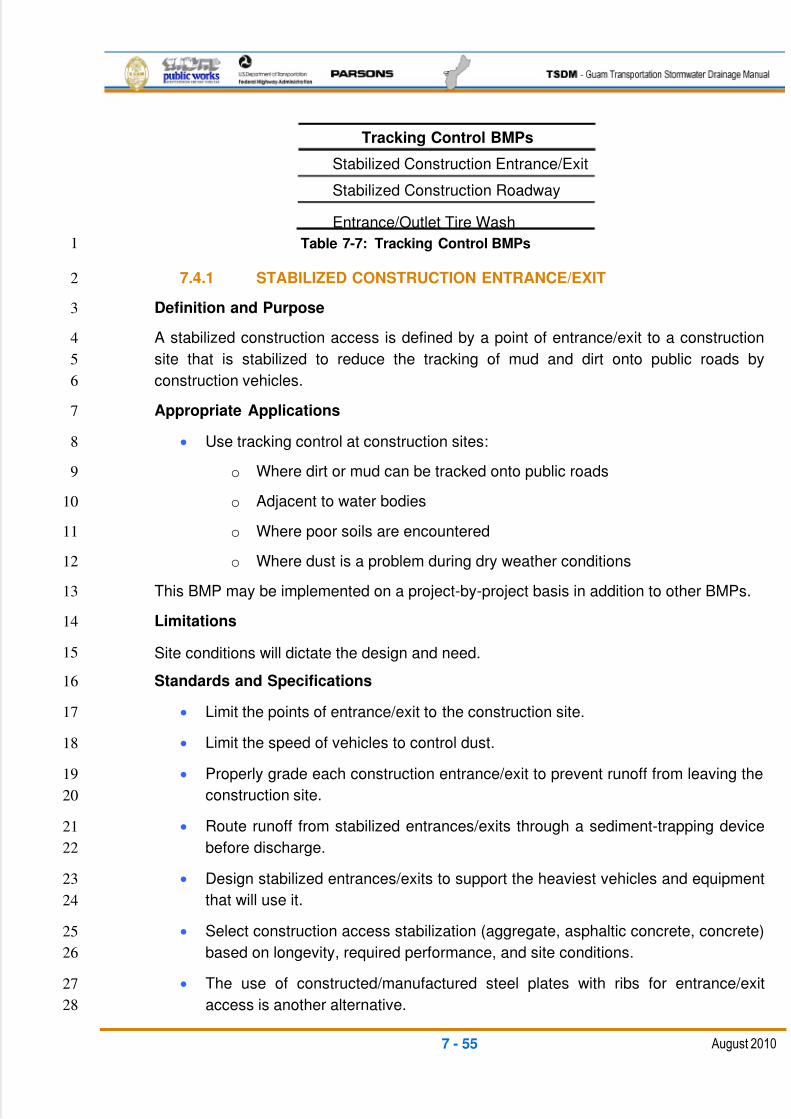
5/13/2018 Guam Storm Water Drainage Manual - slidepdf.com
http://slidepdf.com/reader/full/guam-storm-water-drainage-manual 345/486
7 - 55 August 2010
Tracking Control BMPs
Stabilized Construction Entrance/Exit
Stabilized Construction Roadway
Entrance/Outlet Tire Wash
Table 7-7: Tracking Control BMPs1
7.4.1 STABILIZED CONSTRUCTION ENTRANCE/EXIT2
Definition and Purpose3
A stabilized construction access is defined by a point of entrance/exit to a construction4
site that is stabilized to reduce the tracking of mud and dirt onto public roads by5
construction vehicles.6
Appropriate Applications7
Use tracking control at construction sites:8
o Where dirt or mud can be tracked onto public roads9
o Adjacent to water bodies10
o Where poor soils are encountered11
o Where dust is a problem during dry weather conditions12
This BMP may be implemented on a project-by-project basis in addition to other BMPs.13
Limitations14
Site conditions will dictate the design and need.15
Standards and Specifications16
Limit the points of entrance/exit to the construction site.17
Limit the speed of vehicles to control dust.18
Properly grade each construction entrance/exit to prevent runoff from leaving the19
construction site.20
Route runoff from stabilized entrances/exits through a sediment-trapping device21
before discharge.22
Design stabilized entrances/exits to support the heaviest vehicles and equipment23
that will use it.24
Select construction access stabilization (aggregate, asphaltic concrete, concrete)25
based on longevity, required performance, and site conditions.26
The use of constructed/manufactured steel plates with ribs for entrance/exit27
access is another alternative.28
5/13/2018 Guam Storm Water Drainage Manual - slidepdf.com
http://slidepdf.com/reader/full/guam-storm-water-drainage-manual 346/486
7 - 56 August 2010
If aggregate is selected, place crushed aggregate over geotextile fabric to at1
least 12 in. deep. Crushed aggregate greater than 3 in. and smaller than 6 in.2
should be used.3
Designate combination or single-purpose entrances and exits to the construction4
site.5
Require all employees, subcontractors, and suppliers to use the stabilized6
construction access.7
All exit locations intended to be used continuously and for a period of time should8
have stabilized construction entrance/exit BMPs.9
Maintenance and Inspection10
Inspect the area routinely for damage and assess the effectiveness of the BMP.11
Remove aggregate, and separate and dispose of sediment if the construction12
entrance/exit is clogged with sediment or as directed by the RE.13
Keep all temporary roadway ditches clear.14
Inspect for damage and repair as needed.15
7.4.2 STABILIZED CONSTRUCTION ROADWAY16
Definition and Purpose17
A stabilized construction roadway is a temporary access road. It is designed for the18
control of dust and erosion created by vehicular tracking.19
Appropriate Applications20
Where mud tracking is a problem during wet weather.21
Where dust is a problem during dry weather.22
Adjacent to water bodies.23
Where poor soils are encountered.24
Where there are steep grades and additional traction is needed.25
Limitations26
Materials will likely need to be removed prior to final project grading and27stabilization.28
Site conditions will dictate design and need.29
A stabilized construction roadway may not be applicable to projects of a very30
short duration.31
Limit the speed of vehicles to control dust.32
5/13/2018 Guam Storm Water Drainage Manual - slidepdf.com
http://slidepdf.com/reader/full/guam-storm-water-drainage-manual 347/486
7 - 57 August 2010
Standards and Specifications1
Design stabilized access to support the heaviest vehicles and equipment that will2
use it.3
Stabilize roadway using aggregate, asphalt concrete, or concrete based on4
longevity, required performance, and site conditions.5
Coordinate materials with those used for stabilized construction entrance/exit6
points.7
If aggregate is selected, place crushed aggregate over geotextile fabric to at8
least 12 in. deep, or place aggregate to a depth suitable for the proposed9
loadings. Crushed aggregate greater than 75 mm (3 in.) and smaller than 6 in.10
should be used.11
Maintenance and Inspection12
Inspect routinely for damage and repair as needed.13
Keep all temporary roadway ditches clear.14
7.4.3 ENTRANCE/OUTLET TIRE WASH15
Definition and Purpose16
A tire wash is an area located at stabilized construction access points to remove17
sediment from tires and undercarriages, and to prevent sediment from being transported18
onto public roadways.19
Appropriate Applications20
Tire washes may be used on construction sites where dirt and mud tracking onto21
public roads by construction vehicles may occur.22
Limitations23
Tire washes require a supply of washwater.24
Tire washes require a turnout or double-wide exit to avoid having entering25
vehicles drive through the wash area.26
Standards and Specifications27
Incorporate with a stabilized construction entrance/exit.28
Construct on level ground when possible, on a pad of coarse aggregate greater29
than 3 in. and smaller than 6 in. A geotextile fabric should be placed below the30
aggregate.31
Wash rack should be designed and constructed/manufactured for anticipated32
traffic loads.33
5/13/2018 Guam Storm Water Drainage Manual - slidepdf.com
http://slidepdf.com/reader/full/guam-storm-water-drainage-manual 348/486
7 - 58 August 2010
Provide a drainage ditch that will convey the runoff from the wash area to a1
sediment-trapping device. The drainage ditch should be of sufficient grade, width,2
and depth to carry the wash runoff.3
Require all employees, subcontractors, and others who leave the site with mud-4
caked tires and/or undercarriages to use the wash facility.5
Maintenance and Inspection6
Remove accumulated sediment in the wash rack and/or sediment trap to7
maintain system performance.8
Inspect routinely for damage and repair as needed.9
7.5 NON-STORMWATER MANAGEMENT PRACTICES10
Non-stormwater management BMPs are source control BMPs that prevent pollution by11
limiting or reducing potential pollutants at their source before they come into contact with12
stormwater. These practices involve day-to-day operations of the construction site and13
are usually under the contractor’s control. These BMPs are also referred to as good14
housekeeping practices, which involve keeping a clean, orderly construction site.15
Table 7-8 lists the non-stormwater management BMPs.16
17
Non-Stormwater BMPs
Water Conservation Practices
De-watering Operations
Temporary Stream Crossing
Clean Water Diversion
Potable Water/Irrigation
Vehicle and Equipment Cleaning
Vehicle and Equipment Fueling
Vehicle and Equipment Maintenance
Pile-Driving Operations
Concrete Curing
Material and Equipment Use Over WaterConcrete Finishing
Structure Demolition Over or Adjacent to Water
Table 7-8: Non-Stormwater BMPs18
19
20
21
5/13/2018 Guam Storm Water Drainage Manual - slidepdf.com
http://slidepdf.com/reader/full/guam-storm-water-drainage-manual 349/486
7 - 59 August 2010
7.5.1 WATER CONSERVATION PRACTICES1
Definition and Purpose2
Water conservation practices are activities that use water during the construction of a3
project in a manner that avoids causing erosion and/or the transport of pollutants off-site.4
Appropriate Applications5
Water conservation practices are implemented on all construction sites and6
wherever water is used.7
Water conservation practices apply to all construction projects.8
Limitations9
None identified.10
Standards and Specifications11
Keep water equipment in good working condition.12
Stabilize the water truck filling area.13
Repair water leaks promptly.14
The washing of vehicles and equipment on the construction site is discouraged.15
Avoid using water to clean construction areas. Do not use water to clean16
pavement. Paved areas should be swept and vacuumed.17
Direct construction water runoff to areas where it can infiltrate into the ground.18
Apply water for dust control in accordance with the contract requirements.19
Report discharges immediately.20
Maintenance and Inspection21
Inspect water equipment at least weekly.22
Repair water equipment as needed.23
7.5.2 DE-WATERING OPERATIONS24
Definition and Purpose25
De-watering operations are practices that manage the discharge of pollutants when non-26
stormwater and accumulated precipitation (stormwater) must be removed from a work27
location so that construction work can be accomplished.28
Appropriate Applications29
These practices are implemented for discharges of non-stormwater and stormwater30
(accumulated rain water) from construction sites. Non-stormwater includes, but is not31
5/13/2018 Guam Storm Water Drainage Manual - slidepdf.com
http://slidepdf.com/reader/full/guam-storm-water-drainage-manual 350/486
7 - 60 August 2010
limited to, groundwater, the de-watering of piles, water from cofferdams, water1
diversions, and water used during construction activities that must be removed from a2
work area.3
Practices identified in this section are also appropriate for implementation when4
managing the removal of accumulated precipitation (stormwater) from depressed areas5
at a construction site. Stormwater mixed with non-stormwater should be managed as6
non-stormwater.7
Limitations8
De-watering operations for non-stormwater will require and must comply with9
applicable local permits, project-specific permits, and regulations.10
Site conditions will dictate the design and use of de-watering operations.11
A de-watering plan should be submitted as part of the SWPPP, detailing the12
location of de-watering activities, equipment, and the discharge point.13
The controls discussed in this BMP address sediment only. If the presence of14
polluted water with hazardous substances is identified in the contract, the15
contractor should implement de-watering pollution controls as required by the16
contract documents. If the quality of water to be removed by de-watering is not17
identified as polluted in the contract documents but is later determined by18
observation or testing to be polluted, the contractor should comply with the19
contract requirements.20
Where possible, avoid de-watering discharges by using the water for dust21
control, by infiltration, etc.22
Standards and Specifications23
De-watering for accumulated precipitation (stormwater) should follow this BMP24
and use the treatment measures specified herein.25
A project may require a separate National Pollutant Discharge Elimination26
System (NPDES) permit prior to the de-watering discharge of non-stormwater.27
These permits will have specific testing, monitoring, and discharge requirements28
and can take a significant amount of time to obtain.29
Monitoring for permit compliance will be required.30
Discharges must comply with regional and watershed-specific discharge31
requirements.32
Additional permits or permissions from other agencies may be required for de-33
watering cofferdams or diversions.34
De-watering discharges must not cause erosion at the discharge point.35
5/13/2018 Guam Storm Water Drainage Manual - slidepdf.com
http://slidepdf.com/reader/full/guam-storm-water-drainage-manual 351/486
7 - 61 August 2010
De-watering records should be maintained for a period of three years.1
Maintenance and Inspection2
Inspect all BMPs implemented frequently to ensure they comply with permit3
requirements, and repair or replace BMPs as necessary to ensure they function4
as designed.5
Accumulated sediment removed during the maintenance of a de-watering device6
may be incorporated into the project or disposed of outside of the project limits in7
conformance with the contract requirements.8
Accumulated sediment that is commingled with other pollutants must be9
disposed of in accordance with all applicable laws and regulations.10
Sediment Treatment11
A variety of methods can be used to treat water during de-watering operations from the12
construction site. Several devices are presented in this section that provide options to13
achieve sediment removal. The sizes of particles present in the sediment and permit or14
receiving water limitations on sediment are key considerations for selecting sediment15
treatment options; in some cases, the use of multiple devices may be appropriate.16
Category 1: Constructed Sediment Trap17
Description 18
A sediment trap is a temporary basin with a controlled release structure that is19
formed by excavation and/or construction of an embankment to detain sediment-20
laden runoff and allow sediment to settle out before discharging.21
Appropriate Applications 22
A sediment trap is effective for the removal of trash, gravel, sand, and silt23
and some metals that settle out with the sediment.24
Implementation 25
The excavation and construction of related facilities is required.26
Temporary sediment traps should be fenced if safety is a concern.27
Outlet protection is required to prevent erosion at the outfall location.28
Maintenance 29
Maintenance is required for safety fencing, vegetation, embankment, inlet30
and outfall structures, as well as other features.31
The removal of sediment is required when the storage volume is reduced32
by one-third.33
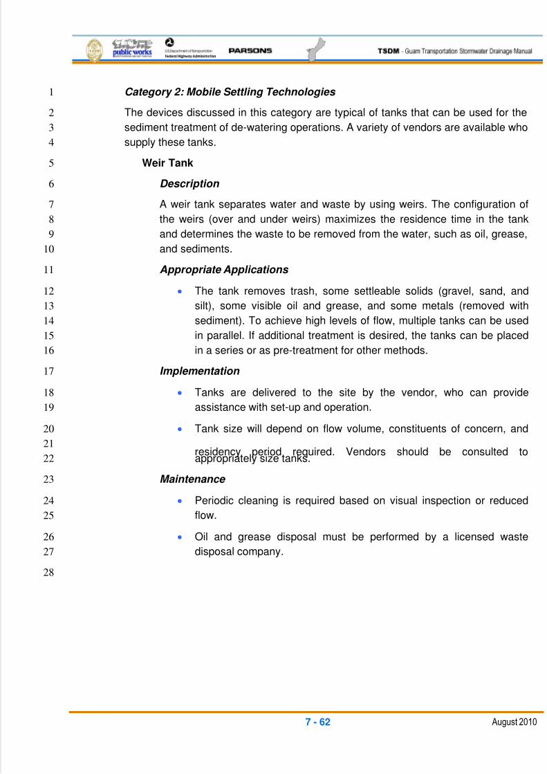
5/13/2018 Guam Storm Water Drainage Manual - slidepdf.com
http://slidepdf.com/reader/full/guam-storm-water-drainage-manual 352/486
7 - 62 August 2010
Category 2: Mobile Settling Technologies 1
The devices discussed in this category are typical of tanks that can be used for the2
sediment treatment of de-watering operations. A variety of vendors are available who3
supply these tanks.4
Weir Tank5
Description 6
A weir tank separates water and waste by using weirs. The configuration of7
the weirs (over and under weirs) maximizes the residence time in the tank8
and determines the waste to be removed from the water, such as oil, grease,9
and sediments.10
Appropriate Applications 11
The tank removes trash, some settleable solids (gravel, sand, and12
silt), some visible oil and grease, and some metals (removed with13
sediment). To achieve high levels of flow, multiple tanks can be used14
in parallel. If additional treatment is desired, the tanks can be placed15
in a series or as pre-treatment for other methods.16
Implementation 17
Tanks are delivered to the site by the vendor, who can provide18
assistance with set-up and operation.19
Tank size will depend on flow volume, constituents of concern, and20
residency period required. Vendors should be consulted to21
appropriately size tanks.22
Maintenance 23
Periodic cleaning is required based on visual inspection or reduced24
flow.25
Oil and grease disposal must be performed by a licensed waste26
disposal company.27
28
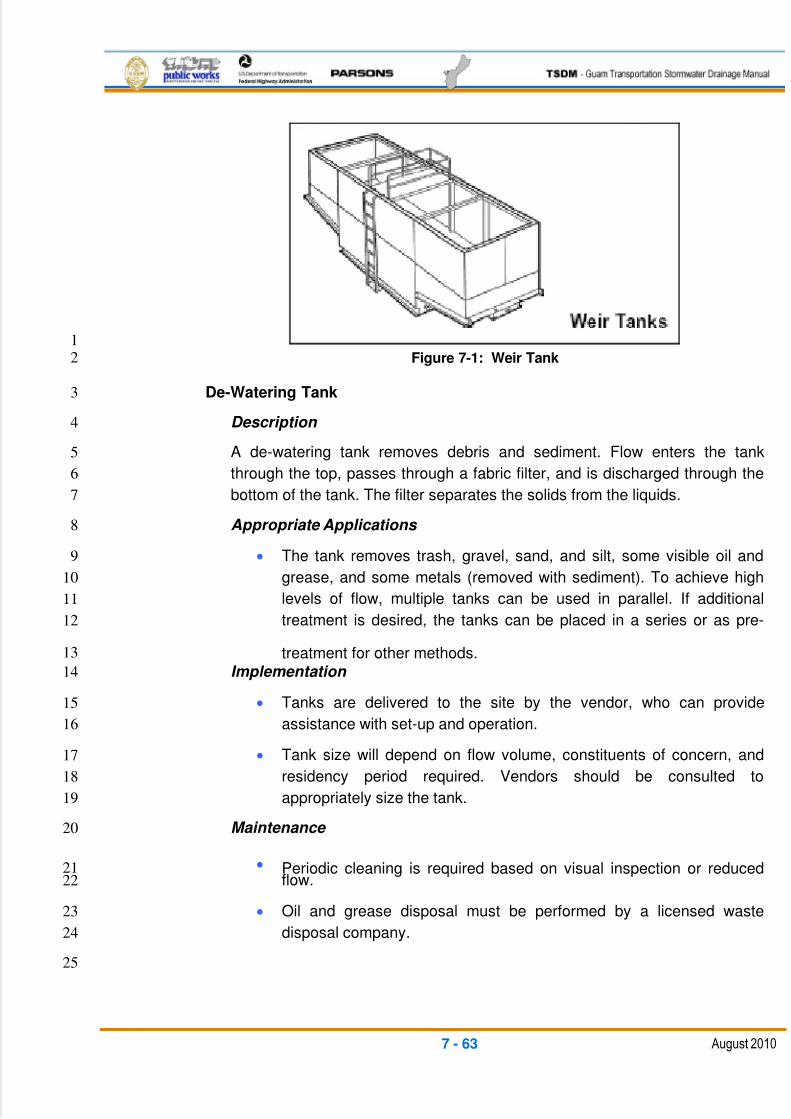
5/13/2018 Guam Storm Water Drainage Manual - slidepdf.com
http://slidepdf.com/reader/full/guam-storm-water-drainage-manual 353/486
7 - 63 August 2010
1
Figure 7-1: Weir Tank2
De-Watering Tank3
Description 4
A de-watering tank removes debris and sediment. Flow enters the tank5
through the top, passes through a fabric filter, and is discharged through the6
bottom of the tank. The filter separates the solids from the liquids.7
Appropriate Applications 8
The tank removes trash, gravel, sand, and silt, some visible oil and9
grease, and some metals (removed with sediment). To achieve high10
levels of flow, multiple tanks can be used in parallel. If additional11
treatment is desired, the tanks can be placed in a series or as pre-12
treatment for other methods.13
Implementation 14
Tanks are delivered to the site by the vendor, who can provide15
assistance with set-up and operation.16
Tank size will depend on flow volume, constituents of concern, and17
residency period required. Vendors should be consulted to18
appropriately size the tank.19
Maintenance 20
Periodic cleaning is required based on visual inspection or reduced21flow.22
Oil and grease disposal must be performed by a licensed waste23
disposal company.24
25
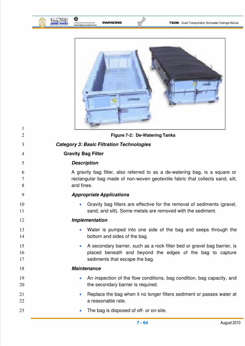
5/13/2018 Guam Storm Water Drainage Manual - slidepdf.com
http://slidepdf.com/reader/full/guam-storm-water-drainage-manual 354/486
7 - 64 August 2010
1
Figure 7-2: De-Watering Tanks2
Category 3: Basic Filtration Technologies 3
Gravity Bag Filter4
Description 5
A gravity bag filter, also referred to as a de-watering bag, is a square or6
rectangular bag made of non-woven geotextile fabric that collects sand, silt,7
and fines.8
Appropriate Applications 9
Gravity bag filters are effective for the removal of sediments (gravel,10
sand, and silt). Some metals are removed with the sediment.11
Implementation 12
Water is pumped into one side of the bag and seeps through the13
bottom and sides of the bag.14
A secondary barrier, such as a rock filter bed or gravel bag barrier, is15
placed beneath and beyond the edges of the bag to capture16
sediments that escape the bag.17
Maintenance 18
An inspection of the flow conditions, bag condition, bag capacity, and19
the secondary barrier is required.20
Replace the bag when it no longer filters sediment or passes water at21
a reasonable rate.22
The bag is disposed of off- or on-site.23
5/13/2018 Guam Storm Water Drainage Manual - slidepdf.com
http://slidepdf.com/reader/full/guam-storm-water-drainage-manual 355/486
7 - 65 August 2010
Category 4: Advanced Filtration Technologies 1
Sand Media Particulate Filter2
Description 3
Water is treated by passing it through canisters filled with sand media.4
Generally, sand filters provide a final level of treatment. They are often used5
as a secondary or higher level of treatment after a significant amount of6
sediment and other pollutants have been removed.7
Appropriate Applications 8
Sand filters are effective for the removal of trash, gravel, sand, silt,9
and some metals, as well as the reduction of Biochemical Oxygen10
Demand (BOD) and turbidity.11
Sand filters can be used for stand-alone treatment or in conjunction12
with bag and cartridge filtration if further treatment is required.13
Sand filters can also be used to provide additional treatment to water14
treated through settling or basic filtration.15
Implementation 16
The filters require delivery to the site and initial set-up. The vendor can17
provide assistance with installation and operation.18
Maintenance 19
The filters require constant service to monitor and maintain the sand media.20
Pressurized Bag Filter21
Description 22
A pressurized bag filter is a unit composed of single filter bags made from23
polyester felt material. The water filters through the unit and is discharged24
through a header, allowing for the flow to discharge in a series to an25
additional treatment unit. Vendors provide pressurized bag filters in a variety26
of configurations. Some units include a combination of bag filters and27
cartridge filters for enhanced contaminant removal.28
Appropriate Applications 29
A pressurized bag filter is effective for the removal of sediment (sand30
and silt) and some metals, as well as the reduction of BOD, turbidity,31
and hydrocarbons. Oil-absorbent bags are available for hydrocarbon32
removal.33
5/13/2018 Guam Storm Water Drainage Manual - slidepdf.com
http://slidepdf.com/reader/full/guam-storm-water-drainage-manual 356/486
7 - 66 August 2010
Filters can be used to provide secondary treatment to water treated1
through settling or basic filtration.2
Implementation 3
The filters require delivery to the site and initial set-up. The vendor4
can provide assistance with installation and operation.5
Maintenance 6
The filter bags require replacement when the pressure differential7
exceeds the manufacturer’s recommendation.8
Cartridge Filter9
Description 10
Cartridge filters provide a high degree of pollutant removal by using a number11
of individual cartridges as part of a larger filtering unit. They are often used as12
a secondary or higher (polishing) level of treatment after a significant amount13
of sediment and other pollutants are removed. Units come with various14
cartridge configurations (for use in a series with pressurized bag filters) or15
with a larger single cartridge filtration unit (with multiple filters within).16
Appropriate Applications 17
Cartridge filters are effective for the removal of sediment (sand, silt,18
and some clays) and metals, as well as the reduction of BOD,19
turbidity, and hydrocarbons. Hydrocarbons can effectively be removed20
with special resin cartridges.21
Filters can be used to provide secondary treatment to water treated22
through settling or basic filtration.23
Implementation 24
The filters require delivery to the site and initial set-up. The vendor25
can provide assistance.26
Maintenance 27
The cartridges require replacement when the pressure differential28
exceeds the manufacturer’s recommendation.29
7.5.3 TEMPORARY STREAM CROSSING30
Definition and Purpose31
A temporary stream crossing is a structure placed across a waterway that allows32
vehicles to cross the waterway during construction, minimizing, reducing, or managing33
the erosion and downstream sedimentation caused by the vehicles.34
5/13/2018 Guam Storm Water Drainage Manual - slidepdf.com
http://slidepdf.com/reader/full/guam-storm-water-drainage-manual 357/486
7 - 67 August 2010
Appropriate Applications1
Temporary stream crossings are installed at sites:2
Where appropriate permits have been secured (404 permits and 4013
certification).4
Where construction equipment or vehicles need to frequently cross a waterway.5
When alternate access routes impose significant constraints.6
When crossing perennial streams or waterways causes significant erosion.7
Where construction activities will not last longer than one year.8
Limitations9
Temporary stream crossings will usually disturb the waterway during installation10
and removal.11
Temporary stream crossings will usually require 401 certification and a COE 40412
permit.13
Installation may require de-watering or a temporary diversion of the stream.14
The crossings may become a constriction in the waterway, which can obstruct15
flood flow and cause flow back-ups or washouts. If improperly designed, flow16
back-ups can increase the pollutant load through washouts and scouring.17
The use of natural or other gravel in the stream for the construction of a ford18
crossing will be contingent upon approval by the appropriate agencies.19
Ford crossings may degrade water quality due to contact with vehicles and20
equipment.21
Ford crossings should not be used in excessively high or fast flows.22
Upon completion of construction activities, the crossing materials must be23
removed from the stream.24
25
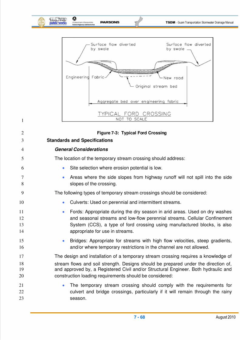
5/13/2018 Guam Storm Water Drainage Manual - slidepdf.com
http://slidepdf.com/reader/full/guam-storm-water-drainage-manual 358/486
7 - 68 August 2010
1
Figure 7-3: Typical Ford Crossing2
Standards and Specifications3
General Considerations 4
The location of the temporary stream crossing should address:5
Site selection where erosion potential is low.6
Areas where the side slopes from highway runoff will not spill into the side7
slopes of the crossing.8
The following types of temporary stream crossings should be considered:9
Culverts: Used on perennial and intermittent streams.10
Fords: Appropriate during the dry season in arid areas. Used on dry washes11
and seasonal streams and low-flow perennial streams. Cellular Confinement12
System (CCS), a type of ford crossing using manufactured blocks, is also13
appropriate for use in streams.14
Bridges: Appropriate for streams with high flow velocities, steep gradients,15
and/or where temporary restrictions in the channel are not allowed.16
The design and installation of a temporary stream crossing requires a knowledge of17
stream flows and soil strength. Designs should be prepared under the direction of,18
and approved by, a Registered Civil and/or Structural Engineer. Both hydraulic and19
construction loading requirements should be considered:20
The temporary stream crossing should comply with the requirements for21
culvert and bridge crossings, particularly if it will remain through the rainy22
season.23
5/13/2018 Guam Storm Water Drainage Manual - slidepdf.com
http://slidepdf.com/reader/full/guam-storm-water-drainage-manual 359/486
7 - 69 August 2010
The temporary stream crossing should provide stability in the crossing and1
adjacent areas to withstand the design flow. The design flow and safety factor2
should be selected based on careful evaluation of the risks due to3
overtopping, flow back-ups, or washout.4
The temporary stream crossing should avoid oil or other potentially5
hazardous waste materials for surface treatment.6
Construction Considerations 7
Stabilize construction roadways, adjacent work areas, and the stream bottom8
against erosion.9
Construct crossings during dry periods to minimize stream disturbance and10
reduce costs.11
Construct crossings at or near the natural elevation of the stream bed to12
prevent potential flooding upstream of the crossing.13
Install temporary sediment control BMPs in accordance with sediment control14
BMPs to minimize the erosion of embankment into flow lines.15
Vehicles and equipment should not be driven, operated, fueled, cleaned,16
maintained, or stored in the wet or dry portions of a water body where17
wetland vegetation, riparian vegetation, or aquatic organisms may be18
destroyed, except as authorized by the RE, as necessary to complete the19
work.20
Temporary water body crossings and encroachments should be constructed21
to minimize scour. Cobbles used for temporary water body crossings or22
encroachments should be clean, rounded river cobble.23
The exterior of vehicles and equipment that will encroach on the water body24
within the project should be maintained free of grease, oil, fuel, and residues.25
The disturbance or removal of vegetation should not exceed the minimum26
necessary to complete operations. Precautions should be taken to avoid27
damage to vegetation by people or equipment. Disturbed vegetation should28
be replaced with the appropriate soil stabilization measures.29
Riparian vegetation, when removed pursuant to the provisions of the work,30should be cut off no lower than ground level to promote rapid re-growth.31
Access roads and work areas built over riparian vegetation should be32
covered by a sufficient layer of clean river run cobble to prevent damage to33
the underlying soil and root structure. The cobble should be removed upon34
completion of project activities.35
5/13/2018 Guam Storm Water Drainage Manual - slidepdf.com
http://slidepdf.com/reader/full/guam-storm-water-drainage-manual 360/486
7 - 70 August 2010
Any temporary artificial obstruction placed within flowing water should only be1
built from material such as clean gravel that will cause little or no siltation.2
Drip pans should be placed under all vehicles, and equipment should be3
placed on docks, barges, or other structures over water bodies when the4
vehicle or equipment will be idle for more than one hour.5
Specific Considerations 6
Culverts are relatively easy to construct and able to support heavy equipment7
loads.8
Fords are the least expensive of the crossings, with maximum load limits.9
Temporary fords are not appropriate if construction will continue through the10
rainy season, if thunderstorms are likely, or if the stream is perennial.11
CCS crossing structures consist of clean, washed gravel and CCS blocks.12CCSs are appropriate for streams that would benefit from an influx of gravel13
such as fish streams; streams or rivers below reservoirs; and urban,14
channelized streams. Many urban stream systems are gravel-deprived due to15
human influences such as dams, gravel mines, and concrete channels.16
CCSs allow designers to use either angular or naturally-occurring, rounded17
gravel, because the cells provide the necessary structure and stability. In fact,18
natural gravel is optimal for this technique because of the habitat19
improvement it will provide after removal of the CCS.20
A gravel depth of 6 in. to 12 in. for a CCS structure is sufficient to support21
most construction equipment.22
An advantage of a CCS crossing structure is that relatively little rock or gravel23
is needed because the CCS provides the stability.24
Bridges are generally more expensive to design and construct but provide the25
least disturbance of the stream bed and constriction of the waterway flows.26
Maintenance and Inspection27
Maintenance provisions should include:28
The periodic removal of debris behind fords, in culverts, and under bridges.29
The replacement of lost protective aggregate from inlets and outlets of30
culverts.31
The removal of temporary crossing promptly once it is no longer needed.32
Inspection should, at a minimum, occur weekly and after each significant rainfall and33
include:34

5/13/2018 Guam Storm Water Drainage Manual - slidepdf.com
http://slidepdf.com/reader/full/guam-storm-water-drainage-manual 361/486
7 - 71 August 2010
Checking for blockage in the channel, debris build-up in culverts, or behind1
fords and under bridges.2
Checking for erosion of abutments, channel scour, riprap displacement, or3
piping in the soil.4
Checking for structural weakening of the temporary crossing, such as cracks,5
and undermining of foundations and abutments.6
7.5.4 CLEAR WATER DIVERSION7
Definition and Purpose8
Clear water diversion consists of a system of structures and measures that intercept9
clear surface water runoff upstream of a project site, transport it around the work area,10
and discharge it downstream, with minimal water quality degradation for either the11
project construction operations or construction of the diversion. Clear water diversions12
are used in a waterway to enclose a construction area and reduce sediment pollution13
from construction work occurring in or adjacent to water. Isolation techniques are14
methods that isolate near shore work from a water body. Structures commonly used as15
part of this system include diversion ditches, berms, dikes, slope drains, rock, gravel16
bags, wood, sheet piles, aqua barriers, cofferdams, filter fabric or turbidity curtains,17
drainage and interceptor swales, pipes, or flumes.18
Appropriate Applications19
A clear water diversion is typically implemented where appropriate permits (40420
permits and 401 water quality certifications) have been secured and work must21
be performed in a live stream or water body.22
Clear water diversions are appropriate for isolating construction activities23
occurring within or near a water body such as streambank stabilization or culvert,24
bridge, pier, or abutment installation. They may also be used in combination with25
other methods, such as clear water bypasses and/or pumps.26
Pumped diversions are suitable for intermittent and low-flow streams.27
Excavation of a temporary bypass channel or passing the flow through a pipe28
called a flume is appropriate for the diversion of streams less than 20 ft. wide,29
with flow rates less than 99 cu. ft. per second.30
Limitations31
Diversion/encroachment activities will usually disturb the waterway during the32
installation and removal of diversion structures.33
Specific permit requirements or mitigation measures, such as the USACE,34
Federal Emergency Management Agency (FEMA), etc., may be included in35
contract documents because of clear water diversion/encroachment activities.36
5/13/2018 Guam Storm Water Drainage Manual - slidepdf.com
http://slidepdf.com/reader/full/guam-storm-water-drainage-manual 362/486
7 - 72 August 2010
Diversion/encroachment activities may constrict the waterway, which can1
obstruct flood flows and cause flooding or washouts. Diversion structures should2
not be installed without identifying potential impacts to the stream channel.3
Diversion or isolation activities should not completely dam stream flow.4
De-watering and removal may require additional sediment control or water5
treatment.6
Standards and Specifications7
General 8
Implement the guidelines presented for the streambank protection BMP.9
Where working areas encroach on live streams, barriers adequate to prevent10
the flow of muddy water into streams should be constructed and maintained11
between working areas and streams. During construction of the barriers, the12
muddying of streams should be held to a minimum.13
Diversion structures must be adequately designed to accommodate14
fluctuations in water depth or flow volume due to tides, storms, flash floods,15
etc.16
Heavy equipment driven in wet portions of a water body to accomplish work17
should be completely clean of petroleum residue and water levels should be18
below the gearboxes of the equipment in use, or lubricants and fuels should19
be sealed so that an inundation of water does not result in leaks.20
Mechanical equipment operated in the water should not be submerged to a21
point above any axle of the mechanical equipment.22
The excavation equipment buckets may reach out into the water for the23
purpose of removing or placing fill materials. Only the bucket of the24
crane/excavator/backhoe may operate in a water body. The main body of the25
crane/excavator/backhoe should not enter the water body, except as26
necessary to cross the stream to access the work site.27
Stationary equipment such as motors and pumps, located within or adjacent28
to a water body, should be positioned over drip pans.29
When any artificial obstruction is being constructed, maintained, or placed in30
operation, sufficient water should, at all times, be allowed to pass31
downstream to maintain aquatic life downstream.32
The exterior of vehicles and equipment that will encroach on a water body33
within the project should be maintained free of grease, oil, fuel, and residues.34
5/13/2018 Guam Storm Water Drainage Manual - slidepdf.com
http://slidepdf.com/reader/full/guam-storm-water-drainage-manual 363/486
7 - 73 August 2010
Equipment should not be parked below the high-water mark, unless allowed1
by a permit.2
The disturbance or removal of vegetation should not exceed the minimum3
necessary to complete operations. Precautions should be taken to avoid4
damage to vegetation by people or equipment. Disturbed vegetation should5
be replaced with the appropriate soil stabilization measures.6
Riparian vegetation, when removed pursuant to the provisions of the work,7
should be cut off no lower than ground level to promote rapid re-growth.8
Access roads and work areas built over riparian vegetation should be9
covered by a sufficient layer of clean river-run rock to prevent damage to the10
underlying soil and root structure. The rock should be removed upon11
completion of project activities.12
Drip pans should be placed under all vehicles, and equipment should be13placed on docks, barges, or other structures over water bodies when the14
vehicle or equipment is planned to be idle for more than one hour.15
Where possible, avoid or minimize diversion/encroachment impacts by16
scheduling construction during periods of low flow or when the stream is dry.17
Also, see the project permits and contract requirements for scheduling.18
Scheduling should also consider seasonal flows, fish spawning seasons, and19
water demands due to irrigation.20
Construct diversion structures with materials free of potential pollutants, such21
as soil, silt, sand, clay, grease, or oil.22
Temporary Diversions/Encroachments23
Construct diversion channels in accordance with the guidelines for the earth24
dikes, drainage swales, and ditches BMPs.25
In high-flow velocity areas, stabilize the slopes of embankments and diversion26
ditches using an appropriate liner, in accordance with the geotextiles, plastic27
covers and erosion control blankets/mats BMPs, or use rock slope protection, as28
described in the Standard Specifications.29
Where appropriate, use natural stream bed materials such as large cobbles and30
boulders for temporary embankment/slope protection or other temporary soil31
stabilization methods.32
Provide for velocity dissipation at transitions in the diversion, such as the point33
where the stream is diverted to the channel and the point where the diverted34
stream is returned to its natural channel, in accordance with the guidelines noted35
under the outlet protection/velocity dissipation devices. BMPs.36
5/13/2018 Guam Storm Water Drainage Manual - slidepdf.com
http://slidepdf.com/reader/full/guam-storm-water-drainage-manual 364/486
7 - 74 August 2010
Temporary Dry Construction Areas1
When de-watering behind temporary structures to create a temporary dry2
construction area such as cofferdams, pass pumped water through a sediment3
settling device, such as a portable tank or settling basin, before returning the4
water to the water body.5
If the presence of polluted water or sediment is identified in the contract, the6
contractor should implement de-watering pollution controls as required by the7
contract documents. If the quality of water or sediment to be removed while de-8
watering is not identified as polluted in the contract documents, but is later9
determined by observation or testing to be polluted, the contractor should comply10
with the contract requirements.11
Any substance used to assemble or maintain diversion structures, such as form12
oil, should be non-toxic and non-hazardous.13
Any material used to minimize seepage underneath diversion structures, such as14
grout, should be non-toxic, non-hazardous, and as close to a neutral pH as15
possible.16
Isolation Techniques17
Isolation techniques are methods that isolate near-shore work from a water body.18
Techniques include sheet pile enclosures, water-filled geotextile (aqua dam), gravel19
berm with impermeable membrane, gravel bags, cofferdams, and K-rail.20
Filter Fabric Isolation Technique 21
Definition and Purpose22
A filter fabric isolation structure is a temporary structure built into a waterway to23
enclose a construction area and reduce sediment pollution from construction24
work in or adjacent to water. This structure is composed of filter fabric, gravel25
bags, and steel T-posts.26
Appropriate Applications27
Geotextile filter fabric may be used for construction activities such as28
streambank stabilization or culvert, bridge, pier, or abutment installation. It29
may also be used in combination with other methods, such as clean water30
bypasses and/or pumps.31
This method involves the placement of gravel bags or continuous berms32
to key in the fabric, subsequently staking the fabric in place.33
If stream bed fish spawning gravel (gravel between 1 in. and 4 in.) is34
used, all other components of the isolation can be removed from the35
stream, and the gravel can be spread out and left as for the stream bed36
5/13/2018 Guam Storm Water Drainage Manual - slidepdf.com
http://slidepdf.com/reader/full/guam-storm-water-drainage-manual 365/486
7 - 75 August 2010
habitat. Whether spawning gravel or other types of gravel are used, only1
clean, washed gravel should be used as infill for the gravel bags or2
continuous berm.3
This is a method that should be used in relatively calm water in smaller4
streams.5
Limitations6
Do not use if the installation, maintenance, and removal of the structures7
will disturb sensitive aquatic species of concern.8
Filter fabric is not appropriate for projects where de-watering is9
necessary.10
Filter fabric is not appropriate to completely dam stream flow.11
Standards and Specifications12
For the filter fabric isolation method, a non-woven or heavy-duty fabric is13
recommended over standard silt fence. Using rolled geotextile allows14
non-standard widths to be used.15
Anchor filter fabric with gravel bags filled with clean, washed gravel. Do16
not use sand. If a bag should split open, the gravel can be left in the17
stream, where it can provide aquatic habitat benefits.18
Another anchor alternative is a continuous berm, made with the19
continuous berm machine. This is a gravel-filled bag that can be made in20
very long segments. The length of the berms is usually limited to 20 ft. for21
ease of handling.22
Installation23
Place the fabric on the bottom of the stream, and place either a bag of24
clean, washed gravel or a continuous berm over the bottom of the fabric,25
so that a bag-width of fabric lies on the stream bottom. The bag should be26
placed on what will be the outside of the isolation area.27
Pull the fabric up and place a metal T-post immediately behind the fabric,28
on the inside of the isolation area; and attach the fabric to the post with29
three diagonal nylon ties.30
Continue placing fabric as described above until the entire work area has31
been isolated, staking the fabric at least every 6 ft.32
Maintenance and Inspection33
During construction, inspect daily during the work week.34
5/13/2018 Guam Storm Water Drainage Manual - slidepdf.com
http://slidepdf.com/reader/full/guam-storm-water-drainage-manual 366/486
7 - 76 August 2010
Schedule additional inspections during storm events.1
Immediately repair any gaps, holes, or scour.2
Remove sediment build-up.3
Remove BMPs upon completion of all construction activity. Recycle or4
reuse if applicable.5
Re-vegetate areas disturbed by BMP removal if needed.6
Turbidity Curtain Isolation Technique 7
Definition and Purpose8
A turbidity curtain is a fabric barrier used to isolate the near-shore work area. The9
barriers are intended to confine the suspended sediment. The curtain is a floating10
barrier, and thus does not prevent water from entering the isolated area; rather, it11
prevents suspended sediment from getting out.12
Appropriate Applications13
Turbidity curtains should be used where sediment discharge to a stream is14
unavoidable. They are used when construction activities adjoin quiescent waters15
such as lakes, ponds, lagoons, bays, and slow-flowing rivers. The curtains are16
designed to deflect and contain sediment within a limited area and provide17
sufficient retention time so that the soil particles will fall out of suspension.18
Limitations19
Turbidity curtains should not be used in flowing water; they are best20
suited for use in ponds, lakes, lagoons, bays, and very slow-moving21
rivers.22
Turbidity curtains should not be placed across the width of a channel.23
Removing sediment that has been deflected and settled out by the curtain24
may create a discharge problem through the re-suspension of particles25
and by accidental dumping by the removal equipment.26
Standards and Specifications27
Turbidity curtains should be oriented parallel to the direction of flow.28
The curtain should extend the entire depth of the watercourse in calm-29
water situations.30
In wave conditions, the curtain should extend to within 1 ft. of the bottom31
of the watercourse, so that the curtain does not stir up sediment by hitting32
the bottom repeatedly. If it is desirable for the curtain to reach the bottom33
5/13/2018 Guam Storm Water Drainage Manual - slidepdf.com
http://slidepdf.com/reader/full/guam-storm-water-drainage-manual 367/486
7 - 77 August 2010
in an active-water situation, a pervious filter fabric may be used for the1
bottom 1 ft.2
The top of the curtain should consist of flexible flotation buoys, and the3
bottom should be held down by a load line incorporated into the curtain4
fabric. The fabric should be a brightly-colored impervious mesh.5
The curtain should be held in place by anchors placed at least every6
100 ft.7
First, place the anchors. Then tow the fabric out in a furled condition and8
connect to the anchors. The anchors should be connected to the flotation9
devices and not to the bottom of the curtain. Once in place, cut the furling10
lines and allow the bottom of the curtain to sink.11
Sediment that has been deflected and settled out by the curtain may be12
removed. Consideration must be given to the probable outcome of the13removal procedure. Consider whether more of a sediment problem will be14
created through re-suspension of the particles or by accidental dumping15
of material during removal. It is recommended that the soil particles16
trapped by the turbidity curtain only be removed if there has been a17
significant change in the original contours of the affected area in the18
watercourse.19
Particles should always be allowed to settle for a minimum of 6 hours to20
12 hours prior to their removal or prior to removal of the turbidity curtain.21
Maintenance and Inspection22
The curtain should be inspected daily for holes or other problems, and23
any repairs needed should be made promptly.24
Allow sediment to settle for 6 hours to 12 hours prior to the removal of25
sediment or curtain. This means that after removing sediment, wait an26
additional 6 hours to 12 hours before removing the curtain.27
To remove, install furling lines along the curtain, detach from anchors,28
and tow out of the water.29
K-Rail (Pre-cast, Concrete Traffic Barriers) River Isolation 30
Definition and Purpose31
This is a temporary sediment control, or stream isolation method, that uses K-32
rails to form the sediment deposition area, or to isolate the in-stream or near-33
bank construction area. Barriers are placed end-to-end in a pre-designed34
configuration, and gravel-filled bags are used at the toe of the barrier and also at35
5/13/2018 Guam Storm Water Drainage Manual - slidepdf.com
http://slidepdf.com/reader/full/guam-storm-water-drainage-manual 368/486
7 - 78 August 2010
their abutting ends to seal and prevent the movement of sediment beneath or1
through the barrier walls.2
Appropriate Applications3
K-rail isolation can be used in streams with higher water velocities than4
many other isolation techniques.5
Limitations6
The K-rail method does not allow for full de-watering.7
Standards and Specifications8
To create a floor for the K-rail, move large rocks and obstructions. Place9
washed gravel and gravel-filled bags to create a level surface for K-rail to10
sit.11
Place the bottom two K-rails adjacent to each other and parallel to the12
direction of flow; fill the center portion with gravel bags. Then place the13
third K-rail on top of the bottom two; there should be sufficient gravel bags14
between the bottom K-rails, so that the top one is supported by the15
gravel. Place plastic sheeting around the K-rails and secure at the bottom16
with gravel bags.17
Further support can be added by pinning and cabling the K-rails together.18
Also, large riprap and boulders can be used to support either side of the19
K-rail, especially where there is a strong current.20
Maintenance and Inspection21
The barrier should be inspected at least once daily, and any damage,22
movement, or other problems should be addressed immediately.23
Sediment should be allowed to settle for at least 6 hours to 12 hours prior24
to removal of sediment and for 6 hours to 12 hours prior to removal of the25
barrier.26
Stream Diversions27
Definition and Purpose28
Stream diversions consist of a system of structures and measures that intercept29an existing stream upstream of the project, transports it around the work area,30
and discharges it downstream. The selection of which stream diversion technique31
to use depends upon the type of work involved, the physical characteristics of the32
site, and the volume of water flowing through the project.33
5/13/2018 Guam Storm Water Drainage Manual - slidepdf.com
http://slidepdf.com/reader/full/guam-storm-water-drainage-manual 369/486
7 - 79 August 2010
Appropriate Applications1
Pumped diversions are appropriate in areas where de-watering is2
necessary.3
Dam-type diversions may serve as temporary access to the site.4
Diversions are appropriate in work areas that require isolation from flows.5
Limitations6
Pumped diversions have a limited flow capacity.7
Pumped diversions require the frequent monitoring of pumps.8
Large flows during storm events can overtop dams.9
Flow diversion and re-direction with small dams involves in-stream10
disturbance and the mobilization of sediment.11
Standards and Specifications12
Diversions should be sized to convey design flood flows.13
Pump capacity must be sufficient for design flow; the upper limit is14
approximately 10 cu. ft. per second (the capacity of two 8-in. pumps).15
Adequate energy dissipation must be provided at the outlet to minimize16
erosion.17
Dam materials used to create dams upstream and downstream of the18
diversion should be erosion-resistant; materials such as steel plate, sheet19
pile, sandbags, continuous berms, inflatable water bladders, etc., would20
be acceptable.21
When constructing a diversion channel, begin excavation of the channel22
at the proposed downstream end, and work upstream. Once the23
watercourse to be diverted is reached and the excavated channel is24
stable, breach the upstream end and allow water to flow down the new25
channel. Once flow has been established in the diversion channel, install26
the diversion weir in the main channel; this will force all water to be27
diverted from the main channel.28
Maintenance and Inspection29
Inspect diversion/encroachment structures before and after significant30
storms and at least once per week while in service. Inspect daily during31
construction.32
Pumped diversions require the frequent monitoring of pumps.33
5/13/2018 Guam Storm Water Drainage Manual - slidepdf.com
http://slidepdf.com/reader/full/guam-storm-water-drainage-manual 370/486
7 - 80 August 2010
Inspect embankments and diversion channels before and after significant1
storms and at least once per week while in service for damage to the2
linings, accumulating debris, sediment build-up, and the adequacy of3
slope protection. Remove debris and repair linings and slope protection4
as required. Repair holes, gaps, or scour.5
In-Stream Construction Sediment Control 6
There are three different options currently available for reducing turbidity while7
working in a stream or river. The stream can be isolated from the area in which work8
is occurring with a water barrier; the stream can be diverted around the work site9
through a pipe or temporary channel; or construction practices that minimize10
sediment suspension can be used.11
Whichever technique is implemented, an important thing to remember is that the12
worst time to release high Total Suspended Solids (TSS) into a stream system might13
be when the stream is very low. During these times, the flow may be low while the14
biological activity in the stream is very high. Conversely, the addition of high TSS or15
sediment during a big storm discharge might have a relatively low impact because16
the stream is already turbid and the stream energy is capable of transporting both17
suspended solids and large quantities of bedload through the system. The optimum18
time to remove in-stream structures may be during the rising limb of a storm19
hydrograph.20
Techniques to Minimize Total Suspended Solids (TSS) 21
Padding : Padding laid in the stream below the work site may trap some22
solids that are deposited in the stream during construction. After work is23
done, the padding is removed from the stream and placed on the bank to24
assist in re-vegetation.25
Clean, washed gravel : Using clean, washed gravel decreases solid26
suspension, as there are fewer small particles deposited in the stream.27
Excavation using a large bucket : Each time a bucket of soil is placed in the28
stream, a portion is suspended. Approximately the same amount is29
suspended whether there is a small or large amount of soil placed in the30
stream. Therefore, using a large excavator bucket will reduce the total31
amount of soil that washes downstream.32
Use of a dozer for backfilling : Using a dozer for backfilling instead of a33
backhoe follows the same principles -- the fewer times soil is deposited in the34
stream, the less soil will be suspended.35
5/13/2018 Guam Storm Water Drainage Manual - slidepdf.com
http://slidepdf.com/reader/full/guam-storm-water-drainage-manual 371/486
7 - 81 August 2010
Partial de-watering with a pump : Partially de-watering a stream with a1
pump reduces the amount of water, and thus the amount of water that can2
suspend sediment.3
Washing Fines 4
Definition and Purpose5
Washing fines is an in-channel sediment control method that uses water, either6
from a water truck or hydrant, to wash any stream fines that were brought to the7
surface of the channel bed during restoration back into the interstitial spaces of8
the gravel and cobbles.9
The purpose of this technique is to reduce or eliminate the discharge of sediment10
from the channel bottom during the first seasonal flows, or first flush. Sediment11
should not be allowed into stream channels; however, occasionally, in-channel12
restoration work will involve moving or otherwise disturbing fines (sand and silt-13
sized particles) that are already in the stream, usually below bank-full discharge14
elevation. Subsequent re-watering of the channel can result in a plume of15
turbidity and sedimentation.16
This technique washes the fines back into the channel bed. Bedload materials,17
including gravel cobbles, boulders, and those fines, are naturally mobilized18
during higher storm flows. This technique is intended to delay the discharge until19
the fines would naturally be mobilized.20
Appropriate Applications21
This technique should be used when construction work is required in22channels. It is especially useful in intermittent or ephemeral streams in23
which work is performed “in the dry” and is subsequently re-watered.24
Limitations25
The stream must have sufficient gravel and cobble substrate composition.26
The use of this technique requires consideration of the time of year and27
timing of expected stream flows.28
The optimum time for the use of this technique is in the dry season.29
Standards and Specifications30
Apply water slowly and evenly to prevent runoff and erosion.31
Consult with the Guam Environmental Protection Agency (GEPA) for32
specific water quality requirements of applied water.33
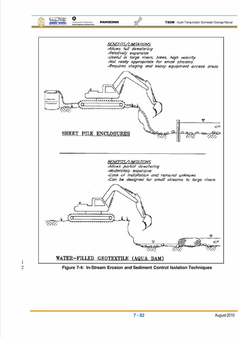
5/13/2018 Guam Storm Water Drainage Manual - slidepdf.com
http://slidepdf.com/reader/full/guam-storm-water-drainage-manual 372/486
7 - 82 August 2010
1
Figure 7-4: In-Stream Erosion and Sediment Control Isolation Techniques2
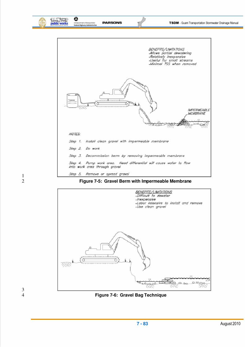
5/13/2018 Guam Storm Water Drainage Manual - slidepdf.com
http://slidepdf.com/reader/full/guam-storm-water-drainage-manual 373/486
7 - 83 August 2010
1
Figure 7-5: Gravel Berm with Impermeable Membrane2
3
Figure 7-6: Gravel Bag Technique4
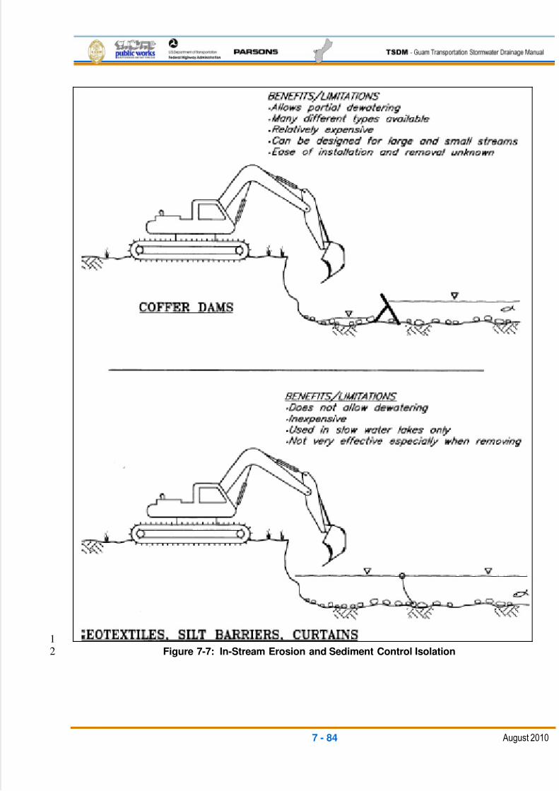
5/13/2018 Guam Storm Water Drainage Manual - slidepdf.com
http://slidepdf.com/reader/full/guam-storm-water-drainage-manual 374/486
7 - 84 August 2010
1
Figure 7-7: In-Stream Erosion and Sediment Control Isolation2
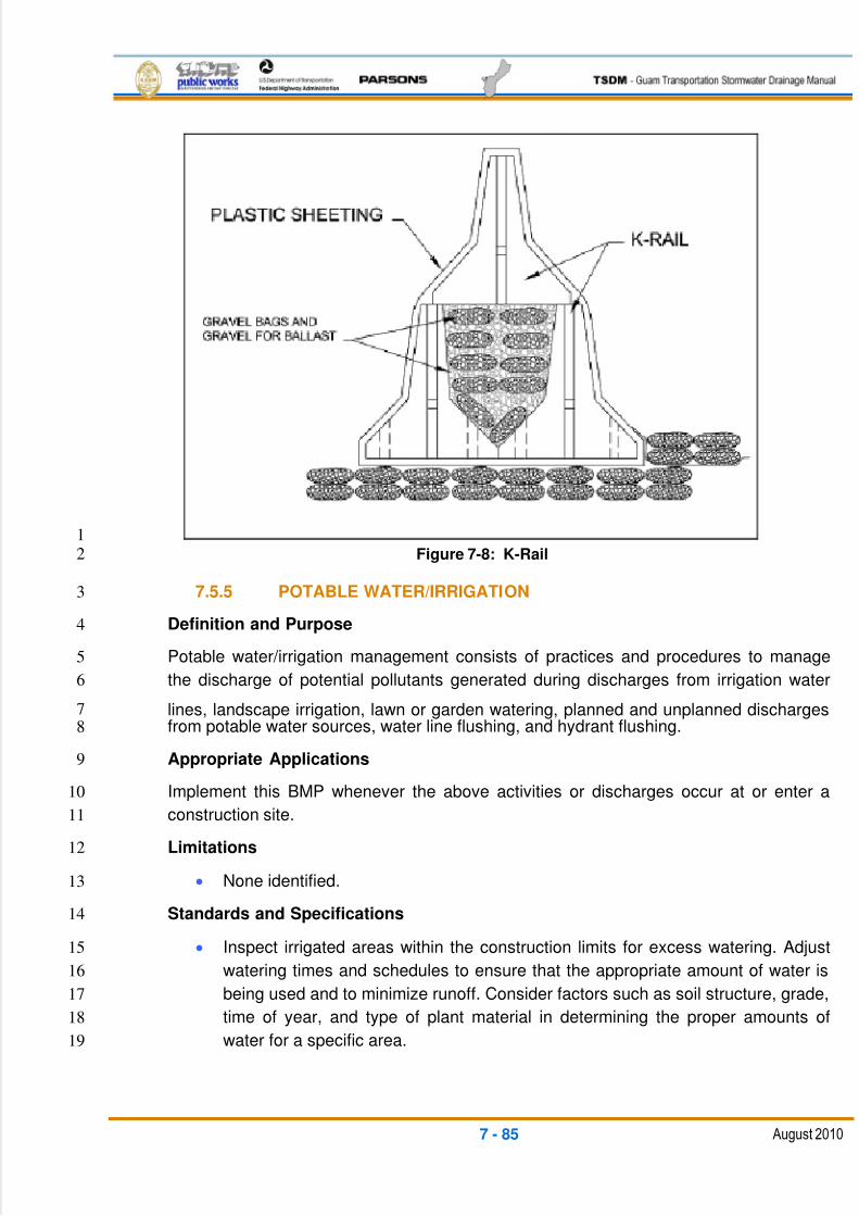
5/13/2018 Guam Storm Water Drainage Manual - slidepdf.com
http://slidepdf.com/reader/full/guam-storm-water-drainage-manual 375/486
7 - 85 August 2010
1
Figure 7-8: K-Rail2
7.5.5 POTABLE WATER/IRRIGATION3
Definition and Purpose4
Potable water/irrigation management consists of practices and procedures to manage5
the discharge of potential pollutants generated during discharges from irrigation water6
lines, landscape irrigation, lawn or garden watering, planned and unplanned discharges7
from potable water sources, water line flushing, and hydrant flushing.8
Appropriate Applications9
Implement this BMP whenever the above activities or discharges occur at or enter a10
construction site.11
Limitations12
None identified.13
Standards and Specifications14
Inspect irrigated areas within the construction limits for excess watering. Adjust15
watering times and schedules to ensure that the appropriate amount of water is16
being used and to minimize runoff. Consider factors such as soil structure, grade,17
time of year, and type of plant material in determining the proper amounts of18
water for a specific area.19
5/13/2018 Guam Storm Water Drainage Manual - slidepdf.com
http://slidepdf.com/reader/full/guam-storm-water-drainage-manual 376/486
7 - 86 August 2010
Equipment or other project washing activities runoff should be quality treated1
prior to discharge to the storm drain or receiving water body.2
Where possible, direct water from off-site sources around or through a3
construction site in a way that minimizes contact with the construction site.4
When possible, discharges from water line flushing should be reused for5
landscaping purposes.6
Shut off the water source to broken lines, sprinklers, or valves as soon as7
possible to prevent excess water flow.8
Protect downstream stormwater drainage systems and watercourses from water9
pumped or bailed from trenches excavated to repair water lines.10
Maintenance and Inspection11
Repair broken water lines as soon as possible or as directed by the RE.12
Inspect irrigated areas regularly for signs of erosion and/or discharge.13
7.5.6 VEHICLE AND EQUIPMENT CLEANING14
Definition and Purpose15
Vehicle and equipment cleaning procedures and practices are used to minimize or16
eliminate the discharge of pollutants from vehicle and equipment cleaning operations to17
a storm drain system or to watercourses.18
Appropriate Applications19
These procedures are applied on all construction sites where vehicle and equipment20
cleaning is performed.21
Limitations22
None.23
Standards and Specifications24
On-site vehicle and equipment washing is discouraged.25
Cleaning vehicles and equipment with soap, solvents, or steam should not occur26
on the project site unless the resulting wastes are fully-contained and disposed of27
outside of the project limits in conformance with the contract requirements.28
Resulting wastes and byproducts should not be discharged or buried within the29
project limits and must be captured and recycled or disposed of.30
Minimize the use of solvents. The use of diesel for vehicle and equipment31
cleaning is prohibited.32
5/13/2018 Guam Storm Water Drainage Manual - slidepdf.com
http://slidepdf.com/reader/full/guam-storm-water-drainage-manual 377/486
7 - 87 August 2010
Vehicle and equipment washwater should be contained for percolation or1
evaporative drying away from storm drain inlets or watercourses, and should not2
be discharged within the project limits. Apply sediment control BMPs if3
applicable.4
All vehicles/equipment that regularly enter and leave the construction site must5
be cleaned off-site.6
When vehicle/equipment washing/cleaning must occur on-site, and the operation7
cannot be located within a structure or building equipped with appropriate8
disposal facilities, the outside cleaning area should have the following9
characteristics:10
o Located away from storm drain inlets, drainage facilities, or watercourses11
o Paved with concrete or asphalt and bermed to contain washwaters and to12
prevent run-on and run-off13
o Configured with a sump to allow for the collection and disposal of14
washwater15
o Washwaters should not be discharged to storm drains or watercourses16
o Used only when necessary17
When cleaning vehicles/equipment with water:18
o Use as little water as possible. High pressure sprayers may use less19
water than a hose and should be considered.20
o Use a positive shutoff valve to minimize water usage21
o Facility wash racks should discharge to a sanitary sewer, recycle system,22
or other approved discharge system and should not discharge to the23
storm drainage system or watercourses24
Maintenance and Inspection25
The control measure should be inspected at a minimum of once a week26
Monitor employees and subcontractors throughout the duration of the27
construction project to ensure appropriate practices are being implemented28
Inspect sump regularly and remove liquids and sediment as needed29
7.5.7 VEHICLE AND EQUIPMENT FUELING30
Definition and Purpose 31
Vehicle and equipment fueling procedures and practices are designed to minimize or32
eliminate the discharge of fuel spills and leaks into storm drain systems or to33
watercourses.34
5/13/2018 Guam Storm Water Drainage Manual - slidepdf.com
http://slidepdf.com/reader/full/guam-storm-water-drainage-manual 378/486
7 - 88 August 2010
Appropriate Applications1
These procedures are applied on all construction sites where vehicle and equipment2
fueling occurs.3
Limitations4
On-site vehicle and equipment fueling should only be used where it is impractical5
to send vehicles and equipment off-site for fueling.6
Standards and Specifications7
When fueling must occur on-site, the contractor should select and designate an8
area to be used.9
Absorbent spill cleanup materials and spill kits should be available in fueling10
areas and on fueling trucks and disposed of properly after use.11
Drip pans or absorbent pads should be used during vehicle and equipment12
fueling, unless the fueling is performed over an impermeable surface in a13
dedicated fueling area.14
Dedicated fueling areas should be protected from stormwater run-on and run-off,15
and located at least 50 ft. from downstream drainage facilities and watercourses.16
Fueling must be performed on level grade areas.17
Nozzles used in vehicle and equipment fueling should be equipped with an18
automatic shutoff to control drips. Fueling operations should not be left19
unattended.20
Protect fueling areas with berms and/or dikes to prevent run-on, run-off, and to21
contain spills.22
Use vapor recovery nozzles to help control drips as well as air pollution where23
required. Ensure the nozzle is secured upright when not in use.24
Fuel tanks should not be "topped-off."25
Vehicles and equipment should be inspected on each day of use for leaks. Leaks26
should be repaired immediately, or problem vehicles or equipment should be27
removed from the project site.28
Absorbent spill cleanup materials should be available in fueling and maintenance29
areas and used on small spills instead of hosing the area down or using burying30
techniques. The spent absorbent material should be removed promptly and31
disposed of properly.32
Federal, state, and local requirements should be observed for any stationary33
above-ground storage tanks.34
5/13/2018 Guam Storm Water Drainage Manual - slidepdf.com
http://slidepdf.com/reader/full/guam-storm-water-drainage-manual 379/486
7 - 89 August 2010
Mobile fueling of construction equipment throughout the site should be1
minimized. Whenever practical, equipment should be transported to the2
designated fueling area.3
Maintenance and Inspection4
Fueling areas and storage tanks should be inspected regularly.5
Keep an ample supply of spill cleanup material on the site.6
Immediately clean up spills and properly dispose of contaminated soil and7
cleanup materials.8
7.5.8 VEHICLE AND EQUIPMENT MAINTENANCE9
Definition and Purpose10
Vehicle and equipment maintenance involves procedures and practices to minimize or11
eliminate the discharge of pollutants to the storm drain systems or to watercourses from12
vehicle and equipment maintenance procedures.13
Appropriate Applications14
These procedures are applied on all construction projects where an on-site yard area is15
necessary for the storage and maintenance of heavy equipment and vehicles.16
Limitations17
None identified.18
Standards and Specifications19
Drip pans or absorbent pads should be used during vehicle and equipment20
maintenance work that involves fluids, unless the maintenance work is performed21
over an impermeable surface in a dedicated maintenance area.22
All maintenance areas are required to have spill kits and/or use other spill23
protection devices.24
Dedicated maintenance areas should be protected from stormwater run-on and25
run-off and located at least 50 ft. from downstream drainage facilities and26
watercourses.27
Drip pans or plastic sheeting should be placed under all vehicles and equipment28placed on docks, barges, or other structures over water bodies when the vehicle29
or equipment is planned to be idle for more than one hour.30
Absorbent spill cleanup materials should be available in maintenance areas and31
disposed of properly after use. Substances used to coat asphalt transport trucks32
and asphalt-spreading equipment should be non-toxic.33
5/13/2018 Guam Storm Water Drainage Manual - slidepdf.com
http://slidepdf.com/reader/full/guam-storm-water-drainage-manual 380/486
7 - 90 August 2010
Use off-site maintenance facilities whenever practical. For long-term projects,1
consider constructing roofs or using portable tents over maintenance areas.2
Properly dispose of used oils, fluids, lubricants, and spill cleanup materials.3
Do not dump fuels and lubricants onto the ground.4
Do not place used oil in a dumpster or pour into a storm drain or watercourse.5
Properly dispose or recycle used batteries.6
Do not bury used tires.7
Repair fluid and oil leaks immediately.8
Provide spill containment dikes or secondary containment around stored oil and9
chemical drums.10
Maintenance and Inspection11
Maintain waste fluid containers in leak-proof condition.12
Vehicle and equipment maintenance areas should be inspected regularly.13
Vehicles and equipment should be inspected on each day of use. Leaks should14
be repaired immediately, or the problem vehicles or equipment should be15
removed from the project site.16
Inspect equipment for damaged hoses and leaky gaskets routinely. Repair or17
replace as needed.18
7.5.9 PILE-DRIVING OPERATIONS19
Definition and Purpose20
The construction and retrofit of bridges and retaining walls often includes driving piles for21
foundation support and shoring operations. Driven piles are typically constructed of22
concrete, steel, or timber. Driven sheet piles are used for shoring and cofferdam23
construction. The proper control and use of equipment, materials, and waste products24
from pile-driving operations will reduce the discharge of potential pollutants to the storm25
drain system or watercourses.26
Appropriate Applications27
These procedures apply to construction sites near or adjacent to a watercourse or28
groundwater where permanent and temporary pile-driving operations (impact and29
vibratory) take place.30
5/13/2018 Guam Storm Water Drainage Manual - slidepdf.com
http://slidepdf.com/reader/full/guam-storm-water-drainage-manual 381/486
7 - 91 August 2010
Standards and Specifications1
Use drip pans or absorbent pads during vehicle and equipment maintenance,2
cleaning, fueling, and storage. Refer to the BMPs “Vehicle and Equipment3
Fueling” and “Vehicle and Equipment Maintenance.”4
Have spill kits and cleanup materials available at all pile-driving locations.5
Keep equipment that is in use in streambeds or on docks, barges, or other6
structures over water bodies, leak free.7
Where possible, park equipment over plastic sheeting or equivalent. Plastic8
sheeting is not a substitute for drip pans or absorbent pads. The storage or use9
of equipment in streambeds or other bodies of water should comply with all10
applicable permits.11
Implement other BMPs as applicable.12
When not in use, store pile-driving equipment away from concentrated flows of13
stormwater, drainage courses, and inlets. Protect hammers and other hydraulic14
attachments from run-on by placing them on plywood and covering them with15
plastic or a comparable material prior to the onset of rain.16
Use less hazardous products, such as vegetable oil, instead of hydraulic fluid,17
when practicable.18
Maintenance and Inspection19
Inspect pile-driving areas and equipment for leaks and spills on a daily basis.20
Inspect equipment routinely and repair equipment as needed (e.g., worn or21
damaged hoses, fittings, gaskets, etc.).22
7.5.10 CONCRETE CURING23
Definition and Purpose24
Concrete curing is used in the construction of structures such as bridges, retaining walls,25
and pump houses. Concrete curing includes the use of both chemical and water26
methods. Proper procedures minimize runoff pollution during concrete curing.27
Appropriate Applications28
All concrete elements of a structure (e.g., footings, columns, abutments, stems, soffit,29
decks, etc.) are subject to curing requirements.30
Standards and Specifications31
Chemical Curing 32
Avoid the overspray of curing compounds.33
5/13/2018 Guam Storm Water Drainage Manual - slidepdf.com
http://slidepdf.com/reader/full/guam-storm-water-drainage-manual 382/486
7 - 92 August 2010
Minimize the drift of chemical cure as much as possible by applying the1
curing compound close to the concrete surface. Apply an amount of2
compound that covers the surface but does not allow any runoff of the3
compound.4
Use proper storage and handling techniques for concrete curing compounds.5
Protect drain inlets prior to the application of curing compounds.6
Water Curing for Bridge Decks, Retaining Walls, and Other Structures 7
Direct curing water away from inlets and watercourses to collection areas for8
removal in accordance with all applicable permits.9
Collect cured water and transport or dispose of water in a non-erodible10
manner.11
Use wet blankets or a similar method that maintains moisture while12minimizing the use and possible discharge of water.13
Maintenance and Inspection14
Ensure that employees and subcontractors implement appropriate measures for15
storage, handling, and the use of curing compounds.16
Inspect any temporary diversion devices, lined channels, or swales for washouts,17
erosion, or debris. Replace lining and remove debris as necessary.18
Inspect cure containers and spraying equipment for leaks.19
7.5.11 MATERIAL AND EQUIPMENT USE OVER WATER20
Definition and Purpose21
The following outlines procedures for the proper use, storage, and disposal of materials22
and equipment on barges, boats, temporary construction pads, or similar locations that23
minimize or eliminate the discharge of potential pollutants to a watercourse.24
Appropriate Applications25
These procedures should be implemented for construction materials and wastes (solid26
and liquid) and any other materials that may be detrimental if released. These27
procedures should be applied where materials and equipment are used on barges,28
boats, docks, and other platforms over or adjacent to a watercourse.29
Standards and Specifications30
Use drip pans and absorbent materials for equipment and vehicles, and ensure31
that an adequate supply of spill cleanup materials is available. Drip pans should32
be placed under all vehicles and equipment placed on docks, barges, or other33

5/13/2018 Guam Storm Water Drainage Manual - slidepdf.com
http://slidepdf.com/reader/full/guam-storm-water-drainage-manual 383/486
7 - 93 August 2010
structures over water bodies when the vehicle or equipment is expected to be1
idle for more than one hour.2
Maintain equipment in accordance with the BMP, “Vehicle and Equipment3
Maintenance.”4
Provide watertight curbs or toe boards to contain spills and prevent materials,5
tools, and debris from leaving the barge, platform, dock, etc.6
Secure all materials to prevent discharges to receiving waters through wind.7
Identify the types of spill control measures to be employed. Ensure that the staff8
is trained to handle spills.9
Ensure the timely and proper removal of accumulated wastes.10
Comply with all necessary permits required for construction within or near the11
watercourse.12
Discharges to waterways should be reported immediately upon discovery. A13
written discharge notification must follow within seven days.14
Maintenance and Inspection15
Inspect equipment for leaks and spills on a daily basis, and make necessary16
repairs.17
Ensure that employees and subcontractors implement appropriate measures for18
the storage and use of materials and equipment.19
7.5.12 CONCRETE FINISHING20
Definition and Purpose21
Concrete finishing methods are used for bridge deck rehabilitation, paint removal, curing22
compound removal, and final surface finish appearances. Methods include sand23
blasting, shot blasting, grinding, or high-pressure water blasting. Proper procedures24
minimize the impact that concrete finishing methods may have on runoff.25
Appropriate Applications26
These procedures apply to all construction locations where concrete finishing operations27
are performed.28
Limitations29
Specific permit requirements may be included in the contract documents for30
certain concrete finishing operations.31
Standards and Specifications32
Follow the containment requirements stated in the contract documents, if any.33
5/13/2018 Guam Storm Water Drainage Manual - slidepdf.com
http://slidepdf.com/reader/full/guam-storm-water-drainage-manual 384/486
7 - 94 August 2010
Collect and properly dispose of water and solid waste from high-pressure water-1
blasting operations.2
Collect water from blasting operations, and transport or dispose of water in a3
non-erodible manner.4
Direct water from blasting operations away from inlets and watercourses to5
collection areas for removal (e.g., de-watering), as approved in advance by the6
RE and in accordance with applicable permits.7
Protect inlets during sandblasting operations.8
Minimize the drift of dust and blast material as much as possible by keeping the9
blasting nozzle close to the surface.10
Maintenance and Inspection11
Follow the inspection procedures as required in the project’s contractual12specifications.13
At a minimum, inspect containment structures, if any, for damage or voids prior to14
their use each day and prior to the onset of rain.15
At the end of each work shift, remove and contain the liquid and solid wastes16
from containment structures, if any, and from the general work area.17
7.5.13 STRUCTURE DEMOLITION/REMOVAL OVER OR ADJACENT TO18
WATER19
Definition and Purpose20
This section outlines the procedures that should be followed to protect water bodies from21
debris and wastes associated with structure demolition or removal over or adjacent to22
watercourses.23
Appropriate Applications24
Structure demolition/removal over or adjacent to water should be applied in the cases of25
full bridge demolition and removal, partial bridge removal (e.g., barrier rail, edge of deck)26
associated with bridge-widening projects, concrete channel removal, or any other27
structure removal that could potentially affect water quality.28
Limitations29
Specific permit requirements may be included in the contract documents.30
Standards and Specifications31
Do not allow demolished material to enter the waterway.32
Refer to the BMP, “Clear Water Diversion”, to direct water away from work areas.33
5/13/2018 Guam Storm Water Drainage Manual - slidepdf.com
http://slidepdf.com/reader/full/guam-storm-water-drainage-manual 385/486
7 - 95 August 2010
Use attachments on construction equipment such as backhoes to catch debris1
from small demolition operations.2
Use covers or platforms to collect debris.3
Platforms and covers should be approved by the RE.4
Stockpile accumulated debris and waste generated during demolition away from5
watercourses.6
Ensure the safe passage of wildlife, as necessary.7
Discharges to waterways should be reported to the RE immediately upon8
discovery. A written discharge notification must follow within seven days.9
Maintenance and Inspection10
The contractor must inspect demolition areas over or near adjacent watercourses11
on a daily basis.12
Any debris-catching devices should be regularly emptied. Collected debris should13
be removed and stored away from the watercourse and protected from run-on14
and run-off.15
7.6 POST-CONSTRUCTION STORMWATER MANAGEMENT BMPS16
Maintenance BMPs are pollution prevention BMPs designed to reduce the discharge of17
pollutants associated with maintenance activities. Maintenance BMPs apply to ongoing18
maintenance of existing roadways, newly constructed BMPs and facilities, and other19
facilities owned or operated by DPW. A list of BMPs is provided in Table 7-9.20
21
Post-Construction Stormwater Management BMPs
Scheduling and Planning
Sediment Control
Silt Fence
Sandbag or Gravel Bag Barrier
Straw Bale Barrier
Fiber Rolls
Check Dam
Concentrated Flow Conveyance Controls
Over Side/Slope Drains
Ditches, Berms, Dikes, and Swales
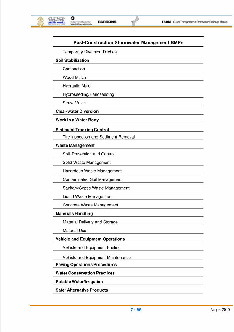
5/13/2018 Guam Storm Water Drainage Manual - slidepdf.com
http://slidepdf.com/reader/full/guam-storm-water-drainage-manual 386/486
7 - 96 August 2010
Post-Construction Stormwater Management BMPs
Temporary Diversion Ditches
Soil Stabilization
Compaction
Wood Mulch
Hydraulic Mulch
Hydroseeding/Handseeding
Straw Mulch
Clear-water Diversion
Work in a Water Body
Sediment Tracking Control
Tire Inspection and Sediment Removal
Waste Management
Spill Prevention and Control
Solid Waste Management
Hazardous Waste Management
Contaminated Soil Management
Sanitary/Septic Waste Management
Liquid Waste Management
Concrete Waste Management
Materials Handling
Material Delivery and Storage
Material Use
Vehicle and Equipment Operations
Vehicle and Equipment Fueling
Vehicle and Equipment Maintenance
Paving Operations Procedures
Water Conservation Practices
Potable Water/Irrigation
Safer Alternative Products
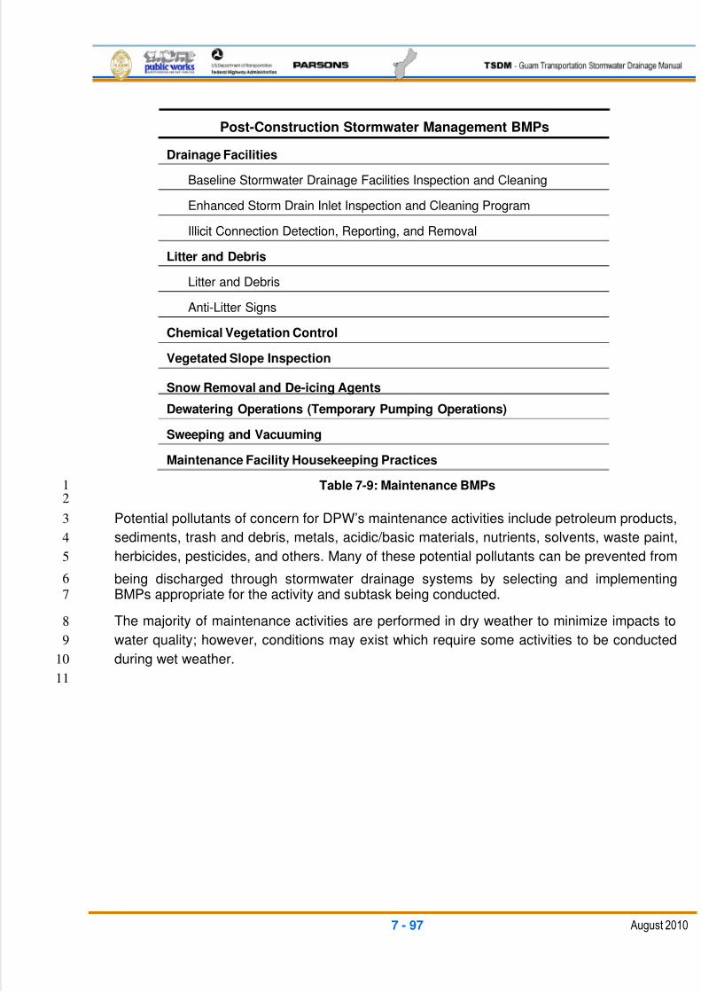
5/13/2018 Guam Storm Water Drainage Manual - slidepdf.com
http://slidepdf.com/reader/full/guam-storm-water-drainage-manual 387/486
7 - 97 August 2010
Post-Construction Stormwater Management BMPs
Drainage Facilities
Baseline Stormwater Drainage Facilities Inspection and Cleaning
Enhanced Storm Drain Inlet Inspection and Cleaning Program
Illicit Connection Detection, Reporting, and Removal
Litter and Debris
Litter and Debris
Anti-Litter Signs
Chemical Vegetation Control
Vegetated Slope Inspection
Snow Removal and De-icing Agents
Dewatering Operations (Temporary Pumping Operations)
Sweeping and Vacuuming
Maintenance Facility Housekeeping Practices
Table 7-9: Maintenance BMPs1
2
Potential pollutants of concern for DPW’s maintenance activities include petroleum products,3
sediments, trash and debris, metals, acidic/basic materials, nutrients, solvents, waste paint,4
herbicides, pesticides, and others. Many of these potential pollutants can be prevented from5
being discharged through stormwater drainage systems by selecting and implementing6
BMPs appropriate for the activity and subtask being conducted.7
The majority of maintenance activities are performed in dry weather to minimize impacts to8
water quality; however, conditions may exist which require some activities to be conducted9
during wet weather.10
11

5/13/2018 Guam Storm Water Drainage Manual - slidepdf.com
http://slidepdf.com/reader/full/guam-storm-water-drainage-manual 388/486
This page intentionally left blank
5/13/2018 Guam Storm Water Drainage Manual - slidepdf.com
http://slidepdf.com/reader/full/guam-storm-water-drainage-manual 389/486
BIBLIOGRAPHY - 1 August 2010
BIBLIOGRAPHY1
2
1. Arcement, G. J. and V. R. Schneider, 1984. Guide for Selecting Manning’s 3
Roughness Coefficients for Natural Channels and Flood Plains: Metric Version,4
Water Supply Paper 2339, U.S. Geological Survey. Note: WSP2339 is the USGS5
version of the U.S. Dept. of Transportation, Federal Highway Administration6
Publication No. FHWA-TS-84-204, which has the same title.7
2. Bradley, J.B., et al., October, 2005. Debris Control Structures – Evaluations and 8
Countermeasures, 3rd ed., Hydraulic Engineering Circular 9, Publication9
No. FHWA-IF-04-016, U.S. Department of Transportation, Federal Highway10
Administration, National Highway Institute, and Office of Bridge Technology.11
3. Bradley, Joseph N., March, 1978. Hydraulics of Bridge Waterways , Hydraulic12
Design Series 1, U.S. Department of Transportation, Federal Highway13
Administration, Office of Engineering and Operations, Bridge Division.14
4. Brown, S. A., et al., September, 2009. Urban Drainage Design Manual, 3rd ed.,15
Hydraulic Engineering Circular 22, Publication No. FHWA-NHI-10-009, U.S.16
Department of Transportation, Federal Highway Administration, National Highway17
Institute.18
5. Brown, Scott. A. and Eric S. Clyde, March 1989. Design of Riprap Revetment,19
Hydraulic Engineering Circular 11, Publication No. FHWA-IP-89-016, U.S.20
Department of Transportation, Federal Highway Administration, Office of21
Implementation: Research, Development, and Technology.22
6. California Department of Transportation, May, 2007. Storm Water Quality 23
Handbooks-Project Planning and Design Guide .24
7. California Department of Transportation, May, 2003. Statewide Stormwater 25
Management Plan , Publication No. CTSW-RT-02-008.26
8. Commonwealth of Virginia, adopted April, 2002. Drainage Manual , Virginia27
Department of Transportation, Location and Design Division, Hydraulics Section.28
9. Cronshey, Roger, et al., revised June, 1986. Urban Hydrology for Small 29
Watersheds , Technical Release-55. Update of Appendix A, January, 1999; first30issued by the Soil Conservation Service, January, 1975. U.S. Department of31
Agriculture, Natural Resources Conservation Service, Conservation Engineering32
Division, Hydrology Unit.33
10. Doubt, Paul D. and Gerald E. Oman, July, 1955. Routing through Tide Gates ,34
Technical Release No. 1. U.S. Department of Agriculture, Soil Conservation35
Service, Engineering Division, Design Section.36
5/13/2018 Guam Storm Water Drainage Manual - slidepdf.com
http://slidepdf.com/reader/full/guam-storm-water-drainage-manual 390/486
BIBLIOGRAPHY - 2 August 2010
11. Douglass, Scott L. and Joe Krolak, June, 2008. Highways in the Coastal 1
Environment, 2nd ed., Hydraulic Engineering Circular 25, Publication No. FHWA-2
NHI-07-096, U.S. Department of Transportation, Federal Highway Administration,3
National Highway Institute, and Office of Bridge Technology.4
12. EarthTech, August, 1997. Flood Control Master Plan for Northern Guam: Phase 1,5
prepared for Government of Guam Department of Public Works.6
13. Engineering Publications, et al., June, 2008. Highway Runoff Manual, Publication7
No. M 31-16.01, Washington Department of Transportation.8
14. Engineering Publications, et al., March, 2007. Hydraulics Manual, 2nd ed.,9
Publication No. M 23-03.01, Washington Department of Transportation.10
15. Guam Environmental Protection Agency, January, 2010. Guam Erosion Control and 11
Stormwater Management Draft Regulations .12
16. Hawkins, Edward, et al., October, 1973. Hydrologic Engineering for Water 13
Resources Development, Vol. 4: Hydrograph Analysis , “Hydrologic Data14
Management,” U.S. Army Corps of Engineers, Institute for Water Resources,15
Hydrologic Engineering Center – International Hydration Decade.16
17. Hjelmfelt, Allen T. Moody and the Natural Resources Conservation17
Service/Agricultural Research Service, July, 2004. Hydrology National Engineering 18
Handbook , Part 630: Hydrology , Ch. 10, Estimation of Direct Runoff from Storm 19
Rainfall , Publication No. 210-VI-NEH. Originally prepared by Victor Mockus, 1964;20
revised in 1998 by Helen Fox Moody. U.S. Department of Agriculture.21
18. Holtz, PhD, Robert D., et al., revised April, 1998. Geosynthetic Design and 22
Construction Guidelines: Participant Notebook, Publication No. FHWA HI-95-038,23
U.S. Department of Transportation, Federal Highway Administration, National24
Highway Institute.25
19. Horsley Witten Group, Inc., October, 2006. CNMI and Guam Stormwater 26
Management Manual, Vol. 1: Final – October 2006 , prepared for Commonwealth of27
the Northern Mariana Islands and the Territory of Guam.28
20. Horsley Witten Group, Inc., October, 2006. CNMI and Guam Stormwater 29
Management Manual, Vol. 2: Final – October 2006 , prepared for Commonwealth of30
the Northern Mariana Islands and the Territory of Guam.31
21. Johnson, Frank L. and Fred F.M. Chang, March, 1984. Drainage of Highway 32
Pavements , Hydraulic Engineering Circular 12, Publication No. FHWA-TS-84-202,33
U.S. Department of Transportation, Federal Highway Administration, Office of34
Implementation: Engineering & Highway Operations.35
36
5/13/2018 Guam Storm Water Drainage Manual - slidepdf.com
http://slidepdf.com/reader/full/guam-storm-water-drainage-manual 391/486
BIBLIOGRAPHY - 3 August 2010
22. Jones, J. Sterling, December, 2006. Effects of Inlet Geometry on Hydraulic 1
Performance of Box Culverts , Publication No. FHWA-HRT-06-138, U.S. Department2
of Transportation, Federal Highway Administration, Office of Infrastructure Research3
and Development, South Dakota Dept. of Transportation.4
23. Kent, K. M., revised April, 1973. A Method for Estimating Volume and Rate of 5
Runoff in Small Watersheds , Publication No. SCS-TP-149, U.S. Department of6
Agriculture, Soil Conservation Service, Hydrology Branch.7
24. Kilgore, Roger T. and George K. Cotton, September, 2005. Design of Roadside 8
Channels with Flexible Linings, 3rd ed., Hydraulic Engineering Circular 15,9
Publication No. FHWA-NHI-05-114, U.S. Department of Transportation, Federal10
Highway Administration, National Highway Institute, and Office of Bridge11
Technology.12
25. Kornel Kerenyi, J., et al., March, 2007. Junction Loss Experiments: Laboratory 13
Report, Publication No. FHWA-HRT-07-036, U.S. Department of Transportation,14
Federal Highway Administration, Office of Infrastructure Research and15
Development.16
26. Lagasse, P.F., et al., March, 2001. Stream Stability at Highway Structures, 3rd ed.,17
Hydraulic Engineering Circular 20, Publication No. FHWA-NHI-01-002, U.S.18
Department of Transportation, Federal Highway Administration, National Highway19
Institute, and Office of Bridge Technology.20
27. Lagasse, P.F., et al., September, 2009. Bridge Scour and Stream Instability 21
Countermeasures Experience, Selection and Design Guidance, Vols. 1 and 2, 3rd 22
ed., Hydraulic Engineering Circular 23, Publication No. FHWA-NHI-09-11., U.S.23
Department of Transportation, Federal Highway Administration, National Highway24
Institute, and Office of Bridge Technology.25
28. Masch, Frank D., October, 1984. Hydrology, Hydraulic Engineering Circular 19,26
Publication No. FHWA-1P-84-15, U.S. Department of Transportation, Federal27
Highway Administration, Office of Implementation.28
29. McCuen, Richard, et al., October, 2002. Highway Hydrology: Hydraulic Design29
Series 2, 2nd ed., Publication No. FHWA-NHI-02-001, U.S. Department of30
Transportation, Federal Highway Administration, National Highway Institute.31
30. Merkel, William H., September, 2008. Rainfall-Frequency and Design Rainfall 32
Distribution for Selected Pacific Islands , Technical Note No. 3, U.S. Department of33
Agriculture, Natural Resources Conservation Services.34
35
36
5/13/2018 Guam Storm Water Drainage Manual - slidepdf.com
http://slidepdf.com/reader/full/guam-storm-water-drainage-manual 392/486
BIBLIOGRAPHY - 4 August 2010
31. Moody, Helen Fox and the Natural Resources Conservation Service/Agricultural1
Research Service, July, 2004. Originally prepared by Victor Mockus, 1964.2
Hydrology National Engineering Handbook , Part 630: Hydrology , Ch. 9, Hydrologic 3
Soil-Cover Complexes , Publication No. 210-VI-NEH, U.S. Department of4
Agriculture.5
32. Normann, Jerome M., et al., May, 2001 (revised May, 2005). Hydraulic Design of 6
Highway Culverts, 2nd ed., Hydraulic Design Series 5, Publication No. FHWA-NHI-7
01-020, U.S. Department of Transportation, Federal Highway Administration,8
National Highway Institute, and Office of Bridge Technology.9
33. Richardson, E.V. and S. R. Davis, May, 2001. Evaluating Scour at Bridges , 4th ed.,10
Hydraulic Engineering Circular 18, Publication No. FHWA NHI 01-001, U.S.11
Department of Transportation, Federal Highway Administration, National Highway12
Institute, and Office of Bridge Technology.13
34. Richardson, E.V., et al., December, 2001. River Engineering for Highway 14
Encroachments, Highways in the River Environment , Hydraulic Design Series 6,15
Publication No. FHWA-NHI-01-004, U.S. Department of Transportation, Federal16
Highway Administration, National Highway Institute, and Office of Bridge17
Technology.18
35. Schall, James D., et al., June, 2008. Introduction to Highway Hydraulics, 4th ed.,19
Hydraulic Design Series 4, Publication No. WA-NHI-08-090, U.S. Department of20
Transportation, Federal Highway Administration, National Highway Institute, and21
Office of Bridge Technology.22
36. Smith, Peter M., February, 2001. Highway Stormwater Pump Station Design,23
Hydraulic Engineering Circular 24, Publication No. FHWA-NHI-01-007, U.S.24
Department of Transportation, Federal Highway Administration, National Highway25
Institute, and Office of Bridge Technology Applications.26
37. Suphunvorranop, Thirasak, July, 1985. A Guide to SCS Runoff Procedures ,27
Technical Publication No. 85-5, Project No. 15/20-200-03, Department of Water28
Resources, St. Johns River Water Management District.29
38. Tenorio, Juan C. and Associates, September, 1980. Guam Storm Drainage Manual 30
– Guam Comprehensive Study: A Technical Report from the Comprehensive Study 31
of Guam’s Water and Related Land Resources, U.S. Army Corps of Engineers,32
Honolulu District, Hawaii.33
39. Thompson, Edward F. and Norman W. Scheffner, January, 2002. Typhoon-Induced 34
Stage-Frequency and Overtopping Relationships for the Commercial Port Road,35
Territory of Guam: Final Report , Publication No. ERDC/CHL TR-02-1, U.S. Army36
Corps of Engineers, Engineer Research and Development Center, Coastal and37
Hydraulics Laboratory.38
5/13/2018 Guam Storm Water Drainage Manual - slidepdf.com
http://slidepdf.com/reader/full/guam-storm-water-drainage-manual 393/486
BIBLIOGRAPHY - 5 August 2010
40. Thompson, Philip L. and Roger T. Kilgore, July 2006. Hydraulic Design of Energy 1
Dissipators for Culverts and Channels, 3rd ed., Hydraulic Engineering Circular 14,2
Publication No. FHWA-HNI-06-086, U.S. Department of Transportation, Federal3
Highway Administration, National Highway Institute, and Office of Bridge4
Technology.5
41. U.S. Department of Transportation, Federal Highway Administration, Standard 6
Specifications for Construction of Roads and Bridges on Federal Highway Projects 7
(FP-03), U.S. Customary Units. 8
42. Woodward, Donald E., revised June, 1986. Time of Concentration , Technical Note9
No. N4. Originally prepared by Paul I. Welle, February, 1983. U.S. Department of10
Agriculture, Soil Conservation Service.11
43. Woodward, Donald E. and the Natural Resources Conservation Service, March,12
2007. Hydrology National Engineering Handbook , Part 630: Hydrology , Ch. 16, 13
Hydrographs , Publication No. 210-VI-NEH. Originally prepared by Dean Snider,141971. U.S. Department of Agriculture.15
44. Young, Fred Y. and Saku Nakamura, 1998. Soil Survey of Territory of Guam , U.S.16
Department of Agriculture, Soil Conservation Service, in cooperation with the Guam17
Department of Commerce and University of Guam.18
45. Young, G. K., et al., May, 1993. Design of Bridge Deck Drainage, Hydraulic19
Engineering Circular 21, Publication No. FHWA-SA-92-010, U.S. Department of20
Transportation, Federal Highway Administration, Office of Technology Applications.21

5/13/2018 Guam Storm Water Drainage Manual - slidepdf.com
http://slidepdf.com/reader/full/guam-storm-water-drainage-manual 394/486
This page intentionally left blank

5/13/2018 Guam Storm Water Drainage Manual - slidepdf.com
http://slidepdf.com/reader/full/guam-storm-water-drainage-manual 395/486
APPENDICES

5/13/2018 Guam Storm Water Drainage Manual - slidepdf.com
http://slidepdf.com/reader/full/guam-storm-water-drainage-manual 396/486
This page intentionally left blank

5/13/2018 Guam Storm Water Drainage Manual - slidepdf.com
http://slidepdf.com/reader/full/guam-storm-water-drainage-manual 397/486
APPENDIX I

5/13/2018 Guam Storm Water Drainage Manual - slidepdf.com
http://slidepdf.com/reader/full/guam-storm-water-drainage-manual 398/486
This page intentionally left blank
5/13/2018 Guam Storm Water Drainage Manual - slidepdf.com
http://slidepdf.com/reader/full/guam-storm-water-drainage-manual 399/486
APPENDIX I
Temporary Erosion and Sediment Control Plans

5/13/2018 Guam Storm Water Drainage Manual - slidepdf.com
http://slidepdf.com/reader/full/guam-storm-water-drainage-manual 400/486
This page intentionally left blank
5/13/2018 Guam Storm Water Drainage Manual - slidepdf.com
http://slidepdf.com/reader/full/guam-storm-water-drainage-manual 401/486
Appendix I TOC 1 August 2010
TABLE OF CONTENTS
TEMPORARY EROSION AND SEDIMENT CONTROL (TESC) PLAN........................................ 1
TESC REPORT OUTLINE ............................................................................................................ 3
CHAPTER 1. PROJECT OVERVIEW .......................................................................................... 3
1-1. Site Description .............................................................................................................. 3
1-1.1. Scope of Work ............................................................................................................ 3
1-1.2. Areas Impacted ........................................................................................................... 3
1-1.3. Existing Conditions ..................................................................................................... 3
1-1.4. Soils or Surface Conditions ......................................................................................... 4
1-1.5. Drainage ..................................................................................................................... 41-1.6. Off-Site Water ............................................................................................................. 4
1-1.7. Outfalls ........................................................................................................................ 4
1-1.8. Sensitive Areas ........................................................................................................... 4
1-1.9. Existing Water Quality ................................................................................................. 4
1-1.10. Affected Utilities .......................................................................................................... 4
1-1.11. Permits and associated reports .................................................................................. 4
1-1.12. Associated Reports ..................................................................................................... 5
1-2. TESC PLAN .................................................................................................................... 5
1-2.1. Construction Staging ................................................................................................... 5
1-2.2. Elements of TESC ...................................................................................................... 5
1-2.2.1. TESC Element 1: Mark Clearing Limits ................................................................... 5
1-2.2.2. TESC Element 2: Establish Construction Access ................................................... 5
1-2.2.3. TESC Element 3: Control Flow Rates ..................................................................... 6
1-2.2.4. TESC Element 4: Install Sediment Controls ............................................................ 7
1-2.2.5. TESC Element 5: Stabilize Soils ............................................................................. 7
1-2.2.6. TESC Element 6: Protect Slopes ............................................................................ 9
1-2.2.7. TESC Element 7: Protect Drain Inlets ................................................................... 10
1-2.2.8. TESC Element 8: Stabilize Channels and Outlets ................................................ 10
1-2.2.9. TESC Element 9: Control Pollutants ..................................................................... 10
1-2.2.10. TESC Element 10: Control De-Watering ............................................................... 11
5/13/2018 Guam Storm Water Drainage Manual - slidepdf.com
http://slidepdf.com/reader/full/guam-storm-water-drainage-manual 402/486
Appendix I TOC 2 August 2010
1-2.2.11. TESC Element 11: Maintain BMPs ....................................................................... 11
1-2.2.12. TESC Element 12: Manage the Project ................................................................ 11
1-3. Schedule ....................................................................................................................... 12
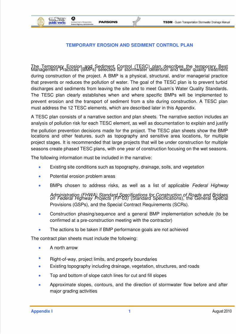
5/13/2018 Guam Storm Water Drainage Manual - slidepdf.com
http://slidepdf.com/reader/full/guam-storm-water-drainage-manual 403/486
Appendix I 1 August 2010
TEMPORARY EROSION AND SEDIMENT CONTROL PLAN
The Temporary Erosion and Sediment Control (TESC) plan describes the temporary BestManagement Practices (BMPs) selected for stormwater detention and water quality treatment
during construction of the project. A BMP is a physical, structural, and/or managerial practice
that prevents or reduces the pollution of water. The goal of the TESC plan is to prevent turbid
discharges and sediments from leaving the site and to meet Guam’s Water Quality Standards.
The TESC plan clearly establishes when and where specific BMPs will be implemented to
prevent erosion and the transport of sediment from a site during construction. A TESC plan
must address the 12 TESC elements, which are described later in this Appendix.
A TESC plan consists of a narrative section and plan sheets. The narrative section includes an
analysis of pollution risk for each TESC element, as well as documentation to explain and justify
the pollution prevention decisions made for the project. The TESC plan sheets show the BMPlocations and other features, such as topography and sensitive area locations, for multiple
project stages. It is recommended that large projects that will be under construction for multiple
seasons create phased TESC plans, with one year of construction focusing on the wet seasons.
The following information must be included in the narrative:
Existing site conditions such as topography, drainage, soils, and vegetation
Potential erosion problem areas
BMPs chosen to address risks, as well as a list of applicable Federal Highway
Administration (FHWA) Standard Specifications for Construction of Roads and Bridges on Federal Highway Projects (FP-03) (Standard Specifications), the General Special
Provisions (GSPs), and the Special Contract Requirements (SCRs).
Construction phasing/sequence and a general BMP implementation schedule (to be
confirmed at a pre-construction meeting with the contractor)
The actions to be taken if BMP performance goals are not achieved
The contract plan sheets must include the following:
A north arrow
Right-of-way, project limits, and property boundaries
Existing topography including drainage, vegetation, structures, and roads
Top and bottom of slope catch lines for cut and fill slopes
Approximate slopes, contours, and the direction of stormwater flow before and after
major grading activities
5/13/2018 Guam Storm Water Drainage Manual - slidepdf.com
http://slidepdf.com/reader/full/guam-storm-water-drainage-manual 404/486
Appendix I 2 August 2010
Areas of soil disturbance and areas that will not be disturbed
Locations of structural and nonstructural pollution controls (temporary construction
BMPs)
Locations of contractor staging including off-site material storage, stockpiles, waste
storage, borrow areas, and vehicle/equipment storage/maintenance areas
Locations of all surface water bodies including wetlands, streams, and lakes, with the
limits of their ordinary high water and buffer zones
Locations where stormwater or non-stormwater discharges off-site or to a surface
water body
Locations of water quality sampling stations
Areas where final stabilization has been accomplished and no further construction-
phase permit requirements apply
It is required that a TESC plan is prepared and signed by a Certified Erosion and Sediment
Control Lead, and the Site Manager is trained and certified.
5/13/2018 Guam Storm Water Drainage Manual - slidepdf.com
http://slidepdf.com/reader/full/guam-storm-water-drainage-manual 405/486
Appendix I 3 August 2010
TESC REPORT OUTLINE
Title Page: The following items should be included on the title page: the project number andname, associated route number and mileposts, name of report, date report was completed,
designers’ names, and the project engineer’s professional civil engineers stamp and signature.
Table of Contents: Both the report and appendix contents should be listed in the Table of
Contents.
CHAPTER 1. PROJECT OVERVIEW
The TESC plan describes the measures to be used during construction to protect the waters of
Guam from degradation due to sediment transport or water pollution. These measures will
require the use of temporary BMPs.
Field conditions during construction may require additional temporary BMPs or a change in
placement of the temporary BMPs. The Contractor’s Erosion and Sediment Control Lead and
the Department of Public Works’ (DPW’s) representatives should modify this plan if necessary
to meet field conditions.
1-1. SITE DESCRIPTION
Besides the narrative, include a vicinity map that shows the project’s location on the
island, as well as the right-of-way limits, project limits, existing roadways, proposed
roadways, drainage basins, flow direction, location of nearby or adjacent construction
activities, and sensitive areas (wetlands, streams, receiving water bodies, etc.).
1-1.1. SCOPE OF WORK
Describe the overall project activities and where they will occur (e.g., clearing and
grubbing, grading, roadway excavation and embankment, constructing storm
sewers, paving with asphalt concrete, constructing temporary BMPs, constructing
permanent stormwater detention and infiltration ponds, bridge widening, adding
turn lanes, constructing curb and gutter, landscape planters, sidewalks,
construction of a bus pullout, fencing, pavement markings, illumination,
signalization, traffic control, etc. Call out the construction plan sheets and details.
1-1.2. AREAS IMPACTEDTotal area of new impervious surface added _____ sq. ft. or acres
Total area of disturbed soil _____ sq. ft. or acres
1-1.3. EXISTING CONDITIONS
This section presents the existing conditions on and surrounding the project site.
Included are descriptions of soils, drainage, off-site water, outfalls, sensitive areas,
5/13/2018 Guam Storm Water Drainage Manual - slidepdf.com
http://slidepdf.com/reader/full/guam-storm-water-drainage-manual 406/486
Appendix I 4 August 2010
existing water quality, Water Resource Inventory Areas (WRIAs), adjacent
construction, and affected utilities.
1-1.4. SOILS OR SURFACE CONDITIONS
Identify the major soil type identified along the project. Identify other soil types
along the project and rank by relative predominance.
1-1.5. DRAINAGE
Provide a list of stream names, locations, drainage pathways, and receiving water
bodies.
1-1.6. OFF-SITE WATER
List the potential for off-site water to enter the project limits. State whether there is
or is not the potential for off-site water. If applicable, include a discussion about the
sources and waterways of off-site water that may enter the project site, and
describe the measures to be taken, if any, to keep off-site water from mixing withon-site runoff. The site should be visited on a rainy day to verify conditions. State
whether there is or is not an illicit connection that discharges within the project
limits.
1-1.7. OUTFALLS
Include a table listing the milepost (and project stationing and control line offset as
appropriate), condition, and location of each outfall within the project area.
1-1.8. SENSITIVE AREAS
Summarize the wetland report, areas of critical habitat, sensitive areas specified in
basin plans, etc. If applicable, provide reference figures.
1-1.9. EXISTING WATER QUALITY
This section should include the Surface Water Classification for all nearby water
bodies and information on impaired water bodies from the Guam Environmental
Protection Agency (GEPA) assessment listing. Include the appropriate water
quality standards.
1-1.10. AFFECTED UTILITIES
This section should include any utilities within the right-of-way of the proposed
construction activities, which may be impacted by this construction project.
1-1.11. PERMITS AND ASSOCIATED REPORTS
Insert below the actual permits required for this project. If necessary, text
describing why some permits may or may not be required should be added.
5/13/2018 Guam Storm Water Drainage Manual - slidepdf.com
http://slidepdf.com/reader/full/guam-storm-water-drainage-manual 407/486
Appendix I 5 August 2010
1-1.12. ASSOCIATED REPORTS
Provide a list of reports. Revise to match actual reports and studies related to this
project.
1-2. TESC PLAN
1-2.1. CONSTRUCTION STAGING
The narrative should include the description of construction staging and how the
TESC will be provided for each stage. During the design phase, if it is impossible to
know the timing and duration of a project, the TESC plans should be prepared
assuming worst-case conditions for timing and duration.
1-2.2. ELEMENTS OF TESC
The 12 TESC elements are described below. All elements must be considered and
included in the TESC plan, unless site conditions render an element unnecessary
and the exemption is clearly justified in the narrative of the TESC plan. Commondesign and procedural BMPs are described for each element, followed by a list of
physical BMPs, if applicable. Each element should be described using the following
format:
Risk analysis
BMPs identified
GSPs
SCR
1-2.2.1. TESC Element 1: Mark Clearing Limits
Prior to land-clearing activities, mark all clearing limits on the plan and in the
field with high-visibility fences to protect sensitive areas and their buffers
(including vegetation to preserve), as well as adjacent properties. Retain duff
layer, native topsoil, and existing vegetation in an undisturbed state to the
maximum extent practicable.
Physical BMPs:
Preserving natural vegetation
Buffer zones High-visibility fence
1-2.2.2. TESC Element 2: Establish Construction Access
Access points should be stabilized with a pad of quarry spalls, crushed rock, or
equivalent BMP, in accordance with the Standard Specifications. Install
stabilized construction access points prior to major grading operations. Limit
5/13/2018 Guam Storm Water Drainage Manual - slidepdf.com
http://slidepdf.com/reader/full/guam-storm-water-drainage-manual 408/486
Appendix I 6 August 2010
access points to the fewest number possible, and only one, whenever feasible.
Whenever practicable, slope entrances downward into the site to reduce track-
out of sediments onto the roadway. If sediment is tracked off-site, roads should
be cleaned thoroughly at the end of each day or more frequently, if necessary.
Sediment should be removed from roads by shoveling or sweeping, and
removed sediment should be transported to a controlled disposal area. If the
stabilized construction entrance is not effective in preventing sediment from
being tracked onto roads, a tire wash must be used and the wash water must
be discharged to a separate on-site treatment system, such as closed-loop
recirculation or land application, or discharged to a sanitary sewer (if allowed
by individual permit).
Street sweeping is only allowed after sediment is removed from the street. If
streets are washed with water, wash water must be treated prior to discharge.
Physical BMPs:
Stabilized construction entrance
Street sweeping
Construction road stabilization
Tire wash
1-2.2.3. TESC Element 3: Control Flow Rates
Protect downstream properties and waterways from erosion by preventing
increases in the volume, velocity, and peak flow rate of stormwater runoff from
the site during construction. Install the permanent sediment control facilities toprovide flow control as early in the construction process as feasible. Protect
infiltration facilities from siltation during the construction phase.
Install retention/detention facilities as one of the first steps in grading for use as
infiltration or sedimentation facilities prior to mass grading and the construction
of site improvements. Design drainages to account for both on- and off-site
water sources. Use vegetated areas that are not identified as wetlands or other
sensitive features to infiltrate and dispose of water whenever possible, and
mark those areas on the TESC plan sheets.
Non-stormwater (de-watering, line flushing) discharges must also be controlledto protect downstream properties. When non-stormwater discharges are routed
through separate storm sewer systems, the flow rate must be controlled to
minimize scouring and the flushing of sediment trapped in the system.
Physical BMPs:
Temporary sediment pond
5/13/2018 Guam Storm Water Drainage Manual - slidepdf.com
http://slidepdf.com/reader/full/guam-storm-water-drainage-manual 409/486
Appendix I 7 August 2010
Sediment trap
Stormwater infiltration
1-2.2.4. TESC Element 4: Install Sediment Controls
Install sediment control BMPs prior to soil-disturbing activities. Prior to leaving aconstruction site or discharging to an infiltration facility, concentrated
stormwater runoff from disturbed areas must pass through sediment ponds or
traps. Sheet flow runoff must pass through sediment control BMPs specifically
designed to remove sediment from sheet flows, such as filter berms, vegetated
filter strips, or silt fencing. Because maintaining sheet flows greatly reduces the
potential for erosion, runoff should be maintained and treated as sheet flow
whenever possible.
Physical BMPs:
Silt fence Fiber Roll
Check dam
Temporary sediment pond or trap
Street sweeping
Surface roughening
Level spreader
Storm drain inlet protection
Outlet protection
Preserving natural vegetation
Portable storage water tanks
Vegetated filter strip
Stormwater chemical treatment
Filter berm (gravel, wood chip, or compost)
Construction stormwater filtration
1-2.2.5. TESC Element 5: Stabilize Soils
Stabilize all exposed and unworked soils by applying effective BMPs that
protect the soil from wind, raindrops, and flowing water. Selected soil
stabilization measures must be appropriate for the time of year, site conditions,
5/13/2018 Guam Storm Water Drainage Manual - slidepdf.com
http://slidepdf.com/reader/full/guam-storm-water-drainage-manual 410/486
Appendix I 8 August 2010
estimated duration of use, and the water quality impacts that stabilization
agents may have on downstream waters or groundwater.
Construction activity, including equipment staging areas, material storage
areas, and borrow areas must be stabilized and addressed in the TESC plan
as well.
Soil stockpiles are especially vulnerable to slumping when saturated and must
be stabilized and protected with sediment-trapping measures. Plastic may be
necessary on silty stockpiles, as it is the only BMP that can prevent soil
saturation. Stockpiles should be located away from storm drain inlets,
waterways, and drainage channels, where possible.
In Guam, cover exposed soil that is not being worked, whether at final grade or
not, within the following time limits, using approved soil cover practices:
July 1st through November 30th – 2 days maximum
December 1st through June 30th – 7 days maximum
Immediately, in accordance with the rain forecast
Physical BMPs:
Preserving vegetation
Sodding
Temporary mulching
Check dam**
Soil binding using polyacrylamide*
Fiber Roll**
Placing erosion control blanket
Surface roughening***
Placing compost blanket
Stabilized construction entrance
Placing plastic covering
Construction road stabilization
Seeding and planting
Dust control BMPs
Gravel base
Bonded fiber matrix
5/13/2018 Guam Storm Water Drainage Manual - slidepdf.com
http://slidepdf.com/reader/full/guam-storm-water-drainage-manual 411/486
Appendix I 9 August 2010
Mechanically-bonded fiber matrix
*While polyacrylamide alone does help stabilize soils, using it in conjunction
with mulch provides more protection for disturbed soil.
**Check dams and fiber rolls alone do not stabilize soils. These BMPs should
be used in conjunction with other soil stabilization BMPs.
***Surface roughening alone does not provide soil stabilization. Another BMP
should be used in conjunction with surface roughening to protect the soil from
raindrop impacts. It must be performed prior to seeding, in accordance with the
Standard Specifications.
1-2.2.6. TESC Element 6: Protect Slopes
Design and construct cut-and-fill slopes in a manner that will minimize erosion
by reducing the continuous length and steepness of slopes with terracing and
diversions; reducing slope steepness; and roughening slope surfaces,
considering soil type and its potential for erosion (such as track walking). In
addition, all soil must be protected from concentrated flows through temporary
conveyances such as diversions and pipe slope drains.
If flow is from seeps or groundwater, use best professional judgment when
sizing slope drains. Conveyances exceeding a 10 percent slope should have a
solid lining.
To capture sediment and runoff when cutting trenches, place excavated soil on
the uphill side of the trench, when consistent with safety and space
considerations.
Check dams should be placed at regular intervals within constructed channels
that are cut down a slope.
Physical BMPs:
Channel lining (riprap, grass)
Subsurface drains
Temporary pipe slope drain
Level spreader
Temporary curb
Interceptor dike and swale
Gradient terraces
Physical BMPs listed under TESC Element 5, with the exception of
stabilized entrance and road stabilization
5/13/2018 Guam Storm Water Drainage Manual - slidepdf.com
http://slidepdf.com/reader/full/guam-storm-water-drainage-manual 412/486
Appendix I 10 August 2010
1-2.2.7. TESC Element 7: Protect Drain Inlets
Protect all operable storm drain inlets from sediment with approved inlet
BMPs.
Physical BMPs:
Storm drain inlet protection (above/below grate and grate covers)
Check dam
1-2.2.8. TESC Element 8: Stabilize Channels and Outlets
All temporary conveyance channels should be designed, constructed, and
stabilized to prevent erosion.
Stabilization, including armoring material, adequate to prevent erosion of
outlets, adjacent stream banks, slopes, and downstream reaches should be
provided at the outlets of all conveyance systems.
Physical BMPs:
Channel lining (riprap, grass)
Erosion control blanket
Level spreader
Sodding
Check dam
Outlet protection
Temporary seeding and planting
1-2.2.9. TESC Element 9: Control Pollutants
All pollutants, including construction materials, waste materials, and
demolition debris, must be handled and disposed of in a manner that does
not cause contamination of stormwater. Methods for controlling non-
hazardous pollutants must be described in the TESC plan. Wood debris may
be chopped and spread on-site. The application of fertilizers and other
chemicals should be conducted in a manner and at application rates that will
not result in loss of chemicals to stormwater runoff. Manufacturers’ labelrequirements for application rates and procedures must be followed.
Methods for controlling pollutants that can be considered hazardous
materials, such as hydrocarbons and pH-modifying substances, must be
described in the contractor’s Spill Prevention Control and Countermeasures
(SPCC) plan.
5/13/2018 Guam Storm Water Drainage Manual - slidepdf.com
http://slidepdf.com/reader/full/guam-storm-water-drainage-manual 413/486
Appendix I 11 August 2010
Stormwater or groundwater that has come into contact with curing concrete
must be sampled to ensure Water Quality Standards are not violated.
Process water (e.g., concrete washout, slurry water, and hydrodemolition)
must be contained and cannot be discharged to the waters of Guam.
1-2.2.10. TESC Element 10: Control Dewatering
When groundwater is encountered in an excavation or other area, control,
treat, and discharge it as described in the Standard Specifications.
1-2.2.11. TESC Element 11: Maintain BMPs
A Certified Erosion and Sediment Control Lead should inspect BMPs to
ensure they perform their intended function properly until the Project
Engineer determines that final stabilization is achieved. Final stabilization
means the completion of all soil-disturbing activities and establishment of a
permanent vegetative cover or permanent stabilization measures (such as
riprap) to prevent erosion. Temporary BMPs should be removed within 30days after final stabilization is achieved.
Maintain BMPs in accordance with the Standard Specifications. When the
depth of accumulated sediment and debris reaches approximately one-third
the height of the device, the contractor must remove the deposits. BMP
implementation and maintenance should be documented in the Site Log
Book. Clean sediments may be stabilized on-site.
1-2.2.12. TESC Element 12: Manage the Project
Apply the following actions on all projects:
1. Preserve vegetation and minimize disturbance and compaction of
native soil, except as needed for building purposes.
2. Phase development projects to minimize the amount of soil exposed
at any one time and prevent the transport of sediment from the site
during construction.
3. Time sediment control BMP installation in accordance with TESC
Element 4.
4. To minimize erosion, follow soil cover timing requirements and
exposure limits in TESC Element 5 and the Standard Specifications.Projects that infiltrate all runoff are exempt from the above
restrictions. Individual contract SCR and DPW directives may be
more stringent based on specific location characteristics or
changing site and weather conditions.
5. The work of utility contractors and subcontractors is coordinated to
meet the requirements of both the TESC and SPCC plans.
5/13/2018 Guam Storm Water Drainage Manual - slidepdf.com
http://slidepdf.com/reader/full/guam-storm-water-drainage-manual 414/486
Appendix I 12 August 2010
1-3. Schedule
A construction schedule must be provided by the contractor. The schedule should
specify TESC plan implementation to effectively reduce erosion risks. Include the
following in the schedule:
Installation of perimeter control and detention BMPs prior to soil-disturbing
activities.
Phasing and timing of clearing, grubbing, and grading. Where feasible, work
must be phased and timed to minimize the amount of exposed soil at any one
time and prevent transport of sediment from the site during construction.
Application of interim BMP strategies when construction activities interfere with
the placement of final-grade BMPs.
Discussion of how temporary BMPs are to be transitioned into permanent
BMPs. Implementation of an erosion control inspection and maintenance schedule.

5/13/2018 Guam Storm Water Drainage Manual - slidepdf.com
http://slidepdf.com/reader/full/guam-storm-water-drainage-manual 415/486
APPENDIX IA

5/13/2018 Guam Storm Water Drainage Manual - slidepdf.com
http://slidepdf.com/reader/full/guam-storm-water-drainage-manual 416/486
This page intentionally left blank
5/13/2018 Guam Storm Water Drainage Manual - slidepdf.com
http://slidepdf.com/reader/full/guam-storm-water-drainage-manual 417/486
APPENDIX IA
Correspondence with
Guam Environmental Protection Agency (GEPA)

5/13/2018 Guam Storm Water Drainage Manual - slidepdf.com
http://slidepdf.com/reader/full/guam-storm-water-drainage-manual 418/486
This page intentionally left blank
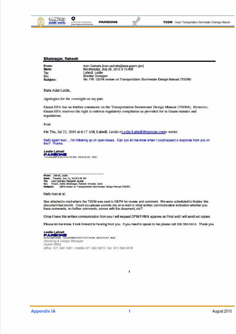
5/13/2018 Guam Storm Water Drainage Manual - slidepdf.com
http://slidepdf.com/reader/full/guam-storm-water-drainage-manual 419/486
Appendix IA 1 August 2010

5/13/2018 Guam Storm Water Drainage Manual - slidepdf.com
http://slidepdf.com/reader/full/guam-storm-water-drainage-manual 420/486
This page intentionally left blank

5/13/2018 Guam Storm Water Drainage Manual - slidepdf.com
http://slidepdf.com/reader/full/guam-storm-water-drainage-manual 421/486
APPENDIX II

5/13/2018 Guam Storm Water Drainage Manual - slidepdf.com
http://slidepdf.com/reader/full/guam-storm-water-drainage-manual 422/486
This page intentionally left blank
5/13/2018 Guam Storm Water Drainage Manual - slidepdf.com
http://slidepdf.com/reader/full/guam-storm-water-drainage-manual 423/486
Appendix II
Hydraulic Report

5/13/2018 Guam Storm Water Drainage Manual - slidepdf.com
http://slidepdf.com/reader/full/guam-storm-water-drainage-manual 424/486
This page intentionally left blank
5/13/2018 Guam Storm Water Drainage Manual - slidepdf.com
http://slidepdf.com/reader/full/guam-storm-water-drainage-manual 425/486
Appendix II TOC 1 August 2010
TABLE OF CONTENTS
HYDRAULIC REPORT .............................................................................................................................. 1 Procedure ................................................................................................................................................. 1 Review Copies ......................................................................................................................................... 1 Final Copies ............................................................................................................................................. 1 Hydraulic Report Revisions And Supplements ................................................................................... 1 Writing A Hydraulic Report .................................................................................................................... 1
HYDRAULIC REPORT OUTLINE ........................................................................................................... 1 CHAPTER 1. PROJECT OVERVIEW ................................................................................................... 1
1-1. Site Location ............................................................................................................................... 1 1-2. Vicinity Map ................................................................................................................................. 1 1-3. Scope Of Work ........................................................................................................................... 1 1-4. Areas Impacted .......................................................................................................................... 1
CHAPTER 2. EXISTING CONDITIONS ................................................................................................ 1 2-1. Existing Conditions .................................................................................................................... 1 2-2. Existing Hydraulic Features ...................................................................................................... 2 2-3. Existing Drainage Areas (DA) .................................................................................................. 2 2-4. Soils ............................................................................................................................................. 2 2-5. Outfalls ......................................................................................................................................... 2 2-6. Existing Utilities .......................................................................................................................... 2
CHAPTER 3. DEVELOPED CONDITIONS .......................................................................................... 2 3-1. Proposed Drainage Basins ....................................................................................................... 2 3-2. Design Standards ...................................................................................................................... 3 3-2.1. Design Frequency ...................................................................................................................... 3 3-2.2. Stormwater Management Guidelines ..................................................................................... 3 3-2.3. Other Requirements .................................................................................................................. 3 3-3. Pipe Alternatives ........................................................................................................................ 3 3-4. Downstream Analysis ................................................................................................................ 4 3-5. Hydrologic and Hydraulic Design ............................................................................................ 4
5/13/2018 Guam Storm Water Drainage Manual - slidepdf.com
http://slidepdf.com/reader/full/guam-storm-water-drainage-manual 426/486
Appendix II TOC 2 August 2010
CHAPTER 4. PERMITS AND ASSOCIATED REPORTS .................................................................. 5 4-1. Environmental Issues, Fish, and Other Endangered Habitat .............................................. 5 4-2. Permits/Approvals ...................................................................................................................... 5 4-3.
Right-of-Way and Easements
.................................................................................................. 5 4-4. Additional Reports or Studies .................................................................................................. 6
CHAPTER 5. INSPECTION AND MAINTENANCE SUMMARY ....................................................... 6 CHAPTER 6. APPENDIX ........................................................................................................................ 6
6-1. Environmental Documentation ................................................................................................. 6 6-1.1. TESC Narrative and Plan Sheets ............................................................................................ 6 6-2. Basin Calculations and Exhibits............................................................................................... 6 6-3. Calculations and Program Output ........................................................................................... 6 6-4. Drainage Plan Sheets, Details, and Structure Notes ........................................................... 6 6-5. Drainage Profile Plan Sheets ................................................................................................... 6 6-6. Roadway Typical Cross Sections and Profiles ...................................................................... 7 6-7. Miscellaneous Contract Plan Sheets ...................................................................................... 7
5/13/2018 Guam Storm Water Drainage Manual - slidepdf.com
http://slidepdf.com/reader/full/guam-storm-water-drainage-manual 427/486
Appendix II 1 August 2010
HYDRAULIC REPORT
PROCEDUREHydraulic reports should be submitted to the Department of Public Works (DPW) or their
designated representative, as follows.
REVIEW COPIES
Designers should submit a complete hard copy of the Hydraulic Report to DPW or its
designated representative for review.
FINAL COPIES
Upon approval, two paper copies of the Hydraulic Report, one electronic copy (CD) of the
report, and the original approval letter should be sent to the following offices:1. The Construction Office for reference during construction.
2. DPW’s Chief Engineer, who will keep it in a secure location as the record of the
project stormwater management facilities.
HYDRAULIC REPORT REVISIONS AND SUPPLEMENTS
At times, a hydraulic report may need to be revised due to various elements within a proposed
project. There are two ways to submit a change:
1. Revision: A revision is a correction of the existing report either due to an error or
omitted design documentation. The designer should submit the revision along with anew title page, stamped and signed by the Project Engineer, showing both the original
approval date and the revision date. The revised document should contain a statement
immediately behind the cover page that provides a summary of the revisions.
2. Supplement: A supplement is a change that was not part of the original scope of work.
The same approval process is required as with the original report; however, the
supplement should be a stand-alone document that references the original report.
Either type of change should be prepared documenting the revisions made, with back-up
documentation. Include revised plans, calculations, and other updates as warranted in a
submittal package to DPW. An approval/concurrence letter will be issued for the supplement.
WRITING A HYDRAULIC REPORT
A Hydraulic Report Outline has been provided below as a starting point for designers.
Organizing reports in the outline format will help to expedite the review process. It is
recommended that designers read through the outline and determine which sections are
applicable to their project. Any sections that are not applicable will include the heading, with the
5/13/2018 Guam Storm Water Drainage Manual - slidepdf.com
http://slidepdf.com/reader/full/guam-storm-water-drainage-manual 428/486
Appendix II 2 August 2010
tern “N.A.” under the heading in the report. DPW or its designated representatives can be
contacted for assistance in preparing a Hydraulic Report.
The Hydraulic Report should contain the elements listed in the outline that apply to the project.
Designers should provide a well-organized report so that an engineer with no prior knowledge of
the project could read and fully understand the hydraulic/hydrologic design of the project. Thereport should contain enough information to allow someone else to reproduce the design in its
entirety, but at the same time, designers should be brief and concise, careful not to provide
duplicate information that could create confusion.
Following and completing the outline does not mean that all of the minimum requirements in the
Highway Runoff Manual have been addressed. The outline is only a tool to aid the designer in
developing a Hydraulics Report. To determine the applicability of the minimum requirements
and Best Management Practices (BMPs) for a project, designers should consult the other
sections of this Guam Transportation Stormwater Drainage Manual (TSDM).
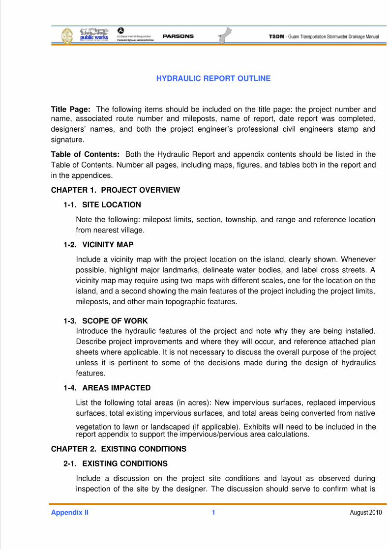
5/13/2018 Guam Storm Water Drainage Manual - slidepdf.com
http://slidepdf.com/reader/full/guam-storm-water-drainage-manual 429/486
Appendix II 1 August 2010
HYDRAULIC REPORT OUTLINE
Title Page: The following items should be included on the title page: the project number andname, associated route number and mileposts, name of report, date report was completed,
designers’ names, and both the project engineer’s professional civil engineers stamp and
signature.
Table of Contents: Both the Hydraulic Report and appendix contents should be listed in the
Table of Contents. Number all pages, including maps, figures, and tables both in the report and
in the appendices.
CHAPTER 1. PROJECT OVERVIEW
1-1. SITE LOCATION
Note the following: milepost limits, section, township, and range and reference location
from nearest village.
1-2. VICINITY MAP
Include a vicinity map with the project location on the island, clearly shown. Whenever
possible, highlight major landmarks, delineate water bodies, and label cross streets. A
vicinity map may require using two maps with different scales, one for the location on the
island, and a second showing the main features of the project including the project limits,
mileposts, and other main topographic features.
1-3. SCOPE OF WORK
Introduce the hydraulic features of the project and note why they are being installed.
Describe project improvements and where they will occur, and reference attached plan
sheets where applicable. It is not necessary to discuss the overall purpose of the project
unless it is pertinent to some of the decisions made during the design of hydraulics
features.
1-4. AREAS IMPACTED
List the following total areas (in acres): New impervious surfaces, replaced impervious
surfaces, total existing impervious surfaces, and total areas being converted from native
vegetation to lawn or landscaped (if applicable). Exhibits will need to be included in thereport appendix to support the impervious/pervious area calculations.
CHAPTER 2. EXISTING CONDITIONS
2-1. EXISTING CONDITIONS
Include a discussion on the project site conditions and layout as observed during
inspection of the site by the designer. The discussion should serve to confirm what is
5/13/2018 Guam Storm Water Drainage Manual - slidepdf.com
http://slidepdf.com/reader/full/guam-storm-water-drainage-manual 430/486
Appendix II 2 August 2010
shown on the maps and site plans, as well as note any features that will influence the
drainage design.
2-2. EXISTING HYDRAULIC FEATURES
Note any existing drainage features and describe how they operate prior to construction.
Also note how project improvements could impact their operation and how they will
function during post-construction activities. If needed, use photographs to describe the
site. Identify any bridges within the project limits.
2-3. EXISTING DRAINAGE AREAS (DA)
For each DA within the project, provide a description of the general drainage systems
and flow patterns. (See Chapter 4 for a detailed description of DAs). Unusual or unique
drainage patterns should be discussed. These areas should also be part of the
description. The designer should also list any off-site flows. Each DA description should
list the eventual downstream water body. Drainage maps delineating entire DAs (i.e.,
beyond DPW’s right-of-way) should be included in the report appendices, as shouldindividual basin area calculations. This section should refer to where the basin
information is located in the appendices.
2-4. SOILS
Discuss the soil testing that has been performed at the site. This includes soil pH and
resistivity to determine acceptable pipe alternatives, soil borings, soil type from National
Resources Conservation Service maps, soil infiltration, groundwater level, etc., for
stormwater BMP design.
2-5. OUTFALLS
An outfall can be any structure (man-made or natural) where stormwater from DPW
highways is conveyed off the right-of-way. (If no stormwater outfalls leave the DPW
right-of-way, the designer should note that instead).
2-6. EXISTING UTILITIES
Note utility conflicts that have been investigated and either are or are not an issue. If
there is a conflict, please note the resolution. Utilities should be shown on the drainage
plan and profile sheets.
CHAPTER 3. DEVELOPED CONDITIONS
3-1. PROPOSED DRAINAGE BASINS
This section should discuss and tabulate the proposed basins, including what has
changed regarding pervious and impervious areas to the existing basins. Maps showing
all DAs and drainage basin areas significant to the project (including portions that are off
the DPW right-of-way) should be included in the report appendices along with all basin
calculations. This section should serve to confirm what is shown on the final drainage
5/13/2018 Guam Storm Water Drainage Manual - slidepdf.com
http://slidepdf.com/reader/full/guam-storm-water-drainage-manual 431/486
Appendix II 3 August 2010
plans, profiles, and details. Note that final level plans may not yet be completed but will
be checked against the Hydraulic Report during review.
Drainage maps should show basin and sub-basin boundaries, areas, and flow direction
arrows. Each drainage basin should be clearly labeled, with the same label referenced in
the hydrologic and hydraulic calculations. When the change between existing and post-construction conditions is important to the calculations, the maps should show both
conditions, on separate maps, if necessary, for clarity. Maps should always be of an
adequate scale to allow reviewers to verify all basin calculations.
3-2. DESIGN STANDARDS
3-2.1. DESIGN FREQUENCY
Note the appropriate design frequencies used to size hydraulic features on the
project, and where applicable, show calculations. Include a discussion of the
climate and chosen precipitation values for the project.
3-2.2. STORMWATER MANAGEMENT GUIDELINES
State the stormwater management criteria and guidelines used for flow control,
basic runoff treatment, and enhanced runoff treatment (if applicable). Include a
summary table noting the BMP and the project location (including structure notes
for each drainage feature) organized by alignment, drainage basin, station, and
offset and/or milepost. The table should include DA-specific pre-project and post-
project pervious and impervious surface areas. Also note what percentage of the
new (and replaced, if applicable) impervious surface areas are addressed for flow
control and runoff treatment according to the stormwater management criteria used
for this report. Wherever possible, use the same structure note from the plans inthe hydrologic and hydraulic calculations.
3-2.3. OTHER REQUIREMENTS
Note any additional requirements used in the hydraulic calculations that differ or
are in addition to those found in the TSDM. Provide a list of references for the
guidelines, manuals, basin plans, local agency codes, or technical documents used
to develop the hydraulics report, and where possible, include a Web link to the
reference.
3-3. PIPE ALTERNATIVES
Note all acceptable pipe alternatives for the project, and provide an engineering
justification for any alternatives that are excluded. This should reference the pipe design
life in relation to the various site conditions (soil type, pH, soil resisitivity, other corrosion
potential and load requirements).
5/13/2018 Guam Storm Water Drainage Manual - slidepdf.com
http://slidepdf.com/reader/full/guam-storm-water-drainage-manual 432/486
Appendix II 4 August 2010
3-4. DOWNSTREAM ANALYSIS
This section focuses on what impact a project will have on the hydraulic conveyance
systems downstream and how the impact is mitigated. The analysis should be divided
into three sections:
1. A review of the existing conditions
2. An analysis of the project impacts
3. Mitigation alternatives with detail on the selected alternative
3-5. HYDROLOGIC AND HYDRAULIC DESIGN
Hydrologic and hydraulic design calculations for all hydraulic features should be
discussed and the results summarized in this section (e.g., culverts, storm drains,
stormwater BMPs, inlets, gutters, ditches, stream bank stabilization). Where applicable,
it is recommended that the design be divided into the sections described below. The
locations of the items on the next page should also be noted, and where there aremultiple locations, designers should consider using a table for clarity.
Calculations should include the following:
Drainage area quantities and assumptions with equivalent area trading
The equations used for the actual numerical calculations
A discussion of what assumptions were made to perform the calculations
How the input parameters were determined
The calculations should always include enough supporting information to allow reviewers
to completely duplicate the process used throughout the original design; however,
excessive data that duplicates information already provided can often make the
calculation process less understandable. Whenever possible, the calculation
methodologies described in the TSDM should be followed, including the following:
Figures from the TSDM
Standard design forms
Suggested software
If a different method or software is selected, the reason for not using the standard DPW
method should be explained and approved prior to submitting the report. Actualcalculations, design forms, exhibits, and output from software used in the project design
should be included as part of the report appendices.
All calculations included in the report should be checked by an individual other than the
person who prepared the report. The checker should be a person of equal or higher
technical level as the designer. The checker should sign and date each sheet of the
5/13/2018 Guam Storm Water Drainage Manual - slidepdf.com
http://slidepdf.com/reader/full/guam-storm-water-drainage-manual 433/486
Appendix II 5 August 2010
calculations. The calculation summaries should be included under the following outline
sections:
3.5.1 Flow Control BMPs
3.5.2 Runoff Treatment BMPs
3.5.3 Gutter Design
3.5.4 Sag Design
3.5.5 Enclosed Drainage Design
3.5.6 Culvert Design
3.5.7 Ditch Design
3.5.8 Special Stream Design
3.5.9 FloodPlain Mitigation
3.5.10 Bridge Scour Evaluation
3.5.11 Channel Changes
3.5.12 Downstream Analysis
CHAPTER 4. PERMITS AND ASSOCIATED REPORTS
4-1. ENVIRONMENTAL ISSUES, FISH, AND OTHER ENDANGERED HABITAT
Describe any water quality receiving bodies, floodplains, stream crossings, wetlands,
steep slopes, or other sensitive areas within the project limits, noting project impacts.
Describe any fish passage design issues with culverts within the project limits. Note if
fish surveys were conducted and what was determined. Also note if there are any
threatened or endangered species within the project limits. This information is usually
detailed in the project’s Environmental Assessment (EA) reports. Include only an
overview summary of the various aspects in this section, and reference the EAs for the
details.
4-2. PERMITS/APPROVALS
List all permits, variances, or approvals required by local jurisdictions and resource
agencies that are necessary to complete the project. Categorize the permits that are
obtained by DPW and those that must be obtained by the contractor for construction.
Include a list of environmental commitments as they pertain to stormwater issues that
are stated in the EAs, the project’s environmental impact statement, permits, and local
regulations.
4-3. RIGHT-OF-WAY AND EASEMENTS
Note any additional easements that may be required for completion of the stormwater
facilities on the project, noting whether the easement is for permanent facilities,
5/13/2018 Guam Storm Water Drainage Manual - slidepdf.com
http://slidepdf.com/reader/full/guam-storm-water-drainage-manual 434/486
Appendix II 6 August 2010
installation and maintenance, or a temporary easement for contractor access or
construction. Highlighting and referencing the areas on the attached plan sheets is
helpful.
4-4. ADDITIONAL REPORTS OR STUDIES
Where applicable, note other reports and studies conducted and prepared for this
project. Examples are the Geotechnical Report (used to note drainage-related special
studies needed for the project, including, but not limited to, soil tests, infiltration rates,
and well monitoring) and the environmental reports.
CHAPTER 5. INSPECTION AND MAINTENANCE SUMMARY
Maintenance should be consulted prior to starting a project concerning any existing drainage
problems or requirements, including maintenance access.
CHAPTER 6. APPENDIX
6-1. ENVIRONMENTAL DOCUMENTATION
The purpose of this section is to document environmental decisions made during the
design, including reasons why decisions were made, who made the decisions, and notes
on any references used. If pollution-loading calculations are required by the regulatory
agencies, these should be included here.
6-1.1. TESC NARRATIVE AND PLAN SHEETS
6-2. BASIN CALCULATIONS AND EXHIBITS
The drainage maps and any exhibits that show how the basins, sub-basins, and flows
were calculated should be included along with the hydrology calculations, hydrographs,or other basin hydraulic modeling.
6-3. CALCULATIONS AND PROGRAM OUTPUT
Include all calculations used to create the hydraulics report, including software outputs,
inlet calculation spreadsheets, sag analyses, etc. All calculations should be clearly
labeled with a file name and initialed (and checked) by an individual other than the one
who prepared the report.
6-4. DRAINAGE PLAN SHEETS, DETAILS, AND STRUCTURE NOTES
For culverts and bridge projects, include the Water Surface Elevation and design flow
rates for the design frequency storms (usually ordinary high water, 25-year and/or 50-
year, 100-year, 500-year and if tidal, mean low, mean high, and mean higher high-water
elevations).
6-5. DRAINAGE PROFILE PLAN SHEETS
For culverts and bridge projects, include the Water Surface Elevation and design flow
rates for the design frequency storms (usually ordinary high water, 25-year and/or 50-

5/13/2018 Guam Storm Water Drainage Manual - slidepdf.com
http://slidepdf.com/reader/full/guam-storm-water-drainage-manual 435/486
Appendix II 7 August 2010
year, 100-year, 500-year, and if tidal, mean low, mean high, and mean higher high-water
elevations). Plans and profiles should be prepared to 1 inch equals a 40-ft. horizontal
scale, and 1 inch equals a 4-ft. vertical scale, unless specified otherwise.
6-6. ROADWAY TYPICAL CROSS SECTIONS AND PROFILES
The cross sections should be prepared to a scale of 1 inch equals a 10-ft. horizontal
scale and 1 ft. equals a 5-ft. vertical scale, unless specified otherwise. Plans and profiles
should be prepared to 1 inch equals a 40-ft. horizontal scale and 1 inch equals a 4-ft.
vertical scale, unless specified otherwise.
6-7. MISCELLANEOUS CONTRACT PLAN SHEETS
Include any plan sheets that will aid the reviewer in completely understanding the
project. This may include utility plan sheets.

5/13/2018 Guam Storm Water Drainage Manual - slidepdf.com
http://slidepdf.com/reader/full/guam-storm-water-drainage-manual 436/486
This page intentionally left blank

5/13/2018 Guam Storm Water Drainage Manual - slidepdf.com
http://slidepdf.com/reader/full/guam-storm-water-drainage-manual 437/486
APPENDIX III

5/13/2018 Guam Storm Water Drainage Manual - slidepdf.com
http://slidepdf.com/reader/full/guam-storm-water-drainage-manual 438/486
This page intentionally left blank
5/13/2018 Guam Storm Water Drainage Manual - slidepdf.com
http://slidepdf.com/reader/full/guam-storm-water-drainage-manual 439/486
Appendix III
Establishment of Intensity Duration Relationships
for Precipitation in Guam
for Design of Transportation-Related Facilities

5/13/2018 Guam Storm Water Drainage Manual - slidepdf.com
http://slidepdf.com/reader/full/guam-storm-water-drainage-manual 440/486
This page intentionally left blank
5/13/2018 Guam Storm Water Drainage Manual - slidepdf.com
http://slidepdf.com/reader/full/guam-storm-water-drainage-manual 441/486
Appendix III 1 August 2010
INTRODUCTION
The objective of this report is to develop the rainfall Intensity Duration Frequency (IDF)
relationship and design storm duration for design of roadway-related drainage facilities for the
Island of Guam. The rainfall IDF relationship is one of the most commonly used tools in
hydraulic engineering for planning, designing, and operations of various engineering projects.
Engineers use precipitation-frequency information in making decisions concerning the size of
stormwater management facilities, as stormwater management facilities must be sized to create
a logical balance between the safety of the project and the economics of installation,
maintenance, and replacement. Accordingly, different aspects of stormwater conveyance,
quality treatment, and flow control are designed to different levels or frequencies of storm
events. These design storm events are selected based on an updated statistical analysis of the
Guam precipitation records.
A one-hour duration storm is recommended for the design of transportation stormwater facilities
for Guam. The one-hour storm duration is selected from statistical analysis, which showed thatmost precipitation on Guam occurs during intense, short duration storms. The probability of
getting storms longer than a one-hour duration, as well as having more than one one-hour storm
in a day is statistically remote.
The one-hour storm distribution is a hybrid curve based on an analysis of the 15-minute rainfall
from the partial duration statistical series, and the lesser 30- and 60-minute precipitation
amounts from the one-hour storm series. The subsequent intensities for durations shorter than
15 minutes are somewhat conservative, while the longer duration intensities closely match the
statistically-predicted rainfall depths. This report discusses in detail, the statistical analysis
comparison of these statistical results to other statistical studies, and includes a discussion of
the selection of design storms.
BACKGROUND
Despite its small size, Guam is characterized by one of the highest levels of rainfall variability in
the world, with the highest annual rainfall nearly three times the amount of the lowest rainfall.
There is a dry season from January to April and a rainy season from July to mid-November. The
other months are transitional periods that may be either rainy or dry depending on the nature of
the particular year. Exceptionally dry years recur about once every 4 years in correlation with
episodes of El Nino Southern Oscillation (ENSO) in the Pacific. Mean annual rainfall ranges
from 85 inches in western Guam to 115 inches on the upper slopes of the southern mountains.
On average, approximately 55 percent of the rainfall occurs in the rainy season and 15 percentduring the dry season, with the remainder falling during transitional months. The prevailing
winds blow from the northeast or east for much of the year. The island is regularly affected by
typhoons, which bring heavy winds and rains. Lander (2004) suggested that rainfall in Guam is
not elevation dependent. Extreme rainfall events in Guam are almost always associated with
typhoons, which may cross the island almost anywhere.
5/13/2018 Guam Storm Water Drainage Manual - slidepdf.com
http://slidepdf.com/reader/full/guam-storm-water-drainage-manual 442/486
Appendix III 2 August 2010
The U.S. Army Corps of Engineers (Honolulu) developed the isohyets for the island of Guam
(1980). These isohyets represent the local variation in total annual rainfall on Guam with rainfall
data before the 1980s. Lately, Guam’s need for an accurate and representative rainfall
database, rainfall climatology, and a representative set of rainfall distribution maps, both for
monthly and seasonal (rainy season, dry season) periods were addressed by report2001GU1342B, developed by the U.S. Geological Survey (USGS) and the Water and
Environmental Research Institute of the Western Pacific, University of Guam (WERI) in 2001.
More recently the USDA National Resources Conservation Service (NRCS, 2008) published the
frequency analysis for Guam as Technical Note 3.
METHODOLOGY
There are two predominant ways of gathering data for performing precipitation frequency
analysis; namely, annual maximum series and partial duration series. Annual maximum series is
performed using highest annual maximum rainfall in a year. Only the greatest rainfall in each
year is used. The most common objection to using this series is that it uses only one rainfallevent per year. Infrequently, there may be other rainfall events in a year that may out-rank many
annual rainfalls. Alternately, the partial duration series selects all rainfall above a certain
threshold, without regard to number within any given period. The threshold is a matter of debate
with various researchers providing various threshold numbers. Irrespective of the threshold, the
most important criteria that needs to be accounted is for is independence of the data. Langbein
(1949) suggested that the threshold selected be equal to the lowest annual flood, so that at
least one flood in each year is included. If long records are available, he suggested using a
threshold so that at least three or four storms a year are included. Wan (2009) suggested that
threshold values should be large enough (99th percentile) to support data independence without
loss of important information.Frequency analyses of hydrologic data use probability distributions to relate the magnitude of
extreme events to their frequency of occurrence. It is in no way a real representation of actual
observed rainfall, but as suggested, is the modeling of extreme events. Historically, lack of short
term rainfall data has resulted in researchers using transformation techniques to determine
short term rainfall estimates. Empirical relationships have been derived to transform one kind of
data into another. Often, annual series are transformed into partial duration series for use in
design. Therefore, both annual maximum series and partial duration series are generated for
analysis. Langbein (1949) demonstrated that the difference between annual maximum series
and partial duration series becomes inconsequential for floods greater than about a 5-year
recurrence interval.
This report develops frequency intensity curves for the short duration storms on Guam by the
following analyses:
5/13/2018 Guam Storm Water Drainage Manual - slidepdf.com
http://slidepdf.com/reader/full/guam-storm-water-drainage-manual 443/486
Appendix III 3 August 2010
Annual Maximum Series is developed by the traditional way of selecting the largest
storm every year. The results are compared with the series developed by the NRCS.
Partial duration series is developed using the three largest storms in a year. Results
are compared to partial duration series developed by NRCS. Whereas NRCS used
generalized transformation techniques to develop partial duration series for Guam, this
study utilizes the three largest storms selected from each year of record of a rain
gauge on Guam.
An Actual Data Series based on selection of the actual storms is developed. This
series selects storms that are at least an hour in duration. One such storm, a one-hour
duration storm, is selected from each year of record to develop the series. This series
will be compared with the partial duration series developed in this report and primarily
used to develop a one-hour design storm distribution for use in roadway drainage
design.
DATA SELECTION
Though a significant amount of data is available, short-term (such as 15 minute and hourly)
rainfall data is available only for limited stations. There are also limitations in the data such as
number of days missing; gauge malfunctions, and others. Hydrosphere made an attempt to
identify the data with inferior quality with identifiers. Any data with identifiers associated with bad
quality were not included in the study, even though they might have been the significant storm
events. Short-term rainfall distribution and selection of design storms is the focus of this study.
Rainfall gauges have existed on Guam since the 1940s, but useful and long-duration rainfall
data is available only for limited stations (NRCS 2008). Therefore, two major assumptions
adopted for analyzing rainfall data were:
1. At least 20 years of rainfall data should be available from stations.
2. Since the objective of the study is to determine IDF for roadway-related facility design
purposes, only stations that experience maximum rainfall and have 15-minute data
available, should be investigated.
A detailed investigation into the rainfall data obtained from Hydrosphere (2009) suggested that
15-minute rainfall data is available only at three precipitation gauging stations -- Fena Lake, Piti,
and Inaranjan. The study of the newly-developed annual rainfall distribution map for Guam
(USGS, 2001) also suggests that south-central Guam experiences higher total annual rainfall
than northern Guam. See Figure 1 for the location of the Fena Lake rainfall gauge on the annualrainfall distribution map developed by USGS. Therefore, the study stations were further limited
to the Fena Lake station (See Table 1), which is centrally located in the south half of the island
and has a long record consistent with the other two gauges (Piti and Inaranjan).
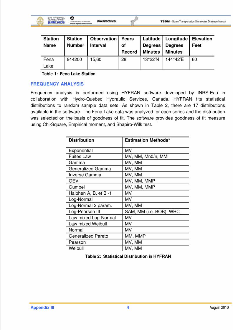
5/13/2018 Guam Storm Water Drainage Manual - slidepdf.com
http://slidepdf.com/reader/full/guam-storm-water-drainage-manual 444/486
Appendix III 4 August 2010
Station
Name
Station
Number
Observation
Interval
Years
of
Record
Latitude
Degrees
Minutes
Longitude
Degrees
Minutes
Elevation
Feet
Fena
Lake
914200 15,60 28 13°22’N 144°42’E 60
Table 1: Fena Lake Station
FREQUENCY ANALYSIS
Frequency analysis is performed using HYFRAN software developed by INRS-Eau in
collaboration with Hydro-Quebec Hydraulic Services, Canada. HYFRAN fits statistical
distributions to random sample data sets. As shown in Table 2, there are 17 distributions
available in the software. The Fena Lake data was analyzed for each series and the distribution
was selected on the basis of goodness of fit. The software provides goodness of fit measure
using Chi-Square, Empirical moment, and Shapiro-Wilk test.
Distribution Estimation Methods*
Exponential MV
Fuites Law MV, MM, Mn0/n, MMI
Gamma MV, MM
Generalized Gamma MV, MM
Inverse Gamma MV, MM
GEV MV, MM, MMP
Gumbel MV, MM, MMP
Halphen A, B, et B -1 MV
Log-Normal MV
Log-Normal 3 param. MV, MM
Log-Pearson III SAM, MM (i.e. BOB), WRC
Law mixed Log-Normal MV
Law mixed Weibull MV
Normal MV
Generalized Pareto MM, MMP
Pearson MV, MM
Weibull MV, MM
Table 2: Statistical Distribution in HYFRAN
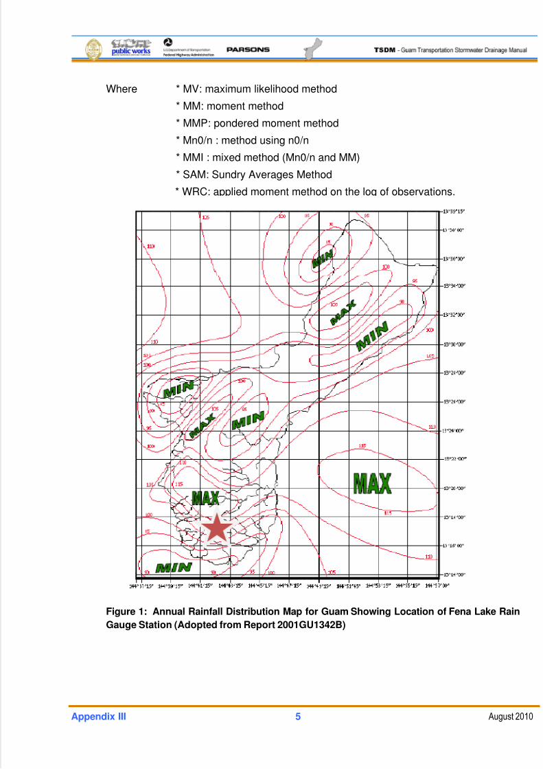
5/13/2018 Guam Storm Water Drainage Manual - slidepdf.com
http://slidepdf.com/reader/full/guam-storm-water-drainage-manual 445/486
Appendix III 5 August 2010
Where * MV: maximum likelihood method
* MM: moment method
* MMP: pondered moment method
* Mn0/n : method using n0/n
* MMI : mixed method (Mn0/n and MM)
* SAM: Sundry Averages Method
* WRC: applied moment method on the log of observations.
Figure 1: Annual Rainfall Distribution Map for Guam Showing Location of Fena Lake Rain
Gauge Station (Adopted from Report 2001GU1342B)
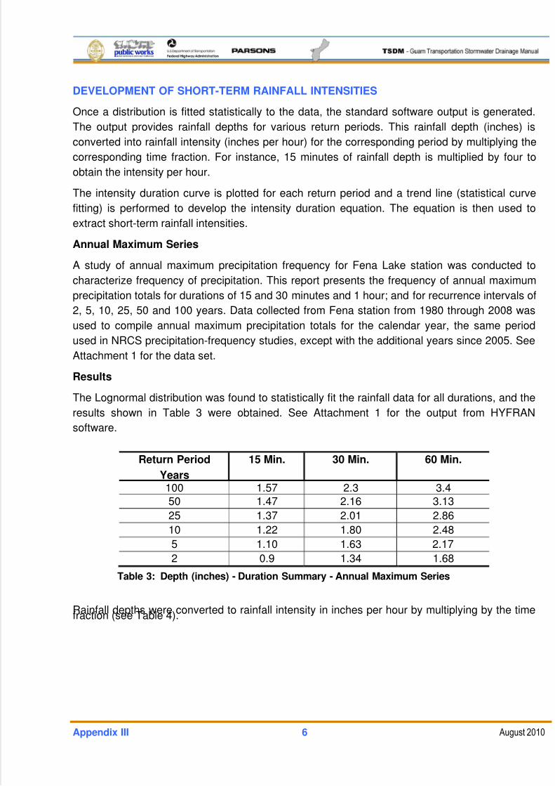
5/13/2018 Guam Storm Water Drainage Manual - slidepdf.com
http://slidepdf.com/reader/full/guam-storm-water-drainage-manual 446/486
Appendix III 6 August 2010
DEVELOPMENT OF SHORT-TERM RAINFALL INTENSITIES
Once a distribution is fitted statistically to the data, the standard software output is generated.
The output provides rainfall depths for various return periods. This rainfall depth (inches) is
converted into rainfall intensity (inches per hour) for the corresponding period by multiplying the
corresponding time fraction. For instance, 15 minutes of rainfall depth is multiplied by four to
obtain the intensity per hour.
The intensity duration curve is plotted for each return period and a trend line (statistical curve
fitting) is performed to develop the intensity duration equation. The equation is then used to
extract short-term rainfall intensities.
Annual Maximum Series
A study of annual maximum precipitation frequency for Fena Lake station was conducted to
characterize frequency of precipitation. This report presents the frequency of annual maximum
precipitation totals for durations of 15 and 30 minutes and 1 hour; and for recurrence intervals of
2, 5, 10, 25, 50 and 100 years. Data collected from Fena station from 1980 through 2008 was
used to compile annual maximum precipitation totals for the calendar year, the same period
used in NRCS precipitation-frequency studies, except with the additional years since 2005. See
Attachment 1 for the data set.
Results
The Lognormal distribution was found to statistically fit the rainfall data for all durations, and the
results shown in Table 3 were obtained. See Attachment 1 for the output from HYFRAN
software.
Return Period
Years
15 Min. 30 Min. 60 Min.
100 1.57 2.3 3.4
50 1.47 2.16 3.13
25 1.37 2.01 2.86
10 1.22 1.80 2.48
5 1.10 1.63 2.17
2 0.9 1.34 1.68
Table 3: Depth (inches) - Duration Summary - Annual Maximum Series
Rainfall depths were converted to rainfall intensity in inches per hour by multiplying by the timefraction (see Table 4).
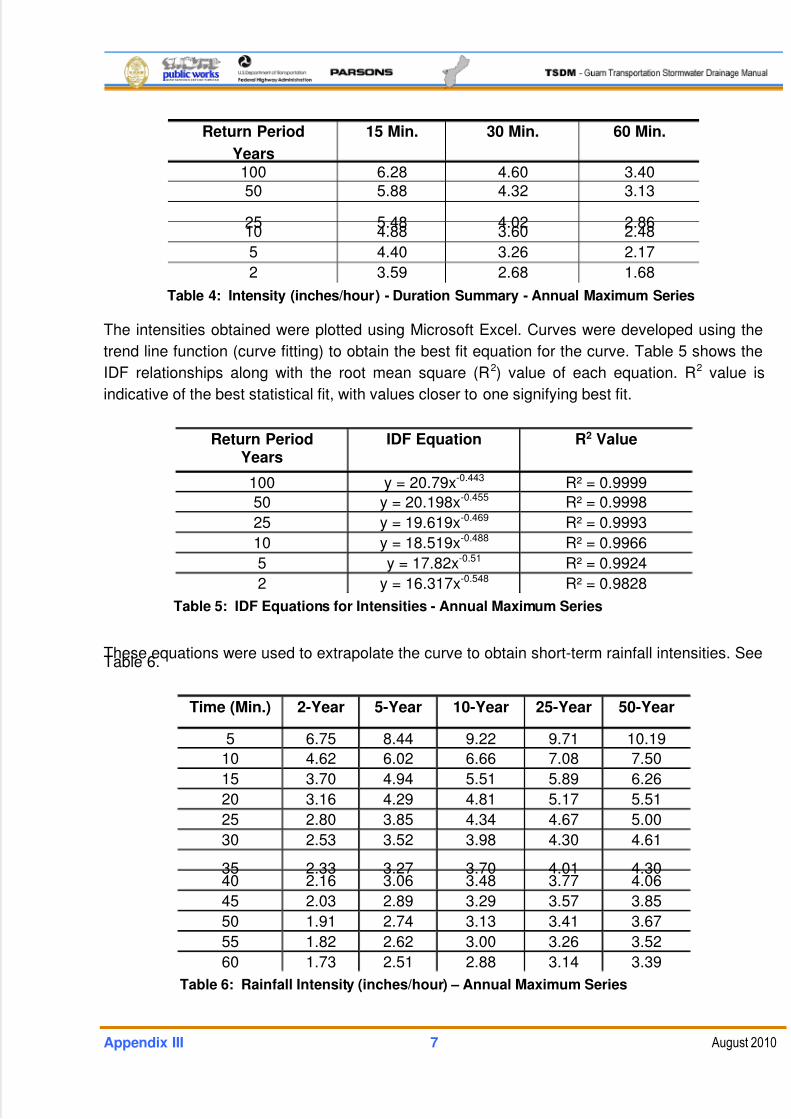
5/13/2018 Guam Storm Water Drainage Manual - slidepdf.com
http://slidepdf.com/reader/full/guam-storm-water-drainage-manual 447/486
Appendix III 7 August 2010
Return Period
Years
15 Min. 30 Min. 60 Min.
100 6.28 4.60 3.40
50 5.88 4.32 3.13
25 5.48 4.02 2.8610 4.88 3.60 2.48
5 4.40 3.26 2.17
2 3.59 2.68 1.68
Table 4: Intensity (inches/hour) - Duration Summary - Annual Maximum Series
The intensities obtained were plotted using Microsoft Excel. Curves were developed using the
trend line function (curve fitting) to obtain the best fit equation for the curve. Table 5 shows the
IDF relationships along with the root mean square (R2) value of each equation. R2 value is
indicative of the best statistical fit, with values closer to one signifying best fit.
Return PeriodYears
IDF Equation R2 Value
100 y = 20.79x-0.443 R² = 0.9999
50 y = 20.198x-0.455 R² = 0.9998
25 y = 19.619x-0.469 R² = 0.9993
10 y = 18.519x-0.488 R² = 0.9966
5 y = 17.82x-0.51 R² = 0.9924
2 y = 16.317x-0.548 R² = 0.9828
Table 5: IDF Equations for Intensities - Annual Maximum Series
These equations were used to extrapolate the curve to obtain short-term rainfall intensities. SeeTable 6.
Time (Min.) 2-Year 5-Year 10-Year 25-Year 50-Year
5 6.75 8.44 9.22 9.71 10.19
10 4.62 6.02 6.66 7.08 7.50
15 3.70 4.94 5.51 5.89 6.26
20 3.16 4.29 4.81 5.17 5.51
25 2.80 3.85 4.34 4.67 5.00
30 2.53 3.52 3.98 4.30 4.61
35 2.33 3.27 3.70 4.01 4.3040 2.16 3.06 3.48 3.77 4.06
45 2.03 2.89 3.29 3.57 3.85
50 1.91 2.74 3.13 3.41 3.67
55 1.82 2.62 3.00 3.26 3.52
60 1.73 2.51 2.88 3.14 3.39
Table 6: Rainfall Intensity (inches/hour) – Annual Maximum Series
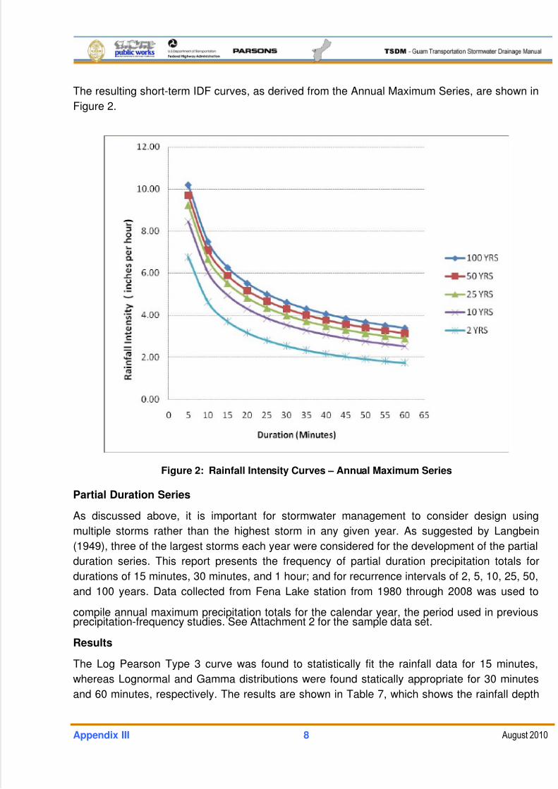
5/13/2018 Guam Storm Water Drainage Manual - slidepdf.com
http://slidepdf.com/reader/full/guam-storm-water-drainage-manual 448/486
Appendix III 8 August 2010
The resulting short-term IDF curves, as derived from the Annual Maximum Series, are shown in
Figure 2.
Figure 2: Rainfall Intensity Curves – Annual Maximum Series
Partial Duration Series
As discussed above, it is important for stormwater management to consider design using
multiple storms rather than the highest storm in any given year. As suggested by Langbein
(1949), three of the largest storms each year were considered for the development of the partial
duration series. This report presents the frequency of partial duration precipitation totals for
durations of 15 minutes, 30 minutes, and 1 hour; and for recurrence intervals of 2, 5, 10, 25, 50,
and 100 years. Data collected from Fena Lake station from 1980 through 2008 was used to
compile annual maximum precipitation totals for the calendar year, the period used in previousprecipitation-frequency studies. See Attachment 2 for the sample data set.
Results
The Log Pearson Type 3 curve was found to statistically fit the rainfall data for 15 minutes,
whereas Lognormal and Gamma distributions were found statically appropriate for 30 minutes
and 60 minutes, respectively. The results are shown in Table 7, which shows the rainfall depth
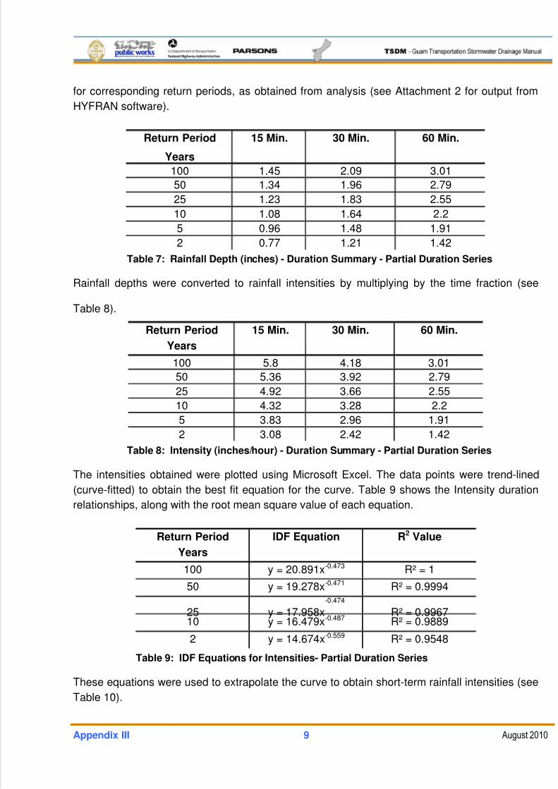
5/13/2018 Guam Storm Water Drainage Manual - slidepdf.com
http://slidepdf.com/reader/full/guam-storm-water-drainage-manual 449/486
Appendix III 9 August 2010
for corresponding return periods, as obtained from analysis (see Attachment 2 for output from
HYFRAN software).
Return Period
Years
15 Min. 30 Min. 60 Min.
100 1.45 2.09 3.01
50 1.34 1.96 2.79
25 1.23 1.83 2.55
10 1.08 1.64 2.2
5 0.96 1.48 1.91
2 0.77 1.21 1.42
Table 7: Rainfall Depth (inches) - Duration Summary - Partial Duration Series
Rainfall depths were converted to rainfall intensities by multiplying by the time fraction (see
Table 8).
Return Period
Years
15 Min. 30 Min. 60 Min.
100 5.8 4.18 3.01
50 5.36 3.92 2.79
25 4.92 3.66 2.55
10 4.32 3.28 2.2
5 3.83 2.96 1.91
2 3.08 2.42 1.42
Table 8: Intensity (inches/hour) - Duration Summary - Partial Duration Series
The intensities obtained were plotted using Microsoft Excel. The data points were trend-lined
(curve-fitted) to obtain the best fit equation for the curve. Table 9 shows the Intensity duration
relationships, along with the root mean square value of each equation.
Return Period
Years
IDF Equation R2 Value
100 y = 20.891x-0.473 R² = 1
50 y = 19.278x-0.471 R² = 0.9994
25 y = 17.958x-0.474
R² = 0.996710 y = 16.479x-0.487 R² = 0.9889
2 y = 14.674x-0.559 R² = 0.9548
Table 9: IDF Equations for Intensities- Partial Duration Series
These equations were used to extrapolate the curve to obtain short-term rainfall intensities (see
Table 10).
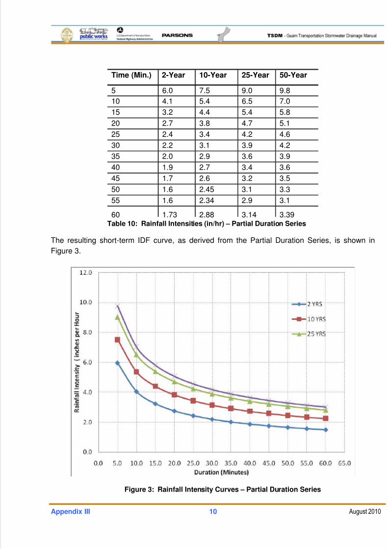
5/13/2018 Guam Storm Water Drainage Manual - slidepdf.com
http://slidepdf.com/reader/full/guam-storm-water-drainage-manual 450/486
Appendix III 10 August 2010
Time (Min.) 2-Year 10-Year 25-Year 50-Year
5 6.0 7.5 9.0 9.8
10 4.1 5.4 6.5 7.0
15 3.2 4.4 5.4 5.8
20 2.7 3.8 4.7 5.1
25 2.4 3.4 4.2 4.6
30 2.2 3.1 3.9 4.2
35 2.0 2.9 3.6 3.9
40 1.9 2.7 3.4 3.6
45 1.7 2.6 3.2 3.5
50 1.6 2.45 3.1 3.3
55 1.6 2.34 2.9 3.1
60 1.73 2.88 3.14 3.39Table 10: Rainfall Intensities (in/hr) – Partial Duration Series
The resulting short-term IDF curve, as derived from the Partial Duration Series, is shown in
Figure 3.
Figure 3: Rainfall Intensity Curves – Partial Duration Series
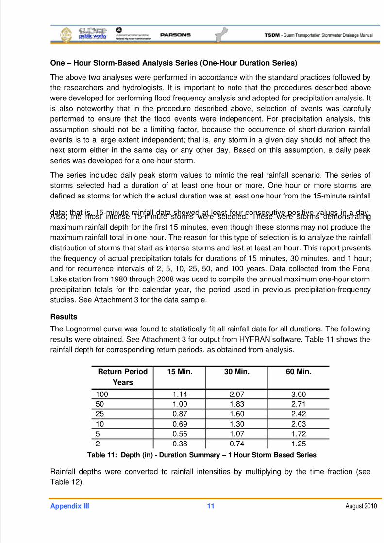
5/13/2018 Guam Storm Water Drainage Manual - slidepdf.com
http://slidepdf.com/reader/full/guam-storm-water-drainage-manual 451/486
Appendix III 11 August 2010
One – Hour Storm-Based Analysis Series (One-Hour Duration Series)
The above two analyses were performed in accordance with the standard practices followed by
the researchers and hydrologists. It is important to note that the procedures described above
were developed for performing flood frequency analysis and adopted for precipitation analysis. It
is also noteworthy that in the procedure described above, selection of events was carefully
performed to ensure that the flood events were independent. For precipitation analysis, this
assumption should not be a limiting factor, because the occurrence of short-duration rainfall
events is to a large extent independent; that is, any storm in a given day should not affect the
next storm either in the same day or any other day. Based on this assumption, a daily peak
series was developed for a one-hour storm.
The series included daily peak storm values to mimic the real rainfall scenario. The series of
storms selected had a duration of at least one hour or more. One hour or more storms are
defined as storms for which the actual duration was at least one hour from the 15-minute rainfall
data; that is, 15-minute rainfall data showed at least four consecutive positive values in a day.Also, the most intense 15-minute storms were selected. These were storms demonstrating
maximum rainfall depth for the first 15 minutes, even though these storms may not produce the
maximum rainfall total in one hour. The reason for this type of selection is to analyze the rainfall
distribution of storms that start as intense storms and last at least an hour. This report presents
the frequency of actual precipitation totals for durations of 15 minutes, 30 minutes, and 1 hour;
and for recurrence intervals of 2, 5, 10, 25, 50, and 100 years. Data collected from the Fena
Lake station from 1980 through 2008 was used to compile the annual maximum one-hour storm
precipitation totals for the calendar year, the period used in previous precipitation-frequency
studies. See Attachment 3 for the data sample.
Results
The Lognormal curve was found to statistically fit all rainfall data for all durations. The following
results were obtained. See Attachment 3 for output from HYFRAN software. Table 11 shows the
rainfall depth for corresponding return periods, as obtained from analysis.
Return Period
Years
15 Min. 30 Min. 60 Min.
100 1.14 2.07 3.00
50 1.00 1.83 2.71
25 0.87 1.60 2.42
10 0.69 1.30 2.03
5 0.56 1.07 1.72
2 0.38 0.74 1.25
Table 11: Depth (in) - Duration Summary – 1 Hour Storm Based Series
Rainfall depths were converted to rainfall intensities by multiplying by the time fraction (see
Table 12).
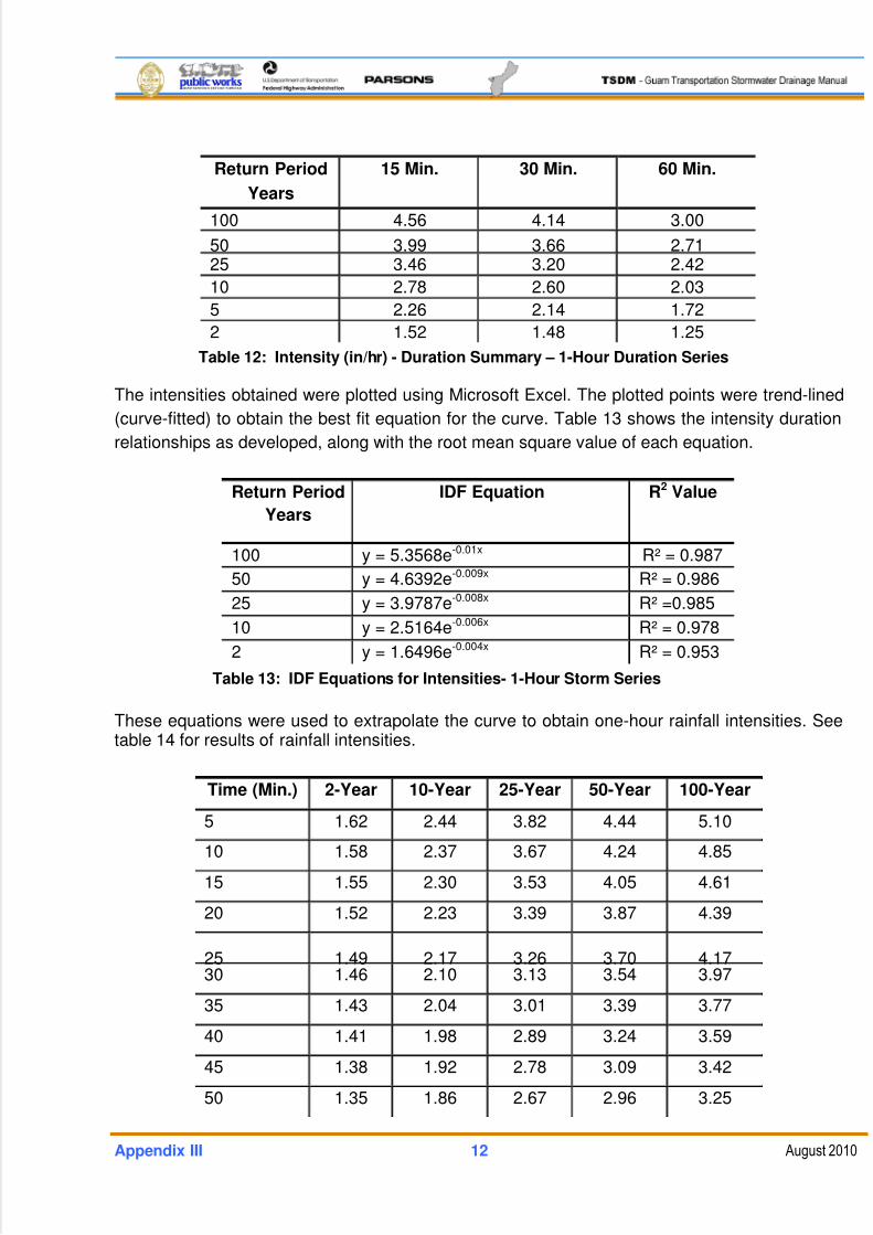
5/13/2018 Guam Storm Water Drainage Manual - slidepdf.com
http://slidepdf.com/reader/full/guam-storm-water-drainage-manual 452/486
Appendix III 12 August 2010
Return Period
Years
15 Min. 30 Min. 60 Min.
100 4.56 4.14 3.00
50 3.99 3.66 2.7125 3.46 3.20 2.42
10 2.78 2.60 2.03
5 2.26 2.14 1.72
2 1.52 1.48 1.25
Table 12: Intensity (in/hr) - Duration Summary – 1-Hour Duration Series
The intensities obtained were plotted using Microsoft Excel. The plotted points were trend-lined
(curve-fitted) to obtain the best fit equation for the curve. Table 13 shows the intensity duration
relationships as developed, along with the root mean square value of each equation.
Return Period
Years
IDF Equation R2 Value
100 y = 5.3568e-0.01x R² = 0.987
50 y = 4.6392e-0.009x R² = 0.986
25 y = 3.9787e-0.008x R² =0.985
10 y = 2.5164e-0.006x R² = 0.978
2 y = 1.6496e-0.004x R² = 0.953
Table 13: IDF Equations for Intensities- 1-Hour Storm Series
These equations were used to extrapolate the curve to obtain one-hour rainfall intensities. Seetable 14 for results of rainfall intensities.
Time (Min.) 2-Year 10-Year 25-Year 50-Year 100-Year
5 1.62 2.44 3.82 4.44 5.10
10 1.58 2.37 3.67 4.24 4.85
15 1.55 2.30 3.53 4.05 4.61
20 1.52 2.23 3.39 3.87 4.39
25 1.49 2.17 3.26 3.70 4.1730 1.46 2.10 3.13 3.54 3.97
35 1.43 2.04 3.01 3.39 3.77
40 1.41 1.98 2.89 3.24 3.59
45 1.38 1.92 2.78 3.09 3.42
50 1.35 1.86 2.67 2.96 3.25
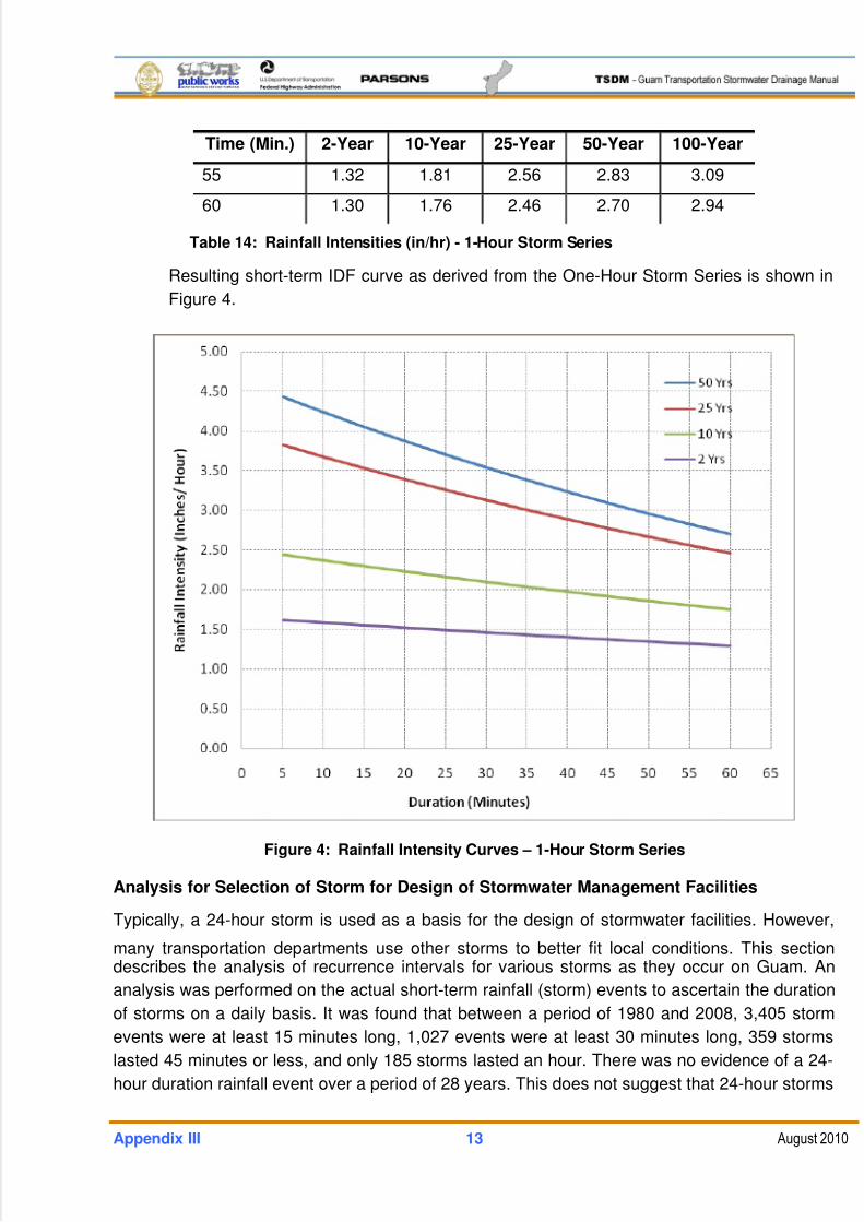
5/13/2018 Guam Storm Water Drainage Manual - slidepdf.com
http://slidepdf.com/reader/full/guam-storm-water-drainage-manual 453/486
Appendix III 13 August 2010
Time (Min.) 2-Year 10-Year 25-Year 50-Year 100-Year
55 1.32 1.81 2.56 2.83 3.09
60 1.30 1.76 2.46 2.70 2.94
Table 14: Rainfall Intensities (in/hr) - 1-Hour Storm Series
Resulting short-term IDF curve as derived from the One-Hour Storm Series is shown in
Figure 4.
Figure 4: Rainfall Intensity Curves – 1-Hour Storm Series
Analysis for Selection of Storm for Design of Stormwater Management Facilities
Typically, a 24-hour storm is used as a basis for the design of stormwater facilities. However,
many transportation departments use other storms to better fit local conditions. This sectiondescribes the analysis of recurrence intervals for various storms as they occur on Guam. An
analysis was performed on the actual short-term rainfall (storm) events to ascertain the duration
of storms on a daily basis. It was found that between a period of 1980 and 2008, 3,405 storm
events were at least 15 minutes long, 1,027 events were at least 30 minutes long, 359 storms
lasted 45 minutes or less, and only 185 storms lasted an hour. There was no evidence of a 24-
hour duration rainfall event over a period of 28 years. This does not suggest that 24-hour storms
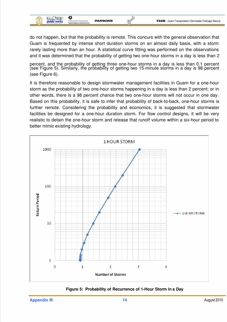
5/13/2018 Guam Storm Water Drainage Manual - slidepdf.com
http://slidepdf.com/reader/full/guam-storm-water-drainage-manual 454/486
Appendix III 14 August 2010
do not happen, but that the probability is remote. This concurs with the general observation that
Guam is frequented by intense short duration storms on an almost daily basis, with a storm
rarely lasting more than an hour. A statistical curve fitting was performed on the observations
and it was determined that the probability of getting two one-hour storms in a day is less than 2
percent, and the probability of getting three one-hour storms in a day is less than 0.1 percent(see Figure 5). Similarly, the probability of getting two 15-minute storms in a day is 98 percent
(see Figure 6).
It is therefore reasonable to design stormwater management facilities in Guam for a one-hour
storm as the probability of two one-hour storms happening in a day is less than 2 percent; or in
other words, there is a 98 percent chance that two one-hour storms will not occur in one day.
Based on this probability, it is safe to infer that probability of back-to-back, one-hour storms is
further remote. Considering the probability and economics, it is suggested that stormwater
facilities be designed for a one-hour duration storm. For flow control designs, it will be very
realistic to detain the one-hour storm and release that runoff volume within a six-hour period to
better mimic existing hydrology.
Figure 5: Probability of Recurrence of 1-Hour Storm in a Day
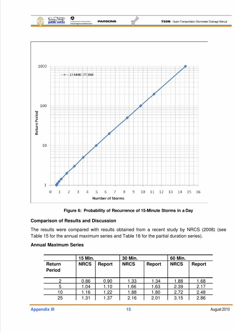
5/13/2018 Guam Storm Water Drainage Manual - slidepdf.com
http://slidepdf.com/reader/full/guam-storm-water-drainage-manual 455/486
Appendix III 15 August 2010
Figure 6: Probability of Recurrence of 15-Minute Storms in a Day
Comparison of Results and Discussion
The results were compared with results obtained from a recent study by NRCS (2008) (see
Table 15 for the annual maximum series and Table 16 for the partial duration series).
Annual Maximum Series
15 Min. 30 Min. 60 Min.
Return
Period
NRCS Report NRCS Report NRCS Report
2 0.86 0.90 1.33 1.34 1.88 1.685 1.04 1.10 1.66 1.63 2.39 2.17
10 1.16 1.22 1.88 1.80 2.72 2.48
25 1.31 1.37 2.16 2.01 3.15 2.86
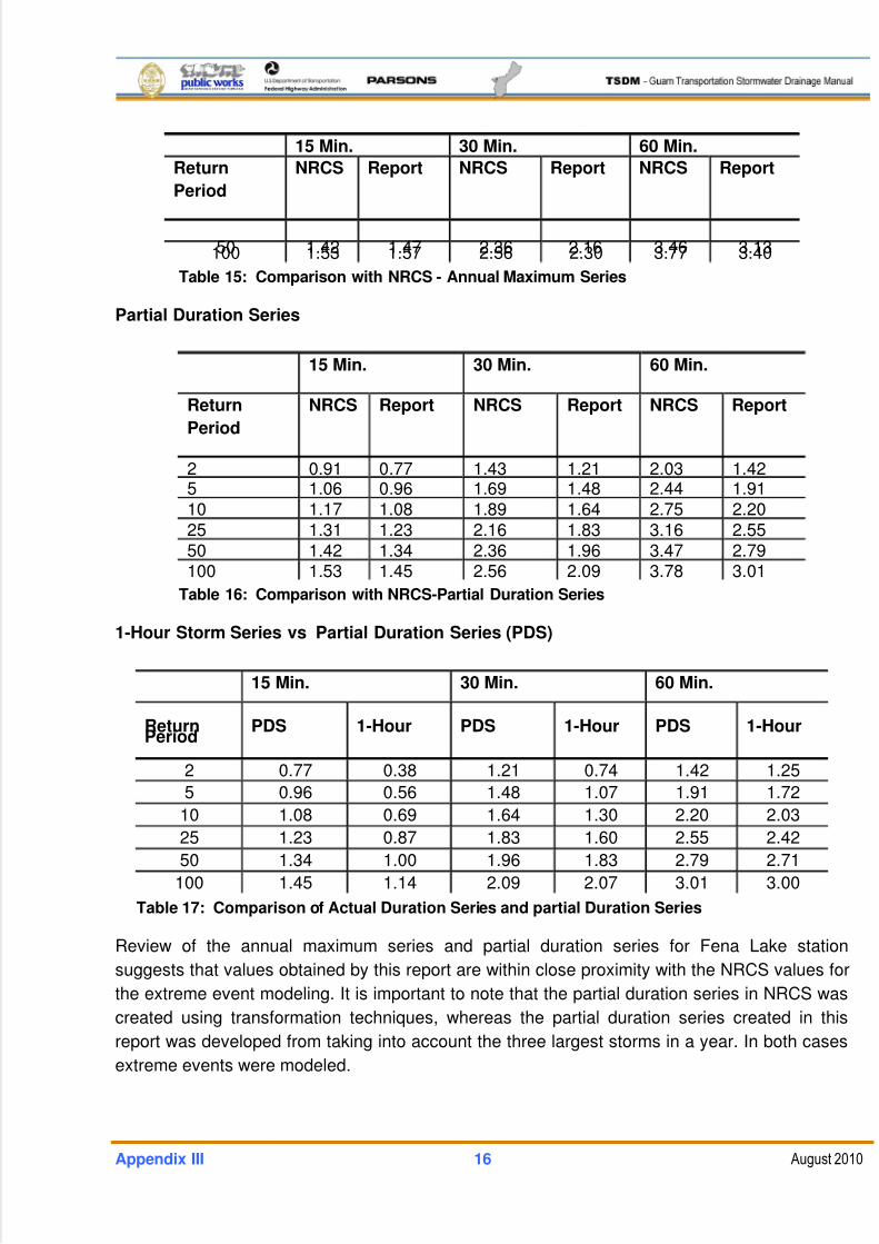
5/13/2018 Guam Storm Water Drainage Manual - slidepdf.com
http://slidepdf.com/reader/full/guam-storm-water-drainage-manual 456/486
Appendix III 16 August 2010
15 Min. 30 Min. 60 Min.
Return
Period
NRCS Report NRCS Report NRCS Report
50 1.42 1.47 2.36 2.16 3.46 3.13100 1.53 1.57 2.56 2.30 3.77 3.40
Table 15: Comparison with NRCS - Annual Maximum Series
Partial Duration Series
15 Min. 30 Min. 60 Min.
Return
Period
NRCS Report NRCS Report NRCS Report
2 0.91 0.77 1.43 1.21 2.03 1.425 1.06 0.96 1.69 1.48 2.44 1.9110 1.17 1.08 1.89 1.64 2.75 2.2025 1.31 1.23 2.16 1.83 3.16 2.5550 1.42 1.34 2.36 1.96 3.47 2.79100 1.53 1.45 2.56 2.09 3.78 3.01
Table 16: Comparison with NRCS-Partial Duration Series
1-Hour Storm Series vs Partial Duration Series (PDS)
15 Min. 30 Min. 60 Min.
ReturnPeriod
PDS 1-Hour PDS 1-Hour PDS 1-Hour
2 0.77 0.38 1.21 0.74 1.42 1.25
5 0.96 0.56 1.48 1.07 1.91 1.72
10 1.08 0.69 1.64 1.30 2.20 2.03
25 1.23 0.87 1.83 1.60 2.55 2.42
50 1.34 1.00 1.96 1.83 2.79 2.71
100 1.45 1.14 2.09 2.07 3.01 3.00
Table 17: Comparison of Actual Duration Series and partial Duration Series
Review of the annual maximum series and partial duration series for Fena Lake station
suggests that values obtained by this report are within close proximity with the NRCS values for
the extreme event modeling. It is important to note that the partial duration series in NRCS was
created using transformation techniques, whereas the partial duration series created in this
report was developed from taking into account the three largest storms in a year. In both cases
extreme events were modeled.
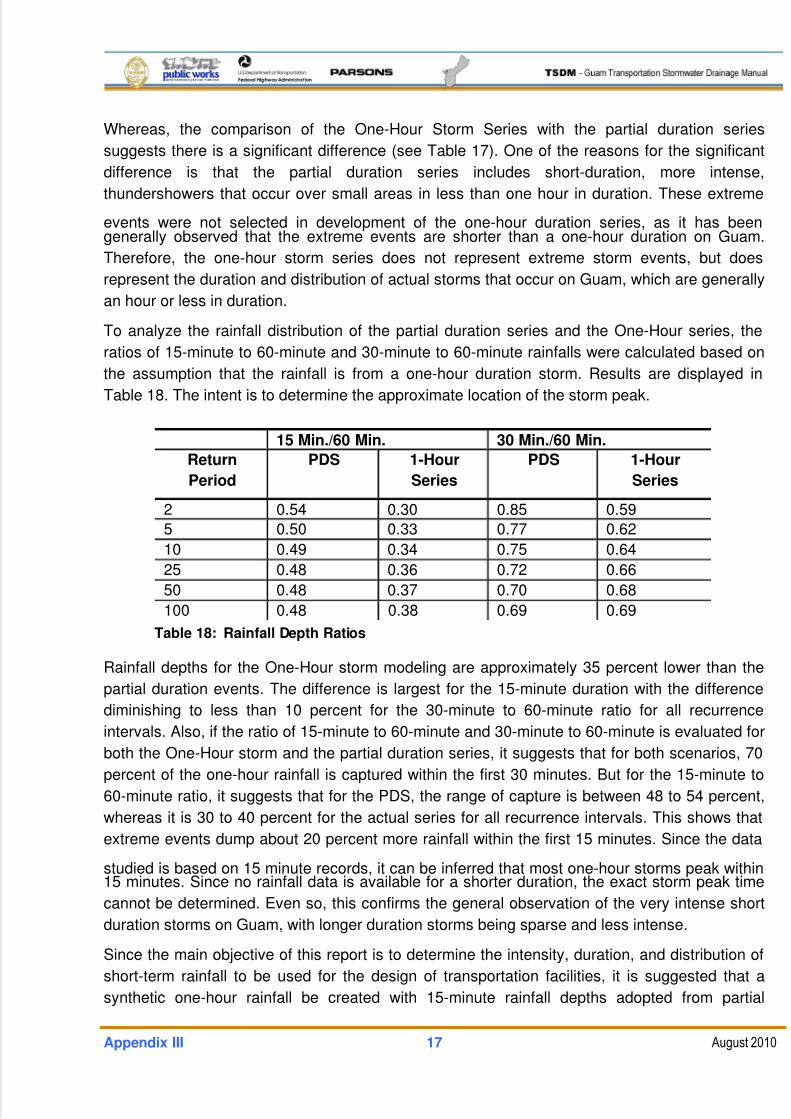
5/13/2018 Guam Storm Water Drainage Manual - slidepdf.com
http://slidepdf.com/reader/full/guam-storm-water-drainage-manual 457/486
Appendix III 17 August 2010
Whereas, the comparison of the One-Hour Storm Series with the partial duration series
suggests there is a significant difference (see Table 17). One of the reasons for the significant
difference is that the partial duration series includes short-duration, more intense,
thundershowers that occur over small areas in less than one hour in duration. These extreme
events were not selected in development of the one-hour duration series, as it has beengenerally observed that the extreme events are shorter than a one-hour duration on Guam.
Therefore, the one-hour storm series does not represent extreme storm events, but does
represent the duration and distribution of actual storms that occur on Guam, which are generally
an hour or less in duration.
To analyze the rainfall distribution of the partial duration series and the One-Hour series, the
ratios of 15-minute to 60-minute and 30-minute to 60-minute rainfalls were calculated based on
the assumption that the rainfall is from a one-hour duration storm. Results are displayed in
Table 18. The intent is to determine the approximate location of the storm peak.
15 Min./60 Min. 30 Min./60 Min.
Return
Period
PDS 1-Hour
Series
PDS 1-Hour
Series
2 0.54 0.30 0.85 0.59
5 0.50 0.33 0.77 0.62
10 0.49 0.34 0.75 0.64
25 0.48 0.36 0.72 0.66
50 0.48 0.37 0.70 0.68
100 0.48 0.38 0.69 0.69
Table 18: Rainfall Depth Ratios
Rainfall depths for the One-Hour storm modeling are approximately 35 percent lower than the
partial duration events. The difference is largest for the 15-minute duration with the difference
diminishing to less than 10 percent for the 30-minute to 60-minute ratio for all recurrence
intervals. Also, if the ratio of 15-minute to 60-minute and 30-minute to 60-minute is evaluated for
both the One-Hour storm and the partial duration series, it suggests that for both scenarios, 70
percent of the one-hour rainfall is captured within the first 30 minutes. But for the 15-minute to
60-minute ratio, it suggests that for the PDS, the range of capture is between 48 to 54 percent,
whereas it is 30 to 40 percent for the actual series for all recurrence intervals. This shows that
extreme events dump about 20 percent more rainfall within the first 15 minutes. Since the data
studied is based on 15 minute records, it can be inferred that most one-hour storms peak within15 minutes. Since no rainfall data is available for a shorter duration, the exact storm peak time
cannot be determined. Even so, this confirms the general observation of the very intense short
duration storms on Guam, with longer duration storms being sparse and less intense.
Since the main objective of this report is to determine the intensity, duration, and distribution of
short-term rainfall to be used for the design of transportation facilities, it is suggested that a
synthetic one-hour rainfall be created with 15-minute rainfall depths adopted from partial
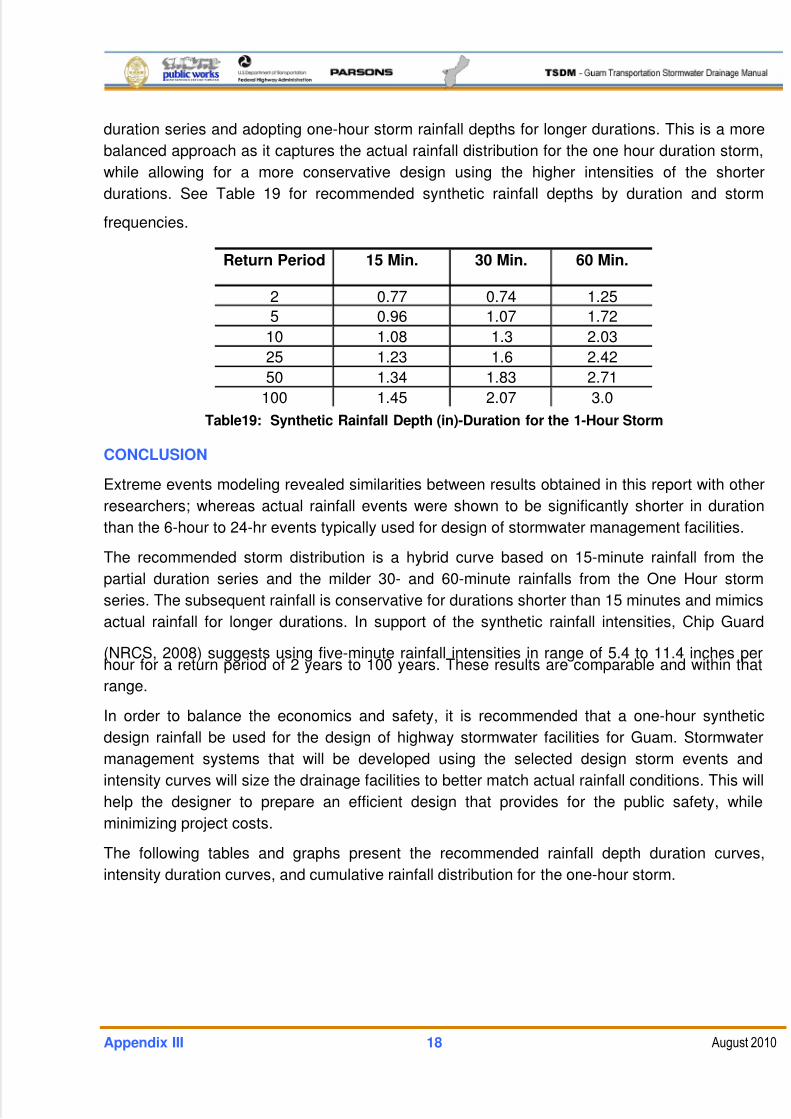
5/13/2018 Guam Storm Water Drainage Manual - slidepdf.com
http://slidepdf.com/reader/full/guam-storm-water-drainage-manual 458/486
Appendix III 18 August 2010
duration series and adopting one-hour storm rainfall depths for longer durations. This is a more
balanced approach as it captures the actual rainfall distribution for the one hour duration storm,
while allowing for a more conservative design using the higher intensities of the shorter
durations. See Table 19 for recommended synthetic rainfall depths by duration and storm
frequencies.
Return Period 15 Min. 30 Min. 60 Min.
2 0.77 0.74 1.25
5 0.96 1.07 1.72
10 1.08 1.3 2.03
25 1.23 1.6 2.42
50 1.34 1.83 2.71
100 1.45 2.07 3.0
Table19: Synthetic Rainfall Depth (in)-Duration for the 1-Hour Storm
CONCLUSION
Extreme events modeling revealed similarities between results obtained in this report with other
researchers; whereas actual rainfall events were shown to be significantly shorter in duration
than the 6-hour to 24-hr events typically used for design of stormwater management facilities.
The recommended storm distribution is a hybrid curve based on 15-minute rainfall from the
partial duration series and the milder 30- and 60-minute rainfalls from the One Hour storm
series. The subsequent rainfall is conservative for durations shorter than 15 minutes and mimics
actual rainfall for longer durations. In support of the synthetic rainfall intensities, Chip Guard
(NRCS, 2008) suggests using five-minute rainfall intensities in range of 5.4 to 11.4 inches perhour for a return period of 2 years to 100 years. These results are comparable and within that
range.
In order to balance the economics and safety, it is recommended that a one-hour synthetic
design rainfall be used for the design of highway stormwater facilities for Guam. Stormwater
management systems that will be developed using the selected design storm events and
intensity curves will size the drainage facilities to better match actual rainfall conditions. This will
help the designer to prepare an efficient design that provides for the public safety, while
minimizing project costs.
The following tables and graphs present the recommended rainfall depth duration curves,
intensity duration curves, and cumulative rainfall distribution for the one-hour storm.

5/13/2018 Guam Storm Water Drainage Manual - slidepdf.com
http://slidepdf.com/reader/full/guam-storm-water-drainage-manual 459/486
Appendix III 19 August 2010
Return PeriodYears
15 Min. 30 Min. 60 Min.
2 3.08 1.48 1.25
5 3.84 2.14 1.7210 4.32 2.60 2.03
25 4.92 3.20 2.42
50 5.36 3.66 2.71
100 5.80 4.14 3.00
Table 20: Rainfall Intensity (in/hr) - Synthetic 1-Hour Rainfall
Return Period
Years
IDF Equation R2 Value
100 y = 20.971x-0.476 R² = 0.99950 y = 20.04x-0.492 R² = 0.995
25 y = 19.187x-0.512 R² =0.985
10 y = 18.086x-0.545 R² = 0.962
2 y = 16.322x-0.651 R² = 0.885
Table 21: Rainfall Intensity Equations-Synthetic 1-Hour Rainfall
Time (Min.) 2-Year 10-Year 25-Year 50-Year 100-Year
5 5.72 7.52 8.43 9.08 9.7510 3.65 5.16 5.91 6.46 7.01
15 2.80 4.13 4.81 5.29 5.78
20 2.32 3.53 4.15 4.59 5.04
25 2.01 3.13 3.70 4.11 4.53
30 1.78 2.83 3.37 3.76 4.15
35 1.61 2.61 3.12 3.49 3.86
40 1.48 2.42 2.91 3.26 3.62
45 1.37 2.27 2.74 3.08 3.43
50 1.28 2.14 2.60 2.92 3.26
55 1.20 2.04 2.47 2.79 3.11
60 1.14 1.94 2.37 2.67 2.99
Table 22: Rainfall Intensities - Synthetic 1-Hour Rainfall
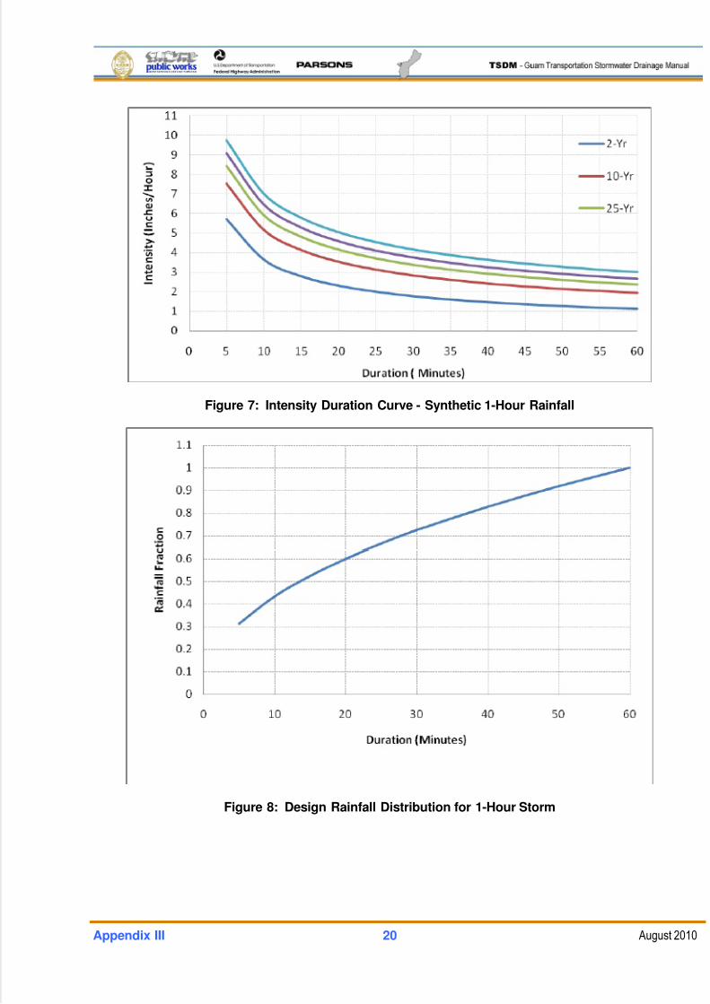
5/13/2018 Guam Storm Water Drainage Manual - slidepdf.com
http://slidepdf.com/reader/full/guam-storm-water-drainage-manual 460/486
Appendix III 20 August 2010
Figure 7: Intensity Duration Curve - Synthetic 1-Hour Rainfall
Figure 8: Design Rainfall Distribution for 1-Hour Storm
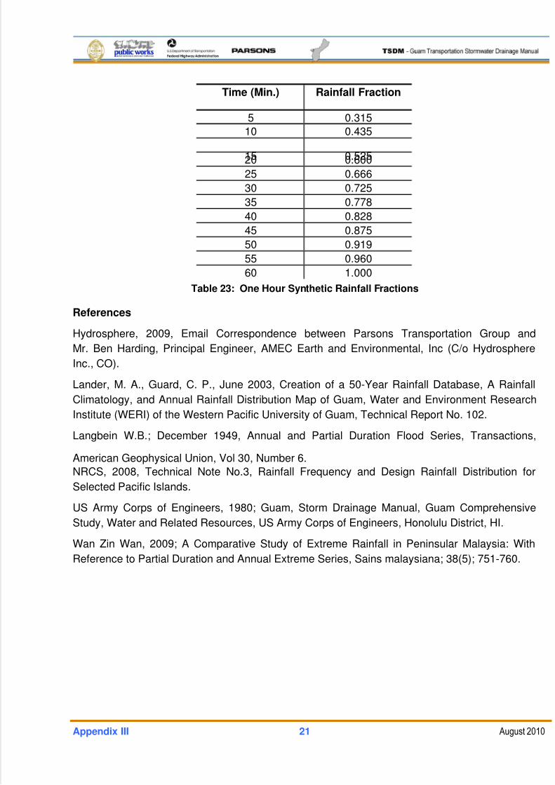
5/13/2018 Guam Storm Water Drainage Manual - slidepdf.com
http://slidepdf.com/reader/full/guam-storm-water-drainage-manual 461/486
Appendix III 21 August 2010
Time (Min.) Rainfall Fraction
5 0.315
10 0.435
15 0.52520 0.600
25 0.666
30 0.725
35 0.778
40 0.828
45 0.875
50 0.919
55 0.960
60 1.000
Table 23: One Hour Synthetic Rainfall Fractions
References
Hydrosphere, 2009, Email Correspondence between Parsons Transportation Group and
Mr. Ben Harding, Principal Engineer, AMEC Earth and Environmental, Inc (C/o Hydrosphere
Inc., CO).
Lander, M. A., Guard, C. P., June 2003, Creation of a 50-Year Rainfall Database, A Rainfall
Climatology, and Annual Rainfall Distribution Map of Guam, Water and Environment Research
Institute (WERI) of the Western Pacific University of Guam, Technical Report No. 102.
Langbein W.B.; December 1949, Annual and Partial Duration Flood Series, Transactions,
American Geophysical Union, Vol 30, Number 6.
NRCS, 2008, Technical Note No.3, Rainfall Frequency and Design Rainfall Distribution for
Selected Pacific Islands.
US Army Corps of Engineers, 1980; Guam, Storm Drainage Manual, Guam Comprehensive
Study, Water and Related Resources, US Army Corps of Engineers, Honolulu District, HI.
Wan Zin Wan, 2009; A Comparative Study of Extreme Rainfall in Peninsular Malaysia: With
Reference to Partial Duration and Annual Extreme Series, Sains malaysiana; 38(5); 751-760.
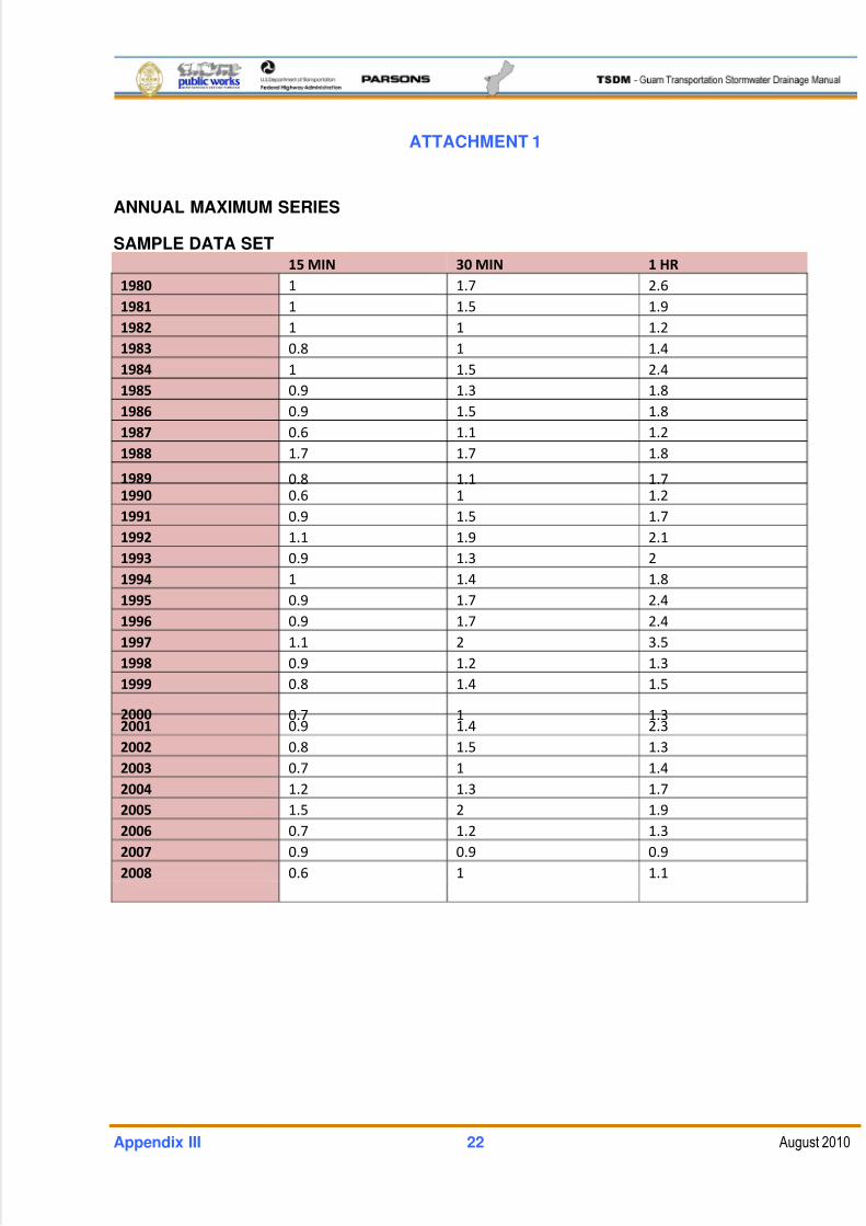
5/13/2018 Guam Storm Water Drainage Manual - slidepdf.com
http://slidepdf.com/reader/full/guam-storm-water-drainage-manual 462/486
Appendix III 22 August 2010
ATTACHMENT 1
ANNUAL MAXIMUM SERIES
SAMPLE DATA SET15 MIN 30 MIN 1 HR
1980 1 1.7 2.6
1981 1 1.5 1.9
1982 1 1 1.2
1983 0.8 1 1.4
1984 1 1.5 2.4
1985 0.9 1.3 1.8
1986 0.9 1.5 1.8
1987 0.6 1.1 1.2
1988 1.7 1.7 1.8
1989 0.8
1.1
1.7
1990 0.6 1 1.2
1991 0.9 1.5 1.7
1992 1.1 1.9 2.1
1993 0.9 1.3 2
1994 1 1.4 1.8
1995 0.9 1.7 2.4
1996 0.9 1.7 2.4
1997 1.1 2 3.5
1998 0.9 1.2 1.3
1999 0.8 1.4 1.5
2000 0.7
1
1.3
2001 0.9 1.4 2.3
2002 0.8 1.5 1.3
2003 0.7 1 1.4
2004 1.2 1.3 1.7
2005 1.5 2 1.9
2006 0.7 1.2 1.3
2007 0.9 0.9 0.9
2008 0.6 1 1.1
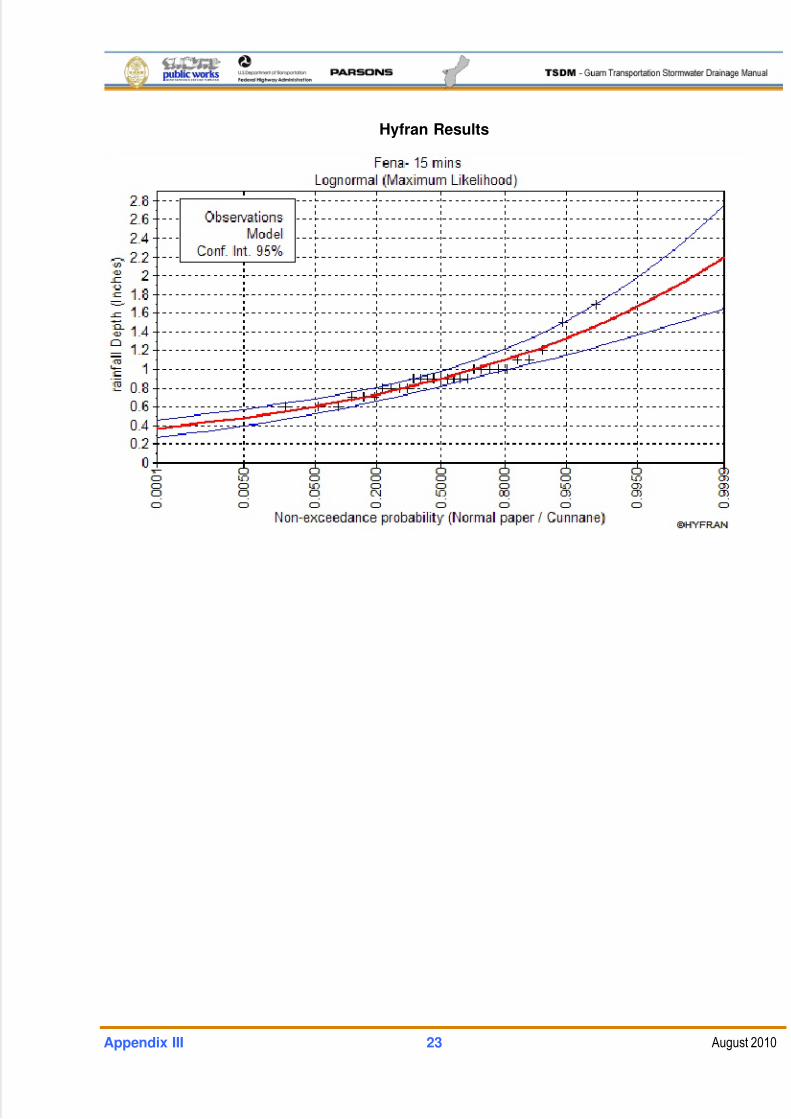
5/13/2018 Guam Storm Water Drainage Manual - slidepdf.com
http://slidepdf.com/reader/full/guam-storm-water-drainage-manual 463/486
Appendix III 23 August 2010
Hyfran Results
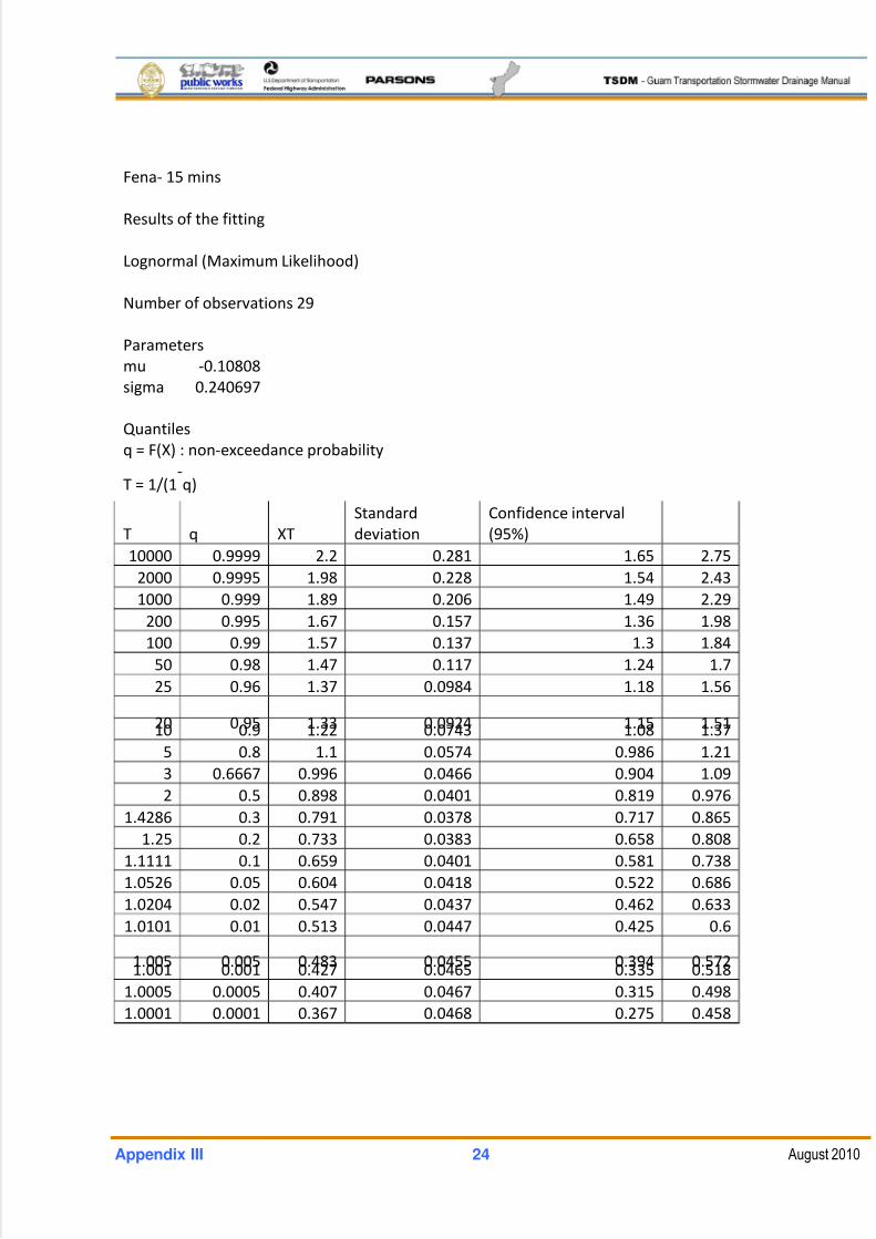
5/13/2018 Guam Storm Water Drainage Manual - slidepdf.com
http://slidepdf.com/reader/full/guam-storm-water-drainage-manual 464/486
Appendix III 24 August 2010
Fena‐ 15 mins
Results of the fitting
Lognormal (Maximum Likelihood)
Number of observations 29
Parameters
mu ‐0.10808
sigma 0.240697
Quantiles
q = F(X) : non‐exceedance probability
T
=
1/(1‐
q)
T q XT
Standard
deviation
Confidence interval
(95%)
10000 0.9999 2.2 0.281 1.65 2.75
2000 0.9995 1.98 0.228 1.54 2.43
1000 0.999 1.89 0.206 1.49 2.29
200 0.995 1.67 0.157 1.36 1.98
100 0.99 1.57 0.137 1.3 1.84
50 0.98 1.47 0.117 1.24 1.7
25 0.96 1.37 0.0984 1.18 1.56
20
0.95
1.33
0.0924 1.15 1.51
10 0.9 1.22 0.0743 1.08 1.37
5 0.8 1.1 0.0574 0.986 1.21
3 0.6667 0.996 0.0466 0.904 1.09
2 0.5 0.898 0.0401 0.819 0.976
1.4286 0.3 0.791 0.0378 0.717 0.865
1.25 0.2 0.733 0.0383 0.658 0.808
1.1111 0.1 0.659 0.0401 0.581 0.738
1.0526 0.05 0.604 0.0418 0.522 0.686
1.0204 0.02 0.547 0.0437 0.462 0.633
1.0101 0.01 0.513 0.0447 0.425 0.6
1.005
0.005
0.483
0.0455 0.394 0.572
1.001 0.001 0.427 0.0465 0.335 0.518
1.0005 0.0005 0.407 0.0467 0.315 0.498
1.0001 0.0001 0.367 0.0468 0.275 0.458
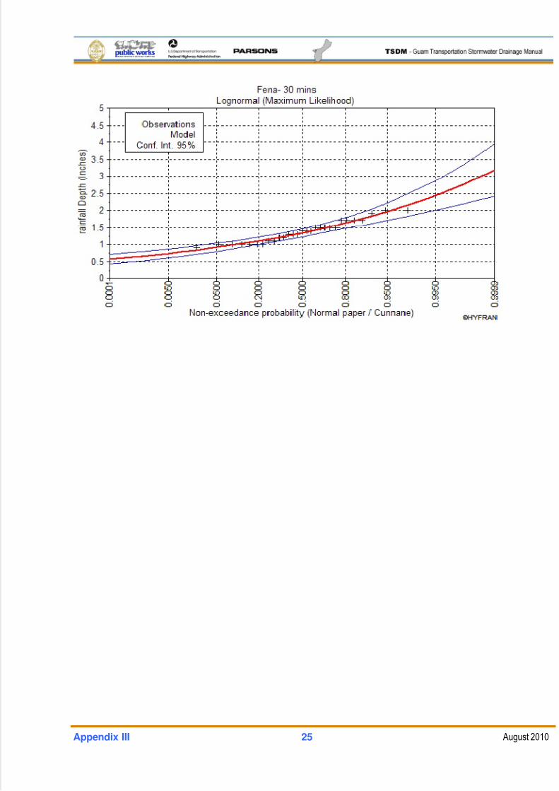
5/13/2018 Guam Storm Water Drainage Manual - slidepdf.com
http://slidepdf.com/reader/full/guam-storm-water-drainage-manual 465/486
Appendix III 25 August 2010
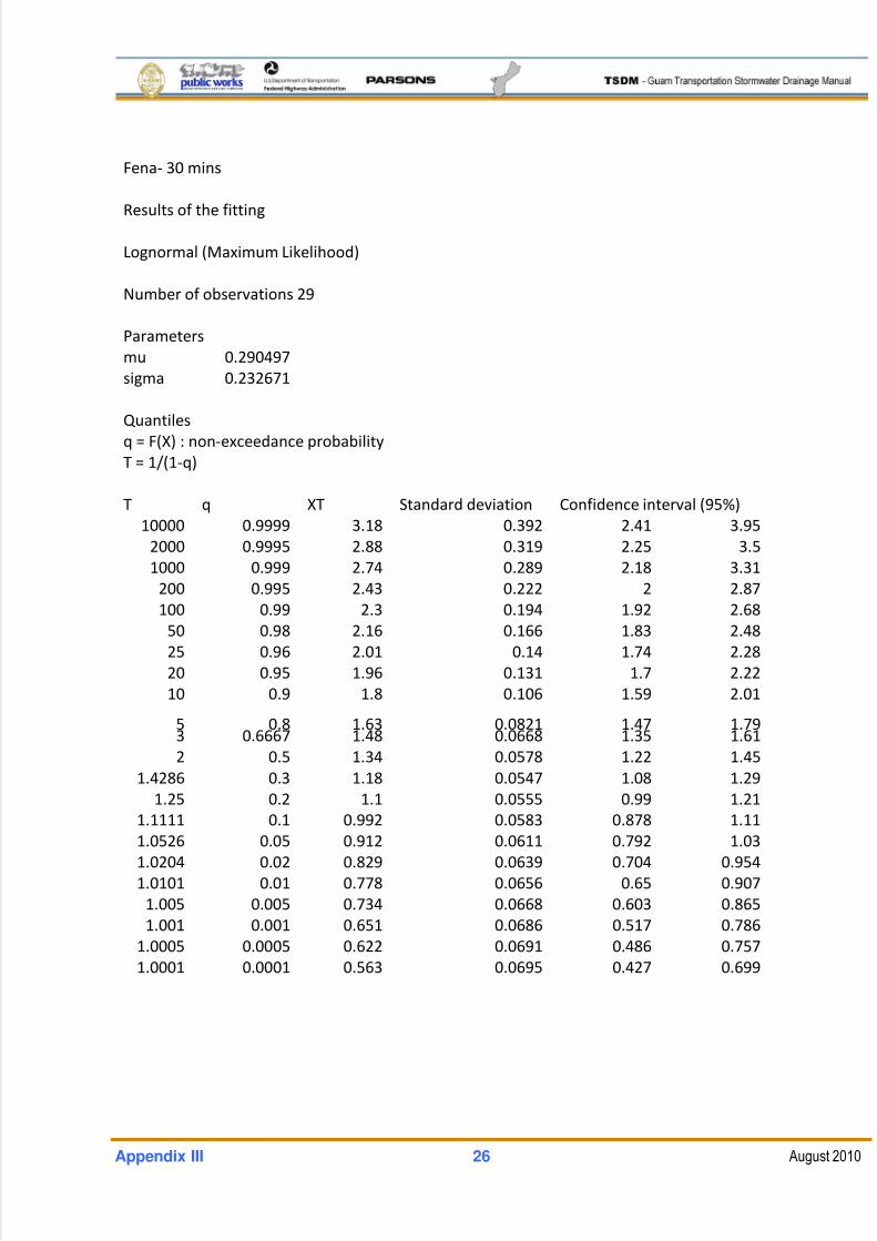
5/13/2018 Guam Storm Water Drainage Manual - slidepdf.com
http://slidepdf.com/reader/full/guam-storm-water-drainage-manual 466/486
Appendix III 26 August 2010
Fena‐ 30 mins
Results of the fitting
Lognormal (Maximum Likelihood)
Number of observations 29
Parameters
mu 0.290497
sigma 0.232671
Quantiles
q = F(X) : non‐exceedance probability
T = 1/(1‐q)
T q XT Standard deviation Confidence interval (95%)
10000 0.9999 3.18 0.392 2.41 3.95
2000 0.9995 2.88 0.319 2.25 3.5
1000 0.999 2.74 0.289 2.18 3.31
200 0.995 2.43 0.222 2 2.87
100 0.99 2.3 0.194 1.92 2.68
50 0.98 2.16 0.166 1.83 2.48
25 0.96 2.01 0.14 1.74 2.28
20 0.95 1.96 0.131 1.7 2.22
10 0.9 1.8 0.106 1.59 2.01
5
0.8 1.63
0.0821 1.47
1.79 3 0.6667 1.48 0.0668 1.35 1.61
2 0.5 1.34 0.0578 1.22 1.45
1.4286 0.3 1.18 0.0547 1.08 1.29
1.25 0.2 1.1 0.0555 0.99 1.21
1.1111 0.1 0.992 0.0583 0.878 1.11
1.0526 0.05 0.912 0.0611 0.792 1.03
1.0204 0.02 0.829 0.0639 0.704 0.954
1.0101 0.01 0.778 0.0656 0.65 0.907
1.005 0.005 0.734 0.0668 0.603 0.865
1.001 0.001 0.651 0.0686 0.517 0.786
1.0005 0.0005 0.622 0.0691 0.486 0.757
1.0001 0.0001 0.563 0.0695 0.427 0.699
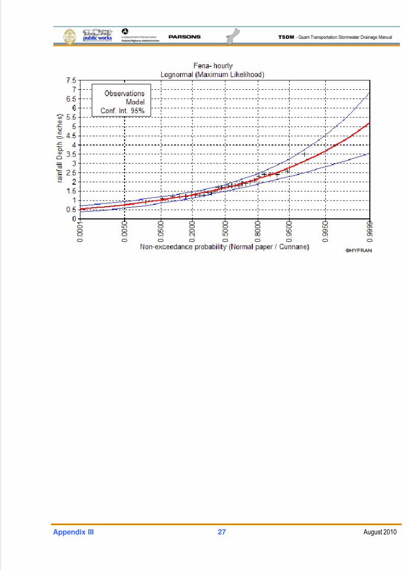
5/13/2018 Guam Storm Water Drainage Manual - slidepdf.com
http://slidepdf.com/reader/full/guam-storm-water-drainage-manual 467/486
Appendix III 27 August 2010
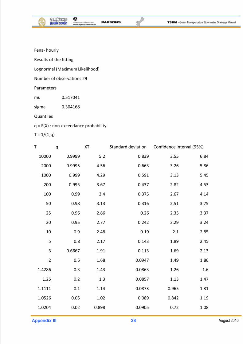
5/13/2018 Guam Storm Water Drainage Manual - slidepdf.com
http://slidepdf.com/reader/full/guam-storm-water-drainage-manual 468/486
Appendix III 28 August 2010
Fena‐ hourly
Results of the fitting
Lognormal (Maximum Likelihood)
Number of observations 29
Parameters
mu 0.517041
sigma 0.304168
Quantiles
q = F(X) : non‐exceedance probability
T = 1/(1
‐q)
T q XT Standard deviation Confidence interval (95%)
10000 0.9999 5.2 0.839 3.55 6.84
2000 0.9995 4.56 0.663 3.26 5.86
1000 0.999 4.29 0.591 3.13 5.45
200 0.995 3.67 0.437 2.82 4.53
100 0.99 3.4 0.375 2.67 4.14
50 0.98 3.13 0.316 2.51 3.75
25 0.96 2.86 0.26 2.35 3.37
20 0.95 2.77 0.242 2.29 3.24
10 0.9 2.48 0.19 2.1 2.85
5 0.8 2.17 0.143 1.89 2.45
3 0.6667 1.91 0.113 1.69 2.13
2 0.5 1.68 0.0947 1.49 1.86
1.4286 0.3 1.43 0.0863 1.26 1.6
1.25 0.2 1.3 0.0857 1.13 1.47
1.1111 0.1 1.14 0.0873 0.965 1.31
1.0526 0.05 1.02 0.089 0.842 1.19
1.0204 0.02 0.898 0.0905 0.72 1.08
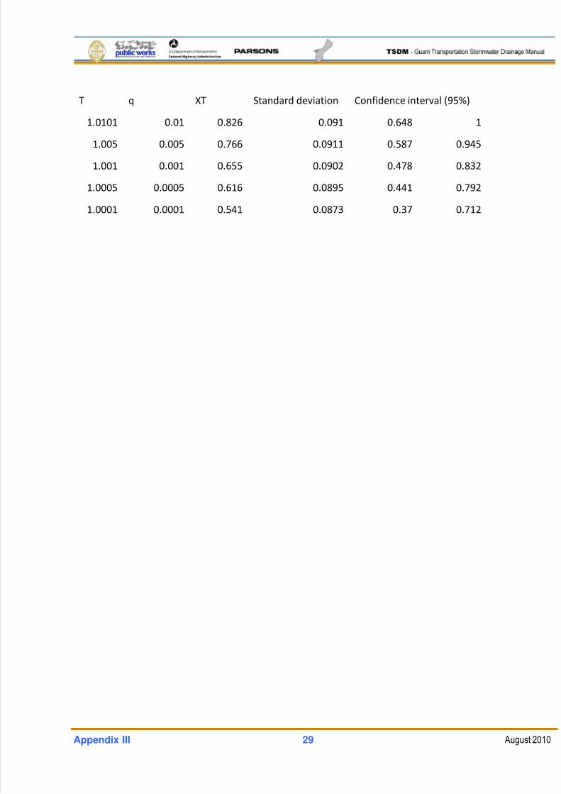
5/13/2018 Guam Storm Water Drainage Manual - slidepdf.com
http://slidepdf.com/reader/full/guam-storm-water-drainage-manual 469/486
Appendix III 29 August 2010
T q XT Standard deviation Confidence interval (95%)
1.0101 0.01 0.826 0.091 0.648 1
1.005 0.005 0.766 0.0911 0.587 0.945
1.001 0.001 0.655 0.0902 0.478 0.832
1.0005 0.0005 0.616 0.0895 0.441 0.792
1.0001 0.0001 0.541 0.0873 0.37 0.712
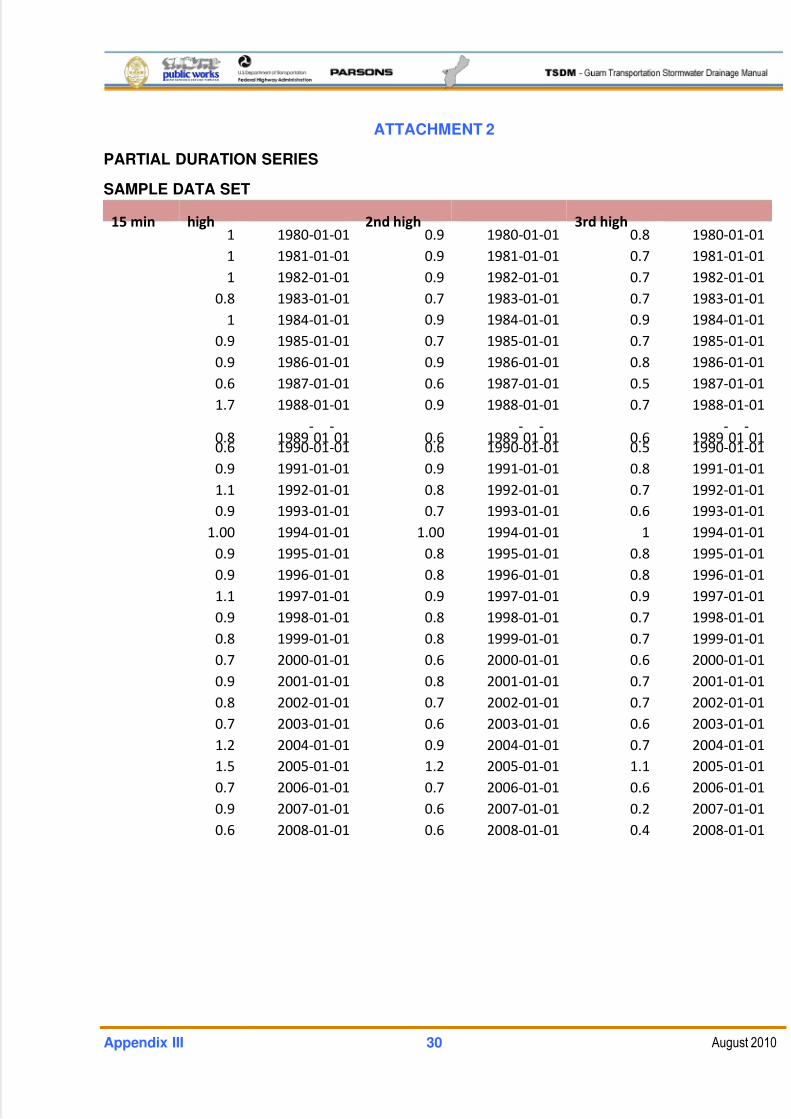
5/13/2018 Guam Storm Water Drainage Manual - slidepdf.com
http://slidepdf.com/reader/full/guam-storm-water-drainage-manual 470/486
Appendix III 30 August 2010
ATTACHMENT 2
PARTIAL DURATION SERIES
SAMPLE DATA SET
15 min high 2nd high 3rd high 1 1980‐01‐01 0.9 1980‐01‐01 0.8 1980‐01‐01
1 1981‐01‐01 0.9 1981‐01‐01 0.7 1981‐01‐01
1 1982‐01‐01 0.9 1982‐01‐01 0.7 1982‐01‐01
0.8 1983‐01‐01 0.7 1983‐01‐01 0.7 1983‐01‐01
1 1984‐01‐01 0.9 1984‐01‐01 0.9 1984‐01‐01
0.9 1985‐01‐01 0.7 1985‐01‐01 0.7 1985‐01‐01
0.9 1986‐01‐01 0.9 1986‐01‐01 0.8 1986‐01‐01
0.6 1987‐01‐01 0.6 1987‐01‐01 0.5 1987‐01‐01
1.7 1988‐01‐01 0.9 1988‐01‐01 0.7 1988‐01‐01
0.8
1989‐
01‐
01
0.6 1989‐
01‐
01
0.6
1989‐
01‐
01
0.6 1990‐01‐01 0.6 1990‐01‐01 0.5 1990‐01‐01
0.9 1991‐01‐01 0.9 1991‐01‐01 0.8 1991‐01‐01
1.1 1992‐01‐01 0.8 1992‐01‐01 0.7 1992‐01‐01
0.9 1993‐01‐01 0.7 1993‐01‐01 0.6 1993‐01‐01
1.00 1994‐01‐01 1.00 1994‐01‐01 1 1994‐01‐01
0.9 1995‐01‐01 0.8 1995‐01‐01 0.8 1995‐01‐01
0.9 1996‐01‐01 0.8 1996‐01‐01 0.8 1996‐01‐01
1.1 1997‐01‐01 0.9 1997‐01‐01 0.9 1997‐01‐01
0.9 1998‐01‐01 0.8 1998‐01‐01 0.7 1998‐01‐01
0.8 1999‐01‐01 0.8 1999‐01‐01 0.7 1999‐01‐01
0.7 2000‐01‐01 0.6 2000‐01‐01 0.6 2000‐01‐01
0.9 2001‐01‐01 0.8 2001‐01‐01 0.7 2001‐01‐01
0.8 2002‐01‐01 0.7 2002‐01‐01 0.7 2002‐01‐01
0.7 2003‐01‐01 0.6 2003‐01‐01 0.6 2003‐01‐01
1.2 2004‐01‐01 0.9 2004‐01‐01 0.7 2004‐01‐01
1.5 2005‐01‐01 1.2 2005‐01‐01 1.1 2005‐01‐01
0.7 2006‐01‐01 0.7 2006‐01‐01 0.6 2006‐01‐01
0.9 2007‐01‐01 0.6 2007‐01‐01 0.2 2007‐01‐01
0.6 2008‐01‐01 0.6 2008‐01‐01 0.4 2008‐01‐01
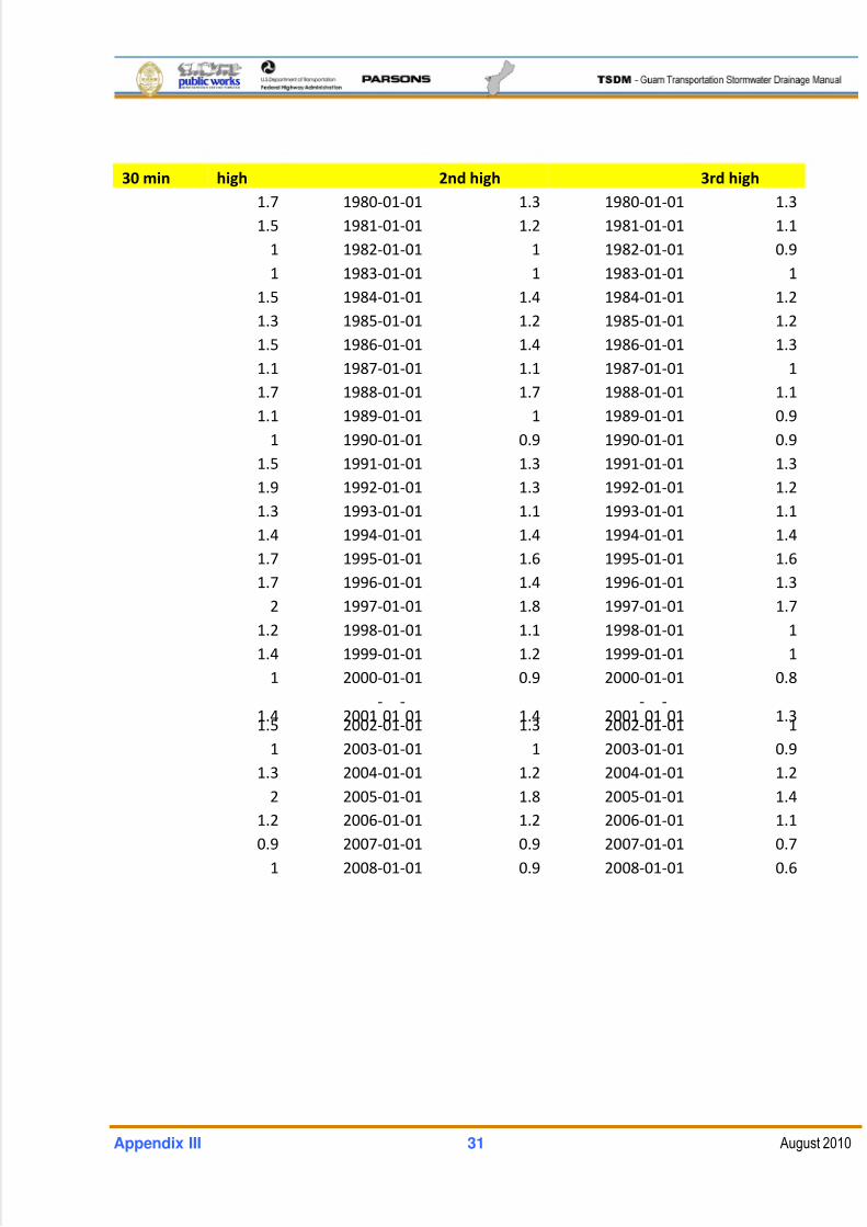
5/13/2018 Guam Storm Water Drainage Manual - slidepdf.com
http://slidepdf.com/reader/full/guam-storm-water-drainage-manual 471/486
Appendix III 31 August 2010
30 min high 2nd high 3rd high 1.7 1980‐01‐01 1.3 1980‐01‐01 1.3
1.5 1981‐01‐01 1.2 1981‐01‐01 1.1
1 1982‐01‐01 1 1982‐01‐01 0.9
1 1983‐01‐01 1 1983‐01‐01 1
1.5 1984‐01‐01 1.4 1984‐01‐01 1.2
1.3 1985‐01‐01 1.2 1985‐01‐01 1.2
1.5 1986‐01‐01 1.4 1986‐01‐01 1.3
1.1 1987‐01‐01 1.1 1987‐01‐01 1
1.7 1988‐01‐01 1.7 1988‐01‐01 1.1
1.1 1989‐01‐01 1 1989‐01‐01 0.9
1 1990‐01‐01 0.9 1990‐01‐01 0.9
1.5 1991‐01‐01 1.3 1991‐01‐01 1.3
1.9 1992‐01‐01 1.3 1992‐01‐01 1.2
1.3 1993‐01‐01 1.1 1993‐01‐01 1.1
1.4 1994‐01‐01 1.4 1994‐01‐01 1.4
1.7 1995‐01‐01 1.6 1995‐01‐01 1.6
1.7 1996‐01‐01 1.4 1996‐01‐01 1.3
2 1997‐01‐01 1.8 1997‐01‐01 1.7
1.2 1998‐01‐01 1.1 1998‐01‐01 1
1.4 1999‐01‐01 1.2 1999‐01‐01 1
1 2000‐01‐01 0.9 2000‐01‐01 0.8
1.4
2001‐
01‐
01 1.4 2001‐
01‐
01
1.3 1.5 2002‐01‐01 1.3 2002‐01‐01 1
1 2003‐01‐01 1 2003‐01‐01 0.9
1.3 2004‐01‐01 1.2 2004‐01‐01 1.2
2 2005‐01‐01 1.8 2005‐01‐01 1.4
1.2 2006‐01‐01 1.2 2006‐01‐01 1.1
0.9 2007‐01‐01 0.9 2007‐01‐01 0.7
1 2008‐01‐01 0.9 2008‐01‐01 0.6
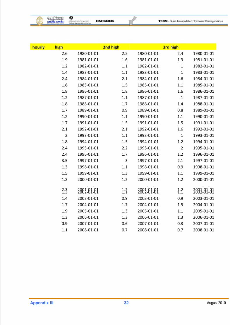
5/13/2018 Guam Storm Water Drainage Manual - slidepdf.com
http://slidepdf.com/reader/full/guam-storm-water-drainage-manual 472/486
Appendix III 32 August 2010
hourly high 2nd high 3rd high 2.6 1980‐01‐01 2.5 1980‐01‐01 2.4 1980‐01‐01
1.9 1981‐01‐01 1.6 1981‐01‐01 1.3 1981‐01‐01
1.2 1982‐01‐01 1.1 1982‐01‐01 1 1982‐01‐01
1.4 1983‐01‐01 1.1 1983‐01‐01 1 1983‐01‐01
2.4 1984‐01‐01 2.1 1984‐01‐01 1.6 1984‐01‐01
1.8 1985‐01‐01 1.5 1985‐01‐01 1.1 1985‐01‐01
1.8 1986‐01‐01 1.8 1986‐01‐01 1.6 1986‐01‐01
1.2 1987‐01‐01 1.1 1987‐01‐01 1 1987‐01‐01
1.8 1988‐01‐01 1.7 1988‐01‐01 1.4 1988‐01‐01
1.7 1989‐01‐01 0.9 1989‐01‐01 0.8 1989‐01‐01
1.2 1990‐01‐01 1.1 1990‐01‐01 1.1 1990‐01‐01
1.7 1991‐01‐01 1.5 1991‐01‐01 1.5 1991‐01‐01
2.1 1992‐01‐01 2.1 1992‐01‐01 1.6 1992‐01‐01
2 1993‐01‐01 1.1 1993‐01‐01 1 1993‐01‐01
1.8 1994‐01‐01 1.5 1994‐01‐01 1.2 1994‐01‐01
2.4 1995‐01‐01 2.2 1995‐01‐01 2 1995‐01‐01
2.4 1996‐01‐01 1.7 1996‐01‐01 1.2 1996‐01‐01
3.5 1997‐01‐01 3 1997‐01‐01 2.1 1997‐01‐01
1.3 1998‐01‐01 1.1 1998‐01‐01 0.9 1998‐01‐01
1.5 1999‐01‐01 1.3 1999‐01‐01 1.1 1999‐01‐01
1.3 2000‐01‐01 1.2 2000‐01‐01 1.2 2000‐01‐01
2.3
2001‐
01‐
01
1.2 2001‐
01‐
01 1.2
2001‐
01‐
01 1.3 2002‐01‐01 1.1 2002‐01‐01 1.1 2002‐01‐01
1.4 2003‐01‐01 0.9 2003‐01‐01 0.9 2003‐01‐01
1.7 2004‐01‐01 1.7 2004‐01‐01 1.5 2004‐01‐01
1.9 2005‐01‐01 1.3 2005‐01‐01 1.1 2005‐01‐01
1.3 2006‐01‐01 1.3 2006‐01‐01 1.3 2006‐01‐01
0.9 2007‐01‐01 0.6 2007‐01‐01 0.3 2007‐01‐01
1.1 2008‐01‐01 0.7 2008‐01‐01 0.7 2008‐01‐01
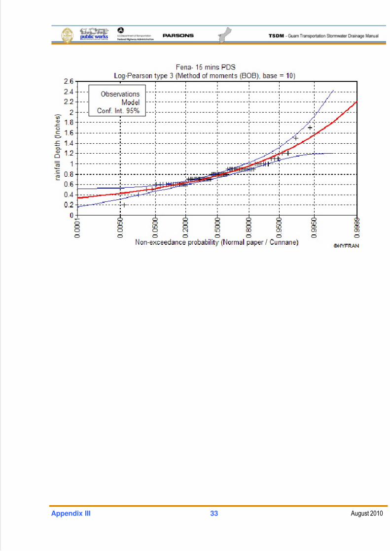
5/13/2018 Guam Storm Water Drainage Manual - slidepdf.com
http://slidepdf.com/reader/full/guam-storm-water-drainage-manual 473/486
Appendix III 33 August 2010
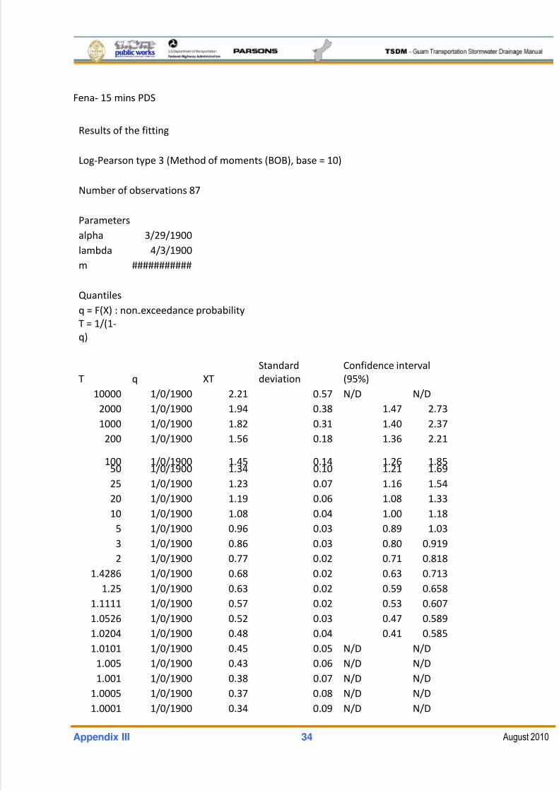
5/13/2018 Guam Storm Water Drainage Manual - slidepdf.com
http://slidepdf.com/reader/full/guam-storm-water-drainage-manual 474/486
Appendix III 34 August 2010
Fena‐ 15 mins PDS
Results of the fitting
Log‐Pearson type 3 (Method of moments (BOB), base = 10)
Number of observations 87
Parameters
alpha 3/29/1900
lambda 4/3/1900
m ###########
Quantiles
q = F(X)
: non
‐exceedance
probability
T = 1/(1‐
q)
T q XT
Standard
deviation
Confidence interval
(95%)
10000 1/0/1900 2.21 0.57 N/D N/D
2000 1/0/1900 1.94 0.38 1.47 2.73
1000 1/0/1900 1.82 0.31 1.40 2.37
200 1/0/1900 1.56 0.18 1.36 2.21
100
1/0/1900
1.45 0.14
1.26 1.85 50 1/0/1900 1.34 0.10 1.21 1.69
25 1/0/1900 1.23 0.07 1.16 1.54
20 1/0/1900 1.19 0.06 1.08 1.33
10 1/0/1900 1.08 0.04 1.00 1.18
5 1/0/1900 0.96 0.03 0.89 1.03
3 1/0/1900 0.86 0.03 0.80 0.919
2 1/0/1900 0.77 0.02 0.71 0.818
1.4286 1/0/1900 0.68 0.02 0.63 0.713
1.25 1/0/1900 0.63 0.02 0.59 0.658
1.1111 1/0/1900 0.57 0.02 0.53 0.607
1.0526 1/0/1900 0.52 0.03 0.47 0.589
1.0204 1/0/1900 0.48 0.04 0.41 0.585
1.0101 1/0/1900 0.45 0.05 N/D N/D
1.005 1/0/1900 0.43 0.06 N/D N/D
1.001 1/0/1900 0.38 0.07 N/D N/D
1.0005 1/0/1900 0.37 0.08 N/D N/D
1.0001 1/0/1900 0.34 0.09 N/D N/D
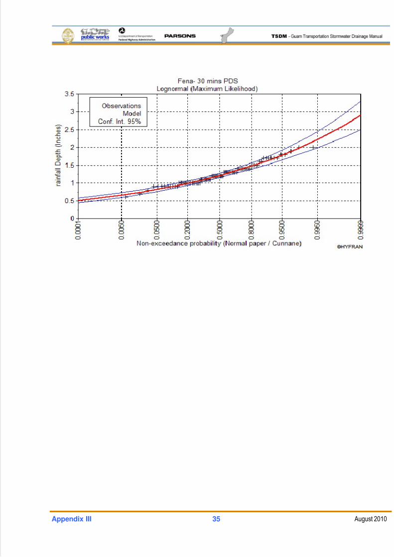
5/13/2018 Guam Storm Water Drainage Manual - slidepdf.com
http://slidepdf.com/reader/full/guam-storm-water-drainage-manual 475/486
Appendix III 35 August 2010
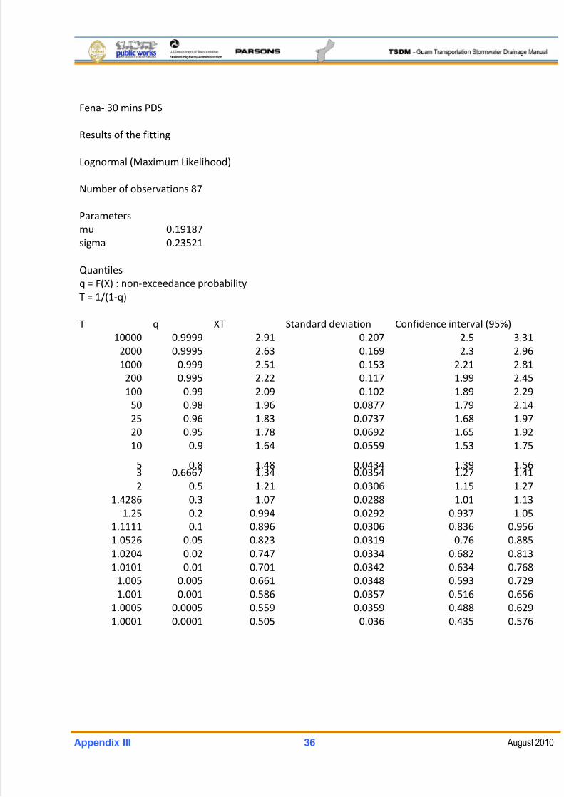
5/13/2018 Guam Storm Water Drainage Manual - slidepdf.com
http://slidepdf.com/reader/full/guam-storm-water-drainage-manual 476/486
Appendix III 36 August 2010
Fena‐ 30 mins PDS
Results of the fitting
Lognormal (Maximum Likelihood)
Number of observations 87
Parameters
mu 0.19187
sigma 0.23521
Quantiles
q = F(X) : non‐exceedance probability
T = 1/(1‐q)
T q XT Standard deviation Confidence interval (95%)
10000 0.9999 2.91 0.207 2.5 3.31
2000 0.9995 2.63 0.169 2.3 2.96
1000 0.999 2.51 0.153 2.21 2.81
200 0.995 2.22 0.117 1.99 2.45
100 0.99 2.09 0.102 1.89 2.29
50 0.98 1.96 0.0877 1.79 2.14
25 0.96 1.83 0.0737 1.68 1.97
20 0.95 1.78 0.0692 1.65 1.92
10 0.9 1.64 0.0559 1.53 1.75
5
0.8
1.48 0.0434 1.39
1.563 0.6667 1.34 0.0354 1.27 1.41
2 0.5 1.21 0.0306 1.15 1.27
1.4286 0.3 1.07 0.0288 1.01 1.13
1.25 0.2 0.994 0.0292 0.937 1.05
1.1111 0.1 0.896 0.0306 0.836 0.956
1.0526 0.05 0.823 0.0319 0.76 0.885
1.0204 0.02 0.747 0.0334 0.682 0.813
1.0101 0.01 0.701 0.0342 0.634 0.768
1.005 0.005 0.661 0.0348 0.593 0.729
1.001 0.001 0.586 0.0357 0.516 0.656
1.0005 0.0005 0.559 0.0359 0.488 0.629
1.0001 0.0001 0.505 0.036 0.435 0.576
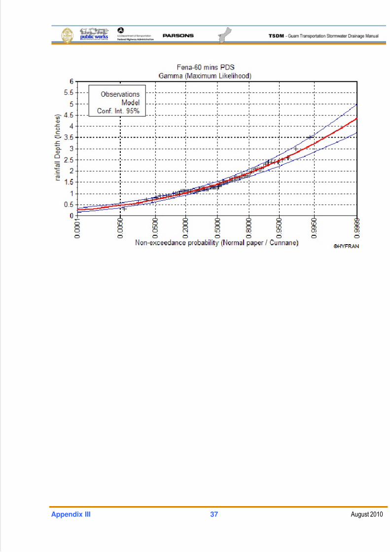
5/13/2018 Guam Storm Water Drainage Manual - slidepdf.com
http://slidepdf.com/reader/full/guam-storm-water-drainage-manual 477/486
Appendix III 37 August 2010
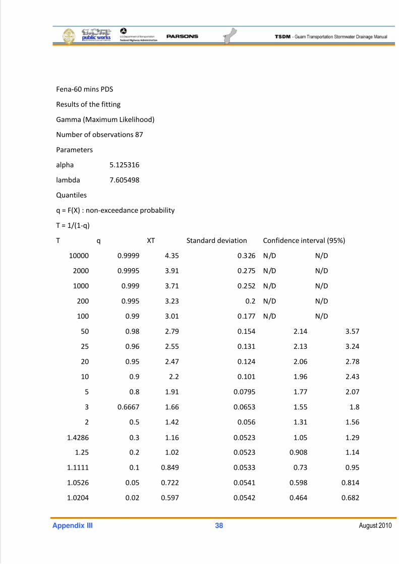
5/13/2018 Guam Storm Water Drainage Manual - slidepdf.com
http://slidepdf.com/reader/full/guam-storm-water-drainage-manual 478/486
Appendix III 38 August 2010
Fena‐60 mins PDS
Results of the fitting
Gamma (Maximum Likelihood)
Number of observations 87
Parameters
alpha 5.125316
lambda 7.605498
Quantiles
q = F(X) : non‐exceedance probability
T = 1/(1‐q)
T q XT Standard deviation Confidence interval (95%)
10000 0.9999 4.35 0.326 N/D N/D
2000 0.9995 3.91 0.275 N/D N/D
1000 0.999 3.71 0.252 N/D N/D
200 0.995 3.23 0.2 N/D N/D
100 0.99 3.01 0.177 N/D N/D
50 0.98 2.79 0.154 2.14 3.57
25 0.96 2.55 0.131 2.13 3.24
20 0.95 2.47 0.124 2.06 2.78
10 0.9 2.2 0.101 1.96 2.43
5 0.8 1.91 0.0795 1.77 2.07
3 0.6667 1.66 0.0653 1.55 1.8
2 0.5 1.42 0.056 1.31 1.56
1.4286
0.3
1.16
0.0523 1.05
1.29
1.25 0.2 1.02 0.0523 0.908 1.14
1.1111 0.1 0.849 0.0533 0.73 0.95
1.0526 0.05 0.722 0.0541 0.598 0.814
1.0204 0.02 0.597 0.0542 0.464 0.682
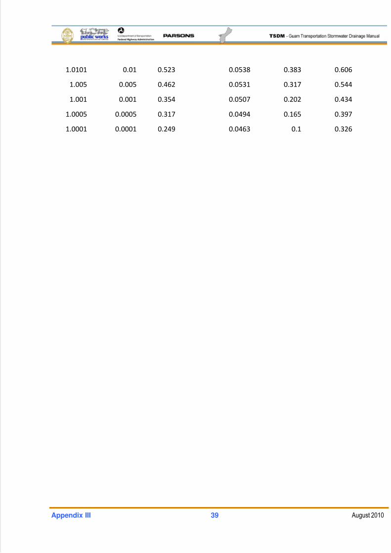
5/13/2018 Guam Storm Water Drainage Manual - slidepdf.com
http://slidepdf.com/reader/full/guam-storm-water-drainage-manual 479/486
Appendix III 39 August 2010
1.0101 0.01 0.523 0.0538 0.383 0.606
1.005 0.005 0.462 0.0531 0.317 0.544
1.001 0.001 0.354 0.0507 0.202 0.434
1.0005 0.0005 0.317 0.0494 0.165 0.397
1.0001 0.0001 0.249 0.0463 0.1 0.326
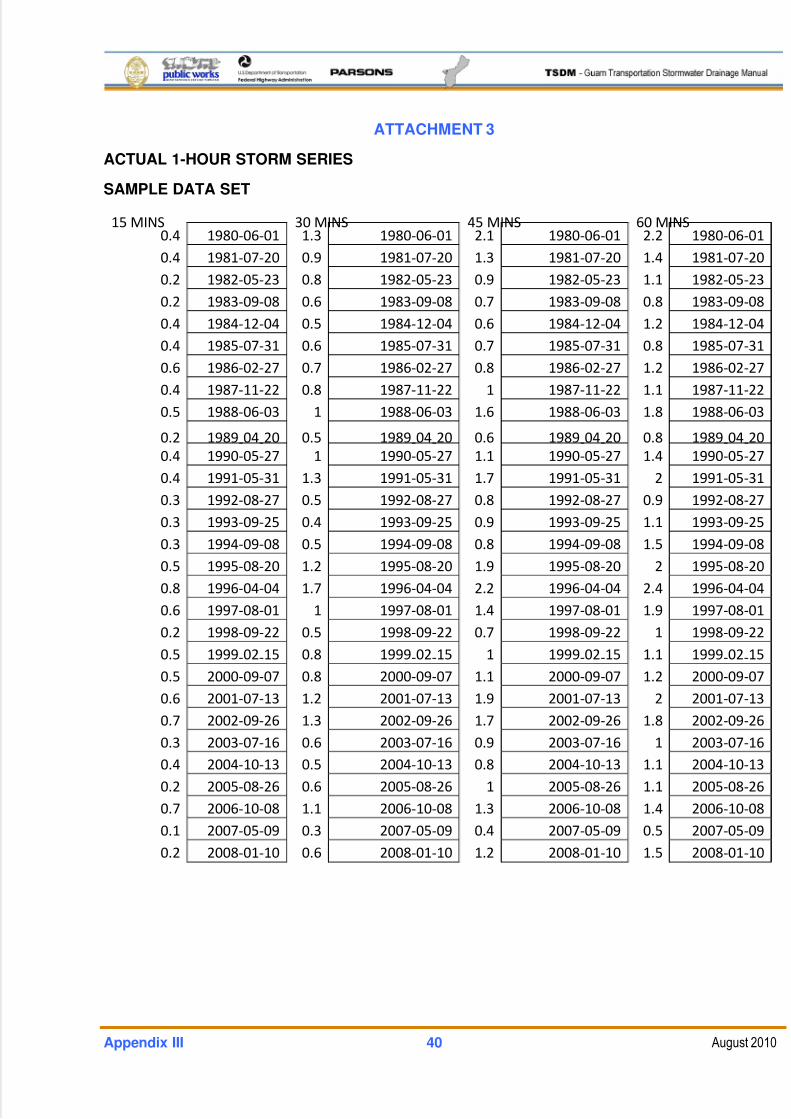
5/13/2018 Guam Storm Water Drainage Manual - slidepdf.com
http://slidepdf.com/reader/full/guam-storm-water-drainage-manual 480/486
Appendix III 40 August 2010
ATTACHMENT 3
ACTUAL 1-HOUR STORM SERIES
SAMPLE DATA SET
15 MINS
30
MINS
45
MINS
60
MINS
0.4 1980‐06‐01 1.3 1980‐06‐01 2.1 1980‐06‐01 2.2 1980‐06‐01
0.4 1981‐07‐20 0.9 1981‐07‐20 1.3 1981‐07‐20 1.4 1981‐07‐20
0.2 1982‐05‐23 0.8 1982‐05‐23 0.9 1982‐05‐23 1.1 1982‐05‐23
0.2 1983‐09‐08 0.6 1983‐09‐08 0.7 1983‐09‐08 0.8 1983‐09‐08
0.4 1984‐12‐04 0.5 1984‐12‐04 0.6 1984‐12‐04 1.2 1984‐12‐04
0.4 1985‐07‐31 0.6 1985‐07‐31 0.7 1985‐07‐31 0.8 1985‐07‐31
0.6 1986‐02‐27 0.7 1986‐02‐27 0.8 1986‐02‐27 1.2 1986‐02‐27
0.4 1987‐11‐22 0.8 1987‐11‐22 1 1987‐11‐22 1.1 1987‐11‐22
0.5 1988‐06‐03 1 1988‐06‐03 1.6 1988‐06‐03 1.8 1988‐06‐03
0.2
1989‐04
‐20
0.5
1989
‐04
‐20 0.6 1989
‐04
‐20
0.8
1989
‐04
‐20
0.4 1990‐05‐27 1 1990‐05‐27 1.1 1990‐05‐27 1.4 1990‐05‐27
0.4 1991‐05‐31 1.3 1991‐05‐31 1.7 1991‐05‐31 2 1991‐05‐31
0.3 1992‐08‐27 0.5 1992‐08‐27 0.8 1992‐08‐27 0.9 1992‐08‐27
0.3 1993‐09‐25 0.4 1993‐09‐25 0.9 1993‐09‐25 1.1 1993‐09‐25
0.3 1994‐09‐08 0.5 1994‐09‐08 0.8 1994‐09‐08 1.5 1994‐09‐08
0.5 1995‐08‐20 1.2 1995‐08‐20 1.9 1995‐08‐20 2 1995‐08‐20
0.8 1996‐04‐04 1.7 1996‐04‐04 2.2 1996‐04‐04 2.4 1996‐04‐04
0.6 1997‐08‐01 1 1997‐08‐01 1.4 1997‐08‐01 1.9 1997‐08‐01
0.2 1998‐09‐22 0.5 1998‐09‐22 0.7 1998‐09‐22 1 1998‐09‐22
0.5
1999‐02
‐15
0.8
1999
‐02
‐15 1 1999
‐02
‐15
1.1
1999
‐02
‐15
0.5 2000‐09‐07 0.8 2000‐09‐07 1.1 2000‐09‐07 1.2 2000‐09‐07
0.6 2001‐07‐13 1.2 2001‐07‐13 1.9 2001‐07‐13 2 2001‐07‐13
0.7 2002‐09‐26 1.3 2002‐09‐26 1.7 2002‐09‐26 1.8 2002‐09‐26
0.3 2003‐07‐16 0.6 2003‐07‐16 0.9 2003‐07‐16 1 2003‐07‐16
0.4 2004‐10‐13 0.5 2004‐10‐13 0.8 2004‐10‐13 1.1 2004‐10‐13
0.2 2005‐08‐26 0.6 2005‐08‐26 1 2005‐08‐26 1.1 2005‐08‐26
0.7 2006‐10‐08 1.1 2006‐10‐08 1.3 2006‐10‐08 1.4 2006‐10‐08
0.1 2007‐05‐09 0.3 2007‐05‐09 0.4 2007‐05‐09 0.5 2007‐05‐09
0.2 2008‐01‐10 0.6 2008‐01‐10 1.2 2008‐01‐10 1.5 2008‐01‐10
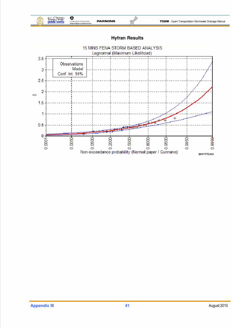
5/13/2018 Guam Storm Water Drainage Manual - slidepdf.com
http://slidepdf.com/reader/full/guam-storm-water-drainage-manual 481/486
Appendix III 41 August 2010
Hyfran Results
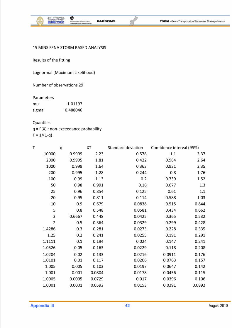
5/13/2018 Guam Storm Water Drainage Manual - slidepdf.com
http://slidepdf.com/reader/full/guam-storm-water-drainage-manual 482/486
Appendix III 42 August 2010
15 MINS FENA STORM BASED ANALYSIS
Results of the fitting
Lognormal (Maximum Likelihood)
Number of observations 29
Parameters
mu ‐1.01197
sigma 0.488046
Quantiles
q = F(X)
: non
‐exceedance
probability
T = 1/(1‐q)
T q XT Standard deviation Confidence interval (95%)
10000 0.9999 2.23 0.578 1.1 3.37
2000 0.9995 1.81 0.422 0.984 2.64
1000 0.999 1.64 0.363 0.931 2.35
200 0.995 1.28 0.244 0.8 1.76
100 0.99 1.13 0.2 0.739 1.52
50 0.98 0.991 0.16 0.677 1.3
25
0.96
0.854 0.125 0.61 1.1
20 0.95 0.811 0.114 0.588 1.03
10 0.9 0.679 0.0838 0.515 0.844
5 0.8 0.548 0.0581 0.434 0.662
3 0.6667 0.448 0.0425 0.365 0.532
2 0.5 0.364 0.0329 0.299 0.428
1.4286 0.3 0.281 0.0273 0.228 0.335
1.25 0.2 0.241 0.0255 0.191 0.291
1.1111 0.1 0.194 0.024 0.147 0.241
1.0526 0.05 0.163 0.0229 0.118 0.208
1.0204
0.02
0.133 0.0216 0.0911 0.176
1.0101 0.01 0.117 0.0206 0.0763 0.157
1.005 0.005 0.103 0.0197 0.0647 0.142
1.001 0.001 0.0804 0.0178 0.0456 0.115
1.0005 0.0005 0.0729 0.017 0.0396 0.106
1.0001 0.0001 0.0592 0.0153 0.0291 0.0892
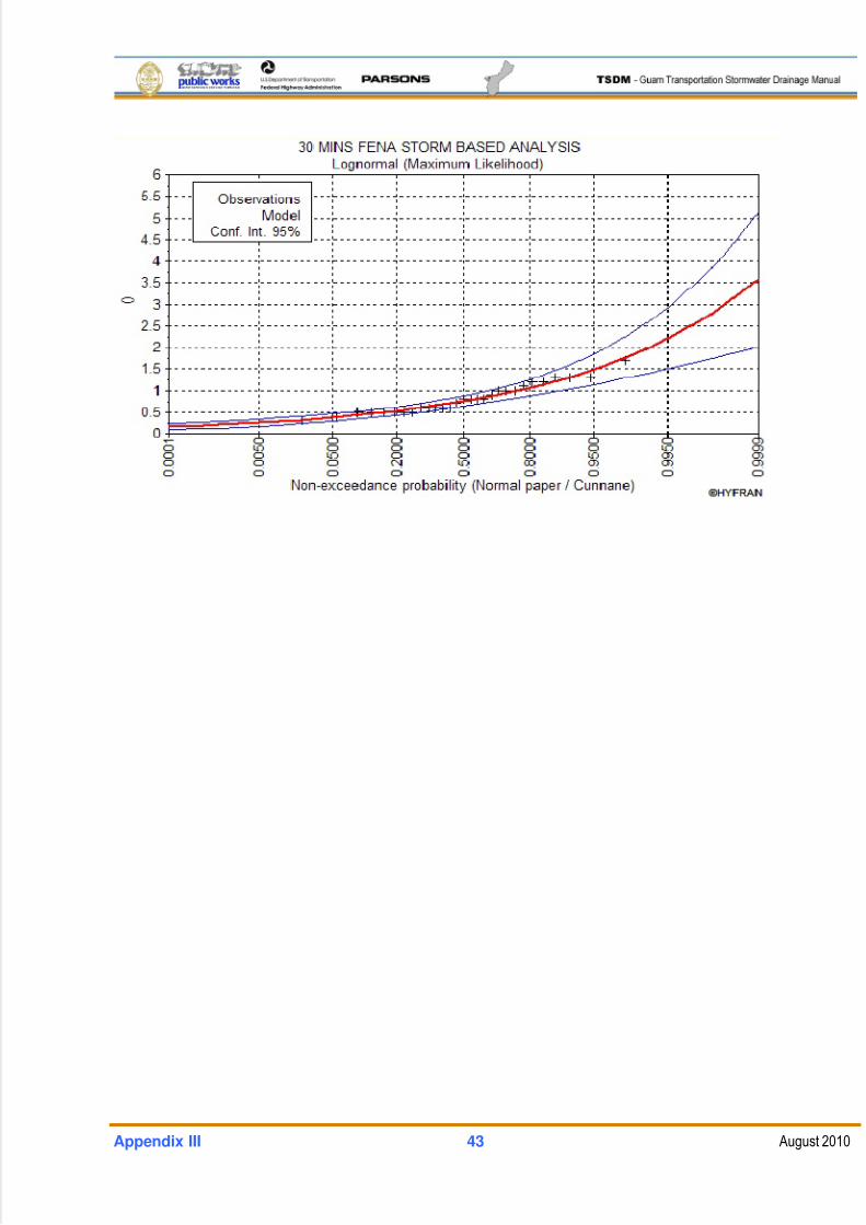
5/13/2018 Guam Storm Water Drainage Manual - slidepdf.com
http://slidepdf.com/reader/full/guam-storm-water-drainage-manual 483/486
Appendix III 43 August 2010
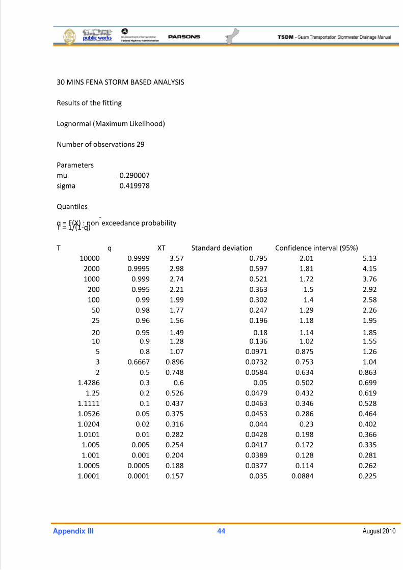
5/13/2018 Guam Storm Water Drainage Manual - slidepdf.com
http://slidepdf.com/reader/full/guam-storm-water-drainage-manual 484/486
Appendix III 44 August 2010
30 MINS FENA STORM BASED ANALYSIS
Results of the fitting
Lognormal (Maximum Likelihood)
Number of observations 29
Parameters
mu ‐0.290007
sigma 0.419978
Quantiles
q
=
F(X)
:
non‐
exceedance
probability
T = 1/(1‐q)
T q XT Standard deviation Confidence interval (95%)
10000 0.9999 3.57 0.795 2.01 5.13
2000 0.9995 2.98 0.597 1.81 4.15
1000 0.999 2.74 0.521 1.72 3.76
200 0.995 2.21 0.363 1.5 2.92
100 0.99 1.99 0.302 1.4 2.58
50 0.98 1.77 0.247 1.29 2.26
25 0.96 1.56 0.196 1.18 1.95
20
0.95
1.49
0.18 1.14
1.85
10 0.9 1.28 0.136 1.02 1.55
5 0.8 1.07 0.0971 0.875 1.26
3 0.6667 0.896 0.0732 0.753 1.04
2 0.5 0.748 0.0584 0.634 0.863
1.4286 0.3 0.6 0.05 0.502 0.699
1.25 0.2 0.526 0.0479 0.432 0.619
1.1111 0.1 0.437 0.0463 0.346 0.528
1.0526 0.05 0.375 0.0453 0.286 0.464
1.0204 0.02 0.316 0.044 0.23 0.402
1.0101 0.01 0.282 0.0428 0.198 0.366
1.005 0.005 0.254 0.0417 0.172 0.335
1.001 0.001 0.204 0.0389 0.128 0.281
1.0005 0.0005 0.188 0.0377 0.114 0.262
1.0001 0.0001 0.157 0.035 0.0884 0.225
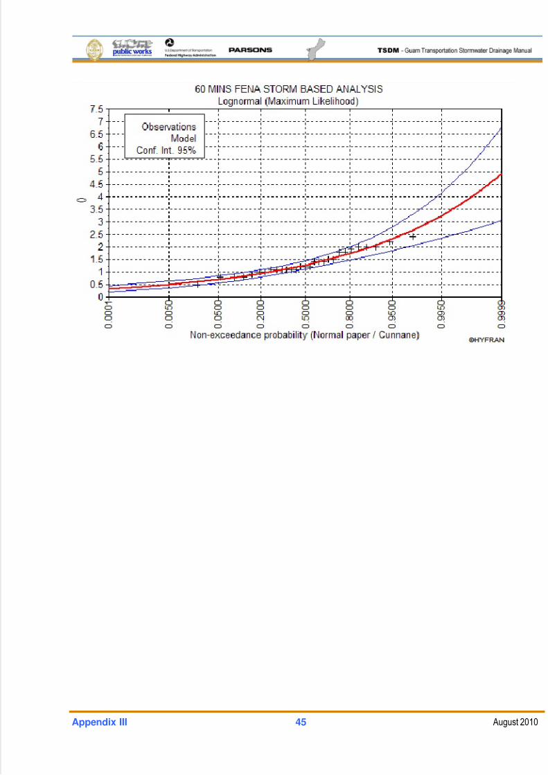
5/13/2018 Guam Storm Water Drainage Manual - slidepdf.com
http://slidepdf.com/reader/full/guam-storm-water-drainage-manual 485/486
Appendix III 45 August 2010
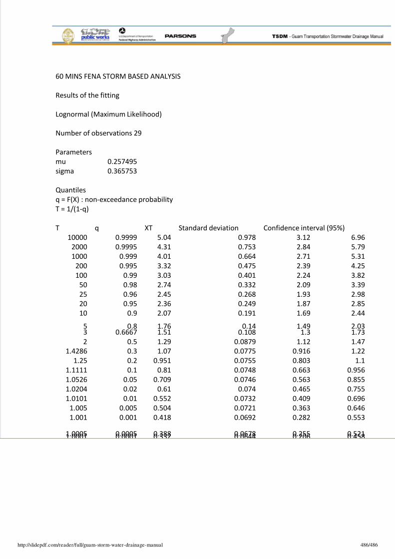
5/13/2018 Guam Storm Water Drainage Manual - slidepdf.com
http://slidepdf.com/reader/full/guam-storm-water-drainage-manual 486/486
60 MINS FENA STORM BASED ANALYSIS
Results of the fitting
Lognormal (Maximum Likelihood)
Number of observations 29
Parameters
mu 0.257495
sigma 0.365753
Quantiles
q = F(X) : non‐exceedance probability
T = 1/(1‐q)
T q XT Standard deviation Confidence interval (95%)
10000 0.9999 5.04 0.978 3.12 6.96
2000 0.9995 4.31 0.753 2.84 5.79
1000 0.999 4.01 0.664 2.71 5.31
200 0.995 3.32 0.475 2.39 4.25
100 0.99 3.03 0.401 2.24 3.82
50 0.98 2.74 0.332 2.09 3.39
25 0.96 2.45 0.268 1.93 2.98
20 0.95 2.36 0.249 1.87 2.85
10 0.9 2.07 0.191 1.69 2.44
5
0.8
1.76
0.14
1.49
2.033 0.6667 1.51 0.108 1.3 1.73
2 0.5 1.29 0.0879 1.12 1.47
1.4286 0.3 1.07 0.0775 0.916 1.22
1.25 0.2 0.951 0.0755 0.803 1.1
1.1111 0.1 0.81 0.0748 0.663 0.956
1.0526 0.05 0.709 0.0746 0.563 0.855
1.0204 0.02 0.61 0.074 0.465 0.755
1.0101 0.01 0.552 0.0732 0.409 0.696
1.005 0.005 0.504 0.0721 0.363 0.646
1.001 0.001 0.418 0.0692 0.282 0.553
1.0005
0.0005
0.388
0.0678
0.255
0.5211.0001 0.0001 0.332 0.0644 0.206 0.458