storm water standards manual
TRANSCRIPT

STORM WATER STANDARDS
January 20, 2012


Storm Water Standards iii
TABLE OF CONTENTS
LIST OF FIGURES ........................................................................................................................................... VI
LIST OF TABLES ............................................................................................................................................. VI
LIST OF ACRONYMS ..................................................................................................................................... VII
1. USE OF THESE STANDARDS ................................................................................................................. 1-1
1.1 Purpose of These Standards ......................................................................................................... 1-1
1.2 When to Apply These Standards ................................................................................................... 1-3
1.3 Applicability of Updated Requirements ........................................................................................ 1-3
2. DETERMINING REQUIREMENTS FOR PERMANENT BEST MANAGEMENT PRACTICES ........................ 2-1
2.1 Priority Development Project ....................................................................................................... 2-1
2.2 Standard Development Project .................................................................................................... 2-6
2.3 Projects Exempt from Requirements for Permanent Best Management Practices ..................... 2-6
3. REQUIRED PERMANENT BEST MANAGEMENT PRACTICES FOR STANDARD DEVELOPMENT PROJECTS3-1
3.1 Source Control BMPs .................................................................................................................... 3-1
3.1.1 Maintenance Bays .............................................................................................................. 3-1
3.1.2 Vehicle and Equipment Wash Areas .................................................................................. 3-1
3.1.3 Outdoor Processing Areas .................................................................................................. 3-2
3.1.4 Retail and Non-Retail Fueling Areas ................................................................................... 3-2
3.1.5 Steep Hillside Landscaping ................................................................................................. 3-2
3.1.6 Use Efficient Irrigation Systems & Landscape Design ........................................................ 3-2
3.1.7 Design Trash Storage Areas to Reduce Pollution Contribution ......................................... 3-3
3.1.8 Design Outdoor Material Storage Areas to Reduce Pollution Contribution ...................... 3-3
3.1.9 Design Loading Docks to Reduce Pollution Contribution .................................................. 3-3
3.1.10 Employ Integrated Pest Management Principles ............................................................... 3-3
3.1.11 Provide Storm Water Conveyance System Stamping and Signage .................................... 3-4
3.1.12 Manage Fire Sprinkler System Discharges ......................................................................... 3-4
3.1.13 Manage Air Conditioning Condensate ............................................................................... 3-4
3.1.14 Use Non-Toxic Roofing Materials Where Feasible: ........................................................... 3-4
3.1.15 Other Source Control Requirements ................................................................................. 3-5
3.2 Low-Impact Development Design Practices ................................................................................. 3-5
3.3 Buffer Measures............................................................................................................................ 3-7
4. REQUIRED PERMANENT BEST MANAGEMENT PRACTICES FOR PRIORITY DEVELOPMENT PROJECTS 4-1
4.1 Required Studies ........................................................................................................................... 4-1
4.1.1 Water Quality Technical Report ......................................................................................... 4-1
4.1.2 Drainage Study ................................................................................................................... 4-1

Storm Water Standards iv
4.1.3 Hydromodification Management Plan ............................................................................... 4-2
4.1.4 Geotechnical Study ............................................................................................................ 4-2
4.1.5 Identification of Anticipated Project Pollutants ................................................................ 4-3
4.1.6 Identification of Pollutants of Concern for the Receiving Water ....................................... 4-4
4.2 Source Control BMPs .................................................................................................................... 4-6
4.2.1 Maintenance Bays .............................................................................................................. 4-6
4.2.2 Vehicle and Equipment Wash Areas .................................................................................. 4-6
4.2.3 Outdoor Processing Areas .................................................................................................. 4-6
4.2.4 Retail and Non-Retail Fueling Areas ................................................................................... 4-7
4.2.5 Steep Hillside Landscaping ................................................................................................. 4-7
4.2.6 Use Efficient Irrigation Systems & Landscape Design ........................................................ 4-7
4.2.7 Design Trash Storage Areas to Reduce Pollution Contribution ......................................... 4-8
4.2.8 Design Outdoor Material Storage Areas to Reduce Pollution Contribution ...................... 4-8
4.2.9 Design Loading Docks to Reduce Pollution Contribution .................................................. 4-8
4.2.10 Employ Integrated Pest Management Principles ............................................................... 4-8
4.2.11 Provide Storm Water Conveyance System Stamping and Signage .................................... 4-9
4.2.12 Manage Fire Sprinkler System Discharges ......................................................................... 4-9
4.2.13 Manage Air Conditioning Condensate ............................................................................... 4-9
4.2.14 Use Non-Toxic Roofing Materials Where Feasible ............................................................. 4-9
4.2.15 Other Source Control Requirements ................................................................................. 4-9
4.3 Low-Impact Development Design Practices ............................................................................... 4-10
4.3.1 Partial List of Suitable Facilities ........................................................................................ 4-10
4.3.2 Additional Guidance on Low-Impact Development Design ............................................. 4-11
4.4 Treatment Control BMPs ............................................................................................................ 4-14
4.4.1 Structural Treatment BMP Selection Procedure.............................................................. 4-15
4.4.2 Restrictions on the Use of Infiltration Treatment BMPs .................................................. 4-16
4.4.3 Structural Treatment Limited Exclusions ......................................................................... 4-17
4.4.4 Numeric Sizing Requirements for Treatment Control BMPs ........................................... 4-18
4.5 Hydromodification Management Requirements ........................................................................ 4-18
4.5.1 HMP Applicability Requirements ..................................................................................... 4-18
4.5.2 Flow Control Performance Criteria .................................................................................. 4-24
4.6 Buffer Measures.......................................................................................................................... 4-34
4.7 Proof of Mechanism for Long-Term Maintenance of Structural Permanent BMPs ................... 4-34
5. CONSTRUCTION STORM WATER BMP PERFORMANCE STANDARDS .................................................. 5-1
5.1 General Requirements for All Construction Projects .................................................................... 5-1
5.1.1 Site Management Requirements ....................................................................................... 5-1
5.1.2 Performance Standards ..................................................................................................... 5-2
5.2 Seasonal Requirements ................................................................................................................ 5-3
5.3 Additional Requirements for Special Situations ........................................................................... 5-4
5.3.1 Maximum Disturbed Area Limitation................................................................................. 5-4

Storm Water Standards v
5.3.2 Advanced Treatment ......................................................................................................... 5-5
5.3.3 Projects Discharging to Impaired or Sensitive Water Bodies ............................................ 5-6
APPENDIX A ................................................................................................................................................... A
Suggested Resources ............................................................................................................................... A
APPENDIX B ................................................................................................................................................... B
Storm Water Requirements Applicability Checklist ................................................................................ B
APPENDIX C ................................................................................................................................................... C
Water Quality Sensitive Areas within the City Of San Diego ................................................................... C
APPENDIX D ................................................................................................................................................... D
Map and Tables........................................................................................................................................ D
APPENDIX E ................................................................................................................................................... E
Example Permanent Storm Water Best Management Practices ............................................................. E
APPENDIX F ................................................................................................................................................... F
Water Quality Technical Report Guidelines ............................................................................................ F
APPENDIX G ................................................................................................................................................... G
Storm Water Pollution Prevention Plan / Water Pollution Control Plan Guidelines ............................... G
APPENDIX H ................................................................................................................................................... H
Example Construction Best Management Practices ................................................................................ H
APPENDIX I ..................................................................................................................................................... I
Low Impact Development Design Guide .................................................................................................. I
APPENDIX J ..................................................................................................................................................... J
Definitions ................................................................................................................................................. J

Storm Water Standards vi
LIST OF FIGURES
Figure 2-1. Flow Chart for Determining Applicability of Redevelopment Rule ................................................................... 2-4
Figure 4-1. HMP Applicability Determination ...................................................................................................................... 4-20
Figure 4-2. Mitigation Criteria and Implementation ........................................................................................................... 4-27
Figure 4-3. Mitigation Criteria and Implementation ........................................................................................................... 4-29
Figure 4-4. SCCWRP Vertical Susceptibility .......................................................................................................................... 4-32
Figure 4-5. Lateral Channel Susceptibility ............................................................................................................................. 4-33
LIST OF TABLES
Table 2-1. Priority Development Project Determination ...................................................................................................... 2-2
Table 4-1. Anticipated and Potential Pollutants Generated by Land Use Type. ................................................................. 4-4
Table 4-2. Probable Pollutants Causing Clean Water Act Section 303(d) Impairment Listing .......................................... 4-5
Table 4-3. Structural BMP Treatment Control Selection Matrix ....................................................................................... 4-16
Table 4-2. Summary of Exempt River Reaches in San Diego County ................................................................................ 4-23
Table 4-3. Summary of Exempt Reservoirs in San Diego County ...................................................................................... 4-24

Storm Water Standards vii
LIST OF ACRONYMS
ADT Average Daily Traffic
BMPs Best Management Practices
BIP BMP Implementation Plan
CASQA California Stormwater Quality Association
CIP Capital Improvement Projects
City’s City of San Diego’s
HMP Hydromodification Management Plan
IMPs Integrated Management Practices
IPM Integrated pest management
LEAD Localized Equivalent Area Drainage
LID Low-Impact Development
NPDES National Pollutant Discharge Elimination System
NOEC no observed effects concentration
NOI Notice of Intent
O&M Operation & Maintenance
PDPs Priority Development Projects
RWQCB Regional Water Quality Control Board
RGOs Retail Gasoline Outlets
SCCWRP Southern California Coastal Water Research Project
SIC Standard Industrial Classification
SUSMP Standard Urban Storm Water Mitigation Plan
SWPPP Storm Water Pollution Prevention Plan
TAC Technical Advisory Committee
TMDL Total Maximum Daily Loads
WPCP Water Pollution Control Plan
WQTR Water Quality Technical Report

THIS PAGE INTENTIONALLY LEFT BLANK.

1-1
STORM WATER STANDARDS
1. Use of These Standards
This chapter describes the purpose of these standards and how they are to be applied.
1.1 Purpose of These Standards
The City of San Diego’s (City’s) storm water conveyance system, which collects runoff from City streets, rooftops, driveways, parking lots, and other impervious areas, flows directly to local creeks, bays and beaches. Since the City’s storm water conveyance system is separate from the sanitary sewer system, the majority of urban runoff from the City is discharged without any form of treatment.
Runoff conveyed and discharged by municipal storm water systems has been identified by local, regional, and national research programs as one of the principal causes of water quality problems in urban areas such as the City of San Diego. This runoff potentially contains a host of pollutants including trash, debris, bacteria, viruses, oil, grease, sediments, nutrients, metals, and toxic chemicals. These contaminants can adversely affect the beneficial uses of receiving creeks, coastal waters, associated wildlife habitat, and public health. Urban runoff pollution is a problem during rainy seasons and also throughout the year due to urban water uses that discharge non-storm water runoff via dry weather flows to the storm water conveyance system.
Land development and construction activities introduce the following water quality concerns:
Contribution of pollutants to receiving waters based on the creation of new impervious surfaces and the permanent “use” of the project site
Contribution of pollutants to receiving waters based on the removal or change of vegetation during construction
Contribution of pollutant based sediment transport caused by increased impervious cover and the resultant increased erosive force
Significant alteration of drainage patterns
When residential, industrial, office, or recreational areas are developed, new impervious areas are created (roads, parking lots, structures, etc.). Since the natural landscape’s ability to infiltrate and cleanse urban runoff is “capped” by the impervious surfaces, rainfall that would have normally percolated into the soil is instead converted to runoff that flows directly to downstream creeks, bays, and beaches. This phenomenon is especially pronounced at low intensity rainfall events. Increases in impervious cover can increase the frequency and intensity of storm water flows.
Additionally, new impervious surfaces often become a source of pollutants associated with development. Pollutants such as automotive fluids, cleaning solvents, hazardous chemicals, sediment, metals, pesticides, oil and grease, and food wastes can be conveyed via impervious surfaces to the receiving storm water conveyance system by urban runoff. Such pollutants often flow untreated through the storm water conveyance system and ultimately into the City’s creeks, bays and beaches.

Storm Water Standards 1-2
To mitigate the potential for pollution from urban runoff, local, state, and federal agencies have instituted regulations requiring development planning and BMP structural controls for construction and post-construction phases of a proposed project. These standards require treatment of storm water-related pollution from development and redevelopment projects prior to discharge to receiving waters.
The Municipal Storm Water National Pollutant Discharge Elimination System (NPDES) Permit – or Municipal Permit - was issued by the San Diego Regional Water Quality Control Board (RWQCB) on January 24, 2007 to the City, the County of San Diego, the Port of San Diego, and 18 other regional Copermittees (see Suggested Resources in Appendix A). Per the Permit order, the San Diego Copermittees are required to develop and implement storm water pollution regulations for private and public development projects. These regulations include requirements for Low-Impact Development (LID) design approaches and development of a Hydromodification Management Plan (HMP) to mitigate development-related erosion of receiving creeks and rivers.
To comply with the Permit, development projects are required to include storm water Best Management Practices (BMPs) during both the construction and post-construction (permanent) phase of the project. These BMPs shall be designed to reduce pollutants discharged from the project site to the maximum extent practicable (see Appendix E for examples of permanent BMPs and see Appendix H for examples of construction BMPs).
The San Diego Regional Copermittees, including the City, are required to adopt a municipal-specific local Standard Urban Storm Water Mitigation Plan (SUSMP) and ordinances consistent with the RWQCB approved Model SUSMP within 360 days of the Model SUSMP approval (Model SUSMP was approved on March 24, 2009).
The Countywide Model SUSMP (see Suggested Resources in Appendix A) is the general model for compliance with the land development requirements within the Municipal Permit. Each municipality has latitude in determining how to conform to this model standard. The approved Model SUSMP is available at the County of San Diego offices, or online at www.projectcleanwater.org.
This manual significantly conforms to the Model SUSMP and will continue to be used in its present forms until the next required permit update. The approved Model SUSMP contains useful methodologies which may be used to assist in the design of LID facilities in complying with this manual (see Appendix I for the Model SUSMP’s LID Design Guide). Specifically, the “design documentation procedure” and “design sheets” for specific LID facilities may be used as a supplement to this manual.
As part of the Model SUSMP development process, the Copermittees collectively reviewed and updated BMP and LID requirements. Applicable SUSMP requirements are incorporated into Priority Project plans as part of the development plan approval process for discretionary projects. Similar requirements are incorporated into City capital improvement projects (CIP).
The primary objectives of the Storm Water Standards manual are as follows:
Prohibit non-storm water discharges.
Reduce the discharge of pollutants to storm water conveyance systems to the maximum extent practicable by implementing BMPs during the project’s construction and post-development (permanent) phases.
Provide consistency with the Model SUSMP approved on March 24, 2009.

Storm Water Standards 1-3
Provide guidance for proper implementation of LID facilities and design approaches.
Provide guidance for conformance with regional hydromodification management requirements.
1.2 When to Apply These Standards
This manual provides processing information related to permanent and construction phase storm water quality requirements for the following project types and phases:
Private projects processed through the Development Services Department
Public capital improvements projects processed through the Engineering and Capital Projects Department
Ongoing maintenance efforts, associated with permanent storm water facilities, to be coordinated by the Operations and Maintenance Department
This manual further guides the project applicant through the selection, design, and incorporation of storm water BMPs into the project’s design plan.
1.3 Applicability of Updated Requirements
Construction BMPs
Updated requirements for construction BMPs shall apply to all construction sites that are active at the time of the updated requirement, and to all subsequent construction activity.
Permanent BMPS
The updated requirements for permanent BMPs shall apply to all projects that have not begun grading or construction activities on or prior to the following effective dates:
Storm Water Standards Updates effective as of March 24, 2008
New requirement to include Low-Impact Development principles in the project design
New requirement to use only those treatment control BMPs that are rated Medium or higher for removal efficiencies for the primary pollutants of concern
New requirement to include hydromodification controls for projects greater than 50 acres
Storm Water Standards updates effective as of January 14, 2011
Updated hydromodification control requirements based on the Hydromodification Management Plan (HMP) approved by the Regional Water Quality Control Board on July 14, 2010, to be applied to all Priority Development Projects regardless of size unless qualifying for an exemption allowed within the approved HMP.
The above applicability timeline is effective unless the project has a lawful prior approval, whereby application of the updated storm water standards to the project is infeasible as determined by the Development Services Director.

2-1
STORM WATER STANDARDS
2. Determining Requirements for Permanent Best
Management Practices
Requirements for permanent BMPs are determined based on criteria set forth in the City’s Storm Water Requirements Applicability Checklist. Projects are identified by three categories:
Priority Development Project (see Section 2.1)
Standard Development Project (see Section 2.2)
Exempt (see Section 2.3)
Project applicants must complete the “Storm Water Requirements Applicability Checklist” in Appendix B1 to determine if their project is subject to permanent and construction storm water BMP requirements. This form must be completed for all permit applications, even if previous approvals exist. The checklist must be signed by the responsible party for the project and submitted with the permit application.
Applicants may verify the project’s storm water BMP requirements through a single discipline preliminary review of the project (see Development Services Department Information Bulletin No. 513). The project design must include all required permanent BMPs (as determined from the Storm Water Requirements Applicability Checklist) prior to deeming the application package complete.
2.1 Priority Development Project
The Municipal Permit requires specific criteria be applied to Priority Development Projects (PDPs). Table 2-1 below, which reflects criteria in the Storm Water Requirements Applicability Checklist, describes criteria used to classify projects as PDPs. Proposed projects on previously undeveloped land are classified as PDPs if they satisfy one or more of the categories listed in Table 2-1.
1 The Storm Water Requirements Applicability Checklist may also be obtained from the Development Services
Department’s Development Process: Step-by-Step website http://www.sandiego.gov/development-services/devprocess/define/application.shtml

Storm Water Standards 2-2
Table 2-1. Priority Development Project Determination
Yes No Is the project in any of these categories?
Residential development of 10 or more dwelling units. Examples: single-family homes, multi-family homes, condominiums, and apartments.
Commercial development and similar non-residential development greater than one acre. Examples: hospitals; laboratories and other medical facilities; educational institutions; recreational facilities; municipal facilities; commercial nurseries; multi-apartment buildings; car wash facilities; mini-malls and other business complexes; shopping malls; hotels; office buildings; public warehouses; automotive dealerships; airfields; and other light industrial facilities.
Heavy industrial development greater than one acre. Examples: manufacturing plants, food processing plants, metal working facilities, printing plants, and fleet storage areas (bus, truck, etc.).
Automotive repair shop. A facility categorized in any one of Standard Industrial Classification (SIC) codes 5013, 5014, 5541, 7532-7534, or 7536-7539.
Restaurant. Any facility that sells prepared foods and drinks for consumption, including stationary lunch counters and refreshment stands selling prepared foods and drinks for immediate consumption (SIC code 5812), and where the land area for development is greater than 5,000 square feet.
Hillside development greater than 5,000 square feet. Any development that creates 5,000 square feet of impervious surface and is located in an area with known erosive soil conditions and where the development will grade on any natural slope that is twenty-five percent or greater.
Water Quality Sensitive Area. All development located within, directly adjacent to, or discharging directly to a Water Quality Sensitive Area (as depicted in Appendix C) in which the project either creates 2,500 square feet of impervious surface on a proposed project site or increases the area of imperviousness of a proposed project site to 10% or more of its naturally occurring condition. “Directly adjacent” is defined as being situated within 200 feet of the Water Quality Sensitive Area. “Discharging directly to” is defined as outflow from a drainage conveyance system that is composed entirely of flows from the subject development or redevelopment site, and not commingled with flows from adjacent lands.
Parking lot with a minimum area of 5,000 square feet or a minimum of 15 parking spaces and potential exposure to urban runoff (unless it meets the exclusion for parking lot reconfiguration on line 11).
Street, road, highway, or freeway. Any new paved surface in excess of 5,000 square feet used for the transportation of automobiles, trucks, motorcycles, and other vehicles (unless it meets the exclusion for road reconfiguration on line 11).
Retail Gasoline Outlet (RGO) that is: (a) 5,000 square feet or more or (b) have a projected Average Daily Traffic (ADT) of 100 or more vehicles per day.
Significant Redevelopment; the project installs and/or replaces 5,000 square feet or more of impervious surface and the existing site meets at least one of the categories above. The project is not considered Significant Redevelopment if reconfiguring an existing road or parking lot without a change to the footprint of an existing developed road or parking lot. The existing footprint is defined as the outside curb or the outside edge of pavement when there is no curb.
Other Pollutant Generating Project. Any other project not covered in the categories above, that disturbs one acre or more and is not excluded by the criteria below.
Exclusions that apply to line 12 only: Projects creating less than 5,000 sf of impervious surface and where any added landscaping does not require regular use of pesticides and fertilizers, such as a slope stabilization project using native plants, are excluded from this category. Calculation of the square footage of impervious surface need not include linear pathways that are for infrequent vehicle use, such as for emergency or maintenance access or for bicycle or pedestrian use, if they are built with pervious surfaces or if they sheet flow to surrounding pervious surfaces

Storm Water Standards 2-3
To use Table 2-1, review each definition A through J. If any of the definitions match the proposed project, the project is a Priority Development Project. Note the following:
Some thresholds are defined by square footage of impervious area created while others are defined by the total area of the proposed development.
The City of San Diego may choose to designate projects not satisfying categories in Table 2-1 as PDPs, based on potential impacts to stormwater quality.
If a new development project feature such as a parking lot falls into a Priority Development Project category, then the entire project footprint is subject to Priority Development Project requirements.
Redevelopment projects on previously developed sites are classified as PDPs if they meet all of the following criteria:
If the project creates, adds, or replaces 5,000 square feet or more of impervious surface
If the project definition matches any of the categories (A-J) listed in Table 2-1
Projects on previously developed sites may also need to retrofit storm water BMPs to treat runoff from all impervious areas of the entire site. For sites creating or replacing more than 5,000 square feet of impervious area, the “50% Rule” for previously developed projects would be in effect:
If the new project increases or replaces 50 percent or more of the previously existing impervious surface and storm water BMP requirements did not apply to the existing development, then the entire project must be included in a retrofit BMP treatment design.
If less than 50 percent of the previously existing impervious surface is increased or replaced, only new impervious area must be included in the BMP treatment design.
Figure 2-1 below outlines the process for determining whether a proposed redevelopment project is a Priority Development Project, Standard Development Project, or exempt from implementing permanent BMPs.
Effective January 24, 2010, the Municipal Permit requires additional projects to be subject to the Priority Development Project requirements for permanent BMPs. These additional PDPs shall include all other pollutant generating development projects that result in the disturbance of one acre or more of land. The Permit further defines “pollutant generating development projects” as those projects that generate pollutants at levels greater than background levels.
This additional requirement will apply to all development project deemed complete after January 24, 2010 or to Capital Improvement Projects for which design was initiated after January 24, 2010. Projects not considered to be new development or significant redevelopment (according to Definition provided in Appendix J of this manual) are excluded from this rule.
Generally, most projects which include impervious surfaces and/or incorporate landscaping that requires the use of fertilizers or pesticides are considered to generate pollutants above background levels. In most cases, linear pathway projects designed for infrequent vehicle use (such as emergency or maintenance access) or pedestrian or bicycle use are not considered to generate pollutants above background levels if they are built with pervious surfaces or if they sheet flow to pervious surfaces prior to discharge to receiving waters.

Storm Water Standards 2-4
Requirements for PDPs are presented in Chapter 4 of this manual. PDPs are required to prepare a Water Quality Technical Report (WQTR) and guidelines for WQTR preparation are provided in Appendix F of this manual.
Figure 2-1. Flow Chart for Determining Applicability of Redevelopment Rule

Storm Water Standards 2-5
Note 1 – Projects that qualify as routine maintenance are those projects that only replace or renewexisting impervious cover because of failed or deteriorating condition. Typically this includes roofreplacement, pavement spot repairs and resurfacing treatments, and the replacement of damaged pavement. It also includes restoring pavement as part of an underground utility project and restriping of roads and parking lots. These projects are exempt. Projects that combine pavementreplacement with other improvements are not exempt.
Note 2 – Projects that ONLY add sidewalk, pedestrian ramps, and/or bike lanes to an existing road are not considered "significant redevelopment" and therefore are not considered Priority DevelopmentProjects. This is provided for in the definition of "redevelopment" provided in the municipal permit(RWQCB Order No. R9-2007-001, Attachment C). These types of projects are subject to the Standard Project requirements. Note 3 – If the existing condition is sheet flow, and the proposed condition is concentrated flow, thenincreased concentrated runoff needs to be mitigated by meeting Standard Development Project sitedesign requirements. An example would be adding curb, gutter and sidewalk to an unimproved road
shoulder which previously dispersed sheet runoff to the unpaved road edge.
Note 4 – The existing footprint is defined as the outside curb of the road or parking lot, or the outsideedge of road or parking lot pavement if there is no curb. A road or parking lot project that does not gobeyond this footprint is considered "reconfiguration of existing roads and parking lots" in accordance with the definition of "redevelopment" provided in the municipal permit (RWQCB Order No.R9-2007-001, Attachment C). Projects that do not go beyond this footprint are not considered Priority Development Projects, but are subject to the Standard Project requirements.
Note 5 – The list of Priority Development catefories is provided in Section 1,Part A, of the Storm
Water Requirements Applicability Checklist (DSD Form-560).
Note 6 – For projects not already determined to be exempt by the above criteria, determine if theproject installs and/or replaces at least 5,000 s.f. of impervious surface. the square footage is ti be calculated for all impervious surfaces installed by the project, regardless of whether it is imperviousor not in the existing condition. In this case, sidewalks, bike lanes and pedestrian ramps will also beapart of the calculation.

Storm Water Standards 2-6
2.2 Standard Development Project
Standard Development Projects include all projects not considered to be PDPs as defined in Section 2.1 and that do not qualify as an exempt project as defined in Section 2.3.
Redevelopment projects on previously developed sites are classified as Standard Development Projects if they meet all of the following criteria:
If the project does not quality as a Priority Development Project as detailed in Section 2.1
If the project is not exempt from requirements for permanent BMPs as detailed in Section 2.3
Requirements for Standard Development Projects are presented in Chapter 3 of this manual. Standard Development Projects are required to prepare a Water Pollution Control Plan (WPCP) and guidelines for WPCP preparation are provided in Appendix G of this manual.
2.3 Projects Exempt from Requirements for Permanent Best Management
Practices
Requirements for permanent storm water BMPs are intended for land development, redevelopment, and capital improvements PDPs (Section 2.1) and Standard Development Projects (Section 2.2). Exempted projects include the following:
Routine maintenance or repair projects, such as pothole repairs
Routine replacement of roofs or exterior structure surfaces
Routine pavement resurfacing
Trenching and resurfacing associated with utility work
Interior remodels
Redevelopment projects that only install sidewalks, bike lanes, or pedestrian ramps on an existing road and do not change sheet flow condition to a concentrated flow condition (see Figure 2-1).
It should be noted the other requirements, such as source control BMP measures, still apply to the exempted project types listed above. See the Definitions section in Appendix J for further definition of these exempted categories.

THIS PAGE INTENTIONALLY LEFT BLANK.

Storm Water Standards 3-1
STORM WATER STANDARDS
3. Required Permanent Best Management Practices for
Standard Development Projects
Standard Development Projects are subject to all requirements detailed in this chapter. Through application of these requirements the project applicant shall ensure that the project:
Reduces discharges of pollutants to the City storm water conveyance system to the maximum extent practicable
Does not cause or contribute to the violation of water quality standards in the receiving waters.
3.1 Source Control BMPs
Some everyday activities, such as trash recycling and disposal and the washing of vehicles and equipment, generate pollutants that eventually drain to the storm water conveyance system. These pollutants can be minimized by applying source control BMPs.
Such source control BMPs include permanent, structural features incorporated into the project plans as well as operational BMPs, including regular street sweeping and “good housekeeping” practices, which must be implemented by the site’s occupant or user.
Standard Development Projects must detail source control BMPs to be incorporated into the project design or long-term project operations plan. Required source control BMPs are outlined below. Where the project scope involves minor improvements to an existing development, the feasibility of meeting these source control standards may be evaluated at on a case-by-case basis.
3.1.1 Maintenance Bays
Maintenance bays shall include at least one of the following:
Repair/ maintenance bays shall be indoors; or,
Drainage system designed to preclude urban run-on and runoff.
Maintenance bays shall include a repair/maintenance bay drainage system to capture all wash water, leaks, and spills. Drains shall be connected to a sump for collection and disposal. Direct connection of the repair/maintenance bays to the storm water conveyance system is prohibited.
3.1.2 Vehicle and Equipment Wash Areas
Areas for washing/steam cleaning of vehicles and areas for outdoor equipment/accessory washing and steam cleaning shall be:
Self-contained to preclude run-on and run-off, covered with a roof or overhang, and equipped with a clarifier or other pretreatment facility; and
Properly connected to a sanitary sewer.

Storm Water Standards 3-2
3.1.3 Outdoor Processing Areas
Outdoor processing areas shall:
Cover or enclose areas that would be the most significant source of pollutants;
Slope the area toward a dead-end sump; or
Discharge to the sanitary sewer system.
Berms or site grading shall be utilized to prevent run-on from surrounding areas. Installation of storm drains in areas of equipment repair is prohibited.
3.1.4 Retail and Non-Retail Fueling Areas
Retail and non-retail fueling areas shall be:
Paved with Portland cement concrete or equivalent smooth impervious surface (asphalt concrete is prohibited);
Designed to extend 6.5 feet (2.0 meters) from the corner of each fuel dispenser, or the length at which the hose and nozzle assembly may be operated plus 1 foot (0.3 meter), whichever is less;
Sloped to prevent ponding;
Separated from the rest of the site by a grade break that prevents run-on of adjacent urban runoff; and
Designed to drain to the project's treatment control BMP(s) prior to discharging to the storm water conveyance system.
The overhanging roof structure or canopy shall be:
Equal to or greater than the area within the fuel dispensing area's grade break; and
Designed to drain away form the fuel dispensing area.
3.1.5 Steep Hillside Landscaping
Steep hillside areas disturbed by project development shall be landscaped with deep-rooted, drought tolerant and/or native plant species selected for erosion control, in accordance with the Landscape Technical Manual.
3.1.6 Use Efficient Irrigation Systems & Landscape Design
Implement rain shutoff devices to prevent irrigation during and after precipitation events in accordance with Section 2.3-4 of the City of San Diego’s Landscape Standards (see Suggested Resources in Appendix A).
Reduce irrigation contribution to dry-weather runoff by avoiding spray irrigation patterns where overspray to paved surfaces or drain inlets will occur.
To avoid overwatering and potential irrigation runoff, design irrigation systems to each landscape area's specific water requirement.
Implement flow reducers or shutoff valves triggered by a pressure drop to control water loss in the event of broken sprinkler heads or lines.

Storm Water Standards 3-3
Avoid locating drain inlets in lawn areas, since such inlets tend to be sources or irrigation runoff and the transport mechanism for lawn care products. Design the grading and drainage systems such that drain inlets can be located outside of the lawn area, or include a non-turf buffer around the inlet.
3.1.7 Design Trash Storage Areas to Reduce Pollution Contribution
Trash storage areas shall:
Be paved with an impervious surface designed to prevent run-on from adjoining areas and screened or walled to prevent off-site transport of trash.
Contain attached lids on all trash containers to prevent rainfall intrusion.
Contain a roof or awning, at the discretion of the City, for high usage trash areas such as those for fast food establishments, convenience stores, and high-density residential developments.
3.1.8 Design Outdoor Material Storage Areas to Reduce Pollution Contribution
Materials with the potential to contaminate urban runoff shall be:
Placed in an enclosure such as a cabinet, shed, or other structure that prevents contact with rainfall or runoff and prevents spillage to the storm water conveyance system.
Protected by secondary containment structures such as berms, dikes, or curbs when the material storage area includes hazardous materials. The storage area shall be paved and sufficiently impervious to contain leaks and spills and be covered by a roof or awning to minimize direct precipitation within the secondary containment area.
3.1.9 Design Loading Docks to Reduce Pollution Contribution
Loading docks areas shall:
Provide overhead cover where appropriate to prevent precipitation contact with debris and potential spills.
Isolate drainage in the loading dock area through the use of paved berms and/or grade breaks to prevent adjacent runoff from entering the loading area and to prevent liquid spills from discharging from the loading area.
Include an acceptable method of spill containment such as a shut-off valve and containment areas.
3.1.10 Employ Integrated Pest Management Principles
Integrated pest management (IPM) is an ecosystem-based pollution prevention strategy that focuses on long-term prevention of pests or their damage through a combination of techniques such as:
Biological control
Habitat manipulation
Use of resistant plant varieties

Storm Water Standards 3-4
Pesticides are used only after monitoring indicates they are needed according to established guidelines. Pest control materials are selected and applied in a manner that minimizes risks to human health, beneficial and non-target organisms, and the surrounding environment. More information regarding pesticide application may be obtained at the following University of California-Davis website: http://www.ipm.ucdavis.edu/WATER/U/index.html.
To eliminate or reduce the need for pesticide use, the following strategies can be used:
Plant pest-resistant or well-adapted plant varieties
Discourage pests by modifying the site and landscaping design
IPM educational materials should be distributed to future site residents and tenants. These educational materials should address the following:
Use of barriers, screens, and caulking to keep pests out of buildings and landscaping
Physical pest elimination techniques, such as weeding, washing , or trapping pests
Relying on natural enemies to eliminate pests
Proper use of pesticides as a last line of defense
3.1.11 Provide Storm Water Conveyance System Stamping and Signage
Concrete stamping, or approved equivalent method, shall be provided for all storm water conveyance system inlets and catch basins within the project area.
Language associated with the stamping (e.g., “No Dumping – I Live in San Diego Bay”) must be satisfactory to the City Engineer. Stamping may also be required in Spanish.
Post signs and prohibitive language (with graphical icons) which prohibit illegal dumping at trailheads, parks, building entrances and public access points along channels and creeks within the project area.
3.1.12 Manage Fire Sprinkler System Discharges
For new buildings with fire sprinkler systems, design fire sprinkler systems as follows:
Contain discharges from sprinkler systems’ operational maintenance and testing and convey discharges to the sanitary sewer system.
3.1.13 Manage Air Conditioning Condensate
Air conditioning condensate is a source of dry-weather runoff and elevated copper levels. Include design features to manage this pollutant source, such as the following:
Direct air conditioning condensate to the sanitary sewer system
Direct air conditioning condensate to landscaping areas
3.1.14 Use Non-Toxic Roofing Materials Where Feasible:
Avoid the use of galvanized steel or copper for roofs, gutters, and downspouts
If using such materials, reduce the potential for leaching of metals by applying a coating or patina
Avoid composite roofing materials that contain copper

Storm Water Standards 3-5
3.1.15 Other Source Control Requirements
Require implementation of post-construction soil stabilization practices, such as the re-vegetation of construction sites, in conformance with the approved Landscaping Plan and Grading Plans.
Provide for pet waste collection dispensers where applicable.
Provide trash receptacles in areas of high pedestrian traffic and in front of retail convenience stores
3.2 Low-Impact Development Design Practices
All Standard Development Projects shall be subject to the LID BMP requirements detailed in this section. Additional LID requirements will apply to PDPs as outlined in section 4.4.
The objectives of the Standard Development Project LID BMP requirements are to detain and filter runoff using natural features. Storm water retention for storm water reuse represents a potential added benefit of LID facilities, but is not specifically required as part of Standard Development Project LID requirements.
The applicability of Standard Development Project LID BMP requirements varies depending on project characteristics such as development density, site location, or other land use issues. While certain landscaping LID features may be incorporated into a detached residential or commercial project, they may not fit into the development footprint of other projects, such as urban high-rise developments.
Additional information regarding LID design approaches can be found in the Countywide Model SUSMP and the City’s LID Design Manual (see Suggested Resources in Appendix A).
LID strategies for Standard Development Projects include:
1. Optimize the Site Layout
To minimize storm water related impacts, apply the following design principles to the layout of newly developed and redeveloped sites.
Utilize existing topography to optimize the site layout and reduce the need for grading. Development envelopes should be focused in the upper elevations of a site to promote sheet flow and natural surface drainage to BMPs or Integrated Management Practices (IMPs) located at lower elevations of the site (IMPs are discussed in detail in Appendix I of this manual).
Where possible, conform the site layout along natural landforms, avoid excessive grading and disturbance of vegetation and soils, and replicate the site’s natural drainage patterns. Set development sufficiently away from creeks, wetlands, and riparian habitats.
Hillside areas should be considered more sensitive to development practices than flatter areas.
Identify soils with high infiltration capacity and, if possible, locate storm water treatment facilities in these locations. Concentrate development on portions of the site with less permeable soils.
Areas of the site where the erosive potential of the soil is high should be considered more sensitive to development practices than areas of the site where the erosive potential of the soil is lower.
Conserve natural areas and vegetation. Define the development envelope and identify areas most suitable for development and areas that should be left undisturbed. Areas devoid of

Storm Water Standards 3-6
vegetation, including previously graded areas and agricultural fields, and areas of non-native vegetation where receiving waters are not present are typically suitable for development. Conversely, areas of occupied habitat of sensitive species and wetlands areas are typically unsuitable for development.
Preserve significant trees, especially native trees and shrubs, and identify locations for planting additional native or drought tolerant trees and large shrubs.
2. Minimize Impervious Footprint
For all types of development, limit the overall coverage of paving and roofs. Examine the site layout and circulation patterns to identify areas where landscaping areas can replace areas of proposed pavement.
Increase building density (number of stories above or below ground) through the design of compact and taller structures.
Construct walkways, trails, patios, overflow parking lots, alleys and other low-traffic areas with permeable surfaces. Such permeable surfaces could include pervious concrete, porous asphalt, unit pavers, etc.
Construct streets, sidewalks and parking lot aisles to the minimum widths necessary, provided that public safety and a walkable environment for pedestrians are not compromised.
Promote the implementation of shared driveways where possible.
Design smaller parking lots with fewer stalls, smaller stalls, more efficient lanes.
Design indoor or underground parking.
Minimize the use of impervious surfaces in the landscape design.
Consider the implementation of permeable pavements into the site design. Identify locations where permeable pavements, such as turf block, unit pavers, pervious concrete, or pervious asphalt could be substituted for impervious concrete or asphalt paving. The Operations and Maintenance Plan for the site must ensure that permeable pavements will not be sealed in the future.
Potential benefits of vegetated or green roofs include lower heating and cooling costs and better sound insulation, in addition to air quality and water quality benefits. For SUSMP compliance purposes, runoff from vegetated roofs requires no further treatment or detention. For more information on vegetated roofs, see www.greenroofs.org.
3. Disperse Runoff to Adjacent Landscaping
Project designs should direct runoff from impervious areas to adjacent landscaping areas. The design, including consideration of slopes and soils, must reflect a reasonable expectation that an inch of rainfall will soak into the soil and produce no runoff.
Minimize directly connected impervious areas as follows:
Drain rooftops into adjacent landscaping areas.
Drain impervious parking lots, sidewalks, walkways, trails, and patios into adjacent landscaping areas.
Reduce or eliminate curb and gutters from roadway sections, thus allowing roadway runoff to drain to adjacent pervious areas.

Storm Water Standards 3-7
Detain and retain runoff throughout the site. On flatter sites, landscaped areas and IMPs can be interspersed among the buildings and pavement areas. On hillside sites, drainage from upper areas may be collected in conventional catch basins and conveyed to landscaped areas and IMPs in lower areas of the site.
Use depressed landscaping areas (also known as Self-Retaining Areas – see Appendix I), vegetated buffers, and bioretention areas as amenities and focal points within the site and landscaping design.
4. Construction Considerations
Minimize soil compaction (see discussion in Countywide Model SUSMP) for landscaped areas of the project site designated for storm water treatment.
Implement soil amendments. Landscape topsoil improvements play a significant role in maintaining plant and lawn health. Such soil amendments also improve the soil’s capacity to retain moisture, which will reduce runoff from the water quality design storm and improve water quality.
Additional information regarding construction considerations is located in the City’s LID Design Manual.
5. Additional Considerations
Stabilize the site. Vegetate disturbed soils and slopes with drought tolerant vegetation and stabilize permanent channel crossings.
Convey runoff safely away from the tops of slopes (to prevent slope instability caused by infiltrated runoff)
Install energy dissipaters, such as riprap, at the outlets of new storm drains, culverts, or channels that discharge to unlined channels in accordance with applicable specifications to reduce the potential for erosion and minimize impacts to receiving waters.
3.3 Buffer Measures
According to the Municipal Permit, buffer zones surrounding natural water bodies should be utilized where feasible. Buffer areas, which can include bioretention areas, provide for reduced site imperviousness and opportunities to incorporate LID facilities into the site and landscape design.
Benefits of buffer zones include the following:
Provides a buffer for aquatic resources from the potential negative impacts of human use of the adjacent land.
Filters nonpoint source pollutants from incoming runoff.
Provides habitat for a balanced, integrated, and adaptive community of riparian and aquatic organisms.
Moderates fluctuations in stream temperature.
Buffer zones should be provided between the edge of the proposed development and the limits of the 100-year floodplain for a distance to be determined by the City. Where buffer zones are infeasible, other buffers such as trees, access restrictions, etc., should be used. Bioretention facilities may be placed in buffer zones, provided that the diffused incoming flow velocity is less than 3 feet per second.

THIS PAGE INTENTIONALLY LEFT BLANK.

Storm Water Standards 4-1
STORM WATER STANDARDS
4. Required Permanent Best Management Practices for
Priority Development Projects
PDPs are subject to all requirements of this chapter, except where specific exclusions are stated. Through application of these requirements the project applicant shall ensure that the project:
Reduces discharges of pollutants to the City storm water conveyance system to the maximum extent practicable.
Does not cause or contribute to violation of water quality standards in the receiving waters.
Manages increases in runoff discharge rates and durations that are likely to cause increased erosion of stream beds and banks, silt pollution generation, or other impacts to beneficial uses and stream habitat due to increased erosive force.
4.1 Required Studies
4.1.1 Water Quality Technical Report
A Water Quality Technical Report is required for submittal with PDPs. Required elements of Water Quality Technical Reports are provided in Appendix F of this manual. Details supporting all decisions made in accordance with Chapter 4 requirements shall be documented in the Water Quality Technical Report.
4.1.2 Drainage Study
A drainage study prepared in accordance with the City of San Diego Drainage Design Manual shall demonstrate runoff calculations for each sized facility listed in the Water Quality Technical Report. The report shall include a map that clearly delineates the drainage areas that accompany the calculations. The following exceptions to the Drainage Design Manual shall apply to the sizing of water quality and hydromodification facilities:
The sizing factor methods presented in this manual may be used in lieu of calculations using the rational method
The storm size will be based on Section 4.4.5 of this manual whenever design requirements specify the “water quality design storm event.”
The continuous simulation modeling methods described in Section 4.5 shall be used whenever performing hydrology studies for hydromodification requirements
The NRCS hydrologic soil group type from a published map, or as determined by a site-specific soil analysis, may be used in rational method calculations
A computerized sizing tool that the City has approved for purposes of sizing these facilities may be used, but adequate documentation of the software version and all input and output parameters must be provided in the report

Storm Water Standards 4-2
Any runoff calculations performed for the purpose of sizing bypass, overflow and flood control facilities should be performed strictly by the methods and storm size requirements described in the Drainage Design Manual.
4.1.3 Hydromodification Management Plan
Required details for project-level HMPs are detailed in section 4.5 of this manual. As detailed in more depth in section 4.5, project applicants will first determine if the proposed project is subject to hydromodification criteria. If applicable, hydromodification management facilities shall be required to mitigate project-related increases to discharge rates and durations.
Projects applicants have the option of designing hydromodification management facilities so that discharge rates and durations are mitigated with the flow range of 10 percent of the 2-year flow to the 10-year flow. If a project applicant believes the receiving channel condition to be more stable than the conservative 0.1Q2 standard, then channel screening tools developed by the Southern California Coastal Water Research Project (SCCWRP) can be used to assess the receiving channel susceptibility to erosion. If the SCCWRP analysis shows the receiving channel to have a Medium or Low Susceptibility to erosion, then higher lower flow thresholds may be used to size the hydromodification management facilities (0.3Q2 or 0.5Q2). The specific process is outlined in the San Diego HMP (see Suggested Resources in Appendix A) and summarized in section 4.5.
4.1.4 Geotechnical Study
The design of any LID or treatment control BMP which allows for infiltration of runoff should be accompanied by geotechnical investigation of the surrounding soils. A Geological Investigation Report should be attached to the Water Quality Technical Report and prepared in conformance with the City of San Diego Technical Guidelines for Geotechnical Reports.
To determine feasibility of a site to infiltrate runoff, the following conditions should be considered.
Is the site subject to high groundwater groundwater conditions (within 10 feet of the base of infiltration facility)?
Is the site is close proximity to contaminated soil or areas that use or store hazardous chemicals or materials?
Is the site constructed on engineered compacted fill (structural fill) subject to hydro-consolidation?
Does the site have infiltration rate less than 0.52 inches/hour1?
Does the site have a clay percentage >20 percent?
Does the site have a silt plus clay percentage >40 percent?
Is the site underlain by impermeable bedrock?
Is the site within 100 feet of a drinking water well?
Is the site within 100 feet of an on-site septic system or designated expansion area?
Does the site have slopes steeper than 25 percent (4 horizontal to 1 vertical)?
Is the site near slopes prone to instability?
1 Stormwater Best Management Practice Design Guide, 2004, EPA/600/R-04/121B http://www.epa.gov/nrmrl/pubs/600r04121/600r04121b.pdf

Storm Water Standards 4-3
If the answer to any of questions 1-11 above is “Yes,” then the site is infeasible for infiltration and infiltration-based facilities should not be constructed.
If the answers to questions 1-11 are all “No,” then the site may be feasible for infiltration and a Geotechnical Investigation Report should be prepared in conformance with Appendix F of the City’s Geotechnical Guidelines.
The Geotechnical Investigation Report shall:
Identify areas of the project site where infiltration is likely to be feasible and provide justifications for selection of those areas based on soil types, slopes, proximity to existing features, etc.
Investigate, evaluate and estimate the vertical infiltration rates and capacities. The site may be broken into sub-basins, each of which has different infiltration rates or capacities. Develop potential infiltration rates and capacities at the sub-basins to be used for design.
Investigate and estimate the lateral migration rates and pathways of infiltrated water.
Investigate the subsurface geological conditions and geotechnical conditions that would affect infiltration or migration of water toward structures, slopes, utilities, or other features.
Investigate depth to groundwater and the nature of the groundwater. Include an estimate of the high seasonal groundwater elevations.
Estimate the maximum allowable infiltration rates and volumes that could occur at the site that would avoid damage to existing and proposed structures, utilities, slopes, or other features.
Provide guidance for the selection and location of infiltration BMPs, including the minimum separations between such infiltration BMPs and structures, streets, utilities, manufactured and existing slopes, engineered fills, utilities or other features. Include guidance for measures that could be used to reduce the minimum separations or to mitigate the potential impacts of infiltration BMPs.
Where the site evaluation indicates potential feasibility for on-site stormwater infiltration, field investigation will be necessary to demonstrate suitability. Details for subsurface exploration and testing for stormwater infiltration BMPs are included in Appendix F of the Geotechnical Guidelines.
4.1.5 Identification of Anticipated Project Pollutants
Using Table 4-1 below, identify the project’s anticipated pollutants by determining which general project category most closely fits the proposed project type. Projects meeting the definition of more than one general project categories shall identify all general pollutant categories that apply. Descriptions of the general pollutant categories listed in Table 4-1 are listed in Appendix J under the definition of “pollutants of concern.”
Designations in Table 4-1 are consistent with the corresponding table in the Countywide Model SUSMP.

Storm Water Standards 4-4
Table 4-1. Anticipated and Potential Pollutants Generated by Land Use Type.
General Project Categories
General Pollutant Categories
Sediments Nutrients Heavy Metals
Organic Compounds
Trash &
Debris
Oxygen Demanding Substances
Oil & Grease
Bacteria &
Viruses Pesticides
Detached Residential Housing Development
X X X X X X X
Attached Residential Development
X X X P(1) P(2) P X
Commercial Development
P(1) P(1) X P(2) X P(5) X P(3) P(5)
Industrial Development
X X X X X X
Automotive Repair Shops
X X(4)(5) X X
Restaurants X X X X P(1)
Steep Hillside Developments
X X X X X X
Parking Lots P(1) P(1) X X P(1) X P(1)
Streets, Highways & Freeways
X P(1) X X(4) X P(5) X X P(1)
Retail Gasoline Outlets (RGO)
X X X X X
X = anticipated
P = potential
(1) A potential pollutant if landscaping exists on-site.
(2) A potential pollutant if the project includes uncovered parking areas.
(3) A potential pollutant if land use involves food or animal waste products.
(4) Including petroleum hydrocarbons.
(5) Including solvents.
4.1.6 Identification of Pollutants of Concern for the Receiving Water
For PDPs, the following analysis shall be conducted and reported in the project’s Water Quality Technical Report:
For each of the proposed project discharge points, identify the receiving waters (including hydrologic unit basin numbers) as identified in the most recent version of the Water Quality Control Plan for the San Diego Basin2, prepared by the RWQCB (see Suggested Resources in Appendix A).
2 To view a copy of the Basin Plan, go to: http://www.swrcb.ca.gov/rwqcb9/programs/basinplan.html

Storm Water Standards 4-5
Identify any receiving waters included in the 2006 CWA Section 303(d) List of Water Quality Limited Segments3, approved by the State Water Resources Control Board on October 25, 2006. List all pollutants for which the receiving waters are impaired. To assist in determining a project’s pollutants of concern, the City created a reference map showing 303d listed water bodies and associated pollutants. This map, titled, “2006 Clean Water Act Section 303(d) Water Quality Limited Segments,” is provided for reference on the SANGIS website4. A reduced copy of the map is also included in Appendix D.
Identify any receiving waters for which Total Maximum Daily Loads (TMDL) have been developed. List all pollutants for which the TMDL was developed.
Note: Some 303(d) listings do not identify a pollutant causing impairment, but instead identify a condition, such as Eutrophic, Benthic Community Degradation, Toxicity, or Sediment Toxicity. To assist in determining the pollutant that would likely cause the 303(d) listing, the following table identifies probable pollutants associated with impairments identified in 2006 CWA Section 303(d) List of Water Quality Limited Segments.
Table 4-2. Probable Pollutants Causing Clean Water Act Section 303(d) Impairment Listing
Probable Pollutants
303(d) Impairment Listing
Eutrophic Benthic
Community Degradation
Sediment Toxicity
Toxicity (in Storm Water
Runoff)
Low Dissolved Oxygen
Sediment
Nutrients X X
Heavy Metals X X
Organic Compounds X X X
Trash and Debris X
Oxygen Demanding Substances X X
Oil and Grease
Bacteria and Viruses
Pesticides X
3 To view the 2006 303(d) List of Impaired Water Bodies, go to:
www.waterboards.ca.gov/tmdl/303d_lists2006.html 4 To view the City’s map titled, “(To be updated) 2006 Clean Water Act Section 303(d) Water Quality Limited
Segments,” go to: www.sangis.org

Storm Water Standards 4-6
4.2 Source Control BMPs
Some everyday activities, such as trash recycling and disposal and the washing of vehicles and equipment, generate pollutants that eventually drain to the storm water conveyance system. These pollutants can be minimized by applying source control BMPs.
Such source control BMPs include permanent, structural features incorporated into the project plans as well as operational BMPs, including regular street sweeping and “good housekeeping” practices, which must be implemented by the site’s occupant or user.
PDPs must detail source control BMPs to be incorporated into the project design or long-term project operations plan. Required source control BMPs are outlined below.
Projects shall adhere to each of the individual Priority Development Project category requirements that apply to the project (e.g., a restaurant with more than 15 parking spaces could be required to incorporate the requirements for Dock Areas, Equipment Wash Areas, and Surface Parking Areas’ into the project design).
4.2.1 Maintenance Bays
Maintenance bays shall include at least one of the following:
Repair/ maintenance bays shall be indoors; or,
Drainage system designed to preclude urban run-on and runoff.
Maintenance bays shall include a repair/maintenance bay drainage system to capture all wash water, leaks, and spills. Drains shall be connected to a sump for collection and disposal. Direct connection of the repair/maintenance bays to the storm water conveyance system is prohibited.
4.2.2 Vehicle and Equipment Wash Areas
Areas for washing/steam cleaning of vehicles and areas for outdoor equipment/accessory washing and steam cleaning shall be:
Self-contained to preclude run-on and run-off, covered with a roof or overhang, and equipped with a clarifier or other pretreatment facility; and
Properly connected to a sanitary sewer.
4.2.3 Outdoor Processing Areas
Outdoor processing areas shall:
Cover or enclose areas that would be the most significant source of pollutants;
Slope the area toward a dead-end sump; or
Discharge to the sanitary sewer system.
Berms or site grading shall be utilized to prevent run-on from surrounding areas. Installation of storm drains in areas of equipment repair is prohibited.

Storm Water Standards 4-7
4.2.4 Retail and Non-Retail Fueling Areas
Retail and non-retail fueling areas shall be:
Paved with Portland cement concrete or equivalent smooth impervious surface (asphalt concrete is prohibited);
Designed to extend 6.5 feet (2.0 meters) from the corner of each fuel dispenser, or the length at which the hose and nozzle assembly may be operated plus 1 foot (0.3 meter), whichever is less;
Sloped to prevent ponding;
Separated from the rest of the site by a grade break that prevents run-on of adjacent urban runoff; and
Designed to drain to the project's treatment control BMP(s) prior to discharging to the storm water conveyance system.
The overhanging roof structure or canopy shall be:
Equal to or greater than the area within the fuel dispensing area's grade break; and
Designed to drain away from the fuel dispensing area.
4.2.5 Steep Hillside Landscaping
Steep hillside areas disturbed by project development shall be landscaped with deep-rooted, drought tolerant and/or native plant species selected for erosion control, in accordance with the Landscape Technical Manual.
4.2.6 Use Efficient Irrigation Systems & Landscape Design
Implement rain shutoff devices to prevent irrigation during and after precipitation events in accordance with section 2.3-4 of the City of San Diego’s Landscape Standards (see Suggested Resources in Appendix A).
Reduce irrigation contribution to dry-weather runoff by avoiding spray irrigation patterns where overspray to paved surfaces or drain inlets will occur.
To avoid overwatering and potential irrigation runoff, design irrigation systems to each landscape area's specific water requirement.
Implement flow reducers or shutoff valves triggered by a pressure drop to control water loss in the event of broken sprinkler heads or lines.
Avoid locating drain inlets in lawn areas, since such inlets tend to be sources or irrigation runoff and the transport mechanism for lawn care products. Design the grading and drainage systems such that drain inlets can be located outside of the lawn area, or include a non-turf buffer around the inlet.

Storm Water Standards 4-8
4.2.7 Design Trash Storage Areas to Reduce Pollution Contribution
Trash storage areas shall:
Be paved with an impervious surface designed to prevent run-on from adjoining areas and screened or walled to prevent off-site transport of trash.
Contain attached lids on all trash containers to prevent rainfall intrusion.
Contain a roof or awning, at the discretion of the City, for high usage trash areas such as those for fast food establishments, convenience stores, and high-density residential developments.
4.2.8 Design Outdoor Material Storage Areas to Reduce Pollution Contribution
Materials with the potential to contaminate urban runoff shall be:
Placed in an enclosure such as a cabinet, shed, or other structure that prevents contact with rainfall or runoff and prevents spillage to the storm water conveyance system, and
Protected by secondary containment structures such as berms, dikes, or curbs when the material storage area includes hazardous materials. The storage area shall be paved and sufficiently impervious to contain leaks and spills and be covered by a roof or awning to minimize direct precipitation within the secondary containment area.
4.2.9 Design Loading Docks to Reduce Pollution Contribution
Loading docks areas shall:
Provide overhead cover where appropriate to prevent precipitation contact with debris and potential spills, and
Isolate drainage in the loading dock area through the use of paved berms and/or grade breaks to prevent adjacent runoff from entering the loading area and to prevent liquid spills from discharging from the loading area.
Include an acceptable method of spill containment such as a shut-off valve and containment areas.
4.2.10 Employ Integrated Pest Management Principles
Integrated pest management (IPM) is an ecosystem-based pollution prevention strategy that focuses on long-term prevention of pests or their damage through a combination of techniques such as:
Biological control
Habitat manipulation
Use of resistant plant varieties
Pesticides are used only after monitoring indicates they are needed according to established guidelines. Pest control materials are selected and applied in a manner that minimizes risks to human health, beneficial and non-target organisms, and the surrounding environment. More information regarding pesticide application may be obtained at the following University of California-Davis website: http://www.ipm.ucdavis.edu/WATER/U/index.html.

Storm Water Standards 4-9
To eliminate or reduce the need for pesticide use, the following strategies can be used:
Plant pest-resistant or well-adapted plant varieties
Discourage pests by modifying the site and landscaping design
IPM educational materials should be distributed to future site residents and tenants. These educational materials should address the following:
Use of barriers, screens, and caulking to keep pests out of buildings and landscaping
Physical pest elimination techniques, such as weeding, washing , or trapping pests
Relying on natural enemies to eliminate pests
Proper use of pesticides as a last line of defense
4.2.11 Provide Storm Water Conveyance System Stamping and Signage
Concrete stamping, or approved equivalent method, shall be provided for all storm water conveyance system inlets and catch basins within the project area.
Language associated with the stamping (e.g., “No Dumping – I Live in San Diego Bay”) must be satisfactory to the City Engineer. Stamping may also be required in Spanish.
Post signs and prohibitive language (with graphical icons) which prohibit illegal dumping at trailheads, parks, building entrances and public access points along channels and creeks within the project area.
4.2.12 Manage Fire Sprinkler System Discharges
For new buildings with fire sprinkler systems, design fire sprinkler systems as follows:
Contain discharges from sprinkler systems’ operational maintenance and testing and convey discharges to the sanitary sewer system
4.2.13 Manage Air Conditioning Condensate
Air conditioning condensate is a source of dry-weather runoff and elevated copper levels. Include design features to manage this pollutant source, including the following:
Direct air conditioning condensate to the sanitary sewer system
Direct air conditioning condensate to landscaping areas
4.2.14 Use Non-Toxic Roofing Materials Where Feasible
Avoid the use of galvanized steel or copper for roofs, gutters, and downspouts
If using such materials, reduce the potential for leaching of metals by applying a coating or patina
Avoid composite roofing materials that contain copper
4.2.15 Other Source Control Requirements
Require implementation of post-construction soil stabilization practices, such as the re-vegetation of construction sites, in conformance with the approved Landscaping Plan and Grading Plans.
Provide for pet waste collection dispensers where applicable.
Restrict the use of galvanized and copper roofing materials.

Storm Water Standards 4-10
4.3 Low-Impact Development Design Practices
Priority Development Projects (PDP) are subject to Low-Impact Development (LID) design standards listed in this section. LID features attempt to mimic predevelopment hydrologic conditions (see Definitions in Appendix J) for the water quality design storm.
The Water Quality Technical Report shall include a detailed analysis to determine the amount of runoff volume reduction that can feasibly be achieved using LID features. The analysis need consider a variety of features that promote storm water infiltration, evapotranspiration, and rainwater harvesting. When possible, the runoff reduction benefit should be quantified using the 85th percentile water quality design storm. After quantifying the feasible amount of runoff reduction, a treatment control method shall be selected and sized for the remaining runoff quantity using the methods described in Section 4.4. Further analysis of runoff reduction may be needed in order to meet hydromodification control requirements in Section 4.5.
In lieu of performing such an analysis, the applicant may choose to follow the procedure outline in Appendix I (the Countywide Model SUSMP approach). This method has the advantage of providing a step-by-step method for complying with the LID, treatment control, and where applicable, hydromodification control requirements in a single integrated approach.
4.3.1 Partial List of Suitable Facilities
LID facilities that retain, reuse, or promote evapotranspiration of storm water include but are not limited to, the following:
Retention and detention systems that utilize evaporation and evapotranspiration of the retained or detained water without overflowing from sequential water quality design storm events (see Section 3.1.2 of The County of San Diego Low Impact Development Handbook).
Use of biofilters and pervious surfaces (including vegetated roofs) that have underdrain systems and promote evapotranspiration of as much water as feasible following the rainfall event.
Incorporating trees and other plants that add foliage material to the landscaping for rainwater interception and evapotranspiration.
Increasing the water holding capacity of the soil used in landscape areas by minimizing compaction and using soil amendments.
Use of cisterns and/or rain barrels to capture rain water and release it for irrigation or other uses without overflowing from sequential water quality design storm events.
Site features and BMPs that promote evapotranspiration and/or treat runoff, such as planter boxes with overflow drains, will receive credit as LID BMPs for the entire volume of water that is managed by such systems.
It may be possible to create a site-specific design that uses cisterns to achieve storm water flow control, storm water treatment, and rainwater reuse for irrigation or indoor uses (water harvesting). Such a design could expand the multiple benefits of LID to include water conservation. The following should be considered:
Facilities must meet criteria for capturing and treating the runoff volume. This volume must be allowed to empty within 24 hours so runoff from additional storms, which may follow, is also captured and treated. Additional volume may be required if the system also stores runoff for longer periods for reuse.

Storm Water Standards 4-11
Storage of water for longer than 72 hours creates the potential for mosquito harborage. Cisterns must be designed to prevent entry by mosquitoes.
Indoor uses of non-potable water may be restricted or prohibited. Check with City of San Diego regarding such clarifications.
All analyses and justifications prepared for the LID treatment control approach shall be detailed in the project’s Water Quality Technical Report.
PDP LID strategies also include the Standard Development Project LID requirements detailed in Section 3.2 and included below.
4.3.2 Additional Guidance on Low-Impact Development Design
Priority Development Projects are required to incorporate all Low-Impact Development principles that may be applicable to the specific project site. The applicant shall consider all of the guidance below, and include these considerations within the Water Quality Technical Report when applicable.
1. Optimize the Site Layout
To minimize storm water related impacts, apply the following design principles to the layout of newly developed and redeveloped sites.
Utilize topography to optimize the site layout and reduce the need for grading. Development envelopes should be focused in the upper elevations of a site to promote sheet flow and natural surface drainage to BMPs or Integrated Management Practices (IMPs) located at lower elevations of the site (IMPs are discussed in detail in Appendix I of this manual).
Where possible, conform the site layout along natural landforms, avoid excessive grading and disturbance of vegetation and soils, and replicate the site’s natural drainage patterns. Set development sufficiently away from creeks, wetlands, and riparian habitats.
Hillside areas should be considered more sensitive to development practices than flatter areas.
Identify soils with high infiltration capacity and, if possible, locate storm water treatment facilities in these locations. Concentrate development on portions of the site with less permeable soils.
Areas of the site where the erosive potential of the soil is high should be considered more sensitive to development and areas that should be left undisturbed. Areas devoid of vegetation, including previously graded areas and agricultural fields, and areas of non-native vegetation where receiving waters are not present are typically suitable for development. Conversely, areas of occupied habitat of sensitive species and wetlands areas are typically unsuitable for development.
Preserve significant trees, especially native trees and shrubs, and identify locations for planting additional native or drought tolerant and large shrubs.
2. Minimize Impervious Footprint
For all types of development, limit the overall coverage of paving and roofs. Examine the site layout and circulation patterns to identify areas where landscaping areas can replace areas of proposed pavement.
Increase building density (number of stories above or below ground) through design of compact and taller structures.

Storm Water Standards 4-12
Construct walkways, trails, patios, overflow parking lots, alleys and other low-traffic areas with permeable surfaces. Such permeable surfaces could include pervious concrete, porous asphalt, unit pavers, etc.
Construct streets, sidewalks and parking lot aisles to the minimum widths necessary, provided that public safety and a walkable environment for pedestrians are not compromised.
Promote the implementation of shared driveways where possible.
Design of smaller parking lots with fewer stalls, smaller stalls, more efficient lanes.
Design of indoor or underground parking.
Minimize the use of impervious surfaces in the landscape design.
3. Disperse Runoff to Adjacent Landscaping and IMPs
Project designs should direct runoff from impervious areas to adjacent landscaping areas. The design, including consideration of slopes and soils, must reflect a reasonable expectation that an inch of rainfall will soak into the soil and produce no runoff.
Minimize directly connected impervious areas as follows:
Drain rooftops into adjacent landscaping areas.
Drain impervious parking lots, sidewalks, walkways, trails, and patios into adjacent landscaping areas.
Reduce or eliminate curb and gutters from roadway sections, thus allowing roadway runoff to drain to adjacent pervious areas.
Detain and retain runoff through the site. On flatter sites, landscaped areas and IMPs can be interspersed among the buildings and pavement areas. On hillside sites, drainage from upper areas may be collected in conventional catch basins and conveyed to landscaped areas and IMPs in lower areas of the site.
Use depressed landscaping areas (also known as Self-Retaining Areas—see Appendix I), vegetated buffers, and bioretention areas as amenities and focal points within the site and landscaping design.
4. Design and Implementation of Pervious Surfaces
Consider the implementation of permeable pavements into the site design. Identify locations where permeable pavements, such as turf block, unit pavers, pervious concrete, or pervious asphalt could be substituted for impervious concrete or asphalt paving. The Operations and Maintenance Plan of the site must ensure that permeable pavements will not be sealed in the future.
Potential benefits of vegetated or green roofs include lower heating and cooling costs and better sound insulation, in addition to air quality and water quality benefits. For SUSMP compliance purposes, runoff from vegetated roofs requires no further treatment or detention. For more information on vegetated roofs, see www.greenroofs.org.

Storm Water Standards 4-13
5. Construction Considerations
Minimize soil compaction (see discussion in Countywide Model SUSMP) for landscaped areas of the project site designated for storm water treatment.
Implement soil amendments. Landscape topsoil improvements play a significant role in maintaining plan and lawn health. Such soil amendments also improve the soil’s capacity to retain moisture, which will reduce runoff from the water quality design storm and improve water quality.
Additional information regarding construction considerations is located in the City of San Diego’s LID Design Manual.
6. Additional Considerations
Stabilize the site. Vegetate disturbed soils and slopes with drought tolerant vegetation and stabilize permanent channel crossings.
Convey runoff safely away from the tops of slopes (to prevent slope instability caused by infiltrated runoff).
Install energy dissipaters, such as riprap, at the outlets of new storm drains, culverts, or channels that discharge to unlined channels in accordance with applicable specifications to reduce the potential for erosion and minimize impacts to receiving waters.
Finding the right location for LID treatment facilities on the proposed site involves a careful and creative integration of several factors:
To make the most efficient use of the site and to maximize aesthetic value, integrate IMPs with site landscaping. Many local zoning codes may require landscape setbacks or buffers, or may specify that a minimum portion of the site be landscaped. It may be possible to locate some or all of the site’s treatment and flow-control facilities within this same area, or within utility easements or other non-buildable areas.
Planter boxes and bioretention areas must be level or nearly level all the way around. Bioretention areas configured as swales may be gently sloped in the linear direction, but opposite sides must be at the same elevation.
For effective, low-maintenance operation, locate facilities so that drainage into and out of the device is by gravity flow. Pumped systems are feasible, but are expensive, require more maintenance, are prone to untimely failure, and can cause mosquito control problems. Most IMPs require 3 feet or more of head.
If property is being subdivided now or in the future, the facility should be in a common, accessible area. In particular, avoid locating facilities on private residential lots. Even if the facility will serve only one site owner or operator, make sure the facility is located for ready access by inspectors from the City of San Diego and the County of San Diego’s vector control department.
The facility must be accessible to equipment needed for maintenance. Access requirements for maintenance will vary with the type of facility selected. Planter boxes and bioretention areas will typically need access for the same types of equipment used for landscape maintenance.

Storm Water Standards 4-14
4.4 Treatment Control BMPs
Structural treatment control BMP facilities are designed to remove pollutants contained in storm water runoff. Methods of pollutant removal include sedimentation settling, filtration, plant uptake, adsorption, and bacterial decomposition. Floatable pollutants such as oil and debris can be removed with separator structures. Treatment control facilities may need to be used in series as a “Treatment Train” to achieve the desired level of pollutant removal for different pollutants.
After LID site design and source control BMPs have been incorporated into the project design, applicants of PDPs shall design treatment control BMPs designed to infiltrate, filter, and/or treat runoff from the remaining project areas requiring treatment. These treatment control BMPs shall be sized to numeric sizing treatment standards listed in this section. The required LID BMPs may be applied towards the numeric sizing treatment standards satisfactory to the City Engineer. Treatment controls may be strategically located within a drainage basin outside the project boundary.
Structural treatment control BMPs shall meet the following requirements:
Be designed to remove pollutants to the maximum extent possible based on ratings for pollutant removal efficiency (see section 4.4.1)
Meet a minimum criteria of “medium removal efficiency” for the most significant pollutants of concern for the project (see section 4.4.1)
Be correctly sized according to numeric sizing requirements (see section 4.4.4)
Be implemented close pollutant sources to the extent feasible
Table 4-3 summarizes structural treatment control BMPs available to project applicants. Many of the structural treatment control BMPs shown in Table 4-3 are associated with LID strategies. Project proponents should refer to Appendix I of this manual to assist with the selection of LID structural BMPs listed in Table 4-3.
Alternative storm water BMPs not currently identified in Table 4-3 may be approved at the discretion of the City Engineer, provided the alternative BMP is as effective in removal of pollutants of concern as other feasible BMPs listed in Table 4-3. Once the City Engineer approves a specific BMP for a specific pollutant and sizing standard, then that BMP will be approved under the same conditions for future projects.
Structural treatment control BMPs may be located on- or off-site, used singularly or in combination, or shared by multiple new developments, pursuant to the following criteria:
All structural treatment control BMPs shall infiltrate, filter, and/or treat the required runoff volume or flow prior to discharging to any receiving water body supporting beneficial uses.
Shared BMPs shall be operational prior to the use of any dependent development or phase of development. The shared BMPs shall only be required to treat the dependent developments or phases of development that are in use.
Interim storm water BMPs that provide equivalent or greater treatment than is required may be implemented by a dependent development until each shared BMP is operational. If interim BMPs are selected, the BMPs shall remain in use until permanent BMPs are operational.

Storm Water Standards 4-15
In cases where no feasible treatment controls are available to achieve medium or high removal efficiencies for a pollutant, the project proponent shall include additional source controls including, but not limited to one or more of the following:
Modify landscape or site design so that fertilizers, pesticides, or substances containing the pollutant(s) of concern do not need to be added to the outdoor portions of the site. Include provisions in the maintenance agreement requiring the maintenance of such site design features and prohibiting the outdoor use of materials containing the pollutant(s) of concern without approval from the City Engineer.
Specify the use of alternative non-chemical products on outdoor portions of the site that do not generate the pollutant(s) of concern in the maintenance agreement. Prohibit the use of other materials outdoors in the maintenance agreement.
Design the site grading and irrigation system to prevent runoff of irrigation water. Specify the use of irrigation controllers that adjust the amount of irrigation based on weather and estimated evapotranspiration. Specify the timing and rate of irrigation to prevent runoff of irrigation water. Design and specify pressure-triggered shutoff valves in the irrigation system that would shut off heads or zones should flows increase suddenly. Specify application of fertilizers, pesticides, or the substance introducing the pollutant of concern such that, if applied outdoors, they are applied at rates and times that would prevent runoff of these substances during irrigation or during rainfall events. Incorporate these specifications in the maintenance agreement.
4.4.1 Structural Treatment BMP Selection Procedure
The selection of treatment control BMPs shall be based on the following criteria, in conjunction with the performance ratings provided in Table 4-3:
For the anticipated project pollutants identified in section 4.1.5, the highest performing BMPs available shall be considered. Site constraints that limit the selection shall be described in the WQTR.
The most significant pollutants of concern for the project are those that both are anticipated, according to section 4.1.5., and are a concern for the receiving water, according to section 4.1.6. The minimum performance for the most significant pollutants of concern is “medium removal efficiency”.

Storm Water Standards 4-16
Table 4-3. Structural BMP Treatment Control Selection Matrix
BMP LID HMP
Control Sediment Nutrients Trash Metals Bacteria
Oils and Grease
Organics
Infiltration Basin Y Y H H H H H H H
Bioretention Basin Y Y H M H H H H H
Cistern Plus Bioretention
Y Y H M H H H H H
Vault plus Bioretention
Y Y H M H H H H H
Self-retaining Area Y Y H H H H H H H
Dry Wells Y Y H H H H H H H
Constructed Wetlands
Y Y H M H H H H H
Extended Detention Basin
Y Y M L H M M M M
Vegetated Swale Y N M L L M L M M
Vegetated Buffer Strips
Y N H L M H L H M
Flow-Through Planter Boxes
Y Y H M H H H H H
Vortex Separator or Wet Vault
N N M L M L L L L
Media Filter N N H L H H M H H
H High removal efficiency
M Medium removal efficiency
L Low removal efficiency
4.4.2 Restrictions on the Use of Infiltration Treatment BMPs
Treatment control BMPs that are designed to function as infiltration devices shall meet the following conditions (these conditions do not apply to treatment BMPs which allow incidental infiltration and are not designed to function primarily as infiltration devices, such as grassy swales, detention basins, vegetated buffer strips, constructed wetlands, etc.):
Urban runoff from commercial developments shall undergo pretreatment to remove both physical and chemical contaminants prior to infiltration.
All dry weather flows shall be diverted from infiltration devices except for those non-storm water discharges authorized pursuant to 40 CFR 122.26(d)(2)(iv)(B)(1):
− Diverted stream flows
− Rising ground waters

Storm Water Standards 4-17
− Uncontaminated ground water infiltration [as defined at 40 CFR 35.2005(20)] to storm water conveyance systems
− Uncontaminated pumped ground water
− Foundation drains
− Springs
− Water from crawl space pumps
− Footing drains
− Air conditioning condensation
− Flow from riparian habitats and wetlands
− Water line flushing
− Landscape irrigation
− Discharges from potable water sources other than water main breaks, irrigation water, individual residential car washing, and dechlorinated swimming pool discharges.
Pollution prevention and source control BMPs shall be implemented at a level appropriate to protect groundwater quality at sites where infiltration structural treatment-control BMPs will be implemented.
The vertical distance from the base of any infiltration structural treatment BMP to the seasonal high groundwater mark shall be at least 10 feet. Where groundwater does not support beneficial uses, this vertical distance criteria may be reduced, provided groundwater quality is maintained.
The horizontal distance between the base of any infiltration structural BMP and any water supply wells shall be no less than 100 feet.
Notification to neighboring jurisdictions may be required where staff determines the infiltration BMPs may impact the groundwater in a neighboring jurisdiction.
Geotechnical concerns discussed in section 4.1.4 may further limit the use of infiltration BMPs.
4.4.3 Structural Treatment Limited Exclusions
Limited exclusions to the structural treatment control BMP requirements include:
Proposed restaurants, where the land area for development or redevelopment is less than 5,000 square feet, are excluded from the numerical sizing criteria requirements listed in Table 4-3.
Where significant redevelopment results in an increase of less than 50 percent of the impervious surfaces of a previously existing development, and the existing development was not subject to Priority Development Project requirements, the numeric sizing criteria apply only to the addition, and not to the entire development.

Storm Water Standards 4-18
4.4.4 Numeric Sizing Requirements for Treatment Control BMPs
Treatment control BMPs shall be sized to infiltrate, filter, or treat the water quality design storm event.
For volume-based treatment control BMPs, the water quality design storm event is defined as follows:
The volume of runoff produced from an 85th percentile storm event. Isopluvial maps for the 85th percentile storm event are provided in the County of San Diego Hydrology Manual. See the County of San Diego’s 85th percentile isopluvial map at:
www.sdcounty.ca.gov/dpw/docs/pct85.pdf
[Note: Applicants may calculate the 85th percentile storm event using local rain data, when available.];
The volume of runoff produced by the 85th percentile storm event, determined as the maximized capture urban runoff volume for the area, from the formula recommended in Urban Runoff Quality Management (see Suggested Resources in Appendix A); or
The volume of annual runoff based on unit basin storage volume to achieve 90 percent or more volume treatment by the method recommended in the latest edition of the California Stormwater Best Management Practices Handbook (see Suggested Resources in Appendix A).
For flow-based treatment control BMPs, the water quality design storm event is defined as follows:
The maximum flow rate of runoff produced from a rainfall intensity of 0.2 inch of rainfall per hour for each hour of a storm event; or
The maximum flow rate of runoff produced by the 85th percentile hourly rainfall intensity, as determined from the local historical rainfall record, multiplied by a factor of two; or
The maximum flow rate of runoff, as determined from the local historical rainfall record, which achieves approximately the same reduction in pollutant loads and flows as achieved by mitigation of the 85th percentile hourly rainfall intensity multiplied by a factor of two.
4.5 Hydromodification Management Requirements
Priority Development Projects (Table 4-1) must be designed so that runoff rates and durations are controlled to maintain or reduce pre-project downstream erosion conditions and protect stream habitat.
4.5.1 HMP Applicability Requirements
To determine if a proposed project must implement hydromodification controls, refer to the HMP Decision Matrix in Figure 4-1. The HMP Decision Matrix can be used for all projects. For redevelopment projects, flow controls would only be required if the redevelopment project increases impervious area or peak flow rates as compared to pre-project conditions.
It should be noted that all Priority Development Projects will be subject to the Permit’s LID and water quality treatment requirements even if hydromodification flow controls are not required.
As noted in Figure 4-1, projects may be exempt from HMP criteria under some conditions. Refer to Figure 4-1 and the nodes on page 4-21 for details on exemption conditions.

Storm Water Standards 4-19
If the proposed project decreases the pre-project impervious area and peak flows to each discharge location, then a flow-duration analysis is implicitly not required. If continuous simulation flow-frequency and flow duration curves were developed for such a scenario, the unmitigated post-project flows and durations would be less as compared to pre-project curves.

Storm Water Standards 4-20
Figure 4-1. HMP Applicability Determination

Storm Water Standards 4-21
Figure 4-1, Node 1 – Hydromodification mitigation measures are only required if the proposed project is a Priority Development Project.
Figure 4-1, Node 2 – Properly designed energy dissipation systems are required for all project outfalls to unlined channels. Such systems should be designed in accordance with the County of San Diego’s Drainage Design Manual to ensure downstream channel protection from concentrated outfalls.
Figure 4-1, Nodes 3 and 4 – Projects may be exempt from hydromodification criteria if the proposed project reduces the pre-project impervious area and if unmitigated post-project outflows (outflows without detention routing) to each outlet location are less as compared to the pre-project condition. The pre and post-project hydrologic analysis should be conducted for the 2 and 10-year design storms and follow single-event methodology set forth in the San Diego Hydrology Manual. This scenario may apply to redevelopment projects in particular.
Figure 6-1, Node 5 – Potential exemptions may be granted for projects discharging runoff directly to an exempt receiving water, such as the Pacific Ocean, San Diego Bay, an exempt river system (detailed in Table 4-2), or an exempt reservoir system (detailed in Table 4-3).
Figure 6-1, Node 6 – For projects discharging runoff directly to a tidally-influenced lagoon, potential exemptions may also be granted. Exemptions related to runoff discharging directly to tidally-influenced areas were drafted based upon precedent set in the Santa Clara HMP. Regarding the potential exemption, additional analysis would be required to assess the effects of the freshwater / saltwater balance and the resultant effects on lagoon-system biology. This assessment, which would be required by other permitting processes such as the Army Corps of Engineers, California Department of Fish and Game, etc., must be provided by a certified biologist or other specialist as approved by the governing municipality. Such discharges would include an energy dissipation system (riprap, etc.) designed to mitigate 100-year outlet velocities based upon a free outfall condition. Such a design would be protective of the channel bed and bank from an erosion standpoint.
Figure 4-1, Nodes 7 and 8 – For projects discharging runoff directly to a hardened conveyance or rehabilitated stream system that extends to exempt receiving waters detailed in Node 5, potential exemptions from hydromodification criteria may be granted. Such hardened or rehabilitated systems could include existing storm drain systems, existing concrete channels, or stable engineered unlined channels. To qualify for this exemption, the existing hardened or rehabilitated conveyance system must continue uninterrupted to the exempt system. In other words, the hardened or rehabilitated conveyance system cannot discharge to an unlined, non-engineered channel segment prior to discharge to the exempt system. Additionally, the project proponent must demonstrate that the hardened or rehabilitated conveyance system has capacity to convey the 10-year ultimate condition flow through the conveyance system. The 10-year flow should be calculated based upon single-event hydrologic criteria as detailed in the San Diego County Hydrology Manual.
Figure 4-1, Node 9 – As allowed per the Municipal Permit, projects discharging runoff to a highly urbanized watershed (defined as an existing, pre-project impervious percentage greater than 70 percent) may be eligible for an exemption from hydromodification criteria.

Storm Water Standards 4-22
Watershed impervious area calculations for this potential exemption will be measured between the project site discharge location and the connection to a downstream exempt receiving conveyance system, such as the Pacific Ocean, San Diego Bay, or an exempt river system. If a tributary area connects with the main line drainage path between the project site and the exempt system, then the entire watershed area contributing to the tributary shall be included in the calculation. Initial review of County land use indicates that this exemption will likely only apply in a limited number of urbanized coastal areas.
Percent imperviousness will be calculated based on an area-weighted average of impervious areas associated with commercial, industrial, single-family residential, multi-family residential, open space, and other miscellaneous areas (schools, churches, etc.) representative for the watershed. Representative percent imperviousness values for each land use type may correspond to values recommended in Table 3-1 of the County of San Diego’s Hydrology Manual and detailed below or by more specific representative percent impervious calculations (using GIS, etc.), which are often required to represent impervious area percentages for park, school and church sites.
Figure 4-1, Nodes 10 through 13 – For urban infill projects discharging runoff to an existing hardened or rehabilitated conveyance system, potential limited exemptions from hydromodification criteria may apply where the existing impervious area percentage in the watershed exceeds 40 percent. For the potential exemption application, the domain of analysis must be determined and the existing hardened or rehabilitated conveyance system must extend beyond the downstream terminus of the domain of analysis. The hardened or rehabilitated conveyance system must discharge to a receiving channel with a Low potential for channel susceptibility for this exemption to be granted (channel susceptibility determined using SCCWRP tool). Finally, continuous simulation sensitivity analysis shows that an exemption could only be granted if the potential future development impacts in the watershed would increase the watershed’s impervious area percentage by less than 3 percent (as compared to the existing condition in the year 2010). If the potential future cumulative impacts in the watershed could increase the impervious area percentage by more than 3 percent (as compared to existing condition), then no exemption could be granted based on this item. Watershed impervious area calculations for this potential exemption, in which a project discharges to a watershed with an existing impervious areas greater than 40 percent, will be measured upstream from the outfall of the urban conveyance system (to a non-crete, non-riprap-lined or non-engineered channel) to the contributing watershed boundary (the entire watershed contributing to the discharge outfall).
Percent imperviousness will be calculated based on an area-weighted average of impervious areas associated with commercial, industrial, single-family residential, multi-family residential, open space, and other miscellaneous areas (schools, churches, etc.) representative for the watershed. Representative percent imperviousness values for each land use type may correspond to values recommended in Table 3-1 of the County of San Diego’s Hydrology Manual and detailed below or by more specific representative percent impervious calculations (using GIS, etc.), which are often required to represent impervious area percentages for park, school and church sites.
Exemptions related to runoff discharging directly to certain river reaches were initially based upon the majority TAC opinion that such river reaches were depositional (aggrading) and that the effects of cumulative watershed impacts to these reaches is minimal. Subsequent justifications for the river reach exemptions were the result of a flow duration curve analysis for the San Diego River

Storm Water Standards 4-23
Potential river reaches that would be exempt from hydromodification criteria include only those reaches for which the contributing drainage area exceeds 100 square miles and which have a 100-year design flow in excess of 20,000 cfs. For reference, proposed Caltrans HMP criteria allows for river/creek exemptions for drainage areas of only 10 square miles.
Per recommendations from members of the TAC, San Diego river systems meeting the drainage area and peak flow criteria are typically aggrading (depositional) and have very wide floodplain areas when in the natural condition. In all cases, river reaches meeting the drainage area and peak flow criteria are located downstream of large reservoir systems which effectively block outflows for most storm events. In addition, the river systems meeting these criteria typically have very low gradients. The combination of low gradients, significant peak flow attenuation, and wide floodplain areas translate to a low potential for channel erosion at the upper limit of the proposed geomorphic flow range (10-year flow event).
All exempt river reaches, which are presented in Table 4-2, have drainage areas in excess of 100 square miles and 100-year flow rates in excess of 20,000 cfs. In addition, all proposed river reaches are subject to significant upstream reservoir flow regulation, have wide floodplain or stabilized channel areas, and low gradients. This combination of factors, in association with field observations and years of historical perspective from the TAC members, justifies exemptions for direct discharges to the exempt river reaches provided that properly sized energy dissipation is provided at the outfall location.
Table 4-2. Summary of Exempt River Reaches in San Diego County
River Downstream Limit Upstream Limit
Otay River Outfall to San Diego Bay Lower Otay Reservoir Dam
San Diego River Outfall to Pacific Ocean Confluence with San Vicente Creek
San Dieguito River Outfall to Pacific Ocean Lake Hodges Dam
San Luis Rey River Outfall to Pacific Ocean Upstream river limit of Basin Plan subwatershed 903.1 upstream of Bonsall and near Interstate 15
Sweetwater River Outfall to San Diego Bay Sweetwater Reservoir Dam
Tijuana River Outfall to Pacific Ocean International Border
Table 4-3 provides a summary of exempt reservoirs in San Diego County. Large reservoirs can be exempt systems from a hydromodification standpoint since reservoir storm water inflow velocities are naturally mitigated by the significant tailwater condition in the reservoir. HMP exemptions would only be granted for projects discharging runoff directly to the exempt reservoirs. Each municipality must define “direct discharge” based on the project site conditions. To qualify for the potential exemption, the outlet elevation must be at or below either the normal operating water surface elevation or the reservoir spillway elevation and properly designed energy dissipation must be provided.

Storm Water Standards 4-24
Table 4-3. Summary of Exempt Reservoirs in San Diego County
Reservoir Watershed
Barrett Lake Tijuana River
El Capitain Reservoir San Diego River
Lake Dixon Escondido Creek
Lake Heneshaw San Luis Rey River
Lake Hodges San Dieguito River
Lake Jennings San Diego River
Lake Murray San Diego River
Lake Poway San Dieguito River
Lake San Marcos San Marcos Creek
Lake Wohlford Escondido Creek
Loveland Reservoir Sweetwater River
Lower Otay Reservoir Otay River
Miramar Lake Los Penasquitos Creek
San Vicente Reservoir San Diego River
Sweetwater Reservoir Sweetwater River
Upper Otay Reservoir Otay River
The final exemption category focuses on small urban infill projects where the potential for future cumulative watershed impacts is minimal.
Urban infill projects may be exempt from HMP criteria if:
1. The potential future development impacts within the sub-watershed, as measured from the entire sub-watershed area draining to the existing conveyance system outfall, would not increase the composite impervious area percentage of the sub-watershed by more than 3 percent
2. The project discharges runoff to an existing hardened or rehabilitated conveyance system (storm drain, concrete channel, or engineered vegetated channel) that extends beyond the Domain of Analysis determined for the project site, and
3. The stabilized conveyance system eventually discharges to a channel with a Low susceptibility to erosion, as designed by the SCCWRP channel assessment tool.
4.5.2 Flow Control Performance Criteria
Figures 4-2 and 4-3, which are part of the HMP Decision Matrix and are presented on the following pages, detail how lower flow thresholds would be determined for a project site. Figures 4-4 and 4-5, which detail the SCCWRP lateral and vertical channel susceptibility requirements, complete the HMP Decision Matrix.
The project applicant must first determine whether field investigations will be conducted pursuant to the SCCWRP channel screening tools. If the screening tools are not completed for a proposed project, then the site must mitigate peak flows and durations based on a pre-project condition lower flow threshold of 0.1Q2. While a project applicant would be held to the 0.1Q2 standard if channel screening tools and assessments are not conducted, less restrictive standards are possible for more erosion-

Storm Water Standards 4-25
resistant receiving channel sections if the screening tools are completed and the SCCWRP method indicates either a Medium or Low susceptibility to channel erosion .
In such a scenario, the project applicant would also use the critical shear stress calculator to assist in determination of the predicted lower flow threshold. The SCCWRP screening tools and critical shear stress calculator work in concert to determine the lower flow threshold for a given site. Lower flow limits determined by the calculator have been grouped into one of three thresholds – 0.1Q2, 0.3Q2 or 0.5Q2. “Low” susceptibilities from the SCCWRP tool generally correspond to the 0.5Q2 threshold, “Medium” susceptibilities generally correspond to the 0.3Q2 threshold, and “High” susceptibilities generally correspond to the 0.1Q2 threshold. The SCCWRP channel screening tools are required to identify channel conditions not considered by the critical shear stress calculator, which focuses on channel material and cross section. Conversely, the SCCWRP channel screening tools considers other channel conditions including channel braiding, mass wasting, and proximity to the erosion threshold. In cases where the critical shear stress calculator and the SCCWRP screening tools return divergent values, then the most conservative value shall be used as the lower flow threshold for the analysis.
Low-Impact Development (LID) and extended detention facilities are required to meet peak flow and duration controls as follows:
1. For flow rates ranging from 10 percent, 30 percent or 50 percent of the pre-project 2-year runoff event (0.1Q2, 0.3Q2, or 0.5Q2) to the pre-project 10-year runoff event (Q10), the post-project discharge rates and durations shall not deviate above the pre-project rates and durations by more than 10 percent over and more than 10 percent of the length of the flow duration curve. The specific lower flow threshold will depend on results from the SCCWRP channel screening study and the critical flow calculator.
2. For flow rates ranging from the lower flow threshold to Q5, the post-project peak flows shall not exceed pre-project peak flows. For flow rates from Q5 to Q10, post-project peak flows may exceed pre-project flows by up to 10 percent for a 1-year frequency interval. For example, post-project flows could exceed pre-project flows by up to 10 percent for the interval from Q9 to Q10 or from Q5.5 to Q6.5, but not from Q8 to Q10..
This HMP recommends the use of LID facilities to satisfy both 85th percentile water quality treatment as well as HMP flow control criteria. The Copermittees and the consultant team have developed detailed standards for LID implementation. These standards are provided in the San Diego County Model SUSMP.
The following methods may be used to meet mitigation requirements.
Install BMPs that meet design requirements to control runoff from new impervious areas. BMPs including bioretention basins, vegetated swales, planter boxes, extended detention basins, etc. shall be designed pursuant to standard sizing and specification criteria detailed in the Model SUSMP and the HMP/LID Sizing Calculator to ensure compliance with hydromodification criteria.
Use of the automated sizing calculator (San Diego Sizing Calculator) that will allow project applicants to select and size LID treatment devices or flow control basins. The tool, akin to the sizing calculator developed for compliance with the Contra Costa HMP, uses pre-calculated sizing factors to determine required footprint sizes for flow control BMPs. Continuous simulation hydrologic analyses are currently being developed to determine the sizing factors for various flow control options and development scenarios. The Sizing Calculator also includes an automated pond sizing tool to assist in the design of extended detention facilities for mitigation of hydromodification effects. Because of the Sizing Calculator’s ease of implementation, and since

Storm Water Standards 4-26
hydromodification BMPs can also serve as treatment BMPs, it is anticipated that most project applicants will choose this option instead of seeking compliance through site-specific continuous simulation model preparation. The HMP/LID Sizing Calculator is an implementation tool, which is currently under development by the consultant team and will be completed by the time final HMP criteria go into effect.
Prepare continuous simulation hydrologic models and compare the pre-project and mitigated post-project runoff peaks and durations (with hydromodification flow controls) until compliance to flow control standards can be demonstrated. The project applicant will be required to quantify the long-term pre- and post-project runoff response from the site and establish runoff routing and stage-storage-discharge relationships for the planned flow control devices. Public domain software such as HSPF, HEC-HMS and SWMM can be used for preparation of a continuous simulation hydrologic analysis.
Points of compliance must be selected to conduct the comparisons of pre-project and post-project flows and durations. Generally, points of compliance are selected at locations along the project boundary where concentrated flows discharge from the project site. If a point of compliance is selected downstream of the project boundary, then the governing municipality should be consulted in advance of the hydromodification analysis. For projects which convey offsite runoff through the site, it is assumed that the offsite runoff would be separated from site runoff. If this is not the case, then the governing municipality should be consulted to further refine the points of compliance for the site (an interior project site point of compliance could be required in such a scenario).

Storm Water Standards 4-27
Figure 4-2. Mitigation Criteria and Implementation

Storm Water Standards 4-28
Figure 4-2, Node 1 – If the project applicant chooses to complete SCCWRP channel screening tools, then the applicant moves to Figures 1-4 and 1-5 to assess the vertical and lateral susceptibility of the receiving channel systems. Depending on the results of the SCCWRP screening tools and critical flow calculator, it is possible that lower flow thresholds in excess of 0.1Q2 may be used. If the project applicant chooses not to complete the SCCWRP channel assessment, then the applicant proceeds with Figure 4-2 of the Decision Matrix.
Figure 4-2, Node 2 – If the project’s LID or BMP approach accounts for the infiltration of runoff to native surrounding soils (below amended soil layers), then consultation with a geotechnical engineer is required (Box 3). If the project mitigation approach does not account for infiltration of runoff, then the applicant would proceed to Box 4.
Figure 4-2, Node 3 – A geotechnical engineer should determine the allowable infiltration rates to be used for the design of each LID or BMP facility. The geotechnical assessment should also identify potential portions of the project which are feasible for infiltration of runoff.
Figure 4-2, Node 4 – In this scenario, the SCCWRP channel assessment was not conducted. Therefore, the project applicant would be held to the 0.1Q2 lower flow threshold. LID and extended detention facilities must be sized so that the mitigated post project flows and durations do not exceed pre-project flows and durations for the geomorphically-significant flow range of 0.1Q2 to Q10.
Figure 4-2, Node 5 - The Decision Matrix includes language regarding a drawdown time requirements so that standards set forth by the County’s Department of Environmental Health are met. As a side note, the County’s Department of Environmental Health has stated that the drawdown requirement would be applied to underground vaults in addition to extended detention basins and the surface ponding areas of LID facilities. Proper maintenance of hydromodification mitigation facilities is essential to guard against potential vector issues as well potential safety issues resulting from long-term standing water. If mitigation facility outlets clog, then runoff will bypass the system and potentially result in additional erosion problems downstream of a site. The County Department of Environmental Health recently amended its drawdown time requirement to 96 hours.

Storm Water Standards 4-29
Figure 4-3. Mitigation Criteria and Implementation

Storm Water Standards 4-30
Figure 4-3, Node 1 – Use of Figure 4-3 assumes that the project applicant conducted the SCCWRP channel assessment. Box 1 would begin following completion of both the lateral and vertical susceptibility flow charts depicted in Figures 1-4 and 1-5. Box 1 is a decision box asking if the project’s LID or BMP approach accounts for the infiltration of runoff to native surrounding soils (below amended soil layers). If the answer is Yes, then consultation with a geotechnical engineer is required (Box 2). If the project mitigation approach does not account for infiltration of runoff, then the applicant would proceed to Box 3.
Figure 4-3, Node 2 – A geotechnical engineer should determine the allowable infiltration rates to be used for the design of each LID or BMP facility. The geotechnical assessment should also identify potential portions of the project which are feasible for infiltration of runoff.
Figure 4-3, Node 3 – Pursuant to criteria detailed in HMP Section 5.2, the Domain of Analysis is determined downstream and upstream of the project site. This determination is used to ascertain the required reach length for data collection (channel bed and bank material, channel cross section data, etc.) required for the critical flow calculator (see Box 4),
Figure 4-3, Node 4 – Pursuant to criteria detailed in HMP Section 5.1.4, the project applicant would run the critical shear stress calculator to determine if the recommended critical flow threshold should be 0.1Q2, 0.3Q2, or 0.5Q2. This result will be compared to the result from the SCCWRP screening analysis (Box 5) to determine the final lower flow threshold for the project.
Figure 4-3, Node 5 – Pursuant to criteria detailed in HMP Appendix B, the project applicant would determine both the lateral and vertical channel susceptibility rating per guidelines set forth by SCCWRP. If the lateral and vertical tools returned divergent results, then the more conservative result would be used. SCCWRP susceptibility ratings include “High,” “Medium” and “Low.”
Figure 4-3, Node 6 – A project applicant would arrive at Box 6 if the SCCWRP channel susceptibility rating was determined to be “High.” This decision box inquires as to whether stream rehabilitation measures such as grade control and channel widening will be used as a mitigation measure instead of flow control. It should be noted that stream rehabilitation options are only allowed if the existing receiving channel susceptibility is considered to be “High.”
Figure 4-3, Node 7 – Stream rehabilitation measures are only allowed if the proposed mitigation project extends to a downstream exempt system (such as an exempt river system). If the mitigation measure did not extend to an exempt system, then the potential for cumulative watershed impacts would be more pronounced.
Figure 4-3, Node 8 – If stream rehabilitation measures are allowed, then guidelines outlined in Section 6.3 of the HMP should be followed to design the in-stream mitigation approach.
Figure 4-3, Node 9 - A project applicant would arrive at Box 9 if the SCCWRP channel susceptibility rating was determined to be “Medium.” If the result from the critical shear stress calculator is also “Medium” (or 0.3Q2), then the lower flow threshold would be 0.3Q2 (Box 11). If the result from the critical shear stress calculator is “High” (or 0.1Q2), then the more conservative value would be used and the lower flow threshold would be 0.1Q2 (Box 10).
Figure 4-3, Node 10 – For stream reaches determined by either the critical flow calculator or the SCCWRP screening tools to have a “High” susceptibility to erosion, LID and extended detention flow control facilities should be sized so that the mitigated post project flows and durations do not exceed pre-project flows and durations for the geomorphically-significant flow range of 0.1Q2 to Q10.

Storm Water Standards 4-31
Figure 4-3, Node 11 - For stream reaches determined by either the critical flow calculator or the SCCWRP screening tools to have a “Medium” susceptibility to erosion, LID and extended detention flow control facilities should be sized so that the mitigated post project flows and durations do not exceed pre-project flows and durations for the geomorphically-significant flow range of 0.3Q2 to Q10.
Figure 4-3, Node 12 - A project applicant would arrive at Box 12 if the SCCWRP channel susceptibility rating was determined to be “Low.” If the result from the critical shear stress calculator is also “Low” (or 0.5Q2), then the lower flow threshold would be 0.5Q2 (Box 16 – note potential waiver in Box 13). If the result from the critical shear stress calculator is “High” (or 0.1Q2), then the more conservative value would be used and the lower flow threshold would be 0.1Q2 (Box 10). If the result from the critical flow calculator is “Medium” (or 0.3Q2), then the more conservative value would be used and the lower flow threshold would be 0.3Q2 (Box 11).
Figure 4-3, Node 13 – In some limited situations, namely small developments in rural or lightly developed areas, an allowance for a minimum outlet orifice size may be granted when the receiving channel susceptibility is “Low.” This criteria may potentially be used for project footprints less than 5 acres. If the project footprint is greater than 5 acres, then the allowance may not be granted and the applicant would proceed to Box 16.
Figure 4-3, Node 14 – The potential allowance discussed in Box 13 could only be granted if the ultimate potential impervious area in the sub-watershed is less than 10 percent. If there is potential for the sub-watershed impervious area to exceed 10 percent, then the minimum orifice size criteria may not be granted.
Figure 4-3, Node 15 – If Boxes 12, 13, and 14 are satisfied, then mitigation facilities may be designed using a 3-inch minimum outlet orifice size.
Figure 4-3, Node 16 - For stream reaches determined by either the critical flow calculator or the SCCWRP screening tools to have a “Low” susceptibility to erosion – and for projects where the minimum outlet orifice criteria does not apply - LID and extended detention flow control facilities should be sized so that the mitigated post project flows and durations do not exceed pre-project flows and durations for the geomorphically-significant flow range of 0.5Q2 to Q10.
Figure 4-3, Node 17 – For all hydromodification mitigation designs, the Decision Matrix includes language regarding drawdown time requirements so that standards set forth by the County’s Department of Environmental Health are met. As a side note, the County’s Department of Environmental Health has stated that the drawdown requirement would be applied to underground vaults in addition to extended detention basins and the surface ponding areas of LID facilities. Proper maintenance of hydromodification mitigation facilities is essential to guard against potential vector issues as well potential safety issues resulting from long-term standing water. If mitigation facility outlets clog, then runoff will bypass the system and potentially result in additional erosion problems downstream of a site. The County Department of Environmental Health recently amended its drawdown time requirement to 96 hours.

Storm Water Standards 4-32
Figure 4-4. SCCWRP Vertical Susceptibility

Storm Water Standards 4-33
Figure 4-5. Lateral Channel Susceptibility

Storm Water Standards 4-34
4.6 Buffer Measures
According to the Municipal Permit, buffer zones surrounding natural water bodies should be utilized where feasible. Buffer areas, which can include bioretention areas, provide for reduced site imperviousness and opportunities to incorporate LID facilities into the site and landscape design.
Benefits of buffer zones include the following:
Provides a buffer for aquatic resources from the potential negative impacts of human use of the adjacent land
Filters nonpoint source pollutants from incoming runoff
Provides habitat for a balanced, integrated, and adaptive community of riparian and aquatic organisms
Moderates fluctuations in stream temperature
Buffer zones should be provided between the edge of the proposed development and the limits of the 100-year floodplain for a distance to be determined by the City. Where buffer zones are infeasible, other buffers such as trees, access restrictions, etc., should be used. Bioretention facilities may be placed in buffer zones, provided that the diffused incoming flow velocity is less than 3 feet per second.
4.7 Proof of Mechanism for Long-Term Maintenance of Structural
Permanent BMPs
Following approval of a project-specific BMP design approach by the City Engineer, applicants must ensure BMP implementation and maintenance. Projects that include permanent BMPs shall be conditioned to require the applicant or designee to execute a maintenance agreement for ongoing permanent BMP maintenance prior to the issuance of any construction permits.
The municipal storm water NPDES permit requires each Copermittee to verify that all treatment and flow-control facilities are adequately maintained. Facilities installed as part of project implementation will be verified for effectiveness and proper performance.
Operation and maintenance of storm water facilities involves the following process:
Determine the responsible party for the maintenance of treatment facilities. Identify the means by which ongoing maintenance will be assured (for example, a maintenance agreement that runs with the land).
Identify typical maintenance requirements, and allow for these requirements in the project planning and preliminary design phases.
Prepare a maintenance plan for the site incorporating detailed requirements for each treatment and flow-control facility.
Maintain the facilities from the time they are constructed until ownership and maintenance responsibility is formally transferred.
Formally transfer operation and maintenance responsibility to the site owner or occupant. A warranty, secured by a bond, or other financial instrument, may be required to secure against lack of performance due to flaws in design or construction.

Storm Water Standards 4-35
Maintain the facilities in perpetuity and comply with the City’s self-inspection, reporting, and verification requirements.
Applicants shall propose a maintenance agreement assuring all permanent BMPs, including LID facilities, will be maintained throughout the life of a project site, satisfactory to the City Engineer (see Appendix H for a list of potential mechanisms). City-approved methods of permanent BMP maintenance shall be incorporated into, and shall be consistent with, permits issued by resource agencies prior to approval of discretionary actions.
For projects requiring only construction permits, the City-approved method of permanent BMP operation and maintenance procedures shall be executed prior to the issuance of any construction permits. The maintenance procedures shall be noted on the construction plans. The verification mechanism will include the applicant's signed statement accepting responsibility for all permanent BMP maintenance, repair, and replacement.
The maintenance agreement shall include the following:
Operation & Maintenance (O&M) Plan. The applicant shall include an Operation & Maintenance (O&M) plan, prepared to the satisfaction of the City Engineer, with the approved maintenance agreement. The Operation and Maintenance Plan must:
Describe the designated responsible party to manage the storm water BMPs
Outline employees’ training program and duties
Outline operating schedule, maintenance frequency, and specific maintenance activities
Include copies of resource agency permits
Provide inspection and maintenance schedule of all permanent treatment BMPs on an annual basis
Provide implementation schedule for non-structural BMPs, such as source control BMPs
Include inspection procedures, elements to inspect, inspection frequencies, and maintenance triggers
Identify the maintenance activity to be implemented upon observation of a maintenance trigger during an inspection
Describe the BMP types
Provide exhibits showing locations of BMPs as well as surrounding topography and land uses
Quantify drainage areas to BMPs
Quantify volumes and peak flows through BMPs during design storm events
Quantify bypass flows around BMPs and explain what storm events would bypass the BMPs
List sizes and dimensions of proposed BMPs
Explain how the BMPs are designed to mitigate pollutants
Explain how the BMPs’ performance can degrade between maintenance cycles
Explain the types of activities or events that can cause the BMPs to fail or require more frequent maintenance
Establish an appropriate inspection and maintenance schedule

Storm Water Standards 4-36
The project proponent or City-approved maintenance entity shall complete and maintain O&M forms to document all maintenance requirements. Parties responsible for the O&M plan shall retain records for at least 5 years. These documents shall be made available to the City for inspection upon request at any time.
Access Easement/Agreement. Unless the project applicant accepts permanent maintenance responsibility, the applicant shall execute an access easement to the official maintenance entity. This easement shall be binding on the land throughout the life of the project, until such time that the permanent treatment BMP requiring access is no longer required to be in use (as determined by the City Engineer).

Storm Water Standards 5-1
STORM WATER STANDARDS
5. Construction Storm Water BMP Performance Standards
5.1 General Requirements for All Construction Projects
All projects and construction activities are required to implement construction BMPs. Project proponent must identify the construction BMPs to be implemented in accordance with the performance standards in this section. For projects disturbing 1 (one) acre or more, the construction BMPs must be identified in a Storm Water Pollution Prevention Plan (SWPPP) in accordance with the State Construction General Permit. Projects disturbing less than 1 (one) acre, a Water Pollution Control Plan (WPCP) is required. Because all projects require BMPs during construction, those projects that disturb less than 1 acre are required to have a Water Pollution Control Plan (WPCP) which identifies the pollution prevention measures that will be taken. These plans must be prepared in accordance with the guidelines in Appendix G.
It is the responsibility of the property owner or his/her designee to select, install, and maintain appropriate BMPs. A list of construction BMPs is provided for reference in Appendix H. BMPs must be installed in accordance with an industry recommended standard or in accordance with the requirements of the State General Construction Permit. More information about BMPs is provided in the Model Construction Program for San Diego Copermittees, the City of Los Angeles “Reference Guide for Stormwater Best Management Practices,” State Storm Water BMP Manuals, and the California Stormwater Quality Association (CASQA) handbook.
BMP requirements differ between the rainy wet season (October 1 to April 30) and the dry season (May 1 to September 30), the type of the project and topography of the site, as described below.
5.1.1 Site Management Requirements
Construction is a dynamic operation where changes are expected. Storm water BMPs for construction sites are typically temporary measures that require frequent maintenance to maintain effectiveness. These facilities may require relocation, revision and re-installation, particularly as project grading progresses. Therefore, owner/contractor self-inspections are required. They shall be performed by the owners/contractor’s Qualified Contact Person specifically trained in storm water pollution prevention site management and storm water BMPs, including the installation and maintenance of sediment and erosion control measures. Additional qualified persons may assist with the inspection activities under the direction of the Qualified Contact Person. A Qualified Contact Person is required for all sites during both wet and dry weather conditions.
The four primary purposes of self-inspections conducted by owners and contractors include the following:
To ensure that the owner/contractor takes full responsibility for managing storm water pollution caused by the project site’s construction activities.
To ensure that storm water BMPs are properly documented, implemented, and functioning effectively.
To identify maintenance (e.g., sediment removal) and repair needs.

Storm Water Standards 5-2
A self-inspection checklist, noting date, time, conditions and inspection date, must be kept on-site and made available for inspection upon request (note: the State General Construction Permit has additional inspection requirements that must be met to comply with the Permit).
Self-inspections must be performed by a Qualified Contact Person according to the following schedule:
At 24-hour intervals during extended rainfall events
Daily evaluations as grading operations are being conducted during the rainy season
Weekly (every 7 days) evaluations in the dry season during grading operations.
Storm water pollution prevention site management requirements include:
Project planning to minimize exposure time of disturbed areas and reduce cleared areas. Project planning is an effective general site management BMP. Regardless of size, to minimize exporsure time of disturbed soil, limit cleared/graded areas to consturction areas and minimize grading during
the wet season
The Qualified Contact Person is responsible for monitoring the weather and implementation of any emergency plans as needed. Weather conditions shall be monitored on a 5-day forecast plan and a full BMP protection plan shall be activated when there is a 40 percent or greater chance of rain.
The Qualified Contact Person is responsible for overseeing site grading operations and evaluating the effectiveness of the BMPs. This person shall modify the BMPs as necessary to maintain site compliance. This person is responsible for checking the BMPs routinely for potential maintenance issues and documenting the BMPs being implemented.
5.1.2 Performance Standards The City of San Diego will evaluate the adequacy of the owner/contractor’s construction site management for storm water pollution prevention, inclusive of BMP implementation. These evaluations will be based on performance standards for storm water BMPs. Performance standards shall include:
Pollution prevention measures designed so that there is no measurable increase of pollution
(including sediment) in runoff from the site.
Prevention of slope erosion.
Mitigation of runoff discharge velocity less than or equal to pre-construction levels.
Preservation of natural hydraulic features and riparian buffers where possible.
The Qualified Contact Person shall implement conditions of the Storm Water Pollution Prevention Plan, contract documents and/or local ordinances with respect to erosion and sediment control and other waste management regulations.
The Qualified Contact Person shall implement conditions of the Storm Water Pollution Prevention Plan, contract documents and/or local ordinances with respect to erosion and sediment control and other waste management regulations.
Daily forecasting at all times
To ensure that project proponents implement site-specific storm water pollution prevention plans.

Storm Water Standards 5-3
Regardless of inspections conducted by the City, property owners or contractors are required to prevent any construction-related materials, wastes, spills or residues from entering a storm water conveyance system and to apply for coverage under the State General Construction Permit as applicable for the site.
5.2 Seasonal Requirements
The following requirements are the minimum standards for a construction site. Additional BMPs may be required to comply with the Performance Standards detailed in section 5.1. The City Engineer or designee may further amend these requirements on a case by case basis. Note that the contractor may utilize phased grading or advanced treatment as BMPs at their discretion in accordance with the provisions herein.
Year round requirements include but are not limited to:
Project planning minimize exposure time of disturbed areas and reduce cleared areas must be prepared prior to the commencement of ocnstruction activities and demonstrated in the WPCP or SWPPP
BMPs to control sediment tracking must be installed and maintained at entrances/exits to comply with performance standards from Section 5.1.
Materials needed to install standby BMPs necessary to completely protect the exposed portions of the site from erosion, and to prevent sediment discharges, must be stored on site. Areas already protected from erosion through implementation of physical stabilization or established vegetation stabilization BMPs (as described below) are not considered to be “exposed” for purposes of this requirement.
Deployment of physical or vegetation erosion control BMPs must commence as soon as grading and/or excavation is completed for any portion of the site. The project proponent may not continue to rely on the ability to deploy standby BMP materials to prevent erosion of graded areas that have been completed.
Protect and stabilize all slopes during rain events.
A washout area shall be designated and maintained for materials such as concrete, stucco, paint, caulking, sealants, drywall plaster, etc.
Properly protected designated storage areas are required for materials and wastes.
Trash and debris shall be removed and properly stored or disposed of daily.
Storage, service, cleaning and maintenance areas for vehicles and equipment shall be identified and protected accordingly.
A site will be considered inactive if construction ceases for a period of 14 or more consecutive calender days. At any time of the year, an inactive site must be fully protected from erosion anddischarges of sediment. It is also the owner/contractor's responsibility (for both active and inactive sites) to implement a plan to address all potential non-storm water discharges.
Sediment control BMPs must be installed and maintained to comply with performance standards from Section 5.1.
Perimeter protection BMPs must be installed and maintained to comply with performance
standards from Section 5.1.

Storm Water Standards 5-4
Additional requirements for the rainy season (October 1 to April 30) include but are not limited to:
Erosion control BMPs must be upgraded, if necessary, to provide sufficient protection for storms likely to occur during the rainy season.
Perimeter protection and sediment control BMPs must be upgraded, if necessary, to provide sufficient protection for storms likely to occur during the rainy season.
Adequate physical or vegetation erosion control BMPs must be installed and established for all graded areas prior to the start of the rainy season. These BMPs must be maintained throughout the rainy season. If a selected BMP fails, it must be repaired and improved, or replaced with an acceptable alternate as soon as it is safe to do so. The failure of a BMP shows that the BMP, as installed, was not adequate and the design should be corrected or modified as necessary. Repairs or replacements must therefore implement a more effective BMP.
All vegetation erosion control must be established prior to the rainy season to be considered as a BMP.
Maximum Disturbed Area Limitations of five acres apply during the rainy season. Should the contractor elect to exceed the maximum disturbed area limitation, a Weather Triggered Action Plan must be implemented in accordance with Section 5.3.1 below.
A disturbed area, that is not completed but is not being actively graded, must be fully protected from erosion if left idle for 14 or more calendar days. The ability to deploy standby BMP materials is not sufficient for these areas. BMPs must actually be deployed.
5.3 Additional Requirements for Special Situations
Additional requirements for special situations are noted below, including grading greater than 5 acres during the rainy season and advanced treatment.
5.3.1 Maximum Disturbed Area Limitation
The maximum disturbed area limitation (or grading limitation) is set at five (5) acres during the rainy season. Sites that are larger than five acre have the option of phased grading at 5 acres each phase. Should the contractor elect to grade more than five (5) acres during the rainy season, prior to commencement of any grading activities, a Weather Triggered Action Plan (WTAP) shall be submitted along with a BMP Implementation Plan (BIP).
The BIP must quantify how sufficient BMPs will be deployed to control site erosion and prevent sediment discharge from the site within 24 hours of a 50 percent or greater probability of rain as reported by the National Weather Service. The BIP shall show the types of BMPs, the quantities of materials, and the labor that will be deployed upon initiation per the weather triggered action plan. The BIP shall be maintained at the construction site for City inspection. Contractors shall allow City inspectors access to the site, applicable documents, and locations of BMPs so that City inspectors can verify the contractor is implementing BIP and other elements of the weather triggered action plan.
Construction sites that are required to develop a Rain Event Action Plan (REAP) by the State Construction General Permit may include the WTAP and BIP as an element of their REAP.
Materials for spill control/containment must be stockpiled onsite.
Non-storm water discharges must be eliminated or controlled to the maximum extent practicable.

Storm Water Standards 5-5
5.3.2 Advanced Treatment
Advanced Treatment systems shall consist of:
Sufficient water retention and treatment processes to treat all construction site runoff generated from the 2-year, 24-hour storm as determined from local rainfall records, using methods in accordance with the San Diego County Hydrology Manual with parameters including time of concentration appropriate to the site and watershed conditions.
Bypass to be provided around the advanced treatment system to accommodate extreme storm events.
Sediment and turbidity discharge limitations
− For projects representing an exceptional threat to water quality (as defined in these standards), sufficient treatment to meet an effluent criteria of turbidity less than or equal to the turbidity water quality objective listed in the basin plan for the receiving water to which the system discharges.
− Sufficient treatment to achieve maximum extent practicable reduction in sediment and turbidity, which shall consist of visibly clear water for projects not representing an exceptional threat to water quality as defined in these standards.
Sufficient treatment technologies and controls to meet the objectives listed above while also not causing any impairments to water quality due to operation of the treatment process itself. In addition, treatment chemicals, if used:
− Must be approved by EPA for potable water use or by another “reputable agency” engaged in the regulation and enforcement of water quality. Such an agency must specifically evaluate the use of such chemicals on stormwater runoff, an example being the State of Washington Department of Ecology. Selection of the reputable agency is at the discretion of the City Engineer.
− Chemicals and treatment systems are to be used and operated in accordance with provisions established by such reputable agencies. Such provisions include dosing rates, sizing requirements, mixing rates and requirements, among other requirements.
− If an approval is not available from a reputable agency selected by the City Engineer, the contractor is to complete site-specific testing of chemicals in accordance with the following provisions:.
Prior to authorization for field use, the chemically treated stormwater shall be tested for acute aquatic toxicity. Whole Effluent Toxicity Testing shall be used using Fathead minnow, Pimephales promelas (96 hour static-renewal test, method: EPA/600/4-90/027F) and Daphnid, Ceriodaphnia dubia, Daphnia pulex, or Daphnia magna (48 hour static test, method: EPA/600/4-90/027F). Testing shall use stormwater from the construction site at which the treatment chemical is proposed for use or a water solution using soil from the proposed site.
The proposed maximum dosage of chemicals shall be at least a factor of five lower than the no observed effects concentration (NOEC). Approval of a proposed treatment chemical shall be conditional, subject to full-scale bioassay monitoring of treated stormwater at the construction site where the proposed treatment chemical is to be used.

Storm Water Standards 5-6
Proposed operational parameters such as dosing, mixing rates, hold and retention times must be established through pilot operations or process modeling to show that effluent concentrations will not exceed NOEC at any point during startup, operation, and shutdown activities.
Chemical discharge limits shall be those concentrations shown to not exceed NOEC.
Operators shall have 40 hours of training during operation of an active system with the same equipment as that to be used. Certifications shall be provided showing that operator training has occurred.
The following monitoring activities shall be conducted (test results shall be recorded on a daily log kept on site):
− Operational Monitoring – twice per day when operating
pH, conductivity (as a surrogate for alkalinity), turbidity and temperature of the untreated stormwater
Total volume treated and discharged
Discharge time and flow rate
Type and amount of chemical used for pH adjustment
Type and amount of chemicals or polymer used for treatment
Settling time
− Compliance Monitoring
pH and turbidity of the treated stormwater once per day during discharges
pH and turbidity of the receiving water once per day during discharges at a location point no more than 50 feet downstream of the point of discharge into receiving water.
Analysis for the chemical added to the system once per day during discharges; or whole effluent toxicity testing using Fathead minnow, Pimephales promelas (96 hour static-renewal test, method: EPA/600/4-90/027F) and Daphnid, Ceriodaphnia dubia, Daphnia pulex, or Daphnia magna (48 hour static test, method: EPA/600/4-90/027F) once per discharge or once every seventh day should discharge occur for more than 7 days.
5.3.3 Projects Discharging to Impaired or Sensitive Water Bodies
Projects likely to discharge to impaired or sensitive water bodies are those tributary 303(d) listed impaired water body segments or adjacent to or discharging directly to coastal lagoons or other receiving waters in Water Quality Sensitive Areas. Such projects shall include, but not be limited to, the following:
1. Shall use high performance erosion control methods such and bonded fiber matrix or anchored erosion control blankets on all exposed slopes.
2. Shall ensure a sufficient vegetated buffer between the grading activity and the protected water body.
3. Where site drainage is directed to an inlet that conveys flow to the impaired or sensitive water body, or to a down gradient perimeter near the impaired or sensitive water body, there shall be at least two lines of defense for sediment control. Such defenses could include two parallel lines of silt fence along the perimeter or silt fence barriers strategically located upstream of a

Storm Water Standards 5-7
protected inlet. Each line of defense shall be designed to independently control sediment to the maximum extent practicable.
4. Stockpiles shall be fully protected and shall be located at a sufficient distance from the perimeter that is near the sensitive water body.
5. The Qualified Contact Person shall perform a site drainage analysis to confirm that, at each significant interim stage of grading, no flow concentration points are present that could scour unprotected soil areas or overwhelm erosion and sediment control measures. Such analysis shall be revisited during construction at significant decision points or changes in the grading sequence.
6. Special Provisions for Exceptional Threats to Water Quality - Where exceptional threats to water quality are anticipated, the contractor/owner shall implement Advanced Treatment An “exceptional threat” to water quality is defined as all of the following:
Site is greater than five acres;
Site is located within, adjacent to, or a portion of the site is within 200 feet of waters listed on the 303(d) list as impaired for sedimentation or turbidity;
Site soils have greater than 10% (by weight of particle sizes) distribution of less than 20 microns;
Site slopes to be disturbed by construction activities average greater than six percent. Averages shall be calculated as area weighted averages for those areas that drain toward the receiving water; and
An absence of source control BMPs, consisting of all of the following:
− Maintain vegetative cover by developing the project in a phased approach to reduce the amount of exposed soil at any one time.
− Limit the areas of active construction to five acres at any one time.
− Provide 100 percent soil cover for all areas of inactive construction throughout the entire construction phase, on a year-round basis.
− Provide perimeter control at all appropriate locations along the site perimeter and at all inlets to the storm drain system at all times during the rainy season.
− Provide vegetated buffer strips between the active construction area and any water bodies.
− Provide stabilized construction entrances and limit all vehicle and foot traffic to those entrances.

Storm Water Standards A
APPENDIX A
Suggested Resources

This Page Intentionally Left Blank.

Appendix A Suggested Resources
Storm Water Standards A-1
SUGGESTED RESOURCES HOW TO GET A COPY
Better Site Design: A Handbook for Changing Development Rules in Your Community (1998) Presents guidance for different model development alternatives.
Center for Watershed Protection 8391 Main Street Ellicott City, MD 21043 410-461-8323 www.cwp.org
California Regional Water Quality Control Board, San Diego Region. Order No. R9-2007-0001, NPDES No. CAS0108758. Waste Discharge Requirements for Discharges of Urban Runoff from the Municipal Separate Storm Sewer Systems (MS4S) Draining the Watersheds of the County of San Diego, the Incorporated Cities of San Diego County, the San Diego Unified Port District, and the San Diego County Regional Airport Authority
San Diego Regional Water Quality Control Board 9174 Sky Park Court, Suite 100 San Diego, CA. 92123-4340 Phone - 858 467-2952 http://www.waterboards.ca.gov/sandiego/
California Storm Water Best Management Practices Handbook for New Development and Redevelopment (2003) Provides “how to” guidance specifically for implementation of permanent BMP requirements typically required across the state, including the City of San Diego’s Storm Water Standards Manual.
California Storm Water Quality Association 7000 East Avenue, L-627 Livermore, CA 94550-0234 Phone: (925) 423-6679 Fax: (925) 422-2748 Internet: www.cabmphandbooks.org/
California Urban runoff Best Management Practices Handbooks (1993) for Construction Activity, Municipal, and Industrial/Commercial Presents a description of a large variety of Structural BMPs, Treatment Control, BMPs and Source Control BMPs
Los Angeles County Department of Public Works Cashiers Office 900 S. Fremont Avenue Alhambra, CA 91803 626-458-6959
Caltrans Urban runoff Quality Handbook: Planning and Design Staff Guide (Best Management Practices Handbooks (1998) Presents guidance for design of urban runoff BMPs
California Department of Transportation P.O. Box 942874 Sacramento, CA 94274-0001 916-653-2975
Countywide Model SUSMP, Standard Urban Stormwater Mitigation Plan, Requirements for Development Applications. San Diego Copermittees, March 24, 2009.
Department of Public Works Watershed Protection Program 5201 Ruffin Road, Suite P, MS 0326 San Diego, CA 92123, USA (858) 495-5318 http://www.projectcleanwater.org/

Appendix A Suggested Resources
Storm Water Standards A-2
SUGGESTED RESOURCES HOW TO GET A COPY
Design Manual for Use of Bioretention in Stormwater Management (1993) Presents guidance for designing bioretention facilities.
Prince George’s County Watershed Protection Branch 9400 Peppercorn Place, Suite 600 Landover, MD 20785
Design of Stormwater Filtering Systems (1996) by Richard A. Claytor and Thomas R. Schuler Presents detailed engineering guidance on ten different urban runoff-filtering systems.
Center for Watershed Protection 8391 Main Street Ellicott City, MD 21043 410-461-8323
Development Planning for Stormwater Management, A Manual for the Standard Urban Stormwater Mitigation Plan (SUSMP), (May 2000)
Los Angeles County Department of Public Works http://dpw.co.la.ca.us/epd/ or http://www.888cleanLA.com
Draft Final Hydromodification Management Plan for San Diego County, San Diego Copermittees, October 21, 2009.
Department of Public Works Watershed Protection Program 5201 Ruffin Road, Suite P, MS 0326 San Diego, CA 92123, USA (858) 495-5318 http://www.projectcleanwater.org/
Evaluation and Management of Highway Runoff Water Quality U.S. Department of Transportation Federal Highway Administration Publication No. FHWA-PD-96-032
Office of Environmental Planning 400 7th Street SW Washington, D.C. 20590
Florida Development Manual: A Guide to Sound Land and Water Management (1988) Presents detailed guidance for designing BMPs
Florida Department of the Environment 2600 Blairstone Road, Mail Station 3570 Tallahassee, FL 32399 850-921-9472
Guidance Specifying Management Measures for Sources of Nonpoint Pollution in Coastal Waters (1993) Report No. EPA–840-B-92-002. Provides an overview of, planning and design considerations, programmatic and regulatory aspects, maintenance considerations, and costs.
National Technical Information Service U.S. Department of Commerce Springfield, VA 22161 800-553-6847
Guide for BMP Selection in Urban Developed Areas (2001)
ASCE Envir. and Water Res. Inst. 1801 Alexander Bell Dr. Reston, VA 20191-4400 (800) 548-2723

Appendix A Suggested Resources
Storm Water Standards A-3
SUGGESTED RESOURCES HOW TO GET A COPY
Low-Impact Development Design Strategies - An Integrated Design Approach (June 1999)
Prince George’s County, Maryland Department of Environmental Resource Programs and Planning Division 9400 Peppercorn Place Largo, Maryland 20774 http://www.co.pg.md.us/Government/DER/PPD/pgcounty/lidmain.htm
Maryland Stormwater Design Manual (1999) Presents guidance for designing urban runoff BMPs
Maryland Department of the Environment 2500 Broening Highway Baltimore, MD 21224 410-631-3000
National Stormwater Best Management Practices (BMP) Database, Version 1.0 Provides data on performance and evaluation of urban runoff BMPs
American Society of Civil Engineers 1801 Alexander Bell Drive Reston, VA 20191 703-296-6000
National Stormwater Best Management Practices Database (2001)
Urban Water Resources Research Council of ASCE Wright Water Engineers, Inc. (303) 480-1700
Operation, Maintenance and Management of Stormwater Management (1997) Provides a thorough look at storm water practices including, planning and design considerations, programmatic and regulatory aspects, maintenance considerations, and costs.
Watershed Management Institute, Inc. 410 White Oak Drive Crawfordville, FL 32327 850-926-5310
Potential Groundwater Contamination from Intentional and Non-Intentional Stormwater Infiltration
Report No. EPA/600/R-94/051, USEPA (1994).
Preliminary Data Summary of Urban runoff Best Management Practices (August 1999) EPA-821-R-99-012
http://www.epa.gov/ost/stormwater/
Reference Guide for Stormwater Best Management Practices (July 2000)
City of Los Angeles Urban Runoff Management Division 650 South Spring Street, 7th Floor Los Angeles, California 90014 http://www.lacity.org/san/swmd/

Appendix A Suggested Resources
Storm Water Standards A-4
SUGGESTED RESOURCES HOW TO GET A COPY
Second Nature: Adapting LA’s Landscape for Sustainable Living (1999) by Tree People Detailed discussion of BMP designs presented to conserve water, improve water quality, and achieve flood protection.
Tree People 12601 Mullholland Drive Beverly Hills, CA 90210 (818) 623-4848 Fax (818) 753-4625
Start at the Source (1999) Detailed discussion of permeable pavements and alternative driveway designs presented.
Bay Area Stormwater Management Agencies Association 2101 Webster Street Suite 500 Oakland, CA 510-286-1255
Stormwater Management in Washington State (1999) Vols. 1-5 Presents detailed guidance on BMP design for new development and construction.
Department of Printing State of Washington Department of Ecology P.O. Box 798 Olympia, WA 98507-0798 360-407-7529
Stormwater, Grading and Drainage Control Code, Seattle Municipal Code Section 22.800-22.808, and Director’s Rules, Volumes 1-4. (Ordinance 119965, effective July 5, 2000)
City of Seattle Department of Design, Construction & Land Use 700 5th Avenue, Suite 1900 Seattle, WA 98104-5070 (206) 684-8880 www.ci.seattle.wa.us/dclu/Codes/sgdccode.htm
Texas Nonpoint Source Book – Online Module (1998)www.txnpsbook.org Presents BMP design and guidance information on-line
Texas Statewide Urban runoff Quality Task Force North Central Texas Council of Governments 616 Six Flags Drive Arlington, TX 76005 817-695-9150
The County of San Diego Low Impact Development Handbook: Stormwater Management Strategies (2007)
County of San Diego Department of Planning and Land Use 5201 Ruffin Road, Suite B, San Diego, CA 92123 (858) 694-2960 http://www.sdcdplu.org/
The Practice of Watershed Protection by Thomas R. Schuler and Heather K. Holland
Center for Watershed Protection 8391 Main Street Ellicott City, MD 21043 410-461-8323 www.cwp.org

Appendix A Suggested Resources
Storm Water Standards A-5
SUGGESTED RESOURCES HOW TO GET A COPY
Urban Runoff Quality Management WEF Manual of Practice, No. 23 ASCE M&REP No. 87 ISBN 1-57278-039-8
Water Environment Foundation 601 Wythe Street Alexandria, VA 22314 (703) 684-2400
Urban Storm Drainage, Criteria Manual – Volume 3, Best Management Practices (1999) Presents guidance for designing BMPs
Urban Drainage and Flood Control District 2480 West 26th Avenue, Suite 156-B Denver, CO 80211 303-455-6277

This Page Intentionally Left Blank.

Storm Water Standards B
APPENDIX B
Storm Water Requirements Applicability Checklist

This Page Intentionally Left Blank.

Storm Water Standards B-2
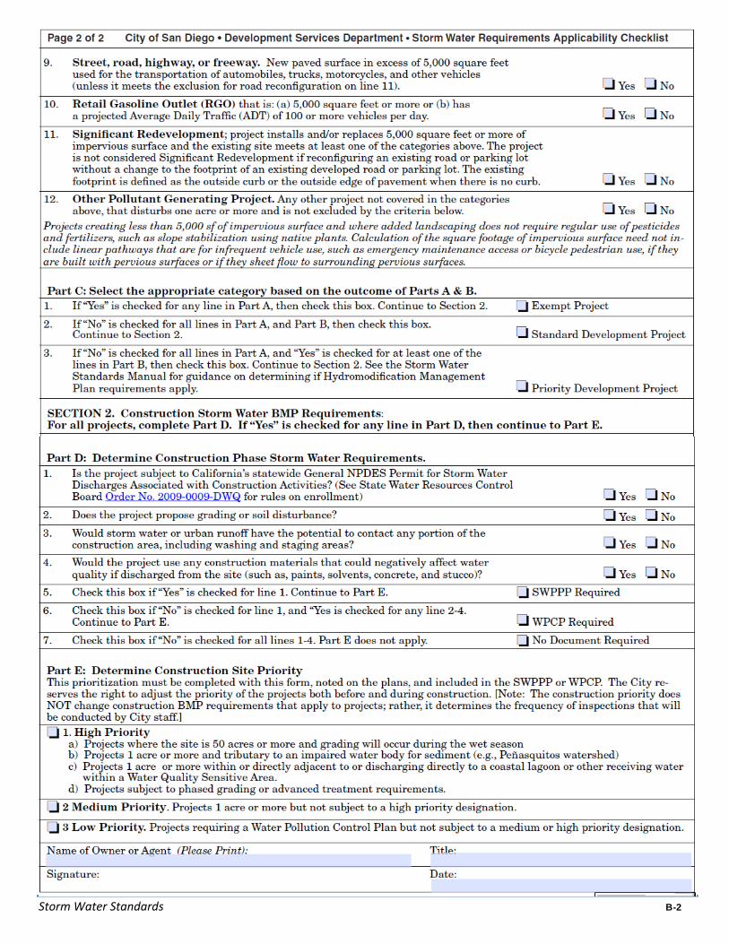
Storm Water Standards B-2

Storm Water Standards C
APPENDIX C
Water Quality Sensitive Areas within the City Of San Diego

This Page Intentionally Left Blank.

Appendix C Water Quality Senssitive Areas within
Storm Water Standards C-1
Water Quality Sensitive Areas within the City Of San Diego
Note: This map is printed here for reference only. A more detailed map with parcel lines is available utilizing the interactive map at the SanGIS website at, www.sangis.org, or by contacting SanGIS at 5469 Kearny Villa Road, Suite 102, San Diego, CA 92123, or by phone at (858) 874-7000. The Water Quality Sensitive Areas map has been produced under the direction of the City of San Diego solely for the purpose of assisting development project applicants in complying with the City’s Storm Water Standards Manual. This map was prepared at a regional scale and may not accurately represent conditions on individual sites. Applicants may submit a proposal to refine the boundaries of the Water Quality Sensitive Areas with the project.

This Page Intentionally Left Blank.

Storm Water Standards D
APPENDIX D
Map and Tables

This Page Intentionally Left Blank.

Appendix D Map and Tables
Storm Water Standards D-1
Note: ID numbers denoting “2006 CWA Section 303(d) List of Water Quality Segments” are illustrated on the following map. These ID numbers may be cross-referenced with the tables following the map.

Appendix D Map and Tables
Storm Water Standards D-2
You may cross reference the tables below with the map on the previous page with regard to the ID# in the column to the left. Information listed in the tables below may also be viewed at: http://www.waterboards.ca.gov/tmdl/docs/303dlists2006/approved/r9_06_303d_reqtmdls.pdf
TABLES
2006 CWA Section 303(d) List of Water Quality Limited Segments

Appendix D Map and Tables
Storm Water Standards D-3
2006 CWA Section 303(d) List of Water Quality Limited Segments

This Page Intentionally Left Blank.

Storm Water Standards E
APPENDIX E
Example Permanent Storm Water Best Management Practices

This Page Intentionally Left Blank.

Appendix E Example Permanent Storm Water BMPs
Storm Water Standards E-1
Example Permanent Storm Water Best Management Practices
The following are a list of BMPs may be used to minimize the introduction of pollutants of concern that may result in significant impacts to receiving waters. Other BMPs approved by the Development Services Department as being equal or more effective in pollutant reduction than comparable BMPs identified below are acceptable. All BMPs must comply with local zoning and building codes and other applicable regulations.
Site Design BMPs
Applicants are required to incorporate Low Impact Development IMPs (Integrated Management Practices) and other BMPs which utilize infiltration as the preferred method for storm water flow control and treatment control.
Applicants should refer to The County of San Diego Low Impact Development Handbook and the included technical fact sheets (Appendix 4) for specific Low Impact Development IMP’s for recommended site design BMPs
Minimizing Impervious Areas
Reduce sidewalk widths
Incorporate landscaped buffer areas between sidewalks and streets.
Design residential streets for the minimum required pavement widths
Minimize the number of residential street cul-de-sacs and incorporate landscaped areas to reduce their impervious cover.
Use open space development that incorporates smaller lot sizes
Increase building density while decreasing the building footprint
Reduce overall lot imperviousness by promoting alternative driveway surfaces and shared driveways that connect two or more homes together
Reduce overall imperviousness associated with parking lots by providing compact car spaces, minimizing stall dimensions, incorporating efficient parking lanes, and using pervious materials in spillover parking areas
Increase Rainfall Infiltration
Use permeable materials for private sidewalks, driveways, parking lots, and interior roadway surfaces (examples: hybrid lots, parking groves, permeable overflow parking, etc.)
Direct rooftop runoff to pervious areas such as yards, open channels, or vegetated areas, and avoid routing rooftop runoff to the roadway or the urban runoff conveyance system
Maximize Rainfall Interception
Maximizing canopy interception and water conservation by preserving existing native trees and shrubs, and planting Additional native or drought tolerant trees and large shrubs.
Minimize Directly Connected Impervious Areas (DCIAs)
Draining rooftops into adjacent landscaping prior to discharging to the storm water conveyance system
Draining parking lots into landscape areas co-designed as biofiltration areas

Appendix E Example Permanent Storm Water BMPs
Storm Water Standards E-2
Draining roads, sidewalks, and impervious trails into adjacent landscaping
Slope and Channel Protection
Use of Natural Drainage Systems to the Maximum Extent Practicable
Stabilized permanent channel crossings
Planting native or drought tolerant vegetation on slopes
Energy dissipaters, such as riprap, at the outlets of new storm drains, culverts, conduits, or channels that enter unlined Channels
Maximize Rainfall Interception
Cisterns
Foundation planting
Increase Rainfall Infiltration
Dry wells
Source Control BMPs
Storm water conveyance system stamping and signage
Outdoor material and trash storage area designed to reduce or control rainfall runoff
Efficient irrigation system
Street and pavement sweeping
Treatment Control BMPs
Biofilters
Grass swale
Grass strip
Wetland vegetation swale
Bioretention
Detention Basins
Extended/dry detention basin with grass lining
Extended/dry detention basin with impervious lining
Infiltration
Infiltration basin
Infiltration trench
Pervious Paving
Porous asphalt
Porous concrete
Porous modular concrete block

Appendix E Example Permanent Storm Water BMPs
Storm Water Standards E-3
Wet Ponds and Wetlands
Wet pond (permanent pool)
Constructed wetland
Filtration Systems
Media filtration
Sand filtration

This Page Intentionally Left Blank.

Storm Water Standards F
APPENDIX F
Water Quality Technical Report Guidelines

This Page Intentionally Left Blank.

Appendix F Water Quality Technical Report Guidelines
Storm Water Standards F-1
Purpose
To describe the permanent storm water Best Management Practices (BMPs) that will be incorporated in the project to mitigate the impacts of urban runoff due to the development.
Minimum Requirements
Water Quality Technical Report prepared by Registered Civil Engineer registered in California
Geologic Investigation Report prepared by a Registered Geotechnical Engineer, Registered Geologist, or Certified Engineering Geologist, registered in California.
Organization & Content
Table of Contents
Vicinity Map
Project Description
− Narrative of project activities
Site Map
− Entire property included on one map (use key map if multi-sheets)
− Drainage areas and direction of flow
− Private storm drain system(s)
− Nearby water bodies and municipal storm drain inlets
− Location of storm water conveyance systems (ditches, inlets, storm drains, etc.)
− Location of existing and proposed storm water controls
− Location of “impervious” areas- paved areas, buildings, covered areas
− Locations where materials would be directly exposed to storm water
− Location of building and activity areas (e.g. fueling islands, garages, waste container area, wash racks, hazardous material storage areas, etc.)
− Areas of potential soil erosion (including areas downstream of project)
− Location of existing drinking water wells
− Location of existing vegetation to be preserved
Pollutants and Conditions of Concern
− Project located in which Watershed
− Impaired water bodies downstream of the project and impairment
− Impacts to hydrologic regime
− Pollutants based upon land use
− Drainage Study (may be appendix)
− Geologic Study (may be appendix)
− Hydromodification Element (may be appendix)
Types of BMPs:

Appendix F Water Quality Technical Report Guidelines
Storm Water Standards F-2
− Low Impact Development BMPs
− Source Control BMPs
− Structural Treatment BMPs
Maintenance Conditions
Drainage Study*
− Purpose of report
− Hydrologic models and/or methods used
− Water Quality Design Storm
− Pre-Development runoff volumes and peak flows
− Post-project runoff volumes and peak flows
Geologic Investigation Report
− Purpose of Report
− Investigation Methods
− Areas selected for investigation.
− Infiltration rates and capacities.
− Lateral migration rates and issues.
− Groundwater elevations, characterization, and maximum seasonal elevations.
− Locations of drinking water wells.
− Locations of features to be protected from infiltrated water.
− Minimum distances between infiltration and site features.
− Minimum distances between infiltration and existing features.
− Mitigation requirements for lateral migration – i.e. minimum permeabilities of cutoff features, depths of cutoff features required, drainage requirements, etc.
− Mapping of areas where infiltration is feasible
− Mapping of areas where infiltration is infeasible.
− Consideration of mitigating measures that may be employed and where.

Storm Water Standards G
APPENDIX G
Storm Water Pollution Prevention Plan / Water Pollution Control Plan Guidelines

This Page Intentionally Left Blank.

Appendix G SWPPP/WPCP Guidelines
Storm Water Standards G-1
Storm Water Pollution Prevention Plan /
Water Pollution Control Plan Guidelines
At a minimum, the Storm Water Pollution Prevention Plan (SWPPP) or Water Pollution Control Plan (WPCP), whichever is required, must cover the areas listed below.
If a project disturbs 1 acre or more, the applicant must provide a Storm Water Pollution Prevention Plan (SWPPP), which identifies all construction BMP requirements required by Section IV, in accordance with the State General Permit for Storm Water Discharges Associated with Construction Activity (State General Construction Permit). The SWPPP must be kept on site and made available upon request of a representative of the City of San Diego. Additionally, the State General Construction Permit has a requirement for a sampling and monitoring program to be implemented. Projects that are also required to obtain a general construction National Pollutant Discharge Elimination System (NPDES) Permit are encouraged to visit the State Water Resource Control Board’s website for permit application instructions, NOI and NOT forms and guidance in preparing a Storm Water Pollution Prevention Plan (go to: http://www.swrcb.ca.gov/stormwtr/construction.html). A checklist to assist with the preparation of a SWPPP is also provided at the following website:
http://www.waterboards.ca.gov/stormwtr/docs/const_swppp.pdf
For projects that disturb less than 1 and are determined to have a potential to impact water quality during construction, the applicant must provide a Water Pollution Control Plan (WPCP), which identifies all construction BMP requirements required by Section IV, with the project submittal. The WPCP shall depict the BMPs to be implemented during construction to reduce/eliminate discharges of pollutants to the storm drain conveyance system. The WPCP shall include but not be limited to erosion and sediment control BMPs, phased grading, good housekeeping measures, and site and materials management.
Planning and Organization
Identify the pollution prevention team members who will maintain and implement the SWPPP.
If applicable, incorporate or reference the appropriate elements of other regulatory requirements.
Site Map
Features displayed on the map must include:
An outline of the entire property
Drainage areas on the property and direction of flow
Areas of soil erosion
Nearby water bodies and municipal storm drain inlets
Location of waters on the 303(d) list for sedimentation or turbidity.
Location of storm water conveyance systems (ditches, inlets, storm drains, etc.)
Location of existing storm water controls (oil/ water separators, sumps, etc.)
Location of “impervious” areas- paved areas, buildings, covered areas
Locations where materials are directly exposed to storm water
Locations where toxic or hazardous materials have spilled in the past

Appendix G SWPPP/WPCP Guidelines
Storm Water Standards G-2
• Location of building and activity areas (e.g., fueling islands, garages, waste container area, wash racks, hazardous material storage areas, etc.)
List of Significant Materials
List materials stored and handled at the site. Include the location and typical quantities.
Description of Potential Pollutant Sources
• Provide a narrative description of the site’s activities and list the potential pollutant sources and the potential pollutants that could be discharged in storm water discharges from each activity.
• List non‐storm water discharges including the source, quantity, frequency, and characteristics of the discharges and drainage area.
Assessment of Potential Sources
Describe which activities are likely to be sources of pollution in storm water and which pollutants are likely to be present in storm water discharges.
Best Management Practices
Describe the BMPs that will be implemented at the site for each potential pollutant and its source.
Phased Grading
If the contractor/owner intends to have more than 5 acres graded during any part of a rainy season, the contractor/owner shall include in their weather triggered action plan a BMP Implementation Plan that shows the materials, equipment, and labor that will be on site to deploy BMPs sufficient to control erosion and sediment transport within 24 hours of a forecast of 50% probability of rain. The BMP Implementation Plan will show BMP types, locations, layout, water flow directions, and describe how the BMP will control erosion and sediment transport. This may include a limitation on grading, if that is the best way for the contractor to guarantee that they will deploy sufficient BMPs within 24 hours.
Source Control
If Source Control is used to prevent an exceptional threat to water quality, the SWPPP or WPCP shall include plans and specifications showing the items, features, materials, and descriptions of the source control measures to be implemented.
Advanced Treatment
If advanced treatment is required, the SWPPP or WPCP shall include
• Plans and specifications showing the advanced treatment system proposed including detention ponds, diversions for extreme events, treatment equipment, discharge locations, and other features,
• Verification that this advanced treatment system will achieve the effluent requirements,
• Verification that this advanced treatment system will not cause any impairment of water quality
• Test results,
• An Operations, Maintenance, and Monitoring Plan showing quantities of materials, including any chemicals proposed, operating conditions, instrumentation, operational procedures, waste management procedures, monitoring procedures, and reporting formats.
• Operator certifications.

Storm Water Standards H
APPENDIX H
Example Construction Best Management Practices

This Page Intentionally Left Blank.

Appendix H Example Construction Best Management Practices
Storm Water Standards H-1
Appendix H
Example Construction Best Management Practices
A. Erosion Control
Physical stabilization BMPs, vegetation stabilization BMPs, or both, will be required to prevent erosion and sediment runoff from exposed graded areas. BMPs for physical and vegetation stabilization include:
1) Physical Stabilization a) Geotextiles b) Mats c) Fiber blankets d) Hydraulic mulch, Bonded Fiber Matrix e) Sprayed on binders f) Mulch on flat areas g) Other material approved by the City for use in specific circumstances
If physical stabilization is selected, materials must be appropriate to the circumstances in which they are deployed, and sufficient material must be deployed.
2) Vegetation Stabilization a) Preservation of existing vegetation b) Established interim vegetation (via Hydroseed, seeded mats, etc.) c) Established permanent landscaping
If vegetation stabilization is selected, the stabilizing vegetation must be installed, irrigated and established (uniform vegetative coverage with 70% coverage established) prior to October 1. In the event stabilizing vegetation has not been established by October 1, other forms of physical stabilization must be employed to prevent erosion until the stabilizing vegetation is established.
B. Sediment Control
1) Perimeter protection. Protect the perimeter of the site or exposed area from sediment ingress/discharge in sheet flows using:
a) Silt fencing b) Gravel bag barriers c) Fiber rolls d) Compost Berms e) Compost Blankets
2) Resource protection. Protect water quality sensitive areas and watercourses from sediment in sheet flows by using:
a) Silt fencing b) Gravel bag barriers c) Fiber rolls d) Compost terms e) Compost Blankets
3) Sediment Capture. Capture sediments in channeled storm water by using: a) Storm-drain inlet protection measures b) De-silting basins (Designed in accordance with an industry standard such as
Caltrans, California Storm water BMP manual etc. If the project is 5 acres or greater

Appendix H Example Construction Best Management Practices
Storm Water Standards H-2
the desilting basin(s) must be designed in accordance with the State General Construction Permit, Order DWQ 99-08.)
4) Velocity Reduction. Reduce the velocity of storm water by using: a) Outlet protection (energy dissipater) b) Equalization basins c) Check dams
5) Off-site Sediment Tracking. Prevent sediment from being tracked off-site by using: a) Stabilized construction entrances/exits b) Construction road stabilization c) Tracking control (i.e., corrugated steel panels, wheel washes) d) Dust control
C. Materials Management
1) Prevent the contamination of storm water by wastes through proper management of the following types of wastes:
a) Solid b) Sanitary c) Concrete d) Hazardous e) Equipment – related wastes f) Stock piles (protection from wind and rain)
2) Prevent the contamination of storm water by construction materials by: a) Covering and/or providing secondary containment of storage areas b) Taking adequate precautions when handling materials.

Storm Water Standards I
APPENDIX I
Low Impact Development Design Guide
Chapter 4 of the Countywide Model SUSMP, Brown and Caldwell, January 13, 2011

This Page Intentionally Left Blank.

Storm Water Standards I-1
EXTRACTED FROM THE COUNTYWIDE MODEL SUSMP
4. Low Impact Development Design Guide
Guidance for designing and documenting your LID site drainage, stormwater treatment facilities, and flow-control facilities
Follow the Low Impact Development (LID) design in this SUSMP to achieve compliance with the stormwater treatment requirements as well as the LID requirements in the stormwater NPDES permit.
This will require careful documentation of:
Pervious and impervious areas in the planned project.
Drainage from each of these areas.
Locations, sizes, and types of proposed treatment facilities.
Your Project Submittal must include calculations showing the site drainage and proposed LID treatment facilities meet the criteria in this SUSMP.
This Low Impact Development Design Guide will help you:
Analyze your project and identify and select options for implementing LID techniques to meet runoff treatment requirements—and flow-control requirements, if they apply.
Design and document drainage for the whole site and document how that design meets this SUSMP’s stormwater treatment criteria.
Specify preliminary design details and integrate your LID drainage design with your paving and landscaping design.
Alternatives to LID design are discussed in the final section of this appendix.
4.1 Analyze Your Project for LID
Conceptually, there are four LID strategies for managing runoff from buildings and paving:
1. Optimize the site layout by preserving natural drainage features and designing buildings and circulation to minimize the amount of roofs and paving.
2. Use pervious surfaces such as turf, gravel, or pervious pavement—or use surfaces that retain rainfall, such as vegetated roofs. All drainage from these surfaces is considered to be “self-retained” (a detailed definition corresponding to this concept is on page 64). No further management of runoff is necessary. An emergency overflow should be provided for extreme events.
3. Disperse runoff from impervious surfaces on to adjacent pervious surfaces (e.g., direct a roof downspout to disperse runoff onto a lawn).

Storm Water Standards I-2
4. Drain impervious surfaces to engineered Integrated Management Practices (IMPs), such as bioretention facilities, planter boxes, cisterns, or infiltration facilities. IMPs infiltrate runoff to groundwater and/or percolate runoff through engineered soil and allow it to drain away slowly. Depending on site conditions and local regulations, it may be possible to harvest and reuse rainwater in conjunction with IMPs.
A combination of two or more strategies may work best for your project. With forethought in design, the four strategies can provide multiple, complementary benefits to your development. Pervious surfaces reduce heat island effects and temperature extremes. Landscaping improves air quality, creates a better place to live or work, and upgrades value for rental or sale. Retaining natural hydrology helps preserve and enhance the natural character of the area. LID drainage design can also conserve water and reduce the need for drainage infrastructure.
Table 4-1 includes ideas for applying lid strategies to site conditions and types of development.
Table 4-1. Ideas for Runoff Management
Site Features and Design Objectives
Vegetated Roof
Self-retaining
Areas
Pervious Pavement
Bioretention Facility
Flow-through Planter
Dry Well Cistern with bioretention
Clayey native soils
Permeable native soils
Very steep slopes
Shallow groundwater
Avoid saturating subsurface soils
Connect to roof downspouts
Parking lots/islands and medians
Sites with extensive landscaping
Densely developed sites with limited space/landscape
Fit IMPs into landscape and setback areas
Make drainage a design feature
Convey as well as treat stormwater

Storm Water Standards I-3
4.1.1 Optimize the Site Layout
To minimize stormwater-related impacts, apply the following design principles to the layout of newly developed and redeveloped sites.
Conserve natural areas, soils, and vegetation. Define the development envelope and protected areas, identifying areas that are most suitable for development and areas that should be left undisturbed. Use the following guideline to determine the least sensitive areas of the site, in order of increasing sensitivity:
1. Areas devoid of vegetation, including previously graded areas and agricultural fields.
5. Areas of non-native vegetation, disturbed habitats and eucalyptus woodlands where receiving waters are not present.
6. Areas of chamise or mixed chaparral, and non-native grasslands.
7. Areas containing coastal scrub communities.
8. All other upland communities.
9. Occupied habitat of sensitive species and all wetlands (as both are defined by the local jurisdiction).
Within each of the previous categories, hillside areas should be considered more sensitive than flatter areas.
Where possible, conform the site layout along natural landforms, avoid excessive grading and disturbance of vegetation and soils, and replicate the site’s natural drainage patterns. Set back development from creeks, wetlands, and riparian habitats. Preserve significant trees, especially native trees and shrubs, and identify locations for planting additional native or drought tolerant trees and large shrubs. Concentrate development on portions of the site with less permeable soils, and preserve areas that can promote infiltration.
For all types of development, limit overall coverage of paving and roofs. Where allowed by local zoning and design standards—and provided public safety and a walkable environment are not compromised—this can be accomplished by designing compact, taller structures, narrower and shorter streets and sidewalks, smaller parking lots (fewer stalls, smaller stalls, and more efficient lanes), and indoor or underground parking. Examine site layout and circulation patterns and identify areas where landscaping can be substituted for pavement.
Detain and retain runoff throughout the site. On flatter sites, it typically works best to intersperse landscaped areas and IMPs among the buildings and paving. On hillside sites, drainage from upper areas may be collected in conventional catch basins and piped to landscaped areas and IMPs in lower areas.
Use drainage as a design element. Use depressed landscape areas, vegetated buffers, and bioretention areas as amenities and focal points within the site and landscape design. Bioretention areas can be almost any shape and should be located at low points. Bioretention areas shaped as swales can detain and treat low runoff flows and also convey higher flows.
Coordination
Chapter One includes a presentation of how review of your project’s site design and
landscape design is coordinated with review for compliance with stormwater
NPDES requirements.

Storm Water Standards I-4
4.1.2 Use Pervious Surfaces
Consider a vegetated roof. Although not yet widely used in California, vegetated or “green” roofs are growing in popularity. Potential benefits include longer roof life, lower heating and cooling costs, and better sound insulation, in addition to air quality and water quality benefits. For SUSMP compliance purposes, vegetated roofs are considered not to produce increased runoff or runoff pollutants (i.e., any runoff from a vegetated roof requires no further treatment or detention). For more information on vegetated roofs, see www.greenroofs.org.
Consider permeable pavements and surface treatments. Inventory paved areas on your preliminary site plan. Identify where permeable pavements, such as crushed aggregate, turf block, unit pavers, pervious concrete, or pervious asphalt could be substituted for impervious concrete or asphalt paving.
4.1.3 Disperse Runoff to Adjacent Pervious Areas
Look for opportunities to direct runoff from impervious areas to adjacent landscaping. The design, including slopes and soils, must reflect a reasonable expectation that an inch of rainfall will soak into the soil and produce no runoff. For example, a lawn or garden depressed 3-4" below surrounding walkways or driveways provides a simple but functional landscape design element.
For sites subject to stormwater treatment requirements only, a 2:1 maximum ratio of impervious to pervious area is acceptable. Be sure soils will drain adequately.
Under some circumstances, it may be allowable to direct runoff from impervious areas to pervious pavement (for example, from roof downspouts to a parking lot paved with crushed aggregate or turf block). The pore volume of pavement and base course must be sufficient to retain an inch of rainfall, including runoff from the tributary area. The slopes and soils must be compatible with infiltrating that volume without producing runoff.
4.1.4 Direct Runoff to Integrated Management Practices
Project Clean Water has developed design criteria for the following IMPs:
Bioretention facilities, which can be configured as swales, free-form areas, or planters to integrate with your landscape design.
Flow-through planters, which can be used near building foundations and other locations where infiltration to native soils is not desired.
Infiltration facilities which can be used only where soils are permeable.
Cisterns or vaults, in combination with a bioretention facility.
See the design sheets at the end of this appendix.
It may be possible to create a site-specific design that uses cisterns to achieve stormwater flow control, stormwater treatment, and rainwater reuse for irrigation or indoor uses (water harvesting). Such a design could expand the multiple benefits of LID to include water conservation. Keep in mind:
Facilities must meet criteria for capturing and treating the volume specified by Equation 4-8 below. This volume must be allowed to empty within 24 hours so runoff from additional storms, which may follow, is also captured and treated. Additional volume may be required if the system also stores runoff for longer periods for reuse.

Storm Water Standards I-5
Storage of water for longer than minimum standards set forth by local jurisdictions (96 hours for County Department of Environmental Health) creates the potential for mosquito harborage. Cisterns and vaults must be designed to prevent entry by mosquitoes.
Indoor uses of non-potable water may be restricted or prohibited. Check with municipal staff.
Some references and resources for water harvesting appear at the end of this appendix.
Finding the right location for treatment facilities on your site involves a careful and creative integration of several factors:
To make the most efficient use of the site and to maximize aesthetic value, integrate IMPs with
site landscaping. Many local zoning codes may require landscape setbacks or buffers, or may specify that a minimum portion of the site be landscaped. It may be possible to locate some or all of your site’s treatment and flow-control facilities within this same area, or within utility easements or other non-buildable areas.
Planter boxes and bioretention areas must be level or nearly level all the way around. Bioretention areas configured as swales may be gently sloped in the linear direction, but opposite sides must be at the same elevation.
For effective, low-maintenance operation, locate facilities so drainage into and out of the device
is by gravity flow. Pumped systems are feasible, but are expensive, require more maintenance, are prone to untimely failure, and can cause mosquito control problems. Most IMPs require 3 feet or more of head.
If the property is being subdivided now or in the future, the facility should be in a common,
accessible area. In particular, avoid locating facilities on private residential lots. Even if the facility will serve only one site owner or operator, make sure the facility is located for ready access by inspectors from the local municipality and local mosquito control agency.
The facility must be accessible to equipment needed for its maintenance. Access requirements
for maintenance will vary with the type of facility selected. Planter boxes and bioretention areas will typically need access for the same types of equipment used for landscape maintenance.
To complete your analysis, if required by your municipality include in your Project Submittal a brief narrative documenting the site layout and site design decisions you made. This will provide background and context for how your design meets the quantitative LID design criteria.
4.2 Develop and Document Your Drainage Design
The design documentation procedure begins with careful delineation of pervious areas and impervious areas (including roofs) throughout the site. The procedure accounts for how runoff from each delineated area is managed. For areas draining to IMPs, the procedure ensures each IMP is appropriately sized.
The procedure results in a space-efficient, cost-efficient LID design for meeting SUSMP requirements on most residential and commercial/industrial developments. The procedure arranges documentation of drainage design and IMP sizing in a consistent format for presentation and review.

Storm Water Standards I-6
This procedure is intended to facilitate, not substitute for, creative interplay among site design, landscape design, and drainage design. Several iterations may be needed to optimize your drainage design as well as aesthetics, circulation, and use of available area for your site.
You should be able to complete the needed calculations using only the project’s site development plan.
4.2.1 Step 1: Delineate Drainage Management Areas
This is the key first step. You must divide the entire project area into individual, discrete Drainage Management Areas (DMAs). Typically, lines delineating DMAs follow grade breaks and roof ridge lines. The Exhibit, tables, text, and calculations in your Project Submittal will illustrate, describe, and account for runoff from each of these areas.
Use separate DMAs for each surface type (e.g., landscaping, pervious paving, or roofs). Each DMA must be assigned a single hydrologic soil group. Assign each DMA an identification number and determine its size in square feet.
4.2.2 Step 2: Classify DMAS and Determine Runoff Factors
Next, determine how drainage from each DMA will be handled. Each DMA will be one of the following four types:
1. Self-treating areas.
2. Self-retaining areas (also called “zero-discharge” areas).
3. Areas that drain to self-retaining areas.
4. Areas that drain to IMPs.
Self-treating areas are landscaped or turf areas that do not drain to IMPs, but rather drain directly off site or to the storm drain system. Examples include upslope undeveloped areas which are ditched and drained around a development and grassed slopes which drain off-site to a street or storm drain. In general, self-treating areas include no impervious areas, unless the impervious area is very small (5 percent or less) in relationship to the receiving pervious area and slopes are gentle enough to ensure runoff will be absorbed into the vegetation and soil. Criteria for self-treating areas are in the design sheet “Self Treating and Self-Retaining Areas” at the end of this appendix.
Figure 4-1. Self-treating areas are entirely pervious and drain directly off-site or to the storm drain system.
Rationale
Pollutants in rainfall and windblown dust will tend to
become entrained in the vegetation and soils of
landscaped areas, so no additional treatment is
needed. It is assumed the self-treating landscaped areas will
produce runoff less than or equal to the pre-project site
condition.

Storm Water Standards I-7
Self-retaining areas are designed to retain the first one inch of rainfall without producing any runoff. The technique works best on flat, heavily landscaped sites. It may be used on mild slopes if there is a reasonable expectation that a one-inch rainfall event would produce no runoff.
To create self-retaining turf and landscape areas in flat areas or on terraced slopes, berm the area or depress the grade into a concave cross-section so that these areas will retain the first inch of rainfall. Specify slopes, if any, toward the center of the pervious area. Inlets of area drains, if any, should be set 3 inches above the low point to allow ponding.
Criteria for self-retaining areas are in the design sheet “Self Treating and Self-Retaining Areas” following this appendix.
Areas draining to self-retaining areas. Runoff from impervious or partially pervious areas can be managed by routing it to self-retaining pervious areas. For example, roof downspouts can be directed to lawns, and driveways can be sloped toward landscaped areas. The maximum ratio is 2 parts impervious area for every 1 part pervious area for water quality treatment, and 1 part impervious area for every 1 part pervious are for hydromodification management.
Figure 4-3. Relationship of impervious to pervious area for self-retaining areas.
Treatment Control Ratio: pervious to impervious,2:1 or less
Hydromodification Control Ratio: pervious to impervious,1:1 or less
Figure 4-2. Self-retaining Areas
Berm or depress the grade to retain at least an inch of rainfall and set inlets of any area drains at least 3 inches above low point to allow ponding.

Storm Water Standards I-8
The drainage from the impervious area must be directed to and dispersed within the pervious area, and the entire area must be designed to retain an inch of rainfall without flowing off-site. For example, using the appropriate area sizing ratios provided above, the pervious area must absorb 3 inches of water over its surface before over¬flowing to an off-site drain.
A partially pervious area may be drained to a self-retaining area. For example, a driveway composed of unit pavers may drain to an adjacent lawn. In this case, the maximum ratios are:
(Runoff factor) x (tributary area) ≤ 2 x (self-retaining area) Treatment Control
(Runoff factor) x (tributary area) ≤ 1 x (self-retaining area) Hydromodification Control
Use the runoff factors in Table 4-2.
Prolonged ponding is a potential problem at higher impervious/pervious ratios. In your design, ensure that the pervious area soils can handle the additional run-on and are sufficiently well-drained.
Under some circumstances, pervious pavement (e.g., crushed stone, pervious asphalt, or pervious concrete) can be self-retaining. Adjacent roofs or impervious pavement may drain on to the pervious pavement in the same maximum ratios as described above.
To design a pervious pavement to be a self-treating area, ensure:
The gravel base course is a minimum of four or more inches deep.
The base course is not to be underdrained.
A qualified engineer has been consulted regarding infiltration rates, pavement stability, and suitability for the intended traffic.
Runoff from self-treating and self-retaining areas does not require any further treatment or flow control.
Table 4-2. Runoff Factors for Surfaces Draining to IMPs
Surface Factor
Roofs 1.0
Concrete 1.0
Pervious Concrete 0.1
Porous Asphalt 0.1
Grouted Unit Pavers 1.0
Solid Unit Pavers on granular base, min. 3/16 inch joint space 0.2
Crushed Aggregate 0.1
Turfblock 0.1
Amended, mulched soil 0.1
Landscape 0.1
Areas draining to IMPs are multiplied by a sizing factor to calculate the required size of the IMP. On most densely developed sites—such as commercial and mixed-use developments and small-lot residential subdivisions—most DMAs will drain to IMPs.

Storm Water Standards I-9
More than one drainage area can drain to the same IMP. However, because the minimum IMP sizes are determined by ratio to drainage area size, a drainage area may not drain to more than one IMP. See Figures 4-4 and 4-5.
Where possible, design site drainage so only impervious roofs and pavement drain to IMPs. This yields a simpler, more efficient design and also helps protect IMPs from becoming clogged by sediment.
If it is necessary to include turf, landscaping, or pervious pavements within the area draining to an IMP, list each surface as a separate DMA. A runoff factor (similar to a “C” factor used in the rational method) is applied to account for the reduction in the quantity of runoff. For example, when a turf or landscaped drainage management area drains to an IMP, the resulting increment in IMP size is:
(Area) = (pervious area) x (runoff factor) x (sizing factor).
Use the runoff factors in Table 4-2.
4.2.3 Step 3: Tabulate Drainage Management Areas
Tabulate self-treating areas in the format shown in Table 4-3.
Tabulate self-retaining areas in the format shown in Table 4-4.
Tabulate areas draining to self-retaining areas in the format shown in Table 4-5. Check to be sure the total product of (square feet of tributary area x runoff factor) for all DMAs draining to a receiving self-retaining area is no greater than the ratios allowed per Sect. 4.2.2.
Compile a list of DMAs draining to IMPs. Proceed to Step 4 to check the sizing of the IMPs.
Figure 4-5. One Drainage Management Area cannot drain to more than one IMP. Use a grade break
to divide the DMA.
Figure 4-4. More than one Drainage Management Area can drain to a single IMP.
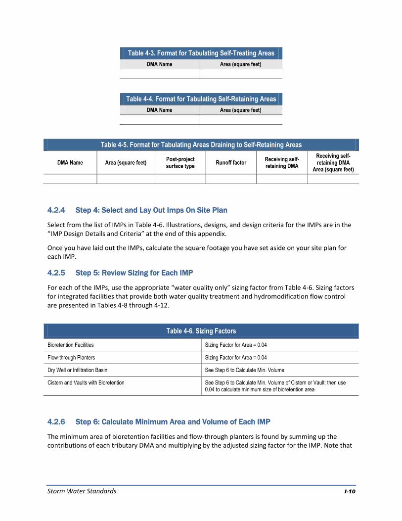
Storm Water Standards I-10
Table 4-3. Format for Tabulating Self-Treating Areas
DMA Name Area (square feet)
Table 4-4. Format for Tabulating Self-Retaining Areas
DMA Name Area (square feet)
Table 4-5. Format for Tabulating Areas Draining to Self-Retaining Areas
DMA Name Area (square feet) Post-project surface type
Runoff factor Receiving self-retaining DMA
Receiving self-retaining DMA
Area (square feet)
4.2.4 Step 4: Select and Lay Out Imps On Site Plan
Select from the list of IMPs in Table 4-6. Illustrations, designs, and design criteria for the IMPs are in the “IMP Design Details and Criteria” at the end of this appendix.
Once you have laid out the IMPs, calculate the square footage you have set aside on your site plan for each IMP.
4.2.5 Step 5: Review Sizing for Each IMP
For each of the IMPs, use the appropriate “water quality only” sizing factor from Table 4-6. Sizing factors for integrated facilities that provide both water quality treatment and hydromodification flow control are presented in Tables 4-8 through 4-12.
Table 4-6. Sizing Factors
Bioretention Facilities Sizing Factor for Area = 0.04
Flow-through Planters Sizing Factor for Area = 0.04
Dry Well or Infiltration Basin See Step 6 to Calculate Min. Volume
Cistern and Vaults with Bioretention See Step 6 to Calculate Min. Volume of Cistern or Vault; then use 0.04 to calculate minimum size of bioretention area
4.2.6 Step 6: Calculate Minimum Area and Volume of Each IMP
The minimum area of bioretention facilities and flow-through planters is found by summing up the contributions of each tributary DMA and multiplying by the adjusted sizing factor for the IMP. Note that

Storm Water Standards I-11
if the IMP is designed to provide hydromodification flow control, then sizing factors from Tables 4-8 through 4-12 should be used in lieu of the “water quality only” sizing factors presented in Table 4-6.
Equation 4-7:
Factor
Sizing
IMP
Factor
Runoff
DMA
Footage
Square
DMA
AreaIMPMin.
Use the format of Table 4-7 to present the calculations of the required minimum area and volumes for bioretention areas and planter boxes:
Table 4-7. Format for Presenting Calculations of Minimum IMP Areas for Bioretention Areas and Planter Boxes
DMA Name
DMA Area
(square feet)
Post-
project surface
type
DMA Runoff factor
DMA Area
runoff factor
Soil Type:
IMP Name
IMP Sizing factor (WQ only)
Minimum Area
Proposed Area
Total 0.04 IMP Area
To size infiltration facilities, infiltration basins, or infiltration trenches for the “water quality treatment
only” option, use the following procedure:
1. Use the County of San Diego's 85th Percentile Isopluvial Map to determine the minimum unit volume.
2. Determine the weighted runoff factor (“C” factor) for the area tributary to the facility. The factors in Table 4-2 may be used.
3. Multiply the weighted runoff factor times the tributary area times the minimum unit volume.
Equation 4-8
volumeunitfactorrunoffweightedAreaTributaryVolume ][
4. Select a facility depth.
5. Determine the required facility area. Infiltration facilities may be designed as an open vault or with rock fill. If rock fill is used, assume a porosity of 40%.
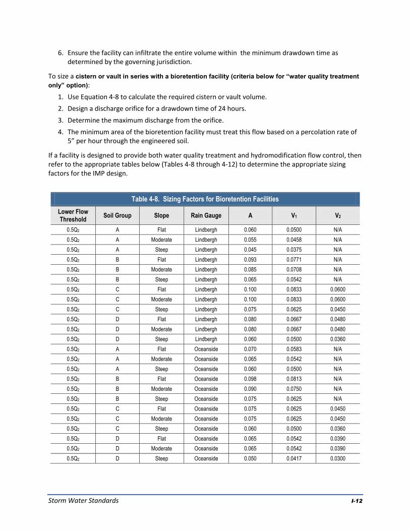
Storm Water Standards I-12
6. Ensure the facility can infiltrate the entire volume within the minimum drawdown time as determined by the governing jurisdiction.
To size a cistern or vault in series with a bioretention facility (criteria below for “water quality treatment
only” option):
1. Use Equation 4-8 to calculate the required cistern or vault volume.
2. Design a discharge orifice for a drawdown time of 24 hours.
3. Determine the maximum discharge from the orifice.
4. The minimum area of the bioretention facility must treat this flow based on a percolation rate of 5” per hour through the engineered soil.
If a facility is designed to provide both water quality treatment and hydromodification flow control, then refer to the appropriate tables below (Tables 4-8 through 4-12) to determine the appropriate sizing factors for the IMP design.
Table 4-8. Sizing Factors for Bioretention Facilities
Lower Flow Threshold
Soil Group Slope Rain Gauge A V1 V2
0.5Q2 A Flat Lindbergh 0.060 0.0500 N/A
0.5Q2 A Moderate Lindbergh 0.055 0.0458 N/A
0.5Q2 A Steep Lindbergh 0.045 0.0375 N/A
0.5Q2 B Flat Lindbergh 0.093 0.0771 N/A
0.5Q2 B Moderate Lindbergh 0.085 0.0708 N/A
0.5Q2 B Steep Lindbergh 0.065 0.0542 N/A
0.5Q2 C Flat Lindbergh 0.100 0.0833 0.0600
0.5Q2 C Moderate Lindbergh 0.100 0.0833 0.0600
0.5Q2 C Steep Lindbergh 0.075 0.0625 0.0450
0.5Q2 D Flat Lindbergh 0.080 0.0667 0.0480
0.5Q2 D Moderate Lindbergh 0.080 0.0667 0.0480
0.5Q2 D Steep Lindbergh 0.060 0.0500 0.0360
0.5Q2 A Flat Oceanside 0.070 0.0583 N/A
0.5Q2 A Moderate Oceanside 0.065 0.0542 N/A
0.5Q2 A Steep Oceanside 0.060 0.0500 N/A
0.5Q2 B Flat Oceanside 0.098 0.0813 N/A
0.5Q2 B Moderate Oceanside 0.090 0.0750 N/A
0.5Q2 B Steep Oceanside 0.075 0.0625 N/A
0.5Q2 C Flat Oceanside 0.075 0.0625 0.0450
0.5Q2 C Moderate Oceanside 0.075 0.0625 0.0450
0.5Q2 C Steep Oceanside 0.060 0.0500 0.0360
0.5Q2 D Flat Oceanside 0.065 0.0542 0.0390
0.5Q2 D Moderate Oceanside 0.065 0.0542 0.0390
0.5Q2 D Steep Oceanside 0.050 0.0417 0.0300

Storm Water Standards I-13
Table 4-8. Sizing Factors for Bioretention Facilities
Lower Flow Threshold
Soil Group Slope Rain Gauge A V1 V2
0.5Q2 A Flat L Wohlford 0.050 0.0417 N/A
0.5Q2 A Moderate L Wohlford 0.045 0.0375 N/A
0.5Q2 A Steep L Wohlford 0.040 0.0333 N/A
0.5Q2 B Flat L Wohlford 0.048 0.0396 N/A
0.5Q2 B Moderate L Wohlford 0.045 0.0375 N/A
0.5Q2 B Steep L Wohlford 0.040 0.0333 N/A
0.5Q2 C Flat L Wohlford 0.065 0.0542 0.0390
0.5Q2 C Moderate L Wohlford 0.065 0.0542 0.0390
0.5Q2 C Steep L Wohlford 0.050 0.0417 0.0300
0.5Q2 D Flat L Wohlford 0.055 0.0458 0.0330
0.5Q2 D Moderate L Wohlford 0.055 0.0458 0.0330
0.5Q2 D Steep L Wohlford 0.045 0.0375 0.0270
0.3Q2 A Flat Lindbergh 0.060 0.0500 N/A
0.3Q2 A Moderate Lindbergh 0.055 0.0458 N/A
0.3Q2 A Steep Lindbergh 0.045 0.0375 N/A
0.3Q2 B Flat Lindbergh 0.098 0.0813 N/A
0.3Q2 B Moderate Lindbergh 0.090 0.0750 N/A
0.3Q2 B Steep Lindbergh 0.070 0.0583 N/A
0.3Q2 C Flat Lindbergh 0.110 0.0917 0.0660
0.3Q2 C Moderate Lindbergh 0.110 0.0917 0.0660
0.3Q2 C Steep Lindbergh 0.085 0.0708 0.0510
0.3Q2 D Flat Lindbergh 0.100 0.0833 0.0600
0.3Q2 D Moderate Lindbergh 0.100 0.0833 0.0600
0.3Q2 D Steep Lindbergh 0.070 0.0583 0.0420
0.3Q2 A Flat Oceanside 0.070 0.0583 N/A
0.3Q2 A Moderate Oceanside 0.065 0.0542 N/A
0.3Q2 A Steep Oceanside 0.060 0.0500 N/A
0.3Q2 B Flat Oceanside 0.098 0.0813 N/A
0.3Q2 B Moderate Oceanside 0.090 0.0750 N/A
0.3Q2 B Steep Oceanside 0.075 0.0625 N/A
0.3Q2 C Flat Oceanside 0.100 0.0833 0.0600
0.3Q2 C Moderate Oceanside 0.100 0.0833 0.0600
0.3Q2 C Steep Oceanside 0.080 0.0667 0.0480
0.3Q2 D Flat Oceanside 0.085 0.0708 0.0510
0.3Q2 D Moderate Oceanside 0.085 0.0708 0.0510
0.3Q2 D Steep Oceanside 0.065 0.0542 0.0390
0.3Q2 A Flat L Wohlford 0.050 0.0417 N/A
0.3Q2 A Moderate L Wohlford 0.045 0.0375 N/A

Storm Water Standards I-14
Table 4-8. Sizing Factors for Bioretention Facilities
Lower Flow Threshold
Soil Group Slope Rain Gauge A V1 V2
0.3Q2 A Steep L Wohlford 0.040 0.0333 N/A
0.3Q2 B Flat L Wohlford 0.060 0.0500 N/A
0.3Q2 B Moderate L Wohlford 0.055 0.0458 N/A
0.3Q2 B Steep L Wohlford 0.045 0.0375 N/A
0.3Q2 C Flat L Wohlford 0.075 0.0625 0.0450
0.3Q2 C Moderate L Wohlford 0.075 0.0625 0.0450
0.3Q2 C Steep L Wohlford 0.060 0.0500 0.0360
0.3Q2 D Flat L Wohlford 0.065 0.0542 0.0390
0.3Q2 D Moderate L Wohlford 0.065 0.0542 0.0390
0.3Q2 D Steep L Wohlford 0.050 0.0417 0.0300
0.1Q2 A Flat Lindbergh 0.060 0.0500 N/A
0.1Q2 A Moderate Lindbergh 0.055 0.0458 N/A
0.1Q2 A Steep Lindbergh 0.045 0.0375 N/A
0.1Q2 B Flat Lindbergh 0.100 0.0833 N/A
0.1Q2 B Moderate Lindbergh 0.095 0.0792 N/A
0.1Q2 B Steep Lindbergh 0.080 0.0667 N/A
0.1Q2 C Flat Lindbergh 0.145 0.1208 0.0870
0.1Q2 C Moderate Lindbergh 0.145 0.1208 0.0870
0.1Q2 C Steep Lindbergh 0.120 0.1000 0.0720
0.1Q2 D Flat Lindbergh 0.160 0.1333 0.0960
0.1Q2 D Moderate Lindbergh 0.160 0.1333 0.0960
0.1Q2 D Steep Lindbergh 0.115 0.0958 0.0690
0.1Q2 A Flat Oceanside 0.070 0.0583 N/A
0.1Q2 A Moderate Oceanside 0.065 0.0542 N/A
0.1Q2 A Steep Oceanside 0.060 0.0500 N/A
0.1Q2 B Flat Oceanside 0.103 0.0854 N/A
0.1Q2 B Moderate Oceanside 0.090 0.0750 N/A
0.1Q2 B Steep Oceanside 0.075 0.0625 N/A
0.1Q2 C Flat Oceanside 0.130 0.1083 0.0780
0.1Q2 C Moderate Oceanside 0.130 0.1083 0.0780
0.1Q2 C Steep Oceanside 0.110 0.0917 0.0660
0.1Q2 D Flat Oceanside 0.130 0.1083 0.0780
0.1Q2 D Moderate Oceanside 0.130 0.1083 0.0780
0.1Q2 D Steep Oceanside 0.065 0.0542 0.0390
0.1Q2 A Flat L Wohlford 0.050 0.0417 N/A
0.1Q2 A Moderate L Wohlford 0.045 0.0375 N/A
0.1Q2 A Steep L Wohlford 0.040 0.0333 N/A
0.1Q2 B Flat L Wohlford 0.090 0.0750 N/A

Storm Water Standards I-15
Table 4-8. Sizing Factors for Bioretention Facilities
Lower Flow Threshold
Soil Group Slope Rain Gauge A V1 V2
0.1Q2 B Moderate L Wohlford 0.085 0.0708 N/A
0.1Q2 B Steep L Wohlford 0.065 0.0542 N/A
0.1Q2 C Flat L Wohlford 0.110 0.0917 0.0660
0.1Q2 C Moderate L Wohlford 0.110 0.0917 0.0660
0.1Q2 C Steep L Wohlford 0.090 0.0750 0.0540
0.1Q2 D Flat L Wohlford 0.100 0.0833 0.0600
0.1Q2 D Moderate L Wohlford 0.100 0.0833 0.0600
0.1Q2 D Steep L Wohlford 0.075 0.0625 0.0450
Q2 = 2-year pre-project flow rate based upon partial duration analysis of long-term hourly rainfall records
Q10 = 10-year pre-project flow rate based upon partial duration analysis of long-term hourly rainfall records
A = Surface area sizing factor
V1 = Surface volume sizing factor
V2 = Subsurface volume sizing factor
Table 4-9. Sizing Factors for Bioretention Plus Cistern Facilities
Lower Flow Threshold
Soil Group Slope Rain Gauge A V1 V2
0.5Q2 A Flat Lindbergh 0.020 0.1200 N/A
0.5Q2 A Moderate Lindbergh 0.020 0.1000 N/A
0.5Q2 A Steep Lindbergh 0.020 0.1000 N/A
0.5Q2 B Flat Lindbergh 0.020 0.3900 N/A
0.5Q2 B Moderate Lindbergh 0.020 0.2000 N/A
0.5Q2 B Steep Lindbergh 0.020 0.1200 N/A
0.5Q2 C Flat Lindbergh 0.020 0.1200 N/A
0.5Q2 C Moderate Lindbergh 0.020 0.1200 N/A
0.5Q2 C Steep Lindbergh 0.020 0.1000 N/A
0.5Q2 D Flat Lindbergh 0.020 0.1000 N/A
0.5Q2 D Moderate Lindbergh 0.020 0.1000 N/A
0.5Q2 D Steep Lindbergh 0.030 0.0800 N/A
0.5Q2 A Flat Oceanside 0.020 0.1600 N/A
0.5Q2 A Moderate Oceanside 0.020 0.1400 N/A
0.5Q2 A Steep Oceanside 0.030 0.1200 N/A
0.5Q2 B Flat Oceanside 0.020 0.1900 N/A
0.5Q2 B Moderate Oceanside 0.025 0.1600 N/A
0.5Q2 B Steep Oceanside 0.035 0.1400 N/A
0.5Q2 C Flat Oceanside 0.030 0.1400 N/A
0.5Q2 C Moderate Oceanside 0.035 0.1400 N/A
0.5Q2 C Steep Oceanside 0.040 0.1200 N/A

Storm Water Standards I-16
Table 4-9. Sizing Factors for Bioretention Plus Cistern Facilities
Lower Flow Threshold
Soil Group Slope Rain Gauge A V1 V2
0.5Q2 D Flat Oceanside 0.035 0.1200 N/A
0.5Q2 D Moderate Oceanside 0.040 0.1200 N/A
0.5Q2 D Steep Oceanside 0.040 0.1000 N/A
0.5Q2 A Flat L Wohlford 0.025 0.1800 N/A
0.5Q2 A Moderate L Wohlford 0.040 0.1400 N/A
0.5Q2 A Steep L Wohlford 0.040 0.0800 N/A
0.5Q2 B Flat L Wohlford 0.040 0.2100 N/A
0.5Q2 B Moderate L Wohlford 0.040 0.2000 N/A
0.5Q2 B Steep L Wohlford 0.040 0.1400 N/A
0.5Q2 C Flat L Wohlford 0.040 0.1400 N/A
0.5Q2 C Moderate L Wohlford 0.040 0.1400 N/A
0.5Q2 C Steep L Wohlford 0.040 0.1000 N/A
0.5Q2 D Flat L Wohlford 0.040 0.1000 N/A
0.5Q2 D Moderate L Wohlford 0.040 0.1000 N/A
0.5Q2 D Steep L Wohlford 0.040 0.0800 N/A
0.3Q2 A Flat Lindbergh 0.020 0.1200 N/A
0.3Q2 A Moderate Lindbergh 0.020 0.1000 N/A
0.3Q2 A Steep Lindbergh 0.020 0.1000 N/A
0.3Q2 B Flat Lindbergh 0.020 0.5900 N/A
0.3Q2 B Moderate Lindbergh 0.020 0.3600 N/A
0.3Q2 B Steep Lindbergh 0.020 0.1800 N/A
0.3Q2 C Flat Lindbergh 0.020 0.1800 N/A
0.3Q2 C Moderate Lindbergh 0.020 0.1800 N/A
0.3Q2 C Steep Lindbergh 0.020 0.1400 N/A
0.3Q2 D Flat Lindbergh 0.020 0.1400 N/A
0.3Q2 D Moderate Lindbergh 0.020 0.1400 N/A
0.3Q2 D Steep Lindbergh 0.020 0.0800 N/A
0.3Q2 A Flat Oceanside 0.020 0.1600 N/A
0.3Q2 A Moderate Oceanside 0.020 0.1400 N/A
0.3Q2 A Steep Oceanside 0.020 0.1200 N/A
0.3Q2 B Flat Oceanside 0.020 0.2200 N/A
0.3Q2 B Moderate Oceanside 0.020 0.1800 N/A
0.3Q2 B Steep Oceanside 0.020 0.1600 N/A
0.3Q2 C Flat Oceanside 0.020 0.1600 N/A
0.3Q2 C Moderate Oceanside 0.020 0.1600 N/A
0.3Q2 C Steep Oceanside 0.025 0.1400 N/A
0.3Q2 D Flat Oceanside 0.020 0.1400 N/A

Storm Water Standards I-17
Table 4-9. Sizing Factors for Bioretention Plus Cistern Facilities
Lower Flow Threshold
Soil Group Slope Rain Gauge A V1 V2
0.3Q2 D Moderate Oceanside 0.025 0.1400 N/A
0.3Q2 D Steep Oceanside 0.030 0.1200 N/A
0.3Q2 A Flat L Wohlford 0.020 0.1800 N/A
0.3Q2 A Moderate L Wohlford 0.025 0.1400 N/A
0.3Q2 A Steep L Wohlford 0.030 0.0800 N/A
0.3Q2 B Flat L Wohlford 0.025 0.2600 N/A
0.3Q2 B Moderate L Wohlford 0.025 0.2400 N/A
0.3Q2 B Steep L Wohlford 0.030 0.1800 N/A
0.3Q2 C Flat L Wohlford 0.030 0.1800 N/A
0.3Q2 C Moderate L Wohlford 0.030 0.1800 N/A
0.3Q2 C Steep L Wohlford 0.035 0.1400 N/A
0.3Q2 D Flat L Wohlford 0.030 0.1400 N/A
0.3Q2 D Moderate L Wohlford 0.035 0.1400 N/A
0.3Q2 D Steep L Wohlford 0.040 0.1000 N/A
0.1Q2 A Flat Lindbergh 0.020 0.1200 N/A
0.1Q2 A Moderate Lindbergh 0.020 0.1000 N/A
0.1Q2 A Steep Lindbergh 0.020 0.1000 N/A
0.1Q2 B Flat Lindbergh 0.020 0.5400 N/A
0.1Q2 B Moderate Lindbergh 0.020 0.7800 N/A
0.1Q2 B Steep Lindbergh 0.020 0.3400 N/A
0.1Q2 C Flat Lindbergh 0.020 0.3600 N/A
0.1Q2 C Moderate Lindbergh 0.020 0.3600 N/A
0.1Q2 C Steep Lindbergh 0.020 0.2400 N/A
0.1Q2 D Flat Lindbergh 0.020 0.2600 N/A
0.1Q2 D Moderate Lindbergh 0.020 0.2600 N/A
0.1Q2 D Steep Lindbergh 0.020 0.1600 N/A
0.1Q2 A Flat Oceanside 0.020 0.1600 N/A
0.1Q2 A Moderate Oceanside 0.020 0.1400 N/A
0.1Q2 A Steep Oceanside 0.020 0.1200 N/A
0.1Q2 B Flat Oceanside 0.020 0.5100 N/A
0.1Q2 B Moderate Oceanside 0.020 0.3400 N/A
0.1Q2 B Steep Oceanside 0.020 0.2400 N/A
0.1Q2 C Flat Oceanside 0.020 0.2600 N/A
0.1Q2 C Moderate Oceanside 0.020 0.2600 N/A
0.1Q2 C Steep Oceanside 0.020 0.2000 N/A
0.1Q2 D Flat Oceanside 0.020 0.2000 N/A
0.1Q2 D Moderate Oceanside 0.020 0.2000 N/A

Storm Water Standards I-18
Table 4-9. Sizing Factors for Bioretention Plus Cistern Facilities
Lower Flow Threshold
Soil Group Slope Rain Gauge A V1 V2
0.1Q2 D Steep Oceanside 0.020 0.1800 N/A
0.1Q2 A Flat L Wohlford 0.020 0.1800 N/A
0.1Q2 A Moderate L Wohlford 0.020 0.1400 N/A
0.1Q2 A Steep L Wohlford 0.020 0.0800 N/A
0.1Q2 B Flat L Wohlford 0.020 0.4400 N/A
0.1Q2 B Moderate L Wohlford 0.020 0.4000 N/A
0.1Q2 B Steep L Wohlford 0.020 0.3200 N/A
0.1Q2 C Flat L Wohlford 0.020 0.3200 N/A
0.1Q2 C Moderate L Wohlford 0.020 0.3200 N/A
0.1Q2 C Steep L Wohlford 0.020 0.2200 N/A
0.1Q2 D Flat L Wohlford 0.020 0.2400 N/A
0.1Q2 D Moderate L Wohlford 0.020 0.2400 N/A
0.1Q2 D Steep L Wohlford 0.020 0.1800 N/A
Q2 = 2-year pre-project flow rate based upon partial duration analysis of long-term hourly rainfall records
Q10 = 10-year pre-project flow rate based upon partial duration analysis of long-term hourly rainfall records
A = Bioretention surface area sizing factor
V1 = Cistern volume sizing factor
Table 4-10. Sizing Factors for Bioretention Plus Vault Facilities
Lower Flow Threshold
Soil Group Slope Rain Gauge A V1 V2
0.5Q2 A Flat Lindbergh N/A N/A N/A
0.5Q2 A Moderate Lindbergh N/A N/A N/A
0.5Q2 A Steep Lindbergh N/A N/A N/A
0.5Q2 B Flat Lindbergh 0.040 0.3600 N/A
0.5Q2 B Moderate Lindbergh 0.040 0.2400 N/A
0.5Q2 B Steep Lindbergh 0.040 0.1400 N/A
0.5Q2 C Flat Lindbergh 0.040 0.1600 N/A
0.5Q2 C Moderate Lindbergh 0.040 0.1600 N/A
0.5Q2 C Steep Lindbergh 0.040 0.1200 N/A
0.5Q2 D Flat Lindbergh 0.040 0.1400 N/A
0.5Q2 D Moderate Lindbergh 0.040 0.1400 N/A
0.5Q2 D Steep Lindbergh 0.040 0.1000 N/A
0.5Q2 A Flat Oceanside N/A N/A N/A
0.5Q2 A Moderate Oceanside N/A N/A N/A
0.5Q2 A Steep Oceanside N/A N/A N/A
0.5Q2 B Flat Oceanside 0.040 0.2100 N/A

Storm Water Standards I-19
Table 4-10. Sizing Factors for Bioretention Plus Vault Facilities
Lower Flow Threshold
Soil Group Slope Rain Gauge A V1 V2
0.5Q2 B Moderate Oceanside 0.040 0.1800 N/A
0.5Q2 B Steep Oceanside 0.040 0.1400 N/A
0.5Q2 C Flat Oceanside 0.040 0.1400 N/A
0.5Q2 C Moderate Oceanside 0.040 0.1400 N/A
0.5Q2 C Steep Oceanside 0.040 0.1200 N/A
0.5Q2 D Flat Oceanside 0.040 0.1400 N/A
0.5Q2 D Moderate Oceanside 0.040 0.1400 N/A
0.5Q2 D Steep Oceanside 0.040 0.1200 N/A
0.5Q2 A Flat L Wohlford N/A N/A N/A
0.5Q2 A Moderate L Wohlford N/A N/A N/A
0.5Q2 A Steep L Wohlford N/A N/A N/A
0.5Q2 B Flat L Wohlford 0.040 0.2600 N/A
0.5Q2 B Moderate L Wohlford 0.040 0.2200 N/A
0.5Q2 B Steep L Wohlford 0.040 0.1200 N/A
0.5Q2 C Flat L Wohlford 0.040 0.1400 N/A
0.5Q2 C Moderate L Wohlford 0.040 0.1400 N/A
0.5Q2 C Steep L Wohlford 0.040 0.1000 N/A
0.5Q2 D Flat L Wohlford 0.040 0.1200 N/A
0.5Q2 D Moderate L Wohlford 0.040 0.1200 N/A
0.5Q2 D Steep L Wohlford 0.040 0.0800 N/A
0.3Q2 A Flat Lindbergh N/A N/A N/A
0.3Q2 A Moderate Lindbergh N/A N/A N/A
0.3Q2 A Steep Lindbergh N/A N/A N/A
0.3Q2 B Flat Lindbergh 0.040 0.4500 N/A
0.3Q2 B Moderate Lindbergh 0.040 0.3200 N/A
0.3Q2 B Steep Lindbergh 0.040 0.1800 N/A
0.3Q2 C Flat Lindbergh 0.040 0.1800 N/A
0.3Q2 C Moderate Lindbergh 0.040 0.1800 N/A
0.3Q2 C Steep Lindbergh 0.040 0.1400 N/A
0.3Q2 D Flat Lindbergh 0.040 0.1600 N/A
0.3Q2 D Moderate Lindbergh 0.040 0.1600 N/A
0.3Q2 D Steep Lindbergh 0.040 0.1200 N/A
0.3Q2 A Flat Oceanside N/A N/A N/A
0.3Q2 A Moderate Oceanside N/A N/A N/A
0.3Q2 A Steep Oceanside N/A N/A N/A
0.3Q2 B Flat Oceanside 0.040 0.2500 N/A
0.3Q2 B Moderate Oceanside 0.040 0.2000 N/A

Storm Water Standards I-20
Table 4-10. Sizing Factors for Bioretention Plus Vault Facilities
Lower Flow Threshold
Soil Group Slope Rain Gauge A V1 V2
0.3Q2 B Steep Oceanside 0.040 0.1600 N/A
0.3Q2 C Flat Oceanside 0.040 0.1600 N/A
0.3Q2 C Moderate Oceanside 0.040 0.1600 N/A
0.3Q2 C Steep Oceanside 0.040 0.1400 N/A
0.3Q2 D Flat Oceanside 0.040 0.1400 N/A
0.3Q2 D Moderate Oceanside 0.040 0.1400 N/A
0.3Q2 D Steep Oceanside 0.040 0.1200 N/A
0.3Q2 A Flat L Wohlford N/A N/A N/A
0.3Q2 A Moderate L Wohlford N/A N/A N/A
0.3Q2 A Steep L Wohlford N/A N/A N/A
0.3Q2 B Flat L Wohlford 0.040 0.2900 N/A
0.3Q2 B Moderate L Wohlford 0.040 0.2600 N/A
0.3Q2 B Steep L Wohlford 0.040 0.1600 N/A
0.3Q2 C Flat L Wohlford 0.040 0.1600 N/A
0.3Q2 C Moderate L Wohlford 0.040 0.1600 N/A
0.3Q2 C Steep L Wohlford 0.040 0.1200 N/A
0.3Q2 D Flat L Wohlford 0.040 0.1200 N/A
0.3Q2 D Moderate L Wohlford 0.040 0.1200 N/A
0.3Q2 D Steep L Wohlford 0.040 0.0800 N/A
0.1Q2 A Flat Lindbergh N/A N/A N/A
0.1Q2 A Moderate Lindbergh N/A N/A N/A
0.1Q2 A Steep Lindbergh N/A N/A N/A
0.1Q2 B Flat Lindbergh 0.040 0.5900 N/A
0.1Q2 B Moderate Lindbergh 0.040 0.5000 N/A
0.1Q2 B Steep Lindbergh 0.040 0.3200 N/A
0.1Q2 C Flat Lindbergh 0.040 0.3400 N/A
0.1Q2 C Moderate Lindbergh 0.040 0.3400 N/A
0.1Q2 C Steep Lindbergh 0.040 0.2400 N/A
0.1Q2 D Flat Lindbergh 0.040 0.2600 N/A
0.1Q2 D Moderate Lindbergh 0.040 0.2600 N/A
0.1Q2 D Steep Lindbergh 0.040 0.1800 N/A
0.1Q2 A Flat Oceanside N/A N/A N/A
0.1Q2 A Moderate Oceanside N/A N/A N/A
0.1Q2 A Steep Oceanside N/A N/A N/A
0.1Q2 B Flat Oceanside 0.040 0.4300 N/A
0.1Q2 B Moderate Oceanside 0.040 0.3400 N/A
0.1Q2 B Steep Oceanside 0.040 0.2400 N/A

Storm Water Standards I-21
Table 4-10. Sizing Factors for Bioretention Plus Vault Facilities
Lower Flow Threshold
Soil Group Slope Rain Gauge A V1 V2
0.1Q2 C Flat Oceanside 0.040 0.2600 N/A
0.1Q2 C Moderate Oceanside 0.040 0.2600 N/A
0.1Q2 C Steep Oceanside 0.040 0.2000 N/A
0.1Q2 D Flat Oceanside 0.040 0.2200 N/A
0.1Q2 D Moderate Oceanside 0.040 0.2200 N/A
0.1Q2 D Steep Oceanside 0.040 0.1600 N/A
0.1Q2 A Flat L Wohlford N/A N/A N/A
0.1Q2 A Moderate L Wohlford N/A N/A N/A
0.1Q2 A Steep L Wohlford N/A N/A N/A
0.1Q2 B Flat L Wohlford 0.040 0.4300 N/A
0.1Q2 B Moderate L Wohlford 0.040 0.3800 N/A
0.1Q2 B Steep L Wohlford 0.040 0.2800 N/A
0.1Q2 C Flat L Wohlford 0.040 0.2800 N/A
0.1Q2 C Moderate L Wohlford 0.040 0.2800 N/A
0.1Q2 C Steep L Wohlford 0.040 0.2000 N/A
0.1Q2 D Flat L Wohlford 0.040 0.2200 N/A
0.1Q2 D Moderate L Wohlford 0.040 0.2200 N/A
0.1Q2 D Steep L Wohlford 0.040 0.1400 N/A
Q2 = 2-year pre-project flow rate based upon partial duration analysis of long-term hourly rainfall records
Q10 = 10-year pre-project flow rate based upon partial duration analysis of long-term hourly rainfall records
A = Bioretention surface area sizing factor
V1 = Vault volume sizing factor
Table 4-11. Sizing Factors for Flow-Through Planters
Lower Flow Threshold
Soil Group Slope Rain Gauge A V1 V2
0.5Q2 A Flat Lindbergh N/A N/A N/A
0.5Q2 A Moderate Lindbergh N/A N/A N/A
0.5Q2 A Steep Lindbergh N/A N/A N/A
0.5Q2 B Flat Lindbergh N/A N/A N/A
0.5Q2 B Moderate Lindbergh N/A N/A N/A
0.5Q2 B Steep Lindbergh N/A N/A N/A
0.5Q2 C Flat Lindbergh 0.115 0.0958 0.0690
0.5Q2 C Moderate Lindbergh 0.115 0.0958 0.0690
0.5Q2 C Steep Lindbergh 0.080 0.0667 0.0480
0.5Q2 D Flat Lindbergh 0.085 0.0708 0.0510
0.5Q2 D Moderate Lindbergh 0.085 0.0708 0.0510

Storm Water Standards I-22
Table 4-11. Sizing Factors for Flow-Through Planters
Lower Flow Threshold
Soil Group Slope Rain Gauge A V1 V2
0.5Q2 D Steep Lindbergh 0.065 0.0542 0.0390
0.5Q2 A Flat Oceanside N/A N/A N/A
0.5Q2 A Moderate Oceanside N/A N/A N/A
0.5Q2 A Steep Oceanside N/A N/A N/A
0.5Q2 B Flat Oceanside N/A N/A N/A
0.5Q2 B Moderate Oceanside N/A N/A N/A
0.5Q2 B Steep Oceanside N/A N/A N/A
0.5Q2 C Flat Oceanside 0.075 0.0625 0.0450
0.5Q2 C Moderate Oceanside 0.075 0.0625 0.0450
0.5Q2 C Steep Oceanside 0.065 0.0542 0.0390
0.5Q2 D Flat Oceanside 0.070 0.0583 0.0420
0.5Q2 D Moderate Oceanside 0.070 0.0583 0.0420
0.5Q2 D Steep Oceanside 0.050 0.0417 0.0300
0.5Q2 A Flat L Wohlford N/A N/A N/A
0.5Q2 A Moderate L Wohlford N/A N/A N/A
0.5Q2 A Steep L Wohlford N/A N/A N/A
0.5Q2 B Flat L Wohlford N/A N/A N/A
0.5Q2 B Moderate L Wohlford N/A N/A N/A
0.5Q2 B Steep L Wohlford N/A N/A N/A
0.5Q2 C Flat L Wohlford 0.070 0.0583 0.0420
0.5Q2 C Moderate L Wohlford 0.070 0.0583 0.0420
0.5Q2 C Steep L Wohlford 0.050 0.0417 0.0300
0.5Q2 D Flat L Wohlford 0.055 0.0458 0.0330
0.5Q2 D Moderate L Wohlford 0.055 0.0458 0.0330
0.5Q2 D Steep L Wohlford 0.045 0.0375 0.0270
0.3Q2 A Flat Lindbergh N/A N/A N/A
0.3Q2 A Moderate Lindbergh N/A N/A N/A
0.3Q2 A Steep Lindbergh N/A N/A N/A
0.3Q2 B Flat Lindbergh N/A N/A N/A
0.3Q2 B Moderate Lindbergh N/A N/A N/A
0.3Q2 B Steep Lindbergh N/A N/A N/A
0.3Q2 C Flat Lindbergh 0.130 0.1083 0.0780
0.3Q2 C Moderate Lindbergh 0.130 0.1083 0.0780
0.3Q2 C Steep Lindbergh 0.100 0.0833 0.0600
0.3Q2 D Flat Lindbergh 0.105 0.0875 0.0630
0.3Q2 D Moderate Lindbergh 0.105 0.0875 0.0630
0.3Q2 D Steep Lindbergh 0.075 0.0625 0.0450

Storm Water Standards I-23
Table 4-11. Sizing Factors for Flow-Through Planters
Lower Flow Threshold
Soil Group Slope Rain Gauge A V1 V2
0.3Q2 A Flat Oceanside N/A N/A N/A
0.3Q2 A Moderate Oceanside N/A N/A N/A
0.3Q2 A Steep Oceanside N/A N/A N/A
0.3Q2 B Flat Oceanside N/A N/A N/A
0.3Q2 B Moderate Oceanside N/A N/A N/A
0.3Q2 B Steep Oceanside N/A N/A N/A
0.3Q2 C Flat Oceanside 0.105 0.0875 0.0630
0.3Q2 C Moderate Oceanside 0.105 0.0875 0.0630
0.3Q2 C Steep Oceanside 0.085 0.0708 0.0510
0.3Q2 D Flat Oceanside 0.090 0.0750 0.0540
0.3Q2 D Moderate Oceanside 0.090 0.0750 0.0540
0.3Q2 D Steep Oceanside 0.070 0.0583 0.0420
0.3Q2 A Flat L Wohlford N/A N/A N/A
0.3Q2 A Moderate L Wohlford N/A N/A N/A
0.3Q2 A Steep L Wohlford N/A N/A N/A
0.3Q2 B Flat L Wohlford N/A N/A N/A
0.3Q2 B Moderate L Wohlford N/A N/A N/A
0.3Q2 B Steep L Wohlford N/A N/A N/A
0.3Q2 C Flat L Wohlford 0.085 0.0708 0.0510
0.3Q2 C Moderate L Wohlford 0.085 0.0708 0.0510
0.3Q2 C Steep L Wohlford 0.060 0.0500 0.0360
0.3Q2 D Flat L Wohlford 0.065 0.0542 0.0390
0.3Q2 D Moderate L Wohlford 0.065 0.0542 0.0390
0.3Q2 D Steep L Wohlford 0.050 0.0417 0.0300
0.1Q2 A Flat Lindbergh N/A N/A N/A
0.1Q2 A Moderate Lindbergh N/A N/A N/A
0.1Q2 A Steep Lindbergh N/A N/A N/A
0.1Q2 B Flat Lindbergh N/A N/A N/A
0.1Q2 B Moderate Lindbergh N/A N/A N/A
0.1Q2 B Steep Lindbergh N/A N/A N/A
0.1Q2 C Flat Lindbergh 0.250 0.2083 0.1500
0.1Q2 C Moderate Lindbergh 0.250 0.2083 0.1500
0.1Q2 C Steep Lindbergh 0.185 0.1542 0.1110
0.1Q2 D Flat Lindbergh 0.200 0.1667 0.1200
0.1Q2 D Moderate Lindbergh 0.200 0.1667 0.1200
0.1Q2 D Steep Lindbergh 0.130 0.1083 0.0780
0.1Q2 A Flat Oceanside N/A N/A N/A

Storm Water Standards I-24
Table 4-11. Sizing Factors for Flow-Through Planters
Lower Flow Threshold
Soil Group Slope Rain Gauge A V1 V2
0.1Q2 A Moderate Oceanside N/A N/A N/A
0.1Q2 A Steep Oceanside N/A N/A N/A
0.1Q2 B Flat Oceanside N/A N/A N/A
0.1Q2 B Moderate Oceanside N/A N/A N/A
0.1Q2 B Steep Oceanside N/A N/A N/A
0.1Q2 C Flat Oceanside 0.190 0.1583 0.1140
0.1Q2 C Moderate Oceanside 0.190 0.1583 0.1140
0.1Q2 C Steep Oceanside 0.140 0.1167 0.0840
0.1Q2 D Flat Oceanside 0.160 0.1333 0.0960
0.1Q2 D Moderate Oceanside 0.160 0.1333 0.0960
0.1Q2 D Steep Oceanside 0.105 0.0875 0.0630
0.1Q2 A Flat L Wohlford N/A N/A N/A
0.1Q2 A Moderate L Wohlford N/A N/A N/A
0.1Q2 A Steep L Wohlford N/A N/A N/A
0.1Q2 B Flat L Wohlford N/A N/A N/A
0.1Q2 B Moderate L Wohlford N/A N/A N/A
0.1Q2 B Steep L Wohlford N/A N/A N/A
0.1Q2 C Flat L Wohlford 0.135 0.1125 0.0810
0.1Q2 C Moderate L Wohlford 0.135 0.1125 0.0810
0.1Q2 C Steep L Wohlford 0.105 0.0875 0.0630
0.1Q2 D Flat L Wohlford 0.110 0.0917 0.0660
0.1Q2 D Moderate L Wohlford 0.110 0.0917 0.0660
0.1Q2 D Steep L Wohlford 0.080 0.0667 0.0480
Q2 = 2-year pre-project flow rate based upon partial duration analysis of long-term hourly rainfall records
Q10 = 10-year pre-project flow rate based upon partial duration analysis of long-term hourly rainfall records
A = Surface area sizing factor
V1 = Surface volume sizing factor
V2 = Subsurface volume sizing factor
Table 4-12. Sizing Factors for Infiltration Facilities
Lower Flow Threshold
Soil Group Slope Rain Gauge A V1 V2
0.5Q2 A Flat Lindbergh 0.040 0.1040 N/A
0.5Q2 A Moderate Lindbergh 0.040 0.1040 N/A
0.5Q2 A Steep Lindbergh 0.035 0.0910 N/A
0.5Q2 B Flat Lindbergh 0.058 0.1495 N/A
0.5Q2 B Moderate Lindbergh 0.055 0.1430 N/A

Storm Water Standards I-25
Table 4-12. Sizing Factors for Infiltration Facilities
Lower Flow Threshold
Soil Group Slope Rain Gauge A V1 V2
0.5Q2 B Steep Lindbergh 0.050 0.1300 N/A
0.5Q2 C Flat Lindbergh N/A N/A N/A
0.5Q2 C Moderate Lindbergh N/A N/A N/A
0.5Q2 C Steep Lindbergh N/A N/A N/A
0.5Q2 D Flat Lindbergh N/A N/A N/A
0.5Q2 D Moderate Lindbergh N/A N/A N/A
0.5Q2 D Steep Lindbergh N/A N/A N/A
0.5Q2 A Flat Oceanside 0.045 0.1170 N/A
0.5Q2 A Moderate Oceanside 0.045 0.1170 N/A
0.5Q2 A Steep Oceanside 0.040 0.1040 N/A
0.5Q2 B Flat Oceanside 0.065 0.1690 N/A
0.5Q2 B Moderate Oceanside 0.065 0.1690 N/A
0.5Q2 B Steep Oceanside 0.060 0.1560 N/A
0.5Q2 C Flat Oceanside N/A N/A N/A
0.5Q2 C Moderate Oceanside N/A N/A N/A
0.5Q2 C Steep Oceanside N/A N/A N/A
0.5Q2 D Flat Oceanside N/A N/A N/A
0.5Q2 D Moderate Oceanside N/A N/A N/A
0.5Q2 D Steep Oceanside N/A N/A N/A
0.5Q2 A Flat L Wohlford 0.050 0.1300 N/A
0.5Q2 A Moderate L Wohlford 0.050 0.1300 N/A
0.5Q2 A Steep L Wohlford 0.040 0.1040 N/A
0.5Q2 B Flat L Wohlford 0.078 0.2015 N/A
0.5Q2 B Moderate L Wohlford 0.075 0.1950 N/A
0.5Q2 B Steep L Wohlford 0.065 0.1690 N/A
0.5Q2 C Flat L Wohlford N/A N/A N/A
0.5Q2 C Moderate L Wohlford N/A N/A N/A
0.5Q2 C Steep L Wohlford N/A N/A N/A
0.5Q2 D Flat L Wohlford N/A N/A N/A
0.5Q2 D Moderate L Wohlford N/A N/A N/A
0.5Q2 D Steep L Wohlford N/A N/A N/A
0.3Q2 A Flat Lindbergh 0.040 0.1040 N/A
0.3Q2 A Moderate Lindbergh 0.040 0.1040 N/A
0.3Q2 A Steep Lindbergh 0.035 0.0910 N/A
0.3Q2 B Flat Lindbergh 0.058 0.1495 N/A
0.3Q2 B Moderate Lindbergh 0.055 0.1430 N/A
0.3Q2 B Steep Lindbergh 0.050 0.1300 N/A

Storm Water Standards I-26
Table 4-12. Sizing Factors for Infiltration Facilities
Lower Flow Threshold
Soil Group Slope Rain Gauge A V1 V2
0.3Q2 C Flat Lindbergh N/A N/A N/A
0.3Q2 C Moderate Lindbergh N/A N/A N/A
0.3Q2 C Steep Lindbergh N/A N/A N/A
0.3Q2 D Flat Lindbergh N/A N/A N/A
0.3Q2 D Moderate Lindbergh N/A N/A N/A
0.3Q2 D Steep Lindbergh N/A N/A N/A
0.3Q2 A Flat Oceanside 0.045 0.1170 N/A
0.3Q2 A Moderate Oceanside 0.045 0.1170 N/A
0.3Q2 A Steep Oceanside 0.040 0.1040 N/A
0.3Q2 B Flat Oceanside 0.065 0.1690 N/A
0.3Q2 B Moderate Oceanside 0.065 0.1690 N/A
0.3Q2 B Steep Oceanside 0.060 0.1560 N/A
0.3Q2 C Flat Oceanside N/A N/A N/A
0.3Q2 C Moderate Oceanside N/A N/A N/A
0.3Q2 C Steep Oceanside N/A N/A N/A
0.3Q2 D Flat Oceanside N/A N/A N/A
0.3Q2 D Moderate Oceanside N/A N/A N/A
0.3Q2 D Steep Oceanside N/A N/A N/A
0.3Q2 A Flat L Wohlford 0.050 0.1300 N/A
0.3Q2 A Moderate L Wohlford 0.050 0.1300 N/A
0.3Q2 A Steep L Wohlford 0.040 0.1040 N/A
0.3Q2 B Flat L Wohlford 0.078 0.2015 N/A
0.3Q2 B Moderate L Wohlford 0.075 0.1950 N/A
0.3Q2 B Steep L Wohlford 0.065 0.1690 N/A
0.3Q2 C Flat L Wohlford N/A N/A N/A
0.3Q2 C Moderate L Wohlford N/A N/A N/A
0.3Q2 C Steep L Wohlford N/A N/A N/A
0.3Q2 D Flat L Wohlford N/A N/A N/A
0.3Q2 D Moderate L Wohlford N/A N/A N/A
0.3Q2 D Steep L Wohlford N/A N/A N/A
0.1Q2 A Flat Lindbergh 0.040 0.1040 N/A
0.1Q2 A Moderate Lindbergh 0.040 0.1040 N/A
0.1Q2 A Steep Lindbergh 0.035 0.0910 N/A
0.1Q2 B Flat Lindbergh 0.058 0.1495 N/A
0.1Q2 B Moderate Lindbergh 0.055 0.1430 N/A
0.1Q2 B Steep Lindbergh 0.050 0.1300 N/A
0.1Q2 C Flat Lindbergh N/A N/A N/A

Storm Water Standards I-27
Table 4-12. Sizing Factors for Infiltration Facilities
Lower Flow Threshold
Soil Group Slope Rain Gauge A V1 V2
0.1Q2 C Moderate Lindbergh N/A N/A N/A
0.1Q2 C Steep Lindbergh N/A N/A N/A
0.1Q2 D Flat Lindbergh N/A N/A N/A
0.1Q2 D Moderate Lindbergh N/A N/A N/A
0.1Q2 D Steep Lindbergh N/A N/A N/A
0.1Q2 A Flat Oceanside 0.045 0.1170 N/A
0.1Q2 A Moderate Oceanside 0.045 0.1170 N/A
0.1Q2 A Steep Oceanside 0.040 0.1040 N/A
0.1Q2 B Flat Oceanside 0.065 0.1690 N/A
0.1Q2 B Moderate Oceanside 0.065 0.1690 N/A
0.1Q2 B Steep Oceanside 0.060 0.1560 N/A
0.1Q2 C Flat Oceanside N/A N/A N/A
0.1Q2 C Moderate Oceanside N/A N/A N/A
0.1Q2 C Steep Oceanside N/A N/A N/A
0.1Q2 D Flat Oceanside N/A N/A N/A
0.1Q2 D Moderate Oceanside N/A N/A N/A
0.1Q2 D Steep Oceanside N/A N/A N/A
0.1Q2 A Flat L Wohlford 0.050 0.1300 N/A
0.1Q2 A Moderate L Wohlford 0.050 0.1300 N/A
0.1Q2 A Steep L Wohlford 0.040 0.1040 N/A
0.1Q2 B Flat L Wohlford 0.078 0.2015 N/A
0.1Q2 B Moderate L Wohlford 0.075 0.1950 N/A
0.1Q2 B Steep L Wohlford 0.065 0.1690 N/A
0.1Q2 C Flat L Wohlford N/A N/A N/A
0.1Q2 C Moderate L Wohlford N/A N/A N/A
0.1Q2 C Steep L Wohlford N/A N/A N/A
0.1Q2 D Flat L Wohlford N/A N/A N/A
0.1Q2 D Moderate L Wohlford N/A N/A N/A
0.1Q2 D Steep L Wohlford N/A N/A N/A
Q2 = 2-year pre-project flow rate based upon partial duration analysis of long-term hourly rainfall records
Q10 = 10-year pre-project flow rate based upon partial duration analysis of long-term hourly rainfall records
A = Surface area sizing factor
V1 = Infiltration volume sizing factor
Rainfall basin boundaries were determined based upon mean annual precipitation values as determined by the County of San Diego and specific precipitation totals at the three base rainfall stations (Lindbergh Field, Oceanside and Lake Wohlford). The final rainfall basin map is provided in the San Diego BMP Sizing Calculator.

Storm Water Standards I-28
Per the County’s chief hydrologist Rand Allan, the 3 base rainfall stations have the following mean annual precipitation values for the time period of 1971-2001 (period of time depicted on the mean annual precipitation map created by the County of San Diego).
Lindbergh Field = 10.2 inches
Oceanside = 13.3 inches
Lake Wohlford = 20.0 inches
To determine the east-west boundary between Oceanside and Lake Wohlford, the average of the mean annual precipitation values between Oceanside and Lake Wohlford was determined:
(13.3 inches + 20.0 inches) / 2 = 16.7 inches
The 17 inch isopluvial line was used as the boundary – anything east of the 17 inch isopluvial line would be part of the Lake Wohlford basin.
To determine the east-west boundary between Oceanside and Lindbergh, the average of the mean annual precipitation values between Oceanside and Lindbergh was determined:
(13.3 inches + 10.2 inches) = 11.8 inches
The 12 inch isopluvial line was used as the boundary – anything west of the 12 inch isopluvial line would be part of the Lindbergh basin.
To determine the east-west boundary between Lindbergh and Lake Wohlford (used only for extreme south county areas), the average of the mean annual precipitation values between Lindbergh and Lake Wohlford was determined:
(10.2 inches + 20.0 inches) / 2 = 15.1 inches
The 15 inch isopluvial line was used as the boundary – anything east of the 15-inch isopluvial line would be part of the Lake Wohlford basin.
Areas located between the 12 inch and 17 inch isopluvial lines and also located north of Sweetwater Reservoir / San Miguel Mountain were designated as part of the Oceanside basin
Additional notes:
1. The southern extent of the Oceanside basin was limited to the area near Sweetwater Reservoir and San Miguel Mountain. At that location, the previously discussed 15 inch and 17 inch isopluvial lines are in close proximity.
2. There is a short reach of 12 inch isopluvial line near the coastline between Encinitas and Los Penasquitos lagoon. Even though this area has a mean annual precipitation less than 12 inches, it is included in the Oceanside basin pursuant to Rand Allan’s determination that a north-south divide between the Lindbergh and Oceanside basins occurs north of La Jolla.
4.2.7 Step 7: Determine if Available Space for IMP is Adequate
Sizing and configuring IMPs may be an iterative process. After computing the minimum IMP area using Steps 1 – 6, review the site plan to determine if the reserved IMP area is sufficient. If so, the planned

Storm Water Standards I-29
IMPs will meet the SUSMP sizing requirements. If not, revise the plan accordingly. Revisions may include:
Reducing the overall imperviousness of the project site.
Changing the grading and drainage to redirect some runoff toward other IMPs which may have excess capacity.
Making tributary landscaped DMAs self-treating or self-retaining.
Expanding IMP surface area.
4.2.8 Step 8: Complete Your Summary Report
Present your IMP sizing calculations in tabular form. Adapt the following format as appropriate to your project. Coordinate your presentation of DMAs and calculation of minimum IMP sizes with the Project Submittal drawing (labeled to show delineation of DMAs and locations of IMPs). It is also helpful to incorporate a brief description of each DMA and each IMP.
Sum the total area of all DMAs and IMPs listed and show it is equal to the total project area. This step may include adjusting the square footage of some DMAs to account for area used for IMPs.
Format:
Project Name:
Project Location:
APN or Subdivision Number:
Total Project Area (square feet):
Mean Annual Precipitation at Project Site:
I. Self-treating areas:
DMA Name Area (square feet)
II. Self-retaining areas:
DMA Name Area (square feet)
III. Areas draining to self-retaining areas:
DMA Name
Post-project surface type
Runoff factor
Area (square feet)
Receiving self- retaining DMA
Receiving self- retaining DMA Area (square feet)

Storm Water Standards I-30
IV. Areas draining to IMPs (repeat for each IMP):
DMA Name
DMA Area
(square feet)
Post-
project surface
type
DMA Runoff factor
DMA
Area runoff factor
Soil Type:
IMP Name
IMP Sizing factor
Minimum Area or Volume
Proposed Area or Volume
Total IMP Area
4.3 Specify Preliminary Design Details
In your Project Submittal, describe your IMPs in sufficient detail to demonstrate the area, volume, and other criteria of each can be met within the constraints of the site.
Ensure these details are consistent with preliminary site plans, landscaping plans, and architectural plans submitted with your application for planning and zoning approvals.
Following are design sheets for:
Self-treating and self-retaining areas
Pervious pavements
Bioretention facilities
Flow-through planter
Infiltration facilities and infiltration basins
Cistern with bioretention facility
These design sheets include recommended configurations and details, and example applications, for these IMPs. The information in these design sheets must be adapted and applied to the conditions
specific to the development project such as unstable slopes or the lack of available head. Designated municipal staff have final review and approval authority over the project design.
Keep in mind that proper and functional design of the IMP is the responsibility of the applicant. Effective operation of the IMP throughout the project’s lifetime will be the responsibility of the property owner.
4.4 Alternatives to Integrated LID Design
If you believe design of features and facilities as described above is infeasible for your development site, consult with municipal staff before preparing an alternative design for stormwater treatment, flow control, and LID compliance.

Storm Water Standards I-31
For all alternative designs, the applicant must prepare a complete Project Submittal, including a drawing showing the entire site divided into discrete Drainage Management Areas, text and tables showing how drainage is routed from each DMA to a treatment facility, and calculations demonstrating that the design achieves the applicable design criteria for each stormwater treatment facility. Alternative treatment facilities are limited to the circumstances and selection criteria identified beginning on
page 36. The Project Submittal must also show how the project meets the minimum LID criteria (page 40) and ensures runoff rates, durations, and velocities are controlled to maintain or reduce downstream erosion conditions and protect stream habitat (NPDES Permit Provision D.1.d.(10)).
4.4.1 Design of Alternative Treatment Facilities
Here are criteria and design considerations for some alternative treatment facilities:
Sand Filters. To ensure effectiveness is not compromised by compacting or clogging of the filter surface, sand filters must be maintained frequently.
The following criteria apply to sand filters:
Calculate the design flow using the rational method with an intensity of 0.2"/hour and the “C” factors for “treatment only” from Table 4-2.
To determine the required filter surface area, divide the design flow by an allowable design surface loading rate of 5"/hour.
The minimum depth of filter media is 18". The media should be washed sand, with gradation similar to that specified for fine aggregate in ASTM C-33.
The entire filter area must be accessible for easy maintenance without the need to enter a confined space.
A typical filter design includes a gravel drain layer and a perforated pipe underdrain. Filter fabric may be used to prevent the filter media from entering the gravel layer.
The design should not include any permanent pool or other standing water. Instead of including a pretreatment basin, consider the following features in the area tributary to the filter to reduce the potential for filter clogging:
Limit the size of the Drainage Management Area.
Include only impervious areas in the DMA.
Stabilize slopes and eliminate sources of sediment in the DMA.
Provide screens for trash and leaves at storm drain inlets (if allowed by municipality).
For additional design considerations and details, see Design of Stormwater Filtering Systems by Richard A. Claytor and Thomas R. Schueler, The Center for Watershed Protection, 1996, and California Stormwater BMP Handbooks Fact Sheet TC-40, Media Filter.
Sand filters do not provide adequate hydromodification flow controls.
Local Requirements
Cities or the County may have requirements that differ from,
or are in addition to, this countywide model SUSMP.
Check with local planning and community development staff.

Storm Water Standards I-32
Extended (“Dry”) Detention Basins. The required detention volume for water quality treatment is based on the 85th percentile 24-hour storm depth. The steps to calculate the required detention volume are:
1. Use the County of San Diego's 85th Percentile Isopluvial Map to determine the unit basin volume.
2. Determine the weighted runoff factor (“C” factor) for the area tributary to the basin. The factors in Table 4-2 may be used.
3. Multiply the weighted runoff factor times the tributary area times the unit basin volume.
For maximum effectiveness the basin should not be sized substantially larger than this volume. If the basin is to be used for hydromodification flow control, then the BMP Sizing Calculator pond sizer or a continuous simulation model must be used to prove the basin meets peak flow and flow duration criteria.
For design considerations and details, see the California Stormwater Best Management Practice Handbooks, Fact Sheet TC-22, “Extended Detention Basins.” The basin outlet should be designed for a 24-hour drawdown time.
As noted in Fact Sheet TC-22, “dry” detention basins may not be practicable for drainage areas less than 5 acres. The potential for mosquito harborage is a concern. In the design, do not create any areas that will hold standing water for time periods in excess of the maximum vector control detention time (96 hours for the County of San Diego).
“Wet” Detention Ponds and Constructed Wetlands. The required water quality detention volume is determined as with a “dry” detention basin. Before proceeding with design, contact the local mosquito control agency to coordinate the design and plan ongoing inspection and maintenance of the facility for mosquito control. For design considerations and details, see the California Stormwater Best Management Practices Handbooks, Fact Sheet TC-20, “Wet Ponds,” and Fact Sheet TC-21, “Constructed Wetlands.”
Vegetated Swales. Design recommendations for conventional vegetated swales are in the California Stormwater Best Management Practices Handbooks. The conventional swale design uses available on-site soils and does not include an underdrain system. Where soils are clayey, there is little infiltration. Treatment occurs as runoff flows through grass or other vegetation before exiting at the downstream end. Recommended detention times are on the order of 10 minutes. It should be noted that such designs would not provide the required hydromodification flow control benefit.
Conventional vegetated swales may be used to meet NPDES permit treatment requirements and LID requirements (see page 25). The following should be incorporated in the design:
Determine the weighted runoff factor (“C” factor) for the area tributary to the swale. The factors in Table 4-2 may be used.
Calculate the design flow by multiplying the weighted runoff factor times the tributary area times either (1) 0.2 inches of rainfall per hour, or (2) twice the 85th percentile hourly rainfall intensity.
When sizing the swale, use a value of 0.25 for Manning’s “n.”
Ensure that all flow enters the swale near its highest point and that no flow short-circuits treatment by entering the swale along its length.
The swale should be a minimum 100 feet in length.

Storm Water Standards I-33
Longitudinal slopes should not exceed 2.5%; on flatter slopes, incorporate measures to avoid prolonged surface ponding.
Consider using linear-shaped bioretention areas (see page 71) in place of conventional vegetated swales because:
Conventional swale design has resulted in standing water and associated nuisances.
Conventional swales often don’t obtain even the design residence time because of the length required and because proper design requires runoff enter the swale at the upstream end rather than at various locations along its length, and
Bioretention areas provide a more flexible drainage design, more effective practicable treatment, and more effective flow control within the same footprint.
In the western part of San Diego County (west of the Pacific Ocean drainage divide), rock swales would not generally provide adequate water quality treatment. In the eastern portion of the County, rock swales could potentially be used as part of the water quality treatment design given the prevalence of high-infiltration sandy soils and the harsh climatic conditions which prevent vegetation establishment. Implementation of rock swales would require approval from the governing municipality. The design of vegetated strips, if allowed by the governing municipality, should follow Caltrans design guidance.
4.4.2 Treatment Facilities for Special Circumstances
Higher-rate surface filters and vault-based proprietary filters can only be used in the circumstances described beginning on page 35 and when sand filters, extended “dry” detention basins, and “wet” detention ponds or constructed wetlands have been found infeasible.
For surface filters, the grading and drainage design should minimize the area draining to each unit and maximize the number of discrete drainage areas and units. Proprietary facilities should be installed consistent with the manufacturer’s instructions.
Such facilities do not provide hydromodification flow control benefit.
References and Resources: RWQCB Order R9-2007-0001 (Stormwater NPDES Permit) Low Impact Development Center County of San Diego Low Impact Development Handbook California Best Management Practices Handbooks Design of Stormwater Filtering Systems (Claytor and Scheuler, 1996) American Rainwater Catchment Systems Association Water Conservation Alliance of Southern Arizona Rainwater Harvesting for Drylands and Beyond The Texas Manual on Rainwater Harvesting Managing Wet Weather With Green Infrastructure: Municipal Handbook,
Rainwater Harvesting Policies (Low Impact Development Center, 2008)

Storm Water Standards I-34
4.5 Self-Treating and Self-Retaining Areas
4.5.1 Criteria
LID design seeks to manage runoff from roofs and paving so effects on water quality and hydrology are minimized. Runoff from landscaping, however, does not need to be managed the same way.
Runoff from landscaping can be managed by creating self-treating and self-retaining areas.
Self-treating areas are natural, landscaped, or turf areas that drain directly off site or to the storm drain system. Examples include upslope undeveloped areas that are ditched and drained around a development and grassed slopes that drain offsite to a street or storm drain. Self-treating areas may not drain on to adjacent paved areas.
Where a landscaped area is upslope from or surrounded by paved areas, a self-retaining area (also called a zero-discharge area) may be created. Self-retaining areas are designed to retain the first one inch of rainfall without producing any runoff. The technique works best on flat, heavily landscaped sites. It may be used on mild slopes if there is a reasonable expectation that the first inch of rainfall would produce no runoff.
To create self-retaining turf and landscape areas in flat areas or on terraced slopes, berm the area or depress the grade into a concave cross-section so that these areas will retain the first inch of rainfall. Inlets of area drains, if any, should be set 3 inches above the low point to allow ponding.
Areas draining to self retaining areas. Drainage from roofs and paving can be directed to self-retaining areas and allowed to infiltrate into the soil. The maximum allowable area sizing ratio is:
2 parts impervious: 1 part pervious (treatment control)
1 part impervious: 1 part pervious (hydromodification control)
The self-retaining area must be bermed or depressed to retain an inch of rainfall including the flow from the tributary impervious area.
Self-retaining areas are designed to retain the first one inch of
rainfall without producing any runoff. During intense storms,
runoff may drain off-site, to the storm drain system, or to IMPs.
Rainfall on self-treating areas infiltrates or—during intense
storms— drains directly off-site or to the storm drain system.
Best Uses
Heavily landscaped sites
Advantages
No maintenance verification requirement
Complements site landscaping
Limitations
Requires substantial square footage
Grading requirements must be coordinated with landscape design
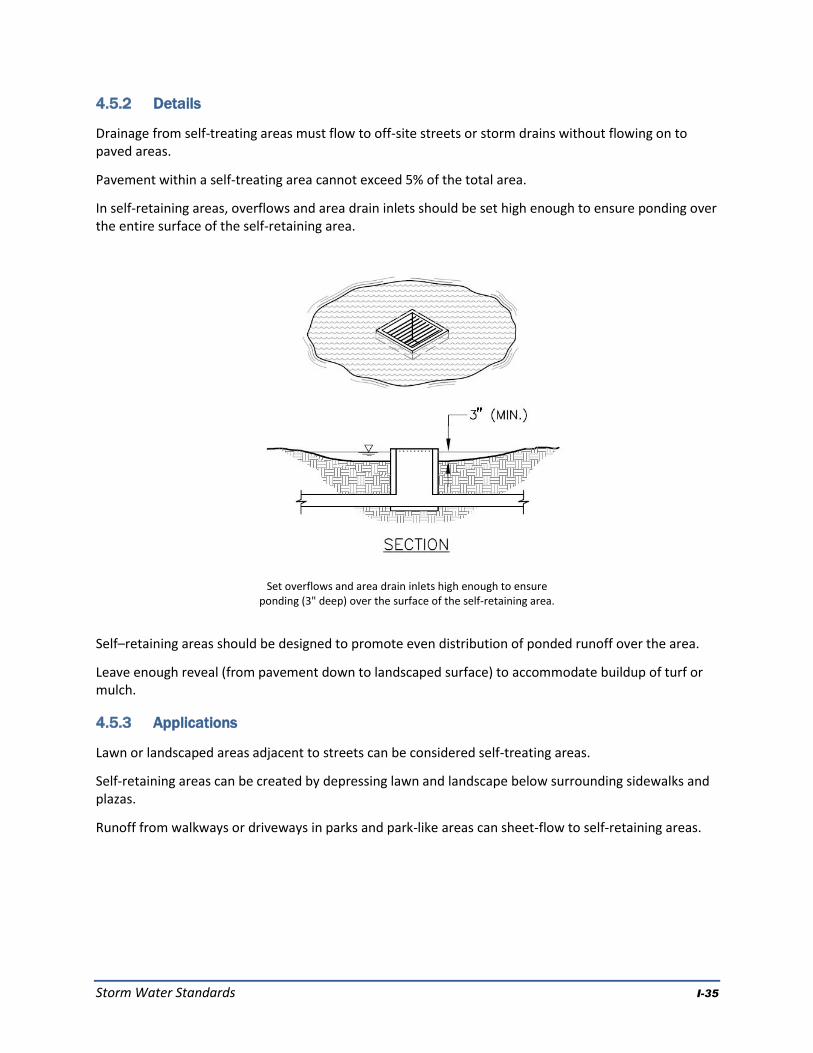
Storm Water Standards I-35
4.5.2 Details
Drainage from self-treating areas must flow to off-site streets or storm drains without flowing on to paved areas.
Pavement within a self-treating area cannot exceed 5% of the total area.
In self-retaining areas, overflows and area drain inlets should be set high enough to ensure ponding over the entire surface of the self-retaining area.
Self–retaining areas should be designed to promote even distribution of ponded runoff over the area.
Leave enough reveal (from pavement down to landscaped surface) to accommodate buildup of turf or mulch.
4.5.3 Applications
Lawn or landscaped areas adjacent to streets can be considered self-treating areas.
Self-retaining areas can be created by depressing lawn and landscape below surrounding sidewalks and plazas.
Runoff from walkways or driveways in parks and park-like areas can sheet-flow to self-retaining areas.
Set overflows and area drain inlets high enough to ensure ponding (3" deep) over the surface of the self-retaining area.

Storm Water Standards I-36
Connecting a roof leader to a self-retaining area. The head from the eave height makes it possible to
route roof drainage some distance away from the building.
Mild slopes can be terraced to create self-retaining areas.
Roof leaders can be connected to self-retaining areas by piping beneath plazas and walkways. If necessary, a “bubble-up” can be used.
Self-retaining areas can be created by terracing mild slopes. The elevation difference promotes subsurface drainage.
4.5.4 Design Checklist for Self-Treating Areas
The self-treating area is at least 95% lawn or landscaping (not more than 5% impervious).
Re-graded or re-landscaped areas have amended soils, vegetation, and irrigation as may be required to maintain soil stability and permeability.
Runoff from the self-treating area does not enter an IMP or another drainage management area, but goes directly to the storm drain system.
4.5.5 Design Checklist for Self-Retaining Areas
Area is bermed all the way around or graded concave.
Slopes do not exceed 4%.
Entire area is lawn, landscaping, or pervious pavement (see criteria in latter part of this appendix).
Area has amended soils, vegetation, and irrigation as may be required to maintain soil stability and permeability.
Any area drain inlets are at least 3 inches above surrounding grade.
4.5.6 Design Checklist for Areas draining to Self-Retaining Areas
Ratio of tributary impervious area to self-retaining area is not greater than 2:1.
Roof leaders collect runoff and route it to the self-retaining area.
Paved areas are sloped so drainage is routed to the self-retaining area.
Inlets are designed to protect against erosion and distribute runoff across the area.

Storm Water Standards I-37
4.6 Pervious Pavements
4.6.1 Criteria
Impervious roadways, driveways, and parking lots account for much of the hydrologic impact of land development. In contrast, pervious pavements allow rainfall to collect in a gravel or sand base course and infiltrate into native soil.
Pervious pavements are designed to transmit rainfall through the surface to storage in a base course. For example, a 4-inch-deep base course provides approximately 1.6 inches of storage. Runoff stored in the base course infiltrates to native soils over time. Except in the case of solid pavers, the surface course provides additional storage.
Areas with the following pervious pavements may be regarded as “self-treating” and require no additional treatment or flow control if they drain off-site (not to an IMP).
Pervious concrete
Porous asphalt
Crushed aggregate (gravel)
Open pavers with grass or plantings
Open pavers with gravel
Artificial turf
Areas with these pervious pavements can also be self-retaining areas and may receive runoff from impervious areas if they are bermed or depressed to retain the first one inch of rainfall, including runoff from the tributary impervious area.
Solid unit pavers—such as bricks, stone blocks, or precast concrete shapes—are considered to reduce runoff compared to impervious pavement, when the unit pavers are set in sand or gravel with 3/16" gaps between the pavers. Joints must be filled with an open-graded aggregate free of fines.
When draining pervious pavements to an IMP, use the runoff factors in Table 4-2.
4.6.2 Details
Permeable pavements can be used in clay soils; however, special design considerations, including an increased depth of base course, typically apply and will increase the cost of this option. Geotechnical fabric between the base course and underlying clay soil is recommended.
Pavement strength and durability typically determines the required depth of base course. If underdrains are used, the outlet elevation must be a minimum of 3 inches above the bottom elevation of the base course.
Best Uses
Areas with permeable native soils
Low-traffic areas
Where aesthetic quality can justify higher cost
Advantages
No maintenance verification requirement
Variety of surface treatments can complement landscape design
Limitations
Initial cost
Placement requires specially trained crews
Geotechnical concerns, especially in clay soils
Concerns about pavement strength and surface integrity
Some municipalities do not allow in public right of way

Storm Water Standards I-38
Pervious concrete and porous asphalt must be installed by crews with special training and tools. Industry associations maintain lists of qualified contractors.
Parking lots with crushed aggregate or unit pavers may require signs or bollards to organize parking.
4.6.3 Design Checklist For Pervious Pavements
No erodible areas drain on to pavement.
Subgrade is uniform. Compaction is minimal.
Reservoir base course is of open-graded crushed stone. Base depth is adequate to retain rainfall and support design loads.
If a subdrain is provided, outlet elevation is a minimum of 3 inches above bottom of base course.
Subgrade is uniform and slopes are not so steep that subgrade is prone to erosion.
Rigid edge is provided to retain granular pavements and unit pavers.
Solid unit pavers are installed with open gaps filled with open-graded aggregate free of fines.
Permeable pavements are installed by industry-certified professionals according to vendor’s recommendations.
Selection and location of pavements incorporates Americans with Disabilities Act requirements, site aesthetics, and uses.
Resources Southern California Concrete Producers www.concreteresources.net. California Asphalt Pavement Association
http://www.californiapavements.org/stormwater.html Interlocking Concrete Pavement Institute
http://www.icpi.org/ Start at the Source Design Manual for Water Quality Protection, pp. 47-53. www.basmaa.org Porous Pavements, by Bruce K. Ferguson. 2005. ISBN 0-8493-2670-2.

Storm Water Standards I-39
Bioretention facility configured for treatment-only requirements. Bioretention facilities can rectangular, linear, or nearly any shape.
Best Uses
Commercial areas
Residential subdivisions
Industrial developments
Roadways
Parking lots
Fit in setbacks, medians, and other landscaped areas
Advantages
Can be any shape
Low maintenance
Can be landscaped
Limitations
Require 4% of tributary impervious square footage
Typically requires 3-4 feet of head
Irrigation typically required
4.7 Bioretention Facilities
Bioretention detains runoff in a surface reservoir, filters it through plant roots and a biologically active soil mix, and then infiltrates it into the ground. Where native soils are less permeable, an underdrain conveys treated runoff to storm drain or surface drainage.
Bioretention facilities can be configured in nearly any shape. When configured as linear swales, they can convey high flows while percolating and treating lower flows.
Bioretention facilities can be configured as in-ground or above-ground planter boxes, with the bottom open to allow infiltration to native soils underneath. If infiltration cannot be allowed, use the sizing factors and criteria for the Flow-Through Planter.
4.7.1 Criteria
For development projects subject only to runoff treatment requirements, the following criteria apply:
Parameter Criterion
Soil mix depth 18 inches minimum
Soil mix minimum percolation rate 5 inches per hour minimum sustained (10 inches per hour initial rate recommended)
Soil mix surface area 0.04 times tributary impervious area (or equivalent)
Surface reservoir depth 6 inches minimum; may be sloped to 4 inches where adjoining walkways.

Storm Water Standards I-40
Parameter Criterion
Underdrain Required in Group “C” and “D” soils. Perforated pipe embedded in gravel (“Class 2 permeable” recommended), connected to storm drain or other accepted discharge point.
4.7.2 Details
Plan. On the surface, a bioretention facility should be one level, shallow basin—or a series of basins. As runoff enters each basin, it should flood and fill throughout before runoff overflows to the outlet or to the next downstream basin. This will help prevent movement of surface mulch and soil mix.
In a linear swale, check dams should be placed so that the lip of each dam is at least as high as the toe of the next upstream dam. A similar principle applies to bioretention facilities built as terraced roadway shoulders.
Inlets. Paved areas draining to the facility should be graded, and inlets should be placed, so that runoff remains as sheet flow or as dispersed as possible. Curb cuts should be wide (12" is recommended) to avoid clogging with leaves or debris. Allow for a minimum reveal of 4"-6" between the inlet and soil mix elevations to ensure turf or mulch buildup does not block the inlet. In addition, place an apron of stone or concrete, a foot square or larger, inside each inlet to prevent vegetation from growing up and blocking the inlet.
Use check dams for linear bioretention facilities (swales) on a slope.

Storm Water Standards I-41
Where runoff is collected in pipes or gutters and conveyed to the facility, protect the landscaping from high-velocity flows with energy-dissipating rocks. In larger installations, provide cobble-lined channels to better distribute flows throughout the facility.
Upturned pipe outlets can be used to dissipate energy when runoff is piped from roofs and upgradient paved areas.
Soil mix. The required soil mix is similar to a loamy sand. It must maintain a minimum percolation rate of 5" per hour throughout the life of the facility, and it must be suitable for maintaining plant life. Typically, on-site soils will not be suitable due to clay content.
Storage and drainage layer. “Class 2 permeable,” Caltrans specification 68-1.025, is recommended. Open-graded crushed rock, washed, may be used, but requires 4"-6" washed pea gravel be substituted at the top of the crushed rock gravel layers. Do not use filter fabric to separate the soil mix from the gravel drainage layer or the gravel drainage layer from the native soil.
Underdrains. No underdrain is required where native soils beneath the facility are Hydrologic Soil Group A or B. For treatment-only facilities where native soils are Group C or D, a perforated pipe must be bedded in the gravel layer and must terminate at a storm drain or other approved discharge point.
Recommended design details for bioretention facility inlets (see text).

Storm Water Standards I-42
Outlets. In treatment-only facilities, outlets must be set high enough to ensure the surface reservoir fills and the entire surface area of soil mix is flooded before the outlet elevation is reached. In swales, this can be achieved with appropriately placed check dams.
The outlet should be designed to exclude floating mulch and debris.
Vaults, utility boxes and light standards. It is best to locate utilities outside the bioretention facility—in adjacent walkways or in a separate area set aside for this purpose. If utility structures are to be placed within the facility, the locations should be anticipated and adjustments made to ensure the minimum bioretention surface area and volumes are achieved. Leaving the final locations to each individual utility can produce a haphazard, unaesthetic appearance and make the bioretention facility more difficult to maintain.
Emergency overflow. The site grading plan should anticipate extreme events and potential clogging of the overflow and route emergency overflows safely.
Trees. Bioretention areas can accommodate small or large trees. There is no need to subtract the area taken up by roots from the effective area of the facility. Extensive tree roots maintain soil permeability and help retain runoff. Normal maintenance of a bioretention facility should not affect tree lifespan.
The bioretention facility can be integrated with a tree pit of the required depth and filled with structural soil. If a root barrier is used, it can be located to allow tree roots to spread throughout the bioretention facility while protecting adjacent pavement. Locations and planting elevations should be selected to avoid blocking the facility’s inlets and outlets.
Bioretention facility configured as a tree well. The root barrier is optional.

Storm Water Standards I-43
4.7.3 Applications
Multi-purpose landscaped areas. Bioretention facilities are easily adapted to serve multiple purposes. The loamy sand soil mix will support turf or a plant palette suitable to the location and a well-drained soil.
Example landscape treatments:
Lawn with sloped transition to adjacent landscaping.
Swale in setback area
Swale in parking median
Lawn with hardscaped edge treatment
Decorative garden with formal or informal plantings
Traffic island with low-maintenance landscaping
Raised planter with seating
Bioretention on a terraced slope
Bioretention facility configured as a
recessed decorative lawn with hardscaped edge.
Bioretention facility configured and planted as a lawn/ play area.
Residential subdivisions. Some subdivisions are designed to drain roofs and driveways to the streets (in the conventional manner) and then drain the streets to bioretention areas, with one bioretention area for each 1 to 6 lots, depending on subdivision layout and topography.

Storm Water Standards I-44
If allowed by the local jurisdiction, bioretention areas can be placed on a separate, dedicated parcel with joint ownership.
Sloped sites. Bioretention facilities must be constructed as a basin, or series of basins, with the circumference of each basin set level. It may be necessary to add curbs or low retaining walls.
Bioretention facility configured as a parking median. Note use of bollards in place of curbs, eliminating the need for curb cuts.
Bioretention facility receiving drainage from individual lots and the street in a residential subdivision.

Storm Water Standards I-45
4.7.4 Design Checklist for Bioretention
Volume or depth of surface reservoir meets or exceeds minimum.
18" depth “loamy sand” soil mix with minimum long-term percolation rate of 5"/hour.
Area of soil mix meets or exceeds minimum.
Perforated pipe underdrain bedded in “Class 2 perm” with connection and sufficient head to storm drain or discharge point (except in “A” or “B” soils).
No filter fabric.
Underdrain has a clean-out port consisting of a vertical, rigid, non-perforated PVC pipe, with a minimum diameter of 6 inches and a watertight cap.
Location and footprint of facility are shown on site plan and landscaping plan.
Bioretention area is designed as a basin (level edges) or a series of basins, and grading plan is consistent with these elevations. If facility is designed as a swale, check dams are set so the lip of each dam is at least as high as the toe of the next upstream dam.
Inlets are 12" wide, have 4"-6" reveal and an apron or other provision to prevent blockage when vegetation grows in, and energy dissipation as needed.
Overflow connected to a downstream storm drain or approved discharge point.
Emergency spillage will be safely conveyed overland.
Plantings are suitable to the climate and a well-drained soil.
Irrigation system with connection to water supply.
Vaults, utility boxes, and light standards are located outside the minimum soil mix surface area.
When excavating, avoid smearing of the soils on bottom and side slopes. Minimize compaction of native soils and “rip” soils if clayey and/or compacted. Protect the area from construction site runoff.

Storm Water Standards I-46

Storm Water Standards I-47

Storm Water Standards I-48
4.8 Flow-through Planter
Flow-through planters treat and detain runoff without allowing seepage into the underlying soil. They can be used next to buildings and on slopes where stability might be affected by adding soil moisture.
Flow-through planters typically receive runoff via downspouts leading from the roofs of adjacent buildings. However, they can also be set in-ground and receive sheet flow from adjacent paved areas.
Pollutants are removed as runoff passes through the soil layer and is collected in an underlying layer of gravel or drain rock. A perforated-pipe underdrain is typically connected to a storm drain or other discharge point. An overflow inlet conveys flows which exceed the capacity of the planter.
4.8.1 Criteria
Treatment only. For development projects subject only to runoff treatment requirements, the following criteria apply:
Parameter Criterion
Soil mix depth 18 inches minimum
Soil mix minimum percolation rate 5 inches per hour minimum sustained (10 inches per hour initial rate recommended)
Soil mix surface area 0.04 times tributary impervious area (or equivalent)
Surface reservoir depth 6" minimum; may be sloped to 4" where adjoining walkways.
Underdrain Typically used. Perforated pipe embedded in gravel (“Class 2 permeable” recommended), connected to storm drain or other accepted discharge point.
Portland 2004 Stormwater Manual
Best Uses
Management of roof runoff
Next to buildings
Dense urban areas
Where infiltration is not desired
Advantages
Can be used next to structures
Versatile
Can be any shape
Low maintenance
Limitations
Can be used for flow-control only on sites with “C” and “D” soils
Requires underdrain
Requires 3-4 feet of head

Storm Water Standards I-49
4.8.2 Details
Configuration. The planter must be level. To avoid standing water in the subsurface layer, set the perforated pipe underdrain and orifice as nearly flush with the planter bottom as possible.
Inlets. Protect plantings from high-velocity flows by adding rocks or other energy-dissipating structures at downspouts and other inlets.
Soil mix. The required soil mix is similar to a loamy sand. It must maintain a minimum percolation rate of 5" per hour throughout the life of the facility, and it must be suitable for maintaining plant life. Typically, on-site soils will not be suitable due to clay content.
Gravel storage and drainage layer. “Class 2 permeable,” Caltrans specification 68-1.025, is recommended. Open-graded crushed rock, washed, may be used, but requires 4"-6" of washed pea gravel be substituted at the top of the crushed rock layer. Do not use filter fabric to separate the soil mix from the gravel drainage layer.
Emergency overflow. The planter design and installation should anticipate extreme events and potential clogging of the overflow and route emergency overflows safely.
4.8.3 Applications
Adjacent to buildings. Flow-through planters may be located adjacent to buildings, where the planter vegetation can soften the visual effect of the building wall. A setback with a raised planter box may be appropriate even in some neo-traditional pedestrian-oriented urban streetscapes.
At plaza level. Flow-through planters have been successfully incorporated into podium-style developments, with the planters placed on the plaza level and receiving runoff from the tower roofs above. Runoff from the plaza level is typically managed separately by additional flow-through planters or bioretention facilities located at street level.
Steep slopes. Flow-through planters provide a means to detain and treat runoff on slopes that cannot accept infiltration from a bioretention facility. The planter can be built into the slope similar to a retaining wall. The design should consider the need to access the planter for periodic maintenance. Flows from the planter underdrain and overflow must be directed in accordance with local requirements. It is sometimes possible to disperse these flows to the downgradient hillside.

Storm Water Standards I-50
Flow-through planter on the plaza level of a podium-style development.
Flow-through planter built into a hillside. Flows from the underdrain and overflow must be directed in accordance with local requirements.
4.8.4 Design Checklist for Flow-through Planter
Reservoir depth is 4-6" minimum.
18" depth “loamy sand” soil mix with minimum long-term infiltration rate of 5"/hour.
Area of soil mix meets or exceeds minimum.
“Class 2 perm” drainage layer.
No filter fabric.
Perforated pipe underdrain with outlet located flush or nearly flush with planter bottom. Connection with sufficient head to storm drain or discharge point.
Underdrain has a clean-out port consisting of a vertical, rigid, non-perforated PVC pipe, with a minimum diameter of 6 inches and a watertight cap.
Overflow connected to a downstream storm drain or approved discharge point.
Location and footprint of facility are shown on site plan and landscaping plan.
Planter is set level.
Emergency spillage will be safely conveyed overland.
Plantings are suitable to the climate and a well-drained soil.
Irrigation system with connection to water supply.

Storm Water Standards I-51

Storm Water Standards I-52
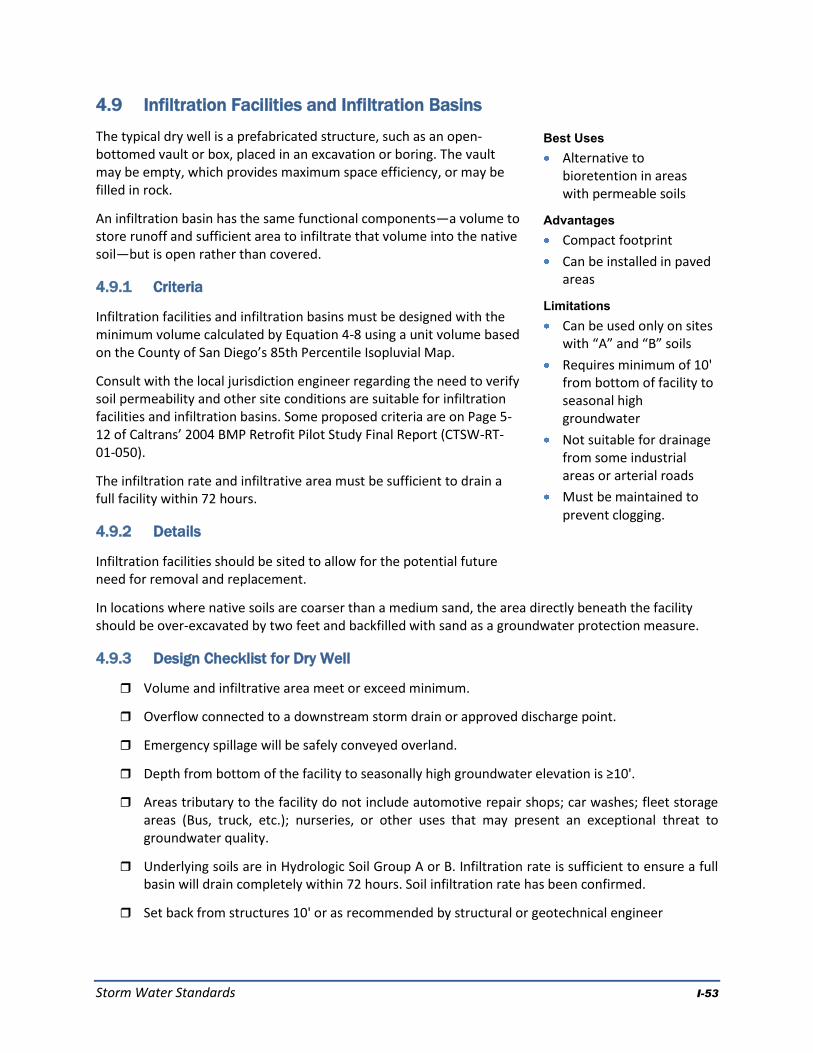
Storm Water Standards I-53
Best Uses
Alternative to bioretention in areas with permeable soils
Advantages
Compact footprint
Can be installed in paved areas
Limitations
Can be used only on sites with “A” and “B” soils
Requires minimum of 10' from bottom of facility to seasonal high groundwater
Not suitable for drainage from some industrial areas or arterial roads
Must be maintained to prevent clogging.
4.9 Infiltration Facilities and Infiltration Basins
The typical dry well is a prefabricated structure, such as an open-bottomed vault or box, placed in an excavation or boring. The vault may be empty, which provides maximum space efficiency, or may be filled in rock.
An infiltration basin has the same functional components—a volume to store runoff and sufficient area to infiltrate that volume into the native soil—but is open rather than covered.
4.9.1 Criteria
Infiltration facilities and infiltration basins must be designed with the minimum volume calculated by Equation 4-8 using a unit volume based on the County of San Diego’s 85th Percentile Isopluvial Map.
Consult with the local jurisdiction engineer regarding the need to verify soil permeability and other site conditions are suitable for infiltration facilities and infiltration basins. Some proposed criteria are on Page 5-12 of Caltrans’ 2004 BMP Retrofit Pilot Study Final Report (CTSW-RT-01-050).
The infiltration rate and infiltrative area must be sufficient to drain a full facility within 72 hours.
4.9.2 Details
Infiltration facilities should be sited to allow for the potential future need for removal and replacement.
In locations where native soils are coarser than a medium sand, the area directly beneath the facility should be over-excavated by two feet and backfilled with sand as a groundwater protection measure.
4.9.3 Design Checklist for Dry Well
Volume and infiltrative area meet or exceed minimum.
Overflow connected to a downstream storm drain or approved discharge point.
Emergency spillage will be safely conveyed overland.
Depth from bottom of the facility to seasonally high groundwater elevation is ≥10'.
Areas tributary to the facility do not include automotive repair shops; car washes; fleet storage areas (Bus, truck, etc.); nurseries, or other uses that may present an exceptional threat to groundwater quality.
Underlying soils are in Hydrologic Soil Group A or B. Infiltration rate is sufficient to ensure a full basin will drain completely within 72 hours. Soil infiltration rate has been confirmed.
Set back from structures 10' or as recommended by structural or geotechnical engineer

Storm Water Standards I-54
Best Uses
In series with a bioretention facility to meet treatment requirement in limited space.
Management of roof runoff
Dense urban areas
Advantages
Storage volume can be in any configuration
Limitations
Somewhat complex to design, build, and operate
Requires head for both cistern and bioretention facility
4.10 Cistern with Bioretention Facility
A cistern in series with a bioretention facility can meet treatment requirements where space is limited. In this configuration, the cistern is equipped with a flow-control orifice and the bioretention facility is sized to treat a trickle outflow from the cistern.
4.10.1 Criteria
Cistern. The cistern must detain the volume calculated by Equation 4-8 and must include an orifice or other device designed for a 24-hour drawdown time.
Bioretention facility. See the design sheet for bioretention facilities. The area of the bioretention facility must be sized to treat the maximum discharge flow, assuming a percolation rate of 5" per hour through the engineered soil.
Use with sand filter. A cistern in series with a sand filter can meet treatment requirements (See the discussion of treatment facility selection in Chapter 2 of the Model SUSMP and the design guidance for sand filters found later in this appendix).
4.10.2 Details
Flow-control orifice. The cistern must be equipped with an orifice plate or other device to limit flow to the bioretention area.
Preventing mosquito harborage. Cisterns should be designed to drain completely, leaving no standing water. Drains should be located flush with the bottom of the cistern. Alternatively—or in addition—all entry and exit points, should be provided with traps or sealed or screened to prevent mosquito entry. Note mosquitoes can enter through openings 1/16" or larger and will fly for many feet through pipes as small as ¼".
Exclude debris. Provide leaf guards and/or screens to prevent debris from accumulating in the cistern.
Ensure access for maintenance. Design the cistern to allow for cleanout. Avoid creating the need for maintenance workers to enter a confined space. Ensure the outlet orifice can be easily accessed for cleaning and maintenance.
4.10.3 Applications
Shallow ponding on a flat roof. The “cistern” storage volume can be designed in any configuration, including simply storing rainfall on the roof where it falls and draining it away slowly. See the County of San Diego’s 85th percentile isopluvial diagrams for required average depths.
Cistern attached to a building and draining to a planter. This arrangement allows a planter box to be constructed with a smaller area.

Storm Water Standards I-55
Vault with pumped discharge to bioretention facility. In this arrangement, runoff from a parking lot and/or building roofs can be captured and detained underground and then pumped to a bioretention facility on the surface. Alternatively, treatment can be accomplished with a sand filter(See the discussion of selection of stormwater treatment facilities in Chapter 2 of the Model SUSMP).
Water harvesting or graywater reuse. It may be possible to create a site-specific design that uses cisterns to achieve stormwater flow control, stormwater treatment, and rainwater reuse for irrigation or indoor uses (water harvesting). Facilities must meet criteria for capturing and treating the volume specified by Equation 4-8. This volume must be allowed to empty within 24 hours so runoff from additional storms, which may follow, is also captured and treated. Additional volume may be required if the system also stores runoff for longer periods for reuse. Indoor uses of non-potable water may be restricted or prohibited. Check with municipal staff.
4.10.4 Design Checklist for Cistern
Volume meets or exceeds minimum.
Outlet with orifice or other flow-control device restricts flow and is designed to provide a 24-hour drawdown time.
Outlet is piped to a bioretention facility designed to treat the maximum discharge from the cistern orifice.
Cistern is designed to drain completely and/or sealed to prevent mosquito harborage.
Design provides for exclusion of debris and accessibility for maintenance.
Overflow connected to a downstream storm drain or approved discharge point.
Emergency spillage will be safely conveyed overland.

Storm Water Standards I-56

Storm Water Standards J
APPENDIX J
Definitions

This Page Intentionally Left Blank.

Appendix J Definitions
Storm Water Standards J-1
APPENDIX J
Definitions
“Advanced Treatment” means to use mechanical or chemical means to flocculate and remove suspended sediment from runoff from construction sites prior to discharge. Advanced treatment is required if there were exceptional threats to water quality. "Attached Residential Development" means any development that provides 10 or more residential units that share an interior/exterior wall. This category includes, but is not limited to dormitories, condominiums, and apartments. "Automotive Repair Shop" means a facility that is categorized in any one of the following Standard Industrial Classification (SIC) codes: 5013, 5014, 5541, 7532-7534, or 7536-7539. “Best Management Practices” Any procedure or device designed to minimize the quantity of pollutants that enter the storm drain system. “California Association of Stormwater Quality Agencies (CASQA)” Publisher of the California Stormwater Best Management Practices Handbooks, available at www.cabmphandbooks.com. Successor to the Storm Water Quality Task Force (SWQTF). “California BMP Method” A method for determining the required volume of stormwater treatment facilities. Described in Section 5.5.1 of the California Stormwater Best Management Practice Manual (New Development) (CASQA, 2003). “Commercial Development” means any development on private land that is not exclusively heavy industrial or residential uses. The category includes, but is not limited to: mini-malls and other business complexes, shopping malls, hotels, office buildings, public warehouses, hospitals, laboratories and other medical facilities, educational institutions, recreational facilities, plant nurseries, car wash facilities, automotive dealerships, commercial airfields, and other light industrial complexes. "Commercial Development greater than one acre" means any commercial development that with a project footprint of at least one acre. Conditions of Approval (COAs). Requirements a municipality may adopt for a project in connection with a discretionary action (e.g., adoption of an EIR or negative declaration or issuance of a use permit). COAs may include features to be incorporated into the final plans for the project and may also specify uses, activities, and operational measures that must be observed over the life of the project. Construction Permits. Any building, electrical, plumbing/mechanical, demolition/removal, grading, public right-of-way, and sign permits, reviewed in accordance with Process One by the Development Services Department, as described in Chapter 12, Article 9, Divisions 1 through 8 of the Land Development Code.

Appendix J Definitions
Storm Water Standards J-2
Continuous Simulation Modeling. A method of hydrological analysis in which a set of rainfall data (typically hourly for 30 years or more) is used as input, and runoff rates are calculated on the same time step. The output is then analyzed statistically for the purposes of comparing runoff patterns under different conditions (for example, pre- and post-development-project). Copermittees. See Dischargers. Detention. The practice of holding stormwater runoff in ponds, vaults, within berms, or in depressed areas and letting it discharge slowly to the storm drain system. See definitions of infiltration and retention. “Development Project” New development or redevelopment with land disturbing activities; structural development, including construction or installation of a building or structure, the creation of impervious surfaces, land development by public agencies, and land subdivision resulting in land development activity. Directly Connected Impervious Area (DCIA). Any impervious surface which drains into a catch basin, area drain, or other conveyance structure without first allowing flow across pervious areas (e.g. lawns). Direct Infiltration. Infiltration via methods or devices, such as dry wells or infiltration trenches, designed to bypass unsaturated surface soils and transmit runoff directly to groundwater. Dischargers. The agencies named in the stormwater NPDES permit (see definition): the County of San Diego; the Cities of Carlsbad, El Cajon, La Mesa, Poway, Solana Beach, Chula Vista, Encinitas, Lemon Grove, San Diego, Vista, Coronado, Escondido, National City, San Marcos, Del Mar, Imperial Beach, Oceanside, and Santee; the San Diego Unified Port District, and the San Diego County Regional Airport Authority. “Discretionary Actions” means any adoption or amendment of a land use plan, zoning or rezoning action, development agreement, subdivision of land in accordance with the Subdivision Map Act, or development permits reviewed by Development Services staff, as described in Chapter 12, Articles 2 through 6 of the Land Development Code. Drainage Management Areas. Areas delineated on a map of the development site showing how drainage is detained, dispersed, or directed to Integrated Management Practices. There are four types of Drainage Management Areas, and specific criteria apply to each type of area. See Chapter 4. Drawdown Time. The time required for a stormwater detention or infiltration facility to drain and return to the dry-weather condition. For detention facilities, drawdown time is a function of basin volume and outlet orifice size. For infiltration facilities, drawdown time is a function of basin volume and infiltration rate. Environmentally Sensitive Areas. Areas that include but are not limited to all Clean Water Act Section 303(d) impaired water bodies; areas designated as Areas of Special Biological Significance by the State Water Resources Control Board (Water Quality Control Plan for the San Diego Basin (1994) and amendments); water bodies designated with the RARE beneficial use by the State Water Resources Control Board (Water Quality Control Plan for the San Diego Basin (1994) and amendments); areas designated as preserves or their equivalent under the

Appendix J Definitions
Storm Water Standards J-3
Multi Species Conservation Program within the Cities and County of San Diego; and any other equivalent environmentally sensitive areas which have been identified by the Copermittees. Flow Control. Control of runoff rates and durations as required by the Hydromodification Management Plan. Head. In hydraulics, energy represented as a difference in elevation. In slow-flowing open systems, the difference in water surface elevation, e.g., between an inlet and outlet. Higher-Rate Biofilter. A biofilter with a design surface loading rate higher than the 5 inches per hour rate specified in this document for bioretention facilities and planter boxes. Housing development greater than 10 dwelling units. This category includes single-family homes, multi-family homes, condominiums, and apartments. Hydromodification. The change in the natural watershed hydrologic processes and runoff characteristics (i.e., interception, infiltration, overland flow, interflow and groundwater flow) caused by urbanization or other land use changes that result in increased stream flows and sediment transport. In addition, alteration of stream and river channels, installation of dams and water impoundments, and excessive stream-bank and shoreline erosion are also considered hydromodification, due to their disruption of natural watershed hydrologic processes. Hydromodification Management Plan (HMP). A Plan implemented by the dischargers so that post-project runoff shall not exceed estimated pre-project rates and/or durations, where increased runoff would result in increased potential for erosion or other adverse impacts to beneficial uses. Also see definition for flow control. Hydrologic Soil Group. Classification of soils by the Natural Resources Conservation Service (NRCS) into A, B, C, and D groups according to infiltration capacity. Impervious surface. Any material that prevents or substantially reduces infiltration of water into the soil. See discussion of imperviousness in Chapter Two. “Industrial development greater than one acre.” This category includes, but is not limited to, manufacturing plants, food processing plants, metal working facilities, printing plants, and fleet storage areas (bus, truck, etc.). Infeasible. As applied to best management practices, impossible to implement because of technical constraints specific to the site. Infiltration. Seepage of runoff into soils underlying the site. See definition of retention. Infiltration Device. Any structure, such as a dry well, that is designed to infiltrate stormwater into the subsurface and, as designed, bypasses the natural groundwater protection afforded by surface or near-surface soil. See definition for direct infiltration. Integrated Management Practice (IMP). A facility (BMP) that provides small-scale treatment, retention, and/or detention and is integrated into site layout, landscaping, and drainage design. See Low Impact Development.

Appendix J Definitions
Storm Water Standards J-4
Integrated Pest Management (IPM). An approach to pest management that relies on information about the life cycles of pests and their interaction with the environment. Pest control methods are applied with the most economical means and with the least possible hazard to people, property, and the environment. Interim Hydromodification Criteria. Pursuant to NPDES permit Provision D.1.d.g.(6), the Copermittees prepared Interim Hydromodification Management criteria, which apply to projects disturbing 50 acres or more. The criteria are described in Chapter 2 and in memoranda on the Project Clean Water website. Jurisdictional Urban Runoff Management Plan (JURMP). A written description of the specific jurisdictional urban runoff management measures and programs that each Copermittee implements to comply with the stormwater NPDES permit and ensure pollutant discharges are reduced to the MEP and do not cause or contribute to a violation of water quality standards. See Stormwater Pollution Prevention Program. Lead Agency. The public agency that has the principal responsibility for carrying out or approving a project. (CEQA Guidelines §15367). Low Impact Development. An integrated site design methodology that uses small-scale detention and retention (Integrated Management Practices, or IMPs) to mimic pre-existing site hydrological conditions. Maximum Extent Practicable (MEP). Standard, established by the 1987 amendments to the Clean Water Act, for the implementation of municipal stormwater pollution prevention programs (see definition). According to the Act, municipal stormwater NPDES permits “shall require controls to reduce the discharge of pollutants to the maximum extent practicable, including management practices, control techniques and system, design and engineering methods, and such other provisions as the Administrator or the State determines appropriate for the control of such pollutants.” National Pollutant Discharge Elimination System (NPDES). As part of the 1972 Clean Water Act, Congress established the NPDES permitting system to regulate the discharge of pollutants from municipal sanitary sewers and industries. The NPDES was expanded in 1987 to incorporate permits for stormwater discharges as well. "New Development" means land disturbing activities; structural development, including construction or installation of a building or structure, the creation of impervious surfaces; and land subdivision. Numeric Criteria. Sizing requirements for stormwater treatment facilities established in Provision D.1.d.(6)(c) of the San Diego RWQCB’s stormwater NPDES permit. Operation and Maintenance (O&M). Refers to requirements in the Stormwater NPDES Permit to inspect treatment BMPs and implement preventative and corrective maintenance in perpetuity. See Chapter Five. Parking Lot. A land area or facility for the temporary parking or storage of motor vehicles used personally, for business, or for commerce.

Appendix J Definitions
Storm Water Standards J-5
Permeable Pavements. Pavements for roadways, sidewalks, or plazas that are designed to infiltrate a portion of rainfall, including pervious concrete, pervious asphalt, unit-pavers-on-sand, and crushed gravel. “Pollutant” is any agent that may cause or contribute to the degradation of water quality such that a condition of pollution or contamination is created or aggravated. “Pollutants of Concern.” For the purposes of identifying pollutants of concern and associated storm water BMPs, pollutants are grouped in nine general categories as follows:
General Categories of Water Pollution:
1. Sediments - Sediments are soils or other surficial materials eroded and then transported or deposited by the action of wind, water, ice, or gravity. Sediments can increase turbidity, clog fish gills, reduce spawning habitat, lower young aquatic organisms survival rates, smother bottom dwelling organisms, and suppress aquatic vegetation growth.
2. Nutrients - Nutrients are inorganic substances, such as nitrogen and phosphorus. They
commonly exist in the form of mineral salts that are either dissolved or suspended in water. Primary sources of nutrients in urban runoff are fertilizers and eroded soils. Excessive discharge of nutrients to water bodies and streams can cause excessive aquatic algae and plant growth. Such excessive production, referred to as cultural eutrophication, may lead to excessive decay of organic matter in the water body, loss of oxygen in the water, release of toxins in sediment, and the eventual death of aquatic organisms.
3. Metals - Metals are raw material components in non-metal products such as fuels,
adhesives, paints, and other coatings. Primary source of metal pollution in storm water are typically commercially available metals and metal products. Metals of concern include cadmium, chromium, copper, lead, mercury, and zinc. Lead and chromium have been used as corrosion inhibitors in primer coatings and cooling tower systems. At low concentrations naturally occurring in soil, metals are not toxic. However, at higher concentrations, certain metals can be toxic to aquatic life. Humans can be impacted from contaminated groundwater resources, and bioaccumulation of metals in fish and shellfish. Environmental concerns, regarding the potential for release of metals to the environment, have already led to restricted metal usage in certain applications.
4. Organic Compounds - Organic compounds are carbon-based. Commercially available
or naturally occurring organic compounds are found in pesticides, solvents, and hydrocarbons. Organic compounds can, at certain concentrations, indirectly or directly constitute a hazard to life or health. When rinsing off objects, toxic levels of solvents and cleaning compounds can be discharged to storm drains. Dirt, grease, and grime retained in the cleaning fluid or rinse water may also adsorb levels of organic compounds that are harmful or hazardous to aquatic life.
5. Trash & Debris - Trash (such as paper, plastic, polystyrene packing foam, and
aluminum materials) and biodegradable organic matter (such as leaves, grass cuttings, and food waste) are general waste products on the landscape. The presence of trash & debris may have a significant impact on the recreational value of a water body and

Appendix J Definitions
Storm Water Standards J-6
aquatic habitat. Excess organic matter can create a high biochemical oxygen demand in a stream and thereby lower its water quality. Also, in areas where stagnant water exists, the presence of excess organic matter can promote septic conditions resulting in the growth of undesirable organisms and the release of odorous and hazardous compounds such as hydrogen sulfide.
6. Oxygen-Demanding Substances - This category includes biodegradable organic
material as well as chemicals that react with dissolved oxygen in water to form other compounds. Proteins, carbohydrates, and fats are examples of biodegradable organic compounds. Compounds such as ammonia and hydrogen sulfide are examples of oxygen-demanding compounds. The oxygen demand of a substance can lead to depletion of dissolved oxygen in a water body and possibly the development of septic conditions.
7. Oil and Grease - Oil and grease are characterized as high-molecular weight organic
compounds. Primary sources of oil and grease are petroleum hydrocarbon products, motor products from leaking vehicles, esters, oils, fats, waxes, and high molecular-weight fatty acids. Introduction of these pollutants to the water bodies are very possible due to the wide uses and applications of some of these products in municipal, residential, commercial, industrial, and construction areas. Elevated oil and grease content can decrease the aesthetic value of the water body, as well as the water quality.
8. Bacteria and Viruses - Bacteria and viruses are ubiquitous microorganisms that thrive
under certain environmental conditions. Their proliferation is typically caused by the transport of animal or human fecal wastes from the watershed. Water containing excessive bacteria and viruses can alter the aquatic habitat and create a harmful environment for humans and aquatic life. Also, the decomposition of excess organic waste causes increased growth of undesirable organisms in the water.
9. Pesticides - Pesticides (including herbicides) are chemical compounds commonly used
to control nuisance growth or prevalence of organisms. Excessive application of a pesticide may result in runoff containing toxic levels of its active component.
“Pollution Prevention” means practices and processes that reduce or eliminate the generation of pollutants, in contrast to source control, treatment, or disposal. Pollution prevention is generally the best “first line of defense” and should be used in conjunction with site design, source control, and treatment control BMPs. “Post-Project Flows” means the peak runoff flows and runoff volume anticipated after the project has been constructed taking into account all permeable and impermeable surfaces, soil and vegetation types and conditions after landscaping is complete, detention or retention basins or other water storage elements incorporated into the site design, and any other site features that would affect runoff volumes and peak flows. “Pre-Development Hydrologic Conditions” means hydrologic conditions that would exist assuming no pavement, structures or hardened surfaces, site vegetation typical of native conditions in the climate and ecological zone of the site, topography similar to current conditions without structures, pavements, or artificially hardened surfaces, and soil types similar to current conditions without structures, pavements, or artificially hardened surfaces. The terms “pre-development runoff”, “pre-development flow”, or “pre-development volume”, are the quantitative measures associated with this definition.

Appendix J Definitions
Storm Water Standards J-7
Priority Development Project. A project subject to SUSMP requirements. Defined in Stormwater NPDES Permit Provision D.1.d.(1). See Chapter One. Project Area. The entire project area comprises all areas to be altered or developed by the project, plus any additional areas that drain on to areas to be altered or developed. Project Submittal. Documents submitted to a municipality in connection with an application for development approval and demonstrating compliance with Stormwater NPDES Permit requirements for the project. Specific requirements vary from municipality to municipality. "Projects Discharging to Receiving Waters within Water Quality Sensitive Areas" means all development and significant redevelopment that would create 2,500 square feet of impervious surfaces or increase the area of imperviousness of a project site to 10% or more of its naturally occurring condition, and either discharge urban runoff to a receiving water within a water quality sensitive area (where any portion of the project footprint is located within 200 feet of the water quality sensitive area), or discharge to a receiving water within an water quality sensitive area without mixing with flows from adjacent lands (where the project footprint is located more than 200 feet from the water quality sensitive area). "Project Footprint" means the limits of all grading and ground disturbance, including landscaping, associated with a project. Proprietary. A proprietary device is one marketed under legal right of the manufacturer. "Residential Development" means any development on private land that provides living accommodations for one or more persons. This category includes, but is not limited to: single-family homes, multi-family homes, condominiums, and apartments. "Restaurant" means a stand-alone facility that sells prepared foods and drinks for consumption, including stationary lunch counters and refreshment stands selling prepared foods and drinks for immediate consumption (SIC code 5812). "Significant Redevelopment" means development that would create, replace, or add at least 5,000 square feet of impervious surfaces on an already developed site. Significant redevelopment includes, but is not limited to: the expansion of a building footprint; addition to or replacement of a structure; replacement of an impervious surface that is not part of a routine maintenance activity; and land disturbing activities related with structural or impervious surfaces. Replacement of impervious surfaces includes any activity that is not part of a routine maintenance activity where impervious material(s) are removed, exposing underlying soil during construction. Significant redevelopment does not include trenching and resurfacing associated with utility work; resurfacing and reconfiguring surface parking lots; new sidewalk construction, pedestrian ramps, or bike lane on existing roads; and replacement of damaged pavement. "Site Design BMP" means any project design feature that reduces the creation or severity of potential pollutant sources or reduces the alteration of the project site's natural flow regime. Redevelopment projects that are undertaken to remove pollutant sources (such as existing surface parking lots and other impervious surfaces) or to reduce the need for new roads and other impervious surfaces (as compared to conventional or low-density new development) by incorporating higher densities and/or mixed land uses into the project design, are also considered site design BMPs.

Appendix J Definitions
Storm Water Standards J-8
"Source Control BMP (both structural and non-structural)" means land use or site planning practices, or structures that aim to prevent urban runoff pollution by reducing the potential for contamination at the source of pollution. Source control BMPs minimize the contact between pollutants and urban runoff. Examples include roof structures over trash or material storage areas, and berms around fuel dispensing areas. "Steep hillside development greater than 5,000 square feet" means any development that would create more than 5,000 square feet of impervious surfaces in hillsides with known erosive soil conditions. "Steep hillside" means lands that have a natural gradient of 25 percent (4 feet of horizontal distance for every 1 foot of vertical distance) or greater and a minimum elevation differential of 50 feet, or a natural gradient of 200 percent (1 foot of horizontal distance for every 2 feet of vertical distance) or greater and a minimum elevation differential of 10 feet. “Retail Gasoline Outlets (RGO).” This category includes RGOs that meet the following criteria: (a) 5,000 square feet or more or (b) a projected Average Daily Traffic (ADT) of 100 or more vehicles per day. Rational Method. A method of calculating runoff flows based on rainfall intensity, tributary area, and a factor representing the proportion of rainfall that runs off. Receiving Waters. Surface bodies of water, which directly or indirectly receive discharges from urban runoff conveyance systems, including naturally occurring wetlands, streams (perennial, intermittent, and ephemeral (exhibiting bed, bank, and ordinary high water mark)), creeks, rivers, reservoirs, lakes, lagoons, estuaries, harbors, bays and the Pacific Ocean. The City shall determine the definition for wetlands and the limits thereof for the purposes of this definition, which shall be as protective as the Federal definition utilized by the United States Army Corps of Engineers and the United States Environmental Protection Agency. Constructed wetlands are not considered wetlands under this definition, unless the wetlands were constructed as mitigation for habitat loss. Other constructed BMPs are not considered receiving waters under this definition, unless the BMP was originally constructed in receiving waters. Redevelopment. The creation, addition, and or replacement of impervious surface on an already developed site. Examples include the expansion of a building footprint, road widening, the addition to or replacement of a structure, and creation or addition of impervious surfaces. Replacement of impervious surfaces includes any activity that is not part of a routine maintenance activity where impervious material(s) are removed, exposing underlying soil during construction. Redevelopment does not include trenching and resurfacing associated with utility work; resurfacing and reconfiguring surface parking lots and existing roadways; new sidewalk construction, pedestrian ramps, or bikelane on existing roads; and routine replacement of damaged pavement, such as pothole repair. Regional (or Watershed) Stormwater Treatment Facility. A facility that treats runoff from more than one project or parcel. Regional Water Quality Control Board (Regional Water Board or RWQCB). California RWQCBs are responsible for implementing pollution control provisions of the Clean Water Act and California Water Code within their jurisdiction. There are nine California RWQCBs.

Appendix J Definitions
Storm Water Standards J-9
Retention. The practice of holding stormwater in ponds or basins, or within berms or depressed areas, and allowing it to slowly infiltrate into underlying soils. Some portion will evaporate. See definitions for infiltration and detention. Self-retaining area. An area designed to retain runoff. Self-retaining areas may include graded depressions with landscaping or pervious pavements and may also include tributary impervious areas up to a 2:1 impervious-to-pervious ratio. Self-treating area. A natural, landscaped, or turf area drains directly off site or to the public storm drain system. Source Control. Land use or site planning practices, or structural or nonstructural measures that aim to prevent urban runoff pollution by reducing the potential for contamination at the source of pollution. Source control BMPs minimize the contact between pollutants and urban runoff. Standard Industrial Classification (SIC). A Federal government system for classifying industries by 4-digit code. It is being supplanted by the North American Industrial Classification System but SIC codes are still referenced by the Regional Water Board in identifying development sites subject to regulation under the NPDES permit. Information and an SIC search function are available at http://www.bls.gov/bls/NAICS.htm Standard Urban Stormwater Mitigation Plan (SUSMP). Refers to various documents prepared in connection with implementation of the stormwater NPDES permit mandate to control pollutants from new development and redevelopment. Each discharger will adapt this model countywide SUSMP to create a local SUSMP for their respective jurisdiction. Applicants for development project approvals will use the local SUSMP to prepare a submittal for each Priority Development Project they propose. "Storm Water Best Management Practice (BMP)" means any schedules of activities, prohibitions of practices, general good house keeping practices, pollution prevention and educational practices, maintenance procedures, structural treatment BMPs, and other management practices to prevent or reduce to the maximum extent practicable the discharge of pollutants directly or indirectly to receiving waters. Storm Water BMPs also include treatment requirements, operating procedures and practices to control site runoff, spillage or leaks, sludge or waste disposal, or drainage from raw material storage. This manual groups development-related storm water BMPs into two categories:
(1) Construction Storm Water BMPs, which are practices, procedures, devices or materials used to prevent the transport and introduction of pollutants both on and from a project site during construction; and
(2) Permanent Storm Water BMPs, which are the site design features, source control features, and treatment control BMPs that become a permanent part of a project’s design and remain functioning throughout the “use” phase of a project site. (See the definitions for site design, source control, and treatment control BMPs in this appendix).
“Stormwater Conveyance System” means private and public drainage facilities by which storm water may be conveyed to Receiving Waters, such as: natural drainages, ditches, roads, streets, constructed channels, aqueducts, storm drains, pipes, street gutters, or catch basins.

Appendix J Definitions
Storm Water Standards J-10
Stormwater NPDES Permit. A permit issued by a Regional Water Quality Control Board (see definition) to local government agencies (Dischargers) placing provisions on allowable discharges of municipal stormwater to waters of the state. Storm Water Pollution Prevention Plan (SWPPP). A plan providing for temporary measures to control sediment and other pollutants during construction as required by the statewide stormwater NPDES permit for construction activities. Stormwater Pollution Prevention Program. A comprehensive program of activities designed to minimize the quantity of pollutants entering storm drains. See Jurisdictional Urban Runoff Management Plan. "Streets, Roads, Highways, and Freeways" means any project that is not part of a routine maintenance activity, and would create a new paved surface that is 5,000 square feet or greater used for the transportation of automobiles, trucks, motorcycles and other vehicles. For the purposes of Storm Water Standards Manual requirements, Streets, Roads, Highways and Freeways do not include trenching and resurfacing associated with utility work; applying asphalt overlay to existing pavement; new sidewalk, pedestrian ramps, or bike lane construction on existing roads; and replacement of damaged pavement. Treatment. Removal of pollutants from runoff, typically by filtration or settling. "Treatment Control (Structural) BMP" means any engineered system designed and constructed to remove pollutants from urban runoff. Pollutant removal is achieved by simple gravity settling of particulate pollutants, filtration, biological uptake, media adsorption, or any other physical, biological, or chemical process. Water Board. See Regional Water Quality Control Board. "Water Quality Sensitive Areas" means areas that include, but are not limited to, all Clean Water Act 303(d) impaired water bodies ("303[d] water bodies"); areas designated as an "Area of Special Biological Significance" (ASBS) by the State Water Resources Control Board (Water Quality Control Plan for the San Diego Basin (1994) and amendments); water bodies designated as having a RARE beneficial use by the State Water Resources Control Board (Water Quality Control Plan for the San Diego Basin (1994) and amendments), or areas designated as preserves or their equivalent under the Multiple Species Conservation Program (MSCP) within the Cities and County of San Diego. The limits of Areas of Special Biological Significance are those defined in the Water Quality Control Plan for the San Diego Basin (1994 and amendments). Water quality sensitive area is defined for the purposes of implementing Storm Water Standards Manual requirements, and does not replace or supplement other environmental resource-based terms, such as "Environmentally Sensitive Lands," employed by the City in their land development review processes. Water quality sensitive areas is synonymous with Environmental sensitive areas term used in the Municipal Storm Water National Pollutant Discharge Elimination System (NPDES) Permit (Municipal Permit), issued on January 24, 2007. A reference map depicting the Water Quality Sensitive Areas in the City of San Diego is included in Appendix B. Water Quality Volume (WQV). For stormwater treatment facilities that depend on detention to work, the volume of water that must be detained to achieve maximum extent practicable pollutant removal. This volume of water must be detained for a specified drawdown time.