stormwater management for superfund … · the design storm event will have a duration that exceeds...
TRANSCRIPT

STORMWATER MANAGEMENT FOR SUPERFUND DUMP CLOSURE IN TYPHOON ALLEY
Aaron Sutton, PE
GHD, Tamuning, Guam
Jake Russell, PE Geo-Logic Associates, Grass Valley, California, USA
ABSTRACT:
Design of the stormwater management system for the Ordot Dump closure, which is on the National Priorities List under the Comprehensive Environmental Response, Compensation, and Liability Act (CERCLA), faced a multitude of obstacles including weather, terrain, geology, and culturally sensitive areas. Guam is located in an area referred to as “Typhoon Alley” and experiences extremely high rainfall rates. The terrain surrounding the dump site is steep, has erodible clay soils, adjacent jurisdictional wetlands, an adjacent stream, and archaeological assets that constrained and complicated the design. The steep waste slopes, seeping leachate, and unstable and exposed waste added to the design challenges. In order to meet stringent regulatory requirements for a Superfund closure, the successful design included robust Best Management Practices (BMPs) to control stormwater flows from typhoon events, wetland detention ponds, and stream realignment. The onsite drainage control systems for the dump were designed to accommodate the anticipated volume of precipitation and resulting run-off generated by a combination of the existing closure waste fill surface, site conditions, and the peak 25-year, 24-hour rainfall of 20 inches generated during a typhoon.

1.0 INTRODUCTION Located on the island of Guam, a territory of the United States, the 43-acre Ordot Dump is an unlined waste facility that was added to the National Priorities List under the federal Comprehensive Environmental Response, Compensation, and Liability Act (CERCLA, Superfund) in 1983. Design of the stormwater management system for the closure of Ordot Dump faced a multitude of obstacles. Guam is located in an area referred to as “Typhoon Alley” and has experienced extremely high rainfall rates. The terrain surrounding the dump site was steep, had erodible clay soils, adjacent jurisdictional wetlands, an adjacent stream, and archaeological assets that constrained and complicated the design. The steep waste slopes, seeping leachate, and unstable and exposed waste added to the design challenges. In order to meet stringent regulatory requirements for a Superfund closure, the successful design included robust BMPs to control stormwater flows from typhoon events, wetland detention ponds, and stream realignment. The onsite drainage control systems for the dump were designed to accommodate the anticipated volume of precipitation and resulting run-off generated from a combination of the new closure surface and site conditions, during the peak 25-year, 24-hour rainfall event of 20 inches generated during a typhoon.
2.0 PROJECT BACKGROUND The Ordot Dump is a 43.5 acre unlined waste disposal facility owned and operated by the Government of Guam. The site is located approximately 2.5 miles south of Guam’s capital, Hagatña. It is not known when the dump began operation. However, it is known that the dump was in use during World War II. The site was used as a disposal area by the Japanese during the Japanese occupation of Guam from December 8, 1941 to July 21, 1944. After the war, the U.S. Navy continued to use the site as a disposal area until ownership of the dump was transferred from the United States Naval Government to the Government of Guam in 1950 under the Organic Act. The Guam Department of Public Works (DPW) operated the dump as a municipal solid waste disposal facility following the transfer from the Naval Government (GBB et al, 2013). In September 1983, the U.S. Environmental Protection Agency (EPA) placed the dump on the National Priorities List (NPL) of Superfund sites under the auspices of CERCLA. In March 1986, EPA determined the facility was violating the Clean Water Act (CWA) for discharging leachate into the adjacent Lonfit River. In July 1990, EPA issued an administrative order directing the DPW to cease discharge of leachate from the site. The Government of Guam entered into a Consent Decree pursuant to the federal CWA with the EPA and the U.S. Department of Justice in February 2004 requiring design and construction of a new landfill and closure of the Ordot Dump by October 2007. The Government of Guam was unable to fully comply with the Consent Decree resulting in the District Court of Guam appointing Gershman, Brickner & Bratton GBB as Receiver in March 2008. The Receiver was responsible for achieving compliance with provisions set forth in the Consent Decree. The dump ceased to operate on August 31, 2011 and the new Layon Landfill, located in Inarajan, Guam opened and began accepting waste on September 1, 2011(GBB et al, 2013). Design of the Ordot Dump closure began in May 2011 and was completed in September 2013. Closure construction of the Ordot Dump began in 2013 and was completed in early 2016.

Figure 1 Ordot Dump after final closure
3.0 FINAL COVER SYSTEM The cover system was designed to provide a long-term barrier to precipitation infiltration into the waste, to provide stability to its components, and to assist in effective collection of landfill gas (LFG). In order to effectively manage stormwater and provide a stable final cover system design included re-grading the waste slopes into a series of inter-slopes ranging from 5H:1V to 2H:1V separated by 25-foot-wide benches. Each inter-slope encompassed a maximum of 50-vertical feet, which reduced the total number of inter-slope benches. The overall slopes after re-grading were approximately equal to the existing overall slope grades (i.e., the dump height and footprint did not change drastically).
The cover system configuration generally consisted of the following from top to bottom:
Coralline Limestone well graded-sand and gravel protection/erosion layer 6 to 8 inches thick on slopes, with geocell for confinement and 24 inches thick on the top deck with no geocell.
Geocomposite lateral drainage layer (with double-sided nonwoven geotextile cover)
60-mil linear low-density polyethylene (LLDPE) geomembrane, textured on both sides
Geocomposite landfill gas (LFG) venting and leachate seep collection layer (double-sided nonwoven geotextile cover)
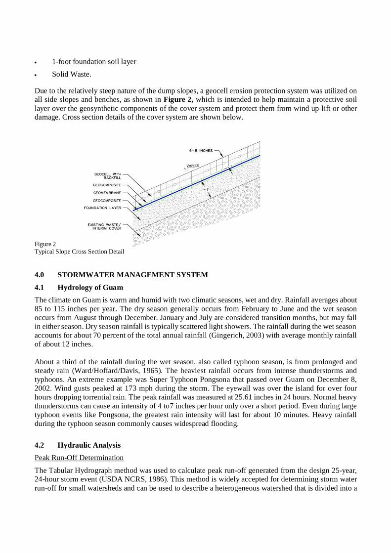
1-foot foundation soil layer
Solid Waste.
Due to the relatively steep nature of the dump slopes, a geocell erosion protection system was utilized on all side slopes and benches, as shown in Figure 2, which is intended to help maintain a protective soil layer over the geosynthetic components of the cover system and protect them from wind up-lift or other damage. Cross section details of the cover system are shown below.
Figure 2 Typical Slope Cross Section Detail
4.0 STORMWATER MANAGEMENT SYSTEM 4.1 Hydrology of Guam The climate on Guam is warm and humid with two climatic seasons, wet and dry. Rainfall averages about 85 to 115 inches per year. The dry season generally occurs from February to June and the wet season occurs from August through December. January and July are considered transition months, but may fall in either season. Dry season rainfall is typically scattered light showers. The rainfall during the wet season accounts for about 70 percent of the total annual rainfall (Gingerich, 2003) with average monthly rainfall of about 12 inches. About a third of the rainfall during the wet season, also called typhoon season, is from prolonged and steady rain (Ward/Hoffard/Davis, 1965). The heaviest rainfall occurs from intense thunderstorms and typhoons. An extreme example was Super Typhoon Pongsona that passed over Guam on December 8, 2002. Wind gusts peaked at 173 mph during the storm. The eyewall was over the island for over four hours dropping torrential rain. The peak rainfall was measured at 25.61 inches in 24 hours. Normal heavy thunderstorms can cause an intensity of 4 to7 inches per hour only over a short period. Even during large typhoon events like Pongsona, the greatest rain intensity will last for about 10 minutes. Heavy rainfall during the typhoon season commonly causes widespread flooding.
4.2 Hydraulic Analysis Peak Run-Off Determination
The Tabular Hydrograph method was used to calculate peak run-off generated from the design 25-year, 24-hour storm event (USDA NCRS, 1986). This method is widely accepted for determining storm water run-off for small watersheds and can be used to describe a heterogeneous watershed that is divided into a

number of homogeneous sub-watersheds. The Tabular Hydrograph method relates rainfall depth, run-off curve number (CN), time of concentration (Tc), and drainage area to determine the peak run-off from a drainage area. For the surface hydrology calculations, it was assumed precipitation impacting a particular sub-area either infiltrated through the ground or eventually diverted into a designed drainage channel. It was also assumed the design storm event will have a duration that exceeds the time of concentration of overland flow. The 25-year, 24-hour and 2-year, 24-hour rainfall depths were determined to be 20.0 inches and 7.0 inches, respectively based on the CNMI and Guam Stormwater Management Manual (SWMM) (CNMI Guam 2006). The regional rainfall distribution was chosen to match normal rainfall conditions in Guam for the current project model and pond design per the SWMM is the Type IA (USDA NRCS, 1986). However, the Type IA distribution does not accurately model a typhoon event. To adequately protect the cover system, pond berms, and structures from a typhoon event, conveyance structures were designed for flows based on the Type I storm (USDA NRCS, 1986). This distribution compresses the rainfall total, 20 inches for a 25-year storm, into a shorter duration which results in higher flows that better reflect actual conditions observed on Guam during recent typhoon events. The most critical aspect of the stormwater management system design was to protect the dump final cover system. If stormwater overwhelmed the drainage swales and structures, then erosion to the final cover layer could occur and ultimately cause a failure of the cover system. The site drainage area (approximately 46.15 acres) was divided into 60 sub-areas delineating potential run-off flow paths and concentration points. Along the anticipated flow path, time of concentration for sheet, shallow-concentrated, and channel flow regimes were calculated for each sub-area. It was determined that hydrologic soil group D best represented on site soils. A run-off curve number (CN) was determined for each sub-area based on the hydrologic soil group, cover type, soil treatment, hydrologic condition, and antecedent run-off condition. Surface Water Drainage Analysis
The onsite drainage control systems were designed to accommodate the anticipated volume of precipitation and resulting run-off generated from a combination of the new closure fill surface and site conditions during the peak 25-year, 24-hour rainfall event. These data were then used for the subsequent design of drainage control structures around the site. In general, run-off from the top deck and side slopes of the dump is collected by a series of berms, diversion channels, down chutes, and culverts directed towards the detention basins located around the perimeter of the dump. Run-off from the detention basins is directed offsite to existing drainage areas on the west, south, and east sides of the site. The drainage areas, flows, and velocities are shown on Figure 3.

Figure 3 Stormwater Drainage Plan The design 25-year, 24-hour storm event was estimated to generate a combined peak discharge of 656 cubic feet per second over the entire contributing site watershed. Table 1 summarizes the peak discharge resulting from each major drainage area and identifies the concentration point and discharge direction (GBB et al 2013). All flow discharges through the four detention ponds located around the perimeter of the dump.
TABLE 1
SUMMARY OF DISCHARGES FROM MAJOR DRAINAGE AREAS
DRAINAGE AREA PEAK
DISCHARGE (CFS)
CONCENTRATION POINT
DISCHARGE LOCATION
Northwest Area 69 Pond 1 Pond 1
Southwest Area 211 Pond 2 Pond 2
Southeast Area 224 Pond 3 Pond 3
Northeast Area 152 Pond 4 Pond 4
POND 4
POND 1
POND 3 POND 2

4.3 Drainage Structure Design As noted above, the general drainage structure design concept was to collect stormwater in a series of benches, berms, and open channels and convey the stormwater into the sedimentation ponds. In addition to usual stormwater design parameters the design had to consider:
High rainfall intensities; Limited space; Steep slopes; Minimize erosion of slide slopes; Significant potential for settlement of waste below the drainage structures; and Final synthetic cover system components below the drainage structures.
Runoff from the top deck is collected by soil berms placed along the perimeter where the top deck transitions (or breaks) to the side slopes. The soil berms are connected to concrete-lined open channel down chutes which direct the runoff into sedimentation ponds. The berms and down chutes prevent water erosion of the side slopes. The benches drain to main collection points where water is transported down to the perimeter ditches via concrete-lined geocell chutes. Channels were constructed along the inside of each bench as illustrated in Figure 4.
Figure 4 Typical Bench Cross Section Detail
Each of these channels was graded to drain with a minimum of 3% slope to down chutes located at various locations around the closure area. The geocell within all channels and down chutes was filled with concrete to minimize erosion along these lines of concentrated flow. The concrete filled geocell was designed to allow the channels to move as the waste settles, acting in a similar fashion to articulated concrete block mats. Due to the large amount of energy that is generated in the down chutes, drainage dissipaters were designed and installed at appropriate locations where water is routed into lower benches or perimeter channels. Box culverts conveyed flow under the perimeter access road to 96-inch perimeter manholes and 60-inch conveyance pipes and ultimately to the detention ponds. The drainage channels and culverts were designed using internally developed spreadsheets and commercially available software packages (Bentley Systems, Inc. 2009a and 2009b).
Managing the high stormwater flows and resulting high velocities proved to be one of the most challenging aspects of the design. In order to manage these high flows and velocities, several unique energy dissipation structures were designed and installed to reduce flow velocities and redirect high flows. 56 of these energy dissipation structures were constructed within the dump footprint.

In-Channel Dissipaters
To control flows in the range of 200 cubic feet per second, the USAC HEC-14 method was utilized to design open channel hydraulic jump dissipaters. These structures were placed into a standard channel cross section to dissipate flow velocity by:
1. Streaming off a standard channel section; an initial section of stone-lined channel creates turbulence which increases the depth of flow, raising the hydraulic grade component of the energy grade line by subtracting from the velocity component.
2. The channel flow then abruptly drops into a sized basin and then is forced to jump upwards in a standing wave while being spread by a horizontal flare in the channel.
3. A section of stone-lined channel transitions the flow back to a standard cross section.
The stone channel lining section was bedded on a layer of coral sand/gravel and geotextile fabric to reduce undermining at the interface of the closure cap. Figure 5 is a photograph of a typical in-channel dissipater.
Figure 5 In-channel Dissipater (Photograph: Geo-Logic Associates, 2017)
Drainage Dissipater/Redirector:
Drainage Dissipater/Redirector structures were designed to redirect flows where the steep down chute channels intercepted the bench channels. The design flows coming off the down chute channels were shallow (generally less than a foot deep) but moving very fast. A bucket dissipater concept, typically used on dam spillways, was utilized with the addition of an angled 48-inch-diameter “half pipe” structure. This curved geometry forces both a jump and change in flow direction, all while maintaining flow within the drainage structures. The shallow fast flow of the slope channel meeting the bench channel at 90° initially jumps the abrupt grade break and drops down to meet the “half pipe”. The momentum carries the flow up past the spring line of the pipe and is directed to drop back onto itself by the curvature of the half pipe. The energy
INITIAL ROUGHENED SECTION
DROP SECTION
TRANSITION SECTION
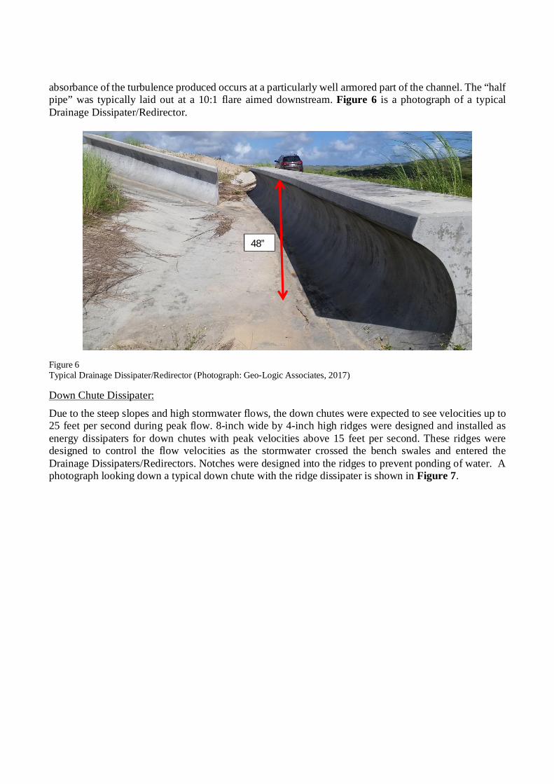
absorbance of the turbulence produced occurs at a particularly well armored part of the channel. The “half pipe” was typically laid out at a 10:1 flare aimed downstream. Figure 6 is a photograph of a typical Drainage Dissipater/Redirector.
Figure 6 Typical Drainage Dissipater/Redirector (Photograph: Geo-Logic Associates, 2017)
Down Chute Dissipater:
Due to the steep slopes and high stormwater flows, the down chutes were expected to see velocities up to 25 feet per second during peak flow. 8-inch wide by 4-inch high ridges were designed and installed as energy dissipaters for down chutes with peak velocities above 15 feet per second. These ridges were designed to control the flow velocities as the stormwater crossed the bench swales and entered the Drainage Dissipaters/Redirectors. Notches were designed into the ridges to prevent ponding of water. A photograph looking down a typical down chute with the ridge dissipater is shown in Figure 7.
48”
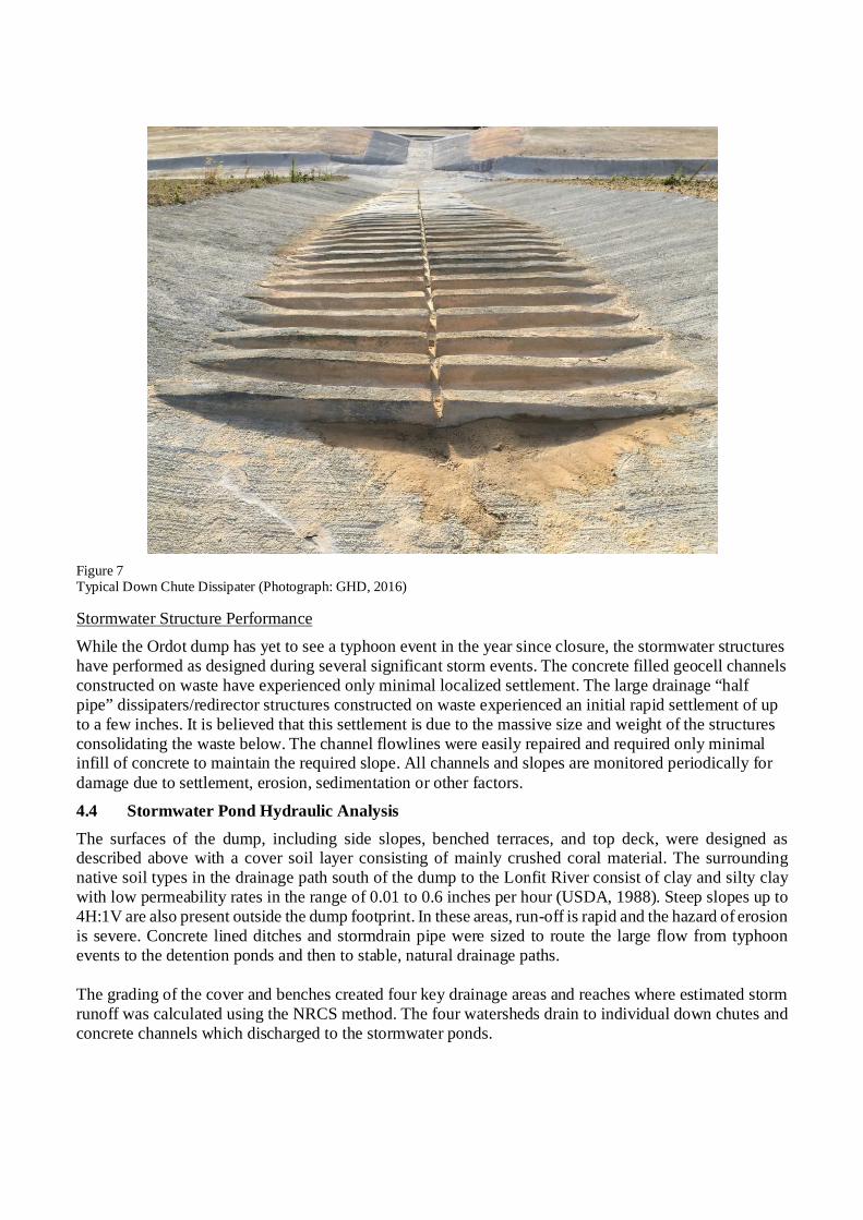
Figure 7 Typical Down Chute Dissipater (Photograph: GHD, 2016)
Stormwater Structure Performance
While the Ordot dump has yet to see a typhoon event in the year since closure, the stormwater structures have performed as designed during several significant storm events. The concrete filled geocell channels constructed on waste have experienced only minimal localized settlement. The large drainage “half pipe” dissipaters/redirector structures constructed on waste experienced an initial rapid settlement of up to a few inches. It is believed that this settlement is due to the massive size and weight of the structures consolidating the waste below. The channel flowlines were easily repaired and required only minimal infill of concrete to maintain the required slope. All channels and slopes are monitored periodically for damage due to settlement, erosion, sedimentation or other factors.
4.4 Stormwater Pond Hydraulic Analysis The surfaces of the dump, including side slopes, benched terraces, and top deck, were designed as described above with a cover soil layer consisting of mainly crushed coral material. The surrounding native soil types in the drainage path south of the dump to the Lonfit River consist of clay and silty clay with low permeability rates in the range of 0.01 to 0.6 inches per hour (USDA, 1988). Steep slopes up to 4H:1V are also present outside the dump footprint. In these areas, run-off is rapid and the hazard of erosion is severe. Concrete lined ditches and stormdrain pipe were sized to route the large flow from typhoon events to the detention ponds and then to stable, natural drainage paths. The grading of the cover and benches created four key drainage areas and reaches where estimated storm runoff was calculated using the NRCS method. The four watersheds drain to individual down chutes and concrete channels which discharged to the stormwater ponds.

The drainage manual criteria required the post-development peak discharge rate to not exceed the pre-development peak discharge rate for the 25-year, 24-hour storm event (USDA NRCS, 1986). The primary purpose of this sizing criterion is to prevent an increase in the frequency and magnitude of overbank flooding downstream of the site. To accomplish this, the design incorporated detention ponds located at or near the cover channel system discharge locations. The ponds provided storage volume that is released at the pre-developed rate to mimic flow prior to the closure. Volumes of the four ponds are about 43,000 cubic feet, 151,500 cubic feet, 167,500 cubic feet and 144,000 cubic feet. Closer to the Lonfit River, the ground flattens. In this area, the run-off is typically very slow and the hazard of water erosion is only slight. However, the relatively flat slopes assisted the development of wetlands. With steep slopes surrounding the dump site, this flatter area was a prime location to site the detention ponds. The design avoided wetlands as much as possible. Three of the ponds were designed as extended detention shallow wetland ponds to replace wetlands that were disturbed. These ponds provide excess storage volume above the permanent pool and therefore have the dual purpose as combination storage ponds and as stormwater treatment Best Management Practices (BMP). The extended detention shallow wetland ponds have a 15’ wide aquatic bench around the perimeter of the pond bottom. This bench is within the 12 or 18 inch deep permanent pool and was planted with wetland plants. The permanent pool volumes were not included in the storage volume for overbank flood control. These combination ponds provide dual treatment allowing for sedimentation and removal of pollutants by wetland plants. Sediment was a concern during the design since the cover system surface is coralline limestone gravel. The pond design included micropools at the inlet to aid in sedimentation. Sediment removal maintenance is expected regularly until the vegetation stabilizes the surface of the dump. A typical cross-section of the wetland ponds is shown below in Figure 8 and with a photograph in Figure 9.
Figure 8 Typical Pond Cross Section Detail

Figure 9 Pond 3 (Photograph: GHD, 2013) Outlet drainage control structures for the ponds regulate flows, in a stepped method, to the required 1-year and then the 25-year, 24-hour storm events. The outlet pipes accommodate the anticipated peak flows for the 25-year storm event from the developed conditions even though the control structure will limit the flow to the pre-developed peak discharge rate. Emergency spillways, consisting of riprap aprons, were provided for flows in excess of the 25-year design storm flow. The riprap aprons reduce velocities to less than 2 feet per second to reduce erosion. Additionally, level spreaders disperse the discharge to limit the chance of scour to the river bank. Stormwater Structure Performance
The dump closure has been completed for over a year. The seedlings planted on the aquatic bench of the extended detention shallow wetland ponds are showing signs of distress. Many of them have yellow leaves and a lack of growth. The exact reason for the problem has not been identified. One theory is the plants selected plants are not able to take the regular inundation of water that they experienced. The past year was wetter than normal causing the seedlings to be underwater more than was expected. While the plants selected are able to have roots in water, as seedlings the excessive water may have been too much. Additionally, the design required the use of native plants. There is a lack of available native plants that can survive the aquatic bench environment. The issue is currently being researched. The solution may just be more time to allow the seedlings to stabilize.
5.0 CONCLUSION The Closure of the Ordot Dump required the design of a unique cover system that could manage the steep terrain and high rainfall, while containing the underlying wastes. This unique closure utilized many components of geosynthetics, earthworks, and concrete to convey large amounts of runoff down the slopes and into extended detention shallow wetland ponds. Conventional cover systems would either not function properly or were not possible to be constructed. Therefore, the use of non-conventional cover components allowed for the design and construction to control the typhoon rainfall events and effectively closed a waste dump site that had been on the EPA Superfund list for over 30 years.

6.0 REFERENCES Bentley Systems, Inc. (2009a), “Bentley CulvertMaster, Version 3.3”, Watertown, Connecticut.
Bentley Systems, Inc. (2009b), “Bentley FlowMaster, Version 8i”, Watertown, Connecticut.
CNMI and the Territory of Guam (2006), “CNMI and Guam Stormwater Management Manual, Volume 1, October 2006.
Federal Highway Administration, Hydraulic Design of Energy Dissipaters for Culverts and Channels, Hydraulic Engineering Circular No. 14 (HEC 14), Third Edition, FHWA-NHI-06-086, 2006.
GBB, Brown and Caldwell, Geo-Logic Associates, GHD (2013), Design Report Ordot Dump Closure Construction and Dero Road Sewer Improvements, July 1, 2013.
GEPA (2000). Guam Soil Erosion and Sedimentation Control Regulations.
GHD, (2012). Appendix D: Memorandum- Hydrology and Hydraulics Study on Dero Road, Dero Road Design Concept Report, May 29, 2012.
Gingerich, Stephen B., Water and Environmental Research Institute (WERI) (2003), Water-Resources Investigation Report 03-4126, USGS, Honolulu, Hawaii, 2003
Parsons, (2010). Guam Transportation Stormwater Drainage Manual, Guam Department of Public Works, August, 2010
U.S. Department of Agriculture, National Resources Conservation Service, Engineering Division, Technical Release 55, (1986), “Urban Hydrology for Small Watersheds, Second Edition”, U.S. Government Printing Office, Washington, D.C.
U.S. Department of Agriculture, Soil Conservation Service, “Soil Survey of Territory of Guam”, 1988
Ward, Porter E., Hoffard, Stuart H., Davis, Dan A. (1965), Hydrology of Guam, Geology and Hydrology of Guam, Mariana Islands, U.S. Government Printing Office, Washington, D.C.