stp / ist fixed & variable length - franklin electric · stp / ist fixed & variable length...
TRANSCRIPT

STP / IST Fixed & Variable LengthInstallation and Owner’s Manual
©2014 400604005 Rev. 20
Franklin Fueling Systems • 3760 Marsh Rd. • Madison, WI 53718 USA
Tel: +1 608 838 8786 • 800 225 9787 • Fax: +1 608 838 6433 • www.franklinfueling.com

2
Important Safety MessagesFE Petro equipment is designed to be installed in association with volatile hydrocarbon liquids such as gasoline and diesel fuel. Installing or working on this equipment means working in an environment in which these highly flammable liquids may be present. Working in such a hazardous environment presents a risk of severe injury or death if these instructions and standard industry practices are not followed. Read and follow all instructions thoroughly before installing or working on this, or any other related equipment.
As you read this guide, please be aware of the following symbols and their meanings:
This symbol identifies a warning. A warning sign will appear in the text of this document when a potentially hazardous situation may arise if the instructions that follow are not adhered to closely. A potentially hazardous situation may involve the possibility of severe bodily harm or even death.
This is a caution symbol. A caution sign will appear in the text of this document when a potentially hazardous environmental situation may arise if the instructions that follow are not adhered to closely. A potentially hazardous environmental situation may involve the leakage of fuel from equipment that could severely harm the environment.
Follow all applicable codes governing the installation and servicing of this product and the entire system. Always lock out and tag electrical circuit breakers while installing or servicing this equipment and related equipment. A potentially lethal electrical shock hazard and the possibility of an explosion or fire from a spark can result if the electrical circuit breakers are accidentally turned on during installation or servicing. Do not smoke while working on or near this equipment, and use only non-sparking tools.
Before entering a containment sump, check for the presence of hydrocarbon vapors. If these vapors are inhaled they could cause dizziness or unconsciousness, and, if ignited, hydrocarbon vapors could explode causing serious injury or death. Electronic and electrical petroleum monitoring equipment is often housed in containment sumps designed to trap hazardous liquid spills and prevent contamination of the environment, and, as a consequence, containment sumps can trap dangerous amounts of hydrocarbon vapors. If these vapor levels reach unsafe amounts, ventilate the sump with fresh air. While working in the sump, periodically check the atmosphere in the sump, if vapors reach unsafe levels, exit the sump and ventilate it before continuing work. Always have a second person standing by for assistance when working in, or around, a containment sump.
Follow all federal, state, and local laws governing the installation of this product and its associated systems. When no other regulations apply, follow NFPA codes 30, 30A, and 70 from the National Fire Protection Association. Failure to follow these codes could result in severe injury, death, serious property damage, and / or environmental contamination.
Always secure the work area from moving vehicles. The equipment in this manual is usually mounted underground, so reduced visibility puts service personnel working on this equipment in danger from moving vehicles entering the work area. To help eliminate these unsafe conditions, secure the area by using a service truck to block access to the work environment, or by using any other reasonable means available to ensure the safety of service personnel.
Do not modify the STP / IST, modifying any feature of the STP / IST can cause environmental and safety issues. FE Petro’s submerged turbine pumps are subjected to rigorous quality control testing during assembly. Field alteration of the pumps in any way, including shortening of the column pipe and conduit, defeats these quality tests, and could result in a fuel leak or dangerous electrical contact.
Thermal expansion can cause pressure to build up in the product lines. FE Petro’s STP / ISTs have a built-in relief valve to release this excess line pressure back to the tank. Do not use an additional check valve unless it has the capability to relieve excess pressure back to the tank, as this could result in a buildup of abnormal pressure in the lines, causing a pipe or joint in the supply line piping to burst, and release of fuel into the environment.
Warning
Caution
Warning
Warning
Warning
Warning
Caution
Caution

3
Note: Some underground storage tanks are ballasted with water during construction. DO NOT use the submersible pump to remove water from the tank. The pump is designed for use with petroleum products only, and pumping other fluids will seriously damage the unit. We do not recommend immersing the pump in water, but, if this does happen, immediately fill the tank with motor fuel after the water is removed from the tank. Severe corrosion takes place very quickly if the unit has been submerged in water and is then exposed to air. If the pump will not operate after gasoline is put into the tank, remove the extractable portion, remove the black plastic end cap from the pump motor assembly (PMA), and turn the Allen screw clockwise at the end of the PMA. This will break free the PMA from any corrosion that may be present. Reinstall the PMA end cap and the extractable section into the pump housing.
Installer: This instruction booklet MUST be left with the owner of the service station at which the equipment is being installed.
Station Owner: Retain these instructions for future use and provide them to persons servicing or removing this equipment.
Installation InstructionsThe piping and underground storage tank must be installed using good standard industry practices. Listed below are several publications that can be used for reference:• Automotive and Marine Service Station Code, NFPA
30A, Flammable and Combustible Code, NFPA 30, and National Electrical Code, NFPA 70 (NEC), National Fire Protection Association, Quincy, Mass.
• Recommended Practices for Installation of Underground Liquid Storage Systems, The Petroleum Equipment Institute, PEI / RP100, Latest Edition.
• Recommended Practices for Installation of Aboveground Storage Systems for Motor Vehicle Fueling, The Petroleum Equipment Institute, PEI / RP200, Latest Edition.
• Installation of Underground Petroleum Storage Systems, American Petroleum Institute, API Recommended Practice 1615, Latest Edition.
• Installation of ATEX approved pumps should be done in compliance with the following Standards:
• EN 60079-14• EN 60079-17• EN 60079-19• VDE 0100
Note: ATEX approved pumps to be installed in Zone 0 (category 1) locations require SIL-1 certified motor control.
Note: Review the Additional Information Sheet for ATEX Compliant Installations for details (Franklin Fueling System’s document 401358001).
Required Tools• Standard 3 / 4" drive ratchet wrench or breaker bar (no
sockets required)• Standard flat head screwdriver• Wire cutter and stripper• 5 / 32" Allen wrench for securing set screw in telescoping
pipe coupling (VL units only)• Pipe wrench (36" minimum) for tightening 4" Riser• 1 / 4" hex driver with socket and ratchet wrench, or 1 / 4"
Allen wrench for attaching PMA• Measuring tape long enough to reach bottom of the tank
from 30" to 70" above the tank
Note: All wiring must conform to applicable guidelines in accordance with all federal, state, and local codes. Failure to comply with all applicable guidelines could result in an unsafe installation. Use the following table for maximum wire length to wire gauge ratios for submersible wiring:
Wire Size Maximum Run10 gauge 650 feet12 gauge 400 feet14 gauge 250 feet
Preparation1. Fill out the Warranty Registration Card and return
it to FE Petro.
Note: If your STP / IST does not operate correctly or there are any questions concerning installation or service, please contact FE Petro Technical Service at (800) 225-9787.
2. Disconnect power to the submersible pump at the electrical supply box (if already installed).
3. Tag and lock out electrical circuit breakers so they are not turned on accidentally.
WarningIf installing fixed length pump (non-variable) with PMA mounted, go to “secure to tank” section. If installing variable length pump continue with this section. If installing fixed length pump (non-variable) without PMA mounted, complete “mounting PMA” section, then go to “secure to tank” section.

4
Mounting the PMA4. Lay packaged pump on a flat, open surface and
remove the package.5. Flatten pump packaging and lay the PMA on the
end of the pump in preparation for mounting.6. The PMA mounting hardware kit (# 152350902)
is attached to the PMA packaging. It contains a gasket, a tube of grease, and four 5 / 16" cap screws with lockwashers.
7. Remove the two packaging ends and the protective sleeve from the PMA.
8. Apply grease provided to the inside wall of the pump motor electrical connector, and the rubber of the lead assembly connector.
9. Place the gasket on the end of the PMA, aligning locating pin and bolt holes (Figure 1).
Figure 1: Aligning Pins10. Mount PMA onto discharge head by aligning
locating pin on PMA with hole in discharge head, assuring that the lead assembly in the motor discharge head is seated in its notched position, and that the PMA gasket is properly in place.
11. Tighten PMA onto discharge head using four cap screws and lock washers supplied. A cross bolt-tightening pattern is recommended for securing PMA (Figure 2).
Figure 2: Tighten Bolts
The motor discharge head must not be rotated more than one full rotation in either direction. Rotation could cause damage to the electrical connections in the conduit, creating a risk of lethal electrical shock or equipment failure.
Note: Before assembling the PMA to the discharge casting make sure the wire lead is properly set and aligned in the discharge casting. Improper alignment could damage the wire lead or motor pins. Failure to push PMA up snug against the discharge casting before tightening cap screws, or failure to use a cross-pattern while tightening the bolts could break the discharge casting or strip the threads in the PMA.
Note: IST units without a VS4 suffix and STP units with a VS2 suffix can only be electrically connected to an IST-VFC or MagVFC.
STP or IST units with a VS4 suffix can only be electrically connected to a MagVFC or EcoVFC. Unlike FE Petro’s standard pumps, the following pumps cannot be interchanged with competitive models:
• The variable speed PMA VS2 (which is part of IST units without the VS4 suffix or the STP units suffixed with VS2)
• The PMA VS4 (which is part of the IST and STP units with the VS4 suffix)
12. Apply a non-hardening, UL classified, gasoline-resistant pipe sealing compound to the riser pipe threads, if not already installed.
WarningFailure to use a proper thread sealing compound could result in a lack of seal where the riser threads into the tank opening, making it impossible to perform a tank-tightness test. This may also create a potential site for fuel to leak into the environment and / or the containment sump.
13. Slide riser over the PMA and tighten into manifold threads (Figure 3). Maximum riser size is found by taking the grade to tank mounting thread measurement and subtracting the manifold height and clearance (6" clearance recommended).
Figure 3: Attach Riser
Note: Riser material required for pump is 4.5" outside diameter with a .188" wall. Minimum riser length supplied by FE Petro is 7".
Warning

5
ExampleGrade to tank mounting threads (bury depth) 48"Minus manifold height without leak detector
(w / leak detector height = 12.50)
-11"
Minus 6" for top clearance (2" minimum) -6= Maximum riser size 31"
Length Setting 14. Cut wire tie(s) securing the motor wire at the top of
the pump; lay the wires out above the pump head so that wires can feed through conduit freely when setting length (Figure 4).
Figure 4: Cut WiresFailure to cut wire ties prior to setting pump length could result in damage to electrical motor wires, presenting a risk of lethal electrical shock or equipment failure.
15. Measure from the bottom of the tank to the top of tank mounting threads. Subtract the distance for clearance between the PMA and the bottom of the tank (6" recommended). This is the length to which the pump should be extracted, measured from the bottom of the riser threads to the bottom of the motor end bell.
Note: 6" clearance provides a 5" clearance from the pump motor end bell to the bottom of the tank once the riser is screwed into tank mounting threads.
Tank + thread measurement 96"Distance from bottom (5") + riser thread engagement (1")
-6"
= Length (bottom of riser to end bell) 90"
Figure 5: Measure Tank
16. Hold the manifold securely to the surface to prevent damage while setting length.
To allow movement of the telescoping pipe, verify that none of the pipe coupling setscrews are in contact with the pipe. Lay a tape measure out to accurately measure the distance from the bottom of the riser to the bottom of the pump motor end bell.
17. Grasp the pump just above the PMA and pull firmly, extending to the length required (from Step 15).
Note: Use care to ensure electrical conduit wires at the top of the discharge manifold are not damaged during length setting. If column pipe is extended beyond desired length have a second person retract conduit wires as column pipe is shortened. This will prevent damage to conduit wires.
Figure 6: Measure Riser
WarningThe motor discharge head must not be rotated more than one full rotation in either direction. Rotating could cause damage to the electrical motor wires, presenting a risk of potentially lethal electrical shock or equipment failure.
Note: O-ring seals inside the locking coupling may have sealed to the column pipe during shipping. Spin the motor discharge head slightly (not more than one full rotation) while pulling to loosen the O-ring seals.
Warning

6
18. Once the length is correct, lock the STP length by tightening all three coupling setscrews. Tighten the setscrews finger-tight, making sure they come into contact with the pipe (Figure 7).
Note: Loctite® 243™ thread locker* must be used on all ATEX approved pumps.
19. Tighten each setscrew an additional full turn minimum. The head of the setscrews should be flush or below flush with the outer surface of the coupling (Figure 8).
Setscrews3 places
Figure 7: Install Setscrews
5 / 32" Allen Wrench
Figure 8: Tighten Setscrews
WarningFailure to properly tighten the coupling setscrews at this stage could present a risk of death, serious bodily injury and / or equipment damage due to movement of pipes during installation.
PMA Wiring 20. Measure approximately 6" of wire from the
discharge manifold; cut off excess wire and discard (Figure 9).
Figure 9: Measure and Cut Wire
21. Place the three wires through the contractors plug assembly (from hardware pack p / n 400301XXX) as shown in figure 10.
Figure 10: Wire Through Contractor’s Plug 22. Using the screwdriver slide the contractors plug
into its seat in the discharge manifold. Tighten the two screws in the contractor plug to secure it in place (Figure 11).
Figure 11: Attach Contractor’s Plug 23. Strip the wire insulation back approximately 3 / 8"
on the three motor leads. Using the wire nuts or terminal blocks supplied (from hardware pack p / n 400301XXX) connect to the wires from the electrical connector orange to orange, black to black, and red to red.
Note: Terminal blocks are provided for wire connections on ATEX approved pumps. For terminal blocks, strip 4.4 - 5 mm insulation from the end of the wires. Torques terminal screws to 0.4 - 0.45 Nm.
24. Coil the wires and push into the discharge manifold cavity using care to ensure wires are not damaged on discharge manifold threads (Figure 12).
Figure 12: Push Wires into Cavity
WarningDamage to the electrical conduit wires creates a risk of lethal electrical shock and equipment failure. Do NOT use equipment if electrical wires have been damaged (contact FE Petro for assistance).
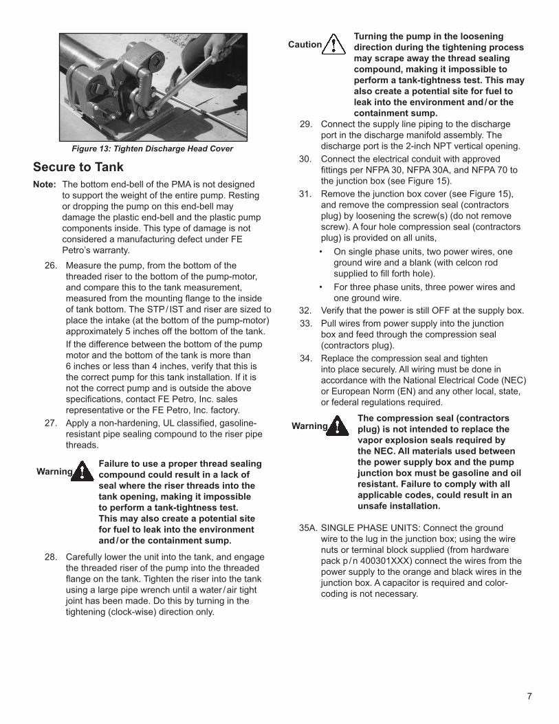
25. Tighten the discharge head cover (from hardware pack p / n 400301XXX) in place using a ¾" ratchet or breaker bar (Figure 13).
* Loctite is a registered trademarks of Henkel Corporation
7
Figure 13: Tighten Discharge Head Cover
Secure to TankNote: The bottom end-bell of the PMA is not designed
to support the weight of the entire pump. Resting or dropping the pump on this end-bell may damage the plastic end-bell and the plastic pump components inside. This type of damage is not considered a manufacturing defect under FE Petro’s warranty.
26. Measure the pump, from the bottom of the threaded riser to the bottom of the pump-motor, and compare this to the tank measurement, measured from the mounting flange to the inside of tank bottom. The STP / IST and riser are sized to place the intake (at the bottom of the pump-motor) approximately 5 inches off the bottom of the tank.
If the difference between the bottom of the pump motor and the bottom of the tank is more than 6 inches or less than 4 inches, verify that this is the correct pump for this tank installation. If it is not the correct pump and is outside the above specifications, contact FE Petro, Inc. sales representative or the FE Petro, Inc. factory.
27. Apply a non-hardening, UL classified, gasoline-resistant pipe sealing compound to the riser pipe threads.
WarningFailure to use a proper thread sealing compound could result in a lack of seal where the riser threads into the tank opening, making it impossible to perform a tank-tightness test. This may also create a potential site for fuel to leak into the environment and / or the containment sump.
28. Carefully lower the unit into the tank, and engage the threaded riser of the pump into the threaded flange on the tank. Tighten the riser into the tank using a large pipe wrench until a water / air tight joint has been made. Do this by turning in the tightening (clock-wise) direction only.
Turning the pump in the loosening direction during the tightening process may scrape away the thread sealing compound, making it impossible to perform a tank-tightness test. This may also create a potential site for fuel to leak into the environment and / or the containment sump.
29. Connect the supply line piping to the discharge port in the discharge manifold assembly. The discharge port is the 2-inch NPT vertical opening.
30. Connect the electrical conduit with approved fittings per NFPA 30, NFPA 30A, and NFPA 70 to the junction box (see Figure 15).
31. Remove the junction box cover (see Figure 15), and remove the compression seal (contractors plug) by loosening the screw(s) (do not remove screw). A four hole compression seal (contractors plug) is provided on all units, • On single phase units, two power wires, one
ground wire and a blank (with celcon rod supplied to fill forth hole).
• For three phase units, three power wires and one ground wire.
32. Verify that the power is still OFF at the supply box. 33. Pull wires from power supply into the junction
box and feed through the compression seal (contractors plug).
34. Replace the compression seal and tighten into place securely. All wiring must be done in accordance with the National Electrical Code (NEC) or European Norm (EN) and any other local, state, or federal regulations required.
WarningThe compression seal (contractors plug) is not intended to replace the vapor explosion seals required by the NEC. All materials used between the power supply box and the pump junction box must be gasoline and oil resistant. Failure to comply with all applicable codes, could result in an unsafe installation.
35A. SINGLE PHASE UNITS: Connect the ground
wire to the lug in the junction box; using the wire nuts or terminal block supplied (from hardware pack p / n 400301XXX) connect the wires from the power supply to the orange and black wires in the junction box. A capacitor is required and color-coding is not necessary.
Caution

8
35B. THREE PHASE UNITS (except IST or STP units with VS2 or VS4 suffix): Connect the ground wire to the lug in the junction box. Connect any three wires from the pump to any three wires from the three-phase power source using the wire nuts or terminal block supplied (from hardware pack p / n 400301XXX). Capacitors are not needed for three phase units. Install a pressure gauge in the line test port (see Figure 15), turn on the pump, and read the pressure gauge. Turn off the pump at the power supply, and change the connection of any two wires at the pump. Turn the pump back on and read the pressure gauge again. The electrical connection that gives the higher reading on the pressure gauge is the correct one.
35C. IST UNITS or STP units with a VS2 or VS4 suffix: Connect the ground wire coming from indoors to the ground lug in the junction box. Connect any three wires from the pump connector assembly to the three power wires coming from the Variable Frequency Controller (VFC). Capacitors are not needed for these units. Detailed installation instructions for the VFC should be referenced when connecting the VFC. These are supplied with the VFC.
Note: Terminal blocks are provided for wire connections on ATEX approved pumps. For terminal blocks, strip 4.4 - 5 mm insulation from the end of the wires. Torques terminal screws to 0.4 - 0.45 Nm.
WarningNot installing a ground wire increases the risk of lethal electric shock and equipment failure. All holes of the compression seal (contractors plug) must be filled with wires or a celcon rod to enable it to seal.
36. Replace the junction box cover and tighten securely.
CautionThe pump discharge manifold has two labeled ports: one for the syphon system and one for the tank. A piston leak detector must be vented to the tank port (lower port) only. Do not connect a piston leak detector to the syphon port because this will make the leak detector inoperative, resulting in an increased risk of contamination of the environment (see tank port in Figure 14).
37. Connect power to the submersible pump at the electrical supply box.
38. Test proper operation by dispensing product into calibration can.
39. Turn off the dispenser switch. Feel the submersible pump to make sure that the pump has stopped running.
Note: If the pump does not turn off when the dispenser switch is turned off, this may indicate an electrical problem in the dispenser or other wiring error or malfunction. Call this to the immediate attention of a qualified electrician.
40. Visually check for leaks on the manifold head during pump operation and after.
41. Install a pressure gauge in the line test port to ensure that the STP / IST is providing proper line pressure.
42. Turn on the STP / IST. While running, the pressure should be above 24 psi (1.65 bar). PMA size will affect psi.
43. Turn off the STP / IST and verify that the line pressure is holding.
44. Remove the pressure gauge and replace the plug. 45. Turn on the STP / IST and, again, visually check for
any leaks.

9
Approximate STP / IST SpecificationsOperating
Pressure (PSI)
PMA
Length (in)
S.F.
Amps
Locked
Rotor AmpsWinding Resistance
Model Description R-B R-O B-OSTP33* 208 / 230 V, 60 Hz, 1 ph 27 16 3.1 11 27 19 8
STP75* 208 / 230 V, 60 Hz, 1 ph 30 18.25 6.1 27 20 17 3
STP150* 208 / 230 V, 60 Hz, 1 ph 32 21 10.5 39 15 13 2
STPH150* 208 / 230 V, 60 Hz, 1 ph 45 21.75 10.5 39 15 13 2
STP200+ 208 / 230 V, 60 Hz, 1 ph 36 23.75 11.4 41 4.6 3 1.8
STPH200+ 208 / 230 V, 60 Hz, 1 ph 46 24.5 11.4 41 4.6 3 1.8
STP75B++ 200 / 250 V, 50 Hz, 1 ph 37 20.5 5.6 23 27 23 4
STP150B++ 200 / 250 V, 50 Hz, 1 ph 38 22.75 8.8 28 16 13 3
STPH150B++ 200 / 250 V, 50 Hz, 1 ph 48 23.25 8.8 28 16 13 3
STP200B‡ 200 / 250 V, 50 Hz, 1 ph 37 25.75 9.5 37 5.5 3.5 2
STPH200B‡ 200 / 250 V, 50 Hz, 1 ph 44 26.25 9.5 37 5.5 3.5 2
STP75C 380-415 V, 50 Hz, 3 ph** 37 19.75 2.1 10 29 29 29
STP150C 380-415 V, 50 Hz, 3 ph** 38 21.75 3.0 14 14 14 14
STPH150C 380-415 V, 50 Hz, 3 ph** 48 22 3.0 14 14 14 14
STP200C 380-415 V, 50 Hz, 3 ph** 37 23.5 4.1 23 11.6 11.6 11.6
STPH200C 380-415 V, 50 Hz, 3 ph** 44 24 4.1 23 11.6 11.6 11.6
IST / STPVS2^ 190 V, 70 Hz, 3 ph† 24-42 20 6.7 N / A 2.5 2.5 2.5
ISTVS4 / STPVS4^^ 190 V, 70 Hz, 3 ph† 24-42 25 14.4 N / A 1.2 1.2 1.2
Symbol Key
* Use a 15 µF, 370 V, single phase, 60 Hz capacitor + Use a 40 µF, 370 V, single phase, 60 Hz capacitor ++ Use a 15 µF, 440 V, single phase, 50 Hz capacitor ‡ Use a 40 µF, 440 V, single phase, 50 Hz capacitor † 190 V, 70 Hz, 3 ph power to variable speed units is output from IST-VFC or MagVFC only (VFC’s are powered
by 200-250 V, 50 or 60 Hz, single or 3 phase input) ^ Use with IST-VFC or MagVFC controller only, No Capacitor ^^ Use with MagVFC controller only, No Capacitor (3 phase input is required for full VS4 output)) ** No capacitor is used with 3 phase pump motor assemblies
Note: The models listed in the table above may contain (ANZ) for ANZEX certified pumps, or either (ATXF) or (ATXF1)ATEX certified pumps.
Warning FE Petro’s STPs are designed for use with motor fuels, and they are UL listed for blend concentrations of:
Standard Models AG (Alcohol / Gasoline) Models0% - 10% ethanol with gasoline 0% - 85% ethanol with gasoline20% MTBE with 80% gasoline 20% MTBE with 80% gasoline20% ETBE with 80% gasoline 20% ETBE with 80% gasoline17% TAME with 83% gasoline 17% TAME with 83% gasoline100% Diesel 0-20% BioDiesel Blend or 100% Biodiesel
Diesel, fuel oil, avgas, jet fuel, or kerosene may also be used with our PMAs. The maximum liquid viscosity for a product is 70 S.S.U. at 60° F.
Using our PMA in liquids other than those mentioned above has not been tested. The reaction of other liquids with seals and wetted surfaces of the pump is unknown. A hazardous situation may result from using other liquids with our pump.

10
Manual Pressure ReliefThe manual line pressure relief (see Figure 14) is located in the center of the stationary manifold under a brass cap. It is available on all pumps manufactured after April of 1996. FE Petro makes it easy to relieve the pressure in the piping system anytime routine maintenance or troubleshooting must be performed.
Simply remove the brass cap at the top of the stationary manifold, and turn the pressure relief screw counter-clockwise until you come to the screw’s retaining ring (approximately 4 complete turns). This allows the pressure in the piping system to bleed back to the storage tank. Next, turn the screw clockwise to its original position to close the path (turn snug, do not over tighten); then replace the brass cap. Line side pressure is now relieved and maintenance or troubleshooting can be performed without having to contain excess product that escapes when the system is pressurized.
Clamp Valve (Check Valve Clamp)The clamp valve (see Figure 14) is located directly above the check valve inside the stationary manifold of the submerged pump. It consists of a lead screw with a sealing disk attached. The head of the screw is accessible by removing the 1 / 4" line test port pipe plug on the check valve cover of the STP / IST.
The cavity under the 1 / 4" pipe plug is at full pump pressure and product will be released through this opening. If the pump is equipped with a manual pressure relief, use it to relieve line pressure prior to removing the plug.
For normal operation, the clamp valve should be rotated fully counter-clockwise where a star washer locks it in place. Be sure to replace the 1 / 4" pipe plug. During a line test, the clamp valve should be rotated fully clockwise, where the sealing disk secures against the check valve. This blocks the pressure relief valve in the check valve so it does not relieve line pressure back to the tank.
Syphon Systems (Optional)Syphoned tanks should be of the same diameter with tank bottoms located on the same horizontal plane. Using tanks of different diameter, or installing the bottoms of the tanks on different horizontal planes may create a potential site for fuel to leak into the environment and / or the containment sump due to overfill of the tank(s).
Some jurisdictions allow two or more tanks of the same product grade to be manifolded together with a syphon loop. These systems usually have a single submersible pump, and the syphoning action keeps the tanks level while pumping out of only one tank. All FE Petro submersible pumps have syphoning capability built into the pump. However, if a syphon check valve is required, it must be ordered separately. The outlet of the syphon check valve should be connected with a line to the highest spot in the syphon loop. At this point the submersible pump creates a vacuum of 20–28" Hg.
When correctly installed, the syphon action between the tanks will continue whether the pump is running or not, as long as the product level in the tanks is higher than the bottom of the syphon loop vertical piping. The function of the STP / IST in the syphon system is merely to prime the syphon line, removing the air and allowing the syphon to take place.
Note: The syphon port on FE Petro submersible pumps was designed to be connected to the syphon piping between tanks. Using the vacuum port (syphon port) for other purposes may create complications with the pump’s ability to draw a vacuum because of excessive foreign materials being drawn into pump components.
Note: A fuel filter, between the syphon check valve and the syphon loop, may be useful to help eliminate debris from entering the syphon check valve. Debris can keep a syphon check valve from operating properly. Be sure to use a fuel filter, which is compatible with the application.
Warning
Warning
11
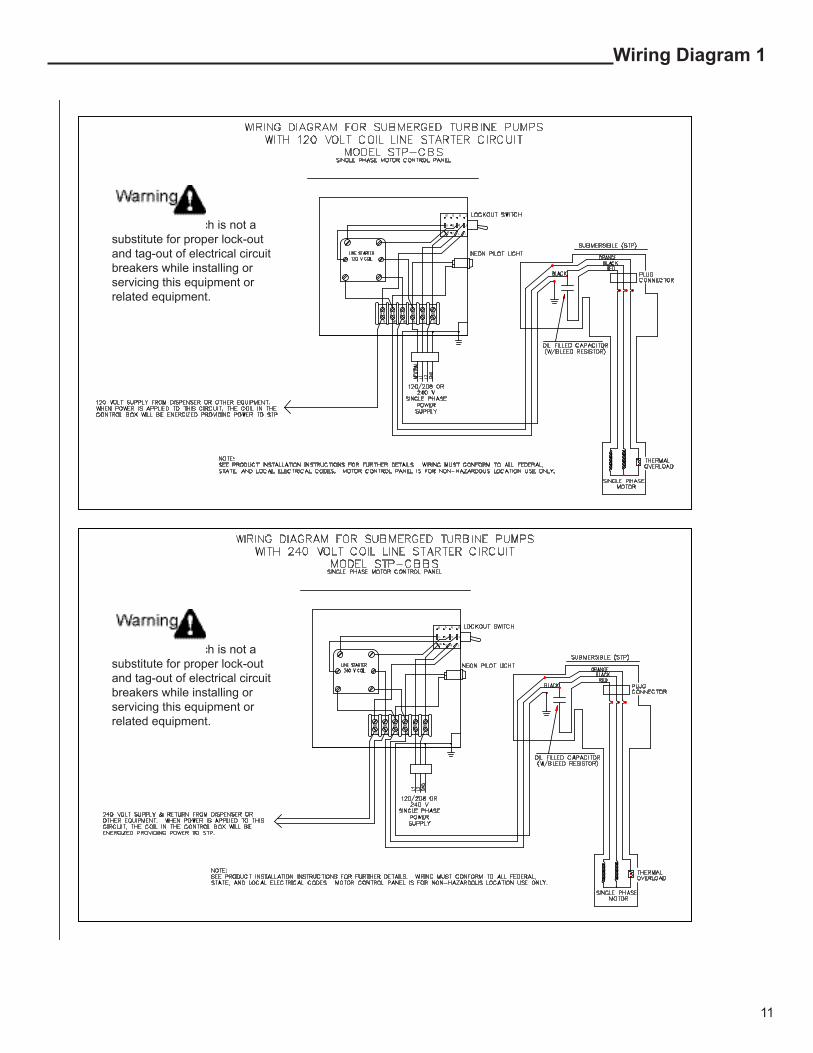
Wiring Diagram 1
The Lockout switch is not a substitute for proper lock-out and tag-out of electrical circuit breakers while installing or servicing this equipment or related equipment.
The Lockout switch is not a substitute for proper lock-out and tag-out of electrical circuit breakers while installing or servicing this equipment or related equipment.
12
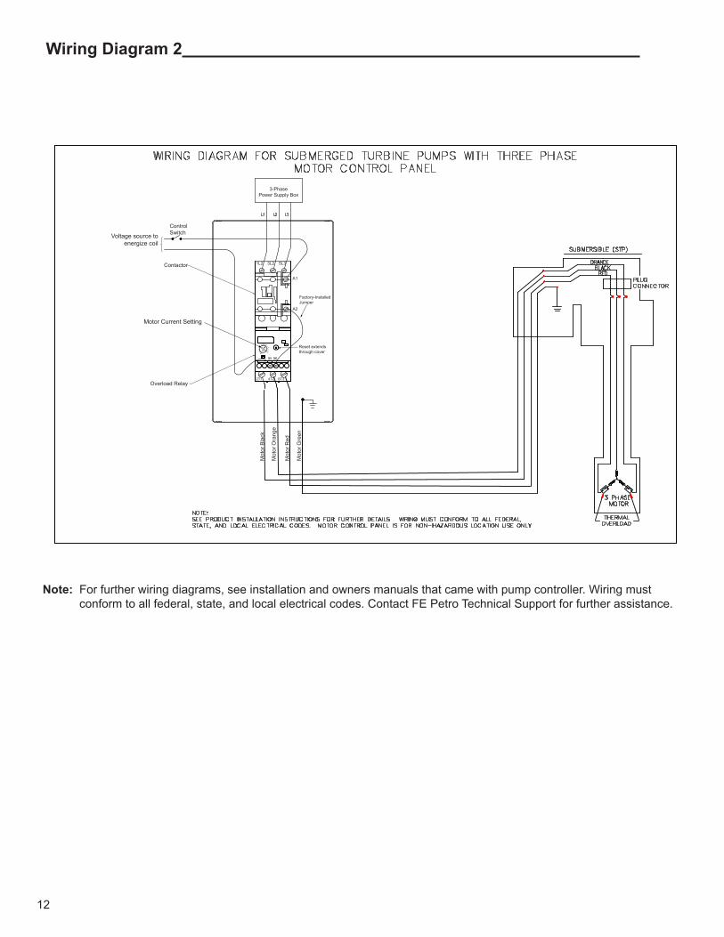
Wiring Diagram 2
Note: For further wiring diagrams, see installation and owners manuals that came with pump controller. Wiring must conform to all federal, state, and local electrical codes. Contact FE Petro Technical Support for further assistance.
Voltage source to energize coil
Mot
or B
lack
Mot
or O
rang
e
Mot
or R
ed
Mot
or G
reen
3-PhasePower Supply Box
Control Switch
Contactor
Overload Relay
A2
A1
Factory-InstalledJumper
Reset extends through cover
95 96
2T1 4T2 6T3
1L2 3L2 5L3
Motor Current Setting
13
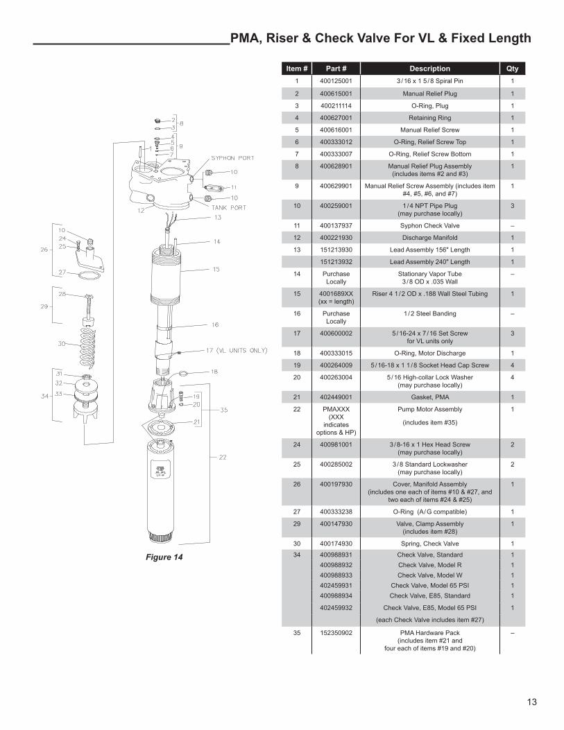
PMA, Riser & Check Valve For VL & Fixed Length
Item # Part # Description Qty1 400125001 3 / 16 x 1 5 / 8 Spiral Pin 1
2 400615001 Manual Relief Plug 1
3 400211114 O-Ring, Plug 1
4 400627001 Retaining Ring 1
5 400616001 Manual Relief Screw 1
6 400333012 O-Ring, Relief Screw Top 1
7 400333007 O-Ring, Relief Screw Bottom 1
8 400628901 Manual Relief Plug Assembly (includes items #2 and #3)
1
9 400629901 Manual Relief Screw Assembly (includes item #4, #5, #6, and #7)
1
10 400259001 1 / 4 NPT Pipe Plug (may purchase locally)
3
11 400137937 Syphon Check Valve –
12 400221930 Discharge Manifold 1
13 151213930 Lead Assembly 156" Length 1
151213932 Lead Assembly 240" Length 1
14 Purchase Locally
Stationary Vapor Tube 3 / 8 OD x .035 Wall
–
15 4001689XX (xx = length)
Riser 4 1 / 2 OD x .188 Wall Steel Tubing 1
16 Purchase Locally
1 / 2 Steel Banding –
17 400600002 5 / 16-24 x 7 / 16 Set Screw for VL units only
3
18 400333015 O-Ring, Motor Discharge 1
19 400264009 5 / 16-18 x 1 1 / 8 Socket Head Cap Screw 4
20 400263004 5 / 16 High-collar Lock Washer (may purchase locally)
4
21 402449001 Gasket, PMA 1
22 PMAXXX (XXX
indicates options & HP)
Pump Motor Assembly
(includes item #35)
1
24 400981001 3 / 8-16 x 1 Hex Head Screw (may purchase locally)
2
25 400285002 3 / 8 Standard Lockwasher (may purchase locally)
2
26 400197930 Cover, Manifold Assembly (includes one each of items #10 & #27, and
two each of items #24 & #25)
1
27 400333238 O-Ring (A / G compatible) 1
29 400147930 Valve, Clamp Assembly (includes item #28)
1
30 400174930 Spring, Check Valve 1
34 400988931 Check Valve, Standard 1400988932 Check Valve, Model R 1400988933 Check Valve, Model W 1402459931 Check Valve, Model 65 PSI 1400988934 Check Valve, E85, Standard 1
402459932 Check Valve, E85, Model 65 PSI 1
(each Check Valve includes item #27)
35 152350902 PMA Hardware Pack(includes item #21 and
four each of items #19 and #20)
–
Figure 14

14
Discharge Manifold Assembly
Item # Part # Description Qty1 400192930 Cover, Junction Box
(includes item #2)
1
2 400210233 O-Ring 1
3 400655001 Boot, Capacitor 1
4
(does not
include item #3)
400170931 Capacitor Assembly
60Hz, 15 µF, 370V 1Ø
1
400170933 Capacitor Assembly
50Hz, 15 µF, 440V 1Ø
1
400170934 Capacitor Assembly
60 Hz, 40 µF, 370 V 1Ø
1
400170935 Capacitor Assembly
50Hz, 40 µF, 440V 1Ø
1
N / A Not required for 3Ø units
including IST / VS2
–
6 400257001 Retaining Ring 1
7 400258002 3 / 8-16 x 1 1 / 4 Hex Head Bolt
(may purchase locally)
4
8 400285002 3 / 8 Standard Lockwasher
(may purchase locally)
4
9 400280001 3 / 8 Standard Flat washer
(may purchase locally)
2
10 400651930 Junction Box Assembly
(includes two of each: Item #7, #8, & #9)
1
11 400210212 O-Ring 2
Item # Part # Description Qty13 400200930 Wire Connector Kit
(includes male / female connectors,
(2) item #11, (1) each item #6, #12, & #20)
1
14 400589930 Cover
(includes item #15)
1
15 400210229 O-Ring 1
16 400236903 Plug, Contractors 2
17 400259002 3 / 8 NPT Pipe Plug
(may purchase locally)
1
18 400562901 Syphon Jet Assembly 1
400562903 Syphon Jet Assembly, E85 1
19 400211046 O-Ring 1
20 400249001 Retaining Ring 1
22 400250002 1 / 8 Dia. x 1 / 2 Roll Pin 1
23 400333343 O-Ring
(A / G compatible)
2
24 400333340 O-Ring
(A / G compatible)
1
25 400259005 2NPT SQ Head Plug 1
1
2
3
4
6
7
8
9
10
16
14
7
8
232425
22
11
11
20
1213 15
16
17
18
19
Line Test Port
Figure 15
15
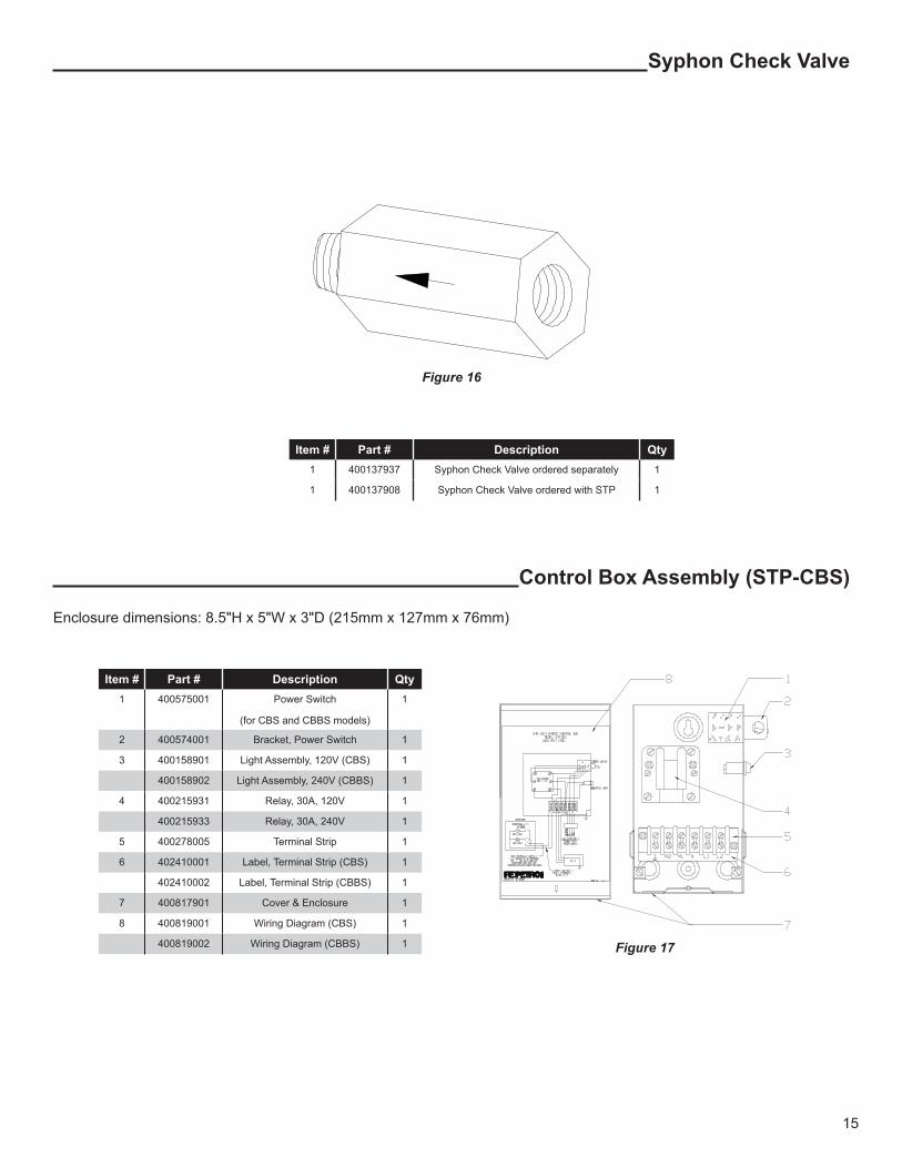
Syphon Check Valve
Item # Part # Description Qty1 400137937 Syphon Check Valve ordered separately 1
1 400137908 Syphon Check Valve ordered with STP 1
Control Box Assembly (STP-CBS)
Figure 16
Figure 17
Item # Part # Description Qty1 400575001 Power Switch
(for CBS and CBBS models)
1
2 400574001 Bracket, Power Switch 1
3 400158901 Light Assembly, 120V (CBS) 1
400158902 Light Assembly, 240V (CBBS) 1
4 400215931 Relay, 30A, 120V 1
400215933 Relay, 30A, 240V 1
5 400278005 Terminal Strip 1
6 402410001 Label, Terminal Strip (CBS) 1
402410002 Label, Terminal Strip (CBBS) 1
7 400817901 Cover & Enclosure 1
8 400819001 Wiring Diagram (CBS) 1
400819002 Wiring Diagram (CBBS) 1
Enclosure dimensions: 8.5"H x 5"W x 3"D (215mm x 127mm x 76mm)

Figure 18
Discharge / Leak Detector Centerline
Discharge / Leak Detector Centerline
Line Test port¼" NPT
Riser / Column Pipe Centerline
Riser / Column Pipe Centerline
11.70"
7.55" R
10.45"8.12" R
3.00"
5.80"
Leak Detector Port2" NPT
Discharge Outlet2" NPT
12.50"
Riser Pipe4" NPT
Tank Port¼" NPT
Syphon Port¼" NPT
10.65"
5.80"
©2014 FFS 400604005 Rev. 20