structural characterisation of materials bycombining … bound... · philips journalof research...
TRANSCRIPT
,~---------_. ~
Philips Journal of Research Vol.47 Nos. 3-S 1993 235
Philips J. Res. 47 (1993) 235-245
STRUCTURAL CHARACTERISATION OF MATERIALSBY COMBINING X-RAY DIFFRACTION SPACE
MAPPING AND TOPOGRAPHY
by PAUL F. FEWSTERPhilips Research Laboratories, Cross Oak Lane, Redhill, U.K.
AbstractRecent advances in X-ray diffraction has aided the interpretation andextended the possibilities in structural analysis of materials. By creating a"ö-function like" diffraction space probe the 3-dimensional shape of thescattering form from a crystalline sample can be determined. Previously wehave been restricted to "pseudo" I-dimensional scans requiring assump-tions about the material properties or probes with complex instrumentartifacts complicating the interpretation. This additional flexibility hasincreased the ease of interpretation since different scattering features areisolated. This has been further enhanced by using the same probe toperform topography therefore the scattering features can be related directlyto topographic images of defects, etc. This has increased our understandingof the origins of diffuse scattering and improved our understanding of thediffraction shapes. Because of the high resolution obtainable unexpectedfeatures have been revealed and the combination with topography hashelped in the understanding of their origin. The basics of the methods arecovered and illustrated with a few examples of the applications for such aninstrument.Keywords: gallium arsenide, interfaces, porous silicon, surface damage,
surface relaxation, X-ray diffraction, X-ray topography.
1. Introduetion
The structural analysis ofmaterials by X-ray diffraction is often compoundedby difficulties in interpretation. Complications arising from the influence ofthediffractometer instrument convolute have been largely eliminated by using a"é-function" type probe of a High Resolution Multiple-Crystal Multiple-Reflection Diffractometer (HRMCMRD), Fewster (1989). This instrumenthas many attributes including the separation of strain and orientation spreadand this considerably improves the ease of interpretation. Despite this the

P.F. Fewster
MonochromatorCJ
<!.,L'::_' __ ~ple......... film 1
Analyser
film 2
Fig. I. The HRMCMRD illustrating the modes of operation, as a diffractometer (using thedetector) and for collecting topographs (showing the two film positions).
diffraction profiles and diffraction space maps obtainable from such an instru-ment still require careful analysis and what is more it yields additional structur-ally related features hidden by other methods (Fewster, 1993).To assist in the interpretation of these features the instrument has been also
used in topography mode, Fewster (I99Ia, I991b). The potentialof thiscombination of diffraction and topography is the subject of this paper.
236 Philips Journalof Research Vol.47 Nos. 3-5 1993
2. The instrument
A schematic of the HRMCMRD is given in figure 1 and themonochromator and the analyser are made from "perfect" Ge crystals. Themonochromator and analyser crystals are set to reflect from the 220 planesusing CuKal radiation and this gives rise to very high reflectivities and a beamof up to I06 photons ç I arriving at the detector with a conventional 2 kWX-ray source. The parasitic scattering is negligible giving a very large butunknown dynamic range for topography whereas in diffractometry mode it isrestricted by the detector electronics to be '" 10-1 photons S-I, giving 7 ordersof magnitude dynamic range. The X-ray beam covers an area on the sampleof up to '" 10 x (I/sin co) mm; this can be reduced by a slit after themonochromator. The monochromator produces a well collimated beam in thediffraction plane with a wavelength band-pass of t1À/ À = 1.6.10-4, Bartels(1983). The analyser only accepts diffracted beams from the sample within ananalyser acceptance similar to that of the probing beam ('" 12"are in theexamples illustrated) and this creates a "b-function like" probe which can beused throughout diffraction space.
An intensity map of diffraction space can be measured in several ways andthe simplest is to record the accumulated photons after rotating the samplethrough a very small angle in co and the analyser/detector through twice this

Structural characterisation of materials
angular step and by repeating this many times, one row of information isproduced. Further rows, to produce a 2-dimensional map, are obtained byoffsetting the sample rotation by bw and repeating, thus creating a matrix ofintensity of coby w-2 co': this is then transformed (for a limited angular range)into reciprocal space co-ordinates by:
(!lqj_, !lqll) = ~ (nb(w - 2co') cos e, mêco sin e)
where n is the number of steps along co - 2co' and m the number of stepsalong w, À. is the X-ray wavelength and () is the Bragg angle for the mid-pointon the map. These maps are effectively projections of the scattering onto aplane, where the integration is over the vertical divergence which is '" 0.8°.Therefore to rebuild the shape of the 3-dimensional scattering at least twoprojections are required; generally two orthogonal directions are used.
For a perfect sample the X-ray beam at the diffracting condition will passthrough the analyser and the recorded intensity will be the integrated valueover the beam size. This integrated intensity masks the distribution whichconveys information on the lateral variation of strain and orientation spread.This lateral variation of strain and orientation is found by the distribution
of intensity on the photographic emulsion. The ultimate resolution is limitedby the developed grain size of the emulsion and for Ilford L4 it is '" 0.25 ut«.The defect resolution of sensitivity to strain-fields or tilts is governed by theinstrument resolution and the sample's intrinsic diffraction properties. Thesensitivity in the diffraction plane is very high and is limited by the smearingeffect of the beam divergence and the experimental conditions. Therefore anyintensity variation will be averaged over >> 2.5" are, corresponding to '" 5%change in intensity, which can be related to a strain sensitivity >- 1.2 x 10⁻⁵for a 004 reflection of a typical semiconductor. The vertical resolution isdefined by the film to sample distance ratio with the source to sample distanceand the vertical divergence.The film emulsion has two positions either in the diffracted beam from the
sample or after the analyser crystal. In position 1 the angular acceptance ofthe scattered beams is large and governed by the Ewald sphere (representingthe satisfaction of Bragg's law) and therefore will integrate the scatteringdistribution at each position on the sample. This does not lead to significantmisplacement of the image with respect to its relative position on the samplebecause of the very small divergence of the X-ray beam which limits thescattering conditions possible. For studying crystal quality e.g. mosaicity thisis perfectly adequate, Fewster (199Ia). A film in the second position is far morepowerful and now can isolate a region in the diffraction space map and relate
Philips Journalof Research Vol.47 Nos.3-5 1993 237

P.F. Fewster
1,';+15.8"~'
L1q [001]
(10-4A -1)
.i';'-15.8
-1.4 +1.8
L1q [110]
(10-4A-1)
Fig. 2. The 004 diffraction space map of a good quality GaAs substrate, showing the Bragg peak,surface streak and the halo of diffuse scattering.
the scattering to a position on the sample crystal. This has permitted the studyof diffuse scattering, unusual diffraction features, etc. simplifying the inter-pretation considerably. Examples of these methods will be given below.
3. Studying surfaces and interfaces
Consider the diffraction space map of a bulk GaAs crystal, figure 2. TheBragg peak is accompanied by a long streak which arises from the abrupttermination of the crystal and also by a halo of diffuse scattering, Fewster andAndrew (1993) have shown that this diffuse scattering arises primarily from
238 Philips Journalof Research Vol. 47 Nos.3--5 1993

Philips Journalof Research Vol. 47 Nos. 3-5 1993 239
Structural characterisation of materials
Fig. 3. A topograph taken of the diffuse scattering of figure 2. The surface scratches show clearlyand dominate the diffuse scattering (400 counts s : 1 on I1ford L4 emulsion).
surface damage and dislocations. With this probe the dislocations and defectswhich give rise to this diffuse scattering can be imaged without the dominatinginfluence of the Bragg scattering. The image can also be identified as emanatingfrom regions on the sample that have a certain tilt and strain. Thus a defectcan be fully characterised by taking a series of topographs at various tilt andstrain values (different positions in the diffuse scattering, figure 2).
For this topography the film is placed after the analyser. This does not meanthat the intensity is low. Because the probe is so close to a 6-function it can beplaced very close to the Bragg peak without interference from it. In figure 2 atopograph close to the Bragg peak, where the intensity is 400 counts çl, anobservable image can be formed in 1.5 h and a publication ready version, figure3, in ~ 5 h. The damage is clearly visible, yet is difficult to observe at the Braggpeak or along the surface streak. The latter two cases are similar to the imagesobtained by double-crystal topography. The Bragg peak topograph takes~ 5 m which gives a very rapid assessment of the bulk quality.The study of interfaces is important for many applications (magnetic multi-
layers, multiple quantum well structures, etc.,) and have been extensively
P.F. Fewster
studied (metallic multilayers - Clarke, 1987, annealed semiconductors -Fleming, McWhan, Gossard, Weigmann & Logan, 1981, MBE growth -Fewster, 1988, Fewster, Andrew & Curling, 1991, c)-doping - Hart, Fahy,Newman & Fewster, 1993). The concentration of these studies has been in themeasurement of the interface extent perpendicular to the interface plane.Many device properties though, are strongly influenced by the interfacialroughness, which is the interfacial quality laterally, parallel to the interface.These properties can be investigated by studying the diffuse scattering whicharises from the finite correlation lengths in the plane of the interface, Fewster1991b, Holy, Kubena, Ohidal & Ploog (1992). This is only practical with aninstrument such as this with undetectable parasitic scattering from a welldefine instrument function. Also by using topography the diffuse scatteringcan be checked to confirm that it arises from small length-scales and notdefects.
4. Relaxation in layered structures
The previous section concentrated on the analysis of diffuse scattering innear "perfect" or coherent structures. These methods give the enhancedfeatures of the HRMCMRD in diffractometry and topography modes. Thissection is concerned with the information that can be extracted fromheterostructures with large mismatches that generate misfit dislocations at theinterfaces.When the layer mismatch is low then the misfit dislocations are well
separated and contribute to the diffuse scattering. The regions between thedislocations are essentially perfect and the diffraction is coherent across theinterface and this contributes to the Bragg scattering, figure 4. Hence it is nowpossible to separate the scattering contributions from the dislocations fromthat ofthe perfect regions in terms ofthe crystal plane bending and local strain.By combining this with topography it has been shown that the diffuse scatter-ing does emanate from the long range strain-fields ofthe dislocations and thisscattering can be modelled theoretically, Fewster (1992). This combination ofa well defined probe, well defined topography and a procedure for modellingthe diffraction gives tremendous potential in fully characterising imperfectlayered structures.The range of parameters that can now be measured with this combination
is illustrated schematically in figure 5. This now gives us the capability tocharacterise the onset ofrelaxation, Kidd, Fewster, Andrew & Dunstan (1993)and has enabled us to understand the evolution of the relaxation in layersabove the "critical layer" thickness, Fewster & Andrew (1993). In the latter
240 Philips Journal of Research Vol.47 Nos.3-S 1993

Philips Journalof Research Vol.47 Nos.3-5 1993 241
Structural characterisation of materials
+291
:~:"b.q [OOlJ
(10-4A -1)
.1,'"
j"
.~.
-831
-64 +63
b.q [100]
(10-4A -1)Fig. 4. The SiGe layer peak (lower) and the Si substrate peak (upper) showing the Bragg scatteringgiving rise to well shaped peaks and the diffuse scattering from the misfit dislocation strain-fields.
case with diffractometry and modelling it was possible to determine the macro-scopic and microscopie tilts and the relaxation in a series of InoosGao.95Aslayers as well as the extent ofthe dislocation strain-fields. The macroscopie tiltsincreased and the microscopie tilts decreased with thickness, whilst the dimen-sions 1(110) and I(ITO)' figure 5, decreased and the contrast increased as observedin topography. This latter point at first sight is indicative ofincreased relativemicroscopie tilts and appears contradictory. An explanation that satisfies theseobservations is given in figure 6. This is a clear example where topography ordiffractometry alone is inadequate to draw such conclusions.

P.F. Fewster
<001>
t~
t<110> depth
<1;0> ij _ composition
a
Zn--rZn-,
Fig. 5. The structural parameters obtainable from the combination of ditrractometry, topographyand modelling for a layered structure.
5. Porous Si
Considerable interest in recent years has been centred on low cost produc-tion of optical devices on Si. Si is normally an indirect semiconductor andcannot be used in its bulk form for light generation. Work has concentratedon GaAs on Si (GaAs has a direct band gap) but suffers from all the inherentproblems of large lattice mismatch, whereas SijSiGe heterostructures haveshown promise but is an expensive technology. Porous Si on the other handcan be produced by etching the surface with hydrofluoric acid. The porosityarises from voids in the structure up to ~ 50% porosity, whereas above thisvalue the structure consists of complex pillars or quantum wires of Si.Quantum size effects can then be used to engineer the band gap and producefavourable optical transitions in the material. This simple technology couldlead to increased 'density and rates of transfer of data for interconnects inintegrated circuits and for display devices on Si, Halimaoui (1992).'Producing porous Si gives rise to significant strains which can be measured
by X-ray diffraction methods Bellet, Dolino & Ligeon (1992). The dimensionsof the Si pillars or the voids, in lower porosity Si can be determined fromstudying the diffuse scattering, figure 7. A topograph taken on this diffusescattering gave an even distribution of intensity thus confirming that it arisesfrom length-scales less than 1Jlm (the approximate lateral resolution limit of
242 Philips Journal of Research Vol.47 Nos. 3-5 1993

Structural characterisation of materials
~50,um
I I
I Ju~25,um
Fig. 6. The "mosaic grain growth" model explaining the evolution of defect interaction duringlayer growth, which reduces the overall average microscopie tilt spread by the coalescing ofdefects.
the photographic emulsion) and not defects. The width along qu of thisdistribution then directly relates to the lateral dimension of the Si pillars.
6. Summary
The examples described here are just a few applications of the HRMCMRDin diffractometry and topography mode. The potential is limited by timeavailable for collecting the intensity, although these maps can take from a fewminutes to several days depending on the detail and information required. Ithas been shown that polycrystalline samples can also be studied even in thinlayer form in diffractometry and topography mode. This resolution though, isgenerally unnecessarily high for very imperfect samples (mosaic spreads > 2°)and a low resolution diffraction space mapper is adequate (Fewster & Andrew,1992). The reduction in resolution though does require careful interpretation
Philips Journalof Research Vol.47 Nos. 3-5 1993 243

P.F. Fewster
+43.9
i.lq [110]
-18
-39.3
+8.9
i1q [001]
Fig. 7. The diffraction space map close to the 004 Bragg peak for Si. The diffuse scatteringassociated with the porous Si pillars.
since the scattering parallel to the diffraction vector is contaminated withperpendicular components and a combination with the HMCMRD is ideal.This is why the "é-function" of the HRMCMRD helps so much with theinterpretation of imperfect structures and with the addition of HighResolution Multiple Crystal Multiple Reflection Topography (HRMCMRT)much of the guess-work and speculation is removed in X-ray diffraction.
244 Philips Journalof Research Vol. 47 Nos.3-5 1993
The author is indebted to Norman L. Andrew forcarrying out some of theseexperiments.
REFERENCES
I) P.F. Fewster, J. App!. Crysl., 22, 64-69 (1989).2) P.F. Fewster, J. Phys. D., 26, to be published (1993).1) P.F. Fewster, J. App!. Cryst., 24,178-183 (199Ia).4) P.F. Fewster, App!. Surf. Science, 50, 9-18 (199Ib).5) W.J. Bartels, J. Vac. Sci. Techno!. B, 1, 338-345 (1983).6) P.F. Fewster and N.L. Andrew, submitted to J. App!. Phys.7) R. Clarke, NATO AS! Series B: Physics Vo!. 163: "Thin Film Growth Techniques for Low
Dimensional Structures" pp 379-403.8). R.M. Fleming, O.B. Mcwhan, A.C. Gossard, W. Weigmann and R.A. Logan, J. App!. Phys.,
51,357-363 (1981).
Structural characterisation of materials
9) P.F. Fewster, J. App!. Cryst., 21, 524-529 (1988).10) P.F. Fewster, N.L. Andrewand c.r. Curling, Semicond. Sci. Techno!., 6, 5-10 (1991).11) L. Hart, M. Fahy, R.e. Newman and P.F. Fewster, App!. Phys. Lett., to be published.12) V. Holy, J. Kubena, L. Ohidal and K. PIoog, submitted to "Superlattices and Mierostruc-
tures".IJ) P.F. Fewster, J. App!. Cryst. 25 (1992) 714-723.14) P.A. Kidd, P.F. Fewster, N.L. Andrewand D.J. Dunstau. "Microscopy of Semiconducting
Materials" Inst. Phys. Conference Series, to be published.15) P.F. Fewster and N.L. Andrew, submitted to J. App!. Phys.16) A. Halimaoui, Phys. World, 5(12), 20-21 (1992).IJ) D. Bellet, G. Dolino and M. Ligeon, 1. App!. Phys., 71, 145-149 (1992).18) P.F. Fewster and N.L. Andrew. In: E.J. Mittemeijer and R. Delhez, Materials Science Forum,
Trans Tech, Switzerland, 1992.
Authors
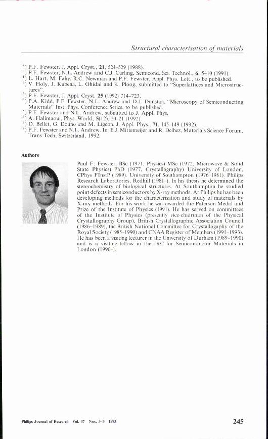
Paul F. Fewster, BSc (1971, Physics) MSc (1972, Microwave & SolidState Physics) PhD (1977, Crystallography) University of London,CPhys FlnstP (1989). University of Southampton (1976-1981). PhilipsResearch Laboratories, Redhill (1981-). In his thesis he determined thestereochemistry of biologica! structures. At Southampton he studiedpoint defects in semiconductors by X-ray methods. At Philips he has beendeveloping methods for the characterisation and study of materials byX-ray methods. For his work he was awarded the Paterson Medal andPrize of the Insriture of Physics (1991). He has served on cornmitteesof the Institute of Physics (presently vice-chairman of the PhysicalCrystallography Group), British Crystallographic Association Council(1986-1989), the British National Committee for Crystallogaphy of theRoyal Society (1985-1990) and CNAA Register of Members (1991-1993).He has been a visiting lecturer in the University of Durham (1989-1990)and is a visiting fellow in the IRC for Semiconductor Materials inLondon (1990-).
Philips Journalof Research Vol.47 Nos.3-5 1993 245