structural design considerations for a 50 kw-class solar array for
TRANSCRIPT

American Institute of Aeronautics and Astronautics
1
Structural Design Considerations for a 50 kW-Class
Solar Array for NASA’s Asteroid Redirect Mission
Thomas W. Kerslake1, Thomas G. Kraft2, John T. Yim3 and Dzu K. Le4
NASA Glenn Research Center, Cleveland, Ohio, 44135
NASA is planning an Asteroid Redirect Mission (ARM) to take place in the 2020s. To
enable this multi-year mission, a 40 kW class solar electric propulsion (SEP) system powered
by an advanced 50 kW class solar array will be required. Powered by the SEP module
(SEPM), the ARM vehicle will travel to a large near-Earth asteroid, descend to its surface,
capture a multi-metric ton (t) asteroid boulder, ascend from the surface and return to the
Earth-moon system to ultimately place the ARM vehicle and its captured asteroid boulder
into a stable distant orbit. During the years that follow, astronauts flying in the Orion
multipurpose crew vehicle (MPCV) will dock with the ARM vehicle and conduct extra-
vehicular activity (EVA) operations to explore and sample the asteroid boulder. This paper
will review the top structural design considerations to successfully implement this 50 kW class
solar array that must meet unprecedented performance levels. These considerations include
beyond state-of-the-art metrics for specific mass, specific volume, deployed area, deployed
solar array wing (SAW) keep in zone (KIZ), deployed strength and deployed frequency.
Analytical and design results are presented that support definition of stowed KIZ and launch
restraint interface definition. An offset boom is defined to meet the deployed SAW KIZ. The
resulting parametric impact of the offset boom length on spacecraft moment of inertias and
deployed SAW quasistatic and dynamic load cases are also presented. Load cases include
ARM spacecraft thruster plume impingement, asteroid surface operations and Orion docking
operations which drive the required SAW deployed strength and damping. The authors
conclude that to support NASA’s ARM power needs, an advanced SAW is required with mass
performance better than 125 W/kg, stowed volume better than 40 kW/m3, a deployed area of
200 m2 (100 m2 for each of two SAWs), a deployed SAW offset distance of nominally 3-4 m, a
deployed SAW quasistatic strength of nominally 0.1 g in any direction, a deployed loading
displacement under 2 m, a deployed fundamental frequency above 0.1 Hz and deployed
damping of at least 1%. These parameters must be met on top of challenging mission
environments and ground testing requirements unique to the ARM project.
Nomenclature
° = angular degree
ACS = attitude control system
ARM = asteroid redirect mission
ARV = asteroid redirect vehicle
B-frame = body frame
°C or C = Celsius
CAD = computer aided design
1 ARM SEP Module solar array lead, Power Architecture and Analysis Branch, 21000 Brookpark Rd., Mail Stop 142-
6. 2 Structures and Mechanisms Senior Engineer, Mechanisms and Tribology Branch, 21000 Brookpark Rd., Mail Stop
86-12, and AIAA Member. 3 Propulsion Engineer, In-Space Propulsion Systems Branch, 21000 Brookpark Rd., Mail Stop 301-3, and AIAA
Member. 4 Structural Dynamics & Control Senior Engineer, Intelligent Control and Autonomy Branch, 21000 Brookpark Rd.,
Mail Stop 77-1, and AIAA Member.
https://ntrs.nasa.gov/search.jsp?R=20160000702 2018-02-05T23:13:31+00:00Z

American Institute of Aeronautics and Astronautics
2
CG = center of gravity
CM = center of mass
conops = concept of operations
CSI = controls structures interactions
dB = decibel
EP = electric propulsion
eV = electron volt
EVA = extra-vehicular activity
FEM = finite element model
g = acceleration due to gravity
GSE = ground support equipment
Hz = hertz
IDS = international docking system
ISS = international space station
IXX = moment of inertia about the X axis
Ixy = moment of inertia about the X-Y plane
IYY = moment of inertia about the Y axis
Iyx = moment of inertia about the Y-X plane
Iyz = moment of inertia about the Y-Z plane
Izy = moment of inertia about the Z-Y plane
IZZ = moment of inertia about the Z axis
KIZ = keep in zone
kg = kilogram
kW = kilowatt
m = meter
mm = millimeter
μm = micrometer
MBD = multibody dynamics
MCR = mission concept review
MOI = moment of inertia
MPCV = multipurpose crew vehicle
N = newton
NDS = NASA docking system
OD = outer diameter
PV = photovoltaic
RAMP2 = reacting and multi-phase 2 computer code
PLIMP = plume impingement computer code
RCS = reaction control system
ROSA = roll out solar array
SADA = solar array drive assembly
SAW = solar array wing
SCS = soft capture system
Sec = second
SEP = solar electric propulsion
SEPM = solar electric propulsion module
SLS = space launch system
SR = structural reference
t = metric ton
TCS = thermal control system
W = watt
I. Introduction
N April 15, 2010, President Obama instructed NASA to develop the spacecraft and technologies needed to enable
human exploration of a near Earth asteroid1. In response to this call, NASA plans to make use of a heavy lift O

American Institute of Aeronautics and Astronautics
3
launch vehicle, such as the Space Launch System (SLS) rocket under development to launch large payloads into space,
and the Orion multipurpose crew vehicle (MPCV), being developed to carry human explorers on missions beyond low
Earth orbit. NASA and its commercial partners are also developing solar electric propulsion (SEP) and power
technologies that enable efficient in-space transportation and ultimately, the Asteroid Redirect Mission (ARM). ARM
pulls together all of these elements, the SLS, Orion and SEP technologies to meet the President’s goal of human
asteroid exploration by the 2020s. To enable this multi-year mission, a 40 kW class solar electric propulsion (SEP)
system powered by an advanced 50 kW class solar array will be required. Using the solar electric propulsion module
(SEPM) in-space propulsion system and mission module, the ARM vehicle, such as the concept shown in Figure 1,
will travel to a large near-Earth asteroid. Once there, the vehicle will descend to the asteroid surface, capture a multi-
metric ton (t) class asteroid boulder, ascend from the surface and return to the Earth-moon system. At this phase of
the mission, the ARM vehicle and its captured asteroid boulder will be placed into a stable distant Earth-moon orbit.
During the years that follow, astronauts flying in the Orion multipurpose crew vehicle (MPCV) will dock with the
ARM vehicle and conduct extra-vehicular activity (EVA) operations to explore and sample the asteroid boulder. Two
solar array wings (SAWs) will comprise the advanced solar array, with possible technology options including, but not
limited to, those recently funded by NASA2: the Roll Out Solar Array (ROSA) and the MegaFlexTM, as shown in
Figure 2. Both of these options use flexible blankets on which the photovoltaic cells are mounted. Ultimately, only
one advanced SAW technology option will be selected for both SAWs that power the SEPM. Each SAW offset boom
is mounted to a single-axis solar array drive assembly (SADA).
Figure 1. ARM spacecraft concept with mission module (right) and the SEPM (left).
Figure 2. Two candidate SAW technology concepts shown side by side for comparison: the Roll Out Solar
Array (ROSA), left, and MegaFlexTM, right. Ultimately, one SAW type (from competing advanced
technologies) will be selected for both SAWs that will power the SEPM.

American Institute of Aeronautics and Astronautics
4
This paper will review the top structural design considerations to successfully implement this 50 kW class solar
array (25 kW class SAW) that must meet unprecedented performance levels. These considerations include beyond
state-of-the-art metrics for specific mass, specific volume, deployed area, deployed keep in zone (KIZ), deployed
strength and deployed frequency. Analytical and design results are presented that support definition of stowed KIZ
and launch restraint interface definition. Also presented, is an offset boom with parametric length required to meet the
deployed SAW KIZ. The resulting impact of boom length on spacecraft moment of inertias and deployed SAW
quasistatic and dynamic load cases is discussed. The SAW deployed strength and damping requirements arise from
loads from ARM spacecraft thruster plume impingement, asteroid surface operations and Orion docking operations.
II. General Considerations
A. Mass
At the Mission Concept Review (MCR) timeframe in early 2015, the mass allocation for each SAW, including
offset boom, was 200 kg. This translates to a specific power value for the SAW of about 130 W/kg at beginning of
life with a SAW power level of 26 kW at the SAW to SADA interface. Compared to a state-of-the-art rigid panel
SAW meeting the same requirements, this specific power value is 2-3X higher. The requirement for low SAW mass
will most likely drive the design solution to one of an advanced, flexible blanket SAW.
B. Deployed SAW flexible blanket area
At the ARM MCR timeframe, the
spacecraft load power, dominated by the
electric propulsion subsystem power draw, led
to a required 52 kW solar array approximate
power level at beginning of life. Using state of
the art, triple junction solar cells with 29%
conversion efficiency, the ARM SEPM
application requires a SAW flexible blanket
area of about 100 m2. This translates to a
deployed MegaFlexTM SAW diameter of about
12.5 m and a ROSA SAW about 5 m wide by
24 m long. The flexible blanket area sizing
accounts for the appropriate power
performance loss mechanisms including
harnessing voltage drop, SAW integration
factors, SAW operational factors and all natural
and induced environmental degradation factors
for the ARM mission.
C. Others
Based on the concept of operations
(conops) for ARM, the SAW must be deployed
autonomously without the assistance of ground
operators or on-orbit crew. During deployed
operation, the SAWs must achieve a high level
of strength and stiffness (further discussed
below). Given the SAW deployed loading
orientation cannot be controlled following
credible failure modes of the SADA, SAW
deployed acceleration requirements must be
both in-plane and out-of-plane directions. The
SEPM coordinate system has the Y axis along
the longitudinal axis of the vehicle with the X-
Z plane coincident with the SEPM to upper
stage separation plane. SAWs are located in the direction of the +Z and –Z axes. See Figures 3a, 3b and 4 depicting
this coordinate system.
Figure 3a. Stowed SAW KIZ – shown as orange regions.

American Institute of Aeronautics and Astronautics
5
III. Stowed SAW Considerations
D. Stowed SAW Keep in Zone
Given a structural optimized SEPM is short and squat, much of the available launch fairing volume is filled up
leaving only a narrow radial gap into which the SAWs must fit. At the SEPM module base, longitudinal length is
limited by the upper stage to spacecraft structural adaptor support. At the SEPM top, longitudinal length is constrained
by the ARM mission module structure. A preliminary drawing has been prepared showing the required KIZ
configuration (orange colored volume, see Figure 3a) and dimensional constraints (see Figure 3b). To meet tight
stowage volume requirements of the ARM SEPM application, SAW technologies tend to need specific volumes of
about 40 kW/m3, or about 3X better than state of the art SAWs. Even if a SAW technology exceeds 40 kW/m3 metric,
it may not be stowable on the SEPM given the combination of KIZ dimensional constraints, tie down location
constraints (discussed in the next section) and kinematic deployment trajectory constraints.
E. Stowed SAW Structural Interface
To meet launch acceleration loading and stowed fundamental frequency requirements, massive and large
dimension SAWs require many (perhaps even 8 or more) structural tie downs per SAW. The tie downs provide a load
path to safely react SAW inertial loads into the spacecraft primary structure without stress and displacement
Figure 3b. Stowed SAW KIZ dimensions in mm.

American Institute of Aeronautics and Astronautics
6
exceedances. Given the SAW technology has not been selected, ARM SEPM designers specified a generalized SAW
tie down structural configuration using secondary structure. Several options for the secondary structure have been
assessed, but all must have a gossamer configuration. This feature is required to minimize view factor blockage for
the SEPM heat rejection radiator surface located below. The allowable area for SAW tie downs is shown in Figure 4.
The SADA interface with the SAW offset boom, envisioned as a circular bolt plate with approximately 0.2 m outer
diameter, is located on the stowed SAW KIZ inner plane surfaces allocated for SAW tie downs (Figure 3b) and along
the dashed line in Figure 4 (exact location under study). Given the stowed SAW tie down locations will not be
generally located in optimum locations, SAW structures may incur a mass penalty associated with stiffer cores, thicker
facesheets and/or the need for greater localized panel reinforcements. The stowed SAW KIZ, in combination with the
SADA interface attachment plus deployed SAW KIZ, discussed below, will drive stowed offset boom dimensions and
overall SAW deployment kinematics to accomplish the needed articulations and trajectories to transition from stowed,
to phased, to fully deployed SAW configuration.
F. Others
A detailed coupled loads analysis has not been performed to define stowed SAW loads during launch. Until that
time, preliminary requirements will include an ascent quasistatic acceleration of 20 g, acoustic excitation as shown in
Figure 5 and random vibration power spectral density levels as shown in Figure 6. The 20 g quasistatic acceleration
includes the launch vehicle mass acceleration curve design load as multiplied by a 1.25 load uncertainty factor and
2.0 distributed load factor to account for the multi-meter span of a stowed SAW. These environments encompass those
anticipated for state of the art heavy lift vehicles and for the SLS under development by NASA. On top of these
environments and design factors, a SAW to SEPM interface load factor of 1.5 must be applied for the design of the
SAW interface components such as tie down mechanisms and their associated panel fittings. Stowed SAW shock
spectrums, maximum levels that the SAW must accommodate from spacecraft events and the maximum levels the
SAW can produce during tie down release, have been assessed and defined. However, these shock levels are not
expected to be SAW design drivers and hence are not discussed further.
Figure 4. Stowed SAW tie down structural interface keep in area for tie down attachments, dimensions in
mm, +Z axis is out of the paper.

American Institute of Aeronautics and Astronautics
7
To avoid excessive coupling with ascent vibroacoustic loads, the stowed SAW fundamental frequency must exceed
Figure 5. Ascent acoustic loading for stowed SAW.
100.0
105.0
110.0
115.0
120.0
125.0
130.0
135.0
140.0
145.0
10 100 1000 10000
Sou
nd
Pre
ssu
re L
eve
l, d
B (
re 2
0 µ
Pa)
One-Third Octave Band Frequency, Hz
Internal Acoustic Requirements for Spacecraft
Protoflight (148.0 dB OASPL)
Acceptance (145.0 dB OASPL)
Figure 6. Ascent random vibration loading levels.
0.01
0.1
1
10 100 1000
Acc
ele
rati
on
Sp
ectr
al D
en
sity
(g2
/Hz)
Frequency (Hz)
Random Vibration Requirement for Solar Array
Solar Array (Protoflight, 9.6 Grms)
Solar Array (Acceptance, 6.8 Grms)

American Institute of Aeronautics and Astronautics
8
25 Hz. This requirement would apply to dynamic modes with >10% mass participation and for those modes that drive
local SAW stress levels. The additional assumption can be made that the SAW is mounted to an infinitely stiff
spacecraft structure. It is expected that subsequent, system level structural dynamic assessments will be performed
that include SEPM structure and SADA interface stiffnesses.
SAW tie down area (see Figure 4) enforced displacements, with respect to the SADA mechanical interface, have
been calculated. Results show displacements of +0.8/-1.1 mm in the X direction, -0.7 to -2.6 mm in the Y direction
and Z direction displacements are shown in Figure 7. The SEPM cylindrical bus structure is very stiff leading to
relatively small displacements compared to that expected with more traditional spacecraft structural topology. The
stowed SAW must be designed to either take up these displacements within the structure or implement tie down
flexures or attachments configured to release the required displacement degrees of freedom. For large SAWs that
cannot use kinematic attachments to the bus, the small displacements of this stiff SEPM structure become all the more
important.
Some mission applications require strength for acceleration loading during SAW deployment prior to mechanism
latching when the SAW may have reduced strength. As of now, the ARM vehicle will be in free drift mode during
SAW deployment and does not have credible single fault scenarios resulting in vehicle acceleration (such as an
inadvertent reaction control system (RCS) thruster firing). Thus, we foresee ARM SEPM SAWs will not be required
to handle acceleration loading events during the brief period of SAW tie down release, phasing and deployment. This
period is anticipated to be <20 minutes in total time.
In addition, the deploying SAW must not extend outside the stowed SAW KIZ XY plane in the Z direction towards
the SEPM centerline as show in Figures 3a and 3b. High power SAWs can have >100 strings of solar cells that leads
to a large power harness that must be managed to avoid entanglement during deployment. The large power harness
also introduces proportionally larger deployment parasitic torques compared to conventional smaller SAWs.
Figure 7. Stowed +Z side SAW tie down enforced displacements relative to the SADA along the Z axis (+Z
out of the page).

American Institute of Aeronautics and Astronautics
9
IV. Deployed SAW Considerations
In this section, deployed SAW structural considerations are discussed. These items are under assessment and
technical study in an effort to properly formulate technical specifications for the ARM SEPM advanced SAW.
A. Keep In Zone (KIZ)
To accomplish the ARM, a deployed SAW KIZ (see Figure 8) is required to ensure the spacecraft and SAW meet
functional operation requirements. This KIZ includes 360° of SADA rotation and SAW displacements from
thermal/structural loading requirements discussed below. The KIZ starts at the SADA structural interface plane and
extends outward from the SEPM along the Z axis. The KIZ includes a 1-m separation margin against interference
with SEPM, mission module and docking/docked Orion MPCV spacecraft surfaces and appendages, asteroid/boulder
surfaces and avoiding the electric propulsion (EP) thruster plume keep out zone. The EP plume keep out zone is
defined by a cone on the thruster centerline with a 55° cone angle (45° plume angle plus 10° thruster gimbal angle)
and the cone apex at the thruster exit plane. KIZ defining surfaces also include: a 0.4 m diameter cylinder with length
between 1.0 m and 2.2 m for offset boom accommodation with the intention of minimizing view factor to the radiator
panels adjacent to and behind the SADA and a high gain antenna minimum separation of 1.0 m.
The KIZ was derived from numerous assessments including: (1) limiting xenon ion sputtering rates from the
electric propulsion (EP) plume, (2) limiting thermal and structural loading from SEPM RCS chemical thruster plume
impingement, (3) limiting the thermal control system (TCS) radiator to SAW view factor, (4) limiting thermal and
structural loading from Orion RCS chemical thruster plume impingement during docking, (5) maintaining a safe
Figure 8. Deployed SAW KIZ, dimensions in mm.
American Institute of Aeronautics and Astronautics
10
separation of the SAW with ARM and Orion spacecraft surfaces during dynamic docking load disturbances, (6)
maintaining a safe separation of the SAW with the asteroid during near surface operation dynamic loading
disturbances, (7) minimizing SADA bending loads during dynamic SAW load events, (8) minimizing deployed SAW
moment of inertias, (9) minimizing line-of-sight blockage of communication antennas, star trackers and cameras, (10)
alignment error stack up in actual flight hardware and (11) separation distance margins. Many of these assessments
are discussed below in greater detail. Even if meeting the 55° cone angle to limit EP plume impingement, SAW
composites may still suffer resin material thickness losses of about 25 μm requiring the use of an extra outer ply or a
thicker outer ply to maintain structural allowables. Similar material thickness losses from EP plume ion sputtering
could occur on flexible blanket mesh materials. As such, thicker flexible blanket mesh products will be required with
their attendant penalties in packaging volume efficiency and mass.
Please note that the EP plume thrust level is so small (about 0.5 Newton (N)) that EP plume impingement results
in negligible structural loading of a deployed SAW. However, the main EP plume should be avoided by deployed
SAWs to limit unwanted disturbance momentum transfer to the spacecraft and to limit excessive xenon ion sputtering
of SAW surfaces and the resulting molecular contamination produced.
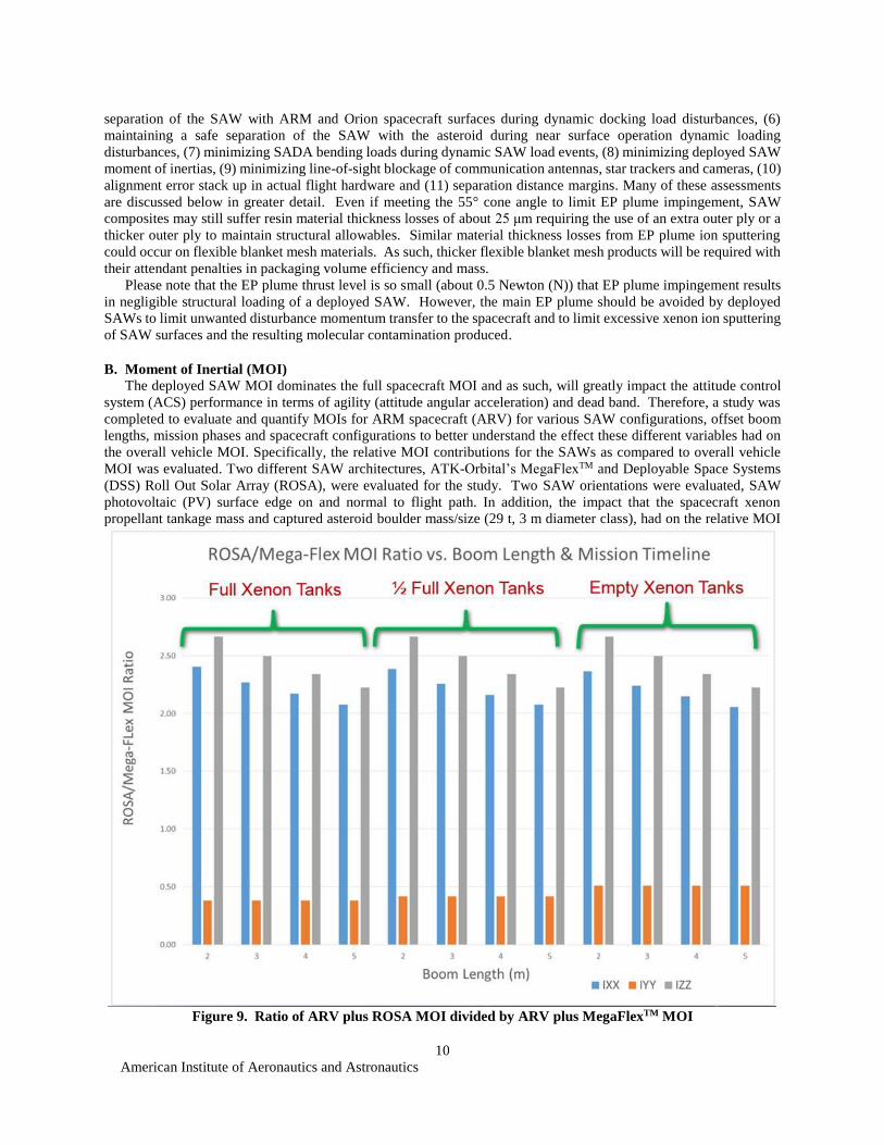
B. Moment of Inertial (MOI)
The deployed SAW MOI dominates the full spacecraft MOI and as such, will greatly impact the attitude control
system (ACS) performance in terms of agility (attitude angular acceleration) and dead band. Therefore, a study was
completed to evaluate and quantify MOIs for ARM spacecraft (ARV) for various SAW configurations, offset boom
lengths, mission phases and spacecraft configurations to better understand the effect these different variables had on
the overall vehicle MOI. Specifically, the relative MOI contributions for the SAWs as compared to overall vehicle
MOI was evaluated. Two different SAW architectures, ATK-Orbital’s MegaFlexTM and Deployable Space Systems
(DSS) Roll Out Solar Array (ROSA), were evaluated for the study. Two SAW orientations were evaluated, SAW
photovoltaic (PV) surface edge on and normal to flight path. In addition, the impact that the spacecraft xenon
propellant tankage mass and captured asteroid boulder mass/size (29 t, 3 m diameter class), had on the relative MOI
Figure 9. Ratio of ARV plus ROSA MOI divided by ARV plus MegaFlexTM MOI

American Institute of Aeronautics and Astronautics
11
contributions and center of gravity (CG) of the spacecraft was evaluated. Finally, the offset boom length for the SAW
was varied between 2 m and 5 m (expected bounding lengths for mission) to better understand effect on overall vehicle
MOIs. The MOIs were calculated based on both a finite element model (FEM) developed for the ARV bus (without
SAWs) in addition to computer aided design (CAD) models developed for the two different SAW configurations and
the various boom lengths evaluated. The coordinate system used for the MOI study was: Z axis-Flight direction (Roll
Axis), Y axis-Pitch Axis and X axis-Yaw axis. Please note, this coordinate system is different than that defined in
section III. All MOIs were calculated about the CG of the ARV (which changed depending on the variables being
evaluated).
As shown in Figure 9, the DSS ROSA IXX and IZZ MOIs are much larger than those of a MegaFlexTM SAW due
to the deployed SAW geometry differences. A MegaFlexTM SAW center of gravity is closer to the spacecraft allowing
these MOIs to be smaller than a more traditional, slender rectangular shape SAW, such as the ROSA. As shown in
Figure 9, the boom length did not significantly change the MOI ratios between the MegaFlexTM and ROSA. As shown
in Figure 10, a more significant finding was the fact that the ROSA SAW MOIs dominated compared to the ARV
(without SAWs) MOIs. Specifically, the ROSA IZZ MOI ranged from between 10–40X greater than the ARV IZZ
MOI. The ROSA IXX MOI ranged from between 2–6X greater than the ARV IXX MOI. Similarly, but to a lesser
extent, as shown in Figure 11, the MegaFlexTM IZZ MOI was quite a bit greater than the ARV IZZ MOI ranging from
between 3–18X greater. Additionally, the study showed the SAW orientation (edge on versus normal to flight path)
had a minimal effect on the relative MOI contributions of either SAW.
The effect xenon propellant loading fraction (full versus ½ full versus empty) had on the overall vehicle MOI was
relatively insignificant as the SAWs were the most dominant contributor to the overall spacecraft MOI. The fact that
the xenon propellant tanks are packaged close to the center line of the spacecraft was the reason that varying the
propellant tankage level had such a minor impact on the overall spacecraft MOIs.
Figure 10. Ratio (as a %) of ROSA MOI divided by the ARV MOI.

American Institute of Aeronautics and Astronautics
12
One final significant finding was the fact that even with the asteroid boulder mass included, the ROSA IZZ MOI
still dominated compared to the IZZ MOI contribution from the ARV with the captured boulder. In addition, the CG
shift of the entire spacecraft due to the asteroid mass was significant – a shift of approximately 4 meters, putting the
CG much closer to the mission module end of the ARV, which would need to be taken into account when designing
the ACS system.
C. Deployed Loading – ARM RCS Plumes
The ARM spacecraft SEPM has an ACS that uses pods of 22 N monopropellant RCS thrusters to provide yaw-
pitch-roll moment inputs. As shown in Figure 3a, these thruster pods (shown in royal blue color) are mounted on
struts (shown in yellow color) attached to the SEPM. Some of these thrusters are directed at the deployed SAWs so
that plume impingement will result. As a limiting design case, the ARM deployed SAWs must demonstrate positive
margins of safety for the loading cases including the 22 N RCS thruster plume impingement force applied at any point
on the SAW and with any line of action. The SAW must be designed to handle the plume forces as quasisteady (as
would be the case for a translational ARV maneuver) and dynamically, at the rate of 5 Hz for a sequence of ten 100-
millisecond on/off pulses. The SAW must be designed for RCS thruster plume loading on top of deployed SAW load
cases associated with asteroid proximity operations. RCS thruster plume loading need not be applied to Orion
approach and docking operations since Orion will be the active vehicle and the ARM spacecraft will be in free drift.
In addition, SAW structures must demonstrate positive margins of safety including RCS plume impingement heating
of 341 W/m2. This heating level causes about a 40°C temperature rise in thin wall composite structures at typical
initial operating temperatures and is expected to result in some loss in material allowables.
D. Deployed Loading – Asteroid Near Surface Operations
ARM vehicle near-surface asteroid operations include the follow dynamic loading cases for the deployed SAWs:
descent touch done impact, asteroid bounder extraction, and ascent acceleration. The dynamic load cases have been
Figure 11. Ratio (as a %) of MegaFlexTM MOI divided by the ARV MOI.

American Institute of Aeronautics and Astronautics
13
analyzed and have been shown to be encompassed by the equivalent of a 0.03 g quasisteady acceleration. As such,
asteroid near surface operational load cases are not design driving for the deployed SAW acceleration requirement.
E. Deployed Loading – Orion RCS Plumes
Deployed SAW strength loading cases analyzed also include thruster plume impingement loads during Orion
docking approach. The scenarios of greatest concern for SEPM SAW plume loading would be firing of the Orion
forward facing RCS thrusters that would occur during an emergency break-out maneuver for aborting a missed
docking attempt. The plumes from these 220 N bi-propellant RCS thrusters were previously modeled for self-
Figure 12. Sample Orion forward RCS thruster plume pressure flow field relative to vehicle geometries.
Figure 13. Orion plume loading geometric parameters.

American Institute of Aeronautics and Astronautics
14
impingement studies on the Orion vehicle3 and the analysis is extended here for impingement to the SEPM SAWs. In
particular, the Reacting And Multi-Phase (RAMP2) and PLume IMPingement (PLIMP) codes are used here for this
initial assessment and further details on the general analysis approach, assumptions and methods can be found
elsewhere3. A sample output of the plume pressure flow field from RAMP2 is shown in Figure 12 relative to a sample
docked Orion and SEPM configuration.
A parametric study was carried out to evaluate the expected plume impingement loads on the SAWs, including
quasistatic acceleration loads as well as bending moments relative to the vehicle body and torsional moments about
the SAW axes. Both the circular and the rectangular SAW geometries were evaluated. Several geometric variables,
diagrammed in Figure 13, were assessed including: (A) angle of SAW about boom axis (0º shown), (B) boom offset
distance between SEPM and SAW (3.5 m shown), (C) clocking angle of Orion with respect to the SEPM docking
adaptor (0º shown), and (D) distance of separation between Orion and the SEPM (0 m shown). Sample impingement
loading results are shown in Figure 14 with the change in pressure profiles on a circular SAW due to changes to the
rotation angle of the SAW about the boom axis (top) and with the boom offset distance (bottom). Figure 15 provides
example pressure loading profiles on a rectangular SAW geometry with variation of the docking clock angle (left) and
inter-vehicle distance (right). For both figures, the main vehicle body of both Orion and the SEPM is to the left.
Figure 14. Pressure profile on a circular SAW with variation of SAW rotation angle and boom length.
American Institute of Aeronautics and Astronautics
15
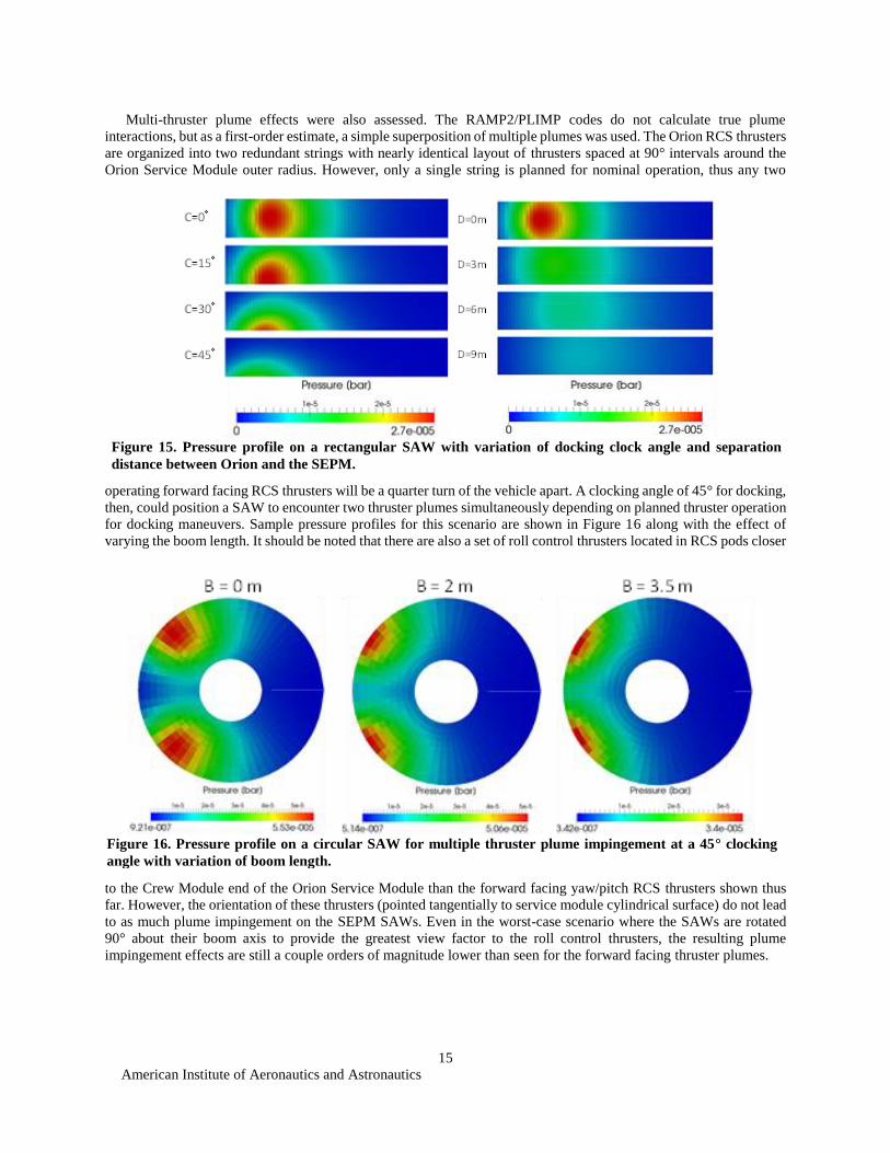
Multi-thruster plume effects were also assessed. The RAMP2/PLIMP codes do not calculate true plume
interactions, but as a first-order estimate, a simple superposition of multiple plumes was used. The Orion RCS thrusters
are organized into two redundant strings with nearly identical layout of thrusters spaced at 90° intervals around the
Orion Service Module outer radius. However, only a single string is planned for nominal operation, thus any two
operating forward facing RCS thrusters will be a quarter turn of the vehicle apart. A clocking angle of 45° for docking,
then, could position a SAW to encounter two thruster plumes simultaneously depending on planned thruster operation
for docking maneuvers. Sample pressure profiles for this scenario are shown in Figure 16 along with the effect of
varying the boom length. It should be noted that there are also a set of roll control thrusters located in RCS pods closer
to the Crew Module end of the Orion Service Module than the forward facing yaw/pitch RCS thrusters shown thus
far. However, the orientation of these thrusters (pointed tangentially to service module cylindrical surface) do not lead
to as much plume impingement on the SEPM SAWs. Even in the worst-case scenario where the SAWs are rotated
90° about their boom axis to provide the greatest view factor to the roll control thrusters, the resulting plume
impingement effects are still a couple orders of magnitude lower than seen for the forward facing thruster plumes.
Figure 15. Pressure profile on a rectangular SAW with variation of docking clock angle and separation
distance between Orion and the SEPM.
Figure 16. Pressure profile on a circular SAW for multiple thruster plume impingement at a 45° clocking
angle with variation of boom length.

American Institute of Aeronautics and Astronautics
16
Each of the input parameters were varied to estimate the worst-case loads. The bending moment of the SAW
relative to the SEPM main vehicle body will be a function of the total plume impingement force across the SAW
surface and the location of the center of pressure. Some geometric parameters will have competing effects on the
bending moment as they may increase the moment arm but reduce the total force or vice versa. A sample of some
bending moment outputs is shown in Figure 17 for the circular SAW. Here it is seen that the separation distance
between the vehicles that cause the maximum bending moment will vary with the boom length. All cases examined,
however, showed the bending moments to remain below 900 N-m for the circular SAWs while the bending moments
for the rectangular SAWs were found to remain below 700 N-m. This range of bending moment is perhaps 10X
greater than experienced in state of the art SAWs. The torsional moments about the boom axis for the SAWs was
Figure 18. Orion plume impingement quasistatic acceleration loading.
Figure 17. Bending moment as a function of the boom length and inter-vehicle distance for the circular array
SAW geometry.
500
550
600
650
700
750
800
850
900
0 1 2 3 4 5 6 7 8
Ben
din
g m
om
ent
[N-m
]
Orion distance from ARRV, D [m]
B = 0 m B = 2 m B = 4 m B = 6 m

American Institute of Aeronautics and Astronautics
17
found to vary the most with clocking angle of the two vehicles for docking, since that effectively moves the center of
pressure further off the boom axis. The maximum torsional moment was found to be around a clocking angle of 30°
for both SAW types. The circular SAW was found to have torsional moments nearing 350 N-m while the rectangular
SAW was much lower, below 30 N-m, due to its small width about the boom axis. The quasisteady acceleration was
also calculated and found be on the order of 0.1 g for the worst-case geometry configurations as shown in Figure 18.
F. Deployed Loading – Orion Docking
The Orion MPCV will dock with the ARM SEPM –X axis end, near the EP thrusters, via the International Docking
System (IDS)4, formerly known as the NASA Docking System (NDS)5. The IDS is shown in Figure 19 mounted to
the SEPM. Please note that the docking loads assessment coordinate system is different from those in Sections III and
IVb. In this section, the X axis is along the SEPM longitudinal axis, the SAWs are mounted along the Y axis and the
Y-Z plane is aligned with the IDS separation plane. Refer to Figure 13 for a conceptual view of the Orion MPCV
docked to the ARM SEPM. The docking event produces dynamic loads and moments in the IDS that are translated
through the SEPM to the base of the SAWs. The worst case SEPM docking port impact was simulated by applying
the maximum load and moment values (per Table 3.3.1.4 in reference 4 and shown in Figure 19) as a single, 0.5
second long step pulse.
Using a multibody dynamics (MBD) analysis approach, the maximum dynamic loads on the SAWs and their
structural response interacting with the ARV main body were predicted. The ARV was modeled as a rigid body with
CG mass and inertia values including the ARV dry mass, 8 t of Xenon propellant and assuming no captured boulder
mass. The Xenon is assumed to be in a supercritical state such that propellant dynamic sloshing effects can be ignored.
IDS docking port was modeled with suitable stiffness and damping properties associated with its soft capture system
(SCS). Simulations also used suitable assumptions for SADA stiffness, a rigid offset boom and 1% damping. The
offset boom to SAW attachment is made using a root hinge with modeled shear stiffness of 13.9 N/mm and bending
stiffness of 1300 N-m/°. The modeled offset boom length is 4 m and the SAW type assumed was MegaFlexTM. A
typical value of 1% modal damping is assumed for all SAW dynamic modes. The mass of each SAW, excluding the
offset boom and SADA, is assumed to be 196 kg. Linear and angular accelerations at the SADA-offset boom interface
plane for this model are generated by the MBD model which includes the ARV, the docking port and the two SAWs.
Figure 19. IDS (formerly known as the NDS) on SEPM.

American Institute of Aeronautics and Astronautics
18
Conversely, linear and angular momentum of SAW motion relative to the SADA are computed, using the Newton-
Euler approach, to model the effective forces and moments of boom whiplash affecting rigid body SAW modes.
The respective MOI of the starboard and portside SAWs, given in the individual Structural Reference (SR)
coordinate frame are given in Eq. (1):
𝐼𝑠𝑡𝑎𝑟𝑏𝑜𝑎𝑟𝑑 = [1229.5 −3.0 110.8−3.0 2086.3 0.1110.8 0.1 3261.5
]𝐾𝑔𝑚2 ; 𝐼𝑝𝑜𝑟𝑡 = [1229.5 +3.0 110.8+3.0 2086.3 −0.1110.8 −0.1 3261.5
]𝐾𝑔𝑚2 (1)
The SR coordinate system has the x-axis pointing inwards along the offset boom towards SADA and the z-axis
pointing upward from the SAW solar cell surface. The off-diagonal entries in the MOI matrices (given in the respective
local SR frame of each SAW) that correspond to Ixy, Iyz, Iyx and Izy switch sign, starboard versus portside. This is
due to mass distribution reflection symmetry of the two SAWs to one another across the y-z plane, while the z-axis of
the two local SR frames are pointing in the same direction.
These simulation results showed that, quasisteady accelerations at SAW center of mass (CM) under worst case
IDS docking impact are below 0.1g. However, peak acceleration is about 0.153 g (or nearly 1.5 m/sec^2) as shown
in Figure 20a. These acceleration levels are about 20X higher than for state of the art SAWs. The resulting reaction
forces and moments at the SADA – offset boom interface for the starboard SAW are shown in Figure 20b. Similar
results would be predicted for the port SAW. As expected, offset boom-SAW root hinge interface reaction torques are
lower than the SADA torques (comparing lower plots of Figures 20c and 20b). On the contrary, due to boom whiplash
motion, linear accelerations at the boom tip are higher than at the base (comparing upper plots of Figures 20d and
20a).
Figure 20a. Orion docking transient starboard SAW linear acceleration and linear displacement at SAW
center of mass, given in ARV body frame (B-frame) coordinates (with the X-axis pointing forwards and the
Y-axis to starboard).

American Institute of Aeronautics and Astronautics
19
The dominant 0.5 Hz response frequency shown is of rigid body rotations of the SAW about the offset boom –
SAW interface. This frequency was found to be greatly dependent on the prescribed shear and bending stiffness of the
offset boom – SAW root hinge. These shear stiffness and bending stiffness values in this simulation were chosen to
be comparable to that of boom bending stiffness.
Figure 20c. Orion docking transient reaction forces and moments of the starboard SADA at the SAW offset
boom base, given in ARV B-Frame coordinates.
Figure 20b. Orion docking transient forces and moments of the starboard SADA at the SAW offset boom
base, given in ARV B-frame coordinates.

American Institute of Aeronautics and Astronautics
20
From the MBD modeling results, the lowest boom bending frequency under SAW inertial loading is about 0.1
Hz for 4 m boom length. This mode is one among the simulated 10 boom bending modes modeled as stiffly
constrained at boom base as part of a companion study. Inertial loads including centrifugal loads on the SAW due to
linear and angular accelerations at the SADA-offset boom interface are applied to the SAW to simulate its response
to docking impact loads. It is desirable to have the natural-frequencies of SAW rigid body motions relative to SADA
mount-structures higher than 0.5 Hz to attain good separation between these modes and the flex modes of the SAW
and the boom. Note that, the lowest-frequency flex mode (in-plane modes) of the 196 kg SAW analyzed is about 0.1
Hz. Hence, dynamic interactions of the SAW with the main body and SADA mount structure below 0.5 Hz could
potentially cause structural instabilities in the SAW or result in vehicle attitude instabilities during docking or
undocking. These interactions will need further parametric studies to fully understand. This will require both frequency
domain analyses and time-domain simulation with sufficient fidelity that should include modeling the effects of RCS
thruster plumes on the SAW and SAW blanket flex dynamics. In addition, NASA does plan to evaluate the effect of
structural and flexible blanket damping levels on the dynamic response and loading of SAWs, offset booms, SADA
and the overall spacecraft dynamics control during transient loading events such as docking.
G. Deployed Stiffness – SAW Flex Body Frequency
Deployed planar SAWs typically have the first three modal shapes associated with out of plane bending, in plane
bending and torsion – although the order of these first 3 modes may switch depending on the exact SAW
configuration/design. The SEPM deployed SAW dynamic modes with > 10% mass participation must exceed 0.1 Hz
when mounted to an infinitely stiff spacecraft sidewall. Likewise, to allow for a reasonable decay of SAW dynamics
and to limit dynamic over shoot, a SAW damping coefficient of >0.01-0.02 is required. This damping value is thought
to provide adequate control band separation between SAW deployed modal frequencies and the spacecraft ACS
bandwidth so that controls-structures-interactions (CSI) are minimized to acceptable levels.
The bending and torsional stiffness, damping and backlash of the SADA as well as the stiffness of the SAW offset
boom all have to be taken into account when evaluating the overall system level structural dynamics, response and
interaction of the deployed SAW with the spacecraft. Figure 21 shows a FEM developed to evaluate the impact that
the offset boom stiffness has on the overall deployed frequency of the SAW (12.5 m diameter MegaFlexTM
SAW
Figure 20d. Orion docking transient starboard SADA - boom interface linear acceleration (upper plot)
and angular acceleration (lower plot), in ARV B-Frame coordinates.

American Institute of Aeronautics and Astronautics
21
shown) assembly. Figure 22 shows the deployed frequency results with an integrated 153 mm outer diameter (OD) x
1.27 mm thick x 4 m long composite offset boom.
The results of early parametric studies have shown that even for a relatively long and slender composite boom
(with quasi-isotropic properties) the effect the boom had on the overall stiffness/frequency (1st Mode – In-Plane “Buzz
Saw” Mode) of the integrated SAW assembly was small, a drop in frequency of ~ 10% (0.10 Hz with offset boom
versus 0.11 Hz without offset boom). Likewise, the addition of the 4 m long offset boom had little impact on the 2nd
SAW mode (torsion), 0.206 Hz versus 0.210 Hz. The 3rd mode of the integrated SAW/offset boom (Out of Plane
Bending “Diving Board” Mode) was the most sensitive to the addition of the offset boom dropping the lateral bending
Figure 21. Parametric MegaFlexTM SAW with offset boom FEM.
Figure 22. Deployed frequency of MegaFlexTM and offset boom.

American Institute of Aeronautics and Astronautics
22
frequency from 0.29 Hz to 0.24 Hz. However, this 3rd mode is not of primary concern and it is well above the 0.1 Hz
requirement for SAW.
Another aspect that needs to be considered as it pertains to the deployed stiffness of the SAW and dynamic
response of the SAW is the torsional stiffness and damping of the SADA. Although it is expected that the torsional
frequency of the SAW should easily meet the 0.1 Hz frequency requirement and thus provide enough separation to
avoid CSI with the SADA motor controller, the stiffness and damping of the SADA still needs to be considered when
evaluating the system level dynamic response. The reference SADA architecture that has been selected for the ARM
mission is a slip-ring style SADA. Typically, torsional stiffness for a slip-ring style SADA is achieved through the
stepper motor drive and the appropriate/required gear reduction which has traditionally been sufficient in the past to
minimize disturbances back to the spacecraft with traditional rigid flat panel SAWs. As the SAWs become larger and
larger the overall torsional stiffness of the integrated SAW and SADA assembly will have to be evaluated more closely
to make sure the levels of disturbance being transmitted back to the spacecraft are acceptable. Likewise, the damping
of the SADA has to be taken into account when estimating the overall dynamic response of the integrated SAW and
SADA assembly. Traditionally, a specific SADA damping level is not specified or formally required for typical
geosynchronous sun-tracking applications with rigid panel SAWs. The friction that is inherent in a slip-ring style
SADA has been enough to enable and maintain stable stepping of the SADA motors to drive the SAWs. However,
further modeling and analysis should be completed to better understand the effect SADA stiffness and damping will
have on the overall spacecraft ACS.
H. Deployed Stiffness – SAW Displacement
During dynamic disturbances, the deployed SAW must limit its tip displacement to avoid damaging contact with
other surfaces and stay within the defined deployed SAW KIZ. Two operational cases are of chief concern: (1) Orion
docking with the ARV and (2) ARV descent to, landing on and ascent from the asteroid. In operational case (1), ARV
SEPM SAW contact with Orion vehicle surfaces must be avoided. Figure 23 illustrates MegaFlexTM SAW
displacement under 0.1 g out of plane steady acceleration. The maximum displacement for the SAW outer gores is
about 0.81 m for this case which is quite acceptable.
In operational case (2), ARV SEPM SAWs must avoid contact with the captured boulder as well as the asteroid
surface. The asteroid surface will have local slopes, boulders and local terrain asperities that will be specified, but
likely not known accurately a priori, to guide the spacecraft design. Instead, landing site attributes will be measured
in real time during the mission and landing sites selected on the basis of meeting many predefined criteria for safe
spacecraft operations and surface boulder extraction probability of success. If NASA elects to use the selected ARM
Figure 23. Displacement (shown in inches) of MegaFlexTM SAW under 0.1 g, out of plane Z-axis
quasisteady acceleration.

American Institute of Aeronautics and Astronautics
23
SAW design or technology for other mission applications, the deployed SAW KIZ may not be defined. In this case,
the maximum deployed SAW displacement must be limited to reasonable value. One chief example is the International
Space Station (ISS) power augmentation application in which the new technology SAW could be mounted closely in
front of the existing ISS SAW. Thus, contact between the 2 SAWs must be avoided to manage ISS and crew safety
risks and loss of channel power. For this application, the deployed SAW maximum displacement must be kept <2 m.
I. Ground Deploying and Deployed Loading
The high power, large area, flexible blanket SAWs required for the ARM SEPM application face challenges during
ground qualification and acceptance testing to verify the SAW deploying process and deployed SAW structural
properties. The 1 g loading of the SAWs during ground testing is 10X greater than SAW design limits and thus weight
offloading ground support equipment (GSE) is required. The GSE must support the SAW weight during ground
deployments and while deployed to avoid over stressing and failing SAW structures and mechanisms. SAW
offloading tends to occur at discrete locations introducing locally high stresses that must be designed for on top of the
primary loading requirements associated with launch and in-space mission dynamic loading events. At the same time,
the GSE must enable release of most degrees of freedom for a faithful replication of in-space, weightless deployment
kinematics. Offloading the weight of advanced SAWs is challenging since most of the SAW mass is in the blankets
that are distributed over a very large area and are flexible. In addition, the blankets are moving over large distances
(meters to 10’s of meters) during deployment. Offloading blanket membranes in 1 g tends to introduce artificially
high tension loads that can over stress SAW components and lead to unrealistic dynamic response in terms of modal
frequencies and damping. SAW structures are also moving during deployments, in some cases in two different planes,
which also present a challenge for attaching, and maintaining the alignment of, overhead offloading elements. If
offloading elements become misaligned with the gravity vector, unwanted torques and/or force imbalances are
introduced. Offloading elements introduce artificial damping and can store and release energy during ground testing.
These effects combine to mask the true SAW weightless deployment and deployed responses.
Since in-space weightless deployments and deployed properties measurements for ARM are cost and schedule
prohibitive, high fidelity ground deployment/deployed testing and analysis is critical. Failure of a SAW deployment
means the loss of mission. Deployed wing structural failure can result in loss of mission and even loss of crew if the
Orion vehicle is damaged. Thus, along with high fidelity offloaded ground deployments and deployed structures
modal measurements, MBD analytical modeling will be key. The MBD model of the SAW in its ground test
configuration can be validated and then the same model can be used to predict weightless SAW kinematic and
structural dynamic performance in space during the mission.
J. Others
One other unique deployed SAW structural consideration arises from the possibility of extremely cold operation
temperatures that can compromise composite structure material allowables. When operating in the stable distant Earth
lunar orbit, the ARM vehicle will experience periodic lunar eclipses with typical durations of 2 to 5 hours, unless
another orbit type can be selected with limited eclipse periods of < 1 hour. The advanced SAWs, with large deployed
area require low areal mass blankets to meet the mass requirement. These low areal mass blankets have very low
thermal capacitance and hence, their temperature responds rapidly to imposed environmental heat fluxes. Coupled
with high emittance surfaces for cool operations when in the sunlight and decreasing material specific heat capacitance
at lower than room temperature, the SAW blankets cool off rapidly during eclipse events. SAWs could reach eclipse
temperatures below -200°C in <2 hours. Composite panel fitting epoxy adhesives undergo a ductile/brittle phase
transition in this temperature regime. Fitting bond line strength may be compromised for subsequent loading events,
such as an Orion docking. Thus, either greater structural margins must be maintained in critical areas at risk of being
compromised and/or dedicated material/structural component coupon testing must be performed to establish accurate
material allowables following the extreme cold exposure. Such testing must be accomplished using vacuum facilities
with liquid helium or liquid hydrogen cyropanels that allow for the required test temperatures. These test facilities
are much less common that those with liquid nitrogen cryopanels and hence, introduce far greater facility/testing costs
and schedule risks associated with facility availability.
V. Conclusion
This paper has covered the top structural/mechanical design considerations for the ARM SEPM SAW application.
The authors conclude that to support NASA’s ARM SEPM power needs, an advanced SAW is required with mass
performance better than 125 W/kg, stowed volume better than 40 kW/m3, a deployed area of 200 m2 (100 m2 for each
of two SAWs), a deployed SAW offset distance of nominally 3-4 m from the SEPM, a deployed SAW quasistatic

American Institute of Aeronautics and Astronautics
24
strength of 0.1 g in any direction, a deployed loading displacement under 2 m, a deployed fundamental frequency
above 0.1 Hz and deployed damping of at least 1%. The SAW must meet KIZ requirements both while stowed and
deployed and limit deployed MOIs to manageable levels. On top of these challenging requirements, the SAW design
must also be tolerant extreme natural mission environments, such as extreme cold during extend eclipse periods, and
also must be robust to ARM induced mission environments, such as EP plume ion sputtering material loss. The SAW
must be designed to allow for high fidelity weightless simulation for ground deployments and deployed properties
testing using GSE. These findings will be considered when formulating future ARM SEPM design and technical
specifications.
Acknowledgments
The authors wish to thank and acknowledge our NASA Glenn Research Center colleagues for their important
contributions to this paper: Tom Cressman (structural interface design, stowed KIZ, technical review), John Heese
(structural interface design/specification, stowed KIZ), Carl Blaser (deployed KIZ formulation), Bill Hughes (dynamic
environments definition), Kim Otten (dynamic environments definition), Paul Solano (SEPM CAD), Jeff Hojnicki
(technical review) and Dave Hoffman (technical review).
References 1President Barack Obama, “Remarks By the President on Space Exploration in the 21st Century,“ John F. Kennedy Space
Center, Merritt Island, Florida, April 15, 2010.
2Kerslake, T. W., “Advanced Solar Arrays for NASA Solar Electric Propulsion (SEP) Missions,” keynote address at the 2nd
AIAA Spacecraft Structures Conference, AIAA SciTech 2015, Kissimmee, FL, January 5, 2015. 3Yim, J. T., Sibé, F., and Ierardo, N. "Plume Impingement Analysis for the European Service Module Propulsion System." 50th
AIAA/ASME/SAE/ASEE Joint Propulsion Conference, Cleveland, OH, AIAA-2014-3883, July 2014.
4International Docking System Standard (IDSS) Interface Definition Document (IDD), Rev. D, International Space Station
(ISS) Multilateral Control Board (MCB), April 30, 2015. 5NASA Docking System (NDS) Interface Definitions Document (IDD), JSC 65795, Revision J, Development Projects Office,
International Space Station Program, September 30, 2014.