structural modeling and flutter analysis of...
TRANSCRIPT

5. ANKARA INTERNATIONAL AEROSPACE CONFERENCE AIAC-2009-132 17-19 August, 2009 - METU, Ankara - TURKEY
STRUCTURAL MODELING AND FLUTTER ANALYSIS OF ADAPTIVE CAMBER WINGS
Güçlü Seber1, Evren Sakarya2, Tolga Erdoğan İnsuyu3, Serkan Özgen4, Melin 4ahin5, Yavuz Yaman6
Middle East Technical University, Department of Aerospace Engineering
Ankara, Turkey
ABSTRACT
In this study, flutter analyses are performed for generic adaptive camber wings with hingeless trailing edge control surfaces. These control surfaces operate based on a concept that exploits the controlled flexibility of the semi-open secondary wing structure. By introducing structural modifications that allow for chordwise sliding between upper and lower skin panels, positive or negative camber changes may be realized for the wing. Using MSC® PATRAN package, wing finite element models are created. In these models, components of the adaptive camber wing, i.e. front and rear spars, spar caps, skins, ribs, stringers and control bars are defined as separate property regions. In order to model the hingeless control surfaces, multi-point-constraints (MPC) are used to represent the sliding action, as well as the interactions between several components. In aeroelastic models created using MSC® FLDS, structural and aerodynamic degrees-of-freedom (dof) are coupled to each other using infinite plate spline functions. The unsteady aerodynamic loads are represented using the Doublet-Lattice Method (DLM). In numerical analyses performed, two different wing configurations are considered, namely Wings A and B. In Wing A, a single hingeless control surface extends throughout the full wing span. Wing B has the same structural properties as Wing A, except for the hingeless control surface, which is split into two equal sized parts. The results of the free vibration analyses show that for both wing configurations, the control surface motion is highly coupled to the bending and torsion type global modes. Furthermore, in the second configuration, additional local modes are observed for the control surface. As a final study, p-k method is employed to calculate flutter speeds for Wings A and B and to identify the modes of instability.
INTRODUCTION
Adaptive camber wings employ strategies to eliminate slots and surface discontinuities in control surfaces to improve aerodynamics and structural design [8] within the complete flight envelope. Fixed wing geometry is mostly optimized for one design point, but the design criteria; Mach number, altitude, weight; change during the flight and thus the overall efficiency of the wing decreases. Traditional control surfaces used in wings are very effective at the design condition where they provide the maximum benefit. However, they have negligible or no effect at the off-design conditions [9]. Adaptive camber wings provide a means to increase the efficiency by better suiting to the changing flight conditions, thus decreasing the fuel consumption [7]. By employing hingeless control surfaces in the design of adaptive camber wings, chordwise and spanwise variable camber can be achieved to improve the lift to drag ratio and to control the spanwise lift distribution, respectively [7].
In most applications of this kind, conventional rib structures are replaced by internal mechanisms and actuators that are designed to change the camber of the wing. The use of open trailing edges to
1 Asst. Prof. Dr. in the Department of Aerospace Engineering, Email: [email protected] 2 M.Sc. Student in the Department of Aerospace Engineering, Email: [email protected] 3 M.Sc. Student in the Department of Aerospace Engineering, Email: [email protected] 4 Assoc.Prof. Dr. in the Department of Aerospace Engineering, Email: [email protected] 5 Asst. Prof. Dr. in the Department of Aerospace Engineering, Email: [email protected] 6 Prof. Dr. in the Department of Aerospace Engineering, Email: [email protected]

AIAC-2009-132 Seber, Sakarya, İnsuyu, Özgen, 4ahin, Yaman
2
permit the sliding of upper and lower skins with respect to each other is also quite common. For instance the ‘belt-rib’ [5] concept uses multiple spokes instead of traditional ribs to permit camber bending of the wing section. The rotating rib concept of Monner [7] uses ribs made out of rotating segments that are combined using revolute joints. When ribs are deformed to the desired shape, the skins follow the movement. Another design, which is analyzed using multi-body-dynamics in Reference 3, employs single piece rotating ribs in combination with sliding skins and an open trailing edge.
Analysis of morphing structures, such as adaptive camber wings, requires proper modeling of the interactions between the aerodynamics, structural dynamics and actuation systems. Therefore, for design and optimization purposes, accurate and efficient models must be created to reduce the analysis and development time. Structural and aeroelastic analyses of such models using MSC® PATRAN and NASTRAN are quite common in literature [2, 3, 9] due to aforementioned reasons. Thus, in this study MSC® PATRAN and NASTRAN are also chosen for modeling and analysis purposes.
METHOD
FE Based Structural Modeling
Figure 1 shows the geometry of the wing that is under consideration in this study. This wing closely approximates the one to be manufactured in the later stages of the ongoing research, and it will be used as a basis for development of methodologies and tools for future studies. To simplify the formulation in this preliminary study, a NACA 0012 airfoil is chosen for this wing and the structural properties are selected such that symmetry exists with respect to the chord line. Also, it is considered that the wing is constructed from aluminum 2024-T3.
Figure 1: The wing dimensions.
Using MSC® PATRAN, finite element models are created using QUAD4 shell and BAR2 beam elements. One must note that, the rigid body modes are not included in the current formulation since the wing models are assumed to be fixed from the spar extensions. Two different configurations are studied here, namely the Wings A and B. These two configurations correspond to wings with single and dual hingeless control surfaces as shown in Figs 2 and 3, respectively. In these figures, different property regions are color coded to represent the components such as spar webs/caps, skins, ribs, stringers and control bars. One must note that both wing models are structurally identical except for the fact that Wing B is a derivative of Wing A, which is created by splitting the full-span hingeless control surface evenly to obtain two hingeless control surfaces. Table 1 and 2 show the dimensions associated to different property regions. As will be discussed in later in this paper, the dynamic and aeroelastic behavior of these two models are in fact quite different from each other.
150 cm
50 cm

AIAC-2009-132 Seber, Sakarya, İnsuyu, Özgen, 4ahin, Yaman
3
Figure 2: Adaptive camber wing with a single full-span control surface: Wing A
Figure 3: Adaptive camber wing with dual control surfaces: Wing B
(See Figure 2 for identification of components)
Table 1: Wing component thicknesses.
Component Thickness (mm)
Skins 0.635
Ribs 0.635
Control surface webs 0.635
Spar webs 2.0
Table 2: Cross sectional dimensions of the wing stiffeners.
Component Dimensions (mm) and Type
Spar caps 10x4, rectangle
Trailing edge stiffeners 3 (radius), circle
Control bars 8x2, rectangle
As shown in Figure 4, a generic hingeless control surface concept is created by connecting control bars, control surface webs and skins (see Figure 2 to identify these components) using multi-point-constraints (MPC). The MPCs constrain the degrees-of-freedom for the adjacent nodes such that only rotations about the wing spanwise axis are independent from each other, and thus creating a hinge-joint. The remaining 5 nodal degrees of freedom, i.e. 3 translations and 2 rotations, are the same. Also, additional MPCs are applied along the trailing edge such that upper and lower panels do not separate from each other, i.e. no independent transverse displacements, which are represented by the red circle in Figure 4. Since this condition leads to the fact that the upper and lower skin surfaces can slide with respect to each other in chordwise direction, the trailing edge may be referred to as ‘semi-open’. The control bars and actuators, which are shown as green rectangles and black circles in Figure 4, connect the rear spar and the control surface webs to each other and also stiffen the hingeless control surface. One may consider this generic concept as a simple representation of the rotating rib design introduced and studied by Monner [7]. In the current study, the actuators are
TE stringer
Control bars
Ribs
CS webs
Spar webs
Upper skin
Hingeless control
surface (CS)
Hingeless control
surfaces
Spar caps
Gap between the two hingeless control surfaces
Lower skin
Spar extensions

AIAC-2009-132 Seber, Sakarya, İnsuyu, Özgen, 4ahin, Yaman
4
assumed to be locked, i.e. they are rigid connections, but this assumption may be relaxed in the future. When compared to the nonlinear static analysis performed in previous studies [1], this generic concept is observed to represent the small deformation behavior of the hingeless control surfaces quite accurately in a qualitative manner.
Figure 4: A representative wing section with MPCs and the actuation system (control bars +
actuators).
Aeroelastic Modeling
Using MSC® FLDS, aeroelastic models are created by coupling the wing finite element model and the aerodynamic model is based on the unsteady Doublet-Lattice-Method. In this approach, infinite plate spline functions are introduced to connect the structural and aerodynamic nodes to each other. Figures 5 and 6 shows the wing mid-surface structural nodes used to define the spline functions and the aerodynamic surfaces for Wings A and B. One may note that since Wing B has two hingeless control surfaces that can move independently, three distinct surfaces are used in its aerodynamic model as well as three separate spline functions.
Figure 5: Wing A: Structural nodes used in the splines (shown as green circles on the left) and the
aerodynamic surface (on the right).
Figure 6: Wing B: Structural nodes used in the splines (shown as green circles on the left) and the
three distinct aerodynamic surfaces (on the right).
Hinge type MPCs
(green circles)
Control bars
Possible location of actuators
(black circles)
AIAC-2009-132 Seber, Sakarya, İnsuyu, Özgen, 4ahin, Yaman
5
RESULTS AND CONCLUSIONS
Free Vibration Analysis
Normal mode analyses are performed to determine the natural frequencies of wings A and B up to 200Hz. This limit also represents the frequency range for the modes that are included in flutter analysis. Tables 3 and 4 present the natural frequencies calculated using finite element analyses and identify the distinctive modes.
Table 3: Natural modes of Wing A
Table 4: Natural modes of Wing B
Mode Number Mode Type Natural Frequency [Hz]
1 1st Bending 20.81
2 Torsion + CS motion 79.43
3 Antisymmetric CS motion 87.37
4 1st Inplane Bending 87.5
5 CS motion 116.89
6 CS motion 126.39
7 CS motion 144.49
8 Torsion + CS motion 168.83
9 CS motion 196.41
10 CS motion 196.99
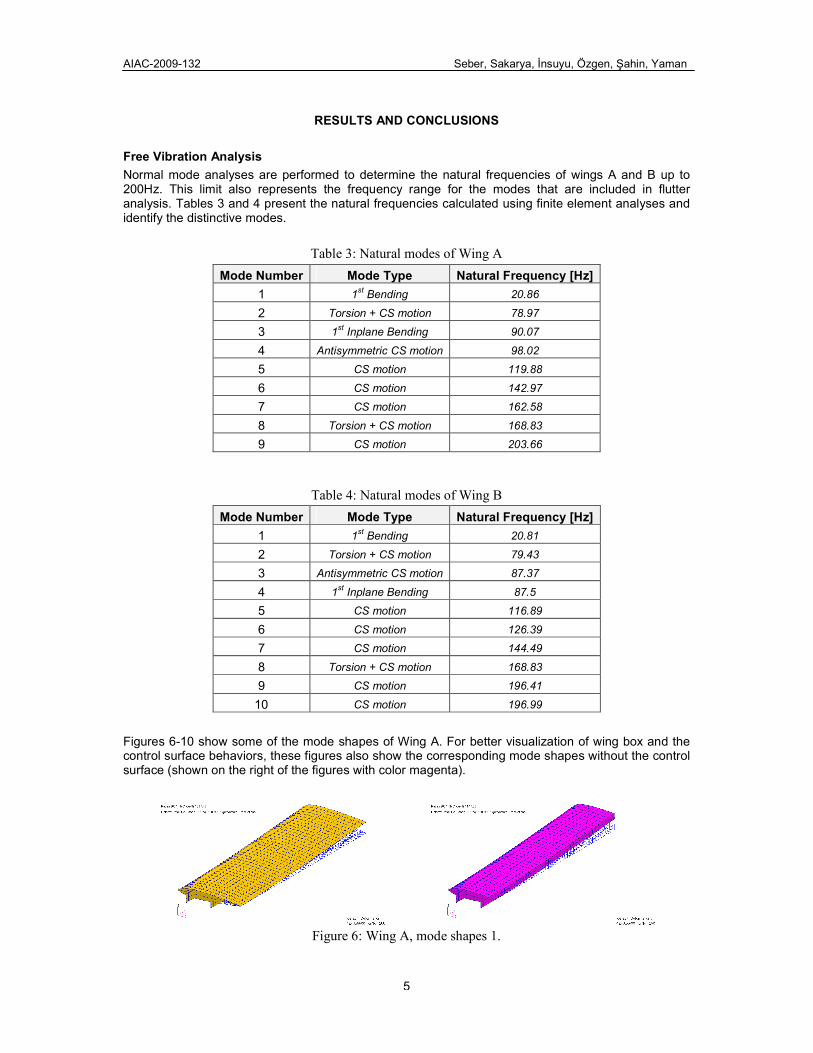
Figures 6-10 show some of the mode shapes of Wing A. For better visualization of wing box and the control surface behaviors, these figures also show the corresponding mode shapes without the control surface (shown on the right of the figures with color magenta).
Figure 6: Wing A, mode shapes 1.
Mode Number Mode Type Natural Frequency [Hz]
1 1st Bending 20.86
2 Torsion + CS motion 78.97
3 1st Inplane Bending 90.07
4 Antisymmetric CS motion 98.02
5 CS motion 119.88
6 CS motion 142.97
7 CS motion 162.58
8 Torsion + CS motion 168.83
9 CS motion 203.66

AIAC-2009-132 Seber, Sakarya, İnsuyu, Özgen, 4ahin, Yaman
6
Figure 7: Wing A, mode shapes 2.
Figure 8: Wing A, mode shapes 3.
Figure 9: Wing A, mode shapes 5.
Figure 10: Wing A, mode shapes 8.
Figures 11-15 present some of the mode shapes for Wing B, once again with and without the control surface.
Figure 11: Wing B, mode shape 1.

AIAC-2009-132 Seber, Sakarya, İnsuyu, Özgen, 4ahin, Yaman
7
Figure 12: Wing B, mode shape 2.
Figure 13: Wing B, mode shape 3.
Figure 14: Wing B, mode shape 5.
Figure 15: Wing B, mode shape 8.
As discussed earlier, for both wing models coupling effects between distinctive deformations such as bending, torsion and control surface motion are quite significant. Also, one may note that splitting the single full-span control surface in two separate ones introduces additional modes with different natural frequencies and mode shapes within the frequency range of interest.
Flutter Analysis
In order to assess the potential hazards brought in by the introduced flexibility and structural coupling effects associated with the hingeless control surface, flutter analyses are performed for both wing models using MSC® FLDS. The p-k method is used in these analyses and compressibility effects are taken into account by defining the flight Mach number. In the preliminary analyses performed, the

AIAC-2009-132 Seber, Sakarya, İnsuyu, Özgen, 4ahin, Yaman
8
control bars have been sized iteratively (Table 2 shows the final values) until the flutter Mach number became equal to the desired value of 0.6. The following results correspond to that particular case.
Figure 16 shows the variation of frequencies and damping ratios corresponding to some of the aeroelastic modes of Wing A. In these plots, only the modes with global significance, such as bending, torsion and control surface motion, and the ones exhibiting the instabilities are shown. The other aeroelastic modes of this wing are observed to be well damped and are not shown here for simplicity. The flutter type instability can be detected for mode 8 (torsion + CS motion) at a flight speed of 225 m/s. One may observe that modes 5 and 8 have a cross over behavior at about 200 m/s, which resembles a mode tracking problem. This observation will be investigated further.
Figure 16: Results of the flutter analysis for Wing A.
Figure 17 shows the variation of frequencies and damping ratios corresponding to some of the selected aeroelastic modes of Wing B. Once again only a few aeroelastic modes are included in the plots shown below due to aforementioned reasons. For this wing, flutter can be detected for mode 8 (torsion + CS motion) at a flight speed of approximately 200 m/s, which corresponds to a 12.5% drop as compared to Wing A.
Figure 17: Results of the flutter analysis for Wing B.
It is believed that splitting the single full-span control surface into two reduces the stiffness of the structure and may cause it to be more likely to flutter. Also, it is possible that the additional modes created to the splitting of the control surface may increase the energy flow from the air into the wing. These issues are currently being studied.
In the extreme case of complete removal of the control bars, natural frequencies go down and a significant drop in flutter speeds are observed for both wings. This modification increases the flexibility of the hingeless control surfaces significantly and changes the modes shapes such that motion of the control surface dominates the bending and torsion type motions of the wing torque-box. As one may expect, lower frequency modes 2 and 3, which exhibits significant control surface motion, becomes unstable at speeds of approximately 35 and 25 m/s for both wings A and B, respectively. This final study may be considered to be helpful in understanding the importance of properly controlling the structural flexibility associated to adaptive camber wings.

AIAC-2009-132 Seber, Sakarya, İnsuyu, Özgen, 4ahin, Yaman
9 Ankara International Aerospace Conference
Acknowledgement
This research was supported by Turkish Scientific and Technological Research Council through the project ‘TUBITAK/107M103, Aeroservoelastic Analysis of the Effects of Camber and Twist on Tactical Unmanned Aerial Vehicle Mission-Adaptive Wings’. The authors gratefully acknowledge the support given.
References
1. Seber, G., Sakarya, E., Insuyu, T. E., Sahin, M., Sozgen, S., Yaman, Y., Evaluation of a Camber Morphing Concept Based on Controlled Flexibility, International Forum on Aeroelasticity and Structural Dynamics, Seattle, Washington, 2009.
2. Andersen, G.R., Cowan, D.L., Aeroelastic Modeling, Analysis and Testing of a Morphing Wing Structure, AIAA/ASME/ASCE/AHS/ASC Structure, Structural Dynamics. And Materials Conference, 2007.
3. Masarati, M., Quaranta, G., Ricci, S. and Scotti, A., Aeroservoelastic Analysis of Morphing Controlled Surfaces, International Forum on Aeroelasticity and Structural Dynamics, Stockholm, Sweden, 2007
4. Ricci, S., Scotti, A. and Terraneo, M., Design, Manufacturing and Preliminary test Results of an Adaptive Wing Camber Model, AIAA/ASME/ASCE/AHS/ASC Structures, Structural Dynamics, and Materials Conference, 2006.
5. Campanile, L.F. and Anders, S., Aerodynamic and Aeroelastic Amplification in Adaptive Belt-rib Airfoils, Aerospace Science and Technology, 9(1), 55–63, 2005.
6. Gern, F.H., Inman, D.J., Kapania, R. K., Structural and Aeroelastic Modeling of General Planform Wings with Morphing Airfoils, AIAA Journal, 40(4), 628-637, 2002.
7. Monner, H. S., Realization of an Optimized Wing Camber by Using Formvariable Flap Structures, Aerospace Science and Technology, 5, 445–455, 2001.
8. Stanewsky, E., Adaptive Wing and Flow Control Technology, Progress in Aerospace Sciences, 37, 583–667, 2001.
9. Stanewsky, E., Aerodynamic Benefits of Adaptive Wing Technology, Aerospace Science and Technologies, 4, 439–452, 2000.