structure and electrochemical properties of spinel …bcui/publication/2014 lto for...int. j....
TRANSCRIPT
Int. J. Electrochem. Sci., 9 (2014) 1583 - 1596
International Journal of
ELECTROCHEMICAL SCIENCE
www.electrochemsci.org
Structure and Electrochemical Properties of Spinel Li4Ti5O12
Nanocomposites as Anode for Lithium-Ion Battery
Xiangcheng Sun1,*
, Manu Hegde2, Yuefei Zhang
3, Min He
4, Lin Gu
4, Yongqing Wang
5, Jie Shu
6, Pavle
V. Radovanovic2, and Bo Cui
1
1Department of Electrical and Computer Engineering, University of Waterloo, Canada
2Department of Chemistry, University of Waterloo, Canada
3Institute of Microstructure and Property of Advanced Materials, Beijing University of Technology,
Beijing 100022, PR China 4Beijing National Laboratory for Condensed Matter Physics, Institute of Physics, Chinese Academy of
Sciences, Beijing 100190, PR China 5Institute of Chemistry, Chinese Academy of Sciences, Beijing 100190, PR China
6Faculty of Materials Science and Chemical Engineering, Ningbo University, 315211, PR China
*E-mail: [email protected]
Received: 1 November 2013 / Accepted: 31 December 2013 / Published: 1 April 2014
Nanocomposite particles of amorphous carbon-Li4Ti5O12 (C-LTO) and carbon nanotube-Li4Ti5O12
(CNT-LTO) were synthesized by solvothermal method and subsequent high-temperature calcination.
X-ray diffraction (XRD), transmission electron microscopy (TEM), high-resolution transmission
electron microscopy (HR-TEM), and selected area electron diffraction (SAED) were applied to
characterize the phase structure, particle morphology, and the coating structure. XRD analysis, TEM
micrographs, HR-TEM images and SAED analysis revealed that both LTO particles exhibited a well-
developed spinel nanocrystal structure with average sizes between 20-70 nm. The C-LTO particles
exhibited roughly spherical shape coated by an amorphous carbon layer up to 10 nm in thickness. The
CNT-LTO samples showed uniform square nanocrystals with edge length around 20 nm and nanoscale
graphitic layers covering the surface, revealing the carbon nanotubes interconnection networks among
the particle assemblies. Electrochemical studies of lithium insertion/extraction performance are
evaluated by the galvanostatic charge/discharge tests, cyclic voltammetry (CV) and electrochemical
impedance spectroscopy (EIS). Both LTO particles showed the superior initial discharge capacity of
more than 200 mAh/g at 1/10C rate. The irreversible capacity of the C-LTO particles at more cycles
was due to large polarization resulted from excessive carbon and possible residual precursors. The
CNT-LTO particles show larger reversible capacity and enhanced electrochemical Li+
insertion/extraction kinetics at different cycling rates. The comparative structural and electrochemical
analyses demonstrated that both nanoscale graphitic covering layers and the CNT interconnection
networks increase the electronic conductivity and improve the kinetics rates of lithium
insertion/extraction in the CNT-LTO particles.
Int. J. Electrochem. Sci., Vol. 9, 2014
1584
Keywords: Lithium-ion battery, Li4Ti5O12, X-ray diffraction, electron microscopy, amorphous
coating, lithium insertion/extraction
1. INTRODUCTION
As an alternative anode material for lithium ion batteries (LIBs), spinel lithium titanate
(Li4Ti5O12, LTO) offers higher safety and longer cycle life (due to the negligible volume change) than
the currently commercial carbon (graphite) anode materials [1-14]. The spinel-type LTO showed
excellent structural stability of almost zero-strain during lithium ion insertion/extraction, leading to
high rate capability and reversibility during discharge-charge cycling. It also provides a stable voltage
of 1.55 V against a lithium electrode with a theoretical capacity of 175 mAh/g and an actual discharge
capacity of over 160 mAh/g [2, 3]. Furthermore, Li4Ti5O12 is cheap and non-toxic, and is easier to
produce than other alloy-based anodes [1-9]. As it does not act as a Li+ ion source during charge-
discharge process, Li4Ti5O12 needs to be coupled with a 4 V cathode such as LiFePO4 to provide a
battery cell with an operating voltage of approximately 2.5 V. It has been reported that lithium reacts
with Li4Ti5O12 according to the kinetic reaction Li4Ti5O12 + 3Li++ 3e → Li7Ti5O12, where lithium
insertion into the Li4Ti5O12 spinal displaces tetrahedrally coordinated lithium ions into octahedral sites,
resulting in the formation of a rock salt-type Li7Ti5O12 crystals [1, 3]. The rate capability of Li4Ti5O12
is relatively low, as the poor electrical conductivity and slow lithium-ion diffusion lead to large
polarization at high charge–discharge rates [5-8].
So far, various doping, mixing and coating techniques were used to improve the electronic
conductivity and electrochemical properties of Li4Ti5O12 [10-13]. The most effective way to improve
their rate performance is the well-known surface carbon-coating technique, which improves the surface
electronic conductivity and the electric contact between particles and conducting agents, leading to a
significantly improved electrochemical performance. However, most of the previous efforts have been
focused on controlling the crystallinity, thickness and uniformity of the carbon coating layer [8-17].
Another effective approach is to produce nano-architectures of Li4Ti5O12 materials such as nanowires
and nanorods that can facilitate both electron and lithium ion transport by reducing the diffusion paths
[16-20]. Much research effort has been paid to carbon-coated Li4Ti5O12 nano-materials that have
demonstrated improvement in the cycling and rate performance [20-29]. However, the question of how
the carbon (i.e. how much content) and active materials connect to each other and what the interfacial
structure between them still needs to be clarified.
In this paper, we carried out the comparative experimental characterization and electrochemical
testing of C-Li4Ti5O12 and CNT-Li4Ti5O12 composite particles. Our result showed that the nanoscale
graphitic covering layers and the CNT interconnection networks between CNT-LTO isolated particles,
gives rise to the effective interconnects that results in enhanced electronic conductivity and
electrochemical properties.

Int. J. Electrochem. Sci., Vol. 9, 2014
1585
2. EXPERIMENTAL METHODS
2.1 Solvothermal synthesis and solid-state reaction
First of all, micro-size Li-Ti-O precursors were solvothermally synthesized using commercial
anatase TiO2 powders (e.g., 25 nm) as raw precursors. In a typical synthesis, a stoichiometric amount
(i.e., Ti:Li=5:4) of anatase TiO2 powder (0.4 g) was dispersed in LiOH·H2O aqueous solution (60 ml).
After stirring for 30 min, the suspension was transferred into a 50 mL Teflon-lined autoclave and
heated at 180oC for 24 hrs. Subsequently, the white precipitate was separated by filtration, and washed
several times with deionized water to remove the excess hydroxides before drying at 80oC for 6 hr.
Finally, the micro-size Li-Ti-O white powder was mixed with multi-wall carbon nanotube and
conducting black carbon powder, and the two different powder mixtures were calcinated respectively
at 800oC and 900
oC for 5 hr under Ar gas, followed by gradual cooling in the furnace.
2.2 Structure Characterizations
The morphologies of as-prepared C-LTO and CNT-LTO nanocomposite particles were
characterized by scanning electron microscopy and transmission electron microscopy (TEM). Crystal
nanostructures were analyzed by powder X-ray diffraction (XRD) with a INEL XRG 3000
diffractometer operating in transmission mode with Cu Ka radiation (λ= 0.15418 nm). Phase
identification and carbon coating structure of both C-LTO and CNT-LTO particles were characterized
and examined by high resolution TEM imaging (HR-TEM) and selected-area electron diffraction
(SAED) using a JEOL 2010F FEG TEM at an accelerating voltage of 200 kV. In addition to TEM, the
carbon coating contents were quantitated by scanning electron microscopy (ZEISS Ultra Plus equipped
with EDX detector).
2.3 Battery preparation and electrochemical testing
Both C-LTO and CNT-LTO nanocomposite materials were examined using a CR2016 coin-
type cell for which the lithium metal was used as a counter electrode. To fabricate the anodes for the
battery test cells, the working electrode was prepared as follows. Active materials (87%) were mixed
with acetylene black (8%) as conducting agent, and polyvinylidene fluoride (PVDF)(5%) as binder in
N-methylpyrrolidine (NMP). The blended slurries were pasted onto a copper current collector, and the
electrode was dried at 80oC for 12 h in a vacuum oven. The electrolyte used was 1M LiPF6 solvent in
a 1:1:1 (vol%) mixture of ethylene carbonate (EC), ethylmethyl carbonate (EMC), and dimethyl
carbonate (DMC). Test cells were assembled in an argon-filled glove box using Li foil as the counter
electrode and polypropylene (PP) film as the separator. Galvanostatic charge-discharge cycling tests
for both coin cells were performed within a range of 1.0 V-3.0 V versus the Lithium counter electrode
using a CT2001A cell test instrument (LAND Electronic Co). The specific capacities of the samples
were calculated based on the mass of the composites. The cyclic voltammetry (CV) for both coin cells
was performed using the Arbin 2000 testing system between 1.0 V and 3.0 V at the scan rate of 0.1
Int. J. Electrochem. Sci., Vol. 9, 2014
1586
mV/s. Electrochemical impedance spectroscopy (EIS) measurements were carried out over a frequency
range of 10mHz –100KHz at 5 mV as the applied sinusoidal perturbation.
3. RESULTS AND DISCUSSIONS
3.1 Particles structures and phase identifications
10 20 30 40 50 60 70 80 900
500
1000
1500
2000
2500
3000
3500
4000
4500
(c)
(b)
(a)
Inte
nsi
ty (
a.u
.)
2 (degree)
(111)
(311) (400)
(511)(440)
(331) (531)
*
* * * * **
L-T-O precursors
C-Li4Ti5O12
CNT-Li4Ti5O12
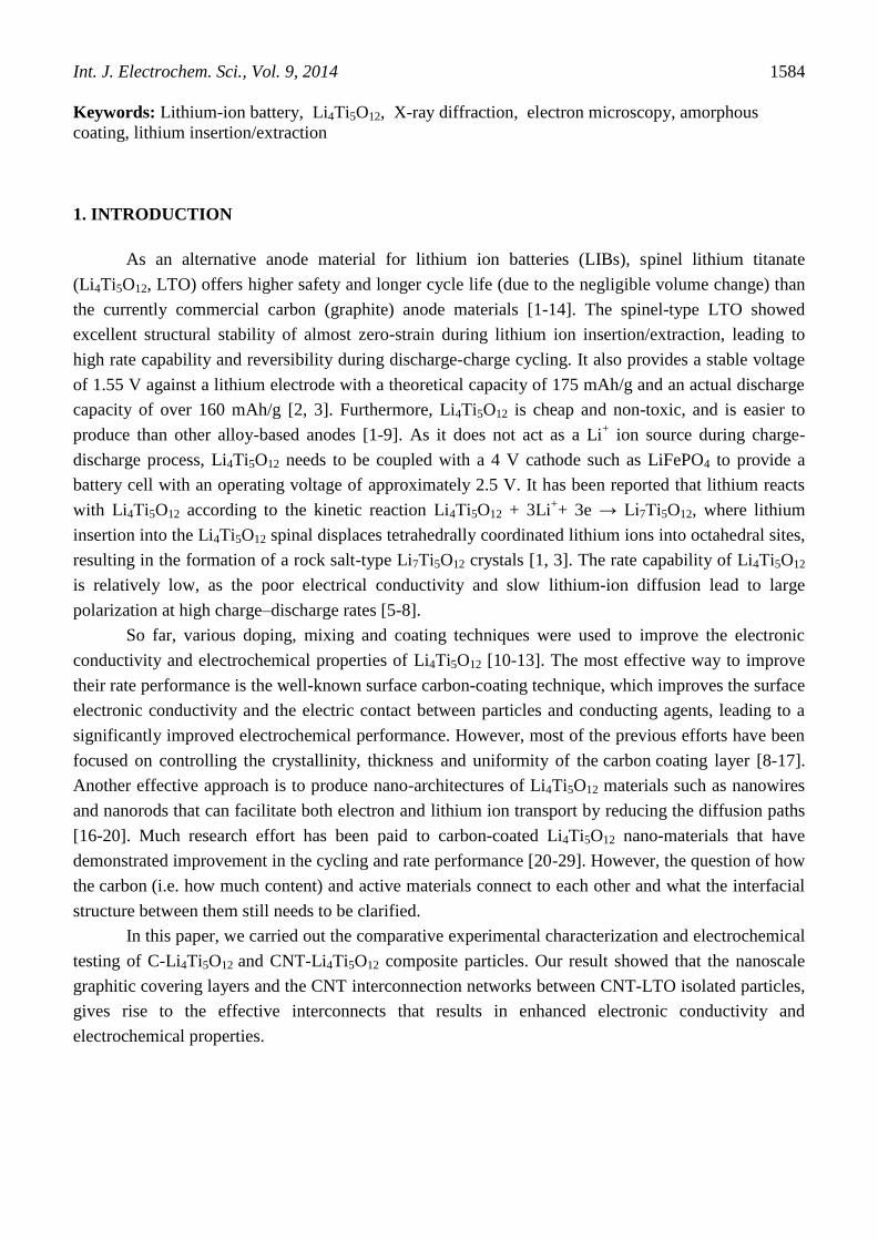
Figure 1. (a, b) XRD patterns of C-LTO and CNT-LTO nanocomposite particles and (c) the L-T-O
precursors
The comparison of XRD patterns of two LTO samples and LTO precursor are shown in Fig. 1.
It is noteworthy that the diffraction peaks of two LTO samples in Fig. 1(a, b) are in good agreement
with JCPDS card No. 49-0207, and can be indexed to the spinel structure with the space group Fd3m,
demonstrating the cubic spinel-Li4Ti5O12 structure was indeed obtained. No crystalline carbon phase
can be identified from XRD patterns, indicating that the coated carbon is amorphous with low content.
It has also been suggested that the addition of carbon and CNTs to the precursor does not influence the
formation of spinel-Li4Ti5O12 during the heat-treatment, except for a weak peak in the pattern of CNT-
LTO due to the CNTs in the composite. No other impurity phases are found compared with the LTO
precursor at Fig.1(c), implying high-purity of spinel-Li4Ti5O12 structure in both LTO samples.
The peaks of (111) and (311) in the XRD pattern were used to calculate average particle sizes
using the Debye Scherrer’s formula (D =0.9λ/βcosθ, where λ = 0.154 nm (Cu Kα) and β = full width

Int. J. Electrochem. Sci., Vol. 9, 2014
1587
half maximum at the diffraction angle of θ), and the estimated average sizes were summarized in Table
1.
Table 1. Comparison of the lattice parameters, average size, and average carbon content
Before calcinations After calcinations
Sample Carbon content
(mass%)
Carbon content
(mass%)
Lattice
parameters
(nm)
Average
size (nm)
C-LTO 10% 3.8 0.8350 26.8
CNT-LTO 20% 9.4 0.8367 35.5
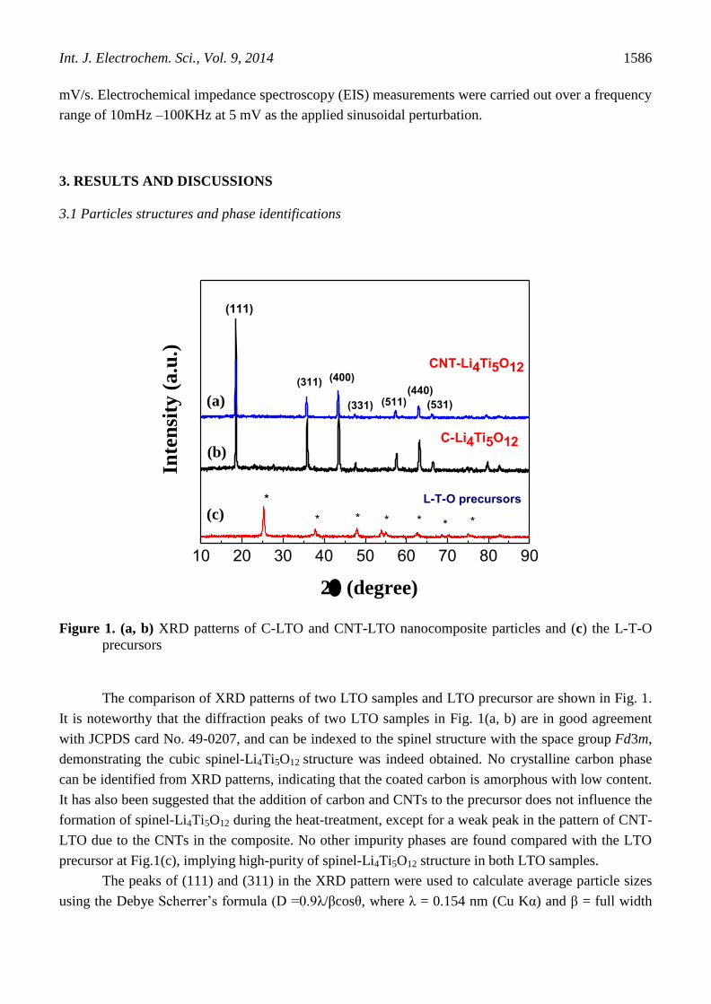
Figure 2. (a) Low magnification TEM micrographs of the C-LTO nanocomposite particles
Bragg equation was used to determine the lattice parameter, a, by n= 2dnkl sin, where n is 1,
is the wavelength of the incident X-ray beam (0.154 nm), is the incident angle, and d is the
distance between the atomic layers of the cubic structure. Because Li4Ti5O12 is face centered cubic, the
lattice parameter can be calculated by using dhkl= a/D, with D=(h2+k
2+l
2)1/2
, and a as the lattice
parameter and (h k l) as the Miller indices. The lattice parameters of two samples are also listed in
Int. J. Electrochem. Sci., Vol. 9, 2014
1588
Table 1. It can be seen that the lattice parameters did not change significantly. In addition, average
carbon content (mass fraction) of two LTO particles were measured from the quantitative energy-
dispersive X-ray micro-analysis (SEM/EDX) and listed in Table 1. It is apparent that the average
carbon content is less for C-LTO particles.
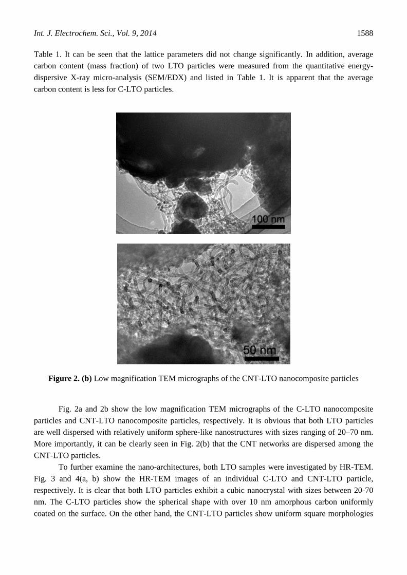
Figure 2. (b) Low magnification TEM micrographs of the CNT-LTO nanocomposite particles
Fig. 2a and 2b show the low magnification TEM micrographs of the C-LTO nanocomposite
particles and CNT-LTO nanocomposite particles, respectively. It is obvious that both LTO particles
are well dispersed with relatively uniform sphere-like nanostructures with sizes ranging of 20–70 nm.
More importantly, it can be clearly seen in Fig. 2(b) that the CNT networks are dispersed among the
CNT-LTO particles.
To further examine the nano-architectures, both LTO samples were investigated by HR-TEM.
Fig. 3 and 4(a, b) show the HR-TEM images of an individual C-LTO and CNT-LTO particle,
respectively. It is clear that both LTO particles exhibit a cubic nanocrystal with sizes between 20-70
nm. The C-LTO particles show the spherical shape with over 10 nm amorphous carbon uniformly
coated on the surface. On the other hand, the CNT-LTO particles show uniform square morphologies

Int. J. Electrochem. Sci., Vol. 9, 2014
1589
with edge length around 20 nm and a few layers of graphitic coating on the surface. The average sizes
of both LTO particles agree well with the above XRD calculations. Furthermore, both HRTEM images
reveal that the lattice fringes have an inter-planar spacing of 0.48 nm, consistent with the (111) atomic
planes of the spinel structure, indicating a well-crystallized spinel phase.
Figure 3. (a, b) HRTEM image of C-LTO particles and (c) SAED patterns of LTO nanocrystal
Fig. 3c and 4 c show the SAED patterns of both LTO nanocrystals. The SAED patterns can be
indexed to be a single spinel phase, which again confirmed that the well-crystallized spinel cubic phase
of Li4Ti5O12 was formed during the calcination process for both types of LTO particles.
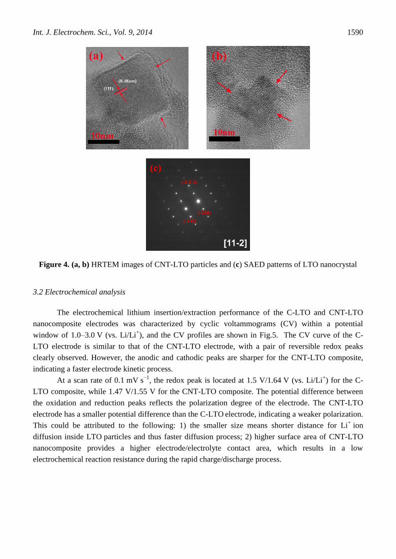
Int. J. Electrochem. Sci., Vol. 9, 2014
1590
Figure 4. (a, b) HRTEM images of CNT-LTO particles and (c) SAED patterns of LTO nanocrystal
3.2 Electrochemical analysis
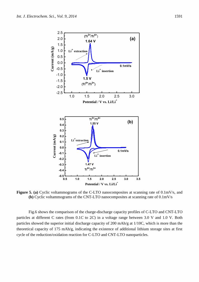
The electrochemical lithium insertion/extraction performance of the C-LTO and CNT-LTO
nanocomposite electrodes was characterized by cyclic voltammograms (CV) within a potential
window of 1.0–3.0 V (vs. Li/Li+), and the CV profiles are shown in Fig.5. The CV curve of the C-
LTO electrode is similar to that of the CNT-LTO electrode, with a pair of reversible redox peaks
clearly observed. However, the anodic and cathodic peaks are sharper for the CNT-LTO composite,
indicating a faster electrode kinetic process.
At a scan rate of 0.1 mV s−1
, the redox peak is located at 1.5 V/1.64 V (vs. Li/Li+) for the C-
LTO composite, while 1.47 V/1.55 V for the CNT-LTO composite. The potential difference between
the oxidation and reduction peaks reflects the polarization degree of the electrode. The CNT-LTO
electrode has a smaller potential difference than the C-LTO electrode, indicating a weaker polarization.
This could be attributed to the following: 1) the smaller size means shorter distance for Li+ ion
diffusion inside LTO particles and thus faster diffusion process; 2) higher surface area of CNT-LTO
nanocomposite provides a higher electrode/electrolyte contact area, which results in a low
electrochemical reaction resistance during the rapid charge/discharge process.
Int. J. Electrochem. Sci., Vol. 9, 2014
1591
1.0 1.5 2.0 2.5 3.0-2.5
-2.0
-1.5
-1.0
-0.5
0.0
0.5
1.0
1.5
2.0
2.5
Li+
extraction
(Ti4+
/Ti3+
)
(Ti3+
/Ti4+
)
Cu
rren
t (m
A/g
)
Potential / V vs. Li/Li+
1.64 V
1.5 V
0.1mV/s
Li+
insertion
(a)
0.5 1.0 1.5 2.0 2.5 3.0 3.5-0.5
-0.4
-0.3
-0.2
-0.1
0.0
0.1
0.2
0.3
0.4
0.5
Li+
insertion
Li+
extraction
0.1mV/s
Ti4+
/Ti3+
Ti3+
/Ti4+
Cu
rren
t (m
A/g
)
Potential / V vs. Li/Li+
1.47 V
1.55 V (b)
Figure 5. (a) Cyclic voltammograms of the C-LTO nanocomposites at scanning rate of 0.1mV/s, and
(b) Cyclic voltammograms of the CNT-LTO nanocomposites at scanning rate of 0.1mV/s
Fig.6 shows the comparison of the charge-discharge capacity profiles of C-LTO and CNT-LTO
particles at different C rates (from 0.1C to 2C) in a voltage range between 3.0 V and 1.0 V. Both
particles showed the superior initial discharge capacity of 200 mAh/g at 1/10C, which is more than the
theoretical capacity of 175 mAh/g, indicating the existence of additional lithium storage sites at first
cycle of the reduction/oxidation reaction for C-LTO and CNT-LTO nanoparticles.

Int. J. Electrochem. Sci., Vol. 9, 2014
1592
Figure 6. The charge-discharge capacity profiles for Li+ ions insertion-extraction of C-LTO and CNT-
LTO nanocomposite particles at various C rates
The charge-discharge cycling behavior is a typical kinetic reaction of Li4Ti5O12 with a flat
charge–discharge plateau at an average potential of 1.55 V (vs. Li/Li+), which is attributed to a two-
phase phenomenon pertaining to Li4Ti5O12 phase and Li7Ti5O12 phase. This intercalation and de-
intercalation process can be expressed as Li4Ti5Ol2+3Li++3e ⇌ Li7Ti5O12 [1-14].
It is also clearly seen from Fig. 6 that the first discharge and charge capacities at 1/10 C of
CNT-LTO were as high as ~200 and ~155 mAh/g, respectively, corresponding to a Coulombic
efficiency of 77.5%. The first discharge and charge capacities of C-LTO were ~200 and ~90 mAh/g
with Coulombic efficiency of 45%. Both initial irreversible capacity losses (i.e. the difference on first
discharge-charge capacity) would possibly be resulted from irreversible lithium loss due to the
formation of solid electrolyte interphase (SEI) film along with carbon modification [30, 31]. The
comparison of Coulombic efficiency suggested that the amorphous carbon coating of C-LTO particles
is much thicker than the few graphitic layers on the CNT-LTO particles. A thick carbon coating
resulted in the decrease in the discharge capacity and increase in polarization at more cycling [32]. On
the contrary, uniform and thin coating layers on the Li4Ti5O12 offer a large effective reaction area
favorable for charge-transfer and Li+ ion diffusion. After first discharge and charge cycle at 0.1C,
further lithium ions insertion/extraction into/from the Li4Ti5O12 electrode exhibited a very good
reversible behavior for the CNT-LTO nanoparticles. Apparently, the CNT-LTO particles have a larger
reversible capacity (e.g., 120-160 mA·h/g) than the reversible capacity (e.g., 75-120 mA·h/g) of the C-
LTO particles. In addition, the CNT-LTO particles show very good reversible symmetry of charge–
discharge from 0.1C to 2C. On the contrary, the C-LTO particles exhibit an asymmetry of charge–
discharge cycling, and sharp step increases of the voltage occurred during the charging process due to
an irreversible electrode polarization. Indeed, it is believed that the difference in the charge–discharge
Int. J. Electrochem. Sci., Vol. 9, 2014
1593
profile may be ascribed to the agglomeration of C-LTO nanoparticle and excessive amorphous carbon
among LTO particles [27, 33, 34]. Such an irreversible capacity of the LTO particles is probably
correlated with its final Li4Ti5O12 crystal structure. Usually some minor amounts of residual anatase
TiO2, even if it was difficult to detect from XRD in Fig. 1 (b, c), resulted in low electrochemical
reactivity. Other possible reasons could be the surface defects such as surface voids and the dissolution
of surface impurities [32, 35, 36] such as adsorbed traces of water from the electrodes into the liquid
electrolyte. This is detrimental for the Li+ exchange and decreases the capacity and gives rise to higher
irreversibility.
As is known, nanoscale electrode materials (i.e. cathode and anode) have demonstrated an
enhanced performance for in Li-ion batteries by providing higher electrode/electrolyte contact area,
shorter Li+
diffusion length (L) and faster electron transport in the intercalation host (smaller time
constant τ = L2/2D, where D is the coupled diffusion coefficient for both Li
+ and e), and better
accommodation of the Li-ion insertion/extraction [28, 29]. Our current CNT-LTO particles have a
larger reversible charge-discharge capacity of 120-160 mA·h/g at 0.1C and 0.2C. We propose that the
interconnected CNT networks among the isolated Li4Ti5O12 particles provided conductive networks
[37, 22], resulting in excellent Li+ insertion/extraction performance, easier and shorter diffusion
pathways for ionic and electronic diffusion, and thus higher discharge capacity. Moreover, the addition
of carbon nanotubes to the precursor hinders particle agglomeration and growth during the high-
temperature calcination process, resulting in uniform particle size and square morphology, which
reduces the distance for lithium ion diffusion and increases the electrode/electrolyte contact surface
area. The graphitic layer coated on the surface of Li4Ti5O12 particles is also favorable for improving
the electronic conductivity.
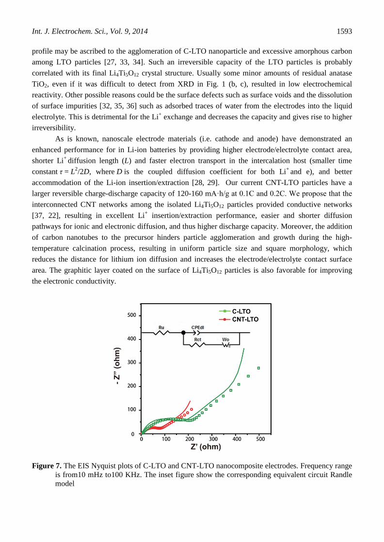
Figure 7. The EIS Nyquist plots of C-LTO and CNT-LTO nanocomposite electrodes. Frequency range
is from10 mHz to100 KHz. The inset figure show the corresponding equivalent circuit Randle
model
Int. J. Electrochem. Sci., Vol. 9, 2014
1594
In order to further clarify and compare the two nanocomposite electrode performance as related
to the electrode kinetics, electrochemical impedance spectroscopy (EIS) was carried out over the
frequency range of 10mHz – 100KHz for both C-LTO and CNT-LTO electrodes in the fully charged
state. The Nyquist plots and the fitting results using an equivalent circuit are given in Fig.7. Both
Nyquist plots are composed of a depressed semicircle in high frequency and a straight line in low
frequency region. The solution resistance Ru of the cell deducted from Z’ axis interception at high
frequency includes both electrolyte and electrode contact resistance. The charge transfer resistance Rct
is determined by the semicircle in the middle frequency range, which is mainly related to the
electrochemical reaction at the electrolyte/electrode interface. The straight line in low frequency range
is attributed to the Warburg impedance Wo, which is due to the solid-state diffusion of Li+ ions into the
bulk of active material. It can be seen from Fig.7 that the CNT-LTO electrode displayed much lower
impedance than that of C-LTO, which is similarly observed in the literature [38, 39]. The equivalent
circuit model is depicted in the inset of Fig. 7, where Ru and Rct are solution resistance and charge
transfer resistance, respectively, and CPE is the Constant Phase Element involving double layer
capacitance of the electrolyte-electrode interface.
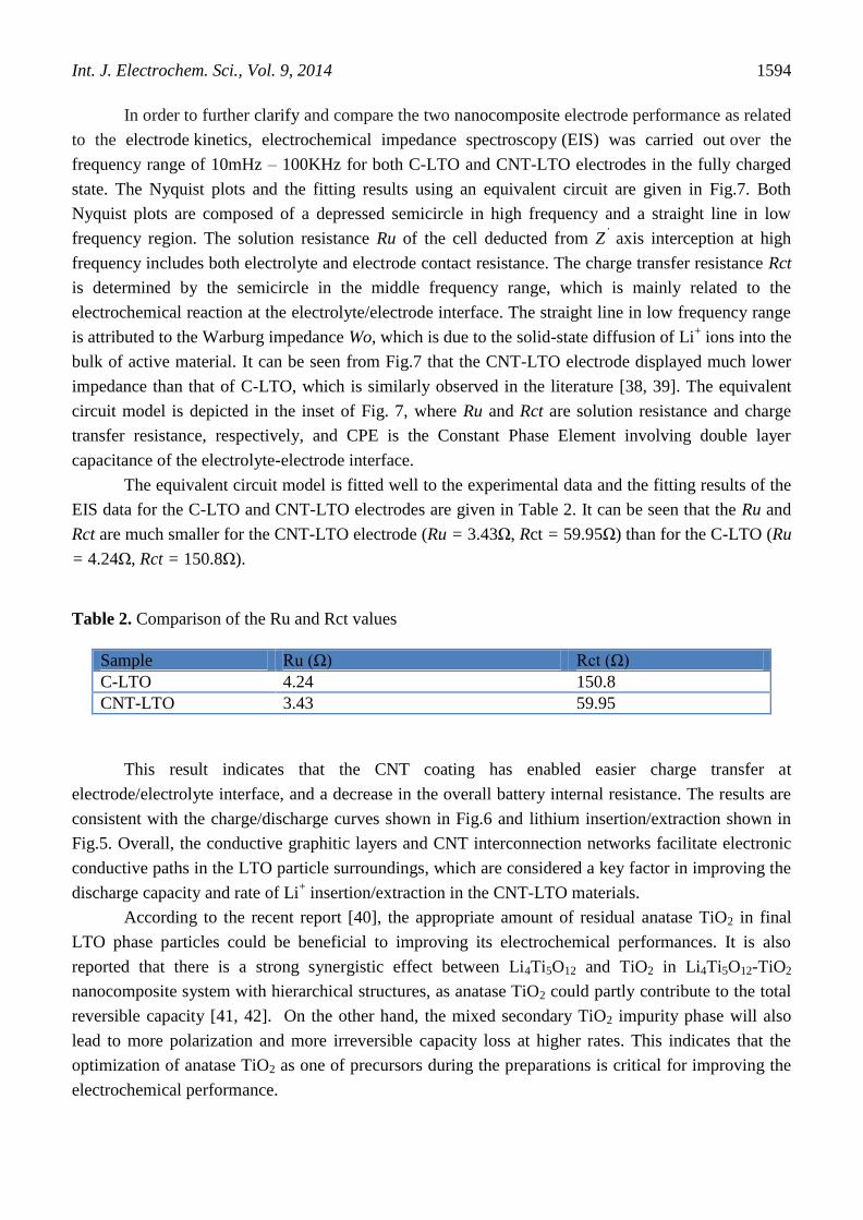
The equivalent circuit model is fitted well to the experimental data and the fitting results of the
EIS data for the C-LTO and CNT-LTO electrodes are given in Table 2. It can be seen that the Ru and
Rct are much smaller for the CNT-LTO electrode (Ru = 3.43Ω, Rct = 59.95Ω) than for the C-LTO (Ru
= 4.24Ω, Rct = 150.8Ω).
Table 2. Comparison of the Ru and Rct values
Sample Ru (Ω) Rct (Ω)
C-LTO 4.24 150.8
CNT-LTO 3.43 59.95
This result indicates that the CNT coating has enabled easier charge transfer at
electrode/electrolyte interface, and a decrease in the overall battery internal resistance. The results are
consistent with the charge/discharge curves shown in Fig.6 and lithium insertion/extraction shown in
Fig.5. Overall, the conductive graphitic layers and CNT interconnection networks facilitate electronic
conductive paths in the LTO particle surroundings, which are considered a key factor in improving the
discharge capacity and rate of Li+ insertion/extraction in the CNT-LTO materials.
According to the recent report [40], the appropriate amount of residual anatase TiO2 in final
LTO phase particles could be beneficial to improving its electrochemical performances. It is also
reported that there is a strong synergistic effect between Li4Ti5O12 and TiO2 in Li4Ti5O12-TiO2
nanocomposite system with hierarchical structures, as anatase TiO2 could partly contribute to the total
reversible capacity [41, 42]. On the other hand, the mixed secondary TiO2 impurity phase will also
lead to more polarization and more irreversible capacity loss at higher rates. This indicates that the
optimization of anatase TiO2 as one of precursors during the preparations is critical for improving the
electrochemical performance.
Int. J. Electrochem. Sci., Vol. 9, 2014
1595
4. CONCLUSIONS
Spinel-type C-LTO and CNT-LTO nanocomposite particles have been synthesized.
Comparative nanostructure analyses (XRD, HRTEM and SAED) and electrochemical testing (charge-
discharge, CV and EIS) revealed that the C-LTO particles have excessive carbon coating on the
surface, resulting in a high irreversible capacity. The CNT-LTO particles have thinner graphitic layers
covering the nanocrystal surface and higher reversible charge–discharge capacity than that of the C-
LTO particles at different rates, which is ascribed to the synergistic effect of thinner graphitic layers
and CNT interconnection networks of the electrode materials that provide shorter diffusion-paths and
faster migration rate of both ions and electrons. This work demonstrates that the CNT-LTO
nanocomposite particles have the improved capacitive performance, making it an efficient and highly
promising material for use in the development of rechargeable Li-ion cells. The current facile reaction
technique represents an effective method for synthesizing Li4Ti5O12 anode material for lithium ion
batteries.
ACKNOWLEDGEMENTS
The President’s Award of University of Waterloo and Postgraduate Scholarships from the Natural
Sciences and Engineering Research Council of Canada (NSERC) and Nano-fellowship from Waterloo
Institute for Nanotechnology (WIN) are greatly appreciated by XC Sun. Financial supports of Beijing
Nova Program (2010B008) and Beijing Natural Science Foundation (2132014) are greatly appreciated
by YF Zhang. Thanks to Dr. Kai Sun at University of Michigan and Dr. Xuedong Bai at Institute of
Physics in Chinese Academy of Sciences for their valuable discussions on HRTEM images processing.
Thanks for Mr. Shanming Li on his helps in TEM imaging at Beijing National Laboratory for
Condensed Matter Physics, Institute of Physics, Chinese Academy of Sciences, China. Special thanks
for Prof. Juewen Liu’s groups on the helps in samples preparation at Chemistry Department,
University of Waterloo.
References
1. K. Zaghib, M. Simoneau, M. Armand, J. Power Sources, 81(1999) 300
2. K. Zaghib, M. Armand, M. Gauthier, J. Electrochem. Soc., 145 (1998) 3135
3. T. Ohzuku, A. Ueda, N. Yamamoto, J. Electrochem. Soc., 142 (1995) 1431
4. E. Ferg, R.J.Gummow, A. de Kock, M. M. Thackeray, J. Electrochem. Soc., 141 (1994) L147
5. S. W. Woo, K. Dokko, K. Kanamura, Electrochim. Acta, 53 (2007) 79
6. L. Cheng, H. J. Liu, J. J. Zhang, H. M. Xiong Y. Y. Xia, J. Electrochem. Soc., 153 (2006) A1472
7. J. R. Li, Z. L. Tang, Z. T. Zhang, Electrochem. Commun., 7 (2005) 894
8. C. H. Jiang, M. Ichihara, I. Honma, H. S. Zhou, Electrochim. Acta , 52 (2007) 6470
9. S. Huang, M. Woodson, R. Smalley, J. Liu, Nano Lett., 4 (2004) 1025
10. H. G. Jung, M. W. Jiang, J. Hassoun, Y. K. Sun, B. Scrosati, Nat. Commun., 2 (2011) 516
11. Z. Liang, Y. S. Hu, H. Li, Z. X. Wang, L. Q. Chen, Adv. Mater., 23 (2011) 1385
12. G. D. Gu, N. Sharma, V. K. Peterson, J. A. Kimpton, D. Z. Jia, Z. P. Guo, Adv. Funct. Mater., 21
(2011) 3990
13. T. F. Yi, J. Shu, X. D. Zhu, Y. R. Zhu, C. B. Yue, A. N. Zhou, R. S. Zhu, Electrochim. Acta, 54
(2009) 7464

Int. J. Electrochem. Sci., Vol. 9, 2014
1596
14. K. Amine, I. Belharouak, Z. H. Chen, T. Tran, H. Yumoto, N. Ota, S.T. Myung, Y. K. Sun Adv.
Mater., 22 (2010) 3052
15. Y. Wang, H. Liu, K. Wang, H. Eiji, Y. Wang, H. Zhou, J. Mater. Chem., 19 (2009) 6789
16. Z. J. Ding, L. Zhao, L.M. Suo, Y. Jiao, S. Meng, Y.S. Hu, Z. X. Wang, L.Q. Chen, Phys. Chem.
Chem. Phys., 13 ( 2011) 15127
17. H. W. Lu, W. Zeng, Y. S. Li, Z. W. Fu, J. Power Sources, 164 (2007) 874
18. J. Y. Kim, J. P. Cho, Electrochem. Solid-State Lett., 10 (2007) A81
19. A. S. Prakash, P. Manikandan, K. Ramesha, M. Sathiya, J. M. Tarascon, A. K. Shukla, Chem.
Mater., 22 (2010) 2857
20. E. M. Sorensen, S. J. Barry, H. K. Jung, J. R. Rondinelli, J. T. Vaughey, K. R. Poeppelmeier,
Chem. Mater., 18 (2006) 482
21. G. Zhu, H. Liu, J. Zhuang, C. Wang, Y.Y. Xia, Energy Environ. Sci., 4 (2011) 4016
22. L. Cheng, J. Yan, G. N. Zhu, J. Y. Luo, Y. Y. Xia, J. Mater. Chem., 20 (2010) 595
23. J. Gao, J. R. Ying, C. Y. Jiang, C. R. Wan, J. Power Sources, 166 (2007) 255
24. J. J. Huang, Z. Y. Jiang, Electrochim. Acta, 53 (2008) 7756
25. K. S. Park, A. Benayad, D.J. Kang, S. G. Doo, J. Am. Chem. Soc., 130 (2008) 14930
26. H. K. Kim, S. M. Bak, K. B. Kim, Electrochem. Communication, 12 (2010) 1768
27. B. H. Li, F. Ning, Y. B. He, H. D. Du, Q.H. Yang, J. Ma, F.Y. Kang, C.T. Hsu, Int. J.
Electrochem. Sci., 6, (2011) 3210
28. K. Amine, I. Belharouak, Z. H. Chen, T. Tran, H. Yumoto, N. Ota, S. T. Myung, Y. K. Sun, Adv.
Mater., 22 (2010) 3052
29. Y. Ren, A. R. Armstrong, F. Jiao, P. G. Bruce, J. Am. Chem. Soc., 132(2010) 996
30. Z. S. Wu, W. Ren, L. Wen, L. Gao, H. M. Cheng, ACS Nano, 4 ( 2010) 3187
31. Y. Shi, L. Wen, F. Li, H. M. Cheng, J. Power Sources, 196 (2011) 8610
32. L. Shen, C. Yuan, H. J. Luo, X. Zhang, H. Xu, Y. Xia, J . Mater. Chem., 20 (2010) 6998.
33. J. H. Ryu, J. Electrochemical Sci. Tech., 2 (2011) 136
34. W. J. H. Borghols, M. Wagemaker, U. Lafont, E. M. Kelder, F. M. Mulder, J. Am. Chem. Soc., 131
(2009) 17786
35. J. Liu, X. F. Li, J. Yang, D. S. Geng, Y. L. Li, D. Wang, R. Li, X. L. Sun, M. Cai, M. W.
Verbrugge, Electrochim. Acta, 63 (2012) 100
36. J. Chen, L. Yang, S. Fang, Y. Tang, Electrochim. Acta, 55 (2010) 6596
37. X. Li, M. Z. Qu, Y. J. Huai, Z .L. Yua, Electrochim. Acta, 55 (2010) 2978
38. T. Yuan, X. Yu, R. Cai, Y. Zhou, Z. Shao, J. Powder Sources, 195 (2010) 4997
39. L. Yang, J. Gao, J. Alloys & Compounds, 485 (2009) 427
40. L. L. Xie, Y. D. Xu, J. J. Zhang, X. Y. Cao, B. Wang, X. Y. Yan, L. B. Qu, Int. J. Electrochem.
Sci., 8 (2013) 1701
41. Y. Q. Wang, L. Gu, Y. G. Guo, H. Li, X. Q. He, S. Tsukimoto, Y. Ikuhara, L. J. Wan, J. Am.
Chem. Soc., 134 (2012) 7874
42. J. Wang, H. Zhao, Q. Yang, C. M. Wang, Q. Xia, J. Powder Sources, 222 (2013) 196
© 2014 by ESG (www.electrochemsci.org)