structure, behavior and function of complex …home.cc.gatech.edu/dil/uploads/sbf2.pdfstructure,...
TRANSCRIPT
Structure, Behavior and Function of Complex Systems:
The SBF Modeling Language
Ashok Goel, Spencer Rugaber, Swaroop Vattam
Design Intelligence Laboratory
School of Interactive Computing, Georgia Institute of Technology
Atlanta, Georgia 30332, USA
{[email protected], [email protected], [email protected]}
Corresponding author
Ashok Goel
School of Interactive Computing, Georgia Institute of Technology
Technology Square Research Building
85 5th Street NW
Atlanta, GA 30332-0760 USA
Email: [email protected]
Phone: 404-894-4994
Fax: 404-894-0673
Short title: The SBF Modeling Language
Total number of pages: 44
Number of tables: 0
Number of figures: 8
Structure, Behavior and Function of Complex Systems:
The SBF Modeling Language
Abstract:
Teleological modeling is fundamental to understanding and explaining many complex systems,
especially engineered systems. Research on engineering design and problem solving has
developed several ontologies for expressing teleology, e.g., FR, FBS, and SBF. In this paper, we
view SBF as a programming language. SBF models of engineering systems have been used in
several computer programs for automated design and problem solving. The SBF language
captures the expressive power of the earlier programs and provides a basis for interactive
construction of SBF models. We provide a precise specification of the SBF language. We also
describe an interactive model construction tool called SBFAuthor.
Keywords: Ontology, Teleology, Structure, Behavior, Function
Section 1: Teleology of Complex Systems
Teleological modeling is fundamental to understanding and explaining many complex systems,
especially engineered systems. By complex system, we mean a system that not only has many
interconnected components, but also has causal processes at multiple levels of abstraction such
that a causal process at one level emerges out of component interactions at a lower level. By
teleological model of a system, we mean a representation that specifies both the functions of the
system and the causal processes that result in the system functions. It follows that a teleological
model of a complex system would specify the system functions, and the causal processes that
result in them, at multiple abstraction levels.
Of course teleological models are not necessarily useful for understanding or explaining all
artifacts. We may view artifacts as lying on a spectrum of teleological explanation. At one end of
this spectrum are artifacts for which teleological explanations are very useful. For example, the
door system in my office has a useful teleological explanation: it’s functions (closing and
opening) are accomplished by causal processes (pushing or pulling on the handle of the door,
which creates a torque about the hinges that connect the door to the wall, which generates an
angular motion about the hinges, and so on). While the physical structure of the door (e.g., its
connection to the wall) both affords and constrains its motion, it’s causal processes mediate
between it’s structure and it’s functions. At the other extreme of the teleological spectrum are
artifacts whose function directly emerges from the shape of its structural components. For
example, the function of the desk on which my computer sits (providing a flat space for placing
objects) directly emerges from the shape of its structure (a large flat top) without any mediation
by a causal process. Many artifacts lie in the middle of this teleological spectrum, containing
some subsystems that are teleological and others that are not. For example, on one hand, the
function of the chair that I am sitting on while I type these words directly emerges from the
shape of its structure. On the other hand, the chair also contains a lever so that when I push the
lever down, it lowers the height of the seat; this function is accomplished by a causal process. In
this paper, we are concerned solely with the ontology of complex systems in which causal
processes mediate between their structure and functions.
Computational research on engineering design and problem solving has led to several ontologies
for teleological modeling such as Functional Representation (Chandrasekaran 1994;
Chandrasekaran & Josephson 2004; Sembugamoorthy and Chandrasekaran 1986), Function-
Behavior-Structure (Gero 1990; Gero, Tham & Lee 1992), and Function-Behavior-State (Umeda
et. al. 1990; Umeda et. al. 1997; Umeda & Tomiyama 1996). By ontology, we mean a
vocabulary of knowledge representation (cf. Bunge (1977), who views ontology as pertaining to
the nature of the world). The Structure-Behavior-Function (or SBF) knowledge representation
language (Bhatta & Goel 1994, 1997; Goel et. al. 1996; Goel & Bhatta 2004; Prabhakar & Goel
1997) provides one such ontology for teleological modeling.
Although SBF modeling is fairly mature by now (as is indicated by the years of publication in
the list of references), recently our work has explored computational tools for interactive
construction of SBF models, which raises several new research issues. The design literature
typically described ontologies for teleological modeling only at a high level, often using
teleological models of specific systems as illustrations. This is because a high-level specification
of the ontology often is sufficient to explain a computational theory or model. However, a high-
level specification of our SBF ontology is inadequate for developing an interactive tool for
constructing an SBF model. This is because model building is an open-ended task, and the higher
the level of specification of the ontology the less constrained the task becomes and the less
guided is the human user. Users may potentially use the interactive tool to construct a variety of
SBF models in a variety of ways, many of which might be incorrect or incomplete. Furthermore,
the tool may need to incorporate model checking functionality to provide feedback to the users
about the correctness of their models, creating a need for more precise specification of the
ontology. Thus, for the purpose of developing an interactive tool, we need to view SBF as a
programming language with a well-defined syntax and semantics. An SBF language would both
constrain the actions of a user as well as afford the construction of useful SBF models. The
language would also enable automated model checking. In addition, it will enable the
construction of agents that both guide a user in constructing an SBF model as well as critique a
constructed model. The primary goal of this paper is to specify the abstract syntax of the SBF
language and to describe how the static semantics of the syntax enables interactive construction
of SBF models.
Section 2: An Illustrative Example of SBF Models
To motivate the SBF programming language, let us consider a simple example: teleological
modeling of a gyroscope follow-up, a device used in gyrocompasses on ships. (Briefly, the
gyrocompass, with its ability to track true north as compared to the unreliable magnetic north, is
an instrument for navigation and piloting aboard many ships. A gyroscope is an assembly with a
very rapidly spinning top. A gyroscope follow-up automatically tracks and amplifies the
movement of a spinning gyro. The follow-up servo can drive any number of gyrocompasses
located anywhere on a ship, each of which replicates the reading of the central gyro. Figure 1
illustrates the structure of a simple gyroscope follow-up with no feedback control.
------------- Figure 1 goes here --------------
Structure: In SBF models, structure is represented in terms of components, the substances
contained in the components, and connections among the components. The specification of a
component includes its functional abstractions, where a component can have multiple functions.
The specification of a substance includes its properties. Substances can be abstract, e.g., angular
momentum.
------------- Figure 2 goes here --------------
Function: A function is represented as a schema that specifies its preconditions and its
postconditions. The function schema contains a reference to the behavior that accomplishes the
function. This schema also may specify conditions under which the specified behavior achieves
the given function (e.g., an external stimulus). Figure 2 illustrates the schema for the function of
the gyroscope follow-up of Figure 1. Informally, the function specifies that the device takes as
input angular momentum of magnitude Li and of clockwise direction at the input (gyroscope)
location, and produces a proportional angular momentum of magnitude Lo and of clockwise
direction at the output shaft location. Lo fluctuates over a large range, i.e., Lo = Lavg ± ∆, where ∆
can be large.
------------- Figure 3 goes here --------------
Behavior: A behavior is represented as a sequence of states and transitions between them. The
states and the transitions are represented as state and transition schemas, respectively. The states
in a behavior specify the evolution in the values of the parameters of substances and/or
components. Continuous state variables are discretized, and temporal ordering is subsumed by
causal ordering. Each state transition in a behavior is annotated by the causes for the transition.
Causal explanations for state transitions may include physical laws, mathematical equations,
functions of its subsystems, structural constraints, other behaviors, or a state or transition in
another behavior. Figure 3 shows the behavior that explains how angular momentum from the
input gyroscope location is transferred to the output shaft location. The functional context
specified by the annotation USING-FUNCTION in Transition_3-4 indicates that the transition
occurs due to the primitive function “CREATE Angular Momentum” of Hydraulic-Motor.
Section 3: Background of SBF Models
Before we go further, we need to situate SBF modeling in the context of teleological modeling of
complex systems in general. In Sciences of the Artificial, Simon (1969, 1996) viewed a system as
having an inner and an outer environment. Further, he viewed a function of the system as an
abstraction of its inner environment, lying at the interface of its inner and outer environments.
Simon suggested that from the perspective of understanding the design of complex systems, the
right kind of explanations specified how the function of a system arises out of the components
and processes in the inner environment of the system.
In the early 1980’s, Chandrasekaran and his associates developed a Functional Representation
(FR) scheme for representing teleology (Chandrasekaran 1994; Sembugamoorthy and
Chandrasekaran 1986). They used the FR representation of a system for explanation and
diagnosis. The FR representation of a system explains how its causal processes accomplish its
functions, and how the causal processes hierarchically compose the functions of the system’s
components into the functions of the systems as a whole. Thus, FR not only represented the
functions of a system explicitly, but also used the functions as indices into the causal processes
(called behaviors) that accomplished the functions; the behaviors in turn indexed the functions of
the subsystems, and so on. At about the same time, Rasmussen developed a Structure Behavior
Function (SBF) scheme for representing teleology (Rasmussen 1985; Rasmussen, Pejterson &
Goodstein 1994). He and his colleagues used the SBF representations of very large complex
systems, such as an electrical power plant, to interactively aid human operators in
troubleshooting the system. Their SBF representations emphasized representation of the
functional roles of the structural components of the system.
In the late 1980s, Gero and his associates (Gero 1990; Gero, Tham & Lee 1992) and Tomiyama
and his colleagues (Umeda et. al. 1990; Umeda et. al. 1997; Umeda & Tomiyama 1996)
independently developed Function Behavior Structure (FBS) schemes for representing teleology.
(Tomiyama sometimes calls his representation scheme Function-Behavior-State models.) Gero
and Tomiyama used their respective FBS schemes for understanding the process of designing
engineered systems and for aiding human designers in the design process. In the 1990s,
Chakrabarti & Bligh (1996), Stone & Wood (2000), and Mizoguchi and his colleagues (Sasajima
et. al. 1995; Kitamura et. al. 2004), among others, developed similar functional representation

schemes and for similar uses. It is important to note that, as a consequence, there is not one but
several functional representation schemes currently in the field. While the various functional
representation schemes have many features in common, their ontologies often are quite different.
For example, behavior in Chandrasekaran’s FR scheme refers to a causal process while behavior
in Gero’s FBS representation pertains to the properties of a structural component. Erden et. al
(2008) provide a recent useful review of several major functional representation schemes.
The origin of our Structure Behavior Function (SBF) representation of teleology (Bhatta & Goel
1994, 1997; Goel et. al. 1996; Goel & Bhatta 2004; Prabhakar & Goel 1998) lies in
Chandrasekaran’s FR scheme (e.g., Goel & Chandrasekaran 1989; Chandrasekaran, Goel &
Iwasaki 1993). In particular, our SBF models both combine FR with Bylander’s component-
substance ontology and primitive functions (Bylander 1991), and extend FR to support the
inferences needed for automated design (Goel 1992; Goel & Chandrasekaran 1989, 1992; Goel,
Bhatta & Stroulia 1997). SBF models share the main features of the FR scheme: (i) functions of
devices are represented explicitly, (ii) functions act as indices into internal causal behaviors
responsible for them, (iii) behaviors are represented as an ordered sequence of states, (iv) state
transitions in a behavior are annotated by the causal explanations for them, (v) the causal
explanations can be of several types, e.g., component function, structural relation, domain
principle, another behavior, and (v) the component function explanations for transitions act as
indices into functions at the next (lower) level of aggregation. SBF models also extend the FR
scheme: (a) SBF models use a component-substance ontology of devices, which enables a more
precise specification of states in a behavior or in a function, (b) SBF models use an ontology of
primitive functions based on the component-substance ontology, which enables a more precise
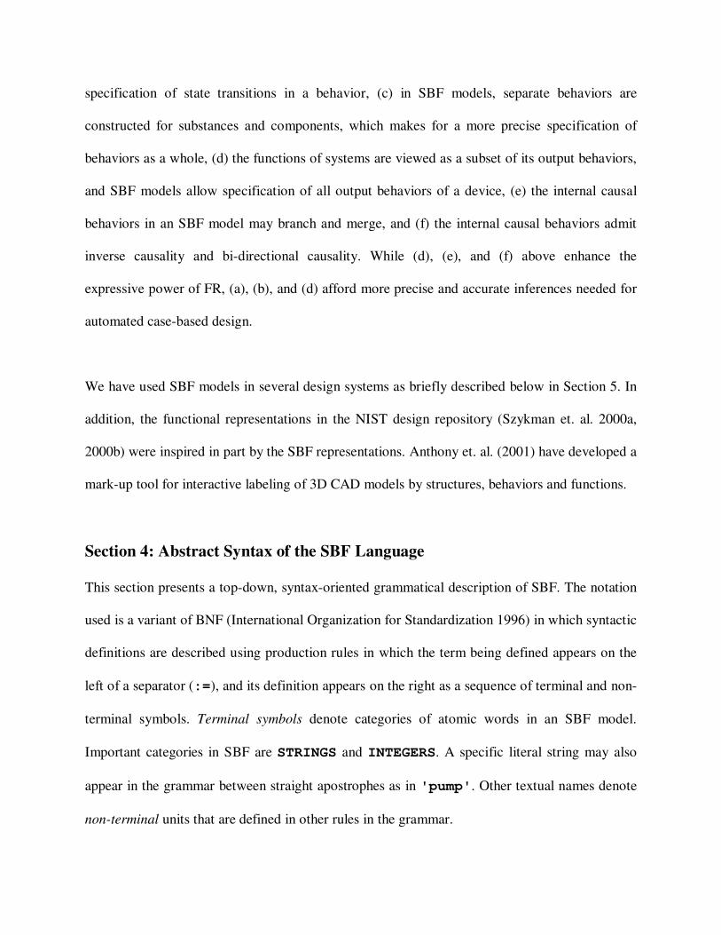
specification of state transitions in a behavior, (c) in SBF models, separate behaviors are
constructed for substances and components, which makes for a more precise specification of
behaviors as a whole, (d) the functions of systems are viewed as a subset of its output behaviors,
and SBF models allow specification of all output behaviors of a device, (e) the internal causal
behaviors in an SBF model may branch and merge, and (f) the internal causal behaviors admit
inverse causality and bi-directional causality. While (d), (e), and (f) above enhance the
expressive power of FR, (a), (b), and (d) afford more precise and accurate inferences needed for
automated case-based design.
We have used SBF models in several design systems as briefly described below in Section 5. In
addition, the functional representations in the NIST design repository (Szykman et. al. 2000a,
2000b) were inspired in part by the SBF representations. Anthony et. al. (2001) have developed a
mark-up tool for interactive labeling of 3D CAD models by structures, behaviors and functions.
Section 4: Abstract Syntax of the SBF Language
This section presents a top-down, syntax-oriented grammatical description of SBF. The notation
used is a variant of BNF (International Organization for Standardization 1996) in which syntactic
definitions are described using production rules in which the term being defined appears on the
left of a separator (:=), and its definition appears on the right as a sequence of terminal and non-
terminal symbols. Terminal symbols denote categories of atomic words in an SBF model.
Important categories in SBF are STRINGS and INTEGERS. A specific literal string may also
appear in the grammar between straight apostrophes as in 'pump'. Other textual names denote
non-terminal units that are defined in other rules in the grammar.
Several operators are used in the syntactic definitions. Juxtaposition denotes concatenation; '|'
denotes alternative; '[T]' denotes optionality, where T is any string of symbols; '{T}*' and
'{T}+' denote respectively any number of occurrences of T and any non-zero number of
occurrences. Finally, '// ...' denotes a comment that proceeds from the slashes to the end of
the line.
Together, the following set of rules comprises an abstract syntax for SBF. The syntactic
description is abstract because it avoids concrete details such as punctuation and keywords.
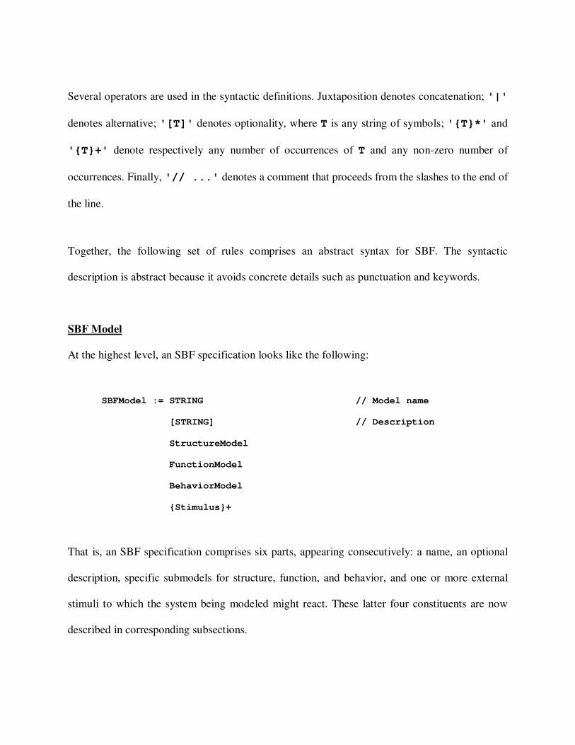
SBF Model
At the highest level, an SBF specification looks like the following:
SBFModel := STRING // Model name
[STRING] // Description
StructureModel
FunctionModel
BehaviorModel
{Stimulus}+
That is, an SBF specification comprises six parts, appearing consecutively: a name, an optional
description, specific submodels for structure, function, and behavior, and one or more external
stimuli to which the system being modeled might react. These latter four constituents are now
described in corresponding subsections.
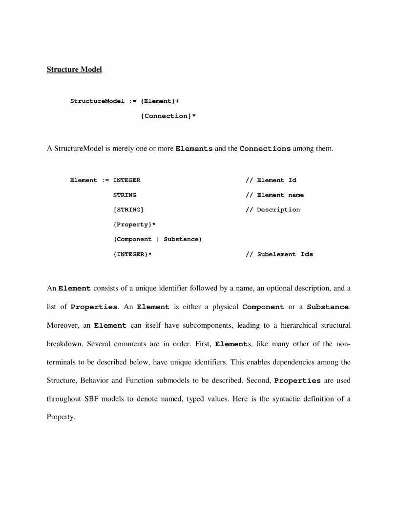
Structure Model
StructureModel := {Element}+
{Connection}*
A StructureModel is merely one or more Elements and the Connections among them.
Element := INTEGER // Element Id
STRING // Element name
[STRING] // Description
{Property}*
(Component | Substance)
{INTEGER}* // Subelement Ids
An Element consists of a unique identifier followed by a name, an optional description, and a
list of Properties. An Element is either a physical Component or a Substance.
Moreover, an Element can itself have subcomponents, leading to a hierarchical structural
breakdown. Several comments are in order. First, Elements, like many other of the non-
terminals to be described below, have unique identifiers. This enables dependencies among the
Structure, Behavior and Function submodels to be described. Second, Properties are used
throughout SBF models to denote named, typed values. Here is the syntactic definition of a
Property.

Property := STRING // Property name
Type
Value
Unit
Constantp
Type := 'boolean' | 'integer' | 'real' | 'string' | ...
Value := STRING
Unit := 'gram' | 'meter' | 'second' | ...
Constantp := 'true' | 'false'
Properties have Types in the sense of belong to a set of related values, such as integers
or strings. Moreover, because SBF models physical devices, its supports the use of scientific
Units to further describe the Values. The non-terminal Constantp is intended to enable the
modeler to indicate that the Value of a particular Property is not subject to change.
Component := INTEGER // Function Id
{ConnectingPoint}*
ConnectingPoint := INTEGER // ConnectingPoint Id
STRING // ConnectingPoint name
Substance :=
Components are Elements that can be connected with other Components. They should be
distinguished from Substances, which are used to model fluids and forces.
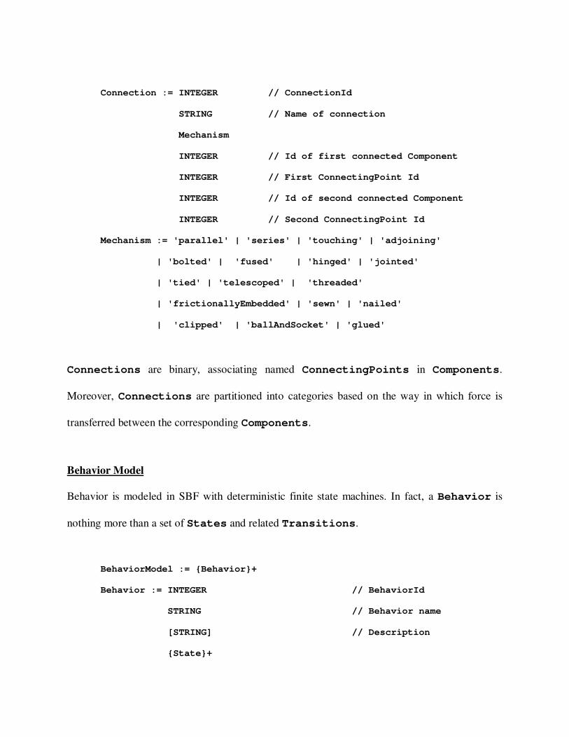
Connection := INTEGER // ConnectionId
STRING // Name of connection
Mechanism
INTEGER // Id of first connected Component
INTEGER // First ConnectingPoint Id
INTEGER // Id of second connected Component
INTEGER // Second ConnectingPoint Id
Mechanism := 'parallel' | 'series' | 'touching' | 'adjoining'
| 'bolted' | 'fused' | 'hinged' | 'jointed'
| 'tied' | 'telescoped' | 'threaded'
| 'frictionallyEmbedded' | 'sewn' | 'nailed'
| 'clipped' | 'ballAndSocket' | 'glued'
Connections are binary, associating named ConnectingPoints in Components.
Moreover, Connections are partitioned into categories based on the way in which force is
transferred between the corresponding Components.
Behavior Model
Behavior is modeled in SBF with deterministic finite state machines. In fact, a Behavior is
nothing more than a set of States and related Transitions.
BehaviorModel := {Behavior}+
Behavior := INTEGER // BehaviorId
STRING // Behavior name
[STRING] // Description
{State}+
{Transition}+
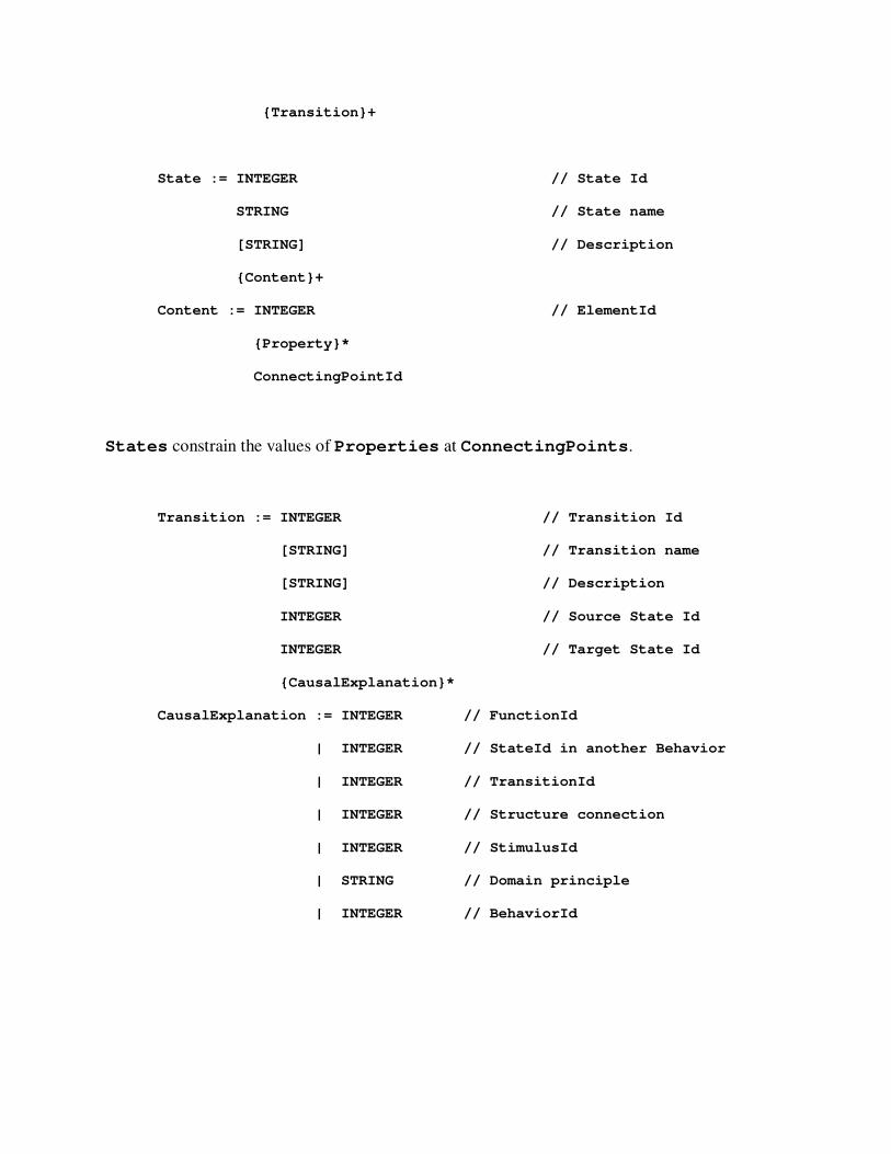
State := INTEGER // State Id
STRING // State name
[STRING] // Description
{Content}+
Content := INTEGER // ElementId
{Property}*
ConnectingPointId
States constrain the values of Properties at ConnectingPoints.
Transition := INTEGER // Transition Id
[STRING] // Transition name
[STRING] // Description
INTEGER // Source State Id
INTEGER // Target State Id
{CausalExplanation}*
CausalExplanation := INTEGER // FunctionId
| INTEGER // StateId in another Behavior
| INTEGER // TransitionId
| INTEGER // Structure connection
| INTEGER // StimulusId
| STRING // Domain principle
| INTEGER // BehaviorId

Transitions are directed binary associations between States. Moreover, each
Transition might have a number of CausalExplanations motivating the change of
State.
Function Model
Functions in SBF describe the role that an Element plays in the overall operation of a
device. They express the purpose or goal of the Element, whereas the Behavior describes
how the purpose is accomplished. Each Element in an SBFModel has a Function, and each
Function has a corresponding Behavior.
FunctionModel := {Function}+
Function := INTEGER // Function Id
Name // Function name
[STRING] // Description
FunctionType
[INTEGER] // PrimaryArgument (ElementId)
INTEGER // Behavior Id
STRING // Provided
INTEGER // Prerequisite StateId
{INTEGER}+ // Resultant StateIds
{INTEGER}* // StimulusIds
Name := Primitive
| NonPrimitive
Primitive := 'create' | 'destroy' | 'expel' | 'allow' | 'pump'
| 'move'
NonPrimitive := STRING

The SBF ontology comprises a number of primitive Functions useful for describing devices.
Moreover, modelers can define new (NonPrimitive) ones.
FunctionType := 'achievement' | 'maintenance' | 'prevention'
| 'negation'
The SBF ontology also distinguishes categories of Functions, partitioned according to how
the corresponding Behavior affects the Element’s State.
Stimuli
The final constituent of an SBFModel describe the environmental Stimuli that can affect its
Behavior.
Stimulus := INTEGER // StimulusId
STRING // Stimulus name
[STRING] // Description
[Value_Type]
A Stimulus may have an associated Typed Value, describing its amplitude.
Section 5: Static Semantics of the SBF Specification Language
The abstract syntax given above is useful for describing the appearance of SBF models, but not
how to interpret them. In particular, some syntactically correct models may be incomplete or
have inconsistencies. Here we present a series of rules that distinguish valid from invalid
SBFModels.

Uniqueness Constraints
The first category of rules merely specifies that the identifiers used to label different model
constituents are themselves different; for example, each ElementId in Element is unique.
Additional rules in this category include the following:
• There is only one (directed) Transition between any two States in the same
Behavior
• No two CausalExplanations on any Transition may be the same
• No NonPrimitive-Function Name can be the same as any Primitive-
Function Name
• For any given Connection, the FirstConnectingPointId must differ from the
SecondConnectingPointId
Referential Integrity Constraints
Another category of model rules has to do with referential integrity. This term refers to situations
in which an identifier in one place in a model refers to (is identical with) an identifier in another
place. In general, there should be no missing targets to any reference.
• Each StartStateId and StopStateId in Function correspond to actual States
existing in the Behavior referred to by BehaviorId in that same Function
• Each ElementId in Content refers to a Component that has a Function with the
Behavior containing the State that has that Content
• Each ConnectingPointId in Content refers to a ConnectingPoint in a
Component that has a Function with the Behavior containing the State that has
that Content

• Each SourceStateId and TargetStateId in Transition refers to States that
exist in the Behavior containing the Transition
Organizational Rules
Several other rules are necessary to further constrain valid SBFModels.
• A StructureModel contains exactly one Element that is not referred to by a
subElementId. That Element must be a Component and not a Substance. That
is, the device itself being modeled is considered as the outermost Element.
• Each SubElementId in any Element refers only to an Element below itself in the
containment hierarchy. That is, the Element containment hierarchy is a strict tree
structure.
• Each FunctionId in the CausalExplanation of a Transition in a Behavior
corresponds to a Function that does not have that Behavior
• Each StateId referred to in a CausalExplanation of a Transition in a
Behavior corresponds to a State in a different Behavior
• Each TransitionId referred to in a CausalExplanation of a Transition in a
Behavior corresponds to a Transition in a different Behavior
Section 6: Dynamic Semantics of the SBF Specification Language
SBF models of complex systems enable computer programs to draw inferences about the
systems. The inference rules for a particular program provide an interpretation of an SBF model.
The set of allowed interpretations for a program provide a specific dynamic semantics to the SBF
language. Here are several examples.

Kritik: Kritik (Goel 1992; Goel, Bhatta & Stroulia 1997; Goel & Chandrasekaran 1989, 1992)
was an early automated design system that integrated case-based and model-based reasoning for
generating conceptual designs of simple engineering devices. It indexed known designs by their
functions, and used SBF models of the known designs to guide the process of design adaptation.
Given the functional specification of a new problem, Kritik retrieved designs that delivered
similar functions, viewed a retrieved design as having failed to achieve the given desired
function, and used the SBF model of the design to diagnose the causes for the failure and
propose modifications to the design. Thus, the SBF models in Kritik enabled both design
retrieval and design adaptation.
Ideal: Ideal (Bhatta & Goel 1994, 1997; Goel & Bhatta 2004) was an early automated design
system that used cross-domain analogies for generating designs of simple engineering systems.
Like Kritik, it indexed known designs by their functions, and used SBF models of known designs
to guide the process of design adaptation. In addition, it used Behavior-Function (BF)
representations of abstract teleological mechanisms (such as “feedback”) for cross-domain
transfer. Given the functional specification of a new problem, Ideal retrieved a design that
delivered a similar function, viewed the retrieved design as having failed to achieve the given
desired function, used the SBF model of the design to diagnose the causes for the failure and
propose modifications to the design. If and when this adaptation process failed, however, Ideal
abstracted the functional specification of the problem, retrieved an abstract teleological solution
relevant to the abstract functional problem, and instantiated the mechanism in the context of the
design retrieved earlier. It also learned abstract teleological mechanisms from SBF models of

known designs, Thus SBF model in Ideal enabled abstraction, transfer and instantiation of
abstract teleological mechanisms,
Torque: Torque (Griffith, Nersessian & Goel 2000) modeled verbal protocols (Clement 1989) of
physicists addressing problems pertaining to spring systems. In Torque, retrieval of an analog
was based on structural similarity instead of functional similarity. The SBF model of the
retrieved analog enabled the transfer of qualitative mathematical knowledge across domains
(from the domain of bending beams to that of spring systems).
Archytas: Archytas (Yaner & Goel 2007, 2008) is a recent automated system that constructs
SBF models from design drawings by analogical transfer of SBF models of similar drawings.
Given a target design drawing, and given also a known design drawing and its SBF model,
Archytas maps, transfers and adapts the SBF model of the known drawing to the target drawing.
To do this, Archytas extends SBF models into DSSBF models (for Drawing-Shape-Structure-
Behavior-Function), thereby incorporating shapes and drawings into SBF models. In Archytas,
analogical mappings at one level of abstraction (e.g., shape) enable transfer at the next higher
level (e.g., structure).
Section 7: From Automated Systems to Interactive Environments
Kritik, Ideal, Torque and Archytas are automated systems. InteractiveKritik (Goel et. al. 1996;
Goel & Murdock 1996) enabled a human to browse the designs in Kritik’s design library, the
SBF models of the designs Kritik generated, and Kritik’s processing in generating a design.
InteractiveKritik, however, did not allow the user to interactively construct SBF models.
Interactive model construction environments provide external representations, which can be
powerful tools to support designing and learning. Clement (2000) has argued that learning is
fundamentally a process of model construction and revision. Buckley (2000) has shown that
interactive environments can help students learn about models of complex systems at multiple
levels of organization. Hmelo-Silver, Holton & Kolodner (2000) have suggested while experts
model a complex system in terms of its interrelated structure, behaviors and functions, novices
primarily express its structure, demonstrate limited understanding of its functions, and largely
miss its behaviors. Hmelo-Silver & Pfeffer (2004) have recommended use of interactive
environments that enable construction of SBF models to support learning about complex
systems. We have constructed an interactive SBF model construction tool, called SBFAuthor,
which will be used in several interactive environments. Here are a few examples.
ACT: SBF models are being used as the foundation for the Aquarium Construction Toolkit
(ACT), an interactive learning environment for modeling aquaria as a complex system (Hmelo-
Silver et. al. 2008). The idea is that middle school students may be better able to understand a
complex system such as an aquarium if they build a model of the system that includes not only
its structural descriptions, but also its functions and behaviors. SBFAuthor is the interactive tool
that will be used to construct these models. ACT also enables the students to simulate their
models using NetLogo (Wilensky 1999). Hence, SBF models must be executable by NetLogo,
and NetLogo provides an operational semantics for SBF. Thus far, we have been able to build
useful interpretations for a subclass of SBF models, and we are actively working on others.

DANTE: SBF models are also the foundation for an interactive environment, called DANTE, for
supporting biologically inspired design (Vattam, Helms & Goel 2008). The idea is that
representations of biological systems as SBF models may facilitate analogical transfer of
biological principles to engineering problems. DANTE provides another semantic interpretation
of SBF models. It does this with a feature called a critic. Critics are reactive checkers of a user’s
models. Consequently, DANTE must treat SBF models as potentially being incorrect. The
semantics of an incorrect model is the appropriate response (diagnosis and suggestion) from the
relevant critic to the modeler.
Section 8: SBFAuthor: An Interactive SBF Model Construction Tool
SBFAuthor is a computational tool for interactive construction of SBF models of complex
systems. SBFAuthor adds a visual syntax for the SBF specification language described above.
The utility of visual notation for modeling languages has been shown in practice through visual
modeling paradigms such as the Entity Relationship (ER) model and the Unified Modeling
Language (UML). Visual representations offer significant advantages over textual
representations for model building and model comprehension. For example, Nosek and Roth
(1990) noted that semantic networks (graphs) are more understandable than their equivalent
predicate logic (textual) representation. Particular knowledge representation frameworks such as
concept maps (Novak & Gowin 1984) are based on well-defined graphical notations.
------------- Figure 4 goes here --------------
SBFAuthor is an editor that facilitates building SBF models using visual notations. Figure 4
captures the correspondence between the elements of the abstract syntax of SBF specification
language and their visual counterparts.
------------- Figure 5 goes here --------------
SBFAuthor visually partitions an SBF model into three views: Structure view, Behavior view
and Function view, as shown in Figure 5. This figure depicts the SBF model of the Gyroscope
follow-up shown in Figure 1.
Structure View
The Structure view enables users to create the StructureModel portion of the SBF model in
terms of Components, Substances and their associated Connections. The Structure
model is presented as a graph. For each Component or Substance, a corresponding node is
created. The Connections are represented as labeled links between nodes in the graph. Figure
6a shows the Structure view of the gyroscope follow-up presented in Figure 1. It consists of
Component nodes like “Gyroscope,” “Worm Wheel,” “Pivot,” etc. It also contains a
Substance node “Angular momentum.” Links between these nodes indicate specific
kinds of Connections like “contains,” “connected,” etc.
------------- Figure 6 goes here --------------
Components and Substances can be described using dialogs boxes (see Figure 6b) that can
be invoked to enter their feature values (e.g. “name,” “description”) and to include their
Properties (e.g. “location” and “magnitude” in case of “Angular Momentum”).
According to the SBF specification, a Component can itself comprise a subsystem with its own
SBF model. In such situations users can create a separate SBF model for that Component and
include a reference to the Function of that model in the parent model.
Behavior View
The Behavior view allows users to create the BehaviorModel portion of the SBF model by
allowing them to create one or more Behaviors which appear as different tabs in the Behavior
view. For each Behavior, users can create States and Transitions. Each Behavior is
represented as a state-transition graph as shown in Figure 7a. Every State and Transition
is associated with a dialog box. Recall from the SBF specification that States can constrain the
values of Component/Substance Properties. The State dialog box allows the user to
model State variables and their values by choosing them from a list of Properties derived
from the StructureModel. For example, Figure 7b represents “State 1” of the behavior
model constructed in Figure 3 above. The variables “Location” and “Magnitude” of
“Angular Momentum” are assigned values “Gyroscope” and “M_input” respectively.
These variables are derived from the StructureModel.
------------- Figure 7 goes here --------------
Recall that Transitions capture the CausalExplanations in the form of references to
various model elements (like Functions, Behaviors, etc.). The Transition dialog box
enables a user to express this information. For instance, in Figure 7c the Transition named
“USING FUNCTION ALLOW Angular Momentum of Linkage-AB” contains a
reference to the Function “ALLOW Angular Momentum.” This captures one of the causes
for the Transition between “State 1” and “State 2,” reflecting the Function of a
particular linkage to allow angular momentum to move from the gyroscope to the pivot.
Function view
------------- Figure 8 goes here --------------
The Function view allows users to create the FunctionModel portion of the SBF model as
one or more Functions that appear as different tabs in the Function view as shown in Figure
8. For each Function users can state its type (Primitive or Non-primitive). If the
function being modeled is a Primitive Function, the user can choose from an existing set
of Primitive Functions that are present in the teleology. If it is a Non-primitive
Function, the user has to define the new Function and include a reference to a Behavior
that accomplishes it. In Figure 8, for example, the Function “Transfer Angular
Momentum” is accomplished by the Behavior “Transfer Angular Momentum
Behavior.” In addition to the reference to a Behavior, a user has to specify a StartState
labeled “Initial State” (e.g., “State 1” in Figure 8) and a StopState called
“Desired State” (e.g., “State 4” in Figure 8) associated with that Function, which the
user can specify by either choosing States existing in the BehaviorModel or by creating
new ones. In accordance with the SBF specification, users can also include a reference in the
Function view to an external Stimulus that initiates that Function.
Section 8: Conclusions
Research on engineering design and problem solving has developed several ontologies for
expressing teleology. The literature typically describes these ontologies only at a high level,
often using teleological models of specific systems as illustrations. However, the developments
of interactive tools for constructing teleological models of complex systems require a more
precise specification of the ontology. Giving a formal definition to SBF leads to a variety of
benefits including precision, consistent usage, and tool building. Each application of the SBF
language requires not only the abstract syntax and static semantics but also a concrete syntax and
a dynamic semantics. The precise specification potentially enables a range of additional
automated capabilities such as model checking, model simulation, and interactive guides and
critics for model construction. In this paper, we viewed SBF as a programming language. We
specified the abstract syntax and the static semantics of the SBF language. The next step in our
work is to develop the precise dynamic semantics of the language; in this paper, we simply
pointed to earlier work that illustrates the dynamic semantics. The SBF language captures the
expressive power of the earlier programs and provides a basis for interactive construction of SBF
models. We also described an interactive model construction tool called SBFAuthor that is based
on the abstract syntax and static semantics of the SBF language.

Acknowledgements
Over the years several people have contributed to the development of the SBF language,
especially Sambasiva Bhatta, Sattiraju Prabhakar and Patrick Yaner. This paper has benefited
from discussions with Michael Helms and Patrick Yaner. The domain of aquaria was suggested
by Cindy Hmelo-Silver and Rebecca Jordan, and the ACT project is joint work with them. The
DANTE project is in collaboration with Georgia Tech’s Center for Biologically Inspired Design.
This research is supported NFS (IIS) Grant (#0534622) on “Multimodal Case-Based Reasoning
in Modeling and Design,” NSF (ALT) Grant (#0632519) on “Learning About Complex Systems
in Middle School by Constructing Structure-Behavior-Function Models,” and NSF (CreativeIT)
Grant (#0733363) on “Towards a Computational Model of Biological Analogies in Innovative
Engineering Design.”
References
Anthony, L., Regli, Wi., John, J., & Lombeyda, S. (2001) An Approach to Capturing Structure,
Behavior and Function of Artifacts in CAD. Transactions of the ASME, the Journal of
Computing and Information Science in Engineering 1(2), pp. 186-192.
Bhatta, S. & Goel, A. (1994) Model-Based Discovery of Physical Principles from Design
Experiences. Artificial Intelligence for Engineering Design, Analysis and Manufacturing, Special
Issue on Machine Learning in Design, 8(2):113-123, May 1994.
Bhatta, S. & Goel, A. (1997) Learning Generic Mechanisms for Innovative Design Adaptation.
Journal of Learning Sciences, 6(4): 367-396, 1997.
Buckley, B. (2000) Interactive Multimedia and Model-Based Learning in Science Education,
International Journal of Science Education, 22:895-935.
Bunge, M. (1977) Ontology I: The Furniture of the World (Treatise on Basic Philosophy, Vol. 3),
Berlin: Springer.
Bylander, T. (1991) A Theory of Consolidation for Reasoning About Devices, International
Journal of Man-Machine Studies, vol. 35, pp. 467-489, 1991.
Chakrabarti, A., & Bligh, T. (1996) Approach to functional synthesis of mechanical design
concepts: theory, applications, and emerging research issues. AI EDAM, 10(4): 313-331.
Chandrasekaran, B. (1994) Functional Representation: A Brief Historical Perspective. Applied
Artificial Intelligence, 8(2): 173-197.
Chandrasekaran, B., Goel, A., & Iwasaki, Y. (1993) Functional Representation as a Basis for
Design Rationale. IEEE Computer, 26(1):48-56.
Chandrasekaran, B., & Josephson, J. (2000) Function in Device Representation. Engineering
with Computers, Special Issue on Computer Aided Engineering, 16:162-177.

Clement, J. (1989) Learning via Model Construction and Criticism: Protocol Evidence on
Sources on Creativity in Science, In Handbook of Creativity: Assessment, Theory and Research,
Glover, Ronning & Reynolds (Eds.), chapter 20, pp. 341-381. New York: Plenum.
Clement, J. (2000) Model-Based Learning as a Key Research Area in Science Education.
International Journal of Science Education, 22:1041-1053.
Erden, M., Komoto, H., van Beek, T., D'Amelio, V., Echavarria, E., & Tomiyama, T. (2008) A
Review of Function Modeling: Approaches and Applications, AI EDAM, 22 (2): 147-169.
Gero, J. (1990). Design prototypes: a knowledge representation schema for design, AI
Magazine, 11(4): 26-36.
Gero, J. S., Tham, K. W., & Lee, H. S. (1992) "Behavior: A Link Between Function and
Structure in Design," in Intelligent Computer Aided Design, D. C. Brown, M. B. Waldron, and
H. Yoshikawa, Eds. Amsterdam: North Holland, pp. 193-225.
Goel, A. (1992) Representation of Design Functions in Experience-Based Design. In Intelligent
Computer Aided Design, D. Brown, M. Waldron, and H. Yoshikawa (editors), pp. 283-308,
Amsterdam, Netherlands: North-Holland, 1992.
Goel, A., & Bhatta, S. (2004) Design Patterns: An Unit of Analogical Transfer in Creative
Design. Advanced Engineering Informatics, 18(2):85-94, April 2004.
Goel, A., Bhatta, S., & Stroulia, E. (1997) Kritik: An Early Case-Based Design System. In Issues
and Applications of Case-Based Reasoning in Design, M. Maher and P. Pu (editors), Mahwah,
NJ: Erlbaum, pages 87-132, 1997.
Goel, A., & Chandrasekaran, B. (1989) Functional Representation of Designs and Redesign
Problem Solving. In Proc. Eleventh International Joint Conference on Artificial Intelligence
(IJCAI-89), Detroit, Michigan, August, 1989, pp. 1388-1394, Los Altos, California: Morgan
Kaufmann Publishers.
Goel, A, & Chandrasekaran, B. (1992) Case-Based Design: A Task Analysis. In Artificial
Intelligence Approaches to Engineering Design, Volume II: Innovative Design, C. Tong and D.
Sriram (editors), pp. 165-184, San Diego: Academic Press, 1992.
Goel, A., Gomez, A., Grue, N., Murdock, W., Recker, M., & Govindaraj, T. (1996) Towards
Design Learning Environments - Explaining How Devices Work. In Proc. International
Conference on Intelligent Tutoring Systems, Montreal, Canada, June 1996.
Goel, A., & Murdock, J. (1996) Meta-Cases: Explaining Case-Based Reasoning. In Lecture
Notes in Artificial Intelligence 1168: Advances in Case-Based Reasoning, Ian Smith and Boi
Faltings (editors), Berlin: Springer-Verlag, 1996.
Griffith, T., Nersessian, N., & Goel, A. (2000). Function-follows-form transformations in
scientific problem solving. In Proceedings of the Twenty-Second Annual Conference of the
Cognitive Science Society. Lawrence Erlbaum Associates. 196--201. Mahwah, New Jersey
Hmelo, C., Holton, D., & Kolodner, J. (2000). Designing to learn about complex systems.
Journal of the Learning Sciences, 9(3), 247–298.
Hmelo-Silver, C., Jordan, R., Liu, L., Gray, S., Demeter, M., Rugaber, S., Vattam, S., & Goel, A.
(2008) Focusing on Function: Thinking Below the Surface of Complex Natural Systems, Science
Scope, 27-35, Summer 2008.
Hmelo-Silver, C. & Pfeffer, M. (2004) Comparing Expert and Novice Understanding of a
Complex Systems from the Perspectives of Structures, Behaviors and Functions. Cognitive
Science, 28:127-138.
International Organization for Standardization and International Electrotechnical Commission
(1996) Information technology - Syntacticmetalanguage - Extended BNF. First edition; 1996-l 2-
l 5; ISO/IEC 14977 : 1996(E);
http://standards.iso.org/ittf/PubliclyAvailableStandards/s026153_ISO_IEC_14977_1996(E).zip
Kitamura, Y., Kashiwase, M., Fuse, M., Mizoguchi, R. (2004) Deployment of an Ontological
Framework of Functional Design Knowledge. Advanced Engineering Informatics, 18(2): 115-
127.

Nosek, J., & Roth, I. (1990). A Comparison of Formal Knowledge Representation Schemes as
Communication Tools: Predicate Logic vs. Semantic Network. International Journal of Man-
Machine Studies 33: 227-239.
Novak, J. & Gowin, D. (1984) Learning How to Learn. Cambridge, UK: Cambridge University
Press.
Prabhakar, S., & Goel, A. (1998) Functional Modeling for Enabling Adaptive Design of Devices
for New Environments. Artificial Intelligence in Engineering, 12:417-444, 1998.
Rasmussen, J. (1985). The Role of Hierarchical Knowledge Representation in Decision Making
and System Management. IEEE Transactions on Systems, Man, and Cybernetics, 15, 234-243.
Rasmussen, J., Pejterson, A. & Goodstein, L. (1994). Cognitive Systems Engineering. New
York: Wiley.
Rieger, C. & Grinberg, M. (1977). "The Declarative Representation and Procedural Simulation
of Causality in Physical Mechanisms," in Proc. International Joint Conf. on Artificial
Intelligence (IJCAI-77), pp. 250-256.
Sasajima M, Kitamura Y, Ikeda M, Mizoguchi R. (1995) FBRL: A Function and Behavior
Representation Language. In Proc. of IJCAI-95, p. 1830–6.
Sembugamoorthy, V., & Chandrasekaran, B. (1986) Functional Representation of Devices and
Compilation of Diagnostic Problem-Solving Systems. In Experience, Memory, and Reasoning,
Kolodner & Riesbeck (Eds), Lawrence Erlbaum Associates, 1986, pp. 47-73.
Simon, H. (1969) Sciences of the Artificial. 3rd
Edition, 1996. MIT Press.
Stone, R., & Wood, K. (2000) Development of a Functional Basis for Design. ASME
Transactions, Journal of Mechanical Design, 122(4): 359-370.
Szykman, S, , Racz, J., Bochenek, C., Sriram, R. (2000a) A Web-based System for Design
Artifact Modeling,” Design Studies, Vol. 21, No. 2, pp. 145-64.
Szykman, S., Sriram, R., Bochenek, C., Racz, J., & Senfaute, J. (2000b) Design Repositories:
Engineering Design's New Knowledge Base. IEEE Intelligent Systems, 15(3): 48-55.
Umeda, Y., Takeda, H., Tomiyama, T., & Yoshikawa, H. (1990). Function, Behavior, and
Structure. In AIENG '90 Applications of AI in Engineering (pp. 177-193). Southernpton and
Berlin: Computational Mechanics Publications and Springer-Verlag.
Umeda, Y., Ishii, M., Yoshioka, M., Shimomura,�Y., & Tomiyama, T. (1996) Supporting
conceptual design based on the function-behavior-state modeler, AI EDAM 10:44, 275-288.
Umeda, Y. & Tomiyama, T. (1997) Functional Reasoning in Design, IEEE Expert, Vol. 12,
No.2, March-April 1997, pp. 42-48.
Vattam, S., Helms, M., & Goel, A. (2008) Compound Analogical Design: Interaction Between
Problem Decomposition and Analogical Transfer in Biologically Inspired Design. In Proc.
Third International Conference on Design Computing and Cognition, J. Gero & A. Goel
(editors), Berlin: Springer, pp 377-396.
Wilensky, U. (1999) NetLogo Itself: 1999. http://ccl.northwestern.edu/netlogo/. Center for
Connected Learning and Computer-Based Modeling, Northwestern University. Evanston, IL.
Yaner, P. & Goel, A. (2007) Understanding Drawings by Compositional Analogy. In Proc.
Twentieth International Joint Conference on Artificial Intelligence (IJCAI-07), Hyderabad,
India, pp. 1131-1137.
Yaner, P. & Goel, A. (2008) Analogical recognition of shape and structure in design drawings.
AI EDAM, 22(2):117-128.
Ashok K. Goel is an Associate Professor of Computer and Cognitive Science and Director of
Design Intelligence Laboratory in the School of Interactive Computing at Georgia Institute of
Technology. He received his Ph.D. in Computer and Information Science from the Ohio State
University in 1989. His research interests are in using cognitive models and artificial intelligence
techniques to address problems in design, including creativity in design.
Dr. Spencer Rugaber is a Senior Research Scientist in the College of Computing at the Georgia
Institute of Technology. He received his PhD. in Computer Science from Yale University in
1978. His research interests are in the area of Software Engineering, specifically reverse
engineering and program comprehension, software evolution and maintenance and software
design. Dr. Rugaber has served as Program Director for the
Software Engineering and Languages Program in the Division of Computer-Communications
Research at the U. S. National Science Foundation and as Vice-Chairman of the IEEE Technical
Committee on Revere Engineering.
Swaroop Vattam is a graduate student in the College of Computing at the Georgia Institute of
Technology. He is a research assistant in the Design Intelligence Laboratory, where his main
interests are design cognition, knowledge capture and sharing, human-computer interaction and
the use of AI technology to enable communicative interactions between humans and computers.
He is currently exploring the domain of biologically inspired design and investigating the use of
AI technology to aid engineers seek and utilize knowledge of biological systems to develop
innovative design solutions.
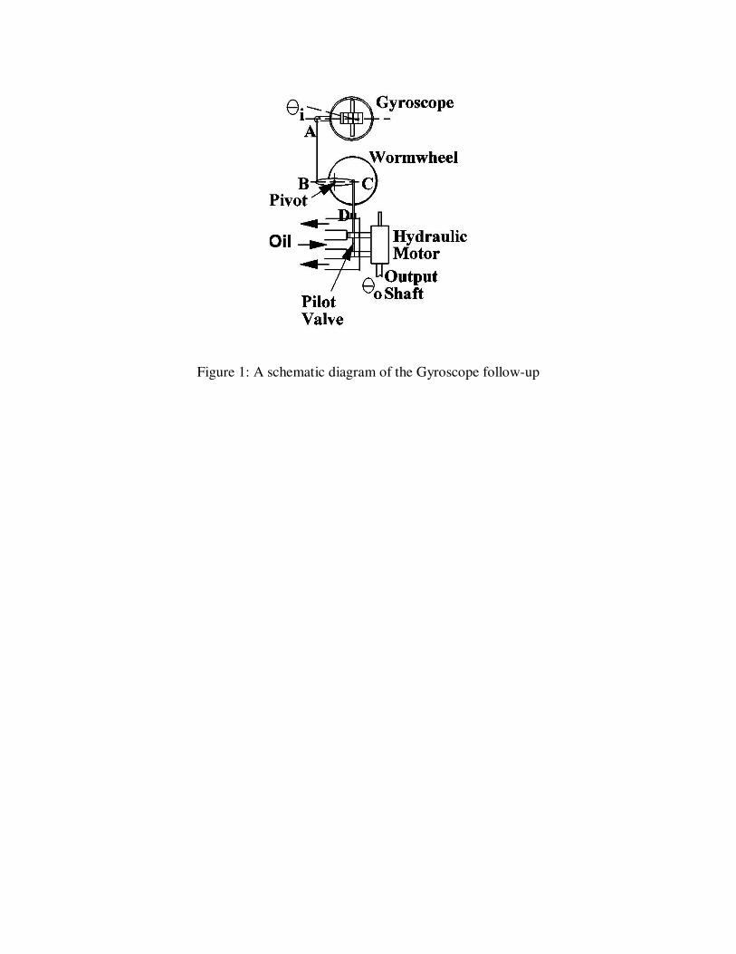
Figure 1: A schematic diagram of the Gyroscope follow-up
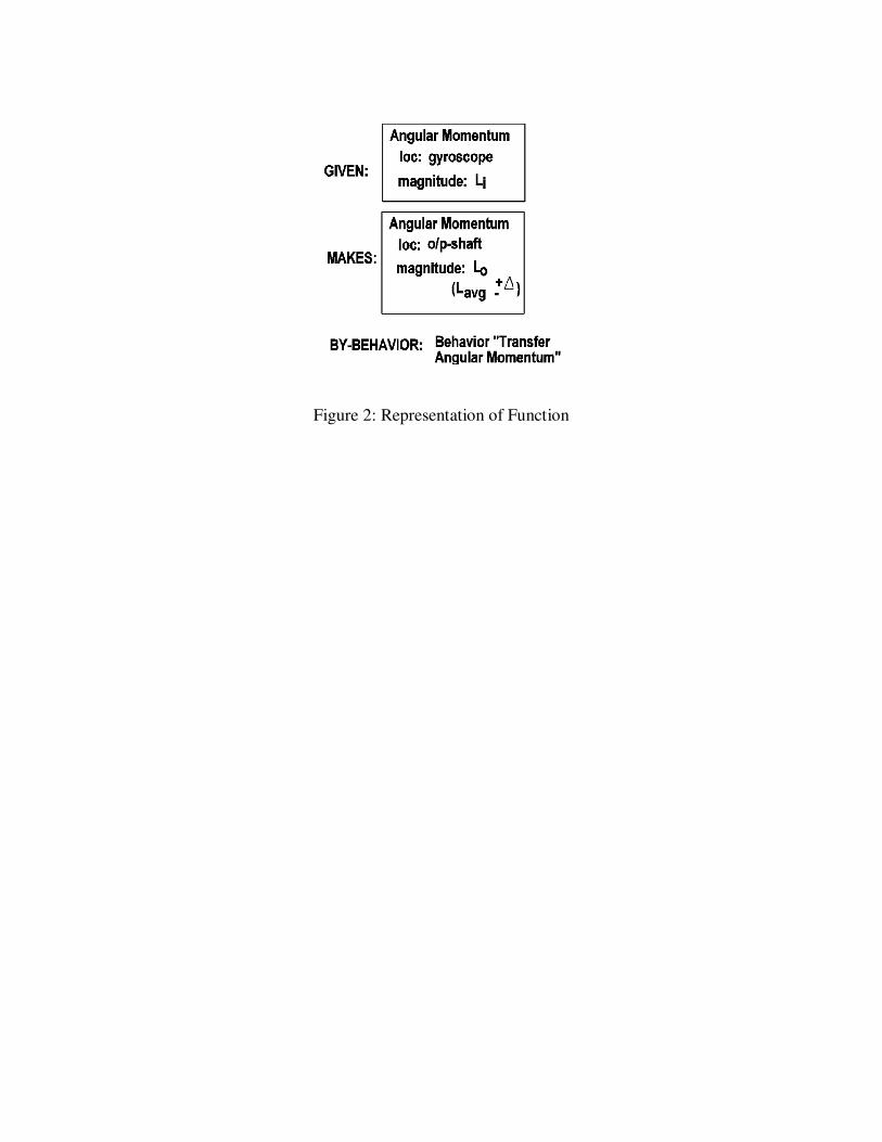
Figure 2: Representation of Function
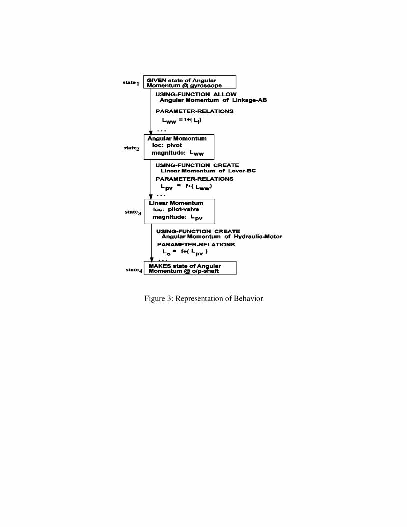
Figure 3: Representation of Behavior
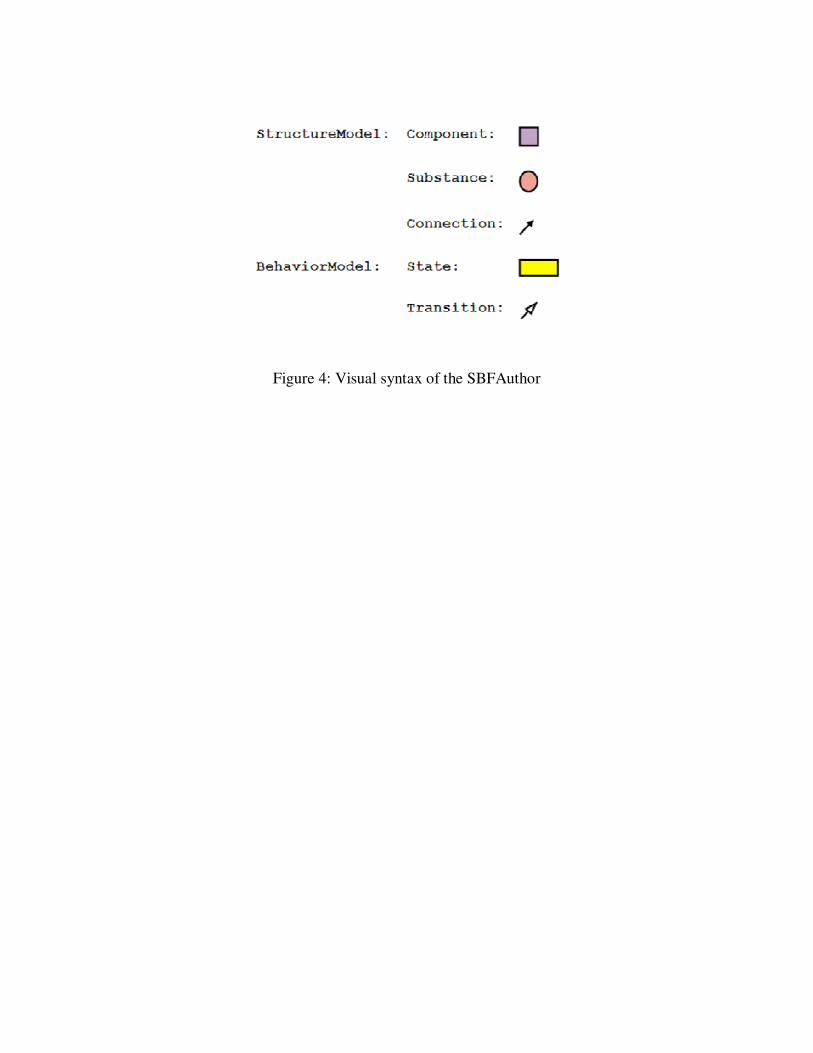
Figure 4: Visual syntax of the SBFAuthor
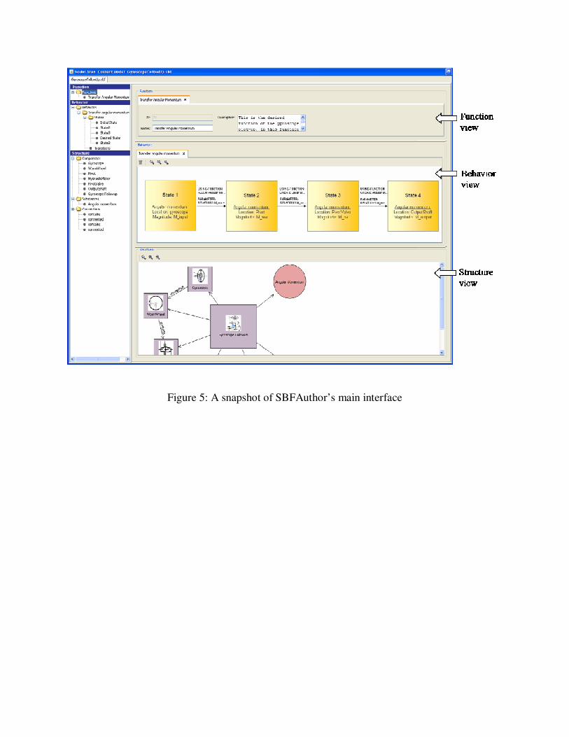
Figure 5: A snapshot of SBFAuthor’s main interface
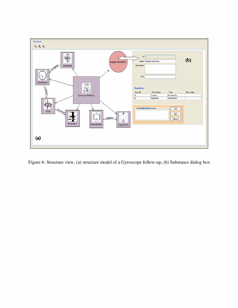
Figure 6: Structure view, (a) structure model of a Gyroscope follow-up, (b) Substance dialog box
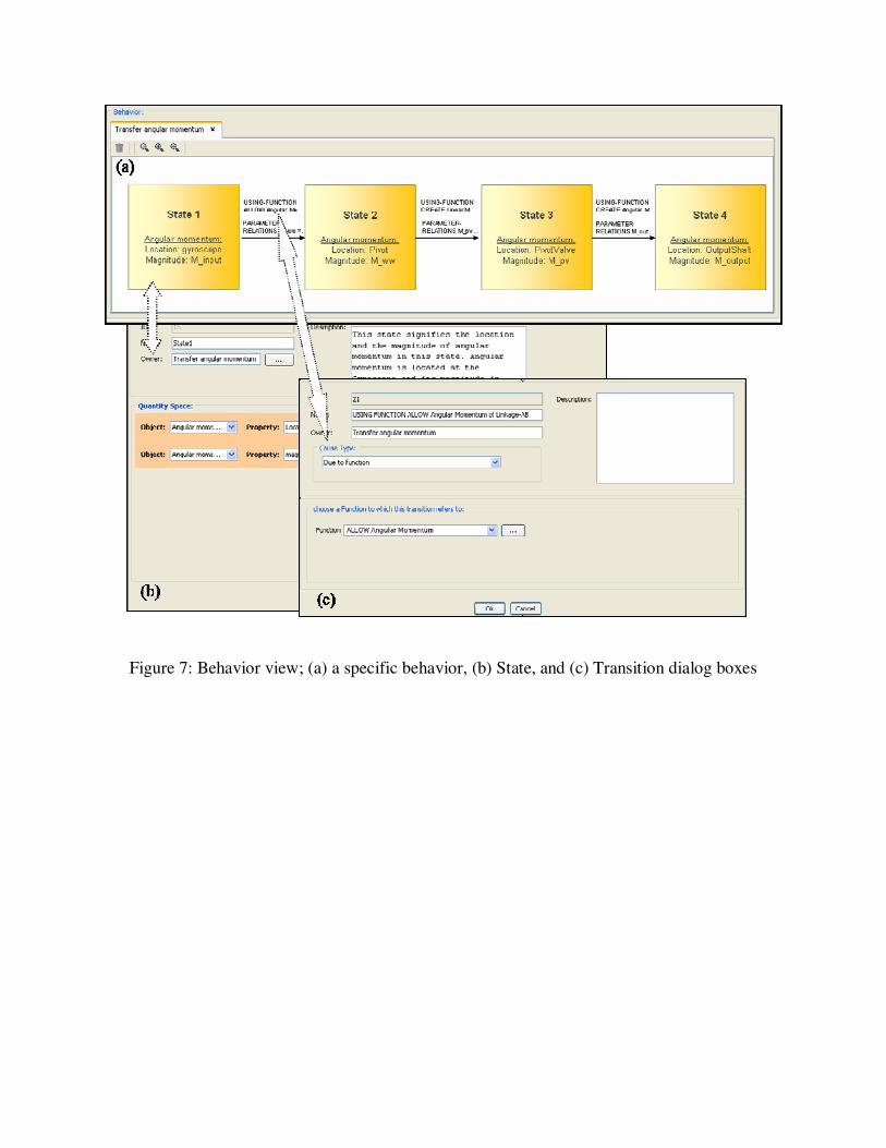
Figure 7: Behavior view; (a) a specific behavior, (b) State, and (c) Transition dialog boxes

Figure 8: The Function view