studies of fast electron transport via proton acceleration and x-ray emission leonida a. gizzi icuil...
TRANSCRIPT

STUDIES OF FAST ELECTRON TRANSPORT VIA PROTONACCELERATION AND X-RAY EMISSION
Leonida A. Gizzi
ICUIL 2010,Watkins Glen (NY)Sept 27 – Oct. 1, 2010
CONSIGLIO NAZIONALE DELLE RICERCHE
TITLE

• Introduction and motivations;
• The experimental technique;
• The experimental results;
• Conclusions
CONTENTS
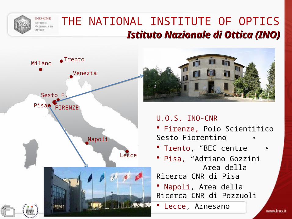
U.O.S. INO-CNR Firenze, Polo Scientifico Sesto Fiorentino Trento, “BEC centre” Pisa, “Adriano Gozzini” Area della Ricerca CNR di Pisa Napoli, Area della Ricerca CNR di Pozzuoli Lecce, Arnesano
FIRENZE
Napoli
Lecce
Sesto F.
Pisa
TrentoMilano
Venezia
Istituto Nazionale di Ottica (INO)Istituto Nazionale di Ottica (INO)THE NATIONAL INSTITUTE OF OPTICS
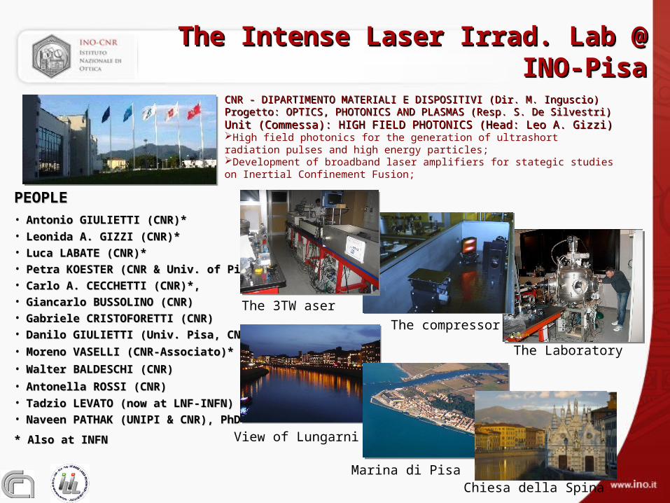
The Intense Laser Irrad. Lab @ INO-PisaThe Intense Laser Irrad. Lab @ INO-PisaThe Intense Laser Irrad. Lab @ INO-PisaThe Intense Laser Irrad. Lab @ INO-Pisa
PEOPLEPEOPLE• Antonio GIULIETTI (CNR)*Antonio GIULIETTI (CNR)*• Leonida A. GIZZI (CNR)* Leonida A. GIZZI (CNR)* • Luca LABATE (CNR)*Luca LABATE (CNR)*• Petra KOESTER (CNR & Univ. of Pisa)*Petra KOESTER (CNR & Univ. of Pisa)*• Carlo A. CECCHETTI (CNR)*,Carlo A. CECCHETTI (CNR)*,• Giancarlo BUSSOLINO (CNR)Giancarlo BUSSOLINO (CNR)• Gabriele CRISTOFORETTI (CNR)Gabriele CRISTOFORETTI (CNR)• Danilo GIULIETTI (Univ. Pisa, CNR)*Danilo GIULIETTI (Univ. Pisa, CNR)*
• Moreno VASELLI (CNR-Associato)*Moreno VASELLI (CNR-Associato)*
• Walter BALDESCHI (CNR)Walter BALDESCHI (CNR)
• Antonella ROSSI (CNR)Antonella ROSSI (CNR)• Tadzio LEVATO (now at LNF-INFN)Tadzio LEVATO (now at LNF-INFN)• Naveen PATHAK (UNIPI & CNR), PhDNaveen PATHAK (UNIPI & CNR), PhD
* Also at INFN* Also at INFN
CNR - DIPARTIMENTO MATERIALI E DISPOSITIVI (Dir. M. Inguscio)CNR - DIPARTIMENTO MATERIALI E DISPOSITIVI (Dir. M. Inguscio)Progetto: OPTICS, PHOTONICS AND PLASMAS (Resp. S. De Silvestri)Progetto: OPTICS, PHOTONICS AND PLASMAS (Resp. S. De Silvestri)Unit (Commessa): HIGH FIELD PHOTONICS (Head: Leo A. Gizzi)Unit (Commessa): HIGH FIELD PHOTONICS (Head: Leo A. Gizzi)High field photonics for the generation of ultrashort radiation pulses and high energy particles;Development of broadband laser amplifiers for stategic studies on Inertial Confinement Fusion;
The Laboratory
The compressor
The 3TW aser
View of Lungarni
Marina di PisaChiesa della Spina

HTTP://ILIL.INO.ITHTTP://ILIL.INO.IT
On-line since 1998
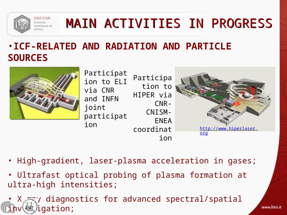
•ICF-RELATED AND RADIATION AND PARTICLE SOURCES
• High-gradient, laser-plasma acceleration in gases;
• Ultrafast optical probing of plasma formation at ultra-high intensities;
• X-ray diagnostics for advanced spectral/spatial investigation;
• Ultraintense laser-foil interactions for X-ray and ion acceleration;
MAIN ACTIVITIES IN PROGRESSMAIN ACTIVITIES IN PROGRESS
http://www.hiperlaser.org
Participation to ELI via CNR and INFN joint participation
Participation to HIPER via
CNR-CNISM-
ENEA coordination

Compressor vacuum chamber
Main targetchamber
Main beam (>250 TW)Vacuum transport lineto SPARC linac
Beam transport to sparc bunker
Radiation protection walls
GeV Electron spectrometer
Off-axis parabola
Goal: 0.9 GeV in 4 mm
See: L.A. Gizzi et al., EPJ-ST, 175, 3-10 (2009)
See presentation by L.
Labate on Thursday, 11.20
– ThO7
See presentation by L.
Labate on Thursday, 11.20
– ThO7
LASER ELECTRON ACCELERATION
250 TW system @LNF

ONGOING HIPER RELATED ACTIVITY
PARTICIPATION TO HIPER EXPERIMENTAL ROADMAP;COORDINATION OF FACILITY DESIGN
•Fast electron generation and transport measurements;
•Laser-plasma interaction studies in a shock-ignition relevant conditions;
ILIL Experiments (PI) at RAL(UK), PALS (CZ), JETI(IOQ, D) + collaborations at TITAN, OMEGA-EP - F. Beg
COLLABORATION
S.Höfer, T. Kämpfer, R.Lötzsch, I. Uschmann, E. Förster,IOQ, Univ. Jena, Germany
F. Zamponi, A.Lubcke, Max Born Institute, Berlin, Germany
A. P. L. RobinsonCentral Laser Facility, RAL, UK
L.A. Gizzi, S. Betti, A. Giulietti, D. Giulietti, P. Koester, L. Labate, T. Levato*ILIL, IPCF-CNR and INFN, Pisa, Italy, * LNF-INFN, Frascati, Italy
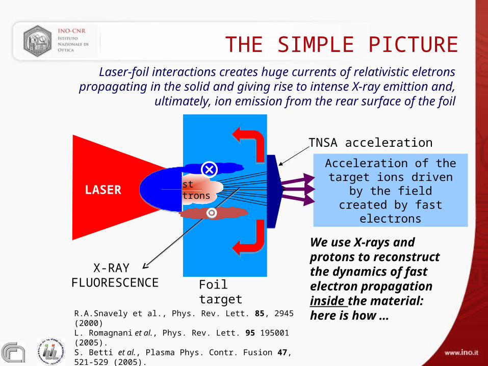
Acceleration of the target ions driven by the field
created by fast electrons
R.A.Snavely et al., Phys. Rev. Lett. 85, 2945 (2000) L. Romagnani et al., Phys. Rev. Lett. 95 195001 (2005).S. Betti et al., Plasma Phys. Contr. Fusion 47, 521-529 (2005).J. Fuchs et al. Nature Physics 2, 48 (2006).X.H.Yuan et al., New Journal of Physics 12 063018 (2010)
Foil target
TNSA acceleration
Fast ElectronsLASER
X-RAY FLUORESCENCE
THE SIMPLE PICTURE
We use X-rays and protons to reconstruct the dynamics of fast electron propagation inside the material: here is how …
Laser-foil interactions creates huge currents of relativistic eletrons propagating in the solid and giving rise to intense X-ray emittion and, ultimately, ion
emission from the rear surface of the foil
⊗

FAST ELECTRON PROPAGATION STUDIES
Fe10µm
Ni10µm
Cr1.2µm
“Front” pin hole camera
“Rear” pin hole camera
Laser 80 fs; up to 0.6 J
Optical spectroscopy
Charged particledetector
≈ 5x10¹⁹ W/cm2
WE USE LARGE AREA FOIL TARGETSa)Multi-layer metal ;b)Double layer metal-insulator;c)Single layer metal targets;
Experiments performed also at theJena (IOQ) JETI laser facility within the LASERLAB access.

Laser
Radiochromic film layers
Target
Spectrum is obtained matching dose released in each layer with predictions of MC (GEANT4) through an iterative process.
FORWARD ESCAPING FAST ELECTRONS

Laser
Radiochromic film layers
Target
Forward emitted charged Particles(electrons)
FORWARD ESCAPING FAST ELECTRONS
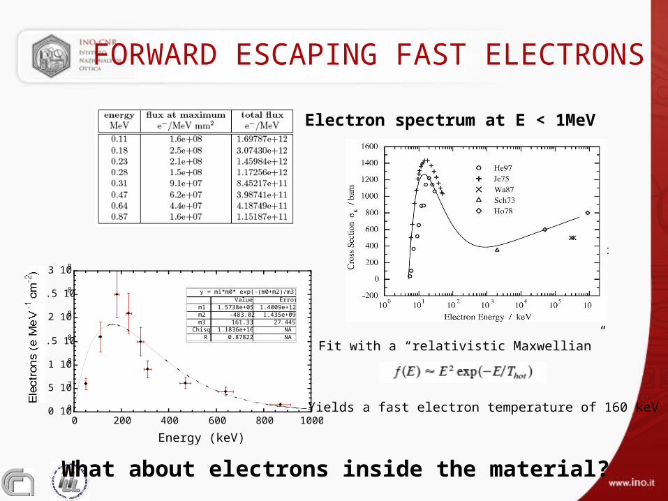
Electron spectrum at E < 1MeV
0 1 005 1 071 1 081 .5 1 082 1 082 .5 1 083 1 0802 0 04 0 06 0 08 0 01 0 0 0E le c tro n s (e M e V -1 c m-2)E n e rg y (k e V )y = m 1 *m 0 * e x p (-(m 0 + m 2 )/m 3 )E rro rV a lu e1 .4 0 0 9 e + 1 21 .5 7 3 8 e + 0 5m 1 1 .4 3 5 e + 0 9-4 8 3 .0 2m 2 2 7 .4 4 51 6 1 .3 3m 3 N A1 .1 8 3 6 e + 1 6C h is qN A0 .8 7 8 2 2R Cr+Ni+Fe target
0 100
5 107
1 108
1.5 108
2 108
2.5 108
3 108
0 200 400 600 800 1000
Energy (keV)
y = m1*m0* exp(-(m0+m2)/m3)ErrorValue
1.4009e+121.5738e+05m1 1.435e+09-483.02m2
27.445161.33m3 NA1.1836e+16ChisqNA0.87822R
Fit with a “relativistic Maxwellian”
Yields a fast electron temperature of 160 keV
FORWARD ESCAPING FAST ELECTRONS
What about electrons inside the material?

NEW X-RAY IMAGING: EEPHCNEW X-RAY IMAGING: EEPHC
L. Labate et al., Novel X-ray multi-spectral imaging …Rev. Sci. Instrum. 78, 103506 (2007)
Enables broad-band (≈2keV to ≈50 keV), micrometer resolution X-ray imaging

Cr Ni
FeLASER
≈ 5x10¹⁹ W/cm2
1.2
µm
10µ
m
10µ
m
MULTI-LAYER K IMAGING
L.A. Gizzi et al., Plasma Phys. Controll. Fusion 49, B221 (2007)
50 µm

SINGLE LAYER METALLIC TARGET SINGLE LAYER METALLIC TARGET
Front and rear X-ray images
(TITANIUM target)

EVIDENCE OF DIRECTIONAL BREMSSTRAHLUNGEVIDENCE OF DIRECTIONAL BREMSSTRAHLUNG
Experiment vs. model for the 5 µm thick Ti foil
F. Zamponi et al., PRL 105, 085001 (2010)
Spectrally resolved imaging is used to identify contribution of directional Bremstrahlung discriminating it from fluorescence k emission
Calculated bremstrahlung emission
Ti k
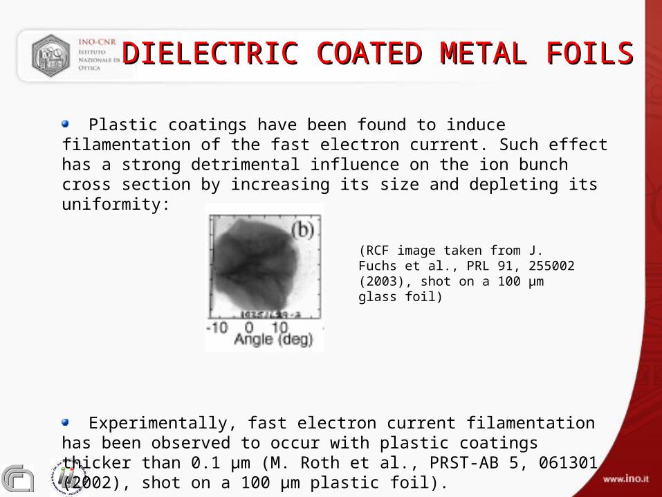
DIELECTRIC COATED METAL FOILSDIELECTRIC COATED METAL FOILS
(RCF image taken from J. Fuchs et al., PRL 91, 255002 (2003), shot on a 100 μm glass foil)
Plastic coatings have been found to induce filamentation of the fast electron current. Such effect has a strong detrimental influence on the ion bunch cross section by increasing its size and depleting its uniformity:
Experimentally, fast electron current filamentation has been observed to
occur with plastic coatings thicker than 0.1 μm (M. Roth et al., PRST-AB 5, 061301 (2002), shot on a 100 μm plastic foil).

IONS FROM LAYERED TARGETSIONS FROM LAYERED TARGETS
Targets adopted: μm thick foils
i) single-layer, lacquer-coatedii) multi-layer, lacquer assemblediii) single-layer, uncoated
Lacquer chemical composition: C6H7(NO2)3O5
<0.6 J, 80 fs, 5E19 W/cm2
Dielectric layers are made using lacquer, an easy to use dielectric coating characterized by a very high resistivity (1.5 x 10⁷ /m) and high adhesion to the substrate;

Ti, 5 μm, uncoated
10 μm Fe + 1.5 μm Mylar + 10 μm Ti, lacquer assembled
Fe, 10 μm,back-coated with
lacquer
RCF ION DATA FROM 1RCF ION DATA FROM 1STST EXP. EXP.
Given their more favourable charge-to-mass ratio, ion bunch mainly consists of protons;
Energy ranges between 1.2 and 3.5 MeV (from a radiographic image of a Ta grid & SRIM calculations), confirmed by 1D, PIC model simulations;
Dielectric coatin collimates and smooths proton beam;
Protons consistently originate from the lacquer layer, even if lacquer is buried in the target;
S. Betti et al., On the effect of rear-surface dielectric coatings on laser-driven proton acceleration Phys. Plasmas, 16, 100701 (2009).
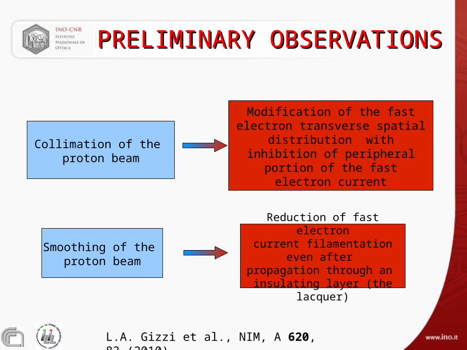
PRELIMINARY OBSERVATIONSPRELIMINARY OBSERVATIONS
Smoothing of the proton beam
Collimation of the proton beam
Reduction of fast electroncurrent filamentation even after
propagation through an insulating layer (the lacquer)
Modification of the fast electron transverse spatial distribution with
inhibition of peripheralportion of the fast electron current
L.A. Gizzi et al., NIM, A 620, 83 (2010).

DEDICATED (2DEDICATED (2NDND) EXPERIMENT) EXPERIMENT
Systematic comparison between the ion bunches emitted from uncoated and lacquer-coated metal foils.
Same experimental setup of the first campaign
Targets: 10 μm thick steel and 5 μm thick Ti foils, either uncoated or back-coated with 1.5 µm thick lacquer.
TARGET
5 cm
Lacquer coating
Uncoated metal
+
+
+
+
+
+
RCF
LASER
7 mm

Without dielectriccoating
EXPERIMENTAL – RCF DATAEXPERIMENTAL – RCF DATA
Experimental results: 10 µm thick steel target
With lacquer Coating (1.5 µm thick)

With lacquer Coating (1.5 µm thick)
Without dielectriccoating
EXPERIMENTAL – RCF DATAEXPERIMENTAL – RCF DATA
Experimental results: 5 µm Ti

With lacquer Coating (1.5 µm thick)
Without dielectriccoating
EXPERIMENTAL - RCF DATAEXPERIMENTAL - RCF DATA
Experimental results: 5 µm Ti

EXPERIMENTAL OBSERVATIONSEXPERIMENTAL OBSERVATIONS
Dielectric coating increases collimation and uniformity of the proton beam;
In contrast with previous experiments that show that dielectric coatings thicker than 0.1 μm induce fast electron current filamentation with detrimental effect on uniformity of the accelerated proton bunch;
As in the TNSA scenario (which is here the key mechanism) ion acceleration is driven by the fast electron current, the observations suggest that modification in the fast electron transport regime;
The different quality/type of dielectric coating (plastic vs. lacquer) and the quality of the coating-metal interface adopted here might played a role. Indeed, standard plastic-coated foils (vacuum deposition) may include uncontrolled vacuum gaps and loose interfaces.
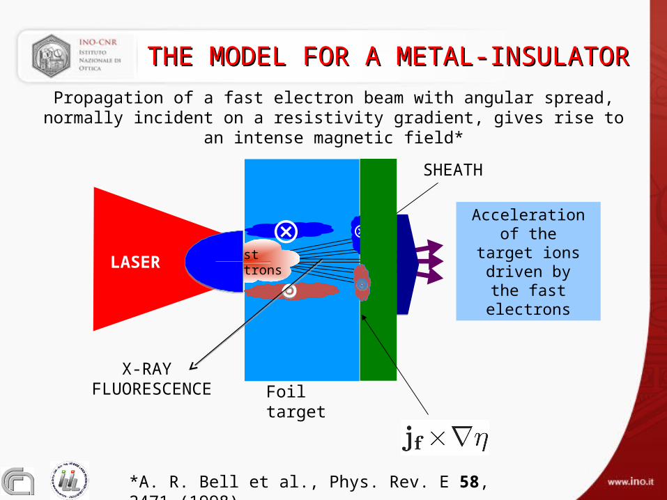
THE MODEL FOR A METAL-INSULATORTHE MODEL FOR A METAL-INSULATOR
Foil target
SHEATH
Acceleration of the target ions driven by the fast electrons
Fast Electrons
⊗
LASER
X-RAY FLUORESCENCE
⊗
*A. R. Bell et al., Phys. Rev. E 58, 2471 (1998)
Propagation of a fast electron beam with angular spread, normally incident on a resistivity gradient, gives rise to an intense magnetic field*

MODELLING APPROACHMODELLING APPROACH
A full modeling of our proton acceleration conditions, including fast electron generation and transport is well beyond the possibility of presently available numerical codes.
Since the emphasis is on the comparison of two configurations with identical laser-target interaction conditions, we can focus on the fast electron transport stage in order to find the possible origine of differences observed between uncoated and lacquer-coated targets.
Fast electron transport is thus investigated with the help of the 2D hybrid Vlasov-Fokker-Planck (VFP) numerical Code LEDA (A. P. L. Robinson and M. Sherlock, Phys. Plasmas 14, 083105 (2007).)
*A. P. L. Robinson and M. Sherlock, Phys. Plasmas 14, 083105 (2007).

CALCULATED F.E. PROFILECALCULATED F.E. PROFILE
LEDA results for the fast electron distribution on the back of the target after the laser-matter interaction stage:
5.7 μm-thick Al foil,uncoated
5.7 μm-thick Al foil, back-coated with a 1.5 μm-thick CH layer (no vacuum gap)
Transverse coordinate [μm] Transverse coordinate [μm]

CALCULATED MAGNETIC FIELD CALCULATED MAGNETIC FIELD
LASER
Simulations using LEDA* hybrid code
*A. P. L. Robinson and M. Sherlock, Phys. Plasmas 14, 083105 (2007).
Effect may originate from the onset of a large scale quasi-static B-field at the interface due to the resistivity gradient in the dielectric;
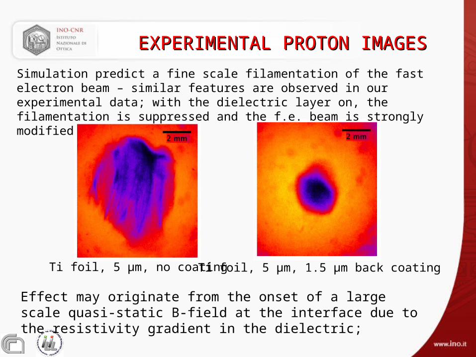
Ti foil, 5 µm, 1.5 µm back coating
EXPERIMENTAL PROTON IMAGESEXPERIMENTAL PROTON IMAGES
Ti foil, 5 µm, no coating
Simulation predict a fine scale filamentation of the fast electron beam – similar features are observed in our experimental data; with the dielectric layer on, the filamentation is suppressed and the f.e. beam is strongly modified

CONCLUSIONSCONCLUSIONS
Use both X-ray fluorescence (k) and ion emission to investigate fast electron transport inside layered targets;
Evidence of directional Bremstrahlung from fast electrons using novel broad-band spectrally resolved X-ray imaging;
Proton bunch collimation and better uniformity observed from lacquer-coated metal targets;
Resistivity gradient leads to a magnetic field that appears to collimate f.e. and suppress fine scale filamentation.
THANK YOUTHANK YOU
THE END