study of a photovoltaic system using mppt buck-boost … · study of a photovoltaic system using...
TRANSCRIPT
Abstract—The work presented in this pape present the
design and the simulation of a centrifugal pump coupled to a
photovoltaic PV generato via a maximum powe point tracker
MPPT controller. The PV system operating is just done in
sunny period by using water storage instead of electric energy
storage. The process concerns the modeling, identification and
simulation of a photovoltaic pumping system, the centrifugal
pump is driven by an asynchronous three-phase voltage
inverter sine triangle PWM motor through. Two
configurations were simulated. For the first, it is about the
alimentation of the motor pump group from electrical power
supply. For the second, the pump unit is connected directly to
the photovoltaic panels by integration of a MPPT control. A
code of simulation of the solar pumping system was initiated
unde the Matlab-Simulink environment. Very convivial and
flexible graphic interfaces allow an easy use of the code and
knowledge of the effects of change of the sunning and
temperature on the pumping system.
Index Terms—Photovoltaic, generator, chopper, electrical
motor, centrifugal pump.
I. INTRODUCTION
Before environmental constraints required on the one
hand and the rising cost of electricity generation on the other
hand, the current trend is towards the use of renewable
energy sources. Most PV plants does not work at their
optimal functioning points because of the worth matching
between the PV and the load characteristics, especially with
load disturbance or climatic variations.
In this work, the problem considered is to control the
operation of a photovoltaic pumping station equipped with
an induction motor driving a centrifugal pump. To avoid the
use of expensive storage, coupling the photovoltaic
generator to the asynchronous motor Fig. 1. which supplies
the submerged centrifugal pump is formed directly by
means of a three-phase inverter chopper assembly and the
energy is stored in shape mounted in a water tank. The
chopper placed at the head causes the PV generator to
operate at maximum power irrespective of the disturbance
(load or climate change).
Manuscript received January 22, 2014; revised May 4, 2014.
A. Bouchakour is with Unité de Recherche Appliquée en Energies
Renouvelables, URAER, Centre de Développement des Energies Renouvelables, CDER, 47133 Ghardaïa, Algeria (e-mail:
abdelhak.bouchakour@ yahoo.fr).
L. Zaghba and A. Borni are with the Applied Unit for Renewable Energy, Algeria (e-mail: layachi40@ yahoo.fr, borni.abdelhalim@
yahoo.fr ).
M. Brahami is with the Intelligent Control and Electrical Power Systems,
Algeria.
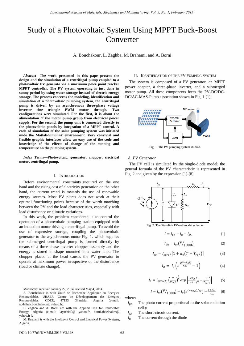
II. IDENTIFICATION OF THE PV PUMPING SYSTEM
The system is composed of a PV generator, an MPPT
power adapter, a three-phase inverter, and a submerged
motor pump. All these components form the PV-DC/DC-
DC/AC-MAS-Pump association shown in Fig. 1 [1].
Fig. 1. The PV pumping system studied.
A. PV Generator
The PV cell is simulated by the single-diode model; the
general formula of the PV characteristic is represented in
Fig. 2 and given by the expression [1]-[8].
Fig. 2. The Simulink PV-cell model scheme.
(1)
(𝜑
1000⁄ ) (2)
[1 ( )] (3)
( ( )
1) (4)
( ) (
)
[
(
)] (5)
(𝜑
1000⁄ ) ( ( ) ⁄ )
(6)
where:
The photo current proportional to the solar radiation
cell φ
The short-circuit current.
The current through the diode
Study of a Photovoltaic System Using MPPT Buck-Boost
Converter
A. Bouchakour, L. Zaghba, M. Brahami, and A. Borni
International Journal of Materials, Mechanics and Manufacturing, Vol. 3, No. 1, February 2015
65DOI: 10.7763/IJMMM.2015.V3.168
The temperature cell
Temperature sensitivity
Electron charge(1.610-19(C))
Boltzmann constant (1.3810-23(j/k))
Ideality of the solar cell factor between 1 and 5 in
practice.
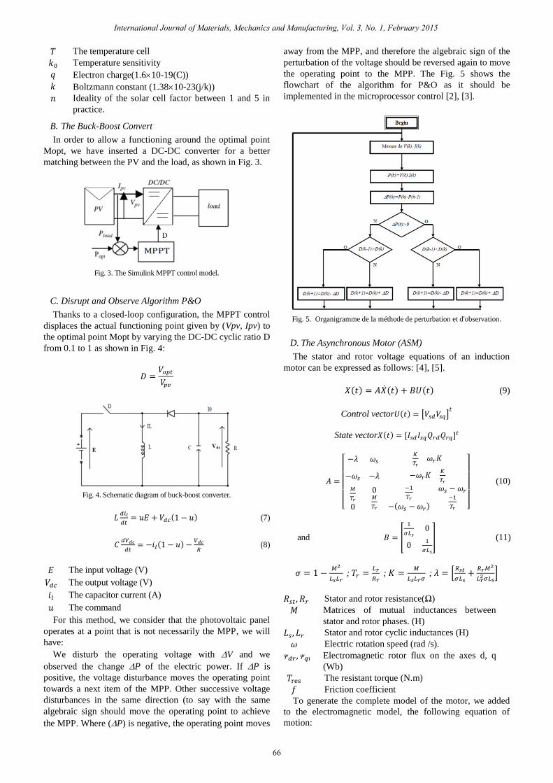
B. The Buck-Boost Convert
In order to allow a functioning around the optimal point
Mopt, we have inserted a DC-DC converter for a better
matching between the PV and the load, as shown in Fig. 3.
Fig. 3. The Simulink MPPT control model.
C. Disrupt and Observe Algorithm P&O
Thanks to a closed-loop configuration, the MPPT control
displaces the actual functioning point given by (Vpv, Ipv) to
the optimal point Mopt by varying the DC-DC cyclic ratio D
from 0.1 to 1 as shown in Fig. 4:
Fig. 4. Schematic diagram of buck-boost converter.
(1 ) (7)
(1 )
(8)
The input voltage (V)
The output voltage (V)
The capacitor current (A)
The command
For this method, we consider that the photovoltaic panel
operates at a point that is not necessarily the MPP, we will
have:
We disturb the operating voltage with V and we
observed the change P of the electric power. If P is
positive, the voltage disturbance moves the operating point
towards a next item of the MPP. Other successive voltage
disturbances in the same direction (to say with the same
algebraic sign should move the operating point to achieve
the MPP. Where (P) is negative, the operating point moves
away from the MPP, and therefore the algebraic sign of the
perturbation of the voltage should be reversed again to move
the operating point to the MPP. The Fig. 5 shows the
flowchart of the algorithm for P&O as it should be
implemented in the microprocessor control [2], [3].
Fig. 5. Organigramme de la méthode de perturbation et d'observation.
D. The Asynchronous Motor (ASM)
The stator and rotor voltage equations of an induction
motor can be expressed as follows: [4], [5].
( ) ( ) ( ) (9)
Control vector ( ) [ ]
State vector ( )
[
0
0
( )
]
(10)
and [
0
0
] (11)
1
;
;
; [
]
Stator and rotor resistance(Ω)
Matrices of mutual inductances between
stator and rotor phases. (H)
Stator and rotor cyclic inductances (H)
Electric rotation speed (rad /s).
Electromagnetic rotor flux on the axes d, q
(Wb)
The resistant torque (N.m)
Friction coefficient
To generate the complete model of the motor, we added
to the electromagnetic model, the following equation of
motion:
International Journal of Materials, Mechanics and Manufacturing, Vol. 3, No. 1, February 2015
66
(12)
( ) :the electromagnetic torque.
E. Modeling of the Centrifugal Pump
Any pump is characterized by its absorptive power which
is obviously a mechanical power on the shaft coupled to the
pump, which is given by [6], [7].
(13)
The final torque equation:
(14)
Speed of rotation of the pump shaft(rad/s)
Density ( ⁄ )
Flow ( )⁄
, , , Coefficients given by the manufacturer
Height of rise(m) Acceleration of gravity(m
2/s)
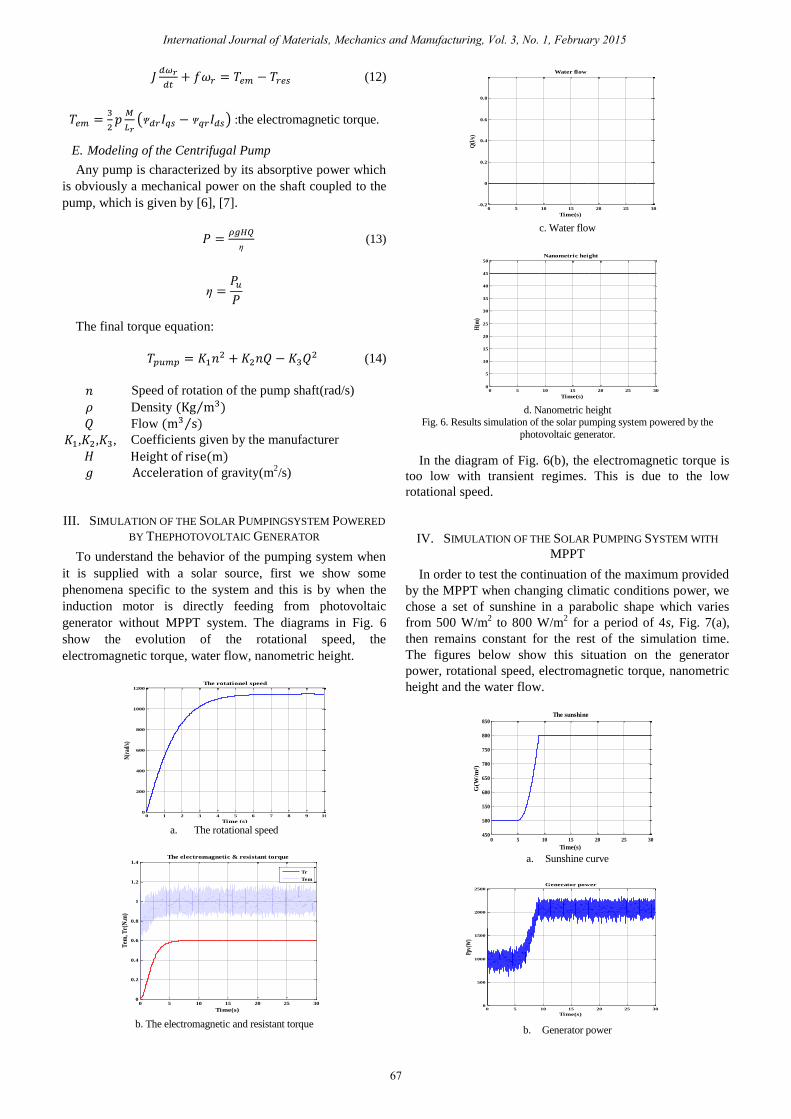
III. SIMULATION OF THE SOLAR PUMPINGSYSTEM POWERED
BY THEPHOTOVOLTAIC GENERATOR
To understand the behavior of the pumping system when
it is supplied with a solar source, first we show some
phenomena specific to the system and this is by when the
induction motor is directly feeding from photovoltaic
generator without MPPT system. The diagrams in Fig. 6
show the evolution of the rotational speed, the
electromagnetic torque, water flow, nanometric height.
a. The rotational speed
b. The electromagnetic and resistant torque
c. Water flow
d. Nanometric height
Fig. 6. Results simulation of the solar pumping system powered by the
photovoltaic generator.
In the diagram of Fig. 6(b), the electromagnetic torque is
too low with transient regimes. This is due to the low
rotational speed.
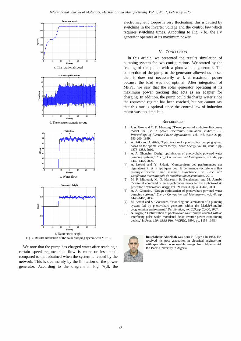
IV. SIMULATION OF THE SOLAR PUMPING SYSTEM WITH
MPPT
In order to test the continuation of the maximum provided
by the MPPT when changing climatic conditions power, we
chose a set of sunshine in a parabolic shape which varies
from 500 W/m2 to 800 W/m
2 for a period of 4s, Fig. 7(a),
then remains constant for the rest of the simulation time.
The figures below show this situation on the generator
power, rotational speed, electromagnetic torque, nanometric
height and the water flow.
a. Sunshine curve
b. Generator power
0 1 2 3 4 5 6 7 8 9 100
200
400
600
800
1000
1200
Time (s)
N(r
ad/s
)
The rotationel speed
0 5 10 15 20 25 300
0.2
0.4
0.6
0.8
1
1.2
1.4The electromagnetic & resistant torque
Time(s)
Tem
, Tr(
N.m
)
Tr
Tem
0 5 10 15 20 25 30-0.2
0
0.2
0.4
0.6
0.8
Time(s)
Q(l
/s)
Water flow
0 5 10 15 20 25 300
5
10
15
20
25
30
35
40
45
50
Time(s)
H(m
)
Nanometric height
0 5 10 15 20 25 30450
500
550
600
650
700
750
800
850
Time(s)
G(W
/m²)
The sunshine
0 5 10 15 20 25 300
500
1000
1500
2000
2500
Time(s)
Ppv(
W)
Generator power
International Journal of Materials, Mechanics and Manufacturing, Vol. 3, No. 1, February 2015
67
c. The rotational speed
d. The electromagnetic torque
e. Water flow
f. Nanometric height
Fig. 7. Results simulation of the solar pumping system with MPPT.
We note that the pump has charged water after reaching a
certain speed regime; this flow is more or less small
compared to that obtained when the system is feeded by the
network. This is due mainly by the limitation of the power
generator. According to the diagram in Fig. 7(d), the
electromagnetic torque is very fluctuating; this is caused by
switching in the inverter voltage and the control law which
requires switching times. According to Fig. 7(b), the PV
generator operates at its maximum power.
V. CONCLUSION
In this article, we presented the results simulation of
pumping system for two configurations. We started by the
feeding of the pump with a photovoltaic generator. The
connection of the pump to the generator allowed us to see
that, it does not necessarily work at maximum power
because the load was not optimal. After integration of
MPPT, we saw that the solar generator operating at its
maximum power tracking that acts as an adapter for
charging. In addition, the pump could discharge water since
the requested regime has been reached, but we cannot say
that this rate is optimal since the control law of induction
motor was too simplistic.
REFERENCES
[1] J. A. Gow and C. D. Manning ,“Development of a photovoltaic array
model for use in power electronics simulation studies,” IEE
Proceedings of Electric Power Applications, vol. 146, issue 2, pp. 193-200, 1999.
[2] A. Betka and A. Attali, “Optimization of a photovoltaic pumping system
based on the optimal control theory,” Solar Energy, vol. 84, issue 7, pp. 1273–1283, 2010.
[3] A. A. Ghoneim “Design optimization of photovoltaic powered water pumping systems,” Energy Conversion and Management, vol. 47, pp.
1449–1463, 2006.
[4] A. Lokriti and Y. Zidani, “Comparaison des performances des régulateurs PI et IP appliques pour la commande vectorielle a flux
rotorique oriente d’une machine asynchrone,” in Proc. 8ème
Conférence Internationale de modélisation et simulation, 2010. [5] M. F. Mimouni, M. N. Mansouri, B. Benghanem, and M. Annabi,
“Vectorial command of an asynchronous motor fed by a photovoltaic
generator,” Renewable Energy, vol. 29, issue 3, pp. 433–442, 2004. [6] A. A. Ghoneim, “Design optimization of photovoltaic powered water
pumping systems,” Energy Conversion and Management, vol. 47, pp.
1449–1463, 2006. [7] M. Arrouf and S. Ghabrourb, “Modeling and simulation of a pumping
system fed by photovoltaic generator within the Matlab/Simulink
programming environment,” Desalination, vol. 209, pp. 23–30, 2007. [8] N. Argaw, “ Optimization of photovoltaic water pumps coupled with an
interfacing pulse width modulated dc/ac inverter power conditioning
device,” in Proc. 1994 IEEE First WCPEC, 1994, pp. 1156-1168.
Bouchakour Abdelhak was born in Algeria in 1984. He
received his post graduation in electrical engineering with specialization renewable energy from Abdelhamid
Ibn Badis University in Algeria.
0 5 10 15 20 25 300
500
1000
1500
2000
2500
Time(s)
N(r
ad
/s)
Rotational speed
0 5 10 15 20 25 30-4
-2
0
2
4
6
8
10
12
Time(s)
Tem
(N.m
)
Electromagnetic torque
0 5 10 15 20 25 300
0.1
0.2
0.3
0.4
0.5
0.6
0.7
Time(s)
Q(l
/s)
Water flow
0 5 10 15 20 25 3044
44.5
45
45.5
46
Time(s)
H(m
)
Nanometric height
International Journal of Materials, Mechanics and Manufacturing, Vol. 3, No. 1, February 2015
68