study on three-dimensionalseismic isolation system … of the 3d base isolation system development...
TRANSCRIPT
13th World Conference on Earthquake Engineering Vancouver, B.C., Canada
August 1-6, 2004 Paper No. 1346
STUDY ON THREE-DIMENSIONAL SEISMIC ISOLATION SYSTEM FOR NEXT GENERATION NUCLEAR POWER PLANT:INDEPENDENT
CABLE REINFORCED ROLLING-SEAL AIR SPRING
Mitsuru KAGEYAMA1, Tsutomu IBA2, Katsuhiko UMEKI3, Takahiro SOMAKI4 Yoshihiko HINO5, Satoshi MORO6, Shinya IKUTAMA7
SUMMARY
In Japan, the development of the next generation NPP has been conducted in recent years. In the equipment/piping design of the plant, seismic condition has been required much more mitigate than before. So, the three-dimensional (abbreviation to 3D) seismic isolation system development has also been conducted since 2000. The superlative 3D base isolation system for the entire building was proposed. The system is composed of cable reinforced air springs, rocking arresters and viscous dampers. Dimensions of the air spring applied to the actual power plant are 8 meters in the outer-diameter and 3.5 meters in height. The allowable half strokes are 1.0 meters in horizontal and 0.5 meters in vertical respectively. The maximum supporting weight for a single device is 70 MN. The inner design air pressure is about 1.8MPa. This air spring has a distinguishing feature, which realizes 3D base isolation with a single device, whose natural periods are about 4 seconds in horizontal and about 3 seconds in vertical. In order to verify the 3D performance of this system, several feasibility tests were conducted. Firstly, 3D shaking table tests were conducted. The test specimen is scaled 1/4 of the actual device. The outer diameter and inner air pressure of air spring is 2 meters and 0.164 MPa. Next, a pressure resistant test for the sub cable, textile sheet and rubber sheet, which composed air spring, were conducted as a full scale model test. Then, air permeation test for the rubber sheet was also conducted. As a result, the proposed system was verified that it could be applied to the actual nuclear power plants. 1 Special advisor to general manager, Obayashi Corporation, Tokyo, Japan,
E-mail: [email protected] 2 General manager, Obayashi Corporation, Tokyo, Japan, E-mail :[email protected] 3 Group leader, Obayashi Corporation, Tokyo, Japan, E-mail :[email protected] 4 Manager, Obayashi Corporation, Tokyo, Japan, E-mail :[email protected] 5 Obayashi Corporation, Tokyo, Japan, E-mail :[email protected] 6 Senior scientist, The Japan Atomic Power Company, Tokyo, Japan,
E-mail :[email protected] 7 The Japan Atomic Power Company, Tokyo, Japan,
E-mail :[email protected]
INTRODUCTION In Japan, the studies on application of two-dimensional (abbreviation to 2D) base isolation systems to FBR or PWR have been continuing for about 15 years. The guideline to design the base isolated nuclear power plants was published in 2001 JEAG [1]. The aims at applying the base isolation system to nuclear power plants are to realize the site-free design standards, free from seismic restrictions, and to reduce the construction cost. The 2D base isolation system enables a remarkable reduction on equipment/piping responses in horizontal direction, compared with non-isolated conventional buildings. In the case of 2D base isolated buildings, the thickness of structural walls besides the neutron shield can be reduced to achieve the reduction in construction cost. However the vertical responses of the equipment/piping in the horizontal base isolated buildings tend to be greater than in the non-isolated conventional buildings due to amplification in the isolation story and in the superstructure. Therefore additional seismic supports for equipment/piping are required depending on the seismic conditions of the site. The primary phase in the 3D base isolation system development was already discussed Kageyama [2]. So, this paper deals with the demonstration phase of the 3D base isolation system development.
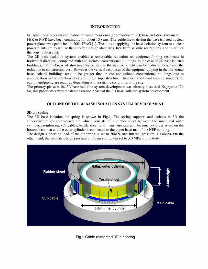
OUTLINE OF THE 3D BASE ISOLATION SYSTEM DEVELOPMENT 3D air spring The 3D base isolation air spring is shown in Fig.1. The spring supports and isolates in 3D the superstructure by compressed air, which consists of a rubber sheet between the inner and outer cylinders, reinforcing sub cables, textile sheet, and main wire cables. The inner cylinder is set on the bottom base-mat and the outer cylinder is connected to the upper base-mat of the NPP building. The design supporting load of the air spring is set to 70MN, and internal pressure is 1.8Mpa. On the other hand, the ultimate design pressure of the air spring was set to 3.0 MPa in this study.
Fig.1 Cable reinforced 3D air spring
8.0m: outer cylinder
6.0m:inner cylinder
3.5m
:hei
gh
t Rubber sheet
Main cable
Textile sheet
Sub cable

Viscous wall type damper The wall type viscous damper is shown in Fig.2. The damper was adopted instead of oil damper to reduce a construction cost. The damper consists of steel resistance plates and a steel box filled with viscous liquid. Damping is realized by the shear deformation of the viscous liquid between resistance plates and a steel box, when the relative displacement is induced between plates and box. As shown in Fig.3, when the damper is displaced in plane direction, damping is realized in horizontal. On the other hand, when the damper is displaced out of the plane direction, damping is realized in horizontal and vertical simultaneously.
Hinge Steel Resistance Plate
Steel Box Hinge
Spacer
Viscous Liquid
Fig.2 Wall type viscous damper
(a) In plane direction (b) Out of the plane direction Fig.3 Displacement of damper
3D base isolation device overview for the actual power plant Application of 3D air springs, viscous dampers and rocking arresters to actual power plant (The medium scaled sodium cooling type FBR plant) is shown in Fig.4. The air springs and rocking arresters support the weight (2.65GN) of the NPP Building. The natural periods of this system are 3.59 seconds in horizontal and 2.65 seconds in vertical. Damping ratio is 35% in horizontal and 50% in vertical.
Air spring The overall specifications of the air spring are as follows;
i. diameter of outer cylinder: 8.0m ii. diameter of inner cylinder: 6.0m iii. allowable horizontal displacement: 1.0m iv. height of inner cylinder: 3.0m v. allowable vertical displacement: 0.5m vi. design inner pressure: 1.8MPa vii. main wire cable size and layout interval: d45mm,@500mm viii. sub cable and sheets size and layout interval: width 50mm, @50mm, 2 layers ix. thickness of rubber sheet: 3mm, 3 layers

Damper The overall specifications of the damper are as follows;
i. Dimensions of steel box: length: 8.0m, width: 1.2m, height: 2.0m ii. Dimensions of steel resistance plate: length: 4.0m, height:, 2.0m, thickness 15mm(15plates)
Supplementary equipments Together with the air springs and dampers, supplementary equipments listed below; are applied
i. rocking arresters ii. air pressure controlling system - air leak detector - air supply for small leaks - air supply for all air springs required for initial air pressure
760
Reactor Building & Auxiliary Building:2.32GN
Control Building:0.33GN
Fig.4 Base isolation system layout for the actual nuclear power plant
TEST AND SIMULATION ANALYSIS
Objectives Following feasibility tests were conducted. Shaking table test Objectives of this test are to confirm the support, base isolation function, smooth and dynamic characteristics of the 3D base isolation system. Structural integrity tests Failure mode test Objectives of this test are to grasp the air leakage behavior and to confirm whether the failure mode of the air spring is catastrophic or not, when a pinhole is bored in the rubber sheet of the air spring. Pressure resistance test Objectives of this test are to grasp the maximum allowable pressure of the air spring and to confirm the margin of safety to the ultimate design pressure 3.0MPa, by the actual size of the test specimen.
76000 86
000
8000
Air spring
(unit:mm)
Viscous Dampers
Rocking Arresters

Rubber sheet air permeation rate test Objectives of this test are to measure the air permeation rate at the rubber sheet general portion in equivalent 60 years aging and the rate at the rubber sheet end portion. Shaking table test Test specimen Test specimen consists of an air spring, four viscous dampers and rocking arresters. The size of the air spring is 1/4 scale of the actual device, 2.0m in diameter and 1.5m in height, as shown in Fig.5 and Photo.1. The internal pressure of the air spring is 0.164MPa that supports the specimen weight of 0.38MN. Viscous dampers are fixed in four sides of the specimen. Damping forces are induced both in plane and out of plane directions of the damper when the specimen displaces in 3D directions. Dimensions of the viscous damper specimen are shown in Fig.6. The damper is 1.0m in length, 0.07m in width, 0.925m in height and 20mm in shear gap. Temperature of viscous liquid was 30℃ at testing.
Fig.5 Test specimen for shaking table test Fig.6 Viscous damper specimen
Photograph 1 Test specimen on the 3D shaking table
Weight
Air Spring
3D Shaking Table
Cable Wire for Rocking Arrester
Viscous Damper
1
3
5
0
2
0
0
2
0
0
200
2
0
0
3
2
5
7
2
5
200 200
1
2
5
隙間
20mm
1
3
5
0
2
0
0
2
0
0
200
2
0
0
3
2
5
7
2
5
200 200
1
2
5
隙間
20mm
200
1350
200
325
200
72
5
200 200 200
Steel Resistance Plate
Viscous Liquid
Steel Box
Hinge
gap: 20mm
Hinge
Spacer
1000 70
200
925

Test cases Input seismic waves in horizontal and vertical directions are shown in Fig.7, 8. The following cases were conducted in the test;
a. FBR case study S2 wave (horizontal: Max 8.30m/s2) b. FBR case study S2 wave (vertical : Max 5.56m/s2) c. FBR case study S2 wave (horizontal and vertical combined)
Time axis of the waves was reduced to half the actual one based on the similarity, because the scale of the specimen was 1/4.
Fig.7 FBR horizontal case study S2 wave Fig.8 FBR vertical case study S2 wave Test results First natural period The comparison of first natural periods from the test results and the design values are shown in Table 1. The design values were evaluated in the formulas shown in eq. (1), (2). From the table, the design natural periods were well consistent with the values by test.
Horizontal direction:
( )
Gr
rrTH
2
22
21
42
+=
ππ (1)
Vertical direction:
( )⎟⎟
⎠
⎞
⎜⎜
⎝
⎛−+
⋅=
150 00
22
21 γ
γπ
)z(Q
QPrr.
zG
W
TV (2)
VH T,T : First natural periods (s) 1r : Radius of inner cylinder (m)
2r : Radius of outer cylinder (m) 0P : Air pressure (Pa) W : Weight of specimen (N) z : Vertical displacement (m)
0Q : Air volume at the displacement 0 (m3) )z(Q : Air volume at the displacement Z (m3) γ : Polytrope index G : Gravity acceleration (9.80665 m/s2)
Table 1 Comparison of natural periods
Natural period by design
Natural period by test Design/Test
Horizontal dir. (first order) 1.83 (sec) 1.79 (sec) 1.04
Vertical dir. 1.38 (sec) 1.35 (sec) 1.04
-10
-5
0
5
10
0 5 10 15 20 25 30 35 40
Acceleration(m/s
2)
(s)-10
-5
0
5
10
0 5 10 15 20 25 30 35 40
Acceleration(m/s
2)
(s)

Wall type viscous damper characteristics The damper specimen restoring force was evaluated by subtracting the restoring force of the air spring from that of the combined damper and air spring. The restoring force of the combined damper and air spring was measured in the preliminary shaking test results. The damper specimen restoring forces from the preliminary tests were compared with those from eq. (3), in Fig.9. eq. (4) provides viscous damping. Viscous damping force is based on the formula from experimental studies Miyake [3]. On the other hand, additional force in eq. (5) is based on the hypothetical compressive stiffness of the viscous liquid when the damper displaces. The restoring forces from tests in Fig.9 were corresponding to those from eq. (3) fairly well except for the beginning phase of loading. That is, eq. (3) could not forecast the viscous damper behavior in this phase. It is thought that the behavior could be caused by the stiffness added when the resistance plates of the damper displace to the non-disturbed portion of the viscous liquid in the beginning of loading. This is a peculiar feature in this type of viscous damper Yamamoto [4], and the behavior disappears in the stable phases following the beginning. Since eq. (3) provides the damper behavior in the stable phases, this equation could not forecast the beginning phase behavior. The actual damper restoring forces evaluated by eq. (3) were in Fig.10. As shown in the figure, additional force is remarkably decreased comparing with the case of the test specimen.
Damping force:
FaFoF += (3) Viscous damping force:
( ) 440043056.t.
dVSseFo ×××= − (4)
Fo : Damping force (kN) V : Velocity (m/s) Ss : Plate shear area (m2)
d : Gap (m) t : Temperature (℃)
Additional force: Sc),f(V, Fa δ= (5)
Fa : Squeeze force (kN) V : Velocity (m/s) δ : Displacement(m)
Sc : Plate cross sectional area (m2)
(a) Horizontal direction (b) Vertical direction Fig. 9 Restoring force of the specimen
(Comparison between analyses and test results)
-75
-50
-25
0
25
50
75
-150 -100 -50 0 50 100 150
TestAnalysis
Damping Force(kN)
Displacement(mm)
-75
-50
-25
0
25
50
75
-150 -100 -50 0 50 100 150
TestAnalysis
Damping Force(kN)
Displacement(mm)

(a) Horizontal direction (b) Vertical direction Fig. 10 Restoring force of the actual device
Floor response spectra of the test specimen Floor response spectra of the test specimen when the FBR case study S2 waves were applied were shown in Fig.11, 12. From these figures, the base isolation performance of the proposed system is clearly confirmed. Furthermore, the FRS curves in horizontal and vertical directions when simultaneous input are almost same with those of input separately, is also confirmed. It shows the bi-axial behavior could be divided clearly into in horizontal and vertical directions.
(a) Horizontal direction (b) Vertical direction Fig. 11 Floor response spectra of x or z-direction input wave
(a) Horizontal direction (b) Vertical direction Fig. 12 Floor response spectra of xz-direction input wave
h=1%
-75
-50
-25
0
25
50
75
-600 -400 -200 0 200 400 600
Fo(Analysis)Fo+Fa(Analysis)
Damping Force(MN)
Displacement(mm)
-75
-50
-25
0
25
50
75
-300 -200 -100 0 100 200 300 400
Fo(Analysis)Fo+Fa(Analysis)
Damping Force(MN)
Displacement(mm)
0
10
20
30
40
50
60
0.1 1 10
above deviceInput Motion
Acceleration(m/s
2)
Period(s)
h=1%
0
10
20
30
40
50
60
0.1 1 10
above deviceInput Motion
Acceleration(m/s
2)
Period(s)
h=1%
0
10
20
30
40
50
60
0.1 1 10
above deviceInput Motion
Acceleration(m/s
2)
Period(s)
h=1%
0
10
20
30
40
50
60
0.1 1 10
above deviceInput Motion
Acceleration(m/s
2)
Period(s)
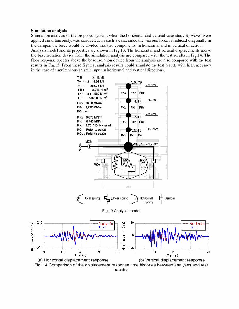
Simulation analysis Simulation analysis of the proposed system, when the horizontal and vertical case study S2 waves were applied simultaneously, was conducted. In such a case, since the viscous force is induced diagonally in the damper, the force would be divided into two components, in horizontal and in vertical direction. Analysis model and its properties are shown in Fig.13. The horizontal and vertical displacements above the base isolation device from the simulation analysis are compared with the test results in Fig.14. The floor response spectra above the base isolation device from the analysis are also compared with the test results in Fig.15. From these figures, analysis results could simulate the test results with high accuracy in the case of simultaneous seismic input in horizontal and vertical directions.
:Axial spring :Shear spring :Rotational :Damper spring
▽5.075m
▽4.275m
▽3.475m
▽2.675m
▽1.750m
WR,JR
W4,J4
W3,J3
W2,J2
W1,J1 MCh
MKv MKh MKr
MCv
WR: 31.12 kN W4~W2:15.96 kN W1: 298.78 kN JR: 3,315 N・m2 J4~J2:1,580 N・m2
J1: 558,989 N・m2
FKh:38.08 MN/m FKv:3,272 MN/m FKr:∞
MKv:0.675 MN/m MKh:0.445 MN/m MKr:2.70×10⁷ N・m/rad MCh:Refer to eq.(3) MCv:Refer to eq.(3) FKv FKh FKr
FKv FKh FKr
FKv FKh FKr
FKv FKh FKr
Fig.13 Analysis model
(a) Horizontal displacement response (b) Vertical displacement response Fig. 14 Comparison of the displacement response time histories between analyses and test
results
-50
0
50
0 10 20 30 40
AnalysisTest
Displacement(mm)
Time(s)
-200
0
200
0 10 20 30 40
AnalysisTest
Displacement(mm)
Time(s)

(a) Floor response spectra in horizontal direction (b) Floor response spectra in verticFig.15 Comparison of the floor response spectra between analyses and test results
STRUCTURAL INTEGRITY TESTS
Following four tests were conducted to verify the integrity of the 3D air spring seismic isolation system. Outline and test results are shown in the following. Failure mode confirmation test Test specimen is shown in Photo.2. That is 1/30 scale of the actual size and its diameter is 0.3m. The test was conducted firstly by increasing the inner pressure to 3.0MPa. Next, a pin hall was bored on the rubber sheet of the air spring, then the air leak through the pin hall was observed. From the test results, the air spring did not have a catastrophic but a stable failure mode, was confirmed.
Photograph 2 Test specimen on failure mode confirmation test
Pressure resistance test of the sub cable The sub cable test specimens and loading set up is shown in Photo.3. The test specimens were 18 sets of 50mm width, 2mm thickness aramid fiber belt. They were set on 500mm span to simulate the actual condition. The test was conducted by tensioning the specimens at first, then increasing the inner pressure until the specimens were broken by water supply. The specimens were broken at the inner pressure 1.8MPa with 57.7kN in tension in maximum. The breaking load was 93% of that in the uni-axial test 62.2kN.
h=1%
0
5
10
15
20
0.1 1 10
Analysis-above deviceTest-above device
Acceleration(m/s
2
)
Period(s)
0
5
10
15
20
0.1 1 10
Analysis-above deviceTest-above device
Acceleration(m/s
2
)
Period(s)
h=1%
From the test results, the air spring was to be designed having several layers of aramid belt to have an adequate margin to ultimate design pressure 3.0 MPa.

Photograph 3 Test specimens on pressure resistance test
Air permeation rate test General portion of the rubber sheet The rubber sheet for actual air spring consists of two layers of chloroprene rubber sheet, one layer of butyl rubber sheet and two nylon sheets. Each rubber sheet of the specimen has 3mm thickness as same as the actual one, as shown in Fig.16.The actual rubber sheet was expected to keep the required air tightness through 60 years of the plant life. So, the specimens were heated at 80℃ in an oven for 45 days, it was named as the accelerated oxidization procedure, to take into account the equivalent aging effect, as shown in Photo.4. In this procedure, specimens tensioned with and without 4.9N/cm were prepared to confirm the tensioning effect on the permeation rate of the rubber sheet. After this procedure was over, their air permeation rates were measured by the Japanese standard test method JIS [5]. Test results showed the air permeation through the general portion was 3.48×10⁻⁴ m3/m2/day, it was the 54% increase of the air permeation rate after equivalent 60 years and 70% more in tensioned specimen.
Fig.16 Rubber sheet specimen Photograph 4 Accelerated oxidization procedure End portion of the rubber sheet End portion of the actual air spring consists of 100mm width steel plate with high strength bolts. So, the portion was modeled and the air permeation rate through it was measured.
Butyl rubber sheet
(t3mm×150mm□)
Chloroprene rubber sheet
(t3mm×150mm□)
Chloroprene rubber sheet
(t3mm×150mm□)
Nylon sheet(150mm□)

The specimen consists of two ring shaped rubber sheets in 100mm width 3mm thickness and two ring shaped steel blocks, as shown in Fig.17. The rubber sheets were compressed in 10.2MPa by high strength bolts arranged in the specimen. The air permeation rate was measured for 55 days by monitoring the air pressure change of 3.0MPa set in the beginning. Since the results showed the air permeation through the end portion was 1.06×10⁻⁸ m3/m/day, it was too small to consider with that through the rubber sheet general portion. From the two sorts of air permeation test, the actual air spring could have feasibility to sustain the supporting and seismic isolation capacity through the plant life without any special air supplying equipments, was confirmed.
Steel ring blocks:t90mm×w300mm×1.0m
Chloroprene ring sheets:t3mm×w100mm
Fig.17 End portion model
CONCLUSION
From the results of the shaking table test and the structural integrity test, the following items were confirmed.
Shaking table test 1.The dynamic characteristics of the proposed 3D base isolation system could be evaluated by the
design method. 2.The first natural frequency of the proposed 3D base isolation device could be evaluated by the design
method. 3.The damping force of the proposed wall type viscous damper could be evaluated by the design
method. Structural integrity test 1.The proposed air spring could have an adequate margin to ultimate design pressure 3.0MPa by
introducing several layers of aramid belt as the sub cable. 2.The air spring could sustain supporting and seismic isolation capacity through the plant life without
any special air supplying equipments, because the air permeation rate was confirmed to increase only 162 % in plant life 60 years and its value was negligibly small to consider in air spring design.
Accordingly, it is considered that the proposed three-dimensional base isolation system is feasible for applying to actual plants.

ACKNOWLEDGMENTS
This study was made as a part of a government sponsored R&D project on three-dimensional seismic isolation.
REFERENCES 1.JEAG 4614-2000, “Design Guideline of Seismic Isolation Systems for Nuclear Power Plants”, Japan
Electric Association, 2000 (in Japanese) 2.Kageyama M., Iba T., Somaki T., Hino H., Umeki K., “Development of cable reinforced
3-dimensional base isolation air spring”, ASME PVP, 2002 3.Miyake H, Minewaki S et al. “Application of the wall type viscous damper to the base isolation
building, Part1:Damping performance confirmation test”, Summaries of Technical Papers of Annual Meeting, AIJ, Aug.2002, pp523-524
4.Yamamoto Y. et al. ”Example of adopting compact viscous damper to high-rise building, Part2. Real Scale Dynamic Loading Experiment”, Summaries of Technical Papers of Annual Meeting, AIJ, Sep. 1999, pp995-996
5.JIS K7126-1987 “Testing Method for Gas Transition Rate through Plastic Film and Sheeting”, Japan Industrial Standard, 1987