study unit fuel systems - indianmcinfo · · 2004-06-06explain the primary principles of...
TRANSCRIPT

Study Unit
Fuel SystemsBy
Ed Abdo

All motorcycle and ATV engines require a fuel system and a carburetion system to operate. Formotorcycle and ATV repair, it’s important to have a good understanding of both of these sys-tems. In this study unit, you’ll first learn about fuels used for motorcycle and ATV engines. You’llthen learn about the principles of carburetion. We’ll discuss the types of fuel delivery systemsused to get the fuel from the fuel tank into the engine. We’ll also describe the different types ofcarburetors found on motorcycles and ATVs. Finally, we’ll discuss the use of multiplecarburetors and fuel injection systems.
Most of what you’ll learn about motorcycle fuel and carburetion systems applies to ATVs as well.From now on, we’ll refer only to motorcycles in this study unit. Unless stated otherwise, you canassume that the information applies to both motorcycles and ATVs.
When you complete this study unit, you’ll be able to
� Define fuel octane ratings and state the factors that affect these ratings
� Explain the primary principles of carburetor operation
� Identify various fuel delivery systems used on motorcycles
� Identify the components of each type of carburetor
� Describe the operation of the circuits in each type of carburetor
� Describe the base carburetor of an engine with multiple carburetors
� Explain the concept of carburetor synchronization
� Identify the components of an electronic fuel injection system
Preview
iii

New Table of ContentsINTRODUCTION . . . . . . . . . . . . . . . . . . . . . . . . . . . . . 1FuelOxygenEngine PowerThe CarburetorThe Principle of AtomizationThe Venturi Principle
FUEL DELIVERY SYSTEMS . . . . . . . . . . . . . . . . . . . . . . . . . 8Fuel TankFuel ValvesFuel LinesFuel PumpsVent HosesFuel FiltersAir FiltersIntake Manifolds
CARBURETOR SYSTEMS AND PHASES OF OPERATION . . . . . . . . . 19Fuel Feed SystemFloat SystemAccelerator Pump SystemAir Cutoff Valve SystemCold Start Phase of OperationSlow-Speed Phase of OperationMid-range Phase of OperationMain Jet Phase of OperationTypes of Carburetors
MECHANICAL SLIDE VARIABLE VENTURI CARBURETOR . . . . . . . . . 30The Idle CircuitIdle Air Bleed PassageIdle Outlet PortIdle Mixture ScrewThe Idle Fuel JetBypass PortsCarburetor SlidesSlide CutawayThe Mid-range CircuitNeedle JetJet NeedleThe Main Jet Circuit
v
Contents
CONSTANT VELOCITY VARIABLE VENTURI CARBURETOR . . . . . . . . 37Butterfly Throttle ValveCV Carburetor SlideThe Idle CircuitIdle Air Bleed PassageIdle Outlet PortIdle Mixture ScrewsIdle Fuel JetBypass PortsCarburetor SlidesSlide CutawayThe Mid-range CircuitNeedle JetJet NeedleThe Main Jet CircuitComparison of Mechanical Slide and CV Carburetors
FIXED VENTURI CARBURETOR . . . . . . . . . . . . . . . . . . . . . . 43Idle CircuitMid-range CircuitMain Jet Circuit
MULTIPLE CARBURETORS. . . . . . . . . . . . . . . . . . . . . . . . . 45Base CarburetorMultiple Carburetor DisassemblyCarburetor Synchronization
FUEL INJECTION . . . . . . . . . . . . . . . . . . . . . . . . . . . . . 48Direct Fuel InjectionIndirect Fuel InjectionElectronic Fuel Injection System Components
ROAD TEST ANSWERS . . . . . . . . . . . . . . . . . . . . . . . . . . 53
EXAMINATION . . . . . . . . . . . . . . . . . . . . . . . . . . . . . 55
vi Contents

INTRODUCTIONOne of the most important parts of any internal-combustion gasolineengine is the carburetor. If the carburetor doesn’t function properly,the engine won’t perform in a satisfactory manner. To understandcarburetion, you must know how an internal-combustion engineworks. This was explained thoroughly in an earlier study unit. If nec-essary, pause and review your past study units before proceeding.
In this study unit, you’ll learn about the principles of carburetion andhow the most popular carburetors used on motorcycles are assem-bled. Later in the program, you’ll learn carburetor adjustment,cleaning, and overhaul techniques.
There are many different types of carburetors, but all have the samebasic purpose in the operation of an internal-combustion engine. Thecarburetor combines air and fuel into an atomized mixture so that itvaporizes efficiently in the combustion chamber. Think of an atomizedmixture as liquid drops suspended in air. It’s vitally important to havea properly atomized air-and-fuel mixture, to obtain the best engineperformance possible.
FuelWhen we speak of fuel in relationship to the internal-combustion en-gine, we’re referring to gasoline. Gasoline (or a gasoline-and-oil mix-ture in the two-stroke engine) is the principle fuel used in moststandard motorcycles. Gasoline is a volatile (vaporizes easily), flamma-ble (burns easily), hydrocarbon (compound of carbon and hydrogen),liquid mixture used as a fuel. Oxygen must be present for gasoline tocombust (burn). You may be aware that some racing machines usehighly specialized fuels. These fuels won’t be a part of this discussionof the basic principles of standard carburetion.
Gasoline is removed from crude oil by a process called fractional distil-lation. This process is based on the fact that each hydrocarbon boils orvaporizes within a certain temperature range. Thus, crude oil isheated in stages until all the various hydrocarbon classes have beenindividually vaporized and collected. Additives are then blendedwith the gasoline to give it distinct properties.
The purpose of fuel is to give satisfactory engine performance over awide range of conditions. Fuel is rated by a method known as fueloctane rating or knock rating. Octane rating is the measure of a fuel’sability to resist detonation. The higher the octane rating, the higher
Fuel Systems
1

the fuel’s resistance to detonation. Detonation is the combustion of thecompressed air-and-fuel mixture in the cylinder. Today, isooctaneand heptane are the main additives used in gasoline to resistdetonation.
There’s no advantage to using gasoline of a higher rating than whatthe engine needs to operate detonation free. Factors that can influencethe octane rating needs of a motorcycle engine are as follows.
� Higher air temperature encourages detonation. The hotter theengine runs, the easier detonation occurs.
� Higher altitudes discourage detonation.
� A carburetor air-and-fuel mixture that’s too lean encouragesdetonation.
� The method of riding the motorcycle also affects detonation! Theheavier the load the rider applies to the engine, such as drivingat a high speed up a steep hill, the greater the chance thatdetonation will occur.
As you can see, many factors can influence the octane rating needs ofa motorcycle engine. The most important thing to remember is to usea gasoline with an octane rating that meets the motorcycle manufac-turer’s minimum requirements.
Oxygenated fuels have an oxygen-based component such as alcohol oran ether that contains more oxygen than normal. Adding oxygen tofuel helps the fuel reduce harmful engine carbon monoxide emis-sions. The two most popular oxygenated additives and the maximumamounts in which they can safely be used in gasoline are
� MTBE (methyl tertiary butyl ether)—up to 15 percent
� Ethanol alcohol (also known as gasohol)—up to 10 percent
OxygenOxygen is a tasteless, odorless, colorless gas that’s contained in thevery air we breath. Oxygen in the air that’s drawn into the engine hasthe ability to combine with gasoline to form a combustible vapor.Pure oxygen has the ability to explode if submitted to extreme com-pression. Ignited oxygen produces a very high temperature and agreat amount of energy. However, because engines don’t receive pureoxygen, and the compression ratio used in an internal-combustion en-gine is too low to cause the amount of pure oxygen that’s present toignite on its own, a fuel mixture is combined with the intake air. Theair-and-fuel mixture permits combustion to take place at a compres-sion ratio lower than that required for pure oxygen to burn. There-fore, a combination of air (oxygen) and fuel (gasoline) is necessary toobtain the explosive characteristics required to operate an internal-combustion engine.
2 Fuel Systems
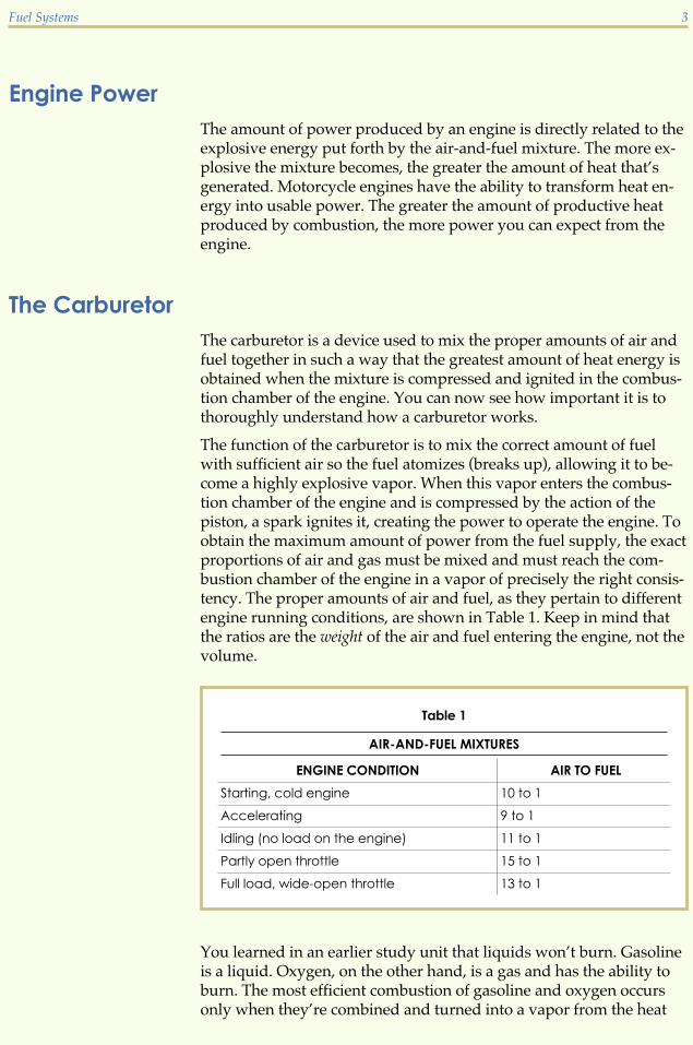
Engine PowerThe amount of power produced by an engine is directly related to theexplosive energy put forth by the air-and-fuel mixture. The more ex-plosive the mixture becomes, the greater the amount of heat that’sgenerated. Motorcycle engines have the ability to transform heat en-ergy into usable power. The greater the amount of productive heatproduced by combustion, the more power you can expect from theengine.
The CarburetorThe carburetor is a device used to mix the proper amounts of air andfuel together in such a way that the greatest amount of heat energy isobtained when the mixture is compressed and ignited in the combus-tion chamber of the engine. You can now see how important it is tothoroughly understand how a carburetor works.
The function of the carburetor is to mix the correct amount of fuelwith sufficient air so the fuel atomizes (breaks up), allowing it to be-come a highly explosive vapor. When this vapor enters the combus-tion chamber of the engine and is compressed by the action of thepiston, a spark ignites it, creating the power to operate the engine. Toobtain the maximum amount of power from the fuel supply, the exactproportions of air and gas must be mixed and must reach the com-bustion chamber of the engine in a vapor of precisely the right consis-tency. The proper amounts of air and fuel, as they pertain to differentengine running conditions, are shown in Table 1. Keep in mind thatthe ratios are the weight of the air and fuel entering the engine, not thevolume.
You learned in an earlier study unit that liquids won’t burn. Gasolineis a liquid. Oxygen, on the other hand, is a gas and has the ability toburn. The most efficient combustion of gasoline and oxygen occursonly when they’re combined and turned into a vapor from the heat
Fuel Systems 3
Table 1
AIR-AND-FUEL MIXTURES
ENGINE CONDITION AIR TO FUEL
Starting, cold engine 10 to 1
Accelerating 9 to 1
Idling (no load on the engine) 11 to 1
Partly open throttle 15 to 1
Full load, wide-open throttle 13 to 1

produced by the engine. This delicately balanced mixing process isaccomplished by the carburetor.
Two primary principles are involved in carburetion operation:
� Atomization, defined earlier as the process of combining air andfuel to create a mixture of liquid droplets suspended in air
� The venturi principle
Let’s look at each of these principles in greater detail.
The Principle of AtomizationAs the piston begins the intake stroke, the air pressure in the cylinderis reduced. The pressure difference causes the higher-pressure out-side air to flow through the air filter and carburetor, and into the en-gine (Figure 1). Atomization takes place when the carburetor metersgasoline into the fast-moving air passing through it. The primaryfunction of the carburetor is to atomize the fuel to create an air-and-fuel mixture.
The atomized gasoline is then vaporized, or changed from a liquid to agas, by the engine heat and by the heat caused by the compression ofthe engine as it completes the compression stroke. This processprovides an efficient, combustible air-and-fuel mixture for the engineto burn.
4 Fuel Systems
FIGURE 1—The Principle ofAtomization (Courtesy Kawasaki
Motor Corp., U.S.A.)
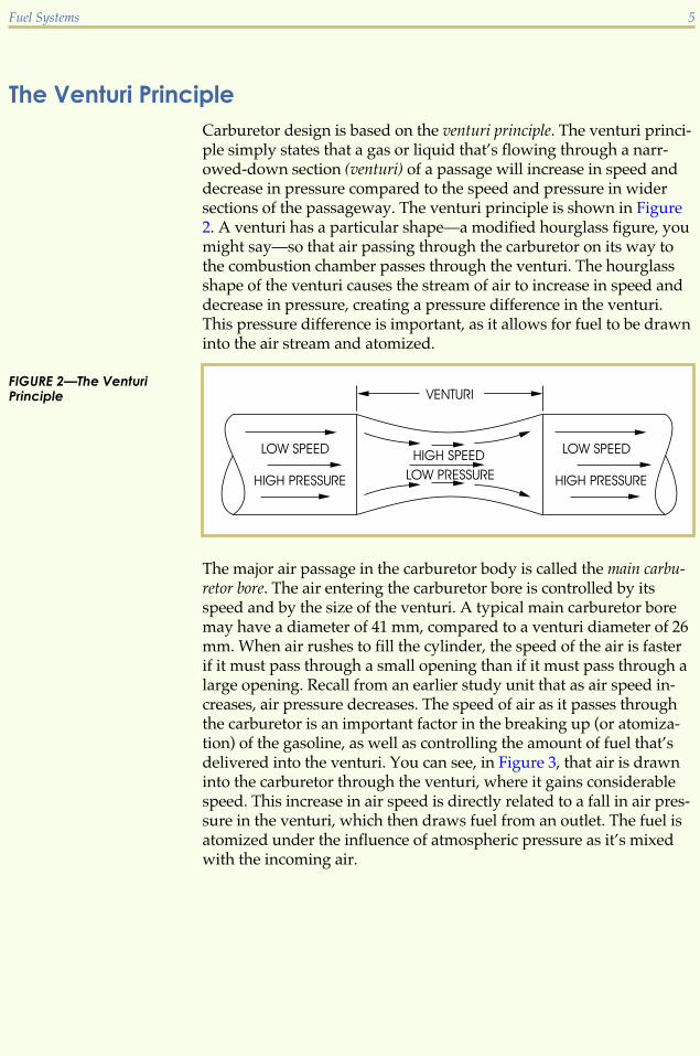
The Venturi PrincipleCarburetor design is based on the venturi principle. The venturi princi-ple simply states that a gas or liquid that’s flowing through a narr-owed-down section (venturi) of a passage will increase in speed anddecrease in pressure compared to the speed and pressure in widersections of the passageway. The venturi principle is shown in Figure2. A venturi has a particular shape—a modified hourglass figure, youmight say—so that air passing through the carburetor on its way tothe combustion chamber passes through the venturi. The hourglassshape of the venturi causes the stream of air to increase in speed anddecrease in pressure, creating a pressure difference in the venturi.This pressure difference is important, as it allows for fuel to be drawninto the air stream and atomized.
The major air passage in the carburetor body is called the main carbu-retor bore. The air entering the carburetor bore is controlled by itsspeed and by the size of the venturi. A typical main carburetor boremay have a diameter of 41 mm, compared to a venturi diameter of 26mm. When air rushes to fill the cylinder, the speed of the air is fasterif it must pass through a small opening than if it must pass through alarge opening. Recall from an earlier study unit that as air speed in-creases, air pressure decreases. The speed of air as it passes throughthe carburetor is an important factor in the breaking up (or atomiza-tion) of the gasoline, as well as controlling the amount of fuel that’sdelivered into the venturi. You can see, in Figure 3, that air is drawninto the carburetor through the venturi, where it gains considerablespeed. This increase in air speed is directly related to a fall in air pres-sure in the venturi, which then draws fuel from an outlet. The fuel isatomized under the influence of atmospheric pressure as it’s mixedwith the incoming air.
Fuel Systems 5
FIGURE 2—The VenturiPrinciple

Venturi size and shape are of considerable importance. If a venturi istoo large, the flow of air is slow and won’t atomize sufficient gasolineto make a balanced mixture. On the other hand, if the venturi is toosmall, not enough air passes through to fill the vacuum inside the cyl-inder created by the engine. A large engine that creates a great vac-uum uses a carburetor with a large venturi. A small engine requires asmaller venturi to be most effective.
Carburetors are equipped with mechanisms for regulation of the airand fuel volumes that are allowed to pass through the venturi. Allcarburetors have a venturi that operates on the same basic principle.Variations are in size, method of attachment, or in the system used toopen and close the venturi. However, the principle of operation is thesame for all carburetors.
The slide-type carburetor is the most popular type of carburetor usedon motorcycle engines and has a venturi whose size is adjusted by athrottle slide (Figure 4). The throttle slide, or throttle valve as it’s alsocalled, is simply a piston that’s raised and lowered in a cylinder. Themethod used to raise and lower each type of slide is fully explainedlater in this study unit. By its change in position, the throttle slide con-trols the venturi opening size. When the throttle slide is raised, thesize of the venturi is enlarged and the amount of air allowed to enterthe engine is increased. This causes the engine speed to increase.When the throttle slide is lowered, the venturi size is reduced. That is,the air passage through the venturi shrinks and engine speed is de-creased. The process of atomization and the venturi principle are whycarburetors work.
6 Fuel Systems
FIGURE 3—Effect of LowPressure in a Venturi (Copyright
by American Honda Motor Co., Inc.
and reprinted with permission)

Road Test 1
At the end of each section of Fuel Systems, you’ll be asked to check your understanding ofwhat you’ve just read by completing a “Road Test.” Writing the answers to these ques-tions will help you review what you’ve learned so far. Please complete Road Test 1 now.
1. True or False? Because there are many different types of carburetors, all have differentpurposes in the operation of an internal-combustion engine.
2. True or False? Gasoline by itself as a liquid won’t burn.
3. The air we breath contains a gas that’s used to help ignite the fuel mixture in an engine.That gas is called _______.
4. What is the purpose of a carburetor?
5. The _______ rating is defined as the fuel’s ability to resist detonation in an engine.(Continued)
Fuel Systems 7
FIGURE 4—A Slide-typeCarburetor Showing aVariable Venturi (Copyright
by American Honda Motor Co., Inc.
and reprinted with permission)

Road Test 1
6. The shape of a venturi is similar to that of a/an _______.
7. What component controls the size of the carburetor’s venturi?
8. An atomized liquid can be described as what?
9. A large venturi opening allows (more/less) air to enter the engine.
10. The major air passage in the carburetor body is called the _______.
Check your answers with those on page 53.
FUEL DELIVERY SYSTEMSThe fuel delivery system of most motorcycles consists of many com-ponents, each of which is discussed in this section. Servicing fuel de-livery systems is very important and involves inspecting and cleaningor replacing many of these components.
Fuel TankThe fuel tank is designed to store fuel (gasoline) for the carburetor.Fuel tanks can be made of steel, aluminum, plastic, or even fiberglass.Most modern street motorcycle fuel tanks are made of a light, thinsteel, while many off-road motorcycle fuel tanks are made of plastic.The important thing to remember is that the fuel tank is a reservoirthat safely stores a supply of gasoline for the carburetor (Figure 5). Inmost cases, the fuel tank uses a gravity feed system to allow fuel toflow into the carburetor. The fuel tank is always higher than thecarburetor when using the gravity feed system.
Typically, the fuel tank is vented to the atmosphere, but some states(California, for example) require fuel tanks to be vented into a char-coal canister (Figure 6). This canister retains the vapors, keeping themfrom entering the air we breathe.
Fuel ValvesFuel valves, also known as a fuel petcocks, are on/off valves that controlthe flow of gasoline from the fuel tank to the carburetor. Fuel petcocks
8 Fuel Systems

are usually located on the fuel tank, on the carburetor, or somewherebetween the fuel tank and carburetor. There are three common types
Fuel Systems 9
FIGURE 5—The fuel tank isused to store gasoline,and is mounted above theengine and carburetor inthis photograph. (Courtesy
Kawasaki Motor Corp., U.S.A.)
FIGURE 6—A charcoalcanister (called the EVAPcanister in this illustration)is used in manymotorcycles to helpreduce emissions. (Copyright
by American Honda Motor Co., Inc.
and reprinted with permission)

of fuel valves used on motorcycles: manual fuel valves, vacuum-operated fuel valves, and vacuum fuel valves with electric assist.
Manual fuel valves allow the rider to control the fuel flow by turningthe valve to one of three positions: off, on, or reserve (Figure 7). Whenturned to the on position, fuel flows to the carburetor from the mainfuel supply. When turned to the off position, the flow of fuel stops.The reserve position serves as a reminder to the rider that the fuel tankneeds to be filled. This position is an important warning device be-cause, unlike an automobile, most motorcycles don’t have a fuelgauge. When in the reserve position, fuel is drawn from a reserve sec-tion of the fuel tank. At this point, there’s usually less than one gallonof fuel left, so it would be wise to seek a filling station soon!
Vacuum-operated fuel valves also have levers with three positions: on,reserve, and prime (Figure 8). The on and reserve positions allow thefuel to flow only when the engine is running and engine vacuum ispresent. Engine vacuum pulls on a diaphragm inside the fuel valve,allowing fuel to flow freely to the carburetor. When the lever is in theprime position, fuel flows at all times. This position doesn’t require en-gine vacuum to allow fuel to flow. The prime position is usually usedonly when the carburetor has been drained of all fuel, after long stor-age, or following disassembly. As you think about this, the prime po-sition is very helpful. If the carburetor has no fuel, the engine won’tstart, so there’s no vacuum available for the fuel valve diaphragm tooperate, thus no fuel flows to the carburetor. The prime position over-rides the vacuum diaphragm, allowing fuel to flow without the en-gine running. The vacuum fuel valve normally has two hoses, asshown in Figure 8—one hose for fuel delivery, and another smallerhose for engine vacuum.
10 Fuel Systems
FIGURE 7—A Manual Fuel Valve (Courtesy of American Suzuki Motor Corporation)

The third fuel valve system is a vacuum valve with electric assist. Thisfuel valve is the same as the vacuum-operated fuel valve, except it hasa float gauge inside the fuel tank. When the fuel level reaches a prede-termined level, the float gauge signals an electrical switch that auto-matically switches the fuel valve from the on position to the reserveposition.
Fuel LinesFuel lines, used to flow gasoline from the fuel valve to the carburetor,are usually made of neoprene. It’s important to use the manufacturer-recommended fuel line, because some hoses can be affected ordamaged by today’s gasoline. It’s also important to always route thefuel line away from hot engine parts and carburetor linkages.
Fuel Systems 11
FIGURE 8—A Vacuum-Operated Fuel Valve(Courtesy of American Suzuki Motor
Corporation)

Fuel PumpsMany motorcycles use a fuel pump system, whose purpose is to deliverfuel from the fuel tank to the carburetor (Figure 9). A fuel pump sys-tem is also used on fuel injection systems. Fuel injection is discussedlater in this study unit. A fuel pump is needed when the motorcycle’sfuel tank is lower than the carburetor. The fuel pump system suppliesfuel under pressure to keep the carburetor filled with fuel. There arethree types of fuel pumps: mechanical, vacuum, and electrical.
The mechanical fuel pump uses a cam, rocker arm, diaphragm, and twocheck valves (Figure 10). This type of pump is normallyactivated by the camshaft inside the engine.
12 Fuel Systems
FIGURE 9—Typical ElectricFuel Pump System (Note:This figure illustrates a fuelsystem for a motorcycleusing an electric fuelpump. In the actual install-ation, the carburetor wouldbe located above the fueltank.) (Courtesy of American Suzuki
Motor Corporation)

The vacuum fuel pump uses a diaphragm that’s moved by the pressuredifferences of engine vacuum and atmospheric pressure. It works inthe same manner as the vacuum fuel valve explained earlier in thissection. A vacuum fuel pump system is illustrated in Figure 11.
The electric fuel pump is operated electronically by the use of an electricsolenoid, or relay, that pumps the fuel from the fuel tank to the carbu-retor (Figure 9). An electric fuel pump operates only when the motor-cycle is running, unless it’s bypassed.
Vent HosesVent hoses are used on fuel tanks and carburetors to permit atmos-pheric air pressure to remain at certain important areas within thefuel system. If these hoses become plugged, twisted, or curled, thefuel may not flow correctly.
Fuel FiltersFuel filters help remove contaminants from the fuel before they reachthe carburetor. Common locations are on the top of the fuel valve orpetcock in the fuel tank, in the fuel valve, in line with the fuel hose, oron top of the seat in the carburetor.
Fuel Systems 13
FIGURE 10—Components ofa Manual-type Fuel Pump

Air FiltersAir filters are designed to filter the incoming air to the carburetor. Airfilters are very important to the life of an engine. If dirt or other con-taminants are allowed to go through the carburetor with the air-and-fuel mixture, they’ll damage the engine quickly.
14 Fuel Systems
FIGURE 11—A TypicalVacuum Fuel Pump System(Courtesy of American Suzuki Motor
Corporation)

The first and most commonly used air filter in motorcycles is the pa-per filter (Figure 12). The paper air filter consists of laminated paper fi-bers that are sealed at the ends or sides of the filter. Some paper airfilters include a supportive inner or outer shell of metal screen. Thepaper used in these air filters is molded in an accordion-style patternas shown in Figure 12. This design increases the surface area and de-creases the restriction of air passing through it. The paper air filter de-sign must be kept dry and free of oil. If it becomes excessively dirty orhas oil in it, the paper air filter must be replaced. Don’t try to clean apaper air filter with soap and water. This will damage the paperfibers, rendering it incapable of doing its job.
Foam air filters use a special foam and oil to aid in trapping dirt andother contaminants. The foam filter usually fits over a metal appara-tus to help hold its shape. These filters work by slowing down the in-coming air and collecting particles of dirt as the air passes through thefiltering material. The dirt sticks to the filter and remains there untilthe filter is serviced. When the filter becomes dirty, it can be cleanedin a warm, soapy water solution, then rinsed and dried. After drying,it must be oiled using a special foam air filter oil (Figure 13).
The gauze air filter is very similar to the paper air filter. Surgical gauzeis used to trap the dirt as the air passes through it. When dirty, youcan clean this filter in warm, soapy water, then rinse and dry it. Youmust also use a special gauze filter oil when servicing this filter.
Fuel Systems 15
FIGURE 12—The paperair filter is molded in anaccordion-style patternto provide greatersurface area. (Courtesy Kawa-
saki Motor Corp., U.S.A.)

Intake ManifoldsThe purpose of the intake manifold is to help deliver the air-and-fuelmixture to the engine. After the mixture has passed through the car-buretor, the intake manifold delivers it to the engine’s cylinders, al-lowing the air and fuel to continue mixing during the delivery. Theintake manifold also secures the carburetor to the engine. The intakemanifold can be either clamped or bolted to the cylinder or cylinderhead. The size and form of the intake manifold vary depending on theparticular motorcycle. Intake manifolds can be made of neoprene oraluminum. Once again, this depends on the particular engine design.
There are three types of intake manifold mounting methods.
� Spigot
� Flange
� Clamp
16 Fuel Systems
FIGURE 13—Whencleaning a foam air filter,wash it with soap andwater, rinse well and dry,apply the proper oil, andfinish by removing theexcess oil. (Courtesy of American
Suzuki Motor Corporation)

Spigot. The spigot-type mount allows the carburetor body to fit insidea rubberlike intake manifold, while a clamp is used to hold it in place(Figure 14).
Flange. With the flange-type mount, the carburetor body has mountingpoints cast into it (Figure 15). These mounting points bolt to the intakemanifold.
Fuel Systems 17
FIGURE 14—A Spigot-typeIntake Manifold Mount
FIGURE 15—A Flange-typeIntake Manifold Mount

Clamp. With the clamp-type mount, the carburetor body has a clampcast into it. The carburetor body fits over the intake manifold asshown in Figure 16. This intake manifold style is the least likely to beused because of the high cost of the machining process required tomanufacture it.
Road Test 2
1. True or False? All fuel tanks are vented directly to the atmosphere.
2. Most fuel tanks on street motorcycles are constructed of _______.
3. Another name for a fuel valve is a _______.
4. Name the three types of fuel pumps used on motorcycles.
(Continued)
18 Fuel Systems
FIGURE 16—The clamp-type intake manifold isused when the carburetoris mounted in an enginecase.

Road Test 2
5. What function does the reserve position serve on a fuel petcock?
6. Why are fuel filters used?
7. Which air filter is most commonly used on motorcycles?
8. Why do foam air filters use a special oil?
9. The _______ type of manifold allows the carburetor body to fit inside a rubberlike mani-fold while a clamp holds it in place.
10. Which intake manifold is least likely to be used because of high manufacturing costs?
Check your answers with those on page 53.
CARBURETOR SYSTEMS AND PHASES OF OPERATIONNow we’ll learn what happens inside a carburetor during its variousphases of operation. But first, recall that all carburetors work usingthe same basic principle. The carburetor has the task of combining theair and fuel into a mixture that produces power for the engine. First,the engine draws in air. The pressure difference between the outsideatmosphere (higher pressure) and the inside of the cylinder (lowerpressure) forces the air to pass through the carburetor. The air mixeswith a predetermined amount of fuel, that’s also moved by pressuredifferences, into the air stream of the carburetor venturi.
Fuel Systems 19

Carburetors use several different fuel metering systems, which sup-ply fuel for the air-and-fuel mixture in regulated amounts. These me-tering systems are called circuits, and their operating ranges overlap.We’ll discuss these circuits as well as the operation of the various car-buretor systems used on all carburetors. We’ll begin the discussion atthe start of the fuel process—the fuel tank.
Fuel Feed SystemAs mentioned earlier, the fuel tank is used to store the fuel for theengine. Fuel is delivered from the fuel tank to the carburetor usingeither a gravity feed method or a fuel pump.
Float SystemThe float chamber is located in the carburetor body in most cases(Figure 17). It’s designed to hold a constant level of fuel for theengine. As the fuel is used in the engine, the fuel level becomes lowand allows a float valve to open and fill the float bowl to a specifiedlevel. This causes the float, which is attached to the float valve, to rise.When the specified level is reached, the float valve closes and stopsthe fuel from entering. This operation repeats continuously as theengine is running. To keep the float bowl at atmospheric pressure, anair vent passage connects the float bowl to the outside air of thecarburetor. Also, an overflow tube is provided to drain any excessfuel to the outside of the carburetor.
20 Fuel Systems
FIGURE 17—A TypicalFloat Chamber (Copyright by
American Honda Motor Co., Inc. and
reprinted with permission)

The fuel level can be modified on many carburetors by adjusting asmall tang that rests on the float valve. Other floats aren’t adjustable.In this case, the float and float valve must be replaced, if out of speci-fication. The float valve contains a small spring used to depress thevalve so it doesn’t become dislodged from the seat (Figure 18). Vibra-tion of the running engine could otherwise cause the float valve tobecome dislodged.
Accelerator Pump SystemWhen the throttle slide is suddenly opened, the mixture of air andfuel being drawn into the engine is lean. This is due to the sudden in-crease of airflow into the cylinder. When this occurs, the fuel can’t bedrawn into the venturi quickly enough to keep the engine runningproperly. Therefore, the engine is in need of assistance in the transi-tion from one carburetor phase to the next. To avoid this condition,some carburetors use an accelerator pump to temporarily enrich themixture. As the throttle slide opens, a diaphragm located in the pumpis depressed by a rod (Figure 19). Fuel is supplied to the main bore ofthe carburetor via the accelerator nozzle. As the throttle valve closes,spring action returns the accelerator’s diaphragm to its originalposition.
Fuel Systems 21
FIGURE 18—A TypicalFloat Valve (Copyright by
American Honda Motor Co., Inc.
and reprinted with permission)

Air Cutoff Valve SystemWhen the throttle slide is suddenly returned to the closed position af-ter the engine has been run at high rpm, engine braking is applied.When this occurs, the fuel mixture becomes lean and the result can bean engine that backfires or pops on deceleration. Under these condi-tions, the air cutoff valve shuts off a portion of the air to the idle circuitof the carburetor (Figure 20). The reduction of air to this circuit allowsfor a temporarily rich mixture. The air cutoff valve is controlled byengine vacuum.
22 Fuel Systems
FIGURE 19—A TypicalAccelerator Pump (Copyright
by American Honda Motor Co., Inc.
and reprinted with permission)

Cold Start Phase of OperationFor the cold start phase, a rich fuel mixture is needed because the en-gine metal is cold. When the engine is cold, the air-and-fuel mixture isalso cold and won’t vaporize or combust readily. To compensate forthis reluctance to burn, the amount of gasoline in proportion to theamount of air must be increased. This is accomplished by the use of acold start system.
Cold start systems are designed to provide and control a richer thannormal air-and-fuel mixture necessary to quickly start a cold motor-cycle engine. Most carburetor cold start mixtures are designed to op-erate at a ratio of approximately 10:1, that is, 10 parts of air to 1 part offuel. Carburetors manufactured today usually include one of threetypes of cold start devices.
Tickler Cold Start SystemIn the early days of motorcycling, a tickler system was used on someEuropean carburetors to aid in the quick start of a cold engine. Thissystem used a pin and spring-loaded rod that, when pushed down,caused the carburetor’s float needle to allow an excessive amount offuel to enter the float bowl. The result was a richer air-and-fuel mix-ture. With this system, the fuel ran out the carburetor’s overflow tube,because the fuel level was higher than normal. This, in turn, causedthe engine to receive raw gasoline in the intake port for an easier coldengine start. The problem with this cold start design was that the en-gine was easily flooded. More important is the fact that overflowingfuel has the potential of being very dangerous. With today’s higherstandards, this system is rarely found on motorcycles.
Fuel Systems 23
FIGURE 20—The aircutoff valve is used insome carburetors toprevent backfiringunder deceleration.(Copyright by American Honda
Motor Co., Inc. and reprinted with
permission)

Choke Plate Cold Start SystemThe choke plate cold start system is an air restriction system that controlsthe amount of air available during a cold engine start. This systemuses a rider-controlled plate, called a choke valve, to block air to thecarburetor venturi at all throttle openings (Figure 21). This plate haseither a small hole cut into it or a spring-loaded relief valve, to allowsome air into the carburetor venturi. This gives the engine enough airto run, but creates a very rich mixture in comparison to the mixturecreated if the plate was in the open position. The choke valve islocated on the air filter side of the carburetor.
Enrichment Cold Start SystemThe enrichment cold start system is the most commonly used system ontoday’s motorcycles. With this system, an enrichment device feeds ad-ditional fuel into the carburetor via the starting enrichment fuel jet(Figure 22). The incoming air combines with the extra-rich fuel andmoves quickly toward the engine’s intake tract. The enriched mixtureignites readily and the engine starts. When using this cold start sys-tem, it’s important to remember to keep the carburetor’s throttle valveclosed. If the throttle valve is open too far, too much air enters the car-buretor venturi. This makes the cold start mixture too lean, and thus,ineffective.
24 Fuel Systems
FIGURE 21—The chokevalve closes off air to theengine. (Copyright by Amer-
ican Honda Motor Co., Inc. and
reprinted with permission)

Slow-Speed Phase of OperationNow that the engine is started and is getting warm, it doesn’t requireas rich a mixture as in the cold start phase. To maintain an idlingspeed, the engine needs a continuous flow of the air-and-fuel mixture,but the quantity required is just enough to keep the engine turningover. The mixture of air and gas is moderate.
When the carburetor is in this idling phase, the throttle slide is almostcompletely closed, permitting only a small amount of air to passthrough the main venturi. The major portion of the air is inductedthrough the pilot jet air passageway (Figure 23). This very small air pas-sage in the pilot jet is sometimes called the primary venturi. The pur-pose of the pilot air screw is to adjust the amount of air flowingthrough. This can be regulated by turning the pilot air screw in or outslightly. As this tiny, fast-moving stream of air enters through the pi-lot jet, it picks up fuel from the float bowl and continues on into themain venturi. A very small volume of air in the main venturi, whichis slipping past the slightly opened throttle slide, combines with themixture coming from the primary venturi. This is the final mixturethat’s drawn into the engine through the intake manifold. This slow-speed phase is in use from idle until the throttle slide is approximate-ly 1
4 open.
Fuel Systems 25
FIGURE 22—The enrichmentvalve permits the flow ofmore fuel to the engine.(Copyright by American Honda Motor
Co., Inc. and reprinted with permission)

Mid-range Phase of OperationThe mid-range phase is used in cruising speeds, when the throttleslide is approximately 1
4 to 34 open. In this phase, the throttle slide is
moved upward to permit a larger quantity of air to pass through themain venturi (Figure 24). Raising the throttle slide raises the jet nee-dle, which fits through the opening at the top of the needle jet. Noticethat the jet needle is tapered. As it moves upward, it permits more gasto flow from the float bowl up through the main jet, out the needle jet,and into the main venturi. The amount of fuel that’s permitted to bedrawn through the needle jet is controlled by the jet needle. As the jetneedle is raised upward, more fuel is allowed to pass through theneedle jet than when the jet needle is down.
Many jet needles have grooves cut into them for the placement of aretaining ring (Figure 25). Raising the retaining ring on the needlelowers the needle in the needle jet, creating a leaner mixture. On theother hand, lowering the retaining ring on the needle raises the nee-dle in the needle jet, thus creating a richer mixture. In this way, theamount of fuel can be metered and atomized by the flow of the airentering through the venturi.
The object of the main jet is to control the amount of fuel allowed topass through the needle jet. A hole located at the bottom of the mainjet holder permits fuel to enter the needle jet during the mid-rangephase of operation. The size of the main jet isn’t important at thispoint because fuel flow is partially restricted by the jet needle in theneedle jet.
26 Fuel Systems
FIGURE 23—Slow-SpeedPhase of Carburetion

During the mid-range phase, the small quantity of fuel that enters themain venturi through the pilot jet is of minor consequence. As thespeed of the engine increases, the demand for more fuel increases, aswell. As the throttle slide is raised further and further, the jet needle,which is fastened to the throttle slide, rises higher and higher. The ta-pered part of the jet needle moves up, permitting the amount of fuelentering the carburetor to be increased. Thus, in the mid-range phaseof carburetor operation there’s a wide range of possible positions thatthe needle and throttle slide can assume in order to accommodatevariations in engine cruising speed.
Fuel Systems 27
FIGURE 24—Mid-rangePhase of Carburetion
FIGURE 25—Many jetneedles have groovesin them that allow foradjustment. (Copyright by
American Honda Motor Co., Inc.
and reprinted with permission)

Main Jet Phase of OperationIn the main jet phase of operation, the throttle slide is 3
4 open to wideopen. The only difference that can be noticed between the main jetphase and the mid-range phase is that the throttle slide is closer to itsabsolute wide-open position (Figure 26). The jet needle is, therefore,in its highest position, allowing for the greatest amount of fuel flowinto the engine. The jet needle barely fits through the needle jet, al-lowing the flow of gas through the main jet to be virtually unob-structed. The amount of fuel entering the carburetor venturi area isnow totally controlled by the size of the main jet. While in the wide-open phase of operation, the engine is operating at maximum rpm.All phases of carburetor operation overlap with one another, as canbe seen in Figure 27.
28 Fuel Systems
FIGURE 26—The Main JetPhase of Carburetion
FIGURE 27—All phases ofcarburetor operationoverlap. (Copyright by American
Honda Motor Co., Inc. and reprinted
with permission)

Types of CarburetorsThere are several carburetor designs, but as you’ve learned, the fun-damental operation is the same for each design. Carburetors must at-omize the fuel before the fuel reaches the engine. Proper atomizationensures that the air-and-fuel mixture is vaporized and the engine per-forms at its best. Carburetors used on motorcycles can be groupedinto two categories: variable venturi and fixed venturi.
Variable Venturi CarburetorsThe variable venturi carburetor is, by far, the most popular carburetorused on today’s motorcycles. There are two basic designs of the vari-able venturi carburetor. The mechanical slide variable venturi carburetoruses a rider-controlled slide to vary the size of the venturi. The con-stant velocity variable venturi carburetor, better known as the CV carbure-tor, uses engine vacuum to control the size of the venturi. Most of theinternal components of these two carburetor designs are exactly thesame, and serve the same function. The key difference between themechanical slide and CV carburetors is in the way the venturi size ischanged.
Fixed Venturi CarburetorsAs the name implies, the fixed venturi has no way of changing thephysical size of its venturi. The amount of air and fuel entering theengine is controlled by a throttle plate. Although this type of carbure-tor is rarely used on modern motorcycles, the fixed venturi carburetorwas used on some older motorcycles. This carburetor type issometimes seen on watercraft and snowmobiles.
In the next section, we’ll explain the two types of variable venturicarburetors in detail and discuss their individual components.
Road Test 3
1. If the needle clip is raised on the needle, the mixture becomes _______.
2. The _______ is used on some carburetors to aid in the transition of one carburetor phase toanother when the throttle is opened quickly.
(Continued)
Fuel Systems 29

Road Test 3
3. Why are cold start devices needed?
4. The cold start system used on motorcycles that allows raw gasoline to directly enter the in-take port is called the _______.
5. The choke plate cold start system controls the amount of _______ entering the carburetor.
6. True or False? Carburetor fuel delivery circuits overlap one another.
7. True or False? During the mid-range phase of carburetor operation, the quantity of fuelthat enters the main venturi through the pilot jet is of minor consequence.
8. True or False? Float bowls are vented to maintain atmospheric pressure and help deliverfuel to the venturi.
9. The CV carburetor’s venturi size is controlled by _______.
10. The mechanical slide carburetor’s venturi is controlled by _______.
Check your answers with those on page 53.
MECHANICAL SLIDE VARIABLE VENTURI CARBURETORAs mentioned earlier, the venturi of the mechanical slide motorcyclecarburetor is controlled by the rider. The rider operates the throttle,which in turn raises and lowers the throttle slide. This procedure con-trols the air volume, velocity, and pressure in the carburetor venturi.To provide the proper air-and-fuel mixture at all throttle openings,the mechanical slide carburetor has several fuel metering circuits,which we’ll discuss in this section.
The Idle CircuitThe idle circuit may also be called a slow-speed or pilot circuit. Theidle circuit meters the air-and-fuel mixture at engine idle and up to ap-proximately 1
4 throttle opening. The idle circuit allows fuel to flow atall times during engine operation but has little to no effect after ap-proximately 1
4 throttle. Because this circuit also has the smallest fueljets, it’s usually the first carburetor circuit to become restricted due tofuel contamination. Figure 28 illustrates the components of the idlecircuit.
30 Fuel Systems

Idle Air Bleed PassageThe idle air bleed passage is located at the air intake side of the carbure-tor. The purpose of the idle air bleed passage is to aid in the atomiza-tion of the idle circuit by mixing air with fuel in the circuit. Some airbleed passages may use a removable air jet. These air jets may have anumber stamped on them to indicate their airflow rate. A largernumber indicates a larger jet. A larger air jet allows a greater amountof airflow over a smaller air jet, therefore creating a slightly leanercarburetor condition.
Idle Outlet PortOn a mechanical slide variable venturi carburetor, the idle outlet port islocated in front of the carburetor slide close to the intake port. Theidle outlet port is the only means of fuel flow while the engine isidling.
Idle Mixture ScrewMotorcycle carburetors have either an air mixture screw or a fuel mix-ture screw to help with idle circuit adjustment. Some motorcycle car-buretors may have both, but this is rare. Adjustments made to an air
Fuel Systems 31
FIGURE 28—The idle circuitin a mechanical slidecarburetor consists of anair bleed passage, an idleoutlet port, a mixturescrew, and a fuel jet. (Courtesy
of American Suzuki Motor Corporation)

mixture screw or a fuel mixture screw require different proceduresand have different effects.
Air mixture screw. On a mechanical slide carburetor, the air mixturescrew is always located on the air filter side of the carburetor slide. Itvaries the flow rate of the air bleed passageway. To create a richerair-and-fuel mixture, you turn the air mixture screw in (or clockwise).This reduces the amount of air allowed to enter the circuit, creating arich mixture. To create a leaner air-and-fuel mixture, you turn the airmixture screw out (or counterclockwise). This increases the amount ofair allowed into the circuit, causing a leaner mixture.
Fuel mixture screw. This screw is always located on the engine side ofthe carburetor slide. The fuel mixture screw controls the amount offuel exiting the idle outlet port. The fuel mixture screw changes theamount of fuel entering the carburetor while the engine is at idle.When this screw is turned out (or counterclockwise), it enriches theair-and-fuel mixture by increasing the amount of fuel allowed to enterthe circuit. When the fuel mixture screw is turned in (or clockwise),the mixture becomes lean by reducing the amount of fuel allowed toenter the circuit. When a fuel mixture screw is used on a street-legalmotorcycle, the carburetors have factory-installed anti-tamper plugsover the screw to prevent the untrained consumer from changing thefactory- and EPA-approved setting.
The Idle Fuel JetThe idle fuel jet is used to meter the amount of fuel flow through theentire idle circuit. This fuel jet is usually made of brass and may be re-movable or may be a pressed-in, non-removable component. Remov-able idle fuel jets are numbered. The larger the number, the larger thejet. The jet number indicates either the diameter of the jet’s opening orthe flow rate of fuel through the jet. In either case, a jet with a largernumber flows more fuel than a jet with a smaller number.
Bypass PortsThe bypass ports of the mechanical slide carburetor are designed tohelp make a smooth transition from the idle circuit to the mid-rangecircuit by allowing more fuel to flow as the throttle slide starts to riseoff the idle circuit. Bypass ports are located directly under the front ofthe mechanical slide’s carburetor slide.
32 Fuel Systems
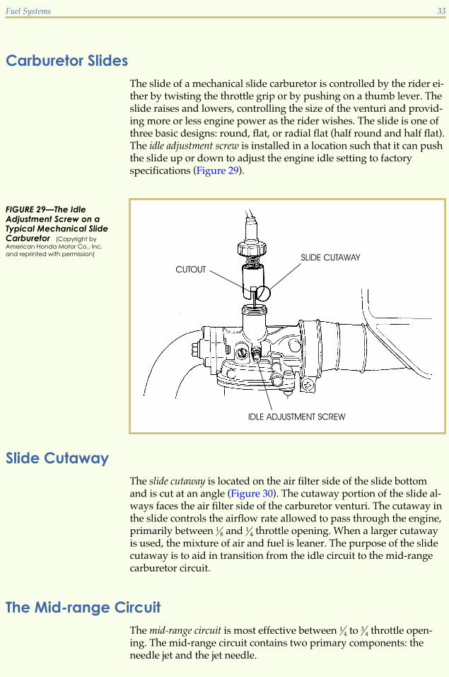
Carburetor SlidesThe slide of a mechanical slide carburetor is controlled by the rider ei-ther by twisting the throttle grip or by pushing on a thumb lever. Theslide raises and lowers, controlling the size of the venturi and provid-ing more or less engine power as the rider wishes. The slide is one ofthree basic designs: round, flat, or radial flat (half round and half flat).The idle adjustment screw is installed in a location such that it can pushthe slide up or down to adjust the engine idle setting to factoryspecifications (Figure 29).
Slide CutawayThe slide cutaway is located on the air filter side of the slide bottomand is cut at an angle (Figure 30). The cutaway portion of the slide al-ways faces the air filter side of the carburetor venturi. The cutaway inthe slide controls the airflow rate allowed to pass through the engine,primarily between 1
8 and 14 throttle opening. When a larger cutaway
is used, the mixture of air and fuel is leaner. The purpose of the slidecutaway is to aid in transition from the idle circuit to the mid-rangecarburetor circuit.
The Mid-range CircuitThe mid-range circuit is most effective between 1
4 to 34 throttle open-
ing. The mid-range circuit contains two primary components: theneedle jet and the jet needle.
Fuel Systems 33
FIGURE 29—The IdleAdjustment Screw on aTypical Mechanical SlideCarburetor (Copyright by
American Honda Motor Co., Inc.
and reprinted with permission)

Needle JetThe needle jet is a stationary jet that’s located in the carburetor body.This jet is numbered for its flow rate. A larger number indicates aricher mixture for the entire mid-range circuit. The needle jet is lo-cated in series with the main jet (Figure 24). The needle jet containsthe air bleed tube for both the mid-range and main jet circuits. Thereare three types of needle jets used on mechanical slide carburetors.
Bleed-type needle jet. This jet is identified by several air bleed holeslocated on its sides (Figure 31). The top of the bleed-type needle jetsits flush with the venturi floor. The bleed-type needle jet allows forgood atomization of fuel over a wide range of conditions.
Primary-type needle jet. This jet has a hood that protrudes into thethroat of the carburetor (Figure 31). The hood, which acts similar to anairfoil, is designed to help increase the negative pressure above it.This type of needle jet allows the best throttle response of the avail-able needle jet designs. This design has only one air bleed hole and isfound primarily in two-stroke motorcycle engines.
34 Fuel Systems
FIGURE 30—The slidecutaway on the left allowsmore airflow than the slidecutaway on the right. Theleft slide, therefore, createsa leaner mixture in thecarburetor than the rightslide. (Courtesy of American Suzuki
Motor Corporation)
FIGURE 31—Needle JetsUsed on MechanicalSlide Carburetors (Courtesy
of American Suzuki Motor Corpora-
tion)

Primary bleed-type needle jet. This jet is a combination of the bleedand primary types. It’s hooded and also has several air bleed holes.The primary bleed needle jet allows for good atomization along withincreased throttle response over the primary-type jet. This needle jetmay have an air bleed passage or an air bleed jet.
Although needle jets have different designs, they all have the sameresponsibility of helping to atomize the fuel for both the mid-rangecircuit and the main circuit.
Jet NeedleThe jet needle is a long, tapered needle that moves up and down withthe throttle slide as the slide opens and closes. The jet needle variesthe amount of fuel flow as it flows through the needle jet. At 1
4 throt-tle opening, the needle restricts the flow of fuel through the needle jetmore than at 3
4 throttle opening (Figure 32). Many jet needles have upto five grooves cut into them for a retaining ring, allowing for adjust-ment of their static height positions (Figure 25). The number one ortop groove is the leanest jet needle setting, as it lowers the needledown into the needle jet. On the other hand, the number five or bot-tom groove is the richest setting, as it raises the needle higher in theneedle jet, thus allowing greater fuel flow.
Fuel Systems 35
FIGURE 32—The jetneedle lets more fuel intothe carburetor venturi asit rises in the slide. (Copyright
by American Honda Motor Co., Inc.
and reprinted with permission)

The Main Jet CircuitThe main jet circuit controls the range of 3
4 to wide-open throttle. Asmentioned earlier, the main fuel jet is located in series with the needlejet, and works in conjunction with the needle jet and jet needle. At 3
4
throttle to full throttle, the needle jet becomes virtually unrestricted.The purpose of the main jet is to regulate the amount of fuel thatflows into the needle jet at this throttle opening range. Without amain jet in place, the engine would allow far too much fuel to flowinto the venturi of the carburetor. This would create an excessivelyrich air-and-fuel mixture and flood the engine.
It’s very important to remember that although the operation of all thecircuits is controlled by the throttle opening, there’s an overlap fromone circuit to the next to allow for a smooth-running engine over avery wide range of engine power needs.
Road Test 4
1. The three types of slides that may be found on the mechanical slide carburetor are the_______, the _______, and the _______.
2. The _______ mixture screw is always located on the air filter side of the carburetor slide.
3. If the jet needle retaining ring is raised from the number three position to the number twoposition, what is the effect on the mid-range circuit of the mechanical slide variable ven-turi carburetor?
4. What is the effect on the idle circuit air-and-fuel mixture when the air mixture screw isturned counterclockwise?
5. What is the effect on the idle circuit air-and-fuel mixture when the fuel mixture screw isturned counterclockwise?
6. The main jet circuit works in conjunction with what other circuit?
7. True or False? The fuel mixture screw is always located on the engine side of the carbure-tor slide.
8. Which circuit has the greatest effect between the range of 14 to 3
4 throttle opening?
Check your answers with those on page 53.
36 Fuel Systems

CONSTANT VELOCITY VARIABLE VENTURI CARBURETORThe constant velocity, or CV, carburetor is also a variable venturi car-buretor that’s widely used on motorcycles. The constant velocity car-buretor is very similar to the mechanical slide carburetor. The majordifference is that the venturi size isn’t controlled by a throttle cablethat raises and lowers the throttle slide. Instead, in a CV carburetor,the venturi is opened when the throttle slide is raised by pressure dif-ferences created by the engine as it’s operating. The air-and-fuel mix-ture is actually controlled by the needs of the engine. If the engine isrunning at a slow speed, it won’t create enough vacuum to raise theslide and, therefore, won’t draw in an excessive amount of air andfuel. In contrast, a cable-controlled mechanical slide carburetor can beopened fully by the rider regardless of engine needs, creating the po-tential for drawing in an excessive amount of air at low enginespeeds.
Another difference between a CV carburetor and a mechanical slidecarburetor is that the CV carburetor has a rider-controlled butterflythrottle valve. The butterfly throttle valve regulates the flow of airinto the engine intake tract. Other than these two differences—theprocedure that moves the throttle slide and the use of a butterflythrottle valve—the components and functions of the CV carburetorare nearly identical to those used on the mechanical slide carburetor.Let’s learn more about the two components that are different on theCV variable venturi carburetor.
Butterfly Throttle ValveThe rider-controlled butterfly throttle valve is a thin, flat disc that fits inthe venturi between the throttle slide and the intake manifold (Figure33). Its job is to open and close the body of the carburetor, thus in-creasing or decreasing the flow of air into the engine intake tract. Therider controls the action of the butterfly valve by manipulating a cableconnected to the handlebar twist grip (throttle). An idle adjustmentscrew is installed in a location that allows it to open the butterflythrottle valve and adjust the engine idle setting to factoryspecifications.
CV Carburetor SlideThe CV carburetor slide looks similar to the mechanical throttle slide.The difference is that the CV-type slide has a rubberlike neoprene dia-phragm or a piston-like apparatus that separates the vacuum cham-ber from the atmospheric pressure area beneath the vacuum chamber(Figure 33). The differences in pressure control the movement of theCV carburetor.
Fuel Systems 37

Recall what happens when the throttle is opened on a mechanicalslide carburetor. When the rider twists the throttle control on a me-chanical slide carburetor for a quick increase in engine power, the ef-fect on the carburetor is to instantly raise the throttle slide. Thisbriefly upsets the proportion of the air-and-fuel mixture, creating arapid increase in the airflow through the carburetor venturi. Theeffect is a temporary lean mixture until the carburetor system catchesup and returns to a balanced mixture.
In contrast, with motorcycles equipped with CV carburetion, whenthe rider turns the throttle control for a sudden increase in speed, the
38 Fuel Systems
FIGURE 33—On a CV carburetor, the rider controls a butterfly throttle valve. In addition, a diaphragmseparates the vacuum chamber from the atmospheric pressure area beneath the vacuum chamber.These pressure differences control the raising and lowering of the CV carburetor slide. (Courtesy Kawasaki Motor
Corp., U.S.A.)

butterfly throttle valve opens between the carburetor and the engine.The airflow in the main bore of the carburetor exerts a strong negativepressure on the lower section of the vacuum piston. At this point, airis drawn out the carburetor’s vacuum chamber and the pressure inthe chamber drops. The atmospheric pressure beneath the vacuumpiston is greater than the pressure in the vacuum chamber, and thisallows the slide to rise. This process can be seen in Figure 34. A low-pressure area is created above the top part of the slide, which causesthe slide to rise. As the slide rises, the tapered jet needle lifts up in theneedle jet and permits an increased amount of fuel to enter andbecome atomized with the incoming air stream.
When the throttle slide is returned to the closed position, the processis reversed. The airflow in the main bore is closed off. The pressurewithin the venturi and carburetor bore rises because of a decrease inthe airflow, which slows down the air speed. The throttle slide islowered by the force of a spring located within the vacuum chamber.
The CV carburetor slide can be thought of as an on-demand carburetorsystem, where the slide opens in keeping with the engine’s demands.A decrease in speed means a decrease in demand. When the rider re-turns the throttle to an idle, the butterfly valve between the carburetorand the engine closes, the vacuum to the top side of the diaphragmdecreases, and the throttle slide eases downward. With the decreasein demand, the quantity of the air-and-fuel mixture decreases.Changes in speed are therefore made more smoothly when a CVcarburetor is used.
Fuel Systems 39
FIGURE 34—Atmosphericpressure pushes the CVcarburetor slide upwardas the pressure in thevacuum chamberdecreases. (Copyright by Ameri-
can Honda Motor Co., Inc. and re-
printed with permission)

Although most of the circuits and parts used in the CV carburetor arethe same as in the mechanical slide carburetor, let’s see what they areand how they work.
The Idle CircuitAs with the mechanical slide carburetor, the CV idle circuit may alsobe called a slow-speed or pilot circuit. This circuit meters the air-and-fuel mixture at engine idle and up to approximately 1
4 throttle open-ing. The idle circuit flows fuel at all times during engine operation buthas very little to no effect after approximately 1
4 throttle. Because thiscircuit has the smallest fuel jets, it’s usually the first CV carburetorcircuit to become restricted due to fuel contamination.
Idle Air Bleed PassageThe idle air bleed passage is located at the air intake side of the carbu-retor. The purpose of the idle air bleed circuit is to aid in the atomiza-tion of the idle circuit by mixing air with fuel in the circuit. Some airbleed passages may use a removable air jet.
Idle Outlet PortOn a CV carburetor, the idle outlet port is located in front of the car-buretor throttle plate close to the intake port. This port is the onlymeans of fuel flow while the engine is at an idle.
Idle Mixture ScrewsCV carburetors for motorcycles have a fuel mixture screw to helpwith idle circuit adjustment. The fuel mixture screw is always locatedon the engine side of the carburetor slide and controls the amount offuel exiting the idle outlet port. The fuel mixture screw changes theamount of fuel entering the carburetor. When this screw is turned out(or counterclockwise), it enriches the air-and-fuel mixture by increas-ing the fuel flow rate. When the fuel mixture screw is turned in (orclockwise), the mixture becomes lean by reducing the fuel flow rate.When a fuel mixture screw is used on a street-legal motorcycle, thecarburetors have factory-installed anti-tamper plugs over the mixturescrews to prevent the untrained consumer from changing the factory-and EPA-approved setting.
40 Fuel Systems

Idle Fuel JetThe idle fuel jet is used to meter the amount of fuel flow through theentire idle circuit. This fuel jet is usually made of brass. It may be re-movable or it may be a pressed-in, non-removable item. Removableidle fuel jets are numbered such that the larger the number, the largerthe jet. The number may indicate either the diameter of the jet’s open-ing or the flow rate of fuel through the jet. In either case, a jet with alarger number flows more fuel than a jet with a smaller number.
Bypass PortsThe bypass ports of the CV carburetor are in a different location thanon the mechanical slide carburetor, but they serve the same purpose.Bypass ports are located directly behind the butterfly throttle valve ofthe CV carburetor. These ports are aids for smooth transition to themid-range circuit by allowing more fuel to flow as the butterflythrottle valve slide starts to open from the idle position.
Carburetor SlidesThe slide of a CV carburetor controls the size of the venturi and raisesand lowers as the engine requires. As with its mechanical slide vari-able venturi counterpart, the slide on a CV carburetor has one of threebasic designs: round, flat, or radial flat (half round and half flat).
Slide CutawayBecause the engine controls the slide in a CV carburetor, the slidecutaway is of little concern on this type of carburetor. Therefore,they’re rarely, if ever, used.
The Mid-range CircuitThe mid-range circuit is most effective between 1
4 to 34 throttle open-
ing. The mid-range circuit contains two primary components: theneedle jet and the jet needle.
Needle JetThe needle jet is a stationary jet that’s located in the carburetor body.As with the mechanical slide carburetor, this jet is numbered for itsflow rate. The needle jet is located in series with the main jet as youcan see in Figure 33. The needle jet contains the air bleed tube for both
Fuel Systems 41

the mid-range and main jet circuits. CV carburetors use the samethree types of needle jets as used on mechanical slide carburetors:
� Bleed-type needle jet
� Primary-type needle jet
� Primary bleed-type needle jet
You may want to review the differences between these needle jets byreviewing the previous section of this study unit. Remember, al-though needle jets can have different designs, they all have the sameresponsibility of helping to atomize the fuel for both the mid-rangecircuit and the main circuit.
Jet NeedleThe jet needle is a long, tapered needle that moves up and down withthe slide as it opens and closes. The jet needle varies the amount offuel flow as it flows through the needle jet. At 1
4 throttle opening, theneedle restricts the flow of fuel through the needle jet more than at 3
4
throttle opening (Figure 32). Many CV carburetor jet needles havegrooves cut into them for a retaining ring that allows for anadjustment of their static height positions.
The Main Jet CircuitThe main jet circuit controls the range of 3
4 to wide-open throttle. Asmentioned earlier, the main fuel jet is located in series with, andworks in conjunction with, the needle jet and jet needle. At 3
4 throttleto full throttle the needle jet becomes virtually unrestricted. The pur-pose of the main jet is to regulate the amount of fuel that flows intothe needle jet at this throttle opening range. Without a main jet inplace, the engine would allow far too much fuel to flow into the ven-turi of the carburetor, which would cause an excessively rich air-and-fuel mixture and flood the engine.
As with the mechanical slide carburetor, it’s very important to re-member that each of these circuits overlap, allowing for a smooth-running engine over a wide range of engine power needs.
Comparison of Mechanical Slide and CV CarburetorsThe CV carburetor offers a number of advantages over the mechani-cal slide carburetor. In addition, both types of variable venturi carbu-retors are better suited for use on motorcycles than the fixed venturicarburetor, which is described in the next section. The differences be-tween the two variable venturi carburetors are minimal. In practice,
42 Fuel Systems

the selection of a variable venturi carburetor depends upon the en-gine design and overall cost of the machine. In many cases, the extracost of producing the CV carburetor outweighs its advantages. Onsome sporting machines, the simplicity and responsiveness of the me-chanical slide carburetor is felt to be more important than improvedefficiency. Therefore, both CV and mechanical slide carburetors areused in a wide range of motorcycles.
Road Test 5
1. The _______ controls the airflow from idle to wide-open throttle opening on the CVcarburetor.
2. The slide on a CV carburetor has a _______ or a _______ to separate the vacuum chamberfrom the atmospheric area below the vacuum chamber.
3. The _______ mixture screw is always located on the engine side of the carburetor slide.
4. If the jet needle retaining ring is lowered from the number three position to the numberfour position, what is the effect on the mid-range circuit of the CV variable venturicarburetor?
5. What is the effect on the idle circuit air-and-fuel mixture when the fuel mixture screw isturned counterclockwise?
6. True or False? The main circuit most likely has an anti-tampering plug installed to preventadjustment on a CV carburetor.
7. The mid-range circuit works in conjunction with what other circuit?
8. Which circuit has the greatest effect between the range of idle to 14 throttle opening?
Check your answers with those on page 54.
FIXED VENTURI CARBURETORThe operation of the fixed venturi carburetor is precise, but its designis simple. As the name suggests, the carburetor’s venturi size is fixed;there’s no slide to change its size during engine operation. A throttleplate controls the amount of air and fuel entering the engine’s intaketract. When the rider turns the throttle control for an increase in
Fuel Systems 43

speed, the throttle plate between the carburetor and the engine’sintake tract opens, allowing more air-and-fuel mixture to enter theengine’s combustion chamber.
Most fixed venturi carburetors have an accelerator pump that forcesan extra amount of fuel into the carburetor air intake tract at a specifictime. The accelerator pump typically has a plunger or diaphragmconnected to a passage, and a nozzle that delivers a fine spray of fuelinto the carburetor air intake tract when the rider twists the throttlecontrol. The pump is synchronized to the throttle plate opening. Theaccelerator pump aids in the reduction of engine hesitation caused bythe carburetor’s lean mixture when the throttle is opened suddenly.The accelerator pump also helps in the transition of fuel from the by-pass ports to the main jet, improving the engine’s overall perform-ance. The jetting sequence on a fixed venturi carburetor is similar tothe mechanical slide and CV carburetors. One difference is that afixed venturi carburetor has a more precise bypass port system andair bleed circuits to aid in a smoother transition from one circuit to thenext.
Idle CircuitThe idle jet and circuit operate in conjunction with the carburetor’s airbleed circuit, and may have three to five bypass ports. This circuitconsists of the idle fuel jet, which meters the amount of fuel flow, andthe idle air bleed, which aids in atomization by mixing air with fuel.Some air bleed passages may have a removable air jet. Fixed venturicarburetors can have an air or fuel mixture screw, which is used tochange the idle circuit mixture. There’s also an idle outlet port that al-lows fuel to flow through the port only when the throttle plate isclosed. The idle port is located on the engine side of the throttle plate.Included in this carburetor design are the bypass ports, also calledtransfer ports. Bypass ports aid in smooth transition by allowing a lit-tle more fuel flow from the idle circuit. The bypass ports are locatedon the air filter side of the throttle plate. The main effect of this circuiton carburetion is from idle to about 1
4 throttle opening.
Mid-range CircuitThe fixed venturi carburetor has a mid-range circuit that affects 1
4 to3
4 throttle opening. The mid-range fuel jet is a brass insert or a pre-cisely drilled hole in the carburetor body that meters the fuel duringthe mid-range operation. There’s also a mid-range outlet port that al-lows air-and-fuel flow when uncovered by the throttle plate at about1
4 throttle opening.
44 Fuel Systems

Main Jet CircuitIn the fixed venturi carburetor, the main jet circuit affects 3
4 throttle tofull throttle. The main air jet allows airflow to the main air bleed tube.The main air bleed tube is located in series between the main fuel jetand the main outlet nozzle. The main outlet nozzle is located in thecenter of the carburetor’s venturi. The main fuel jet allows the correctamount of fuel to flow for proper operation and aids in atomizationby mixing air with fuel.
The fixed venturi carburetor is rarely used on motorcycles today, butis sometimes seen on watercraft and snowmobiles.
Road Test 6
1. The _______ is used to reduce hesitation in a fixed venturi carburetor by delivering a sprayof fuel into the carburetor at a specific time.
2. The fixed venturi carburetor uses a _______ to control the flow of air and fuel entering theengine.
3. The idle port is located on the _______ side of the throttle plate.
4. True or False? The fixed venturi carburetor is widely used on modern motorcycles.
Check your answers with those on page 54.
MULTIPLE CARBURETORSAlmost every multicylinder engine uses one carburetor for each intakeport. In this case, the engine is using multiple carburetors. In fact, thereare some single-cylinder engines that use multiple carburetors. Multi-ple-carburetor designs are generally of the variable venturi design(mechanical slide or CV) and are identical to the carburetors we’vediscussed in this study unit. The only difference is that there’s more ofthem!
Base CarburetorMultiple carburetors are connected together as banks in such a waythat one carburetor controls the opening of all the others (Figure 35).The controlling carburetor is known as the base carburetor. The basecarburetor can be easily spotted as the carburetor with the idle
Fuel Systems 45

adjustment screw attached to it (Figure 36). Carburetors are con-nected together by the use of linkages and plates to allow for eachcarburetor to open with the base carburetor.
46 Fuel Systems
FIGURE 35—A Bank of FourCarburetors (Courtesy of Dan
Ford, Competition Engineering)
FIGURE 36—The basecarburetor is the one withthe idle adjustment screwattached to it. Thesynchronization screwsare used to adjust eachindividual carburetor tooperate equally. (Copyright by
American Honda Motor Co., Inc. and
reprinted with permission)

Multiple Carburetor DisassemblyWhen disassembling multiple carburetors to clean or rebuild them,they should never be separated from their banks unless an individualcarburetor within the set needs to be replaced. They may be cleanedand repaired as a set. The reason for not separating carburetors fromtheir banks is due to the many very small springs and linkagesbetween them (Figure 37).
Fuel Systems 47
FIGURE 37—There aremany small parts to abank of carburetors. Theyshouldn’t be separatedwithout a good reason!(Courtesy Kawasaki Motor Corp.,
U.S.A.)

Carburetor SynchronizationCarburetor synchronization is the process of making the internal sys-tems within a set of two or more carburetors operate the same interms of the amount of air-and-fuel mixture drawn through each one.Carburetor synchronization is measured by the engine vacuum ateach carburetor intake manifold. The operating temperature, smooth-ness, response, and fuel mileage of a multicylinder motorcycle enginedepend greatly upon proper synchronization. This is especially vitalto performance on a multicylinder engine having one carburetor percylinder. Although the physical linkages and synchronization meth-ods vary from model to model, the basic principles of carburetor syn-chronization are the same for all multiple-carburetor engines. Theseprinciples are covered thoroughly in a future study unit.
Remember, no matter how complex carburetors may seem, due to thenumber of carburetors used, the basic fundamentals of carburetion al-ways remain the same. A carburetor is simply an atomizer that sup-plies an internal-combustion engine with a combination of vaporizedfuel, mixed with air in amounts that will burn most efficiently.
Road Test 7
1. To find the base carburetor, you must look for the carburetor with the _______ attached toit.
2. What is carburetor synchronization?
3. Multiple carburetors are connected together by _______ and _______.
4. True or False? When repairing multiple carburetors, you should first separate the individ-ual carburetors from each other.
Check your answers with those on page 54.
FUEL INJECTIONThe purpose of fuel injection is to allow an extremely precise meter-ing of air-and-fuel mixture ratios at any given engine condition. Otherthan the method of getting fuel into the engine, the basic componentsof this system aren’t much different from a standard carburetor en-gine. There are two basic types of fuel injection systems in use today.
48 Fuel Systems

Direct Fuel InjectionWith the direct fuel injection system, fuel is injected directly into thecombustion chamber. This type of fuel injection is found primarily ondiesel engines, but is now finding its way into use on some two-strokemotorcycle engines. The direct system injects an extremely fine mistof fuel into the combustion chamber just prior to TDC (Top DeadCenter) of the engine’s compression stroke.
Indirect Fuel InjectionIndirect fuel injection systems are found on most motorcycle enginesthat use gasoline as a fuel. When an indirect fuel injection system isused, fuel is injected into the intake tract before the intake valve.
Most fuel-injected motorcycle engines use Electronic Fuel Injection(EFI), or Computerized Fuel Injection (CFI). These systems use a com-puterized control unit to control the injectors. Injectors are small sole-noid valves—electronically energized coils of insulated wire. Theinjectors are normally closed, but are opened by the control unit for acalculated length of time. Both EFI and CFI fuel injection systemshave an electric fuel pump to supply constant high fuel pressure tothe fuel injectors. The control unit controls the opening of the fuel in-jector to let a precise amount of fuel enter the intake tract. The amountof fuel allowed into the engine is dependent on how far the throttlevalve is open. Using various sensors that monitor both engine and at-mospheric conditions, the control unit has the ability to deliver a pre-cise air-and-fuel ratio to the engine. The precise air-and-fuel ratiokeeps the engine running more efficiently than an engine using carbu-retors. Indirect electronic fuel injection systems give motorcycles theability to meet EPA standards—standards that are getting tougher tocomply with each year. At the same time, indirect electronic fuelinjection systems provide excellent performance.
Electronic Fuel Injection System ComponentsThe components of an electronic fuel injection system are shown inFigure 38 and described below.
Fuel PumpFuel pumps used with fuel-injected motorcycles have three primaryrequirements. They must be electric powered; they must have theability to handle a high volume of fuel; and they must have the abilityto supply high pressure to the injectors.
Fuel Systems 49

Fuel FilterThere are normally two fuel filters used with electronic fuel injectionsystems. One filter is a large inline type; the other is a smaller filter forthe fuel tank. The operation of fuel filters is critical in a fuel-injectedsystem because clogged injectors won’t function properly.
Fuel Pressure RegulatorThe fuel pressure regulator maintains correct fuel pressure and keeps itabove the pressure of the intake manifold. Excessive pressure isreturned to the fuel tank by a separate return hose.
50 Fuel Systems
FIGURE 38—Components of an Electronic Fuel Injection System (Courtesy Kawasaki Motor Corp., U.S.A.)

Fuel InjectorThe fuel injector is an electronically operated solenoid that turns fuelon and off (Figure 39). The control unit tells the fuel injector when toturn on and off. The control unit also determines how long the injec-tor must stay on. The length of time the fuel injector is turned on isknown as discharge duration. Three things cause fuel to atomize in anEFI system: the shape of the injector, fuel pressure, and turbulence inthe air intake tract.
Control UnitThe computerized control unit receives information from various sen-sors and determines what, when, why, and how long various stepsneed to operate.
SensorsSensors monitor the various engine and atmospheric conditions suchas throttle position, engine rpm, air temperature and pressure (whichis calculated into air density), coolant temperature, and pistonposition.
Fuel Systems 51
FIGURE 39—The fuel injector is a solenoid switch that’s either on (fuel flows) or off (fuel doesn’t flow). (Courtesy
Kawasaki Motor Corp., U.S.A.)
Road Test 8
1. An electronic fuel injection system increases performance by providing the correct _______mixture based on the engine’s demand.
2. The fuel pump in an electronic fuel injection system is _______ powered.
3. The amount of time the injectors are open is known as the _______.
4. The pressure regulator controls the return line to the fuel tank and bleeds excessive_______ back to the fuel tank.
5. Sensors monitor the throttle position, air volume, and other important engine information,then transmit this information to the _______.
6. The intake air temperature and pressure sensors are used for the calculation of air _______.
Check your answers with those on page 54.
52 Fuel Systems

1
1. False
2. True
3. oxygen
4. To atomize the fuel, creating a com-bustible air-and-fuel mixture
5. octane
6. hourglass
7. Throttle slide
8. Liquid droplets suspended in air
9. more
10. main carburetor bore
2
1. False
2. thin steel
3. petcock
4. Mechanical, vacuum, electric
5. Indicates that the fuel tank needsrefilling
6. To keep contamination out of thecarburetor
7. Paper
8. To help trap the dirt
9. spigot
10. Clamp
3
1. leaner
2. accelerator pump
3. To enrich the air-and-fuel mixture so itignites readily when engine compo-nents are cold.
4. tickler system
5. air
6. True
7. True
8. True
9. pressure differences or engine vacuum
10. a rider-controlled slide
4
1. round, flat, radial flat
2. air
3. Creates a leaner circuit by reducingfuel flow
4. Creates a leaner circuit by increasingairflow
5. Enriches the circuit by increasing fuelflow
6. Mid-range circuit
7. True
8. Mid-range circuit
Road Test Answers
53

5
1. butterfly throttle valve
2. diaphragm, piston
3. fuel
4. Enriches the circuit
5. Enriches the mixture
6. False
7. Main jet circuit
8. Idle circuit
6
1. accelerator pump
2. throttle plate
3. engine
4. False
7
1. idle adjuster
2. The process of making all carburetorsoperate equally
3. linkages, plates
4. False
8
1. air-and-fuel
2. electrically
3. discharge duration
4. fuel
5. control unit
6. density
54 Road Test Answers

ONLINE EXAMINATION
When you’re confident that you’ve mastered the material in your studies, you cancomplete your examination online. Follow these instructions:
2. Click the Back button on your browser.3. Click the Take an Exam button near the top of the screen. 4. Type in the eight-digit examination number.
Examination
For the online exam, you must use this
EXAMINATION NUMBER:
03300700
1. Write down the eight-digit examination number shown in the box above.