subdivision design guidelines
TRANSCRIPT
EnginEEring DEsign guiDElinEsFor Unincorporated Alameda County
April 2008
Alameda CountyPublic Works Agency
399 Elmhurst StreetHayward, CA 94544

MiSSion StAtEMEnt
Enhance the quality of life for the people of Alameda County by providing a safe, well-maintained and lasting public works infrastructure through accessible, responsive and effective services.
Alameda County Public Works Agency
Engineering Design Guidelines April 2008
These engineering guidelines were prepared by Engineers of the Public Works Agency
Under the Supervision of:
Arthur Valderrama, P.E. Supervising Civil Engineer Land Development
James Chu, P.E.
Supervising Civil Engineer Road Design
John Bates, P.E., T.E. Supervising Civil Engineer Traffic Design
Cover prepared by:
Jane Ringot
ACKNOWLEDGEMENTS Preparation of these engineering guidelines was guided by the review and comments of staff members of the Public Works Agency:
Stanley Fung, P.E., T.E. Deputy Director Bill Lepere, P.E. Deputy Director Arthur Carrera, P.E., T.E. Principal Civil Engineer Hank Ackerman, P.E. Principal Civil Engineer Tom Hinderlie, P.E. Principal Civil Engineer Moses Tsang, P.E. Supervising Civil Engineer Rohin Saleh, P.E. Supervising Civil Engineer

Alameda County Public Works Agency
Engineering Design Guidelines April 2008
TABLE OF CONTENTS
PAGE GENERAL Foreword ........................................................................................................................ 5 GEOMETRIC DESIGN SECTION General Requirements for Private Access ..................................................................... 6 Width of Private Roadways, Access Easements, and Driveways .................................. 6 Private Roadway Intersections ....................................................................................... 7 Parking on Private Roadways ........................................................................................ 7 Drainage of Private Roadways ....................................................................................... 7 Width of Public Roadways ............................................................................................ 8 Residential Roadways.. .................................................................................................. 8 Local Residential Roadway Widths ............................................................................... 9 Collector and Arterial Roadways ................................................................................... 9 Collector/Arterial Roadway Widths .............................................................................. 9 Curbs, Gutters, and Sidewalks ....................................................................................... 10 Curb/Sidewalk Repair .................................................................................................... 11 Facilities Within or Adjacent to the Roadway ............................................................... 11 Cul-De-Sacs ................................................................................................................... 12 Driveways ...................................................................................................................... 12 INTERSECTION DESIGN General Requirements .................................................................................................... 14 Design Vehicles ............................................................................................................. 14 Curb Return Radius........................................................................................................ 15 Pedestrian Ramps for the Disabled ................................................................................ 15 Taper and Transition Lengths ........................................................................................ 15 PAVEMENT STRUCTURAL SECTION Design Criteria ............................................................................................................... 17 Materials ........................................................................................................................ 17 DESIGN SPEED .......................................................................................................... 19 ROADWAY ALIGNMENT Maximum and Minimum Grades ................................................................................... 20 Sight Distance ................................................................................................................ 20 Corner Sight Distance .................................................................................................... 20 Vertical Curves .............................................................................................................. 20
Alameda County Public Works Agency
Engineering Design Guidelines April 2008
TABLE OF CONTENTS (Continued) Horizontal Curves .......................................................................................................... 20 Cross Slope .................................................................................................................... 21 Guardrails ....................................................................................................................... 21 Stationing ....................................................................................................................... 21 Monuments .................................................................................................................... 22 STORM DRAINAGE General Requirements .................................................................................................... 23 Drainage Calculations .................................................................................................... 23 Storm Drain Pipe............................................................................................................ 23 Slopes and Velocity ....................................................................................................... 24 Surface Flow .................................................................................................................. 24 Gutter Flow .................................................................................................................... 24 Storm Drain Structures .................................................................................................. 24 Valley Gutters ................................................................................................................ 25 Stormwater Detention .................................................................................................... 25 Off-Site Drainage ........................................................................................................... 26 Overland Release ........................................................................................................... 27 FLOODPLAINS Preliminary Floodplain Management Plan .................................................................... 28 POST-CONSTRUCTION (Permanent) STORMWATER QUALITY CONTROLS General Information ....................................................................................................... 29 Treatment and Hydromodification Management Controls ............................................ 29 Site Design ..................................................................................................................... 31 Source Control ............................................................................................................... 32 Hydrograph Modification Management ........................................................................ 35 Projects Requiring Hydromodification Management Controls ..................................... 36 Choosing Hydromodification Management Controls .................................................... 36 Flood Control vs. Hydromodification Controls ............................................................. 36 GRADING General Requirements. ................................................................................................... 38 Preliminary Grading Plans…. ........................................................................................ 38 Stormwater Quality Controls (During Construction) ................................................... 39 Projects One Acre or Greater ......................................................................................... 39 Projects Less Than One Acre ......................................................................................... 40 Geotechnical Investigation Reports ............................................................................... 41 Seismic Hazard Zones .................................................................................................... 41 Earthquake Fault Zones ................................................................................................. 41
Alameda County Public Works Agency
Engineering Design Guidelines April 2008
TABLE OF CONTENTS (Continued) WATERCOURSE SETBACKS Required Setbacks .......................................................................................................... 43 DESIGN REQUIREMENTS FOR PUMPING Total Pumping Systems ................................................................................................. 44 Partial Pumping Systems ............................................................................................... 45 SANITARY SEWERS Design Considerations ................................................................................................... 46 Documentation of Sanitary District Approval ............................................................... 47 WATER MAINS Location of Water Lines and Appurtenances ................................................................. 48 Design Considerations ................................................................................................... 48 Valves ............................................................................................................................ 48 Fire Hydrant Location .................................................................................................... 49 Documentation of Water District Approval ................................................................... 49 UTILITIES (Gas, Electric, Telephone and Cable Television) General Requirements .................................................................................................... 50 EASEMENTS General Requirements .................................................................................................... 51 STREET LIGHTING General Requirements .................................................................................................... 52 Installation Details ......................................................................................................... 52 Typical Street Light Locations....................................................................................... 53 SIGNING, STRIPING, AND SIGNALS Signing and Striping ...................................................................................................... 54 Signals ............................................................................................................................ 54 STREETSCAPE/LAYOUT Streetscape Design ......................................................................................................... 55 Sidewalks ....................................................................................................................... 55
Alameda County Public Works Agency
Engineering Design Guidelines April 2008
TABLE OF CONTENTS (Continued) Street Trees .................................................................................................................... 57 Street Tree Selection/Maintenance ................................................................................ 58 Planter Strips/Tree Wells ............................................................................................... 59 Street Furniture & Public Art ......................................................................................... 60 APPENDIX A Chapter 12.08, Roadway Use Regulations – http://municipalcodes.lexisnexis.com/codes/alamedagen/_DATA/TITLE12/Chapter_12_08_ROADWAY_USE_REGU.html APPENDIX B Chapter 12.11, Regulation of Trees in County Right of Way ‐ Chapter 12.11, Regulation of Trees in County Right of Way ‐ http://municipalcodes.lexisnexis.com/codes/alamedagen/_DATA/TITLE12/Chapter_12_11_REGULATION_OF_TR.html APPENDIX C Chapter 13.08, Stormwater Management and Discharge Control ‐ http://municipalcodes.lexisnexis.com/codes/alamedagen/_DATA/TITLE13/Chapter_13_08_STORMWATER_MANAG.html APPENDIX D Chapter 13.12, Watercourse Protection – http://municipalcodes.lexisnexis.com/codes/alamedagen/_DATA/TITLE13/Chapter_13_12_WATERCOURSE_PROT.html APPENDIX E Chapter 15.36, Grading, Erosion, and Sediment Control ‐ http://municipalcodes.lexisnexis.com/codes/alamedagen/_DATA/TITLE15/Chapter_15_36_GRADING_EROSION_.html APPENDIX F Chapter 15.40, Floodplain Management ‐ http://municipalcodes.lexisnexis.com/codes/alamedagen/_DATA/TITLE15/Chapter_15_40_FLOODPLAIN_MANAG.html APPENDIX G Chapter 16, Subdivisions ‐ http://municipalcodes.lexisnexis.com/codes/alamedagen/_DATA/TITLE16/index.html

Alameda County Public Works Agency
Engineering Design Guidelines 5 April 2008
GENERAL Foreword These Engineering Design Guidelines for Unincorporated Alameda County provide intended users with criteria currently being used by the Alameda County Public Works Agency (ACPWA) in preparation of infrastructure improvement projects in the Capital Improvement Program (CIP) and for use in review of Tracts, Parcel Maps, Site Developments, and Final Maps. Special conditions may require deviations from these guidelines. Any such deviation must be approved by the County Engineer. The detail drawings referenced in these guidelines are found in the Alameda County Public Works Agency publication, “Design Guidelines (SD).” Other materials used in these guidelines include: ASSHTO Geometric Design and Roadside Design Guide, California Manual on Uniform Traffic Control Devices, Caltrans Standard Plans and Standard Specifications, Caltrans Highway Design Manual, Caltrans Traffic Manual, Alameda County Flood Control and Water Conservation District “Hydrology and Hydraulics Criteria Summary”.
Alameda County Public Works Agency
Engineering Design Guidelines 6 April 2008
GEOMETRIC DESIGN SECTION
General Requirements for Private Access Private roadways, access easements, and driveways should conform with all requirements described under these guidelines except as noted in sections pertaining specifically to private access facilities. Private access roadways and driveways differ from public roadways as a matter of who has the responsibility for maintenance and the design standard to which the roadway is designed and built. Private roadways are typically maintained by the property owners along the private roadway by means of a joint maintenance agreement or CC&R’s, depending on the complexity of the infrastructure to be maintained and operated. Width of Private Roadways, Access Easements and Driveways Width of private roadways, access easements, and driveways are established by the Alameda County Planning Director with input from the Public Works Agency and the Fire Department. Where private access intersects with public roadways, criteria established by the County Engineer for public safety must be satisfied. These criteria may include but not be limited to intersection sight distance, pedestrian accessibility, street lighting, traffic control devices, drainage, and paved areas and conforms, etc. The minimum width of the private roadway, access easement, or driveway is a function of the number of residential units served. The minimum recommended driveway width is 20 feet within an easement or lot stem. A 16-foot pavement width may be used when approved by the Fire Department. Private residential roadway access should be designed to a minimum of AASHTO design standards and generally serves four or more units. The recommended minimum curb-to-curb width for private residential roadways is 20-24 feet with no on-street parking, 28-30 feet with parking on one side, and 36 feet with parking on both sides. A Fire Department-approved turnaround area must be provided for cul-de-sacs. A sidewalk may be required by the Planning Director on at least one side of the private roadway. Traffic Calming measures that promote multi-modal means of transportation (bulb-outs, raised crosswalks, bike lanes, street trees, etc.) are encouraged along private roadways and driveways. A toolbox of these measures is available in the Neighborhood Traffic Calming Program or in other transportation resources. Width requirements may vary at the discretion of the Planning Director, depending upon site conditions and requirements of the Fire Department and recommendations from Public Works.
Alameda County Public Works Agency
Engineering Design Guidelines 7 April 2008
Typical private residential roadway lane widths:
Travel Lane 10-12 feet Shoulder areas 0-8 feet Parking Lane 8 feet
Private Roadway/Public Roadway Intersections Where a private roadway intersects a public roadway, a driveway type entrance should be provided rather than a street type (curb returns). When the number of units on the private roadway exceeds 7-10, a street type entrance should be considered. The determination of a street type or driveway access will depend on the traffic characteristics along the public roadway. Factors may include speed, volume, vehicle gaps, pedestrian volume and accessibility, available sight distance, grade, roadway cross slope, etc. A minimum length of 25 feet behind the right-of-way must be relatively flat (6% max.) to ensure safe access to the public roadway. Typically only one driveway will be approved for each build-able lot, with location to be approved by the County Engineer. Parking on Private Roadways Parking spaces on private roadways/driveways may be accommodated in many ways. Two traditional configurations include the following: 1) widening the entire length of one side of the street to form a continuous parking lane, or 2) adding parking bays with either parallel, perpendicular, or diagonal spaces. Parking bays (perpendicular or diagonal) should have adequate backing space which does not encroach beyond the minimum roadway widths. ITE dimensions for parking lots may serve as a guide for determining the area needed for parking maneuverability. Parking bays may be designed as part of turnaround areas, but may not encroach into them. All required parking of private development should be located within the development boundaries. Public roadway frontage is not intended to be counted for the required parking of a private development. Drainage of Private Roadways Intercepted surface storm water must be contained within the private roadway and discharged into an approved County storm drain system. The Flood Control District’s Hydrology and Hydraulics Criteria Summary applies to both public and private roadway development. Please consult the criteria summary for hydraulic criteria that will need to be met. Runoff may be discharged into a public street gutter as long as:
Alameda County Public Works Agency
Engineering Design Guidelines 8 April 2008
1. The runoff has been treated in accordance with stormwater quality control requirements; and
2. County gutter flow criteria are satisfied; and 3. As approved by the County Engineer.
To contain the runoff, curb and gutter must be installed on both sides of the private street. In some areas, asphalt curb and gutters or roadside drainage swales may be acceptable substitutes, but their design and use must be approved by the County Engineer. Width of Public Roadways State law and local ordinance require a minimum right of way width of 40 feet for any roadway that is to be accepted into the County System of Roadways. A minimum right of way width of 50 feet has been established for urban County-maintained roadways including those constructed as part of subdivision improvements. This minimum width may be reduced under special circumstances as approved by the County Engineer. Typical roadway types are shown in the County Design Guidelines (SD). Additional right of way may be required to accommodate conditions such as topography, wider sidewalk widths, landscaping, and bicycle lanes. Roadways widths less than those indicated in the Design Guidelines (SD) must be approved by both the County Engineer and the Fire Department. If used, Public Service Easements (PSE) shall be designated behind sidewalk areas. Aboveground facilities such as fire hydrants, streetlight standards, mailboxes, signs, street trees, and landscaping must be installed within this easement (sidewalks must be unobstructed). Underground longitudinal utility lines (usually placed within the sidewalk area) must not be installed in the PSE but lateral utility lines may cross it and small facilities such as meters, controllers, and transformers may be placed within it when compatible with subdivision design. Private property owners may install and maintain landscaping within this easement. Residential Roadways Residential roadways directly serve local properties only. These should be designed as low volume, low speed roadways with equal emphasis on accommodating pedestrian and bicycle activities. The layout of the roadway should discourage through traffic and include curvilinear alignments if possible. Traffic calming measures that impact vehicle capacity (such as speed humps) may divert traffic to other local roadways and therefore should not be used unless approved by the County Engineer.
Alameda County Public Works Agency
Engineering Design Guidelines 9 April 2008
Local Residential Roadway Widths Typical roadway width guidelines are as follows: Through Travel Lane 10-12 feet Turn Lane 10-12 feet Shoulders (urban) Shoulders (rural)
0-6 feet 0-8 feet
Bike Lane 5-10 feet Parking Lane 8 feet Median Island (face-of-curb to face-of-curb) extra width required for signs within Median Sidewalk width (including curb)
4 feet minimum 5 feet minimum
Collector and Arterial Roadways Collector and Arterial Roadways serve a more regional transportation purpose. In general, arterials carry traffic to freeways or between major areas and collectors convey traffic between local/residential roadways and collector/arterial roadways. Property access to collector and arterial roadways can be both direct and indirect. However, as traffic volumes and motorist speeds increase, direct access should be limited and indirect access should be provided. Collector and arterial roadways need to be designed to accommodate all modes of travel. Bicycle facilities and widened sidewalk areas should be provided. Bus stops on collector and arterial roadways are also more prevalent and need to be incorporated into these facilities. Widened sidewalk sections serve as platform areas to accommodate bus shelters. Measures which facilitate bicycle and pedestrian safety should be considered. Median islands serve as refuge areas for pedestrians and may also provide opportunities for aesthetic treatments and landscaping. Where travel lanes are next to the curb with no on-street parking, treatments must be used to buffer vehicle traffic from pedestrian traffic. Buffer treatments may include class II bike lanes, landscape strips, street trees, etc. Wider sidewalk areas should also be provided to offset the impact of the proximity of vehicle traffic. Collector/Arterial Roadway Widths Typical roadway width guidelines are as follows: Through Travel Lane 11-14 feet Turn Lane 10-14 feet
Alameda County Public Works Agency
Engineering Design Guidelines 10 April 2008
Shoulders Lane Adjacent to Median Island Sidewalk (including curb)
4-8 feet 13 feet 6 – 12 feet
Bike Lane 8 - 10 feet Parking Lane 8 – 10 feet Median Island (face-of-curb to face-of-curb) 4 feet minimum Curbs, Gutters, and Sidewalks A detailed description of sidewalk & streetscape design/layout is included in the Streetscape/Layout section of this document. In general, sidewalk widths and clearances must conform to American Disabilities Act (ADA) requirements. Minimum sidewalk width shall be 5 feet, including an adjacent 6-inch wide curb. Sidewalk widths should be increased where pedestrian traffic will be significant such as along collector and arterial roadways or adjacent to high density or commercial development and school areas. Typical sidewalk widths for collector roadways shall be 6-8 feet and arterial roadways 8-12 feet. Street trees and landscaping within the sidewalk areas are encouraged. These should be maintained by the property owners or homes associations. The trees selected for installation within a sidewalk area must be of a species approved by the County for minimal risk of sidewalk displacement. Where travel lanes are next to the curb with no on-street parking, treatments must be used to buffer vehicle traffic from pedestrian traffic. Buffer treatments may include Class II bike lanes, landscape strips, street trees, etc. Wider sidewalk areas should also be provided to offset the impact of the proximity of vehicle traffic. When aboveground facilities must be placed within the sidewalk area, the sidewalk widths and right of way must be increased to provide adequate clear areas. While a uniform increase is preferable, site specific widening may be more appropriate in retrofit situations. A minimum 4-foot clearance between any obstructions located in the sidewalk area (such as fire hydrants, light standards, etc.) and one longitudinal edge of sidewalk should be provided to accommodate wheelchairs. A minimum of eighteen inches of clear area should be maintained between the face-of-curb and the obstruction. A sidewalk flare (SD-314) may be constructed in order to provide the minimum clear area around previously existing facilities if approved by the County Engineer. Sidewalk flares shall not be used to compensate for improperly installed improvements. Decorative features within a sidewalk may be used to provide an identity enhancement for a community. Such features may include scoring of the concrete, inlays, colored concrete, etc. The cross slope for sidewalks shall be 2% (approximately ¼” per foot). Curb, gutter, and sidewalk (SD-300 and SD-304) must be within the road right of way or easement.
Alameda County Public Works Agency
Engineering Design Guidelines 11 April 2008
Installation of sidewalks in the public right-of-way is subject to review and approval by the County Engineer. Plans for curb, gutter, and sidewalk improvements should include the following details:
1. Where new improvements are to conform to existing improvements, cut sheet and cross sections at 25 feet intervals extending 100’ beyond the proposed Portland cement concrete improvements.
2. Location and elevations of all improvements (new and existing) on both
sides of street.
3. Profiles (with elevations every 25 feet) for existing and proposed centerline and top of curb on both sides of the street.
4. Gutter flowline elevations may be required.
5. Elevations two feet back of sidewalk (if not flat).
6. For vertical curves, show length of curve, elevation of vertex, and grades.
Where Portland cement concrete (PCC) improvements are installed adjacent to unimproved areas, asphalt concrete transitions shall be provided at a slope no greater than 12.5%. Sign post blockout holes shall be provided in both sidewalks and median islands where sign installations have been approved or to replace existing signs. Sidewalks shall conform to the adjacent facilities and surfaces. Transition areas shall be provided as determined by the County Engineer. Curb/Sidewalk Repair Any existing curb, gutter and sidewalk along the site frontage that is to remain shall be repaired or replaced at the discretion of the Director of Public Works. Any curb, gutter or sidewalk with a vertical or horizontal displacement over ¼ inch is considered damaged and shall be repaired or replaced. Facilities within or Adjacent to the Roadway Manholes, valve boxes, etc., may be installed within the roadway. Consideration for placement of utility facilities within County right of way should include minimizing tripping conditions and traffic conflicts during maintenance operations. When a Public Service Easement or landscape strip is utilized, meter
Alameda County Public Works Agency
Engineering Design Guidelines 12 April 2008
boxes, fire hydrants, light standards, utility connection boxes, transformers, etc., shall be placed within either the PSE or landscape strip or behind the sidewalk. Above ground facilities should be placed behind the sidewalk. If this is not feasible, the facilities may be placed adjacent to the curb as long as 48 inches of clear sidewalk width and 18 inches of clearance between face of curb and facility are provided. Cul-De-Sacs Bulbs or hammerheads are required at the end of cul-de-sacs and shall be adequate for emergency vehicles to turn around. Hammerheads are not allowed on public roadways. Typical cul-de-sac bulbs are provided in the Design Guidelines SD-201-A. Driveways For single-family residential developments, driveway approach widths shall be designed to accommodate the appropriate design vehicle ingressing and egressing from the expected roadway conditions. For instance a driveway width along a cul-de-sac could be less wide than a driveway along an arterial roadway. Typically, driveway widths will range from a minimum of 10 feet to a maximum of 20 feet but other widths may be appropriate when justified. Typically, driveway widths should be no wider than the proposed garage door width and should not exceed 50% of the lot frontage length. Twenty-five (25) foot wide driveway approaches may be approved for three car garages or for high density development projects. Note that driveway widths do not include driveway approach flares. The availability of on-street parking should also be considered in establishing driveway widths and spacing. Higher density residential development will typically have joint driveway access and as a result, will have more utilization. These conditions may use driveway approach widths up to thirty (30) feet wide. Prevailing roadway conditions and the availability of on-street parking should also be considered in establishing driveway widths and spacing in higher density areas. For commercial developments, driveway approaches should be designed to accommodate the expected volume of traffic attracted to the site. If the commercial site has a change in business which attracts or reduces more traffic than the previous business, the driveways and access should be modified accordingly to accommodate the change in conditions. Since most commercial developments are along arterial and collector roadways, traffic conditions will also warrant wider driveway widths. Considerations should also be given to access control within the parking lot, median islands for entry features or signing, the number of ingress and egress lanes and the number of driveways for a particular development. A typical driveway would be in the range of thirty-five (35) feet wide.
Alameda County Public Works Agency
Engineering Design Guidelines 13 April 2008
Driveway approach construction for single family residence shall conform to County Design Guidelines (SD), shall not exceed 20% in slope and comply with the requirements of the Fire Department. Other driveways shall conform to private roadway intersections. A minimum of three (3) feet of sidewalk shall be provided between the tops of adjacent driveway approach flares. If this cannot be accommodated, the two driveways should be joined at the approaches to create one continuous driveway approach with a maximum width no greater than the combined maximum width of the two driveway approaches. Driveways shall not be located within the curb return or within intersection bulbouts. Fencing and landscaping along the back of sidewalk shall not be constructed to reduce the stopping sight distance visibility of vehicles entering or exiting the driveway. Gates across driveways shall be set back a minimum of 20 feet behind the right-of-way. Gate operations are not allowed within public right-of-way.
Alameda County Public Works Agency
Engineering Design Guidelines 14 April 2008
INTERSECTION DESIGN
General Requirements Centerline profiles of intersecting roadways shall meet at a common elevation. Intersecting roadways should meet at 90 degree angles and be straight for a minimum of 100 feet in advance of the intersection. The centerline profile grade should not exceed 6% for a minimum of 50 feet behind the crosswalk area. Grades shall be designed so that a “hump” is not created within the traveled way (exclusive of parking lanes) of the major roadway. This will require that the crown of the minor street be depressed to meet the cross slope of the major street. Vertical curves must be provided at grade changes 1.0% or greater. Smooth vertical curves must be provided on curb returns. Profiles of these curb returns should be included on the plans. “Gridding” of all intersection designs is required. This shall consist of a plan of the intersection to a scale no smaller than 1 inch = 20 feet. Grades shall be flagged on centerlines, top of curbs, tangents, and returns, and pavement grades shall be provided every 10 feet along the projection of the gutter tangents to the intersecting street centerline. On wide streets, an additional line of pavement elevations may be required between centerline and curb line. Inspection of the flagged grades should indicate that no depressions or flat spots will be formed. Low spots in the gutter should be drained with a suitable storm drain inlet. Intersections should be designed so that storm drain inlets do not fall within pedestrian crosswalks or interfere with pedestrian ramps for the handicapped. It is preferable that drainage facilities (including tapered gutter sections) be on tangents adjacent to curb returns. Flow of storm water around curb returns should be limited. Design Vehicles Standard Design Vehicles of the American Association of State Highway and Transportation Officials (AASHTO) shall be used in the geometric design of roadways. All roadways must accommodate a standard fire truck. The corresponding minimum design vehicle to be used is the AASHTO Bus. On roadways such as arterials or in industrial areas, the geometrics of the roadway must accommodate the largest type vehicle expected – either in the near or the far future.
Alameda County Public Works Agency
Engineering Design Guidelines 15 April 2008
Curb Return Radius A 28-foot minimum radius is required on curb lines at intersections of public roadways. Larger radii curves will be required if use by large trucks is anticipated or if an exclusive right-turn lane is necessary. On-street parking should not be located within ten feet of the beginning or ending of the curb return. A 20-foot minimum curb return radius is required at intersections of public and private or private and private roadways, but 28 feet is preferred. Along arterial or collector roadway where motorist speeds and traffic volumes are typically high, a 28-foot minimum curb return radius may be required in addition to other necessary mitigations such as exclusive turn lanes. Vertical curves are required on curb returns and should be designed by projecting tangent grades from the intersecting streets. If a low point would be created on the curb return as a result, the gutter flow line should be depressed so as to move the low point (and hence the required drainage structure) to the tangent section of an intersecting street. However, flow line depressing should not be done if the curb would have to be depressed more than one inch. Pedestrian Ramps for the Disabled Pedestrian ramps shall be provided at all curb returns within the public road right of way to facilitate wheelchair crossings at intersecting roadways, including private roadways and at mid-block locations where mid-block crosswalks are approved. A minimum of twelve (12) feet from face of curb to back of sidewalk is required. Sufficient right of way shall be provided so that the entire ramp and platform will be within the public road right of way, or in the case of private roadways, within the private roadway or access easement; this can usually be accommodated with the chord section area from the BC (beginning of curve) to EC (end of curve) of the right of way curve. Pedestrian ramp dimensions are based on the required minimum slopes rather than absolute distances. Pedestrian ramps shall conform to current ADA requirements. In general, two Caltrans Case A ramps are recommended at each curb return. Where ramps other than Caltrans Case A are used, the retaining curb behind the sidewalk shall not be located within the sidewalk area. Taper and Transition Lengths Exclusive turn lanes require taper and transitional sections. These sections should conform to the requirements of Chapter 400 of the Caltrans Highway Design Manual. Transition lengths are a function of design speed and required offset for the direction of travel.

Alameda County Public Works Agency
Engineering Design Guidelines 16 April 2008
The standard bay taper length shall be 90 feet. A 120-foot bay taper shall be used for design speeds of 45 miles per hour or greater or for multiple turn lane configurations. A 60-foot bay taper length may be used where space is limited and when approved by the County Engineer.
Alameda County Public Works Agency
PAVEMENT STRUCTURAL SECTION
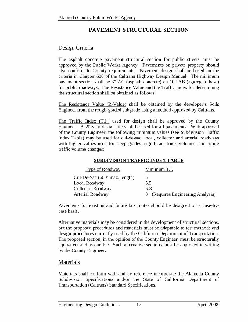
Design Criteria The asphalt concrete pavement structural section for public streets must be approved by the Public Works Agency. Pavements on private property should also conform to County requirements. Pavement design shall be based on the criteria in Chapter 600 of the Caltrans Highway Design Manual. The minimum pavement section shall be 3” AC (asphalt concrete) on 10” AB (aggregate base) for public roadways. The Resistance Value and the Traffic Index for determining the structural section shall be obtained as follows: The Resistance Value (R-Value) shall be obtained by the developer’s Soils Engineer from the rough-graded subgrade using a method approved by Caltrans. The Traffic Index (T.I.) used for design shall be approved by the County Engineer. A 20-year design life shall be used for all pavements. With approval of the County Engineer, the following minimum values (see Subdivision Traffic Index Table) may be used for cul-de-sac, local, collector and arterial roadways with higher values used for steep grades, significant truck volumes, and future traffic volume changes:
SUBDIVISION TRAFFIC INDEX TABLE
Type of Roadway Minimum T.I.
Cul-De-Sac (600’ max. length) 5 Local Roadway 5.5 Collector Roadway 6-8 Arterial Roadway 8+ (Requires Engineering Analysis)
Pavements for existing and future bus routes should be designed on a case-by-case basis. Alternative materials may be considered in the development of structural sections, but the proposed procedures and materials must be adaptable to test methods and design procedures currently used by the California Department of Transportation. The proposed section, in the opinion of the County Engineer, must be structurally equivalent and as durable. Such alternative sections must be approved in writing by the County Engineer. Materials Materials shall conform with and by reference incorporate the Alameda County Subdivision Specifications and/or the State of California Department of Transportation (Caltrans) Standard Specifications.
Engineering Design Guidelines 17 April 2008

Alameda County Public Works Agency
Engineering Design Guidelines 18 April 2008
If the pavement structural section is to be placed on fill, the entire fill shall conform to both the Alameda County Grading Ordinance and the “Embankment” Section of the County Subdivisions Specifications. The portion of imported borrow within 4 feet of the finished sub-grade shall have a resistance value (R-Value) of not less than 20.

Alameda County Public Works Agency
Engineering Design Guidelines 19 April 2008
DESIGN SPEED
The design speed shall be based on the prevailing or critical speed (85th percentile speed) for the roadway to be designed but shall not be less than 30 miles per hour. If an 85th percentile speed is not available, the County Traffic Engineer shall establish a design speed based on comparable roadways within the unincorporated area of Alameda County. If the design speed for a particular roadway cannot be maintained for the entire roadway length, a reduced design speed (for a specific location) may be used with appropriate advanced warning signing as approved by the County Engineer.

Alameda County Public Works Agency
Engineering Design Guidelines 20 April 2008
ROADWAY ALIGNMENT
Maximum and Minimum Grades Maximum and minimum grades for public roadways shall be as specified in the Design Guidelines (SD). Sight Distance All roadway alignment and grades shall provide for the minimum safe stopping sight distance based on the design speed for the roadway. Minimum safe stopping sight distance shall conform to the criteria in Chapter 200 of the Caltrans Highway Design Manual. Sight distances shall be increased for steep roadway grades in accordance with AASHTO criteria. Corner Sight Distance At unsignalized intersections, a clear line of sight for adequate corner sight distance (7-1/2 Second Criteria) must be provided in conformance with Chapter 400 of the Caltrans Highway Design Manual. Vertical Curves Vertical curves shall be symmetrical. The stopping sight distance criteria for grades and design speed will control the minimum length of vertical curves, and larger vertical curves are desirable. Vertical curves shall be used wherever a change of grade is 1.0% or greater. Vertical curves are required on curb returns and should be designed by projecting tangent grades from the intersecting streets. Drainage structures are required at the low point of sag vertical curves except that the gutter flow line should be depressed to allow structures on curb returns to be placed on the tangent portion of the intersecting street rather than on the curb return if the required depression of the gutter flow line does not exceed one inch and provides for complete drainage of the “low spot.” Low points at curb returns shall be designed such that drainage structures are placed on the tangent. Plans should show the length of curve, elevation of vertex, and grades. Horizontal Curves Horizontal curves shall be designed for the design speed applicable to the particular roadway. In most subdivision cases, the design speed will be 30 miles per hour with a posted speed limit of 25 miles per hour. Superelevation of roadways within subdivisions should be used where practicable. Stopping sight

Alameda County Public Works Agency
Engineering Design Guidelines 21 April 2008
distance requirements will be applied on all horizontal curves. In addition to the roadway design criteria for horizontal curves, consideration should be given to obstructions such as cut slopes, existing and potential vegetation, buildings, on-street parking, etc., that may restrict sight distance around a curve. Cross Slope A minimum 2% cross slope shall be provided on all roadways. Where tie-in to an existing pavement will exceed a cross slope of 8%, the pavement should be reconstructed to provide a 2% cross slope. Guardrails Guardrail installations shall conform to Chapter 7 of the Caltrans Traffic Manual. Guardrails are installed to reduce the severity of “run-off-road” accidents. Accident severity will be reduced only for those conditions where striking the guardrail is less severe than going down an embankment or striking a fixed object. Embankment guardrail installations are warranted when two conditions are satisfied:
1. There is a high run-off-road accident history or potential for such accidents; and
2. It has been determined that going off the embankment is more severe than hitting the guardrail.
In general, guardrails are not installed to shield fixed objects located behind curbs in urban areas. Guardrails should be placed at the following fixed objects that are not shielded by other crashworthy barriers:
Steel overhead sign posts.
Structure piers, columns, and abutments.
Exposed ends of retaining walls.
Rows of trees with trunks 6 inches in diameter or greater and spaced less than 50 feet apart.
Stationing Where a subdivision abuts an existing County road, the County road stationing shall be used and an equation shall be shown at all intersections. Generally, on proposed streets, Station 0+00 shall be at the intersection with existing County roads and stationing shall be along street centerline, including horizontal curves. Assumed stationing on existing County roads will not be allowed.
Alameda County Public Works Agency
Engineering Design Guidelines 22 April 2008
Monuments Monuments shown on the final map shall be shown on the improvement plans. At least 3 feet of clearance shall be provided between monuments and utility trenches and other facilities such as manholes or valve boxes. Monuments shall be placed such that an instrument set over one monument can be aligned on a sight 5 feet or less above any adjacent monuments. Where horizontal or vertical curves interfere with a sight line between two monuments, additional monuments will be required. Monument requirements will be established by the Survey Section of the Public Works Agency. Monument installation shall conform to County Design Guidelines (SD). Monument points will be checked by the Survey Section of this Agency. The Survey Section should be consulted to obtain specific details of checking procedures. Generally, spreaders should be set on survey points and checked prior to the actual construction of the monuments.
Alameda County Public Works Agency
Engineering Design Guidelines 23 April 2008
STORM DRAINAGE
General Requirements The design of storm drain facilities must conform to the requirements established in the current Alameda County Flood Control and Water Conservation District “Hydrology and Hydraulics Criteria Summary.” In addition, the Alameda County Flood Control Ordinance (Title 3) and the Alameda County Watercourse Ordinance may be applicable for construction adjacent to Flood Control facilities or watercourses. In the design of the storm drain system, the engineer should develop a contingency overland flow drainage plan to account for blocked drainage inlets and the 100-year storm. Drainage inlets installed in a sump condition should utilize larger inlets as well as multiple inlets. Drainage Calculations Hydrology and hydraulic design calculations will be reviewed for compliance with the “Hydrology and Hydraulics Criteria Summary.” Calculated HGL (hydraulic grade line), EGL (energy grade line), and freeboard should be submitted for review. A copy of the appropriate hydrology calculation form can be obtained from the Land Development Section (do not use the form in the “Hydrology and Hydraulics Criteria Summary”). Storm Drain Pipe Proposed pipe installations running longitudinally within the roadway should be installed 6 feet from the face of curb. Consideration for pipe location should include traffic conflicts during maintenance operations. Storm drain pipes may be either reinforced concrete pipe (RCP), cast-in-place concrete pipe (CIPP), corrugated metal pipe (CMP), or high density polyethylene (HDPE) “ribbed” pipe. Pipes shall conform to the Caltrans Standard Specifications, to approved County criteria, and to the criteria and limitations described below: Reinforced concrete pipe is acceptable for all below-ground installations and shall be Class III or better. Where future or initial cover to top of pipe is less than 3 feet or greater than 8 feet, structural calculations and/or manufacturer’s data to ensure adequate structural capacity of the proposed pipe may be required. If design velocities exceed 14 fps or if pipes are located in a fill slope, the joints shall be fitted with waterproof rubber gaskets and the pipe shall have at least a 2” protective cover of concrete between the inner surface and the steel reinforcement.
Alameda County Public Works Agency
Engineering Design Guidelines 24 April 2008
High density polyethylene “ribbed” pipe having a smooth inner wall and meeting AASHTO Designation M-294, is acceptable on an interim basis. This pipe may be used only with the approval of the County Engineer. Installations of this pipe where storm water runoff may contain abrasive materials may be prohibited. Corrugated metal pipe may be used where special design considerations warrant. Higher gage pipe thicknesses over what is typically prescribed should be used. Special coatings or paved inverts are required for each proposed installation. Anchors are required for surface conduits such as overside drains and shall conform to Caltrans overside drain anchor assembly details. Cast-in-place concrete pipe and plastic pipe may be used outside the roadway right of way as approved by the County Engineer. The type and size of pipe shall be uniform between structures. Pipes placed in public and private roadways as well as large parking areas shall be 18-inch minimum diameter. Slopes and Velocity Slopes and velocity shall conform to requirements listed in the Alameda County Flood Control and Water Conservation District Hydrology and Hydraulics Criteria Summary. Surface Flow Surface water from property containing more than a single dwelling or concentrated flow from any source requires an underground system. A sidewalk drain may be used if the quantity of runoff does not exceed the capacity of either the inlet or the roadway gutter. Flow from commercial developments, parking lots, or other paved areas must be collected in an underground system before entering public roadways. Gutter Flow Gutter flow shall not exceed the capacity of the storm drain inlet nor extend out into the traveled way. On minor residential roadways with on-street parking, gutter flow must not extend out further than 7 feet from the face of curb. For travel lanes next to the curb, gutter flow should not extend out further than 2 feet from the face of curb. Storm Drain Structures Inlet grate capacity is approximately 1 to 1-1/2 cfs with no side curb opening.

Alameda County Public Works Agency
Engineering Design Guidelines 25 April 2008
All gutter flow must be intercepted by proper spacing of inlets, multiple grates, or a combination of these methods. It should be noted that high gutter velocities may result in problems in interception of the gutter flow. In these situations, Caltrans Drop Inlet Type GOL and/or multiple inlets may be required. Inlet structures intercepting gutter flow or manholes shall not be spaced more than 400 feet apart. Extra inlets should be installed near low points of sag vertical curves to take any overflow from blocked inlets. County standard structures should be used. Caltrans standard structures may be used where there is no applicable County structure. When special structures, including inlet, outlet, and energy dissipator structures are needed, construction drawings or specifications shall be submitted together with design calculations for review and approval. Bicycle grates shall be used in all roadway areas. The frame and grate shall conform to County Design Guidelines (SD), or an alternate approved by the County Engineer. These grates must allow the safe passage of all types of bicycle wheels and tires. For inlets located where no parking is proposed or within a bicycle lane, Caltrans Type OL inlets are recommended. Drop inlets must be chosen from the Design Guidelines (SD). Drop inlets within the traveled roadway area must have a taper as shown in the Design Guidelines (SD). For steep slope conditions, Caltrans Drop Inlet Type GOL and/or multiple inlets may be required. Manhole design should be chosen from the Design Guidelines (SD). Where velocities are 14 fps or greater, manholes shall be channelized at ¾ of the larger pipe diameter. Valley Gutters Valley gutters should be avoided whenever possible. They will be approved only when no reasonable alternatives are available. Valley gutters on County roads shall conform to the Design Guidelines (SD) (valley gutters must always be capable of containing the design flow). For private streets, valley gutters may be reduced to 3 feet in width if design gutter flow can be contained within that width. Design shall be such that all water is contained within the concrete valley gutter. Stormwater Detention Development projects that could result in a post-construction stormwater runoff rate of 5 cubic feet per second or more shall be required to detain the increased runoff using on-site detention ponds or equivalent, if: 1) the development project is located upstream of an existing Alameda County Flood Control and Water Conservation District facility that is not designed to carry a 100-year discharge, or 2) the post-construction runoff would increase the elevation or depth of the “base
Alameda County Public Works Agency
Engineering Design Guidelines 26 April 2008
flood” within a FEMA-designated “Special Flood Hazard Area,” or the post-construction runoff would cause the capacity of the downstream storm drain facility to be exceeded. If detention is necessary, the detaining facility must be designed so that post-development runoff flow rates do not exceed pre-development rates for both the 15-year and the 100-year events using the District’s adopted 24-hour design storm. For smaller development projects, with post-development runoff of less than 5 cubic feet per second for the 100-year event, the requirement that post-development runoff not exceed pre-development runoff for the 100-year event does not apply. For these projects, when the District determines that a detention pond is necessary, the pre- vs. post-development runoff limitation will be based on a 15-year event; however, the emergency spillway design must be based on the 100-year discharge. For infill projects with positive drainage, compliance with Hydrograph Modification Plan (HMP) requirements may be sufficient provided that the site is not within a FEMA designated AH Zone and where there is no historic record of flood water ponding. A responsible party shall be identified and funding mechanism established to ensure proper operation, maintenance and repair of the detention facility. A maintenance plan shall also be prepared to guide the responsible party in their efforts to assure that the facility continues to function as designed and built. Refer also to the section on “Detention Facilities,” in the Alameda County Flood Control and Water Conservation District Hydrology and Hydraulics Criteria Summary. Off-Site Drainage Where necessary, storm water may be carried to existing watercourses or storm water facilities outside of the proposed development. Conduits of adequate size shall be installed within suitable easements to transport such runoff. If the conduit drains run-off from existing or future County roads, the easements shall be dedicated to the County. Such easements shall be a minimum 10 feet wide (10 feet for 18” pipe, up to 20 feet for 72” or greater pipe [see Figure 15 of the Hydrology & Hydraulics Criteria Summary]) and shall be free of obstructions so that equipment will have access for maintenance. Facilities draining only private property will not be accepted for maintenance by the County. Foundations located adjacent to easements shall be designed to allow for trenching for repair of the storm drain pipe without causing damage to the building or structure.
Alameda County Public Works Agency
Engineering Design Guidelines 27 April 2008
Non-County maintained facilities shall be installed to the minimum standards established by this guideline. Overland Release An overland release must be provided at the end of all cul-de-sac locations when the roadway slopes toward the cul-de-sac. The release structure must be able to convey the runoff away from structures and toward an acceptable drainage facility. Typically the overland release can consist of an earthen or slope treated swale.

Alameda County Public Works Agency
Engineering Design Guidelines 28 April 2008
FLOODPLAINS
Preliminary Floodplain Management Plan All tentative maps that involve property within or adjacent to a Special Flood Hazard Area (SFHA) as defined on the most recent Flood Insurance Rate Maps (FIRM’s) published by the Federal Emergency Management Agency (FEMA) must clearly indicate the FIRM flood boundary and elevation/depth information either on the map or on a separate plan. FIRM’s can be downloaded from the FEMA website (www.fema.gov) by entering the property address. County floodplain design regulations require that most new buildings, structures, and facilities be designed to withstand a flood that is at least one foot higher than the “base” flood shown on the FIRM. If your proposed subdivision is within (or adjacent to) a SFHA, your project engineer should prepare and submit a preliminary floodplain management plan describing the general methods of protecting against the predicted flood hazard. This plan could include but not be limited to a discussion of the following:
1. The possibility of removing the buildings and structures from the SFHA by establishing a “building limit line” on the property. This would typically require the approval of a Letter of Map Amendment (LOMA) in accordance with the FEMA regulations.
2. The removal of the property from the SFHA by raising the elevation through the addition of fill. This would typically require the approval of a Letter of Map Revision Based on Fill (LOMR-F) in accordance with the FEMA regulations.
3. The design of buildings, structures, and facilities in accordance with the flood-resistant design provisions of the County Building Code.
A special flood hazard condition arises when a new development is proposed for those areas within SFHA’s that are designated on the FIRM’s as “floodways.” County regulations limit construction within floodways to those improvements that would not adversely affect the predicted flood elevations, so that any proposal for a subdivision would have to be accompanied with a drainage study demonstrating “no-rise” to the water surface elevation of the base flood. It is very important that any proposed development of floodway areas be fully described in the subdivision application.
Alameda County Public Works Agency
Engineering Design Guidelines 29 April 2008
POST-CONSTRUCTION
(Permanent) STORMWATER QUALITY CONTROLS
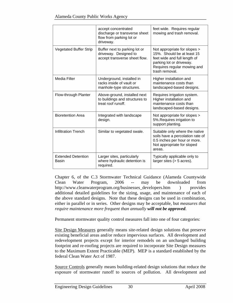
General Information In Alameda County, development projects must comply with the National Pollutant Discharge Elimination System (NPDES) stormwater permit issued to the Alameda Countywide Clean Water Program (ACCWP) by the San Francisco Bay Regional Water Quality Control Board (RWQCB). Project improvements are required to include permanent means of protecting stormwater quality. Treatment and Hydromodification Management Controls All project designs other than interior remodeling on an unchanged building foot print and re-roofing must incorporate certain stormwater quality control measures to minimize the post-construction discharge of stormwater pollutants to the public storm drain systems and ultimately to San Francisco Bay. These include site design and source control measures, and may include numerically-sized stormwater treatment (NS) and/or hydromodification management (HM) measures. Where numerically sized treatment systems are required the project site must be drained to and treated by the on-site treatment system. Projects located on a previously developed site and that will involve the replacement of less than 50 percent of the previously installed impervious surfaces need only treat that portion of the site that is to be redeveloped. Numerically-sized treatment measures are to be sized according to criteria specific to the type of treatment measure selected. These measures must be designed to accommodate large storm events by means of overflow and bypass features that do not erode or damage the site. Treatment systems are generally classed as either “flow-based,” wherein the pollutants are removed from a flowing stream of runoff and the treatment device is sized based upon hourly or peak flow rates, or “volume-based,” where the runoff is stored for a period of time and the pollutants are removed either by treatment measures or infiltration into the ground. The following table lists some of the more common treatment designs for both flow-based and volume-based measures along with their typical usage and limitations: Treatment Measure Typical Usage Limitations Vegetated Swale Part of drainage system,
integrated with landscape design. Can be designed to
Not appropriate for slopes > 8% or where runoff flow rates are > 4%. Should be at least 7
Alameda County Public Works Agency
Engineering Design Guidelines 30 April 2008
accept concentrated discharge or transverse sheet flow from parking lot or driveway.
feet wide. Requires regular mowing and trash removal.
Vegetated Buffer Strip Buffer next to parking lot or driveway. Designed to accept transverse sheet flow.
Not appropriate for slopes > 15%. Should be at least 15 feet wide and full length of parking lot or driveway. Requires regular mowing and trash removal.
Media Filter Underground, installed in racks inside of vault or manhole-type structures.
Higher installation and maintenance costs than landscaped-based designs.
Flow-through Planter Above-ground, installed next to buildings and structures to treat roof runoff.
Requires irrigation system. Higher installation and maintenance costs than landscaped-based designs.
Bioretention Area Integrated with landscape design.
Not appropriate for slopes > 5%.Requires irrigation to support planting.
Infiltration Trench Similar to vegetated swale. Suitable only where the native soils have a percolation rate of 0.5 inches per hour or more. Not appropriate for sloped areas.
Extended Detention Basin
Larger sites, particularly where hydraulic detention is required.
Typically applicable only to larger sites (> 5 acres).
Chapter 6, of the C.3 Stormwater Technical Guidance (Alameda Countywide Clean Water Program, 2006 -- may be downloaded from http://www.cleanwaterprogram.org/businesses_developers.htm ) provides additional detailed guidelines for the sizing, usage, and maintenance of each of the above standard designs. Note that these designs can be used in combination, either in parallel or in series. Other designs may be acceptable, but measures that require maintenance more frequent than annually will not be approved. Permanent stormwater quality control measures fall into one of four categories: Site Design Measures generally means site-related design solutions that preserve existing beneficial areas and/or reduce impervious surfaces. All development and redevelopment projects except for interior remodels on an unchanged building footprint and re-roofing projects are required to incorporate Site Design measures to the Maximum Extent Practicable (MEP). MEP is a standard established by the federal Clean Water Act of 1987.
Source Controls generally means building-related design solutions that reduce the exposure of stormwater runoff to sources of pollution. All development and
Alameda County Public Works Agency
Engineering Design Guidelines 31 April 2008
redevelopment projects except for interior remodels on an unchanged building footprint and re-roofing projects are required to incorporate Source Control measures to MEP and as required by the County Building Code.
Numerically-Sized Treatment Measures (NS) means on-site facilities intended to remove pollutants from the stormwater runoff. These measures are required if a development or redevelopment project for which the development application was deemed complete after August 15, 2006 creates or replaces 10,000 or more square feet or more of impervious surface (certain single family homes are exempted from this requirement). This requirement also applies to development or redevelopment projects creating or replacing one acre or more of impervious surface for which the development application was deemed complete after February 15, 2005. Hydromodification Management Measures (HM) means controlling runoff from the site so as to prevent increases in erosion downstream of the site. HM measures are required if the development or redevelopment project for which the development application was deemed complete after June 15, 2007, creates or replaces 1 acre or more of impervious surface and is located within a defined “susceptible area.” See the brochure entitled “Stormwater Quality Control Requirements What Developers Need to Know” for additional information. This brochure is available from the Community Development Agency or on-line at http://www.cleanwaterprogram.org/businesses_developers.htm. Improvement Plans shall include a Stormwater Quality Control Plan. A dedicated plan sheet shall be included in the improvement plan set for this purpose. All projects that include numerically-sized stormwater treatment measures are required to have a Stormwater Quality Control Maintenance Plan for the measures. A responsible party shall also be identified to implement the maintenance plan. Site Design Site design means measures intended to minimize the runoff of stormwater from the project site by preserving existing open space and other naturally vegetated areas or choosing building, infrastructure and landscaping designs that tend to reduce new impervious surfaces, including the following:
1. Create more self-treating areas such as lawns, parks, “green” building roofs, turf block, etc. Properly designed self-treating areas need little or no “treatment.”
2. Control the impervious footprint by choosing multi-story or clustered building designs, narrower roadways, fewer sidewalk, smaller patios, etc.
Alameda County Public Works Agency
Engineering Design Guidelines 32 April 2008
3. Reduce the required parking areas through the use of shared facilities,
valet parking, pay-as-you-go, multi-story parking structures, parking strips, interior parking, etc.
4. Collect and store rain water with cisterns or barrels for reuse.
5. Allow infiltration into the soil through the use of permeable surfaces such as pervious pavement, crushed aggregate, unit pavers, etc.
One important aspect of site design is to recognize that all surfaces, even self-treating areas, generate runoff following a storm event. However, for water quality purposes, runoff from a properly designed self-treating area that does not receive runoff from impervious surfaces can be drained directly to the stormdrain system, bypassing any treatment measure. Alternative surfaces, such as pervious pavement, crushed aggregate, or pervious pavers on a permeable substrate must be approved by the project geotechnical engineer. Source Control All building construction must comply with the stormwater protection provisions of the County Building and Plumbing Codes. Exterior Enclosures. Separate exterior trash, storage, or recycling enclosures must be “protected,” i.e., covered with an overhanging roof, isolated from surface runoff by grade breaks or berms, and drained to the sanitary sewer system by means of an enclosed floor drain. Car Wash Areas. Residential developments of more than 25 units must:
1. Provide centralized car wash areas, protected as described above; and 2. Install signage and/or enact provisions in the CC&R’s prohibiting washing
of vehicles in driveways. Building Roofs. Unless exempted by the conditions of approval of the Tentative Map, building roofs must discharge runoff via gutters, downspouts, and conductors to landscaping or to a numerically-sized stormwater treatment measure as required. Discharge from Pools. Unless approved by the Director of Public Works, pools, spas, hot tubs, or fountains may not discharge process water to the storm drain system. The local sanitary district should be consulted regarding terms for connecting pool, spa, fountain, or hot tub drains to the sanitary sewer.
Alameda County Public Works Agency
Engineering Design Guidelines 33 April 2008
Discharge from Rooftop Equipment. Rooftop equipment (heating, cooling, ventilating) may not discharge process water to the storm drain system. The local sanitary district should be consulted regarding terms for connecting this equipment to the sanitary sewer. Food-Handling Cleaning Areas. Food handling facilities must plumb and drain equipment cleaning, garbage, and trash storage areas to the sanitary sewer and may be required to incorporate a designated cleaning area, sized to accommodate floor mats and floor mops. Treatment Controls and Hydromodification Management Measures
1. Numerical-sizing of Measures for Stormwater Treatment . Use the Flow Hydraulic Design Basis for treatment controls whose primary mode of action depends on flow capacity, such as swales, sand filters, or wetlands. Use the Volume Hydraulic Design Basis for treatment measures whose primary mode of action depends on volume capacity, such as detention/retention units or Infiltration structures. The calculations can be found at http://www.cleanwaterprogram.org/businesses_developers.htm.
2. Sizing and Design of Hydromodification Management Controls. The Bay
Area Hydrology Model has been set up to assist in verification of proposed design of HM detention systems. A link to the model can be found at http://www.cleanwaterprogram.org/businesses_developers.htm.
3. Mechanical Treatment Systems. The type of mechanical separator
allowed is any cartridge or absorbent-type treatment system for which manufacturer recommended maintenance is not necessary more than once annually. These types of mechanical treatment devices shall only be used in the developments where a maintenance agreement (CC&R’s) holds the property owner(s) liable for maintenance, repair and replacement of the treatment system.
4. Stormwater Treatment Systems Not Allowed.
a. Stormdrain inlet filters are not considered adequate by themselves for stormwater treatment by Alameda County and by the San Francisco Bay Regional Water Quality Control Board. They can be used only as one element in a multi-element stormwater treatment plan where their function is to keep large debris out of other stormwater treatment elements.
b. Oil/water separator (or vault) systems are not considered adequate by themselves for stormwater treatment by Alameda County and by the San Francisco Bay Regional Water Quality Control Board. Vault systems may only be used as one element of an overall stormwater treatment plan at sites where their function is to contain a potential oil
Alameda County Public Works Agency
Engineering Design Guidelines 34 April 2008
spill.
5. The design of Landscape-based Treatment Systems must be integrated to
function properly with other existing or proposed improvements such as retaining walls, trees, foundations, adjacent properties, etc.
6. The design of Numerically-Sized Stormwater Treatment Measures must
consider soil types, depth to groundwater table, percolation rates and may require under drains.
7. Types of Soil-Based Systems. Soil-based treatment measures include but
are not limited to bio swales, flow through planters, permeable paver systems, vertical pipes/boxes or dry well boxes with a mixture of soil, sand, and rock, and other systems. Refer to the C.3 Stormwater Technical Guidance which is available on line at http://www.cleanwaterprogram.org/businesses_developers.htm.
8. Residence Time for Treatment Controls. Landscape or soil-based
treatment systems shall be designed to allow a minimum residence time of 10 minutes and a maximum residence time of 24 hours to prevent mosquito breeding (especially a concern due to West Nile virus).
9. Geotechnical Considerations. All systems must be built to provide
adequate protection of slopes, foundations and other surfaces. This may include under drains and overflow devices. Consultation with a Geotechnical Engineer is encouraged and sometimes required.
10. Design Parameters for Treatment & HM Controls.
Treatment system design considerations include type of soil, depth of soil, infiltration rates, height of grass, slope, width, and length of swale.
11. Location of Treatment & HM Controls. Treatment & HM Controls shall
be located on the private property of the development project. No treatment or HM Controls shall be built in the public right-of-way.
Stormwater treatment & HM Controls shall be located outside of the Alameda County designated creek set back area and shall not be located inside designated riparian corridor boundaries. See setback requirements in the Alameda County Watercourse Ordinance.
12. Protect landscaping/vegetation. Stormwater conveyance systems on the
site shall not convey water to existing trees/plants that would be impacted by an increase of water. Newly planted trees/plants shall not be located where they will be harmed by flows from a required stormwater treatment system.
13. Maintenance. Every installed stormwater treatment or HM control must
Alameda County Public Works Agency
Engineering Design Guidelines 35 April 2008
be maintained by the property owners. Responsibility for maintenance will be determined prior to construction of the project. The County will not assume maintenance responsibility for private stormwater treatment or HM controls. Maintenance agreements shall include language allowing County inspectors access to the facility for on-going inspections.
14. Protection of Treatment Controls during construction. The stormwater
treatment systems must be protected so that they function properly at the end of construction activities. Any damage or clogging resulting from construction must be corrected before completion of construction.
15. Groundwater Considerations. Any stormwater treatment or HM control
facility, with an earthen bottom, may not be located within 12 feet of the groundwater table.
16. Submittal Requirements for the Stormwater Treatment Plan shall include a
dedicated plan page for stormwater management illustrating the integration of:
a. The proposed finished grade.
b. The storm drainage system including all inlets, pipes, catch basins, overland flows, outlets and water flow direction.
c. The design details for each of the water quality elements, including typical sections, length, depth, width, connections.
d. The design details of all source control and site design measures to be implemented.
e. Drainage map indicating the post –construction water flow directions and drainage basins on the property.
f. The landscape plan, if part of the stormwater treatment control plan.
g. Include icons for stormwater quality elements in the plan legend on the front page of the plan set.
Hydrograph Modification Management In addition to and separate from the stormwater quality treatment requirements above, applicable projects located in an erosion-susceptible area, creating and/or replacing one acre or more of impervious surface shall comply with certain Hydromodification Management Requirements. Hydromodification Management (HM) is also referred to as Hydrograph Modification Management or “duration or flow control.” HM addresses increases in runoff flow from the project site that would cause increases in erosion downstream in creeks and other waterways. Hydromodification Management Measures can include:

Alameda County Public Works Agency
Engineering Design Guidelines 36 April 2008
1. Additional source control and/or site design measures intended to reduce the amount of runoff generated by the development.
2. On-site and off-site features and facilities intended to control the flow rate,
concentration and timing of the discharge from the site into the waterway.
3. In-stream improvements intended to provide direct erosion protection and bank stabilization of the waterway.
A computer model has been developed specifically to assist project engineers to either design or verify designs of detention facilities for HM implementation in the Bay Area. The program is called the Bay Area Hydrology Model (BAHM). The BAHM software and the electronic version of its user manual are available for download at www.bayareahydrologymodel.org. Projects Requiring Hydromodification Management Controls Applicability of HM controls depends largely on the location of the project. In certain areas of erosion susceptibility, projects for which the development application was deemed complete after June 15, 2007, and creating or replacing one acre of impervious surface, must provide stormwater HM control to the standards of the BAHM. HM requirements are separate from post-construction treatment. Whereas stormwater treatment is intended to improve the quality of stormwater by removing pollutants, HM controls the rates of flow of stormwater to prevent increased erosion downstream of the project site. However, where both treatment controls and HM controls are required, it may be possible to design one facility or measure to meet the needs for both requirements. Choosing Hydromodification Controls Hydromodification controls may include, but are not limited to, detention basins and site design methodologies. Consideration of HM is required at every stage of project development. During initial project planning, the location must be checked against the ACCWP HM map to determine if controls are required. Site design measures such as permeable parking lot surfaces can minimize runoff and thus reduce the space needed for HM controls. Flood Control vs. Hydromodification Controls Refer to Chapter, “Storm Drainage,” subsection “Stormwater Detention.” Applicants will need to reference the Alameda County Hydrology & Hydraulics

Alameda County Public Works Agency
Engineering Design Guidelines 37 April 2008
Criteria Summary (HHCS) for additional stormwater requirements relating to flood control.

Alameda County Public Works Agency
Engineering Design Guidelines 38 April 2008
GRADING
General Requirements A preliminary grading plan shall be prepared by a registered civil engineer (RCE). All such plans should be consistent with the plan preparation provisions of the County Grading Ordinance, reprinted below for reference. In the event of a conflict between the requirements of the Grading Ordinance and other regulations of the Planning Department or the Public Works Agency, the most stringent shall prevail. Preliminary Grading Plans Preliminary grading plans provide for review and determination of grading permit requirements prior to approval of final plans and issuance of a grading permit. The plans shall be clearly and legibly drawn, entitled "grading plans," shall include the following, unless waived by the Director of Public Works:
1. On a map of appropriate scale, but not smaller than one inch equals one hundred (100) feet:
a. A plan entitled “preliminary grading plan” and the name and signature of preparer and date of preparation.
b. A vicinity sketch (not at map scale) indicating the location of the site relative to the principal roads, lakes and watercourses in the area.
c. A site plan indicating the site of the work and any proposed divisions of land.
d. The complete site boundaries and the locations of any easements and rights-of-way traversing and adjacent to the property, appropriately labeled and dimensioned.
e. The location of all existing and proposed roads, buildings, wells, pipelines, watercourses, and other structures, facilities, and features of the site, and the location of all improvements on adjacent land within fifty (50) feet of the proposed work.
f. Location and nature of known or suspected soil or geologic hazard areas.
g. Contour lines of the existing terrain and proposed approximate finished grade at intervals not greater than five feet, showing all topographic features and drainage patterns throughout the area where proposed grading is to occur. The contour lines shall be extended to a minimum of fifty (50) feet beyond the affected area, and further if needed to define intercepted drainage, and shall be extended a minimum of one hundred (100) feet outside of any future road rights-of-way.
Alameda County Public Works Agency
Engineering Design Guidelines 39 April 2008
h. Approximate location of cut and fill lines and the limits of grading for all of the proposed grading work, including borrow and stockpile areas. A written description of offsite locations of borrow and stockpile areas will suffice.
i. Location, width, direction of flow and approximate location of tops and toes of banks of any watercourses.
j. Approximate boundaries of any areas with a history of flooding.
k. Proposed provisions for storm drainage control and any existing or proposed flood control facilities or septic tank disposal fields in the vicinity of the grading.
l. A conceptual plan for erosion and sediment control including both temporary facilities and long-term stabilization features such as planting or seeding for the area affected by the proposed grading. This requirement may be waived by the Director of Public Works for sites having no slopes greater than five percent unless the large size of the site, its proximity to sensitive areas or other conditions make an erosion or sediment discharge hazard possible.
m. North arrow and scale.
n. General location and character of vegetation covering the site and the locations of trees with a trunk diameter of twelve (12) inches or more, measured at a point three feet above average ground level, within the area to be disturbed by the proposed grading. The plans shall indicate which trees are proposed to remain and how they are to be protected.
2. Typical cross sections (not less than two) of all existing and proposed
graded areas taken at intervals not exceeding two hundred (200) feet and at locations of maximum cuts and fills.
3. An estimate of the quantities of excavation and fill, including quantities to
be moved both on- and off-site. 4. The estimated starting and completion dates of grading. 5. Such supplemental information as required for processing and approval of
the design concept and the application as required by the Director of Public Works.”
Stormwater Quality Controls (During Construction) The erosion control measures shall be in place and operable during the rainy season, October 1st to April 15th. Erosion control planting is to be completed by October 1st. No grading or trenching shall occur between October 1st and April 15th unless authorized by the Director of Public Works. Projects with land disturbances of one acre or greater must file a Notice of

Alameda County Public Works Agency
Engineering Design Guidelines 40 April 2008
Intent (NOI) with the San Francisco Bay Regional Water Quality Control Board (RWQCB) per the regulations of the General Construction Activities NPDES permit. The RWQCB will require the preparation of a Storm Water Pollution Prevention Plan (SWPPP). Two copies of the NOI and the SWPPP must be submitted to the County, one to the Development Review Engineer and one to the Grading Section prior to issuance of a grading permit and prior to any land disturbance on the site. Projects with land disturbances of less than one acre must provide a Stormwater Pollution Prevention Plan (SWPPP) to the Development Review Engineer outlining the pollution prevention practices to be used at the site during construction. This is in addition to an erosion control plan required by the Grading Permit. The owner, contractor and project proponent are responsible to ensure that the following water quality protection measures are addressed in the SWPPP and are implemented:
1. Minimize construction access points to local roads. Provide construction entrances at each access point. Remove all silt, gravel, rubbish, and green waste from the street, gutter, and sidewalks adjoining the construction site prior to October 1. Provide regular maintenance, weekly or after storm events, to keep each access point clean and free of debris which may be washed away. During wet weather, avoid driving off paved areas and tracking mud and silt onto paved areas.
2. Minimize removal of any vegetation. Stabilize all cleared and de-
vegetated areas prior to the rainy season. Stabilization techniques should include temporary or permanent re-seeding, mulching, protective berms and silt fences, plastic covering or rocking of all roads in use, but should be based on ABAG erosion control or California Storm Water BMP Handbook standards.
3. Protect adjacent properties from all storm water or silt runoff generated by
on-site construction activities.
4. Delineate clearing limits, easements, setbacks, trees, drainage courses, sensitive or critical areas and their buffers to be protected on the plan and provide for their marking on-site.
5. Source control of potential pollutants, such as “good housekeeping”
practices shall be used during construction to prevent construction related contaminants from entering the storm drain system. Gather all construction debris on a regular basis. Store all construction materials and waste in a covered area, or under a tarp. Sweep where possible; do not use water to wash down areas draining to storm drains. Indicate on the plan materials and waste storage areas which can be covered during storms. Indicate on the plan vehicle parking, maintenance, and cleaning areas. Use proper equipment cleaning, fueling, and maintenance practices.

Alameda County Public Works Agency
Engineering Design Guidelines 41 April 2008
Indicate on the plans a contained area for concrete truck washing.
6. Stabilize swales, gullies, channels, culverts, field inlets, and outfalls on the construction site to prevent erosion.
7. Use sediment controls and filtration to reduce sedimentation from
dewatering effluent.
8. Control the use and prevent discharge to storm drains of all potential pollutants. For example, pesticides, petroleum products, nutrients (plant wastes), solid wastes, and construction discharges from dewatering activities, street washing, and pavement saw cutting. Install filter materials (sandbags, filter fabric) at all storm drain inlets which drain the site. Filters shall be maintained and changed regularly to ensure effectiveness and prevent flooding. Dispose of filtrate properly.
9. Include on the plan the following emergency measures: storage of extra
erosion control items on-site (hay bales, silt fence, life vests), alternative drainage or erosion control measures, locations of high drainage flow potential, emergency contact names and phone numbers of the contractor, developer and plan preparer.
Geotechnical Investigation Reports In accordance with Section 16.08.050 of the Subdivision Ordinance, a soils-geologic investigation report prepared by a licensed geologist, certified engineering geologist, or a registered civil engineer or soil engineer as provided by Section 6736.1 of the Profession Engineers' Act must accompany the filing of a tentative map. Seismic Hazard Zones If the project site is shown to be located in an area of the designated zone of required investigation for earthquake-induced landslide or liquefaction on the Seismic Hazard Zones maps published by the California Geologic Survey, the proposed project may be subject to the provisions of the Seismic Hazards Mapping Act (SHMA) and a geotechnical report prepared by a qualified engineer assessing such potential hazardous condition per the provisions of SHMA and Special Publication 117 shall be submitted to the County and reviewed and approved by the County Engineer prior to approval of the tentative map. Earthquake Fault Zones If the project site is shown to be located in an Earthquake Fault Zone on the Earthquake Fault Zones maps published by the California Geologic Survey, the project may be subject to the provisions of Alquist-Priolo Earthquake Fault Zoning Act and a geologic investigation report, prepared by a qualified engineer,

Alameda County Public Works Agency
Engineering Design Guidelines 42 April 2008
assessing such potential hazardous condition per the provisions of the Act and Special Publication 42, shall be submitted to the County and reviewed and approved by the County Engineer prior to approval of the tentative map.
Alameda County Public Works Agency
Engineering Design Guidelines 43 April 2008
WATERCOURSE SETBACKS A Watercourse Permit issued by the Public Works Agency will be required for any work proposed within or in the vicinity of the watercourse. Permits or agreements from other related state and federal agencies, i.e. the California State Department of Fish and Game, San Francisco Bay Regional Water Quality Control Board and the U.S. Army Corps of Engineers should be obtained in accordance with their guidelines and requirements. Evidence of compliance with those agencies’ requirements may be required prior to issuance of a Watercourse Permit. Required Setbacks No development shall be permitted within setbacks except as otherwise provided in the Watercourse Ordinance. The Ordinance establishes a setback of 20 feet from the top of bank. However, for existing bank slopes at 2 horizontal to 1 vertical, or steeper, establish the setback by drawing a line at a 2 horizontal to 1 vertical slope from the toe of the existing bank to a point where it intercepts the ground surface. The 20-foot setback is then applied from that intercept point.

Alameda County Public Works Agency
Engineering Design Guidelines 44 April 2008
DESIGN REQUIREMENTS FOR PUMPING
Use of pumps to transport storm water flows is discouraged. If pumps are part of a storm water drainage system, the property owners depending on such a system shall be notified through recorded documents that their property relies on a non-standard drainage system. Property owners are responsible for accepting the operation and maintenance of such system. The two types of pumping systems, “Total Pumping” and “Partial Pumping,” are described as follows: Total Pumping Systems “Total Pumping System” is a means by which all of the intercepted drainage area is pumped to a different watercourse or discharge facility. Total pumping must be used when overflow from the pump inlet would be a hazard to downstream properties.
1. A total pumping system may be diverting flow from another drainage area
or the natural watercourse and, therefore, drainage facilities receiving pumped discharge must be designed to safely handle the additional flow.
2. A minimum of two pumps is required. Either pump alone must
accommodate the design flow rate.
3. The automatic pump control must have the following capabilities:
a. A control that activates one or both pumps depending on the water level in the sump (float control).
b. The capability to alternate the initial pump so that one pump is not overused.
c. An automatic switch to generator power during a power failure.
4. An on-site generator is required. It must satisfactorily supply power for pump start-up and operate both pumps simultaneously.
5. The pump control and the generator must be enclosed in a weatherproof
enclosure.
6. The sump must be designed to eliminate vortex formation and cavitation of the impeller.
7. The sump must be sized such that the pump will operate for a minimum of
10 minutes. With special design, the conveyance pipes can be included in the sump volume to provide necessary storage.
Alameda County Public Works Agency
Engineering Design Guidelines 45 April 2008
Partial Pumping Systems “Partial Pumping” is a means by which the pumping station diverts the augmented flows caused by the changed land use of development and the natural drainage course continues to carry the quantity of storm water that it carried in natural state. Since a natural or drainage facility is in place that will continue to operate should the pump fail, the safe-guards provided for the total pumping system are not needed.
1. A partial pumping system may be diverting flow from the existing or
natural watercourse and, therefore, drainage facilities receiving pumped discharge must be designed to safely handle the additional flow.
2. A minimum of two pumps is required. Either pump alone must accommodate the design flow rate.
3. The automatic pump control must have the following capabilities:
a. A control that activates one or both pumps depending on the water level in the sump (float control).
b. The capability to alternate the initial pump so that one pump is not overused.
4. An on-site generator is required. It must satisfactorily supply power for
pump start-up and operate both pumps simultaneously.
5. The sump must be designed to eliminate vortex formation and cavitation of the impeller.
6. The sump must be sized such that the pump will operate for a minimum of 10 minutes. With special design, the conveyance pipes can be included in the sump volume to provide necessary storage.
Alameda County Public Works Agency
Engineering Design Guidelines 46 April 2008
SANITARY SEWERS
Design Considerations Design shall be approved by the Sanitary District providing sewer service. Only backfill and cover requirements are included in Alameda County specifications. Laterals shall be shown on the plans. Laterals to be located within the road right of way shall be installed before the roadway structural section is placed. Manholes and cleanouts shall conform to Sanitary District design standards. Manholes and cleanouts within the roadway shall be capable of supporting traffic loads and shall be installed so that finished pavement around the structure will be smooth and so that no settlement will occur. Sanitary sewers are usually located in the center of the roadway. Alternate locations are acceptable provided conflict with other facilities and vehicle conflicts will not be significant during maintenance operations. Connection of proposed facilities to existing facilities must be shown. Sanitary sewers must be located so that trenches will not be in conflict with monuments or manholes. Cover over pipes shall be as approved by the County Engineer and the Sanitary District. For example, the amount of cover required by the Castro Valley Sanitary District varies with the type of pipe as follows:
1. Where cover is four feet or greater in areas subject to vehicular loadings, vitrified clay pipes may be used.
2. Where cover is between one foot and four feet in areas subject to vehicular
loadings, cast iron or ductile iron pipe is required. 3. In special circumstances, cast iron, or ductile iron pipe is to be installed as
required by the Sanitary District. 4. Backfill requirements shall conform to Alameda County Specifications.
Sewer construction within the Castlewood County Service Area (R-1967-1) shall conform to the CSA Sewer Handbook. Sewer connections to or through the Castlewood CSA sewerage facilities shall not be made except pursuant to a formal agreement with or annexation to the CSA unless the property is entirely within the CSA.

Alameda County Public Works Agency
Engineering Design Guidelines 47 April 2008
Documentation of Sanitary District Approval A copy of the resolution by the Board of Directors of the sanitary district approving the improvement plans shall be provided. If the Board of Directors of the sanitary district authorized the Engineer-Manager or other official to approve plans, a copy of his letter of approval will be acceptable. In addition to the above, a certificate, for signature of an official of the sanitary district approving the improvement plans, shall be provided on the cover sheet of the improvement plans. The County approved format shall be used.
Alameda County Public Works Agency
Engineering Design Guidelines 48 April 2008
WATER MAINS
Location of Water Lines and Appurtenances Since storm drains and sanitary sewers depend on gravity flow, water mains must be located to avoid conflict with these facilities. Sanitary sewers are usually located on the centerline of streets. Water lines may be located on either side of the street so long as they are not in conflict with other facilities. Coordination with other utilities will be required to provide for their connection to existing facilities. Service and meter locations shall be determined by the Water Utility District and must be shown on the plans. Meters shall be installed so as to not impair pedestrian movements. Meter boxes should not be located in driveways or the traveled portion of the roadway; however, if such location is unavoidable, boxes and covers shall be capable of supporting traffic loads. Meter boxes should be clear of sidewalks; however, if such location is unavoidable, boxes and covers shall be installed to provide a smooth and safe walk area. No metal lids will be allowed in the sidewalk area. If the Conditions of Approval of the tentative map specify number and location of water meters, the conditions must be met. Connection to existing facilities shall be shown in both plan and profile. Design Considerations Pipe cover shall be as specified by the County Engineer and the Water District. Minimum cover shall be 3 feet. Cover less than 3 feet may be considered, but only if some other protection is provided and the proposed installation is approved by the Water District. Backfill requirements shall conform to Alameda County specifications. Bedding and material to 6 inches above the pipe may be specified by the Utility District. Compaction requirements shall conform to Alameda County specifications. Valves Valves shall be as specified by the Water District. Valves located within the roadway shall be protected by suitable valve pots and installed so that the designed roadway surface adjacent to the valve pots is not distorted. Valve pots shall be set in concrete and shall be approved in the field by the County representative.
Alameda County Public Works Agency
Engineering Design Guidelines 49 April 2008
Fire Hydrant Location Fire hydrant location should not create a sidewalk obstruction and shall be as specified and approved by an official of the Fire Protection District. Hydrants will generally be located within the 5-foot PSE behind the sidewalk where feasible. Hydrants requiring placement within the sidewalk area should provide 2 feet of clear area between the face of curb and the hydrant, and 4 feet clear area between the hydrant and the back of sidewalk. Provision for the signature of the Fire District Official on the County approved certificate shall be made on the cover sheet of the improvement plans. Two paper copies of the approved improvement plans shall contain original signatures of the Fire District Official. Documentation of Water District Approval Documentation of the Water District approval of the water facilities, as shown on the improvement plans, plus a statement that necessary financial arrangements have been made for furnishing water to the development will be required before the plans are presented to the Board of Supervisors for approval.

Alameda County Public Works Agency
Engineering Design Guidelines 50 April 2008
UTILITIES (GAS, ELECTRIC, TELEPHONE, AND CABLE TELEVISION)
General Requirements Utilities shall be installed as required by the Conditions of Approval of the tentative map and/or as described in the Streetscape Section of this document. Alameda County Ordinance Code requires that all utilities within subdivisions be underground. Any exception will require approval by the County Engineer. Any (utility) pole placed within the sidewalk area should provide 18 inches of clear area between the face of curb and the pole, and 4 feet between the pole and back of sidewalk. A joint trench is preferred for installation of utilities. The joint trench should be located within the roadway right of way. Consideration for minimizing traffic conflicts during maintenance operations should be given when selecting a joint trench location. A joint trench detail showing placement of utilities therein must be provided and approved by each participating utility. Trench cover shall conform to Caltrans High Low Risk Facilities Manual requirements. Usually, one utility company will be the lead agency, coordinating the installation of the other facilities and providing trenching and backfill. Alternately, the developer may act as coordinator. Any structures that contain utility appurtenances shall be detailed and located on the improvement plans. Installation details shall comply with specifications of the utility involved. Connection to existing utilities must be shown on the improvement plans and approved by both the utility concerned and the County Engineer. Backfill requirements shall conform to Alameda County specifications. No free flowing backfill material will be allowed.
Alameda County Public Works Agency
Engineering Design Guidelines 51 April 2008
EASEMENTS
General Requirements Easements shall be provided for all private and public storm drains, sanitary sewer, water line, and utility mains situated outside the road right of way. Storm drain easements shall be a minimum of 10 feet wide (10 feet for 12” pipe, up to 20 feet for 72” or greater pipe) and shall conform to requirements of the Hydrology and Hydraulics Criteria Summary. Minimum easement widths for sanitary sewers, water lines, and utility mains shall be as required by the appropriate sanitary, water and utility agencies. Slope easements and access easements may be required. Whenever a developer is required to convey or dedicate an interest (easement, fee simple, etc.) in real property to the County of Alameda, or to the Alameda County Flood Control and Water Conservation District, by instrument other than a filed map, the developer, or developer’s engineer, shall submit to the Development Review Division a legal description and plat map of the real property affected by the conveyance or dedication. The Development Review Division shall check the legal description for sufficiency and mathematical accuracy, and then forward it to the Real Estate Section, together with back-up material, for re-writing in County form. The Real Estate Section shall provide the developer, or designated representative, with the final legal description, as well as the proper form for conveyance of the required real property interests to the County or Flood Control District.
Alameda County Public Works Agency
Engineering Design Guidelines 52 April 2008
STREETLIGHTING
General Requirements Development Review Engineer and Special Districts Administration (Streetlights) will establish streetlight location, type of light, and installation details. A County Service Area (CSA) for street lighting has been established for most of the unincorporated areas of Alameda County west of the Hayward/Pleasanton Ridge. Areas outside the CSA may require annexation to the CSA at the Developer’s cost. Provisions for providing streetlight facilities may be found in the Conditions of Approval for the project. The initial installation of streetlights will be the responsibility of the Developer. Cost of energy and maintenance, for lights within the public right of way, will be borne by the Street Lighting CSA after acceptance of the completed improvements provided the types of lighting installed conforms to the CSA specifications and are in proper working order. Lighting within private roadways must be owned and maintained by the development or individual property owners. Alternate lighting provisions may be approved, but costs of energy and maintenance must be provided through a homeowners’ association and may be arranged with the utility. Installation Details Type of light, pole height, mast arm length, base and sub base design, and location must appear on the improvement plans and be approved by the County. The County will provide maintenance for street lighting located on County roads. Types of facilities for which maintenance is available may be obtained from the County’s Street Lighting Guidelines. Privately maintained lighting will require the approval of the County. The utility company supplying energy and the County Engineer must be satisfied that provision for proper maintenance has been made. Streetlight poles should be located at property lines, behind the sidewalk or in the Public Service Easement (PSE) if available. Along existing roadways, streetlight poles should follow the existing installation pattern. Adequate sidewalk clearance shall be provided in all streetlight installations. Streetlights at signalized intersections shall conform to the requirements of the Traffic Engineering Section.

Alameda County Public Works Agency
Engineering Design Guidelines 53 April 2008
Typical Streetlight Locations
Signalized intersections
Intersections at median breaks
Intersections having a high accident rate
Other intersections where one road has two or more lanes in one direction
Street ends (stub ends)
Median breaks
Medians continuing through intersections
Channelizing islands
Midblock crosswalks
Pedestrian crossings
Railroad crossings
Acceleration lanes
Merge areas
Left-turn pockets
Roadside objects (such as lane drops)
Underpasses
Overpasses
Bus pull-out areas
Start of bicycle lanes in the roadway
Bicycle crossing points
Equestrian crossings
Rumble strips
Transversable medians
Alameda County Public Works Agency
Engineering Design Guidelines 54 April 2008
SIGNING, STRIPING AND SIGNALS Signing and Striping Signing and striping designed by the Developer’s Engineer will be reviewed and approved by the County Traffic Engineer. Signing and Striping shall be designed in conformance with California MUTCD. Plans shall include locations of all existing and proposed signs, street lights, utility poles, drainage structures, driveways, intersections and street trees. Street name signs shall be installed as required at each street intersection in accordance with Design Guidelines (SD). Signalized intersections should have street name signs installed either on signal standards or on mast arms. Street names must be approved by the County Planning Department. Stop signs are used to assign motorist right of way. Locations must be approved by the County Traffic Engineer. Any multi-way stop location must conform to California MUTCD Standards. The County Traffic Engineer may require other regulatory or warning signs. Signs shall be installed in accordance with the Design Guidelines (SD). Striping may consist of stop bars at intersections, crosswalks, centerlines, lane lines, bike lanes, edge lines, etc. Materials used for roadway striping shall include both paint, thermoplastic and raised pavement markers (both reflective and non-reflective). Striping requirements will be determined by the County Traffic Engineer using criteria and details illustrated in the California Manual on Uniform Traffic Control Devices (California MUTCD) and Caltrans Standard Plans. Signals Full or partial participation in the design costs of a traffic signal and the costs of construction may be required by the conditions of approval of the tentative map. All traffic signal designs shall be reviewed and approved by the County Engineer. Traffic signal design, equipment and materials shall conform to Caltrans Standard Plans and Standard Specifications and County specifications and requirements. Special requirements include (but are not limited to) the following criteria:
Maximum pull box spacing is 100 feet
Detector loops shall be Type A or Type D configuration
Conduit shall be rigid metal
Plastic heads are not acceptable
Alameda County Public Works Agency
Engineering Design Guidelines 55 April 2008
All signal head lenses shall be LED.
STREETSCAPE/LAYOUT
Streetscape Design The Streetscape is an important element in the successful design of a commercial street corridor, mixed-use development as well as residential streets where the character of a neighborhood sharply defines the livability of that neighborhood. Generally, sidewalks adjacent to mixed-use development should be wide enough to accommodate a landscape area. This should include a combination of at least 3-4 feet for landscaped areas, and 4-10 feet clear for walking. Street trees should be considered for all sidewalk areas. Trees should be spaced 25-30 feet on center and coordinated with the driveway spacing in residential neighborhoods and storefront design in mixed-use commercial area of a new project. Street furniture and pedestrian-scale lighting should be included in development plans for commercial streetscape projects and residential streets where bus stops are located. In new commercial development, new projects shall include at least one street tree per two storefronts or 30 feet of lot frontage whichever is greater. Street trees should also be considered for infill projects in traditional residential neighborhoods. This would include planting at least one tree per lot or 30 feet of frontage to be placed in planting strips, sidewalk tree wells, bulbouts, and paving area tree wells where they do not conflict with utility easements. Above and below ground utilities must coordinate their facilities to allow for landscape and street tree improvements as shown on an approved Streetscape Project Plan. Quality streetscape design requires that special attention be given to key components such as curb and driveway location, sidewalks and crosswalks, placement of at grade or above ground utilities such power poles, guy wires, transformers, controllers, street signals and signage. In addition to street trees, pedestrian areas and street furniture are all important elements of vibrant streetscape development. It also requires that quality workmanship be expected and will be provided by all project contractors at all stages of construction. Sidewalks Alameda County’s goal is to provide an interconnected network of sidewalks and pathways that allow pedestrians to safely access their destinations including transit stops, places of employment, recreation facilities, schools and residences.
Alameda County Public Works Agency
Engineering Design Guidelines 56 April 2008
The County recognizes and supports the range of benefits a well-designed streetscape provides for all pedestrians, including people with disabilities. The County reviews streetscape design elements very carefully to ensure that the materials, dimensions and design elements meet urban design, visual, aesthetics, safety and accessibility requirements. Streetscape design is broken into three parts, ROW Utility Area, Pedestrian Area and Landscape/Street Furniture Area. These parts are defined as follows: ROW Utility Area is defined as the space between the property line and back of sidewalk. Where a standard 50-foot right-of-way exists, the ROW Utility Area provided is usual 2 - 3 feet wide, except in locations adjacent to commercial uses with a high level of pedestrian traffic. It is the preferred location for street trees, and other elements such as pedestrian lighting, fire hydrants and below grade utility hatch covers. Public Service Easements (PSE) as discussed in the Geometric Design Section of this document should also be considered for location of utilities. Pedestrian Area is the area of the sidewalk corridor that is specifically reserved for pedestrian travel. The minimum width of this area is 4 feet, except in locations adjacent to land uses with a high level of pedestrian traffic where the minimum width of this area is 7 feet. Street furniture, plantings, and other fixed items should not protrude into the Pedestrian Area. Landscape/Street Furniture Area (including the curb) is defined as the space between the roadway curb face and the front edge of the pedestrian area. The minimum width of this area is 5 feet wide and is generally located in areas with a high level of pedestrian traffic. Amenities located in the landscape and street furniture area must be setback a minimum of 1.5 feet from the face of the street curb. This area buffers pedestrians from the adjacent roadway and is the appropriate location for street furniture, art and landscaping. Transit stop improvements may also be located in the landscape and street furniture area and are designated for transit customer waiting and loading, and may include transit signage, shelters, benches, litter receptacles, and pedestrian scaled lighting. Any landscaping or other objects proposed for this area must comply with Alameda County permitting requirements and the following design criteria: Standard construction of sidewalks: A standard sidewalk is constructed of Portland cement concrete and is typically located at least 5 feet from the face of the curb and 2 feet from the property line. The sidewalk may be located closer to the property line when necessary to attain a minimum street width. Sidewalks may be constructed of other material as approved in the Project Roadway Design, Streetscape Project Report or Streetscape Master Plan. Sidewalk width: Sidewalks shall be a minimum width of 4.5 feet unobstructed (not including a six inch wide curb), linear sidewalk space and 6 inch curb that is
Alameda County Public Works Agency
Engineering Design Guidelines 57 April 2008
free of street furniture, street trees, planters, and other vertical elements such as power poles and support systems, fire hydrants and street furniture. Wider sidewalks are encouraged and may be required in high pedestrian use areas, locations near commercial areas, schools and parks. Pinch points at street trees and other obstructions may reduce clearance as specificed by the American with Disabilities Act (ADA). Sidewalk path of travel: Sidewalks should be within the natural path of travel parallel to the improved roadway. Ideally, sidewalks will align with the crosswalk. While sidewalks do not need to be perfectly straight, large curves that direct the pedestrian away from the natural path should not be introduced solely for aesthetic reasons. A key principal is that sidewalk design should accommodate existing or planned landscape improvements and is a design tool that can accommodate varying ROW widths. Clearance from obstructions: The sidewalk shall be clear of all vertical obstructions, such as power poles and support systems, fire hydrants, street furniture, and other elements for a width of at least 4-5 feet. Relocation of existing utilities may be required to meet clearance requirements. Moveable improvements such as newspaper racks, transit seating and trash receptacles shall not be located in the sidewalk area. A maximum of 1.5 feet of clearance shall be provided from the face of curb to the face of a utility pole or at the rear of ROW to accommodate bulbouts, guy wires and other support systems. Variations from standard sidewalk construction: In general, variations from standard sidewalk construction are required to meet ADA requirements. Additionally, on residential streets where natural drainage is being installed, variations will be considered based on planning and urban design principles defined for natural drainage systems as identified in the Streets and Highway Code. Maintenance responsibility: The area between the curb and property line, including sidewalks, is the maintenance responsibility of the abutting property owner. When the existing sidewalk adjacent to a project is in disrepair or is damaged during construction, it shall be repaired or replaced by the property owner. The County may provide a planting establishment period and maintenance on a short-term basis. Asphalt pedestrian walkways: There may be locations where asphalt walkways are appropriate on residential streets. These locations shall be limited to areas where permanent concrete walkways will be installed by a project developer, a streetscape project is planned in the near future by the Community Development Agency, or used as an interim improvement where street widening is scheduled to occur in the near future. Street Trees
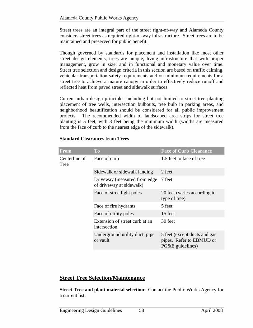
Alameda County Public Works Agency
Engineering Design Guidelines 58 April 2008
Street trees are an integral part of the street right-of-way and Alameda County considers street trees as required right-of-way infrastructure. Street trees are to be maintained and preserved for public benefit. Though governed by standards for placement and installation like most other street design elements, trees are unique, living infrastructure that with proper management, grow in size, and in functional and monetary value over time. Street tree selection and design criteria in this section are based on traffic calming, vehicular transportation safety requirements and on minimum requirements for a street tree to achieve a mature canopy in order to effectively reduce runoff and reflected heat from paved street and sidewalk surfaces. Current urban design principles including but not limited to street tree planting placement of tree wells, intersection bulbouts, tree bulb in parking areas, and neighborhood beautification should be considered for all public improvement projects. The recommended width of landscaped area strips for street tree planting is 5 feet, with 3 feet being the minimum width (widths are measured from the face of curb to the nearest edge of the sidewalk). Standard Clearances from Trees From To Face of Curb ClearanceCenterline of Tree
Face of curb 1.5 feet to face of tree
Sidewalk or sidewalk landing 2 feet Driveway (measured from edge
of driveway at sidewalk) 7 feet
Face of streetlight poles 20 feet (varies according to type of tree)
Face of fire hydrants 5 feet Face of utility poles 15 feet Extension of street curb at an
intersection 30 feet
Underground utility duct, pipe or vault
5 feet (except ducts and gas pipes. Refer to EBMUD or PG&E guidelines)
Street Tree Selection/Maintenance Street Tree and plant material selection: Contact the Public Works Agency for a current list.
Alameda County Public Works Agency
Engineering Design Guidelines 59 April 2008
Installation and maintenance responsibilities: It is the responsibility of the property owner unless otherwise directed by the Board of Supervisors to ensure that the installation and maintenance of grass, plantings and related improvements in planting strips meet public safety and industry standards. Street tree and landscaping improvements required by ordinance must be maintained to meet public standards for the life of the project. Street Tree protection and maintenance: A permit is required for Street Tree Removal or Pruning under Alameda County Tree Ordinance. Removal or pruning of street trees proposed in conjunction with a building permit or subdivision are subject to site development review and, if approved, subject to provisions of the Tree Ordinance as well as inspection by the Alameda County Public Works Agency. Citizen requests for removal or pruning of street trees are subject to review and approval as required by the Tree Ordinance. All permitted work must be completed within 60 working days unless otherwise defined by the permit. Warrantee: All construction, trees, shrubs, and irrigation installed by the Project Contractor and/or subcontractors shall be guaranteed for one (1) full year after the beginning of the maintenance period unless another time period is specified in the Project Specifications approved by the Director of Public Works. The Project Contractor shall replace any and all street improvements, landscape elements, and plant materials that are in an unacceptable condition for the time of use, and any plant material that are not in a vigorous state of growth. The Project Contractor should not be held liable for damage to new construction that is protected according to approved plans and construction documents and the placement of utilities or loss of plant material is due to vandalism, accidental causes, or acts of neglect by others than the Contractor, his or her agents, or employees during the warranty and maintenance period. Planter Strips/Tree Wells Planting strip width: The minimum planting strip width is 3 feet measured between the front of sidewalk and inside edge of the curb. Planting strips serve a number of important functions including:
• Pedestrian safety--they provide a buffer between the sidewalk and roadway;
• Reduction of runoff by providing area for rainfall to infiltrate; • Water quality by infiltrating runoff from sidewalks before it enters the
street; and • Growth and longevity of street trees to allow capture of water.
Planting strip treatments: Plants in planting strips vary greatly in their potential to provide optimum pedestrian and environmental benefits. Lawn areas are permitted but the County encourages the installation of low (24-30 inches) shrubs,
Alameda County Public Works Agency
Engineering Design Guidelines 60 April 2008
perennial or groundcover plantings that provide a superior degree of separation between the sidewalk and street at reduced maintenance costs. Tree wells: Tree wells are typically used as an alternative to planting strips in business districts where additional sidewalk width is important to accommodate pedestrian volumes or in cases of limited ROW. When permitted as an alternative to planting strips, tree wells have a minimum square footage of 16 square feet of open area. Tree Well Grading: Tree wells shall be graded to provide a soil surface 2 inches below the adjacent sidewalk and curb elevation and be top dressed with wood chips or angular aggregate material that is routinely maintained to minimize the grade differential between the sidewalk and open pit area. Street Tree grates: Often proposed as a landscape design element and/or as a means to maximize the pedestrian accessible area in the right-of-way, these grates must be ADA compliant and permitted as approved by the Public Works Agency. Street Furniture & Public Art Street furnishings, public art and other pedestrian and bicycle amenities are important elements that can create a comfortable, safe and attractive public realm. Examples of street furnishings include benches, litter and recycling receptacles, bike racks, multiple publication newsracks, pedestrian scaled lighting and planters. Public art includes art installations that have a functional component and art that is purely aesthetic. The intent of this section is to promote consistency, predictability, safety and design excellence in the type and location of public realm amenities located in the right-of-way. To ensure user comfort/safety the arrangement of elements in the sidewalk area, a landscape/furniture area, shall consider the following: Accessibility consideration: Pedestrians with vision impairments can detect objects mounted on walls or posts if they are installed so that the leading edge is less than 27 inches above the sidewalk. Items mounted above this height should not project more than 4 inches into any circulation route. Particular care should be taken to locate temporary signage so that it does not impede pedestrian travel. Locating objects in the right-of-way: Unique objects in the right-of-way include privately funded public art, commemorative plaques, memorials, bus shelters, special furnishings, directional signage and community bulletin boards. Community Development Agency staff will evaluate applications and serve as the first point of contact for proponents with advice on public art and referral to the Alameda County Art Commission. Any street furniture, public art or other unique objects in the right-of-way requires approval from both the Directors of the Public

Alameda County Public Works Agency
Engineering Design Guidelines 61 April 2008
Works and Community Development Agencies and may be approved as the subject of a site development review or conditional use permit. Special pavement: Used appropriately, special pavement including tile, brick and finish treatments such as exposed aggregate, can increase the quality of the pedestrian environment. Design considerations include ensuring that pavement is durable, slip resistant, and free of trip hazards. Seating: Successful outdoor seating requires thoughtful design and placement. Seating should be designed to encourage appropriate use and be located to maximize user comfort and utility. Consider integrating seating into art installations, softscape or hardscape. Seating should generally face the Pedestrian Area. Benches, Tables and Trash Receptacles: Except as specified in a Streetscape Project Report, benches, tables and trash receptacles must use recycled plastic material and metal frames and shall be surface mounted according to manufacturer’s recommendations. Trash receptacles shall have flat, bolt down tops with metal frames and shall be factory powder coated enamel paint with factory applied graffiti resistant sealant. Alternate benches shall be factory poured concrete benches and tables with anti-skate board devices and anti-graffiti sealant. Public Street Signage: Signs and pole-mounted banners should make a positive contribution to the general appearance of streetscape when facing in that general location. A well-designed sign can be a major asset to a building, open space or street environment. Alameda County encourages imaginative and innovative sign design. Stairways/ramps: Stairways in public right-of-way shall be designed according to Alameda County Public Works Agency standards. Treads shall be 11 inches minimum and 12 inches maximum. Riser height shall be 5 inches minimum and 7 inches maximum. A minimum 5-foot landing shall be provided after each 20 risers. The first riser shall be at least 2 feet clear of the public walk. Pedestrian lighting shall be provided for stairways. Handrails and pedestrian rails: Railings shall be designated as "handrails" or "pedestrian rails" and their usage shall be as determined by the Director of the Public Works Agency. Pedestrian rails may also be designed in accordance with guidelines established by the Director of the Community Development Agency. All handrails and pedestrian rails must comply with guard requirement of the International Building Code (IBC), meaning that they shall have a maximum spacing of 4” for vertical elements of the railing.