subject: network standards standard operating...
TRANSCRIPT

Sumter School District is an equal opportunity employer.
SUBJECT: Network Standards Standard Operating Procedure #1
Date: February, 2017 PREPARED BY: Arpad Jonas Director of Information Systems and Technology
Technology Department
Page 1
APPROVED BY: Information Systems and Technology
Chapter 1 – General Specifications & Material
1. General Network Drop Requirements
Note: TIA/EIA 568B Wiring Standards are the foundation of SSD’s network practices. The following are specific parts and techniques used in conjunction with the TIA/EIA 568B Cabling Standard. We require that installers be BICSI Commercial Installer Level 1 Certified and follow BICSI Telecommunication Cabling Installation Procedures, as well as the TIA/EIA 568B Cabling Standard.
A. Network Data Cable
All cable used for Data Network will be Category 6 Belden, (plenum Datatwist-7882A) (non-plenum Datatwist-7881A).
Unless specifically stated otherwise by SSD, plenum rated cable will be Yellow in color and non-plenum rated cable will be Blue in color.
The Belden Cat 6 cable will be installed under the Belden guidelines for that particular cable. The cable will be in reels of 1000’ minimum when cable is purchased for the project. Subsequent shorter runs on the same project will take advantage of leftover short spools of
cable. Cable must be Plenum rated unless specifically stated otherwise by SSD. Below is the recommended fill chart for Cat 6 BELDEN Datatwist-7882A cables in areas where
conduits are used.
Note: These numbers are only valid for cables with outside diameters of approximately 0.220 inches/Cat 6. The below chart is based on the NEC at a 40% fill ratio.

Sumter School District is an equal opportunity employer.
Conduit Fill Chart for twisted pair copper cabling
Cat 6
Trade Size Number of Cables
¾” 5
1” 9
1-1/4” 15
1-1/2” 21
2” 35
2-1/2” 61
3” 93
3-1/2” 121
4” 155
Table 1 – Conduit Fill Chart
B. Pathways
To avoid electromagnetic interference (EMI), all pathways should provide clearances of at least: 4 feet from large motors or transformers 1 foot from conduit and cables used for electrical power distribution 1 foot from fluorescent lighting Access between hub rooms is typically provided by several 4 to 6 inch conduits with
appropriate sleeves and fire-stop material. Vertical cable pathway is typically provided by conduit in walls for work outlets and to
provide access between telecommunication closets on different floors. In the case of an area that has a false ceiling there should be a conduit stubbed out in the
ceiling for each work area outlet. These conduits should be ¾ inch in diameter, and the work

Sumter School District is an equal opportunity employer.
area outlet should be no further than 10 feet from the electronic equipment they serve. There should be no more than two elbows in a conduit run before an accessible junction box is installed. It is preferred that use of conduit be minimized and is only required to provide access from the work area outlet to some accessible area such as above a false ceiling or similar access point. If an area has a firewall between it and the hallway area there needs to be provisions for penetrating the firewall. All penetrations will be sealed with appropriate material to meet fire safety code requirements.
In cases where the pathway between the closet and the work area outlet is not entirely constructed of conduit it is preferred that the pathway from the closet to where the conduit is provided for each individual work outlet be installed by the owner as part of the cable system.
Current recommendations for overhead cable pathway involve use of J-Hooks and cable support bags suspended from grid wires. We prefer that pathway and cable be installed after the building ceiling infrastructure has been completed but before the ceiling is installed. Since cable pathway of this type has some inherent flexibility it provides the benefit of being able to work around piping, ventilation, and other obstructions that might not have as much location flexibility. This method will more easily allow for available space considerations.
Buildings that have no false ceilings or alternate access methods present special challenges that are probably best addressed on a case-by-case basis. In existing buildings there are wall mounted external raceway or conduit systems that can be used in conjunction with boring techniques to retrofit a usable distribution system.
In a newly constructed building one method is to have conduit installed when the walls are built. These conduits should be ¾ inch in diameter, and the work area outlet should be no further than 10 feet from the electronic equipment they serve. There should be no more than two elbows in a conduit run before an accessible junction box is installed. This method will result in a conduit from each work area outlet back to the telecommunications closet or most convenient accessible location. This method can be modified depending on the availability or lack of special access areas.
Another method in a newly constructed building involves special coordination efforts between the building contractor and the telecommunications installation contractor. This basically involves coordinating the installation of the wiring with the building of the walls and other support structures. While this method can work there are several problems that may arise with this approach that may render some of the wiring plant unusable. Since the wiring is not protected by conduit and is installed before the construction is finished there is opportunity for damage to the cable caused by standard construction techniques. The potential for cable damage combined with the prohibitive cost of cable repair post construction tend to offset the cost of the preferred method of installing a conduit system during construction.

Sumter School District is an equal opportunity employer.
2. Telecommunication Equipment Room Requirements
Note: All installers must be BICSI Commercial Installer Level 1 certified and properly trained to install jacks according to PANDUIT specifications. New installations are wired with Cat 5e/6 unless otherwise specified by SSD.
A. Room Design and Requirements
All telecommunication rooms use designators in accordance with BICSI TDMM Ch. 7 Equipment Rooms and TIA/EIA 568B Procedures and Guidelines.
Where possible, telecommunication rooms shall have direct access to the hallway or other such corridor and should not be shared with other building services, such as Electrical (i.e. electrical distribution panels or transformers) or Mechanical (i.e. air handlers). Supporting codes are found in both BICSI TDMM and the EIA/TIA 568A wiring standard unequivocally against multi-use closets.
Telecommunication rooms shall not contain any type of sink, be used as Custodial supplies storage or be used as general storage areas (books, furniture, etc.).
Floors in telecommunication rooms shall be sealed concrete or tile. Due to the threat of static electricity and resultant potential damage to network distribution equipment, we prefer to avoid carpeted flooring.
Each telecommunication room will have sleeved core holes between floors as requested by SSD.
Empty core holes will be properly fire-stopped, preferably with fire pillows. A minimum space of 10’ X 10’ is required for all single floor telecommunication rooms. A minimum space of 10’ X 15’ is required for all multi-floor telecommunication rooms. At least one long wall of a telecommunication room will be covered from floor to ceiling in ¾”
fire-rated plywood or plywood which is painted with at least two coats of flame retardant white paint.
All telecommunication rooms will be equipped with a grounding bus bar that is tied back to the building’s ground. The grounding conductor will be attached to an approved electrode per NEC 1999 standards, as referenced in TIA 607.
Each telecommunication room will be equipped with a minimum of two (2) 120V-20 amp duplex outlets with independent circuits (with isolated-ground if possible) on the wall where the plywood is mounted.
Note: All installers must be BICSI Commercial Installer Level 1 certified and properly trained to install jacks according to PANDUIT specifications. New installations are wired with Cat 5e/6 unless otherwise specified by SSD.
Sumter School District is an equal opportunity employer.
B. Cat 6 Termination
Standard Data Termination – Blue PANDUIT Brand Cat 6 data jacks P/N CJ688TPBU. Wireless Data Termination – Green PANDUIT Brand Cat 6 data jacks P/N CJ688TPGR. Cameras and AccessCtrl Termination – Red PANDUIT Brand Cat 6 jacks P/N CJ688TPYL.
Note: Cat 6 terminations will use only T568B wiring scheme.
C. UTP Patch Panels / Wall Brackets
Patch Panel - PANDUIT brand 24 port P/N CPP24WBLY or 48 port P/N CPP48WBLY. P/N CPP24WBLY will allow the termination of up to 24 Mini-Com TX style modular jacks. P/N CPP48WBLY will allow the termination of up to 48 Mini-Com TX style modular jacks. Wall Mount Bracket – PANDUIT Brand P/N WBH2 (2 space) or P/N WBH4 (4 space) bracket.
D. Patch Panel Jack Labels
Labels follow practices set forth in ANSI/TIA/EIA – 606A ADMINSTRATION.
The contractor will generate labels for both the Office/Classroom and telecommunication rooms according to the following criteria: The Mini-Com jack label is PANDUIT Brand White label (P/N C138X019FJJ). The font for this
label is an Arial 10 point (5-2-2 for TC 5 Patch Panel 2 Port22.). Use smaller fonts to fit longer circuit ID numbers.
Jack labels will be wrapped around the jacks properly.
Note: Installers will not cut or tear ends off and stick jack labels on while they are snapped in the panel or faceplate. These labels must be installed centered, then wrapped around the jack. Failure to properly install these labels will be repaired by the contractor who will provide replacement labels.
Each end of the Cat 6 cable will be labeled at approximately 3 to 6 inches from the network data jack with a PANDUIT Brand clear cable label (P/N S100X125YAJ) using Arial 12 point font.

Sumter School District is an equal opportunity employer.
E. Wire Management
Vertical Wire Management – Black PANDUIT Brand P/N WMPV45E shall be used.
Horizontal Wire Management - Black PANDUIT Brand P/N WMPSEY and P/N WMP1EY is used where single or double spaced, double-sided management is required. The back wire management ensures proper bend radius compliance. For cables coming from the Office/Classroom, the front side is used to manage patch cords from the horizontal cabling to the Network Equipment.
Horizontal Wire Management – Black PANDUIT Brand P/N WMPFSEY and P/N WMPF1EY is used where single or double spaced, front only management is required. This is primarily used to manage patch cords connecting to the network distribution equipment.
Cable Runway - Black CHATSWORTH Brand P/N 10250-712 ladder-style cable raceway shall be used.
End Caps – Black CHATSWORTH Brand P/N 10642-001 end caps should be used on all exposed ends of the ladder-style cable raceway. All ends shall be filed down to remove any sharp edges before caps are installed.
Metal Rack and raceway mounting hardware shall all be CHATSWORTH Brand fittings. Velcro straps are preferred to plastic tie straps in Telecommunication rooms wherever practical
when securing cabling to cable runway. Velcro should be of sufficient length to wrap around cable bundle twice to accommodate future expansion.
Tie straps used to dress cable will not be over tightened. Tie straps that deform the outer cable jacket and that can’t be slid easily along the length of the cable bundle are too tight.
Tie straps used in plenum airways must be plenum rated.
F. Transition Between Floors
When cables come off a 7 ft. rack and over a ladder way and are ran down vertically, they must be properly secured to the vertical section of ladder rack covering the entire vertical span of the run. Use a rounded transition fitting (water-fall, slide) bracket to ensure proper cable management and bend radius.
Also cables going through risers between floors must be properly supported for their weight, especially
for high pair-count telephone feeder cables and large cable bundles. ERICO Brand P/N #CAT600WM
wall mount support or #CAT600R strut mount support is required. Proper transition between floors.
Bundles are correctly secured to vertical ladder sections by cable ties or Velcro straps. Proper use of

Sumter School District is an equal opportunity employer.
waterfall (rounded transition) fittings for cable changing from a horizontal path to a vertical one. This
maintains the minimum bend radius for Cat 6 cable.
When pulling a cable in conduits between floors, replace the pull string or rope for future use and properly fire-stop the conduits.
Patch Cord Colors in Telecommunication Rooms
Standard Hub Rooms: use Blue patch cords for new installations. For existing installations, match the color currently in use in the telecommunication room.
Special Cases: SSD may request that patch cords of differing colors be used to denote special areas (differing labs, differing floors, servers, etc.)
The following special considerations are in place: Green Red Orange Blue
Trunk connections between Switches, use Orange patch cords. Surveillance and access control, use Red patch cords for connections between patch panels
and switches. Wireless access points, use Green patch cords for connections between patch panels and
switches. Standard Access ports (Computers/Printers), , use Blue patch cords for connections between
patch panels and switches.
Chapter 3 - Fiber Optic Cable Requirements
Note: The TIA/EIA 568A wiring standards are the foundation of SSD’s Network installation requirements. The following are specific parts and techniques used in cooperation with the TIA/EIA 568A cabling standard, including the changes introduced by TIA/EIA TSB-72.
Caution Remember that fiber optic systems can employ the use of lasers. Never look directly into the end of a fiber system under power. Take all recommended safety precautions for the installation and testing of fiber optic systems, including the proper disposal of all fiber shards and related debris.
1. Fiber Optic Cable Construction
The standard fiber optic cable for SSD is Corning. The SSD Network representative must approve substitutes.
The installation of an outside plant (OSP) cable will have each buffer tube of separate color, following the standard order for fiber colors as set forth in TIA/EIA 568A. The first set of buffer

Sumter School District is an equal opportunity employer.
tubes will contain the Single Mode fibers and the last set of buffer tubes will contain the Multi-Mode fibers.
Multi-Mode fiber shall be 50 x 125 micron FDDI grade, <2.3 dB/km @ 850 nm 0.6 dB/km @ 1300 nm
Single-Mode fiber shall be 9.0 x 125 micron, 0.35 dB/km @1310 nm 0.25 dB/km @1550 nm
Note: Only 10G fiber is supported at SSD. Fiber must meet specifications published by Corning..
A. Fiber Optic Outside Plant Cable
The only SSD acceptable manufacturer of fiber optic cable is Corning. The OSP cable will be of a loose tube type with each tube having an outside diameter of 3.0 mm. Each buffer tube will be filled with water blocking gel or dryblock. The cable will be flooded with a water blocking gel or use a water-swelling compound system. The cable will have a polyethylene outer jacket. Multi-mode will be 50/125 m graded index and at least FDDI grade fiber. Single-mode will be 9.0/125 m fiber. Also, all outside plant (OSP) fiber cable will be armored. The cable will come with at least one rip cord, preferably two rip cords. The cable will have an operating range of –40 to 70 degrees Celsius.
Note: The newer water swelling tape or powder cables can be used if they can properly demonstrate at least the same amount of water protection provided by traditional gel filled OSP cables
B. Exclusions: Fiber Optic Cable Specifications Not Allowed At SSD
Central tube construction is not used at SSD. 62.5/125um multi-mode fiber is not used at SSD. C. Indoor Fiber Optic Cable
The standard for SSD is Corning. SSD Network personnel must approve substitutes. Fiber cable will be PLENUM rated unless otherwise noted by SSD Network personnel. Each separate fiber will be 900m tight-buffered 250m fiber. Multi-mode will be 50/125 m graded index and at least FDDI grade fiber.
Single-mode will be 9125 m fiber. Must come with at least one ripcord. No inner-duct required if using MIC interlocking armored plenum cables.
D. Standard Fiber Optic Cable Strand Counts
FOUR basic fiber strand count cables are used at SSD. They are: CORNING six (6) fiber Multi-Mode plenum rated CORNING Twelve (12) Single-Mode/twelve (12) Multi-Mode Plenum Rated Fiber CORNING Twelve (12) Single-Mode/eighteen (18) Multi-Mode OSP Rated Fiber
Sumter School District is an equal opportunity employer.
CORNING Twelve (12) Single-Mode/twenty-four (24) Multi-Mode OSP Rated Fiber
2. Fiber Optic Cable Wall Mount Enclosures
The standard for SSD Wall Mount Fiber Enclosure is Corning. Inner-duct will connect the Slack Enclosure to the Wall-Mount Fiber Box in installations where a Wall-Mount Fiber Box is required.
Wall Mount Fiber Enclosures used at SSD are: 2 slot - Corning P/N WCH-02P enclosure 4 slot - Corning P/N WCH-04P enclosure 6 slot - Corning P/N WCH-06P enclosure 12 slot - Corning P/N WCH-12P enclosure
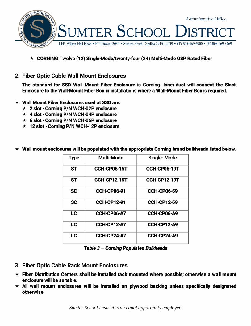
Wall mount enclosures will be populated with the appropriate Corning brand bulkheads listed below.
Type Multi-Mode Single- Mode
ST CCH-CP06-15T CCH-CP06-19T
ST CCH-CP12-15T CCH-CP12-19T
SC CCH-CP06-91 CCH-CP06-59
SC CCH-CP12-91 CCH-CP12-59
LC CCH-CP06-A7 CCH-CP06-A9
LC CCH-CP12-A7 CCH-CP12-A9
LC CCH-CP24-A7 CCH-CP24-A9
Table 3 – Corning Populated Bulkheads
3. Fiber Optic Cable Rack Mount Enclosures
Fiber Distribution Centers shall be installed rack mounted where possible; otherwise a wall mount enclosure will be suitable.
All wall mount enclosures will be installed on plywood backing unless specifically designated otherwise.

Sumter School District is an equal opportunity employer.
For each cable in an enclosure the Single Mode bulkheads are installed first from left to right followed by the Multi-Mode bulkheads. In situations where there are multiple cables, the next set of Single Mode bulkheads go in after the preceding cables Multi-Mode bulkheads.
Be sure to properly secure the fiberglass center member to the designed anchor points inside the enclosures according to the products design.
Rack Mount Fiber Enclosures used at SSD are: 2 slot - Corning P/N CCH-01U enclosure 4 slot - Corning P/N CCH-02U enclosure 6 slot - Corning P/N CCH-03U enclosure 12 slot - Corning P/N CCH-04U enclosure
Rack mount enclosures will be populated with the appropriate Corning bulkheads. Refer above to Table 3 – Corning Populated Bulkheads listed on page 3-3.
4. Fiber Optic Cable Slack Enclosures
A Fiber slack enclosure will be mounted above the wall-mount fiber boxes or on the wall near the rack-mount fiber enclosures to protect the minimum required amount of slack (25-50 ft.) at each end. There will be no exceptions to this minimum fiber slack length. Be sure to properly secure the fiberglass center member to the enclosures designed anchor points according to products design.
5. Fiber Optic Cable Splices and Splice Enclosures
A. Fiber Optic Cable Splices
CORNING CamSplice mechanical splices (P/N 95-000-04), require Splice Trays (P/N M67-031, M67-053, M67-061, M67-070, UST-024) with Closet Splice Housing (CSH) or Closet Connector and Splice Housing (CCS) B. Fiber Optic Cable Splice Enclosure
The specific CORNING Splice Enclosure will be determined by SSD on a case by case basis.
Note: Mechanical Splices will only be allowed if express permission is given by SSD. Otherwise, the use of mechanical splices is prohibited.
6. Fiber Optic Cable Connectors
CORNING brand (P/N 95-101-41) for Multi-Mode terminations for SC connections CORNING brand (P/N 95-201-41-SP) for Single-Mode terminations for SC connections CORNING brand (P/N 95-101-51) for Multi-Mode terminations for ST connections CORNING brand (P/N 95-201-51) for Single-Mode terminations for ST connections CORNING brand (P/N 95-101-98) for Multi-Mode terminations for LC connections CORNING brand (P/N 95-201-98) for Single-Mode terminations for LC connections

Sumter School District is an equal opportunity employer.
Note: These connectors will be polished according to the guidelines outlined by CORNING for polishing. The end will have a mirror finish and the raw pedestal tip will be completely polished away.
7. Fiber Optic Cable - Terminating Connectors
Fiber shall be terminated by or under close supervision of a certified Fiber Optic Installer. The preferred certification is the CORNING S-07 or S-07+. Proof will be required upon request.
Fiber shall be terminated with SC style connectors unless otherwise specified. All loose buffer tube gel filled cables will have CORNING Brand fan-out kits installed
(P/N FAN-OD25-12) (No Substitutions). A fan out kit will always be used, never install fiber terminators directly onto the loose tube fiber.
Failure to comply will be corrected at the contractor’s expense. All armored fiber optic cables will have grounding kits (Corning brand P/N FDC-CABLE-GRND
Armored Cable Grounding Kit) installed at both ends and be properly grounded in the telecommunication rooms per the TIA/EIA 607 Grounding and Bonding procedures. Also these cables will be grounded per the guidelines set forth in Article 250 Grounding and Article 770-33 Fiber Optic Building Entrance Point Grounding located in the 1999 edition of the National Electric Code (NEC). Also refer to page 4-1, Chapter 4 - Grounding of this document for further information.
8. Fiber Optic Cable - Labeling
Labeling on cabinets shall be accomplished by a P-touch (Brother labeler) or similar machine. Use black on white tape. Labels shall identify the far end location, each bulkhead shall be individually lettered A, B, C, D, etc. Labels shall also include the Building and Strand count (refer to Diagram 6, page 35). A plastic self laminating 2” X 3.5” tag (PANDUIT Brand P/N PST-FO) with the legend “CAUTION
FIBER OPTIC CABLE” will also be placed approximately 2 feet from each end of the fiber cable, outside of the fiber termination box. The proper fiber information (end location to end location and fiber strand count) will be written on the tag with a permanent marker.
9. Fiber Optic Cable – Testing and Documentation Every fiber shall be tested and documented. Every fiber shall be tested with a light source tester; OTDR testing may be required at the SSD
Network personnel’s discretion. Testing with either a light source meter or an OTDR shall be done in both directions.

Sumter School District is an equal opportunity employer.

Sumter School District is an equal opportunity employer.
Locations of any mechanical or fusion splice should be noted in the OTDR information. Light meter tests for Multi-mode will be Dual wavelength (850nm, 1300nm). Light meter tests for Single mode will be Dual wavelength (1310nm, 1550nm). All tests should be received by SSD in both a hard copy and electronic version of the file. All information should be delivered to the SSD Information Systems and Technology department in
an accurate and timely manner. A general rule of thumb for acceptable losses are 0.5db for a multimode termination, 0.3db for a
single mode termination and 0.1db for each splice. However, please see below, paragraph 9.A. Fiber System Loss Budget Calculation as to the preferred method of calculating an acceptable db loss for a circuit.
A. Fiber Optic Cable - System Loss Budget Calculation
Acceptable Fiber Attenuations: Wave Length 850nm 3.50db/km Wave Length 1300nm 1.00db/km Wave Length 1310nm 0.40db/km Wave Length 1550nm 0.30db/km
Acceptable Connector Attenuation: .................................................................................................. .......................................................................................................................... 0.75db/connector link
Acceptable Splice Attenuation: .......................................................................................................... ......................................................................................................................................... 0.10db/splice
Formula for calculation: (Cable Footage * Fiber Attenuation / 3281 ft) + (# of connector pairs * 0.75db) +
(# of splices * 0.10db) Cable Footage is the actual length of the fiber run in feet. Fiber Attenuation / 3281 ft is the Acceptable Fiber Attenuation reference for the wavelength
being tested divided by 3281 to convert the measurement from kilometers to feet. # of connector pairs indicate the number of patch panel connection points. This will be 2
unless the strand of fiber contains multiple hops. # of splices indicate the number of splices of any type, if any, in the fiber path
Example Calculation: The job calls for a fiber optic run of 3000 ft. We wish to test it at the 850nm wavelength. This is a single hop test, so there are only 2 connection points, one at either end of the run. There are no splices in the fiber run.
Sumter School District is an equal opportunity employer.
The acceptable db loss for this test would be 4.70db. The calculation would be:
= (3000ft * 3.5db / 3281ft) + (2 [connector pair at either end] * 0.75db) + (0 [no splices] * 0.10db)
= (3.20db) + (1.50db) + (0db) = 4.70db
Result If the fiber optic cable installation in this instance is over 4.70db loss when testing at 850nm
wavelength, the cable installation does not meet SSD minimum standards. Whatever is required to bring the test results up to SSD minimum standards is at the contractor’s expense.
10. Fiber Optic Cable - Splicing Procedures
Only qualified technicians using the proper tools and products rated for the job will perform fiber optic cable splicing at SSD. All splices will be properly tested and documented, noting the point of the splice in all documentation. Technicians will supply all the equipment required to professionally and properly complete the splicing work. On a composite cable, containing both multi-mode and single mode fiber, the contractor will
provide the proper test equipment to completely test both types of fiber. This test equipment will be on-site ready for use as soon as the splice has been completed. When finished with the splicing work the technician will test the impacted fiber according to the
listed documentation and test requirements listed in paragraph 10.B. for standard fiber testing at SSD.
Test results will be provided to the SSD Information Systems and Technology department in both a hard copy and electronic version.
Caution Remember that fiber optic systems can employ the use of lasers. Never look directly into the end of a fiber system under power. Take all recommended safety precautions for the installation and testing of fiber optic systems, including the proper disposal of all fiber shards and related debris.

Sumter School District is an equal opportunity employer.
A. Fiber Optic Cable - Outside Plant Splice Enclosures
Outside Plant fiber splice enclosures will be watertight and properly installed to ensure that the product remains watertight.
Spliced fiber will be properly secured in splice trays to ensure reliable operation. The remaining slack fiber cable from OSP pull vaults will be properly coiled and replaced into
vault. Any grounding system disconnected or cut during the course of splicing will be repaired and
reconnected. This includes where the metal foil of an armored cable has been cut apart to perform the required splice. It must be restored with its original grounded state. If a cable was not properly grounded to start with, the contractor should bring this immediately to the SSD Network Representative or said contractor WILL be held responsible for its repair.
B. Fiber Optic Cable - Testing and Required Documentation for Splices
The requirements for testing and documenting the fiber splices are the same as those found on page describing Fiber Optic Testing and Documentation
Chapter 5 – Safety
1. General Safety Practices
The Contractor shall conform to all applicable Federal, State and Local Regulations and/or standards pertaining to worker safety; including OSHA standards.
All workers will use proper safety in performing their installation tasks, i.e., wearing safety glasses around eye hazards, ladder safety, wearing dust masks under dusty conditions, etc. Contractor injuries should be reported to their supervisors immediately.
Workers will wear approved safety harnesses when working at dangerous heights in accordance with the fall protection guidelines defined by the OSHA standards.
All fire or accidents will be reported to the SSD Information Technology Department immediately at (803) 983-1887.
To prevent accidents and fire hazards; all construction debris will be cleaned up nightly. The Contractor will dispose of all large empty spools of fiber and/or inner-duct in a timely manner
(within a week after the job has been completed). Spools blocking hallways or doors are a fire hazard and are not permitted. They must be removed immediately.
Sumter School District is an equal opportunity employer.
2. Fire-stopping
All penetrations into fire-walls or core holes between floor must be properly fire-stopped in accordance with the guidelines in BICSI TDM and must also conform to any related NEC requirements for Fire-stopping.
Penetrations in fire rated walls shall be sleeved with the appropriate sized “Unique Fire Stop Products” penetrator. (P/N SP-1, SP-2, SP-4) Exceptions at SSD’s discretion on a case by case basis.
Proper Fire-stopping should be performed on any hole and/or penetration of a firewall or solid wall. This may include the Contractor installing Mineral Wool in the space between the sheet rock wall and then installing a sheet rock patch on both sides before installing the Fire-Stopping Material.
Fire-stop any transitions between floor using or not using conduit or sleeve. When using Fire-stopping Putty in a conduit or sleeves between floors a section of Fire-resistant Mineral Wool must be inserted to create the proper base for the putty. Making a form out of cardboard is not acceptable. Fire-stopping pillows are also acceptable to seal an opening that may need to be reentered at a later time.
5. Relevant Information Systems and Technology Phone Numbers
SSD Network Services
Reggie James (Network Manager) .............................................................................. 803) 968-5260
SSD Server Administration
Ovidiu Savulescu (Server Administrator) .................................................................... (803) 968-4211
SSD Technology Assistants
Kelly Brian ................................................................................................................... (803) 607-0949
Chauntae Scott (Projects/Erate) ............................................................................ (803) 607-0058
SSD Director of Information Systems and Technology
Arpad Jonas (Director of Information Systems and Technology) ........................ (803) 983-1887

Sumter School District is an equal opportunity employer.