subject: transport airplane date: ac no: 25-17a cabin interiors
TRANSCRIPT

Subject: TRANSPORT AIRPLANE CABIN INTERIORS CRASHWORTHINESS HANDBOOK
Date: 05/18/09 Initiated By: ANM-110
AC No: 25-17A Change:
l. PURPOSE. This Advisory Circular (AC) provides acceptable certification methods, but not necessarily the only acceptable methods, for demonstrating compliance with the crashworthiness requirements of part 25, as amended through Amendment 25-112, of Title 14 of the Code of Federal Regulations (14 CFR) for transport category airplanes. The guidance in this AC is not mandatory nor a regulation. 2. APPLICABILITY.
a. Available guidance pertaining to part 25 is presented according to the amendment level of part 25 to which it applies. For modified airplanes certificated under part 25, the pertinent guidance may be obtained from this AC by reference to the applicable amendment level. (Compliance with later rules may be required in accordance with §§ 21.101(a) and 25.2, or with applicable operating rules as noted above.) Additional guidance may be included in this AC that pertains to either prior amendments or sections that have not been modified. This guidance has been developed to address issues that either have developed since the original issue of this AC, or were inadvertently omitted. The guidance presented in this AC for part 25 airplanes may be used for airplanes certificated under CAR 4b to the extent the rules contained in the older certification bases are the same as those of part 25. The guidance presented herein applies to part 25 through Amendment 25-112.
b. The guidance provided in this document is directed to airplane manufacturers, modifiers, foreign regulatory authorities, and FAA transport airplane type certification engineers, and their designees.
c. This material is neither mandatory nor regulatory in nature and does not constitute a regulation. It describes acceptable means, but not the only means, for demonstrating compliance with the applicable regulations. The FAA will consider other methods of demonstrating compliance that an applicant may elect to present. While these guidelines are not mandatory, they are derived from extensive FAA and industry experience in determining compliance with the relevant regulations. On the other hand, if we become aware of circumstances that convince us that following this AC would not result in compliance with the applicable regulations, we will

05/18/09 AC 25-17A
ii
not be bound by the terms of this AC, and we may require additional substantiation or design changes as a basis for finding compliance.
d. This material does not change, create any additional, authorize changes in, or permit deviations from, regulatory requirements. 3. CANCELLATION. ADVISORY CIRCULAR 25-17, Transport Airplane Cabin Interiors Crashworthiness Handbook, dated July 15, 1991, is canceled. 4. BACKGROUND. a. Crashworthiness, as applied to airplane cabin interiors, denotes the incorporation in basic design of considerations pertinent to the protection of airplane occupants in a “survivable crash environment.” A survivable crash environment prevails when the cabin occupants are subjected to crash forces within human tolerance levels, and the structural integrity of the passenger space remains intact such that the occupants can rapidly evacuate the airplane. Structural design for airplane safety has embodied airworthiness and crashworthiness design objectives to varying degrees. Airworthiness design objectives pertain to the ability of the airframe to withstand design loads, or to maintain safety of flight of the airplane relative to the operational environment. Crashworthiness design objectives pertain to safety of the occupants relative to the airplane. Some aspects of crashworthiness, e.g., fuel tank/system design, fuselage deformation and prevention of post-crash fires, are beyond the scope of this AC. b. Since the inception of federal civil aircraft certification standards, prime emphasis has focused on design for airworthiness, with a preference for application of static load tests, as opposed to dynamic. The emphasis on airworthiness is understandable, since structural and handling deficiencies were inherent in early airplane designs. Further, there was not enough theoretical or technical knowledge available from service experience to generate meaningful design parameters for crash survival. Likewise, in early design, as now, dynamic criteria have been difficult to ascertain. Except for standards for seat belts, seat static load requirements, and exits, crashworthiness was given very little attention until the post-World War II period. During subsequent years, the regulatory process expanded emphasis on crashworthiness. A significant change occurred in 1967, when the Federal Aviation Administration (FAA) promulgated a series of crashworthiness standards affecting transport category airplanes. Further changes were implemented in 1972. As reflected in the rule changes of 1967, the FAA's approach to crashworthiness principally involved three areas of concern: (1) protection of airplane occupants from crash impact; (2) minimizing development and severity of potential crash fire; and (3) rapid evacuation of airplane occupants. Each of these factors has been a focal point in the periodic upgrading of regulatory standards. c. Part 4b of the former Civil Air Regulations (CAR) was recodified in 1965 as part 25 of 14CFR. The related policy material contained in Civil Aeronautics Manual (CAM) 4b was applicable to part 25 as originally recodified and to current part 25 except in areas that have been amended since recodification. Those policies are included in this AC and listed as guidance applicable to the original recodified version of part 25.

05/18/09 AC 25-17A
iii
d. This AC consists of the original part 25 of 14 CFR (1965 recodified version), followed by appropriate guidance. Amendments to the regulation are presented in chronological order, with those paragraphs changed by the amendment enclosed within [ ] . The complete regulation text is provided for each amendment. If guidance exists for an amended rule, it is presented following the regulation paragraphs. Guidance from previous amendments to the rule are reprinted for each applicable amendment of the regulation. At the end of the guidance paragraph within ( ) is the amendment level when the guidance was first applicable. e. Certain changes may require compliance with rules later than the type certification basis. For example: (1) § 21.101 the change product rule – helps determine when amended and supplemental type certification products need to utilize later amendment levels for areas of change. (2) § 25.2 special retroactive requirements – requires, in part, that applicants for amended or supplemental type certification projects need to utilize amendment levels which may be later than those in the type certification basis of the airplane when the projects will result in an increase in the maximum seating capacity of the airplanes. (3) Operating rules §§ 91.58, 121.310, 121.311, 121.312, 121.317, 121.318, 121.319, 125.113, 135.170, and Appendix A of part 135 of the CFR – require, in some cases, that airplanes operating under these parts have materials or equipment installed which are in excess of the type certification basis of the airplanes. f. Advisory circulars listed in Appendix 3 may be revised after issuance of this AC. The latest available revision of the listed AC should be used. /s/ Ali Bahrami Ali Bahrami Manager, Transport Airplane Directorate Aircraft Certification Service,

05/18/09 AC 25-17A
iv
TABLE OF CONTENTS Paragraph Page 1 - 10. [RESERVED] SECTION 25.561 EMERGENCY LANDING CONDITIONS
GENERAL
11. Regulation in Effect at Adoption of Part 25. 1 12. Amendment 25-23, Effective May 8, 1970. 2 13. Amendment 25-64, Effective June 16, 1988. 3 14. Amendment 25-91, Effective July 29, 1997. 4 15 – 20. [RESERVED] SECTION 25.562 EMERGENCY LANDING DYNAMIC
CONDITIONS
21. Section 25.562 Did Not Exist Prior to Amendment 25-64. 7 22. Amendment 25-64, Effective June 16, 1988. 7 23 – 40. [RESERVED] SECTION 25.772 PILOT COMPARTMENT DOORS 41. Section 25.772 Did Not Exist Prior to Amendment 25-33. 13 42. Amendment 25-33, Effective October 21, 1972. 13 43. Amendment 25-47, Effective December 24, 1979. 13 44. Amendment 25-72, Effective August 20, 1990. 15 45. Amendment 25-106, Effective January 15, 2002. 16 46 - 60. [RESERVED] SECTION 25.783 DOORS 61. Regulation in Effect at Adoption of Part 25. 19 62. Amendment 25-15, Effective October 24, 1967. 22 63. Amendment 25-23, Effective May 8, 1970. 25 64. Amendment 25-54, Effective October 14, 1980. 28 65. Amendment 25-72, Effective August 20, 1990. 32 66. Amendment 25-88, Effective December 9, 1996. 36 67 - 80. [RESERVED] SECTION 25.785 SEATS, BERTHS, SAFETY BELTS, AND
HARNESSES
81. Regulation in Effect at Adoption of Part 25. 41 82. Amendment 25-15, Effective October 24, 1967. 53

05/18/09 AC 25-17A
v
83. Amendment 25-20, Effective April 23, 1969. 66 84. Amendment 25-32, Effective May 1, 1972. 79 85. Amendment 25-51, Effective March 6, 1980. 92 86. Amendment 25-64, Effective June 16, 1988. 106 87. Amendment 25-72, Effective August 20, 1990. 120 88. Amendment 25-88, Effective December 9, 1996. 134 89 - 100. [RESERVED] SECTION 25.787 STOWAGE COMPARTMENTS 101. Regulation in Effect at Adoption of Part 25. 149 102. Amendment 25-32, Effective May 1, 1972. 149 103. Amendment 25-38, Effective February 1, 1977. 152 104. Amendment 25-51, Effective March 6, 1980. 155 105 - 120. [RESERVED] SECTION 25.789 RETENTION OF ITEMS OF MASS 121. Section 25.789 Did Not Exist Prior to Amendment 25-32. 159 122. Amendment 25-32, Effective May 1, 1972. 159 123. Amendment 25-46, Effective December 1, 1978. 159 124 - 140. [RESERVED] SECTION 25.791 PASSENGER INFORMATION SIGNS 141. Section 25.791 Did Not Exist Prior to Amendment 25-32. 161 142. Amendment 25-32, Effective May 1, 1972. 161 143. Amendment 25-72, Effective August 20, 1990. 162 144 - 160. [RESERVED] SECTION 25.793 FLOOR SURFACES 161. Section 25.793 Did Not Exist Prior to Amendment 25-51. 165 162. Amendment 25-51, Effective March 6, 1980. 165 163 - 210. [RESERVED] SECTION 25.795 SECURITY CONSIDERATIONS 211. Section 25.795 Did Not Exist Prior to Amendment 25-106. 167 212. Amendment 25-106, Effective January 15, 2002. 167 213 - 250. [RESERVED]

05/18/09 AC 25-17A
vi
SECTION 25.801 DITCHING 251. Regulation in Effect at Adoption of Part 25. 169 252. Amendment 25-72, Effective August 20, 1990. 171 253 - 270. [RESERVED] SECTION 25.803 EMERGENCY EVACUATION 271. Regulation in Effect at Adoption of Part 25. 175 272. Amendment 25-1, Effective June 7, 1965. 175 273. Amendment 25-15, Effective October 24, 1967. 176 274. Amendment 25-17, Effective June 20, 1968. 180 275. Amendment 25-20, Effective April 23, 1969. 185 276. Amendment 25-32, Effective May 1, 1972. 190 277. Amendment 25-46, Effective December 1, 1978. 195 278. Amendment 25-72, Effective August 20, 1990. 201 279 - 300. [RESERVED] SECTION 25.805 FLIGHT CREW EMERGENCY EXITS 301. Regulation in Effect at Adoption of Part 25. 205 302. Removed at Amendment 25-72, Effective August 20, 1990. 205 303 - 320. [RESERVED] SECTION 25.807 PASSENGER EMERGENCY EXITS 321. Regulation in Effect at Adoption of Part 25. 207 322. Amendment 25-15, Effective October 24, 1967. 211 323. Amendment 25-32, Effective May 1, 1972. 219 324. Amendment 25-39, Effective February 10, 1977. 228 325. Amendment 25-46, Effective February 11, 1978. 236 326. Amendment 25-55, Effective April 28, 1982. 245 327. Amendment 25-67, Effective July 24, 1989. 254 328. Amendment 25-72, Effective August 20, 1990. 263 329. Amendment 25-88, Effective December 9, 1996. 270 330. Amendment 25-94, Effective March 25, 1998. 277 331 - 350. [RESERVED] SECTION 25.809 EMERGENCY EXIT ARRANGEMENT 351. Regulation in Effect at Adoption of Part 25. 285 352. Amendment 25-1, Effective June 7, 1965. 287 353. Amendment 25-9, Effective June 30, 1966. 290 354. Amendment 25-15, Effective October 24, 1967. 292 355. Amendment 25-32, Effective May 1, 1972. 296

05/18/09 AC 25-17A
vii
356. Amendment 25-34, Effective December 31, 1972. 301 357. Amendment 25-46, Effective December 1, 1978. 306 358. Amendment 25-47, Effective December 24, 1979. 312 359. Amendment 25-72, Effective August 20, 1990. 318 360 - 370. [RESERVED] SECTION 25.810 EMERGENCY EGRESS ASSIST MEANS
AND ESCAPE ROUTES
371. Section 25.810 Did Not Exist Prior to Amendment 25-72. 321 372. Amendment 25-72, Effective August 20, 1990. 321 373. Amendment 25-88, Effective December 9, 1996. 326 374 - 380. [RESERVED] SECTION 25.811 EMERGENCY EXIT MARKING 381. Regulation in Effect at Adoption of Part 25. 333 382. Amendment 25-1, Effective June 7, 1965. 334 383. Amendment 25-15, Effective October 24, 1967. 339 384. Amendment 25-32, Effective May 1, 1972. 344 385. Amendment 25-46, Effective December 1, 1978. 349 386. Amendment 25-79, Effective September 27, 1993. 355 387. Amendment 25-88, Effective December 9, 1996. 360 388 - 390. [RESERVED] SECTION 25.812 EMERGENCY LIGHTING 391. Section 25.812 Did Not Exist Prior to Amendment 25-15. 365 392. Amendment 25-15, Effective October 24, 1967. 365 393. Amendment 25-28, Effective September 25, 1971. 369 394. Amendment 25-32, Effective May 1, 1972. 373 395. Amendment 25-46, Effective December 1, 1978. 378 396. Amendment 25-58, Effective November 26, 1984. 383 397. Amendment 25-88, Effective December 9, 1996. 389 398 - 410. [RESERVED] SECTION 25.813 EMERGENCY EXIT ACCESS 411. Regulation in Effect at Adoption of Part 25. 397 412. Amendment 25-1, Effective June 7, 1965. 403 413. Amendment 25-15, Effective October 24, 1967. 409 414. Amendment 25-17, Effective June 20, 1968. 417 415. Amendment 25-32, Effective May 1, 1972. 424 416. Amendment 25-46, Effective December 1, 1978. 432 417. Amendment 25-72, Effective August 20, 1990. 440 418. Amendment 25-76, Effective June 3, 1992. 450
05/18/09 AC 25-17A
viii
419. Amendment 25-88, Effective December 9, 1996. 461 420 - 440. [RESERVED] SECTION 25.815 WIDTH OF MAIN AISLE 441. Regulation in Effect at Adoption of Part 25. 473 442. Amendment 25-15, Effective October 24, 1967. 474 443. Amendment 25-38, Effective February 1, 1977. 476 444 - 460. [RESERVED] SECTION 25.817 MAXIMUM NUMBER OF SEATS
ABREAST
461. Section 25.817 Did Not Exist Prior to Amendment 25-15. 479 462. Amendment 25-15, Effective October 24, 1967. 479 463 - 480. [RESERVED] SECTION 25.819 LOWER DECK SERVICE
COMPARTMENTS (INCLUDING GALLEYS)
481. Section 25.819 Did Not Exist Prior to Amendment 25-53. 481 482. Amendment 25-53, Effective August 31, 1980. 481 483. Amendment 25-110, Effective July 21, 2003. 483 484 - 600. [RESERVED] SECTION 25.851 FIRE EXTINGUISHERS 601. Regulation in Effect at Adoption of Part 25. 487 602. Amendment 25-54, Effective October 14, 1980. 490 603. Amendment 25-72, Effective August 20, 1990. 493 604. Amendment 25-74, Effective May 16, 1991. 497 605 - 620. [RESERVED] SECTION 25.853 COMPARTMENT INTERIORS 621. Regulation in Effect at Adoption of Part 25. 503 622. Amendment 25-15, Effective October 24, 1967. 508 623. Amendment 25-17, Effective June 20, 1968. 511 624. Amendment 25-23, Effective May 8, 1970. 515 625. Amendment 25-32, Effective May 1, 1972. 519 626. Amendment 25-51, Effective March 6, 1980. 523 627. Amendment 25-59, Effective November 26, 1984. 528 628. Amendment 25-60, Effective June 16, 1986. 532 629. Amendment 25-61, Effective August 20, 1986. 537 630. Amendment 25-66, Effective September 26, 1988. 542 631. Amendment 25-72, Effective August 20, 1990. 548

05/18/09 AC 25-17A
ix
632. Amendment 25-83, Effective March 6, 1995. 552 633 - 640. [RESERVED] SECTION 25.854 LAVATORY FIRE PROTECTION 641. Section 25.854 Did Not Exist Prior to Amendment 25-74. 557 642. Amendment 25-74, Effective May 16, 1991. 557 643 - 650. [RESERVED] SECTION 25.855 CARGO AND BAGGAGE
COMPARTMENTS
651. Regulation in Effect at Adoption of Part 25. 559 652. Amendment 25-15, Effective October 24, 1967. 560 653. Amendment 25-32, Effective May 1, 1972. 561 654. Amendment 25-60, Effective June 16, 1986. 563 655. Amendment 25-72, Effective August 20, 1990. 565 656. Amendment 25-93, Effective March 19, 1998. 567 657 - 660. [RESERVED] SECTION 25.856 THERMAL/ACOUSTIC INSULATION
MATERIALS
661. Section 25.856 Did Not Exist Prior to Amendment 25-111. 571 662. Amendment 25-111, Effective September 2, 2003. 571 663 - 670. [RESERVED] SECTION 25.857 CARGO COMPARTMENT
CLASSIFICATION
671. Regulation in Effect at Adoption of Part 25. 573 672. Amendment 25-32, Effective May 1, 1972. 576 673. Amendment 25-60, Effective June 16, 1986. 580 674. Amendment 25-93, Effective March 19, 1998. 585 675 - 730. [RESERVED] SECTION 25.869 FIRE PROTECTION: SYSTEMS 731. Section 25.869 Did Not Exist Prior to Amendment 25-72. 587 732. Amendment 25-72, Effective August 20, 1990. 587 733 - 750. [RESERVED] SECTION 25.1307 MISCELLANEOUS EQUIPMENT 751. Regulation in Effect at Adoption of Part 25. 589 752. Amendment 25-23, Effective May 8, 1970. 589

05/18/09 AC 25-17A
x
753. Amendment 25-46, Effective December 1, 1978. 590 754. Amendment 25-54, Effective October 14, 1980. 591 755. Amendment 25-72, Effective August 20, 1990. 592 756 - 780. [RESERVED] SECTION 25.1359 ELECTRICAL SYSTEM FIRE AND
SMOKE PROTECTION
781. Section 25.1359(d) Did Not Exist Prior to Amendment 25-32. 595 782. Amendment 25-32, Effective May 1, 1972. 595 783. Removed at Amendment 25-72, Effective August 20, 1990. 595 784 - 800. [RESERVED] SECTION 25.1411 SAFETY EQUIPMENT - GENERAL 801. Regulation in Effect at Adoption of Part 25. 597 802. Amendment 25-32, Effective May 1, 1972. 599 803. Amendment 25-46, Effective December 1, 1978. 601 804. Amendment 25-53, Effective August 31, 1980. 603 805. Amendment 25-70, Effective November 27, 1989. 606 806. Amendment 25-79, Effective September 27, 1993. 608 807 - 820. [RESERVED] SECTION 25.1413 SAFETY BELTS 821. Regulation in Effect at Adoption of Part 25. 613 822. Amendment 25-44, Effective December 4, 1978. 613 823. Amendment 25-51, Effective March 8, 1980. 614 824. Removed at Amendment 25-72, Effective August 20, 1990. 614 825 - 840. [RESERVED] SECTION 25.1415 DITCHING EQUIPMENT 841. Regulation in Effect at Adoption of Part 25. 615 842. Amendment 25-29, Effective October 21, 1971. 617 843. Amendment 25-52, Effective September 9, 1980. 619 844. Amendment 25-72, Effective August 20, 1990. 622 845. Amendment 25-82, Effective June 21, 1994. 624 846 - 880. [RESERVED] SECTION 25.1421 MEGAPHONES 881. Section 25.1421 Did Not Exist Prior to Amendment 25-41. 627 882. Amendment 25-41, Effective September 1, 1977. 627 883 - 900. [RESERVED]

05/18/09 AC 25-17A
xi
SECTION 25.1423 PUBLIC ADDRESS SYSTEMS 901. Section 25.1423 Did Not Exist Prior to Amendment 25-70. 629 902. Amendment 25-70, Effective November 27, 1989. 629 903. Amendment 25-79, Effective September 27, 1993. 629 904 – 920. [RESERVED] SECTION 25.1439(a) PROTECTIVE BREATHING
EQUIPMENT
921. Regulation in Effect at Adoption of Part 25. 631 922. Amendment 25-38, Effective February 1, 1977. 631 923 - 970. [RESERVED] SECTION 25.1447 EQUIPMENT STANDARDS FOR
OXYGEN DISPENSING UNITS
971. Regulation in Effect at Adoption of Part 25. 633 972. Amendment 25-41, Effective September 1, 1977. 635 973. Amendment 25-87, Effective July 5, 1996. 637 974 - 1010. [RESERVED] SECTION 25.1451 FIRE PROTECTION FOR OXYGEN
EQUIPMENT
1011. Regulation in Effect at Adoption of Part 25. 641 1012. Removed at Amendment 25-72, Effective August 20, 1990. 641 1013 - 1040. [RESERVED] SECTION 25.1541 MARKINGS AND PLACARDS -
GENERAL
1041. Regulation in Effect at Adoption of Part 25. 643 1042 - 1060. [RESERVED] SECTION 25.1557(a), (c), and (d) MISCELLANEOUS
MARKINGS AND PLACARDS
1061. Regulation in Effect at Adoption of Part 25. 645 1062. Amendment 25-32, Effective May 1, 1972. 645 1063. Amendment 25-38, Effective February 1, 1977. 646 1064. Amendment 25-72, Effective August 20, 1990. 646 1065 - 1100. [RESERVED]

05/18/09 AC 25-17A
xii
SECTION 25.1561 SAFETY EQUIPMENT 1101. Regulation in Effect at Adoption of Part 25. 647 1102. Amendment 25-46, Effective December 1, 1978. 647 1103 - 1150. [RESERVED] APPENDIX F TO PART 25 ACCEPTABLE PROCEDURES
FOR FLAMMABILITY TESTING FOR COMPLIANCE WITH PART 25 FLAMMABILITY REQUIREMENTS
1151. Appendix F Did Not Exist Prior to Amendment 25-15. 649 1152. Amendment 25-15, Effective October 24, 1967. 649 1153. Amendment 25-32, Effective May 1, 1972. 650 1154. Amendment 25-55, Effective April 26, 1982. 653 1155. [Part I] Amendment 25-59, Effective November 26, 1984. 655 1156. Part I Amendment 25-72, Effective August 20, 1990. 658 1157. Part I Amendment 25-111, Effective September 2, 2003. 662 1158 - 1161. [RESERVED] 1162. Appendix F, Part II, Did Not Exist Prior to Amendment 25-59. 667 1163. Part II Amendment 25-59, Effective November 26, 1984. 667 1164. Part II Amendment 25-72, Effective August 20, 1990. 677 1165. Part II Amendment 25-94, Effective March 25, 1998. 685 1166 - 1170. [RESERVED] 1171. Appendix F, Part III, Did Not Exist Prior to Amendment 25-60. 693 1172. Part III Amendment 25-60, Effective June 16, 1986. 693 1173 - 1177. [RESERVED] 1178. Appendix F, Part IV, Did Not Exist Prior to Amendment 25-61. 701 1179. Part IV Amendment 25-61, Effective June 16, 1986. 701 1180. Part IV Amendment 25-66, Effective September 26, 1988. 715 1181 - 1185. [RESERVED] 1186. Appendix F, Part V, Did Not Exist Prior to Amendment 25-66. 727 1187 Part V Amendment 25-66, Effective September 26, 1988. 727 1188 - 1192. [RESERVED] 1193. Appendix F, Part VI, Did Not Exist Prior to Amendment 25-111. 729 1194. Amendment 25-111, Effective September 2, 2003. 729 1195 - 1200. [RESERVED]

05/18/09 AC 25-17A
xiii
1201. Appendix F, Part VII, Did Not Exist Prior to Amendment 25-
111. 743
1202. Amendment 25-111, Effective September 2, 2003. 743 1203 - 1207. [RESERVED] APPENDIX J TO PART 25 – EMERGENCY EVACUATION 1208. Appendix J Did Not Exist Prior to Amendment 25-72. 759 1209. Amendment 25-72, Effective August 20, 1990. 759 1210. Amendment 25-79, Effective September 27, 1993. 761 1211 - 1300. [RESERVED] Appendix 1. CROSS REFERENCE FOR PART 25 AT AMENDMENT 25-0
AND CAM 4b
765
Appendix 2. SYMBOLIC REGULATORY MESSAGES
767
Appendix 3. CRASHWORTHINESS ADVISORY CIRCULARS
773
Appendix 4. TEST PROCEDURES FOR EVALUATING NONSTANDARD EXITS FOR TRANSPORT CATEGORY AIRPLANES
777
Appendix 5. CRASHWORTHINESS TECHNICAL STANDARD ORDERS
781
Appendix 6. INTERIOR COMPLIANCE CHECKLIST- EXAMPLE
783
Appendix 7. AMENDMENT BY AMENDMENT HISTORY OF CRASHWORTHINESS REQUIREMENTS
793
Appendix 8. FIRE CONTAINMENT TEST METHODS
805
Appendix 9. ACRONYMS
813
Appendix 10.
CROSS REFERENCE FOR PRE AMENDMENT 25-72 AND POST AMENDMENT 25-72
815
Appendix 11.
FAA MEMORANDUM, 01-115-11, ORIGINAL RELEASE: DATED NOVEMBER 6, 2001, LATEST REVISION, SUBJECT: CERTIFICATION OF STRENGTHENED FLIGHTDECK DOORS ON TRANSPORT CATEGORY AIRPLANES
819
Appendix 12.
ESTABLISHING THE MAXIMUM PASSENGER SEATING CAPACITY FOR AN AIRPLANE MODEL
841

05/18/09 AC 25-17A
xiv
Appendix 13
FAA POLICY MEMO ANM-03-115-31, “POLICY STATEMENT ON CONDUCTING COMPONENT LEVEL TESTS TO DEMONSTRATE COMPLIANCE WITH §§ 25.785(B) AND (D)” DATED MAY 9, 2005
845
Appendix 14
FAA POLICY MEMO ANM-115-05-001, “POLICY STATEMENT ON THE INSTALLATION OF “NO STOWAGE” PLACARDS ON SURFACES NOT DESIGNED OR INTENDED TO BE USED FOR STOWAGE
867
Appendix 15
FIGURES SHOWING REQUIRED AISLES, CROSS AISLES, AND PASSAGEWAYS FOR TYPE A AND B EXITS
873

05/18/09 AC 25-17A
1
SECTION 25.561 EMERGENCY LANDING CONDITIONS GENERAL
11. REGULATION IN EFFECT AT ADOPTION OF PART 25. a. Regulation.
(a) The airplane, although it may be damaged in emergency landing conditions on land or water, must be designed as prescribed in this section to protect each occupant under those conditions. (b) The structure must be designed to give each occupant every reasonable chance of escaping serious injury in a minor crash landing when- (1) Proper use is made of seats, belts, and all other safety design provisions; (2) The wheels are retracted (where applicable); and (3) The occupant experiences the following ultimate inertia forces relative to the surrounding structure: (i) Upward-2.0 g. (ii) Forward-9.0 g. (iii) Sideward-1.5 g. (iv) Downward-4.5 g, or any lesser force that will not be exceeded when the airplane absorbs the landing loads resulting from impact with an ultimate descent velocity of five f.p.s. at design landing weight. (c) The supporting structure must be designed to restrain, under all loads up to those specified in paragraph (b) (3) of this section, each item of mass that could injure an occupant if it came loose in a minor crash landing.
b. Guidance. Paragraph (b). When testing a seat to demonstrate compliance with the static requirements of § 25.561, the testing should be conducted with an occupant center of gravity (CG) location as defined in NAS 809 (referenced in Technical Standard Order (TSO) C39) and AS8049 (referenced in the current version of TSO-C127). This CG location should be utilized in any airplane interface load analysis conducted. (Amendment 25-0)

05/18/09 AC 25-17A
2
12. AMENDMENT 25-23, Effective May 8, 1970 a. Regulation.
(a) The airplane, although it may be damaged in emergency landing conditions on land or water, must be designed as prescribed in this section to protect each occupant under those conditions. (b) The structure must be designed to give each occupant every reasonable chance of escaping serious injury in a minor crash landing when— (1) Proper use is made of seats, belts, and all other safety design provisions; (2) The wheels are retracted (where applicable); and (3) The occupant experiences the following ultimate inertia forces [acting separately] relative to the surrounding structure: (i) Upward-2.0g. (ii) Forward-9.0g. (iii) Sideward-1.5g . (iv) Downward-4.5g, or any lesser force that will not be exceeded when the airplane absorbs the landing loads resulting from impact with an ultimate descent velocity of five f.p.s. at design landing weight. (c) The supporting structure must be designed to restrain, under all loads up to those specified in paragraph (b)(3) of this section, each item of mass that could injure an occupant if it came loose in a minor crash landing.
b. Guidance. Paragraph (b). When testing a seat to demonstrate compliance with the static requirements of § 25.561, the testing should be conducted with an occupant center of gravity (CG) location as defined in NAS 809 (referenced in Technical Standard Order (TSO) C39) and AS8049 (referenced in the current version of TSO-C127). This CG location should be utilized in any airplane interface load analysis conducted. (Amendment 25-0)

05/18/09 AC 25-17A
3
13. AMENDMENT 25-64, Effective June 16, 1988 a. Regulation.
(a) The airplane, although it may be damaged in emergency landing conditions on land or water, must be designed as prescribed in this section to protect each occupant under those conditions. (b) The structure must be designed to give each occupant every reasonable change of escaping serious injury in a minor crash landing when— (1) Proper use is made of seats, belts, and all other safety design provisions; (2) The wheels are retracted (where applicable); and (3) The occupant experiences the following ultimate inertia forces acting separately relative to the surrounding structure: (i) [Upward, 3.0g.] (ii) Forward, 9.0g. (iii) [Sideward, 3.0g on the airframe; and 4.0g on the seats and their attachments. (iv) Downward, 6.0g. (v) Rearward, 1.5g] (c) The supporting structure must be designed to restrain, under all loads up to those specified in paragraph (b)(3) of this section, each item of mass that could injure an occupant if it came loose in a minor crash landing. [(d) Seats and items of mass (and their supporting structure) must not deform under any loads up to those specified in paragraph (b)(3) of this section in any manner that would impede subsequent rapid evacuation of occupants.]
b. Guidance. (1) Paragraph (b). When testing a seat to demonstrate compliance with the static requirements of § 25.561, the testing should be conducted with an occupant center of gravity (CG) location as defined in NAS 809 (referenced in Technical Standard Order (TSO) C39) and AS8049 (referenced in the current version of TSO-C127). This CG location should be utilized in any airplane interface load analysis conducted. (Amendment 25-0) (2) Paragraph (d). The permanent deformations of items of mass, such as galleys and closets, located near exits should not interfere with the opening of those exits. Also, shared

05/18/09 AC 25-17A
4
loading (loads imposed by the deformation of one furnishing onto an adjacent furnishing) between adjacent items of mass should be considered when determining maximum deformations. Refer to AC 25.562-1B “Dynamic Evaluation of Seat Restraint Systems & Occupant Protection on Transport Airplanes,” dated 1/19/96, Appendix 2 for policy concerning seat deformations for both §§ 25.561(d) and 25.562(c)(8). For § 25.561(d) only the forward, rearward, and sideward deformations are applicable. Deformations and possible load sharing between articles need only be considered for a common load case (e.g., 9g to 9g & 16g to 16g). The dynamic deflections of seats in particular do not have to be considered in conjunction with the static deflections of other articles when assessing possible load sharing. That is, when a seat substantiated under § 25.562 has interaction with another article substantiated under § 25.561, the assessment of load sharing is done using the § 25.561 deflections/reactions for both articles. (Amendment 25-64) 14. AMENDMENT 25-91, Effective July 29, 1997 a. Regulation.
(a) The airplane, although it may be damaged in emergency landing conditions on land or water, must be designed as prescribed in this section to protect each occupant under those conditions. (b) The structure must be designed to give each occupant every reasonable chance of escaping serious injury in a minor crash landing when- (1) Proper use is made of seats, belts, and all other safety design provisions; (2) The wheels are retracted (where applicable); and (3) The occupant experiences the following ultimate inertia forces relative to the surrounding structure: (i) Upward, 3.0g. (ii) Forward, 9.0g. (iii) Sideward, 3.0g on the airframe; and 4.0g on the seats and their attachments. (iv) Downward, 6.0g. (v) Rearward, 1.5g. [(c) For equipment, cargo in the passenger compartments and any other large masses, the following apply: (1) Except as provided in paragraph (c)(2) of this section, these items must be positioned so that if they break loose, they will be unlikely to:

05/18/09 AC 25-17A
5
(i) Cause direct injury to occupants; (ii) Penetrate fuel tanks or lines or cause fire or explosion hazard by damage to adjacent systems; or (iii) Nullify any of the escape facilities provided for use after an emergency landing. (2) When such positioning is not practical (e.g. fuselage mounted engines or auxiliary power units) each such item of mass shall be restrained under all loads up to those specified in paragraph (b)(3) of this section. The local attachments for these items should be designed to withstand 1.33 times the specified loads if these items are subject to severe wear and tear through frequent removal (e.g. quick change interior items).] (d) Seats and items of mass (and their supporting structure) must not deform under any loads up to those specified in paragraph (b)(3) of this section in any manner that would impede subsequent rapid evacuation of occupants.
b. Guidance. (1) Paragraph (b). When testing a seat to demonstrate compliance with the static requirements of § 25.561, the testing should be conducted with an occupant center of gravity (CG) location as defined in NAS 809 (referenced in Technical Standard Order (TSO) C39) and AS8049 (referenced in the current version of TSO-C127). This CG location should be utilized in any airplane interface load analysis conducted. (Amendment 25-0) (2) Paragraph (d). The permanent deformations of items of mass, such as galleys and closets, located near exits should not interfere with the opening of those exits. Also, shared loading (loads imposed by the deformation of one furnishing onto an adjacent furnishing) between adjacent items of mass should be considered when determining maximum deformations. Refer to AC 25.562-1B dated 1/10/2006, Appendix 2 for policy concerning seat deformations for both §§ 25.561(d) and 25.562(c)(8). For § 25.561(d) only the forward, rearward, and sideward deformations are applicable. Deformations and possible load sharing between articles need only be considered for a common load case (e.g., 9g to 9g & 16g to 16g) . The dynamic deflections of seats in particular do not have to be considered in conjunction with the static deflections of other articles when assessing possible load sharing. That is, when a seat substantiated under § 25.562 has interaction with another article substantiated under § 25.561, the assessment of load sharing is done using the § 25.561 deflections/reactions for both articles. (Amendment 25-64) 15 – 20. [RESERVED]

05/18/09 AC 25-17A
6
THIS PAGE INTENTIONALY LEFT BLANK

05/18/09 AC 25-17A
7
SECTION 25.562 EMERGENCY LANDING DYNAMIC CONDITIONS
21. Section 25.562 Did Not Exist Prior to Amendment 25-64. 22. AMENDMENT 25-64, Effective June 16, 1988 a. Regulation.
(a) The seat and restraint system in the airplane must be designed as prescribed in this section to protect each occupant during an emergency landing condition when- (1) Proper use is made of seats, safety belts, and shoulder harnesses provided for in the design; and (2) The occupant is exposed to loads resulting from the conditions prescribed in this section. (b) Each seat type design approved for crew or passenger occupancy during takeoff and landing must successfully complete dynamic tests or be demonstrated by rational analysis based on dynamic tests of a similar type seat, in accordance with each of the following emergency landing conditions. The tests must be conducted with an occupant simulated by a 170-pound anthropomorphic test dummy, as defined by 49 CFR Part 572, Subpart B, or its equivalent, sitting in the normal upright position. (1) A change In downward vertical velocity (ΔV) of not less than 35 feet per second, with the airplane's longitudinal axis canted downward 30 degrees with respect to the horizontal plane and with the wings level. Peak floor deceleration must occur in not more than 0.08 seconds after impact and must reach a minimum of 14g. (2) A change in forward longitudinal velocity (ΔV) of not less than 44 feet per second, with the airplane's longitudinal axis horizontal and yawed 10 degrees either right or left, whichever would cause the greatest likelihood of the upper torso restraint system (where installed) moving off the occupant's shoulder, and with the wings level. Peak floor deceleration must occur in not more than 0.09 seconds after impact and must reach a minimum of 16g. Where floor rails or floor fittings are used to attach the seating devices to the test fixture, the rails or fittings must be misaligned with respect to the adjacent set of rails or fittings by at least 10 degrees vertically (i.e., out of Parallel) with one rolled 10 degrees. (c) The following performance measures must not be exceeded during the dynamic tests conducted in accordance with paragraph (b) of this section: (1) Where upper torso straps are used for crewmembers, tension loads in individual straps must not exceed 1,750 pounds. If dual straps are used for restraining the upper torso, the total strap tension loads must not exceed 2,000 pounds.

05/18/09 AC 25-17A
8
(2) The maximum compressive load measured between the pelvis and the lumbar column of the anthropomorphic dummy must not exceed 1,500 pounds. (3) The upper torso restraint straps (where installed) must remain on the occupant's shoulder during the impact. (4) The lap safety belt must remain on the occupant's pelvis during the impact. (5) Each occupant must be protected from serious head injury under the conditions prescribed in paragraph (b) of this section. Where head contact with seats or other structure can occur, protection must be provided so that the head impact does not exceed a Head Injury Criterion (HIC) of 1,000 units. The level of HIC is defined by the equation:
HIC = (t - t ) [ 1(t - t )
t
t a(t) dt ][ 2 1
2 1 1
22.5∫ ]max
Where: t1 is the initial integration time, t2 is the final integration time, and a(t) is the total acceleration vs. time-curve for the head strike, and where (t) is in seconds, and (a) is in units of gravity (g). (6) Where leg injuries may result from contact with seats or other structure, protection must be provided to prevent axially compressive loads exceeding 2,250 pounds in each femur. (7) The seat must remain attached at all points of attachment, although the structure may have yielded. (8) Seats must not yield under the tests specified in paragraphs (b)(1) and (b)(2) of this section to the extent they would impede rapid evacuation of the airplane occupants.
b. Guidance. (1) Refer to AC 25.562-1B, “Dynamic Evaluation of Seat Restraint Systems & Occupant Protection on Transport Airplanes,” dated 1/10/2006. (Amendment 25-64)

05/18/09 AC 25-17A
9
(2) Paragraph (c)(5). The FAA issued policy memorandum ANM-03-115-28, dated October 2, 2003, and titled “Policy Statement on Use of Surrogate Parts When Evaluating Seatbacks and Seatback Mounted Accessories for Compliance with §§ 25.562(c)(5) and 25.785(b) and (d). This policy may be used with any test method used to demonstrate compliance with blunt force trauma for items mounted on the seatback. The new policy may be used for demonstrating compliance with § 25.562(c)(5), Amendment 25-64, and is provided below. (Amendment 25-64) (i) The FAA has determined that it is acceptable to use a surrogate test article made of 6061-T4 aluminum which meets the criteria below in lieu of an accessory for demonstrating compliance with §§ 25.562(c)(5) and 25.785(b) and (d) for blunt trauma assessments. An exception to the use of the surrogate test article occurs when the accessory is more rigid (deflects less and absorbs less energy during impact) than the plate defined in this memorandum. In that case, the accessory should be used in the test(s) and not a surrogate test article. The following criteria are applicable when using a surrogate test article during blunt trauma testing in accordance with §§ 25.562(c)(5) and 25.785(b) and (d): (Amendment 25-64) (A) The surrogate part should be fabricated from 6061-T4 aluminum and have a minimum thickness of 0.238-inch (i.e., 0.25-inch minus a 0.012-inch manufacturing tolerance) at all locations. The length and width of the surrogate part should equal, within tolerances, the length and width of the actual part, respectively. (Amendment 25-64) (B) The exposed surface of the surrogate part that will be impacted should be flat. That is, it is not required to have the contour of the accessory’s exposed surface represented by the surrogate part. Note that this is based on typical accessory installations, which are essentially mounted flush with the seatback and have a generally homogeneous contact area. Small variations in the surface due to the contour of plastic parts may be ignored. Designs that differ from this (e.g., a design with an exposed structural protrusion) might require the exposed surface of the actual part to be represented in order to adequately assess head injury potential. (Amendment 25-64) (C) The weight of the surrogate part, and additional ballast if needed, should be ±10 percent of the weight of the actual part. (Amendment 25-64) (D) The surrogate part should be located on the seatback in the same place (i.e., within manufacturing tolerances for mounting the actual part) where the actual part would be located in terms of the x and y coordinates in Figure 22-1. The surrogate part should be located such that the surface, which will be contacted during the test, is at the same location (i.e., within manufacturing tolerances for mounting the actual part) where the actual part would be in terms of the z coordinate (refer to figure 22-1). (Amendment 25-64) (E) The surrogate part should be attached to the seat by the final production hardware or a conservative representation of the final production hardware. For substantiating blunt trauma requirements, a conservative representation of the attachment hardware would be at least as rigid as the actual hardware. The surrogate part should be mounted so that it would not move farther or faster, with respect to the seatback, than the actual part during the test. Note that

05/18/09 AC 25-17A
10
a conservative representation of the attachment hardware for determining HIC may not adequately represent the attachment hardware for substantiating it to § 25.562 loads. However, if the attachment hardware is adequately represented for substantiating it to § 25.562 loads, the test using a surrogate part may also be used to demonstrate that the attachment hardware will retain the actual accessory under § 25.562 loads. (Amendment 25-64) (F) If the surrogate part cracks during a test, the test results are invalid. (Amendment 25-64) (G) A surrogate part made of a material and thickness other than 6061-T4 aluminum in a nominal thickness of 0.25-inch may be used if an FAA Aircraft Certification Office finds that it is at least as rigid (i.e., it deflects less and absorbs less energy during the test). Surrogate test articles which are less rigid than the aluminum surrogate part defined above are not addressed in this AC. If an applicant desires to use a surrogate part which is less rigid, its use should be approved through the issue paper process (or equivalent) or by an FAA policy memorandum. Testing may be required to determine the acceptability of these less rigid surrogate parts. (Amendment 25-64)

05/18/09 AC 25-17A
11
FIGURE 22-1 SURROGATE PART INSTALLED ON SEATBACK
23 – 40. [RESERVED]

05/18/09 AC 25-17A
12
THIS PAGE INTENTIONALY LEFT BLANK

05/18/09 AC 25-17A
13
SECTION 25.772 PILOT COMPARTMENT DOORS 41. Section 25.772 Did Not Exist Prior to Amendment 25-33. 42. AMENDMENT 25-33, Effective October 21, 1972. a. Regulation.
(a) Except as provided in paragraph (b) of this section, if a lockable door is installed between the pilot compartment and the passenger compartment to comply with § 121.313(f) of this chapter, the emergency exit configuration of the airplane must be designed so that neither crewmembers nor passengers need use that door in order to reach the emergency exits provided for them. (b) The provisions of paragraph (a) of this section do not apply to an airplane that- (l) Has a maximum passenger seating configuration of 20 seats or less; or (2) Is excepted from the equipment requirements of § 121.313(f) under the provisions of § 121.583(a) of this chapter.
b. Guidance. There is no guidance for this regulation. 43. AMENDMENT 25-47, Effective December 24, 1979. a. Regulation.
(a) Except as provided in paragraph (b) of this section, if a lockable door is installed between the pilot compartment and the passenger compartment to comply with § 121.313(f) of this chapter, the emergency exit configuration of the airplane must be designed so that neither crewmembers nor passengers need use that door in order to reach the emergency exits provided for them. [However, for passenger configuration, means must be provided to enable flight crewmembers to directly enter the passenger compartment from the pilot compartment if the cockpit door becomes jammed.] (b) The provisions of paragraph (a) of this section do not apply to an airplane that- (1) Has a maximum passenger seating configuration of 20 seats or less; or (2) Is excepted from the equipment requirements of § 121.313(f) under the provisions of § 121.583(a) of this chapter.

05/18/09 AC 25-17A
14
b. Guidance. (1) Paragraph (a). Compliance may be shown by either analysis or demonstration. (Amendment 25-47) (2) Paragraph (a). Acceptance of frangible doors. The following test procedure is acceptable to demonstrate that the door between the pilot compartment and the passenger compartment will not block the flight crewmembers' escape in the event the door is jammed. An acceptable means of showing compliance is by demonstrating that the door is frangible and the flightcrew participants can rapidly egress from the pilot compartment without assistance. (Amendment 25-47) (i) The test should be conducted in an airplane, or a mockup if the mockup conforms to the production airplane's interior configuration. If a mockup is used, it should include the observer's seat(s), if they are part of the type design, and the bulkhead and door to be tested. The door should be blocked to simulate possible jamming from the top, bottom, and sides (closing and locking alone may not be adequate to simulate all possible jamming). If the fragments from the broken door could cause an obstruction to the escape routes for passenger emergency egress, and if an emergency evacuation demonstration is required by airworthiness regulations or operating rules, consideration should be given to include the passengers in the test. For emergency evacuation demonstrations with passengers, refer to § 25.803(c), Amendment 25-15. (Amendment 25-47) (ii) Two participants representing a pilot in the left crew seat and a copilot in the right crew seat should be used for the test. They should be persons with no special escape abilities. The crewmembers should be a female approximately 60-inches tall and weighing no more than 102 lbs and a male approximately 74-inches tall and weighing no less than 210 lbs . The foregoing statures and weights represent the 5th percentile female to 95th percentile male occupants respectively. The female participant will be instructed to break the door and be the first person to egress without assistance from the male participant. Instructions for enhancing the egress should be limited to those instructions that will be provided in the FAA-approved Airplane Flight Manual (AFM) or on the related placards. (Amendment 25-47) (iii) The test should be conducted in night conditions. If conducted in a hangar during the day, the hangar should be draped and taped so that all sunlight is prevented from entering the hangar. Similar conditions should exist if conducted at night either in or out of a hangar. Lighting may be allowed at ground level to aid in leaving the area near the airplane providing the lighting is kept low and shielded so it does not aid evacuating the airplane. Use of emergency lighting is acceptable. (Amendment 25-47) (iv) Personnel participating should be informed of the purpose of the demonstration and of the safety precautions. Safety of participants is the responsibility of the applicant, and should be considered to prevent injuries to the participants without compromising the test results. Participants may wear protective gear such as crash helmets, but the protective gear, tools, or any other device should not be used to break through the door. (Amendment 25-47)
05/18/09 AC 25-17A
15
44. AMENDMENT 25-72, Effective August 20, 1990. a. Regulation.
[For an airplane that has a maximum passenger seating configuration of more than 20 seats and that has a lockable door installed between the pilot compartment and the passenger compartment: (a) The emergency exit configuration must be designed so that neither crewmembers nor passengers need use that door in order to reach the emergency exits provided for them; and (b) Means must be provided to enable flight crewmembers to directly enter the passenger compartment from the pilot compartment if the cockpit door becomes jammed.]
b. Guidance. (1) Paragraph (b). Compliance may be shown by either analysis or demonstration. (Amendment 25-47) (2) Paragraph (b). Acceptance of frangible doors. The following test procedure is acceptable to demonstrate that the door between the pilot compartment and the passenger compartment will not block the flight crewmembers' escape in the event the door is jammed. An acceptable means of showing compliance is by demonstrating that the door is frangible and the flightcrew participants can rapidly egress from the pilot compartment without assistance. (Amendment 25-47) (i) The test should be conducted in an airplane, or a mockup if the mockup conforms to the production airplane's interior configuration. If a mockup is used, it should include the observer's seat(s), if they are part of the type design, and the bulkhead and door to be tested. The door should be blocked to simulate possible jamming from the top, bottom, and sides (closing and locking alone may not be adequate to simulate all possible jamming). If the fragments from the broken door could cause an obstruction to the escape routes for passenger emergency egress, and if an emergency evacuation demonstration is required by airworthiness regulations or operating rules, consideration should be given to include the passengers in the test. For emergency evacuation demonstrations with passengers, refer to § 25.803(c), Amendment 25-15. (Amendment 25-47) (ii) Two participants representing a pilot in the left crew seat and a copilot in the right crew seat should be used for the test. They should be persons with no special escape abilities. The crewmembers should be a female approximately 60-inches tall and weighing no more than 102 lbs and a male approximately 74-inches tall and weighing no less than 210 lbs . The foregoing statures and weights represent the 5th percentile female to 95th percentile male occupants respectively. The female participant will be instructed to break the door and be the first person to egress without assistance from the male participant. Instructions for enhancing the

05/18/09 AC 25-17A
16
egress should be limited to those instructions that will be provided in the FAA-approved Airplane Flight Manual (AFM) or on the related placards. (Amendment 25-47) (iii) The test should be conducted in night conditions. If conducted in a hangar during the day, the hangar should be draped and taped so that all sunlight is prevented from entering the hangar. Similar conditions should exist if conducted at night either in or out of a hangar. Lighting may be allowed at ground level to aid in leaving the area near the airplane providing the lighting is kept low and shielded so it does not aid evacuating the airplane. Use of emergency lighting is acceptable. (Amendment 25-47) (iv) Personnel participating should be informed of the purpose of the demonstration and of the safety precautions. Safety of participants is the responsibility of the applicant, and should be considered to prevent injuries to the participants without compromising the test results. Participants may wear protective gear such as crash helmets, but the protective gear, tools, or any other device should not be used to break through the door. (Amendment 25-47) 45. AMENDMENT 25-106, Effective January 15, 2002. a. Regulation.
For an airplane that has a [lockable door installed between the pilot compartment and the passenger compartment: (a) For airplanes with a maximum passenger seating configuration of more than 20 seats, the emergency exit configuration must be designed so that neither crewmembers nor passengers require use of the flightdeck door in order to reach the emergency exits provided for them;] (b) Means must be provided to enable flight crewmembers to directly enter the passenger compartment from the pilot compartment if the cockpit door becomes jammed. [(c) There must be an emergency means to enable a flight attendant to enter the pilot compartment in the event that the flightcrew becomes incapacitated.]
b. Guidance. (1) Paragraph (b). Compliance may be shown by either analysis or demonstration. (Amendment 25-47) (2) Paragraph (b). Acceptance of frangible doors. The following test procedure is acceptable to demonstrate that the door between the pilot compartment and the passenger compartment will not block the flight crewmembers' escape in the event the door is jammed. An acceptable means of showing compliance is by demonstrating that the door is frangible and the

05/18/09 AC 25-17A
17
flightcrew participants can rapidly egress from the pilot compartment without assistance. (Amendment 25-47) (i) The test should be conducted in an airplane, or a mockup if the mockup conforms to the production airplane's interior configuration. If a mockup is used, it should include the observer's seat(s), if they are part of the type design, and the bulkhead and door to be tested. The door should be blocked to simulate possible jamming from the top, bottom, and sides (closing and locking alone may not be adequate to simulate all possible jamming). If the fragments from the broken door could cause an obstruction to the escape routes for passenger emergency egress, and if an emergency evacuation demonstration is required by airworthiness regulations or operating rules, consideration should be given to include the passengers in the test. For emergency evacuation demonstrations with passengers, refer to § 25.803(c), Amendment 25-15. (Amendment 25-47) (ii) Two participants representing a pilot in the left crew seat and a copilot in the right crew seat should be used for the test. They should be persons with no special escape abilities. The crewmembers should be a female approximately 60-inches tall and weighing no more than 102 lbs and a male approximately 74-inches tall and weighing no less than 210 lbs . The foregoing statures and weights represent the 5th percentile female to 95th percentile male occupants respectively. The female participant will be instructed to break the door and be the first person to egress without assistance from the male participant. Instructions for enhancing the egress should be limited to those instructions that will be provided in the FAA-approved Airplane Flight Manual (AFM) or on the related placards. (Amendment 25-47) (iii) The test should be conducted in night conditions. If conducted in a hangar during the day, the hangar should be draped and taped so that all sunlight is prevented from entering the hangar. Similar conditions should exist if conducted at night either in or out of a hangar. Lighting may be allowed at ground level to aid in leaving the area near the airplane providing the lighting is kept low and shielded so it does not aid evacuating the airplane. Use of emergency lighting is acceptable. (Amendment 25-47) (iv) Personnel participating should be informed of the purpose of the demonstration and of the safety precautions. Safety of participants is the responsibility of the applicant, and should be considered to prevent injuries to the participants without compromising the test results. Participants may wear protective gear such as crash helmets, but the protective gear, tools, or any other device should not be used to break through the door. (Amendment 25-47) (3) Paragraph (c). Refer to Appendix 11, FAA Memorandum, 01-115-11, Original Release: dated November 6, 2001, Revised December 3, 2002, “Subject: Certification of Strengthened Flightdeck Doors on Transport Category Airplanes.” This policy memorandum outlines acceptable means of compliance with this paragraph and many other regulatory requirements that were affected by Amendment 25-106. (Amendment 25-106) 46 - 60. [RESERVED]

05/18/09 AC 25-17A
18
THIS PAGE INTENTIONALY LEFT BLANK

05/18/09 AC 25-17A
19
SECTION 25.783 DOORS 61. REGULATION IN EFFECT AT ADOPTION OF PART 25. a. Regulation.
(a) Each cabin must have at least one easily accessible external door. (b) There must be a means to lock and safeguard each external door against opening in flight (either inadvertently by persons or as a result of mechanical failure). Each external door must be openable from both the inside and the outside, even though persons may be crowded against the door on the inside of the airplane. Inward opening doors may be used if there are means to prevent occupants from crowding against the door to an extent that would interfere with the opening of the door. The means of opening must be simple and obvious and must be arranged and marked so that it can be readily located and operated, even in darkness. Auxiliary locking devices may be used. (c) Each external door must be reasonably free from jamming as a result of fuselage deformation in a minor crash. (d) Each external door must be located where persons using them will not be endangered by the propellers when appropriate operating procedures are used. (e) There must be a provision for direct visual inspection of the locking mechanism by crewmembers to determine whether external doors, for which the initial opening movement is outward (including passenger, crew, service, and cargo doors), are fully locked. In addition, there must be a visual means to signal to appropriate crewmembers when normally used external doors are closed and fully locked. (f) Cargo and service doors not suitable for use as an exit in an emergency need only meet paragraph (e) of this section and be safeguarded against opening in flight as a result of mechanical failure.
b. Guidance. (l) Paragraphs (b) through (e). The requirements of these paragraphs apply to all cabin and pilot compartment external doors usable for entrance or egress. It is not restricted to the main cabin door. Cargo and service doors not suitable for emergency egress need only comply with § 25.783(e) and be safeguarded against opening in flight as a result of mechanical failure. (Amendment 25-0)

05/18/09 AC 25-17A
20
(2) Paragraph (b). Auxiliary locking devices. (Amendment 25-0) (i) The use of auxiliary locking devices is permitted. Such devices would include dual locking handles, other types of locking and safety devices, two position handles, and dual operation handles (where one operation such as pushing or pulling on the handle unlocks the latching mechanism and the second operation of turning the handle unlatches the door for opening). Auxiliary locking devices should be used only as an additional safety factor and should not be used as a means of correcting an inadequate design of the primary locking or latching means. The advantages to be gained from the installation of auxiliary or dual locking devices (safety chains and dual handle main locking means) should be weighed against the need to easily and rapidly open the door in case of emergencies so that the overall level of safety is as high as practicable. (Amendment 25-0) (ii) All locking or safety means, including safety chains and latches of any kind, should be so positioned and designed that their presence, location and means of operation are obvious to one not familiar with door designs. (Amendment 25-0) (A) The means of fastening safety devices should be sufficiently simple to make removal easy. (Amendment 25-0) (B) Any emergency release mechanism installed to release the safety device should operate with a simple motion and upon the application of relatively small forces. (Amendment 25-0) (C) All locking devices should be readily operable from both inside and outside of the airplane and be appropriately marked both inside and outside. (Amendment 25-0) (iii) Auxiliary safety devices meeting the standards of paragraph (ii) above may be fastened in place during the entire flight. It will not be necessary to have such devices unlatched during takeoff and landing. Auxiliary safety devices such as safety chains or bars that do not meet the standards of paragraph (ii) above may be used provided operating instructions are installed at or near the device and a placard is installed requiring the removal of such devices prior to takeoff and landing. For related guidance, Refer to paragraph 351b(3). (Amendment 25-0) (3) Paragraph (b). Power operated external doors. Power operated doors should be so designed that the door can be opened by manual means even when power is inactivated. The loss of power should not cause the door to become unlatched. Since emergency landings, such as the wheels-up condition, may result in the severance of electrical wires or rupture of hydraulic and pneumatic lines, the power which may be needed for operation of the doors or exits may be lost. Similarly, it is conceivable that under emergency conditions, the electrical power source may be purposely interrupted to reduce the possibility of fire. (Amendment 25-0) (4) Paragraphs (b) and (e). Means for safeguarding against inadvertent opening in flight. Auxiliary locking devices may be used to reduce the probability of inadvertent opening in flight provided they meet the standards and conditions covered above. (Amendment 25-0)

05/18/09 AC 25-17A
21
(i) It is acceptable to create a limited access zone in front of the door to eliminate the possibility of a passenger using the door handle as a steadying means and thereby inadvertently opening the door. Although providing a restricted zone by means of a barrier may appear to conflict with the requirements of § 25.813 for an unobstructed passageway to Type I, and Type II emergency exits, it is considered that it would contribute sufficiently to the overall safety of the airplane occupants to be permitted. This device may be a rope, chain, rigid bar or gate. Such installations should be waist high to provide the maximum benefits for an adult and the end fastenings should be simple to make removal easy. It is not considered acceptable to install full-length auxiliary doors, but waist-high rigid gates would be acceptable provided they open toward the door and will not block the opening of the cabin door in any way. The locking means should be one, which could be easily overridden such as a spring-loaded ball type latch. (Amendment 25-0) (ii) Flexible gates such as those made from webbing are not acceptable on the basis that persons may become entangled during an emergency egress. The use of a barrier to prevent persons from inadvertently opening the door in flight does not eliminate the need for a safety means to provide for possible malfunctioning of the primary locking mechanism; however, the auxiliary safety means covered above may eliminate the need for a restricted zone. (Amendment 25-0) (5) Paragraph (e). Direct visual inspection. The means of complying with paragraph (e) of this section will depend upon the type of door and locking mechanism used. In all cases there should be provisions to ascertain that an unsatisfactory condition does not exist after closing the door. In some instances a central window for viewing the position of the mechanism may be sufficient while other cases may require one or more windows in the door frame to permit inspection of the bayonet location relative to that portion of the lock in the door frame. The need for or the number and location of inspection openings or windows will depend on the type of door and locking mechanism used. (Amendment 25-0) (6) Paragraph (e). Visual indicating system. The objective herein is to be able to ascertain by visual means that the door or locking means is sufficiently engaged to eliminate hazards emanating from an improperly closed door. Outward opening doors present a different problem from inward opening doors. (Amendment 25-0) (i) The visual indicating system may consist of an indicator for each individual door, or a system connecting all doors in series. If the latter system is used, it need not necessarily show which door is not fully locked. (Amendment 25-0) (ii) It is not necessary that more than one crewmember be able to ascertain by a visual signal that all external doors, normally used by the crew in supplying the airplane, or in loading and unloading passengers and cargo, are fully closed and locked. The visual signal should be located so that it may easily be seen by the appropriate crewmember from his station. (Amendment 25-0)

05/18/09 AC 25-17A
22
62. AMENDMENT 25-15, Effective October 24, 1967. a. Regulation.
(a) Each cabin must have at least one easily accessible external door. (b) There must be a means to lock and safeguard each external door against opening in flight (either inadvertently by persons or as a result of mechanical failure). Each external door must be openable from both the inside and the outside, even though persons may be crowded against the door on the inside of the airplane. Inward opening doors may be used if there are means to prevent occupants from crowding against the door to an extent that would interfere with the opening of the door. The means of opening must be simple and obvious and must be arranged and marked so that it can be readily located and operated, even in darkness. Auxiliary locking devices may be used. (c) Each external door must be reasonably free from jamming as a result of fuselage deformation in a minor crash. (d) Each external door must be located where persons using them will not be endangered by the propellers when appropriate operating procedures are used. (e) There must be a provision for direct visual inspection of the locking mechanism by crewmembers to determine whether external doors, for which the initial opening movement is outward (including passenger, crew, service, and cargo doors), are fully locked. In addition, there must be a visual means to signal to appropriate crewmembers when normally used external doors are closed and fully locked. (f) Cargo and service doors not suitable for use as an exit in an emergency need only meet paragraph (e) of this section and be safeguarded against opening in flight as a result of mechanical failure. [(g) Each passenger entry door in the side of the fuselage must qualify as a Type A, Type I, or Type II passenger emergency exit and must meet the requirements of §§ 25.807 through 25.813 that apply to that type of passenger emergency exit. If an integral stair is installed at such a passenger entry door, the stair must be designed so that when subjected to the inertia forces specified in § 25.561, and following the collapse of one or more legs of the landing gear, it will not interfere to an extent that will reduce the effectiveness of emergency egress through the passenger entry door.]
b. Guidance. (l) Paragraphs (b) through (e). The requirements of these paragraphs apply to all cabin and pilot compartment external doors usable for entrance or egress. It is not restricted to the

05/18/09 AC 25-17A
23
main cabin door. Cargo and service doors not suitable for emergency egress need only comply with § 25.783(e) and be safeguarded against opening in flight as a result of mechanical failure. (Amendment 25-0) (2) Paragraph (b). Auxiliary locking devices. (Amendment 25-0) (i) The use of auxiliary locking devices is permitted. Such devices would include dual locking handles, other types of locking and safety devices, two position handles, and dual operation handles (where one operation such as pushing or pulling on the handle unlocks the latching mechanism and the second operation of turning the handle unlatches the door for opening). Auxiliary locking devices should be used only as an additional safety factor and should not be used as a means of correcting an inadequate design of the primary locking or latching means. The advantages to be gained from the installation of auxiliary or dual locking devices (safety chains and dual handle main locking means) should be weighed against the need to easily and rapidly open the door in case of emergencies so that the overall level of safety is as high as practicable. (Amendment 25-0) (ii) All locking or safety means, including safety chains and latches of any kind, should be so positioned and designed that their presence, location and means of operation are obvious to one not familiar with door designs. (Amendment 25-0) (A) The means of fastening safety devices should be sufficiently simple to make removal easy. (Amendment 25-0) (B) Any emergency release mechanism installed to release the safety device should operate with a simple motion and upon the application of relatively small forces. (Amendment 25-0) (C) All locking devices should be readily operable from both inside and outside of the airplane and be appropriately marked both inside and outside. (Amendment 25-0) (iii) Auxiliary safety devices meeting the standards of paragraph (ii) above may be fastened in place during the entire flight. It will not be necessary to have such devices unlatched during takeoff and landing. Auxiliary safety devices such as safety chains or bars that do not meet the standards of paragraph (ii) above may be used provided operating instructions are installed at or near the device and a placard is installed requiring the removal of such devices prior to takeoff and landing. For related guidance, Refer to paragraph 351b(3). (Amendment 25-0) (3) Paragraph (b). Power operated external doors. Power operated doors should be so designed that the door can be opened by manual means even when power is inactivated. The loss of power should not cause the door to become unlatched. Since emergency landings, such as the wheels-up condition, may result in the severance of electrical wires or rupture of hydraulic and pneumatic lines, the power which may be needed for operation of the doors or exits may be lost. Similarly, it is conceivable that under emergency conditions, the electrical power source may be purposely interrupted to reduce the possibility of fire. (Amendment 25-0)

05/18/09 AC 25-17A
24
(4) Paragraphs (b) and (e). Means for safeguarding against inadvertent opening in flight. Auxiliary locking devices may be used to reduce the probability of inadvertent opening in flight provided they meet the standards and conditions covered above. (Amendment 25-0) (i) It is acceptable to create a limited access zone in front of the door to eliminate the possibility of a passenger using the door handle as a steadying means and thereby inadvertently opening the door. Although providing a restricted zone by means of a barrier may appear to conflict with the requirements of § 25.813 for an unobstructed passageway to Type I, and Type II emergency exits, it is considered that it would contribute sufficiently to the overall safety of the airplane occupants to be permitted. This device may be a rope, chain, rigid bar or gate. Such installations should be waist high to provide the maximum benefits for an adult and the end fastenings should be simple to make removal easy. It is not considered acceptable to install full-length auxiliary doors, but waist-high rigid gates would be acceptable provided they open toward the door and will not block the opening of the cabin door in any way. The locking means should be one, which could be easily overridden such as a spring-loaded ball type latch. (Amendment 25-0) (ii) Flexible gates such as those made from webbing are not acceptable on the basis that persons may become entangled during an emergency egress. The use of a barrier to prevent persons from inadvertently opening the door in flight does not eliminate the need for a safety means to provide for possible malfunctioning of the primary locking mechanism; however, the auxiliary safety means covered above may eliminate the need for a restricted zone. (Amendment 25-0) (5) Paragraph (e). Direct visual inspection. The means of complying with paragraph (e) of this section will depend upon the type of door and locking mechanism used. In all cases there should be provisions to ascertain that an unsatisfactory condition does not exist after closing the door. In some instances a central window for viewing the position of the mechanism may be sufficient while other cases may require one or more windows in the door frame to permit inspection of the bayonet location relative to that portion of the lock in the door frame. The need for or the number and location of inspection openings or windows will depend on the type of door and locking mechanism used. (Amendment 25-0) (6) Paragraph (e). Visual indicating system. The objective herein is to be able to ascertain by visual means that the door or locking means is sufficiently engaged to eliminate hazards emanating from an improperly closed door. Outward opening doors present a different problem from inward opening doors. (Amendment 25-0) (i) The visual indicating system may consist of an indicator for each individual door, or a system connecting all doors in series. If the latter system is used, it need not necessarily show which door is not fully locked. (Amendment 25-0) (ii) It is not necessary that more than one crewmember be able to ascertain by a visual signal that all external doors, normally used by the crew in supplying the airplane, or in

05/18/09 AC 25-17A
25
loading and unloading passengers and cargo, are fully closed and locked. The visual signal should be located so that it may easily be seen by the appropriate crewmember from his station. (Amendment 25-0) 63. AMENDMENT 25-23, Effective May 8, 1970. a. Regulation.
(a) Each cabin must have at least one easily accessible external door. (b) There must be a means to lock and safeguard each external door against opening in flight (either inadvertently by persons or as a result of mechanical failure [or failure of a single structural element]). Each external door must be openable from both the inside and the outside, even though persons may be crowded against the door on the inside of the airplane. Inward opening doors may be used if there are means to prevent occupants from crowding against the door to an extent that would interfere with the opening of the door. The means of opening must be simple and obvious and must be arranged and marked so that it can be readily located and operated, even in darkness. Auxiliary locking devices may be used. (c) Each external door must be reasonably free from jamming as a result of fuselage deformation in a minor crash. (d) Each external door must be located where persons using them will not be endangered by the propellers when appropriate operating procedures are used. (e) There must be a provision for direct visual inspection of the locking mechanism by crewmembers to determine whether external doors, for which the initial opening movement is outward (including passenger, crew, service, and cargo doors), are fully locked. In addition, there must be a visual means to signal to appropriate crewmembers when normally used external doors are closed and fully locked. (f) Cargo and service doors not suitable for use as an exit in an emergency need only meet paragraph (e) of this section and be safeguarded against opening in flight as a result of mechanical failure [or failure of a single structural element]. (g) Each passenger entry door in the side of the fuselage must qualify as a Type A, Type I, or Type II passenger emergency exit and must meet the requirements of §§ 25.807 through 25.813 that apply to that type of passenger emergency exit. If an integral stair is installed at such a passenger entry door, the stair must be designed so that when subjected to the inertia forces specified in § 25.561, and following the collapse of one or more legs of the landing gear, it will not interfere to an extent that will reduce the effectiveness of emergency egress through the passenger entry door.

05/18/09 AC 25-17A
26
b. Guidance. (l) Paragraphs (b) through (e). The requirements of these paragraphs apply to all cabin and pilot compartment external doors usable for entrance or egress. It is not restricted to the main cabin door. Cargo and service doors not suitable for emergency egress need only comply with § 25.783(e) and be safeguarded against opening in flight as a result of mechanical failure. (Amendment 25-0) (2) Paragraph (b). Auxiliary locking devices. (Amendment 25-0) (i) The use of auxiliary locking devices is permitted. Such devices would include dual locking handles, other types of locking and safety devices, two position handles, and dual operation handles (where one operation such as pushing or pulling on the handle unlocks the latching mechanism and the second operation of turning the handle unlatches the door for opening). Auxiliary locking devices should be used only as an additional safety factor and should not be used as a means of correcting an inadequate design of the primary locking or latching means. The advantages to be gained from the installation of auxiliary or dual locking devices (safety chains and dual handle main locking means) should be weighed against the need to easily and rapidly open the door in case of emergencies so that the overall level of safety is as high as practicable. (Amendment 25-0) (ii) All locking or safety means, including safety chains and latches of any kind, should be so positioned and designed that their presence, location and means of operation are obvious to one not familiar with door designs. (Amendment 25-0) (A) The means of fastening safety devices should be sufficiently simple to make removal easy. (Amendment 25-0) (B) Any emergency release mechanism installed to release the safety device should operate with a simple motion and upon the application of relatively small forces. (Amendment 25-0) (C) All locking devices should be readily operable from both inside and outside of the airplane and be appropriately marked both inside and outside. (Amendment 25-0) (iii) Auxiliary safety devices meeting the standards of paragraph (ii) above may be fastened in place during the entire flight. It will not be necessary to have such devices unlatched during takeoff and landing. Auxiliary safety devices such as safety chains or bars that do not meet the standards of paragraph (ii) above may be used provided operating instructions are installed at or near the device and a placard is installed requiring the removal of such devices prior to takeoff and landing. For related guidance, Refer to paragraph 351b(3). (Amendment 25-0) (3) Paragraph (b). Power operated external doors. Power operated doors should be so designed that the door can be opened by manual means even when power is inactivated. The

05/18/09 AC 25-17A
27
loss of power should not cause the door to become unlatched. Since emergency landings, such as the wheels-up condition, may result in the severance of electrical wires or rupture of hydraulic and pneumatic lines, the power which may be needed for operation of the doors or exits may be lost. Similarly, it is conceivable that under emergency conditions, the electrical power source may be purposely interrupted to reduce the possibility of fire. (Amendment 25-0) (4) Paragraphs (b) and (e). Means for safeguarding against inadvertent opening in flight. Auxiliary locking devices may be used to reduce the probability of inadvertent opening in flight provided they meet the standards and conditions covered above. (Amendment 25-0) (i) It is acceptable to create a limited access zone in front of the door to eliminate the possibility of a passenger using the door handle as a steadying means and thereby inadvertently opening the door. Although providing a restricted zone by means of a barrier may appear to conflict with the requirements of § 25.813 for an unobstructed passageway to Type I, and Type II emergency exits, it is considered that it would contribute sufficiently to the overall safety of the airplane occupants to be permitted. This device may be a rope, chain, rigid bar or gate. Such installations should be waist high to provide the maximum benefits for an adult and the end fastenings should be simple to make removal easy. It is not considered acceptable to install full-length auxiliary doors, but waist-high rigid gates would be acceptable provided they open toward the door and will not block the opening of the cabin door in any way. The locking means should be one, which could be easily overridden such as a spring-loaded ball type latch. (Amendment 25-0) (ii) Flexible gates such as those made from webbing are not acceptable on the basis that persons may become entangled during an emergency egress. The use of a barrier to prevent persons from inadvertently opening the door in flight does not eliminate the need for a safety means to provide for possible malfunctioning of the primary locking mechanism; however, the auxiliary safety means covered above may eliminate the need for a restricted zone. (Amendment 25-0) (5) Paragraph (e). Direct visual inspection. The means of complying with paragraph (e) of this section will depend upon the type of door and locking mechanism used. In all cases there should be provisions to ascertain that an unsatisfactory condition does not exist after closing the door. In some instances a central window for viewing the position of the mechanism may be sufficient while other cases may require one or more windows in the door frame to permit inspection of the bayonet location relative to that portion of the lock in the door frame. The need for or the number and location of inspection openings or windows will depend on the type of door and locking mechanism used. (Amendment 25-0) (6) Paragraph (e). Visual indicating system. The objective herein is to be able to ascertain by visual means that the door or locking means is sufficiently engaged to eliminate hazards emanating from an improperly closed door. Outward opening doors present a different problem from inward opening doors. (Amendment 25-0)

05/18/09 AC 25-17A
28
(i) The visual indicating system may consist of an indicator for each individual door, or a system connecting all doors in series. If the latter system is used, it need not necessarily show which door is not fully locked. (Amendment 25-0) (ii) It is not necessary that more than one crewmember be able to ascertain by a visual signal that all external doors, normally used by the crew in supplying the airplane, or in loading and unloading passengers and cargo, are fully closed and locked. The visual signal should be located so that it may easily be seen by the appropriate crewmember from his station. (Amendment 25-0) 64. AMENDMENT 25-54, Effective October 14, 1980. a. Regulation.
(a) Each cabin must have at least one easily accessible external door. (b) There must be a means to lock and safeguard each external door against opening in flight (either inadvertently by persons or as a result of mechanical failure or failure of a single structural element [either during or after closure]). Each external door must be openable from both the inside and the outside, even though persons may be crowded against the door on the inside of the airplane. Inward opening doors may be used if there are means to prevent occupants from crowding against the door to an extent that would interfere with the opening of the door. The means of opening must be simple and obvious and must be arranged and marked so that it can be readily located and operated, even in darkness. Auxiliary locking devices may be used. (c) Each external door must be reasonably free from jamming as a result of fuselage deformation in a minor crash. (d) Each external door must be located where persons using them will not be endangered by the propellers when appropriate operating procedures are used. [(e) There must be a provision for direct visual inspection of the locking mechanism to determine if external doors, for which the initial opening movement is not inward (including passenger, crew, service, and cargo doors), are fully closed and locked. The provision must be discernible under operational lighting conditions by appropriate crewmembers using a flashlight or equivalent lighting source. In addition, there must be a visual warning means to signal the appropriate flight crewmembers if any external door is not fully closed and locked. The means must be designed such that any failure or combination of failures that would result in an erroneous closed and locked indication is improbable for doors for which the initial opening movement is not inward. (f) External doors must have provisions to prevent the initiation of pressurization of the airplane to an unsafe level if the door is not fully closed and locked. In addition,

05/18/09 AC 25-17A
29
it must be shown by safety analysis that inadvertent opening is extremely improbable.] [(g)] Cargo and service doors not suitable for use as an exit in an emergency need only meet paragraph (e) of this section and be safeguarded against opening in flight as a result of mechanical failure or failure of a single structural element. (h) Each passenger entry door in the side of the fuselage must qualify as a Type A, Type I, or Type II passenger emergency exit and must meet the requirements of §§ 25.807 through 25.813 that apply to that type of passenger emergency exit. (i) If an integral stair is installed in a passenger entry door that is qualified as a passenger emergency exit, the stair must be designed so that under the following conditions the effectiveness of passenger emergency egress will not be impaired: (1) The door, integral stair, and operating mechanism have been subjected to the inertia forces specified in § 25.561(b)(3), acting separately relative to the surrounding structure. [(2) The airplane is in the normal ground attitude and in each of the attitudes corresponding to collapse of one or more legs of the landing gear. (j) All lavatory doors must be designed to preclude anyone from becoming trapped inside the lavatory, and if a locking mechanism is installed, it be capable of being unlocked from the outside without the aid of special tools.]
b. Guidance. (1) Refer to § 25.809 for related requirements, and AC 25.783-1, “Fuselage, Doors, Hatches, and Exits,” dated 12/10/86, for related guidance. (Amendment 25-54) (2) Paragraph (b). Protection against inadvertent exit door openings is required, but at the same time, a single-motion handle operation to open a passenger door should be provided to facilitate emergency egress. Auxiliary locking devices that complicate the door opening process may be accepted as necessary, though undesirable, if it can be substantiated that there is no other practicable means of protecting against inadvertent exit door opening. (Amendment 25-54) (i) Auxiliary locking devices that may initially be assumed to be necessary, in fact might be eliminated by assuring that the door is designed in accordance with human factors principles. A door that is opened by moving a handle from the up position to a down position represents a design contrary to the convention believed to be familiar to most people in the aircraft industry. Therefore, this design may lend itself to contributing to an inadvertent door opening, as has actually happened. In addition, a door handle that is in the up position when the door is closed lends itself to more easily being used as a handhold in flight, which may result in an inadvertent opening. The threat inherent in this design would practically mandate the inclusion of auxiliary locking devices, to the possible detriment of emergency egress capability.
05/18/09 AC 25-17A
30
On the other hand, a door handle which operates in a conventional manner (i.e., moves up to open, moves down to close) is not as prone to inappropriate operation, nor is it in a location as susceptible for use as a handhold in flight. Consequently, this design, in addition to being more user-friendly from a human factors viewpoint, may eliminate any need for auxiliary locking devices. (Amendment 25-54) (ii) Handles which operate in a rotary manner (in a plane parallel to that of the door) are not known to have been implicated in any incidents as noted above, nor has clockwise versus counterclockwise rotary motion been known to be controversial in this regard (except that counterclockwise may be the most universally accepted convention for opening jars, faucets, etc.). Likewise, these handles have not been considered to represent the attractive handhold devices in flight that other types of handles might and, furthermore, they require a deliberate effort to actuate. (Amendment 25-54) (iii) When it can be substantiated to the satisfaction of the FAA that auxiliary locking devices are necessary to comply with the inadvertent door opening requirements of §§ 25.783(a) and 25.809(f), and it is not through design defect that these devices are provided, any potentially adverse impact of these devices on emergency egress must be minimized through adherence to the available guidance pertinent to auxiliary locking devices. "Design defect" in this context may reasonably be considered to include designs which neglect to address known human factors concerns as highlighted herein. Auxiliary locking devices which are deemed to be not simple and obvious, are not acceptable. Devices which are hidden by design or color, recessed, contoured, camouflaged, or otherwise concealed to the degree that a naive person may need to read a placard to determine how to open the door are not simple and obvious, and are therefore not acceptable. Suitable demonstrations may be required to substantiate acceptability in this regard. (Amendment 25-54) (3) Paragraphs (b) through (e). The requirements of these paragraphs apply to all cabin and pilot compartment external doors usable for entrance or egress. It is not restricted to the main cabin door. (Amendment 25-0) (4) Paragraph (b). Auxiliary locking devices. (Amendment 25-0) (i) The use of auxiliary locking devices is permitted. Such devices would include dual locking handles, other types of locking and safety devices, two position handles, and dual operation handles (where one operation such as pushing or pulling on the handle unlocks the latching mechanism and the second operation of turning the handle unlatches the door for opening). Auxiliary locking devices should be used only as an additional safety factor and should not be used as a means of correcting an inadequate design of the primary locking or latching means. The advantages to be gained from the installation of auxiliary or dual locking devices (safety chains and dual handle main locking means) should be weighed against the need to easily and rapidly open the door in case of emergencies so that the overall level of safety is as high as practicable. (Amendment 25-0)

05/18/09 AC 25-17A
31
(ii) All locking or safety means, including safety chains and latches of any kind, should be so positioned and designed that their presence, location and means of operation are obvious to one not familiar with door designs. (Amendment 25-0) (A) The means of fastening safety devices should be sufficiently simple to make removal easy. (Amendment 25-0) (B) Any emergency release mechanism installed to release the safety device should operate with a simple motion and upon the application of relatively small forces. (Amendment 25-0) (C) All locking devices should be readily operable from both inside and outside of the airplane and be appropriately marked both inside and outside. (Amendment 25-0) (iii) Auxiliary safety devices meeting the standards of paragraph (ii) above may be fastened in place during the entire flight. It will not be necessary to have such devices unlatched during takeoff and landing. Auxiliary safety devices such as safety chains or bars that do not meet the standards of paragraph (ii) above may be used provided operating instructions are installed at or near the device and a placard is installed requiring the removal of such devices prior to takeoff and landing. For related guidance, Refer to paragraph 351b(3). (Amendment 25-0) (5) Paragraph (b). Power operated external doors. Power operated doors should be so designed that the door can be opened by manual means even when power is inactivated. The loss of power should not cause the door to become unlatched. Since emergency landings, such as the wheels-up condition, may result in the severance of electrical wires or rupture of hydraulic and pneumatic lines, the power which may be needed for operation of the doors or exits may be lost. Similarly, it is conceivable that under emergency conditions, the electrical power source may be purposely interrupted to reduce the possibility of fire. (Amendment 25-0) (i) It is acceptable to create a limited access zone in front of the door to eliminate the possibility of a passenger using the door handle as a steadying means and thereby inadvertently opening the door. Although providing a restricted zone by means of a barrier may appear to conflict with the requirements of § 25.813 for an unobstructed passageway to Type I, and Type II emergency exits, it is considered that it would contribute sufficiently to the overall safety of the airplane occupants to be permitted. This device may be a rope, chain, rigid bar or gate. Such installations should be waist high to provide the maximum benefits for an adult and the end fastenings should be simple to make removal easy. It is not considered acceptable to install full-length auxiliary doors, but waist-high rigid gates would be acceptable provided they open toward the door and will not block the opening of the cabin door in any way. The locking means should be one, which could be easily overridden such as a spring-loaded ball type latch. (Amendment 25-0) (ii) Flexible gates such as those made from webbing are not acceptable on the basis that persons may become entangled during an emergency egress. The use of a barrier to prevent persons from inadvertently opening the door in flight does not eliminate the need for a safety

05/18/09 AC 25-17A
32
means to provide for possible malfunctioning of the primary locking mechanism; however, the auxiliary safety means covered above may eliminate the need for a restricted zone. (Amendment 25-0) (6) Paragraph (e). Visual indicating system. The objective herein is to be able to ascertain by visual means that the door or locking means is sufficiently engaged to eliminate hazards emanating from an improperly closed door. Outward opening doors present a different problem from inward opening doors. (Amendment 25-0) (i) The visual indicating system may consist of an indicator for each individual door, or a system connecting all doors in series. If the latter system is used, it need not necessarily show which door is not fully locked. (Amendment 25-0) (ii) It is not necessary that more than one crewmember be able to ascertain by a visual signal that all external doors, normally used by the crew in supplying the airplane, or in loading and unloading passengers and cargo, are fully closed and locked. The visual signal should be located so that it may easily be seen by the appropriate crewmember from his station. (Amendment 25-0) 65. AMENDMENT 25-72, Effective August 20, 1990. a. Regulation.
(a) Each cabin must have at least one easily accessible external door. (b) There must be a means to lock and safeguard each external door against opening in flight (either inadvertently by persons or as a result of mechanical failure or failure of a single structural element either during or after closure). Each external door must be openable from both the inside and the outside, even though persons may be crowded against the door on the inside of the airplane. Inward opening doors may be used if there are means to prevent occupants from crowding against the door to an extent that would interfere with the opening of the door. The means of opening must be simple and obvious and must be arranged and marked so that it can be readily located and operated, even in darkness. Auxiliary locking devices may be used. (c) Each external door must be reasonably free from jamming as a result of fuselage deformation in a minor crash. (d) Each external door must be located where persons using them will not be endangered by the propellers when appropriate operating procedures are used. (e) There must be a provision for direct visual inspection of the locking mechanism to determine if external doors, for which the initial opening movement is not inward (including passenger, crew, service, and cargo doors), are fully closed and locked. The provision must be discernible under operational lighting conditions by

05/18/09 AC 25-17A
33
appropriate crewmembers using a flashlight or equivalent lighting source. In addition, there must be a visual warning means to signal the appropriate flight crewmembers if any external door is not fully closed and locked. The means must be designed such that any failure or combination of failures that would result in an erroneous closed and locked indication is improbable for doors for which the initial opening movement is not inward. (f) External doors must have provisions to prevent the initiation of pressurization of the airplane to an unsafe level if the door is not fully closed and locked. In addition, it must be shown by safety analysis that inadvertent opening is extremely improbable. [(g) Cargo and service doors not suitable for use as emergency exits need only meet paragraphs (e) and (f) of this section and be safeguarded against opening in flight as a result of mechanical failure or failure of a single structural element.] (h) Each passenger entry door in the side of the fuselage must qualify as a Type A, Type I, or Type II passenger emergency exit and must meet the requirements of §§ 25.807 through 25.813 that apply to that type of passenger emergency exit. (i) If an integral stair is installed in a passenger entry door that is qualified as a passenger emergency exit, the stair must be designed so that under the following conditions the effectiveness of passenger emergency egress will not be impaired: (1) The door, integral stair, and operating mechanism have been subjected to the inertia forces specified in § 25.561(b)(3), acting separately relative to the surrounding structure. (2) The airplane is in the normal ground attitude and in each of the attitudes corresponding to collapse of one or more legs of the landing gear. (j) All lavatory doors must be designed to preclude anyone from becoming trapped inside the lavatory, and if a locking mechanism is installed, it be capable of being unlocked from the outside without the aid of special tools.
b. Guidance. (1) Refer to § 25.809 for related requirements, and AC 25.783-1, “Fuselage, Doors, Hatches, and Exits,” dated 12/10/86, for related guidance. (Amendment 25-54) (2) Paragraph (b). Protection against inadvertent exit door openings is required, but at the same time, a single-motion handle operation to open a passenger door should be provided to facilitate emergency egress. Auxiliary locking devices that complicate the door opening process may be accepted as necessary, though undesirable, if it can be substantiated that there is no other practicable means of protecting against inadvertent exit door opening. (Amendment 25-54)

05/18/09 AC 25-17A
34
(i) Auxiliary locking devices that may initially be assumed to be necessary, in fact might be eliminated by assuring that the door is designed in accordance with human factors principles. A door that is opened by moving a handle from the up position to a down position represents a design contrary to the convention believed to be familiar to most people in the aircraft industry. Therefore, this design may lend itself to contributing to an inadvertent door opening, as has actually happened. In addition, a door handle that is in the up position when the door is closed lends itself to more easily being used as a handhold in flight, which may result in an inadvertent opening. The threat inherent in this design would practically mandate the inclusion of auxiliary locking devices, to the possible detriment of emergency egress capability. On the other hand, a door handle which operates in a conventional manner (i.e., moves up to open, moves down to close) is not as prone to inappropriate operation, nor is it in a location as susceptible for use as a handhold in flight. Consequently, this design, in addition to being more user-friendly from a human factors viewpoint, may eliminate any need for auxiliary locking devices. (Amendment 25-54) (ii) Handles which operate in a rotary manner (in a plane parallel to that of the door) are not known to have been implicated in any incidents as noted above, nor has clockwise versus counterclockwise rotary motion been known to be controversial in this regard (except that counterclockwise may be the most universally accepted convention for opening jars, faucets, etc.). Likewise, these handles have not been considered to represent the attractive handhold devices in flight that other types of handles might and, furthermore, they require a deliberate effort to actuate. (Amendment 25-54) (iii) When it can be substantiated to the satisfaction of the FAA that auxiliary locking devices are necessary to comply with the inadvertent door opening requirements of §§ 25.783(a) and 25.809(f) (Amendment 25-72, 25.810(a)), and it is not through design defect that these devices are provided, any potentially adverse impact of these devices on emergency egress must be minimized through adherence to the available guidance pertinent to auxiliary locking devices. "Design defect" in this context may reasonably be considered to include designs which neglect to address known human factors concerns as highlighted herein. Auxiliary locking devices which are deemed to be not simple and obvious, are not acceptable. Devices which are hidden by design or color, recessed, contoured, camouflaged, or otherwise concealed to the degree that a naive person may need to read a placard to determine how to open the door are not simple and obvious, and are therefore not acceptable. Suitable demonstrations may be required to substantiate acceptability in this regard. (Amendment 25-54) (3) Paragraphs (b) through (e). The requirements of these paragraphs apply to all cabin and pilot compartment external doors usable for entrance or egress. It is not restricted to the main cabin door. (Amendment 25-0) (4) Paragraph (b). Auxiliary locking devices. (Amendment 25-0) (i) The use of auxiliary locking devices is permitted. Such devices would include dual locking handles, other types of locking and safety devices, two position handles, and dual operation handles (where one operation such as pushing or pulling on the handle unlocks the latching mechanism and the second operation of turning the handle unlatches the door for

05/18/09 AC 25-17A
35
opening). Auxiliary locking devices should be used only as an additional safety factor and should not be used as a means of correcting an inadequate design of the primary locking or latching means. The advantages to be gained from the installation of auxiliary or dual locking devices (safety chains and dual handle main locking means) should be weighed against the need to easily and rapidly open the door in case of emergencies so that the overall level of safety is as high as practicable. (Amendment 25-0) (ii) All locking or safety means, including safety chains and latches of any kind, should be so positioned and designed that their presence, location and means of operation are obvious to one not familiar with door designs. (Amendment 25-0) (A) The means of fastening safety devices should be sufficiently simple to make removal easy. (Amendment 25-0) (B) Any emergency release mechanism installed to release the safety device should operate with a simple motion and upon the application of relatively small forces. (Amendment 25-0) (C) All locking devices should be readily operable from both inside and outside of the airplane and be appropriately marked both inside and outside. (Amendment 25-0) (iii) Auxiliary safety devices meeting the standards of paragraph (ii) above may be fastened in place during the entire flight. It will not be necessary to have such devices unlatched during takeoff and landing. Auxiliary safety devices such as safety chains or bars that do not meet the standards of paragraph (ii) above may be used provided operating instructions are installed at or near the device and a placard is installed requiring the removal of such devices prior to takeoff and landing. For related guidance, Refer to paragraph 351b(3). (Amendment 25-0) (5) Paragraph (b). Power operated external doors. Power operated doors should be so designed that the door can be opened by manual means even when power is inactivated. The loss of power should not cause the door to become unlatched. Since emergency landings, such as the wheels-up condition, may result in the severance of electrical wires or rupture of hydraulic and pneumatic lines, the power which may be needed for operation of the doors or exits may be lost. Similarly, it is conceivable that under emergency conditions, the electrical power source may be purposely interrupted to reduce the possibility of fire. (Amendment 25-0) (i) It is acceptable to create a limited access zone in front of the door to eliminate the possibility of a passenger using the door handle as a steadying means and thereby inadvertently opening the door. Although providing a restricted zone by means of a barrier may appear to conflict with the requirements of § 25.813 for an unobstructed passageway to Type I, and Type II emergency exits, it is considered that it would contribute sufficiently to the overall safety of the airplane occupants to be permitted. This device may be a rope, chain, rigid bar or gate. Such installations should be waist high to provide the maximum benefits for an adult and the end fastenings should be simple to make removal easy. It is not considered acceptable to install full-length auxiliary doors, but waist-high rigid gates would be acceptable provided they

05/18/09 AC 25-17A
36
open toward the door and will not block the opening of the cabin door in any way. The locking means should be one, which could be easily overridden such as a spring-loaded ball type latch. (Amendment 25-0) (ii) Flexible gates such as those made from webbing are not acceptable on the basis that persons may become entangled during an emergency egress. The use of a barrier to prevent persons from inadvertently opening the door in flight does not eliminate the need for a safety means to provide for possible malfunctioning of the primary locking mechanism; however, the auxiliary safety means covered above may eliminate the need for a restricted zone. (Amendment 25-0) (6) Paragraph (e). Visual indicating system. The objective herein is to be able to ascertain by visual means that the door or locking means is sufficiently engaged to eliminate hazards emanating from an improperly closed door. Outward opening doors present a different problem from inward opening doors. (Amendment 25-0) (i) The visual indicating system may consist of an indicator for each individual door, or a system connecting all doors in series. If the latter system is used, it need not necessarily show which door is not fully locked. (Amendment 25-0) (ii) It is not necessary that more than one crewmember be able to ascertain by a visual signal that all external doors, normally used by the crew in supplying the airplane, or in loading and unloading passengers and cargo, are fully closed and locked. The visual signal should be located so that it may easily be seen by the appropriate crewmember from his station. (Amendment 25-0) 66. AMENDMENT 25-88, Effective December 9, 1996. a. Regulation.
(a) Each cabin must have at least one easily accessible external door.
(b) There must be a means to lock and safeguard each external door against opening in flight (either inadvertently by persons or as a result of mechanical failure or failure of a single structural element either during or after closure). Each external door must be openable from both the inside and the outside, even though persons may be crowded against the door on the inside of the airplane. Inward opening doors may be used if there are means to prevent occupants from crowding against the door to an extent that would interfere with the opening of the door. The means of opening must be simple and obvious and must be arranged and marked so that it can be readily located and operated, even in darkness. Auxiliary locking devices may be used. (c) Each external door must be reasonably free from jamming as a result of fuselage deformation in a minor crash.

05/18/09 AC 25-17A
37
(d) Each external door must be located where persons using them will not be endangered by the propellers when appropriate operating procedures are used. (e) There must be a provision for direct visual inspection of the locking mechanism to determine if external doors, for which the initial opening movement is not inward (including passenger, crew, service, and cargo doors), are fully closed and locked. The provision must be discernible under operational lighting conditions by appropriate crewmembers using a flashlight or equivalent lighting source. In addition, there must be a visual warning means to signal the appropriate flight crewmembers if any external door is not fully closed and locked. The means must be designed such that any failure or combination of failures that would result in an erroneous closed and locked indication is improbable for doors for which the initial opening movement is not inward. (f) External doors must have provisions to prevent the initiation of pressurization of the airplane to an unsafe level if the door is not fully closed and locked. In addition, it must be shown by safety analysis that inadvertent opening is extremely improbable. (g) Cargo and service doors not suitable for use as emergency exits only meet paragraphs (e) and (f) of this section and be safeguarded against opening in flight as a result of mechanical failure or failure of a single structural element. [(h) Each passenger entry door in the side of the fuselage must meet the applicable requirements of §§ 25.807 through 25.813 for a Type II or larger passenger emergency exit.] (i) If an integral stair is installed in a passenger entry door that is qualified as a passenger emergency exit, the stair must be designed so that under the following conditions the effectiveness of passenger emergency egress will not be impaired: (1) The door, integral stair, and operating mechanism have been subjected to the inertia forces specified in § 25.561(b)(3), acting separately relative to the surrounding structure. (2) The airplane is in the normal ground attitude and in each of the attitudes corresponding to collapse of one or more legs of the landing gear. (j) All lavatory doors must be designed to preclude anyone from becoming trapped inside the lavatory, and if a locking mechanism is installed, it be capable of being unlocked from the outside without the aid of special tools.
b. Guidance. (1) Refer to § 25.809 for related requirements, and AC 25.783-1, “Fuselage, Doors, Hatches, and Exits,” dated 12/10/86, for related guidance. (Amendment 25-54)

05/18/09 AC 25-17A
38
(2) Paragraph (b). Protection against inadvertent exit door openings is required, but at the same time, a single-motion handle operation to open a passenger door should be provided to facilitate emergency egress. Auxiliary locking devices that complicate the door opening process may be accepted as necessary, though undesirable, if it can be substantiated that there is no other practicable means of protecting against inadvertent exit door opening. (Amendment 25-54) (i) Auxiliary locking devices that may initially be assumed to be necessary, in fact might be eliminated by assuring that the door is designed in accordance with human factors principles. A door that is opened by moving a handle from the up position to a down position represents a design contrary to the convention believed to be familiar to most people in the aircraft industry. Therefore, this design may lend itself to contributing to an inadvertent door opening, as has actually happened. In addition, a door handle that is in the up position when the door is closed lends itself to more easily being used as a handhold in flight, which may result in an inadvertent opening. The threat inherent in this design would practically mandate the inclusion of auxiliary locking devices, to the possible detriment of emergency egress capability. On the other hand, a door handle which operates in a conventional manner (i.e., moves up to open, moves down to close) is not as prone to inappropriate operation, nor is it in a location as susceptible for use as a handhold in flight. Consequently, this design, in addition to being more user-friendly from a human factors viewpoint, may eliminate any need for auxiliary locking devices. (Amendment 25-54) (ii) Handles which operate in a rotary manner (in a plane parallel to that of the door) are not known to have been implicated in any incidents as noted above, nor has clockwise versus counterclockwise rotary motion been known to be controversial in this regard (except that counterclockwise may be the most universally accepted convention for opening jars, faucets, etc.). Likewise, these handles have not been considered to represent the attractive handhold devices in flight that other types of handles might and, furthermore, they require a deliberate effort to actuate. (Amendment 25-54) (iii) When it can be substantiated to the satisfaction of the FAA that auxiliary locking devices are necessary to comply with the inadvertent door opening requirements of §§ 25.783(a) and 25.809(f) (Amendment 25-72, 25.810(a)), and it is not through design defect that these devices are provided, any potentially adverse impact of these devices on emergency egress must be minimized through adherence to the available guidance pertinent to auxiliary locking devices. "Design defect" in this context may reasonably be considered to include designs which neglect to address known human factors concerns as highlighted herein. Auxiliary locking devices which are deemed to be not simple and obvious, are not acceptable. Devices which are hidden by design or color, recessed, contoured, camouflaged, or otherwise concealed to the degree that a naive person may need to read a placard to determine how to open the door are not simple and obvious, and are therefore not acceptable. Suitable demonstrations may be required to substantiate acceptability in this regard. (Amendment 25-54) (3) Paragraphs (b) through (e). The requirements of these paragraphs apply to all cabin and pilot compartment external doors usable for entrance or egress. It is not restricted to the main cabin door. (Amendment 25-0)

05/18/09 AC 25-17A
39
(4) Paragraph (b). Auxiliary locking devices. (Amendment 25-0) (i) The use of auxiliary locking devices is permitted. Such devices would include dual locking handles, other types of locking and safety devices, two position handles, and dual operation handles (where one operation such as pushing or pulling on the handle unlocks the latching mechanism and the second operation of turning the handle unlatches the door for opening). Auxiliary locking devices should be used only as an additional safety factor and should not be used as a means of correcting an inadequate design of the primary locking or latching means. The advantages to be gained from the installation of auxiliary or dual locking devices (safety chains and dual handle main locking means) should be weighed against the need to easily and rapidly open the door in case of emergencies so that the overall level of safety is as high as practicable. (Amendment 25-0) (ii) All locking or safety means, including safety chains and latches of any kind, should be so positioned and designed that their presence, location and means of operation are obvious to one not familiar with door designs. (Amendment 25-0) (A) The means of fastening safety devices should be sufficiently simple to make removal easy. (Amendment 25-0) (B) Any emergency release mechanism installed to release the safety device should operate with a simple motion and upon the application of relatively small forces. (Amendment 25-0) (C) All locking devices should be readily operable from both inside and outside of the airplane and be appropriately marked both inside and outside. (Amendment 25-0) (iii) Auxiliary safety devices meeting the standards of paragraph (ii) above may be fastened in place during the entire flight. It will not be necessary to have such devices unlatched during takeoff and landing. Auxiliary safety devices such as safety chains or bars that do not meet the standards of paragraph (ii) above may be used provided operating instructions are installed at or near the device and a placard is installed requiring the removal of such devices prior to takeoff and landing. For related guidance, Refer to paragraph 351b(3). (Amendment 25-0) (5) Paragraph (b). Power operated external doors. Power operated doors should be so designed that the door can be opened by manual means even when power is inactivated. The loss of power should not cause the door to become unlatched. Since emergency landings, such as the wheels-up condition, may result in the severance of electrical wires or rupture of hydraulic and pneumatic lines, the power which may be needed for operation of the doors or exits may be lost. Similarly, it is conceivable that under emergency conditions, the electrical power source may be purposely interrupted to reduce the possibility of fire. (Amendment 25-0) (i) It is acceptable to create a limited access zone in front of the door to eliminate the possibility of a passenger using the door handle as a steadying means and thereby

05/18/09 AC 25-17A
40
inadvertently opening the door. Although providing a restricted zone by means of a barrier may appear to conflict with the requirements of § 25.813 for an unobstructed passageway to Type I, and Type II emergency exits, it is considered that it would contribute sufficiently to the overall safety of the airplane occupants to be permitted. This device may be a rope, chain, rigid bar or gate. Such installations should be waist high to provide the maximum benefits for an adult and the end fastenings should be simple to make removal easy. It is not considered acceptable to install full-length auxiliary doors, but waist-high rigid gates would be acceptable provided they open toward the door and will not block the opening of the cabin door in any way. The locking means should be one, which could be easily overridden such as a spring-loaded ball type latch. (Amendment 25-0) (ii) Flexible gates such as those made from webbing are not acceptable on the basis that persons may become entangled during an emergency egress. The use of a barrier to prevent persons from inadvertently opening the door in flight does not eliminate the need for a safety means to provide for possible malfunctioning of the primary locking mechanism; however, the auxiliary safety means covered above may eliminate the need for a restricted zone. (Amendment 25-0) (6) Paragraph (e). Visual indicating system. The objective herein is to be able to ascertain by visual means that the door or locking means is sufficiently engaged to eliminate hazards emanating from an improperly closed door. Outward opening doors present a different problem from inward opening doors. (Amendment 25-0) (i) The visual indicating system may consist of an indicator for each individual door, or a system connecting all doors in series. If the latter system is used, it need not necessarily show which door is not fully locked. (Amendment 25-0) (ii) It is not necessary that more than one crewmember be able to ascertain by a visual signal that all external doors, normally used by the crew in supplying the airplane, or in loading and unloading passengers and cargo, are fully closed and locked. The visual signal should be located so that it may easily be seen by the appropriate crewmember from his station. (Amendment 25-0) 67 - 80. [RESERVED]

05/18/09 AC 25-17A
41
SECTION 25.785 SEATS, BERTHS, SAFETY BELTS, AND HARNESSES 81. REGULATION IN EFFECT AT ADOPTION OF PART 25. a. Regulation.
(a) Each seat, berth, safety belt, harness, and adjacent part of the airplane, at each station designated as occupiable during takeoff and landing, must be designed so that a person making proper use of these facilities will not suffer serious injury in an emergency landing as a result of the inertia forces specified in § 25.561. (b) Each seat and berth must be approved. (c) Each occupant must be protected from head injury by- (1) A safety belt and shoulder harness that will prevent the head from contacting any injurious object; (2) A safety belt plus the elimination of any injurious object within striking radius of the head; or (3) Safety belt plus a cushioned rest that will support the arms, shoulders, head and spine. (d) If the seat backs do not have a firm hand hold, there must be a hand grip or rail along each aisle to enable occupants to steady themselves while using the aisles in moderately rough air. (e) Each projecting object that would injure persons seated or moving about the airplane in normal flight must be padded. (f) Each berth must be designed so that the forward part has a padded end board, canvas diaphragm, or equivalent means that can withstand the static load reaction of the occupant when subjected to the forward inertia force specified in § 25.561. Berths must be free from corners and protuberances likely to cause serious injury to a person occupying the berth during emergency conditions. (g) Each crewmember seat at flight deck stations must have provisions for a shoulder harness. These seats must meet strength requirements of paragraph (i) of this section. (h) Cabin attendant seats must be in the passenger compartment near approved floor level emergency exits.

05/18/09 AC 25-17A
42
(i) Each seat, berth, and its supporting structure, must be designed for an occupant weight of 170 pounds, considering the maximum load factors, inertia forces, and reactions between the occupant, seat, and safety belt or harness, at each relevant flight and ground load condition (including the emergency landing conditions prescribed in § 25.561). For berths, the forward inertia force must be considered in accordance with paragraph (f) of this section and need not be considered with respect to the safety belt. In addition- (l) The structural analysis and testing of the seats, berths, and their supporting structures may be determined by- (i) Assuming that the critical load in the forward, sideward, downward, and rearward directions (as determined from the prescribed flight, ground, and emergency landing conditions) acts separately; and (ii) Using selected combinations of loads if the required strength in each specified direction is substantiated; (2) Each pilot seat must be designed for the reactions resulting from the application of the pilot forces prescribed in § 25.395; and (3) The inertia forces specified in § 25.561 must be multiplied by a factor of l.33 (instead of the fitting factor prescribed in § 25.625) in determining the strength of the attachment of- (i) Each seat to the structure; and (ii) Each belt or harness to seat or structure.
b. Guidance. (1) Paragraph (a). In order for the seat belt to be effective, it should be positioned to lay across the hip bone and ideally be about 45 degrees from the horizontal. An acceptable range for this angle is 35 degrees to 55 degrees. An acceptable range for the shoulder harness is 30 degrees above to 5 degrees below the horizontal. Refer to ACs 25.785-1A, “Flight Attendant Seat and Torso Restraint System Installations,” dated 1/6/94, and 43.13-1A, “Acceptable Methods, Techniques, and Practices-Aircraft Inspection and Repair (with Errata Sheet),” dated 4/17/72, for related guidance. When testing a seat to demonstrate compliance with the static requirements of § 25.561, the testing should be conducted with an occupant center of gravity (CG) location as defined in NAS 809 (referenced in Technical Standard Order (TSO) C39) and AS8049 (referenced in the current version of TSO-C127). This CG location should be utilized in any airplane interface load analysis conducted. (Amendment 25-0) (2) Paragraphs (a) and (c). The FAA issued policy memorandum ANM-03-115-28, dated October 2, 2003, and titled “Policy Statement on Use of Surrogate Parts When Evaluating

05/18/09 AC 25-17A
43
Seatbacks and Seatback Mounted Accessories for Compliance with §§ 25.562(c) (5) and 25.785(b) and (d). This policy may be used with any test method used to demonstrate compliance with blunt force trauma for items mounted on the seatback. The policy is applicable to Amendment 25-0, for §§ 25.785 (a) and (c) as follows: (Amendment 25-0) (i) In many row-to-row seat configurations, seatback mounted accessories are installed within the head paths of forward facing seated occupants. In order to demonstrate compliance with the aforementioned requirements, tests are conducted to assess the injury potential of these seatbacks and accessories. This policy only addresses head injury caused by blunt trauma. It does not address parts that become loose or sharp projections that are formed that may be injurious to a seated occupant during a head impact. (Amendment 25-0) (ii) The types of tests that are conducted for blunt trauma assessments are dependant on the certification basis of the airplane. Typically, airplanes which do not have § 25.562(c)(5) in their certification basis, must still comply with the more general occupant protection requirements of §§ 25.785(a) and (c). Sections 25.785(a) and (c) require that a seat be designed so that an occupant would not suffer “serious injury” in an emergency landing and that injurious objects within the striking radius of the head be eliminated. As a result, seatbacks/accessories on these airplanes must be evaluated to ensure that an occupant would not suffer serious head injury from blunt trauma. (Amendment 25-0) (iii) Currently, blunt trauma tests are conducted with seatback mounted accessories represented by actual production parts or parts that are similar in construction to the production parts. Industry has informed the FAA that certification delays occur due to the unavailability of actual accessories for testing. In addition, accessories are typically damaged during certification tests and are not usable in subsequent tests or for installation and delivery to a customer. Several specimens of the same part are repeatedly used, and damaged, during certification tests due to test failures or substantiating alternate seatback designs. This results in significant costs to manufacturers and customers. (Amendment 25-0) (iv) The FAA has determined that it is acceptable to use a surrogate test article made of 6061-T4 aluminum which meets the criteria below in lieu of an accessory for demonstrating compliance with §§ 25.785(a) and (c) for blunt trauma assessments. An exception to the use of the surrogate test article occurs when the accessory is more rigid (deflects less and absorbs less energy during impact) than the plate defined in this AC. In that case, the accessory should be used in the test(s) and not a surrogate test article. The following criteria are applicable when using a surrogate test article during blunt trauma testing in accordance with §§ 25. 785(a) and (c): (Amendment 25-0) (A) The surrogate part should be fabricated from 6061-T4 aluminum and have a minimum thickness of 0.238-inch (i.e., 0.25-inch minus a 0.012-inch manufacturing tolerance) at all locations. The length and width of the surrogate part should equal, within tolerances, the length and width of the actual part, respectively. (Amendment 25-0) (B) The exposed surface of the surrogate part that will be impacted should be flat. That is, it is not required to have the contour of the accessory’s exposed surface represented

05/18/09 AC 25-17A
44
by the surrogate part. Note that this is based on typical accessory installations which are essentially mounted flush with the seatback and have a generally homogeneous contact area. Small variations in the surface due to the contour of plastic parts may be ignored. Designs that differ from this (e.g., a design with an exposed structural protrusion) might require the exposed surface of the actual part to be represented in order to adequately assess head injury potential. (Amendment 25-0) (C) The weight of the surrogate part, and additional ballast if needed, should be ±10 percent of the weight of the actual part. (Amendment 25-0) (D) The surrogate part should be located on the seatback in the same place (i.e., within manufacturing tolerances for mounting the actual part) where the actual part would be located in terms of the x and y coordinates in Figure 81-1. The surrogate part should be located such that the surface, which will be contacted during the test, is at the same location (i.e., within manufacturing tolerances for mounting the actual part) where the actual part would be in terms of the z coordinate (refer to figure 81-1). (Amendment 25-0) (E) The surrogate part should be attached to the seat by the final production hardware or a conservative representation of the final production hardware. For substantiating blunt trauma requirements, a conservative representation of the attachment hardware would be at least as rigid as the actual hardware. The surrogate part should be mounted so that it would not move farther or faster, with respect to the seatback, than the actual part during the test. (Amendment 25-0) (F) If the surrogate part cracks during a test, the test results are invalid. (Amendment 25-0)
(G) A surrogate part made of a material and thickness other than 6061-T4 aluminum in a nominal thickness of 0.25-inch may be used if an FAA Aircraft Certification Office finds that it is at least as rigid (i.e., it deflects less and absorbs less energy during the test). Surrogate test articles which are less rigid than the aluminum surrogate part defined above are not addressed in this AC. If an applicant desires to use a surrogate part which is less rigid, its use should be approved through the issue paper process (or equivalent) or by an FAA policy memorandum. Testing may be required to determine the acceptability of these less rigid surrogate parts. (Amendment 25-0)

05/18/09 AC 25-17A
45
FIGURE 81-1 SURROGATE PART INSTALLED ON SEATBACK

05/18/09 AC 25-17A
46
(3) Paragraphs (a) and (c). The FAA issued policy memorandum ANM-03-115-31, dated May 9, 2005, and titled “Policy Statement on Conducting Component Level Tests to Demonstrate Compliance with §§ 25.785(b) and (d).” Appendix 13 of this AC contains the complete policy memorandum. This policy may be used with any test method used to demonstrate compliance with blunt force trauma for items mounted on the seatback. The policy is applicable to Amendment 25-0, for §§ 25.785 (a) and (c). (Amendment 25-0) (4) Paragraph (c). For side facing seat installations, the following are satisfactory and do not need a shoulder harness: (Amendment 25-0) (i) An unpadded bulkhead immediately adjacent to and forward of a normal width armrest. (Amendment 25-0) (ii) Another occupant who serves as a “human cushion.” (Amendment 25-0) (5) Paragraph (c)(2). The striking radius of the head is considered to be an arc of 35-inches whose center is at the intersection of the plane of the uncompressed top of the seat cushion with the plane of the uncompressed front of the back cushion; commonly referred to as the cushion reference point (CRP). Previously this was referred to as seat reference point (SRP). However, with the advent of dynamic seat testing the definition for SRP was changed (refer to current version of AS8049). The arc width is considered to extend to the centerlines of each armrest. The arc is actually a section of a cylinder (refer to figure 81-2). Typical installations to be considered are bulkheads, cabinets, tables and passenger evacuation slide covers. The installation should not contain any pointed corners or sharp edges. The testing used to demonstrate that the installation is not injurious must take into account whether the system (e.g., seatback mounted telephone) is allowed to be used during taxi, takeoff and landing. If the system is allowed to be used during these phases of operation, the testing must consider the system in both the deployed and stowed position (e.g., seatback mounted telephone in or out of the cradle). If the sidewall configuration is such that it is potentially hazardous in a combination of forward and side loads, it should be substantiated even if it might be slightly outside of the centerline of the armrest. Any surface less than 18-inches above the floor need not be considered. Surfaces within the 35-inch arc may be padded with energy absorbing material, such as one-inch of either Ensolite (Type AH, AHC, IV3, HHC or HH), Klegecell or Airex 4070. Foam rubber is not satisfactory since it is an energy storing material. If the padding is easily removed, there should be acceptable placarding requiring the padding be in place during taxi, takeoff and landing. (Amendment 25-0)

05/18/09 AC 25-17A
47
FIGURE 81-2 HEAD STRIKE ZONE FOR § 25.785
Centerline of Armrest
Centerline of Armrest

05/18/09 AC 25-17A
48
(6) Paragraph (c)(2). A flat surface within the 35-inch head strike arc, such as a table or partition, may be tested to the criteria of Society of Automotive Engineers (SAE) J921 or the following criteria. Impact injury criteria is discussed in AC 21-22, Injury Criteria for Human Exposure to Impact. (Amendment 25-0) (i) A 13-pound bowling ball may be used to simulate the head of a 170-pound person whose seat belt is fastened and is subjected to 9g. (Amendment 25-0) (ii) The ball shall impact the surface with at least 2780-inch-pounds of energy. (Amendment 25-0) (iii) The attachments of the test article shall not fail completely. (Amendment 25-0) (iv) No parts shall become loose or sharp projections be formed that would be hazardous to the passengers. (Amendment 25-0) (v) The test article may deform locally. (Amendment 25-0) (vi) The surface being tested should perform equal to or better than a previously approved surface. The intent of this comparative test method is to test similar items (e.g., a seatback that does not have a telephone with a seatback that has a telephone installed). This test method should not be used to compare a seatback to an armrest. (Amendment 25-0) (7) Paragraph (c)(2). (i) Some passenger seats are designed with armrests that pivot upward such that the armrest could protrude beyond the seatbacks resulting in a potentially hazardous condition to persons seated behind these seats. Armrests that are adequately delethalized or restricted such that they cannot protrude aft of either seatback in any position are acceptable. (Amendment 25-0) (ii) Armrests that are offset can be within the headstrike path of an occupant to the rear. Armrests within the striking radius of the head that are: (A) bounded on both sides of the armrest by the seat backs and are offset more than 2-inches from the armrests of the seat to the rear, or (B) forward of an additional (exposed) seat in the row behind it, such that the forward armrest is bounded on one side only are considered to be injurious objects. The head must be protected from these injurious objects by some additional means such as padding. Armrests that are bounded only on one side and not offset from the armrest of the seat in the rear are not considered to be injurious objects. (Amendment 25-0) (8) Paragraph (c)(2). The FAA issued policy memorandum 02-115-15, dated November 25, 2002, titled “New Policy with respect to compliance with § 25.785(d), Amendment 25-88, for certification of passenger seat armrests.” The policy in this

05/18/09 AC 25-17A
49
memorandum may be used for demonstrating compliance with § 25.785(c)(2), Amendment 25-0, and is provided below. (Amendment 25-0) (i) Armrests that might possibly be struck by persons seated behind (aft of) them are characterized as “bounded” or “unbounded.” Bounded armrests are defined as follows: (A) An armrest that has a seatback on both sides, with the distance between the structure of the adjacent seatbacks no greater than five inches, or (B) An armrest that has a seatback on one side and the airplane sidewall panel or a wall that is part of an airplane furnishing (e.g., galley, closet, lavatory) on the other side with the distance between the structure of the seatback and the panel/wall no greater than five inches. (ii) For purposes of this AC, the structure of the seatback is considered to be the parts of the seatback with load carrying capability. It does not include upholstery material or soft foam installed for occupant comfort. In some seat designs there is a metal frame in the seatback that forms the support structure to which the foam and upholstery are used to provide the shape of the seatback. When measuring the distance between the structure of the adjacent seatbacks of no greater than five inches, the measurement would be between these metal or composite supports structures. (iii) Unbounded armrests are those that do not meet either definition above. Additionally, seat places that are located aft of unbounded armrests may be characterized as either “exposed” or “non-exposed.” The non-exposed seat place is typically an aisle seat place, i.e., located adjacent to a passenger aisle (refer to figure 81-3). The exposed seat place is typically located where the number of seats in the row forward is different from that of the seat row aft. For example, near Type III overwing exits, many airplanes have a double seat installed inboard of the exit with an empty space between the seat and the exit. The seat row aft of the double seat has a triple seat (refer to figure 81-4). In figure 81-4, seat place “A” is an exposed seat place that makes the outboard armrest of the double seat an unbounded exposed armrest. (iv) The definitions above apply to all armrests in the airplane as applicable. The existing policy contained in this AC paragraphs 81b(5) and 81b(7) are still applicable to the armrests identified in the new policy below. (A) Note: The policy below addresses armrests within the 35-inch head strike arc and surfaces 18-inches and greater above the floor. Armrests outside the 35-inch head strike arc and armrest surfaces less than 18-inches above the floor are acceptable as defined in this AC paragraphs 81b(5) and 81b(7). (B) An armrest is acceptable by inspection if the armrests of two consecutive (i.e., one aft of the other) seat assemblies (seats need not be of the same part number ) are offset no greater 0.5-inch total, including design and production tolerances. (C) Bounded armrests and non-exposed unbounded armrests are acceptable if:

05/18/09 AC 25-17A
50
(1) The armrests of two consecutive seat assemblies are offset greater than 0.5-inch but no greater than five inches total, including design, and production tolerances, and (2) The breakover feature of the seatback(s) adjacent to the armrest in the forward seat assembly is (are) locked out. (D) The seatback breakover feature may be locked out by any method that requires a tool to release the lock out provision. The lockout of the breakover feature must be effective for the seatback in the upright position used for taxi, takeoff and landing. Seatbacks incorporating an energy absorbing feature to meet the HIC requirements of § 25.562 are considered to have the breakover lockout and are acceptable. Whatever the method of seatback breakover lock out, there typically is some movement of the seatback. This movement of the seatback is acceptable as long as when the seatback is moved to the worst case position by a small hand load applied to the top of the seatback, the armrest is still afforded protection by the seatback, with the end of the top of the armrest being forward of the aft side of the seatback. (E) Bounded armrests and non-exposed unbounded armrests, where the offset is greater than two (2)-inches total, including design and production tolerances, need to be addressed as being injurious objects within the striking radius of the head, e.g., by padding the armrest. (F) Exposed unbounded armrests; if the armrests of two consecutive seat assemblies that are offset by more than 0.5-inch total, including design and production tolerances, need to be addressed as being injurious objects within the striking radius of the head, e.g., by padding the armrest. (G) Armrests that are padded (using appropriate padding material as described in paragraph 81b(5) of this AC) must have the padding cover the length of the armrest that is encompassed by 35-inch and smaller head strike arcs. Bounded armrests, where the seatback(s) have the breakover feature locked out, need not be padded to encompass the entire 35-inch head strike arc because the seatbacks prevent the contact of the armrest on the forward side of the seatback(s). Therefore, these armrests need only be padded to the forward edge of the seatback(s) in their upright position achieved after the small hand force is applied to the seatback. Portions of the armrest surface that cannot be contacted by the head are not required to be padded, e.g., the lower (or under) surface of a curved armrest. (H) As an alternative to the use of padding, surfaces within the striking radius of the head that translate out of the striking radius under a nominal (10 pound) load may be considered to provide adequate protection, e.g., armrests that have been pivoted upward, which pivot downward out of the head strike arc under the nominal load. During an evaluation of this feature, the load must be applied in a direction that approximates the motion of a seated and belted occupant in the seat aft of the armrest under crash conditions.

05/18/09 AC 25-17A
51
FIGURE 81-3 ARMREST OFFSET
FIGURE 81-4 NON-EXPOSED AND EXPOSED ARMREST

05/18/09 AC 25-17A
52
(9) Paragraph (d). The seat back may serve as a firm hand hold. Since many seats are capable of breaking over, the breakover load must be adequate to be considered firm. A load of 25 lbs minimum, acting horizontally, is considered adequate when applied at the top center of the seat back. (Refer to paragraph 411b.(10) for maximum breakover force.) Very large seat pitches (in excess of 65-inches) may not permit the seatbacks to act as a handhold. This is due to both distance between the seatbacks and the capability of the seats to have very large amounts of recline. In this case, it may be necessary to install supplementary features to serve as handholds. Seat mounted headrests that move relative to the seatback do not need to be assessed for their ability to provide a firm handhold, provided the seatback remains available for use as a handhold, and meets the criteria identified above. Other interior features such as class dividers, closets and other monuments may also serve as acceptable handholds if they provide a surface for occupants to push against to steady themselves while moving about the cabin interior. (Amendment 25-0) (10) Paragraph (f). Each berth installation should include a seat belt located approximately at the occupant's pelvis. For a berth installation with the feet facing forward, a bag, enclosing the legs to catch the upper torso when subjected to 9g, would be satisfactory in lieu of a padded end board. If the head is facing forward, a strap over each shoulder configuration would be satisfactory. If the berth is side facing, a padded side board or two belts, located approximately at the thighs and approximately at the chest, would be satisfactory. (Amendment 25-0) (11) Paragraph (h). Flight attendant seats that are provided for the airplane configuration should be installed near the approved floor level emergency exits. This should not be interpreted as a requirement to install flight attendant seats at each floor level exit. “Near” is defined in AC 25.785-1A. (Amendment 25-0) (12) Paragraph (i). In order to reduce the deceleration "g" forces on occupants, some forward facing seats are designed to collapse. Usually, the design incorporates collapsible front legs. Such is acceptable if the collapse does not occur until a minimum of 8g has been applied. After the collapse has occurred, the ultimate load of 9g should be applied and maintained for the required three seconds. The activation of the energy absorbing feature should not result in occupant injury. Various dimensions, such as 35-inches to injurious object clearance, aisle width and clearance, and interference with exits, should be evaluated before and after activation of the energy absorbing feature. Required dimensional clearances, such as aisles, passageways, flight attendant assist spaces, exit opening envelopes, and clearance between seats and potentially injurious surfaces must be maintained after the energy-absorbing feature is activated. The final position of the seat should not trap occupants. When testing a seat to demonstrate compliance with the static requirements of § 25.561, the testing should be conducted with an occupant center of gravity (CG) location as defined in NAS 809 (referenced in Technical Standard Order (TSO) C39) and AS8049 (referenced in the current version of TSO-C127). This CG location should be utilized in any airplane interface load analysis conducted. (Amendment 25-0) (13) Paragraph (i). Technical Standard Order (TSO)-C22 is applicable only to seat belts. Technical Standard Order C114 may be applicable to shoulder harnesses, or they may be

05/18/09 AC 25-17A
53
approved as part of the airplane. Sled tests with anthropomorphic dummies have shown that shoulder harness loads for forward facing seats can vary between 40 percent and 60 percent of the total load. Therefore, it is acceptable to substantiate a shoulder harness load of 60 percent (Refer to AC 25.785-1A, “Flight Attendant Seat and Torso Restraint System Installations,” dated 1/6/94): 0.6x9gx170 lbs = 918 lbs . If the seat belt is not approved under TSO-C22 or later revision, it should be approved as part of the airplane. The seat belt should be substantiated for 100 percent of the occupant load: 9g x 170 lbs = 1530 lbs . This is necessary even if the shoulder harness is permanently attached to the seat belt, since it is usually possible to utilize the seat belt without using the shoulder harness. The l.33 fitting factor is applicable to these configurations. (Amendment 25-0) (14) Paragraph (i)(1)(i). A seat is normally approved to TSO-C39 or later revision. This approval may not account for the critical load when occupied by less than maximum occupants, e.g., one or two occupants in a triple seat. In some seat designs, occupancy by less than the maximum could be a critical design load for a particular structural member. All possible combinations of seat place occupancy should be substantiated by test or analysis. The loads for underseat baggage restraint systems attached to the seat should be added to seat loads. Refer to § 25.787 guidance for underseat baggage criteria. This can be done by the TSO manufacturer when doing the TSO substantiation or by the applicant who is installing the seat. (Amendment 25-0) (15) Paragraph (i)(3). The l.33 factor is only required to be applied to the stated attachments. This factor should be applied to both ends of each attachment, (i.e., the seat end and the airplane end) and the fitting. If the applicant wishes to test the entire seat and belt assembly to this l.33 factor, it is satisfactory. (Amendment 25-0) 82. AMENDMENT 25-15, Effective October 24, 1967. a. Regulation.
(a) Each seat, berth, safety belt, harness, and adjacent part of the airplane at each station designated as occupiable during takeoff and landing must be designed so that a person making proper use of these facilities will not suffer serious injury in an emergency landing as a result of the inertia forces specified in §§ 25.561. (b) Each seat and berth must be approved. [(c) Each occupant of a sideward facing seat must be protected from head injury by a safety belt and an energy absorbing rest that will support the arms, shoulders, head, and spine, or by a safety belt and a shoulder harness that will prevent the head from contacting any injurious object. Each occupant of any other seat must be protected from head injury by- (1) A safety belt and shoulder harness that will prevent the head from contacting any injurious object;

05/18/09 AC 25-17A
54
(2) A safety belt plus the elimination of any injurious object within striking radius of the head; or (3) A safety belt and an energy absorbing rest that will support the arms, shoulders, head, and spine.] (d) If the seat backs do not have a firm hand hold, there must be a hand grip or rail along each aisle to enable occupants to steady themselves while using the aisles in moderately rough air. (e) Each projecting object that would injure persons seated or moving about the airplane in normal flight must be padded. (f) Each berth must be designed so that the forward part has a padded end board, canvas diaphragm, or equivalent means, that can withstand the static load reaction of the occupant when subjected to the forward inertia force specified in § 25.561. Berths must be free from corners and protuberances likely to cause serious injury to a person occupying the berth during emergency conditions. (g) Each crewmember seat at flight deck stations must have provisions for a shoulder harness. These seats must meet the strength requirements of paragraph (i) of this section. (h) Cabin attendant seats must be in the passenger compartment near approved floor level emergency exits. (i) Each seat berth, and its supporting structure, must be designed for an occupant weight of 170 pounds, considering the maximum load factors, inertia forces, and reactions between the occupant, seat, and safety belt or harness, at each relevant flight and ground load condition (including the emergency landing conditions prescribed in § 25.561). For berths, the forward inertia force must be considered in accordance with paragraph (f) of this section and need not be considered with respect to the safety belt. In addition- (1) The structural analysis and testing of the seats, berths, and their supporting structures may be determined by- (i) Assuming that the critical load in the forward, sideward, downward, and rearward directions (as determined from the prescribed flight, ground, and emergency landing conditions) acts separately; and (ii) Using selected combinations of loads if the required strength in each specified direction is substantiated;

05/18/09 AC 25-17A
55
(2) Each pilot seat must be designed for the reactions resulting from the application of the pilot forces prescribed in § 25.395; and (3) The inertia forces specified in § 25.561 must be multiplied by a factor of 1.33 (instead of the fitting factor prescribed in § 25.625) in determining the strength of the attachment of- (i) Each seat to the structure; and (ii) Each belt or harness to the seat or structure.
b. Guidance. (l) Paragraph (a). In order for the seat belt to be effective, it should be positioned to lay across the hip bone and ideally be about 45 degrees from the horizontal. An acceptable range for this angle is 35 degrees to 55 degrees. An acceptable range for the shoulder harness is 30 degrees above to 5 degrees below the horizontal. Refer to ACs 25.785-1A, “Flight Attendant Seat and Torso Restraint System Installations,” dated 1/6/94, and 43.13-1A, “Acceptable Methods, Techniques, and Practices-Aircraft Inspection and Repair (with Errata Sheet),” dated 4/17/72, for related guidance. When testing a seat to demonstrate compliance with the static requirements of § 25.561, the testing should be conducted with an occupant center of gravity (CG) location as defined in NAS 809 (referenced in Technical Standard Order (TSO) C39) and AS8049 (referenced in the current version of TSO-C127). This CG location should be utilized in any airplane interface load analysis conducted. (Amendment 25-0) (2) Paragraphs (a) and (c). The FAA issued policy memorandum ANM-03-115-28, dated October 2, 2003, and titled “Policy Statement on Use of Surrogate Parts When Evaluating Seatbacks and Seatback Mounted Accessories for Compliance with §§ 25.562(c) (5) and 25.785(b) and (d). This policy may be used with any test method used to demonstrate compliance with blunt force trauma for items mounted on the seatback. The policy is applicable to Amendment 25-15, for §§ 25.785 (a) and (c) as follows: (Amendment 25-0) (i) In many row-to-row seat configurations, seatback mounted accessories are installed within the head paths of forward facing seated occupants. In order to demonstrate compliance with the aforementioned requirements, tests are conducted to assess the injury potential of these seatbacks and accessories. This policy only addresses head injury caused by blunt trauma. It does not address parts that become loose or sharp projections that are formed that may be injurious to a seated occupant during a head impact. (ii) The types of tests that are conducted for blunt trauma assessments are dependant on the certification basis of the airplane. Typically, airplanes which do not have § 25.562(c)(5) in their certification basis, must still comply with the more general occupant protection requirements of §§ 25.785(a) and (c). Sections 25.785(a) and (c) require that a seat be designed so that an occupant would not suffer “serious injury” in an emergency landing and that injurious objects within the striking radius of the head be eliminated. As a result,

05/18/09 AC 25-17A
56
seatbacks/accessories on these airplanes must be evaluated to ensure that an occupant would not suffer serious head injury from blunt trauma. (iii) Currently, blunt trauma tests are conducted with seatback mounted accessories represented by actual production parts or parts that are similar in construction to the production parts. Industry has informed the FAA that certification delays occur due to the unavailability of actual accessories for testing. In addition, accessories are typically damaged during certification tests and are not usable in subsequent tests or for installation and delivery to a customer. Several specimens of the same part are repeatedly used, and damaged, during certification tests due to test failures or substantiating alternate seatback designs. This results in significant costs to manufacturers and customers. (iv) The FAA has determined that it is acceptable to use a surrogate test article made of 6061-T4 aluminum which meets the criteria below in lieu of an accessory for demonstrating compliance with §§ 25.785(a) and (c) for blunt trauma assessments. An exception to the use of the surrogate test article occurs when the accessory is more rigid (deflects less and absorbs less energy during impact) than the plate defined in this AC. In that case, the accessory should be used in the test(s) and not a surrogate test article. The following criteria are applicable when using a surrogate test article during blunt trauma testing in accordance with §§ 25. 785(a) and (c): (A) The surrogate part should be fabricated from 6061-T4 aluminum and have a minimum thickness of 0.238-inch (i.e., 0.25-inch minus a 0.012-inch manufacturing tolerance) at all locations. The length and width of the surrogate part should equal, within tolerances, the length and width of the actual part, respectively. (B) The exposed surface of the surrogate part that will be impacted should be flat. That is, it is not required to have the contour of the accessory’s exposed surface represented by the surrogate part. Note that this is based on typical accessory installations which are essentially mounted flush with the seatback and have a generally homogeneous contact area. Small variations in the surface due to the contour of plastic parts may be ignored. Designs that differ from this (e.g., a design with an exposed structural protrusion) might require the exposed surface of the actual part to be represented in order to adequately assess head injury potential. (C) The weight of the surrogate part, and additional ballast if needed, should be ±10 percent of the weight of the actual part. (D) The surrogate part should be located on the seatback in the same place (i.e., within manufacturing tolerances for mounting the actual part) where the actual part would be located in terms of the x and y coordinates in Figure 82-1. The surrogate part should be located such that the surface, which will be contacted during the test, is at the same location (i.e., within manufacturing tolerances for mounting the actual part) where the actual part would be in terms of the z coordinate (refer to figure 82-1). (E) The surrogate part should be attached to the seat by the final production hardware or a conservative representation of the final production hardware. For substantiating

05/18/09 AC 25-17A
57
blunt trauma requirements, a conservative representation of the attachment hardware would be at least as rigid as the actual hardware. The surrogate part should be mounted so that it would not move farther or faster, with respect to the seatback, than the actual part during the test. (F) If the surrogate part cracks during a test, the test results are invalid.
(G) A surrogate part made of a material and thickness other than 6061-T4 aluminum in a nominal thickness of 0.25-inch may be used if an FAA Aircraft Certification Office finds that it is at least as rigid (i.e., it deflects less and absorbs less energy during the test). Surrogate test articles which are less rigid than the aluminum surrogate part defined above are not addressed in this AC. If an applicant desires to use a surrogate part which is less rigid, its use should be approved through the issue paper process (or equivalent) or by an FAA policy memorandum. Testing may be required to determine the acceptability of these less rigid surrogate parts.

05/18/09 AC 25-17A
58
FIGURE 82-1 SURROGATE PART INSTALLED ON SEATBACK

05/18/09 AC 25-17A
59
(3) Paragraphs (a) and (c). The FAA issued policy memorandum ANM-03-115-31, dated May 9, 2005, and titled “Policy Statement on Conducting Component Level Tests to Demonstrate Compliance with §§ 25.785(b) and (d). Appendix 13 of this AC contains the complete policy memorandum. This policy may be used with any test method used to demonstrate compliance with blunt force trauma for items mounted on the seatback. The policy is applicable to Amendment 25-15, for §§ 25.785 (a) and (c). (Amendment 25-0) (4) Paragraph (c). For sideward facing seats, this change removed the option of a safety belt plus eliminated any injurious object from within striking radius of the head. This option is still satisfactory for forward and aft facing seats. The "human cushion" or unpadded bulkhead concept is not an adequate energy absorbing rest and therefore does not comply with this version of the regulation. The shoulder harness may be a diagonal shoulder harness over the forward shoulder. (Amendment 25-15) (5) Paragraph (c)(2). The striking radius of the head is considered to be an arc of 35-inches whose center is at the intersection of the plane of the uncompressed top of the seat cushion with the plane of the uncompressed front of the back cushion; commonly referred to as the cushion reference point (CRP). Previously this was referred to as seat reference point (SRP). However, with the advent of dynamic seat testing the definition for SRP was changed (refer to current version of AS8049). The arc width is considered to extend to the centerlines of each armrest. The arc is actually a section of a cylinder (refer to figure 82-2). Typical installations to be considered are bulkheads, cabinets, tables and passenger evacuation slide covers. The installation should not contain any pointed corners or sharp edges. The testing used to demonstrate that the installation is not injurious must take into account whether the system (e.g., seatback mounted telephone) is allowed to be used during taxi, takeoff and landing. If the system is allowed to be used during these phases of operation, the testing must consider the system in both the deployed and stowed position (e.g., seatback mounted telephone in or out of the cradle). If the sidewall configuration is such that it is potentially hazardous in a combination of forward and side loads, it should be substantiated even if it might be slightly outside of the centerline of the armrest. Any surface less than 18-inches above the floor need not be considered. Surfaces within the 35-inch arc may be padded with energy absorbing material, such as one-inch of either Ensolite (Type AH, AHC, IV3, HHC or HH), Klegecell or Airex 4070. Foam rubber is not satisfactory since it is an energy storing material. If the padding is easily removed, there should be acceptable placarding requiring the padding be in place during taxi, takeoff and landing. (Amendment 25-0)
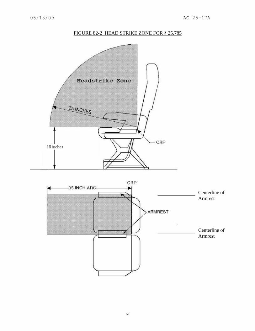
05/18/09 AC 25-17A
60
FIGURE 82-2 HEAD STRIKE ZONE FOR § 25.785
Centerline of Armrest
Centerline of Armrest

05/18/09 AC 25-17A
61
(6) Paragraph (c)(2). A flat surface within the 35-inch head strike arc, such as a table or partition, may be tested to the criteria of Society of Automotive Engineers (SAE) J921 or the following criteria. Impact injury criteria is discussed in AC 21-22, Injury Criteria for Human Exposure to Impact. (Amendment 25-0) (i) A 13-pound bowling ball may be used to simulate the head of a 170-pound person whose seat belt is fastened and is subjected to 9g. (Amendment 25-0) (ii) The ball shall impact the surface with at least 2780-inch-pounds of energy. (Amendment 25-0) (iii) The attachments of the test article shall not fail completely. (Amendment 25-0) (iv) No parts shall become loose or sharp projections be formed that would be hazardous to the passengers. (Amendment 25-0) (v) The test article may deform locally. (Amendment 25-0) (vi) The surface being tested should perform equal to or better than a previously approved surface. The intent of this comparative test method is to test similar items (e.g., a seatback that does not have a telephone with a seatback that has a telephone installed). This test method should not be used to compare a seatback to an armrest. (Amendment 25-0) (7) Paragraph (c)(2). (Amendment 25-0) (i) Some passenger seats are designed with armrests that pivot upward such that the armrest could protrude beyond the seatbacks resulting in a potentially hazardous condition to persons seated behind these seats. Armrests that are adequately delethalized or restricted such that they cannot protrude aft of either seatback in any position are acceptable. (Amendment 25-0) (ii) Armrests that are offset can be within the headstrike path of an occupant to the rear. Armrests within the striking radius of the head that are: (A) bounded on both sides of the armrest by the seat backs and are offset more than 2-inches from the armrests of the seat to the rear, or (B) forward of an additional (exposed) seat in the row behind it, such that the forward armrest is bounded on one side only are considered to be injurious objects. The head must be protected from these injurious objects by some additional means such as padding. Armrests that are bounded only on one side and not offset from the armrest of the seat in the rear are not considered to be injurious objects. (Amendment 25-0) (8) Paragraph (c)(2). The FAA issued policy memorandum 02-115-15, dated November 25, 2002, titled “New Policy with respect to compliance with § 25.785(d), Amendment 25-88, for certification of passenger seat armrests.” The policy in this

05/18/09 AC 25-17A
62
memorandum may be used for demonstrating compliance with § 25.785(c)(2), Amendment 25-15, and is provided below. (Amendment 25-0) (i) Armrests that might possibly be struck by persons seated behind (aft of) them are characterized as “bounded” or “unbounded.” Bounded armrests are defined as follows: (A) An armrest that has a seatback on both sides, with the distance between the structure of the adjacent seatbacks no greater than five inches, or (B) An armrest that has a seatback on one side and the airplane sidewall panel or a wall that is part of an airplane furnishing (e.g., galley, closet, lavatory) on the other side with the distance between the structure of the seatback and the panel/wall no greater than five inches. (ii) For purposes of this AC, the structure of the seatback is considered to be the parts of the seatback with load carrying capability. It does not include upholstery material or soft foam installed for occupant comfort. In some seat designs there is a metal frame in the seatback that forms the support structure to which the foam and upholstery are used to provide the shape of the seatback. When measuring the distance between the structure of the adjacent seatbacks of no greater than five inches, the measurement would be between these metal or composite supports structures. (iii) Unbounded armrests are those that do not meet either definition above. Additionally, seat places that are located aft of unbounded armrests may be characterized as either “exposed” or “non-exposed.” The non-exposed seat place is typically an aisle seat place, i.e., located adjacent to a passenger aisle (refer to figure 82-3). The exposed seat place is typically located where the number of seats in the row forward is different from that of the seat row aft. For example, near Type III overwing exits, many airplanes have a double seat installed inboard of the exit with an empty space between the seat and the exit. The seat row aft of the double seat has a triple seat (refer to figure 82-4). In figure 82-4, seat place “A” is an exposed seat place that makes the outboard armrest of the double seat an unbounded exposed armrest. (iv) The definitions above apply to all armrests in the airplane as applicable. The existing policy contained in this AC paragraphs 81b(5) and 81b(7) are still applicable to the armrests identified in the new policy below. (A) Note: The policy below addresses armrests within the 35-inch head strike arc and surfaces 18-inches and greater above the floor. Armrests outside the 35-inch head strike arc and armrest surfaces less than 18-inches above the floor are acceptable as defined in this AC paragraphs 81b(5) and 81b(7). (B) An armrest is acceptable by inspection if the armrests of two consecutive (i.e., one aft of the other) seat assemblies (seats need not be of the same part number ) are offset no greater 0.5-inch total, including design and production tolerances. (C) Bounded armrests and non-exposed unbounded armrests are acceptable if:

05/18/09 AC 25-17A
63
(1) The armrests of two consecutive seat assemblies are offset greater than 0.5-inch but no greater than two (2)-inches total, including design, and production tolerances, and (2) The breakover feature of the seatback(s) adjacent to the armrest in the forward seat assembly is (are) locked out. (D) The seatback breakover feature may be locked out by any method that requires a tool to release the lock out provision. The lockout of the breakover feature must be effective for the seatback in the upright position used for taxi, takeoff and landing. Seatbacks incorporating an energy absorbing feature to meet the HIC requirements of § 25.562 are considered to have the breakover lockout and are acceptable. Whatever the method of seatback breakover lock out, there typically is some movement of the seatback. This movement of the seatback is acceptable as long as when the seatback is moved to the worst case position by a small hand load applied to the top of the seatback, the armrest is still afforded protection by the seatback, with the end of the top of the armrest being forward of the aft side of the seatback. (E) Bounded armrests and non-exposed unbounded armrests, where the offset is greater than two (2)-inches total, including design and production tolerances, need to be addressed as being injurious objects within the striking radius of the head, e.g., by padding the armrest. (F) Exposed unbounded armrests; if the armrests of two consecutive seat assemblies that are offset by more than 0.5-inch total, including design and production tolerances, need to be addressed as being injurious objects within the striking radius of the head, e.g., by padding the armrest. (G) Armrests that are padded (using appropriate padding material as described in paragraph 81b(5) of this AC) must have the padding cover the length of the armrest that is encompassed by 35-inch and smaller head strike arcs. Bounded armrests, where the seatback(s) have the breakover feature locked out, need not be padded to encompass the entire 35-inch head strike arc because the seatbacks prevent the contact of the armrest on the forward side of the seatback(s). Therefore, these armrests need only be padded to the forward edge of the seatback(s) in their upright position achieved after the small hand force is applied to the seatback. Portions of the armrest surface that cannot be contacted by the head are not required to be padded, e.g., the lower (or under) surface of a curved armrest. (H) As an alternative to the use of padding, surfaces within the striking radius of the head that translate out of the striking radius under a nominal (10 pound) load may be considered to provide adequate protection, e.g., armrests that have been pivoted upward, which pivot downward out of the head strike arc under the nominal load. During an evaluation of this feature, the load must be applied in a direction that approximates the motion of a seated and belted occupant in the seat aft of the armrest under crash conditions.

05/18/09 AC 25-17A
64
FIGURE 82-3 ARMREST OFFSET
FIGURE 82-4 NON-EXPOSED AND EXPOSED ARMREST

05/18/09 AC 25-17A
65
(9) Paragraph (d). The seat back may serve as a firm hand hold. Since many seats are capable of breaking over, the breakover load must be adequate to be considered firm. A load of 25 lbs minimum, acting horizontally, is considered adequate when applied at the top center of the seat back. (Refer to paragraph 411b.(10) for maximum breakover force.) Very large seat pitches (in excess of 65-inches) may not permit the seatbacks to act as a handhold. This is due to both distance between the seatbacks and the capability of the seats to have very large amounts of recline. In this case, it may be necessary to install supplementary features to serve as handholds. Seat mounted headrests that move relative to the seatback do not need to be assessed for their ability to provide a firm handhold, provided the seatback remains available for use as a handhold, and meets the criteria identified above. Other interior features such as class dividers, closets and other monuments may also serve as acceptable handholds if they provide a surface for occupants to push against to steady themselves while moving about the cabin interior. (Amendment 25-0) (10) Paragraph (f). Each berth installation should include a seat belt located approximately at the occupant's pelvis. For a berth installation with the feet facing forward, a bag, enclosing the legs to catch the upper torso when subjected to 9g, would be satisfactory in lieu of a padded end board. If the head is facing forward, a strap over each shoulder configuration would be satisfactory. If the berth is side facing, a padded side board or two belts, located approximately at the thighs and approximately at the chest, would be satisfactory. (Amendment 25-0) (11) Paragraph (h). Flight attendant seats that are provided for the airplane configuration should be installed near the approved floor level emergency exits. This should not be interpreted as a requirement to install flight attendant seats at each floor level exit. “Near” is defined in AC 25.785-A. (Amendment 25-0) (12) Paragraph (i). In order to reduce the deceleration "g" forces on occupants, some forward facing seats are designed to collapse. Usually, the design incorporates collapsible front legs. Such is acceptable if the collapse does not occur until a minimum of 8g has been applied. After the collapse has occurred, the ultimate load of 9g should be applied and maintained for the required three seconds. The activation of the energy absorbing feature should not result in occupant injury. Various dimensions, such as 35-inches to injurious object clearance, aisle width and clearance, and interference with exits, should be evaluated before and after activation of the energy absorbing feature. Required dimensional clearances, such as aisles, passageways, flight attendant assist spaces, exit opening envelopes, and clearance between seats and potentially injurious surfaces must be maintained after the energy-absorbing feature is activated. The final position of the seat should not trap occupants. When testing a seat to demonstrate compliance with the static requirements of § 25.561, the testing should be conducted with an occupant center of gravity (CG) location as defined in NAS 809 (referenced in Technical Standard Order (TSO) C39) and AS8049 (referenced in the current version of TSO-C127). This CG location should be utilized in any airplane interface load analysis conducted. (Amendment 25-0) (13) Paragraph (i). Technical Standard Order (TSO)-C22 is applicable only to seat belts. Technical Standard Order C114 may be applicable to shoulder harnesses, or they may be

05/18/09 AC 25-17A
66
approved as part of the airplane. Sled tests with anthropomorphic dummies have shown that shoulder harness loads for forward facing seats can vary between 40 percent and 60 percent of the total load. Therefore, it is acceptable to substantiate a shoulder harness load of 60 percent (Refer to AC 25.785-1A, “Flight Attendant Seat and Torso Restraint System Installations,” dated 1/6/94): 0.6x9gx170 lbs = 918 lbs . If the seat belt is not approved under TSO-C22 or later revision, it should be approved as part of the airplane. The seat belt should be substantiated for 100 percent of the occupant load: 9g x 170 lbs = 1530 lbs . This is necessary even if the shoulder harness is permanently attached to the seat belt, since it is usually possible to utilize the seat belt without using the shoulder harness. The l.33 fitting factor is applicable to these configurations. (Amendment 25-0) (14) Paragraph (i)(1)(i). A seat is normally approved to TSO-C39 or later revision. This approval may not account for the critical load when occupied by less than maximum occupants, e.g., one or two occupants in a triple seat. In some seat designs, occupancy by less than the maximum could be a critical design load for a particular structural member. All possible combinations of seat place occupancy should be substantiated by test or analysis. The loads for underseat baggage restraint systems attached to the seat should be added to seat loads. Refer to § 25.787 guidance for underseat baggage criteria. This can be done by the TSO manufacturer when doing the TSO substantiation or by the applicant who is installing the seat. (Amendment 25-0) (15) Paragraph (i)(3). The l.33 factor is only required to be applied to the stated attachments. This factor should be applied to both ends of each attachment, (i.e., the seat end and the airplane end) and the fitting. If the applicant wishes to test the entire seat and belt assembly to this l.33 factor, it is satisfactory. (Amendment 25-0) 83. AMENDMENT 25-20, Effective April 23, 1969. a. Regulation.
(a) Each seat, berth, safety belt, harness, and adjacent part of the airplane at each station designated as occupiable during takeoff and landing must be designed so that a person making proper use of these facilities will not suffer serious injury in an emergency landing as a result of the inertia forces specified in §§ 25.561. (b) Each seat and berth must be approved. [(c) Each occupant of a seat that makes more than an 18 degree angle with the vertical plane containing the airplane centerline, must be protected from head injury by a safety belt and an energy absorbing rest that will support the arms, shoulders, head, and spine, or by a safety belt and shoulder harness that will prevent the head from contacting any injurious object.] Each occupant of any other seat must be protected from head injury by-

05/18/09 AC 25-17A
67
(1) A safety belt and shoulder harness that will prevent the head from contacting any injurious object; (2) A safety belt plus the elimination of any injurious object within striking radius of the head; or (3) A safety belt and an energy absorbing rest that will support the arms, shoulders, head, and spine. (d) If the seat backs do not have a firm hand hold, there must be a hand grip or rail along each aisle to enable occupants to steady themselves while using the aisles in moderately rough air. (e) Each projecting object that would injure persons seated or moving about the airplane in normal flight must be padded. (f) Each berth must be designed so that the forward part has a padded end board, canvas diaphragm, or equivalent means, that can withstand the static load reaction of the occupant when subjected to the forward inertia force specified in § 25.561. Berths must be free from corners and protuberances likely to cause serious injury to a person occupying the berth during emergency conditions. (g) Each crewmember seat at flight deck stations must have provisions for a shoulder harness. These seats must meet the strength requirements of paragraph (i) of this section. (h) Cabin attendant seats must be in the passenger compartment near approved floor level emergency exits. (i) Each seat berth, and its supporting structure, must be designed for an occupant weight of 170 pounds, considering the maximum load factors, inertia forces, and reactions between the occupant, seat, and safety belt or harness, at each relevant flight and ground load condition (including the emergency landing conditions prescribed in § 25.561). For berths, the forward inertia force must be considered in accordance with paragraph (f) of this section and need not be considered with respect to the safety belt. In addition- (1) The structural analysis and testing of the seats, berths, and their supporting structures may be determined by- (i) Assuming that the critical load in the forward, sideward, downward, and rearward directions (as determined from the prescribed flight, ground, and emergency landing conditions) acts separately; and (ii) Using selected combinations of loads if the required strength in each specified direction is substantiated;

05/18/09 AC 25-17A
68
(2) Each pilot seat must be designed for the reactions resulting from the application of the pilot forces prescribed in § 25.395; and (3) The inertia forces specified in § 25.561 must be multiplied by a factor of 1.33 (instead of the fitting factor prescribed in § 25.625) in determining the strength of the attachment of- (i) Each seat to the structure; and (ii) Each belt or harness to the seat or structure.
b. Guidance. (l) Paragraph (a). In order for the seat belt to be effective, it should be positioned to lay across the hip bone and ideally be about 45 degrees from the horizontal. An acceptable range for this angle is 35 degrees to 55 degrees. An acceptable range for the shoulder harness is 30 degrees above to 5 degrees below the horizontal. Refer to ACs 25.785-1A, “Flight Attendant Seat and Torso Restraint System Installations,” dated 1/6/94, and 43.13-1A, “Acceptable Methods, Techniques, and Practices-Aircraft Inspection and Repair (with Errata Sheet),” dated 4/17/72, for related guidance. When testing a seat to demonstrate compliance with the static requirements of § 25.561, the testing should be conducted with an occupant center of gravity (CG) location as defined in NAS 809 (referenced in Technical Standard Order (TSO) C39) and AS8049 (referenced in the current version of TSO-C127). This CG location should be utilized in any airplane interface load analysis conducted. (Amendment 25-0) (2) Paragraphs (a) and (c). The FAA issued policy memorandum ANM-03-115-28, dated October 2, 2003, and titled “Policy Statement on Use of Surrogate Parts When Evaluating Seatbacks and Seatback Mounted Accessories for Compliance with §§ 25.562(c) (5) and 25.785(b) and (d). This policy may be used with any test method used to demonstrate compliance with blunt force trauma for items mounted on the seatback. The policy is applicable to Amendment 25-20, for §§ 25.785 (a) and (c) as follows: (Amendment 25-0) (i) In many row-to-row seat configurations, seatback mounted accessories are installed within the head paths of forward facing seated occupants. In order to demonstrate compliance with the aforementioned requirements, tests are conducted to assess the injury potential of these seatbacks and accessories. This policy only addresses head injury caused by blunt trauma. It does not address parts that become loose or sharp projections that are formed that may be injurious to a seated occupant during a head impact. (ii) The types of tests that are conducted for blunt trauma assessments are dependant on the certification basis of the airplane. Typically, airplanes which do not have § 25.562(c)(5) in their certification basis, must still comply with the more general occupant protection requirements of §§ 25.785(a) and (c). Sections 25.785(a) and (c) require that a seat be designed so that an occupant would not suffer “serious injury” in an emergency landing and that injurious objects within the striking radius of the head be eliminated. As a result,

05/18/09 AC 25-17A
69
seatbacks/accessories on these airplanes must be evaluated to ensure that an occupant would not suffer serious head injury from blunt trauma. (iii) Currently, blunt trauma tests are conducted with seatback mounted accessories represented by actual production parts or parts that are similar in construction to the production parts. Industry has informed the FAA that certification delays occur due to the unavailability of actual accessories for testing. In addition, accessories are typically damaged during certification tests and are not usable in subsequent tests or for installation and delivery to a customer. Several specimens of the same part are repeatedly used, and damaged, during certification tests due to test failures or substantiating alternate seatback designs. This results in significant costs to manufacturers and customers. (iv) The FAA has determined that it is acceptable to use a surrogate test article made of 6061-T4 aluminum which meets the criteria below in lieu of an accessory for demonstrating compliance with §§ 25.785(a) and (c) for blunt trauma assessments. An exception to the use of the surrogate test article occurs when the accessory is more rigid (deflects less and absorbs less energy during impact) than the plate defined in this AC. In that case, the accessory should be used in the test(s) and not a surrogate test article. The following criteria are applicable when using a surrogate test article during blunt trauma testing in accordance with §§ 25. 785(a) and (c): (A) The surrogate part should be fabricated from 6061-T4 aluminum and have a minimum thickness of 0.238-inch (i.e., 0.25-inch minus a 0.012-inch manufacturing tolerance) at all locations. The length and width of the surrogate part should equal, within tolerances, the length and width of the actual part, respectively. (B) The exposed surface of the surrogate part that will be impacted should be flat. That is, it is not required to have the contour of the accessory’s exposed surface represented by the surrogate part. Note that this is based on typical accessory installations which are essentially mounted flush with the seatback and have a generally homogeneous contact area. Small variations in the surface due to the contour of plastic parts may be ignored. Designs that differ from this (e.g., a design with an exposed structural protrusion) might require the exposed surface of the actual part to be represented in order to adequately assess head injury potential. (C) The weight of the surrogate part, and additional ballast if needed, should be ±10 percent of the weight of the actual part. (D) The surrogate part should be located on the seatback in the same place (i.e., within manufacturing tolerances for mounting the actual part) where the actual part would be located in terms of the x and y coordinates in Figure 83-1. The surrogate part should be located such that the surface, which will be contacted during the test, is at the same location (i.e., within manufacturing tolerances for mounting the actual part) where the actual part would be in terms of the z coordinate (refer to figure 83-1). (E) The surrogate part should be attached to the seat by the final production hardware or a conservative representation of the final production hardware. For substantiating

05/18/09 AC 25-17A
70
blunt trauma requirements, a conservative representation of the attachment hardware would be at least as rigid as the actual hardware. The surrogate part should be mounted so that it would not move farther or faster, with respect to the seatback, than the actual part during the test. (F) If the surrogate part cracks during a test, the test results are invalid.
(G) A surrogate part made of a material and thickness other than 6061-T4 aluminum in a nominal thickness of 0.25-inch may be used if an FAA Aircraft Certification Office finds that it is at least as rigid (i.e., it deflects less and absorbs less energy during the test). Surrogate test articles which are less rigid than the aluminum surrogate part defined above are not addressed in this AC. If an applicant desires to use a surrogate part which is less rigid, its use should be approved through the issue paper process (or equivalent) or by an FAA policy memorandum. Testing may be required to determine the acceptability of these less rigid surrogate parts.

05/18/09 AC 25-17A
71
FIGURE 83-1 SURROGATE PART INSTALLED ON SEATBACK

05/18/09 AC 25-17A
72
(3) Paragraphs (a) and (c). The FAA issued policy memorandum ANM-03-115-31, dated May 9, 2005, and titled “Policy Statement on Conducting Component Level Tests to Demonstrate Compliance with §§ 25.785(b) and (d). Appendix 13 of this AC contains the complete policy memorandum. This policy may be used with any test method used to demonstrate compliance with blunt force trauma for items mounted on the seatback. The policy is applicable to Amendment 25-20, for §§ 25.785 (a) and (c). (Amendment 25-0) (4) Paragraph (c). For sideward facing seats, this change removed the option of a safety belt plus eliminated any injurious object from within striking radius of the head. This option is still satisfactory for forward and aft facing seats. The "human cushion" or unpadded bulkhead concept is not an adequate energy absorbing rest and therefore does not comply with this version of the regulation. The shoulder harness may be a diagonal shoulder harness over the forward shoulder. (Amendment 25-15) (5) Paragraph (c). The 18-degree requirement applies to both forward and aft facing seat installations. If the forward direction is considered as 0 degrees or 360 degrees of a circle, the segments from 18 degrees to 162 degrees and 198 degrees to 342 degrees are considered a side facing seat and the seat installation must comply with one of the two options stated in the regulation. (Amendment 25-20)
(6) Paragraph (c)(2). The striking radius of the head is considered to be an arc of 35-inches whose center is at the intersection of the plane of the uncompressed top of the seat cushion with the plane of the uncompressed front of the back cushion; commonly referred to as the cushion reference point (CRP). Previously this was referred to as seat reference point (SRP). However, with the advent of dynamic seat testing the definition for SRP was changed (refer to current version of AS8049). The arc width is considered to extend to the centerlines of each armrest. The arc is actually a section of a cylinder (refer to figure 83-2). Typical installations to be considered are bulkheads, cabinets, tables and passenger evacuation slide covers. The installation should not contain any pointed corners or sharp edges. The testing used to demonstrate that the installation is not injurious must take into account whether the system (e.g., seatback mounted telephone) is allowed to be used during taxi, takeoff and landing. If the system is allowed to be used during these phases of operation, the testing must consider the system in both the deployed and stowed position (e.g., seatback mounted telephone in or out of the cradle). If the sidewall configuration is such that it is potentially hazardous in a combination of forward and side loads, it should be substantiated even if it might be slightly outside of the centerline of the armrest. Any surface less than 18-inches above the floor need not be considered. Surfaces within the 35-inch arc may be padded with energy absorbing material, such as one-inch of either Ensolite (Type AH, AHC, IV3, HHC or HH), Klegecell or Airex 4070. Foam rubber is not satisfactory since it is an energy storing material. If the padding is easily removed, there should be acceptable placarding requiring the padding be in place during taxi, takeoff and landing. (Amendment 25-0)

05/18/09 AC 25-17A
73
FIGURE 83-2 HEAD STRIKE ZONE FOR § 25.785
Centerline of Armrest
Centerline of Armrest

05/18/09 AC 25-17A
74
(7) Paragraph (c)(2). A flat surface within the 35-inch head strike arc, such as a table or partition, may be tested to the criteria of Society of Automotive Engineers (SAE) J921 or the following criteria. Impact injury criteria is discussed in AC 21-22, Injury Criteria for Human Exposure to Impact. (Amendment 25-0) (i) A 13-pound bowling ball may be used to simulate the head of a 170-pound person whose seat belt is fastened and is subjected to 9g. (Amendment 25-0) (ii) The ball shall impact the surface with at least 2780-inch-pounds of energy. (Amendment 25-0) (iii) The attachments of the test article shall not fail completely. (Amendment 25-0) (iv) No parts shall become loose or sharp projections be formed that would be hazardous to the passengers. (Amendment 25-0) (v) The test article may deform locally. (Amendment 25-0) (vi) The surface being tested should perform equal to or better than a previously approved surface. The intent of this comparative test method is to test similar items (e.g., a seatback that does not have a telephone with a seatback that has a telephone installed). This test method should not be used to compare a seatback to an armrest. (Amendment 25-0) (8) Paragraph (c)(2). (Amendment 25-0) (i) Some passenger seats are designed with armrests that pivot upward such that the armrest could protrude beyond the seatbacks resulting in a potentially hazardous condition to persons seated behind these seats. Armrests that are adequately delethalized or restricted such that they cannot protrude aft of either seatback in any position are acceptable. (Amendment 25-0) (ii) Armrests that are offset can be within the headstrike path of an occupant to the rear. Armrests within the striking radius of the head that are: (A) bounded on both sides of the armrest by the seat backs and are offset more than 2-inches from the armrests of the seat to the rear, or (B) forward of an additional (exposed) seat in the row behind it, such that the forward armrest is bounded on one side only are considered to be injurious objects. The head must be protected from these injurious objects by some additional means such as padding. Armrests that are bounded only on one side and not offset from the armrest of the seat in the rear are not considered to be injurious objects. (Amendment 25-0) (9) Paragraph (c)(2). The FAA issued policy memorandum 02-115-15, dated November 25, 2002, titled “New Policy with respect to compliance with § 25.785(d), Amendment 25-88, for certification of passenger seat armrests.” The policy in this

05/18/09 AC 25-17A
75
memorandum may be used for demonstrating compliance with § 25.785(c)(2), Amendment 25-20, and is provided below. (Amendment 25-0) (i) Armrests that might possibly be struck by persons seated behind (aft of) them are characterized as “bounded” or “unbounded.” Bounded armrests are defined as follows: (A) An armrest that has a seatback on both sides, with the distance between the structure of the adjacent seatbacks no greater than five inches, or (B) An armrest that has a seatback on one side and the airplane sidewall panel or a wall that is part of an airplane furnishing (e.g., galley, closet, lavatory) on the other side with the distance between the structure of the seatback and the panel/wall no greater than five inches. (ii) For purposes of this AC, the structure of the seatback is considered to be the parts of the seatback with load carrying capability. It does not include upholstery material or soft foam installed for occupant comfort. In some seat designs there is a metal frame in the seatback that forms the support structure to which the foam and upholstery are used to provide the shape of the seatback. When measuring the distance between the structure of the adjacent seatbacks of no greater than five inches, the measurement would be between these metal or composite supports structures. (iii) Unbounded armrests are those that do not meet either definition above. Additionally, seat places that are located aft of unbounded armrests may be characterized as either “exposed” or “non-exposed.” The non-exposed seat place is typically an aisle seat place, i.e., located adjacent to a passenger aisle (refer to figure 83-3). The exposed seat place is typically located where the number of seats in the row forward is different from that of the seat row aft. For example, near Type III overwing exits, many airplanes have a double seat installed inboard of the exit with an empty space between the seat and the exit. The seat row aft of the double seat has a triple seat (refer to figure 83-4). In figure 83-4, seat place “A” is an exposed seat place that makes the outboard armrest of the double seat an unbounded exposed armrest. (iv) The definitions above apply to all armrests in the airplane as applicable. The existing policy contained in this AC paragraphs 81b(5) and 81b(7) are still applicable to the armrests identified in the new policy below. (A) Note: The policy below addresses armrests within the 35-inch head strike arc and surfaces 18-inches and greater above the floor. Armrests outside the 35-inch head strike arc and armrest surfaces less than 18-inches above the floor are acceptable as defined in this AC paragraphs 81b(5) and 81b(7). (B) An armrest is acceptable by inspection if the armrests of two consecutive (i.e., one aft of the other) seat assemblies (seats need not be of the same part number) are offset no greater 0.5-inch total, including design and production tolerances. (C) Bounded armrests and non-exposed unbounded armrests are acceptable if:

05/18/09 AC 25-17A
76
(1) The armrests of two consecutive seat assemblies are offset greater than 0.5-inch but no greater than two (2)-inches total, including design, and production tolerances, and (2) The breakover feature of the seatback(s) adjacent to the armrest in the forward seat assembly is (are) locked out. (D) The seatback breakover feature may be locked out by any method that requires a tool to release the lock out provision. The lockout of the breakover feature must be effective for the seatback in the upright position used for taxi, takeoff and landing. Seatbacks incorporating an energy absorbing feature to meet the HIC requirements of § 25.562 are considered to have the breakover lockout and are acceptable. Whatever the method of seatback breakover lock out, there typically is some movement of the seatback. This movement of the seatback is acceptable as long as when the seatback is moved to the worst case position by a small hand load applied to the top of the seatback, the armrest is still afforded protection by the seatback, with the end of the top of the armrest being forward of the aft side of the seatback. (E) Bounded armrests and non-exposed unbounded armrests, where the offset is greater than two (2)-inches total, including design and production tolerances, need to be addressed as being injurious objects within the striking radius of the head, e.g., by padding the armrest. (F) Exposed unbounded armrests; if the armrests of two consecutive seat assemblies that are offset by more than 0.5-inch total, including design and production tolerances, need to be addressed as being injurious objects within the striking radius of the head, e.g., by padding the armrest. (G) Armrests that are padded (using appropriate padding material as described in paragraph 81b(5) of this AC) must have the padding cover the length of the armrest that is encompassed by 35-inch and smaller head strike arcs. Bounded armrests, where the seatback(s) have the breakover feature locked out, need not be padded to encompass the entire 35-inch head strike arc because the seatbacks prevent the contact of the armrest on the forward side of the seatback(s). Therefore, these armrests need only be padded to the forward edge of the seatback(s) in their upright position achieved after the small hand force is applied to the seatback. Portions of the armrest surface that cannot be contacted by the head are not required to be padded, e.g., the lower (or under) surface of a curved armrest. (H) As an alternative to the use of padding, surfaces within the striking radius of the head that translate out of the striking radius under a nominal (10 pound) load may be considered to provide adequate protection, e.g., armrests that have been pivoted upward, which pivot downward out of the head strike arc under the nominal load. During an evaluation of this feature, the load must be applied in a direction that approximates the motion of a seated and belted occupant in the seat aft of the armrest under crash conditions.
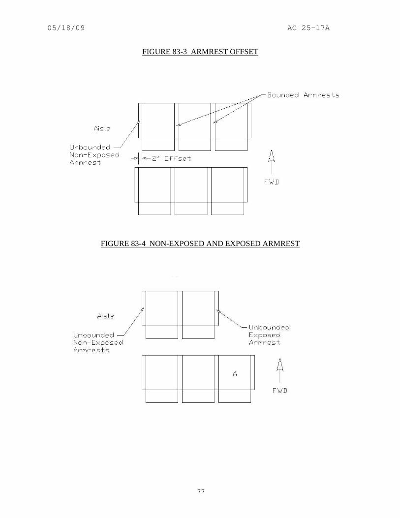
05/18/09 AC 25-17A
77
FIGURE 83-3 ARMREST OFFSET
FIGURE 83-4 NON-EXPOSED AND EXPOSED ARMREST

05/18/09 AC 25-17A
78
(10) Paragraph (d). The seat back may serve as a firm hand hold. Since many seats are capable of breaking over, the breakover load must be adequate to be considered firm. A load of 25 lbs minimum, acting horizontally, is considered adequate when applied at the top center of the seat back. (Refer to paragraph 411b.(10) for maximum breakover force.) Very large seat pitches (in excess of 65-inches) may not permit the seatbacks to act as a handhold. This is due to both distance between the seatbacks and the capability of the seats to have very large amounts of recline. In this case, it may be necessary to install supplementary features to serve as handholds. Seat mounted headrests that move relative to the seatback do not need to be assessed for their ability to provide a firm handhold, provided the seatback remains available for use as a handhold, and meets the criteria identified above. Other interior features such as class dividers, closets and other monuments may also serve as acceptable handholds if they provide a surface for occupants to push against to steady themselves while moving about the cabin interior. (Amendment 25-0) (11) Paragraph (f). Each berth installation should include a seat belt located approximately at the occupant's pelvis. For a berth installation with the feet facing forward, a bag, enclosing the legs to catch the upper torso when subjected to 9g, would be satisfactory in lieu of a padded end board. If the head is facing forward, a strap over each shoulder configuration would be satisfactory. If the berth is side facing, a padded side board or two belts, located approximately at the thighs and approximately at the chest, would be satisfactory. (Amendment 25-0) (12) Paragraph (h). Flight attendant seats that are provided for the airplane configuration should be installed near the approved floor level emergency exits. This should not be interpreted as a requirement to install flight attendant seats at each floor level exit. “Near” is defined in AC 25.785-1A. (Amendment 25-0) (13) Paragraph (i). In order to reduce the deceleration "g" forces on occupants, some forward facing seats are designed to collapse. Usually, the design incorporates collapsible front legs. Such is acceptable if the collapse does not occur until a minimum of 8g has been applied. After the collapse has occurred, the ultimate load of 9g should be applied and maintained for the required three seconds. The activation of the energy absorbing feature should not result in occupant injury. Various dimensions, such as 35-inches to injurious object clearance, aisle width and clearance, and interference with exits, should be evaluated before and after activation of the energy absorbing feature. Required dimensional clearances, such as aisles, passageways, flight attendant assist spaces, exit opening envelopes, and clearance between seats and potentially injurious surfaces must be maintained after the energy-absorbing feature is activated. The final position of the seat should not trap occupants. When testing a seat to demonstrate compliance with the static requirements of § 25.561, the testing should be conducted with an occupant center of gravity (CG) location as defined in NAS 809 (referenced in Technical Standard Order (TSO) C39) and AS8049 (referenced in the current version of TSO-C127). This CG location should be utilized in any airplane interface load analysis conducted. (Amendment 25-0) (14) Paragraph (i). Technical Standard Order (TSO)-C22 is applicable only to seat belts. Technical Standard Order C114 may be applicable to shoulder harnesses, or they may be

05/18/09 AC 25-17A
79
approved as part of the airplane. Sled tests with anthropomorphic dummies have shown that shoulder harness loads for forward facing seats can vary between 40 percent and 60 percent of the total load. Therefore, it is acceptable to substantiate a shoulder harness load of 60 percent (Refer to AC 25.785-1A, “Flight Attendant Seat and Torso Restraint System Installations,” dated 1/6/94): 0.6x9gx170 lbs = 918 lbs . If the seat belt is not approved under TSO-C22 or later revision, it should be approved as part of the airplane. The seat belt should be substantiated for 100 percent of the occupant load: 9g x 170 lbs = 1530 lbs . This is necessary even if the shoulder harness is permanently attached to the seat belt, since it is usually possible to utilize the seat belt without using the shoulder harness. The l.33 fitting factor is applicable to these configurations. (Amendment 25-0) (15) Paragraph (i)(1)(i). A seat is normally approved to TSO-C39 or later revision. This approval may not account for the critical load when occupied by less than maximum occupants, e.g., one or two occupants in a triple seat. In some seat designs, occupancy by less than the maximum could be a critical design load for a particular structural member. All possible combinations of seat place occupancy should be substantiated by test or analysis. The loads for underseat baggage restraint systems attached to the seat should be added to seat loads. Refer to § 25.787 guidance for underseat baggage criteria. This can be done by the TSO manufacturer when doing the TSO substantiation or by the applicant who is installing the seat. (Amendment 25-0) (16) Paragraph (i)(3). The l.33 factor is only required to be applied to the stated attachments. This factor should be applied to both ends of each attachment, (i.e., the seat end and the airplane end) and the fitting. If the applicant wishes to test the entire seat and belt assembly to this l.33 factor, it is satisfactory. (Amendment 25-0) 84. AMENDMENT 25-32, Effective May l, 1972. a. Regulation.
(a) Each seat, berth, safety belt, harness, and adjacent part of the airplane at each station designated as occupiable during takeoff and landing must be designed so that a person making proper use of these facilities will not suffer serious injury in an emergency landing as a result of the inertia forces specified in §§ 25.561. (b) Each seat and berth must be approved. (c) Each occupant of a seat that makes more than an 18 degree angle with the vertical plane containing the airplane centerline, must be protected from head injury by a safety belt and an energy absorbing rest that will support the arms, shoulders, head, and spine, or by a safety belt and shoulder harness that will prevent the head from contacting any injurious object. [Each occupant of any other seat must be protected from head injury by a safety belt and, as appropriate to the type, location, and angle of facing of each seat, by one or more of the following:

05/18/09 AC 25-17A
80
(1) A shoulder harness that will prevent the head from contacting any injurious object. (2) The elimination of any injurious object within striking radius of the head. (3) An energy absorbing rest that will support the arms, shoulders, head, and spine.] (d) If the seat backs do not have a firm hand hold, there must be a hand grip or rail along each aisle to enable occupants to steady themselves while using the aisles in moderately rough air. (e) Each projecting object that would injure persons seated or moving about the airplane in normal flight must be padded. (f) Each berth must be designed so that the forward part has a padded end board, canvas diaphragm, or equivalent means, that can withstand the static load reaction of the occupant when subjected to the forward inertia force specified in § 25.561. Berths must be free from corners and protuberances likely to cause serious injury to a person occupying the berth during emergency conditions. (g) Each crewmember seat at flight deck stations must have provisions for a shoulder harness. These seats must meet the strength requirements of paragraph (i) of this section. (h) Cabin attendant seats must be in the passenger compartment near approved floor level emergency exits. (i) Each seat berth, and its supporting structure, must be designed for an occupant weight of 170 pounds, considering the maximum load factors, inertia forces, and reactions between the occupant, seat, and safety belt or harness, at each relevant flight and ground load condition (including the emergency landing conditions prescribed in § 25.561). For berths, the forward inertia force must be considered in accordance with paragraph (f) of this section and need not be considered with respect to the safety belt. In addition- (1) The structural analysis and testing of the seats, berths, and their supporting structures may be determined by- (i) Assuming that the critical load in the forward, sideward, downward, and rearward directions (as determined from the prescribed flight, ground, and emergency landing conditions) acts separately; and (ii) Using selected combinations of loads if the required strength in each specified direction is substantiated;

05/18/09 AC 25-17A
81
(2) Each pilot seat must be designed for the reactions resulting from the application of the pilot forces prescribed in § 25.395; and (3) The inertia forces specified in § 25.561 must be multiplied by a factor of 1.33 (instead of the fitting factor prescribed in § 25.625) in determining the strength of the attachment of- (i) Each seat to the structure; and (ii) Each belt or harness to the seat or structure.
b. Guidance. (l) Paragraph (a). In order for the seat belt to be effective, it should be positioned to lay across the hip bone and ideally be about 45 degrees from the horizontal. An acceptable range for this angle is 35 degrees to 55 degrees. An acceptable range for the shoulder harness is 30 degrees above to 5 degrees below the horizontal. Refer to ACs 25.785-1A, “Flight Attendant Seat and Torso Restraint System Installations,” dated 1/6/94, and 43.13-1A, “Acceptable Methods, Techniques, and Practices-Aircraft Inspection and Repair (with Errata Sheet),” dated 4/17/72, for related guidance. When testing a seat to demonstrate compliance with the static requirements of § 25.561, the testing should be conducted with an occupant center of gravity (CG) location as defined in NAS 809 (referenced in Technical Standard Order (TSO) C39) and AS8049 (referenced in the current version of TSO-C127). This CG location should be utilized in any airplane interface load analysis conducted. (Amendment 25-0) (2) Paragraphs (a) and (c). The FAA issued policy memorandum ANM-03-115-28, dated October 2, 2003, and titled “Policy Statement on Use of Surrogate Parts When Evaluating Seatbacks and Seatback Mounted Accessories for Compliance with §§ 25.562(c) (5) and 25.785(b) and (d). This policy may be used with any test method used to demonstrate compliance with blunt force trauma for items mounted on the seatback. The policy is applicable to Amendment 25-32, for §§ 25.785 (a) and (c) as follows: (Amendment 25-0) (i) In many row-to-row seat configurations, seatback mounted accessories are installed within the head paths of forward facing seated occupants. In order to demonstrate compliance with the aforementioned requirements, tests are conducted to assess the injury potential of these seatbacks and accessories. This policy only addresses head injury caused by blunt trauma. It does not address parts that become loose or sharp projections that are formed that may be injurious to a seated occupant during a head impact. (ii) The types of tests that are conducted for blunt trauma assessments are dependant on the certification basis of the airplane. Typically, airplanes which do not have § 25.562(c)(5) in their certification basis, must still comply with the more general occupant protection requirements of §§ 25.785(a) and (c). Sections 25.785(a) and (c) require that a seat be designed so that an occupant would not suffer “serious injury” in an emergency landing and that injurious objects within the striking radius of the head be eliminated. As a result,

05/18/09 AC 25-17A
82
seatbacks/accessories on these airplanes must be evaluated to ensure that an occupant would not suffer serious head injury from blunt trauma. (iii) Currently, blunt trauma tests are conducted with seatback mounted accessories represented by actual production parts or parts that are similar in construction to the production parts. Industry has informed the FAA that certification delays occur due to the unavailability of actual accessories for testing. In addition, accessories are typically damaged during certification tests and are not usable in subsequent tests or for installation and delivery to a customer. Several specimens of the same part are repeatedly used, and damaged, during certification tests due to test failures or substantiating alternate seatback designs. This results in significant costs to manufacturers and customers. (iv) The FAA has determined that it is acceptable to use a surrogate test article made of 6061-T4 aluminum which meets the criteria below in lieu of an accessory for demonstrating compliance with §§ 25.785(a) and (c) for blunt trauma assessments. An exception to the use of the surrogate test article occurs when the accessory is more rigid (deflects less and absorbs less energy during impact) than the plate defined in this AC. In that case, the accessory should be used in the test(s) and not a surrogate test article. The following criteria are applicable when using a surrogate test article during blunt trauma testing in accordance with §§ 25. 785(a) and (c): (A) The surrogate part should be fabricated from 6061-T4 aluminum and have a minimum thickness of 0.238-inch (i.e., 0.25-inch minus a 0.012-inch manufacturing tolerance) at all locations. The length and width of the surrogate part should equal, within tolerances, the length and width of the actual part, respectively. (B) The exposed surface of the surrogate part that will be impacted should be flat. That is, it is not required to have the contour of the accessory’s exposed surface represented by the surrogate part. Note that this is based on typical accessory installations which are essentially mounted flush with the seatback and have a generally homogeneous contact area. Small variations in the surface due to the contour of plastic parts may be ignored. Designs that differ from this (e.g., a design with an exposed structural protrusion) might require the exposed surface of the actual part to be represented in order to adequately assess head injury potential. (C) The weight of the surrogate part, and additional ballast if needed, should be ±10 percent of the weight of the actual part. (D) The surrogate part should be located on the seatback in the same place (i.e., within manufacturing tolerances for mounting the actual part) where the actual part would be located in terms of the x and y coordinates in Figure 84-1. The surrogate part should be located such that the surface, which will be contacted during the test, is at the same location (i.e., within manufacturing tolerances for mounting the actual part) where the actual part would be in terms of the z coordinate (refer to figure 84-1). (E) The surrogate part should be attached to the seat by the final production hardware or a conservative representation of the final production hardware. For substantiating

05/18/09 AC 25-17A
83
blunt trauma requirements, a conservative representation of the attachment hardware would be at least as rigid as the actual hardware. The surrogate part should be mounted so that it would not move farther or faster, with respect to the seatback, than the actual part during the test. (F) If the surrogate part cracks during a test, the test results are invalid.
(G) A surrogate part made of a material and thickness other than 6061-T4 aluminum in a nominal thickness of 0.25-inch may be used if an FAA Aircraft Certification Office finds that it is at least as rigid (i.e., it deflects less and absorbs less energy during the test). Surrogate test articles which are less rigid than the aluminum surrogate part defined above are not addressed in this AC. If an applicant desires to use a surrogate part which is less rigid, its use should be approved through the issue paper process (or equivalent) or by an FAA policy memorandum. Testing may be required to determine the acceptability of these less rigid surrogate parts.

05/18/09 AC 25-17A
84
FIGURE 84-1 SURROGATE PART INSTALLED ON SEATBACK

05/18/09 AC 25-17A
85
(3) Paragraphs (a) and (c). The FAA issued policy memorandum ANM-03-115-31, dated May 9, 2005, and titled “Policy Statement on Conducting Component Level Tests to Demonstrate Compliance with §§ 25.785(b) and (d). Appendix 13 of this AC contains the complete policy memorandum. This policy may be used with any test method used to demonstrate compliance with blunt force trauma for items mounted on the seatback. The policy is applicable to Amendment 25-32, for §§ 25.785 (a) and (c). (Amendment 25-0) (4) Paragraph (c). For sideward facing seats, this change removed the option of a safety belt plus eliminated any injurious object from within striking radius of the head. This option is still satisfactory for forward and aft facing seats. The "human cushion" or unpadded bulkhead concept is not an adequate energy absorbing rest and therefore does not comply with this version of the regulation. The shoulder harness may be a diagonal shoulder harness over the forward shoulder. (Amendment 25-15) (5) Paragraph (c). The 18-degree requirement applies to both forward and aft facing seat installations. If the forward direction is considered as 0 degrees or 360 degrees of a circle, the segments from 18 degrees to 162 degrees and 198 degrees to 342 degrees are considered a side facing seat and the seat installation must comply with one of the two options stated in the regulation. (Amendment 25-20)
(6) Paragraph (c)(2). The striking radius of the head is considered to be an arc of 35-inches whose center is at the intersection of the plane of the uncompressed top of the seat cushion with the plane of the uncompressed front of the back cushion; commonly referred to as the cushion reference point (CRP). Previously this was referred to as seat reference point (SRP). However, with the advent of dynamic seat testing the definition for SRP was changed (refer to current version of AS8049). The arc width is considered to extend to the centerlines of each armrest. The arc is actually a section of a cylinder (refer to figure 84-2). Typical installations to be considered are bulkheads, cabinets, tables and passenger evacuation slide covers. The installation should not contain any pointed corners or sharp edges. The testing used to demonstrate that the installation is not injurious must take into account whether the system (e.g., seatback mounted telephone) is allowed to be used during taxi, takeoff and landing. If the system is allowed to be used during these phases of operation, the testing must consider the system in both the deployed and stowed position (e.g., seatback mounted telephone in or out of the cradle). If the sidewall configuration is such that it is potentially hazardous in a combination of forward and side loads, it should be substantiated even if it might be slightly outside of the centerline of the armrest. Any surface less than 18-inches above the floor need not be considered. Surfaces within the 35-inch arc may be padded with energy absorbing material, such as one-inch of either Ensolite (Type AH, AHC, IV3, HHC or HH), Klegecell or Airex 4070. Foam rubber is not satisfactory since it is an energy storing material. If the padding is easily removed, there should be acceptable placarding requiring the padding be in place during taxi, takeoff and landing. (Amendment 25-0)

05/18/09 AC 25-17A
86
FIGURE 84-2 HEAD STRIKE ZONE FOR § 25.785
Centerline of Armrest
Centerline of Armrest

05/18/09 AC 25-17A
87
(7) Paragraph (c)(2). A flat surface within the 35-inch head strike arc, such as a table or partition, may be tested to the criteria of Society of Automotive Engineers (SAE) J921 or the following criteria. Impact injury criteria is discussed in AC 21-22, Injury Criteria for Human Exposure to Impact. (Amendment 25-0) (i) A 13-pound bowling ball may be used to simulate the head of a 170-pound person whose seat belt is fastened and is subjected to 9g. (Amendment 25-0) (ii) The ball shall impact the surface with at least 2780-inch-pounds of energy. (Amendment 25-0) (iii) The attachments of the test article shall not fail completely. (Amendment 25-0) (iv) No parts shall become loose or sharp projections be formed that would be hazardous to the passengers. (Amendment 25-0) (v) The test article may deform locally. (Amendment 25-0) (vi) The surface being tested should perform equal to or better than a previously approved surface. The intent of this comparative test method is to test similar items (e.g., a seatback that does not have a telephone with a seatback that has a telephone installed). This test method should not be used to compare a seatback to an armrest. (Amendment 25-0) (8) Paragraph (c)(2). (Amendment 25-0) (i) Some passenger seats are designed with armrests that pivot upward such that the armrest could protrude beyond the seatbacks resulting in a potentially hazardous condition to persons seated behind these seats. Armrests that are adequately delethalized or restricted such that they cannot protrude aft of either seatback in any position are acceptable. (Amendment 25-0) (ii) Armrests that are offset can be within the headstrike path of an occupant to the rear. Armrests within the striking radius of the head that are: (A) bounded on both sides of the armrest by the seat backs and are offset more than 2-inches from the armrests of the seat to the rear, or (B) forward of an additional (exposed) seat in the row behind it, such that the forward armrest is bounded on one side only are considered to be injurious objects. The head must be protected from these injurious objects by some additional means such as padding. Armrests that are bounded only on one side and not offset from the armrest of the seat in the rear are not considered to be injurious objects. (Amendment 25-0) (9) Paragraph (c)(2). The FAA issued policy memorandum 02-115-15, dated November 25, 2002, titled “New Policy with respect to compliance with § 25.785(d), Amendment 25-88, for certification of passenger seat armrests.” The policy in this
05/18/09 AC 25-17A
88
memorandum may be used for demonstrating compliance with § 25.785(c)(2), Amendment 25-32, and is provided below. (i) Armrests that might possibly be struck by persons seated behind (aft of) them are characterized as “bounded” or “unbounded.” Bounded armrests are defined as follows: (A) An armrest that has a seatback on both sides, with the distance between the structure of the adjacent seatbacks no greater than five inches, or (B) An armrest that has a seatback on one side and the airplane sidewall panel or a wall that is part of an airplane furnishing (e.g., galley, closet, lavatory) on the other side with the distance between the structure of the seatback and the panel/wall no greater than five inches. (ii) For purposes of this AC, the structure of the seatback is considered to be the parts of the seatback with load carrying capability. It does not include upholstery material or soft foam installed for occupant comfort. In some seat designs there is a metal frame in the seatback that forms the support structure to which the foam and upholstery are used to provide the shape of the seatback. When measuring the distance between the structure of the adjacent seatbacks of no greater than five inches, the measurement would be between these metal or composite supports structures. (iii) Unbounded armrests are those that do not meet either definition above. Additionally, seat places that are located aft of unbounded armrests may be characterized as either “exposed” or “non-exposed.” The non-exposed seat place is typically an aisle seat place, i.e., located adjacent to a passenger aisle (refer to figure 84-3). The exposed seat place is typically located where the number of seats in the row forward is different from that of the seat row aft. For example, near Type III overwing exits, many airplanes have a double seat installed inboard of the exit with an empty space between the seat and the exit. The seat row aft of the double seat has a triple seat (refer to figure 84-4). In figure 84-4, seat place “A” is an exposed seat place that makes the outboard armrest of the double seat an unbounded exposed armrest. (iv) The definitions above apply to all armrests in the airplane as applicable. The existing policy contained in this AC paragraphs 81b(5) and 81b(7) are still applicable to the armrests identified in the new policy below. (A) Note: The policy below addresses armrests within the 35-inch head strike arc and surfaces 18-inches and greater above the floor. Armrests outside the 35-inch head strike arc and armrest surfaces less than 18-inches above the floor are acceptable as defined in this AC paragraphs 81b(5) and 81b(7). (B) An armrest is acceptable by inspection if the armrests of two consecutive (i.e., one aft of the other) seat assemblies (seats need not be of the same part number) are offset no greater 0.5-inch total, including design and production tolerances. (C) Bounded armrests and non-exposed unbounded armrests are acceptable if:

05/18/09 AC 25-17A
89
(1) The armrests of two consecutive seat assemblies are offset greater than 0.5-inch but no greater than two (2)-inches total, including design, and production tolerances, and (2) The breakover feature of the seatback(s) adjacent to the armrest in the forward seat assembly is (are) locked out. (D) The seatback breakover feature may be locked out by any method that requires a tool to release the lock out provision. The lockout of the breakover feature must be effective for the seatback in the upright position used for taxi, takeoff and landing. Seatbacks incorporating an energy absorbing feature to meet the HIC requirements of § 25.562 are considered to have the breakover lockout and are acceptable. Whatever the method of seatback breakover lock out, there typically is some movement of the seatback. This movement of the seatback is acceptable as long as when the seatback is moved to the worst case position by a small hand load applied to the top of the seatback, the armrest is still afforded protection by the seatback, with the end of the top of the armrest being forward of the aft side of the seatback. (E) Bounded armrests and non-exposed unbounded armrests, where the offset is greater than two (2)-inches total, including design and production tolerances, need to be addressed as being injurious objects within the striking radius of the head, e.g., by padding the armrest. (F) Exposed unbounded armrests; if the armrests of two consecutive seat assemblies that are offset by more than 0.5-inch total, including design and production tolerances, need to be addressed as being injurious objects within the striking radius of the head, e.g., by padding the armrest. (G) Armrests that are padded (using appropriate padding material as described in paragraph 81b(5) of this AC) must have the padding cover the length of the armrest that is encompassed by 35-inch and smaller head strike arcs. Bounded armrests, where the seatback(s) have the breakover feature locked out, need not be padded to encompass the entire 35-inch head strike arc because the seatbacks prevent the contact of the armrest on the forward side of the seatback(s). Therefore, these armrests need only be padded to the forward edge of the seatback(s) in their upright position achieved after the small hand force is applied to the seatback. Portions of the armrest surface that cannot be contacted by the head are not required to be padded, e.g., the lower (or under) surface of a curved armrest. (H) As an alternative to the use of padding, surfaces within the striking radius of the head that translate out of the striking radius under a nominal (10 pound) load may be considered to provide adequate protection, e.g., armrests that have been pivoted upward, which pivot downward out of the head strike arc under the nominal load. During an evaluation of this feature, the load must be applied in a direction that approximates the motion of a seated and belted occupant in the seat aft of the armrest under crash conditions.

05/18/09 AC 25-17A
90
FIGURE 84-3 ARMREST OFFSET
FIGURE 84-4 NON-EXPOSED AND EXPOSED ARMREST

05/18/09 AC 25-17A
91
(10) Paragraph (d). The seat back may serve as a firm hand hold. Since many seats are capable of breaking over, the breakover load must be adequate to be considered firm. A load of 25 lbs minimum, acting horizontally, is considered adequate when applied at the top center of the seat back. (Refer to paragraph 411b.(10) for maximum breakover force.) Very large seat pitches (in excess of 65-inches) may not permit the seatbacks to act as a handhold. This is due to both distance between the seatbacks and the capability of the seats to have very large amounts of recline. In this case, it may be necessary to install supplementary features to serve as handholds. Seat mounted headrests that move relative to the seatback do not need to be assessed for their ability to provide a firm handhold, provided the seatback remains available for use as a handhold, and meets the criteria identified above. Other interior features such as class dividers, closets and other monuments may also serve as acceptable handholds if they provide a surface for occupants to push against to steady themselves while moving about the cabin interior. (Amendment 25-0) (11) Paragraph (f). Each berth installation should include a seat belt located approximately at the occupant's pelvis. For a berth installation with the feet facing forward, a bag, enclosing the legs to catch the upper torso when subjected to 9g, would be satisfactory in lieu of a padded end board. If the head is facing forward, a strap over each shoulder configuration would be satisfactory. If the berth is side facing, a padded side board or two belts, located approximately at the thighs and approximately at the chest, would be satisfactory. (Amendment 25-0) (12) Paragraph (h). Flight attendant seats that are provided for the airplane configuration should be installed near the approved floor level emergency exits. This should not be interpreted as a requirement to install flight attendant seats at each floor level exit. “Near” is defined in AC 25.785-1A. (Amendment 25-0) (13) Paragraph (i). In order to reduce the deceleration "g" forces on occupants, some forward facing seats are designed to collapse. Usually, the design incorporates collapsible front legs. Such is acceptable if the collapse does not occur until a minimum of 8g has been applied. After the collapse has occurred, the ultimate load of 9g should be applied and maintained for the required three seconds. The activation of the energy absorbing feature should not result in occupant injury. Various dimensions, such as 35-inches to injurious object clearance, aisle width and clearance, and interference with exits, should be evaluated before and after activation of the energy absorbing feature. Required dimensional clearances, such as aisles, passageways, flight attendant assist spaces, exit opening envelopes, and clearance between seats and potentially injurious surfaces must be maintained after the energy-absorbing feature is activated. The final position of the seat should not trap occupants. When testing a seat to demonstrate compliance with the static requirements of § 25.561, the testing should be conducted with an occupant center of gravity (CG) location as defined in NAS 809 (referenced in Technical Standard Order (TSO) C39) and AS8049 (referenced in the current version of TSO-C127). This CG location should be utilized in any airplane interface load analysis conducted. (Amendment 25-0) (14) Paragraph (i). Technical Standard Order (TSO)-C22 is applicable only to seat belts. Technical Standard Order C114 may be applicable to shoulder harnesses, or they may be

05/18/09 AC 25-17A
92
approved as part of the airplane. Sled tests with anthropomorphic dummies have shown that shoulder harness loads for forward facing seats can vary between 40 percent and 60 percent of the total load. Therefore, it is acceptable to substantiate a shoulder harness load of 60 percent (Refer to AC 25.785-1A, “Flight Attendant Seat and Torso Restraint System Installations,” dated 1/6/94): 0.6x9gx170 lbs = 918 lbs . If the seat belt is not approved under TSO-C22 or later revision, it should be approved as part of the airplane. The seat belt should be substantiated for 100 percent of the occupant load: 9g x 170 lbs = 1530 lbs . This is necessary even if the shoulder harness is permanently attached to the seat belt, since it is usually possible to utilize the seat belt without using the shoulder harness. The l.33 fitting factor is applicable to these configurations. (Amendment 25-0) (15) Paragraph (i)(1)(i). A seat is normally approved to TSO-C39 or later revision. This approval may not account for the critical load when occupied by less than maximum occupants, e.g., one or two occupants in a triple seat. In some seat designs, occupancy by less than the maximum could be a critical design load for a particular structural member. All possible combinations of seat place occupancy should be substantiated by test or analysis. The loads for underseat baggage restraint systems attached to the seat should be added to seat loads. Refer to § 25.787 guidance for underseat baggage criteria. This can be done by the TSO manufacturer when doing the TSO substantiation or by the applicant who is installing the seat. (Amendment 25-0) (16) Paragraph (i)(3). The l.33 factor is only required to be applied to the stated attachments. This factor should be applied to both ends of each attachment, (i.e., the seat end and the airplane end) and the fitting. If the applicant wishes to test the entire seat and belt assembly to this l.33 factor, it is satisfactory. (Amendment 25-0) 85. AMENDMENT 25-51, Effective March 6, 1980. a. Regulation.
(a) Each seat, berth, safety belt, harness, and adjacent part of the airplane at each station designated as occupiable during takeoff and landing must be designed so that a person making proper use of these facilities will not suffer serious injury in an emergency landing as a result of the inertia forces specified in § 25.561. (b) Each seat and berth must be approved. (c) Each occupant of a seat that makes more than an 18 degree angle with the vertical plane containing the airplane centerline, must be protected from head injury by a safety belt and an energy absorbing rest that will support the arms, shoulders, head, and sine, or by a safety belt and shoulder harness that will prevent the head from contacting any injurious object. Each occupant of any other seat must be protected from head injury by a safety belt and, as appropriate to the type, location, and angle of facing of each seat, by one or more of the following:

05/18/09 AC 25-17A
93
(1) A shoulder harness that will prevent the head from contacting any injurious object. (2) The elimination of any injurious object within striking radius of the head. (3) An energy absorbing rest that will support the arms, shoulders, head, and spine. (d) If the seat backs do not have a firm hand hold, there must be a hand grip or rail along each aisle to enable occupants to steady themselves while using the aisles in moderately rough air. (e) Each projecting object that would injure persons seated or moving about the airplane in normal flight must be padded. (f) Each berth must be designed so that the forward part has a padded end board, canvas diaphragm, or equivalent means, that can withstand the static load reaction of the occupant when subjected to the forward inertia force specified in § 25.561. Berths must be free from corners and protuberances likely to cause serious injury to a person occupying the berth during emergency conditions. [(g) Each seat at a flight deck station must have a combined safety belt and shoulder harness with a single-point release that permits the flight desk occupant, when seated with safety belt and shoulder harness fastened, to perform all of the occupant's necessary flight deck functions. There must be a means to secure each combined safety belt and shoulder harness when not in use, to prevent interference with the operation of the airplane and with rapid egress in an emergency. (h) Flight attendant seats in passenger compartments must be near required floor level emergency exits and be equipped with a restraint system consisting of a combined safety belt and shoulder harness unit with a single point release. There must be means to secure each combined safety belt and shoulder harness, when not in use, to prevent interference with rapid egress in an emergency. In addition- (1) To the extend possible without compromising their proximity to required floor level emergency exits, flight attendant seats must be located to provide a direct view of the cabin area for which the flight attendant is individually responsible. (2) Flight attendant seats must- (i) Either be forward or rearward facing, with an energy absorbing rest that is designed to support the arms, shoulders, head, and spine; and (ii) Be positioned so that when not in use they will not interfere with the use of passageways and exits.

05/18/09 AC 25-17A
94
(i) Each seat, berth, and its supporting structure, must be designed for an occupant weight of 170 pounds, considering the maximum load factors, inertia forces, and reactions between the occupant, seat, and safety belt, harness or both at each relevant flight and ground load condition (including the emergency landing conditions prescribed in § 25.561). For berths, the forward inertia force must be considered in accordance with paragraph (f) of this section and need not be considered with respect to the safety belt. In addition-] (1) The structural analysis and testing of the seats, berths, and their supporting structures may be determined by- (i) Assuming that the critical load in the forward, sideward, downward, and rearward directions (as determined from the prescribed flight, ground, and emergency landing conditions) acts separately; and (ii) Using selected combinations of loads if the required strength in each specified direction is substantiated; (2) Each pilot seat must be designed for the reactions resulting from the application of the pilot forces prescribed in § 25.395; and (3) The inertia forces specified in § 25.561 must be multiplied by a factor of 1.33 (instead of the fitting factor prescribed in § 25.625) in determining the strength of the attachment of- (i) Each seat to the structure; and (ii) Each belt or harness to the seat or structure. (j) Each flight attendant seat must be located to minimize the probability of its occupant suffering injury by being struck by items dislodged in a galley, or from a stowage compartment or serving cart. All items expected in these locations in service must be considered. (k) Each forward observer's seat required by the operating rules must be shown to be suitable for use in conducting the enroute inspections prescribed by § 121.581(a).]
b. Guidance. (l) Paragraph (a). In order for the seat belt to be effective, it should be positioned to lay across the hip bone and ideally be about 45 degrees from the horizontal. An acceptable range for this angle is 35 degrees to 55 degrees. An acceptable range for the shoulder harness is 30 degrees above to 5 degrees below the horizontal. Refer to ACs 25.785-1A, “Flight Attendant Seat and Torso Restraint System Installations,” dated 1/6/94, and 43.13-1A, “Acceptable Methods, Techniques, and Practices-Aircraft Inspection and Repair (with Errata Sheet),” dated

05/18/09 AC 25-17A
95
4/17/72, for related guidance. When testing a seat to demonstrate compliance with the static requirements of § 25.561, the testing should be conducted with an occupant center of gravity (CG) location as defined in NAS 809 (referenced in Technical Standard Order (TSO) C39) and AS8049 (referenced in the current version of TSO-C127). This CG location should be utilized in any airplane interface load analysis conducted. (Amendment 25-0) (2) Paragraphs (a) and (c). The FAA issued policy memorandum ANM-03-115-28, dated October 2, 2003, and titled “Policy Statement on Use of Surrogate Parts When Evaluating Seatbacks and Seatback Mounted Accessories for Compliance with §§ 25.562(c) (5) and 25.785(b) and (d). This policy may be used with any test method used to demonstrate compliance with blunt force trauma for items mounted on the seatback. The policy is applicable to Amendment 25-51, for §§ 25.785 (a) and (c) as follows: (Amendment 25-0) (i) In many row-to-row seat configurations, seatback mounted accessories are installed within the head paths of forward facing seated occupants. In order to demonstrate compliance with the aforementioned requirements, tests are conducted to assess the injury potential of these seatbacks and accessories. This policy only addresses head injury caused by blunt trauma. It does not address parts that become loose or sharp projections that are formed that may be injurious to a seated occupant during a head impact. (ii) The types of tests that are conducted for blunt trauma assessments are dependant on the certification basis of the airplane. Typically, airplanes which do not have § 25.562(c)(5) in their certification basis, must still comply with the more general occupant protection requirements of §§ 25.785(a) and (c). Sections 25.785(a) and (c) require that a seat be designed so that an occupant would not suffer “serious injury” in an emergency landing and that injurious objects within the striking radius of the head be eliminated. As a result, seatbacks/accessories on these airplanes must be evaluated to ensure that an occupant would not suffer serious head injury from blunt trauma. (iii) Currently, blunt trauma tests are conducted with seatback mounted accessories represented by actual production parts or parts that are similar in construction to the production parts. Industry has informed the FAA that certification delays occur due to the unavailability of actual accessories for testing. In addition, accessories are typically damaged during certification tests and are not usable in subsequent tests or for installation and delivery to a customer. Several specimens of the same part are repeatedly used, and damaged, during certification tests due to test failures or substantiating alternate seatback designs. This results in significant costs to manufacturers and customers. (iv) The FAA has determined that it is acceptable to use a surrogate test article made of 6061-T4 aluminum which meets the criteria below in lieu of an accessory for demonstrating compliance with §§ 25.785(a) and (c) for blunt trauma assessments. An exception to the use of the surrogate test article occurs when the accessory is more rigid (deflects less and absorbs less energy during impact) than the plate defined in this AC. In that case, the accessory should be used in the test(s) and not a surrogate test article. The following criteria are applicable when using a surrogate test article during blunt trauma testing in accordance with §§ 25. 785(a) and (c):
05/18/09 AC 25-17A
96
(A) The surrogate part should be fabricated from 6061-T4 aluminum and have a minimum thickness of 0.238-inch (i.e., 0.25-inch minus a 0.012-inch manufacturing tolerance) at all locations. The length and width of the surrogate part should equal, within tolerances, the length and width of the actual part, respectively. (B) The exposed surface of the surrogate part that will be impacted should be flat. That is, it is not required to have the contour of the accessory’s exposed surface represented by the surrogate part. Note that this is based on typical accessory installations which are essentially mounted flush with the seatback and have a generally homogeneous contact area. Small variations in the surface due to the contour of plastic parts may be ignored. Designs that differ from this (e.g., a design with an exposed structural protrusion) might require the exposed surface of the actual part to be represented in order to adequately assess head injury potential. (C) The weight of the surrogate part, and additional ballast if needed, should be ±10 percent of the weight of the actual part. (D) The surrogate part should be located on the seatback in the same place (i.e., within manufacturing tolerances for mounting the actual part) where the actual part would be located in terms of the x and y coordinates in Figure 85-1. The surrogate part should be located such that the surface, which will be contacted during the test, is at the same location (i.e., within manufacturing tolerances for mounting the actual part) where the actual part would be in terms of the z coordinate (refer to figure 85-1). (E) The surrogate part should be attached to the seat by the final production hardware or a conservative representation of the final production hardware. For substantiating blunt trauma requirements, a conservative representation of the attachment hardware would be at least as rigid as the actual hardware. The surrogate part should be mounted so that it would not move farther or faster, with respect to the seatback, than the actual part during the test. (F) If the surrogate part cracks during a test, the test results are invalid.
(G) A surrogate part made of a material and thickness other than 6061-T4 aluminum in a nominal thickness of 0.25-inch may be used if an FAA Aircraft Certification Office finds that it is at least as rigid (i.e., it deflects less and absorbs less energy during the test). Surrogate test articles which are less rigid than the aluminum surrogate part defined above are not addressed in this AC. If an applicant desires to use a surrogate part which is less rigid, its use should be approved through the issue paper process (or equivalent) or by an FAA policy memorandum. Testing may be required to determine the acceptability of these less rigid surrogate parts.

05/18/09 AC 25-17A
97
FIGURE 85-1 SURROGATE PART INSTALLED ON SEATBACK

05/18/09 AC 25-17A
98
(3) Paragraphs (a) and (c). The FAA issued policy memorandum ANM-03-115-31, dated May 9, 2005, and titled “Policy Statement on Conducting Component Level Tests to Demonstrate Compliance with §§ 25.785(b) and (d). Appendix 13 of this AC contains the complete policy memorandum. This policy may be used with any test method used to demonstrate compliance with blunt force trauma for items mounted on the seatback. The policy is applicable to Amendment 25-51, for §§ 25.785 (a) and (c). (Amendment 25-0) (4) Paragraph (c). For sideward facing seats, this change removed the option of a safety belt plus eliminated any injurious object from within striking radius of the head. This option is still satisfactory for forward and aft facing seats. The "human cushion" or unpadded bulkhead concept is not an adequate energy absorbing rest and therefore does not comply with this version of the regulation. The shoulder harness may be a diagonal shoulder harness over the forward shoulder. (Amendment 25-15) (5) Paragraph (c). The 18-degree requirement applies to both forward and aft facing seat installations. If the forward direction is considered as 0 degrees or 360 degrees of a circle, the segments from 18 degrees to 162 degrees and 198 degrees to 342 degrees are considered a side facing seat and the seat installation must comply with one of the two options stated in the regulation. (Amendment 25-20)
(6) Paragraph (c)(2). The striking radius of the head is considered to be an arc of 35-inches whose center is at the intersection of the plane of the uncompressed top of the seat cushion with the plane of the uncompressed front of the back cushion; commonly referred to as the cushion reference point (CRP). Previously this was referred to as seat reference point (SRP). However, with the advent of dynamic seat testing the definition for SRP was changed (refer to current version of AS8049). The arc width is considered to extend to the centerlines of each armrest. The arc is actually a section of a cylinder (refer to figure 85-2). Typical installations to be considered are bulkheads, cabinets, tables and passenger evacuation slide covers. The installation should not contain any pointed corners or sharp edges. The testing used to demonstrate that the installation is not injurious must take into account whether the system (e.g., seatback mounted telephone) is allowed to be used during taxi, takeoff and landing. If the system is allowed to be used during these phases of operation, the testing must consider the system in both the deployed and stowed position (e.g., seatback mounted telephone in or out of the cradle). If the sidewall configuration is such that it is potentially hazardous in a combination of forward and side loads, it should be substantiated even if it might be slightly outside of the centerline of the armrest. Any surface less than 18-inches above the floor need not be considered. Surfaces within the 35-inch arc may be padded with energy absorbing material, such as one-inch of either Ensolite (Type AH, AHC, IV3, HHC or HH), Klegecell or Airex 4070. Foam rubber is not satisfactory since it is an energy storing material. If the padding is easily removed, there should be acceptable placarding requiring the padding be in place during taxi, takeoff and landing. (Amendment 25-0)

05/18/09 AC 25-17A
99
FIGURE 85-2 HEAD STRIKE ZONE FOR § 25.785
Centerline of Armrest
Centerline of Armrest

05/18/09 AC 25-17A
100
(7) Paragraph (c)(2). A flat surface within the 35-inch head strike arc, such as a table or partition, may be tested to the criteria of Society of Automotive Engineers (SAE) J921 or the following criteria. Impact injury criteria is discussed in AC 21-22, Injury Criteria for Human Exposure to Impact. (Amendment 25-0) (i) A 13-pound bowling ball may be used to simulate the head of a 170-pound person whose seat belt is fastened and is subjected to 9g. (Amendment 25-0) (ii) The ball shall impact the surface with at least 2780-inch-pounds of energy. (Amendment 25-0) (iii) The attachments of the test article shall not fail completely. (Amendment 25-0) (iv) No parts shall become loose or sharp projections be formed that would be hazardous to the passengers. (Amendment 25-0) (v) The test article may deform locally. (Amendment 25-0) (vi) The surface being tested should perform equal to or better than a previously approved surface. The intent of this comparative test method is to test similar items (e.g., a seatback that does not have a telephone with a seatback that has a telephone installed). This test method should not be used to compare a seatback to an armrest. (Amendment 25-0) (8) Paragraph (c)(2). (Amendment 25-0) (i) Some passenger seats are designed with armrests that pivot upward such that the armrest could protrude beyond the seatbacks resulting in a potentially hazardous condition to persons seated behind these seats. Armrests that are adequately delethalized or restricted such that they cannot protrude aft of either seatback in any position are acceptable. (Amendment 25-0) (ii) Armrests that are offset can be within the headstrike path of an occupant to the rear. Armrests within the striking radius of the head that are: (A) bounded on both sides of the armrest by the seat backs and are offset more than 2-inches from the armrests of the seat to the rear, or (B) forward of an additional (exposed) seat in the row behind it, such that the forward armrest is bounded on one side only are considered to be injurious objects. The head must be protected from these injurious objects by some additional means such as padding. Armrests that are bounded only on one side and not offset from the armrest of the seat in the rear are not considered to be injurious objects. (Amendment 25-0) (9) Paragraph (c)(2). The FAA issued policy memorandum 02-115-15, dated November 25, 2002, titled “New Policy with respect to compliance with § 25.785(d), Amendment 25-88, for certification of passenger seat armrests.” The policy in this

05/18/09 AC 25-17A
101
memorandum may be used for demonstrating compliance with § 25.785(c)(2), Amendment 25-51, and is provided below. (i) Armrests that might possibly be struck by persons seated behind (aft of) them are characterized as “bounded” or “unbounded.” Bounded armrests are defined as follows: (A) An armrest that has a seatback on both sides, with the distance between the structure of the adjacent seatbacks no greater than five inches, or (B) An armrest that has a seatback on one side and the airplane sidewall panel or a wall that is part of an airplane furnishing (e.g., galley, closet, lavatory) on the other side with the distance between the structure of the seatback and the panel/wall no greater than five inches. (ii) For purposes of this AC, the structure of the seatback is considered to be the parts of the seatback with load carrying capability. It does not include upholstery material or soft foam installed for occupant comfort. In some seat designs there is a metal frame in the seatback that forms the support structure to which the foam and upholstery are used to provide the shape of the seatback. When measuring the distance between the structure of the adjacent seatbacks of no greater than five inches, the measurement would be between these metal or composite supports structures. (iii) Unbounded armrests are those that do not meet either definition above. Additionally, seat places that are located aft of unbounded armrests may be characterized as either “exposed” or “non-exposed.” The non-exposed seat place is typically an aisle seat place, i.e., located adjacent to a passenger aisle (refer to figure 85-3). The exposed seat place is typically located where the number of seats in the row forward is different from that of the seat row aft. For example, near Type III overwing exits, many airplanes have a double seat installed inboard of the exit with an empty space between the seat and the exit. The seat row aft of the double seat has a triple seat (Refer to figure 85-4). In Figure 85-4, seat place “A” is an exposed seat place that makes the outboard armrest of the double seat an unbounded exposed armrest. (iv) The definitions above apply to all armrests in the airplane as applicable. The existing policy contained in this AC paragraphs 81b(5) and 81b(7) are still applicable to the armrests identified in the new policy below. (A) Note: The policy below addresses armrests within the 35-inch head strike arc and surfaces 18-inches and greater above the floor. Armrests outside the 35-inch head strike arc and armrest surfaces less than 18-inches above the floor are acceptable as defined in this AC paragraphs 81b(5) and 81b(7). (B) An armrest is acceptable by inspection if the armrests of two consecutive (i.e., one aft of the other) seat assemblies (seats need not be of the same part number) are offset no greater 0.5-inch total, including design and production tolerances. (C) Bounded armrests and non-exposed unbounded armrests are acceptable if:

05/18/09 AC 25-17A
102
(1) The armrests of two consecutive seat assemblies are offset greater than 0.5-inch but no greater than two (2)-inches total, including design, and production tolerances, and (2) The breakover feature of the seatback(s) adjacent to the armrest in the forward seat assembly is (are) locked out. (D) The seatback breakover feature may be locked out by any method that requires a tool to release the lock out provision. The lockout of the breakover feature must be effective for the seatback in the upright position used for taxi, takeoff and landing. Seatbacks incorporating an energy absorbing feature to meet the HIC requirements of § 25.562 are considered to have the breakover lockout and are acceptable. Whatever the method of seatback breakover lock out, there typically is some movement of the seatback. This movement of the seatback is acceptable as long as when the seatback is moved to the worst case position by a small hand load applied to the top of the seatback, the armrest is still afforded protection by the seatback, with the end of the top of the armrest being forward of the aft side of the seatback. (E) Bounded armrests and non-exposed unbounded armrests, where the offset is greater than two (2)-inches total, including design and production tolerances, need to be addressed as being injurious objects within the striking radius of the head, e.g., by padding the armrest. (F) Exposed unbounded armrests; if the armrests of two consecutive seat assemblies that are offset by more than 0.5-inch total, including design and production tolerances, need to be addressed as being injurious objects within the striking radius of the head, e.g., by padding the armrest. (G) Armrests that are padded (using appropriate padding material as described in paragraph 81b(5) of this AC) must have the padding cover the length of the armrest that is encompassed by 35-inch and smaller head strike arcs. Bounded armrests, where the seatback(s) have the breakover feature locked out, need not be padded to encompass the entire 35-inch head strike arc because the seatbacks prevent the contact of the armrest on the forward side of the seatback(s). Therefore, these armrests need only be padded to the forward edge of the seatback(s) in their upright position achieved after the small hand force is applied to the seatback. Portions of the armrest surface that cannot be contacted by the head are not required to be padded, e.g., the lower (or under) surface of a curved armrest. (H) As an alternative to the use of padding, surfaces within the striking radius of the head that translate out of the striking radius under a nominal (10 pound) load may be considered to provide adequate protection, e.g., armrests that have been pivoted upward, which pivot downward out of the head strike arc under the nominal load. During an evaluation of this feature, the load must be applied in a direction that approximates the motion of a seated and belted occupant in the seat aft of the armrest under crash conditions.

05/18/09 AC 25-17A
103
FIGURE 85-3 ARMREST OFFSET
FIGURE 85-4 NON-EXPOSED AND EXPOSED ARMREST

05/18/09 AC 25-17A
104
(10) Paragraph (d). The seat back may serve as a firm hand hold. Since many seats are capable of breaking over, the breakover load must be adequate to be considered firm. A load of 25 lbs minimum, acting horizontally, is considered adequate when applied at the top center of the seat back. (Refer to paragraph 411b.(10) for maximum breakover force.) Very large seat pitches (in excess of 65-inches) may not permit the seatbacks to act as a handhold. This is due to both distance between the seatbacks and the capability of the seats to have very large amounts of recline. In this case, it may be necessary to install supplementary features to serve as handholds. Seat mounted headrests that move relative to the seatback do not need to be assessed for their ability to provide a firm handhold, provided the seatback remains available for use as a handhold, and meets the criteria identified above. Other interior features such as class dividers, closets and other monuments may also serve as acceptable handholds if they provide a surface for occupants to push against to steady themselves while moving about the cabin interior. (Amendment 25-0) (11) Paragraph (f). Each berth installation should include a seat belt located approximately at the occupant's pelvis. For a berth installation with the feet facing forward, a bag, enclosing the legs to catch the upper torso when subjected to 9g, would be satisfactory in lieu of a padded end board. If the head is facing forward, a strap over each shoulder configuration would be satisfactory. If the berth is side facing, a padded side board or two belts, located approximately at the thighs and approximately at the chest, would be satisfactory. (Amendment 25-0) (12) Paragraphs (g) and (h). The combined safety belt and shoulder harness should consist of a standard safety belt and a shoulder harness with a strap over each shoulder. The shoulder harness straps should be as close to the neck as possible and may join behind the neck or each strap may attach separately to structure. In the front, the shoulder harness straps should attach to the buckle or safety belt near the buckle. Some harness geometries have been found acceptable where the shoulder harness straps are attached to the seat belt attach fittings. Ideally, the buckle should be located near the center of the torso. The single point release should be one action in which both the safety belt and shoulder harness are released simultaneously. The means provided to secure each combined safety belt and harness should be designed so that the belt and harness strap material does not get repeatedly creased over a long period of wear. (Amendment 25-51) (13) Paragraphs (g), (h) and (j). Refer to AC 25.785-lA, Flight Attendant Seat and Torso Restraint System Installations, dated 1/6/94, for additional acceptable means of compliance. (Amendment 25-51) (14) Paragraph (h). Flight attendant seats that are provided for the airplane configuration should be installed near the approved floor level emergency exits. This should not be interpreted as a requirement to install flight attendant seats at each floor level exit. “Near” is defined in AC 25.785-1A. (Amendment 25-0) (15) Paragraph (i). In order to reduce the deceleration "g" forces on occupants, some forward facing seats are designed to collapse. Usually, the design incorporates collapsible front

05/18/09 AC 25-17A
105
legs. Such is acceptable if the collapse does not occur until a minimum of 8g has been applied. After the collapse has occurred, the ultimate load of 9g should be applied and maintained for the required three seconds. The activation of the energy absorbing feature should not result in occupant injury. Various dimensions, such as 35-inches to injurious object clearance, aisle width and clearance, and interference with exits, should be evaluated before and after activation of the energy absorbing feature. Required dimensional clearances, such as aisles, passageways, flight attendant assist spaces, exit opening envelopes, and clearance between seats and potentially injurious surfaces must be maintained after the energy-absorbing feature is activated. The final position of the seat should not trap occupants. When testing a seat to demonstrate compliance with the static requirements of § 25.561, the testing should be conducted with an occupant center of gravity (CG) location as defined in NAS 809 (referenced in Technical Standard Order (TSO) C39) and AS8049 (referenced in the current version of TSO-C127). This CG location should be utilized in any airplane interface load analysis conducted. (Amendment 25-0) (16) Paragraph (i). Technical Standard Order (TSO)-C22 is applicable only to seat belts. Technical Standard Order C114 may be applicable to shoulder harnesses, or they may be approved as part of the airplane. Sled tests with anthropomorphic dummies have shown that shoulder harness loads for forward facing seats can vary between 40 percent and 60 percent of the total load. Therefore, it is acceptable to substantiate a shoulder harness load of 60 percent (Refer to AC 25.785-1A, “Flight Attendant Seat and Torso Restraint System Installations,” dated 1/6/94): 0.6x9gx170 lbs = 918 lbs . If the seat belt is not approved under TSO-C22 or later revision, it should be approved as part of the airplane. The seat belt should be substantiated for 100 percent of the occupant load: 9g x 170 lbs = 1530 lbs . This is necessary even if the shoulder harness is permanently attached to the seat belt, since it is usually possible to utilize the seat belt without using the shoulder harness. The l.33 fitting factor is applicable to these configurations. (Amendment 25-0) (17) Paragraph (i)(1)(i). A seat is normally approved to TSO-C39 or later revision. This approval may not account for the critical load when occupied by less than maximum occupants, e.g., one or two occupants in a triple seat. In some seat designs, occupancy by less than the maximum could be a critical design load for a particular structural member. All possible combinations of seat place occupancy should be substantiated by test or analysis. The loads for underseat baggage restraint systems attached to the seat should be added to seat loads. Refer to § 25.787 guidance for underseat baggage criteria. This can be done by the TSO manufacturer when doing the TSO substantiation or by the applicant who is installing the seat. (Amendment 25-0) (18) Paragraph (i)(3). The l.33 factor is only required to be applied to the stated attachments. This factor should be applied to both ends of each attachment, (i.e., the seat end and the airplane end) and the fitting. If the applicant wishes to test the entire seat and belt assembly to this l.33 factor, it is satisfactory. (Amendment 25-0)

05/18/09 AC 25-17A
106
86. AMENDMENT 25-64, Effective June 16, 1988. a. Regulation.
[(a) Each seat, berth, safety belt, harness, and adjacent part of the airplane at each station designated as occupiable during takeoff and landing must be designed so that a person making proper use of these facilities will not suffer serious injury in an emergency landing as a result of inertia forces specified in § 25.561 and 25.562.] (b) Each seat and berth must be approved. (c) Each occupant of a seat that makes more than an 18 degree angle with the vertical plane containing the airplane centerline, must be protected from head injury by a safety belt and an energy absorbing rest that will support the arms, shoulders, head, and sine, or by a safety belt and shoulder harness that will prevent the head from contacting any injurious object. Each occupant of any other seat must be protected from head injury by a safety belt and, as appropriate to the type, location, and angle of facing of each seat, by one or more of the following: (1) A shoulder harness that will prevent the head from contacting any injurious object. (2) The elimination of any injurious object within striking radius of the head. (3) An energy absorbing rest that will support the arms, shoulders, head, and spine. (d) If the seat backs do not have a firm hand hold, there must be a hand grip or rail along each aisle to enable occupants to steady themselves while using the aisles in moderately rough air. (e) Each projecting object that would injure persons seated or moving about the airplane in normal flight must be padded. (f) Each berth must be designed so that the forward part has a padded end board, canvas diaphragm, or equivalent means, that can withstand the static load reaction of the occupant when subjected to the forward inertia force specified in § 25.561. Berths must be free from corners and protuberances likely to cause serious injury to a person occupying the berth during emergency conditions. (g) Each seat at a flight deck station must have a combined safety belt and shoulder harness with a single-point release that permits the flight desk occupant, when seated with safety belt and shoulder harness fastened, to perform all of the occupant's necessary flight deck functions. There must be a means to secure each combined safety belt and shoulder harness when not in use, to prevent interference with the operation of the airplane and with rapid egress in an emergency.

05/18/09 AC 25-17A
107
(h) Flight attendant seats in passenger compartments must be near required floor level emergency exits and be equipped with a restraint system consisting of a combined safety belt and shoulder harness unit with a single point release. There must be means to secure each combined safety belt and shoulder harness, when not in use, to prevent interference with rapid egress in an emergency. In addition- (1) To the extend possible without compromising their proximity to required floor level emergency exits, flight attendant seats must be located to provide a direct view of the cabin area for which the flight attendant is individually responsible. (2) Flight attendant seats must- (i) Either be forward or rearward facing, with an energy absorbing rest that is designed to support the arms, shoulders, head, and spine; and (ii) Be positioned so that when not in use they will not interfere with the use of passageways and exits. (i) Each seat, berth, and its supporting structure, must be designed for an occupant weight of 170 pounds, considering the maximum load factors, inertia forces, and reactions between the occupant, seat, and safety belt, harness or both at each relevant flight and ground load condition (including the emergency landing conditions prescribed in § 25.561). For berths, the forward inertia force must be considered in accordance with paragraph (f) of this section and need not be considered with respect to the safety belt. In addition- (1) The structural analysis and testing of the seats, berths, and their supporting structures may be determined by- (i) Assuming that the critical load in the forward, sideward, downward, and rearward directions (as determined from the prescribed flight, ground, and emergency landing conditions) acts separately; and (ii) Using selected combinations of loads if the required strength in each specified direction is substantiated; (2) Each pilot seat must be designed for the reactions resulting from the application of the pilot forces prescribed in § 25.395; and (3) The inertia forces specified in § 25.561 must be multiplied by a factor of 1.33 (instead of the fitting factor prescribed in § 25.625) in determining the strength of the attachment of- (i) Each seat to the structure; and (ii) Each belt or harness to the seat or structure.

05/18/09 AC 25-17A
108
(j) Each flight attendant seat must be located to minimize the probability of its occupant suffering injury by being struck by items dislodged in a galley, or from a stowage compartment or serving cart. All items expected in these locations in service must be considered. (k) Each forward observer's seat required by the operating rules must be shown to be suitable for use in conducting the enroute inspections prescribed by § 121.581(a).
b. Guidance. (1) Refer to AC 25.562-1B dated 1/10/2006, Dynamic Evaluation of Seat Restraint Systems & Occupant Protection on Transport Airplanes, dated 1/19/96, for detailed guidance concerning this amendment. (Amendment 25-64) (2) Compliance with § 25.785(a) can be demonstrated using the tests required by § 25.562(b), and showing compliance with the associated injury criteria, for those objects that are assessed in those tests. However, because the tests specified in § 25.562 are limited to certain conditions, they may not address all areas that could be injurious, either in flight, or in an emergency landing. For this reason, simply showing that an object is outside the headstrike envelope produced in a dynamic test in accordance with § 25.562 is not sufficient to show compliance with 25.785(a). Objects may, in fact, require delethalization, even though they are not struck in a dynamic test. (Amendment 25-64) (3) Paragraph (a). In order for the seat belt to be effective, it should be positioned to lay across the hip bone and ideally be about 45 degrees from the horizontal. An acceptable range for this angle is 35 degrees to 55 degrees. An acceptable range for the shoulder harness is 30 degrees above to 5 degrees below the horizontal. Refer to ACs 25.785-1A, “Flight Attendant Seat and Torso Restraint System Installations,” dated 1/6/94, and 43.13-1A, “Acceptable Methods, Techniques, and Practices-Aircraft Inspection and Repair (with Errata Sheet),” dated 4/17/72, for related guidance. When testing a seat to demonstrate compliance with the static requirements of § 25.561, the testing should be conducted with an occupant center of gravity (CG) location as defined in NAS 809 (referenced in Technical Standard Order (TSO) C39) and AS8049 (referenced in the current version of TSO-C127). This CG location should be utilized in any airplane interface load analysis conducted. (Amendment 25-0) (4) Paragraphs (a) and (c). The FAA issued policy memorandum ANM-03-115-28, dated October 2, 2003, and titled “Policy Statement on Use of Surrogate Parts When Evaluating Seatbacks and Seatback Mounted Accessories for Compliance with §§ 25.562(c) (5) and 25.785(b) and (d). This policy may be used with any test method used to demonstrate compliance with blunt force trauma for items mounted on the seatback. The policy is applicable to Amendment 25-64, for §§ 25.785 (a) and (c) as follows: (Amendment 25-0) (i) In many row-to-row seat configurations, seatback mounted accessories are installed within the head paths of forward facing seated occupants. In order to demonstrate compliance with the aforementioned requirements, tests are conducted to assess the injury

05/18/09 AC 25-17A
109
potential of these seatbacks and accessories. This policy only addresses head injury caused by blunt trauma. It does not address parts that become loose or sharp projections that are formed that may be injurious to a seated occupant during a head impact. (ii) The types of tests that are conducted for blunt trauma assessments are dependant on the certification basis of the airplane. Airplane certification bases, which include § 25.562(c)(5), require that protection be provided so that a head impact does not result in a HIC greater than 1,000 units under the dynamic test conditions specified in § 25.562(b). Typically, airplanes which do not have § 25.562(c)(5) in their certification basis, must still comply with the more general occupant protection requirements of §§ 25.785(b) and (d). Sections 25.785(b) and (d) require that a seat be designed so that an occupant would not suffer “serious injury” in an emergency landing and that injurious objects within the striking radius of the head be eliminated. As a result, seatbacks/accessories on these airplanes must be evaluated to ensure that an occupant would not suffer serious head injury from blunt trauma. (iii) Currently, blunt trauma tests are conducted with seatback mounted accessories represented by actual production parts or parts that are similar in construction to the production parts. Industry has informed the FAA that certification delays occur due to the unavailability of actual accessories for testing. In addition, accessories are typically damaged during certification tests and are not usable in subsequent tests or for installation and delivery to a customer. Several specimens of the same part are repeatedly used, and damaged, during certification tests due to test failures or substantiating alternate seatback designs. This results in significant costs to manufacturers and customers. (iv) The FAA has determined that it is acceptable to use a surrogate test article made of 6061-T4 aluminum which meets the criteria below in lieu of an accessory for demonstrating compliance with §§ 25.562(c)(5) and 25.785(b) and (d) for blunt trauma assessments. An exception to the use of the surrogate test article occurs when the accessory is more rigid (deflects less and absorbs less energy during impact) than the plate defined in this AC. In that case, the accessory should be used in the test(s) and not a surrogate test article. The following criteria are applicable when using a surrogate test article during blunt trauma testing in accordance with §§ 25.562(c)(5) and 25.785(b) and (d): (A) The surrogate part should be fabricated from 6061-T4 aluminum and have a minimum thickness of 0.238-inch (i.e., 0.25-inch minus a 0.012-inch manufacturing tolerance) at all locations. The length and width of the surrogate part should equal, within tolerances, the length and width of the actual part, respectively. (B) The exposed surface of the surrogate part that will be impacted should be flat. That is, it is not required to have the contour of the accessory’s exposed surface represented by the surrogate part. Note that this is based on typical accessory installations which are essentially mounted flush with the seatback and have a generally homogeneous contact area. Small variations in the surface due to the contour of plastic parts may be ignored. Designs that differ from this (e.g., a design with an exposed structural protrusion) might require the exposed surface of the actual part to be represented in order to adequately assess head injury potential.

05/18/09 AC 25-17A
110
(C) The weight of the surrogate part, and additional ballast if needed, should be ±10 percent of the weight of the actual part. (D) The surrogate part should be located on the seatback in the same place (i.e., within manufacturing tolerances for mounting the actual part) where the actual part would be located in terms of the x and y coordinates in Figure 86-1. The surrogate part should be located such that the surface, which will be contacted during the test, is at the same location (i.e., within manufacturing tolerances for mounting the actual part) where the actual part would be in terms of the z coordinate (Refer to figure 86-1). (E) The surrogate part should be attached to the seat by the final production hardware or a conservative representation of the final production hardware. For substantiating blunt trauma requirements, a conservative representation of the attachment hardware would be at least as rigid as the actual hardware. The surrogate part should be mounted so that it would not move farther or faster, with respect to the seatback, than the actual part during the test. Note that a conservative representation of the attachment hardware for determining HIC may not adequately represent the attachment hardware for substantiating it to § 25.562 loads. However, if the attachment hardware is adequately represented for substantiating it to § 25.562 loads, the test using a surrogate part may also be used to demonstrate that the attachment hardware will retain the actual accessory under § 25.562 loads. (F) If the surrogate part cracks during a test, the test results are invalid. (G) A surrogate part made of a material and thickness other than 6061-T4 aluminum in a nominal thickness of 0.25-inch may be used if an FAA Aircraft Certification Office finds that it is at least as rigid (i.e., it deflects less and absorbs less energy during the test). Surrogate test articles which are less rigid than the aluminum surrogate part defined above are not addressed in this AC. If an applicant desires to use a surrogate part which is less rigid, its use should be approved through the issue paper process (or equivalent) or by an FAA policy memorandum. Testing may be required to determine the acceptability of these less rigid surrogate parts.

05/18/09 AC 25-17A
111
FIGURE 86-1 SURROGATE PART INSTALLED ON SEATBACK

05/18/09 AC 25-17A
112
(5) Paragraphs (a) and (c). The FAA issued policy memorandum ANM-03-115-31, dated May 9, 2005, and titled “Policy Statement on Conducting Component Level Tests to Demonstrate Compliance with §§ 25.785(b) and (d). Appendix 13 of this AC contains the complete policy memorandum. This policy may be used with any test method used to demonstrate compliance with blunt force trauma for items mounted on the seatback. The policy is applicable to Amendment 25-64, for §§ 25.785 (a) and (c). (Amendment 25-0) (6) Paragraph (c). For sideward facing seats, this change removed the option of a safety belt plus eliminated any injurious object from within striking radius of the head. This option is still satisfactory for forward and aft facing seats. The "human cushion" or unpadded bulkhead concept is not an adequate energy absorbing rest and therefore does not comply with this version of the regulation. The shoulder harness may be a diagonal shoulder harness over the forward shoulder. (Amendment 25-15) (7) Paragraph (c). The 18-degree requirement applies to both forward and aft facing seat installations. If the forward direction is considered as 0 degrees or 360 degrees of a circle, the segments from 18 degrees to 162 degrees and 198 degrees to 342 degrees are considered a side facing seat and the seat installation must comply with one of the two options stated in the regulation. (Amendment 25-20)
(8) Paragraph (c)(2). The striking radius of the head is considered to be an arc of 35-inches whose center is at the intersection of the plane of the uncompressed top of the seat cushion with the plane of the uncompressed front of the back cushion; commonly referred to as the cushion reference point (CRP). Previously this was referred to as seat reference point (SRP). However, with the advent of dynamic seat testing the definition for SRP was changed (refer to current version of AS8049). The arc width is considered to extend to the centerlines of each armrest. The arc is actually a section of a cylinder (Refer to figure 86-2). Typical installations to be considered are bulkheads, cabinets, tables and passenger evacuation slide covers. The installation should not contain any pointed corners or sharp edges. The testing used to demonstrate that the installation is not injurious must take into account whether the system (e.g., seatback mounted telephone) is allowed to be used during taxi, takeoff and landing. If the system is allowed to be used during these phases of operation, the testing must consider the system in both the deployed and stowed position (e.g., seatback mounted telephone in or out of the cradle). If the sidewall configuration is such that it is potentially hazardous in a combination of forward and side loads, it should be substantiated even if it might be slightly outside of the centerline of the armrest. Any surface less than 18-inches above the floor need not be considered. Surfaces within the 35-inch arc may be padded with energy absorbing material, such as one-inch of either Ensolite (Type AH, AHC, IV3, HHC or HH), Klegecell or Airex 4070. Foam rubber is not satisfactory since it is an energy storing material. If the padding is easily removed, there should be acceptable placarding requiring the padding be in place during taxi, takeoff and landing. (Amendment 25-0)

05/18/09 AC 25-17A
113
FIGURE 86-2 HEAD STRIKE ZONE FOR § 25.785
Centerline of Armrest
Centerline of Armrest

05/18/09 AC 25-17A
114
(9) Paragraph (c)(2). A flat surface within the 35-inch head strike arc, such as a table or partition, may be tested to the criteria of Society of Automotive Engineers (SAE) J921 or the following criteria. Impact injury criteria is discussed in AC 21-22, Injury Criteria for Human Exposure to Impact. (Amendment 25-0) (i) A 13-pound bowling ball may be used to simulate the head of a 170-pound person whose seat belt is fastened and is subjected to 9g. (Amendment 25-0) (ii) The ball shall impact the surface with at least 2780-inch-pounds of energy. (Amendment 25-0) (iii) The attachments of the test article shall not fail completely. (Amendment 25-0) (iv) No parts shall become loose or sharp projections be formed that would be hazardous to the passengers. (Amendment 25-0) (v) The test article may deform locally. (Amendment 25-0) (vi) The surface being tested should perform equal to or better than a previously approved surface. The intent of this comparative test method is to test similar items (e.g., a seatback that does not have a telephone with a seatback that has a telephone installed). This test method should not be used to compare a seatback to an armrest. (Amendment 25-0) (10) Paragraph (c)(2). (Amendment 25-0) (i) Some passenger seats are designed with armrests that pivot upward such that the armrest could protrude beyond the seatbacks resulting in a potentially hazardous condition to persons seated behind these seats. Armrests that are adequately delethalized or restricted such that they cannot protrude aft of either seatback in any position are acceptable. (Amendment 25-0) (ii) Armrests that are offset can be within the headstrike path of an occupant to the rear. Armrests within the striking radius of the head that are: (A) bounded on both sides of the armrest by the seat backs and are offset more than 2-inches from the armrests of the seat to the rear, or (B) forward of an additional (exposed) seat in the row behind it, such that the forward armrest is bounded on one side only are considered to be injurious objects. The head must be protected from these injurious objects by some additional means such as padding. Armrests that are bounded only on one side and not offset from the armrest of the seat in the rear are not considered to be injurious objects. (Amendment 25-0) (11) Paragraph (c)(2). The FAA issued policy memorandum 02-115-15, dated November 25, 2002, titled “New Policy with respect to compliance with § 25.785(d), Amendment 25-88, for certification of passenger seat armrests.” The policy in this

05/18/09 AC 25-17A
115
memorandum may be used for demonstrating compliance with § 25.785(c)(2), Amendment 25-64, and is provided below. (Amendment 25-0) (i) Armrests that might possibly be struck by persons seated behind (aft of) them are characterized as “bounded” or “unbounded.” Bounded armrests are defined as follows: (A) An armrest that has a seatback on both sides, with the distance between the structure of the adjacent seatbacks no greater than five inches, or (B) An armrest that has a seatback on one side and the airplane sidewall panel or a wall that is part of an airplane furnishing (e.g., galley, closet, lavatory) on the other side with the distance between the structure of the seatback and the panel/wall no greater than five inches. (ii) For purposes of this AC, the structure of the seatback is considered to be the parts of the seatback with load carrying capability. It does not include upholstery material or soft foam installed for occupant comfort. In some seat designs there is a metal frame in the seatback that forms the support structure to which the foam and upholstery are used to provide the shape of the seatback. When measuring the distance between the structure of the adjacent seatbacks of no greater than five inches, the measurement would be between these metal or composite supports structures. (iii) Unbounded armrests are those that do not meet either definition above. Additionally, seat places that are located aft of unbounded armrests may be characterized as either “exposed” or “non-exposed.” The non-exposed seat place is typically an aisle seat place, i.e., located adjacent to a passenger aisle (refer to figure 86-3). The exposed seat place is typically located where the number of seats in the row forward is different from that of the seat row aft. For example, near Type III overwing exits, many airplanes have a double seat installed inboard of the exit with an empty space between the seat and the exit. The seat row aft of the double seat has a triple seat (refer to figure 86-4). In figure 86-4, seat place “A” is an exposed seat place that makes the outboard armrest of the double seat an unbounded exposed armrest. (iv) The definitions above apply to all armrests in the airplane as applicable. The existing policy contained in this AC paragraphs 81b(5) and 81b(7) are still applicable to the armrests identified in the new policy below. (A) Note: The policy below addresses armrests within the 35-inch head strike arc and surfaces 18-inches and greater above the floor. Armrests outside the 35-inch head strike arc and armrest surfaces less than 18-inches above the floor are acceptable as defined in this AC paragraphs 81b(5) and 81b(7). (B) An armrest is acceptable by inspection if the armrests of two consecutive (i.e., one aft of the other) seat assemblies (seats need not be of the same part number) are offset no greater 0.5-inch total, including design and production tolerances. (C) Bounded armrests and non-exposed unbounded armrests are acceptable if:

05/18/09 AC 25-17A
116
(1) The armrests of two consecutive seat assemblies are offset greater than 0.5-inch but no greater than two (2)-inches total, including design, and production tolerances, and (2) The breakover feature of the seatback(s) adjacent to the armrest in the forward seat assembly is (are) locked out. (D) The seatback breakover feature may be locked out by any method that requires a tool to release the lock out provision. The lockout of the breakover feature must be effective for the seatback in the upright position used for taxi, takeoff and landing. Seatbacks incorporating an energy absorbing feature to meet the HIC requirements of § 25.562 are considered to have the breakover lockout and are acceptable. Whatever the method of seatback breakover lock out, there typically is some movement of the seatback. This movement of the seatback is acceptable as long as when the seatback is moved to the worst case position by a small hand load applied to the top of the seatback, the armrest is still afforded protection by the seatback, with the end of the top of the armrest being forward of the aft side of the seatback. (E) Bounded armrests and non-exposed unbounded armrests, where the offset is greater than two (2)-inches total, including design and production tolerances, need to be addressed as being injurious objects within the striking radius of the head, e.g., by padding the armrest. (F) Exposed unbounded armrests; if the armrests of two consecutive seat assemblies that are offset by more than 0.5-inch total, including design and production tolerances, need to be addressed as being injurious objects within the striking radius of the head, e.g., by padding the armrest. (G) Armrests that are padded (using appropriate padding material as described in paragraph 81b(5) of this AC) must have the padding cover the length of the armrest that is encompassed by 35-inch and smaller head strike arcs. Bounded armrests, where the seatback(s) have the breakover feature locked out, need not be padded to encompass the entire 35-inch head strike arc because the seatbacks prevent the contact of the armrest on the forward side of the seatback(s). Therefore, these armrests need only be padded to the forward edge of the seatback(s) in their upright position achieved after the small hand force is applied to the seatback. Portions of the armrest surface that cannot be contacted by the head are not required to be padded, e.g., the lower (or under) surface of a curved armrest. (H) As an alternative to the use of padding, surfaces within the striking radius of the head that translate out of the striking radius under a nominal (10 pound) load may be considered to provide adequate protection, e.g., armrests that have been pivoted upward, which pivot downward out of the head strike arc under the nominal load. During an evaluation of this feature, the load must be applied in a direction that approximates the motion of a seated and belted occupant in the seat aft of the armrest under crash conditions.

05/18/09 AC 25-17A
117
FIGURE 86-3 ARMREST OFFSET
FIGURE 86-4 NON-EXPOSED AND EXPOSED ARMREST

05/18/09 AC 25-17A
118
(12) Paragraph (d). The seat back may serve as a firm hand hold. Since many seats are capable of breaking over, the breakover load must be adequate to be considered firm. A load of 25 lbs minimum, acting horizontally, is considered adequate when applied at the top center of the seat back. (Refer to paragraph 411b.(10) for maximum breakover force.) Very large seat pitches (in excess of 65-inches) may not permit the seatbacks to act as a handhold. This is due to both distance between the seatbacks and the capability of the seats to have very large amounts of recline. In this case, it may be necessary to install supplementary features to serve as handholds. Seat mounted headrests that move relative to the seatback do not need to be assessed for their ability to provide a firm handhold, provided the seatback remains available for use as a handhold, and meets the criteria identified above. Other interior features such as class dividers, closets and other monuments may also serve as acceptable handholds if they provide a surface for occupants to push against to steady themselves while moving about the cabin interior. (Amendment 25-0) (13) Paragraph (f). Each berth installation should include a seat belt located approximately at the occupant's pelvis. For a berth installation with the feet facing forward, a bag, enclosing the legs to catch the upper torso when subjected to 9g, would be satisfactory in lieu of a padded end board. If the head is facing forward, a strap over each shoulder configuration would be satisfactory. If the berth is side facing, a padded side board or two belts, located approximately at the thighs and approximately at the chest, would be satisfactory. (Amendment 25-0) (14) Paragraphs (g) and (h). The combined safety belt and shoulder harness should consist of a standard safety belt and a shoulder harness with a strap over each shoulder. The shoulder harness straps should be as close to the neck as possible and may join behind the neck or each strap may attach separately to structure. In the front, the shoulder harness straps should attach to the buckle or safety belt near the buckle. Some harness geometries have been found acceptable where the shoulder harness straps are attached to the seat belt attach fittings. Ideally, the buckle should be located near the center of the torso. The single point release should be one action in which both the safety belt and shoulder harness are released simultaneously. The means provided to secure each combined safety belt and harness should be designed so that the belt and harness strap material does not get repeatedly creased over a long period of wear. (Amendment 25-51) (15) Paragraphs (g), (h) and (j). Refer to AC 25.785-lA, Flight Attendant Seat and Torso Restraint System Installations, dated 1/6/94, for additional acceptable means of compliance. (Amendment 25-51) (16) Paragraph (h). Flight attendant seats that are provided for the airplane configuration should be installed near the approved floor level emergency exits. This should not be interpreted as a requirement to install flight attendant seats at each floor level exit. “Near” is defined in AC 25.785-1A. (Amendment 25-0) (17) Paragraph (i). In order to reduce the deceleration "g" forces on occupants, some forward facing seats are designed to collapse. Usually, the design incorporates collapsible front

05/18/09 AC 25-17A
119
legs. Such is acceptable if the collapse does not occur until a minimum of 8g has been applied. After the collapse has occurred, the ultimate load of 9g should be applied and maintained for the required three seconds. The activation of the energy absorbing feature should not result in occupant injury. Various dimensions, such as 35-inches to injurious object clearance, aisle width and clearance, and interference with exits, should be evaluated before and after activation of the energy absorbing feature. Required dimensional clearances, such as aisles, passageways, flight attendant assist spaces, exit opening envelopes, and clearance between seats and potentially injurious surfaces must be maintained after the energy-absorbing feature is activated. The final position of the seat should not trap occupants. When testing a seat to demonstrate compliance with the static requirements of § 25.561, the testing should be conducted with an occupant center of gravity (CG) location as defined in NAS 809 (referenced in Technical Standard Order (TSO) C39) and AS8049 (referenced in the current version of TSO-C127). This CG location should be utilized in any airplane interface load analysis conducted. (Amendment 25-0) (18) Paragraph (i). Technical Standard Order (TSO)-C22 is applicable only to seat belts. Technical Standard Order C114 may be applicable to shoulder harnesses, or they may be approved as part of the airplane. Sled tests with anthropomorphic dummies have shown that shoulder harness loads for forward facing seats can vary between 40 percent and 60 percent of the total load. Therefore, it is acceptable to substantiate a shoulder harness load of 60 percent (Refer to AC 25.785-1A, “Flight Attendant Seat and Torso Restraint System Installations,” dated 1/6/94): 0.6x9gx170 lbs = 918 lbs . If the seat belt is not approved under TSO-C22 or later revision, it should be approved as part of the airplane. The seat belt should be substantiated for 100 percent of the occupant load: 9g x 170 lbs = 1530 lbs . This is necessary even if the shoulder harness is permanently attached to the seat belt, since it is usually possible to utilize the seat belt without using the shoulder harness. The l.33 fitting factor is applicable to these configurations. (Amendment 25-0) (19) Paragraph (i)(1)(i). A seat is normally approved to TSO-C39 or later revision. This approval may not account for the critical load when occupied by less than maximum occupants, e.g., one or two occupants in a triple seat. In some seat designs, occupancy by less than the maximum could be a critical design load for a particular structural member. All possible combinations of seat place occupancy should be substantiated by test or analysis. The loads for underseat baggage restraint systems attached to the seat should be added to seat loads. Refer to § 25.787 guidance for underseat baggage criteria. This can be done by the TSO manufacturer when doing the TSO substantiation or by the applicant who is installing the seat. (Amendment 25-0) (20) Paragraph (i)(3). The l.33 factor is only required to be applied to the stated attachments. This factor should be applied to both ends of each attachment, (i.e., the seat end and the airplane end) and the fitting. If the applicant wishes to test the entire seat and belt assembly to this l.33 factor, it is satisfactory. (Amendment 25-0)

05/18/09 AC 25-17A
120
87. AMENDMENT 25-72, Effective August 20, 1990. a. Regulation.
[(a) A seat (or berth for a nonambulant person) must be provided for each occupant who has reached his or her second birthday. (b) Each seat, berth, safety belt, harness, and adjacent part of the airplane at each station designated as occupiable during takeoff and landing must be designed so that a person making proper use of these facilities will not suffer serious injury in an emergency landing as a result of the inertia forces specified in §§ 25.561 and 25.562. (c) Each seat or berth must be approved. (d) Each occupant of a seat that makes more than an 18° angle with the vertical plane containing the airplane centerline must be protected from head injury by a safety belt and an energy absorbing rest that will support the arms, shoulders, head, and spine, or by a safety belt and shoulder harness that will prevent the head from contacting any injurious object. Each occupant of any other seat must be protected from head injury by a safety belt and, as appropriate to the type, location, and angle of facing of each seat, by one or more of the following: (1) A shoulder harness that will prevent the head from contacting any injurious object. (2) The elimination of any injurious object within striking radius of the head. (3) An energy absorbing rest that will support the arms, shoulders, head, and spine. (e) Each berth must be designed so that the forward part has a padded end board, canvas diaphragm, or equivalent means, that can withstand the static load reaction of the occupant when subjected to the forward inertia force specified in § 25.561. Berth must be free from corners and protuberances likely to cause injury to a person occupying the berth during emergency conditions. (f) Each seat or berth, and its supporting structure, and each safety belt or harness and its anchorage must be designed for an occupant weight of 170 pounds, considering the maximum load factors, inertia forces, and reactions among the occupant, seat, safety belt, and harness for each relevant flight and ground load condition (including the emergency landing conditions prescribed in § 25.561). In addition- (1) The structural analysis and testing of the seats, berths, and their supporting structures may be determined by assuming that the critical load in the forward, sideward, downward, upward, and rearward directions (as determined from the prescribed flight, ground, and emergency landing conditions) acts separately or using

05/18/09 AC 25-17A
121
selected combinations of loads if the required strength in each specified direction is substantiated. The forward load factor need not be applied to safety belts for berths. (2) Each pilot seat must be designed for the reactions resulting from the application of the pilot forces prescribed in § 25.395. (3) The inertia forces specified in § 25.561 must be multiplied by a factor of 1.33 (instead of the fitting factor prescribed in § 25.625) in determining the strength of the attachment of each seat to the structure and each belt or harness to the seat or structure. (g) Each seat at a flight deck station must have a restraint system consisting of a combined safety belt and shoulder harness with a single-point release that permits the flight deck occupant, when seated with the restraint system fastened, to perform all of the occupant's necessary flight deck functions. There must be a means to secure each combined restraint system when not in use to prevent interference with the operation of the airplane and with rapid egress in an emergency. (h) Each seat located in the passenger compartment and designated for use during takeoff and landing by a flight attendant required by the operating rules of this chapter must be: (1) Near a required floor level emergency exit, except that another location if the emergency egress of passengers would be enhanced with that location. A flight attendant seat must be located adjacent to each Type A emergency exit. Other flight attendant seats must be evenly distributed among the required floor level emergency exits to the extent feasible. (2) To the extent possible, without compromising proximity to a required floor level emergency exit, located to provide a direct view of the cabin area for which the flight attendant is responsible. (3) Positioned so that the seat will not interfere with the use of a passageway or exit when the seat is not in use. (4) Located to minimize the probability that occupants would suffer injury by being struck by items dislodged from service areas, stowage compartments, or service equipment. (5) Either forward or rearward facing with an energy absorbing rest that is designed to support the arms, shoulders, head, and spine. (6) Equipped with a restraint system consisting of a combined safety belt and shoulder harness unit with a single point release. There must be means to secure each restraint system when not in use to prevent interference with rapid egress in an emergency.

05/18/09 AC 25-17A
122
(i) Each safety belt must be equipped with a metal to metal latching device. (j) If the seat backs do not provide a firm handhold, there must be a handgrip or rail along each aisle to enable persons to steady themselves while using the aisles in moderately rough air. (k) Each projecting object that would injure persons seated or moving about the airplane in normal flight must be padded. (l) Each forward observer's seat required by the operating rules must be shown to be suitable for use in conducting the necessary enroute inspection.]
b. Guidance. (1) Refer to Advisory Circular 25.562-1B dated 1/10/2006, Dynamic Evaluation of Seat Restraint Systems & Occupant Protection on Transport Airplanes, dated 1/19/96, for detailed guidance concerning this amendment. (Amendment 25-64) (2) Paragraph (b). Compliance with § 25.785(b) can be demonstrated using the tests required by § 25.562(b), and showing compliance with the associated injury criteria, for those objects that are assessed in those tests. However, because the tests specified in § 25.562 are limited to certain conditions, they may not address all areas that could be injurious, either in flight, or in an emergency landing. For this reason, simply showing that an object is outside the headstrike envelope produced in a dynamic test in accordance with § 25.562 is not sufficient to show compliance with 25.785(b). Objects may, in fact, require delethalization, even though they are not struck in a dynamic test. (Amendment 25-64) (3) Paragraph (b). In order for the seat belt to be effective, it should be positioned to lay across the hip bone and ideally be about 45 degrees from the horizontal. An acceptable range for this angle is 35 degrees to 55 degrees. An acceptable range for the shoulder harness is 30 degrees above to 5 degrees below the horizontal. Refer to ACs 25.785-1A, “Flight Attendant Seat and Torso Restraint System Installations,” dated 1/6/94, and 43.13-1A, “Acceptable Methods, Techniques, and Practices-Aircraft Inspection and Repair (with Errata Sheet),” dated 4/17/72, for related guidance. When testing a seat to demonstrate compliance with the static requirements of § 25.561, the testing should be conducted with an occupant center of gravity (CG) location as defined in NAS 809 (referenced in Technical Standard Order (TSO) C39) and AS8049 (referenced in the current version of TSO-C127). This CG location should be utilized in any airplane interface load analysis conducted. (Amendment 25-0) (4) Paragraphs (b) and (d). The FAA issued policy memorandum ANM-03-115-28, dated October 2, 2003, and titled “Policy Statement on Use of Surrogate Parts When Evaluating Seatbacks and Seatback Mounted Accessories for Compliance with §§ 25.562(c) (5) and 25.785(b) and (d). This policy may be used with any test method used to demonstrate compliance with blunt force trauma for items mounted on the seatback. The policy is applicable to Amendment 25-72, for §§ 25.785 (b) and (d) as follows: (Amendment 25-0)

05/18/09 AC 25-17A
123
(i) In many row-to-row seat configurations, seatback mounted accessories are installed within the head paths of forward facing seated occupants. In order to demonstrate compliance with the aforementioned requirements, tests are conducted to assess the injury potential of these seatbacks and accessories. This policy only addresses head injury caused by blunt trauma. It does not address parts that become loose or sharp projections that are formed that may be injurious to a seated occupant during a head impact. (ii) The types of tests that are conducted for blunt trauma assessments are dependant on the certification basis of the airplane. Airplane certification bases, which include § 25.562(c)(5), require that protection be provided so that a head impact does not result in a HIC greater than 1,000 units under the dynamic test conditions specified in § 25.562(b). Typically, airplanes which do not have § 25.562(c)(5) in their certification basis, must still comply with the more general occupant protection requirements of §§ 25.785(b) and (d). Sections 25.785(b) and (d) require that a seat be designed so that an occupant would not suffer “serious injury” in an emergency landing and that injurious objects within the striking radius of the head be eliminated. As a result, seatbacks/accessories on these airplanes must be evaluated to ensure that an occupant would not suffer serious head injury from blunt trauma. (iii) Currently, blunt trauma tests are conducted with seatback mounted accessories represented by actual production parts or parts that are similar in construction to the production parts. Industry has informed the FAA that certification delays occur due to the unavailability of actual accessories for testing. In addition, accessories are typically damaged during certification tests and are not usable in subsequent tests or for installation and delivery to a customer. Several specimens of the same part are repeatedly used, and damaged, during certification tests due to test failures or substantiating alternate seatback designs. This results in significant costs to manufacturers and customers. (iv) The FAA has determined that it is acceptable to use a surrogate test article made of 6061-T4 aluminum which meets the criteria below in lieu of an accessory for demonstrating compliance with §§ 25.562(c)(5) and 25.785(b) and (d) for blunt trauma assessments. An exception to the use of the surrogate test article occurs when the accessory is more rigid (deflects less and absorbs less energy during impact) than the plate defined in this AC. In that case, the accessory should be used in the test(s) and not a surrogate test article. The following criteria are applicable when using a surrogate test article during blunt trauma testing in accordance with §§ 25.562(c)(5) and 25.785(b) and (d): (A) The surrogate part should be fabricated from 6061-T4 aluminum and have a minimum thickness of 0.238-inch (i.e., 0.25-inch minus a 0.012-inch manufacturing tolerance) at all locations. The length and width of the surrogate part should equal, within tolerances, the length and width of the actual part, respectively. (B) The exposed surface of the surrogate part that will be impacted should be flat. That is, it is not required to have the contour of the accessory’s exposed surface represented by the surrogate part. Note that this is based on typical accessory installations which are essentially mounted flush with the seatback and have a generally homogeneous contact area.

05/18/09 AC 25-17A
124
Small variations in the surface due to the contour of plastic parts may be ignored. Designs that differ from this (e.g., a design with an exposed structural protrusion) might require the exposed surface of the actual part to be represented in order to adequately assess head injury potential. (C) The weight of the surrogate part, and additional ballast if needed, should be ±10 percent of the weight of the actual part. (D) The surrogate part should be located on the seatback in the same place (i.e., within manufacturing tolerances for mounting the actual part) where the actual part would be located in terms of the x and y coordinates in Figure 87-1. The surrogate part should be located such that the surface, which will be contacted during the test, is at the same location (i.e., within manufacturing tolerances for mounting the actual part) where the actual part would be in terms of the z coordinate (Refer to figure 87-1). (E) The surrogate part should be attached to the seat by the final production hardware or a conservative representation of the final production hardware. For substantiating blunt trauma requirements, a conservative representation of the attachment hardware would be at least as rigid as the actual hardware. The surrogate part should be mounted so that it would not move farther or faster, with respect to the seatback, than the actual part during the test. Note that a conservative representation of the attachment hardware for determining HIC may not adequately represent the attachment hardware for substantiating it to § 25.562 loads. However, if the attachment hardware is adequately represented for substantiating it to § 25.562 loads, the test using a surrogate part may also be used to demonstrate that the attachment hardware will retain the actual accessory under § 25.562 loads. (F) If the surrogate part cracks during a test, the test results are invalid. (G) A surrogate part made of a material and thickness other than 6061-T4 aluminum in a nominal thickness of 0.25-inch may be used if an FAA Aircraft Certification Office finds that it is at least as rigid (i.e., it deflects less and absorbs less energy during the test). Surrogate test articles which are less rigid than the aluminum surrogate part defined above are not addressed in this AC. If an applicant desires to use a surrogate part which is less rigid, its use should be approved through the issue paper process (or equivalent) or by an FAA policy memorandum. Testing may be required to determine the acceptability of these less rigid surrogate parts.

05/18/09 AC 25-17A
125
FIGURE 87-1 SURROGATE PART INSTALLED ON SEATBACK

05/18/09 AC 25-17A
126
(5) Paragraphs (b) and (d). The FAA issued policy memorandum ANM-03-115-31, dated May 9, 2005, and titled “Policy Statement on Conducting Component Level Tests to Demonstrate Compliance with §§ 25.785(b) and (d). Appendix 13 of this AC contains the complete policy memorandum. This policy may be used with any test method used to demonstrate compliance with blunt force trauma for items mounted on the seatback. The policy is applicable to Amendment 25-72, for §§ 25.785 (b) and (d). (Amendment 25-0) (6) Paragraph (d). For sideward facing seats, this change removed the option of a safety belt plus eliminated any injurious object from within striking radius of the head. This option is still satisfactory for forward and aft facing seats. The "human cushion" or unpadded bulkhead concept is not an adequate energy absorbing rest and therefore does not comply with this version of the regulation. The shoulder harness may be a diagonal shoulder harness over the forward shoulder. (Amendment 25-15) (7) Paragraph (d). The 18-degree requirement applies to both forward and aft facing seat installations. If the forward direction is considered as 0 degrees or 360 degrees of a circle, the segments from 18 degrees to 162 degrees and 198 degrees to 342 degrees are considered a side facing seat and the seat installation must comply with one of the two options stated in the regulation. (Amendment 25-20)
(8) Paragraph (d)(2). The striking radius of the head is considered to be an arc of 35-inches whose center is at the intersection of the plane of the uncompressed top of the seat cushion with the plane of the uncompressed front of the back cushion; commonly referred to as the cushion reference point (CRP). Previously this was referred to as seat reference point (SRP). However, with the advent of dynamic seat testing the definition for SRP was changed (refer to current version of AS8049). The arc width is considered to extend to the centerlines of each armrest. The arc is actually a section of a cylinder (Refer to figure 87-2). Typical installations to be considered are bulkheads, cabinets, tables and passenger evacuation slide covers. The installation should not contain any pointed corners or sharp edges. The testing used to demonstrate that the installation is not injurious must take into account whether the system (e.g., seatback mounted telephone) is allowed to be used during taxi, takeoff and landing. If the system is allowed to be used during these phases of operation, the testing must consider the system in both the deployed and stowed position (e.g., seatback mounted telephone in or out of the cradle). If the sidewall configuration is such that it is potentially hazardous in a combination of forward and side loads, it should be substantiated even if it might be slightly outside of the centerline of the armrest. Any surface less than 18-inches above the floor need not be considered. Surfaces within the 35-inch arc may be padded with energy absorbing material, such as one-inch of either Ensolite (Type AH, AHC, IV3, HHC or HH), Klegecell or Airex 4070. Foam rubber is not satisfactory since it is an energy storing material. If the padding is easily removed, there should be acceptable placarding requiring the padding be in place during taxi, takeoff and landing. (Amendment 25-0)

05/18/09 AC 25-17A
127
FIGURE 87-2 HEAD STRIKE ZONE FOR § 25.785
Centerline of Armrest
Centerline of Armrest

05/18/09 AC 25-17A
128
(9) Paragraph (d)(2). A flat surface within the 35-inch head strike arc, such as a table or partition, may be tested to the criteria of Society of Automotive Engineers (SAE) J921 or the following criteria. Impact injury criteria is discussed in AC 21-22, Injury Criteria for Human Exposure to Impact. (Amendment 25-0) (i) A 13-pound bowling ball may be used to simulate the head of a 170-pound person whose seat belt is fastened and is subjected to 9g. (Amendment 25-0) (ii) The ball shall impact the surface with at least 2780-inch-pounds of energy. (Amendment 25-0) (iii) The attachments of the test article shall not fail completely. (Amendment 25-0) (iv) No parts shall become loose or sharp projections be formed that would be hazardous to the passengers. (Amendment 25-0) (v) The test article may deform locally. (Amendment 25-0) (vi) The surface being tested should perform equal to or better than a previously approved surface. The intent of this comparative test method is to test similar items (e.g., a seatback that does not have a telephone with a seatback that has a telephone installed). This test method should not be used to compare a seatback to an armrest. (Amendment 25-0) (10) Paragraph (d)(2). (Amendment 25-0) (i) Some passenger seats are designed with armrests that pivot upward such that the armrest could protrude beyond the seatbacks resulting in a potentially hazardous condition to persons seated behind these seats. Armrests that are adequately delethalized or restricted such that they cannot protrude aft of either seatback in any position are acceptable. (Amendment 25-0) (ii) Armrests that are offset can be within the headstrike path of an occupant to the rear. Armrests within the striking radius of the head that are: (A) bounded on both sides of the armrest by the seat backs and are offset more than 2-inches from the armrests of the seat to the rear, or (B) forward of an additional (exposed) seat in the row behind it, such that the forward armrest is bounded on one side only are considered to be injurious objects. The head must be protected from these injurious objects by some additional means such as padding. Armrests that are bounded only on one side and not offset from the armrest of the seat in the rear are not considered to be injurious objects. (Amendment 25-0) (11) Paragraph (d)(2). The FAA issued policy memorandum 02-115-15, dated November 25, 2002, titled “New Policy with respect to compliance with § 25.785(d), Amendment 25-88, for certification of passenger seat armrests.” The policy in this

05/18/09 AC 25-17A
129
memorandum may be used for demonstrating compliance with § 25.785(d)(2), Amendment 25-72, and is provided below. (i) Armrests that might possibly be struck by persons seated behind (aft of) them are characterized as “bounded” or “unbounded.” Bounded armrests are defined as follows: (A) An armrest that has a seatback on both sides, with the distance between the structure of the adjacent seatbacks no greater than five inches, or (B) An armrest that has a seatback on one side and the airplane sidewall panel or a wall that is part of an airplane furnishing (e.g., galley, closet, lavatory) on the other side with the distance between the structure of the seatback and the panel/wall no greater than five inches. (ii) For purposes of this AC, the structure of the seatback is considered to be the parts of the seatback with load carrying capability. It does not include upholstery material or soft foam installed for occupant comfort. In some seat designs there is a metal frame in the seatback that forms the support structure to which the foam and upholstery are used to provide the shape of the seatback. When measuring the distance between the structure of the adjacent seatbacks of no greater than five inches, the measurement would be between these metal or composite supports structures. (iii) Unbounded armrests are those that do not meet either definition above. Additionally, seat places that are located aft of unbounded armrests may be characterized as either “exposed” or “non-exposed.” The non-exposed seat place is typically an aisle seat place, i.e., located adjacent to a passenger aisle (refer to figure 87-3). The exposed seat place is typically located where the number of seats in the row forward is different from that of the seat row aft. For example, near Type III overwing exits, many airplanes have a double seat installed inboard of the exit with an empty space between the seat and the exit. The seat row aft of the double seat has a triple seat (refer to figure 87-4). In figure 87-4, seat place “A” is an exposed seat place that makes the outboard armrest of the double seat an unbounded exposed armrest. (iv) The definitions above apply to all armrests in the airplane as applicable. The existing policy contained in this AC paragraphs 81b(5) and 81b(7) are still applicable to the armrests identified in the new policy below. (A) Note: The policy below addresses armrests within the 35-inch head strike arc and surfaces 18-inches and greater above the floor. Armrests outside the 35-inch head strike arc and armrest surfaces less than 18-inches above the floor are acceptable as defined in this AC paragraphs 81b(5) and 81b(7). (B) An armrest is acceptable by inspection if the armrests of two consecutive (i.e., one aft of the other) seat assemblies (seats need not be of the same part number) are offset no greater 0.5-inch total, including design and production tolerances. (C) Bounded armrests and non-exposed unbounded armrests are acceptable if:

05/18/09 AC 25-17A
130
(1) The armrests of two consecutive seat assemblies are offset greater than 0.5-inch but no greater than two (2)-inches total, including design, and production tolerances, and (2) The breakover feature of the seatback(s) adjacent to the armrest in the forward seat assembly is (are) locked out. (D) The seatback breakover feature may be locked out by any method that requires a tool to release the lock out provision. The lockout of the breakover feature must be effective for the seatback in the upright position used for taxi, takeoff and landing. Seatbacks incorporating an energy absorbing feature to meet the HIC requirements of § 25.562 are considered to have the breakover lockout and are acceptable. Whatever the method of seatback breakover lock out, there typically is some movement of the seatback. This movement of the seatback is acceptable as long as when the seatback is moved to the worst case position by a small hand load applied to the top of the seatback, the armrest is still afforded protection by the seatback, with the end of the top of the armrest being forward of the aft side of the seatback. (E) Bounded armrests and non-exposed unbounded armrests, where the offset is greater than two (2)-inches total, including design and production tolerances, need to be addressed as being injurious objects within the striking radius of the head, e.g., by padding the armrest. (F) Exposed unbounded armrests; if the armrests of two consecutive seat assemblies that are offset by more than 0.5-inch total, including design and production tolerances, need to be addressed as being injurious objects within the striking radius of the head, e.g., by padding the armrest. (G) Armrests that are padded (using appropriate padding material as described in paragraph 81b(5) of this AC) must have the padding cover the length of the armrest that is encompassed by 35-inch and smaller head strike arcs. Bounded armrests, where the seatback(s) have the breakover feature locked out, need not be padded to encompass the entire 35-inch head strike arc because the seatbacks prevent the contact of the armrest on the forward side of the seatback(s). Therefore, these armrests need only be padded to the forward edge of the seatback(s) in their upright position achieved after the small hand force is applied to the seatback. Portions of the armrest surface that cannot be contacted by the head are not required to be padded, e.g., the lower (or under) surface of a curved armrest. (H) As an alternative to the use of padding, surfaces within the striking radius of the head that translate out of the striking radius under a nominal (10 pound) load may be considered to provide adequate protection, e.g., armrests that have been pivoted upward, which pivot downward out of the head strike arc under the nominal load. During an evaluation of this feature, the load must be applied in a direction that approximates the motion of a seated and belted occupant in the seat aft of the armrest under crash conditions.

05/18/09 AC 25-17A
131
FIGURE 87-3 ARMREST OFFSET
FIGURE 87-4 NON-EXPOSED AND EXPOSED ARMREST

05/18/09 AC 25-17A
132
(12) Paragraph (e). Each berth installation should include a seat belt located approximately at the occupant's pelvis. For a berth installation with the feet facing forward, a bag, enclosing the legs to catch the upper torso when subjected to 9g, would be satisfactory in lieu of a padded end board. If the head is facing forward, a strap over each shoulder configuration would be satisfactory. If the berth is side facing, a padded side board or two belts, located approximately at the thighs and approximately at the chest, would be satisfactory. (Amendment 25-0) (13) Paragraph (f). In order to reduce the deceleration "g" forces on occupants, some forward facing seats are designed to collapse. Usually, the design incorporates collapsible front legs. Such is acceptable if the collapse does not occur until a minimum of 8g has been applied. After the collapse has occurred, the ultimate load of 9g should be applied and maintained for the required three seconds. The activation of the energy absorbing feature should not result in occupant injury. Various dimensions, such as 35-inches to injurious object clearance, aisle width and clearance, and interference with exits, should be evaluated before and after activation of the energy absorbing feature. Required dimensional clearances, such as aisles, passageways, flight attendant assist spaces, exit opening envelopes, and clearance between seats and potentially injurious surfaces must be maintained after the energy-absorbing feature is activated. The final position of the seat should not trap occupants. When testing a seat to demonstrate compliance with the static requirements of § 25.561, the testing should be conducted with an occupant center of gravity (CG) location as defined in NAS 809 (referenced in Technical Standard Order (TSO) C39) and AS8049 (referenced in the current version of TSO-C127). This CG location should be utilized in any airplane interface load analysis conducted. (Amendment 25-0) (14) Paragraph (f). Technical Standard Order (TSO)-C22 is applicable only to seat belts. Technical Standard Order C114 may be applicable to shoulder harnesses, or they may be approved as part of the airplane. Sled tests with anthropomorphic dummies have shown that shoulder harness loads for forward facing seats can vary between 40 percent and 60 percent of the total load. Therefore, it is acceptable to substantiate a shoulder harness load of 60 percent (Refer to AC 25.785-1A, “Flight Attendant Seat and Torso Restraint System Installations,” dated 1/6/94): 0.6x9gx170 lbs = 918 lbs . If the seat belt is not approved under TSO-C22 or later revision, it should be approved as part of the airplane. The seat belt should be substantiated for 100 percent of the occupant load: 9g x 170 lbs = 1530 lbs . This is necessary even if the shoulder harness is permanently attached to the seat belt, since it is usually possible to utilize the seat belt without using the shoulder harness. The l.33 fitting factor is applicable to these configurations. (Amendment 25-0) (15) Paragraph (f)(1)(i). A seat is normally approved to TSO-C39 or later revision. This approval may not account for the critical load when occupied by less than maximum occupants, e.g., one or two occupants in a triple seat. In some seat designs, occupancy by less than the maximum could be a critical design load for a particular structural member. All possible combinations of seat place occupancy should be substantiated by test or analysis. The loads for underseat baggage restraint systems attached to the seat should be added to seat loads.

05/18/09 AC 25-17A
133
Refer to § 25.787 guidance for underseat baggage criteria. This can be done by the TSO manufacturer when doing the TSO substantiation or by the applicant who is installing the seat. (Amendment 25-0) (16) Paragraph (f)(3). The l.33 factor is only required to be applied to the stated attachments. This factor should be applied to both ends of each attachment, (i.e., the seat end and the airplane end) and the fitting. If the applicant wishes to test the entire seat and belt assembly to this l.33 factor, it is satisfactory. (Amendment 25-0) (17) Paragraphs (g) and (h). The combined safety belt and shoulder harness should consist of a standard safety belt and a shoulder harness with a strap over each shoulder. The shoulder harness straps should be as close to the neck as possible and may join behind the neck or each strap may attach separately to structure. In the front, the shoulder harness straps should attach to the buckle or safety belt near the buckle. Some harness geometries have been found acceptable where the shoulder harness straps are attached to the seat belt attach fittings. Ideally, the buckle should be located near the center of the torso. The single point release should be one action in which both the safety belt and shoulder harness are released simultaneously. The means provided to secure each combined safety belt and harness should be designed so that the belt and harness strap material does not get repeatedly creased over a long period of wear. (Amendment 25-51) (18) Paragraphs (g) and (h). Refer to AC 25.785-lA, Flight Attendant Seat and Torso Restraint System Installations, dated 1/6/94, for additional acceptable means of compliance. (Amendment 25-51) (19) Paragraph (h). Flight attendant seats that are provided for the airplane configuration should be installed near the approved floor level emergency exits. This should not be interpreted as a requirement to install flight attendant seats at each floor level exit. “Near” is defined in AC 25.785-1A. (Amendment 25-0) (20) Paragraph (j). The seat back may serve as a firm hand hold. Since most seats are capable of breaking over, the breakover load must be adequate to be considered firm. A load of 25 lbs minimum, acting horizontally, is considered adequate when applied at the top center of the seat back. (Refer to paragraph 411b.(10) for maximum breakover force.) Very large seat pitches (in excess of 65-inches) may not permit the seatbacks to act as a handhold. This is due to both distance between the seatbacks and the capability of the seats to have very large amounts of recline. In this case, it may be necessary to install supplementary features to serve as handholds. Seat mounted headrests that move relative to the seatback do not need to be assessed for their ability to provide a firm handhold, provided the seatback remains available for use as a handhold, and meets the criteria identified above. Other interior features such as class dividers, closets and other monuments may also serve as acceptable handholds if they provide a surface for occupants to push against to steady themselves while moving about the cabin interior. (Amendment 25-0)

05/18/09 AC 25-17A
134
88. AMENDMENT 25-88, Effective December 9, 1996. a. Regulation.
(a) A seat (or berth for a nonambulant person) must be provided for each occupant who has reached his or her second birthday. (b) Each seat, berth, safety belt, harness, and adjacent part of the airplane at each station designated as occupiable during takeoff and landing must be designed so that a person making proper use of these facilities will not suffer serious injury in an emergency landing as a result of the inertia forces specified in §§ 25.561 and 25.562. (c) Each seat or berth must be approved. (d) Each occupant of a seat that makes more than an 18° angle with the vertical plane containing the airplane centerline must be protected from head injury by a safety belt and an energy absorbing rest that will support the arms, shoulders, head, and spine, or by a safety belt and shoulder harness that will prevent the head from contacting any injurious object. Each occupant of any other seat must be protected from the head injury by a safety belt and, as appropriate to the type, location, and angle of facing of each seat, by one or more of the following: (1) A shoulder harness that will prevent the head from contacting any injurious object. (2) The elimination of any injurious object within striking radius of the head. (3) An energy absorbing rest that will support the arms, shoulders, head, and spine. (e) Each berth must be designed so that the forward part has a padded end board, canvas diaphragm, or equivalent means, that can withstand the static load reaction of the occupant when subjected to the forward inertia force specified in § 25.561. Berths must be free from corners and protuberances likely to cause injury to a person occupying the berth during emergency conditions. (f) Each seat or berth, and its supporting structure, and each safety belt or harness and its anchorage must be designed for an occupant weight of 170 pounds, considering the maximum load factors, inertia forces, and reactions among the occupant seat, safety belt, and harness for each relevant flight and ground load condition (including the emergency landing conditions prescribed in § 25.561). In addition- (1) The structural analysis and testing of the seats, berths, and their supporting structures may be determined by assuming that the critical load in the forward, sideward, downward, upward, and rearward directions (as determined from the prescribed flight, ground, and emergency landing conditions) acts separately or using

05/18/09 AC 25-17A
135
selected combinations of loads if the required strength in each specified direction is substantiated. The forward load factor need not be applied to safety belts for berths. (2) Each pilot seat must be designed for the reactions resulting from the application of the pilot forces prescribed in § 25.395. (3) The inertia forces specified in § 25.561 must be multiplied by a factor of 1.33 (instead of the fitting factor prescribed in § 25.625) in determining the strength of the attachment of each seat to the structure and each belt or harness to the seat or structure. (g) Each seat at a flight deck station must have a restraint system consisting of a combined safety belt and shoulder harness with a single-point release that permits the flight deck occupant, when seated with the restraint system fastened, to perform all of the occupant's necessary flight deck functions. There must be a means to secure each combined restraint system when not in use to prevent interference with the operation of the airplane and with rapid egress in an emergency. (h) Each seat located in the passenger compartment and designated for use during takeoff and landing by a flight attendant required by the operating rules of this chapter must be: [(1) Near a required floor level emergency exit, except that another location is acceptable if the emergency egress of passengers would be enhanced with that location. A flight attendant seat must be located adjacent to each Type A or B emergency exit. Other flight attendant seats must be evenly distributed among the required floor-level emergency exits to the extent feasible.] (2) To the extent possible, without compromising proximity to a required floor level emergency exit, located to provide a direct view of the cabin area for which the flight attendant is responsible. (3) Positioned so that the seat will not interfere with the use of a passageway or exit when the seat is not in use. (4) Located to minimize the probability that occupants would suffer injury by being struck by items dislodged from service areas, stowage compartments, or service equipment. (5) Either forward or rearward facing with an energy absorbing rest that is designed to support the arms, shoulders, head, and spine. (6) Equipped with a restraint system consisting of a combined safety belt and shoulder harness unit with a single point release. There must be means to secure each restraint system when not in use to prevent interference with rapid egress in an emergency.

05/18/09 AC 25-17A
136
(i) Each safety belt must be equipped with a metal to metal latching device. (j) If the seat backs do not provide a firm handhold, there must be a handgrip or rail along each aisle to enable persons to steady themselves while using the aisles in moderately rough air. (k) Each projecting object that would injure persons seated or moving about the airplane in normal flight must be padded. (l) Each forward observer's seat required by the operating rules must be shown to be suitable for use in conducting the necessary enroute inspection.
b. Guidance. (1) Refer to AC 25.562-1B dated 1/10/2006, Dynamic Evaluation of Seat Restraint Systems & Occupant Protection on Transport Airplanes, dated 1/19/96, for detailed guidance concerning this amendment. (Amendment 25-64) (2) Paragraph (b). Compliance with § 25.785(b) can be demonstrated using the tests required by § 25.562(b), and showing compliance with the associated injury criteria, for those objects that are assessed in those tests. However, because the tests specified in § 25.562 are limited to certain conditions, they may not address all areas that could be injurious, either in flight, or in an emergency landing. For this reason, simply showing that an object is outside the headstrike envelope produced in a dynamic test in accordance with § 25.562 is not sufficient to show compliance with 25.785(b). Objects may, in fact, require delethalization, even though they are not struck in a dynamic test. (Amendment 25-64) (3) Paragraph (b). In order for the seat belt to be effective, it should be positioned to lay across the hip bone and ideally be about 45 degrees from the horizontal. An acceptable range for this angle is 35 degrees to 55 degrees. An acceptable range for the shoulder harness is 30 degrees above to 5 degrees below the horizontal. Refer to ACs 25.785-1A, “Flight Attendant Seat and Torso Restraint System Installations,” dated 1/6/94, and 43.13-1A, “Acceptable Methods, Techniques, and Practices-Aircraft Inspection and Repair (with Errata Sheet),” dated 4/17/72, for related guidance. When testing a seat to demonstrate compliance with the static requirements of § 25.561, the testing should be conducted with an occupant center of gravity (CG) location as defined in NAS 809 (referenced in Technical Standard Order (TSO) C39) and AS8049 (referenced in the current version of TSO-C127). This CG location should be utilized in any airplane interface load analysis conducted. (Amendment 25-0) (4) Paragraphs (b) and (d). The FAA issued policy memorandum ANM-03-115-28, dated October 2, 2003, titled “Policy Statement on Use of Surrogate Parts When Evaluating Seatbacks and Seatback Mounted Accessories for Compliance with §§ 25.562(C)(5) and 25.785(b) and (d).” This policy may be used with any test method used to demonstrate compliance with blunt force trauma for items mounted on the seatback. The policy is applicable to Amendment 25-88, for §§ 25.785 (b) and (d) as follows: (Amendment 25-0)

05/18/09 AC 25-17A
137
(i) In many row-to-row seat configurations, seatback mounted accessories are installed within the head paths of forward facing seated occupants. In order to demonstrate compliance with the aforementioned requirements, tests are conducted to assess the injury potential of these seatbacks and accessories. This policy only addresses head injury caused by blunt trauma. It does not address parts that become loose or sharp projections that are formed that may be injurious to a seated occupant during a head impact. (ii) The types of tests that are conducted for blunt trauma assessments are dependant on the certification basis of the airplane. Airplane certification bases, which include § 25.562(c)(5), require that protection be provided so that a head impact does not result in a HIC greater than 1,000 units under the dynamic test conditions specified in § 25.562(b). Typically, airplanes which do not have § 25.562(c)(5) in their certification basis, must still comply with the more general occupant protection requirements of §§ 25.785(b) and (d). Sections 25.785(b) and (d) require that a seat be designed so that an occupant would not suffer “serious injury” in an emergency landing and that injurious objects within the striking radius of the head be eliminated. As a result, seatbacks/accessories on these airplanes must be evaluated to ensure that an occupant would not suffer serious head injury from blunt trauma. (iii) Currently, blunt trauma tests are conducted with seatback mounted accessories represented by actual production parts or parts that are similar in construction to the production parts. Industry has informed the FAA that certification delays occur due to the unavailability of actual accessories for testing. In addition, accessories are typically damaged during certification tests and are not usable in subsequent tests or for installation and delivery to a customer. Several specimens of the same part are repeatedly used, and damaged, during certification tests due to test failures or substantiating alternate seatback designs. This results in significant costs to manufacturers and customers. (iv) The FAA has determined that it is acceptable to use a surrogate test article made of 6061-T4 aluminum which meets the criteria below in lieu of an accessory for demonstrating compliance with §§ 25.562(c)(5) and 25.785(b) and (d) for blunt trauma assessments. An exception to the use of the surrogate test article occurs when the accessory is more rigid (deflects less and absorbs less energy during impact) than the plate defined in this AC. In that case, the accessory should be used in the test(s) and not a surrogate test article. The following criteria are applicable when using a surrogate test article during blunt trauma testing in accordance with §§ 25.562(c)(5) and 25.785(b) and (d): (A) The surrogate part should be fabricated from 6061-T4 aluminum and have a minimum thickness of 0.238-inch (i.e., 0.25-inch minus a 0.012-inch manufacturing tolerance) at all locations. The length and width of the surrogate part should equal, within tolerances, the length and width of the actual part, respectively. (B) The exposed surface of the surrogate part that will be impacted should be flat. That is, it is not required to have the contour of the accessory’s exposed surface represented by the surrogate part. Note that this is based on typical accessory installations which are essentially mounted flush with the seatback and have a generally homogeneous contact area.

05/18/09 AC 25-17A
138
Small variations in the surface due to the contour of plastic parts may be ignored. Designs that differ from this (e.g., a design with an exposed structural protrusion) might require the exposed surface of the actual part to be represented in order to adequately assess head injury potential. (C) The weight of the surrogate part, and additional ballast if needed, should be ±10 percent of the weight of the actual part. (D) The surrogate part should be located on the seatback in the same place (i.e., within manufacturing tolerances for mounting the actual part) where the actual part would be located in terms of the x and y coordinates in Figure 88-1. The surrogate part should be located such that the surface, which will be contacted during the test, is at the same location (i.e., within manufacturing tolerances for mounting the actual part) where the actual part would be in terms of the z coordinate (Refer to figure 88-1). (E) The surrogate part should be attached to the seat by the final production hardware or a conservative representation of the final production hardware. For substantiating blunt trauma requirements, a conservative representation of the attachment hardware would be at least as rigid as the actual hardware. The surrogate part should be mounted so that it would not move farther or faster, with respect to the seatback, than the actual part during the test. Note that a conservative representation of the attachment hardware for determining HIC may not adequately represent the attachment hardware for substantiating it to § 25.562 loads. However, if the attachment hardware is adequately represented for substantiating it to § 25.562 loads, the test using a surrogate part may also be used to demonstrate that the attachment hardware will retain the actual accessory under § 25.562 loads. (F) If the surrogate part cracks during a test, the test results are invalid. (G) A surrogate part made of a material and thickness other than 6061-T4 aluminum in a nominal thickness of 0.25-inch may be used if an FAA Aircraft Certification Office finds that it is at least as rigid (i.e., it deflects less and absorbs less energy during the test). Surrogate test articles which are less rigid than the aluminum surrogate part defined above are not addressed in this AC. If an applicant desires to use a surrogate part which is less rigid, its use should be approved through the issue paper process (or equivalent) or by an FAA policy memorandum. Testing may be required to determine the acceptability of these less rigid surrogate parts.

05/18/09 AC 25-17A
139
FIGURE 88-1 SURROGATE PART INSTALLED ON SEATBACK

05/18/09 AC 25-17A
140
(5) Paragraphs (b) and (d). The FAA issued policy memorandum ANM-03-115-31, dated May 9, 2005, and titled “Policy Statement on Conducting Component Level Tests to Demonstrate Compliance with §§ 25.785(b) and (d). Appendix 13 of this AC contains the complete policy memorandum. This policy may be used with any test method used to demonstrate compliance with blunt force trauma for items mounted on the seatback. The policy is applicable to Amendment 25-88, for §§ 25.785 (b) and (d). (Amendment 25-0) (6) Paragraph (d). For sideward facing seats, this change removed the option of a safety belt plus eliminated any injurious object from within striking radius of the head. This option is still satisfactory for forward and aft facing seats. The "human cushion" or unpadded bulkhead concept is not an adequate energy absorbing rest and therefore does not comply with this version of the regulation. The shoulder harness may be a diagonal shoulder harness over the forward shoulder. (Amendment 25-15) (7) Paragraph (d). The 18-degree requirement applies to both forward and aft facing seat installations. If the forward direction is considered as 0 degrees or 360 degrees of a circle, the segments from 18 degrees to 162 degrees and 198 degrees to 342 degrees are considered a side facing seat and the seat installation must comply with one of the two options stated in the regulation. (Amendment 25-20)
(8) Paragraph (d)(2). The striking radius of the head is considered to be an arc of 35-inches whose center is at the intersection of the plane of the uncompressed top of the seat cushion with the plane of the uncompressed front of the back cushion; commonly referred to as the cushion reference point (CRP). Previously this was referred to as seat reference point (SRP). However, with the advent of dynamic seat testing the definition for SRP was changed (refer to current version of AS8049). The arc width is considered to extend to the centerlines of each armrest. The arc is actually a section of a cylinder (Refer to figure 88-2). Typical installations to be considered are bulkheads, cabinets, tables and passenger evacuation slide covers. The installation should not contain any pointed corners or sharp edges. The testing used to demonstrate that the installation is not injurious must take into account whether the system (e.g., seatback mounted telephone) is allowed to be used during taxi, takeoff and landing. If the system is allowed to be used during these phases of operation, the testing must consider the system in both the deployed and stowed position (e.g., seatback mounted telephone in or out of the cradle). If the sidewall configuration is such that it is potentially hazardous in a combination of forward and side loads, it should be substantiated even if it might be slightly outside of the centerline of the armrest. Any surface less than 18-inches above the floor need not be considered. Surfaces within the 35-inch arc may be padded with energy absorbing material, such as one-inch of either Ensolite (Type AH, AHC, IV3, HHC or HH), Klegecell or Airex 4070. Foam rubber is not satisfactory since it is an energy storing material. If the padding is easily removed, there should be acceptable placarding requiring the padding be in place during taxi, takeoff and landing. (Amendment 25-0)

05/18/09 AC 25-17A
141
FIGURE 88-2 HEAD STRIKE ZONE FOR § 25.785
Centerline of Armrest
Centerline of Armrest

05/18/09 AC 25-17A
142
(9) Paragraph (d)(2). A flat surface within the 35-inch head strike arc, such as a table or partition, may be tested to the criteria of Society of Automotive Engineers (SAE) J921 or the following criteria. Impact injury criteria is discussed in AC 21-22, Injury Criteria for Human Exposure to Impact. (Amendment 25-0) (i) A 13-pound bowling ball may be used to simulate the head of a 170-pound person whose seat belt is fastened and is subjected to 9g. (Amendment 25-0) (ii) The ball shall impact the surface with at least 2780-inch-pounds of energy. (Amendment 25-0) (iii) The attachments of the test article shall not fail completely. (Amendment 25-0) (iv) No parts shall become loose or sharp projections be formed that would be hazardous to the passengers. (Amendment 25-0) (v) The test article may deform locally. (Amendment 25-0) (vi) The surface being tested should perform equal to or better than a previously approved surface. The intent of this comparative test method is to test similar items (e.g., a seatback that does not have a telephone with a seatback that has a telephone installed). This test method should not be used to compare a seatback to an armrest. (Amendment 25-0) (10) Paragraph (d)(2). (Amendment 25-0) (i) Some passenger seats are designed with armrests that pivot upward such that the armrest could protrude beyond the seatbacks resulting in a potentially hazardous condition to persons seated behind these seats. Armrests that are adequately delethalized or restricted such that they cannot protrude aft of either seatback in any position are acceptable. (Amendment 25-0) (ii) Armrests that are offset can be within the headstrike path of an occupant to the rear. Armrests within the striking radius of the head that are: (A) bounded on both sides of the armrest by the seat backs and are offset more than 2-inches from the armrests of the seat to the rear, or (B) forward of an additional (exposed) seat in the row behind it, such that the forward armrest is bounded on one side only are considered to be injurious objects. The head must be protected from these injurious objects by some additional means such as padding. Armrests that are bounded only on one side and not offset from the armrest of the seat in the rear are not considered to be injurious objects. (Amendment 25-0) (11) Paragraph (d)(2). The FAA issued policy memorandum 02-115-15, dated November 25, 2002, titled “New Policy with respect to compliance with § 25.785(d), Amendment 25-88, for certification of passenger seat armrests.” The policy in this

05/18/09 AC 25-17A
143
memorandum may be used for demonstrating compliance with § 25.785(c)(2), Amendment 25-88, and is provided below. (Amendment 25-0) (i) Armrests that might possibly be struck by persons seated behind (aft of) them are characterized as “bounded” or “unbounded.” Bounded armrests are defined as follows: (A) An armrest that has a seatback on both sides, with the distance between the structure of the adjacent seatbacks no greater than five inches, or (B) An armrest that has a seatback on one side and the airplane sidewall panel or a wall that is part of an airplane furnishing (e.g., galley, closet, lavatory) on the other side with the distance between the structure of the seatback and the panel/wall no greater than five inches. (ii) For purposes of this AC, the structure of the seatback is considered to be the parts of the seatback with load carrying capability. It does not include upholstery material or soft foam installed for occupant comfort. In some seat designs there is a metal frame in the seatback that forms the support structure to which the foam and upholstery are used to provide the shape of the seatback. When measuring the distance between the structure of the adjacent seatbacks of no greater than five inches, the measurement would be between these metal or composite supports structures. (iii) Unbounded armrests are those that do not meet either definition above. Additionally, seat places that are located aft of unbounded armrests may be characterized as either “exposed” or “non-exposed.” The non-exposed seat place is typically an aisle seat place, i.e., located adjacent to a passenger aisle (refer to figure 88-3). The exposed seat place is typically located where the number of seats in the row forward is different from that of the seat row aft. For example, near Type III overwing exits, many airplanes have a double seat installed inboard of the exit with an empty space between the seat and the exit. The seat row aft of the double seat has a triple seat (refer to figure 88-4). In figure 88-4, seat place “A” is an exposed seat place that makes the outboard armrest of the double seat an unbounded exposed armrest. (iv) The definitions above apply to all armrests in the airplane as applicable. The existing policy contained in this AC paragraphs 81b(5) and 81b(7) are still applicable to the armrests identified in the new policy below. (A) Note: The policy below addresses armrests within the 35-inch head strike arc and surfaces 18-inches and greater above the floor. Armrests outside the 35-inch head strike arc and armrest surfaces less than 18-inches above the floor are acceptable as defined in this AC paragraphs 81b(5) and 81b(7). (B) An armrest is acceptable by inspection if the armrests of two consecutive (i.e., one aft of the other) seat assemblies (seats need not be of the same part number) are offset no greater 0.5-inch total, including design and production tolerances. (C) Bounded armrests and non-exposed unbounded armrests are acceptable if:

05/18/09 AC 25-17A
144
(1) The armrests of two consecutive seat assemblies are offset greater than 0.5-inch but no greater than two (2)-inches total, including design, and production tolerances, and (2) The breakover feature of the seatback(s) adjacent to the armrest in the forward seat assembly is (are) locked out. (D) The seatback breakover feature may be locked out by any method that requires a tool to release the lock out provision. The lockout of the breakover feature must be effective for the seatback in the upright position used for taxi, takeoff and landing. Seatbacks incorporating an energy absorbing feature to meet the HIC requirements of § 25.562 are considered to have the breakover lockout and are acceptable. Whatever the method of seatback breakover lock out, there typically is some movement of the seatback. This movement of the seatback is acceptable as long as when the seatback is moved to the worst case position by a small hand load applied to the top of the seatback, the armrest is still afforded protection by the seatback, with the end of the top of the armrest being forward of the aft side of the seatback. (E) Bounded armrests and non-exposed unbounded armrests, where the offset is greater than two (2)-inches total, including design and production tolerances, need to be addressed as being injurious objects within the striking radius of the head, e.g., by padding the armrest. (F) Exposed unbounded armrests; if the armrests of two consecutive seat assemblies that are offset by more than 0.5-inch total, including design and production tolerances, need to be addressed as being injurious objects within the striking radius of the head, e.g., by padding the armrest. (G) Armrests that are padded (using appropriate padding material as described in paragraph 81b(5) of this AC) must have the padding cover the length of the armrest that is encompassed by 35-inch and smaller head strike arcs. Bounded armrests, where the seatback(s) have the breakover feature locked out, need not be padded to encompass the entire 35-inch head strike arc because the seatbacks prevent the contact of the armrest on the forward side of the seatback(s). Therefore, these armrests need only be padded to the forward edge of the seatback(s) in their upright position achieved after the small hand force is applied to the seatback. Portions of the armrest surface that cannot be contacted by the head are not required to be padded, e.g., the lower (or under) surface of a curved armrest. (H) As an alternative to the use of padding, surfaces within the striking radius of the head that translate out of the striking radius under a nominal (10 pound) load may be considered to provide adequate protection, e.g., armrests that have been pivoted upward, which pivot downward out of the head strike arc under the nominal load. During an evaluation of this feature, the load must be applied in a direction that approximates the motion of a seated and belted occupant in the seat aft of the armrest under crash conditions.

05/18/09 AC 25-17A
145
FIGURE 88-3 ARMREST OFFSET
FIGURE 88-4 NON-EXPOSED AND EXPOSED ARMREST

05/18/09 AC 25-17A
146
(12) Paragraph (e). Each berth installation should include a seat belt located approximately at the occupant's pelvis. For a berth installation with the feet facing forward, a bag, enclosing the legs to catch the upper torso when subjected to 9g, would be satisfactory in lieu of a padded end board. If the head is facing forward, a strap over each shoulder configuration would be satisfactory. If the berth is side facing, a padded side board or two belts, located approximately at the thighs and approximately at the chest, would be satisfactory. (Amendment 25-0) (13) Paragraph (f). In order to reduce the deceleration "g" forces on occupants, some forward facing seats are designed to collapse. Usually, the design incorporates collapsible front legs. Such is acceptable if the collapse does not occur until a minimum of 8g has been applied. After the collapse has occurred, the ultimate load of 9g should be applied and maintained for the required three seconds. The activation of the energy absorbing feature should not result in occupant injury. Various dimensions, such as 35-inches to injurious object clearance, aisle width and clearance, and interference with exits, should be evaluated before and after activation of the energy absorbing feature. Required dimensional clearances, such as aisles, passageways, flight attendant assist spaces, exit opening envelopes, and clearance between seats and potentially injurious surfaces must be maintained after the energy-absorbing feature is activated. The final position of the seat should not trap occupants. When testing a seat to demonstrate compliance with the static requirements of § 25.561, the testing should be conducted with an occupant center of gravity (CG) location as defined in NAS 809 (referenced in Technical Standard Order (TSO) C39) and AS8049 (referenced in the current version of TSO-C127). This CG location should be utilized in any airplane interface load analysis conducted. (Amendment 25-0) (14) Paragraph (f). Technical Standard Order (TSO)-C22 is applicable only to seat belts. Technical Standard Order C114 may be applicable to shoulder harnesses, or they may be approved as part of the airplane. Sled tests with anthropomorphic dummies have shown that shoulder harness loads for forward facing seats can vary between 40 percent and 60 percent of the total load. Therefore, it is acceptable to substantiate a shoulder harness load of 60 percent (Refer to AC 25.785-1A, “Flight Attendant Seat and Torso Restraint System Installations,” dated 1/6/94): 0.6x9gx170 lbs = 918 lbs . If the seat belt is not approved under TSO-C22 or later revision, it should be approved as part of the airplane. The seat belt should be substantiated for 100 percent of the occupant load: 9g x 170 lbs = 1530 lbs . This is necessary even if the shoulder harness is permanently attached to the seat belt, since it is usually possible to utilize the seat belt without using the shoulder harness. The l.33 fitting factor is applicable to these configurations. (Amendment 25-0) (15) Paragraph (f)(1)(i). A seat is normally approved to TSO-C39 or later revision. This approval may not account for the critical load when occupied by less than maximum occupants, e.g., one or two occupants in a triple seat. In some seat designs, occupancy by less than the maximum could be a critical design load for a particular structural member. All possible combinations of seat place occupancy should be substantiated by test or analysis. The loads for underseat baggage restraint systems attached to the seat should be added to seat loads.

05/18/09 AC 25-17A
147
Refer to § 25.787 guidance for underseat baggage criteria. This can be done by the TSO manufacturer when doing the TSO substantiation or by the applicant who is installing the seat. (Amendment 25-0) (16) Paragraph (f)(3). The l.33 factor is only required to be applied to the stated attachments. This factor should be applied to both ends of each attachment, (i.e., the seat end and the airplane end) and the fitting. If the applicant wishes to test the entire seat and belt assembly to this l.33 factor, it is satisfactory. (Amendment 25-0) (17) Paragraphs (g) and (h). The combined safety belt and shoulder harness should consist of a standard safety belt and a shoulder harness with a strap over each shoulder. The shoulder harness straps should be as close to the neck as possible and may join behind the neck or each strap may attach separately to structure. In the front, the shoulder harness straps should attach to the buckle or safety belt near the buckle. Some harness geometries have been found acceptable where the shoulder harness straps are attached to the seat belt attach fittings. Ideally, the buckle should be located near the center of the torso. The single point release should be one action in which both the safety belt and shoulder harness are released simultaneously. The means provided to secure each combined safety belt and harness should be designed so that the belt and harness strap material does not get repeatedly creased over a long period of wear. (Amendment 25-51) (18) Paragraphs (g) and (h). Refer to AC 25.785-lA, Flight Attendant Seat and Torso Restraint System Installations, dated 1/6/94, for additional acceptable means of compliance. (Amendment 25-51) (19) Paragraph (h). Flight attendant seats that are provided for the airplane configuration should be installed near the approved floor level emergency exits. This should not be interpreted as a requirement to install for a flight attendant seats at each floor level exit. “Near” is defined in AC 25.785-1A. (Amendment 25-0) (20) Paragraph (h)(1). The intent of the use of the word “adjacent” is to require the flight attendant seat to be closer to the exit than if the word “near” were used. Typically, the flight attendant seat should be located immediately forward or aft of the passageway to the exit. Consideration for an alternative location may be given if the flight attendant seat is located such that the flight attendant will be able to reach the exit faster than any passenger seated in the vicinity of the exit. (Amendment 25-46) (21) Paragraph (j). The seat back may serve as a firm hand hold. Since most seats are capable of breaking over, the breakover load must be adequate to be considered firm. A load of 25 lbs minimum, acting horizontally, is considered adequate when applied at the top center of the seat back. (Refer to paragraph 411b.(10) for maximum breakover force.) Very large seat pitches (in excess of 65-inches) may not permit the seatbacks to act as a handhold. This is due to both distance between the seatbacks and the capability of the seats to have very large amounts of recline. In this case, it may be necessary to install supplementary features to serve as handholds. Seat mounted headrests that move relative to the seatback do not need to be assessed for their ability to provide a firm handhold, provided the seatback remains available for use as a

05/18/09 AC 25-17A
148
handhold, and meets the criteria identified above. Other interior features such as class dividers, closets and other monuments may also serve as acceptable handholds if they provide a surface for occupants to push against to steady themselves while moving about the cabin interior. (Amendment 25-0) 89-100. [RESERVED]

05/18/09 AC 25-17A
149
SECTION 25.787 STOWAGE COMPARTMENTS 101. REGULATION IN EFFECT AT ADOPTION OF PART 25. a. Regulation.
(a) Each cargo and baggage compartment must be designed for its placarded maximum weight and contents and for the critical load distributions at the appropriate maximum load factors corresponding to the specified flight and ground load conditions, except the emergency landing conditions of § 25.561.
(b) There must be a means to prevent the contents in the compartments from becoming a hazard by shifting, under the loads specified in paragraph (a) of this section.
(c) There must be a means to protect the occupants from injury by the contents of any compartment, under the emergency landing conditions of § 25.561.
b. Guidance. (1) Paragraph (a). Compartments placarded "No Stowage" need not have a weight limit placard. Compartments placarded "Emergency Equipment Only" need not have a weight limit placard provided the compartment is filled with designated emergency equipment that does not exceed the compartment's limit. (Refer to paragraphs 801b(1)(ii), 1041b(5) and 1101b(2).) (Amendment 25-0) (2) Paragraph (b). Baggage can be free if it can be shown that the forward barrier and cargo liner are able to restrain impact loads and the compartment is small enough to prevent significant shifts in center of gravity (c.g.). A 9g barrier net or other structure is required in all cargo versions if the cargo is not restrained to § 25.561 loads. In this case the cargo is restrained to flight and ground loads to prevent c.g. movement. If no 9g barrier net is used, the cargo is restrained to § 25.561 loads in an approved installation such as containers or pallets. (Refer to paragraph 1041b.(9).) (Amendment 25-0) 102. AMENDMENT 25-32, Effective May 1, 1972. a. Regulation.
[(a) Each compartment for the stowage of cargo, baggage, carry-on articles, and equipment (such as life rafts), and any other stowage compartment must be designed for its placarded maximum weight of contents and for the critical load distribution at the appropriate maximum load factors corresponding to the specified flight and ground load conditions, and to the emergency landing conditions of § 25.561(b), except that the forces specified in the emergency landing conditions need not be

05/18/09 AC 25-17A
150
applied to compartments located below, or forward, of all occupants in the airplane. If the airplane has a passenger seating configuration, excluding pilots seats, of 10 seats or more, each stowage compartment in the passenger cabin, except for underseat and overhead compartments for passenger convenience, must be completely enclosed.] (b) There must be a means to prevent the contents in the compartments from becoming a hazard by shifting, under the loads specified in paragraph (a) of this section. [(c) [Deleted.]]
b. Guidance. Paragraph (c) was deleted with the adoption of § 25.789. (1) Paragraph (a). The intent for requiring completely enclosed stowage compartments is to provide more protection to occupants than that provided by restraint devices such as tie-down straps or webbing (with or without a curtain). A gap of 0.125-inch or less around the compartment door/drawer for operation of the compartment and manufacturing is acceptable. These compartments are considered to be completely enclosed. (Amendment 25-32) (2) Paragraph (a). Standard design criteria for underseat baggage restraint. (These criteria can be used for test or analysis purposes.) (Amendment 25-32) (i) Forward restraint design criteria. (Amendment 25-32) (A) Load factor - 9g forward. (Amendment 25-32) (B) Basic baggage weight - 20 lbs per individual seat. (Amendment 25-32)
(C) Bag dimension - 3 X 12 X 17-inches (assumed rigid). (Amendment 25-32) NOTE: These dimensions represent what is considered the most severe case and are not to be construed as the maximum baggage size which should be considered. The restraint device should be capable of restraining baggage of a size that can be stowed under the seat in the available space, but the weight need not be more than 20 lbs . (Amendment 25-32) (D) The bag surface upon which it rests should be assumed smooth so as to minimize any friction restraint. (Amendment 25-32) (E) The load (20 lbs X 9 g = 180 lbs ) should be assumed applied through the bag with the seat mounted in its normal position. The 17 X 3-inch bag dimension should impinge on the restraint device unless the underseat dimensions are such that the test bag would protrude beyond the seat. In that case the 3 X 12-inch dimension should be used. (Amendment 25-32)

05/18/09 AC 25-17A
151
(F) The critical load conditions for the underseat baggage restraints should be identified and demonstrated. (Amendment 25-32) (G) The bottom of the restraint system should be no more than 2 1/2-inches above the floor level of the airplane. The top of the system should be no less than 3-inches above the floor level of the airplane. (Amendment 25-32) (ii) Side restraining design criteria. (Amendment 25-32) (A) The underseat baggage side restraint system should be capable of restraining a 20-pound rigid article per seat with the dimensions of 3 X 12 X 17-inches at 1.5g of side loading. (20 lbs X 1.5 g = 30 lbs per article.) (Amendment 25-32) (B) The side restraint system should be capable of restraining the article at 1.5g sidewards with the 17-inch dimension oriented fore and aft in the airplane. (Amendment 25-32) (C) If the restraint system allows application of a footload, the system should be capable of withstanding a 300 pound standing load, applied in the most critical mode, without degrading either the basic forward load carrying capability or the side load carrying capabilities noted above or resulting in deformation causing the system to pose a tripping hazard. (Amendment 25-32) (D) The system should be capable of withstanding the most critical loading condition due to asymmetrical loading of the system. (Amendment 25-32) (E) The bottom of the restraint system should be no more than 2 1/2-inches above the floor level of the airplane. The top of the system should be no less than 3-inches above the floor level of the airplane. The restraint system should extend a minimum of 8.75-inches aft from the aft face of the forward restraint portion of the system. (Amendment 25-32) (F) The side restraint system should not present a tripping hazard either for ingress to the seat or egress to the aisle or to the evacuation route. (Amendment 25-32) (G) The restraint system should not protrude into the aisle or evacuation route farther than the seat armrest on the aisle side. (Amendment 25-32) (3) Paragraph (a). If overhead stowage compartments are intended for carriage of baggage, other than articles of loose clothing, they must be provided with approved restraining devices or doors (§ 121.589 (b)). (Amendment 25-32) (4) Paragraph (a). The wording “a passenger seating configuration, excluding pilot seats, of 10 seats or more,” which was promulgated with the intent of being consistent with Amendment 23-10 to part 23, does not directly address seats intended for use by observers or flight attendants. Seats approved for use by observers or flight attendants are not included in the passenger seating configuration. Seats that have dual approval for occupancy by either

05/18/09 AC 25-17A
152
crew/observers or passengers will be included in the passenger seating configuration. (Amendment 25-32) (5) Paragraph (a). Compartments placarded "No Stowage" need not have a weight limit placard. Compartments placarded "Emergency Equipment Only" need not have a weight limit placard provided the compartment is filled with designated emergency equipment that does not exceed the compartment's limit. (Refer to paragraphs 801b(1)(ii), 1041b(5) and 1101b(2).) (Amendment 25-0) (6) Paragraph (b). Baggage can be free if it can be shown that the forward barrier and cargo liner are able to restrain impact loads and the compartment is small enough to prevent significant shifts in center of gravity (c.g.). A 9g barrier net or other structure is required in all cargo versions if the cargo is not restrained to § 25.561 loads. In this case the cargo is restrained to flight and ground loads to prevent c.g. movement. If no 9g barrier net is used, the cargo is restrained to § 25.561 loads in an approved installation such as containers or pallets. (Refer to paragraph 1041b.(8).) (Amendment 25-0) 103. AMENDMENT 25-38, Effective February 1, 1977. a. Regulation.
(a) Each compartment for the stowage of cargo, baggage, carry-on articles, and equipment (such as life rafts), and any other stowage compartment must be designed for its placarded maximum weight of contents and for the critical load distribution at the appropriate maximum load factors corresponding to the specified flight and ground load conditions, and to the emergency landing conditions of § 25.561(b), except that the forces specified in the emergency landing conditions need not be applied to compartments located below, or forward, of all occupants in the airplane. If the airplane has a passenger seating configuration, excluding pilots seats, of 10 seats or more, each stowage compartment in the passenger cabin, except for underseat and overhead compartments for passenger convenience, must be completely enclosed. (b) There must be a means to prevent the contents in the compartments from becoming a hazard by shifting, under the loads specified in paragraph (a) of this section. [(c) If cargo compartment lamps are installed, each lamp must be installed so as to prevent contact between lamp bulb and cargo.]
b. Guidance. (1) Paragraph (a). The intent for requiring completely enclosed stowage compartments is to provide more protection to occupants than that provided by restraint devices such as tie-down straps or webbing (with or without a curtain). A gap of 0.125-inch or less around the

05/18/09 AC 25-17A
153
compartment door/drawer for operation of the compartment and manufacturing is acceptable. These compartments are considered to be completely enclosed. (Amendment 25-32) (2) Paragraph (a). Standard design criteria for underseat baggage restraint. (These criteria can be used for test or analysis purposes.) (Amendment 25-32) (i) Forward restraint design criteria. (Amendment 25-32) (A) Load factor - 9g forward. (Amendment 25-32) (B) Basic baggage weight - 20 lbs per individual seat. (Amendment 25-32) (C) Bag dimension - 3 X 12 X 17-inches (assumed rigid). (Amendment 25-32) NOTE: These dimensions represent what is considered the most severe case and are not to be construed as the maximum baggage size which should be considered. The restraint device should be capable of restraining baggage of a size that can be stowed under the seat in the available space, but the weight need not be more than 20 lbs . (Amendment 25-32) (D) The bag surface upon which it rests should be assumed smooth so as to minimize any friction restraint. (Amendment 25-32) (E) The load (20 lbs X 9 g = 180 lbs ) should be assumed applied through the bag with the seat mounted in its normal position. The 17 X 3-inch bag dimension should impinge on the restraint device unless the underseat dimensions are such that the test bag would protrude beyond the seat. In that case the 3 X 12-inch dimension should be used. (Amendment 25-32) (F) The critical load conditions for the underseat baggage restraints should be identified and demonstrated. (Amendment 25-32) (G) The bottom of the restraint system should be no more than 2 1/2-inches above the floor level of the airplane. The top of the system should be no less than 3-inches above the floor level of the airplane. (Amendment 25-32) (ii) Side restraining design criteria. (Amendment 25-32) (A) The underseat baggage side restraint system should be capable of restraining a 20-pound rigid article per seat with the dimensions of 3 X 12 X 17-inches at 1.5g of side loading. (20 lbs X 1.5 g = 30 lbs per article.) (Amendment 25-32) (B) The side restraint system should be capable of restraining the article at 1.5g sidewards with the 17-inch dimension oriented fore and aft in the airplane. (Amendment 25-32)

05/18/09 AC 25-17A
154
(C) If the restraint system allows application of a footload, the system should be capable of withstanding a 300 pound standing load, applied in the most critical mode, without degrading either the basic forward load carrying capability or the side load carrying capabilities noted above or resulting in deformation causing the system to pose a tripping hazard. (Amendment 25-32) (D) The system should be capable of withstanding the most critical loading condition due to asymmetrical loading of the system. (Amendment 25-32) (E) The bottom of the restraint system should be no more than 2 1/2-inches above the floor level of the airplane. The top of the system should be no less than 3-inches above the floor level of the airplane. The restraint system should extend a minimum of 8.75-inches aft from the aft face of the forward restraint portion of the system. (Amendment 25-32) (F) The side restraint system should not present a tripping hazard either for ingress to the seat or egress to the aisle or to the evacuation route. (Amendment 25-32) (G) The restraint system should not protrude into the aisle or evacuation route farther than the seat armrest on the aisle side. (Amendment 25-32) (3) Paragraph (a). If overhead stowage compartments are intended for carriage of baggage, other than articles of loose clothing, they must be provided with approved restraining devices or doors (§ 121.589 (b)). (Amendment 25-32) (4) Paragraph (a). The wording “a passenger seating configuration, excluding pilot seats, of 10 seats or more,” which was promulgated with the intent of being consistent with Amendment 23-10 to part 23, does not directly address seats intended for use by observers or flight attendants. Seats approved for use by observers or flight attendants are not included in the passenger seating configuration. Seats that have dual approval for occupancy by either crew/observers or passengers will be included in the passenger seating configuration. (Amendment 25-32) (5) Paragraph (a). Compartments placarded "No Stowage" need not have a weight limit placard. Compartments placarded "Emergency Equipment Only" need not have a weight limit placard provided the compartment is filled with designated emergency equipment that does not exceed the compartment's limit. (Refer to paragraphs 801b(1)(ii), 1041b(5) and 1101b(2).) (Amendment 25-0) (6) Paragraph (b). Baggage can be free if it can be shown that the forward barrier and cargo liner are able to restrain impact loads and the compartment is small enough to prevent significant shifts in center of gravity (c.g.). A 9g barrier net or other structure is required in all cargo versions if the cargo is not restrained to § 25.561 loads. In this case the cargo is restrained to flight and ground loads to prevent c.g. movement. If no 9g barrier net is used, the cargo is restrained to § 25.561 loads in an approved installation such as containers or pallets. (Refer to paragraph 1041b.(8).) (Amendment 25-0)

05/18/09 AC 25-17A
155
104. AMENDMENT 25-51, Effective March 6, 1980. a. Regulation.
(a) Each compartment for the stowage of cargo, baggage, carry-on articles, and equipment (such as life rafts), and any other stowage compartment must be designed for its placarded maximum weight of contents and for the critical load distribution at the appropriate maximum load factors corresponding to the specified flight and ground load conditions, and to the emergency landing conditions of § 25.561(b), except that the forces specified in the emergency landing conditions need not be applied to compartments located below, or forward, of all occupants in the airplane. If the airplane has a passenger seating configuration, excluding pilots seats, of 10 seats or more, each stowage compartment in the passenger cabin, except for underseat and overhead compartments for passenger convenience, must be completely enclosed. (b) There must be a means to prevent the contents in the compartments from becoming a hazard by shifting, under the loads specified in paragraph (a) of this section. [For stowage compartments in the passenger and crew cabin, if the means used is a latched door, the design must take into consideration the wear and deterioration expected in service.] (c) If cargo compartment lamps are installed, each lamp must be installed so as to prevent contact between lamp bulb and cargo.
b. Guidance. (1) Paragraph (a). The intent for requiring completely enclosed stowage compartments is to provide more protection to occupants than that provided by restraint devices such as tie-down straps or webbing (with or without a curtain). A gap of 0.125-inch or less around the compartment door/drawer for operation of the compartment and manufacturing is acceptable. These compartments are considered to be completely enclosed. (Amendment 25-32) (2) Paragraph (a). Standard design criteria for underseat baggage restraint. (These criteria can be used for test or analysis purposes.) (Amendment 25-32) (i) Forward restraint design criteria. (Amendment 25-32) (A) Load factor - 9g forward. (Amendment 25-32) (B) Basic baggage weight - 20 lbs per individual seat. (Amendment 25-32) (C) Bag dimension - 3 X 12 X 17-inches (assumed rigid). (Amendment 25-32)

05/18/09 AC 25-17A
156
NOTE: These dimensions represent what is considered the most severe case and are not to be construed as the maximum baggage size which should be considered. The restraint device should be capable of restraining baggage of a size that can be stowed under the seat in the available space, but the weight need not be more than 20 lbs . (Amendment 25-32) (D) The bag surface upon which it rests should be assumed smooth so as to minimize any friction restraint. (Amendment 25-32) (E) The load (20 lbs X 9 g = 180 lbs ) should be assumed applied through the bag with the seat mounted in its normal position. The 17 X 3-inch bag dimension should impinge on the restraint device unless the underseat dimensions are such that the test bag would protrude beyond the seat. In that case the 3 X 12-inch dimension should be used. (Amendment 25-32) (F) The critical load conditions for the underseat baggage restraints should be identified and demonstrated. (Amendment 25-32) (G) The bottom of the restraint system should be no more than 2 1/2-inches above the floor level of the airplane. The top of the system should be no less than 3-inches above the floor level of the airplane. (Amendment 25-32) (ii) Side restraining design criteria. (Amendment 25-32) (A) The underseat baggage side restraint system should be capable of restraining a 20-pound rigid article per seat with the dimensions of 3 X 12 X 17-inches at 1.5g of side loading. (20 lbs X 1.5 g = 30 lbs per article.) (Amendment 25-32) (B) The side restraint system should be capable of restraining the article at 1.5g sidewards with the 17-inch dimension oriented fore and aft in the airplane. (Amendment 25-32) (C) If the restraint system allows application of a footload, the system should be capable of withstanding a 300 pound standing load, applied in the most critical mode, without degrading either the basic forward load carrying capability or the side load carrying capabilities noted above or resulting in deformation causing the system to pose a tripping hazard. (Amendment 25-32) (D) The system should be capable of withstanding the most critical loading condition due to asymmetrical loading of the system. (Amendment 25-32) (E) The bottom of the restraint system should be no more than 2 1/2-inches above the floor level of the airplane. The top of the system should be no less than 3-inches above the floor level of the airplane. The restraint system should extend a minimum of 8.75-inches aft from the aft face of the forward restraint portion of the system. (Amendment 25-32)

05/18/09 AC 25-17A
157
(F) The side restraint system should not present a tripping hazard either for ingress to the seat or egress to the aisle or to the evacuation route. (Amendment 25-32) (G) The restraint system should not protrude into the aisle or evacuation route farther than the seat armrest on the aisle side. (Amendment 25-32) (3) Paragraph (a). If overhead stowage compartments are intended for carriage of baggage, other than articles of loose clothing, they must be provided with approved restraining devices or doors (§ 121.589 (b)). (Amendment 25-32) (4) Paragraph (a). The wording “a passenger seating configuration, excluding pilot seats, of 10 seats or more,” which was promulgated with the intent of being consistent with Amendment 23-10 to part 23, does not directly address seats intended for use by observers or flight attendants. Seats approved for use by observers or flight attendants are not included in the passenger seating configuration. Seats that have dual approval for occupancy by either crew/observers or passengers will be included in the passenger seating configuration. (Amendment 25-32) (5) Paragraph (a). Compartments placarded "No Stowage" need not have a weight limit placard. Compartments placarded "Emergency Equipment Only" need not have a weight limit placard provided the compartment is filled with designated emergency equipment that does not exceed the compartment's limit. (Refer to paragraphs 801b(1)(ii), 1041b(5) and 1101b(2).) (Amendment 25-0) (6) Paragraph (b). Baggage can be free if it can be shown that the forward barrier and cargo liner are able to restrain impact loads and the compartment is small enough to prevent significant shifts in center of gravity (c.g.). A 9g barrier net or other structure is required in all cargo versions if the cargo is not restrained to § 25.561 loads. In this case the cargo is restrained to flight and ground loads to prevent c.g. movement. If no 9g barrier net is used, the cargo is restrained to § 25.561 loads in an approved installation such as containers or pallets. (Refer to paragraph 1041b.(8).) (Amendment 25-0) (7) Paragraph (b). The intent of the last sentence of paragraph (b) is to prevent inadvertent opening of the latched doors of stowage compartments by specifically requiring that service wear and deterioration be considered in the design. This is not the same as the § 25.789 requirement that is directed to retention of items of mass subjected to maximum load factors. The installation of acceptable dual latching devices, each of which can withstand the applicable loads, has been found to be one means to show compliance with this rule. Refer to AC 25.785-1A, “Flight Attendant Seat and Torso Restraint System Installations,” dated 1/6/94, for additional information. (Amendment 25-51) 105 - 120. [RESERVED]

05/18/09 AC 25-17A
158
THIS PAGE INTENTIONALY LEFT BLANK

05/18/09 AC 25-17A
159
SECTION 25.789 RETENTION OF ITEMS OF MASS 121. Section 25.789 Did Not Exist Prior to Amendment 25-32. 122. AMENDMENT 25-32, Effective May 1, 1972. a. Regulation.
Means must be provided to prevent each item of mass (that is part of the airplane type design) in a passenger or crew compartment from becoming a hazard by shifting under the appropriate maximum load factors corresponding to the specified flight and ground load conditions, and to the emergency landing conditions of § 25.561(b).
b. Guidance. The FAA issued policy memorandum ANM-115-05-001, dated October 28, 2004, and titled “Policy Statement on the Installation of “No Stowage” Placards on Surfaces Not Designed or Intended To Be Used for Stowage”. Appendix 14 of this AC contains the complete policy memorandum. (Amendment 25-32) 123. AMENDMENT 25-46, Effective December 1, 1978. a. Regulation.
[(a)] Means must be provided to prevent each item of mass (that is part of the airplane type design) in a passenger or crew compartment [or galley] from becoming a hazard by shifting under the appropriate maximum load factors corresponding to the specified flight and ground load conditions, and to the emergency landing conditions of § 25.561(b). [(b) Each interphone restraint system must be designed so that when subjected to the load factors specified in § 25.561(b)(3), the interphone will remain in its stowed position.]
b. Guidance. (1) Note: Refer to paragraph 1041.b. for additional guidance material. (Amendment 25-46) (2) Paragraph (a). Refer to AC 25.785-1A, “Flight Attendant Seat and Torso Restraint System Installations,” dated 1/6/94, for additional information. (Amendment 25-46) (3) The FAA issued policy memorandum ANM-115-05-001, dated October 28, 2004, and titled “Policy Statement on the Installation of “No Stowage” Placards on Surfaces Not Designed or Intended To Be Used for Stowage”. Appendix 14 of this AC contains the complete policy memorandum. (Amendment 25-32)

05/18/09 AC 25-17A
160
124 -140. [RESERVED]

05/18/09 AC 25-17A
161
SECTION 25.791 PASSENGER INFORMATION SIGNS
141. Section 25.791 Did Not Exist Prior to Amendment 25-32. 142. AMENDMENT 25-32, Effective May 1, 1972. a. Regulation.
When passenger information signs are installed to comply with the operating rules of this chapter, at least one sign (using either letters or symbols) notifying when smoking is prohibited and one sign (using either letters or symbols) notifying when safety belts should be fastened must, when illuminated, be legible to each person seated in the passenger cabin under all probable conditions of cabin illumination. Signs which notify when safety belts should be fastened and when smoking is prohibited must be so constructed that the crew can turn them on and off.
b. Guidance. (1) Each cabin occupant, including flight attendants but not pilot compartment occupants, should be able to Refer to a passenger information sign when seated in a seat occupiable for taxi, takeoff, and landing and for in-flight only seats. This should be accomplished for any seat position such as upright, reclined, swiveled, or tracked. The sign should be readable by a person with 20/20 vision. To read the sign, the head may be moved about to normal positions, but not rotated backwards (tilted). This evaluation should be conducted with 5th percentile female to 95th percentile male occupants. (Amendment 25-32) (2) The words "FASTEN SEAT BELT" and "NO SMOKING" are acceptable. In remote areas, such as the lavatory or lower lobe galley, a sign with the words "RETURN TO SEAT" is acceptable. This sign should be operated by the same switch as the "FASTEN SEAT BELT" sign switch. (Amendment 25-32) (3) In compartments where smoking is not allowed, it may be necessary to hardwire ON any lighted NO SMOKING signs to avoid confusing occupants. Note: this may affect an operator’s ability to comply with § 121.317(a). The FAA issued a policy memorandum ANM-03-115-05, dated July 7, 2003, titled “Policy Statement and Equivalent Safety Finding on No Smoking Placards and Signs” that addresses this subject. Refer to related guidance in § 25.853, which includes portions of the policy memorandum ANM-03-115-05. (Amendment 25-32) (4) Refer to Appendix 2 for acceptable symbols for these signs. (Amendment 25-32)

05/18/09 AC 25-17A
162
143. AMENDMENT 25-72, Effective August 20, 1990. a. Regulation.
Passenger information signs [and placards.] [(a) If smoking is to be prohibited, there must be at least one placard so stating that is legible to each person seated in the cabin. If smoking is to be allowed, and if the crew compartment is separated from the passenger compartment, there must be at least one sign notifying when smoking is prohibited. Signs which notify when smoking is prohibited must be operable by a member of the flightcrew and, when illuminated, must be legible under all probable conditions of cabin illumination to each person seated in the cabin. (b) Signs that notify when seat belts should be fastened and that are installed to comply with the operating rules of this chapter must be operable by a member of the flightcrew and, when illuminated, must be legible under all probable conditions of cabin illumination to each person seated in the cabin. (c) A placard must be located on or adjacent to the door of each receptacle used for the disposal of flammable waste materials to indicate that use of the receptacle for disposal of cigarettes, etc., is prohibited. (d) Lavatories must have "No Smoking" or "No Smoking in Lavatory" placards conspicuously located on or adjacent to each side of the entry door. (e) Symbols that clearly express the intent of the sign or placard may be used in lieu of letters.]
b. Guidance. (1) Paragraph (a). In compartments where smoking is not allowed, it may be necessary to hardwire ON any lighted NO SMOKING signs to avoid confusing occupants. Note: this may affect an operator’s ability to comply with § 121.317(a). The FAA issued a policy memorandum ANM-03-115-05, dated July 7, 2003, titled “Policy Statement and Equivalent Safety Finding on No Smoking Placards and Signs” that addresses this subject. Refer to related guidance in § 25.853, which includes portions of the policy memorandum ANM-03-115-05. (Amendment 25-32) (2) Paragraph (a) and (b). Each cabin occupant, including flight attendants but not pilot compartment occupants, should be able to Refer to a passenger information sign when seated in a seat occupiable for taxi, takeoff, and landing and for in-flight only seats. This should be accomplished for any seat position such as upright, reclined, swiveled, or tracked. The sign should be readable by a person with 20/20 vision. To read the sign, the head may be moved about to normal positions, but not rotated backwards (tilted). This evaluation should be conducted with 5th percentile female to 95th percentile male occupants. (Amendment 25-32)

05/18/09 AC 25-17A
163
(3) Paragraph (a) and (b). The words "FASTEN SEAT BELT" and "NO SMOKING" are acceptable. In remote areas, such as the lavatory or lower lobe galley, a sign with the words "RETURN TO SEAT" is acceptable. This sign should be operated by the same switch as the "FASTEN SEAT BELT" sign switch. (Amendment 25-32) (4) Paragraph (e). Refer to Appendix 2 for acceptable symbols for these signs. (Amendment 25-32) 144 -160. [RESERVED]

05/18/09 AC 25-17A
164
THIS PAGE INTENTIONALY LEFT BLANK

05/18/09 AC 25-17A
165
SECTION 25.793 FLOOR SURFACES 161. Section 25.793 Did Not Exist Prior to Amendment 25-51. 162. AMENDMENT 25-51, Effective March 6, 1980. a. Regulation.
The floor surface of all areas which are likely to become wet in service must have slip resistant properties.
b. Guidance. Military Specifications Mil-W-5044B and Mil-W-5044C, titled "Walkway Compound, Nonslip and Walkway Matting, Nonslip,” measure dynamic coefficient of friction and provide an acceptable standard for the slip resistant properties when a minimum dynamic coefficient of friction of 0.45 is measured. This is an acceptable measure for this section and for § 25.803. (Amendment 25-51) 163 - 210. [RESERVED]

05/18/09 AC 25-17A
166
THIS PAGE INTENTIONALY LEFT BLANK

05/18/09 AC 25-17A
167
SECTION 25.795 SECURITY CONSIDERATIONS 211. Section 25.795 Did Not Exist Prior to Amendment 25-106. 212. AMENDMENT 25-106, Effective January 15, 2002. a. Regulation.
[(a) Protection of flightdeck. If a flightdeck door is required by operating rules, the door installation must be designed to: (1) Resist forcible intrusion by unauthorized persons and be capable of withstanding impacts of 300 Joules (221.3 foot-pounds) at the critical locations on the door, as well as a 250 pound (1113 Newtons) constant tensile load on the knob or handle, and (2) Resist penetration by small arms fire and fragmentation devices to a level equivalent to level IIIa of the National Institute of Justice Standard (NIJ) 0101.04. (b) [Reserved]]
b. Guidance. (1) Paragraph (a)(1). Refer to AC 25.795-1A, “Flightdeck Intrusion Resistance.” (Amendment 25-106) (2) Paragraph (a)(1). Refer to Appendix 11, FAA Memorandum, 01-115-11, Original Release: dated November 6, 2001, Revision dated December 3, 2002, “Subject: Certification of Strengthened Flightdeck Doors on Transport Category Airplanes.” This memorandum outlines acceptable means of compliance with this paragraph and many other regulatory requirements that were affected by Amendment 25-106. (Amendment 25-106) (3) Paragraph (a)(2). Refer to AC 25.795-2A, “Flightdeck Penetration Resistance.” (Amendment 25-106) (4) Paragraph (a)(2). Refer to Appendix 11, FAA Memorandum, 01-115-11, Original Release: dated November 6, 2001, Revision dated December 3, 2002, “Subject: Certification of Strengthened Flightdeck Doors on Transport Category Airplanes.” This memorandum outlines acceptable means of compliance with this paragraph and many other regulatory requirements that were affected by Amendment 25-106. (Amendment 25-106) 213 - 250. [RESERVED]

05/18/09 AC 25-17A
168
THIS PAGE INTENTIONALY LEFT BLANK

05/18/09 AC 25-17A
169
SECTION 25.801 DITCHING 251. REGULATION IN EFFECT AT ADOPTION OF PART 25. a. Regulation.
(a) If certification with ditching provisions is requested, the airplane must meet the requirements of this section and §§ 25.807(d), 25.1411, and 25.1415(a). (b) Each practicable design measure, compatible with the general characteristics of the airplane, must be taken to minimize the probability that in an emergency landing on water, the behavior of the airplane would cause immediate injury to the occupants or would make it impossible for them to escape. (c) The probable behavior of the airplane in a water landing must be investigated by model tests or by comparison with airplanes of similar configuration for which the ditching characteristics are known. Scoops, flaps, projections, and any other factor likely to affect the hydrodynamic characteristics of the airplane, must be considered. (d) It must be shown that, under reasonably probable water conditions, the flotation time and trim of the airplane will allow the occupants to leave the airplane and enter the liferafts required by § 25.1415. If compliance with this provision is shown by buoyancy and trim computations, appropriate allowances must be made for probable structural damage and leakage. If the airplane has fuel tanks (with fuel jettisoning provisions) that can reasonably be expected to withstand a ditching without leakage, the jettisonable volume of fuel may be considered as buoyancy volume. (e) Unless the effects of the collapse of external doors and windows are accounted for in the investigation of the probable behavior of the airplane in a water landing (as prescribed in paragraphs (c) and (d) of this section), the external doors and windows must be designed to withstand the probable maximum local pressures.
b. Guidance. (l) Background Information. The expression "reasonably probable water conditions" is considered judgmental in application to compliance for ditching and has never been specifically defined as to sea state force or wave height. Early ditching investigations of dynamic models were conducted by the National Advisory Committee for Aeronautics (NACA) at Langley Field, Virginia, and NACA Report 1347, issued in 1958. A compilation of such test results, set the precedence for early and modern transport airplane designers in substantiating airplanes for ditching by analyses. Such early tests were based on calm-water landings with the supposition

05/18/09 AC 25-17A
170
that rough-water landings of particular models that were made parallel to waves or swells would exhibit the same general type of performance. Later rough-water ditching investigations of models were conducted and their results were compiled in documents such as Technical Note No. D-101, issued by the National Aeronautics and Space Administration (NASA) in 1959, and Also referred to by designers in respective ditching analyses. In addition to the reference to actual ditching incidents, it became an acceptable practice for designers to substantiate the ditching behavior of a proposed airplane design by comparisons in basic geometric configuration to airplane designs approved for ditching by the models tested at Langley Field. Parametric comparisons usually revealed some identicalness in geometric aspects and where obvious discrepancies in dimensional relationships were evident, predetermined correction factors were applied. (Amendment 25-0) (2) Paragraph (b). Ditching load factors may be determined by model tests. Landing procedures or design measures must be established that limit the factors to those listed in § 25.561. Load factors above these are considered to expose occupants to injurious loads. In addition, standard parts such as seats, belts, and harnesses are designed to § 25.561 load factors. Higher load factors in the downward direction may be acceptable provided the structural components are designed for the higher loads and also provided it can be shown that the occupants are protected from serious injury under these loads. (Amendment 25-0) (3) Paragraph (d). A maximum permissible evacuation time for liferafts per the rule is also considered judgmental in scope for ditching compliance. During certification, it is usually shown by analysis that an airplane will float for a period of time exceeding the most conservative estimate of time required to completely evacuate the airplane. Evacuation times and rates for liferaft type devices are normally established by analysis and included in the particular airplane model ditching and flotation document presented for approval during type certification. (Amendment 25-0) (4) Paragraph (d). Prior to approval of any size or type of transport airplane for ditching approval under § 25.801, there must be evidence of an engineering evaluation of the provisions for installing the emergency equipment specified in § 25.1411. (Amendment 25-0) (5) Paragraph (d). In approving an airplane for overwater flight certification, two ditching conditions are examined. The first condition is the "planned ditching" case in which there is sufficient time to prepare the airplane for ditching and adjustments have been made to airplane weight and c.g. to account for loss of such items as engines, nacelles, and trailing edge flaps on impact with the water. The other condition is the "unplanned ditching" (§ 25.807(d)) case in which the airplane enters the water with insufficient time to prepare for ditching. The most critical situation for this case is at maximum gross weight due to a failed or aborted takeoff. No airplane damage is considered for the "unplanned ditching" case. (Amendment 25-0)
05/18/09 AC 25-17A
171
(6) Paragraph (d). As to ditching structural criteria, external pressures must be determined for the fuselage and all external doors and exits that are subject to hydrodynamic forces. This can be determined by measurements on ditching models or by analysis based on tests. Section 25.533, "Hull and Main Float Bottom Pressure Loads," may be a source of some pressure information if similarity can be shown. The use of pressure distribution data from similar model airplanes is acceptable and is preferred over purely analytical methods. (Amendment 25-0) 252. AMENDMENT 25-72, Effective August 20, 1990. a. Regulation.
(a) If certification with ditching provisions is requested, the airplane must meet the requirements of this section and §§ 25.807[(e)], 25.1411, and 25.1415(a). (b) Each practicable design measure, compatible with the general characteristics of the airplane, must be taken to minimize the probability that in an emergency landing on water, the behavior of the airplane would cause immediate injury to the occupants or would make it impossible for them to escape. (c) The probable behavior of the airplane in a water landing must be investigated by model tests or by comparison with airplanes of similar configuration for which the ditching characteristics are known. Scoops, flaps, projections, and any other factor likely to affect the hydrodynamic characteristics of the airplane, must be considered. (d) It must be shown that, under reasonably probable water conditions, the flotation time and trim of the airplane will allow the occupants to leave the airplane and enter the liferafts required by § 25.1415. If compliance with this provision is shown by buoyancy and trim computations, appropriate allowances must be made for probable structural damage and leakage. If the airplane has fuel tanks (with fuel jettisoning provisions) that can reasonably be expected to withstand a ditching without leakage, the jettisonable volume of fuel may be considered as buoyancy volume. (e) Unless the effects of the collapse of external doors and windows are accounted for in the investigation of the probable behavior of the airplane in a water landing (as prescribed in paragraphs (c) and (d) of this section), the external doors and windows must be designed to withstand the probable maximum local pressures.
b. Guidance. (l) Background Information. The expression "reasonably probable water conditions" is considered judgmental in application to compliance for ditching and has never been specifically defined as to sea state force or wave height. Early ditching investigations of dynamic models were conducted by the National Advisory Committee for Aeronautics (NACA) at Langley Field, Virginia, and NACA Report 1347, issued in 1958. A compilation of such test results, set the

05/18/09 AC 25-17A
172
precedence for early and modern transport airplane designers in substantiating airplanes for ditching by analyses. Such early tests were based on calm-water landings with the supposition that rough-water landings of particular models that were made parallel to waves or swells would exhibit the same general type of performance. Later rough-water ditching investigations of models were conducted and their results were compiled in documents such as Technical Note No. D-101, issued by the National Aeronautics and Space Administration (NASA) in 1959, and Also referred to by designers in respective ditching analyses. In addition to the reference to actual ditching incidents, it became an acceptable practice for designers to substantiate the ditching behavior of a proposed airplane design by comparisons in basic geometric configuration to airplane designs approved for ditching by the models tested at Langley Field. Parametric comparisons usually revealed some identicalness in geometric aspects and where obvious discrepancies in dimensional relationships were evident, predetermined correction factors were applied. (Amendment 25-0) (2) Paragraph (b). Ditching load factors may be determined by model tests. Landing procedures or design measures must be established that limit the factors to those listed in § 25.561. Load factors above these are considered to expose occupants to injurious loads. In addition, standard parts such as seats, belts, and harnesses are designed to § 25.561 load factors. Higher load factors in the downward direction may be acceptable provided the structural components are designed for the higher loads and also provided it can be shown that the occupants are protected from serious injury under these loads. (Amendment 25-0) (3) Paragraph (d). A maximum permissible evacuation time for liferafts per the rule is also considered judgmental in scope for ditching compliance. During certification, it is usually shown by analysis that an airplane will float for a period of time exceeding the most conservative estimate of time required to completely evacuate the airplane. Evacuation times and rates for liferaft type devices are normally established by analysis and included in the particular airplane model ditching and flotation document presented for approval during type certification. (Amendment 25-0) (4) Paragraph (d). Prior to approval of any size or type of transport airplane for ditching approval under § 25.801, there must be evidence of an engineering evaluation of the provisions for installing the emergency equipment specified in § 25.1411. (Amendment 25-0) (5) Paragraph (d). In approving an airplane for overwater flight certification, two ditching conditions are examined. The first condition is the "planned ditching" case in which there is sufficient time to prepare the airplane for ditching and adjustments have been made to airplane weight and c.g. to account for loss of such items as engines, nacelles, and trailing edge flaps on impact with the water. The other condition is the "unplanned ditching" (§ 25.807(e)) case in which the airplane enters the water with insufficient time to prepare for ditching. The most critical situation for this case is at maximum gross weight due to a failed or aborted takeoff. No airplane damage is considered for the "unplanned ditching" case. (Amendment 25-0) (6) Paragraph (d). As to ditching structural criteria, external pressures must be determined for the fuselage and all external doors and exits that are subject to hydrodynamic forces. This can be determined by measurements on ditching models or by analysis based on

05/18/09 AC 25-17A
173
tests. Section 25.533, "Hull and Main Float Bottom Pressure Loads," may be a source of some pressure information if similarity can be shown. The use of pressure distribution data from similar model airplanes is acceptable and is preferred over purely analytical methods. (Amendment 25-0) 253 - 270. [RESERVED]

05/18/09 AC 25-17A
174
THIS PAGE INTENTIONALY LEFT BLANK
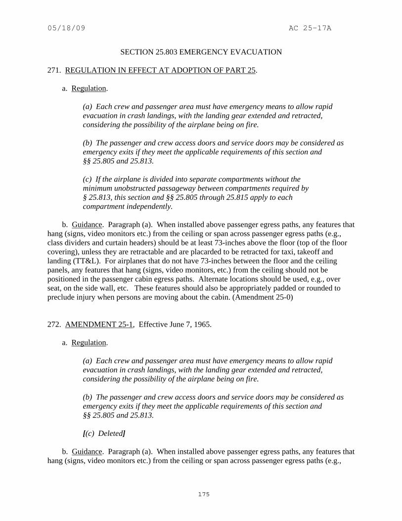
05/18/09 AC 25-17A
175
SECTION 25.803 EMERGENCY EVACUATION 271. REGULATION IN EFFECT AT ADOPTION OF PART 25. a. Regulation.
(a) Each crew and passenger area must have emergency means to allow rapid evacuation in crash landings, with the landing gear extended and retracted, considering the possibility of the airplane being on fire. (b) The passenger and crew access doors and service doors may be considered as emergency exits if they meet the applicable requirements of this section and §§ 25.805 and 25.813. (c) If the airplane is divided into separate compartments without the minimum unobstructed passageway between compartments required by § 25.813, this section and §§ 25.805 through 25.815 apply to each compartment independently.
b. Guidance. Paragraph (a). When installed above passenger egress paths, any features that hang (signs, video monitors etc.) from the ceiling or span across passenger egress paths (e.g., class dividers and curtain headers) should be at least 73-inches above the floor (top of the floor covering), unless they are retractable and are placarded to be retracted for taxi, takeoff and landing (TT&L). For airplanes that do not have 73-inches between the floor and the ceiling panels, any features that hang (signs, video monitors, etc.) from the ceiling should not be positioned in the passenger cabin egress paths. Alternate locations should be used, e.g., over seat, on the side wall, etc. These features should also be appropriately padded or rounded to preclude injury when persons are moving about the cabin. (Amendment 25-0) 272. AMENDMENT 25-1, Effective June 7, 1965. a. Regulation.
(a) Each crew and passenger area must have emergency means to allow rapid evacuation in crash landings, with the landing gear extended and retracted, considering the possibility of the airplane being on fire. (b) The passenger and crew access doors and service doors may be considered as emergency exits if they meet the applicable requirements of this section and §§ 25.805 and 25.813. [(c) Deleted]
b. Guidance. Paragraph (a). When installed above passenger egress paths, any features that hang (signs, video monitors etc.) from the ceiling or span across passenger egress paths (e.g.,

05/18/09 AC 25-17A
176
class dividers and curtain headers) should be at least 73-inches above the floor (top of the floor covering), unless they are retractable and are placarded to be retracted for taxi, takeoff and landing (TT&L). For airplanes that do not have 73-inches between the floor and the ceiling panels, any features that hang (signs, video monitors, etc.) from the ceiling should not be positioned in the passenger cabin egress paths. Alternate locations should be used, e.g., over seat, on the side wall, etc. These features should also be appropriately padded or rounded to preclude injury when persons are moving about the cabin. (Amendment 25-0) 273. AMENDMENT 25-15, Effective October 24, 1967. a. Regulation.
(a) Each crew and passenger area must have emergency means to allow rapid evacuation in crash landings, with the landing gear extended and retracted, considering the possibility of the airplane being on fire. [(b) Passenger ventral and tail cone, crew access, and service doors may be considered as emergency exits if they meet the applicable requirements of this section and §§ 25.805 through 25.813. (c) Except as provided in paragraph (d) of this section, on airplanes having a seating capacity of more than 44 passengers, it must be shown by actual demonstration that the maximum seating capacity, including the number of crewmembers required by the operating rules, for which certification is requested can be evacuated from the airplane to the ground within 90 seconds. Evacuees using stands or ramps allowed by subparagraph (8) of this paragraph are considered to be on the ground when they are on the stand or ramp, provided that the acceptance rate of the stand or ramp is no greater than the acceptance rate of the means available on the airplane for descent from the wing during an actual crash situation. The demonstration must be conducted under the following conditions: (1) It must be conducted either during the dark of the night or during daylight with the dark of the night simulated, utilizing only the emergency lighting system and utilizing only the emergency exits and emergency evacuation equipment on one side of the fuselage, with the airplane in the normal ground attitude, with landing gear extended. (2) All emergency equipment must be installed in accordance with specified limitations of the equipment. (3) Each external door and exit, and each internal door and curtain must be in a configuration to simulate a normal takeoff. (4) Seat belts and shoulder harnesses (as required) must be fastened.

05/18/09 AC 25-17A
177
(5) A representative passenger load of persons in normal health must be used as follows: (i) At least 30 percent must be female. (ii) Approximately 5 percent must be over 60 years of age, with a proportionate number of females. (iii) At least 5 percent but no more than 10 percent must be children under 12 years of age, prorated through that age group. (6) Persons who have knowledge of the operation of the exits and emergency equipment may be used to represent an air carrier crew. Such representative crewmembers must be in their seats assigned for takeoff and landing and none may be seated next to an emergency exit unless that seat is his assigned seat for takeoff. They must remain in their assigned seats until receiving the signal for the beginning of the demonstration. (7) There can be no practice or rehearsal of the demonstration for the passengers except that they may be briefed as to the location of all emergency exits before the demonstration. However, no indication may be given of the particular exits to be used in the demonstration. (8) Stands or ramps may be used for descent from the wing to the ground. (9) All evacuees other than those using an overwing exit must leave the airplane by the means provided as part of the airplane's equipment. (d) The emergency evacuation demonstration need not be repeated after a change in the interior arrangement of the airplane or an increase of not more than 5 percent in passenger seating capacity over that previously approved by actual demonstration, or both, if it can be substantiated by analysis, taking due account of the differences, that all the passengers for which the airplane is certificated can evacuate within 90 seconds. (e) An escape route must be established from each overwing emergency exit, marked and (except for flap surfaces suitable as slides) covered with a slip resistant surface.]
b. Guidance. (1) Paragraph (a). When installed above passenger egress paths, any features that hang (signs, video monitors, etc.) from the ceiling or span across passenger egress paths (e.g., class dividers and curtain headers) should be at least 73-inches above the floor (top of the floor covering), unless they are retractable and are placarded to be retracted for taxi, takeoff and landing (TT&L). For airplanes that do not have 73-inches between the floor and the ceiling panels, any features that hang (signs, video monitors, etc.) from the ceiling should not be

05/18/09 AC 25-17A
178
positioned in the passenger cabin egress paths. Alternate locations should be used, e.g., over seat, on the side wall, etc. These features should also be appropriately padded or rounded to preclude injury when persons are moving about the cabin. (Amendment 25-0) (2) Paragraph (c). (Amendment 25-15) (i) "The maximum capacity, including the number of crewmembers required by the operating rules, for which certification is requested" refers to the airplane model presented for certification. Subsequent models which have planned passenger capacities in excess of the certificated model should be substantiated on an individual basis. (Amendment 25-15) (ii) All passengers and crewmembers used in the demonstration must be evacuated to the ground or off-wing stand or ramp, if used, within 90 seconds to constitute a successful 90-second test. Use only the number of passengers for which approved seating is provided, not to exceed the limits of § 25.807(c) or (d). No credit is given for the number of evacuees on the ground at 90 seconds if all persons have not been evacuated. (Amendment 25-15) (iii) FAA observers should be stationed inside the airplane at expected critical locations, and outside the airplane at each exit to be used. (Amendment 25-15) (iv) The "acceptance rate" of the stand or ramp refers to the width of the passage to the stand or ramp. (Amendment 25-15) (v) The airplane should be configured with minimum aisle and passage clearance expected to be type certificated. This may require combining features of more than one model. (Amendment 25-15) (3) Paragraph (c)(1). One exit from each pair of exits should be used. Illumination on the floor or ground may be used, but it should be kept low and shielded against shining into the airplane windows or doors. (Amendment 25-15) (4) Paragraph (c)(2). (Amendment 25-15) (i) The emergency descent devices used in the demonstration should be those to be in the airplane type design. The slide certification program should have progressed to the point where the system is reliable and can be expected to perform safely during the demonstration. (Amendment 25-15) (ii) The airplane interior need not be a specific airline configuration. For example, galleys and other furnishings may be simulated by mockups, seats need not be TSO'd, etc. The interior should be described in sufficient detail to allow an FAA conformity inspection and an FAA interior compliance inspection. (Amendment 25-15) (5) Paragraph (c)(5). The following two age-sex distributions (A and B) have been found to be equivalent under the provisions of § 21.21(b)(1) to that stipulated in this paragraph: (Amendment 25-15)

05/18/09 AC 25-17A
179
(A) Distribution
Age and Gender Percent of Total Passengers Male 21-50 Not to exceed 56% Male 51-59 At least 9% Male 60+ At least 3.5% Female any age* At least 24% Female 51-59 At least 6% Female 60+ At least 1.5%
* This is in addition to the 6 and 1.5 percent requirements for females 51-59 and 60+ respectively. (B) Distribution
Age and Gender Percent of Total Passengers Male 18-50 Not to exceed 52.5% Male 51+ At least 15% Female 18-50 At least 22.5% Female 51+ At least 10%
Note: These tables have been revised in format to make them easier to understand, but are the same as in the previous version of this AC (i.e., AC 25-17, dated 7/15/1991). (6) Paragraph (c)(6). (Amendment 25-15) (i) Neither the crew nor passengers should hear or otherwise receive any indication that the demonstration is about to begin. The first indication to persons on board the airplane should be the test start signal. (Amendment 25-15) (ii) Following the test start signal, the flightcrew should simulate the time required for normal pilot compartment procedures prior to evacuating the flight deck. (Amendment 25-15) (iii) A group of crewmembers in excess of the number required for the demonstration should be available. The FAA will select the crew that will participate in the test from this group. Subsequent tests, if required, may use crewmembers from the group remaining. (Amendment 25-15) (7) Paragraph (c)(8). If the airplane is equipped with an off-wing assist means, it should be used during the demonstration in lieu of any stands or ramps. (Amendment 25-15)

05/18/09 AC 25-17A
180
(8) Paragraph (c)(9). (Amendment 25-15) (i) If safety pillows or other equipment unique to the active exits are employed, passengers and crew should enter the airplane through a tunnel or other means that prevents them from viewing the airplane exterior. (Amendment 25-15) (ii) Video cameras used to record activity inside the airplane should be positioned so as not to reveal the exits used in this demonstration. This may require the installation of cameras at inoperative exits. (Amendment 25-15) (iii) If exit deactivation is by an external indication (e.g., red light outside exit), this indication should not be visible from inside the airplane until after the demonstration has begun. Alternatively, unlit bulbs may be visible at all exits. (Amendment 25-15) (iv) Airplanes equipped with emergency descent means should be so equipped at inactive exits as well as active exits. (Amendment 25-15) (v) Safety personnel stationed outside the airplane to prevent injury to the participants, should not aid participants (until they have cleared the descent means) or interfere with the evacuation process, or position the assist means following its deployment. (Amendment 25-15) (9) Paragraph (e). (Amendment 25-15) (i) Military Specifications Mil W-5044B and Mil-W-5044C, titled "Walkway Compound, Nonslip and Walkway Matting, Nonslip,” measure dynamic coefficient of friction and provide an acceptable standard for the slip resistant properties when a minimum dynamic coefficient of friction of 0.45 is measured. This is an acceptable measure for this section and for § 25.793. (Amendment 25-15) (ii) A 42-inch wide escape path is acceptable for airplanes incorporating dual overwing Type III exits. (Amendment 25-15) 274. AMENDMENT 25-17, Effective June 20, 1968. a. Regulation.
(a) Each crew and passenger area must have emergency means to allow rapid evacuation in crash landings, with the landing gear extended and retracted, considering the possibility of the airplane being on fire. (b) Passenger ventral and tail cone, crew access, and service doors may be considered as emergency exits if they meet the applicable requirements of this section and §§ 25.805 through 25.813.

05/18/09 AC 25-17A
181
(c) Except as provided in paragraph (d) of this section, on airplanes having a seating capacity of more than 44 passengers, it must be shown by actual demonstration that the maximum seating capacity, including the number of crewmembers required by the operating rules, for which certification is requested can be evacuated from the airplane to the ground within 90 seconds. Evacuees using stands or ramps allowed by subparagraph (8) of this paragraph are considered to be on the ground when they are on the stand or ramp, provided that the [passage width] of the stand or ramp is no greater than the acceptance rate of the means available on the airplane for descent from the wing during an actual crash situation. The demonstration must be conducted under the following conditions: (1) It must be conducted either during the dark of the night or during daylight with the dark of the night simulated, utilizing only the emergency lighting system and utilizing only the emergency exits and emergency evacuation equipment on one side of the fuselage, with the airplane in the normal ground attitude, with landing gear extended. (2) All emergency equipment must be installed in accordance with specified limitations of the equipment. (3) Each external door and exit, and each internal door and curtain must be in a configuration to simulate a normal takeoff. (4) Seat belts and shoulder harnesses (as required) must be fastened. (5) A representative passenger load of persons in normal health must be used as follows: (i) At least 30 percent must be female. (ii) Approximately 5 percent must be over 60 years of age, with a proportionate number of females. (iii) At least 5 percent but no more than 10 percent must be children under 12 years of age, prorated through that age group. (6) Persons who have knowledge of the operation of the exits and emergency equipment may be used to represent an air carrier crew. Such representative crewmembers must be in their seats assigned for takeoff and landing and none may be seated next to an emergency exit unless that seat is his assigned seat for takeoff. They must remain in their assigned seats until receiving the signal for the beginning of the demonstration. (7) There can be no practice or rehearsal of the demonstration for the passengers except that they may be briefed as to the location of all emergency exits before the

05/18/09 AC 25-17A
182
demonstration. However, no indication may be given of the particular exits to be used in the demonstration. (8) Stands or ramps may be used for descent from the wing to the ground. (9) All evacuees other than those using an overwing exit must leave the airplane by the means provided as part of the airplane's equipment. (d) The emergency evacuation demonstration need not be repeated after a change in the interior arrangement of the airplane or an increase of not more than 5 percent in passenger seating capacity over that previously approved by actual demonstration, or both, if it can be substantiated by analysis, taking due account of the differences, that all the passengers for which the airplane is certificated can evacuate within 90 seconds. (e) An escape route must be established from each overwing emergency exit, marked and (except for flap surfaces suitable as slides) covered with a slip resistant surface.
b. Guidance. (1) Paragraph (a). When installed above passenger egress paths, any features that hang (signs, video monitors etc.) from the ceiling or span across passenger egress paths (e.g., class dividers and curtain headers) should be at least 73-inches above the floor (top of the floor covering), unless they are retractable and are placarded to be retracted for taxi, takeoff and landing (TT&L). For airplanes that do not have 73-inches between the floor and the ceiling panels, any features that hang (signs, video monitors, etc.) from the ceiling should not be positioned in the passenger cabin egress paths. Alternate locations should be used, e.g., over seat, on the side wall, etc. These features should also be appropriately padded or rounded to preclude injury when persons are moving about the cabin. (Amendment 25-0) (2) Paragraph (c). (Amendment 25-15) (i) "The maximum capacity, including the number of crewmembers required by the operating rules, for which certification is requested" refers to the airplane model presented for certification. Subsequent models which have planned passenger capacities in excess of the certificated model should be substantiated on an individual basis. (Amendment 25-15) (ii) All passengers and crewmembers used in the demonstration must be evacuated to the ground or off-wing stand or ramp, if used, within 90 seconds to constitute a successful 90-second test. Use only the number of passengers for which approved seating is provided, not to exceed the limits of § 25.807(c) or (d). No credit is given for the number of evacuees on the ground at 90 seconds if all persons have not been evacuated. (Amendment 25-15) (iii) FAA observers should be stationed inside the airplane at expected critical locations, and outside the airplane at each exit to be used. (Amendment 25-15)

05/18/09 AC 25-17A
183
(iv) The "acceptance rate" of the stand or ramp refers to the width of the passage to the stand or ramp. (Amendment 25-15) (v) The airplane should be configured with minimum aisle and passage clearance expected to be type certificated. This may require combining features of more than one model. (Amendment 25-15) (3) Paragraph (c)(1). One exit from each pair of exits should be used. Illumination on the floor or ground may be used, but it should be kept low and shielded against shining into the airplane windows or doors. (Amendment 25-15) (4) Paragraph (c)(2). (Amendment 25-15) (i) The emergency descent devices used in the demonstration should be those to be in the airplane type design. The slide certification program should have progressed to the point where the system is reliable and can be expected to perform safely during the demonstration. (Amendment 25-15) (ii) The airplane interior need not be a specific airline configuration. For example, galleys and other furnishings may be simulated by mockups, seats need not be TSO'd, etc. The interior should be described in sufficient detail to allow an FAA conformity inspection and an FAA interior compliance inspection. (Amendment 25-15) (5) Paragraph (c)(5). The following two age-sex distributions (A and B) have been found to be equivalent under the provisions of § 21.21(b)(1) to that stipulated in this paragraph: (Amendment 25-15) (A) Distribution
Age and Gender Percent of Total Passengers Male 21-50 Not to exceed 56% Male 51-59 At least 9% Male 60+ At least 3.5% Female any age* At least 24% Female 51-59 At least 6% Female 60+ At least 1.5%
* This is in addition to the 6 and 1.5 percent requirements for females 51-59 and 60+ respectively.

05/18/09 AC 25-17A
184
(B) Distribution
Age and Gender Percent of Total Passengers Male 18-50 Not to exceed 52.5% Male 51+ At least 15% Female 18-50 At least 22.5% Female 51+ At least 10%
Note: These tables have been revised in format to make them easier to understand, but are the same as in the previous version of this AC (i.e., AC 25-17, dated 7/15/1991). (6) Paragraph (c)(6). (Amendment 25-15) (i) Neither the crew nor passengers should hear or otherwise receive any indication that the demonstration is about to begin. The first indication to persons on board the airplane should be the test start signal. (Amendment 25-15) (ii) Following the test start signal, the flightcrew should simulate the time required for normal pilot compartment procedures prior to evacuating the flight deck. (Amendment 25-15) (iii) A group of crewmembers in excess of the number required for the demonstration should be available. The FAA will select the crew that will participate in the test from this group. Subsequent tests, if required, may use crewmembers from the group remaining. (Amendment 25-15) (7) Paragraph (c)(8). If the airplane is equipped with an off-wing assist means, it should be used during the demonstration in lieu of any stands or ramps. (Amendment 25-15) (8) Paragraph (c)(9). (Amendment 25-15) (i) If safety pillows or other equipment unique to the active exits are employed, passengers and crew should enter the airplane through a tunnel or other means that prevents them from viewing the airplane exterior. (Amendment 25-15) (ii) Video cameras used to record activity inside the airplane should be positioned so as not to reveal the exits used in this demonstration. This may require the installation of cameras at inoperative exits. (Amendment 25-15) (iii) If exit deactivation is by an external indication (e.g., red light outside exit), this indication should not be visible from inside the airplane until after the demonstration has begun. Alternatively, unlit bulbs may be visible at all exits. (Amendment 25-15)

05/18/09 AC 25-17A
185
(iv) Airplanes equipped with emergency descent means should be so equipped at inactive exits as well as active exits. (Amendment 25-15) (v) Safety personnel stationed outside the airplane to prevent injury to the participants, should not aid participants (until they have cleared the descent means) or interfere with the evacuation process, or position the assist means following its deployment. (Amendment 25-15) (9) Paragraph (e). (Amendment 25-15) (i) Military Specifications Mil W-5044B and Mil-W-5044C, titled "Walkway Compound, Nonslip and Walkway Matting, Nonslip,” measure dynamic coefficient of friction and provide an acceptable standard for the slip resistant properties when a minimum dynamic coefficient of friction of 0.45 is measured. This is an acceptable measure for this section and for § 25.793. (Amendment 25-15) (ii) A 42-inch wide escape path is acceptable for airplanes incorporating dual overwing Type III exits. (Amendment 25-15) 275. AMENDMENT 25-20, Effective April 23, 1969. a. Regulation.
(a) Each crew and passenger area must have emergency means to allow rapid evacuation in crash landings, with the landing gear extended and retracted, considering the possibility of the airplane being on fire. [(b) Passenger ventral and tail cone exits and any floor level door or exit in the side of the fuselage (other than those leading into a cargo or baggage compartment that is not accessible from the passenger cabin) that is 44 or more-inches high and 20 or more-inches wide, but not wider than 46-inches, must meet the applicable emergency exit requirements of this section and §§ 25.807 through 25.813.] (c) Except as provided in paragraph (d) of this section, on airplanes having a seating capacity of more than 44 passengers, it must be shown by actual demonstration that the maximum seating capacity, including the number of crewmembers required by the operating rules, for which certification is requested can be evacuated from the airplane to the ground within 90 seconds. Evacuees using stands or ramps allowed by subparagraph (8) of this paragraph are considered to be on the ground when they are on the stand or ramp, provided that the passage width of the stand or ramp is no greater than the acceptance rate of the means available on the airplane for descent from the wing during an actual crash situation. The demonstration must be conducted under the following conditions:

05/18/09 AC 25-17A
186
[(1) It must be conducted either during the dark of the night or during daylight with the dark of the night simulated, utilizing only the emergency lighting system and utilizing only the minimum number of required emergency exits and the emergency evacuation equipment on one side of the fuselage with the airplane in the normal ground attitude, with landing gear extended.] (2) All emergency equipment must be installed in accordance with specified limitations of the equipment. (3) Each external door and exit, and each internal door and curtain must be in a configuration to simulate a normal takeoff. (4) Seat belts and shoulder harnesses (as required) must be fastened. (5) A representative passenger load of persons in normal health must be used as follows: (i) At least 30 percent must be female. (ii) Approximately 5 percent must be over 60 years of age, with a proportionate number of females. (iii) At least 5 percent but no more than 10 percent must be children under 12 years of age, prorated through that age group. (6) Persons who have knowledge of the operation of the exits and emergency equipment may be used to represent an air carrier crew. Such representative crewmembers must be in their seats assigned for takeoff and landing and none may be seated next to an emergency exit unless that seat is his assigned seat for takeoff. They must remain in their assigned seats until receiving the signal for the beginning of the demonstration. (7) There can be no practice or rehearsal of the demonstration for the passengers except that they may be briefed as to the location of all emergency exits before the demonstration. However, no indication may be given of the particular exits to be used in the demonstration. (8) Stands or ramps may be used for descent from the wing to the ground. (9) All evacuees other than those using an overwing exit must leave the airplane by the means provided as part of the airplane's equipment. (d) The emergency evacuation demonstration need not be repeated after a change in the interior arrangement of the airplane or an increase of not more than 5 percent in passenger seating capacity over that previously approved by actual demonstration, or

05/18/09 AC 25-17A
187
both, if it can be substantiated by analysis, taking due account of the differences, that all the passengers for which the airplane is certificated can evacuate within 90 seconds. (e) An escape route must be established from each overwing emergency exit, marked and (except for flap surfaces suitable as slides) covered with a slip resistant surface.
b. Guidance. (1) Paragraph (a). When installed above passenger egress paths, any features that hang (signs, video monitors etc.) from the ceiling or span across passenger egress paths (e.g., class dividers and curtain headers) should be at least 73-inches above the floor (top of the floor covering), unless they are retractable and are placarded to be retracted for taxi, takeoff and landing (TT&L). For airplanes that do not have 73-inches between the floor and the ceiling panels, any features that hang (signs, video monitors, etc.) from the ceiling should not be positioned in the passenger cabin egress paths. Alternate locations should be used, e.g., over seat, on the side wall, etc. These features should also be appropriately padded or rounded to preclude injury when persons are moving about the cabin. (Amendment 25-0) (2) Paragraph (c). (Amendment 25-15) (i) "The maximum capacity for which certification is requested" refers to the airplane model presented for certification. Subsequent models which have planned passenger capacities in excess of the certificated model should be substantiated on an individual basis. (Amendment 25-15) (ii) All passengers and crewmembers used in the demonstration must be evacuated to the ground or off-wing stand or ramp, if used, within 90 seconds to constitute a successful 90-second test. Use only the number of passengers for which approved seating is provided, not to exceed the limits of § 25.807(c) or (d). No credit is given for the number of evacuees on the ground at 90 seconds if all persons have not been evacuated. (Amendment 25-15) (iii) FAA observers should be stationed inside the airplane at expected critical locations, and outside the airplane at each exit to be used. (Amendment 25-15) (iv) The "acceptance rate" of the stand or ramp refers to the width of the passage to the stand or ramp. (Amendment 25-15) (v) The airplane should be configured with minimum aisle and passage clearance expected to be type certificated. This may require combining features of more than one model. (Amendment 25-15) (3) Paragraph (c)(1). One exit from each pair of exits should be used. Illumination on the floor or ground may be used, but it should be kept low and shielded against shining into the airplane windows or doors. (Amendment 25-15)

05/18/09 AC 25-17A
188
(4) Paragraph (c)(2). (Amendment 25-15) (i) The emergency descent devices used in the demonstration should be those to be in the airplane type design. The slide certification program should have progressed to the point where the system is reliable and can be expected to perform safely during the demonstration. (Amendment 25-15) (ii) The airplane interior need not be a specific airline configuration. For example, galleys and other furnishings may be simulated by mockups, seats need not be TSO'd, etc. The interior should be described in sufficient detail to allow an FAA conformity inspection and an FAA interior compliance inspection. (Amendment 25-15) (5) Paragraph (c)(5). The following two age-sex distributions (A and B) have been found to be equivalent under the provisions of § 21.21(b)(1) to that stipulated in this paragraph: (Amendment 25-15) (A) Distribution
Age and Gender Percent of Total Passengers Male 21-50 Not to exceed 56% Male 51-59 At least 9% Male 60+ At least 3.5% Female any age* At least 24% Female 51-59 At least 6% Female 60+ At least 1.5%
* This is in addition to the 6 and 1.5 percent requirements for females 51-59 and 60+ respectively. (B) Distribution
Age and Gender Percent of Total Passengers Male 18-50 Not to exceed 52.5% Male 51+ At least 15% Female 18-50 At least 22.5% Female 51+ At least 10%
Note: These tables have been revised in format to make them easier to understand, but are the same as in the previous version of this AC (i.e., AC 25-17, dated 7/15/1991).

05/18/09 AC 25-17A
189
(6) Paragraph (c)(6). (Amendment 25-15) (i) Neither the crew nor passengers should hear or otherwise receive any indication that the demonstration is about to begin. The first indication to persons on board the airplane should be the test start signal. (Amendment 25-15) (ii) Following the test start signal, the flightcrew should simulate the time required for normal pilot compartment procedures prior to evacuating the flight deck. (Amendment 25-15) (iii) A group of crewmembers in excess of the number required for the demonstration should be available. The FAA will select the crew that will participate in the test from this group. Subsequent tests, if required, may use crewmembers from the group remaining. (Amendment 25-15) (7) Paragraph (c)(8). If the airplane is equipped with an off-wing assist means, it should be used during the demonstration in lieu of any stands or ramps. (Amendment 25-15) (8) Paragraph (c)(9). (Amendment 25-15) (i) If safety pillows or other equipment unique to the active exits are employed, passengers and crew should enter the airplane through a tunnel or other means that prevents them from viewing the airplane exterior. (Amendment 25-15) (ii) Video cameras used to record activity inside the airplane should be positioned so as not to reveal the exits used in this demonstration. This may require the installation of cameras at inoperative exits. (Amendment 25-15) (iii) If exit deactivation is by an external indication (e.g., red light outside exit), this indication should not be visible from inside the airplane until after the demonstration has begun. Alternatively, unlit bulbs may be visible at all exits. (Amendment 25-15) (iv) Airplanes equipped with emergency descent means should be so equipped at inactive exits as well as active exits. (Amendment 25-15) (v) Safety personnel stationed outside the airplane to prevent injury to the participants, should not aid participants (until they have cleared the descent means) or interfere with the evacuation process, or position the assist means following its deployment. (Amendment 25-15) (9) Paragraph (e). (Amendment 25-15) (i) Military Specifications Mil W-5044B and -5044C, titled "Walkway Compound, Nonslip and Walkway Matting, Nonslip,” measure dynamic coefficient of friction and provide an

05/18/09 AC 25-17A
190
acceptable standard for the slip resistant properties when a minimum dynamic coefficient of friction of 0.45 is measured. This is an acceptable measure for this section and for § 25.793. (Amendment 25-15) (ii) A 42-inch wide escape path is acceptable for airplanes incorporating dual overwing Type III exits. (Amendment 25-15) 276. AMENDMENT 25-32, Effective May 1, 1972. a. Regulation.
(a) Each crew and passenger area must have emergency means to allow rapid evacuation in crash landings, with the landing gear extended and retracted, considering the possibility of the airplane being on fire. (b) Passenger ventral and tail cone exits and any floor level door or exit in the side of the fuselage (other than those leading into a cargo or baggage compartment that is not accessible from the passenger cabin) that is 44 or more-inches high and 20 or more-inches wide, but not wider than 46-inches, must meet the applicable emergency exit requirements of this section and §§ 25.807 through 25.813. (c) Except as provided in paragraph (d) of this section, on airplanes having a seating capacity of more than 44 passengers, it must be shown by actual demonstration that the maximum seating capacity, including the number of crewmembers required by the operating rules, for which certification is requested can be evacuated from the airplane to the ground within 90 seconds. Evacuees using stands or ramps allowed by subparagraph (8) of this paragraph are considered to be on the ground when they are on the stand or ramp, provided that the passage width of the stand or ramp is no greater than the acceptance rate of the means available on the airplane for descent from the wing during an actual crash situation. The demonstration must be conducted under the following conditions: (1) It must be conducted either during the dark of the night or during daylight with the dark of the night simulated, utilizing only the emergency lighting system and utilizing only the minimum number of required emergency exits and the emergency evacuation equipment on one side of the fuselage with the airplane in the normal ground attitude, with landing gear extended. (2) All emergency equipment must be installed in accordance with specified limitations of the equipment. (3) Each external door and exit, and each internal door and curtain must be in a configuration to simulate a normal takeoff. (4) Seat belts and shoulder harnesses (as required) must be fastened.

05/18/09 AC 25-17A
191
(5) A representative passenger load of persons in normal health must be used as follows: (i) At least 30 percent must be female. (ii) Approximately 5 percent must be over 60 years of age, with a proportionate number of females. (iii) At least 5 percent but no more than 10 percent must be children under 12 years of age, prorated through that age group. (6) Persons who have knowledge of the operation of the exits and emergency equipment may be used to represent an air carrier crew. Such representative crewmembers must be in their seats assigned for takeoff and landing and none may be seated next to an emergency exit unless that seat is his assigned seat for takeoff. They must remain in their assigned seats until receiving the signal for the beginning of the demonstration. (7) There can be no practice or rehearsal of the demonstration for the passengers except that they may be briefed as to the location of all emergency exits before the demonstration. However, no indication may be given of the particular exits to be used in the demonstration. (8) Stands or ramps may be used for descent from the wing to the ground. (9) All evacuees other than those using an overwing exit must leave the airplane by the means provided as part of the airplane's equipment. (d) The emergency evacuation demonstration need not be repeated after a change in the interior arrangement of the airplane or an increase of not more than 5 percent in passenger seating capacity over that previously approved by actual demonstration, or both, if it can be substantiated by analysis, taking due account of the differences, that all the passengers for which the airplane is certificated can evacuate within 90 seconds. [(e) An escape route must be established from each overwing emergency exit, and (except for flap surfaces suitable as slides) covered with a slip resistant surface. Except where a means for channeling the flow of evacuees is provided- (1) The escape route must be at least 42-inches wide at Type A passenger emergency exits and must be at least two feet wide at all other passenger emergency exits, and (2) The escape route surface must have a reflectance of at least 80 percent, and must be defined by markings with a surface-to-marking contrast ratio of at least 5.1.]

05/18/09 AC 25-17A
192
b. Guidance. (1) Paragraph (a). When installed above passenger egress paths, any features that hang (signs, video monitors etc.) from the ceiling or span across passenger egress paths (e.g., class dividers and curtain headers) should be at least 73-inches above the floor (top of the floor covering), unless they are retractable and are placarded to be retracted for taxi, takeoff and landing (TT&L). For airplanes that do not have 73-inches between the floor and the ceiling panels, any features that hang (signs, video monitors, etc.) from the ceiling should not be positioned in the passenger cabin egress paths. Alternate locations should be used, e.g., over seat, on the side wall, etc. These features should also be appropriately padded or rounded to preclude injury when persons are moving about the cabin. (Amendment 25-0) (2) Paragraph (c). (Amendment 25-15) (i) "The maximum capacity, including the number of crewmembers required by the operating rules, for which certification is requested" refers to the airplane model presented for certification. Subsequent models which have planned passenger capacities in excess of the certificated model should be substantiated on an individual basis. (Amendment 25-15) (ii) All passengers and crewmembers used in the demonstration must be evacuated to the ground or off-wing stand or ramp, if used, within 90 seconds to constitute a successful 90-second test. Use only the number of passengers for which approved seating is provided, not to exceed the limits of § 25.807(c) or (d). No credit is given for the number of evacuees on the ground at 90 seconds if all persons have not been evacuated. (Amendment 25-15) (iii) FAA observers should be stationed inside the airplane at expected critical locations, and outside the airplane at each exit to be used. (Amendment 25-15) (iv) The "acceptance rate" of the stand or ramp refers to the width of the passage to the stand or ramp. (Amendment 25-15) (v) The airplane should be configured with minimum aisle and passage clearance expected to be type certificated. This may require combining features of more than one model. (Amendment 25-15) (3) Paragraph (c)(1). One exit from each pair of exits should be used. Illumination on the floor or ground may be used, but it should be kept low and shielded against shining into the airplane windows or doors. (Amendment 25-15) (4) Paragraph (c)(2). (Amendment 25-15) (i) The emergency descent devices used in the demonstration should be those to be in the airplane type design. The slide certification program should have progressed to the point where the system is reliable and can be expected to perform safely during the demonstration. (Amendment 25-15)

05/18/09 AC 25-17A
193
(ii) The airplane interior need not be a specific airline configuration. For example, galleys and other furnishings may be simulated by mockups, seats need not be TSO'd, etc. The interior should be described in sufficient detail to allow an FAA conformity inspection and an FAA interior compliance inspection. (Amendment 25-15) (5) Paragraph (c)(5). The following two age-sex distributions (A and B) have been found to be equivalent under the provisions of § 21.21(b)(1) to that stipulated in this paragraph: (Amendment 25-15) (A) Distribution
Age and Gender Percent of Total Passengers Male 21-50 Not to exceed 56% Male 51-59 At least 9% Male 60+ At least 3.5% Female any age* At least 24% Female 51-59 At least 6% Female 60+ At least 1.5%
* This is in addition to the 6 and 1.5 percent requirements for females 51-59 and 60+ respectively. (B) Distribution
Age and Gender Percent of Total Passengers Male 18-50 Not to exceed 52.5% Male 51+ At least 15% Female 18-50 At least 22.5% Female 51+ At least 10%
Note: These tables have been revised in format to make them easier to understand, but are the same as in the previous version of this AC (i.e., AC 25-17, dated 7/15/1991). (6) Paragraph (c)(6). (Amendment 25-15) (i) Neither the crew nor passengers should hear or otherwise receive any indication that the demonstration is about to begin. The first indication to persons on board the airplane should be the test start signal. (Amendment 25-15) (ii) Following the test start signal, the flightcrew should simulate the time required for normal pilot compartment procedures prior to evacuating the flight deck. (Amendment 25-15)

05/18/09 AC 25-17A
194
(iii) A group of crewmembers in excess of the number required for the demonstration should be available. The FAA will select the crew that will participate in the test from this group. Subsequent tests, if required, may use crewmembers from the group remaining. (Amendment 25-15) (7) Paragraph (c)(8). If the airplane is equipped with an off-wing assist means, it should be used during the demonstration in lieu of any stands or ramps. (Amendment 25-15) (8) Paragraph (c)(9). (Amendment 25-15) (i) If safety pillows or other equipment unique to the active exits are employed, passengers and crew should enter the airplane through a tunnel or other means that prevents them from viewing the airplane exterior. (Amendment 25-15) (ii) Video cameras used to record activity inside the airplane should be positioned so as not to reveal the exits used in this demonstration. This may require the installation of cameras at inoperative exits. (Amendment 25-15) (iii) If exit deactivation is by an external indication (e.g., red light outside exit), this indication should not be visible from inside the airplane until after the demonstration has begun. Alternatively, unlit bulbs may be visible at all exits. (Amendment 25-15) (iv) Airplanes equipped with emergency descent means should be so equipped at inactive exits as well as active exits. (Amendment 25-15) (v) Safety personnel stationed outside the airplane to prevent injury to the participants, should not aid participants (until they have cleared the descent means) or interfere with the evacuation process, or position the assist means following its deployment. (Amendment 25-15) (9) Paragraph (e). (Amendment 25-15) (i) Military Specifications Mil W-5044B and Mil-W-5044C, titled "Walkway Compound, Nonslip and Walkway Matting, Nonslip,” measure dynamic coefficient of friction and provide an acceptable standard for the slip resistant properties when a minimum dynamic coefficient of friction of 0.45 is measured. This is an acceptable measure for this section and for § 25.793. (Amendment 25-15) (ii) A 42-inch wide escape path is acceptable for airplanes incorporating dual overwing Type III exits. (Amendment 25-15)

05/18/09 AC 25-17A
195
277. AMENDMENT 25-46, Effective December 1, 1978. a. Regulation.
Note: This amendment substantially revised the regulation to incorporate part 121 requirements.
(a) Each crew and passenger area must have emergency means to allow rapid evacuation in crash landings, with the landing gear extended and retracted, considering the possibility of the airplane being on fire. (b) Passenger ventral and tail cone exits and any floor level door or exit in the side of the fuselage (other than those leading into a cargo or baggage compartment that is not accessible from the passenger cabin) that is 44 or more-inches high and 20 or more-inches wide, but not wider than 46-inches, must meet the applicable emergency exit requirements of this section and sections 25.807 through 25.813. [(c) Except as provided in paragraph (d) of this section, for airplanes having a seating capacity or more than 44 passengers, it must be shown by actual demonstration that the maximum seating capacity, including the number of crewmembers required by the operating rules for which certification is requested, can be evacuated from the airplane to the ground within 90 seconds. The demonstration must be conducted under the following conditions: (1) It must be conducted either during the dark of the night or during daylight with the dark of the night simulated. If the demonstration is conducted indoors during daylight hours it must be conducted with each window covered and each door closed to minimize the daylight effect. Illumination on the floor or ground may be used, but it must be kept low and shielded against shining into the airplane's windows or doors. (2) The airplane must be in a normal attitude with landing gear extended. (3) Stands or ramps may be used for descent from the wing to the ground, and safety equipment such as mats or inverted life rafts may be placed on the floor or ground to protect participants. No other equipment that is not part of the airplane's emergency evacuation equipment may be used to aid the participants in reaching the ground. (4) Except as provided in paragraph (c)(1) of this section, only the airplane's emergency lighting system may provide illumination. (5) All emergency equipment required for the planned operation of the airplane must be installed. (6) Each external door and exit, and each internal door or curtain, must be in the takeoff configuration.

05/18/09 AC 25-17A
196
(7) Each crewmember must be seated in the normally assigned seat for takeoff and must remain in that seat until receiving the signal for commencement of the demonstration. Each crewmember must be- (i) For compliance with this section or § 121.291 of this chapter, a member of a regularly scheduled line crew, or (ii) For compliance with this section, a person having knowledge of the operation of exits and emergency equipment. (8) A representative passenger load of persons in normal health must be used as follows: (i) At least 30 percent must be females. (ii) At least 5 percent must be over 60 years of age with a proportionate number of females. (iii) At least 5 percent but not more than 10 percent, must be children under 12 years of age, prorated through that age group. (iv) Three life-size dolls, not included as part of the total passenger load, must be carried by passengers to simulate live infants 2 years old or younger. (v) Crewmembers, mechanics, and training personnel, who maintain or operate the airplane in the normal course of their duties, may not be used as passengers. (9) No passenger may be assigned a specific seat except as the Administrator may require. Except as required by paragraph (c)(12) of this section, no employee of the applicant may be seated next to an emergency exit. (10) Seat belts and shoulder harnesses (as required) must be fastened. (11) Before the start of the demonstration approximately one-half of the total average amount of carry-on baggage, blankets, pillows, and other similar articles must be distributed at several locations in the aisles and emergency exits access ways to create minor obstructions. (12) Each crewmember must be seated in his normally assigned seat for takeoff and must remain in that seat until receiving the signal for commencement of the demonstration. (13) No prior indication may be given to any crewmember or passenger of the particular exits to be used in the demonstration.

05/18/09 AC 25-17A
197
(14) The applicant may not practice, rehearse, or describe the demonstration for the participants nor may any participant have taken part in this type of demonstration within the preceding 6 months. (15) The pretakeoff passenger briefing required by § 121.571 of this chapter may be given. The passengers may also be advised to follow directions of crewmembers, but not be instructed on the procedures to be followed in the demonstration. (16) If safety equipment as allowed by paragraph (c)(3) of this section is provided, either all passenger and cockpit windows must be blacked out or all of the emergency exits must have safety equipment in order to prevent disclosure of the available emergency exits. (17) Not more than 50 percent of the emergency exits in the sides of the fuselage of an airplane that meet all of the requirements applicable to the required emergency exits for that airplane may be used for the demonstration. Exits that are not to be used in the demonstration must have the exit handle deactivated or must be indicated by red lights, red tape, or other acceptable means, placed outside the exits to indicate fire or other reason why they are unusable. The exits to be used must be representative of all the emergency exits on the airplane and must be designated by the applicant, subject to approval by the Administrator. At least one floor level exit must be used. (18) All evacuees, except those using an over-the-wing exit, must leave the airplane by a means provided as part of the airplane's equipment. (19) The applicant's approved procedures must be fully utilized during the demonstration. (20) The evacuation time period is completed when the last occupant has evacuated the airplane and is on the ground. Provided that the acceptance rate of the stand or ramp is no greater than the acceptance rate of the means available on the airplane for descent from the wing during an actual crash situation, evacuees using stands or ramps allowed by paragraph (c)(3) of this section are considered to be on the ground when they are on the stand or ramp. (d) A combination of analysis and tests may be used to show that the airplane is capable of being evacuated within 90 seconds under the conditions specified in § 25.803(c) of this section if the Administrator finds that the combination of analysis and tests will provide data with respect to the emergency evacuation capability of the airplane equivalent to that which would be obtained by actual demonstration.] (e) An escape route must be established from each overwing emergency exit, and (except for flap surfaces suitable as slides) covered with a slip resistant surface. Except where a means for channeling the flow of evacuees is provided-

05/18/09 AC 25-17A
198
(1) The escape route must be at least 42-inches wide at Type A passenger emergency exits and must be at least two feet wide at all other passenger emergency exits, and (2) The escape route surface must have a reflectance of at least 80 percent, and must be defined by markings with a surface-to-marking contract ratio of at least 5:1.
b. Guidance. (1) Paragraph (a). When installed above passenger egress paths, any features that hang (signs, video monitors etc.) from the ceiling or span across passenger egress paths (e.g., class dividers and curtain headers) should be at least 73-inches above the floor (top of the floor covering), unless they are retractable and are placarded to be retracted for taxi, takeoff and landing (TT&L). For airplanes that do not have 73-inches between the floor and the ceiling panels, any features that hang (signs, video monitors, etc.) from the ceiling should not be positioned in the passenger cabin egress paths. Alternate locations should be used, e.g., over seat, on the side wall, etc. These features should also be appropriately padded or rounded to preclude injury when persons are moving about the cabin. (Amendment 25-0) (2) Paragraph (c). (Amendment 25-15) (i) "The maximum capacity, including the number crewmembers required by the operating rules for which certification is requested" refers to the airplane model presented for certification. Subsequent models which have planned passenger capacities in excess of the certificated model should be substantiated on an individual basis. (Amendment 25-15) (ii) All passengers and crewmembers used in the demonstration must be evacuated to the ground or off-wing stand or ramp, if used, within 90 seconds to constitute a successful 90-second test. Use only the number of passengers for which approved seating is provided, not to exceed the limits of § 25.807(c) or (d). No credit is given for the number of evacuees on the ground at 90 seconds if all persons have not been evacuated. (Amendment 25-15) (iii) FAA observers should be stationed inside the airplane at expected critical locations, and outside the airplane at each exit to be used. (Amendment 25-15) (iv) The airplane should be configured with minimum aisle and passage clearance expected to be type certificated. This may require combining features of more than one model. (Amendment 25-15) (3) Paragraph (c)(3). (Amendment 25-15) (i) The emergency descent devices used in the demonstration should be those to be in the airplane type design. The slide certification program should have progressed to the point where the system is reliable and can be expected to perform safely during the demonstration. (Amendment 25-15)

05/18/09 AC 25-17A
199
(ii) The airplane interior need not be a specific airline configuration. For example, galleys and other furnishings may be simulated by mockups, seats need not be TSO'd, etc. The interior should be described in sufficient detail to allow an FAA conformity inspection and an FAA interior compliance inspection. (Amendment 25-15) (4) Paragraph (c)(3). If the airplane is equipped with an off-wing assist means, it should be used during the demonstration in lieu of any stands or ramps. (Amendment 25-15) (5) Paragraph (c)(8). The following two age-sex distributions (A and B) are acceptable alternates to that stipulated in this paragraph: (Amendment 25-15) (A) Distribution
Age and Gender Percent of Total Passengers Male 21-50 Not to exceed 56% Male 51-59 At least 9% Male 60+ At least 3.5% Female any age* At least 24% Female 51-59 At least 6% Female 60+ At least 1.5%
* This is in addition to the 6 and 1.5 percent requirements for females 51-59 and 60+ respectively. (B) Distribution
Age and Gender Percent of Total Passengers Male 18-50 Not to exceed 52.5% Male 51+ At least 15% Female 18-50 At least 22.5% Female 51+ At least 10%
Note: These tables have been revised in format to make them easier to understand, but are the same as in the previous version of this AC (i.e., AC 25-17, dated 7/15/1991). (6) Paragraph (c)(12). (Amendment 25-15) (i) Neither the crew nor passengers should hear or otherwise receive any indication that the demonstration is about to begin. The first indication to persons on board the airplane should be the test start signal. (Amendment 25-15)

05/18/09 AC 25-17A
200
(ii) Following the test start signal, the flightcrew should simulate the time required for normal pilot compartment procedures prior to evacuating the flight deck. (Amendment 25-15) (iii) A group of crewmembers in excess of the number required for the demonstration should be available. The FAA will select the crew that will participate in the test from this group. Subsequent tests, if required, may use crewmembers from the group remaining. (Amendment 25-15) (7) Paragraph (c)(17). One exit from each pair of exits may be used to satisfy the 50 percent requirement. (Amendment 25-46) (8) Paragraph (c)(17). (Amendment 25-15) (i) Video cameras used to record activity inside the airplane should be positioned so as not to reveal the exits used in this demonstration. This may require the installation of cameras at inoperative exits. (Amendment 25-15) (ii) If exit deactivation is by an external indication (e.g., red light outside exit), this indication should not be visible from inside the airplane until after the demonstration has begun. Alternatively, unlit bulbs may be visible at all exits. (Amendment 25-15) (iii) Airplanes equipped with emergency descent means should be so equipped at inactive exits as well as active exits. (Amendment 25-15) (iv) Safety personnel stationed outside the airplane to prevent injury to the participants, should not aid participants (until they have cleared the descent means) or interfere with the evacuation process, or position the assist means following its deployment. (Amendment 25-15) (9) Paragraph (d). Evacuation analyses should be based on actual demonstrations used to show compliance with §§ 25.803 or 121.291 and/or other appropriate tests. If the test data is available, and applicable to the additional configuration, analysis may be conducted. The analysis should include consideration of exit size and distribution; slide deployment times and evacuee evacuation rates; analysis of critical passenger flow points i.e., door, aisle, slide, for evacuation rate limiting factor; expected evacuee behavior (hesitation, etc.) as observed on previous tests; and any other consideration pertinent to the particular model airplane. (Amendment 25-46) (10) Paragraph (e). (Amendment 25-15) (i) Military Specifications Mil W-5044B and Mil-W-5044C, titled "Walkway Compound, Nonslip and Walkway Matting, Nonslip,” measure dynamic coefficient of friction and provide an acceptable standard for the slip resistant properties when a minimum dynamic coefficient of friction of 0.45 is measured. This is an acceptable measure for this section and for § 25.793. (Amendment 25-15)

05/18/09 AC 25-17A
201
(ii) A 42-inch wide escape path is acceptable for airplanes incorporating dual overwing Type III exits. (Amendment 25-15) (11) Refer to AC 25.803-1, “Emergency Evacuation Demonstrations,” dated 11/13/89. (Amendment 25-46) 278. AMENDMENT 25-72, Effective August 20, 1990. a. Regulation.
Note: This amendment substantially revised the regulation to move the test criteria to a new Appendix J of the regulation.
[(a) Each crew and passenger area must have emergency means to allow rapid evacuation in crash landings, with the landing gear extended as well as with the landing gear retracted, considering the possibility of the airplane being on fire. (b) [Reserved.] (c) For airplanes having a seating capacity of more than 44 passengers, it must be shown that the maximum seating capacity, including the number of crewmembers required by the operating rules for which certification is requested, can be evacuated from the airplane to the ground under simulated emergency conditions within 90 seconds. Compliance with this requirement must be shown by actual demonstration using the test criteria outlined in Appendix J of this part unless the Administrator finds that a combination of analysis and testing will provide data equivalent to that which would be obtained by actual demonstration. (d) [Reserved.] (e) [Reserved.]]
b. Guidance. (1) Paragraph (a). When installed above passenger egress paths, any features that hang (signs, video monitors etc.) from the ceiling or span across passenger egress paths (e.g., class dividers and curtain headers) should be at least 73-inches above the floor (top of the floor covering), unless they are retractable and are placarded to be retracted for taxi, takeoff and landing (TT&L). For airplanes that do not have 73-inches between the floor and the ceiling panels, any features that hang (signs, video monitors, etc.) from the ceiling should not be positioned in the passenger cabin egress paths. Alternate locations should be used, e.g., over seat, on the side wall, etc. These features should also be appropriately padded or rounded to preclude injury when persons are moving about the cabin. (Amendment 25-0)

05/18/09 AC 25-17A
202
(2) Paragraph (c). (Amendment 25-15) (i) "…seating capacity of more than 44 passengers, it must be shown that the maximum seating capacity, including the number of crewmembers required by the operating rules for which certification is requested refers to the airplane model presented for certification.” Subsequent models which have planned passenger capacities in excess of the certificated model should be substantiated on an individual basis. (Amendment 25-15) (ii) All passengers and crewmembers used in the demonstration must be evacuated to the ground or off-wing stand or ramp, if used, within 90 seconds to constitute a successful 90 seconds test. Use only the number of passengers for which approved seating is provided, not to exceed the limits of § 25.807(d) or (e). No credit is given for the number of evacuees on the ground at 90 seconds if all persons have not been evacuated. (Amendment 25-15) (iii) FAA observers should be stationed inside the airplane at expected critical locations, and outside the airplane at each exit to be used. (Amendment 25-15) (iv) The airplane should be configured with minimum aisle and passage clearance expected to be type certificated. This may require combining features of more than one model. (Amendment 25-15) (3) Appendix J. (Amendment 25-15) (i) The emergency descent devices used in the demonstration should be those to be in the airplane type design. The slide certification program should have progressed to the point where the system is reliable and can be expected to perform safely during the demonstration. (Amendment 25-15) (ii) The airplane interior need not be a specific airline configuration. For example, galleys and other furnishings may be simulated by mockups, seats need not be TSO'd, etc. The interior should be described in sufficient detail to allow an FAA conformity inspection and an FAA interior compliance inspection. (Amendment 25-15) (4) Appendix J. If the airplane is equipped with an off-wing assist means, it should be used during the demonstration in lieu of any stands or ramps. (Amendment 25-15) (5) Appendix J. (Amendment 25-15) (i) Neither the crew nor passengers should hear or otherwise receive any indication that the demonstration is about to begin. The first indication to persons on board the airplane should be the test start signal. (Amendment 25-15) (ii) Following the test start signal, the flightcrew should simulate the time required for normal pilot compartment procedures prior to evacuating the flight deck. (Amendment 25-15)
05/18/09 AC 25-17A
203
(iii) A group of crewmembers in excess of the number required for the demonstration should be available. The FAA will select the crew that will participate in the test from this group. Subsequent tests, if required, may use crewmembers from the group remaining. (Amendment 25-15) (6) Appendix J. One exit from each pair of exits may be used to satisfy the 50 percent requirement. (Amendment 25-46) (7) Appendix J. (Amendment 25-15) (i) Video cameras used to record activity inside the airplane should be positioned so as not to reveal the exits used in this demonstration. This may require the installation of cameras at inoperative exits. (Amendment 25-15) (ii) If exit deactivation is by an external indication (e.g., red light outside exit), this indication should not be visible from inside the airplane until after the demonstration has begun. Alternatively, unlit bulbs may be visible at all exits. (iii) Airplanes equipped with emergency descent means should be so equipped at inactive exits as well as active exits. (Amendment 25-15) (iv) Safety personnel stationed outside the airplane to prevent injury to the participants, should not aid participants (until they have cleared the descent means) or interfere with the evacuation process, or position the assist means following its deployment. (Amendment 25-15) (8) Appendix J. The following two age-sex distributions (A and B) are acceptable alternates to that stipulated in this paragraph: (Amendment 25-15)

05/18/09 AC 25-17A
204
(A) Distribution
Age and Gender Percent of Total Passengers Male 21-50 Not to exceed 56% Male 51-59 At least 9% Male 60+ At least 3.5% Female any age* At least 24% Female 51-59 At least 6% Female 60+ At least 1.5%
* This is in addition to the 6 and 1.5 percent requirements for females 51-59 and 60+ respectively. (B) Distribution
Age and Gender Percent of Total Passengers Male 18-50 Not to exceed 52.5% Male 51+ At least 15% Female 18-50 At least 22.5% Female 51+ At least 10%
Note: These tables have been revised in format to make them easier to understand, but are the same as in the previous version of this AC (i.e., AC 25-17, dated 7/15/1991). (9) Paragraph (c). Evacuation analyses should be based on actual demonstrations used to show compliance with §§ 25.803 or 121.291 and/or other appropriate tests. If the test data is available, and applicable to the additional configuration, analysis may be conducted. The analysis should include consideration of exit size and distribution; slide deployment times and evacuee evacuation rates; analysis of critical passenger flow points i.e., door, aisle, slide, for evacuation rate limiting factor; expected evacuee behavior (hesitation, etc.) as observed on previous tests; and any other consideration pertinent to the particular model airplane. (Amendment 25-46) (10) Refer to AC 25.803-1, “Emergency Evacuation Demonstrations,” dated 11/13/89. (Amendment 25-46) 279 - 300. [RESERVED]

05/18/09 AC 25-17A
205
SECTION 25.805 FLIGHTCREW EMERGENCY EXITS 301. REGULATION IN EFFECT AT ADOPTION OF PART 25. a. Regulation.
Except for airplanes with a passenger capacity of 20 or less in which the proximity of passenger emergency exits to the flightcrew area offers a convenient and readily accessible means of evacuation for the flightcrew, the following apply: (a) There must be either one exit on each side of the airplane or a top hatch, in the flightcrew area. (b) Each exit must be of sufficient size and must be located so as to allow rapid evacuation of the crew. An exit size and shape of other than at least 19 by 20-inches unobstructed rectangular opening may be used only if exit utility is satisfactorily shown, by a typical flight crewmember, to the Administrator.
b. Guidance. (1) Also refer to § 25.809 and associated guidance relative to the requirement for crew exits be openable from the outside. (Amendment 25-0) (2) Paragraph (b). The demonstration required for acceptance of other than at least a 19 by 20-inch opening should be accomplished by at least a 95th percentile male (approximately 74-inches tall, and weighing 210 lbs ) with at least analytical consideration to the effects of the failure of one or more legs of the landing gear. (Amendment 25-0) 302. AMENDMENT 25-72, Effective August 20, 1990. a. Regulation.
[Removed.] b. Guidance. This regulation was relocated to § 25.807(f), Amendment 25-72. 303 - 320. [RESERVED]

05/18/09 AC 25-17A
206
THIS PAGE INTENTIONALY LEFT BLANK

05/18/09 AC 25-17A
207
SECTION 25.807 PASSENGER EMERGENCY EXITS 321. REGULATION IN EFFECT AT ADOPTION OF PART 25. a. Regulation.
(a) Type and location. For the purpose of this part, the types and locations of exits are as follows: (1) Type I. This type must have a rectangular opening of not less than 24 inches wide by 48 inches high, with corner radii not greater than l/3 the width of the exit. The first Type I exit on each side of the fuselage must be in the rearward part of the passenger compartment unless another location affords a more effective means of passenger evacuation. Type I exits must be floor level exits. (2) Type II. This type must have a rectangular opening of not less than 20 inches wide by 44 inches high, with corner radii not greater than l/3 the width of the exit. Unless Type I exits are required, one Type II exit on each side of the fuselage must be in the rearward part of the passenger compartment unless another location affords a more effective means of passenger evacuation. Type II exits must be floor level exits unless located over the wing, in which case they may not have a step-up inside the airplane of more than 10 inches nor a step-down outside the airplane of more than 17 inches. (3) Type III. This type must have a rectangular opening of not less than 20 inches wide by 36 inches high, with corner radii not greater than l/3 the width of the exit, located over the wing, with a step-up inside the airplane of not more than 20 inches and a step-down outside the airplane of not more than 27 inches. (4) Type IV. This type must have a rectangular opening of not less than 19 inches wide by 26 inches high, with corner radii not greater than l/3 the width of the exit, located over the wing, with a step-up inside the airplane of not more than 29 inches and a step-down outside the airplane of not more than 36 inches. Step-down distance, as used in this section, means the actual distance between the bottom of the required opening and a usable foothold, extending out from the fuselage, that is large enough to be effective without searching by sight or feel. (b) Accessibility. Each required passenger emergency exit must be accessible to the passengers and located where it will afford the most effective means of passenger evacuation. Openings larger than those specified in this section, whether or not of rectangular shape, may be used if- (1) The specified rectangular opening can be inscribed within the opening; and (2) The base of the inscribed rectangular opening meets the specified step-down heights.

05/18/09 AC 25-17A
208
(c) Passenger emergency exits; side-of-fuselage. The exits prescribed in this paragraph need not be diametrically opposite each other, but must be provided as follows: (1) Except as provided in subparagraphs (2) through (5) of this paragraph, the number and type of passenger emergency exits must be in accordance with the following table: Passenger seating capacity Emergency exits for each
side of the fuselage
Type I Type II Type III Type IV 1 through 10 1 11 through 19 1 20 through 39 1 1 40 through 59 1 1 60 through 79 1 1 80 through 109 1 1 1 110 through 139 2 1 140 through 179 2 2 180 through 219 2 2
(2) Two Type IV exits may be installed instead of each required Type III exit. (3) Additional exits, providing an effective means of passenger evacuation consistent with the minimum number prescribed in subparagraph (1) of this paragraph are required for airplanes with a passenger capacity of 220 or more. (4) If there are additional emergency evacuation means on the airplane, the passenger/emergency exit relationship may be increased by not more than 10 passengers beyond the limits specified in subparagraph (1) of this paragraph. If this means is an approved inflatable slide installed at each floor level exit (other than over-the-wing exits), the passenger/emergency exit relationship may be increased by- (i) Not more than five passengers on airplanes with at least two of these exits; and (ii) Not more than 10 passengers on airplanes with at least four of these exits. (5) For airplanes on which the vertical location of the wing does not allow the installation of over-the-wing exits, an exit of at least the dimensions of a Type III must be installed instead of each Type III and each Type IV exit required by subparagraph (1) of this paragraph.
05/18/09 AC 25-17A
209
(d) Ditching emergency exits. In addition to the requirements of paragraph (c) of this section, the following apply: (1) There must be at least one emergency exit for each unit (or part of a unit) of 35 passengers, but no less than two such exits, both above the waterline with one on each side of the airplane, meeting the minimum dimensions of- (i) A Type IV exit for airplanes with a passenger seating capacity of 10 or less; and (ii) A Type III exit for airplanes with a passenger seating capacity of 11 or more. (2) If side exits cannot be above the waterline, the side exits must be replaced by an equal number of overhead hatches of not less than the dimensions of a Type III exit except that, for airplanes with a passenger capacity of 35 or less, the two required Type III side exits need be replaced by only one overhead hatch. (3) Two Type IV exits may be installed instead of each required Type III exit.
b. Guidance. (1) The equivalency to that required by the regulations of nonstandard exits or arrangements may be determined by use of the Latin-Square test procedure. Refer to Appendix 4, which was derived from Notice FS 8110.12, “Test Procedure for Evaluating Non-Standard Exits for Transport Category Airplanes,” dated May 21, 1964. (Amendment 25-0) (2) An “exit pair” consists of two exits of the same type, one in each side of the fuselage. The exits need not be the same size, nor do they have to be directly opposite each other. As long as the exits on both sides of the fuselage are uniformly distributed with respect to the passenger seating arrangement, a pair need not be the two exits that are physically closest to each other. Refer to figure 321-1. (Amendment 25-0) (3) Paragraph (c). An airplane with a Type I sized exit located in the forward left-hand side of the fuselage, a pair of Type III exits in the middle, and a Type I sized exit located in the aft right-hand side of the fuselage should be limited to a maximum passenger seating capacity of 70, because of concerns with oversized dead-end zones if either the left- or right-side exits are unusable. (Amendment 25-0) (4) Paragraph (c). An airplane with a pair of exits forward in the fuselage with the left one Type I sized and the right one Type III sized, and a pair of exits in the aft end of the fuselage with the left one Type III sized and the right one Type I sized may be approved for passenger seating capacities up to 79. If an emergency evacuation demonstration is required, then either the left-side or right-side exits should be selected so as not to unduly penalize this well-balanced arrangement or to make a radical departure from all previous demonstrations. Refer to figure 321-1. (Amendment 25-0)

05/18/09 AC 25-17A
210
FIGURE 321-1 AIRPLANE CONFIGURATION
(5) Paragraphs (c) and (d). When establishing the maximum capacity to be listed on the type data sheet, consideration should be given to all relevant parameters. For example, if the exit-limited passenger capacity as defined in § 25.807(c) has not been substantiated by compliance with the evacuation demonstration requirements of § 25.803, the data sheet should reflect the evacuation limit and not the exit limit. Other limiting factors include, but are not limited to, structural capability, seating density (uniform distribution of exits), or ditching exits. The maximum passenger capacity is also limited by the ditching requirements of § 25.807(d) whether certification for ditching is requested or not. In any case, the data sheet should not list a capacity for which the airplane is not capable. When the type data sheet limit is not the § 25.807(c) exit limit, an additional note, which briefly describes the reason for the limit, is appropriate. (Amendment 25-0) (6) Paragraph (d). All transport category airplanes must have ditching exits whether or not ditching certification was requested. Actually, this guidance has been in effect since April 9, 1957, as reflected in Amendment 4b-5, "Emergency Evacuation Provisions," to CAR 4b. (Amendment 25-0) (7) Paragraph (c) and (d). Flight attendants are considered part of the crew and are not included in the passenger seating capacity mentioned in § 25.807(c) and (d). (Amendment 25-0)

05/18/09 AC 25-17A
211
(8) Paragraph (c) and (d). An airplane design is determined to be eligible for a certain passenger seating complement which is commensurate with meeting all of the relevant portions of § 25.807. That is, in addition to meeting table § 25.807(c)(1), the eligibility complement is also governed by the ditching requirements of § 25.807(d), whether certification for ditching is requested or not. (Amendment 25-0) 322. AMENDMENT 25-15, Effective October 24, 1967. a. Regulation.
[ (a) Type and location. For the purpose of this part, the types and locations of exits are as follows: (1) Type I. This type must have a rectangular opening of not less than 24 inches wide by 48 inches high, with corner radii not greater than one-third the width of the exit. Type I exits must be floor level exits. (2) Type II. This type must have a rectangular opening of not less than 20 inches wide by 44 inches high, with corner radii not greater than one-third the width of the exit. Type II exits must be floor level exits unless located over the wing, in which case they may not have a step-up inside the airplane of more than 10 inches nor a step-down outside the airplane of more than 17 inches. (3) Type III. This type must have a rectangular opening of not less than 20 inches wide by 36 inches high, with corner radii not greater than one-third the width of the exit, located over the wing, with a step-up inside the airplane of not more than 20 inches and a step-down outside the airplane of not more than 27 inches. (4) Type IV. This type must have a rectangular opening of not less than 19 inches wide by 26 inches high, with corner radii not greater than one-third the width of the exit, located over the wing, with a step-up inside the airplane of not more than 29 inches and a step-down outside the airplane of not more than 36 inches. (5) Ventral. This type is an exit from the passenger compartment through the pressure shell and the bottom fuselage skin. The dimensions and physical configuration of this type of exit must allow at least the same rate of egress as a Type I with the airplane in the normal ground attitude, with landing gear extended. (6) Tail cone. This type is an aft exit from the passenger compartment through the pressure shell and through an openable cone of the fuselage aft of the pressure shell. The means of opening the tail cone must be simple and obvious, and must employ a single operation. (7) Type A. An emergency exit may be designated as a Type A exit if the following criteria are met:

05/18/09 AC 25-17A
212
(i) There must be a rectangular opening not less than 42 inches wide by 72 inches high, with corner radii not greater than one-sixth of the width of the exit. (ii) It must be a floor level exit. (iii) Unless there are two or more main (fore and aft) aisles, the exit must be located so that there is passenger flow along the main aisle to that exit from both the forward and aft direction. (iv) There must be an unobstructed passageway at least 36 inches wide leading from each exit to the nearest main aisle. (v) If two or more main aisles are provided, there must be unobstructed cross aisles at least 20 inches wide between main aisles. There must be a cross aisle leading directly to each passageway between the exit and the nearest main aisle. (vi) There must be at least one seat adjacent to each such exit that could be occupied by a flight attendant. (vii) Adequate assist space next to each Type A exit must be provided at each side of the passageway, to allow the crewmember(s) to assist in the evacuation of passengers without reducing the unobstructed width of the passageway below that required by subdivision (iv) of this subparagraph. (viii) At each non-over-wing exit there must be installed a slide capable of carrying simultaneously two parallel lines of evacuees. (ix) Each overwing exit having a step-down must have an assist means unless the exit without an assist means can be shown to have a rate of passenger egress at least equal to that of the same type of non-over-wing exit. If an assist means is required it must be automatically deployed, and automatically erected, concurrent with the opening of the exit and self-supporting within 10 seconds. Step-down distance as used in this section means the actual distance between the bottom of the required opening and a usable foothold, extending out from the fuselage, that is large enough to be effective without searching by sight or feel.] (b) Accessibility. Each required passenger emergency exit must be accessible to the passengers and located where it will afford the most effective means of passenger evacuation. Openings larger than those specified in this section, whether or not of rectangular shape, may be used if- (1) The specified rectangular opening can be inscribed within the opening; and (2) The base of the inscribed rectangular opening meets the specified step-up and step-down heights.

05/18/09 AC 25-17A
213
[(c) Passenger emergency exits. The prescribed exits need not be diametrically opposite each other nor identical in size and location on both sides. They must be distributed as uniformly as practicable taking into account passenger distribution. The first floor level exit on each side of the fuselage must be in the rearward part of the passenger compartment unless another location affords a more effective means of passenger evacuation. Where more than one floor level exit per side is prescribed, at least one floor level exit per side must be located near each end of the cabin, except that this provision does not apply to combination cargo/passenger configurations. Exits must be provided as follows: (1) Except as provided in subparagraphs (2) through (8) of this paragraph, the number and type of passenger emergency exits must be in accordance with the following table: Emergency exits for
each side of the fuselage
Passenger seating
capacity (cabin attendants not included)
Type I
Type II
Type III
Type IV
1 through 10 ------------ ---- ----- ----- 1 11 through 19 ----------- ---- ----- 1 ----- 20 through 39 ----------- ---- 1 ----- 1 40 through 59 ----------- 1 ----- ----- 1 60 through 79 ----------- 1 ----- 1 ----- 80 through 109 ---------- 1 ----- 1 1 110 through 139 --------- 2 ----- 1 ----- 140 through 179 --------- 2 ----- 2 -----
(2) Two Type IV exits may be installed instead of each required Type III exit prescribed in subparagraph (1) of this paragraph. (3) If slides meeting the requirements of § 25.809(f)(1) are installed at floor level exits (other than overwing exits), the passenger/emergency exit relationship specified in subparagraph (1) of this paragraph may be increased by- (i) Not more than five passengers on airplanes with at least two of these exits; and (ii) Not more than 10 passengers on airplanes with at least four of these exits. However, no increase in passenger seating capacity is allowed under this subparagraph if an increase in passenger seating capacity is obtained under subparagraph (4) of this paragraph.

05/18/09 AC 25-17A
214
(4) An increase in passenger seating capacity above the maximum permitted under subparagraph (1) of this paragraph but not to exceed a total of 299 may be allowed in accordance with the following table for each additional pair of emergency exits in excess of the minimum number prescribed in subparagraph (1) of this paragraph for 179 passengers:
Additional emergency exits (each side of fuselage)
Increase in passenger seating capacity allowed
Type A ---------------------- 100 Type I ---------------------- 45 Type II ---------------------- 40 Type III --------------------- 35
(5) For passenger capacities in excess of 299, each emergency exit in the side of the fuselage must be either a Type A or a Type I. A passenger seating capacity of 100 is allowed for each pair of Type A exits and a passenger seating capacity of 45 is allowed for each pair of Type I exits. (6) If a passenger ventral or tail cone exit is installed and can be shown to allow a rate of egress at least equivalent to that of Type III exit with the airplane in the most adverse exit opening condition because of the collapse of one or more legs of the landing gear, an increase in passenger seating capacity beyond the limits specified in subparagraph (1), (4), or (5) of this paragraph may be allowed as follows: (i) For a ventral exit, 12 additional passengers. (ii) For a tail cone exit incorporating a floor level opening of not less than 20 inches wide by 60 inches high, with corner radii not greater than one-third the width of the exit, in the pressure shell and incorporating an approved assist means in accordance with § 25.809(f)(1), 25 additional passengers; or (iii) For a tail cone exit incorporating an opening in the pressure shell which is at least equivalent to a Type III emergency exit with respect to dimensions, step-up and step-down distance, and with the top of the opening not less than 56 inches from the passenger compartment floor, 15 additional passengers. (7) For airplanes on which the vertical location of the wing does not allow the installation of overwing exits, an exit of at least the dimensions of a Type III must be installed instead of each Type III and each Type IV exit required by subparagraph (1) of this paragraph. (8) Each emergency exit in the passenger compartment in excess of the minimum number of required emergency exits must meet the applicable requirements of §§ 25.809 through 25.812, and must be readily accessible.

05/18/09 AC 25-17A
215
(d) Ditching emergency exits for passengers. If the emergency exits required by paragraph (c) of this section do not meet subparagraphs (1) and (2) of this paragraph, exits must be added to meet them: (1) A Type IV exit on each side of the airplane, both above the waterline, with a passenger seating capacity of 10 or less. (2) A Type III exit for airplanes with a passenger seating capacity of 11 or more, with at least one emergency exit above the waterline for each unit (or part of a unit) of 35 passengers, but no less than two such exits, with one on each side of the airplane. However, where it has been shown through analysis, ditching demonstrations, or any other tests found necessary by the Administrator, that the evacuation capability of the airplane during ditching is improved by the use of larger exits or by other means, the passenger/exit ratio may be increased. (3) If side exits cannot be above the waterline, the side exits must be replaced by an equal number of readily accessible overhead hatches of not less than the dimensions of a Type III exit except that, for airplanes with a passenger capacity of 35 or less, the two required Type III side exits need be replaced by only one overhead hatch. (4) Two Type IV exits may be installed instead of each required Type III exit.]
b. Guidance. (1) The equivalency to that required by the regulations of nonstandard exits or arrangements may be determined by use of the Latin-Square test procedure. Refer to Appendix 4, which was derived from Notice FS 8110.12, “Test Procedure for Evaluating Non-Standard Exits for Transport Category Airplanes,” dated May 21, 1964. (Amendment 25-0) (2) An “exit pair” consists of two exits of the same type, one in each side of the fuselage. The exits need not be the same size, nor do they have to be directly opposite each other. As long as the exits on both sides of the fuselage are uniformly distributed with respect to the passenger seating arrangement, a pair need not be the two exits that are physically closest to each other. Refer to figure 322-1. (Amendment 25-0)

05/18/09 AC 25-17A
216
FIGURE 322-1 AIRPLANE CONFIGURATION
(3) Paragraph (a)(7)(iv) and (v). These two paragraphs define the requirements for passageways to Type A exits and cross aisles in two aisle airplanes. These provide sufficient access for two lines of evacuees to egress simultaneously: (Amendment 25-15) (i) In order to achieve the dual lane flow of evacuees, § 25.807(a)(7)(iv) requires an unobstructed 36-inch width passageway that leads to the exit from the outboard side of the adjacent main aisle. It should not, however, encroach upon the crewmember assist spaces that are required on both sides of the exit by § 25.807(a)(7)(vii). This is particularly important to remember for those situations where the passageway is canted to meet the projected cross aisles, which are discussed below. (Amendment 25-15) (ii) Additionally, where more than one main aisle is provided, § 25.807(a)(7)(v) requires that there must be an unobstructed 20-inch wide cross aisle, leading directly to the exit passageways. This cross aisle is considered to extend from the inboard side of one main aisle to the inboard side of the other main aisle. The required cross aisle does not have to be straight nor does it have to be normal to the main aisles. (Amendment 25-15)

05/18/09 AC 25-17A
217
(iii) For the case where the exit is located at the end of the passenger cabin and there are only two approach paths to the exit (the main aisle from one direction and the cross aisle), the 36-inch wide passageway should extend from the exit to the point where the evacuee flows from the main aisle and cross aisle merge to ensure the dual lane flow can be maintained. (Amendment 25-15) (iv) In the other case, where the exit is not located at the end of the cabin and there are three approach paths (the main aisle from two directions and the cross aisle) to the exit, the 20-inch width of the cross aisle should be within the 36-inch width of the passageway when the cross aisle is projected normal to the main aisle. Some portion of the 20-inch wide cross aisle should be within the width of the projected door opening. (Amendment 25-15) (v) If the boundaries of any of the aforementioned passageways, aisles or cross aisles are formed by passenger seats, ensure that the minimum requirements are met with the seat in the most adverse condition that is not prohibited by design. (Amendment 25-15) (vi) Door and cross aisle visibility is also of prime importance when evaluating the safety level of an exit configuration. This is especially true when the cross aisle is displaced forward or aft from the exit opening or when a pair of exits are not directly across the airplane from each other. The configuration should provide a view across the airplane such that the exit on the other side is readily identifiable. Identification of the opposite exit may be via the exit marking sign, the exit opening handle and related markings or when the field of vision provided allows visual perception of sufficient detail to recognize that there is an exit across the airplane. This identification should be evaluated when standing at the center of the opposite exit. In certain cases, additional exit locator signs may be necessary to direct evacuees to the opposite exit. (Amendment 25-15) (4) Paragraph (a). Exits may be “derated” in accordance with the requirements of a smaller type; that is, exits may not only be oversized, the interior may be reconfigured to specifically derate an exit that has previously been qualified as a larger type. In order to preclude the appearance of the exit being unusable, the following additional considerations have been found acceptable: (Amendment 25-15) (i) Type A to Type I: Only seats may encroach into the projected exit opening, no more than 12-inch cumulative. A 24-inch passageway should be provided, and seats may not breakover into this passageway or into the assist space. The operating handle should be visible from the aisle. (Amendment 25-15) (ii) Type A to Type III: A 24-inch passageway should be provided, and seats may not breakover into this passageway. The operating handle should be visible from the aisle. (Amendment 25-15) (iii) Type I to Type III: A 13-inch passageway is required when the passageway is bordered by seats, or by a seat and a wall. A 20-inch passageway should be provided when the passageway is bordered by walls and should be within the projected opening of the exit. The

05/18/09 AC 25-17A
218
required Type III opening should be unobstructed inboard for the width of one passenger seat place. The operating handle should be visible from the aisle. (Amendment 25-15) (5) Paragraph (c). Although these rules do not prescribe longitudinal distance between exits, they do specify passenger seating configurations matched to exit pairs in which factors of uniform exit distribution, accessibility and location to enhance effective egress must be considered. The uniform exit distribution should consider the situation where the exits on one side of the fuselage are unusable due to fire or other factors. Refer to AC 25.807-1, “Uniform Distribution of Exits,” dated 8/13/90 for additional guidance on this subject. (Amendment 25-15) (6) Paragraph (c)(8). Seats that have dual approval for occupancy by either crew/observers and passengers will be included in the passenger seating configuration for determining the required number of exits. Regarding removal of excess exits, regardless of airplane certification basis, the following criteria applies: (Amendment 25-15) (i) All interior and exterior exit signs, markings, and lighting pertaining to the deactivated exits must be removed. There must be no recognizable evidence of the deactivated exits, visible to occupants of the cabin. However, the exterior door outline and handle need not be obscured. (Amendment 25-15) (ii) The modification which deactivates and obscures the exits must be approved through issuance of an amendment to the Type Certificate (TC) or Supplemental Type Certificate (STC) by the Manager, Aircraft Certification Office having jurisdiction over the project, and the airplane cabin, as modified, must remain in compliance with the certification basis of the model. (Amendment 25-15) (iii) Also refer to AC 20-60, “Accessibility to Excess Emergency Exits,” dated 7/18/68. (Amendment 25-15) (8) Paragraph (c). An airplane with a Type I sized exit located in the forward left-hand side of the fuselage, a pair of Type III exits in the middle, and a Type I sized exit located in the aft right-hand side of the fuselage should be limited to a maximum passenger seating capacity of 70, because of concerns with oversized dead-end zones if either the left- or right-side exits are unusable. (Amendment 25-0) (9) Paragraph (c). An airplane with a pair of exits forward in the fuselage with the left one Type I sized and the right one Type III sized, and a pair of exits in the aft end of the fuselage with the left one Type III sized and the right one Type I sized may be approved for passenger seating capacities up to 79. If an emergency evacuation demonstration is required, then either the left-side or right-side exits should be selected so as not to unduly penalize this well-balanced arrangement or to make a radical departure from all previous demonstrations. Refer to figure 322-1. (Amendment 25-0) (10) Paragraphs (c) and (d). When establishing the maximum capacity to be listed on the type data sheet, consideration should be given to all relevant parameters. For example, if the exit-limited passenger capacity as defined in § 25.807(c) has not been substantiated by

05/18/09 AC 25-17A
219
compliance with the evacuation demonstration requirements of § 25.803, the data sheet should reflect the evacuation limit and not the exit limit. Other limiting factors include, but are not limited to, structural capability, seating density (uniform distribution of exits), or ditching exits. The maximum passenger capacity is also limited by the ditching requirements of § 25.807(d) whether certification for ditching is requested or not. In any case, the data sheet should not list a capacity for which the airplane is not capable. When the type data sheet limit is not the § 25.807(c) exit limit, an additional note, which briefly describes the reason for the limit, is appropriate. (Amendment 25-0) (11) Paragraph (d). All transport category airplanes must have ditching exits whether or not ditching certification was requested. Actually, this guidance has been in effect since April 9, 1957, as reflected in Amendment 4b-5, "Emergency Evacuation Provisions," to CAR 4b. (Amendment 25-0) (12) Paragraph (c) and (d). Flight attendants are considered part of the crew and are not included in the passenger seating capacity mentioned in § 25.807(c) and (d). (Amendment 25-0) (13) Paragraph (c) and (d). An airplane design is determined to be eligible for a certain passenger seating complement which is commensurate with meeting all of the relevant portions of § 25.807. That is, in addition to meeting table of § 25.807(c)(1), the eligibility complement is also governed by the ditching requirements of § 25.807(d), whether certification for ditching is requested or not. (Amendment 25-0) 323. AMENDMENT 25-32, Effective May 1, 1972. a. Regulation.
(a) Type and location. For the purpose of this part, the types and locations of exits are as follows: (1) Type I. This type must have a rectangular opening of not less than 24 inches wide by 48 inches high, with corner radii not greater than one-third the width of the exit. Type I exits must be floor level exits. (2) Type II. This type must have a rectangular opening of not less than 20 inches wide by 44 inches high, with corner radii not greater than one-third the width of the exit. Type II exits must be floor level exits unless located over the wing, in which case they may not have a step-up inside the airplane of more than 10 inches nor a step-down outside the airplane of more than 17 inches. [(3) Type III. This type must have a rectangular opening of not less than 20 inches wide by 36 inches high, with corner radii not greater than one-third the width of the exit, and with a step-up inside the airplane of not more than 20 inches. If the exit is located over-the-wing the step-down outside the airplane may not exceed 27 inches.]

05/18/09 AC 25-17A
220
(4) Type IV. This type must have a rectangular opening of not less than 19 inches wide by 26 inches high, with corner radii not greater than one-third the width of the exit, located over the wing, with a step-up inside the airplane of not more than 29 inches and a step-down outside the airplane of not more than 36 inches. (5) Ventral. This type is an exit from the passenger compartment through the pressure shell and the bottom fuselage skin. The dimensions and physical configuration of this type of exit must allow at least the same rate of egress as a Type I with the airplane in the normal ground attitude, with landing gear extended. (6) Tail cone. This type is an aft exit from the passenger compartment through the pressure shell and through an openable cone of the fuselage aft of the pressure shell. The means of opening the tail cone must be simple and obvious, and must employ a single operation. (7) Type A. An emergency exit may be designated as a Type A exit if the following criteria are met: (i) There must be a rectangular opening not less than 42 inches wide by 72 inches high, with corner radii not greater than one-sixth of the width of the exit. (ii) It must be a floor level exit. (iii) Unless there are two or more main (fore and aft) aisles, the exit must be located so that there is passenger flow along the main aisle to that exit from both the forward and aft direction. (iv) There must be an unobstructed passageway at least 36 inches wide leading from each exit to the nearest main aisle. (v) If two or more main aisles are provided, there must be unobstructed cross aisles at least 20 inches wide between main aisles. There must be a cross aisle leading directly to each passageway between the exit and the nearest main aisle. (vi) There must be at least one seat adjacent to each such exit that could be occupied by a flight attendant. (vii) Adequate assist space next to each Type A exit must be provided at each side of the passageway, to allow the crewmember(s) to assist in the evacuation of passengers without reducing the unobstructed width of the passageway below that required by subdivision (iv) of this subparagraph. (viii) At each non-over-wing exit there must be installed a slide capable of carrying simultaneously two parallel lines of evacuees.

05/18/09 AC 25-17A
221
(ix) Each overwing exit having a step-down must have an assist means unless the exit without an assist means can be shown to have a rate of passenger egress at least equal to that of the same type of non-over-wing exit. If an assist means is required it must be automatically deployed, and automatically erected, concurrent with the opening of the exit and self-supporting within 10 seconds. Step-down distance as used in this section means the actual distance between the bottom of the required opening and a usable foothold, extending out from the fuselage, that is large enough to be effective without searching by sight or feel. (b) Accessibility. Each required passenger emergency exit must be accessible to the passengers and located where it will afford the most effective means of passenger evacuation. Openings larger than those specified in this section, whether or not of rectangular shape, may be used if- (1) The specified rectangular opening can be inscribed within the opening; and (2) The base of the inscribed rectangular opening meets the specified step-up and step-down heights. [(c) Passenger emergency exits. The prescribed exits need not be diametrically opposite each other nor identical in size and location on both sides. They must be distributed as uniformly as practicable taking into account passenger distribution. If only one floor level exit per side is prescribed, and the airplane does not have a tail cone or ventral emergency exit, the floor level exits must be in the rearward part of the passenger compartment, unless another location affords a more effective means of passenger evacuation. Where more than one floor level exit per side is prescribed, at least one floor level exit per side must be located near each end of the cabin, except that this provision does not apply to combination cargo/passenger configurations. Exits must be provided as follows: (1) Except as provided in subparagraphs (2) through (6) of this paragraph, the number and type of passenger emergency exits must be in accordance with the following table:
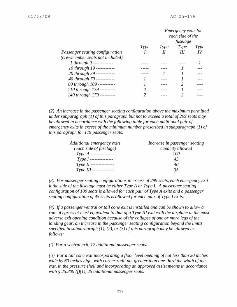
05/18/09 AC 25-17A
222
Emergency exits for each side of the
fuselage
Passenger seating configuration (crewmember seats not included)
Type I
Type II
Type III
Type IV
1 through 9 ------------- ----- ---- ---- 1 10 through 19 ------------ ----- ---- 1 --- 20 through 39 ------------ ----- 1 1 --- 40 through 79 ------------ 1 ---- 1 --- 80 through 109 ----------- 1 ---- 2 ---- 110 through 139 ---------- 2 ---- 1 ---- 140 through 179 ---------- 2 ---- 2 ----
(2) An increase in the passenger seating configuration above the maximum permitted under subparagraph (1) of this paragraph but not to exceed a total of 299 seats may be allowed in accordance with the following table for each additional pair of emergency exits in excess of the minimum number prescribed in subparagraph (1) of this paragraph for 179 passenger seats:
Additional emergency exits
(each side of fuselage) Increase in passenger seating
capacity allowed Type A --------------- 100 Type I --------------- 45 Type II --------------- 40 Type III -------------- 35
(3) For passenger seating configurations in excess of 299 seats, each emergency exit it the side of the fuselage must be either Type A or Type I. A passenger seating configuration of 100 seats is allowed for each pair of Type A exits and a passenger seating configuration of 45 seats is allowed for each pair of Type I exits. (4) If a passenger ventral or tail cone exit is installed and can be shown to allow a rate of egress at least equivalent to that of a Type III exit with the airplane in the most adverse exit opening condition because of the collapse of one or more legs of the landing gear, an increase in the passenger seating configuration beyond the limits specified in subparagraph (1), (2), or (3) of this paragraph may be allowed as follows: (i) For a ventral exit, 12 additional passenger seats. (ii) For a tail cone exit incorporating a floor level opening of not less than 20 inches wide by 60 inches high, with corner radii not greater than one-third the width of the exit, in the pressure shell and incorporating an approved assist means in accordance with § 25.809 (f)(1), 25 additional passenger seats.

05/18/09 AC 25-17A
223
(iii) For a tail cone exit incorporating an opening in the pressure shell which is at least equivalent to a Type III emergency exit with respect to dimensions, step-up and step-down distance, and with the top of the opening not less than 56 inches from the passenger compartment floor, 15 additional passenger seats. (5) For airplanes on which the vertical location of the wing does not allow the installation of overwing exits, an exit of at least the dimensions of a Type III exit must be installed instead of each Type IV exit required by subparagraph (1) of this paragraph. (6) Each emergency exit in the passenger compartment in excess of the minimum number of required emergency exits must meet the applicable requirements of §§ 25.809 through 25.812, and must be readily accessible. (d) Ditching emergency exits for passengers. Ditching emergency exits must be provided in accordance with the following requirements, unless the emergency exits required by paragraph (c) of this section already meet them: (1) For airplanes that have a passenger seating configuration, excluding pilot seats, of nine seats or less, one exit above the waterline in each side of the airplane, meeting at least the dimensions of a Type IV exit. (2) For airplanes that have a passenger seating configuration, excluding pilot seats, of 10 seats or more, one exit above the waterline in a side of the airplane, meeting at least the dimensions of a Type III exit, for each unit (or part of a unit) of 35 passenger seats, but no less than two such exits in the passenger cabin, with one on each side of the airplane. However, where it has been shown through analysis, ditching demonstrations, or any other tests found necessary by the Administrator, that the evacuation capability of the airplane during ditching is improved by the use of larger exits, or by other means, the passenger seat/exit ratio may be increased. (3) If side exits cannot be above the waterline, the side exits must be replaced by an equal number of readily accessible overhead hatches of not less than the dimensions of a Type III exit except that, for airplanes with a passenger configuration, excluding pilot seats, of 35 seats or less, the two required Type III side exits need be replaced by only one overhead hatch.]
b. Guidance. (1) The equivalency to that required by the regulations of nonstandard exits or arrangements may be determined by use of the Latin-Square test procedure. Refer to Appendix 4, which was derived from Notice FS 8110.12, “Test Procedure for Evaluating Non-Standard Exits for Transport Category Airplanes,” dated May 21, 1964. (Amendment 25-0)

05/18/09 AC 25-17A
224
(2) An “exit pair” consists of two exits of the same type, one in each side of the fuselage. The exits need not be the same size, nor do they have to be directly opposite each other. As long as the exits on both sides of the fuselage are uniformly distributed with respect to the passenger seating arrangement, a pair need not be the two exits that are physically closest to each other. Refer to figure 323-1. (Amendment 25-0)
FIGURE 323-1 AIRPLANE CONFIGURATION
(3) Paragraph (a)(3). By this amendment, Type III exits were not restricted to overwing locations. Further, Type IV exits were restricted to airplanes that have a passenger seating capacity of nine or less, as reflected in the § 25.807(c)(l) table. (Amendment 25-32) (4) Paragraph (a)(7)(iv) and (v). These two paragraphs define the requirements for passageways to Type A exits and cross aisles in two aisle airplanes. These provide sufficient access for two lines of evacuees to egress simultaneously: (Amendment 25-15) (i) In order to achieve the dual lane flow of evacuees, § 25.807(a)(7)(iv) requires an unobstructed 36-inch width passageway that leads to the exit from the outboard side of the adjacent main aisle. It should not, however, encroach upon the crewmember assist spaces that are required on both sides of the exit by § 25.807(a)(7)(vii). This is particularly important to

05/18/09 AC 25-17A
225
remember for those situations where the passageway is canted to meet the projected cross aisles, which are discussed below. (Amendment 25-15) (ii) Additionally, where more than one main aisle is provided, § 25.807(a)(7)(v) requires that there must be an unobstructed 20-inch wide cross aisle, leading directly to the exit passageways. This cross aisle is considered to extend from the inboard side of one main aisle to the inboard side of the other main aisle. The required cross aisle does not have to be straight nor does it have to be normal to the main aisles. (Amendment 25-15) (iii) For the case where the exit is located at the end of the passenger cabin and there are only two approach paths to the exit (the main aisle from one direction and the cross aisle), the 36-inch wide passageway should extend from the exit to the point where the evacuee flows from the main aisle and cross aisle merge to ensure the dual lane flow can be maintained. (Amendment 25-15) (iv) In the other case, where the exit is not located at the end of the cabin and there are three approach paths (the main aisle from two directions and the cross aisle) to the exit, the 20-inch width of the cross aisle should be within the 36-inch width of the passageway when the cross aisle is projected normal to the main aisle. Some portion of the 20-inch wide cross aisle should be within the width of the projected door opening. (Amendment 25-15) (v) If the boundaries of any of the aforementioned passageways, aisles or cross aisles are formed by passenger seats, ensure that the minimum requirements are met with the seat in the most adverse condition that is not prohibited by design. (Amendment 25-15) (vi) Door and cross aisle visibility is also of prime importance when evaluating the safety level of an exit configuration. This is especially true when the cross aisle is displaced forward or aft from the exit opening or when a pair of exits are not directly across the airplane from each other. The configuration should provide a view across the airplane such that the exit on the other side is readily identifiable. Identification of the opposite exit may be via the exit marking sign, the exit opening handle and related markings or when the field of vision provided allows visual perception of sufficient detail to recognize that there is an exit across the airplane. This identification should be evaluated when standing at the center of the opposite exit. In certain cases, additional exit locator signs may be necessary to direct evacuees to the opposite exit. (Amendment 25-15) (5) Paragraph (a). Exits may be “derated” in accordance with the requirements of a smaller type; that is, exits may not only be oversized, the interior may be reconfigured to specifically derate an exit that has previously been qualified as a larger type. In order to preclude the appearance of the exit being unusable, the following additional considerations have been found acceptable: (Amendment 25-15) (i) Type A to Type I: Only seats may encroach into the projected exit opening, no more than 12-inch cumulative. A 24-inch passageway should be provided, and seats may not breakover into this passageway or into the assist space. The operating handle should be visible from the aisle. (Amendment 25-15)

05/18/09 AC 25-17A
226
(ii) Type A to Type III: A 24-inch passageway should be provided, and seats may not breakover into this passageway. The operating handle should be visible from the aisle. (Amendment 25-15) (iii) Type I to Type III: A 13-inch passageway is required when the passageway is bordered by seats, or by a seat and a wall. A 20-inch passageway should be provided when the passageway is bordered by walls and should be within the projected opening of the exit. The required Type III opening should be unobstructed inboard for the width of one passenger seat place. The operating handle should be visible from the aisle. (Amendment 25-15) (6) Paragraph (c). Although these rules do not prescribe longitudinal distance between exits, they do specify passenger seating configurations matched to exit pairs in which factors of uniform exit distribution, accessibility and location to enhance effective egress must be considered. The uniform exit distribution should consider the situation where the exits on one side of the fuselage are unusable due to fire or other factors. Refer to AC 25.807-1, “Uniform Distribution of Exits,” dated 8/13/90 for additional guidance on this subject. (Amendment 25-15) (7) Paragraph (c)(6). Seats that have dual approval for occupancy by either crew/observers and passengers will be included in the passenger seating configuration for determining the required number of exits. Regarding removal of excess exits, regardless of airplane certification basis, the following criteria applies: (Amendment 25-15) (i) All interior and exterior exit signs, markings, and lighting pertaining to the deactivated exits must be removed. There must be no recognizable evidence of the deactivated exits, visible to occupants of the cabin. However, the exterior door outline and handle need not be obscured. (Amendment 25-15) (ii) The modification which deactivates and obscures the exits must be approved through issuance of an amendment to the Type Certificate (TC) or Supplemental Type Certificate (STC) by the Manager, Aircraft Certification Office having jurisdiction over the project, and the airplane cabin, as modified, must remain in compliance with the certification basis of the model. (Amendment 25-15) (iii) Also refer to AC 20-60, “Accessibility to Excess Emergency Exits,” dated 7/18/68. (Amendment 25-15) (8) Paragraph (c). An airplane with a Type I sized exit located in the forward left-hand side of the fuselage, a pair of Type III exits in the middle, and a Type I sized exit located in the aft right-hand side of the fuselage should be limited to a maximum passenger seating capacity of 70, because of concerns with oversized dead-end zones if either the left- or right-side exits are unusable. (Amendment 25-0) (9) Paragraph (c). An airplane with a pair of exits forward in the fuselage with the left one Type I sized and the right one Type III sized, and a pair of exits in the aft end of the fuselage with the left one Type III sized and the right one Type I sized may be approved for passenger

05/18/09 AC 25-17A
227
seating capacities up to 79. If an emergency evacuation demonstration is required, then either the left-side or right-side exits should be selected so as not to unduly penalize this well-balanced arrangement or to make a radical departure from all previous demonstrations. Refer to figure 323-1. (Amendment 25-0) (10) Paragraphs (c) and (d). When establishing the maximum capacity to be listed on the type data sheet, consideration should be given to all relevant parameters. For example, if the exit-limited passenger capacity as defined in § 25.807(c) has not been substantiated by compliance with the evacuation demonstration requirements of § 25.803, the data sheet should reflect the evacuation limit and not the exit limit. Other limiting factors include, but are not limited to, structural capability, seating density (uniform distribution of exits), or ditching exits. The maximum passenger capacity is also limited by the ditching requirements of § 25.807(d) whether certification for ditching is requested or not. In any case, the data sheet should not list a capacity for which the airplane is not capable. When the type data sheet limit is not the § 25.807(c) exit limit, an additional note, which briefly describes the reason for the limit, is appropriate. (Amendment 25-0) (11) Paragraph (d). All transport category airplanes must have ditching exits whether or not ditching certification was requested. Actually, this guidance has been in effect since April 9, 1957, as reflected in Amendment 4b-5, "Emergency Evacuation Provisions," to CAR 4b. (Amendment 25-0). (12) Paragraph (c) and (d). Flight attendants are considered part of the crew and are not included in the passenger seating capacity mentioned in § 25.807(c) and (d). (Amendment 25-0) (13) Paragraph (c) and (d). An airplane design is determined to be eligible for a certain passenger seating complement which is commensurate with meeting all of the relevant portions of § 25.807. That is, in addition to meeting table of § 25.807(c)(1), the eligibility complement is also governed by the ditching requirements of § 25.807(d), whether certification for ditching is requested or not. (Amendment 25-0) (14) Paragraph (d)(2). The wording “a passenger seating configuration, excluding pilot seats, of 10 seats or more,” which was promulgated with the intent of being consistent with Amendment 23-10 to part 23, does not directly address seats intended for use by observers or flight attendants. Seats approved for use by observers or flight attendants are not included in the passenger seating configuration. Seats that have dual approval for occupancy by either crew/observers or passengers will be included in the passenger seating configuration. (Amendment 25-32)
(15) Paragraph (d)(3). The wording “a passenger seating configuration, excluding pilot seats, of 35 seats or less,” which was promulgated with the intent of being consistent with Amendment 23-10 to part 23, does not directly address seats intended for use by observers or flight attendants. Seats approved for use by observers or flight attendants are not included in the passenger seating configuration. Seats that have dual approval for occupancy by either crew/observers or passengers will be included in the passenger seating configuration. (Amendment 25-32)
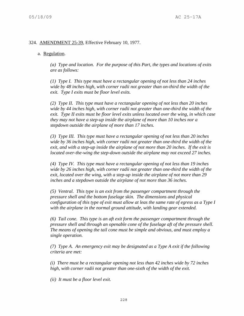
05/18/09 AC 25-17A
228
324. AMENDMENT 25-39, Effective February 10, 1977. a. Regulation.
(a) Type and location. For the purpose of this Part, the types and locations of exits are as follows: (1) Type I. This type must have a rectangular opening of not less than 24 inches wide by 48 inches high, with corner radii not greater than on-third the width of the exit. Type I exits must be floor level exits. (2) Type II. This type must have a rectangular opening of not less than 20 inches wide by 44 inches high, with corner radii not greater than one-third the width of the exit. Type II exits must be floor level exits unless located over the wing, in which case they may not have a step-up inside the airplane of more than 10 inches nor a stepdown outside the airplane of more than 17 inches. (3) Type III. This type must have a rectangular opening of not less than 20 inches wide by 36 inches high, with corner radii not greater than one-third the width of the exit, and with a step-up inside the airplane of not more than 20 inches. If the exit is located over-the-wing the step-down outside the airplane may not exceed 27 inches. (4) Type IV. This type must have a rectangular opening of not less than 19 inches wide by 26 inches high, with corner radii not greater than one-third the width of the exit, located over the wing, with a step-up inside the airplane of not more than 29 inches and a stepdown outside the airplane of not more than 36 inches. (5) Ventral. This type is an exit from the passenger compartment through the pressure shell and the bottom fuselage skin. The dimensions and physical configuration of this type of exit must allow at leas the same rate of egress as a Type I with the airplane in the normal ground attitude, with landing gear extended. (6) Tail cone. This type is an aft exit form the passenger compartment through the pressure shell and through an openable cone of the fuselage aft of the pressure shell. The means of opening the tail cone must be simple and obvious, and must employ a single operation. (7) Type A. An emergency exit may be designated as a Type A exit if the following criteria are met: (i) There must be a rectangular opening not less than 42 inches wide by 72 inches high, with corner radii not greater than one-sixth of the width of the exit. (ii) It must be a floor level exit.

05/18/09 AC 25-17A
229
(iii) Unless there are two or more main (fore and aft) aisles, the exit must be located so that there is passenger flow along the main aisle to that exit from both the forward and aft direction. (iv) There must be an unobstructed passageway at least 36 inches wide leading from each exit to the nearest main aisle. (v) If two or more main aisles are provided, there must be unobstructed cross aisles at least 20 inches wide between main aisles. There must be a cross aisle leading directly to each passageway between the exit and the nearest main aisle. (vi) There must be at least one seat adjacent to each such exit that could be occupied by a flight attendant. (vii) Adequate assist space next to each Type A exit must be provided at each side of the passageway, to allow the crewmember(s) to assist in the evacuation of passengers without reducing the unobstructed width of the passageway below that required by subdivision (iv) of this subparagraph. (viii) At each non-over-wing exit there must be installed a slide capable of carrying simultaneously two parallel lines of evacuees. (ix) Each overwing exit having a stepdown must have an assist means unless the exit without an assist means can be shown to have a rate of passenger degrees at least equal to that of the same type of non-over-wing exit. If an assist means is required it must be automatically deployed, and automatically erected, concurrent with the opening of the exit and self-supporting within 10 seconds. Stepdown distance as used in this section means the actual distance between the bottom of the required opening and a usable foothold, extending out from the fuselage, that is large enough to be effective without searching by sight or feel. (b) Accessibility. Each required passenger emergency exit must be accessible to the passengers and located where it will afford the most effective means if passenger evacuation. Openings larger than those specified in this section, whether or not of rectangular shape, may be used if- (1) The specified rectangular opening can be inscribed within the opening; and (2) The base of the inscribed rectangular opening meets the specified step-up and step-down heights. (c) Passenger emergency exits. The prescribed exits need not be diametrically opposite each other nor identical in size and location on both sides. They must be distributed as uniformly as practicable taking into account passenger distribution. If only one floor level exit per side is prescribed, and the airplane does not have a tail

05/18/09 AC 25-17A
230
cone or ventral emergency exit, the floor level exits must be in the rearward part of the passenger compartment, unless another location affords a more effective means of passenger evacuation. Where more than one floor level exit per side is prescribed, at least one floor level exit per side must be located near each end of the cabin, except that this provision does not apply to combination cargo/passenger configuration. Exits must be provided as follows: (1) Except as provided in subparagraphs (2) through (6) of this paragraph, the number and type of passenger emergency exits must be in accordance with the following table:
Emergency exits for each side of the
fuselage Passenger seating
configuration (crewmember eats on
included)
Type I
Type II
Type III
Type IV
1 through 9---- ------- ------ ------- 1 10 through 19--- ------- ------ 1 ------ 20 through 39--- ------- 1 1 ------ 40 through 79--- 1 ------ 1 ------ 80 through 109-- 1 ------ 2 ------ 110 through 139- 2 ------ 1 ------ 140 through 179- 2 ------ 2 ------
(2) An increase in the passenger seating configuration above the maximum permitted under subparagraph (1) of this paragraph but not to exceed a total of 299 seats may be allowed in accordance with the following table for each additional pair of emergency exits in excess of the minimum number prescribed in subparagraph (1) of this paragraph for 179 passenger seats;
[Additional emergency exits
(each side of fuselage) Increase in passenger seating
configuration allowed Type A ------------------------ 110 Type I ------------------------- 45 Type II ------------------------ 40 Type III ------------------------ 35]
(3) For passenger seating configurations in excess of 299 seats, each emergency exit in the side of the fuselage must be either a Type A or Type I. [A passenger seating configuration of 110 seats is allowed for each pair of Type I exits.] (4) If a passenger ventral or tail cone exit is installed and can be shown to allow a rate of egress at least equivalent to that of a Type III exit with the airplane in the most adverse exit opening condition because of the collapse of one or more legs of the

05/18/09 AC 25-17A
231
landing gear, an increase in the passenger seating configuration beyond the limits specified in subparagraph (1), (2), or (3) of this paragraph may be allowed as follows: (i) For a ventral exit, 12 additional passenger seats. (ii) For a tail cone exit incorporating a floor level opening of not less than 20 inches wide by 60 inches high, with corner radii not greater than one-third the width of the exit, in the pressure shell and incorporating an approved assist means in accordance with § 25.809(f)(1), 25 additional passenger seats. (iii) For a tail cone exit incorporating an opening in the pressure shell which is at least equivalent to a Type III emergency exit with respect to dimensions, step-up and step-down distance, and with the top of the opening not less than 56 inches from the passenger compartment floor, 15 additional passenger seats. (5) For airplanes on which the vertical location of the wing does not allow the installation of overwing exits, an exit of at least the dimensions of a Type III exit must be installed instead of each Type IV exit required by subparagraph (1) of this paragraph. (6) Each emergency exit in the passenger compartment in excess of the minimum number of required emergency exits must meet the applicable requirements of §§ 25.809 through 25.812, and must be readily accessible. (d) Ditching emergency exits for passengers. Ditching emergency exits must be provided in accordance with the following requirements, unless the emergency exits required by paragraph (c) of this section already meet them: (1) For airplanes that have a passenger seating configuration, excluding pilots seats, of nine seats or less, one exit above the waterline in each side of the airplane, meeting at least the dimensions of a Type IV exit. (2) For airplanes that have a passenger seating configuration, excluding pilots seats, of 10 seats or more, one exit above the waterline in a side of the airplane, meeting at least the dimensions of a Type III exit, for each unit (or part of a unit) of 35 passenger seats, but no less than two such exits side of the airplane. However, where it has been shown through analysis, ditching demonstrations, or any other tests found necessary by the Administrator, that the evacuation capability of the airplane during ditching is improved by the use of larger exits, or by other means, the passenger seat/exit ratio may be increased. (3) If side exits cannot be above the waterline, the side exits must be replaced by an equal number of readily accessible overhead hatches of not less than the dimensions of a Type III exit except that, for airplanes with a passenger configuration excluding

05/18/09 AC 25-17A
232
pilots seats, of 35 seats or less, the two required Type III side exits need be replaced by only one overhead hatch.
b. Guidance. (1) The equivalency to that required by the regulations of nonstandard exits or arrangements may be determined by use of the Latin-Square test procedure. Refer to Appendix 4, which was derived from Notice FS 8110.12, “Test Procedure for Evaluating Non-Standard Exits for Transport Category Airplanes,” dated May 21, 1964. (Amendment 25-0) (2) An “exit pair” consists of two exits of the same type, one in each side of the fuselage. The exits need not be the same size, nor do they have to be directly opposite each other. As long as the exits on both sides of the fuselage are uniformly distributed with respect to the passenger seating arrangement, a pair need not be the two exits that are physically closest to each other. (Amendment 25-0) (3) Paragraph (a)(3). Type III exits were not restricted to overwing locations. Further, Type IV exits were restricted to airplanes that have a passenger seating capacity of nine or less, as reflected in the § 25.807(c)(l) table. Refer to figure 324-1. (Amendment 25-32)
FIGURE 324-1 AIRPLANE CONFIGURATION

05/18/09 AC 25-17A
233
(4) Paragraph (a)(7)(iv) and (v). These two paragraphs define the requirements for passageways to Type A exits and cross aisles in two aisle airplanes. These provide sufficient access for two lines of evacuees to egress simultaneously: (Amendment 25-15) (i) In order to achieve the dual lane flow of evacuees, § 25.807(a)(7)(iv) requires an unobstructed 36-inch width passageway that leads to the exit from the outboard side of the adjacent main aisle. It should not, however, encroach upon the crewmember assist spaces that are required on both sides of the exit by § 25.807(a)(7)(vii). This is particularly important to remember for those situations where the passageway is canted to meet the projected cross aisles, which are discussed below. (Amendment 25-15) (ii) Additionally, where more than one main aisle is provided, § 25.807(a)(7)(v) requires that there must be an unobstructed 20-inch wide cross aisle, leading directly to the exit passageways. This cross aisle is considered to extend from the inboard side of one main aisle to the inboard side of the other main aisle. The required cross aisle does not have to be straight nor does it have to be normal to the main aisles. (Amendment 25-15) (iii) For the case where the exit is located at the end of the passenger cabin and there are only two approach paths to the exit (the main aisle from one direction and the cross aisle), the 36-inch wide passageway should extend from the exit to the point where the evacuee flows from the main aisle and cross aisle merge to ensure the dual lane flow can be maintained. (Amendment 25-15) (iv) In the other case, where the exit is not located at the end of the cabin and there are three approach paths (the main aisle from two directions and the cross aisle) to the exit, the 20-inch width of the cross aisle should be within the 36-inch width of the passageway when the cross aisle is projected normal to the main aisle. Some portion of the 20-inch wide cross aisle should be within the width of the projected door opening. (Amendment 25-15) (v) If the boundaries of any of the aforementioned passageways, aisles or cross aisles are formed by passenger seats, ensure that the minimum requirements are met with the seat in the most adverse condition that is not prohibited by design. (Amendment 25-15) (vi) Door and cross aisle visibility is also of prime importance when evaluating the safety level of an exit configuration. This is especially true when the cross aisle is displaced forward or aft from the exit opening or when a pair of exits are not directly across the airplane from each other. The configuration should provide a view across the airplane such that the exit on the other side is readily identifiable. Identification of the opposite exit may be via the exit marking sign, the exit opening handle and related markings or when the field of vision provided allows visual perception of sufficient detail to recognize that there is an exit across the airplane. This identification should be evaluated when standing at the center of the opposite exit. In certain cases, additional exit locator signs may be necessary to direct evacuees to the opposite exit. (Amendment 25-15)

05/18/09 AC 25-17A
234
(5) Paragraph (a). Exits may be “derated” in accordance with the requirements of a smaller type; that is, exits may not only be oversized, the interior may be reconfigured to specifically derate an exit that has previously been qualified as a larger type. In order to preclude the appearance of the exit being unusable, the following additional considerations have been found acceptable: (Amendment 25-15) (i) Type A to Type I: Only seats may encroach into the projected exit opening, no more than 12-inch cumulative. A 24-inch passageway should be provided, and seats may not breakover into this passageway or into the assist space. The operating handle should be visible from the aisle. (Amendment 25-15) (ii) Type A to Type III: A 24-inch passageway should be provided, and seats may not breakover into this passageway. The operating handle should be visible from the aisle. (Amendment 25-15) (iii) Type I to Type III: A 13-inch passageway is required when the passageway is bordered by seats, or by a seat and a wall. A 20-inch passageway should be provided when the passageway is bordered by walls and should be within the projected opening of the exit. The required Type III opening should be unobstructed inboard for the width of one passenger seat place. The operating handle should be visible from the aisle. (Amendment 25-15) (6) Paragraph (c). Although these rules do not prescribe longitudinal distance between exits, they do specify passenger seating configurations matched to exit pairs in which factors of uniform exit distribution, accessibility and location to enhance effective egress must be considered. The uniform exit distribution should consider the situation where the exits on one side of the fuselage are unusable due to fire or other factors. Refer to AC 25.807-1, “Uniform Distribution of Exits,” dated 8/13/90 for additional guidance on this subject. (Amendment 25-15) (7) Paragraph (c)(6). Seats that have dual approval for occupancy by either crew/observers and passengers will be included in the passenger seating configuration for determining the required number of exits. Regarding removal of excess exits, regardless of airplane certification basis, the following criteria applies: (Amendment 25-15) (i) All interior and exterior exit signs, markings, and lighting pertaining to the deactivated exits must be removed. There must be no recognizable evidence of the deactivated exits, visible to occupants of the cabin. However, the exterior door outline and handle need not be obscured. (Amendment 25-15) (ii) The modification which deactivates and obscures the exits must be approved through issuance of an amendment to the Type Certificate (TC) or Supplemental Type Certificate (STC) by the Manager, Aircraft Certification Office having jurisdiction over the project, and the airplane cabin, as modified, must remain in compliance with the certification basis of the model. (Amendment 25-15) (iii) Also refer to AC 20-60, “Accessibility to Excess Emergency Exits,” dated 7/18/68. (Amendment 25-15)

05/18/09 AC 25-17A
235
(8) Paragraph (c). An airplane with a Type I sized exit located in the forward left-hand side of the fuselage, a pair of Type III exits in the middle, and a Type I sized exit located in the aft right-hand side of the fuselage should be limited to a maximum passenger seating capacity of 70, because of concerns with oversized dead-end zones if either the left- or right-side exits are unusable. (Amendment 25-0) (9) Paragraph (c). An airplane with a pair of exits forward in the fuselage with the left one Type I sized and the right one Type III sized, and a pair of exits in the aft end of the fuselage with the left one Type III sized and the right one Type I sized may be approved for passenger seating capacities up to 79. If an emergency evacuation demonstration is required, then either the left-side or right-side exits should be selected so as not to unduly penalize this well-balanced arrangement or to make a radical departure from all previous demonstrations. Refer to figure 324-1. (Amendment 25-0) (10) Paragraphs (c) and (d). When establishing the maximum capacity to be listed on the type data sheet, consideration should be given to all relevant parameters. For example, if the exit-limited passenger capacity as defined in § 25.807(c) has not been substantiated by compliance with the evacuation demonstration requirements of § 25.803, the data sheet should reflect the evacuation limit and not the exit limit. Other limiting factors include, but are not limited to, structural capability, seating density (uniform distribution of exits), or ditching exits. The maximum passenger capacity is also limited by the ditching requirements of § 25.807(d) whether certification for ditching is requested or not. In any case, the data sheet should not list a capacity for which the airplane is not capable. When the type data sheet limit is not the § 25.807(c) exit limit, an additional note, which briefly describes the reason for the limit, is appropriate. (Amendment 25-0) (11) Paragraph (d). All transport category airplanes must have ditching exits whether or not ditching certification was requested. Actually, this guidance has been in effect since April 9, 1957, as reflected in Amendment 4b-5, "Emergency Evacuation Provisions," to CAR 4b. (Amendment 25-0) (12) Paragraph (c) and (d). Flight attendants are considered part of the crew and are not included in the passenger seating capacity mentioned in § 25.807(c) and (d). (Amendment 25-0) (13) Paragraph (c) and (d). An airplane design is determined to be eligible for a certain passenger seating complement which is commensurate with meeting all of the relevant portions of § 25.807. That is, in addition to meeting table of § 25.807(c)(1), the eligibility complement is also governed by the ditching requirements of § 25.807(d), whether certification for ditching is requested or not. (Amendment 25-0) (14) Paragraph (d)(2). The wording “a passenger seating configuration, excluding pilot seats, of 10 seats or more,” which was promulgated with the intent of being consistent with Amendment 23-10 to part 23, does not directly address seats intended for use by observers or flight attendants. Seats approved for use by observers or flight attendants are not included in the passenger seating configuration. Seats that have dual approval for occupancy by either

05/18/09 AC 25-17A
236
crew/observers or passengers will be included in the passenger seating configuration for determining the required number of exits. (Amendment 25-32)
(15) Paragraph (d)(3). The wording “a passenger seating configuration, excluding pilot seats, of 35 seats or less,” which was promulgated with the intent of being consistent with Amendment 23-10 to part 23, does not directly address seats intended for use by observers or flight attendants. Seats approved for use by observers or flight attendants are not included in the passenger seating configuration. Seats that have dual approval for occupancy by either crew/observers or passengers will be included in the passenger seating configuration for determining the required number of exits. (Amendment 25-32)
325. AMENDMENT 25-46, Effective February 11, 1978. a. Regulation.
(a) Type and location. For the purpose of this Part, the types and locations of exits are as follows: (1) Type I. This type must have a rectangular opening of not less than 24 inches wide by 48 inches high, with corner radii not greater than one-third the width of the exit. Type I exits must be floor level exits. (2) Type II. This type must have a rectangular opening of not less than 20 inches wide by 44 inches high, with corner radii not greater than one-third the width of the exit. Type II exits must be floor level exits unless located over the wing, in which case they may not have a step-up inside the airplane of more than 10 inches nor a stepdown outside the airplane of more than 17 inches. (3) Type III. This type must have a rectangular opening of not less than 20 inches wide by 36 inches high, with corner radii not greater than one-third the width of the exit, and with a step-up inside the airplane of not more than 20 inches. If the exit is located over-the-wing the step-down outside the airplane may not exceed 27 inches. (4) Type IV. This type must have a rectangular opening of not less than 19 inches wide by 26 inches high, with corner radii not greater than one-third the width of the exit, located over the wing, with a step-up inside the airplane of not more than 29 inches and a stepdown outside the airplane of not more than 36 inches. (5) Ventral. This type is an exit from the passenger compartment through the pressure shell and the bottom fuselage skin. The dimensions and physical configuration of this type of exit must allow at least the same rate of egress as a Type I with the airplane in the normal ground attitude, with landing gear extended. (6) Tail cone. This type is an aft exit from the passenger compartment through the pressure shell and through an openable cone of the fuselage aft of the pressure shell.

05/18/09 AC 25-17A
237
The means of opening the tail cone must be simple and obvious, and must employ a single operation. (7) Type A. An emergency exit may be designated as a Type A exit if the following criteria are met: (i) There must be a rectangular opening not less than 42 inches wide by 72 inches high, with corner radii not greater than one-sixth of the width of the exit. (ii) It must be a floor level exit. (iii) Unless there are two or more main (fore and aft) aisles, the exit must be located so that there is passenger flow along the main aisle to that exit from both the forward and aft direction. (iv) There must be an unobstructed passageway at least 36 inches wide leading from each exit to the nearest main aisle. (v) If two or more main aisles are provided, there must be unobstructed cross aisles at lest 20 inches wide between main aisles. There must be a cross aisle loading directly to each passageway between the exit and the nearest main aisle. [(vi) There must be at least one flight attendant seat, which meets the requirements of §§ 25.785(h) and (i), adjacent to each such exit.] (vii) Adequate assist space next to each Type A exit must be provided at each side of the passageway, to allow the crewmember(s) to assist in the evacuation of passengers without reducing the unobstructed width of the passageway below that required by subdivision (iv) of this subparagraph. (viii) At each non-over-wing exit there must be installed a slide capable of carrying simultaneously two parallel lines of evacuees. (ix) Each overwing exit having a step-down must have an assist means unless the exit without an assist means can be shown to have a rate of passenger egress at least equal to that of the same type of non-over-wing exit. If an assist means is required it must be automatically deployed, and automatically erected, concurrent with the opening of the exit and self-supporting within 10 seconds. Stepdown distance as used in this section means the actual distance between the bottom of the required opening and a usable foothold, extending out from the fuselage, that is large enough to be effective without searching by sight or feel. (b) Accessibility. Each required passenger emergency exit must be accessible to the passengers and located where it will afford the most effective means of passenger evacuation. Openings larger than those specified in this section, whether or not of rectangular shape, may be used if-

05/18/09 AC 25-17A
238
(1) The specified rectangular opening can be inscribed within the opening; and (2) The base of the inscribed rectangular opening meets the specified step-up and step-down heights. (c) Passenger emergency exits. The prescribed exits need not be diametrically opposite each other nor identical in size and location on both sides. They must be distributed as uniformly as practicable taking into account passenger distribution. If only one floor level exit per side is prescribed, and the airplane does not have a tail cone or ventral emergency exit, the floor level exits must be in the rearward part of the passenger compartment, unless another location affords a more effective means of passenger evacuation. Where more than one floor level exit per side is prescribed, at least one floor level exit per side must be located near each end of the cabin, except that this provision does not apply to combination cargo/passenger configurations. Exits must be provided as follows: (1) Except as provided in subparagraphs (2) through (6) of this paragraph, the number and type of passenger emergency exits must be in accordance with the following table:
Emergency exits for each side of the
fuselage Passenger seating
configuration (crewmember eats on
included)
Type I
Type II
Type III
Type IV
1 through 9---- ------- ------ ------- 1 10 through 19--- ------- ------ 1 ------ 20 through 39--- ------- 1 1 ------ 40 through 79--- 1 ------ 1 ------ 80 through 109-- 1 ------ 2 ------ 110 through 139- 2 ------ 1 ------ 140 through 179- 2 ------ 2 ------
(2) An increase in the passenger seating configuration above the maximum permitted under subparagraph (1) of this paragraph but not to exceed a total of 299 seats may be allowed in accordance with the following table for each additional pair of emergency exits in excess of the minimum number prescribed in subparagraph (1) of this paragraph for 179 passenger seats:

05/18/09 AC 25-17A
239
Additional emergency exits (each side of fuselage)
Increase in passenger seating configuration allowed
Type A ------------------------ 110 Type I ------------------------- 45 Type II ------------------------ 40 Type III ------------------------ 35
(3) For passenger seating configurations in excess of 299 seats, each emergency exit in the side of the fuselage must be either a Type A or Type I. A passenger seating configuration of 110 seats is allowed for each pair of Type A exits and a passenger seating configuration of 45 seats is allowed for each pair of Type I exits. (4) If a passenger ventral or tail cone exit is installed and can be shown to allow a rate of egress at least equivalent to that of a Type III exit with the airplane in the most adverse exit opening condition because of the collapse of one or more legs of the landing gear, an increase in the passenger seating configuration beyond the limits specified in subparagraph (1), (2), or (3) of this paragraph may be allowed as follows: (i) For a ventral exit, 12 additional passenger seats. (ii) For a tail cone exit incorporating a floor level opening of not less than 20 inches wide by 60 inches high, with corner radii not greater than one-third the width of the exit, in the pressure shell and incorporating an approved assist means in accordance with § 25.809(f)(1), 25 additional passenger seats. (iii) For a tail cone exit incorporating an opening in the pressure shell which is at least equivalent to a Type III emergency exit with respect to dimensions, step-up and step-down distance, and with the top of the opening not less than 56 inches from the passenger compartment floor, 15 additional passenger seats. (5) For airplanes on which the vertical location of the wing does not allow the installation of overwing exits, an exit of at least the dimensions of a Type III exit must be installed instead of each Type IV exit required by subparagraph (1) of this paragraph. (6) Each emergency exit in the passenger compartment in excess of the minimum number of required emergency exits must meet the applicable requirements of §§ 25.809 through 25.812, and must be readily accessible. (d) Ditching emergency exits for passengers. Ditching emergency exits must be provided in accordance with the following requirements, unless the emergency exits required by paragraph (c) of this section already meet them:

05/18/09 AC 25-17A
240
(1) For airplanes that have a passenger seating configuration, excluding pilots seats, of nine seats or less, one exit above the waterline in each side of the airplane, meeting at least the dimensions of a Type IV exit. (2) For airplanes that have a passenger seating configuration, excluding pilots seats, of 10 seats or more, one exit above the waterline in a side of the airplane, meeting at least the dimensions of a Type III exit, for each unit (or part of a unit) of 35 passenger seats, but no less than two such exits in the passenger cabin, with one on each side of the airplane. However, where it has been shown through analysis, ditching demonstrations, or any other tests found necessary by the Administrator, that the evacuation capability of the airplane during ditching is improved by the use of larger exits, or by other means, the passenger seat/exit ratio may be increased. (3) If side exits cannot be above the waterline, the side exits must be replaced by an equal number of readily accessible overhead hatches of not less than the dimensions of a Type III exit except that, for airplanes with a passenger configuration, excluding pilots seats, of 35 seats or less, the two required Type III side exits need be replaced by only one overhead hatch.
b. Guidance. (1) The equivalency to that required by the regulations of nonstandard exits or arrangements may be determined by use of the Latin-Square test procedure. Refer to Appendix 4, which was derived from Notice FS 8110.12, “Test Procedure for Evaluating Non-Standard Exits for Transport Category Airplanes,” dated May 21, 1964. (Amendment 25-0) (2) An “exit pair” consists of two exits of the same type, one in each side of the fuselage. The exits need not be the same size, nor do they have to be directly opposite each other. As long as the exits on both sides of the fuselage are uniformly distributed with respect to the passenger seating arrangement, a pair need not be the two exits that are physically closest to each other. Refer to figure 325-1. (Amendment 25-0)

05/18/09 AC 25-17A
241
FIGURE 325-1 AIRPLANE CONFIGURATION
(3) Paragraph (a)(3). Type III exits were not restricted to overwing locations. Further, Type IV exits were restricted to airplanes that have a passenger seating capacity of nine or less, as reflected in the § 25.807(c)(l) table. (Amendment 25-32) (4) Paragraph (a)(7)(iv) and (v). These two paragraphs define the requirements for passageways to Type A exits and cross aisles in two aisle airplanes. These provide sufficient access for two lines of evacuees to egress simultaneously: (Amendment 25-15) (i) In order to achieve the dual lane flow of evacuees, § 25.807(a)(7)(iv) requires an unobstructed 36-inch width passageway that leads to the exit from the outboard side of the adjacent main aisle. It should not, however, encroach upon the crewmember assist spaces that are required on both sides of the exit by § 25.807(a)(7)(vii). This is particularly important to remember for those situations where the passageway is canted to meet the projected cross aisles, which are discussed below. (Amendment 25-15) (ii) Additionally, where more than one main aisle is provided, § 25.807(a)(7)(v) requires that there must be an unobstructed 20-inch wide cross aisle, leading directly to the exit passageways. This cross aisle is considered to extend from the inboard side of one main aisle to

05/18/09 AC 25-17A
242
the inboard side of the other main aisle. The required cross aisle does not have to be straight nor does it have to be normal to the main aisles. (Amendment 25-15) (iii) For the case where the exit is located at the end of the passenger cabin and there are only two approach paths to the exit (the main aisle from one direction and the cross aisle), the 36-inch wide passageway should extend from the exit to the point where the evacuee flows from the main aisle and cross aisle merge to ensure the dual lane flow can be maintained. (Amendment 25-15) (iv) In the other case, where the exit is not located at the end of the cabin and there are three approach paths (the main aisle from two directions and the cross aisle) to the exit, the 20-inch width of the cross aisle should be within the 36-inch width of the passageway when the cross aisle is projected normal to the main aisle. Some portion of the 20-inch wide cross aisle should be within the width of the projected door opening. (Amendment 25-15) (v) If the boundaries of any of the aforementioned passageways, aisles or cross aisles are formed by passenger seats, ensure that the minimum requirements are met with the seat in the most adverse condition that is not prohibited by design. (Amendment 25-15) (vi) Door and cross aisle visibility is also of prime importance when evaluating the safety level of an exit configuration. This is especially true when the cross aisle is displaced forward or aft from the exit opening or when a pair of exits are not directly across the airplane from each other. The configuration should provide a view across the airplane such that the exit on the other side is readily identifiable. Identification of the opposite exit may be via the exit marking sign, the exit opening handle and related markings or when the field of vision provided allows visual perception of sufficient detail to recognize that there is an exit across the airplane. This identification should be evaluated when standing at the center of the opposite exit. In certain cases, additional exit locator signs may be necessary to direct evacuees to the opposite exit. (Amendment 25-15) (5) Paragraph (a). Exits may be “derated” in accordance with the requirements of a smaller type; that is, exits may not only be oversized, the interior may be reconfigured to specifically derate an exit that has previously been qualified as a larger type. In order to preclude the appearance of the exit being unusable, the following additional considerations have been found acceptable: (Amendment 25-15) (i) Type A to Type I: Only seats may encroach into the projected exit opening, no more than 12-inch cumulative. A 24-inch passageway should be provided, and seats may not breakover into this passageway or into the assist space. The operating handle should be visible from the aisle. (Amendment 25-15) (ii) Type A to Type III: A 24-inch passageway should be provided, and seats may not breakover into this passageway. The operating handle should be visible from the aisle. (Amendment 25-15)
05/18/09 AC 25-17A
243
(iii) Type I to Type III: A 13-inch passageway is required when the passageway is bordered by seats, or by a seat and a wall. A 20-inch passageway should be provided when the passageway is bordered by walls and should be within the projected opening of the exit. The required Type III opening should be unobstructed inboard for the width of one passenger seat place. The operating handle should be visible from the aisle. (Amendment 25-15) (6) The intent of this amendment was to specify that the seat required by the present § 25.807(a)(7)(vi) must be a flight attendant seat. (Amendment 25-46) (7) Paragraph (a)(7)(vi). The intent of the use of the word “adjacent” is to require the flight attendant seat to be closer to the exit than if the word “near” were used. Typically, the flight attendant seat should be located immediately forward or aft of the passageway to the exit. Consideration for an alternative location may be given if the flight attendant seat is located such that the flight attendant will be able to reach the exit faster than any passenger seated in the vicinity of the exit. (Amendment 25-46) (8) Paragraph (c). Although these rules do not prescribe longitudinal distance between exits, they do specify passenger seating configurations matched to exit pairs in which factors of uniform exit distribution, accessibility and location to enhance effective egress must be considered. The uniform exit distribution should consider the situation where the exits on one side of the fuselage are unusable due to fire or other factors. Refer to AC 25.807-1, “Uniform Distribution of Exits,” dated 8/13/90 for additional guidance on this subject. (Amendment 25-15) (9) Paragraph (c)(6). Seats that have dual approval for occupancy by either crew/observers and passengers will be included in the passenger seating configuration for determining the required number of exits. Regarding removal of excess exits, regardless of airplane certification basis, the following criteria applies: (Amendment 25-15) (i) All interior and exterior exit signs, markings, and lighting pertaining to the deactivated exits must be removed. There must be no recognizable evidence of the deactivated exits, visible to occupants of the cabin. However, the exterior door outline and handle need not be obscured. (Amendment 25-15) (ii) The modification which deactivates and obscures the exits must be approved through issuance of an amendment to the Type Certificate (TC) or Supplemental Type Certificate (STC) by the Manager, Aircraft Certification Office having jurisdiction over the project, and the airplane cabin, as modified, must remain in compliance with the certification basis of the model. (Amendment 25-15) (iii) Also refer to AC 20-60, “Accessibility to Excess Emergency Exits,” dated 7/18/68. (Amendment 25-15) (10) Paragraph (c). An airplane with a Type I sized exit located in the forward left-hand side of the fuselage, a pair of Type III exits in the middle, and a Type I sized exit located in the aft right-hand side of the fuselage should be limited to a maximum passenger seating capacity of

05/18/09 AC 25-17A
244
70, because of concerns with oversized dead-end zones if either the left- or right-side exits are unusable. (Amendment 25-0) (11) Paragraph (c). An airplane with a pair of exits forward in the fuselage with the left one Type I sized and the right one Type III sized, and a pair of exits in the aft end of the fuselage with the left one Type III sized and the right one Type I sized may be approved for passenger seating capacities up to 79. If an emergency evacuation demonstration is required, then either the left-side or right-side exits should be selected so as not to unduly penalize this well-balanced arrangement or to make a radical departure from all previous demonstrations. Refer to figure 325-1. (Amendment 25-0) (12) Paragraphs (c) and (d). When establishing the maximum capacity to be listed on the type data sheet, consideration should be given to all relevant parameters. For example, if the exit-limited passenger capacity as defined in § 25.807(c) has not been substantiated by compliance with the evacuation demonstration requirements of § 25.803, the data sheet should reflect the evacuation limit and not the exit limit. Other limiting factors include, but are not limited to, structural capability, seating density (uniform distribution of exits), or ditching exits. The maximum passenger capacity is also limited by the ditching requirements of § 25.807(d) whether certification for ditching is requested or not. In any case, the data sheet should not list a capacity for which the airplane is not capable. When the type data sheet limit is not the § 25.807(c) exit limit, an additional note, which briefly describes the reason for the limit, is appropriate. (Amendment 25-0) (13) Paragraph (d). All transport category airplanes must have ditching exits whether or not ditching certification was requested. Actually, this guidance has been in effect since April 9, 1957, as reflected in Amendment 4b-5, "Emergency Evacuation Provisions," to CAR 4b. (Amendment 25-0) (14) Paragraph (c) and (d). Flight attendants are considered part of the crew and are not included in the passenger seating capacity mentioned in § 25.807(c) and (d). (Amendment 25-0) (15) Paragraph (c) and (d). An airplane design is determined to be eligible for a certain passenger seating complement which is commensurate with meeting all of the relevant portions of § 25.807. That is, in addition to meeting table of § 25.807(c)(1), the eligibility complement is also governed by the ditching requirements of § 25.807(d), whether certification for ditching is requested or not. (Amendment 25-0) (16) Paragraph (d)(2). The wording “a passenger seating configuration, excluding pilot seats, of 10 seats or more,” which was promulgated with the intent of being consistent with Amendment 23-10 to part 23, does not directly address seats intended for use by observers or flight attendants. Seats approved for use by observers or flight attendants are not included in the passenger seating configuration. Seats that have dual approval for occupancy by either crew/observers or passengers will be included in the passenger seating configuration for determining the required number of exits. (Amendment 25-32)

05/18/09 AC 25-17A
245
(17) Paragraph (d)(3). The wording “a passenger seating configuration, excluding pilot seats, of 35 seats or less,” which was promulgated with the intent of being consistent with Amendment 23-10 to part 23, does not directly address seats intended for use by observers or flight attendants. Seats approved for use by observers or flight attendants are not included in the passenger seating configuration. Seats that have dual approval for occupancy by either crew/observers or passengers will be included in the passenger seating configuration for determining the required number of exits. (Amendment 25-32) 326. AMENDMENT 25-55, Effective April 26, 1982. a. Regulation.
(a) Type and location. For the purpose of this Part, the types and locations of exits are as follows: (1) Type I. This type must have a rectangular opening of not less than 24 inches wide by 48 inches high, with corner radii not greater than on-third the width of the exit. Type I exits must be floor level exits. (2) Type II. This type must have a rectangular opening of not less than 20 inches wide by 44 inches high, with corner radii not greater than one-third the width of the exit. Type II exits must be floor level exits unless located over the wing, in which case they may not have a step-up inside the airplane of more than 10 inches nor a stepdown outside the airplane of more than 17 inches. (3) Type III. This type must have a rectangular opening of not less than 20 inches wide by 36 inches high, with corner radii not greater than one-third the width of the exit, and with a step-up inside the airplane of not more than 20 inches. If the exit is located over-the-wing the step-down outside the airplane may not exceed 27 inches. (4) Type IV. This type must have a rectangular opening of not less than 19 inches wide by 26 inches high, with corner radii not greater than one-third the width of the exit, located over the wing, with a step-up inside the airplane of not more than 29 inches and a stepdown outside the airplane of not more than 36 inches. (5) Ventral. This type is an exit from the passenger compartment through the pressure shell and the bottom fuselage skin. The dimensions and physical configuration of this type of exit must allow at leas the same rate of egress as a Type I with the airplane in the normal ground attitude, with landing gear extended. (6) Tail cone. This type is an aft exit form the passenger compartment through the pressure shell and through an openable cone of the fuselage aft of the pressure shell. The means of opening the tail cone must be simple and obvious, and must employ a single operation.

05/18/09 AC 25-17A
246
(7) Type A. An emergency exit may be designated as a Type A exit if the following criteria are met: (i) There must be a rectangular opening not less than 42 inches wide by 72 inches high, with corner radii not greater than one-sixth of the width of the exit. (ii) It must be a floor level exit. (iii) Unless there are two or more main (fore and aft) aisles, the exit must be located so that there is passenger flow along the main aisle to that exit from both the forward and aft direction. (iv) There must be an unobstructed passageway at least 36 inches wide leading from each exit to the nearest main aisle. (v) If two or more main aisles are provided, there must be unobstructed cross aisles at least 20 inches wide between main aisles. There must be a cross aisle leading directly to each passageway between the exit and the nearest main aisle. (vi) There must be at least one flight attendant seat, which meets the requirements of §§ 25.785(h) and (i), adjacent to each such exit. (vii) Adequate assist space next to each Type A exit must be provided at each side of the passageway, to allow the crewmember(s) to assist in the evacuation of passengers without reducing the unobstructed width of the passageway below that required by subdivision (iv) of this subparagraph. (viii) At each non-over-wing exit there must be installed a slide capable of carrying simultaneously two parallel lines of evacuees. (ix) Each overwing exit having a stepdown must have an assist means unless the exit without an assist means can be shown to have a rate of passenger degrees at least equal to that of the same type of non-over-wing exit. If an assist means is required it must be automatically deployed, and automatically erected, concurrent with the opening of the exit and self-supporting within 10 seconds. Stepdown distance as used in this section means the actual distance between the bottom of the required opening and a usable foothold, extending out from the fuselage, that is large enough to be effective without searching by sight or feel. (b) Accessibility. Each required passenger emergency exit must be accessible to the passengers and located where it will afford the most effective means if passenger evacuation. Openings larger than those specified in this section, whether or not of rectangular shape, may be used if- (1) The specified rectangular opening can be inscribed within the opening; and

05/18/09 AC 25-17A
247
(2) The base of the inscribed rectangular opening meets the specified step-up and step-down heights. (c) Passenger emergency exits. The prescribed exits need not be diametrically opposite each other nor identical in size and location on both sides. They must be distributed as uniformly as practicable taking into account passenger distribution. If only one floor level exit per side is prescribed, and the airplane does not have a tail cone or ventral emergency exit, the floor level exits must be in the rearward part of the passenger compartment, unless another location affords a more effective means of passenger evacuation. Where more than one floor level exit per side is prescribed, at least one floor level exit per side must be located near each end of the cabin, except that this provision does not apply to combination cargo/passenger configuration. Exits must be provided as follows: (1) Except as provided in subparagraphs (2) through (6) of this paragraph, the number and type of passenger emergency exits must be in accordance with the following table:
Emergency exits for each side of the
fuselage Passenger seating
configuration (crewmember eats on
included)
Type I
Type II
Type III
Type IV
1 through 9---- ------- ------ ------- 1 10 through 19--- ------- ------ 1 ------ 20 through 39--- ------- 1 1 ------ 40 through 79--- 1 ------ 1 ------ 80 through 109-- 1 ------ 2 ------ 110 through 139- 2 ------ 1 ------ 140 through 179- 2 ------ 2 ------
(2) An increase in the passenger seating configuration above the maximum permitted under subparagraph (1) of this paragraph but not to exceed a total of 299 seats may be allowed in accordance with the following table for each additional pair of emergency exits in excess of the minimum number prescribed in subparagraph (1) of this paragraph for 179 passenger seats;

05/18/09 AC 25-17A
248
Additional emergency exits (each side of fuselage)
Increase in passenger seating configuration allowed
Type A ------------------------ 110 Type I ------------------------- 45 Type II ------------------------ 40 Type III ------------------------ 35
(3) For passenger seating configurations in excess of 299 seats, each emergency exit in the side of the fuselage must be either a Type A or Type I. A passenger seating configuration of 110 seats is allowed for each pair of Type I exits. (4) If a passenger ventral or tail cone exit is installed and can be shown to allow a rate of egress at least equivalent to that of a Type III exit with the airplane in the most adverse exit opening condition because of the collapse of one or more legs of the landing gear, an increase in the passenger seating configuration beyond the limits specified in subparagraph (1), (2), or (3) of this paragraph may be allowed as follows: (i) For a ventral exit, 12 additional passenger seats. (ii) For a tail cone exit incorporating a floor level opening of not less than 20 inches wide by 60 inches high, with corner radii not greater than one-third the width of the exit, in the pressure shell and incorporating an approved assist means in accordance with § 25.809(f)(1), 25 additional passenger seats. (iii) For a tail cone exit incorporating an opening in the pressure shell which is at least equivalent to a Type III emergency exit with respect to dimensions, step-up and step-down distance, and with the top of the opening not less than 56 inches from the passenger compartment floor, 15 additional passenger seats. (5) For airplanes on which the vertical location of the wing does not allow the installation of overwing exits, an exit of at least the dimensions of a Type III exit must be installed instead of each Type IV exit required by subparagraph (1) of this paragraph. (6) Each emergency exit in the passenger compartment in excess of the minimum number of required emergency exits must meet the applicable requirements of §§ 25.809 through 25.812, and must be readily accessible. (d) Ditching emergency exits for passengers. [Whether or not ditching certification is requested, ditching emergency exits must be provided in accordance with the following requirements,] unless the emergency exits required by paragraph (c) of this section already meet them:

05/18/09 AC 25-17A
249
(1) For airplanes that have a passenger seating configuration, excluding pilots seats, of nine seats or less, one exit above the waterline in each side of the airplane, meeting at least the dimensions of a Type IV exit. (2) For airplanes that have a passenger seating configuration, excluding pilots seats, of 10 seats or more, one exit above the waterline in a side of the airplane, meeting at least the dimensions of a Type III exit, for each unit (or part of a unit) of 35 passenger seats, but not less than two such exits in the passenger cabin, with one on each side of the airplane. However, where it has been shown through analysis, ditching demonstrations, or any other test found necessary by the Administrator, that the evacuation capability of the airplane during ditching is improved by the use of larger exits, or by other means, the passenger seat/exit ratio may be increased. (3) If side exits cannot be above the waterline, the side exits must be replaced by an equal number of readily accessible overhead hatches of not less than the dimensions of a Type III exit except that, for airplanes with a passenger configuration, excluding pilots seats, of 35 seats or less, the two required Type III side exits need be replaced by only one overhead hatch.
b. Guidance. (1) The equivalency to that required by the regulations of nonstandard exits or arrangements may be determined by use of the Latin-Square test procedure. Refer to Appendix 4, which was derived from Notice FS 8110.12, “Test Procedure for Evaluating Non-Standard Exits for Transport Category Airplanes,” dated May 21, 1964. (Amendment 25-0) (2) An “exit pair” consists of two exits of the same type, one in each side of the fuselage. The exits need not be the same size, nor do they have to be directly opposite each other. As long as the exits on both sides of the fuselage are uniformly distributed with respect to the passenger seating arrangement, a pair need not be the two exits that are physically closest to each other. Refer to figure 326-1. (Amendment 25-0)

05/18/09 AC 25-17A
250
FIGURE 326-1 AIRPLANE CONFIGURATION
(3) Paragraph (a)(3). Type III exits were not restricted to overwing locations. Further, Type IV exits were restricted to airplanes that have a passenger seating capacity of nine or less, as reflected in the § 25.807(c)(l) table. (Amendment 25-32) (4) Paragraph (a)(7)(iv) and (v). These two paragraphs define the requirements for passageways to Type A exits and cross aisles in two aisle airplanes. These provide sufficient access for two lines of evacuees to egress simultaneously: (Amendment 25-15) (i) In order to achieve the dual lane flow of evacuees, § 25.807(a)(7)(iv) requires an unobstructed 36-inch width passageway that leads to the exit from the outboard side of the adjacent main aisle. It should not, however, encroach upon the crewmember assist spaces that are required on both sides of the exit by § 25.807(a)(7)(vii). This is particularly important to remember for those situations where the passageway is canted to meet the projected cross aisles, which are discussed below. (Amendment 25-15) (ii) Additionally, where more than one main aisle is provided, § 25.807(a)(7)(v) requires that there must be an unobstructed 20-inch wide cross aisle, leading directly to the exit passageways. This cross aisle is considered to extend from the inboard side of one main aisle to

05/18/09 AC 25-17A
251
the inboard side of the other main aisle. The required cross aisle does not have to be straight nor does it have to be normal to the main aisles. (Amendment 25-15) (iii) For the case where the exit is located at the end of the passenger cabin and there are only two approach paths to the exit (the main aisle from one direction and the cross aisle), the 36-inch wide passageway should extend from the exit to the point where the evacuee flows from the main aisle and cross aisle merge to ensure the dual lane flow can be maintained. (Amendment 25-15) (iv) In the other case, where the exit is not located at the end of the cabin and there are three approach paths (the main aisle from two directions and the cross aisle) to the exit, the 20-inch width of the cross aisle should be within the 36-inch width of the passageway when the cross aisle is projected normal to the main aisle. Some portion of the 20-inch wide cross aisle should be within the width of the projected door opening. (Amendment 25-15) (v) If the boundaries of any of the aforementioned passageways, aisles or cross aisles are formed by passenger seats, ensure that the minimum requirements are met with the seat in the most adverse condition that is not prohibited by design. (Amendment 25-15) (vi) Door and cross aisle visibility is also of prime importance when evaluating the safety level of an exit configuration. This is especially true when the cross aisle is displaced forward or aft from the exit opening or when a pair of exits are not directly across the airplane from each other. The configuration should provide a view across the airplane such that the exit on the other side is readily identifiable. Identification of the opposite exit may be via the exit marking sign, the exit opening handle and related markings or when the field of vision provided allows visual perception of sufficient detail to recognize that there is an exit across the airplane. This identification should be evaluated when standing at the center of the opposite exit. In certain cases, additional exit locator signs may be necessary to direct evacuees to the opposite exit. (Amendment 25-15) (5) Paragraph (a). Exits may be “derated” in accordance with the requirements of a smaller type; that is, exits may not only be oversized, the interior may be reconfigured to specifically derate an exit that has previously been qualified as a larger type. In order to preclude the appearance of the exit being unusable, the following additional considerations have been found acceptable: (Amendment 25-15) (i) Type A to Type I: Only seats may encroach into the projected exit opening, no more than 12-inch cumulative. A 24-inch passageway should be provided, and seats may not breakover into this passageway or into the assist space. The operating handle should be visible from the aisle. (Amendment 25-15) (ii) Type A to Type III: A 24-inch passageway should be provided, and seats may not breakover into this passageway. The operating handle should be visible from the aisle. (Amendment 25-15)

05/18/09 AC 25-17A
252
(iii) Type I to Type III: A 13-inch passageway is required when the passageway is bordered by seats, or by a seat and a wall. A 20-inch passageway should be provided when the passageway is bordered by walls and should be within the projected opening of the exit. The required Type III opening should be unobstructed inboard for the width of one passenger seat place. The operating handle should be visible from the aisle. (Amendment 25-15) (6) The intent of this amendment was to specify that the seat required by the present § 25.807(a)(7)(vi) must be a flight attendant seat. (Amendment 25-46) (7) Paragraph (a)(7)(vi). The intent of the use of the word “adjacent” is to require the flight attendant seat to be closer to the exit than if the word “near” were used. Typically, the flight attendant seat should be located immediately forward or aft of the passageway to the exit. Consideration for an alternative location may be given if the flight attendant seat is located such that the flight attendant will be able to reach the exit faster than any passenger seated in the vicinity of the exit. (Amendment 25-46) (8) Paragraph (c). Although these rules do not prescribe longitudinal distance between exits, they do specify passenger seating configurations matched to exit pairs in which factors of uniform exit distribution, accessibility and location to enhance effective egress must be considered. The uniform exit distribution should consider the situation where the exits on one side of the fuselage are unusable due to fire or other factors. Refer to AC 25.807-1, “Uniform Distribution of Exits,” dated 8/13/90 for additional guidance on this subject. (Amendment 25-15) (9) Paragraph (c)(6). Seats that have dual approval for occupancy by either crew/observers and passengers will be included in the passenger seating configuration for determining the required number of exits. Regarding removal of excess exits, regardless of airplane certification basis, the following criteria applies: (Amendment 25-15) (i) All interior and exterior exit signs, markings, and lighting pertaining to the deactivated exits must be removed. There must be no recognizable evidence of the deactivated exits, visible to occupants of the cabin. However, the exterior door outline and handle need not be obscured. (Amendment 25-15) (ii) The modification which deactivates and obscures the exits must be approved through issuance of an amendment to the Type Certificate (TC) or Supplemental Type Certificate (STC) by the Manager, Aircraft Certification Office having jurisdiction over the project, and the airplane cabin, as modified, must remain in compliance with the certification basis of the model. (Amendment 25-15) (iii) Also refer to AC 20-60, “Accessibility to Excess Emergency Exits,” dated 7/18/68. (Amendment 25-15) (10) Paragraph (c). An airplane with a Type I sized exit located in the forward left-hand side of the fuselage, a pair of Type III exits in the middle, and a Type I sized exit located in the aft right-hand side of the fuselage should be limited to a maximum passenger seating capacity of

05/18/09 AC 25-17A
253
70, because of concerns with oversized dead-end zones if either the left- or right-side exits are unusable. (Amendment 25-0) (11) Paragraph (c). An airplane with a pair of exits forward in the fuselage with the left one Type I sized and the right one Type III sized, and a pair of exits in the aft end of the fuselage with the left one Type III sized and the right one Type I sized may be approved for passenger seating capacities up to 79. If an emergency evacuation demonstration is required, then either the left-side or right-side exits should be selected so as not to unduly penalize this well-balanced arrangement or to make a radical departure from all previous demonstrations. . Refer to figure 326-1. (Amendment 25-0) (12) Paragraphs (c) and (d). When establishing the maximum capacity to be listed on the type data sheet, consideration should be given to all relevant parameters. For example, if the exit-limited passenger capacity as defined in § 25.807(c) has not been substantiated by compliance with the evacuation demonstration requirements of § 25.803, the data sheet should reflect the evacuation limit and not the exit limit. Other limiting factors include, but are not limited to, structural capability, seating density (uniform distribution of exits), or ditching exits. The maximum passenger capacity is also limited by the ditching requirements of § 25.807(d) whether certification for ditching is requested or not. In any case, the data sheet should not list a capacity for which the airplane is not capable. When the type data sheet limit is not the § 25.807(c) exit limit, an additional note, which briefly describes the reason for the limit, is appropriate. (Amendment 25-0) (13) Paragraph (c) and (d). Flight attendants are considered part of the crew and are not included in the passenger seating capacity mentioned in § 25.807(c) and (d). (Amendment 25-0) (14) Paragraph (c) and (d). An airplane design is determined to be eligible for a certain passenger seating complement which is commensurate with meeting all of the relevant portions of § 25.807. That is, in addition to meeting table of § 25.807(c)(1), the eligibility complement is also governed by the ditching requirements of § 25.807(d), whether certification for ditching is requested or not. (Amendment 25-0) (15) Paragraph (d). All transport category airplanes must have ditching exits whether or not ditching certification was requested. Actually, this guidance has been in effect since April 9, 1957, as reflected in Amendment 4b-5, "Emergency Evacuation Provisions," to CAR 4b. (Amendment 25-0) (16) Paragraph (d)(2). The wording “a passenger seating configuration, excluding pilot seats, of 10 seats or more,” which was promulgated with the intent of being consistent with Amendment 23-10 to part 23, does not directly address seats intended for use by observers or flight attendants. Seats approved for use by observers or flight attendants are not included in the passenger seating configuration. Seats that have dual approval for occupancy by either crew/observers or passengers will be included in the passenger seating configuration for determining the required number of exits. (Amendment 25-32)

05/18/09 AC 25-17A
254
(17) Paragraph (d)(3). The wording “a passenger seating configuration, excluding pilot seats, of 35 seats or less,” which was promulgated with the intent of being consistent with Amendment 23-10 to part 23, does not directly address seats intended for use by observers or flight attendants. Seats approved for use by observers or flight attendants are not included in the passenger seating configuration. Seats that have dual approval for occupancy by either crew/observers or passengers will be included in the passenger seating configuration for determining the required number of exits. (Amendment 25-32) 327. AMENDMENT 25-67, Effective July 24, 1989. a. Regulation.
(a) Type and location. For the purpose of this Part, the types and locations of exits are as follows: (1) Type I. This type must have a rectangular opening of not less than 24 inches wide by 48 inches high, with corner radii not greater than on-third the width of the exit. Type I exits must be floor level exits. (2) Type II. This type must have a rectangular opening of not less than 20 inches wide by 44 inches high, with corner radii not greater than one-third the width of the exit. Type II exits must be floor level exits unless located over the wing, in which case they may not have a step-up inside the airplane of more than 10 inches nor a stepdown outside the airplane of more than 17 inches. (3) Type III. This type must have a rectangular opening of not less than 20 inches wide by 36 inches high, with corner radii not greater than one-third the width of the exit, and with a step-up inside the airplane of not more than 20 inches. If the exit is located over-the-wing the step-down outside the airplane may not exceed 27 inches. (4) Type IV. This type must have a rectangular opening of not less than 19 inches wide by 26 inches high, with corner radii not greater than one-third the width of the exit, located over the wing, with a step-up inside the airplane of not more than 29 inches and a stepdown outside the airplane of not more than 36 inches. (5) Ventral. This type is an exit from the passenger compartment through the pressure shell and the bottom fuselage skin. The dimensions and physical configuration of this type of exit must allow at leas the same rate of egress as a Type I with the airplane in the normal ground attitude, with landing gear extended. (6) Tail cone. This type is an aft exit form the passenger compartment through the pressure shell and through an openable cone of the fuselage aft of the pressure shell. The means of opening the tail cone must be simple and obvious, and must employ a single operation.

05/18/09 AC 25-17A
255
(7) Type A. An emergency exit may be designated as a Type A exit if the following criteria are met: (i) There must be a rectangular opening not less than 42 inches wide by 72 inches high, with corner radii not greater than one-sixth of the width of the exit. (ii) It must be a floor level exit. (iii) Unless there are two or more main (fore and aft) aisles, the exit must be located so that there is passenger flow along the main aisle to that exit from both the forward and aft direction. (iv) There must be an unobstructed passageway at least 36 inches wide leading from each exit to the nearest main aisle. (v) If two or more main aisles are provided, there must be unobstructed cross aisles at least 20 inches wide between main aisles. There must be a cross aisle leading directly to each passageway between the exit and the nearest main aisle. (vi) There must be at least one flight attendant seat, which meets the requirements of §§ 25.785(h) and (i), adjacent to each such exit. (vii) Adequate assist space next to each Type A exit must be provided at each side of the passageway, to allow the crewmember(s) to assist in the evacuation of passengers without reducing the unobstructed width of the passageway below that required by subdivision (iv) of this subparagraph. (viii) At each non-over-wing exit there must be installed a slide capable of carrying simultaneously two parallel lines of evacuees. (ix) Each overwing exit having a stepdown must have an assist means unless the exit without an assist means can be shown to have a rate of passenger degrees at least equal to that of the same type of non-over-wing exit. If an assist means is required it must be automatically deployed, and automatically erected, concurrent with the opening of the exit and self-supporting within 10 seconds. Stepdown distance as used in this section means the actual distance between the bottom of the required opening and a usable foothold, extending out from the fuselage, that is large enough to be effective without searching by sight or feel. (b) Accessibility. Each required passenger emergency exit must be accessible to the passengers and located where it will afford the most effective means if passenger evacuation. Openings larger than those specified in this section, whether or not of rectangular shape, may be used if- (1) The specified rectangular opening can be inscribed within the opening; and

05/18/09 AC 25-17A
256
(2) The base of the inscribed rectangular opening meets the specified step-up and step-down heights. (c) Passenger emergency exits. The prescribed exits need not be diametrically opposite each other nor identical in size and location on both sides. They must be distributed as uniformly as practicable taking into account passenger distribution. If only one floor level exit per side is prescribed, and the airplane does not have a tail cone or ventral emergency exit, the floor level exits must be in the rearward part of the passenger compartment, unless another location affords a more effective means of passenger evacuation. Where more than one floor level exit per side is prescribed, at least one floor level exit per side must be located near each end of the cabin, except that this provision does not apply to combination cargo/passenger configuration. Exits must be provided as follows: (1) Except as provided in subparagraphs (2) through (6) of this paragraph, the number and type of passenger emergency exits must be in accordance with the following table:
Emergency exits for each side of the
fuselage Passenger seating
configuration (crewmember eats on
included)
Type I
Type II
Type III
Type IV
1 through 9---- ------- ------ ------- 1 10 through 19--- ------- ------ 1 ------ 20 through 39--- ------- 1 1 ------ 40 through 79--- 1 ------ 1 ------ 80 through 109-- 1 ------ 2 ------ 110 through 139- 2 ------ 1 ------ 140 through 179- 2 ------ 2 ------
(2) An increase in the passenger seating configuration above the maximum permitted under subparagraph (1) of this paragraph but not to exceed a total of 299 seats may be allowed in accordance with the following table for each additional pair of emergency exits in excess of the minimum number prescribed in subparagraph (1) of this paragraph for 179 passenger seats;
Additional emergency exits
(each side of fuselage) Increase in passenger seating
configuration allowed Type A ------------------------ 110 Type I ------------------------- 45 Type II ------------------------ 40 Type III ------------------------ 35

05/18/09 AC 25-17A
257
(3) For passenger seating configurations in excess of 299 seats, each emergency exit in the side of the fuselage must be either a Type A or Type I. A passenger seating configuration of 110 seats is allowed for each pair of Type I exits. (4) If a passenger ventral or tail cone exit is installed and can be shown to allow a rate of egress at least equivalent to that of a Type III exit with the airplane in the most adverse exit opening condition because of the collapse of one or more legs of the landing gear, an increase in the passenger seating configuration beyond the limits specified in subparagraph (1), (2), or (3) of this paragraph may be allowed as follows: (i) For a ventral exit, 12 additional passenger seats. (ii) For a tail cone exit incorporating a floor level opening of not less than 20 inches wide by 60 inches high, with corner radii not greater than one-third the width of the exit, in the pressure shell and incorporating an approved assist means in accordance with § 25.809(f)(1), 25 additional passenger seats. (iii) For a tail cone exit incorporating an opening in the pressure shell which is at least equivalent to a Type III emergency exit with respect to dimensions, step-up and step-down distance, and with the top of the opening not less than 56 inches from the passenger compartment floor, 15 additional passenger seats. (5) For airplanes on which the vertical location of the wing does not allow the installation of overwing exits, an exit of at least the dimensions of a Type III exit must be installed instead of each Type IV exit required by subparagraph (1) of this paragraph. (6) Each emergency exit in the passenger compartment in excess of the minimum number of required emergency exits must meet the applicable requirements of §§ 25.809 through 25.812, and must be readily accessible. [(7) For an airplane that is required to have more than one passenger emergency exit for each side of the fuselage, no passenger emergency exit shall be more than 60 feet from any adjacent passenger emergency exit on the same side of the same deck of the fuselage, as measure parallel to the airplane's longitudinal axis between the nearest exit edges.] (d) Ditching emergency exits for passengers. Whether or not ditching certification is requested, ditching emergency exits must be provided in accordance with the following requirements, unless the emergency exits required by paragraph (c) of this section already meet them: (1) For airplanes that have a passenger seating configuration, excluding pilots seats, of nine seats or less, one exit above the waterline in each side of the airplane, meeting at least the dimensions of a Type IV exit.

05/18/09 AC 25-17A
258
(2) For airplanes that have a passenger seating configuration, excluding pilots seats, of 10 seats or more, one exit above the waterline in a side of the airplane, meeting at least the dimensions of a Type III exit, for each unit (or part of a unit) of 35 passenger seats, but not less than two such exits in the passenger cabin, with one on each side of the airplane. However, where it has been shown through analysis, ditching demonstrations, or any other test found necessary by the Administrator, that the evacuation capability of the airplane during ditching is improved by the use of larger exits, or by other means, the passenger seat/exit ratio may be increased. (3) If side exits cannot be above the waterline, the side exits must be replaced by an equal number of readily accessible overhead hatches of not less than the dimensions of a Type III exit except that, for airplanes with a passenger configuration, excluding pilots seats, of 35 seats or less, the two required Type III side exits need be replaced by only one overhead hatch.
b. Guidance.
(1) The equivalency to that required by the regulations of nonstandard exits or arrangements may be determined by use of the Latin-Square test procedure. Refer to Appendix 4, which was derived from Notice FS 8110.12, “Test Procedure for Evaluating Non-Standard Exits for Transport Category Airplanes,” dated May 21, 1964. (Amendment 25-0) (2) An “exit pair” consists of two exits of the same type, one in each side of the fuselage. The exits need not be the same size, nor do they have to be directly opposite each other. As long as the exits on both sides of the fuselage are uniformly distributed with respect to the passenger seating arrangement, a pair need not be the two exits that are physically closest to each other. Refer to figure 327-1. (Amendment 25-0)

05/18/09 AC 25-17A
259
FIGURE 327-1 AIRPLANE CONFIGURATION
(3) Paragraph (a)(3). Type III exits were not restricted to overwing locations. Further, Type IV exits were restricted to airplanes that have a passenger seating capacity of nine or less, as reflected in the § 25.807(c)(l) table. (Amendment 25-32) (4) Paragraph (a)(7)(iv) and (v). These two paragraphs define the requirements for passageways to Type A exits and cross aisles in two aisle airplanes. These provide sufficient access for two lines of evacuees to egress simultaneously: (Amendment 25-15) (i) In order to achieve the dual lane flow of evacuees, § 25.807(a)(7)(iv) requires an unobstructed 36-inch width passageway that leads to the exit from the outboard side of the adjacent main aisle. It should not, however, encroach upon the crewmember assist spaces that are required on both sides of the exit by § 25.807(a)(7)(vii). This is particularly important to remember for those situations where the passageway is canted to meet the projected cross aisles, which are discussed below. (Amendment 25-15) (ii) Additionally, where more than one main aisle is provided, § 25.807(a)(7)(v) requires that there must be an unobstructed 20-inch wide cross aisle, leading directly to the exit passageways. This cross aisle is considered to extend from the inboard side of one main aisle to

05/18/09 AC 25-17A
260
the inboard side of the other main aisle. The required cross aisle does not have to be straight nor does it have to be normal to the main aisles. (Amendment 25-15) (iii) For the case where the exit is located at the end of the passenger cabin and there are only two approach paths to the exit (the main aisle from one direction and the cross aisle), the 36-inch wide passageway should extend from the exit to the point where the evacuee flows from the main aisle and cross aisle merge to ensure the dual lane flow can be maintained. (Amendment 25-15) (iv) In the other case, where the exit is not located at the end of the cabin and there are three approach paths (the main aisle from two directions and the cross aisle) to the exit, the 20-inch width of the cross aisle should be within the 36-inch width of the passageway when the cross aisle is projected normal to the main aisle. Some portion of the 20-inch wide cross aisle should be within the width of the projected door opening. (Amendment 25-15) (v) If the boundaries of any of the aforementioned passageways, aisles or cross aisles are formed by passenger seats, ensure that the minimum requirements are met with the seat in the most adverse condition that is not prohibited by design. (Amendment 25-15) (vi) Door and cross aisle visibility is also of prime importance when evaluating the safety level of an exit configuration. This is especially true when the cross aisle is displaced forward or aft from the exit opening or when a pair of exits are not directly across the airplane from each other. The configuration should provide a view across the airplane such that the exit on the other side is readily identifiable. Identification of the opposite exit may be via the exit marking sign, the exit opening handle and related markings or when the field of vision provided allows visual perception of sufficient detail to recognize that there is an exit across the airplane. This identification should be evaluated when standing at the center of the opposite exit. In certain cases, additional exit locator signs may be necessary to direct evacuees to the opposite exit. (Amendment 25-15) (5) Paragraph (a). Exits may be “derated” in accordance with the requirements of a smaller type; that is, exits may not only be oversized, the interior may be reconfigured to specifically derate an exit that has previously been qualified as a larger type. In order to preclude the appearance of the exit being unusable, the following additional considerations have been found acceptable: (Amendment 25-15) (i) Type A to Type I: Only seats may encroach into the projected exit opening, no more than 12-inch cumulative. A 24-inch passageway should be provided, and seats may not breakover into this passageway or into the assist space. The operating handle should be visible from the aisle. (Amendment 25-15) (ii) Type A to Type III: A 24-inch passageway should be provided, and seats may not breakover into this passageway. The operating handle should be visible from the aisle. (Amendment 25-15)

05/18/09 AC 25-17A
261
(iii) Type I to Type III: A 13-inch passageway is required when the passageway is bordered by seats, or by a seat and a wall. A 20-inch passageway should be provided when the passageway is bordered by walls and should be within the projected opening of the exit. The required Type III opening should be unobstructed inboard for the width of one passenger seat place. The operating handle should be visible from the aisle. (Amendment 25-15) (6) The intent of this amendment was to specify that the seat required by the present § 25.807(a)(7)(vi) must be a flight attendant seat. (Amendment 25-46) (7) Paragraph (a)(7)(vi). The intent of the use of the word “adjacent” is to require the flight attendant seat to be closer to the exit than if the word “near” were used. Typically, the flight attendant seat should be located immediately forward or aft of the passageway to the exit. Consideration for an alternative location may be given if the flight attendant seat is located such that the flight attendant will be able to reach the exit faster than any passenger seated in the vicinity of the exit. (Amendment 25-46) (8) Paragraph (c)(6). Seats that have dual approval for occupancy by either crew/observers and passengers will be included in the passenger seating configuration for determining the required number of exits. Regarding removal of excess exits, regardless of airplane certification basis, the following criteria applies: (Amendment 25-15) (i) All interior and exterior exit signs, markings, and lighting pertaining to the deactivated exits must be removed. There must be no recognizable evidence of the deactivated exits, visible to occupants of the cabin. However, the exterior door outline and handle need not be obscured. (Amendment 25-15) (ii) The modification which deactivates and obscures the exits must be approved through issuance of an amendment to the Type Certificate (TC) or Supplemental Type Certificate (STC) by the Manager, Aircraft Certification Office having jurisdiction over the project, and the airplane cabin, as modified, must remain in compliance with the certification basis of the model. (Amendment 25-15) (iii) Also refer to AC 20-60, “Accessibility to Excess Emergency Exits,” dated 7/18/68. (Amendment 25-15) (9) Paragraph (c). An airplane with a Type I sized exit located in the forward left-hand side of the fuselage, a pair of Type III exits in the middle, and a Type I sized exit located in the aft right-hand side of the fuselage should be limited to a maximum passenger seating capacity of 70, because of concerns with oversized dead-end zones if either the left- or right-side exits are unusable. (Amendment 25-0) (10) Paragraph (c). An airplane with a pair of exits forward in the fuselage with the left one Type I sized and the right one Type III sized, and a pair of exits in the aft end of the fuselage with the left one Type III sized and the right one Type I sized may be approved for passenger seating capacities up to 79. If an emergency evacuation demonstration is required, then either the left-side or right-side exits should be selected so as not to unduly penalize this well-balanced

05/18/09 AC 25-17A
262
arrangement or to make a radical departure from all previous demonstrations. Refer to figure 327.-1. (Amendment 25-0) (11) Paragraphs (c) and (d). When establishing the maximum capacity to be listed on the type data sheet, consideration should be given to all relevant parameters. For example, if the exit-limited passenger capacity as defined in § 25.807(c) has not been substantiated by compliance with the evacuation demonstration requirements of § 25.803, the data sheet should reflect the evacuation limit and not the exit limit. Other limiting factors include, but are not limited to, structural capability, seating density (uniform distribution of exits), or ditching exits. The maximum passenger capacity is also limited by the ditching requirements of § 25.807(d) whether certification for ditching is requested or not. In any case, the data sheet should not list a capacity for which the airplane is not capable. When the type data sheet limit is not the § 25.807(c) exit limit, an additional note, which briefly describes the reason for the limit, is appropriate. (Amendment 25-0) (12) Paragraph (c) and (d). Flight attendants are considered part of the crew and are not included in the passenger seating capacity mentioned in § 25.807(c) and (d). (Amendment 25-0) (13) Paragraph (c) and (d). An airplane design is determined to be eligible for a certain passenger seating complement which is commensurate with meeting all of the relevant portions of § 25.807. That is, in addition to meeting table of § 25.807(c)(1), the eligibility complement is also governed by the ditching requirements of § 25.807(d), whether certification for ditching is requested or not. (Amendment 25-0) (14) Paragraph (c)(7). It should be noted that this requirement also affects supplemental type certificates for airplanes manufactured after October 16, 1987. Also refer to § 25.2(b) at this amendment. Refer to AC 25.807-1, “Uniform Distribution of Exits,” dated 8/13/90 for additional guidance on this subject. (Amendment 25-67) (15) Paragraph (d). All transport category airplanes must have ditching exits whether or not ditching certification was requested. Actually, this guidance has been in effect since April 9, 1957, as reflected in Amendment 4b-5, "Emergency Evacuation Provisions," to CAR 4b. (Amendment 25-0) (16) Paragraph (d)(2). The wording “a passenger seating configuration, excluding pilot seats, of 10 seats or more,” which was promulgated with the intent of being consistent with Amendment 23-10 to part 23, does not directly address seats intended for use by observers or flight attendants. Seats approved for use by observers or flight attendants are not included in the passenger seating configuration. Seats that have dual approval for occupancy by either crew/observers or passengers will be included in the passenger seating configuration for determining the required number of exits. (Amendment 25-32)
(17) Paragraph (d)(3). The wording “a passenger seating configuration, excluding pilot seats, of 35 seats or less,” which was promulgated with the intent of being consistent with Amendment 23-10 to part 23, does not directly address seats intended for use by observers or flight attendants. Seats approved for use by observers or flight attendants are not included in the

05/18/09 AC 25-17A
263
passenger seating configuration. Seats that have dual approval for occupancy by either crew/observers or passengers will be included in the passenger seating configuration for determining the required number of exits. (Amendment 25-32) 328. AMENDMENT 25-72, Effective August 20, 1990. a. Regulation.
[Emergency exits.] [(a) Type. For the purpose of this part, the types of exits are defined as follows: (1) Type I. This type is a floor level exit with a rectangular opening of not less than 24 inches wide by 48 inches high, with corner radii not greater than one-third the width of the exit. (2) Type II. This type is a rectangular opening of not less than 20 inches wide by 44 inches high, with corner radii not greater than one-third the width of the exit. Type II exits must be floor level exits unless located over the wing, in which case they may not have a step-up inside the airplane of more than 10 inches nor a step-down outside the airplane of more than 17 inches. (3) Type III. This type is a rectangular opening of not less than 20 inches wide by 36 inches high, with corner radii not greater than one-third the width of the exit, and with a step-up inside the airplane of not more than 20 inches. If the exit is located over the wing, the step-down outside the airplane may not exceed 27 inches. (4) Type IV. This type is a rectangular opening of not less than 19 inches wide by 26 inches high, with corner radii not greater than one-third the width of the exit, located over the wing, with a step-up inside the airplane of not more than 29 inches and a step-down outside the airplane of not more than 36 inches. (5) Ventral. This type is an exit from the passenger compartment through the pressure shell and the bottom fuselage skin. The dimensions and physical configuration of this type of exit must allow at least the same rate of egress as a Type I with airplane in the normal ground attitude, with landing gear extended. (6) Tail cone. This type is an aft exit from the passenger compartment through the pressure shell and through an openable cone of the fuselage aft of the pressure shell. The means of opening the tailcone must be simple and obvious, and must employ a single operation. (7) Type A. This type is a floor level exit with a rectangular opening of not less than 42 inches wide by 72 inches high with corner radii not greater than one-sixth of the width of the exit.

05/18/09 AC 25-17A
264
(b) Step down distance. Step down distance, as used in this section, means the actual distance between the bottom of the required opening and a usable foot hold, extending out from the fuselage, that is large enough to be effective without searching by sight or feel. (c) Over-sized exits. Openings larger than those specified in this section, whether or not of rectangular shape, may be used if the specified rectangular opening can be inscribed within the opening and the base of the inscribed rectangular opening meets the specified step-up and step-down heights. (d) Passenger emergency exits. Except as provided in paragraphs (d)(3) through (7) of this section, the minimum number and type of passenger emergency exits is as follows: (1) For passenger seating configurations of 1 through 299 seats:
Emergency exits for each side of the fuselage
Passenger seating configuration
(crewmember seats not included)
Type
I
Type
II
Type III
Type IV
1 through 9------ ------ ------ ----- 1 10 through 19---- ------ ------ 1 ----- 20 through 39---- ------ 1 1 ----- 40 through 79---- 1 ------ 1 ----- 80 through 109--- 1 ------ 2 ----- 110 through 139-- 2 ------ 1 ----- 140 through 179-- 2 ------ 2 -----
Additional exits are required for passenger seating configurations greater than 179 seats in accordance with the following table:
Additional emergency exits
(each side of fuselage) Increase in passenger
seating configuration allowed
Type A ------------------------- 110 Type I -------------------------- 45 Type II ------------------------- 40 Type III ------------------------- 35
(2) For passenger seating configurations greater than 299 seats, each emergency exit in the side of the fuselage must be either a Type A or Type I. A passenger seating configuration of 110 seats is allowed for each pair of Type A exits and a passenger seating configuration of 45 seats is allowed for each pair of Type I exits.

05/18/09 AC 25-17A
265
(3) If a passenger ventral or tail cone exit is installed and that exit provides at least the same rate of egress as a Type III exit with the airplane in the most adverse exit opening condition that would result from the collapse of one or more legs of the landing gear, an increase in the passenger seating configuration beyond the limits specified in paragraph (d)(1) or (2) of this section may be allowed as follows: (i) For a ventral exit, 12 additional passenger seats. (ii) For a tail cone exit incorporating a floor level opening of not less than 20 inches wide by 60 inches high, with corner radii not greater than one-third the width of the exit, in the pressure shell and incorporating an approved assist means in accordance with Sec 25.809(h), 25 additional passenger seats. (iii) For a tail cone exit incorporating an opening in the pressure shell which is at least equivalent to a Type III emergency exit with respect to dimensions, step-up and step-down distance, and with the top of the opening not less than 56 inches from the passenger compartment floor, 15 additional passenger seats. (4) For airplanes on which the vertical location of the wing does not allow the installation of overwing exits, an exit of at least the dimensions of a Type III exit must be installed of each Type IV exit required by subparagraph (1) of this paragraph. (5) An alternate emergency exit configuration may be approved in lieu of that specified in paragraph (d)(1) or (2) of this section provided the overall evacuation capability is shown to the equal or greater than that of the specified emergency exit configuration. (6) The following must also meet the applicable emergency exit requirements of §§ 25.809 through 25.813: (i) Each emergency exit in the passenger compartment in excess of the minimum number of required emergency exits. (ii) Any other floor level door or exit that is accessible from the passenger compartment and is as large or larger than a Type II exit, but less than 46-inches wide. (iii) Any other passenger ventral or tail cone exit. (7) For an airplane that is required to have more than one passenger emergency exit for each side of the fuselage, no passenger emergency exit shall be more than 60 feet from any adjacent passenger emergency exit on the same side of the same deck of the fuselage, as measured parallel to the airplane's longitudinal axis between the nearest exit edged.

05/18/09 AC 25-17A
266
(e) Ditching emergency exits for passengers. Ditching emergency exit must be provided in accordance with the following requirements whether or not certification with ditching provisions is requested: (1) For airplanes that have a seating configuration of nine seats or less, excluding pilots seats, one exit above the waterline in each side of the airplane, meeting at least the dimensions of a Type IV exit. (2) For airplanes that have a passenger seating configuration of 10 seats or more, excluding pilots seats, one exit above the waterline in each side of the airplane, meeting at least the dimensions of a Type III exit for each unit (or part of a unit) of 35 passenger seats, but no less than two such exits in the passenger cabin, with one on each side of the airplane. The passenger seat/exit ratio may be increased through the use of larger exits, or other means, provided it is shown that the evacuation capability during ditching has been improved accordingly. (3) If it is impractical to locate side exits above the waterline, the side exits must be replaced by an equal number of readily accessible overhead hatches of not less than the dimensions of a Type III exit, except that for airplanes which a passenger configuration of 35 seats or less, excluding pilots seats, the two required Type III side exits need be replaced by only one overhead hatch. (f) Flightcrew emergency exits. For airplanes in which the proximity of passenger emergency exits to the flightcrew area does not offer a convenient and readily accessible means of evacuation of the flightcrew area, and for all airplanes having a passenger seating capacity greater than 20, flightcrew exits shall be located in the flightcrew area. Such exits shall be of sufficient size and so located as to permit rapid evacuation by the crew. One exit shall be provided on each side of the airplane; or, alternatively, a top hatch shall be provided. Each exit must encompass an unobstructed rectangular opening of at least 19 by 20-inches unless satisfactory exit utility can be demonstrated by a typical crewmember.]
b. Guidance. (1) The equivalency to that required by the regulations of nonstandard exits or arrangements may be determined by use of the Latin-Square test procedure. Refer to Appendix 4, which was derived from Notice FS 8110.12, “Test Procedure for Evaluating Non-Standard Exits for Transport Category Airplanes,” dated May 21, 1964. (Amendment 25-0) (2) An “exit pair” consists of two exits of the same type, one in each side of the fuselage. The exits need not be the same size, nor do they have to be directly opposite each other. As long as the exits on both sides of the fuselage are uniformly distributed with respect to the passenger seating arrangement, a pair need not be the two exits that are physically closest to each other. Refer to figure 328-1. (Amendment 25-0)

05/18/09 AC 25-17A
267
FIGURE 328-1 AIRPLANE CONFIGURATION
(3) Paragraph (a). Exits may be “derated” in accordance with the requirements of a smaller type; that is, exits may not only be oversized, the interior may be reconfigured to specifically derate an exit that has previously been qualified as a larger type. In order to preclude the appearance of the exit being unusable, the following additional considerations have been found acceptable: (Amendment 25-15) (i) Type A to Type I: Only seats may encroach into the projected exit opening, no more than 12-inch cumulative. A 24-inch passageway should be provided, and seats may not breakover into this passageway or into the assist space. The operating handle should be visible from the aisle. (Amendment 25-15) (ii) Type A to Type III: A 24-inch passageway should be provided, and seats may not breakover into this passageway. The operating handle should be visible from the aisle. (Amendment 25-15) (iii) Type I to Type III: A 13-inch passageway is required when the passageway is bordered by seats, or by a seat and a wall. A 20-inch passageway should be provided when the passageway is bordered by walls and should be within the projected opening of the exit. The

05/18/09 AC 25-17A
268
required Type III opening should be unobstructed inboard for the width of one passenger seat place. The operating handle should be visible from the aisle. (Amendment 25-15) (4) Paragraph (a)(3). Type III exits were not restricted to overwing locations. Further, Type IV exits were restricted to airplanes that have a passenger seating capacity of nine or less, as reflected in the § 25.807(c)(l) table. (Amendment 25-32) (5) Paragraph (d). An airplane with a Type I sized exit located in the forward left-hand side of the fuselage, a pair of Type III exits in the middle, and a Type I sized exit located in the aft right-hand side of the fuselage should be limited to a maximum passenger seating capacity of 70, because of concerns with oversized dead-end zones if either the left- or right-side exits are unusable. (Amendment 25-0) (6) Paragraph (d). An airplane with a pair of exits forward in the fuselage with the left one Type I sized and the right one Type III sized, and a pair of exits in the aft end of the fuselage with the left one Type III sized and the right one Type I sized may be approved for passenger seating capacities up to 79. If an emergency evacuation demonstration is required, then either the left-side or right-side exits should be selected so as not to unduly penalize this well-balanced arrangement or to make a radical departure from all previous demonstrations. Refer to figure 328-1. (Amendment 25-0) (7) Paragraphs (d) and (e). When establishing the maximum capacity to be listed on the type data sheet, consideration should be given to all relevant parameters. For example, if the exit-limited passenger capacity as defined in § 25.807(d) has not been substantiated by compliance with the evacuation demonstration requirements of § 25.803, the data sheet should reflect the evacuation limit and not the exit limit. Other limiting factors include, but are not limited to, structural capability, seating density (uniform distribution of exits), or ditching exits. The maximum passenger capacity is also limited by the ditching requirements of § 25.807(e) whether certification for ditching is requested or not. In any case, the data sheet should not list a capacity for which the airplane is not capable. When the type data sheet limit is not the § 25.807(d) exit limit, an additional note, which briefly describes the reason for the limit, is appropriate. (Amendment 25-0) (8) Paragraph (d) and (e). Flight attendants are considered part of the crew and are not included in the passenger seating capacity mentioned in §§ 25.807(d) and (e). (Amendment 25-0) (9) Paragraph (d) and (e). An airplane design is determined to be eligible for a certain passenger seating complement which is commensurate with meeting all of the relevant portions of § 25.807. That is, in addition to meeting table of § 25.807(d)(1), the eligibility complement is also governed by the ditching requirements of § 25.807(e), whether certification for ditching is requested or not. (Amendment 25-0) (10) Paragraph (d)(6). Seats that have dual approval for occupancy by either crew/observers and passengers will be included in the passenger seating configuration for determining the required number of exits. Regarding removal of excess exits, regardless of airplane certification basis, the following criteria applies: (Amendment 25-15)

05/18/09 AC 25-17A
269
(i) All interior and exterior exit signs, markings, and lighting pertaining to the deactivated exits must be removed. There must be no recognizable evidence of the deactivated exits, visible to occupants of the cabin. However, the exterior door outline and handle need not be obscured. (Amendment 25-15) (ii) The modification which deactivates and obscures the exits must be approved through issuance of an amendment to the Type Certificate (TC) or Supplemental Type Certificate (STC) by the Manager, Aircraft Certification Office having jurisdiction over the project, and the airplane cabin, as modified, must remain in compliance with the certification basis of the model. (Amendment 25-15) (iii) Also refer to AC 20-60, “Accessibility to Excess Emergency Exits,” dated 7/18/68. (Amendment 25-15) (11) Paragraph (d)(7). It should be noted that this requirement also affects supplemental type certificates for airplanes manufactured after October 16, 1987. Also refer to § 25.2(b) at this amendment. Refer to AC 25.807-1, “Uniform Distribution of Exits,” dated 8/13/90 for additional guidance on this subject. (Amendment 25-67) (12) Paragraph (e). All transport category airplanes must have ditching exits whether or not ditching certification was requested. Actually, this guidance has been in effect since April 9, 1957, as reflected in Amendment 4b-5, "Emergency Evacuation Provisions," to CAR 4b. (Amendment 25-0) (13) Paragraph (e)(2). The wording “a passenger seating configuration, excluding pilot seats, of 10 seats or more,” which was promulgated with the intent of being consistent with Amendment 23-10 to part 23, does not directly address seats intended for use by observers or flight attendants. Seats approved for use by observers or flight attendants are not included in the passenger seating configuration. Seats that have dual approval for occupancy by either crew/observers or passengers will be included in the passenger seating configuration. (Amendment 25-32)
(14) Paragraph (e)(3). The wording “a passenger seating configuration, excluding pilot seats, of 35 seats or less,” which was promulgated with the intent of being consistent with Amendment 23-10 to part 23, does not directly address seats intended for use by observers or flight attendants. Seats approved for use by observers or flight attendants are not included in the passenger seating configuration. Seats that have dual approval for occupancy by either crew/observers or passengers will be included in the passenger seating configuration. (Amendment 25-32) (15) Paragraph (f). The demonstration required for acceptance of other than at least a 19 by 20-inch opening should be accomplished by at least a 95th percentile male (approximately 74-inches tall, and weighing 210 lbs ) with at least analytical consideration to the effects of the failure of one or more legs of the landing gear. (Amendment 25-0)

05/18/09 AC 25-17A
270
329. AMENDMENT 25-88, Effective December 9, 1996. a. Regulation.
(a) Type. For the purpose of this part, the types of exits are defined as follows: [(1) Type I. This type is a floor-level exit with a rectangular opening of not less than 24 inches wide by 48 inches high, with corner radii not greater than eight inches. (2) Type II. This type is a rectangular opening of not less than 20 inches wide by 44 inches high, with corner radii not greater than seven inches. Type II exits must be floor-level exits unless located over the wing, in which case they must not have a step-up inside the airplane of more than 10 inches nor a step-down outside the airplane of more than 17 inches. (3) Type III. [This type is a rectangular opening of not less than 20 inches wide by 36 inches high with corner radii not greater than seven inches, and with a step-up inside the airplane of not more than 20 inches. If the exit is located over the wing, the step-down outside the airplane may not exceed 27 inches. (4) Type IV. This type is a rectangular opening of not less than 19 inches wide by 26 inches high, with corner radii not greater than 6.3 inches, located over the wing, with a step-up inside the airplane of not more than 29 inches and a step-down outside the airplane of not more than 36 inches.] (5) Ventral. This type is an exit from the passenger compartment through the pressure shell and the bottom fuselage skin. The dimensions and physical configuration of this type of exit must allow at least the same rate of egress as a Type I exit with the airplane in the normal ground attitude, with landing gear extended. (6) Tailcone. This type is an aft exit from the passenger compartment though the pressure shell and through an openable cone of the fuselage aft of the pressure shell. The means of opening the tailcone must be simple and obvious and must employ a single operation. [(7) Type A. This type is a floor-level exit with a rectangular opening of not less than 42 inches wide by 72 inches high, with corner radii not greater than seven inches. (8) Type B. This type is a floor-level exit with a rectangular opening of not less than 32 inches wide by 72 inches high, with corner radii not greater than six inches. (9) Type C. This type is a floor-level exit with a rectangular opening of not less than 30 inches wide by 48 inches high, with corner radii not greater than 10 inches.]

05/18/09 AC 25-17A
271
(b) Step down distance. Step down distance, as used in this section, means the actual distance between the bottom of the required opening and a usable foot hold, extending out from the fuselage, that is large enough to be effective without searching by sight or feel. (c) Over-sized exits. Openings larger than those specified in this section, whether or not of rectangular shape, may be used if the specified rectangular opening can be inscribed within the opening and the base of the inscribed rectangular opening meets the specified step-up and step-down heights. [(d) Asymmetry. Exits of an exit pair need not be diametrically opposite each other nor of the same size; however, the number of passenger seats permitted under paragraph (g) of this section is based on the smaller of the two exits. (e) Uniformity. Exits must be distributed as uniformly as practical, taking into account passenger seat distribution. (f) Location. (1) Each required passenger emergency exit must be accessible to the passengers and located where it will afford the most effective means of passenger evacuation. (2) If only one floor-level exit per side is prescribed, and the airplane does not have a tailcone or ventral emergency exit, the floor-level exits must be in the rearward part of the passenger compartment unless another location affords a more effective means of passenger evacuation. (3) If more than one floor-level exit per side is prescribed, and the airplanes does not have a combination cargo and passenger configuration, at least one floor-level exit must be located in each side near each end of the cabin. (g) Type and number required. The maximum number of passenger seats permitted depends on the type and number of exits installed in each side of the fuselage. Except as further restricted in paragraphs (g)(1) through (g)(9) of this section, the maximum number of passenger seats permitted for each exit of a specific type installed in each side of the fuselage is as follows:
Type A 110 Type B 75 Type C 55 Type I 45 Type II 40 Type III 35 Type IV 9

05/18/09 AC 25-17A
272
(1) For a passenger seating configuration of 1 to 9 seats, there must be at least one Type IV or larger overwing exit in each side of the fuselage or, if overwing exits are not provided, at least one exit in each side that meets the minimum dimensions of a Type III exit. (2) For a passenger seating configuration of more than 9 seats, each exit must be a Type III or larger exit. (3) For a passenger seating configuration of 10 to 19 seats, there must be at least one Type III or larger exit in each side of the fuselage. (4) For a passenger seating configuration of 20 to 40 seats, there must be at least two exits, one of which must be a Type II or larger exit, in each side of the fuselage. (5) For a passenger seating configuration of 41 to 110 seats, there must be at least two exits, one of which must be a Type I or larger exit, in each side of the fuselage. (6) For a passenger seating configuration of more than 110 seats, the emergency exits in each side of the fuselage must include at least two Type I or larger exits. (7) The combined maximum number of passenger seats permitted for all Type III exits is 70, and the combined maximum number of passenger seats permitted for two Type III exits in each side of the fuselage that are separated by fewer than three passenger seat rows in 65. (8) If a Type A, Type B, or Type C exit is installed, there must be at least two Type C or larger exits in each side of the fuselage. (9) If a passenger ventral or tailcone exit is installed and that exit provides at least the same rate of egress as a Type III exit with the airplane in the most adverse exit opening condition that would result from the collapse of one or more legs of the landing gear, an increase in the passenger seating configuration is permitted as follows: (i) For a ventral exit, 12 additional passenger seats. (ii) For a tailcone exit incorporating a floor level opening of not less than 20 inches wide by 60 inches high, with corner radii not greater than seven inches, in the pressure shell and incorporating an approved assist means in accordance with § 25.810(a), 25 additional passenger seats. (iii) For a tailcone exit incorporating an opening in the pressure shell which is at least equivalent to a Type III emergency exit with respect to dimensions, step-up and step-down distance, and with the top of the opening not less than 56 inches from the passenger compartment floor, 15 additional passenger seats.

05/18/09 AC 25-17A
273
(h) Excess exits. Each emergency exit in the passenger compartment in excess of the minimum number of required emergency exits must meet the applicable requirements of § 25.809 through 25.812, and must be readily accessible. (i) Ditching emergency exits for passengers. Whether or not ditching certification is requested, ditching emergency exits must be provided in accordance with the following requirements, unless the emergency exits required by paragraph (g) of this section already meet them: (1) For airplanes that have a passenger seating configuration of nine or fewer seats, excluding pilot seats, one exit above the waterline in each side of the airplane, meeting at least the dimensions of a Type IV exit. (2) For airplanes that have a passenger seating configuration of 10 or more seats, excluding pilot seats, one exit above the waterline in a side of the airplane, meeting at least the dimensions of a Type III exit for each unit (or part of a unit) of 35 passenger seats, but no less than two such exits in the passenger cabin, with one on each side of the airplane. The passenger seat/exit ratio may be increased through the use of larger exits, or other means, provided it is shown that the evacuation capability during ditching has been improved accordingly. (3) If it is impractical to locate side exits above the waterline, the side exits must be replaced by an equal number of readily accessible overhead hatches of not less than the dimensions of a Type III exit, except that for airplanes with a passenger configuration of 35 or fewer seats, excluding pilot seats, the two required Type III side exits need be replaced by only one overhead hatch.]
b. Guidance. Note: At this amendment level of the regulation, the maximum distance between exits of 60 feet was inadvertently dropped from the regulation. Previously it was contained in § 25.807 (c)(7) at Amendment 25-67. However, this requirement is addressed in § 25.2 where compliance is required regardless of certification basis. The regulation was reintroduced at Amendment 25-94. Note: At this amendment level of the regulations, the flightcrew exit requirement was inadvertently dropped from the regulation. Previously it was contained in § 25.807(f) at Amendment 25-72. The regulation was reintroduced at Amendment 25-94. (1) The equivalency to that required by the regulations of nonstandard exits or arrangements may be determined by use of the Latin-Square test procedure. Refer to Appendix 4 which was derived from Notice FS 8110.12, Test Procedure for Evaluating Non-Standard Exits for Transport Category Airplanes, dated May 21, 1964. (Amendment 25-0) (2) An “exit pair” consists of two exits of the same type, one in each side of the fuselage. The exits need not be the same size, nor do they have to be directly opposite each

05/18/09 AC 25-17A
274
other. As long as the exits on both sides of the fuselage are uniformly distributed with respect to the passenger seating arrangement, a pair need not be the two exits that are physically closest to each other. Refer to figure 329-1. (Amendment 25-0)
FIGURE 329-1 AIRPLANE CONFIGURATION
(3) Paragraph (a)(3). Type III exits were not restricted to overwing locations. Further, Type IV exits were restricted to airplanes that have a passenger seating capacity of nine or less, as reflected in the § 25.807(c)(l) table. (Amendment 25-32) (4) Paragraph (a). Exits may be “derated” in accordance with the requirements of a smaller type; that is, exits may not only be oversized, the interior may be reconfigured to specifically derate an exit that has previously been qualified as a larger type. In order to preclude the appearance of the exit being unusable, the following additional considerations have been found acceptable: (Amendment 25-15) (i) Type A to Type I: Only seats may encroach into the projected exit opening, no more than 12-inch cumulative. A 24-inch passageway should be provided, and seats may not breakover into this passageway or into the assist space. The operating handle should be visible from the aisle. (Amendment 25-15)
05/18/09 AC 25-17A
275
(ii) Type A to Type III: A 24-inch passageway should be provided, and seats may not breakover into this passageway. The operating handle should be visible from the aisle. (Amendment 25-15) (iii) Type I to Type III: A 13-inch passageway is required when the passageway is bordered by seats, or by a seat and a wall. A 20-inch passageway should be provided when the passageway is bordered by walls and should be within the projected opening of the exit. The required Type III opening should be unobstructed inboard for the width of one passenger seat place. The operating handle should be visible from the aisle. (Amendment 25-15) (5) Paragraph (e). It should be noted that this requirement also affects supplemental type certificates for airplanes manufactured after October 16, 1987. Also refer to § 25.2(b) at this amendment. Refer to AC 25.807-1, “Uniform Distribution of Exits,” dated 8/13/90 for additional guidance on this subject. (Amendment 25-67) (6) Paragraph (g). An airplane with a Type I sized exit located in the forward left-hand side of the fuselage, a pair of Type III exits in the middle, and a Type I sized exit located in the aft right-hand side of the fuselage should be limited to a maximum passenger seating capacity of 70, because of concerns with oversized dead-end zones if either the left- or right-side exits are unusable. (Amendment 25-0) (7) Paragraph (g). An airplane with a pair of exits forward in the fuselage with the left one Type I sized and the right one Type III sized, and a pair of exits in the aft end of the fuselage with the left one Type III sized and the right one Type I sized may be approved for passenger seating capacities up to 79. If an emergency evacuation demonstration is required, then either the left-side or right-side exits should be selected so as not to unduly penalize this well-balanced arrangement or to make a radical departure from all previous demonstrations. Refer to figure 329-1. (Amendment 25-0) (8) Paragraph (g). Flight attendants are considered part of the crew and are not included in the passenger seating capacity mentioned in § 25.807(g). (Amendment 25-0) (9) Paragraphs (g) and (i). When establishing the maximum capacity to be listed on the type data sheet, consideration should be given to all relevant parameters. For example, if the exit-limited passenger capacity as defined in § 25.807(g) has not been substantiated by compliance with the evacuation demonstration requirements of § 25.803, the data sheet should reflect the evacuation limit and not the exit limit. Other limiting factors include, but are not limited to, structural capability, seating density (uniform distribution of exits), or ditching exits. The maximum passenger capacity is also limited by the ditching requirements of § 25.807(i) whether certification for ditching is requested or not. In any case, the data sheet should not list a capacity for which the airplane is not capable. When the type data sheet limit is not the § 25.807(g) exit limit, an additional note, which briefly describes the reason for the limit, is appropriate. (Amendment 25-0) (10) Paragraph (g) and (i). An airplane design is determined to be eligible for a certain passenger seating complement which is commensurate with meeting all of the relevant portions

05/18/09 AC 25-17A
276
of § 25.807. That is, in addition to meeting § 25.807(g), the eligibility complement is also governed by the ditching requirements of § 25.807(i), whether certification for ditching is requested or not. (Amendment 25-0) (11) Paragraph (h). Seats that have dual approval for occupancy by either crew/observers and passengers will be included in the passenger seating configuration. Regarding removal of excess exits, regardless of airplane certification basis, the following criteria applies: (Amendment 25-15) (i) All interior and exterior exit signs, markings, and lighting pertaining to the deactivated exits must be removed. There must be no recognizable evidence of the deactivated exits, visible to occupants of the cabin. However, the exterior door outline and handle need not be obscured. (Amendment 25-15) (ii) The modification which deactivates and obscures the exits must be approved through issuance of an amendment to the Type Certificate (TC) or Supplemental Type Certificate (STC) by the Manager, Aircraft Certification Office having jurisdiction over the project, and the airplane cabin, as modified, must remain in compliance with the certification basis of the model. (Amendment 25-15) (iii) Also refer to AC 20-60, “Accessibility to Excess Emergency Exits,” dated 7/18/68. (Amendment 25-15) (12) Paragraph (i). All transport category airplanes must have ditching exits whether or not ditching certification was requested. Actually, this guidance has been in effect since April 9, 1957, as reflected in Amendment 4b-5, "Emergency Evacuation Provisions," to CAR 4b. (Amendment 25-0) (13) Paragraph (i)(2). The wording “a passenger seating configuration, excluding pilot seats, of 10 seats or more,” which was promulgated with the intent of being consistent with Amendment 23-10 to part 23, does not directly address seats intended for use by observers or flight attendants. Seats approved for use by observers or flight attendants are not included in the passenger seating configuration. Seats that have dual approval for occupancy by either crew/observers or passengers will be included in the passenger seating configuration. (Amendment 25-32)
(14) Paragraph (i)(3). The wording “a passenger seating configuration of 35 seats or less, excluding pilot seats,” which was promulgated with the intent of being consistent with Amendment 23-10 to part 23, does not directly address seats intended for use by observers or flight attendants. Seats approved for use by observers or flight attendants are not included in the passenger seating configuration. Seats that have dual approval for occupancy by either crew/observers or passengers will be included in the passenger seating configuration. (Amendment 25-32)
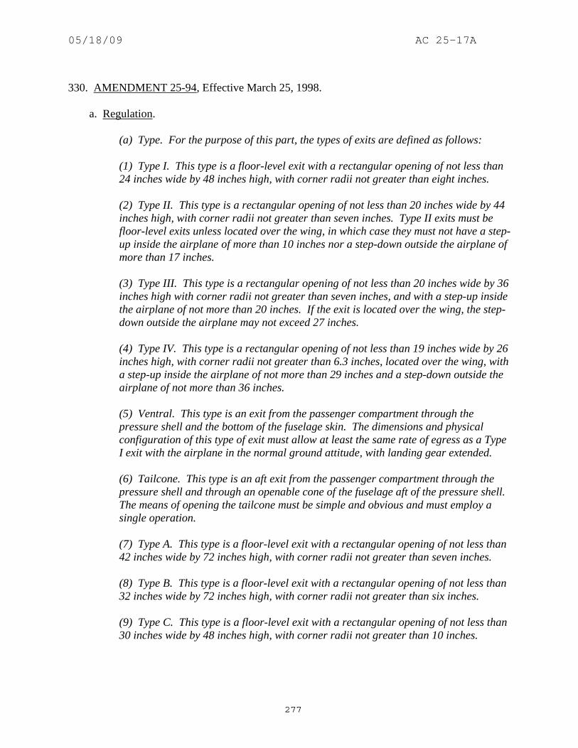
05/18/09 AC 25-17A
277
330. AMENDMENT 25-94, Effective March 25, 1998. a. Regulation.
(a) Type. For the purpose of this part, the types of exits are defined as follows: (1) Type I. This type is a floor-level exit with a rectangular opening of not less than 24 inches wide by 48 inches high, with corner radii not greater than eight inches. (2) Type II. This type is a rectangular opening of not less than 20 inches wide by 44 inches high, with corner radii not greater than seven inches. Type II exits must be floor-level exits unless located over the wing, in which case they must not have a step-up inside the airplane of more than 10 inches nor a step-down outside the airplane of more than 17 inches. (3) Type III. This type is a rectangular opening of not less than 20 inches wide by 36 inches high with corner radii not greater than seven inches, and with a step-up inside the airplane of not more than 20 inches. If the exit is located over the wing, the step-down outside the airplane may not exceed 27 inches. (4) Type IV. This type is a rectangular opening of not less than 19 inches wide by 26 inches high, with corner radii not greater than 6.3 inches, located over the wing, with a step-up inside the airplane of not more than 29 inches and a step-down outside the airplane of not more than 36 inches. (5) Ventral. This type is an exit from the passenger compartment through the pressure shell and the bottom of the fuselage skin. The dimensions and physical configuration of this type of exit must allow at least the same rate of egress as a Type I exit with the airplane in the normal ground attitude, with landing gear extended. (6) Tailcone. This type is an aft exit from the passenger compartment through the pressure shell and through an openable cone of the fuselage aft of the pressure shell. The means of opening the tailcone must be simple and obvious and must employ a single operation. (7) Type A. This type is a floor-level exit with a rectangular opening of not less than 42 inches wide by 72 inches high, with corner radii not greater than seven inches. (8) Type B. This type is a floor-level exit with a rectangular opening of not less than 32 inches wide by 72 inches high, with corner radii not greater than six inches. (9) Type C. This type is a floor-level exit with a rectangular opening of not less than 30 inches wide by 48 inches high, with corner radii not greater than 10 inches.

05/18/09 AC 25-17A
278
(b) Step down distance. Step down distance, as used in this section, means the actual distance between the bottom of the required opening and a usable foot hold, extending out from the fuselage, that is large enough to be effective without searching by sight or feel. (c) Over-sized exits. Openings larger than those specified in this section, whether or not of rectangular shape, may be used if the specified rectangular opening can be inscribed within the opening and the base of the inscribed rectangular opening meets the specified step-up and step-down heights. (d) Asymmetry. Exits of an exit pair need not be diametrically opposite each other nor of the same size; however, the number of passenger seats permitted under paragraph (g) of this section is based on the smaller of the two exits. (e) Uniformity. Exits must be distributed as uniformly as practical, taking into account passenger seat distribution. (f) Location. (1) Each required passenger emergency exit must be accessible to the passengers and located where it will afford the most effective means of passenger evacuation. (2) If only one floor-level exit per side is prescribed, and the airplane does not have a tailcone or ventral emergency exit, the floor-level exits must be in the rearward part of the passenger compartment unless another location affords a more effective means of passenger evacuation. (3) If more than one floor-level exit per side is prescribed, and the airplanes does not have a combination cargo and passenger configuration, at least one floor-level exit must be located in each side near each end of the cabin. [(4) For an airplane that is required to have more than one passenger emergency exit for each side of the fuselage, no passenger emergency exit shall be more than 60 feet from any adjacent passenger emergency exit on the same side of the same deck of the fuselage, as measured parallel to the airplane's longitudinal axis between the nearest exit edges.] (g) Type and number required. The maximum number of passenger seats permitted depends on the type and number of exits installed in each side of the fuselage. Except as further restricted in paragraphs (g)(1) through (g)(9) of this section, the maximum number of passenger seats permitted for each exit of a specific type installed in each side of the fuselage is as follows:

05/18/09 AC 25-17A
279
Type A........... 110 Type B........... 75 Type C........... 55 Type I............. 45 Type II............ 40 Type III........... 35 Type IV........... 9
(1) For a passenger seating configuration of 1 to 9 seats, there must be at least one Type IV or larger overwing exit in each side of the fuselage or, if overwing exits are not provided, at least one exit in each side that meets the minimum dimensions of a Type III exit. (2) For a passenger seating configuration of more than 9 seats, each exit must be a Type III or larger exit. (3) For a passenger seating configuration of 10 to 19 seats, there must be at least one Type III or larger exit in each side of the fuselage. (4) For a passenger seating configuration of 20 to 40 seats, there must be at least two exits, one of which must be a Type II or larger exit, in each side of the fuselage. (5) For a passenger seating configuration of 41 to 110 seats, there must be at least two exits, one of which must be a Type I or larger exit, in each side of the fuselage. (6) For a passenger seating configuration of more than 110 seats, the emergency exits in each side of the fuselage must include at least two Type I or larger exits. (7) The combined maximum number of passenger seats permitted for all Type III exits is 70, and the combined maximum number of passenger seats permitted for two Type III exits in each side of the fuselage that are separated by fewer than three passenger seat rows in 65. (8) If a Type A, Type B, or Type C exit is installed, there must be at least two Type C or larger exits in each side of the fuselage. (9) If a passenger ventral or tailcone exit is installed and that exit provides at least the same rate of egress as a Type III exit with the airplane in the most adverse exit opening condition that would result from the collapse of one or more legs of the landing gear, an increase in the passenger seating configuration is permitted as follows: (i) For a ventral exit, 12 additional passenger seats.
05/18/09 AC 25-17A
280
(ii) For a tailcone exit incorporating a floor level opening of not less than 20 inches wide by 60 inches high, with corner radii not greater than seven inches, in the pressure shell and incorporating an approved assist means in accordance with § 25.810(a), 25 additional passenger seats. (iii) For a tailcone exit incorporating an opening in the pressure shell which is at least equivalent to a Type III emergency exit with respect to dimensions, step-up and step-down distance, and with the top of the opening not less than 56 inches from the passenger compartment floor, 15 additional passenger seats. (h) Excess exits. Each emergency exit in the passenger compartment in excess of the minimum number of required emergency exits must meet the applicable requirements of § 25.809 through 25.812, and must be readily accessible. (i) Ditching emergency exits for passengers. Whether or not ditching certification is requested, ditching emergency exits must be provided in accordance with the following requirements, unless the emergency exits required by paragraph (g) of this section already meet them: (1) For airplanes that have a passenger seating configuration of nine or fewer seats, excluding pilot seats, one exit above the waterline in each side of the airplane, meeting at least the dimensions of a Type IV exit. (2) For airplanes that have a passenger seating configuration of 10 or more seats, excluding pilot seats, one exit above the waterline in a side of the airplane, meeting at least the dimensions of a Type III exit for each unit (or part of a unit) of 35 passenger seats, but no less than two such exits in the passenger cabin, with one on each side of the airplane. The passenger seat/exit ratio may be increased through the use of larger exits, or other means, provided it is shown that the evacuation capability during ditching has been improved accordingly. (3) If it is impractical to locate side exits above the waterline, the side exits must be replaced by an equal number of readily accessible overhead hatches of not less than the dimensions of a Type III exit, except that for airplanes with a passenger configuration of 35 or fewer seats, excluding pilot seats, the two required Type III side exits need be replaced by only one overhead hatch. [(j) Flightcrew emergency exits. For airplanes in which the proximity of passenger emergency exits to the flightcrew area does not offer a convenient and readily accessible means of evacuation of the flightcrew, and for all airplanes having a passenger seating capacity greater than 20, flightcrew exits shall be located in the flightcrew area. Such exits shall be of sufficient size and so located as to permit rapid evacuation by the crew. One exit shall be provided on each side of the airplane; or, alternatively, a top hatch shall be provided. Each exit must encompass an unobstructed rectangular opening of at least 19 by 20 inches unless satisfactory exit utility can be demonstrated by a typical crewmember.]

05/18/09 AC 25-17A
281
b. Guidance. (1) The equivalency to that required by the regulations of nonstandard exits or arrangements may be determined by use of the Latin-Square test procedure. Refer to Appendix 4, which was derived from Notice FS 8110.12, “Test Procedure for Evaluating Non-Standard Exits for Transport Category Airplanes,” dated May 21, 1964. (Amendment 25-0) (2) An “exit pair” consists of two exits of the same type, one in each side of the fuselage. The exits need not be the same size, nor do they have to be directly opposite each other. As long as the exits on both sides of the fuselage are uniformly distributed with respect to the passenger seating arrangement, a pair need not be the two exits that are physically closest to each other. Refer to figure 330-1. (Amendment 25-0)
FIGURE 330-1 AIRPLANE CONFIGURATION
(3) Paragraph (a)(3). Type III exits were not restricted to overwing locations. Further, Type IV exits were restricted to airplanes that have a passenger seating capacity of nine or less, as reflected in the § 25.807(c)(l) table. (Amendment 25-32)

05/18/09 AC 25-17A
282
(4) Paragraph (a). Exits may be “derated” in accordance with the requirements of a smaller type; that is, exits may not only be oversized, the interior may be reconfigured to specifically derate an exit that has previously been qualified as a larger type. In order to preclude the appearance of the exit being unusable, the following additional considerations have been found acceptable: (Amendment 25-15) (i) Type A to Type I: Only seats may encroach into the projected exit opening, no more than 12-inch cumulative. A 24-inch passageway should be provided, and seats may not breakover into this passageway or into the assist space. The operating handle should be visible from the aisle. (Amendment 25-15) (ii) Type A to Type III: A 24-inch passageway should be provided, and seats may not breakover into this passageway. The operating handle should be visible from the aisle. (Amendment 25-15) (iii) Type I to Type III: A 13-inch passageway is required when the passageway is bordered by seats, or by a seat and a wall. A 20-inch passageway should be provided when the passageway is bordered by walls and should be within the projected opening of the exit. The required Type III opening should be unobstructed inboard for the width of one passenger seat place. The operating handle should be visible from the aisle. (Amendment 25-15) (5) Paragraph (e). It should be noted that this requirement also affects supplemental type certificates for airplanes manufactured after October 16, 1987. Also refer to § 25.2(b) at this amendment. Refer to AC 25.807-1, “Uniform Distribution of Exits,” dated 8/13/90 for additional guidance on this subject. (Amendment 25-67) (6) Paragraph (g). An airplane with a Type I sized exit located in the forward left-hand side of the fuselage, a pair of Type III exits in the middle, and a Type I sized exit located in the aft right-hand side of the fuselage should be limited to a maximum passenger seating capacity of 70, because of concerns with oversized dead-end zones if either the left- or right-side exits are unusable. (Amendment 25-0) (7) Paragraph (g). An airplane with a pair of exits forward in the fuselage with the left one Type I sized and the right one Type III sized, and a pair of exits in the aft end of the fuselage with the left one Type III sized and the right one Type I sized may be approved for passenger seating capacities up to 79. If an emergency evacuation demonstration is required, then either the left-side or right-side exits should be selected so as not to unduly penalize this well-balanced arrangement or to make a radical departure from all previous demonstrations. Refer to figure 330-1. (Amendment 25-0) (8) Paragraph (g). Flight attendants are considered part of the crew and are not included in the passenger seating capacity mentioned in § 25.807(g). (Amendment 25-0) (9) Paragraphs (g) and (i). When establishing the maximum capacity to be listed on the type data sheet, consideration should be given to all relevant parameters. For example, if the exit-limited passenger capacity as defined in § 25.807(g) has not been substantiated by

05/18/09 AC 25-17A
283
compliance with the evacuation demonstration requirements of § 25.803, the data sheet should reflect the evacuation limit and not the exit limit. Other limiting factors include, but are not limited to, structural capability, seating density (uniform distribution of exits), or ditching exits. The maximum passenger capacity is also limited by the ditching requirements of § 25.807(i) whether certification for ditching is requested or not. In any case, the data sheet should not list a capacity for which the airplane is not capable. When the type data sheet limit is not the § 25.807(g) exit limit, an additional note, which briefly describes the reason for the limit, is appropriate. (Amendment 25-0) (10) Paragraph (g) and (i). An airplane design is determined to be eligible for a certain passenger seating complement which is commensurate with meeting all of the relevant portions of § 25.807. That is, in addition to meeting § 25.807(g), the eligibility complement is also governed by the ditching requirements of § 25.807(i), whether certification for ditching is requested or not. (Amendment 25-0) (11) Paragraph (h). Seats that have dual approval for occupancy by either crew/observers and passengers will be included in the passenger seating configuration. Regarding removal of excess exits, regardless of airplane certification basis, the following criteria applies: (Amendment 25-15) (i) All interior and exterior exit signs, markings, and lighting pertaining to the deactivated exits must be removed. There must be no recognizable evidence of the deactivated exits, visible to occupants of the cabin. However, the exterior door outline and handle need not be obscured. (Amendment 25-15) (ii) The modification which deactivates and obscures the exits must be approved through issuance of an amendment to the Type Certificate (TC) or Supplemental Type Certificate (STC) by the Manager, Aircraft Certification Office having jurisdiction over the project, and the airplane cabin, as modified, must remain in compliance with the certification basis of the model. (Amendment 25-15) (iii) Also refer to AC 20-60, “Accessibility to Excess Emergency Exits,” dated 7/18/68. (Amendment 25-15) (12) Paragraph (i). All transport category airplanes must have ditching exits whether or not ditching certification was requested. Actually, this guidance has been in effect since April 9, 1957, as reflected in Amendment 4b-5, "Emergency Evacuation Provisions," to CAR 4b. (Amendment 25-0) (13) Paragraph (i)(2). The wording “a passenger seating configuration, excluding pilot seats, of 10 seats or more,” which was promulgated with the intent of being consistent with Amendment 23-10 to part 23, does not directly address seats intended for use by observers or flight attendants. Seats approved for use by observers or flight attendants are not included in the passenger seating configuration. Seats that have dual approval for occupancy by either crew/observers or passengers will be included in the passenger seating configuration. (Amendment 25-32)

05/18/09 AC 25-17A
284
(14) Paragraph (i)(3). The wording “a passenger configuration of 35 seats or less, excluding pilot seats,” which was promulgated with the intent of being consistent with Amendment 23-10 to part 23, does not directly address seats intended for use by observers or flight attendants. Seats approved for use by observers or flight attendants are not included in the passenger seating configuration. Seats that have dual approval for occupancy by either crew/observers or passengers will be included in the passenger seating configuration. (Amendment 25-32) 331 - 350. [RESERVED]

05/18/09 AC 25-17A
285
SECTION 25.809 EMERGENCY EXIT ARRANGEMENT
351. REGULATION IN EFFECT AT ADOPTION OF PART 25. a. Regulation.
(a) Each emergency exit, including a flightcrew emergency exit, must be a movable door or hatch in the external walls of the fuselage, allowing unobstructed opening to the outside. (b) Each emergency exit must be openable from the inside and the outside except that sliding window emergency exits in the flightcrew area need not be openable from the outside if other approved exits are convenient and readily accessible to the flightcrew area. (c) The means of opening emergency exits must be simple and obvious and may not require exceptional effort. Internal exit-opening means involving sequence operations (such as operation of two handles or latches or the release of safety catches) may be used for flightcrew emergency exits if it can be reasonably established that these means are simple and obvious to crewmembers trained in their use. (d) There must be a means to lock each emergency exit and to safeguard against its opening in flight, either inadvertently by persons or as a result of mechanical failure. In addition, there must be a means for direct visual inspection of the locking mechanism by crewmembers to determine that each emergency exit, for which the initial opening movement is outward, is fully locked. (e) There must be provisions to minimize the probability of jamming of the emergency exits resulting from fuselage deformation in a minor crash landing. (f) Each landplane emergency exit (other than exits located over the wing) more than six feet from the ground with the airplane on the ground and the landing gear extended, must have an approved means to assist the occupants in descending to the ground. In addition- (1) The assist device for crew exits may be a rope or any other device demonstrated to be suitable for the purpose; (2) The assist device for passenger exits may be an inflatable slide, a noninflatable slide, or other approved device; and (3) Ropes and ladders may not be used at passenger floor level exits. (g) The proper functioning of each emergency exit must be shown by tests.

05/18/09 AC 25-17A
286
b. Guidance. (1) Paragraph (b). Other approved exits should be usable for rescue personnel to assist incapacitated flight crewmembers. If a cockpit flightcrew exit is not openable from the outside on the left side, another approved exit that is openable from the outside should be on the left side. The same applies to the right side. Also refer to § 25.805. When conducting the evaluation that an exit is openable from both inside and outside of the airplane, the adjacent seats must be positioned in the most adverse position of the seat including seat translation, seat rotation, seat back recline, seat back breakover, and seat tracking. (Amendment 25-0)
(2) Paragraph (b). Some airplanes initially certificated as passenger configurations may include cockpit windows that are openable only from the inside. On those airplanes, convenient and readily accessible passenger exits on both sides of the fuselage, that are openable from both the inside and outside, have been approved to comply with this requirement. When these airplanes are reconfigured as cargo-only airplanes, with an accompanying proposal to deactivate one of these passenger doors, provision must be made for continued compliance with this requirement (e.g., reconfiguring the cockpit window on that side so that it is openable from the outside). (Amendment 25-0) (3) Paragraph (b). The requirement that each emergency exit be openable from the inside and outside does not apply when the airplane is parked and unoccupied. It is acceptable to have locks that prevent unauthorized entry provided there are also satisfactory means to ensure that the locks are disengaged prior to passenger boarding. Such satisfactory means will vary depending on the size and complexity of the airplane. Cockpit annunciator lights are not necessary unless the emergency exits are so remotely located or numerous that lock disengagement might be overlooked. A lock pin with a red flag in an exit is satisfactory. The AFM should include a preflight checklist in the Procedures Section requiring the lock pin removal. (Amendment 25-0) (4) Paragraph (c). The exits should be openable when the fuselage is pressurized to the maximum allowed for takeoff and landing. Usually this pressure is about 0.125 psi. If design features such as automatic bleed-off, would make this full pressure unlikely, the exits should be openable at whatever pressure can reasonably be expected after taxi, rejected takeoff (RTO), or minor crash landing. (Amendment 25-0) (5) Paragraph (e). A hole in the fuselage, such as an exit, inevitably has stronger structure surrounding it and is an acceptable provision. Clearances to account for deflections such as the doors, structure, and hinges, are also provisions. A minor crash landing is one in which the ultimate inertia forces of § 25.561(b)(3) are experienced. (Amendment 25-0) (6) Paragraph (f). Large transport airplanes typically have heights from cockpit windows and/or floor level exits to the ground that may preclude the use of ropes as an acceptable assist means for egress. Demonstrations have shown that typical occupants do not have the upper body strength and/or stamina to descend a rope over longer distances without unacceptable slipping and/or falling. Consequently, alternative means, such as inertia reels or slides should be utilized, as appropriate. (Amendment 25-0)

05/18/09 AC 25-17A
287
(7) Paragraph (f). Part 25 addresses requirements for crew and passenger occupants only. It did not envision nor does it specifically address an increasingly common category of occupant approved (by exemption to part 25) for freighter airplanes: supernumeraries (reference § 121.583). Supernumeraries are typically employed in some fashion to facilitate the movement or care of cargo and passengers, generally receive some degree of training over and above that possessed by passengers. Additionally, relatively few of them are accommodated onboard any particular airplane. Consequently, the terms of each exemption approving the carriage of supernumeraries are tailored to the particular installations and training involved. But in general, the FAA has conservatively considered supernumeraries to be more like passengers than crew, and encourages and expects supernumeraries to be afforded the same overall level of safety as for passengers, to the maximum extent practicable-except that, for supernumeraries, more consideration is permitted for training and other special circumstances to achieve the requisite level of safety. For example, escape slides have typically been retained on freighter conversions. But in some limited special instances, inertial reels have been approved in lieu of slides. (Amendment 25-0) (8) Paragraph (f)(1). If a rope is provided for crew exits, it should be attached to the fuselage structure at or above the upper limit of the exit opening. The rope and attachment should be capable of withstanding a 400-pound static load. Usability of the rope should be demonstrated by a 5th percentile female (approximately 60-inches tall and weighing no more than 102 lbs ) as well as a 95th percentile male (approximately 74-inches tall and weighing no less than 210 lbs ). (Amendment 25-0) 352. AMENDMENT 25-1, Effective June 7, 1965. a. Regulation.
(a) Each emergency exit, including a flight crew emergency exit, must be a movable door or hatch in the external walls of the fuselage, allowing unobstructed opening to the outside. (b) Each emergency exit must be openable from the inside and the outside except that sliding window emergency exits in the flight crew area need not be openable from the outside if other approved exits are convenient and readily accessible to the flight crew area. (c) The means of opening emergency exits must be simple and obvious and may not require exceptional effort. Internal exit-opening means involving sequence operations (such as operation of two handles or latches or the release of safety catches) may be used for flight crew emergency exits if it can be reasonably established that these means are simple and obvious to crewmembers trained in their use.

05/18/09 AC 25-17A
288
(d) There must be a means to lock each emergency exit and to safeguard against its opening in flight, either inadvertently by persons or as a result of mechanical failure. In addition, there must be a means for direct visual inspection of the locking mechanism by crewmembers to determine that each emergency exit, for which the initial opening movement is outward, is fully locked. (e) There must be provisions to minimize the probability of jamming of the emergency exits resulting from fuselage deformation in a minor crash landing. [(f) Each landplane emergency exit more than six feet from the ground with the airplane on the ground and the landing gear extended and each over-the-wing emergency exit must have an approved means to assist the occupants in descending to the ground. The assisting means for a floor level passenger emergency exit must be a slide, or an equivalent approved device. The assisting means for any other emergency exit must be a rope at least 5
8 -inch in diameter, or an equivalent approved device. If the assisting means is a rope or an approved device equivalent to a rope, it must be- (1) Attached to the fuselage structure at or above the top of the emergency exit opening, or, for a device at a pilot's emergency exit window, at another approved location if the stowed device, or its attachment, would reduce the pilot's view in flight; (2) Able (with its attachment) to withstand a 400-pound static load; and (3) For an over-the-wing emergency exit, long enough to allow descent over the leading or trailing edge of the wing, whichever distance is longer.] (g) The proper functioning of each emergency exit must be shown by tests.
b. Guidance. (1) Paragraph (b). Other approved exits should be usable for rescue personnel to assist incapacitated flight crewmembers. If a cockpit flightcrew exit is not openable from the outside on the left side, another approved exit that is openable from the outside should be on the left side. The same applies to the right side. Also refer to § 25.805. The evaluation that an exit is openable from both inside and outside of the airplane, the adjacent seats must be positioned in the most adverse position of the seat including seat translation, seat rotation, seat back recline, seat back breakover, and seat tracking. (Amendment 25-0)
(2) Paragraph (b). Some airplanes initially certificated as passenger configurations may include cockpit windows that are openable only from the inside. On those airplanes, convenient and readily accessible passenger exits on both sides of the fuselage, that are openable from both the inside and outside, have been approved to comply with this requirement. When these airplanes are reconfigured as cargo-only airplanes, with an accompanying proposal to deactivate one of these passenger doors, provision must be made for continued compliance with this

05/18/09 AC 25-17A
289
requirement (e.g., reconfiguring the cockpit window on that side so that it is openable from the outside). (Amendment 25-0) (3) Paragraph (b). The requirement that each emergency exit be openable from the inside and outside does not apply when the airplane is parked and unoccupied. It is acceptable to have locks that prevent unauthorized entry provided there are also satisfactory means to ensure that the locks are disengaged prior to passenger boarding. Such satisfactory means will vary depending on the size and complexity of the airplane. Cockpit annunciator lights are not necessary unless the emergency exits are so remotely located or numerous that lock disengagement might be overlooked. A lock pin with a red flag in an exit is satisfactory. The AFM should include a preflight checklist in the Procedures Section requiring the lock pin removal. (Amendment 25-0) (4) Paragraph (c). The exits should be openable when the fuselage is pressurized to the maximum allowed for takeoff and landing. Usually this pressure is about 0.125 psi. If design features such as automatic bleed-off, would make this full pressure unlikely, the exits should be openable at whatever pressure can reasonably be expected after taxi, rejected takeoff (RTO), or minor crash landing. (Amendment 25-0) (5) Paragraph (e). A hole in the fuselage, such as an exit, inevitably has stronger structure surrounding it and is an acceptable provision. Clearances to account for deflections such as the doors, structure, and hinges, are also provisions. A minor crash landing is one in which the ultimate inertia forces of § 25.561(b)(3) are experienced. (Amendment 25-0) (6) Paragraph (f). Large transport airplanes typically have heights from cockpit windows and/or floor level exits to the ground that may preclude the use of ropes as an acceptable assist means for egress. Demonstrations have shown that typical occupants do not have the upper body strength and/or stamina to descend a rope over longer distances without unacceptable slipping and/or falling. Consequently, alternative means, such as inertia reels or slides should be utilized, as appropriate. (Amendment 25-0) (7) Paragraph (f). Part 25 addresses requirements for crew and passenger occupants only. It did not envision nor does it specifically address an increasingly common category of occupant approved (by exemption to part 25) for freighter airplanes: supernumeraries (reference § 121.583). Supernumeraries are typically employed in some fashion to facilitate the movement or care of cargo and passengers, generally receive some degree of training over and above that possessed by passengers. Additionally, relatively few of them are accommodated onboard any particular airplane. Consequently, the terms of each exemption approving the carriage of supernumeraries are tailored to the particular installations and training involved. But in general, the FAA has conservatively considered supernumeraries to be more like passengers than crew, and encourages and expects supernumeraries to be afforded the same overall level of safety as for passengers, to the maximum extent practicable-except that, for supernumeraries, more consideration is permitted for training and other special circumstances to achieve the requisite level of safety. For example, escape slides have typically been retained on freighter conversions. But in some limited special instances, inertial reels have been approved in lieu of slides. (Amendment 25-0)
05/18/09 AC 25-17A
290
(8) Paragraph (f). Usability of the rope should be demonstrated by a 5th percentile female (approximately 60-inches tall and weighing no more than 102 lbs ) as well as a 95th percentile male (approximately 74-inches tall and weighing no less than 210 lbs ). (Amendment 25-0) 353. AMENDMENT 25-9, Effective June 30, 1966. a. Regulation.
(a) Each emergency exit, including a flight crew emergency exit, must be a movable door or hatch in the external walls of the fuselage, allowing unobstructed opening to the outside. (b) Each emergency exit must be openable from the inside and the outside except that sliding window emergency exits in the flight crew area need not be openable from the outside if other approved exits are convenient and readily accessible to the flight crew area. (c) The means of opening emergency exits must be simple and obvious and may not require exceptional effort. Internal exit-opening means involving sequence operations (such as operation of two handles or latches or the release of safety catches) may be used for flight crew emergency exits if it can be reasonably established that these means are simple and obvious to crewmembers trained in their use. (d) There must be a means to lock each emergency exit and to safeguard against its opening in flight, either inadvertently by persons or as a result of mechanical failure. In addition, there must be a means for direct visual inspection of the locking mechanism by crewmembers to determine that each emergency exit, for which the initial opening movement is outward, is fully locked. (e) There must be provisions to minimize the probability of jamming of the emergency exits resulting from fuselage deformation in a minor crash landing. [(f) Each landplane emergency exit (other than over the wing) more than 6 feet from the ground with the airplane on the ground and the landing gear extended must have an approved means to assist the occupants in descending to the ground. The assisting means for a floor level passenger emergency exit must be a slide, or an equivalent approved device. The assisting means is a rope or an approved device equivalent to a rope, it must be-] (1) Attached to the fuselage structure at or above the top of the emergency exit opening, or, for a device at a pilot's emergency exit window, at another approved

05/18/09 AC 25-17A
291
location if the stowed device, or its attachment, would reduce the pilot's view in flight; and (2) Able (with its attachment) to withstand a 400-pound static load. (g) The proper functioning of each emergency exit must be shown by tests.
b. Guidance. (1) Paragraph (b). Other approved exits should be usable for rescue personnel to assist incapacitated flight crewmembers. If a cockpit flightcrew exit is not openable from the outside on the left side, another approved exit that is openable from the outside should be on the left side. The same applies to the right side. Also refer to § 25.805. The evaluation that an exit is openable from both inside and outside of the airplane, the adjacent seats must be positioned in the most adverse position of the seat including seat translation, seat rotation, seat back recline, seat back breakover, and seat tracking. (Amendment 25-0)
(2) Paragraph (b). Some airplanes initially certificated as passenger configurations may include cockpit windows that are openable only from the inside. On those airplanes, convenient and readily accessible passenger exits on both sides of the fuselage, that are openable from both the inside and outside, have been approved to comply with this requirement. When these airplanes are reconfigured as cargo-only airplanes, with an accompanying proposal to deactivate one of these passenger doors, provision must be made for continued compliance with this requirement (e.g., reconfiguring the cockpit window on that side so that it is openable from the outside). (Amendment 25-0) (3) Paragraph (b). The requirement that each emergency exit be openable from the inside and outside does not apply when the airplane is parked and unoccupied. It is acceptable to have locks that prevent unauthorized entry provided there are also satisfactory means to ensure that the locks are disengaged prior to passenger boarding. Such satisfactory means will vary depending on the size and complexity of the airplane. Cockpit annunciator lights are not necessary unless the emergency exits are so remotely located or numerous that lock disengagement might be overlooked. A lock pin with a red flag in an exit is satisfactory. The AFM should include a preflight checklist in the Procedures Section requiring the lock pin removal. (Amendment 25-0) (4) Paragraph (c). The exits should be openable when the fuselage is pressurized to the maximum allowed for takeoff and landing. Usually this pressure is about 0.125 psi. If design features such as automatic bleed-off, would make this full pressure unlikely, the exits should be openable at whatever pressure can reasonably be expected after taxi, rejected takeoff (RTO), or minor crash landing. (Amendment 25-0) (5) Paragraph (e). A hole in the fuselage, such as an exit, inevitably has stronger structure surrounding it and is an acceptable provision. Clearances to account for deflections such as the doors, structure, and hinges, are also provisions. A minor crash landing is one in which the ultimate inertia forces of § 25.561(b)(3) are experienced. (Amendment 25-0)

05/18/09 AC 25-17A
292
(6) Paragraph (f). Large transport airplanes typically have heights from cockpit windows and/or floor level exits to the ground that may preclude the use of ropes as an acceptable assist means for egress. Demonstrations have shown that typical occupants do not have the upper body strength and/or stamina to descend a rope over longer distances without unacceptable slipping and/or falling. Consequently, alternative means, such as inertia reels or slides should be utilized, as appropriate. (Amendment 25-0) (7) Paragraph (f). Part 25 addresses requirements for crew and passenger occupants only. It did not envision nor does it specifically address an increasingly common category of occupant approved (by exemption to part 25) for freighter airplanes: supernumeraries (reference § 121.583). Supernumeraries are typically employed in some fashion to facilitate the movement or care of cargo and passengers, generally receive some degree of training over and above that possessed by passengers. Additionally, relatively few of them are accommodated onboard any particular airplane. Consequently, the terms of each exemption approving the carriage of supernumeraries are tailored to the particular installations and training involved. But in general, the FAA has conservatively considered supernumeraries to be more like passengers than crew, and encourages and expects supernumeraries to be afforded the same overall level of safety as for passengers, to the maximum extent practicable-except that, for supernumeraries, more consideration is permitted for training and other special circumstances to achieve the requisite level of safety. For example, escape slides have typically been retained on freighter conversions. But in some limited special instances, inertial reels have been approved in lieu of slides. (Amendment 25-0) (8) Paragraph (f). Usability of the rope should be demonstrated by a 5th percentile female (approximately 60-inches tall and weighing no more than 102 lbs ) as well as a 95th percentile male (approximately 74-inches tall and weighing no less than 210 lbs ). (Amendment 25-0) 354. AMENDMENT 25-15, Effective October 24, 1967. a. Regulation.
(a) Each emergency exit, including a flight crew emergency exit, must be a movable door or hatch in the external walls of the fuselage, allowing unobstructed opening to the outside. (b) Each emergency exit must be openable from the inside and the outside except that sliding window emergency exits in the flight crew area need not be openable from the outside if other approved exits are convenient and readily accessible to the flight crew area. (c) The means of opening emergency exits must be simple and obvious and may not require exceptional effort. Internal exit-opening means involving sequence operations (such as operation of two handles or latches or the release of safety catches) may be used for flight crew emergency exits if it can be reasonably

05/18/09 AC 25-17A
293
established that these means are simple and obvious to crewmembers trained in their use. (d) There must be a means to lock each emergency exit and to safeguard against its opening in flight, either inadvertently by persons or as a result of mechanical failure. In addition, there must be a means for direct visual inspection of the locking mechanism by crewmembers to determine that each emergency exit, for which the initial opening movement is outward, is fully locked. (e) There must be provisions to minimize the probability of jamming of the emergency exits resulting from fuselage deformation in a minor crash landing. [(f) Each landplane emergency exit (other than exits located over the wing) more than 6 feet from the ground with the airplane on the ground and the landing gear extended must have an approved means to assist the occupants in descending to the ground as follows: (1) The assisting means for each passenger emergency exit must be a self-supporting slide or equivalent, and must be designed so that it is- (i) Automatically deployed, and automatically erected, concurrent with the opening of the exit except that the assisting means may be erected in a different manner when installed at service doors that qualify as emergency exits, and at passenger doors; and (ii) Erectable within 10 seconds and of such length that the lower end is self-supporting on the ground after collapse of any one or more landing gear legs. (2) The assisting means for flight crew emergency exits may be a rope or any other means demonstrated to be suitable for the purpose. If the assisting means is a rope, or an approved device equivalent to a rope, it must be- (i) Attached to the fuselage structure at or above the top of the emergency exit opening, or, for a device at a pilot's emergency exit window, at another approved location if the stowed device, or its attachment, would reduce the pilot's view in flight; (ii) Able (with its attachment) to withstand a 400-pound static load.] (g) The proper functioning of each emergency exit must be shown by tests. [(h) If the trailing edge of the flaps in the landing position is more than 6 feet above the ground with the airplane on the ground and the landing gear extended, or if the wing is more than 6 feet above the ground with the landing gear extended and the flaps are unsuitable as a slide, means must be provided to assist evacuees (who have used the overwing exits) to reach the ground.]

05/18/09 AC 25-17A
294
b. Guidance. (1) Paragraph (b). Other approved exits should be usable for rescue personnel to assist incapacitated flight crewmembers. If a cockpit flightcrew exit is not openable from the outside on the left side, another approved exit that is openable from the outside should be on the left side. The same applies to the right side. Also refer to § 25.805. The evaluation that an exit is openable from both inside and outside of the airplane, the adjacent seats must be positioned in the most adverse position of the seat including seat translation, seat rotation, seat back recline, seat back breakover, and seat tracking. (Amendment 25-0)
(2) Paragraph (b). Some airplanes initially certificated as passenger configurations may include cockpit windows that are openable only from the inside. On those airplanes, convenient and readily accessible passenger exits on both sides of the fuselage, that are openable from both the inside and outside, have been approved to comply with this requirement. When these airplanes are reconfigured as cargo-only airplanes, with an accompanying proposal to deactivate one of these passenger doors, provision must be made for continued compliance with this requirement (e.g., reconfiguring the cockpit window on that side so that it is openable from the outside). (Amendment 25-0) (3) Paragraph (b). The requirement that each emergency exit be openable from the inside and outside does not apply when the airplane is parked and unoccupied. It is acceptable to have locks that prevent unauthorized entry provided there are also satisfactory means to ensure that the locks are disengaged prior to passenger boarding. Such satisfactory means will vary depending on the size and complexity of the airplane. Cockpit annunciator lights are not necessary unless the emergency exits are so remotely located or numerous that lock disengagement might be overlooked. A lock pin with a red flag in an exit is satisfactory. The AFM should include a preflight checklist in the Procedures Section requiring the lock pin removal. (Amendment 25-0) (4) Paragraph (c). The exits should be openable when the fuselage is pressurized to the maximum allowed for takeoff and landing. Usually this pressure is about 0.125 psi. If design features such as automatic bleed-off, would make this full pressure unlikely, the exits should be openable at whatever pressure can reasonably be expected after taxi, rejected takeoff (RTO), or minor crash landing. (Amendment 25-0) (5) Paragraph (e). A hole in the fuselage, such as an exit, inevitably has stronger structure surrounding it and is an acceptable provision. Clearances to account for deflections such as the doors, structure, and hinges, are also provisions. A minor crash landing is one in which the ultimate inertia forces of § 25.561(b)(3) are experienced. (Amendment 25-0) (6) Paragraph (f). Part 25 addresses requirements for crew and passenger occupants only. It did not envision nor does it specifically address an increasingly common category of occupant approved (by exemption to part 25) for freighter airplanes: supernumeraries (reference § 121.583). Supernumeraries are typically employed in some fashion to facilitate the movement or care of cargo and passengers, generally receive some degree of training over and above that possessed by passengers. Additionally, relatively few of them are accommodated onboard any particular airplane. Consequently, the terms of each exemption approving the carriage of

05/18/09 AC 25-17A
295
supernumeraries are tailored to the particular installations and training involved. But in general, the FAA has conservatively considered supernumeraries to be more like passengers than crew, and encourages and expects supernumeraries to be afforded the same overall level of safety as for passengers, to the maximum extent practicable-except that, for supernumeraries, more consideration is permitted for training and other special circumstances to achieve the requisite level of safety. For example, escape slides have typically been retained on freighter conversions. But in some limited special instances, inertial reels have been approved in lieu of slides. (Amendment 25-0) (7) Paragraph (f)(1). To be self-supporting, the bottom end of the slide should rest on the ground. If it does not rest on the ground, the slide must be usable and look usable to passengers. When the passenger uses the slide, the bottom end should rest on the ground and allow the passenger to egress, the slide readily. (Amendment 25-15) (8) Paragraph (f)(1)(i). There should be a positive visual means of determining girt bar engagement to assure that the assisting means can be automatically deployed. (Amendment 25-15) (9) Paragraph (f)(1)(i). Passenger doors are those that can be expected to be used for normal passenger loading. Current airport terminal passenger loading facilities should be considered. An emergency exit qualifies as a service door if such as a galley or service bar is adjacent to the exit. An exit is not a service door if the galley is on the other side of the airplane with its own door. When the interior is used in more than one configuration, where the exit is a service door at times and solely an emergency exit at other times, the rule allows fully automatic slides at all times, or conversion from automatically inflated to manually inflated as the exit status varies. Since the second option may be impractical, the use of fully automatic slides at all times would be acceptable. The FAA considers that fully automatic slides may be hazardous to ground personnel, and may find it acceptable to install a warning placard or red webbing stretched across the door window. A manual inflation handle with placarding is an acceptable different manner for slide erection. (Amendment 25-15) (10) Paragraph (f)(1)(ii). Collapse of any one or more landing gear legs will cause the slide angle to vary from the normal angle. At these various angles, it may be acceptable if the assisting means is safely usable by normal, healthy passengers. If this is not obvious by inspection, it should be demonstrated by test. The evacuation rate need not be the same as that with a normal angle. The adverse attitude also should be evaluated for the cockpit emergency egress provisions. (Amendment 25-15) (11) Paragraph (f)(2). Large transport airplanes typically have heights from cockpit windows and/or floor level exits to the ground that may preclude the use of ropes as an acceptable assist means for egress. Demonstrations have shown that typical occupants do not have the upper body strength and/or stamina to descend a rope over longer distances without unacceptable slipping and/or falling. Consequently, alternative means, such as inertia reels or slides should be utilized, as appropriate. (Amendment 25-0)

05/18/09 AC 25-17A
296
(12) Paragraph (f)(2). Usability of the rope should be demonstrated by a 5th percentile female (approximately 60-inches tall and weighing no more than 102 lbs ) as well as a 95th percentile male (approximately 74-inches tall and weighing no less than 210 lbs ). (Amendment 25-0) (13) Paragraph (h). The six feet above the ground may be measured as follows: (Amendment 25-15) (i) At the lowest point along the required escape route, (Amendment 25-15) (ii) When the airplane is on level ground, (Amendment 25-15) (iii) The gross weight and center of gravity (c.g.) location should be considered for a typical takeoff configuration for the critical flap setting, (Amendment 25-15) (iv) The flap setting should be the highest landing setting allowed in the AFM, (Amendment 25-15) (v) The landing gear oleo setting, tire pressure and any other rigging dependent tolerances should be the average, and (Amendment 25-15) (vi) The landing gear strut and tire compression should be based on the gross weight and c.g. location used in paragraph (13)(iii) above. (Amendment 25-15) 355. AMENDMENT 25-32, Effective, May 1, 1972. a. Regulation.
(a) Each emergency exit, including a flight crew emergency exit, must be a movable door or hatch in the external walls of the fuselage, allowing unobstructed opening to the outside. (b) Each emergency exit must be openable from the inside and the outside except that sliding window emergency exits in the flight crew area need not be openable from the outside if other approved exits are convenient and readily accessible to the flight crew area. [Each emergency exit must be capable of being opened, when there is no fuselage deformation- (1) With the airplane in the normal ground attitude and in each of the attitudes corresponding to collapse of one or more legs of the landing gear; and (2) Within ten seconds measured from the time when the opening means is actuated to the time when the exit is fully opened.]

05/18/09 AC 25-17A
297
(c) The means of opening emergency exits must be simple and obvious and may not require exceptional effort. Internal exit-opening means involving sequence operations (such as operation of two handles or latches or the release of safety catches) may be used for flight crew emergency exits if it can be reasonably established that these means are simple and obvious to crewmembers trained in their use. (d) There must be a means to lock each emergency exit and to safeguard against its opening in flight, either inadvertently by persons or as a result of mechanical failure. In addition, there must be a means for direct visual inspection of the locking mechanism by crewmembers to determine that each emergency exit, for which the initial opening movement is outward, is fully locked. (e) There must be provisions to minimize the probability of jamming of the emergency exits resulting from fuselage deformation in a minor crash landing. (f) Each landplane emergency exit (other than exits located over the wing) more than 6 feet from the ground with the airplane on the ground and the landing gear extended must have an approved means to assist the occupants in descending to the ground as follows: [(1) The assisting means for each passenger emergency exit must be a self-supporting slide or equivalent, and must be designed to meet the following requirements: (i) It must be automatically deployed and deployment must begin during the interval between the time the exit opening means is actuated from inside the airplane and the time the exit is fully opened. However, each passenger emergency exit which is also a passenger entrance door or a service door must be provided with means to prevent deployment of the assisting means when it is opened from either the inside or the outside under non-emergency conditions for normal use. (ii) It must be automatically erected within 10 seconds after deployment is begun. (iii) It must be of such length that the lower end is self-supporting on the ground after collapse of one or more legs of the landing gear.] (2) The assisting means for flight crew emergency exits may be a rope or any other means demonstrated to be suitable for the purpose. If the assisting means is a rope, or an approved device equivalent to a rope, it must be- (i) Attached to the fuselage structure at or above the top of the emergency exit opening, or, for a device at a pilot's emergency exit window, at another approved location if the stowed device, or its attachment, would reduce the pilot's view in flight;

05/18/09 AC 25-17A
298
(ii) Able (with its attachment) to withstand a 400-pound static load. [(g) Each emergency exit must be shown by tests, or by a combination of analysis and tests, to meet the requirements of paragraphs (b) and (c) of this section. (h) If the place on the airplane structure at which the escape route required in § 25.803(e) terminates is more than six feet from the ground with the airplane on the ground and the landing gear extended, means must be provided to assist evacuees (who have used the overwing exits) to reach the ground. If the escape route is over a flap, the height of the terminal edge must be measured with the flap in the takeoff or landing position, whichever is higher from the ground. The assisting means must be of such length that the lower end is self-supporting on the ground after collapse of any one or more landing gear legs. (i) If a single power-boost or single power-operated system is the primary system for operating more than one exit in an emergency, each exit must be capable of meeting the requirements of paragraph (b) of this section in the event of failure of the primary system. Manual operation of the exit (after failure of the primary system) is acceptable.]
b. Guidance. (1) Paragraph (b). Other approved exits should be usable for rescue personnel to assist incapacitated flight crewmembers. If a cockpit flightcrew exit is not openable from the outside on the left side, another approved exit that is openable from the outside should be on the left side. The same applies to the right side. Also refer to § 25.805. The evaluation that an exit is openable from both inside and outside of the airplane, the adjacent seats must be positioned in the most adverse position of the seat including seat translation, seat rotation, seat back recline, seat back breakover, and seat tracking. (Amendment 25-0)
(2) Paragraph (b). Some airplanes initially certificated as passenger configurations may include cockpit windows that are openable only from the inside. On those airplanes, convenient and readily accessible passenger exits on both sides of the fuselage, that are openable from both the inside and outside, have been approved to comply with this requirement. When these airplanes are reconfigured as cargo-only airplanes, with an accompanying proposal to deactivate one of these passenger doors, provision must be made for continued compliance with this requirement (e.g., reconfiguring the cockpit window on that side so that it is openable from the outside). (Amendment 25-0) (3) Paragraph (b). The requirement that each emergency exit be openable from the inside and outside does not apply when the airplane is parked and unoccupied. It is acceptable to have locks that prevent unauthorized entry provided there are also satisfactory means to ensure that the locks are disengaged prior to passenger boarding. Such satisfactory means will vary depending on the size and complexity of the airplane. Cockpit annunciator lights are not necessary unless the emergency exits are so remotely located or numerous that lock disengagement might be overlooked. A lock pin with a red flag in an exit is satisfactory. The

05/18/09 AC 25-17A
299
AFM should include a preflight checklist in the Procedures Section requiring the lock pin removal. (Amendment 25-0) (4) Paragraph (c). The exits should be openable when the fuselage is pressurized to the maximum allowed for takeoff and landing. Usually this pressure is about 0.125 psi. If design features such as automatic bleed-off, would make this full pressure unlikely, the exits should be openable at whatever pressure can reasonably be expected after taxi, rejected takeoff (RTO), or minor crash landing. (Amendment 25-0) (5) Paragraph (e). A hole in the fuselage, such as an exit, inevitably has stronger structure surrounding it and is an acceptable provision. Clearances to account for deflections such as the doors, structure, and hinges, are also provisions. A minor crash landing is one in which the ultimate inertia forces of § 25.561(b)(3) are experienced. (Amendment 25-0) (6) Paragraph (f). Part 25 addresses requirements for crew and passenger occupants only. It did not envision nor does it specifically address an increasingly common category of occupant approved (by exemption to part 25) for freighter airplanes: supernumeraries (reference § 121.583). Supernumeraries are typically employed in some fashion to facilitate the movement or care of cargo and passengers, generally receive some degree of training over and above that possessed by passengers. Additionally, relatively few of them are accommodated onboard any particular airplane. Consequently, the terms of each exemption approving the carriage of supernumeraries are tailored to the particular installations and training involved. But in general, the FAA has conservatively considered supernumeraries to be more like passengers than crew, and encourages and expects supernumeraries to be afforded the same overall level of safety as for passengers, to the maximum extent practicable-except that, for supernumeraries, more consideration is permitted for training and other special circumstances to achieve the requisite level of safety. For example, escape slides have typically been retained on freighter conversions. But in some limited special instances, inertial reels have been approved in lieu of slides. (Amendment 25-0) (7) Paragraph (f)(1)(i). There should be a positive visual means of determining girt bar engagement to assure that the assisting means can be automatically deployed. (Amendment 25-15) (8) Paragraph (f)(1)(i). Passenger doors are those that can be expected to be used for normal passenger loading. Current airport terminal passenger loading facilities should be considered. An emergency exit qualifies as a service door if such as a galley or service bar is adjacent to the exit. An exit is not a service door if the galley is on the other side of the airplane with its own door. When the interior is used in more than one configuration, where the exit is a service door at times and solely an emergency exit at other times, the rule allows fully automatic slides at all times, or conversion from automatically inflated to manually inflated as the exit status varies. Since the second option may be impractical, the use of fully automatic slides at all times would be acceptable. The FAA considers that fully automatic slides may be hazardous to ground personnel, and may find it acceptable to install a warning placard or red webbing stretched across the door window. A manual inflation handle with placarding is an acceptable different manner for slide erection. (Amendment 25-15)

05/18/09 AC 25-17A
300
(9) Paragraph (f)(1)(i). A passenger entrance door and service door are defined the same as that for passenger doors and service doors in paragraph 354b(8). (Amendment 25-32) (10) Paragraph (f)(1)(iii). To be self-supporting, the bottom end of the slide should rest on the ground. If it does not rest on the ground, the slide must be usable and look usable to passengers. When the passenger uses the slide, the bottom end should rest on the ground and allow the passenger to egress, the slide readily. (Amendment 25-15) (11) Paragraph (f)(1)(iii). Collapse of any one or more landing gear legs will cause the slide angle to vary from the normal angle. At these various angles, it may be acceptable if the assisting means is safely usable by normal, healthy passengers. If this is not obvious by inspection, it should be demonstrated by test. The evacuation rate need not be the same as that with a normal angle. The adverse attitude also should be evaluated for the cockpit emergency egress provisions. (Amendment 25-15) (12) Paragraph (f)(2). Large transport airplanes typically have heights from cockpit windows and/or floor level exits to the ground that may preclude the use of ropes as an acceptable assist means for egress. Demonstrations have shown that typical occupants do not have the upper body strength and/or stamina to descend a rope over longer distances without unacceptable slipping and/or falling. Consequently, alternative means, such as inertia reels or slides should be utilized, as appropriate. (Amendment 25-0) (13) Paragraph (f)(2). Usability of the rope should be demonstrated by a 5th percentile female (approximately 60-inches tall and weighing no more than 102 lbs ) as well as a 95th percentile male (approximately 74-inches tall and weighing no less than 210 lbs ). (Amendment 25-0) (14) Paragraph (h). The guidance stated in paragraph 354b(12) of this AC applies to this amendment except paragraph 354b(12)(iv), as applied here, should read: "The flap setting should be the highest takeoff or landing setting allowed in the AFM." (Amendment 25-32) (15) Paragraph (h). The six feet above the ground may be measured as follows: (Amendment 25-15) (i) At the lowest point along the required escape route, (Amendment 25-15) (ii) When the airplane is on level ground, (Amendment 25-15) (iii) The gross weight and center of gravity (c.g.) location should be considered for a typical takeoff configuration for the critical flap setting, (Amendment 25-15) (iv) The flap setting should be the highest landing setting allowed in the AFM, (Amendment 25-15)

05/18/09 AC 25-17A
301
(v) The landing gear oleo setting, tire pressure and any other rigging dependent tolerances should be the average, and (Amendment 25-15) (vi) The landing gear strut and tire compression should be based on the gross weight and c.g. location used in paragraph (15)(iii) above. (Amendment 25-15) 356. AMENDMENT 25-34, Effective December 31, 1972. a. Regulation.
(a) Each emergency exit, including a flight crew emergency exit, must be a movable door or hatch in the external walls of the fuselage, allowing unobstructed opening to the outside. (b) Each emergency exit must be openable from the inside and the outside except that sliding window emergency exits in the flight crew area need not be openable from the outside if other approved exits are convenient and readily accessible to the flight crew area. Each emergency exit must be capable to being opened, when there is no fuselage deformation- (1) With the airplane in the normal ground attitude and in each of the attitudes corresponding to collapse of one or more legs of the landing gear; and (2) Within ten seconds measured from the time when the opening means is actuated to the time when the exit is fully opened. (c) The means of opening emergency exits must be simple and obvious and may not require exceptional effort. Internal exit-opening means involving sequence operations (such as operation of two handles or latches or the release of safety catches) may be used for flight crew emergency exits if it can be reasonably established that these means are simple and obvious to crewmembers trained in their use. (d) There must be a means to lock each emergency exit and to safeguard against its opening in flight, either inadvertently by persons or as a result of mechanical failure. In addition, there must be a means for direct visual inspection of the locking mechanism by crewmembers to determine that each emergency exit, for which the initial opening movement is outward, is fully locked. (e) There must be provisions to minimize the probability of jamming of the emergency exits resulting from fuselage deformation in a minor crash landing. (f) Each landplane emergency exit (other than exits located over the wing) more than 6 feet from the ground with the airplane on the ground and the landing gear extended

05/18/09 AC 25-17A
302
must have an approved means to assist the occupants in descending to the ground as follows: (1) The assisting means for each passenger emergency exit must be a self-supporting slide or equivalent, and must be designed to meet the following requirements: (i) It must be automatically deployed and deployment must begin during the interval between the time the exit opening means is actuated from inside the airplane and the time the exit is fully opened. However, each passenger emergency exit which is also a passenger entrance door or a service door must be provided with means to prevent deployment of the assisting means when it is opened from either the inside or the outside under non-emergency conditions for normal use. (ii) It must be automatically erected within 10 seconds after deployment is begun. (iii) It must be of such length that the lower end is self-supporting on the ground after collapse of one or more legs of the landing gear. (2) The assisting means for flight crew emergency exits may be a rope or any other means demonstrated to be suitable for the purpose. If the assisting means is a rope, or an approved device equivalent to a rope, it must be- (i) Attached to the fuselage structure at or above the top of the emergency exit opening, or, for a device at a pilot's emergency exit window, at another approved location if the stowed device, or its attachment, would reduce the pilot's view in flight; (ii) Able (with its attachment) to withstand a 400-pound static load. (g) Each emergency exit must be shown by tests, or by a combination of analysis and tests, to meet the requirements of paragraphs (b) and (c) of this section. (h) If the place on the airplane structure at which the escape route required in § 25.803(e) terminates is more than six feet from the ground with the airplane on the ground and the landing gear extended, means must be provided to assist evacuees (who have used the overwing exits) to reach the ground. If the escape route is over a flap, the height of the terminal edge must be measured with the flap in the takeoff or landing position, whichever is higher from the ground. The assisting means must be of such length that the lower end is self-supporting on the ground after collapse of any one or more landing gear legs. (i) If a single power-boost or single power-operated system is the primary system for operating more than one exit in an emergency, each exit must be capable of meeting the requirements of paragraph (b) of this section in the event of failure of the primary system. Manual operation of the exit (after failure of the primary system) is acceptable.

05/18/09 AC 25-17A
303
[(j) When required by the operating rules for any large passenger-carrying turbojet powered airplane, each ventral exit and tailcone exit must be- (1) Designed and constructed so that it cannot be opened during flight; and (2) Marked with a placard readable from a distance of 30-inches and installed at a conspicuous location near the means of opening the exit, stating that the exit has been designed and constructed so that it cannot be opened during flight.]
b. Guidance.
(1) Paragraph (b). Other approved exits should be usable for rescue personnel to assist incapacitated flight crewmembers. If a cockpit flightcrew exit is not openable from the outside on the left side, another approved exit that is openable from the outside should be on the left side. The same applies to the right side. Also refer to § 25.805. The evaluation that an exit is openable from both inside and outside of the airplane, the adjacent seats must be positioned in the most adverse position of the seat including seat translation, seat rotation, seat back recline, seat back breakover, and seat tracking. (Amendment 25-0)
(2) Paragraph (b). Some airplanes initially certificated as passenger configurations may include cockpit windows that are openable only from the inside. On those airplanes, convenient and readily accessible passenger exits on both sides of the fuselage, that are openable from both the inside and outside, have been approved to comply with this requirement. When these airplanes are reconfigured as cargo-only airplanes, with an accompanying proposal to deactivate one of these passenger doors, provision must be made for continued compliance with this requirement (e.g., reconfiguring the cockpit window on that side so that it is openable from the outside). (Amendment 25-0) (3) Paragraph (b). The requirement that each emergency exit be openable from the inside and outside does not apply when the airplane is parked and unoccupied. It is acceptable to have locks that prevent unauthorized entry provided there are also satisfactory means to ensure that the locks are disengaged prior to passenger boarding. Such satisfactory means will vary depending on the size and complexity of the airplane. Cockpit annunciator lights are not necessary unless the emergency exits are so remotely located or numerous that lock disengagement might be overlooked. A lock pin with a red flag in an exit is satisfactory. The AFM should include a preflight checklist in the Procedures Section requiring the lock pin removal. (Amendment 25-0) (4) Paragraph (c). The exits should be openable when the fuselage is pressurized to the maximum allowed for takeoff and landing. Usually this pressure is about 0.125 psi. If design features such as automatic bleed-off, would make this full pressure unlikely, the exits should be openable at whatever pressure can reasonably be expected after taxi, rejected takeoff (RTO), or minor crash landing. (Amendment 25-0) (5) Paragraph (e). A hole in the fuselage, such as an exit, inevitably has stronger structure surrounding it and is an acceptable provision. Clearances to account for deflections

05/18/09 AC 25-17A
304
such as the doors, structure, and hinges, are also provisions. A minor crash landing is one in which the ultimate inertia forces of § 25.561(b)(3) are experienced. (Amendment 25-0) (6) Paragraph (f). Part 25 addresses requirements for crew and passenger occupants only. It did not envision nor does it specifically address an increasingly common category of occupant approved (by exemption to part 25) for freighter airplanes: supernumeraries (reference § 121.583). Supernumeraries are typically employed in some fashion to facilitate the movement or care of cargo and passengers, generally receive some degree of training over and above that possessed by passengers. Additionally, relatively few of them are accommodated onboard any particular airplane. Consequently, the terms of each exemption approving the carriage of supernumeraries are tailored to the particular installations and training involved. But in general, the FAA has conservatively considered supernumeraries to be more like passengers than crew, and encourages and expects supernumeraries to be afforded the same overall level of safety as for passengers, to the maximum extent practicable-except that, for supernumeraries, more consideration is permitted for training and other special circumstances to achieve the requisite level of safety. For example, escape slides have typically been retained on freighter conversions. But in some limited special instances, inertial reels have been approved in lieu of slides. (Amendment 25-0) (7) Paragraph (f)(1)(i). There should be a positive visual means of determining girt bar engagement to assure that the assisting means can be automatically deployed. (Amendment 25-15) (8) Paragraph (f)(1)(i). Passenger doors are those that can be expected to be used for normal passenger loading. Current airport terminal passenger loading facilities should be considered. An emergency exit qualifies as a service door if such as a galley or service bar is adjacent to the exit. An exit is not a service door if the galley is on the other side of the airplane with its own door. When the interior is used in more than one configuration, where the exit is a service door at times and solely an emergency exit at other times, the rule allows fully automatic slides at all times, or conversion from automatically inflated to manually inflated as the exit status varies. Since the second option may be impractical, the use of fully automatic slides at all times would be acceptable. The FAA considers that fully automatic slides may be hazardous to ground personnel, and may find it acceptable to install a warning placard or red webbing stretched across the door window. A manual inflation handle with placarding is an acceptable different manner for slide erection. (Amendment 25-15) (9) Paragraph (f)(1)(i). A passenger entrance door and service door are defined the same as that for passenger doors and service doors in paragraph 354b(8). (Amendment 25-32) (10) Paragraph (f)(1)(iii). To be self-supporting, the bottom end of the slide should rest on the ground. If it does not rest on the ground, the slide must be usable and look usable to passengers. When the passenger uses the slide, the bottom end should rest on the ground and allow the passenger to egress, the slide readily. (Amendment 25-15) (11) Paragraph (f)(1)(iii). Collapse of any one or more landing gear legs will cause the slide angle to vary from the normal angle. At these various angles, it may be acceptable if the

05/18/09 AC 25-17A
305
assisting means is safely usable by normal, healthy passengers. If this is not obvious by inspection, it should be demonstrated by test. The evacuation rate need not be the same as that with a normal angle. The adverse attitude also should be evaluated for the cockpit emergency egress provisions. (Amendment 25-15) (12) Paragraph (f)(2). Large transport airplanes typically have heights from cockpit windows and/or floor level exits to the ground that may preclude the use of ropes as an acceptable assist means for egress. Demonstrations have shown that typical occupants do not have the upper body strength and/or stamina to descend a rope over longer distances without unacceptable slipping and/or falling. Consequently, alternative means, such as inertia reels or slides should be utilized, as appropriate. (Amendment 25-0) (13) Paragraph (f)(2). Usability of the rope should be demonstrated by a 5th percentile female (approximately 60-inches tall and weighing no more than 102 lbs ) as well as a 95th percentile male (approximately 74-inches tall and weighing no less than 210 lbs ). (Amendment 25-0) (14) Paragraph (h). The guidance stated in paragraph 354b(12) of this AC applies to this amendment except paragraph 354b(12)(iv), as applied here, should read: "The flap setting should be the highest takeoff or landing setting allowed in the AFM." (Amendment 25-32) (15) Paragraph (h). The six feet above the ground may be measured as follows: (Amendment 25-15) (i) At the lowest point along the required escape route, (Amendment 25-15) (ii) When the airplane is on level ground, (Amendment 25-15) (iii) The gross weight and center of gravity (c.g.) location should be considered for a typical takeoff configuration for the critical flap setting, (Amendment 25-15) (iv) The flap setting should be the highest landing setting allowed in the AFM, (Amendment 25-15) (v) The landing gear oleo setting, tire pressure and any other rigging dependent tolerances should be the average, and (Amendment 25-15) (vi) The landing gear strut and tire compression should be based on the gross weight and c.g. location used in paragraph (14)(iii) above. (Amendment 25-15)

05/18/09 AC 25-17A
306
357. AMENDMENT 25-46, Effective December 1, 1978. a. Regulation.
(a) Each emergency exit, including a flight crew emergency exit, must be a movable door or hatch in the external walls of the fuselage, allowing unobstructed opening to the outside. (b) Each emergency exit must be openable from the inside and the outside except that sliding window emergency exits in the flight crew area need not be openable from the outside if other approved exits are convenient and readily accessible to the flight crew area. Each emergency exit must be capable of being opened, when there is no fuselage deformation- (1) With the airplane in the normal ground attitude and in each of the attitudes corresponding to collapse of one or more legs of the landing gear; and (2) Within ten seconds measured from the time when the opening means is actuated to the time when the exit is fully opened. (c) The means of opening emergency exits must be simple and obvious and may not require exceptional effort. Internal exit-opening means involving sequence operations (such as operation of two handles or latches or the release of safety catches) may be used for flight crew emergency exits if it can be reasonably established that these means are simple and obvious to crewmembers trained in their use. (d) There must be a means to lock each emergency exit and to safeguard against its opening in flight, either inadvertently by persons or as a result of mechanical failure. In addition, there must be a means for direction visual inspection of the locking mechanism by crewmembers to determine that each emergency exit, for which the initial opening movement is outward, is fully locked. (e) There must be provisions to minimize the probability of jamming of the emergency exits resulting from fuselage deformation in a minor crash landing. (f) Each landplane emergency exit (other than exits located over the wing) more than 6 feet from the ground with the airplane on the ground and the landing gear extended must have an approved means to assist the occupants in descending to the ground as follows: (1) The assisting means for each passenger emergency exit must be a self-supporting slide or equivalent, and must be designed to meet the following requirements: (i) It must be automatically deployed and deployment must begin during the interval between the time the exit opening means is actuated from inside the airplane and the

05/18/09 AC 25-17A
307
time the exit is fully opened. However, each passenger emergency exit which is also a passenger entrance door or a service door must be provided with means to prevent deployment of the assisting means when it is opened from either the inside or the outside under non-emergency conditions for normal use. (ii) It must be automatically erected within 10 seconds after deployment is begun. (iii) It must be of such length that the lower end is self-supporting on the ground after collapse of one or more legs of the landing gear. [(iv) It must have the capability, in 25-knot winds directed from the most critical angle, to deploy and, with the assistance of only one person, to remain usable after full deployment to evacuate occupants safely to the ground. (v) For each system installation (mockup or airplane installed), five consecutive deployment and inflation tests must be conducted (per exit) without failure, and at least three tests of each such five-test series must be conducted using a single representative sample of the device. The sample devices must be deployed and inflated by the system's primary means after being subjected to the inertia forces specified in § 25.561(b). If any part of the system fails or does not function properly during the required tests, the cause of the failure or malfunction must be corrected by positive means and after that the full series of five consecutive deployment and inflation test must be conducted without failure.] (2) The assisting means for flight crew emergency exits may be a rope or any other means demonstrated to be suitable for the purpose. If the assisting means is a rope, or an approved device equivalent to a rope, it must be- (i) Attached to the fuselage structure, at or above the tope of the emergency exit opening, or, for a device at a pilot's emergency exit window, at another approved location if the stowed device, or its attachment, would reduce the pilot's view in flight; (ii) Able (with its attachment) to withstand a 400-pound static load. (g) Each emergency exit must be shown by tests, or by a combination of analysis and tests, to meet the requirements of paragraphs (b) and (c) of this section. (h) If the place on the airplane structure at which the escape route required in § 25.808(e) terminates is more than six feet from the ground with the airplane on the ground and the landing gear extended, means must be provided to assist evacuees (who have used the overwing exits) to reach the ground. If the escape route is over a flap, the height of the terminal edge must be measured with the flap in the takeoff or landing position, whichever is higher from the ground. The assisting means must be of such length that the lower end is self-supporting on the ground after collapse of any one or more landing gear legs.
05/18/09 AC 25-17A
308
(i) If a single power-boost or single power-operated system is the primary system for operating more than one exit in an emergency, each exit must be capable of meeting the requirements of paragraph (b) of this section in the event of failure of the primary system. Manual operation of the exit (after failure of the primary system) is acceptable. (j) When required by the operating rules for any large passenger-carrying turbojet powered airplane, each ventral exit and tailcone exit must be- (1) Designed and constructed so that it cannot be opened during flight; and (2) Marked with a special placard readable from a distance of 30-inches and installed at a conspicuous location near the means of opening the exit, stating that the exit has been designed and constructed so that it cannot be opened during flight.
b. Guidance. (1) Paragraph (b). Other approved exits should be usable for rescue personnel to assist incapacitated flight crewmembers. If a cockpit flightcrew exit is not openable from the outside on the left side, another approved exit that is openable from the outside should be on the left side. The same applies to the right side. Also refer to § 25.805. The evaluation that an exit is openable from both inside and outside of the airplane, the adjacent seats must be positioned in the most adverse position of the seat including seat translation, seat rotation, seat back recline, seat back breakover, and seat tracking. (Amendment 25-0)
(2) Paragraph (b). Some airplanes initially certificated as passenger configurations may include cockpit windows that are openable only from the inside. On those airplanes, convenient and readily accessible passenger exits on both sides of the fuselage, that are openable from both the inside and outside, have been approved to comply with this requirement. When these airplanes are reconfigured as cargo-only airplanes, with an accompanying proposal to deactivate one of these passenger doors, provision must be made for continued compliance with this requirement (e.g., reconfiguring the cockpit window on that side so that it is openable from the outside). (Amendment 25-0) (3) Paragraph (b). The requirement that each emergency exit be openable from the inside and outside does not apply when the airplane is parked and unoccupied. It is acceptable to have locks that prevent unauthorized entry provided there are also satisfactory means to ensure that the locks are disengaged prior to passenger boarding. Such satisfactory means will vary depending on the size and complexity of the airplane. Cockpit annunciator lights are not necessary unless the emergency exits are so remotely located or numerous that lock disengagement might be overlooked. A lock pin with a red flag in an exit is satisfactory. The AFM should include a preflight checklist in the Procedures Section requiring the lock pin removal. (Amendment 25-0) (4) Paragraph (c). The exits should be openable when the fuselage is pressurized to the maximum allowed for takeoff and landing. Usually this pressure is about 0.125 psi. If design

05/18/09 AC 25-17A
309
features such as automatic bleed-off, would make this full pressure unlikely, the exits should be openable at whatever pressure can reasonably be expected after taxi, rejected takeoff (RTO), or minor crash landing. (Amendment 25-0) (5) Paragraph (e). A hole in the fuselage, such as an exit, inevitably has stronger structure surrounding it and is an acceptable provision. Clearances to account for deflections such as the doors, structure, and hinges, are also provisions. A minor crash landing is one in which the ultimate inertia forces of § 25.561(b)(3) are experienced. (Amendment 25-0) (6) Paragraph (f). Part 25 addresses requirements for crew and passenger occupants only. It did not envision nor does it specifically address an increasingly common category of occupant approved (by exemption to part 25) for freighter airplanes: supernumeraries (reference § 121.583). Supernumeraries are typically employed in some fashion to facilitate the movement or care of cargo and passengers, generally receive some degree of training over and above that possessed by passengers. Additionally, relatively few of them are accommodated onboard any particular airplane. Consequently, the terms of each exemption approving the carriage of supernumeraries are tailored to the particular installations and training involved. But in general, the FAA has conservatively considered supernumeraries to be more like passengers than crew, and encourages and expects supernumeraries to be afforded the same overall level of safety as for passengers, to the maximum extent practicable-except that, for supernumeraries, more consideration is permitted for training and other special circumstances to achieve the requisite level of safety. For example, escape slides have typically been retained on freighter conversions. But in some limited special instances, inertial reels have been approved in lieu of slides. (Amendment 25-0) (7) Paragraph (f)(1)(i). There should be a positive visual means of determining girt bar engagement to assure that the assisting means can be automatically deployed. (Amendment 25-15) (8) Paragraph (f)(1)(i). Passenger doors are those that can be expected to be used for normal passenger loading. Current airport terminal passenger loading facilities should be considered. An emergency exit qualifies as a service door if such as a galley or service bar is adjacent to the exit. An exit is not a service door if the galley is on the other side of the airplane with its own door. When the interior is used in more than one configuration, where the exit is a service door at times and solely an emergency exit at other times, the rule allows fully automatic slides at all times, or conversion from automatically inflated to manually inflated as the exit status varies. Since the second option may be impractical, the use of fully automatic slides at all times would be acceptable. The FAA considers that fully automatic slides may be hazardous to ground personnel, and may find it acceptable to install a warning placard or red webbing stretched across the door window. A manual inflation handle with placarding is an acceptable different manner for slide erection. (Amendment 25-15) (9) Paragraph (f)(1)(i). A passenger entrance door and service door are defined the same as that for passenger doors and service doors in paragraph 354b(8). (Amendment 25-32)

05/18/09 AC 25-17A
310
(10) Paragraph (f)(1)(iii). To be self-supporting, the bottom end of the slide should rest on the ground. If it does not rest on the ground, the slide must be usable and look usable to passengers. When the passenger uses the slide, the bottom end should rest on the ground and allow the passenger to egress, the slide readily. (Amendment 25-15) (11) Paragraph (f)(1)(iii). Collapse of any one or more landing gear legs will cause the slide angle to vary from the normal angle. At these various angles, it may be acceptable if the assisting means is safely usable by normal, healthy passengers. If this is not obvious by inspection, it should be demonstrated by test. The evacuation rate need not be the same as that with a normal angle. The adverse attitude also should be evaluated for the cockpit emergency egress provisions. (Amendment 25-15) (12) Paragraph (f)(1)(iv). (Amendment 25-46) (i) The person who assists should come from the airplane. This capability should be demonstrated by test. (Amendment 25-46) (ii) Escape slides that deploy in front of an engine inlet may need to be assessed for the effect of the inlet airflow on the acceptable deployment of the escape slide. Since the wind condition is assumed, the effect of the inlet airflow should be considered in combination with the 25-knot. wind. The effect of the engine is non-linear with respect to distance from the inlet, so that tests that do not use an actual running engine should contain conservative conditions or assumptions to ensure that the installation is acceptable. For example, adding the effect of the engine (at specific distance from the inlet) to the wind velocity, and then verifying that the slide will come no closer to the engine than that distance is an acceptable method. (Amendment 25-46) (13) Paragraph (f)(1)(v). The five tests should be conducted for each individual exit. For instance, if there are a total of four Type I exits in the airplane and each exit with each slide installation is identical, a total of 20 deployment and inflation tests should be conducted, five on each exit. A lesser number of tests may be acceptable for a modification to the system installation or slide design. (Amendment 25-46) (14) Paragraph (f)(1)(v). The packed escape slide as installed in the airplane, up to and including the hardware that attaches the slide to the door, should be subjected to the specified inertia forces. Each escape slide used in the test program should be subjected to the inertia forces, but need not be subjected to the inertia forces more than once, even though it may be tested more than once. (Amendment 25-46) (15) Paragraph (f)(1)(iv) and (v). For wind or repeatability tests, as many deployments as possible should be done on an airplane. When using a mockup (also known as a module) for these tests, the following items, as a minimum, should be satisfactorily addressed: (Amendment 25-46) (i) The door on the mockup should be a full-size door built as close to a production door as possible, using production hardware or prototype equivalents. This is especially critical

05/18/09 AC 25-17A
311
with respect to the girt bar, floor fittings, packboard, bustle, the door motion, door velocity throughout the range of travel, and the manner in which the slide drops. (Amendment 25-46) (ii) The fuselage contour and skin surface of the mockup which might be contacted by the slide, under any normal or adverse attitude or wind conditions, should be the same as the airplane contour. Additionally, fuselage protuberances such as pitot-static tubes and outflow valves should be accurately represented. (Amendment 25-46) (iii) The impingement of the wind on the slide should be shown by aerodynamic analysis to be equal or greater than that on the airplane. (Amendment 25-46) (16) Paragraph (f)(2). Large transport airplanes typically have heights from cockpit windows and/or floor level exits to the ground that may preclude the use of ropes as an acceptable assist means for egress. Demonstrations have shown that typical occupants do not have the upper body strength and/or stamina to descend a rope over longer distances without unacceptable slipping and/or falling. Consequently, alternative means, such as inertia reels or slides should be utilized, as appropriate. (Amendment 25-0) (17) Paragraph (f)(2). Usability of the rope should be demonstrated by a 5th percentile female (approximately 60-inches tall and weighing no more than 102 lbs ) as well as a 95th percentile male (approximately 74-inches tall and weighing no less than 210 lbs ). (Amendment 25-0) (18) Paragraph (h). The guidance stated in paragraph 354b(12) of this AC applies to this amendment except paragraph 354b(12)(iv), as applied here, should read: "The flap setting should be the highest takeoff or landing setting allowed in the AFM." (Amendment 25-32) (19) Paragraph (h). The six feet above the ground may be measured as follows: (Amendment 25-15) (i) At the lowest point along the required escape route, (Amendment 25-15) (ii) When the airplane is on level ground, (Amendment 25-15) (iii) The gross weight and center of gravity (c.g.) location should be considered for a typical takeoff configuration for the critical flap setting, (Amendment 25-15) (iv) The flap setting should be the highest landing setting allowed in the AFM, (Amendment 25-15) (v) The landing gear oleo setting, tire pressure and any other rigging dependent tolerances should be the average, and (Amendment 25-15) (vi) The landing gear strut and tire compression should be based on the gross weight and c.g. location used in paragraph (19)(iii) above. (Amendment 25-15)

05/18/09 AC 25-17A
312
358. AMENDMENT 25-47, Effective December 24, 1979. a. Regulation.
(a) Each emergency exit, including a flight crew emergency exit, must be a movable door or hatch in the external walls of the fuselage, allowing unobstructed opening to the outside. (b) Each emergency exit must be openable from the inside and the outside except that sliding window emergency exits in the flight crew area need not be openable from the outside if other approved exits are convenient and readily accessible to the flight crew area. Each emergency exit must be capable of being opened, when there is no fuselage deformation- (1) With the airplane in the normal ground attitude and in each of the attitudes corresponding to collapse of one or more legs of the landing gear; and (2) Within ten seconds measured from the time when the opening means is actuated to the time when the exit is fully opened. (c) The means of opening emergency exits must be simple and obvious and may not require exceptional effort. Internal exit-opening means involving sequence operations (such as operation of two handles or latches or the release of safety catches) may be used for flight crew emergency exits if it can be reasonably established that these means are simple and obvious to crewmembers trained in their use. (d) There must be a means to lock each emergency exit and to safeguard against its opening in flight, either inadvertently by persons or as a result of mechanical failure. In addition, there must be a means for direct visual inspection of the locking mechanism by crewmembers to determine that each emergency exit, for which the initial opening movement is outward, is fully locked. (e) There must be provisions to minimize the probability of jamming of the emergency exits resulting from fuselage deformation in a minor crash landing. (f) Each landplane emergency exit (other than exits located over the wing) more than 6 feet from the ground with the airplane on the ground and the landing gear extended must have an approved means to assist the occupants in descending to the ground as follows: (1) The assisting means for each passenger emergency exit must be a self-supporting slide or equivalent, and must be designed to meet the following requirements: (i) It must be automatically deployed and deployment must begin during the interval between the time the exit opening means is actuated from inside the airplane and the

05/18/09 AC 25-17A
313
time the exit is fully opened. However, each passenger emergency exit which is also a passenger entrance door or a service door must be provided with means to prevent deployment of the assisting means when it is opened from either the inside or outside under non-emergency conditions for normal use. (ii) It must be automatically erected within 10 seconds after deployment is begun. [(iii) It must be of such length after full deployment that the lower end is self-supporting on the ground and provides safe evacuation of occupants to the ground after collapse of one or more legs of the landing gear.] (iv) It must have the capability, in 25-knot winds directed from the most critical angle, to deploy and, with the assistance of only one person, to remain usable after full deployment to evacuate occupants safely to the ground. (v) For each system installation (mockup or airplane installed), five consecutive deployment and inflation tests must be conducted (per exit) without failure, and at least three tests of each such five-test series must be conducted using a single representative sample of the device. The sample devices must be deployed and inflated by the system's primary means after being subjected to the inertia forces specified in § 25.561(b). If any part of the system fails or does not function properly during the required tests, the cause of the failure or malfunction must be corrected by positive means and after that the full series of five consecutive deployment and inflation tests must be conducted without failure. (2) The assisting means for flight crew emergency exits may be a rope of any other means demonstrated to be suitable for the purpose. If the assisting means is a rope, or an approved device equivalent to a rope, it must be- (i) Attached to the fuselage structure at or above the tope of the emergency exit opening, or, for a device at a pilot's emergency exit window, at another approved location if the stowed device, or its attachment, would reduce the pilot's view in flight; (ii) Able (with its attachment) to withstand a 400-pound static load. (g) Each emergency exit must be shown by tests, or by a combination of analysis and tests, to meet the requirements of paragraphs (b) and (c) of this section. (h) If the place on the airplane structure at which the escape route required in § 25.803(e) terminates is more than six feet from the ground with the airplane on the ground and the landing gear extended, means must be provided to assist evacuees (who have used the overwing exits) to reach the ground. If the escape route is over a flap, the height of the terminal edge must be measured with the flap in the takeoff or landing position, whichever is higher from the ground. The assisting means must be

05/18/09 AC 25-17A
314
of such length that the lower end is self-supporting on the ground after collapse of any one or more landing gear legs. (i) If a single power boost or single power-operated system is the primary system for operating more than one exit in an emergency, each exit must be capable of meeting the requirements of paragraph (b) of this section in the event of failure of the primary system. Manual operation of the exit (after failure of the primary system) is acceptable., (j) When required by the operating rules for any large passenger-carrying turbojet powered airplane, each ventral exit and tailcone exit must be- (1) Designed and constructed so that it cannot be opened during flight; and (2) Marked with a placard readable from a distance of 30-inches and installed at a conspicuous location near the means of opening the exit, stating that the exit has been designed and constructed so that it cannot be opened during flight.
b. Guidance. (1) Paragraph (b). Other approved exits should be usable for rescue personnel to assist incapacitated flight crewmembers. If a cockpit flightcrew exit is not openable from the outside on the left side, another approved exit that is openable from the outside should be on the left side. The same applies to the right side. Also refer to § 25.805. The evaluation that an exit is openable from both inside and outside of the airplane, the adjacent seats must be positioned in the most adverse position of the seat including seat translation, seat rotation, seat back recline, seat back breakover, and seat tracking. (Amendment 25-0)
(2) Paragraph (b). Some airplanes initially certificated as passenger configurations may include cockpit windows that are openable only from the inside. On those airplanes, convenient and readily accessible passenger exits on both sides of the fuselage, that are openable from both the inside and outside, have been approved to comply with this requirement. When these airplanes are reconfigured as cargo-only airplanes, with an accompanying proposal to deactivate one of these passenger doors, provision must be made for continued compliance with this requirement (e.g., reconfiguring the cockpit window on that side so that it is openable from the outside). (Amendment 25-0) (3) Paragraph (b). The requirement that each emergency exit be openable from the inside and outside does not apply when the airplane is parked and unoccupied. It is acceptable to have locks that prevent unauthorized entry provided there are also satisfactory means to ensure that the locks are disengaged prior to passenger boarding. Such satisfactory means will vary depending on the size and complexity of the airplane. Cockpit annunciator lights are not necessary unless the emergency exits are so remotely located or numerous that lock disengagement might be overlooked. A lock pin with a red flag in an exit is satisfactory. The AFM should include a preflight checklist in the Procedures Section requiring the lock pin removal. (Amendment 25-0)

05/18/09 AC 25-17A
315
(4) Paragraph (c). The exits should be openable when the fuselage is pressurized to the maximum allowed for takeoff and landing. Usually this pressure is about 0.125 psi. If design features such as automatic bleed-off, would make this full pressure unlikely, the exits should be openable at whatever pressure can reasonably be expected after taxi, rejected takeoff (RTO), or minor crash landing. (Amendment 25-0) (5) Paragraph (e). A hole in the fuselage, such as an exit, inevitably has stronger structure surrounding it and is an acceptable provision. Clearances to account for deflections such as the doors, structure, and hinges, are also provisions. A minor crash landing is one in which the ultimate inertia forces of § 25.561(b)(3) are experienced. (Amendment 25-0) (6) Paragraph (f). Part 25 addresses requirements for crew and passenger occupants only. It did not envision nor does it specifically address an increasingly common category of occupant approved (by exemption to part 25) for freighter airplanes: supernumeraries (reference § 121.583). Supernumeraries are typically employed in some fashion to facilitate the movement or care of cargo and passengers, generally receive some degree of training over and above that possessed by passengers. Additionally, relatively few of them are accommodated onboard any particular airplane. Consequently, the terms of each exemption approving the carriage of supernumeraries are tailored to the particular installations and training involved. But in general, the FAA has conservatively considered supernumeraries to be more like passengers than crew, and encourages and expects supernumeraries to be afforded the same overall level of safety as for passengers, to the maximum extent practicable-except that, for supernumeraries, more consideration is permitted for training and other special circumstances to achieve the requisite level of safety. For example, escape slides have typically been retained on freighter conversions. But in some limited special instances, inertial reels have been approved in lieu of slides. (Amendment 25-0) (7) Paragraph (f)(1)(i). There should be a positive visual means of determining girt bar engagement to assure that the assisting means can be automatically deployed. (Amendment 25-15) (8) Paragraph (f)(1)(i). Passenger doors are those that can be expected to be used for normal passenger loading. Current airport terminal passenger loading facilities should be considered. An emergency exit qualifies as a service door if such as a galley or service bar is adjacent to the exit. An exit is not a service door if the galley is on the other side of the airplane with its own door. When the interior is used in more than one configuration, where the exit is a service door at times and solely an emergency exit at other times, the rule allows fully automatic slides at all times, or conversion from automatically inflated to manually inflated as the exit status varies. Since the second option may be impractical, the use of fully automatic slides at all times would be acceptable. The FAA considers that fully automatic slides may be hazardous to ground personnel, and may find it acceptable to install a warning placard or red webbing stretched across the door window. A manual inflation handle with placarding is an acceptable different manner for slide erection. (Amendment 25-15)

05/18/09 AC 25-17A
316
(9) Paragraph (f)(1)(i). A passenger entrance door and service door are defined the same as that for passenger doors and service doors in paragraph 354b(8). (Amendment 25-32) (10) Paragraph (f)(1)(iii). To be self-supporting, the bottom end of the slide should rest on the ground. If it does not rest on the ground, the slide must be usable and look usable to passengers. When the passenger uses the slide, the bottom end should rest on the ground and allow the passenger to egress, the slide readily. (Amendment 25-15) (11) Paragraph (f)(1)(iii). In order to meet the 25 knot wind requirement, the escape slide presses against the fuselage and the end of the unoccupied slide may not be in physical contact with the ground, especially in the most adverse attitude (gear collapse). This condition has been found to be acceptable provided the slide is self-supporting on the ground shortly after an evacuee has entered the slide and prior to the evacuee reaching the end of the slide. The unoccupied slide, when viewed from the exit, should not give the visual impression that the slide is unsafe for use. (Amendment 25-47) (12) Paragraph (f)(1)(iii). Collapse of any one or more landing gear legs will cause the slide angle to vary from the normal angle. At these various angles, it may be acceptable if the assisting means is safely usable by normal, healthy passengers. If this is not obvious by inspection, it should be demonstrated by test. The evacuation rate need not be the same as that with a normal angle. The adverse attitude also should be evaluated for the cockpit emergency egress provisions. (Amendment 25-15) (13) Paragraph (f)(1)(iv). (Amendment 25-46) (i) The person who assists should come from the airplane. This capability should be demonstrated by test. (Amendment 25-46) (ii) Escape slides that deploy in front of an engine inlet may need to be assessed for the effect of the inlet airflow on the acceptable deployment of the escape slide. Since the wind condition is assumed, the effect of the inlet airflow should be considered in combination with the 25-knot. wind. The effect of the engine is non-linear with respect to distance from the inlet, so that tests that do not use an actual running engine should contain conservative conditions or assumptions to ensure that the installation is acceptable. For example, adding the effect of the engine (at specific distance from the inlet) to the wind velocity, and then verifying that the slide will come no closer to the engine than that distance is an acceptable method. (Amendment 25-46) (14) Paragraph (f)(1)(v). The five tests should be conducted for each individual exit. For instance, if there are a total of four Type I exits in the airplane and each exit with each slide installation is identical, a total of 20 deployment and inflation tests should be conducted, five on each exit. A lesser number of tests may be acceptable for a modification to the system installation or slide design. (Amendment 25-46) (15) Paragraph (f)(1)(v). The packed escape slide as installed in the airplane, up to and including the hardware that attaches the slide to the door, should be subjected to the specified

05/18/09 AC 25-17A
317
inertia forces. Each escape slide used in the test program should be subjected to the inertia forces, but need not be subjected to the inertia forces more than once, even though it may be tested more than once. (Amendment 25-46) (16) Paragraphs (f)(1)(iv) and (v). For wind or repeatability tests, as many deployments as possible should be done on an airplane. When using a mockup (also known as a module) for these tests, the following items, as a minimum, should be satisfactorily addressed: (Amendment 25-46) (i) The door on the mockup should be a full-size door built as close to a production door as possible, using production hardware or prototype equivalents. This is especially critical with respect to the girt bar, floor fittings, packboard, bustle, the door motion, door velocity throughout the range of travel, and the manner in which the slide drops. (Amendment 25-46) (ii) The fuselage contour and skin surface of the mockup which might be contacted by the slide, under any normal or adverse attitude or wind conditions, should be the same as the airplane contour. Additionally, fuselage protuberances such as pitot-static tubes and outflow valves should be accurately represented. (Amendment 25-46) (iii) The impingement of the wind on the slide should be shown by aerodynamic analysis to be equal or greater than that on the airplane. (Amendment 25-46) (17) Paragraph (f)(2). Large transport airplanes typically have heights from cockpit windows and/or floor level exits to the ground that may preclude the use of ropes as an acceptable assist means for egress. Demonstrations have shown that typical occupants do not have the upper body strength and/or stamina to descend a rope over longer distances without unacceptable slipping and/or falling. Consequently, alternative means, such as inertia reels or slides should be utilized, as appropriate. (Amendment 25-0) (18) Paragraph (f)(2). Usability of the rope should be demonstrated by a 5th percentile female (approximately 60-inches tall and weighing no more than 102 lbs ) as well as a 95th percentile male (approximately 74-inches tall and weighing no less than 210 lbs ). (Amendment 25-0) (19) Paragraph (h). The guidance stated in paragraph 354b(12) of this AC applies to this amendment except paragraph 354b(12)(iv), as applied here, should read: "The flap setting should be the highest takeoff or landing setting allowed in the AFM." (Amendment 25-32) (20) Paragraph (h). The six feet above the ground may be measured as follows: (Amendment 25-15) (i) At the lowest point along the required escape route, (Amendment 25-15) (ii) When the airplane is on level ground, (Amendment 25-15)
05/18/09 AC 25-17A
318
(iii) The gross weight and center of gravity (c.g.) location should be considered for a typical takeoff configuration for the critical flap setting, (Amendment 25-15) (iv) The flap setting should be the highest landing setting allowed in the AFM, (Amendment 25-15) (v) The landing gear oleo setting, tire pressure and any other rigging dependent tolerances should be the average, and (Amendment 25-15) (vi) The landing gear strut and tire compression should be based on the gross weight and c.g. location used in paragraph (20)(iii) above. (Amendment 25-15) 359. AMENDMENT 25-72, Effective August 20, 1990. a. Regulation.
(a) Each emergency exit, including a flight crew emergency exit, must be a movable door or hatch in the external walls of the fuselage, allowing unobstructed opening to the outside. (b) Each emergency exit must be openable from the inside and the outside except that sliding window emergency exits in the flight crew area need not be openable from the outside if other approved exits are convenient and readily accessible to the flight crew area. Each emergency exit must be capable of being opened, when there is no fuselage deformation- (1) With the airplane in the normal ground attitude and in each of the attitudes corresponding to collapse of one or more legs of the landing gear; and (2) Within ten seconds measured from the time when the opening means is actuated to the time when the exit is fully opened. (c) The means of opening emergency exits must be simple and obvious and may not require exceptional effort. Internal exit-opening means involving sequence operations (such as operation of two handles or latches or the release of safety catches) may be used for flight crew emergency exits if it can be reasonably established that these means are simple and obvious to crewmembers trained in their use. [(d)] If a single power-boost or single power-operated system is the primary system for operating more than one exit in an emergency, each exit must be capable of meeting the requirements of paragraph (b) of this section in the event of failure of the primary system. Manual operation of the exit (after failure of the primary system) is acceptable.

05/18/09 AC 25-17A
319
[(e)] Each emergency exit must be shown by tests, or by a combination of analysis and tests, to meet the requirements of paragraphs (b) and (c) of this section. [(f)] There must be a means to lock each emergency exit and to safeguard against its opening in flight, either inadvertently by persons or as a result of mechanical failure. In addition, there must be a means for direct visual inspection of the locking mechanism by crewmembers to determine that each emergency exit, for which the initial opening movement is outward, is fully locked. [(g)] There must be provisions to minimize the probability of jamming of the emergency exits resulting from fuselage deformation in a minor crash landing. [(h)] When required by the operating rules for any large passenger-carrying turbojet-powered airplane, each ventral exit and tailcone exit must be- (1) Designed and constructed so that it cannot be opened during flight; and (2) Marked with a placard readable from a distance of 30-inches and installed at a conspicuous location near the means of opening the exit, stating that the exit has been designed and constructed so that it cannot be opened during flight.
b. Guidance. (1) Paragraph (b). Other approved exits should be usable for rescue personnel to assist incapacitated flight crewmembers. If a cockpit flightcrew exit is not openable from the outside on the left side, another approved exit that is openable from the outside should be on the left side. The same applies to the right side. Also refer to § 25.807(f). The evaluation that an exit is openable from both inside and outside of the airplane, the adjacent seats must be positioned in the most adverse position of the seat including seat translation, seat rotation, seat back recline, seat back breakover, and seat tracking. (Amendment 25-0)
(2) Paragraph (b). Some airplanes initially certificated as passenger configurations may include cockpit windows that are openable only from the inside. On those airplanes, convenient and readily accessible passenger exits on both sides of the fuselage, that are openable from both the inside and outside, have been approved to comply with this requirement. When these airplanes are reconfigured as cargo-only airplanes, with an accompanying proposal to deactivate one of these passenger doors, provision must be made for continued compliance with this requirement (e.g., reconfiguring the cockpit window on that side so that it is openable from the outside). (Amendment 25-0) (3) Paragraph (b). The requirement that each emergency exit be openable from the inside and outside does not apply when the airplane is parked and unoccupied. It is acceptable to have locks that prevent unauthorized entry provided there are also satisfactory means to ensure that the locks are disengaged prior to passenger boarding. Such satisfactory means will vary depending on the size and complexity of the airplane. Cockpit annunciator lights are not necessary unless the emergency exits are so remotely located or numerous that lock disengagement might be overlooked. A lock pin with a red flag in an exit is satisfactory. The AFM should include a preflight checklist in the Procedures Section requiring the lock pin removal. (Amendment 25-0)

05/18/09 AC 25-17A
320
(4) Paragraph (c). The exits should be openable when the fuselage is pressurized to the maximum allowed for takeoff and landing. Usually this pressure is about 0.125 psi. If design features such as automatic bleed-off, would make this full pressure unlikely, the exits should be openable at whatever pressure can reasonably be expected after taxi, rejected takeoff (RTO), or minor crash landing. (Amendment 25-0) (5) Paragraph (g). A hole in the fuselage, such as an exit, inevitably has stronger structure surrounding it and is an acceptable provision. Clearances to account for deflections such as the doors, structure, and hinges, are also provisions. A minor crash landing is one in which the ultimate inertia forces of § 25.561(b)(3) are experienced. (Amendment 25-0) 360 - 370. [RESERVED]

05/18/09 AC 25-17A
321
SECTION 25.810 EMERGENCY EGRESS ASSIST MEANS AND ESCAPE ROUTES 371. Section 25.810 Did Not Exist Prior to Amendment 25-72. 372. AMENDMENT 25-72, Effective August 20, 1990. a. Regulation.
[(a) Each nonoverwing landplane emergency exit more than 6 feet from the ground with the airplane on the ground and the landing gear extended and each nonoverwing Type A exit must have an approved means to assist the occupants in descending to the ground. (1) The assisting means for each passenger emergency exit must be a self supporting slide or equivalent; and, in the case of a Type A or Type B exits, it must be capable of carrying simultaneously two parallel lines of evacuees. In addition, the assisting means must be designed to meet the following requirements: (i) It must be automatically deployed and deployment must begin during the interval between the time the exit opening means is actuated from inside the airplane and the time the exit is fully opened. However, each passenger emergency exit which is also a passenger entrance door or a service door must be provided with means to prevent deployment of the assisting means when it is opened from either the inside or the outside under nonemergency conditions for normal use. (ii) It must be automatically erected within 10 seconds after deployment is begun. (iii) It must be of such length after full deployment that the lower end is self supporting on the ground and provides safe evacuation of occupants to the ground after collapse of one or more legs of the landing gear. (iv) It must have the capability, in 25-knot winds directed from the most critical angle, to deploy and, with the assistance of only one person, to remain usable after full deployment to evacuate occupants safely to the ground. (v) For each system installation (mockup or airplane installed), five consecutive deployment and inflation tests must be conducted (per exit) without failure, and at least three tests of each such five-test series must be conducted using a single representative sample of the device The sample devices must be deployed and inflated by the system's primary means after being subjected to the inertia forces specified in § 25.561(b). If any part of the system fails or does not function properly during the required tests, the cause of the failure or malfunction must be corrected by positive means and after that, the full series of five consecutive deployment and inflation tests must be conducted without failure.

05/18/09 AC 25-17A
322
(2) The assisting means for flightcrew emergency exits may be a rope or any other means demonstrated to be suitable for the purpose. If the assisting means is a rope, or an approved device equivalent to a rope, it must be- (i) Attached to the fuselage structure at or above the top of the emergency exit opening, or, for a device at a pilot's emergency exit window, at another approved location if the stowed device, or its attachment, would reduce the pilot's view in flight; (ii) Able (with its attachment) to withstand a 400-pound static load. (b) Assist means from the cabin to the wing are required for each Type A exit located above the wing and having a stepdown unless the exit without an assist means can be shown to have a rate of passenger egress at least equal to that of the same type or nonoverwing exit. If an assist means is required, it must be automatically deployed and automatically erected, concurrent with the opening of the exit and self-supporting within 10 seconds. (c) An escape route must be established from each overwing emergency exit, and (except for flap surfaces suitable as slides) covered with a slip resistant surface. Except where a means for channelling the flow of evacuees is provided- (1) The escape route must be at least 42-inches wide at Type A passenger emergency exits and must be at least 2 feet wide at all other passenger emergency exits, and (2) The escape route surface must have a reflectance of at least 80 percent, and must be defined by markings with a surface-to-marking contrast ratio of at least 5:1. (d) If the place on the airplane structure at which the escape route required in paragraph (c) of this section terminates, is more than 6 feet from the ground with the airplane on the ground and the landing gear extended, means to reach the ground must be provided to assist evacuees who have used the escape route. If the escape route is over a flap, the height of the terminal edge must be measured with the flap in the takeoff or landing position, whichever is higher from the ground. The assisting means must be usable and self-supporting with one or more landing gear legs collapsed and under a 25-knot wind directed from the most critical angle. The assisting means provided for each escape route leading from a Type A emergency exit must be capable of carrying simultaneously two parallel lines of evacuees. For other than Type A exits, the assist means must be capable of carrying simultaneously as many parallel lines of evacuees as there are required escape routes.]
b. Guidance. (1) Paragraph (a). Part 25 addresses requirements for crew and passenger occupants only. It did not envision nor does it specifically address an increasingly common category of occupant approved (by exemption to part 25) for freighter airplanes: supernumeraries (reference

05/18/09 AC 25-17A
323
§ 121.583). Supernumeraries are typically employed in some fashion to facilitate the movement or care of cargo and passengers, generally receive some degree of training over and above that possessed by passengers. Additionally, relatively few of them are accommodated onboard any particular airplane. Consequently, the terms of each exemption approving the carriage of supernumeraries are tailored to the particular installations and training involved. But in general, the FAA has conservatively considered supernumeraries to be more like passengers than crew, and encourages and expects supernumeraries to be afforded the same overall level of safety as for passengers, to the maximum extent practicable-except that, for supernumeraries, more consideration is permitted for training and other special circumstances to achieve the requisite level of safety. For example, escape slides have typically been retained on freighter conversions. But in some limited special instances, inertial reels have been approved in lieu of slides. (Amendment 25-0) (2) Paragraph (a)(1)(i) and (d). There should be a positive visual means of determining girt bar engagement to assure that the assisting means can be automatically deployed. (Amendment 25-15) (3) Paragraph (a)(1)(i) and (d). Passenger doors are those that can be expected to be used for normal passenger loading. Current airport terminal passenger loading facilities should be considered. An emergency exit qualifies as a service door if such as a galley or service bar is adjacent to the exit. An exit is not a service door if the galley is on the other side of the airplane with its own door. When the interior is used in more than one configuration, where the exit is a service door at times and solely an emergency exit at other times, the rule allows fully automatic slides at all times, or conversion from automatically inflated to manually inflated as the exit status varies. Since the second option may be impractical, the use of fully automatic slides at all times would be acceptable. The FAA considers that fully automatic slides may be hazardous to ground personnel, and may find it acceptable to install a warning placard or red webbing stretched across the door window. A manual inflation handle with placarding is an acceptable different manner for slide erection. (Amendment 25-15) (4) Paragraph (a)(1)(i). A passenger entrance door and service door are defined the same as that for passenger doors and service doors in paragraph 354b(8). (Amendment 25-32) (5) Paragraph (a)(1)(ii) and (d). Collapse of any one or more landing gear legs will cause the slide angle to vary from the normal angle. At these various angles, it may be acceptable if the assisting means is safely usable by normal, healthy passengers. If this is not obvious by inspection, it should be demonstrated by test. The evacuation rate need not be the same as that with a normal angle. The adverse attitude also should be evaluated for the cockpit emergency egress provisions. (Amendment 25-15) (6) Paragraph (a)(1)(iii) and (d). To be self-supporting, the bottom end of the slide should rest on the ground. If it does not rest on the ground, the slide must be usable and look usable to passengers. When the passenger uses the slide, the bottom end should rest on the ground and allow the passenger to egress, the slide readily. (Amendment 25-15)

05/18/09 AC 25-17A
324
(7) Paragraph (a)(1)(iii), (iv) and (d). In order to meet the 25 knot wind requirement, the escape slide presses against the fuselage and the end of the unoccupied slide may not be in physical contact with the ground, especially in the most adverse attitude (gear collapse). This condition has been found to be acceptable provided the slide is self-supporting on the ground shortly after an evacuee has entered the slide and prior to the evacuee reaching the end of the slide. The unoccupied slide, when viewed from the exit, should not give the visual impression that the slide is unsafe for use. (Amendment 25-47) (8) Paragraph (a)(1)(iv) and (d). (Amendment 25-46) (i) The person who assists should come from the airplane. This capability should be demonstrated by test. (Amendment 25-46) (ii) Escape slides that deploy in front of an engine inlet may need to be assessed for the effect of the inlet airflow on the acceptable deployment of the escape slide. Since the wind condition is assumed, the effect of the inlet airflow should be considered in combination with the 25-knot. wind. The effect of the engine is non-linear with respect to distance from the inlet, so that tests that do not use an actual running engine should contain conservative conditions or assumptions to ensure that the installation is acceptable. For example, adding the effect of the engine (at specific distance from the inlet) to the wind velocity, and then verifying that the slide will come no closer to the engine than that distance is an acceptable method. (Amendment 25-46) (9) Paragraphs (a)(1)(iv) and (d). For wind or repeatability tests, as many deployments as possible should be done on an airplane. When using a mockup (also known as a module) for these tests, the following items, as a minimum, should be satisfactorily addressed: (Amendment 25-46) (i) The door on the mockup should be a full-size door built as close to a production door as possible, using production hardware or prototype equivalents. This is especially critical with respect to the girt bar, floor fittings, packboard, bustle, the door motion, door velocity throughout the range of travel, and the manner in which the slide drops. (Amendment 25-46) (ii) The fuselage contour and skin surface of the mockup which might be contacted by the slide, under any normal or adverse attitude or wind conditions, should be the same as the airplane contour. Additionally, fuselage protuberances such as pitot-static tubes and outflow valves should be accurately represented. (Amendment 25-46) (iii) The impingement of the wind on the slide should be shown by aerodynamic analysis to be equal or greater than that on the airplane. (Amendment 25-46) (10) Paragraph (a)(1)(v) and (d). The five tests should be conducted for each individual exit. For instance, if there are a total of four Type I exits in the airplane and each exit with each slide installation is identical, a total of 20 deployment and inflation tests should be conducted, five on each exit. A lesser number of tests may be acceptable for a modification to the system installation or slide design. (Amendment 25-46)
05/18/09 AC 25-17A
325
(11) Paragraph (a)(1)(v) and (d). The packed escape slide as installed in the airplane, up to and including the hardware that attaches the slide to the door, should be subjected to the specified inertia forces. Each escape slide used in the test program should be subjected to the inertia forces, but need not be subjected to the inertia forces more than once, even though it may be tested more than once. (Amendment 25-46) (12) Paragraph (a)(2). Large transport airplanes typically have heights from cockpit windows and/or floor level exits to the ground that may preclude the use of ropes as an acceptable assist means for egress. Demonstrations have shown that typical occupants do not have the upper body strength and/or stamina to descend a rope over longer distances without unacceptable slipping and/or falling. Consequently, alternative means, such as inertia reels or slides should be utilized, as appropriate. (Amendment 25-0) (13) Paragraph (a)(2). Usability of the rope should be demonstrated by a 5th percentile female (approximately 60-inches tall and weighing no more than 102 lbs ) as well as a 95th percentile male (approximately 74-inches tall and weighing no less than 210 lbs ). (Amendment 25-0) (14) Paragraph (c). (Amendment 25-15) (i) Military Specifications Mil W-5044B and Mil-W-5044C, titled "Walkway Compound, Nonslip and Walkway Matting, Nonslip,” measure dynamic coefficient of friction and provide an acceptable standard for the slip resistant properties when a minimum dynamic coefficient of friction of 0.45 is measured. This is an acceptable measure for this section and for § 25.793. (Amendment 25-15) (ii) A 42-inch wide escape path is acceptable for airplanes incorporating dual overwing Type III exits. (Amendment 25-15) (15) Paragraph (d). The guidance stated in paragraph 354b(12) of this AC applies to this amendment except paragraph 354b(12)(iv), as applied here, should read: "The flap setting should be the highest takeoff or landing setting allowed in the AFM." (Amendment 25-32) (16) Paragraph (d). The six feet above the ground may be measured as follows: (Amendment 25-15) (i) At the lowest point along the required escape route, (Amendment 25-15) (ii) When the airplane is on level ground, (Amendment 25-15) (iii) The gross weight and center of gravity (c.g.) location should be considered for a typical takeoff configuration for the critical flap setting, (Amendment 25-15) (iv) The flap setting should be the highest landing setting allowed in the AFM, (Amendment 25-15)

05/18/09 AC 25-17A
326
(v) The landing gear oleo setting, tire pressure and any other rigging dependent tolerances should be the average, and (Amendment 25-15) (vi) The landing gear strut and tire compression should be based on the gross weight and c.g. location used in paragraph (16)(iii) above. (Amendment 25-15) 373. AMENDMENT 25-88, Effective December 9, 1996. a. Regulation.
[(a) Each non over-wing Type A, Type B or Type C exit, and any other non over-wing landplane emergency exit more than 6 feet from the ground with the airplane on the ground and the landing gear extended, must have an approved means to assist the occupants in descending to the ground. (1) The assisting means for each passenger emergency exit must be a self-supporting slide or equivalent; and, in the case of a Type A or Type B exits, it must be capable of carrying simultaneously two parallel lines of evacuees. In addition, the assisting means must be designed to meet the following requirements-] (i) It must be automatically deployed and deployment must begin during the interval between the time the exit opening means is actuated from inside the airplane and the time the exit is fully opened. However, each passenger emergency exit which is also a passenger entrance door or a service door must be provided with means to prevent deployment of the assisting means when it is opened from either the inside or the outside under nonemergency conditions for normal use. [(ii) Except for assisting means installed at Type C exits, it must be automatically erected within 6 seconds after deployment is begun. Assisting means installed at Type C exits must be automatically erected within 10 seconds from the time the opening means of the exit is actuated.] (iii) It must be of such length after full deployment that the lower end is self-supporting on the ground and provides safe evacuation of occupants to the ground after collapse of one or more legs of the landing gear. (iv) It must have the capability, in 25-knot winds directed from the most critical angle, to deploy and, with the assistance of only one person, to remain usable after full deployment to evacuate occupants safely to the ground. (v) For each system installation (mockup or airplane installed), five consecutive deployment and inflation tests must be conducted (per exit) without failure, and at least three tests of each such five-test series must be conducted using a single representative sample of the device. The sample devices must be deployed and

05/18/09 AC 25-17A
327
inflated by the system's primary means after being subjected to the inertia forces specified in § 25.561(b). If any part of the system fails or does not function properly during the required tests, the cause of the failure or malfunction must be corrected by positive means and after that, the full series of five consecutive deployment and inflation tests must be conducted without failure. (2) The assisting means for flightcrew emergency exits may be a rope or any other means demonstrated to be suitable for the purpose. If the assisting means is a rope, or an unapproved device equivalent to a rope, it must be- (i) Attached to the fuselage structure at or above the top of the emergency exit opening, or, for a device at a pilot's emergency exit window, at another approved location if the stowed device, or its attachment, would reduce the pilot's view in flight; (ii) Able (with its attachment) to withstand a 400-pound static load. [(b) Assist means from the cabin to the wing are required for each Type A or Type B exit located above the wing and having a stepdown unless the exit without an assist-means can be shown to have a rate of passenger egress at least equal to that of the same type of non over-wing exit. If an assist means is required, it must be automatically deployed and automatically erected concurrent with the opening of the exit. In the case of assist means installed at Type C exits, it must be self-supporting within 10 seconds from the time the opening means of the exits is actuated. For all other exit types, it must be self-supporting 6 seconds after deployment is begun.] (c) An escape route must be established from each overwing emergency exit, and (except for flap surfaces suitable as slides) covered with a slip resistant surface. Except where a means for channelling the flow of evacuees is provided- [(1) The escape route from each Type A or Type B passenger emergency exit, or any common escape route from two Type III passenger emergency exits, must be at least 42-inches wide; that from any other passenger emergency exit must be at least 24-inches wide; and] (2) The escape route surface must have a reflectance of at least 80 percent, and must be defined by markings with a surface-to-marking contrast ratio of at least 5:1. [(d) Means must be provided to assist evacuees to reach the ground for all Type C exits located over the wing and, if the place on the airplane structure at which the escape route required in paragraph (c) of this section terminates is more than 6 feet from the ground with the airplane on the ground and the landing gear extended, for all other exit types.

05/18/09 AC 25-17A
328
(1) If the escape route is over the flap, the height of the terminal edge must be measured with the flap in the takeoff or landing position, whichever is higher from the ground. (2) The assisting means must be usable and self-supporting with one or more landing gear legs collapsed and under a 25-knot wind directed from the most critical angle. (3) The assisting means provided for each escape route leading from a Type A or B emergency exit must be capable of carrying simultaneously two parallel lines of evacuees; and, the assisting means leading from any other exit type must be capable of carrying as many parallel lines of evacuees as there are required escape routes. (4) The assisting means provided for each escape route leading from a Type C exit must be automatically erected within 10 seconds from the time the opening means of the exit is actuated, and that provided for the escape route leading from any other exit type must be automatically erected within 10 seconds after actuation of the erection system.]
b. Guidance. (1) Paragraph (a). Part 25 addresses requirements for crew and passenger occupants only. It did not envision nor does it specifically address an increasingly common category of occupant approved (by exemption to part 25) for freighter airplanes: supernumeraries (reference § 121.583). Supernumeraries are typically employed in some fashion to facilitate the movement or care of cargo and passengers, generally receive some degree of training over and above that possessed by passengers. Additionally, relatively few of them are accommodated onboard any particular airplane. Consequently, the terms of each exemption approving the carriage of supernumeraries are tailored to the particular installations and training involved. But in general, the FAA has conservatively considered supernumeraries to be more like passengers than crew, and encourages and expects supernumeraries to be afforded the same overall level of safety as for passengers, to the maximum extent practicable-except that, for supernumeraries, more consideration is permitted for training and other special circumstances to achieve the requisite level of safety. For example, escape slides have typically been retained on freighter conversions. But in some limited special instances, inertial reels have been approved in lieu of slides. (Amendment 25-0) (2) Paragraph (a)(1)(i) and (d). There should be a positive visual means of determining girt bar engagement to assure that the assisting means can be automatically deployed. (Amendment 25-15) (3) Paragraph (a)(1)(i) and (d). Passenger doors are those that can be expected to be used for normal passenger loading. Current airport terminal passenger loading facilities should be considered. An emergency exit qualifies as a service door if such as a galley or service bar is adjacent to the exit. An exit is not a service door if the galley is on the other side of the airplane with its own door. When the interior is used in more than one configuration, where the exit is a service door at times and solely an emergency exit at other times, the rule allows fully automatic

05/18/09 AC 25-17A
329
slides at all times, or conversion from automatically inflated to manually inflated as the exit status varies. Since the second option may be impractical, the use of fully automatic slides at all times would be acceptable. The FAA considers that fully automatic slides may be hazardous to ground personnel, and may find it acceptable to install a warning placard or red webbing stretched across the door window. A manual inflation handle with placarding is an acceptable different manner for slide erection. (Amendment 25-15) (4) Paragraph (a)(1)(i). A passenger entrance door and service door are defined the same as that for passenger doors and service doors in paragraph 354b(8). (Amendment 25-32) (5) Paragraph (a)(1)(ii) and (d)(2). Collapse of any one or more landing gear legs will cause the slide angle to vary from the normal angle. At these various angles, it may be acceptable if the assisting means is safely usable by normal, healthy passengers. If this is not obvious by inspection, it should be demonstrated by test. The evacuation rate need not be the same as that with a normal angle. The adverse attitude also should be evaluated for the cockpit emergency egress provisions. (Amendment 25-15) (6) Paragraph (a)(1)(iii) and (d)(2). To be self-supporting, the bottom end of the slide should rest on the ground. If it does not rest on the ground, the slide must be usable and look usable to passengers. When the passenger uses the slide, the bottom end should rest on the ground and allow the passenger to egress, the slide readily. (Amendment 25-15)
(7) Paragraph (a)(1)(iii), (iv) and (d)(2). In order to meet the 25 knot wind requirement, the escape slide presses against the fuselage and the end of the unoccupied slide may not be in physical contact with the ground, especially in the most adverse attitude (gear collapse). This condition has been found to be acceptable provided the slide is self-supporting on the ground shortly after an evacuee has entered the slide and prior to the evacuee reaching the end of the slide. The unoccupied slide, when viewed from the exit, should not give the visual impression that the slide is unsafe for use. (Amendment 25-47) (8) Paragraph (a)(1)(iv) and (d)(2). (Amendment 25-46) (i) The person who assists should come from the airplane. This capability should be demonstrated by test. (Amendment 25-46) (ii) Escape slides that deploy in front of an engine inlet may need to be assessed for the effect of the inlet airflow on the acceptable deployment of the escape slide. Since the wind condition is assumed, the effect of the inlet airflow should be considered in combination with the 25-knot. wind. The effect of the engine is non-linear with respect to distance from the inlet, so that tests that do not use an actual running engine should contain conservative conditions or assumptions to ensure that the installation is acceptable. For example, adding the effect of the engine (at specific distance from the inlet) to the wind velocity, and then verifying that the slide will come no closer to the engine than that distance is an acceptable method. (Amendment 25-46)

05/18/09 AC 25-17A
330
(9) Paragraphs (a)(1)(iv) and (d). For wind or repeatability tests, as many deployments as possible should be done on an airplane. When using a mockup (also known as a module) for these tests, the following items, as a minimum, should be satisfactorily addressed: (Amendment 25-46) (i) The door on the mockup should be a full-size door built as close to a production door as possible, using production hardware or prototype equivalents. This is especially critical with respect to the girt bar, floor fittings, packboard, bustle, the door motion, door velocity throughout the range of travel, and the manner in which the slide drops. (Amendment 25-46) (ii) The fuselage contour and skin surface of the mockup which might be contacted by the slide, under any normal or adverse attitude or wind conditions, should be the same as the airplane contour. Additionally, fuselage protuberances such as pitot-static tubes and outflow valves should be accurately represented. (Amendment 25-46) (iii) The impingement of the wind on the slide should be shown by aerodynamic analysis to be equal or greater than that on the airplane. (Amendment 25-46) (10) Paragraph (a)(1)(v) and (d). The five tests should be conducted for each individual exit. For instance, if there are a total of four Type I exits in the airplane and each exit with each slide installation is identical, a total of 20 deployment and inflation tests should be conducted, five on each exit. A lesser number of tests may be acceptable for a modification to the system installation or slide design. (Amendment 25-46) (11) Paragraph (a)(1)(v) and (d). The packed escape slide as installed in the airplane, up to and including the hardware that attaches the slide to the door, should be subjected to the specified inertia forces. Each escape slide used in the test program should be subjected to the inertia forces, but need not be subjected to the inertia forces more than once, even though it may be tested more than once. (Amendment 25-46) (12) Paragraph (a)(2). Large transport airplanes typically have heights from cockpit windows and/or floor level exits to the ground that may preclude the use of ropes as an acceptable assist means for egress. Demonstrations have shown that typical occupants do not have the upper body strength and/or stamina to descend a rope over longer distances without unacceptable slipping and/or falling. Consequently, alternative means, such as inertia reels or slides should be utilized, as appropriate. (Amendment 25-0) (13) Paragraph (a)(2). Usability of the rope should be demonstrated by a 5th percentile female (approximately 60-inches tall and weighing no more than 102 lbs ) as well as a 95th percentile male (approximately 74-inches tall and weighing no less than 210 lbs ). (Amendment 25-0) (14) Paragraph (c). (Amendment 25-15) (i) Military Specifications Mil W-5044B and Mil-W-5044C, titled "Walkway Compound, Nonslip and Walkway Matting, Nonslip,” measure dynamic coefficient of friction

05/18/09 AC 25-17A
331
and provide an acceptable standard for the slip resistant properties when a minimum dynamic coefficient of friction of 0.45 is measured. This is an acceptable measure for this section and for § 25.793. (Amendment 25-15) (ii) A 42-inch wide escape path is acceptable for airplanes incorporating dual overwing Type III exits. (Amendment 25-15) (15) Paragraph (c). The guidance stated in paragraph 354b(12) of this AC applies to this amendment except paragraph 354b(12)(iv), as applied here, should read: "The flap setting should be the highest takeoff or landing setting allowed in the AFM." (Amendment 25-32) (16) Paragraph (c). The six feet above the ground may be measured as follows: (Amendment 25-15) (i) At the lowest point along the required escape route, (Amendment 25-15) (ii) When the airplane is on level ground, (Amendment 25-15) (iii) The gross weight and center of gravity (c.g.) location should be considered for a typical takeoff configuration for the critical flap setting, (Amendment 25-15) (iv) The flap setting should be the highest landing setting allowed in the AFM, (Amendment 25-15) (v) The landing gear oleo setting, tire pressure and any other rigging dependent tolerances should be the average, and (Amendment 25-15) (vi) The landing gear strut and tire compression should be based on the gross weight and c.g. location used in paragraph (16)(iii) above. (Amendment 25-15) 374 - 380. [RESERVED]

05/18/09 AC 25-17A
332
THIS PAGE INTENTIONALY LEFT BLANK

05/18/09 AC 25-17A
333
SECTION 25.811 EMERGENCY EXIT MARKING 381. REGULATION IN EFFECT AT ADOPTION OF PART 25. a. Regulation.
(a) Each passenger emergency exit, its means of access, and its means of opening must be conspicuously marked. (b) The identity and location of each emergency exit must be recognizable from a distance equal to the width of the cabin. (c) The location of each emergency exit operating handle and the instructions for opening must be marked on or adjacent to the emergency exit, and this marking must be readable from a distance of 30-inches. (d) A source of light, independent of the main lighting system, must be installed to illuminate each passenger emergency exit marking. (e) Each exit light must be designed to function automatically in a crash landing and to operate manually. (f) Each emergency exit that is required to be openable from the outside, and its means of opening, must be marked on the outside of the airplane. (g) Exits marked as emergency exits, though in excess of the required number of emergency exits, must meet the requirements for emergency exits of the particular type. Emergency exits customarily used in entering or leaving the airplane need only be marked with the word "EXIT.”
b. Guidance. (1) Paragraphs (a) and (c). Exit identity and conspicuity of operating instructions should be readable by a person with 20/20 vision making a normal effort under representative day and emergency night lighting. (Amendment 25-0) (2) Paragraph (g). The word “EXIT” may be used to mark all emergency exits in the airplane including emergency exits used solely for emergency evacuation of the airplane. The emergency exits used solely for emergency evacuation of the airplane may also use the words “EMERGENCY EXIT.” (Amendment 25-0)

05/18/09 AC 25-17A
334
382. AMENDMENT 25-1, Effective June 7, 1965. a. Regulation.
[(a) Each passenger emergency exit, its means of access, and its means of opening must be conspicuously marked. (b) The identity and location of each passenger emergency exit must be recognizable from a distance equal to the width of the cabin. (c) The location of each passenger emergency exit must be indicated by a sign visible to occupants approaching along the main passenger aisle. There must be a locating sign- (1) Above the aisle near each over-the-wing passenger emergency exit, or at another ceiling location if it is more practical because of low headroom; (2) Next to each floor level passenger emergency exit, except that one sign may serve two such exits if they both can be seen readily from that sign; and (3) On each bulkhead or divider that prevents fore and aft vision along the passenger cabin, to indicate emergency exits beyond and obscured by it, except that if this is not possible the sign may be placed at another appropriate location. (d) Each passenger emergency exit marking and each locating sign must have white letters one-inch high on a red background two-inches high, be self or electrically illuminated, and have a minimum luminescence (brightness) of at least 160 microlamberts. The colors may be reversed if this will increase the emergency illumination of the passenger compartment. (e) The location of each passenger emergency exit operating handle and instructions for opening must be shown: (1) For each emergency exit, by a marking on or near the exit that is readable from a distance of 30-inches. (2) In addition, for each Type I or Type II emergency exit with a locking mechanism released by rotary motion of the handle, by- (i) A red arrow, with a shaft at least 3/4-inch wide and a head twice the width of the shaft, extending along at least 70° of arc at a radius approximately equal to 3/4 of the handle length; and (ii) The word "open" in red letters one-inch high, placed horizontally near the head of the arrow.

05/18/09 AC 25-17A
335
(f) A source of light, independent of the main lighting system, must be installed to- (1) Illuminate each passenger emergency exit marking and locating sign; and (2) Provide enough general lighting in the passenger cabin so that the average illumination, when measured at 40-inch intervals at seat armrest height on the center line of the main passenger aisle, is at least 0.05 foot-candles. (g) Each light required by paragraph (f) of this section must be designed to be operable manually, and to operate automatically, when armed if necessary, from the independent lighting system required by paragraph (f) of this section in a crash landing or whenever the airplane's normal electrical power to the light is interrupted. (h) Each emergency exit that is required to be openable from the outside, and its means of opening, must be marked on the outside of the airplane. In addition, the following apply: (1) There must be a two-inch colored band outlining the exit. (2) Each outside marking, including the band, must differ in color from the surrounding fuselage surface so that the reflectance of the lighter color exceeds the reflectance of the darker color by a factor of at least three. "Reflectance" is the ratio of the luminous flux reflected by a body to the luminous flux it receives. (i) Exits marked as emergency exits, though in excess of the required number of emergency exits, must meet the requirements for emergency exits of the particular type. Emergency exits customarily used in entering or leaving the airplane need only be marked with the word "Exit."]
b. Guidance. (1) Paragraphs (a) and (e). Exit identity and conspicuity of operating instructions should be readable by a person with 20/20 vision making a normal effort under representative day and emergency night lighting. (Amendment 25-0) (2) Paragraph (c). The signs required by paragraphs (c)(1) and (3) should be removed from the passenger compartment in mixed passenger/cargo arrangements if they indicate exits in the cargo compartment which are not accessible to passengers. For exits inaccessible in the cargo portion of the fuselage, the signs installed by this paragraph for passenger configurations may be left installed if they are not visible to the passengers. (Amendment 25-1) (3) Paragraph (c)(2). The requirement for a sign next to each floor level exit is not satisfied by a sign mounted on the exit. The sign should remain visible whether or not the exit is open. In the case of an exit-mounted sign, the sign is removed when the exit is opened. This arrangement should not be employed. (Amendment 25-1)

05/18/09 AC 25-17A
336
(4) Paragraph (e)(2). An exit opening handle where motion is in the plane perpendicular to the exit is not considered a rotary handle as defined in this paragraph. Therefore, the marking arrow specified is not required by this regulation. However, in order to provide an equivalent level of safety for this type of handle motion, markings appropriate to this type of handle should be provided. This should be documented in an Equivalent Safety Finding Issue Paper. (Amendment 25-1) (5) Paragraphs (d) and (f)(2). Advisory Circular 20-38A, “Measurement of Cabin Interior Emergency Illumination in Transport Airplanes,” dated 2/8/66, provides guidance material for the measurements required in these paragraphs. (Amendment 25-1) (6) Paragraph (f)(2). Refer to § 25.812(c) in effect by Amendment 25-15 and associated guidance. (Amendment 25-1) (7) Paragraph (h). (Amendment 25-1) (i) Guidance material for exterior colored bands around exits is provided in AC 20-47, “Exterior Colored Band Around Exits on Transport Airplanes,” dated 2/8/66. (Amendment 25-1) (ii) For airplanes that are convertible from passenger to mixed passenger/cargo arrangements, the exits unusable due to cargo blockage should be so marked. This can be indicated by a placard on or adjacent to the exit. The placard should provide obvious indication from the ground, to a rescue crew that the exit is not operable. No other change to the external markings is required. (Amendment 25-1) (iii) If exits are deactivated, refer to § 25.807, Amendment 25-15, for guidance regarding deletion of markings for deactivated exits. (Amendment 25-1) (8) Paragraphs (h) and (i). "Exit" or "Emergency Exit" need not be included with required exterior markings. (Amendment 25-1) (9) Paragraphs (h)(1) and (2). The FAA issued policy memorandum ANM-03-115-04, dated April 2, 2003, and titled “Policy Statement on Exit Bands.” The policy is applicable to Amendment 25-1 for §§ 25.811 (h)(1) and (2) as follows: (Amendment 25-1) (i) The FAA has been asked if compliance with § 25.811(h)(1) and (2) can be found with the lower section of a 2-inch colored band located a few-inches above the base of an exit. Metal door sills are often installed on the fuselage below floor-level exits to provide protection from impacts with loading equipment. If the band is located on the bottom edge of an exit, its color must be compared with the door sill color to determine compliance with § 25.811(h)(2). This requirement can result in a color scheme which is not desired by the operator. Note that painting the door sill is not considered a viable option since impacts with loading equipment cause the paint to scratch and wear away quickly. If the band is located a few-inches above the base of the exit, its color is compared with the door color below the band

05/18/09 AC 25-17A
337
instead of the metal door sill. This results in more color options for operators to choose from in determining a desired color scheme. (Amendment 25-1) (ii) The purpose of these bands is to assist rescue personnel in recognizing exits in the side of the fuselage. Section 25.811(h)(1) requires that a two-inch color band outline each passenger emergency exit in the side of the fuselage. AC 20-47, paragraph 4b, indicates that a color band outlining an exit is considered to comply with applicable regulations whether the band is on the edge of the exit itself, on the fuselage surrounding the exit, or partially on both. Although this guidance indicates acceptance of bands located on the edge of the exit itself, the FAA considers that a band could be located a small distance away from the exit’s edge and still be considered to “outline” the exit as required by § 25.811(h)(1). The FAA finds that for floor-level exits the size of a Type II exit or larger, compliance can be found with the top and side sections of a band located a maximum of 2-inches away from the exit’s edge and the bottom section of a band located between 2-inches below and 3-inches above the exit’s edge. Figure 382-1 is a figure that demonstrates these boundaries. The bottom section of the band is allowed to be farther away from the exit’s edge than the other sides of the band to be consistent with past practices for exits with a door sill installed at their base. Although the band is not required to be on the edge of the exit, it must be parallel to the exit’s edge in order to outline the exit as required by the rule. (Amendment 25-1)

05/18/09 AC 25-17A
338
FIGURE 382-1 ACCEPTABLE COLOR BAND LOCATIONS FOR AN EXIT THE SIZE OF A TYPE II EXIT OR LARGER

05/18/09 AC 25-17A
339
(10) Paragraph (i). The word “EXIT” may be used to mark all emergency exits in the airplane including emergency exits used solely for emergency evacuation of the airplane. The emergency exits used solely for emergency evacuation of the airplane may also use the words “EMERGENCY EXIT.” (Amendment 25-0) 383. AMENDMENT 25-15, Effective October 24, 1967. a. Regulation.
[(a) Each passenger emergency exit, its means of access, and its means of opening must be conspicuously marked. (b) The identify and location of each passenger emergency exit must be recognizable from a distance equal to the width of the cabin. (c) Means must be provided to assist the occupants in locating the exits in conditions of dense smoke. (d) The location of each passenger emergency exit must be indicated by a sign visible to occupants approaching along the main passenger aisle. There must be a locating sign- (1) Above the aisle near each over-the-wing passenger emergency exit, or at another ceiling location if it is more practical because of low headroom; (2) Next to each floor level passenger emergency exit, except that one sign may serve two such exits if they both can be seen readily from the sign; and (3) On each bulkhead or divider that prevents fore and aft vision along the passenger cabin, to indicate emergency exits beyond and obscured by it, except that if this is not possible the sign may be placed at another appropriate location. (e) The location of the operating handle and instructions for opening must be shown- (1) For each passenger emergency exit, by a marking on or near the exit that is readable from a distance of 30-inches; and (2) For each Type I or Type II passenger emergency exit with a locking mechanism released by rotary motion of the handle, by- (i) A red arrow, with a shaft at least three-fourths inch wide and a head twice the width of the shaft, extending along at least 70° of arc at a radius approximately equal to three-fourths of the handle length; and

05/18/09 AC 25-17A
340
(ii) The word "open" in red letters 1-inch high, placed horizontally near the head of the arrow. (f) Each emergency exit that is required to be openable from the outside, and its means of opening, must be marked on the outside of the airplane. In addition, the following apply: (1) The outside marking for each passenger emergency exit in the side of the fuselage must include a 2-inch colored band outlining the exit. (2) Each outside marking including the band, must have color contrast to be readily distinguishable from the surrounding fuselage surface. The contrast must be such that if the reflectance of the darker color is 15 percent or less, the reflectance of the lighter color must be at least 45 percent. "Reflectance" is the ratio of the luminous flux reflected by a body to the luminous flux it receives. When the reflectance of the darker color is greater than 15 percent, at least a 30-percent difference between its reflectance and the reflectance of the lighter color must be provided. (3) In the case of exits other than those in the side of the fuselage, such as ventral or tail cone exits, the external means of opening, including instructions if applicable, must be conspicuously marked in red, or bright chrome yellow if the background color is such that red is inconspicuous. When the opening means is located on only one side of the fuselage, a conspicuous marking to that effect must be provided on the other side. (g) Emergency exits need only be marked with the word "Exit."]
b. Guidance. (1) Paragraphs (a) and (e). Exit identity and conspicuity of operating instructions should be readable by a person with 20/20 vision making a normal effort under representative day and emergency night lighting. (Amendment 25-0) (2) Paragraph (c). The intent of this requirement is to require additional hardware means to materially enhance occupant’s ability to locate the exits. Compliance with the floor proximity emergency escape path marking requirements of § 25.812(e) Amendment 25-58 is also considered compliance with the requirements of this section. (Amendment 25-15) (3) Paragraph (d). The signs required by paragraphs (d)(1) and (3) should be removed from the passenger compartment in mixed passenger/cargo arrangements if they indicate exits in the cargo compartment which are not accessible to passengers. For exits inaccessible in the cargo portion of the fuselage, the signs installed by this paragraph for passenger configurations may be left installed if they are not visible to the passengers. (Amendment 25-1) (4) Paragraph (d)(2). The requirement for a sign next to each floor level exit is not satisfied by a sign mounted on the exit. The sign should remain visible whether or not the exit is

05/18/09 AC 25-17A
341
open. In the case of an exit-mounted sign, the sign is removed when the exit is opened. This arrangement should not be employed. (Amendment 25-1) (5) Paragraph (e)(2). An exit opening handle where motion is in the plane perpendicular to the exit is not considered a rotary handle as defined in this paragraph. Therefore, the marking arrow specified is not required by this regulation. However, in order to provide an equivalent level of safety for this type of handle motion, markings appropriate to this type of handle should be provided. This should be documented in an Equivalent Safety Finding Issue Paper. (Amendment 25-1) (6) Paragraph (f). Exit bands are not required for "flightcrew only" exits or other emergency exits not in the sides of the fuselage. (Amendment 25-15) (7) Paragraph (h). (Amendment 25-1) (i) Guidance material for exterior colored bands around exits is provided in AC 20-47, “Exterior Colored Band Around Exits on Transport Airplanes,” dated 2/8/66. (Amendment 25-1) (ii) For airplanes that are convertible from passenger to mixed passenger/cargo arrangements, the exits unusable due to cargo blockage should be so marked. This can be indicated by a placard on or adjacent to the exit. The placard should provide obvious indication from the ground, to a rescue crew that the exit is not operable. No other change to the external markings is required. (Amendment 25-1) (iii) If exits are deactivated, refer to § 25.807, Amendment 25-15, for guidance regarding deletion of markings for deactivated exits. (Amendment 25-1) (8) Paragraphs (f)(1) and (2). The FAA issued policy memorandum ANM-03-115-04, dated April 2, 2003, and titled “Policy Statement on Exit Bands.” The policy is applicable to Amendment 25-15 for §§ 25.811(f)(1) and (2) as follows: (Amendment 25-1) (i) The FAA has been asked if compliance with §§ 25.811(f)(1) and (2) can be found with the lower section of a two-inch colored band located a few-inches above the base of an exit. Metal door sills are often installed on the fuselage below floor-level exits to provide protection from impacts with loading equipment. If the band is located on the bottom edge of an exit, its color must be compared with the door sill color to determine compliance with § 25.811(f)(2). This requirement can result in a color scheme which is not desired by the operator. Note that painting the door sill is not considered a viable option since impacts with loading equipment cause the paint to scratch and wear away quickly. If the band is located a few-inches above the base of the exit, its color is compared with the door color below the band instead of the metal door sill. This results in more color options for operators to choose from in determining a desired color scheme. (Amendment 25-1) (ii) The purpose of these bands is to assist rescue personnel in recognizing exits in the side of the fuselage. Section 25.811(f)(1) requires that a two-inch color band outline each

05/18/09 AC 25-17A
342
passenger emergency exit in the side of the fuselage. Advisory Circular 20-47, paragraph 4b, indicates that a color band outlining an exit is considered to comply with applicable regulations whether the band is on the edge of the exit itself, on the fuselage surrounding the exit, or partially on both. Although this guidance indicates acceptance of bands located on the edge of the exit itself, the FAA considers that a band could be located a small distance away from the exit’s edge and still be considered to “outline” the exit as required by § 25.811(f)(1). The FAA finds that for floor-level exits the size of a Type II exit or larger, compliance can be found with the top and side sections of a band located a maximum of 2-inches away from the exit’s edge and the bottom section of a band located between 2-inches below and 3-inches above the exit’s edge. Figure 383-1 is a figure that demonstrates these boundaries. The bottom section of the band is allowed to be farther away from the exit’s edge than the other sides of the band to be consistent with past practices for exits with a door sill installed at their base. Although the band is not required to be on the edge of the exit, it must be parallel to the exit’s edge in order to outline the exit as required by the rule. (Amendment 25-1)

05/18/09 AC 25-17A
343
FIGURE 383-1 ACCEPTABLE COLOR BAND LOCATIONS FOR AN EXIT THE SIZE OF A TYPE II EXIT OR LARGER

05/18/09 AC 25-17A
344
384. AMENDMENT 25-32, Effective May 1, 1972. a. Regulation.
(a) Each passenger emergency exit, its means of access, and its means of opening must be conspicuously marked. (b) The identify and location of each passenger emergency exit must be recognizable from a distance equal to the width of the cabin. (c) Means must be provided to assist the occupants in locating the exits in conditions of dense smoke. [(d) The location of each passenger emergency exit must be indicated by a sign visible to occupants approaching along the main passenger aisle (or aisles). There must be- (1) A passenger emergency exit locator sign above the aisle (or aisles) near each passenger emergency exit, or at another overhead location if it is more practical because of low headroom, except that one sign may serve more than one exit if each exit can be seen readily from the sign; (2) A passenger emergency exit marking sign next to each passenger emergency exit, except that one sign may serve two such exits if they both can be seen readily from the sign; and (3) A sign on each bulkhead or divider that prevents fore and aft vision along the passenger cabin to indicate emergency exits beyond and obscured by the bulkhead or divider, except that if this is not possible the sign may be placed at another appropriate location. (e) The location of the operating handle and instructions for opening the exit from the inside must be shown as follows: (1) For each passenger emergency exit, by a marking on or near the exit that is readable from a distance of 30-inches. In addition, the operating handle for each Type III passenger emergency exit must be self-illuminated with an initial brightness of at least 160 microlamberts. If the operating handle is covered, self-illuminated cover removal instructions having an initial brightness of at least 160 microlamberts must also be provided.] (2) For each [Type A,] Type I or Type II passenger emergency exit with a locking mechanism released by rotary motion of the handle, by-
05/18/09 AC 25-17A
345
(i) A red arrow, with a shaft at least three-fourths-inch wide and a head twice the width of the shaft, extending along at least 70° of arc at a radius approximately equal to three-fourths of the handle length; and (ii) The word "open" in red letters 1-inch high, placed horizontally near the head of the arrow. (f) Each emergency exit that is required to be openable from the outside, and its means of opening, must be marked on the outside of the airplane. In addition, the following apply: (1) The outside marking for each passenger emergency exit in the side of the fuselage must include a 2-inch colored band outlining the exit. (2) Each outside marking including the band, must have color contrast to be readily distinguishable from the surrounding fuselage surface. The contrast must be such that if the reflectance of the darker color is 15 percent or less, the reflectance of the lighter color must be at least 45 percent. "Reflectance" is the ratio of the luminous flux reflected by a body to the luminous flux it receives. When the reflectance of the darker color is greater than 15 percent, at least a 30-percent difference between its reflectance and the reflectance of the lighter color must be provided. (3) In the case of exits other than those in the side of the fuselage, such as ventral or tail cone exits, the external means of opening, including instructions if applicable, must be conspicuously marked in red, or bright chrome yellow if the background color is such that red is inconspicuous. When the opening means is located on only one side of the fuselage, a conspicuous marking to that effect must be provided on the other side. [(g) Each sign required by paragraph (d) of this section may use the word "exit" in its legend in place of the term "emergency exit.”]
b. Guidance. (1) Paragraphs (a) and (e). Exit identity and conspicuity of operating instructions should be readable by a person with 20/20 vision making a normal effort under representative day and emergency night lighting. (Amendment 25-0) (2) Paragraph (c). The intent of this requirement is to require additional hardware means to materially enhance occupant’s ability to locate the exits. Compliance with the floor proximity emergency escape path marking requirements of § 25.812(e) Amendment 25-58 is also considered compliance with the requirements of this section. (Amendment 25-15) (3) Paragraph (d). The signs required by paragraphs (d)(1), (2) and (3) are intended to be independent and serve different functions. However, certain cabin arrangements might permit a single sign to serve the functions of both paragraph (d)(1) and (3). If such an arrangement

05/18/09 AC 25-17A
346
were presented, the sign should meet the contrast and brightness requirements of § 25.812(b)(1)(i) and should be in close proximity to the exits concerned. Compliance with both §§ 25.811(d)(1) and (3) is required regardless of the number of signs employed. (Amendment 25-32) (4) Paragraph (d). Similar to the guidance immediately above, certain cabin arrangements and especially small cabin sizes might permit a single sign to serve both the locator and marker sign functions of paragraphs (d)(1) and (d)(2). If such a proposal was presented, the proposal should address all pertinent requirements of § 25.812, and it should be demonstrated that the sign satisfactorily performs both marker and locator sign functions. (Amendment 25-32) (5) Paragraph (d)(2). Prior to Amendment 25-32, the exit marking sign of § 25.811(d)(2) was referred to as a locator sign in § 25.811(d)(2) for floor level exits. The locator sign requirement of § 25.811(d)(1) for floor level exits was introduced by Amendment 25-32. (Amendment 25-32) (6) Paragraph (d). The signs required by paragraphs (d)(1) and (3) should be removed from the passenger compartment in mixed passenger/cargo arrangements if they indicate exits in the cargo compartment which are not accessible to passengers. For exits inaccessible in the cargo portion of the fuselage, the signs installed by this paragraph for passenger configurations may be left installed if they are not visible to the passengers. (Amendment 25-1) (7) Paragraph (d)(2). The requirement for a sign next to each floor level exit is not satisfied by a sign mounted on the exit. The sign should remain visible whether or not the exit is open. In the case of an exit-mounted sign, the sign is removed when the exit is opened. This arrangement should not be employed. (Amendment 25-1) (8) Paragraph (e)(2). An exit opening handle where motion is in the plane perpendicular to the exit is not considered a rotary handle as defined in this paragraph. Therefore, the marking arrow specified is not required by this regulation. However, in order to provide an equivalent level of safety for this type of handle motion, markings appropriate to this type of handle should be provided. This should be documented in an Equivalent Safety Finding Issue Paper. (Amendment 25-1) (9) Paragraph (f). Exit bands are not required for "flightcrew only" exits or other emergency exits not in the sides of the fuselage. (Amendment 25-15) (10) Paragraph (f). (Amendment 25-1) (i) Guidance material for exterior colored bands around exits is provided in AC 20-47, “Exterior Colored Band Around Exits on Transport Airplanes,” dated 2/8/66. (Amendment 25-1) (ii) For airplanes that are convertible from passenger to mixed passenger/cargo arrangements, the exits unusable due to cargo blockage should be so marked. This can be indicated by a placard on or adjacent to the exit. The placard should provide obvious indication

05/18/09 AC 25-17A
347
from the ground, to a rescue crew that the exit is not operable. No other change to the external markings is required. (Amendment 25-1) (iii) If exits are deactivated, refer to § 25.807, Amendment 25-15, for guidance regarding deletion of markings for deactivated exits. (Amendment 25-1) (11) Paragraphs (f)(1) and (2). The FAA issued policy memorandum ANM-03-115-04, dated April 2, 2003, and titled “Policy Statement on Exit Bands.” The policy is applicable to Amendment 25-32 for §§ 25.811(f)(1) and (2) as follows: (Amendment 25-1) (i) The FAA has been asked if compliance with §§ 25.811(f)(1) and (2) can be found with the lower section of a two-inch colored band located a few-inches above the base of an exit. Metal door sills are often installed on the fuselage below floor-level exits to provide protection from impacts with loading equipment. If the band is located on the bottom edge of an exit, its color must be compared with the door sill color to determine compliance with § 25.811(f)(2). This requirement can result in a color scheme which is not desired by the operator. Note that painting the door sill is not considered a viable option since impacts with loading equipment cause the paint to scratch and wear away quickly. If the band is located a few-inches above the base of the exit, its color is compared with the door color below the band instead of the metal door sill. This results in more color options for operators to choose from in determining a desired color scheme. (Amendment 25-1) (ii) The purpose of these bands is to assist rescue personnel in recognizing exits in the side of the fuselage. Section 25.811(f)(1) requires that a two-inch color band outline each passenger emergency exit in the side of the fuselage. Advisory Circular 20-47, paragraph 4b, indicates that a color band outlining an exit is considered to comply with applicable regulations whether the band is on the edge of the exit itself, on the fuselage surrounding the exit, or partially on both. Although this guidance indicates acceptance of bands located on the edge of the exit itself, the FAA considers that a band could be located a small distance away from the exit’s edge and still be considered to “outline” the exit as required by § 25.811(f)(1). The FAA finds that for floor-level exits the size of a Type II exit or larger, compliance can be found with the top and side sections of a band located a maximum of 2-inches away from the exit’s edge and the bottom section of a band located between 2-inches below and 3-inches above the exit’s edge. Figure 384-1 is a figure that demonstrates these boundaries. The bottom section of the band is allowed to be farther away from the exit’s edge than the other sides of the band to be consistent with past practices for exits with a door sill installed at their base. Although the band is not required to be on the edge of the exit, it must be parallel to the exit’s edge in order to outline the exit as required by the rule. (Amendment 25-1)
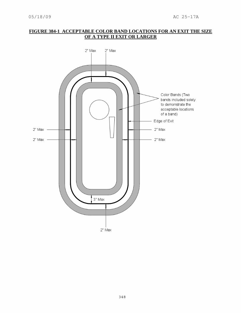
05/18/09 AC 25-17A
348
FIGURE 384-1 ACCEPTABLE COLOR BAND LOCATIONS FOR AN EXIT THE SIZE OF A TYPE II EXIT OR LARGER
05/18/09 AC 25-17A
349
385. AMENDMENT 25-46, Effective December 1, 1978. a. Regulation.
(a) Each passenger emergency exit, its means of access, and its means of opening must be conspicuously marked. (b) The identify and location of each passenger emergency exit must be recognizable from a distance equal to the width of the cabin. (c) Means must be provided to assist the occupants in locating the exits in conditions of dense smoke. (d) The location of each passenger emergency exit must be indicated by a sign visible to occupants approaching along the main passenger aisle (or aisles). There must be- (1) A passenger emergency exit locator sign above the aisle (or aisles) near each passenger emergency exit, or at another overhead location if it is more practical because of low headroom, except that one sign may serve more than one exit if each exit can be seen readily from the sign; (2) A passenger emergency exit marking sign next to each passenger emergency exit, except that one sign may serve two such exits if they both can be seen readily from the sign; and (3) A sign on each bulkhead or divider that prevents fore and aft vision along the passenger cabin to indicate emergency exits beyond and obscured by the bulkhead or divider, except that if this is not possible the sign may be placed at another appropriate location. [(e) The location of the operating handle and instructions for opening exits from the inside of the airplane must be shown in the following manner: (1) Each passenger emergency exit must have, on or near the exit, a marking that is readable from a distance of 30-inches. (2) Each Type I and Type A passenger emergency exit operating handle must- (i) Be self-illuminated with an initial brightness of at least 160 microlamberts or (ii) Be conspicuously located and well illuminated by the emergency lighting even in conditions of occupant crowding at the exit. (3) Each Type III passenger emergency exit operating handle must be self-illuminated with an initial brightness of at least 160 microlamberts. If the operating

05/18/09 AC 25-17A
350
handle is covered, self-illuminated cover removal instructions having an initial brightness of at least 160 microlamberts must also be provided. (4) Each Type A, Type I, and Type II passenger emergency exit with a locking mechanism released by rotary motion of the handle must be marked- (i) With a red arrow, with a shaft at least three-fourths of an-inch wide and a head twice the width of the shaft, extending along at least 70 degrees of arc at a radius approximately equal to three-fourths of the handle length. (ii) So that the centerline of the exit handle is within ±1-inch of the projected point of the arrow when the handle has reached full travel and has released the locking mechanism, and (iii) With the word "open" in red letters 1-inch high, placed horizontally near the head of the arrow.] (f) Each emergency exit that is required to be openable from the outside, and its means of opening, must be marked on the outside of the airplane. In addition, the following apply: (1) The outside marking for each passenger emergency exit in the side of the fuselage must include a 2-inch colored band outlining the exit. (2) Each outside marking including the band, must have color contrast to be readily distinguishable from the surrounding fuselage surface. The contrast must be such that if the reflectance of the darker color is 15 percent or less, the reflectance of the lighter color must be at least 45 percent. "Reflectance" is the ratio of the luminous flux reflected by a body to the luminous flux it receives. When the reflectance of the darker color is greater than 15 percent, at least a 30-percent difference between its reflectance and the reflectance of the lighter color must be provided. (3) In the case of exits other than those in the side of the fuselage, such as ventral or tail cone exits, the external means of opening, including instructions if applicable, must be conspicuously marked in red, or bright chrome yellow if the background color is such that red is inconspicuous. When the opening means is located on only one side of the fuselage, a conspicuous marking to that effect must be provided on the other side. (g) Each sign required by paragraph (d) of this section may use the word "exit" in its legend in place of the term "emergency exit.”

05/18/09 AC 25-17A
351
b. Guidance. (1) Paragraphs (a) and (e). Exit identity and conspicuity of operating instructions should be readable by a person with 20/20 vision making a normal effort under representative day and emergency night lighting. (Amendment 25-0) (2) Paragraph (c). The intent of this requirement is to require additional hardware means to materially enhance occupant’s ability to locate the exits. Compliance with the floor proximity emergency escape path marking requirements of § 25.812(e) Amendment 25-58 is also considered compliance with the requirements of this section. (Amendment 25-15) (3) Paragraph (d). The signs required by paragraphs (d)(1), (2) and (3) are intended to be independent and serve different functions. However, certain cabin arrangements might permit a single sign to serve the functions of both paragraph (d)(1) and (3). If such an arrangement were presented, the sign should meet the contrast and brightness requirements of § 25.812(b)(1)(i) and should be in close proximity to the exits concerned. Compliance with both §§ 25.811(d)(1) and (3) is required regardless of the number of signs employed. (Amendment 25-32) (4) Paragraph (d). Similar to the guidance immediately above, certain cabin arrangements and especially small cabin sizes might permit a single sign to serve both the locator and marker sign functions of paragraphs (d)(1) and (d)(2). If such a proposal was presented, the proposal should address all pertinent requirements of § 25.812, and it should be demonstrated that the sign satisfactorily performs both marker and locator sign functions. (Amendment 25-32) (5) Paragraph (d)(2). Prior to Amendment 25-32, the exit marking sign of § 25.811(d)(2) was referred to as a locator sign in § 25.811(d)(2) for floor level exits. The locator sign requirement of § 25.811(d)(1) for floor level exits was introduced by Amendment 25-32. (Amendment 25-32) (6) Paragraph (d). The signs required by paragraphs (d)(1) and (3) should be removed from the passenger compartment in mixed passenger/cargo arrangements if they indicate exits in the cargo compartment which are not accessible to passengers. For exits inaccessible in the cargo portion of the fuselage, the signs installed by this paragraph for passenger configurations may be left installed if they are not visible to the passengers. (Amendment 25-1) (7) Paragraph (d)(2). The requirement for a sign next to each floor level exit is not satisfied by a sign mounted on the exit. The sign should remain visible whether or not the exit is open. In the case of an exit-mounted sign, the sign is removed when the exit is opened. This arrangement should not be employed. (Amendment 25-1) (8) Paragraph (e). An exit opening handle where motion is in the plane perpendicular to the exit is not considered a rotary handle as defined in this paragraph. Therefore, the marking arrow specified is not required by this regulation. However, in order to provide an equivalent level of safety for this type of handle motion, markings appropriate to this type of handle should

05/18/09 AC 25-17A
352
be provided. This should be documented in an Equivalent Safety Finding Issue Paper. (Amendment 25-1) (9) Paragraph (f). Exit bands are not required for "flightcrew only" exits or other emergency exits not in the sides of the fuselage. (Amendment 25-15) (10) Paragraph (f). (Amendment 25-1) (i) Guidance material for exterior colored bands around exits is provided in AC 20-47, “Exterior Colored Band Around Exits on Transport Airplanes,” dated 2/8/66. (Amendment 25-1) (ii) For airplanes that are convertible from passenger to mixed passenger/cargo arrangements, the exits unusable due to cargo blockage should be so marked. This can be indicated by a placard on or adjacent to the exit. The placard should provide obvious indication from the ground, to a rescue crew that the exit is not operable. No other change to the external markings is required. (Amendment 25-1) (iii) If exits are deactivated, refer to § 25.807, Amendment 25-15, for guidance regarding deletion of markings for deactivated exits. (Amendment 25-1) (11) Paragraphs (f)(1) and (2). The FAA issued policy memorandum ANM-03-115-04, dated April 2, 2003, and titled “Policy Statement on Exit Bands.” The policy is applicable to Amendment 25-46 for §§ 25.811(f)(1) and (2) as follows: (Amendment 25-1) (i) The FAA has been asked if compliance with §§ 25.811(f)(1) and (2) can be found with the lower section of a two-inch colored band located a few-inches above the base of an exit. Metal door sills are often installed on the fuselage below floor-level exits to provide protection from impacts with loading equipment. If the band is located on the bottom edge of an exit, its color must be compared with the door sill color to determine compliance with § 25.811(f)(2). This requirement can result in a color scheme which is not desired by the operator. Note that painting the door sill is not considered a viable option since impacts with loading equipment cause the paint to scratch and wear away quickly. If the band is located a few-inches above the base of the exit, its color is compared with the door color below the band instead of the metal door sill. This results in more color options for operators to choose from in determining a desired color scheme. (Amendment 25-1) (ii) The purpose of these bands is to assist rescue personnel in recognizing exits in the side of the fuselage. Section 25.811(f)(1) requires that a two-inch color band outline each passenger emergency exit in the side of the fuselage. Advisory Circular 20-47, paragraph 4b, indicates that a color band outlining an exit is considered to comply with applicable regulations whether the band is on the edge of the exit itself, on the fuselage surrounding the exit, or partially on both. Although this guidance indicates acceptance of bands located on the edge of the exit itself, the FAA considers that a band could be located a small distance away from the exit’s edge and still be considered to “outline” the exit as required by § 25.811(f)(1). The FAA finds that for floor-level exits the size of a Type II exit or larger, compliance can be found with the top and

05/18/09 AC 25-17A
353
side sections of a band located a maximum of 2-inches away from the exit’s edge and the bottom section of a band located between 2-inches below and 3-inches above the exit’s edge. Figure 385-1 is a figure that demonstrates these boundaries. The bottom section of the band is allowed to be farther away from the exit’s edge than the other sides of the band to be consistent with past practices for exits with a door sill installed at their base. Although the band is not required to be on the edge of the exit, it must be parallel to the exit’s edge in order to outline the exit as required by the rule. (Amendment 25-1)
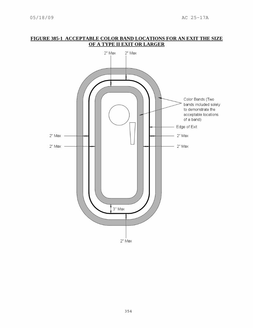
05/18/09 AC 25-17A
354
FIGURE 385-1 ACCEPTABLE COLOR BAND LOCATIONS FOR AN EXIT THE SIZE
OF A TYPE II EXIT OR LARGER

05/18/09 AC 25-17A
355
386. AMENDMENT 25-79, Effective September 27, 1993. a. Regulation.
(a) Each passenger emergency exit, its means of access, and its means of opening must be conspicuously marked. (b) The identity and location of each passenger emergency exit must be recognizable from a distance equal to the width of the cabin. (c) Means must be provided to assist the occupants in locating the exits in conditions of dense smoke. (d) The location of each passenger emergency exit must be indicated by a sign visible to occupants approaching along the main passenger aisle (or aisles). There must be- (1) A passenger emergency exit locator sign above the aisle (or aisles) near each passenger emergency exit, or at another overhead location if it is more practical because of low headroom, except that one sign may serve more than one exit if each exit can be seen readily from the sign; (2) A passenger emergency exit marking sign next to each passenger emergency exit, except that one sign may serve two such exits if they both can be seen readily from the sign; and (3) A sign on each bulkhead or divider that prevents fore and aft vision along the passenger cabin to indicate emergency exits beyond and obscured by the bulkhead or divider, except that if this is not possible the sign may be placed at another appropriate location. (e) The location of the operating handle and instructions for opening exits from the inside of the airplane must be shown in the following manner: (1) Each passenger emergency exit must have, on or near the exit, a marking that is readable from a distance of 30-inches. [(2) Each passenger emergency exit operating handle and the cover removal instructions, if the operating handle is covered, must-] (i) Be self-illuminated with an initial brightness of at least 160 microlamberts; or (ii) Be conspicuously located and well illuminated by the emergency lighting even in conditions of occupant crowding at the exit. [ (3) [Reserved.]]

05/18/09 AC 25-17A
356
(4) Each Type A, Type I, and Type II passenger emergency exit with a locking mechanism released by rotary motion of the handle must be marked- (i) With a red arrow, with a shaft at least three-fourths of an-inch wide and a head twice the width of the shaft, extending along at least 70 degrees of arc at a radius approximately equal to three-fourths of the handle length. (ii) So that the centerline of the exit handle is within ±1-inch of the projected point of the arrow when the handle has reached full travel and has released the locking mechanism, and (iii) With the word "open" in red letters 1-inch high, placed horizontally near the head of the arrow. (f) Each emergency exit that is required to be openable from the outside, and its means of opening, must be marked on the outside of the airplane. In addition, the following apply: (1) The outside marking for each passenger emergency exit in the side of the fuselage must include a 2-inch colored band outlining the exit. (2) Each outside marking including the band, must have color contrast to be readily distinguishable from the surrounding fuselage surface. The contrast must be such that if the reflectance of the darker color is 15 percent or less, the reflectance of the lighter color must be at lest 45 percent. "Reflectance" is the ratio of the luminous flux reflected by a body to the luminous flux it receives. When the reflectance of the darker color is greater than 15 percent, at least a 30-percent difference between its reflectance and the reflectance of the lighter color must be provided. (3) In the case of exits other than those in the side of the fuselage, such as ventral or tail cone exits, the external means of opening, including instructions if applicable, must be conspicuously marked in red, or bright chrome yellow if the background color is such that red is inconspicuous. When the opening means is located on only one side of the fuselage, a conspicuous marking to that effect must be provided on the other side. (g) Each sign required by paragraph (d) of this section may use the word "exit" in its legend in place of the term "emergency exit.”
b. Guidance. (1) Paragraphs (a) and (e). Exit identity and conspicuity of operating instructions should be readable by a person with 20/20 vision making a normal effort under representative day and emergency night lighting. (Amendment 25-0)

05/18/09 AC 25-17A
357
(2) Paragraph (c). The intent of this requirement is to require additional hardware means to materially enhance occupant’s ability to locate the exits. Compliance with the floor proximity emergency escape path marking requirements of § 25.812(e) is also considered compliance with the requirements of this section. (Amendment 25-15) (3) Paragraph (d). The signs required by paragraphs (d)(1), (2) and (3) are intended to be independent and serve different functions. However, certain cabin arrangements might permit a single sign to serve the functions of both paragraph (d)(1) and (3). If such an arrangement were presented, the sign should meet the contrast and brightness requirements of § 25.812(b)(1)(i) and should be in close proximity to the exits concerned. Compliance with both §§ 25.811(d)(1) and (3) is required regardless of the number of signs employed. (Amendment 25-32) (4) Paragraph (d). Similar to the guidance immediately above, certain cabin arrangements and especially small cabin sizes might permit a single sign to serve both the locator and marker sign functions of paragraphs (d)(1) and (d)(2). If such a proposal was presented, the proposal should address all pertinent requirements of § 25.812, and it should be demonstrated that the sign satisfactorily performs both marker and locator sign functions. (Amendment 25-32) (5) Paragraph (d)(2). Prior to Amendment 25-32, the exit marking sign of § 25.811(d)(2) was referred to as a locator sign in § 25.811(d)(2) for floor level exits. The locator sign requirement of § 25.811(d)(1) for floor level exits was introduced by Amendment 25-32. (Amendment 25-32) (6) Paragraph (d). The signs required by paragraphs (d)(1) and (3) should be removed from the passenger compartment in mixed passenger/cargo arrangements if they indicate exits in the cargo compartment which are not accessible to passengers. For exits inaccessible in the cargo portion of the fuselage, the signs installed by this paragraph for passenger configurations may be left installed if they are not visible to the passengers. (Amendment 25-1) (7) Paragraph (d)(2). The requirement for a sign next to each floor level exit is not satisfied by a sign mounted on the exit. The sign should remain visible whether or not the exit is open. In the case of an exit-mounted sign, the sign is removed when the exit is opened. This arrangement should not be employed. (Amendment 25-1) (8) Paragraph (e). An exit opening handle where motion is in the plane perpendicular to the exit is not considered a rotary handle as defined in this paragraph. Therefore, the marking arrow specified is not required by this regulation. However, in order to provide an equivalent level of safety for this type of handle motion, markings appropriate to this type of handle should be provided. This should be documented in an Equivalent Safety Finding Issue Paper. (Amendment 25-1) (9) Paragraph (f). Exit bands are not required for "flightcrew only" exits or other emergency exits not in the sides of the fuselage. (Amendment 25-15)

05/18/09 AC 25-17A
358
(10) Paragraph (h). (Amendment 25-1) (i) Guidance material for exterior colored bands around exits is provided in AC 20-47, “Exterior Colored Band Around Exits on Transport Airplanes,” dated 2/8/66. (Amendment 25-1) (ii) For airplanes that are convertible from passenger to mixed passenger/cargo arrangements, the exits unusable due to cargo blockage should be so marked. This can be indicated by a placard on or adjacent to the exit. The placard should provide obvious indication from the ground, to a rescue crew that the exit is not operable. No other change to the external markings is required. (Amendment 25-1) (iii) If exits are deactivated, refer to § 25.807, Amendment 25-15, for guidance regarding deletion of markings for deactivated exits. (Amendment 25-1) (11) Paragraphs (f)(1) and (2). The FAA issued policy memorandum ANM-03-115-04, dated April 2, 2003, and titled “Policy Statement on Exit Bands.” The policy is applicable to Amendment 25-79 for §§ 25.811(f)(1) and (2) as follows: (Amendment 25-1) (i) The FAA has been asked if compliance with §§ 25.811(f)(1) and (2) can be found with the lower section of a two-inch colored band located a few-inches above the base of an exit. Metal door sills are often installed on the fuselage below floor-level exits to provide protection from impacts with loading equipment. If the band is located on the bottom edge of an exit, its color must be compared with the door sill color to determine compliance with § 25.811(f)(2). This requirement can result in a color scheme which is not desired by the operator. Note that painting the door sill is not considered a viable option since impacts with loading equipment cause the paint to scratch and wear away quickly. If the band is located a few-inches above the base of the exit, its color is compared with the door color below the band instead of the metal door sill. This results in more color options for operators to choose from in determining a desired color scheme. (Amendment 25-1) (ii) The purpose of these bands is to assist rescue personnel in recognizing exits in the side of the fuselage. Section 25.811(f)(1) requires that a two-inch color band outline each passenger emergency exit in the side of the fuselage. Advisory Circular 20-47, paragraph 4b, indicates that a color band outlining an exit is considered to comply with applicable regulations whether the band is on the edge of the exit itself, on the fuselage surrounding the exit, or partially on both. Although this guidance indicates acceptance of bands located on the edge of the exit itself, the FAA considers that a band could be located a small distance away from the exit’s edge and still be considered to “outline” the exit as required by § 25.811(f)(1). The FAA finds that for floor-level exits the size of a Type II exit or larger, compliance can be found with the top and side sections of a band located a maximum of 2-inches away from the exit’s edge and the bottom section of a band located between 2-inches below and 3-inches above the exit’s edge. Figure 386-1 is a figure that demonstrates these boundaries. The bottom section of the band is allowed to be farther away from the exit’s edge than the other sides of the band to be consistent with past practices for exits with a door sill installed at their base. Although the band is not required to be

05/18/09 AC 25-17A
359
on the edge of the exit, it must be parallel to the exit’s edge in order to outline the exit as required by the rule. (Amendment 25-1) FIGURE 386-1 ACCEPTABLE COLOR BAND LOCATIONS FOR AN EXIT THE SIZE
OF A TYPE II EXIT OR LARGER

05/18/09 AC 25-17A
360
387. AMENDMENT 25-88, Effective December 9, 1996. a. Regulation.
(a) Each passenger emergency exit, its means of access, and its means of opening must be conspicuously marked. (b) The identity and location of each passenger emergency exit must be recognizable from a distance equal to the width of the cabin. (c) Means must be provided to assist the occupants in locating the exits in conditions of dense smoke. (d) The location of each passenger emergency exit must be indicated by a sign visible to occupants approaching along the main passenger aisle (or aisles). There must be- (1) A passenger emergency exit locator sign above the aisle (or aisles) near each passenger emergency exit, or at another overhead location if it is more practical because of low headroom, except that one sign may serve more than one exit if each exit can be seen readily from the sign; (2) A passenger emergency exit marking sign next to each passenger emergency exit, except that one sign may serve two such exits if they both can be seen readily from the sign; and (3) A sign on each bulkhead or divider that prevents fore and aft vision along the passenger cabin to indicate emergency exits beyond and obscured by the bulkhead or divider, except that if this is not possible the sign may be placed at another appropriate location. (e) The location of the operating handle and instructions for opening exits from the inside of the airplane must be shown in the following manner: (1) Each passenger emergency exit must have, on or near the exit, a marking that is readable from a distance of 30-inches. [(2) Each Type A, Type B, Type C or Type I passenger emergency exit operating handle must-] (i) Be self-illuminated with an initial brightness of at least 160 microlamberts; or (ii) Be conspicuously located and well illuminated by the emergency lighting even in conditions of occupant crowding at the exit. (3) Reserved.

05/18/09 AC 25-17A
361
[(4) Each Type A, Type B, Type C, Type I, or Type II passenger emergency exit with a locking mechanism released by rotary motion of the handle must be marked-] (i) With a red arrow, with a shaft at least three-fourths of an-inch wide and a head twice the width of the shaft, extending along at least 70 degrees of arc at a radius approximately equal to three-fourths of the handle length. (ii) So that the centerline of the exit handle is within ±1-inch of the projected point of the arrow when the handle has reached full travel and has released the locking mechanism, and (iii) With the word "open" in red letters 1-inch high, placed horizontally near the head of the arrow. (f) Each emergency exit that is required to be openable from the outside, and its means of opening, must be marked on the outside of the airplane. In addition, the following apply: (1) The outside marking for each passenger emergency exit in the side of the fuselage must include a 2-inch colored band outlining the exit. (2) Each outside marking including the band, must have color contrast to be readily distinguishable from the surrounding fuselage surface. The contrast must be such that if the reflectance of the darker color is 15 percent or less, the reflectance of the lighter color must be at least 45 percent. "Reflectance" is the ratio of the luminous flux reflected by a body to the luminous flux it receives. When the reflectance of the darker color is greater than 15 percent, at least a 30-percent difference between its reflectance and the reflectance of the lighter color must be provided. (3) In the case of exits other than those in the side of the fuselage, such as ventral or tailcone exits, the external means of opening, including instructions if applicable, must be conspicuously marked in red, or bright chrome yellow if the background color is such that red is inconspicuous. When the opening means is located on only one side of the fuselage, a conspicuous marking to that effect must be provided on the other side. (g) Each sign required by paragraph (d) of this section may use the word "exit" in its legend in place of the term "emergency exit.”
b. Guidance. (1) Paragraphs (a) and (e). Exit identity and conspicuity of operating instructions should be readable by a person with 20/20 vision making a normal effort under representative day and emergency night lighting. (Amendment 25-0)

05/18/09 AC 25-17A
362
(2) Paragraph (c). The intent of this requirement is to require additional hardware means to materially enhance occupant’s ability to locate the exits. Compliance with the floor proximity emergency escape path marking requirements of § 25.812(e) is also considered compliance with the requirements of this section. (Amendment 25-15) (3) Paragraph (d). The signs required by paragraphs (d)(1), (2) and (3) are intended to be independent and serve different functions. However, certain cabin arrangements might permit a single sign to serve the functions of both paragraph (d)(1) and (3). If such an arrangement were presented, the sign should meet the contrast and brightness requirements of § 25.812(b)(1)(i) and should be in close proximity to the exits concerned. Compliance with both §§ 25.811(d)(1) and (3) is required regardless of the number of signs employed. (Amendment 25-32) (4) Paragraph (d). Similar to the guidance immediately above, certain cabin arrangements and especially small cabin sizes might permit a single sign to serve both the locator and marker sign functions of paragraphs (d)(1) and (d)(2). If such a proposal was presented, the proposal should address all pertinent requirements of § 25.812, and it should be demonstrated that the sign satisfactorily performs both marker and locator sign functions. (Amendment 25-32) (5) Paragraph (d)(2). Prior to Amendment 25-32, the exit marking sign of § 25.811(d)(2) was referred to as a locator sign in § 25.811(d)(2) for floor level exits. The locator sign requirement of § 25.811(d)(1) for floor level exits was introduced by Amendment 25-32. (Amendment 25-32) (6) Paragraph (d). The signs required by paragraphs (d)(1) and (3) should be removed from the passenger compartment in mixed passenger/cargo arrangements if they indicate exits in the cargo compartment which are not accessible to passengers. For exits inaccessible in the cargo portion of the fuselage, the signs installed by this paragraph for passenger configurations may be left installed if they are not visible to the passengers. (Amendment 25-1) (7) Paragraph (d)(2). The requirement for a sign next to each floor level exit is not satisfied by a sign mounted on the exit. The sign should remain visible whether or not the exit is open. In the case of an exit-mounted sign, the sign is removed when the exit is opened. This arrangement should not be employed. (Amendment 25-1) (8) Paragraph (e). An exit opening handle where motion is in the plane perpendicular to the exit is not considered a rotary handle as defined in this paragraph. Therefore, the marking arrow specified is not required by this regulation. However, in order to provide an equivalent level of safety for this type of handle motion, markings appropriate to this type of handle should be provided. This should be documented in an Equivalent Safety Finding Issue Paper. (Amendment 25-1) (9) Paragraph (f). Exit bands are not required for "flightcrew only" exits or other emergency exits not in the sides of the fuselage. (Amendment 25-15)

05/18/09 AC 25-17A
363
(10) Paragraph (h). (Amendment 25-1) (i) Guidance material for exterior colored bands around exits is provided in AC 20-47, “Exterior Colored Band Around Exits on Transport Airplanes,” dated 2/8/66. (Amendment 25-1) (ii) For airplanes that are convertible from passenger to mixed passenger/cargo arrangements, the exits unusable due to cargo blockage should be so marked. This can be indicated by a placard on or adjacent to the exit. The placard should provide obvious indication from the ground, to a rescue crew that the exit is not operable. No other change to the external markings is required. (Amendment 25-1) (iii) If exits are deactivated, refer to § 25.807, Amendment 25-15, for guidance regarding deletion of markings for deactivated exits. (Amendment 25-1) (11) Paragraphs (f)(1) and (2). The FAA issued policy memorandum ANM-03-115-04, dated April 2, 2003, and titled “Policy Statement on Exit Bands.” The policy is applicable to Amendment 25-88 for §§ 25.811(f)(1) and (2) as follows: (Amendment 25-1) (i) The FAA has been asked if compliance with §§ 25.811(f)(1) and (2) can be found with the lower section of a two-inch colored band located a few-inches above the base of an exit. Metal door sills are often installed on the fuselage below floor-level exits to provide protection from impacts with loading equipment. If the band is located on the bottom edge of an exit, its color must be compared with the door sill color to determine compliance with § 25.811(f)(2). This requirement can result in a color scheme which is not desired by the operator. Note that painting the door sill is not considered a viable option since impacts with loading equipment cause the paint to scratch and wear away quickly. If the band is located a few-inches above the base of the exit, its color is compared with the door color below the band instead of the metal door sill. This results in more color options for operators to choose from in determining a desired color scheme. (Amendment 25-1) (ii) The purpose of these bands is to assist rescue personnel in recognizing exits in the side of the fuselage. Section 25.811(f)(1) requires that a two-inch color band outline each passenger emergency exit in the side of the fuselage. Advisory Circular 20-47, paragraph 4b, indicates that a color band outlining an exit is considered to comply with applicable regulations whether the band is on the edge of the exit itself, on the fuselage surrounding the exit, or partially on both. Although this guidance indicates acceptance of bands located on the edge of the exit itself, the FAA considers that a band could be located a small distance away from the exit’s edge and still be considered to “outline” the exit as required by § 25.811(f)(1). The FAA finds that for floor-level exits the size of a Type II exit or larger, compliance can be found with the top and side sections of a band located a maximum of 2-inches away from the exit’s edge and the bottom section of a band located between 2-inches below and 3-inches above the exit’s edge. Figure 387-1 is a figure that demonstrates these boundaries. The bottom section of the band is allowed to be farther away from the exit’s edge than the other sides of the band to be consistent with past practices for exits with a door sill installed at their base. Although the band is not required to be

05/18/09 AC 25-17A
364
on the edge of the exit, it must be parallel to the exit’s edge in order to outline the exit as required by the rule. (Amendment 25-1)
FIGURE 387-1 ACCEPTABLE COLOR BAND LOCATIONS FOR AN EXIT THE SIZE
OF A TYPE II EXIT OR LARGER
388 - 390. [RESERVED]

05/18/09 AC 25-17A
365
SECTION 25.812 EMERGENCY LIGHTING 391. Section 25.812 Did Not Exist Prior to Amendment 25-15. 392. AMENDMENT 25-15, Effective October 24, 1967. a. Regulation.
(a) An emergency lighting system, independent of the main lighting system, must be installed which includes: (1) Illuminated emergency exit marking and locating signs, sources of general cabin illumination, and interior lighting in emergency exit areas. (2) Exterior emergency lighting. (b) Each passenger exit sign and each exit locating sign must have white letters at least 1-inch high on a red background at least 2-inches high. These signs may be internally electrically illuminated, or self-illuminated by other than electrical means, with an initial brightness of at least 160 microlamberts. The colors may be reversed in the case of internally electrically illuminated signs if this will increase the illumination of the exit. (c) General illumination in the passenger cabin must be provided so that when measured along the centerline of main passenger aisles at seat armrest height and at 40-inch intervals, the average illumination is not less than 0.05 foot-candle. A main passenger aisle is considered to extend along the fuselage from the most forward passenger emergency exit or cabin occupant seat, whichever is farther forward, to the most rearward passenger emergency exit or cabin occupant seat, whichever is farther aft. (d) The floor of the passageway leading to each floor-level passenger emergency exit, between the main aisles and the exit openings, must be provided with illumination. (e) The emergency lighting system is to be designed as follows: (1) The lights must be operable manually from the flightcrew station and (if required by the operating rules of this chapter) from a point in the passenger compartment that is readily accessible to the flight attendant seat. Means are to be provided to safeguard against inadvertent operation of the manual controls. (2) When armed or turned on, the lights must remain lighted or become lighted upon interruption (except an interruption caused by a vertical separation of the fuselage during crash landing) of the airplane's normal electric power.

05/18/09 AC 25-17A
366
(f) Exterior emergency lighting must be provided at each overwing exit so that the illumination is - (1) Not less than 0.02 foot-candle (measured on a plane parallel to the surface) on a 2-square-foot area where an evacuee is likely to make his first step outside the cabin: (2) Not less than 0.05 foot-candle (measured normal to the direction of the incident light) for a minimum width of 2 feet along the 30 percent of the slip-resistant escape route required in § 25.803(e) that is farthest from the exit; and (3) Not less than 0.02 foot-candle on the ground surface with the landing gear extended (measured on a horizontal plane) where an evacuee using the established escape route would normally make first contact with the ground. (g) The means required in §§ 25.809(f)(1) and (h) to assist the occupants in descending to the ground must be illuminated so that the deployed assist means is visible from the airplane. (1) If the assist means is illuminated by exterior emergency lighting, it must provide - (i) Illumination at each overwing emergency exit of not less than 0.02 foot-candle on the ground surface with the landing gear extended (measured in a horizontal plane) where an evacuee using the established escape route would normally make first contact with the ground; and (ii) Illumination at each non-overwing emergency exit, of not less than 0.03 foot-candle (measured normal to the direction of the incident light) at the ground end of the assist means and, for each non-over-wing exit in the side of the fuselage, over a spherical surface 10 degrees to either side of the center of the assist means and from 30 degrees above to 5 degrees below the 45 degree position of the assist means. (2) If the assist means is self-illuminated, the lighting provisions - (i) May not be adversely affected by stowage; and (ii) Must provide sufficient ground surface illumination so that obstacles at the end of the assist means are clearly visible to evacuees. (h) The energy supply to each emergency lighting unit must provide the required level of illumination for at least 10 minutes at the critical ambient conditions after emergency landing. (i) If storage batteries are used as the energy supply for the emergency lighting system, they may be recharged from the airplane's main electric power system provided that the charging circuit is designed to preclude inadvertent battery discharge into charging circuit faults.

05/18/09 AC 25-17A
367
(j) Components of the emergency lighting system, including batteries, wiring relays, lamps, and switches, must be capable of normal operation after having been subjected to the inertia forces listed in § 25.561(b). (k) The emergency lighting system must be designed so that after any single vertical separation of the fuselage during crash landing - (1) Not more than 25 percent of all electrically illuminated emergency lights required by this section are rendered inoperative in addition to the lights that are directly damaged by the separation; (2) Each electrically illuminated exit sign required under § 25.811(d)(2) remains operative exclusive of those that are directly damaged by the separation; and (3) At least one required exterior emergency exit light for each side of the airplane remains operative exclusive of those that are directly damaged by the separation.
b. Guidance. (1) Paragraph (b). Advisory Circular 20-38A, “Measurement of Cabin Interior Emergency Illumination in Transport Airplanes,” dated 2/8/66, provides guidance material for the minimum measurements required by this paragraph. (Amendment 25-15) (2) Paragraph (c). (Amendment 25-15) (i) Required illumination levels for main aisles also apply to cross aisles (later incorporated by Amendment 25-32) that are required to meet § 25.807(a)(7)(v). Cross aisles that are in excess of those required need not be provided with emergency lighting. (Amendment 25-15) (ii) When measuring the illumination levels required by this paragraph, the interior color scheme (sidewalls, seat covers, floor covering, etc.) should be evaluated for its reflective contribution to the illumination level. This may be accomplished by negating the contribution of reflected light and demonstrating the minimum illumination levels independent of reflected light. If the reflective contribution is known, subsequent interiors of different reflectivity may be analyzed to show the effect on illumination levels is not detrimental. (Amendment 25-15) (3) Paragraph (e). Normal electrical power is interpreted to mean the engine driven generators. (Amendment 25-15) (4) Paragraph (f)(1). The illumination level at an overwing escape route where the evacuee would take his first step outside the airplane may be measured with the exit unobstructed. It is not necessary to consider an evacuee standing in the exit opening when measuring illumination levels. Transient blocking of the wing contact area illumination as an

05/18/09 AC 25-17A
368
evacuee passes through the exit is acceptable provided no adverse effects are observed during the demonstration required by § 25.803(c). (Amendment 25-15) (5) Paragraph (g). Illumination of the overwing escape path or an assist means at any exit should be automatically activated as part of the airplane emergency lighting system, or by the action of opening the exit. The required exterior lighting at an exit may not be dependent on the operation of another exit. (Amendment 25-15) (6) Paragraph (h). When the airplane is exposed to the critical minimum and maximum ambient temperatures such that the airplane is in equilibrium, the airplane environmental systems may be used to condition the airplane prior to boarding passengers. The temperature of the power supplies may be determined following a reasonable conditioning period to obtain operation voltage when the airplane is at the critical outside ambient temperature. The illumination may then be measured assuming ten-minute operation from these initial conditions. If an applicant is unable to furnish what initial conditions are, it is acceptable to use Radio Technical Commission for Aeronautics Document No. RTCA/DO-160B, titled "Environmental Conditions and Test Procedures for Airborne Equipment," for low and high temperature tests. An additional alternate set of satisfactory environmental conditions may be found in AC 25.812-1A, “Floor Proximity Emergency Escape Path Marking,” dated 5/22/89. (Amendment 25-15) (7) Paragraph (k). A transverse separation is considered to occur at any fuselage station, irrespective of the perceived likelihood that a separation could occur there. “Separation” in this context refers to all degrees of fuselage separation such that the emergency lighting system is interrupted, and not just separations that result in two distinct segments of fuselage. (Amendment 25-15) (8) Paragraph (k)(1). This paragraph is based on the number of electrically illuminated lights required to meet the illumination levels of this section. Exit signs which are not used to contribute to cabin illumination and subsystems provided in accordance with paragraph (g)(2) do not apply to this paragraph. However, an applicant should not be penalized for providing lights in excess of the number required. (Amendment 25-15) (9) Paragraph (k)(2). “Directly damaged,” as used in this paragraph, refers to a sign that is located at the same station as a transverse fuselage separation, or between the frames bounding the separation location, and therefore rendered inoperative. The sign is also considered inoperative if the separation occurs at the same station as any part of the power supply. The sign should remain operative unless it is “directly damaged” or the separation renders the exit unopenable. Therefore, the power supply should be located at a station between the frames that make up the exit, or in the case of a sign beside the exit, the power supply may also be at the same fuselage station as any part of the sign. (Amendment 25-15)

05/18/09 AC 25-17A
369
393. AMENDMENT 25-28, Effective September 25, 1971. a. Regulation.
(a) An emergency lighting system, independent of the main lighting system, must be installed which includes: (1) Illuminated emergency exit marking and locating signs, sources of general cabin illumination, and interior lighting in emergency exit areas. (2) Exterior emergency lighting. (b) Each passenger exit sign and each exit locating sign must have white letters at least 1-inch high on a red background at least 2-inches high. These signs may be internally electrically illuminated, or self-illuminated by other than electrical means, with an initial brightness of at least 160 microlamberts. The colors may be reversed in the case of internally electrically illuminated signs if this will increase the illumination of the exit. (c) General illumination in the passenger cabin must be provided so that when measured along the centerline of main passenger aisles at seat armrest height and at 40-inch intervals, the average illumination is not less than 0.05 foot-candle. A main passenger aisle is considered to extend along the fuselage from the most forward passenger emergency exit or cabin occupant seat, whichever is farther forward, to the most rearward passenger emergency exit or cabin occupant seat, whichever is farther aft. (d) The floor of the passageway leading to each floor-level passenger emergency exit, between the main aisles and the exit openings, must be provided with illumination. [(e) Except for subsystems provided in accordance with paragraph (g) of this section that serve no more than one assist means, are independent of the airplane's main emergency lighting system, and are automatically activated when the assist means is deployed, the emergency lighting system must be designed as follows:] (1) The lights must be operable manually from the flight crew station and (if required by the operating rules of this chapter) from a point in the passenger compartment that is readily accessible to a normal flight attendant seat. Means must be provided to safeguard against inadvertent operation of the manual controls. (2) When armed or turned on, the lights must remain lighted or become lighted upon interruption (except an interruption caused by a vertical separation of the fuselage during crash landing) of the airplane's normal electric power.

05/18/09 AC 25-17A
370
(f) Exterior emergency lighting must be provided at each overwing exit so that the illumination is- (1) Not less than 0.02 foot-candle (measured on a plane parallel to the surface) on a 2-square-foot area where an evacuee is likely to make his first step outside the cabin; (2) Not less than 0.05 foot-candle (measured normal to the direction of the incident light) for a minimum width of 2 feet along the 30 percent of the slip-resistant escape route required in § 25.803(e) that is farthest from the exit; and (3) Not less than 0.02 foot-candle on the ground surface with the landing gear extended (measured on a horizontal plane) where an evacuee using the established escape route would normally make first contact with the ground. (g) The means required in § 25.809 (f)(1) and (h) to assist the occupants in descending to the ground must be illuminated so that the deployed assist means is visible from the airplane. (1) If the assist means is illuminated by exterior emergency lighting, it must provide- (i) Illumination at each overwing emergency exit of not less than 0.02 foot-candle on the ground surface with the landing gear extended (measured in a horizontal plane) where an evacuee using the established escape route would normally make first contact with the ground; and (ii) Illumination at each non-over-wing emergency exit, of not less than 0.03 foot-candle (measured normal to the direction of the incident light) at the ground end of the assist means and, for each non-over-wing exit in the side of the fuselage, over a spherical surface 10° to either side of the center of the assist means and from 30° above the 45° position of the assist means. [(2) If the emergency lighting subsystem illuminating the assist means serves no other assist means, is independent of the airplane's main emergency lighting system, and is automatically activated when the assist means is deployed, the lighting provisions-] (i) May not be adversely affected by stowage; and (ii) Must provide sufficient ground surface illumination so that obstacles at the end of the assist means are clearly visible to evacuees. (h) The energy supply to each emergency lighting unit must provide the required level of illumination for at least 10 minutes at the critical ambient conditions after emergency landing.

05/18/09 AC 25-17A
371
(i) If storage batteries are used as the energy supply for the emergency lighting system, they may be recharged from the airplane's main electric power system: Provided, That, the charging circuit is designed to preclude inadvertent battery discharge into charging circuit faults. (j) Components of the emergency lighting system, including batteries, wiring relays, lamps, and switches must be capable of normal operation after having been subjected to the inertia forces listed in § 25.561(b). (k) The emergency lighting system must be designed so that after any single vertical separation of the fuselage during crash landing- (1) Not more than 25 percent of all electrically illuminated emergency lights required by this section are rendered inoperative, in addition to the lights that are directly damaged by the separation; (2) Each electrically illuminated exit sign required under § 25.811(d)(2) remains operative exclusive of those that are directly damaged by the separation; and (3) At least one required exterior emergency exit light for each side of the airplane remains operative exclusive of those that are directly damaged by the separation.
b. Guidance. (1) Paragraph (b). Advisory Circular 20-38A, “Measurement of Cabin Interior Emergency Illumination in Transport Airplanes,” dated 2/8/66, provides guidance material for the minimum measurements required by this paragraph. (Amendment 25-15) (2) Paragraph (c). (Amendment 25-15) (i) Required illumination levels for main aisles also apply to cross aisles (later incorporated by Amendment 25-32) that are required to meet § 25.807(a)(7)(v). Cross aisles that are in excess of those required need not be provided with emergency lighting. (Amendment 25-15) (ii) When measuring the illumination levels required by this paragraph, the interior color scheme (sidewalls, seat covers, floor covering, etc.) should be evaluated for its reflective contribution to the illumination level. This may be accomplished by negating the contribution of reflected light and demonstrating the minimum illumination levels independent of reflected light. If the reflective contribution is known, subsequent interiors of different reflectivity may be analyzed to show the effect on illumination levels is not detrimental. (Amendment 25-15) (3) Paragraph (e). Normal electrical power is interpreted to mean the engine driven generators. (Amendment 25-15)

05/18/09 AC 25-17A
372
(4) Paragraph (f)(1). The illumination level at an overwing escape route where the evacuee would take his first step outside the airplane may be measured with the exit unobstructed. It is not necessary to consider an evacuee standing in the exit opening when measuring illumination levels. Transient blocking of the wing contact area illumination as an evacuee passes through the exit is acceptable provided no adverse effects are observed during the demonstration required by § 25.803(c). (Amendment 25-15) (5) Paragraph (g). Illumination of the overwing escape path or an assist means at any exit should be automatically activated as part of the airplane emergency lighting system, or by the action of opening the exit. The required exterior lighting at an exit may not be dependent on the operation of another exit. (Amendment 25-15) (6) Paragraph (h). When the airplane is exposed to the critical minimum and maximum ambient temperatures such that the airplane is in equilibrium, the airplane environmental systems may be used to condition the airplane prior to boarding passengers. The temperature of the power supplies may be determined following a reasonable conditioning period to obtain operation voltage when the airplane is at the critical outside ambient temperature. The illumination may then be measured assuming ten-minute operation from these initial conditions. If an applicant is unable to furnish what initial conditions are, it is acceptable to use Radio Technical Commission for Aeronautics Document No. RTCA/DO-160B, titled "Environmental Conditions and Test Procedures for Airborne Equipment," for low and high temperature tests. An additional alternate set of satisfactory environmental conditions may be found in AC 25.812-1A, “Floor Proximity Emergency Escape Path Marking,” dated 5/22/89. (Amendment 25-15) (7) Paragraph (k). A transverse separation is considered to occur at any fuselage station, irrespective of the perceived likelihood that a separation could occur there. “Separation” in this context refers to all degrees of fuselage separation such that the emergency lighting system is interrupted, and not just separations that result in two distinct segments of fuselage. (Amendment 25-15) (8) Paragraph (k)(1). This paragraph is based on the number of electrically illuminated lights required to meet the illumination levels of this section. Exit signs which are not used to contribute to cabin illumination and subsystems provided in accordance with paragraph (g)(2) do not apply to this paragraph. However, an applicant should not be penalized for providing lights in excess of the number required. (Amendment 25-15) (9) Paragraph (k)(2). “Directly damaged,” as used in this paragraph, refers to a sign that is located at the same station as a transverse fuselage separation, or between the frames bounding the separation location, and therefore rendered inoperative. The sign is also considered inoperative if the separation occurs at the same station as any part of the power supply. The sign should remain operative unless it is “directly damaged” or the separation renders the exit unopenable. Therefore, the power supply should be located at a station between the frames that make up the exit, or in the case of a sign beside the exit, the power supply may also be at the same fuselage station as any part of the sign. (Amendment 25-15)

05/18/09 AC 25-17A
373
394. AMENDMENT 25-32, Effective May 1, 1972. a. Regulation.
[(a) An emergency lighting system, independent of the main lighting system, must be installed. However, the sources of general cabin illumination may be common to both the emergency and the main lighting systems if the power supply to the emergency lighting system is independent of the power supply to the main lighting system. The emergency lighting system must include:] (1) Illuminated emergency exit marking and locating signs, sources of general cabin illumination, and interior lighting in emergency exit areas. (2) Exterior emergency lighting. [(b) Emergency exit signs- (1) For airplanes that have a passenger seating configuration, excluding pilot seats, of 10 seats or more must meet the following requirements: (i) Each passenger emergency exit locator sign required by § 25.811 (d)(1) and each passenger emergency exit marking sign required by § 25.811 (d)(2) must have red letters at least 1½-inches high on an illuminated white background, and must have an area of at least 21 square-inches excluding the letters. The lighted background-to-letter contrast must be at least 10:1. The letter height to stroke-width ratio may not be more than 7:1 nor less than 6:1. These signs must be internally electrically illuminated with a background brightness of at least 25 foot-lamberts and high-to-low background contrast no greater than 3:1. (ii) Each passenger emergency exit sign required by § 25.811 (d)(3) must have red letters at least 1½-inches high on a white background having an area of at least 21 square-inches excluding the letters. These signs must be internally electrically illuminated or self-illuminated by other than electrical means and must have an initial brightness of at least 400 microlamberts. The colors may be reversed in the case of a sign that is self-illuminated by other than electrical means. (2) For airplanes that have a passenger seating configuration, excluding pilot seats, of nice seats or less, that are required by § 25.811 (d)(1), (2), and (3) must have red letters at least 1-inch high on a white background at least 2-inches high. These signs may be internally electrically illuminated, or self-illuminated by other than electrical means, with an initial brightness of at least 160 microlamberts. The colors may be reversed in the case of a sign that is self-illuminated by other than electrical means. (c) General illumination in the passenger cabin must be provided so that when measured along the centerline of main passenger aisle(s), and cross aisle(s) between

05/18/09 AC 25-17A
374
main aisles, at seat armrest height and at 40-inch intervals, the average illumination is not less than 0.05 foot-candle and the illumination at each 40-inch interval is not less than 0.01 foot-candle. A main passenger aisle(s) is considered to extend along the fuselage from the most forward passenger emergency exit or cabin occupant seat, whichever is farther forward, to the most rearward passenger emergency exit or cabin occupant seat, whichever is farther aft. (d) The floor of the passageway leading to each floor-level passenger emergency exit, between the main aisles and the exit openings, must be provided with illumination that is not less than 0.02 foot-candle measured along a line that is within six-inches of and parallel to the floor and is centered on the passenger evacuation path. (e) Except for subsystems provided in accordance with paragraph (g) of this section that serve no more than one assist means, are independent of the airplane's main emergency lighting system, and are automatically activated when the assist means is erected, the emergency lighting system must be designed as follows: (1) The lights must be operable manually from the flight crew station and (if required by the operating rules of this chapter) from a point in the passenger compartment that is readily accessibly to a normal flight attendant seat. (2) There must be a flight crew warning light which illuminates when power is on in the airplane and emergency lighting control device is neither armed nor turned on. (3) When armed or turned on, the lights must remain lighted or become lighted upon interruption (except an interruption caused by a transverse vertical separation of the fuselage during crash landing) of the airplane's normal electric power. There must be means to safeguard against inadvertent operation of the control device from the "armed" or "on" position. (f) Exterior emergency lighting must be provided as follows: (1) At each overwing emergency exit the illumination must be- (i) Not less than 0.03 foot-candle (measured normal to the direction of the incident light) on a two-square-foot area where an evacuee is likely to make his first step outside the cabin; (ii) Not less than 0.05 foot-candle (measure normal to the direction of the incident light) for a minimum width of 42-inches for a Type A overwing emergency exit and of 2 feet for all other overwing emergency exits along the 30 percent of the slip-resistant portion of the escape route required in § 25.803(e) that is farthest from the exit; and

05/18/09 AC 25-17A
375
(iii) Not less than 0.03 foot-candle on the ground surface with the landing gear extended (measured normal to the direction of the incident light) where an evacuee using the established escape route would normally make first contact with the ground. (2) At each non-overwing emergency exit not required by § 25.809(f) to have descent assist means the illumination must be not less than 0.03 foot-candle (measured normal to the direction of the incident light) on the ground surface with the landing gear extended where an evacuee is likely to make his first contact with the ground outside the cabin. (g) The means required in § 25.809 (f)(1) and (h) to assist the occupants in descending to the ground must be illuminated so that the erected assist means is visible from the airplane. In addition- (1) If the assist means is illuminated by illumination of not less than 0.03 foot-candle (measured normal to the direction of the incident light) at the ground end of the erected assist means where an evacuee using the established escape route would normally make first contact with the ground, with the airplane in each of the attitudes corresponding to the collapse of one or more legs of the landing gear. (2) If the emergency lighting subsystem illuminating the assist means serves no other assist means, is independent of the airplane's main emergency lighting system, and is automatically activated when the assist means is erected, the lighting provisions- (i) May not be adversely affected by stowage; and (ii) Must provide illumination of not less than 0.03 foot-candle (measured normal to the direction of incident light) at the ground end of the erected assist means where an evacuee would normally make first contact with the ground, with the airplane in each of the attitudes corresponding to the collapse of one or more legs of the landing gear.] (h) The energy supply to each emergency lighting unit must provide the required level of illumination for at least 10 minutes at the critical ambient conditions after emergency landing. (i) If storage batteries are used as the energy supply for the emergency lighting system, they may be recharged from the airplane's main electric power system: Provided, That, the charging circuit is designed to preclude inadvertent battery discharge into charging circuit faults. (j) Components of the emergency lighting system, including batteries, wiring relays, lamps, and switches must be capable of normal operation after having been subjected to the inertia forces listed in § 25.561(b).

05/18/09 AC 25-17A
376
(k) The emergency lighting system must be designed so that after any single [transverse] vertical separation of the fuselage during crash landing- (1) Not more than 25 percent of all electrically illuminated emergency lights required by this section are rendered inoperative, in addition to the lights that are directly damaged by the separation; (2) Each electrically illuminated exit sign required under § 25.811(d)(2) remains operative exclusive of those that are directly damaged by the separation; and [(3) At least one required exterior emergency exit light for each side of the airplane remains operative exclusive of those that are directly damaged by the separation.]
b. Guidance. (1) Advisory Circular 20-38A, “Measurement of Cabin Interior Emergency Illumination in Transport Airplanes,” dated 2/8/66, provides guidance material for the minimum measurements required by this paragraph. (Amendment 25-15) (2) Paragraph (b)(1). The wording “a passenger seating configuration, excluding pilot seats, of 10 seats or more,” which was promulgated with the intent of being consistent with Amendment 23-10 to part 23, does not directly address seats intended for use by observers or flight attendants. Seats approved for use by observers or flight attendants are not included in the passenger seating configuration. Seats that have dual approval for occupancy by either crew/observers or passengers will be included in the passenger seating configuration and must be provided emergency lighting as required by this section. (Amendment 25-32) (3) Paragraph (c). (Amendment 25-15) (i) Required illumination levels for main aisles also apply to cross aisles that are required to meet § 25.807(a)(7)(v). Cross aisles that are in excess of those required need not be provided with emergency lighting. (Amendment 25-15) (ii) When measuring the illumination levels required by this paragraph, the interior color scheme (sidewalls, seat covers, floor covering, etc.) should be evaluated for its reflective contribution to the illumination level. This may be accomplished by negating the contribution of reflected light and demonstrating the minimum illumination levels independent of reflected light. If the reflective contribution is known, subsequent interiors of different reflectivity may be analyzed to show the effect on illumination levels is not detrimental. (Amendment 25-15) (4) Paragraph (e). Normal electrical power is interpreted to mean the engine driven generators. (Amendment 25-15) (5) Paragraph (f)(1). The illumination level at an overwing escape route where the evacuee would take his first step outside the airplane may be measured with the exit

05/18/09 AC 25-17A
377
unobstructed. It is not necessary to consider an evacuee standing in the exit opening when measuring illumination levels. Transient blocking of the wing contact area illumination as an evacuee passes through the exit is acceptable provided no adverse effects are observed during the demonstration required by § 25.803(c). (Amendment 25-15) (6) Paragraphs (g)(1) and (g)(2)(ii). With one or more landing gear legs collapsed, the resultant position of the assist means should be evaluated so that it does not obscure the illumination at the point of evacuees first ground contact. Under such conditions the likely point of contact may change, depending upon the specific collapsed landing gear case. The emergency lighting system must provide for these changes. (Amendment 25-32) (7) Paragraph (g). Illumination of the overwing escape path or an assist means at any exit should be automatically activated as part of the airplane emergency lighting system, or by the action of opening the exit. The required exterior lighting at an exit may not be dependent on the operation of another exit. (Amendment 25-15) (8) Paragraph (h). When the airplane is exposed to the critical minimum and maximum ambient temperatures such that the airplane is in equilibrium, the airplane environmental systems may be used to condition the airplane prior to boarding passengers. The temperature of the power supplies may be determined following a reasonable conditioning period to obtain operation voltage when the airplane is at the critical outside ambient temperature. The illumination may then be measured assuming ten-minute operation from these initial conditions. If an applicant is unable to furnish what initial conditions are, it is acceptable to use Radio Technical Commission for Aeronautics Document No. RTCA/DO-160B, titled "Environmental Conditions and Test Procedures for Airborne Equipment," for low and high temperature tests. An additional alternate set of satisfactory environmental conditions may be found in AC 25.812-1A, “Floor Proximity Emergency Escape Path Marking,” dated 5/22/89. (Amendment 25-15) (9) Paragraph (k). A transverse separation is considered to occur at any fuselage station, irrespective of the perceived likelihood that a separation could occur there. “Separation” in this context refers to all degrees of fuselage separation such that the emergency lighting system is interrupted, and not just separations that result in two distinct segments of fuselage. (Amendment 25-15) (10) Paragraph (k)(1). This paragraph is based on the number of electrically illuminated lights required to meet the illumination levels of this section. Exit signs which are not used to contribute to cabin illumination and subsystems provided in accordance with paragraph (g)(2) do not apply to this paragraph. However, an applicant should not be penalized for providing lights in excess of the number required. (Amendment 25-15) (11) Paragraph (k)(2). “Directly damaged,” as used in this paragraph, refers to a sign that is located at the same station as a transverse fuselage separation, or between the frames bounding the separation location, and therefore rendered inoperative. The sign is also considered inoperative if the separation occurs at the same station as any part of the power supply. The sign should remain operative unless it is “directly damaged” or the separation renders the exit

05/18/09 AC 25-17A
378
unopenable. Therefore, the power supply should be located at a station between the frames that make up the exit, or in the case of a sign beside the exit, the power supply may also be at the same fuselage station as any part of the sign. (Amendment 25-15) 395. AMENDMENT 25-46, Effective December 1, 1978. a. Regulation.
(a) An emergency lighting system, independent of the main lighting system, must be installed. However, the sources of general cabin illumination may be common to both the emergency and the main lighting systems if the power supply to the emergency lighting system is independent of the power supply to the main lighting system. The emergency lighting system must include: (1) Illuminated emergency exit marking and locating signs, sources of general cabin illumination, and interior lighting in emergency exit areas. (2) Exterior emergency lighting. (b) Emergency exit signs- (1) For airplanes that have a passenger seating configuration, excluding pilot seats, of 10 seats or more must meet the following requirements: (i) Each passenger emergency exit locator sign required by § 25.811(d)(1) and each passenger emergency exit marking sign required by § 25.811(d)(2) must have red letters at least 1½-inches high on an illuminated white background, and must have an area of at least 21 square-inches excluding the letters. The lighted background-to-letter contrast must be at least 10:1. The letter height to strokewidth ratio may not be more than 7:1 nor less than 6:1. These signs must be internally electrically illuminated with a background brightness of at least 25 foot-lamberts and a high-to-low background contrast no greater than 3:1. (ii) Each passenger emergency exit sign required by § 25.811(d)(3) must have red letters at least 1½-inches high on a white background having an area of at least 21 square-inches excluding the letters. These signs must be internally electrically illuminated or self-illuminated by other than electrical means and must have an initial brightness of at least 400 microlamberts. The colors may be reversed in the case of a sign that is self-illuminated by other than electrical means (2) For airplanes that have a passenger seating configuration, excluding pilot seats, of nine seats or less, that are required by § 25.811(d)(1), (2), and (3) must have red letters at least 1-inch high on a white background at least 2-inches high. These signs may be internally electrically illuminated or self-illuminated by other than electrical

05/18/09 AC 25-17A
379
means, with an initial brightness of at least 160 microlamberts. The colors may be reversed in the case of a sign that is self-illuminated by other than electrical means. (c) General illumination in the passenger cabin must be provided so that when measured along the centerline of main passenger aisle(s), and cross aisle(s) between main aisles, at seat armrest height and at 40-inch intervals, the average illumination is not less than 0.05 foot-candle and the illumination at each 40-inch interval is not less than 0.01 foot-candle. A main passenger aisle(s) is considered to extend along the fuselage from the most forward passenger emergency exit or cabin occupant seat, whichever is farther forward, to the most rearward passenger emergency exit or cabin occupant seat, whichever is farther aft. (d) The floor of the passageway leading to each floor-level passenger emergency exit, between the main aisles and the exit openings, must be provided with illumination that is not less than 0.02 foot-candle measured along a line that is within six-inches of and parallel to the floor and is centered on the passenger evacuation path. (e) Except for subsystems provided in accordance with paragraph (g) of this section that serve no more than one assist means, are independent of the airplane's main emergency lighting system, and are automatically activated when the assist means is erected, the emergency lighting system must be designed as follows: [(1) The lights must be operable manually from the flight crew station and from a point in the passenger compartment that is readily accessible to a normal flight attendant seat. (2) There must be a flight crew warning light which illuminates when power is on in the airplane and the emergency lighting control device is not armed. (3) The cockpit control device must have an "on," "off," and "armed" position so that when armed in the cockpit or turned on at either the cockpit or flight attendant station the lights will either light or remain lighted upon interruption (except an interruption caused by a transverse vertical separation of the fuselage during crash landing) of the airplane's normal electric power. There must be a means to safeguard against inadvertent operation of the control device from the "armed" or "on" positions.] (f) Exterior emergency lighting must be provided as follows: (1) At each overwing emergency exit the illumination must be- (i) Not less than 0.03 foot-candle (measured normal to the direction of the incident light) on a two-square-foot area where an evacuee is likely to make his first step outside the cabin;

05/18/09 AC 25-17A
380
(ii) Not less than 0.05 foot-candle (measured normal to the direction of the incident light) for a minimum width of 42-inches for a Type A overwing emergency exit and of 2 feet for all other overwing emergency exits along the 30 percent of the slip-resistant portion of the escape route required in § 25.803(e) that is farthest from the exit; and (iii) Not less than 0.03 foot-candle on the ground surface with the landing gear extended (measured normal to the direction of the incident light) where an evacuee using the established escape route would normally make first contact with the ground. (2) At each non-overwing emergency exit not required by § 25.809(f) to have descent assist means the illumination must be not less than 0.03 foot-candle (measured normal to the direction of the incident light) on the ground surface with the landing gear extended where an evacuee is likely to make his first contact with the ground outside the cabin. (g) The means required in §§ 25.809(f)(1) and (h) to assist the occupants in descending to the ground must be illuminated so that the erected assist means is visible from the airplane. In addition- (1) If the assist means is illuminated by exterior emergency lighting, it must provide illumination of not less than 0.03 foot-candle (measured normal to the direction of the incident light) at the ground end of the erected assist means where an evacuee using the established escape route would normally make first contact with the ground, with the airplane in each of the attitudes corresponding to the collapse of one or more legs of the landing gear. (2) If the emergency lighting subsystem illuminating the assist means serves no other assist means, is independent of the airplane's main emergency lighting system, and is automatically activated when the assist means is erected, the lighting provisions- (i) May not be adversely affected by stowage; and (ii) Must provide illumination of not less than 0.03 foot-candle (measured normal to the direction of incident light) at the ground end of the erected assist means where an evacuee would normally make first contact with the ground, with the airplane in each of the attitudes corresponding to the collapse of one or more legs of the landing gear. (h) The energy supply to each emergency lighting unit must provide the required level of illumination for at least 10 minutes at the critical ambient conditions after emergency landing. (i) If storage batteries are used as the energy supply for the emergency lighting system, they may be recharged from the airplane's main electric power system: Provided, That, the charging circuit is designed to preclude inadvertent battery discharge into charging circuit faults.

05/18/09 AC 25-17A
381
(j) Components of the emergency lighting system, including batteries, wiring relays, lamps, and switches must be capable of normal operation after having been subjected to the inertia forces listed in § 25.561(b). (k) The emergency lighting system must be designed so that after any single transverse vertical separation of the fuselage during crash landing- (1) Not more than 25 percent of all electrically illuminated emergency lights required by this section are rendered inoperative, in addition to the lights that are directly damaged by the separation; (2) Each electrically illuminated exit sign required under § 25.811(d)(2) remains operative exclusive of those that are directly damaged by the separation; and (3) At least one required exterior emergency light for each side of the airplane remains operative exclusive of those that are directly damaged by the separation.
b. Guidance. (1) Advisory Circular 20-38A, “Measurement of Cabin Interior Emergency Illumination in Transport Airplanes,” dated 2/8/66, provides guidance material for the minimum measurements required by this paragraph. (Amendment 25-15) (2) Paragraph (b)(1). The wording “a passenger seating configuration, excluding pilot seats, of 10 seats or more,” which was promulgated with the intent of being consistent with Amendment 23-10 to part 23, does not directly address seats intended for use by observers or flight attendants. Seats approved for use by observers or flight attendants are not included in the passenger seating configuration. Seats that have dual approval for occupancy by either crew/observers or passengers will be included in the passenger seating configuration and must be provided emergency lighting as required by this section. (Amendment 25-32) (3) Paragraph (c). (Amendment 25-15) (i) Required illumination levels for main aisles also apply to cross aisles that are required to meet § 25.807(a)(7)(v). Cross aisles that are in excess of those required need not be provided with emergency lighting. (Amendment 25-15) (ii) When measuring the illumination levels required by this paragraph, the interior color scheme (sidewalls, seat covers, floor covering, etc.) should be evaluated for its reflective contribution to the illumination level. This may be accomplished by negating the contribution of reflected light and demonstrating the minimum illumination levels independent of reflected light. If the reflective contribution is known, subsequent interiors of different reflectivity may be analyzed to show the effect on illumination levels is not detrimental. (Amendment 25-15)

05/18/09 AC 25-17A
382
(4) Paragraph (e). Normal electrical power is interpreted to mean the engine driven generators. (Amendment 25-15) (5) Paragraph (e)(1). The emergency lighting switch in the cabin cannot turn off the system once it is activated. This switch should activate the system, however, even if the switch in the cockpit is “off.” (Amendment 25-46) (6) Paragraph (f)(1). The illumination level at an overwing escape route where the evacuee would take his first step outside the airplane may be measured with the exit unobstructed. It is not necessary to consider an evacuee standing in the exit opening when measuring illumination levels. Transient blocking of the wing contact area illumination as an evacuee passes through the exit is acceptable provided no adverse effects are observed during the demonstration required by § 25.803(c). (Amendment 25-15) (7) Paragraphs (g)(1) and (g)(2)(ii). With one or more landing gear legs collapsed, the resultant position of the assist means should be evaluated so that it does not obscure the illumination at the point of evacuees first ground contact. Under such conditions the likely point of contact may change, depending upon the specific collapsed landing gear case. The emergency lighting system must provide for these changes. (Amendment 25-32) (8) Paragraph (g). Illumination of the overwing escape path or an assist means at any exit should be automatically activated as part of the airplane emergency lighting system, or by the action of opening the exit. The required exterior lighting at an exit may not be dependent on the operation of another exit. (Amendment 25-15) (9) Paragraph (h). When the airplane is exposed to the critical minimum and maximum ambient temperatures such that the airplane is in equilibrium, the airplane environmental systems may be used to condition the airplane prior to boarding passengers. The temperature of the power supplies may be determined following a reasonable conditioning period to obtain operation voltage when the airplane is at the critical outside ambient temperature. The illumination may then be measured assuming ten-minute operation from these initial conditions. If an applicant is unable to furnish what initial conditions are, it is acceptable to use Radio Technical Commission for Aeronautics Document No. RTCA/DO-160B, titled "Environmental Conditions and Test Procedures for Airborne Equipment," for low and high temperature tests. An additional alternate set of satisfactory environmental conditions may be found in AC 25.812-1A, “Floor Proximity Emergency Escape Path Marking,” dated 5/22/89. (Amendment 25-15) (10) Paragraph (k). A transverse separation is considered to occur at any fuselage station, irrespective of the perceived likelihood that a separation could occur there. “Separation” in this context refers to all degrees of fuselage separation such that the emergency lighting system is interrupted, and not just separations that result in two distinct segments of fuselage. (Amendment 25-15) (11) Paragraph (k)(1). This paragraph is based on the number of electrically illuminated lights required to meet the illumination levels of this section. Exit signs which are

05/18/09 AC 25-17A
383
not used to contribute to cabin illumination and subsystems provided in accordance with paragraph (g)(2) do not apply to this paragraph. However, an applicant should not be penalized for providing lights in excess of the number required. (Amendment 25-15) (12) Paragraph (k)(2). “Directly damaged,” as used in this paragraph, refers to a sign that is located at the same station as a transverse fuselage separation, or between the frames bounding the separation location, and therefore rendered inoperative. The sign is also considered inoperative if the separation occurs at the same station as any part of the power supply. The sign should remain operative unless it is “directly damaged” or the separation renders the exit unopenable. Therefore, the power supply should be located at a station between the frames that make up the exit, or in the case of a sign beside the exit, the power supply may also be at the same fuselage station as any part of the sign. (Amendment 25-15) 396. AMENDMENT 25-58, Effective November 26, 1984. a. Regulation.
(a) An emergency lighting system, independent of the main lighting system, must be installed. However, the sources of general cabin illumination may be common to both the emergency and the main lighting systems if the power supply to the emergency lighting system is independent of the power supply to the main lighting system. The emergency lighting system must include: [(1) Illuminated emergency exit marking and locating signs, sources of general cabin illumination, interior lighting in emergency exit areas, and floor proximity escape path marking.] (2) Exterior emergency lighting. (b) Emergency exit signs- (1) For airplanes that have a passenger seating configuration, excluding pilot seats, of 10 seats or more must meet the following requirements: (i) Each passenger emergency exit locator sign required by § 25.811(d)(1) and each passenger emergency exit marking sign required by § 25.811(d)(2) must have red letters at least 1½-inches high on an illuminated white background, and must have an area of at least 21 square-inches excluding the letters. The lighted background-to-letter contrast must be at least 10:1. The letter height to stroke-width ratio may not be more than 7:1 nor less than 6:1. These signs must be internally electrically illuminated with a background brightness of at least 25 foot-lamberts and a high-to-low background contrast no greater than 3:1. (ii) Each passenger emergency exit sign required by § 25.811(d)(3) must have red letters at least 1½-inches high on a white background having an area of at least 21

05/18/09 AC 25-17A
384
square-inches excluding the letters. These signs must be internally electrically illuminated or self-illuminated by other than electrical means and must have an initial brightness of at least 400 microlamberts. the colors may be reversed in the case of a sign that is self-illuminated by other than electrical means. (2) For airplanes that have a passenger seating configuration, excluding pilot seats, of nine seats or less, that are required by § 25.811(d)(1), (2), and (3) must have red letters at least 1-inches high. These signs may be internally electrically illuminated, or self-illuminated by other than electrical means, with an initial brightness of at least 160 microlamberts. The colors may be reversed in the case of a sign that is self-illuminated by other than electrical means. (c) General illumination in the passenger cabin must be provided so that when measured along the centerline of main passenger aisle(s), and cross aisle(s) between main aisles, at seat armrest height and at 40-inch intervals, the average illumination is not less than 0.05 foot-candle and the illumination at each 40-inch interval is not less than 0.01 foot-candle. A main passenger aisle(s) is considered to extend along the fuselage from the most forward passenger emergency exit or cabin occupant seat, whichever is farther forward, to the most rearward passenger emergency exit or cabin occupant seat, whichever is farther aft. (d) The floor of the passageway leading to each floor-level passenger emergency exit, between the main aisles and the exit openings, must be provided with illumination that is not less than 0.02 foot-candle measured along a line that is within six-inches of and parallel to the floor and is centered on the passenger evacuation path. [(e) Floor proximity emergency escape path marking must provide emergency evacuation guidance for passengers when all sources of illumination more than 4 feet above the cabin aisle floor are totally obscured. In the dark of the night, the floor proximity emergency escape path marking must enable each passenger to- (1) After leaving the passenger seat, visually identify the emergency escape path along the cabin aisle floor to the first exits or pair of exits forward and aft of the seat; and (2) Readily identify each exit from the emergency escape path by reference only to markings and visual features not more than 4 feet above the cabin floor.] [(f)] Except for subsystems provided in accordance with paragraph [(h)] of this section that serve no more than one assist means, are independent of the airplane's main emergency lighting system, and are automatically activated when the assist means is erected, the emergency lighting system must be designed as follows:

05/18/09 AC 25-17A
385
(1) The lights must be operable manually from the flight crew station and from a point in the passenger compartment that is readily accessible to a normal flight attendant seat. (2) There must be a flight crew warning light which illuminates when power is on in the airplane and in the emergency lighting control device is not armed. (3) The cockpit control device must have an "on," "off," and "armed" position so that when armed in the cockpit or turned on at either the cockpit or flight attendant station the lights will either light or remain lighted upon interruption (except and interruption caused by a transverse vertical separation of the fuselage during crash landing) of the airplane's normal electric power. There must be a means to safeguard against inadvertent operation of the control device from the "armed" or "on" positions. [(g)] Exterior emergency lighting must be provided as follows: (1) At each overwing emergency exit the illumination must be- (i) Not less than 0.03 foot-candle (measured normal to the direction of the incident light) on a two-square-foot area where an evacuee is likely to make is first step outside the cabin; (ii) Not less than 0.05 foot-candle (measured normal to the direction of the incident light) for a minimum width of 42-inches for a Type A overwing emergency exit and of 2 feet for all other overwing emergency exits along the 30 percent of the slip-resistant portion of the escape route required in § 25.803(e) that is farthest fro the exit; and Note: The reference to § 25.803(e) above applies to § 25.803 at Amendment 25-46. However, Amendment 25-72 relocated this requirement from § 25.803(e) to § 25.810(c) at Amendment 25-72. (iii) Not less than 0.03 foot-candle on the ground surface with the landing gear extended (measured normal to the direction of the incident light) where an evacuee using the established escape route would normally make first contact with the ground. (2) At each non-overwing emergency exit not required by § 25.809(f) to have descent assist means the illumination must be not less than 0.03 foot-candle (measured normal to the direction of the incident light) on the ground surface with the landing gear extended where an evacuee is likely to make his first contact with the ground outside the cabin. Note: The reference to § 25.809(f) above applies to § 25.809 at Amendment 25-47. However, Amendment 25-72 relocated this requirement from § 25.809(f) to § 25.810(a) at Amendment 25-72.

05/18/09 AC 25-17A
386
[(h)] The means required in §§ 25.809(f)(1) and (h) and to assist the occupants in descending to the ground must be illuminated so that the erected assist means is visible from the airplane. Note: The references to §§ 25.809(f)(1) and (h) above applies to Amendment 25-47 of § 25.809. Amendment 25-72 relocated these requirements from §§ 25.809(f)(1) and (h) to §§ 25.810(a) and (d) at Amendment 25-72. (1) If the assist means is illuminated by exterior emergency lighting, it must provide illumination of not less than 0.03 foot-candle (measured normal to the direction of the incident light) at the ground end of the erected assist means where an evacuee using the established escape route would normally make first contact with the ground, with the airplane in each of the attitudes corresponding to the collapse of one or more legs of the landing gear. (2) If the emergency lighting subsystem illuminating the assist means serves no other assist means, is independent of the airplane's main emergency lighting system, and is automatically activated when the assist means is erected, the lighting provisions- (i) May not be adversely affected by stowage; and (ii) Must provide illumination of not less than 0.03 foot-candle (measured normal to the direction of incident light) at the ground end of the erected assist means where an evacuee would normally make first contact with the ground, with the airplane in each of the attitudes corresponding to the collapse of one or more legs of the landing gear. [(i)] The energy supply to each emergency lighting unit must provide the required level of illumination for at least 10 minutes at the critical ambient conditions after emergency landing. [(j)] If storage batteries are used as the energy supply for the emergency lighting system, they may be recharged from the airplane's main electric power system: Provided, That, the charging circuit is designed to preclude inadvertent battery discharge into charging circuit faults. [(k)] Components of the emergency lighting system, including batteries, wiring relays, lamps, and switches must be capable of normal operation after having been subjected to the inertia forces listed in § 25.561(b). [(l)] The emergency lighting system must be designed so that after any single transverse vertical separation of the fuselage during crash landing- (1) Not more than 25 percent of all electrically illuminated emergency lights required by this section are rendered inoperative, in addition to the lights that are directly damaged by the separation;

05/18/09 AC 25-17A
387
(2) Each electrically illuminated exit sign required under § 25.811(d)(2) remains operative exclusive of those that are directly damaged by the separation; and (3) At least one required exterior emergency light for each side of the airplane remains operative exclusive of those that are directly damaged by the separation
b. Guidance. NOTE: This change replaced the existing paragraph (e) with a new paragraph (e) and relettered existing paragraphs (e) through (k) as (f) through (l). (1) Advisory Circular 20-38A, “Measurement of Cabin Interior Emergency Illumination in Transport Airplanes,” dated 2/8/66, provides guidance material for the minimum measurements required by this paragraph. (Amendment 25-15) (2) Paragraph (b)(1). The wording “a passenger seating configuration, excluding pilot seats, of 10 seats or more,” which was promulgated with the intent of being consistent with Amendment 23-10 to part 23, does not directly address seats intended for use by observers or flight attendants. Seats approved for use by observers or flight attendants are not included in the passenger seating configuration. Seats that have dual approval for occupancy by either crew/observers or passengers will be included in the passenger seating configuration and must be provided emergency lighting as required by this section. (Amendment 25-32) (3) Paragraph (c). (Amendment 25-15) (i) Required illumination levels for main aisles also apply to cross aisles that are required to meet § 25.807(a)(7)(v). Cross aisles that are in excess of those required need not be provided with emergency lighting. (Amendment 25-15) (ii) When measuring the illumination levels required by this paragraph, the interior color scheme (sidewalls, seat covers, floor covering, etc.) should be evaluated for its reflective contribution to the illumination level. This may be accomplished by negating the contribution of reflected light and demonstrating the minimum illumination levels independent of reflected light. If the reflective contribution is known, subsequent interiors of different reflectivity may be analyzed to show the effect on illumination levels is not detrimental. (Amendment 25-15) (4) Paragraph (e). The floor proximity emergency escape path marking system is included as part of the emergency lighting system when determining compliance with the separation requirements of paragraph (l). (Amendment 25-58) (5) Paragraph (e). Refer to AC 25.812-1A, “Floor Proximity Emergency Escape Path Marking,” dated 5/22/89 and AC 25.812-2, “Floor Proximity Emergency Escape Path Marking Systems Incorporating Photoluminescent Elements,” dated 7/24/97. (Amendment 25-58) (6) Paragraph (f). Normal electrical power is interpreted to mean the engine driven generators. (Amendment 25-15)

05/18/09 AC 25-17A
388
(7) Paragraph (f)(1). The emergency lighting switch in the cabin cannot turn off the system once it is activated. This switch should activate the system, however, even if the switch in the cockpit is “off.” (Amendment 25-46) (8) Paragraph (g)(1). The illumination level at an overwing escape route where the evacuee would take his first step outside the airplane may be measured with the exit unobstructed. It is not necessary to consider an evacuee standing in the exit opening when measuring illumination levels. Transient blocking of the wing contact area illumination as an evacuee passes through the exit is acceptable provided no adverse effects are observed during the demonstration required by § 25.803(c). (Amendment 25-15)
(9) Paragraphs (h)(1) and (h)(2)(ii). With one or more landing gear legs collapsed, the resultant position of the assist means should be evaluated so that it does not obscure the illumination at the point of evacuees first ground contact. Under such conditions the likely point of contact may change, depending upon the specific collapsed landing gear case. The emergency lighting system must provide for these changes. (Amendment 25-32) (10) Paragraph (h). Illumination of the overwing escape path or an assist means at any exit should be automatically activated as part of the airplane emergency lighting system, or by the action of opening the exit. The required exterior lighting at an exit may not be dependent on the operation of another exit. (Amendment 25-15) (11) Paragraph (i). When the airplane is exposed to the critical minimum and maximum ambient temperatures such that the airplane is in equilibrium, the airplane environmental systems may be used to condition the airplane prior to boarding passengers. The temperature of the power supplies may be determined following a reasonable conditioning period to obtain operation voltage when the airplane is at the critical outside ambient temperature. The illumination may then be measured assuming ten-minute operation from these initial conditions. If an applicant is unable to furnish what initial conditions are, it is acceptable to use Radio Technical Commission for Aeronautics Document No. RTCA/DO-160B, titled "Environmental Conditions and Test Procedures for Airborne Equipment," for low and high temperature tests. An additional alternate set of satisfactory environmental conditions may be found in AC 25.812-1A, “Floor Proximity Emergency Escape Path Marking,” dated 5/22/89. (Amendment 25-15) (12) Paragraph (l). A transverse separation is considered to occur at any fuselage station, irrespective of the perceived likelihood that a separation could occur there. “Separation” in this context refers to all degrees of fuselage separation such that the emergency lighting system is interrupted, and not just separations that result in two distinct segments of fuselage. (Amendment 25-15) (13) Paragraph (l)(1). This paragraph is based on the number of electrically illuminated lights required to meet the illumination levels of this section. Exit signs which are not used to contribute to cabin illumination and subsystems provided in accordance with paragraph (h)(2) do not apply to this paragraph. However, an applicant should not be penalized for providing lights in excess of the number required. (Amendment 25-15)

05/18/09 AC 25-17A
389
(14) Paragraph (l)(2). “Directly damaged,” as used in this paragraph, refers to a sign that is located at the same station as a transverse fuselage separation, or between the frames bounding the separation location, and therefore rendered inoperative. The sign is also considered inoperative if the separation occurs at the same station as any part of the power supply. The sign should remain operative unless it is “directly damaged” or the separation renders the exit unopenable. Therefore, the power supply should be located at a station between the frames that make up the exit, or in the case of a sign beside the exit, the power supply may also be at the same fuselage station as any part of the sign. (Amendment 25-15) 397. AMENDMENT 25-88, Effective December 9, 1996. a. Regulation.
(a) An emergency lighting system, independent of the main lighting system, must be installed. However, the sources of general cabin illumination may be common to both the emergency and the main lighting systems if the power supply to the emergency lighting system is independent of the power supply to the main lighting system. The emergency lighting system must include: (1) Illuminated emergency exit marking and locating signs, sources of general cabin illumination, interior lighting in emergency exit areas, and floor proximity escape path marking. (2) Exterior emergency lighting. (b) Emergency exit signs- (1) For airplanes that have a passenger seating configuration, excluding pilot seats, of 10 seats or more must meet the following requirements: (i) Each passenger emergency exit locator sign required by § 25.811(d)(1) and each passenger emergency exit marking sign required by § 25.811(d)(2) must have red letters at least 1½-inches high on an illuminated white background, and must have an area of at least 21 square-inches excluding the letters. The lighted background-to-letter contrast must be at least 10:1. The letter height to stroke-width ratio may not be more than 7:1 nor less than 6:1. These signs must be internally electrically illuminated with a background brightness of at least 25 foot-lamberts and a high-to-low background contrast no greater than 3:1. (ii) Each passenger emergency exit sign required by § 25.811(d)(3) must have red letters at least 1½-inches high on a white background having an area of at least 21 square-inches excluding the letters. These signs must be internally electrically illuminated or self-illuminated by other than electrical means and must have an

05/18/09 AC 25-17A
390
initial brightness of at least 400 microlamberts. The colors may be reversed in the case of a sign that is self-illuminated by other than electrical means. (2) For airplanes that have a passenger seating configuration, excluding pilot seats, of nine seats or less, that are required by § 25.811(d)(1), (2), and (3) must have red letters at least 1-inch high on a white background at least 2-inches high. These signs may be internally electrically illuminated, or self-illuminated by other than electrical means, with an initial brightness of at least 160 microlamberts. The colors may be reversed in the case of a sign that is self-illuminated by other than electrical means. (c) General illumination in the passenger cabin must be provided so that when measured along the centerline of main passenger aisle(s), and cross aisle(s) between main aisles, at seat armrest height and at 40-inch intervals, the average illumination is not less than 0.05 foot-candle and the illumination at each 40-inch interval is not less than 0.01 foot-candle. A main passenger aisle(s) is considered to extend along the fuselage from the most forward passenger emergency exit or cabin occupant seat, whichever is farther forward, to the most rearward passenger emergency exit or cabin occupant seat, whichever is farther left. (d) The floor of the passageway leading to each floor-level passenger emergency exit, between the main aisles and the exit openings, must be provided with illumination that is not less than 0.02 foot-candle measured along a line that is within six-inches of and parallel to the floor and is centered on the passenger evacuation path. (e) Floor proximity emergency escape path marking must provide emergency evacuation guidance for passengers when all sources of illumination more than 4 feet above the cabin aisle floor are totally obscured. In the dark of the night, the floor proximity emergency escape path marking must enable each passenger to- (1) After leaving the passenger seat, visually identify the emergency escape path along the cabin aisle floor to the first exits or pair of exits forward and aft of the seat; and (2) Readily identify each exit from the emergency escape path by reference only to markings and visual features not more than 4 feet above the cabin floor. (f) Except for subsystems provided in accordance with paragraph (h) of this section that serve no more than one assist means, are independent of the airplane's main emergency lighting system, and are automatically activated when the assist means is erected, the emergency lighting system must be designed as follows: (1) The lights must be operable manually from the flight crew station and from a point in the passenger compartment that is readily accessible to a normal flight attendant seat.

05/18/09 AC 25-17A
391
(2) There must be a flight crew warning light which illuminates when power is on in the airplane and the emergency lighting control device is not armed. (3) The cockpit control device must have an "on," "off," and "armed" position so that when armed in the cockpit or turned on at either the cockpit or flight attendant station the lights will either light or remain lighted upon interruption (except an interruption caused by a transverse vertical separation of the fuselage during crash landing) of the airplane's normal electric power. There must be a means to safeguard against inadvertent operation of the control device from the "armed" or "on" positions. (g) Exterior emergency lighting must be provided as follows: (1) At each overwing emergency exit the illumination must be- (i) Not less than 0.03 foot-candle (measured normal to the direction of the incident light) on a two-square-foot area where an evacuee is likely to make his first step outside the cabin; [(ii) Not less than 0.05 foot-candle (measured normal to the direction of incident light) along the 30 percent of the slip-resistant portion of the escape route required in § 25.810(c) that is farthest from the exit for the minimum required width of the escape route; and] (iii) Not less than 0.03 foot-candle on the ground surface with the landing gear extended (measured normal to the direction of the incident light) where an evacuee using the established escape route would normally make first contact with the ground. (2) At each non-overwing emergency exit not required by § 25.809(f) to have descent assist means the illumination must be not less than 0.03 foot-candle (measured normal to the direction of the incident light) on the ground surface with the landing gear extended where an evacuee is likely to make his first contact with the ground outside the cabin. Note: The reference to § 25.809(f) above applies to § 25.809 at Amendment 25-47. However, Amendment 25-72 relocated this requirement from § 25.809(f) to § 25.810(a) at Amendment 25-72. (h) The means required in §§ 25.809(f)(1) and (h) to assist the occupants in descending to the ground must be illuminated so that the erected assist means is visible from the airplane. Note: The references to §§ 25.809(f)(1) and (h) above applies to § 25.809 at Amendment 25-47. However, Amendment 25-72 relocated these requirements from §§ 25.809(f)(1) and (h) to §§ 25.810(a) and (d) at Amendment 25-72.

05/18/09 AC 25-17A
392
(1) If the assist means is illuminated by exterior emergency lighting, it must provide illumination of not less than 0.03 foot-candle (measured normal to the direction of the incident light) at the ground end of the erected assist means where an evacuee using the established escape route would normally make first contact with the ground, with the airplane in each of the attitudes corresponding to the collapse of one or more legs of the landing gear. (2) If the emergency lighting subsystem illuminating the assist means serves no other assist means, is independent of the airplane's main emergency lighting system, and is automatically activated when the assist means is erected, the lighting provisions- (i) May not be adversely affected by stowage; and (ii) Must provide illumination of not less than 0.03 foot-candle (measured normal to the direction of incident light) at the ground end of the erected assist means where an evacuee would normally make first contact with the ground, with the airplane in each of the attitudes corresponding to the collapse of one or more legs of the landing gear. (i) The energy supply to each emergency lighting unit must provide the required level of illumination for at least 10 minutes at the critical ambient conditions after emergency landing. (j) If storage batteries are used as the energy supply for the emergency lighting system, they may be recharged from the airplane's main electric power system: Provided, That, the charging circuit is designed to preclude inadvertent battery discharge into charging circuit faults. (k) Components of the emergency lighting system, including batteries, wiring relays, lamps, and switches must be capable of normal operation after having been subjected to the inertia forces listed in § 25.561(b). (l) The emergency lighting system must be designed so that after any single transverse vertical separation of the fuselage during crash landing- (1) Not more than 25 percent of all electrically illuminated emergency lights required by this section are rendered inoperative, in addition to the lights that are directly damaged by the separation; (2) Each electrically illuminated exit sign required under § 25.811(d)(2) remains operative exclusive of those that are directly damaged by the separation; and (3) At least one required exterior emergency light for each side of the airplane remains operative exclusive of those that are directly damaged by the separation.

05/18/09 AC 25-17A
393
b. Guidance. (1) Advisory Circular 20-38A, “Measurement of Cabin Interior Emergency Illumination in Transport Airplanes,” dated 2/8/66, provides guidance material for the minimum measurements required by this paragraph. (Amendment 25-15) (2) Paragraph (b)(1). The wording “a passenger seating configuration, excluding pilot seats, of 10 seats or more,” which was promulgated with the intent of being consistent with Amendment 23-10 to part 23, does not directly address seats intended for use by observers or flight attendants. Seats approved for use by observers or flight attendants are not included in the passenger seating configuration. Seats that have dual approval for occupancy by either crew/observers or passengers will be included in the passenger seating configuration. (Amendment 25-32) (3) Paragraph (c). (Amendment 25-15) (i) Required illumination levels for main aisles also apply to cross aisles that are required to meet § 25.807(a)(7)(v), Amendment 25-67 (§ 25.813(a), Amendment 25-72). Cross aisles that are in excess of those required need not be provided with emergency lighting. (Amendment 25-15) (ii) When measuring the illumination levels required by this paragraph, the interior color scheme (sidewalls, seat covers, floor covering, etc.) should be evaluated for its reflective contribution to the illumination level. This may be accomplished by negating the contribution of reflected light and demonstrating the minimum illumination levels independent of reflected light. If the reflective contribution is known, subsequent interiors of different reflectivity may be analyzed to show the effect on illumination levels is not detrimental. (Amendment 25-15) (4) Paragraph (e). The floor proximity emergency escape path marking system is included as part of the emergency lighting system when determining compliance with the separation requirements of paragraph (l). (Amendment 25-58) (5) Paragraph (e). Refer to AC 25.812-1A, “Floor Proximity Emergency Escape Path Marking,” dated 5/22/89 and AC 25.812-2, “Floor Proximity Emergency Escape Path Marking Systems Incorporating Photoluminescent Elements,” dated 7/24/97. (Amendment 25-58) (6) Paragraph (f). Normal electrical power is interpreted to mean the engine driven generators. (Amendment 25-15) (7) Paragraph (f)(1). The emergency lighting switch in the cabin cannot turn off the system once it is activated. This switch should activate the system, however, even if the switch in the cockpit is “off.” (Amendment 25-46) (8) Paragraph (g)(1). The illumination level at an overwing escape route where the evacuee would take his first step outside the airplane may be measured with the exit

05/18/09 AC 25-17A
394
unobstructed. It is not necessary to consider an evacuee standing in the exit opening when measuring illumination levels. Transient blocking of the wing contact area illumination as an evacuee passes through the exit is acceptable provided no adverse effects are observed during the demonstration required by § 25.803(c). (Amendment 25-15)
(9) Paragraphs (h)(1) and (h)(2)(ii). With one or more landing gear legs collapsed, the resultant position of the assist means should be evaluated so that it does not obscure the illumination at the point of evacuees first ground contact. Under such conditions the likely point of contact may change, depending upon the specific collapsed landing gear case. The emergency lighting system must provide for these changes. (Amendment 25-32) (10) Paragraph (h). Illumination of the overwing escape path or an assist means at any exit should be automatically activated as part of the airplane emergency lighting system, or by the action of opening the exit. The required exterior lighting at an exit may not be dependent on the operation of another exit. (Amendment 25-15) (11) Paragraph (i). When the airplane is exposed to the critical minimum and maximum ambient temperatures such that the airplane is in equilibrium, the airplane environmental systems may be used to condition the airplane prior to boarding passengers. The temperature of the power supplies may be determined following a reasonable conditioning period to obtain operation voltage when the airplane is at the critical outside ambient temperature. The illumination may then be measured assuming ten-minute operation from these initial conditions. If an applicant is unable to furnish what initial conditions are, it is acceptable to use Radio Technical Commission for Aeronautics Document No. RTCA/DO-160B, titled "Environmental Conditions and Test Procedures for Airborne Equipment," for low and high temperature tests. An additional alternate set of satisfactory environmental conditions may be found in AC 25.812-1A, “Floor Proximity Emergency Escape Path Marking,” dated 5/22/89. (Amendment 25-15) (12) Paragraph (l). A transverse separation is considered to occur at any fuselage station, irrespective of the perceived likelihood that a separation could occur there. “Separation” in this context refers to all degrees of fuselage separation such that the emergency lighting system is interrupted, and not just separations that result in two distinct segments of fuselage. (Amendment 25-15) (13) Paragraph (l)(1). This paragraph is based on the number of electrically illuminated lights required to meet the illumination levels of this section. Exit signs which are not used to contribute to cabin illumination and subsystems provided in accordance with paragraph (h)(2) do not apply to this paragraph. However, an applicant should not be penalized for providing lights in excess of the number required. (Amendment 25-15) (14) Paragraph (l)(2). “Directly damaged,” as used in this paragraph, refers to a sign that is located at the same station as a transverse fuselage separation, or between the frames bounding the separation location, and therefore rendered inoperative. The sign is also considered inoperative if the separation occurs at the same station as any part of the power supply. The sign should remain operative unless it is “directly damaged” or the separation renders the exit

05/18/09 AC 25-17A
395
unopenable. Therefore, the power supply should be located at a station between the frames that make up the exit, or in the case of a sign beside the exit, the power supply may also be at the same fuselage station as any part of the sign. (Amendment 25-15) 398 - 410. [RESERVED]

05/18/09 AC 25-17A
396
THIS PAGE INTENTIONALY LEFT BLANK

05/18/09 AC 25-17A
397
SECTION 25.813 EMERGENCY EXIT ACCESS 411. REGULATION IN EFFECT AT ADOPTION OF PART 25. a. Regulation.
(a) Except as provided in § 25.803(c) with regard to passageways between individual compartments, each passageway between individual passenger areas, and passageways leading to Type I and Type II emergency exits, must be unobstructed and at least 20-inches wide. (b) For each emergency exit covered by § 25.809(f), there must be enough space adjacent to that exit to allow a crewmember to assist in the evacuation of passengers without reducing the unobstructed width of the passageway below that required for that exit. (c) There must be access from the main aisle to each Type III and Type IV exit. The access may not be obstructed by seats, berths, or other protrusions, to an extent that would reduce the effectiveness of the exit. However, there may be minor obstructions if there are compensating factors to maintain the effectiveness of the exit. (d) If it is necessary to pass through a doorway to reach any required emergency exit from any seat in the passenger cabin, the door must have a means to latch it in the open position.
b. Guidance. (1) Paragraph (a). Attendant seating facilities should not normally result in any reduction in required aisle widths, passageways between compartments, or the minimum 20-inch passageway leading to Type I, and Type II exits. Attendants seating facilities provided with any acceptable means of clearing the passageway immediately is not considered as being an obstruction to these passageways. An acceptable means of demonstrating compliance would be a spring loaded attendant seat which provides automatic retraction when the seat is vacated. (Amendment 25-0) (2) Paragraph (a). In determining the 20-inch passageway requirements leading to Type I and Type II exits: (Amendment 25-0) (i) The presence of passenger feet need not be considered. (Amendment 25-0) (ii) Curtain tie-backs with appropriate placards may be required to maintain an unobstructed passageway. (Amendment 25-0) (iii) Seat backs of seats facing the passageway with breakover feature should remain clear of the required passageway when placed in breakover position. (Amendment 25-0)

05/18/09 AC 25-17A
398
(iv) Recline into the required passageway is permitted if the seatback does not preclude opening the exit and if the passageway is located between rows of seats. (Amendment 25-0) (v) No seat cushion compression and no breakover from the upright position of a seat facing away from the passageway should be allowed to achieve the required passageway. (Amendment 25-0) (vi) The passageway may be offset from the projected exit opening if the effectiveness of the exit is not reduced. (Amendment 25-0) (vii) Galley, lavatory or closet doors, drawers, shelves, etc., that obstruct the required passageway, should be placarded to be stowed and/or latched for taxi, takeoff and landing or be spring-loaded closed. (Amendment 25-0) (viii) Galley and stowage unit doors, drawers, etc., that interfere with the opening of an emergency exit should be spring-loaded closed. The evaluation for interference is made with the stowage unit door in any position and opening the emergency exit from either the inside or the outside. If it is not possible to spring-load the door, drawer, etc., there should be a special emphasis placard to close and latch for taxi, takeoff, and landing. (Refer to paragraph 1041b(6).) (Amendment 25-0) (3) Paragraph (a). For excess Type I and Type II exits (Refer to AC 20-60, “Accessibility to Excess Emergency Exits,” dated 7/18/68), access shall be provided from the aisle by one of the following: (Amendment 25-0) (i) By means of an unobstructed 20-inch passageway. (Amendment 25-0) (ii) By means of an unobstructed passageway 20-inches wide at the outboard seat location and 15-inches wide at the inboard seat location. (Amendment 25-0) (iii) By removing the outboard seat nearest the centerline of the exit and establishing two unobstructed 8-inch passageways. (Amendment 25-0) (4) Paragraph (a) and (c). The FAA issued policy memorandum 02-115-20, dated November 21, 2002, titled “Policy Statement on Corded Electrical Devices Used in the Passenger Cabin.” The new policy may be used for demonstrating compliance with § 25.813(a) and (c), Amendment 25-0, and is provided below. (Amendment 25-0) (i) The policy contained herein is intended to provide the applicant with various certification options, which will require little or no on-aircraft evaluation of cord devices, provided that these devices meet certain basic criteria. This policy is applicable to typical commercial air carrier passenger configurations, i.e., 14 CFR part 121 and part 135 operations. (ii) The cordreels used for corded device installations must be of sufficient quality and design that they reliably retract. The reliability of the cord reels should be established by the

05/18/09 AC 25-17A
399
manufacturer, e.g., lifecycle testing, or analysis supported by testing. The data or analysis with supporting data should be made available upon request. The constant tension cordreel should be tested to show that it can be extended and retracted for its service life without a degradation in its performance. In addition to the extension testing, the ratcheting cordreel should also be tested to show that the ratcheting mechanism will perform reliably for its projected service life. The same basic philosophy applies to coiled cords as well. (iii) The following guidelines apply: Refer to figure 411-1, Corded Devices. (A) If the device is not intended for use during taxi, takeoff and landing (TT&L), and is restricted accordingly, e.g., by appropriate placarding, then no cord length and no cord loop evaluations are required.
(B) If the device is intended for use during TT&L, and it has a constant tension cord, then no cord length and no cord loop evaluations are required.
(C) If the device is intended for use during TT&L, and it does not have a constant tension cord and it is not installed on an aisle, cross aisle or exit row, then no cord loop and length evaluation is required.
(D) If, however, the device is intended for use during TT&L, and does not have a constant tension cord, and is installed on an aisle armrest, a cross aisle armrest or aisle side seatback or in an exit row, then cord loop and length evaluations must be made to ensure that the corded device will not interfere with passenger emergency egress. These devices may include breakaway capabilities in the cord connections, or frangibility in the cord itself, that can act as compensating features during the evaluation.
(1) Cord Loop Evaluation. Loops created by mis-stowage of a corded device should be evaluated to determine if they pose an egress hazard. It should be shown that, with the handset stowed in its cradle, an unstowed cord does not become a hazard which can entrap or snag limbs or clothing during an emergency evacuation. Evaluations should be made with a 5th percentile female and a 95th percentile male, as follows: (i) Any cord loop that can be formed by mis-stowing the handset using reasonable force should be evaluated to determine that the location of the loop does not pose an egress hazard. Loops formed below the level of the armrest and contained within the bounds of the seat bottom cushion should be acceptable. (ii) Any loop that can be formed by mis-stowing the handset using reasonable force, which extends into an aisle, must be unable to encircle an appendage (limb or clothing) without significant manipulation or contrivance. (iii) Any loop that can be formed by mis-stowing the handset using reasonable force, in a location where a limb may be encircled, must be easily escapable by

05/18/09 AC 25-17A
400
normal passenger movement, or the handset must be able to be pulled free with normal motion and strength. (2) Cord Length. Applicants must demonstrate that their handset installation cord length will not permit the handset to lie flat on the floor when the handset is not properly stowed. Also, on seat back mounted handsets, the cord length must be restricted so that the device cannot be used by anyone seated across the aisle or by anyone seated in a row behind the row directly facing the unit. Note: This does not preclude the passing of the handset forward to the row on which the handset is mounted. (E) Associated Placards: If placards are installed which state when a handset may (or may not) be used, at least one placard should be in plain sight of the occupant of any position from which the handset is likely to be used, whether or not the handset is stowed. These, and any other safety related placards, should be of sufficient size and color contrast (lettering to background) so as to be easily visible to all expected users under normal cabin lighting conditions. Visibility during low light level conditions, which are often encountered during night flights, is desirable, but not mandatory. (iv) Finally, this guidance material covers compliance for cabin safety issues only. All other applicable certification regulations still apply.

05/18/09 AC 25-17A
401
FIGURE 411-1 CORDED DEVICES

05/18/09 AC 25-17A
402
(5) Paragraph (b). When it is required that there be an area adjacent to an exit to permit a crewmember to assist passengers in the use of escape devices, a 12 x 20-inch assist space with the long dimension parallel to and clear of the required 20-inch exit approach passageway or equivalent facility should be provided. The area should be adequate to permit an attendant to stand erect and to perform needed assist services in the evacuation of passengers. Minor deviations from the 12 X 20-inch assist space are permitted if an evaluation is made that the effectiveness of the exit is not reduced. A demonstration may be necessary to show that passengers can be effectively evacuated. (Amendment 25-0) (6) Paragraph (b). Seat breakover should not be used to clear the assist space. Recline into the assist space and cushion compression are permitted, if the seat is easily pushed forward, and the cushion readily compressible. (Amendment 25-0) (7) Paragraph (b). If the assist space is under the overhead bins such that the attendant cannot stand erect, additional space, such as removal of the outboard seat, is required. The effectiveness of the assist space must be demonstrated. (Amendment 25-0) (8) Paragraph (b). The assist space need not be directly adjacent to the exit. In some cases the assist space could be inboard a short distance from the exit but outboard of the main aisle. (Amendment 25-0) (9) Paragraph (b). Assist handles are often provided at floor level emergency exits to provide stability for the flight attendant during an emergency evacuation. There is no specific requirement to provide an assist handle however, where an assist handle has been utilized for an evacuation demonstration used to show compliance with the regulations, production airplanes should also have an assist handle. The assist handle should be located at the assist space, even if the location of the assist space is not the same as the location on the airplane used for the evacuation demonstration. (Amendment 25-0) (10) Paragraph (c). Projection of the seat backs into the minimum required exit opening should be permitted only if the seat back can be pushed forward or aft to clear the opening with the seat occupied. The force required to push the seat back away from the opening should be as low as practicable and should not exceed a maximum of 35 lbs with the seat unoccupied. The action should not require operation of any mechanical release. (Refer to paragraph 81b(11) for minimum breakover force.) A clear opening should permit the required minimum exit shape to be projected inward past the seat bottom and back cushion. Minor protrusion of the seat upholstery is acceptable if it does not interfere with exit removal and if it could be compressed without special effort by the person(s) using the exit. (Amendment 25-0) (11) Paragraph (c). Armrests, curtains, or other protuberances which are removed simultaneously with opening of the exit are not considered to restrict the required minimum opening. (Amendment 25-0) (12) Paragraph (c). Berth installations, whether or not made up, should not decrease the accessibility and utility of emergency exits. (Amendment 25-0)

05/18/09 AC 25-17A
403
(13) Paragraph (c). Seat back recline or breakover should not render the exit unopenable from either inside or outside. (Amendment 25-0) (14) Paragraph (c). An armrest should not protrude into the projected opening of the required exit, even if it could be rotated out of the projected exit opening. (Amendment 25-0) (15) Paragraph (c). A minor protrusion, not to exceed two-inches, of the outboard seat cushion into the required exit opening is permitted, if the cushion is easily compressed. A force of 170 lbs distributed over 40 square-inches has been found acceptable to determine if the cushion is easily compressed. (Amendment 25-0) 412. AMENDMENT 25-1, Effective June 7, 1965. a. Regulation.
[(a) Each passageway between individual passenger areas, or leading to a Type I or Type II emergency exit, must be unobstructed and at least 20-inches wide. (b) There must be enough space next to each Type I or Type II emergency exit to allow a crewmember to assist in the evacuation of passengers without reducing the unobstructed width of the passageway to the exit below that required by paragraph (a) of this section. (c) There must be access from the main aisle to each Type III or Type IV exit. The access may not be obstructed by seats, berths, or other protrusions to an extent that would reduce the effectiveness of the exit. However, there may be minor obstructions if there are compensatory factors to maintain the effectiveness of the exit. (d) If it is necessary to pass through a passageway between passenger compartments to reach any required emergency exit from any seat in the passenger cabin, the passageway must be unobstructed. However, curtains may be used if they allow free entry through the passageway. (e) No door may be installed in any partition between passenger compartments. (f) If it is necessary to pass through a doorway separating the passenger cabin from other areas to reach any required emergency exit from any passenger seat, the door must have a means to latch it in open position. The latching means must be able to withstand the loads imposed upon it when the door is subjected to the ultimate inertia forces, relative to the surrounding structure, listed in § 25.561(b).]

05/18/09 AC 25-17A
404
b. Guidance. (1) Paragraph (a). Attendant seating facilities should not normally result in any reduction in required aisle widths, passageways between compartments, or the minimum 20-inch passageway leading to Type I, and Type II exits. Attendants seating facilities provided with any acceptable means of clearing the passageway immediately is not considered as being an obstruction to these passageways. An acceptable means of demonstrating compliance would be a spring loaded attendant seat which provides automatic retraction when the seat is vacated. (Amendment 25-0) (2) Paragraph (a). In determining the 20-inch passageway requirements leading to Type I and Type II exits: (Amendment 25-0) (i) The presence of passenger feet need not be considered. (Amendment 25-0) (ii) Curtain tie-backs with appropriate placards may be required to maintain an unobstructed passageway. (Amendment 25-0) (iii) Seat backs of seats facing the passageway with breakover feature should remain clear of the required passageway when placed in breakover position. (Amendment 25-0) (iv) Recline into the required passageway is permitted if the seatback does not preclude opening the exit and if the passageway is located between rows of seats. (Amendment 25-0) (v) No seat cushion compression and no breakover from the upright position of a seat facing away from the passageway should be allowed to achieve the required passageway. (Amendment 25-0) (vi) The passageway may be offset from the projected exit opening if the effectiveness of the exit is not reduced. (Amendment 25-0) (vii) Galley, lavatory or closet doors, drawers, shelves, etc., that obstruct the required passageway, should be placarded to be stowed and/or latched for taxi, takeoff and landing or be spring-loaded closed. (Amendment 25-0) (viii) Galley and stowage unit doors, drawers, etc., that interfere with the opening of an emergency exit should be spring-loaded closed. The evaluation for interference is made with the stowage unit door in any position and opening the emergency exit from either the inside or the outside. If it is not possible to spring-load the door, drawer, etc., there should be a special emphasis placard to close and latch for taxi, takeoff, and landing. (Refer to paragraph 1041b(6).) (Amendment 25-0) (3) Paragraph (a). For excess Type I and Type II exits (Refer to AC 20-60, “Accessibility to Excess Emergency Exits,” dated 7/18/68), access shall be provided from the aisle by one of the following: (Amendment 25-0)

05/18/09 AC 25-17A
405
(i) By means of an unobstructed 20-inch passageway. (Amendment 25-0) (ii) By means of an unobstructed passageway 20-inches wide at the outboard seat location and 15-inches wide at the inboard seat location. (Amendment 25-0) (iii) By removing the outboard seat nearest the centerline of the exit and establishing two unobstructed 8-inch passageways. (Amendment 25-0) (4) Paragraph (a) and (c). The FAA issued policy memorandum 02-115-20, dated November 21, 2002, titled “Policy Statement on Corded Electrical Devices Used in the Passenger Cabin.” The new policy may be used for demonstrating compliance with § 25.813(a) and (c), Amendment 25-1, and is provided below. (Amendment 25-0) (i) The policy contained herein is intended to provide the applicant with various certification options, which will require little or no on-aircraft evaluation of cord devices, provided that these devices meet certain basic criteria. This policy is applicable to typical commercial air carrier passenger configurations, i.e., 14 CFR part 121 and part 135 operations. (ii) The cordreels used for corded device installations must be of sufficient quality and design that they reliably retract. The reliability of the cord reels should be established by the manufacturer, e.g., lifecycle testing, or analysis supported by testing. The data or analysis with supporting data should be made available upon request. The constant tension cordreel should be tested to show that it can be extended and retracted for its service life without a degradation in its performance. In addition to the extension testing, the ratcheting cordreel should also be tested to show that the ratcheting mechanism will perform reliably for its projected service life. The same basic philosophy applies to coiled cords as well. (iii) The following guidelines apply: Refer to figure 412-1, Corded Devices. (A) If the device is not intended for use during taxi, takeoff and landing (TT&L), and is restricted accordingly, e.g., by appropriate placarding, then no cord length and no cord loop evaluations are required.
(B) If the device is intended for use during TT&L, and it has a constant tension cord, then no cord length and no cord loop evaluations are required.
(C) If the device is intended for use during TT&L, and it does not have a constant tension cord and it is not installed on an aisle, cross aisle or exit row, then no cord loop and length evaluation is required.
(D) If, however, the device is intended for use during TT&L, and does not have a constant tension cord, and is installed on an aisle armrest, a cross aisle armrest or aisle side seatback or in an exit row, then cord loop and length evaluations must be made to ensure that the corded device will not interfere with passenger emergency egress. These devices may

05/18/09 AC 25-17A
406
include breakaway capabilities in the cord connections, or frangibility in the cord itself, that can act as compensating features during the evaluation.
(1) Cord Loop Evaluation. Loops created by mis-stowage of a corded device should be evaluated to determine if they pose an egress hazard. It should be shown that, with the handset stowed in its cradle, an unstowed cord does not become a hazard which can entrap or snag limbs or clothing during an emergency evacuation. Evaluations should be made with a 5th percentile female and a 95th percentile male, as follows: (i) Any cord loop that can be formed by mis-stowing the handset using reasonable force should be evaluated to determine that the location of the loop does not pose an egress hazard. Loops formed below the level of the armrest and contained within the bounds of the seat bottom cushion should be acceptable. (ii) Any loop that can be formed by mis-stowing the handset using reasonable force, which extends into an aisle, must be unable to encircle an appendage (limb or clothing) without significant manipulation or contrivance. (iii) Any loop that can be formed by mis-stowing the handset using reasonable force, in a location where a limb may be encircled, must be easily escapable by normal passenger movement, or the handset must be able to be pulled free with normal motion and strength. (2) Cord Length. Applicants must demonstrate that their handset installation cord length will not permit the handset to lie flat on the floor when the handset is not properly stowed. Also, on seat back mounted handsets, the cord length must be restricted so that the device cannot be used by anyone seated across the aisle or by anyone seated in a row behind the row directly facing the unit. Note: This does not preclude the passing of the handset forward to the row on which the handset is mounted. (E) Associated Placards: If placards are installed which state when a handset may (or may not) be used, at least one placard should be in plain sight of the occupant of any position from which the handset is likely to be used, whether or not the handset is stowed. These, and any other safety related placards, should be of sufficient size and color contrast (lettering to background) so as to be easily visible to all expected users under normal cabin lighting conditions. Visibility during low light level conditions, which are often encountered during night flights, is desirable, but not mandatory. (iv) Finally, this guidance material covers compliance for cabin safety issues only. All other applicable certification regulations still apply.

05/18/09 AC 25-17A
407
FIGURE 412-1 CORDED DEVICES

05/18/09 AC 25-17A
408
(5) Paragraph (b). When it is required that there be an area adjacent to an exit to permit a crewmember to assist passengers in the use of escape devices, a 12 x 20-inch assist space with the long dimension parallel to and clear of the required 20-inch exit approach passageway or equivalent facility should be provided. The area should be adequate to permit an attendant to stand erect and to perform needed assist services in the evacuation of passengers. Minor deviations from the 12 X 20-inch assist space are permitted if an evaluation is made that the effectiveness of the exit is not reduced. A demonstration may be necessary to show that passengers can be effectively evacuated. (Amendment 25-0) (6) Paragraph (b). Seat breakover should not be used to clear the assist space. Recline into the assist space and cushion compression are permitted, if the seat is easily pushed forward, and the cushion readily compressible. (Amendment 25-0) (7) Paragraph (b). If the assist space is under the overhead bins such that the attendant cannot stand erect, additional space, such as removal of the outboard seat, is required. The effectiveness of the assist space must be demonstrated. (Amendment 25-0) (8) Paragraph (b). The assist space need not be directly adjacent to the exit. In some cases the assist space could be inboard a short distance from the exit but outboard of the main aisle. (Amendment 25-0) (9) Paragraph (b). Assist handles are often provided at floor level emergency exits to provide stability for the flight attendant during an emergency evacuation. There is no specific requirement to provide an assist handle however, where an assist handle has been utilized for an evacuation demonstration used to show compliance with the regulations, production airplanes should also have an assist handle. The assist handle should be located at the assist space, even if the location of the assist space is not the same as the location on the airplane used for the evacuation demonstration. (Amendment 25-0) (10) Paragraph (c). Projection of the seat backs into the minimum required exit opening should be permitted only if the seat back can be pushed forward or aft to clear the opening with the seat occupied. The force required to push the seat back away from the opening should be as low as practicable and should not exceed a maximum of 35 lbs with the seat unoccupied. The action should not require operation of any mechanical release. (Refer to paragraph 81b(8) for minimum breakover force.) A clear opening should permit the required minimum exit shape to be projected inward past the seat bottom and back cushion. Minor protrusion of the seat upholstery is acceptable if it does not interfere with exit removal and if it could be compressed without special effort by the person(s) using the exit. (Amendment 25-0) (11) Paragraph (c). Armrests, curtains, or other protuberances which are removed simultaneously with opening of the exit are not considered to restrict the required minimum opening. (Amendment 25-0) (12) Paragraph (c). Berth installations, whether or not made up, should not decrease the accessibility and utility of emergency exits. (Amendment 25-0)

05/18/09 AC 25-17A
409
(13) Paragraph (c). Seat back recline or breakover should not render the exit unopenable from either inside or outside. (Amendment 25-0) (14) Paragraph (c). An armrest should not protrude into the projected opening of the required exit, even if it could be rotated out of the projected exit opening. (Amendment 25-0) (15) Paragraph (c). A minor protrusion, not to exceed two-inches, of the outboard seat cushion into the required exit opening is permitted, if the cushion is easily compressed. A force of 170 lbs distributed over 40 square-inches has been found acceptable to determine if the cushion is easily compressed. (Amendment 25-0) (16) Paragraph (d). The curtains may protrude slightly into the required passageway, provided the curtain and its tie-backs do no inhibit passage. (Amendment 25-1) (17) Paragraph (e). Arrangements have been found acceptable for a lavatory door where the lavatory would be occupied by one passenger during taxi, takeoff and landing. This arrangement would require an equivalent level of safety finding. The door should be secured open for taxi, takeoff and landing and be provided with an emergency egress panel. An emergency egress panel is a panel that can be broken through by a passenger who may be inadvertently trapped behind the door. A demonstration should be done using a 5th percentile female subject (approximately 60-inches tall and weighing 102 lbs ). (Amendment 25-1) (18) Paragraph (e). Curtains within a sliding frame are not considered to be a door if a person can easily pass through the curtain when closed. The curtain should be fastened open for taxi, takeoff and landing. (Refer to paragraph 1041b(7).) (Amendment 25-1) (19) Paragraph (e). Doors are permitted on galleys, etc. that are between the main aisle and exit if the door is not between passenger compartments. This would also apply to rooms not occupied for taxi, takeoff and landing. Doors that open into a main aisle should not be permitted in passenger compartments occupiable for taxi, takeoff or landing or in passenger compartments with passenger emergency exits. These types of compartments are typically found in "executive" interiors with the main aisle along the side wall. (Amendment 25-1) 413. AMENDMENT 25-15, Effective October 24, 1967. a. Regulation.
[(a) There must be a passageway between individual passenger areas, and leading from each aisle to each Type I and Type II emergency exit. These passageways must be unobstructed and at least 20-inches wide. (b) For each passenger emergency exit covered by § 25.809(f), there must be enough space next to the exit to allow a crewmember to assist in the evacuation of passengers without reducing the unobstructed width of the passageway below that required for the exit.

05/18/09 AC 25-17A
410
(c) There must be access from each aisle to each Type III or Type IV exit. The access must not be obstructed by seats, berths, or other protrusions which would reduce the effectiveness of the exit. However, for airplanes having a maximum passenger seating capacity not exceeding 19, there may be minor obstructions if there are compensatory factors to maintain the effectiveness of the exit. For airplanes having a maximum seating capacity of 20 or more, the projected opening of the exit provided must not be obstructed by a seatback in any position at the outboard seat locations.] (d) If it is necessary to pass through a passageway between passenger compartments to reach any required emergency exit from any seat in the passenger cabin, the passageway must be unobstructed. However, curtains may be used if they allow free entry through the passageway. (e) No door may be installed in any partition between passenger compartments. (f) If it is necessary to pass through a doorway separating the passenger cabin from other areas to reach any required emergency exit from any passenger seat, the door must have a means to latch it in open position. The latching means must be able to withstand the loads imposed upon it when the door is subjected to the ultimate inertia forces, relative to the surrounding structure, listed in § 25.561(b).
b. Guidance. (1) Paragraph (a). The passageway is the clear space from the floor to ceiling or bottom of the sidewall bins that runs generally perpendicular to the aisle when leading to a Type I or Type II exit. (Amendment 25-15) (2) Paragraph (a). Attendant seating facilities should not normally result in any reduction in required aisle widths, passageways between compartments, or the minimum 20-inch passageway leading to Type I, and Type II exits. Attendants seating facilities provided with any acceptable means of clearing the passageway immediately is not considered as being an obstruction to these passageways. An acceptable means of demonstrating compliance would be a spring loaded attendant seat which provides automatic retraction when the seat is vacated. (Amendment 25-0) (3) Paragraph (a). In determining the 20-inch passageway requirements leading to Type I and Type II exits: (Amendment 25-0) (i) The presence of passenger feet need not be considered. (Amendment 25-0) (ii) Curtain tie-backs with appropriate placards may be required to maintain an unobstructed passageway. (Amendment 25-0)

05/18/09 AC 25-17A
411
(iii) Seat backs of seats facing the passageway with breakover feature should remain clear of the required passageway when placed in breakover position. (Amendment 25-0) (iv) Recline into the required passageway is permitted if the seatback does not preclude opening the exit and if the passageway is located between rows of seats. (Amendment 25-0) (v) No seat cushion compression and no breakover from the upright position of a seat facing away from the passageway should be allowed to achieve the required passageway. (Amendment 25-0) (vi) The passageway may be offset from the projected exit opening if the effectiveness of the exit is not reduced. (Amendment 25-0) (vii) Galley, lavatory or closet doors, drawers, shelves, etc., that obstruct the required passageway, should be placarded to be stowed and/or latched for taxi, takeoff and landing or be spring-loaded closed. (Amendment 25-0) (viii) Galley and stowage unit doors, drawers, etc., that interfere with the opening of an emergency exit should be spring-loaded closed. The evaluation for interference is made with the stowage unit door in any position and opening the emergency exit from either the inside or the outside. If it is not possible to spring-load the door, drawer, etc., there should be a special emphasis placard to close and latch for taxi, takeoff, and landing. (Refer to paragraph 1041b(6).) (Amendment 25-0) (4) Paragraph (a) and (c). The FAA issued policy memorandum 02-115-20, dated November 21, 2002, titled “Policy Statement on Corded Electrical Devices Used in the Passenger Cabin.” The new policy may be used for demonstrating compliance with § 25.813(a) and (c), Amendment 25-15, and is provided below. (Amendment 25-0) (i) The policy contained herein is intended to provide the applicant with various certification options, which will require little or no on-aircraft evaluation of cord devices, provided that these devices meet certain basic criteria. This policy is applicable to typical commercial air carrier passenger configurations, i.e., 14 CFR part 121 and part 135 operations. (ii) The cordreels used for corded device installations must be of sufficient quality and design that they reliably retract. The reliability of the cord reels should be established by the manufacturer, e.g., lifecycle testing, or analysis supported by testing. The data or analysis with supporting data should be made available upon request. The constant tension cordreel should be tested to show that it can be extended and retracted for its service life without a degradation in its performance. In addition to the extension testing, the ratcheting cordreel should also be tested to show that the ratcheting mechanism will perform reliably for its projected service life. The same basic philosophy applies to coiled cords as well. (iii) The following guidelines apply: Refer to figure 413-1, Corded Devices.

05/18/09 AC 25-17A
412
(A) If the device is not intended for use during taxi, takeoff and landing (TT&L), and is restricted accordingly, e.g., by appropriate placarding, then no cord length and no cord loop evaluations are required.
(B) If the device is intended for use during TT&L, and it has a constant tension cord, then no cord length and no cord loop evaluations are required.
(C) If the device is intended for use during TT&L, and it does not have a constant tension cord and it is not installed on an aisle, cross aisle or exit row, then no cord loop and length evaluation is required.
(D) If, however, the device is intended for use during TT&L, and does not have a constant tension cord, and is installed on an aisle armrest, a cross aisle armrest or aisle side seatback or in an exit row, then cord loop and length evaluations must be made to ensure that the corded device will not interfere with passenger emergency egress. These devices may include breakaway capabilities in the cord connections, or frangibility in the cord itself, that can act as compensating features during the evaluation.
(1) Cord Loop Evaluation. Loops created by mis-stowage of a corded device should be evaluated to determine if they pose an egress hazard. It should be shown that, with the handset stowed in its cradle, an unstowed cord does not become a hazard which can entrap or snag limbs or clothing during an emergency evacuation. Evaluations should be made with a 5th percentile female and a 95th percentile male, as follows: (i) Any cord loop that can be formed by mis-stowing the handset using reasonable force should be evaluated to determine that the location of the loop does not pose an egress hazard. Loops formed below the level of the armrest and contained within the bounds of the seat bottom cushion should be acceptable. (ii) Any loop that can be formed by mis-stowing the handset using reasonable force, which extends into an aisle, must be unable to encircle an appendage (limb or clothing) without significant manipulation or contrivance. (iii) Any loop that can be formed by mis-stowing the handset using reasonable force, in a location where a limb may be encircled, must be easily escapable by normal passenger movement, or the handset must be able to be pulled free with normal motion and strength. (2) Cord Length. Applicants must demonstrate that their handset installation cord length will not permit the handset to lie flat on the floor when the handset is not properly stowed. Also, on seat back mounted handsets, the cord length must be restricted so that the device cannot be used by anyone seated across the aisle or by anyone seated in a row behind the row directly facing the unit. Note: This does not preclude the passing of the handset forward to the row on which the handset is mounted.

05/18/09 AC 25-17A
413
(E) Associated Placards: If placards are installed which state when a handset may (or may not) be used, at least one placard should be in plain sight of the occupant of any position from which the handset is likely to be used, whether or not the handset is stowed. These, and any other safety related placards, should be of sufficient size and color contrast (lettering to background) so as to be easily visible to all expected users under normal cabin lighting conditions. Visibility during low light level conditions, which are often encountered during night flights, is desirable, but not mandatory. (iv) Finally, this guidance material covers compliance for cabin safety issues only. All other applicable certification regulations still apply.

05/18/09 AC 25-17A
414
FIGURE 413-1 CORDED DEVICES

05/18/09 AC 25-17A
415
(5) Paragraph (b). When it is required that there be an area adjacent to an exit to permit a crewmember to assist passengers in the use of escape devices, a 12 x 20-inch assist space with the long dimension parallel to and clear of the required 20-inch exit approach passageway or equivalent facility should be provided. The area should be adequate to permit an attendant to stand erect and to perform needed assist services in the evacuation of passengers. Minor deviations from the 12 X 20-inch assist space are permitted if an evaluation is made that the effectiveness of the exit is not reduced. A demonstration may be necessary to show that passengers can be effectively evacuated. (Amendment 25-0) (6) Paragraph (b). Seat breakover should not be used to clear the assist space. Recline into the assist space and cushion compression are permitted, if the seat is easily pushed forward, and the cushion readily compressible. (Amendment 25-0) (7) Paragraph (b). If the assist space is under the overhead bins such that the attendant cannot stand erect, additional space, such as removal of the outboard seat, is required. The effectiveness of the assist space must be demonstrated. (Amendment 25-0) (8) Paragraph (b). The assist space need not be directly adjacent to the exit. In some cases the assist space could be inboard a short distance from the exit but outboard of the main aisle. (Amendment 25-0) (9) Paragraph (b). Assist handles are often provided at floor level emergency exits to provide stability for the flight attendant during an emergency evacuation. There is no specific requirement to provide an assist handle however, where an assist handle has been utilized for an evacuation demonstration used to show compliance with the regulations, production airplanes should also have an assist handle. The assist handle should be located at the assist space, even if the location of the assist space is not the same as the location on the airplane used for the evacuation demonstration. (Amendment 25-0) (10) Paragraph (c). For airplanes with 19 or less passenger seats the following guidance applies. (i) An armrest should not protrude into the projected opening of the required exit, even if it could be rotated out of the projected exit opening. (Amendment 25-0) (ii) Armrests, curtains, or other protuberances which are removed simultaneously with opening of the exit are not considered to restrict the required minimum opening. (Amendment 25-0) (iii) Projection of the seat backs into the minimum required exit opening should be permitted only if the seat back can be pushed forward or aft to clear the opening with the seat occupied. The force required to push the seat back away from the opening should be as low as practicable and should not exceed a maximum of 35 lbs with the seat unoccupied. The action should not require operation of any mechanical release. (Refer to paragraph 81b(8) for minimum breakover force.) A clear opening should permit the required minimum exit shape to be projected inward past the seat bottom and back cushion. Minor protrusion of the seat upholstery

05/18/09 AC 25-17A
416
is acceptable if it does not interfere with exit removal and if it could be compressed without special effort by the person(s) using the exit. (Amendment 25-0) (iv) Berth installations, whether or not made up, should not decrease the accessibility and utility of emergency exits. (Amendment 25-0) (v) Seat back recline or breakover should not render the exit unopenable from either inside or outside. (Amendment 25-0) (vi) A minor protrusion, not to exceed two-inches, of the outboard seat cushion into the required exit opening is permitted, if the cushion is easily compressed. A force of 170 lbs distributed over 40 square-inches has been found acceptable to determine if the cushion is easily compressed. (Amendment 25-0) (11) Paragraph (c). For airplanes with 20 or more passenger seats the following guidance applies. (i) An armrest should not protrude into the projected opening of the required exit, even if it could be rotated out of the projected exit opening. (Amendment 25-0) (ii) Armrests, curtains, or other protuberances which are removed simultaneously with opening of the exit are not considered to restrict the required minimum opening. (Amendment 25-0) (iii) Berth installations, whether or not made up, should not decrease the accessibility and utility of emergency exits. (Amendment 25-0) (iv) Seat back recline or breakover should not render the exit unopenable from either inside or outside. (Amendment 25-0) (v) A minor protrusion, not to exceed two-inches, of the outboard seat cushion into the required exit opening is permitted, if the cushion is easily compressed. A force of 170 lbs distributed over 40 square-inches has been found acceptable to determine if the cushion is easily compressed. (Amendment 25-0) (vi) Seat back breakover and recline at the outboard seat locations should have a positive lockout, (e.g., such that a tool is required to adjust the breakover or recline) to prevent the seatback from protruding into the projected opening of the exit provided. Special seat identification is required. The projected exit opening is the actual rather than the minimum required opening. (Amendment 25-15) (12) Paragraph (d). The curtains may protrude slightly into the required passageway, provided the curtain and its tie-backs do no inhibit passage. (Amendment 25-1) (13) Paragraph (e). Arrangements have been found acceptable for a lavatory door where the lavatory would be occupied by one passenger during taxi, takeoff and landing. This

05/18/09 AC 25-17A
417
arrangement would require an equivalent level of safety finding. The door should be secured open for taxi, takeoff and landing and be provided with an emergency egress panel. An emergency egress panel is a panel that can be broken through by a passenger who may be inadvertently trapped behind the door. A demonstration should be done using a 5th percentile female subject (approximately 60-inches tall and weighing 102 lbs ). (Amendment 25-1) (14) Paragraph (e). Curtains within a sliding frame are not considered to be a door if a person can easily pass through the curtain when closed. The curtain should be fastened open for taxi, takeoff and landing. (Refer to paragraph 1041b(7).) (Amendment 25-1) (15) Paragraph (e). Doors are permitted on galleys, etc. that are between the main aisle and exit if the door is not between passenger compartments. This would also apply to rooms not occupied for taxi, takeoff and landing. Doors that open into a main aisle should not be permitted in passenger compartments occupiable for taxi, takeoff or landing or in passenger compartments with passenger emergency exits. These types of compartments are typically found in "executive" interiors with the main aisle along the side wall. (Amendment 25-1) 414. AMENDMENT 25-17, Effective June 20, 1968. a. Regulation.
(a) There must be a passageway between individual passenger areas, and leading from each aisle to each Type I and Type II emergency exit. These passageways must be unobstructed and at least 20-inches wide. (b) For each passenger emergency exit covered by § 25.809(f), there must be enough space next to the exit to allow a crewmember to assist in the evacuation of passengers without reducing the unobstructed width of the passageway below that required for the exit. (c) There must be access from each aisle to each Type III or Type IV exit. The access may not be obstructed by seats, berths, or other protrusions which would reduce the effectiveness of the exit. However, for airplanes having a maximum passenger seating capacity not exceeding 19, there may be minor obstructions if there are compensatory factors to maintain the effectiveness of the exit. For airplanes having a maximum seating capacity of 20 or more, the projected opening of the exit provided must not be obstructed by a seatback in any position at the outboard seat locations. [However, if the lateral distance between an out board seat and the exit is not less than the width of the narrowest passenger seat installed on the airplane, that seat need not meet the seat back obstruction provision of this paragraph.] (d) If it is necessary to pass through a passageway between passenger compartments to reach any required emergency exit from any seat in the passenger cabin, the passageway must be unobstructed. However, curtains may be used if they allow free entry through the passageway.

05/18/09 AC 25-17A
418
(e) No door may be installed in any partition between passenger compartments. (f) If it is necessary to pass through a doorway separating the passenger cabin from other areas to reach any required emergency exit from any passenger seat, the door must have a means to latch it in open position. The latching means must be able to withstand the loads imposed upon it when the door is subjected to the ultimate inertia forces, relative to the surrounding structure, listed in § 25.561(b).
b. Guidance. (1) Paragraph (a). The passageway is the clear space from the floor to ceiling or bottom of the sidewall bins that runs generally perpendicular to the aisle when leading to a Type I or Type II exit. (Amendment 25-15) (2) Paragraph (a). Attendant seating facilities should not normally result in any reduction in required aisle widths, passageways between compartments, or the minimum 20-inch passageway leading to Type I, and Type II exits. Attendants seating facilities provided with any acceptable means of clearing the passageway immediately is not considered as being an obstruction to these passageways. An acceptable means of demonstrating compliance would be a spring loaded attendant seat which provides automatic retraction when the seat is vacated. (Amendment 25-0) (3) Paragraph (a). In determining the 20-inch passageway requirements leading to Type I and Type II exits: (Amendment 25-0) (i) The presence of passenger feet need not be considered. (Amendment 25-0) (ii) Curtain tie-backs with appropriate placards may be required to maintain an unobstructed passageway. (Amendment 25-0) (iii) Seat backs of seats facing the passageway with breakover feature should remain clear of the required passageway when placed in breakover position. (Amendment 25-0) (iv) No seat cushion compression and no breakover from the upright position of a seat facing away from the passageway should be allowed to achieve the required passageway. (Amendment 25-0) (v) The passageway may be offset from the projected exit opening if the effectiveness of the exit is not reduced. (Amendment 25-0) (vi) Galley, lavatory or closet doors, drawers, shelves, etc., that obstruct the required passageway, should be placarded to be stowed and/or latched for taxi, takeoff and landing or be spring-loaded closed. (Amendment 25-0)

05/18/09 AC 25-17A
419
(vii) Galley and stowage unit doors, drawers, etc., that interfere with the opening of an emergency exit should be spring-loaded closed. The evaluation for interference is made with the stowage unit door in any position and opening the emergency exit from either the inside or the outside. If it is not possible to spring-load the door, drawer, etc., there should be a special emphasis placard to close and latch for taxi, takeoff, and landing. (Refer to paragraph 1041b(6).) (Amendment 25-0) (4) Paragraph (a) and (c). The FAA issued policy memorandum 02-115-20, dated November 21, 2002, titled “Policy Statement on Corded Electrical Devices Used in the Passenger Cabin.” The new policy may be used for demonstrating compliance with § 25.813(a) and (c), Amendment 25-17, and is provided below. (Amendment 25-0) (i) The policy contained herein is intended to provide the applicant with various certification options, which will require little or no on-aircraft evaluation of cord devices, provided that these devices meet certain basic criteria. This policy is applicable to typical commercial air carrier passenger configurations, i.e., 14 CFR part 121 and part 135 operations. (ii) The cordreels used for corded device installations must be of sufficient quality and design that they reliably retract. The reliability of the cord reels should be established by the manufacturer, e.g., lifecycle testing, or analysis supported by testing. The data or analysis with supporting data should be made available upon request. The constant tension cordreel should be tested to show that it can be extended and retracted for its service life without a degradation in its performance. In addition to the extension testing, the ratcheting cordreel should also be tested to show that the ratcheting mechanism will perform reliably for its projected service life. The same basic philosophy applies to coiled cords as well. (iii) The following guidelines apply: Refer to figure 414-1, Corded Devices. (A) If the device is not intended for use during taxi, takeoff and landing (TT&L), and is restricted accordingly, e.g., by appropriate placarding, then no cord length and no cord loop evaluations are required.
(B) If the device is intended for use during TT&L, and it has a constant tension cord, then no cord length and no cord loop evaluations are required.
(C) If the device is intended for use during TT&L, and it does not have a constant tension cord and it is not installed on an aisle, cross aisle or exit row, then no cord loop and length evaluation is required.
(D) If, however, the device is intended for use during TT&L, and does not have a constant tension cord, and is installed on an aisle armrest, a cross aisle armrest or aisle side seatback or in an exit row, then cord loop and length evaluations must be made to ensure that the corded device will not interfere with passenger emergency egress. These devices may

05/18/09 AC 25-17A
420
include breakaway capabilities in the cord connections, or frangibility in the cord itself, that can act as compensating features during the evaluation.
(1) Cord Loop Evaluation. Loops created by mis-stowage of a corded device should be evaluated to determine if they pose an egress hazard. It should be shown that, with the handset stowed in its cradle, an unstowed cord does not become a hazard which can entrap or snag limbs or clothing during an emergency evacuation. Evaluations should be made with a 5th percentile female and a 95th percentile male, as follows: (i) Any cord loop that can be formed by mis-stowing the handset using reasonable force should be evaluated to determine that the location of the loop does not pose an egress hazard. Loops formed below the level of the armrest and contained within the bounds of the seat bottom cushion should be acceptable. (ii) Any loop that can be formed by mis-stowing the handset using reasonable force, which extends into an aisle, must be unable to encircle an appendage (limb or clothing) without significant manipulation or contrivance. (iii) Any loop that can be formed by mis-stowing the handset using reasonable force, in a location where a limb may be encircled, must be easily escapable by normal passenger movement, or the handset must be able to be pulled free with normal motion and strength. (2) Cord Length. Applicants must demonstrate that their handset installation cord length will not permit the handset to lie flat on the floor when the handset is not properly stowed. Also, on seat back mounted handsets, the cord length must be restricted so that the device cannot be used by anyone seated across the aisle or by anyone seated in a row behind the row directly facing the unit. Note: This does not preclude the passing of the handset forward to the row on which the handset is mounted. (E) Associated Placards: If placards are installed which state when a handset may (or may not) be used, at least one placard should be in plain sight of the occupant of any position from which the handset is likely to be used, whether or not the handset is stowed. These, and any other safety related placards, should be of sufficient size and color contrast (lettering to background) so as to be easily visible to all expected users under normal cabin lighting conditions. Visibility during low light level conditions, which are often encountered during night flights, is desirable, but not mandatory. (iv) Finally, this guidance material covers compliance for cabin safety issues only. All other applicable certification regulations still apply.

05/18/09 AC 25-17A
421
FIGURE 414-1 CORDED DEVICES

05/18/09 AC 25-17A
422
(5) Paragraph (b). When it is required that there be an area adjacent to an exit to permit a crewmember to assist passengers in the use of escape devices, a 12 x 20-inch assist space with the long dimension parallel to and clear of the required 20-inch exit approach passageway or equivalent facility should be provided. The area should be adequate to permit an attendant to stand erect and to perform needed assist services in the evacuation of passengers. Minor deviations from the 12 X 20-inch assist space are permitted if an evaluation is made that the effectiveness of the exit is not reduced. A demonstration may be necessary to show that passengers can be effectively evacuated. (Amendment 25-0) (6) Paragraph (b). Seat breakover should not be used to clear the assist space. Recline into the assist space and cushion compression are permitted, if the seat is easily pushed forward, and the cushion readily compressible. (Amendment 25-0) (7) Paragraph (b). If the assist space is under the overhead bins such that the attendant cannot stand erect, additional space, such as removal of the outboard seat, is required. The effectiveness of the assist space must be demonstrated. (Amendment 25-0) (8) Paragraph (b). The assist space need not be directly adjacent to the exit. In some cases the assist space could be inboard a short distance from the exit but outboard of the main aisle. (Amendment 25-0) (9) Paragraph (b). Assist handles are often provided at floor level emergency exits to provide stability for the flight attendant during an emergency evacuation. There is no specific requirement to provide an assist handle however, where an assist handle has been utilized for an evacuation demonstration used to show compliance with the regulations, production airplanes should also have an assist handle. The assist handle should be located at the assist space, even if the location of the assist space is not the same as the location on the airplane used for the evacuation demonstration. (Amendment 25-0) (10) Paragraph (c). For airplanes with 19 or less passenger seats the following guidance applies. (i) An armrest should not protrude into the projected opening of the required exit, even if it could be rotated out of the projected exit opening. (Amendment 25-0) (ii) Armrests, curtains, or other protuberances which are removed simultaneously with opening of the exit are not considered to restrict the required minimum opening. (Amendment 25-0) (iii) Projection of the seat backs into the minimum required exit opening should be permitted only if the seat back can be pushed forward or aft to clear the opening with the seat occupied. The force required to push the seat back away from the opening should be as low as practicable and should not exceed a maximum of 35 lbs with the seat unoccupied. The action should not require operation of any mechanical release. (Refer to paragraph 81b(8) for minimum breakover force.) A clear opening should permit the required minimum exit shape to be projected inward past the seat bottom and back cushion. Minor protrusion of the seat upholstery

05/18/09 AC 25-17A
423
is acceptable if it does not interfere with exit removal and if it could be compressed without special effort by the person(s) using the exit. (Amendment 25-0) (iv) Berth installations, whether or not made up, should not decrease the accessibility and utility of emergency exits. (Amendment 25-0) (v) Seat back recline or breakover should not render the exit unopenable from either inside or outside. (Amendment 25-0) (vi) A minor protrusion, not to exceed two-inches, of the outboard seat cushion into the required exit opening is permitted, if the cushion is easily compressed. A force of 170 lbs distributed over 40 square-inches has been found acceptable to determine if the cushion is easily compressed. (Amendment 25-0) (11) Paragraph (c). For airplanes with 20 or more passenger seats the following guidance applies. (i) An armrest should not protrude into the projected opening of the required exit, even if it could be rotated out of the projected exit opening. (Amendment 25-0) (ii) Armrests, curtains, or other protuberances which are removed simultaneously with opening of the exit are not considered to restrict the required minimum opening. (Amendment 25-0) (iii) Berth installations, whether or not made up, should not decrease the accessibility and utility of emergency exits. (Amendment 25-0) (iv) Seat back recline or breakover should not render the exit unopenable from either inside or outside. (Amendment 25-0) (v) A minor protrusion, not to exceed two-inches, of the outboard seat cushion into the required exit opening is permitted, if the cushion is easily compressed. A force of 170 lbs distributed over 40 square-inches has been found acceptable to determine if the cushion is easily compressed. (Amendment 25-0) (vi) Seat back breakover and recline at the outboard seat locations should have a positive lockout, (e.g., such that a tool is required to adjust the breakover or recline) to prevent the seatback from protruding into the projected opening of the exit provided. Special seat identification is required. The projected exit opening is the actual rather than the minimum required opening. (Amendment 25-15) (12) Paragraph (d). The curtains may protrude slightly into the required passageway, provided the curtain and its tie-backs do no inhibit passage. (Amendment 25-1) (13) Paragraph (e). Arrangements have been found acceptable for a lavatory door where the lavatory would be occupied by one passenger during taxi, takeoff and landing. This

05/18/09 AC 25-17A
424
arrangement would require an equivalent level of safety finding. The door should be secured open for taxi, takeoff and landing and be provided with an emergency egress panel. An emergency egress panel is a panel that can be broken through by a passenger who may be inadvertently trapped behind the door. A demonstration should be done using a 5th percentile female subject (approximately 60-inches tall and weighing 102 lbs ). (Amendment 25-1) (14) Paragraph (e). Curtains within a sliding frame are not considered to be a door if a person can easily pass through the curtain when closed. The curtain should be fastened open for taxi, takeoff and landing. (Refer to paragraph 1041b(7).) (Amendment 25-1) (15) Paragraph (e). Doors are permitted on galleys, etc. that are between the main aisle and exit if the door is not between passenger compartments. This would also apply to rooms not occupied for taxi, takeoff and landing. Doors that open into a main aisle should not be permitted in passenger compartments occupiable for taxi, takeoff or landing or in passenger compartments with passenger emergency exits. These types of compartments are typically found in "executive" interiors with the main aisle along the side wall. (Amendment 25-1) 415. AMENDMENT 25-32, Effective May 1, 1972. a. Regulation.
(a) There must be a passageway between individual passenger areas, and leading from each aisle to each Type I and Type II emergency exit. These passageways must be unobstructed and at least 20-inches wide. (b) For each passenger emergency exit covered by § 25.809(f), there must be enough space next to the exit to allow a crewmember to assist in the evacuation of passengers without reducing the unobstructed width of the passageway below that required for the exit. [(c) There must be access from each aisle to each Type III or Type IV exit, and- (1) For airplanes that have a passenger seating configuration, excluding pilots seats, of 20 or more, the projected opening of the exit provided must not be obstructed by seats, berths, or other protrusions (including seatbacks in any position) for a distance from that exit not less than the width of the narrowest passenger seat installed on the airplane; (2) For airplanes that have a passenger seating configuration, excluding pilots seats, of 19 or less, there may be minor obstructions in this region, if there are compensating factors to maintain the effectiveness of the exit.] (d) If it is necessary to pass through a passageway between passenger compartments to reach any required emergency exit from any seat in the passenger cabin, the

05/18/09 AC 25-17A
425
passageway must be unobstructed. However, curtains may be used if they allow free entry through the passageway. (e) No door may be installed in any partition between passenger compartments. (f) If it is necessary to pass through a doorway separating the passenger cabin from other areas to reach any required emergency exit from any passenger seat, the door must have a means to latch it in open position. The latching means must be able to withstand the loads imposed upon it when the door is subjected to the ultimate inertia forces, relative to the surrounding structure, listed in § 25.561(b).
b. Guidance. (1) Paragraph (a). The seat back in any position (breakover or recline) should not obstruct the required 20-inch passageway. (Amendment 25-32) (2) Paragraph (a). The passageway is the clear space from the floor to ceiling or bottom of the sidewall bins that runs generally perpendicular to the aisle when leading to a Type I or Type II exit. (Amendment 25-15) (3) Paragraph (a). Attendant seating facilities should not normally result in any reduction in required aisle widths, passageways between compartments, or the minimum 20-inch passageway leading to Type I, and Type II exits. Attendants seating facilities provided with any acceptable means of clearing the passageway immediately is not considered as being an obstruction to these passageways. An acceptable means of demonstrating compliance would be a spring loaded attendant seat which provides automatic retraction when the seat is vacated. (Amendment 25-0) (4) Paragraph (a). In determining the 20-inch passageway requirements leading to Type I and Type II exits: (Amendment 25-0) (i) The presence of passenger feet need not be considered. (Amendment 25-0) (ii) Curtain tie-backs with appropriate placards may be required to maintain an unobstructed passageway. (Amendment 25-0) (iii) Seat backs of seats facing the passageway with breakover feature should remain clear of the required passageway when placed in breakover position. (Amendment 25-0) (iv) No seat cushion compression and no breakover from the upright position of a seat facing away from the passageway should be allowed to achieve the required passageway. (Amendment 25-0) (v) The passageway may be offset from the projected exit opening if the effectiveness of the exit is not reduced. (Amendment 25-0)

05/18/09 AC 25-17A
426
(vi) Galley, lavatory or closet doors, drawers, shelves, etc., that obstruct the required passageway, should be placarded to be stowed and/or latched for taxi, takeoff and landing or be spring-loaded closed. (Amendment 25-0) (vii) Galley and stowage unit doors, drawers, etc., that interfere with the opening of an emergency exit should be spring-loaded closed. The evaluation for interference is made with the stowage unit door in any position and opening the emergency exit from either the inside or the outside. If it is not possible to spring-load the door, drawer, etc., there should be a special emphasis placard to close and latch for taxi, takeoff, and landing. (Refer to paragraph 1041b(6).) (Amendment 25-0) (5) Paragraph (a) and (c). The FAA issued policy memorandum 02-115-20, dated November 21, 2002, titled “Policy Statement on Corded Electrical Devices Used in the Passenger Cabin.” The new policy may be used for demonstrating compliance with § 25.813(a) and (c), Amendment 25-32, and is provided below. (Amendment 25-0) (i) The policy contained herein is intended to provide the applicant with various certification options, which will require little or no on-aircraft evaluation of cord devices, provided that these devices meet certain basic criteria. This policy is applicable to typical commercial air carrier passenger configurations, i.e., 14 CFR part 121 and part 135 operations. (ii) The cordreels used for corded device installations must be of sufficient quality and design that they reliably retract. The reliability of the cord reels should be established by the manufacturer, e.g., lifecycle testing, or analysis supported by testing. The data or analysis with supporting data should be made available upon request. The constant tension cordreel should be tested to show that it can be extended and retracted for its service life without a degradation in its performance. In addition to the extension testing, the ratcheting cordreel should also be tested to show that the ratcheting mechanism will perform reliably for its projected service life. The same basic philosophy applies to coiled cords as well. (iii) The following guidelines apply: Refer to figure 415-1, Corded Devices. (A) If the device is not intended for use during taxi, takeoff and landing (TT&L), and is restricted accordingly, e.g., by appropriate placarding, then no cord length and no cord loop evaluations are required.
(B) If the device is intended for use during TT&L, and it has a constant tension cord, then no cord length and no cord loop evaluations are required.
(C) If the device is intended for use during TT&L, and it does not have a constant tension cord and it is not installed on an aisle, cross aisle or exit row, then no cord loop and length evaluation is required.

05/18/09 AC 25-17A
427
(D) If, however, the device is intended for use during TT&L, and does not have a constant tension cord, and is installed on an aisle armrest, a cross aisle armrest or aisle side seatback or in an exit row, then cord loop and length evaluations must be made to ensure that the corded device will not interfere with passenger emergency egress. These devices may include breakaway capabilities in the cord connections, or frangibility in the cord itself, that can act as compensating features during the evaluation.
(1) Cord Loop Evaluation. Loops created by mis-stowage of a corded device should be evaluated to determine if they pose an egress hazard. It should be shown that, with the handset stowed in its cradle, an unstowed cord does not become a hazard which can entrap or snag limbs or clothing during an emergency evacuation. Evaluations should be made with a 5th percentile female and a 95th percentile male, as follows: (i) Any cord loop that can be formed by mis-stowing the handset using reasonable force should be evaluated to determine that the location of the loop does not pose an egress hazard. Loops formed below the level of the armrest and contained within the bounds of the seat bottom cushion should be acceptable. (ii) Any loop that can be formed by mis-stowing the handset using reasonable force, which extends into an aisle, must be unable to encircle an appendage (limb or clothing) without significant manipulation or contrivance. (iii) Any loop that can be formed by mis-stowing the handset using reasonable force, in a location where a limb may be encircled, must be easily escapable by normal passenger movement, or the handset must be able to be pulled free with normal motion and strength. (2) Cord Length. Applicants must demonstrate that their handset installation cord length will not permit the handset to lie flat on the floor when the handset is not properly stowed. Also, on seat back mounted handsets, the cord length must be restricted so that the device cannot be used by anyone seated across the aisle or by anyone seated in a row behind the row directly facing the unit. Note: This does not preclude the passing of the handset forward to the row on which the handset is mounted. (E) Associated Placards: If placards are installed which state when a handset may (or may not) be used, at least one placard should be in plain sight of the occupant of any position from which the handset is likely to be used, whether or not the handset is stowed. These, and any other safety related placards, should be of sufficient size and color contrast (lettering to background) so as to be easily visible to all expected users under normal cabin lighting conditions. Visibility during low light level conditions, which are often encountered during night flights, is desirable, but not mandatory. (iv) Finally, this guidance material covers compliance for cabin safety issues only. All other applicable certification regulations still apply.

05/18/09 AC 25-17A
428
FIGURE 415-1 CORDED DEVICES

05/18/09 AC 25-17A
429
(6) Paragraph (b). When it is required that there be an area adjacent to an exit to permit a crewmember to assist passengers in the use of escape devices, a 12 x 20-inch assist space with the long dimension parallel to and clear of the required 20-inch exit approach passageway or equivalent facility should be provided. The area should be adequate to permit an attendant to stand erect and to perform needed assist services in the evacuation of passengers. Minor deviations from the 12 X 20-inch assist space are permitted if an evaluation is made that the effectiveness of the exit is not reduced. A demonstration may be necessary to show that passengers can be effectively evacuated. (Amendment 25-0) (7) Paragraph (b). Seat breakover should not be used to clear the assist space. Recline into the assist space and cushion compression are permitted, if the seat is easily pushed forward, and the cushion readily compressible. (Amendment 25-0) (8) Paragraph (b). If the assist space is under the overhead bins such that the attendant cannot stand erect, additional space, such as removal of the outboard seat, is required. The effectiveness of the assist space must be demonstrated. (Amendment 25-0) (9) Paragraph (b). The assist space need not be directly adjacent to the exit. In some cases the assist space could be inboard a short distance from the exit but outboard of the main aisle. (Amendment 25-0) (10) Paragraph (b). Assist handles are often provided at floor level emergency exits to provide stability for the flight attendant during an emergency evacuation. There is no specific requirement to provide an assist handle however, where an assist handle has been utilized for an evacuation demonstration used to show compliance with the regulations, production airplanes should also have an assist handle. The assist handle should be located at the assist space, even if the location of the assist space is not the same as the location on the airplane used for the evacuation demonstration. (Amendment 25-0) (11) Paragraph (c)(1). For airplanes with 20 or more passenger seats the following guidance applies. (i) An armrest should not protrude into the projected opening of the required exit, even if it could be rotated out of the projected exit opening. (Amendment 25-0) (ii) Armrests, curtains, or other protuberances which are removed simultaneously with opening of the exit are not considered to obstruct the projected opening provided. (Amendment 25-32) (iii) Berth installations, whether or not made up, should not obstruct the projected opening of the exit provided for a distance from that exit not less than the width of the narrowest passenger seat installed on the airplane. (Amendment 25-32) (iv) Seat back recline or breakover should not render the exit unopenable from either inside or outside. (Amendment 25-0)

05/18/09 AC 25-17A
430
(v) Seat back breakover and recline at the outboard seat locations should have a positive lockout, (e.g., such that a tool is required to adjust the breakover or recline) to prevent the seatback from protruding into the projected opening of the exit provided. Special seat identification is required. The projected exit opening provided must not be obstructed rather than the minimum required opening must not be obstructed. (Amendment 25-32) (vi) All portions of the outboard seat should clear the projected exit opening. No seat cushion compression should be allowed in order to clear the projected exit opening provided. Since seats are not directly controllable by the crew and are susceptible to passengers’ actions after the crew has completed their preparatory duties, crew procedures or placards are not considered adequate to maintain the proper access to the exit. (Amendment 25-32) (vii) Interior features (galleys, closets, seats, etc.) must not prevent an exit from being opened from either inside or outside. (Amendment 25-32) (12) Paragraph (c)(2). For airplanes with 19 or less passenger seats the following guidance applies. The region that is discussed in this paragraph is the same region that is defined in paragraph (c)(1) of the regulation. (i) An armrest should not protrude into the projected opening of the required exit, even if it could be rotated out of the projected exit opening. (Amendment 25-0) (ii) Armrests, curtains, or other protuberances which are removed simultaneously with opening of the exit are not considered to restrict the required minimum opening. (Amendment 25-0) (iii) Projection of the seat backs into the minimum required exit opening should be permitted only if the seat back can be pushed forward or aft to clear the opening with the seat occupied. The force required to push the seat back away from the opening should be as low as practicable and should not exceed a maximum of 35 lbs with the seat unoccupied. The action should not require operation of any mechanical release. (Refer to paragraph 81b(8) for minimum breakover force.) A clear opening should permit the required minimum exit shape to be projected inward past the seat bottom and back cushion. Minor protrusion of the seat upholstery is acceptable if it does not interfere with exit removal and if it could be compressed without special effort by the person(s) using the exit. (Amendment 25-0) (iv) Berth installations, whether or not made up, should not decrease the accessibility and utility of emergency exits. (Amendment 25-0) (v) Seat back recline or breakover should not render the exit unopenable from either inside or outside. (Amendment 25-0) (vi) A minor protrusion, not to exceed two-inches, of the outboard seat cushion into the required exit opening is permitted, if the cushion is easily compressed. A force of 170 lbs distributed over 40 square-inches has been found acceptable to determine if the cushion is easily compressed. (Amendment 25-0)

05/18/09 AC 25-17A
431
(vii) For the smaller airplanes there could be some minor obstructions, provided that they do not reduce the effectiveness of the exit. Unattached (loose), soft seat-back cushions on side-facing divans, for example, may encroach into the minimum required exit opening provided the cushion can be readily moved away and the exit easily opened from the inside and outside. Other incursions into the projected opening, and even some interference in opening the exit are acceptable for these smaller airplanes, provided the exit maintains its effectiveness, and remains openable. The exit signs may not be obscured. (Amendment 25-32) (viii) Interior features (galleys, closets, seats, etc.) must not prevent an exit from being opened from either inside or outside. (Amendment 25-32) (13) Paragraphs (c)(1) and (c)(2). The wording “a passenger seating configuration, excluding pilot seats,” which was promulgated with the intent of being consistent with Amendment 23-10 to part 23, does not directly address seats intended for use by observers or flight attendants. Seats approved for use by observers or flight attendants are not included in the passenger seating configuration. Seats that have dual approval for occupancy by either crew/observers or passengers will be included in the passenger seating configuration. (Amendment 25-32) (14) Paragraph (d). The curtains may protrude slightly into the required passageway, provided the curtain and its tie-backs do no inhibit passage. (Amendment 25-1) (15) Paragraph (e). Arrangements have been found acceptable for a lavatory door where the lavatory would be occupied by one passenger during taxi, takeoff and landing. This arrangement would require an equivalent level of safety finding. The door should be secured open for taxi, takeoff and landing and be provided with an emergency egress panel. An emergency egress panel is a panel that can be broken through by a passenger who may be inadvertently trapped behind the door. A demonstration should be done using a 5th percentile female subject (approximately 60-inches tall and weighing 102 lbs ). (Amendment 25-1) (16) Paragraph (e). Curtains within a sliding frame are not considered to be a door if a person can easily pass through the curtain when closed. The curtain should be fastened open for taxi, takeoff and landing. (Refer to paragraph 1041b(7).) (Amendment 25-1) (17) Paragraph (e). Doors are permitted on galleys, etc. that are between the main aisle and exit if the door is not between passenger compartments. This would also apply to rooms not occupied for taxi, takeoff and landing. Doors that open into a main aisle should not be permitted in passenger compartments occupiable for taxi, takeoff or landing or in passenger compartments with passenger emergency exits. These types of compartments are typically found in "executive" interiors with the main aisle along the side wall. (Amendment 25-1)

05/18/09 AC 25-17A
432
416. AMENDMENT 25-46, Effective December 1, 1978. a. Regulation.
(a) There must be a passageway between individual passenger areas, and leading from each aisle to each Type I and Type II emergency exit. These passageways must be unobstructed and at least 20-inches wide. (b) For each passenger emergency exit covered by § 25.809(f), there must be enough space next to the exit to allow a crewmember to assist in the evacuation of passengers without reducing the unobstructed width of the passageway below that required for the exit. (c) There must be access from each aisle to each Type III or Type IV exit, and- [(1) For airplanes that have a passenger seating configuration, excluding pilot's seats, of 20 or more, the projected opening of the exit provided may not be obstructed and there must be no interference in opening the exit by seats, berths, or other protrusions (including seatbacks in any position) for a distance from that exit not less than the width of the narrowest passenger seat installed on the airplane;] (2) For airplanes that have a passenger seating configuration, excluding pilots seats, of 19 or less, there may be minor obstructions in this region, if there are compensating factors to maintain the effectiveness of the exit. (d) If it is necessary to pass through a passageway between passenger compartments to reach any required emergency exit from any seat in the passenger cabin, the passageway must be unobstructed. However, curtains may be used if they allow free entry through the passageway. (e) No door may be installed in any partition between passenger compartments. (f) If it is necessary to pass through a doorway separating the passenger cabin from other areas to reach any required emergency exit from any passenger seat, the door must have a means to latch it in open position. The latching means must be able to withstand the loads imposed upon it when the door is subjected to the ultimate inertia forces, relative to the surrounding structure, listed in § 25.561(b).
b. Guidance. (1) Paragraph (a). The seat back in any position (breakover or recline) should not obstruct the required 20-inch passageway. (Amendment 25-32)

05/18/09 AC 25-17A
433
(2) Paragraph (a). The passageway is the clear space from the floor to ceiling or bottom of the sidewall bins that runs generally perpendicular to the aisle when leading to a Type I or Type II exit. (Amendment 25-15) (3) Paragraph (a). Attendant seating facilities should not normally result in any reduction in required aisle widths, passageways between compartments, or the minimum 20-inch passageway leading to Type I, and Type II exits. Attendants seating facilities provided with any acceptable means of clearing the passageway immediately is not considered as being an obstruction to these passageways. An acceptable means of demonstrating compliance would be a spring loaded attendant seat which provides automatic retraction when the seat is vacated. (Amendment 25-0) (4) Paragraph (a). In determining the 20-inch passageway requirements leading to Type I and Type II exits: (Amendment 25-0) (i) The presence of passenger feet need not be considered. (Amendment 25-0) (ii) Curtain tie-backs with appropriate placards may be required to maintain an unobstructed passageway. (Amendment 25-0) (iii) Seat backs of seats facing the passageway with breakover feature should remain clear of the required passageway when placed in breakover position. (Amendment 25-0) (iv) No seat cushion compression and no breakover from the upright position of a seat facing away from the passageway should be allowed to achieve the required passageway. (Amendment 25-0) (v) The passageway may be offset from the projected exit opening if the effectiveness of the exit is not reduced. (Amendment 25-0) (vi) Galley, lavatory or closet doors, drawers, shelves, etc., that obstruct the required passageway, should be placarded to be stowed and/or latched for taxi, takeoff and landing or be spring-loaded closed. (Amendment 25-0) (vii) Galley and stowage unit doors, drawers, etc., that interfere with the opening of an emergency exit should be spring-loaded closed. The evaluation for interference is made with the stowage unit door in any position and opening the emergency exit from either the inside or the outside. If it is not possible to spring-load the door, drawer, etc., there should be a special emphasis placard to close and latch for taxi, takeoff, and landing. (Refer to paragraph 1041b(6).) (Amendment 25-0) (5) Paragraph (a) and (c). The FAA issued policy memorandum 02-115-20, dated November 21, 2002, titled “Policy Statement on Corded Electrical Devices Used in the Passenger Cabin.” The new policy may be used for demonstrating compliance with § 25.813(a) and (c), Amendment 25-46, and is provided below. (Amendment 25-0)

05/18/09 AC 25-17A
434
(i) The policy contained herein is intended to provide the applicant with various certification options, which will require little or no on-aircraft evaluation of cord devices, provided that these devices meet certain basic criteria. This policy is applicable to typical commercial air carrier passenger configurations, i.e., 14 CFR part 121 and part 135 operations. (ii) The cordreels used for corded device installations must be of sufficient quality and design that they reliably retract. The reliability of the cord reels should be established by the manufacturer, e.g., lifecycle testing, or analysis supported by testing. The data or analysis with supporting data should be made available upon request. The constant tension cordreel should be tested to show that it can be extended and retracted for its service life without a degradation in its performance. In addition to the extension testing, the ratcheting cordreel should also be tested to show that the ratcheting mechanism will perform reliably for its projected service life. The same basic philosophy applies to coiled cords as well. (iii) The following guidelines apply: Refer to figure 416-1, Corded Devices. (A) If the device is not intended for use during taxi, takeoff and landing (TT&L), and is restricted accordingly, e.g., by appropriate placarding, then no cord length and no cord loop evaluations are required.
(B) If the device is intended for use during TT&L, and it has a constant tension cord, then no cord length and no cord loop evaluations are required.
(C) If the device is intended for use during TT&L, and it does not have a constant tension cord and it is not installed on an aisle, cross aisle or exit row, then no cord loop and length evaluation is required.
(D) If, however, the device is intended for use during TT&L, and does not have a constant tension cord, and is installed on an aisle armrest, a cross aisle armrest or aisle side seatback or in an exit row, then cord loop and length evaluations must be made to ensure that the corded device will not interfere with passenger emergency egress. These devices may include breakaway capabilities in the cord connections, or frangibility in the cord itself, that can act as compensating features during the evaluation.
(1) Cord Loop Evaluation. Loops created by mis-stowage of a corded device should be evaluated to determine if they pose an egress hazard. It should be shown that, with the handset stowed in its cradle, an unstowed cord does not become a hazard which can entrap or snag limbs or clothing during an emergency evacuation. Evaluations should be made with a 5th percentile female and a 95th percentile male, as follows: (i) Any cord loop that can be formed by mis-stowing the handset using reasonable force should be evaluated to determine that the location of the loop does not pose an egress hazard. Loops formed below the level of the armrest and contained within the bounds of the seat bottom cushion should be acceptable.

05/18/09 AC 25-17A
435
(ii) Any loop that can be formed by mis-stowing the handset using reasonable force, which extends into an aisle, must be unable to encircle an appendage (limb or clothing) without significant manipulation or contrivance. (iii) Any loop that can be formed by mis-stowing the handset using reasonable force, in a location where a limb may be encircled, must be easily escapable by normal passenger movement, or the handset must be able to be pulled free with normal motion and strength. (2) Cord Length. Applicants must demonstrate that their handset installation cord length will not permit the handset to lie flat on the floor when the handset is not properly stowed. Also, on seat back mounted handsets, the cord length must be restricted so that the device cannot be used by anyone seated across the aisle or by anyone seated in a row behind the row directly facing the unit. Note: This does not preclude the passing of the handset forward to the row on which the handset is mounted. (E) Associated Placards: If placards are installed which state when a handset may (or may not) be used, at least one placard should be in plain sight of the occupant of any position from which the handset is likely to be used, whether or not the handset is stowed. These, and any other safety related placards, should be of sufficient size and color contrast (lettering to background) so as to be easily visible to all expected users under normal cabin lighting conditions. Visibility during low light level conditions, which are often encountered during night flights, is desirable, but not mandatory. (iv) Finally, this guidance material covers compliance for cabin safety issues only. All other applicable certification regulations still apply.

05/18/09 AC 25-17A
436
FIGURE 416-1 CORDED DEVICES

05/18/09 AC 25-17A
437
(6) Paragraph (b). When it is required that there be an area adjacent to an exit to permit a crewmember to assist passengers in the use of escape devices, a 12 x 20-inch assist space with the long dimension parallel to and clear of the required 20-inch exit approach passageway or equivalent facility should be provided. The area should be adequate to permit an attendant to stand erect and to perform needed assist services in the evacuation of passengers. Minor deviations from the 12 X 20-inch assist space are permitted if an evaluation is made that the effectiveness of the exit is not reduced. A demonstration may be necessary to show that passengers can be effectively evacuated. (Amendment 25-0) (7) Paragraph (b). Seat breakover should not be used to clear the assist space. Recline into the assist space and cushion compression are permitted, if the seat is easily pushed forward, and the cushion readily compressible. (Amendment 25-0) (8) Paragraph (b). If the assist space is under the overhead bins such that the attendant cannot stand erect, additional space, such as removal of the outboard seat, is required. The effectiveness of the assist space must be demonstrated. (Amendment 25-0) (9) Paragraph (b). The assist space need not be directly adjacent to the exit. In some cases the assist space could be inboard a short distance from the exit but outboard of the main aisle. (Amendment 25-0) (10) Paragraph (b). Assist handles are often provided at floor level emergency exits to provide stability for the flight attendant during an emergency evacuation. There is no specific requirement to provide an assist handle however, where an assist handle has been utilized for an evacuation demonstration used to show compliance with the regulations, production airplanes should also have an assist handle. The assist handle should be located at the assist space, even if the location of the assist space is not the same as the location on the airplane used for the evacuation demonstration. (Amendment 25-0) (11) Paragraph (c)(1). For airplanes with 20 or more passenger seats the following guidance applies. (i) An armrest should not protrude into the projected opening of the required exit, even if it could be rotated out of the projected exit opening. (Amendment 25-0) (ii) Armrests, curtains, or other protuberances which are removed simultaneously with opening of the exit are not considered to obstruct the projected opening provided. (Amendment 25-32) (iii) Berth installations, whether or not made up, should not obstruct the projected opening of the exit provided for a distance from that exit not less than the width of the narrowest passenger seat installed on the airplane. (Amendment 25-0) (iv) Seat back recline or breakover should not render the exit unopenable from either inside or outside. (Amendment 25-0)

05/18/09 AC 25-17A
438
(v) Seat back breakover and recline at the outboard seat locations should have a positive lockout, (e.g., such that a tool is required to adjust the breakover or recline) to prevent the seatback from protruding into the projected opening of the exit provided. Special seat identification is required. The projected exit opening provided must be not be obstructed rather than the minimum required opening must be not be obstructed. (Amendment 25-32) (vi) All portions of the outboard seat should clear the projected exit opening. No seat cushion compression should be allowed in order to clear the projected exit opening provided. Since seats are not directly controllable by the crew and are susceptible to passengers’ actions after the crew has completed their preparatory duties, crew procedures or placards are not considered adequate to maintain the proper access to the exit. (Amendment 25-32) (vii) Interior features (galleys, closets, seats, etc.) must not prevent an exit from being opened. (Amendment 25-32) (viii) The outboard seats, berths, or other protrusions, even though they clear the projected exit opening, should not interfere with the opening of the exit. For example, interior lining or trim on the exit hatch may extend beyond the projected opening of the exit, and could interfere with opening of the exit by contacting seats or other structure. (Amendment 25-46) (12) Paragraph (c)(2). For airplanes with 19 or less passenger seats the following guidance applies. The region that is discussed in this paragraph is the same region that is defined in paragraph (c)(1) of the regulation. (i) An armrest should not protrude into the projected opening of the required exit, even if it could be rotated out of the projected exit opening. (Amendment 25-0) (ii) Armrests, curtains, or other protuberances which are removed simultaneously with opening of the exit are not considered to restrict the required minimum opening. (Amendment 25-0) (iii) Projection of the seat backs into the minimum required exit opening should be permitted only if the seat back can be pushed forward or aft to clear the opening with the seat occupied. The force required to push the seat back away from the opening should be as low as practicable and should not exceed a maximum of 35 lbs with the seat unoccupied. The action should not require operation of any mechanical release. (Refer to paragraph 81b(8) for minimum breakover force.) A clear opening should permit the required minimum exit shape to be projected inward past the seat bottom and back cushion. Minor protrusion of the seat upholstery is acceptable if it does not interfere with exit removal and if it could be compressed without special effort by the person(s) using the exit. (Amendment 25-0) (iv) Berth installations, whether or not made up, should not decrease the accessibility and utility of emergency exits. (Amendment 25-0) (v) Seat back recline or breakover should not render the exit unopenable from either inside or outside. (Amendment 25-0)

05/18/09 AC 25-17A
439
(vi) An armrest should not protrude into the projected opening of the required exit, even if it could be rotated out of the projected exit opening. (Amendment 25-0) (vii) A minor protrusion, not to exceed two-inches, of the outboard seat cushion into the required exit opening is permitted, if the cushion is easily compressed. A force of 170 lbs distributed over 40 square-inches has been found acceptable to determine if the cushion is easily compressed. (Amendment 25-0) (viii) For the smaller airplanes there could be some minor obstructions, provided that they do not reduce the effectiveness of the exit. Unattached (loose), soft seat-back cushions on side-facing divans, for example, may encroach into the minimum required exit opening provided the cushion can be readily moved away and the exit easily opened from the inside and outside. Other incursions into the projected opening, and even some interference in opening the exit are acceptable for these smaller airplanes, provided the exit maintains its effectiveness, and remains openable. The exit signs may not be obscured. (Amendment 25-32) (ix) Interior features (galleys, closets, seats, etc.) must not prevent an exit from being opened from either inside or outside. (Amendment 25-32) (13) Paragraphs (c)(1) and (c)(2). The wording “a passenger seating configuration, excluding pilot seats,” which was promulgated with the intent of being consistent with Amendment 23-10 to part 23, does not directly address seats intended for use by observers or flight attendants. Seats approved for use by observers or flight attendants are not included in the passenger seating configuration. Seats that have dual approval for occupancy by either crew/observers or passengers will be included in the passenger seating configuration. (Amendment 25-32) (14) Paragraph (d). The curtains may protrude slightly into the required passageway, provided the curtain and its tie-backs do no inhibit passage. (Amendment 25-1) (15) Paragraph (e). Arrangements have been found acceptable for a lavatory door where the lavatory would be occupied by one passenger during taxi, takeoff and landing. This arrangement would require an equivalent level of safety finding. The door should be secured open for taxi, takeoff and landing and be provided with an emergency egress panel. An emergency egress panel is a panel that can be broken through by a passenger who may be inadvertently trapped behind the door. A demonstration should be done using a 5th percentile female subject (approximately 60-inches tall and weighing 102 lbs ). (Amendment 25-1) (16) Paragraph (e). Curtains within a sliding frame are not considered to be a door if a person can easily pass through the curtain when closed. The curtain should be fastened open for taxi, takeoff and landing. (Refer to paragraph 1041b(7).) (Amendment 25-1) (17) Paragraph (e). Doors are permitted on galleys, etc. that are between the main aisle and exit if the door is not between passenger compartments. This would also apply to rooms not occupied for taxi, takeoff and landing. Doors that open into a main aisle should not be permitted

05/18/09 AC 25-17A
440
in passenger compartments occupiable for taxi, takeoff or landing or in passenger compartments with passenger emergency exits. These types of compartments are typically found in "executive" interiors with the main aisle along the side wall. (Amendment 25-1) 417. AMENDMENT 25-72, Effective August 20, 1990. a. Regulation.
[Each required emergency exit must be accessible to the passengers and located where it will afford an effective means of evacuation. Emergency exit distribution must be as uniform as practical, taking passenger distribution into account; however, the size and location of exits on both sides of the cabin need not be symmetrical. If only one floor level exit per side is prescribed, and the airplane does not have a tail cone or ventral emergency exit, the floor level exit must be in the rearward part of the passenger compartment, unless another location affords a more effective means of passenger evacuation. Where more than one floor level exit per side is prescribed, at least one floor level exit per side must be located near each end of the cabin, except that this provision does not apply to combination cargo/passenger configurations. In addition- (a) There must be a passageway leading from each main aisle to each Type I, Type II, or Type A emergency exit and between individual passenger areas. If two or more main aisles are provided, there must be a cross aisle leading directly to each passageway between the exit and the nearest main aisle. Each passageway leading to a Type A exit must be unobstructed and at least 36-inches wide. Unless there are two or more main aisles, each Type A exit must be located so that there is passenger flow along the main aisle to that exit from both the forward and aft directions. (b) Adequate space to allow crewmember(s) to assist in the evacuation of passengers must be provided as follows: (1) The assist space must not reduce the unobstructed width of the passageway below that required for the exit. (2) For each Type A exit, assist space must be provided at each side of the exit regardless of whether the exit is covered by § 25.810(a). (3) For any other type exit that is covered by § 25.810(a), space must at least be provided at one side of the passageway.] (c) There must be access from each aisle to each Type III or Type IV exit, and- (1) For airplanes that have a passenger seating configuration, excluding pilot's seats, or 20 or more, the projected opening of the exit provided may not be obstructed and there must be no interference in opening the exit by seats, berths, or other

05/18/09 AC 25-17A
441
protrusions (including seatbacks in any position) for a distance from that exit not less than the width of the narrowest passenger seat installed on the airplane. (2) For airplanes that have a passenger seating configuration, excluding pilots seats, of 19 or less, there may be minor obstructions in this region, if there are compensating factors to maintain the effectiveness of this exit. (d) If it is necessary to pass through a passageway between passenger compartments to reach any required emergency exit from any seat in the passenger cabin, the passageway must be unobstructed. However, curtains may be used if they allow free entry through the passageway. (e) No door may be installed in any partition between passenger compartments. (f) If it is necessary to pass through a doorway separating the passenger cabin from other areas to reach any required emergency exit from any passenger seat, the door must have a means to latch it in open position. The latching means must be able to withstand the loads imposed upon it when the door is subjected to the ultimate inertia forces, relative to the surrounding structure, listed in § 25.561(b).
b. Guidance. (1) Refer to AC 25.807-1, “Uniform Distribution of Exits,” dated 8/13/90 for additional guidance on this subject. (Amendment 25-67) (2) Paragraph (a). The seat back in any position (breakover or recline) should not obstruct the required passageway. (Amendment 25-32) (3) Paragraph (a). The passageway is the clear space from the floor to ceiling or bottom of the sidewall bins that runs generally perpendicular to the aisle when leading to a Type A, Type I or Type II exit. (Amendment 25-15) (4) Paragraph (a). Attendant seating facilities should not normally result in any reduction in required aisle widths, passageways between compartments, or the minimum passageway leading to Type A, Type I, and Type II exits. Attendants seating facilities provided with any acceptable means of clearing the passageway immediately is not considered as being an obstruction to these passageways. An acceptable means of demonstrating compliance would be a spring loaded attendant seat which provides automatic retraction when the seat is vacated. (Amendment 25-0) (5) Paragraph (a). In determining the minimum passageway requirements leading to Type A, Type I, and Type II exits: (Amendment 25-0) (i) The presence of passenger feet need not be considered. (Amendment 25-0)

05/18/09 AC 25-17A
442
(ii) Curtain tie-backs with appropriate placards may be required to maintain an unobstructed passageway. (Amendment 25-0) (iii) Seat backs of seats facing the passageway with breakover feature should remain clear of the required passageway when placed in breakover position. (Amendment 25-0) (iv) No seat cushion compression and no breakover from the upright position of a seat facing away from the passageway should be allowed to achieve the required passageway. (Amendment 25-0) (v) The passageway may be offset from the projected exit opening if the effectiveness of the exit is not reduced. (Amendment 25-0) (vi) Galley doors, lavatory doors, closet doors, drawers, shelves, etc., that obstruct the required passageway, should be placarded to be stowed and/or latched for taxi, takeoff and landing or be spring-loaded closed. (Amendment 25-0) (vii) Galley and stowage unit doors, drawers, etc., that interfere with the opening of an emergency exit should be spring-loaded closed. The evaluation for interference is made with the stowage unit door in any position and opening the emergency exit from either the inside or the outside. If it is not possible to spring-load the door, drawer, etc., there should be a special emphasis placard stating to close and latch for taxi, takeoff, and landing. (Refer to paragraph 1041b(6).) (Amendment 25-0) (6) Paragraph (a). This paragraph defines the requirements for passageways to Type A exits and cross aisles in two aisle airplanes. These passageways provide sufficient access for two lines of evacuees to egress simultaneously: (Amendment 25-15) (i) In order to achieve the dual lane flow of evacuees, § 25.785(h)(1) Amendment 25-72 requires an unobstructed 36-inch width passageway that leads to the exit from the outboard side of the adjacent main aisle. It should not, however, encroach upon the crewmember assist spaces that are required on both sides of the exit by § 25.813(b)(2) Amendment 25-72. This is particularly important to remember for those situations where the passageway is canted to meet the projected cross aisles, which are discussed below. (Amendment 25-15) (ii) Additionally, where more than one main aisle is provided, § 25.813(a) Amendment 25-72 requires that there must be an unobstructed 20-inch wide cross aisle, leading directly to the exit passageways. This cross aisle is considered to extend from the inboard side of one main aisle to the inboard side of the other main aisle. The required cross aisle does not have to be straight nor does it have to be normal to the main aisles. (Amendment 25-15) (iii) For the case where the exit is located at the end of the passenger cabin and there are only two approach paths to the exit (the main aisle from one direction and the cross aisle), the 36-inch wide passageway should extend from the exit to the point where the evacuee flows from the main aisle and cross aisle merge to ensure the dual lane flow can be maintained. (Amendment 25-15)

05/18/09 AC 25-17A
443
(iv) In the other case, where the exit is not located at the end of the cabin and there are three approach paths (the main aisle from two directions and the cross aisle) to the exit, the 20-inch width of the cross aisle should be within the 36-inch width of the passageway when the cross aisle is projected normal to the main aisle. Some portion of the 20-inch wide cross aisle should be within the width of the projected door opening. (Amendment 25-15) (v) If the boundaries of any of the aforementioned passageways, aisles or cross aisles are formed by passenger seats, ensure that the minimum requirements are met with the seat in the most adverse condition that is not prohibited by design. (Amendment 25-15) (vi) Door and cross aisle visibility is also of prime importance when evaluating the safety level of an exit configuration. This is especially true when the cross aisle is displaced forward or aft from the exit opening or when a pair of exits are not directly across the airplane from each other. The configuration should provide a view across the airplane such that the exit on the other side is readily identifiable. Identification of the opposite exit may be via the exit marking sign, the exit opening handle and related markings or when the field of vision provided allows visual perception of sufficient detail to recognize that there is an exit across the airplane. This identification should be evaluated when standing at the center of the opposite exit. In certain cases, additional exit locator signs may be necessary to direct evacuees to the opposite exit. (Amendment 25-15) (7) Paragraph (a) and (c). The FAA issued policy memorandum 02-115-20, dated November 21, 2002, titled “Policy Statement on Corded Electrical Devices Used in the Passenger Cabin.” The new policy may be used for demonstrating compliance with § 25.813(a) and (c), Amendment 25-72, and is provided below. (Amendment 25-0) (i) The policy contained herein is intended to provide the applicant with various certification options, which will require little or no on-aircraft evaluation of cord devices, provided that these devices meet certain basic criteria. This policy is applicable to typical commercial air carrier passenger configurations, i.e., 14 CFR part 121 and part 135 operations. (ii) The cordreels used for corded device installations must be of sufficient quality and design that they reliably retract. The reliability of the cord reels should be established by the manufacturer, e.g., lifecycle testing, or analysis supported by testing. The data or analysis with supporting data should be made available upon request. The constant tension cordreel should be tested to show that it can be extended and retracted for its service life without a degradation in its performance. In addition to the extension testing, the ratcheting cordreel should also be tested to show that the ratcheting mechanism will perform reliably for its projected service life. The same basic philosophy applies to coiled cords as well. (iii) The following guidelines apply: Refer to figure 417-1, Corded Devices. (A) If the device is not intended for use during taxi, takeoff and landing (TT&L), and is restricted accordingly, e.g., by appropriate placarding, then no cord length and no cord loop evaluations are required.

05/18/09 AC 25-17A
444
(B) If the device is intended for use during TT&L, and it has a constant tension cord, then no cord length and no cord loop evaluations are required.
(C) If the device is intended for use during TT&L, and it does not have a constant tension cord and it is not installed on an aisle, cross aisle or exit row, then no cord loop and length evaluation is required.
(D) If, however, the device is intended for use during TT&L, and does not have a constant tension cord, and is installed on an aisle armrest, a cross aisle armrest or aisle side seatback or in an exit row, then cord loop and length evaluations must be made to ensure that the corded device will not interfere with passenger emergency egress. These devices may include breakaway capabilities in the cord connections, or frangibility in the cord itself, that can act as compensating features during the evaluation.
(1) Cord Loop Evaluation. Loops created by mis-stowage of a corded device should be evaluated to determine if they pose an egress hazard. It should be shown that, with the handset stowed in its cradle, an unstowed cord does not become a hazard which can entrap or snag limbs or clothing during an emergency evacuation. Evaluations should be made with a 5th percentile female and a 95th percentile male, as follows: (i) Any cord loop that can be formed by mis-stowing the handset using reasonable force should be evaluated to determine that the location of the loop does not pose an egress hazard. Loops formed below the level of the armrest and contained within the bounds of the seat bottom cushion should be acceptable. (ii) Any loop that can be formed by mis-stowing the handset using reasonable force, which extends into an aisle, must be unable to encircle an appendage (limb or clothing) without significant manipulation or contrivance. (iii) Any loop that can be formed by mis-stowing the handset using reasonable force, in a location where a limb may be encircled, must be easily escapable by normal passenger movement, or the handset must be able to be pulled free with normal motion and strength. (2) Cord Length. Applicants must demonstrate that their handset installation cord length will not permit the handset to lie flat on the floor when the handset is not properly stowed. Also, on seat back mounted handsets, the cord length must be restricted so that the device cannot be used by anyone seated across the aisle or by anyone seated in a row behind the row directly facing the unit. Note: This does not preclude the passing of the handset forward to the row on which the handset is mounted. (E) Associated Placards: If placards are installed which state when a handset may (or may not) be used, at least one placard should be in plain sight of the occupant of any

05/18/09 AC 25-17A
445
position from which the handset is likely to be used, whether or not the handset is stowed. These, and any other safety related placards, should be of sufficient size and color contrast (lettering to background) so as to be easily visible to all expected users under normal cabin lighting conditions. Visibility during low light level conditions, which are often encountered during night flights, is desirable, but not mandatory. (iv) Finally, this guidance material covers compliance for cabin safety issues only. All other applicable certification regulations still apply.
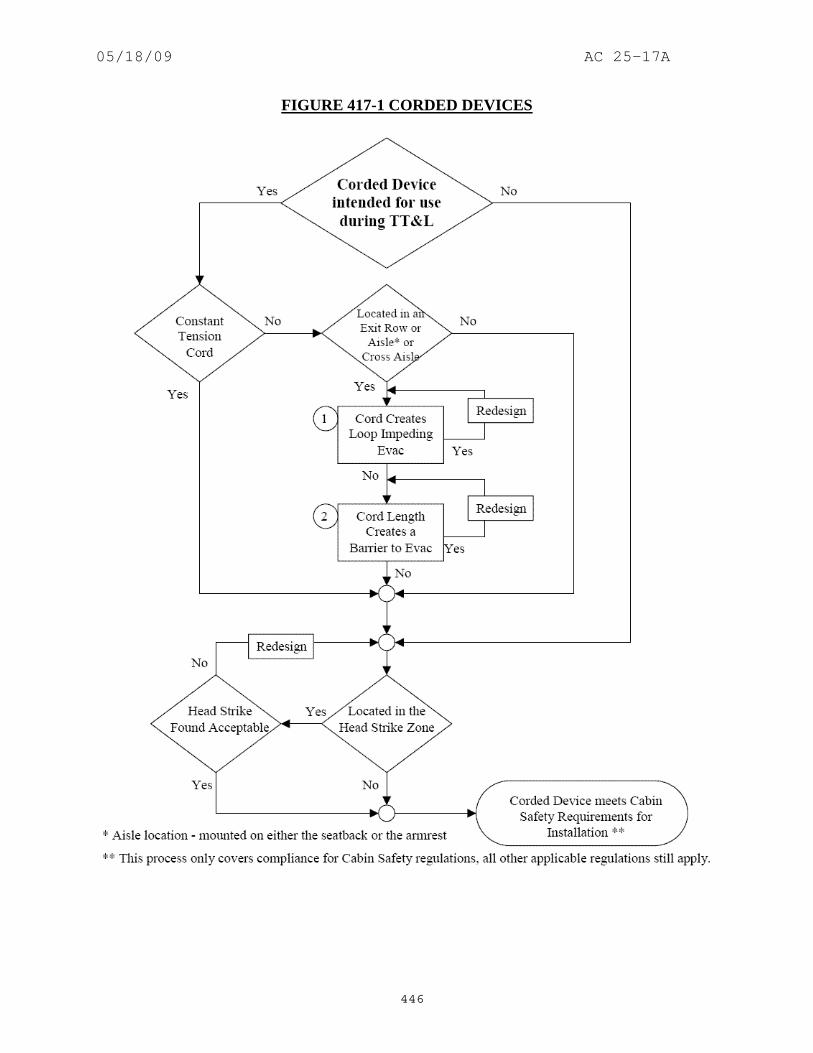
05/18/09 AC 25-17A
446
FIGURE 417-1 CORDED DEVICES

05/18/09 AC 25-17A
447
(8) Paragraph (b). When it is required that there be an area adjacent to an exit to permit a crewmember to assist passengers in the use of escape devices, a 12 x 20-inch assist space with the long dimension parallel to and clear of the required 20-inch exit approach passageway or equivalent facility should be provided. The area should be adequate to permit an attendant to stand erect and to perform needed assist services in the evacuation of passengers. Minor deviations from the 12 X 20-inch assist space are permitted if an evaluation is made that the effectiveness of the exit is not reduced. A demonstration may be necessary to show that passengers can be effectively evacuated. (Amendment 25-0) (9) Paragraph (b). Seat breakover should not be used to clear the assist space. Recline into the assist space and cushion compression are permitted, if the seat is easily pushed forward, and the cushion readily compressible. (Amendment 25-0) (10) Paragraph (b). If the assist space is under the overhead bins such that the attendant cannot stand erect, additional space, such as removal of the outboard seat, is required. The effectiveness of the assist space must be demonstrated. (Amendment 25-0) (11) Paragraph (b). The assist space need not be directly adjacent to the exit. In some cases the assist space could be inboard a short distance from the exit but outboard of the main aisle. (Amendment 25-0) (12) Paragraph (b). Assist handles are often provided at floor level emergency exits to provide stability for the flight attendant during an emergency evacuation. There is no specific requirement to provide an assist handle however, where an assist handle has been utilized for an evacuation demonstration used to show compliance with the regulations, production airplanes should also have an assist handle. The assist handle should be located at the assist space, even if the location of the assist space is not the same as the location on the airplane used for the evacuation demonstration. (Amendment 25-0) (13) Paragraph (c)(1). For airplanes with 20 or more passenger seats the following guidance applies. (i) An armrest should not protrude into the projected opening of the required exit, even if it could be rotated out of the projected exit opening. (Amendment 25-0) (ii) Armrests, curtains, or other protuberances which are removed simultaneously with opening of the exit are not considered to obstruct the projected opening provided. (Amendment 25-32) (iii) Berth installations, whether or not made up, should not obstruct the projected opening of the exit provided for a distance from that exit not less than the width of the narrowest passenger seat installed on the airplane. (Amendment 25-0) (iv) Seat back recline or breakover should not render the exit unopenable from either inside or outside. (Amendment 25-0)

05/18/09 AC 25-17A
448
(v) Seat back breakover and recline at the outboard seat locations should have a positive lockout, (e.g., such that a tool is required to adjust the breakover or recline) to prevent the seatback from protruding into the projected opening of the exit provided. Special seat identification is required. The projected exit opening provided must be not be obstructed rather than the minimum required opening must be not be obstructed. (Amendment 25-32) (vi) All portions of the outboard seat should clear the projected exit opening. No seat cushion compression should be allowed in order to clear the projected exit opening provided. Since seats are not directly controllable by the crew and are susceptible to passengers’ actions after the crew has completed their preparatory duties, crew procedures or placards are not considered adequate to maintain the proper access to the exit. (Amendment 25-32) (vii) Interior features (galleys, closets, seats, etc.) must not prevent an exit from being opened. (Amendment 25-32) (viii) The outboard seats, berths, or other protrusions, even though they clear the projected exit opening, should not interfere with the opening of the exit. For example, interior lining or trim on the exit hatch may extend beyond the projected opening of the exit, and could interfere with opening of the exit by contacting seats or other structure. (Amendment 25-46) (14) Paragraph (c)(2). For airplanes with 19 or less passenger seats the following guidance applies. The region that is discussed in this paragraph is the same region that is defined in paragraph (c)(1) of the regulation. (i) An armrest should not protrude into the projected opening of the required exit, even if it could be rotated out of the projected exit opening. (Amendment 25-0) (ii) Armrests, curtains, or other protuberances which are removed simultaneously with opening of the exit are not considered to restrict the required minimum opening. (Amendment 25-0) (iii) Projection of the seat backs into the minimum required exit opening should be permitted only if the seat back can be pushed forward or aft to clear the opening with the seat occupied. The force required to push the seat back away from the opening should be as low as practicable and should not exceed a maximum of 35 lbs with the seat unoccupied. The action should not require operation of any mechanical release. (Refer to paragraph 81b(8) for minimum breakover force.) A clear opening should permit the required minimum exit shape to be projected inward past the seat bottom and back cushion. Minor protrusion of the seat upholstery is acceptable if it does not interfere with exit removal and if it could be compressed without special effort by the person(s) using the exit. (Amendment 25-0) (iv) Berth installations, whether or not made up, should not decrease the accessibility and utility of emergency exits. (Amendment 25-0) (v) Seat back recline or breakover should not render the exit unopenable from either inside or outside. (Amendment 25-0)

05/18/09 AC 25-17A
449
(vi) A minor protrusion, not to exceed two-inches, of the outboard seat cushion into the required exit opening is permitted, if the cushion is easily compressed. A force of 170 lbs distributed over 40 square-inches has been found acceptable to determine if the cushion is easily compressed. (Amendment 25-0) (vii) For the smaller airplanes there could be some minor obstructions, provided that they do not reduce the effectiveness of the exit. Unattached (loose), soft seat-back cushions on side-facing divans, for example, may encroach into the minimum required exit opening provided the cushion can be readily moved away and the exit easily opened from the inside and outside. Other incursions into the projected opening, and even some interference in opening the exit are acceptable for these smaller airplanes, provided the exit maintains its effectiveness, and remains openable. The exit signs may not be obscured. (Amendment 25-32) (viii) Interior features (galleys, closets, seats, etc.) must not prevent an exit from being opened from either inside or outside. (Amendment 25-32) (15) Paragraphs (c)(1) and (c)(2). The wording “a passenger seating configuration, excluding pilot seats,” which was promulgated with the intent of being consistent with Amendment 23-10 to part 23, does not directly address seats intended for use by observers or flight attendants. Seats approved for use by observers or flight attendants are not included in the passenger seating configuration. Seats that have dual approval for occupancy by either crew/observers or passengers will be included in the passenger seating configuration. (Amendment 25-32) (16) Paragraph (d). The curtains may protrude slightly into the required passageway, provided the curtain and its tie-backs do no inhibit passage. (Amendment 25-1) (17) Paragraph (e). Arrangements have been found acceptable for a lavatory door where the lavatory would be occupied by one passenger during taxi, takeoff and landing. This arrangement would require an equivalent level of safety finding. The door should be secured open for taxi, takeoff and landing and be provided with an emergency egress panel. An emergency egress panel is a panel that can be broken through by a passenger who may be inadvertently trapped behind the door. A demonstration should be done using a 5th percentile female subject (approximately 60-inches tall and weighing 102 lbs ). (Amendment 25-1) (18) Paragraph (e). Curtains within a sliding frame are not considered to be a door if a person can easily pass through the curtain when closed. The curtain should be fastened open for taxi, takeoff and landing. (Refer to paragraph 1041b(7).) (Amendment 25-1) (19) Paragraph (e). Doors are permitted on galleys, etc. that are between the main aisle and exit if the door is not between passenger compartments. This would also apply to rooms not occupied for taxi, takeoff and landing. Doors that open into a main aisle should not be permitted in passenger compartments occupiable for taxi, takeoff or landing or in passenger compartments with passenger emergency exits. These types of compartments are typically found in "executive" interiors with the main aisle along the side wall. (Amendment 25-1)

05/18/09 AC 25-17A
450
418. AMENDMENT 25-76, Effective June 3, 1992. a. Regulation.
Each required emergency exit must be accessible to the passengers and located where it will afford an effective means of evacuation. Emergency exit distribution must be as uniform as practical, taking passenger distribution into account; however, the size and location of exits on both sides of the cabin need not be symmetrical. If only one floor level exit per side is prescribed, and the airplane does not have a tail cone or ventral emergency exit, the floor level exit must be in the rearward part of the passenger compartment, unless another location affords a more effective means of passenger evacuation. Where more than one floor level exit per side is prescribed, at least one floor level exit per side must be located near each end of the cabin, except that this provision does not apply to combination cargo/passenger configurations. In addition- [(a) There must be a passageway leading from the nearest main aisle to each Type I, Type II, or Type A emergency exit and between individual passenger areas. Each passageway leading to a Type A exit must be unobstructed and at least 36-inches wide. Passageways between individual passenger areas and those leading to Type I or Type II emergency exits must be unobstructed and at least 20-inches wide. Unless there are two or more main aisles, each Type A exit must be located so that there is passenger flow along the main aisle to that exit from both the forward and aft directions. If two or more main aisles are provided, there must be unobstructed cross-aisles at least 20-inches wide between main aisles. There must be- (1) A cross-aisle which leads directly to each passageway between the nearest main aisle and a Type A exit; and (2) A cross-aisle which leads to the immediate vicinity of each passageway between the nearest main aisle and a Type I, Type II, or Type III exit except that when two Type III exits are located within three passenger rows of each other, a single cross-aisle may be used if it leads to the vicinity between the passageways from the nearest main aisle to each exit.] (b) Adequate space to allow crewmember(s) to assist in the evacuation of passengers must be provided as follows: (1) The assist space must not reduce the unobstructed width of the passageway below that required for the exit. (2) For each Type A exit, assist space must be provided at each side of the exit regardless of whether the exit is covered by § 25.810(a).

05/18/09 AC 25-17A
451
(3) For any other type exit that is covered by § 25.810(a), space must be at least be provided at one side of the passageway. [(c) The following must be provided for each Type III or Type IV exit- (1) There must be access from the nearest aisle to each exit. In addition, for each Type III exit in an airplane that has a passenger seating configuration of 60 or more- (i) Except as provided in paragraph (c)(1)(ii), the access must be provided by an unobstructed passageway that is at least 10-inches in width for interior arrangements in which the adjacent seat rows on the exit side of the aisle contain no more than two seats, or 20-inches in width for interior arrangements in which those rows contain three seats. The width of the passageway must be measured with adjacent seats adjusted to their most adverse position. The centerline of the required passageway width must not be displaced more than 5-inches horizontally from that of the exit. (ii) In lieu of one 10- or 20-inch passageway, there may be two passageways, between seat rows only, that must be at least 6-inches in width and lead to an unobstructed space adjacent to each exit. (Adjacent exits must not share a common passageway.) The width of the passageways must be measured with adjacent seats adjusted to their most adverse position. The unobstructed space adjacent to the exit must extend vertically from the floor to the ceiling (or bottom of sidewall stowage bins), inboard from the exit for a distance not less than the width of the narrowest passenger seat installed on the airplane, and from the forward edge of the forward passageway to the aft edge of the aft passageway. The exit opening must be totally within the fore and aft bounds of the unobstructed space. (2) In addition to the access- (i) For airplanes that have a passenger seating configuration of 20 or more, the projected opening of the exit provided must not be obstructed and there must be no interference in opening the exit by seats, berths, or other protrusions (including any seatback in the most adverse position) for a distance from that exit not less than the width of the narrowest passenger seat installed on the airplane. (ii) For airplanes that have a passenger seating configuration of 19 or fewer, there may be minor obstructions in this region, if there are compensating factors to maintain the effectiveness of the exit. (3) For each Type III exit, regardless of the passenger capacity of the airplane in which it is installed, there must be placards that- (i) Are readable by all persons seated adjacent to and facing a passageway to the exit:

05/18/09 AC 25-17A
452
(ii) Accurately state or illustrate the proper method of opening the exit, including the use of handholds; and (iii) If the exit is a removable hatch, state the weight of the hatch and indicate an appropriate location to place the hatch after removal.] (d) If it is necessary to pass through a passageway between passenger compartments to reach any required emergency exit from any seat in the passenger cabin, the passageway must be unobstructed. However, curtains may be used if they allow free entry through the passageway. (e) No door may be installed in any partition between passenger compartments. (f) If it is necessary to pass through a doorway separating the passenger cabin from other areas to reach any required emergency exit from any passenger seat, the door must have a means to latch it in open position. The latching means must be able to withstand the loads imposed upon it when the door is subjected to the ultimate inertia forces, relative to the surrounding structure, listed in § 25.561(b).
b. Guidance. (1) Refer to AC 25.807-1, “Uniform Distribution of Exits,” dated 8/13/90 for additional guidance on this subject. (Amendment 25-67) (2) Paragraph (a). The seat back in any position (breakover or recline) should not obstruct the required passageway. (Amendment 25-32) (3) Paragraph (a). The passageway is the clear space from the floor to ceiling or bottom of the sidewall bins that runs generally perpendicular to the aisle when leading to a Type A, Type I or Type II exit. (Amendment 25-15) (4) Paragraph (a). Attendant seating facilities should not normally result in any reduction in required aisle widths, passageways between compartments, or the minimum passageway leading to Type A, Type I, and Type II exits. Attendants seating facilities provided with any acceptable means of clearing the passageway immediately is not considered as being an obstruction to these passageways. An acceptable means of demonstrating compliance would be a spring loaded attendant seat which provides automatic retraction when the seat is vacated. (Amendment 25-0) (5) Paragraph (a). In determining the minimum passageway requirements leading to Type A, Type I and Type II exits: (Amendment 25-0) (i) The presence of passenger feet need not be considered. (Amendment 25-0) (ii) Curtain tie-backs with appropriate placards may be required to maintain an unobstructed passageway. (Amendment 25-0)

05/18/09 AC 25-17A
453
(iii) Seat backs of seats facing the passageway with breakover feature should remain clear of the required passageway when placed in breakover position. (Amendment 25-0) (iv) No seat cushion compression and no breakover from the upright position of a seat facing away from the passageway should be allowed to achieve the required passageway. (Amendment 25-0) (v) The passageway may be offset from the projected exit opening if the effectiveness of the exit is not reduced. (Amendment 25-0) (vi) Galley, lavatory or closet doors, drawers, shelves, etc., that obstruct the required passageway, should be placarded to be stowed and/or latched for taxi, takeoff and landing or be spring-loaded closed. (Amendment 25-0) (vii) Galley and stowage unit doors, drawers, etc., that interfere with the opening of an emergency exit should be spring-loaded closed. The evaluation for interference is made with the stowage unit door in any position and opening the emergency exit from either the inside or the outside. If it is not possible to spring-load the door, drawer, etc., there should be a special emphasis placard to close and latch for taxi, takeoff, and landing. (Refer to paragraph 1041b(6).) (Amendment 25-0) (6) Paragraph (a). This paragraph defines the requirements for passageways to Type A exits and cross aisles in two aisle airplanes. These provide sufficient access for two lines of evacuees to egress simultaneously: (Amendment 25-15) (i) In order to achieve the dual lane flow of evacuees, § 25.785(h)(1) Amendment 25-72 requires an unobstructed 36-inch width passageway that leads to the exit from the outboard side of the adjacent main aisle. It should not, however, encroach upon the crewmember assist spaces that are required on both sides of the exit by § 25.813(b)(2) Amendment 25-72. This is particularly important to remember for those situations where the passageway is canted to meet the projected cross aisles, which are discussed below. (Amendment 25-15) (ii) Additionally, where more than one main aisle is provided, § 25.813(a) Amendment 25-72 requires that there must be an unobstructed 20-inch wide cross aisle, leading directly to the exit passageways. This cross aisle is considered to extend from the inboard side of one main aisle to the inboard side of the other main aisle. The required cross aisle does not have to be straight nor does it have to be normal to the main aisles. (Amendment 25-15) (iii) For the case where the exit is located at the end of the passenger cabin and there are only two approach paths to the exit (the main aisle from one direction and the cross aisle), the 36-inch wide passageway should extend from the exit to the point where the evacuee flows from the main aisle and cross aisle merge to ensure the dual lane flow can be maintained. (Amendment 25-15)

05/18/09 AC 25-17A
454
(iv) In the other case, where the exit is not located at the end of the cabin and there are three approach paths (the main aisle from two directions and the cross aisle) to the exit, the 20-inch width of the cross aisle should be within the 36-inch width of the passageway when the cross aisle is projected normal to the main aisle. Some portion of the 20-inch wide cross aisle should be within the width of the projected door opening. (Amendment 25-15) (v) If the boundaries of any of the aforementioned passageways, aisles or cross aisles are formed by passenger seats, ensure that the minimum requirements are met with the seat in the most adverse condition that is not prohibited by design. (Amendment 25-15) (vi) Door and cross aisle visibility is also of prime importance when evaluating the safety level of an exit configuration. This is especially true when the cross aisle is displaced forward or aft from the exit opening or when a pair of exits are not directly across the airplane from each other. The configuration should provide a view across the airplane such that the exit on the other side is readily identifiable. Identification of the opposite exit may be via the exit marking sign, the exit opening handle and related markings or when the field of vision provided allows visual perception of sufficient detail to recognize that there is an exit across the airplane. This identification should be evaluated when standing at the center of the opposite exit. In certain cases, additional exit locator signs may be necessary to direct evacuees to the opposite exit. (Amendment 25-15) (7) Paragraph (a) and (c). The FAA issued policy memorandum 02-115-20, dated November 21, 2002, titled “Policy Statement on Corded Electrical Devices Used in the Passenger Cabin.” The new policy may be used for demonstrating compliance with § 25.813(a) and (c), Amendment 25-76, and is provided below. (Amendment 25-0) (i) The policy contained herein is intended to provide the applicant with various certification options, which will require little or no on-aircraft evaluation of cord devices, provided that these devices meet certain basic criteria. This policy is applicable to typical commercial air carrier passenger configurations, i.e., 14 CFR part 121 and part 135 operations. (ii) The cordreels used for corded device installations must be of sufficient quality and design that they reliably retract. The reliability of the cord reels should be established by the manufacturer, e.g., lifecycle testing, or analysis supported by testing. The data or analysis with supporting data should be made available upon request. The constant tension cordreel should be tested to show that it can be extended and retracted for its service life without a degradation in its performance. In addition to the extension testing, the ratcheting cordreel should also be tested to show that the ratcheting mechanism will perform reliably for its projected service life. The same basic philosophy applies to coiled cords as well. (iii) The following guidelines apply: Refer to figure 418-1, Corded Devices (A) If the device is not intended for use during taxi, takeoff and landing (TT&L), and is restricted accordingly, e.g., by appropriate placarding, then no cord length and no cord loop evaluations are required.

05/18/09 AC 25-17A
455
(B) If the device is intended for use during TT&L, and it has a constant tension cord, then no cord length and no cord loop evaluations are required.
(C) If the device is intended for use during TT&L, and it does not have a constant tension cord and it is not installed on an aisle, cross aisle or exit row, then no cord loop and length evaluation is required.
(D) If, however, the device is intended for use during TT&L, and does not have a constant tension cord, and is installed on an aisle armrest, a cross aisle armrest or aisle side seatback or in an exit row, then cord loop and length evaluations must be made to ensure that the corded device will not interfere with passenger emergency egress. These devices may include breakaway capabilities in the cord connections, or frangibility in the cord itself, that can act as compensating features during the evaluation.
(1) Cord Loop Evaluation. Loops created by mis-stowage of a corded device should be evaluated to determine if they pose an egress hazard. It should be shown that, with the handset stowed in its cradle, an unstowed cord does not become a hazard which can entrap or snag limbs or clothing during an emergency evacuation. Evaluations should be made with a 5th percentile female and a 95th percentile male, as follows: (i) Any cord loop that can be formed by mis-stowing the handset using reasonable force should be evaluated to determine that the location of the loop does not pose an egress hazard. Loops formed below the level of the armrest and contained within the bounds of the seat bottom cushion should be acceptable. (ii) Any loop that can be formed by mis-stowing the handset using reasonable force, which extends into an aisle, must be unable to encircle an appendage (limb or clothing) without significant manipulation or contrivance. (iii) Any loop that can be formed by mis-stowing the handset using reasonable force, in a location where a limb may be encircled, must be easily escapable by normal passenger movement, or the handset must be able to be pulled free with normal motion and strength. (2) Cord Length. Applicants must demonstrate that their handset installation cord length will not permit the handset to lie flat on the floor when the handset is not properly stowed. Also, on seat back mounted handsets, the cord length must be restricted so that the device cannot be used by anyone seated across the aisle or by anyone seated in a row behind the row directly facing the unit. Note: This does not preclude the passing of the handset forward to the row on which the handset is mounted. (E) Associated Placards: If placards are installed which state when a handset may (or may not) be used, at least one placard should be in plain sight of the occupant of any position from which the handset is likely to be used, whether or not the handset is stowed.

05/18/09 AC 25-17A
456
These, and any other safety related placards, should be of sufficient size and color contrast (lettering to background) so as to be easily visible to all expected users under normal cabin lighting conditions. Visibility during low light level conditions, which are often encountered during night flights, is desirable, but not mandatory. (iv) Finally, this guidance material covers compliance for cabin safety issues only. All other applicable certification regulations still apply.

05/18/09 AC 25-17A
457
FIGURE 418-1 CORDED DEVICES

05/18/09 AC 25-17A
458
(8) Paragraph (b). When it is required that there be an area adjacent to an exit to permit a crewmember to assist passengers in the use of escape devices, a 12 x 20-inch assist space with the long dimension parallel to and clear of the required 20-inch exit approach passageway or equivalent facility should be provided. The area should be adequate to permit an attendant to stand erect and to perform needed assist services in the evacuation of passengers. Minor deviations from the 12 X 20-inch assist space are permitted if an evaluation is made that the effectiveness of the exit is not reduced. A demonstration may be necessary to show that passengers can be effectively evacuated. (Amendment 25-0) (9) Paragraph (b). Seat breakover should not be used to clear the assist space. Recline into the assist space and cushion compression are permitted, if the seat is easily pushed forward, and the cushion readily compressible. (Amendment 25-0) (10) Paragraph (b). If the assist space is under the overhead bins such that the attendant cannot stand erect, additional space, such as removal of the outboard seat, is required. The effectiveness of the assist space must be demonstrated. (Amendment 25-0) (11) Paragraph (b). The assist space need not be directly adjacent to the exit. In some cases the assist space could be inboard a short distance from the exit but outboard of the main aisle. (Amendment 25-0) (12) Paragraph (b). Assist handles are often provided at floor level emergency exits to provide stability for the flight attendant during an emergency evacuation. There is no specific requirement to provide an assist handle however, where an assist handle has been utilized for an evacuation demonstration used to show compliance with the regulations, production airplanes should also have an assist handle. The assist handle should be located at the assist space, even if the location of the assist space is not the same as the location on the airplane used for the evacuation demonstration. (Amendment 25-0) (13) Paragraph (c)(2)(i). For airplanes with 20 or more passenger seats the following guidance applies. (i) An armrest should not protrude into the projected opening of the required exit, even if it could be rotated out of the projected exit opening. (Amendment 25-0) (ii) Armrests, curtains, or other protuberances which are removed simultaneously with opening of the exit are not considered to obstruct the projected opening provided. (Amendment 25-32) (iii) Berth installations, whether or not made up, should not obstruct the projected opening of the exit provided for a distance from that exit not less than the width of the narrowest passenger seat installed on the airplane. (Amendment 25-0) (iv) Seat back recline or breakover should not render the exit unopenable from either inside or outside. (Amendment 25-0)

05/18/09 AC 25-17A
459
(v) Seat back breakover and recline at the outboard seat locations should have a positive lockout, (e.g., such that a tool is required to adjust the breakover or recline) to prevent the seatback from protruding into the projected opening of the exit provided. Special seat identification is required. The projected exit opening provided must be not be obstructed rather than the minimum required opening must be not be obstructed. (Amendment 25-32) (vi) All portions of the outboard seat should clear the projected exit opening. No seat cushion compression should be allowed in order to clear the projected exit opening provided. Since seats are not directly controllable by the crew and are susceptible to passengers’ actions after the crew has completed their preparatory duties, crew procedures or placards are not considered adequate to maintain the proper access to the exit. (Amendment 25-32) (vii) Interior features (galleys, closets, seats, etc.) must not prevent an exit from being opened. (Amendment 25-32) (viii) The outboard seats, berths, or other protrusions, even though they clear the projected exit opening, should not interfere with the opening of the exit. For example, interior lining or trim on the exit hatch may extend beyond the projected opening of the exit, and could interfere with opening of the exit by contacting seats or other structure. (Amendment 25-46) (14) Paragraph (c)(2)(ii). For airplanes with 19 or less passenger seats the following guidance applies. The region that is discussed in this paragraph is the same region that is defined in paragraph (c)(2)(i) of the regulation. (i) An armrest should not protrude into the projected opening of the required exit, even if it could be rotated out of the projected exit opening. (Amendment 25-0) (ii) Armrests, curtains, or other protuberances which are removed simultaneously with opening of the exit are not considered to restrict the required minimum opening. (Amendment 25-0) (iii) Projection of the seat backs into the minimum required exit opening should be permitted only if the seat back can be pushed forward or aft to clear the opening with the seat occupied. The force required to push the seat back away from the opening should be as low as practicable and should not exceed a maximum of 35 lbs with the seat unoccupied. The action should not require operation of any mechanical release. (Refer to paragraph 81b(8) for minimum breakover force.) A clear opening should permit the required minimum exit shape to be projected inward past the seat bottom and back cushion. Minor protrusion of the seat upholstery is acceptable if it does not interfere with exit removal and if it could be compressed without special effort by the person(s) using the exit. (Amendment 25-0) (iv) Berth installations, whether or not made up, should not decrease the accessibility and utility of emergency exits. (Amendment 25-0) (v) Seat back recline or breakover should not render the exit unopenable from either inside or outside. (Amendment 25-0)

05/18/09 AC 25-17A
460
(vi) A minor protrusion, not to exceed two-inches, of the outboard seat cushion into the required exit opening is permitted, if the cushion is easily compressed. A force of 170 lbs distributed over 40 square-inches has been found acceptable to determine if the cushion is easily compressed. (Amendment 25-0) (vii) For the smaller airplanes there could be some minor obstructions, provided that they do not reduce the effectiveness of the exit. Unattached (loose), soft seat-back cushions on side-facing divans, for example, may encroach into the minimum required exit opening provided the cushion can be readily moved away and the exit easily opened from the inside and outside. Other incursions into the projected opening, and even some interference in opening the exit are acceptable for these smaller airplanes, provided the exit maintains its effectiveness, and remains openable. The exit signs may not be obscured. (Amendment 25-32) (viii) Interior features (galleys, closets, seats, etc.) must not prevent an exit from being opened from either inside or outside. (Amendment 25-32) (15) Paragraphs (c)(2)(i) and (c)(2)(ii). The wording “a passenger seating configuration, excluding pilot seats,” which was promulgated with the intent of being consistent with Amendment 23-10 to part 23, does not directly address seats intended for use by observers or flight attendants. Seats approved for use by observers or flight attendants are not included in the passenger seating configuration. Seats that have dual approval for occupancy by either crew/observers or passengers will be included in the passenger seating configuration. (Amendment 25-32) (16) Paragraph (d). The curtains may protrude slightly into the required passageway, provided the curtain and its tie-backs do no inhibit passage. (Amendment 25-1) (17) Paragraph (e). Arrangements have been found acceptable for a lavatory door where the lavatory would be occupied by one passenger during taxi, takeoff and landing. This arrangement would require an equivalent level of safety finding. The door should be secured open for taxi, takeoff and landing and be provided with an emergency egress panel. An emergency egress panel is a panel that can be broken through by a passenger who may be inadvertently trapped behind the door. A demonstration should be done using a 5th percentile female subject (approximately 60-inches tall and weighing 102 lbs ). (Amendment 25-1) (18) Paragraph (e). Curtains within a sliding frame are not considered to be a door if a person can easily pass through the curtain when closed. The curtain should be fastened open for taxi, takeoff and landing. (Refer to paragraph 1041b(7).) (Amendment 25-1) (19) Paragraph (e). Doors are permitted on galleys, etc. that are between the main aisle and exit if the door is not between passenger compartments. This would also apply to rooms not occupied for taxi, takeoff and landing. Doors that open into a main aisle should not be permitted in passenger compartments occupiable for taxi, takeoff or landing or in passenger compartments with passenger emergency exits. These types of compartments are typically found in "executive" interiors with the main aisle along the side wall. (Amendment 25-1)

05/18/09 AC 25-17A
461
419. AMENDMENT 25-88, Effective December 9, 1996. a. Regulation.
Each required emergency exit must be accessible to the passengers and located where it will afford an effective means of evacuation. Emergency exit distribution must be as uniform as practical, taking passenger distribution into account; however, the size and location of exits on both sides of the cabin need not be symmetrical. If only one floor level exit per side is prescribed, and the airplane does not have a tailcone or ventral emergency exit, the floor level exit must be in the rearward part of the passenger compartment, unless another location affords a more effective means of passenger evacuation. Where more than one floor level exit per side is prescribed, at least one floor level exit per side must be located near each end of the cabin, except that this provision does not apply to combination cargo/passenger configurations. In addition- [(a) There must be a passageway leading from the nearest main aisle to each Type A, Type B, Type C, Type I, or Type II emergency exit and between individual passenger areas. Each passageway leading to a Type A or Type B exit must be unobstructed and at least 36-inches wide. Passageways between individual passenger areas and those leading to Type I, Type II, or Type C emergency exits must be unobstructed and at least 20-inches wide. Unless there are two or more main aisles, each Type A or B exit must be located so that there is passenger flow along the main aisle to that exit from both the forward and aft directions. If two or more main aisles are provided, there must be unobstructed cross-aisles at least 20-inches wide between main aisles. There must be- (1) A cross-aisle which leads directly to each passageway between the nearest main aisle and a Type A or B exit; and] (2) A cross-aisle which leads to the immediate vicinity of each passageway between the nearest main aisle and a Type I, Type II, or Type III exit; except that when two Type III exits are located within three passenger rows of each other, a single cross-aisle may be used if it leads to the vicinity between the passageways from the nearest main aisle to each exit. [(b) Adequate space to allow crewmember(s) to assist in the evacuation of passengers must be provided as follows: (1) The assist space must not reduce the unobstructed width of the passageway below that required for the exit. (2) For each Type A or Type B exit, assist space must be provided at each side of the exit regardless of whether a means is required by § 25.810(a) to assist passengers in descending to the ground from that exit.

05/18/09 AC 25-17A
462
(3) Assist space must be provided at one side of any other type exit required by § 25.810(a) to have a means to assist passengers in descending to the ground from that exit.] (c) The following must be provided for each Type III or Type IV exit- (1) There must be access from the nearest aisle to each exit. In addition, for each Type III exit in an airplane that has a passenger seating configuration of 60 or more- (i) Except as provided in paragraph (c)(1)(ii), the access must be provided by an unobstructed passageway that is at least 10-inches in width for interior arrangements in which the adjacent seat rows on the exit side of the aisle contain no more than two seats, or 20-inches in width for interior arrangements in which those rows contain three seats. The width of the passageway must be measured with adjacent seats adjusted to their most adverse position. The centerline of the required passageway width must not be displaced more than 5-inches horizontally from that of the exit. (ii) In lieu of one 10- or 20-inch passageway, there may be two passageways, between seat rows only, that must be at least 6-inches in width and lead to an unobstructed space adjacent to each exit. (Adjacent exits must not share a common passageway.) The width of the passageways must be measured with adjacent seats adjusted to their most adverse position. The unobstructed space adjacent to the exit must extend vertically from the floor to the ceiling (or bottom of sidewall stowage bins), inboard from the exit for a distance not less than the width of the narrowest passenger seat installed on the airplane, and from the forward edge of the forward passageway to the aft edge of the aft passageway. The exit opening must be totally within the fore and aft bounds of the unobstructed space. (2) In addition to the access- (i) For airplanes that have a passenger seating configuration of 20 or more, the projected opening of the exit provided must not be obstructed and there must be no interference in opening the exit by seats, berths, or other protrusions (including any seatback in the most adverse position) for a distance from that exit not less than the width of the narrowest passenger seat installed on the airplane. (ii) For airplanes that have a passenger seating configuration of 19 or fewer, there may be minor obstructions in this region, if there are compensating factors to maintain the effectiveness of the exit. (3) For each Type III exit, regardless of the passenger capacity of the airplane in which it is installed, there must be placards that- (i) Are readable by all persons seated adjacent to and facing a passageway to the exit;

05/18/09 AC 25-17A
463
(ii) Accurately state or illustrate the proper method of opening the exit, including the use of handholds; and (iii) If the exit is a removable hatch, state the weight of the hatch and indicate an appropriate location to place the hatch after removal. (d) If it is necessary to pass through a passageway between passenger compartments to reach any required emergency exit from any seat in the passenger cabin, the passageway must be unobstructed. However, curtains may be used if they allow free entry through the passageway. (e) No door may be installed in any partition between passenger compartments. (f) If it is necessary to pass through a doorway separating the passenger cabin from other areas to reach any required emergency exit from any passenger seat, the door must have a means to latch it in open position. The latching means must be able to withstand the loads imposed upon it when the door is subjected to the ultimate inertia forces, relative to the surrounding structure, listed in § 25.561(b).
b. Guidance. (1) Refer to AC 25.807-1, “Uniform Distribution of Exits,” dated 8/13/90 for additional guidance on this subject. (Amendment 25-67) (2) Paragraph (a). The seat back in any position (breakover or recline) should not obstruct the required passageway. (Amendment 25-32) (3) Paragraph (a). The passageway is the clear space from the floor to ceiling or bottom of the sidewall bins that runs generally perpendicular to the aisle when leading to a Type A, Type I or Type II exit. (Amendment 25-15) (4) Paragraph (a). Attendant seating facilities should not normally result in any reduction in required aisle widths, passageways between compartments, or the minimum passageway leading to Type A, Type I, and Type II exits. Attendants seating facilities provided with any acceptable means of clearing the passageway immediately is not considered as being an obstruction to these passageways. An acceptable means of demonstrating compliance would be a spring loaded attendant seat which provides automatic retraction when the seat is vacated. (Amendment 25-0) (5) Paragraph (a). In determining the minimum passageway requirements leading to Type A, Type I and Type II exits: (Amendment 25-0) (i) The presence of passenger feet need not be considered. (Amendment 25-0)
05/18/09 AC 25-17A
464
(ii) Curtain tie-backs with appropriate placards may be required to maintain an unobstructed passageway. (Amendment 25-0) (iii) Seat backs of seats facing the passageway with breakover feature should remain clear of the required passageway when placed in breakover position. (Amendment 25-0) (iv) No seat cushion compression and no breakover from the upright position of a seat facing away from the passageway should be allowed to achieve the required passageway. (Amendment 25-0) (v) The passageway may be offset from the projected exit opening if the effectiveness of the exit is not reduced. (Amendment 25-0) (vi) Galley, lavatory or closet doors, drawers, shelves, etc., that obstruct the required passageway, should be placarded to be stowed and/or latched for taxi, takeoff and landing or be spring-loaded closed. (Amendment 25-0) (vii) Galley and stowage unit doors, drawers, etc., that interfere with the opening of an emergency exit should be spring-loaded closed. The evaluation for interference is made with the stowage unit door in any position and opening the emergency exit from either the inside or the outside. If it is not possible to spring-load the door, drawer, etc., there should be a special emphasis placard to close and latch for taxi, takeoff, and landing. (Refer to paragraph 1041b(6).) (Amendment 25-0) (6) Paragraph (a). This paragraph defines the requirements for passageways to Type A and Type B exits and cross aisles in two aisle airplanes. These provide sufficient access for two lines of evacuees to egress simultaneously: (Amendment 25-15) (i) In order to achieve the dual lane flow of evacuees, § 25.785(h)(1) Amendment 25-72 requires an unobstructed 36-inch width passageway that leads to the exit from the outboard side of the adjacent main aisle. It should not, however, encroach upon the crewmember assist spaces that are required on both sides of the exit by § 25.813(b)(2) Amendment 25-72. This is particularly important to remember for those situations where the passageway is canted to meet the projected cross aisles, which are discussed below. (Amendment 25-15) (ii) Additionally, where more than one main aisle is provided, § 25.813(a) Amendment 25-72 requires that there must be an unobstructed 20-inch wide cross aisle, leading directly to the exit passageways. This cross aisle is considered to extend from the inboard side of one main aisle to the inboard side of the other main aisle. The required cross aisle does not have to be straight nor does it have to be normal to the main aisles. (Amendment 25-15) (iii) For the case where the exit is located at the end of the passenger cabin and there are only two approach paths to the exit (the main aisle from one direction and the cross aisle), the 36-inch wide passageway should extend from the exit to the point where the evacuee flows from the main aisle and cross aisle merge to ensure the dual lane flow can be maintained. (Amendment 25-15)

05/18/09 AC 25-17A
465
(iv) In the other case, where the exit is not located at the end of the cabin and there are three approach paths (the main aisle from two directions and the cross aisle) to the exit, the 20-inch width of the cross aisle should be within the 36-inch width of the passageway when the cross aisle is projected normal to the main aisle. Some portion of the 20-inch wide cross aisle should be within the width of the projected door opening. (Amendment 25-15) (v) If the boundaries of any of the aforementioned passageways, aisles or cross aisles are formed by passenger seats, ensure that the minimum requirements are met with the seat in the most adverse condition that is not prohibited by design. (Amendment 25-15) (vi) Door and cross aisle visibility is also of prime importance when evaluating the safety level of an exit configuration. This is especially true when the cross aisle is displaced forward or aft from the exit opening or when a pair of exits are not directly across the airplane from each other. The configuration should provide a view across the airplane such that the exit on the other side is readily identifiable. Identification of the opposite exit may be via the exit marking sign, the exit opening handle and related markings or when the field of vision provided allows visual perception of sufficient detail to recognize that there is an exit across the airplane. This identification should be evaluated when standing at the center of the opposite exit. In certain cases, additional exit locator signs may be necessary to direct evacuees to the opposite exit. (Amendment 25-15) (7) Paragraph (a) and (c). The FAA issued policy memorandum 02-115-20, dated November 21, 2002, titled “Policy Statement on Corded Electrical Devices Used in the Passenger Cabin.” The new policy may be used for demonstrating compliance with § 25.813(a) and (c), Amendment 25-88, and is provided below. (Amendment 25-0) (i) The policy contained herein is intended to provide the applicant with various certification options, which will require little or no on-aircraft evaluation of cord devices, provided that these devices meet certain basic criteria. This policy is applicable to typical commercial air carrier passenger configurations, i.e., 14 CFR part 121 and part 135 operations. (ii) The cordreels used for corded device installations must be of sufficient quality and design that they reliably retract. The reliability of the cord reels should be established by the manufacturer, e.g., lifecycle testing, or analysis supported by testing. The data or analysis with supporting data should be made available upon request. The constant tension cordreel should be tested to show that it can be extended and retracted for its service life without a degradation in its performance. In addition to the extension testing, the ratcheting cordreel should also be tested to show that the ratcheting mechanism will perform reliably for its projected service life. The same basic philosophy applies to coiled cords as well. (iii) The following guidelines apply: Refer to figure 419-1, Corded Devices. (A) If the device is not intended for use during taxi, takeoff and landing (TT&L), and is restricted accordingly, e.g., by appropriate placarding, then no cord length and no cord loop evaluations are required.

05/18/09 AC 25-17A
466
(B) If the device is intended for use during TT&L, and it has a constant tension cord, then no cord length and no cord loop evaluations are required.
(C) If the device is intended for use during TT&L, and it does not have a constant tension cord and it is not installed on an aisle, cross aisle or exit row, then no cord loop and length evaluation is required.
(D) If, however, the device is intended for use during TT&L, and does not have a constant tension cord, and is installed on an aisle armrest, a cross aisle armrest or aisle side seatback or in an exit row, then cord loop and length evaluations must be made to ensure that the corded device will not interfere with passenger emergency egress. These devices may include breakaway capabilities in the cord connections, or frangibility in the cord itself, that can act as compensating features during the evaluation.
(1) Cord Loop Evaluation. Loops created by mis-stowage of a corded device should be evaluated to determine if they pose an egress hazard. It should be shown that, with the handset stowed in its cradle, an unstowed cord does not become a hazard which can entrap or snag limbs or clothing during an emergency evacuation. Evaluations should be made with a 5th percentile female and a 95th percentile male, as follows: (i) Any cord loop that can be formed by mis-stowing the handset using reasonable force should be evaluated to determine that the location of the loop does not pose an egress hazard. Loops formed below the level of the armrest and contained within the bounds of the seat bottom cushion should be acceptable. (ii) Any loop that can be formed by mis-stowing the handset using reasonable force, which extends into an aisle, must be unable to encircle an appendage (limb or clothing) without significant manipulation or contrivance. (iii) Any loop that can be formed by mis-stowing the handset using reasonable force, in a location where a limb may be encircled, must be easily escapable by normal passenger movement, or the handset must be able to be pulled free with normal motion and strength. (2) Cord Length. Applicants must demonstrate that their handset installation cord length will not permit the handset to lie flat on the floor when the handset is not properly stowed. Also, on seat back mounted handsets, the cord length must be restricted so that the device cannot be used by anyone seated across the aisle or by anyone seated in a row behind the row directly facing the unit. Note: This does not preclude the passing of the handset forward to the row on which the handset is mounted. (E) Associated Placards: If placards are installed which state when a handset may (or may not) be used, at least one placard should be in plain sight of the occupant of any position from which the handset is likely to be used, whether or not the handset is stowed.

05/18/09 AC 25-17A
467
These, and any other safety related placards, should be of sufficient size and color contrast (lettering to background) so as to be easily visible to all expected users under normal cabin lighting conditions. Visibility during low light level conditions, which are often encountered during night flights, is desirable, but not mandatory. (iv) Finally, this guidance material covers compliance for cabin safety issues only. All other applicable certification regulations still apply.

05/18/09 AC 25-17A
468
FIGURE 419-1 CORDED DEVICES

05/18/09 AC 25-17A
469
(8) Paragraph (b). When it is required that there be an area adjacent to an exit to permit a crewmember to assist passengers in the use of escape devices, a 12 x 20-inch assist space with the long dimension parallel to and clear of the required 20-inch exit approach passageway or equivalent facility should be provided. The area should be adequate to permit an attendant to stand erect and to perform needed assist services in the evacuation of passengers. Minor deviations from the 12 X 20-inch assist space are permitted if an evaluation is made that the effectiveness of the exit is not reduced. A demonstration may be necessary to show that passengers can be effectively evacuated. (Amendment 25-0) (9) Paragraph (b). Seat breakover should not be used to clear the assist space. Recline into the assist space and cushion compression are permitted, if the seat is easily pushed forward, and the cushion readily compressible. (Amendment 25-0) (10) Paragraph (b). If the assist space is under the overhead bins such that the attendant cannot stand erect, additional space, such as removal of the outboard seat, is required. The effectiveness of the assist space must be demonstrated. (Amendment 25-0) (11) Paragraph (b). The assist space need not be directly adjacent to the exit. In some cases the assist space could be inboard a short distance from the exit but outboard of the main aisle. (Amendment 25-0) (12) Paragraph (b). Assist handles are often provided at floor level emergency exits to provide stability for the flight attendant during an emergency evacuation. There is no specific requirement to provide an assist handle however, where an assist handle has been utilized for an evacuation demonstration used to show compliance with the regulations, production airplanes should also have an assist handle. The assist handle should be located at the assist space, even if the location of the assist space is not the same as the location on the airplane used for the evacuation demonstration. (Amendment 25-0) (13) Paragraph (c)(2)(i). For airplanes with 20 or more passenger seats the following guidance applies. (i) An armrest should not protrude into the projected opening of the required exit, even if it could be rotated out of the projected exit opening. (Amendment 25-0) (ii) Armrests, curtains, or other protuberances which are removed simultaneously with opening of the exit are not considered to obstruct the projected opening provided. (Amendment 25-32) (iii) Berth installations, whether or not made up, should not obstruct the projected opening of the exit provided for a distance from that exit not less than the width of the narrowest passenger seat installed on the airplane. (Amendment 25-0) (iv) Seat back recline or breakover should not render the exit unopenable from either inside or outside. (Amendment 25-0)
05/18/09 AC 25-17A
470
(v) Seat back breakover and recline at the outboard seat locations should have a positive lockout, (e.g., such that a tool is required to adjust the breakover or recline) to prevent the seatback from protruding into the projected opening of the exit provided. Special seat identification is required. The projected exit opening provided must be not be obstructed rather than the minimum required opening must be not be obstructed. (Amendment 25-32) (vi) All portions of the outboard seat should clear the projected exit opening. No seat cushion compression should be allowed in order to clear the projected exit opening provided. Since seats are not directly controllable by the crew and are susceptible to passengers’ actions after the crew has completed their preparatory duties, crew procedures or placards are not considered adequate to maintain the proper access to the exit. (Amendment 25-32) (vii) Interior features (galleys, closets, seats, etc.) must not prevent an exit from being opened. (Amendment 25-32) (viii) The outboard seats, berths, or other protrusions, even though they clear the projected exit opening, should not interfere with the opening of the exit. For example, interior lining or trim on the exit hatch may extend beyond the projected opening of the exit, and could interfere with opening of the exit by contacting seats or other structure. (Amendment 25-46) (14) Paragraph (c)(2)(ii). For airplanes with 19 or less passenger seats the following guidance applies. The region that is discussed in this paragraph is the same region that is defined in paragraph (c)(2)(i) of the regulation. (i) An armrest should not protrude into the projected opening of the required exit, even if it could be rotated out of the projected exit opening. (Amendment 25-0) (ii) Armrests, curtains, or other protuberances which are removed simultaneously with opening of the exit are not considered to restrict the required minimum opening. (Amendment 25-0) (iii) Projection of the seat backs into the minimum required exit opening should be permitted only if the seat back can be pushed forward or aft to clear the opening with the seat occupied. The force required to push the seat back away from the opening should be as low as practicable and should not exceed a maximum of 35 lbs with the seat unoccupied. The action should not require operation of any mechanical release. (Refer to paragraph 81b(8) for minimum breakover force.) A clear opening should permit the required minimum exit shape to be projected inward past the seat bottom and back cushion. Minor protrusion of the seat upholstery is acceptable if it does not interfere with exit removal and if it could be compressed without special effort by the person(s) using the exit. (Amendment 25-0) (iv) Berth installations, whether or not made up, should not decrease the accessibility and utility of emergency exits. (Amendment 25-0) (v) Seat back recline or breakover should not render the exit unopenable from either inside or outside. (Amendment 25-0)

05/18/09 AC 25-17A
471
(vi) A minor protrusion, not to exceed two-inches, of the outboard seat cushion into the required exit opening is permitted, if the cushion is easily compressed. A force of 170 lbs distributed over 40 square-inches has been found acceptable to determine if the cushion is easily compressed. (Amendment 25-0) (vii) For the smaller airplanes there could be some minor obstructions, provided that they do not reduce the effectiveness of the exit. Unattached (loose), soft seat-back cushions on side-facing divans, for example, may encroach into the minimum required exit opening provided the cushion can be readily moved away and the exit easily opened from the inside and outside. Other incursions into the projected opening, and even some interference in opening the exit are acceptable for these smaller airplanes, provided the exit maintains its effectiveness, and remains openable. The exit signs may not be obscured. (Amendment 25-32) (viii) Interior features (galleys, closets, seats, etc.) must not prevent an exit from being opened from either inside or outside. (Amendment 25-32) (15) Paragraphs (c)(2)(i) and (c)(2)(ii). The wording “a passenger seating configuration, excluding pilot seats,” which was promulgated with the intent of being consistent with Amendment 23-10 to part 23, does not directly address seats intended for use by observers or flight attendants. Seats approved for use by observers or flight attendants are not included in the passenger seating configuration. Seats that have dual approval for occupancy by either crew/observers or passengers will be included in the passenger seating configuration. (Amendment 25-32) (16) Paragraph (d). The curtains may protrude slightly into the required passageway, provided the curtain and its tie-backs do no inhibit passage. (Amendment 25-1) (17) Paragraph (e). Arrangements have been found acceptable for a lavatory door where the lavatory would be occupied by one passenger during taxi, takeoff and landing. This arrangement would require an equivalent level of safety finding. The door should be secured open for taxi, takeoff and landing and be provided with an emergency egress panel. An emergency egress panel is a panel that can be broken through by a passenger who may be inadvertently trapped behind the door. A demonstration should be done using a 5th percentile female subject (approximately 60-inches tall and weighing 102 lbs ). (Amendment 25-1) (18) Paragraph (e). Curtains within a sliding frame are not considered to be a door if a person can easily pass through the curtain when closed. The curtain should be fastened open for taxi, takeoff and landing. (Refer to paragraph 1041b(7).) (Amendment 25-1) (19) Paragraph (e). Doors are permitted on galleys, etc. that are between the main aisle and exit if the door is not between passenger compartments. This would also apply to rooms not occupied for taxi, takeoff and landing. Doors that open into a main aisle should not be permitted

05/18/09 AC 25-17A
472
in passenger compartments occupiable for taxi, takeoff or landing or in passenger compartments with passenger emergency exits. These types of compartments are typically found in "executive" interiors with the main aisle along the side wall. (Amendment 25-1) 420 - 440. [RESERVED]

05/18/09 AC 25-17A
473
SECTION 25.815 WIDTH OF MAIN AISLE 441. REGULATION IN EFFECT AT ADOPTION OF PART 25. a. Regulation.
The main passenger aisle width at any point between seats must equal or exceed the values in the following table:
Minimum main passenger aisle width Passenger seating capacity Less than 25-inches
from floor 25-inches and more
from floor
10 or less ...................... 12-inches 18-inches 11 through 19 ............... 12-inches 20-inches 20 or more ..................... 15-inches 20-inches
b. Guidance. (l) The passenger aisle width is the normal distance between opposite seats measured without occupants. The distance should be determined without compression of seat fabric or cushion and with the seats or other aisle constraints in the most adverse position, such as seats reclined or broken over. Unlike typical commercial aircraft, private use airplanes (i.e., not for hire, not for common carriage) have seats that can be moved during flight operations. The seating can be reconfigured to accommodate meetings and other arrangements. Some of these arrangements can reduce the aisle widths below those specified. This is acceptable only during en-route flight and only if clear instructions are provided requiring that the seats be positioned for taxi, takeoff and landing in an arrangement that meets the required aisle widths. The private use provision does not preclude the operator from receiving remuneration to the extent consistent with 14 CFR parts 125 and 91, subpart F, as applicable. (Amendment 25-0) (2) When the measurement is not between seats but between other aisle constraints such as galleys, coat closets, storage compartments, etc., the minimum widths at the specified vertical distance above the floor still prevails. Protuberances such as door knobs, latches, rails, etc., should be considered if they encroach into the specified aisle width. This measurement should be made using the vertical projection of any protuberance in its appropriate height zone (less than 25-inches from the floor or 25-inches and more from the floor). The effect of the protuberance on the evacuation of the airplane should be considered when determining if it may or may not protrude into the required aisle width. Curtains may protrude slightly into the required aisle, provided the curtain and its tie-back do not inhibit passage. (Amendment 25-0) (3) For staggered seat rows, or zigzag aisles, the aisle width distance may be considered as that measured perpendicular to the aisle pathway at any point along its full path. (Amendment 25-0)

05/18/09 AC 25-17A
474
(4) Arm rests that swing up, such as those for handicapped persons, may encroach upon the 20-inch width in the up position. If so, the arm rest should automatically return to the down position or be appropriately placarded. (Amendment 25-0) (5) The main aisle widths, as defined by the regulation, should be maintained from floor level to a height of at least 73-inches above the floor (top of the floor covering). For airplanes that do not have 73-inches between the floor and the ceiling panels, the aisle width should be maintained from the floor to the height of the ceiling panels. Any features that hang (signs, video monitors etc.) from the ceiling or span across main aisle (i.e., class dividers and curtain headers) should be at least 73-inches above the floor, unless they are retractable and are placarded to be retracted for taxi, takeoff and landing (TT&L). For airplanes that do not have 73-inches between the floor and the ceiling panels any features that hang (signs, video monitors etc.) from the ceiling should not be positioned in the main aisle. Alternate locations should be used, e.g., over seat, on the side wall etc. These features should also be appropriately padded or rounded to preclude injury when persons are moving about the cabin. (Amendment 25-0) 442. AMENDMENT 25-15, Effective October 24, 1967. a. Regulation.
[ The passenger aisle width at any point between seats must equal or exceed the values in the following table:]
Minimum main passenger aisle width (inches) Passenger seating capacity Less than 25-inches
from floor 25-inches and more
from floor 10 or less ..................... 12-inches [15-inches] 11 through 19 .............. 12-inches 20-inches 20 or more ................... 15-inches 20-inches
b. Guidance. (l) The passenger aisle width is the normal distance between opposite seats measured without occupants. The distance should be determined without compression of seat fabric or cushion and with the seats or other aisle constraints in the most adverse position, such as seats reclined or broken over. Unlike typical commercial aircraft, private use airplanes (i.e., not for hire, not for common carriage) have seats that can be moved during flight operations. The seating can be reconfigured to accommodate meetings and other arrangements. Some of these arrangements can reduce the aisle widths below those specified. This is acceptable only during en-route flight and only if clear instructions are provided requiring that the seats be positioned for taxi, takeoff and landing in an arrangement that meets the required aisle widths. The private use provision does not preclude the operator from receiving remuneration to the extent consistent with 14 CFR parts 125 and 91, subpart F, as applicable. (Amendment 25-0)

05/18/09 AC 25-17A
475
(2) When the measurement is not between seats but between other aisle constraints such as galleys, coat closets, storage compartments, etc., the minimum widths at the specified vertical distance above the floor still prevails. Protuberances such as door knobs, latches, rails, etc., should be considered if they encroach into the specified aisle width. This measurement should be made using the vertical projection of any protuberance in its appropriate height zone (less than 25-inches from the floor or 25-inches and more from the floor). The effect of the protuberance on the evacuation of the airplane should be considered when determining if it may or may not protrude into the required aisle width. Curtains may protrude slightly into the required aisle, provided the curtain and its tie-back do not inhibit passage. (Amendment 25-0) (3) For staggered seat rows, or zigzag aisles, the aisle width distance may be considered as that measured perpendicular to the aisle pathway at any point along its full path. (Amendment 25-0) (4) Arm rests that swing up, such as those for handicapped persons, may encroach upon the 20-inch width in the up position. If so, the arm rest should automatically return to the down position or be appropriately placarded. (Amendment 25-0) (5) The main aisle widths, as defined by the regulation, should be maintained from floor level to a height of at least 73-inches above the floor (top of the floor covering). For airplanes that do not have 73-inches between the floor and the ceiling panels, the aisle width should be maintained from the floor to the height of the ceiling panels. Any features that hang (signs, video monitors etc.) from the ceiling or span across main aisle (i.e., class dividers and curtain headers) should be at least 73-inches above the floor, unless they are retractable and are placarded to be retracted for taxi, takeoff and landing (TT&L). For airplanes that do not have 73-inches between the floor and the ceiling panels any features that hang (signs, video monitors etc.) from the ceiling should not be positioned in the main aisle. Alternate locations should be used, e.g., over seat, on the side wall etc. These features should also be appropriately padded or rounded to preclude injury when persons are moving about the cabin. (Amendment 25-0)
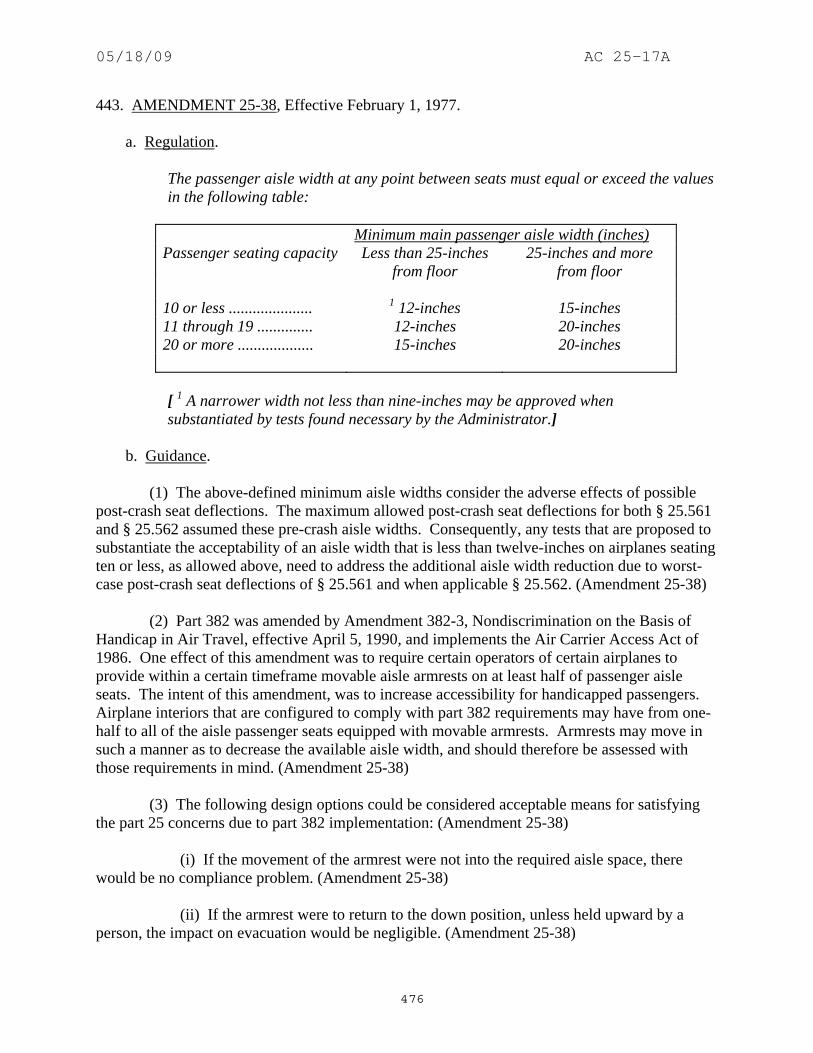
05/18/09 AC 25-17A
476
443. AMENDMENT 25-38, Effective February 1, 1977. a. Regulation.
The passenger aisle width at any point between seats must equal or exceed the values in the following table:
Minimum main passenger aisle width (inches) Passenger seating capacity Less than 25-inches
from floor 25-inches and more
from floor 10 or less ..................... 1 12-inches 15-inches 11 through 19 .............. 12-inches 20-inches 20 or more ................... 15-inches 20-inches
[ 1 A narrower width not less than nine-inches may be approved when substantiated by tests found necessary by the Administrator.]
b. Guidance. (1) The above-defined minimum aisle widths consider the adverse effects of possible post-crash seat deflections. The maximum allowed post-crash seat deflections for both § 25.561 and § 25.562 assumed these pre-crash aisle widths. Consequently, any tests that are proposed to substantiate the acceptability of an aisle width that is less than twelve-inches on airplanes seating ten or less, as allowed above, need to address the additional aisle width reduction due to worst-case post-crash seat deflections of § 25.561 and when applicable § 25.562. (Amendment 25-38) (2) Part 382 was amended by Amendment 382-3, Nondiscrimination on the Basis of Handicap in Air Travel, effective April 5, 1990, and implements the Air Carrier Access Act of 1986. One effect of this amendment was to require certain operators of certain airplanes to provide within a certain timeframe movable aisle armrests on at least half of passenger aisle seats. The intent of this amendment, was to increase accessibility for handicapped passengers. Airplane interiors that are configured to comply with part 382 requirements may have from one-half to all of the aisle passenger seats equipped with movable armrests. Armrests may move in such a manner as to decrease the available aisle width, and should therefore be assessed with those requirements in mind. (Amendment 25-38) (3) The following design options could be considered acceptable means for satisfying the part 25 concerns due to part 382 implementation: (Amendment 25-38) (i) If the movement of the armrest were not into the required aisle space, there would be no compliance problem. (Amendment 25-38) (ii) If the armrest were to return to the down position, unless held upward by a person, the impact on evacuation would be negligible. (Amendment 25-38)

05/18/09 AC 25-17A
477
(iii) The armrest could be removable (provided it was positively latched when installed). (Amendment 25-38) (iv) If the hinged armrest was normally fastened down, but had a discreetly located release that a flight attendant could operate in the event there was a need to accommodate a disabled passenger, the installation may be acceptable. (Amendment 25-38) (4) The passenger aisle width is the normal distance between opposite seats measured without occupants. The distance should be determined without compression of seat fabric or cushion and with the seats or other aisle constraints in the most adverse position, such as seats reclined or broken over. Unlike typical commercial aircraft, private use airplanes (i.e., not for hire, not for common carriage) have seats that can be moved during flight operations. The seating can be reconfigured to accommodate meetings and other arrangements. Some of these arrangements can reduce the aisle widths below those specified. This is acceptable only during en-route flight and only if clear instructions are provided requiring that the seats be positioned for taxi, takeoff and landing in an arrangement that meets the required aisle widths. The private use provision does not preclude the operator from receiving remuneration to the extent consistent with 14 CFR parts 125 and 91, subpart F, as applicable. (Amendment 25-0) (5) When the measurement is not between seats but between other aisle constraints such as galleys, coat closets, storage compartments, etc., the minimum widths at the specified vertical distance above the floor still prevails. Protuberances such as door knobs, latches, rails, etc., should be considered if they encroach into the specified aisle width. This measurement should be made using the vertical projection of any protuberance in its appropriate height zone (less than 25-inches from the floor or 25-inches and more from the floor). The effect of the protuberance on the evacuation of the airplane should be considered when determining if it may or may not protrude into the required aisle width. Curtains may protrude slightly into the required aisle, provided the curtain and its tie-back do not inhibit passage. (Amendment 25-0) (6) For staggered seat rows, or zigzag aisles, the aisle width distance may be considered as that measured perpendicular to the aisle pathway at any point along its full path. (Amendment 25-0) (7) Arm rests that swing up, such as those for handicapped persons, may encroach upon the 20-inch width in the up position. If so, the arm rest should automatically return to the down position or be appropriately placarded. (Amendment 25-0) (8) The main aisle widths, as defined by the regulation, should be maintained from floor level to a height of at least 73-inches above the floor (top of the floor covering). For airplanes that do not have 73-inches between the floor and the ceiling panels, the aisle width should be maintained from the floor to the height of the ceiling panels. Any features that hang (signs, video monitors etc.) from the ceiling or span across main aisle (i.e., class dividers and curtain headers) should be at least 73-inches above the floor, unless they are retractable and are placarded to be retracted for taxi, takeoff and landing (TT&L). For airplanes that do not have 73-inches between the floor and the ceiling panels any features that hang (signs, video monitors

05/18/09 AC 25-17A
478
etc.) from the ceiling should not be positioned in the main aisle. Alternate locations should be used, e.g., over seat, on the side wall etc. These features should also be appropriately padded or rounded to preclude injury when persons are moving about the cabin. (Amendment 25-0) 444 - 460. [RESERVED]

05/18/09 AC 25-17A
479
SECTION 25.817 MAXIMUM NUMBER OF SEATS ABREAST 461. Section 25.817 Did Not Exist Prior to Amendment 25-15. 462. AMENDMENT 25-15, Effective October 24, 1967. a. Regulation.
On airplanes having only one passenger aisle, no more than three seats abreast may be placed on each side of the aisle in any one row.
b. Guidance. On a twin-aisle airplane, a six-place seat assembly could be installed between the two aisles. (Amendment 25-15) 463 - 480. [RESERVED]

05/18/09 AC 25-17A
480
THIS PAGE INTENTIONALY LEFT BLANK

05/18/09 AC 25-17A
481
SECTION 25.819 LOWER DECK SERVICE COMPARTMENTS (INCLUDING GALLEYS) 481. Section 25.819 Did Not Exist Prior to Amendment 25-53. 482. AMENDMENT 25-53, Effective August 31, 1980. a. Regulation.
For airplanes with a service compartment located below the main deck, which may be occupied during taxi or flight but not during takeoff or landing, the following apply: (a) There must be at least two emergency evacuation routes, one at each end of lower deck service compartment, or two having sufficient separation within each compartment, which could be used by each occupant of the lower deck service compartment to rapidly evacuate to the main deck under normal and emergency lighting conditions. The routes must provide for the evacuation of incapacitated persons, with assistance. The use of the evacuation routes may not be dependent on any powered device. The routes must be designed to minimize the possibility of blockage which might result from fire, mechanical or structural failure, or persons standing on top of or against the escape routes. In the event the airplane's main power system or compartment main lighting system should fail, emergency illumination for each lower deck service compartment must be automatically provided. (b) There must be a means for two-way voice communication between the flight deck and each lower deck service compartment. (c) There must be an aural emergency alarm system, audible during normal and emergency conditions, to enable crewmembers on the flight deck and at each required floor level emergency exit to alert occupants of each lower deck service compartment of an emergency situation. (d) There must be a means, readily detectable by occupants of each lower deck service compartment, that indicates when seat belts should be fastened. (e) If a public address system is installed in the airplane, speakers must be provided in each lower deck service compartment. (f) For each occupant permitted in a lower deck service compartment, there must be a forward or aft facing seat which meets the requirements of § 25.785(c) and must be able to withstand maximum flight loads when occupied.
05/18/09 AC 25-17A
482
(g) For each powered lift system installed between a lower deck service compartment and the main deck for the carriage of persons or equipment, or both, the system must meet the following requirements: (l) Each lift control switch outside the lift, except emergency stop buttons, must be designed to prevent the activation of the lift if the lift door, or the hatch required by paragraph (g)(3) of this section, or both, are open. (2) An emergency stop button, that when activated will immediately stop the lift, must be installed within the lift and at each entrance to the lift. (3) There must be a hatch capable of being used for evacuating persons from the lift that is openable from inside and outside the lift without tools, with the lift in any position.
b. Guidance. (1) The following should be used for any installation regardless of certification basis: (Amendment 25-53) (i) The installation of a lower deck service compartment normally results in cart restraint locations on both the main and lower decks. At these locations, the carts are normally restrained by a fitting in the floor, commonly called a mushroom. There are two typical types of mushrooms. One is usually retractable, located in an aisle or passageway, and capable of restraining the cart for inflight load conditions only. The other mushroom is usually fixed, located in a galley, lift or cabinet, and generally capable of restraining the cart during taxi, takeoff and landing (TT&L). If necessary, control of the number of carts allowed on each deck should be provided. For the TT&L condition, there should be enough TT&L mushrooms for each cart on the airplane. In order to be assured the carts can be taken to such a mushroom, there should be at least two independently powered and controlled lifts between the main and lower decks. If there are not at least two such lifts, it should be demonstrated by actual test that all carts can be transported up or down between decks. It is acceptable to transport the contents and cart separately by average flight attendants. If two such lifts are not installed and transportablity is not demonstrated, at any given time, there should not be more carts on one deck than there are TT&L mushrooms. It will be acceptable to have adequate AFM limitations and/or placarding to assure the necessary level of safety. This guidance would be equally applicable if a galley or service compartment is located on a deck above the main deck. (Amendment 25-53) (ii) Remote compartments should have adequate ventilation and conditioned air for all occupants. If the compartment is one in which occupants are working, such as a galley, more than normal ventilation and conditioned air should be supplied than that for a compartment in which the occupants are seated. If carbon dioxide (dry ice) is used in a compartment, additional ventilation may be necessary to demonstrate compliance with § 25.831(b)(2) for all regimes of operation; such as at the gate, taxi, takeoff, climb, cruise, hold and descent. (Amendment 25-53)

05/18/09 AC 25-17A
483
(2) Paragraph (g)(l). Proximity or micro-switches are normally used to sense that the lift door or hatch is open or closed. These interlock switches should be located so that they cannot be easily or inadvertently overridden or deactivated. Special design considerations should be given to these switches to minimize the probability of them becoming damaged during normal use. (Amendment 25-53) (3) Paragraph (g)(2). The emergency stop buttons are of prime importance and should be given special design considerations. These buttons should have absolute and complete priority over any other control, failure or lack of control. No matter what condition, failure or sequence of events that have occurred, operation of any emergency stop button should result in stopping of the lift without the ability to override from any other location. (Amendment 25-53) 483. AMENDMENT 25-110, Effective July 21, 2003. a. Regulation.
For airplanes with a service compartment located below the main deck, which may be occupied during taxi or flight but not during takeoff or landing, the following apply: (a) There must be at least two emergency evacuation routes, one at each end of lower deck service compartment or two having sufficient separation within each compartment, which could be used by each occupant or the lower deck service compartment to rapidly evacuate to the main deck under normal and emergency lighting conditions. The routes must provide for the evacuation of incapacitated persons, with assistance. The use of the evacuation routes may not be dependent on any powered device. The routes must be designed to minimize the possibility of blockage which might result from fire, mechanical or structural failure, or persons standing on top of or against the escape routes. In the event the airplane's main power system or compartment main lighting system should fail, emergency illumination for each lower deck service compartment must be automatically provided. [(b) There must be a means for two-way voice communication between the flight deck and each lower deck service compartment, which remains available following loss of normal electrical power generating system.] (c) There must be an aural emergency alarm system, audible during normal and emergency conditions, to enable crewmembers on the flight deck and at each required floor level emergency conditions, to enable crewmembers on the flight deck and at each required floor level emergency exit to alert occupants of each lower deck service compartment of an emergency situation. (d) There must be a means, readily detectable by occupants of each lower deck service compartment, that indicates when seat belts should be fastened.

05/18/09 AC 25-17A
484
(e) If a public address system is installed in the airplane, speakers must be provided in each lower deck service compartment. [(f) For each occupant permitted in a lower deck service compartment, there must be a forward or aft facing seat which meets the requirements of § 25.785(d) and must be able to withstand maximum flight loads when occupied.] (g) For each powered lift system installed between a lower deck service compartment and the main deck for the carriage of persons or equipment, or both, the system must meet the following requirements: (1) Each lift control switch outside the lift, except emergency stop buttons, must be designed to prevent the activation of the lift if the lift door, or the hatch required by paragraph (g)(3) of this section, or both are open. (2) An emergency stop button, that when activated will immediately stop the lift, must be installed within the lift and at each entrance to the lift. (3) There must be a hatch capable of being used for evacuating persons from the lift that is openable from the inside and outside the lift without tools, with the lift in any position.
b. Guidance. (1) The following should be used for any installation regardless of certification basis: (Amendment 25-53) (i) The installation of a lower deck service compartment normally results in cart restraint locations on both the main and lower decks. At these locations, the carts are normally restrained by a fitting in the floor, commonly called a mushroom. There are two typical types of mushrooms. One is usually retractable, located in an aisle or passageway, and capable of restraining the cart for inflight load conditions only. The other mushroom is usually fixed, located in a galley, lift or cabinet, and generally capable of restraining the cart during taxi, takeoff and landing (TT&L). If necessary, control of the number of carts allowed on each deck should be provided. For the TT&L condition, there should be enough TT&L mushrooms for each cart on the airplane. In order to be assured the carts can be taken to such a mushroom, there should be at least two independently powered and controlled lifts between the main and lower decks. If there are not at least two such lifts, it should be demonstrated by actual test that all carts can be transported up or down between decks. It is acceptable to transport the contents and cart separately by average flight attendants. If two such lifts are not installed and transportablity is not demonstrated, at any given time, there should not be more carts on one deck than there are TT&L mushrooms. It will be acceptable to have adequate AFM limitations and/or placarding to assure the necessary level of safety. This guidance would be equally applicable if a galley or service compartment is located on a deck above the main deck. (Amendment 25-53)
05/18/09 AC 25-17A
485
(ii) Remote compartments should have adequate ventilation and conditioned air for all occupants. If the compartment is one in which occupants are working, such as a galley, more than normal ventilation and conditioned air should be supplied than that for a compartment in which the occupants are seated. If carbon dioxide (dry ice) is used in a compartment, additional ventilation may be necessary to demonstrate compliance with § 25.831(b)(2) for all regimes of operation; such as at the gate, taxi, takeoff, climb, cruise, hold and descent. (Amendment 25-53) (2) Paragraph (g)(l). Proximity or micro-switches are normally used to sense that the lift door or hatch is open or closed. These interlock switches should be located so that they cannot be easily or inadvertently overridden or deactivated. Special design considerations should be given to these switches to minimize the probability of them becoming damaged during normal use. (Amendment 25-53) (3) Paragraph (g)(2). The emergency stop buttons are of prime importance and should be given special design considerations. These buttons should have absolute and complete priority over any other control, failure or lack of control. No matter what condition, failure or sequence of events that have occurred, operation of any emergency stop button should result in stopping of the lift without the ability to override from any other location. (Amendment 25-53) 484 - 600. [RESERVED]

05/18/09 AC 25-17A
486
THIS PAGE INTENTIONALY LEFT BLANK

05/18/09 AC 25-17A
487
SECTION 25.851 FIRE EXTINGUISHERS 601. REGULATION IN EFFECT AT ADOPTION OF PART 25. a. Regulation.
(a) Hand fire extinguishers. For hand fire extinguishers the following apply: (l) Each hand fire extinguisher must be approved. (2) The types and quantities of each extinguishing agent used must be appropriate to the kinds of fires likely to occur where used. (3) Each extinguisher for use in a personnel compartment must be designed to minimize the hazard of toxic gas concentrations. (4) A readily accessible hand fire extinguisher must be available for use in each Class A or Class B cargo compartment. (b) Built-in fire extinguishers. If a built-in fire extinguishing system is required - (l) The capacity of each system, in relation to the volume of the compartment where used and the ventilation rate, must be adequate for any fire likely to occur in that compartment; and (2) Each system must be installed so that - (i) No extinguishing agent likely to enter personnel compartments will be hazardous to the occupants; and (ii) No discharge of the extinguisher can cause structural damage.
b. Guidance. (l) Paragraph (a)(1). Standards for approval. An approved type fire extinguisher includes those approved by the Underwriters' Laboratories, Inc., Factory Mutual Laboratories, Underwriters' Laboratories of Canada, or any other agency deemed qualified by the Administrator, or approved by the Administrator in accordance with the provisions of § 21.301. (Amendment 25-0) (2) Paragraphs (a)(2) and (a)(3). When selecting a hand held fire extinguisher for use in airplanes, consideration should be given to the most appropriate extinguishing agent for the type and location of fires likely to be encountered. At least one extinguisher appropriate for a Class A fire should be provided. Consideration should also be given to the extinguisher agent’s ratio of extinguishing ability to quantity required, toxicity, corrosive properties, freezing point, and to the

05/18/09 AC 25-17A
488
unit's gross weight, ease of operation, and maintenance requirements. Airplane hand held fire extinguishers using extinguisher agents having a rating in toxicity Group 4 or under should not be installed in airplanes for which an application for a type certificate was made on or after March 5, 1952. (Amendment 25-0) NOTE: The toxicity ratings listed by the Underwriters' Laboratories and the halon and freon number for some of the commonly known fire extinguisher chemicals are as follows: Group
Number Halon Number*
Freon Number
Bromochloromethane 3 1011 --- Bromotrifluoromethane 6 1301 13B1/FE1301 Carbon dioxide 5 --- --- Carbon tetrachloride 3 1040 --- Dibromodifluoromethane 4 1202 12B2 Methyl bromide 2 1001 --- * The halon number is defined as follows: the first number is the number of carbon atoms; the second, fluorine; the third, chlorine; and the fourth, bromine in the extinguisher agent’s chemical formula. Some older transport category airplanes, due to their type certification bases, are not required to comply with § 25.851. For such airplanes, it is recommended that hand held fire extinguishers employing agents in toxicity Group 4 or higher be installed when renewing or replacing hand held fire extinguishers employing toxic agents. (Amendment 25-0) (3) Paragraph (a)(2). Types of extinguishers. (Amendment 25-0) (i) Carbon dioxide extinguishers. Carbon dioxide extinguishers are acceptable when the principal hazard is a Class B or Class C fire. Portable carbon dioxide installations should not exceed five lbs of agent per unit to ensure extinguisher portability and to minimize crew compartment carbon dioxide (CO2) concentrations. (Amendment 25-0) (ii) Water extinguishers. Water extinguishers are acceptable when the principal hazard is a Class A fire and where a fire might smolder if attacked solely by such agents as CO2 or dry chemical. (Amendment 25-0) (iii) Vaporizing liquid extinguishers. Vaporizing liquid type fire extinguishers are acceptable when the principal hazard is a Class B or Class C fire. (Amendment 25-0) (iv) Dry chemical extinguishers. Dry chemical extinguishers are acceptable where the principal hazard is a Class B or Class C fire. The extinguisher should not be used in crew compartments because of interference with visibility during discharge and because of the possibility of the nonconductive powders being discharged on electrical contacts not otherwise involved. (Amendment 25-0)

05/18/09 AC 25-17A
489
(v) Specialized Dry Powder extinguishers for Class D fires. Solid materials in powder or granular form are designed to extinguish Class D combustible metal fires by crusting, smothering, or heat-transferring means. The recommendations of the manufacturer for use of those extinguishers should be followed because of the possible chemical reaction between the burning metal and the extinguishing agent. (Amendment 25-0) NOTE: Carbon dioxide is noncorrosive and will not injure food or fabric. Extinguishers must be winterized if they are to operate at temperatures below -40° F. Approved unit capacity ranges upwards from two lbs . These extinguishers have only limited value for the extinguishment of a Class A fire, the action of the agent being to blanket the fire by excluding oxygen. Certain antifreeze agents may be corrosive. Approved extinguishers are either protected against freezing to -40° F. or must be handled as any other unprotected water on the airplane. Technical Standard Order (TSO)-C19a covers a minimum l-3/8 quart capacity approved water extinguisher. Water extinguishers of the kinds currently on the market are not acceptable for flammable liquid or electrical fires. Vaporizing liquid extinguisher agents are not normally corrosive to airplane structure and approved units will be satisfactorily protected against freezing to at least -40° F. Up to the effective date of this guidance, no vaporizing liquid extinguisher with Underwriters' Laboratories toxicity rating higher than Group 4 is commercially available. Approved units have a minimum capacity of one quart. They are of only limited value for the extinguishment of Class A fires, having a cooling effect of about one-tenth that of water. When using dry chemical extinguishers the powder is nontoxic and noncorrosive, and approved units are protected against freezing to at least -40° F. Minimum capacity of approved units is two lbs . (4) Paragraph (a)(2). Class of fires. (Amendment 25-0) (i) Class A fires. Fires in ordinary combustible materials where the quenching and cooling effects of quantities of water, or solutions containing large percentages of water, are of first importance. (Amendment 25-0) (ii) Class B fires. Fires in flammable liquids, greases, etc., where a blanketing effect is essential. (Amendment 25-0) (iii) Class C fires. Fires in electrical equipment, where the use of a nonconducting extinguishing agent is of first importance. (Amendment 25-0) (iv) Class D fires. Fires which involve combustible metals, such as magnesium, titanium, zirconium, sodium, lithium, and potassium, and require extinguishing agents of the dry powder types. (Amendment 25-0) (5) Paragraphs (a)(2) and (a)(3). For further guidance, refer to National Fire Protection Association (NFPA) 10, "Standards for Portable Fire Extinguishers." (Amendment 25-0)

05/18/09 AC 25-17A
490
(6) Paragraph (a)(2). A fire extinguisher containing at least five (5) lbs of Halon 1211 may be used in lieu of a water extinguisher to combat Class A fires. Alternatively, two (2) fire extinguishers containing at least 2.5 lbs of Halon 1211 each, installed in close proximity to each other, may be substituted for one water fire extinguisher. In locations where one Halon and one water extinguisher are installed and replacement of the water extinguisher is desired, the above guidance will apply, however, the existing Halon extinguisher is not part of the substitution; i.e., three (3) 2.5 pound Halon extinguishers are equivalent to one (1) 2.5 pound Halon and one (1) water extinguisher. The resulting configuration from the replacement of a water fire extinguisher with Halon fire extinguishers must not result in unhealthy, toxic gas concentration. (Amendment 25-0) 602. AMENDMENT 25-54, Effective October 14, 1980. a. Regulation.
(a) Hand fire extinguishers. For hand fire extinguishers the following apply: (1) Each hand extinguisher must be approved. (2) The types and quantities of each extinguishing agent used must be appropriate to the kinds of fires likely to occur where used. (3) Each extinguisher for use in a personnel compartment must be designed to minimize the hazard of toxic gas concentrations. (4) A readily accessible hand fire extinguisher must be available for use in each Class A or Class B cargo compartment. [(5) There must be at least the following number of hand fire extinguishers conveniently located in passenger compartments:
Passenger capacity:
Minimum number of hand fire
extinguishers 7 through 30 1 31 through 60 2
61 or more 3
(6) There must be at least one hand fire extinguisher conveniently located in the pilot compartment.] (b) Built-in fire extinguishers. If a built-in fire extinguisher system is required- (1) The capacity of each system, in relation to the volume of the compartment where used and the ventilation rate, must be adequate for any fire likely to occur in that compartment; and

05/18/09 AC 25-17A
491
(2) Each system must be installed so that- (i) No extinguishing agent likely to enter personnel compartments will be hazardous to the occupants; and (ii) No discharge of the extinguisher can cause structural damage
b. Guidance. (l) Paragraph (a)(1). Standards for approval. An approved type fire extinguisher includes those approved by the Underwriters' Laboratories, Inc., Factory Mutual Laboratories, Underwriters' Laboratories of Canada, or any other agency deemed qualified by the Administrator, or approved by the Administrator in accordance with the provisions of § 21.301. (Amendment 25-0) (2) Paragraphs (a)(2) and (a)(3). When selecting a hand held fire extinguisher for use in airplanes, consideration should be given to the most appropriate extinguishing agent for the type and location of fires likely to be encountered. At least one extinguisher appropriate for a Class A fire should be provided. Consideration should also be given to the extinguisher agent’s ratio of extinguishing ability to quantity required, toxicity, corrosive properties, freezing point, and to the unit's gross weight, ease of operation, and maintenance requirements. Airplane hand held fire extinguishers using extinguisher agents having a rating in toxicity Group 4 or under should not be installed in airplanes for which an application for a type certificate was made on or after March 5, 1952. (Amendment 25-0) NOTE: The toxicity ratings listed by the Underwriters' Laboratories and the halon and freon number for some of the commonly known fire extinguisher chemicals are as follows: Group
Number Halon Number*
Freon Number
Bromochloromethane 3 1011 --- Bromotrifluoromethane 6 1301 13B1/FE1301 Carbon dioxide 5 --- --- Carbon tetrachloride 3 1040 --- Dibromodifluoromethane 4 1202 12B2 Methyl bromide 2 1001 --- * The halon number is defined as follows: the first number is the number of carbon atoms; the second, fluorine; the third, chlorine; and the fourth, bromine in the extinguisher agent’s chemical formula. Some older transport category airplanes, due to their type certification bases, are not required to comply with § 25.851. For such airplanes, it is recommended that hand held fire extinguishers

05/18/09 AC 25-17A
492
employing agents in toxicity Group 4 or higher be installed when renewing or replacing hand held fire extinguishers employing toxic agents. (Amendment 25-0) (3) Paragraph (a)(2). Types of extinguishers. (Amendment 25-0) (i) Carbon dioxide extinguishers. Carbon dioxide extinguishers are acceptable when the principal hazard is a Class B or Class C fire. Portable carbon dioxide installations should not exceed five lbs of agent per unit to ensure extinguisher portability and to minimize crew compartment carbon dioxide (CO2) concentrations. (Amendment 25-0) (ii) Water extinguishers. Water extinguishers are acceptable when the principal hazard is a Class A fire and where a fire might smolder if attacked solely by such agents as CO2 or dry chemical. (Amendment 25-0) (iii) Vaporizing liquid extinguishers. Vaporizing liquid type fire extinguishers are acceptable when the principal hazard is a Class B or Class C fire. (Amendment 25-0) (iv) Dry chemical extinguishers. Dry chemical extinguishers are acceptable where the principal hazard is a Class B or Class C fire. The extinguisher should not be used in crew compartments because of interference with visibility during discharge and because of the possibility of the nonconductive powders being discharged on electrical contacts not otherwise involved. (Amendment 25-0) (v) Specialized Dry Powder extinguishers for Class D fires. Solid materials in powder or granular form are designed to extinguish Class D combustible metal fires by crusting, smothering, or heat-transferring means. The recommendations of the manufacturer for use of those extinguishers should be followed because of the possible chemical reaction between the burning metal and the extinguishing agent. (Amendment 25-0) NOTE: Carbon dioxide is noncorrosive and will not injure food or fabric. Extinguishers must be winterized if they are to operate at temperatures below -40° F. Approved unit capacity ranges upwards from two lbs . These extinguishers have only limited value for the extinguishment of a Class A fire, the action of the agent being to blanket the fire by excluding oxygen. Certain antifreeze agents may be corrosive. Approved extinguishers are either protected against freezing to -40° F. or must be handled as any other unprotected water on the airplane. Technical Standard Order (TSO)-C19a covers a minimum l-3/8 quart capacity approved water extinguisher. Water extinguishers of the kinds currently on the market are not acceptable for flammable liquid or electrical fires. Vaporizing liquid extinguisher agents are not normally corrosive to airplane structure and approved units will be satisfactorily protected against freezing to at least -40° F. Up to the effective date of this guidance, no vaporizing liquid extinguisher with Underwriters' Laboratories toxicity rating higher than Group 4 is commercially available. Approved units have a minimum capacity of one quart. They are of only limited value for the extinguishment of Class A fires, having a cooling effect of about one-tenth that of water. When using dry chemical extinguishers

05/18/09 AC 25-17A
493
the powder is nontoxic and noncorrosive, and approved units are protected against freezing to at least -40° F. Minimum capacity of approved units is two lbs . (4) Paragraph (a)(2). Class of fires. (Amendment 25-0) (i) Class A fires. Fires in ordinary combustible materials where the quenching and cooling effects of quantities of water, or solutions containing large percentages of water, are of first importance. (Amendment 25-0) (ii) Class B fires. Fires in flammable liquids, greases, etc., where a blanketing effect is essential. (Amendment 25-0) (iii) Class C fires. Fires in electrical equipment, where the use of a nonconducting extinguishing agent is of first importance. (Amendment 25-0) (iv) Class D fires. Fires which involve combustible metals, such as magnesium, titanium, zirconium, sodium, lithium, and potassium, and require extinguishing agents of the dry powder types. (Amendment 25-0) (5) Paragraphs (a)(2) and (a)(3). For further guidance, refer to National Fire Protection Association (NFPA) 10, "Standards for Portable Fire Extinguishers." (Amendment 25-0) (6) Paragraph (a)(2). A fire extinguisher containing at least five (5) lbs of Halon 1211 may be used in lieu of a water extinguisher to combat Class A fires. Alternatively, two (2) fire extinguishers containing at least 2.5 lbs of Halon 1211 each, installed in close proximity to each other, may be substituted for one water fire extinguisher. In locations where one Halon and one water extinguisher are installed and replacement of the water extinguisher is desired, the above guidance will apply, however, the existing Halon extinguisher is not part of the substitution; i.e., three (3) 2.5 pound Halon extinguishers are equivalent to one (1) 2.5 pound Halon and one (1) water extinguisher. The resulting configuration from the replacement of a water fire extinguisher with Halon fire extinguishers must not result in unhealthy, toxic gas concentration. (Amendment 25-0) (7) Paragraph (a)(5). The quantities of extinguishers noted above are the absolute minimum permitted. Virtually all airplanes with 61 or more passengers will require additional extinguishers due to interior amenities (galleys, lavatories etc.) and division of cabins. Refer to AC 20-42C, “Hand Fire Extinguishers for Use in Aircraft,” dated 3/7/84, for guidance on acceptable fire extinguishers. (Amendment 25-54) 603. AMENDMENT 25-72, Effective August 20, 1990. a. Regulation.
(a) Hand fire extinguishers.

05/18/09 AC 25-17A
494
[(1) The following minimum number of hand fire extinguishers must be conveniently located in passenger compartments:
Passenger capacity:
Minimum number of hand fire
extinguishers 7 through 30 1 31 through 60 2
61 or more 3
(2) At least one hand fire extinguisher must be conveniently located in the pilot compartment. (3) A readily accessible hand fire extinguisher must be available for use in each Class A or Class B cargo compartment. (4) Each hand fire extinguisher must be approved. (5) The types and quantities of each extinguishing agent used must be appropriate to the kinds of fires likely to occur where used. (6) Each extinguisher for use in a personnel compartment must be designed to minimize the hazard of toxic gas concentration. (b) Built-in fire extinguishers. If a built-in fire extinguisher is provided- (1) The capacity must be adequate for any fire likely to occur in the compartment where used, considering the volume of the compartment and the ventilation rate; and,] (2) Each system must be installed so that- (i) No extinguishing agent likely to enter personnel compartments will be hazardous to the occupants; and (ii) No discharge of the extinguisher can cause structural damage.
b. Guidance. (l) Paragraph (a)(1). Standards for approval. An approved type fire extinguisher includes those approved by the Underwriters' Laboratories, Inc., Factory Mutual Laboratories, Underwriters' Laboratories of Canada, or any other agency deemed qualified by the Administrator, or approved by the Administrator in accordance with the provisions of § 21.301. (Amendment 25-0)

05/18/09 AC 25-17A
495
(2) Paragraph (a)(1). The quantities of extinguishers noted above are the absolute minimum permitted. Virtually all airplanes with 61 or more passengers will require additional extinguishers due to interior amenities (galleys, lavatories etc.) and division of cabins. Refer to AC 20-42C, “Hand Fire Extinguishers for Use in Aircraft,” dated 3/7/84, for guidance on acceptable fire extinguishers. (Amendment 25-54) (3) Paragraph (a)(5) and (a)(3). For further guidance, refer to National Fire Protection Association (NFPA) 10, "Standards for Portable Fire Extinguishers." (Amendment 25-0) (4) Paragraph (a)(5). When selecting a hand held fire extinguisher for use in airplanes, consideration should be given to the most appropriate extinguishing agent for the type and location of fires likely to be encountered. At least one extinguisher appropriate for a Class A fire should be provided. Consideration should also be given to the extinguisher agent’s ratio of extinguishing ability to quantity required, toxicity, corrosive properties, freezing point, and to the unit's gross weight, ease of operation, and maintenance requirements. Airplane hand held fire extinguishers using extinguisher agents having a rating in toxicity Group 4 or under should not be installed in airplanes for which an application for a type certificate was made on or after March 5, 1952. (Amendment 25-0) NOTE: The toxicity ratings listed by the Underwriters' Laboratories and the halon and freon number for some of the commonly known fire extinguisher chemicals are as follows: Group
Number Halon Number*
Freon Number
Bromochloromethane 3 1011 --- Bromotrifluoromethane 6 1301 13B1/FE1301 Carbon dioxide 5 --- --- Carbon tetrachloride 3 1040 --- Dibromodifluoromethane 4 1202 12B2 Methyl bromide 2 1001 --- * The halon number is defined as follows: the first number is the number of carbon atoms; the second, fluorine; the third, chlorine; and the fourth, bromine in the extinguisher agent’s chemical formula. Some older transport category airplanes, due to their type certification bases, are not required to comply with § 25.851. For such airplanes, it is recommended that hand held fire extinguishers employing agents in toxicity Group 4 or higher be installed when renewing or replacing hand held fire extinguishers employing toxic agents. (Amendment 25-0) (5) Paragraph (a)(5). Types of extinguishers. (Amendment 25-0) (i) Carbon dioxide extinguishers. Carbon dioxide extinguishers are acceptable when the principal hazard is a Class B or Class C fire. Portable carbon dioxide installations

05/18/09 AC 25-17A
496
should not exceed five lbs of agent per unit to ensure extinguisher portability and to minimize crew compartment carbon dioxide (CO2) concentrations. (Amendment 25-0) (ii) Water extinguishers. Water extinguishers are acceptable when the principal hazard is a Class A fire and where a fire might smolder if attacked solely by such agents as CO2 or dry chemical. (Amendment 25-0) (iii) Vaporizing liquid extinguishers. Vaporizing liquid type fire extinguishers are acceptable when the principal hazard is a Class B or Class C fire. (Amendment 25-0) (iv) Dry chemical extinguishers. Dry chemical extinguishers are acceptable where the principal hazard is a Class B or Class C fire. The extinguisher should not be used in crew compartments because of interference with visibility during discharge and because of the possibility of the nonconductive powders being discharged on electrical contacts not otherwise involved. (Amendment 25-0) (v) Specialized Dry Powder extinguishers for Class D fires. Solid materials in powder or granular form are designed to extinguish Class D combustible metal fires by crusting, smothering, or heat-transferring means. The recommendations of the manufacturer for use of those extinguishers should be followed because of the possible chemical reaction between the burning metal and the extinguishing agent. (Amendment 25-0) NOTE: Carbon dioxide is noncorrosive and will not injure food or fabric. Extinguishers must be winterized if they are to operate at temperatures below -40° F. Approved unit capacity ranges upwards from two lbs . These extinguishers have only limited value for the extinguishment of a Class A fire, the action of the agent being to blanket the fire by excluding oxygen. Certain antifreeze agents may be corrosive. Approved extinguishers are either protected against freezing to -40° F. or must be handled as any other unprotected water on the airplane. Technical Standard Order (TSO)-C19a covers a minimum l-3/8 quart capacity approved water extinguisher. Water extinguishers of the kinds currently on the market are not acceptable for flammable liquid or electrical fires. Vaporizing liquid extinguisher agents are not normally corrosive to airplane structure and approved units will be satisfactorily protected against freezing to at least -40° F. Up to the effective date of this guidance, no vaporizing liquid extinguisher with Underwriters' Laboratories toxicity rating higher than Group 4 is commercially available. Approved units have a minimum capacity of one quart. They are of only limited value for the extinguishment of Class A fires, having a cooling effect of about one-tenth that of water. When using dry chemical extinguishers the powder is nontoxic and noncorrosive, and approved units are protected against freezing to at least -40° F. Minimum capacity of approved units is two lbs . (6) Paragraph (a)(5). Class of fires. (Amendment 25-0) (i) Class A fires. Fires in ordinary combustible materials where the quenching and cooling effects of quantities of water, or solutions containing large percentages of water, are of first importance. (Amendment 25-0)

05/18/09 AC 25-17A
497
(ii) Class B fires. Fires in flammable liquids, greases, etc., where a blanketing effect is essential. (Amendment 25-0) (iii) Class C fires. Fires in electrical equipment, where the use of a nonconducting extinguishing agent is of first importance. (Amendment 25-0) (iv) Class D fires. Fires which involve combustible metals, such as magnesium, titanium, zirconium, sodium, lithium, and potassium, and require extinguishing agents of the dry powder types. (Amendment 25-0) (7) Paragraph (a)(5). A fire extinguisher containing at least five (5) lbs of Halon 1211 may be used in lieu of a water extinguisher to combat Class A fires. Alternatively, two (2) fire extinguishers containing at least 2.5 lbs of Halon 1211 each, installed in close proximity to each other, may be substituted for one water fire extinguisher. In locations where one Halon and one water extinguisher are installed and replacement of the water extinguisher is desired, the above guidance will apply, however, the existing Halon extinguisher is not part of the substitution; i.e., three (3) 2.5 pound Halon extinguishers are equivalent to one (1) 2.5 pound Halon and one (1) water extinguisher. The resulting configuration from the replacement of a water fire extinguisher with Halon fire extinguishers must not result in unhealthy, toxic gas concentration. (Amendment 25-0) 604. AMENDMENT 25-74, Effective May 16, 1991. a. Regulation.
(a) Hand fire extinguishers. [(1) The following minimum number of hand fire extinguishers must be conveniently located and evenly distributed in passenger compartments:
Passenger Capacity
Number of
Extinguishers 7 through 30 1 31 through 60 2 61 through 200 201 through 300 301 through 400 401 through 500 501 through 600 601 through 700
3 4 5 6 7 8

05/18/09 AC 25-17A
498
(2) At least one hand fire extinguisher must be conveniently located in the pilot compartment. (3) At least one readily accessible hand fire extinguisher must be available for use in each Class A or Class B cargo or baggage compartment and in each Class E cargo or baggage compartment that is accessible to crewmembers in flight. (4) At least one hand fire extinguisher must be located in, or readily accessible for use in, each galley located above or below the passenger compartment. (5) Each hand fire extinguisher must be approved. (6) At least one of the required fire extinguishers located in the passenger compartment of an airplane with a passenger capacity of at least 31 and not more than 60, and at least two of the fire extinguishers located in the passenger compartment of an airplane with a passenger capacity of 61 or more must contain Halon 1211 (bromochlorodifluromethane CBrC1F2), or equivalent, as the extinguishing agent. The type of extinguishing agent used in any other extinguisher required by the section must be appropriate for the kinds of fires likely to occur where used. (7) The quantity of extinguishing agent used in each extinguisher required by this section must be appropriate for the kinds of fires likely to occur where used. (8) Each extinguisher intended for use in a personnel compartment must be designed to minimize the hazard of toxic gas concentration. (b) Built-in fire extinguishers. If a built-in fire extinguisher is provided- (1) Each built-in fire extinguishing system must be installed so that- (i) No extinguishing agent likely to enter personnel compartments will be hazardous to the occupants; and (ii) No discharge of the extinguisher can cause structural damage. (2) The capacity of each required built-in extinguishing system must be adequate for any fire likely to occur in the compartment where used, considering the volume of the compartment and the ventilation rate.]
b. Guidance. (l) Standards for approval. An approved type fire extinguisher includes those approved by the Underwriters' Laboratories, Inc., Factory Mutual Laboratories, Underwriters' Laboratories of Canada, or any other agency deemed qualified by the Administrator, or approved by the Administrator in accordance with the provisions of § 21.301. (Amendment 25-0)

05/18/09 AC 25-17A
499
(2) For further guidance, refer to National Fire Protection Association (NFPA) 10, "Standards for Portable Fire Extinguishers." (Amendment 25-0) (3) Paragraph (a)(1). The quantities of extinguishers noted above are the absolute minimum permitted. Virtually all airplanes with 61 or more passengers will require additional extinguishers due to interior amenities (galleys, lavatories etc.) and division of cabins. Refer to AC 20-42C, “Hand Fire Extinguishers for Use in Aircraft,” dated 3/7/84, for guidance on acceptable fire extinguishers. (Amendment 25-54) (4) Paragraph (a)(6). When selecting a hand held fire extinguisher for use in airplanes, consideration should be given to the most appropriate extinguishing agent for the type and location of fires likely to be encountered. At least one extinguisher appropriate for a Class A fire should be provided. Consideration should also be given to the extinguisher agent’s ratio of extinguishing ability to quantity required, toxicity, corrosive properties, freezing point, and to the unit's gross weight, ease of operation, and maintenance requirements. Airplane hand held fire extinguishers using extinguisher agents having a rating in toxicity Group 4 or under should not be installed in airplanes for which an application for a type certificate was made on or after March 5, 1952. (Amendment 25-0) NOTE: The toxicity ratings listed by the Underwriters' Laboratories and the halon and freon number for some of the commonly known fire extinguisher chemicals are as follows: Group
Number Halon Number*
Freon Number
Bromochloromethane 3 1011 --- Bromotrifluoromethane 6 1301 13B1/FE1301 Carbon dioxide 5 --- --- Carbon tetrachloride 3 1040 --- Dibromodifluoromethane 4 1202 12B2 Methyl bromide 2 1001 --- * The halon number is defined as follows: the first number is the number of carbon atoms; the second, fluorine; the third, chlorine; and the fourth, bromine in the extinguisher agent’s chemical formula. Some older transport category airplanes, due to their type certification bases, are not required to comply with § 25.851. For such airplanes, it is recommended that hand held fire extinguishers employing agents in toxicity Group 4 or higher be installed when renewing or replacing hand held fire extinguishers employing toxic agents. (Amendment 25-0) (5) Paragraph (a)(6). Types of extinguishers. (Amendment 25-0) (i) Carbon dioxide extinguishers. Carbon dioxide extinguishers are acceptable when the principal hazard is a Class B or Class C fire. Portable carbon dioxide installations

05/18/09 AC 25-17A
500
should not exceed five lbs of agent per unit to ensure extinguisher portability and to minimize crew compartment carbon dioxide (CO2) concentrations. (Amendment 25-0) (ii) Water extinguishers. Water extinguishers are acceptable when the principal hazard is a Class A fire and where a fire might smolder if attacked solely by such agents as CO2 or dry chemical. (Amendment 25-0) (iii) Vaporizing liquid extinguishers. Vaporizing liquid type fire extinguishers are acceptable when the principal hazard is a Class B or Class C fire. (Amendment 25-0) (iv) Dry chemical extinguishers. Dry chemical extinguishers are acceptable where the principal hazard is a Class B or Class C fire. The extinguisher should not be used in crew compartments because of interference with visibility during discharge and because of the possibility of the nonconductive powders being discharged on electrical contacts not otherwise involved. (Amendment 25-0) (v) Specialized Dry Powder extinguishers for Class D fires. Solid materials in powder or granular form are designed to extinguish Class D combustible metal fires by crusting, smothering, or heat-transferring means. The recommendations of the manufacturer for use of those extinguishers should be followed because of the possible chemical reaction between the burning metal and the extinguishing agent. (Amendment 25-0) NOTE: Carbon dioxide is noncorrosive and will not injure food or fabric. Extinguishers must be winterized if they are to operate at temperatures below -40° F. Approved unit capacity ranges upwards from two lbs . These extinguishers have only limited value for the extinguishment of a Class A fire, the action of the agent being to blanket the fire by excluding oxygen. Certain antifreeze agents may be corrosive. Approved extinguishers are either protected against freezing to -40° F. or must be handled as any other unprotected water on the airplane. Technical Standard Order (TSO)-C19a covers a minimum l-3/8 quart capacity approved water extinguisher. Water extinguishers of the kinds currently on the market are not acceptable for flammable liquid or electrical fires. Vaporizing liquid extinguisher agents are not normally corrosive to airplane structure and approved units will be satisfactorily protected against freezing to at least -40° F. Up to the effective date of this guidance, no vaporizing liquid extinguisher with Underwriters' Laboratories toxicity rating higher than Group 4 is commercially available. Approved units have a minimum capacity of one quart. They are of only limited value for the extinguishment of Class A fires, having a cooling effect of about one-tenth that of water. When using dry chemical extinguishers the powder is nontoxic and noncorrosive, and approved units are protected against freezing to at least -40° F. Minimum capacity of approved units is two lbs . (6) Paragraph (a)(7). Class of fires. (Amendment 25-0) (i) Class A fires. Fires in ordinary combustible materials where the quenching and cooling effects of quantities of water, or solutions containing large percentages of water, are of first importance. (Amendment 25-0)

05/18/09 AC 25-17A
501
(ii) Class B fires. Fires in flammable liquids, greases, etc., where a blanketing effect is essential. (Amendment 25-0) (iii) Class C fires. Fires in electrical equipment, where the use of a nonconducting extinguishing agent is of first importance. (Amendment 25-0) (7) Paragraph (a)(7). A fire extinguisher containing at least five (5) lbs of Halon 1211 may be used in lieu of a water extinguisher to combat Class A fires. Alternatively, two (2) fire extinguishers containing at least 2.5 lbs of Halon 1211 each, installed in close proximity to each other, may be substituted for one water fire extinguisher. In locations where one Halon and one water extinguisher are installed and replacement of the water extinguisher is desired, the above guidance will apply, however, the existing Halon extinguisher is not part of the substitution; i.e., three (3) 2.5 pound Halon extinguishers are equivalent to one (1) 2.5 pound Halon and one (1) water extinguisher. The resulting configuration from the replacement of a water fire extinguisher with Halon fire extinguishers must not result in unhealthy, toxic gas concentration. (Amendment 25-0) 605-620. [RESERVED]

05/18/09 AC 25-17A
502
THIS PAGE INTENTIONALY LEFT BLANK

05/18/09 AC 25-17A
503
SECTION 25.853 COMPARTMENT INTERIORS 621. REGULATION IN EFFECT AT ADOPTION OF PART 25. a. Regulation.
For each compartment to be used by the crew or passengers -
(a) The materials must be at least flash-resistant; (b) The wall and ceiling linings, and the covering of upholstery, floors, and furnishings must be at least flame resistant; (c) Each compartment where smoking is to be allowed must have self-contained, removable ash trays, and each other compartment must be placarded against smoking; (d) Each receptacle for towels, paper, or waste must be at least fire resistant and must have means for containing possible fires; (e) There must be at least one hand fire extinguisher for use by the flight crewmembers; and (f) There must be at least the following number of hand fire extinguishers conveniently located in passenger compartments:
Passenger capacity:
Minimum number of hand fire
extinguishers 7 through 30 1 31 through 60 2
61 or more 3 b. Guidance. (l) Certification by a material manufacturer/supplier, commonly called “certs,” that a material complies with the flammability requirements of § 25.853 does not satisfy FAA rules. All flammability tests to demonstrate compliance should be witnessed by the FAA or its representatives. Refer to § 25.1359(d) for guidance relative to wiring. (Amendment 25-0) (2) Paragraphs (a) and (b). Definitions and procedures for conducting tests were contained in Flight Standards Service Release (FSSR) No. 453. This FSSR was canceled by AC 00-20, “Cancellation of Flight Standards Service Releases,” effective 9/7/66, but the FSSR was never replaced by an AC. The following was derived from FSSR 453, and still should be used for those airplanes whose certification bases included it: (Amendment 25-0)

05/18/09 AC 25-17A
504
Fire Prevention Test Procedure for Aircraft Materials
Fireproof Materials 1. The following test is considered acceptable for demonstrating compliance
with §§ 27.861 and 29.861 (CAR §§ 6.384 and 7.384), with respect to those portions which refer to fireproof materials. All structure, controls, rotor mechanism, and other parts essential to a controlled landing should be capable of resisting flame penetration and remain capable of carrying the loads and satisfactorily performing the function for which they are designed when subject to a test flame of 2000 + 50° F. flame for l5 minutes.
a. Sheet materials should be tested by subjecting the test flame to a test
specimen of approximately l0-inches square. The test flame should be applied at the center of the specimen and be of sufficient size to maintain the required temperature over an area approximately five-inches square.
b. Lines, fittings, controls, and other essential components should be
enveloped in the test flame on the side that would be exposed in case of a fire when mounted in a manner simulating their actual installation. In the case of fluid fittings, lines or conduits should be connected to both sides of the fittings to simulate actual conditions of heat conduction that would be present during an actual fire in the aircraft. The test should be conducted with the operating fluid in the lines unless the design and function of the system is such as to preclude the presence of the fluid in the lines during an actual fire in the aircraft.
Fire-Resistant Materials
2. The following test is considered acceptable for demonstrating
compliance with §§ 25.853, 25.857and (CAR §§ 4b.381, 4b.383, 6.382, 7.38l, and 7.382).
a. If the material is rigid, an eight-inch specimen should be tested. If the material is flexible, the material should be placed in a frame exposing an area of eight-inches by eight-inches. If a backing will be used in the airplane, the test specimen should be provided with the same backing.
b. The test specimen should be supported at an angle of 45 degrees to a horizontal surface. The surface that will be exposed, when installed in the aircraft, should face down for the test. The specimen should be exposed to either a Bunsen or a Tirrill burner adjusted for no air intake, giving a yellow-tipped l-l/2-inch flame when resting on a horizontal surface. Suitable precautions should be taken to avoid drafts. The period of flame application should be 30 seconds with one-third of the flame in contact with the material at the center of the specimen.
c. To be acceptable, no penetration of the material should result during application of the test flame or subsequent to its removal, and if the material ignites,

05/18/09 AC 25-17A
505
the flame should extinguish itself within l5 seconds with no smoldering or glowing visible l0 seconds thereafter.
Flame Resistant Material
3. The following test is considered acceptable for demonstrating
compliance with §§ 23.853, 25.853, 25.855and (CAR §§ 3.388(a), 4b.38l, 4b.382, 6.38l, 6.382, and 7.38l).
a. Test specimens. Three specimens, approximately four-inches wide and l4-inches long, should be tested. Each specimen should be clamped in a metal frame so that the two long edges and one end are held securely. The frame should be such that the exposed area of the specimen is at least two-inches wide and l3-inches long, with the free end at least l/2-inch from the end of frame for ignition purposes. In the case of fabrics, the direction of the weave corresponding to the most critical burn rate should be parallel to the l4-inch dimension. A minimum of l0-inches of the specimen should be used for timing purposes and approximately l-l/2-inches should burn before the burning front reaches the timing zone. The specimen should be long enough so that the timing is stopped at least one-inch before the burning front reaches the end of the exposed specimen.
b. Test procedure. The specimens should be supported horizontally and tested in draft-free conditions. The surface that will be exposed when installed in the aircraft, should face down for the test. The specimens should be ignited by a Bunsen or Tirrill burner. To be acceptable, the average burn rate of the three specimens must not exceed four-inches per minute. Alternatively, if the specimens do not support combustion after the ignition flame is applied for l5 seconds, or if the flame extinguishes itself and subsequent burning without a flame does not extend into the undamaged areas, the material is also acceptable. (Federal Specification CCC-T-191b, Method 5906, may also be used for testing materials of this type, but the material should not exceed the above four-inches per minute burn rate.)
Flash-Resistant Materials
4. The following test is considered acceptable for demonstrating compliance with §§ 23.853, 25.853 and CAR §§ 3.388(a), 4b.38l, 6.38l, and 7.38l.
a. Test specimens. Three specimens, approximately 4-inches wide by l4-inches long, should be tested. Each specimen should be clamped in a metal frame so that the two long edges and one end are held securely. The frame should be such that the exposed area of the specimen is at least two-inches wide and l3-inches long, with the free end at least l/2-inch from the end of the frame for ignition purposes. In the case of fabrics, the direction of the weave corresponding to the most critical burn rate should be parallel to the l4-inch dimension. A minimum of l0-inches of the specimen should be used for timing purposes, and approximately l-l/2-inches should

05/18/09 AC 25-17A
506
burn before the burning front reaches the timing zone. The timing should be stopped at least one-inch before the burning front reaches the end of the exposed specimen.
b. Test procedure. Each of the three specimens should be supported horizontally and tested in draft-free conditions. The surface that will be exposed, when installed in the aircraft, should face down for the test. The specimens may be ignited by a match or similar means. If the specimens do not support combustion after the ignition flame is applied for l5 seconds, or if the average burn rate of the three specimens does not exceed 20-inches per minute, the material is acceptable. (Federal Specification CCC-T-l9lb, Method 5906, may also be used for testing materials of this type but the material should not exceed the above 20-inches per minute burn rate.)
(3) Paragraph (a) and (b). The use of fire/flame retardants is acceptable. The type data should specify the retardant and process for treatment. Treatment should be applied prior to conditioning. The effects of aging and environmental conditions should be considered in the use of retardants. If aging, dry cleaning, washing, etc., adversely affect retardant properties, appropriate documents such as the maintenance manual should address this issue. (Amendment 25-0) (4) Paragraph (b). Oxygen lines for certification basis through Amendment 25-3l and oxygen masks should meet flame resistant criteria. Systems are to be tested in their normal state (which includes lines filled with oxygen, if that is the case; Refer to paragraph 625b(8) of this AC). Oxygen distribution systems, normally pressurized, are aluminum for low pressure (500 pounds per-inch (psi) or less) and stainless steel for high pressure (above 500 psi). Aluminum is classed as "fire resistant" and stainless steel as "fireproof" in 14 CFR, part 1, § l.l. These materials are normally not tested to § 25.853 due to their definition, although the authority of that regulation does allow it. (Amendment 25-0) 5) Paragraph (c). Self-contained is defined as a receptacle within a receptacle, one of which has a lid. Both receptacles are considered trash containers and should meet fire-resistant criteria as defined in 14 CFR, part 1, § l.l and in the preceding guidance in paragraph 621b(2) of this AC. The fixed receptacle should be sealed to prevent penetration of fire or residue into the surrounding area. Ashtrays installed in movable or removable armrests which will spill their contents when the armrest is moved or raised, as in the case of hinged armrests, are not considered self-contained. (Amendment 25-0) (6) Paragraph (c). (Amendment 25-0) (i) In order to avoid confusion in compartments where it is intended that smoking is not to be permitted, and No Smoking placards are installed, the lighted No Smoking signs should either be disabled or, preferably, hardwired ON. (Amendment 25-0) (ii) Hardwired ON lighted No Smoking signs have been considered to be equivalent, and even preferred, alternatives to required No Smoking placards in compartments where smoking is not to be permitted. (Amendment 25-0)

05/18/09 AC 25-17A
507
(iii) In divided compartments where smoking is permitted in one compartment but not in an adjacent one, especially where the no-smoking compartment is aft of the smoking compartment, care needs to be exercised in the placement and design of placarding and/or No Smoking lighted signs to assure no confusion exists. The smoking compartment should be controlled by lighted No Smoking signs controlled by the crew. Passengers in the no-smoking compartment should not be able to Refer to the lighted No Smoking signs in the smoking compartment when switched off. All lighted No Smoking signs visible to passengers in the no-smoking compartment should be hard-wired ON. No Smoking placards may also be installed in the no-smoking compartment, but they are considered insufficient, by themselves, to override the confusing effect of switchable No Smoking signs visible to them. (Amendment 25-0) (iv) In compartments where smoking is not allowed, it may be necessary to hardwire ON any lighted NO SMOKING signs to avoid confusing occupants. Note: this may affect an operator’s ability to comply with § 121.317(a). The FAA issued a policy memorandum ANM-03-115-05, dated July 7, 2003, titled “Policy Statement and Equivalent Safety Finding on No Smoking Placards and Signs” that addresses this subject. (Amendment 25-0) (7) Paragraph (d). Waste receptacles may be mounted in the airplane structure or may be portable units such as food or waste carts. Fire containment testing is not required for special purpose disposal receptacles (for such items as used air sickness bags and sanitary napkins), which are in addition to the normal waste disposal receptacles found in lavatories. The reasons for not requiring the testing is that these receptacles are typically very small, less than half a cubic foot in volume, and that they contain specific waste which are of a relatively non-flammable nature. Appendix 8 contains methodology for substantiating compliance with fire containment criteria. (Amendment 25-0) 8) Paragraph (e) and (f). Refer to AC 20-42C, “Hand Fire Extinguishers for Use in Aircraft,” dated 3/7/84, for guidance on acceptable fire extinguishers. (Amendment 25-0) (9) Note: The FAA Memorandum 00-115-16, dated September 12, 2000, titled, “Use of the Aircraft Fire Test Handbook” provides guidance for the use of the Report # DOT/FAA/CT-99/15 titled, “Aircraft Fire Test Handbook” that may be used to show compliance with, or demonstrate an equivalent level of safety to, the applicable regulations. The test methods described in the handbook are intended to be adopted in total, if they are used. That is, use of a portion of a test method from the handbook, and another portion of the test method from Appendix F, is not automatically acceptable. (Amendment 25-0)

05/18/09 AC 25-17A
508
622. AMENDMENT 25-l5, Effective October 24, 1967. a. Regulation.
[Materials (including finishes, if applied) used in each compartment occupied by the crew or passengers, must meet the following test criteria, as applicable: (a) When tested in accordance with the applicable portions of Appendix F of this part or the applicable portions of methods 5902 and 5906, dated May 15, 1951, or Federal Specification CCC-T-191b (which is available from the General Services Administration, Business Service Center, Region 3, Seventh and D Streets S.W., Washington, D.C. 20407), or other approved equivalent method, the interior wall panels, interior ceiling panels, draperies, structural flooring, baggage racks, partitions, thermal insulation, and coated fabric insulation covering must be self-extinguishing after flame removal. All materials used in these applications must be tested vertically. If the material is tested vertically as a fabricated unit, a section of that fabricated unit must also be tested horizontally. The average char length may not exceed 8-inches when the material is tested vertically, and may not exceed 4-inches when the material is tested horizontally. Layered materials may not be separated for the purpose of this test. (b) When tested horizontally under the applicable portions of Appendix F of this part, or the applicable portions of method 5906, dated May 15, 1951 of Federal Specification CCC-T-191b, or other approved equivalent method, interior materials not specified in paragraph (a) of this section must be at least flame resistant. Layered materials may not be separated for the purpose of this test.] (c) Each compartment where smoking is to be allowed must have self-contained, removable, ash trays, and each other compartment must be placarded against smoking; (d) Each receptacle for towels, paper, or waste must be at least fire resistant and must have means for containing possible fires; (e) There must be at least one hand fire extinguisher for use by the flight crewmembers; and

05/18/09 AC 25-17A
509
(f) There must be at least the following number of hand fire extinguishers conveniently located in passenger compartments:
Passenger capacity:
Minimum number of hand fire
extinguishers 7 through 30 1 31 through 60 2
61 or more 3 b. Guidance. (l) Certification by a material manufacturer/supplier, commonly called “certs,” that a material complies with the flammability requirements of § 25.853 does not satisfy FAA rules. All flammability tests to demonstrate compliance should be witnessed by the FAA or its representatives. Refer to § 25.1359(d) for guidance relative to wiring. (Amendment 25-0) (2) Paragraph (a). A "fabricated unit" specimen is one in which the actual panel edge is exposed to the test flame. The panel edge may be a metal extrusion and, therefore, the panel materials would be protected from the test flame. In this case, additional "section" specimens must be cut from the panel so that the specimen does not include the edge protection, and, tested horizontally. The "section" horizontal test need not be conducted if (1) the panel edge is equally or more flammable than a section edge and the "fabricated unit" specimens pass the vertical test with the panel edge exposed to the test flame, or (2) the panel edge is less flammable than a "section" specimen edge but the "section" specimens pass the vertical test. (Amendment 25-15) (3) Paragraphs (a) and (b). Appendix F, effective October 24, 1967, is applicable to § 25.853, Amendment 25-15 through Amendment 25-3l; and § 121.312. Refer to Appendix F beginning at paragraph 1151. (Amendment 25-15) (4) Paragraphs (a) and (b). Layered materials are entities formed by combining two or more separate materials by bonding, mechanically fastening or other means such that the resulting unit cannot be easily disassembled. Disassembly by removal of screws, staples, glue joints, etc., would not be considered easy. (Amendment 25-15) (5) Paragraphs (a) and (b). Velcro type material should be tested with the Velcro material attached to its backing material but not hook to pile. (Amendment 25-15) (6) Paragraphs (a) and (b). If a material is demonstrated to comply with paragraph (a), it is also considered to comply with paragraph (b). The reverse is not true. (Amendment 25-15) (7) Paragraph (a) and (b). The use of fire/flame retardants is acceptable. The type data should specify the retardant and process for treatment. Treatment should be applied prior to conditioning. The effects of aging and environmental conditions should be considered in the use

05/18/09 AC 25-17A
510
of retardants. If aging, dry cleaning, washing, etc., adversely affect retardant properties, appropriate documents such as the maintenance manual should address this issue. (Amendment 25-0) (8) Paragraph (b). Oxygen lines for certification basis through Amendment 25-3l and oxygen masks should meet flame resistant criteria. Systems are to be tested in their normal state (which includes lines filled with oxygen, if that is the case; Refer to paragraph 625b(3) of this AC). Oxygen distribution systems, normally pressurized, are aluminum for low pressure (500 pounds per-inch (psi) or less) and stainless steel for high pressure (above 500 psi). Aluminum is classed as "fire resistant" and stainless steel as "fireproof" in 14 CFR, part 1, § l.l. These materials are normally not tested to § 25.853 due to their definition, although the authority of that regulation does allow it. (Amendment 25-0) (9) Paragraph (c). Self-contained is defined as a receptacle within a receptacle, one of which has a lid. Both receptacles are considered trash containers and should meet fire-resistant criteria as defined in 14 CFR, part 1, § l.l and in the preceding guidance in paragraph 621b(2) of this AC. The fixed receptacle should be sealed to prevent penetration of fire or residue into the surrounding area. Ashtrays installed in movable or removable armrests which will spill their contents when the armrest is moved or raised, as in the case of hinged armrests, are not considered self-contained. (Amendment 25-0) (10) Paragraph (c). (Amendment 25-0) (i) In order to avoid confusion in compartments where it is intended that smoking is not to be permitted, and No Smoking placards are installed, the lighted No Smoking signs should either be disabled or, preferably, hardwired ON. (Amendment 25-0) (ii) Hardwired ON lighted No Smoking signs have been considered to be equivalent, and even preferred, alternatives to required No Smoking placards in compartments where smoking is not to be permitted. (Amendment 25-0) (iii) In divided compartments where smoking is permitted in one compartment but not in an adjacent one, especially where the no-smoking compartment is aft of the smoking compartment, care needs to be exercised in the placement and design of placarding and/or No Smoking lighted signs to assure no confusion exists. The smoking compartment should be controlled by lighted No Smoking signs controlled by the crew. Passengers in the no-smoking compartment should not be able to Refer to the lighted No Smoking signs in the smoking compartment when switched off. All lighted No Smoking signs visible to passengers in the no-smoking compartment should be hardwired ON. No Smoking placards may also be installed in the no-smoking compartment, but they are considered insufficient, by themselves, to override the confusing effect of switchable No Smoking signs visible to them. (Amendment 25-0) (iv) In compartments where smoking is not allowed, it may be necessary to hardwire ON any lighted NO SMOKING signs to avoid confusing occupants. Note: this may affect an operator’s ability to comply with § 121.317(a). The FAA issued a policy memorandum

05/18/09 AC 25-17A
511
ANM-03-115-05, dated July 7, 2003, titled “Policy Statement and Equivalent Safety Finding on No Smoking Placards and Signs” that addresses this subject. (Amendment 25-0) (11) Paragraph (d). Waste receptacles may be mounted in the airplane structure or may be portable units such as food or waste carts. Fire containment testing is not required for special purpose disposal receptacles (for such items as used air sickness bags and sanitary napkins), which are in addition to the normal waste disposal receptacles found in lavatories. The reasons for not requiring the testing is that these receptacles are typically very small, less than half a cubic foot in volume, and that they contain specific waste which are of a relatively non-flammable nature. Appendix 8 contains methodology for substantiating compliance with fire containment criteria. (Amendment 25-0) (12) Paragraph (e) and (f). Refer to AC 20-42C, “Hand Fire Extinguishers for Use in Aircraft,” dated 3/7/84, for guidance on acceptable fire extinguishers. (Amendment 25-0) (13) Note: The FAA Memorandum 00-115-16, dated September 12, 2000, titled, “Use of the Aircraft Fire Test Handbook” provides guidance for the use of the Report # DOT/FAA/CT-99/15 titled, “Aircraft Fire Test Handbook” that may be used to show compliance with, or demonstrate an equivalent level of safety to, the applicable regulations. The test methods described in the handbook are intended to be adopted in total, if they are used. That is, use of a portion of a test method from the handbook, and another portion of the test method from Appendix F, is not automatically acceptable. (Amendment 25-0) 623. AMENDMENT 25-17, Effective June 20, 1968. a. Regulation.
[Materials (including finishes, if applied) used in each compartment occupied by the crew or passengers (other than materials such as wire insulation, conduit, plastic material in "black boxes", rub strips, pulleys, and small nonmetallic materials that are located behind interior walls or above interior ceilings) must meet the following test criteria, as applicable: (a) Except as provided in paragraph (b) of this section, interior wall panels, interior ceiling panels, draperies, structural flooring, baggage racks, partitions (including wind screens), thermal insulation, light cover transparencies in panel form, and coated fabric insulation covering must be self-extinguishing after flame removal when tested in accordance with the applicable portions of Appendix F of this part or the applicable portions of Methods 5902 and 5906, dated May 15, 1951, or Federal Specification CCC-T-191b (which is available from the General Services Administration, Business Service Center, Region 3, Seventh and D Streets SW., Washington, D.C. 20407), or other approved equivalent method. All materials used in these applications must be tested vertically. If the material is tested vertically as a fabricated unit, a section of that fabricated unit must also be tested horizontally. The average char length may not exceed 8-inches when the material is tested vertically,
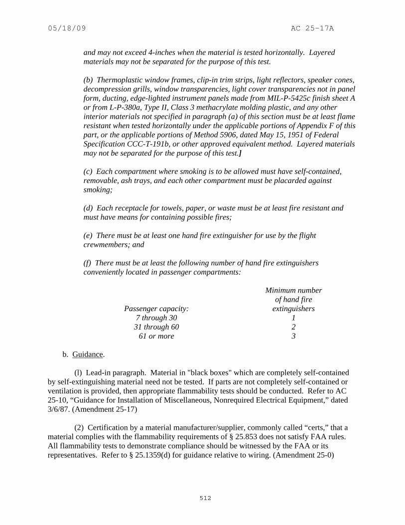
05/18/09 AC 25-17A
512
and may not exceed 4-inches when the material is tested horizontally. Layered materials may not be separated for the purpose of this test. (b) Thermoplastic window frames, clip-in trim strips, light reflectors, speaker cones, decompression grills, window transparencies, light cover transparencies not in panel form, ducting, edge-lighted instrument panels made from MIL-P-5425c finish sheet A or from L-P-380a, Type II, Class 3 methacrylate molding plastic, and any other interior materials not specified in paragraph (a) of this section must be at least flame resistant when tested horizontally under the applicable portions of Appendix F of this part, or the applicable portions of Method 5906, dated May 15, 1951 of Federal Specification CCC-T-191b, or other approved equivalent method. Layered materials may not be separated for the purpose of this test.] (c) Each compartment where smoking is to be allowed must have self-contained, removable, ash trays, and each other compartment must be placarded against smoking; (d) Each receptacle for towels, paper, or waste must be at least fire resistant and must have means for containing possible fires; (e) There must be at least one hand fire extinguisher for use by the flight crewmembers; and
(f) There must be at least the following number of hand fire extinguishers conveniently located in passenger compartments:
Passenger capacity:
Minimum number of hand fire
extinguishers 7 through 30 1 31 through 60 2
61 or more 3 b. Guidance. (l) Lead-in paragraph. Material in "black boxes" which are completely self-contained by self-extinguishing material need not be tested. If parts are not completely self-contained or ventilation is provided, then appropriate flammability tests should be conducted. Refer to AC 25-10, “Guidance for Installation of Miscellaneous, Nonrequired Electrical Equipment,” dated 3/6/87. (Amendment 25-17) (2) Certification by a material manufacturer/supplier, commonly called “certs,” that a material complies with the flammability requirements of § 25.853 does not satisfy FAA rules. All flammability tests to demonstrate compliance should be witnessed by the FAA or its representatives. Refer to § 25.1359(d) for guidance relative to wiring. (Amendment 25-0)
05/18/09 AC 25-17A
513
(3) Paragraph (a). A "fabricated unit" specimen is one in which the actual panel edge is exposed to the test flame. The panel edge may be a metal extrusion and, therefore, the panel materials would be protected from the test flame. In this case, additional "section" specimens must be cut from the panel so that the specimen does not include the edge protection, and, tested horizontally. The "section" horizontal test need not be conducted if (1) the panel edge is equally or more flammable than a section edge and the "fabricated unit" specimens pass the vertical test with the panel edge exposed to the test flame, or (2) the panel edge is less flammable than a "section" specimen edge but the "section" specimens pass the vertical test. (Amendment 25-15) (4) Paragraphs (a) and (b). Sections 25.853 and 25.855 apply to occupied, baggage, and cargo compartments. However, insulation and ducts that are used for occupied, baggage, and cargo compartments are considered part of those compartments, even though items may be located in an adjacent electronics or equipment bay. Therefore, the insulation should meet § 25.853(a) and the ducts should meet § 25.853(b). (Amendment 25-17) (5) Paragraphs (a) and (b). Appendix F, effective October 24, 1967, applies. Refer to Appendix F beginning at paragraph 1151. (Amendment 25-17) (6) Paragraphs (a) and (b). Appendix F, effective October 24, 1967, is applicable to § 25.853, Amendment 25-15 through Amendment 25-3l; and § 121.312. Refer to Appendix F beginning at paragraph 1151. (Amendment 25-15) (7) Paragraphs (a) and (b). Layered materials are entities formed by combining two or more separate materials by bonding, mechanically fastening or other means such that the resulting unit cannot be easily disassembled. Disassembly by removal of screws, staples, glue joints, etc., would not be considered easy. (Amendment 25-15) (8) Paragraphs (a) and (b). Velcro type material should be tested with the Velcro material attached to its backing material but not hook to pile. (Amendment 25-15) (9) Paragraphs (a) and (b). If a material is demonstrated to comply with paragraph (a), it is also considered to comply with paragraph (b). The reverse is not true. (Amendment 25-15) (10) Paragraph (a) and (b). The use of fire/flame retardants is acceptable. The type data should specify the retardant and process for treatment. Treatment should be applied prior to conditioning. The effects of aging and environmental conditions should be considered in the use of retardants. If aging, dry cleaning, washing, etc., adversely affect retardant properties, appropriate documents such as the maintenance manual should address this issue. (Amendment 25-0) (11) Paragraph (b). Oxygen lines for certification basis through Amendment 25-3l and oxygen masks should meet flame resistant criteria. Systems are to be tested in their normal state (which includes lines filled with oxygen, if that is the case; Refer to paragraph 625b(3) of this AC). Oxygen distribution systems, normally pressurized, are aluminum for low pressure (500 pounds per-inch (psi) or less) and stainless steel for high pressure (above 500 psi). Aluminum is classed as "fire resistant" and stainless steel as "fireproof" in 14 CFR, part 1, § l.l. These

05/18/09 AC 25-17A
514
materials are normally not tested to § 25.853 due to their definition, although the authority of that regulation does allow it. (Amendment 25-0) (12) Paragraph (c). Self-contained is defined as a receptacle within a receptacle, one of which has a lid. Both receptacles are considered trash containers and should meet fire-resistant criteria as defined in 14 CFR, part 1, § l.l and in the preceding guidance in paragraph 621b(2) of this AC. The fixed receptacle should be sealed to prevent penetration of fire or residue into the surrounding area. Ashtrays installed in movable or removable armrests which will spill their contents when the armrest is moved or raised, as in the case of hinged armrests, are not considered self-contained. (Amendment 25-0) (13) Paragraph (c). (Amendment 25-0) (i) In order to avoid confusion in compartments where it is intended that smoking is not to be permitted, and No Smoking placards are installed, the lighted No Smoking signs should either be disabled or, preferably, hardwired ON. (Amendment 25-0) (ii) Hardwired ON lighted No Smoking signs have been considered to be equivalent, and even preferred, alternatives to required No Smoking placards in compartments where smoking is not to be permitted. (Amendment 25-0) (iii) In divided compartments where smoking is permitted in one compartment but not in an adjacent one, especially where the no-smoking compartment is aft of the smoking compartment, care needs to be exercised in the placement and design of placarding and/or No Smoking lighted signs to assure no confusion exists. The smoking compartment should be controlled by lighted No Smoking signs controlled by the crew. Passengers in the no-smoking compartment should not be able to Refer to the lighted No Smoking signs in the smoking compartment when switched off. All lighted No Smoking signs visible to passengers in the no-smoking compartment should be hardwired ON. No Smoking placards may also be installed in the no-smoking compartment, but they are considered insufficient, by themselves, to override the confusing effect of switchable No Smoking signs visible to them. (Amendment 25-0) (iv) In compartments where smoking is not allowed, it may be necessary to hardwire ON any lighted NO SMOKING signs to avoid confusing occupants. Note: this may affect an operator’s ability to comply with § 121.317(a). The FAA issued a policy memorandum ANM-03-115-05, dated July 7, 2003, titled “Policy Statement and Equivalent Safety Finding on No Smoking Placards and Signs” that addresses this subject. (Amendment 25-0) (14) Paragraph (d). Waste receptacles may be mounted in the airplane structure or may be portable units such as food or waste carts. Fire containment testing is not required for special purpose disposal receptacles (for such items as used air sickness bags and sanitary napkins), which are in addition to the normal waste disposal receptacles found in lavatories. The reasons for not requiring the testing is that these receptacles are typically very small, less than half a cubic foot in volume, and that they contain specific waste which are of a relatively non-flammable nature. Appendix 8 contains methodology for substantiating compliance with fire containment criteria. (Amendment 25-0)

05/18/09 AC 25-17A
515
(15) Paragraph (e) and (f). Refer to AC 20-42C, “Hand Fire Extinguishers for Use in Aircraft,” dated 3/7/84, for guidance on acceptable fire extinguishers. (Amendment 25-0) (16) Note: The FAA Memorandum 00-115-16, dated September 12, 2000, titled, “Use of the Aircraft Fire Test Handbook” provides guidance for the use of the Report # DOT/FAA/CT-99/15 titled, “Aircraft Fire Test Handbook” that may be used to show compliance with, or demonstrate an equivalent level of safety to, the applicable regulations. The test methods described in the handbook are intended to be adopted in total, if they are used. That is, use of a portion of a test method from the handbook, and another portion of the test method from Appendix F, is not automatically acceptable. (Amendment 25-0) 624. AMENDMENT 25-23, Effective May 8, 1970. a. Regulation.
Materials (including finishes, if applied) used in each compartment occupied by the crew or passengers (other than materials such as wire insulation, conduit, plastic material in "black boxes", rub strips, pulleys, and small nonmetallic materials that are located behind interior walls or above interior ceilings) must meet the following test criteria, as applicable: (a) Except as provided in paragraph (b) of this section, interior wall panels, interior ceiling panels, draperies, structural flooring, baggage racks, partitions (including wind screens), thermal insulation, light cover transparencies in panel form, and coated fabric insulation covering must be self-extinguishing after flame removal when tested in accordance with the applicable portions of Appendix F of this part or the applicable portions of Methods 5902 and 5906, dated May 15, 1951, or Federal Specification CCC-T-191b (which is available from the General Services Administration, Business Service Center, Region 3, Seventh and D Streets SW., Washington, D.C. 20407), or other approved equivalent method. All materials used in these applications must be tested vertically. If the material is tested vertically as a fabricated unit, a section of that fabricated unit must also be tested horizontally. The average char length may not exceed 8-inches when the material is tested vertically, and may not exceed 4-inches when the material is tested horizontally. Layered materials may not be separated for the purpose of this test. (b) Thermoplastic window frames, clip-in trim strips, light reflectors, speaker cones, decompression grills, window transparencies, light cover transparencies not in panel form, ducting, edge-lighted instrument panels made from MIL-P-5425c finish sheet A or from L-P-380a, Type II, Class 3 methacrylate molding plastic, and any other interior materials not specified in paragraph (a) of this section must be at least flame resistant when tested horizontally under the applicable portions of Appendix F of this part, or the applicable portions of Method 5906, dated May 15, 1951 of Federal

05/18/09 AC 25-17A
516
Specification CCC-T-191b, or other approved equivalent method. Layered materials may not be separated for the purpose of this test. (c) Each compartment where smoking is to be allowed must have self-contained, removable, ash trays, and each other compartment must be placarded against smoking; (d) Each receptacle for towels, paper, or waste must be at least fire resistant and must have means for containing possible fires; [(e) There must be at least one hand fire extinguisher conveniently located in the pilot compartment.]
(f) There must be at least the following number of hand fire extinguishers conveniently located in passenger compartments:
Passenger capacity:
Minimum number of hand fire
extinguishers 7 through 30 1 31 through 60 2
61 or more 3 b. Guidance. (l) Lead-in paragraph. Material in "black boxes" which are completely self-contained by self-extinguishing material need not be tested. If parts are not completely self-contained or ventilation is provided, then appropriate flammability tests should be conducted. Refer to AC 25-10, “Guidance for Installation of Miscellaneous, Nonrequired Electrical Equipment,” dated 3/6/87. (Amendment 25-17) (2) Certification by a material manufacturer/supplier, commonly called “certs,” that a material complies with the flammability requirements of § 25.853 does not satisfy FAA rules. All flammability tests to demonstrate compliance should be witnessed by the FAA or its representatives. Refer to § 25.1359(d) for guidance relative to wiring. (Amendment 25-0) (3) Paragraph (a). A "fabricated unit" specimen is one in which the actual panel edge is exposed to the test flame. The panel edge may be a metal extrusion and, therefore, the panel materials would be protected from the test flame. In this case, additional "section" specimens must be cut from the panel so that the specimen does not include the edge protection, and, tested horizontally. The "section" horizontal test need not be conducted if (1) the panel edge is equally or more flammable than a section edge and the "fabricated unit" specimens pass the vertical test with the panel edge exposed to the test flame, or (2) the panel edge is less flammable than a "section" specimen edge but the "section" specimens pass the vertical test. (Amendment 25-15)

05/18/09 AC 25-17A
517
(4) Paragraphs (a) and (b). Sections 25.853 and 25.855 apply to occupied, baggage, and cargo compartments. However, insulation and ducts that are used for occupied, baggage, and cargo compartments are considered part of those compartments, even though items may be located in an adjacent electronics or equipment bay. Therefore, the insulation should meet § 25.853(a) and the ducts should meet § 25.853(b). (Amendment 25-17) (5) Paragraphs (a) and (b). Appendix F, effective October 24, 1967, applies. Refer to Appendix F beginning at paragraph 1151. (Amendment 25-17) (6) Paragraphs (a) and (b). Appendix F, effective October 24, 1967, is applicable to § 25.853, Amendment 25-15 through Amendment 25-3l; and § 121.312. Refer to Appendix F beginning at paragraph 1151. (Amendment 25-15) (7) Paragraphs (a) and (b). Layered materials are entities formed by combining two or more separate materials by bonding, mechanically fastening or other means such that the resulting unit cannot be easily disassembled. Disassembly by removal of screws, staples, glue joints, etc., would not be considered easy. (Amendment 25-15) (8) Paragraphs (a) and (b). Velcro type material should be tested with the Velcro material attached to its backing material but not hook to pile. (Amendment 25-15) (9) Paragraphs (a) and (b). If a material is demonstrated to comply with paragraph (a), it is also considered to comply with paragraph (b). The reverse is not true. (Amendment 25-15) (10) Paragraph (a) and (b). The use of fire/flame retardants is acceptable. The type data should specify the retardant and process for treatment. Treatment should be applied prior to conditioning. The effects of aging and environmental conditions should be considered in the use of retardants. If aging, dry cleaning, washing, etc., adversely affect retardant properties, appropriate documents such as the maintenance manual should address this issue. (Amendment 25-0) (11) Paragraph (b). Oxygen lines for certification basis through Amendment 25-3l and oxygen masks should meet flame resistant criteria. Systems are to be tested in their normal state (which includes lines filled with oxygen, if that is the case; Refer to paragraph 625b(3) of this AC). Oxygen distribution systems, normally pressurized, are aluminum for low pressure (500 pounds per-inch (psi) or less) and stainless steel for high pressure (above 500 psi). Aluminum is classed as "fire resistant" and stainless steel as "fireproof" in 14 CFR, part 1, § l.l. These materials are normally not tested to § 25.853 due to their definition, although the authority of that regulation does allow it. (Amendment 25-0) (12) Paragraph (c). Self-contained is defined as a receptacle within a receptacle, one of which has a lid. Both receptacles are considered trash containers and should meet fire-resistant criteria as defined in 14 CFR, part 1, § l.l and in the preceding guidance in paragraph 621b(2) of this AC. The fixed receptacle should be sealed to prevent penetration of fire or residue into the surrounding area. Ashtrays installed in movable or removable armrests which will spill their
05/18/09 AC 25-17A
518
contents when the armrest is moved or raised, as in the case of hinged armrests, are not considered self-contained. (Amendment 25-0) (13) Paragraph (c). (Amendment 25-0) (i) In order to avoid confusion in compartments where it is intended that smoking is not to be permitted, and No Smoking placards are installed, the lighted No Smoking signs should either be disabled or, preferably, hardwired ON. (Amendment 25-0) (ii) Hardwired ON lighted No Smoking signs have been considered to be equivalent, and even preferred, alternatives to required No Smoking placards in compartments where smoking is not to be permitted. (Amendment 25-0) (iii) In divided compartments where smoking is permitted in one compartment but not in an adjacent one, especially where the no-smoking compartment is aft of the smoking compartment, care needs to be exercised in the placement and design of placarding and/or No Smoking lighted signs to assure no confusion exists. The smoking compartment should be controlled by lighted No Smoking signs controlled by the crew. Passengers in the no-smoking compartment should not be able to Refer to the lighted No Smoking signs in the smoking compartment when switched off. All lighted No Smoking signs visible to passengers in the no-smoking compartment should be hardwired ON. No Smoking placards may also be installed in the no-smoking compartment, but they are considered insufficient, by themselves, to override the confusing effect of switchable No Smoking signs visible to them. (Amendment 25-0) (iv) In compartments where smoking is not allowed, it may be necessary to hardwire ON any lighted NO SMOKING signs to avoid confusing occupants. Note: this may affect an operator’s ability to comply with § 121.317(a). The FAA issued a policy memorandum ANM-03-115-05, dated July 7, 2003, titled “Policy Statement and Equivalent Safety Finding on No Smoking Placards and Signs” that addresses this subject. (Amendment 25-0) (14) Paragraph (d). Waste receptacles may be mounted in the airplane structure or may be portable units such as food or waste carts. Fire containment testing is not required for special purpose disposal receptacles (for such items as used air sickness bags and sanitary napkins), which are in addition to the normal waste disposal receptacles found in lavatories. The reasons for not requiring the testing is that these receptacles are typically very small, less than half a cubic foot in volume, and that they contain specific waste which are of a relatively non-flammable nature. Appendix 8 contains methodology for substantiating compliance with fire containment criteria. (Amendment 25-0) (15) Paragraph (e) and (f). Refer to AC 20-42C, “Hand Fire Extinguishers for Use in Aircraft,” dated 3/7/84, for guidance on acceptable fire extinguishers. (Amendment 25-0) (16) Note: The FAA Memorandum 00-115-16, dated September 12, 2000, titled, “Use of the Aircraft Fire Test Handbook” provides guidance for the use of the Report # DOT/FAA/CT-99/15 titled, “Aircraft Fire Test Handbook” that may be used to show compliance with, or demonstrate an equivalent level of safety to, the applicable regulations. The test

05/18/09 AC 25-17A
519
methods described in the handbook are intended to be adopted in total, if they are used. That is, use of a portion of a test method from the handbook, and another portion of the test method from Appendix F, is not automatically acceptable. (Amendment 25-0) 625. AMENDMENT 25-32, Effective May 1, 1972. a. Regulation.
[Materials (including finishes or decorative surfaces applied to the materials) used in each compartment occupied by the crew or passengers must meet the following test criteria as applicable: ] [(a) Interior ceiling panels, interior wall panels, partitions, galley structure, large cabinet walls, structural flooring, and materials used in the construction of stowage compartments (other than underseat stowage compartments and compartments for stowing small items such as magazines and maps) must be self-extinguishing when tested vertically in accordance with the applicable portions of Appendix F of this part, or other approved equivalent methods. The average burn length may not exceed six-inches and the average flame time after removal of the flame source may not exceed 15 seconds. Drippings from the test specimen may not continue to flame for more than an average of three seconds after falling. ] [(b) Floor covering, textiles (including draperies and upholstery), seat cushions, padding, decorative and non-decorative coated fabrics, leather, trays and galley furnishings, electrical conduit, thermal and acoustical insulation and insulation covering, air ducting, joint and edge covering, cargo compartment liners, insulation blankets, cargo covers, and transparencies, molded and thermoformed parts, air ducting joints, and trim strips (decorative and chafing), that are constructed of materials not covered in paragraph (b-2) of this section, must be self extinguishing when tested vertically in accordance with the applicable portions of Appendix F of this Part, or other approved equivalent methods. The average burn length may not exceed 8-inches and the average flame time after removal of the flame source may not exceed 15 seconds. Drippings from the test specimen may not continue to flame for more than an average of 5 seconds after falling. ] [(b-1) Motion picture film must be safety film meeting the Standard Specifications for Safety Photographic Film PH1.25 (available from the United States of America Standards Institute, 10 East 40 Street, New York, N.Y. 10018), or an FAA-approved equivalent. If the film travels through ducts, the ducts must meet the requirements of paragraph (b) of this section. ] [(b-2) Acrylic windows and signs, parts constructed in whole or in part of elastomeric materials, edge lighted instrument assemblies consisting of two or more instruments in a common housing, seat belts, shoulder harnesses, and cargo and baggage tiedown equipment, including containers, bins, pallets, etc., used in

05/18/09 AC 25-17A
520
passenger or crew compartments, may not have an average burn rate greater than 2.5-inches per minute when tested horizontally in accordance with the applicable portions of Appendix F of this Part, or other approved equivalent methods. ] [(b-3) Except for electrical wire and cable insulation, and for small parts (such as knobs, handles, rollers, fasteners, clips, grommets, rub strips, pulleys, and small electrical parts) that the Administrator finds would not contribute significantly to the propagation of a fire, materials in items not specified in paragraphs (a), (b), (b-1), or (b-2) of this section may not have a burn rate greater than 4.0-inches per minute when tested horizontally in accordance with the applicable portions of Appendix F of this Part or other approved equivalent methods.] (c) Each compartment where smoking is to be allowed must have self-contained, removable, ash trays, and each other compartment must be placarded against smoking. (d) Each receptacle for towels, paper, or waste must be at least fire resistant and must have means for containing possible fires. (e) There must be at least one hand fire extinguisher conveniently located in the pilot compartment.
(f) There must be at least the following number of hand fire extinguishers conveniently located in passenger compartments:
Passenger capacity:
Minimum number of hand fire
extinguishers 7 through 30 1 31 through 60 2
61 or more 3 b. Guidance. (l) Material in "black boxes" which are completely self-contained by self-extinguishing material need not be tested. If parts are not completely self-contained or ventilation is provided, then appropriate flammability tests should be conducted. Refer to AC 25-10, “Guidance for Installation of Miscellaneous, Nonrequired Electrical Equipment,” dated 3/6/87. (Amendment 25-17) (2) Certification by a material manufacturer/supplier, commonly called “certs,” that a material complies with the flammability requirements of § 25.853 does not satisfy FAA rules. All flammability tests to demonstrate compliance should be witnessed by the FAA or its representatives. Refer to § 25.1359(d) for guidance relative to wiring. (Amendment 25-0)

05/18/09 AC 25-17A
521
(3) Paragraph (a). Carpets which extend up and become part of a vertical panel should also meet § 25.853(a). (Amendment 25-32) (4) Paragraphs (a) and (b). Layered materials are entities formed by combining two or more separate materials by bonding, mechanically fastening or other means such that the resulting unit cannot be easily disassembled. Disassembly by removal of screws, staples, glue joints, etc., would not be considered easy. (Amendment 25-15) (5) Paragraphs (a) and (b). Velcro type material should be tested with the Velcro material attached to its backing material but not hook to pile. (Amendment 25-15) (6) Paragraph (a) and (b). The use of fire/flame retardants is acceptable. The type data should specify the retardant and process for treatment. Treatment should be applied prior to conditioning. The effects of aging and environmental conditions should be considered in the use of retardants. If aging, dry cleaning, washing, etc., adversely affect retardant properties, appropriate documents such as the maintenance manual should address this issue. (Amendment 25-0) (7) Paragraph (b). Carpets may be tested without serging. (Amendment 25-32) (8) Paragraph (b). Oxygen lines are considered ducted systems and should be tested in their normal state: pressurized to the maximum operating pressure with a gas considered safe for testing. Refer to paragraph 621.b.(4) above. (Amendment 25-32) (9) Paragraph (b). As required by Appendix F, foam shall be tested in 1/2-inch thickness. If the cushion consists of two or more foams glued together, the foam specimens should be two 1/4-inch (three 1/6-inch, etc.) pieces glued together. Three specimens should be made for each combination of foams that are glued together in the production cushion. Any other production cushion components that are glued together, should be tested together. If such specimens do not pass, it is acceptable to test each production cushion component separately, including a sheet of glue. Additionally, the Bunsen burner is then applied to three separate corners of the production cushion with all its components. The cushion is satisfactory if all tests meet the test criteria. The three corner tests need not be conducted, if the cushion passes the tests of part II of Appendix F at Amendment 25-59. (Amendment 25-32) (10) Paragraph (b-3). Blankets, pillows, headrest covers, and carry-on items that are not part of the aircraft type design are not required to meet the flammability standards. (Amendment 25-32) (11) Paragraph (b-3). Relative to lavatory smoke detectors, the following is quoted from the preamble to Amendment 121-185, effective April 29, 1985: "Unless some circumstance or design feature unforeseen at this time requires otherwise, materials used in the construction of relatively small commercially available smoke detectors would not contribute significantly to the propagation of a fire and would be covered by the small parts exclusion of § 25.853(b-3)." (Amendment 25-32)

05/18/09 AC 25-17A
522
(12) Paragraphs (a) through (b-3). Appendix F, effective May 1, 1972, applies. Refer to Appendix F beginning at paragraph 1151. (Amendment 25-32) (13) Paragraphs (a) through (b-3). Refer to AC 25-10, “Guidance for Installation of Miscellaneous, Nonrequired Electrical Equipment,” dated 3/6/87. (Amendment 25-32) (14) Paragraphs (b), (b-2), and (b-3). If material is demonstrated to comply with paragraph (b), it is also considered to comply with paragraphs (b-2) and (b-3). The reverse is not true. (Amendment 25-32) (15) Paragraph (c). Self-contained is defined as a receptacle within a receptacle, one of which has a lid. Both receptacles are considered trash containers and should meet fire-resistant criteria as defined in 14 CFR, part 1, § l.l and in the preceding guidance in paragraph 621b(2) of this AC. The fixed receptacle should be sealed to prevent penetration of fire or residue into the surrounding area. Ashtrays installed in movable or removable armrests which will spill their contents when the armrest is moved or raised, as in the case of hinged armrests, are not considered self-contained. (Amendment 25-0) (16) Paragraph (c). (Amendment 25-0) (i) In order to avoid confusion in compartments where it is intended that smoking is not to be permitted, and No Smoking placards are installed, the lighted No Smoking signs should either be disabled or, preferably, hardwired ON. (Amendment 25-0) (ii) Hardwired ON lighted No Smoking signs have been considered to be equivalent, and even preferred, alternatives to required No Smoking placards in compartments where smoking is not to be permitted. (Amendment 25-0) (iii) In divided compartments where smoking is permitted in one compartment but not in an adjacent one, especially where the no-smoking compartment is aft of the smoking compartment, care needs to be exercised in the placement and design of placarding and/or No Smoking lighted signs to assure no confusion exists. The smoking compartment should be controlled by lighted No Smoking signs controlled by the crew. Passengers in the no-smoking compartment should not be able to Refer to the lighted No Smoking signs in the smoking compartment when switched off. All lighted No Smoking signs visible to passengers in the no-smoking compartment should be hardwired ON. No Smoking placards may also be installed in the no-smoking compartment, but they are considered insufficient, by themselves, to override the confusing effect of switchable No Smoking signs visible to them. (Amendment 25-0) (iv) In compartments where smoking is not allowed, it may be necessary to hardwire ON any lighted NO SMOKING signs to avoid confusing occupants. Note: this may affect an operator’s ability to comply with § 121.317(a). The FAA issued a policy memorandum ANM-03-115-05, dated July 7, 2003, titled “Policy Statement and Equivalent Safety Finding on No Smoking Placards and Signs” that addresses this subject. (Amendment 25-0)

05/18/09 AC 25-17A
523
(17) Paragraph (d). To meet the "fire resistant" requirements, the receptacle construction should meet the 45-degree burn test described in § 25.855(a-1). (Amendment 25-32) (18) Paragraphs (a) through (b-3) and (d) of Appendix F. For measuring the flame temperature of 1550° F, the center of the flame is 3/4-inch above the top edge of the burner. (Amendment 25-32) (19) Paragraph (d). Waste receptacles may be mounted in the airplane structure or may be portable units such as food or waste carts. Fire containment testing is not required for special purpose disposal receptacles (for such items as used air sickness bags and sanitary napkins), which are in addition to the normal waste disposal receptacles found in lavatories. The reasons for not requiring the testing is that these receptacles are typically very small, less than half a cubic foot in volume, and that they contain specific waste which are of a relatively non-flammable nature. Appendix 8 contains methodology for substantiating compliance with fire containment criteria. (Amendment 25-0) (20) Paragraph (e) and (f). Refer to AC 20-42C, “Hand Fire Extinguishers for Use in Aircraft,” dated 3/7/84, for guidance on acceptable fire extinguishers. (Amendment 25-0) (21) Note: The FAA Memorandum 00-115-16, dated September 12, 2000, titled, “Use of the Aircraft Fire Test Handbook” provides guidance for the use of the Report # DOT/FAA/CT-99/15 titled, “Aircraft Fire Test Handbook” that may be used to show compliance with, or demonstrate an equivalent level of safety to, the applicable regulations. The test methods described in the handbook are intended to be adopted in total, if they are used. That is, use of a portion of a test method from the handbook, and another portion of the test method from Appendix F, is not automatically acceptable. (Amendment 25-0) 626. AMENDMENT 25-51, Effective March 6, 1980. a. Regulation.
Materials (including finishes or decorative surfaces applied to the materials) used in each compartment occupied by the crew or passengers must meet the following test criteria as applicable: (a) Interior ceiling panels, interior wall panels, partitions, galley structure, large cabinet walls, structural flooring, and materials used in the construction of stowage compartments (other than underseat stowage compartments and compartments for stowing small items such as magazines and maps) must be self-extinguishing when tested vertically in accordance with the applicable portions of Appendix F of this Part, or other approved equivalent methods. The average burn length may not exceed six-inches and the average flame time after removal of the flame source may not exceed 15 seconds. Drippings from the test specimen may not continue to flame for more than an average of three seconds after falling.

05/18/09 AC 25-17A
524
(b) Floor covering, textiles (including draperies and upholstery), seat cushions, padding, decorative and non-decorative coated fabrics, leather, trays and galley furnishings, electrical conduit, thermal and acoustical insulation and insulation covering, air ducting, joint and edge covering, cargo compartment liners, insulation blankets, cargo covers, and transparencies, molded and thermoformed parts, air ducting joints, and trim strips (decorative and chafing), that are constructed of materials not covered in paragraph (b-2) of this section, must be self extinguishing when tested vertically in accordance with the applicable portions of Appendix F of this Part, or other approved equivalent methods. The average burn length may not exceed 8-inches and the average flame time after removal of the flame source may not exceed 15 seconds. Drippings from the test specimen may not continue to flame for more than an average of 11 seconds after falling. (b-1) Motion picture film must be safety film meeting the Standard Specifications for Safety Photographic Film PH1.25 (available from the American National Standards Institute, 1430 Broadway, New York, N.Y. 10018), or an FAA approved equivalent. If the film travels through ducts, the ducts must meet the requirements of paragraph (b) of this section. (b-2) Acrylic windows and signs, parts constructed in whole or in part of elastomeric materials, edge lighted instrument assemblies consisting of two or more instruments in a common housing, seat belts, shoulder harnesses, and cargo and baggage tiedown equipment, including containers, bins, pallets, etc., used in passenger or crew compartments, may not have an average burn rate greater than 2.5-inches per minute when tested horizontally in accordance with the applicable portions of Appendix F of this Part, or other approved equivalent methods. (b-3) Except for electrical wire and cable insulation, and for small parts (such as knobs, handles, rollers, fasteners, clips, grommets, rub strips, pulleys, and small electrical parts) that the Administrator finds would not contribute significantly to the propagation of a fire, materials in items not specified in paragraphs (a), (b), (b-1), or (b-2) of this section may not have a burn rate greater than 4.0-inches per minute when tester horizontally in accordance with the applicable portions of Appendix F of this Part or other approved equivalent methods. [(c) If smoking is to be prohibited, there must be a placard so stating, and if smoking is to be allowed- (1) There must be an adequate number of self-contained, removable ashtrays; and (2) Where the crew compartment is separated from the passenger compartment, there must be at least one sign meeting the "No Smoking" sign requirements of § 25.791 notifying all passengers when smoking is prohibited. (d) Each disposal receptacle for towels, paper, or waste must be fully enclosed and constructed of at least fire restrain materials, and must contain fires likely to occur in

05/18/09 AC 25-17A
525
it under normal use. The ability of the disposal receptacle to contain those fires under all probable conditions of wear, misalignment, and ventilation expected in service must be demonstrated by test. A placard containing the legible words "No Cigarette Disposal" must be located on or near each disposal receptacle door. (e) Lavatories must have "No Smoking" or "No Smoking in Lavatory" placards located conspicuously on each side of the entry door, and self-contained removable ashtrays located conspicuously on or near the entry side of each lavatory door, except that one ashtray may serve more than one lavatory door if the ashtray can be seen readily from the cabin side of each lavatory door served. The placards must have red letters at least one-half-inch high on a white background of at least one-inch high. (A "No Smoking" symbol may be included on the placard.)]
b. Guidance. (l) Material in "black boxes" which are completely self-contained by self-extinguishing material need not be tested. If parts are not completely self-contained or ventilation is provided, then appropriate flammability tests should be conducted. Refer to AC 25-10, “Guidance for Installation of Miscellaneous, Nonrequired Electrical Equipment,” dated 3/6/87. (Amendment 25-17) (2) Certification by a material manufacturer/supplier, commonly called “certs,” that a material complies with the flammability requirements of § 25.853 does not satisfy FAA rules. All flammability tests to demonstrate compliance should be witnessed by the FAA or its representatives. Refer to § 25.1359(d) for guidance relative to wiring. (Amendment 25-0) (3) Paragraph (a). Carpets which extend up and become part of a vertical panel should also meet § 25.853(a). (Amendment 25-32) (4) Paragraphs (a) and (b). Layered materials are entities formed by combining two or more separate materials by bonding, mechanically fastening or other means such that the resulting unit cannot be easily disassembled. Disassembly by removal of screws, staples, glue joints, etc., would not be considered easy. (Amendment 25-15) (5) Paragraphs (a) and (b). Velcro type material should be tested with the Velcro material attached to its backing material but not hook to pile. (Amendment 25-15) (6) Paragraph (a) and (b). The use of fire/flame retardants is acceptable. The type data should specify the retardant and process for treatment. Treatment should be applied prior to conditioning. The effects of aging and environmental conditions should be considered in the use of retardants. If aging, dry cleaning, washing, etc., adversely affect retardant properties, appropriate documents such as the maintenance manual should address this issue. (Amendment 25-0) (7) Paragraph (b). Carpets may be tested without serging. (Amendment 25-32)

05/18/09 AC 25-17A
526
(8) Paragraph (b). Oxygen lines are considered ducted systems and should be tested in their normal state: pressurized to the maximum operating pressure with a gas considered safe for testing. Refer to paragraph 621.b.(4) above. (Amendment 25-32) (9) Paragraph (b). As required by Appendix F, foam shall be tested in 1/2-inch thickness. If the cushion consists of two or more foams glued together, the foam specimens should be two 1/4-inch (three 1/6-inch, etc.) pieces glued together. Three specimens should be made for each combination of foams that are glued together in the production cushion. Any other production cushion components that are glued together, should be tested together. If such specimens do not pass, it is acceptable to test each production cushion component separately, including a sheet of glue. Additionally, the Bunsen burner is then applied to three separate corners of the production cushion with all its components. The cushion is satisfactory if all tests meet the test criteria. The three corner tests need not be conducted, if the cushion passes the tests of part II of Appendix F at Amendment 25-59. (Amendment 25-32) (10) Paragraph (b-3). Blankets, pillows, headrest covers, and carry-on items that are not part of the aircraft type design are not required to meet the flammability standards. (Amendment 25-32) (11) Paragraph (b-3). Relative to lavatory smoke detectors, the following is quoted from the preamble to Amendment 121-185, effective April 29, 1985: "Unless some circumstance or design feature unforeseen at this time requires otherwise, materials used in the construction of relatively small commercially available smoke detectors would not contribute significantly to the propagation of a fire and would be covered by the small parts exclusion of § 25.853(b-3)." (Amendment 25-32) (12) Paragraphs (a) through (b-3). Appendix F, effective May 1, 1972, applies. Refer to Appendix F beginning at paragraph 1151. (Amendment 25-32) (13) Paragraphs (a) through (b-3). Refer to AC 25-10, “Guidance for Installation of Miscellaneous, Nonrequired Electrical Equipment,” dated 3/6/87. (Amendment 25-32) (14) Paragraphs (b), (b-2), and (b-3). If material is demonstrated to comply with paragraph (b), it is also considered to comply with paragraphs (b-2) and (b-3). The reverse is not true. (Amendment 25-32) (15) Paragraph (c). Self-contained is defined as a receptacle within a receptacle, one of which has a lid. Both receptacles are considered trash containers and should meet fire-resistant criteria as defined in 14 CFR, part 1, § l.l and in the preceding guidance in paragraph 621b(2) of this AC. The fixed receptacle should be sealed to prevent penetration of fire or residue into the surrounding area. Ashtrays installed in movable or removable armrests which will spill their contents when the armrest is moved or raised, as in the case of hinged armrests, are not considered self-contained. (Amendment 25-0)
05/18/09 AC 25-17A
527
(16) Paragraph (c). (Amendment 25-0) (i) In order to avoid confusion in compartments where it is intended that smoking is not to be permitted, and No Smoking placards are installed, the lighted No Smoking signs should either be disabled or, preferably, hardwired ON. (Amendment 25-0) (ii) Hardwired ON lighted No Smoking signs have been considered to be equivalent, and even preferred, alternatives to required No Smoking placards in compartments where smoking is not to be permitted. (Amendment 25-0) (iii) In divided compartments where smoking is permitted in one compartment but not in an adjacent one, especially where the no-smoking compartment is aft of the smoking compartment, care needs to be exercised in the placement and design of placarding and/or No Smoking lighted signs to assure no confusion exists. The smoking compartment should be controlled by lighted No Smoking signs controlled by the crew. Passengers in the no-smoking compartment should not be able to Refer to the lighted No Smoking signs in the smoking compartment when switched off. All lighted No Smoking signs visible to passengers in the no-smoking compartment should be hard-wired ON. No Smoking placards may also be installed in the no-smoking compartment, but they are considered insufficient, by themselves, to override the confusing effect of switchable No Smoking signs visible to them. (Amendment 25-0) (iv) In compartments where smoking is not allowed, it may be necessary to hardwire ON any lighted NO SMOKING signs to avoid confusing occupants. Note: this may affect an operator’s ability to comply with § 121.317(a). The FAA issued a policy memorandum ANM-03-115-05, dated July 7, 2003, titled “Policy Statement and Equivalent Safety Finding on No Smoking Placards and Signs” that addresses this subject. (Amendment 25-0) (17) Paragraph (d). To meet the "fire resistant" requirements, the receptacle construction should meet the 45-degree burn test described in § 25.855(a-1). (Amendment 25-32) (18) Paragraphs (a) through (b-3) and (d) of Appendix F. For measuring the flame temperature of 1550° F, the center of the flame is 3/4-inch above the top edge of the burner. (Amendment 25-32) (19) Paragraph (d). Waste receptacles may be mounted in the airplane structure or may be portable units such as food or waste carts. Fire containment testing is not required for special purpose disposal receptacles (for such items as used air sickness bags and sanitary napkins), which are in addition to the normal waste disposal receptacles found in lavatories. The reasons for not requiring the testing is that these receptacles are typically very small, less than half a cubic foot in volume, and that they contain specific waste which are of a relatively non-flammable nature. Appendix 8 contains methodology for substantiating compliance with fire containment criteria. (Amendment 25-0) (20) This amendment deleted §§ 25.853(e) and (f). These requirements were moved to §§ 25.851(a)(5) and (6) per Amendment 25-54. This change was a consolidation of regulations for hand held fire extinguishers. (Amendment 25-51)

05/18/09 AC 25-17A
528
(21) Paragraph (e). These requirements reflect those of AIRWORTHINESS DIRECTIVE (AD) 74-08-09, effective April 30, 1974. (Amendment 25-51) (22) Note: The FAA Memorandum 00-115-16, dated September 12, 2000, titled, “Use of the Aircraft Fire Test Handbook” provides guidance for the use of the Report # DOT/FAA/CT-99/15 titled, “Aircraft Fire Test Handbook” that may be used to show compliance with, or demonstrate an equivalent level of safety to, the applicable regulations. The test methods described in the handbook are intended to be adopted in total, if they are used. That is, use of a portion of a test method from the handbook, and another portion of the test method from Appendix F, is not automatically acceptable. (Amendment 25-0) 627. AMENDMENT 25-59, Effective November 26, 1984. a. Regulation.
Materials (including finishes or decorative surfaces applied to the materials) used in each compartment occupied by the crew or passengers must meet the following test criteria as applicable: (a) Interior ceiling panels, interior wall panels, partitions, galley structure, large cabinet walls, structural flooring, and materials used in the construction of stowage compartments (other than underseat stowage compartments and compartments for stowing small items such as magazines and maps) must be self-extinguishing when tested vertically in accordance with the applicable portions of Appendix F of this Part, or other approved equivalent methods. The average burn length may not exceed six-inches and the average flame time after removal of the flame source may not exceed 15 seconds. Drippings from the test specimen may not continue to flame for more than an average of three seconds after falling. (b) Floor covering, textiles (including draperies and upholstery), seat cushions, padding, decorative and non-decorative coated fabrics, leather, trays and galley furnishings, electrical conduit, thermal and acoustical insulation and insulation covering air ducting, joint and edge covering, cargo compartment liners, insulation blankets, cargo covers, and transparencies, molded and thermoformed parts, air ducting joints, and trim strips (decorative and chafing), that are constructed of materials not covered in paragraph (b-2) of this section, must be self extinguishing when tested vertically in accordance with the applicable portions of Appendix F of this Part, of other approved equivalent methods. The average burn length may not exceed 8-inches and the average flame time after removal of the flame source may not exceed 15 seconds. Drippings from the test specimen may not continue to flame for more than an average of 5 seconds after falling. (b-1) Motion picture film must be safety film meeting the Standard Specifications for Safety Photographic Film (PH1.25) (available from the American National Standards

05/18/09 AC 25-17A
529
Institute, 1430 Broadway, New York, N.Y. 10018), or an FAA approved equivalent. If the film travels through ducts, the ducts must meet the requirements of paragraph (b) of this section. (b-2) Acrylic windows and signs, parts constructed in whole or in part of elastomeric materials, edge lighted instrument assemblies consisting of two or more instruments in a common housing, seat belts, shoulder harnesses, and cargo and baggage tiedown equipment, including containers, bins, pallets, etc., used in passenger or crew compartments, may not have an average burn rate greater than 2.5-inches per minute when tested horizontally in accordance with the applicable portions of Appendix F of this Part or other approved equivalent methods. (b-3) Except for electrical wire and cable insulation, and for small parts (such as knobs, handles, rollers, fasteners, clips, grommets, rub strips, pulleys, and small electrical parts) that the Administrator finds would not contribute significantly to the propagation of a fire, materials in items not specified in paragraphs (a), (b), (b-1), or (b-2) of this section may not have a burn rate greater than 4.0-inches per minute when tested horizontally in accordance with the applicable portions of Appendix F of this Part or other approved equivalent methods. [(c) In addition to meeting the requirements of paragraph (b), seat cushions, except those on flight crewmember seats, must meet the test requirements of Part II of Appendix F of this Part, or equivalent. (d)] If smoking is to be prohibited, there must be a placard so stating, and if smoking is to be allowed- (1) There must be an adequate number of self-contained, removable ashtrays; and (2) Where the crew compartment is separated from the passenger compartment, there must be at least one sign meeting the "No Smoking" sign requirements of § 25.791 notifying all passengers when smoking is prohibited. [(e)] Each disposal receptacle for towels, paper, or waste must be fully enclosed and constructed of at least fire restraint materials, and must contain fires likely to occur in it under normal use. The ability of the disposal receptacle to contain those fires under all probable conditions of wear, misalignment, and ventilation expected in service must be demonstrated by test. A placard containing the legible words "No Cigarette Disposal" must be located on or near each disposal receptacle door. [(f)] Lavatories must have "No Smoking" or "No Smoking in Lavatory" placards located conspicuously on each side of the entry door, and self-contained removable ashtrays located conspicuously on or near the entry side of each lavatory door, except that one ashtray may serve more than one lavatory door if the ashtray can be seen readily from the cabin side of each lavatory door served. The placards must

05/18/09 AC 25-17A
530
have red letters at least one-half-inch high on a white background of at least one-inch high. (A "No Smoking" symbol may be included on the placard.)
b. Guidance. (l) Material in "black boxes" which are completely self-contained by self-extinguishing material need not be tested. If parts are not completely self-contained or ventilation is provided, then appropriate flammability tests should be conducted. Refer to AC 25-10, “Guidance for Installation of Miscellaneous, Nonrequired Electrical Equipment,” dated 3/6/87. (Amendment 25-17) (2) Certification by a material manufacturer/supplier, commonly called “certs,” that a material complies with the flammability requirements of § 25.853 does not satisfy FAA rules. All flammability tests to demonstrate compliance should be witnessed by the FAA or its representatives. Refer to § 25.1359(d) for guidance relative to wiring. (Amendment 25-0) (3) Paragraph (a). Carpets which extend up and become part of a vertical panel should also meet § 25.853(a). (Amendment 25-32) (4) Paragraphs (a) and (b). Layered materials are entities formed by combining two or more separate materials by bonding, mechanically fastening or other means such that the resulting unit cannot be easily disassembled. Disassembly by removal of screws, staples, glue joints, etc., would not be considered easy. (Amendment 25-15) (5) Paragraphs (a) and (b). Velcro type material should be tested with the Velcro material attached to its backing material but not hook to pile. (Amendment 25-15) (6) Paragraph (a) and (b). The use of fire/flame retardants is acceptable. The type data should specify the retardant and process for treatment. Treatment should be applied prior to conditioning. The effects of aging and environmental conditions should be considered in the use of retardants. If aging, dry cleaning, washing, etc., adversely affect retardant properties, appropriate documents such as the maintenance manual should address this issue. (Amendment 25-0) (7) Paragraph (b). Carpets may be tested without serging. (Amendment 25-32) (8) Paragraph (b). Oxygen lines are considered ducted systems and should be tested in their normal state: pressurized to the maximum operating pressure with a gas considered safe for testing. Refer to paragraph 621.b.(4) above. (Amendment 25-32) (9) Paragraph (b). As required by Appendix F, foam shall be tested in 1/2-inch thickness. If the cushion consists of two or more foams glued together, the foam specimens should be two 1/4-inch (three 1/6-inch, etc.) pieces glued together. Three specimens should be made for each combination of foams that are glued together in the production cushion. Any other production cushion components that are glued together, should be tested together. If such specimens do not pass, it is acceptable to test each production cushion component separately,

05/18/09 AC 25-17A
531
including a sheet of glue. Additionally, the Bunsen burner is then applied to three separate corners of the production cushion with all its components. The cushion is satisfactory if all tests meet the test criteria. The three corner tests need not be conducted, if the cushion passes the tests of part II of Appendix F. (Amendment 25-32) (10) Paragraph (b-3). Blankets, pillows, headrest covers, and carry-on items that are not part of the aircraft type design are not required to meet the flammability standards. (Amendment 25-32) (11) Paragraph (b-3). Relative to lavatory smoke detectors, the following is quoted from the preamble to Amendment 121-185, effective April 29, 1985: "Unless some circumstance or design feature unforeseen at this time requires otherwise, materials used in the construction of relatively small commercially available smoke detectors would not contribute significantly to the propagation of a fire and would be covered by the small parts exclusion of § 25.853(b-3)." (Amendment 25-32) (12) Paragraphs (a) through (b-3). Refer to AC 25-10, “Guidance for Installation of Miscellaneous, Nonrequired Electrical Equipment,” dated 3/6/87. (Amendment 25-32) (13) Paragraphs (b), (b-2), and (b-3). If material is demonstrated to comply with paragraph (b), it is also considered to comply with paragraphs (b-2) and (b-3). The reverse is not true. (Amendment 25-32) (14) Paragraph (c). Refer to AC 25.853-1, “Flammability Requirements for Aircraft Seat Cushions,” dated 9/17/86. (Amendment 25-59) (15) Paragraph (d). Self-contained is defined as a receptacle within a receptacle, one of which has a lid. Both receptacles are considered trash containers and should meet fire-resistant criteria as defined in 14 CFR, part 1, § l.l and in the preceding guidance in paragraph 621b(2) of this AC. The fixed receptacle should be sealed to prevent penetration of fire or residue into the surrounding area. Ashtrays installed in movable or removable armrests which will spill their contents when the armrest is moved or raised, as in the case of hinged armrests, are not considered self-contained. (Amendment 25-0) (16) Paragraph (d). (Amendment 25-0) (i) In order to avoid confusion in compartments where it is intended that smoking is not to be permitted, and No Smoking placards are installed, the lighted No Smoking signs should either be disabled or, preferably, hardwired ON. (Amendment 25-0) (ii) Hardwired ON lighted No Smoking signs have been considered to be equivalent, and even preferred, alternatives to required No Smoking placards in compartments where smoking is not to be permitted. (Amendment 25-0) (iii) In divided compartments where smoking is permitted in one compartment but not in an adjacent one, especially where the no-smoking compartment is aft of the smoking

05/18/09 AC 25-17A
532
compartment, care needs to be exercised in the placement and design of placarding and/or No Smoking lighted signs to assure no confusion exists. The smoking compartment should be controlled by lighted No Smoking signs controlled by the crew. Passengers in the no-smoking compartment should not be able to Refer to the lighted No Smoking signs in the smoking compartment when switched off. All lighted No Smoking signs visible to passengers in the no-smoking compartment should be hard-wired ON. No Smoking placards may also be installed in the no-smoking compartment, but they are considered insufficient, by themselves, to override the confusing effect of switchable No Smoking signs visible to them. (Amendment 25-0) (iv) In compartments where smoking is not allowed, it may be necessary to hardwire ON any lighted NO SMOKING signs to avoid confusing occupants. Note: this may affect an operator’s ability to comply with § 121.317(a). The FAA issued a policy memorandum ANM-03-115-05, dated July 7, 2003, titled “Policy Statement and Equivalent Safety Finding on No Smoking Placards and Signs” that addresses this subject. (Amendment 25-0) (17) Paragraph (e). To meet the "fire resistant" requirements, the receptacle construction should meet the 45-degree burn test described in § 25.855(a-1). (Amendment 25-32) (18) Paragraph (e). Waste receptacles may be mounted in the airplane structure or may be portable units such as food or waste carts. Fire containment testing is not required for special purpose disposal receptacles (for such items as used air sickness bags and sanitary napkins), which are in addition to the normal waste disposal receptacles found in lavatories. The reasons for not requiring the testing is that these receptacles are typically very small, less than half a cubic foot in volume, and that they contain specific waste which are of a relatively non-flammable nature. Appendix 8 contains methodology for substantiating compliance with fire containment criteria. (Amendment 25-0) (19) Paragraph (f). These requirements reflect those of AIRWORTHINESS DIRECTIVE (AD) 74-08-09, effective April 30, 1974. (Amendment 25-51) (20) Note: The FAA Memorandum 00-115-16, dated September 12, 2000, titled, “Use of the Aircraft Fire Test Handbook” provides guidance for the use of the Report # DOT/FAA/CT-99/15 titled, “Aircraft Fire Test Handbook” that may be used to show compliance with, or demonstrate an equivalent level of safety to, the applicable regulations. The test methods described in the handbook are intended to be adopted in total, if they are used. That is, use of a portion of a test method from the handbook, and another portion of the test method from Appendix F, is not automatically acceptable. (Amendment 25-0) 628. AMENDMENT 25-60, Effective June 16, 1986. a. Regulation.
Materials (including finishes or decorative surfaces applied to the materials) used in each compartment occupied by the crew or passengers must meet the following test criteria as applicable:

05/18/09 AC 25-17A
533
(a) Interior ceiling panels, interior wall panels, partitions, galley structure, large cabinet walls, structural flooring, and materials used in the construction of stowage compartments (other than underseat stowage compartments and compartments for stowing small items such as magazines and maps) must be self-extinguishing when tested vertically in accordance with the applicable portions of Appendix F of this Part, or other approved equivalent methods. The average burn length may not exceed six-inches and the average flame time after removal of the flame source may not exceed 15 seconds. Drippings from the test specimen may not continue to flame for more than an average of three seconds after falling. [(b) Floor covering, textiles (including draperies and upholstery), seat cushions, padding, decorative and non-decorative coated fabrics, leather, trays and galley furnishings, electrical conduit, thermal and acoustical insulation and insulation covering, air ducting, joint and edge covering, liners of Class B and E cargo or baggage compartments, floor panels of C or D cargo and baggage compartments, insulation blankets, cargo covers, and transparencies, molded and thermoformed parts, air ducting joints, and trim strips (decorative and chafing), that are constructed of materials not covered in paragraph (b-2) of this section, must be self extinguishing when tested vertically in accordance with the applicable portions of Part I of Appendix F of this Part, or other approved equivalent methods. The average burn length may not exceed 8-inches, and the average flame time after removal of the flame source may not exceed 15 seconds. Drippings from the test specimen may not continue to flame for more than an average of 5 seconds after falling.] (b-1) Motion picture film must be safety film meeting the Standard Specifications for Safety Photographic Film (PH1.25) (available from the American National Standards Institute, 1430 Broadway, New York, N.Y. 10018), or an FAA approved equivalent. If the film travels through ducts, the ducts must meet the requirements of paragraph (b) of this section. (b-2) Acrylic windows and signs, parts constructed in whole or in part of elastomeric materials, edge lighted instrument assemblies consisting of two or more instruments in a common housing, seat belts, shoulder harness, and cargo and baggage tiedown equipment, including containers, bins, pallets, etc., used in passenger or crew compartments may not have an average burn rate greater than 2.5-inches per minute when tested horizontally in accordance with the applicable portions of Appendix F of this Part, or other approved equivalent methods. (b-3) Except for electrical wire and cable insulation, and for small parts (such as knobs, handles, rollers, fasteners, clips, grommets, rub strips, pulleys, and small electrical parts) that the Administrator finds would not contribute significantly to the propagation of a fire, materials in items not specified in paragraphs (a), (b), (b-1), or (b-2) of this section may not have a burn rate greater than 4.0-inches per minute

05/18/09 AC 25-17A
534
when tested horizontally in accordance with the applicable portions of Appendix F of this Part or other approved equivalent methods. (c) In addition to meeting the requirements of paragraph (b), seat cushions, except those on flight crewmember seats, must meet the test requirements of Part II of Appendix F of this Part, or equivalent. (d) If smoking is to be prohibited, there must be placard so stating, and if smoking is to be allowed- (1) There must be an adequate number of self-contained, removable ashtrays; and (2) Where the crew compartment is separated from the passenger compartment, there must be at least one sign meeting the "No Smoking" sign requirements of § 25.791 notifying all passengers when smoking is prohibited. (e) Each disposal receptacle for towels, paper, or waste must be fully enclosed and constructed of at least fire restraint materials, and must contain fires likely to occur in it under normal use. The ability of the disposal receptacle to contain those fires under all probable conditions of wear, misalignment, and ventilation expected i service must be demonstrated by test. A placard containing the legible words "No Cigarette Disposal" must be located on or near each disposal receptacle door. (f) Lavatories must have "No Smoking" or "No Smoking in Lavatory" placards located conspicuously on each side of the entry door, and self-contained removable ashtrays located conspicuously on or near the entry side of each lavatory door, except that one ashtray may serve more than one lavatory door if the ashtray can be seen readily from the cabin side of each lavatory door served. The placards must have red letters at least one-half-inch high on a white background of at least one-inch high. (A "No Smoking" symbol may be included on the placard.)
b. Guidance. (l) Material in "black boxes" which are completely self-contained by self-extinguishing material need not be tested. If parts are not completely self-contained or ventilation is provided, then appropriate flammability tests should be conducted. Refer to AC 25-10, “Guidance for Installation of Miscellaneous, Nonrequired Electrical Equipment,” dated 3/6/87. (Amendment 25-17) (2) Certification by a material manufacturer/supplier, commonly called “certs,” that a material complies with the flammability requirements of § 25.853 does not satisfy FAA rules. All flammability tests to demonstrate compliance should be witnessed by the FAA or its representatives. Refer to § 25.1359(d) for guidance relative to wiring. (Amendment 25-0) (3) Paragraph (a). Carpets which extend up and become part of a vertical panel should also meet § 25.853(a). (Amendment 25-32)

05/18/09 AC 25-17A
535
(4) Paragraphs (a) and (b). Layered materials are entities formed by combining two or more separate materials by bonding, mechanically fastening or other means such that the resulting unit cannot be easily disassembled. Disassembly by removal of screws, staples, glue joints, etc., would not be considered easy. (Amendment 25-15) (5) Paragraphs (a) and (b). Velcro type material should be tested with the Velcro material attached to its backing material but not hook to pile. (Amendment 25-15) (6) Paragraph (a) and (b). The use of fire/flame retardants is acceptable. The type data should specify the retardant and process for treatment. Treatment should be applied prior to conditioning. The effects of aging and environmental conditions should be considered in the use of retardants. If aging, dry cleaning, washing, etc., adversely affect retardant properties, appropriate documents such as the maintenance manual should address this issue. (Amendment 25-0) (7) Paragraph (b). Carpets may be tested without serging. (Amendment 25-32) (8) Paragraph (b). Oxygen lines are considered ducted systems and should be tested in their normal state: pressurized to the maximum operating pressure with a gas considered safe for testing. Refer to paragraph 621.b.(4) above. (Amendment 25-32) (9) Paragraph (b). As required by Appendix F, foam shall be tested in 1/2-inch thickness. If the cushion consists of two or more foams glued together, the foam specimens should be two 1/4-inch (three 1/6-inch, etc.) pieces glued together. Three specimens should be made for each combination of foams that are glued together in the production cushion. Any other production cushion components that are glued together, should be tested together. If such specimens do not pass, it is acceptable to test each production cushion component separately, including a sheet of glue. Additionally, the Bunsen burner is then applied to three separate corners of the production cushion with all its components. The cushion is satisfactory if all tests meet the test criteria. The three corner tests need not be conducted, if the cushion passes the tests of part II of Appendix F. (Amendment 25-32) (10) Paragraph (b-3). Blankets, pillows, headrest covers, and carry-on items that are not part of the aircraft type design are not required to meet the flammability standards. (Amendment 25-32) (11) Paragraph (b-3). Relative to lavatory smoke detectors, the following is quoted from the preamble to Amendment 121-185, effective April 29, 1985: "Unless some circumstance or design feature unforeseen at this time requires otherwise, materials used in the construction of relatively small commercially available smoke detectors would not contribute significantly to the propagation of a fire and would be covered by the small parts exclusion of § 25.853(b-3)." (Amendment 25-32) (12) Paragraphs (a) through (b-3). Refer to AC 25-10, “Guidance for Installation of Miscellaneous, Nonrequired Electrical Equipment,” dated 3/6/87. (Amendment 25-32)

05/18/09 AC 25-17A
536
(13) Paragraphs (b), (b-2), and (b-3). If material is demonstrated to comply with paragraph (b), it is also considered to comply with paragraphs (b-2) and (b-3). The reverse is not true. (Amendment 25-32) (14) Paragraph (c). Refer to AC 25.853-1, “Flammability Requirements for Aircraft Seat Cushions,” dated 9/17/86. (Amendment 25-59) (15) Paragraph (d). Self-contained is defined as a receptacle within a receptacle, one of which has a lid. Both receptacles are considered trash containers and should meet fire-resistant criteria as defined in 14 CFR, part 1, § l.l and in the preceding guidance in paragraph 621b(2) of this AC. The fixed receptacle should be sealed to prevent penetration of fire or residue into the surrounding area. Ashtrays installed in movable or removable armrests which will spill their contents when the armrest is moved or raised, as in the case of hinged armrests, are not considered self-contained. (Amendment 25-0) (16) Paragraph (d). (Amendment 25-0) (i) In order to avoid confusion in compartments where it is intended that smoking is not to be permitted, and No Smoking placards are installed, the lighted No Smoking signs should either be disabled or, preferably, hardwired ON. (Amendment 25-0) (ii) Hardwired ON lighted No Smoking signs have been considered to be equivalent, and even preferred, alternatives to required No Smoking placards in compartments where smoking is not to be permitted. (Amendment 25-0) (iii) In divided compartments where smoking is permitted in one compartment but not in an adjacent one, especially where the no-smoking compartment is aft of the smoking compartment, care needs to be exercised in the placement and design of placarding and/or No Smoking lighted signs to assure no confusion exists. The smoking compartment should be controlled by lighted No Smoking signs controlled by the crew. Passengers in the no-smoking compartment should not be able to Refer to the lighted No Smoking signs in the smoking compartment when switched off. All lighted No Smoking signs visible to passengers in the no-smoking compartment should be hard-wired ON. No Smoking placards may also be installed in the no-smoking compartment, but they are considered insufficient, by themselves, to override the confusing effect of switchable No Smoking signs visible to them. (Amendment 25-0) (iv) In compartments where smoking is not allowed, it may be necessary to hardwire ON any lighted NO SMOKING signs to avoid confusing occupants. Note: this may affect an operator’s ability to comply with § 121.317(a). The FAA issued a policy memorandum ANM-03-115-05, dated July 7, 2003, titled “Policy Statement and Equivalent Safety Finding on No Smoking Placards and Signs” that addresses this subject. (Amendment 25-0) (17) Paragraph (e). To meet the "fire resistant" requirements, the receptacle construction should meet the 45-degree burn test described in § 25.855(a-1). (Amendment 25-32)

05/18/09 AC 25-17A
537
(18) Paragraph (e). Waste receptacles may be mounted in the airplane structure or may be portable units such as food or waste carts. Fire containment testing is not required for special purpose disposal receptacles (for such items as used air sickness bags and sanitary napkins), which are in addition to the normal waste disposal receptacles found in lavatories. The reasons for not requiring the testing is that these receptacles are typically very small, less than half a cubic foot in volume, and that they contain specific waste which are of a relatively non-flammable nature. Appendix 8 contains methodology for substantiating compliance with fire containment criteria. (Amendment 25-0) (19) Paragraph (f). These requirements reflect those of AIRWORTHINESS DIRECTIVE (AD) 74-08-09, effective April 30, 1974. (Amendment 25-51) (20) Note: The FAA Memorandum 00-115-16, dated September 12, 2000, titled, “Use of the Aircraft Fire Test Handbook” provides guidance for the use of the Report # DOT/FAA/CT-99/15 titled, “Aircraft Fire Test Handbook” that may be used to show compliance with, or demonstrate an equivalent level of safety to, the applicable regulations. The test methods described in the handbook are intended to be adopted in total, if they are used. That is, use of a portion of a test method from the handbook, and another portion of the test method from Appendix F, is not automatically acceptable. (Amendment 25-0) 629. AMENDMENT 25-61, Effective August 20, 1986. a. Regulation.
Materials (including finishes or decorative surfaces applied to the materials) used in each compartment occupied by the crew or passengers must meet the following test criteria as applicable: (a) Interior ceiling panels, interior wall panels, partitions, galley structure, large cabinet walls, structural flooring, and materials used in the construction of stowage compartments (other than underseat stowage compartments and compartments for stowing small items such as magazines and maps) must be self-extinguishing when tested vertically in accordance with the applicable portions of Appendix F of this Part, or other approved equivalent methods. The average burn length may not exceed six-inches and the average flame time after removal of the flame source may not exceed 15 seconds. Drippings from the test specimen may not continue to flame for more than an average of three seconds after falling. [(a-1) For airplanes with passenger capacity of 20 or more, interior ceiling and wall panels (other than lighting lenses), partitions, and the outer surfaces of galleys, large cabinets and stowage compartments (other than underseat stowage compartments and compartments for stowing small items, such as magazines and maps) must also meet the test requirements of Part IV of Appendix F of this Part, or other approved equivalent method, in addition to the flammability requirements prescribed in paragraph (a) of this section.]

05/18/09 AC 25-17A
538
(b) Floor covering, textiles (including draperies and upholstery), seat cushions, padding, decorative and non-decorative coated fabrics, leather, trays, and galley furnishings, electrical conduit, thermal and acoustical insulation and insulation covering, air ducting, joint and edge covering, liners of Class B and E cargo or baggage compartment, floor panels of Class C or D cargo and baggage compartment, insulation blankets, cargo covers, and transparencies, molded and thermoformed parts, air ducting joints, and trim strips (decorative and chafing), that are constructed of materials not covered in paragraph (b-2) of this section, must be self extinguishing when tested vertically in accordance with the applicable portions of Part I of Appendix F of this Part, or other approved equivalent methods. The average burn length may not exceed 8-inches, and the average flame time after removal of the flame source may not exceed 15 seconds. Drippings from the test specimen may not continue to flame for more than an average of 5 seconds after falling. (b-1) Motion picture film must be safety film meeting the Standard Specifications for Safety Photographic Film (PH1.25) (available from the American National Standards Institute, 1430 Broadway, New York, N.Y. 10018), or an FA approved equivalent. If the film travels through ducts, the ducts must meet the requirements of paragraph (b) of this section. (b-2) Acrylic windows and signs, parts constructed in whole or in part of elastomeric materials, edge lighted instrument assemblies consisting of two or more instruments in a common housing, seat belts, shoulder harness, and cargo and baggage tiedown equipment, including containers, bins, pallets, etc., used in passenger or crew compartments may not have an average burn rate greater than 2.5-inches per minute when tested horizontally in accordance with the applicable portions of Appendix F of this Part, or other approved equivalent methods. (b-3) Except for electrical wire and cable insulation, and for small parts (such as knobs, handles, rollers, fasteners, clips, grommets, rub strips, pulleys, and small electrical parts) that the Administrator finds would not contribute significantly to the propagation of a fire, materials in items not specified in paragraphs (a), (b), (b-1), or (b-2) of this section ma not have a burn rate greater than 4.0-inches per minute when tested horizontally in accordance with the applicable portions of Appendix F of this Part or other approved equivalent methods. (c) In addition to meeting the requirements of paragraph (b), seat cushions, except those on flight crewmember seats, must meet the test requirements of Part II of Appendix F of this Part, or equivalent. (d) If smoking is to be prohibited, there must be placard so stating, and if smoking is to be allowed- (1) There must be an adequate number of self-contained, removable ashtrays; and

05/18/09 AC 25-17A
539
(2) Where the crew compartment is separated from the passenger compartment, there must be at least one sign meeting the "No Smoking" sign requirements of § 25.791 notifying all passengers when smoking is prohibited. (e) Each disposal receptacle for towels, paper, or waste must be fully enclosed and constructed of at least fire restraint materials, and must contain fires likely to occur in it under normal use. The ability of the disposal receptacle to contain those fires under all probable conditions of wear, misalignment, and ventilation expected in service must be demonstrated by test. A placard containing the legible words "No Cigarette Disposal" must be located on or near each disposal receptacle door. (f) Lavatories must have "No Smoking" or "No Smoking in Lavatory" placards located conspicuously on each side of the entry door, and self-contained removable ashtrays located conspicuously on or near the entry side of each lavatory door, except that one ashtray may serve more than one lavatory door if the ashtray can be seen readily from the cabin side of each lavatory door served. The placards must have red letters at least one-half-inch high on a white background of at least one-inch high. (A "No Smoking" symbol may be included on the placard.)
b. Guidance. (l) Material in "black boxes" which are completely self-contained by self-extinguishing material need not be tested. If parts are not completely self-contained or ventilation is provided, then appropriate flammability tests should be conducted. Refer to AC 25-10, “Guidance for Installation of Miscellaneous, Nonrequired Electrical Equipment,” dated 3/6/87. (Amendment 25-17) (2) Certification by a material manufacturer/supplier, commonly called “certs,” that a material complies with the flammability requirements of § 25.853 does not satisfy FAA rules. All flammability tests to demonstrate compliance should be witnessed by the FAA or its representatives. Refer to § 25.1359(d) for guidance relative to wiring. (Amendment 25-0) (3) Paragraph (a). Carpets which extend up and become part of a vertical panel should also meet § 25.853(a). (Amendment 25-32) (4) Paragraph (a-1). Some first or business class seats incorporate large panel assemblies, in the form of wall panels, partitions, large cabinets, or stowage compartments. The surface areas of these components are significant and therefore these components of the seat are subject to this requirement, just as regular wall panels, partitions, cabinets, and stowage compartments in the cabin.. All components that make up an affected part (for example, several small panels that make up a large ceiling panel) are required to comply with the standard applicable to the larger part. Therefore, the wall panels, partitions, large cabinets, and stowage compartments of the seat itself, including panel assemblies of consoles, are required to comply with Appendix F, part IV of part 25. (Amendment 25-61)

05/18/09 AC 25-17A
540
(5) Paragraph (a-1). In this paragraph the regulation lighting lens are specifically removed from this requirement. In addition, windows and transparent panels inserted in cabin partitions necessary to provide flight attendants with an unobstructed view of the cabin need not meet this requirement. (Amendment 25-61) (6) Paragraph (a-1). The intent of the phrase “outer surface of galleys” was to make an exception for the interior surfaces of galley cabinets, etc., which would not be exposed to a cabin fire. Any galley surface that would be exposed to a cabin fire is considered an exterior surface insofar as compliance with § 25.853(a-1) is considered. (Amendment 25-61) (7) Paragraph (a-1). Compartments which are isolated from the passenger cabin by a door, that is required to be closed during takeoff and landing, or equivalent means need not meet the new flammability standards. (Amendment 25-61) (8) Paragraph (a-1). As a general guidance, components identified in § 25.853(a-1) with surface areas of one square foot or less may be considered small enough that they do not have to meet the new flammability standards. Components with surface areas greater than two square feet may be considered large enough that they do have to meet the new standards. Those with surface areas greater than on square foot, but less than two square feet, would have to be considered in conjunction with the areas of the cabin in which they are installed before a determination could be made. (Amendment 25-61) (9) Paragraphs (a) and (b). Layered materials are entities formed by combining two or more separate materials by bonding, mechanically fastening or other means such that the resulting unit cannot be easily disassembled. Disassembly by removal of screws, staples, glue joints, etc., would not be considered easy. (Amendment 25-15) (10) Paragraphs (a) and (b). Velcro type material should be tested with the Velcro material attached to its backing material but not hook to pile. (Amendment 25-15) (11) Paragraph (a) and (b). The use of fire/flame retardants is acceptable. The type data should specify the retardant and process for treatment. Treatment should be applied prior to conditioning. The effects of aging and environmental conditions should be considered in the use of retardants. If aging, dry cleaning, washing, etc., adversely affect retardant properties, appropriate documents such as the maintenance manual should address this issue. (Amendment 25-0) (12) Paragraph (b). Carpets may be tested without serging. (Amendment 25-32) (13) Paragraph (b). Oxygen lines are considered ducted systems and should be tested in their normal state: pressurized to the maximum operating pressure with a gas considered safe for testing. Refer to paragraph 621.b.(4) above. (Amendment 25-32) (14) Paragraph (b). As required by Appendix F, foam shall be tested in 1/2-inch thickness. If the cushion consists of two or more foams glued together, the foam specimens should be two 1/4-inch (three 1/6-inch, etc.) pieces glued together. Three specimens should be

05/18/09 AC 25-17A
541
made for each combination of foams that are glued together in the production cushion. Any other production cushion components that are glued together, should be tested together. If such specimens do not pass, it is acceptable to test each production cushion component separately, including a sheet of glue. Additionally, the Bunsen burner is then applied to three separate corners of the production cushion with all its components. The cushion is satisfactory if all tests meet the test criteria. The three corner tests need not be conducted, if the cushion passes the tests of part II of Appendix F at Amendment 25-59. (Amendment 25-32) (15) Paragraph (b-3). Blankets, pillows, headrest covers, and carry-on items that are not part of the aircraft type design are not required to meet the flammability standards. (Amendment 25-32) (16) Paragraph (b-3). Relative to lavatory smoke detectors, the following is quoted from the preamble to Amendment 121-185, effective April 29, 1985: "Unless some circumstance or design feature unforeseen at this time requires otherwise, materials used in the construction of relatively small commercially available smoke detectors would not contribute significantly to the propagation of a fire and would be covered by the small parts exclusion of § 25.853(b-3)." (Amendment 25-32) (17) Paragraphs (a) through (b-3). Refer to AC 25-10, “Guidance for Installation of Miscellaneous, Nonrequired Electrical Equipment,” dated 3/6/87. (Amendment 25-32) (18) Paragraphs (b), (b-2), and (b-3). If material is demonstrated to comply with paragraph (b), it is also considered to comply with paragraphs (b-2) and (b-3). The reverse is not true. (Amendment 25-32) (19) Paragraph (c). Refer to AC 25.853-1, “Flammability Requirements for Aircraft Seat Cushions,” dated 9/17/86. (Amendment 25-59) (20) Paragraph (d). Self-contained is defined as a receptacle within a receptacle, one of which has a lid. Both receptacles are considered trash containers and should meet fire-resistant criteria as defined in 14 CFR, part 1, § l.l and in the preceding guidance in paragraph 621b(2) of this AC. The fixed receptacle should be sealed to prevent penetration of fire or residue into the surrounding area. Ashtrays installed in movable or removable armrests which will spill their contents when the armrest is moved or raised, as in the case of hinged armrests, are not considered self-contained. (Amendment 25-0) (21) Paragraph (d). (Amendment 25-0) (i) In order to avoid confusion in compartments where it is intended that smoking is not to be permitted, and No Smoking placards are installed, the lighted No Smoking signs should either be disabled or, preferably, hardwired ON. (Amendment 25-0) (ii) Hardwired ON lighted No Smoking signs have been considered to be equivalent, and even preferred, alternatives to required No Smoking placards in compartments where smoking is not to be permitted. (Amendment 25-0)

05/18/09 AC 25-17A
542
(iii) In divided compartments where smoking is permitted in one compartment but not in an adjacent one, especially where the no-smoking compartment is aft of the smoking compartment, care needs to be exercised in the placement and design of placarding and/or No Smoking lighted signs to assure no confusion exists. The smoking compartment should be controlled by lighted No Smoking signs controlled by the crew. Passengers in the no-smoking compartment should not be able to Refer to the lighted No Smoking signs in the smoking compartment when switched off. All lighted No Smoking signs visible to passengers in the no-smoking compartment should be hard-wired ON. No Smoking placards may also be installed in the no-smoking compartment, but they are considered insufficient, by themselves, to override the confusing effect of switchable No Smoking signs visible to them. (Amendment 25-0) (iv) In compartments where smoking is not allowed, it may be necessary to hardwire ON any lighted NO SMOKING signs to avoid confusing occupants. Note: this may affect an operator’s ability to comply with § 121.317(a). The FAA issued a policy memorandum ANM-03-115-05, dated July 7, 2003, titled “Policy Statement and Equivalent Safety Finding on No Smoking Placards and Signs” that addresses this subject. (Amendment 25-0) (22) Paragraph (e). To meet the "fire resistant" requirements, the receptacle construction should meet the 45-degree burn test described in § 25.855(a-1). (Amendment 25-32) (23) Paragraph (e). Waste receptacles may be mounted in the airplane structure or may be portable units such as food or waste carts. Fire containment testing is not required for special purpose disposal receptacles (for such items as used air sickness bags and sanitary napkins), which are in addition to the normal waste disposal receptacles found in lavatories. The reasons for not requiring the testing is that these receptacles are typically very small, less than half a cubic foot in volume, and that they contain specific waste which are of a relatively non-flammable nature. Appendix 8 contains methodology for substantiating compliance with fire containment criteria. (Amendment 25-0) (24) Paragraph (f). These requirements reflect those of AIRWORTHINESS DIRECTIVE (AD) 74-08-09, effective April 30, 1974. (Amendment 25-51) (25) Note: The FAA Memorandum 00-115-16, dated September 12, 2000, titled, “Use of the Aircraft Fire Test Handbook” provides guidance for the use of the Report # DOT/FAA/CT-99/15 titled, “Aircraft Fire Test Handbook” that may be used to show compliance with, or demonstrate an equivalent level of safety to, the applicable regulations. The test methods described in the handbook are intended to be adopted in total, if they are used. That is, use of a portion of a test method from the handbook, and another portion of the test method from Appendix F, is not automatically acceptable. (Amendment 25-0) 630. AMENDMENT 25-66, Effective September 26, 1988. a. Regulation.

05/18/09 AC 25-17A
543
Materials (including finishes or decorative surfaces applied to the materials) used in each compartment occupied by the crew or passengers must meet the following test criteria as applicable: (a) Interior ceiling panels, interior walls panels, partitions, galley structure, large cabinet walls, structural flooring, and materials used in the construction of stowage compartments (other than underseat stowage compartments and compartments for stowing small items such as magazines and maps) must be self-extinguishing when tested vertically in accordance with the applicable portions of Appendix F of this part, or other approved equivalent methods. The average burn length may not exceed six-inches and the average flame time after removal of the flame source may not exceed 15 seconds. Drippings from the test specimen may not continue to flame for more than an average of three seconds after falling. [(a-1) For airplanes with passenger capacity of 20 or more, interior ceiling and wall panels (other than lighting lenses), partitions, and the outer surfaces of galleys, large cabinets, and stowage compartments (other than underseat stowage compartments and compartments for stowing small items, such as magazines and maps) must also meet the test requirements of Parts IV and V of Appendix F of this part, or other approved equivalent method, in addition to the flammability requirements prescribed in paragraph (a) of this Section.] (b) Floor covering, textiles (including draperies and upholstery), seat cushions, padding, decorative and non-decorative coated fabrics, leather, trays, and galley furnishings, electrical conduit, thermal and acoustical insulation and insulation covering, air ducting, joint and edge covering, liners of Class B and E cargo or baggage compartments, floor panels of Class C or D cargo and baggage compartments, insulation blankets, cargo covers, and transparencies, molded and thermoformed parts, air ducting joints, and trim strips (decorative and chafing), that are constructed of materials not covered in paragraph (b-2) of this section, must be self-extinguishing when tested vertically in accordance with the applicable portions of Part I of Appendix F of this part, or other approved equivalent methods. The average burn length may not exceed 8-inches, and the average flame time after removal of the flame source may not exceed 15 seconds. Drippings from the test specimen may not continue to flame for more than an average of 5 seconds after falling. (b-1) Motion picture film must be safety film meeting the Standard Specifications for Safety Photographic Film (PH1.25) (available from the American National Standards Institute, 1430 Broadway, New York, N.Y. 10018), or an FAA approved equivalent. If the film travels through ducts, the ducts must meet the requirements of paragraph (b) of this section. (b-2) Acrylic windows and signs, parts constructed in whole or in part of elastomeric materials, edge lighted instrument assemblies consisting of two or more instruments in a common housing, seat belts, shoulder harness, and cargo and baggage tiedown

05/18/09 AC 25-17A
544
equipment, including containers, bins, pallets, etc., used in passenger or crew compartments may not have an average burn rate greater than 2.5-inches per minute when tested horizontally in accordance with the applicable portions of Appendix F of this Part, or other approved equivalent methods. (b-3) Except for electrical wire and cable insulation, and for small parts (such as knobs, handles, rollers, fasteners, clips, grommets, rub strips, pulleys, and small electrical parts) that the Administrator finds would not contribute significantly to the propagation of a fire, materials in items not specified in paragraphs (a), (b), (b-1), or (b-2) of this section may not have a burn rate greater than 4.0-inches per minute when tested horizontally in accordance with the applicable portions of Appendix F of this Part or other approved equivalent methods. (c) In addition to meeting the requirements of paragraph (b), seat cushions, except those on flight crewmember seats, must meet the test requirements of Part II of Appendix F of this Part, or equivalent. (d) If smoking is to be prohibited, there must be placard so stating, and if smoking is to be allowed- (1) There must be an adequate number of self-contained, removable ashtrays; and (2) Where the crew compartment is separated from the passenger compartment, there must be at least one sign meeting the "No Smoking" sign requirements of § 25.791 notifying all passengers when smoking is prohibited. (e) Each disposal receptacle for towels, paper, or waste must be fully enclosed and constructed of at least fire restraint materials, and must contain fires likely to occur in it under normal use. The ability of the disposal receptacle to contain those fires under all probable conditions of wear, misalignment, and ventilation expected in service must be demonstrated by test. A placard containing the legible words "No Cigarette Disposal" must be located on or near each disposal receptacle door. (f) Lavatories must have "No Smoking" or "No Smoking in Lavatory" placards located conspicuously on each side of the entry door, and self-contained removable ashtrays located conspicuously on or near the entry side of each lavatory door, except that one ashtray may serve more than one lavatory door if the ashtray can be seen readily from the cabin side of each lavatory door served. The placards must have red letters at least one-half-inch high on a white background of at least one-inch high. (A "No Smoking" symbol may be included on the placard.)
b. Guidance. (l) Material in "black boxes" which are completely self-contained by self-extinguishing material need not be tested. If parts are not completely self-contained or ventilation is provided, then appropriate flammability tests should be conducted. Refer to AC 25-10, “Guidance for

05/18/09 AC 25-17A
545
Installation of Miscellaneous, Nonrequired Electrical Equipment,” dated 3/6/87. (Amendment 25-17) (2) Certification by a material manufacturer/supplier, commonly called “certs,” that a material complies with the flammability requirements of § 25.853 does not satisfy FAA rules. All flammability tests to demonstrate compliance should be witnessed by the FAA or its representatives. Refer to § 25.1359(d) for guidance relative to wiring. (Amendment 25-0) (3) Paragraph (a). Carpets which extend up and become part of a vertical panel should also meet § 25.853(a). (Amendment 25-32) (4) Paragraph (a-1). Some first or business class seats incorporate large panel assemblies, in the form of wall panels, partitions, large cabinets, or stowage compartments. The surface areas of these components are significant and therefore these components of the seat are subject to this requirement, just as regular wall panels, partitions, cabinets, and stowage compartments in the cabin. All components that make up an affected part (for example, several small panels that make up a large ceiling panel) are required to comply with the standard applicable to the larger part. Therefore, the wall panels, partitions, large cabinets, and stowage compartments of the seat itself, including panel assemblies of consoles, are required to comply with Appendix F, parts IV and V, of part 25. (Amendment 25-61) (5) Paragraph (a-1). In this paragraph the regulation lighting lens are specifically removed from this requirement. In addition, windows and transparent panels inserted in cabin partitions necessary to provide flight attendants with an unobstructed view of the cabin need not comply with Appendix F, parts IV and V, of part 25. (Amendment 25-61) (6) Paragraph (a-1). The intent of the phrase “outer surface of galleys” was to make an exception for the interior surfaces of galley cabinets, etc., which would not be exposed to a cabin fire. Any galley surface that would be exposed to a cabin fire is considered an exterior surface insofar as compliance with § 25.853(a-1) is considered. (Amendment 25-61) (7) Paragraph (a-1). Compartments which are isolated from the passenger cabin by a door, that is required to be closed during takeoff and landing, or equivalent means need not comply with Appendix F, parts IV and V, of part 25. (Amendment 25-61) (8) Paragraph (a-1). As general guidance for compliance with Appendix F, parts IV and V, of part 25, components identified in § 25.853(a-1) with surface areas of one square foot or less may be considered small enough that they do not have to meet the new flammability standards. Components with surface areas greater than two square feet may be considered large enough that they do have to meet the new standards. Those with surface areas greater than on square foot, but less than two square feet, would have to be considered in conjunction with the areas of the cabin in which they are installed before a determination could be made. (Amendment 25-61)
(9) Paragraphs (a) and (b). Layered materials are entities formed by combining two or more separate materials by bonding, mechanically fastening or other means such that the

05/18/09 AC 25-17A
546
resulting unit cannot be easily disassembled. Disassembly by removal of screws, staples, glue joints, etc., would not be considered easy. (Amendment 25-15) (10) Paragraphs (a) and (b). Velcro type material should be tested with the Velcro material attached to its backing material but not hook to pile. (Amendment 25-15) (11) Paragraph (a) and (b). The use of fire/flame retardants is acceptable. The type data should specify the retardant and process for treatment. Treatment should be applied prior to conditioning. The effects of aging and environmental conditions should be considered in the use of retardants. If aging, dry cleaning, washing, etc., adversely affect retardant properties, appropriate documents such as the maintenance manual should address this issue. (Amendment 25-0) (12) Paragraph (b). Carpets may be tested without serging. (Amendment 25-32) (13) Paragraph (b). Oxygen lines are considered ducted systems and should be tested in their normal state: pressurized to the maximum operating pressure with a gas considered safe for testing. Refer to paragraph 621.b.(4) above. (Amendment 25-32) (14) Paragraph (b). As required by Appendix F, foam shall be tested in 1/2-inch thickness. If the cushion consists of two or more foams glued together, the foam specimens should be two 1/4-inch (three 1/6-inch, etc.) pieces glued together. Three specimens should be made for each combination of foams that are glued together in the production cushion. Any other production cushion components that are glued together, should be tested together. If such specimens do not pass, it is acceptable to test each production cushion component separately, including a sheet of glue. Additionally, the Bunsen burner is then applied to three separate corners of the production cushion with all its components. The cushion is satisfactory if all tests meet the test criteria. The three corner tests need not be conducted, if the cushion passes the tests of part II of Appendix F at Amendment 25-59. (Amendment 25-32) (15) Paragraph (b-3). Blankets, pillows, headrest covers, and carry-on items that are not part of the aircraft type design are not required to meet the flammability standards. (Amendment 25-32) (16) Paragraph (b-3). Relative to lavatory smoke detectors, the following is quoted from the preamble to Amendment 121-185, effective April 29, 1985: "Unless some circumstance or design feature unforeseen at this time requires otherwise, materials used in the construction of relatively small commercially available smoke detectors would not contribute significantly to the propagation of a fire and would be covered by the small parts exclusion of § 25.853(b-3)." (Amendment 25-32) (17) Paragraphs (a) through (b-3). Refer to AC 25-10, “Guidance for Installation of Miscellaneous, Nonrequired Electrical Equipment,” dated 3/6/87. (Amendment 25-32)

05/18/09 AC 25-17A
547
(18) Paragraphs (b), (b-2), and (b-3). If material is demonstrated to comply with paragraph (b), it is also considered to comply with paragraphs (b-2) and (b-3). The reverse is not true. (Amendment 25-32) (19) Paragraph (c). Refer to AC 25.853-1, “Flammability Requirements for Aircraft Seat Cushions,” dated 9/17/86. (Amendment 25-59) (20) Paragraph (d). Self-contained is defined as a receptacle within a receptacle, one of which has a lid. Both receptacles are considered trash containers and should meet fire-resistant criteria as defined in 14 CFR, part 1, § l.l and in the preceding guidance in paragraph 621b(2) of this AC. The fixed receptacle should be sealed to prevent penetration of fire or residue into the surrounding area. Ashtrays installed in movable or removable armrests which will spill their contents when the armrest is moved or raised, as in the case of hinged armrests, are not considered self-contained. (Amendment 25-0) (21) Paragraph (d). (Amendment 25-0) (i) In order to avoid confusion in compartments where it is intended that smoking is not to be permitted, and No Smoking placards are installed, the lighted No Smoking signs should either be disabled or, preferably, hardwired ON. (Amendment 25-0) (ii) Hardwired ON lighted No Smoking signs have been considered to be equivalent, and even preferred, alternatives to required No Smoking placards in compartments where smoking is not to be permitted. (Amendment 25-0) (iii) In divided compartments where smoking is permitted in one compartment but not in an adjacent one, especially where the no-smoking compartment is aft of the smoking compartment, care needs to be exercised in the placement and design of placarding and/or No Smoking lighted signs to assure no confusion exists. The smoking compartment should be controlled by lighted No Smoking signs controlled by the crew. Passengers in the no-smoking compartment should not be able to Refer to the lighted No Smoking signs in the smoking compartment when switched off. All lighted No Smoking signs visible to passengers in the no-smoking compartment should be hard-wired ON. No Smoking placards may also be installed in the no-smoking compartment, but they are considered insufficient, by themselves, to override the confusing effect of switchable No Smoking signs visible to them. (Amendment 25-0) (iv) In compartments where smoking is not allowed, it may be necessary to hardwire ON any lighted NO SMOKING signs to avoid confusing occupants. Note: this may affect an operator’s ability to comply with § 121.317(a). The FAA issued a policy memorandum ANM-03-115-05, dated July 7, 2003, titled “Policy Statement and Equivalent Safety Finding on No Smoking Placards and Signs” that addresses this subject. (Amendment 25-0) (22) Paragraph (e). To meet the "fire resistant" requirements, the receptacle construction should meet the 45-degree burn test described in § 25.855(a-1). (Amendment 25-32)

05/18/09 AC 25-17A
548
(23) Paragraph (e). Waste receptacles may be mounted in the airplane structure or may be portable units such as food or waste carts. Fire containment testing is not required for special purpose disposal receptacles (for such items as used air sickness bags and sanitary napkins), which are in addition to the normal waste disposal receptacles found in lavatories. The reasons for not requiring the testing is that these receptacles are typically very small, less than half a cubic foot in volume, and that they contain specific waste which are of a relatively non-flammable nature. Appendix 8 contains methodology for substantiating compliance with fire containment criteria. (Amendment 25-0) (24) Paragraph (f). These requirements reflect those of AIRWORTHINESS DIRECTIVE (AD) 74-08-09, effective April 30, 1974. (Amendment 25-51) (25) Note: The FAA Memorandum 00-115-16, dated September 12, 2000, titled, “Use of the Aircraft Fire Test Handbook” provides guidance for the use of the Report # DOT/FAA/CT-99/15 titled, “Aircraft Fire Test Handbook” that may be used to show compliance with, or demonstrate an equivalent level of safety to, the applicable regulations. The test methods described in the handbook are intended to be adopted in total, if they are used. That is, use of a portion of a test method from the handbook, and another portion of the test method from Appendix F, is not automatically acceptable. (Amendment 25-0) 631. AMENDMENT 25-72, Effective August 20, 1990. a. Regulation.
[For each compartment occupied by the crew or passengers, the following apply: (a) Materials (including finishes or decorative surfaces applied to the materials) must meet the applicable test criteria prescribed in Part I of Appendix F of this part or other approved equivalent methods. (b) In addition to meeting the requirements of paragraph (a), seat cushions, except those on flight crewmember seats, must meet the test requirements of Part II of Appendix F of this part, or equivalent. (c) For airplanes with passenger capacities of 20 or more, interior ceiling and wall panels (other than lighting lenses), partitions, and the outer surfaces of galleys, large cabinets and stowage compartments (other than underseat stowage compartments and compartments for stowing small items, such as magazines and maps) must also meet the test requirements of Parts IV and V of Appendix F of this part, or other approved equivalent method, in addition to the flammability requirements prescribed in paragraph (a) of this section. (d) Smoking is not to be allowed in lavatories. If smoking is to be allowed in any compartment occupied by the crew or passengers, an adequate number of self-contained, removable ashtrays must be provided for all seated occupants, and

05/18/09 AC 25-17A
549
(e) Regardless of whether smoking is allowed in any other part of the airplane, lavatories must have self-contained removable ashtrays as located conspicuously on or near the entry side of each lavatory door, except that one ashtray may serve more than one lavatory door if the ashtray can be seen readily from the cabin side of each lavatory served. (f) Each receptacle used for the disposal of flammable waste material must be fully enclosed, constructed of at least fire resistant materials, and must contain fires likely to occur in it under normal use. The ability of the receptacle to contain those fires under all probable conditions of wear, misalignment, and ventilation expected in service must be demonstrated by test.]
b. Guidance. (l) Material in "black boxes" which are completely self-contained by self-extinguishing material need not be tested. If parts are not completely self-contained or ventilation is provided, then appropriate flammability tests should be conducted. Refer to AC 25-10, “Guidance for Installation of Miscellaneous, Nonrequired Electrical Equipment,” dated 3/6/87. (Amendment 25-17) (2) Certification by a material manufacturer/supplier, commonly called “certs,” that a material complies with the flammability requirements of § 25.853 does not satisfy FAA rules. All flammability tests to demonstrate compliance should be witnessed by the FAA or its representatives. Refer to § 25.1359(d) for guidance relative to wiring. (Amendment 25-0) (3) Paragraph (a). Carpets which extend up and become part of a vertical panel should also meet § 25.853(a). (Amendment 25-32) (4) Paragraphs (a). Layered materials are entities formed by combining two or more separate materials by bonding, mechanically fastening or other means such that the resulting unit cannot be easily disassembled. Disassembly by removal of screws, staples, glue joints, etc., would not be considered easy. (Amendment 25-15) (5) Paragraphs (a). Velcro type material should be tested with the Velcro material attached to its backing material but not hook to pile. (Amendment 25-15) (6) Paragraph (a). The use of fire/flame retardants is acceptable. The type data should specify the retardant and process for treatment. Treatment should be applied prior to conditioning. The effects of aging and environmental conditions should be considered in the use of retardants. If aging, dry cleaning, washing, etc., adversely affect retardant properties, appropriate documents such as the maintenance manual should address this issue. (Amendment 25-0) (7) Paragraph (a). Carpets may be tested without serging. (Amendment 25-32)

05/18/09 AC 25-17A
550
(8) Paragraph (a). Oxygen lines are considered ducted systems and should be tested in their normal state: pressurized to the maximum operating pressure with a gas considered safe for testing. Refer to paragraph 621.b.(4) above. (Amendment 25-32) (9) Paragraph (a). As required by Appendix F, foam shall be tested in 1/2-inch thickness. If the cushion consists of two or more foams glued together, the foam specimens should be two 1/4-inch (three 1/6-inch, etc.) pieces glued together. Three specimens should be made for each combination of foams that are glued together in the production cushion. Any other production cushion components that are glued together, should be tested together. If such specimens do not pass, it is acceptable to test each production cushion component separately, including a sheet of glue. Additionally, the Bunsen burner is then applied to three separate corners of the production cushion with all its components. The cushion is satisfactory if all tests meet the test criteria. The three corner tests need not be conducted, if the cushion passes the tests of part II of Appendix F at Amendment 25-59. (Amendment 25-32) (10) Paragraph (a). Blankets, pillows, headrest covers, and carry-on items that are not part of the aircraft type design are not required to meet the flammability standards. (Amendment 25-32) (11) Paragraphs (a). Refer to AC 25-10, “Guidance for Installation of Miscellaneous, Nonrequired Electrical Equipment,” dated 3/6/87. (Amendment 25-32) (12) Paragraph (b). Refer to AC 25.853-1, “Flammability Requirements for Aircraft Seat Cushions,” dated 9/17/86. (Amendment 25-59) (13) Paragraph (c). Some first or business class seats incorporate large panel assemblies, in the form of wall panels, partitions, large cabinets, or stowage compartments. The surface areas of these components are significant and therefore these components of the seat are subject to this requirement, just as regular wall panels, partitions, cabinets, and stowage compartments in the cabin. All components that make up an affected part (for example, several small panels that make up a large ceiling panel) are required to comply with the standard applicable to the larger part. Therefore, the wall panels, partitions, large cabinets, and stowage compartments of the seat itself, including panel assemblies of consoles, are required to comply with Appendix F, parts IV and V, of part 25. (Amendment 25-61) (14) Paragraph (c). In this paragraph the regulation lighting lens are specifically removed from this requirement. In addition, windows and transparent panels inserted in cabin partitions necessary to provide flight attendants with an unobstructed view of the cabin need not comply with Appendix F, parts IV and V, of part 25. (Amendment 25-61) (15) Paragraph (a-1). The intent of the phrase “outer surface of galleys” was to make an exception for the interior surfaces of galley cabinets, etc., which would not be exposed to a cabin fire. Any galley surface that would be exposed to a cabin fire is considered an exterior surface insofar as compliance with § 25.853(c) is considered. (Amendment 25-61)

05/18/09 AC 25-17A
551
(16) Paragraph (c). Compartments which are isolated from the passenger cabin by a door, that is required to be closed during takeoff and landing, or equivalent means need not comply with Appendix F, parts IV and V, of part 25. (Amendment 25-61) (17) Paragraph (c). As a general guidance for compliance with comply with Appendix F, parts IV and V, of part 25, components identified in § 25.853(a-1) with surface areas of one square foot or less may be considered small enough that they do not have to meet the new flammability standards. Components with surface areas greater than two square feet may be considered large enough that they do have to meet the new standards. Those with surface areas greater than on square foot, but less than two square feet, would have to be considered in conjunction with the areas of the cabin in which they are installed before a determination could be made. (Amendment 25-61) (18) Paragraph (e). These requirements reflect those of AIRWORTHINESS DIRECTIVE (AD) 74-08-09, effective April 30, 1974. (Amendment 25-51) (19) Paragraph (f). Self-contained is defined as a receptacle within a receptacle, one of which has a lid. Both receptacles are considered trash containers and should meet fire-resistant criteria as defined in 14 CFR, part 1, § l.l and in the preceding guidance in paragraph 621b(2) of this AC. The fixed receptacle should be sealed to prevent penetration of fire or residue into the surrounding area. Ashtrays installed in movable or removable armrests which will spill their contents when the armrest is moved or raised, as in the case of hinged armrests, are not considered self-contained. (Amendment 25-0) (20) Paragraph (f). To meet the "fire resistant" requirements, the receptacle construction should meet the 45-degree burn test described in § 25.855(a-1). (Amendment 25-32) (21) Paragraph (f). Waste receptacles may be mounted in the airplane structure or may be portable units such as food or waste carts. Fire containment testing is not required for special purpose disposal receptacles (for such items as used air sickness bags and sanitary napkins), which are in addition to the normal waste disposal receptacles found in lavatories. The reasons for not requiring the testing is that these receptacles are typically very small, less than half a cubic foot in volume, and that they contain specific waste which are of a relatively non-flammable nature. Appendix 8 contains methodology for substantiating compliance with fire containment criteria. (Amendment 25-0) (22) Note: The FAA Memorandum 00-115-16, dated September 12, 2000, titled, “Use of the Aircraft Fire Test Handbook” provides guidance for the use of the Report # DOT/FAA/CT-99/15 titled, “Aircraft Fire Test Handbook” that may be used to show compliance with, or demonstrate an equivalent level of safety to, the applicable regulations. The test methods described in the handbook are intended to be adopted in total, if they are used. That is, use of a portion of a test method from the handbook, and another portion of the test method from Appendix F, is not automatically acceptable. (Amendment 25-0)

05/18/09 AC 25-17A
552
632. AMENDMENT 25-83, Effective March 6, 1995. a. Regulation.
[For each compartment occupied by the crew or passengers, the following apply: (a) Materials (including finishes or decorative surfaces applied to the materials) must meet the applicable test criteria prescribed in part I of appendix F of this part, or other approved equivalent methods, regardless of the passenger capacity of the airplane. (b) [Reserved.] (c) In addition to meeting the requirements of paragraph (a) of this section, seat cushions, except those on flight crewmember seats, must meet the test requirements of part II of appendix F of this part, or other equivalent methods, regardless of the passenger capacity of the airplane. (d) Except as provided in paragraph (e) of this section, the following interior components of airplanes with passenger capacities of 20 or more must also meet the test requirements of parts IV and V of appendix F of this part, or other approved equivalent method, in addition to the flammability requirements prescribed in paragraph (a) of this section: (1) Interior ceiling and wall panels, other than lighting lenses and windows; (2) Partitions, other than transparent panels needed to enhance cabin safety; (3) Galley structure, including exposed surfaces of stowed carts and standard containers and the cavity walls that are exposed when a full complement of such carts or containers is not carried; and (4) Large cabinets and cabin stowage compartments, other than underseat stowage compartments for stowing small items such as magazines and maps. (e) The interiors of compartments, such as pilot compartments, galleys, lavatories, crew rest quarters, cabinets and stowage compartments, need not meet the standards of paragraph (d) of this section, provided the interiors of such compartments are isolated from the main passenger cabin by doors or equivalent means that would normally be closed during an emergency landing condition. (f) Smoking is not to be allowed in lavatories. If smoking is to be allowed in any other compartment occupied by the crew or passengers, an adequate number of self-contained, removable ashtrays must be provided for all seated occupants.

05/18/09 AC 25-17A
553
(g) Regardless of whether smoking is allowed in any other part of the airplane, lavatories must have self-contained, removable ashtrays located conspicuously on or near the entry side of each lavatory door, except that one ashtray may serve more than one lavatory door if the ashtray can be seen readily from the cabin side of each lavatory served. (h) Each receptacle used for the disposal of flammable waste material must be fully enclosed, constructed of at least fire resistant materials, and must contain fires likely to occur in it under normal use. The capability of the receptacle to contain those fires under all probable conditions of wear, misalignment, and ventilation expected in service must be demonstrated by test.]
b. Guidance. (l) Material in "black boxes" which are completely self-contained by self-extinguishing material need not be tested. If parts are not completely self-contained or ventilation is provided, then appropriate flammability tests should be conducted. Refer to AC 25-10, “Guidance for Installation of Miscellaneous, Nonrequired Electrical Equipment,” dated 3/6/87. (Amendment 25-17) (2) Certification by a material manufacturer/supplier, commonly called “certs,” that a material complies with the flammability requirements of § 25.853 does not satisfy FAA rules. All flammability tests to demonstrate compliance should be witnessed by the FAA or its representatives. Refer to § 25.1359(d) for guidance relative to wiring. (Amendment 25-0) (3) Paragraph (a). Carpets which extend up and become part of a vertical panel should also meet § 25.853(a). (Amendment 25-32) (4) Paragraphs (a). Layered materials are entities formed by combining two or more separate materials by bonding, mechanically fastening or other means such that the resulting unit cannot be easily disassembled. Disassembly by removal of screws, staples, glue joints, etc., would not be considered easy. (Amendment 25-15) (5) Paragraphs (a). Velcro type material should be tested with the Velcro material attached to its backing material but not hook to pile. (Amendment 25-15) (6) Paragraph (a). The use of fire/flame retardants is acceptable. The type data should specify the retardant and process for treatment. Treatment should be applied prior to conditioning. The effects of aging and environmental conditions should be considered in the use of retardants. If aging, dry cleaning, washing, etc., adversely affect retardant properties, appropriate documents such as the maintenance manual should address this issue. (Amendment 25-0) (7) Paragraph (a). Carpets may be tested without serging. (Amendment 25-32)

05/18/09 AC 25-17A
554
(8) Paragraph (a). Oxygen lines are considered ducted systems and should be tested in their normal state: pressurized to the maximum operating pressure with a gas considered safe for testing. Refer to paragraph 621.b.(4) above. (Amendment 25-32) (9) Paragraph (a). As required by Appendix F, foam shall be tested in 1/2-inch thickness. If the cushion consists of two or more foams glued together, the foam specimens should be two 1/4-inch (three 1/6-inch, etc.) pieces glued together. Three specimens should be made for each combination of foams that are glued together in the production cushion. Any other production cushion components that are glued together, should be tested together. If such specimens do not pass, it is acceptable to test each production cushion component separately, including a sheet of glue. Additionally, the Bunsen burner is then applied to three separate corners of the production cushion with all its components. The cushion is satisfactory if all tests meet the test criteria. The three corner tests need not be conducted, if the cushion passes the tests of part II of Appendix F at Amendment 25-59. (Amendment 25-32) (10) Paragraph (a). Blankets, pillows, headrest covers, and carry-on items that are not part of the aircraft type design are not required to meet the flammability standards. (Amendment 25-32) (11) Paragraphs (a). Refer to AC 25-10, “Guidance for Installation of Miscellaneous, Nonrequired Electrical Equipment,” dated 3/6/87. (Amendment 25-32) (12) Paragraph (c). Refer to AC 25.853-1, “Flammability Requirements for Aircraft Seat Cushions,” dated 9/17/86. (Amendment 25-59) (13) Paragraph (d). Some first or business class seats incorporate large panel assemblies, in the form of wall panels, partitions, large cabinets, or stowage compartments. The surface areas of these components are significant and therefore these components of the seat are subject to this requirement, just as regular wall panels, partitions, cabinets, and stowage compartments in the cabin. All components that make up an affected part (for example, several small panels that make up a large ceiling panel) are required to comply with the standard applicable to the larger part. Therefore, the wall panels, partitions, large cabinets, and stowage compartments of the seat itself, including panel assemblies of consoles, are required to comply with Appendix F, parts IV and V, of part 25. (Amendment 25-61) (14) Paragraph (d). Compartments which are isolated from the passenger cabin by a door, that is required to be closed during takeoff and landing, or equivalent means need not comply with Appendix F, parts IV and V, of part 25. (Amendment 25-61) (15) Paragraph (d). As a general guidance for compliance with comply with Appendix F, parts IV and V, of part 25, components identified in § 25.853(a-1) with surface areas of one square foot or less may be considered small enough that they do not have to meet the new flammability standards. Components with surface areas greater than two square feet may be considered large enough that they do have to meet the new standards. Those with surface areas greater than on square foot, but less than two square feet, would have to be considered in

05/18/09 AC 25-17A
555
conjunction with the areas of the cabin in which they are installed before a determination could be made. (Amendment 25-61) (16) Paragraph (f). Self-contained is defined as a receptacle within a receptacle, one of which has a lid. Both receptacles are considered trash containers and should meet fire-resistant criteria as defined in 14 CFR, part 1, § l.l and in the preceding guidance in paragraph 621b(2) of this AC. The fixed receptacle should be sealed to prevent penetration of fire or residue into the surrounding area. Ashtrays installed in movable or removable armrests which will spill their contents when the armrest is moved or raised, as in the case of hinged armrests, are not considered self-contained. (Amendment 25-0) (17) Paragraph (g). These requirements reflect those of AIRWORTHINESS DIRECTIVE (AD) 74-08-09, effective April 30, 1974. (Amendment 25-51) (18) Paragraph (h). To meet the "fire resistant" requirements, the receptacle construction should meet the 45-degree burn test described in § 25.855(a-1), Amendment 25-32. (Amendment 25-32) (19) Paragraph (h). Waste receptacles may be mounted in the airplane structure or may be portable units such as food or waste carts. Fire containment testing is not required for special purpose disposal receptacles (for such items as used air sickness bags and sanitary napkins), which are in addition to the normal waste disposal receptacles found in lavatories. The reasons for not requiring the testing is that these receptacles are typically very small, less than half a cubic foot in volume, and that they contain specific waste which are of a relatively non-flammable nature. Appendix 8 contains methodology for substantiating compliance with fire containment criteria. (Amendment 25-0) (20) Note: The FAA Memorandum 00-115-16, dated September 12, 2000, titled, “Use of the Aircraft Fire Test Handbook” provides guidance for the use of the Report # DOT/FAA/CT-99/15 titled, “Aircraft Fire Test Handbook” that may be used to show compliance with, or demonstrate an equivalent level of safety to, the applicable regulations. The test methods described in the handbook are intended to be adopted in total, if they are used. That is, use of a portion of a test method from the handbook, and another portion of the test method from Appendix F, is not automatically acceptable. (Amendment 25-0) 633-640. [RESERVED]

05/18/09 AC 25-17A
556
THIS PAGE INTENTIONALY LEFT BLANK

05/18/09 AC 25-17A
557
SECTION 25.854 LAVATORY FIRE PROTECTION 641. Section 25.854 Did Not Exist Prior to Amendment 25-74. 642. AMENDMENT 25-74, Effective May 16, 1991. a. Regulation.
[For airplanes with a passenger capacity of 20 or more: (a) Each lavatory must be equipped with a smoke detector system or equivalent that provides a warning light in the cockpit, or provides a warning light or audible warning in the passenger cabin that would be readily detected by a flight attendant; and (b) Each lavatory must be equipped with a built-in fire extinguisher for each disposal receptacle for towels, paper, or waste, located within the lavatory. The extinguisher must be designed to discharge automatically into each disposal receptacle upon occurrence of a fire in that receptacle.]
b. Guidance. (1) Paragraph (a). Relative to lavatory smoke detectors, the following is quoted from the preamble to Amendment 121-185, effective April 29, 1985: "Unless some circumstance or design feature unforeseen at this time requires otherwise, materials used in the construction of relatively small commercially available smoke detectors would not contribute significantly to the propagation of a fire and would be covered by the small parts exclusion of § 25.853(a)." (Amendment 25-32) (2) Paragraph (a). Refer to AC 25-9A, “Smoke Detection, Penetration, and Evacuation Test, and Related Flight Manual Emergency Procedures,” dated 1/6/94. (Amendment 25-74) (3) Paragraph (b). The FAA has issued report number DOT/FAA/AR-96/122, titled “Development of a Minimum Performance Standard for Lavatory Trash Receptacle Automatic Fire Extinguishers,” dated February 1997 that can be used to develop a replacement for the Halon fire extinguishers used in lavatory trash receptacles. (Amendment 25-74) 643-650. [RESERVED]

05/18/09 AC 25-17A
558
THIS PAGE INTENTIONALY LEFT BLANK

05/18/09 AC 25-17A
559
SECTION 25.855 CARGO AND BAGGAGE COMPARTMENTS 651. REGULATION IN EFFECT AT ADOPTION OF PART 25. a. Regulation.
(a) Each cargo and baggage compartment (including tie-down equipment) must be constructed of materials that are at least flame resistant. (b) No compartment may contain any controls, wiring, lines, equipment, or accessories whose damage or failure would affect safe operation, unless those items are protected so that- (1) They cannot be damaged by the movement of cargo in the compartment; and (2) Their breakage or failure will not create a fire hazard. (c) There must be means to prevent cargo or baggage from interfering with the functioning of the fire-protective features of the compartment. (d) Sources of heat within the compartment must be shielded and insulated to prevent igniting the cargo. (e) Cargo compartments must meet one of the class requirements of § 25.857. In addition, flight tests must be conducted to show compliance with the provisions of § 25.857 concerning- (1) Compartment accessibility; (2) The entry of hazardous quantities of smoke or extinguishing agent into compartments occupied by the crew or passengers; and (3) The dissipation of the extinguishing agent in Class C compartments. During these tests, it must be shown that no inadvertent operation of smoke or fire detectors in any compartment would occur as a result of fire contained in any one compartment, either during or after extinguishment, unless the extinguishing system floods each such compartment simultaneously.
b. Guidance. (1) Paragraph (a). Refer to paragraph 621b(2) for an acceptable test for flame resistance. (Amendment 25-0)
05/18/09 AC 25-17A
560
(2) Paragraph (e) Refer to AC 25-9A, “Smoke Detection, Penetration, and Evacuation Test, and Related Flight Manual Emergency Procedures,” dated 1/6/94. (Amendment 25-0) (3) Note: The FAA Memorandum 00-115-16, dated September 12, 2000, titled, “Use of the Aircraft Fire Test Handbook” provides guidance for the use of the Report # DOT/FAA/CT-99/15 titled, “Aircraft Fire Test Handbook” that may be used to show compliance with, or demonstrate an equivalent level of safety to, the applicable regulations. The test methods described in the handbook are intended to be adopted in total, if they are used. That is, use of a portion of a test method from the handbook, and another portion of the test method from Appendix F, is not automatically acceptable. (Amendment 25-0) 652. AMENDMENT 25-15, Effective October 24, 1967. a. Regulation.
[(a) Each cargo and baggage compartment (including tie down equipment) must be constructed of materials that at least meet the requirements set forth in § 25.853.] (b) No compartment may contain any controls, wiring, lines, equipment, or accessories whose damage or failure would affect safe operation, unless those items are protected so that- (1) They cannot be damaged by the movement of cargo in the compartment, and (2) Their breakage or failure will not create a fire hazard. (c) There must be means to prevent cargo or baggage from interfering with the functioning of the fire-protective features of the compartment. (d) Sources of heat within the compartment must be shielded and insulated to prevent igniting the cargo. (e) Cargo compartments must meet one of the class requirements of § 25.857. In addition, flight tests must be conducted to show compliance with the provisions of § 25.857 concerning- (1) Compartment accessibility; (2) The entry of hazardous quantities of smoke or extinguishing agent into compartments occupied by the crew or passengers, and (3) The dissipation of the extinguishing agent in Class C compartments. During these tests, it must be shown that no inadvertent operation of smoke or fire detectors in any compartment would occur as a result of fire contained in any one

05/18/09 AC 25-17A
561
compartment, either during or after extinguishment, unless the extinguishing system floods each such compartment simultaneously.
b. Guidance. (1) This change required that the materials used in the cargo and baggage compartments at least meet the requirements of § 25.853(a) or (b), depending on the application of the material (which were also changed by this amendment). The standards in amended §§ 25.853(a) and (b) were believed to represent the most advanced technology then available in the design area. (Amendment 25-15) (2) Paragraph (e) Refer to AC 25-9A, “Smoke Detection, Penetration, and Evacuation Test, and Related Flight Manual Emergency Procedures,” dated 1/6/94. (Amendment 25-0) (3) Note: The FAA Memorandum 00-115-16, dated September 12, 2000, titled, “Use of the Aircraft Fire Test Handbook” provides guidance for the use of the Report # DOT/FAA/CT-99/15 titled, “Aircraft Fire Test Handbook” that may be used to show compliance with, or demonstrate an equivalent level of safety to, the applicable regulations. The test methods described in the handbook are intended to be adopted in total, if they are used. That is, use of a portion of a test method from the handbook, and another portion of the test method from Appendix F, is not automatically acceptable. (Amendment 25-0) 653. Amendment 25-32, Effective May 1, 1972. a. Regulation.
[(a) Thermal and acoustic insulation (including coverings) and liners, used in each cargo and baggage compartment not occupied by passengers or crew, must be constructed of materials that at least meet the requirements set forth in § 25.853(b). (a-1) Class B through Class E cargo or baggage compartments as defined in § 25.857, must have a liner and the liner must be constructed of materials that at least meet the requirements set forth in § 25.853(b), must be separate from (but may be attached to) the airplane structure, and must be tested at a 45° angle in accordance with the applicable portions of Appendix F of this Part or other approved equivalent methods. In the course of the 45° angle test, the flame may not penetrate (pass through) the material during application of the flame or subsequent to its removal, the average flame time after removal of the flame source may not exceed 15 seconds, and the average glow time may not exceed 10 seconds. (a-2) Insulation blankets and cargo covers used to protect cargo in compartments not occupied by passengers or crew must be constructed of materials that at least meet the requirements of § 25.853(b), and tiedown equipment (including containers, bins, and pallets) used in each cargo and baggage compartment not occupied by

05/18/09 AC 25-17A
562
passengers or crew must be constructed of materials that at least meet the requirements set forth in § 25.853(b-3).] (b) No compartment may contain any controls, wiring, lines, equipment, or accessories whose damage or failure would affect safe operation, unless those items are protected so that- (1) They cannot be damaged by the movement of cargo in the compartment, and (2) Their breakage or failure will not create a fire hazard. (c) There must be means to prevent cargo or baggage from interfering with the functioning of the fire-protective features of the compartment. (d) Sources of heat within the compartment must be shielded and insulated to prevent igniting the cargo. (e) Cargo compartments must meet one of the class requirements of § 25.857. In addition, flight tests must be conducted to show compliance with the provisions of § 25.857 concerning- (1) Compartment accessibility; (2) The entry of hazardous quantities of smoke or extinguishing agent into compartments occupied by the crew or passengers, and (3) The dissipation of the extinguishing agent in Class C compartments. During these tests, it must be shown that no inadvertent operation of smoke or fire detectors in any compartment would occur as a result of fire contained in any one compartment, either during or after extinguishment, unless the extinguishing system floods each such compartment simultaneously.
b. Guidance. (1) The purpose of this change was to delete the requirement for a liner in cargo compartments from § 25.857 and put it in § 25.855 and identify the requirement appropriate to Class B through E cargo and baggage compartments. Liner flame penetration for the 45-degree angle test of Appendix F was also emphasized. Also, an additional flammability test in accordance with § 25.853(b) was required for the liner. In paragraph (a-2), the reference to § 25.853(b-3) should be (b-2). Refer to § 25.853(b-2). (Amendment 25-32) (2) Refer to AC 25-9A, “Smoke Detection, Penetration, and Evacuation Test, and Related Flight Manual Emergency Procedures,” dated 1/6/94. (Amendment 25-32)

05/18/09 AC 25-17A
563
(3) Note: The FAA Memorandum 00-115-16, dated September 12, 2000, titled, “Use of the Aircraft Fire Test Handbook” provides guidance for the use of the Report # DOT/FAA/CT-99/15 titled, “Aircraft Fire Test Handbook” that may be used to show compliance with, or demonstrate an equivalent level of safety to, the applicable regulations. The test methods described in the handbook are intended to be adopted in total, if they are used. That is, use of a portion of a test method from the handbook, and another portion of the test method from Appendix F, is not automatically acceptable. (Amendment 25-0) 654. AMENDMENT 25-60, Effective June 16, 1986 a. Regulation.
(a) Thermal and acoustic insulation (including coverings) and liners, used in each cargo and baggage compartment not occupied by passengers or crew, must be constructed of materials that at least meet the requirements set forth in § 25.853(b). [(a-1) Class B through Class E cargo or baggage compartments as defined in § 25.857, must have a liner and the liner must be separate from (but may be attached to) the airplane structure, and must be tested as follows: (1) Ceiling and sidewall liner panels of Class C and D compartments must meet the test requirements of Part III of Appendix F of this Part or other approved equivalent methods. (2) Floor panels of all compartments and ceiling and sidewall liner panels of Class B and E compartments must be constructed of materials that meet at least the requirements set forth in § 25.853(b). Also, these liner panels must be tested at a 45 degree angle in accordance with the applicable portions of Part I of Appendix F of this Part or other approved equivalent methods. The flame may not penetrate (pass through) the material during application of the flame or subsequent to its removal. The average flame time after removal of the flame source may not exceed 15 seconds, and the average glow may not exceed 10 seconds.] (a-2) Insulation blankets and cargo covers used to protect cargo in compartments not occupied by passengers or crew must be constructed of materials that at least meet the requirements of § 25.853(b), and tiedown equipment (including containers, bins, and pallets) used in each cargo and baggage compartment not occupied by passengers or crew must be constructed of materials that at least meet the requirements set forth in § 25.853(b-3). (b) No compartment may contain any controls, wiring, lines, equipment, or accessories whose damage or failure would affect safe operation, unless those items are protected so that- (1) They cannot be damaged by the movement of cargo in the compartment, and

05/18/09 AC 25-17A
564
(2) Their breakage or failure will not create a fire hazard. (c) There must be means to prevent cargo or baggage from interfering with the functioning of the fire-protective features of the compartment. (d) Sources of heat within the compartment must be shielded and insulated to prevent igniting the cargo. (e) Cargo compartments must meet one of the class requirements of § 25.857. In addition, flight tests must be conducted to show compliance with the provisions of § 25.857 concerning- (1) Compartment accessibility; (2) The entry of hazardous quantities of smoke or extinguishing agent into compartments occupied by the crew or passengers, and (3) The dissipation of the extinguishing agent in Class C compartments. During these tests, it must be shown that no inadvertent operation of smoke or fire detectors in any compartment would occur as a result of fire contained in any one compartment, either during or after extinguishment, unless the extinguishing system floods each such compartment simultaneously.
b. Guidance. (1) Paragraph (a-1)(1). Material constructions (panels) which meet the ceiling liner test requirements are also acceptable for use as sidewall panels. The converse is not true. (Amendment 25-60) (2) Paragraph (a-1)(1). The following is recommended when testing design features found in ceiling or sidewall panels: (Amendment 25-60) (i) When testing joints and seams, position them longitudinally in the ceiling sample holder centered over the burner cone. If the seam or joint is in the sidewall, test it in the longitudinal position of the sidewall sample holder 2-inches below the sidewall top. All fastening systems should be tested similarly. (Amendment 25-60) (ii) When testing corners, the corner should be positioned in the test fixture as it normally is in service. The test fixture may be altered slightly to accommodate this corner design feature. This will require the removal of the angle iron on the back corner of the fixture. (Amendment 25-60)

05/18/09 AC 25-17A
565
(iii) When testing lighting fixtures or pressure-relief valves, any material forming the fire barrier should be tested as a flat sheet in the ceiling or sidewall position (depending on actual location in the cargo compartment) and treated as a liner. (Amendment 25-60) (3) Paragraph (a-1)(2). Holes in ceiling panels used to provide access for smoke detector sampling ports should not be larger than 3/8-inch in diameter. (Amendment 25-60) (4) Paragraph (e). Refer to AC 25-9A, “Smoke Detection, Penetration, and Evacuation Test, and Related Flight Manual Emergency Procedures,” dated 1/6/94. (Amendment 25-0) (5) Note: The FAA Memorandum 00-115-16, dated September 12, 2000, titled, “Use of the Aircraft Fire Test Handbook” provides guidance for the use of the Report # DOT/FAA/CT-99/15 titled, “Aircraft Fire Test Handbook” that may be used to show compliance with, or demonstrate an equivalent level of safety to, the applicable regulations. The test methods described in the handbook are intended to be adopted in total, if they are used. That is, use of a portion of a test method from the handbook, and another portion of the test method from Appendix F, is not automatically acceptable. (Amendment 25-0) 655. AMENDMENT 25-72, Effective August 20, 1990.
a. Regulation.
Cargo [or baggage] compartments. [For each cargo and baggage compartment not occupied by crew or passengers, the following apply: (a) The compartment must meet one of the class requirements of § 25.857. (b) Class B through E cargo or baggage compartments, as defined in § 25.857, must have a liner, and the liner must be separate from (but may be attached to) the airplane structure. (c) Ceiling and sidewall liner panels of Class C and D compartments must meet the test requirements of Part III of Appendix F of this part or other approved equivalent methods. (d) All other materials used in the construction of the cargo or baggage compartment must meet the applicable test criteria prescribed in Part I of Appendix F of this part or other approved equivalent methods. (e) No compartment may contain any controls, wiring, lines, equipment, or accessories whose damage or failure would affect safe operation, unless those items are protected so that-

05/18/09 AC 25-17A
566
(1) They cannot be damaged by the movement of cargo in the compartment, and (2) Their breakage or failure will not create a fire hazard. (f) There must be means to prevent cargo or baggage from interfering with the functioning of the fire protective features of the compartment. (g) Sources of heat within the compartment must be shielded and insulated to prevent igniting the cargo or baggage. (h) Flight tests must be conducted to show compliance with the provisions of § 25.857 concerning- (1) Compartment accessibility, (2) The entries of hazardous quantities of smoke or extinguishing agent into compartments occupied by the crew or passengers, and (3) The dissipation of the extinguishing agent in Class C compartments. (i) During the above tests, it must be shown that no inadvertent operation of smoke or fire detectors in any compartment would occur as a result of fire contained in any other compartment, either during or after extinguishment, unless the extinguishing system floods each such compartment simultaneously.]
b. Guidance. (1) Paragraph (c). Material constructions (panels) which meet the ceiling liner test requirements are also acceptable for use as sidewall panels. The converse is not true. (Amendment 25-60) (2) Paragraph (c). The following is recommended when testing design features found in ceiling or sidewall panels: (Amendment 25-60) (i) When testing joints and seams, position them longitudinally in the ceiling sample holder centered over the burner cone. If the seam or joint is in the sidewall, test it in the longitudinal position of the sidewall sample holder 2-inches below the sidewall top. All fastening systems should be tested similarly. (Amendment 25-60) (ii) When testing corners, the corner should be positioned in the test fixture as it normally is in service. The test fixture may be altered slightly to accommodate this corner design feature. This will require the removal of the angle iron on the back corner of the fixture. (Amendment 25-60)

05/18/09 AC 25-17A
567
(iii) When testing lighting fixtures or pressure-relief valves, any material forming the fire barrier should be tested as a flat sheet in the ceiling or sidewall position (depending on actual location in the cargo compartment) and treated as a liner. (Amendment 25-60) (3) Paragraph (c). Holes in ceiling panels used to provide access for smoke detector sampling ports should not be larger than 3/8-inch in diameter. (Amendment 25-60) (4) Paragraph (h). Refer to AC 25-9A, “Smoke Detection, Penetration, and Evacuation Test, and Related Flight Manual Emergency Procedures,” dated 1/6/94. (Amendment 25-0) (5) Note: The FAA Memorandum 00-115-16, dated September 12, 2000, titled, “Use of the Aircraft Fire Test Handbook” provides guidance for the use of the Report # DOT/FAA/CT-99/15 titled, “Aircraft Fire Test Handbook” that may be used to show compliance with, or demonstrate an equivalent level of safety to, the applicable regulations. The test methods described in the handbook are intended to be adopted in total, if they are used. That is, use of a portion of a test method from the handbook, and another portion of the test method from Appendix F, is not automatically acceptable. (Amendment 25-0) 656. AMENDMENT 25-93, Effective March 19, 1998.
a. Regulation.
Cargo or baggage compartments.
For each cargo and baggage compartment not occupied by crew or passengers, the following apply: (a) The compartment must meet one of the class requirements of § 25.857. (b) Class B through E cargo or baggage compartments, as defined in § 25.857, must have a liner, and the liner must be separate from (but may be attached to) the airplane structure. [(c) Ceiling and sidewall liner panels of Class C compartments must meet the test requirements of Part III of Appendix F of this part or other approved equivalent methods.] (d) All other materials used in the construction of the cargo or baggage compartment must meet the applicable test criteria prescribed in Part I of Appendix F of this part or other approved equivalent methods. (e) No compartment may contain any controls, wiring, lines, equipment, or accessories whose damage or failure would affect safe operation, unless those items are protected so that-

05/18/09 AC 25-17A
568
(1) They cannot be damaged by the movement of cargo in the compartment, and (2) Their breakage or failure will not create a fire hazard. (f) There must be means to prevent cargo or baggage from interfering with the functioning of the fire protective features of the compartment. (g) Sources of heat within the compartment must be shielded and insulated to prevent igniting the cargo or baggage. (h) Flight tests must be conducted to show compliance with the provisions of § 25.857 concerning- (1) Compartment accessibility, (2) The entries of hazardous quantities of smoke or extinguishing agent into compartments occupied by the crew or passengers, and (3) The dissipation of the extinguishing agent in Class C compartments. (i) During the above tests, it must be shown that no inadvertent operation of smoke or fire detectors in any compartment would occur as a result of fire contained in any other compartment, either during or after extinguishment, unless the extinguishing system floods each such compartment simultaneously.
b. Guidance. (1) Paragraph (c). Material constructions (panels) which meet the ceiling liner test requirements are also acceptable for use as sidewall panels. The converse is not true. (Amendment 25-60) (2) Paragraph (c). The following is recommended when testing design features found in ceiling or sidewall panels: (Amendment 25-60) (i) When testing joints and seams, position them longitudinally in the ceiling sample holder centered over the burner cone. If the seam or joint is in the sidewall, test it in the longitudinal position of the sidewall sample holder 2-inches below the sidewall top. All fastening systems should be tested similarly. (Amendment 25-60) (ii) When testing corners, the corner should be positioned in the test fixture as it normally is in service. The test fixture may be altered slightly to accommodate this corner design feature. This will require the removal of the angle iron on the back corner of the fixture. (Amendment 25-60)

05/18/09 AC 25-17A
569
(iii) When testing lighting fixtures or pressure-relief valves, any material forming the fire barrier should be tested as a flat sheet in the ceiling or sidewall position (depending on actual location in the cargo compartment) and treated as a liner. (Amendment 25-60) (3) Paragraph (c). Holes in ceiling panels used to provide access for smoke detector sampling ports should not be larger than 3/8-inch in diameter. (Amendment 25-60) (4) Paragraph (h). Refer to AC 25-9A, “Smoke Detection, Penetration, and Evacuation Test, and Related Flight Manual Emergency Procedures,” dated 1/6/94. (Amendment 25-0) (5) Note: The FAA Memorandum 00-115-16, dated September 12, 2000, titled, “Use of the Aircraft Fire Test Handbook” provides guidance for the use of the Report # DOT/FAA/CT-99/15 titled, “Aircraft Fire Test Handbook” that may be used to show compliance with, or demonstrate an equivalent level of safety to, the applicable regulations. The test methods described in the handbook are intended to be adopted in total, if they are used. That is, use of a portion of a test method from the handbook, and another portion of the test method from Appendix F, is not automatically acceptable. (Amendment 25-0) 657 - 660. [RESERVED]

05/18/09 AC 25-17A
570
THIS PAGE INTENTIONALY LEFT BLANK

05/18/09 AC 25-17A
571
SECTION 25.856 THERMAL/ACOUSTIC INSULATION MATERIALS 661. Section 25.856 Did Not Exist Prior to Amendment 25-111. 662. AMENDMENT 25-111, Effective September 2, 2003. a. Regulation.
[Thermal/Acoustic Insulation materials.] [(a) Thermal/acoustic insulation material installed in the fuselage must meet the flame propagation test requirements of part VI of Appendix F to this part, or other approved equivalent test requirements. This requirement does not apply to "small parts," as defined in part I of Appendix F of this part. (b) For airplanes with a passenger capacity of 20 or greater, thermal/acoustic insulation materials (including the means of fastening the materials to the fuselage) installed in the lower half of the airplane fuselage must meet the flame penetration resistance test requirements of part VII of Appendix F to this part, or other approved equivalent test requirements. This requirement does not apply to thermal/acoustic insulation installations that the FAA finds would not contribute to fire penetration resistance.]
b. Guidance. (1) Paragraph (a). Refer to AC 25.856-1, “Thermal/Acoustic insulation flame propagation test method details” dated 6/24/05 for guidance. (2) Paragraph (b). Refer to AC 25.856-2, “Installation of thermal/acoustic insulation for burnthrough protection” dated 1/17/06 for guidance. 663-670. [RESERVED]

05/18/09 AC 25-17A
572
THIS PAGE INTENTIONALY LEFT BLANK

05/18/09 AC 25-17A
573
SECTION 25.857 CARGO COMPARTMENT CLASSIFICATION 671. REGULATION IN EFFECT AT ADOPTION OF PART 25. a. Regulation.
(a) Class A. A Class A cargo or baggage compartment is one in which- (1) The presence of a fire would be easily discovered by a crewmember while at his station; and (2) Each part of the compartment is easily accessible in flight. (b) Class B. A Class B cargo or baggage compartment is one in which- (1) There is sufficient access in flight to enable a crewmember to effectively reach any part of the compartment with the contents of a hand fire extinguisher; (2) When the access provisions are being used, no hazardous quantity of smoke, flames or extinguishing agent, will enter any compartment occupied by the crew or passengers; (3) There is a separate approved smoke detector or fire detector system to give warning at the pilot or flight engineer station; and (4) There is a fire-resistant lining. (c) Class C. A Class C cargo or baggage compartment is one not meeting the requirements for either a Class A or B compartment but in which- (1) There is a separate approved smoke detector or fire detector system to give warning at the pilot or flight engineer station; (2) There is an approved built-in fire-extinguishing system controllable from the pilot or flight engineer stations; (3) There are means to exclude hazardous quantities of smoke, flames, or extinguishing agent, from any compartment occupied by the crew or passengers; (4) There are means to control ventilation and drafts within the compartment so that the extinguishing agent used can control any fire that may start within the compartment; and (5) There is a fire-resistant lining.

05/18/09 AC 25-17A
574
(d) Class D. A Class D cargo or baggage compartment is one in which- (1) A fire occurring in it will be completely confined without endangering the safety of the airplane or the occupants; (2) There are means to exclude hazardous quantities of smoke, flames, or other noxious gases, from any compartment occupied by the crew or passengers; (3) Ventilation and drafts are controlled within each compartment so that any fire likely to occur in the compartment will not progress beyond safe limits; (4) There is a fire-resistant lining; and (5) Consideration is given to the effect of heat within the compartment on adjacent critical parts of the airplane. For compartments of 500 cubic feet or less, an airflow of 1500 cubic feet per hour is acceptable. (e) Class E. A Class E cargo compartment is one on airplanes used only for the carriage of cargo and in which- (1) There is a fire-resistant lining; (2) There is a separate approved smoke or fire detector system to give warning at the pilot or flight engineer station; (3) There are means to shut off the ventilating airflow to, or within, the compartment, and the controls for these means are accessible to the flightcrew in the crew compartment; (4) There are means to exclude hazardous quantities of smoke, flames, or noxious gases, from the flightcrew compartment; and (5) The required crew emergency exits are accessible under any cargo loading condition.
b. Guidance. (1) Paragraphs (a), (b), and (c). In the interest of fire protection, classification of cargo compartments on transport category airplanes was developed and incorporated into a rule with CAR Amendment 04-1 on November 1, 1946. Class A, B, and C categories were established, and two basic factors of fire protection were envisioned: (Amendment 25-0) (i) Detection of a fire by a crewmember while at his station. (Amendment 25-0)

05/18/09 AC 25-17A
575
(ii) Extinguishment or suppression of the fire when detected. (Amendment 25-0) (2) Paragraphs (d) and (e). Later, a Class D compartment was developed and incorporated into a rule with CAR Amendment 4b-6 on July 20, 1950. Further, when a need developed for bulk loading cargo into the main cabin in which the fire protection provision of the Class A, B, C, and D did not suffice, a Class E category was established. The Class E was incorporated into a rule with CAR Amendment 4b-10 on April 23, 1959. The basic category provisions are essentially the same to date in current part 25 requirements. The main differences in classification are: (Amendment 25-0) (i) Accessibility. (Amendment 25-0) (ii) Means of detection of fire or smoke. (Amendment 25-0) (iii) Method of extinguishment or suppression of fire. (Amendment 25-0) (iv) Protection for structural members. (Amendment 25-0) (3) Paragraphs (a), (b), (c), (d) and (e). As prescribed in CAR 4b and part 25, the Class A requires that the presence of a fire be readily discernible to a crewmember at his station and that all parts be easily accessible. The Class B must also be accessible, but detection is by smoke/fire detectors. The Class C, D, and E are generally not accessible and detection in the C and E are by smoke/fire detectors. Extinguishment in the Class C is by flooding, in the Class D by suppressing oxygen, and in the Class E by shutting off the ventilating airflow. Fire resistant liners were required in the Class B, C, D, and E for protection of structural members. (Amendment 25-0) (4) Paragraphs (a), (d), and (e). With the exception of the Class D, which is limited to 2000 cubic feet, and the Class E, which was designed to encompass the entire passenger cabin, no specific volume limits were prescribed for the other category compartments. Early regional guidance, however, envisioned the Class A compartment as a small open container for storage of crew luggage located in the pilot compartment where the presence of any fire could be rapidly detected by the crew. Refer to the guidance in paragraph 672.b.(2) below. (Amendment 25-0) (5) Paragraph (b)(1). In order to demonstrate that any part of the compartment can be effectively reached, the following test may be conducted: (Amendment 25-0) (i) The test may be conducted in an airplane sitting statically on the ground. The cargo compartment should be filled to that allowed by the type design with empty cardboard boxes and such as mailbags filled with crumpled newspapers. (Amendment 25-0) (ii) The assigned flight crewmember should be seated at his station with his seat belt and shoulder harness engaged. (Amendment 25-0) (iii) When the test begins, the crewmember should don the portable oxygen equipment, carry the fire extinguisher to the most remote part of the cargo compartment and

05/18/09 AC 25-17A
576
remove the necessary boxes and bags in order to touch the pre-assigned and/or identified most remote box or bag with his hand. This ends the test. (Amendment 25-0) (iv) The test time should be no longer than 5 minutes. (Amendment 25-0) (6) Paragraphs (b)(3), (c)(1) and (e)(2). An acceptable detection time for smoke detectors is 5 minutes. Use the smoke quantity and location criteria of AC 25-9A, “Smoke Detection, Penetration, and Evacuation Tests, and Related Flight Manual Emergency Procedures,” dated 1/6/94, for showing that the smoke detection system detects a fire in satisfactory time. The time for fire detection systems was changed to one minute by Amendment 25-54 in § 25.858. (Amendment 25-0) (7) Paragraphs (b)(4), (c)(5), (d)(4), and (e)(1). Refer to paragraph 621b(2) for an acceptable test for fire resistance. (Amendment 25-0) (8) Paragraphs (b), (c), (d), and (e). Refer to AC 25-9A, “Smoke Detection, Penetration, and Evacuation Test, and Related Flight Manual Emergency Procedures,” dated 1/6/94. (Amendment 25-0) (9) Paragraphs (b), (c), (d), and (e). The lining discussed in the Class B, C, D, and E, compartments refers to the sidewalls, ceilings and forward and aft panels of the compartments. (Amendment 25-0) 672. AMENDMENT 25-32, Effective May 1, 1972. a. Regulation.
(a) Class A. A Class A cargo or baggage compartment is one in which- (1) The presence of a fire would be easily discovered by a crewmember while at his station; and (2) Each part of the compartment is easily accessible in flight. (b) Class B. A Class B cargo or baggage compartment is one in which- (1) There is sufficient access in flight to enable a crewmember to effectively reach any part of the compartment with the contents of a hand fire extinguisher; (2) When the access provisions are being used, no hazardous quantity of smoke, flames, or extinguishing agent, will enter any compartment occupied by the crew or passengers; (3) There is a separate approved smoke detector or fire detector system to give warning at the pilot or flight engineer station; and

05/18/09 AC 25-17A
577
[(4) [Reserved.]] (c) Class C. A Class C cargo or baggage compartment is one not meeting the requirements for either a Class A or B compartment but in which- (1) There is a separate approved smoke detector or fire detector system to give warning at the pilot or flight engineer station; (2) There is an approved built-in fire-extinguishing system controllable from the pilot or flight engineer stations; (3 ) There are means to exclude hazardous quantities of smoke, flames, or extinguishing agent, from any compartment occupied by the crew or passengers; (4) There are means to control ventilation and drafts within the compartment so that the extinguishing agent used can control any fire that may start within the compartment; and [(5) [Reserved.]] (d) Class D. A Class D cargo or baggage compartment is one in which- (1) A fire occurring in it will be completely confined without endangering the safety of the airplane or the occupants; (2) There are means to exclude hazardous quantities of smoke, flames, or other noxious gases, from any compartment occupied by the crew or passengers; (3) Ventilation and drafts are controlled within each compartment so that any fire likely to occur in the compartment will not progress beyond safe limits; [(4 ) [Reserved.]] (5) Consideration is given to the effect of heat within the compartment on adjacent critical parts of the airplane. For compartments of 500 cu. ft. or less, an airflow of 1500 cu. ft. per hour is acceptable. (e) Class E. A Class E cargo compartment is one on airplanes used only for the carriage of cargo and in which- [(1) [Reserved.]] (2) There is a separate approved smoke or fire detector system to give warning at the pilot or flight engineer station;

05/18/09 AC 25-17A
578
(3) There are means to shut off the ventilating airflow to, or within, the compartment, and the controls for these means are accessible to the flight crew in the crew compartment; (4) There are means to exclude hazardous quantities of smoke, flames, or noxious gases, from the flight crew compartment; and (5) The required crew emergency exists are accessible under any cargo loading condition.
b. Guidance. (1) Paragraphs (b), (c), (d) and (e). When the liner requirements were transferred to § 25.855, in addition to being fire resistant, the liner also had to meet the flammability requirements of § 25.853(b). (Amendment 25-32) (2) Paragraphs (a), (b), (c), (d) and (e). Guidance material was developed to assure that approvals of cargo compartments would meet the intent of the rule and DOT/FAA Order 8110.27A, CAR 4b.383 and CFR 25.855 and 25.857, “Cargo Compartment Classification Requirements,” was written for that purpose in 1978. The order is pertinent to all certificated airplanes engaged in cargo operations and previous approvals not commensurate with the order will not be accepted as precedent. The following is based on the procedures from that order: (Amendment 25-32) (i) Class A. A compartment in which the presence of a fire would be easily discovered by a crewmember while at his station, all parts of which are easily accessible in flight. This is typically a small compartment used for crew luggage and located in the cockpit where a fire would be readily detected and extinguished by a crewmember. Due to the small size and location of the compartment, and the relatively brief time required to extinguish a fire, a liner is not needed to protect adjacent structure. (Amendment 25-32) (ii) Class B. A compartment with sufficient access in flight to enable a crewmember to effectively reach any part of the compartment with the contents of a hand held fire extinguisher and that incorporates a separate, approved smoke or fire detection system to give warning at the pilot or flight engineer station. A Class B compartment is typically much larger than a Class A compartment and can be located in an area remote from the cockpit. Because of the larger size of the compartment and the greater time interval likely to occur before a fire would be controlled, a liner meeting the flame penetration standards of § 25.855 and Appendix F of part 25 must be provided to protect adjacent structure. (Amendment 25-32) (iii) Class C. As defined at the time of initial classification, any compartment that did not fall into either Class A or B was a Class C compartment. Class C compartments differ from Class B compartments primarily in that built-in extinguishment systems are provided for control of fires in lieu of crewmember accessibility. (Amendment 25-32)

05/18/09 AC 25-17A
579
(iv) Later, two additional classes were established and defined as follows: (Amendment 25-32) (A) Class D. A compartment in which a fire would be completely contained without endangering the safety of the airplane or the occupants. A Class D compartment is similar to a Class C compartment in that both are typically large and located in areas that are not readily accessible to a crewmember. In lieu of providing fire detection and extinguishment, Class D compartments are designed to control a fire by severely restricting the supply of available oxygen. Because an oxygen deprived fire might continue to smolder for the duration of the flight, the capability of the liner to resist flame penetration is especially important. (Amendment 25-32) (B) Class E. The main cargo compartment of an airplane used only for the carriage of cargo. A fire in a Class E compartment is controlled through crew action to shut off the ventilating air flow. Like that of a Class D compartment, the capability of the liner to resist flame penetration is especially important. (Amendment 25-32) (v) Liner materials must currently meet the same flame penetration standards regardless of the class of compartment in which they are used. (Amendment 25-32) (vi) No specific volume limits were established for the various classes of compartments although, as noted above, Class A compartments were envisioned as small, open compartments located in the cockpit area. In addition, the compartment volume and leakage rate are factors that must be considered in determining compliance with the objective requirements of part 25 for Class D compartments. The sum of the volume of a Class D compartment and the volume of leakage from the compartment experienced in one hour should not exceed 2,000 cubic feet. (Amendment 25-32) (vii) A nonaccessible compartment located below the main cabin could be either a Class C or D compartment for passenger airplanes or Class C, D, or E for all cargo airplanes. Cabin flooring utilized to protect adjacent structure from fire originating in a cargo or baggage compartment located above the floor should not also serve as the lining for a compartment located below the floor. (Amendment 25-32) (3) Paragraphs (b)(3), (c)(1) and (e)(2). An acceptable detection time for smoke detectors is 5 minutes. Use the smoke quantity and location criteria of AC 25-9A, “Smoke Detection, Penetration, and Evacuation Tests, and Related Flight Manual Emergency Procedures,” dated 1/6/94, for showing that the smoke detection system detects a fire in satisfactory time. The time for fire detection systems was changed to one minute by Amendment 25-54 in § 25.858. (Amendment 25-0) (4) Paragraphs (b), (c), (d), and (e). Refer to AC 25-9A, “Smoke Detection, Penetration, and Evacuation Test, and Related Flight Manual Emergency Procedures,” dated 1/6/94. (Amendment 25-0)

05/18/09 AC 25-17A
580
(5) Paragraphs (b), (c), (d), and (e). The lining discussed in the Class B, C, D, and E, compartments refers to the sidewalls, ceilings and forward and aft panels of the compartments. (Amendment 25-0) 673. AMENDMENT 25-60, Effective June 16, 1986. a. Regulation.
(a) Class A. A Class A cargo or baggage compartment is one in which- (1) The presence of a fire would be easily discovered by a crewmember while at his station; and (2) Each part of the compartment is easily accessible in flight. (b) Class B. A Class B cargo or baggage compartment is one in which- (1) There is sufficient access in flight to enable a cre member to effectively reach any part of the compartment with the contents of a hand fire extinguisher; (2) When the access provisions are being used, no hazardous quantity of smoke, flames, or extinguishing agent, will enter any compartment occupied by the crew or passengers; (3) There is a separate approved smoke detector or fire detector system to give warning at the pilot or flight engineer station; and (4) [Reserved.] (c) Class C. A Class C cargo or baggage compartment is one not meeting the requirements for either a Class A or B compartment but in which- (1) There is a separate approved smoke detector or fire detector system to give warning at the pilot or flight engineer station. (2) There is an approved built-in fire-extinguishing system controllable from the pilot or flight engineer stations; (3) There are means to exclude hazardous quantities of smoke, flames, or extinguishing agent, from any compartment occupied by the crew or passengers; (4) There are means to control ventilation and drafts within the compartment so that the extinguishing agent used can control any fire that may start within the compartment; and

05/18/09 AC 25-17A
581
(5) [Reserved] (d) Class D. A Class D cargo or baggage compartment is one in which- (1) A fire occurring in it will be completely confined without endangering the safety of the airplane or the occupants; (2) There are means to exclude hazardous quantities of smoke, flames, or other noxious gases, from any compartment occupied by the crew or passengers. (3) Ventilation and drafts are controlled within each compartment so that any fire likely to occur in the compartment will not progress beyond safe limits; (4) [Reserved] (5) Consideration is given to the effect of heat within the compartment on adjacent critical parts of the airplane. [(6) The compartment volume does not exceed 1,000 cubic feet.] For compartments of 500 cu. ft. or less, an airflow of 1500 cu. ft. per hour is acceptable. (e) Class E. A Class E cargo compartment is one on airplanes used only for the carriage of cargo and in which- (1) [Reserved] (2) There is a separate approved smoke or fire detector system to give warning at the pilot or flight engineer station; (3) There are means to shut off the ventilating airflow to, or within, the compartment, and the controls for these means are accessible to the flight crew in the crew compartment; (4) There are means to exclude hazardous quantities of smoke, flames, or noxious gases, from the flight crew compartment; and (5) The required crew emergency exits are accessible under any cargo loading condition.
b. Guidance. (1) Paragraphs (b), (c), (d) and (e). When the liner requirements were transferred to § 25.855, in addition to being fire resistant, the liner also had to meet the flammability requirements of § 25.853(b). (Amendment 25-32)

05/18/09 AC 25-17A
582
(2) Paragraphs (a), (b), (c), (d) and (e). Guidance material was developed to assure that approvals of cargo compartments would meet the intent of the rule and DOT/FAA Order 8110.27A, CAR 4b.383 and CFR 25.855 and 25.857, “Cargo Compartment Classification Requirements,” was written for that purpose in 1978. The order is pertinent to all certificated airplanes engaged in cargo operations and previous approvals not commensurate with the order will not be accepted as precedent. The following is based on the procedures from that order: (Amendment 25-32) (i) Class A. A compartment in which the presence of a fire would be easily discovered by a crewmember while at his station, all parts of which are easily accessible in flight. This is typically a small compartment used for crew luggage and located in the cockpit where a fire would be readily detected and extinguished by a crewmember. Due to the small size and location of the compartment, and the relatively brief time required to extinguish a fire, a liner is not needed to protect adjacent structure. (Amendment 25-32) (ii) Class B. A compartment with sufficient access in flight to enable a crewmember to effectively reach any part of the compartment with the contents of a hand held fire extinguisher and that incorporates a separate, approved smoke or fire detection system to give warning at the pilot or flight engineer station. A Class B compartment is typically much larger than a Class A compartment and can be located in an area remote from the cockpit. Because of the larger size of the compartment and the greater time interval likely to occur before a fire would be controlled, a liner meeting the flame penetration standards of § 25.855 and Appendix F of part 25 must be provided to protect adjacent structure. (Amendment 25-32) (iii) Class C. As defined at the time of initial classification, any compartment that did not fall into either Class A or B was a Class C compartment. Class C compartments differ from Class B compartments primarily in that built-in extinguishment systems are provided for control of fires in lieu of crewmember accessibility. (Amendment 25-32) (iv) Later, two additional classes were established and defined as follows: (Amendment 25-32) (A) Class D. A compartment in which a fire would be completely contained without endangering the safety of the airplane or the occupants. A Class D compartment is similar to a Class C compartment in that both are typically large and located in areas that are not readily accessible to a crewmember. In lieu of providing fire detection and extinguishment, Class D compartments are designed to control a fire by severely restricting the supply of available oxygen. Because an oxygen deprived fire might continue to smolder for the duration of the flight, the capability of the liner to resist flame penetration is especially important. (Amendment 25-32) (B) Class E. The main cargo compartment of an airplane used only for the carriage of cargo. A fire in a Class E compartment is controlled through crew action to shut off the ventilating air flow. Like that of a Class D compartment, the capability of the liner to resist flame penetration is especially important. (Amendment 25-32)

05/18/09 AC 25-17A
583
(v) Liner materials must currently meet the same flame penetration standards regardless of the class of compartment in which they are used. (Amendment 25-32) (vi) No specific volume limits were established for the various classes of compartments although, as noted above, Class A compartments were envisioned as small, open compartments located in the cockpit area. In addition, the compartment volume and leakage rate are factors that must be considered in determining compliance with the objective requirements of part 25 for Class D compartments. The sum of the volume of a Class D compartment and the volume of leakage from the compartment experienced in one hour should not exceed 2,000 cubic feet. (Amendment 25-32) (vii) A nonaccessible compartment located below the main cabin could be either a Class C or D compartment for passenger airplanes or Class C, D, or E for all cargo airplanes. Cabin flooring utilized to protect adjacent structure from fire originating in a cargo or baggage compartment located above the floor should not also serve as the lining for a compartment located below the floor. (Amendment 25-32) (3) Paragraphs (b)(3), (c)(1) and (e)(2). An acceptable detection time for smoke detectors is 5 minutes. Use the smoke quantity and location criteria of AC 25-9A, “Smoke Detection, Penetration, and Evacuation Tests, and Related Flight Manual Emergency Procedures,” dated 1/6/94, for showing that the smoke detection system detects a fire in satisfactory time. The time for fire detection systems was changed to one minute by Amendment 25-54 in § 25.858. (Amendment 25-0) (4) Paragraphs (b), (c), (d), and (e). Refer to AC 25-9A, “Smoke Detection, Penetration, and Evacuation Test, and Related Flight Manual Emergency Procedures,” dated 1/6/94. (Amendment 25-0) (5) Paragraphs (b), (c), (d), and (e). The lining discussed in the Class B, C, D, and E, compartments refers to the sidewalls, ceilings and forward and aft panels of the compartments. (Amendment 25-0) 674. AMENDMENT 25-93, Effective March 19, 1998.
a. Regulation.
(a) Class A. A Class A cargo or baggage compartment is one in which- (1) The presence of a fire would be easily discovered by a crewmember while at his station; and (2) Each part of the compartment is easily accessible in flight. (b) Class B. A Class B cargo or baggage compartment is one in which-
05/18/09 AC 25-17A
584
(1) There is sufficient access in flight to enable a crewmember to effectively reach any part of the compartment with the contents of a hand fire extinguisher; (2) When the access provisions are being used, no hazardous quantity of smoke, flames, or extinguishing agent, will enter any compartment occupied by the crew or passengers; (3) There is a separate approved smoke detector or fire detector system to give warning at the pilot or flight engineer station; and (4) [Reserved.] (c) Class C. A Class C cargo or baggage compartment is one not meeting the requirements for either a Class A or B compartment but in which- (1) There is a separate approved smoke detector or fire detector system to give warning at the pilot or flight engineer station. [(2) There is an approved built-in fire extinguishing or suppression system controllable from the cockpit.] (3) There are means to exclude hazardous quantities of smoke, flames, or extinguishing agent, from any compartment occupied by the crew or passengers; (4) There are means to control ventilation and drafts within the compartment so that the extinguishing agent used can control any fire that may start within the compartment; and (5) [Reserved.] [(d) [Reserved.]] (e) Class E. A Class E cargo compartment is one on airplanes used only for the carriage of cargo and in which- (1) [Reserved] (2) There is a separate approved smoke or fire detector system to give warning at the pilot or flight engineer station; (3) There are means to shut off the ventilating airflow to, or within, the compartment, and the controls for these means are accessible to the flight crew in the crew compartment; (4) There are means to exclude hazardous quantities of smoke, flames, or noxious gases, from the flight crew compartment; and

05/18/09 AC 25-17A
585
(5) The required crew emergency exits are accessible under any cargo loading condition.
b. Guidance. (1) Paragraphs (b), (c), and (e). When the liner requirements were transferred to § 25.855, in addition to being fire resistant, the liner also had to meet the flammability requirements of § 25.853(b). (Amendment 25-32) (2) Paragraphs (a), (b), (c), and (e). Guidance material was developed to assure that approvals of cargo compartments would meet the intent of the rule and DOT/FAA Order 8110.27A, CAR 4b.383 and CFR 25.855 and 25.857, “Cargo Compartment Classification Requirements,” was written for that purpose in 1978. The order is pertinent to all certificated airplanes engaged in cargo operations and previous approvals not commensurate with the order will not be accepted as precedent. The following is based on the procedures from that order: (Amendment 25-32) (i) Class A. A compartment in which the presence of a fire would be easily discovered by a crewmember while at his station, all parts of which are easily accessible in flight. This is typically a small compartment used for crew luggage and located in the cockpit where a fire would be readily detected and extinguished by a crewmember. Due to the small size and location of the compartment, and the relatively brief time required to extinguish a fire, a liner is not needed to protect adjacent structure. (Amendment 25-32) (ii) Class B. A compartment with sufficient access in flight to enable a crewmember to effectively reach any part of the compartment with the contents of a hand held fire extinguisher and that incorporates a separate, approved smoke or fire detection system to give warning at the pilot or flight engineer station. A Class B compartment is typically much larger than a Class A compartment and can be located in an area remote from the cockpit. Because of the larger size of the compartment and the greater time interval likely to occur before a fire would be controlled, a liner meeting the flame penetration standards of § 25.855 and Appendix F of part 25 must be provided to protect adjacent structure. (Amendment 25-32) (iii) Class C. As defined at the time of initial classification, any compartment that did not fall into either Class A or B was a Class C compartment. Class C compartments differ from Class B compartments primarily in that built-in extinguishment systems are provided for control of fires in lieu of crewmember accessibility. (Amendment 25-32) (iv) Later, an additional class was established and defined as follows: (Amendment 25-32) (A) Class E. The main cargo compartment of an airplane used only for the carriage of cargo. A fire in a Class E compartment is controlled through crew action to shut off the ventilating air flow. The capability of the liner to resist flame penetration is especially important. (Amendment 25-32)

05/18/09 AC 25-17A
586
(v) Liner materials must currently meet the same flame penetration standards regardless of the class of compartment in which they are used. (Amendment 25-32) (vi) No specific volume limits were established for the various classes of compartments although, as noted above, Class A compartments were envisioned as small, open compartments located in the cockpit area. (Amendment 25-32) (vii) A nonaccessible compartment located below the main cabin could be either a Class C compartment for passenger airplanes or Class C, or E for all cargo airplanes. Cabin flooring utilized to protect adjacent structure from fire originating in a cargo or baggage compartment located above the floor should not also serve as the lining for a compartment located below the floor. (Amendment 25-32) (3) Paragraphs (b)(3), (c)(1) and (e)(2). An acceptable detection time for smoke detectors is 5 minutes. Use the smoke quantity and location criteria of AC 25-9A, “Smoke Detection, Penetration, and Evacuation Tests, and Related Flight Manual Emergency Procedures,” dated 1/6/94, for showing that the smoke detection system detects a fire in satisfactory time. The time for fire detection systems was changed to one minute by Amendment 25-54 in § 25.858. (Amendment 25-0) (4) Paragraphs (b), (c), and (e). Refer to AC 25-9A, “Smoke Detection, Penetration, and Evacuation Test, and Related Flight Manual Emergency Procedures,” dated 1/6/94. (Amendment 25-0) (5) Paragraphs (b), (c), and (e). The lining discussed in the Class B, C, and E, compartments refers to the sidewalls, ceilings and forward and aft panels of the compartments. (Amendment 25-0) 675 - 730. [RESERVED]

05/18/09 AC 25-17A
587
SECTION 25.869 FIRE PROTECTION: SYSTEMS 731. Section 25.869 Did Not Exist Prior to Amendment 25-72. 732. AMENDMENT 25-72, Effective July 20, 1990. a. Regulation.
[Fire protection: systems.] [(a) Electrical system components: (1) Components of the electrical system must meet the applicable fire and smoke protection requirements of §§ 25.831(c) and 25.863. (2) Electrical cables, terminals, and equipment in designated fire zones, that are used during emergency procedures, must be at least fire resistant. (3) Main power cables (including generator cables) in the fuselage must be designed to allow a reasonable degree of deformation and stretching without failure and must be- (i) Isolated from flammable fluid lines; or (ii) Shrouded by means of electrically insulated, flexible conduit, or equivalent, which is in addition to the normal cable insulation. (4) Insulation on electrical wire and electrical cable installed in any area of the fuselage must be self-extinguishing when tested in accordance with the applicable portions of Part I, Appendix F of this part.
(b) Each vacuum air system line and fitting on the discharge side of the pump that might contain flammable vapors or fluids must meet the requirements of § 25.1183 if the line or fitting is in a designated fire zone. Other vacuum air system components in designated fire zones must be at least fire resistant. (c) Oxygen equipment and lines must- (1) Not be located in any designated fire zone, (2) Be protected from heat that may be generated in, or escape from, any designated fire zone, and (3) Be installed so that escaping oxygen cannot cause ignition of grease, fluid, or vapor accumulations that are present in normal operation or as a result of failure or malfunction of any system.]

05/18/09 AC 25-17A
588
b. Guidance. (1) Paragraph (a)(4). Wiring qualified to military specifications, which require flammability testing equivalent to that specified by the certification basis, do not have to be retested with an FAA representative. Refer to AC 25-10, “Guidance for Installation of Miscellaneous, Nonrequired Electrical Equipment,” dated 3/6/87. (Amendment 25-32) (2) Paragraph (c). Oxygen distribution systems are considered as part of the interior and should meet the applicable standards of § 25.853. (Amendment 25-0) 733-750. [RESERVED]

05/18/09 AC 25-17A
589
SECTION 25.1307 MISCELLANEOUS 751. REGULATION IN EFFECT AT ADOPTION OF PART 25. a. Regulation.
The following is required miscellaneous equipment: (a) An approved seat for each occupant. (b) An approved safety belt for each occupant. (c) An adequate source of electrical energy. (d) Electrical protective devices. (e) A two way radio communication system. (f) A radio navigation system. (g) A windshield wiper, or equivalent, for each pilot station. (h) An ignition switch for each engine meeting the requirements of § 25.1145(b). (i) An approved portable fire extinguisher.
b. Guidance. There is no guidance relating to crashworthiness for this regulation. 752. AMENDMENT 25-23, Effective May 8, 1970. a. Regulation.
[The following is required miscellaneous equipment: (a) A seat and safety belt, for each occupant. (b) Two or more independent sources of electrical energy. (c) Electrical protective devices, as prescribed in this part. (d) Two systems for two-way radio communications, with controls for each accessible from each pilot station, designed and installed so that failure of one system will not preclude operation of the other system. The use of a common antenna system is acceptable if adequate reliability is shown.

05/18/09 AC 25-17A
590
(e) Two systems for radio navigation, with controls for each accessible from each pilot station, designed and installed so that failure of one system will not preclude operation of the other system. The use of a common antenna system is acceptable if adequate reliability is shown. (f) A windshield wiper, or equivalent, for each pilot station. (g) An ignition switch, for each engine. (h) Portable fire extinguishers as prescribed in § 25.853(e) and (f).]
b. Guidance. (l) While equipment listed in § 25.1307 may be referred to in other sections of part 25, the listing of such equipment in § 25.1307 is necessary since it is only there that the equipment is required. The other sections generally treat the equipment from the standpoint of performance, reliability and installation. (Amendment 25-23) (2) Regarding duplication of communication and navigation radio equipment, although under parts 91 and 121, there are situations in which an airplane can be operated without two communication and navigation systems, there are always operations in which a transport category airplane would be involved which do require dual systems. Therefore, it is considered necessary to make this a design requirement for all future transport category airplanes. (Amendment 25-23) (3) In order to make it clear that some interconnection or component sharing is permissible if system reliability is not impaired, the regulation now requires that there be two systems for two way radio communication designed and installed so that failure of one system will not preclude operation of the other system. (Amendment 25-23) 753. AMENDMENT 25-46, Effective December 1, 1978. a. Regulation.
The following is required miscellaneous equipment: [(a) A seat for each occupant.] (b) Two or more independent sources of electrical energy. (c) Electrical protective devices, as prescribed in this part. (d) Two systems for two-way radio communications, with controls for each accessible from each pilot station, designed and installed so that failure of one system

05/18/09 AC 25-17A
591
will not preclude operation of the other system. The use of a common antenna system is acceptable if adequate reliability is shown. (e) Two systems for radio navigation, with controls for each accessible from each pilot station, designed and installed so that failure of one system will not preclude operation of the other system. The use of a common antenna system is acceptable if adequate reliability is shown. (f) A windshield wiper, or equivalent, for each pilot station. (g) An ignition switch, for each engine. (h) Portable fire extinguishers as prescribed in § 25.853(e) and (f).
b. Guidance. (l) While equipment listed in § 25.1307 may be referred to in other sections of part 25, the listing of such equipment in § 25.1307 is necessary since it is only there that the equipment is required. The other sections generally treat the equipment from the standpoint of performance, reliability and installation. (Amendment 25-23) (2) Regarding duplication of communication and navigation radio equipment, although under parts 91 and 121, there are situations in which an airplane can be operated without two communication and navigation systems, there are always operations in which a transport category airplane would be involved which do require dual systems. Therefore, it is considered necessary to make this a design requirement for all future transport category airplanes. (Amendment 25-23) (3) In order to make it clear that some interconnection or component sharing is permissible if system reliability is not impaired, the regulation now requires that there be two systems for two way radio communication designed and installed so that failure of one system will not preclude operation of the other system. (Amendment 25-23) 754. AMENDMENT 25-54, Effective October 14, 1980. a. Regulation.
The following is required miscellaneous equipment: (a) A seat for each occupant. (b) Two or more independent sources of electrical energy. (c) Electrical protective devices, as prescribed in this Part.

05/18/09 AC 25-17A
592
(d) Two systems for two-way radio communications, with controls for each accessible from each pilot station, designed and installed so that failure of one system will not preclude operation of the other system. The use of a common antenna system is acceptable if adequate reliability is shown. (e) Two systems for radio navigation, with controls for each accessible from each pilot station, designed and installed so that failure of one system will not preclude operation of the other system. The use of a common antenna system is acceptable if adequate reliability is shown. (f) A windshield wiper, or equivalent, for each pilot station. (g) An ignition switch, for each engine. [(h) Portable fire extinguishers as prescribed in § 25.851(a)(5) and (a)( 6).]
b. Guidance. (l) While equipment listed in § 25.1307 may be referred to in other sections of part 25, the listing of such equipment in § 25.1307 is necessary since it is only there that the equipment is required. The other sections generally treat the equipment from the standpoint of performance, reliability and installation. (Amendment 25-23) (2) Regarding duplication of communication and navigation radio equipment, although under parts 91 and 121, there are situations in which an airplane can be operated without two communication and navigation systems, there are always operations in which a transport category airplane would be involved which do require dual systems. Therefore, it is considered necessary to make this a design requirement for all future transport category airplanes. (Amendment 25-23) (3) In order to make it clear that some interconnection or component sharing is permissible if system reliability is not impaired, the regulation now requires that there be two systems for two way radio communication designed and installed so that failure of one system will not preclude operation of the other system. (Amendment 25-23) 755. AMENDMENT 25-72, Effective August 20, 1990.
a. Regulation.
The following is required miscellaneous equipment: [(a) [Reserved.]] (b) Two or more independent sources of electrical energy.

05/18/09 AC 25-17A
593
(c) Electrical protective devices, as prescribed in this part. (d) Two systems for two-way radio communications, with controls for each accessible from each pilot station, designed and installed so that failure of one system will not preclude operation of the other system. The use of a common antenna system is acceptable if adequate reliability is shown. (e) Two systems for radio navigation, with controls for each accessible from each pilot station, designed and installed so that failure of one system will not preclude operation of the other system. The use of a common antenna system is acceptable if adequate reliability is shown.
b. Guidance. (l) While equipment listed in § 25.1307 may be referred to in other sections of part 25, the listing of such equipment in § 25.1307 is necessary since it is only there that the equipment is required. The other sections generally treat the equipment from the standpoint of performance, reliability and installation. (Amendment 25-23) (2) Regarding duplication of communication and navigation radio equipment, although under parts 91 and 121, there are situations in which an airplane can be operated without two communication and navigation systems, there are always operations in which a transport category airplane would be involved which do require dual systems. Therefore, it is considered necessary to make this a design requirement for all future transport category airplanes. (Amendment 25-23) (3) In order to make it clear that some interconnection or component sharing is permissible if system reliability is not impaired, the regulation now requires that there be two systems for two way radio communication designed and installed so that failure of one system will not preclude operation of the other system. (Amendment 25-23) 756-780. [RESERVED]

05/18/09 AC 25-17A
594
THIS PAGE INTENTIONALY LEFT BLANK

05/18/09 AC 25-17A
595
SECTION 25.1359 ELECTRICAL SYSTEM FIRE AND SMOKE PROTECTION 781. Section 25.1359(d) Did Not Exist Prior to Amendment 25-32. [NOTE: Sections 25.1359(a),(b), and (c) are not considered to be germane to this AC] 782. AMENDMENT 25-32, Effective May 1, 1972. a. Regulation.
(d) Insulation on electrical wire and electrical cable installed in any area of the fuselage must be self-extinguishing when tested at an angle of 60 degrees, in accordance with the applicable portions of Appendix F of this part, or other approved equivalent methods. The average burn length may not exceed 3-inches and the average flame time after removal of the flame source may not exceed 30 seconds. Drippings from the test specimen may not continue to flame for more than an average of 3 seconds after falling.
b. Guidance. Paragraph (d). Wiring qualified to military specifications, which require flammability testing equivalent to that specified by the certification basis, do not have to be retested with an FAA representative. Refer to AC 25-10, “Guidance for Installation of Miscellaneous, Nonrequired Electrical Equipment,” dated 3/6/87. (Amendment 25-32) 783. AMENDMENT 25-72, Effective August 20, 1990. Section 25.1359(d) was relocated to Section 25.869(a)(4) at Amendment 25-72. 784 - 800. [RESERVED]

05/18/09 AC 25-17A
596
THIS PAGE INTENTIONALY LEFT BLANK

05/18/09 AC 25-17A
597
SECTION 25.1411 SAFETY EQUIPMENT - GENERAL 801. REGULATION IN EFFECT AT ADOPTION OF PART 25. a. Regulation.
(a) Accessibility. Required safety equipment to be used by the crew in an emergency, such as automatic life raft releases, must be readily accessible. (b) Stowage provisions. Stowage provisions for required emergency equipment must be furnished and must- (1) Be arranged so that the equipment is directly accessible and its location is obvious; and (2) Protect the safety equipment from inadvertent damage. (c) Emergency exit descent device. The stowage provisions for the emergency exit descent device required by § 25.807(c)(4) must be at the exits for which they are intended. (d) Life rafts. The stowage provisions for the life rafts described in § 25.1415 must accommodate enough rafts for the maximum number of occupants for which certification for ditching is requested. Life rafts must be stowed near exits through which the rafts can be launched during an unplanned ditching. Rafts automatically or remotely released outside the airplane must be attached to the airplane by means of the static line prescribed in § 25.1415. (e) Long-range signaling device. The stowage provisions for the long-range signaling device required by § 25.1415 must be near an exit available during an unplanned ditching. (f) Life preserver stowage provisions. The stowage provisions for life preservers described in § 25.1415 must accommodate one life preserver for each occupant for which certification for ditching is requested. Each life preserver must be within easy reach of each seated occupant. (g) Life line stowage provisions. If certification for ditching under § 25.801 is requested, there must be provisions to store life lines. These provisions must- (1) Allow one life line to be attached to each side of the fuselage; and (2) Be arranged to allow the life lines to be used to enable the occupants to stay on the wing after ditching.

05/18/09 AC 25-17A
598
b. Guidance. (1) Paragraphs (b)(1) and (2). (Amendment 25-0) (i) Safety equipment should be fastened so that it remains operational and accessible following exposure to the emergency landing loads of § 25.561. (Amendment 25-0) (ii) Stowage compartments for safety equipment which are large enough to accommodate additional items that could damage the equipment should be placarded for "soft article only," or, if the safety equipment could be obscured by soft articles, the compartment should be placarded for stowage of emergency equipment only. (Refer to paragraphs 101b(1), 1041b(5), and 1101b(2).) (Amendment 25-0) (2) Paragraph (d). To the extent possible, life rafts should be distributed such that all exits suitable for launching rafts should have rafts stowed near them; i.e., rafts are equally distributed among qualified ditching exits (sills above water). “Near" in this context should be taken to mean as physically nearby the exit as practicable, where its stowed location could be readily determined from the vicinity of the exit, and where a minimum of portaging of the raft would be necessary. Also refer to § 25.1415. (Amendment 25-0) (3) Paragraph (e). The long range signaling device should not be stowed in the cockpit. (Amendment 25-0) (4) Paragraph (f). For domestic operation when life preservers are not required, the life preserver location placard could be retained provided another approved flotation means is provided and its location placarded. (Amendment 25-0) (5) Paragraph (f). Each life preserver must be within easy reach of each seated and belted occupant. The reach requirements should be accomplished by demonstration using a 95th percentile male. For occupants with a combination seat belt and shoulder harness, the shoulder harness may be slipped off while evaluating life vest retrieval. In cases where the life vest is not located directly beneath the seat, the life vest locating placard should accurately state the location of the life vest, e.g. “Life vest under center armrest.” (Amendment 25-0) (6) Paragraph (g). (Amendment 25-0) (i) Life line stowage provisions include any structural modifications necessary to accommodate the use of a life line. Therefore, all airplanes of a particular model certificated for ditching should incorporate lifeline stowage provisions. (Amendment 25-0) (ii) Life line stowage provisions are not required for airplanes which do not have ditching exits that lead evacuees on to the wing. (Amendment 25-0)

05/18/09 AC 25-17A
599
802. AMENDMENT 25-32, Effective May 1, 1972. a. Regulation.
(a) Accessibility. Required safety equipment to be used by the crew in an emergency, such as automatic liferaft releases, must be readily accessible. (b) Stowage provisions. Stowage provisions for required emergency equipment must be furnished and must- (1) Be arranged so that the equipment is directly accessible and its location is obvious; and (2) Protect the safety equipment from inadvertent damage. (c) Emergency exit descent device. The stowage provisions for the emergency exit descent device required by [§ 25.809 (f)] must be at the exits for which they are intended. (d) Liferafts. The stowage provisions for the liferafts described in § 25.1415 must accommodate enough rafts for the maximum number of occupants for which certification for ditching is requested. Liferafts must be stowed near exits through which the rafts can be launched during an unplanned ditching. Rafts automatically or remotely released outside the airplane must be attached to the airplane by means of the static line prescribed in § 25.1415. (e) Long-range signaling device. The stowage provisions for the long-range signaling device required by § 25.1415 must be near an exit available during an unplanned ditching. (f) Life preserver stowage provisions. The stowage provisions for life preservers described in § 25.1415 must accommodate one life preserver for each occupant for which certification for ditching is requested. Each life preserver must be within easy reach of each seated occupant. (g) Life line stowage provisions. If certification for ditching under § 25.801 is requested, there must be provisions to store life lines. These provisions must- (1) Allow one life line to be attached to each side of the fuselage; and (2) Be arranged to allow the life lines to be used to enable the occupants to stay on the wing after ditching.
05/18/09 AC 25-17A
600
b. Guidance. (1) Paragraphs (b)(1) and (2). (Amendment 25-0) (i) Safety equipment should be fastened so that it remains operational and accessible following exposure to the emergency landing loads of § 25.561. (Amendment 25-0) (ii) Stowage compartments for safety equipment which are large enough to accommodate additional items that could damage the equipment should be placarded for "soft article only," or, if the safety equipment could be obscured by soft articles, the compartment should be placarded for stowage of emergency equipment only. (Refer to paragraphs 101b(1), 1041b(5), and 1101b(2).) (Amendment 25-0) (2) Paragraph (d). To the extent possible, life rafts should be distributed such that all exits suitable for launching rafts should have rafts stowed near them; i.e., rafts are equally distributed among qualified ditching exits (sills above water). “Near" in this context should be taken to mean as physically nearby the exit as practicable, where its stowed location could be readily determined from the vicinity of the exit, and where a minimum of portaging of the raft would be necessary. Also refer to § 25.1415. (Amendment 25-0) (3) Paragraph (e). The long range signaling device should not be stowed in the cockpit. (Amendment 25-0) (4) Paragraph (f). For domestic operation when life preservers are not required, the life preserver location placard could be retained provided another approved flotation means is provided and its location placarded. (Amendment 25-0) (5) Paragraph (f). Each life preserver must be within easy reach of each seated and belted occupant. The reach requirements should be accomplished by demonstration using a 95th percentile male. For occupants with a combination seat belt and shoulder harness, the shoulder harness may be slipped off while evaluating life vest retrieval. In cases where the life vest is not located directly beneath the seat, the life vest locating placard should accurately state the location of the life vest, e.g. “Life vest under center armrest.” (Amendment 25-0) (6) Paragraph (g). (Amendment 25-0) (i) Life line stowage provisions include any structural modifications necessary to accommodate the use of a life line. Therefore, all airplanes of a particular model certificated for ditching should incorporate lifeline stowage provisions. (Amendment 25-0) (ii) Life line stowage provisions are not required for airplanes which do not have ditching exits that lead evacuees on to the wing. (Amendment 25-0)

05/18/09 AC 25-17A
601
803. AMENDMENT 25-46, Effective December 1, 1978. a. Regulation.
[(a) Accessibility. (1) Required safety equipment to be used by the crew in an emergency must be readily accessible. (2) At least one public address system, microphone intended for flight attendant use must be positioned at each floor level exit in a passenger compartment and be readily accessible to a flight attendant seated at any seat adjacent to that exit.] (b) Stowage provisions. Stowage provisions for required emergency equipment must be furnished and must- (1) Be arranged so that the equipment is directly accessible and its location is obvious; and (2) Protect the safety equipment from inadvertent damage. (c) Emergency exit descent device. The stowage provisions for the emergency exit descent device required by § 25.809(f) must be at the exits for which they are intended. [(d) Liferafts. (1) The stowage provisions for the liferafts described in § 25.1415 must accommodate enough rafts for the maximum number of occupants for which certification for ditching is requested. (2) Liferafts must be stowed near exits through which the rafts can be launched during an unplanned ditching. (3) Rafts automatically or remotely released outside the airplane must be attached to the airplane by means of the static line prescribed in § 25.1415. (4) The stowage provisions for each portable liferaft must allow rapid detachment and removal of the raft for use at other than the intended exits.] (e) Long-range signaling device. The stowage provisions for the long-range signaling device required by § 25.1415 must be near an exit available during an unplanned ditching. (f) Life preserver stowage provisions. The stowage provisions for life preservers described in § 25.1415 must accommodate one life preserver for each occupant for

05/18/09 AC 25-17A
602
which certification for ditching is requested. Each life preserver must be within easy reach of each seated occupant. (g) Life line stowage provisions. If certification for ditching under § 25.801 is requested, there must be provisions to store life lines. These provisions must- (1) Allow one life line to be attached to one side of the fuselage; and (2) Be arranged to allow the life lines to be used to enable the occupants to stay on the wing after ditching.
b. Guidance. (1) Paragraph (a)(2). (Amendment 25-46) (i) The public address system microphone should be accessible to a 5th percentile female when seated and with seat belt and harness fastened. (Amendment 25-46) (ii) Refer to Paragraph 804 (the amended words to § 25.1411(a)(2)) for the intent of this paragraph. (Amendment 25-46) (2) Paragraphs (b)(1) and (2). (Amendment 25-0) (i) Safety equipment should be fastened so that it remains operational and accessible following exposure to the emergency landing loads of § 25.561. (Amendment 25-0) (ii) Stowage compartments for safety equipment which are large enough to accommodate additional items that could damage the equipment should be placarded for "soft article only," or, if the safety equipment could be obscured by soft articles, the compartment should be placarded for stowage of emergency equipment only. (Refer to paragraphs 101b(1), 1041b(5), and 1101b(2).) (Amendment 25-0) (3) Paragraph (d). To the extent possible, life rafts should be distributed such that all exits suitable for launching rafts should have rafts stowed near them; i.e., rafts are equally distributed among qualified ditching exits (sills above water). “Near" in this context should be taken to mean as physically nearby the exit as practicable, where its stowed location could be readily determined from the vicinity of the exit, and where a minimum of portaging of the raft would be necessary. Also refer to § 25.1415. (Amendment 25-0) (4) Paragraph (d)(4). Rapid detachment and removal of life rafts should be demonstrated by test. Two able-bodied adult males directed by a trained crewmember may be used, if the airplane configuration permits use of that many persons. (Amendment 25-46) (5) Paragraph (e). The long range signaling device should not be stowed in the cockpit. (Amendment 25-0)

05/18/09 AC 25-17A
603
(6) Paragraph (f). For domestic operation when life preservers are not required, the life preserver location placard could be retained provided another approved flotation means is provided and its location placarded. (Amendment 25-0) (7) Paragraph (f). Each life preserver must be within easy reach of each seated and belted occupant. The reach requirements should be accomplished by demonstration using a 95th percentile male. For occupants with a combination seat belt and shoulder harness, the shoulder harness may be slipped off while evaluating life vest retrieval. In cases where the life vest is not located directly beneath the seat, the life vest locating placard should accurately state the location of the life vest, e.g. “Life vest under center armrest.” (Amendment 25-0) (8) Paragraph (g). (Amendment 25-0) (i) Life line stowage provisions include any structural modifications necessary to accommodate the use of a life line. Therefore, all airplanes of a particular model certificated for ditching should incorporate lifeline stowage provisions. (Amendment 25-0) (ii) Life line stowage provisions are not required for airplanes which do not have ditching exits that lead evacuees on to the wing. (Amendment 25-0) 804. AMENDMENT 25-53, Effective August 31, 1980. a. Regulation.
(a) Accessibility. (1) Required safety equipment to be used by the crew in an emergency must be readily accessible. [(2) At least one public address system, microphone intended for flight attendant use must be positioned at each floor level exit in a passenger compartment and be readily accessible to a flight attendant seated at any seat adjacent to that exit.] (b) Stowage provisions. Stowage provisions for required emergency equipment must be furnished and must- (1) Be arranged so that the equipment is directly accessible and its location is obvious; and (2) Protect the safety equipment from inadvertent damage. (c) Emergency exit descent device. The stowage provisions for the emergency exit descent device required by § 25.809(f) must be at the exits for which they are intended.

05/18/09 AC 25-17A
604
(d) Liferafts. (1) The stowage provisions for the liferafts described in § 25.1415 must accommodate enough rafts for the maximum number of occupants for which certification for ditching is requested. (2) Liferafts must be stowed near exits through which the rafts can be launched during an unplanned ditching. (3) Rafts automatically or remotely released outside the airplane must be attached to the airplane by means of the static line prescribed in § 25.1415. (4) The stowage provisions for each portable liferaft must allow rapid detachment and removal of the raft for use at other than the intended exits. (e) Long-range signaling device. The stowage provisions for the long-range signaling device required by § 25.1415 must be near an exit available during an unplanned ditching. (f) Life preserver stowage provisions. The stowage provisions for life preservers described in § 25.1415 must accommodate one life preserver for each occupant for which certification for ditching is requested. Each life preserver must be within easy reach of each seated occupant. (g) Life line stowage provisions. If certification for ditching under § 25.801 is requested, there must be provisions to store life lines. These provisions must- (1) Allow one life line to be attached to one side of the fuselage; and (2) Be arranged to allow the life lines to be used to enable the occupants to stay on the wing after ditching.
b. Guidance. (1) Paragraph (a)(1). Megaphones should be demonstrated to be accessible within five seconds by a 5th percentile female in the nearest flight attendant seat. (Amendment 25-53) (2) Paragraph (a)(2). (Amendment 25-46) (i) The public address system microphone should be accessible to a 5th percentile female when seated and with seat belt and harness fastened. (Amendment 25-46) (ii) Refer to Paragraph 804 (the amended words to § 25.1411(a)(2)) for the intent of this paragraph. (Amendment 25-46)

05/18/09 AC 25-17A
605
(3) Paragraphs (b)(1) and (2). (Amendment 25-0) (i) Safety equipment should be fastened so that it remains operational and accessible following exposure to the emergency landing loads of § 25.561. (Amendment 25-0) (ii) Stowage compartments for safety equipment which are large enough to accommodate additional items that could damage the equipment should be placarded for "soft article only," or, if the safety equipment could be obscured by soft articles, the compartment should be placarded for stowage of emergency equipment only. (Refer to paragraphs 101b(1), 1041b(5), and 1101b(2).) (Amendment 25-0) (4) Paragraph (d). To the extent possible, life rafts should be distributed such that all exits suitable for launching rafts should have rafts stowed near them; i.e., rafts are equally distributed among qualified ditching exits (sills above water). “Near" in this context should be taken to mean as physically nearby the exit as practicable, where its stowed location could be readily determined from the vicinity of the exit, and where a minimum of portaging of the raft would be necessary. Also refer to § 25.1415. (Amendment 25-0) (5) Paragraph (d)(4). Rapid detachment and removal of life rafts should be demonstrated by test. Two able-bodied adult males directed by a trained crewmember may be used, if the airplane configuration permits use of that many persons. (Amendment 25-46) (6) Paragraph (e). The long range signaling device should not be stowed in the cockpit. (Amendment 25-0) (7) Paragraph (f). For domestic operation when life preservers are not required, the life preserver location placard could be retained provided another approved flotation means is provided and its location placarded. (Amendment 25-0) (8) Paragraph (f). Each life preserver must be within easy reach of each seated and belted occupant. The reach requirements should be accomplished by demonstration using a 95th percentile male. For occupants with a combination seat belt and shoulder harness, the shoulder harness may be slipped off while evaluating life vest retrieval. In cases where the life vest is not located directly beneath the seat, the life vest locating placard should accurately state the location of the life vest, e.g. “Life vest under center armrest.” (Amendment 25-0) [This is a change in policy however this is harmonized with the JAA] (9) Paragraph (g). (Amendment 25-0) (i) Life line stowage provisions include any structural modifications necessary to accommodate the use of a life line. Therefore, all airplanes of a particular model certificated for ditching should incorporate lifeline stowage provisions. (Amendment 25-0) (ii) Life line stowage provisions are not required for airplanes which do not have ditching exits that lead evacuees on to the wing. (Amendment 25-0)

05/18/09 AC 25-17A
606
805. AMENDMENT 25-70, Effective November 27, 1989 a. Regulation.
(a) Accessibility [requirements]. (1) Required safety equipment to be used by the crew in an emergency must be readily accessible. [(2) If public address system is required by this chapter- (i) For each required floor-level passenger emergency exit which has an adjacent flight attendant seat, there must be a public address system microphone which is readily accessible to the seated flight attendant, except that- (ii) One microphone may serve more than one exit, provided the proximity of the exits allows unassisted verbal communication between seated flight attendants.] (b) Stowage provisions. Stowage provisions for required emergency equipment must be furnished and must- (1) Be arranged so that the equipment is directly accessible and its location is obvious; and (2) Protect the safety equipment from inadvertent damage. (c) Emergency exit descent device. The stowage provisions for the emergency exit descent device required by § 25.809(f) must be at the exits for which they are intended. Note: The reference to § 25.809(f) above applies to Amendment 25-47 of § 25.809. Amendment 25-72 relocated this requirement from § 25.809(f) to § 25.810(a) at Amendment 25-72. (d) Liferafts. (1) The stowage provisions for the liferafts described in § 25.1415 must accommodate enough rafts for the maximum number of occupants for which certification for ditching is requested. (2) Liferafts must be stowed near exits through which the rafts can be launched during an unplanned ditching. (3) Rafts automatically or remotely released outside the airplane must be attached to the airplane by means of the static line prescribed in § 25.1415.

05/18/09 AC 25-17A
607
(4) The stowage provisions for each portable liferaft must allow rapid detachment and removal of the raft for use at other than the intended exits. (e) Long-range signaling device. The stowage provisions for the long-range signaling device required by § 25.1415 must be near an exit available during an unplanned ditching. (f) Life preserver stowage provisions. The stowage provisions for life preservers described in § 25.1415 must accommodate one life preserver for each occupant for which certification for ditching is requested. Each life preserver must be within easy reach of each seated occupant. (g) Life line stowage provisions. If certification for ditching under § 25.801 is requested, there must be provisions to store life lines. These provisions must- (1) Allow one life line to be attached to each side of the fuselage; and (2) Be arranged to allow the life lines to be used to enable the occupants to stay on the wing after ditching.
b. Guidance. Refer to § 25.1423 added at this amendment. (1) Paragraph (a)(1). Megaphones should be demonstrated to be accessible within five seconds by a 5th percentile female in the nearest flight attendant seat. (Amendment 25-53) (2) Paragraph (a)(2). (Amendment 25-46) (i) The public address system microphone should be accessible to a 5th percentile female when seated and with seat belt and harness fastened. (Amendment 25-46) (ii) Refer to Paragraph 804 (the amended words to § 25.1411(a)(2)) for the intent of this paragraph. (Amendment 25-46) (3) Paragraphs (b)(1) and (2). (Amendment 25-0) (i) Safety equipment should be fastened so that it remains operational and accessible following exposure to the emergency landing loads of § 25.561. (Amendment 25-0) (ii) Stowage compartments for safety equipment which are large enough to accommodate additional items that could damage the equipment should be placarded for "soft article only," or, if the safety equipment could be obscured by soft articles, the compartment should be placarded for stowage of emergency equipment only. (Refer to paragraphs 101b(1), 1041b(5), and 1101b(2).) (Amendment 25-0) (4) Paragraph (d). To the extent possible, life rafts should be distributed such that all exits suitable for launching rafts should have rafts stowed near them; i.e., rafts are equally

05/18/09 AC 25-17A
608
distributed among qualified ditching exits (sills above water). “Near" in this context should be taken to mean as physically nearby the exit as practicable, where its stowed location could be readily determined from the vicinity of the exit, and where a minimum of portaging of the raft would be necessary. Also refer to § 25.1415. (Amendment 25-0) (5) Paragraph (d)(4). Rapid detachment and removal of life rafts should be demonstrated by test. Two able-bodied adult males directed by a trained crewmember may be used, if the airplane configuration permits use of that many persons. (Amendment 25-46) (6) Paragraph (e). The long range signaling device should not be stowed in the cockpit. (Amendment 25-0) (7) Paragraph (f). For domestic operation when life preservers are not required, the life preserver location placard could be retained provided another approved flotation means is provided and its location placarded. (Amendment 25-0) (8) Paragraph (f). Each life preserver must be within easy reach of each seated and belted occupant. The reach requirements should be accomplished by demonstration using a 95th percentile male. For occupants with a combination seat belt and shoulder harness, the shoulder harness may be slipped off while evaluating life vest retrieval. In cases where the life vest is not located directly beneath the seat, the life vest locating placard should accurately state the location of the life vest, e.g. “Life vest under center armrest.” (Amendment 25-0) (9) Paragraph (g). (Amendment 25-0) (i) Life line stowage provisions include any structural modifications necessary to accommodate the use of a life line. Therefore, all airplanes of a particular model certificated for ditching should incorporate lifeline stowage provisions. (Amendment 25-0) (ii) Life line stowage provisions are not required for airplanes which do not have ditching exits that lead evacuees on to the wing. (Amendment 25-0) 806. AMENDMENT 25-79, Effective September 27, 1993. a. Regulation.
[(a) Accessibility. Required safety equipment to be used by the crew in an emergency must be readily accessible.] (b) Stowage provisions. Stowage provisions for required emergency equipment must be furnished and must- (1) Be arranged so that the equipment is directly accessible and its location is obvious; and

05/18/09 AC 25-17A
609
(2) Protect the safety equipment from inadvertent damage. (c) Emergency exit descent device. The stowage provisions for the emergency exit descent device required by § 25.809(f) must be at the exits for which they are intended. Note: The reference to § 25.809(f) above applies to Amendment 25-47 of § 25.809. Amendment 25-72 relocated this requirement from § 25.809(f) to § 25.810(a) at Amendment 25-72. (d) Liferafts. (1) The stowage provisions for the liferafts described in § 25.1415 must accommodate enough rafts for the maximum number of occupants for which certification for ditching is requested. (2) Liferafts must be stowed near exits through which the rafts can be launched during an unplanned ditching. (3) Rafts automatically or remotely released outside the airplane must be attached to the airplane by means of the static line prescribed in § 25.1415. (4) The stowage provisions for each portable liferaft must allow rapid detachment and removal of the raft for use at other than the intended exits. (e) Long-range signaling device. The stowage provisions for the long-range signaling device required by § 25.1415 must be near an exit available during an unplanned ditching. (f) Life preserver stowage provisions. The stowage provisions for life preservers described in § 25.1415 must accommodate one life preserver for each occupant for which certification for ditching is requested. Each life preserver must be within easy reach of each seated occupant. (g) Life line stowage provisions. If certification for ditching under § 25.801 is requested, there must be provisions to store life lines. These provisions must- (1) Allow one life line to be attached to each side of the fuselage; and (2) Be arranged to allow the life lines to be used to enable the occupants to stay on the wing after ditching.
b. Guidance. (1) Paragraph (a). Megaphones should be demonstrated to be accessible within five seconds by a 5th percentile female in the nearest flight attendant seat. (Amendment 25-53)

05/18/09 AC 25-17A
610
(2) Paragraph (a). (Amendment 25-46) (i) The public address system microphone should be accessible to a 5th percentile female when seated and with seat belt and harness fastened. (Amendment 25-46) (ii) Refer to Paragraph 804 (the amended words to § 25.1411(a)(2)) for the intent of this paragraph. (Amendment 25-46) (3) Paragraphs (b)(1) and (2). (Amendment 25-0) (i) Safety equipment should be fastened so that it remains operational and accessible following exposure to the emergency landing loads of § 25.561. (Amendment 25-0) (ii) Stowage compartments for safety equipment which are large enough to accommodate additional items that could damage the equipment should be placarded for "soft article only," or, if the safety equipment could be obscured by soft articles, the compartment should be placarded for stowage of emergency equipment only. (Refer to paragraphs 101b(1), 1041b(5), and 1101b(2).) (Amendment 25-0) (4) Paragraph (d). To the extent possible, life rafts should be distributed such that all exits suitable for launching rafts should have rafts stowed near them; i.e., rafts are equally distributed among qualified ditching exits (sills above water). “Near" in this context should be taken to mean as physically nearby the exit as practicable, where its stowed location could be readily determined from the vicinity of the exit, and where a minimum of portaging of the raft would be necessary. Also refer to § 25.1415. (Amendment 25-0) (5) Paragraph (d)(4). Rapid detachment and removal of life rafts should be demonstrated by test. Two able-bodied adult males directed by a trained crewmember may be used, if the airplane configuration permits use of that many persons. (Amendment 25-46) (6) Paragraph (e). The long range signaling device should not be stowed in the cockpit. (Amendment 25-0) (7) Paragraph (f). For domestic operation when life preservers are not required, the life preserver location placard could be retained provided another approved flotation means is provided and its location placarded. (Amendment 25-0) (8) Paragraph (f). Each life preserver must be within easy reach of each seated and belted occupant. The reach requirements should be accomplished by demonstration using a 95th percentile male. For occupants with a combination seat belt and shoulder harness, the shoulder harness may be slipped off while evaluating life vest retrieval. In cases where the life vest is not located directly beneath the seat, the life vest locating placard should accurately state the location of the life vest, e.g. “Life vest under center armrest.” (Amendment 25-0)
05/18/09 AC 25-17A
611
(9) Paragraph (g). (Amendment 25-0) (i) Life line stowage provisions include any structural modifications necessary to accommodate the use of a life line. Therefore, all airplanes of a particular model certificated for ditching should incorporate lifeline stowage provisions. (Amendment 25-0) (ii) Life line stowage provisions are not required for airplanes which do not have ditching exits that lead evacuees on to the wing. (Amendment 25-0) 807 - 820. [RESERVED]

05/18/09 AC 25-17A
612
THIS PAGE INTENTIONALY LEFT BLANK

05/18/09 AC 25-17A
613
SECTION 25.1413 SAFETY BELTS 821. REGULATION IN EFFECT AT ADOPTION OF PART 25. a. Regulation.
(a) If there are means to indicate to the passengers when safety belts should be fastened, they must be installed to be operated from either pilot seat. (b) The rated strength of safety belts may not be less than that required to withstand the ultimate load factors specified in § 25.561, considering the dimensional characteristics of the belt installation for the specific seat or berth arrangement. (c) Each belt must be attached so that no part of the anchorage can fail at a load lower than that which would result from the application of ultimate load factors equal to those specified in § 25.561, multiplied by a factor of l.33. This factor must be used instead of the fitting factor prescribed in § 25.625. The forward load factor need not be applied to safety belts for berths.
b. Guidance. Refer to AC 21-34, “Shoulder Harness-Safety Belt Installations” dated 9/7/83 for additional information. 822. AMENDMENT 25-44, Effective December 4, 1978. a. Regulation.
(a) If there are means to indicate to the passengers when safety belts should be fastened, they must be installed to be operated from either pilot seat. (b) The rated strength of safety belts may not be less than that required to withstand the ultimate load factors specified in § 25.561, considering the dimensional characteristics of the belt installation for the specific seat or berth arrangement. (c) Each belt must be attached so that no part of the anchorage can fail at a load lower than that which would result from the application of ultimate load factors equal to those specified in § 25.561 multiplied by a factor of 1.33. This factor must be used instead of the fitting factor prescribed in § 25.625. The forward load factor need not be applied to safety belts for berths. [(d) Each safety belt must be equipped with a metal to metal latching device.]
b. Guidance. Section 91.33(b)(12) required that safety belts have metal to metal buckles or latching devices. Implementation of this amendment necessitated corollary amendments to the airworthiness provisions of §§ 23.1413, 25.1413, 27.1413, and 29.1413. (Amendment 25-44)

05/18/09 AC 25-17A
614
Refer to AC 21-34, “Shoulder Harness-Safety Belt Installations” dated 9/7/83 for additional information. 823. AMENDMENT 25-51, Effective March 8, 1980. a. Regulation.
(a) If there are means to indicate to the passengers when safety belts should be fastened. They must be installed to be operated from either pilot seat. (b) The rated strength of safety belts may not be less than that required to withstand the ultimate load factors specified in § 25.561, considering the dimensional characteristics of the belt installation for the specific seat or berth arrangement. (c) Each belt [and shoulder harness] must be attached so that no part of the anchorage can fail at a load lower than that which would result from the application of ultimate load factors equal to those specified in § 25.561, multiplied by a factor of 1.33. This factor must be used in stead of the fitting factor prescribed in § 25.625. The forward load factor need not be applied to safety belts for berths. (d) Each safety belt must be equipped with a metal to metal latching device.
b. Guidance. There is no additional guidance for this amendment. However, §§ 91.200 and 121.311(e) require that transport category airplanes are equipped with shoulder harnesses at each crewmember seat and flight attendant seat after March 6, 1980. (Refer to paragraphs 81b and 85b for related guidance.) (Amendment 25-51) Refer to AC 21-34, “Shoulder Harness-Safety Belt Installations” dated 9/7/83 for additional information. 824. AMENDMENT 25-72, Effective July 20, 1990. The Section 25.1413 was relocated to Section 25.785 (i) at Amendment 25-72. 825 - 840. [RESERVED]

05/18/09 AC 25-17A
615
SECTION 25.1415 DITCHING EQUIPMENT 841. REGULATION IN EFFECT AT ADOPTION OF PART 25. a. Regulation.
(a) Ditching equipment used in airplanes to be certificated for ditching under § 25.801, and operated under the operating rules of this chapter, must meet the requirements of this section. (b) Each life raft and each life preserver must be approved. In addition- (l) Unless excess rafts of enough capacity are provided, the buoyancy and seating capacity beyond the rated capacity of the rafts must accommodate all occupants of the airplane in the event of a loss of one raft of the largest rated capacity; and (2) Each raft must have a trailing line, and must have a static line designed to hold the raft near the airplane but to release it if the airplane becomes totally submerged. (c) Approved survival equipment must be attached to each life raft. (d) There must be an approved long-range signaling device for use in one life raft. (e) For airplanes not certificated for ditching under § 25.801 and not having approved life preservers, there must be an approved flotation means for each occupant. This means must be within easy reach of each seated occupant and must be readily removable from the airplane.
b. Guidance. (1) Paragraph (b). If a TSO-C70 liferaft is used, in order to be considered approved for use on transport category airplanes, the liferaft must be approved as a Type I liferaft per TSO-C70 (or later revision) or equivalent. (Amendment 25-0) (2) Paragraph (b)(1). The determination of life raft requirements in this regard is based on the desired occupancy (crew and passengers), and the normal and overload ratings of the rafts. For a given desired occupancy, all occupants must be accommodated in the rafts without exceeding the normal capacity ratings of all the rafts combined. In addition, for that same desired occupancy, the loss of the largest rated raft is assumed. In that event, the same occupancy must be accommodated in the remaining rafts without exceeding the overload capacity ratings of all the remaining rafts combined. Therefore, the minimum number of life rafts is two since an airplane with only one life raft can not comply with this requirement. (Amendment 25-0) (3) Paragraph (b)(2). The trailing line is for tying rafts together. The following are quoted from the applicable TSO's. The trailing line is referred to as the heaving-trailing line. (Amendment 25-0)

05/18/09 AC 25-17A
616
(i) TSO-C12c. Paragraph 4.2.3 “HEAVING-TRAILING LINE.” At least one floating heaving trailing line not less than 75 feet in length and with a tensile strength of not less than 250 lbs containing a floatable device of suitable size and weight, shall be located on the main flotation tube(s) near the sea anchor attachment and shall be accessible from either side of the raft. (Amendment 25-0) (A) NOTE: This line is considered as being the trailing line required by CAR 4b.645(a) (Section 25.1415(b)(2) of the CFR). (ii) TSO-C69a. Paragraph 4.9 “HEAVING-TRAILING LINE.” At least one floating heaving-trailing line not less than 75 feet in length and at least 250 lbs strength must be located on the main flotation tube near the sea anchor attachment. The attach point of the line must withstand a pull of not less than 1.5 times the line rated strength without damage to the slide/raft. (Amendment 25-0) (iii) TSO-C70a. Paragraph 5.4 “HEAVING-TRAILING LINE.” At least one floating heaving-trailing line not less than 75 feet in length for Type I rafts and not less than 35 feet in length for Type II rafts, and at least 250 lbs strength, must be located on the main flotation tube near the sea anchor attachment. The attach point of the line must withstand a pull of not less than 1.5 times the line rated strength without damage to the raft. A heaving-trailing line must be accessible in any inflated position of a reversible life raft. (Amendment 25-0) (4) Paragraph (b)(2). The static line is for keeping the life raft or slide/raft near the airplane for boarding after the unit is launched or disconnected from the girt. The following are quoted from the applicable TSO's. The static line is referred to as the mooring line. (Amendment 25-0) (i) TSO-C12c. Paragraph 4.2.1 “RAFT MOORING LINE.” A suitable mooring line with a wet breaking strength of 450-550 lbs and with a minimum length of 20 feet shall be provided. One end shall be attached to the raft at the point of intersection of the tubes on the outer periphery of the raft with the rest of the line held flaked to the carrying case (Refer to 4.2.8 below). The strength of the attachment of the raft shall be in excess of the strength of the line. (Amendment 25-0) (A) NOTE: This line is considered as being the static line required by CAR 4b.645(a) (Section 25.1415(b)(2) of the CFR). (ii) TSO-C69a. Paragraph 4.10 “MOORING LINE.” A nonrotting mooring line at least 20 feet in length must be attached at one end to the slide/raft. The mooring line must be capable of keeping the slide/raft, loaded to maximum rated capacity, attached to a floating aircraft, and not endanger the slide/raft or cause the slide/raft to spill occupants if the aircraft sinks. The line may be equipped with a mechanical release linkage. The breaking strength of the line must be at least 500 lbs , or 40 times the rated capacity of the slide/raft, whichever is greater, but need not exceed 1,000 lbs . (Amendment 25-0)

05/18/09 AC 25-17A
617
(iii) TSO-C70a. Paragraph 5.10 “MOORING LINE.” A nonrotting mooring line at least 20 feet in length must be attached at one end to one end of the raft, with the remainder of the line held flaked to the carrying case (Refer to 5.2). The mooring line must be capable of keeping the raft, loaded to maximum rated capacity, attached to a floating aircraft, and not endanger the raft or cause the raft to spill occupants if the aircraft sinks. The line may be equipped with a mechanical release linkage. The breaking strength of the line must be at least 500 lbs , or 40 times the rated capacity of the raft, whichever is greater, but need not exceed 1,000 lbs . (Amendment 25-0) 842. AMENDMENT 25-29, Effective October 21, 1971. a. Regulation.
(a) Ditching equipment used in airplanes to be certificated for ditching under § 25.801, and operated under the operating rules of this chapter, must meet the requirements of this section. (b) Each liferaft and each life preserver must be approved. In addition- (1) Unless excess rafts of enough capacity are provided, the buoyancy and seating capacity beyond the rated capacity of the rafts must accommodate all occupants of the airplane in the event of a loss of one raft of the largest rated capacity; and (2) Each raft must have a trailing line, and must have a static line designed to hold the raft near the airplane but to release it if the airplane becomes totally submerged. (c) Approved survival equipment must be attached to each liferaft. [(d) There must be a survival type emergency locator transmitter that meets the applicable requirements of § 37.200 of this chapter for use in one life raft.] (e) For airplanes not certificated for ditching under § 25.801 and not having approved life preservers, there must be an approved flotation means for each occupant. This means must be within easy reach of each seated occupant and must be readily removable from the airplane.
b. Guidance. (1) Paragraph (b). If a TSO-C70 liferaft is used, in order to be considered approved for use on transport category airplanes, the liferaft must be approved as a Type I liferaft per TSO-C70 (or later revision) or equivalent. (Amendment 25-0) (2) Paragraph (b)(1). The determination of life raft requirements in this regard is based on the desired occupancy (crew and passengers), and the normal and overload ratings of the rafts. For a given desired occupancy, all occupants must be accommodated in the rafts without

05/18/09 AC 25-17A
618
exceeding the normal capacity ratings of all the rafts combined. In addition, for that same desired occupancy, the loss of the largest rated raft is assumed. In that event, the same occupancy must be accommodated in the remaining rafts without exceeding the overload capacity ratings of all the remaining rafts combined. Therefore, the minimum number of life rafts is two since an airplane with only one life raft can not comply with this requirement. (Amendment 25-0) (3) Paragraph (b)(2). The trailing line is for tying rafts together. The following are quoted from the applicable TSO's. The trailing line is referred to as the heaving-trailing line. (Amendment 25-0) (i) TSO-C12c. Paragraph 4.2.3 “HEAVING-TRAILING LINE.” At least one floating heaving trailing line not less than 75 feet in length and with a tensile strength of not less than 250 lbs containing a floatable device of suitable size and weight, shall be located on the main flotation tube(s) near the sea anchor attachment and shall be accessible from either side of the raft. (Amendment 25-0) (A) NOTE: This line is considered as being the trailing line required by CAR 4b.645(a) (Section 25.1415(b)(2) of the CFR). (ii) TSO-C69a. Paragraph 4.9 “HEAVING-TRAILING LINE.” At least one floating heaving-trailing line not less than 75 feet in length and at least 250 lbs strength must be located on the main flotation tube near the sea anchor attachment. The attach point of the line must withstand a pull of not less than 1.5 times the line rated strength without damage to the slide/raft. (Amendment 25-0) (iii) TSO-C70a. Paragraph 5.4 “HEAVING-TRAILING LINE.” At least one floating heaving-trailing line not less than 75 feet in length for Type I rafts and not less than 35 feet in length for Type II rafts, and at least 250 lbs strength, must be located on the main flotation tube near the sea anchor attachment. The attach point of the line must withstand a pull of not less than 1.5 times the line rated strength without damage to the raft. A heaving-trailing line must be accessible in any inflated position of a reversible life raft. (Amendment 25-0) (4) Paragraph (b)(2). The static line is for keeping the life raft or slide/raft near the airplane for boarding after the unit is launched or disconnected from the girt. The following are quoted from the applicable TSO's. The static line is referred to as the mooring line. (Amendment 25-0) (i) TSO-C12c. Paragraph 4.2.1 “RAFT MOORING LINE.” A suitable mooring line with a wet breaking strength of 450-550 lbs and with a minimum length of 20 feet shall be provided. One end shall be attached to the raft at the point of intersection of the tubes on the

05/18/09 AC 25-17A
619
outer periphery of the raft with the rest of the line held flaked to the carrying case (Refer to 4.2.8 below). The strength of the attachment of the raft shall be in excess of the strength of the line. (Amendment 25-0) (A) NOTE: This line is considered as being the static line required by CAR 4b.645(a) (Section 25.1415(b)(2) of the CFR). (ii) TSO-C69a. Paragraph 4.10 “MOORING LINE.” A nonrotting mooring line at least 20 feet in length must be attached at one end to the slide/raft. The mooring line must be capable of keeping the slide/raft, loaded to maximum rated capacity, attached to a floating aircraft, and not endanger the slide/raft or cause the slide/raft to spill occupants if the aircraft sinks. The line may be equipped with a mechanical release linkage. The breaking strength of the line must be at least 500 lbs , or 40 times the rated capacity of the slide/raft, whichever is greater, but need not exceed 1,000 lbs . (Amendment 25-0) (iii) TSO-C70a. Paragraph 5.10 “MOORING LINE.” A nonrotting mooring line at least 20 feet in length must be attached at one end to one end of the raft, with the remainder of the line held flaked to the carrying case (Refer to 5.2). The mooring line must be capable of keeping the raft, loaded to maximum rated capacity, attached to a floating aircraft, and not endanger the raft or cause the raft to spill occupants if the aircraft sinks. The line may be equipped with a mechanical release linkage. The breaking strength of the line must be at least 500 lbs , or 40 times the rated capacity of the raft, whichever is greater, but need not exceed 1,000 lbs . (Amendment 25-0) (5) Paragraph (d). Part 37 has been eliminated, therefore the standard the emergency locator transmitter (ELT) shall meet is TSO-C91. (Amendment 25-29) 843. AMENDMENT 25-52, Effective September 9, 1980. a. Regulation.
(a) Ditching equipment used in airplanes to be certificated for ditching under § 25.801, and operated under the operating rules of this chapter, must meet the requirements of this section. (b) Each liferaft and each life preserver must be approved. In addition- (1) Unless excess rafts of enough capacity are provided, the buoyancy and seating capacity beyond the rated capacity of the rafts must accommodate all occupants of the airplane in the event of a loss of one raft of the largest rated capacity; and (2) Each raft must have a trailing line, and must have a static line designed to hold the raft near the airplane but to release it if the airplane becomes totally submerged. (c) Approved survival equipment must be attached to each liferaft.

05/18/09 AC 25-17A
620
(d) There must be a survival type emergency locator transmitter that meets the applicable requirements of [TSO-C91] for use in one life raft. (e) For airplanes not certificated for ditching under § 25.801 and not having approved life preservers, there must be an approved flotation means for each occupant. This means must be within easy reach of each seated occupant and must be readily removable from the airplane.
b. Guidance. (1) Paragraph (b). If a TSO-C70 liferaft is used, in order to be considered approved for use on transport category airplanes, the liferaft must be approved as a Type I liferaft per TSO-C70 (or later revision) or equivalent. (Amendment 25-0) (2) Paragraph (b)(1). The determination of life raft requirements in this regard is based on the desired occupancy (crew and passengers), and the normal and overload ratings of the rafts. For a given desired occupancy, all occupants must be accommodated in the rafts without exceeding the normal capacity ratings of all the rafts combined. In addition, for that same desired occupancy, the loss of the largest rated raft is assumed. In that event, the same occupancy must be accommodated in the remaining rafts without exceeding the overload capacity ratings of all the remaining rafts combined. Therefore, the minimum number of life rafts is two since an airplane with only one life raft can not comply with this requirement. (Amendment 25-0) (3) Paragraph (b)(2). The trailing line is for tying rafts together. The following are quoted from the applicable TSO's. The trailing line is referred to as the heaving-trailing line. (Amendment 25-0) (i) TSO-C12c. Paragraph 4.2.3 “HEAVING-TRAILING LINE.” At least one floating heaving trailing line not less than 75 feet in length and with a tensile strength of not less than 250 lbs containing a floatable device of suitable size and weight, shall be located on the main flotation tube(s) near the sea anchor attachment and shall be accessible from either side of the raft. (Amendment 25-0) (A) NOTE: This line is considered as being the trailing line required by CAR 4b.645(a) (Section 25.1415(b)(2) of the CFR). (ii) TSO-C69a. Paragraph 4.9 “HEAVING-TRAILING LINE.” At least one floating heaving-trailing line not less than 75 feet in length and at least 250 lbs strength must be located on the main flotation tube near the sea anchor attachment. The attach point of the line must withstand a pull of not less than 1.5 times the line rated strength without damage to the slide/raft. (Amendment 25-0) (iii) TSO-C70a. Paragraph 5.4 “HEAVING-TRAILING LINE.” At least one floating heaving-trailing line not less than 75 feet in length for Type I rafts and not less than 35

05/18/09 AC 25-17A
621
feet in length for Type II rafts, and at least 250 lbs strength, must be located on the main flotation tube near the sea anchor attachment. The attach point of the line must withstand a pull of not less than 1.5 times the line rated strength without damage to the raft. A heaving-trailing line must be accessible in any inflated position of a reversible life raft. (Amendment 25-0) (4) Paragraph (b)(2). The static line is for keeping the life raft or slide/raft near the airplane for boarding after the unit is launched or disconnected from the girt. The following are quoted from the applicable TSO's. The static line is referred to as the mooring line. (Amendment 25-0) (i) TSO-C12c. Paragraph 4.2.1 “RAFT MOORING LINE.” A suitable mooring line with a wet breaking strength of 450-550 lbs and with a minimum length of 20 feet shall be provided. One end shall be attached to the raft at the point of intersection of the tubes on the outer periphery of the raft with the rest of the line held flaked to the carrying case (Refer to 4.2.8 below). The strength of the attachment of the raft shall be in excess of the strength of the line. (Amendment 25-0) (A) NOTE: This line is considered as being the static line required by CAR 4b.645(a) (Section 25.1415(b)(2) of the CFR). (ii) TSO-C69a. Paragraph 4.10 “MOORING LINE.” A nonrotting mooring line at least 20 feet in length must be attached at one end to the slide/raft. The mooring line must be capable of keeping the slide/raft, loaded to maximum rated capacity, attached to a floating aircraft, and not endanger the slide/raft or cause the slide/raft to spill occupants if the aircraft sinks. The line may be equipped with a mechanical release linkage. The breaking strength of the line must be at least 500 lbs , or 40 times the rated capacity of the slide/raft, whichever is greater, but need not exceed 1,000 lbs . (Amendment 25-0) (iii) TSO-C70a. Paragraph 5.10 “MOORING LINE.” A nonrotting mooring line at least 20 feet in length must be attached at one end to one end of the raft, with the remainder of the line held flaked to the carrying case (Refer to 5.2). The mooring line must be capable of keeping the raft, loaded to maximum rated capacity, attached to a floating aircraft, and not endanger the raft or cause the raft to spill occupants if the aircraft sinks. The line may be equipped with a mechanical release linkage. The breaking strength of the line must be at least 500 lbs , or 40 times the rated capacity of the raft, whichever is greater, but need not exceed 1,000 lbs . (Amendment 25-0) (5) Paragraph (c). Refer to AC 120-47, “Survival Equipment for Use in Overwater Operations,” dated 6/12/87. (Amendment 25-52) (6) Paragraph (d). Note: an equivalent level of safety finding is required to use TSO-C91a equipment in lieu of TSO-C91 equipment to meet this regulation. (Amendment 25-52)

05/18/09 AC 25-17A
622
844. AMENDMENT 25-72, Effective August 20, 1990. a. Regulation.
[(a) Ditching equipment used in airplanes to be certificated for ditching under § 25.801, and required by the operating rules of this chapter, must meet the requirements of this section.] (b) Each liferaft and each life preserver must be approved. In addition- (1) Unless excess rafts of enough capacity are provided, the buoyancy and seating capacity beyond the rated capacity of the rafts must accommodate all occupants of the airplane in the event of a loss of one raft of the largest rated capacity; and (2) Each raft must have a trailing line, and must have a static line designed to hold the raft near the airplane but to release it if the airplane becomes totally submerged. (c) Approved survival equipment must be attached to each liferaft. (d) There must be a survival type emergency locator transmitter that meets the applicable requirements of TSO-C91 for use in one life raft. (e) For airplanes not certificated for ditching under § 25.801 and not having approved life preservers, there must be an approved flotation means for each occupant. This means must be within easy reach of each seated occupant and must be readily removable from the airplane.
b. Guidance. (1) Paragraph (b). If a TSO-C70 liferaft is used, in order to be considered approved for use on transport category airplanes, the liferaft must be approved as a Type I liferaft per TSO-C70 (or later revision) or equivalent. (Amendment 25-0) (2) Paragraph (b)(1). The determination of life raft requirements in this regard is based on the desired occupancy (crew and passengers), and the normal and overload ratings of the rafts. For a given desired occupancy, all occupants must be accommodated in the rafts without exceeding the normal capacity ratings of all the rafts combined. In addition, for that same desired occupancy, the loss of the largest rated raft is assumed. In that event, the same occupancy must be accommodated in the remaining rafts without exceeding the overload capacity ratings of all the remaining rafts combined. Therefore, the minimum number of life rafts is two since an airplane with only one life raft can not comply with this requirement. (3) In order to be considered approved for use on transport category airplanes, the liferaft must be approved as a Type I liferaft per TSO-C70 (current version) or equivalent. (Amendment 25-0)
05/18/09 AC 25-17A
623
(4) Paragraph (b)(2). The trailing line is for tying rafts together. The following are quoted from the applicable TSO's. The trailing line is referred to as the heaving-trailing line. (Amendment 25-0) (i) TSO-C12c. Paragraph 4.2.3 “HEAVING-TRAILING LINE.” At least one floating heaving trailing line not less than 75 feet in length and with a tensile strength of not less than 250 lbs containing a floatable device of suitable size and weight, shall be located on the main flotation tube(s) near the sea anchor attachment and shall be accessible from either side of the raft. (Amendment 25-0) (A) NOTE: This line is considered as being the trailing line required by CAR 4b.645(a) (Section 25.1415(b)(2) of the CFR). (ii) TSO-C69a. Paragraph 4.9 “HEAVING-TRAILING LINE.” At least one floating heaving-trailing line not less than 75 feet in length and at least 250 lbs strength must be located on the main flotation tube near the sea anchor attachment. The attach point of the line must withstand a pull of not less than 1.5 times the line rated strength without damage to the slide/raft. (Amendment 25-0) (iii) TSO-C70a. Paragraph 5.4 “HEAVING-TRAILING LINE.” At least one floating heaving-trailing line not less than 75 feet in length for Type I rafts and not less than 35 feet in length for Type II rafts, and at least 250 lbs strength, must be located on the main flotation tube near the sea anchor attachment. The attach point of the line must withstand a pull of not less than 1.5 times the line rated strength without damage to the raft. A heaving-trailing line must be accessible in any inflated position of a reversible life raft. (Amendment 25-0) (5) Paragraph (b)(2). The static line is for keeping the life raft or slide/raft near the airplane for boarding after the unit is launched or disconnected from the girt. The following are quoted from the applicable TSO's. The static line is referred to as the mooring line. (Amendment 25-0) (i) TSO-C12c. Paragraph 4.2.1 “RAFT MOORING LINE.” A suitable mooring line with a wet breaking strength of 450-550 lbs and with a minimum length of 20 feet shall be provided. One end shall be attached to the raft at the point of intersection of the tubes on the outer periphery of the raft with the rest of the line held flaked to the carrying case (Refer to 4.2.8 below). The strength of the attachment of the raft shall be in excess of the strength of the line. (Amendment 25-0) (A) NOTE: This line is considered as being the static line required by CAR 4b.645(a) (Section 25.1415(b)(2) of the CFR). (ii) TSO-C69a. Paragraph 4.10 “MOORING LINE.” A nonrotting mooring line at least 20 feet in length must be attached at one end to the slide/raft. The mooring line must be capable of keeping the slide/raft, loaded to maximum rated capacity, attached to a floating aircraft, and not endanger the slide/raft or cause the slide/raft to spill occupants if the aircraft sinks. The line may be equipped with a mechanical release linkage. The breaking strength of

05/18/09 AC 25-17A
624
the line must be at least 500 lbs , or 40 times the rated capacity of the slide/raft, whichever is greater, but need not exceed 1,000 lbs . (Amendment 25-0) (iii) TSO-C70a. Paragraph 5.10 “MOORING LINE.” A nonrotting mooring line at least 20 feet in length must be attached at one end to one end of the raft, with the remainder of the line held flaked to the carrying case (Refer to 5.2). The mooring line must be capable of keeping the raft, loaded to maximum rated capacity, attached to a floating aircraft, and not endanger the raft or cause the raft to spill occupants if the aircraft sinks. The line may be equipped with a mechanical release linkage. The breaking strength of the line must be at least 500 lbs , or 40 times the rated capacity of the raft, whichever is greater, but need not exceed 1,000 lbs . (Amendment 25-0) (6) Paragraph (c). Refer to AC 120-47, “Survival Equipment for Use in Overwater Operations,” dated 6/12/87. (Amendment 25-52) (7) Paragraph (d). Note: an equivalent level of safety finding is required to use TSO-C91a equipment in lieu of TSO-C91 equipment to meet this regulation. (Amendment 25-52) 845. AMENDMENT 25-82, Effective June 21, 1994. a. Regulation.
(a) Ditching equipment used in airplanes to be certificated for ditching under § 25.801, and required by the operating rules of this chapter, must meet the requirements of this section. (b) Each life raft and each life preserver must be approved. In addition- (1) Unless excess rafts of enough capacity are provided, the buoyancy and seating capacity beyond the rated capacity of the rafts must accommodate all occupants of the airplane in the event of a loss of one raft of the largest rated capacity; and (2) Each raft must have a trailing line, and must have a static line designed to hold the raft near the airplane but to release it if the airplane becomes totally submerged. (c) Approved survival equipment must be attached to each life raft. [(d) There must be an approved survival type emergency locator transmitter for use in one life raft.] (e) For airplanes not certificated for ditching under § 25.801 and not having approved life preservers, there must be an approved flotation means for each occupant. This means must be within easy reach of each seated occupant and must be readily removable from the airplane.

05/18/09 AC 25-17A
625
b. Guidance. (1) Paragraph (b). If a TSO-C70 liferaft is used, in order to be considered approved for use on transport category airplanes, the liferaft must be approved as a Type I liferaft per TSO-C70 (or later revision) or equivalent. (Amendment 25-0) (2) Paragraph (b)(1). The determination of life raft requirements in this regard is based on the desired occupancy (crew and passengers), and the normal and overload ratings of the rafts. For a given desired occupancy, all occupants must be accommodated in the rafts without exceeding the normal capacity ratings of all the rafts combined. In addition, for that same desired occupancy, the loss of the largest rated raft is assumed. In that event, the same occupancy must be accommodated in the remaining rafts without exceeding the overload capacity ratings of all the remaining rafts combined. Therefore, the minimum number of life rafts is two since an airplane with only one life raft can not comply with this requirement. (Amendment 25-0) (3) Paragraph (b)(2). The trailing line is for tying rafts together. The following are quoted from the applicable TSO's. The trailing line is referred to as the heaving-trailing line. (Amendment 25-0) (i) TSO-C12c. Paragraph 4.2.3 “HEAVING-TRAILING LINE.” At least one floating heaving trailing line not less than 75 feet in length and with a tensile strength of not less than 250 lbs containing a floatable device of suitable size and weight, shall be located on the main flotation tube(s) near the sea anchor attachment and shall be accessible from either side of the raft. (Amendment 25-0) (A) NOTE: This line is considered as being the trailing line required by CAR 4b.645(a) (Section 25.1415(b)(2) of the CFR). (ii) TSO-C69a. Paragraph 4.9 “HEAVING-TRAILING LINE.” At least one floating heaving-trailing line not less than 75 feet in length and at least 250 lbs strength must be located on the main flotation tube near the sea anchor attachment. The attach point of the line must withstand a pull of not less than 1.5 times the line rated strength without damage to the slide/raft. (Amendment 25-0) (iii) TSO-C70a. Paragraph 5.4 “HEAVING-TRAILING LINE.” At least one floating heaving-trailing line not less than 75 feet in length for Type I rafts and not less than 35 feet in length for Type II rafts, and at least 250 lbs strength, must be located on the main flotation tube near the sea anchor attachment. The attach point of the line must withstand a pull of not less than 1.5 times the line rated strength without damage to the raft. A heaving-trailing line must be accessible in any inflated position of a reversible life raft. (Amendment 25-0) (4) Paragraph (b)(2). The static line is for keeping the life raft or slide/raft near the airplane for boarding after the unit is launched or disconnected from the girt. The following are quoted from the applicable TSO's. The static line is referred to as the mooring line. (Amendment 25-0)

05/18/09 AC 25-17A
626
(i) TSO-C12c. Paragraph 4.2.1 “RAFT MOORING LINE.” A suitable mooring line with a wet breaking strength of 450-550 lbs and with a minimum length of 20 feet shall be provided. One end shall be attached to the raft at the point of intersection of the tubes on the outer periphery of the raft with the rest of the line held flaked to the carrying case (Refer to 4.2.8 below). The strength of the attachment of the raft shall be in excess of the strength of the line. (Amendment 25-0) (A) NOTE: This line is considered as being the static line required by CAR 4b.645(a) (Section 25.1415(b)(2) of the CFR). (ii) TSO-C69a. Paragraph 4.10 “MOORING LINE.” A nonrotting mooring line at least 20 feet in length must be attached at one end to the slide/raft. The mooring line must be capable of keeping the slide/raft, loaded to maximum rated capacity, attached to a floating aircraft, and not endanger the slide/raft or cause the slide/raft to spill occupants if the aircraft sinks. The line may be equipped with a mechanical release linkage. The breaking strength of the line must be at least 500 lbs , or 40 times the rated capacity of the slide/raft, whichever is greater, but need not exceed 1,000 lbs . (Amendment 25-0) (iii) TSO-C70a. Paragraph 5.10 “MOORING LINE.” A nonrotting mooring line at least 20 feet in length must be attached at one end to one end of the raft, with the remainder of the line held flaked to the carrying case (Refer to 5.2). The mooring line must be capable of keeping the raft, loaded to maximum rated capacity, attached to a floating aircraft, and not endanger the raft or cause the raft to spill occupants if the aircraft sinks. The line may be equipped with a mechanical release linkage. The breaking strength of the line must be at least 500 lbs , or 40 times the rated capacity of the raft, whichever is greater, but need not exceed 1,000 lbs . (Amendment 25-0) (5) Paragraph (c). Refer to AC 120-47, “Survival Equipment for Use in Overwater Operations,” dated 6/12/87. (Amendment 25-52) 846 - 880. [RESERVED]

05/18/09 AC 25-17A
627
SECTION 25.1421 MEGAPHONES 881. Section 25.1421 Did Not Exist Prior to Amendment 25-41. 882. AMENDMENT 25-41, Effective September 1, 1977. a. Regulation.
If a megaphone is installed, a restraining means must be provided that is capable of restraining the megaphone when it is subjected to the ultimate inertia forces specified in § 25.561(b)(3).
b. Guidance. The location of the megaphone and the operation of the restraint means should still allow for quick and easy release of the megaphone in accordance with § 25.1411. (Amendment 25-41) 883 - 900. [RESERVED]

05/18/09 AC 25-17A
628
THIS PAGE INTENTIONALY LEFT BLANK

05/18/09 AC 25-17A
629
SECTION 25.1423 PUBLIC ADDRESS SYSTEMS
901. Section 25.1423 Did Not Exist Prior to Amendment 25-70 902. AMENDMENT 25-70, Effective November 27, 1989. a. Regulation.
[Public address system.] [A public address system required by this chapter must be powerable, in flight or stopped on the ground, after the shutdown or failure of all engines and auxiliary power units, or the disconnection or failure of all power sources dependent on their continued operation, for- (a) A time duration of at least 10 minutes, including an aggregate time duration of at least 5 minutes of announcements made by flight and cabin crewmembers, considering all other loads which may remain powered by the same source when all other power sources are inoperative; and (b) An additional time duration in its standby state appropriate or required for any other loads that are powered by the same source and that are essential to safety of flight or required during emergency conditions.]
b. Guidance. (1) Refer to § 25.1411(a)(2) at this amendment level. (Amendment 25-70) 903. AMENDMENT 25-79, Effective September 27, 1993. a. Regulation.
[A public address system required by this chapter must-
(a) Be powerable when the aircraft is in flight or stopped on the ground, after the shutdown or failure of all engines and auxiliary power units, or the disconnection or failure of all power sources dependent on their continued operation, for-- (1) A time duration of at least 10 minutes, including an aggregate time duration of at least 5 minutes of announcements made by flight and cabin crewmembers, considering all other loads which may remain powered by the same source when all other power sources are inoperative; and (2) An additional time duration in its standby state appropriate or required for any other loads that are powered by the same source and that are essential to safety of flight or required during emergency conditions.

05/18/09 AC 25-17A
630
(b) Be capable of operation within 10 seconds by a flight attendant at those stations in the passenger compartment from which the system is accessible. (c) Be intelligible at all passenger seats, lavatories, and flight attendant seats and work stations. (d) Be designed so that no unused, unstowed microphone will render the system inoperative. (e) Be capable of functioning independently of any required crewmember interphone system. (f) Be accessible for immediate use from each of two flight crewmember stations in the pilot compartment. (g) For each required floor-level passenger emergency exit which has an adjacent flight attendant seat, have a microphone which is readily accessible to the seated flight attendant, except that one microphone may serve more than one exit, provided the proximity of the exits allows unassisted verbal communication between seated flight attendants.]
b. Guidance. (1) Refer to § 25.1411(a)(2) at this amendment level. (Amendment 25-70) (2) “Readily accessible to the seated flight attendant” means that the range of flight attendants between 5th percentile female and 95th percentile male can reach the microphone while seated and belted. A demonstration using a 5th percentile female accessing the microphone while seated and belted would be acceptable for the range of flight attendants for this requirement. (Amendment 25-79) 904 - 920. [RESERVED]
05/18/09 AC 25-17A
631
SECTION 25.1439(a) PROTECTIVE BREATHING EQUIPMENT 921. REGULATION IN EFFECT AT ADOPTION OF PART 25. NOTE: This AC only addresses one paragraph of this section. a. Regulation.
If there is a Class A, B, or E cargo compartment, protective breathing equipment must be installed for the use of appropriate crewmembers.
b. Guidance. There is no guidance for this regulation. 922. AMENDMENT 25-38, Effective February 1, 1977. a. Regulation.
If there is a Class A, B, or E cargo compartment, protective breathing equipment must be installed for the use of appropriate crewmembers. In addition, protective breathing equipment must be installed in each isolated separate compartment in the airplane, including upper and lower lobe galleys, in which crewmember occupancy is permitted during flight for the maximum number of crewmembers expected to be in the area during any operation.
b. Guidance. TSO C116, “Crewmember Protective Breathing Equipment,” provides suitable design standards to meet the intent of this regulation. (Amendment 25-38)
923 - 970. [RESERVED]

05/18/09 AC 25-17A
632
THIS PAGE INTENTIONALY LEFT BLANK

05/18/09 AC 25-17A
633
SECTION 25.1447 EQUIPMENT STANDARDS FOR OXYGEN DISPENSING UNITS 971. REGULATION IN EFFECT AT ADOPTION OF PART 25. a. Regulation.
If oxygen dispensing units are installed, the following apply: (a) There must be an individual dispensing unit for each occupant for whom supplemental oxygen is to be supplied. Units must be designed to cover the nose and mouth and must be equipped with a suitable means to retain the unit in position on the face. Flightcrew masks for supplemental oxygen must have provisions for the use of communication equipment. (b) If certification for operation up to and including 25,000 feet is requested, an oxygen supply terminal and unit of oxygen dispensing equipment for the immediate use of oxygen by each crewmember must be within easy reach of that crewmember. For any other occupants, the supply terminals and dispensing equipment must be located to allow the use of oxygen as required by the operating rules of this chapter. (c) If certification for operation above 25,000 feet is requested, there must be oxygen dispensing equipment meeting the following requirements: (1) There must be an oxygen dispensing unit connected to oxygen supply terminals immediately available to each occupant, wherever seated. If certification for operation above 30,000 feet is requested, the dispensing units providing the required oxygen flow rate must be automatically presented to the occupants. The total number of dispensing units and outlets must exceed the number of seats by at least 10 percent. The extra units must be as uniformly distributed throughout the cabin as practicable. (2) Crewmembers on flight deck duty must be provided with demand equipment. In addition, there must be an oxygen dispensing unit, connected to an oxygen supply terminal, immediately available to each flight crewmember when seated at his station. (3) There must be at least two outlets and units of dispensing equipment of a type similar to that required by subparagraph (1) of this paragraph in- (i) Each washroom; and (ii) Each lavatory, if separate from the washroom. (4) Portable oxygen equipment must be immediately available for each cabin attendant.

05/18/09 AC 25-17A
634
b. Guidance. (1) Paragraph (c)(1). Automatic presentation is acceptable if the dispensing unit (mask) is presented in front of the eyes when the person's head is resting on the seat back cushion with the seat in any position, such as upright, reclined, swiveled or tracked. The mask need not be presented in front of all persons if there is sufficient "crowd awareness," i.e., the vast majority have proper presentation and the others can readily Refer to that the masks have been presented. These latter persons should have a preflight briefing clearly showing them the location of their mask. The mask should be reachable with the seat belt fastened. In some seating arrangements, such as executive interiors, the various seat positions result in many different combinations of occupant groupings. Each combination should have an adequate number of masks reachable by every person. Consideration should be given to minimizing the likelihood of persons taking the wrong mask, thus depriving another person of their mask. If the mask must be pulled to initiate oxygen flow, the mask should be presented so that the person must pull the mask to don it. The 5th percentile female and 95th percentile male should be considered. For such as sleeper seats, bunks or lavatories, a streamer of webbing attached to the mask is acceptable to enable the person to pull the mask down to them. (Amendment 25-0) (2) Paragraph (c)(1). The 10 percent extra mask requirement applies to certification for operation above 25,000 feet rather than 30,000 feet as might be thought based on the regulation wording. The reason for these extra masks is stated in the preamble to Amendment 4b-9, effective September 1, 1958, to CAR 4b. "The cabin attendants, in the course of their normal duties may be at any place in the cabin at the time of depressurization. Since at the normal cruising altitude of turbine-powered airplanes sufficient time may not be available for the attendants to return to a designated oxygen station, it is necessary that either a portable oxygen supply be carried by each attendant or that sufficient additional outlets and units of dispensing equipment be immediately available throughout the cabin to insure that it will be attainable at all times." From a practical standpoint, these extra masks can and will also be used for children seated on an adult's lap. (Amendment 25-0) (3) Paragraph (c)(4). If a portable oxygen bottle is installed for both first aid and flight attendant use, the bottle must be placarded to clearly indicate the quantity of oxygen intended for each purpose. The placard should also indicate which mask, outlet and/or setting should be used. (Amendment 25-0) (4) Paragraph (c)(4). Portable oxygen bottles intended for flight attendant use need not be installed at a flight attendant station. The bottles should have, to the degree practicable, a uniform distribution in the cabin and be immediately available. There need only be one bottle for each required flight attendant: to comply with § 121.391 or for example, if more flight attendants are used in the evacuation test, the higher number is required. There need not be one bottle for each flight attendant seat. (Amendment 25-0)

05/18/09 AC 25-17A
635
972. AMENDMENT 25-41, Effective September 1, 1977. a. Regulation.
If oxygen dispensing units are installed, the following apply: (a) There must be an individual dispensing unit for each occupant for whom supplemental oxygen is to be supplied. Units must be designed to cover the nose and mouth and must be equipped with a suitable means to retain the unit in position on the face. Flight crew masks for supplemental oxygen must have provisions for the use of communication equipment. (b) If certification for operation up to and including 25,000 feet is requested, an oxygen supply terminal and unit of oxygen dispensing equipment for the immediate use of oxygen by each crewmember must be within easy reach of that crewmember. For any other occupants, the supply terminals and dispensing equipment must be located to allow the use of oxygen as required by the operating rules of this chapter. (c) If certification for operation above 25,000 feet is requested, there must be oxygen dispensing equipment meeting the following requirements: [(1) There must be an oxygen dispensing unit connected to oxygen supply terminals immediately available to each occupant, wherever seated. If certification for operation above 30,000 feet is requested, the dispensing units providing the required oxygen flow must be automatically presented to the occupants before the cabin pressure altitude exceeds 15,000 feet and the crew must be provided with a manual means to make the dispensing units immediately available in the event of failure of the automatic system. The total number of dispensing units and outlets must exceed the number of seats by at least 10 percent. The extra units must be as uniformly distributed throughout the cabin as practicable. (2) Each flight crewmember on flight deck duty must be provided with demand equipment. In addition, each flight crewmember must be provided with a quick-donning type of oxygen dispensing unit, connected to an oxygen supply terminal, that is immediately available to him when seated at his station, and that is designed and installed so that it- (i) Can be placed on the face from its ready position, properly secured, scaled, and supplying oxygen upon demand, with one hand within five seconds and without disturbing eyeglasses or causing delay in proceeding with emergency duties; and (ii) Allows, while in place, the performance of normal communication functions.] (3) There must be at least two outlets and units of dispensing equipment of a type similar to that required by subparagraph (1) of this paragraph in-

05/18/09 AC 25-17A
636
(i) Each washroom; and (ii) Each lavatory; if separate from the washroom. (4) Portable oxygen equipment must be immediately available for each cabin attendant.
b. Guidance. (1) Paragraph (c)(1). Automatic presentation is acceptable if the dispensing unit (mask) is presented in front of the eyes when the person's head is resting on the seat back cushion with the seat in any position, such as upright, reclined, swiveled or tracked. The mask need not be presented in front of all persons if there is sufficient "crowd awareness," i.e., the vast majority have proper presentation and the others can readily Refer to that the masks have been presented. These latter persons should have a preflight briefing clearly showing them the location of their mask. The mask should be reachable with the seat belt fastened. In some seating arrangements, such as executive interiors, the various seat positions result in many different combinations of occupant groupings. Each combination should have an adequate number of masks reachable by every person. Consideration should be given to minimizing the likelihood of persons taking the wrong mask, thus depriving another person of their mask. If the mask must be pulled to initiate oxygen flow, the mask should be presented so that the person must pull the mask to don it. The 5th percentile female and 95th percentile male should be considered. For such as sleeper seats, bunks or lavatories, a streamer of webbing attached to the mask is acceptable to enable the person to pull the mask down to them. (Amendment 25-0) (2) Paragraph (c)(1). In order to be assured the dispensing units (masks) are presented before the cabin altitude exceeds 15,000 feet, all system tolerances should be considered. Generally, the aneroid has a broad altitude range of actuation: as much as 2000 feet. It will be acceptable if the upper altitude limit is such as 14,500 feet, thus assuring that the masks will be presented by a cabin altitude of 15,000 feet. This identical guidance has been applied since Amendment 4b-9, effective September 1, 1958, to CAR 4b. This altitude was associated with the requirements of § 25.841(a) (CAR 4b.374(b)), which requires a cabin altitude of no more than 15,000 feet after a reasonably probable pressurization system failure and § 121.329(c)(3) which requires that 100 percent of the passengers be provided oxygen above a cabin altitude of 15,000 feet. (Amendment 25-41) (3) Paragraph (c)(1). The 10 percent extra mask requirement applies to certification for operation above 25,000 feet rather than 30,000 feet as might be thought based on the regulation wording. The reason for these extra masks is stated in the preamble to Amendment 4b-9, effective September 1, 1958, to CAR 4b. "The cabin attendants, in the course of their normal duties may be at any place in the cabin at the time of depressurization. Since at the normal cruising altitude of turbine-powered airplanes sufficient time may not be available for the attendants to return to a designated oxygen station, it is necessary that either a portable oxygen supply be carried by each attendant or that sufficient additional outlets and units of dispensing equipment be immediately available throughout the cabin to insure that it will be attainable at all

05/18/09 AC 25-17A
637
times." From a practical standpoint, these extra masks can and will also be used for children seated on an adult's lap. (Amendment 25-0) (4) Paragraph (c)(4). If a portable oxygen bottle is installed for both first aid and flight attendant use, the bottle must be placarded to clearly indicate the quantity of oxygen intended for each purpose. The placard should also indicate which mask, outlet and/or setting should be used. (Amendment 25-0) (5) Paragraph (c)(4). Portable oxygen bottles intended for flight attendant use need not be installed at a flight attendant station. The bottles should have, to the degree practicable, a uniform distribution in the cabin and be immediately available. There need only be one bottle for each required flight attendant: to comply with § 121.391 or for example, if more flight attendants are used in the evacuation test, the higher number is required. There need not be one bottle for each flight attendant seat. (Amendment 25-0) 973. AMENDMENT 25-87, Effective July 5, 1996. a. Regulation.
If oxygen dispensing units are installed, the following apply: (a) There must be an individual dispensing unit for each occupant for whom supplemental oxygen is to be supplied. Units must be designed to cover the nose and mouth and must be equipped with a suitable means to retain the unit in position on the face. Flight crew masks for supplemental oxygen must have provisions for the use of communication equipment. (b) If certification for operation up to and including 25,000 feet is requested, an oxygen supply terminal and unit of oxygen dispensing equipment for the immediate use of oxygen by each crewmember must be within easy reach of that crewmember. For any other occupants, the supply terminals and dispensing equipment must be located to allow the use of oxygen as required by the operating rules in this chapter. (c) If certification for operation above 25,000 feet is requested, there must be oxygen dispensing equipment meeting the following requirements: [(1) There must be an oxygen dispensing unit connected to oxygen supply terminals immediately available to each occupant wherever seated, and at least two oxygen dispensing units connected to oxygen terminals in each lavatory. The total number of dispensing units and outlets in the cabin must exceed the number of seats by at least 10 percent. The extra units must be as uniformly distributed throughout the cabin as practicable. If certification for operation above 30,000 feet is requested, the dispensing units providing the required oxygen flow must be automatically presented to the occupants before the cabin pressure altitude exceeds 15,000 feet.

05/18/09 AC 25-17A
638
The crew must be provided with a manual means of making the dispensing units immediately available in the event of failure of the automatic system. (2) Each flight crewmember on flight deck duty must be provided with a quick-donning type oxygen dispensing unit connected to an oxygen supply terminal. This dispensing unit must be immediately available to the flight crewmember when seated at his station, and installed so that it:] (i) Can be placed on the face from its ready position, properly secured, sealed, and supplying oxygen upon demand, with one hand, within five seconds and without disturbing eyeglasses or causing delay in proceeding with emergency duties; and (ii) Allows, while in place, the performance of normal communication functions. [(3) The oxygen dispensing equipment for the flight crewmembers must be: (i) The diluter demand or pressure demand (pressure demand mask with a diluter demand pressure breathing regulator) type, or other approved oxygen equipment shown to provide the same degree of protection, for airplanes to be operated above 25,000 feet. (ii) The pressure demand (pressure demand mask with a diluter demand pressure breathing regulator) type with mask-mounted regulator, or other approved oxygen equipment shown to provide the same degree of protection, for airplanes operated at altitudes where decompressions that are not extremely improbable may expose the flightcrew to cabin pressure altitudes in excess of 34,000 feet. (4) Portable oxygen equipment must be immediately available for each cabin attendant.]
b. Guidance. (1) Paragraph (c)(1). Automatic presentation is acceptable if the dispensing unit (mask) is presented in front of the eyes when the person's head is resting on the seat back cushion with the seat in any position, such as upright, reclined, swiveled or tracked. The mask need not be presented in front of all persons if there is sufficient "crowd awareness," i.e., the vast majority have proper presentation and the others can readily Refer to that the masks have been presented. These latter persons should have a preflight briefing clearly showing them the location of their mask. The mask should be reachable with the seat belt fastened. In some seating arrangements, such as executive interiors, the various seat positions result in many different combinations of occupant groupings. Each combination should have an adequate number of masks reachable by every person. Consideration should be given to minimizing the likelihood of persons taking the wrong mask, thus depriving another person of their mask. If the mask must be pulled to initiate oxygen flow, the mask should be presented so that the person must pull the mask to don it. The 5th percentile female and 95th percentile male should be considered. For such as sleeper seats,

05/18/09 AC 25-17A
639
bunks or lavatories, a streamer of webbing attached to the mask is acceptable to enable the person to pull the mask down to them. (Amendment 25-0) (2) Paragraph (c)(1). In order to be assured the dispensing units (masks) are presented before the cabin altitude exceeds 15,000 feet, all system tolerances should be considered. Generally, the aneroid has a broad altitude range of actuation: as much as 2000 feet. It will be acceptable if the upper altitude limit is such as 14,500 feet, thus assuring that the masks will be presented by a cabin altitude of 15,000 feet. This identical guidance has been applied since Amendment 4b-9, effective September 1, 1958, to CAR 4b. This altitude was associated with the requirements of § 25.841(a) (CAR 4b.374(b)), which requires a cabin altitude of no more than 15,000 feet after a reasonably probable pressurization system failure and § 121.329(c)(3) which requires that 100 percent of the passengers be provided oxygen above a cabin altitude of 15,000 feet. (Amendment 25-41) (3) Paragraph (c)(1). The reason for these extra masks is stated in the preamble to Amendment 4b-9, effective September 1, 1958, to CAR 4b. "The cabin attendants, in the course of their normal duties may be at any place in the cabin at the time of depressurization. Since at the normal cruising altitude of turbine-powered airplanes sufficient time may not be available for the attendants to return to a designated oxygen station, it is necessary that either a portable oxygen supply be carried by each attendant or that sufficient additional outlets and units of dispensing equipment be immediately available throughout the cabin to insure that it will be attainable at all times." From a practical standpoint, these extra masks can and will also be used for children seated on an adult's lap. (Amendment 25-0) (4) Paragraph (c)(4). If a portable oxygen bottle is installed for both first aid and flight attendant use, the bottle must be placarded to clearly indicate the quantity of oxygen intended for each purpose. The placard should also indicate which mask, outlet and/or setting should be used. (Amendment 25-0) (5) Paragraph (c)(4). Portable oxygen bottles intended for flight attendant use need not be installed at a flight attendant station. The bottles should have, to the degree practicable, a uniform distribution in the cabin and be immediately available. There need only be one bottle for each required flight attendant: to comply with § 121.391 or for example, if more flight attendants are used in the evacuation test, the higher number is required. There need not be one bottle for each flight attendant seat. (Amendment 25-0) 974 - 1010. [RESERVED]

05/18/09 AC 25-17A
640
THIS PAGE INTENTIONALY LEFT BLANK

05/18/09 AC 25-17A
641
SECTION 25.1451 FIRE PROTECTION FOR OXYGEN EQUIPMENT 1011. REGULATION IN EFFECT AT ADOPTION OF PART 25. a. Regulation.
(a) Oxygen equipment and lines may not be in any designated fire zone. (b) Oxygen equipment and lines must be protected from heat that may be generated in, or escape from, any designated fire zone. (c) Oxygen equipment and lines must be installed so that escaping oxygen cannot cause ignition of grease, fluid, or vapor accumulations that are present in normal operation or as a result of failure or malfunction of any system.
b. Guidance. Oxygen distribution systems are considered as part of the interior and should meet the applicable standards of § 25.853. (Amendment 25-0) 1012. AMENDMENT 25-72, Effective August 20, 1990. The Section 25.1451 was relocated to Section 25.869(c) at Amendment 25-72. 1013 - 1040. [RESERVED]

05/18/09 AC 25-17A
642
THIS PAGE INTENTIONALY LEFT BLANK

05/18/09 AC 25-17A
643
SECTION 25.1541 MARKINGS AND PLACARDS - GENERAL 1041. REGULATION IN EFFECT AT ADOPTION OF PART 25. a. Regulation.
(a) The airplane must contain- (l) The specified markings and placards; and (2) Any additional information, instrument markings, and placards required for safe operation if there are unusual design, operating, or handling characteristics. (b) Each marking and placard prescribed in paragraph (a) of this section- (l) Must be displayed in a conspicuous place; and (2) May not be easily erased, disfigured, or obscured.
b. Guidance. (l) Placards indicating emergency equipment should be approximately at eye level and should not blend in with the surrounding decor. A color contrast that complies with § 25.811(f)(2) is acceptable. If the emergency equipment is located in an upper or lower compartment, the eye level placard should have an arrow indicating the compartment. Each compartment containing emergency equipment such as life preservers, rafts, slides, slide/rafts, or fire extinguishers should be placarded as to its contents. For small executive airplanes which may not allow placards to be located at eye level, the placards should be located in as conspicuous a location as practicable. (Amendment 25-0) (2) Placards should be in English and of command type wording. Bilingual placards are acceptable. Required placards and markings not in English do not meet U.S. type design requirements. (Amendment 25-0) (3) Symbolic placards have been approved for certain emergency equipment and passenger information signs. Refer to Appendix 2. (Amendment 25-0) (4) There should be placards on stowage units, overhead bins, dog houses, etc., that state that the doors, drawers, etc., should be latched or secured closed for taxi, take-off and landing. (Amendment 25-0) (5) Unless there is a partition to protect emergency equipment, stowage units that contain emergency equipment should be placarded for soft articles only, no stowage, or emergency equipment only, to preclude damage to the equipment and the possibility of the equipment being hidden by other articles placed in the compartment. (Refer to paragraphs 101b(1), 801b(1)(ii), and 1101b(2).) (Amendment 25-0)

05/18/09 AC 25-17A
644
(6) Galley and stowage unit doors, drawers, etc., that interfere with the opening of an emergency exit should be spring-loaded closed. The evaluation for interference is made with the stowage unit door in any position and opening the emergency exit from either the inside or the outside. If it is not possible to spring load the door, drawers, etc., there should be a special emphasis placard to close and latch for taxi, takeoff and landing. (Refer to paragraph 411b(2)( ii).) (Amendment 25-0) (7) Curtains in aisles and passageways should be placarded to be fastened open for taxi, takeoff and landing. The placards should be visible from both sides of a curtain installed across an aisle and from at least the aisle side of a curtain installed across a passageway to an exit. (Refer to paragraph 411b(2)(ii).) (Amendment 25-0) (8) Divided compartments should, for maximum clarity, have each section placarded for its weight limit. Alternatively, however, a single placard identifying a compartment load limit may be allowed, provided that the placarded load can be distributed among the sections in any manner and the placard is located such that it is visible throughout the loading process and it is clear that it applies to the entire compartment.. (Refer to paragraph 101b(2).) (Amendment 25-0) (9) Load limit placards on galleys and stowage units should take into account the critical load distribution. (Amendment 25-0) (10) Appendix 2 contains an illustrated listing of acceptable symbolic regulatory messages. (Amendment 25-0) (11) All compartments should be placarded in such a way that the placarding is visible to the individual loading the compartment prior to the installation of dedicated items (e.g., carts, standard meal containers, coffee makers, etc) or during the loading of loose items. The placard should be visible without additional movement of articles beyond that required for loading the compartment. (Amendment 25-0) (12) When a compartment is designed to contain more than one cart with side restraint dependent upon adjacent cart(s), a placard must be installed requiring installation of the adjacent cart(s) or no carts, as applicable, to assure adequate restraint during taxi, takeoff and landing. The placard must be specific and located adjacent to the applicable compartment and must be visible during compartment loading (Refer to paragraph 123a). (Amendment 25-0) (13) Paragraph (b)(2). The intent of the regulation is for the information included on the placarding to remain legible to the occupants needing the information. Placards that can be easily removed do not meet the intent of this regulation. (Amendment 25-0) 1042 - 1060. [RESERVED]

05/18/09 AC 25-17A
645
SECTION 25.1557 MISCELLANEOUS MARKINGS AND PLACARDS 1061. REGULATION IN EFFECT AT ADOPTION OF PART 25. NOTE: This AC only addresses paragraphs (a), (c), and (d) of this section. a. Regulation.
(a) Baggage and cargo compartments, and ballast location. Each baggage and cargo compartment, and each ballast location must have a placard stating any limitations on contents, including weight, that are necessary under the loading conditions. (c) Emergency exit placards. Each emergency exit placard must meet the requirements of § 25.811. (d) Doors. Each door that must be used in order to reach any required emergency exit must have a suitable placard stating that the door is to be latched in the open position during take off and landing.
b. Guidance. There is no guidance for this regulation. 1062. AMENDMENT 25-32, Effective May 1, 1972. a. Regulation.
[(a) Baggage and cargo compartments and ballast location. Each baggage and cargo compartment, and each ballast location must have a placard stating any limitations on contents, including weight, that are necessary under the loading requirements. However, underseat compartments designed for the storage of carry-on articles weighing not more than 20 pounds need not have a loading limitations placard.] (c) Emergency exit placards. Each emergency exit placard must meet the requirements of § 25.811. (d) Doors. Each door that must be used in order to reach any required emergency exit must have a suitable placard stating that the door is to be latched in the open position during takeoff and landing.
b. Guidance. There is no guidance for this amendment.

05/18/09 AC 25-17A
646
1063. AMENDMENT 25-38, Effective February 1, 1977. a. Regulation. - Amendment 25-38 Did Not Change Paragraphs (a), (c), or (d).
(a) Baggage and cargo compartments and ballast location. Each baggage and cargo compartment, and each ballast location must have a placard stating any limitations contents, including weight, that are necessary under the loading requirements. However, underseat compartments designed for the storage of carry-on articles weighing not more than 20 pounds need not have a loading limitation placard. (c) Emergency exit placards. Each emergency exit placard must meet the requirements of § 25.811. (d) Doors. Each door that must be used in order to reach any required emergency exit must have a suitable placard stating that the door is to be latched in the open position during takeoff and landing.
b. Guidance. There is no guidance for this amendment. 1064. AMENDMENT 25-72, Effective August 20, 1990. NOTE: This AC only addresses paragraphs (a), (c), and (d) of this section. a. Regulation.
(a) Baggage and cargo compartments and ballast location. Each baggage and cargo compartment, and each ballast location must have a placard stating any limitations on contents, including weight, that are necessary under the loading requirements. However, underseat compartments designed for the storage of carry-on articles weighing not more than 20 pounds need not have a loading limitation placard. (c) Emergency exit placards. Each emergency exit placard must meet the requirements of § 25.811. (d) Doors. Each door that must be used in order to reach any required emergency exit must have a suitable placard stating that the door is to be latched in the open position during takeoff and landing.
b. Guidance. There is no additional guidance for this amendment. 1065 - 1100. [RESERVED]

05/18/09 AC 25-17A
647
SECTION 25.1561 SAFETY EQUIPMENT 1101. REGULATION IN EFFECT AT ADOPTION OF PART 25. a. Regulation.
(a) Each safety equipment control to be operated by the crew in emergency, such as controls for automatic life raft releases, must be plainly marked as to its method of operation. (b) Each location, such as a locker or compartment, that carries any fire extinguishing, signaling or other life saving equipment must be marked accordingly. (c) Stowage provisions for required emergency equipment must be conspicuously marked to identify the contents and facilitate removal of the equipment. (d) Each life raft must have obviously marked operating instructions. (e) Approved survival equipment must be marked for identification and method of operation.
b. Guidance. (1) Paragraph (b). Equipment such as fire extinguishers, located in clear view, need not have an arrow or other indicators pointing to location. However, the location should be clearly marked to indicate what equipment goes in that location should that equipment be removed. (Amendment 25-0) (2) Paragraph (c). If the slide, slide/raft and/or locator transmitter is installed in a container on the exit, the container should be marked "SLIDE," "SLIDE/RAFT," and/or "LOCATOR TRANSMITTER," as applicable. (Refer to paragraphs 101b(1), 801b(1)(ii), and 1041b(5).) (Amendment 25-0) 1102. AMENDMENT 25-46, Effective December 1, 1978. a. Regulation.
(a) Each safety equipment control to be operated by the crew in emergency, such as controls for automatic liferaft releases, must be plainly marked as to its method of operation. (b) Each location, such as a locker or compartment, that carries any fire extinguishing, signaling, or other lifesaving equipment must be marked accordingly.
05/18/09 AC 25-17A
648
(c) Stowage provisions for required emergency equipment must be conspicuously marked to identify the contents and facilitate [the easy] removal of the equipment. (d) Each liferaft must have obviously marked operating instructions.
(e) Approved survival equipment must be marked for identification and method of operation.
b. Guidance. (1) Paragraph (b). Equipment such as fire extinguishers, located in clear view, need not have an arrow or other indicators pointing to location. However, the location should be clearly marked to indicate what equipment goes in that location should that equipment be removed. (Amendment 25-0) (2) Paragraph (c). If the slide, slide/raft and/or locator transmitter is installed in a container on the exit, the container should be marked "SLIDE," "SLIDE/RAFT," and/or "LOCATOR TRANSMITTER," as applicable. (Refer to paragraphs 101b(1), 801b(1)(ii), and 1041b(5).) (Amendment 25-0) 1103 - 1150. [RESERVED]

05/18/09 AC 25-17A
649
APPENDIX F TO PART 25 ACCEPTABLE PROCEDURES FOR SHOWING COMPLIANCE WITH
25.853, 25.855, and 25.1359 1151. APPENDIX F Did Not Exist Prior to Amendment 25-15. 1152. APPENDIX F, AMENDMENT 25-15, Effective October 24, 1967. AN ACCEPTABLE TEST PROCEDURE FOR SHOWING COMPLIANCE WITH § 25.853. (a) Conditioning. Specimens must be conditioned at 70±5 degrees F., and at 50±5 percent
plus or minus 5 percent relative humidity until moisture equilibrium is reached. Only one specimen at a time may be removed from the conditioned environment immediately before subjecting it to the flame.
(b) Specimen configuration. The specimen must be no thicker than the minimum thickness
to be qualified for use in the airplane. Rigid and flexible specimens, 4-l/2-inches by 12-1/2-inches, or the actual size used in the airplane must be clamped in a metal frame so that the two long edges and one end are held securely. The frame must be such that the exposed area is at least 2-inches wide and 11-l/2-inches long unless the actual size used in the airplane is smaller. In the case of fabrics, the direction of the weave corresponding to the most critical burn rate must be parallel to the longest dimension.
(c) Apparatus. The tests must be conducted in a sheet metal cabinet of approximate size
provided with a door containing a glass insert for observing the burning specimen. The cabinet top must contain a baffled vent. There must be baffled holes or similar means of ventilation near the bottom of the cabinet. Larger panels need not be tested in this apparatus but must be tested in similar draft free conditions.
(d) Horizontal test. A minimum of three specimens must be tested and the results averaged.
Each specimen must be supported horizontally. The surface exposed to the air when installed in the aircraft must be face down for the test. The specimen must be ignited by a Bunsen burner or Tirrill burner with a nominal three-eighths-inch internal diameter (I.D.) tube adjusted to give a flame of 1-1/2-inches in height with the air completely shutoff. The specimen must be positioned so that the edge being tested is three-fourths-inch above the top of, and on the center line of, the burner. The flame must be applied for 15 seconds and then removed. Char length must be noted when testing for compliance with § 25.853(a). To determine burn rate for compliance with § 25.853(b), a minimum of 10-inches of the specimen must be used for timing purposes, approximately 1-1/2-inches must burn before the burning front reaches the timing zone, and the average burn rate must not exceed 4-inches per minute. If, in testing for compliance with § 25.853(b), the specimens do not support combustion after the ignition flame is applied for 15 seconds, or if the flame extinguishes itself and subsequent burning without a flame does not extend into the undamaged areas, the material is also acceptable.
05/18/09 AC 25-17A
650
(e) Vertical test. A minimum of three specimens must be tested and the results averaged.
Each specimen must be supported vertically. Ceiling or floor panels may be tested with any edge down. Rigid specimens of materials mounted vertically in the airplane must be oriented for the test in the same manner as oriented in the airplane. The specimen must be ignited by a Bunsen or Tirrill burner with a nominal 3/8-inch I.D. tube adjusted to give a flame of 1-1/2-inches in height with the air completely shut off. The center line of the burner must be in line with a surface of the material being tested or, in the case of fabricated units, must be in line with the surface exposed to the air in the airplane. The lower edge of the specimen being tested must be three-fourths-inch above the top of the burner. The flame must be applied for 12 seconds and then removed. Char length must be noted.
(f) Char length. Char length for fabrics and coated fabrics is the distance from the
specimen end that was exposed to the flame to the end of a tear made lengthwise on the specimen through the center of the charred area. The test must be made as follows: A hook must be inserted in the specimen at one side of the charred areas one-fourth-inch from the adjacent outside edge and one-fourth-inch in from the charred end of the specimen. A weight of sufficient size such that the weight and hook together equal the total tearing load specified below must be applied gently to the specimen by grasping the corner of the cloth at the opposite edge of the char from the load and raising the specimen and weight clear of the support. The total tearing load for various weights per square yard of test cloth is as follows:
Weight per square
yard of test cloth (ounces)
Total tearing load (pounds)
2 to 6 0.25 Over 6 to 15 0.5 Over 15 to 23 0.75 Over 23 l.0
On materials other than fabrics, the char length is the total length of the specimen consumed or charred by burning. The length is measured from the ignition edge to a point that is not punctured by a ballpoint pen (or equivalent) when progressively moved from unburned to burned areas.
1153. APPENDIX F, AMENDMENT 25-32, Effective May 1, 1972. AN ACCEPTABLE TEST PROCEDURE FOR SHOWING COMPLIANCE WITH §§ 25.853, 25.855 AND 25.1359 (a) Conditioning. Specimens must be conditioned 70±5 degrees F., and at 50±5 percent
relative humidity until moisture equilibrium is reached or for 24 hours. Only one

05/18/09 AC 25-17A
651
specimen at a time may be removed from the conditioning environment immediately before subjecting it to the flame.
(b) Specimen configuration. Except as provided for materials used in electrical wire and
cable insulation and in small parts, materials must be tested either as a section cut from a fabricated part as installed in the airplane or as a specimen simulating a cut section, such as: a specimen cut from a flat sheet of the material or a model of the fabricated part. The specimen may be cut from any location in a fabricated part; however, fabricated units, such as sandwich panels, may not be separated for test. The specimen thickness must be no thicker than the minimum thickness to be qualified for use in the airplane, except that: (1) thick foam parts, such as seat cushions, must be tested in 1/2-inch thickness; (2) when showing compliance with § 25.853(b-3) for materials used in small parts that must be tested, the materials must be tested in no more than 1/8-inch thickness; (3) when showing compliance with § 25.1359(d) for materials used in electrical wire and cable insulation, the wire and cable specimens must be the same size as used in the airplane. In the case of fabrics, both the warp and fill direction of the weave must be tested to determine the most critical flammability condition. When performing the tests prescribed in paragraphs (d) through (e) of this Appendix, the specimen must be mounted in a metal frame so that: (1) in the vertical tests of paragraph (d), the two long edges and the upper edge are held securely; (2) in the horizontal test of paragraph (e), the two long edges and the edge away from the flame are held securely; (3) the exposed area of the specimen is at least 2-inches wide and 12-inches long, unless the actual size used in the airplane is smaller; and (4) the edge to which the burner flame is applied must not consist of the finished or protected edge of the specimen but must be representative of the actual cross-section of the material or part installed in the airplane. When performing the test prescribed in paragraph (f) of this Appendix, the specimen must be mounted in a metal frame so that all four edges are held securely and the exposed area of the specimen is at least 8-inches by 8-inches.
(c) Apparatus. Except as provided in paragraph (g) of this Appendix, tests must be
conducted in a draft-free cabinet in accordance with Federal Test Method Standard 191 Method 5903 (revised Method 5902) for the vertical test, or Method 5906 for horizontal test (available from the General Services Administration, Business Service Center, Region 3, Seventh & D Streets, SW., Washington, D.C., 20407) or other approved equivalent methods. Specimens which are too large for the cabinet must be tested in similar draft-free conditions.
(d) Vertical test in compliance with § 25.853(a) and (b). A minimum of three specimens
must be tested and the results averaged. For fabrics, the direction of weave corresponding to the most critical flammability conditions must be parallel to the longest dimension. Each specimen must be supported vertically. The specimen must be exposed to a Bunsen or Tirrill burner with a nominal 3/8-inch I.D. tube adjusted to give a flame of 1-1/2-inches in height. The minimum flame temperature measured by a calibrated thermocouple pyrometer in the center of the flame must be 1550 degrees F. The lower edge of the specimen must be three-fourths-inch above the top edge of the burner. The flame must be applied to the center line of the lower edge of the specimen. For materials covered by § 25.853(a), the flame must be applied for 60 seconds and then removed. For materials

05/18/09 AC 25-17A
652
covered by § 25.853(b), the flame must be applied for 12 seconds and then removed. Flame time, burn length, and flaming time of drippings, if any, must be recorded. The burn length determined in accordance with paragraph (h) of this Appendix must be measured to the nearest 1/10-inch.
(e) Horizontal test in compliance with § 25.853(b-2) and (b-3). A minimum of three
specimens must be tested and the results averaged. Each specimen must be supported horizontally. The exposed surface when installed in the aircraft must be face down for the test. The specimen must be exposed to a Bunsen burner or Tirrill burner with a nominal 3/8-inch I.D. tube adjusted to give a flame of 1-1/2-inches in height. The minimum flame temperature measured by a calibrated thermocouple pyrometer in the center of the flame must be 1550 degrees F. The specimen must be positioned so that the edge being tested is three-fourths of an-inch above the top of, and on the center line of, the burner. The flame must be applied for 15 seconds and then removed. A minimum of 10-inches of the specimen must be used for timing purposes, approximately 1-1/2-inches must burn before the burning front reaches the timing zone, and the average burn rate must be recorded.
(f) Forty-five degree test in compliance with § 25.855(a-1). A minimum of three specimens
must be tested and the results averaged. The specimens must be supported at an angle of 45 degrees to a horizontal surface. The exposed surface when installed in the aircraft must be face down for the test. The specimens must be exposed to a Bunsen or Tirrill burner with a nominal 3/8-inch I.D. tube adjusted to give a flame of 1-1/2-inches in height. The minimum flame temperature measured by a calibrated thermocouple pyrometer in the center of the flame must be 1550 degrees F. Suitable precautions must be taken to avoid drafts. One-third of the flame must contact the material at the center of the specimen and must be applied for 30 seconds and then removed. Flame time, glow time, and whether the flame penetrates (passes through) the specimen must be recorded.
(g) Sixty degree test in compliance with § 25.1359(d). A minimum of three specimens of
each wire specification (make and size) must be tested. The specimen of wire or cable (including insulation) must be placed at an angle of 60 degrees with the horizontal in the cabinet specified in paragraph (c) of this Appendix with the cabinet door open during the test or must be placed within a chamber approximately 2 feet high x 1 foot x 1 foot, open at the top and at one vertical side (front), and which allows sufficient flow of air for complete combustion, but which is free from drafts. The specimen must be parallel to and approximately 6-inches from the front of the chamber. The lower end of the specimen must be held rigidly clamped. The upper end of the specimen must pass over a pulley or rod and must have an appropriate weight attached to it so that the specimen is held tautly throughout the flammability test. The test specimen span between lower clamp and upper pulley or rod must be 24-inches and must be marked 8-inches from the lower end to indicate the central point for flame application. A flame from a Bunsen or Tirrill burner must be applied for 30 seconds at the test mark. The burner must be mounted underneath the test mark on the specimen, perpendicular to the specimen and at an angle of 30 degrees to the vertical plane of the specimen. The burner must have a nominal bore of three-eighths-inch, and must be adjusted to provide a 3-inch high flame with an inner cone approximately one third of the flame height. The minimum temperature of the hottest

05/18/09 AC 25-17A
653
portion of the flame, as measured with a calibrated thermocouple pyrometer, may not be less than 1750 degrees F. The burner must be positioned so that the hottest portion of the flame is applied to the test mark on the wire. Flame time, burn length, and flaming time of drippings, if any, must be recorded. The burn length determined in accordance with paragraph (h) of this Appendix must be measured to the nearest one-tenth-inch. Breaking of the wire specimens is not considered a failure.
(h) Burn length. Burn length is the distance from the original edge to the farthest evidence
of damage to the test specimen due to flame impingement, including areas of partial or complete consumption, charring, or embrittlement, but not including areas sooted stained, warped, or discolored, nor areas where material has shrunk or melted away from the heat source.
1154. APPENDIX F, AMENDMENT 25-55, Effective April 26, 1982. References to paragraphs (g) and (h) from Amendment 25-32 were corrected by this amendment. The typing errors are shown corrected in Amendment 25-32 above.
(a) Conditioning. Specimens must be conditioned to 70° F., plus or minus 5°[,] and at 50 percent plus or minus 5 percent relative humidity until moisture equilibrium is reached or for 24 hours. Only one specimen at a time may be removed from the conditioning environment immediately before subjecting it to the flame.
(b) Specimen configuration. Except as provided for materials used in electrical wire and cable insulation and in small parts, materials must be tested either as a section cut from a fabricated part as installed in the airplane or as a specimen simulating a cut section, such as: a specimen cut from a flat sheet of the material or a model of the fabricated part. The specimen may be cut from any location in a fabricated part; however, fabricated units, such as sandwich panels, may not be separated for test. The specimen thickness must be no thicker than the minimum thickness to be qualified for use in the airplane, except that: (1) thick foam parts, such as seat cushions, must be tested in ½-inch thickness; (2) when showing compliance with § 25.835(b-3) for materials used in small parts that must be
tested, the materials must be tested in no more than 1
8 -inch thickness; (3) when showing compliance with § 25.1359(d) for materials used in electrical wire and cable insulation, the wire and cable specimens must be the same size as used in the airplane. In the case of fabrics, both the warp and fill direction of the weave must be tested to determine the most critical flammability condition[.] When performing the tests prescribed in paragraphs (d) through (e) of this Appendix, the specimen must be mounted in a metal frame so that; (1) in the vertical tests of paragraph (d), the two long edges and the upper edge are held securely; (2) in the horizontal test of paragraph (e), the two long edges and the edge away from the flame are held securely; (3) the exposed area of the specimen is at least 2-inches wide and 12-inches long, unless the actual size used in the airplane is smaller; and (4) the edge to which the burner flame is applied must not consist of the finished or protected edge of the specimen but must be representative of the actual cross-section of the material or part installed in the airplane. When performing the test prescribed in paragraph (f) of

05/18/09 AC 25-17A
654
this Appendix, the specimen must be mounted in a metal frame so that all four edges are held securely and the exposed area of the specimen is at least 8-inches by 8-inches. (c) Apparatus. Except as provided in paragraph [(g)] of this Appendix, tests must be conducted in a draft-free cabinet in accordance with Federal Test Method Standard 191 Method 5903 (revised Method 5902) for the vertical test, or Method 5906 for horizontal test (available from the General Services Administration, Business Service Center, Region 3, Seventh & D Streets, S.W., Washington, D.C., 20407) or other approved equivalent methods. Specimens which are too large for the cabinet must be tested in similar draft-free conditions. (d) Vertical test in compliance with § 25.853(a) and (b). A minimum of three specimens must be tested and the results averaged. For fabrics, the direction of weave corresponding to the most critical flammability conditions must be parallel to the longest dimension. Each specimen must be supported vertically. The specimen must be exposed
to a Bunsen or Tirrill burner with a nominal 3
8 -inch I.D. tube adjusted to give a flame of 1½-inches in height. The minimum flame temperature measured by a calibrated thermocouple pyrometer in the center of the flame must be 1550° F. The lower edge of the specimen must be three-fourths-inch above the top edge of the burner. The flame must be applied to the center line of the lower edge of the specimen. For materials covered by § 25.853(a), the flame must be applied for 60 seconds and then removed. For materials covered by § 25.853(b), the flame must be applied for 12 seconds and then removed. Flame time, burn length, and flaming time of drippings, if any, must be recorded. The burn length determined in accordance with paragraph [(h)] for this Appendix must be measured to the nearest one-tenth-inch. (e) Horizontal test in compliance with § 25.853(b-2) and (b-3). A minimum of three specimens must be tested and the results averaged. Each specimen must be supported horizontally. The exposed surface when installed in the aircraft must be face down for the test. The specimen must be exposed to a Bunsen burner or Tirrill burner with a nominal three-eighths-inch I.D. tube adjusted to give a flame of 1½-inches in height. The minimum flame temperature measured by a calibrated thermocouple pyrometer in the center of the flame must be 1550° F. The specimen must be positioned so that the edge being tested in three-fourths of an-inch above the top of, and on the center line of, the burner. The flame must be applied for 15 seconds and then removed. A minimum of 10-inches of the specimen must be used for timing purposes, approximately 1½-inches must burn before the burning front reaches the timing zone, and the average burn rate must be recorded. (f) Forty-five degree test in compliance with § 25.855(a-1). A minimum of three specimens must be tested and the results averaged. The specimens must be supported at an angle of 45° to a horizontal surface. The exposed surface when installed in the aircraft must be face down for the test. The specimens must be exposed to a Bunsen or Tirrill burner with a normal three-eighths-inch I.D. tube adjusted to give a flame of 1½-inches in height. The minimum flame temperature measured by a calibrated thermocouple pyrometer in the center of the flame must be 1550° F. Suitable precautions must be taken to avoid drafts. One-third of the flame must contact the material at the center of the

05/18/09 AC 25-17A
655
specimen and must be applied for 30 seconds and then removed. Flame time, glow time, and whether the flame penetrates (passes through) the specimen must be recorded. (g) Sixty degree test in compliance with § 25.1359(d). A minimum of three specimens of each wire specification (make and size) must be tested. The specimen of wire or cable (including insulation) must be placed at an angle of 60° with the horizontal in the cabinet specified in paragraph (c) of this Appendix with the cabinet door open during the test or must be place within a chamber approximately 2 feet high x 1 foot x 1 foot, open at the tope and at one vertical side (front), and which allows sufficient flow of air for complete combustion, but which is free from drafts. The specimen must be parallel to and approximately 6-inches from the front of the chamber. The lower end of the specimen must be held rigidly clamped. The upper end of the specimen must pass over a pulley or rod and must have an appropriate weight attached to it so that the specimen is held tautly throughout the flammability test. The test specimen span between lower clamp and upper pulley or rod must be 24-inches and must be marked 8-inches from the lower end to indicate the central point for flame application. A flame from a Bunsen or Tirrill burner must be applied for 30 seconds at the test mark. The burner must be mounted underneath the test mark on the specimen, perpendicular to the specimen and at an angle of 30° to the vertical plane of the specimen. The burner must be adjusted to provide a 3-inch high flame with an inner cone approximately one-third of the flame height. The minimum temperature of the hottest portion of the flame, as measured with a calibrated thermocouple pyrometer, may not be less than 1750° F. The burner must be positioned so that the hottest portion of the flame is applied to the test mark on the wire. Flame time, burn length, and flaming time of drippings, if any, must be recorded. The burn length determined in accordance with paragraph [(h)] of this Appendix must be measured to the
nearest 110 -inch. Breaking of the wire specimens is not considered failure.
(h) Burn length. Burn length is the distance from the original edge to the farthest evidence of damage to the test specimen due to flame impingement, including areas of partial or complete consumption, charring, or embrittlement, but not discolored, nor areas where material has shrunk or melted away from the heat source.
1155. APPENDIX F, [PART I] AMENDMENT 25-59, Effective November 26, 1984.
(a) Conditioning. Specimens must be conditioned to 70° F., plus or minus 5°, and at 50 percent plus or minus 5 percent relative humidity until moisture equilibrium is reached or for 24 hours. Only one specimen at a time may be removed from the conditioning environment immediately before subjecting it to the flame. (b) Specimen configuration. Except as provided for materials used in electrical wire and cable insulation and in small parts, materials must be tested either as a section cut from a fabricated part as installed in the airplane or as a specimen simulating a cut section, such as: a specimen cut from a flat sheet of the material or a model of the fabricated part. The specimen may be cut from any location in a fabricated part; however, fabricated units, such as sandwich panels, may not be separated for test. The specimen thickness must be

05/18/09 AC 25-17A
656
no thicker than the minimum thickness to be qualified for use in the airplane, except that: (1) thick foam parts, such as seat cushions, must be tested in ½-inch thickness; (2) when showing compliance with § 25.835(b-3) for materials used in small parts that must be
tested, the materials must be tested in no more than 1
8 -inch thickness; (3) when showing compliance with § 25.1359(d) for materials used in electrical wire and cable insulation, the wire and cable specimens must be the same size as used in the airplane. In the case of fabrics, both the warp and fill direction of the weave must be tested to determine the most critical flammability condition. When performing the tests prescribed in paragraphs (d) through (e) of [Part I of this Appendix,] the specimen must be mounted in a metal frame so that; (1) in the vertical tests of paragraph (d), the two long edges and the upper edge are held securely; (2) in the horizontal test of paragraph (e), the two long edges and the edge away from the flame are held securely; (3) the exposed area of the specimen is at least 2-inches wide and 12-inches long, unless the actual size used in the airplane is smaller; and (4) the edge to which the burner flame is applied must not consist of the finished or protected edge of the specimen but must be representative of the actual cross-section of the material or part installed in the airplane. When performing the test prescribed in paragraph (f) of [Part I of this Appendix,] the specimen must be mounted in a metal frame so that all four edges are held securely and the exposed area of the specimen is at least 8-inches by 8-inches. (c) Apparatus. Except as provided in paragraph (g) of [Part I of this Appendix,] tests must be conducted in a draft-free cabinet in accordance with Federal Test Method Standard 191 Method 5903 (revised Method 5902) for the vertical test, or Method 5906 for horizontal test (available from the General Services Administration, Business Service Center, Region 3, Seventh & D Streets, S.W., Washington, D.C., 20407) or other approved equivalent methods. Specimens which are too large for the cabinet must be tested in similar draft-free conditions. (d) Vertical test in compliance with § 25.853(a) and (b). A minimum of three specimens must be tested and the results averaged. For fabrics, the direction of weave corresponding to the most critical flammability conditions must be parallel to the longest dimension. Each specimen must be supported vertically. The specimen must be exposed
to a Bunsen or Tirrill burner with a nominal 3
8 -inch I.D. tube adjusted to give a flame of 1½-inches in height. The minimum flame temperature measured by a calibrated thermocouple pyrometer in the center of the flame must be 1550° F. The lower edge of the specimen must be three-fourths-inch above the top edge of the burner. The flame must be applied to the center line of the lower edge of the specimen. For materials covered by § 25.853(a), the flame must be applied for 60 seconds and then removed. For materials covered by § 25.853(b), the flame must be applied for 12 seconds and then removed. Flame time, burn length, and flaming time of drippings, if any, must be recorded. The burn length determined in accordance with paragraph (h) for [Part I of this Appendix] must be measured to the nearest one-tenth-inch. (e) Horizontal test in compliance with § 25.853(b-2) and (b-3). A minimum of three specimens must be tested and the results averaged. Each specimen must be supported

05/18/09 AC 25-17A
657
horizontally. The exposed surface when installed in the aircraft must be face down for the test. The specimen must be exposed to a Bunsen burner or Tirrill burner with a nominal three-eighths-inch I.D. tube adjusted to give a flame of 1½-inches in height. The minimum flame temperature measured by a calibrated thermocouple pyrometer in the center of the flame must be 1550° F. The specimen must be positioned so that the edge being tested in three-fourths of an-inch above the top of, and on the center line of, the burner. The flame must be applied for 15 seconds and then removed. A minimum of 10-inches of the specimen must be used for timing purposes, approximately 1½-inches must burn before the burning front reaches the timing zone, and the average burn rate must be recorded. (f) Forty-five degree test in compliance with § 25.855(a-1). A minimum of three specimens must be tested and the results averaged. The specimens must be supported at an angle of 45° to a horizontal surface. The exposed surface when installed in the aircraft must be face down for the test. The specimens must be exposed to a Bunsen or Tirrill burner with a normal three-eighths-inch I.D. tube adjusted to give a flame of 1½-inches in height. The minimum flame temperature measured by a calibrated thermocouple pyrometer in the center of the flame must be 1550° F. Suitable precautions must be taken to avoid drafts. One-third of the flame must contact the material at the center of the specimen and must be applied for 30 seconds and then removed. Flame time, glow time, and whether the flame penetrates (passes through) the specimen must be recorded. (g) Sixty degree test in compliance with § 25.1359(d). A minimum of three specimens of each wire specification (make and size) must be tested. The specimen of wire or cable (including insulation) must be placed at an angle of 60° with the horizontal in the cabinet specified in paragraph (c) of [Part I of this Appendix] with the cabinet door open during the test or must be place within a chamber approximately 2 feet high x 1 foot x 1 foot, open at the tope and at one vertical side (front), and which allows sufficient flow of air for complete combustion, but which is free from drafts. The specimen must be parallel to and approximately 6-inches from the front of the chamber. The lower end of the specimen must be held rigidly clamped. The upper end of the specimen must pass over a pulley or rod and must have an appropriate weight attached to it so that the specimen is held tautly throughout the flammability test. The test specimen span between lower clamp and upper pulley or rod must be 24-inches and must be marked 8-inches from the lower end to indicate the central point for flame application. A flame from a Bunsen or Tirrill burner must be applied for 30 seconds at the test mark. The burner must be mounted underneath the test mark on the specimen, perpendicular to the specimen and at an angle of 30° to the vertical plane of the specimen. The burner must be adjusted to provide a 3-inch high flame with an inner cone approximately one-third of the flame height. The minimum temperature of the hottest portion of the flame, as measured with a calibrated thermocouple pyrometer, may not be less than 1750° F. The burner must be positioned so that the hottest portion of the flame is applied to the test mark on the wire. Flame time, burn length, and flaming time of drippings, if any, must be recorded. The burn length determined in accordance with paragraph (h) of [Part I of this Appendix] must be
measured to the nearest 110 -inch. Breaking of the wire specimens is not considered
failure.

05/18/09 AC 25-17A
658
(h) Burn length. Burn length is the distance from the original edge to the farthest evidence of damage to the test specimen due to flame impingement, including areas of partial or complete consumption, charring, or embrittlement, but not discolored, nor areas where material has shrunk or melted away from the heat source.
1156. APPENDIX F, PART I AMENDMENT 25-72, Effective August 20, 1990. PART I-[TEST CRITERIA AND PROCEDURES FOR SHOWING COMPLIANCE WITH § 25.853 OR § 25.855.]
[(a) Material test criteria: (1) Interior compartments occupied by crew or passengers: (i) Interior ceiling panels, interior wall panels, partitions, galley structure, large cabinet walls, structural flooring, and materials used in the construction of stowage compartments (other than underseat stowage compartments and compartments for stowing small items such as magazines and maps) must be self-extinguishing when tested vertically in accordance with the applicable portions of Part I of this Appendix. The average burn length may not exceed 6-inches and the average flame time after removal of the flame source may not exceed 15 seconds. Drippings from the test specimen may not continue to flame for more than an average of 3 seconds after falling. (ii) Floor covering, textiles (including draperies and upholstery), seat cushions, padding, decorative and nondecorative coated fabrics, leather, trays and galley furnishings, electrical conduit, thermal and acoustical insulation and insulation covering, air ducting, joint and edge covering, liners of Class B and E cargo or baggage compartments, floor panels of Class B, C, D, or E cargo or baggage compartments, insulation blankets, cargo covers and transparencies, molded and thermoformed parts, air ducting joints, and trim strips (decorative and chafing), that are constructed of materials not covered in subparagraph (iv) below, must be self-extinguishing when tested vertically in accordance with the applicable portions of Part I of this Appendix or other approved equivalent means. The average burn length may not exceed 8-inches, and the average flame time after removal of the flame source may not exceed 15 seconds. Drippings from the test specimen may not continue to flame for more than an average of 5 seconds after falling. (iii) Motion picture film must be safety film meeting the Standard Specifications for Safety Photographic Film PHI.25 (available from the American National Standards Institute, 1430 Broadway, New York, N.Y. 10018). If the film travels through ducts, the ducts must meet the requirements of subparagraph (ii) of this paragraph. (iv) Clear plastic windows and signs, parts constructed in whole or in part of elastomeric materials, edge lighted instrument assemblies consisting of two or more instruments in a common housing, seat belts, shoulder harnesses, and cargo and baggage tiedown equipment, including containers, bins, pallets, etc., used in passenger or crew

05/18/09 AC 25-17A
659
compartments, may not have an average burn rate greater than 2.5-inches per minute when tested horizontally in accordance with the applicable portions of this Appendix. (v) Except for small parts (such as knobs, handles, rollers, fasteners, clips, grommets, rub strips, pulleys, and small electrical parts) that would not contribute significantly to the propagation of a fire and for electrical wire and cable insulation, materials in items not specified in paragraphs (a)(1)(i), (ii), (iii), or (iv) of Part I of this Appendix may not have a burn rate greater than 4.0-inches per minute when tested horizontally in accordance with the applicable portions of this Appendix. (2) Cargo and baggage compartments not occupied by crew or passengers: (i) Thermal and acoustic insulation (including coverings) used in each cargo and baggage compartment must be constructed of materials that meet the requirements set forth in paragraph (a)(1)(ii) of Part I of this Appendix. (ii) A cargo or baggage compartment defined in § 25.857 as Class B or E must have a liner constructed of materials that meet the requirements of paragraph (a)(1)(ii) of Part I of this Appendix and separated from the airplane structure (except for attachments). In addition, such liners must be subjected to the 45 degree angle test. The flame may not penetrate (pass through) the material during application of the flame or subsequent to its removal. The average flame time after removal of the flame source may not exceed 15 seconds, and the average glow time may not exceed 10 seconds. (iii) A cargo or baggage compartment defined in § 25.857 as Class B, C, D, or E must have floor panels constructed of materials which meet the requirements of paragraph (a)(1)(ii) of Part I of this Appendix and which are separated from the airplane structure (except for attachments). Such panels must be subjected to the 45 degree angle test. The flame may not penetrate (pass through) the material during application of the flame or subsequent to its removal. The average flame time after removal of the flame source may not exceed 15 seconds, and the average glow time may not exceed 10 seconds. (iv) Insulation blankets and covers used to protect cargo must be constructed of materials that meet the requirements of paragraph (a)(1)(ii) of Part I of this Appendix. Tiedown equipment (including containers, bins, and pallets) used in each cargo and baggage compartment must be constructed of materials that meet the requirements of paragraph (a)(1)(v) of Part I of this Appendix. (3) Electrical system components: Insulation on electrical wire or cable installed in any area of the fuselage must be self-extinguishing when subjected to the 60 degree test specified in Part I of this Appendix. The average burn length may not exceed 3-inches, and the average flame time after removal of the flame source may not exceed 30 seconds. Drippings from the test specimen may not continue to flame for more than an average of 3 seconds after falling.

05/18/09 AC 25-17A
660
(b) Test Procedures: (1) Conditioning: Specimens must be conditioned to 70 ± 5F., and at 50 percent ± 5 percent relative humidity until moisture equilibrium is reached or for 24 hours. Each specimen must remain in the conditioning environment until it is subjected to the flame. (2) Specimen configuration. Except for small parts and electrical wire and cable insulation, materials must be tested either as a section cut from a fabricated part as installed in the airplane or as a specimen simulating a cut section, such as a specimen cut from a flat sheet of the material or a model of the fabricated part. The specimen may be cut from any location in a fabricated part; however, fabricated units, such as sandwich panels, may not be separated for test. Except as noted below, the specimen thickness must be no thicker than the minimum thickness to be qualified for use in the airplane. Test specimens of thick foam parts, such as seat cushions, must be ½-inch in thickness. Test specimens of materials that must meet the requirements of paragraph (a)(1)(v) of Part I of this Appendix must be no more than 1/8-inch in thickness. Electrical wire and cable specimens must be the same size as used in the airplane. In the case of fabrics, both the warp and fill direction of the weave must be tested to determine the most critical flammability condition. Specimens must be mounted in a metal frame so that the two long edges and the upper edge are held securely during the vertical test prescribed in subparagraph (4) of this paragraph and the two long edges and the edge away from the flame are held securely during the horizontal test prescribed in subparagraph (5) of this paragraph. The exposed area of the specimen must be at least 2-inches wide and 12-inches long, unless the actual size used in the airplane is smaller. The edge to which the burner flame is applied must not consist of the finished or protected edge of the specimen but must be representative of the actual cross-section of the material or part as installed in the airplane. The specimen must be mounted in a metal frame so that all four edges are held securely and the exposed area of the specimen is at least 8-inches by 8-inches during the 45° test prescribed in subparagraph (6) of this paragraph. (3) Apparatus: Except as provided in subparagraph (7) of this paragraph, tests must be conducted in a draft-free cabinet in accordance with Federal Test Method Standard 191 Model 5903 (revised Method 5902) for the vertical test, or Method 5906 for horizontal test (available from the General Services Administration, Business Service Center, Region 3, Seventh & D Streets, SW., Washington, D.C. 20407). Specimens which are too large for the cabinet must be tested in similar draft-free conditions. (4) Vertical test: A minimum of three specimens must be tested and results averaged. For fabrics, the direction of weave corresponding to the most critical flammability conditions must be parallel to the longest dimension. Each specimen must be supported vertically. The specimen must be exposed to a Bunsen or Tirrill burner with a nominal 3/8-inch I.D. tube adjusted to give a flame of 1½-inches in height. The minimum flame temperature measured by a calibrated thermocouple pyrometer in the center of the flame must be 1550° F. The lower edge of the specimen must be ¾-inch above the top edge of the burner. The flame must be applied to the center line of the lower edge of the specimen. For materials covered by paragraph (a)(1)(i) of Part I of this Appendix, the

05/18/09 AC 25-17A
661
flame must be applied for 60 seconds and then removed. For materials covered by paragraph (a)(1)(ii) of Part I of this Appendix, the flame must be applied for 12 seconds and then removed. Flame time, burn length, and flaming time of drippings, if any, may be recorded. The burn length determined in accordance with subparagraph (7) of this paragraph must be measured to the nearest tenth of an-inch. (5) Horizontal test. A minimum of three specimens must be tested and the results averaged. Each specimen must be supported horizontally. The exposed surface, when installed in the aircraft, must be face down for the test. The specimen must be exposed to a Bunsen or Tirrill burner with a nominal 3/8-inch I.D. tube adjusted to give a flame of 1½-inches in height. The minimum flame temperature measured by a calibrated thermocouple pyrometer in the center of the flame must be 1550° F. The specimen must be positioned so that the edge being tested is centered ¾-inch above the top of the burner. The flame must be applied for 15 seconds and then removed. A minimum of 10-inches of specimen must be used for timing purposes, approximately 1½-inches must burn before the burning front reaches the timing zone, and the average burn rate must be recorded. (6) Forty-five degree test. A minimum of three specimens must be tested and the results averaged. The specimens must be supported at an angle of 45° to a horizontal surface. The exposed surface when installed in the aircraft must be face down for the test. The specimens must be exposed to a Bunsen or Tirrill burner with a nominal 3/8-inch I.D tube adjusted to give a flame of 1½-inches in height. The minimum flame temperature measured by a calibrated thermocouple pyrometer in the center of the flame must be 1550° F. Suitable precautions must be taken to avoid drafts. The flame must be applied for 30 seconds with one-third contacting the material at the center of the specimen and then removed. Flame time, glow time, and whether the flame penetrates (passes through) the specimen must be recorded. (7) Sixty degree test. A minimum of three specimens of each wire specification (make and size) must be tested. The specimen of wire or cable (including insulation) must be placed at an angle of 60° with the horizontal in the cabinet specified in subparagraph (3) of this paragraph with the cabinet door open during the test, or must be placed within a chamber approximately 2 feet high by 1 foot by 1 foot, open at the top and at one vertical side (front), and which allows sufficient flow of air for complete combustion, but which is free from drafts. The specimen must be parallel to and approximately 6-inches from the front of the chamber. The lower end of the specimen must be held rigidly clamped. The upper end of the specimen must pass over a pulley or rod and must have an appropriate weight attached to it so that the specimen is held tautly throughout the flammability test. The test specimen span between lower clamp and upper pulley or rod must be 24-inches and must be marked 8-inches from the lower end to indicate the central point for flame application. A flame from a Bunsen or Tirrill burner must be applied for 30 seconds at the test mark. The burner must be mounted underneath the test mark on the specimen, perpendicular to the specimen and at an angle of 30° to the vertical plane of the specimen. The burner must have a nominal bore of 3/8-inch, and must be adjusted to provide a 3-inch high flame with an inner cone approximately one-third of the flame height. The minimum temperature of the hottest portion of the flame, as measured with a calibrated

05/18/09 AC 25-17A
662
thermocouple pyrometer, may not be less than 1750° F. The burner must be positioned so that the hottest portion of the flame is applied to the test mark on the wire. Flame time, burn length, and flaming time of drippings, if any, must be recorded. The burn length determined in accordance with paragraph (8) of this paragraph must be measured to the nearest tenth of an-inch. Breaking of the wire specimens is not considered a failure. (8) Burn length: Burn length is the distance from the original edge to the farthest evidence of damage to the test specimen due to flame impingement, including areas of partial or complete consumption, charring, or embrittlement, but not including areas sooted, stained, warped, or discolored, nor areas where material has shrunk or melted away from the heat source.]
1157. APPENDIX F, PART I AMENDMENT 25-111, Effective September 2, 2003. PART I-TEST CRITERIA AND PROCEDURES FOR SHOWING COMPLIANCE WITH § 25.853 OR § 25.855.
(a) Material test criteria: (1) Interior compartments occupied by crew or passengers: (i) Interior ceiling panels, interior wall panels, partitions, galley structure, large cabinet walls, structural flooring, and materials used in the construction of stowage compartments (other than underseat stowage compartments and compartments for stowing small items such as magazines and maps) must be self-extinguishing when tested vertically in accordance with the applicable portions of Part I of this Appendix. The average burn length may not exceed 6-inches and the average flame time after removal of the flame source may not exceed 15 seconds. Drippings from the test specimen may not continue to flame for more than an average of 3 seconds after falling. [(ii) Floor covering, textiles (including draperies and upholstery), seat cushions, padding, decorative and nondecorative coated fabrics, leather, trays and galley furnishings, electrical conduit, air ducting, joint and edge covering, liners of Class B and E cargo or baggage compartments, floor panels of Class B, C, D, or E cargo or baggage compartments, cargo covers and transparencies, molded and thermoformed parts, air ducting joints, and trim strips (decorative and chafing), that are constructed of materials not covered in subparagraph (iv) below, must be self-extinguishing when tested vertically in accordance with the applicable portions of Part I of this Appendix or other approved equivalent means.] The average burn length may not exceed 8-inches, and the average flame time after removal of the flame source may not exceed 15 seconds. Drippings from the test specimen may not continue to flame for more than an average of 5 seconds after falling. (iii) Motion picture film must be safety film meeting the Standard Specifications for Safety Photographic Film PHI.25 (available from the American National Standards Institute,

05/18/09 AC 25-17A
663
1430 Broadway, New York, N.Y. 10018). If the film travels through ducts, the ducts must meet the requirements of subparagraph (ii) of this paragraph. (iv) Clear plastic windows and signs, parts constructed in whole or in part of elastomeric materials, edge lighted instrument assemblies consisting of two or more instruments in a common housing, seat belts, shoulder harnesses, and cargo and baggage tiedown equipment, including containers, bins, pallets, etc., used in passenger or crew compartments, may not have an average burn rate greater than 2.5-inches per minute when tested horizontally in accordance with the applicable portions of this Appendix. (v) Except for small parts (such as knobs, handles, rollers, fasteners, clips, grommets, rub strips, pulleys, and small electrical parts) that would not contribute significantly to the propagation of a fire and for electrical wire and cable insulation, materials in items not specified in paragraphs (a)(1)(i), (ii), (iii), or (iv) of Part I of this Appendix may not have a burn rate greater than 4.0-inches per minute when tested horizontally in accordance with the applicable portions of this Appendix. (2) Cargo and baggage compartments not occupied by crew or passengers: [ (i) Removed and reserved.] (ii) A cargo or baggage compartment defined in § 25.857 as Class B or E must have a liner constructed of materials that meet the requirements of paragraph (a)(1)(ii) of Part I of this Appendix and separated from the airplane structure (except for attachments). In addition, such liners must be subjected to the 45 degree angle test. The flame may not penetrate (pass through) the material during application of the flame or subsequent to its removal. The average flame time after removal of the flame source may not exceed 15 seconds, and the average glow time may not exceed 10 seconds. (iii) A cargo or baggage compartment defined in § 25.857 as Class B, C, D, or E must have floor panels constructed of materials which meet the requirements of paragraph (a)(1)(ii) of Part I of this Appendix and which are separated from the airplane structure (except for attachments). Such panels must be subjected to the 45 degree angle test. The flame may not penetrate (pass through) the material during application of the flame or subsequent to its removal. The average flame time after removal of the flame source may not exceed 15 seconds, and the average glow time may not exceed 10 seconds. (iv) Insulation blankets and covers used to protect cargo must be constructed of materials that meet the requirements of paragraph (a)(1)(ii) of Part I of this Appendix. Tiedown equipment (including containers, bins, and pallets) used in each cargo and baggage compartment must be constructed of materials that meet the requirements of paragraph (a)(1)(v) of Part I of this Appendix. (3) Electrical system components: Insulation on electrical wire or cable installed in any area of the fuselage must be self-extinguishing when subjected to the 60 degree test specified in Part I of this Appendix. The average burn length may not exceed 3-inches,

05/18/09 AC 25-17A
664
and the average flame time after removal of the flame source may not exceed 30 seconds. Drippings from the test specimen may not continue to flame for more than an average of 3 seconds after falling. (b) Test Procedures: (1) Conditioning: Specimens must be conditioned to 70 ± 5F., and at 50 percent ± 5 percent relative humidity until moisture equilibrium is reached or for 24 hours. Each specimen must remain in the conditioning environment until it is subjected to the flame. (2) Specimen configuration. Except for small parts and electrical wire and cable insulation, materials must be tested either as a section cut from a fabricated part as installed in the airplane or as a specimen simulating a cut section, such as a specimen cut from a flat sheet of the material or a model of the fabricated part. The specimen may be cut from any location in a fabricated part; however, fabricated units, such as sandwich panels, may not be separated for test. Except as noted below, the specimen thickness must be no thicker than the minimum thickness to be qualified for use in the airplane. Test specimens of thick foam parts, such as seat cushions, must be 1/2-inch in thickness. Test specimens of materials that must meet the requirements of paragraph (a)(1)(v) of Part I of this Appendix must be no more than 1/8-inch in thickness. Electrical wire and cable specimens must be the same size as used in the airplane. In the case of fabrics, both the warp and fill direction of the weave must be tested to determine the most critical flammability condition. Specimens must be mounted in a metal frame so that the two long edges and the upper edge are held securely during the vertical test prescribed in subparagraph (4) of this paragraph and the two long edges and the edge away from the flame are held securely during the horizontal test prescribed in subparagraph (5) of this paragraph. The exposed area of the specimen must be at least 2-inches wide and 12-inches long, unless the actual size used in the airplane is smaller. The edge to which the burner flame is applied must not consist of the finished or protected edge of the specimen but must be representative of the actual cross-section of the material or part as installed in the airplane. The specimen must be mounted in a metal frame so that all four edges are held securely and the exposed area of the specimen is at least 8-inches by 8-inches during the 45° test prescribed in subparagraph (6) of this paragraph. (3) Apparatus: Except as provided in subparagraph (7) of this paragraph, tests must be conducted in a draft-free cabinet in accordance with Federal Test Method Standard 191 Model 5903 (revised Method 5902) for the vertical test, or Method 5906 for horizontal test (available from the General Services Administration, Business Service Center, Region 3, Seventh & D Streets, SW., Washington, D.C. 20407). Specimens which are too large for the cabinet must be tested in similar draft-free conditions. (4) Vertical test: A minimum of three specimens must be tested and results averaged. For fabrics, the direction of weave corresponding to the most critical flammability conditions must be parallel to the longest dimension. Each specimen must be supported vertically. The specimen must be exposed to a Bunsen or Tirrill burner with a nominal 3/8-inch I.D. tube adjusted to give a flame of 1½-inches in height. The minimum flame

05/18/09 AC 25-17A
665
temperature measured by a calibrated thermocouple pyrometer in the center of the flame must be 1550° F. The lower edge of the specimen must be ¾-inch above the top edge of the burner. The flame must be applied to the center line of the lower edge of the specimen. For materials covered by paragraph (a)(1)(i) of Part I of this Appendix, the flame must be applied for 60 seconds and then removed. For materials covered by paragraph (a)(1)(ii) of Part I of this Appendix, the flame must be applied for 12 seconds and then removed. Flame time, burn length, and flaming time of drippings, if any, may be recorded. The burn length determined in accordance with subparagraph (7) of this paragraph must be measured to the nearest tenth of an-inch. (5) Horizontal test. A minimum of three specimens must be tested and the results averaged. Each specimen must be supported horizontally. The exposed surface, when installed in the aircraft, must be face down for the test. The specimen must be exposed to a Bunsen or Tirrill burner with a nominal 3/8-inch I.D. tube adjusted to give a flame of 1½-inches in height. The minimum flame temperature measured by a calibrated thermocouple pyrometer in the center of the flame must be 1550° F. The specimen must be positioned so that the edge being tested is centered ¾-inch above the top of the burner. The flame must be applied for 15 seconds and then removed. A minimum of 10-inches of specimen must be used for timing purposes, approximately 1½-inches must burn before the burning front reaches the timing zone, and the average burn rate must be recorded. (6) Forty-five degree test. A minimum of three specimens must be tested and the results averaged. The specimens must be supported at an angle of 45° to a horizontal surface. The exposed surface when installed in the aircraft must be face down for the test. The specimens must be exposed to a Bunsen or Tirrill burner with a nominal 3/8-inch I.D tube adjusted to give a flame of 1½-inches in height. The minimum flame temperature measured by a calibrated thermocouple pyrometer in the center of the flame must be 1550° F. Suitable precautions must be taken to avoid drafts. The flame must be applied for 30 seconds with one-third contacting the material at the center of the specimen and then removed. Flame time, glow time, and whether the flame penetrates (passes through) the specimen must be recorded. (7) Sixty degree test. A minimum of three specimens of each wire specification (make and size) must be tested. The specimen of wire or cable (including insulation) must be placed at an angle of 60° with the horizontal in the cabinet specified in subparagraph (3) of this paragraph with the cabinet door open during the test, or must be placed within a chamber approximately 2 feet high by 1 foot by 1 foot, open at the top and at one vertical side (front), and which allows sufficient flow of air for complete combustion, but which is free from drafts. The specimen must be parallel to and approximately 6-inches from the front of the chamber. The lower end of the specimen must be held rigidly clamped. The upper end of the specimen must pass over a pulley or rod and must have an appropriate weight attached to it so that the specimen is held tautly throughout the flammability test. The test specimen span between lower clamp and upper pulley or rod must be 24-inches and must be marked 8-inches from the lower end to indicate the central point for flame application. A flame from a Bunsen or Tirrill burner must be applied for 30 seconds at the test mark. The burner must be mounted underneath the test mark on the specimen, perpendicular to

05/18/09 AC 25-17A
666
the specimen and at an angle of 30° to the vertical plane of the specimen. The burner must have a nominal bore of 3/8-inch, and must be adjusted to provide a 3-inch high flame with an inner cone approximately one-third of the flame height. The minimum temperature of the hottest portion of the flame, as measured with a calibrated thermocouple pyrometer, may not be less than 1750° F. The burner must be positioned so that the hottest portion of the flame is applied to the test mark on the wire. Flame time, burn length, and flaming time of drippings, if any, must be recorded. The burn length determined in accordance with paragraph (8) of this paragraph must be measured to the nearest tenth of an-inch. Breaking of the wire specimens is not considered a failure. (8) Burn length: Burn length is the distance from the original edge to the farthest evidence of damage to the test specimen due to flame impingement, including areas of partial or complete consumption, charring, or embrittlement, but not including areas sooted, stained, warped, or discolored, nor areas where material has shrunk or melted away from the heat source.
1158 – 1161. [RESERVED]

05/18/09 AC 25-17A
667
1162. APPENDIX F, PART II. DID NOT EXIST PRIOR TO AMENDMENT 25-59. 1163. APPENDIX F, AMENDMENT 25-59, Effective November 26, 1984.
PART II - FLAMMABILITY OF SEAT CUSHIONS (a) Criteria for Acceptance. Each seat cushion must meet the following criteria: (1) At least three sets of seat bottom and seat back cushion specimens must be tested. (2) If the seat cushion is constructed with a fire blocking material, the fire blocking
material must completely enclose the cushion foam core material. (3) Each specimen tested must be fabricated using the principal components (i.e., foam
core, flotation material, fire blocking material, if used, and dress covering) and assembly processes (representative seams and closures) intended for use in the production articles. If a different material combination is used for the back cushion than for the bottom cushion, both material combinations must be tested as complete specimen sets, each set consisting of a back cushion specimen and a bottom cushion specimen. If a cushion, including outer dress covering, is demonstrated to meet the requirements of this Appendix using the oil burner test, the dress covering of that cushion may be replaced with a similar dress covering provided the burn length of the replacement covering, as determined by the test specified in § 25.853(b), does not exceed the corresponding burn length of the dress covering used on the cushion subjected to the oil burner test.
(4) For at least two-thirds of the total number of specimen sets tested, the burn length from
the burner must not reach the side of the cushion opposite the burner. The burn length must not exceed 17-inches. Burn length is the perpendicular distance from the inside edge of the seat frame closest to the burner to the farthest evidence of damage to the test specimen due to flame impingement, including areas of partial or complete consumption, charring, or embrittlement, but not including areas sooted, stained, warped, or discolored, or areas where material has shrunk or melted away from the heat source.
(5) The average percentage weight loss must not exceed 10 percent. Also, at least
two-thirds of the total number of specimen sets tested must not exceed 10 percent weight loss. All droppings falling from the cushions and mounting stand are to be discarded before the after-test weight is determined. The percentage weight loss for a specimen set is the weight of the specimen set before testing less the weight of the specimen set after testing expressed as the percentage of the weight before testing.
(b) Test Conditions. Vertical air velocity should average 25 fpm + 10 fpm at the top of the
back seat cushion. Horizontal air velocity should be below 10 fpm just above the bottom seat cushion. Air velocities should be measured with the ventilation hood operating and the burner motor off.

05/18/09 AC 25-17A
668
(c) Test Specimens. (1) For each test, one set of cushion specimens representing a seat bottom and seat back
cushion must be used. (2) The seat bottom cushion specimen must be 18+1/8-inches (457+3 mm) wide by 20+1/8-
inches (508+3 mm) deep by 4+1/8-inches (102+3 mm) thick, exclusive of fabric closures and seam overlap.
(3) The seat back cushion specimen must be 18+1/8-inches (432+3 mm) wide by 25+1/8-
inches (635+3 mm) high by 2 + 1/8-inches (51+3 mm) thick, exclusive of fabric closures and seam overlap.
(4) The specimens must be conditioned at 70+5 degrees F (21+2 percent C) 55%+10%
relative humidity for at least 24 hours before testing. (d) Test Apparatus. The arrangement of the test apparatus is shown in Figures 1 through 5
and must include the components described in this section. Minor details of the apparatus may vary, depending on the model burner used.
(1) Specimen Mounting Stand. The mounting stand for the test specimens consists of steel
angles, as shown in Figure 1. The length of the mounting stand legs is 12+1/8-inches (305+3 mm). The mounting stand must be used for mounting the test specimen seat bottom and seat back, as shown in Figure 2. The mounting stand should also include a suitable drip pan lined with aluminum foil, dull side up.
(2) Test Burner. The burner to be used in testing must- (i) Be a modified gun type; (ii) Have an 80-degree spray angle nozzle nominally rated for 2.25 gallons/hour at 100 psi; (iii) Have a 12-inch (305 mm) burner cone installed at the end of the draft tube, with
an opening 6-inches (152 mm) high and 11-inches (280 mm) wide, as shown in Figure 3; and
(iv) Have a burner fuel pressure regulator that is adjusted to deliver a nominal 2.0
gallon/hour of #2 Grade kerosene or equivalent required for the test. Burner models which have been used successfully in testing are the Lennox Model OB-32,
Carlin Model 200 CRD, and Park Model DPL 3400. FAA published reports pertinent to this type of burner are: (1) Powerplant Engineering Report No. 3A, Standard Fire Test Apparatus and Procedure for Flexible Hose Assemblies, dated March 1978; and (2) Report No. DOT/FAA/RD/76/213, Reevaluation of Burner Characteristics for Fire Resistance Tests, dated January 1977.

05/18/09 AC 25-17A
669
(3) Calorimeter. (i) The calorimeter to be used in testing must be a 0-15.0 BTU/ft2-sec. (0-17.0 W/cm2)
calorimeter, accurate +3%, mounted in a 6-inch by 12-inch (152 by 305 mm) by 3/4-inch (19 mm) thick calcium silicate insulating board which is attached to a steel angle bracket for placement in the test stand during burner calibration, as shown in Figure 4.
(ii) Because crumbling of the insulating board with service can result in
misalignment of the calorimeter, the calorimeter must be monitored and the mounting shimmed, as necessary, to ensure that the calorimeter face is flush with the exposed plane of the insulating board in a plane parallel to the exit of the test burner cone.
(4) Thermocouples. The seven thermocouples to be used for testing must be 1/16 to
1/8-inch metal sheathed, ceramic packed, type K, grounded thermocouples with a nominal 22 to 30 American wire gage (AWG)-size conductor. The seven thermocouples must be attached to a steel angle bracket to form a thermocouple rake for placement in the test stand during burner calibration, as shown in Figure 5.
(5) Apparatus Arrangement. The test burner must be mounted on a suitable stand to
position the exit of the burner cone a distance of 4+1/8-inches (102+3 mm) from one side of the specimen mounting stand. The burner stand should have the capability of allowing the burner to be swung away from the specimen mounting stand during warm-up periods.
(6) Data Recording. A recording potentiometer or other suitable calibrated instrument
with an appropriate range must be used to measure and record the outputs of the calorimeter and the thermocouples.
(7) Weight Scale. Weighing Device-A device must be used that with proper procedures may
determine the before and after test weights of each set of seat cushion specimens within 0.02 pound (9 grams). A continuous weighing system is preferred.
(8) Timing Device. A stopwatch or other device (calibrated to ±1 second) must be used to
measure the time of application of the burner flame and self-extinguishing time or test duration.
(e) Preparation of Apparatus. Before calibration, all equipment must be turned on and the
burner fuel must be adjusted as specified in paragraph (d)(2). (f) Calibration. To ensure the proper thermal output of the burner, the following test must
be made: (1) Place the calorimeter on the test stand as shown in Figure 4 at a distance of 4±1/8-
inches (102±3 mm) from the exit of the burner cone.

05/18/09 AC 25-17A
670
(2) Turn on the burner, allow it to run for 2 minutes for warm-up, and adjust the burner air intake damper to produce a reading of 10.5±0.5 BTU/ft2sec, (11.9±0.6 w/cm2) on the calorimeter to ensure steady state conditions have been achieved. Turn off the burner.
(3) Replace the calorimeter with the thermocouple rake (Figure 5). (4) Turn on the burner and ensure that the thermocouples are reading 1900±100 degrees F
(1038±38 degrees C) to ensure steady state conditions have been achieved. (5) If the calorimeter and thermocouples do not read within range, repeat steps in
paragraphs 1 through 4 and adjust the burner air intake damper until the proper readings are obtained. The thermocouple rake and the calorimeter should be used frequently to maintain and record calibrated test parameters. Until the specific apparatus has demonstrated consistency, each test should be calibrated. After consistency has been confirmed, several tests may be conducted with the pre-test calibration before and a calibration check after the series.
(g) Test Procedure. The flammability of each set of specimens must be tested as follows: (1) Record the weight of each set of seat bottom and seat back cushion specimens to be
tested to the nearest 0.02 pound (9 grams). (2) Mount the seat bottom and seat back cushion test specimens on the test stand as shown
in Figure 2, securing the seat back cushion specimen to the test stand at the top. (3) Swing the burner into position and ensure that the distance from the exit of the burner
cone to the side of the seat bottom cushion specimen is 4±1/8-inches (102±3mm). (4) Swing the burner away from the test position. Turn on the burner and allow it to run for
2 minutes to provide adequate warm-up of the burner cone and flame stabilization. (5) To begin the test, swing the burner into the test position and simultaneously start the
timing device. (6) Expose the seat bottom cushion specimen to the burner flame for 2 minutes and then
turn off the burner. Immediately swing the burner away from the test position. Terminate test 7 minutes after initiating cushion exposure to the flame by use of a gaseous extinguishing agent (i.e., Halon or CO2).
(7) Determine the weight of the remains of the seat cushion specimen set left on the
mounting stand to the nearest 0.02 pound (9 grams) excluding all droppings. (h) Test Report. With respect to all specimen sets tested for a particular seat cushion for
which testing of compliance is performed, the following information must be recorded: (1) An identification and description of the specimens being tested.

05/18/09 AC 25-17A
671
(2) The number of specimen sets tested. (3) The initial weight and residual weight of each set, the calculated percentage weight loss
of each set, and the calculated average percentage weight loss for the total number of sets tested.
(4) The burn length for each set tested.

05/18/09 AC 25-17A
672

05/18/09 AC 25-17A
673

05/18/09 AC 25-17A
674

05/18/09 AC 25-17A
675

05/18/09 AC 25-17A
676

05/18/09 AC 25-17A
677
1164. APPENDIX F, AMENDMENT 25-72, Effective August 20, 1990. PART II-FLAMMABILITY OF SEAT CUSHIONS. (a) Criteria for Acceptance. Each seat cushion must meet the following criteria: (1) At least three sets of seat bottom and seat back cushion specimens must be tested. (2) If the cushion is constructed with a fire blocking material, the fire blocking material must completely enclose the cushion foam core material. (3) Each specimen tested must be fabricated using the principal components (i.e., foam core, flotation material, fire blocking material, if used, and dress covering) and assembly processes (representative seams and closures) intended for use in the production articles. If a different material combination is used for the back cushion than for the bottom cushion, both material combinations must be tested as complete specimen sets, each set consisting of a back cushion specimen and a bottom cushion specimen. If a cushion, including outer dress covering, is demonstrated to meet the requirements, of this Appendix using the oil burner test, the dress covering of that cushion may be replaced with a similar dress covering provided the burn length of the replacement covering, as determined by the test specified in § 25.853(b), does not exceed the corresponding burn length of the dress covering used on the cushion subjected to the oil burner test. (4) For at least two-thirds of the total number of specimen sets tested, the burn length from the burner must not reach the side of the cushion opposite the burner. The burn length must not exceed 17-inches. Burn length is the perpendicular distance from the inside edge of the seat frame closest to the burner to the farthest evidence of damage to the test specimen due to flame impingement, including areas of partial or complete consumption, charring, or embrittlement, but not including areas sooted, stained, warped, or discolored, or areas where material has shrunk or melted away from the heat source. (5) The average percentage weight loss must not exceed 10 percent. Also, at least two-thirds of the total number of specimen sets tested must not exceed 10 percent weight loss. All droppings falling from the cushions and mounting stand are to be discarded before the after-test weight is determined. The percentage weight loss for a specimen set is the weight of the specimen set before testing less the weight of the specimen set after testing expressed as the percentage of the weight before testing. (b) Test Conditions. Vertical air velocity should average 25 fpm ± 10 fpm at the top of the back seat cushion. Horizontal air velocity should be below 10 fpm just above the bottom seat cushion. Air velocities should be measured with the ventilation hood operating and the burner motor off.

05/18/09 AC 25-17A
678
(c) Test Specimens. (1) For each test, one set of cushion specimens representing a seat bottom and seat back cushion must be used. (2) The seat bottom cushion specimen must be 18±1/8-inches (457±3 mm) wide by 20±1/8-inches (508±3 mm) deep by 4±1/8-inches (102±3 mm) thick, exclusive of fabric closures and seam overlap. (3) The seat back cushion specimen must be 18±1/8-inches (432±3 mm) wide by 25±1/8-inches (635±3 mm) high by 2±1/8-inches (51±3 mm) thick, exclusive of fabric closures and seam overlap. (4) The specimens must be conditioned at 70±5°F (21±2°C) 55% ± 10% relative humidity for at least 24 hours before testing. (d) Test Apparatus. The arrangement of the test apparatus is shown in Figures 1 through 5 and must include the components described in this section. Minor details of the apparatus may vary, depending on the model burner used. (1) Specimen Mounting Stand. The mounting stand for the test specimens consists of steel angles, as shown in Figure 1. The length of the mounting stand legs is 12±1/8-inches (305±3 mm). The mounting stand must be used for mounting the test specimen seat bottom and seat back, as shown in Figure 2. The mounting stand should also include a suitable drip pan lined with aluminum foil, dull side up. (2) Test Burner. The burner to be used in testing must- (i) Be a modified gun type; (ii) Have an 80-degree spray angle nozzle nominally rated for 2.25 gallons/hour at 100 psi; (iii) Have a 12-inch (305 mm) burner cone installed at the end of the draft tube, with an opening 6-inches (152 mm) high and 11-inches (280 mm) wide, as shown in Figure 3; and (iv) Have a burner fuel pressure regulator that is adjusted to deliver a nominal 2.0 gallon/hour of #2 Grade kerosene or equivalent required for the test. Burner models which have been used successfully in testing are the Lenox Model OB-32, Carlin Model 200 CRD, and Park Model DPL 3400. FAA published reports pertinent to this type of burner are: (1) Powerplant Engineering Report No. 3A, Standard Fire Test Apparatus and Procedure for Flexible Hose Assemblies, dated March 1978; and (2) Report No. DOT/FAA/RD/76/213, Reevaluation of Burner Characteristics for Fire Resistance tests, dated January 1977.

05/18/09 AC 25-17A
679
(3) Calorimeter. (i) The calorimeter to be used in testing must be a (0-15.0 BTU/ft2-sec. 0-17.0 W/cm2) calorimeter, accurate ±3%, mounted in a 6-inch by 12-inch (152 by 305 mm) by 3/4-inch (19 mm) thick calcium silicate insulating board which is attached to a steel angle bracket for placement in the test stand during burner calibration, as shown in figure 4. (ii) Because crumbling of the insulating board with service can result in misalignment of the calorimeter, the calorimeter must be monitored and the mounting shimmed, as necessary, to ensure that the calorimeter face is flush with the exposed plane of the insulating board in a plane parallel to the exit of the test burner cone. (4) Thermocouples. The seven thermocouples to be used for testing must be 1/16 to 1/8-inch metal sheathed, ceramic packed, type K, grounded thermocouples with a nominal 22 to 30 American wire gage (AWG)-size conductor. The seven thermocouples must be attached to a steel angle bracket to form a thermocouple rake for placement in the test stand during burner calibration, as shown in Figure 5. (5) Apparatus Arrangement. The test burner must be mounted on a suitable stand to position the exit of the burner cone a distance of 4±1/8-inches (102 ±3 mm) from one side of the specimen mounting stand. The burner stand should have the capability of allowing the burner to be swung away from the specimen mounting stand during warmup periods. (6) Data Recording. A recording potentiometer or other suitable calibrated instrument with an appropriate range must be used to measure and record the outputs of the calorimeter and the thermocouples. (7) Weight Scale. Weighing Device-A device must be used that with proper procedures may determine the before and after test weights of each set of seat cushion specimens within 0.02 pound (9 grams). A continuous weighing system is preferred. (8) Timing Device. A stopwatch or other device (calibrated to ± 1 second) must be used to measure the time of application of the burner flame and self-extinguishing time or test duration.

05/18/09 AC 25-17A
680

05/18/09 AC 25-17A
681

05/18/09 AC 25-17A
682

05/18/09 AC 25-17A
683

05/18/09 AC 25-17A
684
05/18/09 AC 25-17A
685
1165. APPENDIX F, PART II AMENDMENT 25-94, Effective March 25, 1998. PART II-FLAMMABILITY OF SEAT CUSHIONS. (a) Criteria for Acceptance. Each seat cushion must meet the following criteria: (1) At least three sets of seat bottom and seat back cushion specimens must be tested. (2) If the cushion is constructed with a fire blocking material, the fire blocking material must completely enclose the cushion foam core material. (3) Each specimen tested must be fabricated using the principal components (i.e., foam core, flotation material, fire blocking material, if used, and dress covering) and assembly processes (representative seams and closures) intended for use in the production articles. If a different material combination is used for the back cushion than for the bottom cushion, both material combinations must be tested as complete specimen sets, each set consisting of a back cushion specimen and a bottom cushion specimen. If a cushion, including outer dress covering, is demonstrated to meet the requirements, of this Appendix using the oil burner test, the dress covering of that cushion may be replaced with a similar dress covering provided the burn length of the replacement covering, as determined by the test specified in [§ 25.853(c),] does not exceed the corresponding burn length of the dress covering used on the cushion subjected to the oil burner test. (4) For at least two-thirds of the total number of specimen sets tested, the burn length from the burner must not reach the side of the cushion opposite the burner. The burn length must not exceed 17-inches. Burn length is the perpendicular distance from the inside edge of the seat frame closest to the burner to the farthest evidence of damage to the test specimen due to flame impingement, including areas of partial or complete consumption, charring, or embrittlement, but not including areas sooted, stained, warped, or discolored, or areas where material has shrunk or melted away from the heat source. (5) The average percentage weight loss must not exceed 10 percent. Also, at least two-thirds of the total number of specimen sets tested must not exceed 10 percent weight loss. All droppings falling from the cushions and mounting stand are to be discarded before the after-test weight is determined. The percentage weight loss for a specimen set is the weight of the specimen set before testing less the weight of the specimen set after testing expressed as the percentage of the weight before testing. (b) Test Conditions. Vertical air velocity should average 25 fpm ± 10 fpm at the top of the back seat cushion. Horizontal air velocity should be below 10 fpm just above the bottom seat cushion. Air velocities should be measured with the ventilation hood operating and the burner motor off.

05/18/09 AC 25-17A
686
(c) Test Specimens. (1) For each test, one set of cushion specimens representing a seat bottom and seat back cushion must be used. (2) The seat bottom cushion specimen must be 18±1/8-inches (457±3 mm) wide by 20±1/8-inches (508±3 mm) deep by 4±1/8-inches (102±3 mm) thick, exclusive of fabric closures and seam overlap. (3) The seat back cushion specimen must be 18±1/8-inches (432±3 mm) wide by 25±1/8-inches (635±3 mm) high by 2±1/8-inches (51±3 mm) thick, exclusive of fabric closures and seam overlap. (4) The specimens must be conditioned at 70±5°F (21±2°C) 55% ± 10% relative humidity for at least 24 hours before testing. (d) Test Apparatus. The arrangement of the test apparatus is shown in Figures 1 through 5 and must include the components described in this section. Minor details of the apparatus may vary, depending on the model burner used. (1) Specimen Mounting Stand. The mounting stand for the test specimens consists of steel angles, as shown in Figure 1. The length of the mounting stand legs is 12±1/8-inches (305±3 mm). The mounting stand must be used for mounting the test specimen seat bottom and seat back, as shown in Figure 2. The mounting stand should also include a suitable drip pan lined with aluminum foil, dull side up. (2) Test Burner. The burner to be used in testing must- (i) Be a modified gun type; (ii) Have an 80-degree spray angle nozzle nominally rated for 2.25 gallons/hour at 100 psi; (iii) Have a 12-inch (305 mm) burner cone installed at the end of the draft tube, with an opening 6-inches (152 mm) high and 11-inches (280 mm) wide, as shown in Figure 3; and (iv) Have a burner fuel pressure regulator that is adjusted to deliver a nominal 2.0 gallon/hour of #2 Grade kerosene or equivalent required for the test. Burner models which have been used successfully in testing are the Lenox Model OB-32, Carlin Model 200 CRD, and Park Model DPL 3400. FAA published reports pertinent to this type of burner are: (1) Powerplant Engineering Report No. 3A, Standard Fire Test Apparatus and Procedure for Flexible Hose Assemblies, dated March 1978; and (2) Report No. DOT/FAA/RD/76/213, Reevaluation of Burner Characteristics for Fire Resistance tests, dated January 1977.
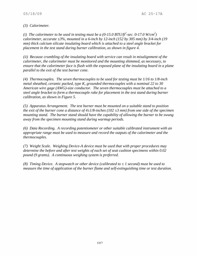
05/18/09 AC 25-17A
687
(3) Calorimeter. (i) The calorimeter to be used in testing must be a (0-15.0 BTU/ft2-sec. 0-17.0 W/cm2) calorimeter, accurate ±3%, mounted in a 6-inch by 12-inch (152 by 305 mm) by 3/4-inch (19 mm) thick calcium silicate insulating board which is attached to a steel angle bracket for placement in the test stand during burner calibration, as shown in figure 4. (ii) Because crumbling of the insulating board with service can result in misalignment of the calorimeter, the calorimeter must be monitored and the mounting shimmed, as necessary, to ensure that the calorimeter face is flush with the exposed plane of the insulating board in a plane parallel to the exit of the test burner cone. (4) Thermocouples. The seven thermocouples to be used for testing must be 1/16 to 1/8-inch metal sheathed, ceramic packed, type K, grounded thermocouples with a nominal 22 to 30 American wire gage (AWG)-size conductor. The seven thermocouples must be attached to a steel angle bracket to form a thermocouple rake for placement in the test stand during burner calibration, as shown in Figure 5. (5) Apparatus Arrangement. The test burner must be mounted on a suitable stand to position the exit of the burner cone a distance of 4±1/8-inches (102 ±3 mm) from one side of the specimen mounting stand. The burner stand should have the capability of allowing the burner to be swung away from the specimen mounting stand during warmup periods. (6) Data Recording. A recording potentiometer or other suitable calibrated instrument with an appropriate range must be used to measure and record the outputs of the calorimeter and the thermocouples. (7) Weight Scale. Weighing Device-A device must be used that with proper procedures may determine the before and after test weights of each set of seat cushion specimens within 0.02 pound (9 grams). A continuous weighing system is preferred. (8) Timing Device. A stopwatch or other device (calibrated to ± 1 second) must be used to measure the time of application of the burner flame and self-extinguishing time or test duration.

05/18/09 AC 25-17A
688

05/18/09 AC 25-17A
689

05/18/09 AC 25-17A
690

05/18/09 AC 25-17A
691

05/18/09 AC 25-17A
692
1166 – 1170. [RESERVED]

05/18/09 AC 25-17A
693
1171. APPENDIX F, PART III, DID NOT EXIST PRIOR TO AMENDMENT 25-60. 1172. APPENDIX F, AMENDMENT 25-60, Effective June 16, 1986. This amendment added Part III.
PART III - TEST METHOD TO DETERMINE FLAME PENETRATION RESISTANCE OF CARGO COMPARTMENT LINERS.
(a) Criteria for Acceptance. (1) At least three specimens of cargo compartment sidewall or ceiling liner panels must be tested. (2) Each specimen tested must simulate the cargo compartment sidewall or ceiling liner panel, including any design features. such as joints, lamp assemblies, etc., the failure of which would affect the capability of the liner to safely contain a fire. (3) There must be no flame penetration of any specimen within 5 minutes after application of the flame source and the peak temperature measured at 4-inches above the upper surface of the horizontal test sample must not exceed 400ºF. (b) Summary of Method. This method provides a laboratory test procedure for measuring the capability of cargo compartment lining materials to resist flame penetration with a 2 gallon per hour (GPH) #2 Grade kerosene or equivalent burner fire source. Ceiling and sidewall liner panels may be tested individually provided a baffle is used to simulate the missing panel. Any specimen that passes the test as a ceiling liner panel may be used as a sidewall liner panel. (c) Test Specimens. (1) The specimen to be tested must measure 16±1/8-inches (406±3 mm) by 24±1/8-inches (610±3 mm). (2) The specimens must be conditioned at 70±5ºF. (21±2ºC.) and 55±5% humidity for at least 24 hours before testing. (d) Test Apparatus. The arrangement of the test apparatus, which is shown in Figure 3 of part II and Figures I through 3 of this part of Appendix F, must include the components described in this section. Minor details of the apparatus may vary, depending on the model of the burner used. (1) Specimen Mounting Stand. The mounting stand for the test specimens consists of steel angles as shown in Figure 1. (2) Test Burner. The burner to be used in testing must- (i) Be a modified gun type.

05/18/09 AC 25-17A
694
(ii) Use a suitable nozzle and maintain fuel pressure to yield a 2 GPH fuel flow. For example: an 80 degree nozzle nominally rated at 2.25 GPH and operated at 85 pounds per square-inch (PSI) gage to deliver 2.03 GPH. (iii) Have a 12-inch (305 mm) burner extension installed at the end of the draft tube with an opening 6-inches (152 mm) high and 11-inches (280 mm) wide as shown in Figure 3 of part II of this Appendix. (iv) Have a burner fuel pressure regulator that is adjusted to deliver a nominal 2.0 GPH of #2 Grade kerosene or equivalent. (v) Burner models which have been used successfully in testing are the Lenox Model OB-32, Carlin Model 200 CRD and Park Model DPL. The basic burner is described in FAA Powerplant Engineering Report No. 3A, Standard Fire Test Apparatus and Procedure for Flexible Hose Assemblies, dated March 1978; however, the test settings specified in this Appendix differ in some instances from those specified in the report. (3) Calorimeter. (i) The calorimeter to be used in testing must be a total heat flux Foil Type Gardon Gage of an appropriate range (approximately 0 to 15.0 British thermal unit (BTU) per ft.2 sec., 0-17.0 watts/cm2). The calorimeter must be mounted in a 6 by 12-inch (152 by 305 mm) by 3/4-inch (19 mm) thick insulating block which is attached to a steel angle bracket for placement in the test stand during burner calibration as shown in Figure 2 of this part of this Appendix. (ii) The insulating block must be monitored for deterioration and the mounting shimmed as necessary to ensure that the calorimeter face is parallel to the exit plane of the test burner cone. (4) Thermocouples. The seven thermocouples to be used for testing must be 1/16-inch ceramic sheathed, type K, grounded thermocouples with a nominal 30 American wire gage (AWG) size conductor. The seven thermocouples must be attached to a steel angle bracket to form a thermocouple rake for placement in the test stand during burner calibration as shown in Figure 3 of this part of this Appendix. (5) Apparatus Arrangement. The test burner must be mounted on a suitable stand to position the exit of the burner cone a distance of 8-inches from the ceiling liner panel and 2-inches from the sidewall liner panel. The burner stand should have the capability of allowing the burner to be swung away from the test specimen during warm-up periods. (6) Instrumentation. A recording potentiometer or other suitable instrument with an appropriate range must be used to measure and record the outputs of the calorimeter and the thermocouples.

05/18/09 AC 25-17A
695
(7) Timing Device. A stopwatch or other device must be used to measure the time of flame application and the time of flame penetration, if it occurs. (e) Preparation of Apparatus. Before calibration, all equipment must be turned on and allowed to stabilize, and the burner fuel flow must be adjusted as specified in paragraph (d)(2). (f) Calibration. To ensure the proper thermal output of the burner the following test must be made: (1) Remove the burner extension from the end of the draft tube. Turn on the blower portion of the burner without turning the fuel or igniters on. Measure the air velocity using a hot wire anemometer in the center of the draft tube across the face of the opening. Adjust the damper such that the air velocity is in the range of 1550 to 1800 ft./min. If tabs are being used at the exit of the draft tube, they must be removed prior to this measurement. Reinstall the draft tube extension cone. (2) Place the calorimeter on the test stand as shown in Figure 2 at a distance of 8-inches (203 mm) from the exit of the burner cone to simulate the position of the horizontal test specimen. (3) Turn on the burner, allow it to run for 2 minutes for warm-up, and adjust the damper to produce a calorimeter reading of 8.0±0.5 BTU per ft.2 sec. (9.1±0.6 Watts/cm2). (4) Replace the calorimeter with the thermocouple rake (see Figure 3). (5) Turn on the burner and ensure that each of the seven thermocouples reads 1700±100ºF. (927± 38ºC.) to ensure steady state conditions have been achieved. If the temperature is out of this range, repeat steps 2 through 5 until proper readings are obtained. (6) Turn off the burner and remove the thermocouple rake. (7) Repeat (1) to ensure that the burner is in the correct range. (g) Test Procedure. (1) Mount a thermocouple of the same type as that used for calibration at a distance of 4-inches (102 mm) above the horizontal (ceiling) test specimen. The thermocouple should be centered over the burner cone. (2) Mount the test specimen on the test stand shown in Figure 1 in either the horizontal or vertical position. Mount the insulating material in the other position. (3) Position the burner so that flames will not impinge on the specimen, turn the burner on, and allow it to run for 2 minutes. Rotate the burner to apply the flame to the specimen and simultaneously start the timing device.

05/18/09 AC 25-17A
696
(4) Expose the test specimen to the flame for 5 minutes and then turn off the burner. The test may be terminated earlier if flame penetrations observed. (5) When testing ceiling liner panels, record the peak temperature measured 4-inches above the sample. (6) Record the time at which flame penetration occurs if applicable. (h) Test Report. The test report must include the following: (1) A complete description of the materials tested including type, manufacturer, thickness, and other appropriate data. (2) Observations of the behavior of the test specimens during flame exposure such as delamination, resin ignition, smoke, etc., including the time of such occurrence. (3) The time at which flame penetration occurs, if applicable, for each of the three specimens tested. (4) Panel orientation (ceiling or sidewall).
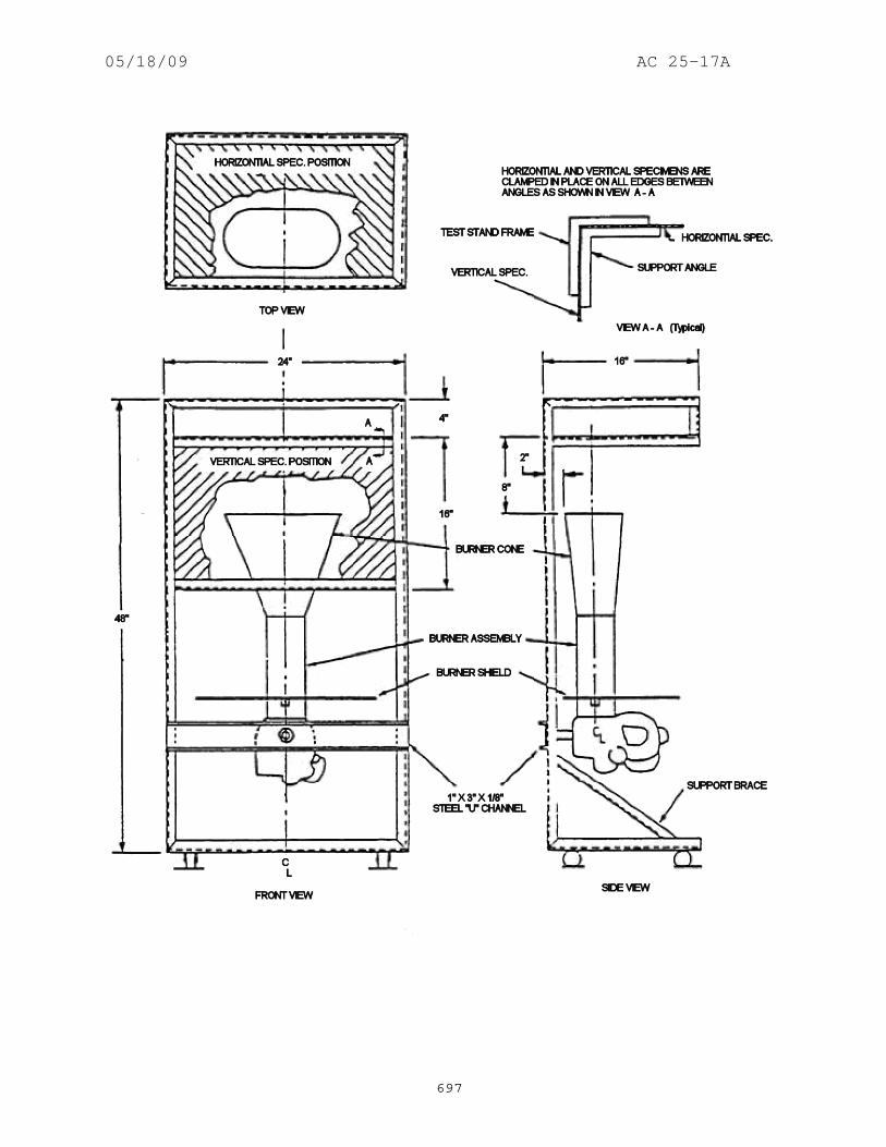
05/18/09 AC 25-17A
697

05/18/09 AC 25-17A
698

05/18/09 AC 25-17A
699

05/18/09 AC 25-17A
700
1173 – 1177. [RESERVED]
05/18/09 AC 25-17A
701
1178. APPENDIX F, PART IV, DID NOT EXIST PRIOR TO AMENDMENT 25-61. 1179. APPENDIX F, AMENDMENT 25-61, Effective August 20, 1986. This amendment added Part IV. PART IV - TEST METHOD TO DETERMINE THE HEAT RELEASE RATE FROM CABIN
MATERIALS EXPOSED TO RADIANT HEAT.
(a) Summary of Method. The specimen to be tested is injected into an environmental chamber through which a constant flow of air passes. The specimen's exposure is determined by a radiant heat source adjusted to produce the desired total heat flux on the specimen of 3.5 W/cm2 using a calibrated calorimeter. The specimen is tested so that the exposed surface is vertical. Combustion is initiated by piloted ignition. The combustion products leaving the chamber are monitored in order to calculate the release rate of heat. (b) Apparatus. The Ohio State University (OSU) rate of heat release apparatus, as described below, is used. This is a modified version of the rate of heat release apparatus standardized by the American Society of Testing and Materials (ASTM), ASTM E-906. (1) This apparatus is shown in Figure 1. All exterior surfaces of the apparatus, except the holding chamber, shall be insulated with 25 mm thick, low density, high temperature, fiberglass board insulation. A gasketed door through which the sample injection rod slides forms an airtight closure on the specimen hold chamber. (2) Thermopile. The temperature difference between the air entering the environmental chamber and that leaving is monitored by a thermopile having three hot and three cold, 32 gauge Chromel-Alumel junctions. The hot Junctions are spaced across the top of the exhaust stack. Two hot junctions are located 25 mm from each side on diagonally opposite corners, and the third in the center of the chimney's cross-section 10 mm below the top of the chimney. The cold junctions are located in the pan below the lower air distribution plate (Refer to paragraph (b)(4)). (i) Thermal Inertia Compensator. A compensator tab is made from 0.55 mm stainless steel sheet, 10 by 20 mm. An 800 mm length of 24 gauge Chromel-Alumel, glass insulated, duplex thermocouple wire is welded or silver soldered to the tab as shown in Figure 2, and the wire bent back so that it is flush against the metal surface. (ii) The compensator tab must be mounted on the exhaust stack as shown in Figure 3 using a 6-32 round head machine screw, 12 mm long. Add small (approximately 4.5 mm O.D., 9 mm O.D.) washers between the head of the machine screw and the compensator tab to give the best response to a square wave input. (One or two washers should be adequate.) The "sharpness" of the square wave can be increased by changing the ratio of the output from the thermopile and compensator thermocouple which is fed to the recorder. The ratio is changed by adjusting the 1-K ohm variable resistor (R1) of the thermopile bleeder shown in Figure 4. When adjusting compensation, keep R1 as small as possible. Adjustment of the compensator

05/18/09 AC 25-17A
702
must be made during calibration (Refer to paragraph (c)(1)) at a heat release rate of 7.0 plus or minus 0.5 kW. (iii) Adjust the washers and the variable resistor (R1) so that 90 percent of full scale response is obtained in 8 to 10 seconds. There must be no overshoot, as shown in Figure 5A. If an insufficient number of washers is added, or R1 is too small, the output with square wave input will look like Figure 5B; if too many washers are added and R1 is too large, the output will look like Figure 5A. (iv) Subtract the output of the compensator from the thermopile. The junctions enclosed in the dotted circle of Figure 4 are kept at the same constant temperature by electrically insulating the junctions and placing them on the pipe carrying air to the manifold, then covering them and the pipe with thermal insulation. (v) Thermopile hot junctions must be cleared of soot deposits on a daily basis during periods of testing. (3) Radiation Source. A radiant heat source for generating a flux up to 100 kW/ m2, using four silicon carbide elements, Type LL, 20-inches (50.8 cm) long by 5/8-inch (1.54 cm) O.D., nominal resistance 1.4 ohms, is shown in Figures 6A and 6B. The silicon carbide elements are mounted in the stainless steel panel box by inserting them through 15.9 mm holes in 0.8 mm thick ceramic fiber board. Location of the holes in the pads and stainless steel cover plates are shown in Figure 6B. The diamond shaped mask of 24 gauge stainless steel is added to provide uniform heat flux over the area occupied by the 150 by 150 mm vertical sample. A power supply of 12.5 kVA. adjustable from 0 to 270 volts, is required. (4) Air Distribution System. The air entering the environmental chamber is distributed by a 6.3 mm thick aluminum plate having eight, No. 4 drill holes, 51 mm from sides on 102 mm centers, mounted at the base of the environmental chamber. A second plate of 18 gauge steel having 120, evenly spaced, No. 28 drill holes is mounted 150 mm above the aluminum plate. A well-regulated air supply is required. The air supply manifold at the base of the pyramidal section has 48, evenly spaced, No. 26 drill holes located 10 mm from the inner edge of the manifold so that 0.03 m3/second of air flows between the pyramidal sections and 0.01 m3/second flows through the environmental chamber when total air flow to apparatus is controlled at 0.04 m3/second. (5) Exhaust Stack. An exhaust stack, 133 mm by 70 mm in cross section, and 254 mm long, fabricated from 28 gauge stainless steel, is mounted on the outlet of the pyramidal section. A 25 mm by 76 mm plate of 31 gauge stainless steel is centered inside the stack, perpendicular to the air flow, 75 mm above the base of the stack. (6) Specimen Holders. (i) The 150 mm by 150 mm specimen is tested in a vertical orientation. The holder (Figure 7) is provided with a specimen holder frame, which touches the specimen (which is wrapped with aluminum foil as required by paragraph (d)(3) of this part) along only the 10 mm

05/18/09 AC 25-17A
703
perimeter, and a "V" shaped spring to hold the assembly together. A detachable 12 mm x12 mm x150 mm drip pan is also provided for testing of materials prone to melting and dripping. The positioning of the spring and frame may be changed to accommodate different specimen thicknesses by inserting the retaining rod in different holes on the specimen holder. (ii) Since the radiation shield described in ASTM E-906 is not used, a guide pin is added to the injection mechanism. This fits into a slotted metal plate on the injection mechanism outside of the holding chamber and can be used to provide accurate positioning of the specimen face after injection. The front surface of the specimen shall be 100 mm from the closed radiation doors after injection. (iii) The specimen holder clips onto the mounted bracket (Figure 7). The mounting bracket is attached to the injection rod by three screws which pass through a wide area washer welded onto a 1/2-inch nut. The end of the injection rod is threaded to screw into the nut and a .020-inch thick wide area washer is held between two 1/2-inch nuts which are adjusted to tightly cover the hole in the radiation doors through which the injection rod or calibration calorimeter pass. (7) Radiometers. A total-flux flush (calorimeter) mounted in the center of a 1/2-inch Kaowool "M" board inserted in the sample holder must be used to measure the total heat flux. The total-flux calorimeter must have a view angle of 180 degrees and be calibrated for incident flux. The calorimeter calibration must be acceptable to the Administrator. (8) Pilot-Flame Positions. Pilot ignition of the specimen must be accomplished by simultaneously exposing the specimen to a lower pilot burner and an upper pilot burner, as described in paragraph (b)(8)(i) and (b)(8)(ii), respectively. (i) Lower Pilot Burner. The pilot-flame tubing must be 6.3 mm O.D., 0.8 mm wall stainless steel tubing. A mixture of 120 cm3/min. of methane and 850 cm3/min. of air must be fed to the lower pilot flame burner. The normal position of the end of the pilot burner tubing is 10 mm from, and perpendicular to, the exposed vertical surface of the specimen. The centerline at the outlet of the burner tubing must intersect the vertical centerline of the sample at a point 5 mm above the lower edge of the specimen. (ii) Upper Pilot Burner. The pilot burner must be a straight length of 6.3 mm O.D., 0.8 mm wall, stainless steel tubing that is 360 mm long. One end of the tubing shall be closed, and three No. 40 drill holes shall be drilled into the tubing, 60 mm apart, for gas ports, all radiating in the same direction. The first hole must be 5 mm from the closed end of the tubing. The tube is inserted into the environmental chamber through a 6.6 mm hole drilled 10 mm above the upper edge of the window frame. The tube is supported and positioned by an adjustable "Z" shaped support mounted outside the environmental chamber, above the viewing window. The tube is positioned above and 20 mm behind the exposed upper edge of the specimen. The middle hole must be in the vertical plane perpendicular to the exposed surface of the specimen which passes through its vertical centerline and must be pointed toward the radiation source. The gas supplied to the burner must be methane adjusted to produce flame lengths of 25 mm.

05/18/09 AC 25-17A
704
(c) Calibration of Equipment. (1) Heat Release Rate. A burner as shown in Figure 8 must be placed over the end of the lower pilot flame tubing using a gas-tight connection. The flow of gas to the pilot flame must be at least 99 percent methane and must be accurately metered. Prior to usage, the wet test meter is properly leveled and filled with distilled water to the tip of the internal pointer while no gas is flowing. Ambient temperature and pressure of the water are based on the internal wet test meter temperature. A baseline flow rate of approximately 1 liter/min is set and increased to higher preset flows of 2, 4, 6, and 8 liters/min. The rate is determined by using a stop watch to time a complete revolution of the wet test meter for both the baseline and higher flow, with the flow returned to base-line before changing to the next higher flow. The thermopile baseline voltage is measured. The gas flow to the burner must be increased to the higher preset flow and allowed to burn for 4.0 minutes, and the thermopile voltage must be measured. The sequence is repeated until all four values have been determined. The average of the four values must be used as the calibration factor. The procedure must be repeated if the percent relative standard deviation is greater than 5 percent. Calculations are shown in paragraph (f). (2) Flux Uniformity. Uniformity of flux over the specimen must be checked periodically and after each heating element change to determine if it is within acceptable limits of ±5 percent. (d) Sample Preparation. (1) The standard size for vertically mounted specimens is 150 mm x 150 mm for exposed surface with thickness up to 100 mm. (2) Conditioning. Specimens must be conditioned as described in part I of this appendix. (3) Mounting. Only one surface of a specimen will be exposed during a test. A single layer of 0.025 mm aluminum foil is wrapped tightly on all unexposed sides. (e) Procedure. (1) The power supply to the radiant panel is set to produce a radiant flux of 3.5 W/cm2. The flux is measured at the point which the center of the specimen surface will occupy when positioned for test. The radiant flux is measured after the air flow through the equipment is adjusted to the desired rate. The sample should be tested in its end use thickness. (2) The pilot flames are lighted and their position, as described in paragraph (b)(8), is checked. (3) The air flow to the equipment is set at 0.04±0.001 m3/s at atmospheric pressure. Proper air flow may be set and monitored by either: (1) An orifice meter designed to produce a pressure drop of at least 200 mm of the manometric fluid, or by; (2) A rotometer (variable

05/18/09 AC 25-17A
705
orifice meter) with a scale capable of being read to ±0.0004 m3/s. The stop on the vertical specimen holder rod is adjusted so that the exposed surface of the specimen is positioned 100 mm from the entrance when injected into the environmental chamber. (4) The specimen is placed in the hold chamber with the radiation doors closed. The airtight outer door is secured, and the recording devices are started. The specimen must be retained in the hold chamber for 60±10 seconds, before injection. The thermopile "zero" value is determined during the last 20 seconds of the hold period. (5) When the specimen is to be injected, the radiation doors are opened, the specimen is injected into the environmental chamber, and the radiation doors are closed behind the specimen. (6) A negative heat release will occur due to heat absorption by the cold specimen holder. Data-acquisition devices must have the capability of following these negative outputs and correcting the sample burn with a "blank" test result. (7) Injection of the specimen marks time zero. A continuous record of the thermopile output must be made during the time the specimen is in the environmental chamber. (8) The test duration time is five minutes. (9) A minimum of three specimens must be tested. (f) Calculations. (1) The calibration factor Is calculated as follows:
( )( )
KF FV V
kmole T
P P moleCH STP WATTkcal
kww
hcal
a
v=
−−
×−
× ×−
× × ×1 0
1 0
2108 22 273760
42241 01433 1000
( . ).
.min.
Fo = flow of methane at baseline (1pm) F1 = higher preset flow of methane (1pm) Vo = thermopile voltage at baseline (mv) V1 = thermopile voltage at higher flow (mv) Ta = Ambient temperature (K) P = Ambient pressure (mm Hg) Pv = Water vapor pressure (mm Hg)

05/18/09 AC 25-17A
706
(2) Heat release rates may be calculated from the reading of the thermopile output voltage at any instant of time as:
H R R V Vm
Km bh=
−×
( ).0 2 3 2 3 2
HRR = Heat release Rate kw/m2 Vm = measured thermopile voltage (mv) Vb = "Blank" thermopile voltage Kh = Calibration Factor (Kw/mv) Vb is the "blank" test obtained by a run conducted with an empty sample holder assembly. Refer to paragraph (7) above.
(3) The integral of the heat release rate is the total heat release as a function of time and is calculated by multiplying the rate by the data sampling frequency in minutes and summing the time from zero to two minutes. (g) Criteria. The total positive heat release over the first two minutes of exposure for each of the three or more samples tested must be averaged, and the peak heat release rate for each of the samples must be averaged. The average total heat release must not exceed 65 kilowatt-minutes per square meter, and the average peak heat release rate must not exceed 65 kilowatts per square meter. (h) Report. The test report must include the following for each specimen tested: (1) Description of the specimen. (2) Radiant heat flux to the specimen, expressed in W/cm2. (3) Data giving release rates of heat (in kW/m2) as a function of time, either graphically or tabulated at intervals no greater than 10 seconds. The calibration factor (kh) must be recorded. (4) If melting, sagging, delaminating, or other behavior that affects the exposed surface area or the mode of burning occurs, these behaviors must be reported, together with the time at which such behaviors were observed. (5) The peak heat release and the 2-minute integrated heat release rate must be reported.

05/18/09 AC 25-17A
707

05/18/09 AC 25-17A
708

05/18/09 AC 25-17A
709

05/18/09 AC 25-17A
710

05/18/09 AC 25-17A
711

05/18/09 AC 25-17A
712

05/18/09 AC 25-17A
713

05/18/09 AC 25-17A
714

05/18/09 AC 25-17A
715
1180. APPENDIX F, AMENDMENT 25-66, Effective September 26, 1988. This amendment revised Part IV and added Part V. PART IV - TEST METHOD TO DETERMINE THE HEAT RELEASE RATE FROM CABIN
MATERIALS EXPOSED TO RADIANT HEAT. Appendix F-Part IV-Test Method to Determine the Heat Release Rate From Cabin Materials Exposed to Radiant Heat (a) Summary of Method. (1) The specimen to be tested is injected into an environmental chamber through which a constant flow of air passes. The specimen's exposure is determined by a radiant heat source adjusted to produce the desired total heat flux on the specimen of 3.5 W/cm2, using a calibrated calorimeter. The specimen is tested so that the exposed surface is vertical. Combustion is initiated by piloted ignition. The combustion products leaving the chamber are monitored in order to calculate the release rate of heat. (b) Apparatus. The Ohio State University (OSU) rate of heat release apparatus as described below, is used. This is a modified version of the rate of heat release apparatus standardized by the American Society of Testing and Materials (ASTM), ASTM E-906. (1) This apparatus is shown in Figures 1A. All exterior surfaces of the apparatus, except the holding chamber, must be insulated with 25 mm thick, low density, high temperature, fiberglass board insulation. A gasketed door through which the sample injection rod slides forms an airtight closure on the specimen hold chamber. (2) Thermopile. [The temperature difference between the air entering the environmental chamber and that leaving is monitored by a thermopile having five hot and five cold, 24 gauge Chromel-Alumel junctions. The hot junctions are spaced across the top of the exhaust stack, 10mm below the tope of the chimney. One thermocouple is located in the geometric center, with the other four located 30mm from the center along the diagonal toward each of the corners (Figure 5). The cold junctions are located in the pan below the lower air distribution plate (Refer to paragraph (b)(4)). Thermopile hot junctions must be cleared of soot deposits as needed to maintain the calibrated sensitivity.] (i) Thermal Inertia Compensator. A compensator tab is made from 0.55mm stainless steel sheet, 10 by 20mm. An 800 length of 24 gauge Chromel-Alumel, glass insulated, duplex thermocouple wire is welded or silver soldered to the tab as shown in Figure 2, and the wire bent back so that it is flush against the metal surface. (ii) The compensator tab must be mounted on the exhaust stack as shown in Figure 3 using a 6-32 round head machine screw, 23mm long. Add small (approximately 4.5mm O.D., 9mm O.D.) washers between the head of the machine screw and the compensator tab to give the best response to a square wave input. (One or two washers should be adequate.) The "sharpness" of the square wave can be increased by changing the ratio of the output from the thermopile and compensator thermocouple which is fed to the recorder. The ratio is changed by adjusting the 1-

05/18/09 AC 25-17A
716
K ohm variable resistor (R1) of the thermopile bleeder shown in Figure 4. When adjusting compensation, keep R1 as small as possible. Adjustment of the compensator must be made during calibration (Refer to paragraph (c)(1)) at a heat release rate of 7.0 plus or minus 0.5 kW. (iii) Adjust the washers and the variable resistor (R1) so that 90 percent of full scale response is obtained in 8 to 10 seconds. There must be no overshoot, as shown in Figure 5A. If an insufficient number of washers is added, or R1 is too small, the output with square wave input will look like Figure 5B; if too many washers are added and R1 is too large, the output will look like Figure 5A. (iv) Subtract the output of the compensator from the thermopile. The junctions enclosed in the dotted circle of Figure 4 are kept at the same constant temperature by electrically insulating the junctions and placing them on the pipe carrying air to the manifold, then covering them and the pipe with thermal insulation. (v) Thermopile hot junctions must be cleared of soot deposits on a daily basis during periods of testing. (3) Radiation Source. [A radiant heat source for generating a flux up to 100 kW/m2, using four silicone carbide elements, Type LL, 20-inches (50.8 cm) long by 5/8-inch (1.54 cm) O.D., nominal resistance 1.4 ohms, is shown in Figures 2A and 2B. The silicone carbide elements are mounted in the stainless steel panel box by inserting them through 15.9mm holes in 0.8mm thick ceramic fiber board. Location of the holes in the pads and stainless steel cover plates are shown in Figure 2B. The diamond shaped mask of 24-gauge stainless steel is added to provide uniform heat flux over the area occupied by the 150 by 150mm vertical sample.] (4) Air Distribution System. The air entering the environmental chamber is distributed by a 6.3 mm thick aluminum plate having eight, No. 4 drill-holes, 51 mm from sides on 102 mm centers, mounted at the base of the environmental chamber. A second plate of 18 gauge steel having 120, evenly spaced, No. 28 drill holes is mounted 150 mm above the aluminum plate. A well-regulated air supply is required. The air supply manifold at the base of the pyramidal section has 48, evenly spaced, No. 26 drill holes located 10 mm from the inner edge of the manifold so that 0.03 m3/second of air flows between the pyramidal sections and 0.01 m3/second flows through the environmental chamber when total air flow to apparatus is controlled at 0.04 m3/second. (5) Exhaust Stack. An exhaust stack, 133mm by 70mm in cross section, and 254mm long, fabricated from 28 gauge stainless steel, is mounted on the outlet of the pyramidal section. A 25mm by 76mm plate of 31 gauge stainless steel is centered inside the stack, perpendicular to the air flow, 75mm above the base of the stack. [(6) Specimen Holders. The 150 mm x 150 mm specimen is tested in a vertical orientation. The holder (Figure 3) is provided with a specimen holder frame, which touches the specimen (which is wrapped with aluminum foil as required by paragraph (d)(3) of this part) along only the 6 mm perimeter, and a "V" shaped spring to hold the assembly together. A detachable 12 mm X 12 mm X 150 mm drip pan and two .020-inch stainless steel wires (as shown in Figure 3) should be
05/18/09 AC 25-17A
717
used for testing of materials prone to melting and dripping. The positioning of the spring and frame may be changed to accommodate different specimen thicknesses by inserting the retaining rod in different holes on the specimen holder. Since the radiation shield described in ASTM E-906 is not used, a guide pin is added to the injection mechanism. This fits into a slotted metal plate on the injection mechanism outside of the holding chamber and can be used to provide accurate positioning of the specimen face after injection. The front surface of the specimen shall be 100mm from the closed radiation doors after injection. The specimen holder clips onto the mounted bracket (Figure 3). The mounting bracket is attached to the injection rod by three screws which pass through a wide area washer welded onto a 1/2-inch nut. The end of the injection rod is threaded to screw into the nut, and a .020-inch thick wide area washer is held between two 1/2-inch nuts which are adjusted to tightly cover the hole in the radiation doors through which the injection rod or calibration calorimeter pass. (7) Calorimeter. A total-flux flush calorimeter must be mounted in the center of a 1/2-inch Kaowool "M" board inserted in the sample holder to measure the total heat flux. The calorimeter must have a view angle of 180 degrees and be calibrated for incident flux. The calorimeter calibration must be acceptable to the Administrator. (8) Pilot-Flame Positions. Pilot ignition of the specimen must be accomplished by simultaneously exposing the specimen to a lower pilot burner and an upper pilot burner, as described in paragraph (b)(8)(i) and (b)(8)(ii), respectively. The pilot burner must remain lighted for the entire 5-minute duration of the test. (i) Lower Pilot Burner. The pilot-flame tubing must be 6.3mm O.D., 0.8mm wall, stainless steel tubing. A mixture of 120 cm3/min. of methane and 850 cm3/min. of air must be fed to the lower pilot flame burner. The normal position of the end of the pilot burner tubing is 10 mm from and perpendicular to the exposed vertical surface of the specimen. The centerline at the outlet of the burner tubing must intersect the vertical centerline of the sample at a point 5mm above the lower exposed edge of the specimen.] (ii) Upper Pilot Burner. The pilot burner must be a straight length of 6.3mm O.D., 0.8mm wall, stainless steel tubing is 360mm long. One end of the tubing shall be closed, and three No. 40 drill holes shall be drilled into the tubing, 60mm apart, for gas ports, all radiating in the same direction. The first hole must be 5mm from the closed end of the tubing. The tube is inserted into the environmental chamber through a 6.6mm hole drilled 10mm above the upper edge of the window frame. The tube is supported and positioned by an adjustable "Z" shaped support mounted outside the environmental chamber, above the viewing window. The tube is positioned above and 20mm behind the exposed upper edge of the specimen. The middle hole must be in the vertical plane perpendicular to the exposed surface of the specimen which passes through its vertical centerline and must be pointed toward the radiation source. The gas supplied to the burner must be methane adjusted to produce flame lengths of 25mm.

05/18/09 AC 25-17A
718
(c) Calibration of Equipment.— (1) Heat Release Rate. [A burner as shown in Figure 4 must be placed over the end of the lower pilot flame tubing using a gas tight connection. The flow of gas to the pilot flame must be at least 99 percent methane and must be accurately metered. Prior to usage, the wet test meter is properly leveled and filled with distilled water to the tip of the internal pointer while no gas is flowing. Ambient temperature and pressure of the water are based on the internal wet test meter temperature. A baseline flow rate of approximately 1 liter/min is set and increased to higher preset flows of 4, 6, 8, 6, and 4 liters/min. The rate is determined by using a stopwatch to time a complete revolution of the wet test meter for both the baseline and higher flow, with the flow returned to baseline before changing to the next higher flow. The thermopile baseline voltage is measured. The gas flow to the burner must be increased to the higher preset flow and allowed to burn for 2.0 minutes, and the thermopile voltage must be measured. The sequence is repeated until all five values have been determined. The average of the five values must be used as the calibration factor. The procedure must be repeated if the percent relative standard deviation is greater than 5 percent. Calculations are shown in paragraph (f).] (2) Flux Uniformity. Uniformity of flux over the specimen must be checked periodically and after each heating element change to determine if it is within acceptable limits of plus or minus 5 percent. (d) Sample Preparation. [(1) The standard size for vertically mounted specimens is 150 X 150 mm with thickness up to 45 mm).] (2) Conditioning. Specimens must be conditioned as described in Part 1 of this Appendix. (3) Mounting. Only one surface of a specimen will be exposed during a test. A single layer of 0.025mm aluminum foil is wrapped tightly on all exposed sides. (e) Procedure. (1) The power supply to the radiant panel is set to produce a radiant flux of 3.5 W/cm2. The flux is measured at the point which the center of the specimen surface will occupy when positioned for test. The radiant flux is measured after the air flow through the equipment is adjusted to the desired rate. The sample should be tested in its end use thickness. (2) The pilot flames are lighted and their position, as described in paragraph (b)(8), is checked. (3) The air flow to the equipment is set at 0.04 plus or minus 0.001 m3/s at atmospheric pressure. Proper air flow may be set and monitored by either: (1) An orifice meter designed to produce a pressure drop of at least 200mm of the manometric fluid, or by (2) a rotometer (variable orifice meter) with a scale capable of being read to plus or minus 0.0004 m3/s. The stop on the vertical specimen holder rod is adjusted so that the exposed surface of the specimen is positioned 100mm from the entrance when injected into environmental chamber.

05/18/09 AC 25-17A
719
(4) The specimen is placed in the hold chamber with the radiation doors closed. The airtight outer door must be secured, and the recording devices must be started. The specimen must be retained in the hold chamber for 60 seconds, plus or minus 10 seconds, before injection. The thermopile "zero" value must be determined during the last 20 seconds of the hold period (5) When the specimen is to be injected, the radiation doors are opened, the specimen is injected into the environmental chamber, and the radiation doors are closed behind the specimen. (6) [[Reserved.]] (7) [Injection of the specimen and closure of the inner door marks time zero. A record of the thermopile output with at least one data point per second must be made during the time the specimen is in the environmental chamber.] (8) The test duration is five minutes. (9) A minimum of three specimens must be tested. (f) Calculations. (1) The calibration factor is calculated as follows:
( )( )
( )Kh
F1 F0V1 V0
210.8 - 22 kcalmole
273Ta
P Pv760
moleCH4STP22.41
WATTmin.01433kcal
kw1000w
=−
−× × ×
−× × ×
F0 = flow of methane at baseline (1pm) F1 = higher preset flow of methane (1pm) V0 = thermopile voltage at baseline (mv) V1 = Thermopile voltage at higher flow (mv) Ta = Ambient temperature (K) P = Ambient pressure (mm Hg) PV = Water vapor pressure (mm Hg) [(2) Heat release rates may be calculated from the reading of the thermopile output voltage at any instant of time as:
( )H R R
Vm K h.0 2 3 2 3 m 2=
×
HRR = Heat release Rate kw/m2 Vm = measured thermopile voltage (mv) Kh = Calibration Factor (Kw/mv)] (3) The integral of the heat release rate is the total heat release as a function of time and is calculated by multiplying the rate by the data sampling frequency in minutes and summing the time from zero to two minutes.

05/18/09 AC 25-17A
720
(g) Criteria. The total positive heat release over the first two minutes of exposure for each of the three or more samples tested must be averaged, and the peak heat release rate for each of the samples must be averaged, and the peak heat release rate for each of the samples tested must be averaged, and the peak heat release rate for each of the samples must be averaged. The average total heat release must not exceed 65 kilowatt-minutes per square meter, and the average peak heat release rate must not exceed 75 kilowatts per square meter. (h) Report. The test report must include the following for each specimen tested: (1) Description of the specimen. (2) Radiant heat flux to the specimen, expressed in W/cm2. (3) Data giving release rates of heat (in kW/m2 ) as a function of time, either graphically or tabulated at intervals no greater than 10 seconds. The calibration factor (kn) must be recorded. (4) If melting, sagging, delaminating, or other behavior that affects the exposed surface area or the mode of burning occurs, these behaviors must be reported, together with the time at which such behaviors were observed. (5) The peak heat release and the 2-minute integrated heat release rate must be reported.

05/18/09 AC 25-17A
721

05/18/09 AC 25-17A
722

05/18/09 AC 25-17A
723

05/18/09 AC 25-17A
724

05/18/09 AC 25-17A
725

05/18/09 AC 25-17A
726
1181 – 1185. [RESERVED]

05/18/09 AC 25-17A
727
1186. APPENDIX F, PART V, DID NOT EXIST PRIOR TO AMENDMENT 25-66. 1187. APPENDIX F, AMENDMENT 25-66, Effective September 26, 1988. PART V - TEST METHOD TO DETERMINE THE SMOKE EMISSION
CHARACTERISTICS OF CABIN MATERIALS
(a) Summary of Method. The specimens must be constructed, conditioned, and tested in the flaming mode in accordance with American Society of Testing and Materials (ASTM) Standard Test Method ASTM F81483. (b) Acceptance Criteria. The specific optical smoke density (DS), which is obtained by averaging the reading obtained after 4 minutes with each of the three specimens, shall not exceed 200 1188 – 1192. [RESERVED]

05/18/09 AC 25-17A
728
THIS PAGE INTENTIONALY LEFT BLANK

05/18/09 AC 25-17A
729
1193. APPENDIX F, PART VI ,DID NOT EXIST PRIOR TO AMENDMENT 25-111. 1194. APPENDIX F, AMENDMENT 25-111, Effective September 2, 2003. This amendment revised Part I and added Parts VI and VII.
[PART VI-TEST METHOD TO DETERMINE THE FLAMMABILITY AND FLAME PROPAGATION CHARACTERISTICS OF THERMAL/ACOUSTIC INSULATION MATERIALS] [Use this test method to evaluate the flammability and flame propagation characteristics of thermal/acoustic insulation when exposed to both a radiant heat source and a flame. (a) Definitions. "Flame propagation" means the furthest distance of the propagation of visible flame towards the far end of the test specimen, measured from the midpoint of the ignition source flame. Measure this distance after initially applying the ignition source and before all flame on the test specimen is extinguished. The measurement is not a determination of burn length made after the test. "Radiant heat source" means an electric or air propane panel. "Thermal/acoustic insulation" means a material or system of materials used to provide thermal and/or acoustic protection. Examples include fiberglass or other batting material encapsulated by a film covering and foams. "Zero point" means the point of application of the pilot burner to the test specimen. (b) Test apparatus.

05/18/09 AC 25-17A
730
(1) Radiant panel test chamber. Conduct tests in a radiant panel test chamber (see figure 1 above). Place the test chamber under an exhaust hood to facilitate clearing the chamber of smoke after each test. The radiant panel test chamber must be an enclosure 55-inches (1397 mm) long by 19.5 (495 mm) deep by 28 (710 mm) to 30-inches (maximum) (762 mm) above the test specimen. Insulate the sides, ends, and top with a fibrous ceramic insulation, such as Kaowool MTM board. On the front side, provide a 52 by 12 inches (1321 by 305 mm) draft-free, high-temperature, glass window for viewing the sample during testing. Place a door below the window to provide access to the movable specimen platform holder. The bottom of the test chamber must be a sliding steel platform that has provision for securing the test specimen holder in a fixed and level position. The chamber must have an internal chimney with exterior dimensions of 5.1-inches (129 mm) wide, by 16.2-inches (411 mm) deep by 13-inches (330 mm) high at the opposite end of the chamber from the radiant energy source. The interior dimensions must be 4.5-inches (114 mm) wide by 15.6-inches (395 mm) deep. The chimney must extend to the top of the chamber (see figure 2).

05/18/09 AC 25-17A
731
(2) Radiant heat source. Mount the radiant heat energy source in a cast iron frame or equivalent. An electric panel must have six, 3--inch wide emitter strips. The emitter strips must be perpendicular to the length of the panel. The panel must have a radiation surface of 12-7/8 by 18-1/2 -inches (327 by 470 mm). The panel must be capable of operating at temperatures up to 1300 degree F (704 degree C). An air propane panel must be made of a porous refractory material and have a radiation surface of 12 by 18-inches (305 by 457 mm).

05/18/09 AC 25-17A
732
The panel must be capable of operating at temperatures up to 1,500 degree F (816 degree C). See figures 3a and 3b.

05/18/09 AC 25-17A
733
(i) Electric radiant panel. The radiant panel must be 3-phase and operate at 208 volts. A single-phase, 240 volt panel is also acceptable. Use a solid-state power controller and microprocessor- based controller to set the electric panel operating parameters. (ii) Gas radiant panel. Use propane (liquid petroleum gas-2.1 UN 1075) for the radiant panel fuel. The panel fuel system must consist of a venturi-type aspirator for mixing gas and air at approximately atmospheric pressure. Provide suitable instrumentation for monitoring and controlling the flow of fuel and air to the panel. Include an air flow gauge, an air flow regulator, and a gas pressure gauge. (iii) Radiant panel placement. Mount the panel in the chamber at 30 degree to the horizontal specimen plane, and 7-1/2-inches above the zero point of the specimen. (3) Specimen holding system. (i) The sliding platform serves as the housing for test specimen placement. Brackets may be attached (via wing nuts) to the top lip of the platform in order to accommodate various

05/18/09 AC 25-17A
734
thicknesses of test specimens. Place the test specimens on a sheet of Kaowool MTM board or 1260 Standard Board (manufactured by Thermal Ceramics and available in Europe), or equivalent, either resting on the bottom lip of the sliding platform or on the base of the brackets. It may be necessary to use multiple sheets of material based on the thickness of the test specimen (to meet the sample height requirement). Typically, these non-combustible sheets of material are available in 1/4-inch (6 mm) thicknesses. See figure 4. A sliding platform that is deeper than the 2-inches (50.8mm) platform shown in figure 4 is also acceptable as long as the sample height requirement is met.
(ii) Attach a 1/2-inch (13 mm) piece of Kaowool MTM board or other high temperature material measuring 41-1/2 by 8-1/4-inches (1054 by 210 mm) to the back of the platform. This board serves as a heat retainer and protects the test specimen from excessive preheating. The height of this board must not impede the sliding platform movement (in and out of the test chamber). If the platform has been fabricated such that the back side of the platform is high enough to prevent excess preheating of the specimen when the sliding platform is out, a retainer board is not necessary. (iii) Place the test specimen horizontally on the non- combustible board(s). Place a steel retaining/securing frame fabricated of mild steel, having a thickness of 1/8-inch (3.2 mm) and overall dimensions of 23 by 13-1/8 -inches (584 by 333 mm) with a specimen opening of 19 by 10-3/4 -inches (483 by 273 mm) over the test specimen. The front, back, and right portions of the top flange of the frame must rest on the top of the sliding platform, and the bottom flanges must pinch all 4 sides of the test specimen. The right bottom flange must be flush with the sliding platform. See figure 5.

05/18/09 AC 25-17A
735
(4) Pilot Burner. The pilot burner used to ignite the specimen must be a BernzomaticTM commercial propane venturi torch with an axially symmetric burner tip and a propane supply tube with an orifice diameter of 0.006-inches (0.15 mm). The length of the burner tube must be 2-7/8 -inches (71 mm). The propane flow must be adjusted via gas pressure through an in-line regulator to produce a blue inner cone length of 3/4-inch (19 mm). A 3/4-nch (19 mm) guide (such as a thin strip of metal) may be soldered to the top of the burner to aid in setting the flame height. The overall flame length must be approximately 5-inches long (127 mm). Provide a way to move the burner out of the ignition position so that the flame is horizontal and at least 2-inches (50 mm) above the specimen plane. See figure 6.

05/18/09 AC 25-17A
736
(5) Thermocouples. Install a 24 American Wire Gauge (AWG) Type K (Chromel-Alumel) thermocouple in the test chamber for temperature monitoring. Insert it into the chamber through a small hole drilled through the back of the chamber. Place the thermocouple so that it extends 11-inches (279 mm) out from the back of the chamber wall, 11-1/2 -inches (292 mm) from the right side of the chamber wall, and is 2-inches (51 mm) below the radiant panel. The use of other thermocouples is optional. (6) Calorimeter. The calorimeter must be a one-inch cylindrical water-cooled, total heat flux density, foil type Gardon Gage that has a range of 0 to 5 BTU/ft 2 -second (0 to 5.7 Watts/cm2 ). (7) Calorimeter calibration specification and procedure. (i) Calorimeter specification. (A) Foil diameter must be 0.25 ±0.005-inches (6.35 ±0.13 mm). (B) Foil thickness must be 0.0005 ±0.0001-inches (0.013 ± ;0.0025 mm). (C) Foil material must be thermocouple grade Constantan. (D) Temperature measurement must be a Copper Constantan thermocouple. (E) The copper center wire diameter must be 0.0005-inches (0.013 mm). (F) The entire face of the calorimeter must be lightly coated with "Black Velvet" paint having an emissivity of 96 or greater. (ii) Calorimeter calibration. (A) The calibration method must be by comparison to a like standardized transducer. (B) The standardized transducer must meet the specifications given in paragraph VI(b)(6) of this appendix.

05/18/09 AC 25-17A
737
(C) Calibrate the standard transducer against a primary standard traceable to the National Institute of Standards and Technology (NIST). (D) The method of transfer must be a heated graphite plate. (E) The graphite plate must be electrically heated, have a clear surface area on each side of the plate of at least 2 by 2-inches (51 by 51 mm), and be 1/8 -inch ± 1/16 -inch thick (3.2 ± 1.6 mm). (F) Center the 2 transducers on opposite sides of the plates at equal distances from the plate. (G) The distance of the calorimeter to the plate must be no less than 0.0625-inches (1.6 mm), nor greater than 0.375-inches (9.5 mm). (H) The range used in calibration must be at least 0-3.5 BTUs/ ft 2 second (0-3.9 Watts/cm2 ) and no greater than 0-5.7 BTUs/ ft 2 second (0-6.4 Watts/cm2 ). (I) The recording device used must record the 2 transducers simultaneously or at least within 1/10 of each other. (8) Calorimeter fixture. With the sliding platform pulled out of the chamber, install the calorimeter holding frame and place a sheet of non-combustible material in the bottom of the sliding platform adjacent to the holding frame. This will prevent heat losses during calibration. The frame must be 13-1/8-inches (333 mm) deep (front to back) by 8-inches (203 mm) wide and must rest on the top of the sliding platform. It must be fabricated of 1/8-inch (3.2 mm) flat stock steel and have an opening that accommodates a 1/2-inch (12.7 mm) thick piece of refractory board, which is level with the top of the sliding platform. The board must have three 1-inch (25.4 mm) diameter holes drilled through the board for calorimeter insertion. The distance to the radiant panel surface from the centerline of the first hole ("zero" position) must be 7-1/2 ± 1/8 -inches (191 ±3 mm). The distance between the centerline of the first hole to the centerline of the second hole must be 2-inches (51 mm). It must also be the same distance from the centerline of the second hole to the centerline of the third hole. See figure 7. A calorimeter holding frame that differs in construction is acceptable as long as the height from the centerline of the first hole to the radiant panel and the distance between holes is the same as described in this paragraph.

05/18/09 AC 25-17A
738
(9) Instrumentation. Provide a calibrated recording device with an appropriate range or a computerized data acquisition system to measure and record the outputs of the calorimeter and the thermocouple. The data acquisition system must be capable of recording the calorimeter output every second during calibration. (10) Timing device. Provide a stopwatch or other device, accurate to ±1 second/hour, to measure the time of application of the pilot burner flame. (c) Test specimens. (1) Specimen preparation. Prepare and test a minimum of three test specimens. If an oriented film cover material is used, prepare and test both the warp and fill directions. (2) Construction. Test specimens must include all materials used in construction of the insulation (including batting, film, scrim, tape etc.). Cut a piece of core material such as foam or fiberglass, and cut a piece of film cover material (if used) large enough to cover the core material. Heat sealing is the preferred method of preparing fiberglass samples, since they can be made without compressing the fiberglass ("box sample"). Cover materials that are not heat sealable may be stapled, sewn, or taped as long as the cover material is over-cut enough to be drawn down the sides without compressing the core material. The fastening means should be as continuous as possible along the length of the seams. The specimen thickness must be of the same thickness as installed in the airplane. (3) Specimen Dimensions. To facilitate proper placement of specimens in the sliding platform housing, cut non-rigid core materials, such as fiberglass, 12-1/2 -inches (318mm) wide by 23-

05/18/09 AC 25-17A
739
inches (584mm) long. Cut rigid materials, such as foam, 11-1/2 + /- 1/4 -inches (292 mm ± 6mm) wide by 23-inches (584mm) long in order to fit properly in the sliding platform housing and provide a flat, exposed surface equal to the opening in the housing. (d) Specimen conditioning. Condition the test specimens at 70 +/ - 5 degree F (21 ± 2 degree C) and 55% ± 10% relative humidity, for a minimum of 24 hours prior to testing. (e) Apparatus Calibration. (1) With the sliding platform out of the chamber, install the calorimeter holding frame. Push the platform back into the chamber and insert the calorimeter into the first hole ("zero" position). See figure 7. Close the bottom door located below the sliding platform. The distance from the centerline of the calorimeter to the radiant panel surface at this point must be 7-1/2-inches ± 1/8 (191 mm ± 3). Prior to igniting the radiant panel, ensure that the calorimeter face is clean and that there is water running through the calorimeter. (2) Ignite the panel. Adjust the fuel/air mixture to achieve 1.5 BTUs/ft2 -second ± 5% (1.7 Watts/cm 2 ± 5%) at the "zero" position. If using an electric panel, set the power controller to achieve the proper heat flux. Allow the unit to reach steady state (this may take up to 1 hour). The pilot burner must be off and in the down position during this time. (3) After steady-state conditions have been reached, move the calorimeter 2-inches (51 mm) from the "zero" position (first hole) to position 1 and record the heat flux. Move the calorimeter to position 2 and record the heat flux. Allow enough time at each position for the calorimeter to stabilize. Table 1 depicts typical calibration values at the three positions.
Table 1.-Calibration Table Position BTU's/ft 2 sec Watts/cm 2
"Zero" Position 1.5 1.7 Position 1 1.51-1.50-1.49 1.71-1.70-1.69 Position 2 1.43-1.44 1.62-1.63
(4) Open the bottom door, remove the calorimeter and holder fixture. Use caution as the fixture is very hot. (f) Test Procedure. (1) Ignite the pilot burner. Ensure that it is at least 2-inches (51 mm) above the top of the platform. The burner must not contact the specimen until the test begins. (2) Place the test specimen in the sliding platform holder. Ensure that the test sample surface is level with the top of the platform. At "zero" point, the specimen surface must be 7-1/2-inches ± 1/8-inch (191 mm ± 3) below the radiant panel.

05/18/09 AC 25-17A
740
(3) Place the retaining/securing frame over the test specimen. It may be necessary (due to compression) to adjust the sample (up or down) in order to maintain the distance from the sample to the radiant panel (7-1/2 -inches ± 1/8 -inch (191 mm± 3) at "zero" position). With film/fiberglass assemblies, it is critical to make a slit in the film cover to purge any air inside. This allows the operator to maintain the proper test specimen position (level with the top of the platform) and to allow ventilation of gases during testing. A longitudinal slit, approximately 2-inches (51mm) in length, must be centered 3-inches ± 1/2 -inch (76mm±13mm) from the left flange of the securing frame. A utility knife is acceptable for slitting the film cover. (4) Immediately push the sliding platform into the chamber and close the bottom door. (5) Bring the pilot burner flame into contact with the center of the specimen at the "zero" point and simultaneously start the timer. The pilot burner must be at a 27 degree angle with the sample and be approximately 1/2-inch (12 mm) above the sample. See figure 7. A stop, as shown in figure 8, allows the operator to position the burner correctly each time.

05/18/09 AC 25-17A
741

05/18/09 AC 25-17A
742
(6) Leave the burner in position for 15 seconds and then remove to a position at least 2-inches (51 mm) above the specimen. (g) Report. (1) Identify and describe the test specimen. (2) Report any shrinkage or melting of the test specimen. (3) Report the flame propagation distance. If this distance is less than 2-inches, report this as a pass (no measurement required). (4) Report the after-flame time. (h) Requirements. (1) There must be no flame propagation beyond 2-inches (51 mm) to the left of the centerline of the pilot flame application. (2) The flame time after removal of the pilot burner may not exceed 3 seconds on any specimen.] 1195 – 1200. [RESERVED]
05/18/09 AC 25-17A
743
1201. APPENDIX F, PART VII, DID NOT EXIST PRIOR TO AMENDMENT 25-111. 1202. APPENDIX F, AMENDMENT 25-111, Effective September 2, 2003. This amendment added Part VII.
[PART VII-TEST METHOD TO DETERMINE THE BURNTHROUGH RESISTANCE OF THERMAL/ACOUSTIC INSULATION MATERIALS.] [Use the following test method to evaluate the burnthrough resistance characteristics of aircraft thermal/acoustic insulation materials when exposed to a high intensity open flame. (a) Definitions. Burnthrough time means the time, in seconds, for the burner flame to penetrate the test specimen, and/or the time required for the heat flux to reach 2.0 Btu/ft2 sec (2.27 W/cm2) on the inboard side, at a distance of 12-inches (30.5 cm) from the front surface of the insulation blanket test frame, whichever is sooner. The burnthrough time is measured at the inboard side of each of the insulation blanket specimens. Insulation blanket specimen means one of two specimens positioned in either side of the test rig, at an angle of 30 degree with respect to vertical. Specimen set means two insulation blanket specimens. Both specimens must represent the same production insulation blanket construction and materials, proportioned to correspond to the specimen size. (b) Apparatus. (1) The arrangement of the test apparatus is shown in figures 1 and 2 and must include the capability of swinging the burner away from the test specimen during warm-up.

05/18/09 AC 25-17A
744
Figure 1 - Burnthrough Test Apparatus Specimen Holder
(2) Test burner. The test burner must be a modified gun-type such as the Park Model DPL 3400. Flame characteristics are highly dependent on actual burner setup. Parameters such as fuel

05/18/09 AC 25-17A
745
pressure, nozzle depth, stator position, and intake airflow must be properly adjusted to achieve the correct flame output.
Figure 2 - Burnthrough Test Apparatus
(i) Nozzle. A nozzle must maintain the fuel pressure to yield a nominal 6.0 gal/hr (0.378 L/min) fuel flow. A Monarch-manufactured 80[degree] PL (hollow cone) nozzle nominally rated at 6.0 gal/hr at 100 lb/in2 (0.71 MPa) delivers a proper spray pattern.
05/18/09 AC 25-17A
746
(ii) Fuel Rail. The fuel rail must be adjusted to position the fuel nozzle at a depth of 0.3125-inch (8 mm) from the end plane of the exit stator, which must be mounted in the end of the draft tube. (iii) Internal Stator. The internal stator, located in the middle of the draft tube, must be positioned at a depth of 3.75-inches (95 mm) from the tip of the fuel nozzle. The stator must also be positioned such that the integral igniters are located at an angle midway between the 10 and 11 o'clock position, when viewed looking into the draft tube. Minor deviations to the igniter angle are acceptable if the temperature and heat flux requirements conform to the requirements of paragraph VII(e) of this appendix. (iv) Blower Fan. The cylindrical blower fan used to pump air through the burner must measure 5.25-inches (133 mm) in diameter by 3.5-inches (89 mm) in width. (v) Burner cone. Install a 12 +0.125-inch (305 ±3 mm) burner extension cone at the end of the draft tube. The cone must have an opening 6 ±0.125-inch (152 ± 3 mm) high and 11 ± 0.125-inch (280 ± 3 mm) wide (See figure 3). (vi) Fuel. Use JP-8, Jet A, or their international equivalent, at a flow rate of 6.0 ± 0.2 gal/hr (0.378 ± 0.0126 L/min). If this fuel is unavailable, ASTM K2 fuel (Number 2 grade kerosene) or ASTM D2 fuel (Number 2 grade fuel oil or Number 2 diesel fuel) are acceptable if the nominal fuel flow rate, temperature, and heat flux measurements conform to the requirements of paragraph VII(e) of this appendix. (vii) Fuel pressure regulator. Provide a fuel pressure regulator, adjusted to deliver a nominal 6.0 gal/hr (0.378 L/min) flow rate. An operating fuel pressure of 100 lb/in2 (0.71 MPa) for a nominally rated 6.0 gal/hr 80 degree spray angle nozzle (such as a PL type) delivers 6.0 ± 0.2 gal/hr (0.378 ± 0.0126 L/min).

05/18/09 AC 25-17A
747
Figure 3 - Burner Draft Tube Extension Cone Diagram
05/18/09 AC 25-17A
748
(3) Calibration rig and equipment. (i) Construct individual calibration rigs to incorporate a calorimeter and thermocouple rake for the measurement of heat flux and temperature. Position the calibration rigs to allow movement of the burner from the test rig position to either the heat flux or temperature position with minimal difficulty. (ii) Calorimeter. The calorimeter must be a total heat flux, foil type Gardon Gage of an appropriate range such as 0-20 Btu/ft 2 -sec (0-22.7 W/cm2 ), accurate to ± 3% of the indicated reading. The heat flux calibration method must be in accordance with paragraph VI(b)(7) of this appendix. (iii) Calorimeter mounting. Mount the calorimeter in a 6- by 12- ± 0.125-inch (152- by 305- ± 3 mm) by 0.75 ± 0.125-inch (19 mm +/ -3 mm) thick insulating block which is attached to the heat flux calibration rig during calibration (figure 4). Monitor the insulating block for deterioration and replace it when necessary. Adjust the mounting as necessary to ensure that the calorimeter face is parallel to the exit plane of the test burner cone.

05/18/09 AC 25-17A
749
Figure 4 - Calorimeter Position Relative to Burner Cone

05/18/09 AC 25-17A
750
Figure 5 - Thermocouple Rake Position Relative to Burner Cone
(iv) Thermocouples. Provide seven 1/8-inch (3.2 mm) ceramic packed, metal sheathed, type K (Chromel-alumel), grounded junction thermocouples with a nominal 24 American Wire Gauge

05/18/09 AC 25-17A
751
(AWG) size conductor for calibration. Attach the thermocouples to a steel angle bracket to form a thermocouple rake for placement in the calibration rig during burner calibration (figure 5). (v) Air velocity meter. Use a vane-type air velocity meter to calibrate the velocity of air entering the burner. An Omega Engineering Model HH30A is satisfactory. Use a suitable adapter to attach the measuring device to the inlet side of the burner to prevent air from entering the burner other than through the measuring device, which would produce erroneously low readings. Use a flexible duct, measuring 4-inches wide (102 mm) by 20 feet long (6.1 meters), to supply fresh air to the burner intake to prevent damage to the air velocity meter from ingested soot. An optional airbox permanently mounted to the burner intake area can effectively house the air velocity meter and provide a mounting port for the flexible intake duct. (4) Test specimen mounting frame. Make the mounting frame for the test specimens of 1/8-inch (3.2 mm) thick steel as shown in figure 1, except for the center vertical former, which should be 1/ 4-inch (6.4 mm) thick to minimize warpage. The specimen mounting frame stringers (horizontal) should be bolted to the test frame formers (vertical) such that the expansion of the stringers will not cause the entire structure to warp. Use the mounting frame for mounting the two insulation blanket test specimens as shown in figure 2. (5) Backface calorimeters. Mount two total heat flux Gardon type calorimeters behind the insulation test specimens on the back side (cold) area of the test specimen mounting frame as shown in figure 6. Position the calorimeters along the same plane as the burner cone centerline, at a distance of 4-inches (102 mm) from the vertical centerline of the test frame.

05/18/09 AC 25-17A
752
Figure 6 - Position of Backface Calorimeters Relative to Test Specimen Frame
(i) The calorimeters must be a total heat flux, foil type Gardon Gage of an appropriate range such as 0-5 Btu/ft2-sec (0- 5.7 W/cm2), accurate to ± 3% of the indicated reading. The heat flux calibration method must comply with paragraph VI(b)(7) of this appendix. (6) Instrumentation. Provide a recording potentiometer or other suitable calibrated instrument with an appropriate range to measure and record the outputs of the calorimeter and the thermocouples.

05/18/09 AC 25-17A
753
(7) Timing device. Provide a stopwatch or other device, accurate to ± 1%, to measure the time of application of the burner flame and burnthrough time. (8) Test chamber. Perform tests in a suitable chamber to reduce or eliminate the possibility of test fluctuation due to air movement. The chamber must have a minimum floor area of 10 by 10 feet (305 by 305 cm). (i) Ventilation hood. Provide the test chamber with an exhaust system capable of removing the products of combustion expelled during tests. (c) Test Specimens. (1) Specimen preparation. Prepare a minimum of three specimen sets of the same construction and configuration for testing. (2) Insulation blanket test specimen. (i) For batt-type materials such as fiberglass, the constructed, finished blanket specimen assemblies must be 32-inches wide by 36-inches long (81.3 by 91.4 cm), exclusive of heat sealed film edges. (ii) For rigid and other non-conforming types of insulation materials, the finished test specimens must fit into the test rig in such a manner as to replicate the actual in-service installation. (3) Construction. Make each of the specimens tested using the principal components (i.e., insulation, fire barrier material if used, and moisture barrier film) and assembly processes (representative seams and closures). (i) Fire barrier material. If the insulation blanket is constructed with a fire barrier material, place the fire barrier material in a manner reflective of the installed arrangement For example, if the material will be placed on the outboard side of the insulation material, inside the moisture film, place it the same way in the test specimen. (ii) Insulation material. Blankets that utilize more than one variety of insulation (composition, density, etc.) must have specimen sets constructed that reflect the insulation combination used. If, however, several blanket types use similar insulation combinations, it is not necessary to test each combination if it is possible to bracket the various combinations. (iii) Moisture barrier film. If a production blanket construction utilizes more than one type of moisture barrier film, perform separate tests on each combination. For example, if a polyimide film is used in conjunction with an insulation in order to enhance the burnthrough capabilities, also test the same insulation when used with a polyvinyl fluoride film. (iv) Installation on test frame. Attach the blanket test specimens to the test frame using 12 steel spring type clamps as shown in figure 7. Use the clamps to hold the blankets in place in both of the outer vertical formers, as well as the center vertical former (4 clamps per former). The clamp

05/18/09 AC 25-17A
754
surfaces should measure 1-inch by 2-inches (25 by 51 mm). Place the top and bottom clamps 6-inches (15.2 cm) from the top and bottom of the test frame, respectively. Place the middle clamps 8-inches (20.3 cm) from the top and bottom clamps.
Figure 7 - Test Specimen Installation on Test Frame
(Note: For blanket materials that cannot be installed in accordance with figure 7 above, the blankets must be installed in a manner approved by the FAA.) (v) Conditioning. Condition the specimens at 70 degree ±5 degree F (21 degree ±2 degree C) and 55% ±10% relative humidity for a minimum of 24 hours prior to testing. (d) Preparation of apparatus. (1) Level and center the frame assembly to ensure alignment of the calorimeter and/or thermocouple rake with the burner cone. (2) Turn on the ventilation hood for the test chamber. Do not turn on the burner blower. Measure the airflow of the test chamber using a vane anemometer or equivalent measuring device. The vertical air velocity just behind the top of the upper insulation blanket test specimen

05/18/09 AC 25-17A
755
must be 100 ±50 ft/min (0.51 ±0.25 m/s). The horizontal air velocity at this point must be less than 50 ft/min (0.25 m/s). (3) If a calibrated flow meter is not available, measure the fuel flow rate using a graduated cylinder of appropriate size. Turn on the burner motor/fuel pump, after insuring that the igniter system is turned off. Collect the fuel via a plastic or rubber tube into the graduated cylinder for a 2-minute period. Determine the flow rate in gallons per hour. The fuel flow rate must be 6.0 ±0.2 gallons per hour (0.378 ±0.0126 L/min). (e) Calibration. (1) Position the burner in front of the calorimeter so that it is centered and the vertical plane of the burner cone exit is 4 ± 0.125-inches (102 ±3 mm) from the calorimeter face. Ensure that the horizontal centerline of the burner cone is offset 1-inch below the horizontal centerline of the calorimeter (figure 8). Without disturbing the calorimeter position, rotate the burner in front of the thermocouple rake, such that the middle thermocouple (number 4 of 7) is centered on the burner cone.
Figure 8 - Burner Information and Calibration Settings
Ensure that the horizontal centerline of the burner cone is also offset 1-inch below the horizontal centerline of the thermocouple tips. Re-check measurements by rotating the burner to each position to ensure proper alignment between the cone and the calorimeter and thermocouple rake. (Note: The test burner mounting system must incorporate "detents" that ensure proper
05/18/09 AC 25-17A
756
centering of the burner cone with respect to both the calorimeter and the thermocouple rakes, so that rapid positioning of the burner can be achieved during the calibration procedure.) (2) Position the air velocity meter in the adapter or airbox, making certain that no gaps exist where air could leak around the air velocity measuring device. Turn on the blower/motor while ensuring that the fuel solenoid and igniters are off. Adjust the air intake velocity to a level of 2150 ft/min, (10.92 m/s) then turn off the blower/motor. (Note: The Omega HH30 air velocity meter measures 2.625-inches in diameter. To calculate the intake airflow, multiply the cross-sectional area (0.03758 ft2) by the air velocity (2150 ft/min) to obtain 80.80 ft3/min. An air velocity meter other than the HH30 unit can be used, provided the calculated airflow of 80.80 ft3/min (2.29 m3/ min) is equivalent.) (3) Rotate the burner from the test position to the warm-up position. Prior to lighting the burner, ensure that the calorimeter face is clean of soot deposits, and there is water running through the calorimeter. Examine and clean the burner cone of any evidence of buildup of products of combustion, soot, etc. Soot buildup inside the burner cone may affect the flame characteristics and cause calibration difficulties. Since the burner cone may distort with time, dimensions should be checked periodically. (4) While the burner is still rotated to the warm-up position, turn on the blower/motor, igniters and fuel flow, and light the burner. Allow it to warm up for a period of 2 minutes. Move the burner into the calibration position and allow 1 minute for calorimeter stabilization, then record the heat flux once every second for a period of 30 seconds. Turn off burner, rotate out of position, and allow to cool. Calculate the average heat flux over this 30-second duration. The average heat flux should be 16.0 ±0.8 Btu/ft2 sec (18.2 ±0.9 W/cm2). (5) Position the burner in front of the thermocouple rake. After checking for proper alignment, rotate the burner to the warm-up position, turn on the blower/motor, igniters and fuel flow, and light the burner. Allow it to warm up for a period of 2 minutes. Move the burner into the calibration position and allow 1 minute for thermocouple stabilization, then record the temperature of each of the 7 thermocouples once every second for a period of 30 seconds. Turn off burner, rotate out of position, and allow to cool. Calculate the average temperature of each thermocouple over this 30- second period and record. The average temperature of each of the 7 thermocouples should be 1900 degree F ± 100 degree F (1038 ± 56 degree C). (6) If either the heat flux or the temperatures are not within the specified range, adjust the burner intake air velocity and repeat the procedures of paragraphs (4) and (5) above to obtain the proper values. Ensure that the inlet air velocity is within the range of 2150 ft/min ± 50 ft/min (10.92 ± 0.25 m/s). (7) Calibrate prior to each test until consistency has been demonstrated. After consistency has been confirmed, several tests may be conducted with calibration conducted before and after a series of tests.

05/18/09 AC 25-17A
757
(f) Test procedure. (1) Secure the two insulation blanket test specimens to the test frame. The insulation blankets should be attached to the test rig center vertical former using four spring clamps positioned as shown in figure 7 (according to the criteria of paragraph (c)(4) or (c)(4)(i) of this part of this appendix). (2) Ensure that the vertical plane of the burner cone is at a distance of 4 ± 0.125-inch (102 ± 3 mm) from the outer surface of the horizontal stringers of the test specimen frame, and that the burner and test frame are both situated at a 30 degree angle with respect to vertical. (3) When ready to begin the test, direct the burner away from the test position to the warm-up position so that the flame will not impinge on the specimens prematurely. Turn on and light the burner and allow it to stabilize for 2 minutes. (4) To begin the test, rotate the burner into the test position and simultaneously start the timing device. (5) Expose the test specimens to the burner flame for 4 minutes and then turn off the burner. Immediately rotate the burner out of the test position. (6) Determine (where applicable) the burnthrough time, or the point at which the heat flux exceeds 2.0 Btu/ft2 -sec (2.27 W/cm2). (g) Report. (1) Identify and describe the specimen being tested. (2) Report the number of insulation blanket specimens tested. (3) Report the burnthrough time (if any), and the maximum heat flux on the back face of the insulation blanket test specimen, and the time at which the maximum occurred. (h) Requirements. (1) Each of the two insulation blanket test specimens must not allow fire or flame penetration in less than 4 minutes. (2) Each of the two insulation blanket test specimens must not allow more than 2.0 Btu/ft2 -sec (2.27 W/cm2) on the cold side of the insulation specimens at a point 12-inches (30.5 cm) from the face of the test rig. ]
1203 - 1207. [RESERVED]

05/18/09 AC 25-17A
758
THIS PAGE INTENTIONALY LEFT BLANK

05/18/09 AC 25-17A
759
APPENDIX J TO PART 25 – EMERGENCY EVACUATION 1208. APPENDIX J Did Not Exist at Prior to Amendment 25-72. 1209. APPENDIX J, AMENDMENT 25-72, Effective August 20, 1990. [EMERGENCY DEMONSTRATION] [The following test criteria and procedures must be used for showing compliance with § 25.803: (a) The emergency evacuation must be conducted either during the dark of the night or during daylight with the dark of night simulated. If the demonstration is conducted indoors during daylight hours, it must be conducted with each window covered and each door closed to minimize the daylight effect. Illumination on the floor or ground may be used, but it must be kept low and shielded against shining into the airplane's windows or doors. (b) The airplane must be in a normal attitude with landing gear extended. (c) Stands or ramps may be used for descent from the wing to the ground, and safety equipment such as mats or inverted life rafts may be placed on the floor or ground to protect participants. No other equipment that is not part of the airplane's emergency evacuation equipment may be used to aid the participants in reaching the ground. (d) Except as provided in paragraph (a) of this Appendix, only the airplane's emergency lighting system may provide illumination. (e) All emergency equipment required for the planned operation of the airplane must be installed. (f) Each external door and exit, and each internal door or curtain, must be in the takeoff configuration. (g) Each crewmember must be seated in the normally assigned seat for takeoff and must remain in the seat until receiving the signal for commencement of the demonstration. Each crewmember must be a person having knowledge of the operation of exits and emergency equipment and, if compliance with § 121.291 is also being demonstrated, a member of a regularly scheduled line crew. (h) A representative passenger load of persons in normal health must be used as follows: (1) At least 30 percent must be females. (2) At least 5 percent must be over 60 years of age with a proportionate number of females. (3) At least 5 percent, but not more than 10 percent, must be children under 12 years of age, prorated through that age group.

05/18/09 AC 25-17A
760
(4) Three life-size dolls, not included as part of the total passenger load, must be carried by passengers to simulate live infants 2 years old or younger. (5) Crewmembers, mechanics, and training personnel, who maintain or operate the airplane in the normal course of their duties, may not be used as passengers. (i) No passenger may be assigned a specific seat except as the Administrator may require. Except as required by subparagraph (g) of this paragraph, no employee of the applicant may be seated next to an emergency exit. (j) Seat belts and shoulder harnesses (as required) must be fastened. (k) Before the start of the demonstration, approximately one-half of the total average amount of carry-on baggage, blankets, pillows, and other similar articles must be distributed at several locations in aisles and emergency exit access ways to create minor obstructions. (l) No prior indication may be given to any crewmember or passenger of the particular exits to be used in the demonstration. (m) The applicant may not practice, rehearse, or describe the demonstration for the participants nor may any participant have taken part in this type of demonstration within the preceding 6 months. (n) The pretakeoff passenger briefing required by § 121.571 may be given. The passengers may also be advised to follow directions of crewmembers but not be instructed on the procedures to be followed in the demonstration. (o) If safety equipment as allowed by paragraph (c) of this appendix is provided, either all passenger and cockpit windows must be blacked out or all of the emergency exits must have safety equipment in order to prevent disclosure of the available emergency exits. (p) Not more than 50 percent of the emergency exits in the sides of the fuselage of an airplane that meets all of the requirements applicable to required emergency exits for that airplane may be used for the demonstration. Exits that are not to be used in the demonstration must have the exit handle deactivated or must be indicated by red lights, red tape, or other acceptable means placed outside the exits to indicate fire or other reason why they are unusable. The exits to be used must be representative of all the emergency exits on the airplane and must be designated by the applicant, subject to approval by the Administrator. At least one floor level exit must be used. (q) All evacuees, except those using an over-the-wing exit, must leave the airplane by a means provided as part of the airplane's equipment. (r) The applicant's approved procedures must be fully utilized during the demonstration.

05/18/09 AC 25-17A
761
(s) The evacuation time period is completed when the last occupant has evacuated the airplane and is on the ground. Provided that the acceptance rate of the stand or ramp is no greater than the acceptance rate of the means available on the airplane for descent from the wing during an actual crash situation, evacuees using stands or ramps allowed by paragraph (c) of this Appendix are considered to be on the ground when they are on a stand or ramp.] 1210. APPENDIX J, AMENDMENT 25-79, Effective September 27, 1993. EMERGENCY [EVACUATION] The following test criteria and procedures must be used for showing compliance with § 25.803: (a) The emergency evacuation must be conducted either during the dark of the night or during daylight with the dark of night simulated. If the demonstration is conducted indoors during daylight hours, it must be conducted with each window covered and each door closed to minimize the daylight effect. Illumination on the floor or ground may be used, but it must be kept low and shielded against shining into the airplane's windows or doors. (b) The airplane must be in a normal attitude with landing gear extended. (c) [Unless the airplane is equipped with an off-wing descent means, stands or ramps may be used for descent from the wing to the ground. Safety equipment such as mats or inverted life rafts may be placed on the floor or ground to protect participants. No other equipment that is not part of the emergency evacuation equipment of the airplane may be used to aid the participants in reaching the ground.] (d) Except as provided in paragraph (a) of this Appendix, only the airplane's emergency lighting system may provide illumination. (e) All emergency equipment required for the planned operation of the airplane must be installed. (f) Each external door and exit, and each internal door or curtain, must be in the takeoff configuration. (g) [Each crewmember must be seated in the normally assigned seat for takeoff and must remain in the seat until receiving the signal for commencement of the demonstration. Each crewmember must be a person having knowledge of the operation of exits and emergency equipment and, if compliance with § 121.291 is also being demonstrated, each flight attendant must be a member of a regularly scheduled line crew.] (h) A representative passenger load of persons in normal health must be used as follows: (1) [At least 40 percent of the passenger load must be female. (2) At least 35 percent of the passenger load must be over 50 years of age.

05/18/09 AC 25-17A
762
(3) At least 15 percent of the passenger load must be female and over 50 years of age.] (4) Three life-size dolls, not included as part of the total passenger load, must be carried by passengers to simulate live infants 2 years old or younger. (5) Crewmembers, mechanics, and training personnel, who maintain or operate the airplanes in the normal course of their duties, may not be used as passengers. (i) No passenger may be assigned a specific seat except as the Administrator may require. Except as required by subparagraph (g) of this paragraph, no employee of the applicant may be seated next to an emergency exit. (j) Seat belts and shoulder harnesses (as required) must be fastened. (k) Before the start of the demonstration, approximately one-half of the total average amount of carry-on baggage, blankets, pillows, and other similar articles must be distributed at several locations in aisles and emergency exit access ways to create minor obstructions. (l) No prior indication may be given to any crewmember or passenger of the particular exits to be used in the demonstration. (m) The applicant may not practice, rehearse, or describe the demonstration for the participants nor may any participant have taken part in this type of demonstration within the preceding 6 months. (n) The pretakeoff passenger briefing required by § 121.571 may be given. The passengers may also be advised to follow directions of crewmembers but not be instructed on the procedures to be followed in the demonstration. (o) If safety equipment as allowed by paragraph (c) of this appendix is provided, either all passenger and cockpit windows must be blacked out or all of the emergency exits must have safety equipment in order to prevent disclosure of the available emergency exits. (p) Not more than 50 percent of the emergency exits in the sides of the fuselage of an airplane that meets all of the requirements applicable to required emergency exits for that airplane may be used for the demonstration. Exits that are not to be used in the demonstration must have the exit handle deactivated or must be indicated by red lights, red tape, or other acceptable means placed outside the exits to indicate fire or other reason why they are unusable. The exits to be used must be representative of all the emergency exits on the airplane and must be designated by the applicant, subject to approval by the Administrator. At least one floor level exit must be used. (q) [Except as provided in paragraph (c) of this section, all evacuees must leave the airplane by a means provided as part of the airplane's equipment.

05/18/09 AC 25-17A
763
(r) The applicant's approved procedures must be fully utilized, except the flightcrew must take no active role in assisting others inside the cabin during the demonstration.] (s) The evacuation time period is completed when the last occupant has evacuated the airplane and is on the ground. Provided that the acceptance rate of the stand or ramp is no greater than the acceptance rate of the means available on the airplane for descent from the wing during an actual crash situation, evacuees using stands or ramps allowed by paragraph (c) of this Appendix are considered to be on the ground when they are on a stand or ramp. 1211 - 1300. [RESERVED]

05/18/09 AC 25-17A
764
THIS PAGE INTENTIONALY LEFT BLANK

05/18/09 AC 25-17A
765
APPENDIX 1 CROSS REFERENCE FOR PART 25 at Amendment 25-0 and CAM 4b
DISTRIBUTION TABLE Former Section Revised
Section Former Section Revised
Section 4b.260----------- 25.561 4b.358-1 (less 2nd and 4b.261----------- 25.563 3rd sentences)---------- Not a rule 4b.350----------- 25.771 4b.359--------------- 25.787 4b.350-1--------- Not a rule 4b.360--------------- Surplusage 4b.351----------- 25.773 4b.361 (introductory 4b.351-1--------- Not a rule paragraph, last sentence)----- 25.1585 4b.351-2--------- Not a rule 4b.361 (less introductory 4b.351-3--------- Not a rule paragraph, last sentence)----- 25.801 4b.352----------- 25.775 4b.362 (introductory para.)--- 25.803 4b.353----------- 25.777 4b.362(a)-------------- 25.805 4b.353-1--------- Not a rule 4b.362(b)-------------- 25.807 4b.356----------- 25.783 4b.362(c)-------------- 25.807 4b.356-1 (less last 4b.362(d)-------------- 25.807 sentence)--------- Not a rule 4b.362(e)-------------- 25.809 4b.356-1 (last sentence) 25.783 4b.362(f)-------------- 25.811 4b.356-2 (less (a) 4b.362(g) (last sentence)----- 25.1557 (1st sentence))------ Not a rule 4b.362(g) (less last sentence)-- 25.813 4b.356-2(a) (1st 4b.362 (less introductory sentence)--------- 25.783 paragraph and (a)-(g))------ 25.815 4b.356-3--------- Not a rule 4b.362-1 (less (a))------- 25.809 &
25.811 4b.356-4--------- Not a rule 4b.362-1(a)------------ 25.805 4b.356-5--------- Not a rule 4b.362-2------------- 25.807 4b.356-6--------- Not a rule 4b.362-3 (less (a))-------- 25.807 4b.358----------- 25.785 4b.362-3(a)------------ Surplusage

05/18/09 AC 25-17A
766
DISTRIBUTION TABLE Former Section Revised
Section Former Section Revised
Section 4b.362-4-------- 25.809 4b.645(e)-------------- 25.1411 4b.362-5 (less (c))--- 25.811 4b.646 (less 4th sentence of 4b.362-5(c)------- Not a rule introductory paragraph)----- 25.1411 4b.362-6-------- Not a rule 4b.646 (4th sentence of 4b.362-7-------- Not a rule introductory paragraph)----- 25.1561 4b.370---------- Surplusage 4b.647--------------- 25.1415 4b.371---------- 25.831 4b.651(d)------------- 25.1447 4b.371-1-------- 25.831 4b.651(f)-------------- 25.1451 4b.381---------- 25.853 4b.651 (less (a)-(g)-------- 25.1439 4b.381-1-------- Not a rule 4b.651-2-------------- Not a rule 4b.382---------- 25.855 4b.651-3-------------- Not a rule 4b.383 (less 2nd 4b.651-4-------------- Not a rule sentence of (a) and 4b.651-5(a)------------ 25.1445 (b)(3))---------- 25.857 4b.651-5 (less (a))-------- Not a rule 4b.383 (2ndsentence of 4b.651-8-------------- Not a rule (a) and (b)(3))------ 25.851 4b.653--------------- 25.1435 4b.384---------- 25.855 4b.654--------------- 25.1435 4b.384-1-------- Not a rule 4b.655--------------- 25.1435 4b.605---------- 25.1307 4b.656--------------- 25.1457 4b.626---------- 25.1359 4b.658--------------- 25.1433 4b.626-1-------- Not a rule 4b.730--------------- 25.1541 4b.643---------- 25.1413 4b.730-1-------------- Not a rule 4b.644---------- 25.1413 4b.738(a)-------------- 25.1557 4b.645 (less (e) and 4b.738(b)-------------- 25.1557 applicability to 4b.738(c)-------------- 25.1556 marking)--------- 25.1415 4b.738(d)------------- 25.1561 4b.645 (less (e) as applicable to marking)--------- 25.1561

05/18/09 AC 25-17A
767
APPENDIX 2
SYMBOLIC REGULATORY MESSAGES 1. Figure 1. No Smoking (DOT) * 2. Figure 2. No Smoking (vertically challenged) * 3. Figure 3. Fire Extinguisher 4. Figure 4. Fasten Seat Belt 5. Figure 5. No Cigarette Disposal * 6. Figure 6. Return to Seat 7. Figure 7. No Stowage 8. Figure 8. Life Raft 9. Figure 9. Oxygen 10. Figure 10. Megaphone *Amendment 25-51, effective March 6, 1980, and AIRWORTHINESS DIRECTIVE (AD) 74-08-09, effective April 8, 1974, requires words for Lavatories. NOTE: The FAA historically accepted the use of a red cross on a white background as being satisfactory for indicating first aid kits. The agency has been advised by the American Red Cross that the use of this symbol is limited by international and federal law, with the exception of certain pre-1905 users, military establishments and the American Red Cross. At this time the FAA does not have a recommended symbol for first aid kits.

05/18/09 AC 25-17A
768
Figure 1. NO SMOKING (DOT) Preferred version. Use wherever dimensional constraints permit. The circle-slash should be red, the cigarette and smoke black and the background white. The circle-slash should override the cigarette.
Figure 2. NO SMOKING Vertically challenged version - square "field" not applicable. If the sign is unlit, the cigarette may appear in positive form (dark gray) or negative (white). In the negative unlit version, provide sufficient background contrast for the red circle-slash. The negative form shown is recommended for a lighted sign. The circle-slash should be red and override the background or cigarette.
Figure 3. FIRE EXTINGUISHER (DOT) The fire extinguisher should be red and the background white.
Figure 4. FASTEN SEAT BELT For lighted sign use. Square "field" not applicable and may be cropped to fit a small vertical dimension. The arrow should be red, the seat belt white, and the background black or sufficiently contrasting to the red arrow.

05/18/09 AC 25-17A
769
Figure 5. NO CIGARETTE DISPOSAL This symbol is intended for application to waste disposal openings. The circle-slash should be red and override the cigarette and receptacle. The cigarette smoke and receptacle should be black and the background white. Caution: Use of etch and fill media for reduced symbols should be avoided as metal necessarily exposed between colors diminishes symbol's understanding.
Figure 6. RETURN TO SEAT To be used in lighted signage exclusively. The figure and seat may appear in either the positive form (dark gray) or negative form (lighted-white). The arrow should be red.

05/18/09 AC 25-17A
770
Figure 7. NO STOWAGE The circle-slash should be red and override the suitcase. The suitcase should be black and the background white.
Figure 8. LIFE RAFT The life raft should be red, the person and wave black.
Figure 9. OXYGEN The bottle and printing should be green and the background white.

05/18/09 AC 25-17A
771
Figure 10. MEGAPHONE The megaphone should be red and the background white.

05/18/09 AC 25-17A
772
THIS PAGE INTENTIONALY LEFT BLANK

05/18/09 AC 25-17A
773
APPENDIX 3 CRASHWORTHINESS ADVISORY CIRCULARS
1. 20-33B “Technical Information Regarding Civil Aeronautics Manuals 1, 3, 4a, 4b, 5, 6, 7, 8,
9, 13, and 14” (5/1/75). 2. 20-36T “Index of Articles (Materials, Parts, Processes and Appliances) Certified Under the
Technical Standard Order System” (10/1/97). 3. 20-38A “Measurement of Cabin Interior Emergency Illumination in Transport Airplanes”
(2/8/66). 4. 20-41A “Substitute Technical Standard Order (TSO) Aircraft Equipment” (4/5/77). 5. 20-42C “Hand Fire Extinguishers for Use in Aircraft” (3/7/84). 6. 20-47 “Exterior Colored Band Around Exits on Transport Airplanes” (2/8/66). 7. 20-56A “Marking of TSO-C72b Individual Flotation Devices” (4/1/75). 8. 20-60 “Accessibility to Excess Emergency Exits” (7/18/68). 9. 20-90C “Directory of Engineering and Manufacturing District Offices” (4/30/81). 10. 20-110L “Index of Aviation Technical Standard Orders” (10/10/2000). 11. 20-118A “Emergency Evacuation Demonstration From Small Airplanes” (3/9/87). 12. 20-146 “Methodology for Dynamic Seat Certification by Analysis for use in Parts 23, 25,
27, and 29 Airplanes and Rotorcraft” (5/19/2003). 13. 21-22 “Injury Criteria for Human Exposure to Impact” (6/20/85). 14. 21-25A, “Approval of Modified Seating Systems Initially Approved Under a Technical
Standard Order” (6/3/97). 15. 21-34 “Shoulder Harness-Safety Belt Installations” (6/4/93). 16. 23-2A “Flammability Tests” (5/11/2007). * 17. 23-17A “System and Equipment Guide for Certification of Part 23 Airplanes” (6/27/02). * 18. 25-5 “Installation Approval on Transport Category Airplanes of Cargo Unit Load Devices
Approved as Meeting the Criteria in NAS 3610” (6/3/1970).
05/18/09 AC 25-17A
774
19. 25-9A “Smoke Detection, Penetration, and Evacuation Tests, and Related Flight Manual Emergency Procedures” (1/6/94).
20. 25-10 “Guidance for Installation of Miscellaneous, Nonrequired Electrical Equipment”
(3/6/87). 21. 25-16 “Electrical Fault and Fire Prevention and Protection” (9/25/1987). 22. 25-18 “Transport Category Airplanes Modified for Cargo Service” (1/6/94). 23. 25.562-1B “Dynamic Evaluation of Seat Restraint Systems & Occupant Protection on
Transport Airplanes” (1/10/06). 24. 25.783-1 “Fuselage Doors, Hatches and Exits” (12/10/86). 25. 25.785-1A “Flight Attendant Seat and Torso Restraint System Installations” (1/6/94). 26. 25.795-1A “Flightdeck Intrusion resistance” (10/24/2008). 27. 25.795-2A “Flightdeck Penetration Resistance” (10/24/2008). 28. 25.803-1 “Emergency Evacuation Demonstrations” (11/13/89). 29. 25.807-1 “Uniform Distribution of Exits” (8/13/90). 30. 25.812-1A “Floor Proximity Emergency Escape Path Marking” (5/22/89). 31. 25.812-2, “Floor Proximity Emergency Escape Path Marking Systems Incorporating
Photoluminescent Elements” (7/24/97). 32. 25.853-1 “Flammability Requirements for Aircraft Seat Cushions” (9/17/86). 33. 25.856-1 “Thermal/Acoustic insulation flame propagation test method details” (6/24/05) 34. 25.856-2A “Installation of thermal/acoustic insulation for burnthrough protection”
(7/29/2008) 35. 27-1A “Certification of Normal Category Rotorcraft” (7/30/97). 36. 29-2B “Certification of Transport Category Rotorcraft” (7/30/97). 37. 43.13-1A “Acceptable Methods, Techniques and Practices-Aircraft Inspection and Repair”
(4/17/72). 38. 43.13-2A “Acceptable Methods, Techniques and Practices-Aircraft Alterations” (6/9/77).

05/18/09 AC 25-17A
775
39. 43.13-2A “Change 2” (10/30/89). 40. 91-8B “Use of Oxygen by Aviation Pilots/Passengers” (4/7/82). 41. 103-4 “Hazard Associated with Sublimation of Solid Carbon Dioxide (Dry Ice) Aboard
Aircraft” (5/1/74). 42. 120-38 “Transport Category Airplanes Cabin Ozone Concentrations” (10/10/80). 43. 120-47 “Survival Equipment for Use in Overwater Operations” (6/12/87). 44. 121-24A “Passenger Safety Information Briefing and Briefing Cards” (5/9/89). * Not directly applicable to part 25 airplanes.

05/18/09 AC 25-17A
776
THIS PAGE INTENTIONALY LEFT BLANK

05/18/09 AC 25-17A
777
APPENDIX 4 TEST PROCEDURES FOR EVALUATING NONSTANDARD EXITS
FOR TRANSPORT CATEGORY AIRPLANES 1. Where it is necessary to determine the acceptability of a non-standard exit arrangement for which an applicant has requested an exemption from the applicable 14 CFR, full scale testing should be employed using representative subjects under conditions such that accurate comparisons may be made. 2. PURPOSE OF THE TEST. The purpose of the test is to determine that the mean escape time using the proposed exit configuration is equal to or better than the time required to use an exit configuration defined by pertinent CFRS applying to Transport Category Airplanes. The results can be used to substantiate equivalency for an exemption or an equivalent level of safety determination. This test procedure should not be used for determining the rating of an exit or exit configuration, since it is not extensive enough for such a determination. 3. EXPERIMENTAL CONDITIONS. a. Direct comparisons are to be made between escape time using the proposed exit or exits and corresponding acceptable arrangements. A proposed exit arrangement may be one or more openings not conforming in all respects to applicable CFR's which would, if approved, replace such opening or openings specified in the regulations. b. A mockup of a section of the fuselage may be used such that arrangement of exit, passenger seats, step-up distance from cabin floor to exit sill and step-down distance from sill to wing or step simulate those proposed for the airplane. If high-density seating is to be used, the minimum distance between the seats should be simulated. Where over-the-wing exits are being tested and the step-down distances of two or more proposed exits differ, either the greater step-down distance should be used, or the several proposed exits should be simultaneously compared with the conventional arrangement they are designed to replace. In the case of floor level exits which are not located over the wing, or Type III and Type IV exits which are not located over the wing, or overwing exits which are at a greater distance than is specified in the CFR, the step, or descent device, shall simulate those designed for operational use and the device or conditions of use shall be fully described, including details of the dimensions. If production devices are available, they should be used. c. At the start of each trial, subjects may either be seated with belts fastened or may be standing in line, whichever is more convenient, provided that the procedure is maintained consistently for each trial included in the test.

05/18/09 AC 25-17A
778
d. Subjects should not be permitted any trials prior to the test, but may be briefed as to the method of escape. The context of the briefing should be reported. Examples of briefing to ensure rapid egress in escaping through window exits would be the instruction to pass through one foot first, then head and body, then the other foot, i.e., "foot first, then head." Examples of instructions for escaping through a door via an escape slide are: "Jump into slide," "Do not hold on," "Keep sitting position." 4. STATISTICAL DESIGN. a. As many subjects should be used as time, funds, and facilities permit. As a minimum, the number of persons in each group should be approximately 1/2 the exit rating specified for the standard exit in § 25.807(c)(4), but no less than 25. b. The subjects should be assigned to a number of subgroups equal to or a multiple of, the number of configurations to be tested, including the standard. As noted above, the number of subjects in each subgroup should be at least 25. c. The subgroups should be as nearly alike as possible with respect to physical agility, age, sex, weight, and the like. This can be achieved by first stratifying the total set of subjects by age and sex and then subdividing each age-sex group at random into the required number of subgroups. The age-sex distribution in each subgroup need not be that stated in § 25.803(c)(8)(i), (ii), and (iii). The subjects should range in age from approximately 20 to 60 years of age with approximately 30 percent of the subjects being female. The dolls of § 25.803(c)(8)(iv) need not be included. d. Each subgroup should test each configuration, but the order of trials should be different for each subgroup and should be chosen in accordance with the principle of the Latin Square. The principle of the Latin Square is that each configuration be tried once by each group and appear once in each possible order. Thus if there are two arrangements to be tested, and therefore, two subgroups labeled A and B, say, then group A should try first the standard then alternative arrangement, Group B should make trials in the reverse order. For the case of three configurations, group A might try first the standard, then the first alternative and last the second alternative; group B would try the first alternative, second alternative and standard, in that order; and group C would first try the second alternative, then the standard and lastly, the first alternative. The arrangement eliminates the effects of individual participants learning, fatigue and agility.

05/18/09 AC 25-17A
779
5. RECORD OF RESULTS. a. Motion picture records of the trials should be made. b. Elapsed time for the demonstration should be recorded on each motion picture record. Synchronized electronic cameras may be used with the time superimposed in the film processing. A signal light to indicate on the film the beginning, end and duration of each trial should be arranged in the camera field. Test board should be photographed to show the essential details illustrated by each motion picture sequence. c. The time in tenths of a second from the start of the trial to the instant at which each individual first has both feet on the wing (or if a step is required between the exit and the wing, the time for both feet on the wing, not the step), or the ground at the foot of the slide, according to the conditions of the test, will be determined from the film. This series of times will comprise the cumulated individual escape times for each trial. The individual escape time required for analysis can be obtained by successive subtraction in reverse order. 6. DETERMINATION OF RESULTS. a. The effectiveness of the non-standard exit, or exits being tested, are compared with the standard exit by comparing the average time of the subgroups to pass through each exit tested. The effects of learning in the subgroups are canceled by use of the Latin Square principle. b. It is possible that, in spite of efforts to keep the composition of the subgroups equal, that one group may contain one or two persons who find it particularly difficult to go through exits. The Latin Square principle will also cancel such unbalance between subgroups. c. It may happen that an individual may, through chance, have considerable difficulty with an exit, but his other performance may compare with the average performance of other individuals. A study of the individual escape times will enable such occurrences to be evaluated and assist in the final determination of the acceptability of the proposed exit, or exits. NOTE: Exemptions must be processed in accordance with part 11. In the evaluation of a request for exemption the recommendations of the controlling Directorate are requested. The foregoing procedure will assist the Directorate in determining what their recommendation should be when the exemption request involves emergency exits. This appendix was derived from Order 8110.12, 5-21-64.

05/18/09 AC 25-17A
780
THIS PAGE INTENTIONALY LEFT BLANK

05/18/09 AC 25-17A
781
APPENDIX 5 CRASHWORTHINESS TECHNICAL STANDARD ORDERS (TSO)
1. TSO-C13f, “Life Preservers” 2. TSO-C19b, “Portable Water-Solution Type Fire Extinguishers” 3. TSO-C22g, “Safety Belts” 4. TSO-C39c, “Aircraft Seats and Berths” 5. TSO-C64a, “Oxygen Mask Assembly, Continuous Flow, Passenger” 6. TSO-C69c, “Emergency Evacuation Slides, Ramps, and Slide/Raft Combinations” 7. TSO-C70a, “Liferafts (Reversible and Non-Reversible)” 8. TSO-C72c, “Individual Flotation Devices” 9. TSO-C91a, “Emergency Locator Transmitters (ELT) Equipment” 10. TSO-C99, “Protective Breathing Equipment” 11. TSO-C100B, “Child Restraint Systems (CRS)” 12. TSO-C114, “Torso Restraint Systems” 13. TSO-C116, “Crewmember Protective Breathing Equipment (PBE)” 14. TSO-C126, “406 MHz Emergency Locator Transmitter (ELT)” 15. TSO-C127a, “Rotorcraft and Transport Airplane Seating Systems” 16. TSO-C137, “Aircraft Portable Megaphones”

05/18/09 AC 25-17A
782
THIS PAGE INTENTIONALY LEFT BLANK

05/18/09 AC 25-17A
783
APPENDIX 6 INTERIOR COMPLIANCE CHECKLIST- EXAMPLE
This checklist is only a guide to performing an interior compliance inspection and is not deemed to be an exhaustive list. No checklist can identify all items that might be encountered on any given inspection. In addition, the difference between a "first of a model" and a “follow-on interior change” can result in quite different inspection requirements, so frequent updating of this checklist is recommended. The type certification basis of the airplane that is being evaluated must be verified. No two airplane models have exactly the same certification basis. Use the checklist to remind yourself of the sorts of items that should be considered, rather than as a list of everything that needs to be verified.
SECTIONS 1. Section 25.562 “Emergency Landing Dynamic Conditions.”
a. Do all seats have a TSO C-127 or TSO-C127a approval? Does the TSO tag have the proper seat type (e.g., type A) marking, seat cushion part numbers, restraint system part numbers, and forward or aft facing?
b. Does seat testing and installation limitations cover all installation requirements, including range of occupants? Front row? Row-to-row? Exit row? Flight attendant? Flight crew? Other?
c. Are the seat tracks part numbers on the airplane same as the seat tracks used in the dynamic seat testing? If not, what substantiation data used to determine seat tracks on the airplane are equivalent or better than those specified in the seat limitation?
d. Are the seats installed in the airplane within the installation limitations? Front row? Row-to-row? Exit row? Flight attendant? Flight crew? Other?
e. Do any of the permanent deformations of the seats exceed the limits (Refer to AC 25.562-1B dated 1/10/2006 Appendix 2 for deformation limits) and affect the following? Front row?

05/18/09 AC 25-17A
784
Row-to-row? Exit row? Minimum aisle width? Flight attendant? Flight crew? Other?
f. Are all of the injury criteria requirements met for each seat place (passenger, flight attendant and flight crew)? HIC? Femur? Lumbar? Belt loads? g. Do side-facing passenger seat meet the appropriate occupant injury criteria identified in the exemption? 2. Section 25.785 “Seats, berths, safety belts and harnesses.” a. Do all seats have a TSO? b. Are there any potentially injurious objects within striking radius of the head? (Bulkheads, slide containers, seat armrests etc.). c. Do armrests fold up beyond the seat back? d. Do footrests, legrests, or headrests incorporate any potentially injurious features (to persons attempting to deploy or stow them)? If the footrest or legrest deploy into required crossaisles or passageways, is there a mechanical lock-out in the stowed position? If the footrest or legrest is electrically operated, is there a manual override to facilitate stowage in the event of loss of electrical power? e. Do all seats have approved seatbelts? Is there a tendency for the seat belt shackle to become tangled or hung up on seat structure? f. Do all flight attendant (F/A) seats have shoulder harnesses as well as lap belts? g. Is flight attendant direct view no worse than on previous arrangements? For those airplanes with this requirement as part of the certification basis, do they meet the current criteria? h. Is there a handhold for passengers to steady themselves? i. Are all projecting objects, that could be contacted in flight, padded? j. Are all flight attendant seats located near a required floor level exit?

05/18/09 AC 25-17A
785
3. Section 25.787 “Stowage compartments.” a. Does each compartment have a weight limit placard or is it dedicated for emergency equipment only or no stowage? b. Are all compartments completely enclosed? c. Are double latches present where necessary? d. Are there provisions to account for wear and tear in service? e. Are means of latching positive with a positive indication when latched or unlatched? 4. Section 25.789 “Retention of items of mass.” a. Is compartment sub-division (critical load distribution) accounted for in weight limits i.e., single carts in a two cart stall? b. Are meal containers stowed in pairs, and is this accounted for with latches or placarding? c. Are there restraints in each direction (including aft and up)? 5. Section 25.791 “Passenger information signs.” a. Is a passenger information sign visible from each flight attendant and passenger seat? b. If there are seats that translate or swivel, is a sign visible from each seat position? 6. Section 25.803 “Emergency evacuation.” a. Are there any tripping hazards present in the aisle, crossaisles or passageways? b. Are there any other impediments (projecting objects) to rapid evacuation (head, arms legs)? c. Are there any data sheet limitations regarding passenger capacity that are relevant to the interior arrangement? d. Refer to also “Video Monitors” under the Special Areas of Attention Section.
05/18/09 AC 25-17A
786
7. Section 25.807 “Passenger emergency exits.” a. Do all clear exit openings equal or exceed the minimum required dimensions, including any protrusions from linings, hinges etc.? b. Are step-ups to and step-downs from exits within the requirements? c. Is there a flight attendant seat positioned adjacent to each Type A exit? 8. Section 25.809 “Emergency exit arrangement.” a. Are exits openable from inside and outside? b. Are all exits openable within 10 seconds? c. Is the means of opening simple and obvious, i.e., could an untrained passenger do it? d. Is the means of opening protected from inadvertent operation? 9. Section 25.811 “Emergency exit marking.” a. Are all of the required signs (locator, bulkhead, marking) present and visible to persons in the main aisle? Evaluation should include consideration of a range of occupants (5th percentile female to 95th percentile male). b. Is the next exit sign visible from each point in the aisle? c. Are all exit signs positioned such that they lead persons to exits and not into galleys or other "dead ends"? d. Do curtains or other features, e.g. video monitors, interfere with exit sign visibility? e. Are exit operating instructions clear? f. Are exits identifiable from a distance equal to the airplane width? 10. Section 25.812 “Emergency lighting.” a. Are floor proximity escape path markings continuous to exits and to the ends of aisles? Are they installed such that they lead occupants to exits and not into galleys or other dead ends? b. Do stowed curtains, baggage bars or carry-on baggage block floor proximity lights? c Are overwing exits given additional aisle cues to draw attention to their location?

05/18/09 AC 25-17A
787
d. Has the interior arrangement affected the original basis of the emergency lighting approval, i.e., location of interior features, ceiling changes that might create new shaded areas? 11. Section 25.813 “Emergency exit access.” a. Are all passageways unobstructed from the aisle to the exit opening, including galley features, retracted flight attendant seats and consideration of assist space? b. Are assist spaces that are 12"x20" on the floor and usable provided at all floor level exits that have slides? c. Is an assist handle provided at the assist space? (Is an assist handle required?) d. Is there an unobstructed projected opening of overwing exits for the width of a seat, including the seatback in any position? (Tools are required to defeat lockouts.) e. Are overwing hatches openable without interference, from the inside and outside? 12. Section 25.815 “Width of aisle.” a. Are any aisle widths compromised by seatback recline, seatback breakover, or swivel? At divided zones? b. Do rubstrips reduce the required aisle? c. Are curtain tiebacks readily movable, where they project into the required aisle? d. Do movable armrests that protrude into the required aisle return to the normal position when released? Are latches discreet (not easily discovered by passenger) when used to control a movable armrest that protrude into the required aisle? 13. Section 25.819 “Lower deck service compartments (including galleys).”
a. Are there at least two emergency evacuation routes?
b. Is there one evacuation route at each end of the compartment or two evacuation routes
that have sufficient separation?
c. Are all emergency evacuation routes independent of any powered devices?
d. Are all emergency evacuation routes usable by all occupants of the service compartment under normal and emergency lighting conditions?
e. Are all emergency evacuation routes designed to minimize the possibility of blockage from fire, mechanical failure, structural failure or persons standing on top of or against the escape routes?

05/18/09 AC 25-17A
788
f. Is the emergency light system automatically activated when the normal light system fails?
g Is there two-way voice communications between the flight deck and the lower deck service compartment?
h. Is there an aural emergency alarm system audible during normal and emergency conditions? Can this system be activated from the flight deck and each required floor level exit?
i. Is there a means to notify the occupants of the lower deck service compartments when seat belts should be fastened?
j. Is there a public address system installed on the airplane? Are there speakers for the public address system installed in the lower deck service compartment?
k. Is there a seat in the lower deck service compartment for each occupant?
l. Are the operating controls for powered lift safeguarded to prevent inadvertent operation when the doors are not properly secured? Does the emergency stop button immediately stop the lift? Is there a hatch in the lift for evacuating persons from the lift that is openable from both inside and outside the lift with out the use of tools? 14. Section 25.853 “Compartment interiors.” a. Are waste compartments completely enclosed? b. Are there any areas where waste material could accumulate, such as behind stowage units, sidewalls, seat armrest cavities? c. Are ashtrays installed outside all lavatories? d. Are all electrical wires protected from abrasion or crushing? e. Are all seats fireblocked? f. Has the applicant provided documentation that all materials in the cabin have been suitably tested to the applicable flammability test? 15. Section 25.1411 “General (safety equipment).” a. Is emergency equipment readily accessible (not requiring special skills to remove)? Consider reclined seats, stowage of other equipment, stowage of carry on baggage. b. Are emergency equipment stowage locations conspicuously and conveniently marked? Are placards as close to eye level height as practicable? Are additional arrows needed to locate the specific stowage location?

05/18/09 AC 25-17A
789
c. Do curtains block access to, or markings of, emergency equipment? d. Is emergency equipment protected from damage in its stowage location? e. Are there sufficient type and quantity of required items, i.e., fire extinguishers, oxygen bottles etc.? f. Are life vests easily removable by a seated, belted, and untrained person, at all locations? Is there a placard for all seats, including the forward rows, indicating the location of the vests? g. Are there lifeline stowage provisions for all models required to have a lifeline? 16. Section 25.1447 “Equipment standards for oxygen dispensing units.” a. Are all oxygen masks reachable by 5th percentile female to 95th percentile male? b. If the activation of oxygen flow is initiated by pulling on a lanyard, does mask drop height allow donning without activation of oxygen flow? Check in the lavatories also. c. Are there 10 percent excess mask drops distributed throughout the airplane? d. Is mask presentation obvious to all occupants? e. Will mask presentation be confused by occupants of the seat row behind? f. Are all positions of translating/swiveling seats accounted for? g. Do open stowage compartment doors interfere with mask drops? h. Are masks reachable by reclined passengers in sleeper seats? Streamers may be necessary to improve reachability of the masks from that position.

05/18/09 AC 25-17A
790
SPECIAL AREAS OF ATTENTION 17. Galleys. a. Are there any compartment doors that could interfere with exit opening? Are they spring loaded closed? b. Are there any folding cart ramps that could be left down for takeoff and landing? Do they pose a tripping hazard? c. Are all waste compartment doors self closing or marked to be closed when not in use? If waste containers are required to meet fire containment requirements, is the waste compartment placarded to require the waste container? d. Are fixed items (ovens, coffee makers) installed for inspection? e. Is all wiring protected from abrasion, especially from rotable items? f. Are the "close for taxi, takeoff, and landing" placards conspicuous, even when compartment doors are open? Are the load limit placards conspicuous when the compartment doors are open? 18. Lavatories. a. Does the lavatory door open into the aisle? Is it spring loaded closed if evacuation flow tends to force it or keep it open? If not, is there placard instructing to close and latch when not in use? b. Are oxygen drops compatible with both standing and seated occupants? c. Are there any potential stowage areas that could lead to a fire hazard? Do these have "NO STOWAGE" placards? d. Is there an ordinance (i.e., No Smoking, Return To Seat) sign? e. Is there a means to unlock the lavatory door from the outside, without the use of tools? f. Are waste compartments designed with wear and tear in mind? (latch engagement, degree of compartment sealing)? 19. Video monitors. a. Are aisle mounted monitors at least 73-inches off the floor, or retractable and so placarded? b. Have all sharp corners been eliminated from the monitor shroud?

05/18/09 AC 25-17A
791
c. Do the monitors obscure any required exit sign? d. Is there a manual means to retract monitors that are normally powered? e. Do in-arm monitors easily break away if contacted by a passenger during turbulence? Are possible head contact surfaces padded? f. Are monitors located under sidewall stowage bins retractable? g. Can in-arm monitors in front rows, at cross aisles or at exits be stowed, or become unstowed, such that they interfere with exit passageways or other egress routes? h. Do in-arm video monitors break away easily without breaking off or, if they do break, are there any sharp or hazardous protrusions? Is the monitor capable of being re-stowed for taxi, takeoff and landing? i. Is required placarding for stowage visible to the seated occupant? j. Is the in-arm cavity "completely open or completely closed" to address the collection of flammable materials?

05/18/09 AC 25-17A
792
THIS PAGE INTENTIONALY LEFT BLANK

05/18/09 AC 25-17A
793
APPENDIX 7 AMENDMENT BY AMENDMENT HISTORY OF CRASHWORTHINESS
REQUIREMENTS The purpose of this appendix is to provide a synopsis of how the crashworthiness requirements have evolved over time. The highlights of each amendment with significant crashworthiness implications are presented to familiarize the reader with the chronology of the most significant changes. Amendment 25-0 (effective 2/1/65), Recodification and New Part 25 This amendment was part of the Agency’s recodification program to streamline and clarify the then present regulatory language and delete obsolete or redundant provisions. Accordingly, a new part 25 was added to the 14 CFR to replace part 4b of the Civil Air Regulations. There was no attempt to incorporate substantive changes, other than relaxatory ones that were completely noncontroversial. Amendment 25-1 (effective 6/7/65), Improved Emergency Evacuation Equipment This amendment prescribed revisions and new standards for: Fitting of ropes at Type III and Type IV exits to facilitate emergency egress for landplanes (§ 25.809). Exterior marking of emergency exits (§ 25.811). Emergency exit locating signs and exit-opening instructions (§ 25.811). Emergency cabin illumination in a crash landing or upon interruption of the airplane's normal electrical power (§ 25.811). Minimum passageway requirements between individual passenger areas and emergency exits (§ 25.813). Strength requirements for latches designed to keep certain interior doors open during takeoffs and landings (§ 25.813). The prohibition again installing interior doors between individual passenger areas (§ 25.813). Amendment 25-9 (effective 6/30/66), Revised Emergency Evacuation Rope Requirements This amendment partially rescinded certain requirements promulgated in Amendment 25-1. In particular, the requirement was removed that each over-the-wing emergency exit have an approved means to assist occupants in descending to the ground (§ 25.809). Amendment 25-15 (effective 10/24/67), Crashworthiness and Passenger Evacuation Standards This amendment represents a substantial revision to the crashworthiness and passenger evacuation standards. It was promulgated to require the implementation of state of the art

05/18/09 AC 25-17A
794
technology with the aim of substantially increasing the probability of occupant survival during and after an aircraft accident. This amendment: Adopted new head injury protection requirements for occupants of side facing seats (§ 25.785). Introduced Type A exits with a 100 passenger rating (§ 25.807). Allowed ventral and tail cone doors to be considered as passenger emergency exits (§ 25.803). Required uniform distribution of exits (§ 25.807). Required that each passenger entry door qualify as a Type A, Type I or Type II emergency exit (§ 25.783). Introduced the 90 second emergency evacuation requirement (§ 25.803). Required escape routes to be established from overwing emergency exits (§ 25.807). Required improved emergency egress following collapse of the landing gear (§§ 25.783, 25.809). Revised the ditching emergency exit requirements (§ 25.807). Required escape slides or equivalent assist means for passenger emergency exits (§ 25.809). Revised the requirements for interior and exterior emergency exit markings (§ 25.811). Introduced new interior and exterior emergency lighting requirements (§ 25.812). Upgraded the flammability standards and introduced flammability test methods in Appendix F (§ 25.853). Introduced special retroactive requirements (§ 25.2). The special retroactive requirements required compliance with virtually all of the changed adopted by Amendment 25-15, whenever a passenger capacity increase was sought in excess of that previously type certificated. Amendment 25-17 (effective 6/20/68), Clarifications of Crashworthiness and Passenger Evacuation Standards This amendment was promulgated to clarify certain of the provisions contained in Amendment 25-15 regarding emergency evacuation demonstrations (§ 25.803), seat-back obstruction provisions (§ 25.813) and flammability test methods for certain materials (§ 25.853). In addition, the special retroactive requirements (§ 25.2) were updated to be consistent with the clarifications promulgated by Amendment 25-17. Amendment 25-20 (effective 4/23/69), Crashworthiness and Passenger Evacuation This amendment was promulgated to amend certain occupant protection and emergency evacuation requirements. This amendment: Clarified the ambiguous term, “side facing seat” to be those seats which were canted more than 18 degrees with respect to a vertical plan containing the airplane centerline (§ 25.785). Added additional emergency exit requirements to certain sized passenger ventral and tail cone exits (§ 25.803). Prohibited the use of excess emergency exits during the conduct of emergency evacuation demonstrations (§ 25.803). Updated the special retroactive requirements (§ 25.2) to be consistent with the clarifications promulgated by Amendment 25-20.

05/18/09 AC 25-17A
795
Amendment 25-23 (effective 5/8/70), Improved Airworthiness Requirements The purpose of this amendment was to implement widespread changes to improve the airworthiness type certification standards. The changes revised far more than just the crashworthiness requirements, however, only the significant crashworthiness aspects are summarized below. This amendment: Clarified that the ultimate inertia forces are considered to act separately relative to the surrounding structure (§ 25.561). Required that each external door not open in flight as a result of a failure of any single structural element (§ 25.783). Clarified that a portable fire extinguisher must be conveniently located in the pilot compartment (§§ 25.853, 25.1307). Amendment 25-28 (effective 9/25/71), Emergency Slide Lighting This amendment was promulgated to take into account technology improvements for self-contained emergency escape slide lighting. Prior to Amendment 25-28, all of the assist means emergency lighting (typically escape slide mounted lights) were required to be controllable by the crew as part of the aircraft emergency lighting system. Amendment 25-28 recognized the acceptability of separately activated lighting systems that provided illumination for a single assist means. These types of lighting systems were allowed to be indirectly controlled by the crew, in that they were automatically illuminated upon activation of the assist means deployment system (§ 25.812). Amendment 25-29 (effective 10/21/71), Emergency Locator Transmitters This amendment promulgated the requirement that ditching certificated aircraft (i.e., aircraft certificated for extended overwater operations) have a survival type emergency locator transmitter available for use in one life raft (§ 25.1415). Amendment 25-32 (effective 5/1/72), Crashworthiness and Passenger Evacuation Standards This amendment was codified to implement improvements in the crashworthiness and emergency evacuation equipment requirements. This amendment: Clarified the means of protection that could be provided for occupants of forward facing seats (§ 25.785). Revised § 25.787 to require carry-on baggage and equipment stowage units to be placarded for their maximum stowage weight, rather than just cargo and baggage compartments, and to require that they be completely enclosed. Required that each item of mass that is part of the type design be prevented from becoming a hazard as a result of inertia loads (§ 25.789).

05/18/09 AC 25-17A
796
Introduced requirements for passenger information signs (no-smoking / fasten seat belts signs) (§ 25.791). Established additional requirements for overwing escape routes (§ 25.803). Revised the requirements for passenger emergency exits, emergency exit arrangements and emergency exit markings (§§ 25.807, 25.809, 25.811). Provided additional requirements for emergency lighting (§ 25.812). Revised the emergency exit access requirements applicable to Type III and Type IV exits (§ 25.813). Revised § 25.853 and Appendix F to make a major improvements in the flammability characteristics of interior materials. Amendment 25-33 (effective 10/21/72), Emergency Exit Arrangement This amendment was promulgated during the time that airline hijackings were becoming a problem and airplane security was becoming a greater concern. This amendment sought to refine the requirements for airplanes equipped with lockable pilot compartment doors. The emergency exit configuration of the airplane had to be designed so that neither crewmembers nor passengers need to use the lockable pilot compartment door in order to reach the emergency exits provided for them (§ 25.772). Amendment 25-34 (effective 12/31/72), Rear Exit Security This amendment was also promulgated during the time that airline hijackings were becoming more prevalent. In response to the hijacking of a Boeing 727 by D.B. Cooper, this amendment provided additional security on certain large passenger-carrying turbojet powered airplanes by requiring that each ventral and tail cone exit be designed and constructed so that it cannot be opened during flight. As a result of these requirements, it is no longer possible to leave a hijacked aircraft in flight, using a parachute (§ 25.809). Amendment 25-38 (effective 2/1/77), Miscellaneous Amendments This amendment was promulgated to update and improve many of the aircraft engine and propeller certification regulations. The changes revised far more than just the crashworthiness requirements, however, only the significant crashworthiness aspects are summarized below. This amendment: Added new requirements for cargo compartment lamps, such that if they were installed, lamp (i.e., bulb) contact with cargo had to be prevented (§ 25.787). Allowed narrower main aisle widths for airplanes with passenger seating capacities of 10 or less (§ 25.815). Added a new requirement that protective breathing equipment be installed in each isolated separate compartment in the airplane, including upper and lower lobe galleys, in which crewmember occupancy is permitted during flight (§ 25.1439).

05/18/09 AC 25-17A
797
Amendment 25-39 (effective 2/10/77), Type A Exit Rating This amendment revised the maximum passenger seating configuration allowed for each pair of Type A exits from 100 to 110 for the type certification of transport category airplanes (§ 25.807). Amendment 25-41 (effective 9/1/77), Equipment and Systems Amendments This amendment was promulgated to update and improve the airworthiness standards applicable to aircraft equipment and systems. The changes revised more than just crashworthiness related systems and equipment requirements. As such, only the significant crashworthiness related aspects are summarized below. This amendment: Added requirements that megaphone restraints be capable of restraining megaphones (when installed) when subjected to the ultimate inertia forces (§ 25.1421). Require oxygen masks to be automatically presented to all occupants, and an additional 10 percent to be distributed as uniformly as practicable throughout the cabin (§ 25.1447). Amendment 25-44 (effective 12/4/78), Safety Belt Requirements This amendment required that each safety belt be equipped with a metal to metal latching device (§ 25.1413). Amendment 25-46 (effective 12/1/78), Airframe and Crashworthiness Standards This amendment was promulgated to update and improve the airframe and crashworthiness standards. As this amendment revised more than just crashworthiness requirements, only the significant crashworthiness related aspects are summarized below. This amendment: Required that items of mass in galleys not become a hazard due to inertia forces (§ 25.789). Required that restraint systems restrain interphones under the emergency landing inertia forces (§ 25.789). Revised the emergency evacuation requirements to be consistent with the operations requirements, and to allow the use of analysis in lieu of an actual demonstration (§ 25.803). Clarified the requirements for flight attendant seats installed adjacent to Type A exits (§ 25.807). Added a new 25-knot wind capability requirement for slides, and required slide repeatability tests after being subjected to the emergency landing inertia forces (§ 25.809). Revised the emergency lighting requirements to require the illumination of operating handles for Type I and Type A exits (§ 25.811). Required additional emergency lighting control functionality (§ 25.812). Revised the emergency exit access requirements to improve the access to Type III exits on airplanes with 20 or more passenger seats (§ 25.813). Required that public address system microphones be positioned at each floor level exit (§ 25.1411).

05/18/09 AC 25-17A
798
Added requirements that portable liferafts allow rapid detachment for use at other than their intended exits (§ 25.1411). Specified that emergency equipment stowage provisions facilitate the easy removal of the equipment (§ 25.1561). Amendment 25-47 (effective 12/24/79), Cabin Safety and Flight Attendant Amendments This amendment was promulgated to update and improve certain requirements applicable to airworthiness, aircraft equipment, and operations. As this amendment revised more than just crashworthiness requirements, only the significant crashworthiness related aspects are summarized below. This amendment: Required that a means be provided for flight crewmembers to directly enter the passenger compartment from the pilot compartment if the cockpit door becomes jammed (§ 25.772). Required that escape slides provide safe evacuation of occupants to the ground under all conditions of gear collapse (§ 25.809). Amendment 25-51 (effective 3/6/80), Cabin Safety and Flight Attendant Amendments This amendment was promulgated to incorporate upgraded cabin safety and flight attendant protection standards. This amendment: Provided increased protection to occupants of flight attendant seats, and included the requirement for flight attendant direct view (§ 25.785). Required stowage compartment latch designs to consider wear and tear deterioration to reduce the likelihood of flight attendants being struck from items becoming dislodged (§ 25.787). Added a new requirement that areas likely to become wet in service have slip resistant floors (§ 25.793). Added more stringent fire containment requirements for lavatory waste receptacles and added requirements for No Smoking placards on the outside of lavatories and waste receptacles (§ 25.853). Amendment 25-52 (effective 9/9/80), Technical Standard Order (TSO) Revision Program This amendment revised § 25.1415 to require that survival type emergency locator transmitter meet the applicable requirements of TSO-C91 rather than the requirements of revoked section 37.200. Amendment 25-53 (effective 8/31/80), Operations Review Program This amendment was promulgated to update and improve certain requirements for the certification and operation of large aircraft. As this amendment revised more than just crashworthiness requirements, only the significant crashworthiness related aspects are summarized below. This amendment:

05/18/09 AC 25-17A
799
Introduced new requirements establishing an appropriate level of safety for occupants of lower deck service compartments and powered lift systems (§ 25.819). Revised the requirements for public address system microphones, such that they only need be positioned adjacent to flight attendant seats located near floor level emergency exits (§ 25.1411). Amendment 25-54 (effective 10/14/80), Improved Airworthiness Standards This amendment was promulgated to update and improve certain requirements for the airworthiness standards of large aircraft. As this amendment revised more than just crashworthiness requirements, only the significant crashworthiness related aspects are summarized below. This amendment: Consolidated the requirements for hand fire extinguishers (§ 25.851). Upgraded the certification and locking requirements for external doors (§ 25.783). Added lavatory door access requirements (§ 25.783). Amendment 25-55 (effective 4/28/82), Miscellaneous Amendments This amendment made minor editorial changes to Appendix F, and clarified § 25.807 to make it clear that all transport category aircraft must have ditching emergency exits, whether or not ditching certification is requested. Amendment 25-58 (effective 11/26/84), Floor Proximity Emergency Escape Path Marking Systems This amendment revised § 25.812 by adding a new paragraph (e), to require a means to locate exits in conditions when lighting above 4 feet is totally obscured. Advisory Circular (AC) 25.812-1, AC 25.812-1A and AC 25.812-2 were subsequently issued to provide guidance regarding finding compliance with the regulation, including how to conduct an evaluation using naïve participants. Amendment 25-59 (effective November 26, 1984), Flammability Requirements for Aircraft Seat Cushions This amendment established new flammability requirements for seat cushions used in Transport Category Aircraft. It revised § 25.853 by adding a requirement for seat back and bottom cushions, except those on flight crewmember seats, to meet a new flammability test using a 2 gallon/hour kerosene burner. Appendix F was also revised to add part II, which describes the test requirements.

05/18/09 AC 25-17A
800
Amendment 25-60 (effective 6/16/86), Fire Protection Requirements for Cargo or Baggage Compartments This amendment established new flammability requirements for cargo compartment liners used in Transport Category Aircraft. This amendment: Introduced a new flammability test, part III, to Appendix F which uses the 2 gallon/hour kerosene burner (§ 25.855). Requires that the sidewall and ceiling panels of Class C and Class D cargo compartments meet new burn through requirements (§ 25.855). Limits the size of Class D compartments to 1000 cubic feet (§ 25.857). Amendment 25-61 (effective 8/20/86), Improved Flammability Standards for Materials Used in the Interiors of Transport Category Airplane Cabins This amendment was promulgated to upgrade the flammability safety standards for materials used in the interiors of transport category airplane cabins, in order to increase occupant survival in the presence of an externally fed fire scenario following an airplane accident. This amendment: Introduced new flammability requirements applicable to large interior surfaces and panels, for aircraft with passenger capacities of 20 or more (§ 25.853). Describes the new test method in part IV of Appendix F, which utilized a rate-of-heat-release chamber or an OSU chamber. The latter designation is for the institution at which the test method was developed; Ohio State University. Amendment 25-64 (effective 6/16/88), Improved Seat Safety Standards This amendment upgraded the standards for occupant protection during emergency landing conditions in transport category airplanes by revising the seat restraint requirements and by defining impact injury criteria. This amendment: Introduced new dynamic test requirements for seats in transport category airplanes of all sizes (§ 25.562). Introduced new occupant protection performance measures to be met under the dynamic conditions, including head injury criterion, lumbar loads, and femur loads (§ 25.562). Increased the static emergency landing load requirements in the upward, sideward and downward directions, and introduced a rearward static load (§ 25.561). Amendment 25-66 (effective 9/26/88), Improved Flammability Standards for Materials Used in the Interiors of Transport Category Airplane Cabins This amendment was promulgated to further improve the flammability standards for materials used in the interiors of transport category airplane cabins. This amendment: Made refinements in the part IV test of Appendix F in order to improve the reproducibility of test results (§ 25.853).
05/18/09 AC 25-17A
801
Added a smoke emissions test, to part V of Appendix F to minimize the possibility that emergency egress will be hampered by smoke obscuration. Required materials which had to comply with part IV of Appendix F (heat release) to also comply with part V of Appendix F (smoke density). Amendment 25-67 (effective 7/24/89), Distances Between Emergency Exits This amendment established a new standard to limit the distance between emergency exits on transport category airplanes. This amendment: Added a new requirement that airplanes with more than one exit on each side of the fuselage may not have adjacent passenger emergency exits more than 60 feet apart (§ 25.807). Revised the certification procedures in part 21 for new aircraft, preventing the issuance of a standard airworthiness certificate for transport category airplanes which do not meet the new 60-foot requirement (§ 21.183). Revised the special retroactive requirements to require that each applicant for a supplemental type certificate meet the new 60-foot rule requirements (§ 25.2). Amendment 25-70 (effective 11/27/89), Independent Power Source for Public Address System in Transport Category Airplanes This amendment was promulgated to ensure the availability of the public address (PA) system during emergency conditions. This amendment: Added new requirements for the accessibility of required PA systems (§ 25.1411). Required an independent PA system power source to ensure functionality during emergency conditions (§ 25.1423). Amendment 25-72 (effective 8/20/1990), Special Review; Transport Category Airplane Airworthiness Standards This amendment was promulgated to update part 25 for clarity and accuracy, and to ensure the airworthiness standards were appropriate for the smaller transport airplane common to regional air carrier operations. This amendment made editorial changes to many of the regulations pertaining to crashworthiness. However, the intent of the crashworthiness requirements remained basically unchanged. Refer to Appendix 10 for a summary of how the different sections were redesignated as a result of Amendment 25-72. Amendment 25-74 (effective 6/16/91), Improved Cabin Fire Protection This amendment was promulgated to improve cabin fire protection capabilities by: Requiring smoke detectors in each lavatory (§ 25.854). Requiring lavatory trash receptacles to be equipped with automatically activated fire extinguishers (§ 25.854).

05/18/09 AC 25-17A
802
Increasing the number of required fire extinguishers for airplanes with more than 200 passengers (§ 25.851). Specifying a number of fire extinguishers be required to contain Halon 1211 as the extinguishing agent (§ 25.851). Requiring one hand fire extinguisher to be installed in, or readily accessible to each galley (§ 25.851). Amendment 25-76 (effective 6/3/92), Improved Access to Type III Exits This amendment revised the emergency exit access regulations (§ 25.813) to require improved access to Type III exits (typically smaller over-wing exits) in transport category airplanes with 60 or more passenger seats. These changes were the results of tests that were conducted at the FAA’s Civil Aeromedical Institute (CAMI) and were promulgated with the intent to improve the ability of occupants to evacuate an airplane under emergency conditions. Amendment 25-79 (effective 9/27/93), Miscellaneous Changes to Emergency Evacuation Demonstration Procedures, Exit Handle Illumination Requirements, and Public Address Systems These amendments were promulgated to enhance the provisions for egress of occupants of transport category airplanes under emergency conditions. This amendment: Modified the procedures for conducting emergency evacuation demonstrations. This included a requirement that the flightcrew take no active role in the demonstration, and a change to the age/sex distribution requirement for demonstration participants. Standardized the illumination requirements for the handles of the various types of passenger emergency exits. Added a requirement to prevent the inadvertent disabling of the PA system because of an unstowed microphone. Amendment 25-82 (effective 6/21/94), Emergency Locator Transmitters This rule was promulgated to improve the reliability and performance of emergency locator transmitters (ELTs). The rule requires that newly installed ELTs on U.S. registered aircraft be of an improved design that meets the requirements of a revised Technical Standard Order (TSO) or later TSOs issued for ELTs (§ 25.1415). Amendment 25-83 (effective 3/6/1995), Improved Flammability Standards This rule was promulgated to clarify the standards propagated in 1986 concerning the flammability of components used in the cabins of certain transport category airplanes. The clarifications were necessary to preclude certain costly, unintended changes to airplane interiors. The resulting changes re-organized § 25.853, and made minor refinements in the test apparatus and procedures within Appendix F, Part IV, regarding rate-of-heat-release testing.

05/18/09 AC 25-17A
803
Amendment 25-87 (effective 7/5/96), Standards for High Altitude Operations This rule was promulgated to specify airplane and equipment airworthiness standards for airplane to be operated up to an altitude of 51,000 feet. This rule change affected the structural requirements for high altitude aircraft and the corresponding system changes to ensure survivability following a rapid decompression at high altitudes. From a crashworthiness perspective, the regulation requires the installation of pressure demand type crew oxygen masks for aircraft where the flightcrew may be exposed to cabin pressure altitude in excess of 34,000 feet (§ 25.1447). Amendment 25-88 (effective 12/9/96), Type and Number of Passenger Emergency Exits This amendment was promulgated in order to update the requirements for passenger emergency exits, and assist means. These changes allow more flexibility in the design of emergency exits and are reflective of improvements in escape slide technology. This amendment: Identifies two new types of passenger emergency exits (Types B and C) in transport category airplanes (§ 25.807). Provides more consistent standards with respect to the passenger seating allowed for each exit type and combination of exit types (§ 25.807). Requires escape slides to be erected in less time, thereby enabling more rapid egress of passengers under emergency conditions (§ 25.810). Inadvertently removed the 60-foot limitation between adjacent passenger emergency exits and the requirements for flight crew emergency exits. Amendment 25-93 (effective 3/19/98), Revised Standards for Cargo or Baggage Compartments This amendment upgraded the fire safety standards for cargo or baggage compartments in certain transport category airplanes. The amendment eliminated Class D compartments as an option for future type certification in order to increase protection from possible in-flight fires (§ 25.855). These upgraded requirements were the result of several in-flight fires in class D compartments, including the Valujet Airlines DC-9 that crashed in the Florida Everglades. Compartments that were no longer allowed to be designated as Class D must meet the standards for Class C or Class E compartments, as applicable. Amendment 25-94 (effective 3/25/98), Technical Amendments and Other Miscellaneous Corrections This amendment corrected a number of errors in the safety standards for transport category airplanes. This amendment: Revised § 25.807 to reintroduce the 60-foot maximum distance between exits, and requirements for flight deck emergency exits. Both requirements were inadvertently omitted from Amendment 25-88. Made minor typographical corrections to cross references contained in Appendix F, Part II.

05/18/09 AC 25-17A
804
Amendment 25-99 (effective 6/10/03), Type Certification Procedures for Changed Products This rule change is not specific to crashworthiness issues; it does however, revise the special retroactive requirements of § 25.2 as part of the Changed Product Rule. Amendment 25-106 (effective 6/15/01), Flight Deck Door Security Considerations This amendment was promulgated in response to the terrorist attacks of September 11, 2001. It introduced a new § 25.795, which requires means to protect the flightdeck from unauthorized intrusion, and protection from small arms fire or fragmentation devices. Amendment 25-110 (effective 7/21/03), Lower Deck Service Compartments This amendment was promulgated to require two-way voice communication systems between lower deck service compartments and the flightdeck remain available following loss of the normal electrical power generating system. It also clarifies the requirements for seats installed in the lower deck service compartment. Amendment 25-111 (effective 9/02/03), Thermal / Acoustic Insulation This amendment promulgated upgraded flammability standards for thermal and acoustic insulation materials used in transport category airplanes. These standards are intended to enhance safety by reducing the incidence and severity of cabin fires, particularly those in inaccessible areas where thermal and acoustic insulation materials are installed, and providing additional time for evacuation by delaying the entry of post-crash fires into the cabin.

05/18/09 AC 25-17A
805
APPENDIX 8 FIRE CONTAINMENT TEST METHODS
l. To demonstrate fire-containment capabilities by test of or similarity to approved containers, carts, or compartments used to store combustible material for showing compliance to the fire containment requirements of § 25.853. 2. PURPOSE. To demonstrate that food service carts, waste material or refuse carts and compartments with waste containers used to receive combustible materials such as food service refuse, paper towels, napkins, paper cups, etc., and subject to accidental ignition, will contain a fire. Carts not usable as waste containers need not be tested. 3. TEST REQUIREMENTS. a. The waste compartment, cart, or waste container used for test should be equivalent to a production unit with regard to material and design, as shown by the test and production drawings provided. b. The waste compartment, cart, or waste container should be tested in the same environment as would occur on the airplane. This includes a complete production enclosure or a simulated configuration that totally duplicates the in-service application, including as a minimum, seals, chutes, ducts, sealant, doors, lids, drain lines, vent lines, compartments with or without containers, and environmental conditions. Tests for waste compartments which contain overboard drains that are vented by differential pressure should be tested with the maximum possible airflow simulated. Tests for chilled carts that receive conditioned air from a chiller unit should also be connected to simulated ducts and have the same air flow through the cart that would occur when in use on the airplane. c. Chilled carts should be tested to demonstrate containment representative of two use conditions: (1) Stowed in the galley unit and connected to the ducts that distribute the conditioned air and with the design air flow rates being used, and (Refer to paragraph 3.b.). (2) Removed from the galley, which would represent the unstowed (disconnected) use condition.

05/18/09 AC 25-17A
806
d. The following information is requested for tests to be witnessed by FAA personnel or its representatives: (1) Identification and location(s) of unit(s) where conformity inspection(s) and test(s) are to be conducted. (2) Name and telephone number of project engineer at the above location(s). (3) Approximate date(s) that the unit(s) will be available for inspection. e. FAA or appointed designee should inspect the cart, waste container, or waste compartment for conformity prior to the test. f. The following suggested materials may be used for this test: (1) Material to be ignited in the waste compartment, waste container, or waste cart should consist of the following typical mixture of crumpled combustibles: (i) Eight paper hand towels-two ply, approximately l0 x 11-inches (40 percent by number). (ii) Five paper napkins-two ply, approximately 16 x 16-inches (25 percent by number). (iii) Four paper hot drink cups-8 ounce size (20 percent by number). (iv) Two paper cold drink cups-3 ounce size (l0 percent by number). (v) One empty cigarette package (5 percent by number). The total amount of combustible material in the above proportions should be sufficient to fill the waste container, compartment, or cart to 3/4 full. Any changes to this mixture should be approved by the FAA. (2) Combustible materials used for meal cart tests should be representative of those regularly used. If the airline for which the cart is intended uses noncombustible dishes, the test should be conducted with combustible dishes. The airline may change or the cart may be used by another airline which uses combustible dishes. Normally this will include: (i) One cup. (ii) One salad dish. (iii) One salad dressing container. (iv) One entree dish.

05/18/09 AC 25-17A
807
(v) One dessert dish. (vi) Three eating utensils (i.e., knife, fork, spoon). (vii) One crumpled paper napkin-two ply, approximately l6 x l6-inches. The total amount of trays, each containing the materials in the above proportions, shall be sufficient to fill the cart. Remove the tray above the one to be ignited to give the fire some air. Ignite the materials on the second or third tray up from the bottom. Entree or heated carts, if they contained ignition sources, should be tested by igniting an entree dish (the second or third one up from the bottom) or equivalent filled l/2 full of alcohol to simulate a grease fire and remove the tray above the one that is to be ignited. If the entree cart is used as a serving cart or for storage of used materials, the procedures used for standard cart tests should also be followed. (3) A thermocouple and readout system capable of continuously recording the temperature within the item being tested may be used. 4. TEST PROCEDURES. 4.l WASTE COMPARTMENT AND WASTE CONTAINER. a. All waste compartments with nonmetallic waste containers should be tested with the containers installed (4.1c and 4.1e through 4.1h) and also with the container removed (4.1d through 4.1h). Alternatively, it may be analyzed which condition (with or without the container) is more critical and only that condition need be tested. Waste compartments with metal waste containers should be tested without the container (4.1d through 4.1h). b. If the compartment is not tested with the container removed, the outside of the compartment must be conspicuously placarded to require the container be in place. c. Install the waste container loosely filled with material per 3.f.(1) and close all doors. Proceed with 4.1e through 4.1h. d. Loosely fill the waste compartment, without the waste container, with material per 3.f.(1) and close all compartment doors. e. If a thermocouple is used, install it through the waste compartment lid or other suitable opening such that the thermocouple bead is located l.5 to 2.0-inches above the surface of the waste material. f. Ignite the waste material in the container or compartment by inserting a crumpled lighted paper towel through the waste compartment lid or chute. Ensure development of an adequate fire by allowing approximately 50 percent of the waste material surface area to ignite prior to closing the lid. It is best to light the back surface first and work forward. The flame coverage is deceiving; be absolutely confident at least 50 percent of the surface is ignited.

05/18/09 AC 25-17A
808
g. The temperature indicated by the thermocouple will increase after ignition and then start to drop as the flame subsides. When the thermocouple indicates a temperature below l50°F., or does not reignite when the door is opened, the test is complete. Open the compartment door, remove the waste container if used, and inspect the container, cart, and/or compartment for damage. h. It is recommended that the applicant takes photographs prior to and after test, records thermocouple temperatures, if used, and record all observations during the test. The photographs, temperatures, and observations should be included in the test report. 4.2 CARTS. a. All tests are to be conducted in an open area equivalent to an aircraft cabin environment or connected to the conditioned air ducts in the galley unit (Refer to 4.2g). b. Load carts with materials as listed in 3.f.(1) for waste carts and 3.f.(2) for meal, entree (heated) or air chilled carts. c. If used, install the thermocouple through the waste access door or other suitable opening such that the thermocouple bead is located l.5 to 2.0-inches above the surface of the top tray. d. Meal Carts. For meal cart tests, ignite two crumpled paper napkins and place adjacent to other combustible items on the lower tray. Remove the tray above for the test. Allow a good flame front to develop by allowing approximately 50 percent of the surface area of the napkin to ignite. Insert tray and close all cart doors. e. Waste Carts. For waste carts, use the procedure called out in Section 4.l. f. Entree (Heated) Carts. For entree or heated carts, ignite a pan of alcohol the size of an entree dish, and insert into the cart on the lower shelf (Refer to 3.f.(2)). Remove the tray above for the test. g. Air-Chilled Carts. (1) The air chilled carts should have all openings, gaskets, seals, and connectors representative of the production carts installed or simulated. (2) Air chilled carts should be loaded with the items as listed in 3.f.(2). (3) Air chilled carts should be tested under two conditions as follows: (i) Stowed within galley.

05/18/09 AC 25-17A
809
(A) If used, install the thermocouple through the access door or other suitable opening such that the thermocouple lead is located l.5 to 2.0-inches above the surface of the top tray. (B) Ignite two crumpled paper napkins and place adjacent to the other combustible items on the lower tray. Remove the tray above for the test. Allow a good flame front to develop by allowing approximately 50 percent of the surface area of the napkin to ignite. Insert the tray and close all cart doors. (C) Place the cart into the galley structure so that it is connected or attached to the chilled air distribution ducts with the designed airflow volume. Circulate air through the cart at the designated airflow rate. (ii) Unstowed Carts. (A) Remove the cart from the chilled air distribution duct. (B) Use the procedure listed in items 4.2g.(3)(i)(A) and 4.2g.(3)(i)(B). h. The temperature indicated by the thermocouple will increase after ignition and then start to drop as the flame subsides. When the thermocouple indicates a temperature below 150°F., or does not reignite when the door is opened, the test is complete. Open the compartment door, remove the waste container if used, and inspect the container, cart, and/or compartment for damage. i. Take photographs prior to and after testing, record thermocouple temperatures, if used, and record all observations during the test. The photographs, temperatures, and observations should be included in the test report. 5. ACCEPTANCE CRITERIA. a. Compliance with the fire containment requirements of § 25.853 requires that the waste compartment/container or cart, as applicable, "must be at least fire resistant" (meet the 45 degree burn test contained in paragraph 621.b(2) of this AC or, alternatively as later promulgated by Amendment 25-32 in § 25.855(a-1)) and be able to contain the fires described in Section 4. b. Damage to the waste compartment/container is acceptable provided the waste compartment does not burn through or ignite surrounding materials or no flame issues from waste compartment or cart. c. Damage to carts and contents are acceptable provided the container portion of the cart does not burn through.

05/18/09 AC 25-17A
810
6. FIRE CONTAINMENT BY SIMILARITY REPORT. A unit that is similar in construction, materials, and volume to a unit previously approved by the FAA may be approved without a fire containment test, with a similarity report that satisfactorily demonstrates the similarity. 6.1 PURPOSE. The similarity report should state the purpose, which is to show by similarity to previously approved units, that waste containers, waste compartments, and carts containing combustible materials contain a fire in compliance with this document and the fire containment requirements of § 25.853. The report should also include: a. Identification by part and drawing number of items to be approved by similarity to previously approved items. b. Identification of airplane(s) in which the item will be installed as well as the airplane and airline customer for which the original test was conducted. A copy of the original test report should also be attached or referenced. c. Identify the fire containment requirements of § 25.853 for which compliance will be demonstrated by similarity. 6.2 DESCRIPTION OF SIMILARITY SPECIMEN. Drawing numbers, photographs, etc., for items to be approved by similarity, and previously approved unit to which they are being compared should be provided. 6.3 SIMILARITY REQUIREMENTS. a. Configuration should be adequately defined by production drawings or equivalent sketches and layouts. b. Construction or fabrication of the subject unit should be similar to previously approved unit as shown by drawing or sketches with part numbers. c. Ventilation or air leakage paths (length or area) should be equal to or less than previously approved unit. Air gap dimensions between waste compartment access or chute doors and sill should be shown on sketches or drawings. d. Compartment volume should be equal to or less than previously approved unit, and tabulated for both units. Include dimensions and volume comparisons of the unit tested and of the unit to be approved by similarity. e. A statement should be made in the report verifying that the design permits no waste material to fall out of the stowage or waste compartments as installed in the airplane. 6.4 CONCLUSION. a. A statement should be made in the report verifying that the design confines a fire within the waste compartment and does not present a hazard to personnel or other compartments.
05/18/09 AC 25-17A
811
b. A statement should be made in the report that the galley or lavatory waste container and compartments are qualified to the fire containment requirements of § 25.853 based on the attached comparison analysis that shows these units to have equivalent fire containment capabilities of the previously approved test unit documented in the referenced report. 7. PARAGRAPH (e) and (f). Refer to AC 20-42C, dated 3/7/84, “Hand Fire Extinguishers for Use in Aircraft,” for guidance on acceptable fire extinguishers.

05/18/09 AC 25-17A
812
THIS PAGE INTENTIONALY LEFT BLANK

05/18/09 AC 25-17A
813
APPENDIX 9 ACRONYMS
AC Aircraft Certification AC Advisory Circular ACO Aircraft Certification Office AFM Airplane Flight Manual ASTM American Society of Testing and Materials AWG American Gage Size Conductor BTU British Thermal Unit CFR Code of Federal Regulations ELT Emergency Locator Transmitter FAA Federal Aviation Administration FSSR Flight Standards Service Releases g. Gravity GPH Gallons Per Hour Hg Mercury HIC Head Injury Criterion NACA National Advisory Committee for Aeronautics NASA National Aeronautics and Space Administration PSI Pounds per Square-inch RTO Rejected Takeoff SAE Society of Automotive Engineers SRP Seat Reference Point STC Supplemental Type Certificate TSO Technical Standard Order TT & L Taxi, Takeoff, and Landing

05/18/09 AC 25-17A
814
THIS PAGE INTENTIONALY LEFT BLANK

05/18/09 AC 25-17A
815
APPENDIX 10 CROSS REFERENCE FOR PRE-AMENDMENT 25-72 AND POST AMENDMENT 25-72
RELOCATION AND REWORDING OF PERTINENT CRASHWORTHINESS SECTIONS BY AMENDMENT 25-72 NOTE: Only those sections, paragraphs or sub-paragraphs that have been relocated are listed here. If the section, paragraph or sub-paragraph is exactly the same between pre and post amendment 25-72, that section, paragraph or sub-paragraph will not appear in the list below. Minor rewording or revisions will also be listed below. Pre-amendment 25-72 Post-Amendment 25-72
(b) rewritten (content the same) 25.783(g) minor revision (correct previous error) 25.785(a), relocated from § 25.1307(a), Refer to below 25.785(a) (b)
(b) (c) (c) (d) (d) (j) (e) (k) (f) (e) (c) rewritten and part moved to (h)(1), part moved to (h)(6) (h)(1) (h)(2) (h)(2)(i) (h)(5) (h)(2)(ii) (h)(3) (i) (f) & (f)(1) (i)(1) (f)(1) (i)(2) (f)(2) (i)(3) (f)(3) (j) (h)(4)
25.785(k) (l) 25.791 separated into 25.791(a) and (b) 25.801(a) revised reference from § 25.807(d) to 25.807(f) 25.803(a) minor rewording
(b) 25.807(d)(6)(ii) and (iii) (c) minor rewording, added content of 25.803(d), Refer to
below (c)(1) Appendix. J (a) (c)(2) “ (b)
(c)(3) “ (c)

05/18/09 AC 25-17A
816
(c)(4) “ (d) (c)(5) “ (e) (c)(6) “ (f) Pre-amendment 25-72 Post-Amendment 25-72 25.803(c)(7) Appendix J (g) with minor rewording
(c)(8) “ (h) (c)(9) “ (i) (c)(10) “ (j) (c)(11) “ (k) (c)(12) deleted, already in Appendix J, (g) (c)(13) Appendix J (l) (c)(14) “ (m) (c)(15) “ (n) (c)(16) “ (o) (c)(17) “ (p) (c)(18) “ (q) (c)(19) “ (r) (c)(20) “ (s)
25.803(d) added to 25.803(c) 25.803(d) is reserved in Amendment 25-72
25.803(e) 25.810(c) 25.803(e) is reserved in Amendment 25-72
25.805 25.807(f) with minor rewording 25.807(a),(a)(1),(a)(2),(a)(3),(a)(4) minor rewording (a)(7),(a)(7)(i),(a)(7)(ii) (a)(7) with minor rewording (a)(7)(iii),(a)(7)(iv),(a)(7)(v) 25.813(a) (a)(7)(vi) 25.785(h)(1) (a)(7)(vii) 25.813(b),(b)(1),(b)(2) (a)(7)(viii) 25.810(a),(a)(1) (a)(7)(ix) 25.810(b) and 25.807(b)
(b) 25.813 and 25.807(c) (b)(1),(b)(2) 25.807(c) (c) 25.813 with minor rewording (c)(1),(c)(2) 25.807(d),(d)(1) (c)(3) (d)(2) (c)(4) (d)(3) (c)(5) (d)(4) (c)(6) (d)(6)(i) (c)(7) (d)(7) (d) (e) with minor rewording

05/18/09 AC 25-17A
817
Pre-amendment 25-72 Post-Amendment 25-72 25.809(d) 25.809(f)
(e) (g) (f) 25.810(a) (g) 25.809(e) (h) 25.810(d) with minor rewording (i) 25.809(d) (j) (h)
25.813(a) revised with additional wording (b) (b),(b)(1),(b)(2)
25.851(a)(1) 25.851(a)(4) (a)(2) (a)(5) (a)(3) (a)(6) (a)(4) (a)(3) (a)(5) (a)(1) with minor rewording (a)(6) (a)(2) (b),(b)(1) minor rewording 25.853 minor rewording
(d) Appendix F, Part I, (a)(1)(i), with minor rewording (a-1) 25.853(c)
(b) Appendix F, Part I, (a)(1)(ii), with minor rewording (b-1) Appendix F, Part I, (a)(1)(iii), with minor rewording (b-2) Appendix F, Part I, (a)(1)(iv), with minor rewording (b-3) Appendix F, Part I, (a)(1)(v), with minor rewording (c) 25.853(b) (d) part (placard requirement) moved to 25.791(a) (d)(1) 25.853(d)
(d)(2) 25.791(a) (e) 25.853(f) plus part (placard requirement) moved to 25.791(c) (f)* 25.853(e) plus part (placard requirement) moved to 25.791(d) and 25.791(e)* NOTE: * last sentence on lettering size and color has been dropped.
25.855(a) 25.855(d) and Appendix F, Part I (a)(2)(i) with liner
requirements moving to 25.855(b) and (c)

05/18/09 AC 25-17A
818
Pre-amendment 25-72 Post-Amendment 25-72 25.855(a-1) 25.855(b) (a-1)(1) (c) (a-1)(2) (d) and Appendix F, Part I (a)(2)(iii) (a-2) (d) and Appendix F, Part I (a)(2)(iv)
(b) (e) (c) (f) (d) (g) (e) (a), (h) and (i) (Note: first sentence of (e) to (a),
second sentence of (e) and (e)(1), (e)(2), (e)(3) to (h), and last sentence of (e) to (i)
25.1307(a) 25.785(a) with minor revision and clarification 25.1359(a) 25.869(a)(1)
(e) (a)(2) (f) (a)(3) (g) (a)(4) and Appendix F, Part I (a)(4)
25.1413 (removed by amendment 25-72)
(a) unnecessary duplication of 25.791 (b) and (c) transferred and combined with the same requirements for seats
and berths, 25.785(f) (d) 25.785(i)
25.1415(a) minor revision Some errors created by Amendment 25-72 25.812(g)(1)(ii) references 25.803(e), should be 25.810(c) 25.812(g)(2) references 25.809(f), should be 25.810(a) 25.812(h) references 25.809(f)(1) and (h), should be 25.810(a) and (d) 25.1411(c) references 25.809(f), should be 25.810(a)

05/18/09 AC 25-17A
819
APPENDIX 11 FAA MEMORANDUM (latest revision)
Certification of Strengthened Flightdeck Doors on Transport Category Airplanes U.S. Department of Transportation Federal Aviation Administration
Subject: INFORMATION: Certification of Strengthened Flightdeck
Doors on Transport Category Airplanes Date: Original
Release: November 6, 2001 Revised: December 3, 2002
From: Manager, Transport Airplane Directorate, ANM-100 Reply to
Attn. of: Jeff Gardlin 01-115-11
To: Refer to Distribution
This memorandum has been revised to include additional information on § 25.772(b) and information contained in the airplane flight manual. The events of September 11, 2001, have highlighted the importance of expediting the installation of strengthened flightdeck doors to prevent, or at least delay, entry of unauthorized persons into the flightdeck. To accomplish this goal in a very short time, the Federal Aviation Administration (FAA) promulgated Special Federal Aviation Regulation (SFAR) 92, effective October 9, 2001, and subsequent amendments, SFAR 92-1 through SFAR 92-4, the latest being effective March 19, 2002. While earlier versions of the SFAR only encouraged entities operating under part 121 of 14 CFR to install internal locking devices on their flightdeck compartment doors to resist intrusion by unwanted persons, the latest version requires the installation of these devices. To facilitate rapid improvements to security, all versions of the SFAR allow installations that do not meet all of the airworthiness requirements of Title 14 CFR part 25. At this time, most U.S. operators have installed bars and/or bolts on their flightdeck doors. These installations have usually resulted in a non-compliance with one or more of the part 25 requirements, typically, the decompression requirements of § 25.365, the egress from the flightdeck requirements of § 25.772, and the entry into the flightdeck requirements of §§ 25.807 and 25.809. On November 19, 2001, the United States Congress enacted Public Law 107-71, the Aviation and Transportation Security Act, henceforth referred to as the Act. Section 104 of the Act required the FAA to issue requirements to improve flightdeck integrity, specifically the strengthening of the flightdeck door. On January 15, 2002, the FAA

05/18/09 AC 25-17A
820
issued Amendment 25-106 which adds new intrusion resistance and ballistic penetration requirements to part 25. Concurrently, the FAA also issued Amendment 121-288 that requires part 121 passenger operators that are required to have flightdeck doors, and part 121 cargo operators with flightdeck doors installed on that date, to strengthen these doors. Flightdeck doors on these airplanes must meet these new requirements of part 25 by April 9, 2003.
Supplemental Type Certificate (STC) applications involving flightdeck door modification must address all affected regulatory requirements, including, but not limited to: §§ 25.301, 25.303, 25.305, 25.307, 25.365, 25.571, 25.601, 25.605, 25.607, 25.609, 25.611, 25.613, 25.619, 25.625, 25.771, 25.772, 25.777, 25.789, 25.803, 25.807, 25.809, 25.831, 23.853, 25.855, 25.857, 25.1301, 25.1309, and 25.1581. Final determination of the affected regulatory sections is dependent on the complexity and scope of the modification, and the agreed certification basis of the design change. As stated earlier, all the applicable regulatory sections must be addressed and complied with in order for an applicant to be issued an STC. The regulations that have been most commonly excepted under SFAR 92-4 (§§ 25.365, 25.772, 25.807, 25. 795, and 25.809) will typically pose the greatest challenge for STC applicants. Additionally, other significant requirements that must be addressed by an STC applicant include the ventilation and smoke requirements of § 25.831, § 25.855, § 25.857, and the flammability requirements of § 25.853. Information about these requirements and possible acceptable design approaches are discussed in the following paragraphs.
Pressurized Compartment Loads: Background: Changes in decompression venting integral to the flightdeck door, and in the surrounding flightdeck barrier, must be reviewed to ensure compliance with § 25.365. Airplane decompression requirements include both minimum effective vent areas and maximum opening times for blowout panels or similar decompression venting devices. In cases where the entire flightdeck door functions as a large decompression blowout panel, applicants should consider the impact of additional door locking features on the release time, the reliability of the latching system to release under decompression loads, as well as any increases in opening time due to an increase in door mass, special or additional door hinges, etc. Some of these same concerns apply to smaller decompression blowout panels. Applicants must also address reduced decompression venting area due to the addition of grilles, louvers, or similar features, as well as the direction of the required venting (e.g., from the main cabin to the flightdeck or from the flightdeck to the main cabin). Failure of a decompression mechanism to function could result in a catastrophic failure of the flightdeck structure. Therefore, if the decompression venting relies on an electrically or mechanically actuated release or opening mechanism, the applicant should

05/18/09 AC 25-17A
821
conduct qualitative and/or quantitative assessments in accordance with Figure 2, "Depth of Analysis Flowchart," in AC (AC) 25.1309-1A, "System Design and Analysis." FAQ: Q: Should the effects of loose articles (e.g., newspapers, magazines, blankets, etc.) blocking the available flightdeck door flow area through grilles, louvers, grates, or similar features be considered? A: The intent of CFR 25.365(e) is to establish a minimum design level of strength for floors, bulkheads, partitions and other structure to be able to withstand prescribed decompression scenarios. In particular, CFR 25.365(e)(2) currently establishes a hole size based on fuselage cross-sectional area and is intended to cover different decompression scenarios through one simple and conservative criterion. Since loose articles are not part of the type design, and their effect cannot be quantified with any certainty, loose articles such as newspapers, magazines, or blankets need not be considered in a decompression analysis. However, if there is something inherent to the airplane design that would become detached or would otherwise be free to block a vent (e.g., a curtain or a lavatory door), then this should be considered in the analysis. While the intent of the decompression criteria is to establish a simple and conservative level of strength, certain rational assumptions, such as the use of a discharge coefficient, have historically been accepted and will continue to be accepted. Other assumptions may also be accepted. For example, the flow area restriction formed by the flightdeck glareshield and overhead panel, as would occur in the event of a windshield blowout, may be considered, provided that it is shown that these components will remain intact. Reliability: The primary purpose of the door systems is to deter and delay unauthorized entry into the flightdeck without compromising aircraft safety. The flightdeck door systems that are developed to comply with the new § 25.795 requirements must have a reliability level commensurate with the security function intended to support the operational strategies for intruder mitigation. Although the conditional probability of an intruder is not considered extremely high (i.e., this probability is less than one), there should be reasonable confidence that the door will deter and delay any intrusion attempt. Systems used to meet flightdeck intrusion, decompression or other safety related criteria, must meet the applicable requirements of § 25.1309. Guidance on compliance to § 25.1309 is provided in AC 25.1309-1A. Reliability guidance is based on section § 25.1309(b) which states: The airplane systems and associated components, considered separately and in relation to other systems, must be designed so that: (1) The occurrence of any failure condition which would prevent the continued safe
flight and landing of the airplane is extremely improbable, and

05/18/09 AC 25-17A
822
(2) The occurrence of any other failure condition which would reduce the capability of
the airplane or the ability of the crew to cope with adverse operating conditions is improbable.
Flightdeck door systems must be shown to comply with §§ 25.1309(b)(1) and (b)(2). In showing compliance with § 25.1309(b)(1) the applicant must consider that the failure of the flightdeck door locking system to unlock during a decompression event may be catastrophic. If the probability of the decompression event is used then the probability of occurrence must be based on statistically valid data or supporting service experience. Further, the applicant must show the independence between the decompression event and the failure of the system to unlock. In addition to the decompression scenario, less severe failure conditions such as the crew “lock out” scenarios discussed elsewhere in this Memorandum may become a more stringent requirement and should be assessed when showing compliance to § 25.1309(b)(2). It is assumed that a failure of the system to lock the door will be detected within one flight. Therefore, the period of latency in this case is reasonable for the failure of the door to unlock. The applicant should provide substantiation that the failure mode is not intermittent. In this case the latency period could be much greater and should factor into the method for showing compliance to § 25.1309(c). Failures of the system to lock the door should be indicated and only be evident to the cockpit crew. Based on the above rationale, the FAA considers a suitable reliability level to be on the order of 10-5 failure per flight-hour for both lock and unlock operations. Applicants should provide specific rationale if a lower reliability target is requested. This should be accomplished via the issue paper process. FAQ: Q: Some designs use decompression panels for venting instead of the opening of the door. Does the above guidance apply to these designs? A: The reliability target of 10-5 for the door lock and unlock functions is also applicable to the decompression detection and venting functions. Q: How do you show that a decompression event, a catastrophic event, to be extremely improbably using the 10-5 reliability target?

05/18/09 AC 25-17A
823
A: There is no agreed probability of occurrence for a decompression event. However, the FAA considers the probability of a decompression event to occur during flight to be much less than 10-4. Using a decompression venting system that is on the order of 10-5 failure per flight-hour, the probability of a catastrophic event becomes extremely improbable (10-9). Intrusion Protection: Background: Section 25.795 (a)(1) requires that the flightdeck door installation be designed to resist intrusion by any person who attempts to enter the flightdeck by physically forcing his or her way through the door. The door installation includes the door, its means of attachment to the surrounding structure, and the attachment structure to the bulkhead itself. Of concern are the integrity of the locking/latching/hinge mechanism, any decompression venting panels included as part of the door panel, the door panel itself, and the attachment of the door to the surrounding structure. It is important to understand that the intent of this regulation is not to make the flightdeck door impenetrable, rather to deter attempts at entry and delay any attempts until other actions can be taken to prevent entry. Advisory Circular 25.795-1 includes test methods and procedures that result in acceptable methods for demonstrating compliance. Other methods, or deviations from methods described in the AC, may be acceptable to demonstrate compliance. Alternative compliance methods should be coordinated with the Transport Directorate Staff and documented in an issue paper. FAQ: Q: How much of the structure surrounding the door must be representative for the test set-up, and how representative must it be? For example, doors may be installed in airplanes with interior configurations that result in the door being installed on various types of bulkheads from multiple suppliers, with different strength and stiffness characteristics. In some cases, the original mounting structure is no longer available. A: Section 25.795(a)(1) identifies intrusion requirements for the door installation. The preamble to this amendment states, “the door installation includes the door, its means of attachment to the surrounding structure, and the attachment structure on the bulkhead itself.” Therefore, the test article should be representative of that installation. If the structure to which the door frame attaches is not available, it may be possible to test with the extreme conditions of stiffness (i.e., soft and firm). Conversely, an installation that does not rely on the existing monuments for structural capabilities (strength and stiffness) would avoid this issue. Q: Do interface loads (static and dynamic) between the door/surround structure need to be collected during the testing? If required, how are these loads applied?

05/18/09 AC 25-17A
824
A: As discussed above, the relevant structure should be included in the test. If the door, the door frame, and the surround structure to which the door frame is attached is represented in the test, collection of interface loads during testing should not be necessary. Testing that is proposed to be conducted with non-representative structure should be coordinated in advance with the appropriate Aircraft Certification Office. In this case, interface loads may be required to substantiate the installation of the door system. Ballistic Penetration: Background: Section 25.795 (a)(2) requires design precautions be taken to minimize the penetration of shrapnel from a fragmentation device and small arms fire which might be fired through the flightdeck doors from occupied compartments. The intent of the ballistic requirements is twofold: (1) to ensure that the integrity of the flightdeck door is not compromised from a ballistic threat that could enable an intruder to gain access to the flightdeck, and (2) to protect the pilot and critical flight instruments from projectiles penetrating into the flightdeck. Again, the intent is not to make the flightdeck “impenetrable,” but to provide a high level of protection. Advisory Circular 25.795-2 includes test methods and procedures that result in acceptable methods for demonstrating compliance. Other methods, or deviations from methods described in the AC, may be acceptable to demonstrate compliance. Alternative compliance methods should be coordinated with the Transport Directorate Staff and documented in an issue paper. FAQ: Q: How will certification of ballistics labs be handled? A: There are two ballistics test facilities, U.S. Test Laboratories and H.P. White, that have been accepted by the National Institute of Justice (NIJ) as being capable of conducting tests in accordance with NIJ 0101.04. The FAA has discussed these laboratories qualifications with the NIJ. Based on their qualifications, the FAA will accept either of these laboratories for testing. Conformity inspections would still be required using the normal processes. Other test facilities may be acceptable; however, additional FAA review and oversight will be required. Note, test witnessing may be delegated to the above two laboratories, however, the pass/fail determination will be made by the FAA or an authorized designated engineering representative (DER). Q: If the door contains decompression panels as part of the design, does the door need to pass the ballistic penetration tests with the panels deployed? A: The door is not required to provide ballistic penetration protection after a decompression event. Q: Some designs may contain louvers or openings in panels that are installed at angles greater or less than the 0-30 degree angle required in AC 25.795-2. Since the bullet would be deflected by these louvers/openings and not allow penetration into the

05/18/09 AC 25-17A
825
flightdeck at the test angles required by the test, would additional testing be required at other angles that may allow the bullet to enter the flightdeck? A: The 0-30 degree test described in AC 25.795-2 is basically a material test. The two test conditions are used to evaluate the penetration resistance of the material and to verify that there is no significant difference in performance based on angle of incidence. With regard to the door design, a shotline that originates in the passenger cabin, and enters the flightdeck, should be evaluated to determine if it constitutes a hazardous trajectory. If it’s determined that no hazardous trajectory can result, additional protection may not be required. Q: Advisory Circular 25.795-2 addresses projectiles targeted at the edge of the door. Our understanding is that the intent was to arrest an errant projectile not an intentionally aimed projectile. Based on the above, would we be expected to aim a shot at the door knob/lock mechanism, the hinges, the gaps or other such door features for ballistic testing? A: The preamble to Amendment 25-106 states, “any compromise to the integrity of the flightdeck door from a ballistic threat could enable an intruder to gain access to the flightdeck. It would be impracticable to protect the door without including a ballistic protection component.” Thus, the features mentioned above would require substantiation if their failure compromises the penetration resistance of the door, or would allow the door to open. For example, if a penetration failure results in a hazardous trajectory or enables an intruder to gain access to the flightdeck, these results would be unacceptable. For a feature with one of these potential types of failures, the feature should be tested, or shown to meet the requirement through some other means. Q: What is the FAA's position on the ballistic testing of gaps? A: Based upon AC 25.795-2, if the gap is protected with an equivalent amount of material that passed the material ballistic tests, testing of the gap is generally not necessary. Surfaces of protective material that are butted flush against each other may also be acceptable without testing, if it is clear that penetration is not an issue. If it’s determined that a gap needs to be tested, however, the same pass/fail criteria for the material ballistic test would apply.

05/18/09 AC 25-17A
826
Q: Is it necessary to test at angles other than 0 and 30 degrees for features where other angles might be critical? A: The intent of the requirement is to provide a ballistic penetration barrier across the door, that will prevent compromise to the flightdeck, either by the ballistic threat itself, or by an intruder. To the extent that this barrier contains features and details that are not homogeneous, they may behave differently with shots at different angles of incidence. Based on experience gathered to date, assuming that there are no discontinuities in the barrier, (Refer to figure), it is sufficient to address these features with shots at 0 and 30 degrees only. It is not necessary to try and define some other angle. Where there are discontinuities, this effectively results in no protective barrier for the part of the door where the discontinuity exists, which is contrary to the intent of the requirement.
Q: Since the revised NIJ standard calls for semi-jacketed bullets, can these types of bullets be used in lieu of jacketed hollow point bullets specified in AC 25.795-2? A: AC 25.795-2 was based on the National Institute of Justice Ballistic Resistance of Personal Body Armor, NIJ Standard 0101.04, dated September 2000. This standard called out a jacketed hollow point bullet. The standard was later revised in June 2001 to call out a semi-jacketed bullet. To promote standardization, the NIJ requires a specific bullet, the Remington R44MG3 semi-jacketed bullet, to be used when testing to the standard. The FAA considers this same bullet as acceptable for testing in accordance with AC 25.795-2. Otherwise, a jacketed bullet should be used as per the AC. Pilot Compartment Doors: Background: In part, § 25.772 requires that a means be provided for the flight crew members to directly enter the passenger compartment from the pilot compartment if the cockpit door becomes jammed. Compliance with this requirement is usually accomplished by way of frangible access panels in the door, removable panels in the door, or quick release hinges. Strengthening of the door may involve removing or covering frangible panels to prevent forced entry, and reducing clearances for ballistic resistance. A possible acceptable design approach would be removable panels in the door, or surrounding structure, that are openable from the flightdeck, but do not allow access from the passenger compartment. FAQ:
Dicontinuity where angle exceeds 30 deg
Door
Ballistic Material Ballistic Material
Discontinuity where angle exceeds 30 deg
Door

05/18/09 AC 25-17A
827
Q: Are the performance tests for ballistic and intrusion protection independent of the requirements of § 25.772? A: Any performance tests for ballistic and intrusion protection would be independent of the requirements of § 25.772. That is, evaluation of the door design for egress from the flightdeck is accomplished without taking into consideration damage resulting from the intrusion or ballistic testing. Q: What is the applicability of § 25.772(b) to strengthened flightdeck door certification programs? A: The requirement that the flightcrew be able to enter the passenger cabin in the event that the flightdeck door becomes jammed was adopted by amendment 25-47 to § 25.772. This rule is not in the certification basis of many airplanes currently in the fleet. While it might seem that this requirement would be adopted for strengthened flightdeck door certification programs under the provisions of § 21.101, this was not clearly delineated in this original guidance memo, and there are some projects that have not added this requirement to the certification basis. The FAA has determined that, for airplanes that have exits on the flightdeck, it is not necessary to add Amendment 25-47 to the certification basis for strengthened flightdeck door projects to retain the level of safety intended. For airplanes that do not have exits on the flightdeck, Amendment 25-47 should be included in the certification basis for strengthened flightdeck door projects. Q: The original type certificate evaluation for demonstrating compliance to § 25.772 allowed overcoming the jam (i.e., pushing on the door to remove the jam). Based on the above guidance, can I use this same approach? A: The following explanation for addressing egress out of a jammed flightdeck door is provided in the preamble of the notice of proposed rulemaking for § 25.772, at amendment 25-47: “The National Transportation Safety Board Recommendation A-74-102 cites cases where, in an emergency situation, flight crewmembers had to exit through cockpit sliding windows because the pilot compartment to passenger compartment door was jammed. As a result, the flight crew was not in a position to assist in the evacuation of the passengers from the airplane.” Further, the preamble to the final rule at Amendment 25-47 responded to several commenters objections that (1) the possibility of door jamming is remote due to aircraft design, (2) cockpit crash axes offer an equivalent method, and (3) cockpit security would be adversely affected. The preamble states: “Some airplanes are designed to preclude floor deformation and subsequent door jamming; however, this proposal provides for any door jamming condition which could occur regardless of aircraft design. The use of a crash axe does not provide the same degree of access to the passenger compartment from the cockpit. Under certain conditions, the crash axe may not provide access until a considerable period of time has elapsed. Cockpit security

05/18/09 AC 25-17A
828
would not be compromised since the requirement applies to new designs and allows sufficient design flexibility.”
As noted above, it is clear that § 25.772 intends to address a situation where a door is jammed, irrespective of design features that are intended to preclude such jamming. It is not clear that past compliance findings have approached the requirement in this way, although it is clear that features have been incorporated to enable the crew to mitigate a jammed door. However, in some cases, the features appear to have been intended to overcome the jammed condition, i.e., the door is forcibly unjammed, rather than providing means of entry into the cabin, even though the door remains jammed. For the purposes of addressing reinforced flightdeck door approvals, previous test methods to show compliance are considered acceptable for a given airplane type. However, we intend to revisit this subject with respect to the methods of compliance intended by the regulation and, if necessary, publish a policy statement for future approvals. Methods of compliance that depend on features intended to overcome a jammed door should be documented in an issue paper. Emergency Exits and Emergency Exit Arrangement: Background: Current regulations require that exits be openable from both the inside and outside (Ref. § 25.809). Additionally, the flightdeck requires access to two emergency exits (one on each side of the airplane) or a single top hatch (Ref. § 25.807). For airplanes with flightdeck windows, or a top hatch, where each are openable from the inside and outside, there is no requirement for the flightdeck door to have provisions for egress from the flightdeck or entry by rescue personnel. On some aircraft, one or both of the window exits are not openable from the outside; access for rescue personnel to the flight crew area in this case is provided from nearby passenger exit(s) through the flightdeck door. The regulations allow flightdeck window exits to not be openable from the outside if other approved exits are convenient and readily accessible to the flight crew area. For airplanes that use other approved exits, which are convenient and readily accessible to the flight crew area (i.e., forward passenger exits), the flightdeck door design must have provisions for entry by rescue personnel to meet the “readily accessible” requirement. Previously, the frangible nature of the flightdeck door provided ready access to the flightdeck for rescue personnel. Flightdeck doors designed to resist intrusion will not provide access as readily as previous doors. Two design approaches that may be employed to demonstrate that airplanes with strengthened door designs continue to meet § 25.809(b) are: (1) providing two exits or one hatch in the flightdeck, each openable from the outside, or (2) showing that the door in the closed and locked position can be entered by rescue personnel using normally available non-powered hand carried rescue tools (e.g., crowbar, ax, etc) in a reasonable time. The FAA expects that most, if not all, rescue personnel would have axes or crowbars at their disposal to gain access to the flightdeck, but not necessarily more sophisticated devices such as the “jaws of life.” Provided rescue personnel can be shown to be able to enter the flightdeck as described above, there is no need to consider structural deformation (jamming) for

05/18/09 AC 25-17A
829
§ 25.809. It should be noted that what may be considered “readily accessible” regarding entry into the flightdeck through strengthened doors by rescue personnel, is likely to be beyond the limits of what is acceptable for “readily accessible” or similar terms used in other sections of part 25. FAQ: Q: Are the performance tests for ballistic and intrusion protection independent of the requirements of § 25.809? A: Any performance tests for ballistic and intrusion protection would be independent of the requirements of § 25.809. That is, evaluation of the door design for ingress and egress from the flightdeck is accomplished without taking into consideration damage resulting from the intrusion or ballistic testing. Q: In the event that the crew is trapped in the cockpit, what is the maximum amount of time allotted for rescue personnel to gain access to the cockpit through the improved flightdeck doors? A: It is expected that with the improvements that are being incorporated into the flightdeck doors that the time needed by rescue personnel to gain access to the cockpit will be increased over that of the existing doors. The existing doors are considered frangible, therefore access by rescue personnel was not previously deemed a critical issue, but with the introduction of the intrusion and ballistic resistance requirements, the door can no longer be considered frangible and therefore the access time must be re-evaluated. Based on information gathered from various sources, the FAA has determined that a maximum of 10 minutes is a reasonable and achievable goal for rescue personnel to gain access to the flightdeck through the strengthened flightdeck door. The FAA will evaluate any demonstrated time over the limit of 10 minutes on a case-by-case basis in order to determine its acceptability. Q: How does an applicant show compliance with flightdeck accessibility by rescue personnel and is a compliance test required? A: Since the doors were previously considered frangible, no known test data exist at this time that could be used as a basis for an analytical analysis Therefore, it is expected that a compliance test will be required. Subsequent certification programs may be candidates for an analytical approach provided they can be shown to be suitably similar to the previously certified doors. Other considerations that need to be addressed are the test parameters. It is expected that the test be conducted using trained rescue personnel, who are naive about the door design, using axes and/or crowbars, or other normally available non-powered hand carried tools. The timing for rescue personnel to gain access into the flightdeck should start with the first contact on the door. Ventilation and Smoke: Background: The previously mentioned decompression venting changes could negatively impact compliance with § 25.831. Venting changes should allow a sufficient

05/18/09 AC 25-17A
830
amount of uncontaminated air to enter the flight crew environment in order to provide a comfortable working environment and exclude harmful or hazardous concentrations of gases or vapors. The ability of the ventilation system to evacuate hazardous quantities of smoke in the flight deck must also be maintained. Venting changes must also not affect the ability to exclude hazardous quantities of smoke or extinguishing agent from the cargo compartments in compliance with §§ 25.855 and 25.857. Previous certification tests have demonstrated that smoke can migrate from a cargo compartment to the flightdeck unless the proper ventilation balance and compartment sealing are provided. Hazardous quantities of smoke or extinguishing agent could also enter other occupied areas (e.g., the main cabin) from the cargo compartment due to changes in the ventilation balance. FAQ: None at this time. Compartment Interiors: Background: All materials in the cabin, including the flightdeck door, are subject to the flammability requirements of § 25.853. Strengthening of the flightdeck doors may introduce materials that have not been traditionally used in Transport Category aircraft construction. In particular, material used to provide ballistic and shrapnel protection to the flightdeck should be evaluated for compliance to the flammability requirements of § 25.853. FAQ: None at this time. Access into Flightdeck During Flight for §121.313(j): Background: The effect of strengthening the flightdeck doors to enhance intrusion resistance, and removing access to the flightdeck for the cabin crew could result in a new unsafe design feature with respect to § 21.21(b)(2). In addition, § 121.313(j)(2), at Amendment 121-288, requires that each operator establish methods to enable a flight attendant to enter the pilot compartment in the event that a member of the flight crew becomes incapacitated. Consideration should be given to the following two situations that result in the crew not being able to access the flightdeck: (1) A pilot leaves the flightdeck, and the remaining pilot becomes incapacitated. The able-bodied pilot in this case may be effectively “locked out” of the flightdeck; or, (2) One pilot becomes incapacitated and the remaining pilot requires assistance to continue flying the airplane. Previously, crew members were able to access the flightdeck via a common key to the flightdeck door, and provide any necessary assistance. Without a key, and behind a

05/18/09 AC 25-17A
831
strengthened door, assistance may not be available from crew members. One acceptable approach to address both situations would be to (a) add an Airplane Flight Manual (AFM) limitation requiring another crew member to be present in the flightdeck when one of the required flight crew leaves the flightdeck, and (b) providing a method to unlock the door from each pilot seat. Other proposed methods should be agreed upon using the issue paper process. Access into Flightdeck During Flight for §25.772(c): Background: As stated above, §121.313(j) requires that operators establish methods for a flight attendant to enter the flightdeck in the event that a member of the flight crew becomes incapacitated. This requirement differs from that of the new §25.772(c), in that the latter rule requires consideration of incapacitation of the entire flight crew. Nonetheless, many manufacturers and modifiers have elected to design systems that comply with §25.772(c), even though this is not required for retrofit applications and is more stringent. The following guidance addresses systems designed to meet §25.772(c). This guidance assumes that (1) the immediate response of a flight crewmember to an entry system alert will be to deny entry, and (2) the cabin crew will be instructed to use this system’s entry method only in the case of suspected incapacitation of the flight crew.
For the purposes of illustration only, a typical design and associated scenario would consist of the following:
1. Cabin crew attempts to contact flight crew using inter-phone system, knocking on flightdeck door, and any other available means.
2. If contact with the flight crew cannot be established and the cabin crew suspects that the flight crew may be incapacitated, the flight attendant requests emergency access to the flightdeck by entering a code using a numeric keypad or by some other method.
3. An alert is generated in the flightdeck to notify the flight crew that the
emergency door unlocking sequence has been initiated from the cabin. 4. If the flight crew is capable of doing so (i.e., they are not incapacitated), one
flight crew member will immediately respond to the alert by inhibiting the system, so that the door will not unlock. Then the flight crew will assess the situation to determine whether or not someone is attempting unauthorized access to the flightdeck.
5. If the flight crew is incapacitated, and as a result the system is not inhibited,
after some period of time (time delay) the door will be automatically unlocked.
Time delay: The time delay for the emergency unlock feature is used to give the flight crew a reasonable amount of time to inhibit the alert while at the same time allowing flight attendants access to the flightdeck in the case of an incapacitated flight crew. The flight attendant would only activate this emergency door unlocking sequence if s/he
05/18/09 AC 25-17A
832
believes the flight crew is incapacitated, and thus needs access to the flightdeck. If the airplane is near the ground (especially while descending), and/or seriously out of control, the ability of the cabin crew to successfully intervene is very unlikely. Therefore, it is unnecessary to require the time delay to be short enough to allow cabin crew intervention in such situations. If the airplane is in stable flight, it may be possible for the cabin crew to successfully intervene. However, in such cases, access should be timely, but a reasonable delay is acceptable. The flight crew needs a reasonable amount of time to inhibit the alert (to ensure intruders do not gain access before the flight crew responds to the alert), since they may be attending to other high priority tasks. This time delay should be consistent with the selected level of alert. Based on the above rationale, the FAA considers the appropriate time delay for the emergency unlock function to be between 30 and 60 seconds. If applicants (the manufacturer and/or operator) desire time delays shorter than 30 seconds, they should provide specific rationale for a shorter time period. This rationale should be weighed against the need to prevent access to the flightdeck by unauthorized persons (if pilots fail to inhibit the unlock sequence within the time delay period). In addition, the applicant should provide information on the design features and/or procedures that will ensure that the pilots will respond to the alert by denying access within the time delay period (i.e., prior to automatic unlocking of the door). These features and/or procedures should account for other potential high priority tasks or high workload phases of flight. Notwithstanding the above, the FAA does not envision approving time delays shorter than 15 seconds. If applicants desire time delays longer than the 60 seconds, they should provide specific rationale for a longer time period. This rationale should be weighed against the need to allow timely access to the flightdeck in case of incapacitation of the flight crew. Notwithstanding the above, the FAA does not envision approving time delays longer than 120 seconds.
If manufacturers develop systems that allow operators to reprogram the time delay after delivery, the approval of the selected time delay for each operator will be managed by the FAA Flight Standards Service, using the guidance provided above. However, the range of programmable time delays allowed by the design should not exceed the maximum range specified above (15-120 seconds). The approved time delay should be identified on the type design.
When the flight crew inhibits the system (i.e., denies entry) after responding to an emergency access alert, the duration time of the system in a disabled mode (i.e., unable to make an access request) should not be more than 30 minutes. Any longer duration needs to be substantiated by the applicant and documented in an issue paper. Once the door is unlocked using the emergency access system due to flight crew incapacitation, the door should remain unlocked for a minimum of 5 seconds after the specified time delay. Level of alert: If the flight crew is in fact incapacitated, the level of alert is irrelevant. If the flight crew is not incapacitated, they must assume one of the two conditions: (1)

05/18/09 AC 25-17A
833
the cabin crew has already tried to contact the flight crew by other means which were unsuccessful. In this case, the cabin crew believes there may be an emergency, or (2) an intruder is attempting to gain access to the flightdeck. This represents an immediate threat to safety of flight. A crew procedure should be associated with this alert, including an action to immediately inhibit the emergency unlock system. If the pilots do not respond to the unlock alert within the specified time period, the system will unlock the door and could allow an intruder access to the flightdeck. This is considered to be a potentially catastrophic event. This alert most closely fits the warning category (reference § 25.1322 and AC 25-11, Section 10). It may be possible for an applicant to substantiate using the caution category, based on the design philosophy for the existing caution and warning system and the time period within which the pilot must respond. The delay time is important because the shorter the time delay, the more urgent the alert, and the more quickly pilots must take action to deny entry. Visual and aural alerts should be consistent with the existing flightdeck design of the airplane’s caution and warning system. If the airplane has master alerts for warnings and/or cautions, it is desirable that the appropriate master alert be triggered in response to the emergency request for flightdeck access. It would also be desirable to integrate the alert into the crew alerting system display, if one is installed. However, the FAA recognizes that it may not be practicable (due to cost and schedule constraints) to fully incorporate the alerts into a centralized alerting system, especially in retrofit designs. However, even if not fully integrated, the emergency access request alert should provide a level of awareness and urgency that is appropriate for the identified alert level (caution or warning). In general, the alert for emergency flightdeck access requests should include an aural alert, unless other suitable attention-getting features are incorporated. Verification of Alerting System Functionality: While specific designs for flightdeck door access systems may allow for alternate approaches to ensure proper system functioning, the following generic policy is applicable: (1) proper functioning of visual and aural alerts must be verified at least daily, and (2) if power can be removed from the flightdeck door system via means other than by pulling a circuit breaker, a preflight verification must be accomplished to ensure that the system is powered. The system should either have visual indication of the system state or flightcrew procedures should incorporate a preflight verification of the system state. It is recommended that the requirements to check the system be implemented to provide maximum flexibility in how they are carried out. With respect to verification of the alerting system, for those systems that include a “doorbell” function (as discussed below under “multi-function designs”), where the same device is used to generate the routine and emergency access signals, use of the doorbell would be sufficient to verify functioning of the aural alert. Multi-function designs: Some proposed designs are intended to provide functionality for the cabin crew to request routine access to the flightdeck (i.e., “doorbell” function) as well as provide emergency access to the flightdeck. In order to be compliant with the

05/18/09 AC 25-17A
834
requirement of § 25.772(c) the system must be designed so that the means by which routine access is requested cannot activate the automatic lock release mechanism. In addition, the routine and emergency entry functions should be distinctive in the method of activation. The intent is to ensure that the undesired mode will not be activated. While not all possible designs can be described here, the following examples are intended to provide additional insight: (1) using one dedicated key (e.g., the number “1”) for routine access and a three-digit code for emergency access would be considered distinctive methods of activation, (2) using a guarded button for one function and a keypad entry for the other would be considered distinctive methods of activation, (3) if a keypad were used, having different three- digit codes for routine and emergency access would not be considered distinctive in the method of activation, and (4) if dedicated pushbuttons were used, having two unguarded buttons for the two modes would not be considered distinctive in the method of activation. The flightdeck alerts (aural and visual) for routine and emergency access functions should be distinctly different from each other. While the emergency access request should result in a caution or warning level alert (due to consequences of failing to respond to the alert), this level of alert is not appropriate for the routine access request, which will not automatically unlock the door. Distinctly different alerts will help ensure that there is never any momentary confusion between the two alerts. The crew response to an emergency access request should be distinct from the response to a routine access request. This is because routine access requests will be orders of magnitude more frequent than emergency access requests, so the most habitual response of the pilot will be to unlock the door. In the rare event of an emergency access request, that habitual response (unlocking the door) is a foreseeable error that would defeat the purpose of the new security measures for the flightdeck doors. If a proposed design has similarities between the routine and emergency access alerts (similar sounds or sound sources) or if the pilot response to the emergency access request is similar to the response to a routine access request (e.g., activating the same switch in a different direction), an alternative method of compliance would be to inhibit the unlock function during the emergency unlock time delay period, to prevent inadvertent activation. In such cases, the time delay should not be less than 30 seconds. Flight crew and cabin crew procedures should clearly distinguish between the two functions, when they are to be used, and the response to the alerts. Irrespective of the system design, there are issues with obtaining positive verification of the personnel requesting entry. FAA Flight Standards is currently in the process of developing guidance on positive verification. Multi-function designs (revised May 24, 2002): The above guidance identifies the potential for a specific pilot error if there are similarities between the alerts and the controls for routine and emergency access requests (i.e., they are not “distinctly different”). This potential error would involve the inadvertent selection of the "unlock"

05/18/09 AC 25-17A
835
function, rather than the "inhibit unlock" function, and could thus allow an unauthorized person access to the flightdeck. In order to prevent this foreseeable error and its consequences, the FAA suggested two methods of compliance: 1) make the alerts for routine access and emergency distinctly different and also make the control actions distinctly different, or 2) inhibit the unlock function during an emergency access request. Other methods of compliance could also be acceptable. The FAA has revisited the above guidance and, while it is still considered valid and prudent, the FAA has concluded that strict adherence to this guidance may not be required. If unauthorized persons were to use the system in an attempt to gain access, they could choose either the routine access function or the emergency access function. The FAA has considered which function would be the most likely to be used. Routine access is activated using a single button press, which could be determined by watching flight attendants or by looking at fairly accessible manuals; the button to use does not change over time; use of this function by cabin crew is routine and would raise no special alarms in the flightdeck. Emergency access is activated using a coded entry which must be retrieved from somewhat obscure sources or forcibly extracted from a flight attendant (if they are required to commit it to memory); the code is programmable and is subject to change; use of this function will produce an alarm in the flightdeck that is likely to raise pilot alertness and signifies a non-normal situation; access would only be granted if, in addition to not following procedures, the pilot makes the error at issue. The FAA has concluded that while error potential still exists, it is much more likely that an unauthorized person would use the routine access function, if they were trying to use the system to gain access to the flightdeck. In such situations, the pilot does nothing (i.e., does not touch the door switch) and the door stays locked. The error potential only exists if the emergency access function is used, which we judge to be much less likely because the intruder would correctly determine that it is much less likely to succeed. Therefore, the potential for the pilot error represents a lesser risk than originally assumed. In the interest of furthering timely design and installation of the new flightdeck doors, the FAA has concluded that the pilot error discussed above, while still possible, represents a small enough risk to justify a more relaxed interpretation of the earlier policy with respect to "distinctly different" alerts and controls. However, it is still important that the pilots be able to reliably discriminate between the alerts for routine and emergency access. That is because, if the pilot determines that an unauthorized person is attempting to gain access, the action that must be taken differs based on the type of alert: (1) For routine access alerts, the pilot does not move the switch and the door remains locked, and (2) For emergency access alerts, the pilot MUST move the switch to the “inhibit unlock” position or the door will automatically unlock.
Therefore, even if the alerts are not “distinctly different,” they must be sufficiently different to allow the pilot to readily discriminate between these two conditions. The FAA recommends that the alert sound continuously for all emergency access requests.

05/18/09 AC 25-17A
836
The procedures which detail the pilot procedures in response to both routine and emergency access requests should be included in the Airplane Flight Manual (AFM).
Airplane Flight Manual (AFM): For flightdeck doors with remote access systems, the functional check of the remote access system should be identified in the AFM as a limitation (reference section on “Verification of Alerting System Functionality”). It is recommended, but not required to have a cross-reference to the operating procedure for conducting the functional check. There may be other items that should also be contained in the AFM limitations depending on the peculiarities of individual door designs. Emergency procedures should note that the automated remote access system will not perform its intended function in the event of a loss of electrical power and explain the use of any other alternative methods for locking the door (e.g., deadbolts). Emergency procedures should also include instructions for emergency egress (e.g., removal of decompression blowout panels). The normal operating procedures should provide the instructions for performing the daily functional check and an explanation of the various functions of the remote access system. Detailed operating procedures may be provided for operators to use “as is” or reformat to standardize with their company manuals.
Indication of Unlocked Flightdeck Door (CFR 25.1309(c))
Since September 11, 2001, an unlocked flightdeck door has been considered a potential hazard. This is a different characterization than existed prior to September 11, but one that is both appropriate and applicable, given the potential consequences of unrestricted access to the flightdeck. Section 14 CFR 25.1309(c) requires that, “Systems, controls, and associated monitoring and warning means must be designed to minimize crew errors which could create additional hazards.” The door locking mechanism is a system (whether mechanical or electro-mechanical) under the terms of § 25.1309(c) and, as noted above, a door that is unlocked is considered a potential hazard. During flight, it is expected that the door may be opened for various reasons (e.g., pilot use of restroom or meal/refreshment service for the flightcrew). For the designs that incorporate a manual locking/unlocking mechanism, it is considered likely that the door will be closed in many cases by persons other than the pilots (e.g., cabin crew or observers’ seat occupant). In such situations, that person may be unable to lock the door or may fail to lock the door. Pilots, who may be occupied with other tasks, may fail to ensure that the door is locked. Therefore, flightdeck door designs should include features that will reduce the likelihood of this foreseeable crew error, which would result in unrestricted access to the flightdeck.
There are a number of possible and feasible design modifications and/or operational procedures that would satisfy this requirement, including, but not limited to:
05/18/09 AC 25-17A
837
• Provide indications to the flight crew that will remind them that the door is not locked. If a visual indication is used, it should be in the pilot’s normal field of view.
• Designing the latch/lock mechanism so that it automatically locks when the door is closed. This would minimize the potential for crew error to result in an unlocked door.
• Incorporate a partial hardware solution (e.g., spring load the bolt to prop the door open or spring load the door open) along with appropriate operational procedures to ensure the door is not inadvertently left unlocked. For this situation, the following limitation should be added to the AFM:
The flightdeck door must be kept closed and locked at all times during flight except to permit access and egress in accordance with the FAA approved procedures for opening, closing, and locking the door.
• Address the issue entirely through required operational procedures. In addition to the above AFM limitation, incorporate operational procedures to include the following challenge and response procedure as an AFM limitation:
The flightdeck door must be kept closed and locked at all times during flight except to permit access and egress in accordance with the FAA approved procedures for opening, closing, and locking the door. Any time the flightdeck door is opened in flight, a challenge and response closing and locking verification procedure must be used to verify that the door is closed and locked.
This approach necessitates an equivalent level of safety finding and is expected to be utilized on smaller transport category airplanes with shorter average flight segments.
Electromagnetic Compatibility and Lightning The strengthened flightdeck doors may include electrical and electronic equipment and associated wiring. This equipment may cause unwanted electromagnetic interference (EMI) to other airplane systems, particularly airplane radio receivers. In addition, the flightdeck door electrical and electronic equipment may be susceptible to radio frequency fields from airplane systems, external high intensity radiated fields (HIRF), and lightning-induced transients. The flightdeck door electrical and electronic equipment must comply with FAA regulations regarding equipment installation compatibility, specifically §§ 25.1353(a) and 25.1431(c). The flightdeck door electrical and electronic equipment should be tested and meet the requirements of RTCA/DO-160D Section 21. Category M is recommended. If the flightdeck door electrical and electronic

05/18/09 AC 25-17A
838
equipment meet the requirements of RTCA/DO-160D Section 21 Category M, then airplane ground testing to ensure no adverse interference with existing systems on the airplane is adequate, and no flight tests to demonstrate electromagnetic compatibility are required. Flight tests to demonstrate compatibility with other systems on the airplane would only be necessary if, a) the ground test demonstrates unresolved electromagnetic interference from the flightdeck door electrical and electronic equipment that may be due to the ground specific test configuration and not representative of in-flight conditions, or b) the RTCA/DO-160D Section 21 test results show significant RF emissions that exceed Category L within airplane communication, navigation or surveillance radio frequency bands. In these cases, the flight tests should assess any possible interference with radio systems required for continued safe flight and landing, such as auto-land, and Instrument Landing Systems during flightdeck door operations which potentially cause the most interference. In general, flightdeck door systems have not been categorized as having catastrophic, hazardous or major failure conditions with respect to HIRF and lightning-induced transients. This must be confirmed by the specific flightdeck door installation applicant. If confirmed by the applicant, then § 25.1316 for system lightning protection and the HIRF special condition do not apply to the flightdeck door system. Although the HIRF special condition generally will not be applied to the flightdeck door system, RF susceptibility tests for the flightdeck door electrical and electronic equipment are recommended as part of the compliance with §§ 25.1353(a) and 25.1431(c). Tests performed according to RTCA/DO-160D Section 20 Category T are acceptable. All airplane wiring associated with the installation of the strengthened flightdeck door should comply with FAA policy statement, ANM-01-04, System Wiring Policy for Certification of Part 25 Airplanes, published in the Federal Register, February 5, 2002. The policy statement addresses wiring installation drawings, safety analysis and instructions for continued airworthiness. The safety analysis should specifically address interference on adjacent wiring and wire bundles in the airplane, especially any wire associated with systems required for safe flight and landing. For example, any potential interference with auto-land systems needs to be specifically addressed.
Although not specifically addressed in this memorandum, the following information is provided for reference and consideration on flightdeck door certification projects. Video Camera Monitoring Systems: As part of the flightdeck door modification, applicants may choose to incorporate a video camera monitoring system in the door design. Policy and guidance relating to video systems used to view the cabin from the flightdeck is not addressed by this Memorandum, but is available in FAA Memorandum 01-111-196, dated October 5, 2001, “Interim Summary of Policy and Advisory Material Available for Use In the Certification of Cabin Mounted Video Cameras Systems with Flightdeck Displays on Title 14 CFR Part 25 Aircraft.”

05/18/09 AC 25-17A
839
For questions regarding the guidance in this memo, please contact Jeff Gardlin at (425) 227-2136, or via email at [email protected]. /s/ Vi Lipski
Vi Lipski

05/18/09 AC 25-17A
840
DISTRIBUTION All Managers, Aircraft Certification Offices Manager, Aircraft Engineering Division, AIR-100 Manager, Transport Standards Staff, ANM-113 Manager, International Branch, ANM-116 Manager, SEA-AEG Manager, LGB-AEG

05/18/09 AC 25-17A
841
APPENDIX 12
ESTABLISHING THE MAXIMUM PASSENGER SEATING CAPACITY FOR AN AIRPLANE MODEL For airplanes intended to be used in passenger carrying operations, the establishment of the maximum passenger seating capacity is one of the most important activities to be accomplished by the airplane manufacturer. The maximum passenger seating capacity is important because the commercial viability of an airplane is often dependent on its passenger seating capacity. The maximum passenger seating capacity must be established considering evacuation on land (emergency evacuation and exits requirements of §§ 25.803 and 25.807), and in the water (the ditching exit requirements of § 25.807). Additionally, if the airplane is proposed to be certified for extended overwater operations, compliance with the ditching requirements of § 25.801 must be demonstrated. If the airplane is to be utilized in extended overwater operations, compliance with all of the ditching requirements is necessary. a. For an airplane not certified for extended overwater operations: There are two or three requirements (depending on the maximum passenger seating capacity sought) that determine the maximum passenger seating capacity. For this appendix, the current amendment level of each regulation is noted. The requirements are as follows: 1. Type and number of emergency exits, § 25.807(g), Amendment 25-94. Paragraph (g) of § 25.807 establishes a maximum passenger seating capacity for land evacuation. Paragraph (g) stipulates the type (e.g., A, B, III) and number of exit pairs (except for ventral and tail cone exits) that need to be installed by adding up the “ratings” of each exit pair. There are some limitations regarding how exit types may be combined in getting the maximum passenger seating capacity, particularly for capacities up to 110. 2. Ditching emergency exits for passengers, § 25.807(i), Amendment 25-94. Paragraph (i) of § 25.807 establishes a maximum passenger seating capacity for water evacuation. Ditching exits are required whether or not the airplane is intended for extended overwater operations. It must be shown that, under reasonably probable water conditions, the flotation time and trim of the airplane will allow the occupants to leave the airplane. For airplanes not certified for extended overwater operations the flotation time and trim of the airplane must provide adequate time for the occupants to leave the airplane either into the water or on to the wing. For airplanes certified for extended overwater operations the flotation time and trim of the airplane must provide adequate time for the occupants to leave the airplane and enter the liferafts required by § 25.1415. Note that ditching exit capacity is based on individual exits, rather than exit pairs. Type A exits are allowed 70 passengers per exit, whereas all other exits are allowed 35 passengers per exit. 3. Emergency evacuation demonstration, § 25.803(c), Amendment 25-72. This demonstration is conducted to ensure that the airplane, with its combination of exits, exit locations, seating and furnishing arrangements, etc., can be evacuated in a timely manner under

05/18/09 AC 25-17A
842
prescribed conditions. This demonstration is only required for airplanes with a maximum passenger seating capacity of 45 or more.
The maximum passenger seating capacity is determined by the smaller (smallest) number of passengers obtained under (a)(1), (a)(2) and, if applicable, (a)(3) above. Example: if an airplane has 4 pairs of Type I exits, (a)(1) would allow a capacity of 180 passengers (4 x 45) and (a)(2) would allow 280 passengers (8 x 35), then the limit would be 180 passengers (the smaller of the two numbers). If a successful evacuation demonstration were conducted with 180 passengers, then the maximum passenger seating capacity would be 180. If, however, the manufacturer conducts the demonstration with only 165 passengers, then the maximum passenger seating capacity would be limited to 165. b. For an airplane certified for extended overwater operations. In addition to the requirements applicable for non-extended overwater operations certified airplanes, there is an additional requirement related to liferaft capacity, which may affect the total passenger seating capacity. Certification for ditching requires the installation of certain ditching equipment, in particular, liferafts, § 25.1415 (b), Amendment 25-82. These capacities liferaft include flight deck seats, flight attendant seats, and passengers’ seats that are occupiable for taxi, takeoff, and landing (TT&L) but does not include lap children (children who have not reached their second birthday who are seated on the lap of a passenger). Two calculations are necessary for determining the liferaft capacity of an airplane, as follows: 1. Maximum capacity of installed liferafts using there “rated” capacities (either remotely stowed, or integrated as part of emergency escape slides, known as “slide rafts”). 2. Maximum capacity of installed liferafts using their “overload” capacities but with one raft of the largest capacity considered to be unavailable. Note: The rated and overload capacities for slide rafts and liferafts are established in Technical Standard Orders (TSO) C69 and C70 respectively. The liferaft capacity is the smaller of the two capacities determined in (b)(1) and (b)(2) above. This number is now compared to the number established for non-extended overwater airplanes. If it is larger than the number established in (a), then the capacity remains as in (a). If it is smaller than the number established in (a), then the capacity is reduced to the number established in (b), during extended overwater operations. Example: If an airplane has two pairs of Type A exits (one pair located at the forward end of the passenger cabin and the other pair located at the aft end of the passenger cabin), one pair of Type B exits, and one pair of Type I exits. The exit arrangement is ABIA. The maximum passenger seating capacity is as follows:

05/18/09 AC 25-17A
843
For (a)(1): two pairs of Type A gives a capacity of 220 (2 x 110), one pair of Type B exits 75, and one pair of Type I exits 45 for a total of 340 passengers. For (a)(2): two pairs of Type A gives a capacity of 280 (4 x 70), one pair of Type B exits 70 (2 x 35), and one pair of Type I exits 70 (2 x 35) for a total of 420 passengers. For (a)(3): the evacuation demonstration was successfully conducted with 340 passengers. For (b)(1): the rated capacity of the slide rafts or liferafts installed on the airplane gives a capacity of for the forward pair of Type A exits 132 (2 x 66), aft pair of Type A exits 120 (2 x 60), for the pair of Type B exits 60 (2 x 30), and for the pair of Type I exits 60 (2 x 30) for a total of 372 occupants (flight deck seats, flight attendant seats, and passenger seats occupiable for TT&L). For (b)(2): the largest slide raft or liferaft is one of the forward Type A exit side rafts. The remaining slide rafts and life rafts provide the overload capacity for the airplanes of for the forward pair of Type A exits 88 (1 x 88), aft pair of Type A exits 160 (2 x 80), for the pair of Type B exits 72 (2 x 36), and for the pair of Type I exits 90 (2 x 45) for a total of 410 occupants (flight deck seats, flight attendant seats, and passenger seats occupiable for TT&L). Provided there are less than 32 crew seats (flight deck seats and flight attendant seats) the airplane is limited by (a)(1) and (a)(3).

05/18/09 AC 25-17A
844
THIS PAGE INTENTIONALY LEFT BLANK

05/18/09 AC 25-17A
845
APPENDIX 13 FAA POLICY MEMO ANM-03-115-31, “POLICY STATEMENT ON CONDUCTING COMPONENT LEVEL TESTS TO DEMONSTRATE COMPLIANCE WITH §§ 25.785(B) AND (D)” DATED MAY 9, 2005

05/18/09 AC 25-17A
846
U.S. Department of Transportation Federal Aviation Administration
Subject: INFORMATION: Policy Statement on Conducting
Component Level Tests to Demonstrate Compliance with §§ 25.785(b) and (d)
Date: May 9, 2005
From: Manager, Transport Airplane Directorate, Aircraft
Certification Service, ANM-100 Reply to Attn. of: ANM-03-115-31
To: Refer to Distribution Regulatory
Reference: §§ 25.785(b) and (d)
The purpose of this memorandum is to provide Federal Aviation Administration (FAA) certification policy on conducting component level tests in order to demonstrate compliance with the requirements of §§ 25.785(b) and (d). The tests described herein provide a standardized approach by which each potentially injurious item located within the headstrike zone can be assessed for occupant injury potential. These test methods are the product of an Aviation Rulemaking Advisory Committee recommendation and are harmonized with the Joint Aviation Authorities (JAA) and Transport Canada. Although this policy memorandum focuses primarily on describing component level tests for seatback mounted accessories installed within the striking radius of the head, the same test methodologies can be applied more generally to any surface or other items that may be potentially injurious and are located within the headstrike zone (e.g., escape slide bustles, and tables, etc.) that need to be addressed for compliance with §§ 25.785(b) and (d).
In addition to §§ 25.785(b) and (d) blunt trauma requirements, some aircraft certification bases include the additional (and more stringent) requirements of § 25.562(c)(5). For these airplanes, protection must also be provided so that the head impact does not exceed a head injury criterion (HIC) measurement of 1000 units. The tests described herein do not address compliance with § 25.562(c)(5) HIC requirements. Current Regulatory and Advisory Material Section 25.785(b), Amendment 25-88, requires that each seat, berth, safety belt, harness, and adjacent part of the airplane at each station designated as occupiable during takeoff and landing be designed so that a person making proper use of those facilities will not
Memorandum

05/18/09 AC 25-17A
847
suffer serious injury in an emergency landing as a result of inertia forces specified in §§ 25.561 and 25.562. Section 25.785(d), Amendment 25-88, requires, in pertinent part, that each occupant of a forward or aft facing seat be protected from head injury by the elimination of injurious objects within the striking radius of the head. These same occupant injury protection requirements have existed within § 25.785 (with the exception of reference to § 25.562 which was added by Amendment 25-64) since the adoption of part 25. As such, the policy contained within this memorandum can be utilized for demonstrating compliance with § 25.785 at all amendments. This policy cannot, however, be used in lieu of HIC testing for airplanes whose certification bases specifically require compliance with the requirements of § 25.562(c)(5). Attachment 1 provides additional information for determining how certification bases considerations affect the applicability of the tests described herein.
In order to demonstrate compliance with §§ 25.785(b) and (d), two injury mechanisms must be examined. The first consideration is blunt trauma injuries experienced by the occupant resulting from the crash loads. This policy memorandum describes three impact test methods that can be used to evaluate blunt trauma injuries. The second injury mechanism is sharp or injurious edges or features. Sharp or injurious edges or features could cause additional injury and thus impede occupants from exiting the airplanes after a crash; they are therefore not acceptable. They are not allowed as design features of airplane interiors, nor are they allowed to be formed as a result of the impact tests described within this policy memo. Both injury mechanisms (i.e., blunt trauma and sharp or injurious edges or features) must be successfully addressed in order to make a determination of compliance with the requirements of §§ 25.785(b) and (d).
Advisory Circular (AC) 25-17, paragraph 81b(4), as supplemented by FAA memorandum dated July 13, 1994, provided a method for demonstrating compliance with § 25.785 blunt trauma requirements using a comparative bowling ball test. This approach allowed an applicant to compare the characteristics of a new (i.e., unapproved) feature against a previously approved configuration. If the blunt trauma characteristics (measured by bowling ball impact accelerations) associated with the new feature were less severe than the previously approved configuration, they were considered acceptable. Advisory Circular 25-17 also described an assessment of the test article for sharp or injurious edges or features post-test. We recognized that there were shortcomings with the bowling ball test policy as it was originally published. Because of these shortcomings, we noted in the July 13, 1994, memorandum our intent to develop more comprehensive policy on this subject. As such, this policy memorandum supersedes the guidance contained in AC 25-17, paragraphs 81b(4)(i) through b(4)(iv) regarding the bowling ball test pass/fail criteria and the subsequent FAA memorandum on this same subject, dated July 13, 1994.

05/18/09 AC 25-17A
848
Likewise, the impact device described in Society of Automotive Engineers (SAE) standard J921 essentially performs the same function as the bowling ball test and therefore is also no longer acceptable for demonstrating compliance with the requirements of §§ 25.785(b) and (d). This policy memorandum does not supersede any of the other methods of compliance pertaining to §§ 25.785(b) and (d) contained within AC 25-17. The remaining allowable methods of compliance described in AC 25-17 include padding potentially injurious surfaces and relocating objects outside of the headstrike zone. Implementation of this new policy memorandum does not nullify any previously completed compliance determinations. However, all new compliance determinations should be made in accordance with this policy memorandum, the remaining methods of compliance identified in AC 25-17, or other methods of compliance established through the issue paper process. Policy Sections 25.785(b) and (d) require that seatbacks, components mounted on the seatbacks (such as video monitors, telephones, cup holders, etc.), and any other objects located within the striking radius of the head, be designed to prevent serious injury to an occupant whose head would impact the objects as a result of the emergency landing inertia forces. We have determined through 16g row to row dynamic tests that seatback accessories totaling less than three lbs do not exceed the performance criteria described below when installed in seatbacks that provide at least one inch of permanent deformation. Industry data indicate that “standard” airline passenger seatback designs generally provide more than one inch of permanent deformation. As a result, data substantiating seatback deformation is not required unless the seatback design contains unusual features that significantly increase the stiffness beyond that of traditional passenger seats. If the seatback has been stiffened such that the one-inch permanent deformation assumption is questionable, testing may be required. For example, a business class pod seat with a separate composite seatback privacy shroud would not be considered a “standard” seatback and may require further investigation. Standard seatback designs containing accessories whose combined weight is less than three lbs can be accepted without further assessment for blunt trauma injury potential. These items still require assessment for the creation of sharp or injurious edges or features resulting from occupant impact. In order to generate compliance determinations for which the objectives may be clearly met, the test methods require, by necessity, determinate pass/fail criteria. As noted in this policy, other acceptable methods of compliance which may not meet these criteria may be proposed. The inclusion of determinate pass/fail criteria is a change from the approach that was previously accepted, which allowed approval based solely on

05/18/09 AC 25-17A
849
comparative analysis. This change is necessary because the comparative bowling ball test could not adequately discriminate between injurious and non-injurious features. For example, a traditional seatback could have very effective energy absorption characteristics. However, this very effective energy absorbing seatback could be modified to include an item such as an “XYZ brand” video monitor, which could result in slightly degraded energy absorption characteristics. Under these circumstances, applying the guidance provided in AC 25-17, as modified by the FAA memorandum dated July 13, 1994, would lead one to conclude that the video monitor installation was unacceptable.
The converse was also possible; an applicant could present a very rigid “standard” seatback that provided very little energy-absorbing capability. Because “standard” seatbacks have been traditionally accepted as being adequately delethalized by inspection, an applicant could then show by comparison that the addition of the same “XYZ brand” video monitor would slightly improve the energy-absorption characteristics of the seatback assembly due to the somewhat crushable nature of the video monitor screen. The applicant could then conclude that the monitor that was determined to be unacceptable in the first example would be acceptable in the second example, even though the seat in the first example would provide greater occupant injury protection. This was not the intent of the previous guidance; therefore, we have determined that changing to absolute pass/fail criteria is necessary.
Test Methods In order to determine whether or not an item is “injurious” from a blunt trauma perspective, the item should be installed in a seatback and subjected to an impact test using either a 13 pound bowling ball, a Free Motion Headform as defined in 49 CFR part 572, subpart L, or a Head Component Test Device. Schematics describing each type of test and the corresponding pass/fail criteria are contained in detail in Attachments 2 through 4. If a seatback contains more than one potentially injurious item, the test should be repeated to strike each potentially injurious item using one of the test methods described in Attachments 2 through 4. Under all three test methods potentially injurious features are struck with a test device simulating a human head traveling at a minimum velocity of 34 ft./sec. The resulting peak accelerations should not exceed 200g’s, and accelerations in excess of 80g’s should not exceed a cumulative duration of 3.0 milliseconds.
In addition to the means of compliance described in Attachments 2 through 4, it remains acceptable to utilize the other means of compliance identified above.
Considerations for Seat Technical Standard Order (TSO) Authorization Holders We believe that the vast majority of these types of component tests will be conducted on seats to address occupant injury considerations. When the seat manufacturer (TSO authorization holder) uses a seatback accessory manufacturer as a supplier, they assume

05/18/09 AC 25-17A
850
responsibility for the integration of the accessory in the seatback (Refer to AIR-100 memorandum, Policy and Guidance on the Approval of Electronic Components on Aircraft Seating Systems, dated October 27, 1998). In this case these types of tests can be conducted in parallel with the seat TSO processes but cannot be approved under the TSO authorization (or Letter of Design Approval for foreign manufacturers). If the testing is done in parallel with a TSO approval, we will accept statements made by seat TSO authorization holders regarding the pass/fail criteria pertaining to the seatback mounted accessories. The design approval for seatback accessories is not covered by the TSO authorization. Instead, the seat TSO design approval only covers the mass, location, and means of attachment of seatback accessories. Current industry practices show that most seat TSO holders do not wish to be held accountable for the design and manufacturing responsibility of accessories. In this case, design approval and installation approval of the accessories is the responsibility of the seat installer, even though the actual integration of the accessories into the seats is most likely accomplished by the seat manufacturer. Whether responsibility for the approval of the seatback accessories is assumed by the TSO holder or the seat installer, it is acceptable for seat manufacturers to conduct the tests described in Attachments 2 through 4 to determine the occupant injury characteristics. In either case, adequate test article definition is still required, but can be encompassed by the seat manufacturer’s quality control system and conformity inspection processes. A statement from the TSO authorization-holding seat manufacturer that the seatback-mounted accessories meet the pass/fail criteria described in this memorandum along with submittal of the resultant test data should be sufficient for the installer to make a determination of compliance with §§ 25.785(b) and (d). This may be a specific statement or encompassed in a more general statement, but cannot be included in the TSO applicant’s statement of conformance (per § 21.605(a)(1)), nor any other documents associated with the TSO approval (e.g., installation limitations drawing/document).
An example of the latter is as follows: The seat installer (e.g., an airplane manufacturer) includes the text from § 25.785(b) and (d) in its seat interface requirements document (or equivalent) that all seat suppliers must meet, and specifically requires that all seatback mounted accessories be evaluated for occupant injury potential (i.e., blunt trauma and sharp or injurious edges) per this memorandum. The seat supplier, upon delivery of the seats, should provide the test data and a statement to the installer that all of the requirements of the interface document have been met, thereby enabling the installer to make a determination that the occupant injury concerns have been adequately addressed. Sharp and Injurious Edges
As a result of the impact tests described above, sharp edges may be formed that are injurious or may impede egress. This is not acceptable. An assessment of sharp or

05/18/09 AC 25-17A
851
injurious edges must therefore be completed for each seatback mounted accessory, or any other potentially injurious item located within the headstrike zone to determine compliance with the requirements of §§ 25.785(b) and (d). We recognize that repeated tests may be necessary to develop and refine a seat/seatback accessory configuration that meets the occupant injury requirements. As such, the costs associated with utilizing production quality accessories for repetitive impact tests can become prohibitive. In order to help reduce the costs associated with these tests, we have determined that blunt trauma evaluations and evaluations of sharp and injurious edges or features can be performed independently, if so desired. The blunt trauma tests described in Attachments 2 through 4 can be conducted utilizing surrogate test articles in accordance with FAA Policy Memorandum ANM-03-115-28, dated October 2, 2003. Likewise, a component level assessment of sharp and injurious edges and features can be made of a seatback accessory by itself, if it is rigidly mounted in a test fixture and subjected to one of the test methods described in Attachments 2 through 4. If a seatback accessory does not show the propensity to create sharp or injurious edges when tested in a rigid fixture, this is sufficient to find compliance for the article as installed. If testing with a surrogate test article yields unacceptable blunt trauma results, or an accessory develops sharp and injurious edges or features characteristics when tested while mounted in a rigid test fixture, it may be advantageous to more accurately represent the energy-absorbing characteristics of the seat and seatback accessory acting together as a system. In these cases it may be necessary to conduct the tests described in Attachments 2 through 4 on the accessory installed in the seatback assembly. If this testing approach still does not yield acceptable results, it remains acceptable to conduct testing to meet the HIC requirements of § 25.562(c)(5), and thereafter demonstrate that no sharp or injurious features were created.
Considerations for Airplane Manufacturers and Airplane Modifiers
An airplane manufacturer/modifier may also utilize the methods described above and in Attachments 2 through 4 to determine that features located within the striking radius of an occupant’s head are non-injurious in accordance with §§ 25.785(b) and (d). In these cases, the development of an FAA-approved test plan, test article conformity, and test witnessing responsibilities must be coordinated with the aircraft certification office with oversight responsibility for the installation or modification in accordance with FAA Order 8110.4. Effect of Policy The general policy stated in this document does not constitute a new regulation or create what the courts refer to as a “binding norm.” The office that implements policy should follow this policy when applicable to the specific project. Whenever an applicant's proposed method of compliance is outside this established policy, it must be coordinated with the policy issuing office (e.g., through the issue paper process or equivalent). Similarly, if the implementing office becomes aware of reasons that an applicant’s

05/18/09 AC 25-17A
852
proposal that meets this policy should not be approved, the office must coordinate its response with the policy issuing office. Applicants should expect that the certificating officials will consider this information when making findings of compliance relevant to new certificate actions. Also, as with all advisory material, this policy statement identifies one means, but not the only means, of compliance. Implementation The compliance method discussed in this policy should be applied to type, amended supplemental, and amended supplemental type certification programs whose application date is on or after the date the policy is finalized. For existing certification programs whose application precedes the date this policy is effective and the methods of compliance have already been coordinated with and approved by the FAA or their designee, the applicant may continue to follow the previously acceptable methods of compliance or choose to follow the guidance contained in this policy. /s/ Ali Bahrami Attachments Attachment 1 Attachment 2 Attachment 3 Attachment 4 Disposition of Comments

05/18/09 AC 25-17A
853

05/18/09 AC 25-17A
854
Attachment 2 Bowling Ball Test Device
Bowling ball tests should be conducted with a bowling ball weighing a minimum of 13.0 lbs., and instrumented with a triaxial accelerometer that records the accelerations associated with impact. As such, this test device can be used to assess blunt trauma injuries, and investigate the propensity for components to create sharp and injurious edges. The following criteria describe the test requirements: • Each potentially injurious seatback mounted feature within the 35” headstrike arc must be
assessed. To the extent practicable, the test articles should be positioned in order for the dropped bowling ball to strike the center of each item, with a direction of motion that is perpendicular to the seatback/seatback mounted accessory. If the seat pitch is such that an item is located outside of the 35” headstrike arc, it need not be assessed.
• Each potentially injurious item should be mounted in a seat back that is connected to a rigid
mounting fixture that shares the appropriate mounting points of the seat back (i.e., pivot and
18 FEET (5.5 M)
Triaxial Accelerometer
Bowling Ball (13 lb.)
Target
Seatback
Data Acquisition
Recline Mechanism
Rigid Fixture
05/18/09 AC 25-17A
855
recline mechanism mounting). It is not necessary to represent a production seat except for the seat back, recline mechanism and their attachment to structure. As an option, it is acceptable to use a complete seat assembly, fastened to a rigid mounting fixture.
• The impact velocity must be a minimum of 34 ft./sec. Note: It is not necessary to measure
the impact velocity provided the bowling ball is dropped from a minimum height of 18 feet above the impact surface.
• Electronic instrumentation shall be accomplished in accordance with SAE J211.
Accelerations shall be measured in accordance with the requirement of Channel Class 1000.
• Pass / Fail Criteria: Peak accelerations shall not exceed 200g’s; accelerations in excess of 80g’s shall not exceed a cumulative duration of 3.0 milliseconds. The impact shall not cause the formation of any sharp or injurious edges or features that may impede egress.

05/18/09 AC 25-17A
856
Attachment 3 Head Component Tester
The head component test device is a Hybrid II Anthropomorphic Test Dummy (ATD) head and neck mounted on a pendulum. The head/neck assembly is accelerated with a pneumatic piston to achieve the desired impact velocity. The ATD head is instrumented with an accelerometer that records the acceleration forces associated with the impact. As such, this test device can be used to assess blunt trauma injuries, and evaluate the propensity for components to create sharp and injurious edges. The following criteria describe the test requirements: • Each potentially injurious seatback mounted feature within the 35” headstrike arc must be
assessed. To the extent practicable, the test articles should be positioned in order to be struck in the center by the headformstrike the center of each item, with a direction of motion that is perpendicular to the seatback/seatback mounted accessory. If the seat pitch is such that an item is located outside of the 35” headstrike arc, it need not be assessed.
Nitrogen Bottle
Triaxial Accelerometer - Hybrid II ATD Headform
& Neck
Target
Rigid Fixture
RECLINE MECHANIS
Fire Control & Data Acquisition
Pressure Accumulator Vessel
Piston
High Pressure Supply Line
Control Signal
Data Lead

05/18/09 AC 25-17A
857
• Each potentially injurious item should be mounted in a seat back that is connected to a rigid mounting fixture that shares the appropriate mounting points of the seat back (i.e., pivot and recline mechanism mounting). It is not necessary to represent a production seat except for the seat back, recline mechanism and their attachment to structure. As an option, it is acceptable to use a complete seat assembly, fastened to a rigid mounting fixture.
• The ATD forehead should be the initial point of contact, and should strike the center of the
target.
• The impact velocity must be a minimum of 34 ft./sec.
• Electronic instrumentation shall be accomplished in accordance with SAE J211. Accelerations shall be measured in accordance with the requirement of Channel Class 1000.
• Pass / Fail Criteria: Peak accelerations shall not exceed 200g’s; accelerations in excess of
80g’s shall not exceed a cumulative duration of 3.0 milliseconds. The impact shall not cause the formation of any sharp or injurious edges or features that may impede egress.

05/18/09 AC 25-17A
858
Attachment 4 Free Motion Headform Test Device
The Free Motion Headform (FMH) device is defined in 49 CFR part 572, subpart L, and is used primarily by the automotive industry to demonstrate compliance to Federal Motor Vehicle Safety Standards (FMVSS) 201U. This device can be used in a manner similar to FMVSS 201 to evaluate blunt trauma injury, and to assess the propensity for components to create sharp and injurious edges. The following criteria describe the test requirements:
• Each potentially injurious seatback mounted feature within the 35” headstrike arc must be
assessed. To the extent practicable, the test articles should be positioned in order to be struck in strike the center by the headformof each, with a direction of motion that is perpendicular to the seatback/seatback mounted accessory. If the seat pitch is such that an item is located outside of the 35” headstrike arc, it need not be assessed.
• Each potentially injurious item should be mounted in a seat back that is connected to a rigid
mounting fixture that shares the appropriate mounting points of the seat back (i.e., pivot and recline mechanism mounting). It is not necessary to represent a production seat except for the seat back, recline mechanism and their attachment to structure. As an option, it is acceptable to use a complete seat assembly, fastened to a rigid mounting fixture.
FIRE CONTROL & DATA ACQUISITION
Pressure Accumulator
Vessel
Piston
Nitrogen Bottle
HeadformTarget
Rigid Fixture
RECLINE MECHANIS
Control Signal
Data Lead
High Pressure Supply Line

05/18/09 AC 25-17A
859
• The FMH forehead should be the initial point of contact, and should strike the center of the
target.
• The impact velocity shall be at least 34 ft./sec.
• Electronic instrumentation shall be accomplished in accordance with SAE J211. Accelerations shall be measured in accordance with the requirement of Channel Class 1000.
• Pass / Fail Criteria: Peak accelerations shall not exceed 200g’s; accelerations in excess of
80g’s shall not exceed a cumulative duration of 3.0 milliseconds. The impact shall not cause the formation of any sharp or injurious edges or features that may impede egress.

05/18/09 AC 25-17A
860
DISPOSITION OF PUBLIC
COMMENTS ON DRAFT POLICY STATEMENT ANM-03-115-31, CONDUCTING COMPONENT LEVEL TESTS TO DEMONSTRATE COMPLIANCE WITH 25.785(B) AND (D)
Commenter Comment Disposition
Transport Canada (TCAA)
TCAA is fully supportive of this FAA action to formally adopt these aspects of the harmonized guidance material developed in the ARAC SHWG.
Concur – no change required.
TCAA The FAA is encouraged to process the formal adoption of the remaining material from the group’s Task 3 product.
Concur - The FAA plans to continue to address the remaining issues associated with the Task 3 project.
TCAA The policy memorandum excludes the continued use of the comparative bowling ball test for demonstrating compliance with § 25.785(b),(d). The rationale for this position is detailed in the policy memorandum and is supported by TCAA
Concur – no change required.
TCAA The use of surrogate test articles in lieu of production quality accessories for blunt trauma tests was not considered in the ARAC discussions. TCAA supports the use of compliance methods, which minimize the burden on applicants, while ensuring that the applicable standards are properly addressed.
Concur – no change required.
TCAA In the section under “Sharp and Injurious Edges,” TCAA
Concur –the words have been revised according to the TCAA

05/18/09 AC 25-17A
861
suggests that the words be changed to “it may be advantageous to more accurately represent the energy-absorbing characteristics of the seat and seatback accessory…”
recommendation.
TCAA Attachment 1: In the left hand text box, replace “bunt” with “blunt”.
Concur –the words have been revised according to the TCAA recommendation.
TCAA Attachment 2: The HCT illustration does not include all of the information from the ARAC Concept Paper regarding positioning of the HCT. TCAA recommends including verbiage allowing the HCT to be positioned to “most closely mimic the intended trajectory of the occupant at the point of impact” to ensure consistency in the energy level used in the test.
The FAA disagrees. The ARAC criteria regarding positioning of the HCT unnecessarily complicates the test setup, and limits the applicability of the resulting compliance data. During past meetings, Industry has stressed the importance of developing simple compliance tests. Although the ARAC Concept Paper specifies that the head trajectory should be positioned to most closely mimic the intended trajectory of the occupant, this requires consideration of the seat pan height and seat pitch ranges and will not ensure that the data is valid if the seats are later reconfigured. Instead, the test should be configured to contact the center of the potentially injurious feature, with the ATD forehead, with the direction of motion as close to perpendicular as practical. This will preclude the need to re-investigate for other seat pitches.
TCAA The policy memorandum should be revised to clarify that at the applicant’s option, a complete seat assembly may be used, in lieu of a seat back attached to a rigid mounting fixture.
Concur – the policy memorandum (attachments) has been revised accordingly.
TCAA The policy memorandum should be revised to clarify that the FMH can also be used to evaluate sharp edges.
Concur – the policy memorandum (attachments) has been revised accordingly.
United Kingdom – Civil
This policy introduces some usable and reasonable criteria for determining whether or
Concur – no change required

05/18/09 AC 25-17A
862
Aviation Authority (UK CAA)
not blunt trauma and/or sharp edge injury testing is necessary.
UK CAA A test should not be required for “normal” installations, but the option of a test should be available. The criteria of a three lbs weight limit for the installed accessories and one inch of permanent seat deformation limit are appropriate, and form a suitable basis for requiring tests.
Concur – no change required
UK CAA The decision to require a specific test should be based on engineering judgment. The option should also be available to require testing for any installation for which a confident engineering judgment cannot be made.
Concur – The FAA also notes that this policy memorandum provides criteria that represents one acceptable method of compliance, but not necessarily the only acceptable method of compliance.
UK CAA The UK CAA reiterated their long-standing policy that demonstrations of compliance with § 25.562(c)(5) is not sufficient for demonstrating compliance with §§ 25.785(b)(d).
The FAA concurs – no change required.
General Aviation Manufacturer’s Association (GAMA)
The intent of the regulation is vague, and due to the age of the regulatory wording, there is little available documentation as to the intent of the words in question.
The FAA disagrees. Although the rule and the preamble do not specifically define the term “serious,” the rule does prescribe that a person should not suffer serious injury as a result of the emergency landing inertia forces. The rule also requires the elimination of any injurious objects within striking radius of the head. This policy memorandum provides a number of acceptable methods by which to assess whether any item is injurious in order to meet the requirement specified by the regulation. The rule was specifically referred to the Aviation Rulemaking Advisory Committee (ARAC) at the request of industry so that suitable guidance could

05/18/09 AC 25-17A
863
be developed, given the general wording in the rule. This policy reflects the harmonized ARAC recommendation. In order to be clear regarding the requirements of § 25.785, the ARAC working group chose to characterize two types of injury mechanisms of concern “blunt trauma” and injury from sharp objects. Blunt trauma is the same concern as has always existed and can be addressed by padding. Injuries from sharp objects have always been a concern also, but with the increase in items that could potentially shatter (e.g., video monitors) placed in seatbacks was highlighted by the working group.
GAMA The draft policy does not meet the seat streamlining objectives.
The FAA disagrees. This policy does not create any additional requirements over and above the regulations, nor are these the only acceptable methods for finding compliance with the regulation. The methods of compliance contained within this policy memorandum provide clear methods for meeting the requirements of the regulation, and therefore, promote up-front planning and consistent evaluations by the FAA. All of these considerations promote a streamlined certification process. This policy memorandum also simplifies the test plan and test setup requirements by eliminating the need for installer DER participation in the testing, and by allowing the conformity process to be conducted under the seat manufacturer’s TSO system.
GAMA The proposed policy will result in expending resources unnecessarily on a compliance method where the safety benefit is unsubstantiated.
If The policy should reduce the effort previously expended by eliminating certain testing for items 3 lbs or less, and by addressing the article at the component supplier for sharp edges. The FAA disagrees that the safety benefit is unsubstantiated. The safety benefits provided by the test methodologies described in this memorandum are within the bounds

05/18/09 AC 25-17A
864
provided by the regulation. Experience indicates that there are designs that result in unacceptable blunt trauma acceleration levels and the creation of sharp/injurious features (including uncontained glass shards) following impact testing. This type of a design would not meet the requirements of §§ 25.785(b) & (d).
GAMA There is no need to investigate §§ 25.785(b),(d) compliance for seats that have been found to meet the requirements of § 25.562(c)(5).
The FAA disagrees. Although § 25.562(c)(5) can be used to demonstrate compliance with the blunt trauma aspects of §§ 25.785(b) and (d), it does not necessarily investigate all aspects of seat and seatback mounted components with regarding to the other injury mechanism of concern, i.e., sharp and injurious features created as a result of impact. As noted in the policy, however, it is possible to address the sharp edge concern at the supplier of the component and these data can be used to support multiple installation approvals.
GAMA GAMA has proposed the following alternate compliance criteria: 1. Design seat and seatback mounted accessories to have rounded edges and corners. 2. Ensure protrusions from the aft face of the seatback do not present a hazard to the occupant. 3. Cover injurious features with a minimum of 1 inch of protective padding material. 4. Consider the deformation/deflection caused by seatback breakover under a 9G forward static load when determining whether a seat back feature is within the head strike zone.
The FAA does not disagree with the criteria proposed by GAMA, and this is essentially what is included in the policy for items less than 3lbs. However, these criteria by themselves are insufficient to ensure that occupants will not suffer serious injury, as required by the regulation when items exceed 3 lbs.. The simplest evaluation would be an inspection of the seat as designed, but this inspection is insufficient in evaluating injury resulting from inertia forces. Blunt trauma impacts and sharp/injurious features created by an impact can result in debilitating injuries, thereby preventing rapid escape from an aircraft following a survivable accident. 1. Designs that incorporate rounded corners may help prevent injury. This however does not sufficiently investigate blunt trauma injury potential

05/18/09 AC 25-17A
865
or the potential creation of sharp/injurious features as a result of impacts. 2. Injurious protrusions should not be a part of seatback design features. The elimination of injurious protrusions however, does not address blunt trauma injuries, or the propensity of a feature to create sharp/injurious features or protrusions as a result of impact. 3. Although covering injurious features with a minimum of 1” of protective padding has been, and will continue to be, accepted by the FAA for certain certification bases, this isn’t a practical option for many designs. For example, covering an LCD video monitor with 1” of padding negates the intended function of the video monitor, i.e., to provide an ability to view video programming. As such, other methods of demonstrating compliance are needed. 4. Consideration of static deflection helps to remove potentially injurious features further away from seated occupants. As such certain items can be removed from consideration for injury potential if they translate out of the headstrike zone. However, for those items left within the headstrike zone, it is still necessary to address blunt trauma injuries and the propensity of a seatback component to create sharp/injurious features or protrusions as a result of impact.
Seattle Aircraft Certification Office (SACO)
The draft policy memorandum criteria was utilized during a recent certification program conducted by the SACO. Confusion was caused by the pictures in Appendices 2 and 3. These Appendices show the test device impacting face first, and as close to perpendicular as possible into
Concur – the intent is to have the test device contact the seatback mounted accessory (or any other item being investigated such as an escape slide bustle, etc.) with a direction of motion that is as close to perpendicular as possible. At the same time, the test setup should be adjusted to have the test device forehead be the initial point of contact.

05/18/09 AC 25-17A
866
the seatback mounted component. The figure should be revised to show that the forehead is the initial point of contact, not the nose.

05/18/09 AC 25-17A
867
APPENDIX 14 FAA POLICY MEMO ANM-115-05-001, “POLICY STATEMENT ON THE INSTALLATION OF “NO STOWAGE” PLACARDS ON SURFACES NOT DESIGNED OR INTENDED TO BE USED FOR STOWAGE

05/18/09 AC 25-17A
868
U.S. Department of Transportation Federal Aviation Administration
Subject: INFORMATION: Policy Statement on the Installation
of “No Stowage” Placards on Surfaces Not Designed or Intended To Be Used for Stowage
Date: October 28, 2004
From: Acting Manager, Transport Airplane Directorate,
Aircraft Certification Service, ANM-100 Reply to Attn. of:
ANM-115-05-001
To: Refer to Distribution Regulatory
Reference: §§ 25.787, 25.789
Summary The purpose of this memorandum is to provide Federal Aviation Administration (FAA) certification policy with respect to the installation of “No Stowage” placards on surfaces that are not designed or intended to be used for stowage. Current Regulatory and Advisory Material Section 25.787 provides design requirements for stowage compartments to prevent items stowed in these compartments from dislodging under specific load conditions and striking airplane occupants. Section 25.789 provides protection against a similar hazard by requiring means of retention for items of mass which are on the airplane type design.
Sections 25.787(a) and (b) states the following:
(a) Each compartment for the stowage of cargo, baggage, carry-on articles, and equipment (such as life rafts), and any other stowage compartment must be designed for its placarded maximum weight of contents and for the critical load distribution at the appropriate maximum load factors corresponding to the specified flight and ground load conditions, and to the emergency landing conditions of Sec. 25.561(b), except that the forces specified in the emergency landing conditions need not be applied to compartments located below, or forward, of all occupants in the airplane. If the airplane has a passenger seating configuration, excluding pilot’s seats, of 10 seats or more, each stowage compartment in the passenger cabin, except for underseat and overhead compartments for passenger convenience, must be completely enclosed.
(b) There must be a means to prevent the contents in the compartments from becoming a hazard by shifting, under the loads specified in paragraph (a) of this section. For stowage compartments in the passenger and crew cabin, if the means
Memorandum

05/18/09 AC 25-17A
869
used is a latched door, the design must take into consideration the wear and deterioration expected in service.
Section 25.789 states the following:
(a) Means must be provided to prevent each item of mass (that is part of the airplane
type design) in a passenger or crew compartment or galley from becoming a hazard by shifting under the appropriate maximum load factors corresponding to the specified flight and ground load conditions, and to the emergency landing conditions of Sec. 25.561(b).
(b) Each interphone restraint system must be designed so that when subjected to the load factors specified in Sec. 25.561(b)(3), the interphone will remain in its stowed position.
Policy It has been brought to the attention of the Transport Airplane Directorate, Transport Standards Staff that an aircraft certification office has, in some instances, required an applicant to install “No Stowage” or “No Stowage During Taxi, Takeoff and Landing” placards on some surfaces that were not designed or intended to be used for stowage. Although not designed for stowage, these surfaces could, because of their shapes and locations, accommodate the placement of articles upon them. Examples of such surfaces are table tops, side wall ledges, and thick bumpers installed in galley cart parking bays. The placards were intended to address a concern that carry-on or other articles, not on the airplane type design, could be inappropriately stowed there and, in case of an accident or severe turbulence become injurious projectiles. The Staff has investigated this practice and determined that the part 25 regulations relating to the stowage of cargo, baggage, carry-on articles, and equipment do not require the installation of these placards for surfaces such as these. Therefore, while an applicant may be encouraged to install such placards, they cannot be required to install the placards to address this specific issue. This policy memorandum is meant to address surfaces that are clearly not intended to be stowage compartments. Areas that are intended to be stowage compartments must meet the requirements of § 25.787. Note that FAA operational regulations (e.g., §§ 121.576, 121.577, 121.589) require the stowage of carry-on baggage and other items during phases of flight where when they could become a hazard. Flight attendants typically prepare the cabin during taxi, takeoff, and landing to address this issue. Effect of Policy The general policy stated in this document does not constitute a new regulation or create what the courts refer to as a "binding norm". The office that implements policy should follow this policy when applicable to the specific project. Whenever an applicant's

05/18/09 AC 25-17A
870
proposed method of compliance is outside this established policy, it must be coordinated with the policy issuing office, e.g., through the issue paper process or equivalent. Similarly, if the implementing office becomes aware of reasons that an applicant’s proposal that meets this policy should not be approved, the office must coordinate its response with the policy issuing office. Applicants should expect that the certificating officials will consider this information when making findings of compliance relevant to new certificate actions. Also, as with all advisory material, this policy statement identifies one means, but not the only means, of compliance. /s/ Kalene C. Yanamura

05/18/09 AC 25-17A
871
DISTRIBUTION: Manager, Aircraft Engineering Division, AIR-100 Manager, Boston Aircraft Certification Office, ANE-150 Manager, New York Aircraft Certification Office, ANE-170 Manager, Ft. Worth Airplane Certification Office, ASW-150 Manager, Ft. Worth Special Certification Office, ASW-190 Manager, Atlanta Aircraft Certification Office, ACE-115A Manager, Wichita Aircraft Certification Office, ACE-115W Manager, Chicago Aircraft Certification Office, ACE-115C Manager, Anchorage Airplane Certification Office, ACE-115N Manager, Seattle Aircraft Certification Office, ANM-100S Manager, Los Angeles Aircraft Certification Office, ANM-100L Manager, Denver Airplane Certification Office, ANM-100D Manager, Brussels Aircraft Certification Office, AEU-100 Manager, Small Airplane Directorate, ACE-100 Manager, Rotorcraft Directorate, ASW-100, Manager, Engine and Propeller Directorate, ANE-100

05/18/09 AC 25-17A
872
THIS PAGE INTENTIONALY LEFT BLANK

05/18/09 AC 25-17A
873
APPENDIX 15 FIGURES SHOWING REQUIRED AISLES, CROSS AISLES, AND PASSAGEWAYS FOR TYPE A AND B EXITS

05/18/09 AC 25-17A
874
20” Main Aisle
36” Passageway
20” Cross Aisle
Figure 1 Mid-cabin without cross aisle
Figure 2 Mid-cabin with cross aisle and irregular passageway and aisle

05/18/09 AC 25-17A
875
20” Main Aisle
36” Passageway
20” Cross Aisle
Figure 3 Mid-cabin with cross aisle
Figure 4 End of the cabin with cross aisle

05/18/09 AC 25-17A
876
20” Main Aisle
36” Passageway
20” Cross Aisle
Figure 5 Mid-cabin with no cross aisle
Figure 6 Mid-cabin with cross aisle