submittal data - geo-flo products corporation · thermistor input ntc 10k na hp in1 ... 3326 1”...
TRANSCRIPT
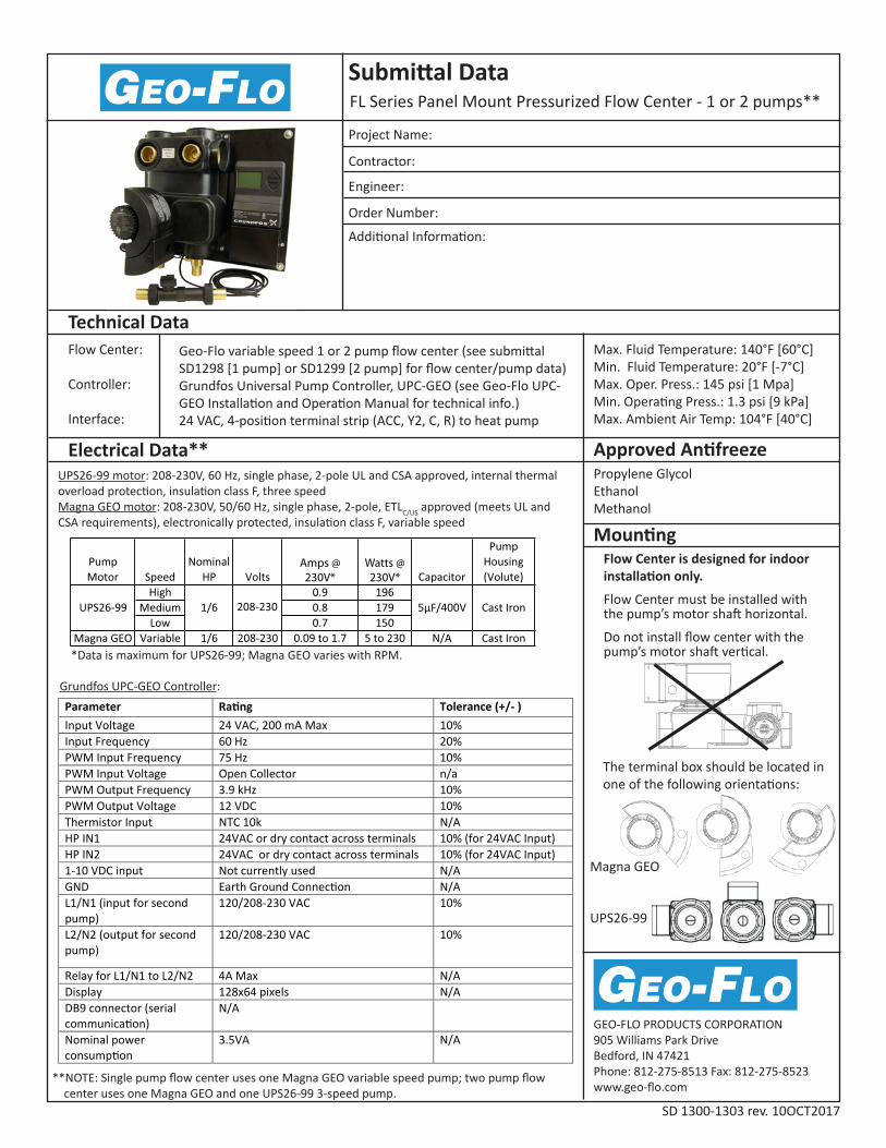
FL Series Panel Mount Pressurized Flow Center - 1 or 2 pumps**
SD 1300-1303 rev. 10OCT2017
Submittal Data
Technical Data
Electrical Data**
Mounting
GEO-FLO PRODUCTS CORPORATION905 Williams Park DriveBedford, IN 47421Phone: 812-275-8513 Fax: 812-275-8523www.geo-flo.com
Project Name:
Contractor:
Engineer:
Order Number:
Additional Information:
Approved AntifreezePropylene Glycol EthanolMethanol
Max. Fluid Temperature: 140°F [60°C]Min. Fluid Temperature: 20°F [-7°C] Max. Oper. Press.: 145 psi [1 Mpa]Min. Operating Press.: 1.3 psi [9 kPa]Max. Ambient Air Temp: 104°F [40°C]
Geo-Flo variable speed 1 or 2 pump flow center (see submittal SD1298 [1 pump] or SD1299 [2 pump] for flow center/pump data)Grundfos Universal Pump Controller, UPC-GEO (see Geo-Flo UPC-GEO Installation and Operation Manual for technical info.)24 VAC, 4-position terminal strip (ACC, Y2, C, R) to heat pump
Flow Center:
Controller:
Interface:
UPS26-99 motor: 208-230V, 60 Hz, single phase, 2-pole UL and CSA approved, internal thermal overload protection, insulation class F, three speedMagna GEO motor: 208-230V, 50/60 Hz, single phase, 2-pole, ETLC/US approved (meets UL and CSA requirements), electronically protected, insulation class F, variable speed
Amps @230V*
Watts @230V*
*Data is maximum for UPS26-99; Magna GEO varies with RPM.
Parameter Rating Tolerance (+/- ) Input Voltage 24 VAC, 200 mA Max 10% Input Frequency 60 Hz 20% PWM Input Frequency 75 Hz 10% PWM Input Voltage Open Collector n/a PWM Output Frequency 3.9 kHz 10% PWM Output Voltage 12 VDC 10% Thermistor Input NTC 10k N/A HP IN1 24VAC or dry contact across terminals 10% (for 24VAC Input) HP IN2 24VAC or dry contact across terminals 10% (for 24VAC Input) 1-10 VDC input Not currently used N/A GND Earth Ground Connection N/A L1/N1 (input for second pump)
120/208-230 VAC 10%
L2/N2 (output for second pump)
120/208-230 VAC 10%
Relay for L1/N1 to L2/N2 4A Max N/A Display 128x64 pixels N/A DB9 connector (serial communication)
N/A
Nominal power consumption
3.5VA N/A
Grundfos UPC-GEO Controller:
Flow Center is designed for indoor installation only.
Flow Center must be installed with the pump’s motor shaft horizontal.
Do not install flow center with thepump’s motor shaft vertical.
The terminal box should be located in one of the following orientations:
Magna GEO
UPS26-99
**NOTE: Single pump flow center uses one Magna GEO variable speed pump; two pump flow center uses one Magna GEO and one UPS26-99 3-speed pump.

GEO-FLO PRODUCTS CORPORATION905 Williams Park DriveBedford, IN 47421Phone: 812-275-8513 Fax: 812-275-8523www.geo-flo.com
Dimensional Data
SD 1300-1303 rev. 10OCT2017
Control / Pump Options
Geo-Flo Part
Number
Description
U.O.M.Variable Speed Pre-wired Packages (Panel Mounted)
Flow Center Control Connections1300 1298 - Single pump 3697 - Delta T Hose kit / PE fusion* Kit1301 1298 - Single pump 3698 - Flow & Temperature Hose kit / PE fusion* Kit1302 1299 - Two pump 3697 - Delta T Hose kit / PE fusion* Kit1303 1299 - Two pump 3698 - Flow & Temperature Hose kit / PE fusion* Kit
*Kit includes all of the fittings necessary for connecting to the ground loop (1-1/4” PE fusion) and to the heat pump (1” MPT). For heat pumps with double O-ring water connections, add P/N 3326 1” FPT x Flo-Link double O-ring fitting set.
NOTES:1. Dimensional data
provided for infor-mational purposes and is rounded to nearest 1/16“.
2. Metric data is a simple conversion of imperial data and should not be considered more accurate.
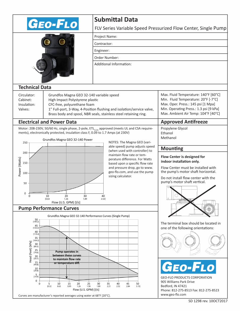
FLV Series Variable Speed Pressurized Flow Center, Single Pump
SD 1298 rev. 10OCT2017
Submittal Data
Technical Data
Electrical and Power Data
Pump Performance Curves
Mounting
GEO-FLO PRODUCTS CORPORATION905 Williams Park DriveBedford, IN 47421Phone: 812-275-8513 Fax: 812-275-8523www.geo-flo.comCurves are manufacturer‘s reported averages using water at 68°F [20°C].
Project Name:
Contractor:
Engineer:
Order Number:
Additional Information:
Approved AntifreezePropylene Glycol EthanolMethanol
Max. Fluid Temperature: 140°F [60°C]Min. Fluid Temperature: 20°F [-7°C] Max. Oper. Press.: 145 psi [1 Mpa]Min. Operating Press.: 1.3 psi [9 kPa]Max. Ambient Air Temp: 104°F [40°C]
Flow Center is designed forindoor installation only.
Flow Center must be installed with the pump’s motor shaft horizontal.
Do not install flow center with thepump’s motor shaft vertical.
The terminal box should be located in one of the following orientations:
Grundfos Magna GEO 32-140 variable speedHigh Impact Polystyrene plasticCFC-free, polyurethane foam1” Full-port, 3-Way, 4-Position flushing and isolation/service valve,Brass body and spool, NBR seals, stainless steel retaining ring.
Motor: 208-230V, 50/60 Hz, single phase, 2-pole, ETLC/US approved (meets UL and CSA require-ments), electronically protected, insulation class F, 0.09 to 1.7 Amps (at 230V)
Circulator:Cabinet:Insulation:Valves:
0 10 20 30 40
Flow (U.S. GPM) [l/s]
Grundfos Magna GEO 32-140 Power
0
50
100
150
200
250
Pow
er (W
atts)
[0.63 1.26 1.89 2.52]
Flow (U.S. GPM) [l/s]
Grundfos Magna GEO 32-140 Performance Curves (Single Pump)
Head
(Fee
t) [k
Pa]
[0.32 0.63 0.95 1.26 1.58 1.89 2.21 2.52 2.84 3.15]
Pump operates inbetween these curvesto maintain flow rateor temperature diff.
0
5
10
15
20
25
30
35
40
45
50
[134.3]
[14.9]
[29.8]
[44.8]
[59.7]
[74.6]
[89.5]
[104.5]
[119.4]
[149.2]
0 5 10 15 20 25 30 35 40 45 50
NOTES: The Magna GEO (vari-able speed) pump adjusts speed (when used with controller) to maintain flow rate or tem-perature difference. For Watts based upon a specific flow rate and pressure drop, go to www.geo-flo.com, and use the pump sizing calculator.

GEO-FLO PRODUCTS CORPORATION905 Williams Park DriveBedford, IN 47421Phone: 812-275-8513 Fax: 812-275-8523www.geo-flo.com
Dimensional Data
13-1/4 5
A WEIGHTIHGFEDCB
Inches
CM
LBS KG3/8” DRIVE
SOCKET
212-1/24-3/49-7/168-1/210-3/16
33.6 5.031.712.024.021.625.9 12.7
E
A
D
F
B
H
G
C
I
1226
Fluid connections are Flo-Link™ double O-ring style. Transition fittings are not included with the flow center packaging. Typically, PE fusion x Flo-Link is used on the ground loop connections. A Geo-Flo hose kit designed for Flo-Link connections includes transition fittings for heat pump connections.
SD 1298 rev. 10OCT2017
NOTES:1. Dimensional data provided for informational purposes and is rounded to nearest 1/16“.2. Metric data is a simple conversion of imperial data and should not be considered more accurate.
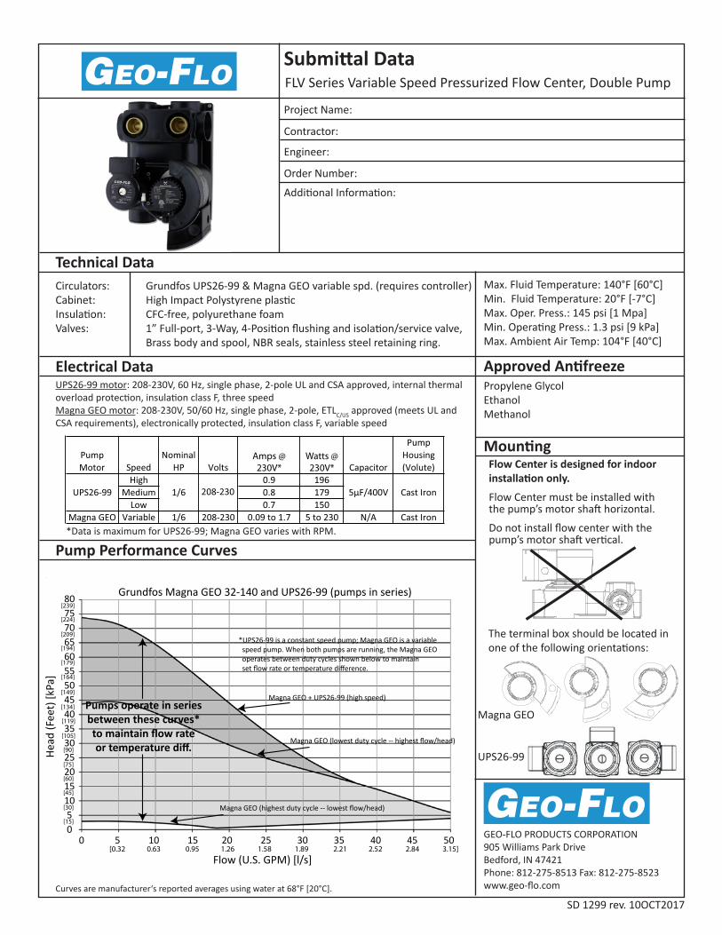
FLV Series Variable Speed Pressurized Flow Center, Double Pump
SD 1299 rev. 10OCT2017
Submittal Data
Technical Data
Electrical Data
Pump Performance Curves
Mounting
GEO-FLO PRODUCTS CORPORATION905 Williams Park DriveBedford, IN 47421Phone: 812-275-8513 Fax: 812-275-8523www.geo-flo.comCurves are manufacturer‘s reported averages using water at 68°F [20°C].
Project Name:
Contractor:
Engineer:
Order Number:
Additional Information:
Approved AntifreezePropylene Glycol EthanolMethanol
Max. Fluid Temperature: 140°F [60°C]Min. Fluid Temperature: 20°F [-7°C] Max. Oper. Press.: 145 psi [1 Mpa]Min. Operating Press.: 1.3 psi [9 kPa]Max. Ambient Air Temp: 104°F [40°C]
Flow Center is designed for indoor installation only.
Flow Center must be installed with the pump’s motor shaft horizontal.
Do not install flow center with thepump’s motor shaft vertical.
The terminal box should be located in one of the following orientations:
Grundfos UPS26-99 & Magna GEO variable spd. (requires controller)High Impact Polystyrene plasticCFC-free, polyurethane foam1” Full-port, 3-Way, 4-Position flushing and isolation/service valve,Brass body and spool, NBR seals, stainless steel retaining ring.
UPS26-99 motor: 208-230V, 60 Hz, single phase, 2-pole UL and CSA approved, internal thermal overload protection, insulation class F, three speedMagna GEO motor: 208-230V, 50/60 Hz, single phase, 2-pole, ETLC/US approved (meets UL and CSA requirements), electronically protected, insulation class F, variable speed
Circulators:Cabinet:Insulation:Valves:
Amps @230V*
Watts @230V*
Flow (U.S. GPM) [l/s]
Grundfos Magna GEO 32-140 and UPS26-99 (pumps in series)
Pumps operate in seriesbetween these curves*to maintain flow rateor temperature diff.
Magna GEO + UPS26-99 (high speed)
Magna GEO (lowest duty cycle -- highest flow/head)
Magna GEO (highest duty cycle -- lowest flow/head)
*UPS26-99 is a constant speed pump; Magna GEO is a variable speed pump. When both pumps are running, the Magna GEO operates between duty cycles shown below to maintain set flow rate or temperature difference.
[0.32 0.63 0.95 1.26 1.58 1.89 2.21 2.52 2.84 3.15] 0 5 10 15 20 25 30 35 40 45 50
05
101520253035404550556065707580
[134]
[15]
[30]
[45]
[60]
[75]
[90]
[105]
[119]
[149]
[164]
[179]
[194]
[209]
[224]
[239]
Head
(Fee
t) [k
Pa]
Magna GEO
UPS26-99
*Data is maximum for UPS26-99; Magna GEO varies with RPM.

GEO-FLO PRODUCTS CORPORATION905 Williams Park DriveBedford, IN 47421Phone: 812-275-8513 Fax: 812-275-8523www.geo-flo.com
Dimensional Data
13-1/4 5
A WEIGHTIHGFEDCB
Inches
CM
LBS KG3/8” DRIVE
SOCKET
212-1/24-3/49-7/168-1/210-3/16
33.6 5.031.712.024.021.625.9 12.7
E
A
D
F
B
H
G
C
I
13.630.0
Pump Power Curves
Fluid connections are Flo-Link™ double O-ring style. Transition fittings are not included with the flow center packaging. Typically, PE fusion x Flo-Link is used on the ground loop connec-tions. A Geo-Flo hose kit designed for Flo-Link connections includes transition fittings for heat pump connections.
Flow center may be field modified to a one pump flow center by replacing the constant speed pump with a blank plate kit.
SD 1299 rev. 10OCT2017
Flow (U.S. GPM) [l/s]
Grundfos UPS26-99 Power Curves
Pow
er (W
atts)
[0.13 0.25 0.38 0.50 0.63 0.76 0.88 1.00 1.14 1.26 1.39 1.51 1.64 1.77 1.89 2.02 2.15 2.27]
0 10 20 30 40
Flow (U.S. GPM) [l/s]
Grundfos Magna GEO 32-140 Power
0
50
100
150
200
250
Pow
er (W
atts)
[0.63 1.26 1.89 2.52]
NOTES: The Magna GEO (variable speed) pump adjusts speed (when used with con-troller) to maintain flow rate or tempera-ture difference. The controller energizes the constant speed pump (UPS26-99) when the Magna GEO cannot meet setpoint, and adjusts the Magna GEO pump accordingly. Total flow center Watts equals constant speed pump Watts plus Magna GEO Watts at design conditions. For Watts based upon a specific flow rate and pressure drop, go to www.geo-flo.com, and use the pump sizing calculator.
NOTES:1. Dimensional data provided for informational purposes and is rounded to nearest 1/16“.2. Metric data is a simple conversion of imperial data and should not be considered more accurate.