subparts d–g reserved subpart h—specifications for ... · pdf...
TRANSCRIPT

865
Research and Special Programs Admin., DOT § 178.245–1
Subparts D–G [Reserved]
Subpart H—Specifications for Portable Tanks
SOURCE: 29 FR 18972, Dec. 29, 1964, unless otherwise noted. Redesignated at 32 FR 5606, Apr. 5, 1967.
§ 178.245 Specification 51; steel port-able tanks.
§ 178.245–1 Requirements for design and construction.
(a) Tanks must be seamless or welded steel construction, or a combination of both, and have a water capacity in ex-cess of 454 kg (1,000 pounds). Tanks must be designed, constructed, cer-tified and stamped in accordance with Section VIII of the ASME Code (IBR, see § 171.7 of this subchapter).
(b) Tanks must be postweld heat treated and radiographed as prescribed in the ASME Code except that each tank constructed in accordance with part UHT of the ASME Code must be postweld heat treated. Where postweld heat treatment is required, the tank must be treated as a unit after comple-tion of all the welds in and/or to the shell and heads. The method must be as prescribed in the ASME Code. Welded attachments to pads may be made after postweld heat treatment is made. A tank used for anhydrous ammonia must be postweld heat treated. The postweld heat treatment must be as prescribed in the ASME Code, but in no event at less than 1050 °F tank metal temperature. Additionally, tanks con-structed in accordance with part UHT of the ASME Code must conform to the following requirements:
(1) Welding procedure and welder per-formance tests must be made annually in accordance with section IX of the ASME Code. In addition to the essen-tial variables named therein, the fol-lowing must be considered to be essen-tial variables: number of passes, thick-ness of plate, heat input per pass, and manufacturer’s identification of rod and flux. The number of passes, thick-ness of plate and heat input per pass may not vary more than 25 percent from the procedure qualification. Records of the qualification must be retained for at least 5 years by the
tank manufacturer and made available to duly identified representatives of the Department of Transportation or the owner of the tank.
(2) Impact tests must be made on a lot basis. A lot is defined as 100 tons or less of the same heat and having a thickness variation no greater than plus or minus 25 percent. The minimum impact required for full-sized speci-mens shall be 20 foot-pounds (or 10 foot-pounds for half-sized specimens) at 0 °F Charpy V-Notch in both the longi-tudinal and transverse direction. If the lot test does not pass this requirement, individual plates may be accepted if they individually meet this impact re-quirement.
(c) Except as provided in paragraph (d) of this section, all openings in the tank shall be grouped in one location, either at the top of the tank or at one end of the tank.
(d) The following openings may be in-stalled at locations other than on the top or end of the tank:
(1) The openings for liquid level gaug-ing devices, pressure gauges, or for safety devices, may be installed sepa-rately at the other location or in the side of the shell;
(2) One plugged opening of 2-inch Na-tional Pipe Thread or less provided for maintenance purposes may be located elsewhere;
(3) An opening of 3-inch National Pipe Size or less may be provided at another location, when necessary, to facilitate installation of condensing coils; or
(4) Filling and discharge connections may be installed below the normal liq-uid level of the tank if the tank design conforms to the following require-ments:
(i) The tank must be permanently mounted in a full framework for con-tainerized transport. For each tank de-sign, a prototype tank, must fulfill the requirements of parts 450 through 453 of this title for compliance with the re-quirements of Annex II of the Inter-national Convention for Safe Con-tainers.
(ii) Each filling and discharge con-nection must be equipped with an in-ternal self-closing stop-valve capable of closing within 30 seconds of actuation. Each internal self-closing stop-valve
VerDate Aug<04>2004 14:12 Dec 15, 2004 Jkt 203206 PO 00000 Frm 00865 Fmt 8010 Sfmt 8010 Y:\SGML\203206T.XXX 203206T

866
49 CFR Ch. I (10–1–04 Edition) § 178.245–2
must be protected by a shear section or sacrificial device located outboard of the valve. The shear section or sacrifi-cial device must break at no more than 70 percent of the load that would cause failure of the internal self-closing stop- valve.
(iii) Each internal self-closing stop- valve must be provided with remote means of automatic closure, both ther-mal and mechanical. The thermal means of automatic closure must actu-ate at a temperature of not over 250 °F.
(e) Each uninsulated tank used for the transportation of compressed gas, as defined in § 173.300 of this sub-chapter, must have an exterior surface finish that is significantly reflective, such as a light reflecting color if paint-ed, or a bright reflective metal or other material if unpainted.
[Amdt. 178–117, 61 FR 50627, Sept. 26, 1996, as amended at 68 FR 75749, Dec. 31, 2003]
§ 178.245–2 Material. (a) All material used for the con-
struction of the tank and appur-tenances shall be suitable for use with the commodity to be transported therein.
(b) A material of thickness less than 3⁄16 inch shall not be used for the shells and heads.
§ 178.245–3 Design pressure. (a) The design pressure of a tank au-
thorized under this specification shall be not less than the vapor pressure of the commodity contained therein at 46 °C (115 °F), or as prescribed for a par-ticular commodity by part 173 of this chapter, except that in no case shall the design pressure of any container be less than 100 psig or more than 500 psig. When corrosion factor is prescribed by these regulations, the wall thickness of the tank calculated in accordance with Section VIII of the ASME Code (IBR, see § 171.7 of this subchapter) shall be increased by 20 percent or 2.54 mm (0.10 inch), whichever is less.
NOTE 1: The term design pressure as used in this specification is identical to the term ‘‘MAWP’’ as used in the ASME Code.
(b) [Reserved]
[29 FR 18972, Dec. 29, 1964; Redesignated at 32 FR 5606, Apr. 5, 1967, as amended by 66 FR 45387, Aug. 28, 2001; 68 FR 75749, Dec. 31, 2003]
§ 178.245–4 Tank mountings.
(a) Tanks shall be designed and fab-ricated with mountings to provide a se-cure base in transit. ‘‘Skids’’ or similar devices shall be deemed to comply with this requirement.
(b) All tank mountings such as skids, fastenings, brackets, cradles, lifting lugs, etc., intended to carry loadings shall be permanently secured to tanks in accordance with the requirements in Section VIII of the ASME Code (IBR, see § 171.7 of this subchapter) under which the tanks were fabricated, and shall be designed to withstand static loadings in any direction equal to twice the weight of the tank and at-tachments when filled with the lading using a safety factor of not less than four, based on the ultimate strength of the material to be used. The specific gravity used in determining the static loadings shall be shown on the marking required by § 178.245–6(a) and on the re-port required by § 178.245–7(a).
(c) Lifting lugs or hold-down lugs may be added to either the tank or tank mountings. If lifting lugs and hold-down lugs are added directly to the tank, they shall be secured to dou-bling plates welded to the tank and lo-cated at points of support, except that lifting lugs or hold-down lugs with in-tegral bases serving as doubling plates may be welded directly to the tank. Each lifting lug and hold-down lug shall be designed to withstand static loadings in any direction equal to twice the weight of the tank and at-tachments when filled with the lading using a safety factor of not less than four, based on the ultimate strength of the material to be used.
(d) All tank mountings shall be de-signed so as to prevent the concentra-tion of excessive loads on the tank shell.
(e) A DOT 51 portable tank that meets the definition of ‘‘container’’ in § 450.3(a)(2) of this title must meet the requirements of parts 450 through 453 of this title, in addition to the require-ments of this subchapter.
[29 FR 18972, Dec. 29, 1964. Redesignated at 32 FR 5606, Apr. 5, 1967, as amended by Amdt. 178–117, 61 FR 50628, Sept. 26, 1996; 64 FR 51919, Sept. 27, 1999; 68 FR 75750, Dec. 31, 2003]
VerDate Aug<04>2004 14:12 Dec 15, 2004 Jkt 203206 PO 00000 Frm 00866 Fmt 8010 Sfmt 8010 Y:\SGML\203206T.XXX 203206T

867
Research and Special Programs Admin., DOT § 178.255–2
§ 178.245–5 Protection of valves and accessories.
(a) All valves, fittings, accessories, safety devices, gaging devices, and the like shall be adequately protected against mechanical damage.
(b) The protective device or housing shall conform to the requirements under which the tanks are fabricated with respect to design and construc-tion, and shall be designed to with-stand static loadings in any direction equal to twice the weight of the tank and attachments when filled with the lading using a safety factor of not less than four, based on the ultimate strength of the material to be used.
(c) Requirements concerning types of valves, retesting, and qualification of portable tanks contained in §§ 173.32 and 173.315 of this chapter must be ob-served.
[29 FR 18972, Dec. 29, 1964. Redesignated at 32 FR 5606, Apr. 5, 1967, as amended by Amdt. 178–104, 59 FR 49135, Sept. 26, 1994]
§ 178.245–6 Name plate. (a) In addition to the markings re-
quired by Section VIII of the ASME Code (IBR, see § 171.7 of this sub-chapter) under which tanks were con-structed, they shall have permanently affixed, in close proximity to the ASME ‘‘U’’ stamp certification, a metal plate. This plate shall be permanently affixed by means of soldering, brazing, or welding around its complete perim-eter. Neither the plate itself nor the means of attachment to the tank shall be subject to destructive attack by the contents of tank. Upon such plate shall be plainly marked by stamping, em-bossing, or other means of forming let-ters into or onto the metal plate itself the following information in characters at least 1⁄8-inch high:
Manufacturer’s name llllllllllll
Serial No. llll Owner’s serial No. llll
D.O.T. Specification No. llllllllll
Water capacity (pounds) llllllllll
Tare weight (pounds) llllllllllll
Design pressure (psig) llllllllllll
Design specific gravity lllllllllll
Original test date llllllllllllll
Tank retested at lll (psig) on: llllll
(b) All tank outlets and inlets, except safety relief valves, shall be marked to designate whether they communicate with vapor or liquid when the tank is
filled to the maximum permitted fill-ing density.
[29 FR 18972, Dec. 29, 1964. Redesignated at 32 FR 5606, Apr. 5, 1967, and amended by Amdt. 178–67, 46 FR 49906, Oct. 8, 1981; Amdt. 178–117, 61 FR 50628, Sept. 26, 1996; 68 FR 75750, Dec. 31, 2003]
§ 178.245–7 Report.
(a) A copy of the manufacturer’s data report required by Section VIII of the ASME Code (IBR, see § 171.7 of this sub-chapter) under which the tank is fab-ricated shall be furnished to the owner for each new tank.
(b) [Reserved]
[Amdt. 178–76, 48 FR 28102, June 20, 1983, as amended at 68 FR 75750, Dec. 31, 2003]
§§ 178.251—178.253–5 [Reserved]
§ 178.255 Specification 60; steel port-able tanks.
§ 178.255–1 General requirements.
(a) Tanks must be of fusion welded construction, cylindrical in shape with seamless heads concave to the pres-sure. Tank shells may be of seamless construction.
(b) Tanks must be designed, con-structed, certified, and stamped in ac-cordance with Section VIII of the ASME Code (IBR, see § 171.7 of this sub-chapter).
(c) Tanks including all permanent at-tachments must be postweld heat treated as a unit.
(d) Requirements concerning types of valves, retesting, and qualification of portable tanks contained in §§ 173.32 and 173.315 of this chapter must be ob-served.
[29 FR 18972, Dec. 29, 1964. Redesignated at 32 FR 5606, Apr. 5, 1967, and amended by Amdt. 178–7, 34 FR 18250, Nov. 14, 1969; 68 FR 75750, Dec. 31, 2003]
§ 178.255–2 Material.
(a) Material used in the tank must be steel of good weldable quality and con-form with the requirements in Sections V, VIII, and IX of the ASME Code (IBR, see § 171.7 of this subchapter).
(b) The minimum thickness of metal, exclusive of lining material, for shell and heads of tanks shall be as follows:
VerDate Aug<04>2004 14:12 Dec 15, 2004 Jkt 203206 PO 00000 Frm 00867 Fmt 8010 Sfmt 8010 Y:\SGML\203206T.XXX 203206T

868
49 CFR Ch. I (10–1–04 Edition) § 178.255–3
Tank capacity Minimum thickness
(inch)
Not more than 1,200 gallons ............................... 1⁄4 Over 1,200 to 1,800 gallons ................................ 5⁄16 Over 1,800 gallons .............................................. 3⁄8
[29 FR 18972, Dec. 29, 1964. Redesignated at 32 FR 5606, Apr. 5, 1967, and amended by Amdt. 178–7, 34 FR 18250, Nov. 14, 1969; 68 FR 75750, Dec. 31, 2003]
§ 178.255–3 Expansion domes.
(a) Expansion domes, if applied, must have a minimum capacity of one per-cent of the combined capacity of the tank and dome.
(b) [Reserved]
§ 178.255–4 Closures for manholes and domes.
(a) The manhole cover shall be de-signed to provide a secure closure of the manhole. All covers, not hinged to the tanks, shall be attached to the out-side of the dome by at least 1⁄8 inch chain or its equivalent. Closures shall be made tight against leakage of vapor and liquid by use of gaskets of suitable material.
(b) [Reserved]
§ 178.255–5 Bottom discharge outlets.
(a) Bottom discharge outlets prohib-ited, except on tanks used for ship-ments of sludge acid and alkaline cor-rosive liquids.
(b) If installed, bottom outlets or bottom washout chambers shall be of metal not subject to rapid deteriora-tion by the lading, and each shall be provided with a valve or plug at its upper end and liquid-tight closure at it lower end. Each valve or plug shall be designed to insure against unseating due to stresses or shocks incident to transportation. Bottom outlets shall be adequately protected against handling damage and outlet equipment must not extend to within less than one inch of the bottom bearing surface of the skids or tank mounting.
[29 FR 18972, Dec. 29, 1964. Redesignated at 32 FR 5606, Apr. 5, 1967, as amended by Amdt. 178–104, 59 FR 49135, Sept. 26, 1994]
§ 178.255–6 Loading and unloading ac-cessories.
(a) When installed, gauging, loading and air inlet devices, including their valves, shall be provided with adequate means for their secure closure; and means shall also be provided for the closing of pipe connections of valves.
(b) Interior heater coils, if installed, must be of extra heavy pipe and so con-structed that breaking off of exterior connections will not cause leakage of tanks.
§ 178.255–7 Protection of valves and accessories.
(a) All valves, fittings, accessories, safety devices, gauging devices, and the like shall be adequately protected against mechanical damage by a hous-ing closed with a cover plate.
(b) Protective housing shall comply with the requirements under which the tanks are fabricated with respect to de-sign and construction, and shall be de-signed with a minimum factor of safety of four to withstand loadings in any di-rection equal to two times the weight of the tank and attachments when filled with water.
§ 178.255–8 Safety devices. (a) See § 173.315(i) of this subchapter. (b) [Reserved]
[Amdt. 178–83, 50 FR 11066, Mar. 19, 1985]
§ 178.255–9 Compartments. (a) When the interior of the tank is
divided into compartments, each com-partment shall be designed, con-structed and tested as a separate tank. Thickness of shell and compartment heads shall be determined on the basis of total tank capacity.
(b) [Reserved]
§ 178.255–10 Lining. (a) If a lining is required, the mate-
rial used for lining the tank shall be homogeneous, nonporous, imperforate when applied, not less elastic than the metal of the tank proper. It shall be of substantially uniform thickness, not less than 1⁄32 inch thick if metallic, and not less than 1⁄16 inch thick if non-metallic, and shall be directly bonded or attached by other equally satisfac-tory means. Rubber lining shall be not
VerDate Aug<04>2004 14:12 Dec 15, 2004 Jkt 203206 PO 00000 Frm 00868 Fmt 8010 Sfmt 8010 Y:\SGML\203206T.XXX 203206T

869
Research and Special Programs Admin., DOT § 178.255–15
less than 3⁄16 inch thick. Joints and seams in the lining shall be made by fusing the material together or by other equally satisfactory means. The interior of the tank shall be free from scale, oxidation, moisture and all for-eign matter during the lining oper-ation.
(b) [Reserved]
§ 178.255–11 Tank mountings.
(a) Tanks shall be designed and fab-ricated with mountings to provide a se-cure base in transit. ‘‘Skids’’ or similar devices shall be deemed to comply with this requirement.
(b) All tank mountings such as skids, fastenings, brackets, cradles, lifting lugs, etc., intended to carry loadings shall be permanently secured to tanks in accordance with the requirements under which the tanks are fabricated, and shall be designed with a factor of safety of four, and built to withstand loadings in any direction equal to two times the weight of the tanks and at-tachments when filled to the maximum permissible loaded weight.
(c) Lifting lugs or side hold-down lugs shall be provided on the tank mountings in a manner suitable for at-taching lifting gear and hold-down de-vices. Lifting lugs and hold-down lugs welded directly to the tank shall be of the pad-eye type. Doubling plates weld-ed to the tank and located at the points of support shall be deemed to comply with this requirement.
(d) All tank mountings shall be so de-signed as to prevent the concentration of excessive loads on the tank shell.
§ 178.255–12 Pressure test.
(a) Each completed portable tank prior to application of lining shall be tested before being put into transpor-tation service by completely filling the tank with water or other liquid having a similar viscosity, the temperature of which shall not exceed 100 °F during the test, and applying a pressure of 60 psig. The tank shall be capable of hold-ing the prescribed pressure for at least 10 minutes without leakage, evidence of impending failure, or failure. All clo-sures shall be in place while the test is made and the pressure shall be gauged at the top of the tank. Safety devices
and/or vents shall be plugged during this test.
(b) [Reserved]
[29 FR 18972, Dec. 29, 1964. Redesignated at 32 FR 5606, Apr. 5, 1967, as amended by Amdt. 178–104, 59 FR 49135, Sept. 26, 1994]
§ 178.255–13 Repair of tanks. (a) Tanks failing to meet the test
may be repaired and retested, provided that repairs are made in complete com-pliance with the requirements of this specification.
(b) [Reserved]
§ 178.255–14 Marking. (a) In addition to markings required
by Section VIII of the ASME Code (IBR, see § 171.7 of this subchapter), every tank shall bear permanent marks at least 1/8-inch high stamped into the metal near the center of one of the tank heads or stamped into a plate per-manently attached to the tank by means of brazing or welding or other suitable means as follows:
Manufacturer’s name lllllll Serial No. llllllllllllllllllll
DOT specification llllllllllllll
Nominal capacity lllllll (gallons) Tare weight lllllll (pounds) Date of manufacture llllllllllll
(b) [Reserved]
[29 FR 18972, Dec. 29, 1964. Redesignated at 32 FR 5606, Apr. 5, 1967, and amended by Amdt. 178–67, 46 FR 49906, Oct. 8, 1981; 68 FR 75750, Dec. 31, 2003]
§ 178.255–15 Report. (a) A copy of the manufacturer’s data
report required by Section VIII of the ASME Code (IBR, see § 171.7 of this sub-chapter) under which the tank is fab-ricated must be furnished to the owner for each new tank.
Place ———————————————Date ————————————————
Portable tank Manufactured for lllllll Company Location llllllllllllllllll
Manufactured by lllllll Company Location llllllllllllllllll
Consigned to lllllllll Company Location llllllllllllllllll
Size lll feet outside diameter by llll
long. Marks on tank as prescribed by § 178.255–14 of
this specification are as follows: Manufacturer’s name llllllllllll
VerDate Aug<04>2004 14:12 Dec 15, 2004 Jkt 203206 PO 00000 Frm 00869 Fmt 8010 Sfmt 8010 Y:\SGML\203206T.XXX 203206T

870
49 CFR Ch. I (10–1–04 Edition) § 178.270
Serial number llllllllllllllll
Owner’s serial number lllllllllll
DOT specification llllllllllllll
ASME Code Symbol (par U–201) lllllll
Date of manufacture llllllllllll
Nominal capacity lllllll gallons. It is hereby certified that this tank is in
complete compliance with the requirements of DOT specification No. 60.
(Signed) ———————————————Manufacturer or owner
(b) [Reserved]
[29 FR 18972, Dec. 29, 1964. Redesignated at 32 FR 5606, Apr. 5, 1967, and amended by Amdt. 178–83, 50 FR 11066, Mar. 19, 1985; 68 FR 75750, Dec. 31, 2003]
§ 178.270 Specification IM 101 and IM 102 steel portable tanks; general de-sign and construction require-ments.
§ 178.270–1 Specification requirements for IM 101 and IM 102 steel portable tanks.
(a) Each IM portable tank must meet the requirements of this section in ad-dition to the requirements of § 178.271 (IM 101) or § 178.272 (IM 102). These re-quirements apply to IM portable tanks of diameters no greater than 2438 mm (96 inches) that are designed to carry liquids having a vapor pressure of less than 2.97 bar-absolute (43 psia) at a temperature of 50 °C (122 °F).
(b) [Reserved]
[Amdt. 178–65, 46 FR 9895, Jan. 29, 1981]
§ 178.270–2 General. (a) Each tank, including attachments
and service and structural equipment, must be designed to withstand, without loss of contents, the maximum internal pressure that can be anticipated to re-sult from the contents and the static and dynamic stresses incurred in nor-mal handling and transportation.
(b) For the purpose of this subchapter MAWP is the maximum pressure that an IM portable tank may experience during any normal operation (including loading and unloading). The only ex-ception to this limitation is hydro-static testing.
(c) Each portable tank must have a cross-sectional design that is capable of being stress analyzed either mathe-matically or by the experimental method contained in UG–101 in Section VIII of the ASME Code (IBR, see § 171.7
of this subchapter), or other method acceptable to the Associate Adminis-trator.
(d) Each portable tank must be de-signed so that the center of gravity of the filled tank is approximately cen-tered within the points of attachment for lifting devices.
(e) When credit is taken for insula-tion to reduce the required emergency venting capacity of safety relief de-vices, the insulation must be jacketed or otherwise protected from the accu-mulation of moisture or foreign matter that would decrease its efficiency or corrode the tank.
(f) Each portable tank that has a lin-ing must have a lining material that meets the following requirements:
(1) The material used to line the tank must be—
(i) Substantially immune to attack by the hazardous material transported;
(ii) Homogeneous; (iii) Nonporous; (iv) Imperforated when applied; (v) At least as elastic as the material
of the tank shell; and (vi) Have thermal-expansion charac-
teristics compatible with the tank shell.
(2) The lining of the tank, tank fit-ting and piping must be—
(i) Attached by bonding or other sat-isfactory means;
(ii) Continuous; and (iii) Extended around the face of any
flange. (3) Joints and seams in the lining
must be made by fusing the material together or by other equally effective means.
[Amdt. 178–65, 46 FR 9895, Jan. 29, 1981, as amended by Amdt. 178–65, 46 FR 24184, Apr. 30, 1981; Amdt. 178–97, 56 FR 66284 and 66287, Dec. 20, 1991; 66 FR 45386, 45389, Aug. 28, 2001; 68 FR 75750, Dec. 31, 2003]
§ 178.270–3 Materials of construction. (a) Each portable tank must be con-
structed of carbon or alloy steels. Ma-terials included in part UHT in Section VIII of the ASME Code (IBR, see § 171.7 of this subchapter) or equivalent mate-rials are not authorized. Any materials used in the tank shell must conform to a recognized national standard and must be suitable for the external envi-ronments in which the tank will be
VerDate Aug<04>2004 14:12 Dec 15, 2004 Jkt 203206 PO 00000 Frm 00870 Fmt 8010 Sfmt 8010 Y:\SGML\203206T.XXX 203206T
871
Research and Special Programs Admin., DOT § 178.270–4
carried. The minimum elongation for any material must be 20 percent or greater.
(b) The maximum stress allowed for a material shall be determined using one of the following methods:
(1) 1.5 times the specified values for the material at 93 °C (200 °F) in Section VIII of the ASME Code;
(2) Derived by test for the actual yield and tensile strengths at 93 °C (200 °F) for the actual group of plates used to fabricate the tank using the meth-ods described in §178.270–3(d); or
(3) Derived from the minimum yield and tensile strengths at 93 °C (200 °F) specified by the national standard to which the material is manufactured using the methods described in § 178.270–3(d).
(c) Maximum allowable stress values, derived for an actual group of plates, that are based on actual tensile and yield strengths of the material at 93 °C (200 °F) shall not be greater than 120 percent of the specified minimum yield and tensile strength specified in the national standard to which the mate-rial is manufactured.
(d) The maximum allowable stress values must be derived from the fol-lowing criteria:
(1) For austenitic steels; (i) When the yield strength is deter-
mined using the 0.2 percent offset, 93.75 percent of the yield strength.
(ii) When the yield strength is deter-mined using the 1.0 percent offset, 75 percent of the yield strength.
(2) For carbon and low alloy steels, the yield strength is determined using the 0.2 percent offset. The maximum allowable stress value is the lower of 93.75 percent of the yield strength or 37.5 percent of the tensile strength.
(e) For purposes of these specifica-tions, tensile strength, yield strength and elongation must be determined using a specimen having a gauge length:
L0 = 5.65(S0)1/2
where: L0=the gauge length of the specimen—milli-
meters (inches); and S0=the cross sectional area of the specimen—
square millimeters (square inches).
Tensile tests and analysis of results must be in accordance with ISO 82,
‘‘Steels-Tensile Testing’’ (IBR, see § 171.7 of this subchapter). The yield strength in tension shall be the stress corresponding to a permanent strain of 0.2 percent of the gauge length, except that for high alloy austenitic steels the yield strength shall be the stress cor-responding to a permanent strain of 0.2 or 1.0 percent of the gauge length as appropriate. The elongation must be at least 20 percent.
(f) If maximum allowable stress val-ues or minimum tank wall thicknesses are based on the actual yield strength, the actual tensile strength, or the ac-tual elongation for the material used to fabricate the tank, the test records or certification of test results by the material producer or tank manufac-turer must be approved by the approval agency, retained by the tank manufac-turer for a period not less than 15 years, and made available to any duly identified representative of the Depart-ment or the owner of the tank.
[Amdt. 178–65, 46 FR 9895, Jan. 29, 1981, as amended at 64 FR 10782, Mar. 5, 1999; 68 FR 75750, Dec. 31, 2003]
§ 178.270–4 Structural integrity. (a) Maximum stress values. The max-
imum calculated stress value in a tank at the Test Pressure must be less than or equal to that specified for the mate-rial of construction at 93 °C. (200 °F.) in § 178.270–3 of this part.
(b) Tank shell loadings. Tank shells, heads, and their fastenings shall be de-signed to prevent stresses in excess of two thirds those specified in § 178.270–3 of this part. The design calculations must include the forces imposed by each of the following loads:
(1) An internal pressure equal to the MAWP less 1 bar (14.5 psig) in combina-tion with the simultaneously applied loadings of 3W vertically downward, 2W longitudinally, and 1W laterally acting through the center of the tank (W is the maximum permissible weight of the loaded tank and its attachments), and the requirements of paragraphs (b) (4), (5) and (6) of this section;
(2) An internal pressure equal to the MAWP less 1 bar (14.5 psig), in com-bination with the simultaneously ap-plied loadings of 1W vertically upward, 2W longitudinally, and 1W laterally acting through the center of the tank
VerDate Aug<04>2004 14:12 Dec 15, 2004 Jkt 203206 PO 00000 Frm 00871 Fmt 8010 Sfmt 8010 Y:\SGML\203206T.XXX 203206T

872
49 CFR Ch. I (10–1–04 Edition) § 178.270–5
(W is the maximum permissible weight of the loaded tank and its attachment), and the requirements of paragraphs (b) (4), (5) and (6) of this section;
(3) The load on the tank head result-ing from an internal pressure equal to the MAWP, less 1 bar (14.5 psig), in combination with the dynamic pres-sure resulting from a longitudinal de-celeration of 2 ‘‘g’’, and the require-ments of paragraphs (b) (4), (5) and (6) of this section;
(4) Loads resulting from any dis-continuities between tank shell and heads;
(5) Superimposed loads such as oper-ating equipment, insulation, linings and piping; and
(6) Reactions of supporting lugs and saddles or other supports.
(c) The shell thickness used in calcu-lating the resulting stress levels in a tank shall be exclusive of any corro-sion allowance.
[Amdt. 178–65, 46 FR 9895, Jan. 29, 1981, as amended at 66 FR 45387, Aug. 28, 2001]
§ 178.270–5 Minimum thickness of shells and heads.
(a) For the purposes of this section, mild steel is steel with a guaranteed minimum tensile strength of 37 decanewtons per square millimeter (53,650 p.s.i.) and a guaranteed elon-gation of 27 percent or greater.
(b) Except as otherwise provided in this subchapter, the shell and heads of each portable tank constructed of ref-erence mild steel:
(1) With a maximum cross-sectional dimension of 1.8 m (5.9 feet) or less, shall be at least 5 mm (0.197 inches) thick; or,
(2) With a maximum cross-sectional dimension exceeding 1.8 m (5.9 feet), shall be at least 6.35mm (0.250 inches) thick.
(c) The minimum thickness of the shell and heads of each portable tank constructed of a steel other than the reference mild steel, shall be obtained from the following formula:
Formula for metric units
e1 = (10e0) / (Rm1 A1)1/3
Formula for nonmetric units
e1 = (112.3e0) / (Rm1 A1)1/3
where:
e0 = Required thickness of the reference steel from § 178.270–5(b)—millimeters (inches);
e1 = Equivalent thickness of the steel used— millimeters (inches);
Rm1 = Specified minimum tensile strength of the steel used—decanewtons per square millimeter (p.s.i.); and
A1 = Specified minimum percentage elon-gation of the steel used—percent times 100 (i.e., if 20% use 20.0).
(d) When other than the standard minimum thickness for the reference mild steel is specified for a tank in this subchapter, the specified minimum shell and head thickness must be at least equal to the larger of the thicknesses calculated from the for-mula given in § 178.270–5(c) and the fol-lowing formula:
Formula for metric units
e1 = (10e0 d1) / 1.8(Rm1 A1)1/3
Formula for nonmetric units
e1 = (112.3e0 d1) / 5.9(Rm1 A1)1/3
where:
e1 = Equivalent thickness of the steel used— millimeters (inches);
e0 = The specified minimum shell and head thickness of the reference mild steel speci-fied in the IM Tank Table—millimeters (inches);
d1 = Actual outside diameter of the tank—m (feet);
Rm1 = Specified minimum tensile strength of the steel used—decanewtons per square millimeter (p.s.i.); and
A1 = Specified minimum percentage elon-gation of the steel used—percent times 100 (i.e., if 20% use 20.0).
NOTE: For paragraphs (c) and (d) of this section the actual values for the tensile strength and percent elongation for the steel, as determined through tests on speci-mens from the group of plates to be used in the fabrication of the tank, may be sub-stituted for the specified minimum values in the calculation prescribed in this paragraph (See § 178.270–3 of this part). Test records or certification of test results by the material producer or tank manufacturer must be re-tained by the tank manufacturer for a period not less than 15 years and must be made available to the Department or the owner of the tank.
[Amdt. 178–65, 46 FR 9896, Jan. 29, 1981, as amended by Amdt. 178–97, 56 FR 66284, Dec. 20, 1991; 57 FR 45465, Oct. 1, 1992; Amdt. 178– 99, 58 FR 51534, Oct. 1, 1993; 66 FR 45387, 45389, Aug. 28, 2001]
VerDate Aug<04>2004 14:12 Dec 15, 2004 Jkt 203206 PO 00000 Frm 00872 Fmt 8010 Sfmt 8010 Y:\SGML\203206T.XXX 203206T
873
Research and Special Programs Admin., DOT § 178.270–11
§ 178.270–6 Tank supports, frameworks and lifting attachments.
(a) Each portable tank must be con-structed with a permanent support structure that provides a secure base in transport. Skids, frameworks, cradles, or similar devices are acceptable. The calculated stress in tank supports, frameworks, and lifting attachments must not exceed 80 percent of the speci-fied minimum yield strength of the material of construction under the ap-plicable loading conditions specified in § 178.270–4(b).
(b) An IM portable tank that meets the definition of ‘‘container’’ in § 450.3(a)(3) must meet the require-ments of parts 450 through 453 of this title, in addition to the requirements of this subchapter.
[Amdt. 178–65, 46 FR 9896, Jan. 29, 1981]
§ 178.270–7 Joints in tank shells. Joints in tank shells must be made
by fusion welding. Such joints and their efficiencies must be as required by Section VIII of the ASME Code (IBR, see § 171.7 of this subchapter). Weld procedures and welder perform-ance must be ASME Code qualified or must be qualified by the approval agen-cy in accordance with the procedures in the ASME Code, Section IX, Welding and Brazing Qualifications. A record of each qualification must be retained by the manufacturer for the period pre-scribed in Section VIII of the ASME Code, and must be made available to any duly identified representative of the Department and the owner of the tank.
[68 FR 75750, Dec. 31, 2003]
§ 178.270–8 Protection of valves and accessories.
Each valve, fitting, accessory, safety device, gauging device, and other ap-purtenance shall be adequately pro-tected against mechanical damage.
[Amdt. 178–65, 46 FR 9896, Jan. 29, 1981]
§ 178.270–9 Inspection openings. Each portable tank must be fitted
with a manhole or other inspection opening sited above the maximum liq-uid level to allow for complete internal inspection and adequate access for
maintenance and repair of the interior. Each portable tank with a capacity of more than 1,894 L (500 gallons) must be fitted with an elliptical or round man-hole at least 279 × 381 mm (11 × 15 inches), or 254 × 405 mm (10 × 16 inches), or with a circular manhole at least 381 mm (15 inches) in diameter. Any in-spection opening and closure must be designed and reinforced as required by Section VIII of the ASME Code (IBR, see § 171.7 of this subchapter).
[68 FR 75750, Dec. 31, 2003]
§ 178.270–10 External design pressure. (a) Each portable tank not fitted
with vacuum relief devices must be de-signed to withstand a positive external pressure differential of at least 0.4 bar (6 psig).
(b) Each portable tank fitted with vacuum relief devices must be designed to withstand a positive external pres-sure differential not less than the set pressure of the vacuum relief device and in any case at least 0.21 bar (3 psig).
[Amdt. 178–65, 46 FR 9896, Jan. 29, 1981, as amended at 66 FR 45387, Aug. 28, 2001]
§ 178.270–11 Pressure and vacuum re-lief devices.
(a) Relief devices required. Each port-able tank, or each independent com-partment of a portable tank, must be fitted with pressure relief devices in accordance with the following:
(1) Each portable tank, or each inde-pendent compartment of a portable tank, with a capacity of more than 1893 L (500 gallons), must be provided with a primary spring-loaded pressure relief device, and, in addition, may have one or more emergency pressure relief de-vices that may be a spring-loaded pres-sure relief valve, a rupture disc or fusi-ble element in parallel with the pri-mary pressure relief device.
(2) Each portable tank, or each inde-pendent compartment of a portable tank, with a capacity of 1893 L (500 gal-lons) or less, must be fitted with a pri-mary pressure relief device that may either be a non-reclosing device or a spring-loaded pressure relief valve.
(3) If a non-reclosing device is in-serted in series with a required pres-sure relief valve, the space between
VerDate Aug<04>2004 14:12 Dec 15, 2004 Jkt 203206 PO 00000 Frm 00873 Fmt 8010 Sfmt 8010 Y:\SGML\203206T.XXX 203206T

874
49 CFR Ch. I (10–1–04 Edition) § 178.270–11
them must have a suitable tell-tale in-dicator to permit detection, prior to and during shipment, of disc rupture, pinholing, or leakage which could cause a malfunction of the pressure re-lief system. The frangible disc must rupture at a tank pressure within the range specified in paragraph (c)(1) of this section.
(b) Location and construction of relief devices. (1) Pressure relief devices must be spring-loaded valves, rupture discs, or fusible elements. Vacuum relief de-vices must be capable of reclosing in any attitude. Each pressure relief de-vice inlet must be situated in the vapor space of the tank. The discharge from any device must be unrestricted and di-rected to prevent impingement upon the tank shell or structural frame-work. Protective devices which deflect the flow of vapor are permissible pro-vided the required vent capacity is maintained. Pressure and vacuum re-lief devices including their inlets must be sited on the top of the tank in a po-sition as near as possible to the longi-tudinal and transversal center of the tank within the following limitation:
(i) Longitudinally on the tank within 107 cm (31⁄2 feet) or 1⁄6 the tank length, whichever is less, from the top center of the tank; and
(ii) Transversally within 12 degrees of the tank top.
(2) Except for a relief device installed in a piping system, each relief device must provide unrestricted venting under all conditions. Each pressure re-lief system, including any piping, must provide a venting capacity at least equal to the venting capacity specified in § 178.270–11(d) for the tank on which the system is installed.
(3) Fusible elements, when installed, must not be protected from direct com-munication with external heat sources.
(4) Spring-loaded pressure relief valves must be constructed in a man-ner to prevent unauthorized adjust-ment of the relief setting.
(c) Pressure settings of relief devices— (1) Primary pressure relief devices. The primary relief device required by para-graph (a) of this section must be set to function in the range of—
(i) No less than 67 percent and no greater than 83 percent of test pressure for tanks hydrostatically tested under
§ 178.270–13(a) of this subpart at a gauge pressure below 455 kPa (66 psig). Spring-loaded pressure relief valves must close after discharge at a pres-sure not less than 80 percent of start- to-discharge pressure.
(ii) No less than 67 percent and no greater than 74 percent of test pressure for tanks hydrostatically tested under § 178.270–13(a) of this subpart at a gauge pressure of 455 kPa (66 psig) or higher. Spring-loaded pressure relief valves must close after discharge at a pres-sure not less than 90 percent of start- to-discharge pressure.
(2) Emergency pressure relief devices. Each rupture disc, other than one used as a primary relief device in accord-ance with paragraph (b)(2) of this sec-tion, must be designed to burst at a pressure greater than 83 percent of and less than or equal to tank hydrostatic test pressure. Each spring-loaded pres-sure relief device must be set to oper-ate at no less than 83 percent of hydro-static test pressure and be fully open at test pressure.
(3) Fusible elements. Fusible elements must have a nominal yield temperature greater than the highest tank oper-ating temperature and less than or equal to 121 °C (250 °F). The pressure developed in the tank at the fusible element yield temperature must be below the test pressure of the tank.
(4) Vacuum relief devices. Vacuum re-lief devices, when used, must be de-signed to provide total containment of product under normal and accident conditions and must be set to open at a nominal external overpressure of not less than 0.21 bar (3 psig) but not great-er than the external pressure for which the tank is designed. Each vacuum re-lief device must have a minimum cross sectional flow area of 2.84 cm2 (0.44 square inches).
(d) Venting capacity of pressure relief devices—(1) Pressure relief valves (spring- loaded). Each pressure relief valve must have a minimum vent capacity of at least 170 standard cubic meters per hour (SCMH) (6,000 standard cubic feet per hour (SCFH)). The minimum total pressure relief valve vent capacity for each tank shall be 340 SCMH (12,000 SCFH) per 32.5m2 (350 square feet) of exposed tank area, but in any case at least 340 SCMH (12,000 SCFH).
VerDate Aug<04>2004 14:12 Dec 15, 2004 Jkt 203206 PO 00000 Frm 00874 Fmt 8010 Sfmt 8010 Y:\SGML\203206T.XXX 203206T

875
Research and Special Programs Admin., DOT § 178.270–11
(2) Total tank vent capacity. The total vent capacity of all pressure relief de-vices installed on each portable tank must be sufficient with all devices op-erating to limit the pressure in the tank to less than or equal to the test pressure. Except as provided in para-graph (d)(3) or (d)(4) of this section, the total vent capacity must be at least equal to that shown in the following table:
TABLE I—MINIMUM TOTAL VENT CAPACITY [Metric units table in cubic meters of air per hour at
atmospheric pressure and 15 °C]
Exposed area square meters
Cubic me-ters free air per hour
Exposed area square
meters
Cubic me-ters free air per hour
2 ............................. 841 37 .5 9.306 3 ............................. 1,172 40 9,810 4 ............................. 1,485 42 .5 10,308 5 ............................. 1,783 45 10,806 6 ............................. 2,069 47 .5 11,392 7 ............................. 2,348 50 11,778 8 ............................. 2,621 52 .5 12,258 9 ............................. 2,821 55 12,732 10 ........................... 3,146 57 .5 13,206 12 ........................... 3,655 60 13,674 14 ........................... 4,146 62 .5 14,142 16 ........................... 4,625 65 14,604 18 ........................... 5,092 67 .5 15,066 20 ........................... 5,556 70 15,516 22.5 ........................ 6,120 75 16,422 25 ........................... 6,672 80 17,316 27.5 ........................ 7,212 85 18,198 30 ........................... 7,746 90 19,074 32.5 ........................ 8,268 95 19,938 35 ........................... 8,790 100 20,790
[Nonmetric units in cubic feet of air per hour at atmospheric pressure and 59 °F]
Exposed area square feet
Cubic feet free air per
hour
Exposed area
square feet
Cubic feet free air per
hour
20. ............................ 27,600 275 237,000 30 ............................. 38,500 300 256,000 40 ............................. 48,600 350 289,500 50 ............................. 58,600 400 322,100 60 ............................. 67,700 450 355,900 70 ............................. 77,000 500 391,000 80 ............................. 85,500 550 417,500 90 ............................. 94,800 600 450,000 100 ........................... 104,000 650 479,000 120 ........................... 121,000 700 512,000 140 ........................... 136,200 750 540,000 160 ........................... 152,100 800 569,000 180 ........................... 168,200 850 597,000 200 ........................... 184,000 900 621,000 225 ........................... 199,000 950 656,000 250 ........................... 219,500 1,000 686,000
Note: Interpolate for intermediate sizes.
(3) Notwithstanding the minimum total vent capacity shown in table I, of paragraph (d)(2), a tank in dedicated service may have a lesser total vent ca-pacity provided the approval certifi-
cate required by § 178.273(b)(7) specifies the hazardous materials for which the tank is suitable. The lesser total vent capacity must be determined in accord-ance with the following formula:
Formula for metric units
Q = 5,660,000 A0.82 (ZT)0.5 / (LC)(M0.5)
Formula for nonmetric units
Q = 37,980,000 A0.82 (ZT)0.5 / (LC)(M0.5)
where:
Q = The total required venting capacity, in cubic meters of air per hour at standard conditions of 15.6 °C and 1 atm (cubic feet of air per hour at standard conditions of 60 °F and 14.7 psia);
T = The absolute temperature of the vapor at the venting conditions—degrees Kelvin ( °C+273) [degrees Rankine ( °F+460)];
A = The exposed surface area of tank shell— square meters (square feet);
L = The latent heat of vaporization of the lading—calories per gram (BTU/lb);
Z = The compressibiliy factor for the vapor (if this factor is unknown, let Z equal 1.0);
M = The molecular weight of vapor; C = A constant derived from (K), the ratio of
specific heats of the vapor. If (K) is un-known, let C = 315.
C = 520[K(2/(K+1)) [(K∂1)/(K¥1)]]1⁄2
where:
K = Cp / Cv Cp = The specific heat at constant pressure,
in -calories per gram degree centigrade (BTU/lb °F.); and
Cv = The specific heat at constant volume, in -calories per gram degree centigrade (BTU/ lb °F.).
(4) The required total venting capac-ity determined by using table I or para-graph (d)(3) of this section may be re-duced for insulated tanks to Qt by the following formula:
Qt = FQ1
where:
Qt = The total required venting capacity of the insulated tank;
Q1 = The total venting capacity required for an uninsulated tank according to table I or paragraph (d)(3) of this section;
F = A coefficient with a value greater than or equal to 0.25 according to the following formula:
Formula for metric units
F = 8U(649–t) / 93.5 × 10⁶
VerDate Aug<04>2004 14:12 Dec 15, 2004 Jkt 203206 PO 00000 Frm 00875 Fmt 8010 Sfmt 8010 Y:\SGML\203206T.XXX 203206T

876
49 CFR Ch. I (10–1–04 Edition) § 178.270–12
Formula for nonmetric units
F = 8U(1200–t) / 34,500
where:
U = The thermal conductance of the insula-tion system taken at 38 °C (100 °F), in gram calories per hour square meter °C (BTU per hour square feet °F); and
t = The actual temperature of the substance at loading, in °C (°F).
(5) Insulation systems, used for the purpose of reducing the venting capac-ity, must be approved by the approval agency. In all cases, insulation systems approved for this purpose must:
(i) Remain effective at all tempera-tures up to 649 °C (1200 °F); and
(ii) Be jacketed with a material hav-ing a melting point of 649 °C (1200 °F) or greater.
(6) The flow capacity rating of any pressure relief device must be certified by the manufacturer to be in accord-ance with the applicable provisions in Section VIII of the ASME Code (IBR, see § 171.7 of this subchapter) with the following exceptions:
(i) The ASME Code stamp is not re-quired; and
(ii) The flow capacity certification test for spring loaded pressure relief valves may be conducted at a pressure not to exceed 120% of the set pressure provided the stamped flow capacity rating is not greater than 83% of the average capacity of the valves tested.
(e) Markings on pressure and vacuum relief devices. The following information shall be plainly displayed on each pres-sure relief device:
(1) The pressure or, when appro-priate, the temperature at which the device is set to function;
(2) Except for vacuum relief devices, the rated flow capacity of air dis-charged per minute at 15 °C (59 °F) and atmospheric pressure, at:
(i) The set pressure for rupture discs; (ii) No greater than 20% above the
start-to-discharge pressure for spring- loaded relief devices; or
(iii) The fusing temperature for fusi-ble elements.
(3) The manufacturer’s name and catalog number; and
(4) The allowable tolerances at the start-to-discharge pressure and the al-
lowable tolerances at the discharge temperature.
[Amdt. 178–65, 46 FR 9897, Jan. 29, 1981; 46 FR 24184, Apr. 30, 1981, as amended by Amdt. 178– 97, 55 FR 52716, Dec. 21, 1990; Amdt. 178–99, 58 FR 51534, Oct. 1, 1993; Amdt. 178–104, 59 FR 49135, Sept. 26, 1994; 66 FR 45386, 45389, Aug. 28, 2001; 67 FR 61016, Sept. 27, 2002; 68 FR 75751, Dec. 31, 2003]
§ 178.270–12 Valves, nozzles, piping, and gauging devices.
(a) All tank nozzles, except those pro-vided for filling and discharge connec-tions below the normal liquid level of the tank, relief devices, thermometer wells, and inspection openings, must be fitted with manually operated stop valves located as near the shell as prac-ticable either internal or external to the shell. Each filling and discharge connection located below the normal liquid level of the tank must be equipped with an internal discharge valve. A tank nozzle installed in the vapor space to provide a filling or cleaning opening, which is closed by a blank flange or other suitable means, need not be provided with a manually operated stop valve. A tank nozzle in-stalled for a thermometer well or in-spection opening need not be provided with a manually operated stop valve.
(b) Each valve must be designed and constructed to a rated pressure not less than the MAWP of the tank. Each stop valve with a screwed spindle must be closed by a clockwise motion of the handwheel. All valves must be con-structed to prevent unintentional opening.
(c) Each internal discharge valve shall be self-closing, located inside the tank, within the welded flange or with-in its companion flange.
(d) A shear section must be located outboard of each internal discharge valve seat and within 10.2 cm (4 inches) of the vessel. The shear section must break under strain without affecting the product retention capabilities of the tank and any attachments.
(e) All piping must be of suitable ma-terial. Welded joints must be used wherever practicable. The bursting strength of all piping and pipe fittings must be at least 4 times the MAWP of the tank. Piping must be supported in such a manner as to prevent damage
VerDate Aug<04>2004 14:12 Dec 15, 2004 Jkt 203206 PO 00000 Frm 00876 Fmt 8010 Sfmt 8010 Y:\SGML\203206T.XXX 203206T

877
Research and Special Programs Admin., DOT § 178.270–14
due to thermal stresses, jarring or vi-bration.
(f) All nozzles and tank shell penetra-tions for nozzles shall be designed and constructed in accordance with Section VIII of the ASME Code (IBR, see § 171.7 of this subchapter).
(g) Glass liquid level gauges, or gauges of other easily destructible ma-terial, which are in direct communica-tion with the contents of the tank are prohibited.
[Amdt. 178–65, 46 FR 9898, Jan. 29, 1981; 46 FR 24184, Apr. 30, 1981, as amended by Amdt. 178– 117, 61 FR 50628, Sept. 26, 1996; 66 FR 45386, Aug. 28, 2001; 68 FR 75751, Dec. 31, 2003]
§ 178.270–13 Testing. (a) Hydrostatic test. Each portable
tank and all piping, valves, and other attachments which are subject to the pressure of the contents of the tank, except pressure relief devices, must be hydrostatically tested by completely filling the tank (including domes, if any) with water or other liquid having a similar density and viscosity and ap-plying a pressure of at least 150 percent of the MAWP. The pressure shall be maintained for at least 10 minutes. While under pressure, the tank shall be inspected for leakage, undue distor-tion, or other conditions which indi-cate weakness or which might render the tank unsafe for transportation service. Failure to successfully meet the test criteria shall be deemed evi-dence of failure to meet the require-ments of this specification. Tanks fail-ing to pass the test shall be suitably repaired and must successfully pass the prescribed tests prior to use for trans-porting any hazardous material.
(b) Testing of internal coils. Internal coils, if installed, must be hydrostatically tested to an internal pressure of 13.8 bar (200 psig) or 150 per-cent of the rated pressure of the coils, whichever is greater.
(c) Tank container qualification test. For each tank design, a prototype tank, using a framework for container-ized transport, must fulfill the require-ments of parts 450–453 of this title for compliance with the requirements of Annex II of the International Conven-tion for Safe Containers. In addition, the following tests must be completed without leakage or deformation that
would render the tank unsuitable for use:
(1) Longitudinal inertia. The tank loaded to its maximum gross weight must be positioned with its longitu-dinal axis vertical. It shall be held in this position for five minutes by sup-port at the lower end of the base struc-ture providing vertical and lateral re-straint and by support at the upper end of the base structure providing lateral restraint only.
(2) Lateral inertia. The tank loaded to its maximum gross weight must be po-sitioned for five minutes with its trans-verse axis vertical. It shall be held in this position for five minutes by sup-port at the lower side of the base struc-ture providing vertical and lateral re-straint and by support at the upper side of the base structure providing lat-eral restraint only.
(d) Approval of smaller tanks of the same design. Design approval must in-clude the prototype testing of at least one tank of each design and each size; however, a set of tests made on a tank of one size may serve for the approval of smaller tanks with equal or lesser diameter and length) made of the same material and thickness by the same fabrication technique and with iden-tical supports and equivalent closures and other appurtenances.
(e) Pressure and vacuum relief devices. Each spring loaded relief device must be tested for the accuracy of the set-ting prior to installation on a tank and must be effectively sealed to maintain the required setting.
[Amdt. 178–65, 46 FR 9898, Jan. 29, 1981; 46 FR 24184, Apr. 30, 1981, as amended by 66 FR 45387, Aug. 28, 2001]
§ 178.270–14 Marking of tanks. (a) General. Each tank must bear a
corrosion resistant metal identifica-tion plate that is permanently at-tached to the portable tank and readily accessible for inspection. The informa-tion required in paragraph (b), and, when appropriate, paragraph (c) of this section must be stamped, embossed or otherwise marked by an equally dura-ble method on the plate in characters at least 3 mm (0.118 inches) high. The plate must not be painted.
(b) Required information. At least the following information must appear on
VerDate Aug<04>2004 14:12 Dec 15, 2004 Jkt 203206 PO 00000 Frm 00877 Fmt 8010 Sfmt 8010 Y:\SGML\203206T.XXX 203206T

878
49 CFR Ch. I (10–1–04 Edition) § 178.271
the metal identification plate for each tank:
(1) US DOT Specification number. (2) Country of manufacture. (3) Manufacturer’s name. (4) Date of manufacture. (5) Manufacturer’s serial number. (6) Identification of USA/DOT ap-
proval agency and approval number. (7) MAWP, in bar or psig. (8) Test pressure, in bar or psig. (9) Total measured water capacity at
20 °C (68 °F), in liters or gallons. (10) Maximum allowable gross
weight, in kg or lbs. (11) Equivalent minimum shell thick-
ness in mild steel, in mm or inches. (12) Tank material and specification
number. (13) Metallurgical design temperature
range, in °C or °F. (c) Additional information. The fol-
lowing additional information must ap-pear on the metal identification plate when applicable:
(1) Lining material. (2) Heating coil MAWP in bar and
psig. (3) Corrosion allowance, in mm or in. (d) In addition to the markings re-
quired above, each tank used in inter-national transport must have a Safety Approval Plate containing the informa-tion required in §§ 451.21 through 451.25 of this title.
(e) Nothing in this section shall be deemed to preclude the display of other pertinent information on the required metal identification plate.
[Amdt. 178–65, 46 FR 9899, Jan. 29, 1981, as amended at 62 FR 51561, Oct. 1, 1997; 66 FR 45387, Aug. 28, 2001]
§ 178.271 Specification IM 101 steel portable tanks.
§ 178.271–1 General requirements. (a) Specification IM 101 portable
tanks must conform to the general de-sign and construction requirements in § 178.270 of this subpart in addition to the specific design requirements con-tained in this section.
(b) The MAWP of each tank shall be equal to or greater than 1.75 bar (25.4 psig) and less than 6.8 bar (100 psig).
(c) Each tank shall be designed and constructed in accordance with the re-quirements in Section VIII of the
ASME Code (IBR, see § 171.7 of this sub-chapter) except as limited or modified in this section or in § 178.270 of this sub-part. ASME certification or stamp is not required.
[Amdt. 178–65, 46 FR 9899, Jan. 29, 1981, as amended by Amdt. 178–104, 59 FR 49135, Sept. 26, 1994; 66 FR 45387, Aug. 28, 2001; 68 FR 75751, Dec. 31, 2003]
§ 178.272 Specification IM 102 steel portable tanks.
§ 178.272–1 General requirements.
(a) Specification IM 102 portable tanks must conform to the general de-sign and construction requirements in § 178.270 of this subpart in addition to the specific design requirements con-tained in this section.
(b) The MAWP of each tank shall be less than 1.75 bar (25.4 psig) but at least 1.0 bar (14.5 psig).
(c) Each tank shall be designed and constructed in accordance with the re-quirements in Section VIII of the ASME Code (IBR, see § 171.7 of this sub-chapter) except as limited or modified in this section or in § 178.270 of this sub-part. ASME certification or stamp is not required.
[Amdt. 178–65, 46 FR 9899, Jan. 29, 1981, as amended by Amdt. 178–104, 59 FR 49135, Sept. 26, 1994; 66 FR 45387, Aug. 28, 2001; 68 FR 75751, Dec. 31, 2003]
§ 178.272–2 Minimum thickness of shells and heads.
(a) The approval agency may author-ize a minimum thickness less than that required by § 178.270–5 of this subpart where additional protection against tank puncture provides equal integrity.
(b) The shell and head thickness of a tank must be at least:
(1) 3.18 mm (0.125 inches) for a tank with a maximum cross-sectional di-mension of 1.8 m (5.9 feet) or less; or
(2) 4 mm (0.157 inches) for a tank con-structed of the reference mild steel having a maximum cross-sectional di-mension exceeding 1.8 m (5.9 feet). For tanks having a maximum cross-sec-tional dimension exceeding 1.8 m (5.9 feet) constructed of other steels, an equivalent head and shell thickness calculated in accordance with § 178.270–
VerDate Aug<04>2004 14:12 Dec 15, 2004 Jkt 203206 PO 00000 Frm 00878 Fmt 8010 Sfmt 8010 Y:\SGML\203206T.XXX 203206T
879
Research and Special Programs Admin., DOT § 178.273
5(c) of this subpart may be used, sub-ject to an absolute minimum of 3.18 mm (0.125 inches).
(c) The following additional puncture protection systems are authorized:
(1) An overall external structural protection, such as a jacket, which is rigidly secured to the tank with a layer of cushioning material installed be-tween the external structural protec-tion and the tank; or
(2) A complete framework sur-rounding the tank including both lon-gitudinal and transverse structural members.
[Amdt. 178–65, 46 FR 9899, Jan. 29, 1981, as amended at 66 FR 45387, Aug. 28, 2001]
§ 178.273 Approval of Specification IM portable tanks and UN portable tanks.
(a) Application for approval. (1) An owner or manufacturer of a portable tank shall apply for approval to a des-ignated approval agency authorized to approve the portable tank in accord-ance with the procedures in subpart E, part 107 of this subchapter.
(2) Each application for approval must contain the following informa-tion:
(i) Two complete copies of all engi-neering drawings, calculations, and test data necessary to ensure that the design meets the relevant specifica-tion.
(ii) The manufacturer’s serial number that will be assigned to each portable tank.
(iii) A statement as to whether the design type has been examined by any approval agency previously and judged unacceptable. Affirmative statements must be documented with the name of the approval agency, reason for non-acceptance, and the nature of modifica-tions made to the design type.
(b) Action by approval agency. The ap-proval agency must perform the fol-lowing activities:
(1) Review the application for ap-proval to determine whether it is com-plete and conforms with the require-ments of paragraph (a) of this section. If an application is incomplete, it will be returned to the applicant with an explanation as to why the application is incomplete.
(2) Review all drawings and calcula-tions to ensure that the design is in compliance with all requirements of the relevant specification. If the appli-cation is approved, one set of the ap-proved drawings, calculations, and test data shall be returned to the applicant. The second (inspector’s copy) set of ap-proved drawings, calculations, and test data shall be retained by the approval agency. Maintain drawings and ap-proval records for as long as the port-able tank remains in service. The draw-ings and records must be provided to the Department of Transportation (DOT) upon request.
(3) Witness all tests required for the approval of the portable tank specified in this section and part 180, subpart G of this subchapter.
(4) Ensure, through appropriate in-spection that each portable tank is fab-ricated in all respects in conformance with the approved drawings, calcula-tions, and test data.
(5) Determine and ensure that the portable tank is suitable for its in-tended use and that it conforms to the requirements of this subchapter.
(6) For UN portable tanks intended for non-refrigerated and refrigerated liquefied gases and Division 6.1 liquids which meet the inhalation toxicity cri-teria (Zone A or B) as defined in § 173.132 of this subchapter, or that are designated as toxic by inhalation mate-rials in the § 172.101 Table of this sub-chapter, the approval agency must en-sure that:
(i) The portable tank has been de-signed, constructed, certified, and stamped in accordance with the re-quirements in Division 1 of Section VIII of the ASME Code (IBR, see § 171.7 of this subchapter). Other design codes may be used if approved by the Asso-ciate Administrator (see § 178.274(b)(1));
(ii) All applicable provisions of the design and construction have been met to the satisfaction of the designated approval agency in accordance with the rules established in the ASME Code and that the portable tank meets the requirements of the ASME Code and all the applicable requirements specified in this subchapter;
(iii) The inspector has carried out all the inspections specified by the rules established in the ASME Code; and
VerDate Aug<04>2004 14:12 Dec 15, 2004 Jkt 203206 PO 00000 Frm 00879 Fmt 8010 Sfmt 8010 Y:\SGML\203206T.XXX 203206T

880
49 CFR Ch. I (10–1–04 Edition) § 178.273
(iv) The portable tank is marked with a U stamp code symbol under the authority of the authorized inde-pendent inspector.
(7) Upon successful completion of all requirements of this subpart, the ap-proval agency must:
(i) Apply its name, identifying mark or identifying number, and the date upon which the approval was issued, to the metal identification marking plate attached to the portable tank. Any ap-provals for UN portable tanks author-izing design or construction alter-natives (Alternate Arrangements) ap-proved by the Associate Administrator (see § 178.274(a)(2)) must be indicated on the plate as specified in § 178.274(i).
(ii) Issue an approval certificate for each portable tank or, in the case of a series of identical portable tanks man-ufactured to a single design type, for each series of portable tanks. The ap-proval certificate must include all the information required to be displayed on the required metal identification plate required by § 178.270–14 of this sub-chapter for IM portable tanks, § 178.245– 6 for Specification 51 steel portable tanks, or § 178.274(i) for UN portable tanks. The approval certificate must certify that the approval agency des-ignated to approve the portable tank has approved the portable tank in ac-cordance with the procedures in sub-part E of part 107 of this subchapter and that the portable tank is suitable for its intended purpose and meets the requirements of this subchapter. When a series of portable tanks is manufac-tured without change in the design type, the certificate may be valid for the entire series of portable tanks rep-resenting a single design type. For UN portable tanks, the certificate must refer to the prototype test report, the hazardous material or group of haz-ardous materials allowed to be trans-ported, the materials of construction of the shell and lining (when applicable) and an approval number. The approval number must consist of the distin-guishing sign or mark of the country (‘‘USA’’ for the United States of Amer-ica) where the approval was granted and a registration number.
(iii) Retain a copy of each approval certificate.
(8) For UN portable tanks, the ap-proval certificate must also include the following:
(i) The results of the applicable framework and rail impact test speci-fied in part 180, subpart G, of this sub-chapter; and
(ii) The results of the initial inspec-tion and test in § 178.274(j).
(9) The approval agency shall be inde-pendent from the manufacturer. The approval agency and the authorized in-spector may be the same entity.
(c) Manufacturers’ responsibilities. The manufacturer is responsible for compli-ance with the applicable specifications for the design and construction of port-able tanks. In addition to responsi-bility for compliance, manufacturers are responsible for ensuring that the contracted approval agency and au-thorized inspector, if applicable, are qualified, reputable and competent. The manufacturer of a portable tank shall—
(1) Comply with all the applicable re-quirements of the ASME Code and of this subpart including, but not limited to, ensuring that the quality control, design calculations and required tests are performed and that all aspects of the portable tank meet the applicable requirements.
(2) Obtain and use a designated ap-proval agency, if applicable, and obtain and use a DOT-designated approval agency to approve the design, construc-tion and certification of the portable tank.
(3) Provide a statement in the manu-facturers’ data report certifying that each portable tank that is manufac-tured complies with the relevant speci-fication and all the applicable require-ments of this subchapter.
(4) Maintain records of the qualifica-tion of portable tanks for at least 5 years and provide copies to the ap-proval agency, the owner or lessee of the tank. Upon request, provide these records to a representative of DOT.
(d) Denial of application for approval. If an approval agency finds that a port-able tank cannot be approved for any reason, it shall notify the applicant in writing and shall provide the applicant
VerDate Aug<04>2004 14:12 Dec 15, 2004 Jkt 203206 PO 00000 Frm 00880 Fmt 8010 Sfmt 8010 Y:\SGML\203206T.XXX 203206T

881
Research and Special Programs Admin., DOT § 178.273
with the reasons for which the ap-proval is denied. A copy of the notifica-tion letter shall be provided to the As-sociate Administrator. An applicant aggrieved by a decision of an approval agency may appeal the decision in writing, within 90 days of receipt, to the Associate Administrator.
(e) Modifications to approved portable tanks. (1) Prior to modification of any approved portable tank which may af-fect conformance and the safe use of an IM or UN portable tank, which may in-volve a change to the design type or which may affect its ability to retain the hazardous material in transpor-tation, the person desiring to make such modification shall inform the ap-proval agency that issued the initial approval of the portable tank (or if un-available another approval agency) of the nature of the modification and re-quest approval of the modification. The person desiring to modify the tank must supply the approval agency with three sets of all revised drawings, cal-culations, and test data relative to the intended modification.
(2) A statement as to whether the in-tended modification has been examined and determined to be unacceptable by any approval agency. The written statement must include the name of the approving agency, the reason for nonacceptance, and the nature of changes made to the modification since its original rejection.
(3) The approval agency shall review the request for modification, and if it is determined that the proposed modi-fication is in full compliance with the relevant DOT specification, including a UN portable tank, the request shall be approved and the approval agency shall perform the following activities:
(i) Return one set of the approved re-vised drawings, calculations, and test data to the applicant. The second and third sets of the approved revised draw-ings, calculations, and data shall be re-tained by the approval agency as re-quired in § 107.404(a)(3) of this sub-chapter.
(ii) Ensure through appropriate in-spection that all modifications con-form to the revised drawings, calcula-tions, and test data.
(iii) Determine the extent to which retesting of the modified tank is nec-
essary based on the nature of the pro-posed modification, and ensure that all required retests are satisfactorily per-formed.
(iv) If modification to an approved tank alters any information on the ap-proval certificate, issue a new approval certificate for the modified tank and ensure that any necessary changes are made to the metal identification plate. A copy of each newly issued approval certificate shall be retained by the ap-proval agency and by the owner of each portable tank.
(4) If the approval agency determines that the proposed modification is not in compliance with the relevant DOT specification, the approval agency shall deny the request in accordance with paragraph (d) of this section.
(f) Termination of Approval Certificate. (1) The Associate Administrator may terminate an approval issued under this section if he determines that—
(i) Information upon which the ap-proval was based is fraudulent or sub-stantially erroneous; or
(ii) Termination of the approval is necessary to adequately protect against risks to life and property; or
(iii) The approval was not issued by the approval agency in good faith; or
(iv) The portable tank does not meet the specification.
(2) Before an approval is terminated, the Associate Administrator gives the interested party(ies):
(i) Written notice of the facts or con-duct believed to warrant the termi-nation;
(ii) Opportunity to submit oral and written evidence; and
(iii) Opportunity to demonstrate or achieve compliance with the applicable requirements.
(3) If the Associate Administrator de-termines that a certificate of approval must be terminated to preclude a sig-nificant and imminent adverse affect on public safety, he may terminate the certificate immediately. In such cir-cumstances, the opportunities of para-graphs (f)(2) (ii) and (iii) of this section need not be provided prior to termi-nation of the approval, but shall be
VerDate Aug<04>2004 14:12 Dec 15, 2004 Jkt 203206 PO 00000 Frm 00881 Fmt 8010 Sfmt 8010 Y:\SGML\203206T.XXX 203206T

882
49 CFR Ch. I (10–1–04 Edition) § 178.274
provided as soon as practicable there-after.
[66 FR 33439, June 21, 2001, as amended at 67 FR 61016, Sept. 27, 2002; 68 FR 75748, 75751, Dec. 31, 2003]
§ 178.274 Specifications for UN port-able tanks.
(a) General. (1) Each UN portable tank must meet the requirements of this section. In addition to the require-ments of this section, requirements specific to UN portable tanks used for liquid and solid hazardous materials, non-refrigerated liquefied gases and re-frigerated liquefied gases are provided in §§ 178.275, 178.276 and 178.277, respec-tively. Requirements for approval, maintenance, inspection, testing and use are provided in § 178.273 and part 180, subpart G, of this subchapter. Any portable tank which meets the defini-tion of a ‘‘container’’ within the terms of the International Convention for Safe Containers (CSC) must meet the requirements of the CSC as amended and 49 CFR parts 450 through 453 and must have a CSC safety approval plate.
(2) In recognition of scientific and technological advances, the technical requirements applicable to UN portable tanks may be varied if approved by the Associate Administrator and the port-able tank is shown to provide a level of safety equal to or exceeding the re-quirements of this subchapter. Port-able tanks approved to alternative technical requirements must be marked ‘‘Alternative Arrangement’’ as specified in paragraph (i) of this sec-tion.
(3) Definitions. The following defini-tions apply for the purposes of design and construction of UN portable tanks under this subpart:
Alternate Arrangement portable tank means a UN portable tank that has been approved to alternative technical requirements or testing methods other than those specified for UN portable tanks in part 178 or part 180 of this sub-chapter.
Approval agency means the des-ignated approval agency authorized to approve the portable tank in accord-ance with the procedures in subpart E of part 107 of this subchapter.
Design pressure is defined according to the hazardous materials intended to
be transported in the portable tank. See §§ 178.275, 178.276 and 178.277, as ap-plicable.
Design type means a portable tank or series of portable tanks made of mate-rials of the same material specifica-tions and thicknesses, manufactured by a single manufacturer, using the same fabrication techniques (for exam-ple, welding procedures) and made with equivalent structural equipment, clo-sures, and service equipment.
Fine grain steel means steel that has a ferritic grain size of 6 or finer when de-termined in accordance with ASTM E 112–96 (IBR, see § 171.7 of this sub-chapter).
Fusible element means a non-reclosing pressure relief device that is thermally activated and that provides protection against excessive pressure buildup in the portable tank developed by expo-sure to heat, such as from a fire (see § 178.275(g)).
Jacket means the outer insulation cover or cladding which may be part of the insulation system.
Leakage test means a test using gas to subject the shell and its service equip-ment to an internal pressure.
Maximum allowable working pressure (MAWP) is defined according to the hazardous materials intended to be transported in the portable tank. See §§ 178.275, 178.276 and 178.277, as applica-ble.
Maximum permissible gross mass (MPGM) means the sum of the tare mass of the portable tank and the heaviest hazardous material authorized for transportation.
Mild steel means a steel with a guar-anteed minimum tensile strength of 360 N/mm2 to 440 N/mm2 and a guaranteed minimum elongation at fracture as specified in paragraph (c)(10) of this section.
Offshore portable tank means a port-able tank specially designed for re-peated use in the transportation of haz-ardous materials to, from and between offshore facilities. An offshore portable tank is designed and constructed in ac-cordance with the Guidelines for the Approval of Containers Handled in Open Seas specified in the IMDG Code (IBR, see § 171.7 of this subchapter).
VerDate Aug<04>2004 14:12 Dec 15, 2004 Jkt 203206 PO 00000 Frm 00882 Fmt 8010 Sfmt 8010 Y:\SGML\203206T.XXX 203206T

883
Research and Special Programs Admin., DOT § 178.274
Reference steel means a steel with a tensile strength of 370 N/mm2 and an elongation at fracture of 27%.
Service equipment means measuring instruments and filling, discharge, venting, safety, heating, cooling and insulating devices.
Shell means the part of the portable tank which retains the hazardous ma-terials intended for transportation, in-cluding openings and closures, but does not include service equipment or exter-nal structural equipment.
Structural equipment means the rein-forcing, fastening, protective and stabi-lizing members external to the shell.
Test pressure means the maximum gauge pressure at the top of the shell during the hydraulic pressure test equal to not less than 1.5 times the de-sign pressure for liquids and 1.3 for liq-uefied compressed gases and refrig-erated liquefied gases. In some in-stances a pneumatic test is authorized as an alternative to the hydraulic test. The minimum test pressures for port-able tanks intended for specific liquid and solid hazardous materials are spec-ified in the applicable portable tank T codes (such as T1–T23) assigned to these hazardous materials in the § 172.101 Table of this subchapter.
(b) General design and construction re-quirements. (1) The design temperature range for the shell must be -40 °C to -50 °C (-40 °F to 122 °F) for hazardous mate-rials transported under normal condi-tions of transportation, except for portable tanks used for refrigerated liquefied gases where the minimum de-sign temperature must not be higher than the lowest (coldest) temperature (for example, service temperature) of the contents during filling, discharge or transportation. For hazardous mate-rials handled under elevated tempera-ture conditions, the design tempera-ture must not be less than the max-imum temperature of the hazardous material during filling, discharge or transportation. More severe design temperatures must be considered for portable tanks subjected to severe cli-matic conditions (for example, portable tanks transported in arctic regions). Shells must be designed and con-structed in accordance with the re-quirements in Section VIII of the ASME Code (IBR, see § 171.7 of this sub-
chapter), except as limited or modified in this subchapter. For portable tanks used for liquid or solid hazardous mate-rials, a design code other than the ASME Code may be used if approved by the Associate Administrator. Portable tanks used for non-refrigerated and re-frigerated liquified compressed gases require an ASME certification and U stamp. Shells must be made of metallic materials suitable for forming. Non- metallic materials may be used for the attachments and supports between the shell and jacket, provided their mate-rial properties at the minimum and maximum design temperatures are proven to be sufficient. For welded shells, only a material whose weldability has been fully dem-onstrated may be used. Welds must be of high quality and conform to a level of integrity at least equivalent to the welding requirements specified in Sec-tion VIII of the ASME Code for the welding of pressure vessels. When the manufacturing process or the materials make it necessary, the shells must be suitably heat-treated to guarantee ade-quate toughness in the weld and in the heat-affected zones. In choosing the material, the design temperature range must be taken into account with re-spect to risk of brittle fracture, stress corrosion cracking, resistance to im-pact, and suitability for the hazardous materials intended for transportation in the portable tank. When fine grain steel is used, the guaranteed value of the yield strength must be not more than 460 N/mm2 and the guaranteed value of the upper limit of the tensile strength must be not more than 725 N/ mm2 according to the material speci-fication. Aluminum may not be used as a construction material for the shells of portable tanks intended for the transport of non-refrigerated liquefied gases. For portable tanks intended for the transport of liquid or solid haz-ardous materials, aluminum may only be used as a construction material for portable tank shells if approved by the Associate Administrator. Portable tank materials must be suitable for the external environment where they will be transported, taking into account the determined design temperature range. Portable tanks shall be designed to withstand, without loss of contents, at
VerDate Aug<04>2004 14:12 Dec 15, 2004 Jkt 203206 PO 00000 Frm 00883 Fmt 8010 Sfmt 8010 Y:\SGML\203206T.XXX 203206T

884
49 CFR Ch. I (10–1–04 Edition) § 178.274
least the internal pressure due to the contents and the static, dynamic and thermal loads during normal condi-tions of handling and transportation. The design must take into account the effects of fatigue, caused by repeated application of these loads through the expected life of the portable tank.
(2) Portable tank shells, fittings, and pipework shall be constructed from materials that are:
(i) Compatible with the hazardous materials intended to be transported; or
(ii) Properly passivated or neutral-ized by chemical reaction, if applica-ble; or
(iii) For portable tanks used for liq-uid and solid materials, lined with cor-rosion-resistant material directly bonded to the shell or attached by equivalent means.
(3) Gaskets and seals shall be made of materials that are compatible with the hazardous materials intended to be transported.
(4) When shells are lined, the lining must be compatible with the hazardous materials intended to be transported, homogeneous, non-porous, free from perforations, sufficiently elastic and compatible with the thermal expansion characteristics of the shell. The lining of every shell, shell fittings and piping must be continuous and must extend around the face of any flange. Where external fittings are welded to the tank, the lining must be continuous through the fitting and around the face of external flanges. Joints and seams in the lining must be made by fusing the material together or by other equally effective means.
(5) Contact between dissimilar met-als which could result in damage by galvanic action must be prevented by appropriate measures.
(6) The construction materials of the portable tank, including any devices, gaskets, linings and accessories, must not adversely affect or react with the hazardous materials intended to be transported in the portable tank.
(7) Portable tanks must be designed and constructed with supports that provide a secure base during transpor-tation and with suitable lifting and tie- down attachments.
(c) Design criteria. (1) Portable tanks and their fastenings must, under the maximum permissible loads and max-imum permissible working pressures, be capable of absorbing the following separately applied static forces (for calculation purposes, acceleration due to gravity (g) =9.81m/s2):
(i) In the direction of travel: 2g (twice the MPGM multiplied by the ac-celeration due to gravity);
(ii) Horizontally at right angles to the direction of travel: 1g (the MPGM multiplied by the acceleration due to gravity);
(iii) Vertically upwards: 1g (the MPGM multiplied by the acceleration due to gravity); and
(iv) Vertically downwards: 2g (twice the MPGM multiplied by the accelera-tion due to gravity).
(2) Under each of the forces specified in paragraph (c)(1) of this section, the safety factor must be as follows:
(i) For metals having a clearly de-fined yield point, a design margin of 1.5 in relation to the guaranteed yield strength; or
(ii) For metals with no clearly de-fined yield point, a design margin of 1.5 in relation to the guaranteed 0.2% proof strength and, for austenitic steels, the 1% proof strength.
(3) The values of yield strength or proof strength must be the values ac-cording to recognized material stand-ards. When austenitic steels are used, the specified minimum values of yield strength or proof strength according to the material standards may be in-creased by up to 15% for portable tanks used for liquid and solid hazardous ma-terials, other than toxic by inhalation liquids meeting the criteria of Hazard Zone A or Hazard Zone B (see § 173.133 of this subchapter), when these greater values are attested in the material in-spection certificate.
(4) Portable tanks must be capable of being electrically grounded to prevent dangerous electrostatic discharge when they are used for Class 2 flammable gases or Class 3 flammable liquids, in-cluding elevated temperature mate-rials transported at or above their flash point.
(5) For shells of portable tanks used for liquefied compressed gases, the shell must consist of a circular cross
VerDate Aug<04>2004 14:12 Dec 15, 2004 Jkt 203206 PO 00000 Frm 00884 Fmt 8010 Sfmt 8010 Y:\SGML\203206T.XXX 203206T

885
Research and Special Programs Admin., DOT § 178.274
section. Shells must be of a design ca-pable of being stress-analyzed mathe-matically or experimentally by resist-ance strain gauges as specified in UG– 101 of Section VIII of the ASME Code, or other methods approved by the As-sociate Administrator.
(6) Shells must be designed and con-structed to withstand a hydraulic test pressure of not less than 1.5 times the design pressure for portable tanks used for liquids and 1.3 times the design pressure for portable tanks used for liq-uefied compressed gases. Specific re-quirements are provided for each haz-ardous material in the applicable T Code or portable tank special provision specified in the § 172.101 Table of this subchapter. The minimum shell thick-ness requirements must also be taken into account.
(7) For metals exhibiting a clearly defined yield point or characterized by a guaranteed proof strength (0.2% proof strength, generally, or 1% proof strength for austenitic steels), the pri-mary membrane stress s (sigma) in the shell must not exceed 0.75 Re or 0.50 Rm, whichever is lower, at the test pressure, where:
Re = yield strength in N/mm2, or 0.2% proof strength or, for austenitic steels, 1% proof strength;
Rm = minimum tensile strength in N/ mm2.
(8) The values of Re and Rm to be used must be the specified minimum values according to recognized mate-rial standards. When austenitic steels are used, the specified minimum values for Re and Rm according to the mate-rial standards may be increased by up to 15% when greater values are at-tested in the material inspection cer-tificate.
(9) Steels which have a Re/Rm ratio of more than 0.85 are not allowed for the construction of welded shells. The values of Re and Rm to be used in de-termining this ratio must be the values specified in the material inspection certificate.
(10) Steels used in the construction of shells must have an elongation at frac-ture, in percentage, of not less than 10,000/Rm with an absolute minimum of 16% for fine grain steels and 20% for other steels.
(11) For the purpose of determining actual values for materials for sheet metal, the axis of the tensile test speci-men must be at right angles (trans-versely) to the direction of rolling. The permanent elongation at fracture must be measured on test specimens of rec-tangular cross sections in accordance with ISO 6892 (IBR, see § 171.7 of this subchapter), using a 50 mm gauge length.
(d) Minimum shell thickness. (1) The minimum shell thickness must be the greatest thickness of the following:
(i) the minimum thickness deter-mined in accordance with the require-ments of paragraphs (d)(2) through (d)(7) of this section;
(ii) the minimum thickness deter-mined in accordance with Section VIII of the ASME Code or other approved pressure vessel code; or
(iii) the minimum thickness specified in the applicable T code or portable tank special provision indicated for each hazardous material in the § 172.101 Table of this subchapter.
(2) Shells (cylindrical portions, heads and manhole covers) not more than 1.80 m in diameter may not be less than 5 mm thick in the reference steel or of equivalent thickness in the metal to be used. Shells more than 1.80 m in diame-ter may not be less than 6 mm (0.2 inches) thick in the reference steel or of equivalent thickness in the metal to be used. For portable tanks used only for the transportation of powdered or granular solid hazardous materials of Packing Group II or III, the minimum thickness requirement may be reduced to 5 mm in the reference steel or of equivalent thickness in the metal to be used regardless of the shell diameter. For vacuum-insulated tanks, the ag-gregate thickness of the jacket and the shell must correspond to the minimum thickness prescribed in this paragraph, with the thickness of the shell itself not less than the minimum thickness prescribed in paragraph (d)(3) of this section.
(3) When additional protection against shell damage is provided in the case of portable tanks used for liquid and solid hazardous materials requir-ing test pressures less than 2.65 bar
VerDate Aug<04>2004 14:12 Dec 15, 2004 Jkt 203206 PO 00000 Frm 00885 Fmt 8010 Sfmt 8010 Y:\SGML\203206T.XXX 203206T

886
49 CFR Ch. I (10–1–04 Edition) § 178.274
(265.0 kPa), subject to certain limita-tions specified in the UN Recommenda-tions (IBR, see § 171.7 of this sub-chapter), the Associate Administrator may approve a reduced minimum shell thickness.
(4) The cylindrical portions, heads and manhole covers of all shells must not be less than 3 mm (0.1 inch) thick regardless of the material of construc-tion, except for portable tanks used for liquefied compressed gases where the cylindrical portions, ends (heads) and manhole covers of all shells must not be less than 4 mm (0.2 inch) thick re-gardless of the material of construc-tion.
(5) When steel is used, that has char-acteristics other than that of reference steel, the equivalent thickness of the shell and heads must be determined ac-cording to the following formula:
ee d
m Rm A1
0 1
1 13
21
18=
×.4
.Where: e1 = required equivalent thickness (in mm) of
the metal to be used; e0 = minimum thickness (in mm) of the ref-
erence steel specified in the applicable T code or portable tank special provision in-dicated for each material in the § 172.101 Table of this subchapter;
d1 = 1.8m, unless the formula is used to de-termine the equivalent minimum thick-ness for a portable tank shell that is re-quired to have a minimum thickness of 8mm or 10mm according to the applicable T code indicated in the § 172.101 Table of this subchapter. When reference steel thicknesses of 8mm or 10mm are specified, d1 is equal to the actual diameter of the shell but not less than 1.8m;
Rm1 = guaranteed minimum tensile strength (in N/mm 2) of the metal to be used;
A1 = guaranteed minimum elongation at fracture (in %) of the metal to be used ac-cording to recognized material standards.
(6) The wall and all parts of the shell may not have a thickness less than that prescribed in paragraphs (d)(2), (d)(3) and (d)(4) of this section. This thickness must be exclusive of any cor-rosion allowance.
(7) There must be no sudden change of plate thickness at the attachment of the heads to the cylindrical portion of the shell.
(e) Service equipment. (1) Service equipment must be arranged so that it
is protected against the risk of me-chanical damage by external forces during handling and transportation. When the connections between the frame and the shell allow relative movement between the sub-assemblies, the equipment must be fastened to allow such movement without risk of damage to any working part. The ex-ternal discharge fittings (pipe sockets, shut-off devices) and the internal stop- valve and its seating must be protected against mechanical damage by exter-nal forces (for example, by using shear sections). Each internal self-closing stop-valve must be protected by a shear section or sacrificial device lo-cated outboard of the valve. The shear section or sacrificial device must break at no more than 70% of the load that would cause failure of the internal self- closing stop valve. The filling and dis-charge devices (including flanges or threaded plugs) and any protective caps must be capable of being secured against unintended opening.
(2) Each filling or discharge opening of a portable tank must be clearly marked to indicate its function.
(3) Each stop-valve or other means of closure must be designed and con-structed to a rated pressure not less than the MAWP of the shell taking into account the temperatures ex-pected during transport. All stop- valves with screwed spindles must close by a clockwise motion of the handwheel. For other stop-valves, the position (open and closed) and direc-tion of closure must be clearly indi-cated. All stop-valves must be designed to prevent unintentional opening.
(4) Piping must be designed, con-structed and installed to avoid the risk of damage due to thermal expansion and contraction, mechanical shock and vibration. All piping must be of a suit-able metallic material. Welded pipe joints must be used wherever possible.
(5) Joints in copper tubing must be brazed or have an equally strong metal union. The melting point of brazing materials must be no lower than 525 °C (977 °F). The joints must not decrease the strength of the tubing, such as may happen when cutting threads. Brazed joints are not authorized for portable tanks intended for refrigerated lique-fied gases.
VerDate Aug<04>2004 14:12 Dec 15, 2004 Jkt 203206 PO 00000 Frm 00886 Fmt 8010 Sfmt 8010 Y:\SGML\203206T.XXX 203206T EN
21JN
01.0
05<
/MA
TH
>

887
Research and Special Programs Admin., DOT § 178.274
(6) The burst pressure of all piping and pipe fittings must be greater than the highest of four times the MAWP of the shell or four times the pressure to which it may be subjected in service by the action of a pump or other device (except pressure relief devices).
(7) Ductile metals must be used in the construction of valves and acces-sories.
(f) Pressure relief devices.—(1) Marking of pressure relief devices. Every pressure relief device must be clearly and per-manently marked with the following:
(i) the pressure (in bar or kPa) or temperature for fusible elements (in °C) at which it is set to discharge;
(ii) the allowable tolerance at the discharge pressure for reclosing de-vices;
(iii) the reference temperature cor-responding to the rated pressure for frangible discs;
(iv) the allowable temperature toler-ance for fusible elements;
(v) the rated flow capacity of the de-vice in standard cubic meters of air per second (m3/s) determined according to ISO 4126–1 (IBR, see § 171.7 of this sub-chapter); and
(vi) when practicable, the device must show the manufacturer’s name and product number.
(2) Connections to pressure relief de-vices. Connections to pressure relief de-vices must be of sufficient size to en-able the required discharge to pass un-restricted to the safety device. No stop- valve may be installed between the shell and the pressure relief devices ex-cept where duplicate devices are pro-vided for maintenance or other reasons and the stop-valves serving the devices actually in use are locked open or the stop-valves are interlocked so that at least one of the devices is always in use. There must be no obstruction in an opening leading to a vent or pres-sure relief device which might restrict or cut-off the flow from the shell to that device. Vents or pipes from the pressure relief device outlets, when used, must deliver the relieved vapor or liquid to the atmosphere in conditions of minimum back-pressure on the re-lieving devices.
(3) Location of pressure relief devices. (i) Each pressure relief device inlet must be situated on top of the shell in
a position as near the longitudinal and transverse center of the shell as rea-sonably practicable. All pressure relief device inlets must, under maximum filling conditions, be situated in the vapor space of the shell and the devices must be so arranged as to ensure that any escaping vapor is not restricted in any manner. For flammable hazardous materials, the escaping vapor must be directed away from the shell in such a manner that it cannot impinge upon the shell. For refrigerated liquefied gases, the escaping vapor must be di-rected away from the tank and in such a manner that it cannot impinge upon the tank. Protective devices which de-flect the flow of vapor are permissible provided the required relief-device ca-pacity is not reduced.
(ii) Provisions must be implemented to prevent unauthorized persons from access to the pressure relief devices and to protect the devices from damage caused by the portable tank over-turning.
(g) Gauging devices. Unless a portable tank is intended to be filled by weight, it must be equipped with one or more gauging devices. Glass level-gauges and gauges made of other fragile material, which are in direct communication with the contents of the tank are pro-hibited. A connection for a vacuum gauge must be provided in the jacket of a vacuum-insulated portable tank.
(h) Portable tank supports, frameworks, lifting and tie-down attachments. (1) Portable tanks must be designed and constructed with a support structure to provide a secure base during transport. The forces and safety factors specified in paragraphs (c)(1) and (c)(2) of this section, respectively, must be taken into account in this aspect of the de-sign. Skids, frameworks, cradles or other similar structures are accept-able.
(2) The combined stresses caused by portable tank mountings (for example, cradles, framework, etc.) and portable tank lifting and tie-down attachments must not cause stress that would dam-age the shell in a manner that would compromise its lading retention capa-bility. Permanent lifting and tie-down attachments must be fitted to all port-able tanks. Preferably they should be fitted to the portable tank supports
VerDate Aug<04>2004 14:12 Dec 15, 2004 Jkt 203206 PO 00000 Frm 00887 Fmt 8010 Sfmt 8010 Y:\SGML\203206T.XXX 203206T

888
49 CFR Ch. I (10–1–04 Edition) § 178.274
but may be secured to reinforcing plates located on the shell at the points of support. Each portable tank must be designed so that the center of gravity of the filled tank is approxi-mately centered within the points of attachment for lifting devices.
(3) In the design of supports and frameworks, the effects of environ-mental corrosion must be taken into account.
(4) Forklift pockets must be capable of being closed off. The means of clos-ing forklift pockets must be a perma-nent part of the framework or perma-nently attached to the framework. Sin-gle compartment portable tanks with a length less than 3.65 m (12 ft.) need not have forklift pockets that are capable of being closed off provided that:
(i) The shell, including all the fit-tings, are well protected from being hit by the forklift blades; and
(ii) The distance between forklift pockets (measured from the center of each pocket) is at least half of the maximum length of the portable tank.
(5) During transport, portable tanks must be adequately protected against damage to the shell, and service equip-ment resulting from lateral and longi-tudinal impact and overturning, or the shell and service equipment must be constructed to withstand the forces re-sulting from impact or overturning. External fittings must be protected so as to preclude the release of the shell contents upon impact or overturning of the portable tank on its fittings. Ex-amples of protection include:
(i) Protection against lateral impact which may consist of longitudinal bars protecting the shell on both sides at the level of the median line;
(ii) Protection of the portable tank against overturning which may consist of reinforcement rings or bars fixed across the frame;
(iii) Protection against rear impact which may consist of a bumper or frame;
(iv) Protection of the shell against damage from impact or overturning by use of an ISO frame in accordance with ISO 1496–3 (IBR, see § 171.7 of this sub-chapter); and
(v) Protection of the portable tank from impact or damage that may re-
sult from overturning by an insulation jacket.
(i) Marking. (1) Every portable tank must be fitted with a corrosion resist-ant metal plate permanently attached to the portable tank in a conspicuous place and readily accessible for inspec-tion. When the plate cannot be perma-nently attached to the shell, the shell must be marked with at least the infor-mation required by Section VIII of the ASME Code. At a minimum, the fol-lowing information must be marked on the plate by stamping or by any other equivalent method:
Country of manufacture U N Approval Country Approval Number Alternative Arrangements (see § 178.274(a)(2))
‘‘AA’’ Manufacturer’s name or mark Manufacturer’s serial number Approval Agency (Authorized body for the
design approval) Owner’s registration number Year of manufacture Pressure vessel code to which the shell is de-
signed Test pressurellllbar gauge. MAWPllllbar gauge. External design pressure (not required for
portable tanks used for refrigerated lique-fied gases)llllbar gauge.
Design temperature rangellll °C tollll °C. (For portable tanks used for refrigerated liquefied gases, the minimum design temperature must be marked.)
Water capacity at 20 °C/llllliters. Water capacity of each compartment at 20
°Cllllliters. Initial pressure test date and witness identi-
fication. MAWP for heating/cooling systemllllbar
gauge. Shell material(s) and material standard ref-
erence(s). Equivalent thickness in reference
steelllllmm. Lining material (when applicable). Date and type of most recent periodic test(s). MonthllllYearllllTest
pressurellllbar gauge. Stamp of approval agency that performed or
witnessed the most recent test. For portable tanks used for refrigerated
liquefied gases: Either ‘‘thermally insulated’’ or ‘‘vacuum in-
sulated’’llll. Effectiveness of the insulation system (heat
influx)llllWatts (W). Reference holding timelllldays or hours
and initial pressurellllbar/kPa gauge and degree of fillingllllin kg for each
VerDate Aug<04>2004 14:12 Dec 15, 2004 Jkt 203206 PO 00000 Frm 00888 Fmt 8010 Sfmt 8010 Y:\SGML\203206T.XXX 203206T

889
Research and Special Programs Admin., DOT § 178.274
refrigerated liquefied gas permitted for transportation.
(2) The following information must be marked either on the portable tank itself or on a metal plate firmly se-cured to the portable tank:
Name of the operator. Name of hazardous materials being trans-
ported and maximum mean bulk tempera-ture (except for refrigerated liquefied gases, the name and temperature are only required when the maximum mean bulk temperature is higher than 50 °C).
Maximum permissible gross mass (MPGM)llllkg.
Unladen (tare) massllllkg.
NOTE TO PARAGRAPH (i)(2): For the identi-fication of the hazardous materials being transported refer to part 172 of this sub-chapter.
(3) If a portable tank is designed and approved for open seas operations, such as offshore oil exploration, in accord-ance with the IMDG Code, the words ‘‘OFFSHORE PORTABLE TANK’’ must be marked on the identification plate.
(j) Initial inspection and test. The ini-tial inspection and test of a portable tank must include the following:
(1) A check of the design characteris-tics.
(2) An internal and external examina-tion of the portable tank and its fit-tings, taking into account the haz-ardous materials to be transported. For UN portable tanks used for refrigerated liquefied gases, a pressure test using an inert gas may be conducted instead of a hydrostatic test. An internal inspec-tion is not required for a portable tank used for the dedicated transportation of refrigerated liquefied gases that are not filled with an inspection opening.
(3) A pressure test as specified in paragraph (i) of this section.
(4) A leakage test. (5) A test of the satisfactory oper-
ation of all service equipment includ-ing pressure relief devices must also be performed. When the shell and its fit-tings have been pressure-tested sepa-rately, they must be subjected to a leakage test after reassembly. All welds, subject to full stress level in the shell, must be inspected during the ini-tial test by radiographic, ultrasonic, or another suitable non-destructive test method. This does not apply to the jacket.
(6) A UN portable tank that meets the definition of ‘‘container’’ in the CSC (see 49 CFR 450.3(a)(2)) must be sub-jected to an impact test using a proto-type representing each design type. The prototype portable tank must be shown to be capable of absorbing the forces resulting from an impact not less than 4 times (4 g) the maximum permissible gross mass of the fully loaded portable tank at a duration typ-ical of the mechanical shocks experi-enced in rail transportation. A listing of standards describing methods ac-ceptable for performing the impact test are provided in the UN Recommenda-tions. UN portable tanks used for the dedicated transportation of ‘‘Helium, refrigerated liquid,’’ UN1963 and ‘‘Hy-drogen, refrigerated liquid,’’ UN1966 that are marked ‘‘NOT FOR RAIL TRANSPORT’’ in letters of a minimum height of 10 cm (4 inches) on at least two sides of the portable tank are ex-cepted from the 4 g impact test.
(7) The following tests must be com-pleted on a portable tank or a series of portable tanks designed and con-structed to a single design type that is also a CSC container without leakage or deformation that would render the portable tank unsafe for transportation and use:
(i) Longitudinal inertia. The portable tank loaded to its maximum gross weight must be positioned with its lon-gitudinal axis vertical. It shall be held in this position for five minutes by sup-port at the lower end of the base struc-ture providing vertical and lateral re-straint and by support at the upper end of the base structure providing lateral restraint only.
(ii) Lateral inertia. The portable tank loaded to its maximum gross weight must be positioned for five minutes with its transverse axis vertical. It shall be held in this position for five minutes by support at the lower side of the base structure providing vertical and lateral restraint and by support at the upper side of the base structure providing lateral restraint only.
[66 FR 33440, June 21, 2001, as amended at 67 FR 15744, Apr. 3, 2002; 68 FR 45041, July 31, 2003; 68 FR 57633, Oct. 6, 2003; 68 FR 75751, Dec. 31, 2003]
EDITORIAL NOTE: At 68 FR 57633, Oct. 6, 2003, § 178.274 was amended in paragraph
VerDate Aug<04>2004 14:12 Dec 15, 2004 Jkt 203206 PO 00000 Frm 00889 Fmt 8010 Sfmt 8010 Y:\SGML\203206T.XXX 203206T

890
49 CFR Ch. I (10–1–04 Edition) § 178.275
(b)(1); however, the amendment could not be incorporated due to inaccurate amendatory instruction.
§ 178.275 Specification for UN Portable Tanks intended for the transpor-tation of liquid and solid hazardous materials.
(a) In addition to the requirements of § 178.274, this section sets forth defini-tions and requirements that apply to UN portable tanks intended for the transportation of liquid and solid haz-ardous materials.
(b) Definitions and requirements—(1) Design pressure means the pressure to be used in calculations required by the recognized pressure vessel code. The design pressure must not be less than the highest of the following pressures:
(i) The maximum effective gauge pressure allowed in the shell during filling or discharge; or
(ii) The sum of— (A) The absolute vapor pressure (in
bar) of the hazardous material at 65 °C, minus 1 bar (149 °F, minus 100 kPa);
(B) The partial pressure (in bar) of air or other gases in the ullage space, resulting from their compression dur-ing filling without pressure relief by a maximum ullage temperature of 65 °C (149 °F) and a liquid expansion due to an increase in mean bulk temperature of 35 °C (95 °F); and
(C) A head pressure determined on the basis of the forces specified in § 178.274(c) of this subchapter, but not less than 0.35 bar (35 kPa).
(2) Maximum allowable working pres-sure (MAWP) means a pressure that must not be less than the highest of the following pressures measured at the top of the shell while in operating position:
(i) The maximum effective gauge pressure allowed in the shell during filling or discharge; or
(ii) The maximum effective gauge pressure to which the shell is designed which must be not less than the design pressure.
(c) Service equipment. (1) In addition to the requirements specified in § 178.274, for service equipment, all openings in the shell, intended for fill-ing or discharging the portable tank must be fitted with a manually oper-ated stop-valve located as close to the shell as reasonably practicable. Other
openings, except for openings leading to venting or pressure relief devices, must be equipped with either a stop- valve or another suitable means of clo-sure located as close to the shell as reasonably practicable.
(2) All portable tanks must be fitted with a manhole or other inspection openings of a suitable size to allow for internal inspection and adequate ac-cess for maintenance and repair of the interior. Compartmented portable tanks must have a manhole or other inspection openings for each compart-ment.
(3) For insulated portable tanks, top fittings must be surrounded by a spill collection reservoir with suitable drains.
(4) Piping must be designed, con-structed and installed to avoid the risk of damage due to thermal expansion and contraction, mechanical shock and vibration. All piping must be of a suit-able metallic material. Welded pipe joints must be used wherever possible.
(d) Bottom openings. (1) Certain haz-ardous materials may not be trans-ported in portable tanks with bottom openings. When the applicable T code or portable tank special provision, as referenced for materials in the § 172.101 Table of this subchapter, specifies that bottom openings are prohibited, there must be no openings below the liquid level of the shell when it is filled to its maximum permissible filling limit. When an existing opening is closed, it must be accomplished by internally and externally welding one plate to the shell.
(2) Bottom discharge outlets for port-able tanks carrying certain solid, crys-tallizable or highly viscous hazardous materials must be equipped with at least two serially fitted and mutually independent shut-off devices. Use of only two shut-off devices is only au-thorized when this paragraph is ref-erenced in the applicable T Code indi-cated for each hazardous material in the § 172.101 Table of this subchapter. The design of the equipment must be to the satisfaction of the approval agency and must include:
(i) An external stop-valve fitted as close to the shell as reasonably prac-ticable; and
VerDate Aug<04>2004 14:12 Dec 15, 2004 Jkt 203206 PO 00000 Frm 00890 Fmt 8010 Sfmt 8010 Y:\SGML\203206T.XXX 203206T

891
Research and Special Programs Admin., DOT § 178.275
(ii) A liquid tight closure at the end of the discharge pipe, which may be a bolted blank flange or a screw cap.
(3) Except as provided in paragraph (c)(2) of this section, every bottom dis-charge outlet must be equipped with three serially fitted and mutually inde-pendent shut-off devices. The design of the equipment must include:
(i) A self-closing internal stop-valve, which is a stop-valve within the shell or within a welded flange or its com-panion flange, such that:
(A) The control devices for the oper-ation of the valve are designed to pre-vent any unintended opening through impact or other inadvertent act;
(B) The valve is operable from above or below;
(C) If possible, the setting of the valve (open or closed) must be capable of being verified from the ground;
(D) Except for portable tanks having a capacity less than 1,000 liters (264.2 gallons), it must be possible to close the valve from an accessible position on the portable tank that is remote from the valve itself within 30 seconds of actuation; and
(E) The valve must continue to be ef-fective in the event of damage to the external device for controlling the op-eration of the valve;
(ii) An external stop-valve fitted as close to the shell as reasonably prac-ticable;
(iii) A liquid tight closure at the end of the discharge pipe, which may be a bolted blank flange or a screw cap; and
(iv) For UN portable tanks, with bot-tom outlets, used for the transpor-tation of liquid hazardous materials that are Class 3, PG I or II, or PG III with a flash point of less than 100 °F (38 °C); Division 5.1, PG I or II; or Division 6.1, PG I or II, the remote means of clo-sure must be capable of thermal acti-vation. The thermal means of activa-tion must activate at a temperature of not more than 250 °F (121 °C).
(e) Pressure relief devices. All portable tanks must be fitted with at least one pressure relief device. All relief devices must be designed, constructed and marked in accordance with the require-ments of this subchapter.
(f) Vacuum-relief devices. (1) A shell which is to be equipped with a vacuum- relief device must be designed to with-
stand, without permanent deformation, an external pressure of not less than 0.21 bar (21.0 kPa). The vacuum-relief device must be set to relieve at a vacu-um setting not greater than –0.21 bar (– 21.0 kPa) unless the shell is designed for a higher external over pressure, in which case the vacuum-relief pressure of the device to be fitted must not be greater than the tank design vacuum pressure. A shell that is not fitted with a vacuum-relief device must be de-signed to withstand, without perma-nent deformation, an external pressure of not less than 0.4 bar (40.0 kPa).
(2) Vacuum-relief devices used on portable tanks intended for the trans-portation of hazardous materials meet-ing the criteria of Class 3, including elevated temperature hazardous mate-rials transported at or above their flash point, must prevent the imme-diate passage of flame into the shell or the portable tank must have a shell ca-pable of withstanding, without leak-age, an internal explosion resulting from the passage of flame into the shell.
(g) Pressure relief devices. (1) Each portable tank with a capacity not less than 1,900 liters (501.9 gallons) and every independent compartment of a portable tank with a similar capacity, must be provided with one or more pressure relief devices of the reclosing type. Such portable tanks may, in ad-dition, have a frangible disc or fusible element in parallel with the reclosing devices, except when the applicable T code assigned to a hazardous material requires that the frangible disc precede the pressure relief device, according to paragraph (g)(3) of this section, or when no bottom openings are allowed. The pressure relief devices must have sufficient capacity to prevent rupture of the shell due to over pressurization or vacuum resulting from filling, dis-charging, heating of the contents or fire.
(2) Pressure relief devices must be de-signed to prevent the entry of foreign matter, the leakage of liquid and the development of any dangerous excess pressure.
(3) When required for certain haz-ardous materials by the applicable T code or portable tank special provision specified for a hazardous material in
VerDate Aug<04>2004 14:12 Dec 15, 2004 Jkt 203206 PO 00000 Frm 00891 Fmt 8010 Sfmt 8010 Y:\SGML\203206T.XXX 203206T
892
49 CFR Ch. I (10–1–04 Edition) § 178.275
the § 172.101 Table of this subchapter, portable tanks must have a pressure relief device consistent with the re-quirements of this subchapter. Except for a portable tank in dedicated service that is fitted with an approved relief device constructed of materials com-patible with the hazardous material, the relief device system must include a frangible disc preceding (such as, be-tween the lading and the reclosing pressure relief device) a reclosing pres-sure relief device. A pressure gauge or suitable tell-tale indicator for the de-tection of disc rupture, pin-holing or leakage must be provided in the space between the frangible disc and the pressure relief device to allow the port-able tank operator to check to deter-mine if the disc is leak free. The fran-gible disc must rupture at a nominal pressure 10% above the start-to-dis-charge pressure of the reclosable pres-sure relief device.
(4) Every portable tank with a capac-ity less than 1,900 liters (501.9 gallons) must be fitted with a pressure relief de-vice which, except as provided in para-graph (g)(3) of this section, may be a frangible disc when this disc is set to rupture at a nominal pressure equal to the test pressure at any temperature within the design temperature range.
(5) When the shell is fitted for pres-sure discharge, a suitable pressure re-lief device must provide the inlet line to the portable tank and set to operate at a pressure not higher than the MAWP of the shell, and a stop-valve must be fitted as close to the shell as practicable to minimize the potential for damage.
(6) Setting of pressure relief devices. (i) Pressure relief devices must operate only in conditions of excessive rise in temperature. The shell must not be subject to undue fluctuations of pres-sure during normal conditions of trans-portation.
(ii) The required pressure relief de-vice must be set to start to discharge at a nominal pressure of five-sixths of the test pressure for shells having a test pressure of not more than 4.5 bar (450 kPa) and 110% of two-thirds of the test pressure for shells having a test pressure of more than 4.5 bar (450 kPa). A self-closing relief device must close at a pressure not more than 10% below
the pressure at which the discharge starts. The device must remain closed at all lower pressures. This require-ment does not prevent the use of vacu-um-relief or combination pressure re-lief and vacuum-relief devices.
(h) Fusible elements. Fusible elements must operate at a temperature between 110 °C (230 °F) and 149 °C (300.2 °F) pro-vided that the pressure in the shell at the fusing temperature will not exceed the test pressure. They must be placed at the top of the shell with their inlets in the vapor space and in no case may they be shielded from external heat. Fusible elements must not be utilized on portable tanks with a test pressure which exceeds 2.65 bar (265.0 kPa). Fusi-ble elements used on portable tanks in-tended for the transport of elevated temperature hazardous materials must be designed to operate at a tempera-ture higher than the maximum tem-perature that will be experienced dur-ing transport and must be designed to the satisfaction of the approval agency.
(i) Capacity of pressure relief devices. (1) The reclosing pressure relief device required by paragraph (g)(1) of this sec-tion must have a minimum cross sec-tional flow area equivalent to an ori-fice of 31.75 mm (1.3 inches) diameter. Vacuum-relief devices, when used, must have a cross sectional flow area not less than 284 mm 2 (11.2 inches 2).
(2) Under conditions of complete fire engulfment of the portable tank, the combined delivery capacity of the re-lief devices must be sufficient to limit the pressure in the shell to 20% above the start-to-discharge pressure speci-fied in paragraph (g)(6) of this section. Emergency pressure relief devices may be used to achieve the full relief capac-ity prescribed. The total required ca-pacity of the relief devices may be de-termined using the formula in para-graph (i)(2)(i)(A) of this section or the table in paragraph (i)(2)(iii) of this sec-tion.
(i)(A) To determine the total re-quired capacity of the relief devices, which must be regarded as being the sum of the individual capacities of all the contributing devices, the following formula must be used:
VerDate Aug<04>2004 14:12 Dec 15, 2004 Jkt 203206 PO 00000 Frm 00892 Fmt 8010 Sfmt 8010 Y:\SGML\203206T.XXX 203206T
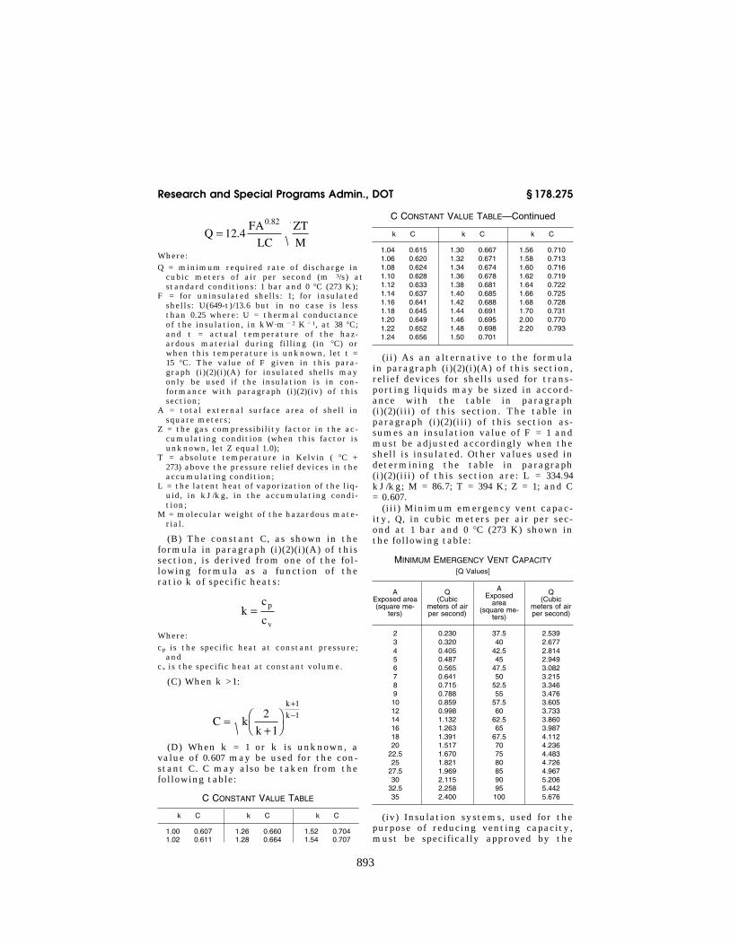
893
Research and Special Programs Admin., DOT § 178.275
QFA
LC
ZT
M= 12
0 82
.4.
Where: Q = minimum required rate of discharge in
cubic meters of air per second (m 3/s) at standard conditions: 1 bar and 0 °C (273 K);
F = for uninsulated shells: 1; for insulated shells: U(649-t)/13.6 but in no case is less than 0.25 where: U = thermal conductance of the insulation, in kW·m¥2 K¥1, at 38 °C; and t = actual temperature of the haz-ardous material during filling (in °C) or when this temperature is unknown, let t = 15 °C. The value of F given in this para-graph (i)(2)(i)(A) for insulated shells may only be used if the insulation is in con-formance with paragraph (i)(2)(iv) of this section;
A = total external surface area of shell in square meters;
Z = the gas compressibility factor in the ac-cumulating condition (when this factor is unknown, let Z equal 1.0);
T = absolute temperature in Kelvin ( °C + 273) above the pressure relief devices in the accumulating condition;
L = the latent heat of vaporization of the liq-uid, in kJ/kg, in the accumulating condi-tion;
M = molecular weight of the hazardous mate-rial.
(B) The constant C, as shown in the formula in paragraph (i)(2)(i)(A) of this section, is derived from one of the fol-lowing formula as a function of the ratio k of specific heats:
kc
cp
v
=
Where: cp is the specific heat at constant pressure;
and cv is the specific heat at constant volume.
(C) When k >1:
C kk
k
k=+
+−2
1
1
1
(D) When k = 1 or k is unknown, a value of 0.607 may be used for the con-stant C. C may also be taken from the following table:
C CONSTANT VALUE TABLE
k C k C k C
1.00 0.607 1.26 0.660 1.52 0.704 1.02 0.611 1.28 0.664 1.54 0.707
C CONSTANT VALUE TABLE—Continued
k C k C k C
1.04 0.615 1.30 0.667 1.56 0.710 1.06 0.620 1.32 0.671 1.58 0.713 1.08 0.624 1.34 0.674 1.60 0.716 1.10 0.628 1.36 0.678 1.62 0.719 1.12 0.633 1.38 0.681 1.64 0.722 1.14 0.637 1.40 0.685 1.66 0.725 1.16 0.641 1.42 0.688 1.68 0.728 1.18 0.645 1.44 0.691 1.70 0.731 1.20 0.649 1.46 0.695 2.00 0.770 1.22 0.652 1.48 0.698 2.20 0.793 1.24 0.656 1.50 0.701
(ii) As an alternative to the formula in paragraph (i)(2)(i)(A) of this section, relief devices for shells used for trans-porting liquids may be sized in accord-ance with the table in paragraph (i)(2)(iii) of this section. The table in paragraph (i)(2)(iii) of this section as-sumes an insulation value of F = 1 and must be adjusted accordingly when the shell is insulated. Other values used in determining the table in paragraph (i)(2)(iii) of this section are: L = 334.94 kJ/kg; M = 86.7; T = 394 K; Z = 1; and C = 0.607.
(iii) Minimum emergency vent capac-ity, Q, in cubic meters per air per sec-ond at 1 bar and 0 °C (273 K) shown in the following table:
MINIMUM EMERGENCY VENT CAPACITY [Q Values]
A Exposed area (square me-
ters)
Q (Cubic
meters of air per second)
A Exposed
area (square me-
ters)
Q (Cubic
meters of air per second)
2 0.230 37.5 2.539 3 0.320 40 2.677 4 0.405 42.5 2.814 5 0.487 45 2.949 6 0.565 47.5 3.082 7 0.641 50 3.215 8 0.715 52.5 3.346 9 0.788 55 3.476 10 0.859 57.5 3.605 12 0.998 60 3.733 14 1.132 62.5 3.860 16 1.263 65 3.987 18 1.391 67.5 4.112 20 1.517 70 4.236
22.5 1.670 75 4.483 25 1.821 80 4.726
27.5 1.969 85 4.967 30 2.115 90 5.206
32.5 2.258 95 5.442 35 2.400 100 5.676
(iv) Insulation systems, used for the purpose of reducing venting capacity, must be specifically approved by the
VerDate Aug<04>2004 14:12 Dec 15, 2004 Jkt 203206 PO 00000 Frm 00893 Fmt 8010 Sfmt 8010 Y:\SGML\203206T.XXX 203206T EN
21JN
01.0
06<
/MA
TH
>E
N21
JN01
.007
</M
AT
H>
EN
21JN
01.0
08<
/MA
TH
>

894
49 CFR Ch. I (10–1–04 Edition) § 178.276
approval agency. In all cases, insula-tion systems approved for this purpose must—
(A) Remain effective at all tempera-tures up to 649 °C (1200.2 °F); and
(B) Be jacketed with a material hav-ing a melting point of 700 °C (1292 °F) or greater.
(j) Approval, inspection and testing. Approval procedures for UN portable tanks are specified in § 178.273. Inspec-tion and testing requirements are spec-ified in § 180.605 of this subchapter.
[66 FR 33445, June 21, 2001, as amended at 68 FR 32414, May 30, 2003]
§ 178.276 Requirements for the design, construction, inspection and testing of portable tanks intended for the transportation of non-refrigerated liquefied compressed gases.
(a) In addition to the requirements of § 178.274 applicable to UN portable tanks, the following requirements apply to UN portable tanks used for non-refrigerated liquefied compressed gases. In addition to the definitions in § 178.274, the following definitions apply:
(1) Design pressure means the pressure to be used in calculations required by the ASME Code, Section VIII (IBR, see § 171.7 of this subchapter). The design pressure must be not less than the highest of the following pressures:
(i) The maximum effective gauge pressure allowed in the shell during filling or discharge; or
(ii) The sum of: (A) The maximum effective gauge
pressure to which the shell is designed as defined in this paragraph under ‘‘MAWP’’; and
(B) A head pressure determined on the basis of the dynamic forces speci-fied in paragraph (h) of this section, but not less than 0.35 bar (35 kPa).
(2) Design reference temperature means the temperature at which the vapor pressure of the contents is determined for the purpose of calculating the MAWP. The value for each portable tank type is as follows:
(i) Shell with a diameter of 1.5 meters (4.9 ft.) or less: 65 °C (149 °F); or
(ii) Shell with a diameter of more than 1.5 meters (4.9 ft.):
(A) Without insulation or sun shield: 60 °C (140 °F);
(B) With sun shield: 55 °C (131 °F); and (C) With insulation: 50 °C (122 °F). (3) Filling density means the average
mass of liquefied compressed gas per liter of shell capacity (kg/l).
(4) Maximum allowable working pres-sure (MAWP) means a pressure that must be not less than the highest of the following pressures measured at the top of the shell while in operating position, but in no case less than 7 bar (700 kPa):
(i) The maximum effective gauge pressure allowed in the shell during filling or discharge; or
(ii) The maximum effective gauge pressure to which the shell is designed, which must be:
(A) Not less than the pressure speci-fied for each liquefied compressed gas listed in portable tank special provi-sion T50; and
(B) Not less than the sum of: (1) The absolute vapor pressure (in
bar) of the liquefied compressed gas at the design reference temperature minus 1 bar; and
(2) The partial pressure (in bar) of air or other gases in the ullage space which is determined by the design ref-erence temperature and the liquid phase expansion due to the increase of the mean bulk temperature of tr¥tf (tf = filling temperature, usually 15 °C, tr = 50 °C maximum mean bulk tempera-ture).
(b) General design and construction re-quirements. (1) Shells must be of seam-less or welded steel construction, or combination of both, and have a water capacity greater than 450 liters (118.9 gallons). Shells must be designed, con-structed, certified and stamped in ac-cordance with the ASME Code, Section VIII.
(2) Portable tanks must be postweld heat-treated and radiographed as pre-scribed in Section VIII of the ASME Code, except that each portable tank constructed in accordance with part UHT of the ASME Code must be postweld heat-treated. Where postweld heat treatment is required, the port-able tank must be treated as a unit after completion of all the welds in and/or to the shell and heads. The method must be as prescribed in the ASME Code. Welded attachments to pads may be made after postweld heat
VerDate Aug<04>2004 14:12 Dec 15, 2004 Jkt 203206 PO 00000 Frm 00894 Fmt 8010 Sfmt 8010 Y:\SGML\203206T.XXX 203206T

895
Research and Special Programs Admin., DOT § 178.276
treatment is made. A portable tank used for anhydrous ammonia must be postweld heat-treated. The postweld heat treatment must be as prescribed in the ASME Code, but in no event at less than 1050 °F tank metal tempera-ture. Additionally, portable tanks con-structed in accordance with part UHT of the ASME Code must conform to the following requirements:
(i) Welding procedure and welder per-formance tests must be made annually in accordance with Section IX of the ASME Code. In addition to the essen-tial variables named therein, the fol-lowing must be considered to be essen-tial variables: number of passes, thick-ness of plate, heat input per pass, and manufacturer’s identification of rod and flux. The number of passes, thick-ness of plate and heat input per pass may not vary more than 25 percent from the qualified procedure. Records of the qualification must be retained for at least 5 years by the portable tank manufacturer or his designated agent and, upon request, made avail-able to a representative of the Depart-ment of Transportation or the owner of the tank.
(ii) Impact tests must be made on a lot basis. A lot is defined as 100 tons or less of the same heat and having a thickness variation no greater than plus or minus 25 percent. The minimum impact required for full-sized speci-mens shall be 20 foot-pounds (or 10 foot-pounds for half-sized specimens) at 0 °F (¥17.8 °F) Charpy V–Notch in both the longitudinal and transverse direc-tion. If the lot test does not pass this requirement, individual plates may be accepted if they individually meet this impact requirement.
(3) When the shells intended for the transportation of non-refrigerated liq-uefied compressed gases are equipped with thermal insulation, a device must be provided to prevent any dangerous pressure from developing in the insu-lating layer in the event of a leak, when the protective covering is closed it must be gas tight. The thermal insu-lation must not inhibit access to the fittings and discharge devices. In addi-tion, the thermal insulation systems must satisfy the following require-ments:
(i) consist of a shield covering not less than the upper third, but not more than the upper half of the surface of the shell, and separated from the shell by an air space of approximately 40 mm (1.7 inches) across; or
(ii) consist of a complete cladding of insulating materials. The insulation must be of adequate thickness and con-structed to prevent the ingress of mois-ture and damage to the insulation. The insulation and cladding must have a thermal conductance of not more than 0.67 (W·m¥2·K¥1) under normal condi-tions of transportation.
(c) Service equipment. (1) Each opening with a diameter of more than 1.5 mm (0.1 inch) in the shell of a portable tank, except openings for pressure-re-lief devices, inspection openings and closed bleed holes, must be fitted with at least three mutually independent shut-off devices in series: the first being an internal stop-valve, excess flow valve, integral excess flow valve, or excess flow feature (see § 178.337– 1(g)), the second being an external stop-valve and the third being a blank flange, thread cap, plug or equivalent tight liquid closure device.
(2) When a portable tank is fitted with an excess flow valve, the excess flow valve must be so fitted that its seating is inside the shell or inside a welded flange or, when fitted exter-nally, its mountings must be designed so that in the event of impact it main-tains its effectiveness. The excess flow valves must be selected and fitted so as to close automatically when the rated flow, specified by the manufacturer, is reached. Connections and accessories leading to or from such a valve must have a capacity for a flow more than the excess flow valve’s rated flow.
(3) For filling and discharge openings that are located below the liquid level, the first shut-off device must be an in-ternal stop-valve and the second must be a stop-valve placed in an accessible position on each discharge and filling pipe.
(4) For filling and discharge openings located below the liquid level of port-able tanks intended for the transpor-tation of flammable and/or toxic lique-fied compressed gases, the internal stop-valve must be a self-closing safety device that fully closes automatically
VerDate Aug<04>2004 14:12 Dec 15, 2004 Jkt 203206 PO 00000 Frm 00895 Fmt 8010 Sfmt 8010 Y:\SGML\203206T.XXX 203206T
896
49 CFR Ch. I (10–1–04 Edition) § 178.276
during filling or discharge in the event of fire engulfment. The device shall fully close within 30 seconds of actu-ation and the thermal means of closure must actuate at a temperature of not more than 121 °C (250 °F). Except for portable tanks having a capacity less than 1,000 liters (264.2 gallons), this de-vice must be operable by remote con-trol.
(5) In addition to filling, discharge and gas pressure equalizing orifices, shells may have openings in which gauges, thermometers and manometers can be fitted. Connections for such in-struments must be made by suitable welded nozzles or pockets and may not be connected by screwed connections through the shell.
(6) All portable tanks must be fitted with manholes or other inspection openings of suitable size to allow for internal inspection and adequate ac-cess for maintenance and repair of the interior.
(7) Inlets and discharge outlets on chlo-rine portable tanks. The inlet and dis-charge outlets on portable tanks used to transport chlorine must meet the re-quirements of § 178.337–1(c)(2) and must be fitted with an internal excess flow valve. In addition to the internal ex-cess flow valve, the inlet and discharge outlets must be equipped with an ex-ternal stop valve (angle valve). Excess flow valves must conform to the stand-ards of The Chlorine Institute, Inc. (IBR, see § 171.7 of this subchapter) as follows:
(i) A valve conforming to Drawing 101–7, dated July 1993, must be installed under each liquid angle valve.
(ii) A valve conforming to Drawing 106–6, dated July 1993, must be installed under each gas angle valve. For port-able tanks used to transport non-re-frigerated liquefied gases.
(8) External fittings must be grouped together as close as reasonably prac-ticable. The following openings may be installed at locations other than on the top or end of the tank:
(i) The openings for liquid level gaug-ing devices, pressure gauges, or for safety devices, may be installed sepa-rately at the other location or in the side of the shell;
(ii) One plugged opening of 2-inch Na-tional Pipe Thread or less provided for
maintenance purposes may be located elsewhere;
(iii) An opening of 3-inch National Pipe Size or less may be provided at another location, when necessary, to facilitate installation of condensing coils.
(9) Filling and discharge connections are not required to be grouped and may be installed below the normal liquid level of the tank if:
(i) The portable tank is permanently mounted in a full framework for con-tainerized transport;
(ii) For each portable tank design, a prototype portable tank, meets the re-quirements of parts 450 through 453 of this title for compliance with the re-quirements of Annex II of the Inter-national Convention for Safe Con-tainers; and
(iii) Each filling and discharge outlet meets the requirements of paragraph (c)(4) of this section.
(d) Bottom openings. Bottom openings are prohibited on portable tanks when the portable tank special provision T50 in § 172.102(c)(7) of this subchapter indi-cates that bottom openings are not al-lowed. In this case, there may be no openings located below the liquid level of the shell when it is filled to its max-imum permissible filling limit.
(e) Pressure relief devices. (1) Portable tanks must be provided with one or more reclosing pressure relief devices. The pressure relief devices must open automatically at a pressure not less than the MAWP and be fully open at a pressure equal to 110% of the MAWP. These devices must, after discharge, close at a pressure not less than 10% below the pressure at which discharge starts and must remain closed at all lower pressures. The pressure relief de-vices must be of a type that will resist dynamic forces including liquid surge. A frangible disc may only be used in se-ries with a reclosing pressure relief de-vice.
(2) Pressure relief devices must be de-signed to prevent the entry of foreign matter, the leakage of gas and the de-velopment of any dangerous excess pressure.
(3) A portable tank intended for the transportation of certain liquefied compressed gases identified in portable tank special provision T50 in § 172.102 of
VerDate Aug<04>2004 14:12 Dec 15, 2004 Jkt 203206 PO 00000 Frm 00896 Fmt 8010 Sfmt 8010 Y:\SGML\203206T.XXX 203206T

897
Research and Special Programs Admin., DOT § 178.277
this subchapter must have a pressure relief device which conforms to the re-quirements of this subchapter. Unless a portable tank, in dedicated service, is fitted with a relief device constructed of materials compatible with the haz-ardous material, the relief device must be comprised of a frangible disc pre-ceded by a reclosing device. The space between the frangible disc and the de-vice must be provided with a pressure gauge or a suitable tell-tale indicator. This arrangement must facilitate the detection of disc rupture, pinholing or leakage which could cause a malfunc-tion of the pressure relief device. The frangible disc must rupture at a nomi-nal pressure 10% above the start-to-dis-charge pressure of the relief device.
(4) In the case of portable tanks used for more than one gas, the pressure re-lief devices must open at a pressure in-dicated in paragraph (e)(1) of this sec-tion for the gas having the highest maximum allowable pressure of the gases allowed to be transported in the portable tank.
(f) Capacity of relief devices. The com-bined delivery capacity of the relief de-vices must be sufficient so that, in the event of total fire engulfment, the pressure inside the shell cannot exceed 120% of the MAWP. Reclosing relief de-vices must be used to achieve the full relief capacity prescribed. In the case of portable tanks used for more than gas, the combined delivery capacity of the pressure relief devices must be taken for the liquefied compressed gas which requires the highest delivery ca-pacity of the liquefied compressed gases allowed to be transported in the portable tank. The total required ca-pacity of the relief devices must be de-termined according to the require-ments in § 178.275(i). These require-ments apply only to liquefied com-pressed gases which have critical tem-peratures well above the temperature at the accumulating condition. For gases that have critical temperatures near or below the temperature at the accumulating condition, the calcula-tion of the pressure relief device deliv-ery capacity must consider the addi-tional thermodynamic properties of the
gas, for example see CGA S–1.2 (IBR, see § 171.7 of this subchapter).
[66 FR 33448, June 21, 2001, as amended at 68 FR 75748, 75752, Dec. 31, 2003; 69 FR 54046, Sept. 7, 2004]
§ 178.277 Requirements for the design, construction, inspection and testing of portable tanks intended for the transportation of refrigerated lique-fied gases.
(a) In addition to the requirements of § 178.274 applicable to UN portable tanks, the following requirements and definitions apply to UN portable tanks used for refrigerated liquefied gases:
Design pressure For the purpose of this section the term ‘‘design pressure’’ is consistent with the definition for de-sign pressure in the ASME Code, Sec-tion VIII (IBR, see § 171.7 of this sub-chapter).
Holding time is the time, as deter-mined by testing, that will elapse from loading until the pressure of the con-tents, under equilibrium conditions, reaches the lowest set pressure of the pressure limiting device(s) (for exam-ple, pressure control valve or pressure relief device). Holding time must be de-termined as specified in § 178.338–9.
Maximum allowable working pressure (MAWP) means the maximum effective gauge pressure permissible at the top of the shell of a loaded portable tank in its operating position including the highest effective pressure during filling and discharge;
Minimum design temperature means the temperature which is used for the design and construction of the shell not higher than the lowest (coldest) service temperature of the contents during normal conditions of filling, dis-charge and transportation.
Shell means the part of the portable tank which retains the refrigerated liq-uefied gas intended for transport, in-cluding openings and their closures, but does not include service equipment or external structural equipment.
Tank means a construction which normally consists of either:
(1) A jacket and one or more inner shells where the space between the shell(s) and the jacket is exhausted of air (vacuum insulation) and may incor-porate a thermal insulation system; or
VerDate Aug<04>2004 14:12 Dec 15, 2004 Jkt 203206 PO 00000 Frm 00897 Fmt 8010 Sfmt 8010 Y:\SGML\203206T.XXX 203206T

898
49 CFR Ch. I (10–1–04 Edition) § 178.277
(2) A jacket and an inner shell with an intermediate layer of solid ther-mally insulating material (for exam-ple, solid foam).
(b) General design and construction re-quirements. (1) Portable tanks must be of seamless or welded steel construc-tion and have a water capacity of more than 450 liters (118.9 gallons). Portable tanks must be designed, constructed, certified and stamped in accordance with Section VIII of the ASME Code.
(2) Portable tanks must be postweld heat treated and radiographed as pre-scribed in Sections V and VIII of the ASME Code except that each tank con-structed in accordance with part UHT in Section VIII of the ASME Code must be postweld heat treated. Where postweld heat treatment is required, the tank must be treated as a unit after completion of all the welds to the shell and heads. The method must be as prescribed in the ASME Code. Welded attachments to pads may be made after postweld heat treatment is made. The postweld heat treatment must be as prescribed in Section VIII of the ASME Code, but in no event at less than 1,050 °F tank metal temperature.
(3) Welding procedure and welder per-formance tests must be made annually in accordance with Section IX of the ASME Code (IBR, see § 171.7 of this sub-chapter). In addition to the essential variables named in the ASME Code, the following must be considered as essen-tial variables: number of passes, thick-ness of plate, heat input per pass, and the specified rod and flux. The number of passes, thickness of plate and heat input per pass may not vary more than 25% from the procedure qualification. Records of the qualification must be retained for at least 5 years by the portable tank manufacturer and made available to the approval agency and the owner of the portable tank as spec-ified in § 178.273.
(4) Shells and jackets must be made of metallic materials suitable for form-ing. Jackets must be made of steel. Non-metallic materials may be used for the attachments and supports be-tween the shell and jacket, provided their material properties at the min-imum design temperature are proven to be sufficient. In choosing the mate-rial, the minimum design temperature
must be taken into account with re-spect to risk of brittle fracture, to hy-drogen embrittlement, to stress corro-sion cracking and to resistance to im-pact.
(5) Any part of a portable tank, in-cluding fittings, gaskets and pipe- work, which can be expected normally to come into contact with the refrig-erated liquefied gas transported must be compatible with that refrigerated liquefied gas.
(6) The thermal insulation system must include a complete covering of the shell with effective insulating ma-terials. External insulation must be protected by a jacket so as to prevent the ingress of moisture and other dam-age under normal transport conditions.
(7) When a jacket is so closed as to be gas-tight, a device must be provided to prevent any dangerous pressure from developing in the insulation space.
(8) Materials which may react with oxygen or oxygen enriched atmospheres in a dangerous manner may not be used in portable tanks in-tended for the transport of refrigerated liquefied gases having a boiling point below minus 182 °C at atmospheric pressure in locations with the thermal insulation where there is a risk of con-tact with oxygen or with oxygen en-riched fluid.
(9) Insulating materials must not de-teriorate to an extent that the effec-tiveness of the insulation system, as determined in accordance with para-graph (b)(11) of this section, would be reduced in service.
(10) A reference holding time must be determined for each refrigerated lique-fied gas intended for transport in a portable tank. The reference holding time must be determined by testing in accordance with the requirements of § 178.338–9, considering the following factors:
(i) The effectiveness of the insulation system, determined in accordance with paragraph (b)(11) of this section;
(ii) The lowest set pressure of the pressure limiting device;
(iii) The initial filling conditions; (iv) An assumed ambient tempera-
ture of 30 °C (86 °F); (v) The physical properties of the in-
dividual refrigerated liquefied gas in-tended to be transported.
VerDate Aug<04>2004 14:12 Dec 15, 2004 Jkt 203206 PO 00000 Frm 00898 Fmt 8010 Sfmt 8010 Y:\SGML\203206T.XXX 203206T

899
Research and Special Programs Admin., DOT § 178.277
(11) The effectiveness of the insula-tion system (heat influx in watts) may be determined by type testing the port-able tank in accordance with a proce-dure specified in § 178.338–9(c) or by using the holding time test in § 178.338– 9(b). This test must consist of either:
(i) A constant pressure test (for ex-ample, at atmospheric pressure) when the loss of refrigerated liquefied gas is measured over a period of time; or
(ii) A closed system test when the rise in pressure in the shell is measured over a period of time.
(12) When performing the constant pressure test, variations in atmos-pheric pressure must be taken into ac-count. When performing either test, corrections must be made for any vari-ation of the ambient temperature from the assumed ambient temperature ref-erence value of 30 °C (86 °F).
(13) The jacket of a vacuum-insulated double-wall tank must have either an external design pressure not less than 100 kPa (1 bar) gauge pressure cal-culated in accordance with Section VIII of the ASME Code or a calculated critical collapsing pressure of not less than 200 kPa (2 bar) gauge pressure. In-ternal and external reinforcements may be included in calculating the ability of the jacket to resist the exter-nal pressure.
NOTE TO PARAGRAPH (b): For the deter-mination of the actual holding time, as indi-cated by paragraphs (b)(10), (11), (12), and (13), before each journey, refer to § 178.338– 9(b).
(c) Design criteria. For shells with vacuum insulation, the test pressure must not be less than 1.3 times the sum of the MAWP and 100 kPa (1 bar). In no case may the test pressure be less than 300 kPa (3 bar) gauge pressure.
(d) Service equipment. (1) Each filling and discharge opening in portable tanks used for the transport of flam-mable refrigerated liquefied gases must be fitted with at least three mutually independent shut-off devices in series: the first being a stop-valve situated as close as reasonably practicable to the jacket, the second being a stop-valve and the third being a blank flange or equivalent device. The shut-off device closest to the jacket must be a self- closing device, which is capable of being closed from an accessible posi-tion on the portable tank that is re-
mote from the valve within 30 seconds of actuation. This device must actuate at a temperature of not more than 121 °C (250 °F).
(2) Each filling and discharge opening in portable tanks used for the trans-port of non-flammable refrigerated liq-uefied gases must be fitted with at least two mutually independent shut- off devices in series: the first being a stop-valve situated as close as reason-ably practicable to the jacket and the second a blank flange or equivalent de-vice.
(3) For sections of piping which can be closed at both ends and where liquid product can be trapped, a method of automatic pressure relief must be pro-vided to prevent excess pressure build- up within the piping.
(4) Each filling and discharge opening on a portable tank must be clearly marked to indicate its function.
(5) When pressure-building units are used, the liquid and vapor connections to that unit must be provided with a valve as close to the jacket as reason-ably practicable to prevent the loss of contents in case of damage to the pres-sure-building unit. A check valve may be used for this purpose if it is located on the vapor side of the pressure build- up coil.
(6) The materials of construction of valves and accessories must have satis-factory properties at the lowest oper-ating temperature of the portable tank.
(7) Vacuum insulated portable tanks are not required to have an inspection opening.
(e) Pressure relief devices. (1) Every shell must be provided with not less than two independent reclosing pres-sure relief devices. The pressure relief devices must open automatically at a pressure not less than the MAWP and be fully open at a pressure equal to 110% of the MAWP. These devices must, after discharge, close at a pres-sure not lower than 10% below the pres-sure at which discharge starts and must remain closed at all lower pres-sures. The pressure relief devices must be of the type that will resist dynamic forces including surge.
VerDate Aug<04>2004 14:12 Dec 15, 2004 Jkt 203206 PO 00000 Frm 00899 Fmt 8010 Sfmt 8010 Y:\SGML\203206T.XXX 203206T

900
49 CFR Ch. I (10–1–04 Edition) § 178.318
(2) Except for portable tanks used for oxygen, portable tanks for non-flam-mable refrigerated liquefied gases (ex-cept oxygen) and hydrogen may in ad-dition have frangible discs in parallel with the reclosing devices as specified in paragraphs (e)(4)(ii) and (e)(4)(iii) of this section.
(3) Pressure relief devices must be de-signed to prevent the entry of foreign matter, the leakage of gas and the de-velopment of any dangerous excess pressure.
(4) Capacity and setting of pressure re-lief devices. (i) In the case of the loss of vacuum in a vacuum-insulated tank or of loss of 20% of the insulation of a portable tank insulated with solid ma-terials, the combined capacity of all pressure relief devices installed must be sufficient so that the pressure (in-cluding accumulation) inside the shell does not exceed 120% of the MAWP.
(ii) For non-flammable refrigerated liquefied gases (except oxygen) and hy-drogen, this capacity may be achieved by the use of frangible discs in parallel with the required safety-relief devices. Frangible discs must rupture at nomi-nal pressure equal to the test pressure of the shell.
(iii) Under the circumstances de-scribed in paragraphs (e)(4)(i) and (e)(4)(ii) of this section, together with complete fire engulfment, the com-bined capacity of all pressure relief de-vices installed must be sufficient to limit the pressure in the shell to the test pressure.
(iv) The required capacity of the re-lief devices must be calculated in ac-cordance with CGA Pamphlet S–1.2 (IBR, see § 171.7 of this subchapter).
[66 FR 33450, June 21, 2001, as amended at 68 FR 75748, 75752, Dec. 31, 2003]
Subpart I [Reserved]
Subpart J—Specifications for Con-tainers for Motor Vehicle Transportation
SOURCE: 29 FR 18975, Dec. 29, 1964, unless otherwise noted. Redesignated at 32 FR 5606, Apr. 5, 1967.
§ 178.318 Specification MC 201; con-tainer for detonators and percus-sion caps.
§ 178.318–1 Scope. (a) This specification pertains to a
container to be used for the transpor-tation of detonators and percussion caps in connection with the transpor-tation of liquid nitroglycerin, desen-sitized liquid nitroglycerin or diethylene glycol dinitrate, where any or all of such types of caps may be used for the detonation of liquid nitroglyc-erin, desentitized liquid nitroglycerin or diethylene glycol dinitrate in blast-ing operations. This specification is not intended to take the place of any shipping or packing requirements of this Department where the caps in question are themselves articles of commerce.
(b) [Reserved]
[29 FR 18975, Dec. 29, 1964. Redesignated at 32 FR 5606, Apr. 5, 1967, and amended by Amdt. 178–60, 44 FR 70733, Dec. 10, 1979]
§ 178.318–2 Container. (a) Every container for detonators
and percussion caps coming within the scope of this specification shall be con-structed entirely of hard rubber, phenolresinous or other resinous mate-rial, or other nonmetallic, nonsparking material, except that metal parts may be used in such locations as not in any event to come in contact with any of the caps. Space shall be provided so that each detonator of whatever nature may be inserted in an individual cell in the body of the container, into which each such cap shall snugly fit. There shall be provided no more than twenty (20) such cellular spaces. Space may be provided into which a plurality of per-cussion caps may be carried, provided that such space may be closed with a screw cap, and further provided that each or any such space is entirely sepa-rate from any space provided for any detonator. Each cellular space into which a detonator is to be inserted and carried shall be capable of being cov-ered by a rotary cover so arranged as to expose not more than one cell at any time, and capable of rotation to such a place that all cells will be covered at the same time, at which place means shall be provided to lock the cover in
VerDate Aug<04>2004 14:12 Dec 15, 2004 Jkt 203206 PO 00000 Frm 00900 Fmt 8010 Sfmt 8010 Y:\SGML\203206T.XXX 203206T