subrack accessories front panels, handles - pixus...
TRANSCRIPT

Page 143
for type I, II extractor handle and type IV injector/extractor handle Width 4 HP
Packs of Model No. RP100 3684.328
with push-buttonFor inserting and removing connectors with a large number of pins. A metal insert ensures reliable functioning, even at forces of up to 815 N.● Insertion/removal function● Push-button for locking and unlocking the
board type plug-in unit (cannot be extracted in the locked position)
● Optionally with 1/2 HP offset PCB attachment, e.g. for component mounting on both sides
● Optional integral micr o-switch for “live inser-tion” applications
● ESD pin to dissipate static charges before contacting the connectors and for precise positioning of the board type plug-in unit
● Codeable● Integral PCB attachment● Bayable.Material:Plastic/metalSupply includes:Assembly parts.Note:● Insertion only when used with front horizontal
rails, with 10 mm extension (B),
● With 3 U front panels, only one extractor handle is required.
Handles without offset
Handles with 1/2 HPoffset
Accessories:Keys, Keyable guide rails Keyable guide rails with 1/2 HP offsetMicro-switchesConnector pin for baying
8.5
2.6
38
47.5
23.6
M2.5
Installation Packs of Model No. RPtop 1 3688.770
bottom 1 3688.771
Installation Packs of Model No. RPtop 1 3688.772
bottom 1 3688.773
for injector/extractor handles, types IV, IVs and VII The connection pin can be used to connect injector/extractor handles, types IV, IVs and VII.Material:Steel
Packs of Model No. RP20 3685.319
Subrack accessories
Front panels, handles
Identification strips
Injector/extractor handletype IVs
Connection pin

Page 144
Plastic (telecom) For inserting and removing connectors with a large number of pins. This handle was specifi-cally designed for use in telecom applications.● Insertion/removal function● Optionally with 1/2 HP offset PCB attachment,
e.g. for component mounting on both sides● Minimum front space requirements, due to
fold-up handle● Codeable● Optional integral micr o-switch for “live inser-
tion” applications● ESD pin to dissipate static charges prior to
making contact with the connectors and for precise positioning of the board type plug-in unit
● Large labelling area on the front. Material:PlasticSupply includes:Assembly parts.Note:Insertion only when used with front horizontal rails, with 10 mm extension (B),
Handles without offset
Handles with 1/2 HPoffset
Accessories:Keys, Keyable guide rails Keyable guide rails with 1/2 HP offset Micro-switchesConnector pin for baying
15
2.6
8.55
24.5
51
M2.5
Installation Packs of Model No. RPtop 1 3688.784
bottom 1 3688.785
Installation Packs of Model No. RPtop 1 3688.780
bottom 1 3688.781
Metal (telecom)For inserting and removing connectors with a large number of pins (up to 815 N). This handle was specifically designed for use in telecom applications.● Insertion/removal function● Optionally with 1/2 HP offset PCB attachment,
e.g. for component mounting on both sides● Minimum front space requirements, due to
fold-up handle● Codeable● Optional integral micr o-switch for “live inser-
tion” applications● ESD pin to dissipate static charges prior to
making contact with the connectors and for precise positioning of the board type plug-in unit
● Metal design for use in aggressive atmospheres.Material:Die-cast zincSupply includes:Assembly parts.Note:Insertion only when used with front horizontal rails, with 10 mm extension (B),
Handles without offset
Handles with 1/2 HPoffset
Accessories:Keys Keyable guide railsKeyable guide rails with 1/2 HP offset Micro-switchesConnector pin for baying
Installation Packs of Model No. RPtop 1 3688.790
bottom 1 3688.791
Installation Packs of Model No. RPtop 1 3688.786
bottom 1 3688.787
For “live insertion” applications. Installation in injector/extractor handles, types IV, IVs and VII. May also be retrofitted.Technical specifications:Switching load: 50 mA 30 V DC Service life/switching cycles: At nominal load: 30,000 mechanical: 50,000
Also required:Micro-switch mounting clip
Packs of Model No. RP10 3684.410
8.5
15
2.6
61.3
24.5
M2.5
Subrack accessories
Injector/extractor handles
Injector/extractor handletype VII
Injector/extractor handletype VII
Micro-switch

Page 145
with cable and connector For “live insertion” applications. Installation in injector/extractor handles, types IV, IVs and VII.Supply includes:Micro-switch, connector type Molex 51021-0300,mounting clips, 3 cables, 25 mm x #32 AWG, fully assembled.
Also required:Micro-switch mounting clip
Micro-switch:with cable and connector
12
3
~25
3
2
1
3 2
1
1
2
Lever not depressed Lever hinge Lever contact point
1
2
31-2 micro-switch levers depressedInjector/extractor handle in latch position 1-3 micro-switch levers not depressed Injector/extractor handle unlatched
Packs of Model No. RP1 set 3686.536
For mounting micro-switches in handles.Packs of Model No. RP
10 3684.411
for PCBsFor mechanical protection of the component side and of the EMC gaskets. Attachment holes as per CPCI or VME-specifica-tions. Optionally available as perforated or solid version.
Material:0.3 mm plastic, anti-staticMaximum temperature up to 65°C1) 0.5 mm plastic, transparent, anti-staticUL 94-V0, maximum temperature up to 65°C2) 0.5 mm plastic, black, anti-static UL 94-V0, maximum temperature up to 120°C
Also required:Required for mounting the perforated cPCI covers: Mounting clips
Packs of Model No. RP100 3687.955
For PCBs Packs ofModel No. RP
EMV rofcPCI rofperforated1) solid1) solid solid
3 U x 160 mm1 3687.932 3686.572 3685.966 3685.6265 – – – 3685.279
3 U x 220 mm1 – – – 3685.8055 – – – 3685.266
6 U x 80 mm 1 3687.933 3686.573 3686.037 3686.146
6 U x 160 mm1 3687.934 3686.574 3685.967 3685.6271 9905.5742) 9905.9902) – – 5 – – – 3685.280
6 U x 220 mm1 – – – 3685.8245 – – – 3685.000
Front panels, handles
Subrack accessories
Micro-switch
Micro-switch mounting clip
Plastic covers

Page 147
Material:1.0 mm extruded aluminium section Surface finish:Untreated
L1
B5.9
A
L2
5.9
L1 L2
3.23
3.5
2 10.1
B
A
C1
C2
Material:Fibreglass-reinforced polycarbonateBase section nickel-plated ABS Colour:Grey
30.9
5.5
3.57
1.1
22.9
16.2
30.9 11.2
5.5
HP Packs of Model No. RP3 1 3685.5914 1 3685.592
Material:Fibreglass-reinforced polycarbonate
HP Width mm Packs of Model No. RP1 5 1 3687.5292 10.08 1 3687.5304 20.24 1 3687.531
HP A mm
W (B) mm
C1mm
C2mm
Model No. RP 3 U 6 U 9 U
3 15.20 12.20 – – 3685.548 3685.555 – 4 20.22 17.20 – – 3685.549 3685.556 3685.5625 25.28 22.28 – 22.68 3685.550 3685.557 3685.5636 30.36 27.36 – 25.22 3685.551 3685.558 3685.5648 40.52 37.52 – 30.30 3685.552 3685.559 3685.56610 50.68 47.68 40.46 25.22 3685.553 3685.560 3685.56712 60.84 57.84 50.62 30.30 3685.554 3685.561 3685.568
07.36353.03200.79mm 1L07.65353.32200.09mm 2L
Available with optional metal screw collars.
for front panel supportMaterial:Nickel-plated plastic
HP Packs of Model No. RP4 1 3687.545
with type V handle and PCB holderComplete modular systemsMaterial:Front panel: 2.5 mm Aluminium, natural anodisedHandle: Aluminium, natural anodisedPCB holder: Polycarbonate Supply includes:1 front panel,1 handle (2 with 6 U),1 PCB holder (2 with 6 U),assembly parts.
Accessories:Identification strips for handles,
HE
a2.5
B
107
9099
2.5
9.5
157.
35
88.9
10.8
5
14
5.92.5
262.
05
3.3
255.
85
2.7
B
a
7.46
a
B
3.3
5.92.5
7.46
122.
512
8.7
2.7
7.35
9.5
2.5
118.
35
9090
9999
88.9
10.8
526
.35
88.9
107
107
14
14
1515
HP a mm
W (B)mm
Model No. RP3 U
H = 128.76 U
H = 262.053 14.9 – 3652.000 3652.2004 20.0 – 3652.010 3652.2105 25.1 – 3652.020 3652.2206 30.1 – 3652.030 3652.2307 35.2 – 3652.040 3652.2408 40.3 – 3652.050 3652.250
10 50.5 35.6 3652.060 3652.26012 60.6 45.7 3652.070 3652.27014 70.8 55.9 3652.080 –
Subrack accessories
Front panels, handles
Universal holder
Flat front panels

Page 150
AluminiumMaterial:Aluminium, anodised
Also required:Mounting kit packs of 1 set, Model No. RP 3687.146(from 6 HP 2 packs required)
14
12
14
8
6.78
HP Model No. RP HP Model No. RP3 3685.605 12 3685.6124 3685.606 14 3685.6135 3685.607 21 3685.6146 3685.608 28 3685.6157 3685.609 42 3685.6168 3685.610 84 3685.617
10 3685.611 1 m 3685.618
For attaching the PCB to front panels with handle types I, II, IV, IVs, VII.Material:Die-castNote:Only required at the top with 3U front panels.
Also required:For securing PCBs to PCB holders: Pan-head screws packs of 100, Model No. RP 3654.320 For attaching the front panel to the PCB holder: Oval head screw packs of 100, Model No. RP 3685.282.
Packs of Model No. RP10 3685.198
For front panelsFor attaching PCBs to front panels (handle type V, VI).Material:NorylSupply includes:Assembly parts.
Packs of Model No. RP10 3606.330
Custom lengths available.
Subrack accessories
Front panels, handles
Type VI handle
PCB holder kit
PCB holder
Page 154
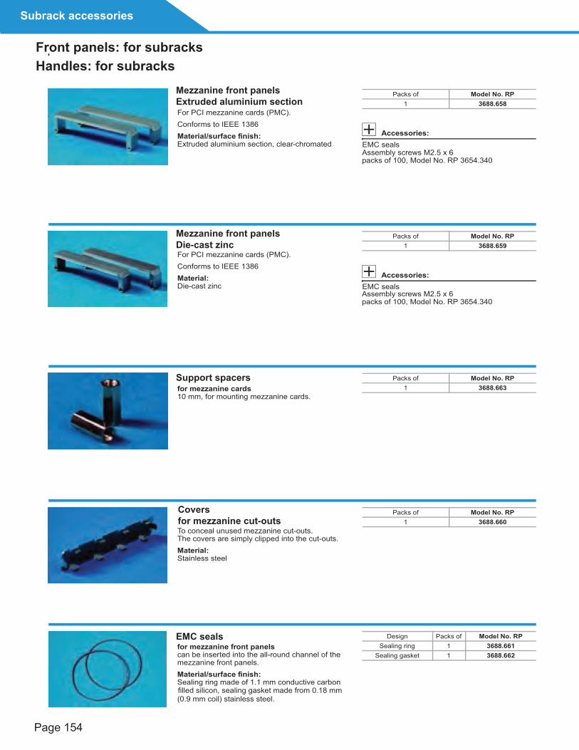
For PCI mezzanine cards (PMC).Conforms to IEEE 1386 Material/surface finish:Extruded aluminium section, clear-chromated
Accessories:EMC sealsAssembly screws M2.5 x 6packs of 100, Model No. RP 3654.340
Packs of Model No. RP1 3688.658
For PCI mezzanine cards (PMC). Conforms to IEEE 1386 Material:Die-cast zinc
Accessories:EMC seals Assembly screws M2.5 x 6packs of 100, Model No. RP 3654.340
Packs of Model No. RP1 3688.659
for mezzanine cards10 mm, for mounting mezzanine cards.
Packs of Model No. RP1 3688.663
To conceal unused mezzanine cut-outs. The covers are simply clipped into the cut-outs. Material:Stainless steel
Packs of Model No. RP1 3688.660
for mezzanine front panelscan be inserted into the all-round channel of the mezzanine front panels. Material/surface finish:Sealing ring made of 1.1 mm conductive carbon
(0.9 mm coil) stainless steel.
Design Packs of Model No. RPSealing ring 1 3688.661
Sealing gasket 1 3688.662
filled silicon, sealing gasket made from 0.18 mm
Subrack accessories
Front panels: for subracks
Mezzanine front panelsExtruded aluminium section
Mezzanine front panelsDie-cast zinc
Support spacers
EMC seals
Coversfor mezzanine cut-outs
Handles: for subracks

Page 131
11
Keyable guide rails with aluminium centre part, for high mechanical loads. Suitable for 1.6 – 2.0 mm PCB thickness.
The guide rails are compiled from the following individual components:
2 end pieces
1 aluminium centre part
Insulating centre part(s)
1
2
3
for three-part guide railsFor 1.6 – 2.0 mm PCB thickness.
Material:Polycarbonate, base material to UL 94-V0
Note:A front and a rear end piece is required for each guide rail.
1 Packs of Model No. RP10 pairs 3685.265
front end piece 3685.790rear end piece 3684.670
for three-part guide railsFor 1.6 – 2.0 mm PCB thickness.
Material:Aluminium, unplated
2 For PCB depth
mm
Model No. RP
Packs of = 1 Packs of = 10
220 3684.673 3685.260280 3684.674 3685.261340 3684.675 3685.262400 3684.676 3685.263
1000 3684.672 –
for three-part guide rails The insulated centre part is pushed onto the aluminium centre part. length: 60 mm.
Material:Plastic, self-extinguishing to UL 94-V0
3 Packs of Model No. RP1 3684.677
10 3685.264
For PCB depth
mm
Number of insulating strips required
1 160
2
3
4
5
Snap-fastening guide rails to accommodate PCBs and assemblies with a height of 4.4˝.
Material:Macrolon
Colour:Dark grey
9
148.80
15
2
1.90
8
1
Ø 3
For PCB depth
mmPacks of Model No. RP
160 1 3686.990
220
280
340
400
for box type plug-in unitsFor PCB depth 1.6 mm. For insertion into covers with vent slots (from 12 HP).Material:Noryl
For PCB depth mm Packs of Model No. RP
160 10 3606.140220 10 3606.200
for unused slots To conceal unused slots and prevent unwanted airflow. The air block panel simply snaps into position on the guide rails.Material:Polycarbonate, self-extinguishing to UL 94-V0 Colour:Blue Note:Not suitable for use in conjunction with guide rails with 1/2 HP offset.
For keyable guiderails Packs of Model No. RP
160 mm 1 3687.924
for installation in keyable guide rails. To discharge static charges.
ESD contact for guide rail For permanent direct discharge via the PCB. ESD contact for front panelTo discharge static charges in conjunction with the ESD pin. For insertion into the end piece of the guide rail. ESD pinKeys
Material:Stainless steelTin bronze, tin-plated
Note:Only for use in conjunction with extractor handle with ESD pin (type IV, IVs, VII), .
3 2 1
1 2
1
2
3
4
1
2
ESD contactfor Packs of Model No. RP
Guide rail 50 3684.204Front panel 50 3684.205
1
24
Subrack accessories
Guide rails
Guide rails
Air block panel
ESD contacts