subsea inspection, maintenance, and repair … · subsea integrity management plan ... risk...
TRANSCRIPT

ABS | SUBSEA INSPECTION, MAINTENANCE, AND REPAIR ADVISORY 2019 | i
SUBSEA INSPECTION, MAINTENANCE, AND REPAIR ADVISORYFEBRUARY 2019
© Sonomatic Inc.

SECTION 1 – EXECUTIVE SUMMARY ...............................................................................................................................................................................................................................1
SECTION 2 – SUBSEA INTEGRITY MANAGEMENT .....................................................................................................................................................................................2
Overview ....................................................................................................................................................................................................................................................................................................2
Applicability ...........................................................................................................................................................................................................................................................................................2
Challenges ................................................................................................................................................................................................................................................................................................3
SECTION 3 – SUBSEA INTEGRITY MANAGEMENT PLAN DEVELOPMENT ................................................................................................................4
Data Collection....................................................................................................................................................................................................................................................................................4
Baseline Survey ..................................................................................................................................................................................................................................................................................5
Risk Assessment ................................................................................................................................................................................................................................................................................5Risk Categorization/Risk Criteria ...........................................................................................................................................................................................................................6
Subsea Integrity Management Plan .........................................................................................................................................................................................................................7
SECTION 4 – SUBSEA INSPECTION, MAINTENANCE, AND REPAIR ..................................................................................................................................8
Condition Data Collection .....................................................................................................................................................................................................................................................8Inspection Technologies ...................................................................................................................................................................................................................................................8Pigging ...................................................................................................................................................................................................................................................................................................11Condition Monitoring Techniques .....................................................................................................................................................................................................................11Inspection Challenges and New Technologies ...................................................................................................................................................................................12
Maintenance .......................................................................................................................................................................................................................................................................................14Reactive (Breakdown) Maintenance ................................................................................................................................................................................................................14Preventative (Scheduled) Maintenance .......................................................................................................................................................................................................14Predictive Maintenance ..................................................................................................................................................................................................................................................15Reliability Centered Maintenance ......................................................................................................................................................................................................................15Summary ...........................................................................................................................................................................................................................................................................................15Maintenance Activities ....................................................................................................................................................................................................................................................15
Repair ...........................................................................................................................................................................................................................................................................................................16General Repair Methods .................................................................................................................................................................................................................................................16Repair Process .............................................................................................................................................................................................................................................................................16
Influence of Standardization of Subsea Equipment on Inspection Maintenance and Repair .....................................................17
SECTION 5 – ROLE OF ABS .......................................................................................................................................................................................................................................................17
New Technology Qualification .....................................................................................................................................................................................................................................17
Risk Based Inspection (RBI) ..............................................................................................................................................................................................................................................18
Fitness-for-Service .......................................................................................................................................................................................................................................................................19Damage Assessment ............................................................................................................................................................................................................................................................19Life Extension ..............................................................................................................................................................................................................................................................................19
SECTION 6 – SUMMARY .............................................................................................................................................................................................................................................................20
APPENDIX .......................................................................................................................................................................................................................................................................................................21
——TABLE OF CONTENTS
Disclaimer:
While ABS uses reasonable efforts to accurately describe and update the information in this Advisory, ABS makes no warranties or representations as to its accuracy, currency or completeness. ABS assumes no liability or responsibility for any errors or omissions in the content of this Advisory. To the extent permitted by applicable law, everything in this Advisory is provided “as is” without warranty of any kind, either expressed or implied, including, but not limited to, the implied warranties of merchantability, fitness for a particular purpose, or noninfringement. In no event will ABS be liable for any damages whatsoever, including special, indirect, consequential or incidental damages or damages for loss of profits, revenue or use, whether brought in contract or tort, arising out of or connected with this Advisory or the use or reliance upon any of the content or any information contained herein.

ABS | SUBSEA INSPECTION, MAINTENANCE, AND REPAIR ADVISORY 2019 | 1
——SECTION 1 – EXECUTIVE SUMMARY The implementation of subsea integrity management across the globe is increasing. There is great importance in planning and maintaining the longevity of structures, equipment, and systems. Alongside the increased activity, there are many existing assets reaching their end of design life. These assets can benefit from integrity management services such as damage evaluations and life extension assessments.
Integrity management is a key area of interest for both new and aging subsea assets. The growing awareness of asset integrity has led to increased incorporation of integrity management into project planning and has increased the understanding of the conditions influencing the remaining life of existing structures and systems. For new projects, subsea integrity management can assess associated risks, designate the inspection and maintenance intervals and repair expectations, and decrease the potential for failures/lost time. Subsea integrity management benefits operators, manufacturers, and regulators by increasing confidence that the equipment or system will reliably function per the intended use and be safely installed and operated. For existing assets, a subsea integrity management plan can assist by assessing the condition and establishing a baseline to move forward for inspections, maintenance, and repair through fitness for service assessments. A subsea integrity management plan may also assist in increasing the original design life through a life extension assessment. These have been greatly beneficial to operators where a costly replacement would have originally been required.
Subsea inspection, maintenance, and repair (IMR) are key components within an overall integrity management system. Inspection of systems can provide assistance in identifying areas of improvement or noncompliance. The maintenance plan is the pathway for equipment to maintain the longevity that it was originally designed for, or even extend service life. The repair component of an IMR plan integrates directly into the maintenance plan and can proactively identify the need to replace or modify damaged or worn out portions of a system to assist the overall operational function, and/or extend the operating lifespan. Certain IMR techniques along with increased technological advances can greatly benefit equipment installed permanently in deep, harsh, and extremely remote environments.
This Advisory addresses the importance of such programs, the technology and methodology associated with IMR for subsurface assets, and discusses options for damaged equipment and the procedure for life extension assessments.
© Vismar UK/Shutterstock

2 | SUBSEA INSPECTION, MAINTENANCE, AND REPAIR ADVISORY 2019 | ABS
——SECTION 2 – SUBSEA INTEGRITY MANAGEMENT
OVERVIEW
Subsea integrity management is a proactive process to maintain the safety and function of a component or system associated with subsea applications. The increased use of integrity management in the offshore oil and gas industry has been in response to operational incidents and catastrophic failures. These programs were initially utilized for aging projects, however, incorporating these plans in the early stages of subsea projects is a proactive approach to managing Life of Field Costs, maintaining system integrity and improving longevity to the life of the system, equipment, or component. They are versatile and assist in aligning all stakeholders in the objectives, goals, and outcomes of the program.
Subsea inspection and maintenance programs are in high demand. Many services are available, ranging from direct inspection of equipment to overall asset and integrity management. Currently, offshore equipment benefiting from these services include risers, umbilicals, pipelines, and other subsea systems/subsystems within production and processing. For this equipment, the length of operational service is a major factor. As most equipment is located in operationally challenging areas, their maintenance and upkeep should be taken into consideration. Inspection, maintenance, and repair are key aspects within the subsea integrity management plan.
APPLICABILITY
The subsea integrity management plan can be applied to any subsea asset. These assets range from the flow source to the tie in facility. Figure 1 displays an example of production and processing equipment. The equipment illustrated includes:
• Wellhead and Tree
• Jumpers/ Spools
• Flowlines/Pipelines
• Risers
• Umbilicals, Power Cable, Flying Leads
• High-Integrity Pressure Protection System (HIPPS)
• Control and Monitoring System
• Subsea Processing Equipment
• Subsea Manifolds/Structures
• Foundation

ABS | SUBSEA INSPECTION, MAINTENANCE, AND REPAIR ADVISORY 2019 | 3
CHALLENGES
The challenges associated with inspection, maintenance, and repair include:
• Technological limitations
• Implementation of preventative monitoring and data usage
• Selection of maintenance intervals
• Maintenance strategy acceptance
Technology limitations become apparent when assessing the condition of subsea equipment. The inability to comprehensively inspect subsea permanent structures results in a poor assessment of actual condition. Reliable data becomes an issue to plan for the longevity of the equipment. Any equipment damage may not be directly observed and may remain undetected until a failure occurs, which may be costly.
The incorporation of subsea IMR plans has increased in recent projects, although initial inclusion is not automatic for all operators. A desire to minimize initial development cost can delay initial incorporation. Discussions pertaining to the importance and the incorporation of IMR should be held prior to actual development.
Utilization of preventative monitoring and data usage can be a benefit for the analyzed assessment of equipment as seen with riser technology. These applications are only beneficial if the data is high quality and the software utilized provides accurate and usable prediction models. Otherwise, the collected data and analysis performed is unusable and valueless, as well as the associated time and cost. These challenges limit the progression of implementation and should be considered in project planning.
Figure 1: Typical Elements in a Subsea Production System
HIPPS High Integrity Pressure Protection System
SUTA Subsea Umbilical Termination Assembly
SDU Subsea Distribution Unit
TUTA Topside Umbilical Termination Assembly
PLEM Pipeline End Manifold
PLET Pipeline End Termination
4 | SUBSEA INSPECTION, MAINTENANCE, AND REPAIR ADVISORY 2019 | ABS
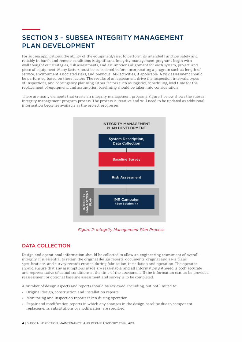
——SECTION 3 – SUBSEA INTEGRITY MANAGEMENT PLAN DEVELOPMENTFor subsea applications, the ability of the equipment/asset to perform its intended function safely and reliably in harsh and remote conditions is significant. Integrity management programs begin with well thought out strategies, risk assessments, and assumptions alignment for each system, project, and piece of equipment. Many factors must be considered before incorporating a program such as length of service, environment associated risks, and previous IMR activities, if applicable. A risk assessment should be performed based on these factors. The results of an assessment drive the inspection intervals, types of inspections, and contingency planning. Other factors such as logistics, scheduling, lead time for the replacement of equipment, and assumption baselining should be taken into consideration.
There are many elements that create an integrity management program. Figure 2 below shows the subsea integrity management program process. The process is iterative and will need to be updated as additional information becomes available as the project progresses.
DATA COLLECTION
Design and operational information should be collected to allow an engineering assessment of overall integrity. It is essential to retain the original design reports, documents, original and as-is plans, specifications, and survey records created during fabrication, installation and operation. The operator should ensure that any assumptions made are reasonable, and all information gathered is both accurate and representative of actual conditions at the time of the assessment. If the information cannot be provided, reassessment or optional baseline assessment and survey is to be completed.
A number of design aspects and reports should be reviewed, including, but not limited to:
• Original design, construction and installation reports
• Monitoring and inspection reports taken during operation
• Repair and modification reports in which any changes in the design baseline due to component replacements, substitutions or modification are specified
Figure 2: Integrity Management Plan Process

ABS | SUBSEA INSPECTION, MAINTENANCE, AND REPAIR ADVISORY 2019 | 5
Due to limited access to the subsea equipment it is likely that its condition will need to be inferred from data that can be monitored by secondary means. Since corrosion of subsea equipment is not directly measurable, special attention may be required. For example, if issues on surface equipment occur, chemical injection failures, subsea sensor failure or expected vs. actual production disparities may occur. Issues with any of these secondary items may identify areas of concern and may trigger IMR actions/intervention.
BASELINE SURVEY
The baseline condition assessment and survey should be performed to understand the starting condition of any system. The following procedure should be applied for the assessment of the baseline condition:
• Review completeness and extent of original design analyses and determine need for further analyses
• Identify the various risks and associated degradation mechanisms
• Specify mitigation program and plan for future monitoring/inspection activities. The baseline condition assessment should be updated regularly after inspections, incidents or changes of condition
The baseline survey identifies the additional specific inspections to be performed to assist in providing accurate data. The baseline survey will include the following activities:
• Review of reports of previous inspection and maintenance
• Development of an inspection procedure
• Complete inspection to verify accurate assessment of the condition
RISK ASSESSMENT
Operators should utilize risk analyses to plan for their projects. A risk assessment creates the foundation of the overall subsea IMR plan.
A risk assessment is defined as the process of acknowledging which undesirable things can happen, the likelihood they are to happen, and the severity of their effects. It provides the basis of risk evaluation and risk treatment/mitigation. The risk assessment process is a systematic method of determining risk levels. The following figure shows the flow process of how a risk assessment is conducted.
Risk assessments conducted for subsea components will evaluate all possible failure modes. There are various methods that can be performed to create a risk assessment. All methods commonly evaluate the probability and consequence of these failure modes. Failure modes vary and are often categorized based on age-related or non-age related damage. Corrosion and erosion typically cause age related failures, and external forces such as impact and accidental damage are typically the cause of non-age-related failures. Probabilities are based on evaluation of design, fabrication, installation, and operation. Consequences are based on safety, environment, cost and reputation. These combined create a risk ranking for the individual equipment and systems.
Figure 3: Risk Assessment Process
6 | SUBSEA INSPECTION, MAINTENANCE, AND REPAIR ADVISORY 2019 | ABS
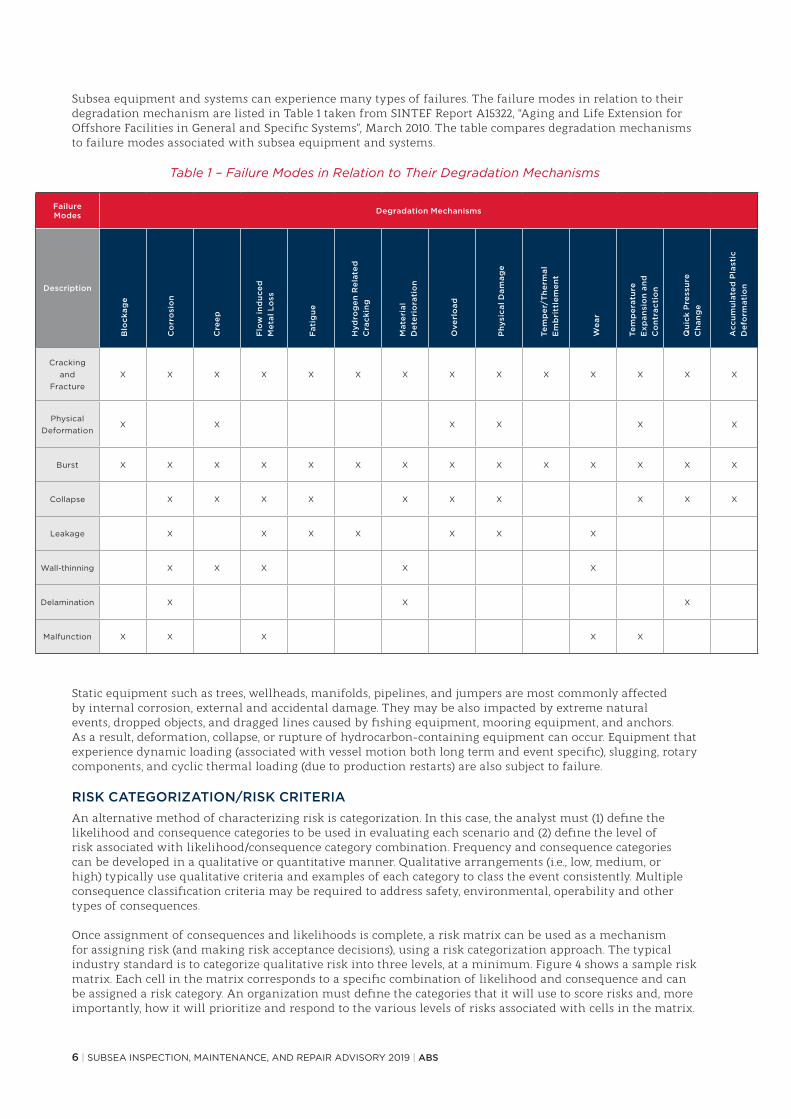
Subsea equipment and systems can experience many types of failures. The failure modes in relation to their degradation mechanism are listed in Table 1 taken from SINTEF Report A15322, “Aging and Life Extension for Offshore Facilities in General and Specific Systems”, March 2010. The table compares degradation mechanisms to failure modes associated with subsea equipment and systems.
Table 1 – Failure Modes in Relation to Their Degradation Mechanisms
Static equipment such as trees, wellheads, manifolds, pipelines, and jumpers are most commonly affected by internal corrosion, external and accidental damage. They may be also impacted by extreme natural events, dropped objects, and dragged lines caused by fishing equipment, mooring equipment, and anchors. As a result, deformation, collapse, or rupture of hydrocarbon-containing equipment can occur. Equipment that experience dynamic loading (associated with vessel motion both long term and event specific), slugging, rotary components, and cyclic thermal loading (due to production restarts) are also subject to failure.
RISK CATEGORIZATION/RISK CRITERIAAn alternative method of characterizing risk is categorization. In this case, the analyst must (1) define the likelihood and consequence categories to be used in evaluating each scenario and (2) define the level of risk associated with likelihood/consequence category combination. Frequency and consequence categories can be developed in a qualitative or quantitative manner. Qualitative arrangements (i.e., low, medium, or high) typically use qualitative criteria and examples of each category to class the event consistently. Multiple consequence classification criteria may be required to address safety, environmental, operability and other types of consequences.
Once assignment of consequences and likelihoods is complete, a risk matrix can be used as a mechanism for assigning risk (and making risk acceptance decisions), using a risk categorization approach. The typical industry standard is to categorize qualitative risk into three levels, at a minimum. Figure 4 shows a sample risk matrix. Each cell in the matrix corresponds to a specific combination of likelihood and consequence and can be assigned a risk category. An organization must define the categories that it will use to score risks and, more importantly, how it will prioritize and respond to the various levels of risks associated with cells in the matrix.
Failure Modes Degradation Mechanisms
Description
Cracking and
FractureX X X X X X X X X X X X X X
Physical Deformation
X X X X X X
Burst X X X X X X X X X X X X X X
Collapse X X X X X X X X X X
Leakage X X X X X X X
Wall-thinning X X X X X
Delamination X X X
Malfunction X X X X X
Blo
ckag
e
Co
rro
sio
n
Cre
ep
Flo
w in
du
ced
M
etal
Lo
ss
Fat
igu
e
Hyd
rog
en R
elat
ed
Cra
ckin
g
Mat
eria
l D
eter
iora
tio
n
Ove
rlo
ad
Phy
sica
l Dam
age
Qu
ick
Pre
ssu
re
Ch
ang
e
Wea
r
Tem
per
/Th
erm
al
Em
bri
ttle
men
t
Tem
per
atu
re
Exp
ansi
on
and
C
on
trac
tio
n
Acc
um
ula
ted
Pla
stic
D
efo
rmat
ion

ABS | SUBSEA INSPECTION, MAINTENANCE, AND REPAIR ADVISORY 2019 | 7
SUBSEA INTEGRITY MANAGEMENT PLAN
Once the results from integrity assessment and risk assessment are compiled and accepted, the integrity management plan is developed. The plan itself is intended to provide guidance for the implementation of the IMR plan. The following should be specified:• Inspection• Monitoring• Analysis and Testing• Preventative Maintenance
Failure Modes Degradation Mechanisms
Description
Cracking and
FractureX X X X X X X X X X X X X X
Physical Deformation
X X X X X X
Burst X X X X X X X X X X X X X X
Collapse X X X X X X X X X X
Leakage X X X X X X X
Wall-thinning X X X X X
Delamination X X X
Malfunction X X X X X
FREQUENT Incident is likely to occur
at this asset within the next 5 years.
4
OCCASIONAL Incident is likely to occur
at this asset within the next 15 years.
3
SELDOM Incident has occurred at a similar asset and may reasonably occur at this facility within the next
30 days.
2
UNLIKELY Given current practices and procedures, Incident is not
likely to occur at this facility.
1
1 2 3 4
INCIDENTAL MINOR SERIOUS MAJOR
PERSONNEL Minor or no injury, no lost time.
Single injury, not severe, possible lost time
One or more severe injuries.
Fatality or permanently disabling injury.
COMMUNITY No injury, hazard or annoyance.
Complaints from those affected.
One or more minor injuries.
One or more severe injuries.
ENVIRONMENTAL
Environmentally recordable event with no Agency notification
or permit violation
Release which results in Agency notification or
permit violation.
Significant release with serious offsite impact.
Significant release with serious offsite impact
and likely to cause immediate or long-term
health effects
FACILITY
Minimal equipment damage at an estimated cost less than US $100K,
negligible downtime.
Some equipment or structural damage at an estimated cost greater than US $100K, 1 to 10
days of downtime.
Major damage to installation at an
estimated cost than US $1MM, 10 to 90 days
of downtime.
Major or total destruction to
installation estimated at a cost greater than US $1MM; downtime in
success of 90 days.
LIK
ELIH
OO
D
C ON S EQUENCE
H I G H R I S K
L O W R I S K
M E D I U M R I S K
Figure 4 – Sample Risk Matrix

8 | SUBSEA INSPECTION, MAINTENANCE, AND REPAIR ADVISORY 2019 | ABS
——SECTION 4 – SUBSEA INSPECTION, MAINTENANCE, AND REPAIRThe IMR aspect of the integrity management system can offer solutions for Operators. Within IMR, conventional minimum inspection of the equipment occurs; however, it may also include monitoring, simulation, mitigation, and additional testing of the equipment and or system. These can identify and measure damage to the system to assess the likelihood of failure. Figure 5 below depicts the flow process of IMR within an Integrity Management Plan.
CONDITION DATA COLLECTION
The types of inspections performed on subsea equipment include internal, external, on-stream, thickness, and corrosion under insulation (CUI), depending on the circumstances. The typical inspection approach for subsea equipment is time-based, with replacement/repairs using ROVs/divers only when failures occur. Other methods such as pigging are used to inspect and monitor internal conditions over time. Alternatively, a risk-based approach can be utilized to address maintenance and repairs as well. The risk-based approach provides a methodical process to prioritize the associated risks specific to each project. The Operators can be confident that they have appropriately planned for any possible failure points. They can design inspections and maintenance plans around the anticipated failures modes to prevent or minimize the effects.
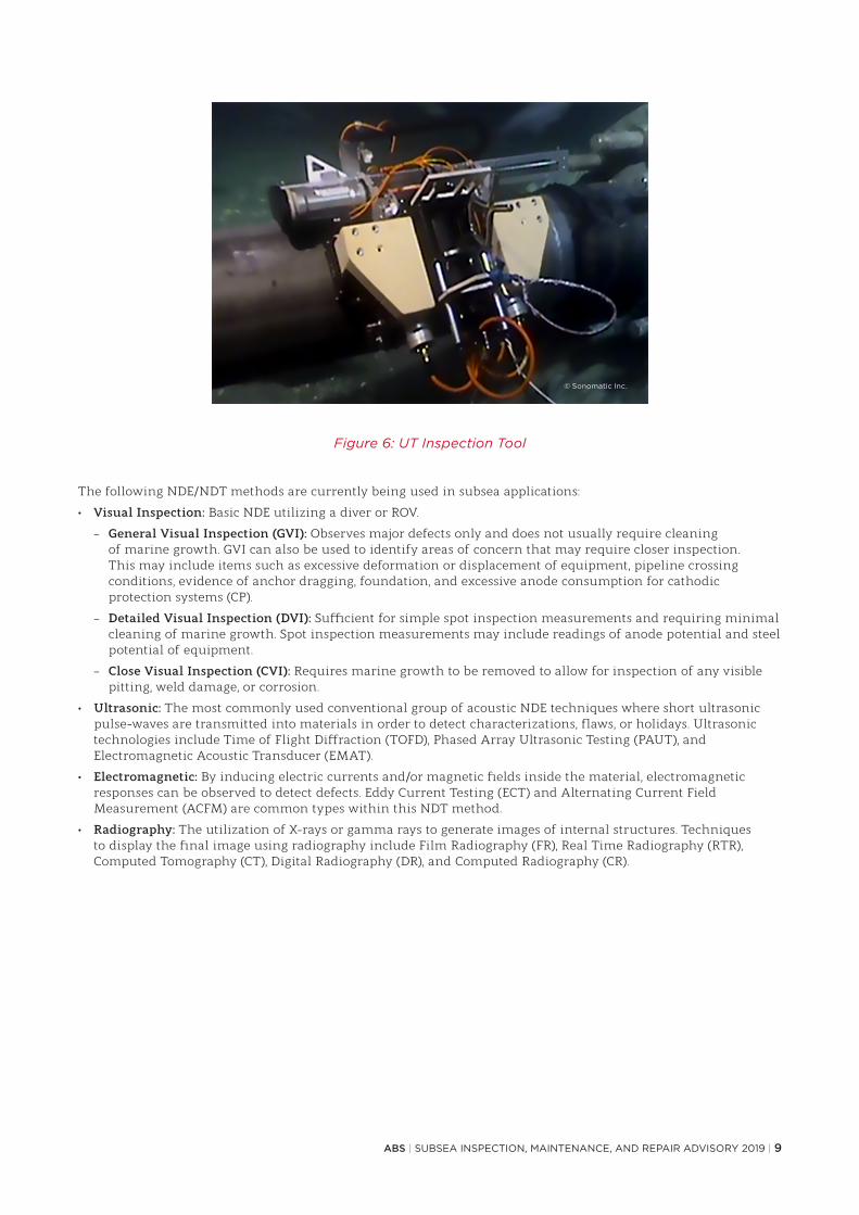
INSPECTION TECHNOLOGIES Inspection of assets that utilize various technologies is a significant part of asset integrity critical for preventing significant damage and production time loss. Neglection of inspection or conducting faulty inspections can not only lead to loss of time but increase the potential of risk to the environment. Conventional inspection techniques include standard non-destructive evaluation (NDE)/non-destructive testing (NDT). These non-invasive methods have been used for many decades. An ultrasonic inspection tool which can inspect subsea equipment conditions can be seen in Figure 6.
Figure 5: IMR Within an Integrity Management Plan
ABS | SUBSEA INSPECTION, MAINTENANCE, AND REPAIR ADVISORY 2019 | 9
Figure 6: UT Inspection Tool
The following NDE/NDT methods are currently being used in subsea applications:
• Visual Inspection: Basic NDE utilizing a diver or ROV.
– General Visual Inspection (GVI): Observes major defects only and does not usually require cleaning of marine growth. GVI can also be used to identify areas of concern that may require closer inspection. This may include items such as excessive deformation or displacement of equipment, pipeline crossing conditions, evidence of anchor dragging, foundation, and excessive anode consumption for cathodic protection systems (CP).
– Detailed Visual Inspection (DVI): Sufficient for simple spot inspection measurements and requiring minimal cleaning of marine growth. Spot inspection measurements may include readings of anode potential and steel potential of equipment.
– Close Visual Inspection (CVI): Requires marine growth to be removed to allow for inspection of any visible pitting, weld damage, or corrosion.
• Ultrasonic: The most commonly used conventional group of acoustic NDE techniques where short ultrasonic pulse-waves are transmitted into materials in order to detect characterizations, flaws, or holidays. Ultrasonic technologies include Time of Flight Diffraction (TOFD), Phased Array Ultrasonic Testing (PAUT), and Electromagnetic Acoustic Transducer (EMAT).
• Electromagnetic: By inducing electric currents and/or magnetic fields inside the material, electromagnetic responses can be observed to detect defects. Eddy Current Testing (ECT) and Alternating Current Field Measurement (ACFM) are common types within this NDT method.
• Radiography: The utilization of X-rays or gamma rays to generate images of internal structures. Techniques to display the final image using radiography include Film Radiography (FR), Real Time Radiography (RTR), Computed Tomography (CT), Digital Radiography (DR), and Computed Radiography (CR).
© Sonomatic Inc.

10 | SUBSEA INSPECTION, MAINTENANCE, AND REPAIR ADVISORY 2019 | ABS
The following table summarizes the techniques available for identifying potential failures in equipment. In varying levels of success, they have been adapted for underwater application.
Table 2: Various Inspection Techniques
Item* Technique Uses Pros Cons
A Alternating Current Field Measurement (ACFM)
Used for the detection and sizing of surface
breaking cracks in metallic components and welds
in any electrically conductive material
Applicable for base material or welds, ferritic or non-ferritic conductive metals. Requires minimal surface preparation and
can be applied over paint and other coatings.
Limitations include inaccuracy in defect
depth if multiple defects are present and bulky associated equipment
B Computed Tomography (CT)
Detection of internal and external corrosion through concrete and
subsea insulated pipelines, capability for detection
of hydrate and wax deposit build up in
pipelines
Coating or marine growth does not have to be
removed. Suitable for rigid and flexible pipe.
Production can continue.
Radiation source required. Regulations on radiation source
should be considered.
C Eddy Current Testing (ECT)
Surface and tubing inspections for cracks,
pits, and wall loss in conductive materials. Detection of corrosion hidden beneath marine
growth or coatings.
Can detect tight cracks, can be used to quickly
test large volumes
Very sensitive to detect and size any
pits, difficultly in sizing wall loss or corrosion, cannot be conducted
on non-conductive materials
D Electromagnetic Acoustic Transducer (EMAT)
Thickness measurement, flaw detection, material
properties, thermal sprayed aluminum (TSA) coated pipeline screening
for corrosion
Does not require contact or couplant
Limited to metallic/magnetic material
E Guided Wave Ultrasonic Testing (GWUT)
Pipeline Inspection; Screening Tool; Detection
of internal or external metal loss
Long range inspectionData Interpretation, difficulty identifying
smaller defects
F Magnetic Flux Leakage (MFL)
Inline inspection of pipe wall for corrosion and
pitting of ferromagnetic materials
Can assess variety of corrosion features and in some cases cracks. Relatively high speed
inspection.
Difficulty sizing defects and poor detection of
axial cracks
G Phased Array Ultrasonic Testing (PAUT)
Thickness measurement, corrosion inspection,
flaw detection
Totally self-contained, shallow water applications
More complex and expensive than single
element probes
H Time of Flight Diffraction (TOFD) Weld defects, crack size Sensitive to cracks Dead zones
I Underwater Magnetic Particle Inspection (UMPI)
Identify defects such as cracks and flaws of
ferromagnetic materials
Totally self-contained, shallow water applications
Method cannot be used when thick paint is applied
*Item assignment correlates to Appendix I table.

ABS | SUBSEA INSPECTION, MAINTENANCE, AND REPAIR ADVISORY 2019 | 11
PIGGING Conventional Pigging
Many, if not most, of the subsea systems installed to date include the possibility of round trip (from the host) pigging or one-way pigging from the subsea end. Even if only conventional pigs are used, significant information about restrictions, corrosion, production, and wax and solids formation can be gained from analysis of the pigging returns. This information can and should be used as part of a comprehensive IMR strategy.
Figure 7: 3D rendering of an in-line inspection tool inspecting a subsea pipeline
Intelligent Pigs
The technology to measure the actual condition of the inside of subsea pipelines and manifolds via mechanical, ultrasonic, electromagnetic, visual and radiographic methods, carried by either free swimming or tethered pigs, is rapidly advancing. These pigs can either transmit data (tethered) or record data for recovery (free swimming). Currently, intelligent pigs focus on major corrosion detection, however, they can also detect cracks, dents, expansions, ovalities, and misalignments to a lesser extent. Figure 7 displays a 3D rendering of an intelligent pig also known as an in-line inspection tool.
CONDITION MONITORING TECHNIQUES Unlike inspection activities, condition monitoring techniques can provide continuous in-service data of subsea assets, and thus provide early detection of abnormal readings. Condition monitoring comprises scheduled diagnostic technologies used to monitor conditions to detect a potential failure and is also known as “on-condition task” or “predictive maintenance”. Condition monitoring includes vibration sensors, infrared cameras to detect temperature conditions, and operational performance sensors for pressure, temperature, and operational flow. Other software-based applications include monitoring internal parameters including differential pressure, changes in flow, and mass balance to offshore pipelines. For external parameters, vapor monitoring and fiber optic cables are in use. Fiber optic technology provides real time data for leak detection via temperature and acoustic monitoring. Monitoring these parameters can provide predictive information on the potential of strain or fatigue or indicative information about the location of a failure. The following table denotes commonly used monitoring techniques for subsea equipment and structures.
© Vismar UK/Shutterstock

12 | SUBSEA INSPECTION, MAINTENANCE, AND REPAIR ADVISORY 2019 | ABS
Table 3: Various Condition Monitoring Techniques
Item* Technique Uses
J Acoustic MonitoringThe use of a directional hydrophone that ‘listens’ for
ultrasounds generated by leaking fluids passing through an orifice under pressure
K Electrical Resistance (ER) Monitoring Probe application to evaluate loss of metal due
to corrosion or erosion
L Fiber Optic MeasurementUtilization of laser light transmission through cables to provide temperature or acoustic sensing to indicate leakage or strain.
This technology is used in umbilicals, risers, and pipelines.
M Field Signature Measurements (FSM)Identification of pipe wall corrosion over time by monitoring real time electric voltage field pattern of localized areas to compare
with baseline “signature” map
N Flow and Pressure MetersFlow and pressure meters monitor changes to identify leaks
and potential failures along with provide critical flow performance diagnostics
O Microbiological Influenced Corrosion (MIC) Monitoring
Internal inspection of pipeline corrosion by analyzing conditions of corrosion coupons or debris from pigging operations
P Sea Condition MonitoringCurrents may be monitored near pipeline to identify potential for
pipe movement or scouring
Q Strain Gauge Monitor the strain and stress of the structures
R Temperature ContouringThermal leak detector that comprises a fast, high precision
thermistor that converts temperature differences into contouring images indicating leaks
S Ultrasonic MonitoringClamp-on devices or probes using ultrasonic NDT methods to monitor
wall thickness changes for corrosion and erosion
T Vapor MonitoringExternal sensors installed to measure concentration of any leakage
fluid to estimate size and location for buried pipelines
U Vibration Monitoring Sensor clamps applied to monitor intensity of vibrations to structures
*Item assignment correlates to Appendix I table.
INSPECTION CHALLENGES AND NEW TECHNOLOGIESNew technologies within the subsea industry continue to advance as there are limitations to in-situ inspections and monitoring. Limitations to subsea inspection techniques include water depth, ability to properly clean equipment surfaces, remote launch application, and limitations on working equipment. Also, some pipelines possess sections not able to be pigged (due to obstructions, hard corners, et al.). These require a solution to provide information on their condition while in service.
• AUV: The efficiency in current ROV operations depends greatly on the skill of the ROV pilot. Autonomous functions, wherein the control of the ROV can be shared in these operations, is a step towards increased efficiency and reduced human error. Repetitive tasks such as visual inspection on pipelines can be autonomous, reserving human pilots for more robust and complicated inspections. The need for semi or fully-autonomous ROVs (S-AUVs) is emerging. The benefits of this technology include the elimination of a dynamically positioned vessel to operate the ROVs and the capability of real time data processing. As ROV sensor system technology advances, more autonomous functions can be developed such as flying pre-programmed inspection routes with collision free path planning, geolocation and time stamp capability, and automated deviation detection with automatic defect detection. Figure 8 displays a ROV deployed subsea inspection scanner inspecting a subsea structure.

ABS | SUBSEA INSPECTION, MAINTENANCE, AND REPAIR ADVISORY 2019 | 13
Figure 8: ROV Deployed Subsea Inspection Scanner
AUV-specific challenges include navigation, visual inspection, free span detection, and corrosion surveys. For fully autonomous vehicles, the ability to maintain correct position can be challenging. Because these vehicles are not accessible remotely, they must be able to recognize features through real time images or sonar data processing. A high quality database of information should be loaded into the program to provide accurate positioning recognition points. Visual images used for inspection purposes must mimic the quality provided by ROV visual inspection data. AUVs utilize HD digital still cameras with geolocators versus video cameras to provide a continuous video feed. This requires more power and sufficient video lighting to obtain full coverage. AUVs also typically have difficulty identifying free spans for pipelines due to the higher inspection speeds. The AUVs equipped with high speed scanning devices such as lasers may require multiple passes over suspect areas. Lastly, AUVs are technologically limited in performing corrosion surveys. Traditionally these inspections are performed by an ROV utilizing a remote cell sensor to provide continuous readings. AUV devices cannot currently perform certain ROV performed tasks, and further technology research would be needed to bridge these gaps. For AUVs, the ability to provide quality data and power management for pipeline inspections is currently a challenge.
• Varied Techniques: Existing technologies with varied approaches have been introduced as a new technology for subsea applications. The Dynamic Response Spectroscopy (DRS) is an ultrasonic inspection technique used for corrosion mapping through challenging coatings where conventional UT techniques are ineffective. The technique utilizes a range of low ultrasonic frequencies that pass through coatings to determine steel thickness profiles, observe composite repair adhesion quality, identify flaws in coatings, determine if corrosion growth is active, and estimate growth rates. An automated UT inspection tool that is diver deployed may be seen in Figure 9.
© Sonomatic Inc.
© Sonomatic Inc.
Figure 9: Automated Ultrasonic Inspection Tool

14 | SUBSEA INSPECTION, MAINTENANCE, AND REPAIR ADVISORY 2019 | ABS
• New Technology Qualification: Other new technologies such as underwater wireless communication, extended battery capacity, and propulsion capacity are being introduced and modified for subsea applications. These technologies are pushing the limitations of existing capabilities of inspection tools. For these new technologies, the reliability and mechanical integrity of the equipment and the quality of data can be in question. They should be verified and validated with a New Technology Qualification Plan to ensure the inspection tool performs intended functions without harming existing equipment. See the ABS New Technology Qualifications Guidance Notes for more information.
MAINTENANCE
An integrity management plan should contain the key details of inspection, monitoring, maintenance and repair for systems and components. The maintenance portion of the integrity management plan should contain any details on the scheduled inspection intervals. There are different types of maintenance strategies and approaches that can be used.
Figure 10: Maintenance Strategies
REACTIVE (BREAKDOWN) MAINTENANCEThis maintenance strategy is implemented only when failures occur. This plan has low costs initially but can be costly depending on the severity of the failure and the cost of replacement. For subsea applications, the current approach is to utilize this strategy.
An enhancement to a strictly reactive approach is to minimize downtime by maintaining a store of critical components, and to wait until failure before replacement. This minimizes shutdown time and reduces the need to purchase replacement parts based on statistical data.
PREVENTATIVE (SCHEDULED) MAINTENANCE A more commonly used strategy is based on time or schedule of planned events. The cost of this plan can be moderate if failures are detected early.
Planned maintenance is a failure management strategy that restores the inherent reliability or performance of the equipment. These tasks are best employed on equipment suffering from age-related failure (e.g., wear-out failure characteristic).
The principle behind planned maintenance is that restoring or discarding the equipment at a predetermined time before expected failure best manages the probability of failure. Following this principle, the planned maintenance tasks are performed at set intervals, regardless of whether or not a failure is impending. Restoring the equipment or replacing it with new equipment prevents the failure.

ABS | SUBSEA INSPECTION, MAINTENANCE, AND REPAIR ADVISORY 2019 | 15
Solely utilizing a preventative maintenance strategy in anticipation of an upcoming failure is unusual in today’s environment. However, it is relatively common to use an unplanned shutdown for one task as an opportunity to replace another item that is at or near its design life.
PREDICTIVE MAINTENANCEPredictive Maintenance is a strategy that analyzes the condition of the equipment to predict the possibility of potential failure. The data collected can be analyzed to forecast the length of remaining life. Savings are realized if scheduled maintenance can be reduced based on the results of the analysis.
CONDITION BASED MAINTENANCE AND CONDITION MONITORINGCondition based maintenance is a predictive maintenance plan conducted on a frequent or real-time basis which is based on the use of condition monitoring to determine when part replacement or other corrective action is required. This process involves establishing a baseline and operating parameters, frequently monitoring the equipment, and comparing any changes in operating conditions to the baseline. Repairs or replacement of parts are carried out before the machinery fails based upon the use of the tools prescribed for condition monitoring. A condition monitoring task is a scheduled task used to detect the potential onset of a failure so that action can be taken to prevent such failure.
Tracking adjustable choke performance trends is an example of condition monitoring. As wear occurs due to erosion, changes in the choke setting may be required to maintain a constant pressure drop. At some point it may be advisable/necessary to replace the choke cage assembly or take other action to prior to complete failure and damage to the choke body.
RELIABILITY CENTERED MAINTENANCEReliability centered maintenance is a process that is used to determine the most effective approach to maintenance. It involves identifying actions that when taken will reduce the probability of failure and which actions are most cost effective.
SUMMARYThe appropriate maintenance plan should be chosen based on cost, risk prevention, desired outcome, and return on investment. The key factors of risk prevention are safety, regulatory compliance, and quality. A maintenance plan strategy can also contain various strategy methods for different equipment. Each strategy provides tailored solutions depending on the criticality of the system and components. These should all be taken into account when designing the appropriate plan for subsea systems and equipment.
MAINTENANCE ACTIVITIES There are several commonly used maintenance applications for various subsea assets and systems:
• Cathodic Protection System: Sacrificial anodes are commonly used to maintain structural integrity by reducing corrosion. This system requires maintenance to keep cathodic protection performance at acceptable levels.
• Production System: Chemical injections are used to prevent the formation of hydrates, wax asphaltenes, and scale. Corrosion inhibitors are used to manage flow assurance issues and internal corrosion. These treatments may be a predictive maintenance method. Local monitoring data can be used to determine the optimal dose or composition of chemical inhibitors to achieve the best results.
Operating in more benign conditions in terms of pressure, temperature, and production rate can be a method of reducing degradation rates with respect to erosion and corrosion. Lower pressure loading can also promote better structural integrity.
• Pipeline and Riser: Pigging activity is part of preventive, predictive, and reactive maintenance. It is used for assessing the condition of manifolds and pipelines and addressing flow assurance issues associated with the formation of hydrates, wax, asphaltenes, and scale. Where serious blockages are encountered and pigging is not an effective solution, other intervention methods including coil tubing or chemical injection can be considered.
• Foundation: Foundation correction is the reinforcement of the foundation of subsea assets to secure stability, load bearing capacity, mitigate effects of burying or trenching, and to avoid excessive subsidence, scouring, soil loss, and any kind of geohazards. Common methods include rock dumping, grout bags, mattresses, and trenching.
• Subsea Boosting Equipment: Subsea pumps and compressors are designed to possess high mean time between failure (MTBF) with zero maintenance demand. The industry uses a predictive maintenance strategy to closely monitor the condition of the boosting equipment. When failure is imminent or performance no longer meets requirements, a replacement approach is then adopted.
• Subsea Separation and Treatment Equipment: Subsea separators and treatment equipment require frequent flushing or jetting to remove settling of produced sand from the chamber. Subsea treatment equipment using filtration technologies may require backwashing or filter replacement to maintain performance.

16 | SUBSEA INSPECTION, MAINTENANCE, AND REPAIR ADVISORY 2019 | ABS
REPAIR
Repairs are mandated when inspection or condition monitoring results indicate that the integrity of a system has been compromised, or when called for upon by fitness for service assessment. During these repairs, production is typically paused. In some cases, a fitness for service analysis may determine that production may proceed at a reduced operating rate. In both scenarios, a repair plan should be created and implemented. The following subsections describe the repair plan process and methods for subsea applications.
GENERAL REPAIR METHODSThe four major repair methods commonly used for subsea equipment and systems are refurbishment, retrofit, patch, and replacement.
• Refurbishment: Existing structures or equipment are fully overhauled on deck or shore and restored to “as new” condition. This option may lead to downtime and thus an optimized implementation plan to minimize lost production time is essential. Industry also takes this approach to recycle unused assets for new projects through refurbishment and requalification programs. Recycling unused assets can save considerable cost and time compared to new construction.
• Retrofit: Equipment or components are replaced and updated with modern equivalents or technologies.
• Patch: Additional materials are added to the damaged equipment or structures, such that the safety integrity of the system is returned to an acceptable level.
• Replacement: The components or equipment are completely replaced with identical spares.
REPAIR PROCESSThe repair process follows the below flow path.
Figure 11: Repair Process Flow Path
• Damage or Malfunction Analysis: The inspected defect or monitored malfunction is analyzed to determine the failure mechanism and root cause. For excessive structural damages and defects, a fitness for service assessment may be used to assess the impact to structure integrity. Type of repair can be selected depending on the assessment findings. For minor structural damage, the maintenance activities mentioned above can be implemented to defer or avoid failure. For failure due to malfunction of machine equipment (such as subsea pumps and compressors) or electronic devices (subsea control module (SCM), subsea electronics model (SEM), monitoring sensors), the repair plan always involves replacement with new items.
• Repair Plan Development: The repair plan is developed to restore functions and safety integrity to subsea systems. The repair plan includes stepwise procedures (such as demolishment, disconnection, retrieval, installation, and/or hook-up, testing, and start-up per API RP 17H) along with associated contingency plans. Design verification is performed of the repair activity, involving operability and access verification, design documents, engineering calculations, and code checks.
• Repair Implementation: The implementation of the repair plan requires qualified personnel, an IMR vessel, an ROV, intervention tools, and examination tools. Ideally the equipment is serviced and repaired in operable sea state windows. Design validation including a factory acceptance test (FAT) of the asset is performed onshore and a system integration test (SIT) is performed to ensure a successful repair.
• Subsea Integrity Management Plan Update: Throughout the repair process, all activity should be well documented. All information should be integrated into the overall subsea integrity management plan. The risk assessment, integrity re-establishment assessment, and inspection plan are required to be updated to reflect the impact of repair activity.

ABS | SUBSEA INSPECTION, MAINTENANCE, AND REPAIR ADVISORY 2019 | 17
Subsea Pipeline, Jumper, and Spool Repair Methods
Subsea pipelines, jumpers, and spools are more prone to damage than other subsea assets. There are several common repair methods.
• Clamp Repair: Standard straight or custom-fabricated clamps are used to seal minor defects of the structures caused by pinhole leaks, localized corrosion attacks, and weld defects. This method is selected where the affected sizes are less than a diameter of the structures. Clamp repair can be performed by a diver or ROV.
• On-bottom Repair: Other vertical and horizontal pipeline repair methods are available that can repair a pipeline with severe damage. These are for applications where clamp repairs cannot be applied and can be used in both shallow and deep water. The repair process typically involves isolating, cutting, cleaning, and removing a damaged pipeline, jumper, and/or spool section, followed by replacement with a new pipeline, jumper, and/or spool aligned and welded to the existing pipeline ends. Finally, testing is conducted to validate the integrity of the repaired pipeline.
• On-surface Repair: The damaged pipeline is lifted to the surface and the damaged section removed. The pipeline may be rejointed together with new pipeline, jumper, and/or spool, and then lowered back to the seabed. Alternatively, a pipeline end termination (PLET) can be used to weld each end of the cut pipeline. The PLET(s) along with the pipeline is then lowered to the seabed, and a jumper is installed to complete the connection.
INFLUENCE OF STANDARDIZATION OF SUBSEA EQUIPMENT ON INSPECTION MAINTENANCE AND REPAIR
Standardization of subsea equipment is an increasing goal within the subsea industry. Many joint industry projects have been created to achieve this goal. Equipment such as subsea pumps are currently undergoing this process. The success of this effort should decrease the CAPEX of storing spare components, devices, or equipment. The OPEX will be minimized for maintenance and repair activities due to reduced requirements for intervention vessels. Standardization can also allow brownfields access to new technology through standardized interface during repair or maintenance.
——SECTION 5 – ROLE OF ABSABS can provide the insight from a safety and integrity standpoint for stakeholders in the subsea industry. Operators, manufacturers, and regulators can make use of the skillsets within ABS to provide services that build confidence for users of subsea equipment and systems. The wide range of global services offered by ABS includes integrity management project planning, regulatory guidance, and IMR guidance. The following services can be provided to those interested in having a one stop shop for subsea integrity management and inspection:
• New Technology Qualification
• Risk Based Inspections
• Fitness-for-Service Evaluations
NEW TECHNOLOGY QUALIFICATION
ABS provides guidance on all new technologies for offshore units and marine vessels that do not follow typical Rules, Guides, or industry codes or standards. New technology is defined as any design (material, component, equipment or system), process or procedure which does not have prior in-service experience, and/or any classification rules, statutory regulations or industry standards that are directly applicable. It is possible to categorize the type of “novelty” in one of four categories:
• Existing design/process/procedures challenging the present boundaries/envelope of current offshore or marine applications
• Existing design/process/procedures in new or novel applications
• New or novel design/process/procedures in existing applications.
• New or novel design/process/procedures in new or novel applications

18 | SUBSEA INSPECTION, MAINTENANCE, AND REPAIR ADVISORY 2019 | ABS
An asset such as a marine vessel or an offshore unit becomes a novel concept if the incorporation of any new technology appreciably alters its service scope, functional capability, and/or risk profile. Novel concepts are typically presented to ABS for review and class approval following the process in the ABS Guidance Notes on Review and Approval of Novel Concepts.
The New Technology Qualification (NTQ) process is applicable when:
• Qualifying new technology that may need to be classed or certified at a later date
• Simultaneously qualifying new technology identified while seeking class approval for a novel concept
• Qualifying a new technology independent of the need to be classed or certified
The NTQ process confirms the ability of a new technology to perform its intended functions in accordance with defined performance requirements. The process starts with a comprehensive description of the technology to be qualified, followed by a screening of the technology to reveal the new or novel features that the qualification should focus on.
The process is divided into five sequential stages that progressively qualify the technology from feasible to operational stages. The five qualification stages are:
• Feasibility Stage
• Concept Verification Stage
• Prototype Validation Stage
• System Integration Stage
• Operational Stage
More information on how to perform the NTQ process can be found in the ABS Guidance Notes on Qualifying New Technologies.
RISK BASED INSPECTION (RBI)
RBI is one type of inspection that is performed in parallel to or in lieu of routine inspections. RBI requires qualitative or quantitative assessments that rank the probability and consequence of associated failures with each system or piece of equipment. RBI can be beneficial for users to identify, understand, and address risk areas associated with the equipment and systems. This can assist by indicating the priority and required frequency of certain inspection related activities, which balances risk reduction against inspection costs. For subsea related equipment, the inspection activities are often NDT/NDE. An inspection plan can then be created based on the results of the RBI assessment. RBI assessments should be performed early in the process and updated as information is collected. The typical RBI plan development for subsea equipment follows the following sequence:
• Data Collection
• Baseline and Fitness for Service Assessment
• Risk Assessment and Risk – Based Prioritization
• Inspection, Monitoring, and Maintenance Plan
These are conducted with all involved parties to assess risk factors of the project.
More information on how to perform risk assessments can be found in the ABS Guidance Notes on Risk Assessment Application for the Marine and Offshore Oil and Gas Industries.

ABS | SUBSEA INSPECTION, MAINTENANCE, AND REPAIR ADVISORY 2019 | 19
FITNESS FOR SERVICE
A fitness for service assessment is the process of evaluating the structural and material integrity of equipment to perform its intended function. ABS offers integrity assessments and life extension assessments to evaluate existing assets. Currently, these assessments are being performed for subsea structures such as risers, pipelines, and equipment structures. The inspections associated with these assessments provide the critical data needed to make major decisions on projects currently being evaluated for decommissioning/repair or life extension. The following flow diagram displays how the fitness for service process is executed.
Figure 12: Fitness for Service Assessment Process
DAMAGE ASSESSMENT In the event an existing asset incurs damage, a damage assessment analysis shall be performed. This detailed assessment utilizes the information collected from the existing maintenance plans, condition monitoring, and any other IMR data that is relevant. Depending on the accuracy and quality of the available information, inspections maybe required to obtain additional data and updated information.
Limitations to damage assessment analysis include inability to collect usable data and limitations of inspection technology. If the results of the analysis indicate the degradation of the equipment or structure is less than what was anticipated, a life extension program may be enacted.
LIFE EXTENSIONLife extension is an approach to extend the use and longevity of preexisting subsea structures. The life extension program confirms that the prescribed work has been completed and is up to date. If a low-level maintenance plan is implemented, a baseline inspection shall be carried out to obtain the current condition of the subsea structures. Otherwise, conservative assumptions shall be used in the assessment. The life extension process generally follows these three steps:
• Investigation phase
– Baseline survey
– Data collection and engineering assessment
• Determination phase
– Reassessment
– Provision of conditions for life extension
• Implementation phase
– Conditions implemented

20 | SUBSEA INSPECTION, MAINTENANCE, AND REPAIR ADVISORY 2019 | ABS
Figure 13 illustrates the flow process for the assessment of a Life Extension process within an integrity management plan. The input of the existing condition is key in assessing the potential life expectancy of a life extension analysis.
For more information on detailed life extension process, refer to ABS Guidance Notes on Life Extension Methodology for Floating Production Installations.
Asset Integrity Management
Asset integrity management is an ongoing lifecycle process to verify that the equipment, installation, or system has adequate integrity to endure the imposed assessment loads and perform its required and intended functions. The purpose of asset integrity management is to provide a link between the assessment, inspection and with the maintenance of the equipment, installation, or system. ABS utilizes this approach as the basis of performing Life Extension Analyses for floating production installations.
——SECTION 6 – SUMMARYSubsea IMR is a valuable process that allows owners, operators, and associated parties to have a cohesive plan for their subsea assets. All parties involved are aligned in the process which provides guidance for the routine maintenance, repair, and replacement of subsea equipment. The IMR aspects of the subsea integrity management provide detailed methods and action items for managing the integrity of each system or components of equipment. The subsea integrity management process also provides the benefits of cost savings, efficiency in repairs, and detailed information on the asset and its anticipated life. The inspections can provide detailed information that can be used for damage assessments for life extension projects. The refined data can provide essential input into analysis that can predict the remaining life of a structure or equipment.
The specific challenges associated with IMR include lack of inspection technologies capable of deep depths, industry resistance, and unreliable/incomplete data needed for analysis. As the industry continues to advance technologies associated with the installation, operation, and maintenance of subsea equipment, the implementation of the subsea integrity management process will continue to improve project execution. ABS can provide services to assist the industry in addressing these challenges.
© Siemens AG
Figure 13: Assessment for Life Extension

ABS | SUBSEA INSPECTION, MAINTENANCE, AND REPAIR ADVISORY 2019 | 21
——
AP
PE
ND
IX
INS
PE
CTI
ON
AN
D C
ON
DIT
ION
MO
NIT
OR
ING
TE
CH
NIQ
UE
S TA
BLE
Wel
lhea
d/T
ree
Jum
per
s/S
po
ols
Flo
wlin
es/
Pip
elin
esR
iser
sU
mb
ilica
ls,
Po
wer
Cab
le,
Fly
ing
Lea
ds
Hig
h In
teg
rity
P
ress
ure
P
rote
ctio
n S
yste
m
(HIP
PS
)
Su
bse
a P
roce
ssin
g
Eq
uip
men
t
Su
bse
a M
anif
old
s/S
tru
ctu
res
Fo
un
dat
ion
Cra
ckin
g a
nd
F
ract
ure
VV
, A, B
, C,
H, I
, UV
, A, B
, C,
H, I
, UV
, A, B
, C, H
, I,
UV
, UV
VV
, A, B
, C,
H, I
, U
Phy
sica
l D
efo
rmat
ion
V, Q
V, L
, QV
, M,L
, P, Q
V, Q
, LV
, LV
, QV
, QV
, QV
Lea
kag
eV
, J, R
, NV
, J, R
, NV
, J, L
, N,
P, T
, RV
, J, L
, NV
, J, L
V, J
, N, R
V, J
, N, R
V, J
, N, R
Wal
l-th
inn
ing
VV
, B, C
, D, E
, F,
G, K
, M, O
, SV
, B, C
, D, E
, F,
G, K
, M, O
, SV
, B, C
, D, E
, F,
G, K
, SV
V, B
, C, D
, E, F
, G
, K, M
, S
AA
lter
nat
ing
Cu
rren
t F
ield
Mea
sure
men
t (A
CF
M)
BC
om
pu
ted
To
mo
gra
phy
(C
T)
CE
dd
y C
urr
ent
Test
ing
(E
CT
)
DE
lect
rom
agn
etic
Aco
ust
ic T
ran
sdu
cer
(EM
AT
)
EG
uid
ed W
ave
Ult
raso
nic
Tes
tin
g (
GW
UT
)
FM
agn
etic
Flu
x L
eaka
ge
(MF
L)
GP
has
ed A
rray
Ult
raso
nic
Tes
tin
g (
PA
UT
)
HT
ime
of
Flig
ht
Diff
ract
ion
(TO
FD
)
IU
nd
erw
ater
Mag
net
ic P
arti
cle
Insp
ecti
on
(UM
PI)
JA
cou
stic
Mo
nit
ori
ng
KE
lect
rica
l Res
ista
nce
(E
R)
Mo
nit
ori
ng
LF
iber
Op
tic
Mea
sure
men
t
MF
ield
Sig
nat
ure
Mea
sure
men
ts (
FS
M)
NF
low
an
d P
ress
ure
Met
ers
OM
icro
bio
log
ical
Infl
uen
ced
Co
rro
sio
n (M
IC)
Mo
nit
ori
ng
PS
ea C
on
dit
ion
Mo
nit
ori
ng
QS
trai
n G
aug
e
RTe
mp
erat
ure
Co
nto
uri
ng
SU
ltra
son
ic M
on
ito
rin
g
TV
apo
r M
on
ito
rin
g
UV
ibra
tio
n M
on
ito
rin
g
VV
isu
al In
spec
tio
n
INS
PE
CT
ION
TE
CH
NIQ
UE
SC
ON
DIT
ION
MO
NIT
OR
ING
TE
CH
NIQ
UE
S

TX 02/19 19016
CONTACT INFORMATION
NORTH AMERICA REGION1701 City Plaza Dr.Spring, Texas 77389, USATel: +1-281-877-6000Email: [email protected]
SOUTH AMERICA REGIONRua Acre, nº 15 - 11º floor, CentroRio de Janeiro 20081-000, BrazilTel: +55 21 2276-3535Email: [email protected]
EUROPE AND AFRICA REGIONABS House, No. 1 Frying Pan AlleyLondon E1 7HR, UKTel: +44-20-7247-3255Email: [email protected]
MIDDLE EAST REGIONAl Joud Center, 1st floor, Suite # 111 Sheikh Zayed RoadP.O. Box 24860, Dubai, UAETel: +971 4 330 6000Email: [email protected]
GREATER CHINA REGION5th Floor, Silver Tower No. 85 Taoyuan Road, Huangpu DistrictShanghai 200021, P.R. ChinaTel: +86 21 23270888Email: [email protected]
NORTH PACIFIC REGION11th Floor, Kyobo Life Insurance Bldg.7, Chungjang-daero, Jung-GuBusan 48939, Korea, Republic ofTel: +82 51 460 4197Email: [email protected]
SOUTH PACIFIC REGION438 Alexandra Road#08-00 Alexandra Point, Singapore 119958Tel: +65 6276 8700Email: [email protected]
© 2019 American Bureau of Shipping. All rights reserved.