sukunka coal project
TRANSCRIPT

-& . Sur(uNw- 76(l) A a t
SUKUNKA COAL PROJECT
GEOLOGICAL REPORT ON THE
STRIP MINE POTENTIAL OF THE
~~ORT~ERN PART OF PLATE 1
,657: PREPARED FOR: COALITION PAINING LIMITED
BY: CLIFFORD MCELROY & ASSOCIATES PTY, LIMITED
REPORT No. : l/4/20 NARCH 31, 1975
.\
Clifford AkElroy 63 ASSORTS& Pty. Limited _
P.O. Box 387 Milsons Point Sydney, N.S.W. 2061 April 9, 1975
Dr. C. B. Newmarch. Vice-President, Exploration, Coalition Mining Limited 1200 Bow Valley Square 1 202 - 6th Avenue S. W. Calgary, Alberta T2P-2R9
Re: Report No. l/4/20 - Geological Report on the Strip Mine Poten- tial of the Northern Part of Plate 1,' Sukunka Coal Project.
Dear Dr. Newmarch,
Herewith are the copies of the above Report, in four volumes, detailing the results of the exploration programme conducted during December, 1974 and January, 1975.
Ten copies of the Report have been produced for distribution as follows:
Coalition Mining Limited, Calgary - 2 copies Coalition Mining Limited, Vancouver - 1 COPY Coalition Mining Limited, Sukunka - 1 COPY Austen & Butta Limited, Sydney - 1 COPY Clifford McElroy & Associates, Sydney - 1 copy
As discussed with you, four spare copies of each volume have been compiled for future use, as the need arises.
A set of mylars of the maps and cross sections, at a scale of __ 1 inch equals 50 feet, have been produced, as requested by Austen & Butta Limited. Additionally, a set of white prints of the full-scale cross sections have been prepared for them.
In addition to a copy of the four volumes prepared for use at the mine site at Sukunka, a set of mylars of the maps and re-
>duced-scale cross sections, and white prints of the full-scale cross sections, have also been produced for housing there.
Yours sincerely,
. .
G. R. Wallis
cc.: Dr. C.T. McElroy; R. Austen
GRW/pjo

PREFACE
This geological report on the Plate 1 Area of the Sukunka Coal Project, British Columbia, Canada, has been prepared for Coalition Mining Limited by Clifford McElroy & Associates Pty. Limited.
The report, in 4 v lumes ..-+ contains the results of the geologica programme carried out between November, 1974 and January, 1975.
The text, with supporting tables and figures, and geological cross sections, is included in Volume 1. Geological, structure contour, iso- wch, and quality maps are included in Volume 2. Volumes 3 and 4 contain the drill hole data.
CLIFFORD MCELROY & ASSOCIATES PTY. LIMITED
G.R. Wallis, B.E., M.Aus.1.M.M.

SECTIOY 1
TASLE OF CONTENTS

'IOLUIE 1
SECTION 1‘: TABLE OF CONTENTS l-l
SECTION 2 : SUMMARY z- 1
SECTION 3 : INTRODUCTION
3.1
3.2
3.3
3.3.1
3.3.2
3.3.3
3.3.4
Objectives
Previous Investigations
Geological Programme
Drilling Programme
(i) Comments on Drilling Techniques
(ii) Drilling Costs
Radiation Logging Analytical Programme
Geological Evaluation and Report Preparation
SECTION 4 : GEOLOGY
4.1 General Geology
4.2 Stratigraphy of Plate 1
4.2.1 Lower Gething Sequence 4.2.2 Upper Gething Sequence
(i) Chamberlain Seam (ii) Chamberlain/Skeeter Inter-
seam Sediments (iii) Skeeter Seam (iv) Remaining Upper Gething
Units 4.2.3 Moosebar Formation
PAGE
3- 1
3-3
3- 3
3-4
3-6 3-7
3- 8
3- 8
3-9
4- 1
4-2
4-3
4-3
4- 5
4-5 4- 7
4-8
4-10

1-2
VOLUME 1 (CONT'D) PAGE
4.3
4.3.1
4.3.2
4.3.3
SECTION 5 : ECONOMIC APPRAISAL
5.1
5.2
5.2.1
5.2.2
5.2.3
5.3
5.3.1
5.3.2
5.3.3
5.4
5.4.1
5.4.2
5.4.3
5.5
5.6
Structural Geology of Plate 1
Introductory Statement
Folding
Faulting
(i) The Chamberlain Fault (ii) Fault Pl-29 (iii) Fault Pl-30 (iv) Fault Pl-25 (v) Minor Faulting
Introduction
Skeeter Seam
Seam Thickness Coal Quality
Coal Reserves
Chamberlain Seam
Seam Thickness
Coal Quality
(i) Seam Character (ii) Degree of Weathering (iii) Cause of Oxidation
Coal Reserves
Economic Significance of Tectonic Action
Reserves
Quality
Mineability
Ground Water
Depth of Cover
4-11
4-17
4-11
4-74
4-15 4-15 4-17 4-17 4-18
5-l
5- 1
5-I 5-3
5-5
5-b
5-b
5-8
s- 8 5- 11 5-72
5-14
5-15
5 15
5-l&
S-lb
5-77
5-20

I-3
VOLUME I. (CONT'D)
5.7 Environmental Impact
5.7.1 Soil Cover
5.7.2 Vegetation
5.7.3 Surface Water 5.1.4 Restoration
SECTION 6 : RECOMMENDATIONS FOR FURTHER FIELD
INVESTIGATIONS
6.1 Plate 1 Recommendations
6.1.1 Quality Evaluation
6.1.2 Reserve Extensions
6.1.3 Outcrop Definition 6.1.4 Structural Discontinuities
6.2
6.2.1 Upper Gething Sequence
6.2.2 Lower Gething Sequence 6.2.3 Commotion Formation Coal Seams
Long-Term Recommendations
SECTION 7 : CONCLUSIONS AND REFERENCES
7.1 Conclusions
7.2 References
PAGE
s- 2 1
S-21
5- 2 I
5- 22
5-22
6- 1
6-4
7-1
7-4

l-4
TABLES
VOLUME 1,
TABLE ‘NO, TITLE PAGE
3.1
5.1
5.2
Plate 1 Drilling Programme 3-5
Skeeter Seam - Mean Quality Data 5-4
Mean Values of Analytical Data for Washed Product at S.G. 1.60 (Air Dry Basis) Skeeter Seam (Plate 2) 5-5
5.3 Chamberlain Seam - Mean Quality Data 5-9
5.4 Range of Mean Values of Analytical Data for Washed Product at S.G. 1.60 (Air Dry Basis) Chamberlain Seam (Plate 2) s- 10
5.5 Ground Water Levels 5-19
l-5
TEXT FIGURES
VOLUME 1,
FIGURE’ NO,
3.1
4.1
4.2
4.3
5.1
5.2
5.3
5.4
TITLE PAGE
Locality Map FO~LOWA 3-3
Composite Graphic Section Upper Gething Sequence 4-4
Sketch Structure Contours on Floor of Chamberlain Seam 4-12
Sketch Structure Contours on Floor of Skeeter Seam 4-13
Sketch Isopach Map - Total Skeeter Seam 5-2
Quality Data - Skeeter Seam FaLLown 5-4
Sketch Isopach Map - Chamberlain Seam 5-7
Quality Data - Chamberlain Seam ~OklbUh 5-9

1-6
APPENDIX A
VOLUMES 1
QUALITY DATA
NOTES TO ACCOMPANY TABLES A-l AND A-2
SELECTED QUALITY DATA, SKEETER SEAM TABLE A-l
SELECTED QUALITY DATA, CHAMBERLAIN SEAM TABLE A-2
LIST OF SAMPLE NUMBERS RELATING TO DRILL HOLES TABLE A-3
GEOLOGICAL CROSS SECTIONS
Notes to Accompany Cross Sections
Composite of Cross Sections TO - T1420
Transverse Cross Sections TO, T370, T750, T1040, T1420, T1240A
Longitudinal Cross Sections L550, LlOOO, L1400
1-7
MAPS
VOLUNE 2
TITLE MAP NO.
Geological Map
Topographic Map
Structure Contours on Floor of Chamberlain Seam
Structure Contours on Floor of Skeeter Seam
Isopach Maps
Chamberlain Seam 5
Skeeter Seam 6
Interseam Sediments Between Skeeter and Chamberlain Seams Cover Over the Skeeter Seam
Total Overburden Over the Chamberlain Seam
Quality Data - Skeeter Seam
Quality Data.- Chamberlain Seam
7
8
9
10
11

l-8
VOLUNE 3.
Drill Hole Data
Pl-1 to Pl-20
VOLIJNE 4,
Drill Hole Data
Pl-21 to Pl-30,
c-30, c-31
s-14, s-49

SECTION 2
SUMMARY
An evaluation of the data from 30 bore holes drilled in the northern part of Plate 1 between November, 1974, and January, 1975, has confirmed the contin- uity of the Skeeter and Chamberlain Seams through- out the area, defined a number of fault zones, and outlined coal quality variations. A separate mining feasibility study has been based on this work
by H. G. Stephenson (Mining Consultants) Ltd.
Total raw coal reserves of 521,000 short tons have been delineated at a stripping ratio of 6.1:1. Except for 152,000 short tons of thermal quality coal, all of this tonnage is of metallurgical grade.
The Skeeter Seam varies in thickness between 3.00 feet and 6.60 feet, and averages 4.73 feet. The upper 46% of this seam has an average ash content of 6.6%, and an F.S.I. of 7. The lower split
averages 32.1% ash, and 2% F.S.I., but with a screening and simple cleaning plant, Stephenson (1975) anticipates that a product having 12% to 15% ash, and an F.S.I. in excess of 5 will be
available, assuming a 60% yield.

2-2
With the exception of a region of oxidized coal around the outcrop of the Skeeter Seam, the total reserves of 135,000 short tons.are of metallurgical quality. An estimated 10,000 short tons of thermal quality coal relates to the outcrop region.
The Chamberlain Seam averages 6.20 feet in thick-
ness and varies between 4.30 feet and 8.00 feet. The upper 10% of the seam is sheared, and is regarded as waste, since it contains 46.3% ash and has an F.S.I. of 24,. The underlying raw coal
of the Chamberlain Seam is of metallurgical grade, having an average ash content of 4.8% and an F.S.I. of 7.
Reserves of metallurgical grade coal in the Chamberlain Seam total 232,000 short tons. In addition, 144,000 short tons of thermal grade coal have been delineated, with an average analysis of 104% ash, 13,248 BTU/lb, and F.S.I. of 2%.
Only one of the defined fault zones acts as a barrier to the strip mining of the area, the remaining faults being outside an economic stripping ratio.
Recommendations for further evaluation of the northern part of Plate 1 for mine design purposes
and in respect of the property as a whole, have been included in Section 6.

SECTIlN 3
INTRODUCTION
3.1 OBJECTIVES
In August, 1974, Coalition Mining Limited commenced a programme to assess the strip mine potential of the coal seams in the
various geological sequences of the Sukunka Property, which is located 37 miles south of Chetwynd, B. C.
Previous field investigations, outlined in Section 3.2 below,
have indicated that there existed seams which might be amenable
to strip mining in:
(a) the Lower Gething sequence - "Middle Coals": (b) the Upper Gething sequence - Skeeter and Chamberlain
Seams: and (c) the Commotion Formation - Gates Member coals.
An evaluation of the Lower Gething "Middle Coals" at the northern end of the property was commenced in September, 1974. The results of more than 25 drill holes indicated that, while in excess of one million tons of coal could be inferred to exist, the quality and structural complexities were such as to warrant a re-direction of activities, at this time, toward the Upper Gething Skeeter and Chamberlain Seams. A report detailing the "Middle Coals" investigations is currently being prepared.
In the Upper Gething sequence, the Plate 1 area, a struc- turally defined entity within itself, was selected as being the most suitable for strip mining, due to favourable topo-
graphic relief and proximity to road access.
In summary, from a structural viewpoint, three major struc- tural "plates", separated by low-angle overthrust faulting,
3-2
were defined. Plate 1, the subject of this report, is the westernmost plate, bounded on the east by the Chamberlain Fault Zone, and on the west by the outcrop of the coal seams. See Figure 3.1 for location.
Dyson (1974), in a brief assessment of the ' . . . significant open pit coal reserves in close proximity to the proposed
plant site" concluded that (1 . . . in excess of 5,000,OOO tons
of Upper Gething coal may be available at less than 1O:l over- burden to coal ratio." In respect of Plate 1, he indicated that 1,250,000 tons of coal are "probably present."
In a preliminary report outlining the potential reserves of
open pit coal in the Upper Gething sequence for the total
property, Wallis (1974) concluded that 5.37 million short tons of coal are inferred to exist ' . . . if a stripping ratio of 7:l is practical." Of this figure, 1.264 million short tons relate to Plate 1, based on the data from four drill holes and an approximate outcrop position.
The objective of this report, therefore, is to further delineate
the various elements relating to the economic potential of operating a strip mine in the northern part of Plate 1. A field
programme was commenced in November, 1974, to assess the struc- tural complexities, seam thickness and continuity, and coal quality.
The results of the programme, as documented in this report,
provide the basis for a preliminary feasibility study into the viability of a strip mine in this part of Plate 1 (Stephenson, 1975).


3-3
3.2 PREVIOUS INVESTIGATIONS
Previous reports have defined the geology and economic potential of the property as a whole. Two principal reports which refer, are the results of the 1971 and 1972 exploration programmes, McElroy & Wallis (1972), and Bryan, McElroy & Wallis (19731, respectively. For ease of reference in this report the above
two documents are referred to as the 1972 Report and the 1972 Supplement, respectively, when applicable data from these
investigations have been integrated into this programme. Examples are, the data from D.D.H.'s C-30, C-31, S-14, and S-49.
In these reports, the stratigraphy, structure, and economic geology are fully detailed with respect to the approximate 10 square miles of area evaluated.
It is appropriate to note here that, where reference is made to "Plate l", the area referred to is the "northern lobe or part of Plate 1" which is the subject of this report.
3.3 GEOLOGICAL PROGRAMMF.
The field programme was commenced on November 12, 1974, with the spudding of diamond drill hole (D.D.H.) Pl-1, and was completed with D.D.H. Pl-30 on January 31, 1975. The area was
topographically surveyed to produce a base map at a scale of 1 inch equals 100 feet; see Map 2.
Owing to snow cover, it was not practical to carry out detailed geological mapping; however, some geological observations were possible where road cuts and drill site construction exposed the bedrock.
All access roads and drill sites were constructed using the bulldozer on lease to Sukunka Colliery.

3-4
3.3.1 DRILLING PROGRAMMS
To fully define the various geological parameters necessary
to satisfy.the above stated objectives, a drilling grid of
300 feet across the structural trend, by 400 feet was selected
as being satisfactory. Drilling at a spacing closer than this
grid was necessary where more detail was required. The
maps accompanying this report (Volume 2) show the positioning
of the drill holes.
The drilling programme was conducted in two stages, using
essentially two types of drilling rigs. Table 3.1 sets out
the hole numbers and their respective footages. A total of 3,334 feet of drilling was completed, comprising 647 feet of
rotary drilling and 2,687 feet of diamond coring.
Rotary drill holes (R.D.H.) Pl-4, Pl-6 to Pl-12 were drilled
during November - December, 1974. Two drilling rigs were
used in this phase of the programme. R.D.H. Pl-4, subsequently
re-drilled as Pl-4A for logging purposes due to hole collapse,
and R.D.H. Pl-6 were drilled using a Mayhew 1500 rotary mud rig. The remainder of the holes, R.D.H.!s Pl-7 to Pl-12, were
drilled using a seismic shot hole air percussion rig, primarily due to a need for early results. The quality data from this phase is considered to be less than satisfactory.
Diamond drill holes (D.D.H.) Pl-1 to Pl-3 and Pl-5, drilled
during November, 1974, were drilled by Sedco Drilling, using a Mayhew 1500 rig with a Christensen core barrel.
The remainder of the programme was completed between January 9
and 31, 1975, by Canadian Longyear, using a Lonqyear 38 Unitized
rig with an H.Q. Triple Tube core barrel. This phase of the

TABLE 3.1
3-5
D.D.H. * Pl-
1
2
3
5
13
14
15
16
17
18
19
20
21
22, 22ix-
23
2.4
25
26
27
28
29
30.
*) D.D.H. : Diamond Drill Hole R.D.H. : Rotary Drill Hole
PLATE 1 DRTLLING PROGRAMME
Total Depth (ft)
82
81
86
160
261
104
83
82.5
59.5
58.0
56
50
171
128
83
186
268
152
100 46
189
201
2,687
R.D.H.* Total Pl- Depth)
4; 4A 191
6' 77
7' 130
8 20
9 60
10 95
11 46
12 28
R.D.H. Footage 647
D.D.H. Footage 2,687
Total Fcotage 3,334
D.D.H.'s from Previous Years
c-30 act. 1971 408 ft
c-31, Oct. 1971 541 ft
s-14 Mar. 1970 498 ft
s-49 NOV. 1970 519 ft
See Volumes 3 and 4 for drill hole data for each individual drill hole.

3-6
drilling operated on a 24 hour basis due to weather conditions
and a time constraint, thus necessitated constant supervision.
(i) Comments on Drilling Techniques
It is relevant to include here comments on the various drilling
methods used. Since conventional diamond coring using a triple
tube barrel can be expected to give maximum information, the
following comments are made against this background.
Rotary drilled holes, using either air or mud as a transport
medium for the cuttings, provides gross-structural information,
but is generally unreliable for quali-ty evaluation due to
contamination and for details regarding fault intersections.
The use of mud by an experienced driller, and employing careful
"control drilling" has produced reasonable samples for analysis,
but this technique was not employed in this programme. However,
if oxidized coal is suspected, the results must be treated
with caution, as some contamination is virtually inevitable.
Rotary air drilling cannot be seriously contemplated where quality evaluation is required. It does, however, provide a
relatively less expensive and rapid mode where gross structural
control is required. Little or no data will be forthcoming
on the location of structural discontinuities, e.g. faults.
The use of a rotary drill rig, e.g. Mayhew 1500, with a 3% inch
Christensen core barrel, has demonstrated that it is a satis-
factory compromise between full diamond drilling and full rotary drilling.
The technique offers greater rig mobility, with a consequent
saving of time and, where tarqet depths are known, has the facility to open hole (non-core) drill to a pre-determined
depth.

3-7
The principal disadvantage is that the plastic liner which replaces the split inner tube on the Longyear rig, for example, must be mechanically cut to properly evaluate the core. This is time consuming and requires considerable space for drying the core before logging. If core loss is suspected, a full evaluation can cause delays in moving the rig. Since a larger hole is drilled than with.conventional diamond coring, the rate of drilling is slower in hard formations.
16 huch a fechnique in employed, i.t in ehhenRial Xhaat ihe 3% inch diamexen Chxintennen bakrrel in uned wiLh Lhe p.tYah&c linen. The 2 inch burr&et, wifh no p.iLahLic kineh, ih heyakded ah being
pa~~iCuJ?Uh~y unna.tih~aciohy due Lo unacceptable cohe khheb.
(ii) Drilling Costs
The costs of the three drilling techniques employed, and discussed above, are included here for comparative purposes.
Technique $/foot (a) Conventional diamond coring (Longyear);
H.Q. Triple Tube (2.5" core) (2278 feet) 24.14 (b) Rotary mud drilling with Christensen bit
(1 hole 3.5" diam., 3 holes 2" diam. cores) (409 feet) 20.21
(c) Rotary air drilling (cuttings,) (570 feet) 8.97 (The footages above include the re-drilling of R.D.H. Pl-4 as Pl-4A)
If a 3.5 inch diameter Christensen core barrel is used through- out, (b) above, as is considered essential if core-drilling, the footage cost can be expected to approximate conventional H.Q. Triple Tube drilling. This figure is based on experience
gained during the Middle Coals programme.

3-8
In addition, and again based on the Middle Coals drilling programme, rotary mud drilling without the use of a core barrel can be expected to approximate $ll.OO/foot.
3.3.2 RADIATION LOGGING
All holes were radiation logged to obtain three logs:
(i) natural gamma radiation log; (ii) neutron log; and
(iii) density log.
These logs were used primarily as a check against seam depths and thicknesses and, in the non-cored holes, as a control for
the description of the cuttings.
Water levels were also identified in those bore holes where free standing water was present.
The logging was contracted to Roke Oil Enterprises Ltd., Calgary.
3.3.3 ANALYTICAL PROGRAMME
The analytical requirements for this investigation were designed
to provide data which delineated the oxidized coal zones, since the overall quality of both seams has been well established' in previous programmes. In addition, a minimum number of prox- imate analyses were done to verify the gross coal quality, in conjunction with calorific value determinations.
The core samples, after visual logging, were normally split into a number of plies on the basis of lithotype and/or
thickness. These samples were analysed for moisture precent,
ash percent, and Free Swelling Index (F.S.I.). In many instances, composite samples of the seam were prepared in the laboratory and similarly analysed.

3-9
Where the quality of the coal was in question, the sample
(ply or composite) was washed at 1.30, 1.40, and 1.60 S.G. to assess the presence or otherwise of oxidized coal. In some instances only a 1.60 S.G. wash was carried out. This procedure was necessary particularly with the rotary drill cuttings, in order to determine if a low F.S.I. was due to oxidation or to high ash content caused by contamination.
The calorific value (C.V.), or heating value, in B.T.U./lb was determined on selected ply or composite samples to eval- uate the thermal potential of the coal.
To check for any major variations in seam quality, a limited
number of proximate analyses were carried out.
Selected quality data is tabulated in Appendix A and the
complete quality data is included with the respective bore record in Volumes 3 and 4.
All analytical work was carried out by the Coal Sciences and Minerals Testing Division of Birtley Engineering Ltd., Calgary.
3.3.4 GEOLOGICAL EVALUATION AND REPORT PREPARATION
Structural evaluation was conducted continuously throughout the drilling programme in conjunction with the usual logging of the core and cuttings, thus enabling additional strategic holes to be sunk, or already programmed holes to be re-sited before completion of the drilling.
The essential elements of both stratigraphy and structure are shown on a series of nine Geological Cross Sections, of which six are transverse to the regional structural trend, and three
longitudinal to it. These two groups of sections are prefixed by the letter T or L respectively, and identified from an

3-10
origin TO/LO by a footage figure. Thus, T750 is TO + 750
feet from the origin; similarly, LlOOO is LO + 1,000 feet (See Map 1).
The Cross Sections are integrated with the Structure Contour
Maps on the Floor of the Chamberlain and Skeeter Seams, Maps 3 and 4.
The above data, in conjunction with the quality evaluation,
form the basis for the mining feasibility study carried out by H. G. Stephenson (Mining Consultants) Ltd. Stephenson (1975), with whom close liason was maintained throughout the proqramme.
To further analyse and illustrate the stratigraphy and seam
thickness variations, and to provide input for later detailed mine planning, Isopach Maps of the Seams and Overburden have
been produced. Volumes 3 and 4 contain the drill hole data on which this evaluation is based. For each hole the following
data elements, where available, are included:
(i) summary data, location, etc.: (ii) seam sections;
(iii) analytical data:
(iv) stratigraphic/lithologic log, combined with radiation log (1" = 10');
(v) written description, if D.D.H., or rotary strip log of strata penetrated.
The completion of this evaluation has been facilitated by the very willing cooperation of the staff of Brascan Resources Limited for drafting, typing and collation of the report: much drafting was done at short notice to.meet deadlines. Thanks is due in particular to Dr. C. B. Newmarch who set out the guidelines for the investigation, and provided constructive criticism throughout the programme and of this report.
The willing assistance from the personnel of the Sukunka Colliery, made available by Mr. J. A. Burns, is gratefully

3-J J
acknowledged. In this respect, Mr. R. E. Shields ably provided the field control and coordination of the drilling rigs and support facilities.

SECTION 4
GEOLOGY
4.1 GENERAL GEOLOGY
In that the Geology of the Sukunka property has been previously dealt with in detail, reference should be made to the corres- ponding section of the 1972 Report for the considerable amount
of data relevant to the stratigraphy and structure of the area
as a whole. Consequently, only that part of the stratigraphic column relevant to the proposed strip mine, will be discussed
'in any detail. The following summary of the stratigraphy will
provide a useful background for the ensuing discussion.
The sequence of rocks of importance in this report is the Upper Gething sequence, which comprises the upper 150 feet to 200 feet of the Gething Formation of Lower Cretaceous age. Twelve individual rock units have been recognized within this sequence, including the Chamberlain, Skeeter and Bird Seams, in ascending stratigraphic order.
The floor of the Chamberlain Seam is the top unit in the Lower Gething sequence and is composed of a carbonaceous quartz- lithic sandstone. Overlying the Upper Gething sequence is
the marine mudstone of the Moosebar Formation.

4-2
4.2 STHATIGRAPHY OF PLATE 1
Plate 1, the westernmost of the structural entities of the Sukunka property, extends from the northern part of the property south to Chamberlain Creek, a distance of 11,500 feet. The geology as described in the following sections
relates only to the northern "lobe" of this plate shown on Figure 3.1, which is 2,500 feet in a longitudinal direction.
The stratiqraphy as observed in drill holes Pl-1 to Pl-30,
sunk between November, 1974, and January, 1975, conforms with the sequence established in previous exploration programmes.
Outcrop throughout the area is poor, making surface mapping difficult. This fact, compounded with the problem of snow
cover, dictated that the definition of the seam positions be based primarily on sub-surface data.
Throughout the drilled area of Plate 1 Upper Gething sequence sediments crop out, with exception of the southeastern corner where the Moosebar Formation is present. The Geological Map,
Map 1, shows that only one bore hole, D.D.H. Pl-25, intersected this latter formation.
The Upper gething is predominantly a sandstone sequence with interbedded siltstone-claystone units and coal seams. In terms of major lithologic units, 10 of the 12 rock units defined in 1971, have been grouped into seven distinct intervals, though described under four major headings. This grouping has
been established on the basis of practicality, to aid mine ,design.
Figure 4.1 shows the re-grouping of the lithologic units, while the Geological Cross Sections illustrate the spatial

4-3
variation of the stratigraphy as intersected in the various
bore holes.
The variations in thickness of the two economic seams, the
Chamberlain and Skeeter, are shown on Maps 5 and 6 respectively: Maps 7 and 8 are Isopach Maps of the Interseam Sediments, and the Cover over the Skeeter Seam, respectively.
The following description of these rock units is in strati-
graphically ascending order.
4.2.1 LOWER GETHING SEQUENCE
The uppermost unit of the Lower Gething sequence is an 80 feet thick unit of massive, hard, quartz-lithic sandstone. It is commonly carbonaceous in the upper 5 to 8 feet, and contains
numerous coaly blebs and flecks. Observations in Mine No. 1 show that the upper surface of this sandstone exhibits small-
scale undulations and rolls, commonly with an amplitude of less than 0.5 foot.
A feature not observed in previously drilled bore holes (1971 -
1972 programmes) is the presence of an abnormal number of joints and fracture planes, often serrated in appearance. These planes are usually iron-stained, even at depths beyond the normally expected zone of weathering, for example 160 feet in D.D.H. Pl-25. These features are interpreted as post-deformational
extension fractures resulting from the uplifting and erosion.
4.2.2 UPPER GETHING SEQUENCE
The Upper Gething sequence is defined by the Chamberlain Seam at the base, and a distinctive glauconitic sandstone at the top.

4-4 REGROUPED SEQUENCE
MOOSEBAR ..-..-..-.._
FORMATION .._ -..-..-
0’ mudstone
glouconitic ~rondrtone --
BIRD SEAM -- --
I UPPER SANDSTONE
. . .; .: . ;.: 1. . . .;:::..... . . . ; ~. .,
. ,.y ..’ .: *: .
., :..’ :: :.. _- :‘: .: ,.
mudrtone
smdrtone
mudstone pebbles mudstone
SILTSTONE - CLAYSTONE SEQUENCE
LOWER SANDSTONE
SKEETER SEAM
f
----
G- c w ITi $ -~- z: ROOF
T
SEDIMENTS
CIIAMBERLAIN SEAM
----
LOWER GETHING
‘,“..f:.
Y.’ ::
:.:.,,y
ltt
.: r .*
.‘.y):’ ,I;.
<, .: ..‘..’ .::
..;:....;;: :‘: . ‘\.. *_
COALITION MINING LTD. 1
See the 1972 GEOLOGICAL REPORT for detailed d&rip~ionr of UNITS 1 ,012.
I COMPOSITE GRAPHIC iECTlON

4-5
Within the drilled area of Plate 1, the thickness of the Upper Gething sequence varies between 145 feet and 182 feet based on thickness variations of the individual units, since no one bore hole penetrates a complete unfaulted sequence.
(i) Chamberlain Seam
In the drilled area of Plate 1, the thickness of the Chamberlain
Seam ranges between 4.30 feet and 8.00 feet, and averages 6.20
feet. The Isopachs of Map 5 show the seam increasing in thick-
ness from north to south, with a broad east-west trending zone in excess of 6.5 feet thick centered around D.D.H. C-31. Further
to the south, outside the drilled area, the seam thickens to 9.6 feet at D.D.H. S-14.
Occurring at the top of the seam is a cone of sheared rock and coal, varying between 0.10 feet and 2.00 feet, and averaging 0.65 feet. This zone is regarded as being caused by tectonic action such as bedding plane slippage or faulting. Such a
phenomenon is observed in the outcrop exposure of the seam on
the northwestern perimeter of the area, and in Mine No. 1 to the northeast. The seam, except for this upper zone, is free of rock bands throughout.
Bore hole observations show that a greater amount of tectonic disturbance of the seam has taken place than is normally
observed elsewhere on the property. This is in accord with
the observed fracture planes in the seam floor, and as was predicted in earlier reports.
Further details relating to this upper zone of the Chamberlain Seam are included in Section 5.3 of this report.
(ii) Chamberlain/Skeeter Interseam Sediments
Between the Chamberlain Seam and the Skeeter Seam is an argillaceous sequence which varies in thickness in the cores

4-6
from 25 feet (D.D.H. s-49) to 40 feet (R.D.H. Pl-6).
Map 7 shows the variations in thickness of these sediments. Throughout most of the area these sediments are in excess of 30 feet. A rapid change in thickness occurs near the western
outcrop, where the interval thins from 32 feet at R.D.H. Pl-10
to 26.11 feet at D.D.H. Pl-2.
Figure 4.1 shows the Interseam Sediments to be composed of three previously defined units, here regarded as one interval. The dominant lithologies are interbedded siltstone and clay-
stone, overlain by a thin and relatively more massive siltstone.
The interbedded siltstone/claystone sequence is distinguished from the underlying laminite by a less frequent alternation of lithologies.
While regarded as being part of the interseam sediments, the lowermost rock unit, a siltstone/claystone laminite, is dis-
tinguished separately on the cross sections, and is informally referred to as Roof Sediments.
This interval forms the immediate roof of the Chamberlain Seam,
and is important with respect to mining.
In general, the interval thickness varies from 7.3 feet in
D.D.H. PI-15 to 12 feet in D.D.H. Pl-23. Three drill holes
intersected in excess of 12 feet: D.D.H.'s Pl-21 (15 feet), Pl-26 (17 feet), and S-49 (22 feet). The Composite of the
Cross Sections, DWG No. SKR 223, shows a thick zone parallelling
the structural trend between D.D.H.' s S-49 (T 750) and Pl-21
(T 1070). A third zone of thickening to 17 feet centres around D.D.H. Pl-26 on cross section T 1240A.
4-7
The laminite of the roof sediments parts more readily along bedding -planes than the overlying interbeds. Further, evidence gained from Mine No. 1 indicates that this rock unit has been
the locus of much of the stress which caused the sheared zone at the top of the seam. Additionally, low-angle thrust faults within this unit are anticipated which will further weaken
the rock.
(iii) Skeeter Seam
The Skeeter Seam throughout the total property area has been fully discussed in Section 5.4.2 of the 1972 Report. Essentially,
the seam was divided into five principal elements, represented by rock bands or coal splits. In the drilled area of Plate 1 these elements are less distinguishable, due principally to increased shearing and, to a lesser degree, to the use of rotary drilling. A simplified correlation is possible, based on both visual logging of the core and the analytical data; two intervals or splits are recognized.
In Plate 1, the Skeeter Seam is regarded as having an upper
interval or split, which is essentially clean coal, and a lower interval or split, which is an admixture of coal and rock. Commonly the rock bands in the lower split are not recoqniz- able due to tectonic action, which has caused shearing and intermixing of the different litholoqies.
The seam sections for each bore hole illustrate these variations. The Skeeter Seam in D.D.H. ~1-14 is most representative of the overall or "property type" seam, that of a discrete rock unit 1.00 foot thick toward the base of the seam. The seam in D.D.H.'s Pl-1 and Pl-21 represent the other recognizable extreme, that of a number of thinner rock bands, 0.10 to 0.15 foot thick. The thickness of the Skeeter Seam varies from 3.0 feet to 6.6 feet, and averages 4.73 feet throughout the area.

4-8
Reference to Map 6 illustrates the variation in seam thickness throughout the drilled area. The minimum thickness occurs as an elongate zone through approximately the centre of the area. To the south, the seam thickness is ill-defined, since the roof is eroded at D.D.H. Pl-6, where at least 4.0 feet occurs.
Details of the two splits of this seam are discussed from an
economic viewpoint in Section 5.2, below.
(iv) Remaining Upper Gething Units
Overlying the Skeeter Seam is a dominantly sandstone sequence which comprises the remaining lithologic units of the Upper Gething sequence. The top unit of this sequence is a glauconitic sandstone - Unit 12 which, for practical reasons, and its affinity
with the arenaceous sandstones of the Gething Formation, has been regarded as part of the Gething Formation in previous reports. The probable correlation of this glauconitic sandstone unit with the Bluesky Formation has been discussed by Stott (1968), and
by Wallis and Jordan (1974).
Six feet of the Bird Seam was intersected in D.D.H. Pl-25. NO detailed discussion of this seam is included in this report due to its uneconomic nature, for example, high ash and sulphur
content.
Consequently, three major lithologic intervals remain as being of importance in this review, see Figure 4.1.
- Upper Sandstone - Siltstone/Claystone Sequence - Lower Sandstone.
The combined thickness of these three units ranges up to 130 feet from zero at the outcrop. The Isopach of the Cover over the Skeeter Seam, Map 7, illustrates this thickness variation.

4- 9
(a) Lower Sandstone:
Overlying the Skeeter Seam is a light grey, fine grained
quartz-lithic sandstone, varying in thickness from 20 to 30 feet. This is in conformity with thicknesses observed elsewhere on the property. The base of the unit is a clay- stone which is sometimes carbonaceous and which forms the roof of the Skeeter Seam.
(b) Siltstone/Claystone Sequence:
This sequence comprises Units I, 8, and 9 of the Upper Gething sequence; see Figure 4.1. A relatively constant thickness variation of between 28.4 feet (D.D.H. Pl-24) and 32.8 feet (R.D.H. Pl-4A) is observed throughout the area where a complete interval is intersected. Interbedded
siltstone and claystone is the dominant lithology of this sequence. In detail, a lower siltstone/claystone laminite is separated from an upper unit of interbeds by a fine-
grained sandstone interval, which contains silty phases. Detailed descriptions are included in Section 4.3 of the
1972 Report.
The Siltstone/Claystone Sequence occurs throughout the northern part of the proposed mine area, and the eastern half north of Section T 750.
(c) Upper Sandstone:
The thickest of the three units here described is a 6% foot interval of fine-grained quartz-lithic sandstone, which has been termed the Upper Sandstone. The only complete thickness intersected is in D.D.H. Pl-25, though it occurs elsewhere as an incomplete unit. Reference to the Cross Sections, in particular the Composite Plan of the Cross Sections, DWG No. SKR 223, shows that it occurs over the eastern one-third of the proposed mining area.

4-10
4.2.3 MOOSEBAR FORMATION
Marine mudstones of the Moosebar Formation crop out in the south-eastern portion of the area, see the Geological Map, Map 1, but are unlikely to be of consequence when considering the proposed strip mine area. Mention was made of the basal qlauconitic sandstone of this unit in Section 4.2.2 (iv), above.
D.D.H. Pl-25 was the only bore hole to intersect this litholqic unit, though identification of the mudstone is principally on the basis of the radiation log, since 28 feet of overburden
and weathered rock were encountered.
4-11
4.3 STRUCTURAL GEOLOGY OF PLATE 1
4.3.1 INTRODUCTORY STATEMENT
AS with previous sections of this report, reference should be made to the corresponding section of the 1972 Report for details of the structural geology on a regional and property scale.
The upthrown block of the Chamberlain Fault constitutes Plate 1. Thus Plate 1 is bounded on the north-east by the Chamberlain
Fault and with respect to the Chamberlain Seam, by the outcrop of that seam, as is shown on the accompanying maps.
On a local scale, the eastern limit, with respect to the potent-
ial strip mine, is bounded by at least three faults subsidiary to the Chamberlain Fault.
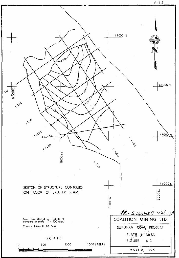
The internal structure of the Plate is a south-easterly plunging anticline. The structural entities of Plate 1 are illustrated
on the Structure Contour Maps on the Floors of the Chamberlain and the Skeeter Seams, Maps 3 and 4, respectively: for conven- ience these maps are reproduced as Text Figures 4.2 and 4.3, respectively. Note that the eastern limit of the plate at the level of the two seams varies with the intersection of the respective seam against the Chamberlain Fault or with respect to the strip mine area, the subsidiary faults.
The Cross Sections in Volume 1 clearly illustrate this variation.
4.3.2 FOLDING
The dominant element of Plate 1 is the anticlinal structure
which is considered to be a drag fold along the Chamberlain Fault. The anticline plunges at 5 o in the direction 155O azimuth

48000 N +
SKETCH OF STRUCTURE CONTOURS
ON FLOOR OF CHAMBEIXAIN SEAM
COALITION MINING LTD.
SUKUNKA COAL PROJECT
0
PLATE 1 AREA SCALE
FIGURE 4.2 500 1000 1500 IFEET)
MARCH 1975
SKETCH OF STRUCTURE CONTOURS
ON FLOOR OF SKEETER SEAM
SCALE
0 500 1000 1500 (FEET)
48OOON
+
\
&-suLtJN~a- 75!I ), COALITION MINING LTD.
SUKUNKA 6&L PROJECT -I
PLATE l/AREA
FICG- 4.3
MARCH, ,975

4-14
to approximately D.D.H. Pl-22, and then swings to the south. Dips on the limbs are 6O east and go west. The relationship of the topography to the structure results in the western limb of the anticline forming a dip slope, with a consequent minimum increase in cover with increasing distance from the outcrop.
Complex folding of the sediments and the contained coal seams occurs adjacent to the fault zones in the eastern part of the area. The nature of the folding, as shown on the relevant cross sections, is essentially diagrammatic based on outcrop observations in other parts of the property, and the general nature of rock deformation associated with overthrust faulting.
4.3.3 FAULTING
The following introductory statements are included here as
background to the description of the fault zones as they relate .to the structural geology of Plate 1.
The south-east limit of the Plate has been stated as being the Chamberlain Fault. When considered in detail, the Chamberlain Fault must be regarded as a zone of deformation and not a simple plane due, to some degreei to the variation in the lithologies under discussion.
Consequently, faults of a lesser magnitude than the Chamberlain Fault yet associated with it will be present and thus identified from the exploration programme.
Thus, consideration is here being given to the Chamberlain Fault Zone, as it relates to the structural geology of this part of Plate 1.
Section 4.3.6 (iv) of the 1972 Report discusses the nature of the fault, zones in more detail than is warranted here. As

4-75
a final point of note, while the faults are shown on the various cross sections as curved planes, it is significant to note
that various rocks react in different manners to similar stress conditions. Thus, the fault "plane" would be steeper when passing through a massive arenaceous unit than through a thinly bedded argillaceous one. Similarly, the zone of shearing or
brecciation representing the fault will vary in width.
(i) The Chamberlain Fault
One phase of the 1971 exploration programme was directed to-
wards establishing the attitude and bearing of the Chamberlain Fault. As such, the positioning of this Fault is regarded as being well defined: see Section 4.3.2 (i) of the 1972 Report.
This fault is regarded as a zone occurring between two limit- ing planes having an average dip of 8O to the west and varying between 4O and 12O. The throw varies between 120 feet and 300 feet with a heave of between 500 feet and 1600 feet. In the area of interest the Chamberlain Fault attains its maximum throw, decreasing to the south-east.
(ii) Fault Pl-29
Fault Pl-29 is named after D.D.H. Pl-29, the drill hole from which the major intersection was identified, as have the other subsidiary faults. This fault is also intersected in D.D.H. C-30 on Section T 370, and D.D.H. Pl-13 on Section T 750. A zone of brecciation in D.D.H. S-49 is interpreted as being
caused by the same fault.
The extension of the fault north to Section T 0 is based on the magnitude of the fault, since no drill hole on this cross section is in a position to intersect the fault.
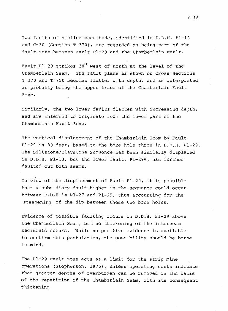
4-16
Two faults of smaller magnitude, identified in D.D.H. Pl-13 and C-30 (Section T 370), are regarded as being part of the
fault zone between Fault Pl-29 and the Chamberlain Fault.
Fault Pl-29 strikes 30° west of north at the level of the
Chamberlain Seam. The fault plane as shown on Cross Sections T 370 and T 750 becomes flatter with depth, and is interpreted as probably being the upper trace of the Chamberlain Fault Zone.
Similarly, the two lower faults flatten with increasing depth, and are inferred to originate from the lower part of the
Chamberlain Fault Zone.
The vertical displacement of the Chamberlain Seam by Fault Pl-29 is 80 feet, based on the bore hole throw in D.D.H. Pl-29. The Siltstone/Claystone Sequence has been similarly displaced in D.D.H. Pl-13, but the lower'fault, Pl-29A, has further faulted out both seams.
In view of the displacement of Fault Pl-29, it is possible that a subsidiary fault higher in the sequence could occur
between D.D.H. 's Pl-27 and Pl-29, thus accounting for the steepening of the dip between these two bore holes.
Evidence of possible faulting occurs in D.D.H. Pl-29 above the Chamberlain Seam, but no thickening of the interseam sediments occurs. While no positive evidence is available to confirm this postulation, the possibility should be borne in mind.
The Pl-29 Fault Zone acts as a limit for the strip mine operations (Stephenson, 1975), unless operating costs indicate that greater depths of overburden can be removed on the basis of the repetition of the Chamberlain Seam, with its consequent thickening.

4-17
(iii) Fault Pl-30
The Pl-30 Fault zone has only been identified in D.D.H. Pl-30 on Section T 1070, and consequently no trend for it can be established. It has not been related directly to Fault Pl-29, since the vertical displacements of the two fault zones are dissimilar.
A third fault plane is inferred to exist below this zone which may be referable to the Pl-29 Fault, but lack of data in
this region precludes any further comment.
The combined throw of the two faults in D.D.H. Pl-30 is 43
feet, half of that in Fault Pl-29. The Skeeter Seam has been repeated twice in the above bore hole, with vertical displace- ments of 15 feet and 28 feet. No Chamberlain Seam was inter- sected in D.D.H. Pl-30, hence the inference of a possible major
fault at depth in this area.
The presence of this fault zone is suggested as being the limit for a strip mine high wall because of the increased depth of overburden.
(iv) Fault Pl-25
As with Fault Pl-30, no trend can be established for this fault, since the only positive identification is in D.D.H. Pl-25.
A bore hole throw of 35 feet occurs with the repetition of the Siltstone/Claystone Sequence above the Skeeter Seam. Vertical displacement of 40 feet and 45 feet for the Skeeter and
Chamberlain Seams, respectively are measured on Cross Section

T 1240~, which is perpendicular to the inferred strike of the fault. The increased throw of 5 feet for the Chamberlain Seam is due to the second fault Pl-25A.
The attitude and bearing of this fault zone as shown on the Structure Contour Maps and Cross Sections, is the most con- servative one, consistent with the data available and the known mode of faulting which occurs on the property 'as a whole.
The drill hole logs record evidence of a number of minor faults
in the Interseam Sediments, for example D.D.H. Pl-6 and Pl-16.
Most of these are in probable or possible category, but cannot be completely discounted. It is not anticipated that they have caused any disruption of the Skeeter Seam continuity.
They are interpreted as being bedding plane or sub-bedding plane faults or shears. This phenomenon is common in the Mine No. 1 exposure, and is fully discussed in Section 4.3.4 (ii) of the
1972 Supplement. It is probable that these faults, to some degree, are the cause of the increased amount of shearing noted in the seams of this plate.
Caution is expressed in respect to the inferred or possible fault in the floor of the Chamberlain Seam in D.D.H. Pl-23 on Section T 1070. Such a feature is anomalous and may
represent a fault of more than a minor nature. No evidence,
however, is available to confirm this suspicion.

ECONOMIC APPRAISAL
5.1 INTRODUCTION
This section discusses the economic aspects of the drilled area of Plate 1 with regard to seam thickness and to quality. Isopach Maps and Quality Distribution Maps of the Chamberlain and Skeeter Seams are included in Volume 2 of this report. The overall quality of the two seams has been evaluated in detail in the previous two major reports on the project; no data has
come forward to suggest a variation in those predictions. In particular, reference should be made to Appendix A, Volume 5, of the 1972 Report (McElroy & Wallis, 1972).
The prime objective in this report with respect to the quality of the two coal seams is the definition of those areas which have suffered oxidation effects and hence must be regarded as thermal coal rather than metallurgical coal.
5.2 SXEETER SEAM
5.2.1 SEAM THICKNESS
The overall character of the Skeeter Seam has been discussed in Section 4.2.2 (iii), above. The Isopach Map of the seam thickness, Map 6 (see also Figure 5.1) shows the seam varying in thickness between 3.0 feet and 6.6 feet. The average seam thickness, based on the bore hole intersections is 4.73 feet.
An upper interval of clean coal has been defined from the various cores. The individual thicknesses of this interval

5- 2
A6000 N .+ -
ia 8 m \
IQ T3
\
\
I
SKETCH OF ISOPACH MAP TOTAL SKEETER SEAM I 460001\

5-3
are plotted on the Isopach Map, Map 6, and listed in Table A-l, Appendix A. The values are not contoured;due to the wide variation in thicknesses and to limited data. The lack of a recorded thickness of this upper, high ash unit for some bore holes on Map 6 cannot be taken as an.indication of its absence.
The thickness of the upper unit averages 2.18 feet, with a range of 1.0 foot to 3.36 feet. While the average thickness of 2.18 feet of clean coal, in respect of average total seam thickness of 4.13 feet, represents 46.1%, the range of individual percentages in the various bore holes is between 25% and 80.4%. An average of these individual percentages is 50.5%.
In view of the 4.5% variation, it is recommended that the lower
of these two average percentages, i.e. 46%, be used for mine
design purposes.
5.2.2 COAL QUALITY
The quality variations are shown in a diagrammatic manner on
Map 10 and, for convenience, at reduced scale as Figure 5.2.
Selected quality data are included in Appendix A. The mean values for ash percent, F.S.I., and C.V. are summarized in Table 5.1, below, for the upper and lower intervals, and the total seam.
To assess the presence or otherwise of oxidized coal, a number
of sink-float tests were undertaken on samples with low F.S.I. values. The average of four such tests on D.D.H.'s Pl-27, Pl-29, C-31, and S-49 yielded a washed product at 1.60 S.G. of 6.25% ash and 7% F.S.I. at an average yield of 81.4%.
On the raw coal (ash: 30.%, F.S.I.: 2) from D.D.H. Pl-15,
the -1.60 fraction yielded 97.6% of clean coal with 2.7% ash and an F.S.I. of 2, indicating oxidation of the coal had
occurred.

5-4
Taking into account:
(a) the area around D.D.H. Pl-15, (b) 'an area in the vicinity of R.D.H. Pl-4 where partial
oxidation appears to have occurred, and
(cl around the outcrop of the seam, no significant oxidation effects are apparent from data presented on Map 10. Consequently, no major thermal coal zones have been outlined for this seam, on the basis of the following two assumptions:
(i) the t op ply will be mined separately; and (ii) some form of simple cleaning process is available
to reduce the ash of the bottom ply to a saleable level.
This aspect is covered in more detail in the mining feasibility
report by H. G. Stephenson.
TABLE 5.1 SKEETER SEAM
Mean Quality Data (1)
Upper Unit Lower Unit Total Seam
Mean Ash % 6.58 32.1 19.1 Range 3.3 -'10.7 19.1 - 43.0 3.0 - 36.7 No. of Values 10 9 16
Mean F.S.I. 7 2% 6 Range 6s - 8 l-5 4- 8 No. of Values 10 9 14
Mean C.V. (2) 14,543 10,198 12,658 Range 13,860 - 15,110~ 8,730 - 12,475 10,152 - 14,287 No. of Values 6 5 12
(1) Analyses on raw coal, air dried basis.
(2) BTU/lb.
For completeness, the following table of analytical data for the washed product at 1.60 S.G. of the Skeeter Seam is reproduced from the 1972 Report (Table 5.6, p. 5-23):


5-5
TABLE 5.2
Mean Values of Analytical Data for
Washed Product at S.G. 1.60 (Air Dry Basis)
Skeeter Seam (Plate 2)
Moisture 0.9% Volatile Matter 22.7% Volatile Matter (D.A.F.) 24.9% Ash. 4.8% Fixed Carbon 71.6% C.S. No. 7+ C.V. (BTU/lb.) 14550 Sulphur 0.45% Phosphorus 0.023%
5.2.3 COAL RESERVES
Using the transverse Cross Sections which show the positions of the coal seams, Stephenson (1975) has calculated the reserves
of coal available for extraction at various stripping ratios.
On the basis of 100% recovery of .the upper 6.6% ash split of the Skeeter Seam and 60% recovery, after screening and simple
cleaning, for the basal split of the seam an overall recovery of 78% of this seam is calculated.
At a stripping ratio of 6.1:1, the total reserves of coal in the Skeeter Seam are 145,000 short tons (s. tons), of which
113,000 s. tons are regarded as saleable. Except for part of - the oxidized coal around the outcrop, amounting to 10,000 s. tons .raw, all the Skeeter Seam reserves are regarded as being
of metallurgical grade.
Increased tonnages, available at nominal stripping ratios of 7:l and 8:l dependent on economic parameters, are detailed in Stephenson's report.
5-6
5.3 CHAMBERLAIN SEAM
5.3.1 SEAM THICKNESS
The thickness of the Chamberlain Seam varies between 4.30 feet and 8.00 feet; see Map 5, reproduced as Figure 5.3 in this section. An average of the bore hole intersections is 6.20
feet.
Section 4.2.2 (i), above discusses the reason for the presence of sheared coal and rock at the top of the Chamberlain Seam. The thickness of this zone varies from 0.10 feet to 2.00 feet, and averages 0.65 feet. The individual thicknesses of the
shear zone are plotted on Map 5 and are tabulated in Appendix A in conjunction with the thicknesses of the sampled intervals from each bore hole.
Expressed as percentages, the thickness range of this shear zone in the individual bore holes is from 1.5% to 34.8%, and averages 1.1%. Alternatively, the average thickness percentage based on 0.65 foot average of sheared material in relation to
6.20 feet average seam thickness is 10.5%.
The sheared upper zone of the Chamberlain Seam is regarded as being present throughout the whole of the drilled part of Plate 1. Values are not recorded where the bore hole was sunk by rotary drilling, or where a detailed log is not available for example, D.D.H. S-49.
The physical constitution of this sheared zone is one of inter- mixed coal and laminite roof material. As such, it is antici-
pated that this zone could be skimmed off the top of the.clean underlying coal with minimum contamination.

SKETCH OF ISOPACH MAP CHAMBERLAIN SEAM
3( 49000 N
48000N
.+
\
\ 47000 ‘?, 1
SCALE
0 500 1000 1500 IFEET)
COALITION MINING LTD.
PLATE 1 AREA
MARC ti. 1975
5.3.2 COAL QUALITY
In detailing the quality of the Chamberlain Seam in Plate 1, four differing elements must be taken into account:
(i) Seam character (Upper unit - sheared coal (Lower unit - clean coal
(ii) Degree of (Oxidized coal weathering (Non-oxidized coal
The quality of the seam is therefore discussed under the two
major divisions, (i) and (ii), above. (i) The basic character of the seam is dealt with
first without consideration of final product which might be produced, i.e., thermal or metallurgical coal.
(ii) The degree of oxidation is the prime determinant as to what product can be produced from the coal seam. Thus the second aspect relates primarily to the defined thermal coal area.
Selected quality data are tabulated in Appendix A for the various analyzed intervals of the Chamberlain Seam. Map 11 displays the ash percent and F.S.I. values for each bore hole; Figure 5.4 is included here for convenience in a reduced version.
The Mean Quality Data for this seam is included as Table 5.3
for conciseness and as a background for the following discussion. Some values plotted on Map 11 have been excluded from the cal-
culation of the averages, since they are rotary drill cuttings
and may not be representative of the seam.
(i) Seam Character
The Chamberlain Seam has been described (Section 5.3.1 above) as being composed of two units or splits:
- an upper, thin interval of sheared coal and rock (approximately 10% of the total seam);
- the remainder of the seam, composed of clean coal.
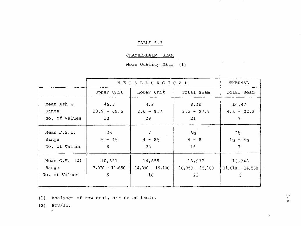
Mean Ash % 46.3 4.8 8.10 Range 23.9 - 69.6 2.6 - 9.7 3.5 - 27.9 No. of Values 13 29 21
Mean F.S.I. 2% 7 6% 2%
Range Ji - 4% 4 - 8% 4-8 1% i 4%
NO. of Values 8 23 16 7
Mean C.V. (2)
Range
No. of Values
r L
TABLE 5.3
CHAMBERLAIN SEAM
Mean Quality Data (1)
METALLURGICAL
Upper Unit
10,321 14,855
7,070 - 11,650 14,390 - 15,100
5 16
Lower Unit
(1) Analyses of raw coal, air dried basis.
(2) BTU/lb. -1
Total Seam Total Seam
13,937 13,248
10,350 - 15,100 11,010 - 14,560
22 5
THERMAL
10.47 4.3 - 22.3
~1


5-10
The ash content, and consequently the swelling index, is
significantly different for these two intervals. The ash
content of the upper split is 46% as against 4.8% for the lower
split: the F.S.I. is 2% and 7, respectively.
This difference in quality dictates that they be mined separately, as far as practicality and economics allow. Contamination of
the lower split by the upper split does not have a severe re-
duction in the quality of the final raw product however. The
addition of 10% of the 46% ash zone to the remainder of the seam increases the ash to 8.10% with a consequent reduction of the
F.S.I. to 64.
Since no evidence has resulted from this programme to suggest that the high quality of the Chamberlain Seam differs in this area of Plate 1 to the remainder of the property, the following analytical data is reproduced from the 1972 Report, (Table 5.2,
P. 5-14) for completeness.
TABLE 5.4
Range of Mean Values of Analytical Data for Washed Product at S.G. 1.60 (Air Dry Basis).
Chamberlain Seam (Various elements - Plate 2)
(Data for Upper Split excluded)
Moisture % V.M. % V.M. %(DAF) Ash % Fixed Carbon % C.S. NO. C.V. (BTU/lb.) Sulphur % Phosphorous %
0.8. to 1.0 19.2 to 22.2 20.6 to 26.2
3.9 to 5.3 73.0 to 73.9
7 to 7% 14520 to 15030
0.35 to 0.45 0.021 to 0.035

5-11
(ii) Degree of Weathering
The prime significance of this factor is the affect it has
on the coal when considering its end use, that is, metallurgi-
cal or thermal coal.
Reference to Map 11 or Figure 5.4 shows the region where
oxidation of the Chamberlain Seam has occurred. This region,
defined on the basis of the analytical data from seven bore
holes, is therefore regarded as containing thermal coal.
It can be seen from the displayed analytical data that a sink-
float test at 1.60 S.G. has not materially increased the F.S.I.
of the cleaned coal. Only one,bore hole, D.D.H. Pl-17, contained
coal with a swell in excess of 2$; this hole is regarded as
partially oxidized, since the lower ply has an F.S.I. of 64.
Special note is made of three localized data points:
(a)
(b)
(cl
The data
D.D.H. Pl-2, where partial oxidation appears to have occurred, though only in the upper 1.00 foot where the ash is 4.4% and swell 2%;
R.D.H. Pl-9, which is 120 feet from the outcrop, gives some slight cause for concern with a clean coal F.S.I. of 1%. However, the seam is under 29.4 feet of cover, which is a most likely explanation;
An extension of the elongate region of oxidized coal to the south, toward R.D.H. Pl-6, cannot be ruled out in the absence of information from this drill hole. This area should be tested at an early date.
Erom the various holes in which oxidized coal occurs
indicates that where the Chamberlain Seam is under less than
30 feet of cover, the probability of oxidation occurring is
high. This should be borne in mind during detailed mine planning.
It is significant to point out,, that while a generally smooth
boundary is shown dividing the oxidized from the non-oxidized

5-12
coal, this is unlikely to be the case. It is anticipated that the boundary will be, at best, gradational both in the vertical and horizontal directions, dependent on the physical factors controlling the degree to which oxidation has taken place.
Careful quality control during mining will be necessary to
ensure that the best balance is obtained between the thermal and metallurgical coal around the limits of the region of
oxidized coal.
(iii) Cause of Oxidation
This section is included since selective oxidation of the Chamberlain Seam has taken place and secondly, since no corre- lative zone of oxidation occurs in the overlying Skeeter Seam.
A number of factors, listed below, are believed to be signifi- cant when discussing the cause of this phenomenon:
(a)
(b)
(cl
Cd)
(e)
(f)
Deformation resulting from the regional structural disturbance; Additional local deformation, normally inherent in the overlapping plate of an overthrust zone; A zone of sheared coal and rock at the top of the Chamberlain Seam, resulting from bedding plane movement; this feature is not present in the Skeeter Seam; The structural dip of that part of the rock mass under review, particularly in relation to the topography: The exposeg flooroof the Chamberlain Seam, dipping 12 to 15 , outside the outcrop of the seam; The overlying Skeeter Seam, not having a coincident crop line with the Chamberlain Seam: the Skeeter Seam crop line is 300 feet south of the Chamberlain Seam at the northern end.

5-13
(9) The relatively less permeable roof of the Skeeter Seam in comparison to the Chamber- lain Seam roof, thus acting as a partial barrier.;
(h) The amount of water gaining access to the seam:
(i) The relatively less permeable floor of the Chamberlain Seam;
(j) Often variable oxidation effects in coal seams underground, further away from the outcrop than fresh coal.
(k) Transport of water being more significant from an oxidation potential than resident water.
A comparison of the Quality Map, Map 11, and Structure Contour
Map, Map 3. of the Chamberlain Seam, shows a parallelism of the axes of the south-plunging anticline and the elongate zone of oxidized coal. The axis of the oxidized coal zone is approx- imately 150 feet down-dip from the axis of the anticline.
Consequently, it may be assumed that down-dip movement of water under the influence of the anticlinal structure occurs. Possibly a hydrostatic head, caused by the steeper topography to the east, may have an effect, though this would be of little consequence north of the Cross Section T 370 area (See DWG No.
SKR 223, Composite of Cross Sections).
Access of water to the seam is proposed as being primarily via two avenues:
(a) The sub-crop of the seam below the soil and gravel cover since, in part in the northern outcrop, the floor is exposed with no over- lying seam thus acting as a "gutter" channelling the water into the seam; and
(b) Approximately 300 feet of Chamberlain Seam and its roof rocks outside the Skeeter Seam outcrop; thus, an area where vertical move- ment of water is possible.
The sheared upper zone of the seam may act as a more permeable medium, allowing greater ingress of water to the seam, particularly

5-74
from downward percolation. The floor of the Chamberlain Seam being relatively less permeable than the seam and, in itself a hard, "non-porous" rock, will act as a barrier to the move- ment of water. In short, it would have a "damming" effect, channelling the water along the seam in a lateral sense.
To summarize, the most probable mechanism causing the selec- tive oxidation of the Chamberlain Seam would appear to be a movement of water gaining access to the seam via the northern outcrop, both vertically and horizontally, and moving to the
south and west under the influence of the west-dipping, south- plunging limb of the anticline. Horizontal movement of water would also be facilitated by the upper sheared zone and the sandstone floor of the seam, possibly aided by hydrostatic pressure caused by the greater cover to the south and east. Protection of the Skeeter Seam by its relatively less permeable roof would also be significant in protecting the Skeeter Seam from significant oxidation effects.
It is not proposed that the above mechanism excludes the down- ward percolation of water through the overburden where the
Skeeter Seam is present, but it is suggested that this is of minor consequence since the passage of water through the Skeeter Seam must cause some oxidation, which is not in evidence.
5.3.3 COAL RESERVES
Stephenson (op tit) has calculated the coal reserves in the Chamberlain Seam on the basis of 100% recovery. The'upper 10%
of sheared coal and rock of the seam has been disregarded in the calculations. Tonnages at a stripping ratio of 6.1:1 are quoted; increased tonnages are available at higher stripping ratios if economic conditions are favourable.
The total reserves of coal in the Chamberlain Seam are 376,000 short tons (s. tons), of which 232,000 s. tons are of metallurg- ical grade, tons are of thermal grade.

s- 15
5.4 ECONOMIC SIGNIFICANCE OF TECTONIC ACTION
The deformation resulting from the tectonic action as it affects
Plate 1 has significance from an economic aspect. The stress conditions operating at the time of deformation have been con-
centrated in different lithologies, with consequently different effects. While the various structural elements have been
described in Section 4.3 of this report, this section summarizes
the effects those elements have had on the reserves, quality
and mineability of Plate 1.
5.4.1 RESERVES
The reserves of coal within Plate 1 are limited by the fault
zones to the south-east of the area and, to a lesser degree,
to the south. Conversely, a dip slope situation occurs on the western limb of the anticline, thus reducing the amount of overburden in this region.
Internal shearing within the seams, while not reducing the
gross in situ reserves, effectively reduces the final product,
dependent on the method of cleaning used. Further, it dictates to some degree the mining method used.
Thickening of the seams occurs as a result of overfolding along
the fault zone, for example, 26.6 feet of Chamberlain Seam was
penetrated in D.D.H. C-30, and 21.5 feet in D.D.H. Pl-29. The lateral extent of this thickened zone of coal is not defin-
able, but would most certainly be erratic, being governed by the intensity of faulting. An addition to the reserves from
this source cannot be given high degree of probability, more
so since the depth of overburden tends to be significant. It
is predicted that the quality of such a thickened seam would contain rock bands, which would significantly increase the ash content.

5-16
5.4.2 QUALITY
Bedding plane faulting at the top of the Chamberlain Seam has produced a zone of sheared coal and rock. This zone,
though higher in ash than the raw coal of the seam, when
mined separately can be cleaned to produce a saleable product. Additionally, the inevitable contamination of the seam by this zone during mining is less significant than contamination by
a normal roof sediment of 100% ash.
Internal shearing of the Skeeter Seam appears to be moderately universal, thus eliminating the opportunity to separately mine the rock bands.
The effect the anticline has played, in part, in the selective oxidation of the Chamberlain Seam has been fully discussed
above.
5.4.3 MINEABILITY
The overall stress system which operated in the region has
resulted in internal deformation of the laminite roof of the
Chamberlain Seam at the northern end of the property. Since
previous observation indicates that deformation is more intense on the upper, overlapping plate of a thrust fault, it is predicted that this situation will obtain in Plate 1. Further, evidence resulting from the recent drilling programme and out- crop observation support this prediction.
Consequently, it is anticipated that the laminite immediately
overlying the sheared zone at the top of the seam may be mine- able with little or no blasting.
Deformation of the floor of the Skeeter Seam, for example the possible fault in R.D.H. Pl-6, may necessitate that stringent
quality.controls are in operation when this seam is being extracted to minimise contamination.

5- 17
5.5 GROUND WATER
Radiation logging of the bore holes has provided data on the water level in each hole. These data are discussed in this part of the report and included in Table 5.5. Shown on the Composite of the Cross Sections is the elevation of the water level in the bore holes on that diagram.
In evaluating the ground water records for this area it is important that the following conditions are noted.
(a) All holes except R.D.H.'s Pl-7 to Pl-12 were drilled using a gel-based mud to maintain circulation: the exceptions were drilled using air.
(b) A time lapse existed between the completion of drilling and logging, ranging up to 11 days and averaging 4 days.
As a consequence of these two facts, the data must be interpreted
with some caution.
Interpretation
Both pore water and fissure water systems may be expected to be present in this area, with the consequence that a uniform water level gradient is unlikely to exist. Further, data from previous drilling progranunes indicated that a series of perched water tables existed throughout the property, rather than a continuous water table.
In approximately 60% of the bore holes drilled in this programme the water level shows a positive relationship to the topography. The spatial distribution is not as distinct, however it is evident that the anticlinal structure is a controlling feature to some extent. This influence is evident on the Composite of the Cross Sections.

No water level is recorded for seven drill holes; see Table 5.5. The topographic situation of six of these drill holes is such as to indicate a dry hole. That is, the water table
would be below the bottom of the hole. R.D.H. Pl-10 is the exception.
In more than 50% of the bore holes, the water levels occur either in the Interseam Sediments or immediately above or below the coal seams. From this it may be inferred that the
coal seams, normally being effectively impermeable, act as a .barrier to the downward movement of water. Where fissuring of
the seams is present however, this situation would not pertain.
Impressed upon this total hydrologic system is the effect of the tectonic action resulting in jointing and fracturing of
the rock mass. Thus irregular and unpredicable channelling of the ground water can occur.
In summary, the ground water situation in this region is a combination of both pore water and fissure water related in part to the topography. Since positive indications of water
existing close to the two seams to be mined is evident, due allowance should be made for this in any strip mine design.

5-19
TABLE 5.5
GROUND WATER LEVELS
Hole No. Water Level R. L.
(Pl- 1 (feet) (feet) Lithology
1 44 2 38 3 32
4 116 5 12 6 15
7 73 9 N.R.*
10 N.R. 11 N.R. 13 53 14 40 15 51 16 18 17 27 18 N.R. 19 N.R. 20 N.R. 21 50 22 69 23 73 24 14 25 65 26 28
27 41 28 N.R. 29 65 30 19
4049 3989 4081
3999 4078 3982
4048
Interseam laminite Interseam interbeds Chamberlain Seam floor -
sandstone Lower Sandstone Upper Sandstone Skeeter Seam floor -
siltstone Lower Sandstone
4064 Upper Sandstone 4075 Lower Sandstone 4032 Interseam siltstone 4025 Lower Sandstone 4067 Interseam siltstone
4081 4028 3938 4080 4056 4042
4067
Upper Sandstone Skeeter Seam roof Chamberlain Seam floor Upper Sandstone Upper Sandstone Siltstone/claystone
sequence Interseam laminity
4035 Skeeter Seam floor 4112 Upper Sandstone
*) N.R. = Not Recorded.

5-20
5.6 DEPTH OF COVER
Included for use during detailed mine design are three Isopach >4aps illustrating:
(a) Interseam Sediments Between the Skeeter and Chamberlain Seams (Map 7).
(b) Cover Over the Skeeter Seam (Map 8). (c) Total Overburden Over the Chamberlain Seam
(Map 9).
In accord with the increase in height of the surface from the west to the east of the area, the cover over the two seams
similarly increases. The maximum cover of 155 feet over the
Skeeter Seam is reached adjacent to the limiting fault, Pl-25. It is anticipated that this depth of cover will not be reached during extraction of the seam since preliminary mine design places a strip mine highwall to the west of this point. It is
significant to note that more than half the area is under less than 70 feet.
The total depth of overburden over the Chamberlain Seam (See
Map 9) increases to 165 feet at the limiting fault, Pl-25. At the corresponding point of the maximum cover over the Skeeter Seam, the maximum Chamberlain Seam cover is 130 feet, due to the differing points of intersection of the two seams against the flat dipping fault plane.
The thickness of the rock units between the two seams (Map 7) which, in conjunction with the Skeeter Seam cover, comprises the total Chamberlain Seam cover, has been discussed separately in Section 4.2.2 (ii), above.
Note that outside the Skeeter Seam outcrop the isopachs on Map 7 represent overburden thickness and not an "interseam" thickness.

5-21
5.7 ENVIRONMENTAL IMPACT
While the environmental factors relating to any proposed strip mine operation are not strictly part of the economic evalua- tion of the area, they nonetheless have impact from the follow- ing aspects:
(a) Government approvals to mine; (b) Operating costs;
Cc) Local support, or otherwise.
Consequently, a brief review of some of the elements is included
here.
5.7.1 SOIL COVER
The soil cover throughout the area is generally less than 1 foot, and not of high quality, since it originates principally from
arenaceous rock types. The weathered rock or sub-soil rarely exceeds 6 feet, based on the evidence of the recent drilling programme.
Prior to removal of the rock overburden, it will be advanta- geous to stockpile separately the topsoil and sub-soil, in order that they can be replaced on the back-filling at the completion of mining.
5.7.2 VEGETATION
The vegetation in the area is principally a thin cover of. mature trees of virtually no economic value. The undergrowth
is sparse, while a reasonably thick litter of tree fall exists. The latter constitutes virtually the only humic material avail- able for soil enrichment, since there is no abundance of grass
growth.
5.7.3 SURFACE WATER
Apart from a small, non-perennial creek to the south of and
outside the proposed mining area, no major watercourses will be subject to disturbance. At the southern end of'the drilled area a "muskeg-type" region exists which is normally wet.
Both underground and surface water are unlikely to have an abnormally low pH value, since the sulphur content of the coal is low.
The inevitable surface water will need to be channelled away
from the working face and further, must be prevented from causing erosion down the steep slope below the area.
Experience has demonstrated that the provision of a series of silt-trap dams prior to the water being allowed to dis- charge into any natural surface drainage feature, will catch both suspended soil and coal. Similarly with oils and greases which may result from the presence of mine machinery. Thus it can be expected that, with reasonable control, pollution
of the surface water should not occur.
5.1.4 RESTORATION
Consideration should be given to sequential restoration of the area, since progressive back-filling of the mined-out area in conjunction with mining should be feasible, though dependent on the final mine design.
The expansion of the overburden, on removal and replacement,
will provide additional material to replace the volume of extracted coal, with the consequence that the restored land surface should be similar to the original surface.
5-23
During replacement of the top soil and sub-soil, the addition of fertilizer and a suitable mixture of grass seeds will ensure stabilization of the surface by promoting rapid grass growth. The reseeding of old exploration roads on the property in recent years without the use of fertilizer has proved successful to date with excellent grass growth.
With careful planning and the adherance to good restoration practices and pollution control measures, no environmental
problems should arise as a result of a strip mine operation in the area evaluated.

SECTI'M 6
RECOMMENDATIONS FOR FURTHER FIELD INVESTIGATIONS
In view of the overall programme to assess the strip coal
potential of the Sukunka Property that has been embarked upon
by Coalition Mining, the recommendations for further evaluation are included here under two categories:
- those relating to that part of Plate 1, and arising from this report; and
- those relating to long-term considerations affecting the property as a whole.
6.1 PLATE I RECOMMENDATIONS
Arising out of the exploration programme and the subsequent data analysis, a number of elements present themselves for further definition.
None are significant from the point of the preliminary mine design prepared by H. G. Stephenson but warrant further inves- tigation in respect of operation and control during production. In the early stages of any proposed mining operation, some of
these elements would be covered in the normal course of events,
by, for example, inexpensive drilling prior to opening the strip mine.

6-2
6.1.1 QUALITY EVALUATION
Skeeter Seam
(i) The area of the oxidized coal around D.D.H. Pl-15 is not anticipated to be extensive but requires definition for quality control.
(ii) Definition of the oxidized region around the outcrop would be covered by pit commencement operations, but is important for quality control.
Chamberlain Seam
(iii) Concern is expressed in Section 5.3 above, in respect of a possible extension of the region of oxidized coal to the south toward R.D.H. Pl-6; limited drilling is recommended in this area.
(iv) Similarly with the partially oxidized coal in D.D.H. Pl-2.
(v) Outcrop oxidation effects would be covered as in the Skeeter Seam, (ii) above.
(vi) Quality control during the extraction of the oxidized coal will necessitate close drilling to define both the limits and the quality variations.
6.1.2 RESERVE EXTENSIONS
An extension of the reserves to the south-east of the suggested pit limits at TO +1670 set by Stephenson (1975) is possible. Topographically the area is steep but surface mapping and drilling could feasibly add a small tonnage from both seams.
6.1.3 OUTCROP DEFINITION
Since the programme was commenced after snow covered the ground, the outcrop of the two seams is approximated in a number of areas. While repetitive in part, in that operations relating to the commencement of mining should elucidate these
6-3
points, they are listed here for completeness. Detailed out- crop definition is recommended by both field work and trenching, in the following areas:
Skeeter Seam
(i) To the north-east of R.D.H. Pl-11.
(ii) Between R.D.H.'s Pl-9 and Pl-6. (iii) South-east of R.D.H. Pl-6, if reserve extensions are
to be investigated in this area.
Chamberlain Seam
(iv) The northern limit along approximately the T 250 line.
(v) Between R.D.H. Pl-9 and Pl-8. (vi) South-east of R.D.H. Pl-8, if reserve extensions
are to be investigated in this area.
6.1.4 STRUCTURAL DISCONTINUITIES
Given the drill hole spacing, it is reasonably predicted that
discontinuities in excess of 5 feet have been defined. Accordingly, drilling to assess the location of ill-defined or suspected faults can be deferred until production has commenced.
The following points, however, warrant drilling by an inex- pensive method to clarify the doubtful factors:
(i) The position and trend of Fault Pl-29 on Section TO;
(ii) The suspected fault between D.D.H.'s Pl-27 and Pl-29;
6-4
6.2 LONG-TERM RECOMMENDATIONS
The following recommendations, not in strict order of priority, are submitted, having in mind the overall aim to obtain strip mine coal at an early date, yet of a quality which requires minimum beneficiation.
6.2.1 UPPER GETHING SEQUENCE
An evaluation of the strip coal in the Skeeter and Chamberlain
Seams in the Plate 2 area, both to the west and east of the present mine area, is warranted.
It has been tentatively suggested that 1 million tons of coal
could exist in these two sub-areas (Wallis, 1974). An estimated cost of $158,580 is suggested for a two-stage programme for this work.
Concerning Plate 3, the more accessible part is reported to contain an estimated 0.8 million tons, at a stripping ratio of 5:l. Thus, this area is recommended for further evaluation
on the basis of coal quality though it is located in an
unfavourable area from an access view-point in comparison with Plates 1 and 2.
6.2.2 LOWER GETHING.SEQUENCE
A report is currently being prepared detailing the 1974 inves- tigations into the strip coal potential of the "Middle Coals" in the Lower Gething sequence. More detailed recommendations will be included in that report.
A very tentative reserve figure of more than one million tons of coal is inferred to exist in the area south of Skeeter Creek and adjacent to the proposed plant site. To the north

6-5
of Skeeter Creek, the drilling indicated no significant potential for strip coal.
Further evaluation of the southern area is warranted, but might well be deferred until a later date when a washing plant is in a more advanced stage of planning. The quality of the raw coal is such as to require cleaning to produce a saleable product.
6.2.3 COMMOTION FORMATION COAL SEAMS
A review of the coal seams occurring in the Gates Member of the Commotion Formation, from an open pit aspect, is warranted
in view of the trenches which were cut during 1974. Data from these trenches, in conjunction with earlier drill hole data, indicates that the Gates "B" Seam is often of the order of 15 feet to 18 feet in thickness, but appears to vary laterally. A rock band occurring within the seam is variable in thickness and distribution and will consequently have economic implications.
Since the data currently available is insufficient to allow a definitive statement regarding the strip coal potential of
this seam to be made, an evaluation with this objective in view should be carried out.
A review of the existing data will provide a basis on which to plan a programme, which would involve additional trenching to establish lateral continuity around the outcrop. Drilling will assist in establishing the continuity transverse to the outcrop, and provide data for positioning a strip mine highwall.

SECTIflN 7
CONCLUSIONS 8 REFERENCES
7.1 CONCLUSIONS
An evaluation of the geological parameters relating to the
strip mine potential of the Skeeter and Chamberlain Seams in the northern part of Plate 1 of the Sukunka Coal Property has resulted from a recently completed exploration programme. The data documented in this report has been used as the basis for a study assessing the viability of such a proposal.
Twenty-three diamond cored drill holes and seven rotary drilled
holes were sunk between November 12, 1974, and January 31, 1975.
The data confirms the already established stratigraphic se- quence, defines a number of fault zones, and enables an assessment of the quality to be made. The results of the 1971 field season were used as a basis for the programme.
The two seams, Skeeter and Chamberlain, occur within the lower 50 feet of the Upper Gething sequence. A third seam, the Bird, occurs at the top of the stratigraphic sequence of 150
to 180 feet. The Bird Seam is uneconomic due to its high ash and sulphur content.
Seam continuity has been established within the limits of the outcrop to the west, and fault zones to the east. The Skeeter Seam crops out 150 feet to 300 feet uphill from the Chamberlain Seam, due to relatively flat topography.
Structural controls affecting the economics of a strip mine in this area are a southeasterly plunging anticline, which
7-2
forms a dip slope on its northwestern limb, and three zones
of faulting. Structural deformation in this plate is more severe than in other areas of the property evaluated to date, with consequently more disturbance of the coal seams.
Three faults are defined, being part of the Chamberlain Fault Zone which is a major structural discontinuity along the western edge of the property as a whole.' While the trends of
two of the three faults have not been established, these faults are outside the economic overburden-to-coal ratio limit.
The thickness of the seams in the drilled area of Plate 1 ranges between 3.00 feet and 6.60 feet for the Skeeter Seam, and between 4.30 feet and 8.00 feet for the Chamberlain Seam. The average thickness of the two seams is 4.73 feet and 6.20
feet. respectively.
The upper 46% of the Skeeter Seam is essentially clean coal having an average ash content of 6.68, and a free swelling
index of 7; the mean calorific value is 14.,543 BTU/lb. The lower split of this seam has an average ash content of 32.1% and a swell of 2%. This coal can be washed at 1.60 S.G. to a product having less than 8 % ash and a swell of 6% to 7, indicating that it has not lost its coking characteristics. The average calorific value of the raw coal in the lower split is 10,198 BTU/lb, and ranges between 8,730 and 12,475 BTU/lb with an ash range of 19.1% to 43.0%.
Except for the oxidized zone around the outcrop, the total Skeeter Seam reserves can be regarded as' metallurgical coal,, on the assumption that some provision is made for cleaninq.the lower split and after selective mining of the upper and lower splits.
The Chamberlain Seam has an upper zone of sheared coal and rock equal to 10% of the seam thickness. This zone has an

7-3
average raw coal analysis of 46.3% ash, F.S.I. equal to 2$, and C.V. 10,321 BTU/lb. Thus, this zone being thin, must generally be regarded as waste or, at the best, diluent.
The clean coal of the Chamberlain Seam underlying the above sheared zone has an average ash of 4.8%, and F.S.I. of 7, with the C.V. averaging 14,855 BTU/lb.
On the western limb of the anticline, a significant zone of
oxidized coal occurs in the Chamberlain Seam: no correlative zone occurs in the Skeeter Seam. The quality of the total Chamberlain Seam in this oxidized zone is such as to provide a good thermal coal, having an average raw coal analysis of lo%% ash, and 13,248 BTU/lb. The average F.S.I. is 2%. The remainder of the area is good quality metallurgical coal, except for the oxidized coal around the outcrop.
Stephenson (1975) has calculated that a total of 521,000 short tons of coal, raw, are available in both seams at a
stripping ratio of 6.1:1. Of this tonnage, 152,000 short tons are regarded as being of thermal quality.
Of the Skeeter Seam reserves, 135,000 short tons are of metallurgical quality, and 10,000 short tons, in the region of the outcrop, are of thermal quality.
In the Chamberlain Seam, 232,000 short tons are of metallurgical grade, and 144,000 short tons, including the outcrop region, are of thermal grade.

7-4
7.2 REFERENCES
BRYAN, J.H., MCELROY, C.T. & WALLIS, G.R., (1973): Sukunka Coal Project - Geological
Report, 1972 Supplement. Rpt. No. l/4/12, Vols. 1-5, Unpub. Rpt. for Coalition Mining Ltd. March, 1973.
DYSON, I.P., (1974): Open Pit Potential. Sukunka Coal Deposit. Unpub. Rpt. for Brascan Resources Ltd. August, 1974.
MCELROY, C.T. & WALLIS, G.R. (1972): Sukunka Coal Project - Geological Report. Vols. l-12. Unpub. Rpt. for Coalition Mining Ltd. March, 1972.
STEPHENSON, H-G., (1975): A Report on Strip Mine Reserves and ' Costs for Various Stripping Ratios, .Plate One Area, Sukunka. Unpub. Rpt. for Brascan Resources Ltd., March, 1975.
STOTT, D.F., (1968): Lower Cretaceous Bullhead and Fort St. John Groups, between Smoky and Peace Rivers, Rocky Mountain Foothills, Alberta and British Columbia: Geol. Surv. Can. (Dept. Ener., Min. & Res.), Bull. 152.
WALLIS, G-R., (1974): Preliminary Report of the Potential Reserves of Open Pit Coal in the Upper Gething Sequence, Sukunka Coal Project. Rpt. No. l/4/19 Unpub. Rpt. for Coalition Mining Ltd. Oct., 1974.
WALLIS, G.R. & JORDAN, G.R., (1974): The Stratigraphy and Structure of the Lower Cretaceous Gething Formation of the Sukunka River Coal Deposit in B.C.; Bull. C.I.M., March, 1974.

APPENDIX A
QUALITY DATA
NOTES TO ACCOMPANY TABLES A-l AND A-Z
SELECTED QUALITY DATA, SKEETER SEAM TABLE A-l
SELECTED QUALITY DATA, CHAMBERLAIN SEAM TABLE A-Z
LIST OF SAMPLE NUMBERS RELATING TO DRILL HOLES TABLE A-3

NOTES TO ACCOMPANY TABLES A-l AND A-2
7. The anaLynen uhe on an aix-tied ba&ih.
2. The ~;-SWLIU in iAkL& me enfimated (pf?y: ah%), ofi
ca&&ted [componite: anh%, F.S.I., C.V.). AU ana&nen
ahe on hm coat.
3. Colohi~ic vaecla ahe on .the RIWJ coti, eLthe.t pLy 0)~ componite
nampLe, except whehe nofed. See ihe npeci6.k anaLi.&&
cti~icaie in Xhe bohe WA7hdh 60h C.V. 06 the whed phoduc.X.
4. AnaLyLicat daXa on washed phoduot af 1.40 S.G.
5. Th.ickneAh cohtected 6oh 6eam dip.
6. C.V. on washed ph0duc.t ai 7.60 S.G.
Genemk SampLe.,s @om bake ho&A Pl-4 and PI-6 to PI-12 ahe, in home
i~tincen, cot&a&tied, being hecovened dhom hoaizhy dhiee
hoea.
See MapA IO and I1 6oh dinpLayed anaLyticaL data doh Skee.teh
and Chambeh.t%inSeamh, h&ApeC.L&&y.
TabLe A-3 tabuktti tie depfhs &Oh each AampLe an&yzed.

Bore m.
Pl-29
c-31
S-14
s-49
sarple NO.
573
--
---
--
Thi'
PlY
21.50
6.~80
9.6
4.3
Pl
Ash %
20.5
11.0
8.0
6.7
-r- :2)
F.S.1,
co-
&h %
L&(2)
F.S.I.

Eare NJ.
Pl-23
Pl-24
Pl-25
Pl-26
Pl-27
Pl-28
Pl-29
Saple No.
552 0.75
553 2.11
554 3.14
558 3.73
559 3.12
-- 0.41
582 5.47
583 2.12
589 8.00
-
566
0.49
5.01
560 0.3c
561 4.5c
568 0.75
569 0.45
570 1.80
571 1.76
572 2.49
Th
6.00
6.85
8.00
--
5.50
4.80
7.25
- P. 0
F.S.1
24.5 3+ 2.6 7% 5.1 8
5.2 6
7.8 1%
--
9.7
6.4
6
8%
5-q 4
50.0
19.6 4%
49.1 .+
3.8 74
!5.8 3
2.5 6
3.8 6%
2.7 8%
6.7' 8
ite(2)
Ash % F.S.I.
6.4
6.8
) 7.7 )
)
jlZZ.9
6.8
7.1
7%
7
7%
4
7
7%

EmYe No.
Pl-16
Pl-17
Pl-18
Pl-19
Pl-20
Pl-21
Pl-2a
SdTpk NO. Ply cumul. Ash % F.S.1 Ash ( F.S.I.
521 0.30
528 0.70
529 4.05 5.05
67.6
4.7
2.6
535
536
0.90
5.60 6.50
25.8
5.2
537 0.50
538 6.10 6.60
51.6
3.8
--
539
0.25
5.00
5.70
5.25 50. 0 4.0
540 4.6
543 5.40 3. 8~
546 2.00
547 2.50
548 1.25 5.75
23.9
3.9
6.2
Thi mess T
cXAKBz1L;IIN SEQ.1 (1)
P: (2) l-
6.9 6
8.1
1.4
ti. 5
10.8
4%
6%
6
7
.ite(2)

TABLEA- SEXXTEDQIIALIW DATA
Bore X0.
Pl-1
Pl-2
Pl-5
Pl-7
Pl-9
Pl-10
Pl-I.1
Pl-14
Pl-15
SaITple NO. Ply
510
509
513
514
1.00
5.00
518 6.20
531 6.20
532 6.60
533 6.00
534 6.00
- 0.10
521 6.65
-- 0.10
523 0.30
524 5.05
525 1.05
Thi
6.30
6.00
6.75
6.50
Ply (2) m
Ash % F.S.I. Ash %
32.7 2 13.2
2.4 2Fi
4.4 2% 3.9
3.5 -/si
3.5 7%
32.0 4%
13.3 1%
22.3 2%
27.9, 14
50.0 - 5.6
4.6 8
(4.3)
4.6 2 3.5
2.6 1% 8.8 1
ite(2)
F.S.I.

TABLE A-3
LIST OF SAMPLE NUMBERS RELATING TO DRILL HOLES
Sample NO. (SKR) Bore No. Seam Interval (feet)
507 508 509 510
511 512 513 514
518
520 521
Pl-1 Pl-1 Pl-1 Pl-1
Pl-2 Pl-2 Pl-2 Pl-2
Pl-5
Pl-14 Pl-14
522 Pl-15 523 Pl-15 524 Pl-15 525 Pl-15
526 Pl-16 527 Pl-16 528 Pl-16 529 Pl-16
530 Pl-4
531 Pl-7
532 Pl-9
533 Pl-10
534 Pl-11
535 Pl-17 536 Pl-17
Skeeter 25.25 - 27.20 Skeeter 27.20 - 29.90 Chamberlain 61.86 - 66.20 Chamberlain 59.90 - 61.86
Skeeter Skeeter Chamberlain Chamberlain
Chamberlain
25.35 - 27.22 27.75 - 31.29
Skeeter Chamberlain
Skeeter Chamberlain Chamberlain Chamberlain
Skeeter Chamberlain Chamberlain Chamberlain
Skeeter
Chamberlain
Chamberlain
Chamberlain
Chamberlain
Chamberlain Chamberlain
57.40 - 58.40 58.40 - 63.40
138.80 - 145.00
47.20 - 51.60 82.60 - 89.25
20.80 - 23.80 59.40 - 59.70 59.70 - 64.75 64.75 - 65.80
24.00 - 25.90 61.70 - 62.00 62.00 - 62.70 62.70 - 66.75
125.5 - 132.0
106.0 - 112.2
29.4 - 36.0
63.0 - 69.0
24.7 - 29.8
38.00 - 38.90 38.90 - 44.50

TABLE A-3
Sample.No. (SKR) ,Bore No. Seam Interval (feet)
-2-
537 Pl-18 Chamberlain 538 Pl-18 Chamberlain
539 II
540 Pl-20 Chamberlain
541 Pl-21 Skeeter 542 Pl-21 Skeeter 543 Pl-21 Chamberlain
544 Pl-22A Skeeter 545 Pl-22A Skeeter 546 P1-22A Chamberlain 547 Pl-22A Chamberlain 548 Pl-22A Chamberlain
549 550 551 552 553 554
Pl-23 Skeeter Pl-23 Skeeter Pl-23 Skeeter Pl-23 Chamberlain Pl-23 Chamberlain Pl-23 Chamberlain
555 Pl-24 Skeeter 556 Pl-24 Skeeter 557 Pl-24 Skeeter 558 Pl-24 Chamberlain 559 Pl-24 Chamberlain
560 Pl-28 Chamberlain 561 Pl-28 Chamberlain
562 Pl-27 Skeeter 563 Pl-27 Skeeter 564 Pl-27 Skeeter 565 Pl-27 Skeeter 566 Pl-27 Chamberlain
Pl-19. Pl-19
Chamberlain I,
35.80 - 36.30 36.30 - 42.40
35.37 - 36.00 36.00 - 41.00
33.50 - 39.20
117.90 - 120.69 120.69 - 121.40 150.20 - 155.60
74.00 ‘- 75.00 75.00 - 78.00
107.00 - 109.00 109.00 - 111.50 111.50 -.112.75
24.5,5 - 27.00 27.00 - 27.15 27.15 - 30.00 64.00 - 64.75 64.75 - 66.86 66.86 - 70.00
124.10 - 126.42 126.42 - 126.89 126.89 - 127.90 164.75 - 168.48 168.48 - 171.60
25.00 - 25.30 25.30 - 29.80
46.50 - 47.50 47.50 - 48.45 48.45 - 49.65 49.65 - 50.15 78.89 - 83.90

TABLE A-3 -3-
Sample No. (SKR) Bore No., Seam Interval (feet)
567A 567B 568 569 570 571 572 573
Pl-29 Pl-29 Pl-29 Pl-29 Pl-29 Pl-29
574 Pl-30 575 Pl-30 576 Pl-30 577 Pl-30 578 Pl-30 579 Pl-30 580 Pl-30
581 Pl-25 582 Pl-25 583 Pl-25 584 Pl-25
585 Pl-26 586 Pl-26 587 Pl-26 588 Pl-26 589 Pl-26
Pl-29 Pl-29
Skeeter Skeeter Chamberlain Chamberlain Chamberlain Chamberlain Chamberlain Chamberlain*
Skeeter Skeeter* Skeeter Skeeter Skeeter x Skeeter Skeeter 1
Skeeter Chamberlain Chamberlain Bird
Skeeter Skeeter Skeeter Skeeter Chamberlain
55.50 - 57.30 57.30 - 60.50 89.75 - 90.50 90.50 - 90.95 90.95 - 92.75 92.75 - 94.51 94.51 - 97.00
152.00 - 173.50
120.00 - 128.00 138.40 - 143.30 162.50 - 164.96 164.96 - 168.57 168.57 - 169.94 169.94 - 170.43 170.43 - 171.30
194.20 - 198.00 244.21 - 249.68 249.68 - 251.80
37.00 - 43.00
86.40 - 86.67 86.67 - 90.03 90.03 - 90.46 90.46 - 90.95
129.00 - 137.00
*) Seam repetition due to faulting.